US9687356B1 - Spinal fusion implants and related methods - Google Patents
Spinal fusion implants and related methodsDownload PDFInfo
- Publication number
- US9687356B1 US9687356B1US13/648,253US201213648253AUS9687356B1US 9687356 B1US9687356 B1US 9687356B1US 201213648253 AUS201213648253 AUS 201213648253AUS 9687356 B1US9687356 B1US 9687356B1
- Authority
- US
- United States
- Prior art keywords
- implant
- vertebral body
- wall
- implants
- end wall
- Prior art date
- Legal status (The legal status is an assumption and is not a legal conclusion. Google has not performed a legal analysis and makes no representation as to the accuracy of the status listed.)
- Active, expires
Links
- 239000007943implantSubstances0.000titleclaimsabstractdescription168
- 230000004927fusionEffects0.000titleclaimsabstractdescription46
- 238000000034methodMethods0.000titleabstractdescription8
- 230000001737promoting effectEffects0.000claimsabstractdescription20
- 239000000463materialSubstances0.000claimsdescription6
- 238000013459approachMethods0.000claimsdescription5
- 238000003780insertionMethods0.000description11
- 230000037431insertionEffects0.000description11
- 230000008468bone growthEffects0.000description5
- 208000007623LordosisDiseases0.000description3
- 230000008901benefitEffects0.000description3
- 238000013508migrationMethods0.000description3
- 238000012800visualizationMethods0.000description3
- 210000000988bone and boneAnatomy0.000description2
- 238000011161developmentMethods0.000description2
- 238000012986modificationMethods0.000description2
- 230000004048modificationEffects0.000description2
- 238000001356surgical procedureMethods0.000description2
- 239000000560biocompatible materialSubstances0.000description1
- 230000002708enhancing effectEffects0.000description1
- 238000002513implantationMethods0.000description1
- 210000000115thoracic cavityAnatomy0.000description1
Images


Classifications
- A—HUMAN NECESSITIES
- A61—MEDICAL OR VETERINARY SCIENCE; HYGIENE
- A61F—FILTERS IMPLANTABLE INTO BLOOD VESSELS; PROSTHESES; DEVICES PROVIDING PATENCY TO, OR PREVENTING COLLAPSING OF, TUBULAR STRUCTURES OF THE BODY, e.g. STENTS; ORTHOPAEDIC, NURSING OR CONTRACEPTIVE DEVICES; FOMENTATION; TREATMENT OR PROTECTION OF EYES OR EARS; BANDAGES, DRESSINGS OR ABSORBENT PADS; FIRST-AID KITS
- A61F2/00—Filters implantable into blood vessels; Prostheses, i.e. artificial substitutes or replacements for parts of the body; Appliances for connecting them with the body; Devices providing patency to, or preventing collapsing of, tubular structures of the body, e.g. stents
- A61F2/02—Prostheses implantable into the body
- A61F2/30—Joints
- A61F2/44—Joints for the spine, e.g. vertebrae, spinal discs
- A61F2/4455—Joints for the spine, e.g. vertebrae, spinal discs for the fusion of spinal bodies, e.g. intervertebral fusion of adjacent spinal bodies, e.g. fusion cages
- A—HUMAN NECESSITIES
- A61—MEDICAL OR VETERINARY SCIENCE; HYGIENE
- A61F—FILTERS IMPLANTABLE INTO BLOOD VESSELS; PROSTHESES; DEVICES PROVIDING PATENCY TO, OR PREVENTING COLLAPSING OF, TUBULAR STRUCTURES OF THE BODY, e.g. STENTS; ORTHOPAEDIC, NURSING OR CONTRACEPTIVE DEVICES; FOMENTATION; TREATMENT OR PROTECTION OF EYES OR EARS; BANDAGES, DRESSINGS OR ABSORBENT PADS; FIRST-AID KITS
- A61F2/00—Filters implantable into blood vessels; Prostheses, i.e. artificial substitutes or replacements for parts of the body; Appliances for connecting them with the body; Devices providing patency to, or preventing collapsing of, tubular structures of the body, e.g. stents
- A61F2/02—Prostheses implantable into the body
- A61F2/30—Joints
- A61F2/46—Special tools for implanting artificial joints
- A61F2/4603—Special tools for implanting artificial joints for insertion or extraction of endoprosthetic joints or of accessories thereof
- A61F2/4611—Special tools for implanting artificial joints for insertion or extraction of endoprosthetic joints or of accessories thereof of spinal prostheses
- A—HUMAN NECESSITIES
- A61—MEDICAL OR VETERINARY SCIENCE; HYGIENE
- A61F—FILTERS IMPLANTABLE INTO BLOOD VESSELS; PROSTHESES; DEVICES PROVIDING PATENCY TO, OR PREVENTING COLLAPSING OF, TUBULAR STRUCTURES OF THE BODY, e.g. STENTS; ORTHOPAEDIC, NURSING OR CONTRACEPTIVE DEVICES; FOMENTATION; TREATMENT OR PROTECTION OF EYES OR EARS; BANDAGES, DRESSINGS OR ABSORBENT PADS; FIRST-AID KITS
- A61F2/00—Filters implantable into blood vessels; Prostheses, i.e. artificial substitutes or replacements for parts of the body; Appliances for connecting them with the body; Devices providing patency to, or preventing collapsing of, tubular structures of the body, e.g. stents
- A61F2/02—Prostheses implantable into the body
- A61F2/30—Joints
- A61F2/30721—Accessories
- A61F2/30742—Bellows or hose-like seals; Sealing membranes
- A—HUMAN NECESSITIES
- A61—MEDICAL OR VETERINARY SCIENCE; HYGIENE
- A61F—FILTERS IMPLANTABLE INTO BLOOD VESSELS; PROSTHESES; DEVICES PROVIDING PATENCY TO, OR PREVENTING COLLAPSING OF, TUBULAR STRUCTURES OF THE BODY, e.g. STENTS; ORTHOPAEDIC, NURSING OR CONTRACEPTIVE DEVICES; FOMENTATION; TREATMENT OR PROTECTION OF EYES OR EARS; BANDAGES, DRESSINGS OR ABSORBENT PADS; FIRST-AID KITS
- A61F2/00—Filters implantable into blood vessels; Prostheses, i.e. artificial substitutes or replacements for parts of the body; Appliances for connecting them with the body; Devices providing patency to, or preventing collapsing of, tubular structures of the body, e.g. stents
- A61F2/02—Prostheses implantable into the body
- A61F2/30—Joints
- A61F2/44—Joints for the spine, e.g. vertebrae, spinal discs
- A61F2/4455—Joints for the spine, e.g. vertebrae, spinal discs for the fusion of spinal bodies, e.g. intervertebral fusion of adjacent spinal bodies, e.g. fusion cages
- A61F2/447—Joints for the spine, e.g. vertebrae, spinal discs for the fusion of spinal bodies, e.g. intervertebral fusion of adjacent spinal bodies, e.g. fusion cages substantially parallelepipedal, e.g. having a rectangular or trapezoidal cross-section
- A—HUMAN NECESSITIES
- A61—MEDICAL OR VETERINARY SCIENCE; HYGIENE
- A61F—FILTERS IMPLANTABLE INTO BLOOD VESSELS; PROSTHESES; DEVICES PROVIDING PATENCY TO, OR PREVENTING COLLAPSING OF, TUBULAR STRUCTURES OF THE BODY, e.g. STENTS; ORTHOPAEDIC, NURSING OR CONTRACEPTIVE DEVICES; FOMENTATION; TREATMENT OR PROTECTION OF EYES OR EARS; BANDAGES, DRESSINGS OR ABSORBENT PADS; FIRST-AID KITS
- A61F2/00—Filters implantable into blood vessels; Prostheses, i.e. artificial substitutes or replacements for parts of the body; Appliances for connecting them with the body; Devices providing patency to, or preventing collapsing of, tubular structures of the body, e.g. stents
- A61F2/02—Prostheses implantable into the body
- A61F2/28—Bones
- A61F2002/2835—Bone graft implants for filling a bony defect or an endoprosthesis cavity, e.g. by synthetic material or biological material
- A—HUMAN NECESSITIES
- A61—MEDICAL OR VETERINARY SCIENCE; HYGIENE
- A61F—FILTERS IMPLANTABLE INTO BLOOD VESSELS; PROSTHESES; DEVICES PROVIDING PATENCY TO, OR PREVENTING COLLAPSING OF, TUBULAR STRUCTURES OF THE BODY, e.g. STENTS; ORTHOPAEDIC, NURSING OR CONTRACEPTIVE DEVICES; FOMENTATION; TREATMENT OR PROTECTION OF EYES OR EARS; BANDAGES, DRESSINGS OR ABSORBENT PADS; FIRST-AID KITS
- A61F2/00—Filters implantable into blood vessels; Prostheses, i.e. artificial substitutes or replacements for parts of the body; Appliances for connecting them with the body; Devices providing patency to, or preventing collapsing of, tubular structures of the body, e.g. stents
- A61F2/02—Prostheses implantable into the body
- A61F2/30—Joints
- A61F2002/30001—Additional features of subject-matter classified in A61F2/28, A61F2/30 and subgroups thereof
- A61F2002/30003—Material related properties of the prosthesis or of a coating on the prosthesis
- A61F2002/3006—Properties of materials and coating materials
- A61F2002/3008—Properties of materials and coating materials radio-opaque, e.g. radio-opaque markers
- A—HUMAN NECESSITIES
- A61—MEDICAL OR VETERINARY SCIENCE; HYGIENE
- A61F—FILTERS IMPLANTABLE INTO BLOOD VESSELS; PROSTHESES; DEVICES PROVIDING PATENCY TO, OR PREVENTING COLLAPSING OF, TUBULAR STRUCTURES OF THE BODY, e.g. STENTS; ORTHOPAEDIC, NURSING OR CONTRACEPTIVE DEVICES; FOMENTATION; TREATMENT OR PROTECTION OF EYES OR EARS; BANDAGES, DRESSINGS OR ABSORBENT PADS; FIRST-AID KITS
- A61F2/00—Filters implantable into blood vessels; Prostheses, i.e. artificial substitutes or replacements for parts of the body; Appliances for connecting them with the body; Devices providing patency to, or preventing collapsing of, tubular structures of the body, e.g. stents
- A61F2/02—Prostheses implantable into the body
- A61F2/30—Joints
- A61F2002/30001—Additional features of subject-matter classified in A61F2/28, A61F2/30 and subgroups thereof
- A61F2002/30316—The prosthesis having different structural features at different locations within the same prosthesis; Connections between prosthetic parts; Special structural features of bone or joint prostheses not otherwise provided for
- A61F2002/30317—The prosthesis having different structural features at different locations within the same prosthesis
- A61F2002/30326—The prosthesis having different structural features at different locations within the same prosthesis differing in height or in length
- A—HUMAN NECESSITIES
- A61—MEDICAL OR VETERINARY SCIENCE; HYGIENE
- A61F—FILTERS IMPLANTABLE INTO BLOOD VESSELS; PROSTHESES; DEVICES PROVIDING PATENCY TO, OR PREVENTING COLLAPSING OF, TUBULAR STRUCTURES OF THE BODY, e.g. STENTS; ORTHOPAEDIC, NURSING OR CONTRACEPTIVE DEVICES; FOMENTATION; TREATMENT OR PROTECTION OF EYES OR EARS; BANDAGES, DRESSINGS OR ABSORBENT PADS; FIRST-AID KITS
- A61F2/00—Filters implantable into blood vessels; Prostheses, i.e. artificial substitutes or replacements for parts of the body; Appliances for connecting them with the body; Devices providing patency to, or preventing collapsing of, tubular structures of the body, e.g. stents
- A61F2/02—Prostheses implantable into the body
- A61F2/30—Joints
- A61F2002/30001—Additional features of subject-matter classified in A61F2/28, A61F2/30 and subgroups thereof
- A61F2002/30316—The prosthesis having different structural features at different locations within the same prosthesis; Connections between prosthetic parts; Special structural features of bone or joint prostheses not otherwise provided for
- A61F2002/30535—Special structural features of bone or joint prostheses not otherwise provided for
- A61F2002/30537—Special structural features of bone or joint prostheses not otherwise provided for adjustable
- A61F2002/3055—Special structural features of bone or joint prostheses not otherwise provided for adjustable for adjusting length
- A—HUMAN NECESSITIES
- A61—MEDICAL OR VETERINARY SCIENCE; HYGIENE
- A61F—FILTERS IMPLANTABLE INTO BLOOD VESSELS; PROSTHESES; DEVICES PROVIDING PATENCY TO, OR PREVENTING COLLAPSING OF, TUBULAR STRUCTURES OF THE BODY, e.g. STENTS; ORTHOPAEDIC, NURSING OR CONTRACEPTIVE DEVICES; FOMENTATION; TREATMENT OR PROTECTION OF EYES OR EARS; BANDAGES, DRESSINGS OR ABSORBENT PADS; FIRST-AID KITS
- A61F2/00—Filters implantable into blood vessels; Prostheses, i.e. artificial substitutes or replacements for parts of the body; Appliances for connecting them with the body; Devices providing patency to, or preventing collapsing of, tubular structures of the body, e.g. stents
- A61F2/02—Prostheses implantable into the body
- A61F2/30—Joints
- A61F2002/30001—Additional features of subject-matter classified in A61F2/28, A61F2/30 and subgroups thereof
- A61F2002/30316—The prosthesis having different structural features at different locations within the same prosthesis; Connections between prosthetic parts; Special structural features of bone or joint prostheses not otherwise provided for
- A61F2002/30535—Special structural features of bone or joint prostheses not otherwise provided for
- A61F2002/30576—Special structural features of bone or joint prostheses not otherwise provided for with extending fixation tabs
- A61F2002/30578—Special structural features of bone or joint prostheses not otherwise provided for with extending fixation tabs having apertures, e.g. for receiving fixation screws
- A—HUMAN NECESSITIES
- A61—MEDICAL OR VETERINARY SCIENCE; HYGIENE
- A61F—FILTERS IMPLANTABLE INTO BLOOD VESSELS; PROSTHESES; DEVICES PROVIDING PATENCY TO, OR PREVENTING COLLAPSING OF, TUBULAR STRUCTURES OF THE BODY, e.g. STENTS; ORTHOPAEDIC, NURSING OR CONTRACEPTIVE DEVICES; FOMENTATION; TREATMENT OR PROTECTION OF EYES OR EARS; BANDAGES, DRESSINGS OR ABSORBENT PADS; FIRST-AID KITS
- A61F2/00—Filters implantable into blood vessels; Prostheses, i.e. artificial substitutes or replacements for parts of the body; Appliances for connecting them with the body; Devices providing patency to, or preventing collapsing of, tubular structures of the body, e.g. stents
- A61F2/02—Prostheses implantable into the body
- A61F2/30—Joints
- A61F2/30767—Special external or bone-contacting surface, e.g. coating for improving bone ingrowth
- A61F2/30771—Special external or bone-contacting surface, e.g. coating for improving bone ingrowth applied in original prostheses, e.g. holes or grooves
- A61F2002/30772—Apertures or holes, e.g. of circular cross section
- A61F2002/30784—Plurality of holes
- A—HUMAN NECESSITIES
- A61—MEDICAL OR VETERINARY SCIENCE; HYGIENE
- A61F—FILTERS IMPLANTABLE INTO BLOOD VESSELS; PROSTHESES; DEVICES PROVIDING PATENCY TO, OR PREVENTING COLLAPSING OF, TUBULAR STRUCTURES OF THE BODY, e.g. STENTS; ORTHOPAEDIC, NURSING OR CONTRACEPTIVE DEVICES; FOMENTATION; TREATMENT OR PROTECTION OF EYES OR EARS; BANDAGES, DRESSINGS OR ABSORBENT PADS; FIRST-AID KITS
- A61F2/00—Filters implantable into blood vessels; Prostheses, i.e. artificial substitutes or replacements for parts of the body; Appliances for connecting them with the body; Devices providing patency to, or preventing collapsing of, tubular structures of the body, e.g. stents
- A61F2/02—Prostheses implantable into the body
- A61F2/30—Joints
- A61F2/30767—Special external or bone-contacting surface, e.g. coating for improving bone ingrowth
- A61F2/30771—Special external or bone-contacting surface, e.g. coating for improving bone ingrowth applied in original prostheses, e.g. holes or grooves
- A61F2002/30878—Special external or bone-contacting surface, e.g. coating for improving bone ingrowth applied in original prostheses, e.g. holes or grooves with non-sharp protrusions, for instance contacting the bone for anchoring, e.g. keels, pegs, pins, posts, shanks, stems, struts
- A61F2002/30884—Fins or wings, e.g. longitudinal wings for preventing rotation within the bone cavity
- A—HUMAN NECESSITIES
- A61—MEDICAL OR VETERINARY SCIENCE; HYGIENE
- A61F—FILTERS IMPLANTABLE INTO BLOOD VESSELS; PROSTHESES; DEVICES PROVIDING PATENCY TO, OR PREVENTING COLLAPSING OF, TUBULAR STRUCTURES OF THE BODY, e.g. STENTS; ORTHOPAEDIC, NURSING OR CONTRACEPTIVE DEVICES; FOMENTATION; TREATMENT OR PROTECTION OF EYES OR EARS; BANDAGES, DRESSINGS OR ABSORBENT PADS; FIRST-AID KITS
- A61F2/00—Filters implantable into blood vessels; Prostheses, i.e. artificial substitutes or replacements for parts of the body; Appliances for connecting them with the body; Devices providing patency to, or preventing collapsing of, tubular structures of the body, e.g. stents
- A61F2/02—Prostheses implantable into the body
- A61F2/30—Joints
- A61F2/30767—Special external or bone-contacting surface, e.g. coating for improving bone ingrowth
- A61F2/30771—Special external or bone-contacting surface, e.g. coating for improving bone ingrowth applied in original prostheses, e.g. holes or grooves
- A61F2002/30904—Special external or bone-contacting surface, e.g. coating for improving bone ingrowth applied in original prostheses, e.g. holes or grooves serrated profile, i.e. saw-toothed
- A—HUMAN NECESSITIES
- A61—MEDICAL OR VETERINARY SCIENCE; HYGIENE
- A61F—FILTERS IMPLANTABLE INTO BLOOD VESSELS; PROSTHESES; DEVICES PROVIDING PATENCY TO, OR PREVENTING COLLAPSING OF, TUBULAR STRUCTURES OF THE BODY, e.g. STENTS; ORTHOPAEDIC, NURSING OR CONTRACEPTIVE DEVICES; FOMENTATION; TREATMENT OR PROTECTION OF EYES OR EARS; BANDAGES, DRESSINGS OR ABSORBENT PADS; FIRST-AID KITS
- A61F2/00—Filters implantable into blood vessels; Prostheses, i.e. artificial substitutes or replacements for parts of the body; Appliances for connecting them with the body; Devices providing patency to, or preventing collapsing of, tubular structures of the body, e.g. stents
- A61F2/02—Prostheses implantable into the body
- A61F2/30—Joints
- A61F2/3094—Designing or manufacturing processes
- A61F2002/30975—Designing or manufacturing processes made of two halves
- A—HUMAN NECESSITIES
- A61—MEDICAL OR VETERINARY SCIENCE; HYGIENE
- A61F—FILTERS IMPLANTABLE INTO BLOOD VESSELS; PROSTHESES; DEVICES PROVIDING PATENCY TO, OR PREVENTING COLLAPSING OF, TUBULAR STRUCTURES OF THE BODY, e.g. STENTS; ORTHOPAEDIC, NURSING OR CONTRACEPTIVE DEVICES; FOMENTATION; TREATMENT OR PROTECTION OF EYES OR EARS; BANDAGES, DRESSINGS OR ABSORBENT PADS; FIRST-AID KITS
- A61F2/00—Filters implantable into blood vessels; Prostheses, i.e. artificial substitutes or replacements for parts of the body; Appliances for connecting them with the body; Devices providing patency to, or preventing collapsing of, tubular structures of the body, e.g. stents
- A61F2/02—Prostheses implantable into the body
- A61F2/30—Joints
- A61F2/44—Joints for the spine, e.g. vertebrae, spinal discs
- A61F2002/4415—Joints for the spine, e.g. vertebrae, spinal discs elements of the prosthesis being arranged in a chain like manner
- A—HUMAN NECESSITIES
- A61—MEDICAL OR VETERINARY SCIENCE; HYGIENE
- A61F—FILTERS IMPLANTABLE INTO BLOOD VESSELS; PROSTHESES; DEVICES PROVIDING PATENCY TO, OR PREVENTING COLLAPSING OF, TUBULAR STRUCTURES OF THE BODY, e.g. STENTS; ORTHOPAEDIC, NURSING OR CONTRACEPTIVE DEVICES; FOMENTATION; TREATMENT OR PROTECTION OF EYES OR EARS; BANDAGES, DRESSINGS OR ABSORBENT PADS; FIRST-AID KITS
- A61F2/00—Filters implantable into blood vessels; Prostheses, i.e. artificial substitutes or replacements for parts of the body; Appliances for connecting them with the body; Devices providing patency to, or preventing collapsing of, tubular structures of the body, e.g. stents
- A61F2/02—Prostheses implantable into the body
- A61F2/30—Joints
- A61F2/44—Joints for the spine, e.g. vertebrae, spinal discs
- A61F2002/448—Joints for the spine, e.g. vertebrae, spinal discs comprising multiple adjacent spinal implants within the same intervertebral space or within the same vertebra, e.g. comprising two adjacent spinal implants
- A61F2002/4485—Joints for the spine, e.g. vertebrae, spinal discs comprising multiple adjacent spinal implants within the same intervertebral space or within the same vertebra, e.g. comprising two adjacent spinal implants comprising three or more adjacent spinal implants
- A—HUMAN NECESSITIES
- A61—MEDICAL OR VETERINARY SCIENCE; HYGIENE
- A61F—FILTERS IMPLANTABLE INTO BLOOD VESSELS; PROSTHESES; DEVICES PROVIDING PATENCY TO, OR PREVENTING COLLAPSING OF, TUBULAR STRUCTURES OF THE BODY, e.g. STENTS; ORTHOPAEDIC, NURSING OR CONTRACEPTIVE DEVICES; FOMENTATION; TREATMENT OR PROTECTION OF EYES OR EARS; BANDAGES, DRESSINGS OR ABSORBENT PADS; FIRST-AID KITS
- A61F2/00—Filters implantable into blood vessels; Prostheses, i.e. artificial substitutes or replacements for parts of the body; Appliances for connecting them with the body; Devices providing patency to, or preventing collapsing of, tubular structures of the body, e.g. stents
- A61F2/02—Prostheses implantable into the body
- A61F2/30—Joints
- A61F2/46—Special tools for implanting artificial joints
- A61F2/4603—Special tools for implanting artificial joints for insertion or extraction of endoprosthetic joints or of accessories thereof
- A61F2002/4625—Special tools for implanting artificial joints for insertion or extraction of endoprosthetic joints or of accessories thereof with relative movement between parts of the instrument during use
- A61F2002/4627—Special tools for implanting artificial joints for insertion or extraction of endoprosthetic joints or of accessories thereof with relative movement between parts of the instrument during use with linear motion along or rotating motion about the instrument axis or the implantation direction, e.g. telescopic, along a guiding rod, screwing inside the instrument
- A—HUMAN NECESSITIES
- A61—MEDICAL OR VETERINARY SCIENCE; HYGIENE
- A61F—FILTERS IMPLANTABLE INTO BLOOD VESSELS; PROSTHESES; DEVICES PROVIDING PATENCY TO, OR PREVENTING COLLAPSING OF, TUBULAR STRUCTURES OF THE BODY, e.g. STENTS; ORTHOPAEDIC, NURSING OR CONTRACEPTIVE DEVICES; FOMENTATION; TREATMENT OR PROTECTION OF EYES OR EARS; BANDAGES, DRESSINGS OR ABSORBENT PADS; FIRST-AID KITS
- A61F2/00—Filters implantable into blood vessels; Prostheses, i.e. artificial substitutes or replacements for parts of the body; Appliances for connecting them with the body; Devices providing patency to, or preventing collapsing of, tubular structures of the body, e.g. stents
- A61F2/02—Prostheses implantable into the body
- A61F2/30—Joints
- A61F2/46—Special tools for implanting artificial joints
- A61F2/4603—Special tools for implanting artificial joints for insertion or extraction of endoprosthetic joints or of accessories thereof
- A61F2002/4629—Special tools for implanting artificial joints for insertion or extraction of endoprosthetic joints or of accessories thereof connected to the endoprosthesis or implant via a threaded connection
Definitions
- the present applicationrelates to spinal fusion surgery, and more particularly, to a system for promoting fusion across an intervertebral disc space.
- FIGS. 1-7illustrate a system of implants for promoting fusion across an intervertebral disc space according to a first embodiment
- FIGS. 8-13illustrate a system and method of inserting implants for promoting fusion across an intervertebral disc space according to the first embodiment
- FIG. 14illustrates a system of implants for promoting fusion across an intervertebral disc space according to an alternative embodiment
- FIG. 15illustrates a system of implants for promoting fusion across an intervertebral disc space according to a second alternative embodiment
- FIG. 16illustrates a system of implants for promoting fusion across an intervertebral disc space according to a third alternative embodiment
- FIGS. 17 a - billustrate a system of implants for promoting fusion across an intervertebral disc space according to fourth alternative embodiment
- FIGS. 18 a - billustrate a system of implants for promoting fusion across an intervertebral disc space according to fifth alternative embodiment
- FIG. 19illustrates a system of implants for promoting fusion across an intervertebral disc space according to a sixth alternative embodiment
- FIG. 20illustrates a system of implants for promoting fusion across an intervertebral disc space according to a seventh alternative embodiment
- FIGS. 21-22illustrate a system of implants for promoting fusion across an intervertebral disc space according to an eighth alternative embodiment
- FIGS. 23-26illustrate a system and method of inserting implants for promoting fusion across an intervertebral disc space according to a ninth embodiment
- FIGS. 27-29illustrate a system and method of inserting implants for promoting fusion across an intervertebral disc space according to a tenth embodiment.
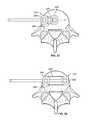
- FIGS. 1-7illustrate a system 10 for promoting fusion across an intervertebral disc space according to an exemplary embodiment.
- the system 10includes a first intervertebral fusion implant 20 and a second intervertebral fusion implant 30 , both dimensioned for insertion into an intervertebral disc space via lateral approach.
- the system of implants 10is dimensioned such that the distal end of the first implant 20 rests on a first lateral aspect 41 of a vertebral body 40 and the proximal end of the second implant 30 rests on the opposite, second lateral aspect 42 of a vertebral body 40 when the system is fully inserted within an intervertebral disc space.
- Each of the first implant 20 and second implant 30includes a top surface 48 , 58 , a bottom surface 49 , 59 , and a fusion aperture 22 , 32 extending between the top surface 48 , 58 and bottom surface 49 , 59 .
- Each of the first and second implants 20 , 30have an anterior wall 28 , 38 and a posterior wall 29 , 39 and a leading end wall 24 , 34 and a trailing end wall 25 , 35 walls defining the perimeter of the fusion apertures 22 , 32 .
- each of the first and second implants 20 , 30include anti-migration features 27 , 37 on one or both of the top surface 48 , 58 and bottom surface 49 , 59 .
- the exemplary implants 20 , 30also include radiopaque markers 23 , 33 proximate the leading end 24 , 34 and trailing end 25 , 35 to aid in positioning during implantation.
- Each of the first implant 20 and second implant 30are constructed of biocompatible material.
- the first implant 20 and second implant 30are mirror images of each other, having equal height and length, wherein the length of each of the first and second implant 20 , 30 is less than or equal to half of the maximum width dimension W of the endplate of the inferior vertebral body 40 adjacent the intervertebral disc space into which the system of implants 10 is inserted, the width dimension W being measured from a first lateral aspect 41 to the opposite second lateral aspect 42 of the vertebral body.
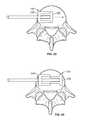
- the implants 20 , 30may have different lengths, but each of the first and second implant will have a maximum length that is less than the depth dimension D of the endplate of the inferior vertebral body 40 adjacent the intervertebral space into which the system of implants 10 is inserted, wherein the depth dimension D is measured from an anterior aspect of the endplate of the inferior vertebral body to a posterior aspect of the endplate of the inferior vertebral body.
- each implantmay also have an anterior wall 28 , 38 that is greater in height than the posterior wall 29 , 39 to create or restore lordosis at the vertebral level into which the system of implants 10 is inserted.
- the first and second implants 20 , 30also include at least one aperture 26 , 36 in the trailing end wall 25 , 35 that is dimensioned to receive bone growth promoting material after the implant 20 , 30 has been inserted into the disc space.
- both the first and second implants 20 , 30include visualization apertures 222 , 322 in the anterior wall 28 , 38 and posterior wall 29 , 39 to aid in the visualization of bone growth through the implants 20 , 30 at some time after a spinal fusion surgery.
- FIGS. 8-13illustrate a system and method for inserting the system of spinal fusion implants 10 shown in FIGS. 1-7 .
- the first and second implants 20 , 30are inserted into the intervertebral disc space using a single inserter 60 .
- the inserterincludes a cannulated outer shaft 61 and an inner shaft 62 that is dimensioned to be received within the cannulated outer shaft 61 .
- each of the first and second implants 20 , 30includes a first insertion tool aperture 21 , 31 in the leading end wall 24 , 34 and aperture 26 , 36 in the opposing trailing end wall 25 , 35 .
- the first insertion tool aperture 21 in the first implant 20is threaded to mate with the threaded distal end of the inner shaft 62 of the insertion tool 60 .
- the inner shaft 62 of the insertion tool 60is received through the aperture 26 in the trailing end 25 of the first implant 20 and coupled to the first insertion tool aperture 21 in the leading end 24 of the first implant.
- the cannulated outer shaft 61may be slid over the inner shaft 62 and engaged with the trailing end 21 of the first implant 20 .
- the inserter 60is used to insert the first implant 20 into the intervertebral disc space from a lateral approach and advance the first implant to the distal side of the disc space until it rests on the distal lateral aspect 41 of the inferior vertebral body 40 adjacent the intervertebral disc space.
- the outer shaft 61 of the inserter 60is disengaged from the first implant.
- the outer shaft 61 of the inserter 60is then engaged to the trailing end 35 of the second implant 30 .
- the outer shafted 61 coupled to the second implant 30is slid over the inner shaft 62 of the inserter, wherein the inner shaft 62 of the inserter 60 is received through an aperture 31 in the leading end wall 34 of the second implant 30 , through the fusion aperture 32 and through the aperture 36 in the trailing end wall 35 of the second implant.
- the second implant 30 and outer shaft 61are advanced along the inner shaft 62 of the inserter and into the disc space until the trailing end wall 35 of the second implant 30 rests on the proximal lateral aspect 42 of the inferior vertebral body 40 adjacent the intervertebral disc space.
- the leading end wall 31 of the second implant 30abuts the trailing end wall 25 of the first implant 20 when both implants 20 , 30 are fully inserted in the disc space.
- the leading end 31 of the second implant 30is coupled to the trailing end wall 25 of the first implant 20 .
- the inner shaft 62 of the inserter 60is disengaged from the first implant 20 and the outer shaft 61 of the inserter 60 is disengaged from the second implant 30 .
- bone growth promoting materialmay be introduced to the fusion apertures 22 , 32 of the first and second implants 20 , 30 through the apertures 26 , 31 , 36 in the trailing ends 25 , 35 of the first and second implants 20 , 30 and leading end 34 of the second implant.
- FIGS. 14-29illustrate a plurality of alternative embodiments of the system of spinal fusion implants 10 to the embodiment shown in FIGS. 1-13 .
- Each of these alternative embodimentsmay include all of the features described with respect to the first embodiment, including anti-migration features 27 , 37 , visualization apertures 222 , 322 in the anterior walls 28 , 38 and/or posterior walls 29 , 39 as well as possible variations in implant length, height and lordosis.
- the system of implants 10 according to these embodimentsmay also be inserted according to the above-described method.
- FIG. 14illustrates an alternative embodiment of the system of spinal fusion implants 10 .
- the anterior walls 28 , 38 of the first and second implantmay have rounded corners.
- FIG. 15illustrates a second alternative embodiment of the system of spinal fusion implants 10 .
- the system according to this embodimentmay be used to correct vertebral column deformity in the coronal plane, such that the trailing end walls 25 , 35 have a greater height than the leading end walls 24 , 34 or vice versa.
- FIG. 16illustrates a third alternative embodiment of the system of spinal fusion implants 10 that is dimensioned for use in the thoracic region of the spine. According to this embodiment, the trailing end 25 of the first implant 20 and the leading end 34 of the second implant 30 are open.
- FIGS. 17 a - billustrate a fourth alternative embodiment of the system of spinal fusion implants 10 including a fixation element on the trailing end 35 of the second implant 30 .
- the fixation elementincludes tabs 54 that extend in superior and inferior directions, perpendicular to the second implant 30 and adjacent the lateral aspects of the superior and inferior vertebral bodies, respectively.
- the tabs 54include fastener apertures 422 dimensioned to receive bone fasteners (not shown) therethrough.
- FIGS. 18 a - billustrate a fifth alternative embodiment of the system of spinal fusion implants 10 including a keel 46 , 56 extending from the top surface 48 , 58 and/or bottom surface 49 / 59 of the first and second implants 20 , 30 .
- FIG. 19demonstrates another alternative embodiment of the system of spinal fusion implants 100 .
- the systemincludes a plurality of implants 200 wherein the individual implants 200 may be uniform in length and height, or the implants can vary in length, height or both.
- the implants 200are configured such that the leading end 224 of the distal implant 200 in the disc space rests on the distal lateral aspect 41 of the inferior vertebral body 40 adjacent the disc space into which the system of implants is inserted, and the trailing end 225 of the proximal implant 200 rests on the proximal lateral aspect 42 of the inferior vertebral body 40 .
- FIG. 20illustrates a seventh alternative embodiment of the system of spinal fusion implants 110 .
- the system 110includes three implants 200 , 300 , wherein the proximal and distal implants 200 are uniform in size.
- the middle implant 300is one of a variety of lengths to accommodate the width of the disc space, such that the leading end 324 of the middle implant 300 abuts the trailing end 225 of the distal implant and the trailing end 325 of the middle implant abuts the leading end 224 of the proximal implant 200 .
- the middle implanthas a maximum length that is less than the depth dimension D of the endplate of the inferior vertebral body 40 adjacent the disc space into which the system of spinal fusion implants 110 is inserted.
- the middle implant 300is constructed of bone or bone growth enhancing material.
- FIGS. 21-22illustrate an eighth alternative embodiment of the system of spinal fusion implants 120 .
- the systemincludes a pair of implants 200 of uniform size and having a flexible anterior wall 330 and a flexible posterior wall 380 extending between the trailing end 225 of the distal implant 200 and the leading end 324 of the proximal implant 300 .
- the system of implants 120is inserted into the disc space in a collapsed configuration.
- the system of implants 120Upon insertion, the system of implants 120 is expanded such that the leading end 224 of the distal implant rests on the distal lateral aspect 41 of the inferior vertebral body 40 adjacent the disc space into which the system of implants 120 is inserted, and the flexible anterior and posterior walls 330 , 380 are stretched to a taut configuration, as best shown in FIG. 22 .
- the inserter 60is removed from the system of implants 120 and at least the space bordered by the trailing end 225 of the distal implant 200 , the leading end 324 of the proximal implant 300 is filled with bone growth promoting material.
- FIGS. 23-26illustrate a ninth alternative embodiment of the system of spinal fusion implants 130 .
- the first implant 220is nested inside of the second implant 230 during insertion into the disc space.
- the nested first and second implants 220 , 230are expanded such that the leading end of the first implant 220 rests on the distal lateral aspect 41 of the vertebral body 40 and the trailing end of the second implant 230 rests on the proximal lateral aspect 42 of the vertebral body 40 .
- the expansion of the system of implants 130 according to this embodimentcan be accomplished in two ways. According to one aspect, and as best shown in FIGS.
- the nested first and second implants 220 , 230are inserted into the disc space until the trailing end of the second implant 230 rests on the proximal lateral aspect 42 of the vertebral body 40 . Then the inner shaft 62 of the inserter 60 is advance across the disc space, pushing the first implant 220 across the disc space until the leading end of the first implant 220 rests on the distal lateral aspect 41 of the vertebral body 40 . Alternatively, the nested first and second implant 220 , 230 is inserted until the leading end of the first implant 220 rests on the distal lateral aspect 41 of the vertebral body 40 .
- the inner shaft 62 of the inserter 60is disengaged from the first implant 220 and the second implant 230 is pulled across the disc space until the trailing end of the second implant 230 rests on the proximal lateral aspect 42 of the vertebral body 40 .
- FIGS. 27-29illustrate a tenth embodiment of the system of spinal fusion implants 140 .
- the first implant 520is dimensioned such that it can inserted via an anterior, anterolateral approach and can support the intervertebral disc space alone, or it can be inserted as part of a system 140 of two implants from a direct lateral approach and be coupled to a lateral inserter via a lateral insertion tool aperture 531 .
- the leading end 524 of the first implants 520rests on the distal lateral aspect 41 of the vertebral body 40 .
- the second implant 530Upon insertion of the first implant 520 , the second implant 530 is inserted such that the leading end 534 of the second implant 530 abuts the trailing end 525 of the first implant 520 . According to another aspect, the leading end 534 of the second implant 530 is coupled to the trailing end 525 of the first implant 520 .
Landscapes
- Health & Medical Sciences (AREA)
- Engineering & Computer Science (AREA)
- Biomedical Technology (AREA)
- Orthopedic Medicine & Surgery (AREA)
- Neurology (AREA)
- Transplantation (AREA)
- Heart & Thoracic Surgery (AREA)
- Oral & Maxillofacial Surgery (AREA)
- Cardiology (AREA)
- Vascular Medicine (AREA)
- Life Sciences & Earth Sciences (AREA)
- Animal Behavior & Ethology (AREA)
- General Health & Medical Sciences (AREA)
- Public Health (AREA)
- Veterinary Medicine (AREA)
- Physical Education & Sports Medicine (AREA)
- Prostheses (AREA)
Abstract
Description
Claims (9)
Priority Applications (1)
| Application Number | Priority Date | Filing Date | Title |
|---|---|---|---|
| US13/648,253US9687356B1 (en) | 2011-10-07 | 2012-10-09 | Spinal fusion implants and related methods |
Applications Claiming Priority (2)
| Application Number | Priority Date | Filing Date | Title |
|---|---|---|---|
| US201161545066P | 2011-10-07 | 2011-10-07 | |
| US13/648,253US9687356B1 (en) | 2011-10-07 | 2012-10-09 | Spinal fusion implants and related methods |
Publications (1)
| Publication Number | Publication Date |
|---|---|
| US9687356B1true US9687356B1 (en) | 2017-06-27 |
Family
ID=59069562
Family Applications (1)
| Application Number | Title | Priority Date | Filing Date |
|---|---|---|---|
| US13/648,253Active2033-09-03US9687356B1 (en) | 2011-10-07 | 2012-10-09 | Spinal fusion implants and related methods |
Country Status (1)
| Country | Link |
|---|---|
| US (1) | US9687356B1 (en) |
Cited By (21)
| Publication number | Priority date | Publication date | Assignee | Title |
|---|---|---|---|---|
| US20160199197A1 (en)* | 2012-07-25 | 2016-07-14 | Spineology Inc. | Mesh spacer hybrid |
| EP3292840A1 (en)* | 2016-09-13 | 2018-03-14 | Warsaw Orthopedic, Inc. | Interbody spinal fusion device |
| CN108852561A (en)* | 2018-03-23 | 2018-11-23 | 广州华钛三维材料制造有限公司 | Split type artificial vertebral body and its application method |
| US10342676B2 (en)* | 2014-06-04 | 2019-07-09 | Spine Wave, Inc. | Apparatus for locating the position of a spinal implant during surgery |
| US20200282105A1 (en)* | 2013-03-15 | 2020-09-10 | Beacon Biomedical, Llc | Spinal implants with bioactive glass markers |
| US20200337861A1 (en)* | 2011-09-23 | 2020-10-29 | Samy Abdou | Spinal fixation devices and methods of use |
| US10857004B2 (en) | 2009-12-07 | 2020-12-08 | Samy Abdou | Devices and methods for minimally invasive spinal stabilization and instrumentation |
| US10857003B1 (en) | 2015-10-14 | 2020-12-08 | Samy Abdou | Devices and methods for vertebral stabilization |
| KR20210007396A (en)* | 2019-07-11 | 2021-01-20 | 이상호 | Splited insertion type intervertebral cage |
| US10973648B1 (en) | 2016-10-25 | 2021-04-13 | Samy Abdou | Devices and methods for vertebral bone realignment |
| US11058548B1 (en) | 2016-10-25 | 2021-07-13 | Samy Abdou | Devices and methods for vertebral bone realignment |
| US11090094B2 (en)* | 2018-06-01 | 2021-08-17 | Ehsan JAZINI | System and method for facilitating osteotomy of the pelvic |
| US11096799B2 (en) | 2004-11-24 | 2021-08-24 | Samy Abdou | Devices and methods for inter-vertebral orthopedic device placement |
| US11173040B2 (en)* | 2012-10-22 | 2021-11-16 | Cogent Spine, LLC | Devices and methods for spinal stabilization and instrumentation |
| US11179248B2 (en) | 2018-10-02 | 2021-11-23 | Samy Abdou | Devices and methods for spinal implantation |
| US11241318B2 (en) | 2019-09-18 | 2022-02-08 | Biedermann Technologies Gmbh & Co. Kg | Intervertebral implant and insertion device therefor |
| US11278422B2 (en)* | 2017-07-19 | 2022-03-22 | Vasudeva Rao Rajakumar Deshpande | Intervertebral spinal cage implant and method of assembling the same |
| US11559336B2 (en) | 2012-08-28 | 2023-01-24 | Samy Abdou | Spinal fixation devices and methods of use |
| US20230105717A1 (en)* | 2021-10-05 | 2023-04-06 | Spineology Inc. | Mesh spacer hybrid spinal implant |
| US11839413B2 (en) | 2012-02-22 | 2023-12-12 | Samy Abdou | Spinous process fixation devices and methods of use |
| US12208016B2 (en) | 2020-09-22 | 2025-01-28 | Biedermann Technologies Gmbh & Co. Kg | Implant, insertion device, and plate assembly |
Citations (26)
| Publication number | Priority date | Publication date | Assignee | Title |
|---|---|---|---|---|
| US5522899A (en)* | 1988-06-28 | 1996-06-04 | Sofamor Danek Properties, Inc. | Artificial spinal fusion implants |
| US6387130B1 (en)* | 1999-04-16 | 2002-05-14 | Nuvasive, Inc. | Segmented linked intervertebral implant systems |
| US20030125739A1 (en)* | 2001-12-12 | 2003-07-03 | Bagga Charanpreet S. | Bioactive spinal implants and method of manufacture thereof |
| US6942697B2 (en)* | 2002-12-19 | 2005-09-13 | Co-Ligne Ag | Pair of lumbar interbody implants and method of fusing together adjoining vertebrae bodies |
| US6986788B2 (en)* | 1998-01-30 | 2006-01-17 | Synthes (U.S.A.) | Intervertebral allograft spacer |
| US6989031B2 (en)* | 2001-04-02 | 2006-01-24 | Sdgi Holdings, Inc. | Hemi-interbody spinal implant manufactured from a major long bone ring or a bone composite |
| US20060142858A1 (en)* | 2004-12-16 | 2006-06-29 | Dennis Colleran | Expandable implants for spinal disc replacement |
| US20060189999A1 (en)* | 2005-02-24 | 2006-08-24 | Paul Zwirkoski | Linked slideable and interlockable rotatable components |
| US7192447B2 (en)* | 2002-12-19 | 2007-03-20 | Synthes (Usa) | Intervertebral implant |
| US20070067035A1 (en)* | 2005-09-16 | 2007-03-22 | Falahee Mark H | Steerable interbody fusion cage |
| US20070191951A1 (en) | 2003-11-21 | 2007-08-16 | Branch Charles L Jr | Expandable spinal implant |
| US20070260314A1 (en)* | 2006-05-02 | 2007-11-08 | Ashok Biyani | Transforaminal lumbar interbody fusion cage |
| US20080221687A1 (en)* | 2007-03-08 | 2008-09-11 | Zimmer Spine, Inc. | Deployable segmented tlif device |
| US20080249628A1 (en)* | 2007-04-09 | 2008-10-09 | Moti Altarac | Multi-component interbody device |
| US7455692B2 (en)* | 2001-04-02 | 2008-11-25 | Warsaw Orthopedic, Inc. | Hemi-artificial contoured spinal fusion implants made of a material other than bone |
| US20090143859A1 (en)* | 2007-11-30 | 2009-06-04 | Mcclellan Iii John W | Maximum support tlif implant |
| US20090182431A1 (en)* | 2008-01-16 | 2009-07-16 | Butler Michael S | Spinal Interbody Fusion Cages Providing Variable Anterior/Posterior Profiles |
| US20090240335A1 (en)* | 2008-03-24 | 2009-09-24 | Arcenio Gregory B | Expandable Devices for Emplacement in Body Parts and Methods Associated Therewith |
| US7867277B1 (en)* | 2005-07-15 | 2011-01-11 | Nuvasive Inc. | Spinal fusion implant and related methods |
| US20110029085A1 (en)* | 2009-07-31 | 2011-02-03 | Warsaw Orthopedic, Inc. | Flexible spinal implant |
| US20110029083A1 (en)* | 2009-07-31 | 2011-02-03 | Warsaw Orthopedic, Inc. | Flexible Spinal Implant |
| US20110125266A1 (en)* | 2007-12-28 | 2011-05-26 | Nuvasive, Inc. | Spinal Surgical Implant and Related Methods |
| US8025697B2 (en)* | 2006-09-21 | 2011-09-27 | Custom Spine, Inc. | Articulating interbody spacer, vertebral body replacement |
| US20110320000A1 (en) | 2010-06-24 | 2011-12-29 | O'neil Michael J | Multi-Segment Lateral Cage Adapted to Flex Substantially in the Coronal Plane |
| US20110321000A1 (en)* | 2007-12-28 | 2011-12-29 | Fujitsu Limited | Technique for creating analysis model and technique for creating circuit board model |
| US8512408B2 (en)* | 2010-12-17 | 2013-08-20 | Warsaw Orthopedic, Inc. | Flexiable spinal implant |
- 2012
- 2012-10-09USUS13/648,253patent/US9687356B1/enactiveActive
Patent Citations (26)
| Publication number | Priority date | Publication date | Assignee | Title |
|---|---|---|---|---|
| US5522899A (en)* | 1988-06-28 | 1996-06-04 | Sofamor Danek Properties, Inc. | Artificial spinal fusion implants |
| US6986788B2 (en)* | 1998-01-30 | 2006-01-17 | Synthes (U.S.A.) | Intervertebral allograft spacer |
| US6387130B1 (en)* | 1999-04-16 | 2002-05-14 | Nuvasive, Inc. | Segmented linked intervertebral implant systems |
| US7455692B2 (en)* | 2001-04-02 | 2008-11-25 | Warsaw Orthopedic, Inc. | Hemi-artificial contoured spinal fusion implants made of a material other than bone |
| US6989031B2 (en)* | 2001-04-02 | 2006-01-24 | Sdgi Holdings, Inc. | Hemi-interbody spinal implant manufactured from a major long bone ring or a bone composite |
| US20030125739A1 (en)* | 2001-12-12 | 2003-07-03 | Bagga Charanpreet S. | Bioactive spinal implants and method of manufacture thereof |
| US6942697B2 (en)* | 2002-12-19 | 2005-09-13 | Co-Ligne Ag | Pair of lumbar interbody implants and method of fusing together adjoining vertebrae bodies |
| US7192447B2 (en)* | 2002-12-19 | 2007-03-20 | Synthes (Usa) | Intervertebral implant |
| US20070191951A1 (en) | 2003-11-21 | 2007-08-16 | Branch Charles L Jr | Expandable spinal implant |
| US20060142858A1 (en)* | 2004-12-16 | 2006-06-29 | Dennis Colleran | Expandable implants for spinal disc replacement |
| US20060189999A1 (en)* | 2005-02-24 | 2006-08-24 | Paul Zwirkoski | Linked slideable and interlockable rotatable components |
| US7867277B1 (en)* | 2005-07-15 | 2011-01-11 | Nuvasive Inc. | Spinal fusion implant and related methods |
| US20070067035A1 (en)* | 2005-09-16 | 2007-03-22 | Falahee Mark H | Steerable interbody fusion cage |
| US20070260314A1 (en)* | 2006-05-02 | 2007-11-08 | Ashok Biyani | Transforaminal lumbar interbody fusion cage |
| US8025697B2 (en)* | 2006-09-21 | 2011-09-27 | Custom Spine, Inc. | Articulating interbody spacer, vertebral body replacement |
| US20080221687A1 (en)* | 2007-03-08 | 2008-09-11 | Zimmer Spine, Inc. | Deployable segmented tlif device |
| US20080249628A1 (en)* | 2007-04-09 | 2008-10-09 | Moti Altarac | Multi-component interbody device |
| US20090143859A1 (en)* | 2007-11-30 | 2009-06-04 | Mcclellan Iii John W | Maximum support tlif implant |
| US20110125266A1 (en)* | 2007-12-28 | 2011-05-26 | Nuvasive, Inc. | Spinal Surgical Implant and Related Methods |
| US20110321000A1 (en)* | 2007-12-28 | 2011-12-29 | Fujitsu Limited | Technique for creating analysis model and technique for creating circuit board model |
| US20090182431A1 (en)* | 2008-01-16 | 2009-07-16 | Butler Michael S | Spinal Interbody Fusion Cages Providing Variable Anterior/Posterior Profiles |
| US20090240335A1 (en)* | 2008-03-24 | 2009-09-24 | Arcenio Gregory B | Expandable Devices for Emplacement in Body Parts and Methods Associated Therewith |
| US20110029085A1 (en)* | 2009-07-31 | 2011-02-03 | Warsaw Orthopedic, Inc. | Flexible spinal implant |
| US20110029083A1 (en)* | 2009-07-31 | 2011-02-03 | Warsaw Orthopedic, Inc. | Flexible Spinal Implant |
| US20110320000A1 (en) | 2010-06-24 | 2011-12-29 | O'neil Michael J | Multi-Segment Lateral Cage Adapted to Flex Substantially in the Coronal Plane |
| US8512408B2 (en)* | 2010-12-17 | 2013-08-20 | Warsaw Orthopedic, Inc. | Flexiable spinal implant |
Cited By (49)
| Publication number | Priority date | Publication date | Assignee | Title |
|---|---|---|---|---|
| US11992423B2 (en) | 2004-11-24 | 2024-05-28 | Samy Abdou | Devices and methods for inter-vertebral orthopedic device placement |
| US11096799B2 (en) | 2004-11-24 | 2021-08-24 | Samy Abdou | Devices and methods for inter-vertebral orthopedic device placement |
| US11918486B2 (en) | 2009-12-07 | 2024-03-05 | Samy Abdou | Devices and methods for minimally invasive spinal stabilization and instrumentation |
| US10857004B2 (en) | 2009-12-07 | 2020-12-08 | Samy Abdou | Devices and methods for minimally invasive spinal stabilization and instrumentation |
| US10945861B2 (en) | 2009-12-07 | 2021-03-16 | Samy Abdou | Devices and methods for minimally invasive spinal stabilization and instrumentation |
| US11324608B2 (en) | 2011-09-23 | 2022-05-10 | Samy Abdou | Spinal fixation devices and methods of use |
| US12167973B2 (en)* | 2011-09-23 | 2024-12-17 | Samy Abdou | Spinal fixation devices and methods of use |
| US11517449B2 (en)* | 2011-09-23 | 2022-12-06 | Samy Abdou | Spinal fixation devices and methods of use |
| US20200337861A1 (en)* | 2011-09-23 | 2020-10-29 | Samy Abdou | Spinal fixation devices and methods of use |
| US11839413B2 (en) | 2012-02-22 | 2023-12-12 | Samy Abdou | Spinous process fixation devices and methods of use |
| US11833058B2 (en)* | 2012-07-25 | 2023-12-05 | Spineology Inc. | Mesh spacer hybrid |
| US20240173144A1 (en)* | 2012-07-25 | 2024-05-30 | Spineology Inc. | Mesh spacer hybrid |
| US20160199197A1 (en)* | 2012-07-25 | 2016-07-14 | Spineology Inc. | Mesh spacer hybrid |
| US20190060084A1 (en)* | 2012-07-25 | 2019-02-28 | Spineology Inc. | Mesh spacer hybrid |
| US10111756B2 (en)* | 2012-07-25 | 2018-10-30 | Spineology Inc. | Mesh spacer hybrid |
| US12303397B2 (en)* | 2012-07-25 | 2025-05-20 | Spineology Inc. | Mesh spacer hybrid |
| US20220133487A1 (en)* | 2012-07-25 | 2022-05-05 | Spineology Inc. | Mesh spacer hybrid |
| US11224520B2 (en)* | 2012-07-25 | 2022-01-18 | Spineology Inc. | Mesh spacer hybrid |
| US11559336B2 (en) | 2012-08-28 | 2023-01-24 | Samy Abdou | Spinal fixation devices and methods of use |
| US11918483B2 (en) | 2012-10-22 | 2024-03-05 | Cogent Spine Llc | Devices and methods for spinal stabilization and instrumentation |
| US11173040B2 (en)* | 2012-10-22 | 2021-11-16 | Cogent Spine, LLC | Devices and methods for spinal stabilization and instrumentation |
| US20200282105A1 (en)* | 2013-03-15 | 2020-09-10 | Beacon Biomedical, Llc | Spinal implants with bioactive glass markers |
| US10342676B2 (en)* | 2014-06-04 | 2019-07-09 | Spine Wave, Inc. | Apparatus for locating the position of a spinal implant during surgery |
| US11246718B2 (en) | 2015-10-14 | 2022-02-15 | Samy Abdou | Devices and methods for vertebral stabilization |
| US10857003B1 (en) | 2015-10-14 | 2020-12-08 | Samy Abdou | Devices and methods for vertebral stabilization |
| EP3292840A1 (en)* | 2016-09-13 | 2018-03-14 | Warsaw Orthopedic, Inc. | Interbody spinal fusion device |
| US10973651B2 (en) | 2016-09-13 | 2021-04-13 | Warsaw Orthopedic, Inc. | Interbody spinal fusion device |
| US11666452B2 (en)* | 2016-09-13 | 2023-06-06 | Warsaw Orthopedic, Inc. | Interbody spinal fusion device |
| US20210196474A1 (en)* | 2016-09-13 | 2021-07-01 | Warsaw Orthopedic, Inc. | Interbody spinal fusion device |
| US11259935B1 (en) | 2016-10-25 | 2022-03-01 | Samy Abdou | Devices and methods for vertebral bone realignment |
| US10973648B1 (en) | 2016-10-25 | 2021-04-13 | Samy Abdou | Devices and methods for vertebral bone realignment |
| US11058548B1 (en) | 2016-10-25 | 2021-07-13 | Samy Abdou | Devices and methods for vertebral bone realignment |
| US11752008B1 (en) | 2016-10-25 | 2023-09-12 | Samy Abdou | Devices and methods for vertebral bone realignment |
| US11278422B2 (en)* | 2017-07-19 | 2022-03-22 | Vasudeva Rao Rajakumar Deshpande | Intervertebral spinal cage implant and method of assembling the same |
| CN108852561B (en)* | 2018-03-23 | 2024-03-01 | 广州华钛三维材料制造有限公司 | Split artificial vertebral body and application method thereof |
| CN108852561A (en)* | 2018-03-23 | 2018-11-23 | 广州华钛三维材料制造有限公司 | Split type artificial vertebral body and its application method |
| US12108970B2 (en) | 2018-06-01 | 2024-10-08 | Ehsan JAZINI | System and method for facilitating osteotomy of the pelvic |
| US11090094B2 (en)* | 2018-06-01 | 2021-08-17 | Ehsan JAZINI | System and method for facilitating osteotomy of the pelvic |
| US20210353340A1 (en)* | 2018-06-01 | 2021-11-18 | Ehsan JAZINI | System and method for facilitating osteotomy of the pelvic |
| US11179248B2 (en) | 2018-10-02 | 2021-11-23 | Samy Abdou | Devices and methods for spinal implantation |
| WO2021006713A3 (en)* | 2019-07-11 | 2021-05-14 | 이상호 | Split insertion-type intervertebral cage |
| KR20210007396A (en)* | 2019-07-11 | 2021-01-20 | 이상호 | Splited insertion type intervertebral cage |
| US12178714B2 (en) | 2019-07-11 | 2024-12-31 | Sang Ho Lee | Split insertion-type intervertebral cage |
| KR102367665B1 (en)* | 2019-07-11 | 2022-02-24 | 이상호 | Splited insertion type intervertebral cage |
| US11241318B2 (en) | 2019-09-18 | 2022-02-08 | Biedermann Technologies Gmbh & Co. Kg | Intervertebral implant and insertion device therefor |
| US12343264B2 (en) | 2019-09-18 | 2025-07-01 | Biedermann Technologies Gmbh & Co. Kg | Inter vertebral implant and insertion device therefor |
| US12208016B2 (en) | 2020-09-22 | 2025-01-28 | Biedermann Technologies Gmbh & Co. Kg | Implant, insertion device, and plate assembly |
| US12023257B2 (en)* | 2021-10-05 | 2024-07-02 | Spineology Inc. | Mesh spacer hybrid spinal implant |
| US20230105717A1 (en)* | 2021-10-05 | 2023-04-06 | Spineology Inc. | Mesh spacer hybrid spinal implant |
Similar Documents
| Publication | Publication Date | Title |
|---|---|---|
| US9687356B1 (en) | Spinal fusion implants and related methods | |
| US9198765B1 (en) | Expandable spinal fusion implants and related methods | |
| US10258481B2 (en) | Modular, customizable spine stabilization system | |
| US10555818B2 (en) | Spinal fusion implant for oblique insertion | |
| US9597199B2 (en) | Orthopedic implants with flexible screws | |
| US9161841B2 (en) | Interbody fusion device and associated methods | |
| US8623088B1 (en) | Spinal fusion implant and related methods | |
| US8114162B1 (en) | Spinal fusion implant and related methods | |
| US7887595B1 (en) | Methods and apparatus for spinal fusion | |
| US9101491B2 (en) | Spinal surgical implant and related methods | |
| JP5876465B2 (en) | Interosseous device | |
| US7875078B2 (en) | Expandable interbody fusion device | |
| US8828084B2 (en) | Dynamic interbody cage anchor system | |
| US9763805B2 (en) | Spacer with temporary fixation plate | |
| US20090182428A1 (en) | Flanged interbody device | |
| US20080306596A1 (en) | Interbody fusion device and associated methods | |
| US8114138B2 (en) | Vertebral template systems and methods of use | |
| US20060167547A1 (en) | Expandable intervertebral fusion implants having hinged sidewalls | |
| US20110295373A1 (en) | Minimally invasive spinal distraction devices and methods | |
| WO2004078070A3 (en) | Apparatus and method for spinal fusion using posteriorly implanted devices | |
| WO2014145939A2 (en) | Expandable inter-body fusion devices and methods | |
| WO2007131165A2 (en) | Expandable device for insertion between anatomical strctures | |
| CN204581605U (en) | Invasive lumbar fusion device | |
| US20180092752A1 (en) | Spinal Fusion Implant with Reducible Graft Aperture | |
| US9241810B1 (en) | Fusion device and associated methods |
Legal Events
| Date | Code | Title | Description |
|---|---|---|---|
| AS | Assignment | Owner name:NUVASIVE, INC., CALIFORNIA Free format text:ASSIGNMENT OF ASSIGNORS INTEREST;ASSIGNORS:SPANGLER, JONATHAN D.;WARREN, NEIL;REEL/FRAME:029900/0766 Effective date:20130226 | |
| AS | Assignment | Owner name:BANK OF AMERICA, N.A., AS ADMINISTRATIVE AGENT, CALIFORNIA Free format text:NOTICE OF GRANT OF SECURITY INTEREST IN PATENTS;ASSIGNORS:NUVASIVE, INC.;IMPULSE MONITORING, INC.;REEL/FRAME:040634/0404 Effective date:20160208 Owner name:BANK OF AMERICA, N.A., AS ADMINISTRATIVE AGENT, CA Free format text:NOTICE OF GRANT OF SECURITY INTEREST IN PATENTS;ASSIGNORS:NUVASIVE, INC.;IMPULSE MONITORING, INC.;REEL/FRAME:040634/0404 Effective date:20160208 | |
| AS | Assignment | Owner name:BANK OF AMERICA, N.A., AS ADMINISTRATIVE AGENT, TEXAS Free format text:NOTICE OF GRANT OF SECURITY INTEREST IN PATENTS;ASSIGNORS:NUVASIVE, INC.;BIOTRONIC NATIONAL, LLC;NUVASIVE CLINICAL SERVICES MONITORING, INC.;AND OTHERS;REEL/FRAME:042490/0236 Effective date:20170425 Owner name:BANK OF AMERICA, N.A., AS ADMINISTRATIVE AGENT, TE Free format text:NOTICE OF GRANT OF SECURITY INTEREST IN PATENTS;ASSIGNORS:NUVASIVE, INC.;BIOTRONIC NATIONAL, LLC;NUVASIVE CLINICAL SERVICES MONITORING, INC.;AND OTHERS;REEL/FRAME:042490/0236 Effective date:20170425 | |
| STCF | Information on status: patent grant | Free format text:PATENTED CASE | |
| AS | Assignment | Owner name:BANK OF AMERICA, N.A., AS ADMINISTRATIVE AGENT, NORTH CAROLINA Free format text:SECURITY INTEREST;ASSIGNORS:NUVASIVE, INC.;NUVASIVE CLINICAL SERVICES MONITORING, INC.;NUVASIVE CLINICAL SERVICES, INC.;AND OTHERS;REEL/FRAME:052918/0595 Effective date:20200224 | |
| MAFP | Maintenance fee payment | Free format text:PAYMENT OF MAINTENANCE FEE, 4TH YEAR, LARGE ENTITY (ORIGINAL EVENT CODE: M1551); ENTITY STATUS OF PATENT OWNER: LARGE ENTITY Year of fee payment:4 | |
| MAFP | Maintenance fee payment | Free format text:PAYMENT OF MAINTENANCE FEE, 8TH YEAR, LARGE ENTITY (ORIGINAL EVENT CODE: M1552); ENTITY STATUS OF PATENT OWNER: LARGE ENTITY Year of fee payment:8 |