US9687284B2 - Locking peg with extended thread - Google Patents
Locking peg with extended threadDownload PDFInfo
- Publication number
- US9687284B2 US9687284B2US14/156,657US201414156657AUS9687284B2US 9687284 B2US9687284 B2US 9687284B2US 201414156657 AUS201414156657 AUS 201414156657AUS 9687284 B2US9687284 B2US 9687284B2
- Authority
- US
- United States
- Prior art keywords
- bone
- shaft
- locking peg
- locking
- proximal portion
- Prior art date
- Legal status (The legal status is an assumption and is not a legal conclusion. Google has not performed a legal analysis and makes no representation as to the accuracy of the status listed.)
- Active, expires
Links
Images


Classifications
- A—HUMAN NECESSITIES
- A61—MEDICAL OR VETERINARY SCIENCE; HYGIENE
- A61B—DIAGNOSIS; SURGERY; IDENTIFICATION
- A61B17/00—Surgical instruments, devices or methods
- A61B17/56—Surgical instruments or methods for treatment of bones or joints; Devices specially adapted therefor
- A61B17/58—Surgical instruments or methods for treatment of bones or joints; Devices specially adapted therefor for osteosynthesis, e.g. bone plates, screws or setting implements
- A61B17/68—Internal fixation devices, including fasteners and spinal fixators, even if a part thereof projects from the skin
- A61B17/84—Fasteners therefor or fasteners being internal fixation devices
- A61B17/86—Pins or screws or threaded wires; nuts therefor
- A61B17/8605—Heads, i.e. proximal ends projecting from bone
- A61B17/861—Heads, i.e. proximal ends projecting from bone specially shaped for gripping driver
- A—HUMAN NECESSITIES
- A61—MEDICAL OR VETERINARY SCIENCE; HYGIENE
- A61B—DIAGNOSIS; SURGERY; IDENTIFICATION
- A61B17/00—Surgical instruments, devices or methods
- A61B17/56—Surgical instruments or methods for treatment of bones or joints; Devices specially adapted therefor
- A61B17/58—Surgical instruments or methods for treatment of bones or joints; Devices specially adapted therefor for osteosynthesis, e.g. bone plates, screws or setting implements
- A61B17/68—Internal fixation devices, including fasteners and spinal fixators, even if a part thereof projects from the skin
- A61B17/84—Fasteners therefor or fasteners being internal fixation devices
- A61B17/86—Pins or screws or threaded wires; nuts therefor
- A61B17/8625—Shanks, i.e. parts contacting bone tissue
- A61B17/863—Shanks, i.e. parts contacting bone tissue with thread interrupted or changing its form along shank, other than constant taper
- A—HUMAN NECESSITIES
- A61—MEDICAL OR VETERINARY SCIENCE; HYGIENE
- A61B—DIAGNOSIS; SURGERY; IDENTIFICATION
- A61B17/00—Surgical instruments, devices or methods
- A61B17/56—Surgical instruments or methods for treatment of bones or joints; Devices specially adapted therefor
- A61B17/58—Surgical instruments or methods for treatment of bones or joints; Devices specially adapted therefor for osteosynthesis, e.g. bone plates, screws or setting implements
- A61B17/68—Internal fixation devices, including fasteners and spinal fixators, even if a part thereof projects from the skin
- A61B17/84—Fasteners therefor or fasteners being internal fixation devices
- A61B17/86—Pins or screws or threaded wires; nuts therefor
- A61B17/866—Material or manufacture
- A—HUMAN NECESSITIES
- A61—MEDICAL OR VETERINARY SCIENCE; HYGIENE
- A61B—DIAGNOSIS; SURGERY; IDENTIFICATION
- A61B17/00—Surgical instruments, devices or methods
- A61B17/56—Surgical instruments or methods for treatment of bones or joints; Devices specially adapted therefor
- A61B17/58—Surgical instruments or methods for treatment of bones or joints; Devices specially adapted therefor for osteosynthesis, e.g. bone plates, screws or setting implements
- A61B17/88—Osteosynthesis instruments; Methods or means for implanting or extracting internal or external fixation devices
- A61B17/8875—Screwdrivers, spanners or wrenches
- A—HUMAN NECESSITIES
- A61—MEDICAL OR VETERINARY SCIENCE; HYGIENE
- A61B—DIAGNOSIS; SURGERY; IDENTIFICATION
- A61B17/00—Surgical instruments, devices or methods
- A61B17/56—Surgical instruments or methods for treatment of bones or joints; Devices specially adapted therefor
- A61B17/58—Surgical instruments or methods for treatment of bones or joints; Devices specially adapted therefor for osteosynthesis, e.g. bone plates, screws or setting implements
- A61B17/68—Internal fixation devices, including fasteners and spinal fixators, even if a part thereof projects from the skin
- A61B17/80—Cortical plates, i.e. bone plates; Instruments for holding or positioning cortical plates, or for compressing bones attached to cortical plates
- A—HUMAN NECESSITIES
- A61—MEDICAL OR VETERINARY SCIENCE; HYGIENE
- A61B—DIAGNOSIS; SURGERY; IDENTIFICATION
- A61B17/00—Surgical instruments, devices or methods
- A61B17/56—Surgical instruments or methods for treatment of bones or joints; Devices specially adapted therefor
- A61B17/58—Surgical instruments or methods for treatment of bones or joints; Devices specially adapted therefor for osteosynthesis, e.g. bone plates, screws or setting implements
- A61B17/68—Internal fixation devices, including fasteners and spinal fixators, even if a part thereof projects from the skin
- A61B17/84—Fasteners therefor or fasteners being internal fixation devices
- A61B17/86—Pins or screws or threaded wires; nuts therefor
- A61B17/8605—Heads, i.e. proximal ends projecting from bone
- A—HUMAN NECESSITIES
- A61—MEDICAL OR VETERINARY SCIENCE; HYGIENE
- A61B—DIAGNOSIS; SURGERY; IDENTIFICATION
- A61B17/00—Surgical instruments, devices or methods
- A61B17/56—Surgical instruments or methods for treatment of bones or joints; Devices specially adapted therefor
- A61B17/58—Surgical instruments or methods for treatment of bones or joints; Devices specially adapted therefor for osteosynthesis, e.g. bone plates, screws or setting implements
- A61B17/68—Internal fixation devices, including fasteners and spinal fixators, even if a part thereof projects from the skin
- A61B17/84—Fasteners therefor or fasteners being internal fixation devices
- A61B17/86—Pins or screws or threaded wires; nuts therefor
- A61B2017/8655—Pins or screws or threaded wires; nuts therefor with special features for locking in the bone
- Y—GENERAL TAGGING OF NEW TECHNOLOGICAL DEVELOPMENTS; GENERAL TAGGING OF CROSS-SECTIONAL TECHNOLOGIES SPANNING OVER SEVERAL SECTIONS OF THE IPC; TECHNICAL SUBJECTS COVERED BY FORMER USPC CROSS-REFERENCE ART COLLECTIONS [XRACs] AND DIGESTS
- Y10—TECHNICAL SUBJECTS COVERED BY FORMER USPC
- Y10T—TECHNICAL SUBJECTS COVERED BY FORMER US CLASSIFICATION
- Y10T29/00—Metal working
- Y10T29/49—Method of mechanical manufacture
- Y10T29/49995—Shaping one-piece blank by removing material
Definitions
- the present inventionrelates to bone plates and the manner in which they are connected to bone, and more particularly, to locking pegs with extended threads to assist in removing the pegs from bone.
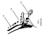
- FIG. 1illustrates a prior art bone plate fixation system including a bone plate 10 , non-locking bone screws 20 , locking screws 25 , and locking pegs 30 .
- Traditional bone screws 20 , locking screws 25 , and locking pegs 30are used to fix bone or at least partially connect plates to bone.
- the shafts of locking pegs 30generally are unthreaded.
- Locking pegs 30may be used, for example, in the distal portion of distal radius plates, as illustrated in FIG. 1 .
- the use of multiple non-parallel locking pegs 30may provide enough local bone-to-plate fixation such that a thread on the shaft of the locking peg 30 is not necessary.
- locking pegs 30may be inserted quickly because they may be pushed through a pilot hole in the bone without requiring screwing the shaft into the bone. This substantially reduces the time required to insert the locking peg, such that the locking peg need only be pushed into the pilot hole and screwed a few revolutions to activate the locking mechanism between a threaded head of the locking peg and a threaded hole of the bone plate. Furthermore, because locking pegs 30 have unthreaded shafts, the locking pegs have fewer sharp edges than traditional bone screws 20 and pose less of a risk for damage to tissues surrounding the bone, such as the radial cartilage in the wrist joint. Thus, locking pegs 30 may be especially useful when it is desired to place the locking peg 30 very close to a joint surface.
- FIGS. 2A-Billustrate steps for explantation (i.e., removal) of locking pegs 30 according to the prior art.
- Explantation of locking pegs 30is generally more difficult than explantation of traditional bone screws 20 .
- locking pegs 30have no threading on the shaft, counterclockwise rotation of the locking peg 30 will only disengage the screw head 40 from the bone plate 10 . Additional rotation will not provide additional axial force to extract the locking peg 30 , as the unthreaded shaft will simply rotate within the bone hole without any translation. Instead, the locking peg 30 must be grasped at the head 40 , as illustrated in FIG. 2B , and pulled out of the bone.
- a locking pegin one embodiment, includes a head at a proximal end of the locking peg and a shaft extending distally from the head to a distal end of the locking peg.
- the shafthas a threaded proximal portion and an unthreaded distal portion.
- the length of the unthreaded distal portion of the shaftis preferably greater than the length of the threaded proximal portion of the shaft.
- the threaded proximal portion of the shaftWhen the locking peg is inserted through a bone plate and into a bone, the threaded proximal portion of the shaft preferably extends approximately 2 to approximately 6 thread revolutions into the bone, more preferably approximately 3 to approximately 5 thread revolutions into the bone, or most preferably approximately 4 thread revolutions into the bone.
- the threaded proximal portion of the shaftmay have double-lead threading.
- the threaded proximal portion of the shaftmay have at least one cutting flute positioned at a distal end
- a method of implanting a locking pegincludes positioning a bone plate on a bone and creating a pilot hole in the bone. The method also includes inserting an unthreaded distal portion of the shaft of the locking peg into the pilot hole, and rotating the locking peg such that a threaded proximal portion of the locking peg shaft engages the bone. Rotation is continued such that the threaded proximal portion of the locking peg shaft advances further into the bone prior to a threaded head of the locking peg engaging threading in the hold of the bone plate. The locking peg is further rotated until a threaded head of the locking peg engages threading in the hole of the bone plate.
- a method of explanting a locking pegincludes unscrewing the locking peg that has previously been inserted through a hole of a bone plate and into a bone on which the bone plate is positioned. Unscrewing is continued until a threaded portion of a head of the locking peg no longer engages a threaded portion of the hole of the bone plate. The locking peg is further unscrewed such that a threaded proximal portion of a shaft of the locking peg disengages from the bone. The step of further unscrewing causes the head of the locking peg to travel away from the bone plate. The head of the locking peg is then grasped and the locking peg is removed from the bone.
- an unthreaded distal portion of the shaft of the locking pegremains in the bone.
- the threaded proximal portion of the shaftmay extend between approximately 2 and approximately 6 thread revolutions into the bone.
- a method of manufacturing a locking pegincludes creating one single lead thread extending from a head of the locking peg to a proximal portion of a shaft of the locking peg. Then, a second thread is created between the previously created single lead thread on the proximal portion of the shaft such that the proximal portion of the shaft has a double lead thread. Finally, at least one cutting flute is milled at the distal end of the double lead thread on the proximal portion of the shaft of the locking peg.
- the double lead threadmay preferably extend distally beyond the head between approximately 2 and approximately 6 thread revolutions. More preferably, the double lead thread may extend distally beyond the head between approximately 3 and approximately 5 thread revolutions. Most preferably, the double lead thread may extend distally beyond the head between approximately 4 thread revolutions.
- FIG. 1is a perspective partial phantom view of a bone plate implanted onto a bone according to the prior art.
- FIGS. 2A-Bare sectional side view of a locking peg according to the prior art being removed from a bone and bone plate.
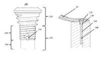
- FIG. 3Ais a side plan view of a locking peg according to an embodiment of the invention shown after a first step of manufacturing.
- FIG. 3Bis a side plan view of the locking peg of FIG. 3A after a second step of manufacturing.
- FIG. 3Cis a side plan view of the locking peg of FIG. 3A after a third step of manufacturing.
- FIGS. 4A-Cillustrate sectional side views of a locking peg according to an embodiment of the invention being removed from a bone and bone plate.
- proximalmeans closer to a user of the described devices and methods, such as a surgeon, while the term “distal” means farther away from the user.
- distalmeans farther away from the user.
- like numbersrefer to similar or identical parts.
- values for structures or characteristics of devicesare provided, those values are merely illustrative, unless otherwise stated, and those values may be altered without departing from the scope of the invention.
- ranges of valuesit should be understood that all values within the provided range are included, as well as all ranges within the range provided. For example, a range of 2 to 8 includes the values of 3 and 4, as well as the ranges of 4 to 7 and 3 to 5.
- locking peg 100is shown according to an embodiment of the invention during different stages of manufacture.
- locking peg 100generally includes a head 110 and a shaft 120 .
- the shaft 120generally includes a proximal portion 130 and a distal portion 140 .
- the head 110 of locking peg 100includes a locking thread configured to mate with complementary threading of a locking hole in a bone plate 10 .
- the locking peg 100includes threading that extends from the head 110 to the proximal portion 130 of shaft 120 .
- This extended threadingprovides additional axial force when unscrewing the locking peg 100 out of the bone and a locking hole in the bone plate 10 , described in further detail below.
- three stepsmay be performed to create the locking peg 100 with extended threading.
- the processcontinues down a portion of the shaft 120 , such that a locking thread exists on a proximal portion 130 of the shaft 120 .
- the distal portion 140 of the shaft 120remains unthreaded.
- an additional threadis then added to the locking thread on the proximal portion 130 of the shaft 120 between the previously created thread, such that the proximal portion 130 of the shaft 120 has a double thread, as shown in FIG. 3B .
- the magnitude of the lead on the proximal portion 130 of the shaft 120is preserved, while the magnitude of the pitch is halved by virtue of the additional thread.
- This configurationhelps ensure that the locking thread on the head 110 and the double thread on the proximal portion 130 of the shaft 120 advance the same distance per revolution of the locking peg 100 .
- One advantage of this configurationis that upon threading the locking peg 100 , it moves through the plate and the bone at the same speed, such that the plate and bone do not move relative to one another.
- the platewould be compressed onto the bone during insertion.
- the thread on the proximal portion 130 of the shaft 120had a lead less than the thread of the head 110 , the plate would be displaced away from the bone during insertion.
- the lead and pitch of the locking thread on the head 110is approximately 0.6 mm.
- the lead of the double threadis still approximately 0.6 mm while the pitch of the double thread is approximately 0.3 mm.
- Each revolution of the locking peg 100would then advance the locking peg by approximately 0.6 mm.
- cutting flutes 150may be created, for example by milling, near the distal end of the proximal portion 130 of the shaft 120 .
- three cutting flutes 150are added to the distal end of the proximal portion 130 of the shaft 120 and are generally equally spaced around the circumference of the locking peg 100 .
- the cutting flutes 150may help the locking peg 100 cut into the bone more effectively.
- Other features, such as a sharp thread angle,may also help the extended thread cut into bone.
- a sharp thread anglemay be created, for example, through the process described in relation to FIG. 3B .
- the locking peg 100is inserted through a locking hole of a bone plate 10 and through the bone in a generally similar method as would be expected for a traditional locking peg 30 .
- the main difference in inserting the locking peg 100is that the extended threading, when the locking peg is advanced, will cut into the bone, whereas a traditional locking peg 30 has no such extended threading to cut into the bone.
- the threading on portion 130is preferably of a diameter greater than portion 140 so as to dig into the walls of a pilot hole created in the bone to receive the unthreaded portion 140 .
- the locking peg 100may be unscrewed from the bone and bone plate 10 in a fashion generally similar to a traditional locking peg 30 by rotating the locking peg 100 counterclockwise.
- the locking thread of the head 110is rotated with respect to the corresponding thread in the locking hole of the bone plate 10
- the locking pegis moved upwards by the axial force provided by rotation.
- the locking peg 100 described hereinmay be rotated an additional number of revolutions, as illustrated in FIG. 4C , due to the extended threading on the proximal end 130 of the shaft 120 .
- the extended threading in the boneprovides additional upward axial force
- additional rotation in a traditional locking peg 30would simply rotate the locking peg 30 without providing additional axial force.
- the extended threading of locking peg 100adds approximately three to four additional revolutions to the unscrewing process.
- the length of the unthreaded portion of the shaft 120is longer than the length of the threaded portion of the shaft 120 .
- the additional revolutionsprovide between approximately 1.8 to approximately 2.4 additional millimeters of axial movement.
- the additional axial movementraises the head 110 of the locking peg 100 higher than would generally be expected in a traditional locking peg 30 .
- a usersuch as a surgeon, is more easily able to grasp the head 110 of the locking peg 100 with forceps or other removal devices. This mitigates the need for a surgeon to pull on the bone plate 10 or create additional incisions.
- the values provided aboveare merely illustrative and may be altered while still remaining within the scope of the invention.
Landscapes
- Health & Medical Sciences (AREA)
- Orthopedic Medicine & Surgery (AREA)
- Surgery (AREA)
- Life Sciences & Earth Sciences (AREA)
- Heart & Thoracic Surgery (AREA)
- Nuclear Medicine, Radiotherapy & Molecular Imaging (AREA)
- Engineering & Computer Science (AREA)
- Biomedical Technology (AREA)
- Medical Informatics (AREA)
- Molecular Biology (AREA)
- Animal Behavior & Ethology (AREA)
- General Health & Medical Sciences (AREA)
- Public Health (AREA)
- Veterinary Medicine (AREA)
- Neurology (AREA)
- Surgical Instruments (AREA)
Abstract
Description
Claims (5)
Priority Applications (1)
| Application Number | Priority Date | Filing Date | Title |
|---|---|---|---|
| US14/156,657US9687284B2 (en) | 2013-02-13 | 2014-01-16 | Locking peg with extended thread |
Applications Claiming Priority (2)
| Application Number | Priority Date | Filing Date | Title |
|---|---|---|---|
| US201361764173P | 2013-02-13 | 2013-02-13 | |
| US14/156,657US9687284B2 (en) | 2013-02-13 | 2014-01-16 | Locking peg with extended thread |
Publications (2)
| Publication Number | Publication Date |
|---|---|
| US20140228894A1 US20140228894A1 (en) | 2014-08-14 |
| US9687284B2true US9687284B2 (en) | 2017-06-27 |
Family
ID=50072845
Family Applications (1)
| Application Number | Title | Priority Date | Filing Date |
|---|---|---|---|
| US14/156,657Active2034-09-15US9687284B2 (en) | 2013-02-13 | 2014-01-16 | Locking peg with extended thread |
Country Status (2)
| Country | Link |
|---|---|
| US (1) | US9687284B2 (en) |
| EP (1) | EP2767248B1 (en) |
Cited By (4)
| Publication number | Priority date | Publication date | Assignee | Title |
|---|---|---|---|---|
| US20190070009A1 (en)* | 2017-09-05 | 2019-03-07 | ExsoMed Corporation | Small bone tapered compression screw |
| US10939944B2 (en) | 2018-04-18 | 2021-03-09 | Glw, Inc. | Removable orthopedic screws |
| US11147681B2 (en) | 2017-09-05 | 2021-10-19 | ExsoMed Corporation | Small bone angled compression screw |
| US12403009B2 (en) | 2019-06-12 | 2025-09-02 | United States Government As Represented By The Department Of Veterans Affairs | Femoral head arthroplasty system |
Families Citing this family (2)
| Publication number | Priority date | Publication date | Assignee | Title |
|---|---|---|---|---|
| US9936990B2 (en) | 2015-02-17 | 2018-04-10 | Biomet C.V. | Bone peg having improved extraction |
| CN105012006A (en)* | 2015-07-19 | 2015-11-04 | 孟媛 | Nail-removing apparatus for orthopedics department |
Citations (52)
| Publication number | Priority date | Publication date | Assignee | Title |
|---|---|---|---|---|
| US4463753A (en) | 1980-01-04 | 1984-08-07 | Gustilo Ramon B | Compression bone screw |
| US4760843A (en) | 1985-07-12 | 1988-08-02 | Artur Fischer | Connector for fractured bones |
| IE59317B1 (en) | 1985-11-28 | 1994-02-09 | Jaquet Orthopedie | Transcutaneous pin for fixation of a bone part or fragment |
| US5360452A (en) | 1991-05-20 | 1994-11-01 | Depuy Inc. | Enhanced fixation system for a prosthetic implant |
| US5360448A (en) | 1991-10-07 | 1994-11-01 | Thramann Jeffrey J | Porous-coated bone screw for securing prosthesis |
| US5375956A (en) | 1993-03-11 | 1994-12-27 | Pennig; Dietmar | Head screw construction for use in fixing the position of an intramedullary nail |
| US5759184A (en) | 1993-07-23 | 1998-06-02 | Santangelo; Massimo | Device for preventive support of the femur |
| US5871504A (en) | 1997-10-21 | 1999-02-16 | Eaton; Katulle Koco | Anchor assembly and method for securing ligaments to bone |
| US5954722A (en) | 1997-07-29 | 1999-09-21 | Depuy Acromed, Inc. | Polyaxial locking plate |
| US5968047A (en) | 1996-04-05 | 1999-10-19 | Reed; Thomas Mills | Fixation devices |
| US6019762A (en) | 1998-04-30 | 2000-02-01 | Orthodyne, Inc. | Adjustable length orthopedic fixation device |
| US6129730A (en)* | 1999-02-10 | 2000-10-10 | Depuy Acromed, Inc. | Bi-fed offset pitch bone screw |
| US6162234A (en) | 1993-03-23 | 2000-12-19 | Freedland; Yosef | Adjustable button cinch anchor orthopedic fastener |
| US6306140B1 (en) | 2001-01-17 | 2001-10-23 | Synthes (Usa) | Bone screw |
| US6699248B2 (en) | 2002-05-09 | 2004-03-02 | Roger P. Jackson | Multiple diameter tangential set screw |
| US20040127909A1 (en) | 2002-12-16 | 2004-07-01 | Morgan Vincent J. | Threaded dental or medical implants |
| US6808526B1 (en) | 1998-07-13 | 2004-10-26 | Sepitec Foundation | Osteosynthesis screw, especially for application by a translaminar vertebral screw |
| US20050131413A1 (en)* | 2003-06-20 | 2005-06-16 | O'driscoll Shawn W. | Bone plate with interference fit screw |
| US6955677B2 (en) | 2002-10-15 | 2005-10-18 | The University Of North Carolina At Chapel Hill | Multi-angular fastening apparatus and method for surgical bone screw/plate systems |
| EP1649819A1 (en) | 2004-10-19 | 2006-04-26 | Christian Maier | Bone plate |
| US20060149265A1 (en)* | 2004-09-07 | 2006-07-06 | Anthony James | Minimal thickness bone plate locking mechanism |
| EP1690509A1 (en) | 2005-02-11 | 2006-08-16 | Mauro Galvan | A prosthesis implant for endo-osseous implantation |
| US20060200151A1 (en)* | 2005-01-28 | 2006-09-07 | Dustin Ducharme | Orthopedic screw for use in repairing small bones |
| US20060276788A1 (en) | 2005-05-26 | 2006-12-07 | Amedica Corporation | Osteoconductive spinal fixation system |
| US20070009340A1 (en)* | 2005-07-11 | 2007-01-11 | Van Cor Dale E | Conic threaded fastener and fastener system |
| US20070088360A1 (en) | 2005-09-19 | 2007-04-19 | Orbay Jorge L | Bone stabilization system including multi-directional threaded fixation element |
| US20070093837A1 (en)* | 2005-09-20 | 2007-04-26 | Peter Bohrmann | System for the fixation of bone segments or bone fragments |
| WO2007095447A1 (en) | 2006-02-16 | 2007-08-23 | Warsaw Orthopedic, Inc. | Multi-thread bone screw |
| US20080140130A1 (en) | 2004-01-26 | 2008-06-12 | Chan Jason S | Highly-versatile variable-angle bone plate system |
| US20080188899A1 (en) | 2007-02-07 | 2008-08-07 | Apex Biomedical Company, Llc | Rotationally asymmetric bone screw |
| US20080234675A1 (en) | 2004-02-02 | 2008-09-25 | Branemark Integration Ab | Anchoring Element, Dental Anchoring Member, and Dental Anchorning Unit |
| WO2008115318A1 (en) | 2007-03-21 | 2008-09-25 | The University Of North Carolina At Chapel Hill | Anti-unscrewing and multi-angular fastening apparatuses and methods for surgical bone screw/plate systems |
| US20080234763A1 (en) | 2007-03-16 | 2008-09-25 | Patterson Chad J | Surgical compression bone screw |
| US20080306555A1 (en) | 2007-06-07 | 2008-12-11 | Patterson Chad J | Bone screw washer |
| US7491236B2 (en) | 2000-02-16 | 2009-02-17 | Trans1, Inc. | Dual anchor prosthetic nucleus apparatus |
| US20090062868A1 (en) | 2005-04-04 | 2009-03-05 | Zimmer Gmbh | Pedicle screw |
| US20090125028A1 (en)* | 2007-11-14 | 2009-05-14 | Jacques Teisen | Hybrid bone fixation element and methods of using the same |
| US20090182385A1 (en) | 2008-01-10 | 2009-07-16 | Smith J Scott | Pedicle screw |
| US20090210067A1 (en) | 2008-02-20 | 2009-08-20 | Biomet Manufacturing Corp. | Acetabular Cup Fixation |
| US20090240291A1 (en) | 2008-03-24 | 2009-09-24 | K2M, Inc. | Breached pedicle screw |
| US20090275993A1 (en) | 2008-04-30 | 2009-11-05 | Phan Christopher U | Apparatus and methods for inserting facet screws |
| US7637928B2 (en) | 2004-01-26 | 2009-12-29 | Synthes Usa, Llc | Variable angle locked bone fixation system |
| US20100094356A1 (en) | 2008-10-15 | 2010-04-15 | Armando Varela | Interlocking bone screw and washer concepts |
| US20100131012A1 (en) | 2008-11-24 | 2010-05-27 | Ralph James D | Clavicle plate and screws |
| US20100174323A1 (en) | 2002-07-05 | 2010-07-08 | Newdeal S.A. | Self-boring and self-tapping screw for osteosynthesis and compression |
| US20110118795A1 (en) | 2009-11-17 | 2011-05-19 | Adam Hashmi | Variable Angle Locking Buttress Pins |
| US7967851B2 (en) | 2003-05-08 | 2011-06-28 | Bickley Barry T | Method and apparatus for securing an object to bone |
| US20110276095A1 (en) | 2008-12-09 | 2011-11-10 | Yossef Bar | Double Threaded Orthopedic Screw |
| WO2011154891A2 (en) | 2010-06-07 | 2011-12-15 | Carbofix Orthopedics Ltd. | Composite material bone implant and methods |
| US8080044B2 (en) | 2006-02-23 | 2011-12-20 | Biedermann Motech Gmbh & Co. Kg | Bone anchoring device |
| US20110313473A1 (en) | 2009-02-09 | 2011-12-22 | Memometal Technologies | Screw for osteosynthesis and arthrodesis |
| US20120232599A1 (en)* | 2011-03-10 | 2012-09-13 | Jared Schoenly | Awl screw fixation members and related systems |
- 2014
- 2014-01-16USUS14/156,657patent/US9687284B2/enactiveActive
- 2014-02-10EPEP14000469.8Apatent/EP2767248B1/enactiveActive
Patent Citations (58)
| Publication number | Priority date | Publication date | Assignee | Title |
|---|---|---|---|---|
| US4463753A (en) | 1980-01-04 | 1984-08-07 | Gustilo Ramon B | Compression bone screw |
| US4760843A (en) | 1985-07-12 | 1988-08-02 | Artur Fischer | Connector for fractured bones |
| IE59317B1 (en) | 1985-11-28 | 1994-02-09 | Jaquet Orthopedie | Transcutaneous pin for fixation of a bone part or fragment |
| US5360452A (en) | 1991-05-20 | 1994-11-01 | Depuy Inc. | Enhanced fixation system for a prosthetic implant |
| US5360448A (en) | 1991-10-07 | 1994-11-01 | Thramann Jeffrey J | Porous-coated bone screw for securing prosthesis |
| US5375956A (en) | 1993-03-11 | 1994-12-27 | Pennig; Dietmar | Head screw construction for use in fixing the position of an intramedullary nail |
| US6162234A (en) | 1993-03-23 | 2000-12-19 | Freedland; Yosef | Adjustable button cinch anchor orthopedic fastener |
| US5759184A (en) | 1993-07-23 | 1998-06-02 | Santangelo; Massimo | Device for preventive support of the femur |
| US5968047A (en) | 1996-04-05 | 1999-10-19 | Reed; Thomas Mills | Fixation devices |
| US5954722A (en) | 1997-07-29 | 1999-09-21 | Depuy Acromed, Inc. | Polyaxial locking plate |
| US5871504A (en) | 1997-10-21 | 1999-02-16 | Eaton; Katulle Koco | Anchor assembly and method for securing ligaments to bone |
| US6019762A (en) | 1998-04-30 | 2000-02-01 | Orthodyne, Inc. | Adjustable length orthopedic fixation device |
| US6808526B1 (en) | 1998-07-13 | 2004-10-26 | Sepitec Foundation | Osteosynthesis screw, especially for application by a translaminar vertebral screw |
| US6129730A (en)* | 1999-02-10 | 2000-10-10 | Depuy Acromed, Inc. | Bi-fed offset pitch bone screw |
| US7491236B2 (en) | 2000-02-16 | 2009-02-17 | Trans1, Inc. | Dual anchor prosthetic nucleus apparatus |
| US20090105768A1 (en) | 2000-02-16 | 2009-04-23 | Trans1 | Dual anchor prosthetic nucleus apparatus |
| US6306140B1 (en) | 2001-01-17 | 2001-10-23 | Synthes (Usa) | Bone screw |
| US6699248B2 (en) | 2002-05-09 | 2004-03-02 | Roger P. Jackson | Multiple diameter tangential set screw |
| US20100174323A1 (en) | 2002-07-05 | 2010-07-08 | Newdeal S.A. | Self-boring and self-tapping screw for osteosynthesis and compression |
| US6955677B2 (en) | 2002-10-15 | 2005-10-18 | The University Of North Carolina At Chapel Hill | Multi-angular fastening apparatus and method for surgical bone screw/plate systems |
| US20040127909A1 (en) | 2002-12-16 | 2004-07-01 | Morgan Vincent J. | Threaded dental or medical implants |
| US7967851B2 (en) | 2003-05-08 | 2011-06-28 | Bickley Barry T | Method and apparatus for securing an object to bone |
| US20050131413A1 (en)* | 2003-06-20 | 2005-06-16 | O'driscoll Shawn W. | Bone plate with interference fit screw |
| US20100076496A1 (en) | 2004-01-26 | 2010-03-25 | Alberto Angel Fernandez | Variable Angle Locked Bone Fixation System |
| US7637928B2 (en) | 2004-01-26 | 2009-12-29 | Synthes Usa, Llc | Variable angle locked bone fixation system |
| US20080140130A1 (en) | 2004-01-26 | 2008-06-12 | Chan Jason S | Highly-versatile variable-angle bone plate system |
| US20080234675A1 (en) | 2004-02-02 | 2008-09-25 | Branemark Integration Ab | Anchoring Element, Dental Anchoring Member, and Dental Anchorning Unit |
| US20060149265A1 (en)* | 2004-09-07 | 2006-07-06 | Anthony James | Minimal thickness bone plate locking mechanism |
| EP1649819A1 (en) | 2004-10-19 | 2006-04-26 | Christian Maier | Bone plate |
| US20060200151A1 (en)* | 2005-01-28 | 2006-09-07 | Dustin Ducharme | Orthopedic screw for use in repairing small bones |
| EP1690509A1 (en) | 2005-02-11 | 2006-08-16 | Mauro Galvan | A prosthesis implant for endo-osseous implantation |
| US20090062868A1 (en) | 2005-04-04 | 2009-03-05 | Zimmer Gmbh | Pedicle screw |
| US20060276788A1 (en) | 2005-05-26 | 2006-12-07 | Amedica Corporation | Osteoconductive spinal fixation system |
| US20070009340A1 (en)* | 2005-07-11 | 2007-01-11 | Van Cor Dale E | Conic threaded fastener and fastener system |
| US20070088360A1 (en) | 2005-09-19 | 2007-04-19 | Orbay Jorge L | Bone stabilization system including multi-directional threaded fixation element |
| US7905909B2 (en) | 2005-09-19 | 2011-03-15 | Depuy Products, Inc. | Bone stabilization system including multi-directional threaded fixation element |
| US20070093837A1 (en)* | 2005-09-20 | 2007-04-26 | Peter Bohrmann | System for the fixation of bone segments or bone fragments |
| WO2007095447A1 (en) | 2006-02-16 | 2007-08-23 | Warsaw Orthopedic, Inc. | Multi-thread bone screw |
| US8080044B2 (en) | 2006-02-23 | 2011-12-20 | Biedermann Motech Gmbh & Co. Kg | Bone anchoring device |
| US20080188899A1 (en) | 2007-02-07 | 2008-08-07 | Apex Biomedical Company, Llc | Rotationally asymmetric bone screw |
| US20080234763A1 (en) | 2007-03-16 | 2008-09-25 | Patterson Chad J | Surgical compression bone screw |
| WO2008115318A1 (en) | 2007-03-21 | 2008-09-25 | The University Of North Carolina At Chapel Hill | Anti-unscrewing and multi-angular fastening apparatuses and methods for surgical bone screw/plate systems |
| US20080306555A1 (en) | 2007-06-07 | 2008-12-11 | Patterson Chad J | Bone screw washer |
| WO2009023666A2 (en) | 2007-08-13 | 2009-02-19 | Synthes (U.S.A.) | Highly-versatile variable-angle bone plate system |
| US20090125028A1 (en)* | 2007-11-14 | 2009-05-14 | Jacques Teisen | Hybrid bone fixation element and methods of using the same |
| US20090182385A1 (en) | 2008-01-10 | 2009-07-16 | Smith J Scott | Pedicle screw |
| US20090210067A1 (en) | 2008-02-20 | 2009-08-20 | Biomet Manufacturing Corp. | Acetabular Cup Fixation |
| US20090240291A1 (en) | 2008-03-24 | 2009-09-24 | K2M, Inc. | Breached pedicle screw |
| US20090275993A1 (en) | 2008-04-30 | 2009-11-05 | Phan Christopher U | Apparatus and methods for inserting facet screws |
| US20100094356A1 (en) | 2008-10-15 | 2010-04-15 | Armando Varela | Interlocking bone screw and washer concepts |
| US20100131012A1 (en) | 2008-11-24 | 2010-05-27 | Ralph James D | Clavicle plate and screws |
| US20110276095A1 (en) | 2008-12-09 | 2011-11-10 | Yossef Bar | Double Threaded Orthopedic Screw |
| US20110313473A1 (en) | 2009-02-09 | 2011-12-22 | Memometal Technologies | Screw for osteosynthesis and arthrodesis |
| WO2011062896A1 (en) | 2009-11-17 | 2011-05-26 | Synthes Usa, Llc | Variable angle locking buttress pins |
| US20110118795A1 (en) | 2009-11-17 | 2011-05-19 | Adam Hashmi | Variable Angle Locking Buttress Pins |
| US8496694B2 (en) | 2009-11-17 | 2013-07-30 | DePuy Synthes Products, LLC | Variable angle locking buttress pins |
| WO2011154891A2 (en) | 2010-06-07 | 2011-12-15 | Carbofix Orthopedics Ltd. | Composite material bone implant and methods |
| US20120232599A1 (en)* | 2011-03-10 | 2012-09-13 | Jared Schoenly | Awl screw fixation members and related systems |
Non-Patent Citations (2)
| Title |
|---|
| European Examination for Application No. 14000469.8 dated Jul. 7, 2015. |
| Extended European Search Report for Application No. 14000469.8 dated May 30, 2014. |
Cited By (8)
| Publication number | Priority date | Publication date | Assignee | Title |
|---|---|---|---|---|
| US20190070009A1 (en)* | 2017-09-05 | 2019-03-07 | ExsoMed Corporation | Small bone tapered compression screw |
| US11147681B2 (en) | 2017-09-05 | 2021-10-19 | ExsoMed Corporation | Small bone angled compression screw |
| US11191645B2 (en)* | 2017-09-05 | 2021-12-07 | ExsoMed Corporation | Small bone tapered compression screw |
| US20220117747A1 (en)* | 2017-09-05 | 2022-04-21 | ExsoMed Corporation | Small bone angled compression screw |
| US12251316B2 (en)* | 2017-09-05 | 2025-03-18 | ExsoMed Corporation | Small bone angled compression screw |
| US10939944B2 (en) | 2018-04-18 | 2021-03-09 | Glw, Inc. | Removable orthopedic screws |
| US11793559B2 (en) | 2018-04-18 | 2023-10-24 | Glw, Inc. | Removable orthopedic screws |
| US12403009B2 (en) | 2019-06-12 | 2025-09-02 | United States Government As Represented By The Department Of Veterans Affairs | Femoral head arthroplasty system |
Also Published As
| Publication number | Publication date |
|---|---|
| EP2767248A1 (en) | 2014-08-20 |
| US20140228894A1 (en) | 2014-08-14 |
| EP2767248B1 (en) | 2017-05-17 |
Similar Documents
| Publication | Publication Date | Title |
|---|---|---|
| US9687284B2 (en) | Locking peg with extended thread | |
| AU2018200716B2 (en) | Orthopedic fastener device | |
| US20200375750A1 (en) | Systems and methods for fusion of sacroiliac joint | |
| JP6334168B2 (en) | Bone screw containing a lot of PEEK | |
| US10299837B2 (en) | Sacroiliac joint stabilization and fixation devices and related methods | |
| US20240238021A1 (en) | Self-Holding Screw Head | |
| JP4728322B2 (en) | Adjustable tool for fasteners cannulated | |
| US9795412B2 (en) | Bone compression and fixation devices | |
| US11273043B1 (en) | System and method for fusion of sacroiliac joint | |
| US9078717B2 (en) | Screw with variable diameter cannulation and driver | |
| US20180071000A1 (en) | Telescoping fixation devices and methods of use | |
| CA2882981C (en) | Orthopedic fastener method | |
| JP2020517341A (en) | Angled flutes in cannulated bone screws | |
| US11426226B2 (en) | Orthopedic screw extractor | |
| US20190008570A1 (en) | Implantable compression screws | |
| US10143509B2 (en) | Medical screw | |
| US10448982B2 (en) | Reinforced cannulated screw assembly systems and methods | |
| JP2022185084A (en) | Easy-start cannulated bone screw | |
| EP3565624B1 (en) | Modular guidewire | |
| US20210322080A1 (en) | Headless screw removal tool | |
| CN106725712B (en) | Articular process nailing device and articular process nailing method | |
| US11844557B2 (en) | Locking variable length compression screw | |
| JP2017209497A (en) | Preventing over-expandable anchoring | |
| US20250107833A1 (en) | Pedicle Screw Tip Insertion Feature | |
| DE202013102084U1 (en) | Surgical Subtalar Screw and System |
Legal Events
| Date | Code | Title | Description |
|---|---|---|---|
| AS | Assignment | Owner name:STRYKER TRAUMA SA, SWITZERLAND Free format text:ASSIGNMENT OF ASSIGNORS INTEREST;ASSIGNORS:PACHECO, FERNANDO;KNAPE, MARTIN;HERMANN, EGON;AND OTHERS;SIGNING DATES FROM 20140121 TO 20140217;REEL/FRAME:032234/0792 | |
| AS | Assignment | Owner name:STRYKER EUROPEAN HOLDINGS V, LLC, MICHIGAN Free format text:NUNC PRO TUNC ASSIGNMENT;ASSIGNOR:STRYKER TRAUMA SA;REEL/FRAME:037153/0001 Effective date:20151008 Owner name:STRYKER EUROPEAN HOLDINGS I, LLC, MICHIGAN Free format text:NUNC PRO TUNC ASSIGNMENT;ASSIGNOR:STRYKER EUROPEAN HOLDINGS V, LLC;REEL/FRAME:037153/0168 Effective date:20151008 | |
| STCF | Information on status: patent grant | Free format text:PATENTED CASE | |
| AS | Assignment | Owner name:STRYKER EUROPEAN OPERATIONS HOLDINGS LLC, MICHIGAN Free format text:CHANGE OF NAME;ASSIGNOR:STRYKER EUROPEAN HOLDINGS III, LLC;REEL/FRAME:052860/0716 Effective date:20190226 Owner name:STRYKER EUROPEAN HOLDINGS III, LLC, DELAWARE Free format text:NUNC PRO TUNC ASSIGNMENT;ASSIGNOR:STRYKER EUROPEAN HOLDINGS I, LLC;REEL/FRAME:052861/0001 Effective date:20200519 | |
| MAFP | Maintenance fee payment | Free format text:PAYMENT OF MAINTENANCE FEE, 4TH YEAR, LARGE ENTITY (ORIGINAL EVENT CODE: M1551); ENTITY STATUS OF PATENT OWNER: LARGE ENTITY Year of fee payment:4 | |
| MAFP | Maintenance fee payment | Free format text:PAYMENT OF MAINTENANCE FEE, 8TH YEAR, LARGE ENTITY (ORIGINAL EVENT CODE: M1552); ENTITY STATUS OF PATENT OWNER: LARGE ENTITY Year of fee payment:8 | |
| AS | Assignment | Owner name:STRYKER EUROPEAN OPERATIONS HOLDINGS LLC, MICHIGAN Free format text:CHANGE OF ADDRESS;ASSIGNOR:STRYKER EUROPEAN OPERATIONS HOLDINGS LLC;REEL/FRAME:069730/0754 Effective date:20241217 |