US9687225B2 - Suture passer with tissue reinforcement positioner - Google Patents
Suture passer with tissue reinforcement positionerDownload PDFInfo
- Publication number
- US9687225B2 US9687225B2US14/137,312US201314137312AUS9687225B2US 9687225 B2US9687225 B2US 9687225B2US 201314137312 AUS201314137312 AUS 201314137312AUS 9687225 B2US9687225 B2US 9687225B2
- Authority
- US
- United States
- Prior art keywords
- suture
- shaft
- handle
- jaw
- tissue
- Prior art date
- Legal status (The legal status is an assumption and is not a legal conclusion. Google has not performed a legal analysis and makes no representation as to the accuracy of the status listed.)
- Expired - Fee Related, expires
Links
Images


Classifications
- A—HUMAN NECESSITIES
- A61—MEDICAL OR VETERINARY SCIENCE; HYGIENE
- A61B—DIAGNOSIS; SURGERY; IDENTIFICATION
- A61B17/00—Surgical instruments, devices or methods
- A61B17/04—Surgical instruments, devices or methods for suturing wounds; Holders or packages for needles or suture materials
- A61B17/0469—Suturing instruments for use in minimally invasive surgery, e.g. endoscopic surgery
- A—HUMAN NECESSITIES
- A61—MEDICAL OR VETERINARY SCIENCE; HYGIENE
- A61B—DIAGNOSIS; SURGERY; IDENTIFICATION
- A61B17/00—Surgical instruments, devices or methods
- A61B17/04—Surgical instruments, devices or methods for suturing wounds; Holders or packages for needles or suture materials
- A61B17/0401—Suture anchors, buttons or pledgets, i.e. means for attaching sutures to bone, cartilage or soft tissue; Instruments for applying or removing suture anchors
- A—HUMAN NECESSITIES
- A61—MEDICAL OR VETERINARY SCIENCE; HYGIENE
- A61B—DIAGNOSIS; SURGERY; IDENTIFICATION
- A61B17/00—Surgical instruments, devices or methods
- A61B17/04—Surgical instruments, devices or methods for suturing wounds; Holders or packages for needles or suture materials
- A61B17/0482—Needle or suture guides
- A—HUMAN NECESSITIES
- A61—MEDICAL OR VETERINARY SCIENCE; HYGIENE
- A61B—DIAGNOSIS; SURGERY; IDENTIFICATION
- A61B17/00—Surgical instruments, devices or methods
- A61B17/04—Surgical instruments, devices or methods for suturing wounds; Holders or packages for needles or suture materials
- A61B17/06—Needles ; Sutures; Needle-suture combinations; Holders or packages for needles or suture materials
- A61B17/062—Needle manipulators
- A—HUMAN NECESSITIES
- A61—MEDICAL OR VETERINARY SCIENCE; HYGIENE
- A61B—DIAGNOSIS; SURGERY; IDENTIFICATION
- A61B17/00—Surgical instruments, devices or methods
- A61B2017/0046—Surgical instruments, devices or methods with a releasable handle; with handle and operating part separable
- A—HUMAN NECESSITIES
- A61—MEDICAL OR VETERINARY SCIENCE; HYGIENE
- A61B—DIAGNOSIS; SURGERY; IDENTIFICATION
- A61B17/00—Surgical instruments, devices or methods
- A61B2017/00477—Coupling
- A—HUMAN NECESSITIES
- A61—MEDICAL OR VETERINARY SCIENCE; HYGIENE
- A61B—DIAGNOSIS; SURGERY; IDENTIFICATION
- A61B17/00—Surgical instruments, devices or methods
- A61B17/04—Surgical instruments, devices or methods for suturing wounds; Holders or packages for needles or suture materials
- A61B17/0401—Suture anchors, buttons or pledgets, i.e. means for attaching sutures to bone, cartilage or soft tissue; Instruments for applying or removing suture anchors
- A61B2017/0406—Pledgets
- A—HUMAN NECESSITIES
- A61—MEDICAL OR VETERINARY SCIENCE; HYGIENE
- A61B—DIAGNOSIS; SURGERY; IDENTIFICATION
- A61B17/00—Surgical instruments, devices or methods
- A61B17/04—Surgical instruments, devices or methods for suturing wounds; Holders or packages for needles or suture materials
- A61B17/0401—Suture anchors, buttons or pledgets, i.e. means for attaching sutures to bone, cartilage or soft tissue; Instruments for applying or removing suture anchors
- A61B2017/0409—Instruments for applying suture anchors
- A—HUMAN NECESSITIES
- A61—MEDICAL OR VETERINARY SCIENCE; HYGIENE
- A61B—DIAGNOSIS; SURGERY; IDENTIFICATION
- A61B17/00—Surgical instruments, devices or methods
- A61B17/04—Surgical instruments, devices or methods for suturing wounds; Holders or packages for needles or suture materials
- A61B17/0401—Suture anchors, buttons or pledgets, i.e. means for attaching sutures to bone, cartilage or soft tissue; Instruments for applying or removing suture anchors
- A61B2017/044—Suture anchors, buttons or pledgets, i.e. means for attaching sutures to bone, cartilage or soft tissue; Instruments for applying or removing suture anchors with a threaded shaft, e.g. screws
- A—HUMAN NECESSITIES
- A61—MEDICAL OR VETERINARY SCIENCE; HYGIENE
- A61B—DIAGNOSIS; SURGERY; IDENTIFICATION
- A61B17/00—Surgical instruments, devices or methods
- A61B17/04—Surgical instruments, devices or methods for suturing wounds; Holders or packages for needles or suture materials
- A61B2017/0495—Reinforcements for suture lines
- A—HUMAN NECESSITIES
- A61—MEDICAL OR VETERINARY SCIENCE; HYGIENE
- A61B—DIAGNOSIS; SURGERY; IDENTIFICATION
- A61B17/00—Surgical instruments, devices or methods
- A61B17/04—Surgical instruments, devices or methods for suturing wounds; Holders or packages for needles or suture materials
- A61B17/06—Needles ; Sutures; Needle-suture combinations; Holders or packages for needles or suture materials
- A61B17/06004—Means for attaching suture to needle
- A61B2017/06042—Means for attaching suture to needle located close to needle tip
- A—HUMAN NECESSITIES
- A61—MEDICAL OR VETERINARY SCIENCE; HYGIENE
- A61B—DIAGNOSIS; SURGERY; IDENTIFICATION
- A61B17/00—Surgical instruments, devices or methods
- A61B17/04—Surgical instruments, devices or methods for suturing wounds; Holders or packages for needles or suture materials
- A61B17/06—Needles ; Sutures; Needle-suture combinations; Holders or packages for needles or suture materials
- A61B17/06066—Needles, e.g. needle tip configurations
- A61B2017/06095—Needles, e.g. needle tip configurations pliable
- Y—GENERAL TAGGING OF NEW TECHNOLOGICAL DEVELOPMENTS; GENERAL TAGGING OF CROSS-SECTIONAL TECHNOLOGIES SPANNING OVER SEVERAL SECTIONS OF THE IPC; TECHNICAL SUBJECTS COVERED BY FORMER USPC CROSS-REFERENCE ART COLLECTIONS [XRACs] AND DIGESTS
- Y10—TECHNICAL SUBJECTS COVERED BY FORMER USPC
- Y10T—TECHNICAL SUBJECTS COVERED BY FORMER US CLASSIFICATION
- Y10T29/00—Metal working
- Y10T29/49—Method of mechanical manufacture
- Y10T29/49815—Disassembling
Definitions
- the present disclosurerelates to a suture passer with tissue reinforcement positioner.
- the present disclosuredescribes a suture passer device that includes a handle, a shaft extending from the handle, a suture carrier secured to the handle and extending through the shaft, and a suturing head extending from the shaft and configured to retain tissue.
- the handleis operable to advance the suture carrier through the suturing head to pass a suture through tissue retained in the suturing head.
- the suture passer deviceincludes a quick-connect mechanism releasably connecting the shaft to the handle.
- the shaftincludes a first shaft and a second shaft pivotally coupled to the first shaft, and the first shaft defines a first channel for receiving the second shaft.
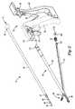
- FIG. 1is a side view of a suture passer device according to the principles of the present disclosure
- FIG. 2is an exploded isometric view of the suture passer device shown in FIG. 1 ;
- FIG. 3Ais an isometric view of a suturing head of the suture passer device with an upper jaw in an open position and a suture carrier in a retracted position;
- FIG. 3Bis a section view taken along line 3 B shown in FIG. 3A ;
- FIG. 4Ais an isometric view of the suturing head with the upper jaw in a closed position and the suture carrier in an extended position;
- FIG. 4Bis a section view taken along line 4 B shown in FIG. 4A ;
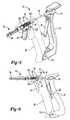
- FIG. 5is an isometric view of a handle assembly of the suture passer device with a trigger and a rear handle in released positions;
- FIG. 6is a side view of the handle assembly with the trigger and the rear handle in applied positions
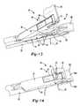
- FIG. 7is an isometric view of a proximal end of a shaft assembly of the suture passer device disconnected from a distal end of the handle assembly;
- FIG. 8is a side view of the proximal end of the shaft assembly connected to the distal end of the handle assembly;
- FIG. 9is a side view of an alternative embodiment of the shaft assembly and the handle assembly with a proximal end of the shaft assembly disconnected from a distal end of the handle assembly;
- FIG. 10is a side view of the alternative embodiment of the shaft assembly and the handle assembly with the proximal end of the shaft assembly connected to the distal end of the handle assembly;
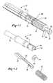
- FIG. 11is an isometric view of the proximal end of the shaft assembly with an inner shaft inserted into an outer shaft;
- FIG. 12is an isometric view of a proximal end of a shaft assembly with the inner shaft removed from the outer shaft;
- FIG. 13is an isometric view of the suturing head with the upper jaw in the open position and positioning a tissue reinforcement construct, the suture carrier in the retracted position, a suture extending through a lower jaw, and soft tissue disposed between the lower jaw and the upper jaw;
- FIG. 14is an isometric view of the suturing head in the closed position, the soft tissue being held between the upper and lower jaws, and the suture carrier in the extended position and passing a portion of the suture through the soft tissue and the tissue reinforcement construct;
- FIG. 15Ais an end view of the suturing head passing two portions of a suture through soft tissue and the tissue reinforcement construct, the suture extending through a suture anchor secured in a hole in bone;
- FIG. 15Bis an end view of the two portions of the suture tied in a knot to form an adjustable loop that secures the soft tissue to the bone;
- FIG. 16Ais an end view of the suturing head passing adjustable loops of a suture construct through soft tissue and the tissue reinforcement construct, the suture construct extending through a suture anchor secured in a hole in bone, and a locking member position adjacent to the loops;
- FIG. 16Bis an end view of the locking member extending through the loops and preventing the loops from being pulled through the soft tissue and the tissue reinforcement member as the loops are tightened;
- FIG. 17Ais an isometric view of the suturing head with the upper jaw in the open position and positioning a tissue reinforcement construct, the suture carrier in the retracted position, and a first end of a flexible suture anchor of a suture construct extending through the lower jaw;
- FIG. 17Bis an isometric view of the suturing head in the closed position, the soft tissue being held between the upper and lower jaws, and the suture carrier in the extended position and passing the first end of the flexible suture anchor through the soft tissue and the tissue reinforcement construct;
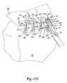
- FIG. 17Cis an isometric view of a plurality of suture constructs extending through soft tissue and the tissue reinforcement construct, with the suturing head passing a portion of one of the suture constructs through the soft tissue and the tissue reinforcement construct as illustrated in FIG. 17B ;
- FIG. 18Ais an isometric view similar to that shown in FIG. 13 but illustrating an alternative embodiment of a suturing head having teeth for positioning the tissue reinforcement construct instead of a slot;
- FIG. 18Bis a side view similar to that shown in FIG. 14 but illustrating the alternative embodiment of the suturing head.
- FIG. 19Ais an isometric view similar to that shown in FIG. 13 but illustrating a second alternative embodiment of a suturing head for positioning the tissue reinforcement construct instead of a slot;
- FIG. 19Bis a side view similar to that shown in FIG. 14 but illustrating a second alternative embodiment of the suturing head.
- FIG. 20Ais an isometric view similar to that shown in FIG. 13 but illustrating a third alternative embodiment of a suturing head having teeth for positioning the tissue reinforcement construct instead of a slot;
- FIG. 20Bis a side view similar to that shown in FIG. 14 but illustrating a third alternative embodiment of the suturing head.
- a suture passer device 10includes a handle assembly 12 , a suture carrier 14 , a shaft assembly 16 , and a suturing head 18 .
- the handle assembly 12includes a front handle 20 , a rear handle 22 , a trigger 24 , and a handle spring 26 .
- the shaft assembly 16includes an outer shaft 28 , an inner shaft 30 , a shaft spring 32 , and a washer 34 .
- the spring 32 and the washer 34can be welded to the inner shaft 30 .
- the suturing head 18includes an upper jaw 36 and a lower jaw 38 .
- the handle assembly 12is operable to actuate the upper jaw 36 of the suturing head 18 from an open position ( FIG. 3 ) to a closed position ( FIG. 4 ) in order to clamp or engage soft tissue between the upper and lower jaws 36 , 38 .
- the handle assembly 12is also operable to actuate the suture carrier 14 from a retracted position ( FIG. 3 ) to an extended position ( FIG. 4 ) to pass a suture 40 through soft tissue that is clamped or held between the upper and lower jaws 36 , 38 .
- the suture carrier 14includes a proximal body 42 having a round plinth, disk, or hockey puck shape, a cylindrical body 44 , and a flat, elongate body 45 .
- the proximal body 42is disposed at the proximal end of the suture carrier 14 and is configured to be retained within a pocket 46 in the rear handle 22 .
- the cylindrical body 44is attached to the proximal body 42 and extends from the proximal body 42 to the elongate body 45 .
- the elongate body 45is attached to the cylindrical body 44 using, for example, a weld 47 , and extends from the cylindrical body 44 to the distal end of the suture carrier 14 .
- the elongate body 45has a notch 48 adjacent to its distal end for holding the suture 40 and a pointed tip 50 at its distal end for piercing a hole in soft tissue so that the suture carrier 14 and the suture 40 can be passed through the tissue.
- the proximal body 42can be made from plastic, and the cylindrical and elongate bodies 44 , 45 can be made from a flexible material such as Nitinol or a flexible polymer.
- the upper jaw 36 of the suturing head 18includes teeth 52 , a tissue reinforcement member holder 54 , a suture carrier receptacle 56 , and a suture retaining mechanism 58 .
- the teeth 52are configured to bite into or grip soft tissue when the upper jaw 36 is in the closed position.
- the tissue reinforcement member holder 54is configured to position a tissue reinforcement member 60 ( FIGS. 13 and 14 ) so that the suture carrier 14 and the suture 40 pass through the tissue reinforcement member 60 after passing through soft tissue held between the upper and lower jaws 36 , 38 .
- the tissue reinforcement member holder 54can also or alternatively be included in the lower jaw 38 .
- the tissue reinforcement member holder 54can be a slot 61 having open lateral sides 61 a , 61 b , an open distal end 61 c , and a closed proximal end 61 d .
- the tissue reinforcement member 60can be inserted into the slot 61 .
- the slot 61can hold the tissue reinforcement member 60 while allowing the tissue reinforcement member 60 to be slidably adjustable in a lateral direction through the open sides 61 a , 61 b.
- the tissue reinforcement member 60can be made from a flexible material such as woven, knitted, or braided polyester tape or a non-woven or non-braided material (such as felt), collagen fiber, or other reinforcement member.
- the tissue reinforcement member 60is configured to increase the strength of a repair by reinforcing soft tissue. For example, a portion of the suture 40 may be passed through soft tissue and tied in a knot, and the tissue reinforcement member 60 may increase the force required to pull the knot through the soft tissue.
- the tissue reinforcement member 60can be one of the example locking members described in U.S. Pat. Pub. No. 2011/0208240 (see, e.g., FIGS. 4 through 9), the disclosure of which is incorporated herein by reference in its entirety.
- the tissue reinforcement member 60can be a mesh such as a SportMeshTM Soft Tissue Reinforcement, available from Arthrotek®, a Biomet® company of Warsaw, Ind.
- the suture carrier receptacle 56can be an opening in the upper jaw 36 .
- the suture carrier receptacle 56can extend through portions of the upper jaw 36 disposed above and below the slot 61 .
- the suture carrier 14 and the suture 40can be passed through the suture carrier receptacle 56 after passing through soft tissue held between the upper and lower jaws 36 , 38 .
- the suture retaining mechanism 58prevents unintentional movement of the suture 40 out of the upper jaw 36 by maintaining the suture 40 at or near the suturing head 18 .
- the suture retaining mechanism 58can be a flap 62 that fits over the suture carrier receptacle 56 .
- the flap 62can be made of a resilient and flexible material, such as spring steel, Nitinol, or a flexible polymer.
- the suture carrier 14can be passed into the receptacle 56 , temporarily disrupting a suture engaging portion 64 of the flap 62 from a closed position in contact with the upper jaw 36 to an open position spaced apart from the upper jaw 36 .
- the flap 62can pull the suture 40 through soft tissue held between the upper and lower jaws 36 , 38 .
- the suture carrier 14can then be retracted through the suture carrier receptacle 56 , allowing the suture engaging portion 64 to return to the closed position.
- the flap 62biases the suture 40 against the receptacle 56 to prevent the suture 40 from being pulled back through the receptacle 56 .
- the upper jaw 36can be rotatably or pivotally coupled to the outer shaft 28 of the shaft assembly 16 using a pin 80 , and the lower jaw 38 of the suturing head 18 can be integrally formed with the outer shaft 28 .
- the shaft assembly 16 and the suturing head 18can be made from metal.
- the lower jaw 38can include a suture carrier channel 82 and a suture receptacle 84 .
- the suture carrier channel 82can guide the suture carrier 14 as the suture carrier 14 is advanced and retracted through the lower jaw 38 .
- the suture carrier channel 82includes a ramped portion 86 that directs the suture carrier 14 through the suture carrier receptacle 56 in the upper jaw 36 .
- the suture receptacle 84can be an opening or slot formed into the lower jaw 38 .
- the suture 40can be passed through the receptacle 84 before being received in the notch 48 in the suture carrier 14 .
- the inner shaft 30can also be rotatably or pivotally coupled to the outer shaft 28 using the pin 80 .
- the inner shaft 30can define an elongate slot 88 , and the pin 80 can extend through the slot 88 .
- the slot 88allows the inner shaft 30 to move distally or proximally relative to the outer shaft 28 .
- the length of the slot 88can correspond to the amount of longitudinal movement of the inner shaft 30 required to actuate the upper jaw 36 between the open position and the closed position.
- the upper jaw 36can be rotatably or pivotally coupled to the inner shaft 30 using a pin 90 .
- the upper jaw 36rotates or pivots from the open position to the closed position.
- the connections at the pins 80 , 90convert linear movement of the inner shaft 30 into rotational movement of the upper jaw 36 .
- the trigger 24 of the handle assembly 12can be actuated from a released position ( FIG. 5 ) to an applied position ( FIG. 6 ) in order to actuate the upper jaw 36 from the open position to the closed position.
- the trigger 24can be rotatably or pivotally coupled to the front handle 20 using a pin 100 , and the trigger 24 can include a hammer portion 102 that is received within a slot 104 ( FIG. 2 ) in the inner shaft 30 .
- the hammer portion 102pushes the inner shaft 30 distally relative to the outer shaft 28 .
- the distal movement of the inner shaft 30causes the upper jaw 36 to rotate or pivot from the open position to the closed position.
- the shaft spring 32can be captured between a proximal end 106 of the outer shaft 28 and the washer 34 .
- the washer 34can define a slot 108 ( FIG. 2 ) configured to receive the inner shaft 30 .
- the width of the slot 108can be less than the width of the inner shaft 30 to yield a press fit between the washer 34 and the inner shaft 30 that fixes the washer 34 onto the inner shaft 30 .
- the rear handle 22can be actuated from a released position ( FIG. 5 ) to an applied position ( FIG. 6 ) in order to actuate the suture carrier 14 from the retracted position to the extended position.
- the rear handle 22can be rotatably or pivotally coupled to the front handle 20 using a pin 110 , and the handle spring 26 can bias the rear handle 22 toward the released position.
- the engagement between the proximal body 42 of the suture carrier 14 and the rear handle 22moves the suture carrier 14 from the retracted position to the extended position.
- the handle spring 26can be a leaf spring and the shaft spring 32 can be a coil spring, as shown. Alternatively, both the handle spring 26 and the shaft spring 32 can be coil springs. In various embodiments, the spring rate of the handle spring 26 is less than the spring rate of the shaft spring 32 .
- a proximal end 112 of the shaft assembly 16can be easily disconnected from a distal end 114 of the handle assembly 12 , and the outer shaft 28 can be rotated or pivoted away from the inner shaft 30 . This facilitates cleaning, disinfecting, and sterilizing the suture passer device 10 .
- the front handle 20 , the rear handle 22 , and the trigger 24can be made from plastic. In these implementations, after a surgery, the shaft assembly 16 can be disconnected from the handle assembly 12 , and the handle assembly 12 can be discarded.
- the proximal end 112 of the shaft assembly 16can be inserted into a cylindrical channel 120 in the front handle 20 and releasably connected to the handle assembly 12 using a quick-connect mechanism such as a bayonet mount.
- the outer shaft 28can define a pair of J-shaped slots 122 (only one shown) disposed on opposite sides of the outer shaft 28
- the front handle 20can include pins 124 extending into the cylindrical channel 120 .
- the open ends 126 of the J-shaped slots 122can be aligned with the pins 124 .
- the proximal end 112 of the shaft assembly 16can then be inserted into the cylindrical channel 120 until the pins 124 contact radial surfaces 128 of the J-shaped slots 122 .
- the shaft assembly 16can then be rotated relative to the handle assembly 12 until the pins 124 contact closed ends 130 of the J-shaped slots 122 .
- the shaft spring 32may be captured between the proximal end 106 of the outer shaft 28 and the washer 34 .
- the biasing force of the shaft spring 32may urge the outer shaft 28 distally, thereby engaging the pins 124 with the closed ends 130 of the J-shaped slots 122 .
- the outer shaft 28can be moved by hand further into the cylindrical channel 120 to overcome the biasing force of the shaft spring 32 and disengage the pins 124 from the closed ends 130 of the J-shaped slots 122 .
- the shaft assembly 16can then be rotated relative to the handle assembly 12 until the pins 124 contact longitudinal surfaces 132 of the J-shaped slots 122 .
- the proximal end 112 of the shaft assembly 16can then be withdrawn from the cylindrical channel 120 .
- the proximal end 112 of the shaft assembly 16includes pins 134 (only one shown) disposed on opposite sides thereof, and the distal end 114 of the handle assembly 12 defines L-shaped slots 136 .
- the pins 134are aligned with open ends 138 of the L-shaped slots 136 .
- the proximal end 112 of the shaft assembly 16can then be inserted into the cylindrical channel 120 until the pins 134 contact radial surfaces 140 of the L-shaped slots 136 .
- the shaft assembly 16can then be rotated relative to the handle assembly 12 until the pins 134 contact closed ends 142 of the L-shaped slots 136 .
- the shaft spring 32may bias the outer shaft 28 distally, thereby maintaining the engagement between the pins 134 and the closed ends 142 of the L-shaped slots 136 .
- the shaft assembly 16can be rotated relative to the handle assembly 12 until the pins 134 contact longitudinal surfaces 144 of the L-shaped slots 136 .
- the proximal end 112 of the shaft assembly 16can then be withdrawn from the cylindrical channel 120 in the front handle 20 .
- the shaft spring 32may bias the outer shaft 28 distally, thereby forcing the proximal end 112 of the shaft assembly 16 out of the cylindrical channel 120 in the front handle 20 .
- FIGS. 11 and 12the proximal end 112 of the shaft assembly 16 is illustrated with the inner shaft 30 inserted into the outer shaft 28 ( FIG. 11 ) and the inner shaft 30 rotated or pivoted away from the outer shaft 28 ( FIG. 12 ).
- the embodiment shown in FIGS. 11 and 12is the same embodiment that is shown in FIGS. 7 and 8 with the J-shaped slots 122 defined in the outer shaft 28 near the proximal end 112 of the shaft assembly 16 .
- the outer shaft 28can also define a U-shaped channel 150 that is configured to receive the inner shaft 30 .
- the inner shaft 30can also define a U-shaped channel 152 .
- the U-shaped channels 150 , 152can cooperate to define a fully enclosed channel for guiding the suture carrier 14 .
- the ability to pivot the inner shaft 30 away from the outer shaft 28exposes interior features, such as the U-shaped channels 150 , 152 , and makes it easier to disassemble and assemble components of the shaft assembly 16 .
- the shaft assembly 16can be easily cleaned, disinfected, and sterilized.
- the shaft spring 32may be captured between the proximal end 106 of the outer shaft 28 and the washer 34 .
- the biasing force of the shaft spring 32can hold the inner shaft 30 in the U-shaped channel 150 of the outer shaft 28 , as shown in FIG. 11 .
- the proximal end 106 of the outer shaft 28may be pulled upward by hand to rotate the outer shaft 28 away from the inner shaft 30 .
- the shaft spring 32is allowed to relax.
- the shaft spring 32may be compressed by hand to avoid interference between the shaft spring 32 and the U-shaped channel 150 in the outer shaft 28 .
- the suture passer 10is illustrated with the tissue reinforcement member 60 positioned or slidably received in the slot 61 in the upper jaw 36 , and soft tissue 160 positioned between the upper and lower jaws 36 , 38 .
- the slot 61 in the upper jaw 36 of the suture passer 10can aid in the positioning of the tissue reinforcement member 60 before, during, and after passing the suture 40 through the soft tissue 160 .
- the suture passer 10can be used to pass the suture 40 through the soft tissue 160 and the tissue reinforcement member 60 substantially simultaneously. For example, using only one hand placed on the handle assembly 12 , the suture carrier 14 can be advanced to pass the suture 40 through the soft tissue 160 and the tissue reinforcement member 60 in a single, continuous operation or motion.
- the tissue reinforcement member 60can be positioned in the path of the suture carrier 14 , and the suture carrier 14 can be advanced to pass the suture 40 through the soft tissue 160 and the tissue reinforcement member 60 .
- a second instrumentis not required to hold the tissue reinforcement member 60 . Since the suture passer 10 accomplishes the functions of multiple tools while requiring minimal space, the suture passer 10 can be used in an arthroscopic surgery or an open surgery.
- the reinforcement member 60is slidably inserted into the slot 61 in the upper jaw 36 , and the suture 40 is inserted into the suture receptacle 84 in the lower jaw 38 , as shown in FIG. 13 .
- the upper jaw 36is then closed to clamp and retain the soft tissue 160 between the upper and lower jaws 36 , 38 while simultaneously positioning the tissue reinforcement member 60 .
- the suture carrier 14is then advanced through the suture carrier channel 82 in the lower jaw 38 and the receptacle 56 in the upper jaw 36 . As the suture carrier 14 advances through the lower jaw 38 , the notch 48 in the suture carrier 14 catches the suture 40 .
- the suture carrier 14passes the suture 40 through both the soft tissue 160 and the tissue reinforcement member 60 substantially simultaneously, as shown in FIG. 14 .
- the suture carrier 14passes the suture 40 from a first side 160 a of the soft tissue 160 to a second side 160 b of the soft tissue 160 .
- the suture retention mechanism 58prevents the suture 40 from retracting with the suture carrier 14 and maintains the suture 40 on the second side 160 b of the soft tissue 160 .
- a suture anchor 164can be secured within a hole 166 formed in the bone 162 .
- the suture anchor 164can be a hard, rigid anchor or a soft, deformable anchor.
- the hole 166can be pre-formed or formed by external threads 168 on the anchor 164 .
- the suture 40can be passed through a hole 170 in the anchor 164 before or after the anchor 164 is secured to the bone 162 .
- the tissue reinforcement member 60can then be inserted into the slot 61 in the upper jaw 36 of the suture passer 10 , and a first end 172 of the suture 40 can be inserted into the suture receptacle 84 in the lower jaw 38 .
- the upper jaw 36can then be closed to clamp or retain the soft tissue 160 between the upper and lower jaws 36 , 38 .
- the suture carrier 14can then be advanced to pass the first end 172 of the suture 40 through both the soft tissue 160 and the tissue reinforcement member 60 substantially simultaneously.
- the suture carrier 14can then be retracted.
- the suture passer 10can then be moved along the length of tissue reinforcement member 60 in a direction X without removing the member 60 from the slot 61 in the upper jaw 36 since the slot 61 has the open sides 61 a , 61 b .
- the suture passer 10can then be used to pass a second end 174 of the suture 40 through the soft tissue 160 and the tissue reinforcement member 60 .
- the first and second ends 172 , 174 of the suture 40can be tied in a slip knot 176 to form an adjustable loop 178 .
- the size of the loop 178can be decreased to bring the soft tissue 160 closer to the bone 162 .
- the tissue reinforcement member 60prevents the knot 176 and the suture 40 from being pulled through the soft tissue 160 while the suture 40 is under tension.
- the suture construct 180can be passed through the hole 170 in the suture anchor 164 , and the anchor 164 can be secured within the hole 166 in the bone 162 .
- the suture construct 180can be formed of a monofilament, a braided fiber or strand, or other flexible material.
- the suture construct 180can include a first end 182 , a second end 184 , a first adjustable loop 186 , a second adjustable loop 188 , and a braided body 200 .
- the braided body 200 of the suture construct 180can define a longitudinal passage 202 extending between a first opening 204 and a second opening 206 .
- the first and second ends 182 , 184 and the braided body 200can be integrally formed as a single braided construct using a braiding process for braiding fibers composed of a biocompatible material.
- the openings 204 , 206can be created during the braiding process as loose portions between pairs of fibers.
- the longitudinal passage 202can be a portion of a longitudinal passage that extends along the entire length of the suture construct 180 .
- the braided body 200can be positioned within the hole 170 in the anchor 164 .
- the first adjustable loop 186can then be formed by passing the first end 182 through the longitudinal passage 202 in the direction from the second opening 206 to the first opening 204 .
- the second adjustable loop 188can be formed by passing the second end 184 through the longitudinal passage 202 in the direction from the first opening 204 to the second opening 206 .
- a second suture anchor 164 ′can also be secured within a hole 166 ′ in the bone 162 , and a suture construct 180 ′ can be passed through a hole 170 ′ in the anchor 164 ′ and arranged to form two adjustable loops 186 ′, 188 ′ as described above.
- the suture passer 10can then be used to pass the adjustable loops 186 , 188 , 186 ′, 188 ′ through the soft tissue 160 and the single, elongated tissue reinforcement member 60 as shown in FIG. 16A .
- the suture passer 10can be moved along the length of the tissue reinforcement member 60 in the direction X without removing the member 60 from the slot 61 in the upper jaw 36 since the slot 61 has the open sides 61 a , 61 b . To this end, the suture passer 10 can be slid axially along the length of the tissue reinforcement member 60 as the member 60 passes through the open sides 61 a , 61 b of the slot 61 .
- a locking member 208can be passed through and positioned within the adjustable loops 186 , 188 , 186 ′, 188 ′.
- the locking member 208can be one of the example locking members described in the U.S. Pat. Pub. No. 2011/0208240 (see, e.g., FIGS. 4 through 9), the disclosure of which is incorporated herein by reference in its entirety.
- the adjustable loops 186 , 188 , 186 ′, 188 ′can be self-locking adjustable loops (e.g., self-locking adjustable loops that have no knots). Examples of self-locking adjustable loops are disclosed in U.S. Pat. No. 7,658,751 and U.S. Pat. No. 7,601,165, the disclosures of which are incorporated herein by reference in their entirety.
- the ends 182 , 184 , 182 ′, 184 ′can be pulled to decrease the sizes of the adjustable loops 186 , 188 , 186 ′, 188 ′, respectively, and thereby bring the soft tissue 160 closer to the bone 162 .
- the size of the adjustable loops 186 , 188 , 186 ′, 188 ′can be decreased until the soft tissue 160 is in contact with the bone 162 as shown in FIG. 16B .
- the tissue reinforcement member 60 and the locking member 208prevent the adjustable loops 186 , 188 , 186 ′, 188 ′ from being pulled through the soft tissue 160 as the size of the adjustable loops 186 , 188 , 186 ′, 188 ′ is decreased and after the repair is made.
- the flexible loop construct 210can include a first flexible anchor 212 , a second flexible anchor 214 , and a suture construct 216 .
- Examples of flexible anchors and suture constructsare disclosed in U.S. Pat. Pub. No. 2011/0098727, the disclosure of which is incorporated herein by reference in its entirety.
- the flexible anchors 212 , 214may be a JuggerKnotTM Soft Anchor, available from Biomet® of Warsaw, Ind.
- the first flexible anchor 212has a first end 218 , a second end 220 , a first opening 222 , a second opening 224 , and a longitudinal passage 226 extending between the first and second openings 222 , 224 .
- the first end 218can be longer than the second end 220 .
- the second flexible anchor 214has a first end 228 , a second end 230 , a first opening 232 , a second opening 234 , and a longitudinal passage 236 extending between the openings 232 , 234 .
- the suture construct 216can include a first end 237 , a second end 238 , adjustable loops 240 , 241 , and a braided body 242 .
- the braided body 242can define a first opening 244 , a second opening 246 , and a longitudinal passage 248 extending between the first and second openings 244 , 246 .
- the first and second ends 237 , 238 and the braided body 242can be integrally formed as a single braided construct using a braiding process for braiding fibers composed of a biocompatible material.
- the openings 244 , 246can be created during the braiding process as loose portions between pairs of fibers.
- the longitudinal passage 248can be a portion of a longitudinal passage that extends along the entire length of the suture construct 216 .
- the suture construct 216can be inserted through the longitudinal passage 236 in the second flexible anchor 214 until the braided body 242 is positioned within the longitudinal passage 236 .
- the first end 237 of the suture construct 216can be inserted through the longitudinal passage 226 in the first flexible anchor 212 in the direction from the first opening 222 to the second opening 224 .
- the first end 237can then be inserted through the longitudinal passage 248 in the braided body 242 in the direction from the second opening 246 to the first opening 244 .
- the second end 238 of the suture construct 216can be inserted through the longitudinal passage 226 in the first flexible anchor 212 in the direction from the second opening 224 to the first opening 222 .
- the first end 237can then be inserted through the longitudinal passage 248 in the braided body 242 in the direction from the first opening 244 to the second opening 246 .
- the first end or tail 218 of the first flexible anchor 212can be inserted through the suture receptacle 84 in the lower jaw 38 , as shown in FIG. 17A .
- the upper jaw 36can then be closed, and the suture carrier 14 can be advanced using only one hand to pass the tail 218 of the first flexible anchor 212 through both the soft tissue 160 and the tissue reinforcement member 60 simultaneously, as shown in FIG. 17B .
- An instrumentsuch as forceps can then be used to grab the tail 218 and pull the remainder of the first flexible anchor 212 through the soft tissue 160 and the tissue reinforcement member 60 .
- the second flexible anchor 214can be inserted into the hole 166 in the bone 162 .
- Tensioncan then be applied to the first and second ends 237 , 238 of the suture construct 216 to decrease the size of the adjustable loops 240 , 241 and thereby bring the soft tissue 160 closer to the bone 162 .
- the flexible anchors 212 , 214deform as shown in FIG. 17C . This prevents the first flexible anchor 212 from being pulled through the tissue reinforcement member 60 and prevents the second flexible anchor 214 from being pulled out of the hole 166 in the bone 162 .
- the suture passer 10can be moved in a direction X without removing the member 60 from the slot 61 in the upper jaw 36 .
- the suture passer 10can then be used to pass first flexible anchors 212 ′, 212 ′′, 212 ′′′ of flexible loop constructs 210 ′, 210 ′′, 210 ′′′ through the soft tissue 160 and the tissue reinforcement member 60 in the manner described above.
- the bone 162may be a humerus
- FIG. 17Cmay illustrate a rotator cuff repair.
- the suture passer 10can also be used to repair an Achilles tendon or to attach soft tissue to soft tissue.
- a suturing head 250is illustrated that is similar to the suturing head 18 except that the suturing head 250 includes an upper jaw 252 instead of the upper jaw 36 .
- the upper jaw 252is similar to the upper jaw 36 except the upper jaw 252 includes a tissue reinforcement member holder 253 formed as teeth 254 on the underside of the upper jaw 252 .
- the teeth 254are configured to bite into or grip the tissue reinforcement member 60 when the tissue reinforcement member 60 is positioned on the teeth 254 as shown in FIG. 18A . Thereafter, the teeth 254 hold or retain the tissue reinforcement member 60 to fix the tissue reinforcement member 60 to the upper jaw 252 .
- the teeth 254can have barbed or hooked ends that enable the teeth 254 to hold the tissue reinforcement member 60 .
- the teeth 254can also be configured to bite into or grip the soft tissue 160 when the upper jaw 252 is closed while the soft tissue is position between the upper and lower jaws 252 , 38 .
- the length of the teeth 254can be greater than the thickness of the tissue reinforcement member 60 .
- the teeth 254can position or hold the tissue reinforcement member 60 in the path of the suture carrier 14 so that, when the upper jaw 252 is closed and the suture carrier 14 is advanced, the suture carrier 14 is passed through the tissue reinforcement member 60 as shown in FIG. 18B .
- a suturing head 260is illustrated that is similar to the suturing head 18 except that the suturing head 250 includes an upper jaw 262 instead of the upper jaw 36 .
- the upper jaw 262includes teeth 264 , a suture carrier receptacle 266 , and a suture retaining mechanism 268 .
- the teeth 264are configured to bite into or grip the soft tissue 160 when the upper jaw 262 is in its closed position.
- the upper jaw 262can also include a tissue reinforcement member holder 270 .
- the tissue reinforcement member holder 270is configured to position the tissue reinforcement member 60 so that the suture carrier 14 and the suture 40 pass through the tissue reinforcement member 60 after passing through soft tissue held between the upper and lower jaws 262 , 38 .
- the tissue reinforcement member holder 270may be a slot 272 , as shown, which is similar to the slot 61 in the upper jaw 36 of the suturing head 18 .
- the suture carrier receptacle 266can be an opening in the upper jaw 36 .
- the suture carrier receptacle 266can extend through portions of the upper jaw 262 disposed above and below the slot 272 .
- the suture carrier 14 and the suture 40can be passed through the suture carrier receptacle 266 after passing through soft tissue held between the upper and lower jaws 262 , 38 .
- the suture retaining mechanism 268prevents unintentional movement of the suture 40 out of the upper jaw 262 by maintaining the suture 40 at or near the suturing head 18 .
- the suture retaining mechanism 268can be made of a resilient and flexible material, such as spring steel, Nitinol, or a flexible polymer.
- the suture retaining mechanism 268can include a distal end 274 , a proximal end 276 , teeth 278 , a wide, substantially flat, rectangular body 280 , a narrow, substantially flat, rectangular body 282 , a first pin-receiving portion 284 , and a second pin-receiving portion 286 .
- the teeth 278can be disposed at the distal end 274 and can be configured to engage the suture 40 to maintain the suture 40 at or near the suturing head 18 .
- the suture carrier 14can be passed into the receptacle 266 , temporarily disrupting the distal end 274 of the suture retaining mechanism 268 from a closed position ( FIG. 19A ) in contact with the upper jaw 262 to an open position ( FIG. 19B ) spaced apart from the upper jaw 262 .
- the suture carrier 14can then be retracted through the receptacle 266 , allowing the distal end 274 to return to its closed position.
- the suture retaining mechanism 268biases the suture 40 against the receptacle 266 to prevent the suture 40 from being pulled back through the receptacle 266 .
- the suture retaining mechanism 268can include ears 288 extending from the rectangular body 280 and configured to engage stops 290 on the upper jaw 262 disposed on opposite sides of the receptacle 266 as the distal end 274 returns to its closed position.
- the first pin-receiving portion 284includes a first cylindrical portion 292 defining a first pin hole 294 , a neck portion 296 extending from the rectangular body 280 to the first cylindrical portion 292 , and a tail 298 extending from the first cylindrical portion 292 .
- the second pin-receiving portion 286includes a second cylindrical portion 300 attached to the rectangular body 280 and defining a second pin hole 302 .
- a first pin 304can be inserted into a first pin hole 306 in the upper jaw 262 and into the first pin hole 294 in the suture retaining mechanism 268 to couple the suture retaining mechanism 268 to the upper jaw 262 adjacent to the distal end 274 of the mechanism 268 .
- a second pin 308can be inserted into a second pin hole 310 in the upper jaw 262 and into the second pin hole 302 in the suture retaining mechanism 268 to couple the proximal end 276 of the mechanism 268 to the upper jaw 262 .
- the suture retaining mechanism 268can be coupled to the upper jaw 262 using two pin connections disposed at or near the distal and proximal ends 274 , 276 of the mechanism 268 .
- the suture retaining mechanism 268fractures at a location between the two pin connections, such as at the junction between the rectangular bodies 280 , 282 , the two portions of the suture retaining mechanism 268 on opposite sides of the fracture remain coupled to the upper jaw 262 . Therefore, the design of the upper jaw 262 ensures that no portion of the suture retaining mechanism 268 is left inside of a patient in the event of a fracture.
- the first pin-receiving portion 284rotates counterclockwise about the first pin 304 , the rectangular body 282 flexes downward, and the second pin-receiving portion 286 moves distally.
- the first pin-receiving portion 284can rotate counterclockwise about the first pin 304 until the tail 298 on the first pin-receiving portion 284 contacts a ledge 312 on the upper jaw 262 .
- the ledge 312 on the upper jaw 262can act as a stop that limits counterclockwise rotation of the first pin-receiving portion 284 .
- the second pin hole 310can be a slot rather than a cylindrical hole such that the second pin 308 can move distally or proximally in the second pin hole 310 to allow the distal or proximal movement of the second pin-receiving portion 286 .
- a suturing head 320is illustrated that is similar to the suturing head 18 except that the suturing head 320 includes an upper jaw 322 instead of the upper jaw 36 .
- the upper jaw 322includes teeth 324 , a suture carrier receptacle 326 , and a suture retaining mechanism 328 .
- the teeth 324are configured to bite into or grip soft tissue when the upper jaw 322 is in its closed position.
- the upper jaw 322can also include a tissue reinforcement member holder 330 .
- the tissue reinforcement member holder 330is configured to position the tissue reinforcement member 60 so that the suture carrier 14 and the suture 40 pass through the tissue reinforcement member 60 after passing through soft tissue held between the upper and lower jaws 322 , 38 .
- the tissue reinforcement member holder 330may be a slot 332 , as shown, which is similar to the slot 61 in the upper jaw 36 of the suturing head 18 .
- the suture carrier receptacle 326can be an opening in the upper jaw 322 .
- the suture carrier receptacle 326can extend through portions of the upper jaw 262 disposed above and below the slot 332 .
- the suture carrier 14 and the suture 40can be passed through the suture carrier receptacle 326 after passing through soft tissue held between the upper and lower jaws 322 , 38 .
- the suture retaining mechanism 328prevents unintentional movement of the suture 40 out of the upper jaw 322 by maintaining the suture 40 at or near the suturing head 18 .
- the suture retaining mechanism 268can be made of a resilient and flexible material, such as spring steel, Nitinol, or a flexible polymer.
- the suture retaining mechanism 328can include a distal end 334 , a proximal end 336 , teeth 338 , a flat rectangular body 340 , a first pin-receiving portion 342 , and a second pin-receiving portion 344 .
- the teeth 338can be disposed at the distal end 334 and can be configured to engage the suture 40 to maintain the suture 40 at or near the suturing head 18 .
- the suture carrier 14can be passed into the receptacle 326 , temporarily disrupting the distal end 334 of the suture retaining mechanism 328 from a closed position ( FIG. 20A ) in contact with the upper jaw 322 to an open position ( FIG. 19B ) spaced apart from the upper jaw 322 .
- the suture carrier 14can then be retracted through the receptacle 326 , allowing the distal end 334 to return to its closed position.
- the suture retaining mechanism 328biases the suture 40 against the receptacle 326 to prevent the suture 40 from being pulled back through the receptacle 326 .
- the suture retaining mechanism 328can include ears 346 extending from the rectangular body 340 and configured to engage stops 348 on the upper jaw 322 disposed on opposite sides of the receptacle 326 as the distal end 334 returns to its closed position.
- the first pin-receiving portion 342includes a first cylindrical portion 350 defining a first pin hole 352 , a distal fillet 354 extending between first cylindrical portion 350 and the rectangular body 340 , and a proximal fillet 356 extending between first cylindrical portion 350 and the rectangular body 340 .
- the second pin-receiving portion 344includes a second cylindrical portion 358 defining a second pin hole 360 , and a curved spring portion 362 extending from the rectangular body 340 to the second cylindrical portion 358 .
- a first pin 364can be inserted into a first pin hole 366 in the upper jaw 322 and into the first pin hole 352 in the suture retaining mechanism 328 to couple the mechanism 328 to the upper jaw 322 adjacent to the distal end 334 of the mechanism 328 .
- a second pin 368can be inserted into a second pin hole 370 in the upper jaw 322 and into the second pin hole 360 in the suture retaining mechanism 328 to couple the proximal end 336 of the mechanism 328 to the upper jaw 322 .
- the suture retaining mechanism 328can be coupled to the upper jaw 322 using two pin connections.
- the suture retaining mechanism 328fractures at a location between the two pin connections, such as across the width of the spring portion 362 , the two portions of the mechanism 268 on opposite sides of the fracture remain coupled to the upper jaw 322 . Therefore, the design of the upper jaw 322 ensures that no portion of the suture retaining mechanism 328 is left inside of a patient in the event of a fracture.
- the first pin-receiving portion 342rotates counterclockwise about the first pin 364 and the spring portion 362 flexes downward through a bottom opening 372 in the upper jaw 322 .
- the first pin-receiving portion 284rotates clockwise about the first pin 364 and the spring portion 362 returns to its relaxed state.
- the spring portion 362may be configured to flex downward without extending through the bottom opening 372 in the upper jaw 322 to avoid contact between the spring portion 362 and the soft tissue 160 .
- the flexibility of the spring portion 362can be adjusted by altering the geometry and/or material of the spring portion 362 .
Landscapes
- Health & Medical Sciences (AREA)
- Surgery (AREA)
- Life Sciences & Earth Sciences (AREA)
- Biomedical Technology (AREA)
- Nuclear Medicine, Radiotherapy & Molecular Imaging (AREA)
- Engineering & Computer Science (AREA)
- Heart & Thoracic Surgery (AREA)
- Medical Informatics (AREA)
- Molecular Biology (AREA)
- Animal Behavior & Ethology (AREA)
- General Health & Medical Sciences (AREA)
- Public Health (AREA)
- Veterinary Medicine (AREA)
- Rheumatology (AREA)
- Surgical Instruments (AREA)
Abstract
Description
Claims (23)
Priority Applications (2)
| Application Number | Priority Date | Filing Date | Title |
|---|---|---|---|
| US14/137,277US10278689B2 (en) | 2013-12-20 | 2013-12-20 | Suture passer with tissue reinforcement positioner |
| US14/137,312US9687225B2 (en) | 2013-12-20 | 2013-12-20 | Suture passer with tissue reinforcement positioner |
Applications Claiming Priority (2)
| Application Number | Priority Date | Filing Date | Title |
|---|---|---|---|
| US14/137,277US10278689B2 (en) | 2013-12-20 | 2013-12-20 | Suture passer with tissue reinforcement positioner |
| US14/137,312US9687225B2 (en) | 2013-12-20 | 2013-12-20 | Suture passer with tissue reinforcement positioner |
Publications (2)
| Publication Number | Publication Date |
|---|---|
| US20150173743A1 US20150173743A1 (en) | 2015-06-25 |
| US9687225B2true US9687225B2 (en) | 2017-06-27 |
Family
ID=56080491
Family Applications (2)
| Application Number | Title | Priority Date | Filing Date |
|---|---|---|---|
| US14/137,277Active2035-06-21US10278689B2 (en) | 2013-12-20 | 2013-12-20 | Suture passer with tissue reinforcement positioner |
| US14/137,312Expired - Fee RelatedUS9687225B2 (en) | 2013-12-20 | 2013-12-20 | Suture passer with tissue reinforcement positioner |
Family Applications Before (1)
| Application Number | Title | Priority Date | Filing Date |
|---|---|---|---|
| US14/137,277Active2035-06-21US10278689B2 (en) | 2013-12-20 | 2013-12-20 | Suture passer with tissue reinforcement positioner |
Country Status (1)
| Country | Link |
|---|---|
| US (2) | US10278689B2 (en) |
Cited By (3)
| Publication number | Priority date | Publication date | Assignee | Title |
|---|---|---|---|---|
| US10278689B2 (en) | 2013-12-20 | 2019-05-07 | Biomet Manufacturing, Llc | Suture passer with tissue reinforcement positioner |
| US11457912B2 (en) | 2016-06-02 | 2022-10-04 | Parcus Medical, Llc | Suture tool and method of use |
| US12433583B1 (en)* | 2024-05-31 | 2025-10-07 | Integrity Medical Services Inc. | Suture passer devices, systems, and methods |
Families Citing this family (27)
| Publication number | Priority date | Publication date | Assignee | Title |
|---|---|---|---|---|
| US10441273B2 (en) | 2007-07-03 | 2019-10-15 | Ceterix Orthopaedics, Inc. | Pre-tied surgical knots for use with suture passers |
| CA2702952C (en) | 2007-10-27 | 2017-01-03 | Parcus Medical, Llc | Suture anchor |
| US11744575B2 (en) | 2009-11-09 | 2023-09-05 | Ceterix Orthopaedics, Inc. | Suture passer devices and methods |
| US9011454B2 (en) | 2009-11-09 | 2015-04-21 | Ceterix Orthopaedics, Inc. | Suture passer with radiused upper jaw |
| US9848868B2 (en) | 2011-01-10 | 2017-12-26 | Ceterix Orthopaedics, Inc. | Suture methods for forming locking loops stitches |
| US9913638B2 (en) | 2011-01-10 | 2018-03-13 | Ceterix Orthopaedics, Inc. | Transosteal anchoring methods for tissue repair |
| US10524778B2 (en) | 2011-09-28 | 2020-01-07 | Ceterix Orthopaedics | Suture passers adapted for use in constrained regions |
| US9492162B2 (en) | 2013-12-16 | 2016-11-15 | Ceterix Orthopaedics, Inc. | Automatically reloading suture passer devices and methods |
| US9247935B2 (en) | 2013-09-23 | 2016-02-02 | Ceterix Orthopaedics, Inc. | Arthroscopic knot pusher and suture cutter |
| CN204951031U (en) | 2014-04-08 | 2016-01-13 | 赛特里克斯整形公司 | Ware device is worn to draw by suture |
| WO2015171962A1 (en) | 2014-05-07 | 2015-11-12 | Bart Bracy | Multipart suture |
| US10226245B2 (en) | 2015-07-21 | 2019-03-12 | Ceterix Orthopaedics, Inc. | Automatically reloading suture passer devices that prevent entanglement |
| US10080562B2 (en)* | 2015-08-06 | 2018-09-25 | DePuy Synthes Products, Inc. | Methods, systems, and devices for surgical suturing |
| US10405853B2 (en) | 2015-10-02 | 2019-09-10 | Ceterix Orthpaedics, Inc. | Knot tying accessory |
| US11484401B2 (en) | 2016-02-01 | 2022-11-01 | Medos International Sarl | Tissue augmentation scaffolds for use in soft tissue fixation repair |
| US20170273680A1 (en) | 2016-02-01 | 2017-09-28 | DePuy Synthes Products, Inc. | Tissue augmentation tacks for use with soft tissue fixation repair systems and methods |
| US11523812B2 (en)* | 2016-02-01 | 2022-12-13 | Medos International Sarl | Soft tissue fixation repair methods using tissue augmentation constructs |
| US9702872B1 (en) | 2016-04-15 | 2017-07-11 | Dnt Scientific Research, Llc | Rapid diagnostic test device by driven flow technology |
| US9632083B1 (en) | 2016-04-15 | 2017-04-25 | Dnt Scientific Research, Llc | Rapid diagnostic test device by driven flow technology |
| US11517301B2 (en) | 2016-06-02 | 2022-12-06 | Parcus Medical, Llc | Surgical tool and method of use |
| US9535061B1 (en)* | 2016-06-29 | 2017-01-03 | Dnt Scientific Research, Llc | Multi-functional rapid diagnostic test device |
| US9784733B1 (en) | 2017-06-22 | 2017-10-10 | Dnt Scientific Research, Llc | Rapid diagnostic test device by driven flow technology |
| US9823244B1 (en) | 2017-07-31 | 2017-11-21 | Dnt Scientific Research, Llc | Digital progressive compression driven flow cartridge for analyte detecting device and method |
| US10451613B1 (en) | 2018-11-09 | 2019-10-22 | Dnt Scientific Research, Llc | Rapid diagnostic test device and sampling method using driven flow technology |
| US11399822B2 (en) | 2020-01-03 | 2022-08-02 | Maruho Medical, Inc. | Method and apparatus for passing suture |
| CN111803155B (en)* | 2020-06-24 | 2025-07-04 | 北京德益达美医疗科技有限公司 | Suture handles and soft tissue staplers |
| US20240341750A1 (en)* | 2023-04-17 | 2024-10-17 | Arthrex, Inc. | Methods of Tissue Repairs |
Citations (85)
| Publication number | Priority date | Publication date | Assignee | Title |
|---|---|---|---|---|
| US1822330A (en) | 1930-01-13 | 1931-09-08 | Ainslie George | Suturing instrument |
| US3349772A (en) | 1963-07-24 | 1967-10-31 | C V Heljestrand Ab | Needle holding instrument for applying continuous sutures |
| US3842840A (en) | 1973-05-07 | 1974-10-22 | E Schweizer | Suture applicator |
| US3946740A (en) | 1974-10-15 | 1976-03-30 | Bassett John W | Suturing device |
| US3946840A (en) | 1974-05-10 | 1976-03-30 | G. M. Sommer Company, Inc. | Flywheel clutch assembly with brake |
| US4161951A (en) | 1978-04-27 | 1979-07-24 | Scanlan International, Inc. | Needle driver |
| US4164225A (en) | 1977-12-28 | 1979-08-14 | Johnson & Lorenz, Inc. | Surgical suturing instrument |
| US4890615A (en) | 1987-11-05 | 1990-01-02 | Concept, Inc. | Arthroscopic suturing instrument |
| US4926860A (en) | 1988-02-05 | 1990-05-22 | Flexmedics Corporation | ARthroscopic instrumentation and method |
| US4957398A (en) | 1987-04-30 | 1990-09-18 | Friedrich Deckel Aktiengesellschaft | Two-section tool spindle having a channel for carrying pressurized fluid |
| US4957498A (en) | 1987-11-05 | 1990-09-18 | Concept, Inc. | Suturing instrument |
| US5188636A (en) | 1992-05-07 | 1993-02-23 | Ethicon, Inc. | Purse string suture instrument |
| US5222962A (en) | 1992-04-23 | 1993-06-29 | Burkhart Stephen S | Endoscopic surgical instrument for releasably grasping a curved needle |
| US5250054A (en) | 1992-05-01 | 1993-10-05 | Li Medical Technologies, Inc. | Intracorporeal knot tying apparatus and method |
| US5254126A (en) | 1992-06-24 | 1993-10-19 | Ethicon, Inc. | Endoscopic suture punch |
| DE4235602A1 (en) | 1992-10-22 | 1994-04-28 | Oktay Dr Med Sevinc | Laparoscopic suture preforming instrument - has two jaws, one forked and other having inclined hole to hold needle head and also having recess to accommodate needle |
| US5318577A (en) | 1990-06-26 | 1994-06-07 | Mitek Surgical Products, Inc. | Suture threading device |
| US5397325A (en) | 1993-11-09 | 1995-03-14 | Badiaco, Inc. | Laparoscopic suturing device |
| US5454827A (en) | 1994-05-24 | 1995-10-03 | Aust; Gilbert M. | Surgical instrument |
| US5474565A (en) | 1992-07-16 | 1995-12-12 | Linvatec Corporation | Endoscopic suturing needle |
| US5522820A (en) | 1993-01-15 | 1996-06-04 | Arthrotech | Method and apparatus for suturing tissue |
| US5573542A (en) | 1994-08-17 | 1996-11-12 | Tahoe Surgical Instruments-Puerto Rico | Endoscopic suture placement tool |
| US5618290A (en) | 1993-10-19 | 1997-04-08 | W.L. Gore & Associates, Inc. | Endoscopic suture passer and method |
| EP0778004A1 (en) | 1995-12-06 | 1997-06-11 | Kabushiki Kaisha Matsutani Seisakusho | Guide instrument for a medical needle with thread |
| US5702407A (en) | 1994-11-29 | 1997-12-30 | Olympus Optical Co., Ltd. | Ligating apparatus |
| US5713908A (en) | 1995-01-09 | 1998-02-03 | Jameel; Irfan Mufty | Laparascopic suturing instrument |
| US5730747A (en) | 1995-06-07 | 1998-03-24 | Smith & Nephew, Inc. | Suture passing forceps |
| WO1998043545A1 (en) | 1997-04-02 | 1998-10-08 | Smith & Nephew, Inc. | Suture-passing forceps |
| US5820628A (en) | 1989-08-16 | 1998-10-13 | Medtronic, Inc. | Device or apparatus for manipulating matter |
| US5851212A (en) | 1997-06-11 | 1998-12-22 | Endius Incorporated | Surgical instrument |
| US5868760A (en) | 1994-12-07 | 1999-02-09 | Mcguckin, Jr.; James F. | Method and apparatus for endolumenally resectioning tissue |
| US5885288A (en) | 1994-05-24 | 1999-03-23 | Endius Incorporated | Surgical instrument |
| US5899914A (en) | 1997-06-11 | 1999-05-04 | Endius Incorporated | Surgical instrument |
| US5919199A (en) | 1998-01-14 | 1999-07-06 | Mers Kelly; William Charles | Suture device |
| US5935149A (en) | 1995-06-07 | 1999-08-10 | Smith & Nephew Inc. | Suturing tissue |
| US5938678A (en) | 1997-06-11 | 1999-08-17 | Endius Incorporated | Surgical instrument |
| US5972005A (en) | 1998-02-17 | 1999-10-26 | Advanced Cardiovascular Systems, Ind. | Wound closure assembly and method of use |
| US6048339A (en) | 1998-06-29 | 2000-04-11 | Endius Incorporated | Flexible surgical instruments with suction |
| US6051006A (en) | 1999-04-12 | 2000-04-18 | Smith & Nephew, Inc. | Suture-passing forceps |
| US6053907A (en) | 1998-08-13 | 2000-04-25 | Endius Incorporated | Surgical instruments with flexible drive shaft |
| US6062951A (en) | 1998-09-24 | 2000-05-16 | Endius Incorporated | Method of making a surgical instrument cutting jaw |
| US6077277A (en) | 1999-04-05 | 2000-06-20 | Starion Instruments, Inc. | Suture welding device |
| US6171316B1 (en) | 1997-10-10 | 2001-01-09 | Origin Medsystems, Inc. | Endoscopic surgical instrument for rotational manipulation |
| US6187000B1 (en) | 1998-08-20 | 2001-02-13 | Endius Incorporated | Cannula for receiving surgical instruments |
| US20020103493A1 (en) | 2001-01-26 | 2002-08-01 | Raymond Thal | Surgical suture passer |
| US20020147456A1 (en) | 2001-02-26 | 2002-10-10 | Diduch David R. | Superelastic suture passing devices and methods |
| US6524320B2 (en) | 2001-05-15 | 2003-02-25 | Endius Incorporated | Cannula for receiving surgical instruments |
| US6533795B1 (en) | 2000-04-11 | 2003-03-18 | Opus Medical, Inc | Dual function suturing apparatus and method |
| US20030065337A1 (en)* | 2001-10-01 | 2003-04-03 | Brad Topper | Suturing apparatus and method |
| US6626929B1 (en) | 1999-04-15 | 2003-09-30 | Classic Wire Cut | Surgical instrument with locking ratchet apparatus and method |
| US20030208187A1 (en) | 2002-05-02 | 2003-11-06 | Gmp Surgical Solutions, Inc. | Apparatus for positioning a medical instrument |
| US6645218B1 (en) | 2002-08-05 | 2003-11-11 | Endius Incorporated | Surgical instrument |
| US6652553B2 (en) | 1998-08-20 | 2003-11-25 | Endius Incorporated | Surgical tool for use in expanding a cannula |
| USRE38335E1 (en) | 1994-05-24 | 2003-11-25 | Endius Incorporated | Surgical instrument |
| US20030233106A1 (en) | 2002-05-15 | 2003-12-18 | Dreyfuss Peter J. | Suture passing instrument |
| US6743241B2 (en) | 2002-03-01 | 2004-06-01 | Intellimed Surgical Solutions Llc | Laparoscopic port site fascial closure device |
| US6743239B1 (en) | 2000-05-25 | 2004-06-01 | St. Jude Medical, Inc. | Devices with a bendable tip for medical procedures |
| US6755843B2 (en) | 2000-09-29 | 2004-06-29 | Olympus Optical Co., Ltd. | Endoscopic suturing device |
| US20040181242A1 (en) | 2003-03-12 | 2004-09-16 | Stack Richard S. | Articulated suturing system |
| US20040249394A1 (en) | 2001-08-06 | 2004-12-09 | Arthrex, Inc. | Compact suture punch with malleable needle |
| US20040260314A1 (en) | 2003-06-23 | 2004-12-23 | Lizardi Jose E. | Tissue grasper/suture passer instrument |
| US6896686B2 (en) | 2001-03-23 | 2005-05-24 | Arthrex, Inc. | Arthroscopic suture passing instrument |
| US20050234479A1 (en) | 2002-05-22 | 2005-10-20 | Orthopaedic Biosystems Ltd., Inc. A Delaware Corporation | Suture passing surgical instrument |
| US20050288690A1 (en) | 2004-06-16 | 2005-12-29 | Bourque Bernard J | Suture passing |
| USD523554S1 (en) | 2002-09-25 | 2006-06-20 | Depuy Mitek, Inc. | Suture needle |
| US7112208B2 (en) | 2001-08-06 | 2006-09-26 | Morris John K | Compact suture punch with malleable needle |
| US20080208221A1 (en) | 2007-02-13 | 2008-08-28 | Murray R Pepper | Suture passing instrument and method of passing suture |
| US20090088781A1 (en)* | 2007-09-29 | 2009-04-02 | Richard Wolf Gmbh | Surgical suture instrument |
| US7572265B2 (en)* | 2006-03-21 | 2009-08-11 | Biomet Sports Medicine, Llc | Method and apparatus for passing a suture |
| US7601165B2 (en) | 2006-09-29 | 2009-10-13 | Biomet Sports Medicine, Llc | Method and apparatus for forming a self-locking adjustable suture loop |
| US20090270886A1 (en)* | 2004-06-18 | 2009-10-29 | Bellafiore Mark A | Hollow suture needle with handle |
| US20100121352A1 (en) | 2008-11-07 | 2010-05-13 | Murray R Pepper | Suturing instrument and method for passing multiple sutures |
| US20100137887A1 (en)* | 2004-05-13 | 2010-06-03 | Cayenne Medical, Inc. | Devices, systems and methods for tissue repair |
| US20100241142A1 (en) | 2009-03-23 | 2010-09-23 | Linvatec Corporation | Suture passing apparatus and method |
| US7879046B2 (en) | 2001-10-01 | 2011-02-01 | Depuy Mitek, Inc. | Suturing apparatus and method |
| US7879076B2 (en) | 2006-02-03 | 2011-02-01 | The Catholic University Of America | Use of weak stressors to enhance the effectiveness of ionizing radiation and other treatments of disease |
| US20110060350A1 (en) | 2009-09-04 | 2011-03-10 | Cost Containment, Inc. | Suture passer device and suture needle |
| US7905903B2 (en) | 2006-02-03 | 2011-03-15 | Biomet Sports Medicine, Llc | Method for tissue fixation |
| US20110098727A1 (en) | 2006-09-29 | 2011-04-28 | Biomet Sports Medicine, Llc | Method and Apparatus for Securing Soft Tissue to Bone |
| US20110118760A1 (en)* | 2009-11-16 | 2011-05-19 | David Gregoire | Suture passer |
| US20110208240A1 (en) | 2006-02-03 | 2011-08-25 | Biomet Sports Medicine, Llc | Method and Apparatus for Soft Tissue Fixation |
| US20110251626A1 (en)* | 2010-01-20 | 2011-10-13 | Howmedica Osteonics Corp. | Suture passer assembly |
| US8282656B2 (en)* | 2009-05-28 | 2012-10-09 | Karl Storz Gmbh & Co. Kg | Suture passing instrument |
| US8361113B2 (en) | 2006-02-03 | 2013-01-29 | Biomet Sports Medicine, Llc | Method and apparatus for coupling soft tissue to a bone |
| US20150173742A1 (en) | 2013-12-20 | 2015-06-25 | Biomet Sports Medicine, Llc | Suture Passer With Tissue Reinforcement Positioner |
- 2013
- 2013-12-20USUS14/137,277patent/US10278689B2/enactiveActive
- 2013-12-20USUS14/137,312patent/US9687225B2/ennot_activeExpired - Fee Related
Patent Citations (109)
| Publication number | Priority date | Publication date | Assignee | Title |
|---|---|---|---|---|
| US1822330A (en) | 1930-01-13 | 1931-09-08 | Ainslie George | Suturing instrument |
| US3349772A (en) | 1963-07-24 | 1967-10-31 | C V Heljestrand Ab | Needle holding instrument for applying continuous sutures |
| US3842840A (en) | 1973-05-07 | 1974-10-22 | E Schweizer | Suture applicator |
| US3946840A (en) | 1974-05-10 | 1976-03-30 | G. M. Sommer Company, Inc. | Flywheel clutch assembly with brake |
| US3946740A (en) | 1974-10-15 | 1976-03-30 | Bassett John W | Suturing device |
| US4164225A (en) | 1977-12-28 | 1979-08-14 | Johnson & Lorenz, Inc. | Surgical suturing instrument |
| US4161951A (en) | 1978-04-27 | 1979-07-24 | Scanlan International, Inc. | Needle driver |
| US4957398A (en) | 1987-04-30 | 1990-09-18 | Friedrich Deckel Aktiengesellschaft | Two-section tool spindle having a channel for carrying pressurized fluid |
| US4890615B1 (en) | 1987-11-05 | 1993-11-16 | Linvatec Corporation | Arthroscopic suturing instrument |
| US4923461B2 (en) | 1987-11-05 | 1995-06-20 | Linvatec Corp | Method of arthroscopic suturing |
| US4923461A (en) | 1987-11-05 | 1990-05-08 | Concept, Inc. | Method of arthroscopic suturing of tissue |
| US4957498A (en) | 1987-11-05 | 1990-09-18 | Concept, Inc. | Suturing instrument |
| US4890615A (en) | 1987-11-05 | 1990-01-02 | Concept, Inc. | Arthroscopic suturing instrument |
| US4923461B1 (en) | 1987-11-05 | 1994-10-18 | Linvatec Corp | Method of arthroscopic suturing of tissue |
| US4926860A (en) | 1988-02-05 | 1990-05-22 | Flexmedics Corporation | ARthroscopic instrumentation and method |
| US5820628A (en) | 1989-08-16 | 1998-10-13 | Medtronic, Inc. | Device or apparatus for manipulating matter |
| US5318577A (en) | 1990-06-26 | 1994-06-07 | Mitek Surgical Products, Inc. | Suture threading device |
| US5222962A (en) | 1992-04-23 | 1993-06-29 | Burkhart Stephen S | Endoscopic surgical instrument for releasably grasping a curved needle |
| US5250054A (en) | 1992-05-01 | 1993-10-05 | Li Medical Technologies, Inc. | Intracorporeal knot tying apparatus and method |
| US5188636A (en) | 1992-05-07 | 1993-02-23 | Ethicon, Inc. | Purse string suture instrument |
| US5254126A (en) | 1992-06-24 | 1993-10-19 | Ethicon, Inc. | Endoscopic suture punch |
| US5474565A (en) | 1992-07-16 | 1995-12-12 | Linvatec Corporation | Endoscopic suturing needle |
| DE4235602A1 (en) | 1992-10-22 | 1994-04-28 | Oktay Dr Med Sevinc | Laparoscopic suture preforming instrument - has two jaws, one forked and other having inclined hole to hold needle head and also having recess to accommodate needle |
| US5522820A (en) | 1993-01-15 | 1996-06-04 | Arthrotech | Method and apparatus for suturing tissue |
| US5618290A (en) | 1993-10-19 | 1997-04-08 | W.L. Gore & Associates, Inc. | Endoscopic suture passer and method |
| US5397325A (en) | 1993-11-09 | 1995-03-14 | Badiaco, Inc. | Laparoscopic suturing device |
| US5618294A (en) | 1994-05-24 | 1997-04-08 | Aust & Taylor Medical Corporation | Surgical instrument |
| USRE38335E1 (en) | 1994-05-24 | 2003-11-25 | Endius Incorporated | Surgical instrument |
| US5454827A (en) | 1994-05-24 | 1995-10-03 | Aust; Gilbert M. | Surgical instrument |
| US5885288A (en) | 1994-05-24 | 1999-03-23 | Endius Incorporated | Surgical instrument |
| US5573542A (en) | 1994-08-17 | 1996-11-12 | Tahoe Surgical Instruments-Puerto Rico | Endoscopic suture placement tool |
| US5741278A (en) | 1994-08-17 | 1998-04-21 | Tahoe Surgical Instruments | Endoscopic suture placement tool |
| US5702407A (en) | 1994-11-29 | 1997-12-30 | Olympus Optical Co., Ltd. | Ligating apparatus |
| US5868760A (en) | 1994-12-07 | 1999-02-09 | Mcguckin, Jr.; James F. | Method and apparatus for endolumenally resectioning tissue |
| US5713908A (en) | 1995-01-09 | 1998-02-03 | Jameel; Irfan Mufty | Laparascopic suturing instrument |
| US5730747A (en) | 1995-06-07 | 1998-03-24 | Smith & Nephew, Inc. | Suture passing forceps |
| US5935149A (en) | 1995-06-07 | 1999-08-10 | Smith & Nephew Inc. | Suturing tissue |
| EP0778004A1 (en) | 1995-12-06 | 1997-06-11 | Kabushiki Kaisha Matsutani Seisakusho | Guide instrument for a medical needle with thread |
| US5824009A (en) | 1995-12-06 | 1998-10-20 | Kabushiki Kaisha Matsutani Seisakusho | Guide instrument for a medical needle with thread |
| WO1998043545A1 (en) | 1997-04-02 | 1998-10-08 | Smith & Nephew, Inc. | Suture-passing forceps |
| US5947982A (en) | 1997-04-02 | 1999-09-07 | Smith & Nephew, Inc. | Suture-passing forceps |
| US6077287A (en) | 1997-06-11 | 2000-06-20 | Endius Incorporated | Surgical instrument |
| US5851212A (en) | 1997-06-11 | 1998-12-22 | Endius Incorporated | Surgical instrument |
| US5899914A (en) | 1997-06-11 | 1999-05-04 | Endius Incorporated | Surgical instrument |
| US5938678A (en) | 1997-06-11 | 1999-08-17 | Endius Incorporated | Surgical instrument |
| US6171316B1 (en) | 1997-10-10 | 2001-01-09 | Origin Medsystems, Inc. | Endoscopic surgical instrument for rotational manipulation |
| US6283979B1 (en) | 1998-01-14 | 2001-09-04 | William Charles Mers Kelly | Suturing device with tensioning adjustment member |
| US5919199A (en) | 1998-01-14 | 1999-07-06 | Mers Kelly; William Charles | Suture device |
| US5972005A (en) | 1998-02-17 | 1999-10-26 | Advanced Cardiovascular Systems, Ind. | Wound closure assembly and method of use |
| US6048339A (en) | 1998-06-29 | 2000-04-11 | Endius Incorporated | Flexible surgical instruments with suction |
| US6053907A (en) | 1998-08-13 | 2000-04-25 | Endius Incorporated | Surgical instruments with flexible drive shaft |
| US6652553B2 (en) | 1998-08-20 | 2003-11-25 | Endius Incorporated | Surgical tool for use in expanding a cannula |
| US6187000B1 (en) | 1998-08-20 | 2001-02-13 | Endius Incorporated | Cannula for receiving surgical instruments |
| US6062951A (en) | 1998-09-24 | 2000-05-16 | Endius Incorporated | Method of making a surgical instrument cutting jaw |
| US6077277A (en) | 1999-04-05 | 2000-06-20 | Starion Instruments, Inc. | Suture welding device |
| US6051006A (en) | 1999-04-12 | 2000-04-18 | Smith & Nephew, Inc. | Suture-passing forceps |
| US6626929B1 (en) | 1999-04-15 | 2003-09-30 | Classic Wire Cut | Surgical instrument with locking ratchet apparatus and method |
| US6533795B1 (en) | 2000-04-11 | 2003-03-18 | Opus Medical, Inc | Dual function suturing apparatus and method |
| US6743239B1 (en) | 2000-05-25 | 2004-06-01 | St. Jude Medical, Inc. | Devices with a bendable tip for medical procedures |
| US6755843B2 (en) | 2000-09-29 | 2004-06-29 | Olympus Optical Co., Ltd. | Endoscopic suturing device |
| US20020103493A1 (en) | 2001-01-26 | 2002-08-01 | Raymond Thal | Surgical suture passer |
| US7842050B2 (en) | 2001-02-26 | 2010-11-30 | Diduch David R | Suture passing devices |
| US20020147456A1 (en) | 2001-02-26 | 2002-10-10 | Diduch David R. | Superelastic suture passing devices and methods |
| US6896686B2 (en) | 2001-03-23 | 2005-05-24 | Arthrex, Inc. | Arthroscopic suture passing instrument |
| US6524320B2 (en) | 2001-05-15 | 2003-02-25 | Endius Incorporated | Cannula for receiving surgical instruments |
| US20040249394A1 (en) | 2001-08-06 | 2004-12-09 | Arthrex, Inc. | Compact suture punch with malleable needle |
| US20070149986A1 (en) | 2001-08-06 | 2007-06-28 | Arthrex, Inc. | Compact suture punch with malleable needle |
| US20070060953A1 (en) | 2001-08-06 | 2007-03-15 | Arthrex, Inc. | Compact suture punch with malleable needle |
| US7112208B2 (en) | 2001-08-06 | 2006-09-26 | Morris John K | Compact suture punch with malleable needle |
| US7377926B2 (en) | 2001-10-01 | 2008-05-27 | Depuy Mitek, Inc. | Suturing apparatus and method |
| US20030065337A1 (en)* | 2001-10-01 | 2003-04-03 | Brad Topper | Suturing apparatus and method |
| US7879046B2 (en) | 2001-10-01 | 2011-02-01 | Depuy Mitek, Inc. | Suturing apparatus and method |
| US20040199184A1 (en) | 2001-10-01 | 2004-10-07 | Brad Topper | Suturing apparatus and method |
| US20110087245A1 (en) | 2001-10-01 | 2011-04-14 | Depuy Mitek, Inc., A Massachusetts Corporation | Suturing Apparatus and Method |
| US7381212B2 (en) | 2001-10-01 | 2008-06-03 | Depuy Mitek, Inc. | Suturing apparatus and method |
| US6743241B2 (en) | 2002-03-01 | 2004-06-01 | Intellimed Surgical Solutions Llc | Laparoscopic port site fascial closure device |
| US20030208207A1 (en) | 2002-05-02 | 2003-11-06 | Gmp Surgical Solutions, Inc. | Apparatus for positioning a medical instrument relative to a patient |
| US20030208187A1 (en) | 2002-05-02 | 2003-11-06 | Gmp Surgical Solutions, Inc. | Apparatus for positioning a medical instrument |
| US20030233106A1 (en) | 2002-05-15 | 2003-12-18 | Dreyfuss Peter J. | Suture passing instrument |
| US7585305B2 (en) | 2002-05-15 | 2009-09-08 | Arthrex, Inc. | Suture passing instrument |
| US20050234479A1 (en) | 2002-05-22 | 2005-10-20 | Orthopaedic Biosystems Ltd., Inc. A Delaware Corporation | Suture passing surgical instrument |
| US6984237B2 (en) | 2002-05-22 | 2006-01-10 | Orthopaedic Biosystems Ltd., Inc. | Suture passing surgical instrument |
| US6645218B1 (en) | 2002-08-05 | 2003-11-11 | Endius Incorporated | Surgical instrument |
| USD523554S1 (en) | 2002-09-25 | 2006-06-20 | Depuy Mitek, Inc. | Suture needle |
| US20040181242A1 (en) | 2003-03-12 | 2004-09-16 | Stack Richard S. | Articulated suturing system |
| US20040260314A1 (en) | 2003-06-23 | 2004-12-23 | Lizardi Jose E. | Tissue grasper/suture passer instrument |
| US7166116B2 (en) | 2003-06-23 | 2007-01-23 | Ethicon, Inc. | Tissue grasper/suture passer instrument |
| US20100137887A1 (en)* | 2004-05-13 | 2010-06-03 | Cayenne Medical, Inc. | Devices, systems and methods for tissue repair |
| US20050288690A1 (en) | 2004-06-16 | 2005-12-29 | Bourque Bernard J | Suture passing |
| US20090270886A1 (en)* | 2004-06-18 | 2009-10-29 | Bellafiore Mark A | Hollow suture needle with handle |
| US7879076B2 (en) | 2006-02-03 | 2011-02-01 | The Catholic University Of America | Use of weak stressors to enhance the effectiveness of ionizing radiation and other treatments of disease |
| US20110208240A1 (en) | 2006-02-03 | 2011-08-25 | Biomet Sports Medicine, Llc | Method and Apparatus for Soft Tissue Fixation |
| US8361113B2 (en) | 2006-02-03 | 2013-01-29 | Biomet Sports Medicine, Llc | Method and apparatus for coupling soft tissue to a bone |
| US7905903B2 (en) | 2006-02-03 | 2011-03-15 | Biomet Sports Medicine, Llc | Method for tissue fixation |
| US7572265B2 (en)* | 2006-03-21 | 2009-08-11 | Biomet Sports Medicine, Llc | Method and apparatus for passing a suture |
| US8057489B2 (en) | 2006-03-21 | 2011-11-15 | Biomet Sports Medicine, Llc | Method and apparatus for passing a suture |
| US20090306684A1 (en) | 2006-03-21 | 2009-12-10 | Biomet Sports Medicine, Llc | Method and Apparatus for Passing a Suture |
| US20110098727A1 (en) | 2006-09-29 | 2011-04-28 | Biomet Sports Medicine, Llc | Method and Apparatus for Securing Soft Tissue to Bone |
| US7601165B2 (en) | 2006-09-29 | 2009-10-13 | Biomet Sports Medicine, Llc | Method and apparatus for forming a self-locking adjustable suture loop |
| US7658751B2 (en) | 2006-09-29 | 2010-02-09 | Biomet Sports Medicine, Llc | Method for implanting soft tissue |
| US20080208221A1 (en) | 2007-02-13 | 2008-08-28 | Murray R Pepper | Suture passing instrument and method of passing suture |
| US20090088781A1 (en)* | 2007-09-29 | 2009-04-02 | Richard Wolf Gmbh | Surgical suture instrument |
| US20100121352A1 (en) | 2008-11-07 | 2010-05-13 | Murray R Pepper | Suturing instrument and method for passing multiple sutures |
| US20100241142A1 (en) | 2009-03-23 | 2010-09-23 | Linvatec Corporation | Suture passing apparatus and method |
| US8282656B2 (en)* | 2009-05-28 | 2012-10-09 | Karl Storz Gmbh & Co. Kg | Suture passing instrument |
| US20110060350A1 (en) | 2009-09-04 | 2011-03-10 | Cost Containment, Inc. | Suture passer device and suture needle |
| US20110118760A1 (en)* | 2009-11-16 | 2011-05-19 | David Gregoire | Suture passer |
| US20110251626A1 (en)* | 2010-01-20 | 2011-10-13 | Howmedica Osteonics Corp. | Suture passer assembly |
| US20150173742A1 (en) | 2013-12-20 | 2015-06-25 | Biomet Sports Medicine, Llc | Suture Passer With Tissue Reinforcement Positioner |
Non-Patent Citations (7)
| Title |
|---|
| "SportMesh™ Soft Tissue Reinforcement," by Arthrotek®, a Biomet® company of Warsaw, Indiana (2006) 4 sheets. |
| "U.S. Appl. No. 14/137,277, Final Office Action mailed Oct. 21, 2016", 14 pgs. |
| "U.S. Appl. No. 14/137,277, Non Final Office Action mailed Jun. 30, 2016", 16 pgs. |
| "U.S. Appl. No. 14/137,277, Preliminary Amendment filed Apr. 24, 2015", 8 pgs. |
| "U.S. Appl. No. 14/137,277, Response filed May 16, 2016 to Restriction Requirement mailed Mar. 16, 2016", 6 pgs. |
| "U.S. Appl. No. 14/137,277, Response filed Sep. 29, 2016 to Non Final Office Action mailed Jun. 30, 2016", 10 pgs. |
| "U.S. Appl. No. 14/137,277, Restriction Requirement mailed Mar. 16, 2016", 7 pgs. |
Cited By (4)
| Publication number | Priority date | Publication date | Assignee | Title |
|---|---|---|---|---|
| US10278689B2 (en) | 2013-12-20 | 2019-05-07 | Biomet Manufacturing, Llc | Suture passer with tissue reinforcement positioner |
| US11457912B2 (en) | 2016-06-02 | 2022-10-04 | Parcus Medical, Llc | Suture tool and method of use |
| US12274436B2 (en) | 2016-06-02 | 2025-04-15 | Parcus Medical, Llc | Suture tool and method of use |
| US12433583B1 (en)* | 2024-05-31 | 2025-10-07 | Integrity Medical Services Inc. | Suture passer devices, systems, and methods |
Also Published As
| Publication number | Publication date |
|---|---|
| US20150173742A1 (en) | 2015-06-25 |
| US10278689B2 (en) | 2019-05-07 |
| US20150173743A1 (en) | 2015-06-25 |
Similar Documents
| Publication | Publication Date | Title |
|---|---|---|
| US9687225B2 (en) | Suture passer with tissue reinforcement positioner | |
| US11766253B2 (en) | Automatically reloading suture passer devices and methods | |
| US11013510B2 (en) | Meniscus repair | |
| US10987095B2 (en) | Suture methods for forming locking loops stitches | |
| CA2153329C (en) | Suturing method, apparatus and system for use in endoscopic procedures | |
| EP2967548B1 (en) | Suture passer devices | |
| US8562631B2 (en) | Devices, systems and methods for meniscus repair | |
| US20240173026A1 (en) | Automatically Reloading Suture Passer Devices That Prevent Entanglement | |
| JP5323815B2 (en) | Loader and threader for knot elements | |
| US20140074157A1 (en) | Pre-tied surgical knots for use with suture passers | |
| US20230404569A1 (en) | Suture passer devices and methods | |
| AU2012225668A1 (en) | Suture passing devices and methods | |
| JP2014519358A (en) | Forward suture passer | |
| JP2014519872A (en) | Suture passer device and method | |
| CN105120768B (en) | stapler | |
| US20240032911A1 (en) | Automatically reloading suture passer devices and methods | |
| HK1214748B (en) | Suture passer devices |
Legal Events
| Date | Code | Title | Description |
|---|---|---|---|
| AS | Assignment | Owner name:BIOMET SPORTS MEDICINE, LLC, INDIANA Free format text:ASSIGNMENT OF ASSIGNORS INTEREST;ASSIGNORS:PALESE, CHRISTOPHER;STONE, KEVIN T.;TOPPER, BRAD;AND OTHERS;SIGNING DATES FROM 20140623 TO 20150108;REEL/FRAME:035490/0399 | |
| FEPP | Fee payment procedure | Free format text:PAYOR NUMBER ASSIGNED (ORIGINAL EVENT CODE: ASPN); ENTITY STATUS OF PATENT OWNER: LARGE ENTITY | |
| STCF | Information on status: patent grant | Free format text:PATENTED CASE | |
| AS | Assignment | Owner name:BIOMET, INC., INDIANA Free format text:ASSIGNMENT OF ASSIGNORS INTEREST;ASSIGNOR:BIOMET U.S. RECONSTRUCTION, LLC;REEL/FRAME:045935/0557 Effective date:20171103 Owner name:BIOMET U.S. RECONSTRUCTION, LLC, INDIANA Free format text:ASSIGNMENT OF ASSIGNORS INTEREST;ASSIGNOR:BIOMET SPORTS MEDICINE, LLC;REEL/FRAME:045935/0497 Effective date:20171103 Owner name:ZB MANUFACTURING, LLC, INDIANA Free format text:ASSIGNMENT OF ASSIGNORS INTEREST;ASSIGNOR:BIOMET, INC.;REEL/FRAME:045935/0570 Effective date:20171103 Owner name:BIOMET MANUFACTURING, LLC, INDIANA Free format text:ASSIGNMENT OF ASSIGNORS INTEREST;ASSIGNOR:ZB MANUFACTURING, LLC;REEL/FRAME:045935/0673 Effective date:20171103 | |
| MAFP | Maintenance fee payment | Free format text:PAYMENT OF MAINTENANCE FEE, 4TH YEAR, LARGE ENTITY (ORIGINAL EVENT CODE: M1551); ENTITY STATUS OF PATENT OWNER: LARGE ENTITY Year of fee payment:4 | |
| FEPP | Fee payment procedure | Free format text:MAINTENANCE FEE REMINDER MAILED (ORIGINAL EVENT CODE: REM.); ENTITY STATUS OF PATENT OWNER: LARGE ENTITY | |
| LAPS | Lapse for failure to pay maintenance fees | Free format text:PATENT EXPIRED FOR FAILURE TO PAY MAINTENANCE FEES (ORIGINAL EVENT CODE: EXP.); ENTITY STATUS OF PATENT OWNER: LARGE ENTITY | |
| STCH | Information on status: patent discontinuation | Free format text:PATENT EXPIRED DUE TO NONPAYMENT OF MAINTENANCE FEES UNDER 37 CFR 1.362 | |
| FP | Lapsed due to failure to pay maintenance fee | Effective date:20250627 |