US9685903B2 - Method and system for controlling a power output of an inverter - Google Patents
Method and system for controlling a power output of an inverterDownload PDFInfo
- Publication number
- US9685903B2 US9685903B2US14/597,625US201514597625AUS9685903B2US 9685903 B2US9685903 B2US 9685903B2US 201514597625 AUS201514597625 AUS 201514597625AUS 9685903 B2US9685903 B2US 9685903B2
- Authority
- US
- United States
- Prior art keywords
- inverter
- current
- input voltage
- voltage
- reference input
- Prior art date
- Legal status (The legal status is an assumption and is not a legal conclusion. Google has not performed a legal analysis and makes no representation as to the accuracy of the status listed.)
- Expired - Fee Related, expires
Links
- 238000000034methodMethods0.000titleclaimsabstractdescription23
- 230000003247decreasing effectEffects0.000claimsdescription3
- 230000000630rising effectEffects0.000abstractdescription4
- 230000001276controlling effectEffects0.000description11
- 230000008901benefitEffects0.000description2
- 238000012986modificationMethods0.000description2
- 230000004048modificationEffects0.000description2
- 230000004075alterationEffects0.000description1
- 230000008859changeEffects0.000description1
- 238000007796conventional methodMethods0.000description1
- 238000010586diagramMethods0.000description1
- 230000007246mechanismEffects0.000description1
- 230000001105regulatory effectEffects0.000description1
Images


Classifications
- H—ELECTRICITY
- H02—GENERATION; CONVERSION OR DISTRIBUTION OF ELECTRIC POWER
- H02S—GENERATION OF ELECTRIC POWER BY CONVERSION OF INFRARED RADIATION, VISIBLE LIGHT OR ULTRAVIOLET LIGHT, e.g. USING PHOTOVOLTAIC [PV] MODULES
- H02S40/00—Components or accessories in combination with PV modules, not provided for in groups H02S10/00 - H02S30/00
- H02S40/30—Electrical components
- H02S40/32—Electrical components comprising DC/AC inverter means associated with the PV module itself, e.g. AC modules
- G—PHYSICS
- G05—CONTROLLING; REGULATING
- G05F—SYSTEMS FOR REGULATING ELECTRIC OR MAGNETIC VARIABLES
- G05F1/00—Automatic systems in which deviations of an electric quantity from one or more predetermined values are detected at the output of the system and fed back to a device within the system to restore the detected quantity to its predetermined value or values, i.e. retroactive systems
- G05F1/66—Regulating electric power
- G05F1/67—Regulating electric power to the maximum power available from a generator, e.g. from solar cell
- H02J3/385—
- H—ELECTRICITY
- H02—GENERATION; CONVERSION OR DISTRIBUTION OF ELECTRIC POWER
- H02M—APPARATUS FOR CONVERSION BETWEEN AC AND AC, BETWEEN AC AND DC, OR BETWEEN DC AND DC, AND FOR USE WITH MAINS OR SIMILAR POWER SUPPLY SYSTEMS; CONVERSION OF DC OR AC INPUT POWER INTO SURGE OUTPUT POWER; CONTROL OR REGULATION THEREOF
- H02M7/00—Conversion of AC power input into DC power output; Conversion of DC power input into AC power output
- H02M7/42—Conversion of DC power input into AC power output without possibility of reversal
- H02M7/44—Conversion of DC power input into AC power output without possibility of reversal by static converters
- Y—GENERAL TAGGING OF NEW TECHNOLOGICAL DEVELOPMENTS; GENERAL TAGGING OF CROSS-SECTIONAL TECHNOLOGIES SPANNING OVER SEVERAL SECTIONS OF THE IPC; TECHNICAL SUBJECTS COVERED BY FORMER USPC CROSS-REFERENCE ART COLLECTIONS [XRACs] AND DIGESTS
- Y02—TECHNOLOGIES OR APPLICATIONS FOR MITIGATION OR ADAPTATION AGAINST CLIMATE CHANGE
- Y02E—REDUCTION OF GREENHOUSE GAS [GHG] EMISSIONS, RELATED TO ENERGY GENERATION, TRANSMISSION OR DISTRIBUTION
- Y02E10/00—Energy generation through renewable energy sources
- Y02E10/50—Photovoltaic [PV] energy
- Y02E10/56—Power conversion systems, e.g. maximum power point trackers
- Y02E10/58—
Definitions
- the present disclosurerelates to a method and corresponding system for controlling a power output of an inverter, especially a photovoltaic inverter.
- the disclosurerelates to a method and system for limiting the power output of an inverter.
- a photovoltaic inverteris operated at the Maximum Power Point (MPP) in order to maximise the revenue from the solar panel plant.
- MPPMaximum Power Point
- FIG. 2Ba control system which controls the inverter so that the photovoltaic array voltage is held at the optimum level as required by the MPP.
- the integral controller (PI control) and limiterare part of the internal control arrangement of the inverter which allows it to follow the required MPP voltage.
- inverter output powerneeds to be restricted to below the MPP.
- thismay be because the power company has issued a command to restrict the output power of the plant, as the power system may not accept the whole power output of the plant, or for other operational reasons.
- the array power outputmay exceed the agreed maximum export rating of the plant—this may occur if the array is deliberately over-sized relative to the inverter, and by limiting the power, such that the power varies less throughout the day. This requirement is becoming more common with the reduced capital cost of photovoltaic panels, and in parts of the world where real estate allows for the array to be over-sized relative to the rated exported power.
- a method of controlling a power output of an invertercomprises measuring an output current of the inverter, determining a difference between the output current and a reference current, and controlling a reference input voltage of the inverter as a function of the determined difference.
- the inventive methodmay allow the inverter voltage rating to be more closely matched to the photovoltaic array, giving the potential for cost saving as well as improving availability by reducing the tendency to over-voltage trips during restricted-power operation when the array voltage is high.
- the methodmay allow for control of a photovoltaic inverter at a power less than its maximum capability for a given solar irradiation, which may avoid the problem of the photovoltaic array voltage rising above a level where the inverter can run. Unwanted power may be automatically and harmlessly dissipated in the photovoltaic panels.
- the reference currentmay correspond to a desired power output of the inverter, the desired power output being less than a maximum power output of the inverter. In other words, the reference current may be equal to a current that would produce a desired power output, for a given reference input voltage.
- the reference currentmay be derived by scaling of the required exported power with the voltage at the inverter output terminals, or by using a suitable control algorithm.
- the methodmay further comprise switching from controlling the reference input voltage as a function of the determined difference to controlling the reference input voltage as a function of the power output of the inverter.
- the methodmay switch to traditional MPP tracking in order to continuously export maximum available power.
- the switchingmay occur if the reference input voltage exceeds a predetermined threshold, for example if the reference input voltage reaches levels that may trigger a trip-out of the inverter.
- the predetermined thresholdmay be a voltage corresponding to a maximum power output of the inverter.
- the systemmay determine when the MPP has been reached, in which case, in order to avoid further increase in voltage with no further increase in power output, the system may switch to MPP tracking.
- the control of the reference input voltagepreferably comprises feedback control.
- the reference input voltagemay be increased if the reference current is greater than the output current.
- the reference input voltagemay be decreased if the reference current is less than the output current.
- a system for controlling a power output of an invertercomprising an inverter arranged to output a current as a function of a reference input voltage.
- the systemfurther comprises a controller arranged to determine a difference between the output current and a reference current.
- the controlleris further arranged to control the reference input voltage as a function of the determined difference.
- the systemmay further comprise a tracker for controlling the reference input voltage as a function of the power output of the inverter.
- the systemmay further comprise one or more switches for switching between control of the reference input voltage by the controller and control of the reference input voltage by the tracker.
- the one or more switchesmay be arranged to switch control of the reference input voltage from the controller to the tracker when the reference input voltage exceeds a predetermined threshold.
- the predetermined thresholdmay be a voltage corresponding to a maximum power output of the inverter.
- the systemmay further comprise a limiter arranged to detect when the reference input voltage exceeds the predetermined threshold.
- FIG. 1 ais a graph showing a typical current/voltage curve of an inverter
- FIG. 1 bis a graph showing a typical power/voltage curve of an inverter
- FIG. 2is a block diagram of a system for controlling a power output of an inverter, in accordance with a preferred embodiment of the disclosure.
- FIG. 3is a flow chart showing a method of controlling a power output of an inverter, in accordance with a preferred embodiment of the disclosure.
- the present disclosureseeks to provide an improved method and system for controlling a power output of an inverter. Whilst various embodiments of the disclosure are described below, the disclosure is not limited to these embodiments, and variations of these embodiments may well fall within the scope of the disclosure which is to be limited only by the appended claims.
- an inverteris operated with internal control loops which adapt the active component of the output current to give a desired reference value of DC input voltage.
- the loopswork so that if the voltage increases then the active current is increased, which therefore increases the inverter input current and corrects the change in voltage.
- this reference voltageis continuously modulated to find the optimum value, using a tracking algorithm of which many are known.
- FIGS. 1 a and 1 billustrate typical photovoltaic array current and power functions of voltage, showing possible operating points for fixed power.
- a small increase in voltageresults in an increase in power delivered from the array, since the current only falls by a small amount whilst the voltage increases by a correspondingly greater amount. This then results in a further increase in voltage so that the system rapidly moves over the power curve to point 2 .
- any further increase in voltageresults in a rapid fall in current (as per FIG. 1 a ) and power delivered from the array, so the system naturally settles at point 2 .
- the power exportedis fixed in the inverter control system, then the system naturally moves to the higher voltage state, i.e. point 2 in FIG. 1 b , because that state is inherently stable.
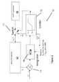
- FIG. 2shows a system 10 for controlling a power output of an inverter, according to a preferred embodiment of the disclosure.
- System 10comprises a photovoltaic inverter 12 arranged to output an active current I A .
- Current I Ais fed into a subtraction block 14 or other suitable device into which is also received a reference current I A *.
- Subtraction block 14is connected to integrator 16 which is arranged to control a reference DC link voltage V DC * input to inverter 12 .
- Integrator 16may be implemented in software in inverter 12 , or a separate controller, or in hardware, by techniques which are well known.
- System 10further includes MPP tracking controller 18 .
- a switching element 17is arranged to alternately allow integrator 16 and MPP tracking controller 18 to regulate V DC *. Switching element 17 is controlled by limiter 15 which detects when a maximum voltage is reached.
- System 10takes advantage of the fact that when operating on the rising flank of the power/voltage curve (i.e. the side comprising point 1 in FIG. 1 b ), below the MPP, an increase in the DC voltage set in inverter 12 results in an increase in exported power.
- the phase of integrator 16is such that stable control is achievable in this state, whereas for voltage above the MPP the feedback becomes positive and the control is not stable.
- Inverter 12includes a control system which may act to control the active current I A exported to the AC power grid so as to maintain the DC link voltage V DC at a desired value.
- MPP tracking controller 18would control the DC link voltage reference value.
- the desired active currentis specified as a reference (e.g. desired) value input I A *.
- the desired current I A *is compared in subtraction block 14 with the actual current I A output by inverter 12 , which is available as data within inverter 12 .
- the differenceis processed through integrator 16 using an integral control function, in order to determine the reference value of DC link voltage V DC *. This is instead of the voltage reference usually derived from the MPP tracking algorithm.
- Integrator 16is initialised at or near to the minimum value of DC voltage permitted by inverter 12 .
- the DC voltageis low and the power exported by the photovoltaic array is at the minimum value possible with reduced voltage. Therefore, the active current I A exported is also low. If the active current reference I A * is lower than I A (step 21 ), then system 10 would remain at this lower voltage indefinitely, exporting the lowest possible power under the conditions (step 22 ), unless stopped by some other mechanism.
- integrator 16increases the DC voltage (step 23 ) so that the power received from the array increases.
- integrator 16regulates the DC voltage so that no further increase in voltage occurs.
- the voltage control loopis preferably fast-acting so as to ensure stable operation in this condition (steps 21 - 22 - 23 ). By using an integral control, the constant-power control function is prevented from counteracting the inherently stable constant-voltage control.
- V DC *exceeds the MPP voltage (e.g. the voltage corresponding to a maximum power output)
- the feedback loopbecomes unstable (positive feedback) and the voltage quickly rises until it reaches a predefined limit.
- the voltageis subject to a limit so that inverter 12 does not trip through excessive voltage.
- This conditionmay be detected (step 24 ) by limiter 15 , at which point switching element 17 initiates reversion to the MPPT controller 18 (step 25 ).
- system 10is arranged to revert to control under MPPT controller 18 in order to obtain maximum power output by tracking the MPP (step 26 ).
- switch 17then causes control of V DC * to revert to integrator 16 (step 28 ).
- integrator 16is pre-loaded with a voltage less than the MPPT voltage in order to ensure that integrator 16 acts in a stable fashion to revert to the desired power.
- the MPPTis not used, and switch 17 connects the inverter reference input voltage V DC * to the output of controller 16 , allowing control of the output current of inverter 12 so as to give the desired power.
- the photovoltaic array voltagemay be controlled on the rising side of the power curve, where the voltage is low. Without the control loop the voltage would naturally jump up to the falling side of the power curve and find a natural balance point, but one where the voltage is relatively high and in some cases too high for inverter 12 to function. MPP tracking may still be used if there is insufficient solar energy to achieve the required power. In this case the control loop causes integrator 16 to reach its upper limit, at which point control is passed to MPPT controller 18 .
Landscapes
- Engineering & Computer Science (AREA)
- Power Engineering (AREA)
- Life Sciences & Earth Sciences (AREA)
- Sustainable Development (AREA)
- Sustainable Energy (AREA)
- Physics & Mathematics (AREA)
- Electromagnetism (AREA)
- General Physics & Mathematics (AREA)
- Radar, Positioning & Navigation (AREA)
- Automation & Control Theory (AREA)
- Control Of Electrical Variables (AREA)
- Inverter Devices (AREA)
Abstract
Description
This application claims the benefit and priority of Great Britain Patent Application No. 1400670.4 filed Jan. 15, 2014. The entire disclosure of the above application is incorporated herein by reference.
The present disclosure relates to a method and corresponding system for controlling a power output of an inverter, especially a photovoltaic inverter. In particular the disclosure relates to a method and system for limiting the power output of an inverter.
This section provides background information related to the present disclosure which is not necessarily prior art.
Traditionally, a photovoltaic inverter is operated at the Maximum Power Point (MPP) in order to maximise the revenue from the solar panel plant. For example, in US 2013/0155735, there is shown in FIG. 2B a control system which controls the inverter so that the photovoltaic array voltage is held at the optimum level as required by the MPP. The integral controller (PI control) and limiter are part of the internal control arrangement of the inverter which allows it to follow the required MPP voltage.
Recently, however, there have been cases in which inverter output power needs to be restricted to below the MPP. For example, this may be because the power company has issued a command to restrict the output power of the plant, as the power system may not accept the whole power output of the plant, or for other operational reasons. In other cases, when the sun is strong, the array power output may exceed the agreed maximum export rating of the plant—this may occur if the array is deliberately over-sized relative to the inverter, and by limiting the power, such that the power varies less throughout the day. This requirement is becoming more common with the reduced capital cost of photovoltaic panels, and in parts of the world where real estate allows for the array to be over-sized relative to the rated exported power.
However, when one tries to restrict the power output of the inverter to the grid, the voltage of the array rises. Depending on the system design and the array temperature, the voltage might become too high for the inverter to run, and may rise so high that the inverter cannot operate. Conventional techniques used to address this issue include:
(a) allowing the voltage to rise and accepting the cost of a higher voltage rated inverter, or otherwise re-scaling the system to reduce the voltage, both of which result in higher cost;
(b) using an additional resistor to dissipate the unwanted power with a controller such as a “chopper” (see for example US 2010/0275966)—which is expensive and requires a facility to dissipate the heat energy generated in the resistor, and is therefore not practical in a large system.
There is therefore a need in the art for a more cost-effective and efficient means of allowing restriction or limitation of the output power of an inverter.
This section provides a general summary of the disclosure, and is not a comprehensive disclosure of its full scope or all of its features.
According to a first aspect of the disclosure, there is provided a method of controlling a power output of an inverter. The method comprises measuring an output current of the inverter, determining a difference between the output current and a reference current, and controlling a reference input voltage of the inverter as a function of the determined difference.
Thus, the inventive method may allow the inverter voltage rating to be more closely matched to the photovoltaic array, giving the potential for cost saving as well as improving availability by reducing the tendency to over-voltage trips during restricted-power operation when the array voltage is high. The method may allow for control of a photovoltaic inverter at a power less than its maximum capability for a given solar irradiation, which may avoid the problem of the photovoltaic array voltage rising above a level where the inverter can run. Unwanted power may be automatically and harmlessly dissipated in the photovoltaic panels.
The reference current may correspond to a desired power output of the inverter, the desired power output being less than a maximum power output of the inverter. In other words, the reference current may be equal to a current that would produce a desired power output, for a given reference input voltage. The reference current may be derived by scaling of the required exported power with the voltage at the inverter output terminals, or by using a suitable control algorithm.
The method may further comprise switching from controlling the reference input voltage as a function of the determined difference to controlling the reference input voltage as a function of the power output of the inverter. Thus, if given the prevailing conditions the inverter is unable to produce the desired power output for a given reference current, the method may switch to traditional MPP tracking in order to continuously export maximum available power.
The switching may occur if the reference input voltage exceeds a predetermined threshold, for example if the reference input voltage reaches levels that may trigger a trip-out of the inverter. Alternatively, the predetermined threshold may be a voltage corresponding to a maximum power output of the inverter. For example, the system may determine when the MPP has been reached, in which case, in order to avoid further increase in voltage with no further increase in power output, the system may switch to MPP tracking.
The control of the reference input voltage preferably comprises feedback control. For example, the reference input voltage may be increased if the reference current is greater than the output current. In addition the reference input voltage may be decreased if the reference current is less than the output current.
In a second aspect of the disclosure, there is described a system for controlling a power output of an inverter. The system comprises an inverter arranged to output a current as a function of a reference input voltage. The system further comprises a controller arranged to determine a difference between the output current and a reference current. The controller is further arranged to control the reference input voltage as a function of the determined difference.
The system may further comprise a tracker for controlling the reference input voltage as a function of the power output of the inverter.
The system may further comprise one or more switches for switching between control of the reference input voltage by the controller and control of the reference input voltage by the tracker. The one or more switches may be arranged to switch control of the reference input voltage from the controller to the tracker when the reference input voltage exceeds a predetermined threshold. The predetermined threshold may be a voltage corresponding to a maximum power output of the inverter.
The system may further comprise a limiter arranged to detect when the reference input voltage exceeds the predetermined threshold.
Further aspects and areas of applicability will become apparent from the description provided herein. It should be understood that various aspects of this disclosure may be implemented individually or in combination with one or more other aspects. It should also be understood that the description and specific examples herein are intended for purposes of illustration only and are not intended to limit the scope of the present disclosure.
The drawings described herein are for illustrative purposes only of selected embodiments and not all possible implementations, and are not intended to limit the scope of the present disclosure.
The present disclosure seeks to provide an improved method and system for controlling a power output of an inverter. Whilst various embodiments of the disclosure are described below, the disclosure is not limited to these embodiments, and variations of these embodiments may well fall within the scope of the disclosure which is to be limited only by the appended claims.
Before describing an embodiment of the disclosure in detail, a brief discussion of the operation of typical prior art inverters follows.
Typically, an inverter is operated with internal control loops which adapt the active component of the output current to give a desired reference value of DC input voltage. The loops work so that if the voltage increases then the active current is increased, which therefore increases the inverter input current and corrects the change in voltage. In the usual MPP tracking mode, this reference voltage is continuously modulated to find the optimum value, using a tracking algorithm of which many are known.
If the power output is required to be below the MPP, then there is a need to control the inverter so as to give a constant output power at the desired value. There then generally exists two possible pairs of values of voltage and current. This is shown inFIGS. 1aand 1b , which illustrate typical photovoltaic array current and power functions of voltage, showing possible operating points for fixed power.
Atpoint 1, a small increase in voltage results in an increase in power delivered from the array, since the current only falls by a small amount whilst the voltage increases by a correspondingly greater amount. This then results in a further increase in voltage so that the system rapidly moves over the power curve topoint 2. Atpoint 2, any further increase in voltage results in a rapid fall in current (as perFIG. 1a ) and power delivered from the array, so the system naturally settles atpoint 2. Thus, without intervention, if the power exported is fixed in the inverter control system, then the system naturally moves to the higher voltage state, i.e.point 2 inFIG. 1b , because that state is inherently stable.
In order to obtain stable operation at point1 (e.g. at a lower voltage), it is necessary to implement a control function which defeats the natural tendency to instability when the power is regulated. If the inverter is simply operated with a fixed voltage reference value, then stable operation is possible at any (physically realisable) voltage. In this mode, the inverter internal control loops act to regulate the voltage by exporting more power if it tends to rise, counteracting the tendency to instability which occurs if the exported power is fixed. However, when taken alone this system does not export a controlled output power, but only an amount of power which happens to be available at the set voltage and under the prevailing conditions. Therefore, in order to export a controlled output power, an additional control function must be added.
System10 takes advantage of the fact that when operating on the rising flank of the power/voltage curve (i.e. theside comprising point 1 inFIG. 1b ), below the MPP, an increase in the DC voltage set ininverter 12 results in an increase in exported power. The phase ofintegrator 16 is such that stable control is achievable in this state, whereas for voltage above the MPP the feedback becomes positive and the control is not stable.
According to the present disclosure, the desired active current is specified as a reference (e.g. desired) value input IA*. The desired current IA* is compared insubtraction block 14 with the actual current IAoutput byinverter 12, which is available as data withininverter 12. The difference is processed throughintegrator 16 using an integral control function, in order to determine the reference value of DC link voltage VDC*. This is instead of the voltage reference usually derived from the MPP tracking algorithm.
Now with reference toFIG. 3 , there is described a preferred method of operation of system10.
If exported current IAis initially less than reference current IA*,integrator 16 increases the DC voltage (step23) so that the power received from the array increases. When the desired active current export is achieved,integrator 16 regulates the DC voltage so that no further increase in voltage occurs. The voltage control loop is preferably fast-acting so as to ensure stable operation in this condition (steps21-22-23). By using an integral control, the constant-power control function is prevented from counteracting the inherently stable constant-voltage control.
In the event that reference current IA* is higher than that which can be achieved under the prevailing conditions, the DC voltage continues to rise. When VDC* exceeds the MPP voltage (e.g. the voltage corresponding to a maximum power output), the feedback loop becomes unstable (positive feedback) and the voltage quickly rises until it reaches a predefined limit. The voltage is subject to a limit so thatinverter 12 does not trip through excessive voltage. This condition may be detected (step24) bylimiter 15, at which point switchingelement 17 initiates reversion to the MPPT controller18 (step25). In other words, if the desired output power cannot be achieved under the prevailing conditions, system10 is arranged to revert to control underMPPT controller 18 in order to obtain maximum power output by tracking the MPP (step26).
If the active current IAin MPPT mode then is determined to exceed reference current IA* (step27), switch17 then causes control of VDC* to revert to integrator16 (step28). Preferably, before reverting,integrator 16 is pre-loaded with a voltage less than the MPPT voltage in order to ensure thatintegrator 16 acts in a stable fashion to revert to the desired power.
To summarise, according to the above embodiment there is a set power (corresponding to a set active current) which is required to be exported. In this case the MPPT is not used, and switch17 connects the inverter reference input voltage VDC* to the output ofcontroller 16, allowing control of the output current ofinverter 12 so as to give the desired power. Thus, the photovoltaic array voltage may be controlled on the rising side of the power curve, where the voltage is low. Without the control loop the voltage would naturally jump up to the falling side of the power curve and find a natural balance point, but one where the voltage is relatively high and in some cases too high forinverter 12 to function. MPP tracking may still be used if there is insufficient solar energy to achieve the required power. In this case the control loop causesintegrator 16 to reach its upper limit, at which point control is passed toMPPT controller 18.
Whilst the disclosure has been described in connection with preferred embodiments, it is to be understood that the disclosure is not limited to these embodiments, and that alterations, modifications, and variations of these embodiments may be carried out by the skilled person without departing from the scope of the disclosure.
For example, whilst the principle application of the disclosure lies in the field of photovoltaic converters, the concept may be equally well applicable to an alternative form of photovoltaic controller such as a DC/DC converter.
The foregoing description of the embodiments has been provided for purposes of illustration and description. It is not intended to be exhaustive or to limit the disclosure. Individual elements or features of a particular embodiment are generally not limited to that particular embodiment, but, where applicable, are interchangeable and can be used in a selected embodiment, even if not specifically shown or described. The same may also be varied in many ways. Such variations are not to be regarded as a departure from the disclosure, and all such modifications are intended to be included within the scope of the disclosure.
Claims (14)
1. A method of controlling a power output of an inverter, comprising:
measuring an output current of the inverter;
determining a difference between the output current and a reference current; and
controlling a reference input voltage of the inverter as a function of the determined difference so that the reference input voltage is increased if the reference current is greater than the output current and decreased if the reference current is less than the output current.
2. The method ofclaim 1 , wherein the reference current corresponds to a desired power output of the inverter, the desired power output being less than a maximum power output of the inverter.
3. The method ofclaim 1 , further comprising switching from controlling the reference input voltage as a function of the determined difference to controlling the reference input voltage as a function of the power output of the inverter.
4. The method ofclaim 3 , wherein the switching occurs if the reference input voltage exceeds a predetermined threshold.
5. The method ofclaim 4 , wherein the predetermined threshold is a voltage corresponding to a maximum power output of the inverter.
6. The method ofclaim 1 , wherein the inverter is a photovoltaic inverter.
7. A system for controlling a power output of an inverter, comprising:
an inverter arranged to output a current as a function of a reference input voltage; and
a controller arranged to:
determine a difference between the output current and a reference current; and
control the reference input voltage as a function of the determined difference so that the reference input voltage is increased if the reference current is greater than the output current and decreased if the reference current is less than the output current.
8. The system ofclaim 7 , further comprising:
a tracker for controlling the reference input voltage as a function of the power output of the inverter.
9. The system ofclaim 8 , further comprising:
a switch for switching between control of the reference input voltage by the controller and control of the reference input voltage by the tracker.
10. The system ofclaim 9 , wherein the switch is arranged to switch control of the reference input voltage from the controller to the tracker when the reference input voltage exceeds a predetermined threshold.
11. The system ofclaim 10 , wherein the predetermined threshold is a voltage corresponding to a maximum power output of the inverter.
12. The system ofclaim 10 , further comprising a limiter arranged to detect when the reference input voltage exceeds the predetermined threshold.
13. The system ofclaim 11 , further comprising a limiter arranged to detect when the reference input voltage exceeds the predetermined threshold.
14. Machine-readable instructions stored on a non-transitory computer-readable medium and which, when executed on a machine, are arranged to carry out the method ofclaim 1 .
Applications Claiming Priority (2)
| Application Number | Priority Date | Filing Date | Title |
|---|---|---|---|
| GB1400670.4 | 2014-01-15 | ||
| GB1400670.4AGB2522201B (en) | 2014-01-15 | 2014-01-15 | Method and system for controlling a power output of an inverter |
Publications (2)
| Publication Number | Publication Date |
|---|---|
| US20150200624A1 US20150200624A1 (en) | 2015-07-16 |
| US9685903B2true US9685903B2 (en) | 2017-06-20 |
Family
ID=50238994
Family Applications (1)
| Application Number | Title | Priority Date | Filing Date |
|---|---|---|---|
| US14/597,625Expired - Fee RelatedUS9685903B2 (en) | 2014-01-15 | 2015-01-15 | Method and system for controlling a power output of an inverter |
Country Status (5)
| Country | Link |
|---|---|
| US (1) | US9685903B2 (en) |
| EP (1) | EP2897020A3 (en) |
| CN (1) | CN104779636B (en) |
| GB (1) | GB2522201B (en) |
| IN (1) | IN2015MU00015A (en) |
Families Citing this family (32)
| Publication number | Priority date | Publication date | Assignee | Title |
|---|---|---|---|---|
| US11855231B2 (en) | 2006-12-06 | 2023-12-26 | Solaredge Technologies Ltd. | Distributed power harvesting systems using DC power sources |
| US8473250B2 (en) | 2006-12-06 | 2013-06-25 | Solaredge, Ltd. | Monitoring of distributed power harvesting systems using DC power sources |
| US11687112B2 (en) | 2006-12-06 | 2023-06-27 | Solaredge Technologies Ltd. | Distributed power harvesting systems using DC power sources |
| US8816535B2 (en) | 2007-10-10 | 2014-08-26 | Solaredge Technologies, Ltd. | System and method for protection during inverter shutdown in distributed power installations |
| US8319471B2 (en) | 2006-12-06 | 2012-11-27 | Solaredge, Ltd. | Battery power delivery module |
| US8947194B2 (en) | 2009-05-26 | 2015-02-03 | Solaredge Technologies Ltd. | Theft detection and prevention in a power generation system |
| US8618692B2 (en) | 2007-12-04 | 2013-12-31 | Solaredge Technologies Ltd. | Distributed power system using direct current power sources |
| US8963369B2 (en) | 2007-12-04 | 2015-02-24 | Solaredge Technologies Ltd. | Distributed power harvesting systems using DC power sources |
| US11569659B2 (en) | 2006-12-06 | 2023-01-31 | Solaredge Technologies Ltd. | Distributed power harvesting systems using DC power sources |
| US11735910B2 (en) | 2006-12-06 | 2023-08-22 | Solaredge Technologies Ltd. | Distributed power system using direct current power sources |
| US12316274B2 (en) | 2006-12-06 | 2025-05-27 | Solaredge Technologies Ltd. | Pairing of components in a direct current distributed power generation system |
| US8319483B2 (en) | 2007-08-06 | 2012-11-27 | Solaredge Technologies Ltd. | Digital average input current control in power converter |
| US9088178B2 (en) | 2006-12-06 | 2015-07-21 | Solaredge Technologies Ltd | Distributed power harvesting systems using DC power sources |
| US11888387B2 (en) | 2006-12-06 | 2024-01-30 | Solaredge Technologies Ltd. | Safety mechanisms, wake up and shutdown methods in distributed power installations |
| US8013472B2 (en) | 2006-12-06 | 2011-09-06 | Solaredge, Ltd. | Method for distributed power harvesting using DC power sources |
| CN105244905B (en) | 2007-12-05 | 2019-05-21 | 太阳能安吉有限公司 | Release mechanism in distributed power device is waken up and method for closing |
| EP2294669B8 (en) | 2008-05-05 | 2016-12-07 | Solaredge Technologies Ltd. | Direct current power combiner |
| US12418177B2 (en) | 2009-10-24 | 2025-09-16 | Solaredge Technologies Ltd. | Distributed power system using direct current power sources |
| GB2485527B (en) | 2010-11-09 | 2012-12-19 | Solaredge Technologies Ltd | Arc detection and prevention in a power generation system |
| US10673229B2 (en) | 2010-11-09 | 2020-06-02 | Solaredge Technologies Ltd. | Arc detection and prevention in a power generation system |
| GB2483317B (en) | 2011-01-12 | 2012-08-22 | Solaredge Technologies Ltd | Serially connected inverters |
| GB2498365A (en) | 2012-01-11 | 2013-07-17 | Solaredge Technologies Ltd | Photovoltaic module |
| US9853565B2 (en) | 2012-01-30 | 2017-12-26 | Solaredge Technologies Ltd. | Maximized power in a photovoltaic distributed power system |
| GB2498790A (en) | 2012-01-30 | 2013-07-31 | Solaredge Technologies Ltd | Maximising power in a photovoltaic distributed power system |
| GB2498791A (en) | 2012-01-30 | 2013-07-31 | Solaredge Technologies Ltd | Photovoltaic panel circuitry |
| US9548619B2 (en) | 2013-03-14 | 2017-01-17 | Solaredge Technologies Ltd. | Method and apparatus for storing and depleting energy |
| US11018623B2 (en) | 2016-04-05 | 2021-05-25 | Solaredge Technologies Ltd. | Safety switch for photovoltaic systems |
| US11177663B2 (en) | 2016-04-05 | 2021-11-16 | Solaredge Technologies Ltd. | Chain of power devices |
| US12057807B2 (en) | 2016-04-05 | 2024-08-06 | Solaredge Technologies Ltd. | Chain of power devices |
| CN108333491B (en)* | 2017-01-17 | 2022-05-27 | 太阳能安吉科技有限公司 | Arc Detection and Prevention in Power Generation System |
| CN107370178B (en)* | 2017-07-25 | 2019-12-20 | 合肥工业大学 | Photovoltaic grid-connected inverter maximum power tracking control method with inverted droop characteristic |
| CN107623488B (en)* | 2017-08-29 | 2019-08-23 | 深圳市禾望电气股份有限公司 | Limit Poewr control method, collecting and distributing type photovoltaic combiner box and storage medium |
Citations (7)
| Publication number | Priority date | Publication date | Assignee | Title |
|---|---|---|---|---|
| US5047914A (en)* | 1989-11-21 | 1991-09-10 | Sundstrand Corporation | Current controlled inverter |
| US20080278983A1 (en)* | 2006-07-26 | 2008-11-13 | Chang Won National University Business Administrat | Controlling Apparatus of a Power Converter of Single-Phase Current For Photovoltaic Generation System |
| US20100052627A1 (en)* | 2008-08-26 | 2010-03-04 | Kabushiki Kaisha Toshiba | Dc/dc converter |
| US20100275966A1 (en) | 2009-11-25 | 2010-11-04 | American Superconductor Corporation | Reducing photovoltaic array voltage during inverter re-enablement |
| US20130155735A1 (en) | 2011-12-16 | 2013-06-20 | Milan Ilic | Stacked voltage source inverter with separate dc sources |
| US20130307339A1 (en) | 2012-05-16 | 2013-11-21 | General Electric Company | Optimized control of a power converter in response to load conditions |
| WO2013177360A1 (en) | 2012-05-25 | 2013-11-28 | Solaredge Technologies Ltd. | Circuit for interconnected direct current power sources |
Family Cites Families (7)
| Publication number | Priority date | Publication date | Assignee | Title |
|---|---|---|---|---|
| JP2002112459A (en)* | 2000-09-29 | 2002-04-12 | Canon Inc | Solar cell module and power generator |
| CN1669208A (en)* | 2002-07-15 | 2005-09-14 | 皇家飞利浦电子股份有限公司 | Inverter |
| TWI232361B (en)* | 2003-11-25 | 2005-05-11 | Delta Electronics Inc | Maximum-power tracking method and device of solar power generation system |
| US8072187B2 (en)* | 2008-11-19 | 2011-12-06 | Ablerex Electronics Co., Ltd. | Battery-charging device for a stand-alone generator system having a MPPT function and method thereof |
| US8358031B2 (en)* | 2010-02-26 | 2013-01-22 | General Electric Company | System and method for a single stage power conversion system |
| CN102123555A (en)* | 2011-04-08 | 2011-07-13 | 重庆大学 | HID (High Intensity Discharge) lamp electronic ballast and multimode control method thereof |
| KR101214676B1 (en)* | 2011-04-20 | 2012-12-21 | 성균관대학교산학협력단 | Electric generating system using solar cell |
- 2014
- 2014-01-15GBGB1400670.4Apatent/GB2522201B/ennot_activeExpired - Fee Related
- 2015
- 2015-01-03ININ15MU2015patent/IN2015MU00015A/enunknown
- 2015-01-13CNCN201510016367.7Apatent/CN104779636B/ennot_activeExpired - Fee Related
- 2015-01-14EPEP15151079.9Apatent/EP2897020A3/ennot_activeWithdrawn
- 2015-01-15USUS14/597,625patent/US9685903B2/ennot_activeExpired - Fee Related
Patent Citations (7)
| Publication number | Priority date | Publication date | Assignee | Title |
|---|---|---|---|---|
| US5047914A (en)* | 1989-11-21 | 1991-09-10 | Sundstrand Corporation | Current controlled inverter |
| US20080278983A1 (en)* | 2006-07-26 | 2008-11-13 | Chang Won National University Business Administrat | Controlling Apparatus of a Power Converter of Single-Phase Current For Photovoltaic Generation System |
| US20100052627A1 (en)* | 2008-08-26 | 2010-03-04 | Kabushiki Kaisha Toshiba | Dc/dc converter |
| US20100275966A1 (en) | 2009-11-25 | 2010-11-04 | American Superconductor Corporation | Reducing photovoltaic array voltage during inverter re-enablement |
| US20130155735A1 (en) | 2011-12-16 | 2013-06-20 | Milan Ilic | Stacked voltage source inverter with separate dc sources |
| US20130307339A1 (en) | 2012-05-16 | 2013-11-21 | General Electric Company | Optimized control of a power converter in response to load conditions |
| WO2013177360A1 (en) | 2012-05-25 | 2013-11-28 | Solaredge Technologies Ltd. | Circuit for interconnected direct current power sources |
Also Published As
| Publication number | Publication date |
|---|---|
| EP2897020A3 (en) | 2015-11-04 |
| EP2897020A2 (en) | 2015-07-22 |
| CN104779636B (en) | 2018-09-11 |
| US20150200624A1 (en) | 2015-07-16 |
| GB2522201A (en) | 2015-07-22 |
| GB2522201B (en) | 2018-06-27 |
| CN104779636A (en) | 2015-07-15 |
| GB201400670D0 (en) | 2014-03-05 |
| IN2015MU00015A (en) | 2015-10-16 |
Similar Documents
| Publication | Publication Date | Title |
|---|---|---|
| US9685903B2 (en) | Method and system for controlling a power output of an inverter | |
| JP6063031B2 (en) | Power conditioner and control method thereof | |
| JP6521325B2 (en) | Voltage stabilization device and control method thereof | |
| US20160301312A1 (en) | Photovoltaic inverter comprising an upstream dc/dc converter and temperature regulation of the power semiconductors | |
| JP6158476B2 (en) | Power converter for photovoltaic power generation | |
| US9985553B2 (en) | Control device of inverter | |
| JP6952245B2 (en) | Power conversion system | |
| JP6312558B2 (en) | DC feeding system | |
| KR102716638B1 (en) | Circuit and method for bus voltage fluctuation of power converter | |
| JP2022039145A (en) | Power conversion device | |
| JP6242128B2 (en) | Power converter | |
| KR102040599B1 (en) | Protect device for direct current distributio line and control method thereof | |
| KR101305634B1 (en) | Photovoltaic power generation system and control method thereof | |
| JP6618870B2 (en) | Power conversion device for solar power generation, control method, and solar power generation system | |
| JP6256287B2 (en) | Solar cell control device | |
| JP5033683B2 (en) | Control device for power converter | |
| JP6792820B2 (en) | Solar power system | |
| JP6907855B2 (en) | 3-level chopper and its control circuit | |
| JP6140037B2 (en) | Power converter | |
| JP6669434B2 (en) | Power converter | |
| JP6958387B2 (en) | Control method of DC power supply and DC power supply | |
| KR101250866B1 (en) | Temperature control apparatus of inverter for photovoltaic system and its method | |
| KR20130141782A (en) | Photovoltaic power generation system and control method thereof | |
| US11258262B2 (en) | Method for the voltage-impressing feed of electrical power into an electrical supply grid by means of a wind power installation | |
| JP4617944B2 (en) | Inverter cross current control device |
Legal Events
| Date | Code | Title | Description |
|---|---|---|---|
| AS | Assignment | Owner name:CONTROL TECHNIQUES LIMITED, UNITED KINGDOM Free format text:ASSIGNMENT OF ASSIGNORS INTEREST;ASSIGNOR:HARGIS, COLIN;REEL/FRAME:034872/0454 Effective date:20150129 | |
| AS | Assignment | Owner name:NIDEC CONTROL TECHNIQUES LIMITED, UNITED KINGDOM Free format text:CHANGE OF NAME;ASSIGNOR:CONTROL TECHNIQUES LIMITED;REEL/FRAME:042082/0827 Effective date:20170227 | |
| STCF | Information on status: patent grant | Free format text:PATENTED CASE | |
| FEPP | Fee payment procedure | Free format text:MAINTENANCE FEE REMINDER MAILED (ORIGINAL EVENT CODE: REM.); ENTITY STATUS OF PATENT OWNER: LARGE ENTITY | |
| LAPS | Lapse for failure to pay maintenance fees | Free format text:PATENT EXPIRED FOR FAILURE TO PAY MAINTENANCE FEES (ORIGINAL EVENT CODE: EXP.); ENTITY STATUS OF PATENT OWNER: LARGE ENTITY | |
| STCH | Information on status: patent discontinuation | Free format text:PATENT EXPIRED DUE TO NONPAYMENT OF MAINTENANCE FEES UNDER 37 CFR 1.362 | |
| FP | Lapsed due to failure to pay maintenance fee | Effective date:20210620 |