US9685814B1 - Detection of coil coupling in an inductive charging system - Google Patents
Detection of coil coupling in an inductive charging systemDownload PDFInfo
- Publication number
- US9685814B1 US9685814B1US14/304,064US201414304064AUS9685814B1US 9685814 B1US9685814 B1US 9685814B1US 201414304064 AUS201414304064 AUS 201414304064AUS 9685814 B1US9685814 B1US 9685814B1
- Authority
- US
- United States
- Prior art keywords
- receiver
- receiver device
- resonant circuit
- coil
- resonant
- Prior art date
- Legal status (The legal status is an assumption and is not a legal conclusion. Google has not performed a legal analysis and makes no representation as to the accuracy of the status listed.)
- Active, expires
Links
Images


Classifications
- H02J7/025—
- H—ELECTRICITY
- H02—GENERATION; CONVERSION OR DISTRIBUTION OF ELECTRIC POWER
- H02J—CIRCUIT ARRANGEMENTS OR SYSTEMS FOR SUPPLYING OR DISTRIBUTING ELECTRIC POWER; SYSTEMS FOR STORING ELECTRIC ENERGY
- H02J7/00—Circuit arrangements for charging or depolarising batteries or for supplying loads from batteries
- H02J7/00032—Circuit arrangements for charging or depolarising batteries or for supplying loads from batteries characterised by data exchange
- H02J7/00034—Charger exchanging data with an electronic device, i.e. telephone, whose internal battery is under charge
- G—PHYSICS
- G01—MEASURING; TESTING
- G01R—MEASURING ELECTRIC VARIABLES; MEASURING MAGNETIC VARIABLES
- G01R31/00—Arrangements for testing electric properties; Arrangements for locating electric faults; Arrangements for electrical testing characterised by what is being tested not provided for elsewhere
- G01R31/28—Testing of electronic circuits, e.g. by signal tracer
- G01R31/302—Contactless testing
- G01R31/315—Contactless testing by inductive methods
- H—ELECTRICITY
- H02—GENERATION; CONVERSION OR DISTRIBUTION OF ELECTRIC POWER
- H02J—CIRCUIT ARRANGEMENTS OR SYSTEMS FOR SUPPLYING OR DISTRIBUTING ELECTRIC POWER; SYSTEMS FOR STORING ELECTRIC ENERGY
- H02J50/00—Circuit arrangements or systems for wireless supply or distribution of electric power
- H02J50/10—Circuit arrangements or systems for wireless supply or distribution of electric power using inductive coupling
- H02J50/12—Circuit arrangements or systems for wireless supply or distribution of electric power using inductive coupling of the resonant type
- H—ELECTRICITY
- H02—GENERATION; CONVERSION OR DISTRIBUTION OF ELECTRIC POWER
- H02J—CIRCUIT ARRANGEMENTS OR SYSTEMS FOR SUPPLYING OR DISTRIBUTING ELECTRIC POWER; SYSTEMS FOR STORING ELECTRIC ENERGY
- H02J50/00—Circuit arrangements or systems for wireless supply or distribution of electric power
- H02J50/80—Circuit arrangements or systems for wireless supply or distribution of electric power involving the exchange of data, concerning supply or distribution of electric power, between transmitting devices and receiving devices
Definitions
- the inventionrelates generally to inductive charging systems, and more particular to detecting coil coupling in an inductive charging system.
- USBuniversal serial bus
- Many electronic devicesinclude one or more rechargeable batteries that require external power to recharge from time to time. Often, these devices may be charged using a similar power cord or connector, for example a universal serial bus (“USB”) connector.
- USBuniversal serial bus
- devicesdespite having common connection types, devices often require separate power supplies with different power outputs. These multiple power supplies can be burdensome to use, store, and transport from place to place. As a result, the benefits of device portability may be substantially limited.
- charging cordsmay be unsafe to use in certain circumstances. For example, a driver of a vehicle may become distracted attempting to plug an electronic device into a vehicle charger. In another example, a charging cord may present a tripping hazard if left unattended.
- some devicesinclude an inductive charging system.
- the usermay simply place the device on an inductive charging surface of a charging device in order to charge the battery.
- the charging devicecan detect the presence of the electronic device on the inductive charging surface by pinging or transmitting power to the electronic device for a given time period and waiting to receive a response (e.g., a communication signal) from the electronic device. If the electronic device is not on the inductive charging surface, a response is not received from the electronic device and the charging device stops pinging. The charging device may then ping periodically until a communication signal is received from the electronic device.
- Periodic pingingconsumes power and can reduce the charge on the battery. For example, if the electronic device is not present for twelve hours, periodic pinging can consume power needlessly. The time interval between pings can be increased to save power, but this slows the response time of the charging device. For example, the charging device can ping every minute, but up to a minute can pass before the charging device responds by transmitting power to the electronic device.
- a receiver device for use in an inductive charging systemcan include a receiver coil operatively connected to an input of an AC-to-DC converter, a first resonant circuit operatively connected in series between the receiver coil and the input of the AC-to-DC converter, and a second resonant circuit operatively connected in parallel with the receiver coil between the receiver coil and the input to the AC-to-DC converter.
- a loadmay be operatively connected to an output of the AC-to-DC converter.
- the loadcan be a rechargeable battery.
- the first resonant circuitis associated with a first resonant frequency and the second resonant circuit is associated with a second resonant frequency that is different from the first resonant frequency. In one embodiment, the second resonant frequency is higher than the first resonant frequency.
- a switchmay be operatively connected in series with the second resonant circuit in the receiver device.
- a processing device in the receiver devicecan control the state of the switch.
- the switchcan be used to communicate with the transmitter device.
- the switchcan be opened when the receiver device is to be “cloaked” or not in communication with the transmitter device, even when the receiver coil is able to couple with the transmitter coil (e.g., the receiver device is on the charging surface).
- the transmitter devicecan transfer energy to the receiver device to charge a battery in the receiver device.
- the switchis closed while the battery is charging.
- the switchcan be opened when the battery is charged fully to inform the transmitter device to stop transferring energy.
- the transmitter devicemay then enter a low power or sleep state in response to the open state of the switch.
- a method for detecting coupling between a receiver coil and a transmitter coil in an inductive power transfer systemcan include a transmitter device transmitting pings to a receiver device at different frequencies and measuring a current input into a DC-to-AC converter in the transmitter device based on each ping. The current measurements can then be analyzed to determine whether a current measurement indicates the receiver coil and the transmitter coil are inductively coupled. As one example, the current input into the DC-to-AC converter can be higher when the receiver and transmitter coils are coupled than when the receiver and transmitter coils are not coupled.
- a receiver in an inductive charging systemcan include a resonant circuit connected in parallel with a receiver coil.
- a switchcan be connected in series with the resonant circuit.
- a method for operating a transmitter devicecan include the transmitter device transferring energy to the receiver device when the switch is closed, and the transmitter device responsively taking a different action when the switch is open.
- the different actioncan include the transmitter device entering a low power state when the switch is open. Additionally or alternatively, the different action may include the transmitter device periodically transmitting one or more pings to the receiver device.
- an inductive charging systemcan include a transmitter device and a receiver device.
- the transmitter devicecan include a current sense operatively connected between an output of a power supply and an input of a DC-to-AC converter.
- a method for operating the inductive charging systemcan include detecting a change in a current that is input into the DC-to-AC converter and transferring energy based on the current change. The energy transfer can stop when a response is not received from a receiver device.
- One or more operations in the transmitter devicecan be adaptively adjusted based on not receiving a response from the receiver device. For example, the time interval between pings can be increased.
- FIG. 1illustrates one example of inductive charging system
- FIG. 2depicts a simplified block diagram of one example of the inductive charging system 100 shown in FIG. 1 ;
- FIG. 3depicts a simplified block diagram of another example of the inductive charging system 100 shown in FIG. 1 ;
- FIG. 4is a flowchart of a method for scanning a frequency range to detect coil coupling
- FIG. 5is a flowchart of one method for operating an inductive charging system
- FIG. 6is a flowchart of another method for operating an inductive charging system.
- Embodiments described hereincan transfer energy inductively from a transmitter device to a receiver device to charge a battery or to operate the receiver device. Additionally or alternatively, communication or control signals can be transmitted to the receiver device through the inductive coupling between the transmitter and receiver coils. For example, while charging, high frequency pulses can be added on top of the inductive charging frequency to enable both charging and communication. Alternatively, the transferred energy can be used solely for communication. Thus, the terms “energy”, “signal”, or “signals” are meant to encompass transferring energy for wireless charging, transferring energy as communication and/or control signals, or both wireless charging and the transmission of communication and/or control signals.
- the inductive charging system 100includes a charging device 102 and an electronic device 104 .
- the charging device 102is depicted as a charging dock and the electronic device as a smart telephone.
- the electronic device and/or the charging devicecan be implemented as different devices in other embodiments.
- the electronic device 104can be a digital media player, a wearable electronic or communication device, a health monitoring device, a tablet computing device, and any other type of electronic device that includes one or more inductive charging coils.
- the charging device 102may be adapted to be inserted into a charging port in an electronic device.
- the electronic device 104is placed on a charging surface 106 of the charging dock 102 .
- the charging dock 102may be connected to a power source (e.g., a wall outlet) through a power cord or connector (not shown).
- the charging dock 102includes one or more inductive charging coils that transfer signals or energy to one or more inductive charging coils in the electronic device 104 .
- Energycan be transferred, for example, to charge a battery in the electronic device 104 or to operate the electronic device. Additionally or alternatively, control and/or communication signals can be transferred wirelessly between the charging dock 102 and the electronic device 104 .
- the charging dock 102is a transmitter device with a transmitter coil or coils and the portable electronic device 104 is a receiver device with one or more receiver coils.
- FIG. 2depicts a simplified block diagram of one example of the inductive charging system 100 shown in FIG. 1 .
- the charging device 102includes a power supply 200 operably connected to a DC-to-AC converter 202 .
- a DC-to-AC converterAny suitable type of a DC-to-AC converter may be used in one or more embodiments.
- the DC-to-AC converteris constructed as an H bridge in one embodiment.
- An input of a current sense circuit 204is connected to an output of the power supply 200 , and the output of the current sense circuit 204 is connected to an input of the DC-to-AC converter 202 .
- An input of an amplifier 206is operably connected to an output of the current sense circuitry 204 , and the output of the amplifier 206 is operably connected to a processing device 208 .
- the processing devicecan be implemented as any electronic device capable of processing, receiving, or transmitting data or instructions.
- the processing device 208can be a microprocessor, a central processing unit (CPU), an application-specific integrated circuit (ASIC), a digital signal processor (DSP), or combinations of multiple such devices.
- the term “processing device”is meant to encompass a single processor or processing unit, multiple processors, multiple processing units, or other suitably configured computing element or elements.
- the processing device 208may also be operably connected to the DC-to-AC converter 202 .
- the processing device 208can control the operation of the DC-to-AC converter 202 in some embodiments.
- the output of the DC-to-AC converter 202is operably connected to the transmitter coil 210 .
- the electronic device 104can include a receiver coil 212 operably connected to an AC-to-DC converter 214 .
- Any suitable type of AC-to-DC convertermay be used in one or more embodiments.
- the AC-to-DC converteris constructed as a diode bridge in one embodiment.
- a load 216is operably connected to the output of the AC-to-DC converter 214 .
- the load 216is a rechargeable battery in one embodiment. A different type of load can be used in other embodiments.
- the transmitter coil 210 and the receiver coil 212together form a transformer 218 .
- the transformer 218transfers energy through inductive coupling between the transmitter coil 210 and the receiver coil 212 .
- energyis transferred from the transmitter coil 210 to the receiver coil 212 through the creation of a varying magnetic flux by the AC signal in the transmitter coil 210 that induces a current in the receiver coil 212 .
- the AC signal induced in the receiver coil 212is received by the AC-to-DC converter 214 that converts the AC signal into a DC signal.
- the load 122is a rechargeable battery
- the DC signalis used to charge the battery.
- the leakage inductance of the transformer 218can be significant.
- Resonant circuitsmay be included in the inductive charging system 100 to cancel some or all of the leakage inductance when the capacitance and inductance values are near the resonant frequency (f R1 ).
- the resonant circuit in the transmitter device 102is a resonant capacitor C RP connected in series between the DC-to-AC converter 202 and the transmitter coil 210 .
- the resonant circuit in the receiver device 104is a resonant capacitor C RS1 connected in series between the receiver coil 212 and the AC-to-DC converter 214 .
- the resonant circuitscan include additional or different components.
- the resonant circuitscan be included at different locations or connected in a different circuit configuration within the transmitter and/or receiver device.
- the transmitter device 102can determine whether the receiver coil 212 is coupled to the transmitter coil 210 by measuring the current input into the DC-to-AC converter 202 .
- the processing device 208can receive current measurements from the current sense circuit 204 and based on an analysis or review of the current measurements, determine whether the receiver coil 212 is coupled to the transmitter coil 210 .
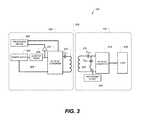
- FIG. 3there is shown a simplified block diagram of another example of the inductive charging system 100 shown in FIG. 1 .
- the inductive charging systemis similar to the embodiment shown in FIG. 2 except for the switch 300 connected in series with the second resonant capacitor C RS2 .
- Any suitable type of switchcan be used.
- a processing device 302can control the state of the switch 300 (i.e., open or closed). Like the processing device 208 in FIG. 2 , the processing device 302 can be implemented as any electronic device capable of processing, receiving, or transmitting data or instructions.
- the switch 300can be used by the receiver device to communicate with the transmitter device. As one example, the switch can be opened when the receiver device 104 is to be “cloaked” or not in communication with the transmitter device 102 , even when the receiver coil is able to couple with the transmitter coil (e.g., the receiver device is on the charging surface). As one example, the transmitter device 102 can transfer energy to the receiver device 104 to charge a battery (e.g., load 216 ) in the receiver device. The switch 300 is closed while the battery is charging. The switch can be opened when the battery is charged fully to inform the transmitter device 102 to stop transferring energy. The transmitter device 102 may enter a low power or sleep state in response to the open state of the switch 300 .
- a batterye.g., load 216
- the transmitter device 102can wake up periodically to transmit a ping to the receiver device 104 . If the switch 300 is closed, the processing device 208 in the transmitter device 102 can detect the receiver device based on one or more current measurements received from the current sense circuit 204 .
- FIG. 4is a flowchart of a method for scanning a frequency range to detect coil coupling. Initially, the transmitter device transmits one or more pings to a receiver device at a given frequency and the current input into the DC-to-AC converter in the transmitter device is measured (blocks 400 and 402 ). A determination may then be made at block 404 as to whether or not the frequency scan is complete. If not, the process can pass to block 406 where the frequency is adjusted. The method returns to block 400 and repeats until the frequency scan is complete.
- the current measurementscan optionally be processed at block 408 . As one example, if multiple current measurements are taken at each frequency, the current measurements measured at a particular frequency can be averaged together. The current measurements are then analyzed at block 410 . A determination can be made at block 412 as to whether or not a current measurement equals or exceeds a threshold value.
- the threshold valuecan be a minimum or expected current measurement that indicates the receiver coil is coupled to the transmitter coil. The method may end if a current measurement does not equal or exceed the threshold value. Coupling between a transmitter and receiver coil is indicated when a current measurement equals or exceeds the threshold value (block 414 ) and the method ends.
- the transmitter devicecan transmit one or more pings to the receiver device (block 500 ).
- the current measurementscan optionally be processed at block 502 . As one example, if multiple current measurements are taken at a particular frequency, the current measurements can be averaged together.
- the switchi.e., switch 300 in FIG. 3
- the processcontinues at block 508 where the transmitter device can transmit energy to the receiver device.
- the transferred energycan be used to charge a battery in the receiver device, to operate the receiver device, and/or to transmit control or communication signals to the receiver device.
- a determinationmay then be made at block 510 as to whether or not the switch remains closed or has been opened. If the switch remains closed, the method can check the state of the switch continuously, periodically, or at select times.
- the processmay pass to block 512 where the transmitter device can take one or more actions based on the open state of the switch. For example, in one embodiment, the transmitter device may enter a low power state, such as a sleep state or an off state.
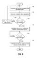
- FIG. 6is a flowchart of another method for operating an inductive charging system.
- this methodcan be used to distinguish between a foreign object and a receiver device positioned on a charging surface of the transmitter device.
- the transmitter devicemay detect an increase in the current that is input into the DC-to-AC converter at block 600 .
- the increased currentcan initially be interpreted as a receiver coil coupling with the transmitter coil in the receiver device.
- the transmitter devicecan begin transferring energy at block 602 .
- a determinationis then made at block 604 as to whether or not a response is received from a receiver device. The method ends if a response is received from a receiver device.
- Blocks in FIGS. 4-6can be performed differently in other embodiments. Blocks can be added, omitted, or re-order in some embodiments. In one example, block 408 in FIG. 4 can be omitted or block 408 can be performed before block 404 . Block 502 in FIG. 5 can be omitted as another example.
- Embodiments disclosed hereinhave been described with respect to the second resonant frequency being higher than the first resonant frequency, and the current input into the DC-to-AC converter in the transmitter device being a higher or increased current when indicating coil coupling. Other embodiments, however, are not limited to this implementation.
- the second resonant frequencycan be lower than the first resonant frequency (f R1 >f R2 ), and when indicating coil coupling, the current input into the DC-to-AC converter can be a smaller or reduced current.
- the current value that indicates coil couplingcan be lower than a threshold value.
Landscapes
- Engineering & Computer Science (AREA)
- Power Engineering (AREA)
- Computer Networks & Wireless Communication (AREA)
- General Engineering & Computer Science (AREA)
- Physics & Mathematics (AREA)
- General Physics & Mathematics (AREA)
- Charge And Discharge Circuits For Batteries Or The Like (AREA)
Abstract
Description
The invention relates generally to inductive charging systems, and more particular to detecting coil coupling in an inductive charging system.
Many electronic devices include one or more rechargeable batteries that require external power to recharge from time to time. Often, these devices may be charged using a similar power cord or connector, for example a universal serial bus (“USB”) connector. However, despite having common connection types, devices often require separate power supplies with different power outputs. These multiple power supplies can be burdensome to use, store, and transport from place to place. As a result, the benefits of device portability may be substantially limited.
Furthermore, charging cords may be unsafe to use in certain circumstances. For example, a driver of a vehicle may become distracted attempting to plug an electronic device into a vehicle charger. In another example, a charging cord may present a tripping hazard if left unattended.
To account for these and other shortcomings of portable electronic devices, some devices include an inductive charging system. The user may simply place the device on an inductive charging surface of a charging device in order to charge the battery. The charging device can detect the presence of the electronic device on the inductive charging surface by pinging or transmitting power to the electronic device for a given time period and waiting to receive a response (e.g., a communication signal) from the electronic device. If the electronic device is not on the inductive charging surface, a response is not received from the electronic device and the charging device stops pinging. The charging device may then ping periodically until a communication signal is received from the electronic device.
Periodic pinging, however, consumes power and can reduce the charge on the battery. For example, if the electronic device is not present for twelve hours, periodic pinging can consume power needlessly. The time interval between pings can be increased to save power, but this slows the response time of the charging device. For example, the charging device can ping every minute, but up to a minute can pass before the charging device responds by transmitting power to the electronic device.
In one aspect, a receiver device for use in an inductive charging system can include a receiver coil operatively connected to an input of an AC-to-DC converter, a first resonant circuit operatively connected in series between the receiver coil and the input of the AC-to-DC converter, and a second resonant circuit operatively connected in parallel with the receiver coil between the receiver coil and the input to the AC-to-DC converter. A load may be operatively connected to an output of the AC-to-DC converter. As one example, the load can be a rechargeable battery. The first resonant circuit is associated with a first resonant frequency and the second resonant circuit is associated with a second resonant frequency that is different from the first resonant frequency. In one embodiment, the second resonant frequency is higher than the first resonant frequency.
In another aspect, a switch may be operatively connected in series with the second resonant circuit in the receiver device. A processing device in the receiver device can control the state of the switch. The switch can be used to communicate with the transmitter device. As one example, the switch can be opened when the receiver device is to be “cloaked” or not in communication with the transmitter device, even when the receiver coil is able to couple with the transmitter coil (e.g., the receiver device is on the charging surface). As one example, the transmitter device can transfer energy to the receiver device to charge a battery in the receiver device. The switch is closed while the battery is charging. The switch can be opened when the battery is charged fully to inform the transmitter device to stop transferring energy. The transmitter device may then enter a low power or sleep state in response to the open state of the switch.
In another aspect, a method for detecting coupling between a receiver coil and a transmitter coil in an inductive power transfer system can include a transmitter device transmitting pings to a receiver device at different frequencies and measuring a current input into a DC-to-AC converter in the transmitter device based on each ping. The current measurements can then be analyzed to determine whether a current measurement indicates the receiver coil and the transmitter coil are inductively coupled. As one example, the current input into the DC-to-AC converter can be higher when the receiver and transmitter coils are coupled than when the receiver and transmitter coils are not coupled.
In yet another aspect, a receiver in an inductive charging system can include a resonant circuit connected in parallel with a receiver coil. A switch can be connected in series with the resonant circuit. A method for operating a transmitter device can include the transmitter device transferring energy to the receiver device when the switch is closed, and the transmitter device responsively taking a different action when the switch is open. In one embodiment, the different action can include the transmitter device entering a low power state when the switch is open. Additionally or alternatively, the different action may include the transmitter device periodically transmitting one or more pings to the receiver device.
In another aspect, an inductive charging system can include a transmitter device and a receiver device. The transmitter device can include a current sense operatively connected between an output of a power supply and an input of a DC-to-AC converter. A method for operating the inductive charging system can include detecting a change in a current that is input into the DC-to-AC converter and transferring energy based on the current change. The energy transfer can stop when a response is not received from a receiver device. One or more operations in the transmitter device can be adaptively adjusted based on not receiving a response from the receiver device. For example, the time interval between pings can be increased.
Embodiments of the invention are better understood with reference to the following drawings. The elements of the drawings are not necessarily to scale relative to each other. Identical reference numerals have been used, where possible, to designate identical features that are common to the figures.
Embodiments described herein can transfer energy inductively from a transmitter device to a receiver device to charge a battery or to operate the receiver device. Additionally or alternatively, communication or control signals can be transmitted to the receiver device through the inductive coupling between the transmitter and receiver coils. For example, while charging, high frequency pulses can be added on top of the inductive charging frequency to enable both charging and communication. Alternatively, the transferred energy can be used solely for communication. Thus, the terms “energy”, “signal”, or “signals” are meant to encompass transferring energy for wireless charging, transferring energy as communication and/or control signals, or both wireless charging and the transmission of communication and/or control signals.
Referring now toFIG. 1 , there is shown a top view of one example of an inductive charging system. Theinductive charging system 100 includes acharging device 102 and anelectronic device 104. In the illustrated embodiment, the chargingdevice 102 is depicted as a charging dock and the electronic device as a smart telephone. The electronic device and/or the charging device can be implemented as different devices in other embodiments. For example, theelectronic device 104 can be a digital media player, a wearable electronic or communication device, a health monitoring device, a tablet computing device, and any other type of electronic device that includes one or more inductive charging coils. As another example, the chargingdevice 102 may be adapted to be inserted into a charging port in an electronic device.
To transfer energy to theelectronic device 104, theelectronic device 104 is placed on a chargingsurface 106 of the chargingdock 102. The chargingdock 102 may be connected to a power source (e.g., a wall outlet) through a power cord or connector (not shown). The chargingdock 102 includes one or more inductive charging coils that transfer signals or energy to one or more inductive charging coils in theelectronic device 104. Energy can be transferred, for example, to charge a battery in theelectronic device 104 or to operate the electronic device. Additionally or alternatively, control and/or communication signals can be transferred wirelessly between the chargingdock 102 and theelectronic device 104. Thus, in the illustrated embodiment the chargingdock 102 is a transmitter device with a transmitter coil or coils and the portableelectronic device 104 is a receiver device with one or more receiver coils.
An input of acurrent sense circuit 204 is connected to an output of thepower supply 200, and the output of thecurrent sense circuit 204 is connected to an input of the DC-to-AC converter 202. An input of anamplifier 206 is operably connected to an output of thecurrent sense circuitry 204, and the output of theamplifier 206 is operably connected to aprocessing device 208. The processing device can be implemented as any electronic device capable of processing, receiving, or transmitting data or instructions. For example, theprocessing device 208 can be a microprocessor, a central processing unit (CPU), an application-specific integrated circuit (ASIC), a digital signal processor (DSP), or combinations of multiple such devices. As described herein, the term “processing device” is meant to encompass a single processor or processing unit, multiple processors, multiple processing units, or other suitably configured computing element or elements.
Theprocessing device 208 may also be operably connected to the DC-to-AC converter 202. Theprocessing device 208 can control the operation of the DC-to-AC converter 202 in some embodiments. The output of the DC-to-AC converter 202 is operably connected to thetransmitter coil 210.
Theelectronic device 104 can include areceiver coil 212 operably connected to an AC-to-DC converter 214. Any suitable type of AC-to-DC converter may be used in one or more embodiments. For example, the AC-to-DC converter is constructed as a diode bridge in one embodiment. Aload 216 is operably connected to the output of the AC-to-DC converter 214. Theload 216 is a rechargeable battery in one embodiment. A different type of load can be used in other embodiments.
Thetransmitter coil 210 and thereceiver coil 212 together form atransformer 218. Thetransformer 218 transfers energy through inductive coupling between thetransmitter coil 210 and thereceiver coil 212. Essentially, energy is transferred from thetransmitter coil 210 to thereceiver coil 212 through the creation of a varying magnetic flux by the AC signal in thetransmitter coil 210 that induces a current in thereceiver coil 212. The AC signal induced in thereceiver coil 212 is received by the AC-to-DC converter 214 that converts the AC signal into a DC signal. In embodiments where the load122 is a rechargeable battery, the DC signal is used to charge the battery.
In some embodiments, the leakage inductance of thetransformer 218 can be significant. Resonant circuits may be included in theinductive charging system 100 to cancel some or all of the leakage inductance when the capacitance and inductance values are near the resonant frequency (fR1). In the illustrated embodiment, the resonant circuit in thetransmitter device 102 is a resonant capacitor CRPconnected in series between the DC-to-AC converter 202 and thetransmitter coil 210. The resonant circuit in thereceiver device 104 is a resonant capacitor CRS1connected in series between thereceiver coil 212 and the AC-to-DC converter 214.
In some embodiments, thetransmitter device 102 may scan the environment to detect the presence of thereceiver device 104 when the transmitter device is not inductively coupled to the receiver device (e.g., not transferring energy to the receiver device). To scan the environment, thetransmitter device 102 can transfer a short burst of energy to thereceiver device 104 to determine if thereceiver coil 212 is coupled to thetransmitter coil 210. This short burst of energy is known as a ping. Thetransmitter device 102 may transmit a ping and wait for a response from thereceiver device 104. If no response is received, thetransmitter device 102 waits for a given period of time before sending another ping. If a response is received, thetransmitter device 102 can transfer energy to thereceiver device 104 to charge a battery and/or to transmit one or more communication signals to thereceiver device 104.
In some embodiments, a second resonant circuit is included in thereceiver device 104 to reduce the amount of power consumed by thetransmitter coil 210 when transmitting pings. In the illustrated embodiment, the second resonant circuit is a second resonant capacitor CRS2connected in parallel with thereceiver coil 212 between the receiver coil and the AC-to-DC converter 214. The second resonant circuit can have a resonant frequency (fR2) that is higher than the resonant frequency (fR1) of the first resonant circuits CRPand CRS1. In other words, fR1<fR2. As one example, the lower first resonant frequency approximately 250 kHz and the second higher resonant frequency (fR2) can be in the range of 750 kHz to 1 MHz. Other embodiments can operate at different frequencies and/or frequency ranges.
Other embodiments can configure the resonant circuits differently. The resonant circuits can include additional or different components. The resonant circuits can be included at different locations or connected in a different circuit configuration within the transmitter and/or receiver device.
Thetransmitter coil 210 can be energized at the higher second resonant frequency (fR2) when transmitting a ping and draw relatively low current when the inductance of the transmitter coil is low. At the higher second resonant frequency the impedance of thetransmitter coil 210 is higher and the transmitter coil does not consume as much power when transmitting pings.
When the pings are transmitted at the second resonant frequency, thetransmitter device 102 can determine whether thereceiver coil 212 is coupled to thetransmitter coil 210 by measuring the current input into the DC-to-AC converter 202. When thereceiver coil 212 is coupled to thetransmitter coil 210, a higher current can be input into the DC-to-AC converter than when thereceiver coil 212 is not coupled to thetransmitter coil 210. Theprocessing device 208 can receive current measurements from thecurrent sense circuit 204 and based on an analysis or review of the current measurements, determine whether thereceiver coil 212 is coupled to thetransmitter coil 210.
Referring now toFIG. 3 , there is shown a simplified block diagram of another example of theinductive charging system 100 shown inFIG. 1 . The inductive charging system is similar to the embodiment shown inFIG. 2 except for theswitch 300 connected in series with the second resonant capacitor CRS2. Any suitable type of switch can be used. In some embodiments, aprocessing device 302 can control the state of the switch300 (i.e., open or closed). Like theprocessing device 208 inFIG. 2 , theprocessing device 302 can be implemented as any electronic device capable of processing, receiving, or transmitting data or instructions.
Theswitch 300 can be used by the receiver device to communicate with the transmitter device. As one example, the switch can be opened when thereceiver device 104 is to be “cloaked” or not in communication with thetransmitter device 102, even when the receiver coil is able to couple with the transmitter coil (e.g., the receiver device is on the charging surface). As one example, thetransmitter device 102 can transfer energy to thereceiver device 104 to charge a battery (e.g., load216) in the receiver device. Theswitch 300 is closed while the battery is charging. The switch can be opened when the battery is charged fully to inform thetransmitter device 102 to stop transferring energy. Thetransmitter device 102 may enter a low power or sleep state in response to the open state of theswitch 300. Thetransmitter device 102 can wake up periodically to transmit a ping to thereceiver device 104. If theswitch 300 is closed, theprocessing device 208 in thetransmitter device 102 can detect the receiver device based on one or more current measurements received from thecurrent sense circuit 204.
In some embodiments, the resonant frequency can vary due various reasons, such as manufacturing tolerances and coupling differences between different receiver and transmitter coils. As one example, the resonant frequency can vary up to 50 kHz. Thus, in some embodiments, the transmitter device can sweep or scan a given range of frequencies to determine a frequency at which a maximum current is input into the DC-to-AC converter. For example, a higher resonant frequency can be set to 1 MHz, and the transmitter device may scan a frequency range of 800 kHz to 1.2 MHz.
When the frequency scan is complete, the current measurements can optionally be processed atblock 408. As one example, if multiple current measurements are taken at each frequency, the current measurements measured at a particular frequency can be averaged together. The current measurements are then analyzed atblock 410. A determination can be made atblock 412 as to whether or not a current measurement equals or exceeds a threshold value. The threshold value can be a minimum or expected current measurement that indicates the receiver coil is coupled to the transmitter coil. The method may end if a current measurement does not equal or exceed the threshold value. Coupling between a transmitter and receiver coil is indicated when a current measurement equals or exceeds the threshold value (block414) and the method ends.
Referring now toFIG. 5 , there is shown a flowchart of one method for operating an inductive charging system. Initially, the transmitter device can transmit one or more pings to the receiver device (block500). The current measurements can optionally be processed atblock 502. As one example, if multiple current measurements are taken at a particular frequency, the current measurements can be averaged together.
A determination may then be made atblock 504 as to whether or not the switch (i.e.,switch 300 inFIG. 3 ) in the receiver device is open or closed. If the switch is open, the process can pass to block506 where the transmitter device waits for a given period of time. The method may then return to block500 and repeat until the transmitter detects the switch is closed.
When the switch is closed, the process continues atblock 508 where the transmitter device can transmit energy to the receiver device. The transferred energy can be used to charge a battery in the receiver device, to operate the receiver device, and/or to transmit control or communication signals to the receiver device. A determination may then be made atblock 510 as to whether or not the switch remains closed or has been opened. If the switch remains closed, the method can check the state of the switch continuously, periodically, or at select times. When the switch is opened, the process may pass to block512 where the transmitter device can take one or more actions based on the open state of the switch. For example, in one embodiment, the transmitter device may enter a low power state, such as a sleep state or an off state.
When a response is not received, the transmitter device can change the initial interpretation and assume a receiver coil is not coupled to the transmitter coil and responsively stop the transfer of energy (block606). The transmitter device may then adjust one or more operations based on the lack of a response. For example, in one embodiment, the transmitter device may increase the time interval between pings to save power. Additionally or alternatively, the threshold value for indicating coil coupling (seeblock 412 inFIG. 4 ) can be adjusted (e.g., increased). Different actions may be taken in other embodiments.
The flowcharts inFIGS. 4-6 can be performed differently in other embodiments. Blocks can be added, omitted, or re-order in some embodiments. In one example, block408 inFIG. 4 can be omitted or block408 can be performed beforeblock 404.Block 502 inFIG. 5 can be omitted as another example.
Embodiments disclosed herein have been described with respect to the second resonant frequency being higher than the first resonant frequency, and the current input into the DC-to-AC converter in the transmitter device being a higher or increased current when indicating coil coupling. Other embodiments, however, are not limited to this implementation. In some embodiments, the second resonant frequency can be lower than the first resonant frequency (fR1>fR2), and when indicating coil coupling, the current input into the DC-to-AC converter can be a smaller or reduced current. In such embodiments, the current value that indicates coil coupling can be lower than a threshold value.
Various embodiments have been described in detail with particular reference to certain features thereof, but it will be understood that variations and modifications can be effected within the spirit and scope of the disclosure. And even though specific embodiments have been described herein, it should be noted that the application is not limited to these embodiments. In particular, any features described with respect to one embodiment may also be used in other embodiments, where compatible. Likewise, the features of the different embodiments may be exchanged, where compatible.
Claims (18)
1. A receiver device for use in an inductive charging system, comprising:
a receiver coil operatively connected to an input of an AC-to-DC converter;
a rechargeable battery operatively connected to an output of the AC-to-DC converter;
a first resonant circuit operatively connected in series between the receiver coil and the input of the AC-to-DC converter, the first resonant circuit associated with a first resonant frequency;
a second resonant circuit operatively connected in series across leads of the first resonant circuit, the second resonant circuit associated with a second resonant frequency that is different from the first resonant frequency; and
a switch configured to:
connect the second resonant circuit across the leads of the first resonant circuit when the receiver device is receiving power; and
disconnect the second resonant circuit from the first resonant circuit when the rechargeable battery is fully charged.
2. The receiver device as in claim, further comprising a processing device for controlling a state of the switch.
3. The receiver device as inclaim 1 , further comprising a load operatively connected to an output of the AC-to-DC converter.
4. The receiver device as inclaim 3 , wherein the load comprises the rechargeable battery.
5. The receiver device as inclaim 1 , wherein the first and second resonant circuits each comprise a capacitor.
6. The receiver device as inclaim 1 , wherein the AC-to-DC converter comprises a four diode bridge circuit.
7. The receiver device as inclaim 1 , wherein the second resonant frequency is higher than the first resonant frequency.
8. A receiver device for use in an inductive charging system, comprising:
a receiver coil operative to receive inductive power;
a first resonant circuit operatively connected in series with the receiver coil and associated with a first resonant frequency; and
a second resonant circuit coupling an output of the first resonant circuit to a lead of the receiver coil, the second resonant circuit associated with a second resonant frequency that is higher than the first resonant frequency; wherein: the second resonant circuit is associated with a low-power mode of a transmitter device coupled to the receiver device.
9. The receiver device ofclaim 8 , further comprising an electronic switch connected in series with the second resonant circuit.
10. The receiver device ofclaim 9 , wherein the electronic switch is configured to connect or disconnect the second resonant circuit from the receiver coil.
11. The receiver device ofclaim 9 , wherein the first resonant circuit is configured to resonate with a third resonant circuit associated with the transmitter device.
12. The receiver device ofclaim 11 , wherein the transmitter device comprises a coil coupled in series with the third resonant circuit.
13. The receiver device ofclaim 12 , wherein the electronic switch disables the second resonant circuit to cloak the receiver device from the transmitter device.
14. A receiver device for use in a wireless charging system, the receiver device comprising:
a processor;
a rechargeable battery in communication with the processor;
an inductive coil in communication with the processor and the rechargeable battery;
a first capacitor connected in series with a first lead of inductive coil;
a second capacitor coupling an output lead of the first capacitor to a second lead of the inductive coil; and
a switch connected in series with the second capacitor and in communication with the processor; wherein
the processor is configured to send a signal to the switch to disconnect the second capacitor from the receiver coil when the rechargeable battery is charged beyond a threshold.
15. The receiver device ofclaim 14 , further comprising a housing at least partially enclosing the processor and the inductive coil.
16. The receiver device ofclaim 14 , wherein the first capacitor is configured to resonate at a first frequency with a third resonant circuit associated with a transmitter device.
17. The receiver device ofclaim 16 , wherein the second capacitor is configured to resonant at a second frequency different from the first frequency.
18. The receiver device ofclaim 17 , wherein the second frequency is greater than the first frequency.
Priority Applications (3)
| Application Number | Priority Date | Filing Date | Title |
|---|---|---|---|
| US14/304,064US9685814B1 (en) | 2014-06-13 | 2014-06-13 | Detection of coil coupling in an inductive charging system |
| US15/626,930US10110051B2 (en) | 2014-06-13 | 2017-06-19 | Detection of coil coupling in an inductive charging system |
| US16/133,195US10879721B2 (en) | 2014-06-13 | 2018-09-17 | Detection of coil coupling in an inductive charging system |
Applications Claiming Priority (1)
| Application Number | Priority Date | Filing Date | Title |
|---|---|---|---|
| US14/304,064US9685814B1 (en) | 2014-06-13 | 2014-06-13 | Detection of coil coupling in an inductive charging system |
Related Child Applications (1)
| Application Number | Title | Priority Date | Filing Date |
|---|---|---|---|
| US15/626,930ContinuationUS10110051B2 (en) | 2014-06-13 | 2017-06-19 | Detection of coil coupling in an inductive charging system |
Publications (1)
| Publication Number | Publication Date |
|---|---|
| US9685814B1true US9685814B1 (en) | 2017-06-20 |
Family
ID=59034397
Family Applications (3)
| Application Number | Title | Priority Date | Filing Date |
|---|---|---|---|
| US14/304,064Active2034-08-22US9685814B1 (en) | 2014-06-13 | 2014-06-13 | Detection of coil coupling in an inductive charging system |
| US15/626,930ActiveUS10110051B2 (en) | 2014-06-13 | 2017-06-19 | Detection of coil coupling in an inductive charging system |
| US16/133,195Active2034-08-30US10879721B2 (en) | 2014-06-13 | 2018-09-17 | Detection of coil coupling in an inductive charging system |
Family Applications After (2)
| Application Number | Title | Priority Date | Filing Date |
|---|---|---|---|
| US15/626,930ActiveUS10110051B2 (en) | 2014-06-13 | 2017-06-19 | Detection of coil coupling in an inductive charging system |
| US16/133,195Active2034-08-30US10879721B2 (en) | 2014-06-13 | 2018-09-17 | Detection of coil coupling in an inductive charging system |
Country Status (1)
| Country | Link |
|---|---|
| US (3) | US9685814B1 (en) |
Cited By (18)
| Publication number | Priority date | Publication date | Assignee | Title |
|---|---|---|---|---|
| US20160260541A1 (en)* | 2013-11-22 | 2016-09-08 | Toyota Jidosha Kabushiki Kaisha | Power reception device and power transmission device |
| US20160372934A1 (en)* | 2015-06-18 | 2016-12-22 | STMicroelectronics (Grand Ouest) SAS | Method for managing contactless power transfer from a transmitter to a receiver, and corresponding transmitter |
| US9813041B1 (en) | 2014-07-31 | 2017-11-07 | Apple Inc. | Automatic boost control for resonant coupled coils |
| US20180054086A1 (en)* | 2015-03-05 | 2018-02-22 | Hanrim Postech Co., Ltd. | Method and device for adjusting position of coils in wireless power transmission system |
| US10014733B2 (en) | 2014-08-28 | 2018-07-03 | Apple Inc. | Temperature management in a wireless energy transfer system |
| US10032557B1 (en) | 2014-05-29 | 2018-07-24 | Apple Inc. | Tuning of primary and secondary resonant frequency for improved efficiency of inductive power transfer |
| CN108695998A (en)* | 2017-04-07 | 2018-10-23 | Oppo广东移动通信有限公司 | Data transmission method, device, storage medium and electronic equipment |
| US10110051B2 (en) | 2014-06-13 | 2018-10-23 | Apple Inc. | Detection of coil coupling in an inductive charging system |
| US10116279B2 (en) | 2014-02-23 | 2018-10-30 | Apple Inc. | Impedance matching for inductive power transfer systems |
| US20190027967A1 (en)* | 2017-07-24 | 2019-01-24 | Samsung Electronics Co., Ltd. | Wireless power receiving apparatus and method |
| US10346830B2 (en)* | 2016-12-29 | 2019-07-09 | The Swatch Group Research And Development Ltd | Portable object comprising a near-field communication device |
| US10389274B2 (en) | 2017-04-07 | 2019-08-20 | Apple Inc. | Boosted output inverter for electronic devices |
| US10523063B2 (en) | 2017-04-07 | 2019-12-31 | Apple Inc. | Common mode noise compensation in wireless power systems |
| US10594159B2 (en) | 2014-06-03 | 2020-03-17 | Apple Inc. | Methods for detecting mated coils |
| US10644531B1 (en) | 2016-09-22 | 2020-05-05 | Apple Inc. | Adaptable power rectifier for wireless charger system |
| US10980689B2 (en)* | 2017-07-14 | 2021-04-20 | Stryker Corporation | Patient support apparatuses with personal electronic device charging |
| US20210330526A1 (en)* | 2020-04-27 | 2021-10-28 | Stryker Corporation | Patient Support Apparatus For Removably Retaining Differently-Sized Portable Electronic Devices |
| US20230229244A1 (en)* | 2021-03-24 | 2023-07-20 | Honor Device Co., Ltd. | Wireless keyboard |
Families Citing this family (12)
| Publication number | Priority date | Publication date | Assignee | Title |
|---|---|---|---|---|
| US10193372B2 (en) | 2014-09-02 | 2019-01-29 | Apple Inc. | Operating an inductive energy transfer system |
| US10666084B2 (en) | 2015-07-10 | 2020-05-26 | Apple Inc. | Detection and notification of an unpowered releasable charging device |
| CN108539853A (en)* | 2018-04-11 | 2018-09-14 | 乐宜嘉家居集团有限公司 | Electric energy device of whole house customization of internet |
| CN109143031A (en)* | 2018-08-06 | 2019-01-04 | 深圳市鑫研创科技有限公司 | The calibration method of wireless charging full-automatic testing mould group and wireless charging transmitter |
| US11489367B2 (en)* | 2019-06-11 | 2022-11-01 | Raytheon Company | Polyphase contactless induction power transfer system for transferring electrical power across gap |
| CN110460139A (en)* | 2019-08-14 | 2019-11-15 | 深圳优地科技有限公司 | A wireless charging circuit and wireless charging system based on magnetic coupling resonance |
| CN110571875A (en)* | 2019-10-30 | 2019-12-13 | 广东电网有限责任公司 | Uninterrupted wireless power supply device |
| WO2021118932A1 (en)* | 2019-12-09 | 2021-06-17 | Instant Energy Llc | Adhesive backed induction charging device |
| US20220052557A1 (en)* | 2020-08-15 | 2022-02-17 | Aira, Inc. | Dynamic Digital Ping Power |
| CN113472094B (en)* | 2021-08-13 | 2024-07-26 | 上海伏达半导体有限公司 | Wireless charging transmitting device, resonant circuit, quality factor detection method and processor |
| US20230352976A1 (en)* | 2022-04-27 | 2023-11-02 | SWR Technology Inc. | Efficient and Low Profile Wireless Power Transfer System |
| US12212144B2 (en) | 2023-04-19 | 2025-01-28 | Raytheon Company | Multi-port subsea high-voltage power modulation and stored energy distribution system |
Citations (108)
| Publication number | Priority date | Publication date | Assignee | Title |
|---|---|---|---|---|
| US4268899A (en) | 1979-06-15 | 1981-05-19 | Sperry Corporation | Bridge-doubler rectifier |
| US5293308A (en) | 1991-03-26 | 1994-03-08 | Auckland Uniservices Limited | Inductive power distribution system |
| JPH08331850A (en) | 1995-05-30 | 1996-12-13 | Nemic Lambda Kk | Power supply |
| US5639989A (en) | 1994-04-19 | 1997-06-17 | Motorola Inc. | Shielded electronic component assembly and method for making the same |
| US6960968B2 (en) | 2002-06-26 | 2005-11-01 | Koninklijke Philips Electronics N.V. | Planar resonator for wireless power transfer |
| US6972543B1 (en) | 2003-08-21 | 2005-12-06 | Stryker Corporation | Series resonant inductive charging circuit |
| CN1826715A (en) | 2005-03-21 | 2006-08-30 | 翰林Postech株式会社 | Contactless Charging System |
| US7641358B1 (en) | 2007-06-13 | 2010-01-05 | Sunlite Safety Products, LLC | Explosion proof lantern |
| US20100066261A1 (en)* | 2008-09-18 | 2010-03-18 | Sanken Electric Co., Ltd. | Dc/ac converter and controller thereof |
| US20100109443A1 (en)* | 2008-07-28 | 2010-05-06 | Qualcomm Incorporated | Wireless power transmission for electronic devices |
| WO2010077991A2 (en) | 2008-12-31 | 2010-07-08 | Palm, Inc. | Inductive signal transfer system for computing devices |
| JP2010161882A (en) | 2009-01-08 | 2010-07-22 | Panasonic Electric Works Co Ltd | Contactless power transmission circuit |
| WO2010108191A1 (en) | 2009-03-20 | 2010-09-23 | Qualcomm Incorporated | Adaptive impedance tuning in wireless power transmission |
| US20100328044A1 (en) | 2006-10-26 | 2010-12-30 | Koninklijke Philips Electronics N.V. | Inductive power system and method of operation |
| US20110050164A1 (en) | 2008-05-07 | 2011-03-03 | Afshin Partovi | System and methods for inductive charging, and improvements and uses thereof |
| US20110109264A1 (en) | 2009-11-09 | 2011-05-12 | Samsung Electronics Co., Ltd. | Apparatus and method for providing charge in battery charging system |
| US7948208B2 (en) | 2006-06-01 | 2011-05-24 | Mojo Mobility, Inc. | Power source, charging system, and inductive receiver for mobile devices |
| US7952322B2 (en) | 2006-01-31 | 2011-05-31 | Mojo Mobility, Inc. | Inductive power source and charging system |
| US20110136550A1 (en) | 2008-08-18 | 2011-06-09 | Nxp B.V. | Mobile device to control a charge pad system |
| US20110198937A1 (en)* | 2010-02-15 | 2011-08-18 | Qualcomm Incorporated | Impedance neutral wireless power receivers |
| US8024491B1 (en) | 2007-08-20 | 2011-09-20 | Cypress Semiconductor Corporation | Detecting a connection to an unpowered host |
| US20110234012A1 (en) | 2010-03-29 | 2011-09-29 | Samsung Electronics Co., Ltd. | Power receiving apparatus and wireless power transceiving system |
| US20110241615A1 (en)* | 2010-03-30 | 2011-10-06 | Winharbor Technology Co., Ltd. | Adapter capable of wireless charging |
| US20110254379A1 (en) | 2008-11-26 | 2011-10-20 | Auckland Uniservices Limited | Bi-directional inductive power transfer |
| US8054651B2 (en) | 2006-08-09 | 2011-11-08 | Mbda Uk Limited | Simple and effective self regulating inductive power transfer system |
| CN102257696A (en) | 2009-02-11 | 2011-11-23 | 高通股份有限公司 | Wireless power and data transfer for electronic devices |
| US20110291491A1 (en)* | 2007-12-21 | 2011-12-01 | Access Business Group International Llc | Circuitry for inductive power transfer |
| WO2011156555A2 (en) | 2010-06-10 | 2011-12-15 | Access Business Group International Llc | Coil configurations for inductive power transfer |
| CN102355035A (en) | 2011-09-27 | 2012-02-15 | 青岛海信电器股份有限公司 | Wireless charging transmitting device, wireless charging system and wireless charging control method |
| US20120068550A1 (en) | 2009-05-25 | 2012-03-22 | Koninklijke Philips Electronics N.V. | Method and device for detecting a device in a wireless power transmission system |
| US8169185B2 (en) | 2006-01-31 | 2012-05-01 | Mojo Mobility, Inc. | System and method for inductive charging of portable devices |
| GB2484999A (en) | 2010-10-29 | 2012-05-02 | Digi Triumph Technology Inc | Un-interruptible power supply system (UPS) using wireless communication to signal a power outage to a remote power supply module. |
| US20120146576A1 (en) | 2010-06-11 | 2012-06-14 | Mojo Mobility, Inc. | System for wireless power transfer that supports interoperability, and multi-pole magnets for use therewith |
| WO2012085119A2 (en) | 2010-12-21 | 2012-06-28 | Harri Elo | A wireless power receiver for receiving a power signal over an inductive coupling, and an improvement in the method for operating a wireless power receiver |
| US20120161696A1 (en)* | 2010-10-29 | 2012-06-28 | Qualcomm Incorporated | Wireless energy transfer via coupled parasitic resonators |
| US8274178B2 (en) | 2009-06-21 | 2012-09-25 | Christopher Allen Tucker | System of transmission of wireless energy |
| US20120313577A1 (en) | 2011-06-10 | 2012-12-13 | Access Business Group International Llc | System and method for detecting, characterizing, and tracking an inductive power receiver |
| US8362744B2 (en) | 2009-06-16 | 2013-01-29 | Sanyo Electric Co., Ltd. | Battery charging pad employing magnetic induction |
| CN202712982U (en) | 2012-06-04 | 2013-01-30 | 比亚迪股份有限公司 | Sending device of wireless charging and wireless charging system |
| US20130076648A1 (en) | 2011-09-23 | 2013-03-28 | Christoph Horst Krah | Power management for integrated touch screens |
| US8421274B2 (en) | 2008-09-12 | 2013-04-16 | University Of Pittsburgh-Of The Commonwealth System Of Higher Education | Wireless energy transfer system |
| KR20130055199A (en) | 2011-11-18 | 2013-05-28 | 삼성전자주식회사 | Apparatus and method for controlling amount of charging current for wireless power receiver |
| JP2013115929A (en) | 2011-11-29 | 2013-06-10 | Suzuki Motor Corp | Charging auxiliary device |
| US20130154554A1 (en)* | 2011-12-20 | 2013-06-20 | Sony Mobile Communications Japan, Inc. | Mobile device and charging apparatus |
| US20130234532A1 (en) | 2008-10-03 | 2013-09-12 | Access Business Group International Llc | Power system |
| JP2013183497A (en) | 2012-02-29 | 2013-09-12 | Equos Research Co Ltd | Power transmission system |
| CN103326475A (en) | 2012-03-19 | 2013-09-25 | Lg伊诺特有限公司 | Wireless power transmission device and method thereof |
| US20130249479A1 (en)* | 2011-01-18 | 2013-09-26 | Mojo Mobility, Inc. | Systems and methods for wireless power transfer |
| US20130257168A1 (en) | 2011-10-13 | 2013-10-03 | Integrated Device Technology, Inc. | Apparatus, system, and method for detecting a foreign object in an inductive wireless power transfer system based on input power |
| US20130285604A1 (en) | 2011-01-18 | 2013-10-31 | Mojo Mobility, Inc. | Systems and methods for wireless power transfer |
| US20130285605A1 (en) | 2011-01-18 | 2013-10-31 | Mojo Mobility, Inc. | Systems and methods for wireless power transfer |
| US20130300204A1 (en) | 2011-01-18 | 2013-11-14 | Mojo Mobility, Inc. | Systems and methods for wireless power transfer |
| CN103457362A (en) | 2012-06-04 | 2013-12-18 | 比亚迪股份有限公司 | Wireless charging sending device, wireless charging system and wireless charging control method |
| CN103518175A (en) | 2011-04-01 | 2014-01-15 | 高通股份有限公司 | Touchscreen controller with adjustable parameters |
| US20140015522A1 (en)* | 2012-07-13 | 2014-01-16 | Qualcomm Incorporated | Systems, methods, and apparatus for detection of metal objects in a predetermined space |
| US20140015327A1 (en) | 2012-07-16 | 2014-01-16 | Qualcomm Incorporated | Tuning circuit and method for wireless power transfer systems |
| US20140035378A1 (en) | 2012-07-31 | 2014-02-06 | Witricity Corporation | Prevention of interference between wireless power transmission systems and touch surfaces |
| CN103765722A (en) | 2011-08-29 | 2014-04-30 | 丰田自动车株式会社 | Mobile terminal charging system and mobile terminal charging method |
| US20140132210A1 (en) | 2012-03-21 | 2014-05-15 | Mojo Mobility, Inc. | System and method for charging or powering devices, such as robots, electric vehicles, or other mobile devices or equipment |
| CN103812162A (en) | 2012-11-08 | 2014-05-21 | 福特全球技术公司 | System and method for reducing thermal conditions during wireless charging |
| KR20140061337A (en) | 2014-04-09 | 2014-05-21 | 엘지이노텍 주식회사 | Wireless power transmission apparatus and wireless power transmission method |
| US20140159656A1 (en)* | 2012-08-03 | 2014-06-12 | Mediatek Singapore Pte. Ltd. | Dual-mode wireless power receiver |
| US20140191568A1 (en) | 2013-01-04 | 2014-07-10 | Mojo Mobility, Inc. | System and method for powering or charging multiple receivers wirelessly with a power transmitter |
| US20140191818A1 (en)* | 2011-08-16 | 2014-07-10 | Koninklijke Philips N.V. | Dynamic resonant matching circuit for wireless power receivers |
| US20140197782A1 (en) | 2013-01-15 | 2014-07-17 | Lite-On It Corporation | Wireless charger with combined electric radiation shielding and capacitive sensing functions |
| US20140197687A1 (en) | 2012-10-12 | 2014-07-17 | Espower Electronics Inc. | Wireless power supply system for supporting multi remote devices |
| US20140225439A1 (en)* | 2013-02-14 | 2014-08-14 | Hengchun Mao | High Efficiency High Frequency Resonant Power Conversion |
| US8810071B2 (en) | 2008-04-03 | 2014-08-19 | Koninklijke Philips N.V. | Wireless power transmission system |
| CN103999320A (en) | 2011-12-14 | 2014-08-20 | 马维尔国际贸易有限公司 | Method and apparatus for charging a battery in a mobile device through a near field communication (NFC) antenna |
| US20140266018A1 (en) | 2013-03-12 | 2014-09-18 | Qualcomm Incorporated | Systems and methods for extending the power capability of a wireless charger |
| JP2014193087A (en) | 2013-03-28 | 2014-10-06 | Ntt Docomo Inc | Charger and method for detecting charge |
| US20140306654A1 (en) | 2013-04-12 | 2014-10-16 | Mojo Mobility, Inc. | System and method for powering or charging receivers or devices having small surface areas or volumes |
| US20140320090A1 (en)* | 2013-04-29 | 2014-10-30 | Qualcomm Incorporated | Induction power transfer system with coupling and reactance selection |
| US20140347007A1 (en) | 2013-05-23 | 2014-11-27 | Broadcom Corporation | Wireless Power Transfer (WPT) for a Mobile Communication Device |
| US20150001950A1 (en) | 2013-07-01 | 2015-01-01 | City University Of Hong Kong | Apparatus for transferring electromagnetic energy |
| US20150035372A1 (en) | 2013-08-02 | 2015-02-05 | Integrated Device Technology, Inc. | Multimode wireless power receivers and related methods |
| US20150077046A1 (en)* | 2013-09-13 | 2015-03-19 | Qualcomm Incorporated | Systems and methods for bi-state impedance conversion in wireless power transfer |
| US9018904B2 (en) | 2011-08-12 | 2015-04-28 | GM Global Technology Operations LLC | Wireless battery charging apparatus mounted in a vehicle designed to reduce electromagnetic interference |
| US20150207333A1 (en)* | 2012-09-11 | 2015-07-23 | Access Business Group International Llc | Wireless power control |
| US20150215006A1 (en) | 2013-03-13 | 2015-07-30 | Integrated Device Technology, Inc. | Apparatuses and related methods for communication with a wireless power receiver |
| US9106083B2 (en) | 2011-01-18 | 2015-08-11 | Mojo Mobility, Inc. | Systems and method for positioning freedom, and support of different voltages, protocols, and power levels in a wireless power system |
| US20150244179A1 (en) | 2014-02-23 | 2015-08-27 | Apple Inc. | Adjusting filter in a coupled coil system |
| US20150244341A1 (en) | 2014-02-23 | 2015-08-27 | Apple Inc. | Impedance Matching for Inductive Power Transfer Systems |
| US9124112B2 (en) | 2013-03-14 | 2015-09-01 | Tyco Fire & Security Gmbh | Accelerometer-based battery charge status indicator |
| US20150270058A1 (en) | 2014-03-24 | 2015-09-24 | Apple Inc. | Magnetic shielding in inductive power transfer |
| US9148201B2 (en) | 2011-02-11 | 2015-09-29 | Qualcomm Incorporated | Systems and methods for calibration of a wireless power transmitter |
| US20150280455A1 (en) | 2014-03-31 | 2015-10-01 | Abb Technology Ag | Inductive power transfer system and method for operating an inductive power transfer system |
| US9154189B2 (en) | 2012-08-17 | 2015-10-06 | Qualcomm Incorporated | Wireless power system with capacitive proximity sensing |
| US9160180B2 (en) | 2011-12-29 | 2015-10-13 | Sony Corporation | Charging apparatus for charging a secondary battery with a wireless feeding method |
| US20150333530A1 (en)* | 2014-05-19 | 2015-11-19 | Apple Inc. | Operating a Wireless Power Transfer System at Multiple Frequencies |
| US9197070B2 (en) | 2011-11-10 | 2015-11-24 | Lg Innotek Co., Ltd. | Wireless power transmitter using a resonance coil via a resonance frequency band and corresponding method |
| US9197065B2 (en) | 2011-12-06 | 2015-11-24 | Varentec, Inc. | Compact dynamic phase angle regulators |
| US20150349538A1 (en) | 2014-05-30 | 2015-12-03 | Infineon Technologies Austria Ag | Active rectifier for efficient wireless power transfer |
| US20150364931A1 (en) | 2012-06-11 | 2015-12-17 | Powerbyproxi Limited | Wireless power transfer system |
| US9231411B2 (en) | 2009-04-08 | 2016-01-05 | Access Business Group International Llc | Selectable coil array |
| US20160043567A1 (en) | 2014-08-05 | 2016-02-11 | Panasonic Corporation | Power transmission device and wireless power transmission system |
| WO2016024869A1 (en) | 2014-08-12 | 2016-02-18 | Powerbyproxi Limited | System and method for power transfer |
| US20160056664A1 (en) | 2011-01-18 | 2016-02-25 | Mojo Mobility Inc. | Powering and/or charging with a plurality of protocols |
| US20160064992A1 (en) | 2014-09-02 | 2016-03-03 | Apple Inc. | Operating an Inductive Energy Transfer System |
| US20160064948A1 (en) | 2014-08-28 | 2016-03-03 | Apple Inc. | Temperature Management in a Wireless Energy Transfer System |
| US9318915B2 (en) | 2013-03-20 | 2016-04-19 | Halo2Cloud Llc | Portable power charger with wireless and direct charging connectivity |
| US20160172894A1 (en) | 2014-12-16 | 2016-06-16 | Samsung Electronics Co., Ltd. | Wireless charger and wireless power receiver |
| US20160261137A1 (en) | 2015-03-06 | 2016-09-08 | Mediatek Inc. | Wireless charging transmitter using capacitive sensing for device detection |
| US20160285278A1 (en) | 2015-03-26 | 2016-09-29 | Integrated Device Technology, Inc. | Apparatuses and wireless power transmitters having multiple transmit coils and related method |
| US9460846B2 (en) | 2014-06-20 | 2016-10-04 | Apple Inc. | Methods for forming shield materials onto inductive coils |
| US9496731B2 (en) | 2012-01-20 | 2016-11-15 | Samsung Electronics Co., Ltd | Apparatus and method for transmitting wireless power by using resonant coupling and system for the same |
| US9537353B1 (en) | 2014-06-03 | 2017-01-03 | Apple Inc. | Methods for detecting mated coils |
| US20170012463A1 (en) | 2015-07-10 | 2017-01-12 | Apple Inc. | Detection and Notification of an Unpowered Releasable Charging Device |
Family Cites Families (99)
| Publication number | Priority date | Publication date | Assignee | Title |
|---|---|---|---|---|
| JP2849300B2 (en) | 1993-03-15 | 1999-01-20 | ローム株式会社 | Cordless telephone |
| JP3306675B2 (en) | 1993-04-21 | 2002-07-24 | 九州日立マクセル株式会社 | Small electrical equipment |
| JP3461394B2 (en) | 1994-11-21 | 2003-10-27 | 本田技研工業株式会社 | Telephone control system for electric vehicles |
| US20010044588A1 (en) | 1996-02-22 | 2001-11-22 | Mault James R. | Monitoring system |
| JP3191706B2 (en) | 1996-12-11 | 2001-07-23 | 株式会社田村電機製作所 | Mobile terminal device |
| JP2001069388A (en) | 1999-08-30 | 2001-03-16 | Olympus Optical Co Ltd | Camera and charger |
| JP3551304B2 (en) | 2000-05-22 | 2004-08-04 | 日立機電工業株式会社 | Non-contact power supply |
| US6198260B1 (en) | 2000-06-05 | 2001-03-06 | Technical Witts, Inc. | Zero voltage switching active reset power converters |
| JP2005151796A (en) | 2003-09-30 | 2005-06-09 | Sony Corp | Switching power supply circuit |
| WO2005092177A1 (en) | 2004-03-22 | 2005-10-06 | Bodymedia, Inc. | Non-invasive temperature monitoring device |
| EP1633122A3 (en) | 2004-08-27 | 2006-08-09 | Vodafone K.K. | Server for delivering content by the separate delivery method |
| US7352344B2 (en) | 2005-04-20 | 2008-04-01 | Chunghwa Picture Tubes, Ltd. | Driver circuit for plasma display panels |
| KR20070023337A (en) | 2005-08-24 | 2007-02-28 | 주식회사 팬택 | Charger cradle of mobile communication terminal providing contact failure notification function and method |
| US7430679B2 (en) | 2005-08-31 | 2008-09-30 | Apple Inc. | Charging of mobile devices |
| DE602007000498D1 (en) | 2006-04-11 | 2009-03-12 | Shinetsu Chemical Co | Silicon-containing, film-forming composition, silicon-containing film, silicon-containing, film-carrying substrate and structuring method |
| US7764046B2 (en)* | 2006-08-31 | 2010-07-27 | Semiconductor Energy Laboratory Co., Ltd. | Power storage device and semiconductor device provided with the power storage device |
| EP2086085B1 (en)* | 2006-11-08 | 2015-04-15 | Panasonic Corporation | Non-contact charger and non-contact charge system |
| KR20080060535A (en) | 2006-12-27 | 2008-07-02 | 주식회사 유진로봇 | Automatic charging device of autonomous mobile robot and automatic charging method using the same |
| CN101232190A (en) | 2007-01-22 | 2008-07-30 | 陆健 | Multifunctional power supply adapter |
| US20080284609A1 (en) | 2007-05-17 | 2008-11-20 | Broadcom Corporation, A California Corporation | RF Integrated circuit having an on-chip thermal sensing circuit |
| EP2026462B1 (en) | 2007-08-06 | 2012-05-02 | STE s.a.s. di G. Moiraghi & C. | A surface acoustic wave driving circuit and oscillator therefor |
| ES2722176T3 (en) | 2007-08-29 | 2019-08-07 | Mitsubishi Electric Corp | AC / DC transformer and compressor drive unit and air conditioner that uses it |
| US8461817B2 (en) | 2007-09-11 | 2013-06-11 | Powercast Corporation | Method and apparatus for providing wireless power to a load device |
| WO2009041058A1 (en) | 2007-09-27 | 2009-04-02 | Panasonic Corporation | Electronic device, recharger and recharging system |
| JP5346028B2 (en) | 2007-09-28 | 2013-11-20 | アクセス ビジネス グループ インターナショナル リミテッド ライアビリティ カンパニー | Multiphase induction power supply system |
| KR101437975B1 (en) | 2007-12-06 | 2014-09-05 | 엘지전자 주식회사 | Solid state charging device with charge state display function and charging method thereof |
| JP2009251895A (en) | 2008-04-04 | 2009-10-29 | Sony Corp | Power exchange device, power exchange method, program, and power exchange system |
| JP4725604B2 (en)* | 2008-06-25 | 2011-07-13 | セイコーエプソン株式会社 | Power transmission control device, power transmission device, power reception control device, power reception device, and electronic device |
| US7893564B2 (en) | 2008-08-05 | 2011-02-22 | Broadcom Corporation | Phased array wireless resonant power delivery system |
| JP5362437B2 (en) | 2009-05-12 | 2013-12-11 | 長野日本無線株式会社 | Power transmission system |
| JP5451174B2 (en) | 2009-05-14 | 2014-03-26 | キヤノン株式会社 | Charger and control method thereof |
| JP5446452B2 (en) | 2009-05-21 | 2014-03-19 | ソニー株式会社 | POWER SUPPLY DEVICE, POWERED SUPPLY DEVICE, POWER SUPPLY DEVICE SYSTEM, AND POSITIONING CONTROL METHOD |
| JP5459058B2 (en) | 2009-11-09 | 2014-04-02 | 株式会社豊田自動織機 | Resonant contactless power transmission device |
| WO2011077488A1 (en) | 2009-12-24 | 2011-06-30 | 株式会社 東芝 | Wireless power transmission apparatus |
| US20110221387A1 (en) | 2010-03-09 | 2011-09-15 | Robert Louis Steigerwald | System and method for charging an energy storage system for an electric or hybrid-electric vehicle |
| CN101814757B (en) | 2010-04-14 | 2012-03-07 | 青岛海信移动通信技术股份有限公司 | Method and system for supplying power to mobile terminal |
| US8841881B2 (en) | 2010-06-02 | 2014-09-23 | Bryan Marc Failing | Energy transfer with vehicles |
| CN102270872B (en) | 2010-06-03 | 2013-05-01 | 富达通科技股份有限公司 | Light sensor charger identification method |
| JP5435236B2 (en) | 2010-06-09 | 2014-03-05 | 三菱自動車工業株式会社 | Electric vehicle charging state notification device |
| WO2012016336A2 (en) | 2010-08-06 | 2012-02-09 | Cynetic Designs Ltd. | Inductive transmission of power and data through ceramic armor panels |
| KR101184503B1 (en) | 2010-08-13 | 2012-09-20 | 삼성전기주식회사 | Wireless power transmission apparatus and transmission method thereof |
| KR101243555B1 (en) | 2011-02-10 | 2013-03-20 | 삼성에스디아이 주식회사 | System for charging using battery pack |
| KR101243587B1 (en)* | 2011-02-17 | 2013-03-20 | 주식회사 팬택 | Non-contract charging device, non-contact charghing system and non-contact charging method |
| KR20120097155A (en) | 2011-02-24 | 2012-09-03 | 김남철 | Charging system of hand-held devices using voltage boost gender for tta standard charger |
| US20120255039A1 (en) | 2011-03-31 | 2012-10-04 | Keith Sipes | Protected Digital Storage Device |
| CN103597711B (en) | 2011-06-08 | 2017-01-18 | Lg伊诺特有限公司 | Electronic device, wireless power receiving apparatus, and display apparatus |
| US9099885B2 (en) | 2011-06-17 | 2015-08-04 | Semiconductor Energy Laboratory Co., Ltd. | Wireless power feeding system |
| JPWO2013011905A1 (en) | 2011-07-15 | 2015-02-23 | 三洋電機株式会社 | Charging stand, battery pack and charging stand, and battery pack |
| US8797301B2 (en) | 2012-02-15 | 2014-08-05 | Cypress Semiconductor Corporation | Active stylus to host data transmitting method |
| JP2013059236A (en) | 2011-09-09 | 2013-03-28 | Sony Corp | Detection device, power reception device, power transmission device, non-contact power transmission system, and detection method |
| WO2013047557A1 (en) | 2011-09-27 | 2013-04-04 | Necカシオモバイルコミュニケーションズ株式会社 | Charger, control method, and terminal device |
| KR101781650B1 (en) | 2011-10-04 | 2017-09-26 | 삼성전자주식회사 | Wireless power multi-charge method and power transmitter |
| US20130101127A1 (en) | 2011-10-21 | 2013-04-25 | Research In Motion Limited | System and method for changing an activation state of an electronic device using acoustic signals |
| US9507447B2 (en) | 2011-12-08 | 2016-11-29 | Atmel Corporation | Touch sensor with inductive charging |
| JP5662954B2 (en) | 2012-02-08 | 2015-02-04 | 株式会社東芝 | Control device and wireless power transmission device |
| US20130214909A1 (en) | 2012-02-22 | 2013-08-22 | Qualcomm Incorporated | Airplane mode for wireless transmitter device and system using short-range wireless broadcasts |
| US8922525B2 (en) | 2012-03-19 | 2014-12-30 | Htc Corporation | Touch-controlled electronic device and method for reducing wireless signal interference to touch sensing function |
| EP3309928B1 (en) | 2012-05-11 | 2023-05-17 | InductEV Inc. | Resonant inductive power transmission system with adjustable reactance |
| CN103512144B (en) | 2012-06-15 | 2016-12-21 | 艾默生电气公司 | Split type heating ventilation and air conditioning system is connected to the Internet and/or intelligence instrument |
| KR101882754B1 (en)* | 2012-06-20 | 2018-07-27 | 삼성전자주식회사 | Method for controlling power trasnmitting in wireless charging device and the wireless charging device therefor |
| JP2014023281A (en) | 2012-07-18 | 2014-02-03 | Panasonic Corp | Transmission coil device and portable wireless terminal |
| JP5801268B2 (en) | 2012-09-03 | 2015-10-28 | 株式会社東芝 | Power transmission device, power reception device, and wireless power transmission system |
| US9768643B2 (en) | 2012-11-02 | 2017-09-19 | Panasonic Intellectual Property Management Co., Ltd. | Wireless power transmission system capable of continuing power transmission while suppressing heatup of foreign objects |
| US9864730B2 (en) | 2012-11-05 | 2018-01-09 | Qualcomm Incorporated | Thermal aware headphones |
| US9564776B2 (en) | 2012-11-07 | 2017-02-07 | Nokia Technologies Oy | Determining presence of a magnet for controlling wireless charging |
| WO2014132465A1 (en) | 2013-02-28 | 2014-09-04 | 株式会社ニコン | Electronic apparatus |
| JP5449593B1 (en) | 2013-03-05 | 2014-03-19 | 三菱電機株式会社 | On-vehicle electronic control device and power supply control method thereof |
| EP3282546B1 (en) | 2013-03-21 | 2019-09-04 | Samsung Electronics Co., Ltd. | Wireless power transmitting unit, wireless power receiving unit, and control methods thereof |
| CN103269092B (en) | 2013-03-28 | 2016-04-13 | 小米科技有限责任公司 | A kind of employing wireless charger carries out the method for charging and wireless charger |
| KR101787796B1 (en) | 2013-05-03 | 2017-10-18 | 삼성전자주식회사 | Wireless power transmitter, wireless power receiver and method for controlling each thereof |
| US9312753B2 (en) | 2013-07-02 | 2016-04-12 | Delta Electronics (Shanghai) Co., Ltd. | Power converter with low common mode noise |
| CN105144535B (en) | 2013-07-17 | 2017-07-11 | 皇家飞利浦有限公司 | Wireless power transfer system and power receiver and method of operation thereof |
| US20150022194A1 (en) | 2013-07-18 | 2015-01-22 | Blackberry Limited | Magnetometer for aligning a portable device on a planar charging surface of an inductive charging unit |
| US9376027B2 (en) | 2013-09-13 | 2016-06-28 | Deere & Company | Robotic mower inductive charging station |
| US9531300B2 (en) | 2013-09-16 | 2016-12-27 | Enphase Energy, Inc. | Single phase cycloconverter with integrated line-cycle energy storage |
| CN103545893A (en) | 2013-10-30 | 2014-01-29 | 上海斐讯数据通信技术有限公司 | Mobile terminal charging safety control method and system |
| EP4588433A3 (en) | 2013-11-29 | 2025-07-30 | Ouraring Inc. | Wearable computing device |
| JP2015146723A (en) | 2014-01-06 | 2015-08-13 | 日東電工株式会社 | Wireless power transmitter |
| US20150214750A1 (en) | 2014-01-28 | 2015-07-30 | Powermat Technologies Ltd. | Wireless power system |
| JP6233780B2 (en) | 2014-01-31 | 2017-11-22 | アルプス電気株式会社 | Wireless power transmission system |
| US9800076B2 (en) | 2014-02-14 | 2017-10-24 | Massachusetts Institute Of Technology | Wireless power transfer |
| US10027185B2 (en) | 2014-05-30 | 2018-07-17 | Apple Inc. | Reducing the impact of an inductive energy transfer system on a touch sensing device |
| US9685814B1 (en) | 2014-06-13 | 2017-06-20 | Apple Inc. | Detection of coil coupling in an inductive charging system |
| US9811204B2 (en) | 2014-06-23 | 2017-11-07 | Apple Inc. | Time multiplexed touch detection and power charging |
| US9813041B1 (en) | 2014-07-31 | 2017-11-07 | Apple Inc. | Automatic boost control for resonant coupled coils |
| KR20160021613A (en) | 2014-08-18 | 2016-02-26 | 삼성전기주식회사 | Apparatus and method for receiving wireless power, and wireless power supply system using the same |
| EP3203602B1 (en) | 2014-09-30 | 2019-06-19 | FUJI Corporation | Non-contact power feeding device |
| KR20160046195A (en) | 2014-10-20 | 2016-04-28 | 삼성전기주식회사 | Apparatus for transmiting wireless power |
| US9197082B1 (en) | 2014-12-09 | 2015-11-24 | Jack Ke Zhang | Techniques for power source management using a wrist-worn device |
| US20160181849A1 (en) | 2014-12-22 | 2016-06-23 | Qualcomm Incorporated | System and method for thermal management in wireless charging devices |
| US9716433B2 (en) | 2015-01-15 | 2017-07-25 | R2 Semiconductor, Inc. | Control of conversion ratios of a power source block and a bidirectional active filter |
| US9685802B1 (en) | 2015-04-29 | 2017-06-20 | Verily Life Sciences, LLC | Detection of accessory presence and orientation |
| KR101771804B1 (en) | 2015-09-25 | 2017-08-25 | 삼성전기주식회사 | Apparatus for transmiting power wirelessly and resonance frequency control method using the same |
| JP2017068623A (en) | 2015-09-30 | 2017-04-06 | パナソニック インテレクチュアル プロパティ コーポレーション オブ アメリカPanasonic Intellectual Property Corporation of America | Information presentation method and information presentation apparatus |
| US9831787B1 (en) | 2016-05-27 | 2017-11-28 | Nxp B.V. | Resonant power converter with switchable reflected output voltage |
| US10483803B2 (en) | 2016-08-23 | 2019-11-19 | Wits Co., Ltd. | Wireless power transmitter and method for wirelessly transmitting power |
| US20180233955A1 (en) | 2017-02-15 | 2018-08-16 | Samsung Electro-Mechanics Co., Ltd. | Wireless power transmitter |
| US10389274B2 (en) | 2017-04-07 | 2019-08-20 | Apple Inc. | Boosted output inverter for electronic devices |
| US10523063B2 (en) | 2017-04-07 | 2019-12-31 | Apple Inc. | Common mode noise compensation in wireless power systems |
- 2014
- 2014-06-13USUS14/304,064patent/US9685814B1/enactiveActive
- 2017
- 2017-06-19USUS15/626,930patent/US10110051B2/enactiveActive
- 2018
- 2018-09-17USUS16/133,195patent/US10879721B2/enactiveActive
Patent Citations (140)
| Publication number | Priority date | Publication date | Assignee | Title |
|---|---|---|---|---|
| US4268899A (en) | 1979-06-15 | 1981-05-19 | Sperry Corporation | Bridge-doubler rectifier |
| US5293308A (en) | 1991-03-26 | 1994-03-08 | Auckland Uniservices Limited | Inductive power distribution system |
| US5639989A (en) | 1994-04-19 | 1997-06-17 | Motorola Inc. | Shielded electronic component assembly and method for making the same |
| JPH08331850A (en) | 1995-05-30 | 1996-12-13 | Nemic Lambda Kk | Power supply |
| US6960968B2 (en) | 2002-06-26 | 2005-11-01 | Koninklijke Philips Electronics N.V. | Planar resonator for wireless power transfer |
| US6972543B1 (en) | 2003-08-21 | 2005-12-06 | Stryker Corporation | Series resonant inductive charging circuit |
| CN1826715A (en) | 2005-03-21 | 2006-08-30 | 翰林Postech株式会社 | Contactless Charging System |
| US8629654B2 (en) | 2006-01-31 | 2014-01-14 | Mojo Mobility, Inc. | System and method for inductive charging of portable devices |
| US20130099563A1 (en) | 2006-01-31 | 2013-04-25 | Mojo Mobility, Inc. | Distributed charging of mobile devices |
| US20110221385A1 (en) | 2006-01-31 | 2011-09-15 | Mojo Mobility, Inc. | Inductive power source and charging system |
| US9276437B2 (en) | 2006-01-31 | 2016-03-01 | Mojo Mobility, Inc. | System and method that provides efficiency and flexiblity in inductive charging |
| US8169185B2 (en) | 2006-01-31 | 2012-05-01 | Mojo Mobility, Inc. | System and method for inductive charging of portable devices |
| US7952322B2 (en) | 2006-01-31 | 2011-05-31 | Mojo Mobility, Inc. | Inductive power source and charging system |
| US8947047B2 (en) | 2006-01-31 | 2015-02-03 | Mojo Mobility, Inc. | Efficiency and flexibility in inductive charging |
| US8629652B2 (en) | 2006-06-01 | 2014-01-14 | Mojo Mobility, Inc. | Power source, charging system, and inductive receiver for mobile devices |
| US20140103873A1 (en) | 2006-06-01 | 2014-04-17 | Mojo Mobility, Inc. | Power source, charging system, and inductive receiver for mobile devices |
| US7948208B2 (en) | 2006-06-01 | 2011-05-24 | Mojo Mobility, Inc. | Power source, charging system, and inductive receiver for mobile devices |
| US8054651B2 (en) | 2006-08-09 | 2011-11-08 | Mbda Uk Limited | Simple and effective self regulating inductive power transfer system |
| US20100328044A1 (en) | 2006-10-26 | 2010-12-30 | Koninklijke Philips Electronics N.V. | Inductive power system and method of operation |
| US7641358B1 (en) | 2007-06-13 | 2010-01-05 | Sunlite Safety Products, LLC | Explosion proof lantern |
| US8024491B1 (en) | 2007-08-20 | 2011-09-20 | Cypress Semiconductor Corporation | Detecting a connection to an unpowered host |
| US8884469B2 (en) | 2007-12-21 | 2014-11-11 | Access Business Group International Llc | Circuitry for inductive power transfer |
| US20110291491A1 (en)* | 2007-12-21 | 2011-12-01 | Access Business Group International Llc | Circuitry for inductive power transfer |
| US8810071B2 (en) | 2008-04-03 | 2014-08-19 | Koninklijke Philips N.V. | Wireless power transmission system |
| US20130260677A1 (en) | 2008-05-07 | 2013-10-03 | Mojo Mobility, Inc. | Contextually aware charging of mobile devices |
| US20130093388A1 (en) | 2008-05-07 | 2013-04-18 | Mojo Mobility, Inc. | Inductive charging including use of after-market accessories |
| US20110050164A1 (en) | 2008-05-07 | 2011-03-03 | Afshin Partovi | System and methods for inductive charging, and improvements and uses thereof |
| US20100109443A1 (en)* | 2008-07-28 | 2010-05-06 | Qualcomm Incorporated | Wireless power transmission for electronic devices |
| US8278784B2 (en) | 2008-07-28 | 2012-10-02 | Qualcomm Incorporated | Wireless power transmission for electronic devices |
| CN102124624A (en) | 2008-08-18 | 2011-07-13 | Nxp股份有限公司 | A mobile device to control a charge pad system |
| US20110136550A1 (en) | 2008-08-18 | 2011-06-09 | Nxp B.V. | Mobile device to control a charge pad system |
| US8421274B2 (en) | 2008-09-12 | 2013-04-16 | University Of Pittsburgh-Of The Commonwealth System Of Higher Education | Wireless energy transfer system |
| US20100066261A1 (en)* | 2008-09-18 | 2010-03-18 | Sanken Electric Co., Ltd. | Dc/ac converter and controller thereof |
| US8169151B2 (en) | 2008-09-18 | 2012-05-01 | Sanken Electric Co., Ltd. | DC/AC converter and controller thereof |
| US20130234532A1 (en) | 2008-10-03 | 2013-09-12 | Access Business Group International Llc | Power system |
| US20110254379A1 (en) | 2008-11-26 | 2011-10-20 | Auckland Uniservices Limited | Bi-directional inductive power transfer |
| WO2010077991A2 (en) | 2008-12-31 | 2010-07-08 | Palm, Inc. | Inductive signal transfer system for computing devices |
| JP2010161882A (en) | 2009-01-08 | 2010-07-22 | Panasonic Electric Works Co Ltd | Contactless power transmission circuit |
| CN102257696A (en) | 2009-02-11 | 2011-11-23 | 高通股份有限公司 | Wireless power and data transfer for electronic devices |
| WO2010108191A1 (en) | 2009-03-20 | 2010-09-23 | Qualcomm Incorporated | Adaptive impedance tuning in wireless power transmission |
| US9231411B2 (en) | 2009-04-08 | 2016-01-05 | Access Business Group International Llc | Selectable coil array |
| US20120068550A1 (en) | 2009-05-25 | 2012-03-22 | Koninklijke Philips Electronics N.V. | Method and device for detecting a device in a wireless power transmission system |
| US8362744B2 (en) | 2009-06-16 | 2013-01-29 | Sanyo Electric Co., Ltd. | Battery charging pad employing magnetic induction |
| US8274178B2 (en) | 2009-06-21 | 2012-09-25 | Christopher Allen Tucker | System of transmission of wireless energy |
| US20110109264A1 (en) | 2009-11-09 | 2011-05-12 | Samsung Electronics Co., Ltd. | Apparatus and method for providing charge in battery charging system |
| US20110198937A1 (en)* | 2010-02-15 | 2011-08-18 | Qualcomm Incorporated | Impedance neutral wireless power receivers |
| US20110234012A1 (en) | 2010-03-29 | 2011-09-29 | Samsung Electronics Co., Ltd. | Power receiving apparatus and wireless power transceiving system |
| US20110241615A1 (en)* | 2010-03-30 | 2011-10-06 | Winharbor Technology Co., Ltd. | Adapter capable of wireless charging |
| WO2011156555A2 (en) | 2010-06-10 | 2011-12-15 | Access Business Group International Llc | Coil configurations for inductive power transfer |
| JP2013536664A (en) | 2010-06-10 | 2013-09-19 | アクセス ビジネス グループ インターナショナル リミテッド ライアビリティ カンパニー | Coil configuration for inductive power transfer |
| US20130093389A1 (en) | 2010-06-11 | 2013-04-18 | Mojo Mobility, Inc. | Intelligent initiation of inductive charging process |
| US20130099735A1 (en) | 2010-06-11 | 2013-04-25 | Mojo Mobility, Inc. | Inductive charging with support for multiple charging protocols |
| US20150130412A1 (en) | 2010-06-11 | 2015-05-14 | Mojo Mobility, Inc. | Intelligent initiation of inductive charging process |
| US20120146576A1 (en) | 2010-06-11 | 2012-06-14 | Mojo Mobility, Inc. | System for wireless power transfer that supports interoperability, and multi-pole magnets for use therewith |
| GB2484999A (en) | 2010-10-29 | 2012-05-02 | Digi Triumph Technology Inc | Un-interruptible power supply system (UPS) using wireless communication to signal a power outage to a remote power supply module. |
| US20120161696A1 (en)* | 2010-10-29 | 2012-06-28 | Qualcomm Incorporated | Wireless energy transfer via coupled parasitic resonators |
| US9126490B2 (en) | 2010-10-29 | 2015-09-08 | Qualcomm Incorporated | Wireless energy transfer via coupled parasitic resonators |
| WO2012085119A2 (en) | 2010-12-21 | 2012-06-28 | Harri Elo | A wireless power receiver for receiving a power signal over an inductive coupling, and an improvement in the method for operating a wireless power receiver |
| US20130285604A1 (en) | 2011-01-18 | 2013-10-31 | Mojo Mobility, Inc. | Systems and methods for wireless power transfer |
| US9112363B2 (en) | 2011-01-18 | 2015-08-18 | Mojo Mobility, Inc. | Intelligent charging of multiple electric or electronic devices with a multi-dimensional inductive charger |
| US9106083B2 (en) | 2011-01-18 | 2015-08-11 | Mojo Mobility, Inc. | Systems and method for positioning freedom, and support of different voltages, protocols, and power levels in a wireless power system |
| US9112364B2 (en) | 2011-01-18 | 2015-08-18 | Mojo Mobility, Inc. | Multi-dimensional inductive charger and applications thereof |
| US20160056664A1 (en) | 2011-01-18 | 2016-02-25 | Mojo Mobility Inc. | Powering and/or charging with a plurality of protocols |
| US20130285605A1 (en) | 2011-01-18 | 2013-10-31 | Mojo Mobility, Inc. | Systems and methods for wireless power transfer |
| US20130300204A1 (en) | 2011-01-18 | 2013-11-14 | Mojo Mobility, Inc. | Systems and methods for wireless power transfer |
| US9112362B2 (en) | 2011-01-18 | 2015-08-18 | Mojo Mobility, Inc. | Methods for improved transfer efficiency in a multi-dimensional inductive charger |
| US9356659B2 (en) | 2011-01-18 | 2016-05-31 | Mojo Mobility, Inc. | Chargers and methods for wireless power transfer |
| US9178369B2 (en) | 2011-01-18 | 2015-11-03 | Mojo Mobility, Inc. | Systems and methods for providing positioning freedom, and support of different voltages, protocols, and power levels in a wireless power system |
| US20130249479A1 (en)* | 2011-01-18 | 2013-09-26 | Mojo Mobility, Inc. | Systems and methods for wireless power transfer |
| US9148201B2 (en) | 2011-02-11 | 2015-09-29 | Qualcomm Incorporated | Systems and methods for calibration of a wireless power transmitter |
| CN103518175A (en) | 2011-04-01 | 2014-01-15 | 高通股份有限公司 | Touchscreen controller with adjustable parameters |
| US9030421B2 (en) | 2011-04-01 | 2015-05-12 | Qualcomm Incorporated | Touchscreen controller with adjustable parameters |
| US20120313577A1 (en) | 2011-06-10 | 2012-12-13 | Access Business Group International Llc | System and method for detecting, characterizing, and tracking an inductive power receiver |
| US9018904B2 (en) | 2011-08-12 | 2015-04-28 | GM Global Technology Operations LLC | Wireless battery charging apparatus mounted in a vehicle designed to reduce electromagnetic interference |
| US20140191818A1 (en)* | 2011-08-16 | 2014-07-10 | Koninklijke Philips N.V. | Dynamic resonant matching circuit for wireless power receivers |
| CN103765722A (en) | 2011-08-29 | 2014-04-30 | 丰田自动车株式会社 | Mobile terminal charging system and mobile terminal charging method |
| US20130076648A1 (en) | 2011-09-23 | 2013-03-28 | Christoph Horst Krah | Power management for integrated touch screens |
| CN202976038U (en) | 2011-09-23 | 2013-06-05 | 苹果公司 | Integrated touch screen system and equipment for managing electric power in touch screen system |
| CN103019485A (en) | 2011-09-23 | 2013-04-03 | 苹果公司 | Power management for integrated touch screens |
| CN102355035A (en) | 2011-09-27 | 2012-02-15 | 青岛海信电器股份有限公司 | Wireless charging transmitting device, wireless charging system and wireless charging control method |
| US20130257168A1 (en) | 2011-10-13 | 2013-10-03 | Integrated Device Technology, Inc. | Apparatus, system, and method for detecting a foreign object in an inductive wireless power transfer system based on input power |
| US9197070B2 (en) | 2011-11-10 | 2015-11-24 | Lg Innotek Co., Ltd. | Wireless power transmitter using a resonance coil via a resonance frequency band and corresponding method |
| KR20130055199A (en) | 2011-11-18 | 2013-05-28 | 삼성전자주식회사 | Apparatus and method for controlling amount of charging current for wireless power receiver |
| US9407107B2 (en) | 2011-11-18 | 2016-08-02 | Samsung Electronics Co., Ltd | Apparatus and method for controlling charging power of wireless power receiver |
| JP2013115929A (en) | 2011-11-29 | 2013-06-10 | Suzuki Motor Corp | Charging auxiliary device |
| US9197065B2 (en) | 2011-12-06 | 2015-11-24 | Varentec, Inc. | Compact dynamic phase angle regulators |
| CN103999320A (en) | 2011-12-14 | 2014-08-20 | 马维尔国际贸易有限公司 | Method and apparatus for charging a battery in a mobile device through a near field communication (NFC) antenna |
| US20130154554A1 (en)* | 2011-12-20 | 2013-06-20 | Sony Mobile Communications Japan, Inc. | Mobile device and charging apparatus |
| US9160180B2 (en) | 2011-12-29 | 2015-10-13 | Sony Corporation | Charging apparatus for charging a secondary battery with a wireless feeding method |
| US9496731B2 (en) | 2012-01-20 | 2016-11-15 | Samsung Electronics Co., Ltd | Apparatus and method for transmitting wireless power by using resonant coupling and system for the same |
| JP2013183497A (en) | 2012-02-29 | 2013-09-12 | Equos Research Co Ltd | Power transmission system |
| US9270138B2 (en) | 2012-02-29 | 2016-02-23 | Equos Research Co., Ltd. | Electric power transmission system |
| EP2642628A1 (en) | 2012-03-19 | 2013-09-25 | LG Innotek Co., Ltd. | Wireless power transmitting apparatus and method thereof |
| CN103326475A (en) | 2012-03-19 | 2013-09-25 | Lg伊诺特有限公司 | Wireless power transmission device and method thereof |
| US20130271069A1 (en) | 2012-03-21 | 2013-10-17 | Mojo Mobility, Inc. | Systems and methods for wireless power transfer |
| US20140132210A1 (en) | 2012-03-21 | 2014-05-15 | Mojo Mobility, Inc. | System and method for charging or powering devices, such as robots, electric vehicles, or other mobile devices or equipment |
| CN103457362A (en) | 2012-06-04 | 2013-12-18 | 比亚迪股份有限公司 | Wireless charging sending device, wireless charging system and wireless charging control method |
| CN202712982U (en) | 2012-06-04 | 2013-01-30 | 比亚迪股份有限公司 | Sending device of wireless charging and wireless charging system |
| US20150364931A1 (en) | 2012-06-11 | 2015-12-17 | Powerbyproxi Limited | Wireless power transfer system |
| US20140015522A1 (en)* | 2012-07-13 | 2014-01-16 | Qualcomm Incorporated | Systems, methods, and apparatus for detection of metal objects in a predetermined space |
| US20140015327A1 (en) | 2012-07-16 | 2014-01-16 | Qualcomm Incorporated | Tuning circuit and method for wireless power transfer systems |
| US20140035378A1 (en) | 2012-07-31 | 2014-02-06 | Witricity Corporation | Prevention of interference between wireless power transmission systems and touch surfaces |
| US20140159656A1 (en)* | 2012-08-03 | 2014-06-12 | Mediatek Singapore Pte. Ltd. | Dual-mode wireless power receiver |
| US9154189B2 (en) | 2012-08-17 | 2015-10-06 | Qualcomm Incorporated | Wireless power system with capacitive proximity sensing |
| US20150207333A1 (en)* | 2012-09-11 | 2015-07-23 | Access Business Group International Llc | Wireless power control |
| US20140197687A1 (en) | 2012-10-12 | 2014-07-17 | Espower Electronics Inc. | Wireless power supply system for supporting multi remote devices |
| CN103812162A (en) | 2012-11-08 | 2014-05-21 | 福特全球技术公司 | System and method for reducing thermal conditions during wireless charging |
| US20140191568A1 (en) | 2013-01-04 | 2014-07-10 | Mojo Mobility, Inc. | System and method for powering or charging multiple receivers wirelessly with a power transmitter |
| US20140197782A1 (en) | 2013-01-15 | 2014-07-17 | Lite-On It Corporation | Wireless charger with combined electric radiation shielding and capacitive sensing functions |
| US20140225439A1 (en)* | 2013-02-14 | 2014-08-14 | Hengchun Mao | High Efficiency High Frequency Resonant Power Conversion |
| US20140266018A1 (en) | 2013-03-12 | 2014-09-18 | Qualcomm Incorporated | Systems and methods for extending the power capability of a wireless charger |
| US20150215006A1 (en) | 2013-03-13 | 2015-07-30 | Integrated Device Technology, Inc. | Apparatuses and related methods for communication with a wireless power receiver |
| US9124112B2 (en) | 2013-03-14 | 2015-09-01 | Tyco Fire & Security Gmbh | Accelerometer-based battery charge status indicator |
| US9318915B2 (en) | 2013-03-20 | 2016-04-19 | Halo2Cloud Llc | Portable power charger with wireless and direct charging connectivity |
| JP2014193087A (en) | 2013-03-28 | 2014-10-06 | Ntt Docomo Inc | Charger and method for detecting charge |
| US20140306654A1 (en) | 2013-04-12 | 2014-10-16 | Mojo Mobility, Inc. | System and method for powering or charging receivers or devices having small surface areas or volumes |
| US20140320090A1 (en)* | 2013-04-29 | 2014-10-30 | Qualcomm Incorporated | Induction power transfer system with coupling and reactance selection |
| US9352661B2 (en) | 2013-04-29 | 2016-05-31 | Qualcomm Incorporated | Induction power transfer system with coupling and reactance selection |
| US20140347007A1 (en) | 2013-05-23 | 2014-11-27 | Broadcom Corporation | Wireless Power Transfer (WPT) for a Mobile Communication Device |
| US20150001950A1 (en) | 2013-07-01 | 2015-01-01 | City University Of Hong Kong | Apparatus for transferring electromagnetic energy |
| US20150035372A1 (en) | 2013-08-02 | 2015-02-05 | Integrated Device Technology, Inc. | Multimode wireless power receivers and related methods |
| US20150077046A1 (en)* | 2013-09-13 | 2015-03-19 | Qualcomm Incorporated | Systems and methods for bi-state impedance conversion in wireless power transfer |
| US20150244179A1 (en) | 2014-02-23 | 2015-08-27 | Apple Inc. | Adjusting filter in a coupled coil system |
| US20150244341A1 (en) | 2014-02-23 | 2015-08-27 | Apple Inc. | Impedance Matching for Inductive Power Transfer Systems |
| US20150270058A1 (en) | 2014-03-24 | 2015-09-24 | Apple Inc. | Magnetic shielding in inductive power transfer |
| US20150280455A1 (en) | 2014-03-31 | 2015-10-01 | Abb Technology Ag | Inductive power transfer system and method for operating an inductive power transfer system |
| KR20140061337A (en) | 2014-04-09 | 2014-05-21 | 엘지이노텍 주식회사 | Wireless power transmission apparatus and wireless power transmission method |
| US20150333530A1 (en)* | 2014-05-19 | 2015-11-19 | Apple Inc. | Operating a Wireless Power Transfer System at Multiple Frequencies |
| US20150349538A1 (en) | 2014-05-30 | 2015-12-03 | Infineon Technologies Austria Ag | Active rectifier for efficient wireless power transfer |
| US9537353B1 (en) | 2014-06-03 | 2017-01-03 | Apple Inc. | Methods for detecting mated coils |
| US20170110911A1 (en) | 2014-06-03 | 2017-04-20 | Apple Inc. | Methods for Detecting Mated Coils |
| US9460846B2 (en) | 2014-06-20 | 2016-10-04 | Apple Inc. | Methods for forming shield materials onto inductive coils |
| US20160043567A1 (en) | 2014-08-05 | 2016-02-11 | Panasonic Corporation | Power transmission device and wireless power transmission system |
| WO2016024869A1 (en) | 2014-08-12 | 2016-02-18 | Powerbyproxi Limited | System and method for power transfer |
| US20160064948A1 (en) | 2014-08-28 | 2016-03-03 | Apple Inc. | Temperature Management in a Wireless Energy Transfer System |
| US20160064992A1 (en) | 2014-09-02 | 2016-03-03 | Apple Inc. | Operating an Inductive Energy Transfer System |
| US20160172894A1 (en) | 2014-12-16 | 2016-06-16 | Samsung Electronics Co., Ltd. | Wireless charger and wireless power receiver |
| US20160261137A1 (en) | 2015-03-06 | 2016-09-08 | Mediatek Inc. | Wireless charging transmitter using capacitive sensing for device detection |
| US20160285278A1 (en) | 2015-03-26 | 2016-09-29 | Integrated Device Technology, Inc. | Apparatuses and wireless power transmitters having multiple transmit coils and related method |
| US20170012463A1 (en) | 2015-07-10 | 2017-01-12 | Apple Inc. | Detection and Notification of an Unpowered Releasable Charging Device |
Non-Patent Citations (1)
| Title |
|---|
| U.S. Appl. No. 15/179,922, filed Jun. 10, 2016, Lynch. |
Cited By (27)
| Publication number | Priority date | Publication date | Assignee | Title |
|---|---|---|---|---|
| US20160260541A1 (en)* | 2013-11-22 | 2016-09-08 | Toyota Jidosha Kabushiki Kaisha | Power reception device and power transmission device |
| US10332677B2 (en)* | 2013-11-22 | 2019-06-25 | Toyota Jidosha Kabushiki Kaisha | Power reception device and power transmission device |
| US10116279B2 (en) | 2014-02-23 | 2018-10-30 | Apple Inc. | Impedance matching for inductive power transfer systems |
| US10032557B1 (en) | 2014-05-29 | 2018-07-24 | Apple Inc. | Tuning of primary and secondary resonant frequency for improved efficiency of inductive power transfer |
| US10594159B2 (en) | 2014-06-03 | 2020-03-17 | Apple Inc. | Methods for detecting mated coils |
| US10879721B2 (en) | 2014-06-13 | 2020-12-29 | Apple Inc. | Detection of coil coupling in an inductive charging system |
| US10110051B2 (en) | 2014-06-13 | 2018-10-23 | Apple Inc. | Detection of coil coupling in an inductive charging system |
| US9813041B1 (en) | 2014-07-31 | 2017-11-07 | Apple Inc. | Automatic boost control for resonant coupled coils |
| US10014733B2 (en) | 2014-08-28 | 2018-07-03 | Apple Inc. | Temperature management in a wireless energy transfer system |
| US10879745B2 (en) | 2014-08-28 | 2020-12-29 | Apple Inc. | Temperature management in a wireless energy transfer system |
| US20180054086A1 (en)* | 2015-03-05 | 2018-02-22 | Hanrim Postech Co., Ltd. | Method and device for adjusting position of coils in wireless power transmission system |
| US9991722B2 (en)* | 2015-06-18 | 2018-06-05 | STMicroelectronics (Grand Ouest) SAS | Method for managing contactless power transfer from a transmitter to a receiver, and corresponding transmitter |
| US20160372934A1 (en)* | 2015-06-18 | 2016-12-22 | STMicroelectronics (Grand Ouest) SAS | Method for managing contactless power transfer from a transmitter to a receiver, and corresponding transmitter |
| US10644531B1 (en) | 2016-09-22 | 2020-05-05 | Apple Inc. | Adaptable power rectifier for wireless charger system |
| US10346830B2 (en)* | 2016-12-29 | 2019-07-09 | The Swatch Group Research And Development Ltd | Portable object comprising a near-field communication device |
| CN108695998A (en)* | 2017-04-07 | 2018-10-23 | Oppo广东移动通信有限公司 | Data transmission method, device, storage medium and electronic equipment |
| US10523063B2 (en) | 2017-04-07 | 2019-12-31 | Apple Inc. | Common mode noise compensation in wireless power systems |
| WO2019192586A1 (en)* | 2017-04-07 | 2019-10-10 | Oppo广东移动通信有限公司 | Data transmission method and apparatus, storage medium, and electronic device |
| US10389274B2 (en) | 2017-04-07 | 2019-08-20 | Apple Inc. | Boosted output inverter for electronic devices |
| US10980689B2 (en)* | 2017-07-14 | 2021-04-20 | Stryker Corporation | Patient support apparatuses with personal electronic device charging |
| US20190027967A1 (en)* | 2017-07-24 | 2019-01-24 | Samsung Electronics Co., Ltd. | Wireless power receiving apparatus and method |
| US10965161B2 (en)* | 2017-07-24 | 2021-03-30 | Samsung Electronics Co., Ltd. | Wireless power receiving apparatus and method |
| US20210330526A1 (en)* | 2020-04-27 | 2021-10-28 | Stryker Corporation | Patient Support Apparatus For Removably Retaining Differently-Sized Portable Electronic Devices |
| US11707392B2 (en)* | 2020-04-27 | 2023-07-25 | Stryker Corporation | Patient support apparatus for removably retaining differently-sized portable electronic devices |
| US12156839B2 (en) | 2020-04-27 | 2024-12-03 | Stryker Corporation | Patient support apparatus for removably retaining differently-sized portable electronic devices |
| US20230229244A1 (en)* | 2021-03-24 | 2023-07-20 | Honor Device Co., Ltd. | Wireless keyboard |
| US12130970B2 (en)* | 2021-03-24 | 2024-10-29 | Honor Device Co., Ltd. | Wireless keyboard |
Also Published As
| Publication number | Publication date |
|---|---|
| US10879721B2 (en) | 2020-12-29 |
| US10110051B2 (en) | 2018-10-23 |
| US20180013312A1 (en) | 2018-01-11 |
| US20190020213A1 (en) | 2019-01-17 |
Similar Documents
| Publication | Publication Date | Title |
|---|---|---|
| US10879721B2 (en) | Detection of coil coupling in an inductive charging system | |
| US10135303B2 (en) | Operating a wireless power transfer system at multiple frequencies | |
| US20210184506A1 (en) | Method for transmitting signal by wireless power transmitter in wireless charging system, wireless power transmitter and wireless power receiver | |
| JP6134747B2 (en) | Wireless power receiver, load modulation method, and wireless power transmitter | |
| EP2317625B1 (en) | Foreign object detection in inductive coupled devices | |
| US9627895B2 (en) | Power supply apparatus, power supply method, and computer program | |
| US9472983B2 (en) | Wireless power transmitter and method for controlling same | |
| US20150380978A1 (en) | Wireless charger | |
| EP3098937B1 (en) | Wirelessly providing power to a fully discharged battery | |
| US9490651B2 (en) | Sweep frequency mode for magnetic resonant power transmission | |
| RU2603009C2 (en) | Electronic device and method | |
| US9899862B2 (en) | Wireless charger | |
| US20150233990A1 (en) | Method for detecting load in wireless charging priority | |
| JP2016506228A (en) | Resolving communication in a wireless power system with a collocated transmitter | |
| US10170933B2 (en) | Non-contact type power supplying apparatus and non-contact type power supplying method | |
| KR101273762B1 (en) | Wireless power transfer system | |
| JP2018046637A (en) | Wireless power supply system | |
| US20230072541A1 (en) | Harmonic Current Monitoring in a Wireless Power System | |
| US20190334366A1 (en) | Analog ping detection for a wireless charging receiver | |
| EP3242374A1 (en) | Wireless power transmission device and wireless charging system comprising same | |
| US11916406B1 (en) | Techniques for wireless power systems power delivery | |
| US20250253708A1 (en) | Techniques for Wireless Charging Negotiation | |
| KR101761984B1 (en) | Non-contact type power supplying apparatus and non-contact type power supplying method |
Legal Events
| Date | Code | Title | Description |
|---|---|---|---|
| AS | Assignment | Owner name:APPLE INC., CALIFORNIA Free format text:ASSIGNMENT OF ASSIGNORS INTEREST;ASSIGNORS:MOYER, TODD K.;BOSSETTI, CHAD A.;TERLIZZI, JEFFREY J.;REEL/FRAME:033098/0748 Effective date:20140528 | |
| FEPP | Fee payment procedure | Free format text:PAYOR NUMBER ASSIGNED (ORIGINAL EVENT CODE: ASPN); ENTITY STATUS OF PATENT OWNER: LARGE ENTITY | |
| STCF | Information on status: patent grant | Free format text:PATENTED CASE | |
| MAFP | Maintenance fee payment | Free format text:PAYMENT OF MAINTENANCE FEE, 4TH YEAR, LARGE ENTITY (ORIGINAL EVENT CODE: M1551); ENTITY STATUS OF PATENT OWNER: LARGE ENTITY Year of fee payment:4 | |
| MAFP | Maintenance fee payment | Free format text:PAYMENT OF MAINTENANCE FEE, 8TH YEAR, LARGE ENTITY (ORIGINAL EVENT CODE: M1552); ENTITY STATUS OF PATENT OWNER: LARGE ENTITY Year of fee payment:8 |