US9685187B1 - Bonding tool and method for high accuracy chip-to-chip bonding - Google Patents
Bonding tool and method for high accuracy chip-to-chip bondingDownload PDFInfo
- Publication number
- US9685187B1 US9685187B1US14/498,664US201414498664AUS9685187B1US 9685187 B1US9685187 B1US 9685187B1US 201414498664 AUS201414498664 AUS 201414498664AUS 9685187 B1US9685187 B1US 9685187B1
- Authority
- US
- United States
- Prior art keywords
- carrier
- stage
- vacuum
- rough
- slider
- Prior art date
- Legal status (The legal status is an assumption and is not a legal conclusion. Google has not performed a legal analysis and makes no representation as to the accuracy of the status listed.)
- Expired - Fee Related
Links
- 238000000034methodMethods0.000titledescription46
- 229910003460diamondInorganic materials0.000claims1
- 239000010432diamondSubstances0.000claims1
- 230000005496eutecticsEffects0.000abstractdescription14
- 238000010168coupling processMethods0.000description41
- 230000008878couplingEffects0.000description34
- 238000005859coupling reactionMethods0.000description34
- 230000008569processEffects0.000description31
- 238000010586diagramMethods0.000description26
- 238000005516engineering processMethods0.000description13
- 239000006023eutectic alloySubstances0.000description7
- 208000034564Coronary ostial stenosis or atresiaDiseases0.000description3
- 238000010438heat treatmentMethods0.000description3
- 239000000758substrateSubstances0.000description3
- 239000000969carrierSubstances0.000description2
- 238000004519manufacturing processMethods0.000description2
- 239000004065semiconductorSubstances0.000description2
- 230000000087stabilizing effectEffects0.000description2
- 230000004075alterationEffects0.000description1
- 230000000712assemblyEffects0.000description1
- 238000000429assemblyMethods0.000description1
- 230000008859changeEffects0.000description1
- 238000003486chemical etchingMethods0.000description1
- 230000006835compressionEffects0.000description1
- 238000007906compressionMethods0.000description1
- 238000001816coolingMethods0.000description1
- 230000001788irregularEffects0.000description1
- 239000000463materialSubstances0.000description1
- 230000004048modificationEffects0.000description1
- 238000012986modificationMethods0.000description1
- 239000000047productSubstances0.000description1
- 238000005488sandblastingMethods0.000description1
- 238000000992sputter etchingMethods0.000description1
- 239000013589supplementSubstances0.000description1
- 238000012876topographyMethods0.000description1
Images


Classifications
- G—PHYSICS
- G11—INFORMATION STORAGE
- G11B—INFORMATION STORAGE BASED ON RELATIVE MOVEMENT BETWEEN RECORD CARRIER AND TRANSDUCER
- G11B5/00—Recording by magnetisation or demagnetisation of a record carrier; Reproducing by magnetic means; Record carriers therefor
- G11B5/84—Processes or apparatus specially adapted for manufacturing record carriers
- B—PERFORMING OPERATIONS; TRANSPORTING
- B32—LAYERED PRODUCTS
- B32B—LAYERED PRODUCTS, i.e. PRODUCTS BUILT-UP OF STRATA OF FLAT OR NON-FLAT, e.g. CELLULAR OR HONEYCOMB, FORM
- B32B38/00—Ancillary operations in connection with laminating processes
- B32B38/18—Handling of layers or the laminate
- B32B38/1825—Handling of layers or the laminate characterised by the control or constructional features of devices for tensioning, stretching or registration
- B32B38/1833—Positioning, e.g. registration or centering
- B32B38/1841—Positioning, e.g. registration or centering during laying up
- H—ELECTRICITY
- H01—ELECTRIC ELEMENTS
- H01L—SEMICONDUCTOR DEVICES NOT COVERED BY CLASS H10
- H01L24/00—Arrangements for connecting or disconnecting semiconductor or solid-state bodies; Methods or apparatus related thereto
- H01L24/01—Means for bonding being attached to, or being formed on, the surface to be connected, e.g. chip-to-package, die-attach, "first-level" interconnects; Manufacturing methods related thereto
- H01L24/26—Layer connectors, e.g. plate connectors, solder or adhesive layers; Manufacturing methods related thereto
- H01L24/31—Structure, shape, material or disposition of the layer connectors after the connecting process
- H01L24/32—Structure, shape, material or disposition of the layer connectors after the connecting process of an individual layer connector
- H—ELECTRICITY
- H01—ELECTRIC ELEMENTS
- H01L—SEMICONDUCTOR DEVICES NOT COVERED BY CLASS H10
- H01L24/00—Arrangements for connecting or disconnecting semiconductor or solid-state bodies; Methods or apparatus related thereto
- H01L24/74—Apparatus for manufacturing arrangements for connecting or disconnecting semiconductor or solid-state bodies
- H01L24/75—Apparatus for connecting with bump connectors or layer connectors
- B—PERFORMING OPERATIONS; TRANSPORTING
- B32—LAYERED PRODUCTS
- B32B—LAYERED PRODUCTS, i.e. PRODUCTS BUILT-UP OF STRATA OF FLAT OR NON-FLAT, e.g. CELLULAR OR HONEYCOMB, FORM
- B32B38/00—Ancillary operations in connection with laminating processes
- B32B38/0012—Mechanical treatment, e.g. roughening, deforming, stretching
- B32B2038/0016—Abrading
- B—PERFORMING OPERATIONS; TRANSPORTING
- B32—LAYERED PRODUCTS
- B32B—LAYERED PRODUCTS, i.e. PRODUCTS BUILT-UP OF STRATA OF FLAT OR NON-FLAT, e.g. CELLULAR OR HONEYCOMB, FORM
- B32B38/00—Ancillary operations in connection with laminating processes
- B32B38/0012—Mechanical treatment, e.g. roughening, deforming, stretching
- B32B2038/002—Sandblasting
- B—PERFORMING OPERATIONS; TRANSPORTING
- B32—LAYERED PRODUCTS
- B32B—LAYERED PRODUCTS, i.e. PRODUCTS BUILT-UP OF STRATA OF FLAT OR NON-FLAT, e.g. CELLULAR OR HONEYCOMB, FORM
- B32B2307/00—Properties of the layers or laminate
- B32B2307/20—Properties of the layers or laminate having particular electrical or magnetic properties, e.g. piezoelectric
- B32B2307/208—Magnetic, paramagnetic
- B—PERFORMING OPERATIONS; TRANSPORTING
- B32—LAYERED PRODUCTS
- B32B—LAYERED PRODUCTS, i.e. PRODUCTS BUILT-UP OF STRATA OF FLAT OR NON-FLAT, e.g. CELLULAR OR HONEYCOMB, FORM
- B32B2310/00—Treatment by energy or chemical effects
- B32B2310/04—Treatment by energy or chemical effects using liquids, gas or steam
- B32B2310/0409—Treatment by energy or chemical effects using liquids, gas or steam using liquids
- B32B2310/0418—Treatment by energy or chemical effects using liquids, gas or steam using liquids other than water
- B—PERFORMING OPERATIONS; TRANSPORTING
- B32—LAYERED PRODUCTS
- B32B—LAYERED PRODUCTS, i.e. PRODUCTS BUILT-UP OF STRATA OF FLAT OR NON-FLAT, e.g. CELLULAR OR HONEYCOMB, FORM
- B32B2310/00—Treatment by energy or chemical effects
- B32B2310/04—Treatment by energy or chemical effects using liquids, gas or steam
- B32B2310/0445—Treatment by energy or chemical effects using liquids, gas or steam using gas or flames
- B32B2310/0463—Treatment by energy or chemical effects using liquids, gas or steam using gas or flames other than air
- B—PERFORMING OPERATIONS; TRANSPORTING
- B32—LAYERED PRODUCTS
- B32B—LAYERED PRODUCTS, i.e. PRODUCTS BUILT-UP OF STRATA OF FLAT OR NON-FLAT, e.g. CELLULAR OR HONEYCOMB, FORM
- B32B2310/00—Treatment by energy or chemical effects
- B32B2310/14—Corona, ionisation, electrical discharge, plasma treatment
- B—PERFORMING OPERATIONS; TRANSPORTING
- B32—LAYERED PRODUCTS
- B32B—LAYERED PRODUCTS, i.e. PRODUCTS BUILT-UP OF STRATA OF FLAT OR NON-FLAT, e.g. CELLULAR OR HONEYCOMB, FORM
- B32B37/00—Methods or apparatus for laminating, e.g. by curing or by ultrasonic bonding
- B32B37/14—Methods or apparatus for laminating, e.g. by curing or by ultrasonic bonding characterised by the properties of the layers
- B—PERFORMING OPERATIONS; TRANSPORTING
- B32—LAYERED PRODUCTS
- B32B—LAYERED PRODUCTS, i.e. PRODUCTS BUILT-UP OF STRATA OF FLAT OR NON-FLAT, e.g. CELLULAR OR HONEYCOMB, FORM
- B32B38/00—Ancillary operations in connection with laminating processes
- B32B38/0008—Electrical discharge treatment, e.g. corona, plasma treatment; wave energy or particle radiation
- B—PERFORMING OPERATIONS; TRANSPORTING
- B32—LAYERED PRODUCTS
- B32B—LAYERED PRODUCTS, i.e. PRODUCTS BUILT-UP OF STRATA OF FLAT OR NON-FLAT, e.g. CELLULAR OR HONEYCOMB, FORM
- B32B38/00—Ancillary operations in connection with laminating processes
- B32B38/0012—Mechanical treatment, e.g. roughening, deforming, stretching
- B—PERFORMING OPERATIONS; TRANSPORTING
- B32—LAYERED PRODUCTS
- B32B—LAYERED PRODUCTS, i.e. PRODUCTS BUILT-UP OF STRATA OF FLAT OR NON-FLAT, e.g. CELLULAR OR HONEYCOMB, FORM
- B32B38/00—Ancillary operations in connection with laminating processes
- B32B38/10—Removing layers, or parts of layers, mechanically or chemically
- H—ELECTRICITY
- H01—ELECTRIC ELEMENTS
- H01L—SEMICONDUCTOR DEVICES NOT COVERED BY CLASS H10
- H01L2224/00—Indexing scheme for arrangements for connecting or disconnecting semiconductor or solid-state bodies and methods related thereto as covered by H01L24/00
- H01L2224/01—Means for bonding being attached to, or being formed on, the surface to be connected, e.g. chip-to-package, die-attach, "first-level" interconnects; Manufacturing methods related thereto
- H01L2224/26—Layer connectors, e.g. plate connectors, solder or adhesive layers; Manufacturing methods related thereto
- H01L2224/28—Structure, shape, material or disposition of the layer connectors prior to the connecting process
- H01L2224/29—Structure, shape, material or disposition of the layer connectors prior to the connecting process of an individual layer connector
- H01L2224/29001—Core members of the layer connector
- H01L2224/2902—Disposition
- H01L2224/29026—Disposition relative to the bonding area, e.g. bond pad, of the semiconductor or solid-state body
- H—ELECTRICITY
- H01—ELECTRIC ELEMENTS
- H01L—SEMICONDUCTOR DEVICES NOT COVERED BY CLASS H10
- H01L2224/00—Indexing scheme for arrangements for connecting or disconnecting semiconductor or solid-state bodies and methods related thereto as covered by H01L24/00
- H01L2224/01—Means for bonding being attached to, or being formed on, the surface to be connected, e.g. chip-to-package, die-attach, "first-level" interconnects; Manufacturing methods related thereto
- H01L2224/26—Layer connectors, e.g. plate connectors, solder or adhesive layers; Manufacturing methods related thereto
- H01L2224/28—Structure, shape, material or disposition of the layer connectors prior to the connecting process
- H01L2224/29—Structure, shape, material or disposition of the layer connectors prior to the connecting process of an individual layer connector
- H01L2224/29001—Core members of the layer connector
- H01L2224/29099—Material
- H01L2224/291—Material with a principal constituent of the material being a metal or a metalloid, e.g. boron [B], silicon [Si], germanium [Ge], arsenic [As], antimony [Sb], tellurium [Te] and polonium [Po], and alloys thereof
- H—ELECTRICITY
- H01—ELECTRIC ELEMENTS
- H01L—SEMICONDUCTOR DEVICES NOT COVERED BY CLASS H10
- H01L2224/00—Indexing scheme for arrangements for connecting or disconnecting semiconductor or solid-state bodies and methods related thereto as covered by H01L24/00
- H01L2224/01—Means for bonding being attached to, or being formed on, the surface to be connected, e.g. chip-to-package, die-attach, "first-level" interconnects; Manufacturing methods related thereto
- H01L2224/26—Layer connectors, e.g. plate connectors, solder or adhesive layers; Manufacturing methods related thereto
- H01L2224/31—Structure, shape, material or disposition of the layer connectors after the connecting process
- H01L2224/32—Structure, shape, material or disposition of the layer connectors after the connecting process of an individual layer connector
- H01L2224/321—Disposition
- H01L2224/32104—Disposition relative to the bonding area, e.g. bond pad
- H—ELECTRICITY
- H01—ELECTRIC ELEMENTS
- H01L—SEMICONDUCTOR DEVICES NOT COVERED BY CLASS H10
- H01L2224/00—Indexing scheme for arrangements for connecting or disconnecting semiconductor or solid-state bodies and methods related thereto as covered by H01L24/00
- H01L2224/01—Means for bonding being attached to, or being formed on, the surface to be connected, e.g. chip-to-package, die-attach, "first-level" interconnects; Manufacturing methods related thereto
- H01L2224/26—Layer connectors, e.g. plate connectors, solder or adhesive layers; Manufacturing methods related thereto
- H01L2224/31—Structure, shape, material or disposition of the layer connectors after the connecting process
- H01L2224/32—Structure, shape, material or disposition of the layer connectors after the connecting process of an individual layer connector
- H01L2224/321—Disposition
- H01L2224/32135—Disposition the layer connector connecting between different semiconductor or solid-state bodies, i.e. chip-to-chip
- H01L2224/32145—Disposition the layer connector connecting between different semiconductor or solid-state bodies, i.e. chip-to-chip the bodies being stacked
- H—ELECTRICITY
- H01—ELECTRIC ELEMENTS
- H01L—SEMICONDUCTOR DEVICES NOT COVERED BY CLASS H10
- H01L2224/00—Indexing scheme for arrangements for connecting or disconnecting semiconductor or solid-state bodies and methods related thereto as covered by H01L24/00
- H01L2224/74—Apparatus for manufacturing arrangements for connecting or disconnecting semiconductor or solid-state bodies and for methods related thereto
- H01L2224/75—Apparatus for connecting with bump connectors or layer connectors
- H01L2224/7525—Means for applying energy, e.g. heating means
- H01L2224/75251—Means for applying energy, e.g. heating means in the lower part of the bonding apparatus, e.g. in the apparatus chuck
- H—ELECTRICITY
- H01—ELECTRIC ELEMENTS
- H01L—SEMICONDUCTOR DEVICES NOT COVERED BY CLASS H10
- H01L2224/00—Indexing scheme for arrangements for connecting or disconnecting semiconductor or solid-state bodies and methods related thereto as covered by H01L24/00
- H01L2224/74—Apparatus for manufacturing arrangements for connecting or disconnecting semiconductor or solid-state bodies and for methods related thereto
- H01L2224/75—Apparatus for connecting with bump connectors or layer connectors
- H01L2224/7525—Means for applying energy, e.g. heating means
- H01L2224/75252—Means for applying energy, e.g. heating means in the upper part of the bonding apparatus, e.g. in the bonding head
- H—ELECTRICITY
- H01—ELECTRIC ELEMENTS
- H01L—SEMICONDUCTOR DEVICES NOT COVERED BY CLASS H10
- H01L2224/00—Indexing scheme for arrangements for connecting or disconnecting semiconductor or solid-state bodies and methods related thereto as covered by H01L24/00
- H01L2224/74—Apparatus for manufacturing arrangements for connecting or disconnecting semiconductor or solid-state bodies and for methods related thereto
- H01L2224/75—Apparatus for connecting with bump connectors or layer connectors
- H01L2224/757—Means for aligning
- H01L2224/75703—Mechanical holding means
- H01L2224/75704—Mechanical holding means in the lower part of the bonding apparatus, e.g. in the apparatus chuck
- H—ELECTRICITY
- H01—ELECTRIC ELEMENTS
- H01L—SEMICONDUCTOR DEVICES NOT COVERED BY CLASS H10
- H01L2224/00—Indexing scheme for arrangements for connecting or disconnecting semiconductor or solid-state bodies and methods related thereto as covered by H01L24/00
- H01L2224/74—Apparatus for manufacturing arrangements for connecting or disconnecting semiconductor or solid-state bodies and for methods related thereto
- H01L2224/75—Apparatus for connecting with bump connectors or layer connectors
- H01L2224/757—Means for aligning
- H01L2224/75703—Mechanical holding means
- H01L2224/75705—Mechanical holding means in the upper part of the bonding apparatus, e.g. in the bonding head
- H—ELECTRICITY
- H01—ELECTRIC ELEMENTS
- H01L—SEMICONDUCTOR DEVICES NOT COVERED BY CLASS H10
- H01L2224/00—Indexing scheme for arrangements for connecting or disconnecting semiconductor or solid-state bodies and methods related thereto as covered by H01L24/00
- H01L2224/74—Apparatus for manufacturing arrangements for connecting or disconnecting semiconductor or solid-state bodies and for methods related thereto
- H01L2224/75—Apparatus for connecting with bump connectors or layer connectors
- H01L2224/757—Means for aligning
- H01L2224/75743—Suction holding means
- H01L2224/75744—Suction holding means in the lower part of the bonding apparatus, e.g. in the apparatus chuck
- H—ELECTRICITY
- H01—ELECTRIC ELEMENTS
- H01L—SEMICONDUCTOR DEVICES NOT COVERED BY CLASS H10
- H01L2224/00—Indexing scheme for arrangements for connecting or disconnecting semiconductor or solid-state bodies and methods related thereto as covered by H01L24/00
- H01L2224/74—Apparatus for manufacturing arrangements for connecting or disconnecting semiconductor or solid-state bodies and for methods related thereto
- H01L2224/75—Apparatus for connecting with bump connectors or layer connectors
- H01L2224/757—Means for aligning
- H01L2224/75743—Suction holding means
- H01L2224/75745—Suction holding means in the upper part of the bonding apparatus, e.g. in the bonding head
- H—ELECTRICITY
- H01—ELECTRIC ELEMENTS
- H01L—SEMICONDUCTOR DEVICES NOT COVERED BY CLASS H10
- H01L2224/00—Indexing scheme for arrangements for connecting or disconnecting semiconductor or solid-state bodies and methods related thereto as covered by H01L24/00
- H01L2224/80—Methods for connecting semiconductor or other solid state bodies using means for bonding being attached to, or being formed on, the surface to be connected
- H01L2224/83—Methods for connecting semiconductor or other solid state bodies using means for bonding being attached to, or being formed on, the surface to be connected using a layer connector
- H01L2224/8319—Arrangement of the layer connectors prior to mounting
- H01L2224/83191—Arrangement of the layer connectors prior to mounting wherein the layer connectors are disposed only on the semiconductor or solid-state body
- H—ELECTRICITY
- H01—ELECTRIC ELEMENTS
- H01L—SEMICONDUCTOR DEVICES NOT COVERED BY CLASS H10
- H01L2224/00—Indexing scheme for arrangements for connecting or disconnecting semiconductor or solid-state bodies and methods related thereto as covered by H01L24/00
- H01L2224/80—Methods for connecting semiconductor or other solid state bodies using means for bonding being attached to, or being formed on, the surface to be connected
- H01L2224/83—Methods for connecting semiconductor or other solid state bodies using means for bonding being attached to, or being formed on, the surface to be connected using a layer connector
- H01L2224/8319—Arrangement of the layer connectors prior to mounting
- H01L2224/83192—Arrangement of the layer connectors prior to mounting wherein the layer connectors are disposed only on another item or body to be connected to the semiconductor or solid-state body
- H—ELECTRICITY
- H01—ELECTRIC ELEMENTS
- H01L—SEMICONDUCTOR DEVICES NOT COVERED BY CLASS H10
- H01L2224/00—Indexing scheme for arrangements for connecting or disconnecting semiconductor or solid-state bodies and methods related thereto as covered by H01L24/00
- H01L2224/80—Methods for connecting semiconductor or other solid state bodies using means for bonding being attached to, or being formed on, the surface to be connected
- H01L2224/83—Methods for connecting semiconductor or other solid state bodies using means for bonding being attached to, or being formed on, the surface to be connected using a layer connector
- H01L2224/8319—Arrangement of the layer connectors prior to mounting
- H01L2224/83193—Arrangement of the layer connectors prior to mounting wherein the layer connectors are disposed on both the semiconductor or solid-state body and another item or body to be connected to the semiconductor or solid-state body
- H—ELECTRICITY
- H01—ELECTRIC ELEMENTS
- H01L—SEMICONDUCTOR DEVICES NOT COVERED BY CLASS H10
- H01L2224/00—Indexing scheme for arrangements for connecting or disconnecting semiconductor or solid-state bodies and methods related thereto as covered by H01L24/00
- H01L2224/80—Methods for connecting semiconductor or other solid state bodies using means for bonding being attached to, or being formed on, the surface to be connected
- H01L2224/83—Methods for connecting semiconductor or other solid state bodies using means for bonding being attached to, or being formed on, the surface to be connected using a layer connector
- H01L2224/838—Bonding techniques
- H01L2224/83801—Soldering or alloying
- H01L2224/83805—Soldering or alloying involving forming a eutectic alloy at the bonding interface
- H—ELECTRICITY
- H01—ELECTRIC ELEMENTS
- H01L—SEMICONDUCTOR DEVICES NOT COVERED BY CLASS H10
- H01L24/00—Arrangements for connecting or disconnecting semiconductor or solid-state bodies; Methods or apparatus related thereto
- H01L24/01—Means for bonding being attached to, or being formed on, the surface to be connected, e.g. chip-to-package, die-attach, "first-level" interconnects; Manufacturing methods related thereto
- H01L24/26—Layer connectors, e.g. plate connectors, solder or adhesive layers; Manufacturing methods related thereto
- H01L24/28—Structure, shape, material or disposition of the layer connectors prior to the connecting process
- H01L24/29—Structure, shape, material or disposition of the layer connectors prior to the connecting process of an individual layer connector
- H—ELECTRICITY
- H01—ELECTRIC ELEMENTS
- H01L—SEMICONDUCTOR DEVICES NOT COVERED BY CLASS H10
- H01L24/00—Arrangements for connecting or disconnecting semiconductor or solid-state bodies; Methods or apparatus related thereto
- H01L24/80—Methods for connecting semiconductor or other solid state bodies using means for bonding being attached to, or being formed on, the surface to be connected
- H01L24/83—Methods for connecting semiconductor or other solid state bodies using means for bonding being attached to, or being formed on, the surface to be connected using a layer connector
- H—ELECTRICITY
- H01—ELECTRIC ELEMENTS
- H01L—SEMICONDUCTOR DEVICES NOT COVERED BY CLASS H10
- H01L2924/00—Indexing scheme for arrangements or methods for connecting or disconnecting semiconductor or solid-state bodies as covered by H01L24/00
- H01L2924/013—Alloys
- H01L2924/0132—Binary Alloys
- H01L2924/01322—Eutectic Alloys, i.e. obtained by a liquid transforming into two solid phases
Definitions
- the present disclosurerelates to eutectic bonding technology, and in particular, to chip-to-chip bonding techniques used in the manufacturing of magnetic recording media.
- PMRperpendicular magnetic recording
- Areal densityis generally limited by the media's ability to, at a sufficiently small bit size, write a data bit, read back the same data bit, and maintain the magnetic characteristics of the data bit over time.
- these parametersare controlled by the materials coercivity.
- the coercivityis so high, and the bit size so small, that the writing element must use an impractically high magnetic field to affect change to a data bit.
- HAMRheat-assisted magnetic recording
- HAMR mediagenerally incorporate a semiconductor laser diode coupled to a waveguide to provide heat energy to the non-volatile recording media during write operations.
- the semiconductor laser diode chipis aligned and bonded on a submount chip, sometimes referred to as the Chip-on-Submount-Assembly (COSA).
- COSAChip-on-Submount-Assembly
- the COSAis then aligned and mounted on a magnetic head slider assembly, with the light emitting end of the laser diode coupling to a waveguide.
- the alignment tolerance for the COSA-to-slider mounting processgenerally is less than 0.5 um at 3-sigma.
- the COSA-to-slider mounting processmay include a eutectic bonding step.
- Eutectic bondingincorporates the use of a eutectic alloy deposited on the surfaces of two objects, and then bringing the surfaces of those two objects in contact while applying heat and pressure.
- the eutectic alloywill liquefy at predetermined heat and pressure combinations, and then re-solidifies once the heat and/or pressure is removed, thus creating a bond between the two objects.
- One such eutectic bonding processmay be used to bond a COSA to a slider by applying a eutectic alloy to a surface of the COSA and/or to an opposite facing surface of a slider, and then bringing the COSA in contact with the slider while applying heat and pressure.
- each of the COSA and the slidermay be coupled to a carrier using a vacuum mounting process, and the respective carrier may be coupled to an alignment stage, also using a vacuum mount.
- Conventional bonding processesmay result in lowered yield due to misalignment because of lateral sliding forces that are generated when orthogonal pressure is applied to the COSA and slider during bonding.
- the smooth surfaces on conventional alignment stages and carriersprovide minimal lateral resistance when components start to slide. The resulting potential for misalignment results in a lower than desired yield of properly aligned completed COSA-on-slider assemblies.
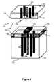
- FIG. 1is a perspective view diagram of a chip-to-chip bonding device consistent with embodiments disclosed herein;
- FIG. 2Ais a perspective view diagram of stage components from a chip-to-chip bonding device consistent with embodiments disclosed herein;
- FIG. 2Bis a perspective view diagram of the bond head stage mechanically coupling to a component carrier and the bond slider stage mechanically coupling to a bond stage tool consistent with embodiments disclosed herein;
- FIG. 2Cis a perspective view diagram of the component carrier mechanically coupling to a component and the slider carrier mechanically coupling to a slider consistent with embodiments disclosed herein;
- FIG. 2Dis a perspective view diagram illustrating a passive alignment process consistent with embodiments disclosed herein;
- FIG. 2Eis a perspective view diagram illustrating a eutectic bonding process consistent with embodiments disclosed herein;
- FIG. 2Fis a perspective view diagram illustrating a cooling process consistent with embodiments disclosed herein;
- FIG. 3Ais a cross-section diagram of a carrier with rough and smooth surfaces coupled to a stage with rough surfaces consistent with embodiments disclosed herein;
- FIG. 3Bis a cross-section diagram of a carrier with rough and smooth surfaces coupled to a stage with rough surfaces consistent with embodiments disclosed herein;
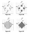
- FIG. 4Ais side-view diagram illustrating sliding forces present during a chip-to-chip bonding process
- FIG. 4Bis side-view diagram illustrating sliding forces present during a chip-to-chip bonding process
- FIG. 5Ais side-view diagram illustrating good chip-to-chip alignment during a chip-to-chip bonding process
- FIG. 5Bis side-view diagram illustrating bad chip-to-chip alignment following a chip-to-chip bonding process
- FIG. 6Ais a top down view of a carrier surface with disk-shaped rough surface patterns consistent with embodiments disclosed herein;
- FIG. 6Bis a top down view of a carrier surface with square-shaped rough surface patterns consistent with embodiments disclosed herein;
- FIG. 6Cis a top down view of a carrier surface with a disk-shaped rough surface pattern consistent with embodiments disclosed herein;
- FIG. 6Dis a top down view of a carrier surface with a diamond-shaped rough surface pattern consistent with embodiments disclosed herein;
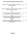
- FIG. 7is a process flow chart illustrating a method for vacuum coupling a carrier to a stage during a chip-to-chip bonding process consistent with embodiments disclosed herein.
- a eutectic bonding toolincludes a stage and a carrier, wherein the stage includes at least one vacuum aperture extending between a top surface and a bottom surface, and the bottom surface includes one or more rough surface portions.
- the carrierincludes a top surface with one or more rough surface portions and one or more smooth surface portions, wherein at least one of the carrier's smooth surface portions laterally aligns to one of the vacuum apertures when the carrier's top surface couples to and opposes the stage's bottom surface.
- the position of the stage and of the carrierare vertically flipped such that the carrier is located above the stage, instead of below the stage, such that the stage or carrier surfaces referred to as being top surfaces may be bottom surfaces, and the stage or carrier surfaces referred to as being bottom surfaces may be top surfaces.
- the terms top or bottommay be interchanged when appropriate according to the relative vertical positions of the stage and carrier.
- the embodiment disclosed abovemay also be described such that the stage includes a top surface with one or more rough surface portions, and the carrier includes a bottom surface with one or more rough surface portions and one or more smooth surface portions, wherein at least one of the carrier's smooth surface portions laterally aligns to one of the vacuum apertures when the carrier's bottom surface couples to and opposes the stage's top surface.
- At least one of the stage's rough surface portionsfrictionally couples to at least one of the carrier's rough surface portions such that frictional force counteracts lateral movement of the carrier relative to the stage. Accordingly, the carrier's position becomes laterally stable with respect to the stage, even when lateral slipping forces are applied during the eutectic bonding process, resulting in improved lateral alignment of the carrier with respect to the stage and increasing product yield.
- Some embodiments of the disclosureprovide a method for vacuum coupling a carrier to a stage that includes providing a stage with a top surface, a bottom surface, and at least one vacuum aperture extending therebetween, wherein the bottom surface includes one or more rough surface portions.
- the methodmay also include providing a carrier that includes a top surface with one or more smooth surface portions and one or more rough surface portions.
- the methodmay also include laterally aligning at least one of the carrier's smooth surface portions with at least one of the stage's vacuum apertures and vacuum coupling the carrier to the stage by bringing the carrier's top surface in contact with the stage's bottom surface and removing air pressure from the vacuum apertures.
- the methodalso includes heating the stage using a direct heat source, such as a stage heater. In other examples, the method includes heating the stage using an indirect heat source. Providing heat to the stage may enable heating the carrier and any components—such as a COSA or a slider—that are coupled to the carrier. Accordingly, providing heat to the stage, carrier, and any attached component may enable a eutectic bonding process by liquefying any eutectic alloy layered between the components.
- a direct heat sourcesuch as a stage heater.
- the methodincludes heating the stage using an indirect heat source.
- Providing heat to the stagemay enable heating the carrier and any components—such as a COSA or a slider—that are coupled to the carrier. Accordingly, providing heat to the stage, carrier, and any attached component may enable a eutectic bonding process by liquefying any eutectic alloy layered between the components.
- the methodalso includes laterally aligning at least one of the carrier's rough surface portions with at least one of the stage's rough surface portions. In some examples, the method also includes frictionally coupling at least one of the carrier's rough surface portions to at least one of the stage's rough surface portions such that frictional force counteracts lateral movement of the carrier relative to the stage, for example, when vertical pressure is applied to the carrier and stage to eutectic bond a COSA to a slider.
- the carriermay be a chip carrier that may hold and stabilize the COSA, or other integrated circuit. In other examples, the carrier may be a slider carrier that may hold and stabilize a slider.
- Some embodimentsmay incorporate two sets of stages and carriers—one top set relative to holding, aligning, and stabilizing a COSA carrier coupled to a COSA, and one bottom set relative to holding, aligning, and stabilizing a slider carrier coupled to a slider head.
- the two stage and carrier setsmay be configured, as disclosed herein, to align the COSA with respect to the slider and provide opposing pressure to the COSA and slider, while also providing heat sufficient to enable eutectic bonding of the COSA to the slider.
- FIG. 1is a perspective view diagram of a chip-to-chip bonding device.
- the bonding devicemay include a stage 100 and a carrier 110 .
- Stage 100may be, for example, a bond head heater stage.
- Stage 100includes top surface 106 and bottom surface 108 .
- stage 100includes vacuum apertures 102 and 104 extending between stage top surface 106 and stage bottom surface 108 .
- Vacuum aperture 104may be a component vacuum aperture configured to provide vacuum coupling directly or indirectly to a component 120 .
- Component 120may be, for example, a COSA or slider.
- Vacuum aperture 102may be configured to provide vacuum coupling to carrier 110 .
- stage 100may be configured to be mechanically positioned with respect to its lateral or vertical axes.
- stage 100includes a direct heat source to provide heat to the stage, as well as to carrier 110 and component 120 .
- an indirect heat sourcemay be configured to provide heat to stage 100 , carrier 110 , and component 120 .
- carrier 110includes top surface 112 and bottom surface 114 .
- Vacuum aperture 104 extending through stage 100may further be configured to extend between carrier top surface 112 and carrier bottom surface 114 such that it provides vacuum coupling to component 120 .
- carrier 110vacuum couples to stage 100 when carrier top surface 112 is brought in contact with stage bottom surface 108 and air pressure is removed any of the vacuum apertures 102 . Accordingly, carrier 110 is held in a stable position under stage 100 such that any lateral or vertical movement experienced by stage 100 is translated to carrier 110 .
- component 120for example, an integrated circuit or a COSA
- any lateral or vertical movement experienced by stage 100 and carrier 110is also translated to component 120 .
- component 120may be affixed to carrier 110 using other mechanical coupling technologies such as form fitting, snap-fitting, press-fitting, or other coupling techniques as known in the art.
- carrier 110may be affixed to stage 100 using other mechanical coupling technologies such as form fitting, snap-fitting, press-fitting, or other coupling techniques as known in the art.
- the bonding devicemay include stage 150 and carrier 160 .
- the bonding devicemay include a top stage set comprising a top stage 100 and a top carrier 110 configured to hold, position, and align component 120 , as well as a bottom stage set comprising bottom stage 150 and bottom carrier 160 configured to hold, position, and align component 170 .
- top stage 100may be a bond head heater stage and bottom stage 150 may be a bond slider heater stage, wherein component 120 may be an integrated circuit or COSA and component 170 may be a slider.
- the entire bonding devicemay be inverted such that component 120 is a slider and component 170 is an integrated circuit or COSA.
- Components 120 and 170may also be other component types wherein component 120 is intended to be bonded to component 170 and wherein aligning component 120 to component 170 is important during the bonding process.
- component 120may be bonded to component 170 using eutectic bonding by providing opposing vertical force or pressure between the components while also providing heat, provided that the opposing surfaces of component 120 and/or component 170 comprise a eutectic alloy.
- stage 150includes bottom surface 156 and top surface 158 .
- stage 150includes vacuum apertures 152 and 154 extending between stage bottom surface 156 and stage top surface 158 .
- Vacuum aperture 154may be a component vacuum aperture configured to provide vacuum coupling directly or indirectly to a component 170 .
- Component 170may be, for example, a slider or COSA.
- Vacuum aperture 152may be configured to provide vacuum coupling to carrier 160 .
- stage 150may be configured to be mechanically positioned with respect to its lateral or vertical axes. In alternate embodiments, stage 150 may be fixed on its vertical axis, but may be configured for mechanical positioning along its lateral axes. Still in other embodiments, stage 150 may be fixed both vertically and laterally allowing alignment of components 120 and 170 to be controlled entirely through lateral and vertical positioning of stage 100 .
- Stage 150may include a direct heat source to provide heat to the stage, as well as to carrier 160 and component 170 .
- the bonding devicemay include an indirect heat source configured to provide heat to stage 150 , carrier 160 , and component 170 .
- carrier 160includes top surface 162 and bottom surface 164 .
- Vacuum aperture 154 extending through stage 150may further be configured to extend between carrier top surface 162 and carrier bottom surface 164 such that it provides vacuum coupling to component 170 .
- carrier 160vacuum couples to stage 150 when carrier bottom surface 164 is brought in contact with stage top surface 158 and air pressure is removed any of the vacuum apertures 152 . Accordingly, carrier 160 is held in a stable position above stage 150 such that any lateral or vertical motion experienced by stage 150 is translated to carrier 160 .
- component 170for example, a slider
- any lateral or vertical movement experienced by stage 150 and carrier 160is also translated to component 170 .
- component 170may be affixed to carrier 160 using other mechanical coupling technologies such as form fitting, snap-fitting, press-fitting, or other coupling techniques as known in the art.
- carrier 160may be affixed to stage 150 using other mechanical coupling technologies such as form fitting, snap-fitting, press-fitting, or other coupling techniques as known in the art.
- FIG. 2Ais a perspective view diagram of stage components from a chip-to-chip bonding device.
- bond head stage 200includes a top surface 202 , a bottom surface 208 , and a plurality of vacuum apertures 202 and 204 extending therebetween.
- bond slider stage 250includes a top surface 258 , a bottom surface 256 , and a plurality of vacuum apertures 252 and 254 extending therebetween.
- FIG. 2Bis a perspective view diagram of the bond head stage mechanically coupling to a component carrier and the bond slider stage mechanically coupling to a bond stage tool.
- component carrier 210includes a top surface 212 and a bottom surface 214 .
- Component 220may mechanically couple to carrier bottom surface 214 .
- Component carrier top surface 212may mechanically couple to bond head stage 200 .
- the component carriermay vacuum couple to the bond head stage when component carrier top surface 212 contacts vacuum aperture 202 and a vacuum is supplied through vacuum aperture 202 , the vacuum being supplied by removing air pressure from the opposite end of the vacuum aperture 202 .
- the component carriermay couple to the bond head stage using other mechanical coupling techniques as known in the art.
- slider carrier 260includes a top surface 262 and a bottom surface 264 .
- Slider carrier bottom surface 264may mechanically couple to bond slider stage 250 .
- the slider carriermay vacuum couple to the bond slider stage when slider carrier bottom surface 264 contacts vacuum aperture 252 and a vacuum is supplied through vacuum aperture 252 , the vacuum being supplied by removing air pressure from the opposite end of the vacuum aperture 252 .
- the slider carriermay couple to the bond slider stage using other mechanical coupling techniques as known in the art.
- FIG. 2Cis a perspective view diagram of the component carrier mechanically coupling to a component and the slider carrier mechanically coupling to a slider.
- component 220mechanically couples to component carrier 210 , and indirectly to bond head stage 200 .
- component 220may vacuum couple to carrier 210 using a vacuum created in vacuum aperture 204 , as illustrated in FIG. 2A .
- Vacuum aperture 204may extend through both bond head stage 200 and component carrier 210 and contact a top surface of component 220 in order to hold component 220 in place when a vacuum is supplied through the vacuum aperture 204 .
- slider 270mechanically couples to slider carrier 260 , and indirectly to bond slider stage 250 .
- slider 270may vacuum couple to slider carrier 260 using a vacuum created in vacuum aperture 254 , as illustrated in FIG. 2A .
- Vacuum aperture 254may extend through both bond slider stage 250 and slider carrier 260 and contact a bottom surface of slider 270 in order to hold slider 270 in place when a vacuum is supplied through the vacuum aperture 254 .
- FIG. 2Dis a perspective view diagram illustrating a passive alignment process.
- component 220e.g., a COSA
- the alignment processmay be manual or automated using alignment technologies as known in the art.
- FIG. 2Eis a perspective view diagram illustrating a chip-to-chip bonding process.
- bond head stage 200is moved downward towards bond slider stage 250 , bringing a bottom surface of component 220 in physical contact with a top surface of slider 270 , as illustrated by FIG. 2F .
- bonding pressureis supplied by continuing to apply downward force to bond head stage 200 , and both bond head stage 200 and bond slider stage 250 are heated using either a direct or indirect heat source.
- the bond head stage and bond slider stagemay continue to supply heat ad pressure to the slider 270 and component 220 until any eutectic alloy present on the surfaces of the slider and component liquefies.
- the component and slidermay then be cooled by removing the heat source until the eutectic alloy re-solidifies, creating a eutectic bond between the slider and component.
- FIG. 3Ais a cross-section diagram of a carrier with rough and smooth surfaces coupled to a stage with rough surfaces.
- stage 300includes a top surface, a bottom surface, and a plurality of vacuum apertures 302 extending therebetween.
- the top surfaceincludes rough surface portions 305 .
- Carrier 310includes a bottom surface made up of rough surface portions 315 and smooth surface portions 317 .
- Carrier rough surface portions 315may be laterally aligned with stage rough surface portions 305
- carrier smooth surface portions 317may be laterally aligned with vacuum apertures 302 when stage 300 contacts carrier 310 .
- stage rough surface portions 305 and carrier rough surface portions 315may frictionally couple together to create sufficient lateral resistance to limit lateral slipping of the carrier with respect to the stage when lateral force is applied.
- smooth carrier surface portions 317may completely cover the openings and extend to the circumferential surface lips of vacuum apertures 302 such that air passage, or leaking from the area between the stage 300 and carrier 310 into vacuum aperture 302 is limited, or eliminated altogether when air pressure is removed from the vacuum apertures 302 . Accordingly, the vacuum seal, and corresponding vacuum coupling, between carrier 310 and stage 300 is efficiently strong.
- Providing frictional coupling between rough surface portions 315 and 305 , and vacuum coupling between vacuum apertures 302 and smooth surface portions 317 ,may create an efficiently strong vacuum coupling between the stage 300 and carrier 310 may be maintained, while limiting lateral slipping between the stage and the carrier when lateral force is applied.
- rough surface portions 305may have a roughness of between 50 nm and 150 nm when measuring the average vertical distance between the peaks and valleys of the surface topography.
- rough surface portions 315may also have a roughness of between 50 nm and 150 nm.
- Smooth surface portions 317may have a roughness of less than 50 nm.
- the roughness of rough surface portions 305 and 315may be varied such that it is less than 50 nm, or more than 150 nm depending on the size and weight of carrier 310 and stage 300 , as well as the type of bonding process and degree of bonding force required. Greater roughness will limit lateral slippage when greater bonding pressure is applied, or when larger and/or heavier carriers are utilized.
- roughness of smooth surface portions 317may be varied, or increased to 50 nm or more depending on the level of vacuum that is required to maintain an efficient seal between the carrier and the stage.
- Rough surface portions 305 and 315may be formed using various surface processing technologies as known in the art, including for example, sand blasting, chemical etching, or ion etching.
- FIG. 3Bis a cross-section diagram of a carrier with rough and smooth surfaces coupled to a stage with rough surfaces.
- stage 350includes a top surface, a bottom surface, and a plurality of vacuum apertures 352 extending therebetween.
- the top surfaceincludes rough surface portions 355 .
- Carrier 360includes a bottom surface made up of rough surface portions 365 and a smooth surface portion 367 .
- Carrier rough surface portions 365may be laterally aligned with stage rough surface portions 355 . Accordingly, the stage rough surface portions 355 and carrier rough surface portions 365 may frictionally couple together to create sufficient lateral resistance to limit lateral slipping of the carrier with respect to the stage when lateral force is applied.
- smooth carrier surface portion 367may completely cover each of the openings and extend to the circumferential surface lips of vacuum apertures 352 such that air passage, or leaking from the area between the stage 350 and carrier 360 into vacuum aperture 352 is limited, or eliminated altogether when air pressure is removed from the vacuum apertures 352 . Accordingly, the vacuum seal, and corresponding vacuum coupling, between carrier 360 and stage 350 is efficiently strong. Providing frictional coupling between rough surface portions 365 and 355 , and vacuum coupling between vacuum apertures 352 and smooth surface portion 367 , may create an efficiently strong vacuum coupling between the stage 350 and carrier 360 may be maintained, while limiting lateral slipping between the stage and the carrier when lateral force is applied.
- FIG. 4Ais side-view diagram illustrating sliding forces present during a chip-to-chip bonding process.
- vertical bonding force f 1may be applied to component 420 .
- lateral sliding force f 2may be created causing slider 470 to move laterally with respect to component 420 , as illustrated by FIG. 4B . This lateral movement may create a misalignment between component 420 and slider 470 during the bonding process.
- FIG. 5Ais side-view diagram illustrating good chip-to-chip alignment during a chip-to-chip bonding process.
- carrier 510may vacuum couple to stage 500 when by bringing the carrier in contact with the stage such that a top surface of carrier 510 completely obscures the opening of vacuum aperture 504 , and removing or reducing the air pressure from vacuum aperture 504 .
- component 520may vacuum couple to carrier 510 by bringing component 520 in contact with carrier 510 such that it completely obscures the opening of vacuum aperture 502 , and removing or reducing the air pressure from vacuum aperture 502 .
- the same vacuum coupling processmay be used to couple carrier 560 to stage 550 , and slider 570 to carrier 560 .
- Stage 500may then be positioned to laterally align component 520 with slider 570 prior to lowering stage 500 to bring the component 520 (e.g., a COSA) in contact with slider 570 to administer a eutectic bonding process.
- the alignment illustrated in FIG. 5Ais a desired alignment.
- FIG. 5Bis side-view diagram illustrating bad chip-to-chip alignment following a chip-to-chip bonding process.
- the stage 500may be lowered towards slider 570 to bring component 520 in contact with slider 570 , and then continuing to apply downward force, f 1 , to create a compression of the bottom surface of component 520 and the upper surface of slider 570 .
- f 1downward force
- a sliding force f 2may be generated, causing the slider 570 and carrier 560 to slip laterally with respect to their desired positions relative to stages 500 and 550 , and component 520 , and causing a misalignment of the slider 570 and component 520 .
- This sliding force, f 2may be counteracted by frictional resistance created by frictionally coupling rough surface portions of carrier 560 to the rough surface portions of stage 550 , similar to the examples illustrated herein (e.g., FIG. 3A and FIG. 3B ).
- FIG. 6Ais a top down view of either a carrier surface with disk-shaped rough surface patterns.
- FIG. 6Bis a top down view of either a carrier surface with square-shaped rough surface patterns.
- FIG. 6Cis a top down view of a carrier surface with a disk-shaped rough surface pattern.
- FIG. 6Dis a top down view of a carrier surface with a diamond-shaped rough surface pattern.
- 6A, 6B, 6C, and 6Dcombine a series of rough surface portions 610 and smooth surface portions 620 such that the smooth surface portions may entirely obscure the openings to one or more of the stage's vacuum apertures when the stage is brought in contact with the carrier, and the rough surface portions 610 will provide adequate lateral frictional resistance to limit or eliminate lateral slipping during the bonding process.
- These rough surface portion patternsare exemplary and other patterns and sizes may be used as would be known in the art.
- FIG. 7is a process flow chart illustrating a method for vacuum coupling a carrier to a stage during a chip-to-chip bonding process.
- the methodincludes providing a stage with vacuum apertures and rough surface portions at step 700 (e.g. the stage disclosed in FIG. 3A and FIG. 3B ), providing a carrier with rough surface portions and smooth surface portions at step 705 (e.g. the carrier disclosed in FIG. 3A and FIG. 3B ), and laterally aligning the carrier's smooth surface portions with the vacuum apertures such that the opening of one or more of the vacuum apertures is completely obscured by the carrier's smooth surface portions at step 710 .
- the methodmay also include laterally aligning the carrier's rough surface portions with the stage's rough surface portions at step 715 in order to frictionally couple the carrier to the stage.
- the methodsalso includes removing air pressure from the vacuum apertures while bringing the carrier in contact with the stage at step 720 in order to vacuum couple the carrier to the stage.
- the terms “over,” “under,” “between,” and “on” as used hereinrefer to a relative position of one media layer with respect to other layers.
- one layer disposed over or under another layermay be directly in contact with the other layer or may have one or more intervening layers.
- one layer disposed between two layersmay be directly in contact with the two layers or may have one or more intervening layers.
- a first layer “on” a second layeris in contact with that second layer.
- the relative position of one layer with respect to other layersis provided assuming operations are performed relative to a substrate without consideration of the absolute orientation of the substrate.
- moduledoes not imply that the components or functionality described or claimed as part of the module are all configured in a common package. Indeed, any or all of the various components of a module, whether control logic or other components, can be combined in a single package or separately maintained and can further be distributed in multiple groupings or packages or across multiple locations.
Landscapes
- Engineering & Computer Science (AREA)
- Mechanical Engineering (AREA)
- Physics & Mathematics (AREA)
- Plasma & Fusion (AREA)
- Thermal Sciences (AREA)
- Computer Hardware Design (AREA)
- Microelectronics & Electronic Packaging (AREA)
- Power Engineering (AREA)
- Manufacturing & Machinery (AREA)
- Die Bonding (AREA)
Abstract
Description
Claims (6)
Priority Applications (1)
| Application Number | Priority Date | Filing Date | Title |
|---|---|---|---|
| US14/498,664US9685187B1 (en) | 2014-09-26 | 2014-09-26 | Bonding tool and method for high accuracy chip-to-chip bonding |
Applications Claiming Priority (1)
| Application Number | Priority Date | Filing Date | Title |
|---|---|---|---|
| US14/498,664US9685187B1 (en) | 2014-09-26 | 2014-09-26 | Bonding tool and method for high accuracy chip-to-chip bonding |
Publications (1)
| Publication Number | Publication Date |
|---|---|
| US9685187B1true US9685187B1 (en) | 2017-06-20 |
Family
ID=59034103
Family Applications (1)
| Application Number | Title | Priority Date | Filing Date |
|---|---|---|---|
| US14/498,664Expired - Fee RelatedUS9685187B1 (en) | 2014-09-26 | 2014-09-26 | Bonding tool and method for high accuracy chip-to-chip bonding |
Country Status (1)
| Country | Link |
|---|---|
| US (1) | US9685187B1 (en) |
Cited By (1)
| Publication number | Priority date | Publication date | Assignee | Title |
|---|---|---|---|---|
| US20220278071A1 (en)* | 2021-02-26 | 2022-09-01 | Taiwan Semiconductor Manufacturing Company, Ltd. | Apparatus and method for forming a package structure |
Citations (113)
| Publication number | Priority date | Publication date | Assignee | Title |
|---|---|---|---|---|
| US5986335A (en)* | 1995-12-01 | 1999-11-16 | Texas Instruments Incorporated | Semiconductor device having a tapeless mounting |
| US6075673A (en) | 1997-05-05 | 2000-06-13 | Read-Rite Corporation | Composite slider design |
| US6097575A (en) | 1998-07-14 | 2000-08-01 | Read-Rite Corporation | Composite slider with housing and interlocked body |
| US6125014A (en) | 1998-06-26 | 2000-09-26 | Read-Rite Corporation | Via-less connection using interconnect traces between bond pads and a transducer coil of a magnetic head slider |
| US6125015A (en) | 1998-12-04 | 2000-09-26 | Read-Rite Corporation | Head gimbal assembly with low stiffness flex circuit and ESD Protection |
| US6130863A (en) | 1997-11-06 | 2000-10-10 | Read-Rite Corporation | Slider and electro-magnetic coil assembly |
| US6137656A (en) | 1998-10-26 | 2000-10-24 | Read-Rite Corporation | Air bearing slider |
| US6144528A (en) | 1998-10-26 | 2000-11-07 | Read-Rite Corporation | Air bearing slider with reduced stiction |
| US6147838A (en) | 1997-02-10 | 2000-11-14 | Read-Rite Corporation | Air bearing slider with shaped taper |
| US6151196A (en) | 1999-02-16 | 2000-11-21 | Read-Rite Corporation | Magnetic head suspension assembly including an intermediate flexible member that supports an air bearing slider with a magnetic transducer for testing |
| US6181522B1 (en) | 1998-12-12 | 2001-01-30 | Read-Write Corporation | Read/write head with a gimbal ball assembly |
| US6181673B1 (en) | 1996-07-30 | 2001-01-30 | Read-Rite Corporation | Slider design |
| US6229672B1 (en) | 1998-10-19 | 2001-05-08 | Read-Rite Corporation | High gram load air bearing geometry for a tripad slider |
| US6236543B1 (en) | 1999-01-29 | 2001-05-22 | Read-Rite Corporation | Durable landing pads for an air-bearing slider |
| US6246547B1 (en) | 1999-02-16 | 2001-06-12 | Read-Rite Corporation | Low profile flexure and slider-flexure assembly |
| US6249404B1 (en) | 1999-02-04 | 2001-06-19 | Read-Rite Corporation | Head gimbal assembly with a flexible printed circuit having a serpentine substrate |
| US6330131B1 (en) | 1993-09-17 | 2001-12-11 | Read-Rite Corporation | Reduced stiction air bearing slider |
| US6349017B1 (en) | 1997-02-21 | 2002-02-19 | Read-Rite Corporation | Magnetic head suspension assembly using bonding pads of a slider to an attachment surface of a flexure |
| US6373660B1 (en) | 2000-03-14 | 2002-04-16 | Read-Rite Corporation | Method and system for providing a permanent shunt for a head gimbal assembly |
| US6506672B1 (en)* | 1999-06-30 | 2003-01-14 | University Of Maryland, College Park | Re-metallized aluminum bond pad, and method for making the same |
| US6522504B1 (en) | 2001-01-31 | 2003-02-18 | Western Digital Technologies, Inc. | Head stack assembly and disk drive using a reversed direction head gimbal assembly |
| US6538850B1 (en) | 1999-10-06 | 2003-03-25 | Read-Rite Corporation | Low profile head gimbal assembly with shock limiting and load/unload capability and method of manufacture thereof |
| US6583953B1 (en) | 1999-07-12 | 2003-06-24 | Mark Lauer | Silicon carbide overcoats for information storage systems and method of making |
| US6646832B2 (en) | 2001-01-29 | 2003-11-11 | Manuel Anaya-Dufresne | Slider for load/unload operation with high stiffness and low unload force |
| US6661612B1 (en) | 2001-10-21 | 2003-12-09 | Western Digital Technologies, Inc. | Air bearing slider including side rail shallow recessed surfaces extending along trailing portions of leading side air bearing surfaces |
| US6665146B2 (en) | 1999-12-28 | 2003-12-16 | Western Digital (Fremont) | Airflow assisted ramp loading and unloading of sliders in hard disk drives |
| US6690545B1 (en) | 2001-09-28 | 2004-02-10 | Western Digital Technologies, Inc. | Air bearing slider including a depressed region extending from a main support structure between a pressurized pad support base and a contact pad support base |
| US6704173B1 (en) | 2000-08-16 | 2004-03-09 | Western Digital (Fremont), Inc. | Method and system for providing ESD protection using diodes and a grounding strip in a head gimbal assembly |
| US6721142B1 (en) | 2000-12-21 | 2004-04-13 | Western Digital (Fremont) Inc. | Non-corrosive GMR slider for proximity recording |
| US6744599B1 (en) | 2002-04-30 | 2004-06-01 | Western Digital Technologies, Inc. | Air bearing slider with an angularly disposed channel formed between a side rail and a leading side air bearing surface |
| US6771468B1 (en) | 2001-10-22 | 2004-08-03 | Western Digital Corporation | Slider with high pitch-stiffness air bearing design |
| US6796018B1 (en) | 2001-12-21 | 2004-09-28 | Western Digital (Fremont), Inc. | Method of forming a slider/suspension assembly |
| US6801402B1 (en) | 2002-10-31 | 2004-10-05 | Western Digital Technologies, Inc. | ESD-protected head gimbal assembly for use in a disk drive |
| US6873496B1 (en) | 2000-01-03 | 2005-03-29 | Western Digital Fremont, Inc. | Side rail slider having improved fly height control |
| US6912103B1 (en) | 2002-07-31 | 2005-06-28 | Western Digital Technologies, Inc. | Method of operating a disk drive with a slider at loading and unloading fly heights greater than an operational fly height |
| US6937439B1 (en) | 2001-11-30 | 2005-08-30 | Western Digital Technologies, Inc. | Slider having a textured air bearing surface, head stack assembly and disk drive using same |
| US6956718B1 (en) | 2002-08-19 | 2005-10-18 | Western Digital (Fremont), Inc. | Sandwich diamond-like carbon overcoat for use in slider designs of proximity recording heads |
| US6972930B1 (en) | 2003-02-28 | 2005-12-06 | Western Digital Technologies, Inc. | ESD-protected slider and head gimbal assembly |
| US7006331B1 (en) | 2003-09-30 | 2006-02-28 | Western Digital Technologies, Inc. | Head gimbal assembly including a trace suspension assembly backing layer with a conductive layer formed upon a gimbal having a lower oxidation rate |
| US7006330B1 (en) | 2003-03-10 | 2006-02-28 | Western Digital Technologies, Inc. | Head stack assembly including a ground conductive pad for grounding a slider to a gimbal |
| US7019945B1 (en) | 2002-12-23 | 2006-03-28 | Western Digital Technologies, Inc. | Air bearing slider including pressurized side pads with forward and trailing shallow etched surfaces |
| US7027264B1 (en) | 2003-10-31 | 2006-04-11 | Western Digital Technologies, Inc. | Slider with a slider ground pad electrically connected to write head poles and read head shields |
| US7042070B2 (en) | 1999-09-22 | 2006-05-09 | Texas Instruments Incorporated | Direct attachment of semiconductor chip to organic substrate |
| US7085104B1 (en) | 1999-10-06 | 2006-08-01 | Western Digital (Fremont), Inc. | Low profile head gimbal assembly with shock limiting and load/unload capability |
| US7099117B1 (en) | 2003-09-30 | 2006-08-29 | Western Digital Technologies, Inc. | Head stack assembly including a trace suspension assembly backing layer and a ground trace for grounding a slider |
| US7289299B1 (en) | 2005-02-02 | 2007-10-30 | Western Digital (Fremont), Llc | Air bearing slider with three-projection trailing center pad |
| US7307816B1 (en) | 2001-12-21 | 2007-12-11 | Western Digital (Fremont), Llc | Flexure design and assembly process for attachment of slider using solder and laser reflow |
| US7315436B1 (en) | 2004-06-25 | 2008-01-01 | Western Digital Technologies, Inc. | Suspension assembly with a shape memory actuator coupled to a gimbal |
| US7315435B1 (en) | 2005-03-17 | 2008-01-01 | Western Digital Technologies, Inc. | Disk drives, head stack, head gimbal and suspension assemblies having positional conductive features |
| US7414814B1 (en) | 2005-04-28 | 2008-08-19 | Western Digital Technologies, Inc. | Disk drives, head stack, head gimbal and suspension assemblies having a compliant suspension tail design for solder reflow |
| US7436631B1 (en) | 2004-06-30 | 2008-10-14 | Western Digital (Fremont), Llc | Heated gimbal for magnetic head to disk clearance adjustment |
| US7474508B1 (en) | 2005-03-09 | 2009-01-06 | Western Digital (Fremont), Inc. | Head gimbal assembly with air bearing slider crown having reduced temperature sensitivity |
| US7477486B1 (en) | 2005-12-07 | 2009-01-13 | Western Digital (Fremont), Llc | Air bearing slider with a side pad having a shallow recess depth |
| US7595963B1 (en) | 2006-06-07 | 2009-09-29 | Western Digital Technologies, Inc. | Head gimbal assembly including a flexure with a first conductive trace disposed between a slider and a dielectric layer |
| US7616405B2 (en) | 2006-11-15 | 2009-11-10 | Western Digital (Fremont), Llc | Slider with an air bearing surface having a inter-cavity dam with OD and ID dam surfaces of different heights |
| US7729089B1 (en) | 2006-10-13 | 2010-06-01 | Western Digital Technologies, Inc. | Head-gimbal assembly including a flexure tongue with stand-offs arranged to facilitate lateral light entry |
| US20100261312A1 (en)* | 2009-04-09 | 2010-10-14 | Renesas Technology Corp. | Manufacturing method of semiconductor integrated circuit device |
| US7995310B1 (en) | 2006-11-09 | 2011-08-09 | Western Digital Technologies, Inc. | Head-gimbal assembly including a flexure tongue with adhesive receptacles disposed adjacent to stand-offs |
| US8081400B1 (en) | 2008-08-29 | 2011-12-20 | Western Digital (Fremont), Llc | Slider with an air-bearing surface including four pressure generating pockets for countering disruptive movement |
| US8089730B1 (en) | 2009-10-28 | 2012-01-03 | Western Digital (Fremont), Llc | Suspension assembly having a read head clamp |
| US8087973B1 (en) | 2008-08-19 | 2012-01-03 | Western Digital (Fremont), Llc | Slider with leading edge blend and conformal step features |
| US8164858B1 (en) | 2009-11-04 | 2012-04-24 | Western Digital (Fremont), Llc | Read head having conductive filler in insulated hole through substrate |
| US8199437B1 (en) | 2010-03-09 | 2012-06-12 | Western Digital (Fremont), Llc | Head with an air bearing surface having a particle fence separated from a leading pad by a continuous moat |
| US8208224B1 (en) | 2011-08-29 | 2012-06-26 | Western Digital Technologies, Inc. | Suspension assemblies for minimizing stress on slider solder joints |
| US8218268B1 (en) | 2009-05-27 | 2012-07-10 | Western Digital Technologies, Inc. | Head gimbal assembly having a load beam aperature over conductive heating pads that are offset from head bonding pads |
| US8240545B1 (en) | 2011-08-11 | 2012-08-14 | Western Digital (Fremont), Llc | Methods for minimizing component shift during soldering |
| US8256272B1 (en) | 2009-12-23 | 2012-09-04 | Western Digital (Fremont), Llc | UV adhesive viscosity adjustment apparatus and method |
| US8295014B1 (en) | 2010-10-29 | 2012-10-23 | Western Digital Technologies, Inc. | Disk drive head gimbal assembly having a flexure tail with transverse flying leads |
| US8295013B1 (en) | 2010-10-29 | 2012-10-23 | Western Digital Technologies, Inc. | Disk drive head stack assembly having a flexible printed circuit with heat transfer limiting features |
| US8295012B1 (en) | 2011-06-14 | 2012-10-23 | Western Digital Technologies, Inc. | Disk drive suspension assembly with rotary fine actuator at flexure tongue |
| US8320084B1 (en) | 2010-10-29 | 2012-11-27 | Western Digital Technologies, Inc. | Disk drive head gimbal assembly having a flexure tail with features to facilitate bonding |
| US8325446B1 (en) | 2010-10-29 | 2012-12-04 | Western Digital Technologies, Inc. | Disk drive head gimbal assembly having a flexure tail with features to facilitate bonding |
| US8339747B1 (en) | 2011-03-11 | 2012-12-25 | Western Digital Technologies, Inc. | Removable actuator assemblies for testing head gimbal assemblies of a storage device |
| US8339748B2 (en) | 2010-06-29 | 2012-12-25 | Western Digital Technologies, Inc. | Suspension assembly having a microactuator bonded to a flexure |
| US8343363B1 (en) | 2010-03-10 | 2013-01-01 | Western Digital (Fremont), Llc | Method and system for fabricating a cavity in a substrate of a magnetic recording head |
| US8345519B1 (en) | 2010-12-22 | 2013-01-01 | Western Digital (Fremont), Llc | Method and system for providing a suspension head bond pad design |
| US20130062782A1 (en)* | 2011-09-01 | 2013-03-14 | Kabushiki Kaisha Toshiba | Stacked semiconductor devices and fabrication method/equipment for the same |
| US8418353B1 (en) | 2009-12-23 | 2013-04-16 | Western Digital (Fremont), Llc | Method for providing a plurality of energy assisted magnetic recording EAMR heads |
| US8441896B2 (en) | 2010-06-25 | 2013-05-14 | Western Digital (Fremont), Llc | Energy assisted magnetic recording head having laser integrated mounted to slider |
| US8446694B1 (en) | 2011-06-14 | 2013-05-21 | Western Digital Technologies, Inc. | Disk drive head suspension assembly with embedded in-plane actuator at flexure tongue |
| US8456776B1 (en) | 2010-09-22 | 2013-06-04 | Western Digital Technologies, Inc. | Disk drive head gimbal assembly having a flexure bond pad shelf offset from a tongue |
| US8456643B2 (en) | 2010-05-24 | 2013-06-04 | Western Digital (Fremont), Llc | Method and system for mapping the shape of a head under operating conditions |
| US8462462B1 (en) | 2011-10-20 | 2013-06-11 | Western Digital (Fremont), Llc | Localized heating for flip chip bonding |
| US8477459B1 (en) | 2010-10-29 | 2013-07-02 | Western Digital Technologies, Inc. | Disk drive head gimbal assembly having a flexure tail with dual conductive layers and features to facilitate bonding |
| US8488281B1 (en) | 2011-09-13 | 2013-07-16 | Western Digital (Fremont), Llc | Disk drive suspension assembly having a flexure bond pad shelf separate from a tongue |
| US8490211B1 (en) | 2012-06-28 | 2013-07-16 | Western Digital Technologies, Inc. | Methods for referencing related magnetic head microscopy scans to reduce processing requirements for high resolution imaging |
| US8485579B2 (en) | 2011-03-17 | 2013-07-16 | Western Digital (Fremont), Llc | Vacuum pickup assemblies for picking up articles and minimizing contamination thereof |
| US8488279B1 (en) | 2011-11-22 | 2013-07-16 | Western Digital (Fremont), Llc | Disk drive suspension assembly with flexure having stacked interleaved traces |
| US8514522B1 (en) | 2011-01-25 | 2013-08-20 | Western Digital (Fremont), Llc | Systems for interconnecting magnetic heads of storage devices in a test assembly |
| US8533936B1 (en) | 2011-01-26 | 2013-09-17 | Western Digital (Fremont), Llc | Systems and methods for pre-heating adjacent bond pads for soldering |
| US20130244541A1 (en) | 2012-03-14 | 2013-09-19 | Western Digital Technologies, Inc. | Systems and methods for correcting slider parallelism error using compensation lapping |
| US8545164B2 (en) | 2010-12-06 | 2013-10-01 | Western Digital (Fremont), Llc | Systems and methods for repositioning row bars used for manufacturing magnetic heads |
| US8553365B1 (en) | 2012-02-21 | 2013-10-08 | Western Digital (Fremont), Llc | Apparatuses and methods for loading a head onto a disk medium |
| US20130293982A1 (en) | 2012-05-02 | 2013-11-07 | Western Digital Technologies, Inc. | Disk drive employing single polarity supply voltage to generate write current |
| US20130299947A1 (en)* | 2012-05-14 | 2013-11-14 | Freescale Semiconductor, Inc. | Passivated test structures to enable saw singulation of wafer |
| US8587901B1 (en) | 2009-12-30 | 2013-11-19 | Western Digital (Fremont), Llc | Magnetic recording head slider comprising bond pad having a probe contact area and a solder contact area |
| US8593764B1 (en) | 2011-06-14 | 2013-11-26 | Western Digital Technologies, Inc. | Method for fine actuation of a head during operation of a disk drive |
| US8599653B1 (en) | 2012-09-11 | 2013-12-03 | Western Digital Technologies, Inc. | Systems and methods for reducing condensation along a slider air bearing surface in energy assisted magnetic recording |
| US8605389B1 (en) | 2006-06-09 | 2013-12-10 | Western Digital Technologies, Inc. | Head gimbal assembly including a conductive trace disposed upon a continuous dielectric layer segment without overlying a gimbal arm |
| US8611052B1 (en) | 2012-03-27 | 2013-12-17 | Western Digital Technologies, Inc. | Systems and methods for aligning components of a head stack assembly of a hard disk drive |
| US8623197B1 (en) | 2010-12-20 | 2014-01-07 | Western Digital (Fremont), Llc | Testing workpiece overcoat |
| US8624184B1 (en) | 2012-11-28 | 2014-01-07 | Western Digital Technologies, Inc. | Methods for spatially resolved alignment of independent spectroscopic data from scanning transmission electron microscopes |
| US8665566B1 (en) | 2011-12-20 | 2014-03-04 | Western Digital Technologies, Inc. | Suspension tail design for a head gimbal assembly of a hard disk drive |
| US8665567B2 (en) | 2010-06-30 | 2014-03-04 | Western Digital Technologies, Inc. | Suspension assembly having a microactuator grounded to a flexure |
| US8665677B1 (en) | 2011-12-19 | 2014-03-04 | Western Digital (Fremont), Llc | Disk drive magnetic read head with affixed and recessed laser device |
| US8693144B1 (en) | 2013-03-15 | 2014-04-08 | Western Digital Technologies, Inc. | Head gimbal assemblies and methods for measuring slider parameters |
| US8760812B1 (en) | 2011-12-20 | 2014-06-24 | Western Digital Technologies, Inc. | Disk drive head gimbal assembly having a jumper in a flexible printed circuit overlap region |
| US8758083B1 (en) | 2010-09-13 | 2014-06-24 | Western Digital (Fremont), Llc | Method and system for adjusting lapping of a transducer using a disk windage |
| US8770463B1 (en) | 2013-05-20 | 2014-07-08 | Western Digital Technologies, Inc. | Head gimbal assembly carrier with adjustable protective bar |
| US8773664B1 (en) | 2011-12-20 | 2014-07-08 | Western Digital (Fremont), Llc | Method and system for aligning substrates for direct laser coupling in an energy assisted magnetic recording head |
| US8792213B1 (en) | 2013-02-20 | 2014-07-29 | Western Digital Technologies, Inc. | Tethered gimbal on suspension for improved flyability |
| US8792212B1 (en) | 2010-09-14 | 2014-07-29 | Western Digital (Fremont), Llc | Robust gimbal design for head gimbal assembly |
| US8797691B1 (en) | 2013-05-21 | 2014-08-05 | Western Digital Technologies, Inc. | Disk drive head suspension with a single piezoelectric element adhered to rotary-actuated and non-actuated portions of a structural layer of a tongue of a laminated flexure |
- 2014
- 2014-09-26USUS14/498,664patent/US9685187B1/ennot_activeExpired - Fee Related
Patent Citations (127)
| Publication number | Priority date | Publication date | Assignee | Title |
|---|---|---|---|---|
| US6330131B1 (en) | 1993-09-17 | 2001-12-11 | Read-Rite Corporation | Reduced stiction air bearing slider |
| US5986335A (en)* | 1995-12-01 | 1999-11-16 | Texas Instruments Incorporated | Semiconductor device having a tapeless mounting |
| US6181673B1 (en) | 1996-07-30 | 2001-01-30 | Read-Rite Corporation | Slider design |
| US6147838A (en) | 1997-02-10 | 2000-11-14 | Read-Rite Corporation | Air bearing slider with shaped taper |
| US6339518B1 (en) | 1997-02-10 | 2002-01-15 | Read-Rite Corporation | Air bearing slider with shaped taper |
| US6178064B1 (en) | 1997-02-10 | 2001-01-23 | Read-Rite Corporation | Air bearing slider with shaped taper |
| US6349017B1 (en) | 1997-02-21 | 2002-02-19 | Read-Rite Corporation | Magnetic head suspension assembly using bonding pads of a slider to an attachment surface of a flexure |
| US6075673A (en) | 1997-05-05 | 2000-06-13 | Read-Rite Corporation | Composite slider design |
| US6130863A (en) | 1997-11-06 | 2000-10-10 | Read-Rite Corporation | Slider and electro-magnetic coil assembly |
| US6125014A (en) | 1998-06-26 | 2000-09-26 | Read-Rite Corporation | Via-less connection using interconnect traces between bond pads and a transducer coil of a magnetic head slider |
| US6097575A (en) | 1998-07-14 | 2000-08-01 | Read-Rite Corporation | Composite slider with housing and interlocked body |
| US6229672B1 (en) | 1998-10-19 | 2001-05-08 | Read-Rite Corporation | High gram load air bearing geometry for a tripad slider |
| US6144528A (en) | 1998-10-26 | 2000-11-07 | Read-Rite Corporation | Air bearing slider with reduced stiction |
| US6137656A (en) | 1998-10-26 | 2000-10-24 | Read-Rite Corporation | Air bearing slider |
| US6125015A (en) | 1998-12-04 | 2000-09-26 | Read-Rite Corporation | Head gimbal assembly with low stiffness flex circuit and ESD Protection |
| US6181522B1 (en) | 1998-12-12 | 2001-01-30 | Read-Write Corporation | Read/write head with a gimbal ball assembly |
| US6378195B1 (en) | 1998-12-12 | 2002-04-30 | Read-Rite Corporation | Read/write head with a gimbal ball assembly |
| US6236543B1 (en) | 1999-01-29 | 2001-05-22 | Read-Rite Corporation | Durable landing pads for an air-bearing slider |
| US6249404B1 (en) | 1999-02-04 | 2001-06-19 | Read-Rite Corporation | Head gimbal assembly with a flexible printed circuit having a serpentine substrate |
| US6151196A (en) | 1999-02-16 | 2000-11-21 | Read-Rite Corporation | Magnetic head suspension assembly including an intermediate flexible member that supports an air bearing slider with a magnetic transducer for testing |
| US6708389B1 (en) | 1999-02-16 | 2004-03-23 | Western Digital (Fremont), Inc. | Method of forming a magnetic head suspension assembly |
| US6246547B1 (en) | 1999-02-16 | 2001-06-12 | Read-Rite Corporation | Low profile flexure and slider-flexure assembly |
| US6506672B1 (en)* | 1999-06-30 | 2003-01-14 | University Of Maryland, College Park | Re-metallized aluminum bond pad, and method for making the same |
| US6583953B1 (en) | 1999-07-12 | 2003-06-24 | Mark Lauer | Silicon carbide overcoats for information storage systems and method of making |
| US7042070B2 (en) | 1999-09-22 | 2006-05-09 | Texas Instruments Incorporated | Direct attachment of semiconductor chip to organic substrate |
| US6538850B1 (en) | 1999-10-06 | 2003-03-25 | Read-Rite Corporation | Low profile head gimbal assembly with shock limiting and load/unload capability and method of manufacture thereof |
| US7010847B1 (en) | 1999-10-06 | 2006-03-14 | Western Digital (Fremont), Inc. | Method of manufacturing a head gimbal assembly with substantially orthogonal tab, side beam and base |
| US7085104B1 (en) | 1999-10-06 | 2006-08-01 | Western Digital (Fremont), Inc. | Low profile head gimbal assembly with shock limiting and load/unload capability |
| US6856489B2 (en) | 1999-12-28 | 2005-02-15 | Western Digital (Fremont), Inc. | Airflow assisted ramp loading and unloading of sliders in hard disk drives |
| US6665146B2 (en) | 1999-12-28 | 2003-12-16 | Western Digital (Fremont) | Airflow assisted ramp loading and unloading of sliders in hard disk drives |
| US6717773B2 (en) | 1999-12-28 | 2004-04-06 | Western Digital (Fremont), Inc. | Airflow assisted ramp loading and unloading of sliders in hard disk drives |
| US6873496B1 (en) | 2000-01-03 | 2005-03-29 | Western Digital Fremont, Inc. | Side rail slider having improved fly height control |
| US6373660B1 (en) | 2000-03-14 | 2002-04-16 | Read-Rite Corporation | Method and system for providing a permanent shunt for a head gimbal assembly |
| US6704173B1 (en) | 2000-08-16 | 2004-03-09 | Western Digital (Fremont), Inc. | Method and system for providing ESD protection using diodes and a grounding strip in a head gimbal assembly |
| US6721142B1 (en) | 2000-12-21 | 2004-04-13 | Western Digital (Fremont) Inc. | Non-corrosive GMR slider for proximity recording |
| US7174622B2 (en) | 2000-12-21 | 2007-02-13 | Western Digital (Fremont), Inc. | Process of making a non-corrosive GMR slider for proximity recording |
| US6646832B2 (en) | 2001-01-29 | 2003-11-11 | Manuel Anaya-Dufresne | Slider for load/unload operation with high stiffness and low unload force |
| US6522504B1 (en) | 2001-01-31 | 2003-02-18 | Western Digital Technologies, Inc. | Head stack assembly and disk drive using a reversed direction head gimbal assembly |
| US6690545B1 (en) | 2001-09-28 | 2004-02-10 | Western Digital Technologies, Inc. | Air bearing slider including a depressed region extending from a main support structure between a pressurized pad support base and a contact pad support base |
| US6661612B1 (en) | 2001-10-21 | 2003-12-09 | Western Digital Technologies, Inc. | Air bearing slider including side rail shallow recessed surfaces extending along trailing portions of leading side air bearing surfaces |
| US6771468B1 (en) | 2001-10-22 | 2004-08-03 | Western Digital Corporation | Slider with high pitch-stiffness air bearing design |
| US6937439B1 (en) | 2001-11-30 | 2005-08-30 | Western Digital Technologies, Inc. | Slider having a textured air bearing surface, head stack assembly and disk drive using same |
| US7307816B1 (en) | 2001-12-21 | 2007-12-11 | Western Digital (Fremont), Llc | Flexure design and assembly process for attachment of slider using solder and laser reflow |
| US7593190B1 (en) | 2001-12-21 | 2009-09-22 | Western Digital (Fremont), Llc | Flexure design and assembly process for attachment of slider using solder and laser reflow |
| US6796018B1 (en) | 2001-12-21 | 2004-09-28 | Western Digital (Fremont), Inc. | Method of forming a slider/suspension assembly |
| US6744599B1 (en) | 2002-04-30 | 2004-06-01 | Western Digital Technologies, Inc. | Air bearing slider with an angularly disposed channel formed between a side rail and a leading side air bearing surface |
| US6912103B1 (en) | 2002-07-31 | 2005-06-28 | Western Digital Technologies, Inc. | Method of operating a disk drive with a slider at loading and unloading fly heights greater than an operational fly height |
| US6956718B1 (en) | 2002-08-19 | 2005-10-18 | Western Digital (Fremont), Inc. | Sandwich diamond-like carbon overcoat for use in slider designs of proximity recording heads |
| US6801402B1 (en) | 2002-10-31 | 2004-10-05 | Western Digital Technologies, Inc. | ESD-protected head gimbal assembly for use in a disk drive |
| US7019945B1 (en) | 2002-12-23 | 2006-03-28 | Western Digital Technologies, Inc. | Air bearing slider including pressurized side pads with forward and trailing shallow etched surfaces |
| US6972930B1 (en) | 2003-02-28 | 2005-12-06 | Western Digital Technologies, Inc. | ESD-protected slider and head gimbal assembly |
| US7006330B1 (en) | 2003-03-10 | 2006-02-28 | Western Digital Technologies, Inc. | Head stack assembly including a ground conductive pad for grounding a slider to a gimbal |
| US7099117B1 (en) | 2003-09-30 | 2006-08-29 | Western Digital Technologies, Inc. | Head stack assembly including a trace suspension assembly backing layer and a ground trace for grounding a slider |
| US7006331B1 (en) | 2003-09-30 | 2006-02-28 | Western Digital Technologies, Inc. | Head gimbal assembly including a trace suspension assembly backing layer with a conductive layer formed upon a gimbal having a lower oxidation rate |
| US7027264B1 (en) | 2003-10-31 | 2006-04-11 | Western Digital Technologies, Inc. | Slider with a slider ground pad electrically connected to write head poles and read head shields |
| US7315436B1 (en) | 2004-06-25 | 2008-01-01 | Western Digital Technologies, Inc. | Suspension assembly with a shape memory actuator coupled to a gimbal |
| US7436631B1 (en) | 2004-06-30 | 2008-10-14 | Western Digital (Fremont), Llc | Heated gimbal for magnetic head to disk clearance adjustment |
| US7289299B1 (en) | 2005-02-02 | 2007-10-30 | Western Digital (Fremont), Llc | Air bearing slider with three-projection trailing center pad |
| US7474508B1 (en) | 2005-03-09 | 2009-01-06 | Western Digital (Fremont), Inc. | Head gimbal assembly with air bearing slider crown having reduced temperature sensitivity |
| US7315435B1 (en) | 2005-03-17 | 2008-01-01 | Western Digital Technologies, Inc. | Disk drives, head stack, head gimbal and suspension assemblies having positional conductive features |
| US7414814B1 (en) | 2005-04-28 | 2008-08-19 | Western Digital Technologies, Inc. | Disk drives, head stack, head gimbal and suspension assemblies having a compliant suspension tail design for solder reflow |
| US7477486B1 (en) | 2005-12-07 | 2009-01-13 | Western Digital (Fremont), Llc | Air bearing slider with a side pad having a shallow recess depth |
| US7595963B1 (en) | 2006-06-07 | 2009-09-29 | Western Digital Technologies, Inc. | Head gimbal assembly including a flexure with a first conductive trace disposed between a slider and a dielectric layer |
| US8605389B1 (en) | 2006-06-09 | 2013-12-10 | Western Digital Technologies, Inc. | Head gimbal assembly including a conductive trace disposed upon a continuous dielectric layer segment without overlying a gimbal arm |
| US7729089B1 (en) | 2006-10-13 | 2010-06-01 | Western Digital Technologies, Inc. | Head-gimbal assembly including a flexure tongue with stand-offs arranged to facilitate lateral light entry |
| US7995310B1 (en) | 2006-11-09 | 2011-08-09 | Western Digital Technologies, Inc. | Head-gimbal assembly including a flexure tongue with adhesive receptacles disposed adjacent to stand-offs |
| US7616405B2 (en) | 2006-11-15 | 2009-11-10 | Western Digital (Fremont), Llc | Slider with an air bearing surface having a inter-cavity dam with OD and ID dam surfaces of different heights |
| US8339742B1 (en) | 2008-08-19 | 2012-12-25 | Western Digital (Fremont), Llc | Slider with leading edge blend and conformal step features |
| US8087973B1 (en) | 2008-08-19 | 2012-01-03 | Western Digital (Fremont), Llc | Slider with leading edge blend and conformal step features |
| US8081400B1 (en) | 2008-08-29 | 2011-12-20 | Western Digital (Fremont), Llc | Slider with an air-bearing surface including four pressure generating pockets for countering disruptive movement |
| US20100261312A1 (en)* | 2009-04-09 | 2010-10-14 | Renesas Technology Corp. | Manufacturing method of semiconductor integrated circuit device |
| US8218268B1 (en) | 2009-05-27 | 2012-07-10 | Western Digital Technologies, Inc. | Head gimbal assembly having a load beam aperature over conductive heating pads that are offset from head bonding pads |
| US8325447B1 (en) | 2009-05-27 | 2012-12-04 | Western Digital Technologies, Inc. | Head gimbal assembly having a load beam aperature over conductive heating pads that are offset from head bonding pads |
| US8089730B1 (en) | 2009-10-28 | 2012-01-03 | Western Digital (Fremont), Llc | Suspension assembly having a read head clamp |
| US8756795B1 (en) | 2009-11-04 | 2014-06-24 | Western Digital (Fremont), Llc | Method for manufacturing a read head having conductive filler in insulated hole through substrate |
| US8164858B1 (en) | 2009-11-04 | 2012-04-24 | Western Digital (Fremont), Llc | Read head having conductive filler in insulated hole through substrate |
| US8256272B1 (en) | 2009-12-23 | 2012-09-04 | Western Digital (Fremont), Llc | UV adhesive viscosity adjustment apparatus and method |
| US8665690B1 (en) | 2009-12-23 | 2014-03-04 | Western Digital (Fremont), Llc | System for providing an energy assisted magnetic recording head having a leading face-mounted laser |
| US8418353B1 (en) | 2009-12-23 | 2013-04-16 | Western Digital (Fremont), Llc | Method for providing a plurality of energy assisted magnetic recording EAMR heads |
| US8587901B1 (en) | 2009-12-30 | 2013-11-19 | Western Digital (Fremont), Llc | Magnetic recording head slider comprising bond pad having a probe contact area and a solder contact area |
| US8199437B1 (en) | 2010-03-09 | 2012-06-12 | Western Digital (Fremont), Llc | Head with an air bearing surface having a particle fence separated from a leading pad by a continuous moat |
| US8343363B1 (en) | 2010-03-10 | 2013-01-01 | Western Digital (Fremont), Llc | Method and system for fabricating a cavity in a substrate of a magnetic recording head |
| US8456643B2 (en) | 2010-05-24 | 2013-06-04 | Western Digital (Fremont), Llc | Method and system for mapping the shape of a head under operating conditions |
| US8441896B2 (en) | 2010-06-25 | 2013-05-14 | Western Digital (Fremont), Llc | Energy assisted magnetic recording head having laser integrated mounted to slider |
| US8339748B2 (en) | 2010-06-29 | 2012-12-25 | Western Digital Technologies, Inc. | Suspension assembly having a microactuator bonded to a flexure |
| US8665567B2 (en) | 2010-06-30 | 2014-03-04 | Western Digital Technologies, Inc. | Suspension assembly having a microactuator grounded to a flexure |
| US8758083B1 (en) | 2010-09-13 | 2014-06-24 | Western Digital (Fremont), Llc | Method and system for adjusting lapping of a transducer using a disk windage |
| US8792212B1 (en) | 2010-09-14 | 2014-07-29 | Western Digital (Fremont), Llc | Robust gimbal design for head gimbal assembly |
| US8456776B1 (en) | 2010-09-22 | 2013-06-04 | Western Digital Technologies, Inc. | Disk drive head gimbal assembly having a flexure bond pad shelf offset from a tongue |
| US8477459B1 (en) | 2010-10-29 | 2013-07-02 | Western Digital Technologies, Inc. | Disk drive head gimbal assembly having a flexure tail with dual conductive layers and features to facilitate bonding |
| US8295014B1 (en) | 2010-10-29 | 2012-10-23 | Western Digital Technologies, Inc. | Disk drive head gimbal assembly having a flexure tail with transverse flying leads |
| US8295013B1 (en) | 2010-10-29 | 2012-10-23 | Western Digital Technologies, Inc. | Disk drive head stack assembly having a flexible printed circuit with heat transfer limiting features |
| US8320084B1 (en) | 2010-10-29 | 2012-11-27 | Western Digital Technologies, Inc. | Disk drive head gimbal assembly having a flexure tail with features to facilitate bonding |
| US8325446B1 (en) | 2010-10-29 | 2012-12-04 | Western Digital Technologies, Inc. | Disk drive head gimbal assembly having a flexure tail with features to facilitate bonding |
| US8545164B2 (en) | 2010-12-06 | 2013-10-01 | Western Digital (Fremont), Llc | Systems and methods for repositioning row bars used for manufacturing magnetic heads |
| US8623197B1 (en) | 2010-12-20 | 2014-01-07 | Western Digital (Fremont), Llc | Testing workpiece overcoat |
| US8345519B1 (en) | 2010-12-22 | 2013-01-01 | Western Digital (Fremont), Llc | Method and system for providing a suspension head bond pad design |
| US8514522B1 (en) | 2011-01-25 | 2013-08-20 | Western Digital (Fremont), Llc | Systems for interconnecting magnetic heads of storage devices in a test assembly |
| US8533936B1 (en) | 2011-01-26 | 2013-09-17 | Western Digital (Fremont), Llc | Systems and methods for pre-heating adjacent bond pads for soldering |
| US8339747B1 (en) | 2011-03-11 | 2012-12-25 | Western Digital Technologies, Inc. | Removable actuator assemblies for testing head gimbal assemblies of a storage device |
| US8485579B2 (en) | 2011-03-17 | 2013-07-16 | Western Digital (Fremont), Llc | Vacuum pickup assemblies for picking up articles and minimizing contamination thereof |
| US8446694B1 (en) | 2011-06-14 | 2013-05-21 | Western Digital Technologies, Inc. | Disk drive head suspension assembly with embedded in-plane actuator at flexure tongue |
| US8593764B1 (en) | 2011-06-14 | 2013-11-26 | Western Digital Technologies, Inc. | Method for fine actuation of a head during operation of a disk drive |
| US8295012B1 (en) | 2011-06-14 | 2012-10-23 | Western Digital Technologies, Inc. | Disk drive suspension assembly with rotary fine actuator at flexure tongue |
| US8240545B1 (en) | 2011-08-11 | 2012-08-14 | Western Digital (Fremont), Llc | Methods for minimizing component shift during soldering |
| US8208224B1 (en) | 2011-08-29 | 2012-06-26 | Western Digital Technologies, Inc. | Suspension assemblies for minimizing stress on slider solder joints |
| US20130062782A1 (en)* | 2011-09-01 | 2013-03-14 | Kabushiki Kaisha Toshiba | Stacked semiconductor devices and fabrication method/equipment for the same |
| US8488281B1 (en) | 2011-09-13 | 2013-07-16 | Western Digital (Fremont), Llc | Disk drive suspension assembly having a flexure bond pad shelf separate from a tongue |
| US8462462B1 (en) | 2011-10-20 | 2013-06-11 | Western Digital (Fremont), Llc | Localized heating for flip chip bonding |
| US8611050B1 (en) | 2011-10-20 | 2013-12-17 | Western Digital (Fremont), Llc | Localized heating for flip chip bonding |
| US8488279B1 (en) | 2011-11-22 | 2013-07-16 | Western Digital (Fremont), Llc | Disk drive suspension assembly with flexure having stacked interleaved traces |
| US8665677B1 (en) | 2011-12-19 | 2014-03-04 | Western Digital (Fremont), Llc | Disk drive magnetic read head with affixed and recessed laser device |
| US8760812B1 (en) | 2011-12-20 | 2014-06-24 | Western Digital Technologies, Inc. | Disk drive head gimbal assembly having a jumper in a flexible printed circuit overlap region |
| US8665566B1 (en) | 2011-12-20 | 2014-03-04 | Western Digital Technologies, Inc. | Suspension tail design for a head gimbal assembly of a hard disk drive |
| US8773664B1 (en) | 2011-12-20 | 2014-07-08 | Western Digital (Fremont), Llc | Method and system for aligning substrates for direct laser coupling in an energy assisted magnetic recording head |
| US8553365B1 (en) | 2012-02-21 | 2013-10-08 | Western Digital (Fremont), Llc | Apparatuses and methods for loading a head onto a disk medium |
| US20130244541A1 (en) | 2012-03-14 | 2013-09-19 | Western Digital Technologies, Inc. | Systems and methods for correcting slider parallelism error using compensation lapping |
| US8611052B1 (en) | 2012-03-27 | 2013-12-17 | Western Digital Technologies, Inc. | Systems and methods for aligning components of a head stack assembly of a hard disk drive |
| US20130293982A1 (en) | 2012-05-02 | 2013-11-07 | Western Digital Technologies, Inc. | Disk drive employing single polarity supply voltage to generate write current |
| US20130299947A1 (en)* | 2012-05-14 | 2013-11-14 | Freescale Semiconductor, Inc. | Passivated test structures to enable saw singulation of wafer |
| US8490211B1 (en) | 2012-06-28 | 2013-07-16 | Western Digital Technologies, Inc. | Methods for referencing related magnetic head microscopy scans to reduce processing requirements for high resolution imaging |
| US8599653B1 (en) | 2012-09-11 | 2013-12-03 | Western Digital Technologies, Inc. | Systems and methods for reducing condensation along a slider air bearing surface in energy assisted magnetic recording |
| US8624184B1 (en) | 2012-11-28 | 2014-01-07 | Western Digital Technologies, Inc. | Methods for spatially resolved alignment of independent spectroscopic data from scanning transmission electron microscopes |
| US8792213B1 (en) | 2013-02-20 | 2014-07-29 | Western Digital Technologies, Inc. | Tethered gimbal on suspension for improved flyability |
| US8693144B1 (en) | 2013-03-15 | 2014-04-08 | Western Digital Technologies, Inc. | Head gimbal assemblies and methods for measuring slider parameters |
| US8770463B1 (en) | 2013-05-20 | 2014-07-08 | Western Digital Technologies, Inc. | Head gimbal assembly carrier with adjustable protective bar |
| US8797691B1 (en) | 2013-05-21 | 2014-08-05 | Western Digital Technologies, Inc. | Disk drive head suspension with a single piezoelectric element adhered to rotary-actuated and non-actuated portions of a structural layer of a tongue of a laminated flexure |
Cited By (2)
| Publication number | Priority date | Publication date | Assignee | Title |
|---|---|---|---|---|
| US20220278071A1 (en)* | 2021-02-26 | 2022-09-01 | Taiwan Semiconductor Manufacturing Company, Ltd. | Apparatus and method for forming a package structure |
| US11961817B2 (en)* | 2021-02-26 | 2024-04-16 | Taiwan Semiconductor Manufacturing Company, Ltd. | Apparatus and method for forming a package structure |
Similar Documents
| Publication | Publication Date | Title |
|---|---|---|
| US9065236B2 (en) | Method and apparatus for aligning a laser diode on a slider | |
| US9105282B1 (en) | Head gimbal assembly carrier with adjustable protective bar | |
| US8611050B1 (en) | Localized heating for flip chip bonding | |
| US8322022B1 (en) | Method for providing an energy assisted magnetic recording head in a wafer packaging configuration | |
| US7986592B2 (en) | Components and assembly procedure for thermal assisted recording | |
| CN103377659B (en) | The system and method dispelled the heat for the near field transducer from energy assisted magnetic recording device | |
| US20110267930A1 (en) | Method and Apparatus for Aligning a Laser Diode on a Slider | |
| CN102411937B (en) | Method for manufacturing head including light source unit for thermal assist | |
| CN103440874B (en) | Sub-base bar is utilized to manufacture the apparatus and method of laser diode unit | |
| US8987052B2 (en) | Attachment of microelectronic components | |
| US8675310B2 (en) | Embedded chip tape head | |
| US9711170B1 (en) | High accuracy bearing surface slotting process for tape head fabrication | |
| US9202489B2 (en) | Laser mounted on edge of a slider | |
| US9685187B1 (en) | Bonding tool and method for high accuracy chip-to-chip bonding | |
| US10614837B2 (en) | Tape head having a portion of a bearing surface slot that defines a skiving edge | |
| US10204647B2 (en) | High accuracy tape bearing surface length definition process for tape head fabrication | |
| US10486283B2 (en) | Manufacturing method of a slider | |
| US9257138B1 (en) | Slider assembly and method of manufacturing same | |
| JP5812931B2 (en) | Method and apparatus for aligning laser diodes on a slider | |
| US9779766B1 (en) | High accuracy tape bearing surface length definition process by closure lapping for tape head fabrication | |
| US6756287B2 (en) | Laser-assisted slicing of notched wafer | |
| US20140016234A1 (en) | Hardened layer on a drive head | |
| US9312107B1 (en) | Disk handling apparatus and method for supporting a disk during material deposition at a deposition station | |
| US9475151B1 (en) | Method and apparatus for attaching a laser diode and a slider in an energy assisted magnetic recording head | |
| US8811130B1 (en) | Method of manufacturing thermally-assisted magnetic head |
Legal Events
| Date | Code | Title | Description |
|---|---|---|---|
| AS | Assignment | Owner name:WESTERN DIGITAL (FREMONT), LLC, CALIFORNIA Free format text:ASSIGNMENT OF ASSIGNORS INTEREST;ASSIGNORS:OUYANG, BIN;LIM, CHEE KHENG;REEL/FRAME:036426/0471 Effective date:20150821 | |
| AS | Assignment | Owner name:JPMORGAN CHASE BANK, N.A., AS COLLATERAL AGENT, IL Free format text:SECURITY AGREEMENT;ASSIGNOR:WESTERN DIGITAL (FREMONT), LLC;REEL/FRAME:038710/0845 Effective date:20160512 Owner name:U.S. BANK NATIONAL ASSOCIATION, AS COLLATERAL AGEN Free format text:SECURITY AGREEMENT;ASSIGNOR:WESTERN DIGITAL (FREMONT), LLC;REEL/FRAME:038744/0675 Effective date:20160512 Owner name:JPMORGAN CHASE BANK, N.A., AS COLLATERAL AGENT, IL Free format text:SECURITY AGREEMENT;ASSIGNOR:WESTERN DIGITAL (FREMONT), LLC;REEL/FRAME:038744/0755 Effective date:20160512 | |
| STCF | Information on status: patent grant | Free format text:PATENTED CASE | |
| AS | Assignment | Owner name:WESTERN DIGITAL (FREMONT), LLC, CALIFORNIA Free format text:RELEASE BY SECURED PARTY;ASSIGNOR:U.S. BANK NATIONAL ASSOCIATION, AS COLLATERAL AGENT;REEL/FRAME:045501/0158 Effective date:20180227 | |
| AS | Assignment | Owner name:WESTERN DIGITAL TECHNOLOGIES, INC., CALIFORNIA Free format text:ASSIGNMENT OF ASSIGNORS INTEREST;ASSIGNOR:WESTERN DIGITAL (FREMONT), LLC;REEL/FRAME:050450/0582 Effective date:20190508 | |
| FEPP | Fee payment procedure | Free format text:MAINTENANCE FEE REMINDER MAILED (ORIGINAL EVENT CODE: REM.); ENTITY STATUS OF PATENT OWNER: LARGE ENTITY | |
| LAPS | Lapse for failure to pay maintenance fees | Free format text:PATENT EXPIRED FOR FAILURE TO PAY MAINTENANCE FEES (ORIGINAL EVENT CODE: EXP.); ENTITY STATUS OF PATENT OWNER: LARGE ENTITY | |
| STCH | Information on status: patent discontinuation | Free format text:PATENT EXPIRED DUE TO NONPAYMENT OF MAINTENANCE FEES UNDER 37 CFR 1.362 | |
| FP | Lapsed due to failure to pay maintenance fee | Effective date:20210620 | |
| AS | Assignment | Owner name:WESTERN DIGITAL TECHNOLOGIES, INC., CALIFORNIA Free format text:RELEASE OF SECURITY INTEREST AT REEL 038710 FRAME 0845;ASSIGNOR:JPMORGAN CHASE BANK, N.A.;REEL/FRAME:058965/0445 Effective date:20220203 Owner name:WESTERN DIGITAL (FREMONT), LLC, CALIFORNIA Free format text:RELEASE OF SECURITY INTEREST AT REEL 038710 FRAME 0845;ASSIGNOR:JPMORGAN CHASE BANK, N.A.;REEL/FRAME:058965/0445 Effective date:20220203 |