US9683563B2 - Vibration protection in a variable speed compressor - Google Patents
Vibration protection in a variable speed compressorDownload PDFInfo
- Publication number
- US9683563B2 US9683563B2US14/499,849US201414499849AUS9683563B2US 9683563 B2US9683563 B2US 9683563B2US 201414499849 AUS201414499849 AUS 201414499849AUS 9683563 B2US9683563 B2US 9683563B2
- Authority
- US
- United States
- Prior art keywords
- frequency
- operating time
- control module
- allowed
- prohibited
- Prior art date
- Legal status (The legal status is an assumption and is not a legal conclusion. Google has not performed a legal analysis and makes no representation as to the accuracy of the status listed.)
- Active, expires
Links
Images


Classifications
- F—MECHANICAL ENGINEERING; LIGHTING; HEATING; WEAPONS; BLASTING
- F04—POSITIVE - DISPLACEMENT MACHINES FOR LIQUIDS; PUMPS FOR LIQUIDS OR ELASTIC FLUIDS
- F04B—POSITIVE-DISPLACEMENT MACHINES FOR LIQUIDS; PUMPS
- F04B49/00—Control, e.g. of pump delivery, or pump pressure of, or safety measures for, machines, pumps, or pumping installations, not otherwise provided for, or of interest apart from, groups F04B1/00 - F04B47/00
- F04B49/06—Control using electricity
- F04B49/065—Control using electricity and making use of computers
- F—MECHANICAL ENGINEERING; LIGHTING; HEATING; WEAPONS; BLASTING
- F01—MACHINES OR ENGINES IN GENERAL; ENGINE PLANTS IN GENERAL; STEAM ENGINES
- F01B—MACHINES OR ENGINES, IN GENERAL OR OF POSITIVE-DISPLACEMENT TYPE, e.g. STEAM ENGINES
- F01B25/00—Regulating, controlling or safety means
- F01B25/16—Safety means responsive to specific conditions
- F—MECHANICAL ENGINEERING; LIGHTING; HEATING; WEAPONS; BLASTING
- F01—MACHINES OR ENGINES IN GENERAL; ENGINE PLANTS IN GENERAL; STEAM ENGINES
- F01C—ROTARY-PISTON OR OSCILLATING-PISTON MACHINES OR ENGINES
- F01C20/00—Control of, monitoring of, or safety arrangements for, machines or engines
- F01C20/28—Safety arrangements; Monitoring
- F—MECHANICAL ENGINEERING; LIGHTING; HEATING; WEAPONS; BLASTING
- F04—POSITIVE - DISPLACEMENT MACHINES FOR LIQUIDS; PUMPS FOR LIQUIDS OR ELASTIC FLUIDS
- F04B—POSITIVE-DISPLACEMENT MACHINES FOR LIQUIDS; PUMPS
- F04B39/00—Component parts, details, or accessories, of pumps or pumping systems specially adapted for elastic fluids, not otherwise provided for in, or of interest apart from, groups F04B25/00 - F04B37/00
- F04B39/0027—Pulsation and noise damping means
- F—MECHANICAL ENGINEERING; LIGHTING; HEATING; WEAPONS; BLASTING
- F04—POSITIVE - DISPLACEMENT MACHINES FOR LIQUIDS; PUMPS FOR LIQUIDS OR ELASTIC FLUIDS
- F04B—POSITIVE-DISPLACEMENT MACHINES FOR LIQUIDS; PUMPS
- F04B49/00—Control, e.g. of pump delivery, or pump pressure of, or safety measures for, machines, pumps, or pumping installations, not otherwise provided for, or of interest apart from, groups F04B1/00 - F04B47/00
- F04B49/10—Other safety measures
- F—MECHANICAL ENGINEERING; LIGHTING; HEATING; WEAPONS; BLASTING
- F04—POSITIVE - DISPLACEMENT MACHINES FOR LIQUIDS; PUMPS FOR LIQUIDS OR ELASTIC FLUIDS
- F04C—ROTARY-PISTON, OR OSCILLATING-PISTON, POSITIVE-DISPLACEMENT MACHINES FOR LIQUIDS; ROTARY-PISTON, OR OSCILLATING-PISTON, POSITIVE-DISPLACEMENT PUMPS
- F04C14/00—Control of, monitoring of, or safety arrangements for, machines, pumps or pumping installations
- F04C14/28—Safety arrangements; Monitoring
- G—PHYSICS
- G01—MEASURING; TESTING
- G01H—MEASUREMENT OF MECHANICAL VIBRATIONS OR ULTRASONIC, SONIC OR INFRASONIC WAVES
- G01H17/00—Measuring mechanical vibrations or ultrasonic, sonic or infrasonic waves, not provided for in the preceding groups
- G—PHYSICS
- G05—CONTROLLING; REGULATING
- G05B—CONTROL OR REGULATING SYSTEMS IN GENERAL; FUNCTIONAL ELEMENTS OF SUCH SYSTEMS; MONITORING OR TESTING ARRANGEMENTS FOR SUCH SYSTEMS OR ELEMENTS
- G05B9/00—Safety arrangements
- G—PHYSICS
- G05—CONTROLLING; REGULATING
- G05D—SYSTEMS FOR CONTROLLING OR REGULATING NON-ELECTRIC VARIABLES
- G05D19/00—Control of mechanical oscillations, e.g. of amplitude, of frequency, of phase
- G05D19/02—Control of mechanical oscillations, e.g. of amplitude, of frequency, of phase characterised by the use of electric means
- G—PHYSICS
- G01—MEASURING; TESTING
- G01M—TESTING STATIC OR DYNAMIC BALANCE OF MACHINES OR STRUCTURES; TESTING OF STRUCTURES OR APPARATUS, NOT OTHERWISE PROVIDED FOR
- G01M99/00—Subject matter not provided for in other groups of this subclass
- G—PHYSICS
- G06—COMPUTING OR CALCULATING; COUNTING
- G06F—ELECTRIC DIGITAL DATA PROCESSING
- G06F11/00—Error detection; Error correction; Monitoring
- G06F11/30—Monitoring
- G—PHYSICS
- G06—COMPUTING OR CALCULATING; COUNTING
- G06F—ELECTRIC DIGITAL DATA PROCESSING
- G06F17/00—Digital computing or data processing equipment or methods, specially adapted for specific functions
- G06F17/40—Data acquisition and logging
- G06F19/00—
- G—PHYSICS
- G16—INFORMATION AND COMMUNICATION TECHNOLOGY [ICT] SPECIALLY ADAPTED FOR SPECIFIC APPLICATION FIELDS
- G16Z—INFORMATION AND COMMUNICATION TECHNOLOGY [ICT] SPECIALLY ADAPTED FOR SPECIFIC APPLICATION FIELDS, NOT OTHERWISE PROVIDED FOR
- G16Z99/00—Subject matter not provided for in other main groups of this subclass
Definitions
- the present disclosurerelates to compressors, and more particularly, to vibration protection of a compressor system with a variable speed compressor.
- Compressorsare used in a wide variety of industrial and residential applications to circulate refrigerant within a refrigeration, heat pump, HVAC, or chiller system (generally referred to as “refrigeration systems”) to provide a desired heating and/or cooling effect.
- refrigeration systemsgenerally referred to as “refrigeration systems”
- the compressorshould provide consistent and efficient operation to ensure that the particular refrigeration system functions properly.
- a refrigeration systemmay include a series of components such as a compressor, condenser, evaporator, valves, piping and electrical components.
- a compressor system of the refrigeration systemmay include the compressor and related components that may be packaged as a unit.
- the compressormay be driven by a motor and the compressor system may experience vibrations.
- the compressor and compressor systemmay have one or more resonant (or natural) frequencies which may be excited at corresponding motor speeds (i.e., frequency) and result in relatively high amplitude vibrations of the compressor and compressor system.
- a suspension systemsuch as grommets or other such devices may be added to the compressor system such that the operating speed of the compressor does not correspond to a resonant frequency of the system.
- the compressor systemmay be designed such that its resonant frequency is at an acceptable value in relation to the compressor's operating frequency.
- a variable-speed compressormay operate at frequencies above, below and including the operating frequency of a typical fixed-speed compressor.
- a suspension system as was described with respect to the fixed-speed compressormay not be suitable for a variable-speed compressor as it would normally operate at some resonant frequency without any other preventative solutions.
- a method of vibration protection in a compressor system with a variable speed compressorincluding operating a variable speed compressor at a plurality of frequencies, measuring a plurality of vibration values associated with the plurality of frequencies, determining a frequency characteristic of the compressor system based on the plurality of vibration values, and identifying prohibited frequencies of the compressor based on the frequency characteristic.
- the frequency characteristicmay include a resonant frequency.
- the prohibited compressor frequenciesmay include a range of the resonant frequency plus or minus a critical frequency difference.
- the critical frequency differencemay be at least 1 Hz.
- the frequency characteristicmay include a frequency range wherein the vibration values exceed a maximum acceleration amplitude.
- the maximum allowable displacement amplitudemay be at least 25 ⁇ 10 ⁇ 6 meters.
- the prohibited compressor frequenciesmay include the frequency range wherein the vibration values exceed the maximum acceleration amplitude.
- the operating stepmay include operating a variable speed compressor at a minimum sweep frequency, increasing the frequency of the variable speed compressor by a frequency increment, and continuing the increasing until the frequency of the variable speed compressor is at least a maximum sweep frequency.
- the measuring stepmay include measuring a vibration value associated with each frequency increment.
- the vibration valuemay be at least one of an acceleration of the system, a velocity of the system and an amplitude of the vibration.
- the identifying stepmay include storing a prohibited frequency value for each frequency wherein the vibration value exceeds a maximum allowable vibration.
- the measuring stepmay include receiving a plurality of vibration values from an accelerometer and storing the vibration values in memory.
- the methodmay further include operating the variable speed compressor at a first frequency (F 1 ) outside of the prohibited frequencies for a first time (T 1 ) and operating the variable speed compressor at a second frequency (F 2 ) outside of the prohibited frequencies for a second time (T 2 ), wherein the time-averaged frequency is equal to a requested frequency (T R ) within the prohibited frequencies.
- the first frequencymay be a closest allowable upper frequency
- the second frequencyis a closest allowable lower frequency
- the methodmay further include requesting operation at a first frequency, determining a first allowed frequency furthest from the first frequency, operating at said first allowed frequency for a predetermined time, determining a second allowed frequency in a direction opposite to a direction of the first allowed frequency, and operating at said second allowed frequency for a period of time substantially equal to said predetermined time.
- the methodmay further include repeating the operating, measuring, determining and identifying when the compressor restarts.
- the methodmay further include repeating the operating, measuring, determining and identifying steps at a predetermined interval.
- the predetermined intervalmay be once a week.
- the methodmay further include repeating the operating, measuring, determining and identifying steps when a heat pump system changes an operating mode between heating and cooling.
- the methodmay further include repeating the operating, measuring, determining and identifying steps when a measured vibration value exceeds a predetermined sweep threshold.
- the methodmay further include repeating the operating, measuring, determining and identifying when the ambient temperature change over a predetermined time exceeds a predetermined temperature threshold.
- the predetermined timemay be at least 24 hours and the predetermined temperature threshold is at least 40 degrees Fahrenheit.
- a method of vibration protection in a compressor system having a variable speed compressorincludes operating a variable speed compressor at a first frequency, measuring a vibration of the compressor system at the first frequency, determining whether the vibration exceeds a maximum vibration value, and operating the variable speed compressor at an average frequency equivalent to the first frequency when the vibration exceeds the maximum vibration value.
- Operating the variable speed compressor at an average frequency vibration valuemay include identifying an allowed upper frequency and an allowed lower frequency, calculating an upper operating time and a lower operating time, and operating the variable speed compressor at the allowed upper frequency for the upper operating time and the allowed lower frequency for the lower operating time.
- the maximum allowable displacementmay be at least 25 ⁇ 10 ⁇ 6 meters.
- the allowed upper frequencymay be a closest frequency above the first frequency wherein a measured acceleration is less than a maximum acceleration value for the allowed upper frequency.
- the allowed lower frequencymay be a closest frequency below the first frequency wherein a measured acceleration is less than a maximum acceleration value for the allowed lower frequency.
- the step of calculating the upper operating time and the lower operating timemay include calculating an upper ratio of the difference between the first frequency and the allowed lower frequency divided by the difference between the allowed upper frequency and the allowed lower frequency, calculating the upper operating time by multiplying a predetermined operating time by the upper ratio, and calculating the lower operating time by subtracting the upper operating time from the predetermined operating time.
- the predetermined operating timemay be at least four minutes.
- a variable speed compressor and drive systemmay include a compressor including a motor having a variable frequency based on a motor input, a drive in communication with the motor providing the motor input based on a drive input, a vibration measurement device operably coupled to the compressor to receive vibration from a compressor system and output vibration values based on the received vibration, and a control module in communication with the vibration measurement device and the drive, wherein the control module receives and stores the vibration values, determines frequency characteristics of the compressor based on the vibration values, and provides the drive input based on the frequency characteristics.
- the vibration measurement devicemay be mounted to the shell of the compressor.
- the vibration measurement devicemay be mounted to the drive.
- the systemmay further include a terminal box attached to the compressor.
- the vibration measurement devicemay be mounted to the terminal box.
- the frequency characteristicsmay include a resonant frequency.
- the control modulemay include an input to the drive that prohibits the drive from operating the motor at frequencies including the resonant frequency plus or minus a critical frequency difference.
- the critical frequency differencemay be at least 1 Hz.
- the frequency characteristicsmay include a frequency range wherein the vibration values exceed a predetermined threshold.
- the control modulemay include an input to the drive that prohibits the drive from operating the motor at frequencies including the frequency range wherein the vibration values exceed the predetermined threshold.
- the control modulemay provide a signal to the drive to operate the motor at a minimum frequency, provide a signal to the drive to increase the motor frequency by a frequency interval, and receive and store vibration values from the accelerometer for each frequency interval, continue the increasing until the frequency of the variable speed compressor is at least a maximum compressor frequency, and calculate a prohibited frequency range based on the vibration values.
- FIG. 1is a schematic illustration of a heat pump system
- FIG. 2is a schematic view of a control system for vibration protection
- FIG. 3is a flow diagram of steps of a control system for vibration protection
- FIG. 4is a flow diagram of steps of a control system for vibration protection.
- FIG. 5is a flow diagram of steps of a control system for vibration protection.
- modulerefers to an application specific integrated circuit (ASIC), an electronic circuit, a processor (shared, dedicated or group) and memory that execute one or more software or firmware programs, a combinational logic circuit, or other suitable components that provide the described functionality.
- ASICapplication specific integrated circuit
- processorshared, dedicated or group
- memorythat execute one or more software or firmware programs, a combinational logic circuit, or other suitable components that provide the described functionality.
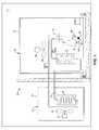
- a heat pump system 10may include an indoor unit 12 and a compressor system 14 .
- a heat pump systemis used for illustration purposes only, and it should be understood that the present teachings apply to any application in which a compressor may be utilized.
- a compressormay alternatively be used in an air conditioning system, a refrigeration system, or generally in any system in which a refrigerant is compressed to provide a desired heating or cooling effect.
- compressor system 14has been depicted as including the components described below, compressor system 14 may be any group of components that is packaged as a unit with compressor 32 .
- Indoor unit 12may include an indoor coil or heat exchanger 16 and a variable speed indoor fan 18 driven by a motor 20 .
- Indoor coil 16 and fan 18may be enclosed in a cabinet 22 so that fan 18 forces ambient air across indoor coil 16 .
- Compressor system 14may include an outdoor coil or heat exchanger 24 and a variable speed outdoor fan 26 driven by a motor 28 .
- Outdoor coil 24 and fan 26may be enclosed in a protective housing 30 so that fan 26 will draw ambient outdoor air across outdoor coil 24 to improve heat transfer.
- Compressor system 14may further include a compressor 32 in communication with indoor coil 16 and outdoor coil 24 .
- Compressor 32may include inverter drive 36 and terminal box 38 .
- Inverter drive 36may be fixedly attached to a shell of compressor 32 and may provide a variable input power to a motor of compressor 32 , allowing compressor 32 to operate at a variable speed (i.e., frequency).
- Terminal box 38may be fixedly attached to a shell of compressor 32 and may provide an input point for electrical, communication and other inputs to compressor 32 .
- Accelerometer 40 and control module 42are depicted as mounted to inverter drive 36 .
- Accelerometer 40may measure acceleration and may alternatively be mounted to a shell of compressor 32 , terminal box 38 , or other locations within heat pump system 10 .
- Control module 42may be integral to inverter drive 32 .
- Control module 42may receive a signal from accelerometer 40 and control the output of inverter drive 36 .
- Communication between compressor 32 , indoor coil 16 , and outdoor coil 24may generally form a loop, wherein compressor 32 , indoor coil 16 , and outdoor coil 24 are arranged in series with one another with an expansion device 33 located between indoor coil 16 and outdoor coil 24 .
- the heat pump system 10may include a reversing valve 34 disposed between compressor 32 and indoor and outdoor coils 16 , 24 , such that the direction of flow between compressor 32 , indoor coil 16 , and outdoor coil 24 may be reversed between first and second directions.
- heat pump system 10operates in a cooling mode providing a flow in a direction indicated by the “cooling” arrow.
- compressor 32provides a fluid to outdoor coil 24 .
- the fluidthen travels to indoor coil 16 and then back to compressor 32 .
- indoor coil 16functions as an evaporator coil and outdoor coil 24 functions as a condenser coil.
- heat pump system 10operates in a heating mode providing a flow in a direction indicated by the “heating” arrow.
- flowis reversed, traveling from compressor 32 to indoor coil 16 to outdoor coil 24 , and then back to compressor 32 .
- indoor coil 16functions as a condenser coil and outdoor coil 24 functions as an evaporator coil.
- control module 42may include frequency control module 140 , frequency module 142 , and storage module 144 .
- Frequency module 142may be in communication with an output from accelerometer 40 as well as other sensors 120 from heat pump system 10 and other control modules 122 from heat pump system 10 such as a compressor controller or system controller.
- Frequency module 142may be in communication with storage module 144 and frequency control module 140 .
- Storage module 144may receive measured or determined values from frequency module 142 and may store those values. Storage module 144 may also contain predetermined values and thresholds. Frequency control module 140 may be in communication with frequency module 142 and may control inverter drive 36 to operate a motor of compressor 32 at a chosen frequency. Although control module 42 is depicted as separate from inverter drive 36 , it should be recognized that control module 42 may be integral to inverter drive 36 .
- Compressor 32may be driven by a motor (not shown) and compressor system 14 may experience vibrations. Vibrations experienced by compressor system 14 may be defined in different manners including, but not limited to, an amplitude of the vibration, a maximum velocity of the system 14 , or as a maximum acceleration of the system 14 .
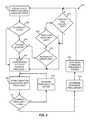
- Control logic 200depicts a continuous loop, but for purposes of the present disclosure description of control logic 200 will begin at block 201 .
- the compressor 32 of compressor system 14may operate at steady state until a sweep check is initiated.
- steady state operationmay include control module 42 operating compressor 32 to avoid prohibited frequency ranges while a frequency sweep is not being performed.
- a sweep checkmay be initiated in response to a flag from an input, at a regular time interval, at an electronic clock interval, or as a regular portion of a programmed subroutine. When the sweep check is initiated, control logic 200 may continue to block 202 .
- frequency module 142may determine whether it is necessary to run a frequency sweep to determine vibration characteristics of the compressor.
- frequency module 142may determine whether the compressor system 14 has transitioned from OFF to ON. The ability to determine the compressor system 14 OFF or ON state may be internal to frequency module 142 or may be determined from communications with other sensors 120 or other control modules 122 . If the compressor system 14 state has changed from OFF to ON, control logic 200 may continue to block 206 . If the compressor system 14 state has not changed from OFF to ON, control logic 200 may continue to block 204 .
- frequency module 142may determine whether a change in the operating mode of heat pump system 10 has occurred. This may occur when heat pump system 10 switches from heating to cooling mode or vice versa. Frequency module 142 may communicate with other control modules 122 or other sensors 120 to determine whether the mode has changed. If there has been a change in mode, control logic 200 may continue to step 206 . If there has not been a change in mode, control logic 200 may continue to step 220 .
- frequency module 142may determine whether an input from accelerometer 40 exceeds a sweep limit.
- Ymay be a maximum amplitude of motion that may not be exceeded at any rotational frequency of the compressor, where the frequency is represented by the variable F in hertz (Hz).
- An example Y valuemay be 25 ⁇ 10 ⁇ 6 meters.
- frequency module 142may compare accelerometer output 40 to a maximum amplitude A for the current operating frequency of the motor of compressor 32 .
- control logic 200may continue to block 206 .
- control logicmay continue to step 222 .
- frequency module 142may determine the time since the last frequency sweep was performed. In many situations, a heat pump system 10 may operate for an extended period without shutting down or without other conditions that may initiate a frequency sweep. Accordingly, frequency module 142 may determine the time since the last frequency sweep and may access a predetermined time value such as one week from storage module 144 . If the elapsed time since the last frequency sweep exceeds the predetermined time, control logic 200 may continue to block 206 . If the elapsed time since the last frequency sweep does not exceed the predetermined limit, control logic 200 may continue to block 224 .
- frequency module 142may receive an ambient temperature.
- a temperature sensormay be integral to control module 142 or a temperature value may be read from other sensors 120 .
- frequency module 142may communicate with other control modules 122 of heat pump system 10 which may measure an ambient temperature value.
- Frequency module 142may access storage module 144 to acquire previously stored temperature values and a predetermined temperature change limit. For example, previous temperature values may be stored for 24 hours and a predetermined temperature change limit may be at least 40 degrees Fahrenheit. Frequency module 142 may compare the measured temperature with stored temperature values from the previous 24 hours and if the difference between any set of temperature readings exceeds the predetermined temperature change limit, control logic 200 may continue to block 206 . If the temperature difference does not exceed 40 degrees Fahrenheit, control logic 200 may return to block 201 to continue steady state operation.
- the frequency sweep routinemay begin.
- Frequency module 142may receive a minimum sweep frequency and a maximum sweep frequency from storage module 144 .
- Frequency module 142may communicate with frequency control module 140 to operate inverter drive 36 to operate a motor of compressor 32 at the minimum sweep frequency.
- Control logic 200may continue to block 208 .
- frequency module 142may receive an accelerometer output 40 associated with the commanded frequency.
- Frequency module 142may store the accelerometer and frequency values at storage module 144 .
- Control logic 200may continue to block 210 .
- frequency module 142may determine whether the present operating frequency is at least the maximum sweep frequency. If the present operating frequency is not at least the maximum sweep frequency, control logic 200 may continue to block 212 . At block 212 , frequency module 142 may increment the current frequency of operation of the motor to a higher value to continue the frequency sweep. Frequency control module 140 may control inverter drive 36 such that the motor of compressor 32 operates at the incremented frequency. In this manner, blocks 208 , 210 , and 212 may loop until the frequency sweep is complete and store the frequency values and associated accelerometer 40 acceleration readings. Once the operating frequency reaches the maximum sweep frequency, control logic 200 may continue to block 214 .
- frequency module 142may determine the resonant frequencies from the stored acceleration and frequency values in storage module 144 .
- a resonant or natural frequencymay also be found within a given frequency range where a local maximum displacement or velocity amplitude occurs within the given range.
- Frequency module 142may store the resonant frequencies in storage module 144 .
- frequency module 142may determine a prohibited frequency range such that frequency control module 140 will not operate inverter drive 36 to operate the motor of compressor 32 at any frequency within the prohibited frequency range in steady-state mode.
- the prohibited frequency rangemay be a range defined by the resonant frequency plus or minus a critical frequency difference (CFD), which for a typical compressor may be at least 1 hertz (Hz). This CFD may be approximately 1.5 percent of the particular resonant frequency encountered based on the following relationship.
- Undesirable vibrationsmay occur when the f o value is within 1.5 percent of f n as represented by the following equation of
- the prohibited frequency rangecan be the actual ranges where the measured acceleration exceeds the maximum A.
- Frequency module 142may store the prohibited frequency ranges in storage module 144 . It should be noted that the steps described in blocks 214 and 216 may also be performed as part of the loop of blocks 208 , 210 and 212 , wherein blocks 214 and 216 may calculate the resonant frequencies and forbidden frequency ranges during the frequency sweep. Control logic 200 may return to block 201 to operate at steady state.
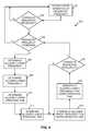
- control logic for operating a motor of compressor 32 at a requested frequencyis depicted.
- a requested frequencymay be based on an input from a user such as to change the heating or cooling effect of the heat pump system 10 or may be based on an output of other control modules 122 of heat pump system 10 such as a thermostat.
- control logic 300depicts a continuous loop, control logic 300 is a subloop of overall steady state operation demonstrating a response to a changed requested frequency. Description of control logic 300 will begin at block 301 .
- frequency module 142upon receiving a command from other controllers 122 , may command frequency control module 140 to operate inverter drive 36 to operate a motor of compressor 32 at a previously requested frequency. Otherwise, steady state operation may continue until the requested frequency changes.
- control logic 300may continue to block 304 .
- frequency module 142may compare the requested frequency to the prohibited frequency values stored in storage module 144 . If the requested frequency value is not within the prohibited frequency ranges, control logic 300 may return to steady state operation at block 301 . If the requested frequency value is within the prohibited frequency ranges, control logic 300 may continue to block 306 .
- frequency module 142may receive an allowed upper frequency from storage module 144 .
- This allowed upper frequencymay be a first frequency above the requested frequency but outside of the prohibited frequency range.
- the allowed upper frequencymay also include a safety factor above this first frequency.
- frequency module 142may receive an allowed lower frequency from storage module 144 .
- This allowed lower frequencymay be a first frequency below the requested frequency but outside of the prohibited frequency range.
- the allowed lower frequencymay also include a safety factor below this first frequency.
- frequency module 142may access a predetermined time value from storage module 144 .
- the predetermined time valuemay correspond to a total time during which the frequency averaging routine described below may be run. For example, the total time may be four minutes.
- frequency module 142may use the predetermined time and calculated upper frequency operating time to determine the lower frequency operating time.
- frequency module 142may command frequency control module 140 to operate inverter drive 36 and the motor of compressor 32 at the allowed upper frequency and continue to operate at that frequency for the upper frequency operating time. Once the upper frequency operating time has elapsed, control logic 300 may continue to block 316 . At block 316 , frequency module 142 may command frequency control module 140 to operate inverter drive 36 and the motor of compressor 32 at the allowed lower frequency for the lower frequency operating time. Once the lower frequency operating time is complete, the time-averaged frequency output of the compressor over the total predetermined time may be equal to the requested frequency. Control logic 300 may then continue to block 318 .
- frequency module 142may determine whether there has been change in the requested frequency. If there has not been a change in the requested frequency, control logic 300 may return to block 314 and continue to loop through operating at the allowed upper frequency and allowed lower frequency such that the average frequency is equivalent to the requested frequency. If there has been a change in the requested frequency, control logic 300 may continue to block 304 to determine whether the requested frequency is prohibited.
- frequency module 142may determine the allowed frequency furthest from the requested frequency.
- the motor of compressor 32may be operated by inverter drive 36 and frequency control module 140 at this frequency for a predetermined time.
- Frequency module 142may then determine a second operating frequency in the opposite (greater than or less than) direction from the first operating frequency.
- the second operating frequencymay be at a same frequency difference from the requested frequency as the first operating frequency.
- the motor of compressor 32may then be operated by inverter drive 36 and frequency module 140 at the second frequency for the same predetermined time as the first operating frequency because the differences between the requested frequency and the two operating frequencies are the same.
- FIG. 5alternative steps for variable speed compressor vibration protection are depicted.
- the steps described in FIG. 3 and FIG. 4show performing a frequency sweep based on certain conditions, storing prohibited frequency ranges, and avoiding these frequency ranges during normal operation.
- control logic 400depicts operation in a continuous loop
- the description of control logic 400may begin with block 401 .
- frequency module 142may command frequency control module 140 to operate inverter drive 36 to operate the motor of compressor 32 at a requested frequency. Operation may continue in this manner until a check of an acceleration value from accelerometer 40 is initiated. A check may be initiated in a number of ways, such as with each change in requested frequency, at a predetermined time interval, or whenever an acceleration value is received. Control logic 400 may continue to block 402 .
- frequency module 142may command frequency control module 140 to operate inverter drive 36 such that a motor of compressor 32 operates at a higher frequency.
- This first frequency at which the measured acceleration does not exceed the acceleration limitmay be the allowed upper frequency.
- the allowed upper frequencymay also be this first measured frequency plus a safety factor. Once the allowed upper frequency is determined, control logic 400 may continue to block 408 .
- frequency module 142may command frequency control module 140 to operate inverter drive 36 such that a motor of compressor 32 operates at a frequency less than the requested frequency.
- This first frequency at which the measured acceleration does not exceed the acceleration limitmay be the allowed lower frequency.
- the allowed lower frequencymay also be this first measured frequency minus a safety factor.
- frequency module 142may access a predetermined time value from storage module 144 .
- the predetermined time valuemay correspond to a total time during which the frequency averaging routine described below may be run. For example, the total time may be four minutes.
- frequency module 142may use the predetermined time and calculated upper operating time to determine the lower frequency operating time.
- frequency module 142may command frequency control module 140 to operate inverter drive 36 and the motor of compressor 32 at the allowed upper frequency and continue to operate at that frequency for the upper frequency operating time. Once the upper frequency operating time has elapsed, control logic 400 may continue to block 416 . At block 416 , frequency module 142 may command frequency control module 140 to operate inverter drive 36 and the motor of compressor 32 at the allowed lower frequency for the lower frequency operating time. Once the lower frequency operating time is complete, control logic 400 may continue to block 418 .
- frequency module 142may determine whether there has been change in the requested frequency. If there has not been a change in the requested frequency, control logic 400 may return to block 414 and continue to loop through operating at the allowed upper frequency and allowed lower frequency such that the average frequency is equivalent to the requested frequency. If a change in the requested frequency has occurred, control logic 400 may continue to block 420 . At block 420 , frequency module 142 may command frequency control module 140 to operate inverter drive 36 and the motor of compressor 32 at the new requested frequency. Control logic 400 may continue to block 401 to operate at steady state until the next check of the accelerometer.
Landscapes
- Engineering & Computer Science (AREA)
- Mechanical Engineering (AREA)
- General Engineering & Computer Science (AREA)
- Physics & Mathematics (AREA)
- General Physics & Mathematics (AREA)
- Automation & Control Theory (AREA)
- Computer Hardware Design (AREA)
- Air Conditioning Control Device (AREA)
- Control Of Positive-Displacement Pumps (AREA)
- Control Of Ac Motors In General (AREA)
- Control Of Motors That Do Not Use Commutators (AREA)
Abstract
Description
Claims (18)
Priority Applications (1)
| Application Number | Priority Date | Filing Date | Title |
|---|---|---|---|
| US14/499,849US9683563B2 (en) | 2007-10-05 | 2014-09-29 | Vibration protection in a variable speed compressor |
Applications Claiming Priority (4)
| Application Number | Priority Date | Filing Date | Title |
|---|---|---|---|
| US97785907P | 2007-10-05 | 2007-10-05 | |
| US12/244,528US7895003B2 (en) | 2007-10-05 | 2008-10-02 | Vibration protection in a variable speed compressor |
| US12/983,615US8849613B2 (en) | 2007-10-05 | 2011-01-03 | Vibration protection in a variable speed compressor |
| US14/499,849US9683563B2 (en) | 2007-10-05 | 2014-09-29 | Vibration protection in a variable speed compressor |
Related Parent Applications (1)
| Application Number | Title | Priority Date | Filing Date |
|---|---|---|---|
| US12/983,615ContinuationUS8849613B2 (en) | 2007-10-05 | 2011-01-03 | Vibration protection in a variable speed compressor |
Publications (2)
| Publication Number | Publication Date |
|---|---|
| US20150051742A1 US20150051742A1 (en) | 2015-02-19 |
| US9683563B2true US9683563B2 (en) | 2017-06-20 |
Family
ID=40523968
Family Applications (3)
| Application Number | Title | Priority Date | Filing Date |
|---|---|---|---|
| US12/244,528Active2029-04-16US7895003B2 (en) | 2007-10-05 | 2008-10-02 | Vibration protection in a variable speed compressor |
| US12/983,615Active2031-03-10US8849613B2 (en) | 2007-10-05 | 2011-01-03 | Vibration protection in a variable speed compressor |
| US14/499,849Active2029-12-08US9683563B2 (en) | 2007-10-05 | 2014-09-29 | Vibration protection in a variable speed compressor |
Family Applications Before (2)
| Application Number | Title | Priority Date | Filing Date |
|---|---|---|---|
| US12/244,528Active2029-04-16US7895003B2 (en) | 2007-10-05 | 2008-10-02 | Vibration protection in a variable speed compressor |
| US12/983,615Active2031-03-10US8849613B2 (en) | 2007-10-05 | 2011-01-03 | Vibration protection in a variable speed compressor |
Country Status (6)
| Country | Link |
|---|---|
| US (3) | US7895003B2 (en) |
| EP (1) | EP2198157B1 (en) |
| KR (1) | KR101213992B1 (en) |
| CN (1) | CN101821505B (en) |
| ES (1) | ES2643319T3 (en) |
| WO (1) | WO2009045495A1 (en) |
Cited By (4)
| Publication number | Priority date | Publication date | Assignee | Title |
|---|---|---|---|---|
| US20200240689A1 (en)* | 2019-01-30 | 2020-07-30 | Lennox Industries Inc. | Method and apparatus for preventing component malfunction using accelerometers |
| US10962009B2 (en) | 2007-10-08 | 2021-03-30 | Emerson Climate Technologies, Inc. | Variable speed compressor protection system and method |
| US11060776B2 (en) | 2019-03-27 | 2021-07-13 | Follett Corporation | Method for controlling a refrigeration device |
| US11206743B2 (en) | 2019-07-25 | 2021-12-21 | Emerson Climate Technolgies, Inc. | Electronics enclosure with heat-transfer element |
Families Citing this family (45)
| Publication number | Priority date | Publication date | Assignee | Title |
|---|---|---|---|---|
| US7895003B2 (en) | 2007-10-05 | 2011-02-22 | Emerson Climate Technologies, Inc. | Vibration protection in a variable speed compressor |
| US8950206B2 (en) | 2007-10-05 | 2015-02-10 | Emerson Climate Technologies, Inc. | Compressor assembly having electronics cooling system and method |
| US8448459B2 (en) | 2007-10-08 | 2013-05-28 | Emerson Climate Technologies, Inc. | System and method for evaluating parameters for a refrigeration system with a variable speed compressor |
| US9541907B2 (en) | 2007-10-08 | 2017-01-10 | Emerson Climate Technologies, Inc. | System and method for calibrating parameters for a refrigeration system with a variable speed compressor |
| US8539786B2 (en) | 2007-10-08 | 2013-09-24 | Emerson Climate Technologies, Inc. | System and method for monitoring overheat of a compressor |
| US8418483B2 (en) | 2007-10-08 | 2013-04-16 | Emerson Climate Technologies, Inc. | System and method for calculating parameters for a refrigeration system with a variable speed compressor |
| JP5899407B2 (en)* | 2011-07-22 | 2016-04-06 | パナソニックIpマネジメント株式会社 | refrigerator |
| KR101772083B1 (en)* | 2012-01-30 | 2017-08-28 | 엘지전자 주식회사 | Apparatus for controlling compressor and refrigerator having the same |
| EP2717000B1 (en)* | 2012-10-08 | 2020-08-26 | Emerson Climate Technologies GmbH | Refrigeration system and method for operating said refrigeration system |
| US10208978B2 (en)* | 2012-11-08 | 2019-02-19 | Lennox Industries Inc. | System for generating electrical energy from waste energy |
| CN103912956B (en)* | 2013-01-04 | 2016-12-28 | 广东美的制冷设备有限公司 | Convertible frequency air-conditioner and resonance point jump adaptive approach thereof |
| KR102037290B1 (en)* | 2013-01-29 | 2019-10-28 | 엘지전자 주식회사 | Device and method for reducing vibration in compressor |
| US10145589B2 (en)* | 2013-03-15 | 2018-12-04 | Whirlpool Corporation | Net heat load compensation control method and appliance for temperature stability |
| US9817408B2 (en) | 2013-07-30 | 2017-11-14 | Trane International Inc. | Vibration control for a variable speed cooling system |
| US9473060B2 (en)* | 2014-08-11 | 2016-10-18 | Nidec Motor Corporation | Motor control system and method for skipping resonant operating frequencies |
| CN104535174B (en)* | 2014-12-05 | 2019-01-29 | 苏州汇川技术有限公司 | A kind of mechanical resonance detection device and method |
| CN104697260B (en)* | 2015-02-13 | 2017-03-22 | 广东芬尼克兹节能设备有限公司 | Control method for frequency adjustment point of heat pump unit |
| KR102295969B1 (en)* | 2015-03-24 | 2021-08-30 | 엘지전자 주식회사 | Air-conditioner and method for thereof |
| EP3101278B1 (en)* | 2015-06-03 | 2021-04-28 | ABB Schweiz AG | Active damping of oscillations in a control process |
| US20180291901A1 (en)* | 2015-11-13 | 2018-10-11 | Hitachi Industrial Equipment Systems Co., Ltd. | Gas Compressor |
| DE102016206337B4 (en)* | 2015-12-23 | 2022-03-24 | Brose Fahrzeugteile SE & Co. Kommanditgesellschaft, Würzburg | Method for operating an electric motor auxiliary unit and electric motor refrigerant compressor of a motor vehicle |
| CN106930964B (en)* | 2015-12-31 | 2018-10-12 | 华为技术有限公司 | Piezoelectric fan intrinsic frequency measurement method and piezoelectric fan |
| JP6524335B2 (en)* | 2016-03-14 | 2019-06-05 | 三菱電機株式会社 | Air conditioner |
| CN107816836A (en)* | 2016-09-12 | 2018-03-20 | 澄光绿能科技有限公司 | Cooling circulation system capable of accurately controlling temperature to cool processing medium |
| CN106895660A (en)* | 2017-02-06 | 2017-06-27 | 安徽美芝制冷设备有限公司 | Frequency conversion refrigerator and its control system and control method |
| CN107436018B (en)* | 2017-08-09 | 2019-01-29 | 珠海格力电器股份有限公司 | Control method and device for improving air column resonance of air conditioner piping and air conditioner |
| CN107387382B (en)* | 2017-08-31 | 2019-06-04 | 广东美芝制冷设备有限公司 | Control method, compressor assembly and the refrigeration equipment of compressor amplitude |
| CN107883626A (en)* | 2017-11-27 | 2018-04-06 | 珠海格力电器股份有限公司 | Refrigerant circulation system and control method thereof |
| CN108253590B (en)* | 2018-01-09 | 2021-03-19 | 广东美的制冷设备有限公司 | Variable frequency air conditioner, resonance point judgment method of compressor of variable frequency air conditioner and storage medium |
| US11313568B2 (en)* | 2018-01-20 | 2022-04-26 | Daikin Industries, Ltd. | System and method for heating and cooling |
| CN110281730B (en)* | 2018-03-19 | 2024-11-26 | 开利公司 | Resonance Mitigation in Transport Refrigeration Units |
| CN110030683B (en)* | 2019-03-11 | 2021-11-26 | 青岛海尔空调电子有限公司 | Control method for air conditioner |
| US11946671B2 (en)* | 2019-07-15 | 2024-04-02 | Ecoer Inc. | Heat pump system and control method |
| CN112576488B (en)* | 2019-09-29 | 2023-02-21 | 广东芬尼克兹节能设备有限公司 | Frequency adjusting method, device and equipment of variable frequency compressor and storage medium |
| CN110779612A (en)* | 2019-11-13 | 2020-02-11 | 深圳天祥质量技术服务有限公司 | Method and device for measuring pipeline of refrigeration system |
| CN112009199A (en)* | 2020-08-20 | 2020-12-01 | 珠海格力电器股份有限公司 | Vehicle-mounted air conditioner control method and device, vehicle-mounted air conditioner and storage medium |
| CN114383378A (en)* | 2020-10-20 | 2022-04-22 | 青岛海尔电冰箱有限公司 | Noise reduction method for refrigeration system, refrigeration device and computer storage medium |
| CN113153452B (en)* | 2021-04-26 | 2022-10-14 | 大唐湘潭发电有限责任公司 | Method for solving large unit vibration in starting process of steam turbine unit |
| US20230025205A1 (en)* | 2021-07-20 | 2023-01-26 | Haier Us Appliance Solutions, Inc. | System and method for operating a variable speed compressor of an air conditioner unit |
| CN114382678B (en)* | 2022-01-14 | 2024-08-20 | 四川奥库科技有限公司 | Vibration avoidance method for variable frequency compressor |
| DE102022200475A1 (en) | 2022-01-18 | 2023-07-20 | Robert Bosch Gesellschaft mit beschränkter Haftung | Heat pump device, heat pump with such a heat pump device and method for operating such a heat pump device |
| CN114754523A (en)* | 2022-04-13 | 2022-07-15 | 青岛海尔空调器有限总公司 | Air conditioner frequency hopping point determination method, device, electronic device and storage medium |
| JP2025527605A (en) | 2022-09-06 | 2025-08-22 | ニデック グローバル アプライアンス ブラジル リミターダ | Method and system for controlling vibrations in a variable displacement compressor of a refrigeration system |
| CN115434905A (en)* | 2022-10-12 | 2022-12-06 | 杰瑞石油天然气工程有限公司 | Compressor unit and control method thereof |
| CN118309642A (en)* | 2022-12-30 | 2024-07-09 | 丹佛斯(天津)有限公司 | Control method for compressor and compressor system |
Citations (319)
| Publication number | Priority date | Publication date | Assignee | Title |
|---|---|---|---|---|
| US2883255A (en) | 1954-04-28 | 1959-04-21 | Panellit Inc | Automatic process logging system |
| US2981076A (en) | 1958-06-30 | 1961-04-25 | Gen Motors Corp | Refrigerating apparatus |
| US3082609A (en) | 1957-02-12 | 1963-03-26 | Carrier Corp | Air conditioning system for aircraft |
| US3242321A (en) | 1965-02-11 | 1966-03-22 | Industrial Nucleonics Corp | Automatic machine analyzer |
| US3265948A (en) | 1964-08-31 | 1966-08-09 | Gen Motors Corp | Machine control system |
| US3600657A (en) | 1970-06-17 | 1971-08-17 | Jeanne Pfaff | Method and apparatus for electronic sensing of motor torque |
| US4130997A (en) | 1975-12-10 | 1978-12-26 | Hitachi, Ltd. | Refrigerator |
| JPS55155134A (en) | 1979-05-21 | 1980-12-03 | Toshiba Corp | Air conditioner |
| US4280910A (en) | 1980-03-10 | 1981-07-28 | Baumann Edward J | Method and apparatus for controlling aeration in biological treatment processes |
| US4370564A (en) | 1980-06-04 | 1983-01-25 | Ricoh Company, Ltd. | AC Switching device |
| US4448038A (en) | 1979-10-01 | 1984-05-15 | Sporlan Valve Company | Refrigeration control system for modulating electrically-operated expansion valves |
| US4460861A (en) | 1983-01-21 | 1984-07-17 | Westinghouse Electric Corp. | Control system for machine commutated inverter-synchronous motor drives |
| US4461153A (en) | 1980-11-24 | 1984-07-24 | Deutsche Forschungs- und Versuchanstalt fur Luft- und Raumfahrt e.V. | Method and apparatus for inoculating crystallization seeds into a liquid latent heat storage substance |
| US4507936A (en) | 1983-08-19 | 1985-04-02 | System Homes Company Ltd. | Integral solar and heat pump water heating system |
| US4527399A (en) | 1984-04-06 | 1985-07-09 | Carrier Corporation | High-low superheat protection for a refrigeration system compressor |
| JPS61272483A (en) | 1985-05-29 | 1986-12-02 | Toshiba Corp | Refrigerating cycle device |
| US4653280A (en) | 1985-09-18 | 1987-03-31 | Hansen John C | Diagnostic system for detecting faulty sensors in a refrigeration system |
| JPS6277539A (en) | 1985-09-27 | 1987-04-09 | Mitsubishi Electric Corp | inverter air conditioner |
| US4706469A (en) | 1986-03-14 | 1987-11-17 | Hitachi, Ltd. | Refrigerant flow control system for use with refrigerator |
| US4750338A (en) | 1986-04-04 | 1988-06-14 | Bodenseewerk Geratetchnik Gmbh | Device for cooling a detector, particularly in an optical seeker |
| JPH01167556A (en) | 1987-12-22 | 1989-07-03 | Mitsubishi Electric Corp | Refrigerant equipment |
| JPH024163A (en) | 1988-03-08 | 1990-01-09 | Mitsubishi Electric Corp | Cooling device for power semiconductor devices |
| US4940929A (en) | 1989-06-23 | 1990-07-10 | Apollo Computer, Inc. | AC to DC converter with unity power factor |
| US4974427A (en) | 1989-10-17 | 1990-12-04 | Copeland Corporation | Compressor system with demand cooling |
| JPH03129255A (en) | 1989-10-13 | 1991-06-03 | Hitachi Ltd | Refrigeration equipment |
| US5056712A (en) | 1989-12-06 | 1991-10-15 | Enck Harry J | Water heater controller |
| US5058389A (en) | 1989-04-17 | 1991-10-22 | Hitachi, Ltd. | Fluid temperature control system and computer system using same |
| JPH04344073A (en) | 1991-05-21 | 1992-11-30 | Toyota Autom Loom Works Ltd | Controlling method for drive of cooling circuit |
| US5182918A (en) | 1991-11-26 | 1993-02-02 | Spx Corporation | Refrigerant recovery system |
| US5203178A (en) | 1990-10-30 | 1993-04-20 | Norm Pacific Automation Corp. | Noise control of air conditioner |
| US5255529A (en) | 1990-09-14 | 1993-10-26 | Nartron Corporation | Environmental control system |
| US5258901A (en) | 1992-03-25 | 1993-11-02 | At&T Bell Laboratories | Holdover circuit for AC-to-DC converters |
| JPH05322224A (en) | 1992-05-26 | 1993-12-07 | Mitsubishi Electric Corp | Air conditioner |
| US5269146A (en) | 1990-08-28 | 1993-12-14 | Kerner James M | Thermoelectric closed-loop heat exchange system |
| US5291115A (en) | 1992-09-25 | 1994-03-01 | The Texas A&M University System | Method and apparatus for sensing the rotor position of a switched reluctance motor without a shaft position sensor |
| US5315214A (en) | 1992-06-10 | 1994-05-24 | Metcal, Inc. | Dimmable high power factor high-efficiency electronic ballast controller integrated circuit with automatic ambient over-temperature shutdown |
| JPH06159738A (en) | 1992-11-25 | 1994-06-07 | Daikin Ind Ltd | Device for cooling heat generating element of air conditioner |
| US5347467A (en) | 1992-06-22 | 1994-09-13 | Compressor Controls Corporation | Load sharing method and apparatus for controlling a main gas parameter of a compressor station with multiple dynamic compressors |
| US5359276A (en) | 1993-05-12 | 1994-10-25 | Unitrode Corporation | Automatic gain selection for high power factor |
| US5359281A (en) | 1992-06-08 | 1994-10-25 | Motorola, Inc. | Quick-start and overvoltage protection for a switching regulator circuit |
| JPH0735393A (en) | 1993-07-21 | 1995-02-07 | Toshiba Corp | Air conditioner |
| US5410221A (en) | 1993-04-23 | 1995-04-25 | Philips Electronics North America Corporation | Lamp ballast with frequency modulated lamp frequency |
| US5425246A (en) | 1994-03-03 | 1995-06-20 | General Electric Company | Refrigerant flow rate control based on evaporator dryness |
| US5426952A (en) | 1994-03-03 | 1995-06-27 | General Electric Company | Refrigerant flow rate control based on evaporator exit dryness |
| US5428965A (en) | 1993-12-10 | 1995-07-04 | Whirlpool Corporation | Motor control for refrigeration appliance |
| US5440218A (en) | 1994-07-13 | 1995-08-08 | General Electric Company | Reversible switched reluctance motor operating without a shaft position sensor |
| WO1995023944A1 (en) | 1994-03-03 | 1995-09-08 | General Electric Company | Refrigerant flow rate control based on liquid level in dual evaporator two-stage refrigeration cycles |
| US5502970A (en) | 1995-05-05 | 1996-04-02 | Copeland Corporation | Refrigeration control using fluctuating superheat |
| US5506930A (en) | 1993-08-11 | 1996-04-09 | Fuji Electric Co., Ltd. | Control apparatus for a variable speed motor |
| US5519300A (en) | 1993-06-29 | 1996-05-21 | Liberty Technologies, Inc. | Method and apparatus for analysis of polyphase electrical motor systems |
| US5524449A (en) | 1992-05-29 | 1996-06-11 | Daikin Industries, Ltd. | System for controlling operation of refrigeration device |
| KR960024115A (en) | 1994-12-14 | 1996-07-20 | 전성원 | Apparatus and Method for Predicting Cooling Performance of Refrigerant Compression Refrigeration Cycle |
| WO1997002729A1 (en) | 1995-07-06 | 1997-01-23 | Danfoss A/S | Compressor with control electronics |
| JPH0926246A (en) | 1995-07-07 | 1997-01-28 | Matsushita Refrig Co Ltd | Control device for refrigerator |
| US5603222A (en) | 1995-06-09 | 1997-02-18 | Dube; Serge | Cooling method and system for a compressor of a refrigerating system |
| US5603227A (en) | 1995-11-13 | 1997-02-18 | Carrier Corporation | Back pressure control for improved system operative efficiency |
| US5646499A (en) | 1994-08-25 | 1997-07-08 | Matsushita Electric Industrial Co.,Ltd. | Inverter control apparatus |
| JPH09196524A (en) | 1996-01-16 | 1997-07-31 | Mitsubishi Heavy Ind Ltd | Trouble diagnostic device of refrigerating equipment |
| US5663627A (en) | 1994-07-26 | 1997-09-02 | Fujitsu General Limited | Control apparatus for controlling motor of air conditioner |
| JPH109683A (en) | 1996-06-26 | 1998-01-16 | Toshiba Corp | Air conditioner |
| US5712802A (en) | 1996-04-16 | 1998-01-27 | General Electric Company | Thermal protection of traction inverters |
| US5712551A (en) | 1994-12-02 | 1998-01-27 | Samsung Electronics Co., Ltd. | Starting circuit protection apparatus and method for brushless DC motor compressor |
| JPH1097331A (en) | 1996-09-25 | 1998-04-14 | Tokyo Gas Co Ltd | Reactive power control device |
| US5742103A (en) | 1995-10-27 | 1998-04-21 | Dell U.S.A., L.P. | External line harmonics reduction module for power supplies |
| JPH10153353A (en) | 1996-09-27 | 1998-06-09 | Toshiba Corp | Air conditioner |
| JPH10160271A (en) | 1996-11-26 | 1998-06-19 | Hitachi Ltd | Air conditioner |
| US5786992A (en) | 1994-04-08 | 1998-07-28 | Vlt Corporation | Efficient power conversion |
| JPH1123075A (en) | 1997-07-08 | 1999-01-26 | Denso Corp | Heat generating body cooling device |
| WO1999011987A1 (en) | 1997-08-28 | 1999-03-11 | Empresa Brasileira De Compressores S.A. - Embraco | A refrigeration circuit arrangement for a refrigeration system |
| WO1999013225A1 (en) | 1997-09-05 | 1999-03-18 | American Standard Inc. | Oil flow protection scheme |
| US5903138A (en) | 1995-03-30 | 1999-05-11 | Micro Linear Corporation | Two-stage switching regulator having low power modes responsive to load power consumption |
| JPH11159895A (en) | 1997-11-28 | 1999-06-15 | Hitachi Ltd | Air conditioner |
| US5960207A (en) | 1997-01-21 | 1999-09-28 | Dell Usa, L.P. | System and method for reducing power losses by gating an active power factor conversion process |
| US5963442A (en) | 1997-12-26 | 1999-10-05 | Matsushita Electric Industrial Co., Ltd. | Inverter system for driving motor |
| JPH11287497A (en) | 1998-03-31 | 1999-10-19 | Toyotomi Co Ltd | Controller of air conditioner |
| US6005365A (en) | 1997-05-21 | 1999-12-21 | Hitachi, Ltd. | Motor control apparatus |
| JP2000002496A (en) | 1998-06-17 | 2000-01-07 | Zexel Corp | Condenser fixing unit |
| US6028406A (en) | 1996-07-16 | 2000-02-22 | Danfoss A/S | Method for commutating a brushless motor and power supply for a brushless motor |
| US6035653A (en) | 1997-04-17 | 2000-03-14 | Denso Corporation | Air conditioner |
| US6065298A (en) | 1997-06-20 | 2000-05-23 | Sharp Kabushiki Kaisha | Air conditioner automatically controlling operation based on supply voltage or supply frequency |
| US6073457A (en) | 1997-03-28 | 2000-06-13 | Behr Gmbh & Co. | Method for operating an air conditioner in a motor vehicle, and an air conditioner having a refrigerant circuit |
| DE19859340A1 (en) | 1998-12-22 | 2000-07-06 | Mannesmann Vdo Ag | Electrohydraulic unit e.g. for motor vehicle steering, has dry running electric motor arranged in first of two shells of hydraulic fluid container with hydraulic pump in other shell |
| US6091215A (en) | 1998-06-02 | 2000-07-18 | Switched Reluctance Drives Limited | Trajectory controller |
| US6091233A (en) | 1999-01-14 | 2000-07-18 | Micro Linear Corporation | Interleaved zero current switching in a power factor correction boost converter |
| JP2000205630A (en) | 1999-01-12 | 2000-07-28 | Fujitsu General Ltd | Air conditioner control method |
| US6102665A (en) | 1997-10-28 | 2000-08-15 | Coltec Industries Inc | Compressor system and method and control for same |
| US6116040A (en) | 1999-03-15 | 2000-09-12 | Carrier Corporation | Apparatus for cooling the power electronics of a refrigeration compressor drive |
| US6123146A (en) | 1996-10-31 | 2000-09-26 | Valeo Electronique | Air conditioning installation with an external temperature estimator, especially for a motor vehicle |
| JP2000297970A (en) | 1999-04-14 | 2000-10-24 | Yanmar Diesel Engine Co Ltd | Controller for heat pump |
| JP2001026214A (en) | 1999-05-11 | 2001-01-30 | Denso Corp | Air conditioner for vehicle |
| US6222746B1 (en) | 1998-02-09 | 2001-04-24 | Samsung Electronics Co., Ltd. | Power supply device and method with a power factor correction circuit |
| US6220045B1 (en) | 1998-11-28 | 2001-04-24 | Lg Electronics, Inc. | Apparatus and method for controlling resonance frequency of inverter refrigerator |
| US6226998B1 (en) | 1999-03-26 | 2001-05-08 | Carrier Corporation | Voltage control using engine speed |
| DE10036378A1 (en) | 1999-10-02 | 2001-05-10 | Elanvital Corp Ping Jen | Power factor correction device has power factor correction control activated in dependence on power level of external load |
| US6236183B1 (en) | 1996-09-10 | 2001-05-22 | Societe De Mecanique Magnetique | Device for sensing the angular position for controlling a synchronous motor excited by a permanent magnet |
| US6236193B1 (en) | 1999-10-07 | 2001-05-22 | Inrange Technologies Corporation | Apparatus for voltage regulation and recovery of signal termination energy |
| KR20010044273A (en) | 2001-01-31 | 2001-06-05 | 김옥평 | Transformer for Power Saving |
| US6259614B1 (en) | 1999-07-12 | 2001-07-10 | International Rectifier Corporation | Power factor correction control circuit |
| US6281656B1 (en) | 1998-09-30 | 2001-08-28 | Hitachi, Ltd. | Synchronous motor control device electric motor vehicle control device and method of controlling synchronous motor |
| US6281658B1 (en) | 1999-01-08 | 2001-08-28 | Lg Electronics Inc. | Power factor compensation device for motor driving inverter system |
| US20010022939A1 (en) | 2000-03-17 | 2001-09-20 | Katsuyuki Morita | Electric compressor |
| EP1146299A1 (en) | 2000-04-14 | 2001-10-17 | Carrier Corporation | Integrated electronic refrigerant management system |
| US6316918B1 (en) | 1998-08-26 | 2001-11-13 | Satcon Technology Corporation | Integrated control system and method for controlling mode, synchronization, power factor, and utility outage ride-through for micropower generation systems |
| JP2001317470A (en) | 2000-05-09 | 2001-11-16 | Funai Electric Co Ltd | Frequency control device and frequency control method of air conditioner |
| US6318101B1 (en) | 2000-03-15 | 2001-11-20 | Carrier Corporation | Method for controlling an electronic expansion valve based on cooler pinch and discharge superheat |
| US6321549B1 (en) | 2000-04-14 | 2001-11-27 | Carrier Corporation | Electronic expansion valve control system |
| US6326750B1 (en) | 1999-06-17 | 2001-12-04 | Emerson Electric Co. | Active reduction of torque irregularities in rotating machines |
| JP2002013858A (en) | 2000-06-29 | 2002-01-18 | Fuji Electric Co Ltd | Control device and control method for inverter compressor |
| US6344725B2 (en) | 1999-08-20 | 2002-02-05 | Mitsubishi Denki Kabushiki Kaisha | Method and apparatus for controlling a synchronous motor |
| US6370888B1 (en) | 2000-08-31 | 2002-04-16 | Carrier Corporation | Method for controlling variable speed drive with chiller equipped with multiple compressors |
| US6373200B1 (en) | 2000-07-31 | 2002-04-16 | General Electric Company | Interface circuit and method |
| US20020047635A1 (en) | 2000-10-20 | 2002-04-25 | International Rectifier Corporation | Ballast control IC with power factor correction |
| US6396229B1 (en) | 2000-03-06 | 2002-05-28 | Hitachi, Ltd. | Method of estimating a rotor position of synchronous motor, method of controlling synchronous motor with no position sensor and a controller of synchronous motor |
| EP1209362A2 (en) | 2000-11-24 | 2002-05-29 | Kabushiki Kaisha Toyota Jidoshokki | Hermetic compressors |
| US6404154B2 (en) | 1998-06-02 | 2002-06-11 | Emerson Electric Co. | Force control system |
| US6406265B1 (en) | 2000-04-21 | 2002-06-18 | Scroll Technologies | Compressor diagnostic and recording system |
| US6414462B2 (en) | 2000-03-25 | 2002-07-02 | Lg Electronics, Inc. | Speed control apparatus for synchronous reluctance motor |
| US20020108384A1 (en) | 2001-02-15 | 2002-08-15 | Akiyoshi Higashiyama | Air conditioning systems |
| US6434960B1 (en) | 2001-07-02 | 2002-08-20 | Carrier Corporation | Variable speed drive chiller system |
| US6438978B1 (en) | 1998-01-07 | 2002-08-27 | General Electric Company | Refrigeration system |
| US20020117989A1 (en) | 2001-02-26 | 2002-08-29 | Yukio Kawabata | Starting control method of and control apparatus for synchronous motor, and air conditioner, refrigerator, washing machine and vacuum cleaner each provided with the control apparatus |
| US6446618B1 (en) | 1998-09-30 | 2002-09-10 | Orbital Engine Company (Australia) Pty Limited | Purge fuel flow rate determination method |
| US6462492B1 (en) | 1999-11-30 | 2002-10-08 | Hitachi, Ltd. | Position-sensorless controlling method of synchronous motor |
| US20020157408A1 (en) | 2001-03-05 | 2002-10-31 | Satoru Egawa | Air conditioning systems and methods for operating the same |
| US20020162339A1 (en) | 2001-05-04 | 2002-11-07 | Harrison Howard R. | High performance thermoelectric systems |
| WO2002090840A2 (en) | 2001-05-03 | 2002-11-14 | Emerson Retail Services Inc. | Method of managing a refrigeration system |
| WO2002090913A1 (en) | 2001-05-03 | 2002-11-14 | Emerson Retail Services Inc. | System for remote refrigeration monitoring and diagnostics |
| CN1382912A (en) | 2001-04-25 | 2002-12-04 | 科普兰公司 | Diagnostic system of compressor |
| US20030019221A1 (en) | 2001-05-11 | 2003-01-30 | Rossi Todd M. | Estimating operating parameters of vapor compression cycle equipment |
| KR20030011415A (en) | 2001-08-02 | 2003-02-11 | 아데나코리아(주) | Anti-power turbulence system |
| JP2003074945A (en) | 2001-08-31 | 2003-03-12 | Daikin Ind Ltd | Air conditioner |
| US6532754B2 (en) | 2001-04-25 | 2003-03-18 | American Standard International Inc. | Method of optimizing and rating a variable speed chiller for operation at part load |
| US6539734B1 (en) | 2001-12-10 | 2003-04-01 | Carrier Corporation | Method and apparatus for detecting flooded start in compressor |
| US20030077179A1 (en) | 2001-10-19 | 2003-04-24 | Michael Collins | Compressor protection module and system and method incorporating same |
| US20030085621A1 (en) | 1997-11-17 | 2003-05-08 | Potega Patrick Henry | Power supply methods and configurations |
| WO2003038987A1 (en) | 2001-11-02 | 2003-05-08 | Leopold Kostal Gmbh & Co. Kg | Method for operating a control device |
| US20030094004A1 (en) | 1995-06-07 | 2003-05-22 | Pham Hung M. | Adaptive control for a cooling system |
| JP2003156244A (en) | 2001-11-20 | 2003-05-30 | Fujitsu General Ltd | Control method of air conditioner |
| US6578373B1 (en) | 2000-09-21 | 2003-06-17 | William J. Barbier | Rate of change detector for refrigerant floodback |
| US6583593B2 (en) | 2000-10-11 | 2003-06-24 | Matsushita Electric Industrial Co., Ltd. | Method and apparatus for position-sensorless motor control |
| US20030146290A1 (en) | 2002-02-04 | 2003-08-07 | Mingyu Wang | Model-based method of generating control algorithms for an automatic climate control system |
| US20030182956A1 (en) | 2002-03-29 | 2003-10-02 | Yoshiaki Kurita | Refrigerating apparatus and an inverter device used therein |
| US6636011B2 (en) | 2001-06-13 | 2003-10-21 | Emerson Electric Co. | Induction motor control system |
| US6670784B2 (en) | 2001-06-08 | 2003-12-30 | Kabushiki Kaisha Toyota Jidoshokki | Motor Apparatus and control method therefor |
| US20040011020A1 (en) | 2001-08-23 | 2004-01-22 | Mitsubishi Heavy Industries, Ltd. | Gas turbine control apparatus and gas turbine system using the same |
| US6688124B1 (en) | 2002-11-07 | 2004-02-10 | Carrier Corporation | Electronic expansion valve control for a refrigerant cooled variable frequency drive (VFD) |
| US6698217B2 (en) | 2001-06-26 | 2004-03-02 | Daikin Industries, Ltd. | Freezing device |
| JP2004069295A (en) | 2003-10-02 | 2004-03-04 | Mitsubishi Electric Corp | Refrigerator using flammable refrigerant |
| US6708507B1 (en) | 2003-06-17 | 2004-03-23 | Thermo King Corporation | Temperature control apparatus and method of determining malfunction |
| US6714425B2 (en) | 2001-11-29 | 2004-03-30 | Sanken Electric Co., Ltd. | Power factor corrected SMPS with light and heavy load control modes |
| US6711911B1 (en) | 2002-11-21 | 2004-03-30 | Carrier Corporation | Expansion valve control |
| US20040061472A1 (en) | 2002-09-26 | 2004-04-01 | Lg Electronics Inc. | Apparatus for measuring magnetic flux of synchronous reluctance motor and sensorless control system for the same motor |
| US20040070364A1 (en) | 2002-10-10 | 2004-04-15 | Lg Electronics Inc. | System for controlling motor and method for the same |
| US20040085785A1 (en) | 2002-11-01 | 2004-05-06 | Taimela Pasi S. | Power supply apparatus and methods with power-factor correcting bypass mode |
| US20040100221A1 (en) | 2002-11-25 | 2004-05-27 | Zhenxing Fu | Field weakening with full range torque control for synchronous machines |
| US20040107716A1 (en) | 2002-08-26 | 2004-06-10 | Tgk Co., Ltd. | Method of operating a refrigeration cycle |
| US6749404B2 (en) | 2001-06-28 | 2004-06-15 | Kabushiki Kaisha Toyota Jidoshokki | Scroll compressors |
| US6753670B2 (en) | 2002-03-06 | 2004-06-22 | Andrew S. Kadah | Universal energy regulating controller circuit |
| US20040119434A1 (en) | 2001-04-19 | 2004-06-24 | Dadd Michael W. | System and method for monitoring and control |
| US6756757B2 (en) | 2002-05-21 | 2004-06-29 | Emerson Electric Company | Control system and method for a rotating electromagnetic machine |
| US6756753B1 (en) | 2002-12-11 | 2004-06-29 | Emerson Electric Co. | Sensorless control system and method for a permanent magnet rotating machine |
| US6758050B2 (en) | 2001-03-27 | 2004-07-06 | Copeland Corporation | Compressor diagnostic system |
| WO2004059822A1 (en) | 2002-12-24 | 2004-07-15 | Sanken Electric Co., Ltd. | Switching power supply device, and method for controlling switching power supply device |
| US6767851B1 (en) | 2000-04-05 | 2004-07-27 | Ahlstrom Glassfibre Oy | Chopped strand non-woven mat production |
| US6788024B2 (en) | 2002-09-18 | 2004-09-07 | Hitachi, Ltd. | Position-sensorless motor control method and apparatus |
| US20040183491A1 (en) | 2003-03-20 | 2004-09-23 | Corac Group Plc | Power electronic converter system |
| CN1532474A (en) | 2003-03-25 | 2004-09-29 | 三洋电机株式会社 | Refrigerant circulation device |
| WO2004083744A1 (en) | 2003-03-17 | 2004-09-30 | Matsushita Electric Industrial Co. Ltd. | Air conditioner |
| US6815925B2 (en) | 2001-11-13 | 2004-11-09 | Ballard Power Systems Corporation | Systems and methods for electric motor control |
| US20040221594A1 (en) | 2003-03-17 | 2004-11-11 | Kenichi Suzuki | Air conditioning system for vehicles |
| US6825637B2 (en) | 2001-04-24 | 2004-11-30 | Mitsubishi Denki Kabushiki Kaisha | System for controlling synchronous motor |
| US6828751B2 (en) | 2001-06-13 | 2004-12-07 | Emerson Electric Co. | Induction motor control system |
| US20040261431A1 (en) | 2003-04-30 | 2004-12-30 | Abtar Singh | Predictive maintenance and equipment monitoring for a refrigeration system |
| US20040261448A1 (en) | 2003-06-30 | 2004-12-30 | Haruyuki Nishijima | Ejector cycle |
| JP2005003710A (en) | 2003-06-09 | 2005-01-06 | Konica Minolta Business Technologies Inc | Image forming apparatus |
| DE10328213A1 (en) | 2003-06-24 | 2005-01-13 | Robert Bosch Gmbh | Electric pump device for fluid, especially high-pressure fuel pump for motor vehicle, fuel flow path runs in-part through electric drive or past it, for cooling by fluid supplied |
| US6857845B2 (en)* | 2002-08-23 | 2005-02-22 | York International Corporation | System and method for detecting rotating stall in a centrifugal compressor |
| US20050047179A1 (en) | 2003-08-27 | 2005-03-03 | Lesea Ronald A. | Single-stage power converter with high power factor |
| US6876171B2 (en) | 2002-10-17 | 2005-04-05 | Lg Electronics | Driving apparatus and method of three phase induction motor |
| JP2005132167A (en) | 2003-10-29 | 2005-05-26 | Mitsubishi Electric Corp | Air conditioner for vehicles |
| EP1541869A1 (en) | 2002-07-25 | 2005-06-15 | Daikin Industries, Ltd. | Driver of compressor and refrigerator |
| KR20050059842A (en) | 2003-12-15 | 2005-06-21 | 주식회사 대우일렉트로닉스 | Switching mode power supply |
| US6915646B2 (en) | 2002-07-02 | 2005-07-12 | Delphi Technologies, Inc. | HVAC system with cooled dehydrator |
| CN1654893A (en) | 2005-01-28 | 2005-08-17 | 杨东 | Central air-conditioning energy-saving intelligent control system |
| US20050204760A1 (en) | 2003-12-02 | 2005-09-22 | Yoshiaki Kurita | Refrigerating apparatus and inverter device |
| EP1580498A2 (en) | 2004-03-22 | 2005-09-28 | Sanyo Electric Co., Ltd. | Refrigerant cycle apparatus |
| JP2005282972A (en) | 2004-03-30 | 2005-10-13 | Hitachi Ltd | Refrigeration equipment |
| US20050235662A1 (en) | 2004-04-27 | 2005-10-27 | Pham Hung M | Compressor configuration system and method |
| WO2005101939A1 (en) | 2004-04-19 | 2005-10-27 | Rittal Gmbh & Co. Kg | Mounting plate for electronic components |
| US6967851B2 (en) | 2003-12-15 | 2005-11-22 | System General Corp. | Apparatus for reducing the power consumption of a PFC-PWM power converter |
| US20050270814A1 (en) | 2004-06-02 | 2005-12-08 | In-Hwan Oh | Modified sinusoidal pulse width modulation for full digital power factor correction |
| US6982533B2 (en) | 2003-09-17 | 2006-01-03 | Rockwell Automation Technologies, Inc. | Method and apparatus to regulate loads |
| US6984948B2 (en) | 2002-12-12 | 2006-01-10 | Matsushita Electric Industrial Co., Ltd. | Motor control apparatus |
| US20060041335A9 (en) | 2001-05-11 | 2006-02-23 | Rossi Todd M | Apparatus and method for servicing vapor compression cycle equipment |
| US7005829B2 (en) | 2005-03-01 | 2006-02-28 | York International Corp. | System for precharging a DC link in a variable speed drive |
| US20060042276A1 (en) | 2004-08-25 | 2006-03-02 | York International Corporation | System and method for detecting decreased performance in a refrigeration system |
| WO2006023075A2 (en) | 2004-08-11 | 2006-03-02 | Lawrence Kates | Method and apparatus for monitoring refrigerant-cycle systems |
| US20060048530A1 (en) | 2002-12-20 | 2006-03-09 | Young-Hoan Jun | Operation control apparatus for compressor and method thereof |
| US20060090490A1 (en) | 2004-10-28 | 2006-05-04 | Caterpillar Inc. | Air-conditioning assembly |
| US7049774B2 (en) | 2004-05-21 | 2006-05-23 | Lg Electronics Inc. | Apparatus for controlling power factor compensation in inverter control circuit and method thereof |
| US20060117773A1 (en) | 2000-03-14 | 2006-06-08 | Hussmann Corporation | Refrigeration system and method of operating the same |
| US20060123809A1 (en) | 2004-12-14 | 2006-06-15 | Lg Electronics Inc. | Control method of an air conditioner indoor unit |
| US20060130501A1 (en) | 2004-10-28 | 2006-06-22 | Abtar Singh | Variable speed condenser fan control system |
| JP2006177214A (en) | 2004-12-21 | 2006-07-06 | Mitsubishi Heavy Ind Ltd | Electric compressor |
| US20060150651A1 (en) | 2002-12-09 | 2006-07-13 | Naomi Goto | Inverter device and air conditioning system using inverter device |
| CN1804489A (en) | 2005-01-14 | 2006-07-19 | 刘永青 | Air source hot pump water heater capable of changing speed and regulating pressure under multiple working conditions |
| CN1806478A (en) | 2004-04-19 | 2006-07-19 | 利塔尔两合公司 | Mounting plate for electronic components |
| US20060158912A1 (en) | 2005-01-14 | 2006-07-20 | Tsai-Fu Wu | Power factor corrector control device for accommodating mains voltage distortion and achieving high power factor and low harmonic current |
| JP2006188954A (en) | 2004-12-28 | 2006-07-20 | Max Co Ltd | Air compressor cooling system |
| US7095208B2 (en) | 2003-04-03 | 2006-08-22 | Matsushita Electric Industrial Co., Ltd. | Inverter controller for driving motor and air conditioner using inverter controller |
| US20060185373A1 (en) | 2005-02-23 | 2006-08-24 | Butler William P | Interactive control system for an HVAC system |
| US20060187693A1 (en) | 2005-02-23 | 2006-08-24 | Allen Pak Chuen Tang | Power factor correction apparatus |
| CN1830131A (en) | 2003-12-30 | 2006-09-06 | 科普兰公司 | Compressor protection and diagnostic system |
| US20060198744A1 (en) | 2005-03-03 | 2006-09-07 | Carrier Corporation | Skipping frequencies for variable speed controls |
| US20060198172A1 (en) | 2003-10-01 | 2006-09-07 | International Rectifier Corporation | Bridgeless boost converter with PFC circuit |
| JP2006233820A (en) | 2005-02-23 | 2006-09-07 | Mitsubishi Heavy Ind Ltd | Electric compressor |
| US20060247895A1 (en) | 2005-04-26 | 2006-11-02 | Nagaraj Jayanth | Compressor information network and method |
| US20060255772A1 (en) | 2003-01-27 | 2006-11-16 | Weibin Chen | High-Q digital active power factor correction device and its IC |
| US7138777B2 (en) | 2004-08-12 | 2006-11-21 | Lg Electronics Inc. | Sensorless motor drive apparatus and method for protecting and controlling the same |
| US20060261830A1 (en) | 2005-04-07 | 2006-11-23 | Bill Taylor | Inverter thermal protection |
| US7143594B2 (en) | 2004-08-26 | 2006-12-05 | Thermo King Corporation | Control method for operating a refrigeration system |
| US7154237B2 (en) | 2005-01-26 | 2006-12-26 | General Motors Corporation | Unified power control method of double-ended inverter drive systems for hybrid vehicles |
| US20060290302A1 (en) | 2005-06-24 | 2006-12-28 | Marcinkiewicz Joseph G | Sensorless control systems and methods for permanent magnet rotating machines |
| US20070012052A1 (en) | 2005-02-23 | 2007-01-18 | Emerson Electric Co. | Interactive control system for an HVAC system |
| US20070029987A1 (en) | 2003-09-11 | 2007-02-08 | Jian Li | Power factor correction circuit |
| US7176644B2 (en) | 2003-04-30 | 2007-02-13 | Matsushita Electric Industrial Co., Ltd. | Motor driving apparatus |
| US20070040524A1 (en) | 2005-08-17 | 2007-02-22 | Honeywell International Inc. | Power factor control for floating frame controller for sensorless control of synchronous machines |
| US20070040534A1 (en) | 2004-09-30 | 2007-02-22 | General Electric Company | System and method for power conversion |
| US7184902B2 (en) | 2003-09-30 | 2007-02-27 | Reliance Electric Technologies, Llc | Motor parameter estimation method and apparatus |
| US7208895B2 (en) | 2005-06-24 | 2007-04-24 | Emerson Electric Co. | Control systems and methods for permanent magnet rotating machines |
| US20070089424A1 (en) | 2005-10-24 | 2007-04-26 | Venkataramani Kattalaicheri S | Gas turbine engine combustor hot streak control |
| US20070132437A1 (en) | 2004-05-18 | 2007-06-14 | Rosario Scollo | Method and cell for controlling the power factor of a power supply line |
| CN1987258A (en) | 2005-12-23 | 2007-06-27 | 乐金电子(天津)电器有限公司 | Variable frequency air conditioner and power factor compensating method for variable frequency air conditioner |
| US20070144354A1 (en) | 2005-12-22 | 2007-06-28 | Muller P Keith | Automated monitoring of the condition of an air filter in an electronics system |
| KR20070071407A (en) | 2005-12-30 | 2007-07-04 | 삼성전자주식회사 | compressor |
| JP2007198230A (en) | 2006-01-25 | 2007-08-09 | Sanden Corp | Electric compressor |
| JP2007198705A (en) | 2006-01-30 | 2007-08-09 | Corona Corp | Outdoor unit for air conditioner |
| US7307401B2 (en) | 2006-03-16 | 2007-12-11 | Gm Global Technology Operations, Inc. | Method and apparatus for PWM control of voltage source inverter |
| US20070289322A1 (en) | 2006-04-28 | 2007-12-20 | Mathews Thomas J | Air handler unit fan installation and control method |
| US20080089792A1 (en) | 2004-11-26 | 2008-04-17 | L.G. Electronics, Inc. | Operation Control Device And Method Of Compressor |
| US20080110610A1 (en) | 2005-02-02 | 2008-05-15 | Carrier Corporation | Pulse Width Modulation Or Variable Speed Control Of Fans In Refrigerant Systems |
| US20080160840A1 (en) | 2006-12-29 | 2008-07-03 | Bax Randall L | Bus bar interconnection techniques |
| US20080209925A1 (en) | 2006-07-19 | 2008-09-04 | Pham Hung M | Protection and diagnostic module for a refrigeration system |
| US20080216494A1 (en) | 2006-09-07 | 2008-09-11 | Pham Hung M | Compressor data module |
| US20080245083A1 (en) | 2006-08-15 | 2008-10-09 | American Power Conversion Corporation | Method and apparatus for cooling |
| US20080252269A1 (en) | 2007-04-10 | 2008-10-16 | Infineon Technologies Austria Ag | Actuating circuit |
| US20080265847A1 (en) | 2007-04-26 | 2008-10-30 | Samsung Electronics Co., Ltd. | Saturation preventing power factor improving method and apparatus |
| US20080272747A1 (en) | 2007-05-02 | 2008-11-06 | Cirrus Logic, Inc. | Programmable power control system |
| US20080284399A1 (en) | 2007-05-18 | 2008-11-20 | Eric Gregory Oettinger | Methods and apparatus for controlling a digital power supply |
| US20080285318A1 (en) | 2007-01-15 | 2008-11-20 | Oyl Research And Development Centre Sdn. Bhd. | Power Factor Correction Circuit |
| US20090015214A1 (en) | 2007-07-09 | 2009-01-15 | Hung-Chi Chen | Power factor correction method and device |
| US20090016087A1 (en) | 2007-07-09 | 2009-01-15 | Fuji Electric Device Technology Co., Ltd | Switching power source |
| US20090015225A1 (en) | 2006-03-02 | 2009-01-15 | Semiconductor Components Industries, Llc | Method for regulating a voltage and circuit therefor |
| US20090033296A1 (en) | 2007-07-31 | 2009-02-05 | Battelle Memorial Institute | Device, method, and system for improving electrical power factor and harmonic power quality through active control of power quality improving electrical appliances |
| US20090039852A1 (en) | 2007-08-06 | 2009-02-12 | Solaredge Technologies Ltd. | Digital average input current control in power converter |
| US20090059625A1 (en) | 2007-09-05 | 2009-03-05 | Abb Oy | Single-phase to three-phase converter |
| US20090071175A1 (en) | 2007-09-19 | 2009-03-19 | Emerson Climate Technologies, Inc. | Refrigeration monitoring system and method |
| US20090085510A1 (en) | 2007-09-28 | 2009-04-02 | Manish Pande | Motor Drive Using Flux Adjustment to Control Power Factor |
| US20090090118A1 (en) | 2007-10-08 | 2009-04-09 | Emerson Climate Technologies, Inc. | Variable speed compressor protection system and method |
| US20090092502A1 (en) | 2007-10-08 | 2009-04-09 | Emerson Climate Technologies, Inc. | Compressor having a power factor correction system and method |
| US20090091961A1 (en) | 2007-10-09 | 2009-04-09 | Tsun-Hsiao Hsia | Single-Stage Power Factor Correction Circuit |
| US20090090117A1 (en) | 2007-10-08 | 2009-04-09 | Emerson Climate Technologies, Inc. | System and method for monitoring overheat of a compressor |
| US20090093911A1 (en) | 2007-10-05 | 2009-04-09 | Emerson Climate Technologies, Inc. | Vibration Protection In A Variable Speed Compressor |
| US20090092501A1 (en) | 2007-10-08 | 2009-04-09 | Emerson Climate Technologies, Inc. | Compressor protection system and method |
| US20090094998A1 (en) | 2007-10-08 | 2009-04-16 | Emerson Climate Technologies, Inc. | System and method for evaluating parameters for a refrigeration system with a variable speed compressor |
| WO2009048579A2 (en) | 2007-10-08 | 2009-04-16 | Emerson Climate Technologies, Inc. | System and method for calibrating parameters for a refrigeration system with a variable speed compressor |
| WO2009048577A2 (en) | 2007-10-08 | 2009-04-16 | Emerson Climate Technologies, Inc. | System and method for calculating parameters for a refrigeration system with a variable speed compressor |
| WO2009048466A1 (en) | 2007-10-10 | 2009-04-16 | Carrier Corporation | Suction superheat control based on refrigerant condition at discharge |
| US20090112368A1 (en) | 2007-10-31 | 2009-04-30 | Mann Iii James W | Maintenance and control system for ground support equipment |
| US20090140680A1 (en) | 2007-11-20 | 2009-06-04 | Lg Electronics Inc. | Motor controller of air conditioner |
| US7554271B2 (en) | 2003-02-27 | 2009-06-30 | International Rectifier Corporation | Single stage PFC and power converter circuit |
| US7580272B2 (en) | 2005-11-04 | 2009-08-25 | Fujitsu General Limited | Power source apparatus |
| US20090237963A1 (en) | 2008-03-24 | 2009-09-24 | Pyboyina Prasad | Ups frequency converter and line conditioner |
| US7595613B2 (en) | 1995-01-11 | 2009-09-29 | Microplanet Inc. | Method and apparatus for electronic power control |
| US20090243561A1 (en) | 2006-05-17 | 2009-10-01 | Sync Power Corp. | Method of power factor correction |
| US20090255278A1 (en) | 2005-10-17 | 2009-10-15 | Carrier Corporation | Refrigerant System With Variable Speed Drive |
| US7605570B2 (en) | 2006-05-30 | 2009-10-20 | Delta Electronics, Inc. | Bridgeless PFC converter with low common-mode noise and high power density |
| US7613018B2 (en) | 2006-03-14 | 2009-11-03 | Lg Electronics Inc. | Apparatus and method for supplying DC power source |
| US20090273330A1 (en) | 2008-04-30 | 2009-11-05 | International Rectifier Corporation | Merged ramp/oscillator for precise ramp control in one cycle pfc converter |
| JP2009264699A (en) | 2008-04-28 | 2009-11-12 | Daikin Ind Ltd | Heat pump device |
| US20090290395A1 (en) | 2008-05-22 | 2009-11-26 | Sanken Electric Co., Ltd. | Power factor correction circuit |
| US20090295347A1 (en) | 2008-06-02 | 2009-12-03 | Dell Products, Lp | System and Method for Reducing an Input Current Ripple in a Boost Converter |
| US20090303765A1 (en) | 2008-06-09 | 2009-12-10 | Fuji Electric Device Technology Co., Ltd | Switching power source system |
| US20090316454A1 (en) | 2008-06-19 | 2009-12-24 | Power Integrations, Inc. | Power factor correction converter control offset |
| US20100007317A1 (en) | 2008-07-09 | 2010-01-14 | System General Corporation | Buck-boost pfc converters |
| US20100014326A1 (en) | 2008-07-17 | 2010-01-21 | Gu Linlin | Means of eliminating electrolytic capacitor as the energy storage component in the single phase ad/dc two-stage converter |
| US20100014329A1 (en) | 2008-07-18 | 2010-01-21 | Yong Zhang | Enhanced one cycle control for power factor correction |
| US7660139B2 (en) | 2004-06-21 | 2010-02-09 | Xantrex International | Output power factor control of pulse-width modulated inverter |
| US7667986B2 (en) | 2006-12-01 | 2010-02-23 | Flextronics International Usa, Inc. | Power system with power converters having an adaptive controller |
| US20100052601A1 (en) | 2008-09-03 | 2010-03-04 | Alexander Pummer | Voltage control and power factor correction in ac induction motors |
| US20100052641A1 (en) | 2008-08-27 | 2010-03-04 | Dell Products, Lp | System and Method for Improving Efficiency of a Power Factor Correction Boost Pre-Regulator |
| US20100057263A1 (en) | 2006-08-15 | 2010-03-04 | Ozan Tutunoglu | Method and apparatus for cooling |
| US7675759B2 (en) | 2006-12-01 | 2010-03-09 | Flextronics International Usa, Inc. | Power system with power converters having an adaptive controller |
| US20100080026A1 (en) | 2008-10-01 | 2010-04-01 | Xiaoyang Zhang | Power factor correction circuit |
| US20100079125A1 (en) | 2008-07-25 | 2010-04-01 | Melanson John L | Current sensing in a switching power converter |
| US20100109615A1 (en) | 2008-10-31 | 2010-05-06 | Jong-Tae Hwang | Power Factor Correction Circuit And Method Of Driving The Same |
| US20100109626A1 (en) | 2008-09-29 | 2010-05-06 | Fuji Electric Device Technology Co., Ltd. | Power factor correction power supply unit, and control circuit and control method used in the same |
| US20100118576A1 (en) | 2007-05-01 | 2010-05-13 | Sanken Electric Co., Ltd. | Power factor correction circuit |
| US20100118571A1 (en) | 2008-11-07 | 2010-05-13 | Power Integrations, Inc. | Method and apparatus to control a power factor correction circuit |
| US7723964B2 (en) | 2004-12-15 | 2010-05-25 | Fujitsu General Limited | Power supply device |
| US20100128503A1 (en) | 2008-11-24 | 2010-05-27 | Holtek Semiconductor Inc. | Switch-mode power supply |
| US7733678B1 (en) | 2004-03-19 | 2010-06-08 | Marvell International Ltd. | Power factor correction boost converter with continuous, discontinuous, or critical mode selection |
| US20100156377A1 (en) | 2008-12-19 | 2010-06-24 | Siegler John J | Systems and methods of increasing power measurement accuracy for power factor correction |
| US20100165683A1 (en) | 2008-12-25 | 2010-07-01 | Fuji Electric Systems Co., Ltd. | Switching power supply circuit |
| US20100181930A1 (en) | 2009-01-22 | 2010-07-22 | Phihong Usa Corp | Regulated power supply |
| US20100187914A1 (en) | 2009-01-26 | 2010-07-29 | Geneva Cleantech Inc. | Methods and apparatus for power factor correction and reduction of distortion in and noise in a power supply delivery network |
| US20100202169A1 (en) | 2009-02-12 | 2010-08-12 | Polar Semiconductor, Inc. | Protection and clamp circuit for power factor correction controller |
| US7782033B2 (en) | 2006-03-02 | 2010-08-24 | Semiconductor Components Industries, L.L.C. | Method for regulating a voltage and circuit therefor |
| US20100226149A1 (en) | 2009-03-03 | 2010-09-09 | Kabushiki Kaisha Toshiba | Power-supply control device and power-supply apparatus therewith |
| US20100246220A1 (en) | 2009-03-26 | 2010-09-30 | Delta Electronics Inc. | Method and apparatus for multi-stage power supplies |
| US20100246226A1 (en) | 2009-03-25 | 2010-09-30 | Evergreen Micro Devices Co., Ltd. | Transition mode power factor correction device with built-in automatic total harmonic distortion reduction feature |
| US20100253307A1 (en) | 2009-04-07 | 2010-10-07 | System General Corp. | Pfc converter having two-level output voltage without voltage undershooting |
| US20100259230A1 (en) | 2009-04-13 | 2010-10-14 | Boothroyd Howard G | Power factor correction device with adjustable capacitance |
| US20100270984A1 (en) | 2009-04-27 | 2010-10-28 | Park Young-Bae | Power factor correction circuit and driving method thereof |
| JP2010266132A (en) | 2009-05-15 | 2010-11-25 | Mitsubishi Heavy Ind Ltd | Inverter cooling device, inverter cooling method, and refrigerating machine |
| JP2011033340A (en) | 2010-11-17 | 2011-02-17 | Daikin Industries Ltd | Air conditioner |
| US7905702B2 (en)* | 2007-03-23 | 2011-03-15 | Johnson Controls Technology Company | Method for detecting rotating stall in a compressor |
| US20110138826A1 (en) | 2008-08-07 | 2011-06-16 | Carrier Corporation | Discrete frequency operation for unit capacity control |
| WO2011083756A1 (en) | 2010-01-05 | 2011-07-14 | ダイキン工業株式会社 | Refrigeration device |
Family Cites Families (4)
| Publication number | Priority date | Publication date | Assignee | Title |
|---|---|---|---|---|
| JPH0539405Y2 (en) | 1988-05-13 | 1993-10-06 | ||
| JP4060429B2 (en)* | 1998-02-24 | 2008-03-12 | 東芝キヤリア株式会社 | Air conditioner |
| US6302654B1 (en)* | 2000-02-29 | 2001-10-16 | Copeland Corporation | Compressor with control and protection system |
| KR100557039B1 (en)* | 2003-10-16 | 2006-03-03 | 엘지전자 주식회사 | Air Conditioning Control Method |
- 2008
- 2008-10-02USUS12/244,528patent/US7895003B2/enactiveActive
- 2008-10-03EPEP08835849.4Apatent/EP2198157B1/enactiveActive
- 2008-10-03CNCN2008801104848Apatent/CN101821505B/enactiveActive
- 2008-10-03KRKR1020107009659Apatent/KR101213992B1/enactiveActive
- 2008-10-03WOPCT/US2008/011441patent/WO2009045495A1/enactiveApplication Filing
- 2008-10-03ESES08835849.4Tpatent/ES2643319T3/enactiveActive
- 2011
- 2011-01-03USUS12/983,615patent/US8849613B2/enactiveActive
- 2014
- 2014-09-29USUS14/499,849patent/US9683563B2/enactiveActive
Patent Citations (380)
| Publication number | Priority date | Publication date | Assignee | Title |
|---|---|---|---|---|
| US2883255A (en) | 1954-04-28 | 1959-04-21 | Panellit Inc | Automatic process logging system |
| US3082609A (en) | 1957-02-12 | 1963-03-26 | Carrier Corp | Air conditioning system for aircraft |
| US2981076A (en) | 1958-06-30 | 1961-04-25 | Gen Motors Corp | Refrigerating apparatus |
| US3265948A (en) | 1964-08-31 | 1966-08-09 | Gen Motors Corp | Machine control system |
| US3242321A (en) | 1965-02-11 | 1966-03-22 | Industrial Nucleonics Corp | Automatic machine analyzer |
| US3600657A (en) | 1970-06-17 | 1971-08-17 | Jeanne Pfaff | Method and apparatus for electronic sensing of motor torque |
| US4130997A (en) | 1975-12-10 | 1978-12-26 | Hitachi, Ltd. | Refrigerator |
| JPS55155134A (en) | 1979-05-21 | 1980-12-03 | Toshiba Corp | Air conditioner |
| US4448038A (en) | 1979-10-01 | 1984-05-15 | Sporlan Valve Company | Refrigeration control system for modulating electrically-operated expansion valves |
| US4280910A (en) | 1980-03-10 | 1981-07-28 | Baumann Edward J | Method and apparatus for controlling aeration in biological treatment processes |
| US4370564A (en) | 1980-06-04 | 1983-01-25 | Ricoh Company, Ltd. | AC Switching device |
| US4461153A (en) | 1980-11-24 | 1984-07-24 | Deutsche Forschungs- und Versuchanstalt fur Luft- und Raumfahrt e.V. | Method and apparatus for inoculating crystallization seeds into a liquid latent heat storage substance |
| US4460861A (en) | 1983-01-21 | 1984-07-17 | Westinghouse Electric Corp. | Control system for machine commutated inverter-synchronous motor drives |
| US4507936A (en) | 1983-08-19 | 1985-04-02 | System Homes Company Ltd. | Integral solar and heat pump water heating system |
| US4527399A (en) | 1984-04-06 | 1985-07-09 | Carrier Corporation | High-low superheat protection for a refrigeration system compressor |
| JPS61272483A (en) | 1985-05-29 | 1986-12-02 | Toshiba Corp | Refrigerating cycle device |
| US4653280A (en) | 1985-09-18 | 1987-03-31 | Hansen John C | Diagnostic system for detecting faulty sensors in a refrigeration system |
| JPS6277539A (en) | 1985-09-27 | 1987-04-09 | Mitsubishi Electric Corp | inverter air conditioner |
| US4706469A (en) | 1986-03-14 | 1987-11-17 | Hitachi, Ltd. | Refrigerant flow control system for use with refrigerator |
| US4750338A (en) | 1986-04-04 | 1988-06-14 | Bodenseewerk Geratetchnik Gmbh | Device for cooling a detector, particularly in an optical seeker |
| JPH01167556A (en) | 1987-12-22 | 1989-07-03 | Mitsubishi Electric Corp | Refrigerant equipment |
| JPH024163A (en) | 1988-03-08 | 1990-01-09 | Mitsubishi Electric Corp | Cooling device for power semiconductor devices |
| US5058389A (en) | 1989-04-17 | 1991-10-22 | Hitachi, Ltd. | Fluid temperature control system and computer system using same |
| US4940929A (en) | 1989-06-23 | 1990-07-10 | Apollo Computer, Inc. | AC to DC converter with unity power factor |
| JPH03129255A (en) | 1989-10-13 | 1991-06-03 | Hitachi Ltd | Refrigeration equipment |
| CN1051080A (en) | 1989-10-17 | 1991-05-01 | 科普兰公司 | The compressor assembly of instant cooling |
| US4974427A (en) | 1989-10-17 | 1990-12-04 | Copeland Corporation | Compressor system with demand cooling |
| US5056712A (en) | 1989-12-06 | 1991-10-15 | Enck Harry J | Water heater controller |
| US5269146A (en) | 1990-08-28 | 1993-12-14 | Kerner James M | Thermoelectric closed-loop heat exchange system |
| US5255529A (en) | 1990-09-14 | 1993-10-26 | Nartron Corporation | Environmental control system |
| US5203178A (en) | 1990-10-30 | 1993-04-20 | Norm Pacific Automation Corp. | Noise control of air conditioner |
| JPH04344073A (en) | 1991-05-21 | 1992-11-30 | Toyota Autom Loom Works Ltd | Controlling method for drive of cooling circuit |
| US5182918A (en) | 1991-11-26 | 1993-02-02 | Spx Corporation | Refrigerant recovery system |
| US5258901A (en) | 1992-03-25 | 1993-11-02 | At&T Bell Laboratories | Holdover circuit for AC-to-DC converters |
| JPH05322224A (en) | 1992-05-26 | 1993-12-07 | Mitsubishi Electric Corp | Air conditioner |
| US5524449A (en) | 1992-05-29 | 1996-06-11 | Daikin Industries, Ltd. | System for controlling operation of refrigeration device |
| US5359281A (en) | 1992-06-08 | 1994-10-25 | Motorola, Inc. | Quick-start and overvoltage protection for a switching regulator circuit |
| US5315214A (en) | 1992-06-10 | 1994-05-24 | Metcal, Inc. | Dimmable high power factor high-efficiency electronic ballast controller integrated circuit with automatic ambient over-temperature shutdown |
| US5347467A (en) | 1992-06-22 | 1994-09-13 | Compressor Controls Corporation | Load sharing method and apparatus for controlling a main gas parameter of a compressor station with multiple dynamic compressors |
| US5291115A (en) | 1992-09-25 | 1994-03-01 | The Texas A&M University System | Method and apparatus for sensing the rotor position of a switched reluctance motor without a shaft position sensor |
| US5410235A (en) | 1992-09-25 | 1995-04-25 | The Texas A&M University System | Method and apparatus for sensing the rotor position of a switched reluctance motor |
| JPH06159738A (en) | 1992-11-25 | 1994-06-07 | Daikin Ind Ltd | Device for cooling heat generating element of air conditioner |
| US5410221A (en) | 1993-04-23 | 1995-04-25 | Philips Electronics North America Corporation | Lamp ballast with frequency modulated lamp frequency |
| US5359276A (en) | 1993-05-12 | 1994-10-25 | Unitrode Corporation | Automatic gain selection for high power factor |
| US5519300A (en) | 1993-06-29 | 1996-05-21 | Liberty Technologies, Inc. | Method and apparatus for analysis of polyphase electrical motor systems |
| JPH0735393A (en) | 1993-07-21 | 1995-02-07 | Toshiba Corp | Air conditioner |
| US5506930A (en) | 1993-08-11 | 1996-04-09 | Fuji Electric Co., Ltd. | Control apparatus for a variable speed motor |
| US5428965A (en) | 1993-12-10 | 1995-07-04 | Whirlpool Corporation | Motor control for refrigeration appliance |
| US5426952A (en) | 1994-03-03 | 1995-06-27 | General Electric Company | Refrigerant flow rate control based on evaporator exit dryness |
| EP0697086A1 (en) | 1994-03-03 | 1996-02-21 | General Electric Company | Refrigerant flow rate control based on evaporator dryness |
| EP0697087A1 (en) | 1994-03-03 | 1996-02-21 | General Electric Company | Refrigerant flow rate control based on liquid level in dual evaporator two-stage refrigeration cycles |
| WO1995023944A1 (en) | 1994-03-03 | 1995-09-08 | General Electric Company | Refrigerant flow rate control based on liquid level in dual evaporator two-stage refrigeration cycles |
| US5425246A (en) | 1994-03-03 | 1995-06-20 | General Electric Company | Refrigerant flow rate control based on evaporator dryness |
| WO1995023943A1 (en) | 1994-03-03 | 1995-09-08 | General Electric Company | Refrigerant flow rate control based on evaporator dryness |
| US5786992A (en) | 1994-04-08 | 1998-07-28 | Vlt Corporation | Efficient power conversion |
| US5440218A (en) | 1994-07-13 | 1995-08-08 | General Electric Company | Reversible switched reluctance motor operating without a shaft position sensor |
| US5663627A (en) | 1994-07-26 | 1997-09-02 | Fujitsu General Limited | Control apparatus for controlling motor of air conditioner |
| US5646499A (en) | 1994-08-25 | 1997-07-08 | Matsushita Electric Industrial Co.,Ltd. | Inverter control apparatus |
| US5712551A (en) | 1994-12-02 | 1998-01-27 | Samsung Electronics Co., Ltd. | Starting circuit protection apparatus and method for brushless DC motor compressor |
| KR960024115A (en) | 1994-12-14 | 1996-07-20 | 전성원 | Apparatus and Method for Predicting Cooling Performance of Refrigerant Compression Refrigeration Cycle |
| US7595613B2 (en) | 1995-01-11 | 2009-09-29 | Microplanet Inc. | Method and apparatus for electronic power control |
| US5903138A (en) | 1995-03-30 | 1999-05-11 | Micro Linear Corporation | Two-stage switching regulator having low power modes responsive to load power consumption |
| US5502970A (en) | 1995-05-05 | 1996-04-02 | Copeland Corporation | Refrigeration control using fluctuating superheat |
| US20030094004A1 (en) | 1995-06-07 | 2003-05-22 | Pham Hung M. | Adaptive control for a cooling system |
| US5603222A (en) | 1995-06-09 | 1997-02-18 | Dube; Serge | Cooling method and system for a compressor of a refrigerating system |
| WO1997002729A1 (en) | 1995-07-06 | 1997-01-23 | Danfoss A/S | Compressor with control electronics |
| US6041609A (en) | 1995-07-06 | 2000-03-28 | Danfoss A/S | Compressor with control electronics |
| JPH0926246A (en) | 1995-07-07 | 1997-01-28 | Matsushita Refrig Co Ltd | Control device for refrigerator |
| US5742103A (en) | 1995-10-27 | 1998-04-21 | Dell U.S.A., L.P. | External line harmonics reduction module for power supplies |
| US5603227A (en) | 1995-11-13 | 1997-02-18 | Carrier Corporation | Back pressure control for improved system operative efficiency |
| JPH09196524A (en) | 1996-01-16 | 1997-07-31 | Mitsubishi Heavy Ind Ltd | Trouble diagnostic device of refrigerating equipment |
| US5712802A (en) | 1996-04-16 | 1998-01-27 | General Electric Company | Thermal protection of traction inverters |
| JPH109683A (en) | 1996-06-26 | 1998-01-16 | Toshiba Corp | Air conditioner |
| US6028406A (en) | 1996-07-16 | 2000-02-22 | Danfoss A/S | Method for commutating a brushless motor and power supply for a brushless motor |
| US6236183B1 (en) | 1996-09-10 | 2001-05-22 | Societe De Mecanique Magnetique | Device for sensing the angular position for controlling a synchronous motor excited by a permanent magnet |
| JPH1097331A (en) | 1996-09-25 | 1998-04-14 | Tokyo Gas Co Ltd | Reactive power control device |
| JPH10153353A (en) | 1996-09-27 | 1998-06-09 | Toshiba Corp | Air conditioner |
| US6123146A (en) | 1996-10-31 | 2000-09-26 | Valeo Electronique | Air conditioning installation with an external temperature estimator, especially for a motor vehicle |
| JPH10160271A (en) | 1996-11-26 | 1998-06-19 | Hitachi Ltd | Air conditioner |
| US5960207A (en) | 1997-01-21 | 1999-09-28 | Dell Usa, L.P. | System and method for reducing power losses by gating an active power factor conversion process |
| US6073457A (en) | 1997-03-28 | 2000-06-13 | Behr Gmbh & Co. | Method for operating an air conditioner in a motor vehicle, and an air conditioner having a refrigerant circuit |
| JP3799732B2 (en) | 1997-04-17 | 2006-07-19 | 株式会社デンソー | Air conditioner |
| US6035653A (en) | 1997-04-17 | 2000-03-14 | Denso Corporation | Air conditioner |
| US6005365A (en) | 1997-05-21 | 1999-12-21 | Hitachi, Ltd. | Motor control apparatus |
| US6065298A (en) | 1997-06-20 | 2000-05-23 | Sharp Kabushiki Kaisha | Air conditioner automatically controlling operation based on supply voltage or supply frequency |
| JPH1123075A (en) | 1997-07-08 | 1999-01-26 | Denso Corp | Heat generating body cooling device |
| WO1999011987A1 (en) | 1997-08-28 | 1999-03-11 | Empresa Brasileira De Compressores S.A. - Embraco | A refrigeration circuit arrangement for a refrigeration system |
| WO1999013225A1 (en) | 1997-09-05 | 1999-03-18 | American Standard Inc. | Oil flow protection scheme |
| US6471486B1 (en) | 1997-10-28 | 2002-10-29 | Coltec Industries Inc. | Compressor system and method and control for same |
| US6102665A (en) | 1997-10-28 | 2000-08-15 | Coltec Industries Inc | Compressor system and method and control for same |
| US20030085621A1 (en) | 1997-11-17 | 2003-05-08 | Potega Patrick Henry | Power supply methods and configurations |
| JPH11159895A (en) | 1997-11-28 | 1999-06-15 | Hitachi Ltd | Air conditioner |
| US5963442A (en) | 1997-12-26 | 1999-10-05 | Matsushita Electric Industrial Co., Ltd. | Inverter system for driving motor |
| US6438978B1 (en) | 1998-01-07 | 2002-08-27 | General Electric Company | Refrigeration system |
| US6222746B1 (en) | 1998-02-09 | 2001-04-24 | Samsung Electronics Co., Ltd. | Power supply device and method with a power factor correction circuit |
| JPH11287497A (en) | 1998-03-31 | 1999-10-19 | Toyotomi Co Ltd | Controller of air conditioner |
| US6091215A (en) | 1998-06-02 | 2000-07-18 | Switched Reluctance Drives Limited | Trajectory controller |
| US6404154B2 (en) | 1998-06-02 | 2002-06-11 | Emerson Electric Co. | Force control system |
| JP2000002496A (en) | 1998-06-17 | 2000-01-07 | Zexel Corp | Condenser fixing unit |
| US6316918B1 (en) | 1998-08-26 | 2001-11-13 | Satcon Technology Corporation | Integrated control system and method for controlling mode, synchronization, power factor, and utility outage ride-through for micropower generation systems |
| US6446618B1 (en) | 1998-09-30 | 2002-09-10 | Orbital Engine Company (Australia) Pty Limited | Purge fuel flow rate determination method |
| US6281656B1 (en) | 1998-09-30 | 2001-08-28 | Hitachi, Ltd. | Synchronous motor control device electric motor vehicle control device and method of controlling synchronous motor |
| US6220045B1 (en) | 1998-11-28 | 2001-04-24 | Lg Electronics, Inc. | Apparatus and method for controlling resonance frequency of inverter refrigerator |
| DE19859340A1 (en) | 1998-12-22 | 2000-07-06 | Mannesmann Vdo Ag | Electrohydraulic unit e.g. for motor vehicle steering, has dry running electric motor arranged in first of two shells of hydraulic fluid container with hydraulic pump in other shell |
| US6281658B1 (en) | 1999-01-08 | 2001-08-28 | Lg Electronics Inc. | Power factor compensation device for motor driving inverter system |
| JP4150870B2 (en) | 1999-01-12 | 2008-09-17 | 株式会社富士通ゼネラル | Control method of air conditioner |
| JP2000205630A (en) | 1999-01-12 | 2000-07-28 | Fujitsu General Ltd | Air conditioner control method |
| US6091233A (en) | 1999-01-14 | 2000-07-18 | Micro Linear Corporation | Interleaved zero current switching in a power factor correction boost converter |
| US6116040A (en) | 1999-03-15 | 2000-09-12 | Carrier Corporation | Apparatus for cooling the power electronics of a refrigeration compressor drive |
| US6226998B1 (en) | 1999-03-26 | 2001-05-08 | Carrier Corporation | Voltage control using engine speed |
| JP2000297970A (en) | 1999-04-14 | 2000-10-24 | Yanmar Diesel Engine Co Ltd | Controller for heat pump |
| JP2001026214A (en) | 1999-05-11 | 2001-01-30 | Denso Corp | Air conditioner for vehicle |
| US6326750B1 (en) | 1999-06-17 | 2001-12-04 | Emerson Electric Co. | Active reduction of torque irregularities in rotating machines |
| US6259614B1 (en) | 1999-07-12 | 2001-07-10 | International Rectifier Corporation | Power factor correction control circuit |
| US6344725B2 (en) | 1999-08-20 | 2002-02-05 | Mitsubishi Denki Kabushiki Kaisha | Method and apparatus for controlling a synchronous motor |
| DE10036378A1 (en) | 1999-10-02 | 2001-05-10 | Elanvital Corp Ping Jen | Power factor correction device has power factor correction control activated in dependence on power level of external load |
| US6236193B1 (en) | 1999-10-07 | 2001-05-22 | Inrange Technologies Corporation | Apparatus for voltage regulation and recovery of signal termination energy |
| US6462492B1 (en) | 1999-11-30 | 2002-10-08 | Hitachi, Ltd. | Position-sensorless controlling method of synchronous motor |
| US6396229B1 (en) | 2000-03-06 | 2002-05-28 | Hitachi, Ltd. | Method of estimating a rotor position of synchronous motor, method of controlling synchronous motor with no position sensor and a controller of synchronous motor |
| US20060117773A1 (en) | 2000-03-14 | 2006-06-08 | Hussmann Corporation | Refrigeration system and method of operating the same |
| US6318101B1 (en) | 2000-03-15 | 2001-11-20 | Carrier Corporation | Method for controlling an electronic expansion valve based on cooler pinch and discharge superheat |
| US20010022939A1 (en) | 2000-03-17 | 2001-09-20 | Katsuyuki Morita | Electric compressor |
| US6414462B2 (en) | 2000-03-25 | 2002-07-02 | Lg Electronics, Inc. | Speed control apparatus for synchronous reluctance motor |
| US6767851B1 (en) | 2000-04-05 | 2004-07-27 | Ahlstrom Glassfibre Oy | Chopped strand non-woven mat production |
| US6321549B1 (en) | 2000-04-14 | 2001-11-27 | Carrier Corporation | Electronic expansion valve control system |
| US6318100B1 (en) | 2000-04-14 | 2001-11-20 | Carrier Corporation | Integrated electronic refrigerant management system |
| EP1146299A1 (en) | 2000-04-14 | 2001-10-17 | Carrier Corporation | Integrated electronic refrigerant management system |
| US6966759B2 (en) | 2000-04-21 | 2005-11-22 | Scroll Technologies | Compressor diagnostic and recording system |
| US6406265B1 (en) | 2000-04-21 | 2002-06-18 | Scroll Technologies | Compressor diagnostic and recording system |
| JP2001317470A (en) | 2000-05-09 | 2001-11-16 | Funai Electric Co Ltd | Frequency control device and frequency control method of air conditioner |
| JP2002013858A (en) | 2000-06-29 | 2002-01-18 | Fuji Electric Co Ltd | Control device and control method for inverter compressor |
| US6373200B1 (en) | 2000-07-31 | 2002-04-16 | General Electric Company | Interface circuit and method |
| US6370888B1 (en) | 2000-08-31 | 2002-04-16 | Carrier Corporation | Method for controlling variable speed drive with chiller equipped with multiple compressors |
| US6578373B1 (en) | 2000-09-21 | 2003-06-17 | William J. Barbier | Rate of change detector for refrigerant floodback |
| US6583593B2 (en) | 2000-10-11 | 2003-06-24 | Matsushita Electric Industrial Co., Ltd. | Method and apparatus for position-sensorless motor control |
| US20020047635A1 (en) | 2000-10-20 | 2002-04-25 | International Rectifier Corporation | Ballast control IC with power factor correction |
| EP1209362A2 (en) | 2000-11-24 | 2002-05-29 | Kabushiki Kaisha Toyota Jidoshokki | Hermetic compressors |
| US20020062656A1 (en) | 2000-11-24 | 2002-05-30 | Ken Suitou | Compressors |
| KR20010044273A (en) | 2001-01-31 | 2001-06-05 | 김옥평 | Transformer for Power Saving |
| JP2002243246A (en) | 2001-02-15 | 2002-08-28 | Sanden Corp | Air conditioner |
| US20020108384A1 (en) | 2001-02-15 | 2002-08-15 | Akiyoshi Higashiyama | Air conditioning systems |
| US6523361B2 (en) | 2001-02-15 | 2003-02-25 | Sanden Corporation | Air conditioning systems |
| US20020117989A1 (en) | 2001-02-26 | 2002-08-29 | Yukio Kawabata | Starting control method of and control apparatus for synchronous motor, and air conditioner, refrigerator, washing machine and vacuum cleaner each provided with the control apparatus |
| US20020157408A1 (en) | 2001-03-05 | 2002-10-31 | Satoru Egawa | Air conditioning systems and methods for operating the same |
| US6758050B2 (en) | 2001-03-27 | 2004-07-06 | Copeland Corporation | Compressor diagnostic system |
| US20040119434A1 (en) | 2001-04-19 | 2004-06-24 | Dadd Michael W. | System and method for monitoring and control |
| US6825637B2 (en) | 2001-04-24 | 2004-11-30 | Mitsubishi Denki Kabushiki Kaisha | System for controlling synchronous motor |
| CN1382912A (en) | 2001-04-25 | 2002-12-04 | 科普兰公司 | Diagnostic system of compressor |
| US6532754B2 (en) | 2001-04-25 | 2003-03-18 | American Standard International Inc. | Method of optimizing and rating a variable speed chiller for operation at part load |
| WO2002090840A2 (en) | 2001-05-03 | 2002-11-14 | Emerson Retail Services Inc. | Method of managing a refrigeration system |
| US20100179703A1 (en) | 2001-05-03 | 2010-07-15 | Emerson Retail Services, Inc. | Refrigeration system energy monitoring and diagnostics |
| WO2002090913A1 (en) | 2001-05-03 | 2002-11-14 | Emerson Retail Services Inc. | System for remote refrigeration monitoring and diagnostics |
| WO2002090842A2 (en) | 2001-05-03 | 2002-11-14 | Emerson Retail Services Inc. | Method of managing a refrigeration system |
| US7644591B2 (en) | 2001-05-03 | 2010-01-12 | Emerson Retail Services, Inc. | System for remote refrigeration monitoring and diagnostics |
| US20020162339A1 (en) | 2001-05-04 | 2002-11-07 | Harrison Howard R. | High performance thermoelectric systems |
| US20030019221A1 (en) | 2001-05-11 | 2003-01-30 | Rossi Todd M. | Estimating operating parameters of vapor compression cycle equipment |
| US20060041335A9 (en) | 2001-05-11 | 2006-02-23 | Rossi Todd M | Apparatus and method for servicing vapor compression cycle equipment |
| US6670784B2 (en) | 2001-06-08 | 2003-12-30 | Kabushiki Kaisha Toyota Jidoshokki | Motor Apparatus and control method therefor |
| US6828751B2 (en) | 2001-06-13 | 2004-12-07 | Emerson Electric Co. | Induction motor control system |
| US6636011B2 (en) | 2001-06-13 | 2003-10-21 | Emerson Electric Co. | Induction motor control system |
| US6698217B2 (en) | 2001-06-26 | 2004-03-02 | Daikin Industries, Ltd. | Freezing device |
| US6749404B2 (en) | 2001-06-28 | 2004-06-15 | Kabushiki Kaisha Toyota Jidoshokki | Scroll compressors |
| US6434960B1 (en) | 2001-07-02 | 2002-08-20 | Carrier Corporation | Variable speed drive chiller system |
| KR20030011415A (en) | 2001-08-02 | 2003-02-11 | 아데나코리아(주) | Anti-power turbulence system |
| US20050262849A1 (en) | 2001-08-23 | 2005-12-01 | Mitsubishi Heavy Industries, Ltd. | Gas turbine control apparatus and gas turbine system using the same |
| US20040011020A1 (en) | 2001-08-23 | 2004-01-22 | Mitsubishi Heavy Industries, Ltd. | Gas turbine control apparatus and gas turbine system using the same |
| US6955039B2 (en) | 2001-08-23 | 2005-10-18 | Mitsubishi Heavy Industries, Ltd. | Gas turbine control apparatus and gas turbine system using the same |
| US7234305B2 (en) | 2001-08-23 | 2007-06-26 | Mitsubishi Heavy Industries, Ltd. | Gas turbine control apparatus and gas turbine system using the same |
| JP2003074945A (en) | 2001-08-31 | 2003-03-12 | Daikin Ind Ltd | Air conditioner |
| US20030077179A1 (en) | 2001-10-19 | 2003-04-24 | Michael Collins | Compressor protection module and system and method incorporating same |
| WO2003038987A1 (en) | 2001-11-02 | 2003-05-08 | Leopold Kostal Gmbh & Co. Kg | Method for operating a control device |
| US6815925B2 (en) | 2001-11-13 | 2004-11-09 | Ballard Power Systems Corporation | Systems and methods for electric motor control |
| JP2003156244A (en) | 2001-11-20 | 2003-05-30 | Fujitsu General Ltd | Control method of air conditioner |
| US6714425B2 (en) | 2001-11-29 | 2004-03-30 | Sanken Electric Co., Ltd. | Power factor corrected SMPS with light and heavy load control modes |
| US6539734B1 (en) | 2001-12-10 | 2003-04-01 | Carrier Corporation | Method and apparatus for detecting flooded start in compressor |
| US20030146290A1 (en) | 2002-02-04 | 2003-08-07 | Mingyu Wang | Model-based method of generating control algorithms for an automatic climate control system |
| US6753670B2 (en) | 2002-03-06 | 2004-06-22 | Andrew S. Kadah | Universal energy regulating controller circuit |
| US20030182956A1 (en) | 2002-03-29 | 2003-10-02 | Yoshiaki Kurita | Refrigerating apparatus and an inverter device used therein |
| US6756757B2 (en) | 2002-05-21 | 2004-06-29 | Emerson Electric Company | Control system and method for a rotating electromagnetic machine |
| US6915646B2 (en) | 2002-07-02 | 2005-07-12 | Delphi Technologies, Inc. | HVAC system with cooled dehydrator |
| EP1541869A1 (en) | 2002-07-25 | 2005-06-15 | Daikin Industries, Ltd. | Driver of compressor and refrigerator |
| CN1671964A (en) | 2002-07-25 | 2005-09-21 | 大金工业株式会社 | Compressor drives and refrigeration units |
| US20050247073A1 (en) | 2002-07-25 | 2005-11-10 | Daikin Industries, Ltd. | Driver of compressor and refrigerator |
| US6857845B2 (en)* | 2002-08-23 | 2005-02-22 | York International Corporation | System and method for detecting rotating stall in a centrifugal compressor |
| US20040107716A1 (en) | 2002-08-26 | 2004-06-10 | Tgk Co., Ltd. | Method of operating a refrigeration cycle |
| US6788024B2 (en) | 2002-09-18 | 2004-09-07 | Hitachi, Ltd. | Position-sensorless motor control method and apparatus |
| US6831439B2 (en) | 2002-09-26 | 2004-12-14 | Electronics, Inc. | Apparatus for measuring magnetic flux of synchronous reluctance motor and sensorless control system for the same motor |
| US20040061472A1 (en) | 2002-09-26 | 2004-04-01 | Lg Electronics Inc. | Apparatus for measuring magnetic flux of synchronous reluctance motor and sensorless control system for the same motor |
| US20040070364A1 (en) | 2002-10-10 | 2004-04-15 | Lg Electronics Inc. | System for controlling motor and method for the same |
| JP2004135491A (en) | 2002-10-10 | 2004-04-30 | Lg Electronics Inc | Control system for motor and its control method |
| US6735284B2 (en) | 2002-10-10 | 2004-05-11 | Lg Electronics Inc. | System for controlling motor and method for the same |
| US6876171B2 (en) | 2002-10-17 | 2005-04-05 | Lg Electronics | Driving apparatus and method of three phase induction motor |
| US20040085785A1 (en) | 2002-11-01 | 2004-05-06 | Taimela Pasi S. | Power supply apparatus and methods with power-factor correcting bypass mode |
| US6688124B1 (en) | 2002-11-07 | 2004-02-10 | Carrier Corporation | Electronic expansion valve control for a refrigerant cooled variable frequency drive (VFD) |
| US6711911B1 (en) | 2002-11-21 | 2004-03-30 | Carrier Corporation | Expansion valve control |
| US20040100221A1 (en) | 2002-11-25 | 2004-05-27 | Zhenxing Fu | Field weakening with full range torque control for synchronous machines |
| US20060150651A1 (en) | 2002-12-09 | 2006-07-13 | Naomi Goto | Inverter device and air conditioning system using inverter device |
| US6756753B1 (en) | 2002-12-11 | 2004-06-29 | Emerson Electric Co. | Sensorless control system and method for a permanent magnet rotating machine |
| US6984948B2 (en) | 2002-12-12 | 2006-01-10 | Matsushita Electric Industrial Co., Ltd. | Motor control apparatus |
| US20060048530A1 (en) | 2002-12-20 | 2006-03-09 | Young-Hoan Jun | Operation control apparatus for compressor and method thereof |
| US20060056210A1 (en) | 2002-12-24 | 2006-03-16 | Sanken Electric Co., Ltd. | Switching power supply device and method for controlling switching power supply device |
| KR20050085544A (en) | 2002-12-24 | 2005-08-29 | 산켄덴키 가부시키가이샤 | Switching power supply device, and method for controlling switching power supply device |
| US7272018B2 (en) | 2002-12-24 | 2007-09-18 | Sanken Electric Co., Ltd. | Switching power supply device and method for controlling switching power supply device |
| WO2004059822A1 (en) | 2002-12-24 | 2004-07-15 | Sanken Electric Co., Ltd. | Switching power supply device, and method for controlling switching power supply device |
| US20060255772A1 (en) | 2003-01-27 | 2006-11-16 | Weibin Chen | High-Q digital active power factor correction device and its IC |
| US7554271B2 (en) | 2003-02-27 | 2009-06-30 | International Rectifier Corporation | Single stage PFC and power converter circuit |
| US20040221594A1 (en) | 2003-03-17 | 2004-11-11 | Kenichi Suzuki | Air conditioning system for vehicles |
| CN1697954A (en) | 2003-03-17 | 2005-11-16 | 松下电器产业株式会社 | air conditioner |
| WO2004083744A1 (en) | 2003-03-17 | 2004-09-30 | Matsushita Electric Industrial Co. Ltd. | Air conditioner |
| US20040183491A1 (en) | 2003-03-20 | 2004-09-23 | Corac Group Plc | Power electronic converter system |
| CN1532474A (en) | 2003-03-25 | 2004-09-29 | 三洋电机株式会社 | Refrigerant circulation device |
| US7095208B2 (en) | 2003-04-03 | 2006-08-22 | Matsushita Electric Industrial Co., Ltd. | Inverter controller for driving motor and air conditioner using inverter controller |
| US7176644B2 (en) | 2003-04-30 | 2007-02-13 | Matsushita Electric Industrial Co., Ltd. | Motor driving apparatus |
| US20040261431A1 (en) | 2003-04-30 | 2004-12-30 | Abtar Singh | Predictive maintenance and equipment monitoring for a refrigeration system |
| JP2005003710A (en) | 2003-06-09 | 2005-01-06 | Konica Minolta Business Technologies Inc | Image forming apparatus |
| US6708507B1 (en) | 2003-06-17 | 2004-03-23 | Thermo King Corporation | Temperature control apparatus and method of determining malfunction |
| DE10328213A1 (en) | 2003-06-24 | 2005-01-13 | Robert Bosch Gmbh | Electric pump device for fluid, especially high-pressure fuel pump for motor vehicle, fuel flow path runs in-part through electric drive or past it, for cooling by fluid supplied |
| US20040261448A1 (en) | 2003-06-30 | 2004-12-30 | Haruyuki Nishijima | Ejector cycle |
| US20050047179A1 (en) | 2003-08-27 | 2005-03-03 | Lesea Ronald A. | Single-stage power converter with high power factor |
| US20070029987A1 (en) | 2003-09-11 | 2007-02-08 | Jian Li | Power factor correction circuit |
| US6982533B2 (en) | 2003-09-17 | 2006-01-03 | Rockwell Automation Technologies, Inc. | Method and apparatus to regulate loads |
| US20070118307A1 (en) | 2003-09-30 | 2007-05-24 | Yehia El-Ibiary | Motor parameter estimation method and apparatus |
| US7184902B2 (en) | 2003-09-30 | 2007-02-27 | Reliance Electric Technologies, Llc | Motor parameter estimation method and apparatus |
| US20070118308A1 (en) | 2003-09-30 | 2007-05-24 | Yehia El-Ibiary | Motor parameter estimation method and apparatus |
| US20060198172A1 (en) | 2003-10-01 | 2006-09-07 | International Rectifier Corporation | Bridgeless boost converter with PFC circuit |
| JP2004069295A (en) | 2003-10-02 | 2004-03-04 | Mitsubishi Electric Corp | Refrigerator using flammable refrigerant |
| JP2005132167A (en) | 2003-10-29 | 2005-05-26 | Mitsubishi Electric Corp | Air conditioner for vehicles |
| US20050204760A1 (en) | 2003-12-02 | 2005-09-22 | Yoshiaki Kurita | Refrigerating apparatus and inverter device |
| KR20050059842A (en) | 2003-12-15 | 2005-06-21 | 주식회사 대우일렉트로닉스 | Switching mode power supply |
| US6967851B2 (en) | 2003-12-15 | 2005-11-22 | System General Corp. | Apparatus for reducing the power consumption of a PFC-PWM power converter |
| CN1830131A (en) | 2003-12-30 | 2006-09-06 | 科普兰公司 | Compressor protection and diagnostic system |
| US7733678B1 (en) | 2004-03-19 | 2010-06-08 | Marvell International Ltd. | Power factor correction boost converter with continuous, discontinuous, or critical mode selection |
| EP1580498A2 (en) | 2004-03-22 | 2005-09-28 | Sanyo Electric Co., Ltd. | Refrigerant cycle apparatus |
| CN100339664C (en) | 2004-03-30 | 2007-09-26 | 株式会社日立空调系统 | Refrigeration system |
| JP2005282972A (en) | 2004-03-30 | 2005-10-13 | Hitachi Ltd | Refrigeration equipment |
| CN1806478A (en) | 2004-04-19 | 2006-07-19 | 利塔尔两合公司 | Mounting plate for electronic components |
| WO2005101939A1 (en) | 2004-04-19 | 2005-10-27 | Rittal Gmbh & Co. Kg | Mounting plate for electronic components |
| US7706143B2 (en) | 2004-04-19 | 2010-04-27 | Rittal Gmbh & Co. Kg | Mounting plate for electronic components |
| US20080232065A1 (en) | 2004-04-19 | 2008-09-25 | Martin Lang | Mounting Plate for Electronic Components |
| US20050235662A1 (en) | 2004-04-27 | 2005-10-27 | Pham Hung M | Compressor configuration system and method |
| US7458223B2 (en) | 2004-04-27 | 2008-12-02 | Emerson Climate Technologies, Inc. | Compressor configuration system and method |
| US20050235663A1 (en) | 2004-04-27 | 2005-10-27 | Pham Hung M | Compressor diagnostic and protection system and method |
| US20050235660A1 (en) | 2004-04-27 | 2005-10-27 | Pham Hung M | Compressor diagnostic and protection system |
| US20050235661A1 (en) | 2004-04-27 | 2005-10-27 | Pham Hung M | Compressor diagnostic and protection system and method |
| US20050235664A1 (en) | 2004-04-27 | 2005-10-27 | Pham Hung M | Compressor diagnostic and protection system and method |
| US20070132437A1 (en) | 2004-05-18 | 2007-06-14 | Rosario Scollo | Method and cell for controlling the power factor of a power supply line |
| US7049774B2 (en) | 2004-05-21 | 2006-05-23 | Lg Electronics Inc. | Apparatus for controlling power factor compensation in inverter control circuit and method thereof |
| US20050270814A1 (en) | 2004-06-02 | 2005-12-08 | In-Hwan Oh | Modified sinusoidal pulse width modulation for full digital power factor correction |
| US7660139B2 (en) | 2004-06-21 | 2010-02-09 | Xantrex International | Output power factor control of pulse-width modulated inverter |
| WO2006023075A2 (en) | 2004-08-11 | 2006-03-02 | Lawrence Kates | Method and apparatus for monitoring refrigerant-cycle systems |
| US7138777B2 (en) | 2004-08-12 | 2006-11-21 | Lg Electronics Inc. | Sensorless motor drive apparatus and method for protecting and controlling the same |
| US20060042276A1 (en) | 2004-08-25 | 2006-03-02 | York International Corporation | System and method for detecting decreased performance in a refrigeration system |
| US7143594B2 (en) | 2004-08-26 | 2006-12-05 | Thermo King Corporation | Control method for operating a refrigeration system |
| US20070040534A1 (en) | 2004-09-30 | 2007-02-22 | General Electric Company | System and method for power conversion |
| US20060090490A1 (en) | 2004-10-28 | 2006-05-04 | Caterpillar Inc. | Air-conditioning assembly |
| US20060130501A1 (en) | 2004-10-28 | 2006-06-22 | Abtar Singh | Variable speed condenser fan control system |
| US20080089792A1 (en) | 2004-11-26 | 2008-04-17 | L.G. Electronics, Inc. | Operation Control Device And Method Of Compressor |
| US20060123809A1 (en) | 2004-12-14 | 2006-06-15 | Lg Electronics Inc. | Control method of an air conditioner indoor unit |
| US7723964B2 (en) | 2004-12-15 | 2010-05-25 | Fujitsu General Limited | Power supply device |
| JP2006177214A (en) | 2004-12-21 | 2006-07-06 | Mitsubishi Heavy Ind Ltd | Electric compressor |
| US20080112823A1 (en) | 2004-12-28 | 2008-05-15 | Tsutomu Yoshida | Air Compressor |
| JP2006188954A (en) | 2004-12-28 | 2006-07-20 | Max Co Ltd | Air compressor cooling system |
| CN1804489A (en) | 2005-01-14 | 2006-07-19 | 刘永青 | Air source hot pump water heater capable of changing speed and regulating pressure under multiple working conditions |
| US20060158912A1 (en) | 2005-01-14 | 2006-07-20 | Tsai-Fu Wu | Power factor corrector control device for accommodating mains voltage distortion and achieving high power factor and low harmonic current |
| US7154237B2 (en) | 2005-01-26 | 2006-12-26 | General Motors Corporation | Unified power control method of double-ended inverter drive systems for hybrid vehicles |
| CN1654893A (en) | 2005-01-28 | 2005-08-17 | 杨东 | Central air-conditioning energy-saving intelligent control system |
| US20080110610A1 (en) | 2005-02-02 | 2008-05-15 | Carrier Corporation | Pulse Width Modulation Or Variable Speed Control Of Fans In Refrigerant Systems |
| US20060185373A1 (en) | 2005-02-23 | 2006-08-24 | Butler William P | Interactive control system for an HVAC system |
| US20060187693A1 (en) | 2005-02-23 | 2006-08-24 | Allen Pak Chuen Tang | Power factor correction apparatus |
| JP2006233820A (en) | 2005-02-23 | 2006-09-07 | Mitsubishi Heavy Ind Ltd | Electric compressor |
| US20070012052A1 (en) | 2005-02-23 | 2007-01-18 | Emerson Electric Co. | Interactive control system for an HVAC system |
| US7005829B2 (en) | 2005-03-01 | 2006-02-28 | York International Corp. | System for precharging a DC link in a variable speed drive |
| US20060198744A1 (en) | 2005-03-03 | 2006-09-07 | Carrier Corporation | Skipping frequencies for variable speed controls |
| US20060261830A1 (en) | 2005-04-07 | 2006-11-23 | Bill Taylor | Inverter thermal protection |
| US7738228B2 (en) | 2005-04-07 | 2010-06-15 | Pv Powered, Inc. | Inverter thermal protection |
| US20060247895A1 (en) | 2005-04-26 | 2006-11-02 | Nagaraj Jayanth | Compressor information network and method |
| US7342379B2 (en) | 2005-06-24 | 2008-03-11 | Emerson Electric Co. | Sensorless control systems and methods for permanent magnet rotating machines |
| US7375485B2 (en) | 2005-06-24 | 2008-05-20 | Emerson Electric Co. | Control systems and methods for starting permanent magnet rotating machines |
| US20080143289A1 (en) | 2005-06-24 | 2008-06-19 | Marcinkiewicz Joseph G | Sensorless control systems and methods for permanent magnet rotating machines |
| US20060290302A1 (en) | 2005-06-24 | 2006-12-28 | Marcinkiewicz Joseph G | Sensorless control systems and methods for permanent magnet rotating machines |
| US7208895B2 (en) | 2005-06-24 | 2007-04-24 | Emerson Electric Co. | Control systems and methods for permanent magnet rotating machines |
| US20070040524A1 (en) | 2005-08-17 | 2007-02-22 | Honeywell International Inc. | Power factor control for floating frame controller for sensorless control of synchronous machines |
| US20090255278A1 (en) | 2005-10-17 | 2009-10-15 | Carrier Corporation | Refrigerant System With Variable Speed Drive |
| US20070089424A1 (en) | 2005-10-24 | 2007-04-26 | Venkataramani Kattalaicheri S | Gas turbine engine combustor hot streak control |
| US7580272B2 (en) | 2005-11-04 | 2009-08-25 | Fujitsu General Limited | Power source apparatus |
| US20070144354A1 (en) | 2005-12-22 | 2007-06-28 | Muller P Keith | Automated monitoring of the condition of an air filter in an electronics system |
| CN1987258A (en) | 2005-12-23 | 2007-06-27 | 乐金电子(天津)电器有限公司 | Variable frequency air conditioner and power factor compensating method for variable frequency air conditioner |
| KR20070071407A (en) | 2005-12-30 | 2007-07-04 | 삼성전자주식회사 | compressor |
| JP2007198230A (en) | 2006-01-25 | 2007-08-09 | Sanden Corp | Electric compressor |
| JP2007198705A (en) | 2006-01-30 | 2007-08-09 | Corona Corp | Outdoor unit for air conditioner |
| US7782033B2 (en) | 2006-03-02 | 2010-08-24 | Semiconductor Components Industries, L.L.C. | Method for regulating a voltage and circuit therefor |
| US20090015225A1 (en) | 2006-03-02 | 2009-01-15 | Semiconductor Components Industries, Llc | Method for regulating a voltage and circuit therefor |
| US7613018B2 (en) | 2006-03-14 | 2009-11-03 | Lg Electronics Inc. | Apparatus and method for supplying DC power source |
| US7307401B2 (en) | 2006-03-16 | 2007-12-11 | Gm Global Technology Operations, Inc. | Method and apparatus for PWM control of voltage source inverter |
| US20070289322A1 (en) | 2006-04-28 | 2007-12-20 | Mathews Thomas J | Air handler unit fan installation and control method |
| US20090243561A1 (en) | 2006-05-17 | 2009-10-01 | Sync Power Corp. | Method of power factor correction |
| US7605570B2 (en) | 2006-05-30 | 2009-10-20 | Delta Electronics, Inc. | Bridgeless PFC converter with low common-mode noise and high power density |
| US20080209925A1 (en) | 2006-07-19 | 2008-09-04 | Pham Hung M | Protection and diagnostic module for a refrigeration system |
| US20100057263A1 (en) | 2006-08-15 | 2010-03-04 | Ozan Tutunoglu | Method and apparatus for cooling |
| US20080245083A1 (en) | 2006-08-15 | 2008-10-09 | American Power Conversion Corporation | Method and apparatus for cooling |
| US20080216494A1 (en) | 2006-09-07 | 2008-09-11 | Pham Hung M | Compressor data module |
| US7667986B2 (en) | 2006-12-01 | 2010-02-23 | Flextronics International Usa, Inc. | Power system with power converters having an adaptive controller |
| US7675759B2 (en) | 2006-12-01 | 2010-03-09 | Flextronics International Usa, Inc. | Power system with power converters having an adaptive controller |
| US20080160840A1 (en) | 2006-12-29 | 2008-07-03 | Bax Randall L | Bus bar interconnection techniques |
| US20080285318A1 (en) | 2007-01-15 | 2008-11-20 | Oyl Research And Development Centre Sdn. Bhd. | Power Factor Correction Circuit |
| US7905702B2 (en)* | 2007-03-23 | 2011-03-15 | Johnson Controls Technology Company | Method for detecting rotating stall in a compressor |
| US20080252269A1 (en) | 2007-04-10 | 2008-10-16 | Infineon Technologies Austria Ag | Actuating circuit |
| US20080265847A1 (en) | 2007-04-26 | 2008-10-30 | Samsung Electronics Co., Ltd. | Saturation preventing power factor improving method and apparatus |
| US20100118576A1 (en) | 2007-05-01 | 2010-05-13 | Sanken Electric Co., Ltd. | Power factor correction circuit |
| US20080272747A1 (en) | 2007-05-02 | 2008-11-06 | Cirrus Logic, Inc. | Programmable power control system |
| US7821237B2 (en) | 2007-05-02 | 2010-10-26 | Cirrus Logic, Inc. | Power factor correction (PFC) controller and method using a finite state machine to adjust the duty cycle of a PWM control signal |
| US20080273356A1 (en) | 2007-05-02 | 2008-11-06 | Melanson John L | Switching Power Converter with Efficient Switching Control Signal Period Generation |
| US20080272745A1 (en) | 2007-05-02 | 2008-11-06 | Cirrus Logic, Inc. | Power factor correction controller with feedback reduction |
| US7688608B2 (en) | 2007-05-18 | 2010-03-30 | Texas Instruments Incorporated | Reference voltage change in a digital power supply |
| US20080284399A1 (en) | 2007-05-18 | 2008-11-20 | Eric Gregory Oettinger | Methods and apparatus for controlling a digital power supply |
| US20090016087A1 (en) | 2007-07-09 | 2009-01-15 | Fuji Electric Device Technology Co., Ltd | Switching power source |
| US20090015214A1 (en) | 2007-07-09 | 2009-01-15 | Hung-Chi Chen | Power factor correction method and device |
| US20090033296A1 (en) | 2007-07-31 | 2009-02-05 | Battelle Memorial Institute | Device, method, and system for improving electrical power factor and harmonic power quality through active control of power quality improving electrical appliances |
| US20090039852A1 (en) | 2007-08-06 | 2009-02-12 | Solaredge Technologies Ltd. | Digital average input current control in power converter |
| US20090059625A1 (en) | 2007-09-05 | 2009-03-05 | Abb Oy | Single-phase to three-phase converter |
| US20090071175A1 (en) | 2007-09-19 | 2009-03-19 | Emerson Climate Technologies, Inc. | Refrigeration monitoring system and method |
| US20090085510A1 (en) | 2007-09-28 | 2009-04-02 | Manish Pande | Motor Drive Using Flux Adjustment to Control Power Factor |
| US7683568B2 (en) | 2007-09-28 | 2010-03-23 | Rockwell Automation Technologies, Inc. | Motor drive using flux adjustment to control power factor |
| US20090093911A1 (en) | 2007-10-05 | 2009-04-09 | Emerson Climate Technologies, Inc. | Vibration Protection In A Variable Speed Compressor |
| US7895003B2 (en) | 2007-10-05 | 2011-02-22 | Emerson Climate Technologies, Inc. | Vibration protection in a variable speed compressor |
| WO2009045495A1 (en) | 2007-10-05 | 2009-04-09 | Emerson Climate Technologies, Inc. | Vibration protection in a variable speed compressor |
| US20090090117A1 (en) | 2007-10-08 | 2009-04-09 | Emerson Climate Technologies, Inc. | System and method for monitoring overheat of a compressor |
| WO2009048576A1 (en) | 2007-10-08 | 2009-04-16 | Emerson Climate Technologies, Inc. | System and method for evaluating parameters for a refrigeration system with a variable speed compressor |
| US20140033746A1 (en) | 2007-10-08 | 2014-02-06 | Emerson Climate Technologies, Inc. | System And Method For Monitoring Compressor Floodback |
| WO2009048575A1 (en) | 2007-10-08 | 2009-04-16 | Emerson Climate Technologies, Inc. | Compressor protection system and method |
| US20090092502A1 (en) | 2007-10-08 | 2009-04-09 | Emerson Climate Technologies, Inc. | Compressor having a power factor correction system and method |
| US20090090118A1 (en) | 2007-10-08 | 2009-04-09 | Emerson Climate Technologies, Inc. | Variable speed compressor protection system and method |
| US20090094997A1 (en) | 2007-10-08 | 2009-04-16 | Emerson Climate Technologies, Inc. | System and method for calibrating parameters for a refrigeration system with a variable speed compressor |
| US20090094998A1 (en) | 2007-10-08 | 2009-04-16 | Emerson Climate Technologies, Inc. | System and method for evaluating parameters for a refrigeration system with a variable speed compressor |
| US20090092501A1 (en) | 2007-10-08 | 2009-04-09 | Emerson Climate Technologies, Inc. | Compressor protection system and method |
| WO2009048579A2 (en) | 2007-10-08 | 2009-04-16 | Emerson Climate Technologies, Inc. | System and method for calibrating parameters for a refrigeration system with a variable speed compressor |
| US20090095002A1 (en) | 2007-10-08 | 2009-04-16 | Emerson Climate Technologies, Inc. | System and method for calculating parameters for a refrigeration system with a variable speed compressor |
| WO2009048577A2 (en) | 2007-10-08 | 2009-04-16 | Emerson Climate Technologies, Inc. | System and method for calculating parameters for a refrigeration system with a variable speed compressor |
| WO2009048566A3 (en) | 2007-10-08 | 2009-05-28 | Emerson Climate Technologies | System and method for monitoring overheat of a compressor |
| WO2009048578A1 (en) | 2007-10-08 | 2009-04-16 | Emerson Climate Technologies, Inc. | Variable speed compressor protection system and method |
| WO2009048566A2 (en) | 2007-10-08 | 2009-04-16 | Emerson Climate Technologies, Inc. | System and method for monitoring overheat of a compressor |
| US20090091961A1 (en) | 2007-10-09 | 2009-04-09 | Tsun-Hsiao Hsia | Single-Stage Power Factor Correction Circuit |
| WO2009048466A1 (en) | 2007-10-10 | 2009-04-16 | Carrier Corporation | Suction superheat control based on refrigerant condition at discharge |
| US20090112368A1 (en) | 2007-10-31 | 2009-04-30 | Mann Iii James W | Maintenance and control system for ground support equipment |
| US20090140680A1 (en) | 2007-11-20 | 2009-06-04 | Lg Electronics Inc. | Motor controller of air conditioner |
| US20090237963A1 (en) | 2008-03-24 | 2009-09-24 | Pyboyina Prasad | Ups frequency converter and line conditioner |
| JP2009264699A (en) | 2008-04-28 | 2009-11-12 | Daikin Ind Ltd | Heat pump device |
| US20090273330A1 (en) | 2008-04-30 | 2009-11-05 | International Rectifier Corporation | Merged ramp/oscillator for precise ramp control in one cycle pfc converter |
| US20090290395A1 (en) | 2008-05-22 | 2009-11-26 | Sanken Electric Co., Ltd. | Power factor correction circuit |
| US20090295347A1 (en) | 2008-06-02 | 2009-12-03 | Dell Products, Lp | System and Method for Reducing an Input Current Ripple in a Boost Converter |
| US20090303765A1 (en) | 2008-06-09 | 2009-12-10 | Fuji Electric Device Technology Co., Ltd | Switching power source system |
| WO2009151841A1 (en) | 2008-06-11 | 2009-12-17 | American Power Conversion Corporation | Method and apparatus for cooling |
| US20090316454A1 (en) | 2008-06-19 | 2009-12-24 | Power Integrations, Inc. | Power factor correction converter control offset |
| US20100007317A1 (en) | 2008-07-09 | 2010-01-14 | System General Corporation | Buck-boost pfc converters |
| US20100014326A1 (en) | 2008-07-17 | 2010-01-21 | Gu Linlin | Means of eliminating electrolytic capacitor as the energy storage component in the single phase ad/dc two-stage converter |
| US20100014329A1 (en) | 2008-07-18 | 2010-01-21 | Yong Zhang | Enhanced one cycle control for power factor correction |
| US20100079125A1 (en) | 2008-07-25 | 2010-04-01 | Melanson John L | Current sensing in a switching power converter |
| US20110138826A1 (en) | 2008-08-07 | 2011-06-16 | Carrier Corporation | Discrete frequency operation for unit capacity control |
| US20100052641A1 (en) | 2008-08-27 | 2010-03-04 | Dell Products, Lp | System and Method for Improving Efficiency of a Power Factor Correction Boost Pre-Regulator |
| US20100052601A1 (en) | 2008-09-03 | 2010-03-04 | Alexander Pummer | Voltage control and power factor correction in ac induction motors |
| US20100109626A1 (en) | 2008-09-29 | 2010-05-06 | Fuji Electric Device Technology Co., Ltd. | Power factor correction power supply unit, and control circuit and control method used in the same |
| US20100080026A1 (en) | 2008-10-01 | 2010-04-01 | Xiaoyang Zhang | Power factor correction circuit |
| US20100109615A1 (en) | 2008-10-31 | 2010-05-06 | Jong-Tae Hwang | Power Factor Correction Circuit And Method Of Driving The Same |
| US20100118571A1 (en) | 2008-11-07 | 2010-05-13 | Power Integrations, Inc. | Method and apparatus to control a power factor correction circuit |
| US20100128503A1 (en) | 2008-11-24 | 2010-05-27 | Holtek Semiconductor Inc. | Switch-mode power supply |
| US20100156377A1 (en) | 2008-12-19 | 2010-06-24 | Siegler John J | Systems and methods of increasing power measurement accuracy for power factor correction |
| US20100165683A1 (en) | 2008-12-25 | 2010-07-01 | Fuji Electric Systems Co., Ltd. | Switching power supply circuit |
| US20100181930A1 (en) | 2009-01-22 | 2010-07-22 | Phihong Usa Corp | Regulated power supply |
| US20100187914A1 (en) | 2009-01-26 | 2010-07-29 | Geneva Cleantech Inc. | Methods and apparatus for power factor correction and reduction of distortion in and noise in a power supply delivery network |
| US20100202169A1 (en) | 2009-02-12 | 2010-08-12 | Polar Semiconductor, Inc. | Protection and clamp circuit for power factor correction controller |
| US20100226149A1 (en) | 2009-03-03 | 2010-09-09 | Kabushiki Kaisha Toshiba | Power-supply control device and power-supply apparatus therewith |
| US20100246226A1 (en) | 2009-03-25 | 2010-09-30 | Evergreen Micro Devices Co., Ltd. | Transition mode power factor correction device with built-in automatic total harmonic distortion reduction feature |
| US20100246220A1 (en) | 2009-03-26 | 2010-09-30 | Delta Electronics Inc. | Method and apparatus for multi-stage power supplies |
| US20100253307A1 (en) | 2009-04-07 | 2010-10-07 | System General Corp. | Pfc converter having two-level output voltage without voltage undershooting |
| US20100259230A1 (en) | 2009-04-13 | 2010-10-14 | Boothroyd Howard G | Power factor correction device with adjustable capacitance |
| US20100270984A1 (en) | 2009-04-27 | 2010-10-28 | Park Young-Bae | Power factor correction circuit and driving method thereof |
| JP2010266132A (en) | 2009-05-15 | 2010-11-25 | Mitsubishi Heavy Ind Ltd | Inverter cooling device, inverter cooling method, and refrigerating machine |
| WO2011083756A1 (en) | 2010-01-05 | 2011-07-14 | ダイキン工業株式会社 | Refrigeration device |
| US20120279251A1 (en) | 2010-01-05 | 2012-11-08 | Naohiro Kido | Refrigeration apparatus |
| JP2011033340A (en) | 2010-11-17 | 2011-02-17 | Daikin Industries Ltd | Air conditioner |
Non-Patent Citations (133)
| Title |
|---|
| "Electrical Power vs Mechanical Power," by Suvo, http://www.brighthubengineering.com/machine-design/62310-electrical-power-vs-mechanical-power/; dated Jan. 25, 2010; 2 pages. |
| "Solving System of Equations by Substitution," by http://cstl.syr.edu/fipse/algebra/unit5/subst.htm, dated Aug. 30, 2012; 4 pages. |
| Advisory Action regarding U.S. Appl. No. 14/739,207, dated Aug. 2, 2016. |
| Appeal Brief regarding U.S. Appl. No. 12/247,001, dated Feb. 1, 2012. |
| Applicant-Initiated Interview Summary regarding U.S. Appl. No. 12/246,927, dated Sep. 5, 2012. |
| Applicant-Initiated Interview Summary regarding U.S. Appl. No. 12/247,020, dated Sep. 6, 2012. |
| Decision of Rejection from the State Intellectual Property Office for People's Republic of China regarding Chinese Patent Application No. 200880110616.7, dated Nov. 27, 2013. |
| European Search Report regarding Application No. 08836902.0-1602 / 2198159 PCT/US2008011464, dated Apr. 2014. |
| European Search Report regarding Application No. 08836902.0-1602 / 2198159 PCT/US2008011464, dated Apr. 4, 2014. |
| European Search Report regarding Application No. 08837748.6-1608, dated Aug. 7, 2015. |
| European Search Report regarding Application No. 13161753.2-1602, dated Jul. 12, 2013. |
| Examiner's Answer to Appellant's Appeal Brief regarding U.S. Appl. No. 12/247,001, dated Mar. 26, 2012. |
| Extended European Search Report regarding Application No. 08836944.2-1605 / 2198165 PCT/US2008011596, dated Dec. 4, 2014. |
| Extended European Search Report regarding Application No. 08837249.5-1605 / 2195540 PCT/US2008011589, dated Dec. 4, 2014. |
| Extended European Search Report regarding Application No. 08837504.3-1605 / 2198218 PCT/US2008011597, dated Dec. 3, 2014. |
| Extended European Search Report regarding Application No. 08837777.5-1605 / 2198160 PCT/US2008011590, dated Dec. 3, 2014. |
| Extended European Search Report regarding Application No. 08838154.6-1605 / 21 95588 PCT/US2008011593, dated Dec. 4, 2014. |
| Extended European Search Report regarding Application No. 08838154.6-1605 / 2195588 PCT/US2008011593, dated Dec. 4, 2014. |
| Final Office Action regarding U.S. Appl. No. 12/244,387, dated Aug. 13, 2012. |
| Final Office Action regarding U.S. Appl. No. 12/244,387, dated Aug. 17, 2011. |
| Final Office Action regarding U.S. Appl. No. 12/244,416, dated Nov. 15, 2011. |
| Final Office Action regarding U.S. Appl. No. 12/246,825, dated Jun. 14, 2011. |
| Final Office Action regarding U.S. Appl. No. 12/246,959, dated Dec. 4, 2012. |
| Final Office Action regarding U.S. Appl. No. 12/246,959, dated Oct. 12, 2011. |
| Final Office Action regarding U.S. Appl. No. 12/247,001, dated Sep. 1, 2011. |
| Final Office Action regarding U.S. Appl. No. 12/247,020, dated Jun. 6, 2012. |
| Final Office Action regarding U.S. Appl. No. 12/247,033, dated Jul. 12, 2011. |
| Final Office Action regarding U.S. Appl. No. 12/247,033, dated Jul. 5, 2012. |
| Final Office Action regarding U.S. Appl. No. 14/031,905, dated Jul. 23, 2014. |
| First Office Action regarding Chinese Patent Application No. 201310484685.7, dated May 20, 2015. Translation provided by Unitalen Attorneys at Law. |
| Fourth Office Action from the State Intellectual Property Office of People's Republic of China regarding Chinese Patent Application No. 200880110785.0, dated Oct. 21, 2013. Translation provided by Unitalen Attorneys at Law. |
| International Preliminary Report on Patentability for International Application No. PCT/US2008/011441, dated Apr. 7, 2010. |
| International Preliminary Report on Patentability for International Application No. PCT/US2008/011442, dated Apr. 7, 2010. |
| International Preliminary Report on Patentability for International Application No. PCT/US2008/011464, dated Apr. 7, 2010. |
| International Preliminary Report on Patentability for International Application No. PCT/US2008/011570, dated Apr. 13, 2010. |
| International Preliminary Report on Patentability for International Application No. PCT/US2008/011576, dated Apr. 13, 2010. |
| International Preliminary Report on Patentability for International Application No. PCT/US2008/011589, dated Apr. 13, 2010. |
| International Preliminary Report on Patentability for International Application No. PCT/US2008/011590, dated Apr. 13, 2010. |
| International Preliminary Report on Patentability for International Application No. PCT/US2008/011593, dated Apr. 13, 2010. |
| International Preliminary Report on Patentability for International Application No. PCT/US2008/011596, dated Apr. 13, 2010. |
| International Preliminary Report on Patentability for International Application No. PCT/US2008/011597, dated Apr. 13, 2010. |
| International Search Report for International Application No. PCT/US2008/011441, dated Jan. 30, 2009. |
| International Search Report for International Application No. PCT/US2008/011442 dated Feb. 3, 2009. |
| International Search Report for International Application No. PCT/US2008/011570, dated May 26, 2009. |
| International Search Report for International Application No. PCT/US2008/011589, dated Feb. 27, 2009. |
| International Search Report for International Application No. PCT/US2008/011590, dated Feb. 27, 2009. |
| International Search Report for International Application No. PCT/US2008/011593, dated Jun. 17, 2009. |
| International Search Report for International Application No. PCT/US2008/011597, dated Jun. 19, 2009. |
| International Search Report for International Applicatoin No. PCT/US2008/011596, dated Feb. 25, 2009. |
| International Search Report regarding International Application No. PCT/US2008/011464 dated Mar. 13, 2009. |
| International Search Report regarding International Application No. PCT/US2008/011576 dated Mar. 23, 2009. |
| Interview Summary regarding U.S. Appl. No. 12/246,893, dated Mar. 15, 2017. |
| Non-Final Office Action regarding U.S. Appl. No. 12/244,387, dated Mar. 3, 2011. |
| Non-Final Office Action regarding U.S. Appl. No. 12/246,825, dated Jan. 4, 2011. |
| Non-Final Office Action regarding U.S. Appl. No. 12/246,893, dated Apr. 1, 2011. |
| Non-Final Office Action regarding U.S. Appl. No. 12/246,927, dated Jun. 6, 2012. |
| Non-Final Office Action regarding U.S. Appl. No. 12/246,959, dated Jun. 13, 2012. |
| Non-Final Office Action regarding U.S. Appl. No. 12/247,001, dated Feb. 25, 2011. |
| Non-Final Office Action regarding U.S. Appl. No. 12/247,033, dated Jan. 19, 2012. |
| Non-Final Office Action regarding U.S. Appl. No. 12/247,033, dated Jan. 21, 2011. |
| Non-Final Office Action regarding U.S. Appl. No. 12/247,033, dated Jan. 29, 2013. |
| Notice of Allowance and Fee(s) Due and Notice of Allowability regarding U.S. Appl. No. 12/244,528, dated Sep. 7, 2010. |
| Notice of Allowance and Fee(s) Due regarding U.S. Appl. No. 12/246,959, dated Feb. 14, 2013. |
| Notice of Allowance and Fees Due regarding U.S. Appl. No. 12/246,927, dated Dec. 21, 2012. |
| Notice of Allowance and Fees Due regarding U.S. Appl. No. 12/247,020, dated Jan. 4, 2013. |
| Notice of Allowance and Fees Due regarding U.S. Appl. No. 12/983,615 dated Feb. 28, 2014. |
| Notice of Allowance and Fees Due regarding U.S. Appl. No. 12/983,615, dated May 23, 2014. |
| Notice of Allowance and Fees Due regarding U.S. Appl. No. 14/031,905, dated Apr. 27, 2015. |
| Notice of Allowance and Fees Due regarding U.S. Appl. No. 14/031,905, dated Mar. 23, 2015. |
| Notice of Appeal from the Examiner to the Board of Patent Appeals and Interferences and Pre-Appeal Brief Request for Review regarding U.S. Appl. No. 12/247,001, dated Dec. 1, 2011. |
| Notice of Final Rejection from the Korean Intellectual Property Office regarding Korean Application No. 10-2010-7009374, dated Nov. 18, 2011. Translation provided by Y.S. Chang & Associates. |
| Notice of Grounds for Rejection from the Korean Intellectual Property Office regarding Korean Patent Application No. 10-2010-7009374, dated May 31, 2011. Translation provided by Y.S. Change & Associates. |
| Notice of Panel Decision from Pre-Appeal Brief Review regarding U.S. Appl. No. 12/247,001, dated Dec. 27, 2011. |
| Notification of Final Rejection from Korean Intellectual Property Office regarding Korean Patent Application No. 10-2010-7006707, dated Apr. 2, 2013. Translation provided by Y.S. Chang & Associates. |
| Notification of First Office action from the State Intellectual Property Office of People's Republic of China regarding Chinese Patent Application No. 200880110484.8, dated Dec. 23, 2011. Translation provided by Unitalen Attorneys at Law. |
| Notification of First Office Action from the State Intellectual Property Office of People's Republic of China regarding Chinese Patent Application No. 200880110590.6, dated Feb. 29, 2012. Translation provided by Unitalen Attorneys at Law. |
| Notification of First Office Action from the State Intellectual Property Office of People's Republic of China regarding Chinese Patent Application No. 200880110616.7, dated Jul. 4, 2012. Translation provided by Unitalen Attorneys at Law. |
| Notification of First Office Action from the State Intellectual Property Office of People's Republic of China regarding Chinese Patent Application No. 200880110665.0, dated Apr. 8, 2011. Translation provided by Unitalen Attorneys At Law. |
| Notification of Grounds for Refusal regarding Korean Patent Application No. 10-2010-7006707, dated May 22, 2012. Translation provided by Y.S. Chang & Associates. |
| Notification of Grounds for Refusal regarding Korean Patent Application No. 10-2010-7006707, dated Oct. 23, 2012. Translation provided by Y.S. Chang & Associates. |
| Notification of Grounds for Refusal regarding Korean Patent Application No. 10-2010-7007375, dated Dec. 7, 2011. Translation provided by Y.S. Chang & Associates. |
| Notification of Grounds for Refusal regarding Korean Patent Application No. 10-2010-7007581, dated Nov. 14, 2011. Translation provided by Y.S. Chang & Associates. |
| Notification of Grounds for Refusal regarding Korean Patent Application No. 10-2010-7007583 from the Korean Intellectual Property Office, dated Dec. 28, 2011. Translation provided by Y.S. Chang & Associates. |
| Notification of Grounds for Refusal regarding Korean Patent Application No. 10-2010-7009659, dated Feb. 8, 2012. |
| Notification of the First Office Action from the State Intellectual Property Office of People's Republic of China regarding Chinese Application No. 2008801110726, dated Jun. 5, 2012. Translation provided by Unitalen Attorneys at Law. |
| Notification of the First Office Action from the State Intellectual Property Office of People's Republic of China regarding Chinese Patent Application No. 200880111091.9 dated Nov. 23, 2011. Translation provided by Unitalen Attorneys at Law. |
| Notification of the First Office Action from the State Intelletual Property Office of People's Republic of China regarding Chinese Application No. 200880110551.6, dated Feb. 11, 2011. Translation provided by Unitalen Attorneys At Law. |
| Notification of the Second Office Action from the State Intellectual Property Office of People's Republic of China regarding Chinese Patent Application No. 200880110665.0, dated Apr. 5, 2012. Translation provided by Unitalen Attorneys at Law. |
| Office Action regarding Chinese Patent Application No. 201410312784.1, dated Aug. 3, 2016. Translation provided by Unitalen Attorneys At Law. |
| Office Action regarding Chinese Patent Application No. 201410312784.1, dated Nov. 30, 2015. Translation provided by Unitalen Attorneys at Law. |
| Office Action regarding Chinese Patent Application No. 201510382548.1, dated Dec. 9, 2016. Translation provided by Unitalen Attorneys at Law. |
| Office Action regarding European Patent Application No. 08835849.4, dated Aug. 5, 2016. |
| Office Action regarding European Patent Application No. 08836902.0, dated Dec. 2, 2016. |
| Office Action regarding India Patent Application No. 536/MUMNP/2010, dated Dec. 31, 2015. |
| Office Action regarding U.S. Appl. No. 12/244,387, dated Mar. 1, 2012. |
| Office Action regarding U.S. Appl. No. 12/244,416, dated Aug. 8, 2011. |
| Office Action regarding U.S. Appl. No. 12/246,825, dated Oct. 12, 2011. |
| Office Action regarding U.S. Appl. No. 12/246,893, dated Aug. 1, 2011. |
| Office Action regarding U.S. Appl. No. 12/246,893, dated Dec. 28, 2016. |
| Office Action regarding U.S. Appl. No. 12/246,893, dated Dec. 7, 2011. |
| Office Action regarding U.S. Appl. No. 12/246,927, dated Sep. 6, 2011. |
| Office Action regarding U.S. Appl. No. 12/246,959, dated Jun. 21, 2011. |
| Office Action regarding U.S. Appl. No. 12/247,020, dated Sep. 1, 2011. |
| Office Action regarding U.S. Appl. No. 13/893,493, dated Jul. 14, 2016. |
| Office Action regarding U.S. Appl. No. 14/031,905, dated Dec. 13, 2013. |
| Office Action regarding U.S. Appl. No. 14/739,207, dated Dec. 31, 2015. |
| Office Action regarding U.S. Appl. No. 14/739,207, dated May 20, 2016. |
| Restriction Requirement regarding U.S. Appl. No. 13/893,493, dated Mar. 29, 2016. |
| Search Report regarding European Patent Application No. 08835849.4—1608 / 2198157 PCT/US2008011441, dated Jun. 9, 2015. |
| Search Report regarding European Patent Application No. 08836567.1—1608 / 2198158 PCT/US2008011442, dated Jun. 9, 2015. |
| Search Report regarding European Patent Application No. 08837748.6—1608 / 2201437 PCT/US2008011570, dated Aug. 7, 2015. |
| Second Office Action from the State Intellectual Property Office of People's Republic of China regarding Chinese Patent Application No. 200880110616.7, dated Apr. 1, 2013. Translation provided by Unitalen Attorneys at Law. |
| Second Office Action from the State Intellectual Property Office of People's Republic of China regarding Chinese Patent Application No. 200880110785.0, dated Dec. 28, 2012. Translation provided by Unitalen Attorneys at Law. |
| Second Office Action from the State Intellectual Property Office of People's Republic of China regarding Chinese Patent Application No. 2008801110726, dated Mar. 15, 2013. Translation provided by Unitalen Attorneys at Law. |
| Second Office Action from the State Intellectual Property Office of People's Republic of China regarding Chinese Patent Application No. 201110371859.X, dated Jun. 23, 2014. Translation provided by Unitalen Attorneys at Law. |
| Supplemental Notice of Allowability regarding U.S. Appl. No. 12/244,528, dated Dec. 17, 2010. |
| Supplemental Notice of Allowability regarding U.S. Appl. No. 12/244,528, dated Jan. 12, 2011. |
| Supplementary European Search Report regarding Application No. 08837095.2-1605 / 2195539 PCT/US2008011576, dated Nov. 25, 2014. |
| Third Chinese Office Action from the State Intellectual Property Office of People's Republic of China regarding Chinese Patent Application No. 200880111091.9, dated Feb. 18, 2013. Translation provided by Unitalen Attorneys at Law. |
| Third Office Action from the State Intellectual Property Office of People's Republic of China regarding Chinese Patent Application No. 200880110616.7, dated Jul. 22, 2013. Translation provided by Unitalen Attorneys at Law. |
| Third Office Action from the State Intellectual Property Office of People's Republic of China regarding Chinese Patent Application No. 2008801110726, dated Sep. 12, 2013. Translation provided by Unitalen Attorneys at Law. |
| Third Office Action from the State Intellectual Property Office of People's Republic of China regarding Chinese Patent Application No. 200880111091.9, dated Feb. 18, 2013. Translation provided by Unitalen Attorneys at Law. |
| U.S. Office Action regarding U.S. Appl. No. 13/845,784, dated May 11, 2015. |
| Written Opinion of the International Searching Authority for International Application No. PCT/US2008/011441, dated Jan. 30, 2009. |
| Written Opinion of the International Searching Authority for International Application No. PCT/US2008/011442, dated Feb. 3, 2009. |
| Written Opinion of the International Searching Authority for International Application No. PCT/US2008/011570, dated May 26, 2009. |
| Written Opinion of the International Searching Authority for International Application No. PCT/US2008/011589, dated Feb. 27, 2009. |
| Written Opinion of the International Searching Authority for International Application No. PCT/US2008/011590, dated Feb. 27, 2009. |
| Written Opinion of the International Searching Authority for International Application No. PCT/US2008/011593, dated Jun. 17, 2009. |
| Written Opinion of the International Searching Authority for International Application No. PCT/US2008/011596, dated Feb. 25, 2009. |
| Written Opinion of the International Searching Authority for International Application No. PCT/US2008/011597, dated Jun. 19, 2009. |
| Written Opinion of the International Searching Authority regarding International Application No. PCT/US2008/011464 dated Mar. 13, 2009. |
| Written Opinion of the International Searching Authority regarding International Application No. PCT/US2008/011576 dated Mar. 20, 2009. |
Cited By (7)
| Publication number | Priority date | Publication date | Assignee | Title |
|---|---|---|---|---|
| US10962009B2 (en) | 2007-10-08 | 2021-03-30 | Emerson Climate Technologies, Inc. | Variable speed compressor protection system and method |
| US20200240689A1 (en)* | 2019-01-30 | 2020-07-30 | Lennox Industries Inc. | Method and apparatus for preventing component malfunction using accelerometers |
| US11067322B2 (en)* | 2019-01-30 | 2021-07-20 | Lennox Industries Inc. | Method and apparatus for preventing component malfunction using accelerometers |
| US11796237B2 (en) | 2019-01-30 | 2023-10-24 | Lennox Industries Inc. | Method and apparatus for preventing component malfunction using accelerometers |
| US11060776B2 (en) | 2019-03-27 | 2021-07-13 | Follett Corporation | Method for controlling a refrigeration device |
| US11206743B2 (en) | 2019-07-25 | 2021-12-21 | Emerson Climate Technolgies, Inc. | Electronics enclosure with heat-transfer element |
| US11706899B2 (en) | 2019-07-25 | 2023-07-18 | Emerson Climate Technologies, Inc. | Electronics enclosure with heat-transfer element |
Also Published As
| Publication number | Publication date |
|---|---|
| KR20100083804A (en) | 2010-07-22 |
| EP2198157A4 (en) | 2015-07-08 |
| CN101821505B (en) | 2013-06-19 |
| US7895003B2 (en) | 2011-02-22 |
| US8849613B2 (en) | 2014-09-30 |
| EP2198157B1 (en) | 2017-09-13 |
| US20090093911A1 (en) | 2009-04-09 |
| US20150051742A1 (en) | 2015-02-19 |
| WO2009045495A1 (en) | 2009-04-09 |
| KR101213992B1 (en) | 2012-12-20 |
| ES2643319T3 (en) | 2017-11-22 |
| EP2198157A1 (en) | 2010-06-23 |
| CN101821505A (en) | 2010-09-01 |
| US20110129354A1 (en) | 2011-06-02 |
Similar Documents
| Publication | Publication Date | Title |
|---|---|---|
| US9683563B2 (en) | Vibration protection in a variable speed compressor | |
| US10775084B2 (en) | System for refrigerant charge verification | |
| US8904814B2 (en) | System and method for detecting a fault condition in a compressor | |
| US10551086B2 (en) | Sound level control in an HVAC system | |
| CN104131978B (en) | Variable speed compressor protection system and method | |
| US9797640B2 (en) | Refrigerating apparatus and corresponding control device | |
| US10330099B2 (en) | HVAC compressor prognostics | |
| CN110895020B (en) | Refrigerant leakage detection method and air conditioner | |
| CN101821565A (en) | System and method for calculating parameters for refrigeration system with variable speed compressor | |
| US20170336119A1 (en) | On board chiller capacity calculation | |
| CA2572667A1 (en) | Methods for detecting and responding to freezing coils in hvac systems | |
| CN103959290A (en) | System and method for reducing noise within a refrigeration system | |
| CN116209964B (en) | Information processing device, information processing method, and program product | |
| CN114264048B (en) | Air conditioning unit control method and device and air conditioner | |
| Park et al. | An experimental study on cycle performance of the mobile air conditioner with and without indoor fan operation | |
| CN113944977A (en) | Control method of air conditioning system | |
| JPS62108947A (en) | Compressor control device of heat-pump type air conditioner | |
| Khalil et al. | Experimental investigations of variable load control in residential air conditioning equipment |
Legal Events
| Date | Code | Title | Description |
|---|---|---|---|
| STCF | Information on status: patent grant | Free format text:PATENTED CASE | |
| MAFP | Maintenance fee payment | Free format text:PAYMENT OF MAINTENANCE FEE, 4TH YEAR, LARGE ENTITY (ORIGINAL EVENT CODE: M1551); ENTITY STATUS OF PATENT OWNER: LARGE ENTITY Year of fee payment:4 | |
| AS | Assignment | Owner name:COPELAND LP, OHIO Free format text:ENTITY CONVERSION;ASSIGNOR:EMERSON CLIMATE TECHNOLOGIES, INC.;REEL/FRAME:064058/0724 Effective date:20230503 | |
| AS | Assignment | Owner name:WELLS FARGO BANK, NATIONAL ASSOCIATION, AS COLLATERAL AGENT, CALIFORNIA Free format text:SECURITY INTEREST;ASSIGNOR:COPELAND LP;REEL/FRAME:064280/0695 Effective date:20230531 Owner name:U.S. BANK TRUST COMPANY, NATIONAL ASSOCIATION, AS NOTES COLLATERAL AGENT, MINNESOTA Free format text:SECURITY INTEREST;ASSIGNOR:COPELAND LP;REEL/FRAME:064279/0327 Effective date:20230531 Owner name:ROYAL BANK OF CANADA, AS COLLATERAL AGENT, CANADA Free format text:SECURITY INTEREST;ASSIGNOR:COPELAND LP;REEL/FRAME:064278/0598 Effective date:20230531 | |
| AS | Assignment | Owner name:U.S. BANK TRUST COMPANY, NATIONAL ASSOCIATION, AS NOTES COLLATERAL AGENT, MINNESOTA Free format text:SECURITY INTEREST;ASSIGNOR:COPELAND LP;REEL/FRAME:068241/0264 Effective date:20240708 | |
| MAFP | Maintenance fee payment | Free format text:PAYMENT OF MAINTENANCE FEE, 8TH YEAR, LARGE ENTITY (ORIGINAL EVENT CODE: M1552); ENTITY STATUS OF PATENT OWNER: LARGE ENTITY Year of fee payment:8 |