US9682231B2 - Construction of an MRI-safe tachycardia lead - Google Patents
Construction of an MRI-safe tachycardia leadDownload PDFInfo
- Publication number
- US9682231B2 US9682231B2US15/245,600US201615245600AUS9682231B2US 9682231 B2US9682231 B2US 9682231B2US 201615245600 AUS201615245600 AUS 201615245600AUS 9682231 B2US9682231 B2US 9682231B2
- Authority
- US
- United States
- Prior art keywords
- segment
- kerfs
- conductive element
- tubular conductive
- medical device
- Prior art date
- Legal status (The legal status is an assumption and is not a legal conclusion. Google has not performed a legal analysis and makes no representation as to the accuracy of the status listed.)
- Expired - Fee Related
Links
Images


Classifications
- A—HUMAN NECESSITIES
- A61—MEDICAL OR VETERINARY SCIENCE; HYGIENE
- A61N—ELECTROTHERAPY; MAGNETOTHERAPY; RADIATION THERAPY; ULTRASOUND THERAPY
- A61N1/00—Electrotherapy; Circuits therefor
- A61N1/02—Details
- A61N1/08—Arrangements or circuits for monitoring, protecting, controlling or indicating
- A—HUMAN NECESSITIES
- A61—MEDICAL OR VETERINARY SCIENCE; HYGIENE
- A61N—ELECTROTHERAPY; MAGNETOTHERAPY; RADIATION THERAPY; ULTRASOUND THERAPY
- A61N1/00—Electrotherapy; Circuits therefor
- A61N1/02—Details
- A61N1/04—Electrodes
- A61N1/05—Electrodes for implantation or insertion into the body, e.g. heart electrode
- A61N1/056—Transvascular endocardial electrode systems
- A61N1/0563—Transvascular endocardial electrode systems specially adapted for defibrillation or cardioversion
- A—HUMAN NECESSITIES
- A61—MEDICAL OR VETERINARY SCIENCE; HYGIENE
- A61N—ELECTROTHERAPY; MAGNETOTHERAPY; RADIATION THERAPY; ULTRASOUND THERAPY
- A61N1/00—Electrotherapy; Circuits therefor
- A61N1/02—Details
- A61N1/04—Electrodes
- A61N1/05—Electrodes for implantation or insertion into the body, e.g. heart electrode
- A61N1/0551—Spinal or peripheral nerve electrodes
- A61N1/0558—Anchoring or fixation means therefor
- A—HUMAN NECESSITIES
- A61—MEDICAL OR VETERINARY SCIENCE; HYGIENE
- A61N—ELECTROTHERAPY; MAGNETOTHERAPY; RADIATION THERAPY; ULTRASOUND THERAPY
- A61N1/00—Electrotherapy; Circuits therefor
- A61N1/02—Details
- A61N1/04—Electrodes
- A61N1/05—Electrodes for implantation or insertion into the body, e.g. heart electrode
- A61N1/056—Transvascular endocardial electrode systems
- A61N1/057—Anchoring means; Means for fixing the head inside the heart
- A61N1/0573—Anchoring means; Means for fixing the head inside the heart chacterised by means penetrating the heart tissue, e.g. helix needle or hook
- H—ELECTRICITY
- H01—ELECTRIC ELEMENTS
- H01R—ELECTRICALLY-CONDUCTIVE CONNECTIONS; STRUCTURAL ASSOCIATIONS OF A PLURALITY OF MUTUALLY-INSULATED ELECTRICAL CONNECTING ELEMENTS; COUPLING DEVICES; CURRENT COLLECTORS
- H01R43/00—Apparatus or processes specially adapted for manufacturing, assembling, maintaining, or repairing of line connectors or current collectors or for joining electric conductors
- A—HUMAN NECESSITIES
- A61—MEDICAL OR VETERINARY SCIENCE; HYGIENE
- A61N—ELECTROTHERAPY; MAGNETOTHERAPY; RADIATION THERAPY; ULTRASOUND THERAPY
- A61N1/00—Electrotherapy; Circuits therefor
- A61N1/02—Details
- A61N1/08—Arrangements or circuits for monitoring, protecting, controlling or indicating
- A61N1/086—Magnetic resonance imaging [MRI] compatible leads
- A61N2001/086—
- Y—GENERAL TAGGING OF NEW TECHNOLOGICAL DEVELOPMENTS; GENERAL TAGGING OF CROSS-SECTIONAL TECHNOLOGIES SPANNING OVER SEVERAL SECTIONS OF THE IPC; TECHNICAL SUBJECTS COVERED BY FORMER USPC CROSS-REFERENCE ART COLLECTIONS [XRACs] AND DIGESTS
- Y10—TECHNICAL SUBJECTS COVERED BY FORMER USPC
- Y10T—TECHNICAL SUBJECTS COVERED BY FORMER US CLASSIFICATION
- Y10T29/00—Metal working
- Y10T29/49—Method of mechanical manufacture
- Y10T29/49002—Electrical device making
- Y10T29/49117—Conductor or circuit manufacturing
Definitions
- the present inventionrelates to implantable medical devices and methods of manufacturing. More specifically, the invention relates to MRI compatible medical device lead and methods for manufacturing MRI compatible medical device lead.
- IMDsImplantable Medical Devices
- an IMDincludes an implantable pulse generator and one or more conducting leads with electrodes used to conduct signals between the heart and the implantable pulse generator (IPG).
- IPGimplantable pulse generator
- the IMDis implanted into the pectoral region of the patient's body.
- the leadsextend from the IPG to stimulate one or more chambers of the heart.
- the leadsare used to deliver therapy to the patient and each include one or more conducting cables, electrodes, and/or coils.
- the patient with an IMDmay need to undergo a Magnetic Resonance Imaging (MRI) scan.
- An MRIis a non-invasive imaging modality that utilizes a magnetic field and radio frequency (RF) pulses to generate images of various anatomical structures within a patient's body.
- RFradio frequency
- an MRI scanneruses a magnet to create a strong static magnetic field to align the protons of hydrogen atoms in the patient's body. Then, the patient is exposed to RF pulses of electromagnetic energy causing the protons to spin about their axis. Once the RF pulses are removed, these protons tend to come back to their resting state aligned with the static magnetic field.
- the MRI scannerdetects the signal generated by the spinning protons that is processed to create an image.
- the RF pulsesmay be picked up by leads implanted within a patient's body. There is a need for improved lead design to minimize induced currents generated from MRI energy.
- a medical device leadcomprising a lead body, an electrical conductor and a tubular conductive element.
- the lead bodyincludes a tubular member having a proximal end, a distal end, and a conductor lumen extending therebetween, wherein the tubular member is made of an electrically insulative material.
- the electrical conductorextends within the conductor lumen from the proximal end of the tubular member toward the distal end of the tubular member.
- the tubular conductive elementis disposed over the tubular member of the lead body between the proximal and distal ends thereof.
- the tubular conductive elementhas one or more kerfs formed therethrough so as to affect an electrical property thereof, and wherein the electrical conductor is electrically coupled to the tubular conductive element.
- Example 2the medical device lead of Example 1, wherein the one or more kerfs are formed in a helical pattern such that electrical current passing through the tubular conductive element travels along a helical path.
- Example 3the medical device lead of either of Examples 1 or 2, wherein the one or more kerfs have a constant pitch.
- Example 4the medical device lead of either of Examples 1 or 2, wherein the one or more kerfs have a variable pitch.
- Example 5the medical device lead of any of Examples 1-4, wherein the first segment defines an electrode of the medical device lead.
- Example 6the medical device lead of any of Examples 1-5, wherein the tubular conductive element includes a first segment and a second segment extending distally from the first segment, wherein the one or more kerfs are formed in each of the first and second segments so as to affect an electrical property of the first and second segments, wherein the first segment has a higher electrical impedance than the second segment.
- Example 7the medical device lead of Example 6, further comprising a layer of insulative material disposed over the first segment.
- Example 8the medical device lead of either of Examples 6 or 7, wherein the first segment is operable to inhibit induced currents in the tubular conductive element in the presence of an external source of electromagnetic energy.
- Example 9the medical device lead of any of Examples 1-5, wherein the tubular conductive element includes first, second and third segments, the second segment extending distally from the first segment, and the third segment extending distally from the second segment, wherein the one or more kerfs are formed in each of the first, second and third segments, and wherein the one or more kerfs in each of the first and second segments are configured so that the first and second segments have a higher electrical impedance than the third segment.
- Example 10the medical device lead of Example 9, further comprising a layer of insulative material disposed over the first and second segments of the tubular conductive element, so that the first and second segments of the tubular conductive element are operable to inhibit induced currents in the tubular conductive element in the presence of an external source of electromagnetic energy.
- Example 11the medical device lead of Example 10, wherein an outer surface of the third segment of the tubular conductive element is uninsulated so that the third segment can be operable as a shocking electrode.
- Example 12the medical device lead of any of Examples 9-11, wherein the electrical conductor is mechanically and electrically coupled to the tubular conductive element at a connection location disposed at a transition between the first and second segments of the tubular conductive element.
- Example 13the medical device lead of any of Examples 9-11, wherein the first, second and third segments are formed from a single tube of conductive material.
- Example 14the medical device lead of any of Examples 9-11, wherein one or more of the first, second and third segments are formed from separate tubes of conductive material and subsequently joined together by a weld joint.
- Example 15the medical device lead of any of Examples 9-14, wherein the kerfs in the third segment include a series of kerfs each extending partially circumferentially about the tubular conductive element and distributed along the length of the third segment, wherein each kerf in the third segment is circumferentially offset from adjacent kerfs so as to cause electrical current to assume a non-linear flow path through the third segment.
- a medical device leadcomprising a lead body, an electrical conductor and a tubular conductive element.
- the lead bodyincludes a tubular member having a proximal end and a distal end and a conductor lumen extending therebetween, wherein the tubular member is made of an electrically insulative material.
- the electrical conductorextends within the conductor lumen from the proximal end of the tubular member toward the distal end of the tubular member.
- the tubular conductive elementis disposed over the tubular member of the lead body between the proximal and distal ends thereof.
- the tubular conductive elementincludes a first segment, a second segment extending distally from the first segment, and a third segment extending distally from the second segment, each of the segments having one or more kerfs formed radially therethrough in a predetermined configuration so as to affect an electrical impedance of the respective segment.
- the one or more kerfs in each of the first and second segmentsare configured so that the first and second segments have a higher electrical impedance than the third segment, and the electrical conductor is mechanically and electrically coupled to the tubular conductive element.
- a layer of insulative materialis disposed over the first and second segments of the tubular conductive element.
- the first and second segments of the tubular conductive elementare operable to inhibit induced currents in the tubular conductive element in the presence of an external source of electromagnetic energy.
- An outer surface of the third segment of the tubular conductive elementis uninsulated so that the third segment can be operable as a shocking electrode.
- Example 17the medical device lead of Example 16, wherein the electrical conductor is mechanically and electrically coupled to the tubular conductive element at a connection location disposed at a transition between the first and second segments of the tubular conductive element.
- Example 18the medical device lead of either of Examples 16 or 17, wherein the kerfs in the first and second segments are formed in a helical pattern along a length thereof.
- Example 19the medical device lead of any of Examples 16-18, wherein the kerfs in the first segment have a constant pitch along the length of the first segment.
- Example 20the medical device lead of any of Examples 16-19, wherein the kerfs in the second segment have a constant pitch along the length of the second segment.
- Example 21the medical device lead of any of Examples 16-18, wherein the kerfs in one or both of the first and second segments have a pitch that varies along the length of the respective segment.
- Example 22the medical device lead of Example 21, wherein the pitch of the kerfs in one or both of the first and second segments decrease with distance from the connection location.
- Example 23the medical device lead of any of Examples 16-22, wherein the kerfs in the third segment include a series of kerfs each extending partially circumferentially about the tubular conductive element and distributed along the length of the third segment, wherein each kerf in the third segment is circumferentially offset from adjacent kerfs so as to cause electrical current to assume a non-linear flow path through the third segment.
- Example 24the medical device lead of any of Examples 16-23, wherein the first, second and third segments are formed from a single tube of conductive material.
- Example 25the medical device lead of any of Examples 16-23, wherein one or more of the first, second and third segments are formed from separate tubes of conductive material and subsequently joined together by a weld joint.
- a filtered electrode component for an implantable medical device leadcomprising a tubular conductive element including a first segment, a second segment extending distally from the first segment, and a third segment extending distally from the second segment, each of the segments having one or more kerfs formed radially therethrough in a predetermined configuration so as to affect an electrical impedance of the respective segment.
- the one or more kerfs in each of the first and second segmentsare configured so that the first and second segments have a higher electrical impedance than the third segment, and the tubular conductive element is configured to be mechanically and electrically coupled to an electrical conductor.
- Example 27the filtered electrode component of Example 26, wherein the kerfs in the first and second segments are formed in a helical pattern along a length thereof.
- Example 28the filtered electrode component of either of Examples 26 or 27 , wherein the kerfs in one or both of the first and second segments has a constant pitch along the length of the respective segment.
- Example 29the filtered electrode component of either of Examples 27 or 28, wherein the kerfs in one or both of the first and second segments have a pitch that varies along the length of the respective segment.
- Example 30the filtered electrode component of Example 29, wherein the pitch of the kerfs in one or both of the first and second segments decreases with distance from the other of the first and second segments.
- Example 31the filtered electrode component of any of Examples 26-30, wherein the kerfs in the third segment include a series of kerfs each extending partially circumferentially about the tubular conductive element and distributed along the length of the third segment, wherein each kerf in the third segment is circumferentially offset from adjacent kerfs so as to cause electrical current to assume a non-linear flow path through the third segment.
- Example 32a method of forming an electrical component for a medical device lead, comprising mounting a tubular conductive element to a fixture, and cutting one or more kerfs radially through the tubular conductive element using a laser in one or more predetermined patterns configured so as to affect an electrical property of the tubular conductive element.
- Example 33the method of Example 32, wherein cutting one or more kerfs includes cutting a first pattern of kerfs in a helical path along a first length of the tubular conductive element, and cutting a second pattern of kerfs in a non-helical pattern along a second length of the tubular conductive element.
- Example 34the method of either of Examples 32 or 33, wherein cutting one or more kerfs includes cutting first, second and third patterns of kerfs to define first, second and third segments of the tubular conductive element, wherein the first and second patterns are helical patterns each having a variable pitch that decreases with distance from the other of the first and second patterns, and wherein the third pattern is a non-helical pattern, so that the first and second segments have an electrical impedance that is higher than an electrical impedance of the third segment.
- Example 35the method of any of Examples 32-34, wherein the tubular conductive element is a first tubular conductive element, and wherein the method further comprises cutting one or more kerfs radially through a second tubular conductive element using a laser in one or more predetermined patterns configured so as to affect an electrical impedance of the second tubular conductive element, and mechanically and electrically joining the first and second tubular conductive elements.
- FIG. 1is a schematic illustration of a cardiac rhythm management (CRM) system including a defibrillation lead and a pulse generator according to one embodiment.
- CRMcardiac rhythm management
- FIG. 2is a schematic illustration of the defibrillation lead illustrated in FIG. 1 according to one embodiment.
- FIGS. 3-5are schematic illustrations of shocking electrode and MRI filter arrangements for the defibrillation lead of FIG. 1 according to various embodiments.
- FIG. 6is a schematic illustration showing a technique for manufacturing a shocking electrode and MRI filter arrangement for the defibrillation lead of FIG. 1 according to various embodiments.
- FIG. 1is a schematic illustration of a cardiac rhythm management (CRM) system 100 providing therapy to a patient's heart 102 , which includes a right ventricle 104 , right atrium 106 , left ventricle 108 , and left atrium 110 .
- the CRM system 100includes a medical device lead 112 such as a defibrillation lead and a pulse generator 114 coupled to a proximal end 116 of the lead 112 to perform desired set of operations.
- the pulse generator 114generates signals for delivering treatment to the heart 102 with pacing and/or defibrillation capabilities.
- the pulse generator 114is an implantable cardioverter-defibrillator (ICD).
- the CRM system 100may include multiple leads for delivering therapy.
- the lead 112includes a lead body 117 , a shocking electrode 118 , a pacing/sensing electrode 120 , and one or more conductors (not shown in FIG. 1 ).
- the shocking electrode 118is disposed proximate a distal end 122 of the lead 112 and is coupled to at least one conductor and is configured to deliver shock to the patient's heart 102 in scenarios when an anomaly, such as an arrhythmia, is sensed or detected.
- the electrode 120is disposed at the distal end 122 of the lead 112 and is also connected to at least one conductor that enables the electrode 120 to sense and pace the patient's heart 102 .
- the conductorenables the electrode 120 to sense and pace by conducting electrical signals generated by the heart 102 to the pulse generator 114 and the electrical pulses generated by the pulse generator 114 for pacing to the heart 102 .
- the lead 112is deployed in the right ventricle 104 .
- the lead 112can be implanted in the right atrium 106 or both the right atrium 106 and the right ventricle 104 , or a left chamber of the heart 102 .
- two or more leads 112may be deployed within the heart 102 at different target regions.
- the pulse generator 114generally includes a power source and electronic circuitry configured to process and generate electrical signals.
- the power sourceincludes a battery that provides power to the CRM system 100 to perform its operations.
- the electronic circuitrymay include components for memory, processing, or the like.
- the pulse generator 114is implanted by forming a subcutaneous pocket in the pectoral girdle of the patient.
- the pulse generator 114can also be implanted in the thoracic cavity, abdominal region, neck region, or the like.
- FIG. 2is a schematic illustration of the lead 112 illustrated in FIG. 1 , according to one embodiment.
- the lead 112includes the lead body 117 , an electrical conductor 126 , a low voltage conductor 128 , a tubular conductive element 130 , a layer of insulative material 132 , and a tip electrode 134 .
- the tubular conductive element 130is disposed over the lead body 117 that encompasses the electrical conductor 126 and the low voltage conductor 128 as shown in Section A-A of FIG. 2 .
- the lead body 117includes an insulative tubular member 136 having a proximal end (not shown in FIG. 2 ), a distal end 138 , one or more conductor lumens (shown in Section A-A) extending either partially or entirely between the proximal end and the distal end 138 of the tubular member 136 .
- the tubular member 136defines a first conductor lumen 140 that has a profile slightly smaller than that of a second conductor lumen 142 .
- the first conductor lumen 140is configured to receive the electrical conductor 126 .
- the electrical conductor 126can be a high voltage cable or wire extending from the proximal end of the tubular member 136 towards the distal end 138 .
- the electrical conductor 126is configured to carry high voltage electrical signals from the pulse generator 114 to deliver shock to the heart 102 (see FIG. 1 ). To deliver shocks, the electrical conductor 126 is electrically coupled to the tubular conductive element 130 at a connection location 144 .
- the tubular conductive element 130is a tube like structure including a proximal segment 146 , an intermediate segment 148 , and a distal segment 150 .
- the proximal segment 146 and the intermediate segment 148are operable to filter electromagnetic energy from an external source such as an MRI.
- the distal segment 150is operable as a shocking electrode configured to deliver shock to the heart 102 .
- the layer of insulative material 132is disposed over the proximal segment 146 and the intermediate segment 148 such that these segments will not be able to deliver energy to surrounding tissue.
- the lead 112may include two or more tubular conductive elements 130 disposed along its length, a distal tubular conductive element, and a proximal tubular conductive element.
- the distally located tubular conductive elementis positioned within the right ventricle 104 and the proximally located tubular conductive element is positioned within the right atrium 106 or superior vena cava.
- the two tubular conductive elementsmay be independently activated based on the requirement of therapy.
- the second conductor lumen 142is configured to receive a conductor such as a low voltage conductor 128 .
- the low voltage conductor 128extends to the tip electrode 134 at the distal end 138 of the insulative tubular member 136 of the lead body 117 .
- the low voltage conductor 128can be in the form of a single- or multi-filar coil conductor.
- the low voltage conductor 128can be a non-coiled conductor (e.g., a multi-strand cable, or the like).
- the low voltage conductor 128is configured to convey electrical signals from the heart 102 , such as electrical activity of the heart 102 , to the pulse generator 114 to detect abnormal rhythms.
- the low voltage conductor 128may also transmit pacing signals from the pulse generator 114 to the heart 102 .
- the low voltage conductor 128can be configured as a relatively high inductance coil to inhibit induced currents in the conductor.
- the low voltage conductor 128may define a lumen configured to receive a stylet or guide wire (not shown) for implanting the lead 112 within the patient's body.
- the tip electrode 134 connected to the distal end of the low voltage conductor 128is in contact with the tissue, such as heart tissue, for sensing electrical signals produced by the heart 102 and/or pacing the heart 102 by transmitting the pulses generated by the pulse generator 114 .
- the tip electrode 134can be engaged with the tissue by active fixation such as a helix screw that can be inserted into the tissue by rotation of the helix screw.
- the tip electrode 134is mechanically coupled to the low voltage conductor 128 , which in turn is mechanically coupled to a rotatable element (e.g., a terminal pin) at the proximal end of the lead.
- the tip electrode 134conducts as well as secures, the lead 112 to the cardiac tissue.
- the tip electrode 134can be passively engaged with the tissue just by contacting the tissue, such as a ring electrode, a ball shape electrode, or the like.
- the layer of insulative material 132 and the insulative tubular member 136can be formed using a suitable electrically insulative biocompatible material such as, but not limited to, silicone, polytetrafluoroethylene (PTFE), ethylene tetrafluoroethylene (ETFE), fluorinated ethylene propylene (FEP), polyvinylchloride (PVC), polyether-ester, polyamide, polyetheretherketone (PEEK), or the like.
- PTFEpolytetrafluoroethylene
- ETFEethylene tetrafluoroethylene
- FEPfluorinated ethylene propylene
- PVCpolyvinylchloride
- PEEKpolyether-ester
- the tubular member 136 and the conductor lumens 140 , 142have a circular cross-section.
- other suitable cross-sectional shapesmay also be contemplated, such as but not limited to, rectangular, square, triangular, oval, or the like.
- FIG. 3is a schematic illustration of a shocking electrode (such as shocking electrode 118 of FIG. 1 ) and MRI filter arrangement for the lead 112 of FIG. 1 .
- the shocking electrode and MRI filter arrangementtogether forms a part of the tubular conductive element 130 .
- the tubular conductive element 130includes the proximal segment 146 , the intermediate segment 148 extending distally from the proximal segment 146 , and the distal segment 150 extending distally from the intermediate segment 148 .
- the proximal, intermediate, and distal segments 146 , 148 , 150respectively, each include patterns of kerfs formed radially through the wall defining the tubular conductive element 130 .
- the kerfsare slots created by cutting (e.g., laser cutting) or otherwise removing (e.g., by etching) material of the tubular conductive material 130 in a predetermined pattern.
- the proximal segment 146 , and the intermediate segment 148constitutes the MRI filter arrangement and the distal segment 150 is the shocking electrode.
- the proximal segment 146includes a proximal end 152 , a distal end 154 , and a coiled conductor extending between the proximal end 152 and the distal end 154 .
- the proximal segment 146is operable as a transmission line filter configured to shield the electrical conductor from RF energy produced during an MRI scan, so as to cancel the effect of MRI interference in the electrical conductor 126 .
- the electrical conductor 126is connected to the tubular conductive element 130 between the proximal segment 146 and the intermediate segment 148 at the connection location 144 . As shown, the distal end 154 of the proximal segment 146 is coupled to the electrical conductor 126 .
- the intermediate segment 148is operable as an in-line tuning filter used to tune or choke the RF signals induced due to RF pulsating magnetic field or the MRI environment.
- the intermediate segment 148has an inductance that poses high impedance to certain frequencies without affecting the flow of electrical signals generated by the pulse generator (such as pulse generator 114 ).
- the pulse generatorsuch as pulse generator 114 .
- a magnetic fieldis generated around the intermediate segment 148 and this field opposes any further current changes.
- Thisenables the intermediate segment 148 to attenuate the undesired current or voltage signals generated within the lead 112 or the electrical conductor 126 such that the signals generated are not transmitted to other parts of the lead 112 , particularly the shocking electrode.
- the proximal segment 146 and the intermediate segment 148may be tuned to different MRI frequencies such as 64 MHz, 128 MHz or other frequencies involved during MRI procedure.
- the proximal segment 146 and the intermediate segment 148are configured and arranged to have kerfs formed in a helical pattern around the circumference and length of the tubular conductive element 130 , such that the remaining conductive material also extends in a helical configuration.
- the pitchi.e., the distance between adjacent turns of the helically-arranged kerfs
- the pitchcan be substantially uniform along the length of the proximal and/or intermediate segments 146 , 148 .
- one or both of the proximal and distal segments 146 , 150can be configured such that the pitch(es) of the kerfs varies along all or part of the length of the segment.
- the variable pitchmay alter the electrical properties of the proximal segment 146 and/or the intermediate segment 148 .
- the proximal segment 146 and the intermediate segment 148are configured so as to have smaller pitch near the connection location 144 .
- the distal segment 150forms a distal portion of the tubular conductive element 130 .
- the distal segment 150is operable as the shocking electrode configured to deliver shock or high voltage pulses to the heart.
- the distal segment 150is designed to have kerfs extending partially along the circumference of the tubular conductive element 130 . When the electrical signal is sent to the distal segment 150 , the kerfs direct the current to take a non-linear path distributing energy over a larger surface area, and thereby minimizing heating of surrounding tissue.
- the tubular conductive element 130can be formed using a suitable non-ferromagnetic conducting biocompatible material such as, but not limited to, NitinolTM, gold, silver, stainless steel, copper, platinum, or a combination of these materials.
- a suitable non-ferromagnetic conducting biocompatible materialsuch as, but not limited to, NitinolTM, gold, silver, stainless steel, copper, platinum, or a combination of these materials.
- FIG. 4is a schematic illustration of a shocking electrode and MRI filter arrangement for a lead 212 similar to lead 112 of FIG. 1 manufactured from a single tube of conductive material.
- a tubular conductive element 230includes a proximal segment 246 , an intermediate segment 248 , and a distal segment 250 formed by forming kerfs through the wall of a unitary tube.
- the electrical conductor 226is mechanically and electrically coupled to the tubular conductive element 230 at a connection location 244 between the proximal segment 246 and the intermediate segment 248 .
- a connector 256(as shown in the detail view of FIG. 4 ) is used to couple the electrical conductor 226 to the tubular conductive element 230 .
- the connector 256includes a saddle-shaped portion 258 configured to receive a distal end of the electrical conductor 226 .
- the electrical conductor 226is placed within the saddle-shaped portion 258 of the connector 256 and coupled to the connector 256 .
- the connector 256includes a flap configured to tightly secure the electrical conductor 226 with the connector 256 .
- the connector 256Upon fixation, the connector 256 , along with the electrical conductor 226 , is disposed within the tubular conductive element 230 . Then, the connector 256 is coupled to the tubular conductive element 230 by a suitable technique such as, but not limited to, welding, soldering, or the like. In some embodiments, the connector 256 is a metallic ring that electrically couples the electrical conductor 226 to the tubular conductive element 230 .
- the proximal segment 246 and the intermediate segment 248have variable pitches.
- the pitches of the kerfs in the proximal segment 246 and the intermediate segment 248decrease in a direction away from the connection location 244 where the electrical conductor 226 is coupled to the tubular conductive element 230 to reduce reflection at the connection location 244 .
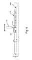
- FIG. 5is a schematic illustration of a shocking electrode and MRI filter arrangement for a lead 312 , similar to the lead 112 of FIG. 1 , manufactured from two tubes of conductive material.
- the shocking electrode and the MRI filter arrangementcan be configured substantially similar to the shocking electrode and MRI filter arrangement of FIG. 4 except as described below.
- the tubular conductive element 330is formed by joining a first tube 360 and a second tube 362 at a weld joint.
- the first tube 360includes a proximal segment 346 and the second tube 362 includes an intermediate segment 348 and a distal segment 350 .
- a connector 356 having a saddle-shaped portion 358similar to the connector 256 of FIG.
- first tube 360is coupled to an electrical conductor 326 and the second tube 362 .
- first tube 360is slid over the electrical conductor 326 and coupled to the second tube 362 forming the tubular conductive element 330 .
- Coupling of the first tube 360 to the second tube 362can be achieved by any suitable technique known in the art. Exemplary techniques include welding, soldering, heat bonding, or the like.
- FIG. 6is a schematic illustration showing a technique for manufacturing a shocking electrode and MRI filter arrangement for the lead of FIG. 1 according to various embodiments.
- the shocking electrode and the MRI filter arrangementcan be from a single tube of conductive material.
- the tubular conductive element 430is mounted on a fixture 464 .
- the fixture 464is configured to hold and rotate the tubular conductive element 430 in a predefined manner.
- the fixture 464may engage with a distal and/or a proximal end of the tubular conductive element 464 .
- a laser 466is deployed at a position over the tubular conductive element 430 mounted on the fixture 464 .
- the laser 466is configured to generate a high intensity light beam 468 and move axially in a transverse plane for cutting one or more kerfs 470 radially through the tubular conductive element 430 .
- the laser 466emits a high intensity beam of light that is made to fall on the tubular conductive element 430 .
- the energy of the light beam 468is transferred to the tubular conductive element 430 , thereby melting and/or vaporizing the material of the tubular conductive element 430 and forming the kerfs 470 .
- the motion of the laser 466can be controlled by an automated system causes the laser 466 output to follow a predetermined pattern.
- a CO 2 laseris used to form the kerfs 470 .
- Other suitable examples of the laser 466 that can be used to from the kerfs 470include, but are not limited to, Nd-YAG laser, YAG laser, or the like.
- plasma techniquesmay be employed to form kerfs 470 through the tubular conductive element 430 .
- the kerfs 470can be formed so as to affect the electrical properties of the tubular conductive element 430 .
- a first pattern (not shown) of the kerfs 470is cut along a first length of the tubular conductive material 430 and a second pattern of the kerfs 470 is cut along a second length of the tubular conductive element 430 .
- the first pattern of the kerfs 470includes a helical path formed along the first length, including the proximal segment and the intermediate segment.
- the second pattern of the kerfs 470can include a helical pattern or a non-helical pattern along the second length. As shown, the non-helical pattern includes cuts or slots formed that extend partially along the circumference of the tubular conductive element 430 .
- the kerfs 470include a first pattern, a second pattern, and a third pattern of kerfs defined along different portions of the tubular conductive element 430 .
- the first patterndefines a proximal segment (similar to proximal segment 146 ), a second pattern defines an intermediate segment (similar to intermediate segment 148 ), and a third pattern defines a distal segment (similar to distal segment 150 ) of the tubular conductive element 430 .
- the first and the second patternsare helical patterns having a variable pitch. The variable pitch decreases with distance from the other of the first and second patterns.
- the third patternis a non-helical pattern such that the proximal and intermediate segments have electrical impedances higher than the electrical impedance of the distal segment.
Landscapes
- Health & Medical Sciences (AREA)
- Heart & Thoracic Surgery (AREA)
- Cardiology (AREA)
- Engineering & Computer Science (AREA)
- Life Sciences & Earth Sciences (AREA)
- Veterinary Medicine (AREA)
- Nuclear Medicine, Radiotherapy & Molecular Imaging (AREA)
- Radiology & Medical Imaging (AREA)
- Biomedical Technology (AREA)
- Animal Behavior & Ethology (AREA)
- General Health & Medical Sciences (AREA)
- Public Health (AREA)
- Vascular Medicine (AREA)
- Neurology (AREA)
- Neurosurgery (AREA)
- Orthopedic Medicine & Surgery (AREA)
- Manufacturing & Machinery (AREA)
- Electrotherapy Devices (AREA)
Abstract
Description
This application is a continuation of U.S. application Ser. No. 14/631,010, filed Feb. 25, 2015, now U.S. Pat. No. 9,504,821, which claims priority to Provisional Application No. 61/945,081, filed Feb. 26, 2014, all of which are herein incorporated by reference in their entirety.
The present invention relates to implantable medical devices and methods of manufacturing. More specifically, the invention relates to MRI compatible medical device lead and methods for manufacturing MRI compatible medical device lead.
Various medical devices are commonly used to treat patients suffering from chronic and/or disabling diseases such as chronic pain, Parkinson's disease, cardiac arrhythmias. Few of these medical devices are temporarily or permanently implanted within patient's body. Such medical devices include neurostimulators, cardiac pacemakers, or implantable cardioverter-defibrillators (ICDs) (collectively Implantable Medical Devices (IMDs)).
Generally, an IMD includes an implantable pulse generator and one or more conducting leads with electrodes used to conduct signals between the heart and the implantable pulse generator (IPG). Commonly, the IMD is implanted into the pectoral region of the patient's body. The leads extend from the IPG to stimulate one or more chambers of the heart. The leads are used to deliver therapy to the patient and each include one or more conducting cables, electrodes, and/or coils.
Further, in some scenarios, the patient with an IMD may need to undergo a Magnetic Resonance Imaging (MRI) scan. An MRI is a non-invasive imaging modality that utilizes a magnetic field and radio frequency (RF) pulses to generate images of various anatomical structures within a patient's body. Typically, an MRI scanner uses a magnet to create a strong static magnetic field to align the protons of hydrogen atoms in the patient's body. Then, the patient is exposed to RF pulses of electromagnetic energy causing the protons to spin about their axis. Once the RF pulses are removed, these protons tend to come back to their resting state aligned with the static magnetic field. The MRI scanner detects the signal generated by the spinning protons that is processed to create an image.
During the MRI scan, the RF pulses may be picked up by leads implanted within a patient's body. There is a need for improved lead design to minimize induced currents generated from MRI energy.
In Example 1, a medical device lead, comprising a lead body, an electrical conductor and a tubular conductive element. The lead body includes a tubular member having a proximal end, a distal end, and a conductor lumen extending therebetween, wherein the tubular member is made of an electrically insulative material. The electrical conductor extends within the conductor lumen from the proximal end of the tubular member toward the distal end of the tubular member. The tubular conductive element is disposed over the tubular member of the lead body between the proximal and distal ends thereof. The tubular conductive element has one or more kerfs formed therethrough so as to affect an electrical property thereof, and wherein the electrical conductor is electrically coupled to the tubular conductive element.
In Example 2, the medical device lead of Example 1, wherein the one or more kerfs are formed in a helical pattern such that electrical current passing through the tubular conductive element travels along a helical path.
In Example 3, the medical device lead of either of Examples 1 or 2, wherein the one or more kerfs have a constant pitch.
In Example 4, the medical device lead of either of Examples 1 or 2, wherein the one or more kerfs have a variable pitch.
In Example 5, the medical device lead of any of Examples 1-4, wherein the first segment defines an electrode of the medical device lead.
In Example 6, the medical device lead of any of Examples 1-5, wherein the tubular conductive element includes a first segment and a second segment extending distally from the first segment, wherein the one or more kerfs are formed in each of the first and second segments so as to affect an electrical property of the first and second segments, wherein the first segment has a higher electrical impedance than the second segment.
In Example 7, the medical device lead of Example 6, further comprising a layer of insulative material disposed over the first segment.
In Example 8. the medical device lead of either of Examples 6 or 7, wherein the first segment is operable to inhibit induced currents in the tubular conductive element in the presence of an external source of electromagnetic energy.
In Example 9, the medical device lead of any of Examples 1-5, wherein the tubular conductive element includes first, second and third segments, the second segment extending distally from the first segment, and the third segment extending distally from the second segment, wherein the one or more kerfs are formed in each of the first, second and third segments, and wherein the one or more kerfs in each of the first and second segments are configured so that the first and second segments have a higher electrical impedance than the third segment.
In Example 10, the medical device lead of Example 9, further comprising a layer of insulative material disposed over the first and second segments of the tubular conductive element, so that the first and second segments of the tubular conductive element are operable to inhibit induced currents in the tubular conductive element in the presence of an external source of electromagnetic energy.
In Example 11, the medical device lead of Example 10, wherein an outer surface of the third segment of the tubular conductive element is uninsulated so that the third segment can be operable as a shocking electrode.
In Example 12, the medical device lead of any of Examples 9-11, wherein the electrical conductor is mechanically and electrically coupled to the tubular conductive element at a connection location disposed at a transition between the first and second segments of the tubular conductive element.
In Example 13, the medical device lead of any of Examples 9-11, wherein the first, second and third segments are formed from a single tube of conductive material.
In Example 14, the medical device lead of any of Examples 9-11, wherein one or more of the first, second and third segments are formed from separate tubes of conductive material and subsequently joined together by a weld joint.
In Example 15, the medical device lead of any of Examples 9-14, wherein the kerfs in the third segment include a series of kerfs each extending partially circumferentially about the tubular conductive element and distributed along the length of the third segment, wherein each kerf in the third segment is circumferentially offset from adjacent kerfs so as to cause electrical current to assume a non-linear flow path through the third segment.
In Example 16, a medical device lead, comprising a lead body, an electrical conductor and a tubular conductive element. The lead body includes a tubular member having a proximal end and a distal end and a conductor lumen extending therebetween, wherein the tubular member is made of an electrically insulative material. The electrical conductor extends within the conductor lumen from the proximal end of the tubular member toward the distal end of the tubular member. The tubular conductive element is disposed over the tubular member of the lead body between the proximal and distal ends thereof. The tubular conductive element includes a first segment, a second segment extending distally from the first segment, and a third segment extending distally from the second segment, each of the segments having one or more kerfs formed radially therethrough in a predetermined configuration so as to affect an electrical impedance of the respective segment. The one or more kerfs in each of the first and second segments are configured so that the first and second segments have a higher electrical impedance than the third segment, and the electrical conductor is mechanically and electrically coupled to the tubular conductive element. A layer of insulative material is disposed over the first and second segments of the tubular conductive element. The first and second segments of the tubular conductive element are operable to inhibit induced currents in the tubular conductive element in the presence of an external source of electromagnetic energy. An outer surface of the third segment of the tubular conductive element is uninsulated so that the third segment can be operable as a shocking electrode.
In Example 17, the medical device lead of Example 16, wherein the electrical conductor is mechanically and electrically coupled to the tubular conductive element at a connection location disposed at a transition between the first and second segments of the tubular conductive element.
In Example 18, the medical device lead of either of Examples 16 or 17, wherein the kerfs in the first and second segments are formed in a helical pattern along a length thereof.
In Example 19, the medical device lead of any of Examples 16-18, wherein the kerfs in the first segment have a constant pitch along the length of the first segment.
In Example 20, the medical device lead of any of Examples 16-19, wherein the kerfs in the second segment have a constant pitch along the length of the second segment.
In Example 21, the medical device lead of any of Examples 16-18, wherein the kerfs in one or both of the first and second segments have a pitch that varies along the length of the respective segment.
In Example 22, the medical device lead of Example 21, wherein the pitch of the kerfs in one or both of the first and second segments decrease with distance from the connection location.
In Example 23, the medical device lead of any of Examples 16-22, wherein the kerfs in the third segment include a series of kerfs each extending partially circumferentially about the tubular conductive element and distributed along the length of the third segment, wherein each kerf in the third segment is circumferentially offset from adjacent kerfs so as to cause electrical current to assume a non-linear flow path through the third segment.
In Example 24, the medical device lead of any of Examples 16-23, wherein the first, second and third segments are formed from a single tube of conductive material.
In Example 25, the medical device lead of any of Examples 16-23, wherein one or more of the first, second and third segments are formed from separate tubes of conductive material and subsequently joined together by a weld joint.
In Example 26, a filtered electrode component for an implantable medical device lead, the filtered electrode component comprising a tubular conductive element including a first segment, a second segment extending distally from the first segment, and a third segment extending distally from the second segment, each of the segments having one or more kerfs formed radially therethrough in a predetermined configuration so as to affect an electrical impedance of the respective segment. The one or more kerfs in each of the first and second segments are configured so that the first and second segments have a higher electrical impedance than the third segment, and the tubular conductive element is configured to be mechanically and electrically coupled to an electrical conductor.
In Example 27, the filtered electrode component of Example 26, wherein the kerfs in the first and second segments are formed in a helical pattern along a length thereof.
In Example 28, the filtered electrode component of either of Examples 26 or27, wherein the kerfs in one or both of the first and second segments has a constant pitch along the length of the respective segment.
In Example 29, the filtered electrode component of either of Examples 27 or 28, wherein the kerfs in one or both of the first and second segments have a pitch that varies along the length of the respective segment.
In Example 30, the filtered electrode component of Example 29, wherein the pitch of the kerfs in one or both of the first and second segments decreases with distance from the other of the first and second segments.
In Example 31, the filtered electrode component of any of Examples 26-30, wherein the kerfs in the third segment include a series of kerfs each extending partially circumferentially about the tubular conductive element and distributed along the length of the third segment, wherein each kerf in the third segment is circumferentially offset from adjacent kerfs so as to cause electrical current to assume a non-linear flow path through the third segment.
In Example 32, a method of forming an electrical component for a medical device lead, comprising mounting a tubular conductive element to a fixture, and cutting one or more kerfs radially through the tubular conductive element using a laser in one or more predetermined patterns configured so as to affect an electrical property of the tubular conductive element.
In Example 33, the method of Example 32, wherein cutting one or more kerfs includes cutting a first pattern of kerfs in a helical path along a first length of the tubular conductive element, and cutting a second pattern of kerfs in a non-helical pattern along a second length of the tubular conductive element.
In Example 34, the method of either of Examples 32 or 33, wherein cutting one or more kerfs includes cutting first, second and third patterns of kerfs to define first, second and third segments of the tubular conductive element, wherein the first and second patterns are helical patterns each having a variable pitch that decreases with distance from the other of the first and second patterns, and wherein the third pattern is a non-helical pattern, so that the first and second segments have an electrical impedance that is higher than an electrical impedance of the third segment.
In Example 35, the method of any of Examples 32-34, wherein the tubular conductive element is a first tubular conductive element, and wherein the method further comprises cutting one or more kerfs radially through a second tubular conductive element using a laser in one or more predetermined patterns configured so as to affect an electrical impedance of the second tubular conductive element, and mechanically and electrically joining the first and second tubular conductive elements.
While multiple embodiments are disclosed, still other embodiments of the present invention will become apparent to those skilled in the art from the following detailed description, which shows and describes illustrative embodiments of the invention. Accordingly, the drawings and detailed description are to be regarded as illustrative in nature and not restrictive.
While the invention is amenable to various modifications and alternative forms, specific embodiments have been shown by way of example in the drawings and are described in detail below. The intention, however, is not to limit the invention to the particular embodiments described. On the contrary, the invention is intended to cover all modifications, equivalents, and alternatives falling within the scope of the invention as defined by the appended claims.
In some embodiments, thelead 112 includes alead body 117, ashocking electrode 118, a pacing/sensing electrode 120, and one or more conductors (not shown inFIG. 1 ). Theshocking electrode 118 is disposed proximate adistal end 122 of thelead 112 and is coupled to at least one conductor and is configured to deliver shock to the patient'sheart 102 in scenarios when an anomaly, such as an arrhythmia, is sensed or detected. Theelectrode 120 is disposed at thedistal end 122 of thelead 112 and is also connected to at least one conductor that enables theelectrode 120 to sense and pace the patient'sheart 102. The conductor enables theelectrode 120 to sense and pace by conducting electrical signals generated by theheart 102 to thepulse generator 114 and the electrical pulses generated by thepulse generator 114 for pacing to theheart 102.
In the illustrated embodiment, thelead 112 is deployed in theright ventricle 104. However, in other embodiments, thelead 112 can be implanted in theright atrium 106 or both theright atrium 106 and theright ventricle 104, or a left chamber of theheart 102. In various embodiments, two or more leads112 may be deployed within theheart 102 at different target regions.
Thepulse generator 114 generally includes a power source and electronic circuitry configured to process and generate electrical signals. The power source includes a battery that provides power to theCRM system 100 to perform its operations. The electronic circuitry may include components for memory, processing, or the like. In some embodiments, thepulse generator 114 is implanted by forming a subcutaneous pocket in the pectoral girdle of the patient. Optionally, thepulse generator 114 can also be implanted in the thoracic cavity, abdominal region, neck region, or the like.
The following embodiments are primarily described in context of theCRM system 100. However, the skilled artisan will readily understand that the embodiments may also be used in conjunction with other implantable medical devices such as, but not limited to, deep brain stimulators, spinal cord stimulators, or the like.
More particularly, thelead body 117 includes an insulativetubular member 136 having a proximal end (not shown inFIG. 2 ), adistal end 138, one or more conductor lumens (shown in Section A-A) extending either partially or entirely between the proximal end and thedistal end 138 of thetubular member 136. In the illustrated embodiment, thetubular member 136 defines afirst conductor lumen 140 that has a profile slightly smaller than that of asecond conductor lumen 142.
Thefirst conductor lumen 140 is configured to receive theelectrical conductor 126. In some embodiments, theelectrical conductor 126 can be a high voltage cable or wire extending from the proximal end of thetubular member 136 towards thedistal end 138. Theelectrical conductor 126 is configured to carry high voltage electrical signals from thepulse generator 114 to deliver shock to the heart102 (seeFIG. 1 ). To deliver shocks, theelectrical conductor 126 is electrically coupled to the tubularconductive element 130 at aconnection location 144.
In some embodiments, the tubularconductive element 130 is a tube like structure including aproximal segment 146, anintermediate segment 148, and adistal segment 150. In various embodiments, theproximal segment 146 and theintermediate segment 148 are operable to filter electromagnetic energy from an external source such as an MRI. Thedistal segment 150 is operable as a shocking electrode configured to deliver shock to theheart 102. The layer ofinsulative material 132 is disposed over theproximal segment 146 and theintermediate segment 148 such that these segments will not be able to deliver energy to surrounding tissue.
In various embodiments, thelead 112 may include two or more tubularconductive elements 130 disposed along its length, a distal tubular conductive element, and a proximal tubular conductive element. In an example, the distally located tubular conductive element is positioned within theright ventricle 104 and the proximally located tubular conductive element is positioned within theright atrium 106 or superior vena cava. The two tubular conductive elements may be independently activated based on the requirement of therapy.
Thesecond conductor lumen 142 is configured to receive a conductor such as alow voltage conductor 128. In some embodiments, thelow voltage conductor 128 extends to thetip electrode 134 at thedistal end 138 of the insulativetubular member 136 of thelead body 117. In one embodiment, thelow voltage conductor 128 can be in the form of a single- or multi-filar coil conductor. In various embodiments, thelow voltage conductor 128 can be a non-coiled conductor (e.g., a multi-strand cable, or the like). Thelow voltage conductor 128 is configured to convey electrical signals from theheart 102, such as electrical activity of theheart 102, to thepulse generator 114 to detect abnormal rhythms. Thelow voltage conductor 128 may also transmit pacing signals from thepulse generator 114 to theheart 102. In various embodiments, thelow voltage conductor 128 can be configured as a relatively high inductance coil to inhibit induced currents in the conductor. In some embodiments, thelow voltage conductor 128 may define a lumen configured to receive a stylet or guide wire (not shown) for implanting thelead 112 within the patient's body.
Thetip electrode 134 connected to the distal end of thelow voltage conductor 128 is in contact with the tissue, such as heart tissue, for sensing electrical signals produced by theheart 102 and/or pacing theheart 102 by transmitting the pulses generated by thepulse generator 114. In some embodiments, thetip electrode 134 can be engaged with the tissue by active fixation such as a helix screw that can be inserted into the tissue by rotation of the helix screw. To accomplish rotation of the helix screw, thetip electrode 134 is mechanically coupled to thelow voltage conductor 128, which in turn is mechanically coupled to a rotatable element (e.g., a terminal pin) at the proximal end of the lead. In such scenarios, thetip electrode 134 conducts as well as secures, thelead 112 to the cardiac tissue. In other embodiments, thetip electrode 134 can be passively engaged with the tissue just by contacting the tissue, such as a ring electrode, a ball shape electrode, or the like.
In some embodiments, the layer ofinsulative material 132 and the insulativetubular member 136 can be formed using a suitable electrically insulative biocompatible material such as, but not limited to, silicone, polytetrafluoroethylene (PTFE), ethylene tetrafluoroethylene (ETFE), fluorinated ethylene propylene (FEP), polyvinylchloride (PVC), polyether-ester, polyamide, polyetheretherketone (PEEK), or the like. In some embodiments, thetubular member 136 and theconductor lumens
Theproximal segment 146 includes aproximal end 152, adistal end 154, and a coiled conductor extending between theproximal end 152 and thedistal end 154.
Referring toFIGS. 2 and 3 , in some embodiments, theproximal segment 146 is operable as a transmission line filter configured to shield the electrical conductor from RF energy produced during an MRI scan, so as to cancel the effect of MRI interference in theelectrical conductor 126. Theelectrical conductor 126 is connected to the tubularconductive element 130 between theproximal segment 146 and theintermediate segment 148 at theconnection location 144. As shown, thedistal end 154 of theproximal segment 146 is coupled to theelectrical conductor 126.
Theintermediate segment 148 is operable as an in-line tuning filter used to tune or choke the RF signals induced due to RF pulsating magnetic field or the MRI environment. Theintermediate segment 148 has an inductance that poses high impedance to certain frequencies without affecting the flow of electrical signals generated by the pulse generator (such as pulse generator114). When an alternating current is induced in thelead 112 due to RF signals, a magnetic field is generated around theintermediate segment 148 and this field opposes any further current changes. This enables theintermediate segment 148 to attenuate the undesired current or voltage signals generated within thelead 112 or theelectrical conductor 126 such that the signals generated are not transmitted to other parts of thelead 112, particularly the shocking electrode. In some embodiments, theproximal segment 146 and theintermediate segment 148 may be tuned to different MRI frequencies such as 64 MHz, 128 MHz or other frequencies involved during MRI procedure.
In some embodiments, theproximal segment 146 and theintermediate segment 148 are configured and arranged to have kerfs formed in a helical pattern around the circumference and length of the tubularconductive element 130, such that the remaining conductive material also extends in a helical configuration. In various embodiments, the pitch (i.e., the distance between adjacent turns of the helically-arranged kerfs) can be substantially uniform along the length of the proximal and/orintermediate segments distal segments proximal segment 146 and/or theintermediate segment 148. In one embodiment, theproximal segment 146 and theintermediate segment 148 are configured so as to have smaller pitch near theconnection location 144.
Thedistal segment 150 forms a distal portion of the tubularconductive element 130. Thedistal segment 150 is operable as the shocking electrode configured to deliver shock or high voltage pulses to the heart. In the illustrated embodiment, thedistal segment 150 is designed to have kerfs extending partially along the circumference of the tubularconductive element 130. When the electrical signal is sent to thedistal segment 150, the kerfs direct the current to take a non-linear path distributing energy over a larger surface area, and thereby minimizing heating of surrounding tissue.
In various embodiments, the tubularconductive element 130 can be formed using a suitable non-ferromagnetic conducting biocompatible material such as, but not limited to, Nitinol™, gold, silver, stainless steel, copper, platinum, or a combination of these materials.
In some embodiments, a connector256 (as shown in the detail view ofFIG. 4 ) is used to couple theelectrical conductor 226 to the tubularconductive element 230. In the illustrated embodiments, theconnector 256 includes a saddle-shapedportion 258 configured to receive a distal end of theelectrical conductor 226. Theelectrical conductor 226 is placed within the saddle-shapedportion 258 of theconnector 256 and coupled to theconnector 256. For fixation, techniques such as welding, soldering, heat bonding, crimping, or the like may be used. In some embodiments, theconnector 256 includes a flap configured to tightly secure theelectrical conductor 226 with theconnector 256. Upon fixation, theconnector 256, along with theelectrical conductor 226, is disposed within the tubularconductive element 230. Then, theconnector 256 is coupled to the tubularconductive element 230 by a suitable technique such as, but not limited to, welding, soldering, or the like. In some embodiments, theconnector 256 is a metallic ring that electrically couples theelectrical conductor 226 to the tubularconductive element 230.
Additionally, as shown, theproximal segment 246 and theintermediate segment 248 have variable pitches. In some embodiments, the pitches of the kerfs in theproximal segment 246 and theintermediate segment 248 decrease in a direction away from theconnection location 244 where theelectrical conductor 226 is coupled to the tubularconductive element 230 to reduce reflection at theconnection location 244.
Further, alaser 466 is deployed at a position over the tubularconductive element 430 mounted on thefixture 464. Thelaser 466 is configured to generate a highintensity light beam 468 and move axially in a transverse plane for cutting one ormore kerfs 470 radially through the tubularconductive element 430. Thelaser 466 emits a high intensity beam of light that is made to fall on the tubularconductive element 430. The energy of thelight beam 468 is transferred to the tubularconductive element 430, thereby melting and/or vaporizing the material of the tubularconductive element 430 and forming thekerfs 470. In some embodiments, the motion of thelaser 466 can be controlled by an automated system causes thelaser 466 output to follow a predetermined pattern.
In various embodiments, a CO2laser is used to form thekerfs 470. Other suitable examples of thelaser 466 that can be used to from thekerfs 470 include, but are not limited to, Nd-YAG laser, YAG laser, or the like. Alternatively, in some embodiments, plasma techniques may be employed to formkerfs 470 through the tubularconductive element 430.
In the various embodiments, thekerfs 470 can be formed so as to affect the electrical properties of the tubularconductive element 430. In some embodiments, a first pattern (not shown) of thekerfs 470 is cut along a first length of the tubularconductive material 430 and a second pattern of thekerfs 470 is cut along a second length of the tubularconductive element 430. The first pattern of thekerfs 470 includes a helical path formed along the first length, including the proximal segment and the intermediate segment. Further, in the illustrated embodiment, the second pattern of thekerfs 470 can include a helical pattern or a non-helical pattern along the second length. As shown, the non-helical pattern includes cuts or slots formed that extend partially along the circumference of the tubularconductive element 430.
In other embodiments, thekerfs 470 include a first pattern, a second pattern, and a third pattern of kerfs defined along different portions of the tubularconductive element 430. The first pattern defines a proximal segment (similar to proximal segment146), a second pattern defines an intermediate segment (similar to intermediate segment148), and a third pattern defines a distal segment (similar to distal segment150) of the tubularconductive element 430. In a preferred embodiment, the first and the second patterns are helical patterns having a variable pitch. The variable pitch decreases with distance from the other of the first and second patterns. The third pattern is a non-helical pattern such that the proximal and intermediate segments have electrical impedances higher than the electrical impedance of the distal segment.
Various modifications and additions can be made to the exemplary embodiments discussed without departing from the scope of the present invention. For example, while the embodiments described above refer to particular features, the scope of this invention also includes embodiments having different combinations of features and embodiments that do not include all of the described features. Accordingly, the scope of the present invention is intended to embrace all such alternatives, modifications, and variations as fall within the scope of the claims, together with all equivalents thereof.
Claims (16)
1. A medical device lead comprising:
an insulating tubular member having a proximal end, a distal end, and a lumen extending therebetween;
an electrical conductor extending within the lumen from the proximal end toward the distal end; and
a tubular conductive element disposed over the insulating tubular member and between the proximal end and the distal end, wherein the tubular conductive element is electrically coupled to the electrical conductor and has one or more kerfs formed in it to affect an electrical property of the tubular conductive element, wherein the one or more kerfs include kerfs formed in a helical pattern such that electrical current passing through the tubular conductive element travels along a helical path and the kerfs formed in the helical pattern have a variable pitch.
2. The medical device lead ofclaim 1 , wherein the tubular conductive element is configured to provide a shocking electrode.
3. The medical device lead ofclaim 1 , wherein the tubular conductive element includes a first segment and a second segment extending distally from the first segment, wherein the one or more kerfs are formed in each of the first segment and the second segment to affect electrical properties of the first segment and the second segment, wherein the first segment has a higher electrical impedance than the second segment.
4. The medical device lead ofclaim 3 , comprising a layer of insulative material disposed over the first segment.
5. The medical device lead ofclaim 3 , wherein the first segment is configured to inhibit induced currents in the tubular conductive element in the presence of an external source of electromagnetic energy.
6. The medical device lead ofclaim 3 , wherein the second segment is configured to provide a shocking electrode.
7. A medical device lead comprising:
an insulating tubular member having a proximal end, a distal end, and a lumen extending therebetween;
an electrical conductor extending within the lumen from the proximal end toward the distal end; and
a tubular conductive element disposed over the insulating tubular member and between the proximal end and the distal end, wherein the tubular conductive element is electrically coupled to the electrical conductor and has a first segment with first kerfs formed in it and a second segment extending distally from the first segment and with second kerfs formed in it, wherein the first kerfs are different than the second kerfs, and wherein the first kerfs and the second kerfs are configured to provide a higher electrical impedance in the first segment as compared to the second segment.
8. The medical device lead ofclaim 7 , wherein the first kerfs are formed in a helical pattern such that electrical current passing through the first segment travels along a helical path.
9. The medical device lead ofclaim 7 , wherein the second kerfs include a series of kerfs each extending partially circumferentially about the tubular conductive element and distributed along the length of the second segment, wherein each of the second kerfs is circumferentially offset from adjacent second kerfs so as to cause electrical current to assume a non-linear flow path through the second segment.
10. The medical device lead ofclaim 7 , comprising a layer of insulative material disposed over the first segment of the tubular conductive element and the first segment is configured to inhibit induced currents in the tubular conductive element in the presence of an external source of electromagnetic energy.
11. The medical device lead ofclaim 7 , wherein an outer surface of the second segment is uninsulated and the second segment is configured to provide a shocking electrode.
12. An electrode component for an implantable medical device lead, the electrode component comprising:
a tubular conductive element including a first segment, a second segment extending distally from the first segment, and a third segment extending distally from the second segment, wherein one or more kerfs are formed in each of the first segment, the second segment, and the third segment such that the first segment and the second segment have a higher electrical impedance than the third segment.
13. The electrode component ofclaim 12 , comprising a layer of insulative material disposed over the first segment and the second segment, wherein the first segment and the second segment are configured to inhibit induced currents in the tubular conductive element in the presence of an external source of electromagnetic energy.
14. The electrode component ofclaim 12 , wherein an outer surface of the third segment is uninsulated and the third segment is configured to provide a shocking electrode.
15. The electrode component ofclaim 12 , wherein the first segment, the second segment, and the third segment are formed from a single tube of conductive material.
16. The electrode component ofclaim 12 , wherein one or more of the first segment, the second segment, and the third segment are formed from separate tubes of conductive material.
Priority Applications (1)
| Application Number | Priority Date | Filing Date | Title |
|---|---|---|---|
| US15/245,600US9682231B2 (en) | 2014-02-26 | 2016-08-24 | Construction of an MRI-safe tachycardia lead |
Applications Claiming Priority (3)
| Application Number | Priority Date | Filing Date | Title |
|---|---|---|---|
| US201461945081P | 2014-02-26 | 2014-02-26 | |
| US14/631,010US9504821B2 (en) | 2014-02-26 | 2015-02-25 | Construction of an MRI-safe tachycardia lead |
| US15/245,600US9682231B2 (en) | 2014-02-26 | 2016-08-24 | Construction of an MRI-safe tachycardia lead |
Related Parent Applications (1)
| Application Number | Title | Priority Date | Filing Date |
|---|---|---|---|
| US14/631,010ContinuationUS9504821B2 (en) | 2014-02-26 | 2015-02-25 | Construction of an MRI-safe tachycardia lead |
Publications (2)
| Publication Number | Publication Date |
|---|---|
| US20160361538A1 US20160361538A1 (en) | 2016-12-15 |
| US9682231B2true US9682231B2 (en) | 2017-06-20 |
Family
ID=52630512
Family Applications (2)
| Application Number | Title | Priority Date | Filing Date |
|---|---|---|---|
| US14/631,010Expired - Fee RelatedUS9504821B2 (en) | 2014-02-26 | 2015-02-25 | Construction of an MRI-safe tachycardia lead |
| US15/245,600Expired - Fee RelatedUS9682231B2 (en) | 2014-02-26 | 2016-08-24 | Construction of an MRI-safe tachycardia lead |
Family Applications Before (1)
| Application Number | Title | Priority Date | Filing Date |
|---|---|---|---|
| US14/631,010Expired - Fee RelatedUS9504821B2 (en) | 2014-02-26 | 2015-02-25 | Construction of an MRI-safe tachycardia lead |
Country Status (6)
| Country | Link |
|---|---|
| US (2) | US9504821B2 (en) |
| EP (1) | EP3110499B1 (en) |
| JP (1) | JP6244469B2 (en) |
| CN (1) | CN106029162A (en) |
| AU (1) | AU2015223154B2 (en) |
| WO (1) | WO2015130753A1 (en) |
Families Citing this family (3)
| Publication number | Priority date | Publication date | Assignee | Title |
|---|---|---|---|---|
| US8983623B2 (en) | 2012-10-18 | 2015-03-17 | Cardiac Pacemakers, Inc. | Inductive element for providing MRI compatibility in an implantable medical device lead |
| WO2015130753A1 (en) | 2014-02-26 | 2015-09-03 | Cardiac Pacemakers, Inc | Construction of an mri-safe tachycardia lead |
| CN111265771B (en)* | 2018-12-05 | 2025-04-15 | 上海神奕医疗科技有限公司 | Electrical conductor and preparation method thereof and implantable biological electrode |
Citations (329)
| Publication number | Priority date | Publication date | Assignee | Title |
|---|---|---|---|---|
| US3614692A (en) | 1970-06-02 | 1971-10-19 | Magnetech Ind Inc | Variable induction device |
| US4131759A (en) | 1977-08-10 | 1978-12-26 | United States Steel Corporation | Slip sleeve mechanism for a strength tapered caged armored electromechanical cable |
| US4135518A (en) | 1976-05-21 | 1979-01-23 | Medtronic, Inc. | Body implantable lead and electrode |
| US4146036A (en) | 1977-10-06 | 1979-03-27 | Medtronic, Inc. | Body-implantable lead with protector for tissue securing means |
| US4209019A (en) | 1979-01-05 | 1980-06-24 | Medtronic, Inc. | Stylet insertion guide and rotation control device for use with body implantable lead |
| US4253462A (en) | 1979-08-09 | 1981-03-03 | Medtronic, Inc. | Stylet |
| US4350169A (en) | 1979-01-05 | 1982-09-21 | Medtronic, Inc. | Flexible tip stiffening stylet for use with body implantable lead |
| US4381013A (en) | 1981-03-19 | 1983-04-26 | Medtronic, Inc. | "J" Stylet wire |
| US4404125A (en) | 1981-10-14 | 1983-09-13 | General Electric Company | Polyphenylene ether resin compositions for EMI electromagnetic interference shielding |
| CA1154833A (en) | 1979-08-27 | 1983-10-04 | Robert G. Dutcher | Endocardial pacing lead |
| US4437474A (en) | 1982-07-16 | 1984-03-20 | Cordis Corporation | Method for making multiconductor coil and the coil made thereby |
| US4484586A (en) | 1982-05-27 | 1984-11-27 | Berkley & Company, Inc. | Hollow conductive medical tubing |
| US4493329A (en) | 1982-08-19 | 1985-01-15 | Lynn Crawford | Implantable electrode having different stiffening and curvature maintaining characteristics along its length |
| US4574800A (en) | 1984-12-07 | 1986-03-11 | Cordis Corporation | Implanted lead extractor |
| US4643202A (en) | 1985-04-15 | 1987-02-17 | Cordis Corporation | Multi-material insulation sheath for pacer lead |
| US4643203A (en) | 1982-07-01 | 1987-02-17 | Molins Plc | Conveying and uniting rod-like articles of the tobacco industry |
| US4649938A (en) | 1985-04-29 | 1987-03-17 | Mcarthur William A | Tissue-stimulating electrode having sealed, low-friction extendable/retractable active fixation means |
| US4869970A (en) | 1986-07-14 | 1989-09-26 | Shipley Company Inc. | Radiation attenuation shielding |
| US5002067A (en) | 1989-08-23 | 1991-03-26 | Medtronic, Inc. | Medical electrical lead employing improved penetrating electrode |
| US5003975A (en) | 1988-04-19 | 1991-04-02 | Siemens-Pacesetter, Inc. | Automatic electrode configuration of an implantable pacemaker |
| US5020545A (en) | 1990-01-23 | 1991-06-04 | Siemens-Pacesetter, Inc. | Cardiac lead assembly and method of attaching a cardiac lead assembly |
| US5056516A (en) | 1989-11-02 | 1991-10-15 | Intermedics, Inc. | Implantable endocordial lead with torque-transmitting lanyard |
| US5074313A (en) | 1989-03-20 | 1991-12-24 | Cardiac Pacemakers, Inc. | Porous electrode with enhanced reactive surface |
| US5144960A (en) | 1991-03-20 | 1992-09-08 | Medtronic, Inc. | Transvenous defibrillation lead and method of use |
| US5201865A (en) | 1991-10-28 | 1993-04-13 | Medtronic, Inc. | Medical lead impedance measurement system |
| US5217010A (en) | 1991-05-28 | 1993-06-08 | The Johns Hopkins University | Ecg amplifier and cardiac pacemaker for use during magnetic resonance imaging |
| US5222506A (en) | 1991-07-29 | 1993-06-29 | Medtronic, Inc. | Implantable medical lead with electrical cross-over adaptor |
| US5231996A (en) | 1992-01-28 | 1993-08-03 | Medtronic, Inc. | Removable endocardial lead |
| US5241957A (en) | 1991-11-18 | 1993-09-07 | Medtronic, Inc. | Bipolar temporary pacing lead and connector and permanent bipolar nerve wire |
| US5243911A (en) | 1990-09-18 | 1993-09-14 | Dow Robert L | Attenuator for protecting electronic equipment from undesired exposure to RF energy and/or lightning |
| US5246014A (en) | 1991-11-08 | 1993-09-21 | Medtronic, Inc. | Implantable lead system |
| US5259395A (en) | 1992-01-15 | 1993-11-09 | Siemens Pacesetter, Inc. | Pacemaker lead with extendable retractable lockable fixing helix |
| US5300108A (en) | 1993-01-05 | 1994-04-05 | Telectronics Pacing Systems, Inc. | Active fixation lead with a dual-pitch, free spinning compound screw |
| US5324322A (en) | 1992-04-20 | 1994-06-28 | Case Western Reserve University | Thin film implantable electrode and method of manufacture |
| US5330522A (en) | 1992-12-29 | 1994-07-19 | Siemens Pacesetter, Inc. | Ring electrode for a multilumen lead and method of constructing a multilumen lead |
| US5354327A (en) | 1993-04-07 | 1994-10-11 | Medtronic, Inc. | Conductor coil with specific ratio of torque to bending stiffness |
| US5370666A (en) | 1992-06-05 | 1994-12-06 | Siemens-Elema Ab | Pacemaker with power-consuming component inhibited during storage |
| US5378234A (en) | 1993-03-15 | 1995-01-03 | Pilot Cardiovascular Systems, Inc. | Coil polymer composite |
| US5387199A (en) | 1992-02-24 | 1995-02-07 | Baxter International Inc. | Polymer blends for torque transmitting catheters |
| JPH0747139A (en) | 1993-04-27 | 1995-02-21 | Siemens Ag | Implantable pacing leads for cardiac pacemakers |
| US5417208A (en) | 1993-10-12 | 1995-05-23 | Arrow International Investment Corp. | Electrode-carrying catheter and method of making same |
| US5425755A (en) | 1992-12-04 | 1995-06-20 | Pacesetter, Inc. | Rotatable pin, screw-in pacing and sensing lead having Teflon-coated conductor coil |
| US5456707A (en) | 1993-10-22 | 1995-10-10 | Vitatron Medical Bv | Pacing lead with improved torsion characteristics |
| US5476485A (en) | 1993-09-21 | 1995-12-19 | Pacesetter, Inc. | Automatic implantable pulse generator |
| US5483022A (en) | 1994-04-12 | 1996-01-09 | Ventritex, Inc. | Implantable conductor coil formed from cabled composite wire |
| WO1996006655A1 (en) | 1994-08-29 | 1996-03-07 | Angeion Corporation | Low profile defibrillation catheter |
| US5522875A (en) | 1994-07-28 | 1996-06-04 | Medtronic, Inc. | Medical electrical lead system having a torque transfer stylet |
| US5522872A (en) | 1994-12-07 | 1996-06-04 | Ventritex, Inc. | Electrode-conductor sleeve joint for cardiac lead |
| US5534018A (en) | 1994-11-30 | 1996-07-09 | Medtronic, Inc. | Automatic lead recognition for implantable medical device |
| US5542174A (en) | 1994-09-15 | 1996-08-06 | Intel Corporation | Method and apparatus for forming solder balls and solder columns |
| US5542173A (en) | 1993-09-24 | 1996-08-06 | Ventritex, Inc. | Method of making flexible defibrillation electrode |
| US5545205A (en) | 1989-12-08 | 1996-08-13 | Cardiac Pacemakers, Inc. | Unitary intravascular defibrillating catheter with bipolar sensing |
| US5549646A (en) | 1994-12-06 | 1996-08-27 | Pacesetter, Inc. | Periodic electrical lead intergrity testing system and method for implantable cardiac stimulating devices |
| US5554139A (en) | 1993-12-24 | 1996-09-10 | Terumo Kabushiki Kaisha | Catheter |
| US5574249A (en) | 1994-07-18 | 1996-11-12 | Lindsay Audiophile Inc. | High resistivity inner shields for cabinets housing electronic circuitry |
| US5584873A (en) | 1995-05-08 | 1996-12-17 | Medtronic, Inc. | Medical lead with compression lumens |
| US5599576A (en) | 1995-02-06 | 1997-02-04 | Surface Solutions Laboratories, Inc. | Medical apparatus with scratch-resistant coating and method of making same |
| US5609622A (en) | 1993-02-01 | 1997-03-11 | W. L. Gore & Associates, Inc. | Implantable electrode with conductive polytetrafluoroethylene elecrode |
| US5618208A (en) | 1994-06-03 | 1997-04-08 | Siemens Medical Systems, Inc. | Fully insulated, fully shielded electrical connector arrangement |
| US5649974A (en) | 1992-07-27 | 1997-07-22 | Angeion Corporation | Low profile defibrillation catheter |
| US5658709A (en) | 1994-08-16 | 1997-08-19 | Ventritex, Inc. | Method for manufacturing implantable cardiac defibrillation electrodes using a laser beam material removal process |
| US5676694A (en) | 1996-06-07 | 1997-10-14 | Medtronic, Inc. | Medical electrical lead |
| US5693523A (en) | 1992-02-24 | 1997-12-02 | Q. P. Corporation | Ice nucleus-forming bacterium, process for cultivation of the same, ice nucleus-forming substance containing the same, and uses of said substance |
| US5728149A (en) | 1995-12-20 | 1998-03-17 | Medtronic, Inc. | Integral spiral band electrode for transvenous defibrillation leads |
| US5727552A (en) | 1996-01-11 | 1998-03-17 | Medtronic, Inc. | Catheter and electrical lead location system |
| US5727553A (en) | 1996-03-25 | 1998-03-17 | Saad; Saad A. | Catheter with integral electromagnetic location identification device |
| US5755742A (en) | 1996-11-05 | 1998-05-26 | Medtronic, Inc. | Cardioversion/defibrillation lead impedance measurement system |
| US5760341A (en) | 1996-09-10 | 1998-06-02 | Medtronic, Inc. | Conductor cable for biomedical lead |
| US5766227A (en) | 1997-03-04 | 1998-06-16 | Nappholz; Tibor A. | EMI detection in an implantable pacemaker and the like |
| US5800496A (en) | 1996-06-24 | 1998-09-01 | Medtronic, Inc. | Medical electrical lead having a crush resistant lead body |
| US5810887A (en) | 1996-08-23 | 1998-09-22 | Rhythm Technologies, Inc. | Temporary catheter |
| US5817136A (en) | 1997-05-02 | 1998-10-06 | Pacesetter, Inc. | Rate-responsive pacemaker with minute volume determination and EMI protection |
| US5824026A (en) | 1996-06-12 | 1998-10-20 | The Spectranetics Corporation | Catheter for delivery of electric energy and a process for manufacturing same |
| US5833715A (en) | 1992-09-03 | 1998-11-10 | Pacesetter, Inc. | Implantable stimulation lead having an advanceable therapeutic drug delivery system |
| US5849031A (en) | 1997-12-16 | 1998-12-15 | Medtronic, Inc. | Method and apparatus for termination of tachyarrhythmias |
| US5891179A (en) | 1997-11-20 | 1999-04-06 | Paceseter, Inc. | Method and apparatus for monitoring and displaying lead impedance in real-time for an implantable medical device |
| US5891114A (en) | 1997-09-30 | 1999-04-06 | Target Therapeutics, Inc. | Soft-tip high performance braided catheter |
| WO1999023958A1 (en) | 1997-11-07 | 1999-05-20 | Prolifix Medical, Inc. | Methods and systems for treating obstructions in a body lumen |
| US5935159A (en) | 1996-12-19 | 1999-08-10 | Medtronic, Inc. | Medical electrical lead |
| US5957966A (en) | 1998-02-18 | 1999-09-28 | Intermedics Inc. | Implantable cardiac lead with multiple shape memory polymer structures |
| US5957970A (en) | 1998-02-18 | 1999-09-28 | Medtronic, Inc. | Method of fabricating a medical electrical lead |
| US5968087A (en) | 1996-12-19 | 1999-10-19 | Medtronic, Inc. | Multi-component lead body for medical electrical leads |
| US6016447A (en) | 1998-10-27 | 2000-01-18 | Medtronic, Inc. | Pacemaker implant recognition |
| US6057031A (en) | 1997-08-21 | 2000-05-02 | Gfe Metalle Und Materialien Gmbh. | Plastic substrate with thin metal-containing layer |
| US6078840A (en) | 1997-04-30 | 2000-06-20 | Medtronic, Inc. | Medical electrical lead having improved fixation |
| US6083216A (en) | 1999-01-05 | 2000-07-04 | Intermedics Inc. | Bent cardiac lead with shape memory torque coil |
| US6101417A (en) | 1998-05-12 | 2000-08-08 | Pacesetter, Inc. | Implantable electrical device incorporating a magnetoresistive magnetic field sensor |
| US6106522A (en) | 1993-10-14 | 2000-08-22 | Ep Technologies, Inc. | Systems and methods for forming elongated lesion patterns in body tissue using straight or curvilinear electrode elements |
| US6141593A (en) | 1998-11-10 | 2000-10-31 | Intermedics Inc. | Cardiac lead with ETEE coated DBS coil |
| US6143013A (en) | 1995-04-28 | 2000-11-07 | Target Therapeutics, Inc. | High performance braided catheter |
| US6178355B1 (en) | 1997-04-29 | 2001-01-23 | Medtronic, Inc. | Intracardiac defibrillation leads |
| US6192280B1 (en) | 1999-06-02 | 2001-02-20 | Medtronic, Inc. | Guidewire placed implantable lead with tip seal |
| US6208881B1 (en) | 1998-10-20 | 2001-03-27 | Micropure Medical, Inc. | Catheter with thin film electrodes and method for making same |
| US6249708B1 (en) | 1997-08-26 | 2001-06-19 | Angeion Corporation | Fluted channel construction for a multi-conductor catheter lead |
| US6256541B1 (en) | 1998-04-17 | 2001-07-03 | Cardiac Pacemakers, Inc. | Endocardial lead having defibrillation and sensing electrodes with septal anchoring |
| US6259954B1 (en) | 1999-02-18 | 2001-07-10 | Intermedics Inc. | Endocardial difibrillation lead with strain-relief coil connection |
| US6289250B1 (en) | 1998-05-27 | 2001-09-11 | Kabushiki Kaisha Cardio-Pacing Research Laboratory | Implantable electrode lead |
| US6295476B1 (en) | 1999-11-01 | 2001-09-25 | Medtronic, Inc. | Medical lead conductor fracture visualization method and apparatus |
| US6304784B1 (en) | 1999-06-15 | 2001-10-16 | Arizona Board Of Regents, Acting For And On Behalf Of Arizona State University | Flexible probing device and methods for manufacturing the same |
| US6317633B1 (en) | 1999-01-19 | 2001-11-13 | Medtronic, Inc. | Implantable lead functional status monitor and method |
| US6356790B1 (en)* | 1996-03-11 | 2002-03-12 | Medtronic, Inc. | Apparatus for R-F ablation |
| US6360129B1 (en) | 1999-12-13 | 2002-03-19 | Cardiac Pacemakers, Inc. | Mannitol/hydrogel cap for tissue-insertable connections |
| WO2002032325A1 (en) | 2000-10-18 | 2002-04-25 | Scimed Life Systems, Inc. | Non-overlapping spherical three-dimensional vaso-occlusive coil |
| US20020065544A1 (en) | 1999-11-29 | 2002-05-30 | Medtronic, Inc. | Medical electrical lead having variable bending stiffness |
| US6400992B1 (en) | 1999-03-18 | 2002-06-04 | Medtronic, Inc. | Co-extruded, multi-lumen medical lead |
| US20020072769A1 (en) | 2000-12-11 | 2002-06-13 | Sergiu Silvian | System and method of protecting transformer-driven switches from external magnetic fields |
| US6428537B1 (en) | 1998-05-22 | 2002-08-06 | Scimed Life Systems, Inc. | Electrophysiological treatment methods and apparatus employing high voltage pulse to render tissue temporarily unresponsive |
| US20020111664A1 (en) | 1999-09-29 | 2002-08-15 | Cardiac Pacemakers, Inc. | Low profile, ventricular, transvenous, epicardial defibrillation lead |
| US20020128689A1 (en) | 2001-02-20 | 2002-09-12 | Connelly Patrick R. | Electromagnetic interference immune tissue invasive system |
| US6456888B1 (en) | 2000-08-18 | 2002-09-24 | Cardiac Pacemakers, Inc. | Geometry for coupling and electrode to a conductor |
| US20020144720A1 (en) | 1997-08-20 | 2002-10-10 | Zahorik Russell C. | Method and apparatus for selective removal of material from wafer alignment marks |
| US6493591B1 (en) | 2000-07-19 | 2002-12-10 | Medtronic, Inc. | Implantable active fixation lead with guidewire tip |
| US6501994B1 (en) | 1997-12-24 | 2002-12-31 | Cardiac Pacemakers, Inc. | High impedance electrode tip |
| US6501991B1 (en) | 2000-06-21 | 2002-12-31 | Medtronic, Inc. | Electrically-isolated multiple conductor lead body |
| US6510345B1 (en) | 2000-04-24 | 2003-01-21 | Medtronic, Inc. | System and method of bridging a transreceiver coil of an implantable medical device during non-communication periods |
| US6516230B2 (en) | 2000-04-26 | 2003-02-04 | Medtronic, Inc. | Medical electrical lead with fiber core |
| US20030028231A1 (en) | 2001-08-01 | 2003-02-06 | Cardiac Pacemakers, Inc. | Radiopaque drug collar for implantable endocardial leads |
| US6526321B1 (en) | 1998-06-05 | 2003-02-25 | Intermedics, Inc. | Method for making cardiac leads with zone insulated electrodes |
| US20030050680A1 (en) | 2001-09-07 | 2003-03-13 | Gibson Scott R. | Electronic lead for a medical implant device, method of making same, and method and apparatus for inserting same |
| US20030063946A1 (en) | 2000-12-18 | 2003-04-03 | Janet Williams | Disposable lotion applicator |
| US20030083723A1 (en) | 2001-10-31 | 2003-05-01 | Wilkinson Jeffrey D. | Apparatus and method for shunting induced currents in an electrical lead |
| US20030083726A1 (en) | 2001-10-31 | 2003-05-01 | Medtronic, Inc. | Method and apparatus for shunting induced currents in an electrical lead |
| US6564107B1 (en) | 2000-08-21 | 2003-05-13 | Cardiac Pacemakers, Inc. | Coil-less lead system |
| US20030092303A1 (en) | 2001-11-09 | 2003-05-15 | Osypka Thomas P. | Multifilar conductor for cardiac leads |
| US20030093138A1 (en) | 2001-11-09 | 2003-05-15 | Osypka Thomas P. | High impedance drug eluting cardiac lead |
| US20030139794A1 (en) | 2002-01-18 | 2003-07-24 | Jenney Christopher R. | Body implantable lead including one or more conductive polymer electrodes and methods for fabricating same |
| US20030140931A1 (en) | 2002-01-29 | 2003-07-31 | Zeijlemaker Volkert A. | Medical implantable system for reducing magnetic resonance effects |
| US20030144719A1 (en) | 2002-01-29 | 2003-07-31 | Zeijlemaker Volkert A. | Method and apparatus for shielding wire for MRI resistant electrode systems |
| US20030144720A1 (en) | 2002-01-29 | 2003-07-31 | Villaseca Eduardo H. | Electromagnetic trap for a lead |
| US20030144716A1 (en) | 2002-01-29 | 2003-07-31 | Reinke James D. | Method and apparatus for shunting induced currents in an electrical lead |
| US20030144705A1 (en) | 2002-01-29 | 2003-07-31 | Medtronic, Inc. | Methods and apparatus for controlling a pacing system in the presence of EMI |
| US20030144718A1 (en) | 2002-01-29 | 2003-07-31 | Zeijlemaker Volkert A. | Method and apparatus for shielding coating for MRI resistant electrode systems |
| WO2003089045A2 (en) | 2002-04-11 | 2003-10-30 | Medtronic, Inc. | Implantable medical lead conductor insulation |
| US20030204217A1 (en) | 2002-04-25 | 2003-10-30 | Wilson Greatbatch | MRI-safe cardiac stimulation device |
| US20040014355A1 (en) | 2002-07-10 | 2004-01-22 | Osypka Thomas P. | Low profile cardiac leads |
| US6701191B2 (en) | 2001-05-30 | 2004-03-02 | Cardiac Pacemakers, Inc. | Lead having composite tubing |
| US20040064174A1 (en) | 2002-09-27 | 2004-04-01 | Belden Elisabeth L. | Methods and apparatus for joining small diameter conductors within medical electrical leads |
| US20040064173A1 (en) | 2002-09-27 | 2004-04-01 | Hine Douglas S. | Cardiac vein lead with flexible anode and method for forming same |
| US20040064161A1 (en) | 2002-09-30 | 2004-04-01 | Gunderson Bruce D. | Method and apparatus for identifying lead-related conditions using lead impedance measurements |
| US6721604B1 (en) | 2000-07-27 | 2004-04-13 | Micronet Medical, Inc. | Reduced diameter, low resistance medical electrical lead |
| US6721600B2 (en) | 2000-01-19 | 2004-04-13 | Medtronic, Inc. | Implantable lead functional status monitor and method |
| US20040088033A1 (en) | 2002-10-31 | 2004-05-06 | Smits Karel F.A.A. | Implantable medical lead designs |
| JP2004141679A (en) | 1996-04-30 | 2004-05-20 | Target Therapeutics Inc | Superelastic alloy braiding structure |
| US20040097965A1 (en) | 2002-11-19 | 2004-05-20 | Gardeski Kenneth C. | Multilumen body for an implantable medical device |
| US20040122490A1 (en) | 2002-09-25 | 2004-06-24 | Medtronic, Inc. | Implantable medical device communication system with pulsed power biasing |
| US20040153049A1 (en) | 2002-10-10 | 2004-08-05 | Hewitt Todd J. | Wire braid-reinforced microcatheter |
| US20040162600A1 (en) | 2003-02-14 | 2004-08-19 | Medtronic, Inc. | Reverse wound electrodes |
| US20040167442A1 (en) | 2003-02-26 | 2004-08-26 | Shireman Brice L. | Elongated intracorporal medical device |
| US20040172117A1 (en) | 2001-03-29 | 2004-09-02 | Rolf Hill | Electrically conductive lead and a method of producing such a lead |
| US20040193140A1 (en) | 2003-03-27 | 2004-09-30 | Scimed Life Systems,Inc. | Medical device |
| US6813521B2 (en) | 2001-04-17 | 2004-11-02 | Medtronic, Inc. | Medical electrical lead |
| US6813251B1 (en) | 1999-07-27 | 2004-11-02 | Intel Corporation | Split Transaction protocol for a bus system |
| US20040243210A1 (en) | 2003-05-30 | 2004-12-02 | Morgan Kevin L. | Fixation of a left heart medical lead in the coronary sinus |
| US20040267107A1 (en) | 2003-06-24 | 2004-12-30 | Medtronic, Inc. | Medical electrical lead conductor formed from modified MP35N alloy |
| US6850803B1 (en) | 2000-06-16 | 2005-02-01 | Medtronic, Inc. | Implantable medical device with a recharging coil magnetic shield |
| US20050030322A1 (en) | 1998-06-25 | 2005-02-10 | Gardos Thomas R. | Perceptually based display |
| US6854994B2 (en) | 2001-04-19 | 2005-02-15 | Medtronic, Inc. | Medical electrical lead connector arrangement including anti-rotation means |
| US6866044B2 (en) | 2000-09-18 | 2005-03-15 | Cameron Health, Inc. | Method of insertion and implantation of implantable cardioverter-defibrillator canisters |
| US20050070972A1 (en) | 2003-09-26 | 2005-03-31 | Wahlstrand Carl D. | Energy shunt for producing an MRI-safe implantable medical device |
| US20050090886A1 (en) | 2001-02-20 | 2005-04-28 | Biophan Technologies, Inc. | Medical device with an electrically conductive anti-antenna geometrical shaped member |
| US20050113873A1 (en) | 2003-04-02 | 2005-05-26 | Biophan Technologies, Inc. | Device and method for preventing magnetic-resonance imaging induced damage |
| JP2005515854A (en) | 2002-01-29 | 2005-06-02 | メドトロニック・インコーポレーテッド | Medical electrical leads |
| US6906256B1 (en) | 2002-01-22 | 2005-06-14 | Nanoset, Llc | Nanomagnetic shielding assembly |
| US6909256B2 (en) | 2003-04-22 | 2005-06-21 | Oriental Motor Co., Ltd. | Control device of a position control motor |
| US20050136385A1 (en) | 2003-12-19 | 2005-06-23 | Brian Mann | Flexible lead for digital cardiac rhythm management |
| US20050149169A1 (en) | 2003-04-08 | 2005-07-07 | Xingwu Wang | Implantable medical device |
| US6925334B1 (en) | 2003-08-04 | 2005-08-02 | Pacesetter, Inc. | Implantable medical lead having multiple, jointly insulated electrical conductors |
| US20050177135A1 (en) | 2004-02-06 | 2005-08-11 | Hildebrand Keith R. | Delivery of a sympatholytic cardiovascular agent to the central nervous system to counter heart failure and pathologies associated with heart failure |
| US20050182471A1 (en) | 2002-01-22 | 2005-08-18 | Xingwu Wang | Magnetically shielded conductor |
| US20050197677A1 (en) | 2004-02-12 | 2005-09-08 | Stevenson Robert A. | Apparatus and process for reducing the susceptability of active implantable medical devices to medical procedures such as magnetic resonance imaging |
| US6949929B2 (en) | 2003-06-24 | 2005-09-27 | Biophan Technologies, Inc. | Magnetic resonance imaging interference immune device |
| US20050222657A1 (en) | 2004-03-30 | 2005-10-06 | Wahlstrand Carl D | MRI-safe implantable lead |
| US20050222659A1 (en) | 2004-03-30 | 2005-10-06 | Medtronic, Inc. | Lead electrode for use in an MRI-safe implantable medical device |
| US20050222642A1 (en) | 2004-03-30 | 2005-10-06 | Medtronic, Inc. | Lead electrode for use in an MRI-safe implantable medical device |
| US20050222656A1 (en) | 2004-03-30 | 2005-10-06 | Wahlstrand Carl D | MRI-safe implantable medical device |
| US20050222658A1 (en) | 2004-03-30 | 2005-10-06 | Medtronic, Inc. | Lead electrode for use in an MRI-safe implantable medical device |
| US20050227398A1 (en) | 2000-10-20 | 2005-10-13 | Advanced Metal Coatings Pty Limited | Method of manufacturing an electrical lead |
| US20050246007A1 (en) | 2004-04-28 | 2005-11-03 | Medtronic, Inc. | Novel lead body assemblies |
| US20050267556A1 (en) | 2004-05-28 | 2005-12-01 | Allan Shuros | Drug eluting implants to prevent cardiac apoptosis |
| US20050272280A1 (en) | 2001-10-22 | 2005-12-08 | Osypka Thomas P | Lead adaptor having low resistance conductors and/or encapsulated housing |
| US20050283167A1 (en) | 2003-08-25 | 2005-12-22 | Biophan Technologies, Inc. | Medical device with an electrically conductive anti-antenna member |
| US6985755B2 (en) | 2002-04-17 | 2006-01-10 | Broadcom Corporation | Reduced power consumption wireless interface device |
| US20060009819A1 (en) | 2004-07-12 | 2006-01-12 | Medtronic, Inc. | Medical electrical device including novel means for reducing high frequency electromagnetic field-induced tissue heating |
| US6993373B2 (en) | 2000-11-24 | 2006-01-31 | Koninklijke Philips Electronics, N.V. | Invasive device provided with a segmented electrical connection conductor |
| US20060030774A1 (en) | 2003-06-24 | 2006-02-09 | Biophan Technologies, Inc. | Magnetic resonance imaging interference immune device |
| US6999818B2 (en) | 2003-05-23 | 2006-02-14 | Greatbatch-Sierra, Inc. | Inductor capacitor EMI filter for human implant applications |
| US20060041294A1 (en) | 2004-08-20 | 2006-02-23 | Biophan Technologies, Inc. | Magnetic resonance imaging interference immune device |
| US20060041296A1 (en) | 2004-08-23 | 2006-02-23 | Medtronic, Inc. | Novel medical electrode configurations |
| US20060041293A1 (en) | 2004-08-19 | 2006-02-23 | Mehdizadeh Bruce R | Novel lead body-to-connector transition zone |
| US20060037461A1 (en) | 2003-08-21 | 2006-02-23 | Masayuki Yasumura | Switching power supply circuit |
| US7013182B1 (en) | 2000-05-04 | 2006-03-14 | Cardiac Pacemakers, Inc. | Conductive polymer sheath on defibrillator shocking coils |
| CN1762510A (en) | 2004-09-02 | 2006-04-26 | 巨佰-雪莱公司 | Apparatus and process for reducing the susceptability of active implantable medical devices to medical procedures such as magnetic resonance imaging |
| US20060089695A1 (en) | 2004-10-21 | 2006-04-27 | Medtronic, Inc. | Implantable medical lead with helical reinforcement |
| US20060089696A1 (en) | 2004-10-21 | 2006-04-27 | Medtronic, Inc. | Implantable medical lead with reinforced outer jacket |
| US20060089691A1 (en) | 2004-10-21 | 2006-04-27 | Medtronic, Inc. | Implantable medical lead with axially oriented coiled wire conductors |
| US20060093685A1 (en) | 2004-10-28 | 2006-05-04 | Mower Thomas W | High mineral content dietary supplement |
| US7047075B2 (en) | 2003-04-17 | 2006-05-16 | Cardiac Pacemakers, Inc. | Apparatus for actively monitoring device for lead fixation in implantable tissue stimulators |
| US20060106442A1 (en) | 2004-05-19 | 2006-05-18 | The Board Of Trustees Of The Leland Stanford Junior University | Devices and methods for treating cardiac pathologies |
| US20060105066A1 (en) | 2003-07-22 | 2006-05-18 | Avoca, Inc. | Compounds for altering food intake in humans |
| US20060118758A1 (en) | 2004-09-15 | 2006-06-08 | Xingwu Wang | Material to enable magnetic resonance imaging of implantable medical devices |
| US20060129043A1 (en) | 2002-11-06 | 2006-06-15 | Ramot At Tel Aviv University Ltd. | System for and method of positioning cells and determing cellular activity thereof |
| US20060167536A1 (en) | 2005-01-25 | 2006-07-27 | Nygren Lea A | Method for fabrication of low-polarization implantable stimulation electrode |
| US20060200218A1 (en) | 2005-02-01 | 2006-09-07 | Wahlstrand Carl D | Extensible implantable medical lead |
| US7113827B2 (en) | 2003-01-17 | 2006-09-26 | Ela Medical S.A.S. | Determining the presence and type of probe associated with an active implantable medical device, in particular a cardiac pacemaker |
| WO2006105066A2 (en) | 2005-03-31 | 2006-10-05 | Medtronic. Inc. | Medical electrical lead with co-radial multi-conductor coil |
| US7127294B1 (en) | 2002-12-18 | 2006-10-24 | Nanoset Llc | Magnetically shielded assembly |
| US20060247747A1 (en) | 2005-04-29 | 2006-11-02 | Medtronic, Inc. | Lead electrode for use in an MRI-safe implantable medical device |
| US20060247748A1 (en) | 2005-04-29 | 2006-11-02 | Medtronic, Inc. | Lead electrode for use in an MRI-safe implantable medical device |
| US20060252314A1 (en) | 2005-05-04 | 2006-11-09 | Ergin Atalar | Electrical lead for an electronic device such as an implantable device |
| US20060253180A1 (en) | 2005-05-06 | 2006-11-09 | Cardiac Pacemakers, Inc. | Cable electrode assembly for a lead terminal and method therefor |
| US7135978B2 (en) | 2001-09-14 | 2006-11-14 | Calypso Medical Technologies, Inc. | Miniature resonating marker assembly |
| US20060271138A1 (en) | 2005-05-27 | 2006-11-30 | Biophan Technologies, Inc. | Electromagnetic interference immune pacing/defibrillation lead |
| US20060293737A1 (en) | 2005-06-22 | 2006-12-28 | Cardiac Pacemakers, Inc. | Multiple electrode implantable lead |
| US20070010702A1 (en) | 2003-04-08 | 2007-01-11 | Xingwu Wang | Medical device with low magnetic susceptibility |
| CN1905789A (en) | 2005-07-26 | 2007-01-31 | 严立贤 | Electromagnetic wave absorbing thin film structure and manufacturing method thereof |
| US20070027532A1 (en) | 2003-12-22 | 2007-02-01 | Xingwu Wang | Medical device |
| US7174220B1 (en) | 2004-03-16 | 2007-02-06 | Pacesetter, Inc. | Construction of a medical electrical lead |
| US7174219B2 (en) | 2004-03-30 | 2007-02-06 | Medtronic, Inc. | Lead electrode for use in an MRI-safe implantable medical device |
| US20070055317A1 (en) | 2005-09-06 | 2007-03-08 | Cardiac Pacemakers, Inc. | Pressure sensing for feedback control of post-MI remodeling control pacing |
| US7205768B2 (en) | 2002-10-23 | 2007-04-17 | Koninklijke Philips Electronics N.V. | Connection lead for an electrical accessory device of an MRI system |
| WO2007047966A2 (en) | 2005-10-21 | 2007-04-26 | Surgi-Vision, Inc. | Mri-safe high impedance lead systems |
| US20070106332A1 (en) | 2005-11-04 | 2007-05-10 | Stephen Denker | MRI Compatible Implanted Electronic Medical Device |
| US20070112398A1 (en) | 2005-11-11 | 2007-05-17 | Greatbatch Ltd. | Tank filters placed in series with the lead wires or circuits of active medical devices to enhance mri compatibility |
| US7239916B2 (en) | 2001-07-17 | 2007-07-03 | Medtronic, Inc. | Method and apparatus for automatic implantable medical lead recognition and configuration |
| US20070156205A1 (en) | 2006-01-05 | 2007-07-05 | Larson Dennis E | Implantable medical device with inductive coil configurable for mechanical fixation |
| US7242987B2 (en) | 2003-06-19 | 2007-07-10 | Medtronic, Inc. | Medical lead adaptor |
| US20070179577A1 (en) | 2006-01-31 | 2007-08-02 | Marshall Mark T | Medical electrical lead having improved inductance |
| US20070179582A1 (en) | 2006-01-31 | 2007-08-02 | Marshall Mark T | Polymer reinforced coil conductor for torque transmission |
| US7257449B2 (en) | 2001-05-30 | 2007-08-14 | Cardiac Pacemakers, Inc. | Extendable/retractable lead having downsized lead body |
| US20070191914A1 (en) | 2006-02-16 | 2007-08-16 | Stessman Nicholas J | Mri detector for implantable medical device |
| US20070208383A1 (en) | 2002-04-11 | 2007-09-06 | Williams Terrell M | Medical electrical lead body designs incorporating energy dissipating shunt |
| CN101039619A (en) | 2004-08-09 | 2007-09-19 | 约翰斯·霍普金斯大学 | Implantable mri compatible stimulation leads and antennas and related systems and methods |
| WO2007118194A2 (en) | 2006-04-07 | 2007-10-18 | Biophan Technologies, Inc. | Resonance circuit for implantable devices and leads |
| US7289851B2 (en) | 2003-12-04 | 2007-10-30 | Medtronic, Inc. | Method and apparatus for identifying lead-related conditions using impedance trends and oversensing criteria |
| US20070255317A1 (en) | 2006-03-22 | 2007-11-01 | Fanton Gary S | Suture passer devices and uses thereof |
| US20070255378A1 (en) | 2006-05-01 | 2007-11-01 | Polkinghorne Jeannette C | Lead with fibrous matrix coating and methods related thereto |
| US20080009905A1 (en) | 2006-06-23 | 2008-01-10 | Zeijlemaker Volkert A | Electrode system with shunt electrode |
| US20080033497A1 (en) | 2005-11-04 | 2008-02-07 | Cherik Bulkes | Mri compatible implanted electronic medical device and lead |
| US20080051854A1 (en) | 2005-11-04 | 2008-02-28 | Cherik Bulkes | Mri compatible implanted electronic medical device with power and data communication capability |
| US20080049376A1 (en) | 1998-11-04 | 2008-02-28 | Greatbatch Ltd. | Non-ferromagnetic tank filters in lead wires of active implantable medical devices to enhance mri compatibility |
| US20080058902A1 (en) | 2006-04-07 | 2008-03-06 | Biophan Technologies, Inc. | Resonance tuning module for implantable devices and leads |
| US20080057784A1 (en) | 2006-08-31 | 2008-03-06 | Cardiac Pacemakers, Inc. | Lead assembly including a polymer interconnect and methods related thereto |
| US7363090B2 (en) | 2001-04-13 | 2008-04-22 | Greatbatch Ltd. | Band stop filter employing a capacitor and an inductor tank circuit to enhance MRI compatibility of active implantable medical devices |
| WO2008051122A1 (en) | 2006-10-25 | 2008-05-02 | St. Jude Medical Ab | A medical implantable lead |
| US7369898B1 (en) | 2004-12-22 | 2008-05-06 | Pacesetter, Inc. | System and method for responding to pulsed gradient magnetic fields using an implantable medical device |
| US20080119917A1 (en) | 2006-11-17 | 2008-05-22 | Wolfgang Geistert | Electrode catheter for intervention purposes |
| US7378931B2 (en) | 2005-09-29 | 2008-05-27 | Murata Manufacturing Co., Ltd. | Multilayer coil component |
| US20080125754A1 (en) | 2006-07-17 | 2008-05-29 | Beer Lawrence P | Polymer tube with embedded electrically conductive patterns and method for providing electrically conductive paths in polymer tubing |
| US20080132985A1 (en) | 2006-11-30 | 2008-06-05 | Cardiac Pacemakers, Inc. | Rf rejecting lead |
| US20080129435A1 (en) | 2003-06-24 | 2008-06-05 | Medtronic, Inc. | Magnetic resonance imaging interference immune device |
| US20080140152A1 (en) | 2006-12-06 | 2008-06-12 | Spinal Modulation, Inc. | Implantable flexible circuit leads and methods of use |
| US7389148B1 (en) | 2004-05-05 | 2008-06-17 | Pacesetter, Inc. | Electrode design for defibrillation and/or sensing capabilities |
| US20080154348A1 (en) | 2006-12-18 | 2008-06-26 | Ergin Atalar | Mri compatible implantable devices |
| US20080208290A1 (en) | 2007-01-18 | 2008-08-28 | Medtronic, Inc. | Bi-directional connector assembly for an implantable medical device |
| US20080243218A1 (en) | 2007-03-19 | 2008-10-02 | Bottomley Paul A | Mri and rf compatible leads and related methods of operating and fabricating leads |
| US20080262584A1 (en) | 2007-03-19 | 2008-10-23 | Bottomley Paul A | Methods and apparatus for fabricating leads with conductors and related flexible lead configurations |
| US20080269831A1 (en) | 2007-04-25 | 2008-10-30 | Erickson John H | Implantable pulse generator comprising mri current limiting windings in header structure |
| US7453344B2 (en) | 2005-10-14 | 2008-11-18 | Murata Manufacturing Co., Ltd. | Multilayer coil component |
| US20090005825A1 (en) | 2007-06-27 | 2009-01-01 | Medtronic, Inc. | Mri-safe defibrillator electrodes |
| US20090024180A1 (en) | 2006-01-13 | 2009-01-22 | Universitat Duisburg-Essen | Stimulation system, in particular a cardiac pacemaker |
| US20090024197A1 (en) | 2007-07-18 | 2009-01-22 | Cardiac Pacemakers, Inc. | Elution control via geometric features of an implantable substance matrix |
| US20090099440A1 (en) | 2007-10-11 | 2009-04-16 | Ingmar Viohl | Reduction of rf induced tissue heating using discrete winding patterns |
| US20090099555A1 (en) | 2007-10-11 | 2009-04-16 | Ingmar Viohl | Reduction of rf induced tissue heating using conductive surface pattern |
| US20090118610A1 (en) | 2005-11-29 | 2009-05-07 | Karmarkar Parag V | Mri-guided localization and/or lead placement systems, related methods, devices and computer program products |
| US20090149920A1 (en) | 2007-12-06 | 2009-06-11 | Yingbo Li | Leads with high surface resistance |
| US20090149933A1 (en) | 2007-12-06 | 2009-06-11 | Cardiac Pacemakers, Inc. | Implantable lead having a variable coil conductor pitch |
| US20090149934A1 (en) | 2007-12-06 | 2009-06-11 | Cardiac Pacemakers, Inc. | Implantable lead with shielding |
| US20090198314A1 (en) | 2008-02-06 | 2009-08-06 | Foster Arthur J | Lead with mri compatible design features |
| US20090204171A1 (en) | 2008-02-11 | 2009-08-13 | Masoud Ameri | Mri shielding in electrodes using ac pacing |
| US20090210022A1 (en) | 2006-05-16 | 2009-08-20 | Koninklijke Philips Electronics, N.V. | Simplified biphasic defibrillator circuit with make-only switching |
| US7584005B1 (en) | 2006-04-12 | 2009-09-01 | Pacesetter, Inc. | Steroid eluting pacing tip electrode |
| US20090270956A1 (en) | 2008-04-25 | 2009-10-29 | Pacesetter, Inc. | Implantable medical lead configured for improved mri safety |
| US20090270948A1 (en) | 2008-04-23 | 2009-10-29 | Enteromedics, Inc. | Antenna arrangements for implantable therapy device |
| US20090281608A1 (en) | 2008-05-09 | 2009-11-12 | Cardiac Pacemakers, Inc. | Medical lead coil conductor with spacer element |
| US7630761B2 (en) | 2005-11-04 | 2009-12-08 | Cardiac Pacemakers, Inc. | Method and apparatus for modifying tissue to improve electrical stimulation efficacy |
| US20100049290A1 (en) | 2008-08-25 | 2010-02-25 | Pacesetter, Inc. | Mri compatible lead |
| US20100103215A1 (en) | 2005-11-28 | 2010-04-29 | Akira Iriguchi | Jetting timing determining method, liquid-droplet jetting method and ink-jet printer |
| US20100106215A1 (en) | 2008-10-23 | 2010-04-29 | Stubbs Scott R | Systems and methods to detect implantable medical device configuaration changes affecting mri conditional safety |
| US20100114277A1 (en) | 2008-10-30 | 2010-05-06 | Pacesetter, Inc. | Mri compatible implantable medical lead and method of making same |
| US20100125320A1 (en) | 2008-11-20 | 2010-05-20 | Polkinghorne Jeannette C | Overmolded components for implantable medical leads and related methods |
| US20100137928A1 (en) | 2008-11-07 | 2010-06-03 | Duncan Jeffrey B | Implantable lead |
| US20100174348A1 (en) | 2009-01-05 | 2010-07-08 | Cherik Bulkes | Mri compatible electrical lead for an implanted electronic medical device |
| US20100174349A1 (en) | 2001-04-13 | 2010-07-08 | Greatbatch Ltd. | System for terminating abandoned implanted leads to minimize heating in high power electromagnetic field environments |
| US20100234929A1 (en) | 2009-03-12 | 2010-09-16 | Torsten Scheuermann | Thin profile conductor assembly for medical device leads |
| US20100249892A1 (en) | 2009-03-26 | 2010-09-30 | Cherik Bulkes | Mri compatible implanted lead-electrode interface |
| US20100292744A1 (en) | 2007-11-14 | 2010-11-18 | St. Jude Medical Ab | A method of producing a ring electrode of an implantable lead |
| US20100331936A1 (en) | 2009-06-26 | 2010-12-30 | Christopher Perrey | Medical device lead including a unifilar coil with improved torque transmission capacity and reduced mri heating |
| US20110060394A1 (en) | 2009-09-10 | 2011-03-10 | Pacesetter, Inc. | Mri rf rejection module for implantable lead |
| US20110079423A1 (en) | 2009-10-06 | 2011-04-07 | Pacesetter, Inc. | Mri compatible implantable lead |
| US20110087299A1 (en) | 2009-10-08 | 2011-04-14 | Masoud Ameri | Medical device lead including a flared conductive coil |
| US20110087302A1 (en) | 2009-10-09 | 2011-04-14 | Masoud Ameri | Mri compatible medical device lead including transmission line notch filters |
| US20110093054A1 (en) | 2009-10-19 | 2011-04-21 | Masoud Ameri | Mri compatible tachycardia lead |
| US7933662B2 (en) | 2006-04-26 | 2011-04-26 | Marshall Mark T | Medical electrical lead including an inductance augmenter |
| EP1852810B1 (en) | 2006-05-05 | 2011-05-25 | Quality Electro Dynamics, LLC. | IC tags/RFID tags for magnetic resonance imaging applications |
| US7953499B2 (en) | 2003-09-30 | 2011-05-31 | Cardiac Pacemakers, Inc. | Drug-eluting electrode |
| US20110160816A1 (en) | 2009-12-30 | 2011-06-30 | Stubbs Scott R | Apparatus to selectively increase medical device lead inner conductor inductance |
| US20110160818A1 (en) | 2009-12-30 | 2011-06-30 | Roger Struve | Mri-conditionally safe medical device lead |
| US20110160817A1 (en) | 2009-12-31 | 2011-06-30 | Foster Arthur J | Mri safe, multipolar active fixation stimulation lead with co-radial construction |
| US20110160829A1 (en) | 2009-12-31 | 2011-06-30 | Foster Arthur J | Mri conditionally safe lead with multi-layer conductor |
| US20110160805A1 (en) | 2009-12-30 | 2011-06-30 | Blair Erbstoeszer | Implantable electrical lead including a cooling assembly to dissipate mri induced electrode heat |
| US20110160828A1 (en) | 2009-12-31 | 2011-06-30 | Foster Arthur J | Mri conditionally safe lead with low-profile multi-layer conductor for longitudinal expansion |
| US7991484B1 (en) | 2007-05-15 | 2011-08-02 | Pacesetter, Inc. | Active fixation medical lead and related method and system |
| US20110208280A1 (en) | 2010-02-19 | 2011-08-25 | Yingbo Li | Lead including conductors configured for reduced mri-induced currents |
| CN102186534A (en) | 2008-10-15 | 2011-09-14 | 皇家飞利浦电子股份有限公司 | Probe for an implantable medical device |
| US8032230B1 (en) | 2007-10-09 | 2011-10-04 | Advanced Neuromodulation Systems, Inc. | Stimulation lead, stimulation system, and method for limiting MRI induced current in a stimulation lead |
| US20110288403A1 (en) | 2006-11-09 | 2011-11-24 | Greatbatch Ltd. | Multilayer helical wave filter for mri applications |
| US8099177B2 (en) | 2006-03-02 | 2012-01-17 | St. Jude Medical Ab | Implantable medical lead and method for the manufacture thereof |
| US20120016451A1 (en) | 2010-07-13 | 2012-01-19 | Roger Struve | Torque enhancement for mri-conditionally safe medical device lead |
| US20120022356A1 (en) | 2009-03-31 | 2012-01-26 | St Jude Medical Ab | implantable mri compatible medical lead with a rotatable control member |
| US8108054B2 (en) | 2009-02-04 | 2012-01-31 | Pacesetter, Inc. | Active fixation implantable medical lead configured to indicate via fluoroscopy embedment of helical anchor in cardiac tissue |
| US20120035698A1 (en) | 2006-11-09 | 2012-02-09 | Greatbatch Ltd. | Capacitor and inductor elements physically disposed in series whose lumped parameters are electrically connected in parallel to form a bandstop filter |
| US20120053662A1 (en) | 2010-08-30 | 2012-03-01 | Foster Arthur J | Lead conductor with pitch and torque control for mri conditionally safe use |
| US8145324B1 (en) | 2001-04-13 | 2012-03-27 | Greatbatch Ltd. | Implantable lead bandstop filter employing an inductive coil with parasitic capacitance to enhance MRI compatibility of active medical devices |
| WO2012038378A1 (en) | 2010-09-20 | 2012-03-29 | St. Jude Medical Ab | Mri-compatible implantable medical lead |
| US20120101558A1 (en) | 2010-10-26 | 2012-04-26 | Pacesetter, Inc. | Implantable leads having coiled conductors to reduce rf-induced current |
| US20120143273A1 (en) | 2010-12-07 | 2012-06-07 | Stubbs Scott R | Implantable lead including a spark gap to reduce heating in mri environments |
| US20120161901A1 (en) | 2006-06-08 | 2012-06-28 | Greatbatch Ltd. | Method of tuning bandstop filters for implantable medical leads |
| US20120232609A1 (en) | 2011-03-07 | 2012-09-13 | Greatbatch Ltd. | Secondary header for an implantable medical device incorporating an iso df4 connector and connector cavity and/or an is4 connector and connector cavity |
| US20120253340A1 (en) | 2009-02-04 | 2012-10-04 | Greatbatch Ltd. | Composite rf current attenuator for a medical lead |
| US20130116764A1 (en) | 2011-11-04 | 2013-05-09 | Joseph Walker | Implantable medical device lead including inner coil reverse-wound relative to shocking coil |
| US20130282093A1 (en) | 2012-04-20 | 2013-10-24 | Cardiac Pacemakers, Inc. | Implantable medical device lead including a unifilar coiled cable |
| US20130325093A1 (en) | 2012-06-01 | 2013-12-05 | Cardiac Pacemakers, Inc. | Implantable device lead including a distal electrode assembly with a coiled component |
| US20140067030A1 (en) | 2012-08-31 | 2014-03-06 | Cardiac Pacemakers, Inc. | Mri compatible lead coil |
| US8670828B2 (en) | 2009-05-26 | 2014-03-11 | Cardiac Pacemakers, Inc. | Method and devices for coupling a lead conductor member to a functional component |
| US8676344B2 (en) | 2009-09-02 | 2014-03-18 | Cardiac Pacemakers Inc. | Polyisobutylene urethane, urea and urethane/urea copolymers and medical leads containing the same |
| US8682451B2 (en) | 2006-06-28 | 2014-03-25 | Cardiac Pacemakers, Inc. | Lead system having a non-stationary to stationary electrical interconnect and method therefor |
| US20140114383A1 (en) | 2012-10-18 | 2014-04-24 | Cardiac Pacemakers, Inc. | Inductive element for providing mri compatibility in an implantable medical device lead |
| WO2014066010A1 (en) | 2012-10-23 | 2014-05-01 | Medtronic, Inc. | Mr-compatible implantable medical lead |
| US9203648B2 (en) | 2004-05-02 | 2015-12-01 | Thomson Reuters Global Resources | Online fraud solution |
Family Cites Families (2)
| Publication number | Priority date | Publication date | Assignee | Title |
|---|---|---|---|---|
| US8239041B2 (en)* | 2010-08-02 | 2012-08-07 | Greatbatch Ltd. | Multilayer helical wave filter for medical therapeutic or diagnostic applications |
| WO2015130753A1 (en) | 2014-02-26 | 2015-09-03 | Cardiac Pacemakers, Inc | Construction of an mri-safe tachycardia lead |
- 2015
- 2015-02-25WOPCT/US2015/017473patent/WO2015130753A1/enactiveApplication Filing
- 2015-02-25EPEP15708657.0Apatent/EP3110499B1/ennot_activeNot-in-force
- 2015-02-25CNCN201580008911.1Apatent/CN106029162A/enactivePending
- 2015-02-25AUAU2015223154Apatent/AU2015223154B2/ennot_activeCeased
- 2015-02-25USUS14/631,010patent/US9504821B2/ennot_activeExpired - Fee Related
- 2015-02-25JPJP2016542717Apatent/JP6244469B2/ennot_activeExpired - Fee Related
- 2016
- 2016-08-24USUS15/245,600patent/US9682231B2/ennot_activeExpired - Fee Related
Patent Citations (437)
| Publication number | Priority date | Publication date | Assignee | Title |
|---|---|---|---|---|
| US3614692A (en) | 1970-06-02 | 1971-10-19 | Magnetech Ind Inc | Variable induction device |
| US4135518A (en) | 1976-05-21 | 1979-01-23 | Medtronic, Inc. | Body implantable lead and electrode |
| US4131759A (en) | 1977-08-10 | 1978-12-26 | United States Steel Corporation | Slip sleeve mechanism for a strength tapered caged armored electromechanical cable |
| US4146036A (en) | 1977-10-06 | 1979-03-27 | Medtronic, Inc. | Body-implantable lead with protector for tissue securing means |
| US4350169A (en) | 1979-01-05 | 1982-09-21 | Medtronic, Inc. | Flexible tip stiffening stylet for use with body implantable lead |
| US4209019A (en) | 1979-01-05 | 1980-06-24 | Medtronic, Inc. | Stylet insertion guide and rotation control device for use with body implantable lead |
| US4253462A (en) | 1979-08-09 | 1981-03-03 | Medtronic, Inc. | Stylet |
| CA1154833A (en) | 1979-08-27 | 1983-10-04 | Robert G. Dutcher | Endocardial pacing lead |
| US4381013A (en) | 1981-03-19 | 1983-04-26 | Medtronic, Inc. | "J" Stylet wire |
| US4404125A (en) | 1981-10-14 | 1983-09-13 | General Electric Company | Polyphenylene ether resin compositions for EMI electromagnetic interference shielding |
| US4484586A (en) | 1982-05-27 | 1984-11-27 | Berkley & Company, Inc. | Hollow conductive medical tubing |
| US4643203A (en) | 1982-07-01 | 1987-02-17 | Molins Plc | Conveying and uniting rod-like articles of the tobacco industry |
| US4437474A (en) | 1982-07-16 | 1984-03-20 | Cordis Corporation | Method for making multiconductor coil and the coil made thereby |
| US4493329A (en) | 1982-08-19 | 1985-01-15 | Lynn Crawford | Implantable electrode having different stiffening and curvature maintaining characteristics along its length |
| US4574800A (en) | 1984-12-07 | 1986-03-11 | Cordis Corporation | Implanted lead extractor |
| US4643202A (en) | 1985-04-15 | 1987-02-17 | Cordis Corporation | Multi-material insulation sheath for pacer lead |
| US4649938A (en) | 1985-04-29 | 1987-03-17 | Mcarthur William A | Tissue-stimulating electrode having sealed, low-friction extendable/retractable active fixation means |
| US4869970A (en) | 1986-07-14 | 1989-09-26 | Shipley Company Inc. | Radiation attenuation shielding |
| US5003975A (en) | 1988-04-19 | 1991-04-02 | Siemens-Pacesetter, Inc. | Automatic electrode configuration of an implantable pacemaker |
| US5074313A (en) | 1989-03-20 | 1991-12-24 | Cardiac Pacemakers, Inc. | Porous electrode with enhanced reactive surface |
| US5002067A (en) | 1989-08-23 | 1991-03-26 | Medtronic, Inc. | Medical electrical lead employing improved penetrating electrode |
| US5056516A (en) | 1989-11-02 | 1991-10-15 | Intermedics, Inc. | Implantable endocordial lead with torque-transmitting lanyard |
| US5545205A (en) | 1989-12-08 | 1996-08-13 | Cardiac Pacemakers, Inc. | Unitary intravascular defibrillating catheter with bipolar sensing |
| US5020545A (en) | 1990-01-23 | 1991-06-04 | Siemens-Pacesetter, Inc. | Cardiac lead assembly and method of attaching a cardiac lead assembly |
| US5243911A (en) | 1990-09-18 | 1993-09-14 | Dow Robert L | Attenuator for protecting electronic equipment from undesired exposure to RF energy and/or lightning |
| US5144960A (en) | 1991-03-20 | 1992-09-08 | Medtronic, Inc. | Transvenous defibrillation lead and method of use |
| US5217010A (en) | 1991-05-28 | 1993-06-08 | The Johns Hopkins University | Ecg amplifier and cardiac pacemaker for use during magnetic resonance imaging |
| US5222506A (en) | 1991-07-29 | 1993-06-29 | Medtronic, Inc. | Implantable medical lead with electrical cross-over adaptor |
| US5201865A (en) | 1991-10-28 | 1993-04-13 | Medtronic, Inc. | Medical lead impedance measurement system |
| US5246014A (en) | 1991-11-08 | 1993-09-21 | Medtronic, Inc. | Implantable lead system |
| US5241957A (en) | 1991-11-18 | 1993-09-07 | Medtronic, Inc. | Bipolar temporary pacing lead and connector and permanent bipolar nerve wire |
| US5259395A (en) | 1992-01-15 | 1993-11-09 | Siemens Pacesetter, Inc. | Pacemaker lead with extendable retractable lockable fixing helix |
| US5231996A (en) | 1992-01-28 | 1993-08-03 | Medtronic, Inc. | Removable endocardial lead |
| US5387199A (en) | 1992-02-24 | 1995-02-07 | Baxter International Inc. | Polymer blends for torque transmitting catheters |
| US5693523A (en) | 1992-02-24 | 1997-12-02 | Q. P. Corporation | Ice nucleus-forming bacterium, process for cultivation of the same, ice nucleus-forming substance containing the same, and uses of said substance |
| US5324322A (en) | 1992-04-20 | 1994-06-28 | Case Western Reserve University | Thin film implantable electrode and method of manufacture |
| US5370666A (en) | 1992-06-05 | 1994-12-06 | Siemens-Elema Ab | Pacemaker with power-consuming component inhibited during storage |
| US5649974A (en) | 1992-07-27 | 1997-07-22 | Angeion Corporation | Low profile defibrillation catheter |
| US5833715A (en) | 1992-09-03 | 1998-11-10 | Pacesetter, Inc. | Implantable stimulation lead having an advanceable therapeutic drug delivery system |
| US5425755A (en) | 1992-12-04 | 1995-06-20 | Pacesetter, Inc. | Rotatable pin, screw-in pacing and sensing lead having Teflon-coated conductor coil |
| US5330522A (en) | 1992-12-29 | 1994-07-19 | Siemens Pacesetter, Inc. | Ring electrode for a multilumen lead and method of constructing a multilumen lead |
| US5300108A (en) | 1993-01-05 | 1994-04-05 | Telectronics Pacing Systems, Inc. | Active fixation lead with a dual-pitch, free spinning compound screw |
| US5609622A (en) | 1993-02-01 | 1997-03-11 | W. L. Gore & Associates, Inc. | Implantable electrode with conductive polytetrafluoroethylene elecrode |
| US5378234A (en) | 1993-03-15 | 1995-01-03 | Pilot Cardiovascular Systems, Inc. | Coil polymer composite |
| US5354327A (en) | 1993-04-07 | 1994-10-11 | Medtronic, Inc. | Conductor coil with specific ratio of torque to bending stiffness |
| JPH0747139A (en) | 1993-04-27 | 1995-02-21 | Siemens Ag | Implantable pacing leads for cardiac pacemakers |
| US5476485A (en) | 1993-09-21 | 1995-12-19 | Pacesetter, Inc. | Automatic implantable pulse generator |
| US5542173A (en) | 1993-09-24 | 1996-08-06 | Ventritex, Inc. | Method of making flexible defibrillation electrode |
| US5417208A (en) | 1993-10-12 | 1995-05-23 | Arrow International Investment Corp. | Electrode-carrying catheter and method of making same |
| US6106522A (en) | 1993-10-14 | 2000-08-22 | Ep Technologies, Inc. | Systems and methods for forming elongated lesion patterns in body tissue using straight or curvilinear electrode elements |
| US5456707A (en) | 1993-10-22 | 1995-10-10 | Vitatron Medical Bv | Pacing lead with improved torsion characteristics |
| US5554139A (en) | 1993-12-24 | 1996-09-10 | Terumo Kabushiki Kaisha | Catheter |
| US5483022A (en) | 1994-04-12 | 1996-01-09 | Ventritex, Inc. | Implantable conductor coil formed from cabled composite wire |
| US5618208A (en) | 1994-06-03 | 1997-04-08 | Siemens Medical Systems, Inc. | Fully insulated, fully shielded electrical connector arrangement |
| US5574249A (en) | 1994-07-18 | 1996-11-12 | Lindsay Audiophile Inc. | High resistivity inner shields for cabinets housing electronic circuitry |
| US5522875A (en) | 1994-07-28 | 1996-06-04 | Medtronic, Inc. | Medical electrical lead system having a torque transfer stylet |
| US5658709A (en) | 1994-08-16 | 1997-08-19 | Ventritex, Inc. | Method for manufacturing implantable cardiac defibrillation electrodes using a laser beam material removal process |
| WO1996006655A1 (en) | 1994-08-29 | 1996-03-07 | Angeion Corporation | Low profile defibrillation catheter |
| US5542174A (en) | 1994-09-15 | 1996-08-06 | Intel Corporation | Method and apparatus for forming solder balls and solder columns |
| US5534018A (en) | 1994-11-30 | 1996-07-09 | Medtronic, Inc. | Automatic lead recognition for implantable medical device |
| US5549646A (en) | 1994-12-06 | 1996-08-27 | Pacesetter, Inc. | Periodic electrical lead intergrity testing system and method for implantable cardiac stimulating devices |
| US5522872A (en) | 1994-12-07 | 1996-06-04 | Ventritex, Inc. | Electrode-conductor sleeve joint for cardiac lead |
| US5599576A (en) | 1995-02-06 | 1997-02-04 | Surface Solutions Laboratories, Inc. | Medical apparatus with scratch-resistant coating and method of making same |
| US6143013A (en) | 1995-04-28 | 2000-11-07 | Target Therapeutics, Inc. | High performance braided catheter |
| US5584873A (en) | 1995-05-08 | 1996-12-17 | Medtronic, Inc. | Medical lead with compression lumens |
| US5728149A (en) | 1995-12-20 | 1998-03-17 | Medtronic, Inc. | Integral spiral band electrode for transvenous defibrillation leads |
| US5727552A (en) | 1996-01-11 | 1998-03-17 | Medtronic, Inc. | Catheter and electrical lead location system |
| US6356790B1 (en)* | 1996-03-11 | 2002-03-12 | Medtronic, Inc. | Apparatus for R-F ablation |
| US5727553A (en) | 1996-03-25 | 1998-03-17 | Saad; Saad A. | Catheter with integral electromagnetic location identification device |
| JP2004141679A (en) | 1996-04-30 | 2004-05-20 | Target Therapeutics Inc | Superelastic alloy braiding structure |
| US5676694A (en) | 1996-06-07 | 1997-10-14 | Medtronic, Inc. | Medical electrical lead |
| US5824026A (en) | 1996-06-12 | 1998-10-20 | The Spectranetics Corporation | Catheter for delivery of electric energy and a process for manufacturing same |
| US5800496A (en) | 1996-06-24 | 1998-09-01 | Medtronic, Inc. | Medical electrical lead having a crush resistant lead body |
| US5810887A (en) | 1996-08-23 | 1998-09-22 | Rhythm Technologies, Inc. | Temporary catheter |
| US5760341A (en) | 1996-09-10 | 1998-06-02 | Medtronic, Inc. | Conductor cable for biomedical lead |
| US5755742A (en) | 1996-11-05 | 1998-05-26 | Medtronic, Inc. | Cardioversion/defibrillation lead impedance measurement system |
| US5935159A (en) | 1996-12-19 | 1999-08-10 | Medtronic, Inc. | Medical electrical lead |
| US5968087A (en) | 1996-12-19 | 1999-10-19 | Medtronic, Inc. | Multi-component lead body for medical electrical leads |
| US5766227A (en) | 1997-03-04 | 1998-06-16 | Nappholz; Tibor A. | EMI detection in an implantable pacemaker and the like |
| US6178355B1 (en) | 1997-04-29 | 2001-01-23 | Medtronic, Inc. | Intracardiac defibrillation leads |
| US6078840A (en) | 1997-04-30 | 2000-06-20 | Medtronic, Inc. | Medical electrical lead having improved fixation |
| US5817136A (en) | 1997-05-02 | 1998-10-06 | Pacesetter, Inc. | Rate-responsive pacemaker with minute volume determination and EMI protection |
| US20020144720A1 (en) | 1997-08-20 | 2002-10-10 | Zahorik Russell C. | Method and apparatus for selective removal of material from wafer alignment marks |
| US6057031A (en) | 1997-08-21 | 2000-05-02 | Gfe Metalle Und Materialien Gmbh. | Plastic substrate with thin metal-containing layer |
| EP0897997B1 (en) | 1997-08-21 | 2003-02-26 | GfE Metalle und Materialien GmbH | Composite material |
| US6249708B1 (en) | 1997-08-26 | 2001-06-19 | Angeion Corporation | Fluted channel construction for a multi-conductor catheter lead |
| US5891114A (en) | 1997-09-30 | 1999-04-06 | Target Therapeutics, Inc. | Soft-tip high performance braided catheter |
| WO1999023958A1 (en) | 1997-11-07 | 1999-05-20 | Prolifix Medical, Inc. | Methods and systems for treating obstructions in a body lumen |
| JP2001522631A (en) | 1997-11-07 | 2001-11-20 | プロリフィックス メディカル, インコーポレイテッド | Method and system for treating obstruction in a body lumen |
| US5891179A (en) | 1997-11-20 | 1999-04-06 | Paceseter, Inc. | Method and apparatus for monitoring and displaying lead impedance in real-time for an implantable medical device |
| US5849031A (en) | 1997-12-16 | 1998-12-15 | Medtronic, Inc. | Method and apparatus for termination of tachyarrhythmias |
| US6501994B1 (en) | 1997-12-24 | 2002-12-31 | Cardiac Pacemakers, Inc. | High impedance electrode tip |
| US5957970A (en) | 1998-02-18 | 1999-09-28 | Medtronic, Inc. | Method of fabricating a medical electrical lead |
| US5957966A (en) | 1998-02-18 | 1999-09-28 | Intermedics Inc. | Implantable cardiac lead with multiple shape memory polymer structures |
| US6256541B1 (en) | 1998-04-17 | 2001-07-03 | Cardiac Pacemakers, Inc. | Endocardial lead having defibrillation and sensing electrodes with septal anchoring |
| US6101417A (en) | 1998-05-12 | 2000-08-08 | Pacesetter, Inc. | Implantable electrical device incorporating a magnetoresistive magnetic field sensor |
| US6428537B1 (en) | 1998-05-22 | 2002-08-06 | Scimed Life Systems, Inc. | Electrophysiological treatment methods and apparatus employing high voltage pulse to render tissue temporarily unresponsive |
| US6289250B1 (en) | 1998-05-27 | 2001-09-11 | Kabushiki Kaisha Cardio-Pacing Research Laboratory | Implantable electrode lead |
| US6526321B1 (en) | 1998-06-05 | 2003-02-25 | Intermedics, Inc. | Method for making cardiac leads with zone insulated electrodes |
| US20050030322A1 (en) | 1998-06-25 | 2005-02-10 | Gardos Thomas R. | Perceptually based display |
| US6208881B1 (en) | 1998-10-20 | 2001-03-27 | Micropure Medical, Inc. | Catheter with thin film electrodes and method for making same |
| US6016447A (en) | 1998-10-27 | 2000-01-18 | Medtronic, Inc. | Pacemaker implant recognition |
| US20080049376A1 (en) | 1998-11-04 | 2008-02-28 | Greatbatch Ltd. | Non-ferromagnetic tank filters in lead wires of active implantable medical devices to enhance mri compatibility |
| US6141593A (en) | 1998-11-10 | 2000-10-31 | Intermedics Inc. | Cardiac lead with ETEE coated DBS coil |
| US6083216A (en) | 1999-01-05 | 2000-07-04 | Intermedics Inc. | Bent cardiac lead with shape memory torque coil |
| US6317633B1 (en) | 1999-01-19 | 2001-11-13 | Medtronic, Inc. | Implantable lead functional status monitor and method |
| US6259954B1 (en) | 1999-02-18 | 2001-07-10 | Intermedics Inc. | Endocardial difibrillation lead with strain-relief coil connection |
| US6434430B2 (en) | 1999-03-18 | 2002-08-13 | Medtronic, Inc. | Co-extruded, multi-lumen medical lead |
| US6400992B1 (en) | 1999-03-18 | 2002-06-04 | Medtronic, Inc. | Co-extruded, multi-lumen medical lead |
| US6192280B1 (en) | 1999-06-02 | 2001-02-20 | Medtronic, Inc. | Guidewire placed implantable lead with tip seal |
| US6304784B1 (en) | 1999-06-15 | 2001-10-16 | Arizona Board Of Regents, Acting For And On Behalf Of Arizona State University | Flexible probing device and methods for manufacturing the same |
| US6813251B1 (en) | 1999-07-27 | 2004-11-02 | Intel Corporation | Split Transaction protocol for a bus system |
| US20020111664A1 (en) | 1999-09-29 | 2002-08-15 | Cardiac Pacemakers, Inc. | Low profile, ventricular, transvenous, epicardial defibrillation lead |
| US6295476B1 (en) | 1999-11-01 | 2001-09-25 | Medtronic, Inc. | Medical lead conductor fracture visualization method and apparatus |
| US20020065544A1 (en) | 1999-11-29 | 2002-05-30 | Medtronic, Inc. | Medical electrical lead having variable bending stiffness |
| US6360129B1 (en) | 1999-12-13 | 2002-03-19 | Cardiac Pacemakers, Inc. | Mannitol/hydrogel cap for tissue-insertable connections |
| US6721600B2 (en) | 2000-01-19 | 2004-04-13 | Medtronic, Inc. | Implantable lead functional status monitor and method |
| US6510345B1 (en) | 2000-04-24 | 2003-01-21 | Medtronic, Inc. | System and method of bridging a transreceiver coil of an implantable medical device during non-communication periods |
| US6516230B2 (en) | 2000-04-26 | 2003-02-04 | Medtronic, Inc. | Medical electrical lead with fiber core |
| US7013182B1 (en) | 2000-05-04 | 2006-03-14 | Cardiac Pacemakers, Inc. | Conductive polymer sheath on defibrillator shocking coils |
| US6850803B1 (en) | 2000-06-16 | 2005-02-01 | Medtronic, Inc. | Implantable medical device with a recharging coil magnetic shield |
| US6501991B1 (en) | 2000-06-21 | 2002-12-31 | Medtronic, Inc. | Electrically-isolated multiple conductor lead body |
| US6493591B1 (en) | 2000-07-19 | 2002-12-10 | Medtronic, Inc. | Implantable active fixation lead with guidewire tip |
| US6721604B1 (en) | 2000-07-27 | 2004-04-13 | Micronet Medical, Inc. | Reduced diameter, low resistance medical electrical lead |
| US6456888B1 (en) | 2000-08-18 | 2002-09-24 | Cardiac Pacemakers, Inc. | Geometry for coupling and electrode to a conductor |
| US6564107B1 (en) | 2000-08-21 | 2003-05-13 | Cardiac Pacemakers, Inc. | Coil-less lead system |
| US6866044B2 (en) | 2000-09-18 | 2005-03-15 | Cameron Health, Inc. | Method of insertion and implantation of implantable cardioverter-defibrillator canisters |
| WO2002032325A1 (en) | 2000-10-18 | 2002-04-25 | Scimed Life Systems, Inc. | Non-overlapping spherical three-dimensional vaso-occlusive coil |
| JP2004511293A (en) | 2000-10-18 | 2004-04-15 | サイムド ライフ システムズ, インコーポレイテッド | Non-overlapping spherical three-dimensional vaso-occlusive coil |
| US20050227398A1 (en) | 2000-10-20 | 2005-10-13 | Advanced Metal Coatings Pty Limited | Method of manufacturing an electrical lead |
| US6993373B2 (en) | 2000-11-24 | 2006-01-31 | Koninklijke Philips Electronics, N.V. | Invasive device provided with a segmented electrical connection conductor |
| US20020072769A1 (en) | 2000-12-11 | 2002-06-13 | Sergiu Silvian | System and method of protecting transformer-driven switches from external magnetic fields |
| US20030063946A1 (en) | 2000-12-18 | 2003-04-03 | Janet Williams | Disposable lotion applicator |
| US20050090886A1 (en) | 2001-02-20 | 2005-04-28 | Biophan Technologies, Inc. | Medical device with an electrically conductive anti-antenna geometrical shaped member |
| US20020128689A1 (en) | 2001-02-20 | 2002-09-12 | Connelly Patrick R. | Electromagnetic interference immune tissue invasive system |
| US20040172117A1 (en) | 2001-03-29 | 2004-09-02 | Rolf Hill | Electrically conductive lead and a method of producing such a lead |
| US20100174349A1 (en) | 2001-04-13 | 2010-07-08 | Greatbatch Ltd. | System for terminating abandoned implanted leads to minimize heating in high power electromagnetic field environments |
| US8000801B2 (en) | 2001-04-13 | 2011-08-16 | Greatbatch Ltd. | System for terminating abandoned implanted leads to minimize heating in high power electromagnetic field environments |
| US8145324B1 (en) | 2001-04-13 | 2012-03-27 | Greatbatch Ltd. | Implantable lead bandstop filter employing an inductive coil with parasitic capacitance to enhance MRI compatibility of active medical devices |
| US7363090B2 (en) | 2001-04-13 | 2008-04-22 | Greatbatch Ltd. | Band stop filter employing a capacitor and an inductor tank circuit to enhance MRI compatibility of active implantable medical devices |
| US8200342B2 (en) | 2001-04-13 | 2012-06-12 | Greatbatch Ltd. | Methodology and apparatus to terminate abandoned active implantable medical device leads |
| US6813521B2 (en) | 2001-04-17 | 2004-11-02 | Medtronic, Inc. | Medical electrical lead |
| US6854994B2 (en) | 2001-04-19 | 2005-02-15 | Medtronic, Inc. | Medical electrical lead connector arrangement including anti-rotation means |
| US7257449B2 (en) | 2001-05-30 | 2007-08-14 | Cardiac Pacemakers, Inc. | Extendable/retractable lead having downsized lead body |
| US8046084B2 (en) | 2001-05-30 | 2011-10-25 | Cardiac Pacemakers, Inc. | Extendable/retractable lead having downsized lead body |
| US6701191B2 (en) | 2001-05-30 | 2004-03-02 | Cardiac Pacemakers, Inc. | Lead having composite tubing |
| US7239916B2 (en) | 2001-07-17 | 2007-07-03 | Medtronic, Inc. | Method and apparatus for automatic implantable medical lead recognition and configuration |
| US20030028231A1 (en) | 2001-08-01 | 2003-02-06 | Cardiac Pacemakers, Inc. | Radiopaque drug collar for implantable endocardial leads |
| US6671554B2 (en) | 2001-09-07 | 2003-12-30 | Medtronic Minimed, Inc. | Electronic lead for a medical implant device, method of making same, and method and apparatus for inserting same |
| US20030050680A1 (en) | 2001-09-07 | 2003-03-13 | Gibson Scott R. | Electronic lead for a medical implant device, method of making same, and method and apparatus for inserting same |
| JP2005501673A (en) | 2001-09-07 | 2005-01-20 | メドトロニック ミニメド インコーポレイテッド | ELECTRONIC LEAD FOR MEDICAL IMPLEMENTATION DEVICE, ITS MANUFACTURING METHOD, AND INSERTION METHOD AND DEVICE |
| US7535363B2 (en) | 2001-09-14 | 2009-05-19 | Calypso Medical Technologies, Inc. | Miniature resonating marker assembly |
| US7135978B2 (en) | 2001-09-14 | 2006-11-14 | Calypso Medical Technologies, Inc. | Miniature resonating marker assembly |
| US20050272280A1 (en) | 2001-10-22 | 2005-12-08 | Osypka Thomas P | Lead adaptor having low resistance conductors and/or encapsulated housing |
| US6944489B2 (en) | 2001-10-31 | 2005-09-13 | Medtronic, Inc. | Method and apparatus for shunting induced currents in an electrical lead |
| US20030083723A1 (en) | 2001-10-31 | 2003-05-01 | Wilkinson Jeffrey D. | Apparatus and method for shunting induced currents in an electrical lead |
| US20030083726A1 (en) | 2001-10-31 | 2003-05-01 | Medtronic, Inc. | Method and apparatus for shunting induced currents in an electrical lead |
| US20030093138A1 (en) | 2001-11-09 | 2003-05-15 | Osypka Thomas P. | High impedance drug eluting cardiac lead |
| US20030092303A1 (en) | 2001-11-09 | 2003-05-15 | Osypka Thomas P. | Multifilar conductor for cardiac leads |
| US20030093136A1 (en) | 2001-11-09 | 2003-05-15 | Osypka Thomas P. | Cardiac lead with steroid eluting ring |
| US6978185B2 (en) | 2001-11-09 | 2005-12-20 | Oscor Inc. | Multifilar conductor for cardiac leads |
| US20030139794A1 (en) | 2002-01-18 | 2003-07-24 | Jenney Christopher R. | Body implantable lead including one or more conductive polymer electrodes and methods for fabricating same |
| US6999821B2 (en) | 2002-01-18 | 2006-02-14 | Pacesetter, Inc. | Body implantable lead including one or more conductive polymer electrodes and methods for fabricating same |
| US20050182471A1 (en) | 2002-01-22 | 2005-08-18 | Xingwu Wang | Magnetically shielded conductor |
| US6906256B1 (en) | 2002-01-22 | 2005-06-14 | Nanoset, Llc | Nanomagnetic shielding assembly |
| US20030144705A1 (en) | 2002-01-29 | 2003-07-31 | Medtronic, Inc. | Methods and apparatus for controlling a pacing system in the presence of EMI |
| US20030144716A1 (en) | 2002-01-29 | 2003-07-31 | Reinke James D. | Method and apparatus for shunting induced currents in an electrical lead |
| US20030140931A1 (en) | 2002-01-29 | 2003-07-31 | Zeijlemaker Volkert A. | Medical implantable system for reducing magnetic resonance effects |
| US20030144719A1 (en) | 2002-01-29 | 2003-07-31 | Zeijlemaker Volkert A. | Method and apparatus for shielding wire for MRI resistant electrode systems |
| US7013180B2 (en) | 2002-01-29 | 2006-03-14 | Medtronic, Inc. | Conditioning of coupled electromagnetic signals on a lead |
| WO2003063946A2 (en) | 2002-01-29 | 2003-08-07 | Medtronic,Inc. | Apparatus and method for shunting induced currents in an electrical lead |
| US20030144718A1 (en) | 2002-01-29 | 2003-07-31 | Zeijlemaker Volkert A. | Method and apparatus for shielding coating for MRI resistant electrode systems |
| US20030144720A1 (en) | 2002-01-29 | 2003-07-31 | Villaseca Eduardo H. | Electromagnetic trap for a lead |
| WO2003063953A2 (en) | 2002-01-29 | 2003-08-07 | Medtronic,Inc. | Method and apparatus for shunting induced currents in an electrical lead |
| JP2005515854A (en) | 2002-01-29 | 2005-06-02 | メドトロニック・インコーポレーテッド | Medical electrical leads |
| JP2005515852A (en) | 2002-01-29 | 2005-06-02 | メドトロニック・インコーポレーテッド | Method and apparatus for shielding coating for MRI-resistant electrode system |
| US20030144721A1 (en) | 2002-01-29 | 2003-07-31 | Villaseca Eduardo H. | Conditioning of coupled electromagnetic signals on a lead |
| US6985775B2 (en) | 2002-01-29 | 2006-01-10 | Medtronic, Inc. | Method and apparatus for shunting induced currents in an electrical lead |
| US7050855B2 (en) | 2002-01-29 | 2006-05-23 | Medtronic, Inc. | Medical implantable system for reducing magnetic resonance effects |
| JP2005522301A (en) | 2002-04-11 | 2005-07-28 | メドトロニック・インコーポレーテッド | Conductor insulator for implantable medical device and method for manufacturing the same |
| US20070208383A1 (en) | 2002-04-11 | 2007-09-06 | Williams Terrell M | Medical electrical lead body designs incorporating energy dissipating shunt |
| WO2003089045A2 (en) | 2002-04-11 | 2003-10-30 | Medtronic, Inc. | Implantable medical lead conductor insulation |
| US6985755B2 (en) | 2002-04-17 | 2006-01-10 | Broadcom Corporation | Reduced power consumption wireless interface device |
| US20030204217A1 (en) | 2002-04-25 | 2003-10-30 | Wilson Greatbatch | MRI-safe cardiac stimulation device |
| US7158837B2 (en) | 2002-07-10 | 2007-01-02 | Oscor Inc. | Low profile cardiac leads |
| US20040014355A1 (en) | 2002-07-10 | 2004-01-22 | Osypka Thomas P. | Low profile cardiac leads |
| US20040122490A1 (en) | 2002-09-25 | 2004-06-24 | Medtronic, Inc. | Implantable medical device communication system with pulsed power biasing |
| US20040064173A1 (en) | 2002-09-27 | 2004-04-01 | Hine Douglas S. | Cardiac vein lead with flexible anode and method for forming same |
| US20040064174A1 (en) | 2002-09-27 | 2004-04-01 | Belden Elisabeth L. | Methods and apparatus for joining small diameter conductors within medical electrical leads |
| US20040064161A1 (en) | 2002-09-30 | 2004-04-01 | Gunderson Bruce D. | Method and apparatus for identifying lead-related conditions using lead impedance measurements |
| US7047083B2 (en) | 2002-09-30 | 2006-05-16 | Medtronic, Inc. | Method and apparatus for identifying lead-related conditions using lead impedance measurements |
| US20040153049A1 (en) | 2002-10-10 | 2004-08-05 | Hewitt Todd J. | Wire braid-reinforced microcatheter |
| US7205768B2 (en) | 2002-10-23 | 2007-04-17 | Koninklijke Philips Electronics N.V. | Connection lead for an electrical accessory device of an MRI system |
| US20040088033A1 (en) | 2002-10-31 | 2004-05-06 | Smits Karel F.A.A. | Implantable medical lead designs |
| US20060129043A1 (en) | 2002-11-06 | 2006-06-15 | Ramot At Tel Aviv University Ltd. | System for and method of positioning cells and determing cellular activity thereof |
| US20040097965A1 (en) | 2002-11-19 | 2004-05-20 | Gardeski Kenneth C. | Multilumen body for an implantable medical device |
| US7127294B1 (en) | 2002-12-18 | 2006-10-24 | Nanoset Llc | Magnetically shielded assembly |
| US7113827B2 (en) | 2003-01-17 | 2006-09-26 | Ela Medical S.A.S. | Determining the presence and type of probe associated with an active implantable medical device, in particular a cardiac pacemaker |
| EP1594564A1 (en) | 2003-02-14 | 2005-11-16 | Medtronic, Inc. | Reverse wound electrodes |
| US6920361B2 (en) | 2003-02-14 | 2005-07-19 | Medtronic, Inc. | Reverse wound electrodes |
| WO2004073791A1 (en) | 2003-02-14 | 2004-09-02 | Medtronic, Inc. | Reverse wound electrodes |
| US20040162600A1 (en) | 2003-02-14 | 2004-08-19 | Medtronic, Inc. | Reverse wound electrodes |
| US20040167442A1 (en) | 2003-02-26 | 2004-08-26 | Shireman Brice L. | Elongated intracorporal medical device |
| US20040193140A1 (en) | 2003-03-27 | 2004-09-30 | Scimed Life Systems,Inc. | Medical device |
| US20050113876A1 (en) | 2003-04-02 | 2005-05-26 | Biophan Technologies, Inc. | Device and method for preventing magnetic-resonance imaging induced damage |
| US20050113873A1 (en) | 2003-04-02 | 2005-05-26 | Biophan Technologies, Inc. | Device and method for preventing magnetic-resonance imaging induced damage |
| US20070010702A1 (en) | 2003-04-08 | 2007-01-11 | Xingwu Wang | Medical device with low magnetic susceptibility |
| US20050149169A1 (en) | 2003-04-08 | 2005-07-07 | Xingwu Wang | Implantable medical device |
| US7047075B2 (en) | 2003-04-17 | 2006-05-16 | Cardiac Pacemakers, Inc. | Apparatus for actively monitoring device for lead fixation in implantable tissue stimulators |
| US6909256B2 (en) | 2003-04-22 | 2005-06-21 | Oriental Motor Co., Ltd. | Control device of a position control motor |
| US6999818B2 (en) | 2003-05-23 | 2006-02-14 | Greatbatch-Sierra, Inc. | Inductor capacitor EMI filter for human implant applications |
| US20040243210A1 (en) | 2003-05-30 | 2004-12-02 | Morgan Kevin L. | Fixation of a left heart medical lead in the coronary sinus |
| US7242987B2 (en) | 2003-06-19 | 2007-07-10 | Medtronic, Inc. | Medical lead adaptor |
| JP2007520254A (en) | 2003-06-19 | 2007-07-26 | メドトロニック・インコーポレーテッド | Medical lead adapter |
| US7138582B2 (en) | 2003-06-24 | 2006-11-21 | Medtronic, Inc. | Medical electrical lead conductor formed from modified MP35N alloy |
| US7123013B2 (en) | 2003-06-24 | 2006-10-17 | Biophan Technologies, Inc. | Magnetic resonance imaging interference immune device |
| US20080129435A1 (en) | 2003-06-24 | 2008-06-05 | Medtronic, Inc. | Magnetic resonance imaging interference immune device |
| US7388378B2 (en) | 2003-06-24 | 2008-06-17 | Medtronic, Inc. | Magnetic resonance imaging interference immune device |
| US6949929B2 (en) | 2003-06-24 | 2005-09-27 | Biophan Technologies, Inc. | Magnetic resonance imaging interference immune device |
| US20060030774A1 (en) | 2003-06-24 | 2006-02-09 | Biophan Technologies, Inc. | Magnetic resonance imaging interference immune device |
| US20040267107A1 (en) | 2003-06-24 | 2004-12-30 | Medtronic, Inc. | Medical electrical lead conductor formed from modified MP35N alloy |
| US20060105066A1 (en) | 2003-07-22 | 2006-05-18 | Avoca, Inc. | Compounds for altering food intake in humans |
| US6925334B1 (en) | 2003-08-04 | 2005-08-02 | Pacesetter, Inc. | Implantable medical lead having multiple, jointly insulated electrical conductors |
| US20060037461A1 (en) | 2003-08-21 | 2006-02-23 | Masayuki Yasumura | Switching power supply circuit |
| US20050283167A1 (en) | 2003-08-25 | 2005-12-22 | Biophan Technologies, Inc. | Medical device with an electrically conductive anti-antenna member |
| US20050070972A1 (en) | 2003-09-26 | 2005-03-31 | Wahlstrand Carl D. | Energy shunt for producing an MRI-safe implantable medical device |
| WO2005030322A1 (en) | 2003-09-26 | 2005-04-07 | Medtronic, Inc. | Energy shunt for producing an mri-safe implantable medical device |
| US7953499B2 (en) | 2003-09-30 | 2011-05-31 | Cardiac Pacemakers, Inc. | Drug-eluting electrode |
| US7289851B2 (en) | 2003-12-04 | 2007-10-30 | Medtronic, Inc. | Method and apparatus for identifying lead-related conditions using impedance trends and oversensing criteria |
| US20050136385A1 (en) | 2003-12-19 | 2005-06-23 | Brian Mann | Flexible lead for digital cardiac rhythm management |
| US20070027532A1 (en) | 2003-12-22 | 2007-02-01 | Xingwu Wang | Medical device |
| US20050177135A1 (en) | 2004-02-06 | 2005-08-11 | Hildebrand Keith R. | Delivery of a sympatholytic cardiovascular agent to the central nervous system to counter heart failure and pathologies associated with heart failure |
| US20050197677A1 (en) | 2004-02-12 | 2005-09-08 | Stevenson Robert A. | Apparatus and process for reducing the susceptability of active implantable medical devices to medical procedures such as magnetic resonance imaging |
| US7765005B2 (en) | 2004-02-12 | 2010-07-27 | Greatbatch Ltd. | Apparatus and process for reducing the susceptability of active implantable medical devices to medical procedures such as magnetic resonance imaging |
| US7174220B1 (en) | 2004-03-16 | 2007-02-06 | Pacesetter, Inc. | Construction of a medical electrical lead |
| US7877150B2 (en) | 2004-03-30 | 2011-01-25 | Medtronic, Inc. | Lead electrode for use in an MRI-safe implantable medical device |
| US7174219B2 (en) | 2004-03-30 | 2007-02-06 | Medtronic, Inc. | Lead electrode for use in an MRI-safe implantable medical device |
| US20050222658A1 (en) | 2004-03-30 | 2005-10-06 | Medtronic, Inc. | Lead electrode for use in an MRI-safe implantable medical device |
| US20050222657A1 (en) | 2004-03-30 | 2005-10-06 | Wahlstrand Carl D | MRI-safe implantable lead |
| US20050222659A1 (en) | 2004-03-30 | 2005-10-06 | Medtronic, Inc. | Lead electrode for use in an MRI-safe implantable medical device |
| US20050222642A1 (en) | 2004-03-30 | 2005-10-06 | Medtronic, Inc. | Lead electrode for use in an MRI-safe implantable medical device |
| US20050222656A1 (en) | 2004-03-30 | 2005-10-06 | Wahlstrand Carl D | MRI-safe implantable medical device |
| US20050246007A1 (en) | 2004-04-28 | 2005-11-03 | Medtronic, Inc. | Novel lead body assemblies |
| US9203648B2 (en) | 2004-05-02 | 2015-12-01 | Thomson Reuters Global Resources | Online fraud solution |
| US7389148B1 (en) | 2004-05-05 | 2008-06-17 | Pacesetter, Inc. | Electrode design for defibrillation and/or sensing capabilities |
| US20060106442A1 (en) | 2004-05-19 | 2006-05-18 | The Board Of Trustees Of The Leland Stanford Junior University | Devices and methods for treating cardiac pathologies |
| US20050267556A1 (en) | 2004-05-28 | 2005-12-01 | Allan Shuros | Drug eluting implants to prevent cardiac apoptosis |
| US7912552B2 (en) | 2004-07-12 | 2011-03-22 | Medtronic, Inc. | Medical electrical device including novel means for reducing high frequency electromagnetic field-induced tissue heating |
| US20060009819A1 (en) | 2004-07-12 | 2006-01-12 | Medtronic, Inc. | Medical electrical device including novel means for reducing high frequency electromagnetic field-induced tissue heating |
| US20080039709A1 (en) | 2004-08-09 | 2008-02-14 | Karmarkar Parag V | Implantable Mri compatible Stimulation Leads And Antennas And Related Systems And Methods |
| CN101039619A (en) | 2004-08-09 | 2007-09-19 | 约翰斯·霍普金斯大学 | Implantable mri compatible stimulation leads and antennas and related systems and methods |
| US20060041293A1 (en) | 2004-08-19 | 2006-02-23 | Mehdizadeh Bruce R | Novel lead body-to-connector transition zone |
| US20060041294A1 (en) | 2004-08-20 | 2006-02-23 | Biophan Technologies, Inc. | Magnetic resonance imaging interference immune device |
| US20060041296A1 (en) | 2004-08-23 | 2006-02-23 | Medtronic, Inc. | Novel medical electrode configurations |
| CN1762510A (en) | 2004-09-02 | 2006-04-26 | 巨佰-雪莱公司 | Apparatus and process for reducing the susceptability of active implantable medical devices to medical procedures such as magnetic resonance imaging |
| US20060118758A1 (en) | 2004-09-15 | 2006-06-08 | Xingwu Wang | Material to enable magnetic resonance imaging of implantable medical devices |
| US20060089696A1 (en) | 2004-10-21 | 2006-04-27 | Medtronic, Inc. | Implantable medical lead with reinforced outer jacket |
| US20060089691A1 (en) | 2004-10-21 | 2006-04-27 | Medtronic, Inc. | Implantable medical lead with axially oriented coiled wire conductors |
| US20060089695A1 (en) | 2004-10-21 | 2006-04-27 | Medtronic, Inc. | Implantable medical lead with helical reinforcement |
| US20060093685A1 (en) | 2004-10-28 | 2006-05-04 | Mower Thomas W | High mineral content dietary supplement |
| US7369898B1 (en) | 2004-12-22 | 2008-05-06 | Pacesetter, Inc. | System and method for responding to pulsed gradient magnetic fields using an implantable medical device |
| US20060167536A1 (en) | 2005-01-25 | 2006-07-27 | Nygren Lea A | Method for fabrication of low-polarization implantable stimulation electrode |
| US20060200218A1 (en) | 2005-02-01 | 2006-09-07 | Wahlstrand Carl D | Extensible implantable medical lead |
| WO2006093685A1 (en) | 2005-02-25 | 2006-09-08 | Medtronic, Inc. | Lead electrode for use in an mri-safe implantable medical device |
| US20060229693A1 (en) | 2005-03-31 | 2006-10-12 | Bauer Ryan T | Medical electrical lead with co-radial multi-conductor coil |
| WO2006105066A2 (en) | 2005-03-31 | 2006-10-05 | Medtronic. Inc. | Medical electrical lead with co-radial multi-conductor coil |
| US8027736B2 (en) | 2005-04-29 | 2011-09-27 | Medtronic, Inc. | Lead electrode for use in an MRI-safe implantable medical device |
| US20060247748A1 (en) | 2005-04-29 | 2006-11-02 | Medtronic, Inc. | Lead electrode for use in an MRI-safe implantable medical device |
| US7853332B2 (en) | 2005-04-29 | 2010-12-14 | Medtronic, Inc. | Lead electrode for use in an MRI-safe implantable medical device |
| US20060247747A1 (en) | 2005-04-29 | 2006-11-02 | Medtronic, Inc. | Lead electrode for use in an MRI-safe implantable medical device |
| US20060252314A1 (en) | 2005-05-04 | 2006-11-09 | Ergin Atalar | Electrical lead for an electronic device such as an implantable device |
| US20110218422A1 (en) | 2005-05-04 | 2011-09-08 | Surgivision, Inc. | Electrical lead for an electronic device such as an implantable device |
| CN101553165B (en) | 2005-05-04 | 2011-05-18 | 波士顿科学神经调制公司 | Electrical lead for an electronic device such as an implantable device |
| US20060253180A1 (en) | 2005-05-06 | 2006-11-09 | Cardiac Pacemakers, Inc. | Cable electrode assembly for a lead terminal and method therefor |
| US7571010B2 (en) | 2005-05-06 | 2009-08-04 | Cardiac Pacemakers, Inc. | Cable electrode assembly for a lead terminal and method therefor |
| US20060271138A1 (en) | 2005-05-27 | 2006-11-30 | Biophan Technologies, Inc. | Electromagnetic interference immune pacing/defibrillation lead |
| US20060293737A1 (en) | 2005-06-22 | 2006-12-28 | Cardiac Pacemakers, Inc. | Multiple electrode implantable lead |
| CN1905789A (en) | 2005-07-26 | 2007-01-31 | 严立贤 | Electromagnetic wave absorbing thin film structure and manufacturing method thereof |
| US20070055317A1 (en) | 2005-09-06 | 2007-03-08 | Cardiac Pacemakers, Inc. | Pressure sensing for feedback control of post-MI remodeling control pacing |
| US7378931B2 (en) | 2005-09-29 | 2008-05-27 | Murata Manufacturing Co., Ltd. | Multilayer coil component |
| US7453344B2 (en) | 2005-10-14 | 2008-11-18 | Murata Manufacturing Co., Ltd. | Multilayer coil component |
| WO2007047966A2 (en) | 2005-10-21 | 2007-04-26 | Surgi-Vision, Inc. | Mri-safe high impedance lead systems |
| US7630761B2 (en) | 2005-11-04 | 2009-12-08 | Cardiac Pacemakers, Inc. | Method and apparatus for modifying tissue to improve electrical stimulation efficacy |
| US20080033497A1 (en) | 2005-11-04 | 2008-02-07 | Cherik Bulkes | Mri compatible implanted electronic medical device and lead |
| US7917213B2 (en) | 2005-11-04 | 2011-03-29 | Kenergy, Inc. | MRI compatible implanted electronic medical lead |
| US20070106332A1 (en) | 2005-11-04 | 2007-05-10 | Stephen Denker | MRI Compatible Implanted Electronic Medical Device |
| US20080051854A1 (en) | 2005-11-04 | 2008-02-28 | Cherik Bulkes | Mri compatible implanted electronic medical device with power and data communication capability |
| US20070112398A1 (en) | 2005-11-11 | 2007-05-17 | Greatbatch Ltd. | Tank filters placed in series with the lead wires or circuits of active medical devices to enhance mri compatibility |
| US20100103215A1 (en) | 2005-11-28 | 2010-04-29 | Akira Iriguchi | Jetting timing determining method, liquid-droplet jetting method and ink-jet printer |
| US20090118610A1 (en) | 2005-11-29 | 2009-05-07 | Karmarkar Parag V | Mri-guided localization and/or lead placement systems, related methods, devices and computer program products |
| US20070156205A1 (en) | 2006-01-05 | 2007-07-05 | Larson Dennis E | Implantable medical device with inductive coil configurable for mechanical fixation |
| US20090024180A1 (en) | 2006-01-13 | 2009-01-22 | Universitat Duisburg-Essen | Stimulation system, in particular a cardiac pacemaker |
| US20070179577A1 (en) | 2006-01-31 | 2007-08-02 | Marshall Mark T | Medical electrical lead having improved inductance |
| US20070179582A1 (en) | 2006-01-31 | 2007-08-02 | Marshall Mark T | Polymer reinforced coil conductor for torque transmission |
| WO2007089986A1 (en) | 2006-01-31 | 2007-08-09 | Medtronic, Inc. | Polymer reinforced coil conductor for torque transmission |
| US20070191914A1 (en) | 2006-02-16 | 2007-08-16 | Stessman Nicholas J | Mri detector for implantable medical device |
| US8099177B2 (en) | 2006-03-02 | 2012-01-17 | St. Jude Medical Ab | Implantable medical lead and method for the manufacture thereof |
| US20070255317A1 (en) | 2006-03-22 | 2007-11-01 | Fanton Gary S | Suture passer devices and uses thereof |
| US20080058902A1 (en) | 2006-04-07 | 2008-03-06 | Biophan Technologies, Inc. | Resonance tuning module for implantable devices and leads |
| US20080132986A1 (en) | 2006-04-07 | 2008-06-05 | Medtronic, Inc. | Resonance tuning module for implantable devices and leads |
| WO2007118194A2 (en) | 2006-04-07 | 2007-10-18 | Biophan Technologies, Inc. | Resonance circuit for implantable devices and leads |
| US7584005B1 (en) | 2006-04-12 | 2009-09-01 | Pacesetter, Inc. | Steroid eluting pacing tip electrode |
| US7933662B2 (en) | 2006-04-26 | 2011-04-26 | Marshall Mark T | Medical electrical lead including an inductance augmenter |
| US20070255378A1 (en) | 2006-05-01 | 2007-11-01 | Polkinghorne Jeannette C | Lead with fibrous matrix coating and methods related thereto |
| US7689291B2 (en) | 2006-05-01 | 2010-03-30 | Cardiac Pacemakers, Inc. | Lead with fibrous matrix coating and methods related thereto |
| EP1852810B1 (en) | 2006-05-05 | 2011-05-25 | Quality Electro Dynamics, LLC. | IC tags/RFID tags for magnetic resonance imaging applications |
| US20090210022A1 (en) | 2006-05-16 | 2009-08-20 | Koninklijke Philips Electronics, N.V. | Simplified biphasic defibrillator circuit with make-only switching |
| US20120161901A1 (en) | 2006-06-08 | 2012-06-28 | Greatbatch Ltd. | Method of tuning bandstop filters for implantable medical leads |
| US20080009905A1 (en) | 2006-06-23 | 2008-01-10 | Zeijlemaker Volkert A | Electrode system with shunt electrode |
| US8682451B2 (en) | 2006-06-28 | 2014-03-25 | Cardiac Pacemakers, Inc. | Lead system having a non-stationary to stationary electrical interconnect and method therefor |
| US20080125754A1 (en) | 2006-07-17 | 2008-05-29 | Beer Lawrence P | Polymer tube with embedded electrically conductive patterns and method for providing electrically conductive paths in polymer tubing |
| US20080057784A1 (en) | 2006-08-31 | 2008-03-06 | Cardiac Pacemakers, Inc. | Lead assembly including a polymer interconnect and methods related thereto |
| WO2008051122A1 (en) | 2006-10-25 | 2008-05-02 | St. Jude Medical Ab | A medical implantable lead |
| US20100016935A1 (en) | 2006-10-25 | 2010-01-21 | Hans Strandberg | Medical implantable lead |
| US20110288403A1 (en) | 2006-11-09 | 2011-11-24 | Greatbatch Ltd. | Multilayer helical wave filter for mri applications |
| US20120035698A1 (en) | 2006-11-09 | 2012-02-09 | Greatbatch Ltd. | Capacitor and inductor elements physically disposed in series whose lumped parameters are electrically connected in parallel to form a bandstop filter |
| US20080119917A1 (en) | 2006-11-17 | 2008-05-22 | Wolfgang Geistert | Electrode catheter for intervention purposes |
| US20120179233A1 (en) | 2006-11-30 | 2012-07-12 | Wedan Steven R | Rf rejecting lead |
| US8670840B2 (en) | 2006-11-30 | 2014-03-11 | Cardiac Pacemakers, Inc. | RF rejecting lead |
| US8401671B2 (en) | 2006-11-30 | 2013-03-19 | Cardiac Pacemakers, Inc. | RF rejecting lead |
| US20130190850A1 (en) | 2006-11-30 | 2013-07-25 | Cardiac Pacemakers, Inc. | Rf rejecting lead |
| US7986999B2 (en) | 2006-11-30 | 2011-07-26 | Cardiac Pacemakers, Inc. | RF rejecting lead |
| US20110238146A1 (en) | 2006-11-30 | 2011-09-29 | Wedan Steven R | Rf rejecting lead |
| US7610101B2 (en) | 2006-11-30 | 2009-10-27 | Cardiac Pacemakers, Inc. | RF rejecting lead |
| US20100010602A1 (en) | 2006-11-30 | 2010-01-14 | Wedan Steven R | Rf rejecting lead |
| US20080132985A1 (en) | 2006-11-30 | 2008-06-05 | Cardiac Pacemakers, Inc. | Rf rejecting lead |
| US8170688B2 (en) | 2006-11-30 | 2012-05-01 | Cardiac Pacemakers, Inc. | RF rejecting lead |
| US20080140152A1 (en) | 2006-12-06 | 2008-06-12 | Spinal Modulation, Inc. | Implantable flexible circuit leads and methods of use |
| US20080154348A1 (en) | 2006-12-18 | 2008-06-26 | Ergin Atalar | Mri compatible implantable devices |
| US20080208290A1 (en) | 2007-01-18 | 2008-08-28 | Medtronic, Inc. | Bi-directional connector assembly for an implantable medical device |
| US20080243218A1 (en) | 2007-03-19 | 2008-10-02 | Bottomley Paul A | Mri and rf compatible leads and related methods of operating and fabricating leads |
| US20080262584A1 (en) | 2007-03-19 | 2008-10-23 | Bottomley Paul A | Methods and apparatus for fabricating leads with conductors and related flexible lead configurations |
| US8543218B2 (en) | 2007-04-25 | 2013-09-24 | Advanced Neuromodulation Sytems, Inc. | Implantable pulse generator comprising MRI current limiting windings in header structure |
| US20080269831A1 (en) | 2007-04-25 | 2008-10-30 | Erickson John H | Implantable pulse generator comprising mri current limiting windings in header structure |
| US8214055B2 (en) | 2007-04-25 | 2012-07-03 | Advanced Neuromodulation Systems, Inc. | Implantable pulse generator comprising MRI current limiting windings in header structure |
| US8315715B2 (en) | 2007-04-25 | 2012-11-20 | Advanced Neuromodulation Systems, Inc. | Implantable pulse generator comprising MRI current limiting windings in header structure |
| US7991484B1 (en) | 2007-05-15 | 2011-08-02 | Pacesetter, Inc. | Active fixation medical lead and related method and system |
| US20090005825A1 (en) | 2007-06-27 | 2009-01-01 | Medtronic, Inc. | Mri-safe defibrillator electrodes |
| US20090024197A1 (en) | 2007-07-18 | 2009-01-22 | Cardiac Pacemakers, Inc. | Elution control via geometric features of an implantable substance matrix |
| US8032230B1 (en) | 2007-10-09 | 2011-10-04 | Advanced Neuromodulation Systems, Inc. | Stimulation lead, stimulation system, and method for limiting MRI induced current in a stimulation lead |
| US20090099440A1 (en) | 2007-10-11 | 2009-04-16 | Ingmar Viohl | Reduction of rf induced tissue heating using discrete winding patterns |
| US20090099555A1 (en) | 2007-10-11 | 2009-04-16 | Ingmar Viohl | Reduction of rf induced tissue heating using conductive surface pattern |
| US20100292744A1 (en) | 2007-11-14 | 2010-11-18 | St. Jude Medical Ab | A method of producing a ring electrode of an implantable lead |
| US20090149920A1 (en) | 2007-12-06 | 2009-06-11 | Yingbo Li | Leads with high surface resistance |
| JP2011504405A (en) | 2007-12-06 | 2011-02-10 | カーディアック ペースメイカーズ, インコーポレイテッド | Implantable lead with variable coil conductor pitch |
| US20090149934A1 (en) | 2007-12-06 | 2009-06-11 | Cardiac Pacemakers, Inc. | Implantable lead with shielding |
| US20090149933A1 (en) | 2007-12-06 | 2009-06-11 | Cardiac Pacemakers, Inc. | Implantable lead having a variable coil conductor pitch |
| US8731685B2 (en) | 2007-12-06 | 2014-05-20 | Cardiac Pacemakers, Inc. | Implantable lead having a variable coil conductor pitch |
| EP2227289B1 (en) | 2007-12-06 | 2015-07-22 | Cardiac Pacemakers, Inc. | Implantable lead having a variable coil conductor pitch |
| US8666508B2 (en) | 2008-02-06 | 2014-03-04 | Cardiac Pacemakers, Inc. | Lead with MRI compatible design features |
| WO2009100003A1 (en) | 2008-02-06 | 2009-08-13 | Cardiac Pacemakers, Inc. | Lead with mri compatible design features |
| US20120271394A1 (en) | 2008-02-06 | 2012-10-25 | Foster Arthur J | Lead with mri compatible design features |
| JP2011509813A (en) | 2008-02-06 | 2011-03-31 | カーディアック ペースメイカーズ, インコーポレイテッド | Lead with design features compatible with MRI |
| US20090198314A1 (en) | 2008-02-06 | 2009-08-06 | Foster Arthur J | Lead with mri compatible design features |
| US8244346B2 (en) | 2008-02-06 | 2012-08-14 | Cardiac Pacemakers, Inc. | Lead with MRI compatible design features |
| US8255055B2 (en) | 2008-02-11 | 2012-08-28 | Cardiac Pacemakers, Inc. | MRI shielding in electrodes using AC pacing |
| US20090204171A1 (en) | 2008-02-11 | 2009-08-13 | Masoud Ameri | Mri shielding in electrodes using ac pacing |
| US20090270948A1 (en) | 2008-04-23 | 2009-10-29 | Enteromedics, Inc. | Antenna arrangements for implantable therapy device |
| US20090270956A1 (en) | 2008-04-25 | 2009-10-29 | Pacesetter, Inc. | Implantable medical lead configured for improved mri safety |
| US8688236B2 (en) | 2008-05-09 | 2014-04-01 | Cardiac Pacemakers, Inc. | Medical lead coil conductor with spacer element |
| US20090281608A1 (en) | 2008-05-09 | 2009-11-12 | Cardiac Pacemakers, Inc. | Medical lead coil conductor with spacer element |
| WO2009137186A1 (en) | 2008-05-09 | 2009-11-12 | Cardiac Pacemakers, Inc. | Medical lead coil conductor with spacer element |
| US8103360B2 (en) | 2008-05-09 | 2012-01-24 | Foster Arthur J | Medical lead coil conductor with spacer element |
| US20120109270A1 (en) | 2008-05-09 | 2012-05-03 | Foster Arthur J | Medical lead coil conductor with spacer element |
| US20100049290A1 (en) | 2008-08-25 | 2010-02-25 | Pacesetter, Inc. | Mri compatible lead |
| CN102186534A (en) | 2008-10-15 | 2011-09-14 | 皇家飞利浦电子股份有限公司 | Probe for an implantable medical device |
| US20100106215A1 (en) | 2008-10-23 | 2010-04-29 | Stubbs Scott R | Systems and methods to detect implantable medical device configuaration changes affecting mri conditional safety |
| US20100114277A1 (en) | 2008-10-30 | 2010-05-06 | Pacesetter, Inc. | Mri compatible implantable medical lead and method of making same |
| US20100137928A1 (en) | 2008-11-07 | 2010-06-03 | Duncan Jeffrey B | Implantable lead |
| CN102209575A (en) | 2008-11-07 | 2011-10-05 | 戈尔企业控股股份有限公司 | implantable lead |
| US20100125320A1 (en) | 2008-11-20 | 2010-05-20 | Polkinghorne Jeannette C | Overmolded components for implantable medical leads and related methods |
| WO2010078552A1 (en) | 2009-01-05 | 2010-07-08 | Kenergy, Inc. | Mri compatible electrical lead for an implantable electronic medical device |
| US20100174348A1 (en) | 2009-01-05 | 2010-07-08 | Cherik Bulkes | Mri compatible electrical lead for an implanted electronic medical device |
| US20120253340A1 (en) | 2009-02-04 | 2012-10-04 | Greatbatch Ltd. | Composite rf current attenuator for a medical lead |
| US8108054B2 (en) | 2009-02-04 | 2012-01-31 | Pacesetter, Inc. | Active fixation implantable medical lead configured to indicate via fluoroscopy embedment of helical anchor in cardiac tissue |
| US20100234929A1 (en) | 2009-03-12 | 2010-09-16 | Torsten Scheuermann | Thin profile conductor assembly for medical device leads |
| US20100249892A1 (en) | 2009-03-26 | 2010-09-30 | Cherik Bulkes | Mri compatible implanted lead-electrode interface |
| US20120022356A1 (en) | 2009-03-31 | 2012-01-26 | St Jude Medical Ab | implantable mri compatible medical lead with a rotatable control member |
| US8670828B2 (en) | 2009-05-26 | 2014-03-11 | Cardiac Pacemakers, Inc. | Method and devices for coupling a lead conductor member to a functional component |
| US20130190849A1 (en) | 2009-06-26 | 2013-07-25 | Christopher Perrey | Medical device lead including a unifilar coil with improved torque transmission capacity and reduced mri heating |
| US8332050B2 (en) | 2009-06-26 | 2012-12-11 | Cardiac Pacemakers, Inc. | Medical device lead including a unifilar coil with improved torque transmission capacity and reduced MRI heating |
| EP2445577B1 (en) | 2009-06-26 | 2015-08-05 | Cardiac Pacemakers, Inc. | Medical device lead including a unifilar coil with improved torque transmission capacity and reduced mri heating |
| US20100331936A1 (en) | 2009-06-26 | 2010-12-30 | Christopher Perrey | Medical device lead including a unifilar coil with improved torque transmission capacity and reduced mri heating |
| US8744600B2 (en) | 2009-06-26 | 2014-06-03 | Cardiac Pacemakers, Inc. | Medical device lead including a unifilar coil with improved torque transmission capacity and reduced MRI heating |
| US8676344B2 (en) | 2009-09-02 | 2014-03-18 | Cardiac Pacemakers Inc. | Polyisobutylene urethane, urea and urethane/urea copolymers and medical leads containing the same |
| US20110060394A1 (en) | 2009-09-10 | 2011-03-10 | Pacesetter, Inc. | Mri rf rejection module for implantable lead |
| US20110079423A1 (en) | 2009-10-06 | 2011-04-07 | Pacesetter, Inc. | Mri compatible implantable lead |
| US20110087299A1 (en) | 2009-10-08 | 2011-04-14 | Masoud Ameri | Medical device lead including a flared conductive coil |
| US8335572B2 (en) | 2009-10-08 | 2012-12-18 | Cardiac Pacemakers, Inc. | Medical device lead including a flared conductive coil |
| US20110087302A1 (en) | 2009-10-09 | 2011-04-14 | Masoud Ameri | Mri compatible medical device lead including transmission line notch filters |
| US8369964B2 (en) | 2009-10-09 | 2013-02-05 | Cardiac Pacemakers, Inc. | MRI compatible medical device lead including transmission line notch filters |
| US20130123884A1 (en) | 2009-10-09 | 2013-05-16 | Masoud Ameri | Mri compatible medical device lead including transmission line notch filters |
| US20110093054A1 (en) | 2009-10-19 | 2011-04-21 | Masoud Ameri | Mri compatible tachycardia lead |
| US9254380B2 (en) | 2009-10-19 | 2016-02-09 | Cardiac Pacemakers, Inc. | MRI compatible tachycardia lead |
| US20110160818A1 (en) | 2009-12-30 | 2011-06-30 | Roger Struve | Mri-conditionally safe medical device lead |
| US8306630B2 (en) | 2009-12-30 | 2012-11-06 | Cardiac Pacemakers, Inc. | Apparatus to selectively increase medical device lead inner conductor inductance |
| US8406895B2 (en) | 2009-12-30 | 2013-03-26 | Cardiac Pacemakers, Inc. | Implantable electrical lead including a cooling assembly to dissipate MRI induced electrode heat |
| US20110160816A1 (en) | 2009-12-30 | 2011-06-30 | Stubbs Scott R | Apparatus to selectively increase medical device lead inner conductor inductance |
| US20110160805A1 (en) | 2009-12-30 | 2011-06-30 | Blair Erbstoeszer | Implantable electrical lead including a cooling assembly to dissipate mri induced electrode heat |
| US9050457B2 (en) | 2009-12-31 | 2015-06-09 | Cardiac Pacemakers, Inc. | MRI conditionally safe lead with low-profile conductor for longitudinal expansion |
| US20140324139A1 (en) | 2009-12-31 | 2014-10-30 | Cardiac Pacemakers, Inc. | Mri conditionally safe lead with multi-layer conductor |
| US20130158641A1 (en) | 2009-12-31 | 2013-06-20 | Cardiac Pacemakers, Inc. | Mri conditionally safe lead with low-profile multi-layer conductor for longitudinal expansion |
| US9199077B2 (en) | 2009-12-31 | 2015-12-01 | Cardiac Pacemakers, Inc. | MRI conditionally safe lead with multi-layer conductor |
| US20110160817A1 (en) | 2009-12-31 | 2011-06-30 | Foster Arthur J | Mri safe, multipolar active fixation stimulation lead with co-radial construction |
| US20110160829A1 (en) | 2009-12-31 | 2011-06-30 | Foster Arthur J | Mri conditionally safe lead with multi-layer conductor |
| US8391994B2 (en) | 2009-12-31 | 2013-03-05 | Cardiac Pacemakers, Inc. | MRI conditionally safe lead with low-profile multi-layer conductor for longitudinal expansion |
| WO2011081713A1 (en) | 2009-12-31 | 2011-07-07 | Cardiac Pacemakers, Inc. | Mri conditionally safe lead with multi-layer conductor |
| US8798767B2 (en) | 2009-12-31 | 2014-08-05 | Cardiac Pacemakers, Inc. | MRI conditionally safe lead with multi-layer conductor |
| US20110160828A1 (en) | 2009-12-31 | 2011-06-30 | Foster Arthur J | Mri conditionally safe lead with low-profile multi-layer conductor for longitudinal expansion |
| US20140155972A1 (en) | 2009-12-31 | 2014-06-05 | Cardiac Pacemakers, Inc. | Mri conditionally safe lead with low-profile conductor for longitudinal expansion |
| US8676351B2 (en) | 2009-12-31 | 2014-03-18 | Cardiac Pacemakers, Inc. | MRI conditionally safe lead with low-profile multi-layer conductor for longitudinal expansion |
| US20110208280A1 (en) | 2010-02-19 | 2011-08-25 | Yingbo Li | Lead including conductors configured for reduced mri-induced currents |
| US20120016451A1 (en) | 2010-07-13 | 2012-01-19 | Roger Struve | Torque enhancement for mri-conditionally safe medical device lead |
| US20120053662A1 (en) | 2010-08-30 | 2012-03-01 | Foster Arthur J | Lead conductor with pitch and torque control for mri conditionally safe use |
| US8825181B2 (en) | 2010-08-30 | 2014-09-02 | Cardiac Pacemakers, Inc. | Lead conductor with pitch and torque control for MRI conditionally safe use |
| WO2012038378A1 (en) | 2010-09-20 | 2012-03-29 | St. Jude Medical Ab | Mri-compatible implantable medical lead |
| US20120101558A1 (en) | 2010-10-26 | 2012-04-26 | Pacesetter, Inc. | Implantable leads having coiled conductors to reduce rf-induced current |
| US20120143273A1 (en) | 2010-12-07 | 2012-06-07 | Stubbs Scott R | Implantable lead including a spark gap to reduce heating in mri environments |
| US8543209B2 (en) | 2011-03-07 | 2013-09-24 | Greatbatch Ltd. | Secondary header for an implantable medical device incorporating an ISO DF4 connector and connector cavity and/or an IS4 connector and connector cavity |
| US20120232609A1 (en) | 2011-03-07 | 2012-09-13 | Greatbatch Ltd. | Secondary header for an implantable medical device incorporating an iso df4 connector and connector cavity and/or an is4 connector and connector cavity |
| US20130116764A1 (en) | 2011-11-04 | 2013-05-09 | Joseph Walker | Implantable medical device lead including inner coil reverse-wound relative to shocking coil |
| US8666512B2 (en) | 2011-11-04 | 2014-03-04 | Cardiac Pacemakers, Inc. | Implantable medical device lead including inner coil reverse-wound relative to shocking coil |
| US8825179B2 (en) | 2012-04-20 | 2014-09-02 | Cardiac Pacemakers, Inc. | Implantable medical device lead including a unifilar coiled cable |
| US20130282093A1 (en) | 2012-04-20 | 2013-10-24 | Cardiac Pacemakers, Inc. | Implantable medical device lead including a unifilar coiled cable |
| US20150105846A1 (en) | 2012-06-01 | 2015-04-16 | Cardiac Pacemakers, Inc. | Implantable device lead including a distal electrode assembly with a coiled component |
| US8954168B2 (en) | 2012-06-01 | 2015-02-10 | Cardiac Pacemakers, Inc. | Implantable device lead including a distal electrode assembly with a coiled component |
| US20130325093A1 (en) | 2012-06-01 | 2013-12-05 | Cardiac Pacemakers, Inc. | Implantable device lead including a distal electrode assembly with a coiled component |
| EP2890446A1 (en) | 2012-08-31 | 2015-07-08 | Cardiac Pacemakers, Inc. | Mri compatible lead coil |
| JP2015520007A (en) | 2012-08-31 | 2015-07-16 | カーディアック ペースメイカーズ, インコーポレイテッド | MRI implantable lead wire type coil |
| US20140067030A1 (en) | 2012-08-31 | 2014-03-06 | Cardiac Pacemakers, Inc. | Mri compatible lead coil |
| CN104736196A (en) | 2012-10-18 | 2015-06-24 | 心脏起搏器股份公司 | Inductive element for providing mri compatibility in an implantable medical device lead |
| US20150182744A1 (en) | 2012-10-18 | 2015-07-02 | Cardiac Pacemakers, Inc. | Inductive element for providing mri compatibility in an implantable medical device lead |
| US8983623B2 (en) | 2012-10-18 | 2015-03-17 | Cardiac Pacemakers, Inc. | Inductive element for providing MRI compatibility in an implantable medical device lead |
| EP2908903A1 (en) | 2012-10-18 | 2015-08-26 | Cardiac Pacemakers, Inc. | Inductive element for providing mri compatibility in an implantable medical device lead |
| US20140114383A1 (en) | 2012-10-18 | 2014-04-24 | Cardiac Pacemakers, Inc. | Inductive element for providing mri compatibility in an implantable medical device lead |
| US9504822B2 (en) | 2012-10-18 | 2016-11-29 | Cardiac Pacemakers, Inc. | Inductive element for providing MRI compatibility in an implantable medical device lead |
| WO2014066010A1 (en) | 2012-10-23 | 2014-05-01 | Medtronic, Inc. | Mr-compatible implantable medical lead |
Non-Patent Citations (32)
| Title |
|---|
| "High Voltage Engineering and Testing, 2nd Edition", edited by Hugh M. Ryan, Institution of Engineering and Technology, 2001, 15 pages. |
| Avalanche Breakdown, Wikipedia Article, captured Apr. 6, 2010, [http://en.wikipedia.org/wiki/Avalanche—breakdown]. |
| Basso, Christophe, "SPICE Model Simulates Spark-Gap Arrestor", Electronics Design, Strategy, and News (EDN), Jul. 3, 1997, 4 pages. |
| Citel Inc., Data Sheet, BH Series 2 Electrode Miniature Gas Discharge Tube Surge Arrester—8mm, May 14, 2009, 2 pages. |
| File History for U.S. Appl. No. 11/015,807, filed Dec. 17, 2004 to Cooke, Daniel J. et al. |
| Gray, Robert W. et al., "Simple design changes to wires to substantially reduce MRI-induced heating at 1.5 T: implications for implanted leads", Magnetic Resonance Imaging 23 (2005) 887-891. |
| Hayes, David L., Chapter 4, "Generator and Lead Selection" from book entitled "Cardiac Pacing and Defibrillation a Clinical Approach", John Wiley & Sons, (c) 2000 Mayo Foundation, p. 129-157. |
| International Preliminary Examination Report issued in PCT/US2013/065517, completed Apr. 21, 2015, 8 pages. |
| International Preliminary Report on Patentability issued in PCT/US2015/017473, mailed Sep. 9, 2016, 8 pages. |
| International Search Report and Written Opinion issued in PCT/US2008/085518 on Oct. 29, 2009, 15 pages. |
| International Search Report and Written Opinion issued in PCT/US2009/032838, mailed May 4, 2009, 14 pages. |
| International Search Report and Written Opinion issued in PCT/US2009/038629, mailed Jun. 29, 2009, 11 pages. |
| International Search Report and Written Opinion issued in PCT/US2009/056843, mailed Dec. 29, 2009, 13 pages. |
| International Search Report and Written Opinion issued in PCT/US2010/024062, mailed Sep. 27, 2010. |
| International Search Report and Written Opinion issued in PCT/US2010/033686 on Aug. 10, 2010, 12 pages. |
| International Search Report and Written Opinion issued in PCT/US2010/048620, mailed Apr. 5, 2011, 10 pages. |
| International Search Report and Written Opinion issued in PCT/US2010/053223, mailed Dec. 27, 2010, 11 pages. |
| International Search Report and Written Opinion issued in PCT/US2010/055130, mailed Mar. 10, 2011, 11 pages. |
| International Search Report and Written Opinion issued in PCT/US2010/055653, mailed Feb. 1, 2011, 14 pages. |
| International Search Report and Written Opinion issued in PCT/US2011/052541, dated Mar. 9, 2012, 22 pages. |
| International Search Report and Written Opinion issued in PCT/US2012/055673, mailed Dec. 13, 2012, 10 pages. |
| International Search Report and Written Opinion issued in PCT/US2013/037432, mailed Nov. 19, 2013, 17 pages. |
| International Search Report and Written Opinion issued in PCT/US2013/057732, mailed Dec. 13, 2013, 11 pages. |
| International Search Report and Written Opinion issued in PCT/US2013/065517, mailed Dec. 20, 2013, 11 pgs. |
| International Search Report and Written Opinion issued in PCT/US2015/017473, mailed May 20, 2015, 10 pages. |
| Invitation to Pay Additional Fees and Partial Search Report, dated Aug. 17, 2009, issued in PCT/US2008/085533, 6 pages. |
| Invitation to Pay Additional Fees and Partial Search Report, issued in PCT/US2010/024062, mailed May 7, 2010. |
| Partial International Search Report issued in PCT/US2011/052541, mailed Dec. 6, 2011, 4 pages. |
| Partial International Search Report issued in PCT/US2013/013432, mailed Jul. 17, 2013, 6 pages. |
| Partial International Search Report issued in PCT/US2013/037432, mailed Jul. 17, 2013, 6 pages. |
| Static Spark Gap Analysis, captured Dec. 24, 2002, [http://www.richieburnett.co.uk/static.html]. |
| Third Party Submission Under 37 CFR 1.290 filed in U.S. Appl. No. 14/056,746 on May 20, 2014, 13 pages. |
Also Published As
| Publication number | Publication date |
|---|---|
| AU2015223154A1 (en) | 2016-06-16 |
| US20160361538A1 (en) | 2016-12-15 |
| AU2015223154B2 (en) | 2017-04-13 |
| CN106029162A (en) | 2016-10-12 |
| US20150238756A1 (en) | 2015-08-27 |
| JP2017500154A (en) | 2017-01-05 |
| WO2015130753A1 (en) | 2015-09-03 |
| EP3110499B1 (en) | 2018-01-24 |
| JP6244469B2 (en) | 2017-12-06 |
| US9504821B2 (en) | 2016-11-29 |
| EP3110499A1 (en) | 2017-01-04 |
Similar Documents
| Publication | Publication Date | Title |
|---|---|---|
| US9254380B2 (en) | MRI compatible tachycardia lead | |
| US20190143103A1 (en) | Mri compatible medical devices | |
| US8396568B2 (en) | Medical electrical lead body designs incorporating energy dissipating shunt | |
| US7904178B2 (en) | Medical electrical lead body designs incorporating energy dissipating shunt | |
| US8666512B2 (en) | Implantable medical device lead including inner coil reverse-wound relative to shocking coil | |
| JP5905611B2 (en) | Implantable medical device lead with Unifilar coiled cable | |
| US20090270956A1 (en) | Implantable medical lead configured for improved mri safety | |
| US20110015713A1 (en) | Systems and methods for reducing lead heating and the risks of mri-induced stimulation | |
| US10413721B2 (en) | System and method for implantable medical device lead shielding | |
| CN103384547B (en) | The medical electrical lead of compatible nuclear magnetic resonance and manufacture its method | |
| US9682231B2 (en) | Construction of an MRI-safe tachycardia lead | |
| EP2121119B1 (en) | Medical electrical lead body designs incorporating energy dissipating shunt | |
| US20100331942A1 (en) | Mri compatible implantable medical lead and method of making same | |
| US8554338B2 (en) | MRI-compatible implantable lead having a heat spreader and method of using same | |
| US20130282087A1 (en) | Implantable lead assembly having a plurality of inductors | |
| US20110144722A1 (en) | Mri-compatible implantable lead with improved lc resonant component |
Legal Events
| Date | Code | Title | Description |
|---|---|---|---|
| FEPP | Fee payment procedure | Free format text:PAYOR NUMBER ASSIGNED (ORIGINAL EVENT CODE: ASPN); ENTITY STATUS OF PATENT OWNER: LARGE ENTITY | |
| STCF | Information on status: patent grant | Free format text:PATENTED CASE | |
| FEPP | Fee payment procedure | Free format text:MAINTENANCE FEE REMINDER MAILED (ORIGINAL EVENT CODE: REM.); ENTITY STATUS OF PATENT OWNER: LARGE ENTITY | |
| LAPS | Lapse for failure to pay maintenance fees | Free format text:PATENT EXPIRED FOR FAILURE TO PAY MAINTENANCE FEES (ORIGINAL EVENT CODE: EXP.); ENTITY STATUS OF PATENT OWNER: LARGE ENTITY | |
| STCH | Information on status: patent discontinuation | Free format text:PATENT EXPIRED DUE TO NONPAYMENT OF MAINTENANCE FEES UNDER 37 CFR 1.362 | |
| FP | Lapsed due to failure to pay maintenance fee | Effective date:20210620 |