US9681982B2 - Wearable user interface for use with ocular surgical console - Google Patents
Wearable user interface for use with ocular surgical consoleDownload PDFInfo
- Publication number
- US9681982B2 US9681982B2US13/716,680US201213716680AUS9681982B2US 9681982 B2US9681982 B2US 9681982B2US 201213716680 AUS201213716680 AUS 201213716680AUS 9681982 B2US9681982 B2US 9681982B2
- Authority
- US
- United States
- Prior art keywords
- surgical
- user interface
- console
- wearable user
- live video
- Prior art date
- Legal status (The legal status is an assumption and is not a legal conclusion. Google has not performed a legal analysis and makes no representation as to the accuracy of the status listed.)
- Active, expires
Links
Images


Classifications
- A—HUMAN NECESSITIES
- A61—MEDICAL OR VETERINARY SCIENCE; HYGIENE
- A61F—FILTERS IMPLANTABLE INTO BLOOD VESSELS; PROSTHESES; DEVICES PROVIDING PATENCY TO, OR PREVENTING COLLAPSING OF, TUBULAR STRUCTURES OF THE BODY, e.g. STENTS; ORTHOPAEDIC, NURSING OR CONTRACEPTIVE DEVICES; FOMENTATION; TREATMENT OR PROTECTION OF EYES OR EARS; BANDAGES, DRESSINGS OR ABSORBENT PADS; FIRST-AID KITS
- A61F9/00—Methods or devices for treatment of the eyes; Devices for putting in contact-lenses; Devices to correct squinting; Apparatus to guide the blind; Protective devices for the eyes, carried on the body or in the hand
- A61F9/007—Methods or devices for eye surgery
- A61F9/00736—Instruments for removal of intra-ocular material or intra-ocular injection, e.g. cataract instruments
- A61F9/00745—Instruments for removal of intra-ocular material or intra-ocular injection, e.g. cataract instruments using mechanical vibrations, e.g. ultrasonic
- G—PHYSICS
- G02—OPTICS
- G02B—OPTICAL ELEMENTS, SYSTEMS OR APPARATUS
- G02B21/00—Microscopes
- G02B21/0004—Microscopes specially adapted for specific applications
- G02B21/0012—Surgical microscopes
- G—PHYSICS
- G02—OPTICS
- G02B—OPTICAL ELEMENTS, SYSTEMS OR APPARATUS
- G02B27/00—Optical systems or apparatus not provided for by any of the groups G02B1/00 - G02B26/00, G02B30/00
- G02B27/01—Head-up displays
- G02B27/017—Head mounted
- G—PHYSICS
- G06—COMPUTING OR CALCULATING; COUNTING
- G06F—ELECTRIC DIGITAL DATA PROCESSING
- G06F3/00—Input arrangements for transferring data to be processed into a form capable of being handled by the computer; Output arrangements for transferring data from processing unit to output unit, e.g. interface arrangements
- G06F3/14—Digital output to display device ; Cooperation and interconnection of the display device with other functional units
- A—HUMAN NECESSITIES
- A61—MEDICAL OR VETERINARY SCIENCE; HYGIENE
- A61B—DIAGNOSIS; SURGERY; IDENTIFICATION
- A61B90/00—Instruments, implements or accessories specially adapted for surgery or diagnosis and not covered by any of the groups A61B1/00 - A61B50/00, e.g. for luxation treatment or for protecting wound edges
- A61B90/36—Image-producing devices or illumination devices not otherwise provided for
- G—PHYSICS
- G02—OPTICS
- G02B—OPTICAL ELEMENTS, SYSTEMS OR APPARATUS
- G02B27/00—Optical systems or apparatus not provided for by any of the groups G02B1/00 - G02B26/00, G02B30/00
- G02B27/01—Head-up displays
- G02B27/0101—Head-up displays characterised by optical features
- G02B2027/014—Head-up displays characterised by optical features comprising information/image processing systems
- G—PHYSICS
- G02—OPTICS
- G02B—OPTICAL ELEMENTS, SYSTEMS OR APPARATUS
- G02B27/00—Optical systems or apparatus not provided for by any of the groups G02B1/00 - G02B26/00, G02B30/00
- G02B27/01—Head-up displays
- G—PHYSICS
- G06—COMPUTING OR CALCULATING; COUNTING
- G06F—ELECTRIC DIGITAL DATA PROCESSING
- G06F9/00—Arrangements for program control, e.g. control units
- G06F9/06—Arrangements for program control, e.g. control units using stored programs, i.e. using an internal store of processing equipment to receive or retain programs
- G06F9/30—Arrangements for executing machine instructions, e.g. instruction decode
- G—PHYSICS
- G09—EDUCATION; CRYPTOGRAPHY; DISPLAY; ADVERTISING; SEALS
- G09G—ARRANGEMENTS OR CIRCUITS FOR CONTROL OF INDICATING DEVICES USING STATIC MEANS TO PRESENT VARIABLE INFORMATION
- G09G2380/00—Specific applications
- G09G2380/08—Biomedical applications
Definitions
- the devices, systems, and methods disclosed hereinrelate generally to surgical systems and methods for using a wearable user interface.
- magnification devicessuch as microscopes
- surgery under a microscopeposes several challenges because the surgical site can be viewed only when the eyes are directly aligned with the oculars. Therefore, when a surgeon desires to check settings or surgical parameters of the surgical system, he or she must pause the surgery, change his or her gaze from the surgical site to a surgical console that may show the settings, and then turn back to the surgical site. While this may take only a few seconds each time, the multiple pauses decrease the efficiency of the surgery, and may result in fewer surgeries that can be scheduled for a single day.
- the present disclosureis directed to devices, systems, and methods that address one or more of the disadvantages of the prior art.
- the present disclosureis directed to an ocular surgical system, including a surgical console having a fluidics subsystem, an input pedal subsystem, and a phacoemulsification subsystem. It also includes a wearable user interface in communication with the console.
- the wearable user interfacecomprising an interface display having a centrally disposed surgical viewing area and having a peripheral data display region configured to display data relating to the surgery or the console.
- the peripheral data display regionmay display information received from the surgical console.
- a camerais in communication with the wearable user interface, the user interface being arranged to display images captured by the camera in the centrally disposed surgical viewing area.
- the systemincludes a microscope for viewing a surgical site, the wearable user interface being configured to permit a user to look through the microscope and simultaneously view the peripheral data display region.
- the user interfacecomprises a peripheral viewing region that permits viewing through the wearable user interface.
- the present disclosureis directed to an ocular surgical system, including a surgical console having a fluidics subsystem, an input pedal subsystem, a phacoemulsification subsystem, and a camera configured to communicate live video of an ocular surgical site. It also includes a wearable user interface in communication with the console and configured to receive the live video of the surgical site communicated from the camera.
- the wearable user interfacemay include an interface display having a centrally disposed surgical viewing area that displays the live video of the ocular surgical site and having a peripheral data display region configured to display data relating to the surgery or the console.
- the peripheral data display regionmay display information received from the surgical console.
- a second camerais disposed on the wearable user interface.
- the second cameramay be configured to communicate live video
- the wearable user interfacemay be configured to simultaneously display the live video from the second camera and the live video of the surgical site.
- the present disclosureis directed to a method including detecting intraocular pressure of a patient undergoing ocular surgery, receiving at a wearable user interface system a signal representing information relating to the detected intraocular pressure, and displaying the information relating to intraocular pressure on a peripheral portion of a display screen on the wearable user interface system.
- the methodincludes receiving at the wearable user interface system a signal representing irrigation and aspiration settings for performing the ocular surgery, and displaying the information relating to intraocular pressure on the peripheral portion of a display screen on the wearable user interface system.
- FIG. 1illustrates a perspective view of an exemplary surgical system according to an embodiment consistent with the principles of the present disclosure.
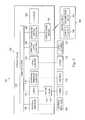
- FIG. 2is an illustration of an exemplary block diagram of the surgical system of FIG. 1 according to an aspect consistent with the principles of the present disclosure.
- FIG. 3is an illustration of an exemplary image displayable on a wearable user interface according to an aspect consistent with the principles of the present disclosure.
- FIG. 4is an illustration of an exemplary block diagram of another surgical system according to an aspect consistent with the principles of the present disclosure.
- FIG. 5is an illustration of an exemplary image displayable on a wearable user interface according to an aspect consistent with the principles of the present disclosure.
- FIG. 6is an illustration of another exemplary image displayable on a wearable user interface according to an aspect consistent with the principles of the present disclosure.
- FIG. 7is an illustration of an exemplary block diagram of another wearable user interface of a surgical system according to an aspect consistent with the principles of the present disclosure.
- FIG. 8illustrates another exemplary surgical system according to an embodiment consistent with the principles of the present disclosure.
- the devices, systems, and methods described hereindisplay information on a wearable user interface that shows the status of an ocular surgical system to a surgeon performing the ocular surgery, while also permitting the surgeon to see the surgical site. In one example, it does this with an informational peripheral data display region or frame about a central surgical viewing area that may be used to view the surgical site. As such, the surgeon may continue to perform the surgery while visually being made aware of changing states or measured parameters during the surgery. This may increase the efficiency of the surgery, benefiting both the surgeon and the patient.
- the devices, systems, and methods described hereinprovide a surgeon with a more comfortable surgical setting by permitting a surgeon to view a surgical site for an ocular surgery outside of a microscope.
- the surgeonobserves the surgical site through a wearable user interface carried on and moveable with a surgeon's head so that the surgeon can view the surgical site without bending over the microscope.
- information regarding the surgical systemmay also be presented to the surgeon so that the surgeon can be aware of the status of the surgical equipment and the eye.
- FIG. 1shows an exemplary surgical system 100 for treating an ophthalmic condition.
- the surgical systemincludes a console 102 for performing a surgery and includes a wearable user interface 104 .
- the console 102is a surgical console configured and arranged to perform a surgical procedure, such an ocular surgical procedure on a patient.
- the surgical consoleis a phacoemulsification surgical console.
- FIG. 2is a block diagram of the system 100 including the console 102 and the wearable user interface 104 .
- the console 102includes a computer unit 103 , a display screen 105 , and a number of subsystems that are used together to perform ocular surgical procedures, such as emulsification or vitrectomy surgical procedures, for example.
- the subsystemsinclude a foot pedal subsystem 106 including, for example, a foot pedal 108 , a fluidics subsystem 110 including an aspiration vacuum 112 and an irrigation pump 114 that connect to tubing 115 , an ultrasonic generator subsystem 116 including an ultrasonic oscillation handpiece 118 , an intravenous (IV) pole subsystem 120 including a motorized IV pole 122 , and a pneumatic vitrectomy cutter subsystem 124 including a vitrectomy handpiece 127 , and an imaging and control subsystem 126 including a communication module 130 .
- IVintravenous
- a microscope 128 and arm 150also form a part of the console 102 .
- the microscope 128 and arm 150are separate from the console 102 .
- their operating parametersdiffer according to, for example, the particular procedure being performed, the different stages of the procedure, the surgeon's personal preferences, whether the procedure is being performed in the anterior or posterior portion of the patient's eye, and so on.
- alternative consolesmay have alternative subsystems.
- the different subsystems in the console 102comprise control circuits for the operation and control of the respective microsurgical instruments.
- the computer system 103governs the interaction and relationship between the different subsystems to properly perform an ocular surgical procedure. To do this, it includes a processor and memory and is preprogrammed with instructions for controlling the subsystems to carry out a surgical procedure, such as an emulsification procedure or a vitrectomy, for example.
- the console 102includes an input device that permits a user to make selections within a limited scope to control or modify the preprogrammed relationships between different subsystems.
- input devicesmay be incorporated into the console and may include the footpedal 108 , a touch screen device responsive to selections made directly on the screen, a standard computer keyboard, a standard pointing device, such as a mouse or trackball, buttons, knobs, or other input devices are also contemplated.
- a surgeon, scientist, or other usermay select or adjust parameters that affect the relationships between the different subsystems of the console 102 . Accordingly, based on a user input, a user may change or adjust the relationships from those that were hard-coded into the console by the system programmers.
- the console 102includes an arm 150 that supports the microscope 128 .
- the microscope 128may be attached to the console 102 and may be positioned at a location proximate the surgical site so that a surgeon may view the surgical site.
- a surgeonwears the wearable user interface 104 and looks through the microscope 128 at the surgical site, he or she may perform the surgery while additional status, state, and parameter information is simultaneously viewable. This may increase the efficiency of the operation because the surgeon need not take his eyes off the surgical site to obtain status information of the system.
- the imaging and control subsystem 126is configured and arranged to present data and information to the wearable user interface 104 for easy and intuitive display to a surgeon during a surgical procedure.
- the communication module 130 of the imaging and control subsystem 126may comprise a transceiver used to communicate with the wearable user interface 104 . It may communicate settings and/or setting images relating to the surgical site and the console settings.
- the transceiveris an RF (Radio Frequency) transceiver enabling wireless communication. It may also communicate via Bluetooth, Wi-Fi (Wireless Fidelity), infrared or other communication method. Wired systems are also contemplated.
- the transceivermay receive information and data from the wearable user interface 104 . The information and data may include user selections and instructions for operating different aspects of the console 100 and may include information and data relating to the wearable user interface 104 itself, such as battery status and any error information.
- FIG. 2also shows the wearable user interface 104 that can display data relating to system operation and performance during an ocular surgical procedure.
- the wearable user interface 104may comprise a display screen 140 and a communication module 142 .
- the wearable user interface 104may be configured as a monocle or goggles that are worn over the eyes of the surgeon. Other wearable user interfaces may be used, including head-sets, facial shields, or other wearable user interfaces.
- An advantage associated with a wearable user interfaceis that the display shows information that may be relevant to the surgery directly to the surgeon without requiring the surgeon to move away from the monocles of the microscope. In addition, the surgeon may move his or her head, and may still view the displayed surgical data.
- the display screen 140 on the wearable user interface 104may be, for example, standard (480i) or high definition (720p, 1080i, or 1080p) display screen that presents images to the wearer. Other screens having other resolutions are also contemplated.
- the wearable user interface 104has particular regions of the screen that are transparent and permit the surgeon to see through, similar to a pair of conventional eyeglasses. As such, the surgeon can look through the microscope 128 to see the surgical environment while still obtaining a benefit of the data display. This may enable the surgeon to look through a microscope, grasp tools see about the surgical room, etc. to maintain an optimal surgical experience.
- the communication module 142receives the transmitted data and information from the communication module 130 of the console 102 . It then conveys the information to the display screen 140 for display to the surgeon. In addition, it may convey information and data from the wearable user interface 104 to the communication module 130 on the console 102 .
- the communication module 142comprises a transceiver as described above.
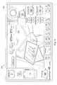
- FIG. 3shows an exemplary image 200 that may be presented on the display screen 140 during a surgical procedure. It may also be shown on the console display 105 .
- the image 200includes a central surgical viewing area 202 configured to display an area of focus and includes a peripheral data display region or display frame 204 about the central surgical viewing area 202 that shows information relating to the surgical process, surgical components, or other parts of the console 102 .
- the central surgical viewing area 202is disposed primarily in the central region of the display screen 140 and is sized to permit a surgeon to have a sufficiently large and unobstructed view of the surgical site.
- the central surgical viewing area 202is a transparent portion of the wearable user interface 104 permitting a surgeon to see through the wearable user interface 104 and into oculars of a microscope to visualize the surgical site in a conventional manner. As such, the surgeon can see and perform the surgery as is done conventionally.
- the display frame 204provides important surgical status and setting data to the surgeon that can be visualized without turning his head or removing it from the monocles of the microscope. As such, a surgeon does not need to look at the console in order to know which settings are active and the status of the surgical process.
- the display frame 204is shown as a solid frame with a solid background, some embodiments merely overlay the informational and data elements onto the image viewed by the surgeon. As such, the display frame 204 may have fewer obstructions and the surgeon may feel that he has a larger and more complete view of the surgical site.
- the display frame 204includes features relating to settings of the console, supply status, and conditions of the patient. For ease of explanation, the exemplary information will be described in detail.
- the imageincludes console mode settings that correspond to typical surgical processes.
- the console mode settingincludes a selectable Setup icon 220 , a PrePhaco icon 222 , a Sculpt icon 224 , a Quad icon 226 , an EPI icon 228 , a Cortex icon 230 , a Polish icon 232 , a Visco icon 234 , a Coag icon 236 and a Vit icon 238 .
- These iconsshow the mode in which the console is operating. Whenever one of these icons is selected, the information and selections displayed are changed as appropriate for the surgical process each of the icons represents. In one embodiment, these settings are changed on the console 102 , and the display 200 is updated to show the newest settings.
- the PrePhaco icon 222is displayed as being selected.
- buttons, knobs, or touch screen on the console or foot pedalmay be selected by input settings on the console, such as by buttons, knobs, or touch screen on the console or foot pedal.
- a knobmay be rotated to highlight each selectable icon in turn, and when the desired icon is highlighted an input is made using a button, pressuring the knob, or tapping the foot pedal.
- Other selection methodsare also contemplated.
- the aspiration flow rate value 240indicates the flow rate in cc/min (Cubic Centimeter/minute). In this example, a line across the display indicates whether the flow rate value is on target, above target, and below target.
- the IOP (Intraocular Pressure) ramp value 242indicates ramp time in seconds to arrive at the desired flow rate.
- the flow comp value 244indicates the setting or rate for compensating for overshoot. Accordingly, overshoot in the aspiration flow is compensated at the set rate of the flow comp value 244 .
- a vacuum pressure value 246 in mmHgMillimeters of Mercury
- a PEL (patient eye level) value 248PEL (patient eye level)
- a Dyn Rise (Dynamic Rise) value 250The vacuum pressure value 246 represents the vacuum pulled by the pump to achieve the desired aspiration pressure.
- the PEL value 248represents the patient eye level to track the basic saline solution or irrigation source input pressure.
- the Dyn Rise value 250is used to control the rate of response to overshoot in the vacuum pressure. Again, these may be set on the console 102 .
- the Torsional setting 254shows the setting for the direction of ultrasonic vibration delivered by the phacoemulsification handpiece 118 .
- the upper right corner of the image 200may be an additional viewing window that permits the viewer to see through the wearable headset into the environment.
- itmay include a live video feed that enables the surgeon to see portions of the environment, such as the surgical site or the instruments tray, for example.
- the display screen 140includes a status bar 256 .
- Thismay be used to present important information to the surgeon during the surgical procedure. In one example, this may include a green light or text indication that all functions and subsystems are operating normally or as expected.
- the status bar 256may be arranged to alert the surgeon of unusual conditions that require the surgeon's attention. In some embodiments, the status bar uses color codes and flashing indicators to capture the surgeon's attention as he performs the surgery.
- the status indicatorsinclude two foot pedals 260 and their battery levels on the frame display and two wearable user interfaces 262 and their battery levels.
- a state of operation indicator 264displays to the surgeon whether the console 102 is in a continuous operating mode or whether the console is being run under foot pedal control. In this case, the console is set in continuous mode.
- the display frame 204shows a longitudinal parameter 208 that displays to the surgeon the longitudinal setting of the ultrasonic vibration delivered by the phacoemulsification handpiece 118 .
- the display frame 204also includes continuous irrigation indicator 210 .
- the continuous irrigationis off. However, it may be switched on at the console 102 , and the console will transmit information to generate a different image for viewing on the wearable user interface 104 that shows the continuous irrigation as on.
- the display frame 204also includes an irrigation source level indicator 212 .
- the irrigation source level indicator 212displays to the surgeon the current level of the irrigation source.
- the irrigation sourceis conventionally an IV saline source carried by the IV pole on the console 102 .
- the irrigation source level indicator 212is shown as full. It also includes a fill line that indicates to the surgeon that the irrigation source is depleted and should be replaced with a full irrigation source.
- the statusis sent from the console 102 to the wearable user interface 104 so that the surgeon can monitor the status of the irrigation source without removing his eyes from the monocles of the microscope.
- the irrigation source level indicator 212may flash, pulse, or change colors, such as to a red color, when the fluid level falls below a preset threshold, thereby more fully drawing the surgeon's attention to the state of the fluid source.
- the display frame 204Adjacent the irrigation source level indicator 212 , the display frame 204 includes an intraocular pressure (IOP) indicator 214 .
- the IOP indicatordisplays the value of the IOP for continuous monitoring by the surgeon. Since IOP is a function of both atmospheric pressure and intraocular pressure, some embodiments of the IOP indicator 214 are configured to display secondary values that are used to acquire IOP.
- the IOP indicator 214displays an atmospheric pressure level 216 at the indicator 214 .
- the IOP indicatoralso displays the equivalent bottle height 218 .
- the equivalent bottle heightis set at 68 (centimeters of water (cmH2O)). This is typically determined via a pressure transducer in the irrigation line, and can be adjusted to achieve a desired IOP.
- the above described informationis displayed to the surgeon through the wearable user interface as he looks in oculars of a microscope to perform the ocular surgery. Accordingly, the system may operate as though the surgeon is wearing eye-glasses that present the frame around the visual line of sight. If the surgeon were to desire to change the settings or the information, he or she would change them on the console and with the foot pedal, for example. It should be understood that different arrangements of the displayed information are contemplated.
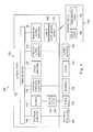
- FIG. 4shows another exemplary surgical system 300 that includes a camera 302 as a part of the imaging and control system 126 .
- the microscope 128 in FIG. 1may be replaced with the camera 302 or the camera 302 may be disposed alongside the microscope 128 for imaging.
- the surgical system 300includes many features similar to that of the embodiments of FIG. 1 , and therefore, a description of those is not repeated here.
- the imaging and control subsystem 126is configured and arranged to capture images with the camera 302 and present image data in addition to status and parameter data to the wearable user interface 104 .
- the arm 150may carry the camera 302 of the imaging and control subsystem 126 .
- the camera 302may be disposed in a location proximate the surgical site so that the camera 302 can capture images of the surgical site. Images from the camera 302 are processed by the imaging and control subsystem 126 and then transmitted by the communication module 130 to the wearable user interface 104 .
- the camera 302is a high definition 3D (three dimensional) imaging camera configured to capture images of the surgical site in a manner enabling the surgeon to view the surgical site and have depth perception at the surgical site that may not be obtained by a traditional camera image displayed on a 2D (two dimensional) display screen.
- the camera 302is associated with oculars disposed adjacent the camera 302 to enable a surgeon to view the surgical site in a traditional manner through a microscope. This may aid the surgeon in aligning the camera 302 at a desired location relative to the surgical site prior to beginning an ocular surgery.
- FIG. 5shows an example of an image 310 displayed on the display screen of the wearable user interface 104 .
- the image 310includes a central surgical viewing area 312 and a display frame 314 . Since most of the display frame 314 is similar to the display frame 204 in FIG. 3 , it will not all be described again in detail.
- the central surgical viewing area 312is showing an image captured through the real-time camera 302 that is transmitted to the wearable user interface 104 . Accordingly, in this embodiment, the surgeon need not align his head to look through the oculars on the microscope in order to view the surgical site. As such, the surgeon may hold his head more comfortably, and may even move his head during the surgical procedure while still viewing the surgical site and while performing the surgery.
- the display frame 314includes a second display region 316 in place of the status bar shown in FIG. 3 .
- the second display region 316is simply a transparent region that the surgeon may look through in order to see the environment. Accordingly, during the surgery, the surgeon may view the environment through the second display region 316 of the wearable user interface 104 , while video of the surgical site is displayed in the central surgical viewing area. As such, he or she may be able to view the instrument tray for example and grasp desired instruments or see other parts of the surgical room without removing the wearable user interface 104 . In addition, the surgeon can turn and view the console and make any necessary changes or adjustments on the console without removing the wearable user interface 104 . He needs only to gaze into the corner that does not have a displayed image.
- the system 100includes a wearable camera disposed on the wearable user interface 104 itself.
- This wearable cameramay capture and display images in real-time.
- the display in FIG. 5is showing two captured images, it may replace one for the other as is shown in FIG. 6 . That is, if both images are images captured by cameras, either the console 102 or the wearable user interface 104 may permit a surgeon to toggle between the image in the central surgical viewing area 312 and the image in the second display region 316 . This is shown in FIG. 6 .
- the usermay use any input to toggle between the images, including for example, an input on the wearable user interface or an input on the console 102 .
- the display screen 140comprises a screen for each eye, increasing the depth perception as compared to a conventional image on a 2D screen which may be important to a surgeon during the ocular surgical process.
- control of the console 102is integrated with the images displayed to the surgeon during the surgical procedure.
- the usermay make selections or adjust parameters based on the images in the wearable user interface 104 .
- the console 100includes a scroll wheel that moves a cursor about the selectable portions of the display screen.
- the icons, values, or regionsare highlighted in turn as the user turns the scroll wheel.
- the usermay select it using an input, such as a button on the console 102 , the wearable user interface 104 or elsewhere.
- the selectionsmay be made using the foot pedal 108 .
- FIG. 7discloses an alternative embodiment of a wearable user interface 450 usable in the system 100 .
- the wearable user interface 450includes an eye tracking system 452 that permits the console 102 to identify the point of gaze of the surgeon. Based on information obtained from the eye tracking system 452 , the system 100 may highlight the particular selectable icon in the surgeon's gaze on the wearable user interface. The surgeon may then select it using an input device, such as, for example, the foot pedal 108 . Depending on the selected item, the value may be adjusted further using additional inputs, such as wheels or knobs, keyboards, buttons, etc. As such, the eye tracking system may enable selection and control of the console using the wearable user interface 450 .
- FIG. 8shows an alternative system 460 that includes a camera system 462 , a console 464 , and the wearable user interface 104 .
- the camera system 462is configured to secure or hold the camera 302 at the desired height.
- the camera system 462is independent of the console 464 and is shaped to be disposed at the head of a surgical bed so that the camera may be located above the eye of a patient on the surgical bed.
- the console 464may be in communication with the camera system 462 and may receive live video feed for transmission to the wearable user interface 104 .
- the console 464includes a display screen 466 .
- the display screen 466displays the same data and imaging as the wearable user interface 104 .
- the display screen 466rests on a housing of the console 464 for viewing and access by the operator.
- An exemplary method of displaying data to a userincludes obtaining information relating the functions, parameters, and settings of a surgical console and parameters relating to the surgery site or the surgery itself. This may include, for example, obtaining information relating to console settings, such as irrigation settings, aspiration settings, and vacuum settings. In addition, this may include obtaining information relating to mode or state settings, such as PrePhaco settings, Sculpting settings, Quad settings, and the other settings identified relative to FIG. 3 . This may also include obtaining surgical site parameters relating the patient condition, such as IOP. Finally, this may include obtain information relating to the settings of surgical instruments of the surgical system. For example, this may include obtaining information relating to the longitudinal and torsional ultrasonic vibration profiles. With this information obtained, the information may be organized into a presentable manner as a display frame disposed around a central surgical viewing area of a display.
- the surgeonmay use a microscope through the central surgical viewing area, while simultaneously being able to view and monitor the status of the console and other surgical information.
- the systemobtains a video image of a surgical site from a video camera disposed adjacent the surgical site.
- the video imagemay, in some aspects, be organized to fit within the central surgical viewing area of the displayed image.
- the consolemay transmit the information regarding the image to the wearable user interface for display.
- the consolesends the data and information relating to the console to the wearable user interface and the camera sends a video feed directly to the wearable user interface.
- the wearable user interfaceorganizes and presents the image in the wearable user interface. The surgeon may then perform the surgery while viewing the surgical site on the wearable user interface.
- the surgeonmay select and make changes to settings using the wearable user interface.
- the surgeonmay select information or settings displayed on the wearable user interface and may modify or toggle them using input devices.
- seeking information or settings for modificationmay be accomplished using eye tracking technology that tracks the user's gaze.
- the systemmay highlight or otherwise identify that icon or setting. It may then be selected by a further input at the console or at the wearable user interface. It may then be adjusted. In one embodiment, the selection may occur by pressing the foot pedal 108 .
- the systems, devices, and methods disclosed hereinmay enable a surgeon to more efficiently perform ocular surgical procedures by providing a wearable user interface that presents information and data relating to the surgical parameters and the patient condition so that the surgeon need not remove his gaze from the surgical site to visually see the parameters, possibly resulting in more efficient surgeries.
- a cameracapture the surgical site and displaying it to the surgeon on a wearable user interface, the surgeon may more comfortably perform the surgery.
Landscapes
- Health & Medical Sciences (AREA)
- Physics & Mathematics (AREA)
- Engineering & Computer Science (AREA)
- Ophthalmology & Optometry (AREA)
- General Physics & Mathematics (AREA)
- General Health & Medical Sciences (AREA)
- Surgery (AREA)
- Theoretical Computer Science (AREA)
- Optics & Photonics (AREA)
- Biomedical Technology (AREA)
- Heart & Thoracic Surgery (AREA)
- Public Health (AREA)
- Veterinary Medicine (AREA)
- Animal Behavior & Ethology (AREA)
- Life Sciences & Earth Sciences (AREA)
- Nuclear Medicine, Radiotherapy & Molecular Imaging (AREA)
- Vascular Medicine (AREA)
- Human Computer Interaction (AREA)
- General Engineering & Computer Science (AREA)
- Chemical & Material Sciences (AREA)
- Analytical Chemistry (AREA)
- Microscoopes, Condenser (AREA)
- User Interface Of Digital Computer (AREA)
Abstract
Description
Claims (12)
Priority Applications (8)
| Application Number | Priority Date | Filing Date | Title |
|---|---|---|---|
| US13/716,680US9681982B2 (en) | 2012-12-17 | 2012-12-17 | Wearable user interface for use with ocular surgical console |
| CN201380065887.6ACN104869922B (en) | 2012-12-17 | 2013-12-10 | For the wearable user interface being used together with eye surgery operation console |
| ES13864678.1TES2653288T3 (en) | 2012-12-17 | 2013-12-10 | Portable user interface for use with eye surgical console |
| JP2015547468AJP6034509B2 (en) | 2012-12-17 | 2013-12-10 | Ophthalmic surgery system and control method thereof |
| EP13864678.1AEP2906130B1 (en) | 2012-12-17 | 2013-12-10 | Wearable user interface for use with ocular surgical console |
| CA2891554ACA2891554A1 (en) | 2012-12-17 | 2013-12-10 | Wearable user interface for use with ocular surgical console |
| PCT/US2013/074117WO2014099494A1 (en) | 2012-12-17 | 2013-12-10 | Wearable user interface for use with ocular surgical console |
| AU2013363388AAU2013363388B2 (en) | 2012-12-17 | 2013-12-10 | Wearable user interface for use with ocular surgical console |
Applications Claiming Priority (1)
| Application Number | Priority Date | Filing Date | Title |
|---|---|---|---|
| US13/716,680US9681982B2 (en) | 2012-12-17 | 2012-12-17 | Wearable user interface for use with ocular surgical console |
Publications (2)
| Publication Number | Publication Date |
|---|---|
| US20140171959A1 US20140171959A1 (en) | 2014-06-19 |
| US9681982B2true US9681982B2 (en) | 2017-06-20 |
Family
ID=50931769
Family Applications (1)
| Application Number | Title | Priority Date | Filing Date |
|---|---|---|---|
| US13/716,680Active2033-10-24US9681982B2 (en) | 2012-12-17 | 2012-12-17 | Wearable user interface for use with ocular surgical console |
Country Status (8)
| Country | Link |
|---|---|
| US (1) | US9681982B2 (en) |
| EP (1) | EP2906130B1 (en) |
| JP (1) | JP6034509B2 (en) |
| CN (1) | CN104869922B (en) |
| AU (1) | AU2013363388B2 (en) |
| CA (1) | CA2891554A1 (en) |
| ES (1) | ES2653288T3 (en) |
| WO (1) | WO2014099494A1 (en) |
Cited By (5)
| Publication number | Priority date | Publication date | Assignee | Title |
|---|---|---|---|---|
| USD872284S1 (en)* | 2016-11-03 | 2020-01-07 | This Ag | Ophthalmologic apparatus |
| US10983604B2 (en) | 2018-05-16 | 2021-04-20 | Alcon Inc. | Foot controlled cursor |
| US20210220168A1 (en)* | 2014-04-23 | 2021-07-22 | Johnson & Johnson Surgical Vision, Inc. | Medical device data filtering for real time display |
| US20240206991A1 (en)* | 2019-09-24 | 2024-06-27 | Globus Medical, Inc. | Systems and methods for facilitating robotic surgical procedures |
| US12070280B2 (en) | 2021-02-05 | 2024-08-27 | Alcon Inc. | Voice-controlled surgical system |
Families Citing this family (24)
| Publication number | Priority date | Publication date | Assignee | Title |
|---|---|---|---|---|
| JP2015170175A (en)* | 2014-03-07 | 2015-09-28 | ソニー株式会社 | Information processing apparatus, and information processing method |
| US10426339B2 (en)* | 2016-01-13 | 2019-10-01 | Novartis Ag | Apparatuses and methods for parameter adjustment in surgical procedures |
| CN105640653A (en)* | 2016-02-22 | 2016-06-08 | 李慧 | Auxiliary frame for ophthalmologic operation |
| TWI702562B (en)* | 2016-03-19 | 2020-08-21 | 香港商亞太醫療科技開發有限公司 | Systems and methods for medical procedure logging including image capture in a complex medical procedure |
| CN108601670B (en)* | 2016-03-30 | 2021-03-23 | 索尼公司 | Image processing device and method, surgical system, and surgical member |
| US10278861B2 (en)* | 2016-06-24 | 2019-05-07 | Novartis Ag | Phacoemulsification handpiece with flexible impeller pump |
| US9844321B1 (en)* | 2016-08-04 | 2017-12-19 | Novartis Ag | Enhanced ophthalmic surgical experience using a virtual reality head-mounted display |
| US10874776B2 (en) | 2017-09-01 | 2020-12-29 | Medos International Sarl | Methods, systems, and devices for joint to pump elevation level user interfaces, autocalibration for joint elevation, and joint pressure estimation |
| US10861236B2 (en) | 2017-09-08 | 2020-12-08 | Surgical Theater, Inc. | Dual mode augmented reality surgical system and method |
| WO2019077495A2 (en)* | 2017-10-18 | 2019-04-25 | Johnson & Johnson Surgical Vision, Inc. | Surgical workstation for simplified loading of intraocular lenses |
| CA2983780C (en) | 2017-10-25 | 2020-07-14 | Synaptive Medical (Barbados) Inc. | Surgical imaging sensor and display unit, and surgical navigation system associated therewith |
| US11116663B2 (en) | 2018-01-19 | 2021-09-14 | Iridex Corporation | System and method for a patient-invisible laser treatment alignment pattern in ophthalmic photomedicine |
| JP7099848B2 (en)* | 2018-03-29 | 2022-07-12 | 株式会社トプコン | Ophthalmic laser system |
| JP7099849B2 (en)* | 2018-03-29 | 2022-07-12 | 株式会社トプコン | Ophthalmic laser system |
| USD893547S1 (en) | 2018-08-28 | 2020-08-18 | DePuy Synthes Products, Inc. | Surgical pump display screen or portion thereof with graphical user interface |
| JP7263716B2 (en)* | 2018-08-31 | 2023-04-25 | 株式会社ニデック | Graphical User Interface for Ophthalmic Surgical Equipment |
| US11722644B2 (en) | 2018-09-18 | 2023-08-08 | Johnson & Johnson Surgical Vision, Inc. | Live cataract surgery video in phacoemulsification surgical system |
| JP6856594B2 (en)* | 2018-09-25 | 2021-04-07 | 株式会社メディカロイド | Surgical system and display method |
| JP6898285B2 (en)* | 2018-09-25 | 2021-07-07 | 株式会社メディカロイド | Surgical system and display method |
| JP7632284B2 (en)* | 2019-07-05 | 2025-02-19 | ソニーグループ株式会社 | Medical display system, control device, and control method |
| JP2022041664A (en)* | 2020-09-01 | 2022-03-11 | ソニーグループ株式会社 | Control device, control method, program, and ophthalmologic surgery system |
| WO2022079546A1 (en)* | 2020-10-15 | 2022-04-21 | Alcon Inc. | Wireless injector |
| EP4086687A1 (en)* | 2021-05-07 | 2022-11-09 | Leica Instruments (Singapore) Pte. Ltd. | An optical carrier for an at least partly digital microscope, a connectable viewer module for viewing an image of an object, a surgical microscope and a system |
| JP2024036816A (en)* | 2022-09-06 | 2024-03-18 | 川崎重工業株式会社 | Control method for surgical support system and operating device |
Citations (52)
| Publication number | Priority date | Publication date | Assignee | Title |
|---|---|---|---|---|
| US4202037A (en) | 1977-04-22 | 1980-05-06 | Der Loos Hendrik Van | Computer microscope apparatus and method for superimposing an electronically-produced image from the computer memory upon the image in the microscope's field of view |
| US4544243A (en) | 1984-05-24 | 1985-10-01 | Cooper Lasersonics, Inc. | Heads up display for microscope using remotely controlled instrument |
| US5303085A (en) | 1992-02-07 | 1994-04-12 | Rallison Richard D | Optically corrected helmet mounted display |
| US5450143A (en) | 1990-09-05 | 1995-09-12 | Nestle S.A. | Surgical optometer |
| US5880773A (en) | 1991-12-27 | 1999-03-09 | Sony Corporation | Head mounted display configured to a user's physical features |
| US5969791A (en) | 1998-09-23 | 1999-10-19 | Alcon Laboratories, Inc. | Intraocular data display device |
| US5991087A (en) | 1993-11-12 | 1999-11-23 | I-O Display System Llc | Non-orthogonal plate in a virtual reality or heads up display |
| JP2001142003A (en) | 1999-11-16 | 2001-05-25 | Olympus Optical Co Ltd | Microscope for operation |
| US6251113B1 (en) | 1996-08-29 | 2001-06-26 | Bausch & Lomb Surgical, Inc. | Ophthalmic microsurgical system employing surgical module employing flash EEPROM and reprogrammable modules |
| US6847336B1 (en) | 1996-10-02 | 2005-01-25 | Jerome H. Lemelson | Selectively controllable heads-up display system |
| US20050203380A1 (en) | 2004-02-17 | 2005-09-15 | Frank Sauer | System and method for augmented reality navigation in a medical intervention procedure |
| US20050277913A1 (en)* | 2004-06-09 | 2005-12-15 | Mccary Brian D | Heads-up display for displaying surgical parameters in a surgical microscope |
| US20060114175A1 (en) | 2004-11-30 | 2006-06-01 | Mikhail Boukhny | Graphical user interface system and method for representing and controlling surgical parameters |
| US20060142657A1 (en)* | 2002-03-06 | 2006-06-29 | Mako Surgical Corporation | Haptic guidance system and method |
| US20060247659A1 (en) | 2004-10-26 | 2006-11-02 | Carl Zeiss Surgical Gmbh | Surgical microscopy system and method for performing eye surgery |
| US20070008624A1 (en) | 2004-03-12 | 2007-01-11 | Nikon Corporation | Optical image display system and image display unit |
| US20070081078A1 (en) | 2005-09-27 | 2007-04-12 | Eric Cummings | Synchronized video microscope |
| US20070164990A1 (en) | 2004-06-18 | 2007-07-19 | Christoffer Bjorklund | Arrangement, method and computer program for controlling a computer apparatus based on eye-tracking |
| US20070167702A1 (en) | 2005-12-30 | 2007-07-19 | Intuitive Surgical Inc. | Medical robotic system providing three-dimensional telestration |
| US20070202479A1 (en) | 2006-02-27 | 2007-08-30 | Todd Kirk W | System and Method for a Procedure Based Graphical Interface |
| US20080123183A1 (en)* | 2006-06-30 | 2008-05-29 | Richard Awdeh | Microscope Viewing Device |
| US20080216171A1 (en) | 2007-02-14 | 2008-09-04 | Sony Corporation | Wearable device, authentication method, and recording medium |
| US20080243142A1 (en) | 2007-02-20 | 2008-10-02 | Gildenberg Philip L | Videotactic and audiotactic assisted surgical methods and procedures |
| US7460305B2 (en) | 2004-02-04 | 2008-12-02 | Microvision, Inc. | Scanned-beam heads-up display and related systems and methods |
| US20090036902A1 (en) | 2006-06-06 | 2009-02-05 | Intuitive Surgical, Inc. | Interactive user interfaces for robotic minimally invasive surgical systems |
| US20090049397A1 (en) | 2007-08-15 | 2009-02-19 | Mikhail Boukhny | System And Method For A Simple Graphical Interface |
| WO2009023408A1 (en) | 2007-08-15 | 2009-02-19 | Alcon, Inc. | System and method for a user interface |
| US7519223B2 (en) | 2004-06-28 | 2009-04-14 | Microsoft Corporation | Recognizing gestures and using gestures for interacting with software applications |
| US20090125849A1 (en) | 2005-10-28 | 2009-05-14 | Tobii Technology Ab | Eye Tracker with Visual Feedback |
| JP2009153785A (en) | 2007-12-27 | 2009-07-16 | Morita Mfg Co Ltd | Medical display device, medical device and medical display device |
| US20090231485A1 (en) | 2006-09-06 | 2009-09-17 | Bernd Steinke | Mobile Terminal Device, Dongle and External Display Device Having an Enhanced Video Display Interface |
| US20090270678A1 (en) | 2008-04-26 | 2009-10-29 | Intuitive Surgical, Inc. | Augmented stereoscopic visualization for a surgical robot using time duplexing |
| WO2010067267A1 (en) | 2008-12-09 | 2010-06-17 | Philips Intellectual Property & Standards Gmbh | Head-mounted wireless camera and display unit |
| US7763015B2 (en) | 2005-01-24 | 2010-07-27 | Intuitive Surgical Operations, Inc. | Modular manipulator support for robotic surgery |
| US7777960B2 (en) | 2007-09-10 | 2010-08-17 | Microvision, Inc. | Wide field of view head-up display system |
| US20100217278A1 (en)* | 2009-02-20 | 2010-08-26 | Ashok Burton Tripathi | Real-time surgical reference indicium apparatus and methods for intraocular lens implantation |
| US7784946B2 (en) | 2007-12-21 | 2010-08-31 | Alcon Refractivehorizons, Inc. | Virtual microscope system for monitoring the progress of corneal ablative surgery and associated methods |
| US20100281438A1 (en) | 2009-05-01 | 2010-11-04 | Microsoft Corporation | Altering a view perspective within a display environment |
| US20100277411A1 (en) | 2009-05-01 | 2010-11-04 | Microsoft Corporation | User tracking feedback |
| US7855743B2 (en) | 2006-09-08 | 2010-12-21 | Sony Corporation | Image capturing and displaying apparatus and image capturing and displaying method |
| US7901072B1 (en) | 2009-11-13 | 2011-03-08 | Vuzix Corporation | Prismatic ocular device and personal video display device incorporating same |
| US20110093821A1 (en) | 2009-10-20 | 2011-04-21 | Microsoft Corporation | Displaying gui elements on natural user interfaces |
| WO2011053921A2 (en) | 2009-10-30 | 2011-05-05 | The Johns Hopkins University | Visual tracking and annotation of clinically important anatomical landmarks for surgical interventions |
| US7983771B2 (en) | 2004-11-30 | 2011-07-19 | Novartis Ag | Graphical user interface including a pop up window for an ocular surgical system |
| US20110279666A1 (en) | 2009-01-26 | 2011-11-17 | Stroembom Johan | Detection of gaze point assisted by optical reference signal |
| US8066375B2 (en) | 2005-10-10 | 2011-11-29 | Tobii Technology Ab | Eye tracker having an extended span of operating distances |
| US20120105483A1 (en)* | 2010-10-28 | 2012-05-03 | Fedorovskaya Elena A | Head-mounted display control with image-content analysis |
| WO2012137067A2 (en) | 2011-04-07 | 2012-10-11 | Oculox Technology | Intraocular pressure monitoring device and methods |
| US20120330129A1 (en)* | 2011-06-23 | 2012-12-27 | Richard Awdeh | Medical visualization systems and related methods of use |
| US20130021374A1 (en)* | 2011-07-20 | 2013-01-24 | Google Inc. | Manipulating And Displaying An Image On A Wearable Computing System |
| US20130041368A1 (en)* | 2011-08-09 | 2013-02-14 | Tyco Healthcare Group Lp | Apparatus and Method for Using a Remote Control System in Surgical Procedures |
| US8631802B2 (en) | 2006-06-30 | 2014-01-21 | Novartis Ag | System and method for the modification of surgical procedures using a graphical drag and drop interface |
Family Cites Families (1)
| Publication number | Priority date | Publication date | Assignee | Title |
|---|---|---|---|---|
| TWI522085B (en)* | 2010-04-14 | 2016-02-21 | 愛爾康研究有限公司 | Display for ophthalmic surgical console with user-selectable sectors |
- 2012
- 2012-12-17USUS13/716,680patent/US9681982B2/enactiveActive
- 2013
- 2013-12-10AUAU2013363388Apatent/AU2013363388B2/ennot_activeCeased
- 2013-12-10EPEP13864678.1Apatent/EP2906130B1/enactiveActive
- 2013-12-10WOPCT/US2013/074117patent/WO2014099494A1/enactiveApplication Filing
- 2013-12-10JPJP2015547468Apatent/JP6034509B2/enactiveActive
- 2013-12-10ESES13864678.1Tpatent/ES2653288T3/enactiveActive
- 2013-12-10CACA2891554Apatent/CA2891554A1/ennot_activeAbandoned
- 2013-12-10CNCN201380065887.6Apatent/CN104869922B/ennot_activeExpired - Fee Related
Patent Citations (59)
| Publication number | Priority date | Publication date | Assignee | Title |
|---|---|---|---|---|
| US4202037A (en) | 1977-04-22 | 1980-05-06 | Der Loos Hendrik Van | Computer microscope apparatus and method for superimposing an electronically-produced image from the computer memory upon the image in the microscope's field of view |
| US4544243A (en) | 1984-05-24 | 1985-10-01 | Cooper Lasersonics, Inc. | Heads up display for microscope using remotely controlled instrument |
| US5450143A (en) | 1990-09-05 | 1995-09-12 | Nestle S.A. | Surgical optometer |
| US5880773A (en) | 1991-12-27 | 1999-03-09 | Sony Corporation | Head mounted display configured to a user's physical features |
| US5303085A (en) | 1992-02-07 | 1994-04-12 | Rallison Richard D | Optically corrected helmet mounted display |
| US5619377A (en) | 1992-02-07 | 1997-04-08 | Virtual I/O, Inc. | Optically corrected helmet mounted display |
| US5642227A (en) | 1992-02-07 | 1997-06-24 | Virtual I/O, Inc. | Optical correction for virtual reality and heads up displays |
| US5673151A (en) | 1992-02-07 | 1997-09-30 | Virtual I/O | Image correction in virtual reality and heads up displays |
| US5991087A (en) | 1993-11-12 | 1999-11-23 | I-O Display System Llc | Non-orthogonal plate in a virtual reality or heads up display |
| US6251113B1 (en) | 1996-08-29 | 2001-06-26 | Bausch & Lomb Surgical, Inc. | Ophthalmic microsurgical system employing surgical module employing flash EEPROM and reprogrammable modules |
| US6847336B1 (en) | 1996-10-02 | 2005-01-25 | Jerome H. Lemelson | Selectively controllable heads-up display system |
| US5969791A (en) | 1998-09-23 | 1999-10-19 | Alcon Laboratories, Inc. | Intraocular data display device |
| JP2001142003A (en) | 1999-11-16 | 2001-05-25 | Olympus Optical Co Ltd | Microscope for operation |
| US20060142657A1 (en)* | 2002-03-06 | 2006-06-29 | Mako Surgical Corporation | Haptic guidance system and method |
| US7460305B2 (en) | 2004-02-04 | 2008-12-02 | Microvision, Inc. | Scanned-beam heads-up display and related systems and methods |
| US20050203380A1 (en) | 2004-02-17 | 2005-09-15 | Frank Sauer | System and method for augmented reality navigation in a medical intervention procedure |
| US20070008624A1 (en) | 2004-03-12 | 2007-01-11 | Nikon Corporation | Optical image display system and image display unit |
| US20050277913A1 (en)* | 2004-06-09 | 2005-12-15 | Mccary Brian D | Heads-up display for displaying surgical parameters in a surgical microscope |
| US20070164990A1 (en) | 2004-06-18 | 2007-07-19 | Christoffer Bjorklund | Arrangement, method and computer program for controlling a computer apparatus based on eye-tracking |
| US7519223B2 (en) | 2004-06-28 | 2009-04-14 | Microsoft Corporation | Recognizing gestures and using gestures for interacting with software applications |
| US20060247659A1 (en) | 2004-10-26 | 2006-11-02 | Carl Zeiss Surgical Gmbh | Surgical microscopy system and method for performing eye surgery |
| US7983771B2 (en) | 2004-11-30 | 2011-07-19 | Novartis Ag | Graphical user interface including a pop up window for an ocular surgical system |
| US20060114175A1 (en) | 2004-11-30 | 2006-06-01 | Mikhail Boukhny | Graphical user interface system and method for representing and controlling surgical parameters |
| US7763015B2 (en) | 2005-01-24 | 2010-07-27 | Intuitive Surgical Operations, Inc. | Modular manipulator support for robotic surgery |
| US20070081078A1 (en) | 2005-09-27 | 2007-04-12 | Eric Cummings | Synchronized video microscope |
| US8066375B2 (en) | 2005-10-10 | 2011-11-29 | Tobii Technology Ab | Eye tracker having an extended span of operating distances |
| US20090125849A1 (en) | 2005-10-28 | 2009-05-14 | Tobii Technology Ab | Eye Tracker with Visual Feedback |
| US20070167702A1 (en) | 2005-12-30 | 2007-07-19 | Intuitive Surgical Inc. | Medical robotic system providing three-dimensional telestration |
| US20070202479A1 (en) | 2006-02-27 | 2007-08-30 | Todd Kirk W | System and Method for a Procedure Based Graphical Interface |
| US20090036902A1 (en) | 2006-06-06 | 2009-02-05 | Intuitive Surgical, Inc. | Interactive user interfaces for robotic minimally invasive surgical systems |
| US8631802B2 (en) | 2006-06-30 | 2014-01-21 | Novartis Ag | System and method for the modification of surgical procedures using a graphical drag and drop interface |
| US20080123183A1 (en)* | 2006-06-30 | 2008-05-29 | Richard Awdeh | Microscope Viewing Device |
| US7800820B2 (en) | 2006-06-30 | 2010-09-21 | Richard Awdeh | Microscope viewing device |
| US20090231485A1 (en) | 2006-09-06 | 2009-09-17 | Bernd Steinke | Mobile Terminal Device, Dongle and External Display Device Having an Enhanced Video Display Interface |
| US7855743B2 (en) | 2006-09-08 | 2010-12-21 | Sony Corporation | Image capturing and displaying apparatus and image capturing and displaying method |
| US20080216171A1 (en) | 2007-02-14 | 2008-09-04 | Sony Corporation | Wearable device, authentication method, and recording medium |
| US20080243142A1 (en) | 2007-02-20 | 2008-10-02 | Gildenberg Philip L | Videotactic and audiotactic assisted surgical methods and procedures |
| US20090049397A1 (en) | 2007-08-15 | 2009-02-19 | Mikhail Boukhny | System And Method For A Simple Graphical Interface |
| WO2009023408A1 (en) | 2007-08-15 | 2009-02-19 | Alcon, Inc. | System and method for a user interface |
| US7981109B2 (en) | 2007-08-15 | 2011-07-19 | Novartis Ag | System and method for a user interface |
| US20090048587A1 (en)* | 2007-08-15 | 2009-02-19 | Paul Avanzino | System And Method For A User Interface |
| JP2010536423A (en) | 2007-08-15 | 2010-12-02 | アルコン,インコーポレイティド | Apparatus and method for user interface |
| US7777960B2 (en) | 2007-09-10 | 2010-08-17 | Microvision, Inc. | Wide field of view head-up display system |
| US7784946B2 (en) | 2007-12-21 | 2010-08-31 | Alcon Refractivehorizons, Inc. | Virtual microscope system for monitoring the progress of corneal ablative surgery and associated methods |
| JP2009153785A (en) | 2007-12-27 | 2009-07-16 | Morita Mfg Co Ltd | Medical display device, medical device and medical display device |
| US20090270678A1 (en) | 2008-04-26 | 2009-10-29 | Intuitive Surgical, Inc. | Augmented stereoscopic visualization for a surgical robot using time duplexing |
| WO2010067267A1 (en) | 2008-12-09 | 2010-06-17 | Philips Intellectual Property & Standards Gmbh | Head-mounted wireless camera and display unit |
| US20110279666A1 (en) | 2009-01-26 | 2011-11-17 | Stroembom Johan | Detection of gaze point assisted by optical reference signal |
| US20100217278A1 (en)* | 2009-02-20 | 2010-08-26 | Ashok Burton Tripathi | Real-time surgical reference indicium apparatus and methods for intraocular lens implantation |
| US20100277411A1 (en) | 2009-05-01 | 2010-11-04 | Microsoft Corporation | User tracking feedback |
| US20100281438A1 (en) | 2009-05-01 | 2010-11-04 | Microsoft Corporation | Altering a view perspective within a display environment |
| US20110093821A1 (en) | 2009-10-20 | 2011-04-21 | Microsoft Corporation | Displaying gui elements on natural user interfaces |
| WO2011053921A2 (en) | 2009-10-30 | 2011-05-05 | The Johns Hopkins University | Visual tracking and annotation of clinically important anatomical landmarks for surgical interventions |
| US7901072B1 (en) | 2009-11-13 | 2011-03-08 | Vuzix Corporation | Prismatic ocular device and personal video display device incorporating same |
| US20120105483A1 (en)* | 2010-10-28 | 2012-05-03 | Fedorovskaya Elena A | Head-mounted display control with image-content analysis |
| WO2012137067A2 (en) | 2011-04-07 | 2012-10-11 | Oculox Technology | Intraocular pressure monitoring device and methods |
| US20120330129A1 (en)* | 2011-06-23 | 2012-12-27 | Richard Awdeh | Medical visualization systems and related methods of use |
| US20130021374A1 (en)* | 2011-07-20 | 2013-01-24 | Google Inc. | Manipulating And Displaying An Image On A Wearable Computing System |
| US20130041368A1 (en)* | 2011-08-09 | 2013-02-14 | Tyco Healthcare Group Lp | Apparatus and Method for Using a Remote Control System in Surgical Procedures |
Non-Patent Citations (6)
| Title |
|---|
| European Patent Office, Supplementary European Search Report for corresponding Application No. 13864678.1 dated May 31, 2016, 8 pages. |
| International Search Report and Written Opinion issued for PCT/US2013/074117 dated Feb. 14, 2014, 10 pgs. |
| Japanese Patent Office, Office Action for corresponding Application No. 2015-547468 dated May 20, 2016, 3 pages. |
| Lumus, Professional Market Products, Lumus LTD, Jul. 12, 2016, 2 pages. http://lumus-optical.com/?option=com-content&task=view&id=l. |
| Lumus, Professional Market Products, Lumus LTD, Jul. 12, 2016, 2 pages. http://lumus-optical.com/?option=com—content&task=view&id=l. |
| Vuzix, Augmented Reality, Start 1200, Jul. 13, 2016, pp. 1-2. https://www.vuzix.com/Products/LegacyProduct/6. |
Cited By (8)
| Publication number | Priority date | Publication date | Assignee | Title |
|---|---|---|---|---|
| US20210220168A1 (en)* | 2014-04-23 | 2021-07-22 | Johnson & Johnson Surgical Vision, Inc. | Medical device data filtering for real time display |
| US11806279B2 (en)* | 2014-04-23 | 2023-11-07 | Johnson & Johnson Surgical Vision, Inc. | Medical device data filtering for real time display |
| USD872284S1 (en)* | 2016-11-03 | 2020-01-07 | This Ag | Ophthalmologic apparatus |
| USD884191S1 (en)* | 2016-11-03 | 2020-05-12 | This Ag | Ophthalmologic apparatus |
| US10983604B2 (en) | 2018-05-16 | 2021-04-20 | Alcon Inc. | Foot controlled cursor |
| US20240206991A1 (en)* | 2019-09-24 | 2024-06-27 | Globus Medical, Inc. | Systems and methods for facilitating robotic surgical procedures |
| US12245828B2 (en)* | 2019-09-24 | 2025-03-11 | Globus Medical, Inc. | Systems and methods for facilitating robotic surgical procedures |
| US12070280B2 (en) | 2021-02-05 | 2024-08-27 | Alcon Inc. | Voice-controlled surgical system |
Also Published As
| Publication number | Publication date |
|---|---|
| EP2906130A4 (en) | 2016-06-29 |
| JP6034509B2 (en) | 2016-11-30 |
| AU2013363388B2 (en) | 2017-12-14 |
| ES2653288T3 (en) | 2018-02-06 |
| WO2014099494A1 (en) | 2014-06-26 |
| EP2906130A1 (en) | 2015-08-19 |
| US20140171959A1 (en) | 2014-06-19 |
| CN104869922B (en) | 2018-05-15 |
| CA2891554A1 (en) | 2014-06-26 |
| AU2013363388A1 (en) | 2015-07-02 |
| JP2016505312A (en) | 2016-02-25 |
| CN104869922A (en) | 2015-08-26 |
| EP2906130B1 (en) | 2017-12-06 |
Similar Documents
| Publication | Publication Date | Title |
|---|---|---|
| US9681982B2 (en) | Wearable user interface for use with ocular surgical console | |
| US12322164B2 (en) | UI for head mounted display system | |
| EP3494502B1 (en) | An enhanced ophthalmic surgical experience using a virtual reality head-mounted display | |
| US10426339B2 (en) | Apparatuses and methods for parameter adjustment in surgical procedures | |
| AU2008287185B2 (en) | System and method for a simple graphical interface | |
| JP2010536423A (en) | Apparatus and method for user interface | |
| US20180310998A1 (en) | Graphical user interface for surgical console | |
| US20170045728A1 (en) | Systems and methods for an optical system with an adjustable projected focal plane | |
| US20220022852A1 (en) | Controlling a surgical system using a footswitch |
Legal Events
| Date | Code | Title | Description |
|---|---|---|---|
| AS | Assignment | Owner name:ALCON RESEARCH, LTD., TEXAS Free format text:ASSIGNMENT OF ASSIGNORS INTEREST;ASSIGNOR:YACONO, MATTHEW DAVID;REEL/FRAME:030013/0942 Effective date:20130228 | |
| STCF | Information on status: patent grant | Free format text:PATENTED CASE | |
| AS | Assignment | Owner name:ALCON INC., SWITZERLAND Free format text:CONFIRMATORY DEED OF ASSIGNMENT EFFECTIVE APRIL 8, 2019;ASSIGNOR:NOVARTIS AG;REEL/FRAME:051454/0788 Effective date:20191111 | |
| AS | Assignment | Owner name:ALCON RESEARCH, LLC, TEXAS Free format text:MERGER;ASSIGNOR:ALCON RESEARCH, LTD.;REEL/FRAME:053273/0022 Effective date:20190228 | |
| AS | Assignment | Owner name:ALCON INC., SWITZERLAND Free format text:CONFIRMATORY DEED OF ASSIGNMENT EFFECTIVE APRIL 8, 2019;ASSIGNOR:ALCON RESEARCH, LLC;REEL/FRAME:053293/0484 Effective date:20200619 | |
| MAFP | Maintenance fee payment | Free format text:PAYMENT OF MAINTENANCE FEE, 4TH YEAR, LARGE ENTITY (ORIGINAL EVENT CODE: M1551); ENTITY STATUS OF PATENT OWNER: LARGE ENTITY Year of fee payment:4 | |
| MAFP | Maintenance fee payment | Free format text:PAYMENT OF MAINTENANCE FEE, 8TH YEAR, LARGE ENTITY (ORIGINAL EVENT CODE: M1552); ENTITY STATUS OF PATENT OWNER: LARGE ENTITY Year of fee payment:8 |