US9681898B2 - Spinous process fusion devices and methods thereof - Google Patents
Spinous process fusion devices and methods thereofDownload PDFInfo
- Publication number
- US9681898B2 US9681898B2US14/499,301US201414499301AUS9681898B2US 9681898 B2US9681898 B2US 9681898B2US 201414499301 AUS201414499301 AUS 201414499301AUS 9681898 B2US9681898 B2US 9681898B2
- Authority
- US
- United States
- Prior art keywords
- rod
- wing
- spinous process
- fusion device
- process fusion
- Prior art date
- Legal status (The legal status is an assumption and is not a legal conclusion. Google has not performed a legal analysis and makes no representation as to the accuracy of the status listed.)
- Active, expires
Links
Images


Classifications
- A—HUMAN NECESSITIES
- A61—MEDICAL OR VETERINARY SCIENCE; HYGIENE
- A61B—DIAGNOSIS; SURGERY; IDENTIFICATION
- A61B17/00—Surgical instruments, devices or methods
- A61B17/56—Surgical instruments or methods for treatment of bones or joints; Devices specially adapted therefor
- A61B17/58—Surgical instruments or methods for treatment of bones or joints; Devices specially adapted therefor for osteosynthesis, e.g. bone plates, screws or setting implements
- A61B17/68—Internal fixation devices, including fasteners and spinal fixators, even if a part thereof projects from the skin
- A61B17/70—Spinal positioners or stabilisers, e.g. stabilisers comprising fluid filler in an implant
- A61B17/7062—Devices acting on, attached to, or simulating the effect of, vertebral processes, vertebral facets or ribs ; Tools for such devices
- A61B17/7068—Devices comprising separate rigid parts, assembled in situ, to bear on each side of spinous processes; Tools therefor
- A—HUMAN NECESSITIES
- A61—MEDICAL OR VETERINARY SCIENCE; HYGIENE
- A61B—DIAGNOSIS; SURGERY; IDENTIFICATION
- A61B17/00—Surgical instruments, devices or methods
- A61B17/56—Surgical instruments or methods for treatment of bones or joints; Devices specially adapted therefor
- A61B17/58—Surgical instruments or methods for treatment of bones or joints; Devices specially adapted therefor for osteosynthesis, e.g. bone plates, screws or setting implements
- A61B17/68—Internal fixation devices, including fasteners and spinal fixators, even if a part thereof projects from the skin
- A61B17/70—Spinal positioners or stabilisers, e.g. stabilisers comprising fluid filler in an implant
- A61B17/7062—Devices acting on, attached to, or simulating the effect of, vertebral processes, vertebral facets or ribs ; Tools for such devices
- A61B17/7067—Devices bearing against one or more spinous processes and also attached to another part of the spine; Tools therefor
- A—HUMAN NECESSITIES
- A61—MEDICAL OR VETERINARY SCIENCE; HYGIENE
- A61B—DIAGNOSIS; SURGERY; IDENTIFICATION
- A61B17/00—Surgical instruments, devices or methods
- A61B17/02—Surgical instruments, devices or methods for holding wounds open, e.g. retractors; Tractors
- A61B17/025—Joint distractors
- A61B2017/0256—Joint distractors for the spine
- A—HUMAN NECESSITIES
- A61—MEDICAL OR VETERINARY SCIENCE; HYGIENE
- A61B—DIAGNOSIS; SURGERY; IDENTIFICATION
- A61B17/00—Surgical instruments, devices or methods
- A61B17/56—Surgical instruments or methods for treatment of bones or joints; Devices specially adapted therefor
- A61B2017/564—Methods for bone or joint treatment
Definitions
- the present disclosuregenerally relates to a device for positioning and immobilizing at least two adjacent vertebrae.
- the present disclosurerelates to spinous process fusion devices that distract and/or immobilize the spinous processes of adjacent vertebrae.
- Bones and bony structuresare susceptible to a variety of weaknesses that can affect their ability to provide support and structure. Weaknesses in bony structures may have many causes, including degenerative diseases, tumors, fractures, and dislocations. Advances in medicine and engineering have provided doctors with a plurality of devices and techniques for alleviating or curing these weaknesses.
- a devicethat provides structural stability to adjacent vertebrae, for example, a plate system that can distract and/or immobilize the spinous processes of adjacent vertebrae.
- An embodiment of the present inventionprovides an implantable device.
- the implantable devicemay comprise a rod, a first wing coupled to the rod, and a second wing, wherein a ratcheting lock secures the second wing to the rod.
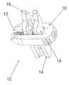
- FIG. 1is a perspective view of one embodiment of a spinous process fusion device of the present invention having a ratcheting lock
- FIG. 2is a lateral view of the spinous process fusion device of FIG. 1 ;
- FIG. 3is a top view of one embodiment of the spinous process fusion device of FIG. 1 ;
- FIGS. 4 and 5are views of the spinous process fusion device positioned between adjacent vertebrae
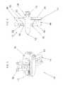
- FIG. 6is a perspective view of another embodiment of a spinous process fusion device according to the present invention.
- FIG. 7is a top view of the spinous process fusion device of FIG. 6 ;
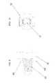
- FIGS. 8-12illustrate the cam locking and ratcheting mechanism associated with the spinous process fusion device according to the present invention
- FIG. 13is a perspective view of a distraction tool according to the present invention.
- FIG. 14is an illustration of the distraction tool positioned between adjacent spinous processes
- FIG. 15illustrates the distraction of the adjacent spinous processes with a distraction tool according to the present invention.
- FIG. 16illustrates the implantation of a spinous process fusion device between adjacent spinous processes.
- FIG. 17illustrates an spinous process fusion device insertion instrument
- FIG. 18illustrates an instrument for positioning the second wing or locking plate of the spinous process fusion device according to the present invention.
- FIGS. 19 and 20illustrate the positioning and implantation of the spinous process fusion device according to the present invention.
- the present disclosuregenerally relates to a device for positioning and immobilizing at least two adjacent vertebrae.
- the present disclosurerelates to spinous process fusion devices that distract and/or immobilize the spinous processes of adjacent vertebrae.
- the fusion devicesmay be implanted in a patient, for example, without the need for removal of the supraspinous ligament.
- the fusion devicesprovide for distraction of the interspinous space, for example, allowing use of the device as a spacer and a clamp.
- FIGS. 1-3illustrate a spinous process fusion device 10 in accordance with one embodiment of the present invention.
- the spinous process fusion device 10may comprise a rod 12 , a first wing 14 , a second wing 16 and a central barrel 18 .
- the first wing 14 and the second wing 16may be secured by the rod 12 which is coupled to the central barrel 18 .
- the first wing 14 and the second wing 16may engage spinous processes of adjacent vertebra above and below the interspinous space.
- the device 10should thus, for example, immobilize the lumbar motion segment associated with the vertebrae of the engaged spinous processes. In certain embodiments, the device 10 should immobilize the lumbar motion segment without the need for additional devices.
- the rod 12may have a length, for example, of about 20 millimeters to about 50 millimeters. As illustrated, the rod 12 extends from a first end to a second end. The first end of the rod 12 is coupled to the central barrel 18 through an opening in the central barrel 18 . The second end of the rod 12 is tapered to be configured as a frustoconical tip 20 .
- the rod 12further may include ratchet receivers 22 on opposing sides of the rod 12 that comprise protuberances.
- the protuberancesmay be, for example, in the shape of an inclined wedge with the inclined portion of the protuberance extending in the direction of the tapered end of the rod 12 .
- the protuberances of the ratchet receiversmay be arranged along the longitudinal axis of the rod 12 .
- the protuberances 12further may be arranged in various positions on a first and a second side of the rod 12 .
- the protuberances of the ratchet receivers 22are integrally formed with the rod 12 .
- the rod 12is also provided with a portion 24 proximal to the first end that does not have ratcheting teeth or threads that is coupled to the first wing 14 .
- the first wing 14is configured to be angulated with the portion 24 proximal to the first end of the rod 12 .
- the second wing 16is configured with a hole which can receive the second end of the rod 12 .
- the second wing 16is also provided with extensions or ratchets 26 positioned on either side of the second wing 16 . Each one of the extensions or ratchets 26 are adapted to couple with the protuberances of the ratchet members 22 . As force is applied upon the second wing 16 , the second wing 16 is moved toward the first wing 14 along the rod 12 .
- the first wing 14may extend transversely from the rod 12 and the barrel 18 and be disposed over the portion proximal 24 to the first end of the rod 12 and the head 28 .
- the first wing 14may have a length sufficient to span, for example between adjacent spinous processes, such as about 20 millimeters to about 60 millimeters.
- the first wing 14may comprise an upper portion 30 , a central portion 32 , a lower portion 34 , and teeth 36 .
- the upper portion 30 and the lower portion 34may have widths respectively of about 10 millimeters to about 80 millimeters, while the central portion 32 may have a width of about 5 millimeters to about 10 millimeters.
- the upper portion 30 and the lower portion 34are each generally rectangular in shape. It should be understood that other shapes for these portions of the first wing 14 may also be suitable. By way of example, the wing 14 may be rectangular with rounded corners, oval, circular, football shaped, wedge-shaped, and a variety of other shapes suitable for a particular application.
- each of the upper portion 30 and the lower portion 34may have a cutout, for example, to facilitate stacking of more than one spinous process fusion device 10 .
- the cutoutmay be configured so that the upper portion 30 and the lower portion 34 of the first wing 14 mate. In this manner, an upper portion 14 of one spinous process fusion device 10 may engage the same spinous process as the lower portion of another fusion device 10 .
- the first wing 14may be configured to angulate on the connector portion or portion 24 proximal to the first end of the rod 12 , for example, to conform to the patient's anatomy.
- the first wing 14may be configured to rotate about its longitudinal axis.
- the central portion 32 of the first wing 14may have an opening that should allow the first wing 14 to be placed onto the connector portion 24 .
- the openingshould be configured so that the first wing 14 cannot be removed from the connecting portion 24 over the rod 12 .
- the first wing 14may include the teeth 36 (e.g., spikes) for engaging the spinous processes.
- the teeth 36may bite into the spinous processes clamping the spinous processes in position.
- the teeth 36extend from the side of the first wing 14 that is facing the second wing 16 .
- Second wing 16may be placed onto the rod 12 over the protuberances of the ratcheting receivers 22 , in accordance with embodiments of the present invention. Second wing 16 may extend transversely from the rod 12 .
- the second wing 16may have a length sufficient to span, for example between adjacent spinous processes, such as about 20 millimeters to about 60 millimeters.
- the second wing 16may comprise upper portion 38 , central portion 40 and lower portion 42 .
- the upper portion 38 and lower portion 42may have widths respectively of about 10 millimeters to about 20 millimeters, while the central portion 40 may have a width of about 5 millimeters to about 10 millimeters.
- the upper portion 38 and the lower portion 42 of the second wing 16may also be rectangular shaped or any other shape suitable for a particular application.
- the upper portion 38 and the lower portion 42may also have cutouts, in certain embodiments.
- the second wing 16further may include teeth 44 (e.g., spikes) for engaging the spinous processes.
- the teeth 44may, for example, bite into the spinous process clamping them in position.
- the teeth 44may extend from the side of the second wing 16 that is facing the first wing 14 .
- the second wing 16further may include an opening that should allow the second wing 16 to be placed onto the rod 12 .
- the exterior wall of the second wing 16 surrounding the openingmay include ratcheting members 46 that extend outwardly from the exterior wall of the second wing 16 .
- the ratcheting members 46are configured to extend from the exterior wall at one edge of the opening of the second wing 16 .
- the ratcheting members 46may be grooved so that it fits over a corresponding one of the protuberances of the ratcheting receivers 22 .
- the ratcheting members 36may be in the shape of an inclined wedge with the inclined portion in the opposite direction of the inclined portion of the protuberances so that the ratcheting members 46 fit into a space between adjacent protuberances. In alternative embodiments, additional ratcheting members may be utilized.
- the ratcheting members 46should interact with the ratcheting receivers 22 to create a one-way ratcheting lock, in accordance with embodiments of the present invention.
- the ratcheting members 46 and the protuberances of the ratcheting receivers 22should be configured so that, as the second wing 16 is slid onto the rod 14 , the second wing 16 is movable over the protuberances. Once the second wing 16 is slid onto the rod 12 , the ratcheting members 46 should engage the protuberances and prevent movement when the second wing 16 is urged in the opposite direction, for example, when removal of the second wing 16 from the rod 12 is attempted.
- the second wing 16may be ratcheted onto the rod 12 . While the one-way ratcheting lock is described with respect to the illustrated embodiment, it should be understood that other techniques may be used for the one-way ratcheting lock in accordance with embodiments of the present invention.
- FIGS. 8-12illustrate the ratcheting and locking mechanism of the present invention.
- FIGS. 8 and 10illustrate the rod 12 in a locked position.
- the protuberance of the ratchet receivers 22are engaged with the ratchet extensions 46 of the second wing 16 , the spinous process fusion device 10 is in a locked position, as illustrated in FIG. 12 .
- FIGS. 9 and 11illustrate the rod 12 in an unlocked position, wherein the ratchet extensions 46 do not engage with the protuberances of the ratchet receivers 22 .
- a removal instrumentis configured to adapt to couple with the head of the rod 12 .
- the rod 12When pressure is applied to the removal instrument, the rod 12 is moved from either a locked/unlocked position to the unlocked/locked position by disengaging the ratchet extensions 46 to the ratchet receivers 22 or engaging the ratchet receivers 22 .
- the removal instrumentcan be actuated to turn the rod 90 degrees to position the rod in a locked position and turned 90 degrees further to position the rod 12 in an unlocked position.
- spinous process fusion device 10comprises the rod 12 , the first wing 14 , and the second wing 16 .
- the central barrel 18comprises a first side 50 and second side 52 , which each extend on either side of the rod 12 .
- the first side 50 and the second side 52may have widths respectively of about 10 millimeters to about 30 millimeters.
- Each of the first side 50 and the second side 52may include a tapered end 54 .
- the tapered end 54should facilitate insertion of the spinous process fusion device 10 into the interspinous space between adjacent vertebrae.
- the width of the first side 50 and the second side 52generally should provide for distraction of the interspinous space during placement of the device 10 .
- the device 10may function, for example, as both a spacer and a clamp.
- the first side 50 and the second side 52generally should restrict and/or prevent rotation of the first wing 14 and the second wing 16 about the connecting portion 24 and the rod 12 , respectively.
- the central portion 32 of the first wing 14may have a narrower width than the upper portion 30 and lower portion 34 thereof so that the upper portion 30 and the lower portion 34 may extend over the first side 50 and the second side 52 of the central barrel 18 .
- the central portion 40 of the second wing 16may also have a narrower width than the upper portion 38 and the lower portion 42 thereof.
- the central barrel 18may act as a guide for the second wing 16 when it is inserted onto the rod 12 so that it is in alignment with the first wing 14 .
- the central barrel 18further may comprise an end 56 that connects the first side 50 and the second side 52 .
- the central barrel 18also comprises at least one insertion instrument connecting portions 19 .
- connecting portions 19are configured on opposing sides of the first and second sides 50 , 52 of the central barrel 18 .
- the connecting portions 19are configured and adapted to couple with an insertion instrument.
- the connecting portions 19can be configured in various embodiments for connecting to an insertion instrument, for instance, a dovetail connection for attaching to an insertion instrument can be utilized.
- FIGS. 4 and 5illustrate the spinous process fusion device 10 of FIGS. 1-3 positioned in the interspinous space between adjacent vertebrae. As illustrated in FIGS. 4 and 5 , the first and second wing 14 , 16 are firmly positioned in between the adjacent spinous process with the central barrel of the device 10 distracting the spinous processes. Bone graft may be implanted within the spinous process fusion device 10 and within the interspinous space to enable greater fusion in the interspinous space.
- FIGS. 6 and 7illustrate another embodiment of the present invention.
- the implant 30is comprised of a rod 12 , a pivoting plate 14 , and a locking plate 16 .
- the rod 12is coupled to the pivoting plate 14 through an opening in the pivoting plate 14 .
- the rod 12is configured with a first end and a second end.
- the first end of the rod 12is tapered to be configured to be a frustoconical tip 20 .
- the second end 24is configured with a connection portion 24 and head 25 having a diameter greater than the diameter than the opening in the pivoting plate 14 .
- the head 25 of the rodis configured to receive an instrument capable of actuating the rod at least 90 degrees in either direction.
- the rod 12is also configured with ratchet receivers 22 on opposing sides of the rod 12 .
- the ratchet receivers 22comprise protuberances that extend from near the frustoconical tip 20 of the first end of the rod 12 to pivoting plate 14 .
- the number of protuberancesmay be varied depending on a patient's anatomy.
- the rod 12is also provided with a portion proximal to the first end that does not have ratcheting teeth or threads that is coupled to the pivoting plate 14 .
- the pivoting plate 14is configured to be angulated with the portion proximal to the first end of the rod 12 .
- the locking plate 16is configured with a hole which can receive the second end of the rod 12 .
- the locking plate 16is also provided with extensions 46 positioned on either side of the locking plate 16 . Each one of the extensions 16 is adapted to couple with the ratcheting members 22 . As force is applied upon the locking plate 16 , the locking plate 16 is moved toward the pivoting plate 14 along the rod 12 .
- the spinous process fusion device 10may be implanted in a patient to, for example, immobilize the spinous processes of adjacent vertebrae.
- An embodiment of implanting the spinous process fusion device 10 in a patientmay comprise inserting a spinous fusion device 10 comprising a rod and a first wing between adjacent spinous processes of a patient.
- the spinous fusion device 10generally may be inserted until the teeth of the first wing engage the adjacent spinous processes both above and below the interspinous space.
- a second winggenerally may not be on the device 10 when it is inserted.
- the central barrelmay provide for distraction of the interspinous space during placement of the device 10 .
- additional techniques and/or devicesmay be used for distraction of the interspinous space.
- the design of the spinous process fusion device 10generally should allow its insertion between adjacent spinous processes without removal of the supraspinous ligament.
- the second wingmay be placed onto the rod such that the teeth of the second wing engage the adjacent spinous processes both above and below the interspinous space.
- the second winggenerally may be positioned on the rod such that the first wing and the second wing clamp the spinous processes in place.
- the one-way ratcheting lock from interaction of the protuberances of the rod and the ratcheting members of the second winggenerally should prevent removal of the second wing. In this manner, the lumbar motion segment may be immobilized, for example, without the need for additional devices.
- FIGS. 13-15illustrate a distraction tool 60 and the distraction of the interspinous space between adjacent spinous processes.
- the spinous processesare distracted to create space for the positioning of the implant according to one embodiment of the present invention.
- the distraction tool 60distracts and creates spaces between adjacent spinous processes.
- the spinous process fusion implantmay be inserted utilizing a spinous process fusion insertion instrument as illustrated in FIGS. 16-20 .
- implant insertion instrument 62is adapted to be coupled with the implant 10 .
- a connection knob 64 of the insertion instrument 62is rotated to firmly couple the ratcheting rod to the insertion instrument 62 .
- the tip of the ratcheting rodis then introduced into the distracted interspinous space and advanced until the spikes of the pivoting plate or first wing are touching the spinous processes.
- the locking plate or second wingis then introduced into the interspinous space using a plate insertion instrument 66 , as illustrated in FIG. 18 .
- the locking plateis lined up with the tip of the ratcheting rod and squeezed until the locking plate is captured by the ratcheting rod members.
- a compressor instrumentmay be positioned over both the ratcheting rod and the locking plate and squeezed, advancing the compressor instrument until the spikes of the locking plate are firmly seated in the spinous processes.
- a plate pincher instrumentmay be used to sink the plate teeth deeper into the spinous processes, as illustrated in FIGS. 19 and 20 .
- the spinous process fusion device 10may comprise, for example, any of a variety of biocompatible materials, including metals, ceramic materials, and polymers.
- biocompatible materialsinclude titanium, stainless steel, aluminum, cobalt-chromium, alloys, and polyethylene.
- one or more components (e.g., central barrel, central core, etc.) of the device 10may comprise polyetheretherketone.
Landscapes
- Health & Medical Sciences (AREA)
- Orthopedic Medicine & Surgery (AREA)
- Life Sciences & Earth Sciences (AREA)
- Neurology (AREA)
- Surgery (AREA)
- Heart & Thoracic Surgery (AREA)
- Engineering & Computer Science (AREA)
- Biomedical Technology (AREA)
- Nuclear Medicine, Radiotherapy & Molecular Imaging (AREA)
- Medical Informatics (AREA)
- Molecular Biology (AREA)
- Animal Behavior & Ethology (AREA)
- General Health & Medical Sciences (AREA)
- Public Health (AREA)
- Veterinary Medicine (AREA)
- Prostheses (AREA)
- Surgical Instruments (AREA)
Abstract
Description
This application is a divisional of U.S. application Ser. No. 12/966,662 filed on Dec. 13, 2010, the contents of which are incorporated herein by reference in its entirety for all purposes.
The present disclosure generally relates to a device for positioning and immobilizing at least two adjacent vertebrae. In particular, in one or more embodiments, the present disclosure relates to spinous process fusion devices that distract and/or immobilize the spinous processes of adjacent vertebrae.
Bones and bony structures are susceptible to a variety of weaknesses that can affect their ability to provide support and structure. Weaknesses in bony structures may have many causes, including degenerative diseases, tumors, fractures, and dislocations. Advances in medicine and engineering have provided doctors with a plurality of devices and techniques for alleviating or curing these weaknesses.
Typically, weaknesses in the spine are corrected by using devices that fuse one or more vertebrae together. Common devices involve plate systems that align and maintain adjacent vertebrae in a desired position, with desired spacing. These devices, commonly referred to as bone fixation plating systems, typically include one or more plates and screws for aligning and holding vertebrae in a fixed position with respect to one another. When implanting these devices in a patient, it may be desirable for interspinous distraction, for example, to obtain a desired spacing between the fused spinous processes.
Thus, there is a need for a device that provides structural stability to adjacent vertebrae, for example, a plate system that can distract and/or immobilize the spinous processes of adjacent vertebrae.
An embodiment of the present invention provides an implantable device. The implantable device may comprise a rod, a first wing coupled to the rod, and a second wing, wherein a ratcheting lock secures the second wing to the rod.
The features and advantages of the present invention will be readily apparent to those skilled in the art. While numerous changes may be made by those skilled in the art, such changes are within the spirit of the invention.
The present disclosure generally relates to a device for positioning and immobilizing at least two adjacent vertebrae. In particular, in one or more embodiments, the present disclosure relates to spinous process fusion devices that distract and/or immobilize the spinous processes of adjacent vertebrae. The fusion devices may be implanted in a patient, for example, without the need for removal of the supraspinous ligament. In certain embodiments, the fusion devices provide for distraction of the interspinous space, for example, allowing use of the device as a spacer and a clamp.
In the preferred embodiment, therod 12 may have a length, for example, of about 20 millimeters to about 50 millimeters. As illustrated, therod 12 extends from a first end to a second end. The first end of therod 12 is coupled to thecentral barrel 18 through an opening in thecentral barrel 18. The second end of therod 12 is tapered to be configured as afrustoconical tip 20. Therod 12 further may includeratchet receivers 22 on opposing sides of therod 12 that comprise protuberances. The protuberances may be, for example, in the shape of an inclined wedge with the inclined portion of the protuberance extending in the direction of the tapered end of therod 12. The protuberances of the ratchet receivers may be arranged along the longitudinal axis of therod 12. Theprotuberances 12 further may be arranged in various positions on a first and a second side of therod 12. In the illustrated embodiment, the protuberances of theratchet receivers 22 are integrally formed with therod 12.
Therod 12 is also provided with aportion 24 proximal to the first end that does not have ratcheting teeth or threads that is coupled to thefirst wing 14. Thefirst wing 14 is configured to be angulated with theportion 24 proximal to the first end of therod 12. Thesecond wing 16 is configured with a hole which can receive the second end of therod 12. Thesecond wing 16 is also provided with extensions orratchets 26 positioned on either side of thesecond wing 16. Each one of the extensions orratchets 26 are adapted to couple with the protuberances of theratchet members 22. As force is applied upon thesecond wing 16, thesecond wing 16 is moved toward thefirst wing 14 along therod 12.
An embodiment of thefirst wing 14 will be described in more detail with respect toFIGS. 1-5 . Thefirst wing 14 may extend transversely from therod 12 and thebarrel 18 and be disposed over the portion proximal24 to the first end of therod 12 and thehead 28. Thefirst wing 14 may have a length sufficient to span, for example between adjacent spinous processes, such as about 20 millimeters to about 60 millimeters. Thefirst wing 14 may comprise anupper portion 30, acentral portion 32, alower portion 34, andteeth 36. Theupper portion 30 and thelower portion 34 may have widths respectively of about 10 millimeters to about 80 millimeters, while thecentral portion 32 may have a width of about 5 millimeters to about 10 millimeters. In the illustrated embodiment, theupper portion 30 and thelower portion 34 are each generally rectangular in shape. It should be understood that other shapes for these portions of thefirst wing 14 may also be suitable. By way of example, thewing 14 may be rectangular with rounded corners, oval, circular, football shaped, wedge-shaped, and a variety of other shapes suitable for a particular application.
In alternative embodiment of thefirst wing 14, each of theupper portion 30 and thelower portion 34 may have a cutout, for example, to facilitate stacking of more than one spinousprocess fusion device 10. The cutout may be configured so that theupper portion 30 and thelower portion 34 of thefirst wing 14 mate. In this manner, anupper portion 14 of one spinousprocess fusion device 10 may engage the same spinous process as the lower portion of anotherfusion device 10. While not illustrated, thefirst wing 14 may be configured to angulate on the connector portion orportion 24 proximal to the first end of therod 12, for example, to conform to the patient's anatomy. By way of example, thefirst wing 14 may be configured to rotate about its longitudinal axis.
Referring again toFIGS. 1-5 , thecentral portion 32 of thefirst wing 14 may have an opening that should allow thefirst wing 14 to be placed onto theconnector portion 24. The opening should be configured so that thefirst wing 14 cannot be removed from the connectingportion 24 over therod 12. Thefirst wing 14 may include the teeth36 (e.g., spikes) for engaging the spinous processes. By way of example, theteeth 36 may bite into the spinous processes clamping the spinous processes in position. As illustrated, theteeth 36 extend from the side of thefirst wing 14 that is facing thesecond wing 16.
Referring now toFIGS. 6-12 , thesecond wing 16 further may include an opening that should allow thesecond wing 16 to be placed onto therod 12. The exterior wall of thesecond wing 16 surrounding the opening may include ratchetingmembers 46 that extend outwardly from the exterior wall of thesecond wing 16. The ratchetingmembers 46 are configured to extend from the exterior wall at one edge of the opening of thesecond wing 16. The ratchetingmembers 46 may be grooved so that it fits over a corresponding one of the protuberances of the ratchetingreceivers 22. The ratchetingmembers 36 may be in the shape of an inclined wedge with the inclined portion in the opposite direction of the inclined portion of the protuberances so that the ratchetingmembers 46 fit into a space between adjacent protuberances. In alternative embodiments, additional ratcheting members may be utilized.
When thesecond wing 16 is placed over therod 12, the ratchetingmembers 46 should interact with the ratchetingreceivers 22 to create a one-way ratcheting lock, in accordance with embodiments of the present invention. By way of example, the ratchetingmembers 46 and the protuberances of the ratchetingreceivers 22 should be configured so that, as thesecond wing 16 is slid onto therod 14, thesecond wing 16 is movable over the protuberances. Once thesecond wing 16 is slid onto therod 12, the ratchetingmembers 46 should engage the protuberances and prevent movement when thesecond wing 16 is urged in the opposite direction, for example, when removal of thesecond wing 16 from therod 12 is attempted. Thesecond wing 16, thus, may be ratcheted onto therod 12. While the one-way ratcheting lock is described with respect to the illustrated embodiment, it should be understood that other techniques may be used for the one-way ratcheting lock in accordance with embodiments of the present invention.
Referring now toFIGS. 3 and 4 , thecentral barrel 18 is discussed in greater detail. Illustrated, spinousprocess fusion device 10 comprises therod 12, thefirst wing 14, and thesecond wing 16. In the illustrated embodiment, thecentral barrel 18 comprises afirst side 50 andsecond side 52, which each extend on either side of therod 12. Thefirst side 50 and thesecond side 52 may have widths respectively of about 10 millimeters to about 30 millimeters. Each of thefirst side 50 and thesecond side 52 may include atapered end 54. Thetapered end 54 should facilitate insertion of the spinousprocess fusion device 10 into the interspinous space between adjacent vertebrae. Moreover, the width of thefirst side 50 and thesecond side 52 generally should provide for distraction of the interspinous space during placement of thedevice 10. Thus, thedevice 10 may function, for example, as both a spacer and a clamp. Moreover, thefirst side 50 and thesecond side 52 generally should restrict and/or prevent rotation of thefirst wing 14 and thesecond wing 16 about the connectingportion 24 and therod 12, respectively. As illustrated inFIG. 4 , thecentral portion 32 of thefirst wing 14 may have a narrower width than theupper portion 30 andlower portion 34 thereof so that theupper portion 30 and thelower portion 34 may extend over thefirst side 50 and thesecond side 52 of thecentral barrel 18. Likewise, thecentral portion 40 of thesecond wing 16 may also have a narrower width than theupper portion 38 and thelower portion 42 thereof. As such, thecentral barrel 18 may act as a guide for thesecond wing 16 when it is inserted onto therod 12 so that it is in alignment with thefirst wing 14. Thecentral barrel 18 further may comprise an end56 that connects thefirst side 50 and thesecond side 52. Thecentral barrel 18 also comprises at least one insertioninstrument connecting portions 19. In the preferred embodiment, connectingportions 19 are configured on opposing sides of the first andsecond sides central barrel 18. The connectingportions 19 are configured and adapted to couple with an insertion instrument. The connectingportions 19 can be configured in various embodiments for connecting to an insertion instrument, for instance, a dovetail connection for attaching to an insertion instrument can be utilized.
As in the previous embodiment, therod 12 is also provided with a portion proximal to the first end that does not have ratcheting teeth or threads that is coupled to the pivotingplate 14. The pivotingplate 14 is configured to be angulated with the portion proximal to the first end of therod 12. The lockingplate 16 is configured with a hole which can receive the second end of therod 12. The lockingplate 16 is also provided withextensions 46 positioned on either side of the lockingplate 16. Each one of theextensions 16 is adapted to couple with the ratchetingmembers 22. As force is applied upon the lockingplate 16, the lockingplate 16 is moved toward the pivotingplate 14 along therod 12.
Now turning toFIGS. 13-20 , the method and implantation of the spinous fusion device will be described in greater detail. As explained above, the spinousprocess fusion device 10 may be implanted in a patient to, for example, immobilize the spinous processes of adjacent vertebrae. An embodiment of implanting the spinousprocess fusion device 10 in a patient may comprise inserting aspinous fusion device 10 comprising a rod and a first wing between adjacent spinous processes of a patient. Thespinous fusion device 10 generally may be inserted until the teeth of the first wing engage the adjacent spinous processes both above and below the interspinous space. In certain embodiments, a second wing generally may not be on thedevice 10 when it is inserted. If used, the central barrel may provide for distraction of the interspinous space during placement of thedevice 10. However, it should be understood that additional techniques and/or devices may be used for distraction of the interspinous space. In addition, the design of the spinousprocess fusion device 10 generally should allow its insertion between adjacent spinous processes without removal of the supraspinous ligament. Once the spinousfusion process device 10 has been placed between the adjacent spinous processes, the second wing may be placed onto the rod such that the teeth of the second wing engage the adjacent spinous processes both above and below the interspinous space. The second wing generally may be positioned on the rod such that the first wing and the second wing clamp the spinous processes in place. The one-way ratcheting lock from interaction of the protuberances of the rod and the ratcheting members of the second wing generally should prevent removal of the second wing. In this manner, the lumbar motion segment may be immobilized, for example, without the need for additional devices.
Specifically,FIGS. 13-15 illustrate adistraction tool 60 and the distraction of the interspinous space between adjacent spinous processes. During the surgical implantation of the spinous process fusion implant, the spinous processes are distracted to create space for the positioning of the implant according to one embodiment of the present invention. As illustrated inFIGS. 13-15 , thedistraction tool 60 distracts and creates spaces between adjacent spinous processes. Once distracted, the spinous process fusion implant may be inserted utilizing a spinous process fusion insertion instrument as illustrated inFIGS. 16-20 .
Turning toFIGS. 16-20 , additional instruments used in implanting the fusion implant are disclosed. First,implant insertion instrument 62 is adapted to be coupled with theimplant 10. Once the ratcheting rod is positioned with a channel provided in theimplant insertion instrument 62, aconnection knob 64 of theinsertion instrument 62 is rotated to firmly couple the ratcheting rod to theinsertion instrument 62. The tip of the ratcheting rod is then introduced into the distracted interspinous space and advanced until the spikes of the pivoting plate or first wing are touching the spinous processes. The locking plate or second wing is then introduced into the interspinous space using aplate insertion instrument 66, as illustrated inFIG. 18 . The locking plate is lined up with the tip of the ratcheting rod and squeezed until the locking plate is captured by the ratcheting rod members. Next, a compressor instrument may be positioned over both the ratcheting rod and the locking plate and squeezed, advancing the compressor instrument until the spikes of the locking plate are firmly seated in the spinous processes. For additional bite or to accommodate varying spinous process thickness, a plate pincher instrument may be used to sink the plate teeth deeper into the spinous processes, as illustrated inFIGS. 19 and 20 .
The spinousprocess fusion device 10 may comprise, for example, any of a variety of biocompatible materials, including metals, ceramic materials, and polymers. Examples of biocompatible materials include titanium, stainless steel, aluminum, cobalt-chromium, alloys, and polyethylene. By way of example, one or more components (e.g., central barrel, central core, etc.) of thedevice 10 may comprise polyetheretherketone.
While it is apparent that the invention disclosed herein is well calculated to fulfill the objects stated above, it will be appreciated that numerous modifications and embodiments may be devised by those skilled in the art.
Claims (19)
1. A method for positioning an implantable device comprising the steps of:
distracting adjacent spinous processes from one another creating an interspinous space between the adjacent spinous processes;
attaching a spinous process fusion device to an insertion instrument, the spinous process fusion device comprising, a rod having protuberances arranged along a longitudinal axis of the rod, and a first wing coupled to a first portion of the rod;
positioning the spinous process fusion device in the interspinous space;
actuating the rod to be in a first position;
attaching a second wing to a wing insertion instrument, the second wing having an opening and ratchet members configured to couple to a second portion of the rod;
placing the rod through the opening of the second wing thereby engaging the ratchet members with the protuberances on the longitudinal axis of the rod;
applying pressure upon the second wing to attach the second wing to the spinous process by engaging teeth provided on the second wing with the spinous process; and
removing the wing insertion instrument and the insertion instrument,
wherein the method further comprises distracting the adjacent spinous processes using a central barrel attached to the rod.
2. The method ofclaim 1 , wherein the first wing comprises teeth that contact the spinous processes of the vertebrae.
3. The method ofclaim 1 , wherein the method further comprises actuating the rod from the first position to a second position for removal of the second wing.
4. The method ofclaim 1 , wherein the method further comprises applying bone graft material in the interspinous space.
5. The method ofclaim 1 , wherein the spinous process fusion device includes a central barrel having a first side and a second side, which extend on either side of the rod.
6. The method ofclaim 5 , wherein the first side of the barrel includes at least one insertion instrument connecting portion and the second side of the barrel includes at least one insertion instrument connecting portion.
7. The method ofclaim 5 , wherein the method further comprises positioning the central barrel in the interspinous space.
8. The method ofclaim 1 , wherein at least one of the first and second wings have a length sufficient to span between the adjacent spinous processes.
9. The method ofclaim 1 , wherein the spinous process fusion device immobilizes a lumbar motion segment associated with respective vertebrae of the engaged spinous processes.
10. A method for positioning an implantable device comprising:
positioning a spinous process fusion device in an interspinous space between adjacent spinous processes, the spinous process fusion device comprising a rod having protuberances arranged along a longitudinal axis of the rod and a first wing coupled to a first portion of the rod;
and attaching a second wing to a second portion of the rod, the second wing having an opening and ratchet members configured to couple to the second portion of the rod, by placing the rod through the opening of the second wing thereby engaging the ratchet members with the protuberances on the longitudinal axis of the rod, and applying pressure to the second wing to attach the second wing to the spinous processes by engaging teeth provided on the second wing with the spinous processes,
wherein the spinous process fusion device includes a central barrel coupled to the rod.
11. The method ofclaim 10 , wherein the method further comprises applying bone graft material within the spinous process fusion device.
12. The method ofclaim 10 , wherein the spinous process fusion device may be positioned in the interspinous space without removal of the supraspinous ligament.
13. The method ofclaim 10 , wherein the barrel is a central barrel having a first side and a second side, which extend on either side of the rod.
14. A method for immobilizing a motion segment of the spine comprising:
positioning a spinous process fusion device in an interspinous space between adjacent spinous processes, the spinous process fusion device comprising a rod having protuberances arranged along a longitudinal axis of the rod, a first wing coupled to a first portion of the rod, and a barrel coupled to the rod; and
positioning the rod through an opening in a second wing and applying pressure to the second wing to attach the second wing to a second portion of the rod, wherein the second wing has ratchet members configured to engage with the protuberances on the longitudinal axis of the rod.
15. The method ofclaim 14 , wherein the ratchet members and protuberances provide a one-way ratcheting lock to lock the second wing to the rod.
16. The method ofclaim 14 , wherein the first wing includes a plurality of teeth configured to engage the adjacent spinous process above and below the interspinous space.
17. The method ofclaim 14 , wherein the second wing includes a plurality of teeth configured to engage the adjacent spinous process above and below the interspinous space.
18. The method ofclaim 14 , wherein the barrel is positioned in the interspinous space to distract the spinous processes.
19. The method ofclaim 14 , wherein the barrel is a central barrel having a first side and a second side, which extend on either side of the rod.
Priority Applications (5)
| Application Number | Priority Date | Filing Date | Title |
|---|---|---|---|
| US14/499,301US9681898B2 (en) | 2010-12-13 | 2014-09-29 | Spinous process fusion devices and methods thereof |
| US15/596,605US10213235B2 (en) | 2010-12-13 | 2017-05-16 | Spinous process fusion devices and methods thereof |
| US16/244,678US10722277B2 (en) | 2010-12-13 | 2019-01-10 | Spinous process fusion devices and methods thereof |
| US16/910,349US11399875B2 (en) | 2010-12-13 | 2020-06-24 | Spinous process fusion devices and methods thereof |
| US17/852,566US20220338906A1 (en) | 2010-12-13 | 2022-06-29 | Spinous process fusion devices and methods thereof |
Applications Claiming Priority (2)
| Application Number | Priority Date | Filing Date | Title |
|---|---|---|---|
| US12/966,662US8876866B2 (en) | 2010-12-13 | 2010-12-13 | Spinous process fusion devices and methods thereof |
| US14/499,301US9681898B2 (en) | 2010-12-13 | 2014-09-29 | Spinous process fusion devices and methods thereof |
Related Parent Applications (1)
| Application Number | Title | Priority Date | Filing Date |
|---|---|---|---|
| US12/966,662DivisionUS8876866B2 (en) | 2010-12-13 | 2010-12-13 | Spinous process fusion devices and methods thereof |
Related Child Applications (1)
| Application Number | Title | Priority Date | Filing Date |
|---|---|---|---|
| US15/596,605ContinuationUS10213235B2 (en) | 2010-12-13 | 2017-05-16 | Spinous process fusion devices and methods thereof |
Publications (2)
| Publication Number | Publication Date |
|---|---|
| US20150018887A1 US20150018887A1 (en) | 2015-01-15 |
| US9681898B2true US9681898B2 (en) | 2017-06-20 |
Family
ID=46200115
Family Applications (6)
| Application Number | Title | Priority Date | Filing Date |
|---|---|---|---|
| US12/966,662Active2031-04-21US8876866B2 (en) | 2010-12-13 | 2010-12-13 | Spinous process fusion devices and methods thereof |
| US14/499,301Active2031-10-19US9681898B2 (en) | 2010-12-13 | 2014-09-29 | Spinous process fusion devices and methods thereof |
| US15/596,605ActiveUS10213235B2 (en) | 2010-12-13 | 2017-05-16 | Spinous process fusion devices and methods thereof |
| US16/244,678ActiveUS10722277B2 (en) | 2010-12-13 | 2019-01-10 | Spinous process fusion devices and methods thereof |
| US16/910,349Active2031-03-31US11399875B2 (en) | 2010-12-13 | 2020-06-24 | Spinous process fusion devices and methods thereof |
| US17/852,566AbandonedUS20220338906A1 (en) | 2010-12-13 | 2022-06-29 | Spinous process fusion devices and methods thereof |
Family Applications Before (1)
| Application Number | Title | Priority Date | Filing Date |
|---|---|---|---|
| US12/966,662Active2031-04-21US8876866B2 (en) | 2010-12-13 | 2010-12-13 | Spinous process fusion devices and methods thereof |
Family Applications After (4)
| Application Number | Title | Priority Date | Filing Date |
|---|---|---|---|
| US15/596,605ActiveUS10213235B2 (en) | 2010-12-13 | 2017-05-16 | Spinous process fusion devices and methods thereof |
| US16/244,678ActiveUS10722277B2 (en) | 2010-12-13 | 2019-01-10 | Spinous process fusion devices and methods thereof |
| US16/910,349Active2031-03-31US11399875B2 (en) | 2010-12-13 | 2020-06-24 | Spinous process fusion devices and methods thereof |
| US17/852,566AbandonedUS20220338906A1 (en) | 2010-12-13 | 2022-06-29 | Spinous process fusion devices and methods thereof |
Country Status (1)
| Country | Link |
|---|---|
| US (6) | US8876866B2 (en) |
Cited By (3)
| Publication number | Priority date | Publication date | Assignee | Title |
|---|---|---|---|---|
| WO2010011944A2 (en) | 2008-07-25 | 2010-01-28 | Wagner Richard W | Protein screeing methods |
| US20170311993A1 (en)* | 2010-12-13 | 2017-11-02 | Globus Medical, Inc. | Spinous process fusion devices and methods thereof |
| US12263095B2 (en) | 2020-08-20 | 2025-04-01 | Spinal Simplicity, Llc | Interspinous process implant |
Families Citing this family (159)
| Publication number | Priority date | Publication date | Assignee | Title |
|---|---|---|---|---|
| FR2871366A1 (en) | 2004-06-09 | 2005-12-16 | Ceravic Soc Par Actions Simpli | PROSTHETIC EXPANSIBLE BONE IMPLANT |
| US9675385B2 (en)* | 2005-04-12 | 2017-06-13 | Nathan C. Moskowitz | Spinous process staple with interdigitating-interlocking hemi-spacers for adjacent spinous process separation and distraction |
| US8219178B2 (en) | 2007-02-16 | 2012-07-10 | Catholic Healthcare West | Method and system for performing invasive medical procedures using a surgical robot |
| US10357184B2 (en) | 2012-06-21 | 2019-07-23 | Globus Medical, Inc. | Surgical tool systems and method |
| US10653497B2 (en) | 2006-02-16 | 2020-05-19 | Globus Medical, Inc. | Surgical tool systems and methods |
| US10893912B2 (en) | 2006-02-16 | 2021-01-19 | Globus Medical Inc. | Surgical tool systems and methods |
| US8940019B2 (en)* | 2007-12-28 | 2015-01-27 | Osteomed Spine, Inc. | Bone tissue fixation device and method |
| US9861399B2 (en) | 2009-03-13 | 2018-01-09 | Spinal Simplicity, Llc | Interspinous process implant having a body with a removable end portion |
| US9757164B2 (en)* | 2013-01-07 | 2017-09-12 | Spinal Simplicity Llc | Interspinous process implant having deployable anchor blades |
| EP2445428A2 (en) | 2009-06-23 | 2012-05-02 | Osteomed Spine, Inc. | Bone tissue clamp |
| US8636772B2 (en) | 2009-06-23 | 2014-01-28 | Osteomed Llc | Bone plates, screws, and instruments |
| BR112012003050A2 (en)* | 2009-08-10 | 2019-09-24 | Osteomed Llc | bone plate assembly, bone surface attachment plate, cushion and bone plate |
| US9402656B2 (en)* | 2009-09-11 | 2016-08-02 | Globus Medical, Inc. | Spinous process fusion devices |
| DE102010000230A1 (en) | 2010-01-27 | 2011-07-28 | Aesculap AG, 78532 | Surgical instruments |
| DE102010000231A1 (en) | 2010-01-27 | 2011-07-28 | Aesculap AG, 78532 | Implant for the mutual support of spinous processes of adjacent vertebral bodies and surgical system |
| US8623024B2 (en) | 2010-03-12 | 2014-01-07 | Southern Spine, Llc | Implantation tools for interspinous process spacing device |
| US9308050B2 (en) | 2011-04-01 | 2016-04-12 | Ecole Polytechnique Federale De Lausanne (Epfl) | Robotic system and method for spinal and other surgeries |
| EP2693967B1 (en)* | 2011-04-07 | 2017-10-18 | Vexim Sas | Expandable orthopedic device |
| US20120323276A1 (en)* | 2011-06-17 | 2012-12-20 | Bryan Okamoto | Expandable interspinous device |
| USD757943S1 (en)* | 2011-07-14 | 2016-05-31 | Nuvasive, Inc. | Spinous process plate |
| US8882805B1 (en) | 2011-08-02 | 2014-11-11 | Lawrence Maccree | Spinal fixation system |
| FR2983696B1 (en)* | 2011-12-09 | 2015-11-13 | Spineart Sa | BONE PINCH SYSTEM |
| US10448977B1 (en) | 2012-03-31 | 2019-10-22 | Ali H. MESIWALA | Interspinous device and related methods |
| WO2013167731A1 (en) | 2012-05-11 | 2013-11-14 | Aesculap Ag | Implant for stabilizing spinous processes |
| US10350013B2 (en) | 2012-06-21 | 2019-07-16 | Globus Medical, Inc. | Surgical tool systems and methods |
| US11864839B2 (en) | 2012-06-21 | 2024-01-09 | Globus Medical Inc. | Methods of adjusting a virtual implant and related surgical navigation systems |
| US20150032164A1 (en) | 2012-06-21 | 2015-01-29 | Globus Medical, Inc. | Methods for Performing Invasive Medical Procedures Using a Surgical Robot |
| US10758315B2 (en) | 2012-06-21 | 2020-09-01 | Globus Medical Inc. | Method and system for improving 2D-3D registration convergence |
| US11607149B2 (en) | 2012-06-21 | 2023-03-21 | Globus Medical Inc. | Surgical tool systems and method |
| US11857266B2 (en) | 2012-06-21 | 2024-01-02 | Globus Medical, Inc. | System for a surveillance marker in robotic-assisted surgery |
| US11399900B2 (en) | 2012-06-21 | 2022-08-02 | Globus Medical, Inc. | Robotic systems providing co-registration using natural fiducials and related methods |
| US11857149B2 (en) | 2012-06-21 | 2024-01-02 | Globus Medical, Inc. | Surgical robotic systems with target trajectory deviation monitoring and related methods |
| US10231791B2 (en) | 2012-06-21 | 2019-03-19 | Globus Medical, Inc. | Infrared signal based position recognition system for use with a robot-assisted surgery |
| US11793570B2 (en) | 2012-06-21 | 2023-10-24 | Globus Medical Inc. | Surgical robotic automation with tracking markers |
| US11974822B2 (en) | 2012-06-21 | 2024-05-07 | Globus Medical Inc. | Method for a surveillance marker in robotic-assisted surgery |
| US12310683B2 (en) | 2012-06-21 | 2025-05-27 | Globus Medical, Inc. | Surgical tool systems and method |
| US11116576B2 (en) | 2012-06-21 | 2021-09-14 | Globus Medical Inc. | Dynamic reference arrays and methods of use |
| US10624710B2 (en) | 2012-06-21 | 2020-04-21 | Globus Medical, Inc. | System and method for measuring depth of instrumentation |
| US12329593B2 (en) | 2012-06-21 | 2025-06-17 | Globus Medical, Inc. | Surgical robotic automation with tracking markers |
| US12004905B2 (en) | 2012-06-21 | 2024-06-11 | Globus Medical, Inc. | Medical imaging systems using robotic actuators and related methods |
| US11253327B2 (en) | 2012-06-21 | 2022-02-22 | Globus Medical, Inc. | Systems and methods for automatically changing an end-effector on a surgical robot |
| US10136954B2 (en) | 2012-06-21 | 2018-11-27 | Globus Medical, Inc. | Surgical tool systems and method |
| US11045267B2 (en) | 2012-06-21 | 2021-06-29 | Globus Medical, Inc. | Surgical robotic automation with tracking markers |
| US12220120B2 (en) | 2012-06-21 | 2025-02-11 | Globus Medical, Inc. | Surgical robotic system with retractor |
| EP2863827B1 (en) | 2012-06-21 | 2022-11-16 | Globus Medical, Inc. | Surgical robot platform |
| US11298196B2 (en) | 2012-06-21 | 2022-04-12 | Globus Medical Inc. | Surgical robotic automation with tracking markers and controlled tool advancement |
| US12262954B2 (en) | 2012-06-21 | 2025-04-01 | Globus Medical, Inc. | Surgical robotic automation with tracking markers |
| US11864745B2 (en) | 2012-06-21 | 2024-01-09 | Globus Medical, Inc. | Surgical robotic system with retractor |
| US11395706B2 (en) | 2012-06-21 | 2022-07-26 | Globus Medical Inc. | Surgical robot platform |
| US11317971B2 (en) | 2012-06-21 | 2022-05-03 | Globus Medical, Inc. | Systems and methods related to robotic guidance in surgery |
| US8906065B2 (en)* | 2012-10-22 | 2014-12-09 | Spectrum Spine Ip Holdings, Llc | Inter-spinous process device and method |
| US9668786B2 (en) | 2012-11-16 | 2017-06-06 | Southern Spine, Llc | Linkage systems for interspinous process spacing device |
| US9486251B2 (en) | 2012-12-31 | 2016-11-08 | Globus Medical, Inc. | Spinous process fixation system and methods thereof |
| US9198697B2 (en) | 2013-03-13 | 2015-12-01 | Globus Medical, Inc. | Spinous process fixation system and methods thereof |
| US9510872B2 (en)* | 2013-03-15 | 2016-12-06 | Jcbd, Llc | Spinal stabilization system |
| US9283048B2 (en) | 2013-10-04 | 2016-03-15 | KB Medical SA | Apparatus and systems for precise guidance of surgical tools |
| US9259249B2 (en)* | 2013-11-26 | 2016-02-16 | Globus Medical, Inc. | Spinous process fixation system and methods thereof |
| FR3015221B1 (en) | 2013-12-23 | 2017-09-01 | Vexim | EXPANSIBLE INTRAVERTEBRAL IMPLANT SYSTEM WITH POSTERIOR PEDICULAR FIXATION |
| US9241771B2 (en) | 2014-01-15 | 2016-01-26 | KB Medical SA | Notched apparatus for guidance of an insertable instrument along an axis during spinal surgery |
| WO2015121311A1 (en) | 2014-02-11 | 2015-08-20 | KB Medical SA | Sterile handle for controlling a robotic surgical system from a sterile field |
| CN103932773A (en)* | 2014-04-14 | 2014-07-23 | 北京市奥斯比利克新技术开发有限公司 | Dual fixing device for spinous process vertebral plate |
| EP3134022B1 (en) | 2014-04-24 | 2018-01-10 | KB Medical SA | Surgical instrument holder for use with a robotic surgical system |
| AU2015269383B2 (en) | 2014-06-04 | 2017-12-07 | Wenzel Spine, Inc. | Bilaterally expanding intervertebral body fusion device |
| US9603637B2 (en)* | 2014-06-06 | 2017-03-28 | Aurora Spine, Inc. | Polyaxial interspinous fusion implant and bone growth stimulation system |
| US10357257B2 (en) | 2014-07-14 | 2019-07-23 | KB Medical SA | Anti-skid surgical instrument for use in preparing holes in bone tissue |
| US9763706B2 (en)* | 2014-08-14 | 2017-09-19 | FloSpine, LLC | Interspinous fusion device |
| EP3226781B1 (en) | 2014-12-02 | 2018-08-01 | KB Medical SA | Robot assisted volume removal during surgery |
| US10013808B2 (en) | 2015-02-03 | 2018-07-03 | Globus Medical, Inc. | Surgeon head-mounted display apparatuses |
| WO2016131903A1 (en) | 2015-02-18 | 2016-08-25 | KB Medical SA | Systems and methods for performing minimally invasive spinal surgery with a robotic surgical system using a percutaneous technique |
| US20160354161A1 (en) | 2015-06-05 | 2016-12-08 | Ortho Kinematics, Inc. | Methods for data processing for intra-operative navigation systems |
| US10058394B2 (en) | 2015-07-31 | 2018-08-28 | Globus Medical, Inc. | Robot arm and methods of use |
| US10646298B2 (en) | 2015-07-31 | 2020-05-12 | Globus Medical, Inc. | Robot arm and methods of use |
| HK1259385A1 (en) | 2015-07-31 | 2019-11-29 | Paradigm Spine, Llc. | Interspinous stabilization and fusion device |
| US10080615B2 (en) | 2015-08-12 | 2018-09-25 | Globus Medical, Inc. | Devices and methods for temporary mounting of parts to bone |
| JP6894431B2 (en) | 2015-08-31 | 2021-06-30 | ケービー メディカル エスアー | Robotic surgical system and method |
| US10034716B2 (en) | 2015-09-14 | 2018-07-31 | Globus Medical, Inc. | Surgical robotic systems and methods thereof |
| US9771092B2 (en) | 2015-10-13 | 2017-09-26 | Globus Medical, Inc. | Stabilizer wheel assembly and methods of use |
| US11883217B2 (en) | 2016-02-03 | 2024-01-30 | Globus Medical, Inc. | Portable medical imaging system and method |
| US11058378B2 (en) | 2016-02-03 | 2021-07-13 | Globus Medical, Inc. | Portable medical imaging system |
| US10842453B2 (en) | 2016-02-03 | 2020-11-24 | Globus Medical, Inc. | Portable medical imaging system |
| US10117632B2 (en) | 2016-02-03 | 2018-11-06 | Globus Medical, Inc. | Portable medical imaging system with beam scanning collimator |
| US10448910B2 (en) | 2016-02-03 | 2019-10-22 | Globus Medical, Inc. | Portable medical imaging system |
| US10866119B2 (en) | 2016-03-14 | 2020-12-15 | Globus Medical, Inc. | Metal detector for detecting insertion of a surgical device into a hollow tube |
| EP3241518B1 (en) | 2016-04-11 | 2024-10-23 | Globus Medical, Inc | Surgical tool systems |
| US10368881B2 (en) | 2016-06-03 | 2019-08-06 | Quandary Medical, Llc | Method and apparatus for minimally invasive posterolateral spinal fusion |
| WO2018009671A1 (en) | 2016-07-07 | 2018-01-11 | Stern Mark S | Spinous laminar clamp assembly |
| US11707203B2 (en) | 2016-10-11 | 2023-07-25 | Wenzel Spine, Inc. | Systems for generating image-based measurements during diagnosis |
| JP7233841B2 (en) | 2017-01-18 | 2023-03-07 | ケービー メディカル エスアー | Robotic Navigation for Robotic Surgical Systems |
| US11071594B2 (en) | 2017-03-16 | 2021-07-27 | KB Medical SA | Robotic navigation of robotic surgical systems |
| US20180289432A1 (en) | 2017-04-05 | 2018-10-11 | Kb Medical, Sa | Robotic surgical systems for preparing holes in bone tissue and methods of their use |
| US11135015B2 (en) | 2017-07-21 | 2021-10-05 | Globus Medical, Inc. | Robot surgical platform |
| EP3492032B1 (en) | 2017-11-09 | 2023-01-04 | Globus Medical, Inc. | Surgical robotic systems for bending surgical rods |
| US11357548B2 (en) | 2017-11-09 | 2022-06-14 | Globus Medical, Inc. | Robotic rod benders and related mechanical and motor housings |
| US11794338B2 (en) | 2017-11-09 | 2023-10-24 | Globus Medical Inc. | Robotic rod benders and related mechanical and motor housings |
| US11134862B2 (en) | 2017-11-10 | 2021-10-05 | Globus Medical, Inc. | Methods of selecting surgical implants and related devices |
| US20190254753A1 (en) | 2018-02-19 | 2019-08-22 | Globus Medical, Inc. | Augmented reality navigation systems for use with robotic surgical systems and methods of their use |
| US10573023B2 (en) | 2018-04-09 | 2020-02-25 | Globus Medical, Inc. | Predictive visualization of medical imaging scanner component movement |
| US11337742B2 (en) | 2018-11-05 | 2022-05-24 | Globus Medical Inc | Compliant orthopedic driver |
| US11278360B2 (en) | 2018-11-16 | 2022-03-22 | Globus Medical, Inc. | End-effectors for surgical robotic systems having sealed optical components |
| US11744655B2 (en) | 2018-12-04 | 2023-09-05 | Globus Medical, Inc. | Drill guide fixtures, cranial insertion fixtures, and related methods and robotic systems |
| US11602402B2 (en) | 2018-12-04 | 2023-03-14 | Globus Medical, Inc. | Drill guide fixtures, cranial insertion fixtures, and related methods and robotic systems |
| US11419616B2 (en) | 2019-03-22 | 2022-08-23 | Globus Medical, Inc. | System for neuronavigation registration and robotic trajectory guidance, robotic surgery, and related methods and devices |
| US11382549B2 (en) | 2019-03-22 | 2022-07-12 | Globus Medical, Inc. | System for neuronavigation registration and robotic trajectory guidance, and related methods and devices |
| US20200297357A1 (en) | 2019-03-22 | 2020-09-24 | Globus Medical, Inc. | System for neuronavigation registration and robotic trajectory guidance, robotic surgery, and related methods and devices |
| US11317978B2 (en) | 2019-03-22 | 2022-05-03 | Globus Medical, Inc. | System for neuronavigation registration and robotic trajectory guidance, robotic surgery, and related methods and devices |
| US11806084B2 (en) | 2019-03-22 | 2023-11-07 | Globus Medical, Inc. | System for neuronavigation registration and robotic trajectory guidance, and related methods and devices |
| US11571265B2 (en) | 2019-03-22 | 2023-02-07 | Globus Medical Inc. | System for neuronavigation registration and robotic trajectory guidance, robotic surgery, and related methods and devices |
| US11045179B2 (en) | 2019-05-20 | 2021-06-29 | Global Medical Inc | Robot-mounted retractor system |
| US11628023B2 (en) | 2019-07-10 | 2023-04-18 | Globus Medical, Inc. | Robotic navigational system for interbody implants |
| US12396692B2 (en) | 2019-09-24 | 2025-08-26 | Globus Medical, Inc. | Compound curve cable chain |
| US11571171B2 (en) | 2019-09-24 | 2023-02-07 | Globus Medical, Inc. | Compound curve cable chain |
| US12329391B2 (en) | 2019-09-27 | 2025-06-17 | Globus Medical, Inc. | Systems and methods for robot-assisted knee arthroplasty surgery |
| US11890066B2 (en) | 2019-09-30 | 2024-02-06 | Globus Medical, Inc | Surgical robot with passive end effector |
| US12408929B2 (en) | 2019-09-27 | 2025-09-09 | Globus Medical, Inc. | Systems and methods for navigating a pin guide driver |
| US11426178B2 (en) | 2019-09-27 | 2022-08-30 | Globus Medical Inc. | Systems and methods for navigating a pin guide driver |
| US11864857B2 (en) | 2019-09-27 | 2024-01-09 | Globus Medical, Inc. | Surgical robot with passive end effector |
| US11510684B2 (en) | 2019-10-14 | 2022-11-29 | Globus Medical, Inc. | Rotary motion passive end effector for surgical robots in orthopedic surgeries |
| US12133772B2 (en) | 2019-12-10 | 2024-11-05 | Globus Medical, Inc. | Augmented reality headset for navigated robotic surgery |
| US11992373B2 (en) | 2019-12-10 | 2024-05-28 | Globus Medical, Inc | Augmented reality headset with varied opacity for navigated robotic surgery |
| US12220176B2 (en) | 2019-12-10 | 2025-02-11 | Globus Medical, Inc. | Extended reality instrument interaction zone for navigated robotic |
| US12064189B2 (en) | 2019-12-13 | 2024-08-20 | Globus Medical, Inc. | Navigated instrument for use in robotic guided surgery |
| CN111249039B (en)* | 2020-01-17 | 2022-02-22 | 河北瑞鹤医疗器械有限公司 | Expandable bone forming device |
| US11382699B2 (en) | 2020-02-10 | 2022-07-12 | Globus Medical Inc. | Extended reality visualization of optical tool tracking volume for computer assisted navigation in surgery |
| US12414752B2 (en) | 2020-02-17 | 2025-09-16 | Globus Medical, Inc. | System and method of determining optimal 3-dimensional position and orientation of imaging device for imaging patient bones |
| US11207150B2 (en) | 2020-02-19 | 2021-12-28 | Globus Medical, Inc. | Displaying a virtual model of a planned instrument attachment to ensure correct selection of physical instrument attachment |
| US11253216B2 (en) | 2020-04-28 | 2022-02-22 | Globus Medical Inc. | Fixtures for fluoroscopic imaging systems and related navigation systems and methods |
| US11510750B2 (en) | 2020-05-08 | 2022-11-29 | Globus Medical, Inc. | Leveraging two-dimensional digital imaging and communication in medicine imagery in three-dimensional extended reality applications |
| US11153555B1 (en) | 2020-05-08 | 2021-10-19 | Globus Medical Inc. | Extended reality headset camera system for computer assisted navigation in surgery |
| US11382700B2 (en) | 2020-05-08 | 2022-07-12 | Globus Medical Inc. | Extended reality headset tool tracking and control |
| US12070276B2 (en) | 2020-06-09 | 2024-08-27 | Globus Medical Inc. | Surgical object tracking in visible light via fiducial seeding and synthetic image registration |
| US11317973B2 (en) | 2020-06-09 | 2022-05-03 | Globus Medical, Inc. | Camera tracking bar for computer assisted navigation during surgery |
| US11382713B2 (en) | 2020-06-16 | 2022-07-12 | Globus Medical, Inc. | Navigated surgical system with eye to XR headset display calibration |
| US11877807B2 (en) | 2020-07-10 | 2024-01-23 | Globus Medical, Inc | Instruments for navigated orthopedic surgeries |
| US11793588B2 (en) | 2020-07-23 | 2023-10-24 | Globus Medical, Inc. | Sterile draping of robotic arms |
| US11737831B2 (en) | 2020-09-02 | 2023-08-29 | Globus Medical Inc. | Surgical object tracking template generation for computer assisted navigation during surgical procedure |
| US11523785B2 (en) | 2020-09-24 | 2022-12-13 | Globus Medical, Inc. | Increased cone beam computed tomography volume length without requiring stitching or longitudinal C-arm movement |
| US12076091B2 (en) | 2020-10-27 | 2024-09-03 | Globus Medical, Inc. | Robotic navigational system |
| US11911112B2 (en) | 2020-10-27 | 2024-02-27 | Globus Medical, Inc. | Robotic navigational system |
| US11941814B2 (en) | 2020-11-04 | 2024-03-26 | Globus Medical Inc. | Auto segmentation using 2-D images taken during 3-D imaging spin |
| US11717350B2 (en) | 2020-11-24 | 2023-08-08 | Globus Medical Inc. | Methods for robotic assistance and navigation in spinal surgery and related systems |
| US12161433B2 (en) | 2021-01-08 | 2024-12-10 | Globus Medical, Inc. | System and method for ligament balancing with robotic assistance |
| US12150728B2 (en) | 2021-04-14 | 2024-11-26 | Globus Medical, Inc. | End effector for a surgical robot |
| US12178523B2 (en) | 2021-04-19 | 2024-12-31 | Globus Medical, Inc. | Computer assisted surgical navigation system for spine procedures |
| US11857273B2 (en) | 2021-07-06 | 2024-01-02 | Globus Medical, Inc. | Ultrasonic robotic surgical navigation |
| US11439444B1 (en) | 2021-07-22 | 2022-09-13 | Globus Medical, Inc. | Screw tower and rod reduction tool |
| US12213745B2 (en) | 2021-09-16 | 2025-02-04 | Globus Medical, Inc. | Extended reality systems for visualizing and controlling operating room equipment |
| US12184636B2 (en) | 2021-10-04 | 2024-12-31 | Globus Medical, Inc. | Validating credential keys based on combinations of credential value strings and input order strings |
| US12238087B2 (en) | 2021-10-04 | 2025-02-25 | Globus Medical, Inc. | Validating credential keys based on combinations of credential value strings and input order strings |
| US20230368330A1 (en) | 2021-10-20 | 2023-11-16 | Globus Medical, Inc. | Interpolation of medical images |
| US20230165639A1 (en) | 2021-12-01 | 2023-06-01 | Globus Medical, Inc. | Extended reality systems with three-dimensional visualizations of medical image scan slices |
| US11911115B2 (en) | 2021-12-20 | 2024-02-27 | Globus Medical Inc. | Flat panel registration fixture and method of using same |
| US12103480B2 (en) | 2022-03-18 | 2024-10-01 | Globus Medical Inc. | Omni-wheel cable pusher |
| US12048493B2 (en) | 2022-03-31 | 2024-07-30 | Globus Medical, Inc. | Camera tracking system identifying phantom markers during computer assisted surgery navigation |
| US12394086B2 (en) | 2022-05-10 | 2025-08-19 | Globus Medical, Inc. | Accuracy check and automatic calibration of tracked instruments |
| US12161427B2 (en) | 2022-06-08 | 2024-12-10 | Globus Medical, Inc. | Surgical navigation system with flat panel registration fixture |
| US20240020840A1 (en) | 2022-07-15 | 2024-01-18 | Globus Medical, Inc. | REGISTRATION OF 3D and 2D IMAGES FOR SURGICAL NAVIGATION AND ROBOTIC GUIDANCE WITHOUT USING RADIOPAQUE FIDUCIALS IN THE IMAGES |
| US12226169B2 (en) | 2022-07-15 | 2025-02-18 | Globus Medical, Inc. | Registration of 3D and 2D images for surgical navigation and robotic guidance without using radiopaque fiducials in the images |
| US12318150B2 (en) | 2022-10-11 | 2025-06-03 | Globus Medical Inc. | Camera tracking system for computer assisted surgery navigation |
| US12133664B2 (en) | 2022-12-13 | 2024-11-05 | Spinal Simplicity, Llc | Medical implant |
Citations (15)
| Publication number | Priority date | Publication date | Assignee | Title |
|---|---|---|---|---|
| US6183471B1 (en)* | 1997-01-02 | 2001-02-06 | St. Francis Medical Technologies, Inc. | Spine distraction implant and method |
| US7048736B2 (en)* | 2002-05-17 | 2006-05-23 | Sdgi Holdings, Inc. | Device for fixation of spinous processes |
| US20080147190A1 (en)* | 2006-12-14 | 2008-06-19 | Warsaw Orthopedic, Inc. | Interspinous Process Devices and Methods |
| US20080183211A1 (en)* | 2007-01-11 | 2008-07-31 | Lanx, Llc | Spinous process implants and associated methods |
| US20080312741A1 (en)* | 2007-04-10 | 2008-12-18 | David Lee | Adjustable spine distraction implant |
| US20100036419A1 (en)* | 2008-08-08 | 2010-02-11 | Alphatec Spine, Inc. | Spinous process device and method of use |
| US20110066186A1 (en)* | 2009-09-11 | 2011-03-17 | Boyer Ii Michael Lee | Spinous Process Fusion Devices |
| US8226653B2 (en)* | 2005-04-29 | 2012-07-24 | Warsaw Orthopedic, Inc. | Spinous process stabilization devices and methods |
| US8372118B2 (en)* | 2006-12-12 | 2013-02-12 | Spinefrontier Inc | Spinous process fixation implant |
| US8603143B2 (en)* | 2010-12-05 | 2013-12-10 | James C. Robinson | Spinous process fixation apparatus |
| US8721687B2 (en)* | 2010-11-29 | 2014-05-13 | Life Spine, Inc. | Spinal implant for lumbar vertebra to sacrum fixation |
| US8795335B1 (en)* | 2009-11-06 | 2014-08-05 | Samy Abdou | Spinal fixation devices and methods of use |
| US8906064B2 (en)* | 2012-04-23 | 2014-12-09 | Alphatec Spine, Inc. | Interspinous process device and method |
| US9192414B2 (en)* | 2012-05-11 | 2015-11-24 | Aesculap Ag | Implant for stabilizing spinous processes |
| US9402656B2 (en)* | 2009-09-11 | 2016-08-02 | Globus Medical, Inc. | Spinous process fusion devices |
Family Cites Families (172)
| Publication number | Priority date | Publication date | Assignee | Title |
|---|---|---|---|---|
| US3056852A (en)* | 1961-03-31 | 1962-10-02 | Leslie W Sachs | Strain relief grommet |
| US4116104A (en)* | 1977-04-15 | 1978-09-26 | Arvest Gethner Kennedy | Toggle bolt wing nut retainer |
| CA1146301A (en) | 1980-06-13 | 1983-05-17 | J. David Kuntz | Intervertebral disc prosthesis |
| GB8620937D0 (en) | 1986-08-29 | 1986-10-08 | Shepperd J A N | Spinal implant |
| US4863477A (en) | 1987-05-12 | 1989-09-05 | Monson Gary L | Synthetic intervertebral disc prosthesis |
| US5390683A (en) | 1991-02-22 | 1995-02-21 | Pisharodi; Madhavan | Spinal implantation methods utilizing a middle expandable implant |
| US5645596A (en) | 1993-07-07 | 1997-07-08 | Asahi Kogaku Kogyo Kabushiki Kaisha | Ceramic vertebrae prosthesis |
| US5665122A (en) | 1995-01-31 | 1997-09-09 | Kambin; Parviz | Expandable intervertebral cage and surgical method |
| US20050245937A1 (en)* | 2004-04-28 | 2005-11-03 | St. Francis Medical Technologies, Inc. | System and method for insertion of an interspinous process implant that is rotatable in order to retain the implant relative to the spinous processes |
| US7959652B2 (en) | 2005-04-18 | 2011-06-14 | Kyphon Sarl | Interspinous process implant having deployable wings and method of implantation |
| US8128661B2 (en)* | 1997-01-02 | 2012-03-06 | Kyphon Sarl | Interspinous process distraction system and method with positionable wing and method |
| US6039761A (en) | 1997-02-12 | 2000-03-21 | Li Medical Technologies, Inc. | Intervertebral spacer and tool and method for emplacement thereof |
| US6045579A (en) | 1997-05-01 | 2000-04-04 | Spinal Concepts, Inc. | Adjustable height fusion device |
| US6641614B1 (en) | 1997-05-01 | 2003-11-04 | Spinal Concepts, Inc. | Multi-variable-height fusion device |
| US6287308B1 (en)* | 1997-07-14 | 2001-09-11 | Sdgi Holdings, Inc. | Methods and apparatus for fusionless treatment of spinal deformities |
| DE19807236C2 (en) | 1998-02-20 | 2000-06-21 | Biedermann Motech Gmbh | Intervertebral implant |
| US6126689A (en) | 1998-06-15 | 2000-10-03 | Expanding Concepts, L.L.C. | Collapsible and expandable interbody fusion device |
| DK1100417T3 (en) | 1998-08-03 | 2004-08-02 | Synthes Ag | Intervertebral allograft spacer |
| US6099531A (en) | 1998-08-20 | 2000-08-08 | Bonutti; Peter M. | Changing relationship between bones |
| FR2782632B1 (en) | 1998-08-28 | 2000-12-29 | Materiel Orthopedique En Abreg | EXPANSIBLE INTERSOMATIC FUSION CAGE |
| AU770261B2 (en) | 1999-06-04 | 2004-02-19 | Warsaw Orthopedic, Inc. | Artificial disc implant |
| US6419705B1 (en) | 1999-06-23 | 2002-07-16 | Sulzer Spine-Tech Inc. | Expandable fusion device and method |
| WO2002009626A1 (en) | 1999-07-26 | 2002-02-07 | Advanced Prosthetic Technologies, Inc. | Improved spinal surgical prosthesis |
| US7918888B2 (en) | 1999-10-13 | 2011-04-05 | Hamada James S | Spinal fusion instrumentation, implant and method |
| FR2799638B1 (en) | 1999-10-14 | 2002-08-16 | Fred Zacouto | FIXATOR AND VERTEBRAL JOINT |
| US6666891B2 (en) | 2000-11-13 | 2003-12-23 | Frank H. Boehm, Jr. | Device and method for lumbar interbody fusion |
| DE10065232C2 (en) | 2000-12-27 | 2002-11-14 | Ulrich Gmbh & Co Kg | Implant for insertion between the vertebral body and surgical instrument for handling the implant |
| WO2002098332A1 (en) | 2001-02-16 | 2002-12-12 | Sulzer Spine-Tech Inc. | Bone implants and methods |
| US6364883B1 (en)* | 2001-02-23 | 2002-04-02 | Albert N. Santilli | Spinous process clamp for spinal fusion and method of operation |
| US6849093B2 (en) | 2001-03-09 | 2005-02-01 | Gary K. Michelson | Expansion constraining member adapted for use with an expandable interbody spinal fusion implant and method for use thereof |
| US7128760B2 (en) | 2001-03-27 | 2006-10-31 | Warsaw Orthopedic, Inc. | Radially expanding interbody spinal fusion implants, instrumentation, and methods of insertion |
| WO2003007829A1 (en)* | 2001-07-20 | 2003-01-30 | Spinal Concepts, Inc. | Spinal stabilization system and method |
| DE10138079B4 (en) | 2001-08-03 | 2004-02-12 | Biedermann Motech Gmbh | Placeholder with variable axial length |
| US6648917B2 (en) | 2001-10-17 | 2003-11-18 | Medicinelodge, Inc. | Adjustable bone fusion implant and method |
| AU2003215099A1 (en) | 2002-02-07 | 2003-09-02 | Ebi, L.P. | Anterior spinal implant |
| US7018415B1 (en) | 2002-09-23 | 2006-03-28 | Sdgi Holdings, Inc. | Expandable spinal fusion device and methods of promoting spinal fusion |
| FR2846550B1 (en) | 2002-11-05 | 2006-01-13 | Ldr Medical | INTERVERTEBRAL DISC PROSTHESIS |
| WO2004047689A1 (en) | 2002-11-21 | 2004-06-10 | Sdgi Holdings, Inc. | Systems and techniques for intravertebral spinal stablization with expandable devices |
| US7828849B2 (en) | 2003-02-03 | 2010-11-09 | Warsaw Orthopedic, Inc. | Expanding interbody implant and articulating inserter and method |
| CA2524066C (en) | 2003-04-28 | 2011-03-15 | Michael Guetlin | Intervertebral implant |
| US7377923B2 (en)* | 2003-05-22 | 2008-05-27 | Alphatec Spine, Inc. | Variable angle spinal screw assembly |
| WO2004105656A1 (en)* | 2003-05-27 | 2004-12-09 | Pentax Corporation | Surgical instrument |
| US7204853B2 (en) | 2003-08-05 | 2007-04-17 | Flexuspine, Inc. | Artificial functional spinal unit assemblies |
| US7909869B2 (en) | 2003-08-05 | 2011-03-22 | Flexuspine, Inc. | Artificial spinal unit assemblies |
| US20060229729A1 (en) | 2003-08-05 | 2006-10-12 | Gordon Charles R | Expandable intervertebral implant for use with instrument |
| US7753958B2 (en) | 2003-08-05 | 2010-07-13 | Gordon Charles R | Expandable intervertebral implant |
| US7217293B2 (en) | 2003-11-21 | 2007-05-15 | Warsaw Orthopedic, Inc. | Expandable spinal implant |
| US7217291B2 (en) | 2003-12-08 | 2007-05-15 | St. Francis Medical Technologies, Inc. | System and method for replacing degenerated spinal disks |
| US20050171541A1 (en) | 2003-12-19 | 2005-08-04 | Boehm Frank H.Jr. | Device for lumbar surgery |
| US7931688B2 (en) | 2004-08-25 | 2011-04-26 | Spine Wave, Inc. | Expandable interbody fusion device |
| US7799081B2 (en) | 2004-09-14 | 2010-09-21 | Aeolin, Llc | System and method for spinal fusion |
| US8409282B2 (en) | 2004-10-20 | 2013-04-02 | Vertiflex, Inc. | Systems and methods for posterior dynamic stabilization of the spine |
| JP2008517723A (en) | 2004-10-25 | 2008-05-29 | アルファスパイン インコーポレイテッド | Expandable intervertebral spacer method and device |
| US20060095136A1 (en) | 2004-11-03 | 2006-05-04 | Mcluen Design, Inc. | Bone fusion device |
| US20060122701A1 (en) | 2004-11-23 | 2006-06-08 | Kiester P D | Posterior lumbar interbody fusion expandable cage with lordosis and method of deploying the same |
| US7655046B2 (en) | 2005-01-20 | 2010-02-02 | Warsaw Orthopedic, Inc. | Expandable spinal fusion cage and associated instrumentation |
| US8057548B2 (en) | 2005-03-16 | 2011-11-15 | Dennis Lee Abernathie | Spinal fusion cage, method of design, and method of use |
| US7780732B2 (en) | 2005-03-16 | 2010-08-24 | Dennis Lee Abernathie | Spinal fusion cage and method of use |
| US7731751B2 (en) | 2005-03-31 | 2010-06-08 | Life Spine, Inc. | Expandable spinal devices and method of insertion |
| US7655043B2 (en) | 2005-04-29 | 2010-02-02 | Warsaw Orthopedic, Inc. | Expandable spinal implant and associated instrumentation |
| EP1903949A2 (en) | 2005-07-14 | 2008-04-02 | Stout Medical Group, L.P. | Expandable support device and method of use |
| US8221462B2 (en)* | 2005-08-01 | 2012-07-17 | Globus Medical, Inc. | Interspinous internal fixation/distraction device |
| US20070050030A1 (en) | 2005-08-23 | 2007-03-01 | Kim Richard C | Expandable implant device with interchangeable spacer |
| US20070050032A1 (en) | 2005-09-01 | 2007-03-01 | Spinal Kinetics, Inc. | Prosthetic intervertebral discs |
| US7674294B2 (en) | 2005-12-01 | 2010-03-09 | Warsaw Orthopedic, Inc. | End device for a vertebral implant |
| WO2007076377A2 (en) | 2005-12-19 | 2007-07-05 | Stout Medical Group, L.P. | Expandable support device |
| EP1965713A2 (en) | 2005-12-28 | 2008-09-10 | Stout Medical Group, L.P. | Expandable support device and method of use |
| US20070185490A1 (en)* | 2006-01-31 | 2007-08-09 | Dante Implicito | Percutaneous interspinous distraction device and method |
| EP2023864B1 (en) | 2006-05-01 | 2019-07-10 | Stout Medical Group, L.P. | Expandable support device |
| US8048120B1 (en)* | 2006-05-31 | 2011-11-01 | Medicine Lodge, Inc. | System and method for segmentally modular spinal plating |
| US20070282372A1 (en)* | 2006-06-01 | 2007-12-06 | Yedlicka Joseph W | Guide forceps device for use with vertebral treatment device, system and methods of use |
| US7771473B2 (en) | 2006-07-06 | 2010-08-10 | Lanx, Inc. | Expandable spinal fusion cage |
| US20080021559A1 (en) | 2006-07-06 | 2008-01-24 | Lanx, Llc | Expandable spinal fusion cage |
| GB0620400D0 (en) | 2006-10-13 | 2006-11-22 | Seddon Peter | Spinal implant |
| US7815683B2 (en) | 2006-10-16 | 2010-10-19 | Warsaw Orthopedic, Inc. | Implants with helical supports and methods of use for spacing vertebral members |
| US20080114455A1 (en)* | 2006-11-15 | 2008-05-15 | Warsaw Orthopedic, Inc. | Rotating Interspinous Process Devices and Methods of Use |
| WO2008070863A2 (en) | 2006-12-07 | 2008-06-12 | Interventional Spine, Inc. | Intervertebral implant |
| US20080177319A1 (en)* | 2006-12-09 | 2008-07-24 | Helmut Schwab | Expansion Rod, Self-Adjusting |
| US20080177312A1 (en)* | 2006-12-28 | 2008-07-24 | Mi4Spine, Llc | Interspinous Process Spacer Device |
| US20080167657A1 (en) | 2006-12-31 | 2008-07-10 | Stout Medical Group, L.P. | Expandable support device and method of use |
| US8974496B2 (en)* | 2007-08-30 | 2015-03-10 | Jeffrey Chun Wang | Interspinous implant, tools and methods of implanting |
| US9247968B2 (en)* | 2007-01-11 | 2016-02-02 | Lanx, Inc. | Spinous process implants and associated methods |
| US9265532B2 (en)* | 2007-01-11 | 2016-02-23 | Lanx, Inc. | Interspinous implants and methods |
| US8568453B2 (en)* | 2007-01-29 | 2013-10-29 | Samy Abdou | Spinal stabilization systems and methods of use |
| US20080183218A1 (en)* | 2007-01-31 | 2008-07-31 | Nuvasive, Inc. | System and Methods for Spinous Process Fusion |
| US8454622B2 (en)* | 2007-04-25 | 2013-06-04 | Spinal Elements, Inc. | Spinal implant distractor/inserter |
| US8142479B2 (en)* | 2007-05-01 | 2012-03-27 | Spinal Simplicity Llc | Interspinous process implants having deployable engagement arms |
| US8273124B2 (en) | 2007-05-17 | 2012-09-25 | Depuy Spine, Inc. | Self-distracting cage |
| US7967867B2 (en) | 2007-05-31 | 2011-06-28 | Spine Wave, Inc. | Expandable interbody fusion device |
| US8133232B2 (en) | 2007-07-17 | 2012-03-13 | Expanding Orthopedics Inc. | Expandable bone device |
| US9750544B2 (en)* | 2007-11-02 | 2017-09-05 | Zimmer Biomet Spine, Inc. | Interspinous implants with deployable wing |
| US8685065B1 (en)* | 2012-04-20 | 2014-04-01 | Lanx, Inc. | Tools for implantation of interspinous implants and methods thereof |
| US9561060B2 (en)* | 2007-11-02 | 2017-02-07 | Zimmer Biomet Spine, Inc. | Interspinous implants with adjustable height spacer |
| US8241331B2 (en) | 2007-11-08 | 2012-08-14 | Spine21 Ltd. | Spinal implant having a post-operative adjustable dimension |
| WO2009067568A1 (en) | 2007-11-19 | 2009-05-28 | Magellan Spine Technologies, Inc. | Spinal implants and methods |
| US8808332B2 (en)* | 2012-12-31 | 2014-08-19 | Globus Medical, Inc. | Method for stabilizing the spine |
| US20090198338A1 (en)* | 2008-02-04 | 2009-08-06 | Phan Christopher U | Medical implants and methods |
| US8216314B2 (en) | 2008-02-13 | 2012-07-10 | Marc Richelsoph | Distractable spinal implant assembly |
| US8267939B2 (en) | 2008-02-28 | 2012-09-18 | Stryker Spine | Tool for implanting expandable intervertebral implant |
| US20090240334A1 (en) | 2008-03-19 | 2009-09-24 | Richelsoph Marc E | Vertebral device for restoration of vertebral body height |
| US8202299B2 (en)* | 2008-03-19 | 2012-06-19 | Collabcom II, LLC | Interspinous implant, tools and methods of implanting |
| US8343190B1 (en)* | 2008-03-26 | 2013-01-01 | Nuvasive, Inc. | Systems and methods for spinous process fixation |
| US8936641B2 (en) | 2008-04-05 | 2015-01-20 | DePuy Synthes Products, LLC | Expandable intervertebral implant |
| WO2009125242A1 (en) | 2008-04-08 | 2009-10-15 | Vexim | Apparatus for restoration of the spine and methods of use thereof |
| US8308769B2 (en)* | 2008-05-07 | 2012-11-13 | Innovative Spine LLC. | Implant device and method for interspinous distraction |
| ES2361099B1 (en) | 2008-05-26 | 2012-05-08 | Rudolf Morgenstern Lopez | "INTERVERTEBRAL PROSTHESIS" |
| US20090299478A1 (en) | 2008-06-03 | 2009-12-03 | Warsaw Orthopedic, Inc. | Lordotic Implant for Posterior Approach |
| EP2323574B1 (en)* | 2008-08-13 | 2012-02-15 | Synthes GmbH | Interspinous spacer assembly |
| US20100087869A1 (en)* | 2008-08-18 | 2010-04-08 | Abdou M Samy | Devices and methods to limit aberrant movement of the vertebral bones |
| US8110004B2 (en) | 2008-08-21 | 2012-02-07 | The Trustees Of The Stevens Institute Of Technology | Expandable interbody fusion cage with rotational insert |
| US20100082109A1 (en) | 2008-09-22 | 2010-04-01 | Stout Medical Group, L.P. | Expandable intervertebral implant |
| WO2010056895A1 (en) | 2008-11-12 | 2010-05-20 | Stout Medical Group, L.P. | Fixation device and method |
| US20100211176A1 (en) | 2008-11-12 | 2010-08-19 | Stout Medical Group, L.P. | Fixation device and method |
| US20100191336A1 (en) | 2008-11-12 | 2010-07-29 | Stout Medical Group. L.P. | Fixation device and method |
| JP5685548B2 (en) | 2008-12-22 | 2015-03-18 | ジンテス ゲゼルシャフト ミット ベシュレンクテル ハフツング | Expandable interspinous spacer |
| US8523944B2 (en) | 2008-12-31 | 2013-09-03 | Spinex Tec, Llc | Methods and apparatus for vertebral body distraction and fusion employing flexure members |
| US8252054B2 (en) | 2009-01-14 | 2012-08-28 | Stout Medical Group, L.P. | Expandable support device and method of use |
| US10052139B2 (en)* | 2009-01-26 | 2018-08-21 | Life Spine, Inc. | Flexible and static interspinous/inter-laminar spinal spacers |
| US9861399B2 (en)* | 2009-03-13 | 2018-01-09 | Spinal Simplicity, Llc | Interspinous process implant having a body with a removable end portion |
| US8945184B2 (en)* | 2009-03-13 | 2015-02-03 | Spinal Simplicity Llc. | Interspinous process implant and fusion cage spacer |
| US9050194B2 (en) | 2009-05-06 | 2015-06-09 | Stryker Spine | Expandable spinal implant apparatus and method of use |
| US8382842B2 (en) | 2009-05-14 | 2013-02-26 | Stout Medical Group, L.P. | Expandable support device and method of use |
| US8157842B2 (en)* | 2009-06-12 | 2012-04-17 | Kyphon Sarl | Interspinous implant and methods of use |
| US8636772B2 (en)* | 2009-06-23 | 2014-01-28 | Osteomed Llc | Bone plates, screws, and instruments |
| US8721686B2 (en)* | 2009-06-23 | 2014-05-13 | Osteomed Llc | Spinous process fusion implants and insertion, compression, and locking instrumentation |
| CN102470035A (en) | 2009-06-30 | 2012-05-23 | 捷迈公司 | Screw thread placement in a porous medical device |
| BR112012003050A2 (en)* | 2009-08-10 | 2019-09-24 | Osteomed Llc | bone plate assembly, bone surface attachment plate, cushion and bone plate |
| US9149305B2 (en)* | 2009-10-14 | 2015-10-06 | Latitude Holdings, Llc | Spinous process fixation plate and minimally invasive method for placement |
| US8062375B2 (en) | 2009-10-15 | 2011-11-22 | Globus Medical, Inc. | Expandable fusion device and method of installation thereof |
| US8968367B2 (en)* | 2010-01-05 | 2015-03-03 | The Johns Hopkins University | Compression-distraction spinal fixation system and kit |
| US8262697B2 (en)* | 2010-01-14 | 2012-09-11 | X-Spine Systems, Inc. | Modular interspinous fixation system and method |
| US20110184468A1 (en)* | 2010-01-28 | 2011-07-28 | Warsaw Orthopedic, Inc., An Indiana Corporation | Spinous process fusion plate with osteointegration insert |
| US8623024B2 (en)* | 2010-03-12 | 2014-01-07 | Southern Spine, Llc | Implantation tools for interspinous process spacing device |
| US20110264221A1 (en)* | 2010-04-24 | 2011-10-27 | Custom Spine, Inc. | Interspinous Fusion Device and Method |
| US9913668B2 (en)* | 2010-07-15 | 2018-03-13 | Spinefrontier, Inc | Interspinous fixation implant |
| US20120101528A1 (en)* | 2010-07-26 | 2012-04-26 | Souza John J | Spinous process implant and method of fixation |
| US20120059422A1 (en)* | 2010-09-02 | 2012-03-08 | Lanx, Inc. | Methods for compression fracture treatment with spinous process fixation systems |
| TWI434666B (en)* | 2010-10-08 | 2014-04-21 | Paonan Biotech Co Ltd | A spine pedicle fastening device |
| US8636771B2 (en)* | 2010-11-29 | 2014-01-28 | Life Spine, Inc. | Spinal implants for lumbar vertebra to sacrum fixation |
| US8603142B2 (en)* | 2010-12-05 | 2013-12-10 | James C. Robinson | Spinous process fixation apparatus and method |
| US8876866B2 (en)* | 2010-12-13 | 2014-11-04 | Globus Medical, Inc. | Spinous process fusion devices and methods thereof |
| US8906092B2 (en)* | 2011-01-24 | 2014-12-09 | Samy Abdou | Spinous process fixation devices and methods of use |
| US9498560B2 (en)* | 2011-03-04 | 2016-11-22 | Spinefrontier, Inc | Interspinous spacer implant |
| US20120239089A1 (en)* | 2011-03-17 | 2012-09-20 | Kyphon Sarl | Interspinous process implant and method of implantation |
| US8591548B2 (en)* | 2011-03-31 | 2013-11-26 | Warsaw Orthopedic, Inc. | Spinous process fusion plate assembly |
| US20120323276A1 (en)* | 2011-06-17 | 2012-12-20 | Bryan Okamoto | Expandable interspinous device |
| US9149306B2 (en)* | 2011-06-21 | 2015-10-06 | Seaspine, Inc. | Spinous process device |
| US8882805B1 (en)* | 2011-08-02 | 2014-11-11 | Lawrence Maccree | Spinal fixation system |
| US11812923B2 (en)* | 2011-10-07 | 2023-11-14 | Alan Villavicencio | Spinal fixation device |
| FR2983696B1 (en)* | 2011-12-09 | 2015-11-13 | Spineart Sa | BONE PINCH SYSTEM |
| US20130184752A1 (en)* | 2011-12-27 | 2013-07-18 | Binder Biomedical, Inc. | Spinous process fusion device |
| US20130184751A1 (en)* | 2012-01-17 | 2013-07-18 | Warsaw Orthopedic, Inc. | Spinous process implant with plate moveable by gear nut |
| US20130190820A1 (en)* | 2012-01-25 | 2013-07-25 | Warsaw Orthopedic, Inc. | Spinous process implant with gear teeth |
| US20130197581A1 (en)* | 2012-01-30 | 2013-08-01 | Warsaw Orthopedic, Inc. | Spinous process implant with temporarily extended post |
| US20130226240A1 (en)* | 2012-02-22 | 2013-08-29 | Samy Abdou | Spinous process fixation devices and methods of use |
| US8771277B2 (en)* | 2012-05-08 | 2014-07-08 | Globus Medical, Inc | Device and a method for implanting a spinous process fixation device |
| US8998906B2 (en)* | 2012-07-09 | 2015-04-07 | X-Spine Systems, Inc. | Surgical implant inserter compressor |
| US8906065B2 (en)* | 2012-10-22 | 2014-12-09 | Spectrum Spine Ip Holdings, Llc | Inter-spinous process device and method |
| US9668786B2 (en)* | 2012-11-16 | 2017-06-06 | Southern Spine, Llc | Linkage systems for interspinous process spacing device |
| US9486251B2 (en)* | 2012-12-31 | 2016-11-08 | Globus Medical, Inc. | Spinous process fixation system and methods thereof |
| US9168073B2 (en)* | 2013-03-15 | 2015-10-27 | DePuy Synthes Products, Inc. | Spinous process fixator |
| US9072550B2 (en)* | 2013-03-15 | 2015-07-07 | Warsaw Orthopedic, Inc. | Spinal fixation system and method |
| US9480502B2 (en)* | 2013-05-16 | 2016-11-01 | Smokey Mountain Spine, Llc | Expansion interspinous fixation device and method |
| US9763706B2 (en)* | 2014-08-14 | 2017-09-19 | FloSpine, LLC | Interspinous fusion device |
| WO2016088058A2 (en)* | 2014-12-04 | 2016-06-09 | Giuseppe Calvosa | Intervertebral distractor |
| WO2016137983A1 (en)* | 2015-02-24 | 2016-09-01 | X-Spine Systems, Inc. | Modular interspinous fixation system with threaded component |
| US9763707B2 (en)* | 2015-07-21 | 2017-09-19 | Asfora Ip, Llc | Interspinous process device and method |
| US9757165B2 (en)* | 2015-10-23 | 2017-09-12 | Warsaw Orthopedic, Inc. | Spinal implant system and method |
| US10335207B2 (en)* | 2015-12-29 | 2019-07-02 | Nuvasive, Inc. | Spinous process plate fixation assembly |
| US9622793B1 (en)* | 2016-02-02 | 2017-04-18 | Globus Medical, Inc. | Expandable spinal fixation system |
| US9974575B2 (en)* | 2016-02-02 | 2018-05-22 | Globus Medical, Inc. | Expandable spinal fixation system |
| US10420591B2 (en)* | 2016-04-14 | 2019-09-24 | Spinal Simplicity, Llc | Interspinous implant insertion instrument with staggered path implant deployment mechanism |
- 2010
- 2010-12-13USUS12/966,662patent/US8876866B2/enactiveActive
- 2014
- 2014-09-29USUS14/499,301patent/US9681898B2/enactiveActive
- 2017
- 2017-05-16USUS15/596,605patent/US10213235B2/enactiveActive
- 2019
- 2019-01-10USUS16/244,678patent/US10722277B2/enactiveActive
- 2020
- 2020-06-24USUS16/910,349patent/US11399875B2/enactiveActive
- 2022
- 2022-06-29USUS17/852,566patent/US20220338906A1/ennot_activeAbandoned
Patent Citations (15)
| Publication number | Priority date | Publication date | Assignee | Title |
|---|---|---|---|---|
| US6183471B1 (en)* | 1997-01-02 | 2001-02-06 | St. Francis Medical Technologies, Inc. | Spine distraction implant and method |
| US7048736B2 (en)* | 2002-05-17 | 2006-05-23 | Sdgi Holdings, Inc. | Device for fixation of spinous processes |
| US8226653B2 (en)* | 2005-04-29 | 2012-07-24 | Warsaw Orthopedic, Inc. | Spinous process stabilization devices and methods |
| US8372118B2 (en)* | 2006-12-12 | 2013-02-12 | Spinefrontier Inc | Spinous process fixation implant |
| US20080147190A1 (en)* | 2006-12-14 | 2008-06-19 | Warsaw Orthopedic, Inc. | Interspinous Process Devices and Methods |
| US20080183211A1 (en)* | 2007-01-11 | 2008-07-31 | Lanx, Llc | Spinous process implants and associated methods |
| US20080312741A1 (en)* | 2007-04-10 | 2008-12-18 | David Lee | Adjustable spine distraction implant |
| US20100036419A1 (en)* | 2008-08-08 | 2010-02-11 | Alphatec Spine, Inc. | Spinous process device and method of use |
| US20110066186A1 (en)* | 2009-09-11 | 2011-03-17 | Boyer Ii Michael Lee | Spinous Process Fusion Devices |
| US9402656B2 (en)* | 2009-09-11 | 2016-08-02 | Globus Medical, Inc. | Spinous process fusion devices |
| US8795335B1 (en)* | 2009-11-06 | 2014-08-05 | Samy Abdou | Spinal fixation devices and methods of use |
| US8721687B2 (en)* | 2010-11-29 | 2014-05-13 | Life Spine, Inc. | Spinal implant for lumbar vertebra to sacrum fixation |
| US8603143B2 (en)* | 2010-12-05 | 2013-12-10 | James C. Robinson | Spinous process fixation apparatus |
| US8906064B2 (en)* | 2012-04-23 | 2014-12-09 | Alphatec Spine, Inc. | Interspinous process device and method |
| US9192414B2 (en)* | 2012-05-11 | 2015-11-24 | Aesculap Ag | Implant for stabilizing spinous processes |
Cited By (6)
| Publication number | Priority date | Publication date | Assignee | Title |
|---|---|---|---|---|
| WO2010011944A2 (en) | 2008-07-25 | 2010-01-28 | Wagner Richard W | Protein screeing methods |
| US20170311993A1 (en)* | 2010-12-13 | 2017-11-02 | Globus Medical, Inc. | Spinous process fusion devices and methods thereof |
| US10213235B2 (en)* | 2010-12-13 | 2019-02-26 | Globus Medical, Inc. | Spinous process fusion devices and methods thereof |
| US20190142479A1 (en)* | 2010-12-13 | 2019-05-16 | Globus Medical, Inc. | Spinous process fusion devices and methods thereof |
| US10722277B2 (en)* | 2010-12-13 | 2020-07-28 | Globus Medical Inc. | Spinous process fusion devices and methods thereof |
| US12263095B2 (en) | 2020-08-20 | 2025-04-01 | Spinal Simplicity, Llc | Interspinous process implant |
Also Published As
| Publication number | Publication date |
|---|---|
| US10722277B2 (en) | 2020-07-28 |
| US11399875B2 (en) | 2022-08-02 |
| US10213235B2 (en) | 2019-02-26 |
| US20220338906A1 (en) | 2022-10-27 |
| US20190142479A1 (en) | 2019-05-16 |
| US20200315670A1 (en) | 2020-10-08 |
| US20150018887A1 (en) | 2015-01-15 |
| US20170311993A1 (en) | 2017-11-02 |
| US8876866B2 (en) | 2014-11-04 |
| US20120150228A1 (en) | 2012-06-14 |
Similar Documents
| Publication | Publication Date | Title |
|---|---|---|
| US11399875B2 (en) | Spinous process fusion devices and methods thereof | |
| US9675388B2 (en) | Spinous process fusion devices | |
| US10085777B2 (en) | Spinous process fusion devices | |
| EP2077783B1 (en) | Central rod connector and t-rod | |
| AU2004208819B2 (en) | Midline occipital vertebral fixation system | |
| US7857837B2 (en) | Adjustable spinal system | |
| US8591551B2 (en) | Linked spinal stabilization elements for spinal fixation | |
| US7909855B2 (en) | Orthopedic implant assembly | |
| AU2004281737A1 (en) | Polyaxial bone anchor and method of spinal fixation | |
| EP2819621A1 (en) | Spinous process fusion devices | |
| US10582954B2 (en) | Clivus plate | |
| EP1635721B1 (en) | Orthopedic clamps | |
| HK1100059A (en) | Support for bone |
Legal Events
| Date | Code | Title | Description |
|---|---|---|---|
| AS | Assignment | Owner name:GLOBUS MEDICAL, INC., PENNSYLVANIA Free format text:ASSIGNMENT OF ASSIGNORS INTEREST;ASSIGNORS:ZAPPACOSTA, JASON;LASKOWITZ, DANIEL;DUFFIELD, WILLIAM;AND OTHERS;SIGNING DATES FROM 20110221 TO 20110223;REEL/FRAME:033835/0806 | |
| STCF | Information on status: patent grant | Free format text:PATENTED CASE | |
| MAFP | Maintenance fee payment | Free format text:PAYMENT OF MAINTENANCE FEE, 4TH YEAR, LARGE ENTITY (ORIGINAL EVENT CODE: M1551); ENTITY STATUS OF PATENT OWNER: LARGE ENTITY Year of fee payment:4 | |
| MAFP | Maintenance fee payment | Free format text:PAYMENT OF MAINTENANCE FEE, 8TH YEAR, LARGE ENTITY (ORIGINAL EVENT CODE: M1552); ENTITY STATUS OF PATENT OWNER: LARGE ENTITY Year of fee payment:8 |