US9681889B1 - Depth controlled needle assembly - Google Patents
Depth controlled needle assemblyDownload PDFInfo
- Publication number
- US9681889B1 US9681889B1US14/734,988US201514734988AUS9681889B1US 9681889 B1US9681889 B1US 9681889B1US 201514734988 AUS201514734988 AUS 201514734988AUS 9681889 B1US9681889 B1US 9681889B1
- Authority
- US
- United States
- Prior art keywords
- sheath
- cannula
- assembly
- attachment member
- needle
- Prior art date
- Legal status (The legal status is an assumption and is not a legal conclusion. Google has not performed a legal analysis and makes no representation as to the accuracy of the status listed.)
- Active
Links
- 210000000988bone and boneAnatomy0.000claimsabstractdescription28
- 239000000463materialSubstances0.000claimsdescription11
- 239000003550markerSubstances0.000claimsdescription7
- 230000000994depressogenic effectEffects0.000claimsdescription2
- 230000007246mechanismEffects0.000abstractdescription14
- 230000008878couplingEffects0.000description23
- 238000010168coupling processMethods0.000description23
- 238000005859coupling reactionMethods0.000description23
- 238000000429assemblyMethods0.000description15
- 230000000712assemblyEffects0.000description8
- 238000000034methodMethods0.000description8
- 210000005036nerveAnatomy0.000description7
- 230000000149penetrating effectEffects0.000description6
- 229910010293ceramic materialInorganic materials0.000description3
- 210000003484anatomyAnatomy0.000description2
- 210000004204blood vesselAnatomy0.000description2
- 238000005336crackingMethods0.000description2
- 238000003384imaging methodMethods0.000description2
- 239000007943implantSubstances0.000description2
- 238000012986modificationMethods0.000description2
- 230000004048modificationEffects0.000description2
- 230000000284resting effectEffects0.000description2
- 230000002411adverseEffects0.000description1
- 238000001574biopsyMethods0.000description1
- 210000001185bone marrowAnatomy0.000description1
- 230000001054cortical effectEffects0.000description1
- 230000000694effectsEffects0.000description1
- 239000012530fluidSubstances0.000description1
- 239000007769metal materialSubstances0.000description1
- 210000003205muscleAnatomy0.000description1
- 230000000399orthopedic effectEffects0.000description1
- 238000003825pressingMethods0.000description1
- 238000001356surgical procedureMethods0.000description1
- 210000001519tissueAnatomy0.000description1
Images


Classifications
- A—HUMAN NECESSITIES
- A61—MEDICAL OR VETERINARY SCIENCE; HYGIENE
- A61B—DIAGNOSIS; SURGERY; IDENTIFICATION
- A61B17/00—Surgical instruments, devices or methods
- A61B17/34—Trocars; Puncturing needles
- A61B17/3417—Details of tips or shafts, e.g. grooves, expandable, bendable; Multiple coaxial sliding cannulas, e.g. for dilating
- A61B17/3421—Cannulas
- A—HUMAN NECESSITIES
- A61—MEDICAL OR VETERINARY SCIENCE; HYGIENE
- A61B—DIAGNOSIS; SURGERY; IDENTIFICATION
- A61B17/00—Surgical instruments, devices or methods
- A61B17/34—Trocars; Puncturing needles
- A61B17/3472—Trocars; Puncturing needles for bones, e.g. intraosseus injections
- A—HUMAN NECESSITIES
- A61—MEDICAL OR VETERINARY SCIENCE; HYGIENE
- A61B—DIAGNOSIS; SURGERY; IDENTIFICATION
- A61B17/00—Surgical instruments, devices or methods
- A61B17/34—Trocars; Puncturing needles
- A61B17/3417—Details of tips or shafts, e.g. grooves, expandable, bendable; Multiple coaxial sliding cannulas, e.g. for dilating
- A61B17/3421—Cannulas
- A61B2017/3443—Cannulas with means for adjusting the length of a cannula
- A—HUMAN NECESSITIES
- A61—MEDICAL OR VETERINARY SCIENCE; HYGIENE
- A61B—DIAGNOSIS; SURGERY; IDENTIFICATION
- A61B90/00—Instruments, implements or accessories specially adapted for surgery or diagnosis and not covered by any of the groups A61B1/00 - A61B50/00, e.g. for luxation treatment or for protecting wound edges
- A61B90/03—Automatic limiting or abutting means, e.g. for safety
- A61B2090/033—Abutting means, stops, e.g. abutting on tissue or skin
- A61B2090/036—Abutting means, stops, e.g. abutting on tissue or skin abutting on tissue or skin
Definitions
- the present applicationrelates to orthopedic surgery in general, and more particularly, to needle assemblies having features to control the depth to which the needle is inserted in a target location in a patient.
- Needle assembliesfor example, jamshidi type needles, are used for a variety of procedures, for example, for bone marrow biopsies, delivering bone graft and/or other materials to a target location, or to access a target location and form a pilot hole, for example to access a pedicle for delivery of a pedicle screw.
- proceduresthere is a risk of damaging nerves near the target anatomical structure.
- pedicle screw placement proceduresthere is a risk of cracking or otherwise compromising the bone and the pedicle screw contacting the underlying nerves or blood vessels, which can cause pain and/or complications for the patient.
- the present disclosureprovides needle assemblies that include depth-stop mechanisms that help inhibit the needle from being driven too far into the target bone.
- the needle assembliesinclude sheaths or sleeves configured to inhibit further advancement of the needle into the target location.
- a needle assemblyincludes an elongate needle having a sharp tip, a cannula sub-assembly, and a sheath.
- the cannula sub-assemblyincludes an elongated shaft having a lumen therethrough, the lumen configured to receive the needle.
- the sheathhas a lumen therethrough.
- the cannula shaftis disposed in the lumen of the sheath, and the sheath is configured to slide longitudinally relative to the cannula shaft.
- the sheathis adjustable to one of a plurality of discrete positions relative to the cannula shaft.
- the needle assemblyfurther includes an adjustment mechanism coupled to a proximal portion of the sheath, the adjustment mechanism configured to slide along the cannula sub-assembly and configured to be used to adjust the sheath to one of the plurality of discrete positions relative to the cannula shaft.
- the sheathincludes a radiopaque marker at or near a distal end of the sheath. In some embodiments, the sheath is made of or includes a radiopaque material.
- the needle assemblycan further include a hollow attachment member disposed about the cannula shaft, wherein the adjustment mechanism is disposed about and configured to slide along the attachment member and configured to releasably engage the attachment member to adjust the sheath to one of the plurality of discrete positions relative to the cannula.
- the sheathcan be disposed about the attachment member. Alternatively, a proximal portion of the sheath can slide within the attachment member.
- the cannula sub-assemblycan further include a handle coupled to a proximal end of the cannula shaft, and the attachment member can be integrally formed with the handle.
- At least a portion of the attachment memberhas a non-circular cross-section and at least a proximal portion of the lumen of the sheath has a corresponding non-circular cross-section.
- the cross-sections of at least a portion of the attachment member and at least a proximal portion of the lumen of the sheathcan be plus-sign shaped.
- a distal end of the attachment memberincludes a grapple hook configured to inhibit the sheath from sliding distally off of the attachment member.
- a rear side of the attachment memberincludes a series of longitudinally spaced holes and the adjustment mechanism includes a spring-loaded selector button.
- the selector buttoncan include a body portion having a central opening configured to receive the attachment member, a button disposed on a front side of the body portion, a spring disposed within the body portion, and a spring retainer on a rear side of the body portion having a forwardly-projecting pin sized to fit within each of the series of spaced holes.
- the body portionis disposed about the attachment member, the button is configured to be depressed to urge the pin out of one of the series of spaced holes so that the adjustment mechanism can be slid along the attachment member, and when the button is released, the spring is configured to bias the pin into one of the series of spaced holes.
- a needle assembly kitincludes an elongated needle having a sharp tip, a cannula sub-assembly, and at least two sheaths.
- the cannula sub-assemblyincludes an elongated shaft having a lumen therethrough, the lumen of the cannula shaft configured to receive the needle.
- Each sheathincludes a lumen therethrough, and the cannula shaft is configured to be disposed in the lumen of the sheath.
- Each of the at least two sheathshas a different length.
- the cannula sub-assemblyfurther includes a mount, and each of the sheaths includes a coupling portion at a proximal end of the sheath configured to couple to the mount.
- the coupling portioncan include a recess extending from a proximal end of the coupling portion and configured to receive the mount.
- the mountcan be disposed around the shaft of the cannula sub-assembly.
- the cannula sub-assemblyfurther includes a handle coupled to a proximal end of the cannula shaft and the mount is disposed adjacent and distal to the handle.
- At least one of front and back sides of the mountincludes a post extending forwardly or rearwardly, respectively, and at least one of front and back sides of the recess includes a keyhole shape, wherein a base of the keyhole is configured to receive the post when the sheath is fully mounted on the cannula sub-assembly.
- at least one of the at least two sheathsincludes a radiopaque marker at or near a distal end of the sheath.
- at least one of the sheathsis made of or includes a radiopaque material.
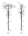
- FIG. 1illustrates a front perspective view of an example embodiment of a target needle assembly
- FIG. 2illustrates a rear perspective view of the target needle assembly of FIG. 1 ;
- FIG. 3illustrates a front view of the target needle assembly of FIGS. 1-2 ;
- FIG. 4illustrates a side view of the target needle assembly of FIGS. 1-3 ;
- FIG. 5illustrates an exploded view of the target needle assembly of FIGS. 1-4 ;
- FIG. 6illustrates an exploded view of a cannula and sheath of the target needle assembly of FIGS. 1-5 ;
- FIG. 7illustrates a front cross-sectional view of the target needle assembly of FIGS. 1-6 ;
- FIG. 8illustrates a side cross-sectional view of the target needle assembly of FIGS. 1-7 ;
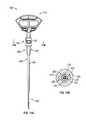
- FIG. 9illustrates an example embodiment of a target needle assembly
- FIGS. 10A-10Cillustrate another example embodiment of a target needle assembly with an outer sheath in a first position
- FIGS. 10D-10Fillustrate the target needle assembly of FIGS. 10A-10C with the outer sheath in a second position
- FIGS. 10G-10Killustrate an alternative embodiment of a target needle assembly
- FIGS. 11A-11Cillustrate another example embodiment of a target needle assembly
- FIGS. 12A-12Fillustrate another example embodiment of a target needle assembly
- FIGS. 13A-13Eillustrate another example embodiment of a target needle assembly
- FIGS. 14A-14Dillustrate another example embodiment of a target needle assembly
- FIG. 15illustrates an example embodiment of a target needle assembly kit including sheath sub-assemblies having various lengths.
- target needle assembliessuch as jamshidi type needles
- a surgeonmay use a needle assembly to percutaneously access the target pedicle and form a pilot hole.
- a needle assemblyto percutaneously access the target pedicle and form a pilot hole.
- the needle assemblymay contact a nerve.
- the bonecould crack as the pilot hole is being formed, which could expose underlying nerves.
- a needle assembly as described hereincan include an inner shaft having a penetrating tip configured to penetrate into the target bone.
- the needle assemblycan further include an outer sheath disposed around at least a portion of the shaft and configured to limit or inhibit further advancement of the needle into the bone.
- the inner shaftis metallic.
- the outer sheathcan be made of any suitable material, such as a plastic or ceramic material. In use, a portion of the shaft that extends distally beyond a distal end of the sheath is able to penetrate into the target bone. The sheath helps inhibit the needle from being advanced too far into the target bone and potentially damaging contacting a nerve, cracking the bone, or causing other adverse effects.
- FIGS. 1-8illustrate an example embodiment of a target needle assembly 100 .
- the needle assembly 100generally includes a stylet or needle sub-assembly 110 , a cannula sub-assembly 120 , and a sheath sub-assembly 150 .
- the stylet sub-assembly 110includes a stylet shaft 112 and a stylet handle 114 coupled to a proximal end of the stylet shaft 112 . As shown, the proximal end of the stylet shaft 112 can be coupled to a center of the stylet handle 114 .
- the cannula sub-assembly 120includes a cannula shaft 122 having a lumen therethrough and a cannula handle 124 coupled to a proximal end of the cannula shaft 122 .
- the cannula handle 124includes a central opening 128 .
- a portion of the cannula shaft 122 , post 123extends across the central opening 128 to a proximal portion of the cannula handle 124 .
- various other instruments or componentscan couple to the post 123 .
- the lumen of the cannula shaft 122is configured to removably receive the stylet shaft 112 .
- a distal end of the stylet shaft 112includes a penetrating tip 116 configured to extend beyond a distal end of the cannula shaft 122 when the stylet shaft 112 is inserted into the cannula shaft 122 .
- the penetrating tip 116is configured to penetrate into bone at the target site.
- the stylet shaft 112 and/or cannula shaft 122can be made of a metallic material.
- the stylet handle 114 and cannula handle 124include features configured to lockingly engage each other to selectively lock the stylet sub-assembly 110 to the cannula sub-assembly 120 .
- the stylet handle 114includes a body portion 130 and two tabs 132 , each extending downward and outward from an outer end of the body portion 130 .
- the stylet handle 114can further include two projections 134 , each extending downward from the body portion 130 at a location between the center of the stylet handle 114 and one of the outer ends of the body portion 130 .
- Each of the tabs 132 and projections 134can be generally L-shaped or elbow shaped.
- the cannula handle 124includes corresponding recesses 142 configured to receive the tabs 134 and corresponding protrusions 144 configured to engage the projections 134 .
- the recesses 142are formed in proximal side portions 124 a of the cannula handle 124 and are open inwardly toward a center of the cannula handle 124 .
- a first recess 142is open toward the front of the cannula sub-assembly 120
- a second recess 142is open toward the back of the cannula sub-assembly 120 .
- the usercan position the stylet handle 114 such that one of the tabs 132 is positioned in front of the first recess 142 and the other tab 132 is positioned behind the second recess 142 ; the user can then turn the stylet handle 114 relative to the cannula handle 124 to rotate the tabs 132 into the recesses 142 .
- a rear wall of the first recess 142 and a front wall of the second recess 142can provide stops to prevent or inhibit further rotation of the stylet handle 114 relative to the cannula handle 124 when the tabs 132 are fully received in the recesses 142 .
- the stylet handle 114is rotated clockwise to engage the tabs 132 with the recesses 142 and lock the stylet handle 114 relative to the cannula handle 124 .
- rotating the stylet handle 114 to position the tabs 132 in the recesses 142also rotates the projections 134 into engagement with the protrusions 144 .
- the cannula handle 124includes a coupling 126 , for example, a luer lock, threaded coupling, or other suitable coupling, that is exposed when the stylet handle 114 is removed from the cannula handle 124 .
- the coupling 126can be configured to receive, for example, a syringe to aspirate or introduce fluids and/or other materials from or into the target location.
- the sheath sub-assembly 150generally includes a shaft 152 , a collar 154 , and a lumen extending through the shaft 152 and collar 154 .
- the collar 154is disposed at a proximal end of the shaft 152 .
- the collar 154is integrally formed with the shaft 152 .
- an exterior of the collar 154can be generally cylindrical.
- the collar 154has a non-smooth surface, for example, to allow a user to more easily grip the collar 154 .
- the collar 154includes an adjustment mechanism configured to be used to adjust the sheath sub-assembly to one of a plurality of discrete positions relative to the cannula as described in greater detail herein.
- the adjustment mechanismis configured to be used to adjust the sheath sub-assembly to one of at least three discrete positions relative to the cannula.
- the sheath sub-assembly 150can be made of any suitable material, for example, a plastic or ceramic material.
- the sheath sub-assembly 150can be made of a radiopaque material or can include a radiopaque marker or ring 51 at or near a distal end of the shaft 152 .
- the needle assembly 100can further include an attachment member 160 disposed around the cannula shaft 122 .
- the attachment member 160can generally include a hollow shaft that surrounds a portion of the cannula shaft 122 . As shown, the attachment member 160 can surround a portion of the cannula shaft 122 distal to and adjacent or proximate to the cannula handle 124 .
- the attachment member 160can have a round, square, rectangular, or other internal cross-sectional shape to correspond to or mate with the portion of the cannula shaft 122 surrounded by the attachment member 160 , which may have a round, square, rectangular, or other external cross-sectional shape.
- the attachment member 160can have a circular or non-circular external cross-section, for example, a square, rectangular, round, plus-sign or other shaped external cross-section.
- the attachment member 160comprises a cannula.
- the attachment member 160is integrally formed with and extends distally from the cannula handle 124 , as shown in FIG. 6 .
- the attachment member 160can be separate from the cannula handle 124 .
- the attachment member 160can be made from, for example, a plastic or ceramic material.
- the collar 154and in some cases, a portion of the sheath shaft 152 , is disposed about the attachment member 160 .
- the sheath shaft 152includes a distal portion 151 and a proximal portion 153 .
- the distal portion 151 and proximal portion 153can be integrally formed as shown.
- the proximal portion 153has a greater diameter than the distal portion 151 to accommodate the attachment member 160 .
- a rear side of the attachment member 160includes a plurality of longitudinally aligned and spaced holes 162 .
- the attachment member 160includes four holes 162 , although more or fewer holes are also possible.
- the collar 154 of the sheath sub-assembly 150includes a spring loaded selector button 156 .
- the selector button 156is part of or disposed on a body portion 157 .
- the body portion 157is disposed in the collar 154 .
- the body portion 157has a central opening that allows the body portion 157 to receive and be disposed about the attachment member 160 .
- a spring 158is disposed within the body portion 157 and extends between the button 156 and a front side of the attachment member 160 .
- the body portion 157also has a rear opening configured to receive a spring retainer 159 .
- the spring retainer 159is positioned on the back of the collar 154 and operatively coupled to the body portion 157 .
- the spring retainer 159is press fit into the body portion 157 .
- the spring retainer 159includes a forwardly projecting pin 159 a sized to fit within the holes 162 of the attachment member 160 .
- the selector button 156 , body portion 157 , spring 158 , and spring retainer 159allow the user to adjust the position of the collar 154 and therefore the sheath 150 relative to the attachment member 160 and cannula sub-assembly 120 .
- the pin 159 a of the spring retainer 159is configured to be disposed within one of the holes 162 of the attachment member 160 to lock the position of the collar 154 relative to the attachment member 160 .
- the userdepresses the button 156 , causing the body portion 157 to move rearwardly within the collar 154 and the spring 158 to compress.
- the spring retainer 159is coupled to the body portion 157 , the spring retainer 159 also moves rearwardly, and the pin 159 a moves out of the hole 162 .
- the usercan then slide the collar 154 and sheath sub-assembly 150 proximally or distally relative to the attachment member 160 and cannula sub-assembly 120 .
- the spring 158is therefore allowed to expand back to its resting, uncompressed state, which causes the body portion 157 to move forwardly and the spring retainer 159 to move forwardly with the body portion 157 .
- the pin 159 aIf the pin 159 a is aligned with one of the holes 162 , the pin 159 a will move into the hole 162 to lock the position of the collar 154 relative to the attachment member 160 . If the pin 159 a is not aligned with one of the holes 162 , the collar 154 will not be locked, and the user can slide the collar 154 proximally or distally until the pin 159 a engages an adjacent hole 162 .
- the sheath sub-assembly 150can therefore be adjusted to as many discrete positions as there are holes 162 . For example, in the illustrated embodiment, the sheath sub-assembly 150 can be adjusted to four different positions relative to the cannula sub-assembly 120 .
- the sheath sub-assembly 150can be adjusted to more or fewer positions relative to the cannula sub-assembly 120 . In some embodiments, the sheath sub-assembly 150 can be adjusted to at least three positions relative to the cannula sub-assembly 120 .
- a distal end of the attachment member 160can include a grapple hook 164 , for example as shown in FIGS. 6-7 .
- the grapple hook 164can act as a stop to advantageously inhibit the collar 154 from sliding distally off of the attachment member 160 .
- a width of the grapple hook 164 at its widest pointis slightly greater than a width of a main body portion 168 of the attachment member 160 .
- the attachment member 160can include a reduced width portion 166 proximal to the grapple hook 164 and a proximal outward taper from the reduced width portion 166 to the main body portion 168 .
- a width of the central opening of the body portion 157 of the adjustment buttonis selected to be substantially flush with or to fit snugly to the main body portion 168 of the attachment member 160 .
- the width of the central opening of the body portion 157is slightly less than the width of the grapple hook 164 at its widest point, as shown in FIG. 7 , such that if the collar 154 of the sheath sub-assembly 150 is advanced distally, the body portion 157 will abut the top of the grapple hook 164 and prevent or inhibit the sheath sub-assembly 150 from sliding off of the attachment member 160 .
- the sheath sub-assembly 150is slid proximally onto the cannula sub-assembly 120 and attachment member 160 , or the cannula sub-assembly 120 and attachment member 160 are slid distally into the sheath sub-assembly 150 .
- the arms of the grapple hook 164can flex to compress slightly inward to allow the body portion 157 of the button to slide onto and past the grapple hook 164 and onto the main body portion 168 of the attachment member 160 .
- the needle assembly 100can be provided with the sheath sub-assembly 150 preassembled on the cannula sub-assembly 120 and attachment member 160 .
- the sheath sub-assembly 150can be assembled onto the cannula sub-assembly 120 and the attachment member 160 by the user, such as a surgeon or other medical personnel.
- sheath sub-assemblies 150 of various lengthscan be provided, and the user can select a particular length sheath sub-assembly 150 for use.
- the lumen extending through the collar 154 and at least a portion of the proximal portion 153 of the sheath shaft 152has a cross or plus sign-shaped transverse cross-section
- the main body portion 161 of the attachment member 160has a corresponding cross or plus sign-shaped transverse cross-section.
- Such non-circular cross-sectionscan advantageously help keep the collar properly rotationally aligned relative to the attachment member 160 so that the spring retainer is able to engage the holes 162 .
- the sheath sub-assembly 150has a length less than that of the cannula sub-assembly 120 . Adjustment of the position of the sheath sub-assembly 150 relative to the cannula sub-assembly 120 adjusts the length of the cannula shaft 122 exposed distal to the sheath sub-assembly 150 .
- the adjustable sheath sub-assembly 150therefore allows the surgeon to select the length of the exposed portion of the cannula shaft 122 to correspond to the intended depth the pilot hole to be formed in the bone.
- the exposed portion of the cannula shaft 122can therefore be limited to the portion of the cannula shaft 122 that will be disposed within the bone.
- the distal edge of the sheath sub-assembly 150can act as a stop to inhibit further advancement of the needle assembly 100 into the bone. This can provide the surgeon with tactile feedback that the needle assembly 100 has reached the desired depth in the bone and reduce the likelihood of advancing the needle assembly 100 beyond a desired depth and potentially contacting or coming too close to an underlying nerve or passing the desired depth for optimal implant positioning.
- the sheath sub-assembly 150is made of a radiopaque material or includes a radiopaque marker or ring 51 at or near the distal end, which allows the surgeon to visualize the position of the sheath sub-assembly 150 via imaging techniques.
- the sheath sub-assembly 150can be made of a radiopaque material or include a radiopaque marker or ring at or near the distal end.
- the sheath sub-assembly 150when the collar 154 is positioned at a distalmost hole 162 , the sheath sub-assembly 150 fully covers the distal end of the cannula shaft 122 and/or the penetrating tip 116 of the stylet shaft 112 . In other embodiments, when the collar 154 is positioned at the distalmost hole 162 , the penetrating tip 116 and/or a portion of the cannula shaft 122 is exposed.
- the collar 154 , another portion of the sheath sub-assembly 150 , attachment member 160 , or cannula sub-assembly 120can include depth markers or an indication of the length of the exposed portion of the cannula shaft 122 extending from the distal end of the sheath sub-assembly 150 and depth the needle assembly 100 will penetrate into the bone.
- the attachment member 160can include markings associated with or corresponding to each hole 162 to indicate the length of the exposed portion of the cannula shaft 122 when the spring retainer pin 159 a is positioned in that hole 162 . In some embodiments, for example as shown in FIG.
- the cannula shaft 122can include depth markings 121 near the distal end of the cannula shaft 122 .
- the depth markings 121can be spaced at various intervals. For example, in some embodiments, the depth markings 121 are spaced at 5 mm intervals.
- the surgeonadvances the target needle assembly 100 through skin, muscle, and/or other tissue to the target location, such as a pedicle or other bony anatomical region.
- the penetrating tip 116is used to break through the cortical bone and allow the target needle assembly 100 to advance toward the cancellous bone.
- the surgeoncan adjust the position of the sheath sub-assembly 150 relative to the cannula sub-assembly 120 to adjust the length of the exposed portion of the cannula shaft 122 before and/or during the procedure.
- the surgeoncan adjust the sheath sub-assembly 150 such that the length of the exposed portion of the cannula shaft 122 corresponds to the desired depth for the pilot hole to be formed.
- the surgeoncan readjust the position of the sheath sub-assembly 150 .
- FIGS. 10A-10Fillustrate an alternative embodiment of a target needle assembly 200 .
- the target needle assembly 200includes a stylet sub-assembly 210 , cannula sub-assembly 220 , sheath sub-assembly 250 , collar 254 , and attachment member 260 including a series of holes 262 .
- a proximal portion of the sheath shaft 251is disposed and moves within the attachment member 260 .
- the attachment member 260can be integrally formed with or separate from the cannula handle 224 .
- FIGS. 10G-10Killustrate another embodiment of a target needle assembly 300 including a stylet sub-assembly 310 , cannula sub-assembly 320 , sheath sub-assembly 350 , collar 354 , and attachment member 360 including a series of holes 362 and in which the sheath shaft 351 is disposed and moves within the attachment member 360 .
- the embodiment of FIGS. 10G-10Kis modular. As shown in FIGS. 10H-10I , the attachment member 360 and sheath sub-assembly 350 can be provided separately from the stylet sub-assembly 310 and cannula sub-assembly 320 .
- the attachment member 360 and sheath sub-assembly 350can be slid proximally onto the cannula sub-assembly 320 .
- the attachment member 360includes a coupling portion 361 configured to couple to the cannula sub-assembly 320 .
- the target needle assembly 300includes a mount 325 disposed around the cannula shaft 322 adjacent and distal to the cannula handle 324 and fixed to the cannula shaft 322 and/or cannula handle 324 . At least one of the front and back sides of the mount 325 can include a post or protrusion 327 .
- a proximal side of the coupling portion 361 of the attachment member 360includes a recess 365 , as shown in FIG. 10I , configured to receive and couple to the mount 325 , for example, via a snap fit or friction fit. At least one of the front and back sides of the recess 365 can have a keyhole shape as shown in FIG. 10I .
- a base 365 a of the keyholeis configured to receive the protrusion 327 when the attachment member 360 is fully mounted on the cannula sub-assembly 320 , and a narrower neck 365 b of the keyhole helps secure the keyhole about the protrusion 327 and secure the coupling portion 361 to the mount 325 .
- the proximal side of the coupling portion 361can also include a slit 367 on each side of the recess 365 to allow portions of the coupling portion 361 on either side of the recess 365 to flex outwardly so that the neck 365 b of the keyhole can be pushed around and past the protrusion 327 as the attachment member 360 is slid onto the cannula sub-assembly 320 .
- a distal side of the coupling portion 361has a contoured surface or grips 369 , which can advantageously allow the surgeon to more easily hold and manipulate the assembled needle assembly 300 .
- a modular configurationcan advantageously allow the surgeon to choose to use the needle assembly with or without the sheath sub-assembly.
- Other embodiments of target needle assemblies as described herein and according to the present disclosurecan also include modular attachment member sub-assemblies and sheath sub-assemblies.
- the attachment member 360can be permanently fixed to the cannula sub-assembly 320 .
- the target needle assemblies 200 , 300 shown in FIGS. 10A-10Kinclude collars 254 , 354 including selector buttons 256 , 356 to allow for adjustment of the sheath sub-assembly 250 , 350 relative to the attachment member 260 , 360 .
- the attachment member 360includes a longitudinal groove 370 extending on each side of the attachment member 360 .
- the collar 354includes at least one pin 355 extending from each side of the collar 354 into one of the grooves 370 .
- the corresponding pins 355 and grooves 370help prevent or inhibit rotation of the collar 354 and sheath sub-assembly 350 relative to the attachment member 360 .
- the grooves 370can also end proximal to a distal end of the attachment member 360 to provide a stop for the pins 355 and prevent or inhibit the collar 354 from disengaging from the attachment member 360 .
- the collar 254includes pins 255 extending into longitudinal grooves 270 to help prevent or inhibit rotation of the collar 254 and sheath sub-assembly 250 relative to the attachment member 260 .
- FIGS. 11A-11Cillustrate an alternative embodiment of a target needle assembly 400 including a stylet sub-assembly 410 , cannula sub-assembly 420 , sheath sub-assembly 450 , collar 454 including a selector button 456 , and attachment member 460 .
- a proximal portion of the sheath shaft 451is disposed and moves within the attachment member 460 .
- the attachment member 460includes a protrusion 470 on each side configured to act as a track for the collar 454 .
- In inner surface of the collarincludes two recesses 455 configured to receive the protrusions 470 .
- FIGS. 12A-12Fillustrate another alternative embodiment of a target needle assembly 500 including a stylet sub-assembly 510 , cannula sub-assembly 520 , sheath sub-assembly 550 , and attachment member 560 .
- a proximal portion of the sheath shaft 551is disposed and moves within the attachment member 560 via a ratcheting mechanism.
- a proximal portion 553 of the sheath shaft 551includes a series of notches 555 on each lateral side of the sheath shaft 551 .
- the attachment member 560includes a body portion 562 and an extension 564 extending longitudinally along each lateral side of the body portion 562 .
- each extension 564has a pawl 566 .
- the pawls 566are configured to be received in one of the notches 555 .
- the length of the exposed portion of the cannula shaft 522can be increased by pressing the sheath shaft 551 proximally such that the pawls 566 slide distally along the sheath shaft 551 and series of notches 555 to more distal notches 555 .
- the engagement between the pawls 566 and notches 555inhibits the sheath shaft 551 from being moved distally.
- the attachment member 560can also include tabs 562 , which can be positioned such that the tabs 562 are easily gripped by a surgeon when holding the assembled needle assembly 500 via the cannula handle 524 .
- Each of the tabs 562is integrally formed with or operatively connected to one of the extensions 564 .
- the tabs 562can be pulled or lifted upward or proximally to cause the extensions 564 to flex outwardly and release the ratcheting mechanism, for example, so that the sheath shaft 551 can be moved distally relative to the attachment member 560 .
- the attachment member 560further includes a spring 563 disposed within the body portion 562 .
- the spring 563can bias the sheath shaft 551 downwards or distally and provide some resistance to the sheath shaft 551 being inadvertently moved proximally within the attachment member 560 , for example, as the needle assembly 500 is advanced into the target location.
- FIGS. 13A-13Eillustrate another example embodiment of a target needle assembly 600 including a stylet sub-assembly 610 , cannula sub-assembly 620 , sheath sub-assembly 650 , and attachment member 660 in which a proximal end of the sheath shaft 651 is disposed and moves within the attachment member 660 .
- at least one lateral side of the attachment member 660includes a longitudinal channel 670 running along at least a portion of its length.
- the sheath sub-assembly 650includes at least one pin 655 protruding from at least one lateral side of the sheath shaft 651 near the proximal end of the sheath shaft 651 .
- the sheath sub-assembly 650includes two pins 655 that each protrude from both lateral sides of the sheath shaft 651 .
- the pins 655are received and slide within the channel 670 of the attachment member 660 to help maintain the proper orientation of the sheath sub-assembly 650 relative to the attachment member 660 and/or to inhibit the sheath sub-assembly 650 from disengaging from the attachment member 660 . As shown in FIG.
- a spring 663is disposed within the attachment member 660 and applies downward pressure to bias the sheath shaft 651 to a distalmost position in which the cannula shaft 622 is most covered by the sheath shaft 651 .
- the sheath shaft 651can be moved proximally within the attachment member 660 by simply overcoming the force of the spring 663 .
- the target needle assembly 700 illustrated in FIGS. 14A-14Dalso includes a stylet 710 , cannula sub-assembly 720 , sheath sub-assembly 750 , attachment member 760 , and spring disposed within the attachment member 760 and is configured such that a proximal end of the sheath shaft 751 is disposed and moves within the attachment member 760 .
- the needle assembly 700includes a collar 754 slideably disposed around the attachment member 760 and operatively coupled to the sheath sub-assembly 750 .
- the internal springbiases the sheath sub-assembly 750 to its distalmost position, but the surgeon can manually move the sheath sub-assembly 750 proximally to expose a greater length of the cannula shaft 722 by sliding the collar 754 proximally along the attachment member 760 .
- a target needle assemblyincludes a stylet, cannula sub-assembly, and sheath sub-assembly similar to embodiments shown and described herein.
- the sheath sub-assemblyinstead of the sheath sub-assembly being adjustable, the sheath sub-assembly can be configured to have a set length and position relative to the cannula sub-assembly.
- a stylet sub-assembly 810 and cannula sub-assembly 820can be provided in a kit with two or more sheath sub-assemblies 850 of different lengths, for example as shown in FIG. 15 .
- the surgeoncan select the sheath sub-assembly 850 having the appropriate and/or desired length, and attach the selected sheath sub-assembly 850 to the stylet 810 and/or cannula subassembly 820 by sliding the sheath sub-assembly 850 proximally onto the cannula sub-assembly 820 .
- one or more of the sheath sub-assemblies 850can be made of a radiopaque material or can include a radiopaque marker or ring 51 at or near a distal end of the shaft 852 .
- each of the sheath sub-assemblies 850includes a coupling portion 861 configured to couple to the cannula sub-assembly 820 .
- the cannula sub-assembly 820includes a mount 825 disposed around the cannula shaft 822 adjacent and distal to the cannula handle and fixed to the cannula shaft 822 and/or cannula handle.
- the coupling portion 861is configured to couple to the mount 825 , for example, via a snap fit or friction fit.
- the mount 825 and/or coupling portion 861can be similar to the mount 325 and/or coupling portion 361 , respectively, shown in, for example, FIGS. 10G-10I and described herein.
- At least one of the front and back sides of the mount 825can include a post or protrusion 827 .
- a proximal side of the coupling portion 861 of the sheath 850includes a recess 865 configured to receive and couple to the mount 825 , for example, via a snap fit or friction fit.
- At least one of the front and back sides of the recess 865can have a keyhole shape.
- a base 865 a of the keyholeis configured to receive the protrusion 827 when the sheath 850 is fully mounted on the cannula sub-assembly 820 , and a narrower neck 865 b of the keyhole helps secure the keyhole about the protrusion 827 and secure the coupling portion 861 to the mount 825 .
- the proximal side of the coupling portion 861can also include a slit 867 on each side of the recess 865 to allow portions of the coupling portion 861 on either side of the recess 865 to flex outwardly so that the neck 865 b of the keyhole can be pushed around and past the protrusion 827 as the sheath 850 is slid onto the cannula sub-assembly 820 .
- a distal side of the coupling portion 861has a contoured surface or grips 869 , which can advantageously allow the surgeon to more easily hold and manipulate the assembled needle assembly.
- sheath 850can be coupled to the cannula sub-assembly 820 via a threaded, snap on, clip on, slide on, or other type of connection.
Landscapes
- Health & Medical Sciences (AREA)
- Surgery (AREA)
- Life Sciences & Earth Sciences (AREA)
- Heart & Thoracic Surgery (AREA)
- Nuclear Medicine, Radiotherapy & Molecular Imaging (AREA)
- Pathology (AREA)
- Engineering & Computer Science (AREA)
- Biomedical Technology (AREA)
- Medical Informatics (AREA)
- Molecular Biology (AREA)
- Animal Behavior & Ethology (AREA)
- General Health & Medical Sciences (AREA)
- Public Health (AREA)
- Veterinary Medicine (AREA)
- Orthopedic Medicine & Surgery (AREA)
- Surgical Instruments (AREA)
Abstract
Description
Claims (9)
Priority Applications (1)
| Application Number | Priority Date | Filing Date | Title |
|---|---|---|---|
| US14/734,988US9681889B1 (en) | 2015-06-09 | 2015-06-09 | Depth controlled needle assembly |
Applications Claiming Priority (1)
| Application Number | Priority Date | Filing Date | Title |
|---|---|---|---|
| US14/734,988US9681889B1 (en) | 2015-06-09 | 2015-06-09 | Depth controlled needle assembly |
Publications (1)
| Publication Number | Publication Date |
|---|---|
| US9681889B1true US9681889B1 (en) | 2017-06-20 |
Family
ID=59034033
Family Applications (1)
| Application Number | Title | Priority Date | Filing Date |
|---|---|---|---|
| US14/734,988ActiveUS9681889B1 (en) | 2015-06-09 | 2015-06-09 | Depth controlled needle assembly |
Country Status (1)
| Country | Link |
|---|---|
| US (1) | US9681889B1 (en) |
Cited By (42)
| Publication number | Priority date | Publication date | Assignee | Title |
|---|---|---|---|---|
| CN108158670A (en)* | 2018-01-24 | 2018-06-15 | 北京天智航医疗科技股份有限公司 | Depth vernier |
| US10179054B2 (en) | 2008-02-06 | 2019-01-15 | Jeffrey B. Kleiner | Spinal fusion cage system with inserter |
| US10195053B2 (en) | 2009-09-18 | 2019-02-05 | Spinal Surgical Strategies, Llc | Bone graft delivery system and method for using same |
| US10201355B2 (en) | 2009-02-06 | 2019-02-12 | Kleiner Intellectual Property, Llc | Angled surgical tool for removing tissue from within an intervertebral space |
| US10245159B1 (en) | 2009-09-18 | 2019-04-02 | Spinal Surgical Strategies, Llc | Bone graft delivery system and method for using same |
| US10898658B2 (en) | 2016-07-06 | 2021-01-26 | LynJohnston, LLC | Compact injection device with telescoping components |
| US10973656B2 (en) | 2009-09-18 | 2021-04-13 | Spinal Surgical Strategies, Inc. | Bone graft delivery system and method for using same |
| US11123103B2 (en)* | 2019-09-12 | 2021-09-21 | Relievant Medsystems, Inc. | Introducer systems for bone access |
| US11160563B2 (en) | 2012-11-05 | 2021-11-02 | Relievant Medsystems, Inc. | Systems for navigation and treatment within a vertebral body |
| JP2022508311A (en)* | 2018-08-09 | 2022-01-19 | オプティカル スパイン | Translucent illuminated endoscope probe |
| US11246637B2 (en)* | 2020-05-11 | 2022-02-15 | Alphatec Spine, Inc. | Stimulating targeting needle |
| CN114258288A (en)* | 2019-08-21 | 2022-03-29 | 瑞崴制造股份有限公司 | Bone marrow collection device |
| US20220218434A1 (en)* | 2021-01-14 | 2022-07-14 | Medtronic Holding Company Sárl | Devices, systems, and methods facilitating access to and mapping of target tissue |
| US11413064B2 (en)* | 2016-07-01 | 2022-08-16 | Intuitive Surgical Operations, Inc. | Computer-assisted tele-operated surgery systems and methods |
| US11471171B2 (en) | 2008-09-26 | 2022-10-18 | Relievant Medsystems, Inc. | Bipolar radiofrequency ablation systems for treatment within bone |
| US11471210B2 (en) | 2011-12-30 | 2022-10-18 | Relievant Medsystems, Inc. | Methods of denervating vertebral body using external energy source |
| US11517349B2 (en) | 2019-09-27 | 2022-12-06 | Bard Access Systems, Inc. | Autovance feature of an intraosseous device |
| US11596468B2 (en) | 2002-09-30 | 2023-03-07 | Relievant Medsystems, Inc. | Intraosseous nerve treatment |
| US11607502B2 (en) | 2018-01-10 | 2023-03-21 | LynJohnston, LLC | Compact injector systems and methods |
| US11612419B2 (en)* | 2020-01-24 | 2023-03-28 | Warsaw Orthopedic, Inc. | Spinal implant system and method |
| US11633214B2 (en) | 2019-09-27 | 2023-04-25 | Bard Access Systems, Inc. | Various operating mechanisms for intraosseous access medical devices and methods thereof |
| US20230149062A1 (en)* | 2021-08-11 | 2023-05-18 | Bone Solutions, Inc. | Self-Drilling Bone Cement Delivery Cannula and Methods for Use |
| US11666455B2 (en) | 2009-09-18 | 2023-06-06 | Spinal Surgical Strategies, Inc., A Nevada Corporation | Bone graft delivery devices, systems and kits |
| US11690667B2 (en) | 2012-09-12 | 2023-07-04 | Relievant Medsystems, Inc. | Radiofrequency ablation of tissue within a vertebral body |
| US11759235B2 (en) | 2019-09-27 | 2023-09-19 | Bard Access Systems, Inc. | Constant-torque intraosseous access devices and methods thereof |
| US20230404561A1 (en)* | 2022-06-16 | 2023-12-21 | Vertos Medical, Inc. | Integrated instrument assembly |
| US11883071B2 (en) | 2016-10-27 | 2024-01-30 | C. R. Bard, Inc. | Intraosseous access device |
| US11896264B2 (en) | 2020-04-21 | 2024-02-13 | Bard Access Systems, Inc. | Reusable push-activated intraosseous access device |
| US11925361B2 (en) | 2021-02-08 | 2024-03-12 | Bard Access Systems, Inc. | Intraosseous modular power |
| US11998237B2 (en) | 2020-06-03 | 2024-06-04 | Bard Access Systems, Inc. | Intraosseous device including a sensing obturator |
| US12039731B2 (en) | 2020-12-22 | 2024-07-16 | Relievant Medsystems, Inc. | Prediction of candidates for spinal neuromodulation |
| US12082843B2 (en) | 2019-09-27 | 2024-09-10 | Bard Access Systems, Inc. | Step needle for intraosseous access device |
| US12082876B1 (en) | 2020-09-28 | 2024-09-10 | Relievant Medsystems, Inc. | Introducer drill |
| US12102348B2 (en) | 2016-09-07 | 2024-10-01 | Vertos Medical, Inc. | Percutaneous lateral recess resection methods and instruments |
| US12167869B2 (en) | 2020-02-28 | 2024-12-17 | Bard Access Systems, Inc. | Flexible intraosseous obturator |
| US12171669B2 (en) | 2020-10-09 | 2024-12-24 | Spinal Elements, Inc. | Systems and methods for filling material |
| US12193719B2 (en) | 2013-08-08 | 2025-01-14 | Relievant Medsystems, Inc. | Modulating nerves within bone |
| US12226123B2 (en) | 2020-07-17 | 2025-02-18 | Bard Access Systems, Inc. | Safety mechanism |
| US12274469B2 (en) | 2020-08-25 | 2025-04-15 | Bard Access Systems, Inc. | Angled intraosseous access system |
| US12303166B2 (en) | 2008-09-26 | 2025-05-20 | Relievant Medsystems, Inc. | Methods for accessing nerves within bone |
| US12402911B2 (en) | 2020-09-09 | 2025-09-02 | Bard Access Systems, Inc. | Aspiration apparatus for intraosseous access system |
| US12433668B1 (en) | 2021-11-08 | 2025-10-07 | Relievant Medsystems, Inc. | Impedance stoppage mitigation during radiofrequency tissue ablation procedures |
Citations (25)
| Publication number | Priority date | Publication date | Assignee | Title |
|---|---|---|---|---|
| US5250054A (en)* | 1992-05-01 | 1993-10-05 | Li Medical Technologies, Inc. | Intracorporeal knot tying apparatus and method |
| US5368046A (en)* | 1992-09-09 | 1994-11-29 | Symbiosis Corporation | Bone marrow needle assembly |
| US5480389A (en)* | 1994-08-09 | 1996-01-02 | Becton, Dickinson And Company | Method and apparatus for adjusting the length of a combined spinal-epidural needle |
| US6019776A (en)* | 1997-10-14 | 2000-02-01 | Parallax Medical, Inc. | Precision depth guided instruments for use in vertebroplasty |
| US6066146A (en)* | 1998-06-24 | 2000-05-23 | Carroll; Brendan J. | Laparascopic incision closure device |
| US6197002B1 (en)* | 1997-12-10 | 2001-03-06 | Phillips Plastics Corporation | Laparoscopic tool and method |
| US20020022847A1 (en)* | 1998-04-09 | 2002-02-21 | Ray Eddie F. | Methods and instrumentation for vertebral interbody fusion |
| US20040068264A1 (en)* | 2002-10-03 | 2004-04-08 | Treace John T. | Bendable needle for delivering bone graft material and method of use |
| US20050038465A1 (en)* | 2003-08-15 | 2005-02-17 | Stat Medical Devices, Inc. | Adjustable lancet device and method |
| US20070260255A1 (en)* | 2006-05-04 | 2007-11-08 | Sdgi Holdings, Inc. | Method for using retractable stylet and cannula combination to form an opening in bone |
| US20080200915A1 (en)* | 2005-07-31 | 2008-08-21 | Disc-O-Tech Medical Technologies, Ltd. | Marked tools |
| US20090024056A1 (en)* | 2007-07-16 | 2009-01-22 | Inrad, Inc. | Coaxial Needle Assembly |
| US7643884B2 (en) | 2005-01-31 | 2010-01-05 | Warsaw Orthopedic, Inc. | Electrically insulated surgical needle assembly |
| US7657308B2 (en) | 2003-08-05 | 2010-02-02 | Nuvasive, Inc. | System and methods for performing dynamic pedicle integrity assessments |
| US20110093024A1 (en)* | 2007-09-14 | 2011-04-21 | Layne Richard W | Method and apparatus for bone removal |
| US7942826B1 (en) | 2005-06-06 | 2011-05-17 | Nuvasive, Inc. | Insulated pedicle access system and related methods |
| US7963927B2 (en) | 1999-11-24 | 2011-06-21 | Nuvasive, Inc. | Electromyography system |
| US7976498B2 (en) | 2005-07-11 | 2011-07-12 | Tyco Healthcare Group Lp | Needle assembly including obturator with safety reset |
| US8062259B2 (en) | 2006-07-06 | 2011-11-22 | Warsaw Orthopedic, Inc. | Cannulated sensing device |
| US8192443B2 (en) | 2006-04-21 | 2012-06-05 | Mi4Spine, Llc | Pedicle access device |
| US20120226301A1 (en) | 2011-03-01 | 2012-09-06 | Wyatt Drake Geist | Depth Controlled Jamshidi Needle |
| US20120239050A1 (en)* | 2005-11-18 | 2012-09-20 | Linderman Evan D | Multistate-curvature device and method for delivering a curable material into bone |
| US20130150752A1 (en)* | 2011-12-12 | 2013-06-13 | Karl W. Swann | Apparatus for Bone Aspiration |
| US20140171946A1 (en)* | 2012-12-14 | 2014-06-19 | Warsaw Orthopedic, Inc. | Surgical instrument and method |
| US20140257356A1 (en)* | 2011-08-17 | 2014-09-11 | John Stephen Pacak | Trocar Support |
- 2015
- 2015-06-09USUS14/734,988patent/US9681889B1/enactiveActive
Patent Citations (28)
| Publication number | Priority date | Publication date | Assignee | Title |
|---|---|---|---|---|
| US5250054A (en)* | 1992-05-01 | 1993-10-05 | Li Medical Technologies, Inc. | Intracorporeal knot tying apparatus and method |
| US5368046A (en)* | 1992-09-09 | 1994-11-29 | Symbiosis Corporation | Bone marrow needle assembly |
| US5480389A (en)* | 1994-08-09 | 1996-01-02 | Becton, Dickinson And Company | Method and apparatus for adjusting the length of a combined spinal-epidural needle |
| US6019776A (en)* | 1997-10-14 | 2000-02-01 | Parallax Medical, Inc. | Precision depth guided instruments for use in vertebroplasty |
| US6197002B1 (en)* | 1997-12-10 | 2001-03-06 | Phillips Plastics Corporation | Laparoscopic tool and method |
| US20020022847A1 (en)* | 1998-04-09 | 2002-02-21 | Ray Eddie F. | Methods and instrumentation for vertebral interbody fusion |
| US6066146A (en)* | 1998-06-24 | 2000-05-23 | Carroll; Brendan J. | Laparascopic incision closure device |
| US7963927B2 (en) | 1999-11-24 | 2011-06-21 | Nuvasive, Inc. | Electromyography system |
| US20040068264A1 (en)* | 2002-10-03 | 2004-04-08 | Treace John T. | Bendable needle for delivering bone graft material and method of use |
| US8255044B2 (en) | 2003-08-05 | 2012-08-28 | Nuvasive, Inc. | System and methods for performing dynamic pedicle integrity assessments |
| US7657308B2 (en) | 2003-08-05 | 2010-02-02 | Nuvasive, Inc. | System and methods for performing dynamic pedicle integrity assessments |
| US20050038465A1 (en)* | 2003-08-15 | 2005-02-17 | Stat Medical Devices, Inc. | Adjustable lancet device and method |
| US7643884B2 (en) | 2005-01-31 | 2010-01-05 | Warsaw Orthopedic, Inc. | Electrically insulated surgical needle assembly |
| US7942826B1 (en) | 2005-06-06 | 2011-05-17 | Nuvasive, Inc. | Insulated pedicle access system and related methods |
| US8784330B1 (en) | 2005-06-06 | 2014-07-22 | Nu Vasive, Inc. | Insulated pedicle access system and related methods |
| US8162889B2 (en) | 2005-07-11 | 2012-04-24 | Covidien Ag | Safety reset key and needle assembly |
| US7976498B2 (en) | 2005-07-11 | 2011-07-12 | Tyco Healthcare Group Lp | Needle assembly including obturator with safety reset |
| US20080200915A1 (en)* | 2005-07-31 | 2008-08-21 | Disc-O-Tech Medical Technologies, Ltd. | Marked tools |
| US20120239050A1 (en)* | 2005-11-18 | 2012-09-20 | Linderman Evan D | Multistate-curvature device and method for delivering a curable material into bone |
| US8192443B2 (en) | 2006-04-21 | 2012-06-05 | Mi4Spine, Llc | Pedicle access device |
| US20070260255A1 (en)* | 2006-05-04 | 2007-11-08 | Sdgi Holdings, Inc. | Method for using retractable stylet and cannula combination to form an opening in bone |
| US8062259B2 (en) | 2006-07-06 | 2011-11-22 | Warsaw Orthopedic, Inc. | Cannulated sensing device |
| US20090024056A1 (en)* | 2007-07-16 | 2009-01-22 | Inrad, Inc. | Coaxial Needle Assembly |
| US20110093024A1 (en)* | 2007-09-14 | 2011-04-21 | Layne Richard W | Method and apparatus for bone removal |
| US20120226301A1 (en) | 2011-03-01 | 2012-09-06 | Wyatt Drake Geist | Depth Controlled Jamshidi Needle |
| US20140257356A1 (en)* | 2011-08-17 | 2014-09-11 | John Stephen Pacak | Trocar Support |
| US20130150752A1 (en)* | 2011-12-12 | 2013-06-13 | Karl W. Swann | Apparatus for Bone Aspiration |
| US20140171946A1 (en)* | 2012-12-14 | 2014-06-19 | Warsaw Orthopedic, Inc. | Surgical instrument and method |
Cited By (73)
| Publication number | Priority date | Publication date | Assignee | Title |
|---|---|---|---|---|
| US11596468B2 (en) | 2002-09-30 | 2023-03-07 | Relievant Medsystems, Inc. | Intraosseous nerve treatment |
| US10179054B2 (en) | 2008-02-06 | 2019-01-15 | Jeffrey B. Kleiner | Spinal fusion cage system with inserter |
| US12329412B2 (en) | 2008-09-26 | 2025-06-17 | Relievant Medsystems, Inc. | Systems for accessing nerves within bone |
| US12161350B2 (en) | 2008-09-26 | 2024-12-10 | Relievant Medsystems, Inc. | Systems for treating nerves within bone using steam |
| US11471171B2 (en) | 2008-09-26 | 2022-10-18 | Relievant Medsystems, Inc. | Bipolar radiofrequency ablation systems for treatment within bone |
| US12303166B2 (en) | 2008-09-26 | 2025-05-20 | Relievant Medsystems, Inc. | Methods for accessing nerves within bone |
| US10201355B2 (en) | 2009-02-06 | 2019-02-12 | Kleiner Intellectual Property, Llc | Angled surgical tool for removing tissue from within an intervertebral space |
| US11666455B2 (en) | 2009-09-18 | 2023-06-06 | Spinal Surgical Strategies, Inc., A Nevada Corporation | Bone graft delivery devices, systems and kits |
| US12167971B2 (en) | 2009-09-18 | 2024-12-17 | Spinal Surgical Strategies, Inc. | Bone graft delivery devices, systems and kits |
| US11660208B2 (en) | 2009-09-18 | 2023-05-30 | Spinal Surgical Strategies, Inc. | Bone graft delivery system and method for using same |
| US12053393B2 (en) | 2009-09-18 | 2024-08-06 | Spinal Surgical Strategies, Inc. | Bone graft delivery system and method for use |
| US10195053B2 (en) | 2009-09-18 | 2019-02-05 | Spinal Surgical Strategies, Llc | Bone graft delivery system and method for using same |
| US10245159B1 (en) | 2009-09-18 | 2019-04-02 | Spinal Surgical Strategies, Llc | Bone graft delivery system and method for using same |
| US10973656B2 (en) | 2009-09-18 | 2021-04-13 | Spinal Surgical Strategies, Inc. | Bone graft delivery system and method for using same |
| US11471210B2 (en) | 2011-12-30 | 2022-10-18 | Relievant Medsystems, Inc. | Methods of denervating vertebral body using external energy source |
| US12059193B2 (en) | 2011-12-30 | 2024-08-13 | Relievant Medsystems, Inc. | Methods of denervating vertebral body using external energy source |
| US11690667B2 (en) | 2012-09-12 | 2023-07-04 | Relievant Medsystems, Inc. | Radiofrequency ablation of tissue within a vertebral body |
| US11737814B2 (en) | 2012-09-12 | 2023-08-29 | Relievant Medsystems, Inc. | Cryotherapy treatment for back pain |
| US11701168B2 (en) | 2012-09-12 | 2023-07-18 | Relievant Medsystems, Inc. | Radiofrequency ablation of tissue within a vertebral body |
| US11234764B1 (en) | 2012-11-05 | 2022-02-01 | Relievant Medsystems, Inc. | Systems for navigation and treatment within a vertebral body |
| US11974759B2 (en) | 2012-11-05 | 2024-05-07 | Relievant Medsystems, Inc. | Methods of navigation and treatment within a vertebral body |
| US11291502B2 (en) | 2012-11-05 | 2022-04-05 | Relievant Medsystems, Inc. | Methods of navigation and treatment within a vertebral body |
| US11160563B2 (en) | 2012-11-05 | 2021-11-02 | Relievant Medsystems, Inc. | Systems for navigation and treatment within a vertebral body |
| US12193719B2 (en) | 2013-08-08 | 2025-01-14 | Relievant Medsystems, Inc. | Modulating nerves within bone |
| US11413064B2 (en)* | 2016-07-01 | 2022-08-16 | Intuitive Surgical Operations, Inc. | Computer-assisted tele-operated surgery systems and methods |
| US10898658B2 (en) | 2016-07-06 | 2021-01-26 | LynJohnston, LLC | Compact injection device with telescoping components |
| US12201819B2 (en) | 2016-07-06 | 2025-01-21 | LynJohnston, LLC | Compact injection device with telescoping components |
| US12102348B2 (en) | 2016-09-07 | 2024-10-01 | Vertos Medical, Inc. | Percutaneous lateral recess resection methods and instruments |
| US11883071B2 (en) | 2016-10-27 | 2024-01-30 | C. R. Bard, Inc. | Intraosseous access device |
| US11607502B2 (en) | 2018-01-10 | 2023-03-21 | LynJohnston, LLC | Compact injector systems and methods |
| CN108158670A (en)* | 2018-01-24 | 2018-06-15 | 北京天智航医疗科技股份有限公司 | Depth vernier |
| JP2022508311A (en)* | 2018-08-09 | 2022-01-19 | オプティカル スパイン | Translucent illuminated endoscope probe |
| EP4018937A4 (en)* | 2019-08-21 | 2023-08-30 | Rev-Med, Inc. | BONE MARROW HARVEST DEVICE |
| CN114258288B (en)* | 2019-08-21 | 2024-12-17 | 瑞崴制造股份有限公司 | Bone marrow collection device |
| CN114258288A (en)* | 2019-08-21 | 2022-03-29 | 瑞崴制造股份有限公司 | Bone marrow collection device |
| US11123103B2 (en)* | 2019-09-12 | 2021-09-21 | Relievant Medsystems, Inc. | Introducer systems for bone access |
| US11202655B2 (en) | 2019-09-12 | 2021-12-21 | Relievant Medsystems, Inc. | Accessing and treating tissue within a vertebral body |
| EP4027912A4 (en)* | 2019-09-12 | 2023-08-16 | Relievant Medsystems, Inc. | Systems and methods for tissue modulation |
| US11426199B2 (en) | 2019-09-12 | 2022-08-30 | Relievant Medsystems, Inc. | Methods of treating a vertebral body |
| US11633214B2 (en) | 2019-09-27 | 2023-04-25 | Bard Access Systems, Inc. | Various operating mechanisms for intraosseous access medical devices and methods thereof |
| US12178471B2 (en) | 2019-09-27 | 2024-12-31 | Bard Access Systems, Inc. | Autovance feature of an intraosseous device |
| US11759235B2 (en) | 2019-09-27 | 2023-09-19 | Bard Access Systems, Inc. | Constant-torque intraosseous access devices and methods thereof |
| US12226124B2 (en) | 2019-09-27 | 2025-02-18 | Bard Access Systems, Inc. | Constant-torque intraosseous access devices and methods thereof |
| US12082843B2 (en) | 2019-09-27 | 2024-09-10 | Bard Access Systems, Inc. | Step needle for intraosseous access device |
| US11517349B2 (en) | 2019-09-27 | 2022-12-06 | Bard Access Systems, Inc. | Autovance feature of an intraosseous device |
| US11612419B2 (en)* | 2020-01-24 | 2023-03-28 | Warsaw Orthopedic, Inc. | Spinal implant system and method |
| US12167869B2 (en) | 2020-02-28 | 2024-12-17 | Bard Access Systems, Inc. | Flexible intraosseous obturator |
| US11896264B2 (en) | 2020-04-21 | 2024-02-13 | Bard Access Systems, Inc. | Reusable push-activated intraosseous access device |
| US12193710B2 (en) | 2020-04-21 | 2025-01-14 | Bard Access Systems, Inc. | Reusable push-activated intraosseous access device |
| US11819254B2 (en) | 2020-05-11 | 2023-11-21 | Alphatec Spine, Inc. | Stimulating targeting needle |
| US20240058045A1 (en)* | 2020-05-11 | 2024-02-22 | Alphatec Spine, Inc. | Stimulating targeting needle |
| US11246637B2 (en)* | 2020-05-11 | 2022-02-15 | Alphatec Spine, Inc. | Stimulating targeting needle |
| US12201336B2 (en)* | 2020-05-11 | 2025-01-21 | Alphatec Spine, Inc. | Stimulating targeting needle |
| JP2023525339A (en)* | 2020-05-11 | 2023-06-15 | アルファテック スパイン, インコーポレイテッド | irritating target needle |
| US11998237B2 (en) | 2020-06-03 | 2024-06-04 | Bard Access Systems, Inc. | Intraosseous device including a sensing obturator |
| US12226123B2 (en) | 2020-07-17 | 2025-02-18 | Bard Access Systems, Inc. | Safety mechanism |
| US12274469B2 (en) | 2020-08-25 | 2025-04-15 | Bard Access Systems, Inc. | Angled intraosseous access system |
| US12402911B2 (en) | 2020-09-09 | 2025-09-02 | Bard Access Systems, Inc. | Aspiration apparatus for intraosseous access system |
| US12082876B1 (en) | 2020-09-28 | 2024-09-10 | Relievant Medsystems, Inc. | Introducer drill |
| US12171669B2 (en) | 2020-10-09 | 2024-12-24 | Spinal Elements, Inc. | Systems and methods for filling material |
| US12039731B2 (en) | 2020-12-22 | 2024-07-16 | Relievant Medsystems, Inc. | Prediction of candidates for spinal neuromodulation |
| US12239492B2 (en)* | 2021-01-14 | 2025-03-04 | Medtronic Holding Company Sárl | Devices, systems, and methods facilitating access to and mapping of target tissue |
| US20220218434A1 (en)* | 2021-01-14 | 2022-07-14 | Medtronic Holding Company Sárl | Devices, systems, and methods facilitating access to and mapping of target tissue |
| US12390229B2 (en) | 2021-02-08 | 2025-08-19 | Bard Access Systems, Inc. | Intraosseous modular power |
| US11925361B2 (en) | 2021-02-08 | 2024-03-12 | Bard Access Systems, Inc. | Intraosseous modular power |
| US20230149062A1 (en)* | 2021-08-11 | 2023-05-18 | Bone Solutions, Inc. | Self-Drilling Bone Cement Delivery Cannula and Methods for Use |
| US12268427B2 (en)* | 2021-08-11 | 2025-04-08 | Bone Solutions, Inc. | Self-drilling bone cement delivery cannula and methods for use |
| US12433668B1 (en) | 2021-11-08 | 2025-10-07 | Relievant Medsystems, Inc. | Impedance stoppage mitigation during radiofrequency tissue ablation procedures |
| US12324572B2 (en)* | 2022-06-16 | 2025-06-10 | Vertos Medical, Inc. | Integrated instrument assembly |
| US20240423600A1 (en)* | 2022-06-16 | 2024-12-26 | Vertos Medical, Inc. | Integrated instrument assembly |
| US12342999B2 (en) | 2022-06-16 | 2025-07-01 | Vertos Medical, Inc. | Integrated instrument assembly |
| US20240423601A1 (en)* | 2022-06-16 | 2024-12-26 | Vertos Medical, Inc. | Integrated instrument assembly |
| US20230404561A1 (en)* | 2022-06-16 | 2023-12-21 | Vertos Medical, Inc. | Integrated instrument assembly |
Similar Documents
| Publication | Publication Date | Title |
|---|---|---|
| US9681889B1 (en) | Depth controlled needle assembly | |
| US11937857B2 (en) | Bone anchors and surgical instruments with integrated guide tips | |
| AU2020201041B2 (en) | Biceps tenodesis delivery tools | |
| US11642158B2 (en) | Methods and devices for spinal screw insertion | |
| US11648038B2 (en) | Spinal screw insertion devices and methods | |
| US10987116B2 (en) | Adjustable drill guides and related methods | |
| DE102016224493B4 (en) | Surgical reduction instrument |
Legal Events
| Date | Code | Title | Description |
|---|---|---|---|
| AS | Assignment | Owner name:SURGICAL DEVICE EXCHANGE, LLC DOING BUSINESS UNDER Free format text:ASSIGNMENT OF ASSIGNORS INTEREST;ASSIGNORS:GREENHALGH, TRAVIS;LEWIS, RYAN;SIGNING DATES FROM 20160406 TO 20160411;REEL/FRAME:038621/0884 | |
| AS | Assignment | Owner name:SURGENTEC, LLC, FLORIDA Free format text:ASSIGNMENT OF ASSIGNORS INTEREST;ASSIGNOR:SURGICAL DEVICE EXCHANGE, LLC;REEL/FRAME:041478/0985 Effective date:20170306 | |
| STCF | Information on status: patent grant | Free format text:PATENTED CASE | |
| RF | Reissue application filed | Effective date:20190620 | |
| RF | Reissue application filed | Effective date:20190620 | |
| MAFP | Maintenance fee payment | Free format text:PAYMENT OF MAINTENANCE FEE, 4TH YR, SMALL ENTITY (ORIGINAL EVENT CODE: M2551); ENTITY STATUS OF PATENT OWNER: SMALL ENTITY Year of fee payment:4 | |
| CC | Certificate of correction | ||
| RF | Reissue application filed | Effective date:20210524 | |
| MAFP | Maintenance fee payment | Free format text:PAYMENT OF MAINTENANCE FEE, 8TH YR, SMALL ENTITY (ORIGINAL EVENT CODE: M2552); ENTITY STATUS OF PATENT OWNER: SMALL ENTITY Year of fee payment:8 |