US9675380B2 - Surgical tool positioning system - Google Patents
Surgical tool positioning systemDownload PDFInfo
- Publication number
- US9675380B2 US9675380B2US14/418,993US201314418993AUS9675380B2US 9675380 B2US9675380 B2US 9675380B2US 201314418993 AUS201314418993 AUS 201314418993AUS 9675380 B2US9675380 B2US 9675380B2
- Authority
- US
- United States
- Prior art keywords
- tool
- tool support
- constructed
- guide element
- support
- Prior art date
- Legal status (The legal status is an assumption and is not a legal conclusion. Google has not performed a legal analysis and makes no representation as to the accuracy of the status listed.)
- Expired - Fee Related, expires
Links
- 239000000523sampleSubstances0.000claimsabstractdescription89
- 238000000034methodMethods0.000claimsdescription42
- 230000000087stabilizing effectEffects0.000claimsdescription6
- 230000008878couplingEffects0.000claimsdescription2
- 238000010168coupling processMethods0.000claimsdescription2
- 238000005859coupling reactionMethods0.000claimsdescription2
- 230000008901benefitEffects0.000description5
- 210000003238esophagusAnatomy0.000description5
- 230000007246mechanismEffects0.000description5
- 238000000115helium ionisation detectionMethods0.000description4
- 239000004033plasticSubstances0.000description4
- 229920003023plasticPolymers0.000description4
- 238000001356surgical procedureMethods0.000description4
- 210000001015abdomenAnatomy0.000description3
- 210000003128headAnatomy0.000description3
- 229920002614Polyether block amidePolymers0.000description2
- 239000000853adhesiveSubstances0.000description2
- 230000001070adhesive effectEffects0.000description2
- 206010003119arrhythmiaDiseases0.000description2
- 230000006793arrhythmiaEffects0.000description2
- 230000000712assemblyEffects0.000description2
- 238000000429assemblyMethods0.000description2
- 238000002192cholecystectomyMethods0.000description2
- 238000012321colectomyMethods0.000description2
- 238000009799cystectomyMethods0.000description2
- 238000002224dissectionMethods0.000description2
- 210000003026hypopharynxAnatomy0.000description2
- 238000009802hysterectomyMethods0.000description2
- 210000000867larynxAnatomy0.000description2
- 239000000463materialSubstances0.000description2
- 229910052751metalInorganic materials0.000description2
- 239000002184metalSubstances0.000description2
- 238000009806oophorectomyMethods0.000description2
- 210000002741palatine tonsilAnatomy0.000description2
- -1polytetrafluoroethylenePolymers0.000description2
- 229920001343polytetrafluoroethylenePolymers0.000description2
- 239000004810polytetrafluoroethyleneSubstances0.000description2
- 238000002271resectionMethods0.000description2
- 230000004044responseEffects0.000description2
- 210000000813small intestineAnatomy0.000description2
- 238000010911splenectomyMethods0.000description2
- 210000002784stomachAnatomy0.000description2
- 210000003437tracheaAnatomy0.000description2
- 239000004812Fluorinated ethylene propyleneSubstances0.000description1
- HQQADJVZYDDRJT-UHFFFAOYSA-Nethene;prop-1-eneChemical groupC=C.CC=CHQQADJVZYDDRJT-UHFFFAOYSA-N0.000description1
- 239000004811fluoropolymerSubstances0.000description1
- 229920002313fluoropolymerPolymers0.000description1
- 210000001035gastrointestinal tractAnatomy0.000description1
- 229920001903high density polyethylenePolymers0.000description1
- 239000004700high-density polyethyleneSubstances0.000description1
- 229920001684low density polyethylenePolymers0.000description1
- 239000004702low-density polyethyleneSubstances0.000description1
- 229910001000nickel titaniumInorganic materials0.000description1
- 229920009441perflouroethylene propylenePolymers0.000description1
- 229920000642polymerPolymers0.000description1
- 238000002432robotic surgeryMethods0.000description1
- 238000000926separation methodMethods0.000description1
- 238000004904shorteningMethods0.000description1
- 210000003625skullAnatomy0.000description1
- 210000001154skull baseAnatomy0.000description1
- 239000010935stainless steelSubstances0.000description1
- 229910001220stainless steelInorganic materials0.000description1
- 239000011800void materialSubstances0.000description1
- 238000003466weldingMethods0.000description1
Images


Classifications
- A—HUMAN NECESSITIES
- A61—MEDICAL OR VETERINARY SCIENCE; HYGIENE
- A61B—DIAGNOSIS; SURGERY; IDENTIFICATION
- A61B17/00—Surgical instruments, devices or methods
- A61B17/34—Trocars; Puncturing needles
- A61B17/3417—Details of tips or shafts, e.g. grooves, expandable, bendable; Multiple coaxial sliding cannulas, e.g. for dilating
- A61B17/3421—Cannulas
- A61B17/3423—Access ports, e.g. toroid shape introducers for instruments or hands
- A—HUMAN NECESSITIES
- A61—MEDICAL OR VETERINARY SCIENCE; HYGIENE
- A61B—DIAGNOSIS; SURGERY; IDENTIFICATION
- A61B17/00—Surgical instruments, devices or methods
- A61B17/34—Trocars; Puncturing needles
- A61B17/3403—Needle locating or guiding means
- A—HUMAN NECESSITIES
- A61—MEDICAL OR VETERINARY SCIENCE; HYGIENE
- A61B—DIAGNOSIS; SURGERY; IDENTIFICATION
- A61B90/00—Instruments, implements or accessories specially adapted for surgery or diagnosis and not covered by any of the groups A61B1/00 - A61B50/00, e.g. for luxation treatment or for protecting wound edges
- A61B90/50—Supports for surgical instruments, e.g. articulated arms
- A—HUMAN NECESSITIES
- A61—MEDICAL OR VETERINARY SCIENCE; HYGIENE
- A61B—DIAGNOSIS; SURGERY; IDENTIFICATION
- A61B17/00—Surgical instruments, devices or methods
- A61B17/28—Surgical forceps
- A61B17/29—Forceps for use in minimally invasive surgery
- A61B2017/2901—Details of shaft
- A61B2017/2906—Multiple forceps
- A—HUMAN NECESSITIES
- A61—MEDICAL OR VETERINARY SCIENCE; HYGIENE
- A61B—DIAGNOSIS; SURGERY; IDENTIFICATION
- A61B17/00—Surgical instruments, devices or methods
- A61B17/34—Trocars; Puncturing needles
- A61B17/3403—Needle locating or guiding means
- A61B2017/3405—Needle locating or guiding means using mechanical guide means
- A61B2017/3407—Needle locating or guiding means using mechanical guide means including a base for support on the body
- A—HUMAN NECESSITIES
- A61—MEDICAL OR VETERINARY SCIENCE; HYGIENE
- A61B—DIAGNOSIS; SURGERY; IDENTIFICATION
- A61B90/00—Instruments, implements or accessories specially adapted for surgery or diagnosis and not covered by any of the groups A61B1/00 - A61B50/00, e.g. for luxation treatment or for protecting wound edges
- A61B90/10—Instruments, implements or accessories specially adapted for surgery or diagnosis and not covered by any of the groups A61B1/00 - A61B50/00, e.g. for luxation treatment or for protecting wound edges for stereotaxic surgery, e.g. frame-based stereotaxis
- A61B90/11—Instruments, implements or accessories specially adapted for surgery or diagnosis and not covered by any of the groups A61B1/00 - A61B50/00, e.g. for luxation treatment or for protecting wound edges for stereotaxic surgery, e.g. frame-based stereotaxis with guides for needles or instruments, e.g. arcuate slides or ball joints
Definitions
- the present inventive conceptsgenerally relate to the field of robotics, and more particularly, to multi-operator robotic systems for medical applications.
- articulating surgical toolscan be operated by a surgeon or other clinician at a single operator location.
- a tool positioning systemcomprises an introduction device constructed and arranged to slidingly receive an articulating probe; a first tool support comprising at least one guide element constructed and arranged to slidingly receive a first tool, wherein the first tool support is oriented toward a first operator location; and a second tool support comprising at least one guide element constructed and arranged to slidingly receive a second tool, wherein the second tool support is oriented toward a second operator location.
- At least one of the first tool or the second toolis positioned at a patient to perform a medical procedure on the patient.
- the medical procedurecomprises a transoral surgery procedure.
- the transoral surgery procedureincludes a resection at or near at least one of a base of a tongue, tonsils, a base of a skull, a hypopharynx, a larynx, a trachea, an esophagus, a stomach, or a small intestine.
- the medical procedureincludes at least one of a single or multiport transaxilla, thoracoscopic, pericardial, laparoscopic, transgastric, transenteric, transanal, or transvaginal procedure.
- the single or multiport transaxilla procedureincludes a laryngectomy.
- the single or multiport thoracoscopic procedureincludes a mediastinal nodal dissection.
- the single or multiport pericardial procedureincludes measuring and treating arrhythmias.
- the single or multiport single or multiport laparoscopic procedureincludes a revision of bariatric lap-band procedures.
- the single or multiport transgastric or transenteric procedureincludes at least one of a cholecystectomy or a splenectomy.
- the single or multiport transanal or transvaginal procedureincludes at least one of a hysterectomy, oophorectomy, cystectomy or colectomy.
- the first tool supportis coupled to the second tool support.
- the first tool support and the second tool supportare coupled to each other at a common element.
- a connection at the common elementmaintains a fixed distance between the first tool support and the second tool support.
- a connection at the common elementmaintains a fixed orientation between the first tool support and the second tool support.
- the at least one of the first and second tool supportsmoves linearly relative to the common element.
- the first tool support and second tool supportare fixed in position relative to each other.
- positions of the first and second tool supportsare maintained during an operation of the tool positioning system.
- the first tool support and second tool supportare fixed in orientation relative to each other.
- orientations of the first and second tool supportsare maintained during an operation of the tool positioning system.
- At least one of the first tool support or second tool supportis rotatable relative to the other.
- At least one of the first tool support or the second tool supportis rotatable relative to the other at a common element to which each of the first and second tool supports is coupled.
- At least one of the first and second tool supportsis locked in a fixed position relative to the common element.
- systemfurther comprises a locking mechanism that locks the at least one of the first and second tool supports in the fixed position.
- At least one of the first tool support and the second tool supportis directly anchored to the introduction device.
- At least one of the first tool support and second tool supportis bonded to the introduction device.
- At least one of the first tool support and second tool supportis welded to the introduction device.
- the systemfurther comprises a base, wherein the first tool support and the second tool support are coupled to the base.
- the introduction deviceis coupled to the base.
- the basecomprises a collar that surrounds at least a portion of the introduction device.
- the collarextends in a lateral direction relative to a direction of extension of the introduction device.
- the collarhas first and second openings aligned with the first and second tool supports.
- the collarhas first and second openings, wherein the first and second tool supports extend through the first and second openings.
- At least one of the first tool support or the second tool supportcomprises at least one guide element that rotatably engages the base.
- the at least one of the first tool support and the second tool supportcomprises a gimbal which rotatably engages the at least one guide element at the base.
- the least one guide element of the first tool supportcomprises a mid-portion that rotatably engages the base.
- the first tool supportrotatably engages the base and the second tool support rotatably engages the base.
- the at least one guide element of the first tool supportis fixedly attached to the base.
- the at least one guide element of the first tool supportcomprises a mid-portion that rotatably engages the base.
- the at least one of the first or second tool supportsmoves linearly relative to the base.
- the systemis constructed and arranged to slidingly receive two tools.
- the systemis constructed and arranged to slidingly receive three tools.
- the systemis constructed and arranged to slidingly receive four tools.
- the systemis constructed and arranged to slidingly receive five or more tools.
- the at least one guide element of the first tool supportis constructed and arranged to receive a shaft of the first tool
- the at least one guide element of the second tool supportis constructed and arranged to receive a shaft of the second tool
- the first toolis positioned at a first side of a distal end of the articulating probe and the second tool is positioned at a second side of the distal end of the articulating probe relatively opposite the first side.
- the first toolis controlled by an operator at the first operator location at the first side of the distal end of the articulating probe
- the second toolis controlled by an operator at the second operator location at the second side of the distal end of the articulating probe.
- the first tool and a third toolare positioned at a first side of a distal end of the articulating probe and the second tool and a fourth tool are positioned at a second side of the distal end of the articulating probe relatively opposite the first side.
- the first and third toolsare controlled by an operator at the first operator location at the first side of the distal end of the articulating probe, and the second and fourth tools are controlled by an operator at the second operator location at the second side of the distal end of the articulating probe.
- At least one of the first tool support or the second tool supportcomprises a funnel shaped proximal end.
- At least one guide element of at least one of the first tool support or the second tool supportcomprises an inner guide element and an outer guide element.
- the outer guide elementcomprises a first tube and the inner guide element comprises a second tube slidingly positioned in the first tube.
- the inner guide elementmovably extends from the outer guide element.
- At least a portion of the inner guide elementis flexible.
- the systemfurther comprises a third tool support, the third tool support comprising at least one guide element constructed and arranged to slidingly receive a third tool.
- the third tool supportis oriented toward the first operator location.
- systemfurther comprises a connector coupled to the first tool support and the third tool support, wherein the connector is constructed and arranged to maintain a relative position between the first tool support and the third tool support.
- the systemfurther comprises a fourth tool support, the fourth tool support comprising at least one guide element constructed and arranged to slidingly receive a fourth tool.
- the fourth tool supportis oriented toward the second operator location.
- systemfurther comprises a connector coupled to the second tool support and the fourth tool support, wherein the connector is constructed and arranged to maintain a relative position between the second tool support and the fourth tool support.
- systemfurther comprises a connector coupled to a proximal end of each of the first and third tool supports, and a connector attached to a proximal end of each of the second and fourth tool supports.
- systemfurther comprises a connector coupled to the first tool support and the second tool support, wherein the connector is constructed and arranged to maintain a relative position between the first tool support and second tool support.
- the connectoris rotatably coupled to the first tool support.
- the connectoris rotatably coupled to the first tool support and the second tool support.
- the connectoris attached to a proximal end of the first and second tool supports.
- the connectorextends in a direction that is transverse the directions of extension of proximal ends of the first and second tool supports.
- systemfurther comprises a fixation point on the connector constructed and arranged to attach to a stabilizing brace.
- systemfurther comprises a third tool support and a connector coupled to the first, second and third tool supports, wherein the connector is constructed and arranged to maintain a relative position between the first, second, and third tool supports.
- the at least one guide element of the first tool support or the second tool supportcomprises a hollow elongate member.
- the hollow elongate membercomprises a structure selected from the group consisting of: a hollow tube, a coil such as a helical coil, a plastic tube such as a braided plastic tube, and combinations thereof.
- At least a portion of the hollow elongate memberis rigid.
- At least a portion of the hollow elongate memberis flexible.
- first operator location and the second operator locationcomprise side-by-side locations.
- the first tool supportis constructed and arranged to provide tool access to a patient's head.
- the first tool supportis constructed and arranged to provide tool access to a patient's esophagus.
- the first operator location and the second operator locationcomprise face-to-face locations.
- the first tool supportis constructed and arranged to provide tool access to at least one of a patient chest or a patient abdomen.
- systemfurther comprises a fixation point constructed and arranged to attach to a stabilizing brace.
- the first tool supportcomprises the fixation point.
- systemfurther comprises a connector coupled to the first tool support and the second tool support.
- the connectoris constructed and arranged to maintain a relative position between the first tool support and second tool support, wherein the connector comprises the fixation point.
- the introduction devicecomprises the fixation point.
- systemfurther comprises a base coupling the first tool support and the second tool support, wherein the base comprises the fixation point.
- systemfurther comprises a brace attachable to the fixation point.
- the braceis further attachable to a location selected from the group consisting of: a floor, a patient operating table, an articulating probe feeder, and combinations thereof.
- systemfurther comprises a second fixation point constructed and arranged to attach to a stabilizing brace.
- the systemfurther comprises a first brace for attachment to the first fixation point and a second brace for attachment to the second fixation point.
- systemfurther comprises the articulating probe.
- the articulating probecomprises a distal link.
- the distal linkcomprises at least a first sideport coupled to the first tool support and a second sideport coupled to the second tool support.
- the systemfurther comprises a third tool support, wherein the distal link comprises at least a first sideport coupled to the first tool support, a second sideport coupled to the second tool support and a third sideport coupled to the third tool support.
- the first, second and third sideportsare symmetrically spaced about a periphery of the distal link.
- the first, second and third sideportsare asymmetrically spaced about a periphery of the distal link.
- the first and second sideportsare positioned 30° to 180° apart about a periphery of the distal link.
- systemfurther comprises a fourth tool support wherein the distal link further comprises a fourth sideport coupled to the fourth tool support.
- systemfurther comprises a fifth tool support wherein the distal link further comprise a fifth sideport coupled to the fifth tool support.
- systemfurther comprises a controller constructed and arranged to manipulate the articulating probe.
- systemfurther comprises a first human interface device oriented toward the first operator location, the first human interface generating a first control signal received by the controller for manipulating the articulating probe.
- the systemfurther comprises a tool wherein the tool comprises the first human interface device.
- systemfurther comprises a second human interface device oriented toward the second operator location and constructed and arranged to generate a second control signal received by the controller for manipulating the articulating probe.
- systemfurther comprises a tool wherein the tool comprises the second human interface device.
- the systemfurther comprises a connector coupled to the first tool support and the second tool support, wherein the connector is constructed and arranged to maintain a relative position between the first tool support and second tool support, wherein the first human interface device is positioned on the connector.
- the human interface device on the connectorcommunicates with the controller via a wireless connection.
- systemfurther comprises at least one tool constructed and arranged to be slidingly received by at least one of the first tool support or the second tool support.
- the at least one toolcomprises at least two tools, wherein each tool comprises a shaft constructed and arranged to be slidingly received by at least one of the first tool support or the second tool support.
- the at least one toolcomprises a tool selected from the group consisting of: a suction device, a ventilator, a light, a camera, a grasper, a laser, a cautery, a clip applier, a scissors, a needle, a needle driver, a scalpel, an RF energy delivery device, a cryogenic energy delivery device, and combinations thereof.
- a tool positioning systemcomprises a first tool support comprising at least one guide element constructed and arranged to slidingly receive a first tool, wherein the first tool support is oriented toward a first operator location; a second tool support comprising at least one guide element constructed and arranged to slidingly receive a second tool, wherein the second tool support is oriented toward a second operator location; and a base that couples the first tool support and the second tool support.
- systemfurther comprises an introduction device coupled to the base.
- the basecomprises a collar that surrounds at least a portion of the introduction device.
- the collarextends in a lateral direction relative to a direction of extension of the introduction device.
- the collarhas first and second openings aligned with the first and second tool supports.
- the collarhas first and second openings, wherein the first and second tool supports extend through the first and second openings.
- At least one of the first tool support or the second tool supportcomprises at least one guide element that rotatably engages the base.
- the at least one of the first tool support and the second tool supportcomprises a gimbal which rotatably engages the at least one guide element at the base.
- the least one guide element of the first tool supportcomprises a mid-portion that rotatably engages the base.
- the first tool supportrotatably engages the base and the second tool support rotatably engages the base.
- the at least one guide element of the first tool supportis fixedly attached to the base.
- the at least one guide element of the first tool supportcomprises a mid-portion that rotatably engages the base.
- a tool positioning systemcomprises a first tool support comprising at least one first guide element constructed and arranged to slidingly receive a first tool; a second tool support comprising at least one second guide element constructed and arranged to slidingly receive a second tool; and a first connector attached to the first tool support and the second tool support, wherein the connector is constructed and arranged to maintain a distance between the first tool support and second tool support.
- the first connectoris fixedly attached to at least the first tool support or the second tool support.
- the first connectoris rotatably attached to at least the first tool support or the second tool support.
- the systemfurther comprises a gimbal which rotatably engages the at least one first or second guide element at the base.
- the first connectorcomprises a first opening and a second opening each constructed and arranged to operably engage a tool support of the first and second tool supports.
- first opening and the second openingare constructed and arranged to position the first tool support and the second tool support in a non-parallel configuration.
- At least one of the first opening or the second openingcomprises a funnel-shaped opening.
- the first connectorfurther comprises a third opening constructed and arranged to operably engage a third tool support.
- a single operatoroperates a tool extending from each of the first, second, and third tool supports from an operator location.
- the first connectorcomprises a rigid structure.
- the first connectorcomprises at least a portion that is flexible.
- the first connectorcomprises an operator shapeable structure.
- the first connectorcomprises a malleable structure.
- the first connectorcomprises a hinged portion.
- the first connectoris constructed and arranged to be shaped after at least one of the application of hear or the removal of heat.
- the first connectoris constructed and arranged to be attachable to at least one of the first tool support or the second tool support.
- the first connectoris constructed and arranged to be detachable to at least one of the first tool support or the second tool support.
- systemfurther comprises a second connector attachable to the first tool support and the second tool support, wherein the second connector is constructed and arranged to maintain a relative position between the first tool support and the second tool support.
- the first connectoris constructed and arranged to position the first tool support and the second tool support in a first geometry
- the second connectoris constructed and arranged to position the first tool support and the second tool support in a second geometry different than the first geometry
- the first connectordiffers from the second connector by at least one of length, shape or curvature.
- the systemfurther comprises a third tool support comprising at least one guide element constructed and arranged to slidingly receive a shaft of a tool.
- the first connectorfurther maintains a relative position of the third tool support relative to the first tool support and the second tool support.
- the systemfurther comprises a fourth tool support comprising at least one guide element constructed and arranged to slidingly receive a shaft of a tool.
- systemfurther comprises a second connector constructed and arranged to maintain a relative position between the second tool support and the fourth tool support, wherein the first connector is constructed and arranged to maintain a relative position between the first tool support and the third tool support.
- a single operatoroperates a tool extending from each of the first, second, and third tool supports from an operator location
- a first operatoroperates tools extending from two of the first, second, and third tool supports
- a second operatoroperates a tool extending from the other of the first, second, and third tool supports.
- the first connectorcan be removably coupled to the first and second tool supports.
- the first connectoris replaced with a third connector having different dimensions than the first connector.
- the inventive conceptscomprise an articulating probe as described in reference to the figures.
- the inventive conceptscomprise a surgical tool as described in reference to the figures.
- the inventive conceptscomprise a controller as described in reference to the figures.
- the inventive conceptscomprise a method of controlling a robotic system as described in reference to the figures.
- the inventive conceptscomprise a human interface device as described in reference to the figures.
- the inventive conceptscomprise a method of performing a medical procedure as described in reference to the figures.
- FIG. 1is a top view of a tool positioning system for performing a medical procedure, in accordance with embodiments of the present inventive concepts
- FIG. 2is a top view of a tool positioning system for performing a medical procedure, in accordance with other embodiments of the present inventive concepts
- FIG. 3is a perspective view of a tool positioning system, in accordance with an embodiment of the present inventive concepts
- FIG. 4is a cross-sectional front view of a tool positioning system, in accordance with embodiments of the present inventive concepts
- FIG. 5is a perspective view of a tool positioning system having multiple connectors, in accordance with an embodiment of the present inventive concepts
- FIG. 6is a perspective view of a tool positioning system having three tools in communication with a connector, in accordance with an embodiment of the present inventive concepts
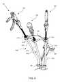
- FIG. 7is a perspective view of a distal end of a tool positioning system, in accordance with an embodiment of the present inventive concepts.
- FIGS. 8A-8Dare perspective views of distal links having multiple side ports, in accordance with an embodiment of the present inventive concepts.
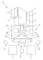
- FIG. 1is a top view of a tool positioning system 100 for performing a medical procedure, in accordance with embodiments of the present inventive concepts.
- the tool positioning system 100is constructed and arranged to position one or more tools (not shown in FIG. 1 ) for performing a medical procedure on a patient P, for example, a transoral robotic surgery procedure or the like.
- the medical procedurecan include a surgical procedure that includes inserting one or more tools into a cavity of the patient (P), or a region of the patient (P) formed by an incision or related opening.
- a surgical procedurecan include one or more transoral procedures.
- Typical transoral proceduresinclude resections or other procedures performed at or near a location selected from the group consisting of: base of a tongue; tonsils; base of skull; hypopharynx; larynx; trachea; esophagus; stomach; small intestine; and combinations of these.
- Other procedurescan include but not be limited to single or multiport transaxilla procedures, such as a laryngectomy, single or multiport thoracoscopic procedures, such as a mediastinal nodal dissection, single or multiport pericardial procedures, for example, related to measuring and treating arrhythmias, single or multiport laparoscopic procedures, such as revision of bariatric lap-band procedures, single or multiport transgastric or transenteric procedures, such as a cholecystectomy or splenectomy, and/or single or multiport transanal or transvaginal procedures, such as a hysterectomy, oophorectomy, cystectomy and colectomy.
- single or multiport transaxilla proceduressuch as a laryngectomy, single or multiport thoracoscopic procedures, such as a mediastinal nodal dissection, single or multiport pericardial procedures, for example, related to measuring and treating arrhythmias, single or multiport laparoscopic procedures, such as revision of bari
- the tool positioning system 100comprises an introduction device 250 , a first tool support 260 a , and a second tool support 260 b . Although two tool supports 260 a , 260 b (generally, 260 ) are shown, the tool positioning system 100 can be constructed and arranged to include more than two tool supports 260 . In one embodiment, as shown in FIG. 5 , the tool positioning system 100 includes two, three, or four tool supports 260 , each constructed and arranged to slidingly receive a tool, for example, a shaft of a tool. In other embodiments, the tool positioning system 100 includes five or more tool supports 260 , each constructed and arranged to slidingly receive a tool.
- the introduction device 250can be constructed and arranged to slidingly receive an articulating probe such as the articulating probe 10 , and support, stabilize, and/or guide the articulating probe to a region of interest.
- the region of interestmay be a lumen of a body of a patient (P), such as a cavity at the patient's head (H), e.g., a nose or mouth, or an opening formed by an incision.
- typical regions of interestcan include but not be limited to the esophagus or other locations within the gastrointestinal tract, the pericardial space, the peritoneal space, and combinations thereof.
- the region of interestmay alternatively be a mechanical device, a building, or another open or closed environment in which the probe 10 can be used.
- the articulating probe 10may be configured to guide one or more surgical tools, for example, during a medical procedure.
- the articulating probe 10may include inner and outer sleeves, which can advance or retract with respect to one another during manipulation of the articulating probe 10 .
- the inner and outer sleeves of the articulating probe 10which may include a plurality of inner links and a plurality of outer links (see FIG. 4 ), can be configured in one of a limp mode and a rigid mode so as to facilitate the manipulation of the articulating probe 10 .
- the inner and outer sleevesmay be configured in one of the limp mode and the rigid mode via one or more steering cables (not shown) of the articulation probe 10 .
- the articulating probe 10can be a highly articulated probe, for example, a highly articulated probe as described in U.S. Patent Application Publication No. 2009-0171151 entitled STEERABLE, FOLLOW THE LEADER DEVICE, U.S. Patent Publication No. 2008-0039690 entitled STEERABLE MULTI LINKED DEVICE HAVING MULTIPLE WORKING PORTS, or PCT Application No. PCT/US2011/044811 entitled “SURGICAL POSITIONING AND SUPPORT SYSTEM, each incorporated by reference in their entirety herein.
- the articulating probe 10may include one or more light sources, image capturing devices, e.g., a camera, provided at the distal end of the articulating probe 10 and/or proximal the distal end of the tool supports 260 .
- the articulating probe 10comprises a feeder 110 which controllably advances one or more cables within an outer sleeve of the probe 10 , such as a cable (not shown) extending to a distal link, for example, a distal link 631 shown in FIG. 7 .
- the feeder 110can comprise one or more cable control assemblies such as bobbin-driven motors and one or more link translating assemblies such as linearly advanceable carts.
- the first tool support 260 acan be constructed and arranged to slidingly receive a shaft of a tool (not shown).
- the first tool support 260 ais oriented toward a first operator location (L 1 ).
- the second tool support 260 bcan also be constructed and arranged to slidingly receive a shaft of a tool (not shown).
- the second tool support 260 bis oriented toward a second operator location (L 2 ).
- the first and second tool supports 260 a , 260 bcan have similar configurations, or different configurations such as different lengths.
- First and second tool supports 260 a , 260 bcan be attached to one or more locations on the distal end of probe 10 .
- tool supports 260 a , 260 bare on opposite sides of the distal end of probe 10 .
- tool support 260 ais attached to the same side of the distal end of probe 10 as operator location L 1 is positioned (e.g. the left side of the page as shown), and tool support 260 b is attached to the same side of the distal end of probe 10 as operator location L 2 is positioned, e.g. the right side of the page as shown.
- tool support 260 ais attached to the opposite side of the distal end of probe 10 as operator location L 1 is positioned (e.g.
- tool support 260 bis attached to the opposite side of the distal end of probe 10 as operator location L 2 is positioned, e.g. the left side of the page.
- One operatorcan control a first tool at one side of the introduction device 250 at which extends from a distal end of the articulating probe 10 .
- Another operatorcan control a second tool positioned at another side of the distal end of the articulating probe 10 .
- both operatorscan have tools positioned at both sides of the introduction device 250 and the distal end of the articulating probe 10 .
- the tool positioning system 100can include a base 285 .
- the base 285can comprise openings for receiving the tool supports 260 and the introducer 250 , which can be attached to the base 285 at their midportions, or at distal ends thereof.
- the first tool support 260 a and the second tool support 260 bare coupled to the base 285 to maintain a relative position between the first tool support 260 a and the second tool support 260 b and/or maintain a fixed orientation between the first tool support 260 a and the second tool support 260 b.
- the base 285can comprise a collar or the like that surrounds at least a portion of the introduction device 250 .
- the collarcan extend in a lateral direction relative to a direction of extension of the introduction device 250 .
- the base 285can have an opening 287 aligned with a guide element 261 of each tool support 260 .
- the guide element 261can be affixed to the opening 287 of the base 285 .
- the tool positioning system 100can include a connector 280 , also referred to as a dogbone connector, coupled to the first tool support 260 a and the second tool support 260 b .
- the connector 280is constructed and arranged to maintain a relative position between the first tool support 260 a and the second tool support 260 b .
- connector 280is constructed and arranged to maintain a relative orientation between the first tool support 260 a and the second tool support 260 b.
- the connector 280can comprise a rigid structure.
- the connector 280can comprise at least a portion that is flexible.
- the connector 280can comprise an operator shapeable structure.
- the connector 280can comprise a malleable structure.
- the connector 280can comprise two segments connected by a hinge, such as a butt hinge, a butterfly hinge, a barrel hinge or a hinge comprising a flexible portion positioned between two rigid portions.
- the connector 280can comprise a telescopically adjustable structure, such as to allow separation of tool supports 260 a and 260 b .
- the connector 280can comprise two segments connected by a rotatable connector, such as a universal joint.
- the connector 280can be constructed and arranged to be shaped, molded, or the like, such as after the application of heat.
- the connector 280can be constructed and arranged to be attachable to at least one of the first tool support 260 a or the second tool support 260 b .
- the connector 280can be constructed and arranged to be detachable to at least one of the first tool support 260 a or the second tool support 260 b.
- An alternative connectorcan be provided, for example, connector 280 ′′ shown in FIG. 5 , that is attachable to the first tool support 260 a and the second tool support 260 b .
- the alternative connector 280 ′′can be constructed and arranged to maintain a relative position between the first tool support 260 a and the second tool support 260 b .
- the original connector 280can be constructed and arranged to position the first tool support 260 a and the second tool support 260 b in a first geometry
- the alternative connector 280 ′′can be constructed and arranged to position the first tool support 260 a and the second tool support 260 b in a second geometry different than the first geometry.
- the original connector 280can differ from the alternative connector 280 ′′ by at least one of length, shape or curvature.
- the connector 280comprises a first opening and a second opening, each constructed and arranged to operably engage a guide element of the first and second tool supports 260 a , 260 b .
- the first opening and the second openingcan be constructed and arranged to position the first tool support 260 a and the second tool support 260 b in a non-parallel configuration.
- At least one of the first opening or the second openingcan comprise a funnel-shaped opening, for example, for receiving a guide element 261 , more specifically, a funnel-shaped proximal end 264 of an outer guide element 262 as shown in FIG. 3 .
- the tool positioning system 100can include at least one fixation point, 133 a - e shown (generally, 133 ), each constructed and arranged to attach to a stabilizing brace.
- a fixation point 133 acan be positioned at the introduction device 250 .
- a fixation point 133 bcan be positioned at the base 285 .
- a fixation point 133 ccan be positioned at the first tool support 260 a .
- a fixation point 133 dcan be positioned at the second tool support 260 b .
- a fixation point 133 ecan be positioned at the connector 280 .
- a brace 132also referred to as a support, can be attached to the fixation point 133 a .
- the brace 132can be attached to other locations related to the tool positioning system 100 , such as an operating room floor, the patient operating table (T) and/or an articulating probe feeder 110 .
- the brace 132can include a clamping device and the like for clamping to a floor table or other supporting object.
- Multiple bracescan be coupled to different fixation points 133 .
- a brace(not shown) can be coupled between the fixation point 133 b at the base 285 and a fixation point 133 c at the first tool support 260 a .
- Another brace 131can be attached to the feeder 110 and can be clamped or otherwise attached to a floor, table or other object providing stability.
- the system 100can include a first human interface device (HID) 80 a and a second HID 80 b that communicate with a controller 85 .
- the first HID 80 acan be proximate to or oriented toward the first operator location (L 1 ) and the second HID 80 b can be proximate to or oriented toward the second operator location (L 2 ).
- the first and second HIDs 80 a , 80 bcan be part of a same hardware platform, and can be at a single or multiple operator location, for example, location (L 1 ), and can permit an operator at either location L 1 or L 2 to access the HIDs 80 a , 80 b at the same location.
- the system 100includes a third HID 80 c attached to integral with dogbone connector 280 , HID 80 c in wired or wireless communication with the controller 85 .
- One or more HIDs 80 a, b, ccan be constructed and arranged to manipulate the articulating probe 10 , the tool supports 260 , one or more tools inserted into tool supports 260 , or a combination thereof.
- the first HID 80 ais oriented toward the first operator location (L 1 ).
- the second HID 80 bis oriented toward the second operator location (L 2 ).
- a first operatorsuch as a medical professional, may control the articulating probe 10 via the HID 80 a to steer, advance, retract or otherwise control the functions and movement of articulating probe 10 via commands sent to the controller 85 .
- a light source, camera, or other device attached to the articulating probemay be activated in response to a control signal generated by the HID 80 a .
- a second operatormay control the articulating probe 10 via the second HID 80 b , to steer, advance, retract or otherwise control the functions and movement of the articulating probe 10 via commands sent to the controller 85 .
- a light source, camera, or other device attached to the articulating probemay be activated in response to a control signal generated by the HID 80 b .
- the first HID 80 a and/or the second HID 80 bmay include a device selected from the group consisting of: a haptic controller, a joystick, a track ball, a mouse and an electromechanical device.
- the articulating probe 10may be controlled via an HID 80 , and the surgical tools may be controlled via a tool handle, for example, a tool handle as shown in FIG. 6 .
- One or more HIDs 80can communicate with the controller by a physical connector, such as a conductive wire, or by a wireless connection, for example, a BluetoothTM connection.
- An HID 80can include switches, joystick, buttons, and the like for applying forces related to the movement of an articulating probe 10 shown in FIG. 4 .
- an HID 80can include force sensors such as strain gauges, which can detect forces applied to a dogbone connector 280 , for example, push, pull, and/or twist forces. Such forces can be applied for controlling the articulating probe 10 shown in FIG. 4 , for example, to advance, retract, or steer the probe 10 .
- the patient (P)can lie on an operation table (T), for example, face up as shown in FIG. 1 .
- the first operator location (L 1 ) and second operator location (L 2 )can be side-by-side, or neighboring each other in a manner that permits two or more operators to each maneuver one or more tools.
- the first tool support 260 a and/or the second tool support 260 bcan be constructed and arranged to provide tool access to a patient's head (H).
- the first tool support 260 acan provide tool access to a patient's esophagus via the patient's mouth.
- the first tool support 260 a and/or the second tool support 260 bcan be constructed and arranged to provide tool access to at least one of a patient chest or a patient abdomen
- FIG. 2is a top view of a tool positioning system 100 for performing a medical procedure, in accordance with other embodiments of the present inventive concepts. Many of the elements described with respect to FIG. 1 are the same as or similar to those of FIG. 2 , and will therefore not be described again for brevity.
- the first operator location (L 1 ) and the second operator location (L 2 )are at face-to-face locations, for example, at opposite sides of an operating table (T) so that an operator at the first operator location (L 1 ) and an operator at the second operator location (L 2 ) can face each other.
- the first tool support 260 acan extend in a direction towards the first operator location (L 1 ) at a first side of the table (T) and the second tool support 260 b can extend in a direction towards the second operator location (L 2 ) at a second side of the table (T) opposite the first side.
- the first tool support 260 a and/or the second tool support 260 bcan be constructed and arranged to provide tool access to a region of the patient's (P) body, for example, at least one of a patient chest or a patient abdomen.
- the first tool support 260 a and the second tool support 260 bcan be fixedly coupled to a surface of the introduction device 250 instead of a base.
- the first tool support 260 a and/or the second tool support 260 bare directly coupled to the introduction device 250 by attachment mechanisms, for example, welding points 286 a , 286 b , respectively.
- attachment mechanismsfor example, welding points 286 a , 286 b , respectively.
- other bonding techniquesfor example, adhesives and the like, can be applied.
- the connection at the introduction device 250maintains a fixed distance and/or a fixed orientation between the first tool support 260 a and the second tool support 260 b .
- the tool supports 260 a and 260 bcan be rotatably attached to each other and/or a base for maintaining a fixed distance but not a fixed orientation.
- the first tool support 260 a and the second tool support 260 bcan be fixed in position relative to each other. Accordingly, positions of the first and second tool supports 260 a , 260 b are maintained during an operation of the tool positioning system 100 .
- At least one of the first tool support 260 a and the second tool support 260 bcan include first and second guide elements 261 a , 261 b , respectively.
- the first guide element 261 acan include an outer guide element 262 a , also referred to as a proximal guide element, and an inner guide element 263 a , also referred to as a distal guide element.
- the second guide element 261 bcan include an outer guide element 262 b and an inner guide element 263 b . At least a portion of the inner guide element 263 a, b (generally, 263 ) is flexible.
- the inner guide element 263can be formed of plastic or related material.
- Inner guide element 263can comprise laser cut tubes (e.g. polymer or metal tubes) and/or coils or braids of plastic or metal.
- inner guide element 263comprises a polytetrafluoroethylene liner.
- inner guide element 263comprises a stainless steel coil.
- inner guide element 263comprises a coil covered by a polyether block amide.
- inner guide element 263comprises different varying stiffness along its length, such as when comprising a tube of varying durometers along its length. At least a portion of the outer guide element 262 a , 262 b (generally, 262 ) is rigid, with limited or no flexibility. As shown in FIG. 3 , the outer guide elements 262 a , 262 b can be directly anchored to the introduction device 250 by a weld 286 a , 286 b , respectively.
- the outer guide elements 262can include a first tube.
- the inner guide elements 263can include a second tube, a portion of which can be positioned in, and move relative to, the first tube of the outer guide element 262 . In this manner, the inner guide element 263 can movably extend from the outer guide element 262 , for example, in a telescoping configuration.
- a tool support 260can rotatably engage the base 285 .
- a single tool support 260is shown in FIG. 4 , however any tool support described herein (e.g. first tool support 260 a , second tool support 260 b , third tool support 260 c , and/or fourth tool support 260 d ) can be configured as shown.
- the tool support 260can be coupled to the base 285 by a gimbal 630 , permitting the tool support 260 to rotate relative to the base 285 , for example, allowing for three degrees of freedom between tool support 260 and base 285 , which can include two-dimensional (X-Y) movement plus rotation.
- the gimbal 630 or other pivoted or ball and joint mechanismpermits the guide element 261 of the tool support 260 to rotatably or fixedly engage the base 285 , for example, at a mid-portion of the guide element 261 .
- the dogbone connector 280may require adjustability of the distance between connector openings. Depending on the desired relative orientation of one support 260 to the other, parallel or angled, then the adjustability in the connector 280 for the distance between openings can occur along a straight or curved path.
- the guide element 261 of the tool support 260can be fixedly attached to a base, for example, at a mid-portion of the guide element 261 .
- the tool support 260can be locked in a fixed position relative to the base 285 .
- the system 100can include a locking mechanism 635 to lock the at least one tool support 260 in the fixed position.
- the locking mechanismmay be constructed to secure a position of the tool supports 260 with respect to the base 285 , thus preventing the tool supports 260 from sliding or otherwise moving axially during movement of the tools by one or more operators.
- the outer guide element 262 of the guide element 261 of a tool support 260can be constructed and arranged to have a hollow elongate member.
- the hollow elongate membercan be constructed and arranged as a structure known to those of ordinary skill in the art, for example, a hollow tube; a coil such as a helical coil, or combinations thereof.
- the entire hollow elongate memberis rigid.
- at least a portion of the hollow elongate membercan be rigid.
- the inner guide element 263can be likewise constructed and arranged to have a hollow elongate member.
- the entire hollow elongate membercan include a flexible tube.
- the hollow elongate membercan include at least a flexible portion.
- the inner guide element 263can slide along an inner surface in the opening of the outer guide element 262 in which the inner guide element 263 is positioned.
- the outer guide element 262can have a funnel-shaped proximal end 264 .
- the inner guide element 263can likewise have a funnel shaped proximal end 265 .
- Either or both funnels 264 , 265can be configured to readily and atraumatically introduce tools to the tool support 260 .
- a funnel shaped proximal end 264 a, b of each tool support 260 a, bcan be positioned about an opening in a connector 280 .
- the outer guide element 262 and/or inner guide element 263can be constructed and arranged to guide or otherwise provide a support for a tool shaft so that it can be guided to a side port 637 coupled to an outer surface of the articulating probe 10 .
- the side port 637can be coupled to a distal link 631 of the articulating probe 10 .
- the side port 637can be formed at a flange at the articulating probe 10 .
- Multiple side portsmay be positioned along the outer sleeve of the articulating probe 10 so as to provide a guide for one or more guide elements 261 that articulate in common with the articulating probe 10 .
- the inner guide element 263can be fixedly attached to the outer surface of the articulating probe 10 , for example, the distal link 631 , such as with an adhesive or mechanical fastener.
- FIG. 5is a perspective view of a tool positioning system 100 having multiple connectors 280 , 280 ′, in accordance with an embodiment.
- the tool positioning system 100can also comprise a first tool support 260 a , a second tool support 260 b , a third tool support 260 c and a fourth tool support 260 d .
- Each of tool supports 260 a - dcan include a funnel-shaped opening, 264 a - d respectively, on its proximal end.
- the tool supports 260 a - d and the introduction device 250are fixedly attached to base 285 .
- the third tool support 260 ccan comprise at least one guide element 261 c , which can be similar to the guide elements 261 a and 261 b described herein.
- the guide element 261 ccan include an outer guide element 262 c and an inner guide element 263 c .
- the fourth tool support 260 dcan comprise at least one guide element 261 d , which can be similar to the guide elements 261 a and 261 b described herein.
- the guide element 261 dcan include an outer guide element 262 d and an inner guide element 263 d.
- the first tool support 260 a and the third tool support 260 ccan be oriented in a same or similar direction, for example, toward a first operator location.
- the second tool support 260 b and the fourth tool support 260 dcan be oriented in a same or similar direction, for example, toward a second operator location.
- Tools (not shown) extending from the first and third tool supports 260 a, c , respectively,are shown positioned at a first side and a second side of a distal end of the articulating probe 10
- tools (not shown) extending from the second and fourth tool supports 260 b, d , respectively,are shown positioned at the first side and the second side of the distal end of the articulating probe 10 , where the first side is opposite the second side.
- tools extending from the first and third tool supports 260 a, c , respectivelycan be positioned at a first side of a distal end of the articulating probe 10
- tools extending from the second and fourth tool supports 260 b, dcan be positioned at a second side of the distal end of the articulating probe 10 .
- the outer guide element 262 a of the first tool support 260 a and the outer guide element 262 c of the third tool support 260 ccan be oriented in a same or similar direction, for example, toward a first operator location.
- the outer guide element 262 b of the second tool support 260 b and the outer guide element 262 d of the fourth tool support 260 dcan be oriented in a same or similar direction, for example, toward a first operator location.
- the first and second inner guide elements 263 a, bcan be collocated
- the third and fourth inner guide elements 263 c, dcan be collocated.
- the tool positioning system 100can comprise a connector 280 attached to proximal ends of the first tool support 260 a and the third tool support 260 c .
- the connector 280is constructed and arranged to maintain a relative position between the first tool support 260 a and the third tool support 260 c .
- the tool positioning system 100can also comprise a second connector 280 ′ attached to proximal ends of the second tool support 260 b and the fourth tool support 260 d .
- the connector 280 ′is constructed and arranged to maintain a relative position between the second tool support 260 b and fourth tool support 260 d .
- first connector 280can be attached to proximal ends of the first tool support 260 a and the second tool support 260 b
- second connector 280 ′can be attached proximal ends of the third tool support 260 c and the fourth tool support 260 d.
- the connector 280also referred to as a first connector or first dogbone connector, and/or the connector 280 ′, also referred to as a second connector or second dogbone connector, can be removed from the tool supports 260 and replaced with a different connector 280 ′′, which can have different configuration parameters than the connectors 280 , 280 ′, for example, a different length or openings for receiving a funnel shaped guide element 261 .
- FIG. 6is a perspective view of a tool positioning system 100 having three tools 201 , 202 , 203 in communication with a connector 280 , in accordance with an embodiment.
- a single operatorcan operate tool positioning system 100 , including any or all three tools 201 , 202 , 203 .
- two or more operatorscan operate tool positioning system 100 of FIG. 6 , including any or all three tools 201 , 202 , 203 .
- Three tool supports 260 a , 260 c , 260 eextend between a base 285 and a connector 280 .
- Each of tool supports 260 a , 260 c and 260 ecan include a funnel-shaped opening, 264 a , 264 c and 264 e respectively, on their proximal end.
- the base 285includes a collar having first, second, and third openings aligned with the first, second, and third tool supports 260 a , 260 c , 260 e , respectively.
- the guide elements 261 a , 261 c , 261 e(generally, 261 ) of the first, second, third and tool supports 260 a , 260 c , 260 e , respectively, can extend through the first, second, and third openings so that mid-portions of the guide elements 261 are positioned in the openings during operation.
- the base 285can include a fourth opening for receiving an introduction device 250 .
- At least one tool 201 , 202 , 203can have a shaft, shown inserted into tool supports 260 a , 260 c and 260 e , respectively, constructed and arranged to be slidingly received by a corresponding tool support 260 .
- One or more tools 201 , 202 , 203can be selected from the group consisting of: suction device; ventilator; light; camera; grasper; laser; cautery; clip applier; scissors; needle; needle driver; scalpel; RF energy delivery device; cryogenic energy delivery device; and combinations thereof.
- a tool 201 , 202 , 203can include a rigid and/or a flexible tool shaft.
- the connector 280is attached to first, second, and third tool supports 260 a , 260 c , 260 e and can be constructed and arranged to maintain a relative distance between the tool supports 260 a , 260 c , 260 e .
- the connector 280can be fixedly attached to one or more of the tool supports 260 .
- the connector 280can be rotatably attached to one or more of the tool supports 260 .
- the connector 280maintains a relative position of the third tool support 260 e relative to the first tool support 260 a and the second tool support 260 c.
- the base 285can be fixedly attached to one or more of the tool supports 260 .
- the base 285can be rotatably attached to one or more of the tool supports 260 .
- a gimbal(see FIG. 4 ) can be at the base 285 which rotatably engages one or more guide elements 261 at the base 285 .
- a single operatorcan operate one or more of: the tool 201 extending from the first tool support 260 a , the tool 202 extending from the second tool support 260 c , and/or the tool 203 extending from the third tool support 260 e , for example, from a single operator location.
- one operatorcan operate two tools of the tools 201 , 202 , 203 , and another operator can operate the remaining tool of the tools 201 , 202 , 203 .
- a first tool 201is positioned at a first side of a distal end of the articulating probe 10 , i.e., the left side of the page as shown, and a second tool 202 is positioned at a second side of the distal end of the articulating probe 10 , i.e., the right side of the page as shown, opposite the first side.
- a third tool 203can optionally be positioned between the first and second tools 201 , 202 at the distal end of the probe 10 .
- First tool 201has been inserted through a first tool support including inner guide element 263 a .
- Inner guide element 263 apasses through base 285 , such as via a gimbal not shown but positioned behind probe 10 .
- Second tool 202has been inserted through a second tool support including inner guide element 263 c .
- Inner guide element 263 cpasses through base 285 via gimbal 630 c .
- Third tool 203has been inserted through a third tool support including inner guide element 263 e .
- Inner guide element 263 epasses through base 285 via gimbal 630 e .
- the first tool 201can be controlled by an operator at the corresponding side of the articulating probe 10 , i.e., the first side or left side of the page as shown. Alternatively, the first tool 201 can be controlled by an operator on the opposite side of the articulating probe 10 , i.e., the second side or right side of the page as shown.
- the second tool 202can be controlled by an operator at the corresponding side of the articulating probe 10 , i.e., the second side or right side of the page as shown.
- the second tool 202can be controlled by an operator on the opposite side of the articulating probe 10 , i.e., the first side or left side of the page as shown.
- the operator at the first and second sidescan be the same operator, or different operators at different locations, for example, side-by-side as shown in FIG. 1 or face-to-face as shown in FIG. 2 .
- the articulating probe 10comprises a distal link 631 , which can be positioned about an articulating probe 10 .
- the distal link 631comprises at least three side ports 637 .
- the distal link 631 ′′can include three side ports 637 that can be coupled to three tool supports, for example, tool supports 260 a, c, e , respectively, shown in FIG. 6 and FIG. 7 .
- a distal link 631 ′′′comprises four side ports 637 , which can be coupled to four tool supports, for example, tool supports 260 a - d , respectively, shown in FIG. 5 .
- a distal link 631 ′comprises five side ports 637 , which can be coupled to five tool supports, for example, two tool supports oriented toward one operator location, and three tool supports oriented toward another operator location.
- the sideports 637are symmetrically spaced about a periphery of the distal link 631 ′′. In an embodiment, as shown in FIG. 8D , the sideports 637 are asymmetrically spaced about a periphery of the distal link 631 ′′′′.
- the side ports 637can be positioned 30° to 180° apart from each other about a periphery of the connector 280 .
- first and second side ports 637can be less than 180° apart from each other, such as 150° apart
- a third side port 637can be positioned between the first and second side ports, such that the third side port 637 is less than 90° apart from each of the first and second side ports 637 .
- the side ports 637can be attached to one or more tool supports 260 oriented toward an operator location on a similar or dissimilar side as the side port 637 .
Landscapes
- Health & Medical Sciences (AREA)
- Surgery (AREA)
- Life Sciences & Earth Sciences (AREA)
- Medical Informatics (AREA)
- Animal Behavior & Ethology (AREA)
- Engineering & Computer Science (AREA)
- Biomedical Technology (AREA)
- Heart & Thoracic Surgery (AREA)
- Pathology (AREA)
- Molecular Biology (AREA)
- Nuclear Medicine, Radiotherapy & Molecular Imaging (AREA)
- General Health & Medical Sciences (AREA)
- Public Health (AREA)
- Veterinary Medicine (AREA)
- Oral & Maxillofacial Surgery (AREA)
- Surgical Instruments (AREA)
- Endoscopes (AREA)
Abstract
Description
Claims (52)
Priority Applications (1)
| Application Number | Priority Date | Filing Date | Title |
|---|---|---|---|
| US14/418,993US9675380B2 (en) | 2012-08-09 | 2013-08-09 | Surgical tool positioning system |
Applications Claiming Priority (6)
| Application Number | Priority Date | Filing Date | Title |
|---|---|---|---|
| US201261681340P | 2012-08-09 | 2012-08-09 | |
| US201361751498P | 2013-01-11 | 2013-01-11 | |
| US201361818878P | 2013-05-02 | 2013-05-02 | |
| US201361825297P | 2013-05-20 | 2013-05-20 | |
| PCT/US2013/054326WO2014026104A1 (en) | 2012-08-09 | 2013-08-09 | Surgical tool positioning systems |
| US14/418,993US9675380B2 (en) | 2012-08-09 | 2013-08-09 | Surgical tool positioning system |
Related Parent Applications (1)
| Application Number | Title | Priority Date | Filing Date |
|---|---|---|---|
| PCT/US2013/054326A-371-Of-InternationalWO2014026104A1 (en) | 2012-08-09 | 2013-08-09 | Surgical tool positioning systems |
Related Child Applications (1)
| Application Number | Title | Priority Date | Filing Date |
|---|---|---|---|
| US15/619,875ContinuationUS20180021060A1 (en) | 2012-08-09 | 2017-06-12 | Surgical tool positioning system |
Publications (2)
| Publication Number | Publication Date |
|---|---|
| US20150282835A1 US20150282835A1 (en) | 2015-10-08 |
| US9675380B2true US9675380B2 (en) | 2017-06-13 |
Family
ID=50068600
Family Applications (3)
| Application Number | Title | Priority Date | Filing Date |
|---|---|---|---|
| US14/418,993Expired - Fee RelatedUS9675380B2 (en) | 2012-08-09 | 2013-08-09 | Surgical tool positioning system |
| US15/619,875AbandonedUS20180021060A1 (en) | 2012-08-09 | 2017-06-12 | Surgical tool positioning system |
| US16/440,397AbandonedUS20200129205A1 (en) | 2012-08-09 | 2019-06-13 | Surgical tool positioning system |
Family Applications After (2)
| Application Number | Title | Priority Date | Filing Date |
|---|---|---|---|
| US15/619,875AbandonedUS20180021060A1 (en) | 2012-08-09 | 2017-06-12 | Surgical tool positioning system |
| US16/440,397AbandonedUS20200129205A1 (en) | 2012-08-09 | 2019-06-13 | Surgical tool positioning system |
Country Status (6)
| Country | Link |
|---|---|
| US (3) | US9675380B2 (en) |
| EP (1) | EP2882367A4 (en) |
| AU (2) | AU2013299440A1 (en) |
| CA (1) | CA2880621A1 (en) |
| IL (1) | IL237005A0 (en) |
| WO (1) | WO2014026104A1 (en) |
Cited By (3)
| Publication number | Priority date | Publication date | Assignee | Title |
|---|---|---|---|---|
| US20180021060A1 (en)* | 2012-08-09 | 2018-01-25 | Medrobotics Corporation | Surgical tool positioning system |
| WO2019090288A1 (en) | 2017-11-06 | 2019-05-09 | Medrobotics Corporation | Robotic system wiht articulating probe and articulating camera |
| USD874655S1 (en) | 2018-01-05 | 2020-02-04 | Medrobotics Corporation | Positioning arm for articulating robotic surgical system |
Families Citing this family (2)
| Publication number | Priority date | Publication date | Assignee | Title |
|---|---|---|---|---|
| US10751044B2 (en) | 2017-02-02 | 2020-08-25 | Covidien Lp | Vaginal tissue closure |
| CN106890057A (en)* | 2017-03-14 | 2017-06-27 | 张妍妍 | A kind of new combination of Chinese tradiational and Western medicine diagnosis and treatment bed |
Citations (121)
| Publication number | Priority date | Publication date | Assignee | Title |
|---|---|---|---|---|
| US3060972A (en) | 1957-08-22 | 1962-10-30 | Bausch & Lomb | Flexible tube structures |
| US3557780A (en) | 1967-04-20 | 1971-01-26 | Olympus Optical Co | Mechanism for controlling flexure of endoscope |
| US3572325A (en) | 1968-10-25 | 1971-03-23 | Us Health Education & Welfare | Flexible endoscope having fluid conduits and control |
| US3583393A (en) | 1967-12-26 | 1971-06-08 | Olympus Optical Co | Bendable tube assembly |
| US3625200A (en) | 1969-08-26 | 1971-12-07 | Us Catheter & Instr Corp | Controlled curvable tip member |
| US3638973A (en) | 1969-06-04 | 1972-02-01 | Charles Ellis Poletti | Joint means for use in work supporting arm |
| US3703968A (en) | 1971-09-20 | 1972-11-28 | Us Navy | Linear linkage manipulator arm |
| US3739770A (en) | 1970-10-09 | 1973-06-19 | Olympus Optical Co | Bendable tube of an endoscope |
| US3790002A (en) | 1971-10-11 | 1974-02-05 | Commissariat Energie Atomique | Manipulator with drive motors |
| US3892228A (en) | 1972-10-06 | 1975-07-01 | Olympus Optical Co | Apparatus for adjusting the flexing of the bending section of an endoscope |
| US3920972A (en) | 1974-07-16 | 1975-11-18 | Cincinnati Milacron Inc | Method and apparatus for programming a computer operated robot arm |
| US4078670A (en) | 1974-07-18 | 1978-03-14 | Commissariat A L'energie Atomique | Cable-operated power manipulator |
| US4108211A (en) | 1975-04-28 | 1978-08-22 | Fuji Photo Optical Co., Ltd. | Articulated, four-way bendable tube structure |
| US4150329A (en) | 1976-03-29 | 1979-04-17 | Asea Aktiebolag | Method and means in an industrial robot for the generation of a complex movement |
| US4221997A (en) | 1978-12-18 | 1980-09-09 | Western Electric Company, Incorporated | Articulated robot arm and method of moving same |
| US4260319A (en) | 1978-07-28 | 1981-04-07 | Motoda Denshi Kogyo Kabushiki Kaisha | End position control robot |
| US4259876A (en) | 1979-10-02 | 1981-04-07 | Belyanin Petr N | Mechanical arm |
| US4299533A (en) | 1978-06-06 | 1981-11-10 | Shiroyama Kogyo Kabushiki Kaisha | Jointed manipulator |
| US4351323A (en) | 1979-10-20 | 1982-09-28 | Kabushiki Kaisha Medos Kenkyusho | Curvable pipe assembly in endoscope |
| US4432349A (en) | 1979-04-03 | 1984-02-21 | Fuji Photo Optical Co., Ltd. | Articulated tube structure for use in an endoscope |
| US4445184A (en) | 1980-07-19 | 1984-04-24 | Shin Meiwa Industry Co., Ltd. | Articulated robot |
| US4474174A (en) | 1979-05-21 | 1984-10-02 | American Hospital Supply Corporation | Surgical instrument for an endoscope |
| US4475375A (en) | 1983-01-24 | 1984-10-09 | Hill Ernest W | Multi-flex tube bending mandrel |
| US4494417A (en) | 1979-03-16 | 1985-01-22 | Robotgruppen Hb | Flexible arm, particularly a robot arm |
| US4496278A (en) | 1982-04-07 | 1985-01-29 | Okamura Corporation | Industrial robot equipped with articulated arm unit |
| US4502830A (en) | 1980-09-30 | 1985-03-05 | Fujitsu Fanuc Limited | Industrial robot |
| US4517963A (en) | 1983-01-04 | 1985-05-21 | Harold Unger | Image-erecting barrel rotator for articulated optical arm |
| US4531885A (en) | 1981-10-05 | 1985-07-30 | Graco Robotics, Inc. | Device for robot manipulator |
| US4535207A (en) | 1982-06-24 | 1985-08-13 | Asea Aktiebolag | Safety device in an operating unit for an industrial robot |
| US4564179A (en) | 1984-04-12 | 1986-01-14 | Hollingsworth Ashley J | Articulated support arm apparatus |
| US4600355A (en) | 1984-08-29 | 1986-07-15 | Cybot, Inc. | Modular robotics system with basic interchangeable parts |
| US4655257A (en) | 1985-03-25 | 1987-04-07 | Kabushiki Kaisha Machida Seisakusho | Guide tube assembly for industrial endoscope |
| US4661032A (en) | 1984-12-20 | 1987-04-28 | Agency Of Industrial Science & Technology, Ministry Of International Trade & Industry | Bilateral master-slave manipulator control device |
| US4666366A (en) | 1983-02-14 | 1987-05-19 | Canon Kabushiki Kaisha | Articulated arm transfer device |
| US4700693A (en) | 1985-12-09 | 1987-10-20 | Welch Allyn, Inc. | Endoscope steering section |
| US4706001A (en) | 1984-07-04 | 1987-11-10 | Fanuc Ltd. | Industrial robot |
| US4726355A (en) | 1986-02-17 | 1988-02-23 | Olympus Optical Co., Ltd. | Curvable part device for endoscope devices |
| US4780045A (en) | 1987-11-09 | 1988-10-25 | Gmf Robotics Corporation | Robot with improved cable routing system |
| US4787369A (en) | 1987-08-14 | 1988-11-29 | Welch Allyn, Inc. | Force relieving, force limiting self-adjusting steering for borescope or endoscope |
| US4790294A (en) | 1987-07-28 | 1988-12-13 | Welch Allyn, Inc. | Ball-and-socket bead endoscope steering section |
| US4796607A (en) | 1987-07-28 | 1989-01-10 | Welch Allyn, Inc. | Endoscope steering section |
| US4804897A (en) | 1987-08-19 | 1989-02-14 | Hewlett-Packard Company | Orientation-dependant robot controller |
| US4806066A (en) | 1982-11-01 | 1989-02-21 | Microbot, Inc. | Robotic arm |
| US4805477A (en) | 1987-10-22 | 1989-02-21 | Gmf Robotics Corporation | Multiple joint robot part |
| US4830569A (en) | 1987-03-31 | 1989-05-16 | Asea Brown Boveri Ab | Industrial robot having a detachable electrical connection between housing on robot arm and tool holder |
| US4831547A (en) | 1985-06-06 | 1989-05-16 | Toyota Jidosha Kabushiki Kaisha | Multi-joint-robot controller for enabling detection of the spatial relationship between a robot and a rotary cable |
| US4838859A (en) | 1987-05-19 | 1989-06-13 | Steve Strassmann | Steerable catheter |
| US4863133A (en) | 1987-05-26 | 1989-09-05 | Leonard Medical | Arm device for adjustable positioning of a medical instrument or the like |
| US4864888A (en) | 1987-04-13 | 1989-09-12 | Mitsubishi Denki Kabushiki Kaisha | Robot articulation joint |
| US4873965A (en) | 1987-07-31 | 1989-10-17 | Guido Danieli | Flexible endoscope |
| US4888708A (en) | 1982-06-28 | 1989-12-19 | Asea Aktiebolag | Control system for an industrial robot |
| US4900218A (en) | 1983-04-07 | 1990-02-13 | Sutherland Ivan E | Robot arm structure |
| US4941457A (en) | 1989-08-17 | 1990-07-17 | Olympus Optical Co., Ltd. | Endoscope using an optical guide twisted on the tip side to have the visual field direction and curvature axis coincide with each other |
| US4943296A (en) | 1986-03-28 | 1990-07-24 | Life Technology Research Foundation | Robot for surgical operation |
| US4947827A (en) | 1988-12-30 | 1990-08-14 | Opielab, Inc. | Flexible endoscope |
| US4950116A (en) | 1988-08-18 | 1990-08-21 | Kabushiki Kaisha Toshiba | Manipulator controlling apparatus |
| US4949927A (en) | 1989-10-17 | 1990-08-21 | John Madocks | Articulable column |
| US4956790A (en) | 1987-02-06 | 1990-09-11 | Kabushiki Kaisha Toshiba | Instruction system of remote-control robot |
| US4979949A (en) | 1988-04-26 | 1990-12-25 | The Board Of Regents Of The University Of Washington | Robot-aided system for surgery |
| US4998916A (en) | 1989-01-09 | 1991-03-12 | Hammerslag Julius G | Steerable medical device |
| US5006035A (en) | 1985-04-27 | 1991-04-09 | Fanuc, Ltd. | Industrial robot |
| US5005558A (en) | 1988-05-16 | 1991-04-09 | Kabushiki Kaisha Toshiba | Endoscope |
| US5012169A (en) | 1988-07-20 | 1991-04-30 | Yokogawa Electric Corporation | Motor drive system |
| US5037391A (en) | 1989-01-09 | 1991-08-06 | Pilot Cardiovascular Systems, Inc. | Steerable angioplasty device |
| US5044063A (en) | 1990-11-02 | 1991-09-03 | The United States Of America As Represented By The Administrator Of The National Aeronautics And Space Administration | Robotic tool change mechanism |
| US5046375A (en) | 1988-04-21 | 1991-09-10 | Massachusetts Institute Of Technology | Compact cable transmission with cable differential |
| US5064340A (en) | 1989-01-20 | 1991-11-12 | Genmark Automation | Precision arm mechanism |
| US5078140A (en) | 1986-05-08 | 1992-01-07 | Kwoh Yik S | Imaging device - aided robotic stereotaxis system |
| US5086401A (en) | 1990-05-11 | 1992-02-04 | International Business Machines Corporation | Image-directed robotic system for precise robotic surgery including redundant consistency checking |
| US5105819A (en) | 1988-09-01 | 1992-04-21 | Kon-Tron Elektronik AG | Ultrasound endoscope device |
| US5108368A (en) | 1990-01-04 | 1992-04-28 | Pilot Cardiovascular System, Inc. | Steerable medical device |
| US5143475A (en) | 1990-03-14 | 1992-09-01 | Kabushiki Kaisha Machida Seisakusho | Bending device |
| US5167221A (en) | 1990-03-14 | 1992-12-01 | Kabushiki Kaisha Machida Seisakusho | Bending device |
| US5174277A (en) | 1990-01-24 | 1992-12-29 | Kabushiki Kaisha Toshiba | Endoscope |
| US5176126A (en) | 1989-10-13 | 1993-01-05 | Kabushiki Kaisha Machida Seisakusho | Bending device |
| US5178129A (en) | 1989-12-28 | 1993-01-12 | Kabushiki Kaisha Machida Seisakusho | Method of producing bending device |
| US5179935A (en) | 1990-05-17 | 1993-01-19 | Olympus Optical Co., Ltd. | Endoscope provided in the insertable section with a flexible part which can be made linear |
| US5193963A (en) | 1990-10-31 | 1993-03-16 | The United States Of America As Represented By The Administrator Of The National Aeronautics And Space Administration | Force reflecting hand controller |
| US5195968A (en) | 1990-02-02 | 1993-03-23 | Ingemar Lundquist | Catheter steering mechanism |
| US5200679A (en) | 1990-02-22 | 1993-04-06 | Graham Douglas F | Artificial hand and digit therefor |
| US5201325A (en) | 1989-09-01 | 1993-04-13 | Andronic Devices Ltd. | Advanced surgical retractor |
| US5203772A (en) | 1989-01-09 | 1993-04-20 | Pilot Cardiovascular Systems, Inc. | Steerable medical device |
| US5203380A (en) | 1989-10-13 | 1993-04-20 | Kabushiki Kaisha Machida Seisakusho | Bending device |
| US5217003A (en) | 1991-03-18 | 1993-06-08 | Wilk Peter J | Automated surgical system and apparatus |
| US5217453A (en) | 1991-03-18 | 1993-06-08 | Wilk Peter J | Automated surgical system and apparatus |
| US5251611A (en) | 1991-05-07 | 1993-10-12 | Zehel Wendell E | Method and apparatus for conducting exploratory procedures |
| US5254088A (en) | 1990-02-02 | 1993-10-19 | Ep Technologies, Inc. | Catheter steering mechanism |
| US5257669A (en) | 1992-02-10 | 1993-11-02 | The United States Of America As Represented By The Administrator Of The National Aeronautics And Space Administration | Climbing robot |
| US5266875A (en) | 1991-05-23 | 1993-11-30 | Massachusetts Institute Of Technology | Telerobotic system |
| US5271381A (en) | 1991-11-18 | 1993-12-21 | Vision Sciences, Inc. | Vertebrae for a bending section of an endoscope |
| US5297443A (en) | 1992-07-07 | 1994-03-29 | Wentz John D | Flexible positioning appendage |
| US5318526A (en) | 1992-09-29 | 1994-06-07 | Neuro Navigational Corporation | Flexible endoscope with hypotube activating wire support |
| US5327905A (en) | 1992-02-14 | 1994-07-12 | Boaz Avitall | Biplanar deflectable catheter for arrhythmogenic tissue ablation |
| US5337732A (en) | 1992-09-16 | 1994-08-16 | Cedars-Sinai Medical Center | Robotic endoscopy |
| US5386741A (en) | 1993-06-07 | 1995-02-07 | Rennex; Brian G. | Robotic snake |
| EP0653922A1 (en) | 1992-08-10 | 1995-05-24 | Computer Motion, Inc. | Automated endoscope system for optimal positioning |
| US5448989A (en) | 1993-02-22 | 1995-09-12 | Richard Wolf Gmbh | Medical instrument shaft capable of positive and non-positive linking of segments |
| US6080181A (en) | 1995-06-07 | 2000-06-27 | Sri International | System and method for releasably holding a surgical instrument |
| EP1015068A1 (en) | 1996-12-12 | 2000-07-05 | Intuitive Surgical, Inc. | Multi-component telepresence system and method |
| US20010013764A1 (en) | 1998-08-04 | 2001-08-16 | Blumenkranz Steven J. | Manipulator positioning linkage for robotic surgery |
| US6837846B2 (en) | 2000-04-03 | 2005-01-04 | Neo Guide Systems, Inc. | Endoscope having a guide tube |
| US6837847B2 (en) | 2002-06-13 | 2005-01-04 | Usgi Medical, Inc. | Shape lockable apparatus and method for advancing an instrument through unsupported anatomy |
| US20070299387A1 (en) | 2006-04-24 | 2007-12-27 | Williams Michael S | System and method for multi-instrument surgical access using a single access port |
| US20080045803A1 (en)* | 2006-04-24 | 2008-02-21 | Williams Michael S | Procedural cannula and support system for surgical procedures using natural orifice access |
| US20080188868A1 (en)* | 2006-12-01 | 2008-08-07 | Barry Weitzner | Direct drive endoscopy systems and methods |
| US20080269562A1 (en)* | 2007-04-25 | 2008-10-30 | Karl Storz Endovision, Inc. | Endoscope system with pivotable arms |
| US20090024141A1 (en)* | 2007-05-25 | 2009-01-22 | Hansen Medical, Inc. | Rotational apparatus system and method for a robotic instrument system |
| US20100063354A1 (en)* | 2008-09-02 | 2010-03-11 | Tatsutoshi Hashimoto | Manipulation mechanism and medical device instrument |
| US20100204713A1 (en) | 2006-02-03 | 2010-08-12 | The European Atomic Energy Community (Euratom) | Medical robotic system |
| US7789875B2 (en) | 1998-02-24 | 2010-09-07 | Hansen Medical, Inc. | Surgical instruments |
| US20100224022A1 (en) | 2008-10-13 | 2010-09-09 | Seung Wook Choi | Surgical slave robot |
| US7850642B2 (en) | 2004-03-05 | 2010-12-14 | Hansen Medical, Inc. | Methods using a robotic catheter system |
| US7854738B2 (en) | 2001-02-15 | 2010-12-21 | Hansen Medical, Inc. | Robotically controlled medical instrument |
| US7867241B2 (en) | 1998-02-24 | 2011-01-11 | Hansen Medical, Inc. | Flexible instrument |
| US20110118543A1 (en)* | 2009-11-14 | 2011-05-19 | SPI Surgical, Inc. | Surgical device |
| US20110152609A1 (en)* | 2009-12-17 | 2011-06-23 | Ethicon Endo-Surgery, Inc. | User interface support devices for endoscopic surgical instruments |
| US20110213384A1 (en) | 2008-10-31 | 2011-09-01 | Chang Wook Jeong | Surgical robot system having tool for minimally invasive surgery |
| US20110230723A1 (en)* | 2008-12-29 | 2011-09-22 | Salvatore Castro | Active Instrument Port System for Minimally-Invasive Surgical Procedures |
| DE102010020220A1 (en) | 2010-05-11 | 2011-11-17 | Gunnar Loske | Aid for insertion of endoscopic instruments and medical devices during tissue removal, has flexible dimensionally stable collet externally attached with endoscope by releasable sleeve or adhesive strip |
| WO2012015659A2 (en) | 2010-07-28 | 2012-02-02 | Arnold Oyola | Surgical positioning and support system |
| US9351759B2 (en)* | 2007-06-05 | 2016-05-31 | Atropos Limited | Instrument access device |
Family Cites Families (2)
| Publication number | Priority date | Publication date | Assignee | Title |
|---|---|---|---|---|
| US7173376B1 (en)* | 2005-08-03 | 2007-02-06 | Poweramper Electronic Industry Corp. | Multi-functional high intensity discharge automobile headlamp |
| US9675380B2 (en)* | 2012-08-09 | 2017-06-13 | Medrobotics Corporation | Surgical tool positioning system |
- 2013
- 2013-08-09USUS14/418,993patent/US9675380B2/ennot_activeExpired - Fee Related
- 2013-08-09WOPCT/US2013/054326patent/WO2014026104A1/enactiveApplication Filing
- 2013-08-09EPEP13827617.5Apatent/EP2882367A4/ennot_activeCeased
- 2013-08-09CACA2880621Apatent/CA2880621A1/enactivePending
- 2013-08-09AUAU2013299440Apatent/AU2013299440A1/ennot_activeAbandoned
- 2015
- 2015-01-29ILIL237005Apatent/IL237005A0/enunknown
- 2017
- 2017-06-12USUS15/619,875patent/US20180021060A1/ennot_activeAbandoned
- 2018
- 2018-10-08AUAU2018241218Apatent/AU2018241218A1/ennot_activeAbandoned
- 2019
- 2019-06-13USUS16/440,397patent/US20200129205A1/ennot_activeAbandoned
Patent Citations (138)
| Publication number | Priority date | Publication date | Assignee | Title |
|---|---|---|---|---|
| US3060972A (en) | 1957-08-22 | 1962-10-30 | Bausch & Lomb | Flexible tube structures |
| US3557780A (en) | 1967-04-20 | 1971-01-26 | Olympus Optical Co | Mechanism for controlling flexure of endoscope |
| US3583393A (en) | 1967-12-26 | 1971-06-08 | Olympus Optical Co | Bendable tube assembly |
| US3572325A (en) | 1968-10-25 | 1971-03-23 | Us Health Education & Welfare | Flexible endoscope having fluid conduits and control |
| US3638973A (en) | 1969-06-04 | 1972-02-01 | Charles Ellis Poletti | Joint means for use in work supporting arm |
| US3625200A (en) | 1969-08-26 | 1971-12-07 | Us Catheter & Instr Corp | Controlled curvable tip member |
| US3739770A (en) | 1970-10-09 | 1973-06-19 | Olympus Optical Co | Bendable tube of an endoscope |
| US3703968A (en) | 1971-09-20 | 1972-11-28 | Us Navy | Linear linkage manipulator arm |
| US3790002A (en) | 1971-10-11 | 1974-02-05 | Commissariat Energie Atomique | Manipulator with drive motors |
| US3892228A (en) | 1972-10-06 | 1975-07-01 | Olympus Optical Co | Apparatus for adjusting the flexing of the bending section of an endoscope |
| US3920972A (en) | 1974-07-16 | 1975-11-18 | Cincinnati Milacron Inc | Method and apparatus for programming a computer operated robot arm |
| US4078670A (en) | 1974-07-18 | 1978-03-14 | Commissariat A L'energie Atomique | Cable-operated power manipulator |
| US4108211A (en) | 1975-04-28 | 1978-08-22 | Fuji Photo Optical Co., Ltd. | Articulated, four-way bendable tube structure |
| US4150329A (en) | 1976-03-29 | 1979-04-17 | Asea Aktiebolag | Method and means in an industrial robot for the generation of a complex movement |
| US4299533A (en) | 1978-06-06 | 1981-11-10 | Shiroyama Kogyo Kabushiki Kaisha | Jointed manipulator |
| US4260319A (en) | 1978-07-28 | 1981-04-07 | Motoda Denshi Kogyo Kabushiki Kaisha | End position control robot |
| US4221997A (en) | 1978-12-18 | 1980-09-09 | Western Electric Company, Incorporated | Articulated robot arm and method of moving same |
| US4494417A (en) | 1979-03-16 | 1985-01-22 | Robotgruppen Hb | Flexible arm, particularly a robot arm |
| US4432349A (en) | 1979-04-03 | 1984-02-21 | Fuji Photo Optical Co., Ltd. | Articulated tube structure for use in an endoscope |
| US4474174A (en) | 1979-05-21 | 1984-10-02 | American Hospital Supply Corporation | Surgical instrument for an endoscope |
| US4259876A (en) | 1979-10-02 | 1981-04-07 | Belyanin Petr N | Mechanical arm |
| US4351323A (en) | 1979-10-20 | 1982-09-28 | Kabushiki Kaisha Medos Kenkyusho | Curvable pipe assembly in endoscope |
| US4445184A (en) | 1980-07-19 | 1984-04-24 | Shin Meiwa Industry Co., Ltd. | Articulated robot |
| US4502830A (en) | 1980-09-30 | 1985-03-05 | Fujitsu Fanuc Limited | Industrial robot |
| US4531885A (en) | 1981-10-05 | 1985-07-30 | Graco Robotics, Inc. | Device for robot manipulator |
| US4496278A (en) | 1982-04-07 | 1985-01-29 | Okamura Corporation | Industrial robot equipped with articulated arm unit |
| US4535207A (en) | 1982-06-24 | 1985-08-13 | Asea Aktiebolag | Safety device in an operating unit for an industrial robot |
| US4888708A (en) | 1982-06-28 | 1989-12-19 | Asea Aktiebolag | Control system for an industrial robot |
| US4806066A (en) | 1982-11-01 | 1989-02-21 | Microbot, Inc. | Robotic arm |
| US4517963A (en) | 1983-01-04 | 1985-05-21 | Harold Unger | Image-erecting barrel rotator for articulated optical arm |
| US4475375A (en) | 1983-01-24 | 1984-10-09 | Hill Ernest W | Multi-flex tube bending mandrel |
| US4666366A (en) | 1983-02-14 | 1987-05-19 | Canon Kabushiki Kaisha | Articulated arm transfer device |
| US4900218A (en) | 1983-04-07 | 1990-02-13 | Sutherland Ivan E | Robot arm structure |
| US4564179A (en) | 1984-04-12 | 1986-01-14 | Hollingsworth Ashley J | Articulated support arm apparatus |
| US4706001A (en) | 1984-07-04 | 1987-11-10 | Fanuc Ltd. | Industrial robot |
| US4600355A (en) | 1984-08-29 | 1986-07-15 | Cybot, Inc. | Modular robotics system with basic interchangeable parts |
| US4661032A (en) | 1984-12-20 | 1987-04-28 | Agency Of Industrial Science & Technology, Ministry Of International Trade & Industry | Bilateral master-slave manipulator control device |
| US4655257A (en) | 1985-03-25 | 1987-04-07 | Kabushiki Kaisha Machida Seisakusho | Guide tube assembly for industrial endoscope |
| US5006035A (en) | 1985-04-27 | 1991-04-09 | Fanuc, Ltd. | Industrial robot |
| US4831547A (en) | 1985-06-06 | 1989-05-16 | Toyota Jidosha Kabushiki Kaisha | Multi-joint-robot controller for enabling detection of the spatial relationship between a robot and a rotary cable |
| US4700693A (en) | 1985-12-09 | 1987-10-20 | Welch Allyn, Inc. | Endoscope steering section |
| US4726355A (en) | 1986-02-17 | 1988-02-23 | Olympus Optical Co., Ltd. | Curvable part device for endoscope devices |
| US4943296A (en) | 1986-03-28 | 1990-07-24 | Life Technology Research Foundation | Robot for surgical operation |
| US5078140A (en) | 1986-05-08 | 1992-01-07 | Kwoh Yik S | Imaging device - aided robotic stereotaxis system |
| US4956790A (en) | 1987-02-06 | 1990-09-11 | Kabushiki Kaisha Toshiba | Instruction system of remote-control robot |
| US4830569A (en) | 1987-03-31 | 1989-05-16 | Asea Brown Boveri Ab | Industrial robot having a detachable electrical connection between housing on robot arm and tool holder |
| US4864888A (en) | 1987-04-13 | 1989-09-12 | Mitsubishi Denki Kabushiki Kaisha | Robot articulation joint |
| US4838859A (en) | 1987-05-19 | 1989-06-13 | Steve Strassmann | Steerable catheter |
| US4863133A (en) | 1987-05-26 | 1989-09-05 | Leonard Medical | Arm device for adjustable positioning of a medical instrument or the like |
| US4790294A (en) | 1987-07-28 | 1988-12-13 | Welch Allyn, Inc. | Ball-and-socket bead endoscope steering section |
| US4796607A (en) | 1987-07-28 | 1989-01-10 | Welch Allyn, Inc. | Endoscope steering section |
| US4873965A (en) | 1987-07-31 | 1989-10-17 | Guido Danieli | Flexible endoscope |
| US4787369A (en) | 1987-08-14 | 1988-11-29 | Welch Allyn, Inc. | Force relieving, force limiting self-adjusting steering for borescope or endoscope |
| US4804897A (en) | 1987-08-19 | 1989-02-14 | Hewlett-Packard Company | Orientation-dependant robot controller |
| US4805477A (en) | 1987-10-22 | 1989-02-21 | Gmf Robotics Corporation | Multiple joint robot part |
| US4780045A (en) | 1987-11-09 | 1988-10-25 | Gmf Robotics Corporation | Robot with improved cable routing system |
| US5046375A (en) | 1988-04-21 | 1991-09-10 | Massachusetts Institute Of Technology | Compact cable transmission with cable differential |
| US5236432A (en) | 1988-04-26 | 1993-08-17 | Board Of Regents Of The University Of Washington | Robot-aided system for surgery |
| US4979949A (en) | 1988-04-26 | 1990-12-25 | The Board Of Regents Of The University Of Washington | Robot-aided system for surgery |
| US5005558A (en) | 1988-05-16 | 1991-04-09 | Kabushiki Kaisha Toshiba | Endoscope |
| US5012169A (en) | 1988-07-20 | 1991-04-30 | Yokogawa Electric Corporation | Motor drive system |
| US4950116A (en) | 1988-08-18 | 1990-08-21 | Kabushiki Kaisha Toshiba | Manipulator controlling apparatus |
| US5105819A (en) | 1988-09-01 | 1992-04-21 | Kon-Tron Elektronik AG | Ultrasound endoscope device |
| US4947827A (en) | 1988-12-30 | 1990-08-14 | Opielab, Inc. | Flexible endoscope |
| US5037391A (en) | 1989-01-09 | 1991-08-06 | Pilot Cardiovascular Systems, Inc. | Steerable angioplasty device |
| US4998916A (en) | 1989-01-09 | 1991-03-12 | Hammerslag Julius G | Steerable medical device |
| US5203772A (en) | 1989-01-09 | 1993-04-20 | Pilot Cardiovascular Systems, Inc. | Steerable medical device |
| US5064340A (en) | 1989-01-20 | 1991-11-12 | Genmark Automation | Precision arm mechanism |
| US4941457A (en) | 1989-08-17 | 1990-07-17 | Olympus Optical Co., Ltd. | Endoscope using an optical guide twisted on the tip side to have the visual field direction and curvature axis coincide with each other |
| US5201325A (en) | 1989-09-01 | 1993-04-13 | Andronic Devices Ltd. | Advanced surgical retractor |
| US5203380A (en) | 1989-10-13 | 1993-04-20 | Kabushiki Kaisha Machida Seisakusho | Bending device |
| US5176126A (en) | 1989-10-13 | 1993-01-05 | Kabushiki Kaisha Machida Seisakusho | Bending device |
| US4949927A (en) | 1989-10-17 | 1990-08-21 | John Madocks | Articulable column |
| US5178129A (en) | 1989-12-28 | 1993-01-12 | Kabushiki Kaisha Machida Seisakusho | Method of producing bending device |
| US5108368A (en) | 1990-01-04 | 1992-04-28 | Pilot Cardiovascular System, Inc. | Steerable medical device |
| US5174277A (en) | 1990-01-24 | 1992-12-29 | Kabushiki Kaisha Toshiba | Endoscope |
| US5195968A (en) | 1990-02-02 | 1993-03-23 | Ingemar Lundquist | Catheter steering mechanism |
| US5254088A (en) | 1990-02-02 | 1993-10-19 | Ep Technologies, Inc. | Catheter steering mechanism |
| US5200679A (en) | 1990-02-22 | 1993-04-06 | Graham Douglas F | Artificial hand and digit therefor |
| US5167221A (en) | 1990-03-14 | 1992-12-01 | Kabushiki Kaisha Machida Seisakusho | Bending device |
| US5143475A (en) | 1990-03-14 | 1992-09-01 | Kabushiki Kaisha Machida Seisakusho | Bending device |
| US5086401A (en) | 1990-05-11 | 1992-02-04 | International Business Machines Corporation | Image-directed robotic system for precise robotic surgery including redundant consistency checking |
| US5179935A (en) | 1990-05-17 | 1993-01-19 | Olympus Optical Co., Ltd. | Endoscope provided in the insertable section with a flexible part which can be made linear |
| US5193963A (en) | 1990-10-31 | 1993-03-16 | The United States Of America As Represented By The Administrator Of The National Aeronautics And Space Administration | Force reflecting hand controller |
| US5044063A (en) | 1990-11-02 | 1991-09-03 | The United States Of America As Represented By The Administrator Of The National Aeronautics And Space Administration | Robotic tool change mechanism |
| US5217453A (en) | 1991-03-18 | 1993-06-08 | Wilk Peter J | Automated surgical system and apparatus |
| US5217003A (en) | 1991-03-18 | 1993-06-08 | Wilk Peter J | Automated surgical system and apparatus |
| US5251611A (en) | 1991-05-07 | 1993-10-12 | Zehel Wendell E | Method and apparatus for conducting exploratory procedures |
| US5266875A (en) | 1991-05-23 | 1993-11-30 | Massachusetts Institute Of Technology | Telerobotic system |
| US5271381A (en) | 1991-11-18 | 1993-12-21 | Vision Sciences, Inc. | Vertebrae for a bending section of an endoscope |
| US5257669A (en) | 1992-02-10 | 1993-11-02 | The United States Of America As Represented By The Administrator Of The National Aeronautics And Space Administration | Climbing robot |
| US5327905A (en) | 1992-02-14 | 1994-07-12 | Boaz Avitall | Biplanar deflectable catheter for arrhythmogenic tissue ablation |
| US5297443A (en) | 1992-07-07 | 1994-03-29 | Wentz John D | Flexible positioning appendage |
| US5815640A (en) | 1992-08-10 | 1998-09-29 | Computer Motion, Inc. | Automated endoscope system for optimal positioning |
| EP0653922A1 (en) | 1992-08-10 | 1995-05-24 | Computer Motion, Inc. | Automated endoscope system for optimal positioning |
| US5524180A (en) | 1992-08-10 | 1996-06-04 | Computer Motion, Inc. | Automated endoscope system for optimal positioning |
| US5841950A (en) | 1992-08-10 | 1998-11-24 | Computer Motion, Inc. | Automated endoscope system for optimal positioning |
| US5907664A (en) | 1992-08-10 | 1999-05-25 | Computer Motion, Inc. | Automated endoscope system for optimal positioning |
| US5337732A (en) | 1992-09-16 | 1994-08-16 | Cedars-Sinai Medical Center | Robotic endoscopy |
| US5318526A (en) | 1992-09-29 | 1994-06-07 | Neuro Navigational Corporation | Flexible endoscope with hypotube activating wire support |
| US5448989A (en) | 1993-02-22 | 1995-09-12 | Richard Wolf Gmbh | Medical instrument shaft capable of positive and non-positive linking of segments |
| US5386741A (en) | 1993-06-07 | 1995-02-07 | Rennex; Brian G. | Robotic snake |
| US6080181A (en) | 1995-06-07 | 2000-06-27 | Sri International | System and method for releasably holding a surgical instrument |
| US6132368A (en) | 1996-12-12 | 2000-10-17 | Intuitive Surgical, Inc. | Multi-component telepresence system and method |
| EP1015068A1 (en) | 1996-12-12 | 2000-07-05 | Intuitive Surgical, Inc. | Multi-component telepresence system and method |
| US6346072B1 (en) | 1996-12-12 | 2002-02-12 | Intuitive Surgical, Inc. | Multi-component telepresence system and method |
| US20020091374A1 (en) | 1996-12-12 | 2002-07-11 | Intuitive Surgical, Inc. | Multi-component telepresence system and method |
| US20110066161A1 (en) | 1996-12-12 | 2011-03-17 | Intuitive Surgical Operations, Inc. | Multi-Component Telepresence System and Method |
| US20110028990A1 (en) | 1996-12-12 | 2011-02-03 | Intuitive Surgical Operations, Inc. | Multi-Component Telepresence System and Method |
| US20050021050A1 (en) | 1996-12-12 | 2005-01-27 | Intuitive Surgical, Inc. | Multi-component telepresence system and method |
| US7819885B2 (en) | 1996-12-12 | 2010-10-26 | Intuitive Surgical Operations, Inc. | Multi-component telepresence system and method |
| US7357774B2 (en) | 1996-12-12 | 2008-04-15 | Intuitive Surgical Inc. | Multi-component telepresence system and method |
| US20080147091A1 (en) | 1996-12-12 | 2008-06-19 | Intuitive Surgical, Inc. | Multi-component telepresence system and method |
| US7789875B2 (en) | 1998-02-24 | 2010-09-07 | Hansen Medical, Inc. | Surgical instruments |
| US7867241B2 (en) | 1998-02-24 | 2011-01-11 | Hansen Medical, Inc. | Flexible instrument |
| US20010013764A1 (en) | 1998-08-04 | 2001-08-16 | Blumenkranz Steven J. | Manipulator positioning linkage for robotic surgery |
| US6837846B2 (en) | 2000-04-03 | 2005-01-04 | Neo Guide Systems, Inc. | Endoscope having a guide tube |
| US7854738B2 (en) | 2001-02-15 | 2010-12-21 | Hansen Medical, Inc. | Robotically controlled medical instrument |
| US6837847B2 (en) | 2002-06-13 | 2005-01-04 | Usgi Medical, Inc. | Shape lockable apparatus and method for advancing an instrument through unsupported anatomy |
| US7850642B2 (en) | 2004-03-05 | 2010-12-14 | Hansen Medical, Inc. | Methods using a robotic catheter system |
| US20100204713A1 (en) | 2006-02-03 | 2010-08-12 | The European Atomic Energy Community (Euratom) | Medical robotic system |
| US20080045803A1 (en)* | 2006-04-24 | 2008-02-21 | Williams Michael S | Procedural cannula and support system for surgical procedures using natural orifice access |
| US20150105629A1 (en) | 2006-04-24 | 2015-04-16 | Transenterix Surgical, Inc. | System and method for multi-instrument surgical access |
| US20070299387A1 (en) | 2006-04-24 | 2007-12-27 | Williams Michael S | System and method for multi-instrument surgical access using a single access port |
| US20110118545A1 (en) | 2006-04-24 | 2011-05-19 | Williams Michael S | System and method for multi-instrument surgical access |
| US20080188868A1 (en)* | 2006-12-01 | 2008-08-07 | Barry Weitzner | Direct drive endoscopy systems and methods |
| US20080269562A1 (en)* | 2007-04-25 | 2008-10-30 | Karl Storz Endovision, Inc. | Endoscope system with pivotable arms |
| US20090024141A1 (en)* | 2007-05-25 | 2009-01-22 | Hansen Medical, Inc. | Rotational apparatus system and method for a robotic instrument system |
| US9351759B2 (en)* | 2007-06-05 | 2016-05-31 | Atropos Limited | Instrument access device |
| US20100063354A1 (en)* | 2008-09-02 | 2010-03-11 | Tatsutoshi Hashimoto | Manipulation mechanism and medical device instrument |
| US20100224022A1 (en) | 2008-10-13 | 2010-09-09 | Seung Wook Choi | Surgical slave robot |
| US20110213384A1 (en) | 2008-10-31 | 2011-09-01 | Chang Wook Jeong | Surgical robot system having tool for minimally invasive surgery |
| US20110230723A1 (en)* | 2008-12-29 | 2011-09-22 | Salvatore Castro | Active Instrument Port System for Minimally-Invasive Surgical Procedures |
| US20110118543A1 (en)* | 2009-11-14 | 2011-05-19 | SPI Surgical, Inc. | Surgical device |
| US20110152609A1 (en)* | 2009-12-17 | 2011-06-23 | Ethicon Endo-Surgery, Inc. | User interface support devices for endoscopic surgical instruments |
| DE102010020220A1 (en) | 2010-05-11 | 2011-11-17 | Gunnar Loske | Aid for insertion of endoscopic instruments and medical devices during tissue removal, has flexible dimensionally stable collet externally attached with endoscope by releasable sleeve or adhesive strip |
| WO2012015659A2 (en) | 2010-07-28 | 2012-02-02 | Arnold Oyola | Surgical positioning and support system |
| US20140012287A1 (en) | 2010-07-28 | 2014-01-09 | Medrobotics Corporation | Surgical positioning and support system |
Non-Patent Citations (161)
| Title |
|---|
| "An Improved CT-Aided Stereotactic Neurosurgery Technique", Fifth Annual Symposium on Computer Applications in Medical Care, 1981, p. 591-595. |
| "Baby Robot", http://cyberneticzoo.com/wp-content/uploads/2010/03/Ticket-robot-russian-1973.pdf, 1970. |
| "Minicomputer Control Robot's Six Electrohydraulic Servoactuators", Hydraulics & Pneumatics, 1982, p. 53-58. |
| A Study on a Basic System Configuration for the PC Interface and the Robot Trajectory Generation, 1993, p. 354-358. |
| A. Swarup, M. Gopal, "On robustness of decentralized control for robot manipulators", Robotics and Autonomous Systems; Department of Electrical Engineering, Indian Institute of Technology, New Delhi-110016, India, 1993, p. 109-112. |
| A. Swarup, M. Gopal, "On robustness of decentralized control for robot manipulators", Robotics and Autonomous Systems; Department of Electrical Engineering, Indian Institute of Technology, New Delhi—110016, India, 1993, p. 109-112. |
| A.V. Timofejev, N.V. Ivanova, "Expert System of the Control Programs Designing of Adaptive Robots", The Lenigrand Institute of Aircraft Instrumentation, 1991, p. 912-915. |
| Adams, L, Krybus, W., Meyer-Ebrecht, D., Rueger, R., Gilsbach, J.M., Moesges, R., Schloendorff, G., "Computer Assisted Surgery", IEEE Computer Graphics and Application, 1990, p. 43-51. |
| Alberto Rovetta, Xia Wen, Telemanipulation Control of a Robotic Hand With Cooperating Fingers by Means of Telepresence With a Hybrid Virtual-Real Structure, RoManSy 9: Proceedings of the Ninth CISM-IFToMM Symposium on Theory and Practice of Robots and. |
| Andrew K, Rist, Ellen Y. Lin, Bartholomew O. Nnaji, RALPH Application for Surface Mount Assembly, International Journal of Flexible Manufacturing Systems, 1993, p. 27-52. |
| Antonio Bicchi, J. Kenneth Salisbury, David L. Brock, Experimental Evaluation of Friction Characteristics With an Articulated Robotic Hand, Experimental Robotics II, 1993, p. 153-167. |
| ASEA Industrial Robot System IRb-60, 1975, p. 1-8. |
| B. Espiau, F. Chaumette, P. Rives, "A new approach to visual servoing in robotics", Research Report; IRISA/INRIA (France), 1990. |
| B.L. Davies, R.D. Hibberd, A. Timoney, J.E.A. Wickham, "A surgeon robot for prostatectomies", Proc. of 2nd Int. Conference on Robotics in Medicine (UK), 1989. |
| Bejczy et al., "Controlling Remote Manipulators Through Kinesthetic Coupling", Computers in Mechanical Engineering, 1983, p. 48-60. |
| Bejczy, A. K., Salisbury, Jr., J. K., "Kinesthetic Coupling Between Operator and Remote Manipulator", Advances in Computer Technology, 1980. |
| Bose, B., Kalra, A.K., Thukral, S., Sood, A., Guha, S.K., Anand, S., Tremor Compensation for Robotics Assisted Microsurgery, Engineering in Medicine and Biology Society, 1992, p. 1067-1068. |
| Bu Yonghong, Wang Yi, "The Identification of Geometric Link Parameters of Robot Manipulators", ACTAAutomatica Sinica, 1992. |
| Byong Suk Kim, Computer-Assisted System for Accident Analysis and MUL-Function Protection in Industrial Robot, Papersearch.net (Korean Studies Information Co.), 1993, p. 61-64. |
| Byong Suk Kim, Computer—Assisted System for Accident Analysis and MUL-Function Protection in Industrial Robot, Papersearch.net (Korean Studies Information Co.), 1993, p. 61-64. |
| C. Samson, B. Espiau, "Robot Control: The Task Function Approach", Oxford Univ., 1990. |
| C.M. Lim; T. Hiyama, "Experimental implementation of a fuzzy logic control scheme for a servomotor", Mechatronics; Department of Electronic Engineering, Ngee Ann Polytechnic, Singapore 2159 Singapore. |
| Cai Zi-Xing, Jiang Zhiming, High-Level Expert System-Based Robot Planning, 1993. |
| Canudas de Wit, C., Ortega, R., Seleme, S.I., Robot Motion Control Using Induction Motor Drives, Robotics and Automation, 1993, p. 533-538. |
| Chang-Boo Kim, Seung-Hoon Lee, Formulation of the Equation of Motion for Flexible Robotics Arms by Using the Finite Element Method, Inha Univ., Daewoo Heavy Industries Ltd, 1992, p. 233-238. |
| Chang-Boo Kim, Seung-Hoon Lee, Inverse Dynamic Analysis of a Felxible Robot Arm With Multiple Joints by Using the Optimal Control Method, Journal of the Korean Society of Precision Engineering, 1993, p. 133-140. |
| Chang-Soo Han, The Optimum Design of a 6 D.O.F. Fully-Parallel Micromanipulator for Enhanced Robot Accuracy, Journal of the Korean Society of Precision Engineering , 1993, p. 42-51. |
| Chun-Yi Su, "Adaptive sliding mode control of nonlinear robotic systems with time-varying parameters", Systems and Control Letters; Department of Mechanical Engineering, University of Victoria, Victoria, B.C. Canada V8W 3P6, 1993, p. 35-41. |
| Claudio Melchiorri, Gabriele Vassura, Mechanical and Control Issues for Integration of an Arm-Hand Robotic System, Experimental Robotics II, 1993, p. 136-152. |
| Conductor Robot, http://cyberneticzoo.com/wp-content/uploads/2010/03/Ticket-robot-russian-1973.pdf, 1973. |
| D.E. Whitney, "The Mathematics of Coordinated Control of Prosthetic Arms and Manipulators", Asme Publication, 1972. |
| Dae-Gab Gweon, Choong-Min Jung, Development of a Robot Wrist for the Assembly of Chamferless Parts, Journal of the Korean Society of Precision Engineering , 1992, p. 36-43. |
| Dennis E. Bullard, "CT-Guided Stereotactic Biopsies Using a Modified Grame and Gildenberg Techniques", Journal of Neurology, Neurosurgery and Psychiatry, 1984, p. 590-595. |
| Dimitrios M. Emiris, Vassilios D. Tourassis, "Singularity-robust decoupled control of dual-elbow manipulators", Journal of Intelligent & Robotic Systems, 1993, p. 225-243. |
| E. Al-Gallaf, A.J. Allen, K. Warwick, "Dextrous hands: Issues relating to a four-finger articulated hand", Mechatronics; Department of Cybernetics, School of Engineering and Information Sciences, University of Reading, Reading, Berks RG6 2AY, U.K., 1993, p. 329-342. |
| E. V. Panteley, A. A. Stotsky, "Adaptive trajectory/force control scheme for constrained robot manipulators", International Journal of Adaptive Control and Signal Processing, 1993, p. 489-496. |
| E.S. Jeon, S.H. Park, J.E. Oh, Singylarty Control of Robot Wrist Joints Using Euler Parameters, Journal of the Korean Society of Precision Engineering , 1992, p. 11-152. |
| Elysseev S., Kuznetzov, N., Lukyanov A., "Control of Robot Vibrations", 1990. |
| Erick Garcia-Benitez; Stephen Yurkovich; Kevin M. Passino, "Rule-Based Supervisory Control of a Two-Link Flexible Manipulator", Journal of Intelligent and Robotic Systems, 1993, p. 195-213. |
| Expo-70 Robot-Vadim Matskevich's students, http://cyberneticzoo.com/wp-content/uploads/2010/03/Expo-70-MK-1969-02-p31-3.pdf, 1969. |
| Expo-70 Robot—Vadim Matskevich's students, http://cyberneticzoo.com/wp-content/uploads/2010/03/Expo-70-MK-1969-02-p31-3.pdf, 1969. |
| Extended European Search Report dated Jun. 1, 2016 issued in corresponding European Application No. 13827617.5-1659. |
| F.M. Kulakov, "Modeling Robot Control in Assembly Operations", Modern Robot Engineering Moscow, MIR Publishers, 1982, p. 100-116. |
| F.M. Kulakov, Russian Research on Robotics, Intelligent Autonomous Systems, 1995, p. 53-62. |
| Filaretov, V.F., "A Synthesis of Adaptive Control Systems for Industrial Robots", Electronic Mfg Technology Symposium, 1993, p. 168-171. |
| Francois Chaumette, Patrick Rives, Bernard Espiau, "Positioning of A Robot With Respect to An Object, Tracking It and Estimating Its Velocity by Visual Servoing", IEEE International Conf. on Robotics and Automation, 1991, p. 2248-2253. |
| Fumio Harashima, Yaskuhiko Dote, Sensor-Based Robot Systems, Proc. IEEE Int. Symposium; Muroran Institute of Tech. (Japan), 1992, p. 10-19. |
| G,T. Yang, S.D. Ahn, S.C. Lee, Tip Position Control of Flexible Robot Arm by Self-Tuning Fuzzy Algorithm, Chonbuk Univ., 1993, p. 213-217. |
| Gimdongha, imhyeongyo (Dong Ha Kim, Hyeon Kyo Lim), Safe Speed Limit of Robot Arm During Teaching and Maintenance Work, 1993, p. 64-70. |
| Giulio E. Lancioni, Domenico Bellini, Doretta Oliva, "A robot to provide multi-handicapped blind persons with physical guidance and activity choices", Journal of Developmental and Physical Disabilities, 1993, p. 337-348. |
| H Kojima, R Toyama, Development of Wall Cleaning Robot, 1992. |
| H. Azaria, A. Dvir, "Algorithm optimization using a rule-based system. A case study: The Direct Kinematic Solution in robotics", Journal of Intelligent & Robotic Systems, 1993, p. 309-324. |
| H. C. Shen, W. P. Yan, G. E. Taylor, Intelligent Sensory Decision-Making for Error Identification in Autonomous Robotics Systems, The International Journal of Advanced Manufacturing Technology, 1993, p. 377-384. |
| H.A. Paul, B. Mittelstadt, W.L. Bargar, B. Musits, R.H, Taylor, P. Kazanzides, J. Zuhars, B. Williamson, W. Hanson, "A surgical robot for total hip replacement surgery", IEEE Conference on Robotics and Automation (Nice), 1992, p. 606-611. |
| H.S. Moon, S.Y. Lee, S.J. Na, A Study on Selection of Gas Metalarc Welding Parameters of Fillet Joints Using Neural Network, Journal of the Korean Welding Society, 1993, p. 151-160. |
| Han-Sig Lee, The Prospects for the Future on Research of Flexible Automation and Robot System, 1992, p. 37-38. |
| Henk Nijmeijer, "Global regulation of robots using only position measurements", Systems and Control Letters; Department of Electrical Engineering, Mechatronics Research Centre Twente, University of Twente, P.O. Box 217, 7500 AE Enschede, Netherlands, 1992, p. 289-293. |
| Heung-Joo Jeon, Bum-Hee Lee, Robot Motion Planning for Time-Varying Obstacle Avoidance Using the Distance Function, 1992, p. 1429-1438. |
| Hitoshi Maekawa, Kazuhito Yokoi, Kazuo Tanie, Makoto Kaneko, Nobuo Kimura, Nobuaki Imamura, "Development of a three-fingered robot hand with stiffness control capability", Mechatronics; Mechanical Engineering Laboratory, 1992, p. 483-494. |
| Ho Kyung Kim, Nonlinear Static Analysis and Determination of Initial Equilibrium States of Suspension Bridges, 1993, p. 177-186. |
| International Machine Intelligence Robot System Users Manual, International Machine Intelligence, 1983. |
| International Search Report dated Dec. 9, 2013 issued in International application No. PCT/US2013/054326. |
| J. I. Arocena, R. W. Daniel, P. Elosegui, End Point Control of Compliant Robots, Experimental Robotics II, 1993, p. 435-449. |
| J.C. Latombe, "Robot Motion Planning", The Kluwer International Series in Engineering and Computer Science, Kluwer Academic Publishers, 1991. |
| J.D. Moon, D.W. Cho, "A component mode synthesis applied to mechanisms for an investigation of vibration", Journal of Sound and Vibration; Department of Mechanical Engineering, Pohang Institute of Science and Technology, Pohang, Korea, 1992, p. 67-79. |
| J.L. Dallaway, R.M. Mahoney, R.D. Jackson, R.G. Gosine, An Interactive Robot Control Environment for Rehabilitation Applications, Robotica, 1993, p. 541-551. |
| J.T. Feddema, C.S.G. Lee, O.R. Mitchell, "Automatic selection of image features for visual servoing of a robot manipulator", Conf. IEEE Robotics and Automation (USA), 1989, p. 14-19. |
| J.T. Feddema, O.R. Mitchell, "Vision-Guided Servoing with Feature-Based Trajectory Generation", IEEE Transaction on Robotics and Automation, 1989. |
| Jacobsen, S.C., Iversen, E.K., Knutti, D. F., Johnson, R.T., Biggers, K. B., "Design of the Utah/MIT Dexterous Hand", Conf. on Robotics and Automation, 1986. |
| Jae-Hun Jung, Yong-Hyun Jung, Jong-Mo Kim, Suck-Gyu Lee, Dal-Hae Lee, Motion Control of Autonomous Mobile Robot With Fuzzy Algorithm, Yeungnam Univ., 1993, p. 362-365. |
| James K. Mills, Hybrid Actuator for Robot Manipulators: Design, Controland Performance, Robotics and Automation, IEEE Conference, 1993, p. 19-38. |
| Jean-Jacques E. Slotine, Weiping Li, "Composite adaptive control of robot manipulators", Automatica; Nonlinear Systems Laboratory, Massachusetts Institute of Technology, Cambridge, MA 02139, U.S.A., 1989, p. 509-519. |
| Jeong Park, Hoe-Young Yoo, The Study of the Method of Position Control for the One-Link Flexible Robot Arm, 1993, p. 57-60. |
| Jianguo Fu, Naresh K. Sinha, "An iterative learning scheme for motion control of robots using neural networks: A case study", Journal of Intelligent & Robotic Systems, 1993, p. 375-398. |
| Jin-Geol Kim, A Study on the Robust Digital Tracking Control of a Robot With Flexible Joints, Journal of the Korean Society of Precision Engineering , 1992, p. 92-100. |
| Jin-Seob Choi, Dong-Won Kim, Sung-Mo Yang, A Study on the Pseudoinverse Kinematic Motion Control of 6-Axis Arc Welding Robot, Journal of the Korean Society of Precision Engineering , 1993, p. 170-177. |
| Joachim O. Berg, Path and Orientation Accuracy of Industrial Robots, The International Journal of Advanced Manufacturing Technology, 1993, p. 29-33. |
| John G. Hunter, Jonathan M. Sackier, Minimally Invasive Surgery, McGraw Hill, Inc., Health Professions Division, 1993. |
| John T. Feddema, C. S. George Lee, "Adaptive Image Feature Prediction and Control for Visual Tracking with A Hand-eye Coordinated Camera", IEEE Transactions on Systems, man, and Cybernetics, 1990, p. 1172-1183. |
| Jong-Wu Moon, Jeung Park, Chong-Xuk Park, Adaptibe Control of a Flexible Robot Manipulator-Using ARMA Prediction Model, 1992, p. 122-127. |
| Jong-Wu Moon, Jeung Park, Chong-Xuk Park, Adaptibe Control of a Flexible Robot Manipulator—Using ARMA Prediction Model, 1992, p. 122-127. |
| Junji Furusho, Hiroshi Nagao, Naruse Makoto, "Multivariable Root Loci of Control Systems of Robot Manipulators with Flexible Driving Systems* : Distortion Feedback", JSME International Journal, 1992, p. 65-73. |
| K. Periyasamy, V. S. Alagar, T. D. Bui, "A formal framework for design and verification of robotic agents", Journal of Intelligent & Robotic Systems, 1993, p. 173-200. |
| Kenneth L. Hillsley, Stephen Yurkovich, Vibration Control of a Two-Link Flexible Robot Arm, Dynamics and Control, 1993, p. 261-280. |
| Korikov, Anatoliim, Syriamkin, Vladimiri, Titov, Vitaliis, "Correlation robot vision systems", 1990, p. 264. |
| Kubota, T., Sato, M., Harashima, F., "Visual Control of Robotic Manipulator Based on Neural Networks", Industrial Electronics, IEEE, 1992, p. 490-496. |
| L. Behera, M. Gopal, Santanu Chaudhury, "Trajectory tracking of robot manipulator using Gaussian networks", Dept. of Electrical Engineering, Indian Institute of Technology, Delhi, Hauz Khas, New Delhi 110 016, India, 1993. |
| L. Dade Lunsford, M.D., "Stereotactic Exploration of the Brain in the Era of Computed Tomography", Surg. Neurol, 1984, p. 222-230. |
| L.E. Weiss, "Dynamic Visual Servo Control of Robots: an adaptive image-based approach, Technical Report", Part 1 Carnegie Mellon, 1984. |
| L.E. Weiss, "Dynamic Visual Servo Control of Robots: an adaptive image-based approach, Technical Report", Part 2 Carnegie Mellon, 1984. |
| L.E. Weiss, "Dynamic Visual Servo Control of Robots: an adaptive image-based approach, Technical Report", Part 3 Carnegie Mellon, 1984. |
| L.E. Weiss; A.C. Sanderson, "Dynamic Sensor-based Control of Robots with Visual Feedback", IEEE Journal of Robotics and Automation, 1987, p. 5. |
| Lee E. Weiss, Arthur C. Sanderson, Charles P. Neuman, "Dynamic Sensor Based Control of Robots with Visual Feedback", IEEE Journal of Robotics and Automation, 1987, p. 404-417. |
| M. Caporali et al., "Design and Construction of a Five Fingered Robotic Hand", Robotics Age, 1984, p. 14-20. |
| M. Peter Heilburn, M.D., J., Preliminary Experience With Brown-Robert-Wells (BRW) Computerized Tomography Stereotaxis Guidance System, Neurourgery, 1983, p. 217-221. |
| M. Wu, B. C. Jiang, Y. R. Shiau, Controlling a Robot's Position Using Neural Networks, The International Journal of Advanced Manufacturing Technology, 1993, p. 216-226. |
| M.M. Bayoumi, "Adaptive Control of Robots with Rigid Links: A Status Report", Department of Electrical Engineering, Queen's University, Ontario, Canada (IEEE), 1993, p. 232-236. |
| Melzer A, Schurr MO, Kunert W, Buess G, Voges U, Meyer JU., Intelligent Surgical Instrument System ISIS. Concept and Preliminary Experimental Application of Components and Prototypes, Endosc Surg Allied Technol., 1993, p. 165-170. |
| Michael L. Rhodes, "Computer Graphics and an Interactive Stereotactic System for CT-Aided Neurosurgery", IEEE Computer Graphics and Application, Computer Graphics in Medicine & Biology, 1983, p. 31-37. |
| Michael L. Thodes, Ph.D, "Stereotactic Meurosurgery Using 3D Image Data From Computed Tomography", Journal of Medical Systems, 1982, p. 106-118. |
| Mills, J.K., "Hybrid actuation of robotic manipulators: an integral manifold control approach", Intelligent Control, IEEE, 1990, p. 817-823. |
| Morris R. Driels, W. Swayze, S. Potter, Full-Pose Calibration of a Root Manipulator Using a Coordinate-Measuring Machine, The International Journal of Advanced Manufacturing Technology, 1993, p. 34-41. |
| Nakamura, H., Shimada, T., "An inspection robot for feeder cables-snake like motion control", Industrial Electronics, Control, Instrumentation, and Automation, 1992, p. 849-852. |
| Nam Gu Lee, Chong Soo Lee, Chong Kug Park, Dynamic Hybrid Position/Force Controller for Two Cooperating Robots, 1992, p. 103-107. |
| Ng, W.S. Davies, B.L. Hibberd, R.D. Timoney, A.G., Robotic Surgery, Engineering in Medicine and Biology Magazine, 1993, p. 120-125. |
| Nicholas Jackson, The Story Behind the Russian Robot Collie Patent Sketches, The Atlantic, 2011. |
| Nicolay V. Kim, Algorithms of Observation Information Synthesis, International Conference on Electronics, Informations and Communications, 1993, p. 120-124. |
| Nobuyuki Furuya, Masatomo Matubara, An Algorithm of Motor Control by Software Servo System (2nd Report): Application to 4-Axes SCARA Robot, Journal of the Japan Society of Precision Engineering , 1993, p. 423-428. |
| Oh Joong Chan, Jong Sik Boong, Choi Ko Bong, Kwon Key Jo, Design a Mobile Robot's Tracking Control System Using Fuzzy Theory, Sung Kyun Kwan Univ., 1992, p. 112-115. |
| Orbitran Wafer Handling Robot, Genmark Automation, 1989, p. 2,3,4. |
| P. Kazanzides, J, Zuhars, B, Mittelsstadt, R.H. Taylor, "Force sensing and control for a surgical robot", IEEE conference on Robotics and Automation (Nice), 1992, p. 612-617. |
| P. Rives, F. Chaumette, B. Espiau, "Visual Servoing Based on a Task Function Approach", International Symposium on Experimental Robotics (Canada), 1989. |
| Ph, Cinquin, et. al, IGOR: Image Guided Operating Robot. Methodology, Medical Applications, Results, Innov. Tech. Biol. Med., 1992, p. 1048-1049. |
| Pierre J. de Smet, Eugene I. Rivin, Yongle Lou, D. Kegg, "Robot Performance as Influenced by Mechanical System", CIRP Annals-Manufacturing Technology, 1990, p. 383-386. |
| Pierre J. de Smet, Eugene I. Rivin, Yongle Lou, D. Kegg, "Robot Performance as Influenced by Mechanical System", CIRP Annals—Manufacturing Technology, 1990, p. 383-386. |
| Pietro Fanghella, Carlo Galletti, An Approach to Symbolic Kinematics of Multiloop Robot Mechanisms, RoManSy9, 1993, p. 33-40. |
| Potemkin, E., Astafurov, P., Osipov, A., Malenkov, M., Mishkinyuk, V., Sologub, P., "Remote-controlled robots for repair and recovery in the zones of high radiation levels", Robotics and Automation, IEEE, 1992, p. 80-82. |
| R.H. Taylor, et. al, A Model-Based Optimal Planning and Execution System With Active Sensing and Passive Manipulation for Augmentation of Human-Precision in Computer-Integrated Surgery, Lecture Notes in Control and Information Sciences; Experimental Robo. |
| R.H. Taylor, et. al, Augmentation of Human Precision in Computer-Integrated Surgery, Innov. Tech. Biol. Med., 1992. |
| Rafiqul I. Noorani, "Microcomputer-based robot arm control", Mathematical and Computer Modelling, 1990, p. 450-455. |
| Rajac, "Variable-Pitch Transfer Mechanism", IBM Technical Disclosure Bulletin, 1974. |
| Reynolds, O., "On Efficiency of Belts or Straps as Communicators of Work", The Engineer, 1874, p. 396. |
| Robots Take a Hold on Production, 1982, p. 122-129. |
| Rocheleau, D.N., Crane, C.D., III, "Development of a graphical interface for robotic operation in a hazardous environment", Systems, Man, and Cybernetics, 1991, p. 1077-1081. |
| S. Hayati, M. Mirmirani, "Improving the Absolute positioning Accuracy of Robot Manipulators", Journal of Robotic Systems, 1986, p. 397-413. |
| S. L. Shishkin, "Adaptive control of a biped robot walking across a horizontal plane", International Journal of Adaptive Control and Signal Processing, 1992, p. 259-264. |
| S. Lavallee, J. Troccaz, L. Gaborit, A.L. Benabid, D. Hoffman, "Image guided operating robot: A clinical application in stereotactic neurosurgery", IEEE Conference on Robotics and Automation (Nice), 1992. |
| S. Nicosia, A. Tornambè, P. Valigi, "State estimation in robotic manipulators: Some experimental results", Journal of Intelligent & Robotic Systems,, 1993, p. 321-351. |
| S. Zenkevich, A. Maximov, A. Nazarova, A. Korshunov, "Control of robot-based assembly cell", Lecture Notes in Control and Information Sciences , 1993, p. 418-427. |
| S.D. Park, K.W. Jeong, W.K. Chung, Y. Youm, Development of a Control Method Using Both Electric and Pneumatic Actuators For a Heavy Load Handing Robot, Journal of the Korean Society of Precision Engineering , 1993, p. 14-21. |
| Sadegh N, Hopowitz R, "Stability and robustness analysis of a class of adaptive controller for robotic manipulator", The International Journal of Robotics Research, 1990. |
| Salisburg, Jr., J. Kenneth, "Kinematic and Force Analysis of Articulated Hands", 1982. |
| Salisbury, Jr., J. K., "Design and Control of an Articulated Hand", International Symposium on Dessign and Synthesis, 1984. |
| Sang-Gwon Lim, Jin-Won Lee, Yong-Ky Moon, Dong-Lyeol Jeon, Sang-Hyun Jin, In-Hwan Oh, Dong-Il Kim, Sung-Kwun Kim, Development of AC Servo Motor Controller for Industrial Robot and CNC Machine System, Control R/D Team, Samsung Electronics, 1992, p. 1211-1214. |
| Shaheen Ahmad, Mohamed Zribi, Lyapunov-Based Control Design for Multiple Robots Handling a Common Object, Dynamics and Control, 1993, p. 127-157. |
| Shapiro, "Digital Technology Enables Robots to See", Computer Design, 1978. |
| Shevtsova N.A., Faure A., Klepatch A.A., Podladchikova L.N., Rybak I.A. , Model of Foveal Visual Preprocessor, Intelligent Robots and Computer Vision XIV: Algorithms, Techniques, Active Vision, and Material Handling, 1995, p. 588-596. |
| Smith, G. A. et al., "Surgery", 1950, p. 817-821. |
| Stefano Chiaverini, Bruno Siciliano, Olav Egeland, Robot Control in Singular Configurations-Analysis and Experimental Results, Experimental Robotics II, 1993, p. 25-34. |
| Stefano Chiaverini, Bruno Siciliano, Olav Egeland, Robot Control in Singular Configurations—Analysis and Experimental Results, Experimental Robotics II, 1993, p. 25-34. |
| Sung Do Chi, Seok Pil Lee, Wang Jae Lee, San Hui Park, Hierarchical Design of Intelligent Robot System, Hankuk Aviation Univ., Yonsel Univ., 1993, p. 213-216. |
| Swarup, M. Gopal, "Comparative study on linearized robot models", Journal of Intelligent & Robotic Systems, 1993, p. 287-300. |
| Swift, H. W., "Power Transmission by Belts: An Investigation of Fundamentals", The Institution of Mechanical Engineers, 1928. |
| Takashi Matsui, Mochizuki Yoshihiro, Effect of Positive Angular Velocity Feedback on Torque Control of Hydraulic Actuator, JSME international journal, 1992, p. 406-412. |
| Timopheev, A.V., Prokhorov, D.V., "Neural networks processing systems in recognition and control problems", Neuroinformatics and Neurocomputers; IEEE, 1992, p. 820-828. |
| Townsend, W.T., Salisbury, Jr. J. K., "The Effect of Coulomb Friction and Stiction on Force Control", Conf. on Robotics and Automation, 1987. |
| Troccaz, J. Lavallee, S. Hellion, E., "A passive arm with dynamic constraints: a solution to safety problems in medical robotics", Systems Engineering in the Service of Humans', Conference Proceedings, 1993, p. 166-171. |
| Vertut, J., Coiffet, P., "Teleoperations and Robotics Evolution and Development", Robot Technology, 1986, p. 191-194. |
| Vsevolod I. Astafyev Farus, Yakutsk, Russia Yuri M. Gorsky, "Homeostatics", Cybernetics and applied systems, 1992, p. 7-22. |
| W Szczepiński, "Theory of polyhedrons of positioning accuracy of manipulators", Mechanism and Machine Theory; Institute of Fundamental Technological Research, Polish Academy of Sciences, 00-049 Warsaw, Swietokrzyska 21, Poland, 1991, p. 697-709. |
| Weiping Li, Jean-Jacques E. Slotine, "An indirect adaptive robot controller", Systems & Control Letters; Nonlinear Systems Laboratory, Massachusetts Institute of Technology Cambridge, MA 02139, U.S.A., 1989, p. 259-266. |
| Xu Hongbin, "Stability and performance robustness analysis of hybrid control for robot manipulators", Journal of UEST of China, vol. 22 No. 5, Oct. 1993, p. 501-505. |
| Y. Edan, B. A. Engel, G. E. Miles, "Intelligent control system simulation of an agricultural robot", Journal of Intelligent & Robotic Systems, 1993, p. 267-284. |
| Yalou Huang; Guizhang Lu, "Force Analysis and Hybrid Control Scheme for Multiple Robot Manipulators", Artificial Intelligence and Robotics Research Laboratories; Dept of Computer and System Sciences; Nankai University, China (Proceedings of the 1993 IEEE/RSJ International Conference on Intelligent Robots and Systems in Japan), 1993, p. 1530-1534. |
| Yong-Deuk Seo, Dong-Joon Choi, Ki-Sang Hong, Hong Joeng, The Development of Intelligent Robot Using Vision and Speech Recognition System, Department of EE, POSTECH, 1993, p. 39-44. |
| Yoon Seok Chang, Hakil Kim, Motion Estimation of Moving Objects Using Frequency Domain Transforms, 1992, p. 92-99. |
| Young Hood Joo, Seok Joo Yi, San Yeob Cha, Kwang Bang Woo, Hyung Woo Yoon, Gun Woong Hae, Sung Kwun Kim, A Study on Optimal Navigation of Autonomous Mobile Robot, Production of Eng. Division, Samsung Electronics Co., 1992, p. 128-133. |
| Yozo Fujino, Pennung Warnitchai, B.M. Pacheco, Active Stiffness Control of Cable Vibration, Journal of Applied Mechanics, 1993, p. 948-953. |
| ZH Luo , "Theoretical and Experimental Study on Control of Flexible Robot Arms Using Direct Strain Feedback", 1992. |
| Zhao Yu-shan Gu Liang-xian , Generalized Dynamic Model for Multibodies Manipulator, 1993. |
| Zheng Nanning Wang Long Hu chao Liu Jianqin, "Improved BP Neural Net and Its Application to Handwritten Numeral Recognition", 1992. |
Cited By (3)
| Publication number | Priority date | Publication date | Assignee | Title |
|---|---|---|---|---|
| US20180021060A1 (en)* | 2012-08-09 | 2018-01-25 | Medrobotics Corporation | Surgical tool positioning system |
| WO2019090288A1 (en) | 2017-11-06 | 2019-05-09 | Medrobotics Corporation | Robotic system wiht articulating probe and articulating camera |
| USD874655S1 (en) | 2018-01-05 | 2020-02-04 | Medrobotics Corporation | Positioning arm for articulating robotic surgical system |
Also Published As
| Publication number | Publication date |
|---|---|
| US20150282835A1 (en) | 2015-10-08 |
| CA2880621A1 (en) | 2014-02-13 |
| EP2882367A4 (en) | 2016-06-29 |
| US20180021060A1 (en) | 2018-01-25 |
| IL237005A0 (en) | 2015-03-31 |
| AU2013299440A1 (en) | 2015-03-05 |
| US20200129205A1 (en) | 2020-04-30 |
| EP2882367A1 (en) | 2015-06-17 |
| AU2018241218A1 (en) | 2018-11-01 |
| WO2014026104A1 (en) | 2014-02-13 |
Similar Documents
| Publication | Publication Date | Title |
|---|---|---|
| US20200129205A1 (en) | Surgical tool positioning system | |
| US10828118B2 (en) | Medical instruments for tissue cauterization | |
| EP3539495A1 (en) | Supplying electrical energy to electrosurgical instruments | |
| US11589913B2 (en) | Vessel sealer with heating and cooling capabilities | |
| US12035993B2 (en) | Multi-function actuation and articulation end effectors | |
| US12121253B2 (en) | Systems for setting jaw gap in surgical tool end effectors | |
| US12035984B2 (en) | End effectors for surgical tools with split clevis articulable wrists | |
| US11723737B2 (en) | Surgical tools with proximally mounted, cable based actuation systems | |
| US20220226050A1 (en) | Surgical tool end effectors with wire routing distal wedge | |
| US12029515B2 (en) | Surgical tools with proximally mounted, cable based actuation systems | |
| US12279842B2 (en) | Surgical tool end effectors with distal wedge slot constraint | |
| US11806099B2 (en) | Articulable wrists for surgical tool end effectors | |
| US20220226055A1 (en) | Articulable joints for surgical tool end effectors | |
| US12364549B2 (en) | Self-winding cable surgical instruments | |
| JP2018138221A (en) | Surgical tool positioning system | |
| US12285230B2 (en) | Surgical tool end effectors with alignment arms |
Legal Events
| Date | Code | Title | Description |
|---|---|---|---|
| AS | Assignment | Owner name:MEDROBOTICS CORPORATION, MASSACHUSETTS Free format text:ASSIGNMENT OF ASSIGNORS INTEREST;ASSIGNORS:CASTRO, MICHAEL S.;DEGEORGE, CHRISTOPHER P.;FLAHERTY, J. CHRISTOPHER;AND OTHERS;SIGNING DATES FROM 20140626 TO 20140814;REEL/FRAME:033789/0276 | |
| AS | Assignment | Owner name:MEDROBOTICS, INC., MASSACHUSETTS Free format text:ASSIGNMENT OF ASSIGNORS INTEREST;ASSIGNORS:CASTRO, MICHAEL S.;DEGEORGE, CHRISTOPHER P.;FLAHERTY, J. CHRISTOPHER;AND OTHERS;SIGNING DATES FROM 20140626 TO 20140814;REEL/FRAME:037633/0636 | |
| STCF | Information on status: patent grant | Free format text:PATENTED CASE | |
| AS | Assignment | Owner name:VENTURE LENDING & LEASING VIII, INC., CALIFORNIA Free format text:SECURITY INTEREST;ASSIGNOR:MEDROBOTICS CORPORATION;REEL/FRAME:046348/0878 Effective date:20180608 Owner name:VENTURE LENDING & LEASING IX, INC., CALIFORNIA Free format text:SECURITY INTEREST;ASSIGNOR:MEDROBOTICS CORPORATION;REEL/FRAME:046348/0878 Effective date:20180608 | |
| FEPP | Fee payment procedure | Free format text:MAINTENANCE FEE REMINDER MAILED (ORIGINAL EVENT CODE: REM.); ENTITY STATUS OF PATENT OWNER: SMALL ENTITY | |
| AS | Assignment | Owner name:ENDOBOTICS, LLC, DELAWARE Free format text:DEFAULT JUDGMENT;ASSIGNOR:MEDROBOTICS CORPORATION;REEL/FRAME:056451/0676 Effective date:20201124 | |
| LAPS | Lapse for failure to pay maintenance fees | Free format text:PATENT EXPIRED FOR FAILURE TO PAY MAINTENANCE FEES (ORIGINAL EVENT CODE: EXP.); ENTITY STATUS OF PATENT OWNER: SMALL ENTITY | |
| STCH | Information on status: patent discontinuation | Free format text:PATENT EXPIRED DUE TO NONPAYMENT OF MAINTENANCE FEES UNDER 37 CFR 1.362 | |
| FP | Lapsed due to failure to pay maintenance fee | Effective date:20210613 |