US9675364B2 - Grater and trial liner - Google Patents
Grater and trial linerDownload PDFInfo
- Publication number
- US9675364B2 US9675364B2US14/501,708US201414501708AUS9675364B2US 9675364 B2US9675364 B2US 9675364B2US 201414501708 AUS201414501708 AUS 201414501708AUS 9675364 B2US9675364 B2US 9675364B2
- Authority
- US
- United States
- Prior art keywords
- handle
- reamer
- trial
- apex
- coupling feature
- Prior art date
- Legal status (The legal status is an assumption and is not a legal conclusion. Google has not performed a legal analysis and makes no representation as to the accuracy of the status listed.)
- Active, expires
Links
- 230000008878couplingEffects0.000claimsabstractdescription58
- 238000010168coupling processMethods0.000claimsabstractdescription58
- 238000005859coupling reactionMethods0.000claimsabstractdescription58
- 210000000588acetabulumAnatomy0.000claimsabstractdescription19
- 210000000988bone and boneAnatomy0.000claimsdescription39
- 238000000034methodMethods0.000claimsdescription11
- 230000007246mechanismEffects0.000claimsdescription7
- 210000004394hip jointAnatomy0.000claimsdescription3
- 230000009467reductionEffects0.000claimsdescription2
- 239000007943implantSubstances0.000description9
- 210000000845cartilageAnatomy0.000description8
- 210000001503jointAnatomy0.000description8
- 239000000463materialSubstances0.000description7
- 229910052751metalInorganic materials0.000description7
- 239000002184metalSubstances0.000description7
- 230000033001locomotionEffects0.000description6
- 210000000689upper legAnatomy0.000description6
- 208000012659Joint diseaseDiseases0.000description4
- 206010003246arthritisDiseases0.000description4
- 239000000919ceramicSubstances0.000description4
- 229920003023plasticPolymers0.000description4
- 239000004033plasticSubstances0.000description4
- 208000036487ArthropathiesDiseases0.000description3
- 239000004698PolyethyleneSubstances0.000description3
- 210000003127kneeAnatomy0.000description3
- 150000002739metalsChemical class0.000description3
- 210000004197pelvisAnatomy0.000description3
- -1polyethylenePolymers0.000description3
- 229920000573polyethylenePolymers0.000description3
- 206010061218InflammationDiseases0.000description2
- 210000003423ankleAnatomy0.000description2
- 201000010099diseaseDiseases0.000description2
- 208000037265diseases, disorders, signs and symptomsDiseases0.000description2
- 210000001624hipAnatomy0.000description2
- 230000004054inflammatory processEffects0.000description2
- 208000014674injuryDiseases0.000description2
- 238000005461lubricationMethods0.000description2
- 239000010935stainless steelSubstances0.000description2
- 229910001220stainless steelInorganic materials0.000description2
- 230000008733traumaEffects0.000description2
- 229910000684Cobalt-chromeInorganic materials0.000description1
- 206010031264OsteonecrosisDiseases0.000description1
- 229930182556PolyacetalNatural products0.000description1
- 201000001263Psoriatic ArthritisDiseases0.000description1
- 208000036824Psoriatic arthropathyDiseases0.000description1
- 206010039203Road traffic accidentDiseases0.000description1
- RTAQQCXQSZGOHL-UHFFFAOYSA-NTitaniumChemical compound[Ti]RTAQQCXQSZGOHL-UHFFFAOYSA-N0.000description1
- WAIPAZQMEIHHTJ-UHFFFAOYSA-N[Cr].[Co]Chemical compound[Cr].[Co]WAIPAZQMEIHHTJ-UHFFFAOYSA-N0.000description1
- 238000011882arthroplastyMethods0.000description1
- 230000009286beneficial effectEffects0.000description1
- 230000036770blood supplyEffects0.000description1
- 239000004568cementSubstances0.000description1
- 239000010952cobalt-chromeSubstances0.000description1
- 239000002131composite materialSubstances0.000description1
- 210000002808connective tissueAnatomy0.000description1
- 230000007850degenerationEffects0.000description1
- 210000001513elbowAnatomy0.000description1
- 210000003041ligamentAnatomy0.000description1
- 206010025135lupus erythematosusDiseases0.000description1
- 230000004048modificationEffects0.000description1
- 238000012986modificationMethods0.000description1
- 230000000399orthopedic effectEffects0.000description1
- 201000008482osteoarthritisDiseases0.000description1
- 229920006324polyoxymethylenePolymers0.000description1
- 238000003825pressingMethods0.000description1
- 230000008569processEffects0.000description1
- 206010039073rheumatoid arthritisDiseases0.000description1
- 210000002832shoulderAnatomy0.000description1
- 238000001356surgical procedureMethods0.000description1
- 230000008961swellingEffects0.000description1
- 210000002435tendonAnatomy0.000description1
- 210000001694thigh boneAnatomy0.000description1
- 239000010936titaniumSubstances0.000description1
- 229910052719titaniumInorganic materials0.000description1
- 238000011541total hip replacementMethods0.000description1
- 210000000707wristAnatomy0.000description1
Images


Classifications
- A—HUMAN NECESSITIES
- A61—MEDICAL OR VETERINARY SCIENCE; HYGIENE
- A61B—DIAGNOSIS; SURGERY; IDENTIFICATION
- A61B17/00—Surgical instruments, devices or methods
- A61B17/16—Instruments for performing osteoclasis; Drills or chisels for bones; Trepans
- A61B17/1662—Instruments for performing osteoclasis; Drills or chisels for bones; Trepans for particular parts of the body
- A61B17/1664—Instruments for performing osteoclasis; Drills or chisels for bones; Trepans for particular parts of the body for the hip
- A61B17/1666—Instruments for performing osteoclasis; Drills or chisels for bones; Trepans for particular parts of the body for the hip for the acetabulum
- A—HUMAN NECESSITIES
- A61—MEDICAL OR VETERINARY SCIENCE; HYGIENE
- A61B—DIAGNOSIS; SURGERY; IDENTIFICATION
- A61B17/00—Surgical instruments, devices or methods
- A61B17/16—Instruments for performing osteoclasis; Drills or chisels for bones; Trepans
- A61B17/1613—Component parts
- A61B17/1615—Drill bits, i.e. rotating tools extending from a handpiece to contact the worked material
- A61B17/1617—Drill bits, i.e. rotating tools extending from a handpiece to contact the worked material with mobile or detachable parts
- A—HUMAN NECESSITIES
- A61—MEDICAL OR VETERINARY SCIENCE; HYGIENE
- A61F—FILTERS IMPLANTABLE INTO BLOOD VESSELS; PROSTHESES; DEVICES PROVIDING PATENCY TO, OR PREVENTING COLLAPSING OF, TUBULAR STRUCTURES OF THE BODY, e.g. STENTS; ORTHOPAEDIC, NURSING OR CONTRACEPTIVE DEVICES; FOMENTATION; TREATMENT OR PROTECTION OF EYES OR EARS; BANDAGES, DRESSINGS OR ABSORBENT PADS; FIRST-AID KITS
- A61F2/00—Filters implantable into blood vessels; Prostheses, i.e. artificial substitutes or replacements for parts of the body; Appliances for connecting them with the body; Devices providing patency to, or preventing collapsing of, tubular structures of the body, e.g. stents
- A61F2/02—Prostheses implantable into the body
- A61F2/30—Joints
- A61F2/46—Special tools for implanting artificial joints
- A61F2/4684—Trial or dummy prostheses
- A—HUMAN NECESSITIES
- A61—MEDICAL OR VETERINARY SCIENCE; HYGIENE
- A61B—DIAGNOSIS; SURGERY; IDENTIFICATION
- A61B17/00—Surgical instruments, devices or methods
- A61B17/16—Instruments for performing osteoclasis; Drills or chisels for bones; Trepans
- A61B17/1613—Component parts
- A61B17/162—Chucks or tool parts which are to be held in a chuck
- A—HUMAN NECESSITIES
- A61—MEDICAL OR VETERINARY SCIENCE; HYGIENE
- A61B—DIAGNOSIS; SURGERY; IDENTIFICATION
- A61B17/00—Surgical instruments, devices or methods
- A61B2017/0046—Surgical instruments, devices or methods with a releasable handle; with handle and operating part separable
- A—HUMAN NECESSITIES
- A61—MEDICAL OR VETERINARY SCIENCE; HYGIENE
- A61B—DIAGNOSIS; SURGERY; IDENTIFICATION
- A61B17/00—Surgical instruments, devices or methods
- A61B2017/00477—Coupling
Definitions
- the present inventionrelates generally to the field of orthopedics, and, more particularly, to an instrument for reaming an acetabulum.
- a joint within the human bodyforms a juncture between two or more bones or other skeletal parts.
- the ankle, hip, knee, shoulder, elbow and wristare just a few examples of the multitude of joints found within the body.
- many of the jointspermit relative motion between the bones.
- the anklepermits a hinge movement
- the kneeallows for a combination of gliding and hinge movements
- the shoulder and hippermit movement through a ball and socket arrangement.
- the joints in the bodyare stressed or can be damaged in a variety of ways. Gradual wear and tear is imposed on the joints through the continuous use of a joint over the years.
- the joints that permit motionhave cartilage positioned between the bones providing lubrication to the motion and also absorbing some of the forces direct for the joint. Over time, the normal use of a joint may wear down the cartilage and bring the moving bones in a direct contact with each other.
- a trauma to a jointsuch as the delivery of a large force from an automobile accident for example, may cause considerable damage to the bones, the cartilage or to other connective tissue such as tendons or ligaments.
- Arthropathya term referring to a disease of the joint, is another way in which a joint may become damaged.
- One form of joint diseaseis arthritis, which is generally referred to a disease or inflammation of a joint that results in pain, swelling, stiffness, instability, and often deformity.
- osteoarthritisthere are many different forms of arthritis, with osteoarthritis being the most common and resulting from the wear and tear of a cartilage within a joint.
- Another type of arthropathyis osteonecrosis, which is caused by the death of a part of the bone due to loss of blood supply and subsequent degeneration of the cartilage.
- Other types of arthritisare caused by trauma to the joint while others, such as rheumatoid arthritis, Lupus, and psoriatic arthritis destroy cartilage and are associated with the inflammation of the joint lining.
- the hip jointis one of the joints that is commonly afflicted.
- the hip jointis a ball and socket joint that joins the femur or thighbone with the pelvis.
- the pelvishas a hemispherical socket called the acetabulum for receiving the head of the femur.
- Both the head of the femur and the acetabulumare coated with cartilage for allowing the femur to articulate within the pelvis.
- Other joints commonly afflictedinclude those of the spine, knee, shoulder, elbow, carpals, metacarpals, and phalanges of the hand.
- arthroplastywhich commonly refers to the making of an artificial joint.
- the prosthetic implantis formed of a rigid material that becomes bonded with the bone and provides strength and rigidity to the joint and a bearing member chosen to allow for lubrication to the joint.
- Suitable materials for the implantinclude metals and composite materials such as titanium, cobalt chromium, stainless steel, ceramic and suitable materials for the bearing include polyethylene, metal and ceramics.
- a cementmay also be used to secure the prosthetic implant to the host bone.
- Total hip replacementinvolves removing the ball shaped head of the femur and inserting a stemmed implant into the center of the bone, which is referred to as the medullary canal of the bone.
- the stem implantmay be cemented into the medullary canal or may have a porous coated surface for allowing the bone to heal directly to the implant.
- the stemmed implanthas a neck and a ball shaped head, which are intended to perform the same functions as the neck and head of a healthy femur.
- the acetabulum of the patientis reamed to receive a shell and liner.
- a polyethylene, metal, or ceramic liner with a metal shellis inserted into the acetabulum and acts as socket for receiving the head on the stemmed implant.
- an instrument for preparing an acetabulumincludes a handle having a reamer coupling feature and a trial coupling feature.
- the instrumentfurther includes an acetabular reamer having an outer cutting surface and an inner concave surface having an apex.
- the acetabular reamerhas a first handle coupling feature located at the apex adapted to couple to the reamer coupling feature of the handle.
- a trial having an outer convex surface having an apexis also included. The outer convex surface adapted to fit inside the inner concave surface of the acetabular reamer.
- the trialhas a second handle coupling feature located at the apex of the outer convex surface adapted to couple to the trial coupling feature of the handle.
- a method for preparing and trialing an acetabulumincludes coupling a handle to an acetabular reamer.
- the acetabular reamerhas an outer cutting surface and an inner concave surface having an apex.
- the userreams the acetabulum to a desired depth and uncouples the handle from the acetabular reamer.
- the usercouples the handle to a trial, the trial having an outer convex surface having an apex and then inserts the trial into the acetabular reamer.
- the outer convex surface of the trialis adapted to fit into the inner concave surface of the acetabular reamer.
- an instrument for preparing an acetabulumincludes a handle having a hex-shaped rod and a sleeve having a recess extending around and outer periphery of the sleeve.
- the instrumentfurther includes an acetabular reamer having an outer cutting surface and an inner concave surface having an apex.
- the acetabular reamerhas a recess located at the apex adapted to couple to the hex-shaped rod of the handle.
- a trial having an outer convex surface having an apexis also included.
- the outer convex surfaceis adapted to fit inside the inner concave surface of the acetabular reamer.
- the trialhas a plurality of flexible fingers located at the apex of the outer convex surface adapted to engage to the recess on the sleeve of the handle.
- FIG. 1is a perspective view of a handle of an instrument according to one embodiment of the present invention
- FIG. 2is an inside view of a reamer to be coupled to the handle of FIG. 1 ;
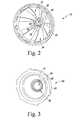
- FIG. 3is an inside view of a trial to be coupled with the handle of FIG. 1 ;
- FIG. 4is a perspective view of the handle of FIG. 1 coupled to the reamer of FIG. 2 ;
- FIG. 5is a cut-away view of the handle of FIG. 1 coupled to the trial of FIG. 3 ;
- FIG. 6is a cut-away view of the handle of FIG. 1 coupled to the trial of FIG. 3 and the reamer of FIG. 2 ;
- FIG. 7is a perspective view of the reamer of FIG. 2 and a bone strainer according to one embodiment of the invention.
- FIG. 8is a flow chart illustrating the use of an instrument according to one embodiment of the present invention.
- FIG. 1a handle 10 of an instrument 11 ( FIG. 4 ) according to one embodiment of the present invention is illustrated.
- the handle 10includes a reamer coupling feature 12 and a trial coupling feature 14 .
- the reamer coupling feature 12includes a hex-shaped rod 16 having a hex-shaped end 18 . Whilst the reamer coupling feature 12 is illustrated as a hex-shaped rod, it is understood other types of coupling mechanisms may be used such as rods with buttons or latches.
- the hex-shaped rod 16may also include a locking mechanism 20 .
- the locking mechanism in this embodimentis illustrated as a pair of ball bearings 22 that protrude from the rod 16 .
- the ball bearings 22are coupled to a button 23 , such that as the button 23 is pressed, the ball bearings retract.
- Other locking mechanismssuch as latches or buttons may be used.
- the trial coupling feature 14is illustrated as a slidable sleeve 24 having a recess 26 at one end.
- the sleeve 24may be of any configuration which allows it slide along the handle 10 .
- the acetabular reamer 30includes an outer cutting surface 32 and an inner concave surface 34 .
- the acetabular reamer 30includes an apex 36 .
- the outer cutting surface 32may include a plurality of cutting blades 38 extending from the apex 36 to a rim 40 opposite the apex 36 .
- the inner concave surface 34includes a first handle coupling feature 42 at the apex 36 .
- the first handle coupling feature 42may be a female hex boss 44 .
- the female hex boss 44is sized and shaped to engage the hex-shaped rod 16 of the handle 10 .
- the female hex boss 44may also include a recess (or locking feature) 48 extending around its inner periphery.
- the recess 48may be used in conjunction with a trial 60 as detailed further below.
- a female hex boss 44is illustrated as the first handle coupling feature, other coupling devices known by those skilled in the art may be used.
- the locking feature 48may be of locking mechanisms other than a recess.
- the trial 60includes a convex outer surface 62 and an apex 64 .
- the convex outer surface 62is designed to fit inside the inner concave surface 34 of the reamer 30 .
- the trial 60includes a second handle coupling feature 66 .
- the second handle coupling feature 66is a plurality of flexible fingers 68 which extend from the apex 64 and into a recess of the trial 60 .
- the flexible fingers 68include a protrusion 70 .
- the protrusion 70is adapted to grasp the recess 26 of the sleeve 24 when the trial is coupled to the handle 10 .
- FIG. 4illustrates an embodiment of the instrument 11 with the handle 10 coupled with the acetabular reamer 30 .
- the hex-shaped rod 16 of the handle 10fits into the female hex boss 40 of the reamer 30 .
- the ball bearings 22FIG. 1
- the recess 48FIG. 2
- the usermay depress the button 23 , which causes the ball bearings 22 to disengage the recess 48 .
- FIG. 5is a cross-sectional view of the handle 10 coupled to the trial 60 .
- the sleeve 24 of the handle 10can be slid along the handle 10 .
- the fingers 68engage the recess 26 of the sleeve. This causes the trial 60 to be locked into place with respect to the handle 10 .
- the userslides the sleeve toward the other end of the handle 10 .
- the flexible fingers 68will flex and disengage from the trial.
- FIG. 6is a cross-sectional view of the handle 10 , the trial 60 and the reamer 30 .
- the viewis of the handle 10 just after it has disengaged from the trial 60 and the trial 60 has engaged the reamer 30 .
- the flexible fingers 68 of the trial 60have been snap-fit into a recess 80 on the outside of the female hex boss 44 .
- This viewalso shows the ball bearings 22 of the handle 10 engaged with the recess 48 of the hex boss 44 . If the user continues to push the sleeve 24 into the trial 60 , it causes the trial to disengage from the reamer 30 and the trial 60 would engage the sleeve 24 , allowing the user to remove the trial 60 from the reamer 30 .
- the bone strainer 90is a generally hemispherical part having an inner concave cavity 92 and an outer convex shell 94 that is designed to fit inside the inner concave surface 34 of the reamer 30 .
- the bone strainer 90includes a plurality of curved arms 96 that extend from an apex 97 to a rim 98 .
- the apex 97engages the boss 44 ( FIG. 2 ) of the reamer 30 .
- the plurality of curved pieces 96act to retain the reamed bone chips during the reaming process.
- the usercan remove the bone strainer 90 and handle 10 .
- the bone chipsare removed with the bone strainer 90 , leaving a clean surface in order to place the trial 60 .
- step s 100the handle 10 is inserted into the reamer 30 and the bone strainer 90 , with the hex-shaped rod 16 engaging the female hex boss 44 of the reamer.
- the reamer 30is then locked to the handle 10 via the ball bearings 22 engaging the recess 48 of the reamer 30 (step s 102 ).
- the userreams the acetabulum by rotating the handle 10 at step s 104 .
- the edges of the hex-shaped rod 16engage the edges of the female hex boss 44 , causing the reamer 30 to also rotate.
- the cutting blades 38 on the outer cutting surface 32ream the acetabular bone (step s 104 ).
- the bone strainer 90collects the bone in its cavity 92 .
- the handle 10is disengaged from the reamer 30 at step s 106 by pressing the button 23 .
- the reamer 30is left in the reamed acetabulum, while the handle 10 and bone strainer 90 are removed.
- the bone strainer 90also removes the bone chips, thereby leaving a clean reamer to receive the trial 60 .
- the handle 30is then inserted into the trial 60 (step s 108 ).
- the flexible fingers 68 of the trialsnap-fit into the recess 26 of the handle 10 . More specifically, the flexible fingers 68 include protrusions 70 that engage the recess 26 .
- the handleis then removed.
- the trial 60is then inserted into the reamer 30 (step s 110 ).
- the fingers 68engage the recess 80 of the outside of the female hex boss 44 .
- the trial 60is now locked in position relative to the reamer and the trial reduction can be done (step s 112 ).
- the reamer, bone strainer, and handlemay be made from a variety of known materials such as stainless steel. Other metals may also be used. In some embodiments, plastics may be used or a combination of plastic and metal.
- the trial 60may be made of a plastic such as polyacetal. Other known materials such as polyethylenes or other plastic materials may be used. The trial may also be made of other materials such as ceramics or metals.
Landscapes
- Health & Medical Sciences (AREA)
- Life Sciences & Earth Sciences (AREA)
- Surgery (AREA)
- Orthopedic Medicine & Surgery (AREA)
- Veterinary Medicine (AREA)
- General Health & Medical Sciences (AREA)
- Oral & Maxillofacial Surgery (AREA)
- Engineering & Computer Science (AREA)
- Biomedical Technology (AREA)
- Heart & Thoracic Surgery (AREA)
- Public Health (AREA)
- Animal Behavior & Ethology (AREA)
- Molecular Biology (AREA)
- Nuclear Medicine, Radiotherapy & Molecular Imaging (AREA)
- Medical Informatics (AREA)
- Dentistry (AREA)
- Transplantation (AREA)
- Physical Education & Sports Medicine (AREA)
- Cardiology (AREA)
- Vascular Medicine (AREA)
- Prostheses (AREA)
Abstract
Description
Claims (21)
Priority Applications (4)
| Application Number | Priority Date | Filing Date | Title |
|---|---|---|---|
| US14/501,708US9675364B2 (en) | 2014-09-30 | 2014-09-30 | Grater and trial liner |
| PCT/US2015/051674WO2016053712A1 (en) | 2014-09-30 | 2015-09-23 | Grater and trial liner |
| US15/590,188US9943319B2 (en) | 2014-09-30 | 2017-05-09 | Grater and trial liner |
| US15/915,488US10194924B2 (en) | 2014-09-30 | 2018-03-08 | Grater and trial liner |
Applications Claiming Priority (1)
| Application Number | Priority Date | Filing Date | Title |
|---|---|---|---|
| US14/501,708US9675364B2 (en) | 2014-09-30 | 2014-09-30 | Grater and trial liner |
Related Child Applications (1)
| Application Number | Title | Priority Date | Filing Date |
|---|---|---|---|
| US15/590,188ContinuationUS9943319B2 (en) | 2014-09-30 | 2017-05-09 | Grater and trial liner |
Publications (2)
| Publication Number | Publication Date |
|---|---|
| US20160089156A1 US20160089156A1 (en) | 2016-03-31 |
| US9675364B2true US9675364B2 (en) | 2017-06-13 |
Family
ID=54266637
Family Applications (3)
| Application Number | Title | Priority Date | Filing Date |
|---|---|---|---|
| US14/501,708Active2035-09-03US9675364B2 (en) | 2014-09-30 | 2014-09-30 | Grater and trial liner |
| US15/590,188ActiveUS9943319B2 (en) | 2014-09-30 | 2017-05-09 | Grater and trial liner |
| US15/915,488ActiveUS10194924B2 (en) | 2014-09-30 | 2018-03-08 | Grater and trial liner |
Family Applications After (2)
| Application Number | Title | Priority Date | Filing Date |
|---|---|---|---|
| US15/590,188ActiveUS9943319B2 (en) | 2014-09-30 | 2017-05-09 | Grater and trial liner |
| US15/915,488ActiveUS10194924B2 (en) | 2014-09-30 | 2018-03-08 | Grater and trial liner |
Country Status (2)
| Country | Link |
|---|---|
| US (3) | US9675364B2 (en) |
| WO (1) | WO2016053712A1 (en) |
Cited By (2)
| Publication number | Priority date | Publication date | Assignee | Title |
|---|---|---|---|---|
| US10194924B2 (en)* | 2014-09-30 | 2019-02-05 | Depuy Ireland Unlimited Company | Grater and trial liner |
| US20220133504A1 (en)* | 2019-02-27 | 2022-05-05 | Zimmer, Inc. | Tool for reaming a carpal bone |
Families Citing this family (14)
| Publication number | Priority date | Publication date | Assignee | Title |
|---|---|---|---|---|
| GB201322237D0 (en) | 2013-12-16 | 2014-01-29 | Depuy Ireland Ltd | Surgical reamer |
| US10543003B2 (en) | 2014-09-30 | 2020-01-28 | Depuy Ireland Unlimited Company | Orthopaedic surgical instrument assembly and method of manufacturing same |
| US10092304B2 (en) | 2014-09-30 | 2018-10-09 | Depuy Ireland Unlimited Company | Orthopaedic surgical instrument assembly for reaming a patient's acetabulum |
| US10478197B2 (en)* | 2015-12-11 | 2019-11-19 | Viant As&O Holdings, Llc | Minimally invasive bone sparing acetabular reamer |
| WO2017218589A1 (en) | 2016-06-14 | 2017-12-21 | Razor Medical Instruments LLC | Tool for cutting bone for surgical use |
| US10603178B2 (en)* | 2016-11-22 | 2020-03-31 | Storage Enterprises, LLC | Prosthetic hip system |
| EP3684273A4 (en) | 2017-09-21 | 2021-11-03 | Razor Medical Instruments, Inc. | BLADE CLEARER ARRANGEMENT FOR SURGICAL PURPOSES |
| USD827823S1 (en)* | 2018-01-06 | 2018-09-04 | Venta Endo, LLC | Endodontic instrument |
| ES2978763T3 (en)* | 2018-03-07 | 2024-09-19 | Tecres Spa | Acetabular spacer device comprising a pharmaceutical substance |
| US11103367B2 (en) | 2019-02-15 | 2021-08-31 | Encore Medical, L.P. | Acetabular liner |
| US11801151B2 (en) | 2019-03-12 | 2023-10-31 | Howmedica Osteonics Corp. | Anatomic shell 2-in-1 window trial |
| IT202000005947A1 (en)* | 2020-03-19 | 2021-09-19 | Limacorporate Spa | GUIDED MILLING DEVICE FOR PROSTHETIC SURGERY |
| US11925362B2 (en) | 2021-12-10 | 2024-03-12 | Depuy Ireland Unlimited Company | Augment reamer and related methods |
| CN114145808B (en)* | 2021-12-13 | 2024-01-16 | 天衍医疗器材有限公司 | Acetabular tool, acetabular file system and acetabular trial mould system |
Citations (67)
| Publication number | Priority date | Publication date | Assignee | Title |
|---|---|---|---|---|
| DE2437772A1 (en) | 1974-08-06 | 1976-02-19 | Hanfried Dr Med Weigand | Cotyloidal cavity milling tool - has hollow body closed by detachable cover |
| US4023572A (en)* | 1974-08-06 | 1977-05-17 | Hanfried Weigand | Milling tool for preparing a joint socket in the prosthetic replacement of a joint |
| US4712951A (en)* | 1985-08-26 | 1987-12-15 | Brown Byron L | Tool for cutting annular groove |
| US4802468A (en)* | 1984-09-24 | 1989-02-07 | Powlan Roy Y | Device for cutting threads in the walls of the acetabular cavity in humans |
| US5295992A (en) | 1992-03-16 | 1994-03-22 | Othy, Inc. | Patella cutting system |
| US5431657A (en)* | 1994-05-23 | 1995-07-11 | Zimmer, Inc. | Instrument for installing an acetabular cup assembly |
| US5462548A (en)* | 1992-07-06 | 1995-10-31 | Pappas; Michael J. | Acetabular reamer |
| US5540697A (en)* | 1993-02-12 | 1996-07-30 | U.S. Medical Products, Inc. | Prosthetic socket installation apparatus and method |
| US5584837A (en)* | 1993-08-13 | 1996-12-17 | Petersen; Thomas D. | Acetabular cup inserter for orthopedic |
| US5879355A (en)* | 1994-05-16 | 1999-03-09 | Ullmark; Goesta | Device for use in transplantation of bone tissue material in a cavity in bone |
| US5976148A (en)* | 1996-11-12 | 1999-11-02 | Ppc | Set of ancillary equipment for the implantation of acetabular cups of hip prosthesis, and prosthetic acetabular cup assembly ready to be implanted |
| US6015411A (en) | 1996-10-23 | 2000-01-18 | Nagoya Screw Mfg. Co., Ltd. | Bone excavating apparatus for repairing ligament and a bone tunnel forming method |
| US6102915A (en) | 1996-02-13 | 2000-08-15 | Advanced Technical Fabrication | Hip prosthesis positioning instrument |
| US6168600B1 (en)* | 1999-08-20 | 2001-01-02 | Grace Manufacturing, Inc. | Acetabular reamer backing plate and method of use |
| US6221076B1 (en)* | 1997-01-31 | 2001-04-24 | Astra Aktiebolag | Bone reamer for sharping bone sockets or cavities during orthopaedic surgery |
| US6409732B1 (en) | 1999-07-09 | 2002-06-25 | Othy, Inc. | Tool driver |
| US20030050645A1 (en)* | 2002-10-30 | 2003-03-13 | Parker Brad A. | Acetabular cup impactor |
| US20030130741A1 (en)* | 2002-01-07 | 2003-07-10 | Mcminn Derek James Wallace | Hip prosthesis |
| US20040073224A1 (en)* | 2002-10-10 | 2004-04-15 | Bauer Clayton T. | Minimally invasive adjustable acetubular reamer |
| US20040073226A1 (en)* | 2001-03-15 | 2004-04-15 | Anton Cotting | Positioning instrument for inserting an extension shell |
| US20040117029A1 (en)* | 2002-12-13 | 2004-06-17 | Lewis Paul P. | Modular orthopaedic implant apparatus and method |
| US20040133210A1 (en) | 2003-01-08 | 2004-07-08 | Todd Wolford | Orthopaedic reamer assembly |
| US20050038443A1 (en)* | 2002-12-12 | 2005-02-17 | Hedley Anthony K. | Surgical tools for joint replacement |
| US20050085823A1 (en)* | 2003-10-21 | 2005-04-21 | Murphy Stephen B. | Acetabular impactor |
| US20050228394A1 (en)* | 2004-03-31 | 2005-10-13 | Diane Bihary | Suction inserter |
| US20050261694A1 (en)* | 2002-05-07 | 2005-11-24 | Marcus Orton | Assembly for use in orthopaedic surgery |
| US20060025774A1 (en) | 2004-07-29 | 2006-02-02 | Meyer Fishbein | Minimally invasive collapsible surgical reamer |
| US20060079906A1 (en)* | 2004-10-12 | 2006-04-13 | Benoist Girard Sas | Acetabular rim cutter |
| JP2006288863A (en) | 2005-04-13 | 2006-10-26 | Nakashima Propeller Co Ltd | Cup reamer for surgery |
| US7220264B1 (en)* | 2003-03-12 | 2007-05-22 | Biomet Manufacturing Corp. | Minimally invasive reamer |
| US20070203583A1 (en)* | 2006-02-28 | 2007-08-30 | Biomet Manufacturing Corp. | Method and apparatus for aligning a taper lock connection |
| US20070233132A1 (en)* | 2006-03-16 | 2007-10-04 | Valla Joseph R | Surgical cutting tool and system |
| WO2007121313A2 (en) | 2006-04-12 | 2007-10-25 | Smtih & Nephew, Inc. | Acetabular trial system |
| US20070276394A1 (en)* | 2002-02-12 | 2007-11-29 | Alexandria Research Technologies, Llc | Apparatus and method for minimally invasive total joint replacement |
| US20080009952A1 (en)* | 2006-06-30 | 2008-01-10 | Hodge W A | Precision acetabular machining system and resurfacing acetabular implant |
| US7335207B1 (en)* | 2003-11-26 | 2008-02-26 | Biomet Manufacturing Corp. | Minimally invasive cup impactor |
| US20090088757A1 (en) | 2007-10-02 | 2009-04-02 | Howmedica Osteonics Corp. | Acetabular reamer |
| US20090163921A1 (en) | 2007-12-20 | 2009-06-25 | Andre Lechot | Disposable acetabular reamer from flat stock |
| US7621921B2 (en)* | 2006-01-25 | 2009-11-24 | Symmetry Medical, Inc | Split thread orthopaedic implant impactor |
| US20100069908A1 (en)* | 2007-02-09 | 2010-03-18 | Sidebotham Christopher G | Modular spherical hollow reamer assembly for medical applications |
| US7744602B2 (en)* | 2005-01-28 | 2010-06-29 | Steven M. Teeny | Acetabular shell removal tool |
| US20100168749A1 (en)* | 2007-02-09 | 2010-07-01 | Sidebotham Christopher G | Disposable reamer shaft or modular spherical or tapered hollow reamer assembly for medical applications |
| US7763031B2 (en)* | 2005-03-01 | 2010-07-27 | Howmedica Osteonics Corp. | Acetabular shell removal instrument |
| US20100272533A1 (en) | 2009-04-26 | 2010-10-28 | Iscar, Ltd. | Rotary Cutting Tool |
| US20110208202A1 (en)* | 2008-08-01 | 2011-08-25 | Smith & Nephew Orthopaedics Ag | Positioning aid in the form of a self-affixing test jip joint socket |
| US20110213372A1 (en)* | 2009-12-31 | 2011-09-01 | Keefer Ryan C | Reciprocating rasps for use in an orthopaedic surgical procedure |
| US8123815B2 (en)* | 2008-11-24 | 2012-02-28 | Biomet Manufacturing Corp. | Multiple bearing acetabular prosthesis |
| US20120185059A1 (en)* | 2011-01-14 | 2012-07-19 | Zimmer, Inc. | Provisional liner system |
| US8308810B2 (en)* | 2009-07-14 | 2012-11-13 | Biomet Manufacturing Corp. | Multiple bearing acetabular prosthesis |
| US8357163B2 (en)* | 2007-02-09 | 2013-01-22 | Sidebotham Christopher G | Low cost modular tapered and spherical hollow reamers for medical applications |
| US8435243B2 (en)* | 2010-02-12 | 2013-05-07 | Greatbatch Ltd. | Disposable reamer |
| US20130131741A1 (en)* | 2011-11-21 | 2013-05-23 | Lampros Kourtis | Systems, devices, and methods for anchoring orthopaedic implants to bone |
| US20130211407A1 (en)* | 2010-06-01 | 2013-08-15 | Benjamin Geebelen | Acetabular cup reamer guide |
| US8556897B2 (en)* | 2007-02-09 | 2013-10-15 | Christopher G. Sidebotham | Modular spherical hollow reamer assembly for medical applications |
| US20130325139A1 (en)* | 2012-05-29 | 2013-12-05 | Zimmer, Inc. | Modular screw apparatus and method |
| US20140114321A1 (en)* | 2012-10-23 | 2014-04-24 | Biomet Manufacturing Corporation | Method And Apparatus For Implanting A Prosthesis |
| US20140163564A1 (en)* | 2012-12-11 | 2014-06-12 | Biomet Manufacturing Corporation | Patient-Specific Acetabular Guide For Anterior Approach |
| US8771275B2 (en)* | 2008-09-23 | 2014-07-08 | Ping Xie | Device for shaping object with a profile of at least a partial sphere |
| US20140228854A1 (en)* | 2013-02-08 | 2014-08-14 | Biomet Manufacturing Corporation | Apparatus And Method For Positioning A Prosthesis |
| US8870886B2 (en)* | 2011-08-26 | 2014-10-28 | Greatbatch Medical S.A. | Straight cup impactor |
| US20140324183A1 (en)* | 2011-12-15 | 2014-10-30 | Thorwald Springer | Prosthetic acetabular cup |
| US20150100060A1 (en)* | 2013-10-08 | 2015-04-09 | Howmedica Osteonics Corp. | Acetabular cup insertion instruments |
| US20150366568A1 (en)* | 2014-06-20 | 2015-12-24 | Greatbatch Ltd. | Disposable cutter acetabular reamer |
| US20160089156A1 (en)* | 2014-09-30 | 2016-03-31 | DePuy Synthes Products, LLC | Grater and trial liner |
| US20160089158A1 (en)* | 2014-09-30 | 2016-03-31 | Michael Fortin | Orthopaedic surgical instrument assembly for reaming a patient's acetabulum |
| US20160175112A1 (en)* | 2013-03-14 | 2016-06-23 | In'Tech Medical, Inc. | Modular acetabular cup impactor and reamer |
| US9439781B2 (en)* | 2011-05-03 | 2016-09-13 | Smith & Nephew, Inc. | Patient-matched guides for orthopedic implants |
- 2014
- 2014-09-30USUS14/501,708patent/US9675364B2/enactiveActive
- 2015
- 2015-09-23WOPCT/US2015/051674patent/WO2016053712A1/enactiveApplication Filing
- 2017
- 2017-05-09USUS15/590,188patent/US9943319B2/enactiveActive
- 2018
- 2018-03-08USUS15/915,488patent/US10194924B2/enactiveActive
Patent Citations (68)
| Publication number | Priority date | Publication date | Assignee | Title |
|---|---|---|---|---|
| US4023572A (en)* | 1974-08-06 | 1977-05-17 | Hanfried Weigand | Milling tool for preparing a joint socket in the prosthetic replacement of a joint |
| DE2437772A1 (en) | 1974-08-06 | 1976-02-19 | Hanfried Dr Med Weigand | Cotyloidal cavity milling tool - has hollow body closed by detachable cover |
| US4802468A (en)* | 1984-09-24 | 1989-02-07 | Powlan Roy Y | Device for cutting threads in the walls of the acetabular cavity in humans |
| US4712951A (en)* | 1985-08-26 | 1987-12-15 | Brown Byron L | Tool for cutting annular groove |
| US5295992A (en) | 1992-03-16 | 1994-03-22 | Othy, Inc. | Patella cutting system |
| US5462548A (en)* | 1992-07-06 | 1995-10-31 | Pappas; Michael J. | Acetabular reamer |
| US5540697A (en)* | 1993-02-12 | 1996-07-30 | U.S. Medical Products, Inc. | Prosthetic socket installation apparatus and method |
| US5584837A (en)* | 1993-08-13 | 1996-12-17 | Petersen; Thomas D. | Acetabular cup inserter for orthopedic |
| US5879355A (en)* | 1994-05-16 | 1999-03-09 | Ullmark; Goesta | Device for use in transplantation of bone tissue material in a cavity in bone |
| US5431657A (en)* | 1994-05-23 | 1995-07-11 | Zimmer, Inc. | Instrument for installing an acetabular cup assembly |
| US6102915A (en) | 1996-02-13 | 2000-08-15 | Advanced Technical Fabrication | Hip prosthesis positioning instrument |
| US6015411A (en) | 1996-10-23 | 2000-01-18 | Nagoya Screw Mfg. Co., Ltd. | Bone excavating apparatus for repairing ligament and a bone tunnel forming method |
| US5976148A (en)* | 1996-11-12 | 1999-11-02 | Ppc | Set of ancillary equipment for the implantation of acetabular cups of hip prosthesis, and prosthetic acetabular cup assembly ready to be implanted |
| US6221076B1 (en)* | 1997-01-31 | 2001-04-24 | Astra Aktiebolag | Bone reamer for sharping bone sockets or cavities during orthopaedic surgery |
| US6409732B1 (en) | 1999-07-09 | 2002-06-25 | Othy, Inc. | Tool driver |
| US6168600B1 (en)* | 1999-08-20 | 2001-01-02 | Grace Manufacturing, Inc. | Acetabular reamer backing plate and method of use |
| US20040073226A1 (en)* | 2001-03-15 | 2004-04-15 | Anton Cotting | Positioning instrument for inserting an extension shell |
| US20030130741A1 (en)* | 2002-01-07 | 2003-07-10 | Mcminn Derek James Wallace | Hip prosthesis |
| US20070276394A1 (en)* | 2002-02-12 | 2007-11-29 | Alexandria Research Technologies, Llc | Apparatus and method for minimally invasive total joint replacement |
| US20050261694A1 (en)* | 2002-05-07 | 2005-11-24 | Marcus Orton | Assembly for use in orthopaedic surgery |
| US20040073224A1 (en)* | 2002-10-10 | 2004-04-15 | Bauer Clayton T. | Minimally invasive adjustable acetubular reamer |
| US20030050645A1 (en)* | 2002-10-30 | 2003-03-13 | Parker Brad A. | Acetabular cup impactor |
| US20050038443A1 (en)* | 2002-12-12 | 2005-02-17 | Hedley Anthony K. | Surgical tools for joint replacement |
| US20040117029A1 (en)* | 2002-12-13 | 2004-06-17 | Lewis Paul P. | Modular orthopaedic implant apparatus and method |
| US20040133210A1 (en) | 2003-01-08 | 2004-07-08 | Todd Wolford | Orthopaedic reamer assembly |
| US6875217B2 (en)* | 2003-01-08 | 2005-04-05 | Symmetry Medical, Inc. | Orthopaedic reamer assembly |
| US7220264B1 (en)* | 2003-03-12 | 2007-05-22 | Biomet Manufacturing Corp. | Minimally invasive reamer |
| US20050085823A1 (en)* | 2003-10-21 | 2005-04-21 | Murphy Stephen B. | Acetabular impactor |
| US7335207B1 (en)* | 2003-11-26 | 2008-02-26 | Biomet Manufacturing Corp. | Minimally invasive cup impactor |
| US20050228394A1 (en)* | 2004-03-31 | 2005-10-13 | Diane Bihary | Suction inserter |
| US20060025774A1 (en) | 2004-07-29 | 2006-02-02 | Meyer Fishbein | Minimally invasive collapsible surgical reamer |
| US20060079906A1 (en)* | 2004-10-12 | 2006-04-13 | Benoist Girard Sas | Acetabular rim cutter |
| US7744602B2 (en)* | 2005-01-28 | 2010-06-29 | Steven M. Teeny | Acetabular shell removal tool |
| US7763031B2 (en)* | 2005-03-01 | 2010-07-27 | Howmedica Osteonics Corp. | Acetabular shell removal instrument |
| JP2006288863A (en) | 2005-04-13 | 2006-10-26 | Nakashima Propeller Co Ltd | Cup reamer for surgery |
| US7621921B2 (en)* | 2006-01-25 | 2009-11-24 | Symmetry Medical, Inc | Split thread orthopaedic implant impactor |
| US20070203583A1 (en)* | 2006-02-28 | 2007-08-30 | Biomet Manufacturing Corp. | Method and apparatus for aligning a taper lock connection |
| US20070233132A1 (en)* | 2006-03-16 | 2007-10-04 | Valla Joseph R | Surgical cutting tool and system |
| WO2007121313A2 (en) | 2006-04-12 | 2007-10-25 | Smtih & Nephew, Inc. | Acetabular trial system |
| US20080009952A1 (en)* | 2006-06-30 | 2008-01-10 | Hodge W A | Precision acetabular machining system and resurfacing acetabular implant |
| US8357163B2 (en)* | 2007-02-09 | 2013-01-22 | Sidebotham Christopher G | Low cost modular tapered and spherical hollow reamers for medical applications |
| US20100069908A1 (en)* | 2007-02-09 | 2010-03-18 | Sidebotham Christopher G | Modular spherical hollow reamer assembly for medical applications |
| US20100168749A1 (en)* | 2007-02-09 | 2010-07-01 | Sidebotham Christopher G | Disposable reamer shaft or modular spherical or tapered hollow reamer assembly for medical applications |
| US8556897B2 (en)* | 2007-02-09 | 2013-10-15 | Christopher G. Sidebotham | Modular spherical hollow reamer assembly for medical applications |
| US20090088757A1 (en) | 2007-10-02 | 2009-04-02 | Howmedica Osteonics Corp. | Acetabular reamer |
| US20090163921A1 (en) | 2007-12-20 | 2009-06-25 | Andre Lechot | Disposable acetabular reamer from flat stock |
| US20110208202A1 (en)* | 2008-08-01 | 2011-08-25 | Smith & Nephew Orthopaedics Ag | Positioning aid in the form of a self-affixing test jip joint socket |
| US8771275B2 (en)* | 2008-09-23 | 2014-07-08 | Ping Xie | Device for shaping object with a profile of at least a partial sphere |
| US8123815B2 (en)* | 2008-11-24 | 2012-02-28 | Biomet Manufacturing Corp. | Multiple bearing acetabular prosthesis |
| US20100272533A1 (en) | 2009-04-26 | 2010-10-28 | Iscar, Ltd. | Rotary Cutting Tool |
| US8308810B2 (en)* | 2009-07-14 | 2012-11-13 | Biomet Manufacturing Corp. | Multiple bearing acetabular prosthesis |
| US20110213372A1 (en)* | 2009-12-31 | 2011-09-01 | Keefer Ryan C | Reciprocating rasps for use in an orthopaedic surgical procedure |
| US8435243B2 (en)* | 2010-02-12 | 2013-05-07 | Greatbatch Ltd. | Disposable reamer |
| US20130211407A1 (en)* | 2010-06-01 | 2013-08-15 | Benjamin Geebelen | Acetabular cup reamer guide |
| US20120185059A1 (en)* | 2011-01-14 | 2012-07-19 | Zimmer, Inc. | Provisional liner system |
| US9439781B2 (en)* | 2011-05-03 | 2016-09-13 | Smith & Nephew, Inc. | Patient-matched guides for orthopedic implants |
| US8870886B2 (en)* | 2011-08-26 | 2014-10-28 | Greatbatch Medical S.A. | Straight cup impactor |
| US20130131741A1 (en)* | 2011-11-21 | 2013-05-23 | Lampros Kourtis | Systems, devices, and methods for anchoring orthopaedic implants to bone |
| US20140324183A1 (en)* | 2011-12-15 | 2014-10-30 | Thorwald Springer | Prosthetic acetabular cup |
| US20130325139A1 (en)* | 2012-05-29 | 2013-12-05 | Zimmer, Inc. | Modular screw apparatus and method |
| US20140114321A1 (en)* | 2012-10-23 | 2014-04-24 | Biomet Manufacturing Corporation | Method And Apparatus For Implanting A Prosthesis |
| US20140163564A1 (en)* | 2012-12-11 | 2014-06-12 | Biomet Manufacturing Corporation | Patient-Specific Acetabular Guide For Anterior Approach |
| US20140228854A1 (en)* | 2013-02-08 | 2014-08-14 | Biomet Manufacturing Corporation | Apparatus And Method For Positioning A Prosthesis |
| US20160175112A1 (en)* | 2013-03-14 | 2016-06-23 | In'Tech Medical, Inc. | Modular acetabular cup impactor and reamer |
| US20150100060A1 (en)* | 2013-10-08 | 2015-04-09 | Howmedica Osteonics Corp. | Acetabular cup insertion instruments |
| US20150366568A1 (en)* | 2014-06-20 | 2015-12-24 | Greatbatch Ltd. | Disposable cutter acetabular reamer |
| US20160089156A1 (en)* | 2014-09-30 | 2016-03-31 | DePuy Synthes Products, LLC | Grater and trial liner |
| US20160089158A1 (en)* | 2014-09-30 | 2016-03-31 | Michael Fortin | Orthopaedic surgical instrument assembly for reaming a patient's acetabulum |
Cited By (3)
| Publication number | Priority date | Publication date | Assignee | Title |
|---|---|---|---|---|
| US10194924B2 (en)* | 2014-09-30 | 2019-02-05 | Depuy Ireland Unlimited Company | Grater and trial liner |
| US20220133504A1 (en)* | 2019-02-27 | 2022-05-05 | Zimmer, Inc. | Tool for reaming a carpal bone |
| US12232979B2 (en)* | 2019-02-27 | 2025-02-25 | Zimmer, Inc. | Tool for reaming a carpal bone |
Also Published As
| Publication number | Publication date |
|---|---|
| US20180193038A1 (en) | 2018-07-12 |
| US9943319B2 (en) | 2018-04-17 |
| US10194924B2 (en) | 2019-02-05 |
| US20160089156A1 (en) | 2016-03-31 |
| US20170238942A1 (en) | 2017-08-24 |
| WO2016053712A1 (en) | 2016-04-07 |
Similar Documents
| Publication | Publication Date | Title |
|---|---|---|
| US10194924B2 (en) | Grater and trial liner | |
| US20170086980A1 (en) | Acetabular cup taper cover and liner trial | |
| US7927376B2 (en) | Expandable acetabular liner extraction device, cup assembly and associated method | |
| US9713531B2 (en) | Deflection resistant acetabular cup | |
| EP3545909B1 (en) | Self-centring, anti-seizing acetabular liner | |
| US20070010825A1 (en) | Acetabular liner extraction device, kit and associated method | |
| US20060004463A1 (en) | Extended radius prosthesis and associated method | |
| US20150100061A1 (en) | Canal sizer and associated method | |
| US7799029B2 (en) | Radial impaction bone tamp and associated method | |
| US10111754B2 (en) | Acetabular shell and liner system | |
| AU2020307535B2 (en) | Distal radioulnar joint prosthesis system and method of use | |
| WO2019186475A1 (en) | Orthopaedic hip prosthesis surface protection system and method | |
| JP6640286B2 (en) | Kit used for hip arthroplasty |
Legal Events
| Date | Code | Title | Description |
|---|---|---|---|
| AS | Assignment | Owner name:DEPUY SYNTHES PRODUCTS, LLC, MASSACHUSETTS Free format text:ASSIGNMENT OF ASSIGNORS INTEREST;ASSIGNORS:FORTIN, MICHAEL;MCCLEARY, LARRY;HAYES, KEN;SIGNING DATES FROM 20150106 TO 20150421;REEL/FRAME:035454/0604 Owner name:DEPUY SYNTHES PRODUCTS, INC., MASSACHUSETTS Free format text:CHANGE OF NAME;ASSIGNOR:DEPUY SYNTHES PRODUCTS, LLC;REEL/FRAME:035465/0690 Effective date:20141219 | |
| AS | Assignment | Owner name:DEPUY (IRELAND), IRELAND Free format text:ASSIGNMENT OF ASSIGNORS INTEREST;ASSIGNOR:DEPUY SYNTHES PRODUCTS, INC.;REEL/FRAME:039982/0150 Effective date:20160805 Owner name:DEPUY IRELAND UNLIMITED COMPANY, IRELAND Free format text:CHANGE OF NAME;ASSIGNOR:DEPUY (IRELAND);REEL/FRAME:040302/0111 Effective date:20160812 | |
| STCF | Information on status: patent grant | Free format text:PATENTED CASE | |
| MAFP | Maintenance fee payment | Free format text:PAYMENT OF MAINTENANCE FEE, 4TH YEAR, LARGE ENTITY (ORIGINAL EVENT CODE: M1551); ENTITY STATUS OF PATENT OWNER: LARGE ENTITY Year of fee payment:4 | |
| MAFP | Maintenance fee payment | Free format text:PAYMENT OF MAINTENANCE FEE, 8TH YEAR, LARGE ENTITY (ORIGINAL EVENT CODE: M1552); ENTITY STATUS OF PATENT OWNER: LARGE ENTITY Year of fee payment:8 |