US9669226B2 - Methods and systems for reducing interference in stimulation treatment - Google Patents
Methods and systems for reducing interference in stimulation treatmentDownload PDFInfo
- Publication number
- US9669226B2 US9669226B2US12/876,461US87646110AUS9669226B2US 9669226 B2US9669226 B2US 9669226B2US 87646110 AUS87646110 AUS 87646110AUS 9669226 B2US9669226 B2US 9669226B2
- Authority
- US
- United States
- Prior art keywords
- stimulation
- transducer
- pulse
- additional
- detection period
- Prior art date
- Legal status (The legal status is an assumption and is not a legal conclusion. Google has not performed a legal analysis and makes no representation as to the accuracy of the status listed.)
- Active, expires
Links
Images


Classifications
- A—HUMAN NECESSITIES
- A61—MEDICAL OR VETERINARY SCIENCE; HYGIENE
- A61N—ELECTROTHERAPY; MAGNETOTHERAPY; RADIATION THERAPY; ULTRASOUND THERAPY
- A61N1/00—Electrotherapy; Circuits therefor
- A61N1/18—Applying electric currents by contact electrodes
- A61N1/32—Applying electric currents by contact electrodes alternating or intermittent currents
- A61N1/36—Applying electric currents by contact electrodes alternating or intermittent currents for stimulation
- A61N1/362—Heart stimulators
- A61N1/37—Monitoring; Protecting
- A—HUMAN NECESSITIES
- A61—MEDICAL OR VETERINARY SCIENCE; HYGIENE
- A61N—ELECTROTHERAPY; MAGNETOTHERAPY; RADIATION THERAPY; ULTRASOUND THERAPY
- A61N1/00—Electrotherapy; Circuits therefor
- A61N1/18—Applying electric currents by contact electrodes
- A61N1/32—Applying electric currents by contact electrodes alternating or intermittent currents
- A61N1/36—Applying electric currents by contact electrodes alternating or intermittent currents for stimulation
- A61N1/36014—External stimulators, e.g. with patch electrodes
- A61N1/3603—Control systems
- A—HUMAN NECESSITIES
- A61—MEDICAL OR VETERINARY SCIENCE; HYGIENE
- A61N—ELECTROTHERAPY; MAGNETOTHERAPY; RADIATION THERAPY; ULTRASOUND THERAPY
- A61N1/00—Electrotherapy; Circuits therefor
- A61N1/18—Applying electric currents by contact electrodes
- A61N1/32—Applying electric currents by contact electrodes alternating or intermittent currents
- A61N1/36—Applying electric currents by contact electrodes alternating or intermittent currents for stimulation
- A61N1/372—Arrangements in connection with the implantation of stimulators
- A61N1/37211—Means for communicating with stimulators
- A61N1/37252—Details of algorithms or data aspects of communication system, e.g. handshaking, transmitting specific data or segmenting data
- A61N1/37288—Communication to several implantable medical devices within one patient
- A—HUMAN NECESSITIES
- A61—MEDICAL OR VETERINARY SCIENCE; HYGIENE
- A61N—ELECTROTHERAPY; MAGNETOTHERAPY; RADIATION THERAPY; ULTRASOUND THERAPY
- A61N1/00—Electrotherapy; Circuits therefor
- A61N1/18—Applying electric currents by contact electrodes
- A61N1/32—Applying electric currents by contact electrodes alternating or intermittent currents
- A61N1/36—Applying electric currents by contact electrodes alternating or intermittent currents for stimulation
- A61N1/362—Heart stimulators
- A61N1/37—Monitoring; Protecting
- A61N1/3702—Physiological parameters
- A—HUMAN NECESSITIES
- A61—MEDICAL OR VETERINARY SCIENCE; HYGIENE
- A61N—ELECTROTHERAPY; MAGNETOTHERAPY; RADIATION THERAPY; ULTRASOUND THERAPY
- A61N1/00—Electrotherapy; Circuits therefor
- A61N1/18—Applying electric currents by contact electrodes
- A61N1/32—Applying electric currents by contact electrodes alternating or intermittent currents
- A61N1/36—Applying electric currents by contact electrodes alternating or intermittent currents for stimulation
- A61N1/372—Arrangements in connection with the implantation of stimulators
- A61N1/37211—Means for communicating with stimulators
- A61N1/37252—Details of algorithms or data aspects of communication system, e.g. handshaking, transmitting specific data or segmenting data
- A61N1/37264—Changing the program; Upgrading firmware
Definitions
- Stimulation treatmentsmay include electrical treatments, ultrasound, massage, or any other treatment in which energy is imparted to a patient's body. Stimulation treatments may be applied to muscles, for example, in order to shape, firm, increase elasticity, refine, increase caloric expenditure, rehabilitate or redevelop.
- the characteristics of the stimulationsuch as frequency, duration, pulse shape, and intensity, are selected to achieve different treatment goals.
- a typical electrotherapy deviceis programmed to output electrical pulses at varying levels of intensity and duration to provide muscle and/or nerve stimulation.
- Many stimulation systemsutilize multiple channels, with multiple transducers delivering operator-specified or pre-programmed stimulation signals to electrodes or other stimulation devices. These signals may vary over time in frequency, pulse duration, current and/or voltage intensity, waveform shape, rest periods, and may also vary between channels. When multiple channels deliver stimulation pulses at approximately the same time, the pulses interfere with each other and can cause pain or other problems for the user to whom the stimulation is applied.
- FIG. 1Adepicts a stimulation system with two stimulation channels, Channel A 102 and Channel B 104 .
- Channel A 102is coupled to a user by two electrodes A 1 106 and A 2 108 , and provides pulses of stimulation current ia at a frequency denoted by FA.
- Channel B 104is coupled to a user by two electrodes B 1 110 and B 2 112 , and provides pulses of stimulation current ib at a frequency denoted by FB.
- FIG. 1Bdepicts two illustrative waveforms ia 114 and ib 116 in accordance with this scenario.
- FIG. 1Balso illustrates two periods of interference 118 and 120 , which arise because Channels A 102 and B 104 are independent (and thus not synchronized or otherwise coordinated in time) and generate pulses within a short time frame so as to interfere. Interference effects may arise when the channels generate pulses in close proximity in time, even if not precisely simultaneously.
- the energy supplied by a stimulation signal applied at a first body sitemay be detectable at a different body site.
- This energy transmissionoccurs because living tissue has finite impedance. As an energy signal travels through the body, the impedance of the tissue attenuates and delays the energy signal.
- the amplitude, shape and other properties of a detected signaldepend on a number of factors, including the stimulation signal duration, wave shape and intensity, the distance between the stimulation site and the detection site, the properties of the tissue between the stimulation site and the detection site, and other physiological and environmental variables.
- the usermay feel an intermittent intensity peak and/or stimulation modulation (e.g., a frequency and/or an intensity modulation). Any of the following conditions may affect the intensity or other aspects of a patient's sensation of stimulation interference:
- FIG. 1Cdepicts a common stimulation system including a synchronization link 122 between Channels A 102 and B 104 .
- synchronizationmay proceed, for example, using the known synchronization pulses technique illustrated in FIG. 1D .
- Channel A 102when a stimulation pulse 124 is completed on Channel A 102 , Channel A 102 sends a synchronization pulse (not illustrated, but sent at the synchronization time marker 132 ) via the synchronization link 122 ( FIG. 1C ) to Channel B 104 .
- the synchronization time 126 between the completion of the stimulation pulse on Channel A 102 and the receipt of the synchronization pulse at Channel B 104which has duration tsyncAB, represents the minimum amount of time required for a pulse transmitted at Channel A 102 to be received by Channel B 104 .
- Channel B 104may then generate its own stimulation pulse 128 , then transmit a synchronization pulse back to Channel A 102 (not illustrated, but sent at the synchronization time marker 134 ), which takes a synchronization time 130 of duration tsyncBA to arrive. If each channel waits to receive a synchronization pulse from the other channel before proceeding to deliver its own stimulation pulse, interference is avoided.
- a synchronization strategymay not provide optimal functionality for stimulation treatment, particularly in wireless stimulation systems.
- the frequencies of two channelse.g., frequencies FA and FB for Channels A 102 and B 104 , respectively
- the timing constraints resulting from the synchronization timemay impair a channel's ability to provide stimulation pulses at the desired frequency.
- the timing constraintsare tightened even further, impacting the frequencies at which stimulation pulses may be supplied and the precision with which stimulation at a particular frequency may be delivered.
- the synchronization strategy illustrated in FIG. 1Drelies on a central controller or synchronization link 122 ( FIG. 1C ), which can be costly, cumbersome and impractical for use in wireless and other systems with independent stimulation units.
- these stimulation modulesare capable of independent operation (i.e., without requiring the use of a central controller to time and coordinate the delivery of stimulation pulses) and are adjustable and replaceable.
- the stimulation modulesare capable of wireless communication with a microprocessor that serves as a management module used by an operator to program the independent stimulation modules and collect data from their operation.
- the techniques described hereinmay be used in distributed stimulation systems (e.g., those without a central controller) or in centrally-controlled stimulation systems. These techniques advantageously involve reduced distortion of the stimulation provided by each stimulation module, and may be configured so as to only modify stimulation signals when those signals have a significant chance of causing user-perceptible interference sensations, as described in detail herein.
- an electrostimulation systemis provided and is configured with first and second transducers and a wireless management device.
- Each of the first and second transducersprovide stimulation signals and also can detect stimulation signals provided by the other.
- the systemincludes one or more processors that are programmed to carry out methods for reducing interference between two stimulation transducers, wherein the first transducer is configured to be applied at a first body site and the second transducer is configured to be applied at a second body site.
- the first transducermonitors the first body site during a first detection period. During the first detection period, when a signal is detected indicative of a pulse generated by the second transducer, the first transducer delays generating a first stimulation pulse for a first delay period. If no such signal is detected, the first transducer generates the first stimulation pulse.
- the first transducerdetects a signal indicative of a pulse generated by a second transducer by, for example, detecting a signal whose magnitude exceeds a threshold.
- the second transducermonitors the second body site for a second detection period and when a signal is detected indicative of a pulse generated by the first transducer, the second transducer delays for a second delay period before generating a stimulation pulse. If no such first transducer pulse is detected, the second transducer generates a stimulation pulse.
- the systemmonitors the first body site at first pre-determined time intervals, which may be coupled with a first detection period and/or a first delay period, and monitors the second body site at second pre-determined time intervals with a second detection period and/or a second delay period.
- the time periodsmay be pre-determined and/or random.
- the first delay periodmay be different from the second delay period.
- the systemmay be wireless or wired.
- Thresholds and indicatorsmay also be used.
- the systemmay be configured to increment a retry counter when delaying for the first delay period, and indicate a conflict (e.g., by triggering an electronic indicator) when the retry counter reaches a retry limit.
- Certain implementationsmay also generate a first marking pulse with the first transducer prior to monitoring the first body site for the first detection period, and may generate a second marking pulse with the second transducer prior to monitoring the second body site for a second detection period.
- a signal indicative of a pulse generated with the second transducerindicates one of the second marking pulse and the second stimulation pulse.
- the first transduceris configured to receive and interpret a marking pulse from the second transducer that signifies a priority level of a treatment to be delivered by the second transducer.
- the processordetermines the duration of the first delay period based at least in part on the identified priority level of the treatment to be delivered by the second transducer.
- the transducersare operatively coupled to stimulation clocks that aid in the timing of the delivery of stimulation treatment and also operatively coupled to communication clocks that aid in the timing of communication between the transducers and a management module device.
- a communication synchronization signalis sent wirelessly to one or both communications clocks and, in response to receiving the communication signal, one or both stimulation clocks are synchronized (with the communications clocks or with the other stimulation clock(s)).
- synchronizing the stimulation clockis performed repeatedly, and a plurality of communication clock synchronization signals are received between successive stimulation clock synchronizations.
- the number of communication synchronization signals received between successive stimulation clock synchronizationsis based at least in part on a frequency of stimulation pulses generated by the first transducer.
- a stimulation systemincluding a first processor and a first stimulation transducer device, where the first processor includes is configured to communicate with the first stimulation transducer device and manage the stimulation provided by the first stimulation transducer device.
- the first stimulation transducer deviceis configured to deliver stimulation to a user in accordance with the received information, and to detect a signal indicative of stimulation already delivered to the user by a second stimulation transducer device (a potentially interfering signal). In response to detecting an interfering signal, the first stimulation transducer device delays the delivery of stimulation.
- the first stimulation transducer deviceis configured to detect a signal during a first detection period, and if a signal is detected, delay for a delay period. After delaying the delivery of a stimulation pulse in response to detecting a signal, the stimulation transducer device allows the delivery of a stimulation pulse. In some such implementations, after delaying the delivery of stimulation, and prior to allowing the delivery of stimulation, the stimulation module allows the delivery of a marking pulse from the stimulation circuitry, which indicates to other electronic devices (attached to the user's body) that a stimulation pulse is soon to be delivered.
- the first stimulation transducer devicemay also include filtering circuitry (for, e.g., denoising, reshaping, and identifying features of detected signals) and a processor for ascribing a priority to a detected signal (for determining whether the stimulation transducer device should delay for an additional period to allow other stimulation transducer devices to deliver their pulses first).
- the stimulation treatment systemmay also include a counter for storing a value indicative of the number of times a stimulation transducer device is delayed in generating a stimulation pulse.
- the stimulation treatment systemmay also include a second stimulation transducer device, which may be configured in any of the ways described above for the first stimulation transducer device.
- the processoris coupled with wireless communication circuitry configured to communicate with the first (and second) stimulation transducer device, and the first (and second) stimulation transducer device includes wireless communication circuitry.
- the first (and second) stimulation transducer deviceis configured to receive optical or electrical signals, indicative of therapy or treatment information, sent from the first processor with the wireless communication circuitry.
- FIG. 1Ais a diagram of a two-channel stimulation system
- FIG. 1Billustrates interfering stimulation waveforms
- FIG. 1Cis a diagram of a two-channel stimulation system with a synchronization link
- FIG. 1Dillustrates synchronized stimulation waveforms that may be generated by the system of FIG. 1C ;
- FIG. 2is a block diagram of an illustrative stimulation system
- FIGS. 3A-3Ddepict an illustrative stimulation module
- FIGS. 4A-4Bdepict an illustrative connection between a stimulation pod and a snap electrode
- FIG. 5illustrates the use of an electrical stimulation system on a user's body
- FIG. 6Ais a diagram of a two-channel stimulation system applied to a user's body
- FIG. 6Billustrates current and voltage waveforms that may be generated and detected by a two-channel stimulation system in accordance with the diagram of FIG. 6A ;
- FIG. 7is a flow diagram of the operation of a stimulation interference avoidance system
- FIG. 8depicts non-interfering stimulation waveforms that may be generated by a system implementing the technique of FIG. 7 ;
- FIG. 9depicts interfering stimulation waveforms that may be generated by a system implementing the technique of FIG. 7 ;
- FIG. 10is a flow diagram of a stimulation interference avoidance technique
- FIG. 11is an illustration of a waveform that may be generated by a system implementing the technique of FIG. 10 ;
- FIGS. 12A-12Bdepict waveforms that may be generated by a system implementing the technique of FIG. 10 ;
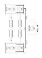
- FIG. 13is a diagram of a two-channel stimulation system with clock synchronization
- FIG. 14depicts waveforms that may be generated according to a stimulation interference avoidance technique using the clock synchronization system of FIG. 13 .
- Described hereinare many examples of stimulation interference avoidance systems and methods, which are configured to reduce unintended stimulation interference. It will be noted that the systems and methods described herein may be implemented via any suitable combination of hardware (e.g., electronic parts), firmware (e.g., software embedded in a dedicated processing device) and software (e.g., applications executed on a general purpose microprocessor or personal computer). It will also be noted that examples of electrical stimulation systems are described for ease of illustration, and that the systems and methods disclosed herein may be applied to any treatment or therapy system in which interference may occur, such as ultrasound therapy, laser therapy, thermal therapy, acoustic therapy, or any other energy-based therapy.
- the stimulation interference avoidance systems and methods disclosed hereinare implemented in a stimulation system that uses wireless communication between independent stimulation modules and a management module.
- An exemplary wireless stimulation systemwill first be described, along with exemplary components of such a wireless system and exemplary transducers that may be used with the system, followed by various implementations of interference avoidance systems and techniques that may be used with the exemplary stimulation system or with other stimulation systems (e.g., wired or wireless, centrally-controlled or independent, or a combination thereof).
- FIG. 2is a diagram of a wireless stimulation system 200 that may be configured with an interference avoidance system as described herein.
- the stimulation system 200includes a management module 202 , a stimulation module 204 that generates and provides stimulation energy that can be used for therapeutic or prophylactic treatment, and a docking station 206 .
- FIG. 2also depicts a computer 208 which is configured to communicate with a remote data source 210 .
- the management module 202communicates with the stimulation module 204 to specify a stimulation treatment to be provided to the user.
- the management module 202uses stored programs and user inputs to determine the stimulation waveform provided to the user by specifying certain waveform parameters to the stimulation module such as amplitude, pulse duration, pulse frequency and pulse shape.
- the management module 202can manage more than one output channel.
- each output channel of stimulationis generated by a different stimulation module, such as the stimulation module 204 , and each channel provides a different stimulation waveform than the other channels. Multiple channels may operate simultaneously, alternately, or in any other time-based relation.
- the stimulation treatment delivered by each channelmay be customized and adjusted by an operator, who may be a care provider or the user him/herself. For example, an operator may control the intensity and/or energy output on each stimulation channel.
- the management module 202includes an operator interface subsystem 212 that allows an operator to select stimulation programs or protocols, set desired options and control the waveforms applied to the user.
- the management module 202includes one or more processors (e.g., microprocessors) that communicate with and control the operation of the stimulation module 204 , providing an interface between the stimulation module 204 and an operator managing the treatment or therapy applied to the user.
- the management module 202transmits information to and receives information from the stimulation module 204 using a wireless communication protocol.
- the management module 202also interfaces with the computer 208 to access the remote data source 210 and allow user control over the stimulation system 200 .
- the management module 202is housed in a handheld unit with a plastic outer casing that encloses an electronics board on which are mounted the electronic components described below.
- the management module 202may be waterproof or water-resistant (e.g., sweat or water are not permitted to penetrate the plastic casing), and operable with one adult hand.
- FIG. 2depicts a number of subsystems included in the management module 202 .
- the operator interface subsystem 212allows an operator to adjust the stimulation signals provided to a user by the system 200 , view current operating parameters, view historical user data (such as performance and use statistics), view current physiological parameters (such as chemical or electrical muscle feedback signals), and adjust the capabilities of the system 200 (e.g., by downloading additional programs to the management module 202 from the remote data source 210 ).
- the operator interface subsystem 212may include any number of outputs, including an audible output (e.g., a speaker or buzzer), a visual display (e.g., an LCD screen or one or more LEDs), and a tactile output (e.g., a vibrating element).
- the operator interface subsystem 212may include any number of user inputs, such as switches, dials, buttons, and touchpads, including non-tactile inputs such as microphones and cameras, as are commonly known in the field.
- the operator interface subsystem 212includes a “help” button that sends alarm signals to a personal emergency response system.
- the management module 202includes a power supply 214 , which may be any suitable source of energy for powering the components of the management module 202 .
- the power supply 214includes one or more of a battery (which may be a rechargeable battery), an AC power supply, a solar cell, a thermal cell or a kinetic cell capable of converting motion energy to electrical energy for powering the management module 202 .
- the management module 202may contain multiple power supplies, any of which may be any of the power supplies described herein.
- the management module 202may also include power supply monitoring circuitry (not shown). Such circuitry may monitor the power supply 214 of the management module 202 and/or the power supply 216 of the stimulation module 204 .
- power supply monitoring circuitrymay monitor the power supply 214 of the management module 202 and/or the power supply 216 of the stimulation module 204 .
- an indicationis presented (e.g., on a visual display or via an audible output included with the operator interface subsystem 212 ) that indicates insufficient power is available. In this situation, an operator may be prohibited from accessing certain functions of the system 200 (e.g., beginning a new round of stimulation treatment).
- the management module 202(as well as any device or system component described herein) includes memory for storing basic operating parameters (e.g., pre-stored sounds, volume, display parameters, time and date) and/or supporting the subsystems described herein. In certain implementations, usage statistics are uploadable from this memory to the remote data source 210 when the management module 202 is in communication with the remote data source 210 (e.g., via the computer 208 ).
- basic operating parameterse.g., pre-stored sounds, volume, display parameters, time and date
- usage statisticsare uploadable from this memory to the remote data source 210 when the management module 202 is in communication with the remote data source 210 (e.g., via the computer 208 ).
- the management module 202includes a number of additional subsystems, such as the treatment subsystem 218 , the communication subsystem 220 , and the docking interface subsystem 222 . These subsystems may be configured as processor-executable code in a general or special purpose processing device (e.g., a programmable microprocessor), logic circuits, analog circuits, or any combination of hardware and software configured to provide therapeutic stimulation and perform the stimulation interference avoidance techniques described herein.
- a general or special purpose processing devicee.g., a programmable microprocessor
- logic circuitse.g., analog circuits, or any combination of hardware and software configured to provide therapeutic stimulation and perform the stimulation interference avoidance techniques described herein.
- the following subsystems of the management module 202are described as separate subsystems, but the functionality of any one or more of any of the subsystems described herein may be implemented together in one or more control circuits.
- the management module 202includes a treatment subsystem 218 .
- the treatment subsystem 218includes circuitry for communicating with any one or more of the other subsystems and components of the management module 202 , including the operator interface subsystem 212 and the communication subsystem 220 .
- the treatment subsystem 218includes memory for storing one or more stimulation protocols and/or programs.
- the memory coupled to the treatment subsystem 218may be capable of storing at least 15 different stimulation protocols or programs.
- a stimulation programrefers to one or more stimulation waveforms (e.g., a succession of stimulation pulses) applied for a finite period of time.
- a programmay be provided to improve a particular muscle condition, such as “endurance,” “force,” or “active recovery.”
- a programmay be described by any one or more of the following parameters: pulse width, pulse duration, frequency, changes in frequency, treatment duration, warm up phase parameters, work phase parameters, and recovery phase parameters.
- a stimulation protocolrefers to a succession of a plurality of sessions, with each session including one or more programs and/or other activities aimed at reaching a tangible goal. Examples of protocols include “firm thighs,” “reduce waist,” and “tone arm.”
- the communication subsystem 220has a wireless receiver/transmitter which is configured for wireless communication with the stimulation module 204 .
- This wireless communicationmay be an RF-based protocol, and may use a proprietary or public communications protocol.
- the communication subsystem 220communicates with the stimulation module 204 when they are spaced apart during operation of the system 200 , for example, about 2 meters apart, although the system 200 may be configured for more or less separation.
- the communication subsystem 220communicates with the stimulation module 204 at up to 1 meter of separation during operation of the system 200 outdoors (e.g., with line of sight between the management module 202 and the stimulation module 204 ).
- the communication subsystemmay be separated into two or more different subsystems (e.g., one subsystem for communication between the management module 202 and the stimulation module 204 as described above, and a separate subsystem for communication between the management module 202 and the remote data source 210 , each driven and controlled by different control circuits).
- the communication subsystem 220includes a data port for interfacing with the remote data source 210 .
- a data portmay include a USB port for connecting a USB cable between the management module 202 and a corresponding USB port on the computer 208 .
- the communication subsystem 220enables the management module 202 to communicate with the remote data source 210 via the computer 208 .
- the communication subsystem 220communicates directly with the remote data source 210 without the need for an intermediate computer such as the computer 208 (e.g., via a wireless Internet or device-to-device connection such as Bluetooth).
- the communication subsystem 220maintains wireless communication with one or more stimulation modules such as stimulation module 204 (but may be wired in some implementations).
- the communication subsystem 220includes at least one communication clock 221 , which is an oscillator or control signal circuit that serves to coordinate the timing of communications between the management module 202 and the stimulation module 204 . Additional clocks for different communication and internal operations may also be included in the management module 202 .
- all active stimulation modulese.g., every module currently delivering or preparing to deliver a stimulation treatment
- a pause modemay begin.
- a displaymay present an operator with an opportunity to attempt to re-initialize the communication between the stimulation module and the management module 202 .
- an operatormay instruct the management module 202 to re-commence any paused treatments or preparations.
- An operatormay also abort the treatment at the time of loss of communication and/or when communication is successfully re-established.
- the docking interface subsystem 222couples the management module 202 to the docking station 206 (described in additional detail below) and recharges the power supply 214 .
- the management module 202also includes a mounting element 226 that allows an operator or user to position or carry the management module 202 .
- the mounting element 226may include any one or more of a neck band, an arm band, a waist band, an ankle band, a garment clip, an adhesive patch, or a connector attachable to any of these.
- a connectormay be a rigid mechanical connector, a flexible connector, a hook-and-loop connector, or any other connector.
- the system 200includes one or more stimulation modules such as the stimulation module 204 that interfaces with and drives the transducers 238 (e.g., electrodes or any other energy-delivery elements).
- the transducers 238couple the stimulation module 204 to the patient.
- a stimulation systemmay include two, four, or more stimulation modules.
- a plurality of stimulation modules(such as a plurality of the stimulation module 204 ) can be configured with an interference control system to reduce interference that may arise when the plurality of such modules are used on a single patient.
- the transducers 238may include a single transducer or more than one. In certain applications, the transducers 238 are adapted to be applied to a target site on or in a user's body.
- the target sitemay be an external surface, such as a skin surface, to provide surface or transcutaneous stimulation for non-invasive therapy applications.
- the target sitemay be an internal surface, such as a muscle or organ, in which case the transducer may be implantable.
- the stimulation module 204 and the transducers 238are configured within one or more housings that contain electronics and software/processing functionality, and couple with electrodes or other stimulation delivery elements.
- An exemplary pair of housings encasing the stimulation module 204 and the transducers 238are depicted in FIGS. 3A-3D , in which FIG. 3A is a top view with an extended cable 306 , FIG. 3B is a bottom view with an extended cable 306 , FIG. 3C is a side view with a wound cable 306 , and FIG. 3D is a top view with a wound cable 306 .
- the stimulation module 204includes two pods 302 and 304 .
- Each of the two pods 302 and 304is adapted to couple to one or more transducers 238 as described below.
- the pods 302 and 304may be removably engageable from the transducers, which permits reuse of the pods with different, disposable (or reusable) transducers ( FIG. 2 ).
- the stimulation module 204 of FIGS. 3A-3Dincludes two pods linked by a connector, such as the flexible cable 306 that links the two pods.
- a connectorsuch as the flexible cable 306 that links the two pods.
- more than two pods and more than one flexible cablemay be used.
- Each podmay be positioned at a different body site.
- the podsmay be spaced away from each other by a fixed distance (e.g., when the pods are connected by a rigid connector), or a cable connecting the pods may be flexible to allow the pods to be positioned at any sites that are separated by any distances within the maximum cable lengths.
- the flexible cable 306is non-elastic and supports the torsion, flexion and traction that can occur while manipulating the stimulation module 204 .
- the cable lengthis adjustable, with the stimulation module 204 configured to extend extra cable when necessary and retract/take up excess cable (e.g., by winding).
- the flexible connecting cable 306may allow a “close” pod placement on the body (e.g., approximately 6 cm between the pods 302 and 304 ), as well as a “distant” pod placement (e.g., approximately 25 cm between the pods 302 and 304 ). Side and top views of the flexible cable 306 wound around the pods 302 and 304 are depicted in FIGS. 3C and 3D .
- Two or more podsmay be connected by a cable, garment, bandage, or any other material, and/or electrically connected by a conductive textile, a printed conductive trace, a wire or any other conductive pathway.
- a stimulation module including three or more podsmay have multiple connections between one or more of the pods in the module, in any suitable geometric and/or electrical configuration (e.g., a star, a line, a grid, in parallel, in series, etc.).
- the transducers 238may be removably engageable with the stimulation module 204 , which permits reuse of the stimulation module 204 with different transducers.
- a transduceris coupled to the stimulation module 204 , and the module is positioned on a user's body at a treatment site.
- the stimulation module 204includes one or more transducer connectors that allow connection from the side as illustrated in FIGS. 4A-4B and described in co-pending U.S. patent application Ser. No. 12/856,382 filed Aug. 13, 2010 and entitled “Low Profile Connector System,” hereby incorporated by reference in its entirety herein.
- the transducersmay include an adhesive, conductive or coupling gel, or such a gel may be applied to the treatment site or the transducer prior to treatment.
- the connection between the stimulation module 204 and the transducers 238may be strong enough for the weight of the stimulation module 204 to be supported by the connection when the system 200 is in use. In some such applications, the stimulation module 204 stays in place on a user's body even when the user is running or cycling while using the system 200 .
- the connection between the stimulation module 204 and the transducers 238may be a proprietary connection which only permits connection between the stimulation module 204 and certain transducers (e.g., those produced by selected manufacturers).
- the transducers 238 and the stimulation module 204may also be securely mounted on a user's body by a strap, garment or other attachment mechanism.
- the stimulation module 204also includes an operator interface subsystem 228 .
- the operator interface subsystem 228may include any of the features described above for the operator interface subsystem 212 of the management module 202 , as well as any of the additional features described below.
- the stimulation module 204includes multiple electrode pods and all elements of the operator interface subsystem 228 are included in a single pod or are distributed over multiple pods.
- the operator interface subsystem 228includes an indicator LED 310 and a mechanical press button 308 to turn the module 204 “on” and “off,” as illustrated by the indicator LED 310 and mechanical press button 308 of FIG. 3A .
- the mechanical press button 308is an emergency button that, when pressed during a stimulation session, stops the delivery of stimulation pulses by the stimulation module 204 , and may also stop any other active stimulation modules in the system 200 .
- an indicator LED included with the operator interface subsystem 228 of the stimulation module 204indicates a “state” of the stimulation module by exhibiting distinguishing properties such as blinking or changing color. Exemplary states include “applying treatment,” “interference detected” and “conflict detected” (discussed in further detail below).
- the stimulation module 204includes a communication subsystem 224 .
- the communication subsystem 224includes one or more microprocessors and other circuitry configured to communicate with the communication subsystem 220 of the management module 202 . Communication between the communication subsystem 224 and the communication subsystem 220 may be wired or wireless or both. In certain applications, the communication subsystem 224 includes an RF receiver/transmitter for wireless communication with an RF receiver/transmitter included in the communication subsystem 220 .
- the stimulation module 204may be “paired” with one or more management modules, such as the management module 202 . This pairing may occur through a wired or wireless exchange of information, or by electronic or mechanical settings within one or more of the stimulation module 204 and the management module 202 . In certain applications, the stimulation module 204 is paired with a corresponding management module after manufacture of the stimulation module 204 . The pairing may occur before the stimulation module 204 and its corresponding management module are packaged together. After manufacture and/or sale, the management module 202 may be paired with new or replacement stimulation modules by automatic detection and/or by a command issued by an operator through the operator interface subsystem 212 .
- the communication subsystem 224includes at least one communication clock 225 , which is an oscillator or control signal circuit that serves to coordinate the timing of communications between the stimulation module 204 and the management module 202 . Additional clocks for different communication and internal operations may also be included in the stimulation module 204 .
- the stimulation module 204includes a generator 236 that provides energy to one or more of the transducers 238 in accordance with the stimulation regimen or protocol specified by the management module 202 .
- the generator 236includes circuitry for receiving energy from the power supply 216 , circuitry for transforming the received energy into the waveform specified by the management module 202 , and circuitry for transmitting the transformed energy to one or more of the transducers 238 .
- the generator 236includes a stimulation clock 237 , which is an oscillator or control signal circuit that serves to serves to time and trigger the stimulation treatment provided by the stimulation module 204 .
- the generator 236may be separate from the transducers 238 , or some or all of the components of the generator 236 may be integrated with the transducers 238 . In certain applications that include electrical stimulation, the generator 236 is capable of supplying energy to the transducers 238 to provide waveforms with some or all of the following characteristics:
- the power supply 216 included in the stimulation module 204can take the form of any of the examples described above with reference to the power supply 214 of the management module 202 , or any other suitable power supply.
- a first podmay include the power supply 216 (e.g., as a battery).
- the stimulation module 204includes a feedback subsystem 232 .
- the feedback subsystem 232provides indications of the user's physiological characteristics and/or the response of a user's body to applied stimulation.
- the feedback subsystem 232detects stimulation applied by other stimulation modules at different body sites (e.g., by sensing voltage, current, or motion).
- the feedback subsystem 232is included in the generator 236 , and may share a portion of the circuitry used by the generator 236 .
- the feedback subsystem 232is integrated with the transducers 238 .
- the feedback subsystem 232provides feedback to an operator via the operator interface subsystem 228 of the stimulation module 204 , the operator interface subsystem 212 of the management module 202 , or the remote data source 210 .
- the feedback subsystem 232measures or detects a user's characteristics and/or response and may do so by detecting electrical signals using a connected electrode, mechanical signals using a piezoelectric sensor or accelerometer, chemical signals using a chemosensor, or any other known physiological sensor.
- the feedback subsystem 232provides feedback about the user to the management module 202 via the communication subsystem 224 .
- the feedback subsystem 232includes a feedback sensor for measuring or detecting a user's characteristics and/or response to stimulation.
- This feedback sensormay include one or more electrodes, which may also be used as the transducers 238 to deliver electrical stimulation to the user.
- the feedback sensormay register the mechanical signals of stimulated tissue using a piezoelectric sensor or accelerometer, which may provide feedback of muscle characteristics and activity.
- the feedback sensormay monitor any user characteristics, including optical and chemical properties.
- a feedback sensormay also receive signals from a user input, through which a user can indicate pain, relief of pain, fatigue, or any treatment response.
- a pod containing the feedback sensormay be visually differentiable from other pods to facilitate placing the feedback sensor on a correct muscle motor point or other body site (e.g., a pod including a feedback sensor may be larger and/or differently-shaped).
- the feedback sensormay be a motor point pen that is removably engageable with the stimulation module 204 .
- the feedback subsystem 232may provide feedback using the Mi-technology approach developed and commercialized by Compex Technologies.
- an automatic cronaxy measurementis made by one or more stimulation modules included in the system 200 .
- an automatic cronaxy measurementis made by just one stimulation module 204 included in the system 200 , and an operator has the option to select which of multiple stimulation modules will make the measurement. An operator may extend this function to additional channels by interacting with the remote data source 210 .
- Additional Mi-applications developed by Compex Technologies, such as Mi-Action, Mi-Range or Mi-TENSmay be included in the system 200 or added to the basic functionality of the system 200 (e.g., by accessing the remote data source 210 to download additional functionality).
- the stimulation module 204includes a docking interface subsystem 234 to couple the stimulation module 204 to the docking station 206 .
- the docking station 206includes a management module port 240 and a stimulation module port 244 , which may be used to dock one or more management modules and one or more stimulation modules, respectively, and may include circuitry for transforming energy from a power supply 242 into a form that is suitable for recharging the management module 202 and the stimulation module 204 through the respective ports.
- the docking station 206may also include circuitry for receiving information from one or more of the management module 202 and the stimulation module 204 (e.g., usage information, status information and diagnostic information).
- the docking station 206may provide a validation indicator when a stimulation module 204 is properly interfaced with a stimulation module port 244 (e.g., by sounding a tone or illuminating an LED).
- the system 200is configured to connect to a remote data source 210 .
- this connectionoccurs through an intermediate connection with a computer 208 .
- the remote data source 210is a web server and the computer 208 mediates between the management module 202 and the remote data source 210 .
- the computer 208may present a web interface to an operator which allows the operator to perform any one or more of the following operations:
- the management module 202may be configured for at least three modes of operation: a “use mode,” a “charge mode” and a “programming mode.”
- “use mode”an operator navigates through menus displayed by the operator interface subsystem 212 and selects a protocol or program. Once a protocol or program is selected, and after placing the stimulation module 204 and attached transducers 238 on the user's body, a stimulation session begins.
- FIG. 5illustrates the system 200 in use on a patient's body.
- the management module 202uses communication subsystem 220 to communicate and exchange information wirelessly with the stimulation module 204 before stimulation (and may communicate during or after stimulation). In some applications, the management module 202 communicates with the stimulation module 204 prior to treatment to communicate the parameters of the desired stimulation treatment.
- the stimulation module 204then supplies the stimulation treatment according to those parameters without requiring additional control signals from the management module 202 .
- Informationsuch as actual time, network quality (i.e., the quality of the communication between the management module 202 and all connected stimulation modules) and the power level of the power supply 214 may be displayed on a display included with the management module 202 . If a transducer default is detected during a stimulation session, all the active stimulation modules may cease to supply stimulation treatment and the management module 202 may enter a pause mode.
- a display included with the management module 202may identify one or more channels on which the electrode default has been detected.
- the management module 202 and the stimulation module 204are placed in the docking station 206 and may recharge their power supplies 214 and 216 , respectively.
- the management module 202may provide an indication when the components of the system 200 are charging, and a different indication when the components of the system 200 are fully charged (e.g., via a display included in the operator interface subsystem 212 ).
- the management module 202is connected to the computer 208 via an USB cable, as discussed above.
- the computer 208is, in turn, connected to the remote data source 210 (e.g., via a remote communication protocol, such as an Internet or Ethernet protocol).
- a remote communication protocolsuch as an Internet or Ethernet protocol.
- An operatormay use the management module 202 and/or the computer 208 to obtain features and functions made available by the remote data source 210 , including viewing new protocols or establishing a treatment program.
- An operatormay also download new protocols and new settings to the management module 202 from the remote data source 210 .
- informationmay be transferred from the computer 208 to the management module 202 .
- Information transferred from the computer 208 to the management module 202may include any one or more of:
- Information transferred from the management module 202 to the computer 208may include any one or more of:
- the system 200may include multiple stimulation modules such as the stimulation module 204 .
- Each moduleis placed at a particular location on a user's body and delivers one or more channels of stimulation treatment.
- the following discussiondescribes systems and methods in which two stimulation modules are used during a stimulation session, with each module providing one channel of stimulation, but it will be understood that the challenges and solutions discussed herein may be applied to stimulation systems in which two or more stimulation channels are used.
- three or more channels of stimulationmay be advantageous; for example, certain muscle stimulation treatments for gait regulation may benefit from three, four or more channels of stimulation.
- the stimulation interference avoidance systems described hereininclude processing devices that, in preferred implementations, are stored within the housing of stimulation hardware, such as the stimulation module 204 , and are configured to receive and process electronic signals indicative of energy transmitted through a patient's tissue.
- FIG. 6Aillustrates a two-channel stimulation system applied to a user's body that can be configured with a stimulation interference avoidance system.
- a stimulation signal delivered by electrode A 1may travel through the patient's tissue and reach electrode A 2 , and also may travel to electrodes B 1 and B 2 .
- the freedom of the signal energy to traverse these pathwaysdepends on the impedance of the tissue through which the signal energy passes.
- the energy transmissive pathways through the patienthave impedances indicated by the impedances Z 602 , Z′ 604 , Z′′ 606 and Z′′′ 608 , which are connected between and across the Channels A 102 and B 104 .
- the first pair of electrodesdelivers the Channel A 102 stimulation pulses
- a second pair of electrodesdelivers the Channel B 104 stimulation pulses.
- one electrodeis designated as the “active” electrode (e.g., a source of medicament) and the other electrode is the “return” electrode (e.g., the receiving electrode or reservoir of treatment-neutral molecules in iontophoretic treatment).
- the active electrodee.g., a source of medicament
- the return electrodee.g., the receiving electrode or reservoir of treatment-neutral molecules in iontophoretic treatment.
- a single transducer per channelis sufficient.
- the first pair of electrodes(A 1 106 and A 2 108 ) delivers a current ia to a user's body. Because the user's body exhibits impedance along the conductive pathways between the electrode A 1 106 and the electrode A 2 108 , the applied current ia will induce a voltage difference ua between the electrodes A 1 106 and A 2 108 . This phenomenon may also be characterized as a current ia induced by an applied voltage difference ua between the electrodes A 1 106 and A 2 108 .
- An example waveform for iais illustrated as the stimulation pulse 610 in FIG. 6B , and an illustrative induced voltage signal ua taken between the electrodes A 1 106 and A 2 108 is shown as the voltage signal 612 of FIG. 6B .
- the current stimulation pulseis results in a voltage signal ub across the two electrodes B 1 110 and B 2 112 of Channel B 104 .
- An illustrative voltage signal 614is depicted in FIG. 6B .
- the shape, amplitude and other characteristics of the voltage signal ubdepend on the characteristics of the stimulation pulse and on the impedances Z 602 , Z′ 604 , Z′′ 606 and Z′′′ 608 .
- a stimulation signal delivered to one body sitemay be detectable at another body site due to energy transmissive pathways between the channels through the user's body. If a stimulation pulse is generated on Channel B 104 near to when a stimulation pulse is generated on Channel A 102 , it is possible that the pulses will interfere within the user's body and cause discomfort or pain. Therefore, the system of FIG. 6A can include processors configured to detect such nearby stimulations and avoid generating interfering stimulation pulses, thus reducing unintended and potentially harmful stimulation interference.
- FIG. 7is a flow diagram 700 of the operation of such a stimulation interference avoidance system.
- Each stimulation module 204 of the system 200includes microprocessor circuitry configured for carrying out the stimulation interference avoidance process illustrated by the flow diagram 700 .
- Execution of this process in a stimulation modulemay be performed by any combination of dedicated hardware (e.g., semiconductor logic circuits configures appropriately and printed on a circuit board), firmware (e.g., dedicated software embedded in a programmable processor) and software (e.g., applications installed and executable on a general purpose processor).
- the stimulation interference avoidance process of the flow diagram 700is sometimes described as being performed by a stimulation module, but any one or more components of a stimulation system may be configured to perform one or more of the desired steps.
- the step 702may be performed by a monitoring device (e.g., an electrode system configured for sensing electrical signals) and the step 704 may be performed by a management module (e.g., with processors configured for analyzing the sensed electrical signals).
- a monitoring devicee.g., an electrode system configured for sensing electrical signals
- a management modulee.g., with processors configured for analyzing the sensed electrical signals.
- a first devicesuch as the stimulation module 204 ( FIG. 2 ) begins to monitor a first body site.
- the first devicemonitors the first body site by measuring one or more signals indicative of a stimulation pulse (e.g., a voltage, current, pressure, motion, temperature, radiation or other signal) or a signal indicative of a patient response to a stimulation pulse (e.g., a nervous response, a muscle response, a movement response, a pain response, etc.).
- the first devicemonitors the first body site by receiving voltage signals across two or more electrical terminals.
- sensing terminalsare used to receive the voltage signal and also apply electrical stimulation pulses to the first body site.
- the systemmay have terminals dedicated to receiving and monitoring a voltage signal, and different terminals to apply stimulation signals to the user's body.
- the step 702may be performed periodically at a particular frequency, which may be greater than, less than, or equal to the frequency of stimulation applied by a stimulation module, or at pre-determined time intervals.
- the step 702may be performed at random intervals, at a changing frequency (e.g., a modulated frequency that varies between a lower frequency and an upper frequency), or in response to commands from a management module (e.g., the management module 202 of FIG. 2 ) or from an operator.
- the monitoring that begins at the step 702is performed over a stimulation activity detection period with a duration denoted by Tsad.
- the stimulation activity detection periodmay have a pre-determined, fixed duration, a random duration, a combination of fixed and random durations, and may include two or more non-contiguous time intervals. Moreover, the time intervals at which the step 702 is performed and the duration of the stimulation activity detection period may be different for different stimulation modules executing the step 702 .
- the duration of the stimulation activity detection periodmay change in response to user or environmental conditions detected by the first device. In some applications, Tsad is increased when the first device detects an increase in noise in one or more monitored signals. In some applications, Tsad is decreased when other stimulation modules are detected (as discussed below with reference to the step 704 ) or a conflict occurs (as discussed below with reference to the step 706 ).
- each stimulation moduleperforms the step 702 prior to providing a new stimulation pulse by measuring a voltage signal ux over a stimulation activity detection period of duration Tsad.
- the duration Tsadmay vary between different stimulation modules. This measurement is taken across the stimulation module's stimulation electrode terminals (or, in some applications, across alternate voltage measurement terminals).
- the monitoring that begins at step 702may include storing received signal data in a buffer or other memory.
- the step 702includes signal processing steps, performed by any appropriately-configured circuitry included in the first device (such as a DSP chip).
- Examples of signal processing stepsinclude upsampling, downsampling, interpolating, determining statistics (e.g., means, modes, maxima, minima, standard deviations), time windowing, removing outliers, filtering (e.g., high-, low-, band-pass or notch filtering), transforming into a spectral domain, calculating energy and/or power in a time or frequency interval, correlating, detecting peaks, shape matching, FIR or IIR filtering, or any combination thereof.
- the step 702is performed by software, hardware, or a combination of software and hardware.
- the first devicedetermines whether a signal is present that is indicative of a stimulation pulse generated by a second device. Such a signal will be referred to as a “significant signal.”
- the second devicemay be a stimulation module like the stimulation module 204 ( FIG. 2 ).
- the significant signalis detected in the signal or signals received by the first device during monitoring of the first body site at the step 702 .
- the first devicewill either “fire” a stimulation pulse, or delay (and then fire), depending on whether the first device detects a significant signal.
- the systemis configured so that it directs a firing or delay depending on whether a detected signal is significant. Determining whether a significant signal is present may employ any one or more known detection, estimation and pattern recognition techniques: for example, hypothesis testing, a decision tree, maximum likelihood detection, pattern matching, principal components analysis, correlations, total transmitted power, shape matching, frequency analysis, wavelet analysis, statistical likelihood techniques, etc.
- processing circuitry in a stimulation moduleis configured to analyze a monitored signal and use a threshold test to determine whether a significant signal is present.
- An exemplary threshold testincludes the following assessment:
- the intensity of a monitored signalrefers to any one or more of amplitude, magnitude, energy, power, or duration over any time intervals or frequency bands.
- the first rangemay be a symmetric range (e.g., a current amplitude within [ ⁇ 5 mA, +5 mA]), an asymmetric range (e.g., a current amplitude within [ ⁇ 2 mA, +4 mA]), or include multiple non-contiguous intervals (e.g., a power within [0 mW, 1 mW] or [4 mW, 6 mW]).
- the monitored signalis a voltage ux and the first range is [ ⁇ Vth, +Vth], where Vth is a pre-determined voltage level.
- a significant signalis detected when the voltage signal ux has an amplitude outside the first range.
- the voltage uxis monitored by the electrode terminals of a stimulation module, as discussed above. More than one significant signal may be detected at the step 704 .
- two or more significant signalsmay be spaced apart in time, or two or more significant signals may be of different modalities (e.g., a voltage signal and a chemo-detector signal).
- the first devicemay use dynamic criteria at the step 704 to determinate whether a significant signal is present.
- the first devicemay implement a threshold test as described above and may dynamically adjust the thresholds required for detection of the significant signal. Examples of dynamic adjustments include raising an amplitude threshold or an energy threshold in response to a higher noise floor.
- Dynamic criteriamay be implemented as dynamic signal processing steps. For example, filtering applied to a monitored signal may depend on the frequency characteristics of the environmental noise impinging on the monitored signal.
- the first devicemay selectively apply a 60 Hz notch filter or other suitable filter to remove this frequency component before determining whether a significant signal is present.
- the first deviceif the first device does not detect a significant signal at the step 704 , the first device proceeds to generate a stimulation pulse at the step 708 . In some implementations, the first device instructs another device to generate the stimulation pulse at the step 708 . In certain applications, circuitry included with the stimulation module 204 causes the generator 236 ( FIG. 2 ) to generate the stimulation pulse at the step 708 .
- the first devicedelays generating the stimulation pulse at the step 706 .
- the delaylasts for a duration of time denoted by Tpd, as programmed into the microprocessor and controlled thereby.
- the duration Tpdmay be pre-determined, fixed or variable, and may depend upon any of the factors discussed above for the stimulation activity detection period Tsad. Additionally, the duration Tpd may be determined based at least in part on characteristics of the significant signal detected at the step 704 .
- the value of Tpdmay increase from a nominal or baseline value when the significant signal has an energy or magnitude that exceeds a threshold (which may be a different, higher threshold than the threshold used in a threshold test included as part of the significance test at the step 704 ), while the value of Tpd decreases from a nominal or baseline value when the significant signal has an energy or magnitude that is below a threshold (which may be a different, lower threshold than the threshold used in a threshold test included as part of the significance test at the step 704 ).
- the value of Tpdincreases from a nominal or baseline value when more than one significant signal is detected at the step 704 .
- the duration Tpdmay include a random component, as generated by a pseudo-random number generator within the processing circuitry of the first device.
- the random component of Tpdmay be selected from within an allowable range of random time periods defined by a lower duration limit and an upper duration limit (e.g., 1-1000 ⁇ s).
- the first deviceafter the first device delays at the step 706 , it then proceeds to generate a stimulation pulse as described above with reference to the step 708 .
- itafter the first device delays at the step 706 , it “retries” by returning to step 702 and executing steps 702 and 704 .
- the first devicewhen the number of retries reaches a retry limit (e.g., ten retries as counted by a retry counter variable stored in a memory in the first device or another device, such as a management module), the first device registers an error condition, which may prompt an operator alert.
- a retry limite.g., ten retries as counted by a retry counter variable stored in a memory in the first device or another device, such as a management module
- An electronic indicator(such as an LED, a display screen, a piezoelectric buzzer or an electronic memory) may be used to store the error condition or alert an operator.
- Such an error conditionmay be considered a “conflict” between the first device and at least one other stimulation device causing the detected significant signals.
- the likelihood of conflictsdepends on one or more of several factors, including the number of stimulation devices in operation (e.g., the number of stimulation channels delivering stimulation signals), the stimulation frequency of each channel (e.g., the instantaneous frequency of a channel during a treatment or therapy in which the frequency changes over time) and the pulse duration of each channel (e.g., the duty cycle of stimulation delivered by each channel).
- the number of retries required before registration of an error conditionis not fixed, but instead depends on an acceptable amount of delay that can be tolerated by the first device. For example, when the first device is configured to separate delivered stimulation pulses by a nominal period, the first device may tolerate “skipping” a certain number of stimulation pulses when significant signals from other stimulation modules are detected. In such implementations, the number of retries allowed before registering an error condition depends on the number of retries that can be attempted in the time it would have taken the first device to generate the certain number of “skipped” pulses, which may in turn depend on Tsad and Tpd. In some implementations, a retry counter is included in a management module, or a signal is transmitted (e.g., wirelessly) from the first device to a management module when a conflict occurs.
- each stimulation deviceWhen two or more stimulation devices are in operation, and each stimulation device is executing an interference avoidance process like the process illustrated by the flow diagram 700 of FIG. 7 , multiple stimulation devices may detect each other and, in response, the multiple stimulation devices may delay their respective stimulation pulses for approximately the same delay period Tpd. This situation may lead to additional conflicts. To avoid such conflicts, the delay period of different channels are preferably programmed to have different durations Tpd. For example, the delay time of Channel A 102 may be pre-programmed to be shorter than the delay time of Channel B 104 ( FIG. 6A ).
- the delay time Tpd for each channelis calculated as the sum of a fixed time (which may be common to all channels) and a random time generated for that channel (e.g., as generated by a pseudo-random number generation circuit communicable with the device delivering stimulation for that channel). Further, as discussed above (e.g., with reference to the step 706 ), the ability of a stimulation device to generate pulses at desired time intervals may be impacted by time delays that result from the interference avoidance steps described herein.
- jitterThe variation of the actual stimulation delivery schedule around a nominal, desired stimulation schedule may be referred to as “jitter.”
- Different stimulation applicationsmay impose different therapeutically-acceptable limits on jitter, which in turn lead to allowable ranges for interference avoidance technique parameters such as Tsad, Tpd, and the maximum allowable number of retries.
- allowable parameter rangesare determined by any of a number of techniques, including mathematical approximation methods, physiological constraints, and simulation-based methods.
- the exemplary interference avoidance techniques described hereincan be implemented in a detection system configured with a first device that detects a signal indicative of a pulse generated by a second device.
- the interference detection systemis also used to assist in proper placement of the electrodes or other transducers. For example, good contact between the second device and the patient's body can be confirmed when the second device also detects the signal indicative of a pulse generated by the second device (e.g., an electrical pulse generated by one electrode attached to a patient's body can be detected at the same electrode or a different electrode on the same device).
- the second devicedetects this signal, a positive body site contact condition for the second device is registered by the stimulation system.
- registering a positive body site contact conditionis required before the second device is allowed to generate stimulation pulses, in order to prevent stimulation pulses from being delivered to transducers that are not in contact with a patient's body (i.e., an open circuit-like condition exists between the transducers).
- that devicemay proceed to generate a stimulation pulse.
- FIG. 8depicts exemplary waveforms that are generated by a stimulation interference avoidance system operating according to the process illustrated by the flow diagram 700 ( FIG. 7 ).
- FIG. 8depicts an example pair of waveforms that are generated by Channels A 102 and B 104 (and controlled by stimulation modules A and B, respectively, each implementing the process of FIG. 7 ).
- stimulation module Abegins making a voltage measurement over a stimulation activity detection period 808 of duration TsadA on Channel A 102 to detect stimulation signals generated on other channels.
- a stimulation module Bbegins making a voltage measurement over a stimulation activity detection period 805 of duration TsadB on Channel B 104 .
- the stimulation module AAt the time 806 , since no activity was detected by the stimulation module A during its stimulation activity detection period 808 , the stimulation module A generates a stimulation pulse 810 on Channel A 102 (in accordance with the step 704 of FIG. 7 ).
- Channel B 104senses the stimulation pulse 810 generated on Channel A 102 by a voltage measurement that reaches a detection threshold (+Vth 814 ), indicating a significant signal from Channel A 102 has been detected.
- the stimulation module Bconsequently delays beginning another stimulation pulse for a period 816 of duration TpdB (in accordance with the step 708 of FIG. 7 ).
- stimulation module Bbegins again to measure stimulation activity voltages over a stimulation activity detection period 819 of duration TsadB. As shown, no signal is detected by the stimulation module B that exceeds the threshold range [ ⁇ Vth, +Vth] during the period 819 . Accordingly, stimulation module B proceeds to generate its stimulation pulse 820 at the time 822 . As a result of the stimulation pulse generated by the stimulation module B, a voltage signal 824 appears across the electrode terminals of Channel A 102 (and could be actively measured by the stimulation module A, if desired). At the time 825 , the stimulation module A begins again to monitor for an opportunity to generate another stimulation pulse, and thus begins a new stimulation activity detection period 826 using the Channel A 102 terminals, repeating the cycle.
- the stimulation avoidance systemis configured to not only monitor other stimulation signals and delay providing stimulation pulses when other signals are detector, but is also configured to provide marking pulses and another auxiliary functionality to address interferences that may be caused by system-based delays between the time at which a stimulation module determines that a stimulation pulse may be generated and the time at which generation of that pulse actually begins.
- Such delaysare in part due to the finite speed at which information can travel within a device (e.g., between processing circuitry and pulse generating circuitry), as well as other physical limitations. A consequence of such delays is illustrated in FIG. 9 and exemplary solutions are illustrated by FIG. 10 .
- Td 2 pthe delay time between the time at which a stimulation module determines that a stimulation pulse may be generated and the time at which generation of that pulse actually begins will be denoted as Td 2 p (recognizing that this delay time may be different for different channels).
- Td 2 pmay be minimized, for example, by choosing appropriate circuit components and architectures.
- stimulation module Abegins monitoring a first body site by measuring a voltage (e.g., at a skin surface site) over a stimulation activity detection period 908 of duration TsadA on Channel A 102 (in accordance with the step 702 of FIG. 7 ).
- stimulation module Bbegins monitoring a voltage (e.g., at a different skin surface site) over a stimulation activity detection period 912 of duration TsadB on Channel B 104 (in accordance with the step 702 of FIG. 7 ).
- the stimulation module Adetermines to generate a stimulation pulse on Channel A 102 (in accordance with the step 704 of FIG. 7 ).
- the stimulation module Bdetermines to generate a stimulation pulse on Channel B 104 (in accordance with the step 704 of FIG. 7 ).
- stimulation module Abegins generating a stimulation pulse 918 on Channel A 102 (in accordance with the step 706 of the flow diagram 700 of FIG. 7 ).
- stimulation module Bbegins generating a stimulation pulse 922 on Channel B 104 (in accordance with the step 706 of the flow diagram 700 of FIG. 7 ).
- the stimulation pulses 918 and 922interfere, as indicated by the shaded region 904 .
- the pulses from two different stimulation channelsare offset in time by a period less than the time Td 2 p of one channel (i.e., the delay time between the decision to generate a pulse and the generation of that pulse), which allows additional stimulation interference to occur. While faster electronic components may enable a decrease in the duration of Td 2 p , most devices exhibit a non-zero decision-to-pulse delay period Td 2 p.
- the interference avoidance systems and methods disclosed hereininclude a number of variations and examples that address non-zero delay periods by accounting for such latency. (In certain applications, the stimulation interference arising from the non-zero delay period Td 2 p is ignored as negligible, particularly when the interference is imperceptible to a user.)
- a marking pulseis used, as illustrated by the flow diagram 1000 of FIG. 10 (in addition to or instead of the process depicted by the flow diagram 700 of FIG. 7 ).
- a first devicegenerates a first marking pulse.
- a second devicemay also generate a second marking pulse.
- the marking pulseis generated by the first device prior to or in concert with beginning a stimulation activity detection period as described above.
- a marking pulseis a very short pulse (e.g., approximately 25 ⁇ s) that cannot be strongly perceived by the user but is detected by the second device coupled to the user when the first and second devices share an energy transmissive pathway through the user's body.
- the second devicemay be configured to detect marking pulses generated by the first device when interference between stimulation pulses generated by the first and second devices may be perceptible to the user.
- the second devicemay detect the marking pulses generated by the first device.
- the second devicedelays providing a stimulation signal to avoid interfering with the stimulation signal to be generated by the first device.
- the first deviceAfter generating the marking pulse, the first device performs the remainder of the process illustrated by the flow diagram 1000 as described above for the flow diagram 700 of FIG. 7 .
- steps 1002 , 1004 , 1006 and 1008are performed by the first device (e.g., a stimulation module) in accordance with any of the examples described above for the steps 702 , 704 , 706 and 708 , respectively, of FIG. 7 .
- the monitoring in step 1004extends over a stimulation activity detection period of a duration Tsad.
- TsadXis greater than Td 2 p X (where the latter is the minimum delay time between the decision to generate a pulse and the actual generation of that pulse, as described above with reference to FIG. 9 ).
- FIG. 11depicts an illustrative waveform that may be produced by Channel A 102 in accordance with an implementation of the flow diagram 1000 of FIG. 10 .
- the waveformincludes a marking pulse 1104 , a channel-specific stimulation activity detection period 1106 of duration TsadA, a decision-to-pulse delay period 1108 of duration Td 2 p A and a stimulation pulse 1110 .
- the marking pulse 1104is a very short pulse (e.g., approximately 25 ⁇ s) that cannot be strongly perceived by the user, if perceived at all.
- FIGS. 12A-12Bdepict two examples of waveforms produced by two devices in a stimulation interference avoidance system over a period of duration T, each executing the steps of the flow diagram 1000 of FIG. 10 .
- Channels A 102 and B 104generate marking pulses 1204 and 1206 , respectively (the step 1001 of FIG. 10 ).
- each of Channels A 102 and B 104begins its stimulation activity detection period (the periods 1208 and 1210 , respectively) to detect stimulation signals coming from neighboring electrodes or other stimulation sources along or under the user's skin.
- the duration of this periodis TsadA for Channel A 102 , and TsadB for Channel B 104 .
- the systemis pre-programmed so that TsadA is longer than TsadB, with TsadB starting at the same time as TsadA but ending before TsadA ends.
- TsadAis longer than TsadB
- TsadBstarting at the same time as TsadA but ending before TsadA ends.
- Channel B 104has completed its stimulation activity detection period without detecting any significant stimulation and therefore prepares to generate a stimulation pulse.
- Channel B 104then generates a stimulation pulse 1214 .
- Channel A 102detects significant stimulation from another source (here, stimulation from Channel B that exceeds +VthA 1220 ) and thus commences its retry delay period 1222 of duration TpdA.
- Channel A 102has completed its retry delay period 1222 , whereupon it generates a marking pulse 1226 and again executes the step 1001 of FIG. 10 .
- Channel A 102detects no competing signal from another source and therefore provides the stimulation pulse 1227 (only partially shown in FIG. 12A ). In this manner, Channel A 102 does not fire during the firing of Channel B 104 , thus avoiding interference.
- Channel A 102generates a marking pulse 1232 and then begins its stimulation activity detection period 1234 .
- Channel B 104generates a marking pulse 1238 .
- Channel A 102detects a signal outside the negligible range (here, the range [ ⁇ VthA,+VthA]). This signal arises from the marking pulse 1238 from Channel B 104 , and thus Channel A 102 commences its retry delay period 1244 of duration TpdA.
- Channel B 104begins its stimulation activity detection period 1248 of duration TsadB.
- Channel B 104has completed its stimulation activity detection period 1248 without registering any significant signal, and Channel B 104 proceeds to generate a stimulation pulse 1258 .
- Channel A 102has completed its retry delay period 1244 and generates another marking pulse 1252 .
- Channel A 102detects a voltage signal 1256 outside the range [ ⁇ VthA,+VthA], and thus begins another retry delay period 1260 of duration TpdA.
- the marking pulse generated at the step 1001 of FIG. 10may take any of a variety of shapes, including one or more square pulses, one or more sine pulses, one or more triangle pulses, or any combination of shapes of pulses.
- the marking pulse generated at the step 1001has frequency components similar to those in the stimulation pulses intended to be generated. Due to the complex impedances encountered by an energy signal as it moves through a user's body, similarity in frequency content between the marking pulse and the stimulation pulse may improve the performance of the stimulation avoidance techniques described herein by distributing the energy of the marking pulse over energy pathways in the same way that the energy of the stimulation pulse is distributed.
- a muscle-building treatment protocol in an electrostimulation systemmay include 50 Hz electrical stimulation (e.g., delivered as a sequence of 8-second pulses) during a contraction phase and 4 Hz electrical stimulation (e.g., delivered as a sequence of 8-second pulses) during a relaxation phase.
- marking pulses delivered during the contraction phasemay include 50 Hz electrical stimulation (or have a substantial 50 Hz frequency component, or a substantial frequency component that is an integer multiple of 50 Hz, or any combination thereof)
- marking pulses delivered during the relaxation phasemay include 4 Hz electrical stimulation (or have a substantial 4 Hz frequency component, or a substantial frequency component that is an integer multiple of 4 Hz, or any combination thereof).
- the parameters of a marking pulsemay be dynamically adjusted and personalized according to the tissue characteristics of the user, the spacing of the stimulation modules, and the stimulation treatments to be applied.
- a marking pulse set-up processis automatically performed before the start of a stimulation treatment session.
- a stimulation modulegenerates a sequence of trial marking pulses with different parameters (e.g., increasing amplitudes, increasing pulse widths, different wave shapes, etc.).
- the useractivates an input on the stimulation module or a management module.
- the user inputindicates that the particular trial marking pulse generated prior to the user input was perceptible to the user, and thus the parameters of that particular trial marking pulse should not be used for the marking pulses to be generated at the step 1001 .
- the stimulation modulemay respond to user input of perceptibility by setting the amplitude of future marking pulses to the amplitude of the last trial marking pulse not perceptible to the user.
- a marking pulsemay be encoded with information regarding a stimulation module that generated the marking pulse, a characteristic of the stimulation treatment to be delivered via the marking pulse channel, or any other information regarding the source of the marking pulse.
- a first device that receives an indication of the marking pulsee.g., at the step 1006 of FIG. 10
- a marking pulsemay have information about the schedule of stimulation treatment to be applied on its associated channel; upon receiving an indication of the marking pulse and decoding its information, the first device may adjust its stimulation schedule so that its firing is offset compared to the stimulation schedule of the second device, thereby reducing the likelihood of interference with stimulation pulses generated at the marking pulse channel.
- the first devicestores the decoded marking signal information in a memory, and transmits the information to another device (such as the management module 202 of FIG. 2 ).
- the encoding/decoding of information within marking pulsesmay be performed according to any known technique, including amplitude, frequency and phase modulation, pulse width modulation, pulse code modulation, encoded data strings appended to the beginning or end of a marking pulse, spread spectrum techniques, and any combination thereof.
- the systemsare programmed to prioritize the firing of one or more channels of stimulation with respect to each other, in which cases the marking pulse from a particular channel may have features indicative of information regarding the channel's priority level.
- the systemsmay apply a priority level or ranking during detected interference periods to prioritize which channel may fire next.
- a marking pulse that indicates prioritymay include specific frequencies, amplitudes, and pulse shapes. The marking pulse can thus be said to be encoded with the priority information.
- a priority levelis established based on a particular type of stimulation treatment delivered by a channel. For example, a pain-blocking stimulation treatment may be programmed to have a first/higher priority than a conflicting muscle-exercising stimulation treatment, and so should be applied first and ahead of the exercising treatment.
- a channel's priority levelis determined based on the probability that the stimulation device will fail to meet adequate stimulation treatment goals if the channel is delayed when delivering its next stimulation pulse. For example, a stimulation module that has been deferred from generating its stimulation pulse for a certain number of cycles (e.g., by repeatedly reaching the step 708 when operating according to the flow diagram 700 of FIG. 7 ) is increasingly likely to provide insufficient stimulation treatment as such pulses are missed.
- the likelihood of failure for an overall stimulation protocolis determined based on the deviation between the actual stimulation frequency from its pre-programmed frequency.
- the marking pulse generated by the channel at the step 1001includes an encoded priority level identifier indicating that the stimulation module is at risk for failing to provide its scheduled treatment and should be given priority in generating its next stimulation pulse.
- a stimulation module receiving this signaldecodes the priority level, compares the decoded priority level to its own priority level (as stored in memory) and delays its next stimulation pulse if the decoded priority level is higher than its own priority level.
- a stimulation module receiving a signal at the step 1002detects the presence of a “priority” indicator in the received signal and delays its next stimulation pulse (without performing a comparison of priority levels).
- Identification of a priority levelmay be implemented in software (e.g., via pattern recognition or decision algorithms implemented by a special- or general-purpose processing device), in hardware (e.g., analog or digital logic circuitry), or a combination of hardware and software.
- Any of the priority information encoding techniques disclosed hereinmay be applied to stimulation pulses instead of or in addition to marking pulses. Different encoding methods may be used for stimulation pulses than marking pulses, and different encoding methods may be used for pulses generated by different channels. A particular encoding method may be chosen to be compatible with the stimulation treatment applied (and not introduce unsafe levels or types of stimulation to the user).
- exemplary systemsmay include an internal stimulation clock (e.g., the stimulation clock 237 of the stimulation module 204 of FIG. 2 ) to drive stimulation pulse firing.
- an internal stimulation clocke.g., the stimulation clock 237 of the stimulation module 204 of FIG. 2
- the stimulation systemmay include further processors to prevent excessive drift of the stimulation clocks included in each stimulation module using the systems and methods disclosed below.
- FIG. 13depicts an implementation of a stimulation system in which the stimulation module A 1302 and the stimulation module B 1304 are in wireless communication with a management module 1306 (e.g., as described above for the system 200 of FIG. 2 ), with each of the stimulation modules A 1302 and B 1304 including a stimulation clock (the clocks 1308 and 1310 , respectively) for timing stimulation pulses.
- Each of the stimulation modules A 1302 and B 1304includes a transceiver for conducting wireless communication with the management module 1306 according to a wireless communication protocol coordinated, in part, by the communication clocks 1316 and 1318 , respectively.
- the management module 1306also includes a communication clock 1320 .
- the stimulation clocks 1308 and 1310are synchronized according to the following exemplary stimulation clock synchronization technique.
- the exemplary techniqueis illustrated with a two-module system for ease of illustration, but is applicable to systems with more than two modules and/or channels and may be implemented alone or with any of the stimulation interference avoidance systems and methods described herein.
- the management module 1306communicates wirelessly with stimulation modules A 1302 and B 1304 using a wireless transceiver configured to operate at a given communications frequency (e.g., 2.4 GHz).
- a wireless transceiverconfigured to operate at a given communications frequency (e.g., 2.4 GHz).
- the communication clocks 1316 and 1318 included in the stimulation modulesare wirelessly synchronized with the communication clock 1320 in the management module 1306 in order to maintain successful wireless communication (according to known techniques).
- 2.4 GHz wireless communicationrequires communication clocks synchronized to within about 30 parts per million.
- the separate stimulation clocks 1308 and 1310 included in the stimulation modules A 1302 and B 1304respectively, have their own specific accuracy and are subject to drift with respect to each other, as discussed above.
- the management module 1306generates communication clock synchronization signals PsyncA and PsyncB periodically (e.g., once every 1 ms), which are received by the transceivers included in each of the stimulation modules A 1302 and B 1304 and used to synchronize their communication clocks 1316 and 1318 , respectively.
- the stimulation modules A 1302 and B 1304use these communication synchronization signals to synchronize the stimulation clocks 1308 and 1310 that govern pulse generation to reduce drift.
- Stimulation clock synchronizationsmay not need to be performed prior to each stimulation pulse. Instead, stimulation clock synchronizations may be performed at intervals of duration Treg which depend on the drift of the stimulation clocks included in the stimulation modules A 1302 and B 1304 .
- the stimulation modules A 1302 and B 1304have a reaction delay period d ( FIG. 14 ) between a synchronization signal and the stimulation module response.
- the reaction delay period dmay be approximately the same for multiple stimulation modules, or may be different.
- the stimulation module A 1302generates pulses of maximum duration TpAmax (e.g., TpA 1406 of FIG. 14 ) with a minimum period of repetition of TAmin (e.g., TA 1410 of FIG. 14 ).
- the stimulation clock 1308 of the stimulation module A 1302operates with a period of TckA.
- the stimulation module B 1304generates pulses of maximum duration TpBmax (e.g., TpB 1408 of FIG. 14 ) according to the stimulation clock 1310 which operates with a period of TckB.
- TpBmaxe.g., TpB 1408 of FIG. 14
- the drift between the stimulation clocks A 1308 and B 1310is kept below the time gap between the completion of a stimulation pulse from the stimulation module A 1302 and the start of a stimulation pulse from the stimulation module B 1304 .
- the amount of time between stimulation clock synchronizationsdenoted by Tsync (e.g., Tsync 1402 of FIG. 14 ), may be computed by determining how long it will take for the drift between stimulation clocks to “close the gap” between stimulation pulses from the stimulation modules A 1302 and B 1304 .
- a numerical example of the operation of this systemis illustrative.
- the maximal separation between the two stimulation clocksoccurs when each stimulation clock drifts in an opposite direction, resulting in 60 ppm of drift that may contribute to stimulation interference and should be corrected.
- the systems and methods disclosed aboveadjust the stimulation clocks to synchronize the stimulation clocks at intervals calculated using the expressions of Eqs.
- These stimulation systemsmay synchronize the stimulation clocks approximately every 30.6 s (or more often) to avoid stimulation interference caused by the drift between the stimulation clocks in the stimulation modules A 1302 and B 1304 .
- the management module 1306transmits communication clock PSync pulses every 1 ms
- a stimulation clock synchronizationmay be performed at intervals of every 30 Psync pulses.
- any of the stimulation interference avoidance systems and methods described hereinmay include visual or audio indicators to signal the state of the performance of the stimulation interference avoidance components and/or indicate the occurrence of any stimulation interference avoidance events.
- the stimulation system 200 of FIG. 2may use interference avoidance indicators (e.g., displays, LEDs, spoken indicators, tones, electronic messages, writes to electronic memory) via any of the operator interface subsystem 228 of the stimulation module 204 , the operator interface subsystem 212 of the management module 202 , the computer 208 , the remote data source 210 , or any other system component.
- displays, audio outputs or electronic outputsmay indicate any one or more of:
Landscapes
- Health & Medical Sciences (AREA)
- Life Sciences & Earth Sciences (AREA)
- Radiology & Medical Imaging (AREA)
- Engineering & Computer Science (AREA)
- Biomedical Technology (AREA)
- Nuclear Medicine, Radiotherapy & Molecular Imaging (AREA)
- Animal Behavior & Ethology (AREA)
- General Health & Medical Sciences (AREA)
- Public Health (AREA)
- Veterinary Medicine (AREA)
- Heart & Thoracic Surgery (AREA)
- Cardiology (AREA)
- Biophysics (AREA)
- Electrotherapy Devices (AREA)
Abstract
Description
- the position of the
Channel A 102 electrodes with respect to the position of theChannel B 104 electrodes on the user's body—closer positions may intensify interference sensations; - the intensity of the stimulation provided by Channel A102 and/or
Channel B 104—higher stimulation intensities may intensify interference sensations; - relative pulse frequencies on
Channels A 102 andB 104—closer frequencies (e.g., within a few parts per million or about 1%), or frequencies that are integer multiples of each other, may intensify interference sensations; - absolute pulse frequencies on
Channels A 102 andB 104—interference sensations may more likely occur during contraction-inducing stimulation (e.g., frequencies approximately 14 Hz and greater) than during twitch-inducing stimulation (e.g., frequencies approximately 10 Hz or less).
- the position of the
- square, symmetrical, and/or compensated waveforms;
- up to approximately 120 mA current deliverable in an impulse under a specified body load;
- pulse widths between approximately 60 and 400 μs; and
- pulse frequencies between approximately 1 Hz and 150 Hz.
- navigate through a number of stimulation protocols and choose which ones he/she would like to download to the
management module 202; - customize the planning of protocols (e.g., by adjusting the frequency of the sessions and the days and time of occurrence);
- customize a voluntary training calendar;
- see statistics of stimulation usage; and
- set preferences (e.g., desired language).
- navigate through a number of stimulation protocols and choose which ones he/she would like to download to the
- selected protocols to be downloaded to the remote;
- a text library in a specified language;
- customized planning (stimulation and treatment program planning); and
- new user settings, date and hour, new icons and logos.
- state of usage of the programs/protocols in the
management module 202; - statistics of the used programs/protocols;
- programs/protocols embedded in the
management module 202; - ID of the
management module 202 and the user/operator; - power supply level; and
- settings of the
management module 202.
- state of usage of the programs/protocols in the
- a. if the intensity of the monitored signal remains within a first range, no significant signal is detected.
- b. if the intensity of the monitored signal exceeds the first range, a significant signal is detected.
Drift=|TckA−TckB|/TckA, (1)
which represents the factor by which the period of the stimulation clock A1308 advances on the period of the
D=TpAmax+(TAmin−TpAmax−TpBmax)/n (2)
where n>1 is a parameter that allows the delay between the beginning of the A pulse and the beginning of the B pulse to be tuned between a maximum value D=TAmin−TpBmax (when n=1) and a minimum value D=TpAmax (as n→∞). For example, when n=2, the pulse generated by the
Tsync=(D−TpAmax)/Drift. (3)
D=1 ms+(6.67 ms−1 ms−1 ms)/2=3.335 ms, and (4)
Tsync=(3.335 ms−1 ms)/0.06 ms/s=30.58 s (5)
- a conflict for one or more stimulation modules (e.g., as discussed with reference to the
step 706 ofFIG. 7 ); - a deviation between the stimulation treatment delivered by a stimulation module and the stimulation treatment actually delivered; and
- the occurrence of a stimulation clock synchronization.
- a conflict for one or more stimulation modules (e.g., as discussed with reference to the
Claims (29)
Priority Applications (13)
| Application Number | Priority Date | Filing Date | Title |
|---|---|---|---|
| US12/876,461US9669226B2 (en) | 2010-09-07 | 2010-09-07 | Methods and systems for reducing interference in stimulation treatment |
| CN201180050206.XACN103180012B (en) | 2010-09-07 | 2011-09-03 | Method and system for reducing interference in stimulation therapy |
| CN201510683756.5ACN105288848B (en) | 2010-09-07 | 2011-09-03 | For reducing the method and system of the interference in stimulation therapy |
| ES15002322TES2724480T3 (en) | 2010-09-07 | 2011-09-03 | Systems to reduce interference in stimulation treatment |
| EP15002322.4AEP2982409B1 (en) | 2010-09-07 | 2011-09-03 | Systems for reducing interference in stimulation treatment |
| EP11774098.5AEP2613845B1 (en) | 2010-09-07 | 2011-09-03 | Systems for reducing interference in stimulation treatment |
| ES11774098.5TES2552351T3 (en) | 2010-09-07 | 2011-09-03 | Systems to reduce interference in stimulation treatment |
| PCT/IB2011/002034WO2012032387A1 (en) | 2010-09-07 | 2011-09-03 | Methods and systems for reducing interference in stimulation treatment |
| CA2814394ACA2814394C (en) | 2010-09-07 | 2011-09-03 | Methods and systems for reducing interference in stimulation treatment |
| US15/612,236US11065454B2 (en) | 2010-09-07 | 2017-06-02 | Methods and systems for reducing interference in stimulation treatment |
| US17/305,848US11794019B2 (en) | 2010-09-07 | 2021-07-15 | Methods and systems for reducing interference in stimulation treatment |
| US18/460,963US20240058615A1 (en) | 2010-09-07 | 2023-09-05 | Methods and systems for reducing interference in stimulation treatment |
| US18/829,707US20250082943A1 (en) | 2010-09-07 | 2024-09-10 | Methods and systems for reducing interference in stimulation treatment |
Applications Claiming Priority (1)
| Application Number | Priority Date | Filing Date | Title |
|---|---|---|---|
| US12/876,461US9669226B2 (en) | 2010-09-07 | 2010-09-07 | Methods and systems for reducing interference in stimulation treatment |
Related Child Applications (1)
| Application Number | Title | Priority Date | Filing Date |
|---|---|---|---|
| US15/612,236DivisionUS11065454B2 (en) | 2010-09-07 | 2017-06-02 | Methods and systems for reducing interference in stimulation treatment |
Publications (2)
| Publication Number | Publication Date |
|---|---|
| US20120059436A1 US20120059436A1 (en) | 2012-03-08 |
| US9669226B2true US9669226B2 (en) | 2017-06-06 |
Family
ID=44860443
Family Applications (5)
| Application Number | Title | Priority Date | Filing Date |
|---|---|---|---|
| US12/876,461Active2034-05-03US9669226B2 (en) | 2010-09-07 | 2010-09-07 | Methods and systems for reducing interference in stimulation treatment |
| US15/612,236Active2030-11-09US11065454B2 (en) | 2010-09-07 | 2017-06-02 | Methods and systems for reducing interference in stimulation treatment |
| US17/305,848Active2031-03-21US11794019B2 (en) | 2010-09-07 | 2021-07-15 | Methods and systems for reducing interference in stimulation treatment |
| US18/460,963AbandonedUS20240058615A1 (en) | 2010-09-07 | 2023-09-05 | Methods and systems for reducing interference in stimulation treatment |
| US18/829,707PendingUS20250082943A1 (en) | 2010-09-07 | 2024-09-10 | Methods and systems for reducing interference in stimulation treatment |
Family Applications After (4)
| Application Number | Title | Priority Date | Filing Date |
|---|---|---|---|
| US15/612,236Active2030-11-09US11065454B2 (en) | 2010-09-07 | 2017-06-02 | Methods and systems for reducing interference in stimulation treatment |
| US17/305,848Active2031-03-21US11794019B2 (en) | 2010-09-07 | 2021-07-15 | Methods and systems for reducing interference in stimulation treatment |
| US18/460,963AbandonedUS20240058615A1 (en) | 2010-09-07 | 2023-09-05 | Methods and systems for reducing interference in stimulation treatment |
| US18/829,707PendingUS20250082943A1 (en) | 2010-09-07 | 2024-09-10 | Methods and systems for reducing interference in stimulation treatment |
Country Status (6)
| Country | Link |
|---|---|
| US (5) | US9669226B2 (en) |
| EP (2) | EP2982409B1 (en) |
| CN (2) | CN103180012B (en) |
| CA (1) | CA2814394C (en) |
| ES (2) | ES2724480T3 (en) |
| WO (1) | WO2012032387A1 (en) |
Cited By (1)
| Publication number | Priority date | Publication date | Assignee | Title |
|---|---|---|---|---|
| US11065454B2 (en) | 2010-09-07 | 2021-07-20 | Djo, Llc | Methods and systems for reducing interference in stimulation treatment |
Families Citing this family (98)
| Publication number | Priority date | Publication date | Assignee | Title |
|---|---|---|---|---|
| CA3126430C (en)* | 2012-11-12 | 2023-03-07 | Empi, Inc. | Systems and methods for wireless pairing and communication for electro-stimulation |
| WO2015106015A1 (en) | 2014-01-10 | 2015-07-16 | Cardiac Pacemakers, Inc. | Systems and methods for detecting cardiac arrhythmias |
| AU2015204693B2 (en) | 2014-01-10 | 2017-03-23 | Cardiac Pacemakers, Inc. | Methods and systems for improved communication between medical devices |
| AU2015306670B2 (en)* | 2014-08-28 | 2017-12-14 | Cardiac Pacemakers, Inc. | Energy adaptive communication for medical devices |
| CN107073275B (en) | 2014-08-28 | 2020-09-01 | 心脏起搏器股份公司 | Medical device with triggered blanking period |
| CN104888346B (en)* | 2014-12-21 | 2020-10-13 | 徐志强 | Method and device for performing nerve stimulation on coma brain |
| AU2016215606B2 (en) | 2015-02-06 | 2018-05-31 | Cardiac Pacemakers, Inc. | Systems and methods for treating cardiac arrhythmias |
| EP3253449B1 (en) | 2015-02-06 | 2018-12-12 | Cardiac Pacemakers, Inc. | Systems for safe delivery of electrical stimulation therapy |
| US10046167B2 (en) | 2015-02-09 | 2018-08-14 | Cardiac Pacemakers, Inc. | Implantable medical device with radiopaque ID tag |
| CN107530002B (en) | 2015-03-04 | 2021-04-30 | 心脏起搏器股份公司 | System and method for treating cardiac arrhythmias |
| EP3270768B1 (en) | 2015-03-18 | 2023-12-13 | Cardiac Pacemakers, Inc. | Communications in a medical device system with link quality assessment |
| US10050700B2 (en)* | 2015-03-18 | 2018-08-14 | Cardiac Pacemakers, Inc. | Communications in a medical device system with temporal optimization |
| US10368774B2 (en)* | 2015-07-30 | 2019-08-06 | Medtronic, Inc. | Absolute intrathoracic impedance based scheme to stratify patients for risk of a heart failure event |
| WO2017031311A1 (en)* | 2015-08-18 | 2017-02-23 | University Of Louisville Research Foundation, Inc. | Sync pulse detector |
| CN108136187B (en) | 2015-08-20 | 2021-06-29 | 心脏起搏器股份公司 | System and method for communication between medical devices |
| CN108136186B (en) | 2015-08-20 | 2021-09-17 | 心脏起搏器股份公司 | System and method for communication between medical devices |
| US9968787B2 (en) | 2015-08-27 | 2018-05-15 | Cardiac Pacemakers, Inc. | Spatial configuration of a motion sensor in an implantable medical device |
| US9956414B2 (en) | 2015-08-27 | 2018-05-01 | Cardiac Pacemakers, Inc. | Temporal configuration of a motion sensor in an implantable medical device |
| US10137305B2 (en) | 2015-08-28 | 2018-11-27 | Cardiac Pacemakers, Inc. | Systems and methods for behaviorally responsive signal detection and therapy delivery |
| WO2017040115A1 (en) | 2015-08-28 | 2017-03-09 | Cardiac Pacemakers, Inc. | System for detecting tamponade |
| US10226631B2 (en) | 2015-08-28 | 2019-03-12 | Cardiac Pacemakers, Inc. | Systems and methods for infarct detection |
| CN105107089B (en)* | 2015-09-02 | 2017-12-01 | 杨振敏 | A kind of pseudo random pulse sequence electric stimulation therapeutic apparatus and its method of work |
| WO2017044389A1 (en) | 2015-09-11 | 2017-03-16 | Cardiac Pacemakers, Inc. | Arrhythmia detection and confirmation |
| WO2017062806A1 (en) | 2015-10-08 | 2017-04-13 | Cardiac Pacemakers, Inc. | Devices and methods for adjusting pacing rates in an implantable medical device |
| EP3389775B1 (en) | 2015-12-17 | 2019-09-25 | Cardiac Pacemakers, Inc. | Conducted communication in a medical device system |
| US10905886B2 (en) | 2015-12-28 | 2021-02-02 | Cardiac Pacemakers, Inc. | Implantable medical device for deployment across the atrioventricular septum |
| WO2017127548A1 (en) | 2016-01-19 | 2017-07-27 | Cardiac Pacemakers, Inc. | Devices for wirelessly recharging a rechargeable battery of an implantable medical device |
| CN109069840B (en) | 2016-02-04 | 2022-03-15 | 心脏起搏器股份公司 | Delivery system with force sensor for leadless cardiac devices |
| EP3436142B1 (en) | 2016-03-31 | 2025-04-30 | Cardiac Pacemakers, Inc. | Implantable medical device with rechargeable battery |
| US10668294B2 (en) | 2016-05-10 | 2020-06-02 | Cardiac Pacemakers, Inc. | Leadless cardiac pacemaker configured for over the wire delivery |
| US10328272B2 (en) | 2016-05-10 | 2019-06-25 | Cardiac Pacemakers, Inc. | Retrievability for implantable medical devices |
| EP3474945B1 (en) | 2016-06-27 | 2022-12-28 | Cardiac Pacemakers, Inc. | Cardiac therapy system using subcutaneously sensed p-waves for resynchronization pacing management |
| US11207527B2 (en) | 2016-07-06 | 2021-12-28 | Cardiac Pacemakers, Inc. | Method and system for determining an atrial contraction timing fiducial in a leadless cardiac pacemaker system |
| WO2018009392A1 (en) | 2016-07-07 | 2018-01-11 | Cardiac Pacemakers, Inc. | Leadless pacemaker using pressure measurements for pacing capture verification |
| EP3487579B1 (en) | 2016-07-20 | 2020-11-25 | Cardiac Pacemakers, Inc. | System for utilizing an atrial contraction timing fiducial in a leadless cardiac pacemaker system |
| WO2018035343A1 (en) | 2016-08-19 | 2018-02-22 | Cardiac Pacemakers, Inc. | Trans septal implantable medical device |
| EP3503799B1 (en) | 2016-08-24 | 2021-06-30 | Cardiac Pacemakers, Inc. | Integrated multi-device cardiac resynchronization therapy using p-wave to pace timing |
| EP3503970B1 (en) | 2016-08-24 | 2023-01-04 | Cardiac Pacemakers, Inc. | Cardiac resynchronization using fusion promotion for timing management |
| CN109803720B (en) | 2016-09-21 | 2023-08-15 | 心脏起搏器股份公司 | Leadless stimulation device having a housing containing its internal components and functioning as a terminal for a battery case and an internal battery |
| US10758737B2 (en) | 2016-09-21 | 2020-09-01 | Cardiac Pacemakers, Inc. | Using sensor data from an intracardially implanted medical device to influence operation of an extracardially implantable cardioverter |
| US10994145B2 (en) | 2016-09-21 | 2021-05-04 | Cardiac Pacemakers, Inc. | Implantable cardiac monitor |
| WO2018081275A1 (en) | 2016-10-27 | 2018-05-03 | Cardiac Pacemakers, Inc. | Multi-device cardiac resynchronization therapy with timing enhancements |
| EP3532161B1 (en) | 2016-10-27 | 2023-08-30 | Cardiac Pacemakers, Inc. | Implantable medical device with pressure sensor |
| US10561330B2 (en) | 2016-10-27 | 2020-02-18 | Cardiac Pacemakers, Inc. | Implantable medical device having a sense channel with performance adjustment |
| US10434314B2 (en) | 2016-10-27 | 2019-10-08 | Cardiac Pacemakers, Inc. | Use of a separate device in managing the pace pulse energy of a cardiac pacemaker |
| CN109922860B (en) | 2016-10-27 | 2023-07-04 | 心脏起搏器股份公司 | Implantable medical device delivery system with integrated sensor |
| US10413733B2 (en) | 2016-10-27 | 2019-09-17 | Cardiac Pacemakers, Inc. | Implantable medical device with gyroscope |
| EP3532157B1 (en) | 2016-10-31 | 2020-08-26 | Cardiac Pacemakers, Inc. | Systems for activity level pacing |
| CN106474625B (en)* | 2016-10-31 | 2019-02-15 | 乐普医学电子仪器股份有限公司 | The method for eliminating the High-frequency Interference of Implanted cardiac pacemaker AV interphase ventricular |
| US10434317B2 (en) | 2016-10-31 | 2019-10-08 | Cardiac Pacemakers, Inc. | Systems and methods for activity level pacing |
| WO2018089311A1 (en) | 2016-11-08 | 2018-05-17 | Cardiac Pacemakers, Inc | Implantable medical device for atrial deployment |
| WO2018089308A1 (en) | 2016-11-09 | 2018-05-17 | Cardiac Pacemakers, Inc. | Systems, devices, and methods for setting cardiac pacing pulse parameters for a cardiac pacing device |
| WO2018093605A1 (en) | 2016-11-21 | 2018-05-24 | Cardiac Pacemakers, Inc. | Leadless cardiac pacemaker providing cardiac resynchronization therapy |
| CN109963618B (en) | 2016-11-21 | 2023-07-04 | 心脏起搏器股份公司 | Leadless cardiac pacemaker with multi-mode communication |
| US11147979B2 (en) | 2016-11-21 | 2021-10-19 | Cardiac Pacemakers, Inc. | Implantable medical device with a magnetically permeable housing and an inductive coil disposed about the housing |
| US10881869B2 (en) | 2016-11-21 | 2021-01-05 | Cardiac Pacemakers, Inc. | Wireless re-charge of an implantable medical device |
| US10639486B2 (en) | 2016-11-21 | 2020-05-05 | Cardiac Pacemakers, Inc. | Implantable medical device with recharge coil |
| US11207532B2 (en) | 2017-01-04 | 2021-12-28 | Cardiac Pacemakers, Inc. | Dynamic sensing updates using postural input in a multiple device cardiac rhythm management system |
| US10029107B1 (en) | 2017-01-26 | 2018-07-24 | Cardiac Pacemakers, Inc. | Leadless device with overmolded components |
| JP7000438B2 (en) | 2017-01-26 | 2022-01-19 | カーディアック ペースメイカーズ, インコーポレイテッド | Human device communication with redundant message transmission |
| CN110198759B (en) | 2017-01-26 | 2023-08-11 | 心脏起搏器股份公司 | Leadless implantable device with removable fasteners |
| CN106667485A (en)* | 2017-01-26 | 2017-05-17 | 中国医学科学院生物医学工程研究所 | Magnetoacoustic coupling effect based electrical stimulation current real-time monitoring device and method |
| CN106730365A (en)* | 2017-01-26 | 2017-05-31 | 中国医学科学院生物医学工程研究所 | Neural stem cell electric current real-time monitoring device and monitoring method based on magnetosonic coupling effect |
| US10905872B2 (en) | 2017-04-03 | 2021-02-02 | Cardiac Pacemakers, Inc. | Implantable medical device with a movable electrode biased toward an extended position |
| CN110740779B (en) | 2017-04-03 | 2024-03-08 | 心脏起搏器股份公司 | Cardiac pacemaker with pacing pulse energy modulation based on sensed heart rate |
| CN111032148B (en) | 2017-08-18 | 2024-04-02 | 心脏起搏器股份公司 | Implantable medical device with pressure sensor |
| US10918875B2 (en) | 2017-08-18 | 2021-02-16 | Cardiac Pacemakers, Inc. | Implantable medical device with a flux concentrator and a receiving coil disposed about the flux concentrator |
| US11235163B2 (en) | 2017-09-20 | 2022-02-01 | Cardiac Pacemakers, Inc. | Implantable medical device with multiple modes of operation |
| CN107875516B (en)* | 2017-10-31 | 2021-01-05 | 乐普医学电子仪器股份有限公司 | Wireless communication method between implantable medical device and in-vitro program control device |
| US10771167B2 (en) | 2017-11-02 | 2020-09-08 | Covidien Lp | System and methods for mitigating interferences between electrosurgical systems |
| US11185703B2 (en) | 2017-11-07 | 2021-11-30 | Cardiac Pacemakers, Inc. | Leadless cardiac pacemaker for bundle of his pacing |
| EP3717059B1 (en) | 2017-12-01 | 2024-11-20 | Cardiac Pacemakers, Inc. | Systems for detecting atrial contraction timing fiducials within a search window from a ventricularly implanted leadless cardiac pacemaker |
| WO2019108482A1 (en) | 2017-12-01 | 2019-06-06 | Cardiac Pacemakers, Inc. | Methods and systems for detecting atrial contraction timing fiducials and determining a cardiac interval from a ventricularly implanted leadless cardiac pacemaker |
| WO2019108830A1 (en) | 2017-12-01 | 2019-06-06 | Cardiac Pacemakers, Inc. | Leadless cardiac pacemaker with reversionary behavior |
| CN111417433B (en) | 2017-12-01 | 2024-04-30 | 心脏起搏器股份公司 | Method and system for detecting atrial contraction timing reference during ventricular filling from a ventricularly implanted leadless cardiac pacemaker |
| WO2019136148A1 (en) | 2018-01-04 | 2019-07-11 | Cardiac Pacemakers, Inc. | Dual chamber pacing without beat-to-beat communication |
| US11529523B2 (en) | 2018-01-04 | 2022-12-20 | Cardiac Pacemakers, Inc. | Handheld bridge device for providing a communication bridge between an implanted medical device and a smartphone |
| JP2021518192A (en) | 2018-03-23 | 2021-08-02 | メドトロニック,インコーポレイテッド | VfA cardiac resynchronization therapy |
| EP3768160B1 (en) | 2018-03-23 | 2023-06-07 | Medtronic, Inc. | Vfa cardiac therapy for tachycardia |
| CN111886046B (en) | 2018-03-23 | 2025-05-27 | 美敦力公司 | AV-synchronized VFA cardiac therapy |
| US11235161B2 (en) | 2018-09-26 | 2022-02-01 | Medtronic, Inc. | Capture in ventricle-from-atrium cardiac therapy |
| US11951313B2 (en) | 2018-11-17 | 2024-04-09 | Medtronic, Inc. | VFA delivery systems and methods |
| US12296177B2 (en) | 2018-12-21 | 2025-05-13 | Medtronic, Inc. | Delivery systems and methods for left ventricular pacing |
| US11679265B2 (en) | 2019-02-14 | 2023-06-20 | Medtronic, Inc. | Lead-in-lead systems and methods for cardiac therapy |
| US11697025B2 (en) | 2019-03-29 | 2023-07-11 | Medtronic, Inc. | Cardiac conduction system capture |
| US11213676B2 (en) | 2019-04-01 | 2022-01-04 | Medtronic, Inc. | Delivery systems for VfA cardiac therapy |
| CN110193143B (en)* | 2019-04-19 | 2023-06-09 | 天津博雅信息科技有限公司 | Transcranial magnetic stimulation system and method |
| US11712188B2 (en) | 2019-05-07 | 2023-08-01 | Medtronic, Inc. | Posterior left bundle branch engagement |
| US11239928B2 (en) | 2019-06-21 | 2022-02-01 | Pacesetter, Inc. | Dynamic sensitivity and strength control of communication signals between implantable medical devices |
| US11305127B2 (en) | 2019-08-26 | 2022-04-19 | Medtronic Inc. | VfA delivery and implant region detection |
| US11813466B2 (en) | 2020-01-27 | 2023-11-14 | Medtronic, Inc. | Atrioventricular nodal stimulation |
| US11911168B2 (en) | 2020-04-03 | 2024-02-27 | Medtronic, Inc. | Cardiac conduction system therapy benefit determination |
| US11813464B2 (en) | 2020-07-31 | 2023-11-14 | Medtronic, Inc. | Cardiac conduction system evaluation |
| EP4203764A4 (en)* | 2020-08-28 | 2024-05-08 | Covidien LP | System and method for pairing medical devices |
| EP4237070A1 (en)* | 2020-11-02 | 2023-09-06 | NMES Group AB | Method for synchronizing multiple wireless ems and tens devices |
| CN114681790B (en)* | 2020-12-28 | 2025-07-25 | 未来穿戴技术有限公司 | Pulse output control method, device and computer storage medium |
| US12168137B1 (en)* | 2023-01-18 | 2024-12-17 | Bardy Technologies, Inc. | De-energizable defibrillation assembly |
| TWI879711B (en)* | 2024-12-31 | 2025-04-01 | 國立臺灣大學 | Circulatory system stimulation device |
Citations (100)
| Publication number | Priority date | Publication date | Assignee | Title |
|---|---|---|---|---|
| GB1093773A (en) | 1964-07-31 | 1967-12-06 | Eleanor Sheridan Larue | Detachable fastener |
| US4331157A (en) | 1980-07-09 | 1982-05-25 | Stimtech, Inc. | Mutually noninterfering transcutaneous nerve stimulation and patient monitoring |
| EP0057561A1 (en) | 1981-01-29 | 1982-08-11 | Bio Medical Research Limited | Muscle stimulating apparatus |
| US4398537A (en) | 1981-01-19 | 1983-08-16 | Medtronic, Inc. | Independently rate-adjusting multiple channel controller for nerve stimulator transmitter |
| US4690144A (en) | 1982-04-02 | 1987-09-01 | Medtronic, Inc. | Wireless transcutaneous electrical tissue stimulator |
| US4832033A (en) | 1985-04-29 | 1989-05-23 | Bio-Medical Research Limited | Electrical stimulation of muscle |
| US5014705A (en) | 1989-04-07 | 1991-05-14 | Sigmedics, Inc. Of Delaware | Microprocessor-controlled multiplexed functional electrical stimulator for surface stimulation in paralyzed patients |
| US5033168A (en) | 1989-11-06 | 1991-07-23 | Luca Sbragi | Button cover with slidable fastening member |
| US5109845A (en) | 1989-11-17 | 1992-05-05 | Sanyo Electric Co., Ltd. | Wireless low-frequency medical treatment device |
| EP0552156A1 (en) | 1990-06-28 | 1993-07-28 | Arne Hansen | Clamp means for holding objects or joining objects together. |
| US5478303A (en) | 1992-09-18 | 1995-12-26 | Foley-Nolan; Darragh | Electromagnetic apparatus for use in therapy |
| WO1996028858A1 (en) | 1995-03-13 | 1996-09-19 | Imed Corporation | Electrical and structural interconnector |
| US5578060A (en) | 1995-06-23 | 1996-11-26 | Chattanooga Group, Inc. | Physical therapy apparatus having an interactive interface, and method of configuring same |
| US5621951A (en) | 1996-06-17 | 1997-04-22 | Gould; John C. | Device for covering and concealing buttons |
| WO1997027797A2 (en) | 1996-02-05 | 1997-08-07 | Shlomo Ben-Haim | Electrical muscle controller |
| US5704351A (en) | 1995-02-28 | 1998-01-06 | Mortara Instrument, Inc. | Multiple channel biomedical digital telemetry transmitter |
| US5862803A (en) | 1993-09-04 | 1999-01-26 | Besson; Marcus | Wireless medical diagnosis and monitoring equipment |
| US5891182A (en) | 1995-10-11 | 1999-04-06 | Regeneration Tech | Bio-active frequency generator and method |
| US5913284A (en) | 1996-02-27 | 1999-06-22 | Innotek, Inc. | Stimulation device and technique |
| USRE36690E (en) | 1995-09-29 | 2000-05-16 | International Rehabilitative Sciences, Inc. | Portable muscle stimulator with pulse width control |
| US6091989A (en) | 1998-04-08 | 2000-07-18 | Swerdlow; Charles D. | Method and apparatus for reduction of pain from electric shock therapies |
| WO2000043064A1 (en) | 1999-01-25 | 2000-07-27 | Esd Limited Liability Company | Method and apparatus for treating oropharyngeal, respiratory and oral motor neuromuscular disorders with electrical stimulation |
| US6141592A (en) | 1998-03-06 | 2000-10-31 | Intermedics Inc. | Data transmission using a varying electric field |
| US6167258A (en) | 1998-10-09 | 2000-12-26 | Cleveland Medical Devices Inc. | Programmable wireless data acquisition system |
| US6208894B1 (en) | 1997-02-26 | 2001-03-27 | Alfred E. Mann Foundation For Scientific Research And Advanced Bionics | System of implantable devices for monitoring and/or affecting body parameters |
| WO2001051118A2 (en) | 2000-01-07 | 2001-07-19 | Neurocontrol Corporation | Treatment of shoulder dysfunction using a percutaneous intramuscular stimulation system |
| US6324432B1 (en) | 1999-11-01 | 2001-11-27 | Compex Sa | Electrical neuromuscular stimulator for measuring muscle responses to electrical stimulation pulses |
| US20020016617A1 (en) | 1996-06-13 | 2002-02-07 | Oldham Jacqueline A. | Stimulation of muscles |
| US6353763B1 (en) | 1998-01-15 | 2002-03-05 | Regenesis Biomedical, Inc. | Pulsed electromagnetic energy treatment apparatus and method |
| US6366816B1 (en) | 1998-12-23 | 2002-04-02 | Fabio Paolo Marchesi | Electronic stimulation equipment with wireless satellite units |
| US6434421B1 (en) | 2000-01-31 | 2002-08-13 | Integrated Biosensing Technologies | Biopotential sensor electrode |
| US6438413B1 (en) | 2000-01-31 | 2002-08-20 | Integrated Biosensing Technologies | Biopotential sensor electrode system |
| US6445955B1 (en) | 1999-07-08 | 2002-09-03 | Stephen A. Michelson | Miniature wireless transcutaneous electrical neuro or muscular-stimulation unit |
| US6449511B1 (en) | 1996-09-05 | 2002-09-10 | University Technologies International Inc. | Gastrointestinal electrical stimulator having a variable electrical stimulus |
| US6472991B1 (en) | 2001-06-15 | 2002-10-29 | Alfred E. Mann Foundation For Scientific Research | Multichannel communication protocol configured to extend the battery life of an implantable device |
| US6480740B2 (en) | 2000-12-26 | 2002-11-12 | Cardiac Pacemakers, Inc. | Safety pacing in multi-site CRM devices |
| US6493586B1 (en) | 2000-08-30 | 2002-12-10 | Cardiac Pacemakers, Inc. | Site reversion in cardiac rhythm management |
| US20020193844A1 (en) | 1999-07-08 | 2002-12-19 | Michelson Steve A. | Combination electrode-battery assembly for a miniature wireless transcutaneous electrical neuro or muscular-stimulation unit |
| US6507755B1 (en) | 1998-12-01 | 2003-01-14 | Neurometrix, Inc. | Apparatus and method for stimulating human tissue |
| USD475322S1 (en) | 2002-05-16 | 2003-06-03 | Richard Ouellette | Button cover |
| US6584358B2 (en) | 2000-01-07 | 2003-06-24 | Biowave Corporation | Electro therapy method and apparatus |
| US6587728B2 (en) | 2001-03-30 | 2003-07-01 | Neurocontrol Corporation | Systems and methods for performing prosthetic or therapeutic neuromuscular stimulation using an external, battery powered controller with power conservation features |
| US6606519B2 (en) | 2000-06-16 | 2003-08-12 | Newcare Products, Llc | Microcurrent therapy device components stack and conductive pad |
| US6609031B1 (en) | 1996-06-07 | 2003-08-19 | Advanced Neuromodulation Systems, Inc. | Multiprogrammable tissue stimulator and method |
| US6662051B1 (en) | 2000-03-31 | 2003-12-09 | Stephen A. Eraker | Programmable pain reduction device |
| US6666821B2 (en) | 2001-01-08 | 2003-12-23 | Medtronic, Inc. | Sensor system |
| US6694180B1 (en) | 1999-10-11 | 2004-02-17 | Peter V. Boesen | Wireless biopotential sensing device and method with capability of short-range radio frequency transmission and reception |
| US6701190B2 (en) | 2000-10-10 | 2004-03-02 | Meagan Medical, Inc. | System and method for varying characteristics of electrical therapy |
| US6701189B2 (en) | 2001-03-30 | 2004-03-02 | Neurocontrol Corporation | Systems and methods for performing prosthetic or therapeutic neuromuscular stimulation using a universal external controller accommodating different control inputs and/or different control outputs |
| WO2004034880A2 (en) | 2002-10-15 | 2004-04-29 | Medtronic Inc. | Timed delay for redelivery of treatment therapy for a medical device system |
| US6749566B2 (en) | 2001-02-14 | 2004-06-15 | Draeger Medical Systems, Inc. | Patient monitoring area network |
| US6801137B2 (en) | 2001-04-23 | 2004-10-05 | Cardionet, Inc. | Bidirectional communication between a sensor unit and a monitor unit in patient monitoring |
| US6811534B2 (en) | 2000-01-21 | 2004-11-02 | Medtronic Minimed, Inc. | Ambulatory medical apparatus and method using a telemetry system with predefined reception listening periods |
| EP1495783A1 (en) | 2003-07-07 | 2005-01-12 | Pacesetter, Inc. | Multi-device telemetry architecture |
| US6860896B2 (en) | 2002-09-03 | 2005-03-01 | Jeffrey T. Samson | Therapeutic method and apparatus |
| US6878643B2 (en) | 2002-12-18 | 2005-04-12 | The Regents Of The University Of California | Electronic unit integrated into a flexible polymer body |
| US6897788B2 (en) | 2000-04-18 | 2005-05-24 | Motorola, Inc. | Wireless system protocol for telemetry monitoring |
| US6930590B2 (en) | 2002-06-10 | 2005-08-16 | Ownway Biotronics, Inc. | Modular electrotactile system and method |
| US6940403B2 (en) | 1997-03-07 | 2005-09-06 | Cardionet, Inc. | Reprogrammable remote sensor monitoring system |
| US20050197680A1 (en) | 2004-03-03 | 2005-09-08 | Delmain Gregory J. | System and method for sharing a common communication channel between multiple systems of implantable medical devices |
| US6944503B2 (en) | 2001-07-12 | 2005-09-13 | Bmr Research And Development Limited | Method and apparatus for electrical stimulation |
| US6978181B1 (en) | 2002-05-24 | 2005-12-20 | Pacesetter, Inc. | Inter-programmer communication among programmers of implantable medical devices |
| US6987965B2 (en) | 2000-04-18 | 2006-01-17 | Motorola, Inc. | Programmable wireless electrode system for medical monitoring |
| US7010356B2 (en) | 2001-10-31 | 2006-03-07 | London Health Sciences Centre Research Inc. | Multichannel electrode and methods of using same |
| US20060149337A1 (en) | 2005-01-21 | 2006-07-06 | John Michael S | Systems and methods for tissue stimulation in medical treatment |
| US7082333B1 (en) | 2000-04-27 | 2006-07-25 | Medtronic, Inc. | Patient directed therapy management |
| US7110821B1 (en) | 2002-07-10 | 2006-09-19 | Advanced Bionics Corporation | Channel interaction cancellation within a multichannel neural stimulation system |
| US7130692B2 (en) | 2000-02-23 | 2006-10-31 | The Trustees Of The University Of Pennsylvania | Portable electrotherapy device for treating osteoarthritis and other diseases, defects and injuries of the knee joint |
| US7187977B2 (en) | 2002-06-13 | 2007-03-06 | Atlantic Medical, Inc. | Transcutaneous electrical nerve stimulation device and method using microcurrent |
| WO2007028035A2 (en) | 2005-09-01 | 2007-03-08 | Proteus Biomedical, Inc. | Implantable zero-wire communications system |
| US20070088405A1 (en) | 2005-10-14 | 2007-04-19 | Jacobson Peter M | Programmer for biostimulator system |
| US7212854B2 (en) | 2003-02-26 | 2007-05-01 | Kovak Stanley J | Neuro-muscular stimulattor channel sequencer |
| WO2007061233A1 (en) | 2005-11-24 | 2007-05-31 | Yoon-Sik Choi | Connector |
| US20070123952A1 (en) | 2004-02-12 | 2007-05-31 | Ndi Medical, Llc | Portable assemblies, systems, and methods for providing functional or therapeutic neurostimulation |
| US20070142874A1 (en) | 2005-01-21 | 2007-06-21 | John Michael S | Multiple-symptom medical treatment with roving-based neurostimulation. |
| US7254443B2 (en) | 2003-06-06 | 2007-08-07 | Medtronic, Inc. | Implantable medical device including a hermetic connector block extension |
| US7260420B2 (en) | 2004-10-14 | 2007-08-21 | Motorola, Inc. | Apparatus and method for stimulating one or more areas on a wearer |
| US20070225770A1 (en) | 2003-11-07 | 2007-09-27 | Cardola Ltd | Electrotherapy Apparatus and Method of Treating a Person or a Mammal Using Such Electrotherapy Apparatus |
| US20070239228A1 (en) | 2006-04-07 | 2007-10-11 | Kerry Bradley | System and method using multiple timing channels for electrode adjustement during set up of an implanted stimulator device |
| WO2007117232A1 (en) | 2006-04-07 | 2007-10-18 | Boston Scientific Neuromodulation Corporation | System and method using multiple timing channels for electrode adjustment during set up of an implanted stimulator device |
| US20070260284A1 (en) | 2006-05-02 | 2007-11-08 | Pastore Joseph M | Myocardium conditioning using myocardial and parasympathetic stimulation |
| US7295872B2 (en) | 2001-10-10 | 2007-11-13 | Massachusetts Institute Of Technology | System for and method of power efficient electrical tissue stimulation |
| US7298868B2 (en) | 2002-10-08 | 2007-11-20 | Siemens Corporate Research, Inc. | Density estimation-based information fusion for multiple motion computation |
| US7342311B2 (en) | 2004-09-13 | 2008-03-11 | Lawrence Livermore National Security, Llc | Electronic unit integrated into a flexible polymer body |
| US7450996B2 (en) | 2001-02-20 | 2008-11-11 | Medtronic, Inc. | Medical device with an electrically conductive anti-antenna geometrical shaped member |
| US20090030484A1 (en) | 2007-04-30 | 2009-01-29 | Cochlear Limited | Bilateral prosthesis synchronization |
| US7519431B2 (en) | 2005-04-11 | 2009-04-14 | Medtronic, Inc. | Shifting between electrode combinations in electrical stimulation device |
| US7557433B2 (en) | 2004-10-25 | 2009-07-07 | Mccain Joseph H | Microelectronic device with integrated energy source |
| US20090182393A1 (en) | 2008-01-07 | 2009-07-16 | Thomas Jerome Bachinski | Systems and methods for therapeutic electrical stimulation |
| US7565195B1 (en) | 2005-04-11 | 2009-07-21 | Pacesetter, Inc. | Failsafe satellite pacemaker system |
| US7574262B2 (en) | 2002-06-21 | 2009-08-11 | Neurodan A/S | Transmitter or receiver mounting |
| US20090247854A1 (en) | 2008-03-27 | 2009-10-01 | Nellcor Puritan Bennett Llc | Retractable Sensor Cable For A Pulse Oximeter |
| US7613518B2 (en) | 2004-06-15 | 2009-11-03 | Encore Medical Asset Corporation | Interferential and neuromuscular electrical stimulation system and apparatus |
| US7624293B2 (en) | 2002-10-15 | 2009-11-24 | Medtronic, Inc. | Synchronization and calibration of clocks for a medical device and calibrated clock |
| US20100004708A1 (en) | 1996-04-30 | 2010-01-07 | Medtronic, Inc. | Method and system for nerve stimulation and cardiac sensing prior to and during a medical procedure |
| WO2010013170A1 (en) | 2008-07-29 | 2010-02-04 | Koninklijke Philips Electronics N.V. | System and method for communicating information between implantable devices |
| US20100042180A1 (en) | 2005-04-19 | 2010-02-18 | Compex Technologies, Inc | Electrical stimulation device and method for therapeutic treatment and pain management |
| US7668667B2 (en) | 2005-03-07 | 2010-02-23 | Microstrain, Inc. | Miniature stimulating and sensing system |
| US20100114211A1 (en) | 2008-10-31 | 2010-05-06 | Medtronic, Inc. | Shunt-current reduction techniques for an implantable therapy system |
| US7769462B2 (en) | 1999-07-27 | 2010-08-03 | Boston Scientific Neuromodulation Corporation | Rechargeable spinal cord stimulation system |
Family Cites Families (1)
| Publication number | Priority date | Publication date | Assignee | Title |
|---|---|---|---|---|
| US9669226B2 (en) | 2010-09-07 | 2017-06-06 | Empi, Inc. | Methods and systems for reducing interference in stimulation treatment |
- 2010
- 2010-09-07USUS12/876,461patent/US9669226B2/enactiveActive
- 2011
- 2011-09-03CNCN201180050206.XApatent/CN103180012B/enactiveActive
- 2011-09-03EPEP15002322.4Apatent/EP2982409B1/enactiveActive
- 2011-09-03EPEP11774098.5Apatent/EP2613845B1/enactiveActive
- 2011-09-03CACA2814394Apatent/CA2814394C/enactiveActive
- 2011-09-03ESES15002322Tpatent/ES2724480T3/enactiveActive
- 2011-09-03CNCN201510683756.5Apatent/CN105288848B/enactiveActive
- 2011-09-03ESES11774098.5Tpatent/ES2552351T3/enactiveActive
- 2011-09-03WOPCT/IB2011/002034patent/WO2012032387A1/enactiveApplication Filing
- 2017
- 2017-06-02USUS15/612,236patent/US11065454B2/enactiveActive
- 2021
- 2021-07-15USUS17/305,848patent/US11794019B2/enactiveActive
- 2023
- 2023-09-05USUS18/460,963patent/US20240058615A1/ennot_activeAbandoned
- 2024
- 2024-09-10USUS18/829,707patent/US20250082943A1/enactivePending
Patent Citations (115)
| Publication number | Priority date | Publication date | Assignee | Title |
|---|---|---|---|---|
| GB1093773A (en) | 1964-07-31 | 1967-12-06 | Eleanor Sheridan Larue | Detachable fastener |
| US4331157A (en) | 1980-07-09 | 1982-05-25 | Stimtech, Inc. | Mutually noninterfering transcutaneous nerve stimulation and patient monitoring |
| US4398537A (en) | 1981-01-19 | 1983-08-16 | Medtronic, Inc. | Independently rate-adjusting multiple channel controller for nerve stimulator transmitter |
| EP0057561A1 (en) | 1981-01-29 | 1982-08-11 | Bio Medical Research Limited | Muscle stimulating apparatus |
| US4690144A (en) | 1982-04-02 | 1987-09-01 | Medtronic, Inc. | Wireless transcutaneous electrical tissue stimulator |
| US4832033A (en) | 1985-04-29 | 1989-05-23 | Bio-Medical Research Limited | Electrical stimulation of muscle |
| US5014705A (en) | 1989-04-07 | 1991-05-14 | Sigmedics, Inc. Of Delaware | Microprocessor-controlled multiplexed functional electrical stimulator for surface stimulation in paralyzed patients |
| US5033168A (en) | 1989-11-06 | 1991-07-23 | Luca Sbragi | Button cover with slidable fastening member |
| US5109845A (en) | 1989-11-17 | 1992-05-05 | Sanyo Electric Co., Ltd. | Wireless low-frequency medical treatment device |
| EP0552156A1 (en) | 1990-06-28 | 1993-07-28 | Arne Hansen | Clamp means for holding objects or joining objects together. |
| US5478303A (en) | 1992-09-18 | 1995-12-26 | Foley-Nolan; Darragh | Electromagnetic apparatus for use in therapy |
| US6577893B1 (en) | 1993-09-04 | 2003-06-10 | Motorola, Inc. | Wireless medical diagnosis and monitoring equipment |
| US5957854A (en) | 1993-09-04 | 1999-09-28 | Besson; Marcus | Wireless medical diagnosis and monitoring equipment |
| US7215991B2 (en) | 1993-09-04 | 2007-05-08 | Motorola, Inc. | Wireless medical diagnosis and monitoring equipment |
| US6289238B1 (en) | 1993-09-04 | 2001-09-11 | Motorola, Inc. | Wireless medical diagnosis and monitoring equipment |
| US5862803A (en) | 1993-09-04 | 1999-01-26 | Besson; Marcus | Wireless medical diagnosis and monitoring equipment |
| US5704351A (en) | 1995-02-28 | 1998-01-06 | Mortara Instrument, Inc. | Multiple channel biomedical digital telemetry transmitter |
| WO1996028858A1 (en) | 1995-03-13 | 1996-09-19 | Imed Corporation | Electrical and structural interconnector |
| US5578060A (en) | 1995-06-23 | 1996-11-26 | Chattanooga Group, Inc. | Physical therapy apparatus having an interactive interface, and method of configuring same |
| USRE36690E (en) | 1995-09-29 | 2000-05-16 | International Rehabilitative Sciences, Inc. | Portable muscle stimulator with pulse width control |
| US5891182A (en) | 1995-10-11 | 1999-04-06 | Regeneration Tech | Bio-active frequency generator and method |
| WO1997027797A2 (en) | 1996-02-05 | 1997-08-07 | Shlomo Ben-Haim | Electrical muscle controller |
| US5913284A (en) | 1996-02-27 | 1999-06-22 | Innotek, Inc. | Stimulation device and technique |
| US20100004708A1 (en) | 1996-04-30 | 2010-01-07 | Medtronic, Inc. | Method and system for nerve stimulation and cardiac sensing prior to and during a medical procedure |
| US6609031B1 (en) | 1996-06-07 | 2003-08-19 | Advanced Neuromodulation Systems, Inc. | Multiprogrammable tissue stimulator and method |
| US7127297B2 (en) | 1996-06-07 | 2006-10-24 | Advanced Neuromodulation Systems, Inc. | Multiprogrammable tissue stimulator and method |
| US20020016617A1 (en) | 1996-06-13 | 2002-02-07 | Oldham Jacqueline A. | Stimulation of muscles |
| US5621951A (en) | 1996-06-17 | 1997-04-22 | Gould; John C. | Device for covering and concealing buttons |
| US6449511B1 (en) | 1996-09-05 | 2002-09-10 | University Technologies International Inc. | Gastrointestinal electrical stimulator having a variable electrical stimulus |
| US6208894B1 (en) | 1997-02-26 | 2001-03-27 | Alfred E. Mann Foundation For Scientific Research And Advanced Bionics | System of implantable devices for monitoring and/or affecting body parameters |
| US6940403B2 (en) | 1997-03-07 | 2005-09-06 | Cardionet, Inc. | Reprogrammable remote sensor monitoring system |
| US6353763B1 (en) | 1998-01-15 | 2002-03-05 | Regenesis Biomedical, Inc. | Pulsed electromagnetic energy treatment apparatus and method |
| US6141592A (en) | 1998-03-06 | 2000-10-31 | Intermedics Inc. | Data transmission using a varying electric field |
| US6711442B1 (en) | 1998-04-08 | 2004-03-23 | Imperception, Incorporated | Method and apparatus for reduction of pain from electric stimulation therapies |
| US6091989A (en) | 1998-04-08 | 2000-07-18 | Swerdlow; Charles D. | Method and apparatus for reduction of pain from electric shock therapies |
| US6167258A (en) | 1998-10-09 | 2000-12-26 | Cleveland Medical Devices Inc. | Programmable wireless data acquisition system |
| US6507755B1 (en) | 1998-12-01 | 2003-01-14 | Neurometrix, Inc. | Apparatus and method for stimulating human tissue |
| US6366816B1 (en) | 1998-12-23 | 2002-04-02 | Fabio Paolo Marchesi | Electronic stimulation equipment with wireless satellite units |
| WO2000043064A1 (en) | 1999-01-25 | 2000-07-27 | Esd Limited Liability Company | Method and apparatus for treating oropharyngeal, respiratory and oral motor neuromuscular disorders with electrical stimulation |
| US6445955B1 (en) | 1999-07-08 | 2002-09-03 | Stephen A. Michelson | Miniature wireless transcutaneous electrical neuro or muscular-stimulation unit |
| US20020193844A1 (en) | 1999-07-08 | 2002-12-19 | Michelson Steve A. | Combination electrode-battery assembly for a miniature wireless transcutaneous electrical neuro or muscular-stimulation unit |
| US7769462B2 (en) | 1999-07-27 | 2010-08-03 | Boston Scientific Neuromodulation Corporation | Rechargeable spinal cord stimulation system |
| US6694180B1 (en) | 1999-10-11 | 2004-02-17 | Peter V. Boesen | Wireless biopotential sensing device and method with capability of short-range radio frequency transmission and reception |
| US6324432B1 (en) | 1999-11-01 | 2001-11-27 | Compex Sa | Electrical neuromuscular stimulator for measuring muscle responses to electrical stimulation pulses |
| US6792315B2 (en) | 2000-01-07 | 2004-09-14 | Biowave Corporation | Electro therapy method and apparatus |
| WO2001051118A2 (en) | 2000-01-07 | 2001-07-19 | Neurocontrol Corporation | Treatment of shoulder dysfunction using a percutaneous intramuscular stimulation system |
| US6853863B2 (en) | 2000-01-07 | 2005-02-08 | Biowave Corporation | Electro therapy method and apparatus |
| US6584358B2 (en) | 2000-01-07 | 2003-06-24 | Biowave Corporation | Electro therapy method and apparatus |
| US6760627B2 (en) | 2000-01-07 | 2004-07-06 | Biowave Corporation | Electro therapy method and apparatus |
| US6811534B2 (en) | 2000-01-21 | 2004-11-02 | Medtronic Minimed, Inc. | Ambulatory medical apparatus and method using a telemetry system with predefined reception listening periods |
| US6434421B1 (en) | 2000-01-31 | 2002-08-13 | Integrated Biosensing Technologies | Biopotential sensor electrode |
| US6438413B1 (en) | 2000-01-31 | 2002-08-20 | Integrated Biosensing Technologies | Biopotential sensor electrode system |
| US7130692B2 (en) | 2000-02-23 | 2006-10-31 | The Trustees Of The University Of Pennsylvania | Portable electrotherapy device for treating osteoarthritis and other diseases, defects and injuries of the knee joint |
| US6662051B1 (en) | 2000-03-31 | 2003-12-09 | Stephen A. Eraker | Programmable pain reduction device |
| US6987965B2 (en) | 2000-04-18 | 2006-01-17 | Motorola, Inc. | Programmable wireless electrode system for medical monitoring |
| US6897788B2 (en) | 2000-04-18 | 2005-05-24 | Motorola, Inc. | Wireless system protocol for telemetry monitoring |
| US7171166B2 (en) | 2000-04-18 | 2007-01-30 | Motorola Inc. | Programmable wireless electrode system for medical monitoring |
| US7082333B1 (en) | 2000-04-27 | 2006-07-25 | Medtronic, Inc. | Patient directed therapy management |
| US6606519B2 (en) | 2000-06-16 | 2003-08-12 | Newcare Products, Llc | Microcurrent therapy device components stack and conductive pad |
| US6493586B1 (en) | 2000-08-30 | 2002-12-10 | Cardiac Pacemakers, Inc. | Site reversion in cardiac rhythm management |
| US6922589B2 (en) | 2000-08-30 | 2005-07-26 | Cardiac Pacemakers, Inc. | Site reversion in cardiac rhythm management |
| US6701190B2 (en) | 2000-10-10 | 2004-03-02 | Meagan Medical, Inc. | System and method for varying characteristics of electrical therapy |
| US7058449B2 (en) | 2000-12-26 | 2006-06-06 | Cardiac Pacemakers, Inc. | Safety pacing in multi-site CRM devices |
| US6480740B2 (en) | 2000-12-26 | 2002-11-12 | Cardiac Pacemakers, Inc. | Safety pacing in multi-site CRM devices |
| US6666821B2 (en) | 2001-01-08 | 2003-12-23 | Medtronic, Inc. | Sensor system |
| US6749566B2 (en) | 2001-02-14 | 2004-06-15 | Draeger Medical Systems, Inc. | Patient monitoring area network |
| US7450996B2 (en) | 2001-02-20 | 2008-11-11 | Medtronic, Inc. | Medical device with an electrically conductive anti-antenna geometrical shaped member |
| US6701189B2 (en) | 2001-03-30 | 2004-03-02 | Neurocontrol Corporation | Systems and methods for performing prosthetic or therapeutic neuromuscular stimulation using a universal external controller accommodating different control inputs and/or different control outputs |
| US6587728B2 (en) | 2001-03-30 | 2003-07-01 | Neurocontrol Corporation | Systems and methods for performing prosthetic or therapeutic neuromuscular stimulation using an external, battery powered controller with power conservation features |
| US6801137B2 (en) | 2001-04-23 | 2004-10-05 | Cardionet, Inc. | Bidirectional communication between a sensor unit and a monitor unit in patient monitoring |
| US6472991B1 (en) | 2001-06-15 | 2002-10-29 | Alfred E. Mann Foundation For Scientific Research | Multichannel communication protocol configured to extend the battery life of an implantable device |
| US6944503B2 (en) | 2001-07-12 | 2005-09-13 | Bmr Research And Development Limited | Method and apparatus for electrical stimulation |
| US7295872B2 (en) | 2001-10-10 | 2007-11-13 | Massachusetts Institute Of Technology | System for and method of power efficient electrical tissue stimulation |
| US7010356B2 (en) | 2001-10-31 | 2006-03-07 | London Health Sciences Centre Research Inc. | Multichannel electrode and methods of using same |
| USD475322S1 (en) | 2002-05-16 | 2003-06-03 | Richard Ouellette | Button cover |
| US6978181B1 (en) | 2002-05-24 | 2005-12-20 | Pacesetter, Inc. | Inter-programmer communication among programmers of implantable medical devices |
| US6930590B2 (en) | 2002-06-10 | 2005-08-16 | Ownway Biotronics, Inc. | Modular electrotactile system and method |
| US7187977B2 (en) | 2002-06-13 | 2007-03-06 | Atlantic Medical, Inc. | Transcutaneous electrical nerve stimulation device and method using microcurrent |
| US7574262B2 (en) | 2002-06-21 | 2009-08-11 | Neurodan A/S | Transmitter or receiver mounting |
| US7110821B1 (en) | 2002-07-10 | 2006-09-19 | Advanced Bionics Corporation | Channel interaction cancellation within a multichannel neural stimulation system |
| US6860896B2 (en) | 2002-09-03 | 2005-03-01 | Jeffrey T. Samson | Therapeutic method and apparatus |
| US7298868B2 (en) | 2002-10-08 | 2007-11-20 | Siemens Corporate Research, Inc. | Density estimation-based information fusion for multiple motion computation |
| WO2004034880A2 (en) | 2002-10-15 | 2004-04-29 | Medtronic Inc. | Timed delay for redelivery of treatment therapy for a medical device system |
| US7624293B2 (en) | 2002-10-15 | 2009-11-24 | Medtronic, Inc. | Synchronization and calibration of clocks for a medical device and calibrated clock |
| US6878643B2 (en) | 2002-12-18 | 2005-04-12 | The Regents Of The University Of California | Electronic unit integrated into a flexible polymer body |
| US6991963B2 (en) | 2002-12-18 | 2006-01-31 | The Regents Of The University Of California | Electronic unit integrated into a flexible polymer body |
| US7212854B2 (en) | 2003-02-26 | 2007-05-01 | Kovak Stanley J | Neuro-muscular stimulattor channel sequencer |
| US7254443B2 (en) | 2003-06-06 | 2007-08-07 | Medtronic, Inc. | Implantable medical device including a hermetic connector block extension |
| EP1495783A1 (en) | 2003-07-07 | 2005-01-12 | Pacesetter, Inc. | Multi-device telemetry architecture |
| US20070225770A1 (en) | 2003-11-07 | 2007-09-27 | Cardola Ltd | Electrotherapy Apparatus and Method of Treating a Person or a Mammal Using Such Electrotherapy Apparatus |
| US20070123952A1 (en) | 2004-02-12 | 2007-05-31 | Ndi Medical, Llc | Portable assemblies, systems, and methods for providing functional or therapeutic neurostimulation |
| US20050197680A1 (en) | 2004-03-03 | 2005-09-08 | Delmain Gregory J. | System and method for sharing a common communication channel between multiple systems of implantable medical devices |
| US7406105B2 (en) | 2004-03-03 | 2008-07-29 | Alfred E. Mann Foundation For Scientific Research | System and method for sharing a common communication channel between multiple systems of implantable medical devices |
| US7613518B2 (en) | 2004-06-15 | 2009-11-03 | Encore Medical Asset Corporation | Interferential and neuromuscular electrical stimulation system and apparatus |
| US7342311B2 (en) | 2004-09-13 | 2008-03-11 | Lawrence Livermore National Security, Llc | Electronic unit integrated into a flexible polymer body |
| US7260420B2 (en) | 2004-10-14 | 2007-08-21 | Motorola, Inc. | Apparatus and method for stimulating one or more areas on a wearer |
| US7557433B2 (en) | 2004-10-25 | 2009-07-07 | Mccain Joseph H | Microelectronic device with integrated energy source |
| US20060149337A1 (en) | 2005-01-21 | 2006-07-06 | John Michael S | Systems and methods for tissue stimulation in medical treatment |
| US20070142874A1 (en) | 2005-01-21 | 2007-06-21 | John Michael S | Multiple-symptom medical treatment with roving-based neurostimulation. |
| US7668667B2 (en) | 2005-03-07 | 2010-02-23 | Microstrain, Inc. | Miniature stimulating and sensing system |
| US7519431B2 (en) | 2005-04-11 | 2009-04-14 | Medtronic, Inc. | Shifting between electrode combinations in electrical stimulation device |
| US7565195B1 (en) | 2005-04-11 | 2009-07-21 | Pacesetter, Inc. | Failsafe satellite pacemaker system |
| US20100042180A1 (en) | 2005-04-19 | 2010-02-18 | Compex Technologies, Inc | Electrical stimulation device and method for therapeutic treatment and pain management |
| WO2007028035A2 (en) | 2005-09-01 | 2007-03-08 | Proteus Biomedical, Inc. | Implantable zero-wire communications system |
| US20070088405A1 (en) | 2005-10-14 | 2007-04-19 | Jacobson Peter M | Programmer for biostimulator system |
| WO2007061233A1 (en) | 2005-11-24 | 2007-05-31 | Yoon-Sik Choi | Connector |
| US20070239228A1 (en) | 2006-04-07 | 2007-10-11 | Kerry Bradley | System and method using multiple timing channels for electrode adjustement during set up of an implanted stimulator device |
| WO2007117232A1 (en) | 2006-04-07 | 2007-10-18 | Boston Scientific Neuromodulation Corporation | System and method using multiple timing channels for electrode adjustment during set up of an implanted stimulator device |
| US20070260284A1 (en) | 2006-05-02 | 2007-11-08 | Pastore Joseph M | Myocardium conditioning using myocardial and parasympathetic stimulation |
| US20090030484A1 (en) | 2007-04-30 | 2009-01-29 | Cochlear Limited | Bilateral prosthesis synchronization |
| US20090182393A1 (en) | 2008-01-07 | 2009-07-16 | Thomas Jerome Bachinski | Systems and methods for therapeutic electrical stimulation |
| US20090247854A1 (en) | 2008-03-27 | 2009-10-01 | Nellcor Puritan Bennett Llc | Retractable Sensor Cable For A Pulse Oximeter |
| WO2010013170A1 (en) | 2008-07-29 | 2010-02-04 | Koninklijke Philips Electronics N.V. | System and method for communicating information between implantable devices |
| US20110184492A1 (en)* | 2008-07-29 | 2011-07-28 | Koninklijke Philips Electronics N.V. | System and method for communicating information between implantable devices |
| US20100114211A1 (en) | 2008-10-31 | 2010-05-06 | Medtronic, Inc. | Shunt-current reduction techniques for an implantable therapy system |
Non-Patent Citations (2)
| Title |
|---|
| Extended European Search Report dated Jan. 12, 2016 in European Application No. 15002322.4. |
| PCT/IB2011/002034, International Search Report, Dec. 28, 2011. |
Cited By (3)
| Publication number | Priority date | Publication date | Assignee | Title |
|---|---|---|---|---|
| US11065454B2 (en) | 2010-09-07 | 2021-07-20 | Djo, Llc | Methods and systems for reducing interference in stimulation treatment |
| US20210402189A1 (en)* | 2010-09-07 | 2021-12-30 | Djo, Llc | Methods and systems for reducing interference in stimulation treatment |
| US11794019B2 (en)* | 2010-09-07 | 2023-10-24 | Djo, Llc | Methods and systems for reducing interference in stimulation treatment |
Also Published As
| Publication number | Publication date |
|---|---|
| US20250082943A1 (en) | 2025-03-13 |
| WO2012032387A1 (en) | 2012-03-15 |
| US20240058615A1 (en) | 2024-02-22 |
| CN103180012A (en) | 2013-06-26 |
| US11065454B2 (en) | 2021-07-20 |
| EP2613845A1 (en) | 2013-07-17 |
| EP2613845B1 (en) | 2015-08-05 |
| CN103180012B (en) | 2015-11-25 |
| US20170361106A1 (en) | 2017-12-21 |
| CN105288848A (en) | 2016-02-03 |
| US11794019B2 (en) | 2023-10-24 |
| US20210402189A1 (en) | 2021-12-30 |
| US20120059436A1 (en) | 2012-03-08 |
| CA2814394A1 (en) | 2012-03-15 |
| EP2982409A1 (en) | 2016-02-10 |
| CN105288848B (en) | 2017-12-15 |
| ES2552351T3 (en) | 2015-11-27 |
| ES2724480T3 (en) | 2019-09-11 |
| CA2814394C (en) | 2018-10-02 |
| EP2982409B1 (en) | 2019-02-06 |
Similar Documents
| Publication | Publication Date | Title |
|---|---|---|
| US11794019B2 (en) | Methods and systems for reducing interference in stimulation treatment | |
| AU2021212090B2 (en) | Systems and methods for wireless control of noninvasive electrotherapy | |
| JP6987816B2 (en) | Systems and methods for monitoring and reporting programming changes in stimulus treatments made by patients | |
| US12053633B2 (en) | Systems and methods for determining spinal cord stimulation parameters based on patient feedback | |
| EP3463550B1 (en) | Nerve stimulation apparatus and method | |
| US20140330342A1 (en) | Smart phone application for providing neuro/muscular electro stimulation | |
| US20140371814A1 (en) | Stimulation device and method of use thereof | |
| US20160325100A1 (en) | Apparatus and method for spinal cord stimulation to treat pain | |
| JP2014168698A (en) | Non-invasive neuro stimulation system | |
| CN104394930A (en) | Safety features for use in medical devices | |
| CN102946942A (en) | System and method of delivering vestibular stimulation customizable to individual subjects | |
| KR102512499B1 (en) | Wireless Earphone with Vagus Nerve Stimulation Function | |
| US20150088229A1 (en) | Method and System to Remotely Control a Transcutaneous Electrical Nerve Stimulation Device | |
| KR101302074B1 (en) | handset electronic needle. | |
| US20250025691A1 (en) | Cross-appendage kinetic stimulator | |
| TR202022383A1 (en) | A SYSTEM AND METHOD WHERE THE TREATMENT OF DISEASES AND DISEASES IS CARRIED OUT BY NERVE Stimulation |
Legal Events
| Date | Code | Title | Description |
|---|---|---|---|
| AS | Assignment | Owner name:EMPI, INC., MINNESOTA Free format text:ASSIGNMENT OF ASSIGNORS INTEREST;ASSIGNORS:FONTAINE, NICOLAS;GUEX, STEVE;BAUMGARTNER, FLAVIEN;SIGNING DATES FROM 20110822 TO 20110906;REEL/FRAME:026899/0015 | |
| AS | Assignment | Owner name:EMPI, INC., MINNESOTA Free format text:CORRECTIVE ASSIGNMENT TO CORRECT THE ASSIGNEE STREET ADDRESS TO READ 599 CARDIGAN ROAD PREVIOUSLY RECORDED ON REEL 026899 FRAME 0015. ASSIGNOR(S) HEREBY CONFIRMS THE CORRECTION OF ASSIGNEE STREET ADDRESS TO READ 599 CARDIGAN ROAD;ASSIGNORS:FONTAINE, NICOLAS;GUEX, STEVE;BAUMGARTNER, FLAVIEN;SIGNING DATES FROM 20110822 TO 20110906;REEL/FRAME:027388/0189 | |
| AS | Assignment | Owner name:THE BANK OF NEW YORK MELLON, AS SECOND LIEN AGENT, Free format text:SECURITY AGREEMENT;ASSIGNORS:DJO, LLC;EMPI, INC.;ENCORE MEDICAL ASSET CORPORATION;AND OTHERS;REEL/FRAME:028078/0320 Effective date:20120320 | |
| AS | Assignment | Owner name:EMPI, INC., MINNESOTA Free format text:RELEASE BY SECURED PARTY;ASSIGNOR:THE BANK OF NEW YORK MELLON, AS SECOND LIEN AGENT;REEL/FRAME:035706/0457 Effective date:20150507 Owner name:RIKCO INTERNATIONAL, LLC, WISCONSIN Free format text:RELEASE BY SECURED PARTY;ASSIGNOR:THE BANK OF NEW YORK MELLON, AS SECOND LIEN AGENT;REEL/FRAME:035706/0457 Effective date:20150507 Owner name:DJO, LLC, CALIFORNIA Free format text:RELEASE BY SECURED PARTY;ASSIGNOR:THE BANK OF NEW YORK MELLON, AS SECOND LIEN AGENT;REEL/FRAME:035706/0457 Effective date:20150507 Owner name:ENCORE MEDICAL ASSET CORPORATION, CALIFORNIA Free format text:RELEASE BY SECURED PARTY;ASSIGNOR:THE BANK OF NEW YORK MELLON, AS SECOND LIEN AGENT;REEL/FRAME:035706/0457 Effective date:20150507 | |
| STCF | Information on status: patent grant | Free format text:PATENTED CASE | |
| AS | Assignment | Owner name:MACQUARIE US TRADING LLC, AS COLLATERAL AGENT, ILLINOIS Free format text:PATENT SECURITY AGREEMENT (TERM LOAN);ASSIGNORS:DJO, LLC;EMPI, INC.;ENCORE MEDICAL, L.P.;REEL/FRAME:045995/0822 Effective date:20180420 Owner name:WELLS FARGO BANK, NATIONAL ASSOCIATION, AS COLLATERAL AGENT, CALIFORNIA Free format text:PATENT SECURITY AGREEMENT (ABL);ASSIGNORS:DJO, LLC;EMPI, INC.;ENCORE MEDICAL, L.P.;REEL/FRAME:045995/0781 Effective date:20180420 Owner name:WELLS FARGO BANK, NATIONAL ASSOCIATION, AS COLLATE Free format text:PATENT SECURITY AGREEMENT (ABL);ASSIGNORS:DJO, LLC;EMPI, INC.;ENCORE MEDICAL, L.P.;REEL/FRAME:045995/0781 Effective date:20180420 Owner name:MACQUARIE US TRADING LLC, AS COLLATERAL AGENT, ILL Free format text:PATENT SECURITY AGREEMENT (TERM LOAN);ASSIGNORS:DJO, LLC;EMPI, INC.;ENCORE MEDICAL, L.P.;REEL/FRAME:045995/0822 Effective date:20180420 | |
| AS | Assignment | Owner name:ENCORE MEDICAL, L.P., CALIFORNIA Free format text:RELEASE BY SECURED PARTY;ASSIGNOR:MACQUARIE US TRADING LLC AS COLLATERAL AGENT;REEL/FRAME:048604/0552 Effective date:20190222 Owner name:DJO, LLC, CALIFORNIA Free format text:RELEASE BY SECURED PARTY;ASSIGNOR:MACQUARIE US TRADING LLC AS COLLATERAL AGENT;REEL/FRAME:048604/0552 Effective date:20190222 Owner name:EMPI, INC., CALIFORNIA Free format text:RELEASE BY SECURED PARTY;ASSIGNOR:MACQUARIE US TRADING LLC AS COLLATERAL AGENT;REEL/FRAME:048604/0552 Effective date:20190222 | |
| AS | Assignment | Owner name:EMPI, INC., CALIFORNIA Free format text:RELEASE BY SECURED PARTY;ASSIGNOR:WELLS FARGO BANK, NATIONAL ASSOCIATION AS COLLATERAL AGENT;REEL/FRAME:048665/0152 Effective date:20190222 Owner name:ENCORE MEDICAL, L.P., CALIFORNIA Free format text:RELEASE BY SECURED PARTY;ASSIGNOR:WELLS FARGO BANK, NATIONAL ASSOCIATION AS COLLATERAL AGENT;REEL/FRAME:048665/0152 Effective date:20190222 Owner name:DJO, LLC, CALIFORNIA Free format text:RELEASE BY SECURED PARTY;ASSIGNOR:WELLS FARGO BANK, NATIONAL ASSOCIATION AS COLLATERAL AGENT;REEL/FRAME:048665/0152 Effective date:20190222 | |
| AS | Assignment | Owner name:DJO, LLC, TEXAS Free format text:ASSIGNMENT OF ASSIGNORS INTEREST;ASSIGNOR:EMPI, INC.;REEL/FRAME:051864/0324 Effective date:20200214 | |
| MAFP | Maintenance fee payment | Free format text:PAYMENT OF MAINTENANCE FEE, 4TH YEAR, LARGE ENTITY (ORIGINAL EVENT CODE: M1551); ENTITY STATUS OF PATENT OWNER: LARGE ENTITY Year of fee payment:4 | |
| AS | Assignment | Owner name:JPMORGAN CHASE BANK, N.A., AS ADMINISTRATIVE AGENT, ILLINOIS Free format text:SECURITY INTEREST;ASSIGNOR:DJO, LLC;REEL/FRAME:066186/0659 Effective date:20240103 | |
| MAFP | Maintenance fee payment | Free format text:PAYMENT OF MAINTENANCE FEE, 8TH YEAR, LARGE ENTITY (ORIGINAL EVENT CODE: M1552); ENTITY STATUS OF PATENT OWNER: LARGE ENTITY Year of fee payment:8 |