US9668868B2 - Apparatus and methods for treatment of patellofemoral conditions - Google Patents
Apparatus and methods for treatment of patellofemoral conditionsDownload PDFInfo
- Publication number
- US9668868B2 US9668868B2US14/644,792US201514644792AUS9668868B2US 9668868 B2US9668868 B2US 9668868B2US 201514644792 AUS201514644792 AUS 201514644792AUS 9668868 B2US9668868 B2US 9668868B2
- Authority
- US
- United States
- Prior art keywords
- fixation
- prosthesis
- bone
- displacement
- displacement portion
- Prior art date
- Legal status (The legal status is an assumption and is not a legal conclusion. Google has not performed a legal analysis and makes no representation as to the accuracy of the status listed.)
- Active
Links
Images


Classifications
- A—HUMAN NECESSITIES
- A61—MEDICAL OR VETERINARY SCIENCE; HYGIENE
- A61F—FILTERS IMPLANTABLE INTO BLOOD VESSELS; PROSTHESES; DEVICES PROVIDING PATENCY TO, OR PREVENTING COLLAPSING OF, TUBULAR STRUCTURES OF THE BODY, e.g. STENTS; ORTHOPAEDIC, NURSING OR CONTRACEPTIVE DEVICES; FOMENTATION; TREATMENT OR PROTECTION OF EYES OR EARS; BANDAGES, DRESSINGS OR ABSORBENT PADS; FIRST-AID KITS
- A61F2/00—Filters implantable into blood vessels; Prostheses, i.e. artificial substitutes or replacements for parts of the body; Appliances for connecting them with the body; Devices providing patency to, or preventing collapsing of, tubular structures of the body, e.g. stents
- A61F2/02—Prostheses implantable into the body
- A61F2/30—Joints
- A61F2/38—Joints for elbows or knees
- A—HUMAN NECESSITIES
- A61—MEDICAL OR VETERINARY SCIENCE; HYGIENE
- A61B—DIAGNOSIS; SURGERY; IDENTIFICATION
- A61B17/00—Surgical instruments, devices or methods
- A61B17/16—Instruments for performing osteoclasis; Drills or chisels for bones; Trepans
- A61B17/1659—Surgical rasps, files, planes, or scrapers
- A—HUMAN NECESSITIES
- A61—MEDICAL OR VETERINARY SCIENCE; HYGIENE
- A61B—DIAGNOSIS; SURGERY; IDENTIFICATION
- A61B17/00—Surgical instruments, devices or methods
- A61B17/16—Instruments for performing osteoclasis; Drills or chisels for bones; Trepans
- A61B17/1662—Instruments for performing osteoclasis; Drills or chisels for bones; Trepans for particular parts of the body
- A61B17/1675—Instruments for performing osteoclasis; Drills or chisels for bones; Trepans for particular parts of the body for the knee
- A—HUMAN NECESSITIES
- A61—MEDICAL OR VETERINARY SCIENCE; HYGIENE
- A61B—DIAGNOSIS; SURGERY; IDENTIFICATION
- A61B17/00—Surgical instruments, devices or methods
- A61B17/56—Surgical instruments or methods for treatment of bones or joints; Devices specially adapted therefor
- A61B17/58—Surgical instruments or methods for treatment of bones or joints; Devices specially adapted therefor for osteosynthesis, e.g. bone plates, screws or setting implements
- A61B17/68—Internal fixation devices, including fasteners and spinal fixators, even if a part thereof projects from the skin
- A61B17/80—Cortical plates, i.e. bone plates; Instruments for holding or positioning cortical plates, or for compressing bones attached to cortical plates
- A61B17/8061—Cortical plates, i.e. bone plates; Instruments for holding or positioning cortical plates, or for compressing bones attached to cortical plates specially adapted for particular bones
- A—HUMAN NECESSITIES
- A61—MEDICAL OR VETERINARY SCIENCE; HYGIENE
- A61B—DIAGNOSIS; SURGERY; IDENTIFICATION
- A61B17/00—Surgical instruments, devices or methods
- A61B17/56—Surgical instruments or methods for treatment of bones or joints; Devices specially adapted therefor
- A61B2017/564—Methods for bone or joint treatment
- A—HUMAN NECESSITIES
- A61—MEDICAL OR VETERINARY SCIENCE; HYGIENE
- A61F—FILTERS IMPLANTABLE INTO BLOOD VESSELS; PROSTHESES; DEVICES PROVIDING PATENCY TO, OR PREVENTING COLLAPSING OF, TUBULAR STRUCTURES OF THE BODY, e.g. STENTS; ORTHOPAEDIC, NURSING OR CONTRACEPTIVE DEVICES; FOMENTATION; TREATMENT OR PROTECTION OF EYES OR EARS; BANDAGES, DRESSINGS OR ABSORBENT PADS; FIRST-AID KITS
- A61F2/00—Filters implantable into blood vessels; Prostheses, i.e. artificial substitutes or replacements for parts of the body; Appliances for connecting them with the body; Devices providing patency to, or preventing collapsing of, tubular structures of the body, e.g. stents
- A61F2/02—Prostheses implantable into the body
- A61F2/30—Joints
- A61F2/38—Joints for elbows or knees
- A61F2/3877—Patellae or trochleae
- A—HUMAN NECESSITIES
- A61—MEDICAL OR VETERINARY SCIENCE; HYGIENE
- A61F—FILTERS IMPLANTABLE INTO BLOOD VESSELS; PROSTHESES; DEVICES PROVIDING PATENCY TO, OR PREVENTING COLLAPSING OF, TUBULAR STRUCTURES OF THE BODY, e.g. STENTS; ORTHOPAEDIC, NURSING OR CONTRACEPTIVE DEVICES; FOMENTATION; TREATMENT OR PROTECTION OF EYES OR EARS; BANDAGES, DRESSINGS OR ABSORBENT PADS; FIRST-AID KITS
- A61F2/00—Filters implantable into blood vessels; Prostheses, i.e. artificial substitutes or replacements for parts of the body; Appliances for connecting them with the body; Devices providing patency to, or preventing collapsing of, tubular structures of the body, e.g. stents
- A61F2/02—Prostheses implantable into the body
- A61F2/30—Joints
- A61F2002/30001—Additional features of subject-matter classified in A61F2/28, A61F2/30 and subgroups thereof
- A61F2002/30667—Features concerning an interaction with the environment or a particular use of the prosthesis
- A61F2002/30688—Means for allowing passage or sliding of tendons or ligaments
Definitions
- the present inventiongenerally relates to the field of orthopedic prostheses and procedures.
- the present inventionis directed to apparatus and methods for treatment of patellofemoral conditions.
- FIG. 1is a schematic portrayal in side view of a human knee.
- the bones of the knee jointcomprise the femur (F), tibia (T), and patella (P).
- the fibula (fib)is another bone in the lower leg that attaches to the tibia.
- connective tissues of the knee jointinclude the patellar tendon (PT) and the quadriceps tendon (QT).
- the patellar tendonis also referred to as the patellar ligament as its primary function is to create a connection between bones, i.e., the tibia and patella.
- the patellar tendonextends from the caudal (lower) extent of the patella to an attachment point on the tibial tuberosity (TT) of the tibia.
- the tibial tuberositycomprises a raised area on the anterior (forward) aspect of the tibia, caudally positioned (toward the foot or lower) with respect to the cranial (upper) end of the tibia.
- the quadriceps tendonextends from the cranial extent of the patella and joins with the quadriceps-femoris muscle.
- the kneeis a synovial joint, meaning that the bones are not directly joined but are surrounded by dense connective tissues forming an articular capsule (C) lined by a synovial membrane.
- the capsuledefines a synovial cavity or intracapsular space (IC) that contains the articular cartilage of the joint (not shown) and synovial fluid that acts to reduce friction between the articular cartilages.
- the approximate extent of the capsuleis indicated in FIG. 1 by dashed lines (C′).
- the quadriceps and patellar tendonslie outside the capsule.
- the fat padis situated posteriorly and caudally with respect to the patella and joins with the patellar tendon on its posterior side over much of its length.
- the knee jointalso includes a number of bursae to protect and facilitate movement between various bony and soft tissues.
- One of these bursaeis the deep infrapatellar bursa (B), which allows for movement of the patellar tendon over the tibia. This bursa is positioned between the upper part of the tibia and the patellar tendon and lies in a pocket outside of the infrapatellar fat pad.
- the capsuleBecause of the importance of the capsule in protecting and lubricating the articular cartilage, it is usually preferable, whenever possible in a knee intervention, to avoid penetrating the capsule. Because of the role of the infrapatellar fat pad in protecting the knee, it is also usually preferable to avoid dissecting the fat pad during knee interventions. Previously, removal of all or part of the fat pad was common in arthroscopic procedures in order to permit better visibility for the surgeon. However, it has been discovered that damage to the fat pad can lead to scarring, which can be painful and even crippling in some patients.
- patellofemoral pathologiessuch as patellofemoral pain and patellofemoral osteoarthritis (PFOA) have been increasingly investigated.
- PFOApatellofemoral pain and patellofemoral osteoarthritis
- Dr. Paul MaquetOne early treatment, which involves anteriorization of the patellar tendon by a relatively invasive surgical procedure, was devised by Dr. Paul Maquet in the early 1960s. See, P. Maquet, 30 Revue Du Rhumatisme, No. 12, December 1963, pp. 779-783, “Biomechanical Treatment of Patellofemoral Osteoarthritis, Advancement of the Patellar Tendon” (translated title). In this procedure, an iliac bone autograft is implanted under the patellar tendon to relieve pressure in the patellofemoral space. Later Dr.
- Maquetevolved his technique to cut the tibial tuberosity away from the tibia and reposition it. This became known as the Maquet Osteotomy, which has been performed on tens of thousands of patients over the years with positive results. See, e.g, Maquet, Biomechanics of the Knee, pp. 134-143 (pub. Springer-Verlag 1976).
- the Maquet Osteotomyis a highly invasive procedure, which carries with it all of the risks and costs associated with highly invasive orthopedic surgeries.
- FIG. 2is a schematic illustration of a relatively square bone implant 2 of the type proposed by Dr. Maquet implanted on the tibia (T) under the patellar tendon (PT).
- the patellar tendonis attached cranially to a caudal portion of the patella, and caudally to the tibia at the Tibial Tuberosity (TT).
- the natural line of action of the patella tendonwould be generally along a line (L) extending between the two attachment points. Placing the bone implant 2 under the patellar tendon moves the patellar tendon anteriorly between its two attachment points and thus alters the line of action with respect to the patella.
- the new line of action (L 1 ), oriented more away from the patellofemoral spacecan reduce the pressure on that space. Said another way, anteriorizing the patellar tendon renders the angle between the patellar tendon and the quadriceps tendon more obtuse, reducing the resultant force pressing the patella against the femur.
- the success of such a proceduremay depend heavily on the configuration of the implant used. If the anterior, tissue-engaging surface of the implant is roughly perpendicular to the caudal face of the implant and/or parallel to the underlying surface of the tibia, it displaces the patellar tendon relatively directly anteriorly (perpendicular to the tibial surface) and creates an abrupt step at the caudal edge of the implant, which can produce a number of complications.
- Firstis the creation of an unsightly bump on the knee. This is not merely a cosmetic problem, as the bump may catch on clothing or other, harder objects that could cause bruising or injury in the course of daily activity.
- Second, such an implantcould be extremely uncomfortable in certain common positions. For example, if a patient with such an implant were to kneel on that knee, all of the load would be placed on that implant, which could be painful and also damaging to the patellar tendon.
- a third possible complicationarises from the fact that an implant shaped such as implant 2 also pulls the patella caudally, creating an undesirable misalignment. This condition is referred to as “Patella Infera” or “Patella Baja”.
- the symptoms of this misalignmentcan include pain on quadriceps contraction, inadequate quadriceps contraction, swelling, edema, joint stiffness, limited joint motion and limited patellar mobility.
- the implantmay be desirable to maximize the area of the posterior surface of the implant that lies against the bone in order to spread the forces on the implant over as wide an area as possible. And, in order to minimize Patella Baja, it may be desirable to engage the patellar tendon as far cranially as possible without interfering with the patella or other tissues during knee movement. Yet, the space in which the implant is to be located, between the tibial tuberosity and the fat pad, bursa, and/or capsular tissues, is extremely limited. If the posterior surface of the implant extends too far cranially along the bone surface it may interfere with the fat pad, bursa, or joint capsule, causing pain or other complications. What is needed, therefore, are devices and methods for relieving patella-femoral pain due to osteoarthritis or other conditions that overcome the foregoing challenges.
- the present disclosureis directed to a prosthesis for treating disorders of the knee in the patellofemoral compartment of the knee.
- the prosthesisincludes a fixation portion configured to be mounted to the tibia proximate the upper tibial extremity and medially or laterally of the tibial tuberosity, a spanning section configured and dimensioned to extend cranially and laterally or medially from the fixation portion in a direction towards the tibial mid-line, and a displacement portion configured and dimensioned to (i) extend from the spanning section further laterally or medially under patellar tendon and in engagement therewith, and (ii) displace the patellar tendon anteriorly sufficiently to alter the location, angle or magnitude of forces exerted thereby on the patella so as to achieve a therapeutic effect in patellofemoral compartment of the knee.
- the present disclosureis directed to a prosthesis for treating disorders of the knee in the patellofemoral compartment of the knee.
- the prosthesisincludes a fixation portion configured to be mounted to the tibia proximate the upper tibial extremity and medially or laterally of the tibial tuberosity, a spanning section configured and dimensioned to extend cranially and laterally or medially from the fixation portion in a direction towards the tibial mid-line, a displacement portion configured and dimensioned to extend from the spanning section further laterally or medially under the patellar tendon, defining a space between at least a part of the displacement portion and tibial surface, to displace the patellar tendon at least anteriorly from a normal, anatomical path; and a supplemental support element with a bone engaging surface disposed at an end of the displacement portion opposite the spanning section, the displacement portion being further configured and dimensioned to dispose the bone engaging surface against the tibial surface when the fixation portion is mounted to the
- the present disclosureis directed to a prosthesis for repositioning a target tissue, the target tissue comprising a connective tissue or muscle relative to a bone on which the target tissue acts.
- the prosthesisincludes a fixation portion having one or more fixation features configured to receive fixation elements for securing the implant to the bone, and a displacement portion having a first end connected to the fixation portion and a free end opposite the first end, the displacement portion having a bearing surface configured to atraumatically engage and reposition the target tissue relative to the bone wherein the displacement portion has a base portion configured to engage the bone and a cantilevered portion extending from the base portion to the free end, the cantilevered portion being configured to be spaced apart from bone when the base portion is engaging the bone.
- the present disclosureis directed to a femorally mountable prosthesis for treating patellofemoral osteoarthritis or patellar maltracking.
- the prosthesisincludes a fixation portion including one or more fixation holes, the fixation portion being generally straight and elongated, and configured for fixation to the femur at least approximately aligned with the femoral shaft on a lateral, medial or anterior-medial/lateral side of the femur, and cranially with respect to the patella; a displacement portion configured and dimensioned to (i) be positioned under the quadriceps tendon cranially with respect the attachment point of the quadriceps tendon to the patella, and (ii) to atraumatically engage and displace the quadriceps tendon anteriorly relative to the femur to increase space in the patellofemoral area; and a spanning section interconnecting the fixation portion and the displacement portion, the spanning section configured and dimensioned to position the displacement portion to engage and displace
- the present disclosureis directed to an instrument for reshaping a bone surface.
- the instrumentincludes a shaft having proximal and distal ends arranged along a longitudinal axis and an elongated file element coupled to the distal end of the shaft and extending in a direction transverse to the shaft and longitudinal axis, the file element having a curvature about a second axis transverse to the longitudinal axis and having anterior and posterior surfaces lying in respective planes intersected by the second axis, at least one of the anterior and posterior surfaces having features configured to reshape bone when the file is moved in engagement therewith.
- the present disclosureis directed to a method for treating patellofemoral osteoarthritis or patellar maltracking.
- the methodincludes mounting a prosthesis on the tibia at a fixation site outside of the knee joint capsule proximate the upper tibial extremity and medially or laterally of the tibial tuberosity without rupturing the capsule and with a portion of the prosthesis extending under the patellar tendon to displace the patellar tendon from a normal, anatomical path in at least an anterior direction and without disrupting the attachment of the infrapatellar fat pad to the tibia and without dissecting the infrapatellar fat pad.
- the present disclosureis directed to a method of implanting a device on the tibia.
- the methodincludes inserting a file element through an incision on a medial or lateral side of the tibia such that the file element extends in a medial-lateral direction across an anterior surface of the tibia cranially of the tibial tuberosity and a handle coupled to the file element extends in a cranial-caudal direction along the tibia outside the incision; moving the handle such that file element reshapes the anterior surface of the tibia to a first shape; placing an implant through the incision and positioning a base portion of the implant in engagement with the anterior surface of the tibia with a displacement portion of the implant under the patellar tendon, the base portion having a posterior surface with a shape complementary to the first shape; and securing the implant to the tibia.
- FIG. 1is a schematic diagram illustrating anatomical features of a human knee joint in a side view
- FIG. 2is a schematic representation of an implant in accordance with early work of Dr. Paul Maquet
- FIG. 3is a schematic illustration of an implant according to one disclosed embodiment
- FIG. 3Ais a combined view with the embodiment shown in FIG. 3 superimposed over the implant shown in FIG. 2 ;
- FIGS. 4A and 4Bare diagrams illustrating profiles for tissue bearing surfaces in accordance with disclosed embodiments
- FIGS. 5A, 5B and 5Care a series of schematic illustrations showing disclosed embodiments implanted on the tibia at the knee, with the knee at flexion angles of about 0°, 45° and 90°, respectively;
- FIGS. 6A and 6Billustrate another embodiment disclosed by the inventors in an incorporated application
- FIGS. 7A, 7B, 7C, 7D, 7E, 7F and 7Gillustrate features of another embodiment disclosed by the present inventors in another incorporated application;
- FIGS. 8A, 8B and 8Cshow alternative embodiments, wherein FIG. 8A is a schematic illustration of an implant on the tibia, FIG. 8B is a perspective view of the implant, and FIG. 8C illustrates a further alternative, as would be seen along line C-C in FIG. 8B ;
- FIGS. 9A and 9Bshow further alternative embodiments, wherein FIG. 9A is a schematic illustration of the implant on the tibia and FIG. 9B is a cross-sectional view through section A-A of FIG. 9A ;
- FIG. 9Cillustrates another alternative embodiment, again in a view through section A-A of FIG. 9A ;
- FIG. 9Dis a cross-sectional view through section D-D of FIG. 9B ;
- FIG. 10is a schematic diagram of a human knee in side view illustrating positioning of an implant according to another disclosed embodiment
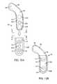
- FIGS. 11A, 11B and 11Care perspective views of further alternative embodiments employing supplemental fixation/support means
- FIG. 11Dis a schematic illustration of an embodiment such as shown in FIG. 11C in place on a portion of the tibia;
- FIGS. 12A, 12B, 12C, 12D and 12Eare various views of yet another alternative embodiment employing a separate fixation base member
- FIG. 12Fis a schematic illustration of a further alternative embodiment, also employing a separate fixation base in place on a portion of the tibia;
- FIGS. 13A, 13B, 13C, 13D and 13Eare views of other alternative embodiments having differently shaped fixation portions
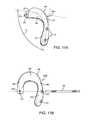
- FIGS. 14A and 14Bare schematic illustrations of further alternative embodiments adapted for femoral fixation
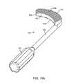
- FIGS. 15A and 15Bare views of an embodiment of disclosed instrumentation useful in procedures for placement of implants disclosed herein;
- FIG. 16is a drawing of another alternative embodiment viewed from the anterior aspect of an implant with a configuration generally as described herein;
- FIG. 17is a drawing of another alternative embodiment viewed from the anterior aspect of an alternative implant including features similar to the embodiment shown in FIGS. 9A and 9B ;
- FIG. 18is a drawing of another alternative embodiment viewed from a cranial aspect of another alternative implant with a displacement portion having an increasing thickness;
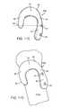
- FIG. 19is a drawing of another alternative embodiment viewed from an anterior aspect of a further alternative implant including features similar to the embodiments shown in FIGS. 11B and 11C ;
- FIG. 20is a drawing of another alternative embodiment viewed from a caudal aspect of yet another alternative implant with features to facilitate positioning prior to fixation;
- Embodiments of the present inventionemploy an improved implant geometry with an appropriately curved cross-section to address drawbacks of some prior devices and procedures, such as an unsightly and uncomfortable bump, concerns about tissue damage, and the caudal movement of the patella as previously discussed.
- Other embodiments of the present inventionemploy supplemental support/fixation means and specially shaped fixation portions to facilitate implantation, increase fixation security and resist torqueing forces.
- Further embodiments of the present inventionencompass less invasive methods for treatment of patellofemoral conditions, including employing implant embodiments disclosed herein.
- an implant portionis inserted underneath the patellar tendon, just cranial to the attachment of the patellar tendon to the tibial tuberosity.
- This implant portiondisplaces the patellar tendon anteriorly, flattening the angle between the patellar tendon and the quadriceps tendon. This change in angle reduces the resultant pressure of the patella against the femur, reducing patellar pain and patellofemoral cartilage wear.
- the implantmay also improve patellar tracking, or shift the location, angle or loading of the patella against the femur.
- FIG. 3schematically illustrates features of the embodiments in this disclosure.
- the schematic side view of FIG. 3helps to illustrate the positioning and curved shape of the bearing surface 11 and displacement portion 12 of embodiments disclosed herein.
- the bearing surface 11is the surface of the displacement portion 12 in contact with the patellar tendon.
- Line L 2shows the approximate line of action of the patellar tendon after repositioning over displacement portion 12 .
- fixation means and other implant structuressuch as the fixation portion and spanning section discussed in more detail below are not called out.
- the various fixation and support structures discussed belowfacilitate the cantilevering of displacement portion to better accommodate soft tissue structures while properly positioning the bearing surface as discussed in more detail below.
- implants according to embodiments of the inventionwill be configured and dimensioned to displace the tissue targeted for treatment by between about 5 mm to about 30 mm from the natural, anatomical tissue path. In some embodiments, the displacement will be greater than about 10 mm.
- Overall displacement amountscan be set through a combination of shape and size of the fixation portion, spanning section and displacement portion of the implant as previously described. Working within those parameters, it has been discovered that by shaping the bearing surface at least approximately as a quarter-circle in cross-section with a minimum radius of about 8 mm, caudal biasing of the patella can be reduced.
- the displacement portion and/or bearing surfacemay be shaped and dimensioned to provide different magnitudes of displacement at different points along the surface such that the tissue is displaced different amounts at different joint positions, e.g. at different points in the gait cycle.
- therapeutic effectmeans an effect on a treated joint that reduces forces acting on the articular surfaces, reduces wear, lessens pain or provides another positive outcome for the patient whether across the joint as a whole or in particular compartments of the knee. “Therapeutic effect,” however, does not imply, and should not be understood as requiring, any specific, quantified outcome other than as stated above.
- the patellais pulled caudally by only about ( ⁇ /2 ⁇ 1) or 0.57 millimeters.
- the bearing surface curvemay be flattened even further with a length of about 2 mm while maintaining the 1 mm depth, as shown in FIG. 4B .
- the caudal displacement of the patellawould be less than half of the anterior displacement.
- the generally elliptical shape of the bearing surfacecauses such an implant to extend generally twice as far cranially as it does anteriorly and thus would pull the patella caudally by an amount approximately equal to 0.42 times the anterior displacement.
- Caudal displacement with an elliptically shaped bearing surfacemay be estimated based on a corresponding elliptical circumference. For example, using an “ellipse calculator” (e.g. as available online at http://www.cleavebooks.co.uk/scol/callipse.htm) and selecting a major axis of 4 and a minor axis of 2, a circumference of 9.69 can be determined. Dividing the circumference by 4 gives 2.422 (approximately one quarter of the elliptical circumference corresponding to the overall length of the bearing surface). With this information, it may be estimated that a curved bearing surface with a cranial-caudal length of 2 cm and an anteriorization of 1 cm will pull the patellar tendon caudally approximately 0.42 cm.
- a geometry as described in the preceding paragraphsshould dramatically reduce the complications caused by patella baja from square or steeply profiled implants.
- a prior art implant with a square cross-sectionsuch as shown in FIG. 2 , would pull the patella caudally by approximately one millimeter for each millimeter of anteriorization; about twice the amount of caudal displacement created by embodiments disclosed herein for the same amount of anteriorization.
- the bearing surface 11will be positioned with its outer most point (apogee) at a perpendicular distance from the surface of the tibia below it of about 0.3-3 cm, or more typically about 0.5-1.5 cm for an implant configured to treat an average adult knee.
- the width of the bearing surface in the generally cranial-caudal directionwill be about 0.5-3.0 cm, or more typically about 1.0-2.5 cm. While distance from the tibia to the apogee of the bearing surface can equal the bearing surface width, in some embodiments the width will be greater than that distance, about 1.1-3.0 times greater, or more typically about 1.5-2.0 times greater. Further alternative embodiments may employ bearing surfaces with compound curvatures comprising elements of FIGS. 4A and 4B as previously discussed.
- a further physiologic benefit to an implant with the curved geometry as describedis that the forces pressing the patella against the femur are highest when the knee is bent, such as when a person is climbing stairs.
- the shape of the present inventionis more effective in flattening the angle between the patellar tendon and the quadriceps tendon when the knee is bent. It also reduces the focal stress on the sharply angled portion of the patellar tendon caused by such prior implants, especially when the leg is straight.
- the extreme caudal positioning of the prior implant 2is indicated at (A) in FIG. 3A .
- FIGS. 5A-CThe beneficial effect of embodiments of the present invention as related to knee flexion are further illustrated in FIGS. 5A-C . From these figures, it can be seen that the angle ⁇ of anteriorization is increased from the natural line of the patella tendon from ⁇ 1 with the knee fully extended, to ⁇ 2 at partial flexion, up to ⁇ 3 at 90° flexion in FIG. 5C , where ⁇ 1 ⁇ 2 ⁇ 3 . The unloading provided by the implant thus increases with knee flexion, providing the greatest relief when the patella is maximally loaded.
- implant 210includes a support member 212 and bearing member 214 .
- the support and bearing membersare functionally divided into displacement portion 216 , spanning section 218 and fixation portion 220 .
- the displacement portion, with the bearing memberis partly cantilevered over the tibia so that a portion of the fat pad may be received thereunder.
- FIGS. 7A-Gdepict an exemplary prototype of implant 300 for treating patellofemoral osteoarthritis and/or patellar maltracking for the right knee.
- Implant 300has a fixation portion 312 having one or more holes 315 for receiving screws for anchoring the implant to bone.
- Fixation portion 312is generally straight and elongated, being configured for positioning in general alignment with the tibial shaft on the medial or anterior-medial side of the tibia.
- Bone engaging surface 313is provided on the bone facing side of the fixation portion.
- Holes 315are preferably positioned in approximate alignment with a longitudinal centerline of fixation portion 312 .
- Displacement portion 314is configured and dimensioned to be positioned under the patellar tendon caudally separated from the insertion point of the tendon in the tibia.
- the displacement portion 314is configured to atraumatically engage the tendon and displace it anteriorly relative to the tibia.
- the displacement portion 314has a length in the lateral-medial direction generally selected to accommodate the full width of the tendon so that the tendon remains engaged along its entire width as it slides on the displacement portion.
- Displacement portion 314preferably has a convex curvature on its outer tissue-engaging surface (bearing surface 309 ), preferably being curved at least around an axis generally parallel to the tibial shaft, usually being curved also around an axis perpendicular to the tibial shaft, and more preferably being spherical or partially spherical. Displacement portion 314 has a width in the caudal-cranial direction is selected so that it does not interfere with the patella or engage the insertion point of the tendon, typically being less than its length. A spanning section 316 interconnects fixation portion 312 and displacement portion 314 .
- Spanning section 316extends cranially and laterally from fixation portion 312 to displacement portion 314 , forming a curve of about 90° about a dorsal-ventral axis. Where fixation portion 312 is configured for attachment to a more medial aspect of the tibia, spanning section 316 will extend ventrally as well as cranially and laterally from fixation portion 312 , preferably being curved about an axis generally parallel to the tibial shaft. Displacement portion 314 appropriately displaces the patellar tendon in cooperation with the fixation portion 312 and spanning section 316 .
- Displacement of the target tissuecan be altered by changing the length, curvature and angle of the spanning section among other features.
- the angle ⁇ between the displacement portion 314 and the fixation portion 312(as measured at the intersection of the center line axes of the two portions in the top view of the implant in FIG. 7B ) may range from about 80 degrees to 135 degrees, more specifically from about 85 degrees to 120 degrees, and in some embodiments about 90 degrees to 110 degrees.
- the width W 1 of the fixation portion 312typically will be large enough to span a substantial portion of the width of the tibia and to accommodate one or more screw holes of sufficient size, ranging from about 10 mm to 25 mm. In some embodiments, width W 1 may be about 12 mm to 20 mm, and in other embodiments about 14 mm to 18 mm.
- the length L 1 of the fixation portion 312will be selected to accommodate a sufficient number of screw holes in the cranial-caudal direction along the tibia, usually at least two and in some embodiments up to five or more, and may range from about 20 mm to 50 mm, more specifically about 25 mm to 45 mm, and in some embodiments about 30 mm to 40 mm.
- the width W 2 (generally cranial-caudal direction) of the displacement portion 314is generally selected to provide a broad area of contact with the tendon to spread the force and reduce wear, while not interfering with the patella or the tendon insertion point throughout the full range of joint motion.
- Width W 2may thus range from about 10 mm to 25 mm, more specifically about 12 mm to 20 mm, and in some embodiments about 14 mm to 18 mm.
- the length L 2 (generally medial-lateral direction) of the displacement portion 314is selected so that the displacement portion extends under the full width of the tendon so that the entire width of the tendon remains in engagement and displaced the desired amount throughout the range of joint motion.
- Length L 2may thus range from about 20 mm to 50 mm, more specifically about 25 mm to 45 mm, and in certain embodiments about 30 mm to 40 mm.
- implant 300also includes a supporting section 320 extending along the caudal extent of displacement portion 314 , into spanning section 316 and merging into the bone engaging surface 313 of fixation portion 312 .
- contour line 322illustrates the approximate extent of supporting section 320 from the displacement portion, through the spanning section and into the fixation portion.
- Supporting section 320rests on the surface of tibia between the tendon insertion point and the fat pad and/or capsular tissue.
- the cranial-caudal length of bone engaging surface 313i.e., the approximate distance from cranial most location of contour line 322 delineating the cranial extent of the supporting section, to the caudal end of fixation portion 312 is preferably greater than the distance from same point on contour line 322 to the cranial edge of displacement portion 314 .
- the appropriate distance ratios between these two regionsincreases the moment arm resisting torqueing force applied by the patellar tendon through the cantilevered displacement portion 314 to help fix the implant in place and resist loosening over time due to the cyclic torqueing forces applied by knee flexion and extension.
- Displacement portion Height (H), shown in FIG. 7Gis the perpendicular distance from the apogee of bearing surface 309 to the bone engaging surface 313 .
- Height (H)directly effects the amount of displacement of the tendon achievable with the implant. In general terms, the displacement distance will approximately equal Height (H) minus the normal anatomical distance between the patellar tendon and the tibial surface below it at the location of the displacement portion when implanted.
- Implant depth Dalong with the radius of curvature R 1 of the outer surface of displacement portion 314 , shown in FIG. 7F , are selected to balance tendon displacement throughout the range of joint motion with the appropriate fixation location.
- Radius of curvature R 1is usually 20-35 mm, more preferably 22-33 mm, and most preferably 25-30 mm.
- an overall implant depth (D), shown in FIGS. 7C and 7Fas measured from the outermost surface of displacement portion 314 to the centerline of the screw holes in fixation portion 312 , would be in the range of 10-45 mm in order to provide target tissue displacements in the ranges cited hereinabove to achieve a therapeutic effect.
- the inferior edge 304 of the spanning section 316can also be curved to minimize or eliminate any contact with the medial edge of the patellar tendon.
- the superior surface edge 305 of the displacement portion 314can be curved to allow for easy motion of the patellar tendon during flexion as well as to vary the displacement of the patellar tendon during flexion by varying the region of the implant surface in contact with the tendon at higher flexion angles.
- implant 300is placed on the medial side of the distal tibia such that fixation portion 312 is substantially aligned with the tibial shaft, the spanning section 316 is positioned to minimize contact with the medial edge of the patellar tendon, and the displacement portion 314 , extending laterally from the spanning section, is substantially parallel to the tibial plateau.
- a supporting section as generally described abovemay be incorporated into other embodiments disclosed herein to facilitate locating the fixation portion (and in particular bone screw site) at a distance from the area where displacement portion acts to allow for easier placement of the device, without a need to place fixation elements such as nails or screws under or close to the patellar tendon, the joint capsule or the infrapatellar fat pad. It also means that the displacement element can be appropriately rounded and smooth, without any surface roughness or disturbances due to fixation elements. And although the fixation portion is at a distance from the displacement portion, much of the force from the patellar tendon is transmitted through the supporting section directly onto the tibia behind it.
- the fixation portion 312caudally down the tibia relative to the supporting section (and contour line 322 ) so as to counter any tendency of the displacement portion to be tilted toward the tibia under the forces exerted by the patellar tendon.
- implant 20may have a displacement portion 22 with a bearing surface 24 .
- the bearing surfacemay be curved as described above in connection with FIGS. 4A and 4B .
- the bearing surfacealso may be optionally provided with a concave groove or channel 25 extending in the cranial-caudal direction to assist in guiding the displaced tissue as it passes thereover.
- the same embodimentalso may be provided without the channel.
- Implant 20also may have a fixation portion 26 with a bottom surface having a slight concavity 27 in the cranial-caudal direction configured to be seated on the tibia just cranially of the tibial tuberosity.
- Fixation means 28such as screw holes, spikes or bone ingrown facilitating elements may be included in fixation portion 26 .
- Persons of ordinary skill in the artwill appreciate that the features of the concave groove or channel 25 and/or bottom surface concavity 27 may be employed with other embodiments as described herein and are not restricted to use with implant 20 .
- displacement portion 22includes a cantilevered portion 22 A extending in the cranial direction, forming an undercut region 22 B on the inferior (bone facing) side of cantilevered portion 22 A, cranially of fixation portion 26 .
- Cantilevered region 22 Ais configured to extend cranially over the anterior surface of the tibia and the overlying fat pad such that the cranial edge of bearing surface 24 extends a distance X of about 5-30 mm, more preferably about 10-25 mm, and most preferably about 15-22 mm, from the cranial edge of fixation portion 26 .
- a cover member 21may be provided as shown in FIG. 8C to protect and retain the tendon when it is received in channel 25 .
- Cover 21is securable over bearing surface 24 , such as with screws 23 .
- implant 30may have a displacement portion 32 with a bearing surface 34 .
- Bearing surface 34also may be curved as described above in connection with FIGS. 4A and 4B .
- Displacement portionmay be supported and positioned by spanning section 36 , which is in turn supported by fixation portion 38 .
- Spanning section 36 and displacement portion 32may be configured and dimensioned to provide varying amounts of cantilever for the bearing surface 34 .
- Such a cantilevercan provide clearance for the fat pad and/or other critical tissues behind the implant.
- Fixation means 39such as screw holes, spikes or bone ingrown facilitating elements may be included in fixation portion 38 .
- displacement portion 32can be provided with a concavity on the bone-facing posterior side of displacement portion 32 that spaces the displacement portion away from the tibial, forming a space (S) therebetween with a height indicated by the double arrow.
- Space Spreferably has a maximum height between an underside 32 U of displacement portion 32 and the surface of the tibia in a range of about 5-25 mm, or more typically about 10-20 mm, in order to accommodate the fat pad and other tissues beneath the displacement portion 32 .
- Displacement portion 32has a supporting section 32 B, as described above, that sits in engagement with the tibia in the space between the tibial tuberosity TT and the caudal edge of the fat pad, thereby supporting displacement portion 32 .
- Height (H)the perpendicular distance between the bone engaging surface 326 of supporting section 32 B and the apogee of bearing surface 34 , as also described above, is shown in FIG. 9D .
- supporting section 32 Bpreferably extends in the cranial-caudal direction a distance (SS) of no more than about 20 mm, usually being about 5-15 mm, more preferably about 8-12 mm.
- the cranial end 32 C of displacement portion 32preferably extends a distance (CE) of about 5-30 mm, typically about 10-25 mm, or more typically about 15-22 mm in the cranial direction from the upper (cranial) extent of supporting section 32 B, which lies against the tibia approximately at dimension line (DL) in FIG.
- lateral margin 33may be configured to contact the tibia to provide additional support for the displacement portion and bearing surface in resisting forces applied by the patellar tendon, particularly at high flexion angles.
- An additional embodimentmay have an additional fixation portion on the lateral end of the implant as shown in FIG. 9C , to provide additional support and stabilization for the implant.
- FIG. 10illustrates an embodiment of the present invention, such as implant 30 described above, after implantation on the tibia.
- implant 30also employs an extended fixation portion 38 A for enhanced torque resistance as described in more detail below.
- Fixation portion 38 Amay have an extension portion that wraps around either the anterior or posterior side of the tibia, or both, to further stabilize the implant.
- Multiple screw holes 39 and bone screws 31are used as dictated by patient anatomy and clinical factors such as condition of the bone.
- Placement and fixation of an implant according to embodiments of the present inventioncan often be accomplished through a single surgical incision adjacent the patient's knee.
- the implantis then placed through the incision with the displacement portion inserted under the patellar tendon cranially with respect to its attachment point to the tibia at the tibial tuberosity.
- a therapeutic location that is a target area for placement of the displacement portionincludes the caudal pocket below the infrapatellar fat pad containing the infrapatellar bursa (B).
- Reference letter (B)is provided in FIG. 10 to identify the target area, but the bursa itself is not shown because in some situations it may be necessary to remove part or all of the bursa to accommodate the implant.
- unlike the articular capsule or the infrapatellar fat padthere are not significant potential negative indications associated with removal or dissection of the infrapatellar bursa.
- Placement of the implant as shown for example in FIG. 10allows the implant to be placed and fixed through a single incision without penetrating the capsule (C) or dissecting the infrapatellar fat pad (FP) or separating it from its attachment along the posterior of the patellar tendon (PT).
- Cthe capsule
- FPthe infrapatellar fat pad
- PTthe infrapatellar fat pad
- TTthe tibial tuberosity
- FIG. 10also further illustrates how the shape of the spanning section 36 and displacement portion 32 provides a cantilevered bearing surface 34 to define space (S) under the implant to accommodate the fat pad and its attachment to the side of the tibia.
- the cantilevered portion of the implantmay be configured to deflect under high loading conditions to reduce strain on the tendon. Such deflection may be engineered into the implant by selection of shape, thickness and material so as to allow the implant to flex, or more active means such as springs or hydraulic cylinders may be used.
- bearing surfaces of implants according to embodiments of the inventionmay include resilient elements such as fluid filled pillows and/or pressure control volumes utilizing check or relief valve systems.
- FIGS. 11A and 11Billustrate further alternative embodiments employing supplemental support and fixation elements 50 and 54 .
- Implants 40 A and 40 Beach include fixation portion 42 with fixation means such as bone screw holes 43 , spanning section 44 and displacement portion 46 with bearing surface 48 , all as previously described.
- fixation meanssuch as bone screw holes 43 , spanning section 44 and displacement portion 46 with bearing surface 48 , all as previously described.
- supplemental support and fixation tab member 50Positioned at the end of displacement portion 46 on implant 40 A is supplemental support and fixation tab member 50 with at least one bone screw hole 52 .
- implant 40 Amay be generally shaped in a manner similar to implant 30 of FIG. 9B , with tab member 50 disposed at the lateral margin 33 of the implant having a bone engaging surface in contact with the tibia.
- the shapemay be generally reversed such that tab member 50 would be disposed at a medial margin of the implant displacement portion.
- tab member 50has no bone screw hole, but simply provides additional surface area resting against the tibial surface to stabilize the device and to more widely distribute the pressure of the device due to the force of the patellar tendon against the device.
- the position of tab member 50 with respect to fixation portion 42may necessitate a second surgical incision site when placing implant 40 A.
- meanssuch as shown in FIG. 11B for implant 40 B may be alternatively employed.
- displacement portion extension 56extends the displacement portion in a caudal direction around the lateral side of the tibia (if the fixation portion 42 is mounted to the medial side of the tibia).
- Supplemental support and fixation tab 54is disposed at the caudal and/or lateral margin of the extended displacement portion and provided with at least one fixation hole 57 .
- fixation hole 57is configured to accommodate fixation rod 58 and is aligned with a corresponding fixation hole 57 in fixation portion 42 .
- Fixation rod 58may comprise a threaded rod or elongated bone screw, and fixation hole 57 may be threaded so as to receive the threaded tip of the fixation rod.
- fixation rod 58may be threaded over its entire length with a pointed distal end and a bone screw head at the proximal end adapted to receive a torqueing tool such as a hex driver.
- Placement of an embodiment such as implant 40 Bis achieved by positioning the fixation portion on one side of the tibial tuberosity with the extended displacement portion 56 extending around the attachment of the patellar tendon to the tibia and back down caudally on the opposite side of the tibial tuberosity.
- fixation rod 58may be inserted through the same surgical incision and through a portion of the tibia to fix both holes 57 in a single operation. Additional fixation screws may be placed in other holes 43 , again through the same surgical incision.
- a specialized drill guidemight be employed to ensure accurate alignment while drilling the hole.
- implant 60has a fixation portion that comprises a body member fixation portion 62 A and a base member fixation portion 62 B.
- FIG. 12Ashows the part unassembled before placement of the body member fixation portion 62 A
- FIG. 12Bshows the assembled parts as they may appear after placement.
- implant 60also includes spanning section 66 and displacement portion 68 with bearing surface 69 generally as previously described.
- screw holes 63configured to receive bone screws 64 , are provided only in base member fixation portion 62 B.
- additional fixation screw holes 63 Amay be provided in both the base member and body member fixation portions and positioned so that the holes align when the body member is received in the base member.
- bone screw access holes 63 Bmay be provided as discussed further below. Access holes 63 B are shown in FIG. 12A in dashed lines as optional features.
- Body member fixation portion 62 A and base member fixation portion 62 Bare provided with complementary, mating shapes to permit them to be securely fitted together.
- Persons of ordinary skill in the artmay select from various complementary shapes, one example of which is shown in FIGS. 12C and 12D , which are end views at lines C-C and D-D, respectively, in FIG. 12A .
- base member fixation portion 62 Bdefines a channel 70 with retaining edge 72 that extends therearound.
- the complementary shape of body member fixation portion 62 Ais provided by guide channel 74 , which in this exemplary embodiment extends around the caudal end and onto both sides of the body member fixation portion 62 A.
- separate mating featuresmay be provided only on the sides, not extending around the caudal end of the implant.
- the two-piece design of an embodiment such as implant 60permits the base member fixation portion 62 B to be first secured at a selected location without an eccentric or torqueing forces applied by the target tissue through the displacement portion 68 .
- Fixation meanssuch as holes 63 and bone screws 64 may be used to secure the base member fixation portion 62 B.
- displacement portion 68may be inserted under the target tissue, such as the patellar tendon, and then base member fixation portion 62 A inserted into base member fixation portion 62 B with a relatively straightforward sliding action as indicated by the arrow in FIG. 12A to provide a combined implant generally as shown in FIG. 12B .
- Screw holes 63 and screws 64are shown in phantom lines in FIG.
- screws 64preferably are low profile screws with flat heads to avoid interference with the body member when inserted into the base member.
- Channel 74is also shown in phantom lines because it is received behind edge 72 .
- FIG. 12EVarious locking means for securing the body member to the base member are possible.
- inter-engaging teeth 76 A and 76 Bare provided on the facing surfaces, respectively, of the body member channel 74 and the base member retaining edge 72 .
- the inter-engaging teethact in a ratchet-like manner, permitting insertion but preventing removal.
- the teethmay themselves be formed with resiliency to permit insertion.
- the teethmay be relatively short with less resiliency to permit insertion provided by elastic deformation of base member fixation portion 62 B and retaining edge 72 .
- additional bone screwsmay be inserted through optional, additional fixation screw holes 63 A, which become aligned as described above.
- inter-engaging teeth or other ratchet-type locking meansmay be difficult to disengage if it becomes necessary to remove or reposition the base member during the initial implant procedure or a later intervention. Disengagement may be achieved, for example, by deformation of base member fixation portion 62 B and retaining edge 72 .
- bone screw access holes 63 Bmay be provided in body member fixation portion 62 A as shown in FIG. 12A . Access holes 63 B are positioned to align with bone screw holes 63 in base member fixation portion 62 B when the body member is received in the base member after implantation. Using access holes 63 B, bone screws 64 may be removed without separating the body member from the base member.
- inter-engaging or ratchet-type locking meansis not provided.
- locking meansmay be provided by one or more additional fixation screw holes 63 A.
- body member fixation portion 62 Amay be freely inserted and removed from base member fixation portion 62 B once the base member is installed.
- the complementary shape of the mating parts as describedinitially carries the torqueing force of the target tissue acting on displacement portion 68 and then the two members are locked together using bone screws through one or more additional fixation screw holes 63 A.
- Bone screw access holes 63 Balso may be included as desired to provide further removal options.
- FIG. 12Fshows an additional alternative body member-base member geometry, with a curved interface between the parts which allows adjustment for any variation in the angle of the tibial surface against the fixation portion. This allows the body member 69 to be positioned so that the posterior edge of the displacement section rests firmly against the tibia as the fixation screws are tightened.
- Implants 80 A-E of FIGS. 13A-Eeach include fixation portion 82 with screw holes 83 , spanning section 84 and displacement portion 86 with bearing surface 88 generally as previously described.
- implant 80 Amay include extension portions extending from fixation portion 82 in a direction generally transverse to that of fixation portion 82 . For example, as shown in FIG.
- an extension portion 90 Amay be configured to extend generally in the same direction as the displacement portion, e.g., if the fixation portion 82 is mounted on the lateral side of the tibia, in a medial direction (or angled medially and caudally), across the anterior surface of the tibia transverse to the longitudinal axis of fixation portion 82 , but caudally of the tibial tuberosity.
- implant 80 Bincludes extended fixation portion 90 B, which extends in a direction opposite from the displacement portion 86 , e.g. laterally, or laterally and caudally, relative to fixation portion 82 so as to extend around the lateral side of the tibia.
- extended fixation portion 90 Bmay be configured to extend posteriorly further around the medial and/or posterior side of the tibia (if the fixation portion 82 is mounted to the medial side). Extended fixation portions 90 A and 90 B create a wider base for fixation portion 82 and thus provide greater resistance to torqueing forces as described. Extended fixation portions 90 A and 90 B generally will be configured and dimensioned to match the shape of the tibia in the area of contact.
- An extended fixation portion configured and positioned as extended fixation portion 90 Awill help to resist torqueing applied to the displacement portion 86 by creating a greater surface bearing against the bone at a greater distance from the center of rotation of the torqueing force, which will lie approximately along a centerline of fixation portion 82 .
- An extended fixation portion configured and positioned as extended fixation portion 90 Bwill help to resist torqueing force applied to the displacement portion 86 by creating a greater lever arm through which a bone screw in fixation holes 83 may act to resist the torqueing force.
- FIG. 13Cshows exemplary implant 80 C employing both laterally- and medially-extended fixation portions 90 A, 90 B on one device.
- split fixation portion 92may be employed such as shown with implant 80 D in the exemplary embodiment of FIG. 13D .
- split fixation portion 92forms two fixation arms 92 A and 92 B at its caudal end, one extending laterally and posteriorly, and a second extending medially and anteriorly, that can be configured to wrap around the tibia in opposing directions to the extent appropriate for the patient anatomy and clinical situation presented.
- fixation arms 92 A, 92 Bcan be oriented transverse to longitudinal axis of fixation portion 92 to extend primarily in the medial-lateral direction, or angled caudally as wells as medially or laterally.
- a single arm 92 A or 92 Bmay be employed in a manner similar to the exemplary embodiments of FIGS. 13A and 13B employing single extended fixation portions 90 A or 90 B.
- the caudal ends of fixation arms 92 A, 92 Bmay have holes configured to receive a rod or screw extending through one fixation arm 92 A and through the tibia to the other fixation arm 92 B.
- fixation portion 82may be desirable to provide differently shaped bone facing fixation surfaces for fixation portion 82 .
- Alternativesinclude fixed protrusions 94 and adjustable protrusions 96 as illustrated in FIG. 13E .
- Such protrusionsallow the fixation portion 82 to contact the bone at discreet locations to accommodate variability in the contour of the bone surface.
- Fixed protrusionsmay be ground to a desired height and shape according to the anatomy of each patient to provide further patient specific adaptability.
- Adjustable protrusionsmay be provided with an adjustment mechanism 98 , such as a threaded member accessible at the outer surface of fixation portion 82 and rotatable to move adjustable protrusions 96 between an inner position and an outer position (shown in dashed lines in FIG.
- fixed or adjustable protrusionsmay be provided on the bone-facing side of the displacement portion such that it contacts the bone at discrete locations, accommodating variations in shape of the bone surface on the cranial side of the tibial tuberosity where the displacement portion extends under the patellar tendon.
- each of the different supplemental fixation or support means shown in FIG. 11A or 11B , the fixation base member shown in FIGS. 12A-E , and/or the different fixation portion shapes shown in FIGS. 13A-13Emay be used together in different combinations or individually with each different implant herein.
- FIGS. 14A and 14Bdepict further exemplary embodiments of implants 400 A and 400 B, respectively, also for treating patellofemoral osteoarthritis and/or patellar maltracking, but with femorally mounted implants as shown.
- implants 400 A and 400 Beach have a fixation portion 412 including one or more holes 415 for receiving screws, or other fixation means for anchoring the implant to bone.
- Fixation portion 412is generally straight and elongated, being configured for positioning in general alignment with the femoral shaft on the lateral, medial or anterior-medial/lateral side of the femur, cranially with respect to the patella.
- Holes 415may be positioned in approximate alignment with a longitudinal centerline of fixation portion 412 as shown, however additional holes may be included for added fixation security, similar to embodiments shown, inter alia, FIG. 10 or 13A -D.
- fixation portion 412is configured to be mounted to the femur outside the joint capsule, cranially with respect to the tendons, ligaments and other tissues that form the capsule.
- Displacement portion 414is configured and dimensioned to be positioned under the quadriceps tendon caudally separated from the insertion point of the tendon in the quadriceps muscle and cranially with respect to its attachment point to the patella, with the entire displacement portion 414 preferably being disposed entirely outside the joint capsule.
- displacement portion 414will also extend laterally across an anterior portion of the femur.
- a laterally placed devicewill have a displacement portion 414 that also extends medially across an anterior portion of the femur.
- the displacement portion 414is configured to atraumatically engage the quadriceps tendon and displace it anteriorly relative to the femur, thus increasing space in the patellofemoral area.
- the displacement portion 414has a width in the lateral-medial direction selected to accommodate the full width of the quadriceps tendon so that the tendon remains engaged along its entire width as it slides on the displacement portion.
- Displacement portion 414has a length in the caudal-cranial direction selected so that it does not interfere with the patella.
- Displacement portion 414preferably has a convex curvature on bearing surface 418 , which engages the tendon.
- the displacement portion and, in particular the bearing surface of the displacement portionwill be free of holes or other fixation means, with configuration similar to the bearing surfaces in other described embodiments.
- the displacement portion 414 and/or bearing surfacemay have a curvature which provides a constant displacement of the tissue throughout the range of motion of the joint, or configured to vary the displacement at different points throughout the range of motion.
- the curvaturemay be entirely or partially spherical, elliptical, parabolic, logarithmic spiral, or other curvature or combination thereof.
- the displacement portion 414is configured such that a cranial aspect of bearing surface 418 slopes or curves gradually away from the femur as it extends in the caudal direction to provide gradually increasing displacement of the tendon.
- Implant 400 Amay also include a cantilevered portion 420 of displacement portion 414 which has an undercut surface that is spaced apart from the underlying femoral surface. As with other described embodiments, cantilevered portion 420 creates a space (S) between the implant and the bone to accommodate soft tissue structures as needed.
- Cantilevered portion 420also extends the displacement portion 414 in the caudal direction toward the patella to optimize displacement while minimizing interference with the joint capsule and other soft tissues.
- implant 400 Bshown in FIG. 14B , may be configured without a cantilevered portion such that substantially all of the bearing surface 418 overlies and is supported by portions of the displacement portion 414 that engage the femur.
- Implants 400 A, 400 Bmay optionally include various other features described above in connection with tibial-mounted embodiments.
- implants 400 A and 400 Bmay include a supporting section extending from a cranial part of the underside of the displacement portion into and merging with the fixation portion as described above in connection with tibially mounted embodiments.
- the configuration of a supporting section in these embodimentswill, however, be generally inverted to accommodate fixation on the femur cranially with respect to the patella, as opposed to, on the tibia, caudally with respect to the patella.
- Implants 400 A, 400 Bmay alternatively have a tab or extension portion extending cranially, medially, and/or posteriorly from the displacement portion 414 on the opposite side from the fixation portion 412 which can engage the femur to provide additional support for the displacement portion 414 .
- such tab or extensionmay include a hole through which a bone screw may be inserted into the bone, or a hole for receiving a rod or screw extending from fixation portion 412 through the femur.
- Implants according to embodiments of the present inventionmay be positioned and fixed using well-known instrumentation that is used for other orthopedic implant procedures.
- a specially shaped curved file as shown in FIGS. 15A and 15Bmay be useful for preparing the bone surface at the implant location, particularly for tibially mounted implants.
- Curved file 500comprises a shaft 502 with a handle 504 at a proximal end and a curved file element 506 at the opposite, distal end.
- File element 506preferably made of a metal suitable for filing bone, extends in a transverse direction from shaft 502 and has a lower surface 506 A and an upper surface 506 B, one or both of which have grooves, knurling, points, bumps, or other features configured to file the bone surface to give it a suitable shape for receiving the implants of the invention.
- File element 506is preferably curved about a second axis extending in a direction transverse to shaft 502 longitudinal axis in an anterior-posterior direction, giving file element 506 a convex cranial side 507 and a concave caudal side 509 .
- Upper and lower surfaces 506 A, 506 Bare disposed at least partially in respective planes which are intersected by the second axis.
- lower and/or upper surfaces 506 A, 506 Bmay have a curvature about a third axis parallel to the longitudinal axis of shaft 502 .
- This latter curvaturemay have various shapes, e.g. generally matching the curvature of the anterior surface of the tibia in the region just cranial to the tuberosity where the implant will be fixed, or a different curvature as is suitable to provide a stable base for the implant.
- either or both the convex cranial side 507 or concave caudal side 509may have grooves or other features to facilitate filing the bone with these surfaces.
- the lower and/or upper surfaces 506 A, 506 Bmay have either a convex or concave curvature about an axis transverse to shaft 502 as may be suitable to create the particular shape desired for the bone surface.
- the file element 506may be inserted through an incision on the lateral or medial side of the tibia just cranial to the tibial tuberosity such that the file element extends across the anterior tibial surface.
- File 500may be drawn back and forth in a cranial-caudal direction (parallel to the tibial shaft), or in a medial-lateral direction, to file down the tibial surface cranially of the tuberosity to the desired shape.
- the files disclosed hereinmay be used for other treatments, including bone re-shaping for the treatment of Osgood-Schlatter disease or other diseases.
- FIGS. 16-20illustrate further exemplary implants made according to the teachings of the present disclosure.
- implant 610 in FIG. 16is made according to the general teachings of the disclosure and includes, inter alia, fixation portion 612 , displacement portion 614 and spanning section 616 , as well as other features described herein for the various embodiments.
- Implant 620shown in FIG. 17 , includes a fixation portion 622 , displacement portion 624 and spanning section 626 , wherein displacement portion 624 is extended laterally as compared to implant 610 so that the lateral edge 628 of displacement portion 624 may be supported on the tibia, for example on Gerdy's tubercle or adjacent thereto, to provide a supplemental support element.
- implant 620includes features similar to embodiments shown in FIGS. 9A-D .
- Implant 630shown in FIG. 18 , also includes a fixation portion 632 , displacement portion 634 and spanning section 636 .
- Displacement portion 634has a gradually increased thickness area 638 towards the lateral end in order to increase the tendon displacement at the lateral side.
- Implant 640shown in FIG. 19 , includes fixation portion 642 , displacement portion 644 and spanning section 646 .
- displacement portion 644includes lateral pad 648 at an outer end to provide supplemental support and fixation adjacent the tibial tubercle.
- implant 640may include features similar to embodiments shown in FIGS. 11B and 11C .
- Implant 650shown in FIG. 20 , includes fixation portion 652 , displacement portion 654 and spanning section 656 .
- Fixation portion 652has a bone engaging surface 658 formed with a convex profile to facilitate positioning along the tibial tuberosity prior to fixation.
- the convex profilemay be in the range of about 10 degrees of convexity.
Landscapes
- Health & Medical Sciences (AREA)
- Orthopedic Medicine & Surgery (AREA)
- Life Sciences & Earth Sciences (AREA)
- Surgery (AREA)
- Animal Behavior & Ethology (AREA)
- Veterinary Medicine (AREA)
- Public Health (AREA)
- Engineering & Computer Science (AREA)
- Biomedical Technology (AREA)
- Heart & Thoracic Surgery (AREA)
- General Health & Medical Sciences (AREA)
- Molecular Biology (AREA)
- Medical Informatics (AREA)
- Nuclear Medicine, Radiotherapy & Molecular Imaging (AREA)
- Oral & Maxillofacial Surgery (AREA)
- Dentistry (AREA)
- Neurology (AREA)
- Physical Education & Sports Medicine (AREA)
- Cardiology (AREA)
- Transplantation (AREA)
- Vascular Medicine (AREA)
- Prostheses (AREA)
Abstract
Description
This application claims the benefit of priority of U.S. Provisional Patent Application Ser. No. 61/951,469, filed Mar. 11, 2014, and U.S. Provisional Patent Application Ser. No. 61/951,470, filed Mar. 11, 2014, both of which are entitled “Apparatus and Methods for Treatment of Patellofemoral Conditions”; this application is also a continuation-in-part of U.S. Nonprovisional patent application Ser. No. 13/002,829, filed Aug. 27, 2010, and titled “Method and Apparatus for Force Redistribution in Articular Joints”; which application is a 371 of International Patent Application No. PCT/US10/46996, filed Aug. 27, 2010, and titled “Method and Apparatus for Force Redistribution in Articular Joints”, which claims the benefit of priority of U.S. Provisional Patent Application Ser. No. 61/237,518, filed Aug. 27, 2009, and U.S. Provisional Patent Application Ser. No. 61/288,692, filed Dec. 21, 2009, each entitled “Method and Apparatus for Force Redistribution in Articular Joints”; this application is also a continuation-in-part of U.S. Nonprovisional patent application Ser. No. 13/843,128, filed Mar. 15, 2013, and titled “Method and Apparatus for Altering Biomechanics of Articular Joints”; which application claims priority to U.S. Provisional Patent Application Ser. No. 61/620,756 filed on Apr. 5, 2012 and U.S. Provisional Patent Application Ser. No. 61/695,406 filed on Aug. 31, 2012; and which application is also a continuation-in-part of U.S. Nonprovisional patent application Ser. No. 12/870,462, filed on Aug. 27, 2010 (now U.S. Pat. No. 8,597,362 issued Dec. 3, 2013), which claims priority to U.S. Provisional Patent Application Ser. No. 61/237,518, filed Aug. 27, 2009, and U.S. Provisional Patent Application Ser. No. 61/288,692, filed Dec. 21, 2009. Each of the foregoing applications is incorporated by reference herein in its entirety.
The present invention generally relates to the field of orthopedic prostheses and procedures. In particular, the present invention is directed to apparatus and methods for treatment of patellofemoral conditions.
As the present invention is directed to apparatus and methods for treatment of patellofemoral conditions, a basic discussion of the anatomy of the knee with a focus on the patellofemoral structures may assist in describing the various embodiments of the invention.FIG. 1 is a schematic portrayal in side view of a human knee. The bones of the knee joint comprise the femur (F), tibia (T), and patella (P). The fibula (fib) is another bone in the lower leg that attaches to the tibia. As primarily relevant to embodiments of the present invention, connective tissues of the knee joint include the patellar tendon (PT) and the quadriceps tendon (QT). The patellar tendon is also referred to as the patellar ligament as its primary function is to create a connection between bones, i.e., the tibia and patella. The patellar tendon extends from the caudal (lower) extent of the patella to an attachment point on the tibial tuberosity (TT) of the tibia. The tibial tuberosity comprises a raised area on the anterior (forward) aspect of the tibia, caudally positioned (toward the foot or lower) with respect to the cranial (upper) end of the tibia. The quadriceps tendon extends from the cranial extent of the patella and joins with the quadriceps-femoris muscle.
The knee is a synovial joint, meaning that the bones are not directly joined but are surrounded by dense connective tissues forming an articular capsule (C) lined by a synovial membrane. The capsule defines a synovial cavity or intracapsular space (IC) that contains the articular cartilage of the joint (not shown) and synovial fluid that acts to reduce friction between the articular cartilages. The approximate extent of the capsule is indicated inFIG. 1 by dashed lines (C′). The quadriceps and patellar tendons lie outside the capsule. Also outside the capsule is the infrapatellar fat pad (FP). The fat pad is situated posteriorly and caudally with respect to the patella and joins with the patellar tendon on its posterior side over much of its length. The knee joint also includes a number of bursae to protect and facilitate movement between various bony and soft tissues. One of these bursae is the deep infrapatellar bursa (B), which allows for movement of the patellar tendon over the tibia. This bursa is positioned between the upper part of the tibia and the patellar tendon and lies in a pocket outside of the infrapatellar fat pad.
Because of the importance of the capsule in protecting and lubricating the articular cartilage, it is usually preferable, whenever possible in a knee intervention, to avoid penetrating the capsule. Because of the role of the infrapatellar fat pad in protecting the knee, it is also usually preferable to avoid dissecting the fat pad during knee interventions. Previously, removal of all or part of the fat pad was common in arthroscopic procedures in order to permit better visibility for the surgeon. However, it has been discovered that damage to the fat pad can lead to scarring, which can be painful and even crippling in some patients.
Treatments for various patellofemoral pathologies such as patellofemoral pain and patellofemoral osteoarthritis (PFOA) have been increasingly investigated. One early treatment, which involves anteriorization of the patellar tendon by a relatively invasive surgical procedure, was devised by Dr. Paul Maquet in the early 1960s. See, P. Maquet, 30 Revue Du Rhumatisme, No. 12, December 1963, pp. 779-783, “Biomechanical Treatment of Patellofemoral Osteoarthritis, Advancement of the Patellar Tendon” (translated title). In this procedure, an iliac bone autograft is implanted under the patellar tendon to relieve pressure in the patellofemoral space. Later Dr. Maquet evolved his technique to cut the tibial tuberosity away from the tibia and reposition it. This became known as the Maquet Osteotomy, which has been performed on tens of thousands of patients over the years with positive results. See, e.g, Maquet, Biomechanics of the Knee, pp. 134-143 (pub. Springer-Verlag 1976). However, the Maquet Osteotomy is a highly invasive procedure, which carries with it all of the risks and costs associated with highly invasive orthopedic surgeries.
However, the success of such a procedure may depend heavily on the configuration of the implant used. If the anterior, tissue-engaging surface of the implant is roughly perpendicular to the caudal face of the implant and/or parallel to the underlying surface of the tibia, it displaces the patellar tendon relatively directly anteriorly (perpendicular to the tibial surface) and creates an abrupt step at the caudal edge of the implant, which can produce a number of complications. First is the creation of an unsightly bump on the knee. This is not merely a cosmetic problem, as the bump may catch on clothing or other, harder objects that could cause bruising or injury in the course of daily activity. Second, such an implant could be extremely uncomfortable in certain common positions. For example, if a patient with such an implant were to kneel on that knee, all of the load would be placed on that implant, which could be painful and also damaging to the patellar tendon.
A third possible complication arises from the fact that an implant shaped such asimplant 2 also pulls the patella caudally, creating an undesirable misalignment. This condition is referred to as “Patella Infera” or “Patella Baja”. The symptoms of this misalignment can include pain on quadriceps contraction, inadequate quadriceps contraction, swelling, edema, joint stiffness, limited joint motion and limited patellar mobility.
Further, it may be desirable to maximize the area of the posterior surface of the implant that lies against the bone in order to spread the forces on the implant over as wide an area as possible. And, in order to minimize Patella Baja, it may be desirable to engage the patellar tendon as far cranially as possible without interfering with the patella or other tissues during knee movement. Yet, the space in which the implant is to be located, between the tibial tuberosity and the fat pad, bursa, and/or capsular tissues, is extremely limited. If the posterior surface of the implant extends too far cranially along the bone surface it may interfere with the fat pad, bursa, or joint capsule, causing pain or other complications. What is needed, therefore, are devices and methods for relieving patella-femoral pain due to osteoarthritis or other conditions that overcome the foregoing challenges.
In one implementation, the present disclosure is directed to a prosthesis for treating disorders of the knee in the patellofemoral compartment of the knee. The prosthesis includes a fixation portion configured to be mounted to the tibia proximate the upper tibial extremity and medially or laterally of the tibial tuberosity, a spanning section configured and dimensioned to extend cranially and laterally or medially from the fixation portion in a direction towards the tibial mid-line, and a displacement portion configured and dimensioned to (i) extend from the spanning section further laterally or medially under patellar tendon and in engagement therewith, and (ii) displace the patellar tendon anteriorly sufficiently to alter the location, angle or magnitude of forces exerted thereby on the patella so as to achieve a therapeutic effect in patellofemoral compartment of the knee.
In another implementation, the present disclosure is directed to a prosthesis for treating disorders of the knee in the patellofemoral compartment of the knee. The prosthesis includes a fixation portion configured to be mounted to the tibia proximate the upper tibial extremity and medially or laterally of the tibial tuberosity, a spanning section configured and dimensioned to extend cranially and laterally or medially from the fixation portion in a direction towards the tibial mid-line, a displacement portion configured and dimensioned to extend from the spanning section further laterally or medially under the patellar tendon, defining a space between at least a part of the displacement portion and tibial surface, to displace the patellar tendon at least anteriorly from a normal, anatomical path; and a supplemental support element with a bone engaging surface disposed at an end of the displacement portion opposite the spanning section, the displacement portion being further configured and dimensioned to dispose the bone engaging surface against the tibial surface when the fixation portion is mounted to the tibia.
In yet another implementation, the present disclosure is directed to a prosthesis for repositioning a target tissue, the target tissue comprising a connective tissue or muscle relative to a bone on which the target tissue acts. The prosthesis includes a fixation portion having one or more fixation features configured to receive fixation elements for securing the implant to the bone, and a displacement portion having a first end connected to the fixation portion and a free end opposite the first end, the displacement portion having a bearing surface configured to atraumatically engage and reposition the target tissue relative to the bone wherein the displacement portion has a base portion configured to engage the bone and a cantilevered portion extending from the base portion to the free end, the cantilevered portion being configured to be spaced apart from bone when the base portion is engaging the bone.
In still another implementation, the present disclosure is directed to a femorally mountable prosthesis for treating patellofemoral osteoarthritis or patellar maltracking. The prosthesis includes a fixation portion including one or more fixation holes, the fixation portion being generally straight and elongated, and configured for fixation to the femur at least approximately aligned with the femoral shaft on a lateral, medial or anterior-medial/lateral side of the femur, and cranially with respect to the patella; a displacement portion configured and dimensioned to (i) be positioned under the quadriceps tendon cranially with respect the attachment point of the quadriceps tendon to the patella, and (ii) to atraumatically engage and displace the quadriceps tendon anteriorly relative to the femur to increase space in the patellofemoral area; and a spanning section interconnecting the fixation portion and the displacement portion, the spanning section configured and dimensioned to position the displacement portion to engage and displace the quadriceps tendon.
In still yet another implementation, the present disclosure is directed to an instrument for reshaping a bone surface. The instrument includes a shaft having proximal and distal ends arranged along a longitudinal axis and an elongated file element coupled to the distal end of the shaft and extending in a direction transverse to the shaft and longitudinal axis, the file element having a curvature about a second axis transverse to the longitudinal axis and having anterior and posterior surfaces lying in respective planes intersected by the second axis, at least one of the anterior and posterior surfaces having features configured to reshape bone when the file is moved in engagement therewith.
In another implementation, the present disclosure is directed to a method for treating patellofemoral osteoarthritis or patellar maltracking. The method includes mounting a prosthesis on the tibia at a fixation site outside of the knee joint capsule proximate the upper tibial extremity and medially or laterally of the tibial tuberosity without rupturing the capsule and with a portion of the prosthesis extending under the patellar tendon to displace the patellar tendon from a normal, anatomical path in at least an anterior direction and without disrupting the attachment of the infrapatellar fat pad to the tibia and without dissecting the infrapatellar fat pad.
In yet another implementation, the present disclosure is directed to a method of implanting a device on the tibia. The method includes inserting a file element through an incision on a medial or lateral side of the tibia such that the file element extends in a medial-lateral direction across an anterior surface of the tibia cranially of the tibial tuberosity and a handle coupled to the file element extends in a cranial-caudal direction along the tibia outside the incision; moving the handle such that file element reshapes the anterior surface of the tibia to a first shape; placing an implant through the incision and positioning a base portion of the implant in engagement with the anterior surface of the tibia with a displacement portion of the implant under the patellar tendon, the base portion having a posterior surface with a shape complementary to the first shape; and securing the implant to the tibia.
For the purpose of illustrating the invention, the drawings show aspects of one or more embodiments of the invention. However, it should be understood that the present invention is not limited to the precise arrangements and instrumentalities shown in the drawings, wherein:
Embodiments of the present invention employ an improved implant geometry with an appropriately curved cross-section to address drawbacks of some prior devices and procedures, such as an unsightly and uncomfortable bump, concerns about tissue damage, and the caudal movement of the patella as previously discussed. Other embodiments of the present invention employ supplemental support/fixation means and specially shaped fixation portions to facilitate implantation, increase fixation security and resist torqueing forces. Further embodiments of the present invention encompass less invasive methods for treatment of patellofemoral conditions, including employing implant embodiments disclosed herein.
The present inventors have disclosed implants for treating PFOA in United States Patent Publication US 2011/0213466, entitled “METHOD AND APPARATUS FOR FORCE REDISTRIBUTION IN ARTICULAR JOINTS,” and, more recently in United States Patent Publication US 2013/0211521, entitled “METHOD AND APPARATUS FOR ALTERING BIOMECHANICS OF ARTICULAR JOINTS,” each of which is incorporated herein by reference in their entirety. In certain embodiments therein disclosed, an implant portion is inserted underneath the patellar tendon, just cranial to the attachment of the patellar tendon to the tibial tuberosity. This implant portion displaces the patellar tendon anteriorly, flattening the angle between the patellar tendon and the quadriceps tendon. This change in angle reduces the resultant pressure of the patella against the femur, reducing patellar pain and patellofemoral cartilage wear. The implant may also improve patellar tracking, or shift the location, angle or loading of the patella against the femur.
In general, implants according to embodiments of the invention will be configured and dimensioned to displace the tissue targeted for treatment by between about 5 mm to about 30 mm from the natural, anatomical tissue path. In some embodiments, the displacement will be greater than about 10 mm. Overall displacement amounts can be set through a combination of shape and size of the fixation portion, spanning section and displacement portion of the implant as previously described. Working within those parameters, it has been discovered that by shaping the bearing surface at least approximately as a quarter-circle in cross-section with a minimum radius of about 8 mm, caudal biasing of the patella can be reduced. Further flattening the curvature of the bearing surface, by increasing radius, or making the surface more oval, elliptical, hyperbolic, or of another complex shape, can further reduce caudal biasing, but space limitation arising from the anatomy and need for a minimum displacement to achieve therapeutic effects may limit the amount of such flattening that may be applied to the implant. In addition, the displacement portion and/or bearing surface may be shaped and dimensioned to provide different magnitudes of displacement at different points along the surface such that the tissue is displaced different amounts at different joint positions, e.g. at different points in the gait cycle. As used herein, “therapeutic effect” means an effect on a treated joint that reduces forces acting on the articular surfaces, reduces wear, lessens pain or provides another positive outcome for the patient whether across the joint as a whole or in particular compartments of the knee. “Therapeutic effect,” however, does not imply, and should not be understood as requiring, any specific, quantified outcome other than as stated above.
As shown inFIG. 4A , for a bearing surface (B) with a depth and length of 1 mm in each dimension, the patella is pulled caudally by only about (Π/2−1) or 0.57 millimeters. In an alternative embodiment, the bearing surface curve may be flattened even further with a length of about 2 mm while maintaining the 1 mm depth, as shown inFIG. 4B . In this embodiment, the caudal displacement of the patella would be less than half of the anterior displacement. The generally elliptical shape of the bearing surface causes such an implant to extend generally twice as far cranially as it does anteriorly and thus would pull the patella caudally by an amount approximately equal to 0.42 times the anterior displacement. Caudal displacement with an elliptically shaped bearing surface may be estimated based on a corresponding elliptical circumference. For example, using an “ellipse calculator” (e.g. as available online at http://www.cleavebooks.co.uk/scol/callipse.htm) and selecting a major axis of 4 and a minor axis of 2, a circumference of 9.69 can be determined. Dividing the circumference by 4 gives 2.422 (approximately one quarter of the elliptical circumference corresponding to the overall length of the bearing surface). With this information, it may be estimated that a curved bearing surface with a cranial-caudal length of 2 cm and an anteriorization of 1 cm will pull the patellar tendon caudally approximately 0.42 cm.
A geometry as described in the preceding paragraphs should dramatically reduce the complications caused by patella baja from square or steeply profiled implants. For example, a prior art implant with a square cross-section, such as shown inFIG. 2 , would pull the patella caudally by approximately one millimeter for each millimeter of anteriorization; about twice the amount of caudal displacement created by embodiments disclosed herein for the same amount of anteriorization.
In certain embodiments, the bearingsurface 11 will be positioned with its outer most point (apogee) at a perpendicular distance from the surface of the tibia below it of about 0.3-3 cm, or more typically about 0.5-1.5 cm for an implant configured to treat an average adult knee. The width of the bearing surface in the generally cranial-caudal direction will be about 0.5-3.0 cm, or more typically about 1.0-2.5 cm. While distance from the tibia to the apogee of the bearing surface can equal the bearing surface width, in some embodiments the width will be greater than that distance, about 1.1-3.0 times greater, or more typically about 1.5-2.0 times greater. Further alternative embodiments may employ bearing surfaces with compound curvatures comprising elements ofFIGS. 4A and 4B as previously discussed.
A further physiologic benefit to an implant with the curved geometry as described is that the forces pressing the patella against the femur are highest when the knee is bent, such as when a person is climbing stairs. As shown inFIG. 3A , where an embodiment of the present invention is superimposed over a prior implant, the shape of the present invention is more effective in flattening the angle between the patellar tendon and the quadriceps tendon when the knee is bent. It also reduces the focal stress on the sharply angled portion of the patellar tendon caused by such prior implants, especially when the leg is straight. The extreme caudal positioning of theprior implant 2 is indicated at (A) inFIG. 3A .
The beneficial effect of embodiments of the present invention as related to knee flexion are further illustrated inFIGS. 5A-C . From these figures, it can be seen that the angle α of anteriorization is increased from the natural line of the patella tendon from α1with the knee fully extended, to α2at partial flexion, up to α3at 90° flexion inFIG. 5C , where α1<α2<α3. The unloading provided by the implant thus increases with knee flexion, providing the greatest relief when the patella is maximally loaded.
Further embodiments are shown inFIGS. 6A and 6B (corresponding toFIGS. 24 and 25 , respectively, of the present inventors' first incorporated publication above), andFIGS. 7A-F (corresponding toFIGS. 8 and 9A -E, respectively, of the present inventors' second incorporated publication above). In the embodiments ofFIGS. 6A and 6B ,implant 210 includes asupport member 212 and bearingmember 214. The support and bearing members are functionally divided intodisplacement portion 216, spanningsection 218 andfixation portion 220. The displacement portion, with the bearing member is partly cantilevered over the tibia so that a portion of the fat pad may be received thereunder.
Displacement of the target tissue can be altered by changing the length, curvature and angle of the spanning section among other features. For example, the angle α between thedisplacement portion 314 and the fixation portion312 (as measured at the intersection of the center line axes of the two portions in the top view of the implant inFIG. 7B ) may range from about 80 degrees to 135 degrees, more specifically from about 85 degrees to 120 degrees, and in some embodiments about 90 degrees to 110 degrees.
The width W1of the fixation portion312 (FIG. 7C ) typically will be large enough to span a substantial portion of the width of the tibia and to accommodate one or more screw holes of sufficient size, ranging from about 10 mm to 25 mm. In some embodiments, width W1may be about 12 mm to 20 mm, and in other embodiments about 14 mm to 18 mm. The length L1of thefixation portion 312 will be selected to accommodate a sufficient number of screw holes in the cranial-caudal direction along the tibia, usually at least two and in some embodiments up to five or more, and may range from about 20 mm to 50 mm, more specifically about 25 mm to 45 mm, and in some embodiments about 30 mm to 40 mm.
The width W2(generally cranial-caudal direction) of the displacement portion314 (FIG. 7B ) is generally selected to provide a broad area of contact with the tendon to spread the force and reduce wear, while not interfering with the patella or the tendon insertion point throughout the full range of joint motion. Width W2may thus range from about 10 mm to 25 mm, more specifically about 12 mm to 20 mm, and in some embodiments about 14 mm to 18 mm. The length L2(generally medial-lateral direction) of thedisplacement portion 314 is selected so that the displacement portion extends under the full width of the tendon so that the entire width of the tendon remains in engagement and displaced the desired amount throughout the range of joint motion. Length L2may thus range from about 20 mm to 50 mm, more specifically about 25 mm to 45 mm, and in certain embodiments about 30 mm to 40 mm.
As best seen inFIGS. 7E-G ,implant 300 also includes a supportingsection 320 extending along the caudal extent ofdisplacement portion 314, into spanningsection 316 and merging into thebone engaging surface 313 offixation portion 312. As will be appreciated by persons of ordinary skill,contour line 322 illustrates the approximate extent of supportingsection 320 from the displacement portion, through the spanning section and into the fixation portion.
Supportingsection 320 rests on the surface of tibia between the tendon insertion point and the fat pad and/or capsular tissue. The cranial-caudal length ofbone engaging surface 313, i.e., the approximate distance from cranial most location ofcontour line 322 delineating the cranial extent of the supporting section, to the caudal end offixation portion 312 is preferably greater than the distance from same point oncontour line 322 to the cranial edge ofdisplacement portion 314. The appropriate distance ratios between these two regions increases the moment arm resisting torqueing force applied by the patellar tendon through the cantilevereddisplacement portion 314 to help fix the implant in place and resist loosening over time due to the cyclic torqueing forces applied by knee flexion and extension.
Displacement portion Height (H), shown inFIG. 7G , is the perpendicular distance from the apogee of bearingsurface 309 to thebone engaging surface 313. Height (H) directly effects the amount of displacement of the tendon achievable with the implant. In general terms, the displacement distance will approximately equal Height (H) minus the normal anatomical distance between the patellar tendon and the tibial surface below it at the location of the displacement portion when implanted.
Implant depth D, along with the radius of curvature R1of the outer surface ofdisplacement portion 314, shown inFIG. 7F , are selected to balance tendon displacement throughout the range of joint motion with the appropriate fixation location. Radius of curvature R1is usually 20-35 mm, more preferably 22-33 mm, and most preferably 25-30 mm. For average patient anatomy, an overall implant depth (D), shown inFIGS. 7C and 7F , as measured from the outermost surface ofdisplacement portion 314 to the centerline of the screw holes infixation portion 312, would be in the range of 10-45 mm in order to provide target tissue displacements in the ranges cited hereinabove to achieve a therapeutic effect.
Theinferior edge 304 of the spanningsection 316 can also be curved to minimize or eliminate any contact with the medial edge of the patellar tendon. Thesuperior surface edge 305 of thedisplacement portion 314 can be curved to allow for easy motion of the patellar tendon during flexion as well as to vary the displacement of the patellar tendon during flexion by varying the region of the implant surface in contact with the tendon at higher flexion angles. In one exemplary embodiment,implant 300 is placed on the medial side of the distal tibia such thatfixation portion 312 is substantially aligned with the tibial shaft, the spanningsection 316 is positioned to minimize contact with the medial edge of the patellar tendon, and thedisplacement portion 314, extending laterally from the spanning section, is substantially parallel to the tibial plateau.
A supporting section as generally described above may be incorporated into other embodiments disclosed herein to facilitate locating the fixation portion (and in particular bone screw site) at a distance from the area where displacement portion acts to allow for easier placement of the device, without a need to place fixation elements such as nails or screws under or close to the patellar tendon, the joint capsule or the infrapatellar fat pad. It also means that the displacement element can be appropriately rounded and smooth, without any surface roughness or disturbances due to fixation elements. And although the fixation portion is at a distance from the displacement portion, much of the force from the patellar tendon is transmitted through the supporting section directly onto the tibia behind it. Further, by extending thefixation portion 312 caudally down the tibia relative to the supporting section (and contour line322), the leverage applied by the fixation screws is increased so as to counter any tendency of the displacement portion to be tilted toward the tibia under the forces exerted by the patellar tendon.
Another alternative embodiment of the present invention is shown inFIGS. 8A and 8B . While typically it would be preferable to position the fixation portion more caudally to locate the fixation means such as screws more distant from the joint capsule and other sensitive structures of the joint, in some patients and in some clinical situations this may not be possible, or fixation adjacent to the displacement portion may have other advantages. In this embodiment, implant20 may have a displacement portion22 with a bearing surface24. The bearing surface may be curved as described above in connection withFIGS. 4A and 4B . The bearing surface also may be optionally provided with a concave groove or channel25 extending in the cranial-caudal direction to assist in guiding the displaced tissue as it passes thereover. However, the same embodiment also may be provided without the channel. Implant20 also may have a fixation portion26 with a bottom surface having a slight concavity27 in the cranial-caudal direction configured to be seated on the tibia just cranially of the tibial tuberosity. Fixation means28 such as screw holes, spikes or bone ingrown facilitating elements may be included in fixation portion26. Persons of ordinary skill in the art will appreciate that the features of the concave groove or channel25 and/or bottom surface concavity27 may be employed with other embodiments as described herein and are not restricted to use with implant20.
As shown inFIG. 8A , and as employed by other embodiments of the invention disclosed herein, displacement portion22 includes a cantilevered portion22A extending in the cranial direction, forming an undercut region22B on the inferior (bone facing) side of cantilevered portion22A, cranially of fixation portion26. Cantilevered region22A is configured to extend cranially over the anterior surface of the tibia and the overlying fat pad such that the cranial edge of bearing surface24 extends a distance X of about 5-30 mm, more preferably about 10-25 mm, and most preferably about 15-22 mm, from the cranial edge of fixation portion26. This facilitates engagement of bearing surface24 with the patellar tendon as far in the cranial direction as possible without interfering with the patella or femur, while undercut region22B provides a space in which the fat pad, capsular ligaments or other soft tissues may reside. By engaging the patellar tendon further in the cranial direction, the displacement force applied to the patella has less of a caudal component, reducing “Patella Baja”.
In another alternative, a cover member21 may be provided as shown inFIG. 8C to protect and retain the tendon when it is received in channel25. Cover21 is securable over bearing surface24, such as with screws23.
A further alternative embodiment of the present invention is shown inFIGS. 9A and 9B . In this embodiment,implant 30 may have adisplacement portion 32 with a bearingsurface 34. Bearingsurface 34 also may be curved as described above in connection withFIGS. 4A and 4B . Displacement portion may be supported and positioned by spanningsection 36, which is in turn supported byfixation portion 38. Spanningsection 36 anddisplacement portion 32 may be configured and dimensioned to provide varying amounts of cantilever for the bearingsurface 34. Such a cantilever can provide clearance for the fat pad and/or other critical tissues behind the implant. Fixation means39 such as screw holes, spikes or bone ingrown facilitating elements may be included infixation portion 38.
Referring toFIGS. 9B and 9D , it can be seen thatdisplacement portion 32 can be provided with a concavity on the bone-facing posterior side ofdisplacement portion 32 that spaces the displacement portion away from the tibial, forming a space (S) therebetween with a height indicated by the double arrow. Space S preferably has a maximum height between anunderside 32U ofdisplacement portion 32 and the surface of the tibia in a range of about 5-25 mm, or more typically about 10-20 mm, in order to accommodate the fat pad and other tissues beneath thedisplacement portion 32.Displacement portion 32 has a supportingsection 32B, as described above, that sits in engagement with the tibia in the space between the tibial tuberosity TT and the caudal edge of the fat pad, thereby supportingdisplacement portion 32. Height (H), the perpendicular distance between the bone engaging surface326 of supportingsection 32B and the apogee of bearingsurface 34, as also described above, is shown inFIG. 9D .
To fitdisplacement portion 32 within the available space, with reference again toFIG. 9A , supportingsection 32B preferably extends in the cranial-caudal direction a distance (SS) of no more than about 20 mm, usually being about 5-15 mm, more preferably about 8-12 mm. The cranial end32C ofdisplacement portion 32 preferably extends a distance (CE) of about 5-30 mm, typically about 10-25 mm, or more typically about 15-22 mm in the cranial direction from the upper (cranial) extent of supportingsection 32B, which lies against the tibia approximately at dimension line (DL) inFIG. 9A The concave shape of the posterior side ofdisplacement portion 32 causes itslateral margin 33 to extend around the lateral side of the tibia (if the fixation portion of the implant is mounted on the medial side). In some embodiments, for example as shown inFIG. 9B ,lateral margin 33 may be configured to contact the tibia to provide additional support for the displacement portion and bearing surface in resisting forces applied by the patellar tendon, particularly at high flexion angles. An additional embodiment may have an additional fixation portion on the lateral end of the implant as shown inFIG. 9C , to provide additional support and stabilization for the implant.
Placement and fixation of an implant according to embodiments of the present invention can often be accomplished through a single surgical incision adjacent the patient's knee. The implant is then placed through the incision with the displacement portion inserted under the patellar tendon cranially with respect to its attachment point to the tibia at the tibial tuberosity. A therapeutic location that is a target area for placement of the displacement portion includes the caudal pocket below the infrapatellar fat pad containing the infrapatellar bursa (B). Reference letter (B) is provided inFIG. 10 to identify the target area, but the bursa itself is not shown because in some situations it may be necessary to remove part or all of the bursa to accommodate the implant. However, unlike the articular capsule or the infrapatellar fat pad, there are not significant potential negative indications associated with removal or dissection of the infrapatellar bursa.
Placement of the implant as shown for example inFIG. 10 , allows the implant to be placed and fixed through a single incision without penetrating the capsule (C) or dissecting the infrapatellar fat pad (FP) or separating it from its attachment along the posterior of the patellar tendon (PT). Of course, depending on the shape and size of the implant as clinically determined by the surgeon, it may be necessary to push on and somewhat reposition the fat pad as indicated inFIG. 10 as compared toFIG. 1 . Also, as previously described, the smooth, curved shape of the bearingsurface 34 anddisplacement portion 32 moves the patella anteriorly and away from the femur while limiting the amount of movement caudally, thus reducing or avoiding a Baja effect. The shape ofimplant 30 also effectively avoids and preserves the natural attachment point of the patellar tendon (PT) to the tibia at the tibial tuberosity (TT).
The position oftab member 50 with respect tofixation portion 42 may necessitate a second surgical incision site when placingimplant 40A. In order to provide supplemental fixation and support means without necessitating a second incision site, means such as shown inFIG. 11B forimplant 40B may be alternatively employed. In this embodiment,displacement portion extension 56 extends the displacement portion in a caudal direction around the lateral side of the tibia (if thefixation portion 42 is mounted to the medial side of the tibia). Supplemental support andfixation tab 54 is disposed at the caudal and/or lateral margin of the extended displacement portion and provided with at least onefixation hole 57. To allow for placement and fixation from a single incision site,fixation hole 57 is configured to accommodatefixation rod 58 and is aligned with acorresponding fixation hole 57 infixation portion 42.Fixation rod 58 may comprise a threaded rod or elongated bone screw, andfixation hole 57 may be threaded so as to receive the threaded tip of the fixation rod. In an alternative embodiment,fixation rod 58 may be threaded over its entire length with a pointed distal end and a bone screw head at the proximal end adapted to receive a torqueing tool such as a hex driver.
Placement of an embodiment such asimplant 40B is achieved by positioning the fixation portion on one side of the tibial tuberosity with theextended displacement portion 56 extending around the attachment of the patellar tendon to the tibia and back down caudally on the opposite side of the tibial tuberosity. With fixation holes57 thus aligned on opposite sides of the tibia,fixation rod 58 may be inserted through the same surgical incision and through a portion of the tibia to fix bothholes 57 in a single operation. Additional fixation screws may be placed inother holes 43, again through the same surgical incision. A specialized drill guide might be employed to ensure accurate alignment while drilling the hole.
Depending on patient anatomy and other clinically determined parameters, placement of an implant according to embodiments of the present invention may present a challenge because of the torqueing forces exerted on the displacement portion after insertion under the patellar tendon, even before fixation means, such as bone screws, are secured. Such torqueing forces would tend to lift the fixation portion away from the bone surface to which it was to be affixed. In this situation, a separate fixation base may be employed as shown, for example, inFIGS. 12A-E . In this alternative embodiment,implant 60 has a fixation portion that comprises a bodymember fixation portion 62A and a basemember fixation portion 62B.FIG. 12A shows the part unassembled before placement of the bodymember fixation portion 62A, andFIG. 12B shows the assembled parts as they may appear after placement.
As shown inFIGS. 12A and 12B ,implant 60 also includes spanningsection 66 anddisplacement portion 68 with bearingsurface 69 generally as previously described. In one embodiment, screw holes63, configured to receivebone screws 64, are provided only in basemember fixation portion 62B. In a further alternative embodiment, illustrated only inFIG. 12A , additional fixation screw holes63A may be provided in both the base member and body member fixation portions and positioned so that the holes align when the body member is received in the base member. In another alternative embodiment, bonescrew access holes 63B may be provided as discussed further below. Access holes63B are shown inFIG. 12A in dashed lines as optional features.
Bodymember fixation portion 62A and basemember fixation portion 62B are provided with complementary, mating shapes to permit them to be securely fitted together. Persons of ordinary skill in the art may select from various complementary shapes, one example of which is shown inFIGS. 12C and 12D , which are end views at lines C-C and D-D, respectively, inFIG. 12A . In this exemplary embodiment, basemember fixation portion 62B defines achannel 70 with retainingedge 72 that extends therearound. The complementary shape of bodymember fixation portion 62A is provided byguide channel 74, which in this exemplary embodiment extends around the caudal end and onto both sides of the bodymember fixation portion 62A. In other embodiments, separate mating features may be provided only on the sides, not extending around the caudal end of the implant.
The two-piece design of an embodiment such asimplant 60 permits the basemember fixation portion 62B to be first secured at a selected location without an eccentric or torqueing forces applied by the target tissue through thedisplacement portion 68. Fixation means such asholes 63 and bone screws64 may be used to secure the basemember fixation portion 62B. Once proper placement is confirmed,displacement portion 68 may be inserted under the target tissue, such as the patellar tendon, and then basemember fixation portion 62A inserted into basemember fixation portion 62B with a relatively straightforward sliding action as indicated by the arrow inFIG. 12A to provide a combined implant generally as shown inFIG. 12B . Screw holes63 and screws64 are shown in phantom lines inFIG. 12B because they are covered by bodymember fixation portion 62A. For this reason screws64 preferably are low profile screws with flat heads to avoid interference with the body member when inserted into the base member.Channel 74 is also shown in phantom lines because it is received behindedge 72.
Various locking means for securing the body member to the base member are possible. One such locking means embodiment is schematically illustrated inFIG. 12E . In this illustrative embodiment,inter-engaging teeth body member channel 74 and the basemember retaining edge 72. When body member is inserted into the base member as indicated by the arrow inFIG. 12E , the inter-engaging teeth act in a ratchet-like manner, permitting insertion but preventing removal. In some embodiments, the teeth may themselves be formed with resiliency to permit insertion. In other embodiments, the teeth may be relatively short with less resiliency to permit insertion provided by elastic deformation of basemember fixation portion 62B and retainingedge 72. For even greater fixation security, after the body member is fully received in the base member, additional bone screws may be inserted through optional, additional fixation screw holes63A, which become aligned as described above.
It will also be appreciated by persons of skill in the art, that inter-engaging teeth or other ratchet-type locking means may be difficult to disengage if it becomes necessary to remove or reposition the base member during the initial implant procedure or a later intervention. Disengagement may be achieved, for example, by deformation of basemember fixation portion 62B and retainingedge 72. In one alternative, bonescrew access holes 63B may be provided in bodymember fixation portion 62A as shown inFIG. 12A . Access holes63B are positioned to align with bone screw holes63 in basemember fixation portion 62B when the body member is received in the base member after implantation. Usingaccess holes 63B, bone screws64 may be removed without separating the body member from the base member.
In another alternative embodiment, inter-engaging or ratchet-type locking means is not provided. Instead, locking means may be provided by one or more additional fixation screw holes63A. In such an embodiment, bodymember fixation portion 62A may be freely inserted and removed from basemember fixation portion 62B once the base member is installed. The complementary shape of the mating parts as described initially carries the torqueing force of the target tissue acting ondisplacement portion 68 and then the two members are locked together using bone screws through one or more additional fixation screw holes63A. Bonescrew access holes 63B also may be included as desired to provide further removal options.
As mentioned above, torqueing and other complex forces applied to the fixation portion through the target tissue acting on the displacement portion may be significant. In order to better resist such forces various supplemental fixation and support embodiments may be provided. Two such exemplary embodiments have been described above in connection withFIGS. 11A and 11B . Additional exemplary embodiments are shown inFIGS. 13A-E .Implants 80A-E ofFIGS. 13A-E each includefixation portion 82 with screw holes83, spanningsection 84 anddisplacement portion 86 with bearingsurface 88 generally as previously described. In addition to these basic structures,implant 80A may include extension portions extending fromfixation portion 82 in a direction generally transverse to that offixation portion 82. For example, as shown inFIG. 13A , anextension portion 90A may be configured to extend generally in the same direction as the displacement portion, e.g., if thefixation portion 82 is mounted on the lateral side of the tibia, in a medial direction (or angled medially and caudally), across the anterior surface of the tibia transverse to the longitudinal axis offixation portion 82, but caudally of the tibial tuberosity. In another alternative, as shown inFIG. 13B ,implant 80B includesextended fixation portion 90B, which extends in a direction opposite from thedisplacement portion 86, e.g. laterally, or laterally and caudally, relative tofixation portion 82 so as to extend around the lateral side of the tibia. In another example, if thefixation portion 82 is mounted to the medial side,extended fixation portion 90B may be configured to extend posteriorly further around the medial and/or posterior side of the tibia (if thefixation portion 82 is mounted to the medial side).Extended fixation portions fixation portion 82 and thus provide greater resistance to torqueing forces as described.Extended fixation portions
An extended fixation portion configured and positioned asextended fixation portion 90A will help to resist torqueing applied to thedisplacement portion 86 by creating a greater surface bearing against the bone at a greater distance from the center of rotation of the torqueing force, which will lie approximately along a centerline offixation portion 82. An extended fixation portion configured and positioned asextended fixation portion 90B will help to resist torqueing force applied to thedisplacement portion 86 by creating a greater lever arm through which a bone screw in fixation holes83 may act to resist the torqueing force. In some situations it may be desirable to utilize both extendedfixation portions FIG. 13C showsexemplary implant 80C employing both laterally- and medially-extendedfixation portions
Depending on patient anatomy, it may be desirable to provide a fixation portion that wraps farther around the tibia. In such situations, a split orbifurcated fixation portion 92 may be employed such as shown withimplant 80D in the exemplary embodiment ofFIG. 13D . In this embodiment, splitfixation portion 92 forms twofixation arms fixation arms fixation portion 92 to extend primarily in the medial-lateral direction, or angled caudally as wells as medially or laterally. Alternatively, asingle arm FIGS. 13A and 13B employing singleextended fixation portions fixation arms fixation arm 92A and through the tibia to theother fixation arm 92B.
Again, depending on patient anatomy, it also may be desirable to provide differently shaped bone facing fixation surfaces forfixation portion 82. Alternatives include fixedprotrusions 94 andadjustable protrusions 96 as illustrated inFIG. 13E . Such protrusions allow thefixation portion 82 to contact the bone at discreet locations to accommodate variability in the contour of the bone surface. Fixed protrusions may be ground to a desired height and shape according to the anatomy of each patient to provide further patient specific adaptability. Adjustable protrusions may be provided with anadjustment mechanism 98, such as a threaded member accessible at the outer surface offixation portion 82 and rotatable to moveadjustable protrusions 96 between an inner position and an outer position (shown in dashed lines inFIG. 13E ) to adjust the distance the protrusion extends from thefixation portion 32. Alternatively or additionally, fixed or adjustable protrusions may be provided on the bone-facing side of the displacement portion such that it contacts the bone at discrete locations, accommodating variations in shape of the bone surface on the cranial side of the tibial tuberosity where the displacement portion extends under the patellar tendon.
The present disclosure contains multiple alternative embodiments and multiple alternative features within each disclosed embodiments. As will be apparent to persons of ordinary skill in the art based on the teachings herein contained, different features may be employed with embodiments other than those on which they are shown in the drawings for purposes of illustration. Given the number of possible combinations, it is not possible within a concise disclosure to separately illustrate each combination of features as would be understood by those skilled in the art. As non-limiting examples, each of the different supplemental fixation or support means shown inFIG. 11A or 11B , the fixation base member shown inFIGS. 12A-E , and/or the different fixation portion shapes shown inFIGS. 13A-13E may be used together in different combinations or individually with each different implant herein.
As with tibial mounted embodiments, thedisplacement portion 414 and/or bearing surface may have a curvature which provides a constant displacement of the tissue throughout the range of motion of the joint, or configured to vary the displacement at different points throughout the range of motion. The curvature may be entirely or partially spherical, elliptical, parabolic, logarithmic spiral, or other curvature or combination thereof. In preferred embodiments thedisplacement portion 414 is configured such that a cranial aspect of bearingsurface 418 slopes or curves gradually away from the femur as it extends in the caudal direction to provide gradually increasing displacement of the tendon.
A spanningsection 416interconnects fixation portion 412 anddisplacement portion 414. Spanningsection 416, is previously described to appropriately position the displacement portion with respect to the fixation portion and soft and bony tissues in the area of treatment. As with other embodiments, displacement of the target tissue can be altered by changing the length, curvature and angle of the spanning section among other features.Implant 400A (FIG. 14A ) may also include a cantileveredportion 420 ofdisplacement portion 414 which has an undercut surface that is spaced apart from the underlying femoral surface. As with other described embodiments, cantileveredportion 420 creates a space (S) between the implant and the bone to accommodate soft tissue structures as needed.Cantilevered portion 420 also extends thedisplacement portion 414 in the caudal direction toward the patella to optimize displacement while minimizing interference with the joint capsule and other soft tissues. Alternatively,implant 400B, shown inFIG. 14B , may be configured without a cantilevered portion such that substantially all of the bearingsurface 418 overlies and is supported by portions of thedisplacement portion 414 that engage the femur.
In general, implants according to embodiments of the present invention may be positioned and fixed using well-known instrumentation that is used for other orthopedic implant procedures. However, because of the unique position and seating of embodiments of the present invention, a specially shaped curved file as shown inFIGS. 15A and 15B may be useful for preparing the bone surface at the implant location, particularly for tibially mounted implants.Curved file 500 comprises ashaft 502 with ahandle 504 at a proximal end and acurved file element 506 at the opposite, distal end.File element 506, preferably made of a metal suitable for filing bone, extends in a transverse direction fromshaft 502 and has alower surface 506A and anupper surface 506B, one or both of which have grooves, knurling, points, bumps, or other features configured to file the bone surface to give it a suitable shape for receiving the implants of the invention.File element 506 is preferably curved about a second axis extending in a direction transverse toshaft 502 longitudinal axis in an anterior-posterior direction, giving file element506 a convexcranial side 507 and a concavecaudal side 509. Upper andlower surfaces upper surfaces shaft 502. This latter curvature may have various shapes, e.g. generally matching the curvature of the anterior surface of the tibia in the region just cranial to the tuberosity where the implant will be fixed, or a different curvature as is suitable to provide a stable base for the implant. Further, either or both the convexcranial side 507 or concavecaudal side 509 may have grooves or other features to facilitate filing the bone with these surfaces. Moreover, the lower and/orupper surfaces shaft 502 as may be suitable to create the particular shape desired for the bone surface. Thefile element 506 may be inserted through an incision on the lateral or medial side of the tibia just cranial to the tibial tuberosity such that the file element extends across the anterior tibial surface.File 500 may be drawn back and forth in a cranial-caudal direction (parallel to the tibial shaft), or in a medial-lateral direction, to file down the tibial surface cranially of the tuberosity to the desired shape. It should be noted that in addition to their use in implanting the implants of the invention, the files disclosed herein may be used for other treatments, including bone re-shaping for the treatment of Osgood-Schlatter disease or other diseases.
Exemplary embodiments have been disclosed above and illustrated in the accompanying drawings. It will be understood by those skilled in the art that various changes, omissions and additions may be made to that which is specifically disclosed herein without departing from the spirit and scope of the present invention.
Claims (26)
1. A prosthesis for treating disorders of the knee in the patellofemoral compartment of the knee, the prosthesis comprising:
a fixation portion configured to be mounted to the tibia at a fixation site proximate the upper tibial extremity and medially or laterally of the tibial tuberosity;
a spanning section configured and dimensioned to extend cranially and laterally or medially from the fixation portion in a direction towards the tibial mid-line; and
a displacement portion having an overall curvature around an axis generally parallel to the tibial shaft when the fixation portion is mounted at the fixation site and configured and dimensioned to (i) extend from the spanning section further laterally or medially under patellar tendon and in engagement therewith, and (ii) displace the patellar tendon anteriorly sufficiently to alter the location, angle or magnitude of forces exerted thereby on the patella so as to achieve a therapeutic effect in patellofemoral compartment of the knee.
2. The prosthesis ofclaim 1 , wherein the therapeutic effect comprises a reduction of loading on an articular surface in the patellofemoral compartment of the knee.
3. The prosthesis ofclaim 1 , wherein:
the displacement portion has a base portion configured to engage at least in part an anterior surface of the tibia and a cantilevered portion extending from the base portion to a free end, the cantilevered portion being configured to be spaced apart from the tibia when the base portion is engaging the tibia;
the displacement portion includes a bearing surface configured to atraumatically engage the patellar tendon, the bearing surface being free of holes or other fixation means; and
said base portion and said cantilevered portion e formed with said curvature around a common axis generally parallel to the tibial shaft.
4. The prosthesis ofclaim 1 , wherein said displacement portion and spanning section are configured and dimensioned in combination to displace the patellar tendon from a pre-treatment anatomical path by displacement distance of more than about 5 mm and less than about 30 mm when the fixation portion is mounted to the tibia.
5. The prosthesis ofclaim 4 , wherein said displacement portion and spanning section are further configured to position the displacement portion to define a space between at least a part of the displacement portion and the tibial surface.
6. The prosthesis ofclaim 5 , wherein said displacement portion is configured and dimensioned to form a cantilevered structure with respect to the tibial surface with said space positioned under at least a portion of the cantilevered structure of the displacement portion when the fixation portion is mounted to the tibia.
7. The prosthesis ofclaim 6 , wherein said space is further defined by a cranially-facing undercut in the displacement portion.
8. The prosthesis ofclaim 5 , wherein:
the displacement portion has an outer end opposite the spanning section with said outer end including a supplemental support element having a bone engaging surface configured and dimensioned to rest against the tibia to support said displacement portion.
9. The prosthesis ofclaim 8 , wherein said space is defined in an area between the spanning section and bone engaging surface of the displacement portion outer end.
10. The prosthesis ofclaim 8 , further comprising a bone fixation element cooperating with said supplemental support element.
11. The prosthesis ofclaim 10 , wherein said bone fixation element comprises at least one bone screw hole in said supplemental support element.
12. The prosthesis ofclaim 8 , wherein said displacement portion and supplemental support element lie along a displacement portion axis at an angle of about 80-135 degrees with respect to a fixation portion axis.
13. The prosthesis ofclaim 8 , wherein the displacement portion outer end extends in a caudal direction, with the displacement portion configured to extend around the tibia to an opposite side of the tibia from the fixation portion.
14. The prosthesis ofclaim 13 , wherein the supplemental support element includes at least one fixation hole aligned with at least one bone screw hole in the fixation portion, said fixation hole and said bone screw hole configured to receive a single fixation rod extending therethrough.
15. The prosthesis ofclaim 8 , wherein:
the fixation portion comprises a body member and a separate base member to which the body member may be coupled, said body and base members having complementary, mating shapes to provide a secure coupling of the body member to the base member; and
the separate base member includes plural bone screw holes for fixation to the tibia.
16. The prosthesis ofclaim 15 , further comprising locking means for securing the fixation portion body member to the fixation portion base member.
17. The prosthesis ofclaim 1 , wherein:
the fixation portion is disposed at an angle with the spanning section such that with the prosthesis implanted and the displacement portion engaging the patellar tendon, the fixation portion is substantially aligned with the tibial shaft;
the spanning section is configured and dimensioned to avoid contact with the medial edge of the patellar tendon; and
the displacement portion is further configured and dimensioned to lie substantially parallel to the axis of the tibial plateau when the fixation portion is secured medially of the tibial tuberosity with the fixation portion substantially aligned with the tibial shaft.
18. The prosthesis ofclaim 1 , wherein:
the fixation portion comprises a body member and a separate base member to which the body member may be coupled, said body and base members having complementary, mating shapes to provide a secure coupling of the body member to the base member; and
the separate base member includes plural bone screw holes for fixation to the tibia.
19. The prosthesis ofclaim 18 , wherein the fixation portion body member includes at least one bone screw access hole positioned to align with a bone screw hole in the fixation portion base member when said body member is fit with the base member.
20. The prosthesis ofclaim 18 , further comprising locking means for securing the fixation portion body member to the fixation portion base member.
21. The prosthesis ofclaim 20 , wherein said locking means comprise inter-engaging surfaces on said base and body members.
22. The prosthesis ofclaim 20 , wherein said locking means comprises at least one bone screw hole extending through both said base and body members.
23. The apparatus ofclaim 1 , wherein the fixation portion includes alterable protrusions on a bone facing surface, said protrusions being alterable to match bone surface contour at a fixation site.
24. A prosthesis for repositioning a target tissue, the target tissue comprising a connective tissue or muscle relative to a bone on which said target tissue acts, and the prosthesis comprising:
a fixation portion having one or more fixation features configured to receive fixation elements for securing the implant to the bone; and
a displacement portion having a first end connected to the fixation portion and a free end opposite the first end, the displacement portion having a bearing surface configured to atraumatically engage and reposition the target tissue relative to the bone;
wherein the displacement portion has a base portion configured to engage the bone and a cantilevered portion extending from the base portion to the free end, the cantilevered portion being configured to be spaced apart from bone when the base portion is engaging the bone, the base portion and the cantilevered portion each having a curvature formed around a common axis parallel to a longitudinal axis of the bone when the fixation portion is secured thereto.
25. The implant ofclaim 24 , wherein the displacement portion is at least partially ramp-shaped such that, when implanted, a lower part of the displacement portion has a first height relative to the bone surface and an upper part of the displacement portion has a second greater height relative to the bone surface, the ramp-shaped portion facing in a direction generally away from the free end.
26. The implant ofclaim 24 , wherein the displacement portion is connected to the fixation portion at an end opposite the free end by a spanning section.
Priority Applications (1)
| Application Number | Priority Date | Filing Date | Title |
|---|---|---|---|
| US14/644,792US9668868B2 (en) | 2009-08-27 | 2015-03-11 | Apparatus and methods for treatment of patellofemoral conditions |
Applications Claiming Priority (11)
| Application Number | Priority Date | Filing Date | Title |
|---|---|---|---|
| US23751809P | 2009-08-27 | 2009-08-27 | |
| US28869209P | 2009-12-21 | 2009-12-21 | |
| PCT/US2010/046996WO2011025959A1 (en) | 2009-08-27 | 2010-08-27 | Method and apparatus for force redistributon in articular joints |
| US12/870,462US8597362B2 (en) | 2009-08-27 | 2010-08-27 | Method and apparatus for force redistribution in articular joints |
| US201113002829A | 2011-01-06 | 2011-01-06 | |
| US201261620756P | 2012-04-05 | 2012-04-05 | |
| US201261695406P | 2012-08-31 | 2012-08-31 | |
| US13/843,128US9278004B2 (en) | 2009-08-27 | 2013-03-15 | Method and apparatus for altering biomechanics of the articular joints |
| US201461951470P | 2014-03-11 | 2014-03-11 | |
| US201461951469P | 2014-03-11 | 2014-03-11 | |
| US14/644,792US9668868B2 (en) | 2009-08-27 | 2015-03-11 | Apparatus and methods for treatment of patellofemoral conditions |
Related Parent Applications (4)
| Application Number | Title | Priority Date | Filing Date |
|---|---|---|---|
| US13/002,829Continuation-In-PartUS9795410B2 (en) | 2009-08-27 | 2010-08-27 | Method and apparatus for force redistribution in articular joints |
| PCT/US2010/046996Continuation-In-PartWO2011025959A1 (en) | 2009-08-27 | 2010-08-27 | Method and apparatus for force redistributon in articular joints |
| US13/843,128Continuation-In-PartUS9278004B2 (en) | 2009-08-27 | 2013-03-15 | Method and apparatus for altering biomechanics of the articular joints |
| US14/644,792Continuation-In-PartUS9668868B2 (en) | 2009-08-27 | 2015-03-11 | Apparatus and methods for treatment of patellofemoral conditions |
Related Child Applications (1)
| Application Number | Title | Priority Date | Filing Date |
|---|---|---|---|
| US14/644,792Continuation-In-PartUS9668868B2 (en) | 2009-08-27 | 2015-03-11 | Apparatus and methods for treatment of patellofemoral conditions |
Publications (2)
| Publication Number | Publication Date |
|---|---|
| US20150196325A1 US20150196325A1 (en) | 2015-07-16 |
| US9668868B2true US9668868B2 (en) | 2017-06-06 |
Family
ID=53520325
Family Applications (1)
| Application Number | Title | Priority Date | Filing Date |
|---|---|---|---|
| US14/644,792ActiveUS9668868B2 (en) | 2009-08-27 | 2015-03-11 | Apparatus and methods for treatment of patellofemoral conditions |
Country Status (1)
| Country | Link |
|---|---|
| US (1) | US9668868B2 (en) |
Cited By (22)
| Publication number | Priority date | Publication date | Assignee | Title |
|---|---|---|---|---|
| US20170325971A1 (en)* | 2011-10-27 | 2017-11-16 | Toby Orthopaedics, Inc. | Bone joint replacement and repair assembly and method of repairing and replacing a bone joint |
| US20180125550A1 (en)* | 2009-08-27 | 2018-05-10 | The Foundry, Llc | Method and Apparatus for Treating Canine Cruciate Ligament Disease |
| US20180206887A1 (en)* | 2009-08-27 | 2018-07-26 | The Foundry, Llc | Method and Apparatus for Altering Biomechanics of Articular Joints |
| US10349982B2 (en) | 2011-11-01 | 2019-07-16 | Nuvasive Specialized Orthopedics, Inc. | Adjustable magnetic devices and methods of using same |
| US10478232B2 (en) | 2009-04-29 | 2019-11-19 | Nuvasive Specialized Orthopedics, Inc. | Interspinous process device and method |
| US10617453B2 (en) | 2015-10-16 | 2020-04-14 | Nuvasive Specialized Orthopedics, Inc. | Adjustable devices for treating arthritis of the knee |
| US10646262B2 (en) | 2011-02-14 | 2020-05-12 | Nuvasive Specialized Orthopedics, Inc. | System and method for altering rotational alignment of bone sections |
| US10660675B2 (en) | 2010-06-30 | 2020-05-26 | Nuvasive Specialized Orthopedics, Inc. | External adjustment device for distraction device |
| US10729470B2 (en) | 2008-11-10 | 2020-08-04 | Nuvasive Specialized Orthopedics, Inc. | External adjustment device for distraction device |
| US10743794B2 (en) | 2011-10-04 | 2020-08-18 | Nuvasive Specialized Orthopedics, Inc. | Devices and methods for non-invasive implant length sensing |
| US10751094B2 (en) | 2013-10-10 | 2020-08-25 | Nuvasive Specialized Orthopedics, Inc. | Adjustable spinal implant |
| US10835290B2 (en) | 2015-12-10 | 2020-11-17 | Nuvasive Specialized Orthopedics, Inc. | External adjustment device for distraction device |
| US10918425B2 (en) | 2016-01-28 | 2021-02-16 | Nuvasive Specialized Orthopedics, Inc. | System and methods for bone transport |
| US11191579B2 (en) | 2012-10-29 | 2021-12-07 | Nuvasive Specialized Orthopedics, Inc. | Adjustable devices for treating arthritis of the knee |
| US11202707B2 (en) | 2008-03-25 | 2021-12-21 | Nuvasive Specialized Orthopedics, Inc. | Adjustable implant system |
| US11234849B2 (en) | 2006-10-20 | 2022-02-01 | Nuvasive Specialized Orthopedics, Inc. | Adjustable implant and method of use |
| US11241256B2 (en) | 2015-10-15 | 2022-02-08 | The Foundry, Llc | Method and apparatus for altering biomechanics of the shoulder |
| US11246694B2 (en) | 2014-04-28 | 2022-02-15 | Nuvasive Specialized Orthopedics, Inc. | System for informational magnetic feedback in adjustable implants |
| US11357549B2 (en) | 2004-07-02 | 2022-06-14 | Nuvasive Specialized Orthopedics, Inc. | Expandable rod system to treat scoliosis and method of using the same |
| US11439449B2 (en) | 2014-12-26 | 2022-09-13 | Nuvasive Specialized Orthopedics, Inc. | Systems and methods for distraction |
| US11612416B2 (en) | 2015-02-19 | 2023-03-28 | Nuvasive Specialized Orthopedics, Inc. | Systems and methods for vertebral adjustment |
| US11730519B2 (en) | 2009-08-27 | 2023-08-22 | The Foundry, Llc | Method and apparatus for force redistribution in articular joints |
Families Citing this family (5)
| Publication number | Priority date | Publication date | Assignee | Title |
|---|---|---|---|---|
| AU2018203343B2 (en) | 2017-05-15 | 2023-04-27 | Howmedica Osteonics Corp. | Patellofemoral implant |
| US10940666B2 (en) | 2017-05-26 | 2021-03-09 | Howmedica Osteonics Corp. | Packaging structures and additive manufacturing thereof |
| US10893948B2 (en) | 2017-11-02 | 2021-01-19 | Howmedica Osteonics Corp. | Rotary arc patella articulating geometry |
| US11896476B2 (en)* | 2020-01-02 | 2024-02-13 | Zkr Orthopedics, Inc. | Patella tendon realignment implant with changeable shape |
| WO2021231253A1 (en)* | 2020-05-11 | 2021-11-18 | Zkr Orthopedics, Inc. | Adjustable patellar tendon realignment implant |
Citations (511)
| Publication number | Priority date | Publication date | Assignee | Title |
|---|---|---|---|---|
| US2632440A (en) | 1947-12-17 | 1953-03-24 | John M Hauser | Leg brace joint and lock |
| US2877033A (en) | 1956-03-16 | 1959-03-10 | Dreher Mfg Company | Artificial joint |
| US3242922A (en) | 1963-06-25 | 1966-03-29 | Charles B Thomas | Internal spinal fixation means |
| US3648294A (en) | 1969-02-08 | 1972-03-14 | Esfandiar Shahrestani | Endoprostheses, especially for hip joints |
| US3681786A (en) | 1970-07-13 | 1972-08-08 | Medical Eng Corp | Solid human prosthesis of varying consistency |
| US3779654A (en) | 1971-08-06 | 1973-12-18 | R Horne | Artificial joint |
| US3872519A (en) | 1974-04-04 | 1975-03-25 | Nicholas J Giannestras | Total ankle prosthesis |
| US3875594A (en) | 1973-08-27 | 1975-04-08 | Dow Corning | Surgically implantable prosthetic joint having load distributing flexible hinge |
| US3879767A (en) | 1972-01-26 | 1975-04-29 | Cutter Lab | Prosthesis for articulating body structures |
| US3886599A (en) | 1974-07-25 | 1975-06-03 | Schlein Louis Charles | Surgically implantable total ankle prosthesis |
| US3889300A (en) | 1974-08-28 | 1975-06-17 | Wright Mfg | Articulated two-part prosthesis replacing the ankle joint |
| US3902482A (en) | 1974-05-21 | 1975-09-02 | George A Taylor | Mechanical joint for an orthopedic brace or prosthesis |
| US3964106A (en) | 1975-03-03 | 1976-06-22 | Physical Systems, Inc. | Three-part total knee prosthesis |
| US3988783A (en) | 1976-01-21 | 1976-11-02 | Richards Manufacturing Company, Inc. | Prosthetic collateral ligament |
| US4007495A (en) | 1976-05-28 | 1977-02-15 | Frazier Calvin H | Patello-femoral prothesis |
| US4041550A (en) | 1976-07-30 | 1977-08-16 | Frazier Calvin H | Artificial patella and method of repairing a natural patella |
| US4052753A (en) | 1976-08-02 | 1977-10-11 | Dedo Richard G | Knee spacer and method of reforming sliding body surfaces |
| US4054955A (en) | 1976-01-29 | 1977-10-25 | Arnold Ivanovich Seppo | Orthopaedic endoapparatus designed to grow a new live shoulder and hip joint, to reconstruct a deformed joint or to restore a pathologically dysplastic and congenitally luxated joint |
| SU578063A1 (en) | 1971-05-20 | 1977-10-30 | Seppo Arnold | Orthopedic endoapparatus for restoring hip joint |
| SU578957A1 (en) | 1976-03-30 | 1977-11-05 | Pozdnikin Yurij | Method of reconstruction of cotyloid cavity at dysplasia of hip joint |
| US4069518A (en) | 1976-08-31 | 1978-01-24 | Groth Jr Harry E | Total ankle prosthesis |
| SU624613A1 (en) | 1977-05-10 | 1978-09-25 | Tikhonenkov Egor S | Method of treating congenital femur dislocation |
| SU640740A1 (en) | 1977-07-12 | 1979-01-05 | Предприятие П/Я В-2769 | Arrangement for developing mobility of the joint of lower extremities |
| US4156944A (en) | 1976-11-15 | 1979-06-05 | Sulzer Brothers Limited | Total ankle prosthesis |
| US4158894A (en) | 1978-03-13 | 1979-06-26 | Worrell Richard V | Patellar prosthesis and method of implanting the same |
| US4164793A (en) | 1978-04-26 | 1979-08-21 | Swanson Alfred B | Lunate implant |
| SU704605A1 (en) | 1978-03-14 | 1979-12-25 | Е. С. Тихоненков и С. . И. Федоров | Method of fixing fragments of the femur after intertrochanteric and supratrochateric osteotomy |
| US4187841A (en) | 1978-07-07 | 1980-02-12 | Knutson Richard A | Bone compression or distraction device |
| SU719612A1 (en) | 1977-10-28 | 1980-03-05 | Tikhonenkov Egor S | Method of recessing cotyloid cavity |
| SU741872A1 (en) | 1978-05-04 | 1980-06-25 | за вители | Splint for treating femur congenital dislocation |
| US4246660A (en) | 1978-12-26 | 1981-01-27 | Queen's University At Kingston | Artificial ligament |
| US4285070A (en) | 1978-06-05 | 1981-08-25 | Minnesota Mining And Manufacturing Company | Prosthetic device |
| US4308863A (en) | 1979-10-18 | 1982-01-05 | Ace Orthopedic Manufacturing, Inc. | External fixation device |
| US4353361A (en) | 1980-08-25 | 1982-10-12 | Foster Robert W | Orthotic/prosthetic joint |
| US4367562A (en) | 1980-06-19 | 1983-01-11 | Georges Gauthier | Joint prosthesis |
| JPS59131348A (en) | 1982-09-10 | 1984-07-28 | ダブリユ・エル・ゴア・アンド・アソシエイツ,インコ−ポレイテイド | Prosthetic material for tensile load support tissue and production thereof |
| US4470158A (en) | 1978-03-10 | 1984-09-11 | Biomedical Engineering Corp. | Joint endoprosthesis |
| US4501266A (en) | 1983-03-04 | 1985-02-26 | Biomet, Inc. | Knee distraction device |
| SU1186204A1 (en) | 1984-05-28 | 1985-10-23 | Московский Ордена Ленина И Ордена Октябрьской Революции Авиационный Институт Им.Серго Орджоникидзе | Apparatus for surgical treatment of hip joint injures |
| US4570625A (en) | 1981-08-06 | 1986-02-18 | National Research Development Corporation | Apparatus for external fixation of bone fractures |
| US4576158A (en) | 1983-01-28 | 1986-03-18 | Region Wallone | Method for determining the stability of an orthopedic device composed of an external fixation bar during setting of bone fractures |
| CA1205602A (en) | 1982-09-10 | 1986-06-10 | William C. Bruchman | Prosthesis for tensile load-carrying tissue |
| SU1251889A1 (en) | 1984-01-27 | 1986-08-23 | Ленинградский Ордена Трудового Красного Знамени Научно-Исследовательский Детский Ортопедический Институт Им.Г.И.Турнера | Apparatus for dynamic unloading of hip joint |
| US4621627A (en) | 1984-12-18 | 1986-11-11 | Orthofix S.R.L. | External axial fixation device |
| US4637382A (en) | 1982-04-27 | 1987-01-20 | Brigham & Women's Hospital | Motion-guiding load-bearing external linkage for the knee |
| US4642122A (en) | 1986-04-02 | 1987-02-10 | Laure Prosthetics, Inc. | Toe implant |
| SU1316666A1 (en) | 1984-09-27 | 1987-06-15 | В. В. Василенкайтис | Arrangement for relieving the load of a joint |
| US4696293A (en) | 1982-09-30 | 1987-09-29 | Ciullo Jerome V | Hinged external fixator |
| US4759765A (en) | 1986-03-17 | 1988-07-26 | Minnesota Mining And Manufacturing Company | Tissue augmentation device |
| US4759766A (en) | 1984-09-04 | 1988-07-26 | Humboldt-Universitaet Zu Berlin | Intervertebral disc endoprosthesis |
| US4776851A (en) | 1986-07-23 | 1988-10-11 | Bruchman William C | Mechanical ligament |
| US4778472A (en)* | 1985-04-30 | 1988-10-18 | Vitek, Inc. | Implant for reconstruction of temporomanibular joint |
| US4846842A (en) | 1987-06-25 | 1989-07-11 | Connolly & Mcmaster | Body joint rotation support device |
| US4863471A (en) | 1987-01-07 | 1989-09-05 | Sulzer Brothers Limited | Crucial ligament replacement for a knee joint |
| US4871367A (en) | 1987-09-03 | 1989-10-03 | Sutter Biomedical Corporation | Surgically implanted prosthesis |
| US4873967A (en) | 1987-04-27 | 1989-10-17 | Sutherland Jeffrey L | Knee orthosis |
| US4883486A (en) | 1988-05-31 | 1989-11-28 | Indu Kapadia | Prosthetic ligament |
| US4904261A (en) | 1987-08-06 | 1990-02-27 | A. W. Showell (Surgicraft) Limited | Spinal implants |
| GB2223406A (en) | 1988-08-01 | 1990-04-11 | Univ Bristol | External fixator device |
| US4919672A (en) | 1989-01-23 | 1990-04-24 | Millar Edward A | Hip joint augmentation |
| US4923471A (en) | 1989-10-17 | 1990-05-08 | Timesh, Inc. | Bone fracture reduction and fixation devices with identity tags |
| US4942875A (en) | 1986-03-03 | 1990-07-24 | American Cyanamid Company | Surgical repair device having absorbable and nonabsorbable components |
| EP0383419A1 (en) | 1989-02-15 | 1990-08-22 | Johnson & Johnson Professional Products GmbH | Orthopaedic fixator |
| SU1588404A1 (en) | 1988-06-12 | 1990-08-30 | Тартуский государственный университет | Device for functional unloading of coxofemoral joint in fractures of cotyloid cavity |
| US4955915A (en) | 1989-06-02 | 1990-09-11 | Swanson Alfred B | Lunate implant and method of stabilizing same |
| US4959065A (en) | 1989-07-14 | 1990-09-25 | Techmedica, Inc. | Bone plate with positioning member |
| US4988349A (en) | 1987-01-21 | 1991-01-29 | Orthofix S.R.L. | Device for osteosynthesis |
| US4988350A (en) | 1988-06-24 | 1991-01-29 | Wolfgang Herzberg | Device for reconnecting a broken bone |
| US5002574A (en) | 1989-08-18 | 1991-03-26 | Minnesota Mining And Manufacturing Co. | Tensioning means for prosthetic devices |
| US5011497A (en) | 1987-10-29 | 1991-04-30 | Atos Medical Ab | Joint prosthesis |
| US5019104A (en) | 1990-01-16 | 1991-05-28 | Dow Corning Wright Corporation | Patellar prosthesis and method of making the same |
| US5019077A (en) | 1989-03-17 | 1991-05-28 | Orthofix S.R.L. | External splint |
| WO1991007137A1 (en) | 1989-11-14 | 1991-05-30 | Kuzovova, Ljudmila Ivanovna +Lf | Endoapparatus for restoration of hip joint |
| US5026372A (en) | 1987-11-05 | 1991-06-25 | Robert Sturtzkopf | Fixation device for the external adjusting of bone fragments |
| US5035700A (en) | 1988-02-03 | 1991-07-30 | Pfizer Hospital Products Group, Inc. | Prosthetic knee joint with improved patellar component tracking |
| US5041112A (en) | 1989-11-30 | 1991-08-20 | Citieffe S.R.L. | External splint for the treatment of fractures of the long bones of limbs |
| SU1699441A1 (en) | 1981-07-08 | 1991-12-23 | Предприятие П/Я Г-4778 | Endoprosthesis for reconstructing hip joint |
| US5100403A (en) | 1990-06-08 | 1992-03-31 | Smith & Nephew Richards, Inc. | Dynamic elbow support |
| US5103811A (en) | 1990-07-09 | 1992-04-14 | Crupi Jr Theodore P | Body part or joint brace |
| US5121742A (en) | 1989-10-27 | 1992-06-16 | Baylor College Of Medicine | Lower extremity orthotic device |
| US5152280A (en) | 1989-01-04 | 1992-10-06 | Confida S.A.S | Bone support device |
| US5152790A (en) | 1991-03-21 | 1992-10-06 | American Cyanamid Company | Ligament reconstruction graft anchor apparatus |
| SU1769868A1 (en) | 1990-03-05 | 1992-10-23 | Le Ni Detskij Ortoped | Method for treatment consequences of shoulder plexus |
| US5197986A (en) | 1990-04-11 | 1993-03-30 | Mikhail Michael W E | Recessed patellar prosthesis |
| US5197966A (en) | 1992-05-22 | 1993-03-30 | Sommerkamp T Greg | Radiodorsal buttress blade plate implant for repairing distal radius fractures |
| US5231977A (en) | 1991-09-11 | 1993-08-03 | Graston David A | Tools and method for performing soft tissue massage |
| US5258032A (en) | 1992-04-03 | 1993-11-02 | Bertin Kim C | Knee prosthesis provisional apparatus and resection guide and method of use in knee replacement surgery |
| WO1994006364A1 (en) | 1992-09-15 | 1994-03-31 | Dynastab Limited Partnership | Dynamic compensating stabilizer |
| US5304180A (en) | 1992-01-17 | 1994-04-19 | Slocum D Barclay | Tibial osteotomy fixation plate |
| US5314481A (en) | 1992-11-12 | 1994-05-24 | Wright Medical Technology, Inc. | Hinged knee prosthesis with extended patellar track |
| US5318567A (en) | 1991-07-02 | 1994-06-07 | Olivier Vichard | Screw-on plate for treatment of fractures of the odontoid apophysis |
| US5326364A (en) | 1992-12-16 | 1994-07-05 | Wright Medical Technology, Inc. | Trapezial implant |
| US5352190A (en) | 1990-03-16 | 1994-10-04 | Q-Motus, Inc. | Knee brace |
| US5375823A (en) | 1992-06-25 | 1994-12-27 | Societe Psi | Application of an improved damper to an intervertebral stabilization device |
| US5405347A (en) | 1993-02-12 | 1995-04-11 | Zimmer, Inc. | Adjustable connector for external fixation rods |
| JPH07100159A (en) | 1993-10-12 | 1995-04-18 | Ryoji Jo | External artificial joint |
| US5415661A (en) | 1993-03-24 | 1995-05-16 | University Of Miami | Implantable spinal assist device |
| US5425775A (en) | 1992-06-23 | 1995-06-20 | N.K. Biotechnical Engineering Company | Method for measuring patellofemoral forces |
| US5456722A (en) | 1993-01-06 | 1995-10-10 | Smith & Nephew Richards Inc. | Load bearing polymeric cable |
| US5480443A (en) | 1992-01-31 | 1996-01-02 | Elias; Sarmed G. | Artifical implant component and method for securing same |
| WO1996019944A1 (en) | 1994-12-23 | 1996-07-04 | Danieli Giorgio S | Articulation support device |
| US5540688A (en) | 1991-05-30 | 1996-07-30 | Societe "Psi" | Intervertebral stabilization device incorporating dampers |
| US5545229A (en) | 1988-08-18 | 1996-08-13 | University Of Medicine And Dentistry Of Nj | Functional and biocompatible intervertebral disc spacer containing elastomeric material of varying hardness |
| US5571198A (en) | 1994-01-21 | 1996-11-05 | David A. Drucker | Acetabular shell with selectively available bone screw holds |
| US5575819A (en) | 1986-09-19 | 1996-11-19 | Imperial College Of Science And Technology | Artificial ligaments |
| US5578038A (en) | 1992-06-18 | 1996-11-26 | Slocum; D. Barclay | Jig for use in osteotomies |
| US5580353A (en) | 1994-04-19 | 1996-12-03 | Mendes; David | Prosthetic patella implant of the knee joint |
| US5601553A (en) | 1994-10-03 | 1997-02-11 | Synthes (U.S.A.) | Locking plate and bone screw |
| US5624440A (en) | 1996-01-11 | 1997-04-29 | Huebner; Randall J. | Compact small bone fixator |
| RU2085148C1 (en) | 1994-12-02 | 1997-07-27 | Научно-производственное внедренческое малое предприятие "Медилар" | Endoapparatus for restoring coxofemoral joint |
| US5662650A (en) | 1995-05-12 | 1997-09-02 | Electro-Biology, Inc. | Method and apparatus for external fixation of large bones |
| US5662648A (en) | 1993-03-15 | 1997-09-02 | Orthofix S.R.L. | Method and apparatus for the external setting of fractures |
| US5676667A (en) | 1995-12-08 | 1997-10-14 | Hausman; Michael | Bone fixation apparatus and method |
| US5681313A (en) | 1995-02-06 | 1997-10-28 | Karl Leibinger Medizintechnik Gmbh & Co. Kg | Device for the extension of bones |
| US5695496A (en) | 1995-01-17 | 1997-12-09 | Smith & Nephew Inc. | Method of measuring bone strain to detect fracture consolidation |
| US5702465A (en) | 1996-05-13 | 1997-12-30 | Sulzer Orthopedics Inc. | Patella prosthesis having rotational and translational freedom |
| US5702460A (en) | 1995-02-15 | 1997-12-30 | Smith & Nephew, Inc. | Revision femoral trial prosthesis |
| US5702467A (en) | 1996-06-12 | 1997-12-30 | Johnson & Johnson Professional, Inc. | Patellar resurfacing component |
| US5716357A (en) | 1993-10-08 | 1998-02-10 | Rogozinski; Chaim | Spinal treatment and long bone fixation apparatus and method |
| US5733287A (en) | 1994-05-24 | 1998-03-31 | Synthes (U.S.A.) | Bone plate |
| US5749872A (en) | 1995-09-08 | 1998-05-12 | Ace Medical Company | Keyed/keyless barrel for bone plates |
| US5766251A (en) | 1992-03-13 | 1998-06-16 | Tomihisa Koshino | Wedge-shaped spacer for correction of deformed extremities |
| US5803924A (en) | 1993-08-05 | 1998-09-08 | Hi-Shear Fastners Europe Limited | External fixator |
| US5824106A (en) | 1996-04-11 | 1998-10-20 | Tornier Sa | Ankle prosthesis |
| US5871540A (en) | 1996-07-30 | 1999-02-16 | Osteonics Corp. | Patellar implant component and method |
| US5873843A (en) | 1994-02-18 | 1999-02-23 | Btg International Limited | Assessing the state of union in a bone fracture |
| US5879386A (en) | 1994-12-13 | 1999-03-09 | Jore; Matthew B. | Magnetic prosthetic system |
| US5888203A (en) | 1995-03-09 | 1999-03-30 | Goldberg; Robert | Biaxial ligamentous-restrained prostheses for upper and lower extremity arthroplasties |
| US5928234A (en) | 1997-10-10 | 1999-07-27 | Manspeizer; Sheldon | External fixture for tracking motion of a joint |
| US5976136A (en) | 1998-05-11 | 1999-11-02 | Electro Biology, Inc. | Method and apparatus for external bone fixator |
| US5976125A (en) | 1995-08-29 | 1999-11-02 | The Cleveland Clinic Foundation | External distractor/fixator for the management of fractures and dislocations of interphalangeal joints |
| US5989292A (en)* | 1994-12-21 | 1999-11-23 | Van Loon; Jan-Paul | Adjustable temporomandibular surgical implant |
| US6036691A (en) | 1993-12-14 | 2000-03-14 | Richardson; James Bruce | External orthopedic fixator with patient-operated mechanism |
| JP2000503865A (en) | 1996-01-22 | 2000-04-04 | ハンデベロプ アクチボラゲット | Joint prosthetic device |
| DE19855254A1 (en) | 1998-11-30 | 2000-06-08 | Richard Hans Albert | Device for the retention and protection of damaged bones |
| US6096040A (en) | 1996-06-14 | 2000-08-01 | Depuy Ace Medical Company | Upper extremity bone plates |
| US6113637A (en) | 1998-10-22 | 2000-09-05 | Sofamor Danek Holdings, Inc. | Artificial intervertebral joint permitting translational and rotational motion |
| US6132468A (en) | 1998-09-10 | 2000-10-17 | Mansmann; Kevin A. | Arthroscopic replacement of cartilage using flexible inflatable envelopes |
| US6139550A (en) | 1997-02-11 | 2000-10-31 | Michelson; Gary K. | Skeletal plating system |
| US6143032A (en) | 1997-11-12 | 2000-11-07 | Schafer Micomed Gmbh | Intervertebral implant |
| US6146423A (en) | 1999-01-28 | 2000-11-14 | Implex Corporation | Patella replacement apparatus |
| US6161080A (en) | 1997-11-17 | 2000-12-12 | The Trustees Of Columbia University In The City Of New York | Three dimensional multibody modeling of anatomical joints |
| US6162223A (en) | 1999-04-09 | 2000-12-19 | Smith & Nephew, Inc. | Dynamic wrist fixation apparatus for early joint motion in distal radius fractures |
| US6176860B1 (en) | 1995-07-24 | 2001-01-23 | Hadasit Medical Research Services & Development Company, Ltd. | Orthopaedic fixator |
| US6193225B1 (en) | 1997-11-27 | 2001-02-27 | Tama Spring Co., Ltd. | Non-linear non-circular coiled spring |
| US6200347B1 (en) | 1999-01-05 | 2001-03-13 | Lifenet | Composite bone graft, method of making and using same |
| JP2001145647A (en) | 1999-11-19 | 2001-05-29 | Naohide Tomita | Knee joint load removing appliance |
| USD443060S1 (en) | 2000-06-01 | 2001-05-29 | Bristol-Myers Squibb Company | Bone plate |
| US6245110B1 (en) | 1997-07-04 | 2001-06-12 | Eska Implants Gmbh & Co. | Shankless knee joint endoprosthesis |
| US6264696B1 (en) | 1999-01-04 | 2001-07-24 | Aesculap | Tibial knee prosthesis comprising a ball joint with double inserts |
| US6277124B1 (en) | 1999-10-27 | 2001-08-21 | Synthes (Usa) | Method and apparatus for ratcheting adjustment of bone segments |
| US6280474B1 (en) | 1997-01-09 | 2001-08-28 | Neucoll, Inc. | Devices for tissue repair and methods for preparation and use thereof |
| US20010020143A1 (en) | 1997-03-24 | 2001-09-06 | Stark John G. | Instrumented accelerometers for patient monitoring |
| US20010023371A1 (en) | 1993-04-12 | 2001-09-20 | Bonutti Peter M. | Bone implant and method of securing |
| US6302915B1 (en) | 2000-08-30 | 2001-10-16 | The Mayo Foundation For Medical Education & Research | Ulnar implant system |
| US20010037155A1 (en) | 2000-03-21 | 2001-11-01 | Merchant Alan C. | Patellar bearing implant |
| US6315852B1 (en) | 1996-09-04 | 2001-11-13 | Anna Magrini | Production process of varying thickness osteosynthesis plates |
| US6315798B1 (en) | 1994-10-05 | 2001-11-13 | Howmedica International S. De R.L. | Prosthetic implant attachment surface |
| US20020013587A1 (en) | 1998-03-31 | 2002-01-31 | Robert A. Winquist | Orthopaedic bone plate |
| US20020029084A1 (en) | 1998-08-03 | 2002-03-07 | Paul David C. | Bone implants with central chambers |
| US20020029045A1 (en) | 2000-01-14 | 2002-03-07 | Bonutti Peter M. | Method of performing surgery |
| US6355037B1 (en) | 2000-12-05 | 2002-03-12 | Smith & Nephew, Inc. | Apparatus and method of external skeletal support allowing for internal-external rotation |
| US6364881B1 (en) | 1997-07-30 | 2002-04-02 | Interpore Cross International | Longitudinally adjustable bone plates and method for use thereof |
| US6368326B1 (en) | 1998-09-28 | 2002-04-09 | Daos Limited | Internal cord fixation device |
| US6371985B1 (en) | 1995-03-09 | 2002-04-16 | Robert S. Goldberg | Prostheses restrained by immediate attachment while ingrowth proceeds naturally over time |
| US20020052606A1 (en) | 2000-01-14 | 2002-05-02 | Bonutti Peter M. | Method of performing surgery |
| US20020065560A1 (en) | 2000-06-12 | 2002-05-30 | Ortho Development Corporation | Intervertebral spacing implant system |
| US6409729B1 (en) | 1998-05-19 | 2002-06-25 | Synthes (Usa) | Clamp assembly for an external fixation system |
| US6409767B1 (en) | 1999-11-05 | 2002-06-25 | European Foot Platform | Ankle prosthesis |
| US20020091447A1 (en) | 2000-11-03 | 2002-07-11 | Osteotech, Inc. | Spinal intervertebral implant and method of making |
| US20020095154A1 (en) | 2000-04-04 | 2002-07-18 | Atkinson Robert E. | Devices and methods for the treatment of spinal disorders |
| US20020107574A1 (en) | 2000-11-13 | 2002-08-08 | Boehm Frank H. | Device and method for lumbar interbody fusion |
| US20020133230A1 (en) | 2000-12-26 | 2002-09-19 | Repicci John A. | Prosthetic knee |
| US20020151978A1 (en) | 1996-07-22 | 2002-10-17 | Fred Zacouto | Skeletal implant |
| US6468314B2 (en) | 1999-06-04 | 2002-10-22 | Depuy Orthopaedics, Inc. | Cartilage repair unit |
| US20020165550A1 (en) | 1999-10-21 | 2002-11-07 | George Frey | Devices and techniques for a posterior lateral disc space approach |
| US6482232B1 (en) | 1997-07-23 | 2002-11-19 | Biomet, Inc. | Apparatus and method for tibial fixation of soft tissue |
| US6485503B2 (en) | 2000-05-19 | 2002-11-26 | Coapt Systems, Inc. | Multi-point tissue tension distribution device, a brow and face lift variation, and a method of tissue approximation using the device |
| US6494914B2 (en) | 2000-12-05 | 2002-12-17 | Biomet, Inc. | Unicondylar femoral prosthesis and instruments |
| US6520964B2 (en) | 2000-05-01 | 2003-02-18 | Std Manufacturing, Inc. | System and method for joint resurface repair |
| US6527733B1 (en) | 2000-02-22 | 2003-03-04 | Dj Orthopedics, Llc | Hinge assembly for an orthopedic knee brace and knee brace incorporating the hinge assembly |
| US20030055500A1 (en) | 1999-05-10 | 2003-03-20 | Fell Barry M. | Surgically implantable knee prosthesis having two-piece keyed components |
| US6540708B1 (en) | 2000-02-18 | 2003-04-01 | Sheldon Manspeizer | Polycentric joint for internal and external knee brace |
| JP2003102744A (en) | 2001-09-26 | 2003-04-08 | Newdeal Sa | Plate for fixing bone of joint, especially bone of metatarsophalangeal joint |
| US20030083751A1 (en) | 2001-10-30 | 2003-05-01 | Tornier Sa | Patellar implant and knee prosthesis incorporating such an implant |
| US20030088315A1 (en) | 2001-11-08 | 2003-05-08 | Supinski Robert S | Patella replacement apparatus |
| US20030100950A1 (en) | 2000-03-22 | 2003-05-29 | Olivier Moret | Cage-type intervertebral implant |
| US6572653B1 (en) | 2001-12-07 | 2003-06-03 | Rush E. Simonson | Vertebral implant adapted for posterior insertion |
| US20030109928A1 (en) | 2000-07-12 | 2003-06-12 | Denis Pasquet | Intersomatic implant |
| US20030120346A1 (en) | 2001-08-07 | 2003-06-26 | James Mercinek | Patellar prosthetic arrangement and associated surgical method |
| US20030120344A1 (en) | 2001-04-02 | 2003-06-26 | Michelson Gary K. | Contoured spinal fusion implants made of bone or a bone composite material |
| US20030125807A1 (en) | 1999-08-18 | 2003-07-03 | Gregory Lambrecht | Encapsulated intervertebral disc prosthesis and methods of manufacture |
| US6589248B1 (en) | 2002-01-29 | 2003-07-08 | Joe L. Hughes | Patellar alignment device |
| US6592622B1 (en) | 2000-10-24 | 2003-07-15 | Depuy Orthopaedics, Inc. | Apparatus and method for securing soft tissue to an artificial prosthesis |
| US20030139813A1 (en) | 2001-05-03 | 2003-07-24 | Dominique Messerli | Intervertebral implant for transforaminal posterior lumbar interbody fusion procedure |
| US6599321B2 (en) | 2000-06-13 | 2003-07-29 | Edward R. Hyde, Jr. | Magnetic array implant and prosthesis |
| US6599322B1 (en) | 2001-01-25 | 2003-07-29 | Tecomet, Inc. | Method for producing undercut micro recesses in a surface, a surgical implant made thereby, and method for fixing an implant to bone |
| US6616696B1 (en) | 1998-09-04 | 2003-09-09 | Alan C. Merchant | Modular knee replacement system |
| US6620332B2 (en) | 2001-01-25 | 2003-09-16 | Tecomet, Inc. | Method for making a mesh-and-plate surgical implant |
| US6623486B1 (en) | 1999-09-13 | 2003-09-23 | Synthes (U.S.A.) | bone plating system |
| US6626945B2 (en) | 2000-03-14 | 2003-09-30 | Chondrosite, Llc | Cartilage repair plug |
| US6632247B2 (en) | 2000-03-22 | 2003-10-14 | Synthes (Usa) | Implants formed of coupled bone |
| US20030204265A1 (en) | 2002-04-29 | 2003-10-30 | Short Timothy J. | Ankle implant |
| US6652529B2 (en) | 2001-09-12 | 2003-11-25 | Todd V. Swanson | Method and apparatus for treating supracondylar fractures of the femur |
| RU2217105C2 (en) | 2002-01-21 | 2003-11-27 | Федеральное государственное унитарное предприятие "Красноярский машиностроительный завод" | Endoapparatus for repairing hip joint |
| US6663631B2 (en) | 2000-12-01 | 2003-12-16 | Charles A. Kuntz | Method and device to correct instability of hinge joints |
| US6679914B1 (en) | 2000-11-14 | 2004-01-20 | Shlomo Gabbay | Implantable orthopedic support apparatus |
| US6692498B1 (en) | 2000-11-27 | 2004-02-17 | Linvatec Corporation | Bioabsorbable, osteopromoting fixation plate |
| US6692497B1 (en) | 1998-03-06 | 2004-02-17 | Toermaelae Pertti | Bioabsorbable, deformable fixation plate |
| WO2004019831A2 (en) | 2002-08-12 | 2004-03-11 | Marc Franke | Artificial joint |
| US20040054409A1 (en) | 2002-08-19 | 2004-03-18 | Finsbury (Development) Limited | Prosthesis |
| WO2004024037A1 (en) | 2002-09-10 | 2004-03-25 | Ferree Bret A | Shock-absorbing joint and spine replacements |
| US6712856B1 (en) | 2000-03-17 | 2004-03-30 | Kinamed, Inc. | Custom replacement device for resurfacing a femur and method of making the same |
| EP0953317B1 (en) | 1998-04-30 | 2004-04-07 | Fred Zacouto | Skeletal implant |
| US6719794B2 (en) | 2001-05-03 | 2004-04-13 | Synthes (U.S.A.) | Intervertebral implant for transforaminal posterior lumbar interbody fusion procedure |
| US20040117020A1 (en) | 1999-10-21 | 2004-06-17 | George Frey | Devices and techniques for a posterior lateral disc space approach |
| US6752831B2 (en) | 2000-12-08 | 2004-06-22 | Osteotech, Inc. | Biocompatible osteogenic band for repair of spinal disorders |
| US20040127990A1 (en) | 2002-12-31 | 2004-07-01 | Bartish, Charles M. | Novel banana cage |
| US20040133278A1 (en) | 2002-10-31 | 2004-07-08 | Marino James F. | Spinal disc implant |
| US20040143336A1 (en) | 2003-01-22 | 2004-07-22 | Brian Burkinshaw | Two-piece modular patellar prosthetic system |
| US20040143338A1 (en) | 2003-01-21 | 2004-07-22 | Brian Burkinshaw | Multi-piece modular patellar prosthetic system |
| US20040148026A1 (en) | 1998-08-20 | 2004-07-29 | Bonutti Peter M. | Joint spacer with compartment for orthobiologic material |
| US20040167630A1 (en) | 2003-02-20 | 2004-08-26 | Rolston Lindsey R. | Device and method for bicompartmental arthroplasty |
| US20040186585A1 (en) | 2003-03-21 | 2004-09-23 | Lawrence Feiwell | Sphere-on-sphere ankle prosthesis |
| US6800094B2 (en) | 2003-01-21 | 2004-10-05 | Zimmer Technology, Inc. | Mobile bearing patellar prosthesis with orbital translation |
| US20040215195A1 (en) | 2003-04-25 | 2004-10-28 | Sdgi Holdings, Inc. | Non-metallic orthopedic plate |
| US6814757B2 (en) | 2000-03-23 | 2004-11-09 | Ascension Orthopedics, Inc. | Joint surface replacement of the distal radioulnar joint |
| US20040230303A1 (en) | 2003-05-16 | 2004-11-18 | Gomes Katherine A. | Cartilage allograft plug |
| US20040230315A1 (en) | 2000-05-01 | 2004-11-18 | Ek Steven W. | Articular surface implant |
| US6824567B2 (en) | 1999-08-03 | 2004-11-30 | Tornier | Method of positioning a malleolar implant for partial or total ankle prosthesis |
| US20040243240A1 (en) | 2001-05-04 | 2004-12-02 | Jacques Beaurain | Intervertebral disc prosthesis and fitting tools |
| RU2241400C2 (en) | 2002-09-23 | 2004-12-10 | Малахов Олег Алексеевич | Device for carrying hip joint decompression |
| US20040260302A1 (en) | 2003-06-19 | 2004-12-23 | Sheldon Manspeizer | Internal brace for distraction arthroplasty |
| US20040267179A1 (en) | 2003-06-30 | 2004-12-30 | Max Lerman | Knee unloading orthotic device and method |
| US20050004671A1 (en) | 2003-07-01 | 2005-01-06 | Thomas Ross | Spinal spacer assembly |
| US20050027360A1 (en) | 2003-08-01 | 2005-02-03 | Webb Scott A. | Spinal implant |
| US6852330B2 (en) | 2000-12-21 | 2005-02-08 | Depuy Mitek, Inc. | Reinforced foam implants with enhanced integrity for soft tissue repair and regeneration |
| US20050033424A1 (en) | 1999-05-10 | 2005-02-10 | Fell Barry M. | Surgically implantable knee prosthesis |
| US20050033426A1 (en) | 2003-01-07 | 2005-02-10 | Ogilvie William F. | Carpometacarpal joint prosthesis |
| US6855150B1 (en) | 2001-07-13 | 2005-02-15 | Timothy R. Linehan | Patellar trial and drill guide for use in knee replacement surgery |
| US6854330B2 (en) | 2001-10-26 | 2005-02-15 | Nth Tech Corporation | Accelerometer and methods thereof |
| US20050043808A1 (en) | 1994-05-06 | 2005-02-24 | Advanced Bio Surfaces, Inc. | Knee joint prosthesis |
| NZ533300A (en) | 2001-12-07 | 2005-02-25 | Mathys Medizinaltechnik Ag | Damping element and device for stabilisation of adjacent vertebral bodies |
| US20050049711A1 (en) | 2003-09-03 | 2005-03-03 | Ball Robert J. | Modular total ankle prosthesis apparatuses and methods |
| US6866684B2 (en) | 1999-05-10 | 2005-03-15 | Barry M. Fell | Surgically implantable knee prosthesis having different tibial and femoral surface profiles |
| US20050085815A1 (en) | 2003-10-17 | 2005-04-21 | Biedermann Motech Gmbh | Rod-shaped implant element for application in spine surgery or trauma surgery, stabilization apparatus comprising said rod-shaped implant element, and production method for the rod-shaped implant element |
| US6884242B2 (en) | 2001-04-06 | 2005-04-26 | Society De Fabrication De Materiel Orthopedique, S.A. | Anterior plating system and method |
| US6890358B2 (en) | 2002-03-29 | 2005-05-10 | Depuy Products, Inc. | Distal component for wrist prosthesis |
| US6896702B2 (en) | 2002-05-10 | 2005-05-24 | Howmedica Osteonics Corp. | Securing an augment to a prosthetic implant component |
| US20050119744A1 (en) | 2000-01-11 | 2005-06-02 | Regeneration Technologies, Inc. | Soft and calcified tissue implants |
| US6905513B1 (en) | 2002-08-30 | 2005-06-14 | Biomet, Inc. | Knee prosthesis with graft ligaments |
| US20050137708A1 (en) | 2003-12-23 | 2005-06-23 | Ron Clark | Device and method of arthroscopic knee joint resurfacing |
| US6911044B2 (en) | 1999-05-10 | 2005-06-28 | Barry M. Fell | Surgically implantable knee prosthesis having medially shifted tibial surface |
| US20050143822A1 (en) | 2003-12-29 | 2005-06-30 | Paul David C. | Spinal fusion implant |
| US20050154390A1 (en) | 2003-11-07 | 2005-07-14 | Lutz Biedermann | Stabilization device for bones comprising a spring element and manufacturing method for said spring element |
| US6926739B1 (en) | 1999-05-13 | 2005-08-09 | John J. O'Connor | Prosthesis device for human articulations, in particular for the ankle articulation |
| US20050192674A1 (en) | 1999-10-08 | 2005-09-01 | Ferree Bret A. | Prosthetic joints with contained compressible resilient members |
| US20050222685A1 (en) | 2004-03-31 | 2005-10-06 | Hayden Adam I | Sliding patellar prosthesis |
| US20050251080A1 (en) | 2004-05-06 | 2005-11-10 | Hyde Edward R Jr | Magnetic vector control system |
| US6966928B2 (en) | 1999-05-10 | 2005-11-22 | Fell Barry M | Surgically implantable knee prosthesis having keels |
| US6966910B2 (en) | 2002-04-05 | 2005-11-22 | Stephen Ritland | Dynamic fixation device and method of use |
| US20050261680A1 (en) | 2001-03-28 | 2005-11-24 | Imperial College Innovations Ltd. | Bone fixated, articulated joint load control device |
| US20050267584A1 (en) | 2001-05-25 | 2005-12-01 | Burdulis Albert G Jr | Patient selectable knee joint arthroplasty devices |
| US6972020B1 (en) | 2001-06-01 | 2005-12-06 | New York University | Multi-directional internal distraction osteogenesis device |
| US20050273114A1 (en) | 2004-05-07 | 2005-12-08 | Novak Vincent P | Open wedge osteotomy system and surgical method |
| US20050288788A1 (en) | 2004-06-25 | 2005-12-29 | Gretchen Dougherty-Shah | Intervertebral implant and associated method |
| US6994730B2 (en) | 2003-01-31 | 2006-02-07 | Howmedica Osteonics Corp. | Meniscal and tibial implants |
| US6997940B2 (en) | 1998-02-06 | 2006-02-14 | Bonutti Ip, Llc | Bone suture assembly |
| US20060036321A1 (en) | 2002-05-06 | 2006-02-16 | Jurgen Henninger | Vertebral column implant consisting of bone material |
| US7004971B2 (en) | 2002-12-31 | 2006-02-28 | Depuy Acromed, Inc. | Annular nucleus pulposus replacement |
| US7008452B2 (en) | 2003-06-26 | 2006-03-07 | Depuy Acromed, Inc. | Dual durometer elastomer artificial disc |
| US7011687B2 (en) | 2003-01-06 | 2006-03-14 | Depuy Products, Inc. | Ankle prosthesis with a front loading bearing and associated method |
| US7018418B2 (en) | 2001-01-25 | 2006-03-28 | Tecomet, Inc. | Textured surface having undercut micro recesses in a surface |
| US20060074423A1 (en) | 2004-08-30 | 2006-04-06 | Neville Alleyne | Method of using an implant for treament of ligaments and tendons |
| US20060074492A1 (en) | 2004-09-09 | 2006-04-06 | Theo Frey | Endoprosthesis for a metatarsophalangeal joint |
| US7025790B2 (en) | 2002-06-27 | 2006-04-11 | Concepts In Medicine Iii, L.L.C. | Ankle joint prosthesis and its method of implantation |
| US7029475B2 (en) | 2003-05-02 | 2006-04-18 | Yale University | Spinal stabilization method |
| US20060085069A1 (en) | 2004-10-20 | 2006-04-20 | The Board Of Trustees Of The Leland Stanford Junior University | Systems and methods for posterior dynamic stabilization of the spine |
| WO2006045091A2 (en) | 2004-10-20 | 2006-04-27 | The Board Of Trustees Of The Leland Stanford Junior University | Systems and methods for posterior dynamic stabilization of the spine |
| US20060100715A1 (en) | 2002-09-19 | 2006-05-11 | De Villiers Malan | Arthroplasty implant |
| WO2006049993A2 (en) | 2004-10-28 | 2006-05-11 | Axial Biotech, Inc. | Apparatus and method for concave scoliosis expansion |
| US20060122620A1 (en) | 2004-10-20 | 2006-06-08 | The Board Of Trustees Of The Leland Stanford Junior University | Systems and methods for stabilizing the motion or adjusting the position of the spine |
| US20060129243A1 (en) | 2004-09-21 | 2006-06-15 | Wong Hee K | Interbody spinal device |
| CN2788765Y (en) | 2005-05-17 | 2006-06-21 | 吕龙 | Artificial metal cotyla top |
| US20060142858A1 (en) | 2004-12-16 | 2006-06-29 | Dennis Colleran | Expandable implants for spinal disc replacement |
| US20060149274A1 (en) | 2003-02-06 | 2006-07-06 | Medincelodge, Inc. | Methods for performing a tibial tubercle osteotomy |
| US20060161260A1 (en) | 2003-12-23 | 2006-07-20 | Gareth Thomas | Total wrist prosthesis |
| US20060178744A1 (en) | 2005-02-04 | 2006-08-10 | Spinalmotion, Inc. | Intervertebral prosthetic disc with shock absorption |
| US7105025B2 (en) | 1999-04-07 | 2006-09-12 | Howmedica Osteonics Corp. | Low profile fusion cage and insertion set |
| US7105027B2 (en) | 2002-05-08 | 2006-09-12 | Mathys Medical Ltd. | Self-aligning knee prosthesis |
| US20060235387A1 (en) | 2005-04-15 | 2006-10-19 | Sdgi Holdings, Inc. | Transverse process/laminar spacer |
| WO2006110578A2 (en) | 2005-04-08 | 2006-10-19 | Paradigm Spine, Llc. | Interspinous vertebral and lumbosacral stabilization devices and methods of use |
| JP2006280951A (en) | 2005-03-31 | 2006-10-19 | Depuy Products Inc | Plate for uniting metatarsophalangeal joint |
| US7124762B2 (en) | 2002-08-15 | 2006-10-24 | Arthrex, Inc. | Dovetail meniscal allograft technique and system |
| US7141073B2 (en) | 1993-11-01 | 2006-11-28 | Biomet, Inc. | Compliant fixation of external prosthesis |
| US7160333B2 (en) | 2000-08-04 | 2007-01-09 | Depuy Orthopaedics, Inc. | Reinforced small intestinal submucosa |
| US7163563B2 (en) | 2001-07-16 | 2007-01-16 | Depuy Products, Inc. | Unitary surgical device and method |
| US20070027547A1 (en) | 2003-06-27 | 2007-02-01 | Advanced Bio Surfaces, Inc. | System and method for ankle arthroplasty |
| US20070043356A1 (en) | 2005-07-26 | 2007-02-22 | Timm Jens P | Dynamic spine stabilization device with travel-limiting functionality |
| US7182787B2 (en) | 2001-12-12 | 2007-02-27 | Bioprofile | Trapezium or trapezometacarpal implant |
| US7188626B2 (en) | 1999-10-20 | 2007-03-13 | Warsaw Orthopedic, Inc. | Instruments and methods for stabilization of bony structures |
| EP1770302A1 (en) | 2005-09-30 | 2007-04-04 | Acandis GmbH & Co. KG | Damping method and device |
| US7201728B2 (en) | 2002-06-28 | 2007-04-10 | Shane Sterling | Anatomically designed orthopedic knee brace |
| WO2007056645A2 (en) | 2005-11-02 | 2007-05-18 | Zimmer Technology, Inc. | Joint spacer implant |
| US7226482B2 (en) | 2003-09-02 | 2007-06-05 | Synthes (U.S.A.) | Multipiece allograft implant |
| US20070129804A1 (en) | 2005-12-07 | 2007-06-07 | Zimmer Spine, Inc. | Transforaminal lumbar interbody fusion spacers |
| US20070129809A1 (en) | 2005-12-05 | 2007-06-07 | Biomet Manufacturing Corp. | Apparatus for use of porous implants |
| US7235102B2 (en) | 2002-05-10 | 2007-06-26 | Ferree Bret A | Prosthetic components with contained compressible resilient members |
| US7235077B1 (en) | 2001-11-09 | 2007-06-26 | Board Of Regents Of The University And Community College System Of Nevada On Behalf Of The University Of Nevada, Reno | Bone fixation device and method |
| US7238203B2 (en) | 2001-12-12 | 2007-07-03 | Vita Special Purpose Corporation | Bioactive spinal implants and method of manufacture thereof |
| JP2007170969A (en) | 2005-12-21 | 2007-07-05 | Niigata Univ | Joint-free device inspection device |
| JP2007167318A (en) | 2005-12-21 | 2007-07-05 | Niigata Univ | Joint-free device inspection device |
| JP2007167319A (en) | 2005-12-21 | 2007-07-05 | Niigata Univ | Hip joint loader |
| US7241298B2 (en) | 2003-01-31 | 2007-07-10 | Howmedica Osteonics Corp. | Universal alignment guide |
| US20070161993A1 (en) | 2005-09-27 | 2007-07-12 | Lowery Gary L | Interspinous vertebral stabilization devices |
| US20070168033A1 (en) | 2003-08-01 | 2007-07-19 | Kim Daniel H | Prosthetic intervertebral discs having substantially rigid end plates and fibers between those end plates |
| US20070168036A1 (en) | 2003-10-23 | 2007-07-19 | Trans1 Inc. | Spinal motion preservation assemblies |
| US7247157B2 (en) | 2003-01-23 | 2007-07-24 | Stryker Trauma Gmbh | Implant for osteosynthesis |
| US20070173946A1 (en) | 2000-01-14 | 2007-07-26 | Bonutti Peter M | Inlaid articular implant |
| US7252670B2 (en) | 1999-04-16 | 2007-08-07 | Sdgi Holdings, Inc. | Multi-axial bone anchor system |
| WO2007090015A1 (en) | 2006-01-27 | 2007-08-09 | Warsaw Orthopedic, Inc. | Vertebral rods and methods of use |
| WO2007090009A1 (en) | 2006-01-27 | 2007-08-09 | Warsaw Orthopedic, Inc. | Interspinous devices and methods of use |
| WO2007090017A1 (en) | 2006-01-27 | 2007-08-09 | Warsaw Orthopedic, Inc. | Intervertebral implants and methods of use |
| US20070198091A1 (en) | 2005-12-06 | 2007-08-23 | Boyer Michael L | Facet joint prosthesis |
| US20070198088A1 (en) | 2003-10-17 | 2007-08-23 | Lutz Biedermann | Flexible implant |
| US7261739B2 (en) | 2001-10-18 | 2007-08-28 | Spinecore, Inc. | Intervertebral spacer device having arch shaped spring element |
| US20070203581A1 (en) | 2005-09-07 | 2007-08-30 | Vanaclocha Vicente V | Lumbar disc prosthesis |
| US20070208343A1 (en) | 2004-03-10 | 2007-09-06 | Sepitec Foundation | Implant Used in Stabilising Operations on the Thoracic and Lumbar Vertebral Column |
| US7273481B2 (en) | 2002-10-28 | 2007-09-25 | Blackstone Medical, Inc. | Bone plate assembly provided with screw locking mechanisms |
| WO2007109140A2 (en) | 2006-03-17 | 2007-09-27 | Nexa Orthopedics, Inc. | Bone screw with selectively securable washer |
| WO2007109417A2 (en) | 2005-03-17 | 2007-09-27 | Depuy Products, Inc. | Modular fracture fixation plate system |
| WO2007109436A2 (en) | 2006-03-20 | 2007-09-27 | Depuy Products, Inc. | Bone stabilization system including multi-directional threaded fixation element |
| WO2007106962A1 (en) | 2006-03-17 | 2007-09-27 | Gm Dos Reis Jr Indústria E Comércio De Equipamentos Médicos | Bone plate |
| WO2007109132A2 (en) | 2006-03-17 | 2007-09-27 | Nexa Orthopedics, Inc. | Compression pin with opposed threaded regions |
| US7276070B2 (en) | 2003-06-11 | 2007-10-02 | Mueckter Helmut | Osteosynthesis plate or comparable implant plus ball socket |
| US20070233141A1 (en) | 2006-02-15 | 2007-10-04 | Ilwhan Park | Arthroplasty devices and related methods |
| WO2007114769A1 (en) | 2006-04-04 | 2007-10-11 | Gs Development Ab | Prosthetic device for joints |
| US7282065B2 (en) | 2004-04-09 | 2007-10-16 | X-Spine Systems, Inc. | Disk augmentation system and method |
| EP1682020B1 (en) | 2003-09-08 | 2007-10-17 | Synthes GmbH | Bone fixing device |
| US20070244488A1 (en) | 2006-03-03 | 2007-10-18 | Robert Metzger | Tensor for use in surgical navigation |
| US20070244483A9 (en) | 2005-05-10 | 2007-10-18 | Winslow Charles J | Inter-cervical facet implant with implantation tool |
| WO2007117571A2 (en) | 2006-04-06 | 2007-10-18 | Lotus Medical, Llc | Active compression to facilitate healing of bones |
| US7285134B2 (en) | 2003-10-22 | 2007-10-23 | Warsaw Orthopedic, Inc. | Vertebral body replacement implant |
| EP1429675B1 (en) | 2001-08-24 | 2007-10-24 | Zimmer Spine, Inc. | Bone fixation device |
| EP1847228A1 (en) | 2006-04-21 | 2007-10-24 | DePuy Products, Inc. | Fixation plate with multifunctional holes |
| EP1847229A2 (en) | 1997-02-11 | 2007-10-24 | Warsaw Orthopedic, Inc. | Single lock skeletal plating system |
| US7288095B2 (en) | 2004-08-12 | 2007-10-30 | Atlas Spine, Inc. | Bone plate with screw lock |
| US7288094B2 (en) | 2005-06-10 | 2007-10-30 | Sdgi Holdings, Inc. | System and method for retaining screws relative to a vertebral plate |
| US7291169B2 (en) | 2005-04-15 | 2007-11-06 | Zimmer Technology, Inc. | Cartilage implant |
| US7291150B2 (en) | 1999-12-01 | 2007-11-06 | Sdgi Holdings, Inc. | Intervertebral stabilising device |
| US20070265708A1 (en) | 2006-05-15 | 2007-11-15 | Biomet Manufacturing Corp. | Porous titanium modular revision patella system |
| US7297161B2 (en) | 1999-05-10 | 2007-11-20 | Fell Barry M | Surgically implantable knee prosthesis |
| US7306605B2 (en) | 2003-10-02 | 2007-12-11 | Zimmer Spine, Inc. | Anterior cervical plate |
| US20070288014A1 (en) | 2006-06-06 | 2007-12-13 | Shadduck John H | Spine treatment devices and methods |
| US20070293947A1 (en) | 2006-06-19 | 2007-12-20 | Mansmann Kevin A | Multi-part implants for combined repair of hyaline and meniscal cartilage in joints |
| US20070299528A9 (en) | 2004-01-12 | 2007-12-27 | Lotke Paul A | Patello-femoral prosthesis |
| WO2008006098A2 (en) | 2006-07-07 | 2008-01-10 | Warsaw Orthopedic, Inc. | Dynamic constructs for spinal stablization |
| US20080015604A1 (en) | 2006-06-30 | 2008-01-17 | Howmedica Osteonics Corp. | Method for performing a high tibial osteotomy |
| US20080015591A1 (en) | 2006-07-13 | 2008-01-17 | Castaneda Javier E | Threaded Guide for an Orthopedic Fixation Plate |
| US20080015593A1 (en) | 2005-03-24 | 2008-01-17 | Joachim Pfefferle | Bone plate |
| US20080015592A1 (en) | 2006-06-28 | 2008-01-17 | Depuy Products, Inc. | CAM/compression lock plate |
| US20080021566A1 (en) | 2006-07-18 | 2008-01-24 | Biomet Manufacturing Corp. | Method and apparatus for a knee implant |
| US7322984B2 (en) | 2005-01-06 | 2008-01-29 | Spinal, Llc | Spinal plate with internal screw locks |
| US7322983B2 (en) | 2002-02-12 | 2008-01-29 | Ebi, L.P. | Self-locking bone screw and implant |
| US7323012B1 (en) | 2004-03-17 | 2008-01-29 | Biomet Manufacturing Corp. | Ankle implant |
| US20080033552A1 (en) | 2004-05-17 | 2008-02-07 | Canon Kasushiki Kaisha | Sensor Device |
| EP1005290B1 (en) | 1997-07-29 | 2008-02-13 | DePuy Spine, Inc. | Polyaxial locking plate |
| US20080044449A1 (en) | 2006-08-17 | 2008-02-21 | Mckay William F | Medical implant sheets useful for tissue regeneration |
| US7341590B2 (en) | 2001-03-27 | 2008-03-11 | Nuvasive, Inc. | Hinged anterior thoracic/lumbar plate |
| US7341602B2 (en) | 1999-05-10 | 2008-03-11 | Fell Barry M | Proportioned surgically implantable knee prosthesis |
| US20080071375A1 (en) | 2005-10-10 | 2008-03-20 | Carver Donna J | Artificial spinal disc replacement system and method |
| US20080071373A1 (en) | 2004-01-30 | 2008-03-20 | Molz Fred J | Orthopedic distraction implants and techniques |
| US20080091270A1 (en) | 2005-01-14 | 2008-04-17 | Miller Timothy R | Expandable osteoimplant |
| US7361196B2 (en) | 2005-02-22 | 2008-04-22 | Stryker Spine | Apparatus and method for dynamic vertebral stabilization |
| US20080097617A1 (en) | 2004-11-08 | 2008-04-24 | Alphamed Medizintechnik Fischer Gmbh | Ankle Joint Endoprosthesis Elements |
| US20080097434A1 (en) | 2006-09-22 | 2008-04-24 | Missoum Moumene | Dynamic Stabilization System |
| US20080097441A1 (en) | 2004-10-20 | 2008-04-24 | Stanley Kyle Hayes | Systems and methods for posterior dynamic stabilization of the spine |
| EP1468655B1 (en) | 2003-03-26 | 2008-05-21 | Precimed S.A. | Locking bone plate |
| US20080132954A1 (en) | 2005-05-02 | 2008-06-05 | Kinetic Spine Technologies, Inc. | Spinal stabilisation implant |
| US20080140213A1 (en) | 2005-01-31 | 2008-06-12 | Ammann Kelly G | Method and apparatus for performing an open wedge, high tibial osteotomy |
| US20080140094A1 (en) | 2006-12-11 | 2008-06-12 | Schwartz Herbert E | Unitary surgical device and method |
| US20080154378A1 (en) | 2006-12-22 | 2008-06-26 | Warsaw Orthopedic, Inc. | Bone implant having engineered surfaces |
| US20080154311A1 (en) | 2004-12-23 | 2008-06-26 | Hans Ulrich Staeubli | Bone Fixing Device |
| US20080161815A1 (en) | 2006-02-27 | 2008-07-03 | Biomet Manufacturing Corp. | Patient Specific Knee Alignment Guide And Associated Method |
| US20080161933A1 (en) | 2005-09-26 | 2008-07-03 | Innvotec Surgical, Inc. | Selectively expanding spine cage, hydraulically controllable in three dimensions for vertebral body replacement |
| US20080195099A1 (en) | 2007-02-13 | 2008-08-14 | The Brigham And Women's Hospital, Inc. | Osteotomy system |
| US20080200995A1 (en) | 2007-02-21 | 2008-08-21 | Sidebotham Christopher G | Percutaneous implant for limb salvage |
| US20080262618A1 (en) | 2007-04-23 | 2008-10-23 | Jointsphere B.V. | Device for cartilage repair |
| US20080262549A1 (en) | 2006-10-19 | 2008-10-23 | Simpirica Spine, Inc. | Methods and systems for deploying spinous process constraints |
| US20080275565A1 (en) | 2007-05-01 | 2008-11-06 | Exploramed Nc4, Inc. | Adjustable absorber designs for implantable device |
| US20080275564A1 (en) | 2007-05-01 | 2008-11-06 | Exploramed Nc4, Inc. | Adjustable absorber designs for implantable device |
| US20080275567A1 (en) | 2007-05-01 | 2008-11-06 | Exploramed Nc4, Inc. | Extra-Articular Implantable Mechanical Energy Absorbing Systems |
| US20080275562A1 (en) | 2007-05-01 | 2008-11-06 | Exploramed Nc4, Inc. | Femoral and tibial base components |
| US20080275509A1 (en) | 2007-05-01 | 2008-11-06 | Exploramed Nc4, Inc. | Mounts for implantable extra-articular systems |
| US20080275561A1 (en) | 2007-05-01 | 2008-11-06 | Exploramed Nc4, Inc. | Extra-articular implantable mechanical energy absorbing systems and implantation method |
| US20080275563A1 (en) | 2007-05-01 | 2008-11-06 | Exploramed Nc4, Inc. | Adjustable absorber designs for implantable device |
| US20080281425A1 (en) | 2007-02-21 | 2008-11-13 | John Thalgott | Orthopaedic Implants and Prostheses |
| US20080281422A1 (en) | 2007-05-01 | 2008-11-13 | Reinhold Schmieding | Arthroscopic knotless technique for collagen patch fixation |
| US20090012615A1 (en) | 2006-01-13 | 2009-01-08 | Fell Barry M | Surgically implantable prosthesis with active component |
| US7476225B2 (en) | 2003-03-14 | 2009-01-13 | J. Dean Cole | Percutaneous fixator method of insertion |
| US20090014016A1 (en) | 2007-07-09 | 2009-01-15 | Exploramed Nc4, Inc. | Surgical implantation method and devices for an extra-articular mechanical energy absorbing apparatus |
| US20090018665A1 (en) | 2007-07-09 | 2009-01-15 | Exploramed Nc4, Inc. | Surgical implantation method and devices for an extra-articular mechanical energy absorbing apparatus |
| US20090018656A1 (en) | 2007-07-09 | 2009-01-15 | Exploramed Nc4, Inc. | Surgical implantation method and devices for an extra-articular mechanical energy absorbing apparatus |
| US7479160B2 (en) | 1998-10-28 | 2009-01-20 | Warsaw Orthopedic, Inc. | Interbody fusion grafts and instrumentation |
| US7485147B2 (en) | 2004-02-13 | 2009-02-03 | Pappas Michael J | Ankle prosthesis including tibial component having peripheral wall for preventing the formation of bone cysts |
| WO2009018365A1 (en) | 2007-08-01 | 2009-02-05 | Jeffrey Halbrecht | Method and system for patella tendon realignment |
| US20090036893A1 (en) | 2007-08-02 | 2009-02-05 | Proactive Orthopedic, Llc | Fixation and alignment device and method used in orthopaedic surgery |
| US20090048683A1 (en) | 2007-08-13 | 2009-02-19 | Arch Day Design, Llc | Tissue positioning device |
| US20090088846A1 (en) | 2007-04-17 | 2009-04-02 | David Myung | Hydrogel arthroplasty device |
| US20090088763A1 (en) | 2007-09-30 | 2009-04-02 | Aram Luke J | Customized Patient-Specific Bone Cutting Block with External Reference |
| US7544210B2 (en) | 2004-02-27 | 2009-06-09 | Roberto Schaefer | Medial and lateral femoral implants for single-compartment knee prosthesis |
| US20090164014A1 (en) | 2005-10-21 | 2009-06-25 | Artimplant Ab | Biodegradable ostochondreal implant |
| US20090182433A1 (en) | 2005-03-14 | 2009-07-16 | Inbone Technologies, Inc. | Ankle Replacement System |
| FR2926456A1 (en) | 2008-01-21 | 2009-07-24 | Fournitures Hospitalieres Ind | Ligament transplant fixing device for reconstructing e.g. posterior cruciate ligament, has insertion part impacted in tunnel that is formed in bone, where insertion part has passage hole through which transplant is passed |
| US20090198341A1 (en) | 2006-03-02 | 2009-08-06 | Talus Medical, Inc. | Bone prosthesis |
| US7572291B2 (en) | 2006-03-28 | 2009-08-11 | Warsaw Orthopedic, Inc. | Osteochondral repair assembly including retracting spacer, kit and method |
| US20090210063A1 (en) | 2007-12-05 | 2009-08-20 | Patrick Barrett | Disc nucleus replacement and method of use |
| US20090226068A1 (en) | 2008-03-05 | 2009-09-10 | Conformis, Inc. | Implants for Altering Wear Patterns of Articular Surfaces |
| US20090259312A1 (en) | 2008-04-09 | 2009-10-15 | Active Implants Corporation | Meniscus Prosthetic Devices with Anti-Migration Features |
| US20090259311A1 (en) | 2008-04-09 | 2009-10-15 | Active Implants Corporation | Tensioned Meniscus Prosthetic Devices and Associated Methods |
| US20090306783A1 (en) | 2008-06-06 | 2009-12-10 | Blum Michael F | Total Knee Prosthesis and Method for Total Knee Arthroplasty |
| US7632311B2 (en) | 2003-10-28 | 2009-12-15 | Xiros Plc | Repair of damaged tissue on a bone site |
| US20090312807A1 (en) | 2008-06-13 | 2009-12-17 | The Foundry, Llc | Methods and apparatus for joint distraction |
| US20090318924A1 (en) | 2008-06-19 | 2009-12-24 | Helenbolt Kenneth T | Amz tibial tuberosity transfer system |
| US20090318976A1 (en) | 2007-05-01 | 2009-12-24 | Moximed, Inc. | Implantable brace for providing joint support |
| US7641689B2 (en) | 2004-04-22 | 2010-01-05 | Fell Barry M | Surgically implantable knee prosthesis |
| US20100023126A1 (en) | 2008-07-24 | 2010-01-28 | Grotz R Thomas | Resilient arthroplasty device |
| US7655029B2 (en) | 2001-05-28 | 2010-02-02 | Synthes Usa, Llc | Bone plate |
| US20100049325A1 (en) | 2003-12-09 | 2010-02-25 | Biedermann Motech Gmbh | Height-adjustable intervertebrae implant |
| US20100049322A1 (en) | 2008-08-19 | 2010-02-25 | Warsaw Orthopedic, Inc. | Osteochondral repair implants and methods |
| US20100057216A1 (en) | 2008-07-23 | 2010-03-04 | Jamy Gannoe | System and method for joint resurfacing with dynamic fixation |
| US20100076564A1 (en)* | 2008-09-23 | 2010-03-25 | Schilling Eric M | Tibial tuberosity advancement implant |
| US20100121355A1 (en) | 2008-10-24 | 2010-05-13 | The Foundry, Llc | Methods and devices for suture anchor delivery |
| US20100125266A1 (en) | 2008-11-17 | 2010-05-20 | The Foundry, Llc | Methods and devices to treat compressive neuropathy and other diseases |
| US7723395B2 (en) | 2004-04-29 | 2010-05-25 | Kensey Nash Corporation | Compressed porous materials suitable for implant |
| US7722676B2 (en) | 2003-02-05 | 2010-05-25 | Wright Medical Technology, Inc. | Articulating implant system |
| US20100131069A1 (en) | 2007-08-01 | 2010-05-27 | Jeffrey Halbrecht | Method and system for patella tendon realignment |
| US7726319B1 (en) | 2000-08-24 | 2010-06-01 | Osteotech, Inc. | Method for removal of water associated with bone while diminishing the dimensional changes associated with lyophilization |
| US20100137996A1 (en) | 2007-05-01 | 2010-06-03 | Moximed, Inc. | Femoral and tibial base components |
| US20100145449A1 (en) | 2007-05-01 | 2010-06-10 | Moximed, Inc. | Adjustable absorber designs for implantable device |
| US20100161057A1 (en) | 2008-12-19 | 2010-06-24 | Amicus, Llc | Interbody Vertebral Prosthetic Device With Self-Deploying Screws |
| US7744638B2 (en) | 2004-01-23 | 2010-06-29 | Depuy Products, Inc. | System for stabilization of fractures of convex articular bone surfaces including subchondral support structure |
| US20100168857A1 (en) | 2008-05-30 | 2010-07-01 | Edwin Burton Hatch | Flexibly compliant ceramic prosthetic meniscus for the replacement of damaged cartilage in orthopedic surgical repair or reconstruction of hip, knee, ankle, shoulder, elbow. wrist and other anatomical joints |
| US7749276B2 (en) | 2004-01-23 | 2010-07-06 | Depuy Products, Inc. | Bone protector, kit and method |
| US7758651B2 (en) | 2006-10-18 | 2010-07-20 | Howmedica Osteonics Corp. | Mis patellar preparation |
| US20100204798A1 (en) | 2005-10-21 | 2010-08-12 | Stryker Spine | System and method for fusion cage implantation |
| US7806898B2 (en) | 2004-07-09 | 2010-10-05 | Zimmer, Inc. | Modular guide systems and related rasps and methods for resecting a joint articulation surface |
| US20100262246A1 (en) | 2007-06-12 | 2010-10-14 | David Attia | Expandable cage for vertebral surgery involving lumbar intersomatic fusion by a transforaminal posterior approach |
| US7819918B2 (en) | 2001-07-16 | 2010-10-26 | Depuy Products, Inc. | Implantable tissue repair device |
| US20100292733A1 (en) | 2009-05-12 | 2010-11-18 | Foundry Newco Xi, Inc. | Knotless suture anchor and methods of use |
| US20100292731A1 (en) | 2009-05-12 | 2010-11-18 | Foundry Newco Xl, Inc. | Methods and devices to treat diseased or injured musculoskeletal tissue |
| US20100305698A1 (en) | 2009-05-28 | 2010-12-02 | Biomet Manufacturing Corp. | Knee Prosthesis Assembly With Ligament Link |
| US20110004305A1 (en) | 2009-07-06 | 2011-01-06 | Aesculap Ag | Elevated implant for the reconstruction of meniscus defects or partial meniscus defects |
| US7875082B2 (en) | 2008-05-09 | 2011-01-25 | Remi Sciences, Inc. | Ulnar head prosthesis system |
| US7879105B2 (en) | 2004-11-23 | 2011-02-01 | Arthrex, Inc. | Method and apparatus for arthroscopic joint resurfacing |
| US7896921B2 (en) | 2004-12-30 | 2011-03-01 | Depuy Products, Inc. | Orthopaedic bearing and method for making the same |
| US7896923B2 (en) | 2006-11-30 | 2011-03-01 | Biomet Manufacturing Corp. | Arthroscopic unicompartmental knee implantation system and related method |
| WO2011025959A1 (en) | 2009-08-27 | 2011-03-03 | The Foundry Llc | Method and apparatus for force redistributon in articular joints |
| US20110054627A1 (en) | 2009-09-01 | 2011-03-03 | Bear Brian J | Biologic Soft Tissue Arthroplasty Spacer and Joint Resurfacing of Wrist and Hand |
| US20110093079A1 (en) | 2009-10-20 | 2011-04-21 | Slone Clinton N | Extra-articular implantable mechanical energy absorbing assemblies having a tension member, and methods |
| US20110093080A1 (en) | 2009-10-20 | 2011-04-21 | Slone Clinton N | Extra-articular implantable mechanical energy absorbing assemblies having two deflecting members and methods |
| US20110093073A1 (en) | 2008-06-02 | 2011-04-21 | Gatt Charles J | Tissue engineered fibrocartilage replacement |
| US20110121457A1 (en) | 2009-11-11 | 2011-05-26 | International Business Machines Corporation | Process for Reversing Tone of Patterns on Integrated Circuit and Structural Process for Nanoscale Production |
| US7951176B2 (en) | 2003-05-30 | 2011-05-31 | Synthes Usa, Llc | Bone plate |
| US7959675B2 (en) | 2005-04-08 | 2011-06-14 | G&L Consulting, Llc | Spine implant insertion device and method |
| US7972383B2 (en) | 2008-06-30 | 2011-07-05 | Depuy Products, Inc. | Implantable patella component having a thickened superior edge |
| US20110172768A1 (en) | 2006-10-19 | 2011-07-14 | Cragg Andrew H | Knee joint prosthesis and hyaluronate compositions for treatment of osteoarthritis |
| US7993402B2 (en) | 2004-07-14 | 2011-08-09 | Hkross AG | Filler, supply device and method for forming a support structure in a bone cavity |
| US8002841B2 (en) | 2006-01-20 | 2011-08-23 | Synthes Usa, Llc | Method of preparing an ankle joint for replacement, joint prosthesis, and cutting alignment apparatus for use in performing an arthroplasty procedure |
| US8002837B2 (en) | 2006-05-19 | 2011-08-23 | Pioneer Surgical Technology | Spinal stabilization device and methods |
| US8002833B2 (en) | 2002-02-26 | 2011-08-23 | Warsaw Orthopedic, Inc. | Connectable interbody implant |
| US20110224734A1 (en) | 2009-10-28 | 2011-09-15 | Orthopro Llc | Compression plate kit and methods for repairing bone discontinuities |
| US20110230919A1 (en) | 2009-12-16 | 2011-09-22 | Neville Alleyne | Implant for promoting stability of the canine stifle joint |
| US20110238180A1 (en) | 2003-10-13 | 2011-09-29 | Aesculap Ag & Co. Kg | Cartilage replacement implant and method for producing a cartilage replacement implant |
| US20110245928A1 (en) | 2010-04-06 | 2011-10-06 | Moximed, Inc. | Femoral and Tibial Bases |
| US8034117B2 (en) | 2003-12-09 | 2011-10-11 | Hoya Corporation | Bone replacement material |
| US8043375B2 (en) | 2008-03-06 | 2011-10-25 | MoiRai Orthopaedic, LLC | Cartilage implants |
| US8043380B1 (en) | 2003-07-31 | 2011-10-25 | Aesculap Implant Systems, Llc. | Bone implant with osteo-inducing structure |
| US20110264216A1 (en) | 2007-05-01 | 2011-10-27 | Moximed, Inc. | Unlinked Implantable Knee Unloading Device |
| US20110270393A1 (en) | 2008-06-04 | 2011-11-03 | James Marvel | Buffer for a human joint and method of arthroscopically inserting |
| US8052755B2 (en) | 2008-05-09 | 2011-11-08 | Remi Sciences, Inc. | Ulnar head prosthesis system |
| US8052753B2 (en) | 2005-01-07 | 2011-11-08 | University Of Cincinnati | Prosthetic anchor and method of making same |
| US20110288643A1 (en) | 2008-04-09 | 2011-11-24 | Active Implants Corporation | Meniscus Prosthetic Device Selection and Implantation Methods |
| US8088168B2 (en) | 2005-11-17 | 2012-01-03 | Tornier Sas | Implant, more particularly partial ulnar head implant |
| US8092544B2 (en) | 2008-06-30 | 2012-01-10 | Depuy Products, Inc. | Implantable patella component having a thickened superior edge |
| US20120022649A1 (en) | 2009-09-11 | 2012-01-26 | Articulinx, Inc. | Disc-shaped orthopedic devices |
| US20120022655A1 (en) | 2010-07-26 | 2012-01-26 | Moximed, Inc. | Absorber design for implantable device |
| US20120046754A1 (en) | 2010-08-18 | 2012-02-23 | Moximed, Inc. | Apparatus for controlling a load on a hip joint |
| US20120053644A1 (en) | 2010-08-26 | 2012-03-01 | Moximed, Inc. | Implantable Device For Relieving Ankle Pain |
| US8128704B2 (en) | 2007-02-06 | 2012-03-06 | Zimmer, Inc. | Femoral trochlea prostheses |
| US20120065640A1 (en) | 2006-06-09 | 2012-03-15 | Biomet Manufacturing Corp. | Patient-specific knee alignment guide and associated method |
| US8142503B2 (en) | 2000-12-14 | 2012-03-27 | Depuy Spine, Inc. | Devices and methods for facilitating controlled bone growth or repair |
| EP2452641A1 (en) | 2010-11-12 | 2012-05-16 | Kyon AG | Patellar ligament spacer for ACL injuries |
| US20120197410A1 (en)* | 2011-01-31 | 2012-08-02 | Horan Timothy J | System and methods for patellar tendon advancement in quadrupeds |
| US8257444B2 (en) | 2009-09-21 | 2012-09-04 | Linares Medical Devices, Llc | End surface mounted plugs incorporated into an artificial joint and including cushioned soft plastic between outer hardened plastic layers |
| US8262707B2 (en) | 2008-07-31 | 2012-09-11 | Biomet C.V. | Periarticular bone plate with biplanar offset head member |
| US8267972B1 (en) | 2006-12-01 | 2012-09-18 | Gehlert Rick J | Bone plate |
| US20120271366A1 (en) | 2011-04-19 | 2012-10-25 | Biomet Manufacturing Corp. | Patient-specific fracture fixation instrumentation and method |
| US20120290088A1 (en) | 2002-03-19 | 2012-11-15 | The Board Of Trustees Of The University Of Illinois | System and Method for Prosthetic Fitting and Balancing in Joints |
| US20130013066A1 (en) | 2011-07-06 | 2013-01-10 | Moximed, Inc. | Methods and Devices for Joint Load Control During Healing of Joint Tissue |
| US20130013067A1 (en) | 2011-07-06 | 2013-01-10 | Moximed, Inc. | Transcutaneous Joint Unloading Device and Method |
| US20130041416A1 (en) | 2009-11-06 | 2013-02-14 | Moximed, Inc. | Positioning systems and methods for implanting an energy absorbing system |
| US8382807B2 (en) | 2005-07-25 | 2013-02-26 | Smith & Nephew, Inc. | Systems and methods for using polyaxial plates |
| US20130096629A1 (en) | 2010-07-09 | 2013-04-18 | Medartis Ag | Osteosynthesis System |
| US20130150977A1 (en) | 2011-12-08 | 2013-06-13 | Moximed, Inc. | Spacers for Redistributing Forces for the Patella |
| US20130166036A1 (en) | 2010-06-23 | 2013-06-27 | André De Cortanze | Orthopedic device to be provided on the knee joint |
| US20130211521A1 (en)* | 2009-08-27 | 2013-08-15 | Cotera, Inc. | Method and Apparatus for Altering Biomechanics of the Articular Joints |
| US8523921B2 (en) | 2006-02-24 | 2013-09-03 | DePuy Synthes Products, LLC | Tibial plateau leveling osteotomy plate |
| US20130304208A1 (en) | 2012-05-14 | 2013-11-14 | Moximed, Inc. | Active and passive devices for redistributing forces for the medial and lateral knee |
| US20130325123A1 (en) | 2012-05-14 | 2013-12-05 | Moximed, Inc. | Load Transferring Systems and Methods for Transferring Load in a Joint |
| US20140257292A1 (en) | 2013-03-11 | 2014-09-11 | Embark Enterprises Inc. | Quadruped stifle stabilization system |
- 2015
- 2015-03-11USUS14/644,792patent/US9668868B2/enactiveActive
Patent Citations (605)
| Publication number | Priority date | Publication date | Assignee | Title |
|---|---|---|---|---|
| US2632440A (en) | 1947-12-17 | 1953-03-24 | John M Hauser | Leg brace joint and lock |
| US2877033A (en) | 1956-03-16 | 1959-03-10 | Dreher Mfg Company | Artificial joint |
| US3242922A (en) | 1963-06-25 | 1966-03-29 | Charles B Thomas | Internal spinal fixation means |
| US3648294A (en) | 1969-02-08 | 1972-03-14 | Esfandiar Shahrestani | Endoprostheses, especially for hip joints |
| US3681786A (en) | 1970-07-13 | 1972-08-08 | Medical Eng Corp | Solid human prosthesis of varying consistency |
| SU578063A1 (en) | 1971-05-20 | 1977-10-30 | Seppo Arnold | Orthopedic endoapparatus for restoring hip joint |
| US3779654A (en) | 1971-08-06 | 1973-12-18 | R Horne | Artificial joint |
| US3879767A (en) | 1972-01-26 | 1975-04-29 | Cutter Lab | Prosthesis for articulating body structures |
| US3875594A (en) | 1973-08-27 | 1975-04-08 | Dow Corning | Surgically implantable prosthetic joint having load distributing flexible hinge |
| US3872519A (en) | 1974-04-04 | 1975-03-25 | Nicholas J Giannestras | Total ankle prosthesis |
| US3902482A (en) | 1974-05-21 | 1975-09-02 | George A Taylor | Mechanical joint for an orthopedic brace or prosthesis |
| US3886599A (en) | 1974-07-25 | 1975-06-03 | Schlein Louis Charles | Surgically implantable total ankle prosthesis |
| US3889300A (en) | 1974-08-28 | 1975-06-17 | Wright Mfg | Articulated two-part prosthesis replacing the ankle joint |
| US3964106A (en) | 1975-03-03 | 1976-06-22 | Physical Systems, Inc. | Three-part total knee prosthesis |
| US3988783A (en) | 1976-01-21 | 1976-11-02 | Richards Manufacturing Company, Inc. | Prosthetic collateral ligament |
| US4054955A (en) | 1976-01-29 | 1977-10-25 | Arnold Ivanovich Seppo | Orthopaedic endoapparatus designed to grow a new live shoulder and hip joint, to reconstruct a deformed joint or to restore a pathologically dysplastic and congenitally luxated joint |
| GB1507953A (en) | 1976-01-29 | 1978-04-19 | Tallinsk Polt Inst | Orthopaedic apparatus |
| SU578957A1 (en) | 1976-03-30 | 1977-11-05 | Pozdnikin Yurij | Method of reconstruction of cotyloid cavity at dysplasia of hip joint |
| US4007495A (en) | 1976-05-28 | 1977-02-15 | Frazier Calvin H | Patello-femoral prothesis |
| US4041550A (en) | 1976-07-30 | 1977-08-16 | Frazier Calvin H | Artificial patella and method of repairing a natural patella |
| US4052753A (en) | 1976-08-02 | 1977-10-11 | Dedo Richard G | Knee spacer and method of reforming sliding body surfaces |
| US4069518A (en) | 1976-08-31 | 1978-01-24 | Groth Jr Harry E | Total ankle prosthesis |
| US4156944A (en) | 1976-11-15 | 1979-06-05 | Sulzer Brothers Limited | Total ankle prosthesis |
| SU624613A1 (en) | 1977-05-10 | 1978-09-25 | Tikhonenkov Egor S | Method of treating congenital femur dislocation |
| SU640740A1 (en) | 1977-07-12 | 1979-01-05 | Предприятие П/Я В-2769 | Arrangement for developing mobility of the joint of lower extremities |
| SU719612A1 (en) | 1977-10-28 | 1980-03-05 | Tikhonenkov Egor S | Method of recessing cotyloid cavity |
| US4470158A (en) | 1978-03-10 | 1984-09-11 | Biomedical Engineering Corp. | Joint endoprosthesis |
| US4158894A (en) | 1978-03-13 | 1979-06-26 | Worrell Richard V | Patellar prosthesis and method of implanting the same |
| SU704605A1 (en) | 1978-03-14 | 1979-12-25 | Е. С. Тихоненков и С. . И. Федоров | Method of fixing fragments of the femur after intertrochanteric and supratrochateric osteotomy |
| US4164793A (en) | 1978-04-26 | 1979-08-21 | Swanson Alfred B | Lunate implant |
| SU741872A1 (en) | 1978-05-04 | 1980-06-25 | за вители | Splint for treating femur congenital dislocation |
| US4285070A (en) | 1978-06-05 | 1981-08-25 | Minnesota Mining And Manufacturing Company | Prosthetic device |
| US4187841A (en) | 1978-07-07 | 1980-02-12 | Knutson Richard A | Bone compression or distraction device |
| US4246660A (en) | 1978-12-26 | 1981-01-27 | Queen's University At Kingston | Artificial ligament |
| US4308863A (en) | 1979-10-18 | 1982-01-05 | Ace Orthopedic Manufacturing, Inc. | External fixation device |
| US4367562A (en) | 1980-06-19 | 1983-01-11 | Georges Gauthier | Joint prosthesis |
| US4353361A (en) | 1980-08-25 | 1982-10-12 | Foster Robert W | Orthotic/prosthetic joint |
| SU1699441A1 (en) | 1981-07-08 | 1991-12-23 | Предприятие П/Я Г-4778 | Endoprosthesis for reconstructing hip joint |
| US4570625A (en) | 1981-08-06 | 1986-02-18 | National Research Development Corporation | Apparatus for external fixation of bone fractures |
| US4637382A (en) | 1982-04-27 | 1987-01-20 | Brigham & Women's Hospital | Motion-guiding load-bearing external linkage for the knee |
| CA1205602A (en) | 1982-09-10 | 1986-06-10 | William C. Bruchman | Prosthesis for tensile load-carrying tissue |
| JPS59131348A (en) | 1982-09-10 | 1984-07-28 | ダブリユ・エル・ゴア・アンド・アソシエイツ,インコ−ポレイテイド | Prosthetic material for tensile load support tissue and production thereof |
| US4696293A (en) | 1982-09-30 | 1987-09-29 | Ciullo Jerome V | Hinged external fixator |
| US4576158A (en) | 1983-01-28 | 1986-03-18 | Region Wallone | Method for determining the stability of an orthopedic device composed of an external fixation bar during setting of bone fractures |
| US4501266A (en) | 1983-03-04 | 1985-02-26 | Biomet, Inc. | Knee distraction device |
| SU1251889A1 (en) | 1984-01-27 | 1986-08-23 | Ленинградский Ордена Трудового Красного Знамени Научно-Исследовательский Детский Ортопедический Институт Им.Г.И.Турнера | Apparatus for dynamic unloading of hip joint |
| SU1186204A1 (en) | 1984-05-28 | 1985-10-23 | Московский Ордена Ленина И Ордена Октябрьской Революции Авиационный Институт Им.Серго Орджоникидзе | Apparatus for surgical treatment of hip joint injures |
| US4759766A (en) | 1984-09-04 | 1988-07-26 | Humboldt-Universitaet Zu Berlin | Intervertebral disc endoprosthesis |
| SU1316666A1 (en) | 1984-09-27 | 1987-06-15 | В. В. Василенкайтис | Arrangement for relieving the load of a joint |
| US4621627A (en) | 1984-12-18 | 1986-11-11 | Orthofix S.R.L. | External axial fixation device |
| US4778472A (en)* | 1985-04-30 | 1988-10-18 | Vitek, Inc. | Implant for reconstruction of temporomanibular joint |
| US4942875A (en) | 1986-03-03 | 1990-07-24 | American Cyanamid Company | Surgical repair device having absorbable and nonabsorbable components |
| US4759765A (en) | 1986-03-17 | 1988-07-26 | Minnesota Mining And Manufacturing Company | Tissue augmentation device |
| US4642122A (en) | 1986-04-02 | 1987-02-10 | Laure Prosthetics, Inc. | Toe implant |
| US4776851A (en) | 1986-07-23 | 1988-10-11 | Bruchman William C | Mechanical ligament |
| US5575819A (en) | 1986-09-19 | 1996-11-19 | Imperial College Of Science And Technology | Artificial ligaments |
| US4863471A (en) | 1987-01-07 | 1989-09-05 | Sulzer Brothers Limited | Crucial ligament replacement for a knee joint |
| US4988349A (en) | 1987-01-21 | 1991-01-29 | Orthofix S.R.L. | Device for osteosynthesis |
| US4873967A (en) | 1987-04-27 | 1989-10-17 | Sutherland Jeffrey L | Knee orthosis |
| US4846842A (en) | 1987-06-25 | 1989-07-11 | Connolly & Mcmaster | Body joint rotation support device |
| US4904261A (en) | 1987-08-06 | 1990-02-27 | A. W. Showell (Surgicraft) Limited | Spinal implants |
| US4871367A (en) | 1987-09-03 | 1989-10-03 | Sutter Biomedical Corporation | Surgically implanted prosthesis |
| US5011497A (en) | 1987-10-29 | 1991-04-30 | Atos Medical Ab | Joint prosthesis |
| US5026372A (en) | 1987-11-05 | 1991-06-25 | Robert Sturtzkopf | Fixation device for the external adjusting of bone fragments |
| US5035700A (en) | 1988-02-03 | 1991-07-30 | Pfizer Hospital Products Group, Inc. | Prosthetic knee joint with improved patellar component tracking |
| US4883486A (en) | 1988-05-31 | 1989-11-28 | Indu Kapadia | Prosthetic ligament |
| SU1588404A1 (en) | 1988-06-12 | 1990-08-30 | Тартуский государственный университет | Device for functional unloading of coxofemoral joint in fractures of cotyloid cavity |
| US4988350A (en) | 1988-06-24 | 1991-01-29 | Wolfgang Herzberg | Device for reconnecting a broken bone |
| GB2223406A (en) | 1988-08-01 | 1990-04-11 | Univ Bristol | External fixator device |
| US5545229A (en) | 1988-08-18 | 1996-08-13 | University Of Medicine And Dentistry Of Nj | Functional and biocompatible intervertebral disc spacer containing elastomeric material of varying hardness |
| US5152280A (en) | 1989-01-04 | 1992-10-06 | Confida S.A.S | Bone support device |
| US4919672A (en) | 1989-01-23 | 1990-04-24 | Millar Edward A | Hip joint augmentation |
| EP0383419A1 (en) | 1989-02-15 | 1990-08-22 | Johnson & Johnson Professional Products GmbH | Orthopaedic fixator |
| US5019077A (en) | 1989-03-17 | 1991-05-28 | Orthofix S.R.L. | External splint |
| US4955915A (en) | 1989-06-02 | 1990-09-11 | Swanson Alfred B | Lunate implant and method of stabilizing same |
| US4959065A (en) | 1989-07-14 | 1990-09-25 | Techmedica, Inc. | Bone plate with positioning member |
| US5002574A (en) | 1989-08-18 | 1991-03-26 | Minnesota Mining And Manufacturing Co. | Tensioning means for prosthetic devices |
| US4923471A (en) | 1989-10-17 | 1990-05-08 | Timesh, Inc. | Bone fracture reduction and fixation devices with identity tags |
| US5121742A (en) | 1989-10-27 | 1992-06-16 | Baylor College Of Medicine | Lower extremity orthotic device |
| GB2250919A (en) | 1989-11-14 | 1992-06-24 | Lazar Lvovich Rodnyansky | Endoapparatus for restoration of hip joint |
| WO1991007137A1 (en) | 1989-11-14 | 1991-05-30 | Kuzovova, Ljudmila Ivanovna +Lf | Endoapparatus for restoration of hip joint |
| US5041112A (en) | 1989-11-30 | 1991-08-20 | Citieffe S.R.L. | External splint for the treatment of fractures of the long bones of limbs |
| US5019104A (en) | 1990-01-16 | 1991-05-28 | Dow Corning Wright Corporation | Patellar prosthesis and method of making the same |
| SU1769868A1 (en) | 1990-03-05 | 1992-10-23 | Le Ni Detskij Ortoped | Method for treatment consequences of shoulder plexus |
| US5352190A (en) | 1990-03-16 | 1994-10-04 | Q-Motus, Inc. | Knee brace |
| US5383937A (en) | 1990-04-11 | 1995-01-24 | Mikhail; W. E. Michael | Recessed patellar prosthesis |
| US5197986A (en) | 1990-04-11 | 1993-03-30 | Mikhail Michael W E | Recessed patellar prosthesis |
| US5100403A (en) | 1990-06-08 | 1992-03-31 | Smith & Nephew Richards, Inc. | Dynamic elbow support |
| US5103811A (en) | 1990-07-09 | 1992-04-14 | Crupi Jr Theodore P | Body part or joint brace |
| US5152790A (en) | 1991-03-21 | 1992-10-06 | American Cyanamid Company | Ligament reconstruction graft anchor apparatus |
| US5540688A (en) | 1991-05-30 | 1996-07-30 | Societe "Psi" | Intervertebral stabilization device incorporating dampers |
| US5318567A (en) | 1991-07-02 | 1994-06-07 | Olivier Vichard | Screw-on plate for treatment of fractures of the odontoid apophysis |
| US5231977A (en) | 1991-09-11 | 1993-08-03 | Graston David A | Tools and method for performing soft tissue massage |
| US5304180A (en) | 1992-01-17 | 1994-04-19 | Slocum D Barclay | Tibial osteotomy fixation plate |
| US5480443A (en) | 1992-01-31 | 1996-01-02 | Elias; Sarmed G. | Artifical implant component and method for securing same |
| US5766251A (en) | 1992-03-13 | 1998-06-16 | Tomihisa Koshino | Wedge-shaped spacer for correction of deformed extremities |
| US5258032A (en) | 1992-04-03 | 1993-11-02 | Bertin Kim C | Knee prosthesis provisional apparatus and resection guide and method of use in knee replacement surgery |
| US5197966A (en) | 1992-05-22 | 1993-03-30 | Sommerkamp T Greg | Radiodorsal buttress blade plate implant for repairing distal radius fractures |
| US5578038A (en) | 1992-06-18 | 1996-11-26 | Slocum; D. Barclay | Jig for use in osteotomies |
| US5425775A (en) | 1992-06-23 | 1995-06-20 | N.K. Biotechnical Engineering Company | Method for measuring patellofemoral forces |
| US5375823A (en) | 1992-06-25 | 1994-12-27 | Societe Psi | Application of an improved damper to an intervertebral stabilization device |
| WO1994006364A1 (en) | 1992-09-15 | 1994-03-31 | Dynastab Limited Partnership | Dynamic compensating stabilizer |
| US5314481A (en) | 1992-11-12 | 1994-05-24 | Wright Medical Technology, Inc. | Hinged knee prosthesis with extended patellar track |
| US5326364A (en) | 1992-12-16 | 1994-07-05 | Wright Medical Technology, Inc. | Trapezial implant |
| US5456722A (en) | 1993-01-06 | 1995-10-10 | Smith & Nephew Richards Inc. | Load bearing polymeric cable |
| US5405347A (en) | 1993-02-12 | 1995-04-11 | Zimmer, Inc. | Adjustable connector for external fixation rods |
| US5662648A (en) | 1993-03-15 | 1997-09-02 | Orthofix S.R.L. | Method and apparatus for the external setting of fractures |
| US5415661A (en) | 1993-03-24 | 1995-05-16 | University Of Miami | Implantable spinal assist device |
| US20010023371A1 (en) | 1993-04-12 | 2001-09-20 | Bonutti Peter M. | Bone implant and method of securing |
| US5803924A (en) | 1993-08-05 | 1998-09-08 | Hi-Shear Fastners Europe Limited | External fixator |
| US5716357A (en) | 1993-10-08 | 1998-02-10 | Rogozinski; Chaim | Spinal treatment and long bone fixation apparatus and method |
| JP2532346B2 (en) | 1993-10-12 | 1996-09-11 | 良二 城 | Extracorporeal artificial joint |
| JPH07100159A (en) | 1993-10-12 | 1995-04-18 | Ryoji Jo | External artificial joint |
| US7141073B2 (en) | 1993-11-01 | 2006-11-28 | Biomet, Inc. | Compliant fixation of external prosthesis |
| US6036691A (en) | 1993-12-14 | 2000-03-14 | Richardson; James Bruce | External orthopedic fixator with patient-operated mechanism |
| US5571198A (en) | 1994-01-21 | 1996-11-05 | David A. Drucker | Acetabular shell with selectively available bone screw holds |
| US5873843A (en) | 1994-02-18 | 1999-02-23 | Btg International Limited | Assessing the state of union in a bone fracture |
| US5580353A (en) | 1994-04-19 | 1996-12-03 | Mendes; David | Prosthetic patella implant of the knee joint |
| US20050043808A1 (en) | 1994-05-06 | 2005-02-24 | Advanced Bio Surfaces, Inc. | Knee joint prosthesis |
| US5733287A (en) | 1994-05-24 | 1998-03-31 | Synthes (U.S.A.) | Bone plate |
| US5601553A (en) | 1994-10-03 | 1997-02-11 | Synthes (U.S.A.) | Locking plate and bone screw |
| US6315798B1 (en) | 1994-10-05 | 2001-11-13 | Howmedica International S. De R.L. | Prosthetic implant attachment surface |
| RU2085148C1 (en) | 1994-12-02 | 1997-07-27 | Научно-производственное внедренческое малое предприятие "Медилар" | Endoapparatus for restoring coxofemoral joint |
| US5879386A (en) | 1994-12-13 | 1999-03-09 | Jore; Matthew B. | Magnetic prosthetic system |
| US5989292A (en)* | 1994-12-21 | 1999-11-23 | Van Loon; Jan-Paul | Adjustable temporomandibular surgical implant |
| WO1996019944A1 (en) | 1994-12-23 | 1996-07-04 | Danieli Giorgio S | Articulation support device |
| US5695496A (en) | 1995-01-17 | 1997-12-09 | Smith & Nephew Inc. | Method of measuring bone strain to detect fracture consolidation |
| US5681313A (en) | 1995-02-06 | 1997-10-28 | Karl Leibinger Medizintechnik Gmbh & Co. Kg | Device for the extension of bones |
| US5702460A (en) | 1995-02-15 | 1997-12-30 | Smith & Nephew, Inc. | Revision femoral trial prosthesis |
| US6371985B1 (en) | 1995-03-09 | 2002-04-16 | Robert S. Goldberg | Prostheses restrained by immediate attachment while ingrowth proceeds naturally over time |
| US5888203A (en) | 1995-03-09 | 1999-03-30 | Goldberg; Robert | Biaxial ligamentous-restrained prostheses for upper and lower extremity arthroplasties |
| US5662650A (en) | 1995-05-12 | 1997-09-02 | Electro-Biology, Inc. | Method and apparatus for external fixation of large bones |
| US6176860B1 (en) | 1995-07-24 | 2001-01-23 | Hadasit Medical Research Services & Development Company, Ltd. | Orthopaedic fixator |
| US5976125A (en) | 1995-08-29 | 1999-11-02 | The Cleveland Clinic Foundation | External distractor/fixator for the management of fractures and dislocations of interphalangeal joints |
| US5749872A (en) | 1995-09-08 | 1998-05-12 | Ace Medical Company | Keyed/keyless barrel for bone plates |
| US5676667A (en) | 1995-12-08 | 1997-10-14 | Hausman; Michael | Bone fixation apparatus and method |
| US5624440A (en) | 1996-01-11 | 1997-04-29 | Huebner; Randall J. | Compact small bone fixator |
| JP2000503865A (en) | 1996-01-22 | 2000-04-04 | ハンデベロプ アクチボラゲット | Joint prosthetic device |
| US5824106A (en) | 1996-04-11 | 1998-10-20 | Tornier Sa | Ankle prosthesis |
| US5702465A (en) | 1996-05-13 | 1997-12-30 | Sulzer Orthopedics Inc. | Patella prosthesis having rotational and translational freedom |
| US5702467A (en) | 1996-06-12 | 1997-12-30 | Johnson & Johnson Professional, Inc. | Patellar resurfacing component |
| US6096040A (en) | 1996-06-14 | 2000-08-01 | Depuy Ace Medical Company | Upper extremity bone plates |
| US20020151978A1 (en) | 1996-07-22 | 2002-10-17 | Fred Zacouto | Skeletal implant |
| US5871540A (en) | 1996-07-30 | 1999-02-16 | Osteonics Corp. | Patellar implant component and method |
| US6315852B1 (en) | 1996-09-04 | 2001-11-13 | Anna Magrini | Production process of varying thickness osteosynthesis plates |
| US6280474B1 (en) | 1997-01-09 | 2001-08-28 | Neucoll, Inc. | Devices for tissue repair and methods for preparation and use thereof |
| US6139550A (en) | 1997-02-11 | 2000-10-31 | Michelson; Gary K. | Skeletal plating system |
| EP1847229A2 (en) | 1997-02-11 | 2007-10-24 | Warsaw Orthopedic, Inc. | Single lock skeletal plating system |
| US20010020143A1 (en) | 1997-03-24 | 2001-09-06 | Stark John G. | Instrumented accelerometers for patient monitoring |
| US6245110B1 (en) | 1997-07-04 | 2001-06-12 | Eska Implants Gmbh & Co. | Shankless knee joint endoprosthesis |
| US6482232B1 (en) | 1997-07-23 | 2002-11-19 | Biomet, Inc. | Apparatus and method for tibial fixation of soft tissue |
| EP1005290B1 (en) | 1997-07-29 | 2008-02-13 | DePuy Spine, Inc. | Polyaxial locking plate |
| US6364881B1 (en) | 1997-07-30 | 2002-04-02 | Interpore Cross International | Longitudinally adjustable bone plates and method for use thereof |
| US5928234A (en) | 1997-10-10 | 1999-07-27 | Manspeizer; Sheldon | External fixture for tracking motion of a joint |
| US6143032A (en) | 1997-11-12 | 2000-11-07 | Schafer Micomed Gmbh | Intervertebral implant |
| US6161080A (en) | 1997-11-17 | 2000-12-12 | The Trustees Of Columbia University In The City Of New York | Three dimensional multibody modeling of anatomical joints |
| US6193225B1 (en) | 1997-11-27 | 2001-02-27 | Tama Spring Co., Ltd. | Non-linear non-circular coiled spring |
| US6997940B2 (en) | 1998-02-06 | 2006-02-14 | Bonutti Ip, Llc | Bone suture assembly |
| US6692497B1 (en) | 1998-03-06 | 2004-02-17 | Toermaelae Pertti | Bioabsorbable, deformable fixation plate |
| US20020013587A1 (en) | 1998-03-31 | 2002-01-31 | Robert A. Winquist | Orthopaedic bone plate |
| EP0953317B1 (en) | 1998-04-30 | 2004-04-07 | Fred Zacouto | Skeletal implant |
| US5976136A (en) | 1998-05-11 | 1999-11-02 | Electro Biology, Inc. | Method and apparatus for external bone fixator |
| US6409729B1 (en) | 1998-05-19 | 2002-06-25 | Synthes (Usa) | Clamp assembly for an external fixation system |
| US20020029084A1 (en) | 1998-08-03 | 2002-03-07 | Paul David C. | Bone implants with central chambers |
| US20040148026A1 (en) | 1998-08-20 | 2004-07-29 | Bonutti Peter M. | Joint spacer with compartment for orthobiologic material |
| US7780670B2 (en) | 1998-08-20 | 2010-08-24 | P Tech, Llc | Changing relationship between bones |
| US6616696B1 (en) | 1998-09-04 | 2003-09-09 | Alan C. Merchant | Modular knee replacement system |
| US6132468A (en) | 1998-09-10 | 2000-10-17 | Mansmann; Kevin A. | Arthroscopic replacement of cartilage using flexible inflatable envelopes |
| US6368326B1 (en) | 1998-09-28 | 2002-04-09 | Daos Limited | Internal cord fixation device |
| US6113637A (en) | 1998-10-22 | 2000-09-05 | Sofamor Danek Holdings, Inc. | Artificial intervertebral joint permitting translational and rotational motion |
| US7479160B2 (en) | 1998-10-28 | 2009-01-20 | Warsaw Orthopedic, Inc. | Interbody fusion grafts and instrumentation |
| US7637953B2 (en) | 1998-10-28 | 2009-12-29 | Warsaw Orthopedic, Inc. | Interbody fusion grafts and instrumentation |
| DE19855254A1 (en) | 1998-11-30 | 2000-06-08 | Richard Hans Albert | Device for the retention and protection of damaged bones |
| US6264696B1 (en) | 1999-01-04 | 2001-07-24 | Aesculap | Tibial knee prosthesis comprising a ball joint with double inserts |
| US20050261767A1 (en) | 1999-01-05 | 2005-11-24 | Lifenet | Composite bone graft, method of making and using same |
| US6200347B1 (en) | 1999-01-05 | 2001-03-13 | Lifenet | Composite bone graft, method of making and using same |
| US6146423A (en) | 1999-01-28 | 2000-11-14 | Implex Corporation | Patella replacement apparatus |
| US8128697B2 (en) | 1999-04-02 | 2012-03-06 | Fell Barry M | Proportioned surgically implantable knee prosthesis |
| US20080154371A1 (en) | 1999-04-02 | 2008-06-26 | Fell Barry M | Proportioned surgically implantable knee prosthesis |
| US7105025B2 (en) | 1999-04-07 | 2006-09-12 | Howmedica Osteonics Corp. | Low profile fusion cage and insertion set |
| US6162223A (en) | 1999-04-09 | 2000-12-19 | Smith & Nephew, Inc. | Dynamic wrist fixation apparatus for early joint motion in distal radius fractures |
| US7252670B2 (en) | 1999-04-16 | 2007-08-07 | Sdgi Holdings, Inc. | Multi-axial bone anchor system |
| US20030055500A1 (en) | 1999-05-10 | 2003-03-20 | Fell Barry M. | Surgically implantable knee prosthesis having two-piece keyed components |
| US6866684B2 (en) | 1999-05-10 | 2005-03-15 | Barry M. Fell | Surgically implantable knee prosthesis having different tibial and femoral surface profiles |
| US6911044B2 (en) | 1999-05-10 | 2005-06-28 | Barry M. Fell | Surgically implantable knee prosthesis having medially shifted tibial surface |
| US6893463B2 (en) | 1999-05-10 | 2005-05-17 | Barry M. Fell | Surgically implantable knee prosthesis having two-piece keyed components |
| US7341602B2 (en) | 1999-05-10 | 2008-03-11 | Fell Barry M | Proportioned surgically implantable knee prosthesis |
| US20050033424A1 (en) | 1999-05-10 | 2005-02-10 | Fell Barry M. | Surgically implantable knee prosthesis |
| US6966928B2 (en) | 1999-05-10 | 2005-11-22 | Fell Barry M | Surgically implantable knee prosthesis having keels |
| US7297161B2 (en) | 1999-05-10 | 2007-11-20 | Fell Barry M | Surgically implantable knee prosthesis |
| US6926739B1 (en) | 1999-05-13 | 2005-08-09 | John J. O'Connor | Prosthesis device for human articulations, in particular for the ankle articulation |
| US6468314B2 (en) | 1999-06-04 | 2002-10-22 | Depuy Orthopaedics, Inc. | Cartilage repair unit |
| US6824567B2 (en) | 1999-08-03 | 2004-11-30 | Tornier | Method of positioning a malleolar implant for partial or total ankle prosthesis |
| US20030125807A1 (en) | 1999-08-18 | 2003-07-03 | Gregory Lambrecht | Encapsulated intervertebral disc prosthesis and methods of manufacture |
| US6623486B1 (en) | 1999-09-13 | 2003-09-23 | Synthes (U.S.A.) | bone plating system |
| US7341589B2 (en) | 1999-09-13 | 2008-03-11 | Synthes (U.S.A.) | Bone plating system |
| US7128744B2 (en) | 1999-09-13 | 2006-10-31 | Synthes (Usa) | Bone plating system |
| US20050192674A1 (en) | 1999-10-08 | 2005-09-01 | Ferree Bret A. | Prosthetic joints with contained compressible resilient members |
| US7188626B2 (en) | 1999-10-20 | 2007-03-13 | Warsaw Orthopedic, Inc. | Instruments and methods for stabilization of bony structures |
| US7060073B2 (en) | 1999-10-21 | 2006-06-13 | Sdgi Holdings, Inc. | Devices and techniques for a posterior lateral disc space approach |
| US20020165550A1 (en) | 1999-10-21 | 2002-11-07 | George Frey | Devices and techniques for a posterior lateral disc space approach |
| US20040117020A1 (en) | 1999-10-21 | 2004-06-17 | George Frey | Devices and techniques for a posterior lateral disc space approach |
| US7967863B2 (en) | 1999-10-21 | 2011-06-28 | Warsaw Orthopedic, Inc. | Devices and techniques for a posterior lateral disc space approach |
| US6277124B1 (en) | 1999-10-27 | 2001-08-21 | Synthes (Usa) | Method and apparatus for ratcheting adjustment of bone segments |
| US6409767B1 (en) | 1999-11-05 | 2002-06-25 | European Foot Platform | Ankle prosthesis |
| JP2001145647A (en) | 1999-11-19 | 2001-05-29 | Naohide Tomita | Knee joint load removing appliance |
| US7291150B2 (en) | 1999-12-01 | 2007-11-06 | Sdgi Holdings, Inc. | Intervertebral stabilising device |
| US20050119744A1 (en) | 2000-01-11 | 2005-06-02 | Regeneration Technologies, Inc. | Soft and calcified tissue implants |
| US7828852B2 (en) | 2000-01-14 | 2010-11-09 | Marctec, Llc. | Inlaid articular implant |
| US6770078B2 (en) | 2000-01-14 | 2004-08-03 | Peter M. Bonutti | Movable knee implant and methods therefor |
| US20020029045A1 (en) | 2000-01-14 | 2002-03-07 | Bonutti Peter M. | Method of performing surgery |
| US6702821B2 (en) | 2000-01-14 | 2004-03-09 | The Bonutti 2003 Trust A | Instrumentation for minimally invasive joint replacement and methods for using same |
| US20070173946A1 (en) | 2000-01-14 | 2007-07-26 | Bonutti Peter M | Inlaid articular implant |
| US20020052606A1 (en) | 2000-01-14 | 2002-05-02 | Bonutti Peter M. | Method of performing surgery |
| US6540708B1 (en) | 2000-02-18 | 2003-04-01 | Sheldon Manspeizer | Polycentric joint for internal and external knee brace |
| US6527733B1 (en) | 2000-02-22 | 2003-03-04 | Dj Orthopedics, Llc | Hinge assembly for an orthopedic knee brace and knee brace incorporating the hinge assembly |
| US6626945B2 (en) | 2000-03-14 | 2003-09-30 | Chondrosite, Llc | Cartilage repair plug |
| US6852125B2 (en) | 2000-03-14 | 2005-02-08 | Chondrosite, Inc. | Cartilage repair plug |
| US6712856B1 (en) | 2000-03-17 | 2004-03-30 | Kinamed, Inc. | Custom replacement device for resurfacing a femur and method of making the same |
| US20050119664A1 (en) | 2000-03-17 | 2005-06-02 | Kinamed, Inc. | Marking template for installing a custom replacement device for resurfacing a femur and associated installation method |
| US20010037155A1 (en) | 2000-03-21 | 2001-11-01 | Merchant Alan C. | Patellar bearing implant |
| US6709460B2 (en) | 2000-03-21 | 2004-03-23 | Alan C. Merchant | Patellar bearing implant |
| US20060276907A1 (en) | 2000-03-22 | 2006-12-07 | Boyer Michael L Ii | Multipiece implants formed of bone material |
| US6632247B2 (en) | 2000-03-22 | 2003-10-14 | Synthes (Usa) | Implants formed of coupled bone |
| US20030100950A1 (en) | 2000-03-22 | 2003-05-29 | Olivier Moret | Cage-type intervertebral implant |
| US6814757B2 (en) | 2000-03-23 | 2004-11-09 | Ascension Orthopedics, Inc. | Joint surface replacement of the distal radioulnar joint |
| US20020095154A1 (en) | 2000-04-04 | 2002-07-18 | Atkinson Robert E. | Devices and methods for the treatment of spinal disorders |
| US20050049708A1 (en) | 2000-04-04 | 2005-03-03 | Atkinson Robert E. | Devices and methods for the treatment of spinal disorders |
| US20040230315A1 (en) | 2000-05-01 | 2004-11-18 | Ek Steven W. | Articular surface implant |
| US6520964B2 (en) | 2000-05-01 | 2003-02-18 | Std Manufacturing, Inc. | System and method for joint resurface repair |
| US6485503B2 (en) | 2000-05-19 | 2002-11-26 | Coapt Systems, Inc. | Multi-point tissue tension distribution device, a brow and face lift variation, and a method of tissue approximation using the device |
| USD443060S1 (en) | 2000-06-01 | 2001-05-29 | Bristol-Myers Squibb Company | Bone plate |
| US20020065560A1 (en) | 2000-06-12 | 2002-05-30 | Ortho Development Corporation | Intervertebral spacing implant system |
| US6579318B2 (en) | 2000-06-12 | 2003-06-17 | Ortho Development Corporation | Intervertebral spacer |
| US6599321B2 (en) | 2000-06-13 | 2003-07-29 | Edward R. Hyde, Jr. | Magnetic array implant and prosthesis |
| US20030109928A1 (en) | 2000-07-12 | 2003-06-12 | Denis Pasquet | Intersomatic implant |
| US7160333B2 (en) | 2000-08-04 | 2007-01-09 | Depuy Orthopaedics, Inc. | Reinforced small intestinal submucosa |
| US7726319B1 (en) | 2000-08-24 | 2010-06-01 | Osteotech, Inc. | Method for removal of water associated with bone while diminishing the dimensional changes associated with lyophilization |
| US6302915B1 (en) | 2000-08-30 | 2001-10-16 | The Mayo Foundation For Medical Education & Research | Ulnar implant system |
| US20030216809A1 (en) | 2000-10-24 | 2003-11-20 | Ferguson Joe W. | Method for securing soft tissue to an artificial prosthesis |
| US6592622B1 (en) | 2000-10-24 | 2003-07-15 | Depuy Orthopaedics, Inc. | Apparatus and method for securing soft tissue to an artificial prosthesis |
| US20020091447A1 (en) | 2000-11-03 | 2002-07-11 | Osteotech, Inc. | Spinal intervertebral implant and method of making |
| US20020107574A1 (en) | 2000-11-13 | 2002-08-08 | Boehm Frank H. | Device and method for lumbar interbody fusion |
| US6679914B1 (en) | 2000-11-14 | 2004-01-20 | Shlomo Gabbay | Implantable orthopedic support apparatus |
| US6692498B1 (en) | 2000-11-27 | 2004-02-17 | Linvatec Corporation | Bioabsorbable, osteopromoting fixation plate |
| US6663631B2 (en) | 2000-12-01 | 2003-12-16 | Charles A. Kuntz | Method and device to correct instability of hinge joints |
| US6355037B1 (en) | 2000-12-05 | 2002-03-12 | Smith & Nephew, Inc. | Apparatus and method of external skeletal support allowing for internal-external rotation |
| US6494914B2 (en) | 2000-12-05 | 2002-12-17 | Biomet, Inc. | Unicondylar femoral prosthesis and instruments |
| US6752831B2 (en) | 2000-12-08 | 2004-06-22 | Osteotech, Inc. | Biocompatible osteogenic band for repair of spinal disorders |
| US8142503B2 (en) | 2000-12-14 | 2012-03-27 | Depuy Spine, Inc. | Devices and methods for facilitating controlled bone growth or repair |
| US6852330B2 (en) | 2000-12-21 | 2005-02-08 | Depuy Mitek, Inc. | Reinforced foam implants with enhanced integrity for soft tissue repair and regeneration |
| US20020133230A1 (en) | 2000-12-26 | 2002-09-19 | Repicci John A. | Prosthetic knee |
| US6599322B1 (en) | 2001-01-25 | 2003-07-29 | Tecomet, Inc. | Method for producing undercut micro recesses in a surface, a surgical implant made thereby, and method for fixing an implant to bone |
| US6620332B2 (en) | 2001-01-25 | 2003-09-16 | Tecomet, Inc. | Method for making a mesh-and-plate surgical implant |
| US7018418B2 (en) | 2001-01-25 | 2006-03-28 | Tecomet, Inc. | Textured surface having undercut micro recesses in a surface |
| US7341590B2 (en) | 2001-03-27 | 2008-03-11 | Nuvasive, Inc. | Hinged anterior thoracic/lumbar plate |
| US20050261680A1 (en) | 2001-03-28 | 2005-11-24 | Imperial College Innovations Ltd. | Bone fixated, articulated joint load control device |
| US20090248026A1 (en) | 2001-03-28 | 2009-10-01 | Moximed, Inc. | Bone fixated, articulated joint load control device |
| US20030120344A1 (en) | 2001-04-02 | 2003-06-26 | Michelson Gary K. | Contoured spinal fusion implants made of bone or a bone composite material |
| US6884242B2 (en) | 2001-04-06 | 2005-04-26 | Society De Fabrication De Materiel Orthopedique, S.A. | Anterior plating system and method |
| US6974480B2 (en) | 2001-05-03 | 2005-12-13 | Synthes (Usa) | Intervertebral implant for transforaminal posterior lumbar interbody fusion procedure |
| US20040172133A1 (en) | 2001-05-03 | 2004-09-02 | Synthes(U.S.A.) | Intervertebral Implant for transforaminal posterior lumbar interbody fusion procedure |
| US6719794B2 (en) | 2001-05-03 | 2004-04-13 | Synthes (U.S.A.) | Intervertebral implant for transforaminal posterior lumbar interbody fusion procedure |
| US20060106460A1 (en) | 2001-05-03 | 2006-05-18 | Synthes (Usa) | Intervertebral implant for transforaminal posterior lumbar interbody fusion procedure |
| US20030139813A1 (en) | 2001-05-03 | 2003-07-24 | Dominique Messerli | Intervertebral implant for transforaminal posterior lumbar interbody fusion procedure |
| US7223292B2 (en) | 2001-05-03 | 2007-05-29 | Synthes (U.S.A.) | Intervertebral implant for transforaminal posterior lumbar interbody fusion procedure |
| US7226483B2 (en) | 2001-05-03 | 2007-06-05 | Synthes (U.S.A.) | Method of performing a transforaminal posterior lumber interbody fusion procedure |
| US20080234686A1 (en) | 2001-05-04 | 2008-09-25 | Jacques Beaurain | Intervertebral disc prosthesis, surgical methods, and fitting tools |
| US20040243240A1 (en) | 2001-05-04 | 2004-12-02 | Jacques Beaurain | Intervertebral disc prosthesis and fitting tools |
| US20050267584A1 (en) | 2001-05-25 | 2005-12-01 | Burdulis Albert G Jr | Patient selectable knee joint arthroplasty devices |
| US20100305708A1 (en) | 2001-05-25 | 2010-12-02 | Conformis, Inc. | Patient Selectable Knee Joint Arthroplasty Devices |
| US7655029B2 (en) | 2001-05-28 | 2010-02-02 | Synthes Usa, Llc | Bone plate |
| US6972020B1 (en) | 2001-06-01 | 2005-12-06 | New York University | Multi-directional internal distraction osteogenesis device |
| US6855150B1 (en) | 2001-07-13 | 2005-02-15 | Timothy R. Linehan | Patellar trial and drill guide for use in knee replacement surgery |
| US7163563B2 (en) | 2001-07-16 | 2007-01-16 | Depuy Products, Inc. | Unitary surgical device and method |
| US7819918B2 (en) | 2001-07-16 | 2010-10-26 | Depuy Products, Inc. | Implantable tissue repair device |
| US20030120346A1 (en) | 2001-08-07 | 2003-06-26 | James Mercinek | Patellar prosthetic arrangement and associated surgical method |
| US20050143830A1 (en) | 2001-08-07 | 2005-06-30 | James Marcinek | Patellar prosthetic arrangement and associated surgical method |
| EP1429675B1 (en) | 2001-08-24 | 2007-10-24 | Zimmer Spine, Inc. | Bone fixation device |
| US6652529B2 (en) | 2001-09-12 | 2003-11-25 | Todd V. Swanson | Method and apparatus for treating supracondylar fractures of the femur |
| JP2003102744A (en) | 2001-09-26 | 2003-04-08 | Newdeal Sa | Plate for fixing bone of joint, especially bone of metatarsophalangeal joint |
| US7261739B2 (en) | 2001-10-18 | 2007-08-28 | Spinecore, Inc. | Intervertebral spacer device having arch shaped spring element |
| US6854330B2 (en) | 2001-10-26 | 2005-02-15 | Nth Tech Corporation | Accelerometer and methods thereof |
| US20030083751A1 (en) | 2001-10-30 | 2003-05-01 | Tornier Sa | Patellar implant and knee prosthesis incorporating such an implant |
| US20030088315A1 (en) | 2001-11-08 | 2003-05-08 | Supinski Robert S | Patella replacement apparatus |
| US7235077B1 (en) | 2001-11-09 | 2007-06-26 | Board Of Regents Of The University And Community College System Of Nevada On Behalf Of The University Of Nevada, Reno | Bone fixation device and method |
| NZ533300A (en) | 2001-12-07 | 2005-02-25 | Mathys Medizinaltechnik Ag | Damping element and device for stabilisation of adjacent vertebral bodies |
| US6572653B1 (en) | 2001-12-07 | 2003-06-03 | Rush E. Simonson | Vertebral implant adapted for posterior insertion |
| US7238203B2 (en) | 2001-12-12 | 2007-07-03 | Vita Special Purpose Corporation | Bioactive spinal implants and method of manufacture thereof |
| US7182787B2 (en) | 2001-12-12 | 2007-02-27 | Bioprofile | Trapezium or trapezometacarpal implant |
| RU2217105C2 (en) | 2002-01-21 | 2003-11-27 | Федеральное государственное унитарное предприятие "Красноярский машиностроительный завод" | Endoapparatus for repairing hip joint |
| US6589248B1 (en) | 2002-01-29 | 2003-07-08 | Joe L. Hughes | Patellar alignment device |
| US7322983B2 (en) | 2002-02-12 | 2008-01-29 | Ebi, L.P. | Self-locking bone screw and implant |
| US8002833B2 (en) | 2002-02-26 | 2011-08-23 | Warsaw Orthopedic, Inc. | Connectable interbody implant |
| US20120290088A1 (en) | 2002-03-19 | 2012-11-15 | The Board Of Trustees Of The University Of Illinois | System and Method for Prosthetic Fitting and Balancing in Joints |
| US6890358B2 (en) | 2002-03-29 | 2005-05-10 | Depuy Products, Inc. | Distal component for wrist prosthesis |
| US6966910B2 (en) | 2002-04-05 | 2005-11-22 | Stephen Ritland | Dynamic fixation device and method of use |
| US20030204265A1 (en) | 2002-04-29 | 2003-10-30 | Short Timothy J. | Ankle implant |
| US20060036321A1 (en) | 2002-05-06 | 2006-02-16 | Jurgen Henninger | Vertebral column implant consisting of bone material |
| US7105027B2 (en) | 2002-05-08 | 2006-09-12 | Mathys Medical Ltd. | Self-aligning knee prosthesis |
| US7235102B2 (en) | 2002-05-10 | 2007-06-26 | Ferree Bret A | Prosthetic components with contained compressible resilient members |
| US6896702B2 (en) | 2002-05-10 | 2005-05-24 | Howmedica Osteonics Corp. | Securing an augment to a prosthetic implant component |
| US7025790B2 (en) | 2002-06-27 | 2006-04-11 | Concepts In Medicine Iii, L.L.C. | Ankle joint prosthesis and its method of implantation |
| US7201728B2 (en) | 2002-06-28 | 2007-04-10 | Shane Sterling | Anatomically designed orthopedic knee brace |
| WO2004019831A2 (en) | 2002-08-12 | 2004-03-11 | Marc Franke | Artificial joint |
| US7124762B2 (en) | 2002-08-15 | 2006-10-24 | Arthrex, Inc. | Dovetail meniscal allograft technique and system |
| EP1410769A2 (en) | 2002-08-19 | 2004-04-21 | Finsbury (Development) Limited | Flexor tendon prosthesis |
| US20040054409A1 (en) | 2002-08-19 | 2004-03-18 | Finsbury (Development) Limited | Prosthesis |
| US6905513B1 (en) | 2002-08-30 | 2005-06-14 | Biomet, Inc. | Knee prosthesis with graft ligaments |
| WO2004024037A1 (en) | 2002-09-10 | 2004-03-25 | Ferree Bret A | Shock-absorbing joint and spine replacements |
| US20060064169A1 (en) | 2002-09-10 | 2006-03-23 | Ferree Bret A | Shock-absorbing joint and spine replacements |
| US20060100715A1 (en) | 2002-09-19 | 2006-05-11 | De Villiers Malan | Arthroplasty implant |
| RU2241400C2 (en) | 2002-09-23 | 2004-12-10 | Малахов Олег Алексеевич | Device for carrying hip joint decompression |
| US7273481B2 (en) | 2002-10-28 | 2007-09-25 | Blackstone Medical, Inc. | Bone plate assembly provided with screw locking mechanisms |
| US20040133278A1 (en) | 2002-10-31 | 2004-07-08 | Marino James F. | Spinal disc implant |
| US20040127990A1 (en) | 2002-12-31 | 2004-07-01 | Bartish, Charles M. | Novel banana cage |
| US7500991B2 (en) | 2002-12-31 | 2009-03-10 | Depuy Acromed, Inc. | Banana cage |
| US7004971B2 (en) | 2002-12-31 | 2006-02-28 | Depuy Acromed, Inc. | Annular nucleus pulposus replacement |
| US7011687B2 (en) | 2003-01-06 | 2006-03-14 | Depuy Products, Inc. | Ankle prosthesis with a front loading bearing and associated method |
| US20050033426A1 (en) | 2003-01-07 | 2005-02-10 | Ogilvie William F. | Carpometacarpal joint prosthesis |
| US6800094B2 (en) | 2003-01-21 | 2004-10-05 | Zimmer Technology, Inc. | Mobile bearing patellar prosthesis with orbital translation |
| US20040236428A1 (en) | 2003-01-21 | 2004-11-25 | Zimmer Technology, Inc. | Multi-piece modular patellar prosthetic system |
| US20040143338A1 (en) | 2003-01-21 | 2004-07-22 | Brian Burkinshaw | Multi-piece modular patellar prosthetic system |
| US20040143336A1 (en) | 2003-01-22 | 2004-07-22 | Brian Burkinshaw | Two-piece modular patellar prosthetic system |
| US7247157B2 (en) | 2003-01-23 | 2007-07-24 | Stryker Trauma Gmbh | Implant for osteosynthesis |
| US7241298B2 (en) | 2003-01-31 | 2007-07-10 | Howmedica Osteonics Corp. | Universal alignment guide |
| US6994730B2 (en) | 2003-01-31 | 2006-02-07 | Howmedica Osteonics Corp. | Meniscal and tibial implants |
| US7722676B2 (en) | 2003-02-05 | 2010-05-25 | Wright Medical Technology, Inc. | Articulating implant system |
| US20060149274A1 (en) | 2003-02-06 | 2006-07-06 | Medincelodge, Inc. | Methods for performing a tibial tubercle osteotomy |
| US20040167630A1 (en) | 2003-02-20 | 2004-08-26 | Rolston Lindsey R. | Device and method for bicompartmental arthroplasty |
| US6916341B2 (en) | 2003-02-20 | 2005-07-12 | Lindsey R. Rolston | Device and method for bicompartmental arthroplasty |
| US20090112268A1 (en) | 2003-03-14 | 2009-04-30 | Cole J Dean | Percutaneous Fixator and Method of Insertion |
| US8328805B2 (en) | 2003-03-14 | 2012-12-11 | J. Dean Cole | Percutaneous fixator and method of insertion |
| US7476225B2 (en) | 2003-03-14 | 2009-01-13 | J. Dean Cole | Percutaneous fixator method of insertion |
| US20040186585A1 (en) | 2003-03-21 | 2004-09-23 | Lawrence Feiwell | Sphere-on-sphere ankle prosthesis |
| EP1468655B1 (en) | 2003-03-26 | 2008-05-21 | Precimed S.A. | Locking bone plate |
| US20040215195A1 (en) | 2003-04-25 | 2004-10-28 | Sdgi Holdings, Inc. | Non-metallic orthopedic plate |
| US7029475B2 (en) | 2003-05-02 | 2006-04-18 | Yale University | Spinal stabilization method |
| US20040230303A1 (en) | 2003-05-16 | 2004-11-18 | Gomes Katherine A. | Cartilage allograft plug |
| US7951176B2 (en) | 2003-05-30 | 2011-05-31 | Synthes Usa, Llc | Bone plate |
| US7276070B2 (en) | 2003-06-11 | 2007-10-02 | Mueckter Helmut | Osteosynthesis plate or comparable implant plus ball socket |
| US7553331B2 (en) | 2003-06-19 | 2009-06-30 | Sheldon Manspeizer | Internal brace for distraction arthroplasty |
| US20040260302A1 (en) | 2003-06-19 | 2004-12-23 | Sheldon Manspeizer | Internal brace for distraction arthroplasty |
| US20070106299A1 (en) | 2003-06-19 | 2007-05-10 | Sheldon Manspeizer | Internal brace for distraction arthroplasty |
| US7008452B2 (en) | 2003-06-26 | 2006-03-07 | Depuy Acromed, Inc. | Dual durometer elastomer artificial disc |
| US20070027547A1 (en) | 2003-06-27 | 2007-02-01 | Advanced Bio Surfaces, Inc. | System and method for ankle arthroplasty |
| US20040267179A1 (en) | 2003-06-30 | 2004-12-30 | Max Lerman | Knee unloading orthotic device and method |
| US20050004671A1 (en) | 2003-07-01 | 2005-01-06 | Thomas Ross | Spinal spacer assembly |
| US8043380B1 (en) | 2003-07-31 | 2011-10-25 | Aesculap Implant Systems, Llc. | Bone implant with osteo-inducing structure |
| US20070168033A1 (en) | 2003-08-01 | 2007-07-19 | Kim Daniel H | Prosthetic intervertebral discs having substantially rigid end plates and fibers between those end plates |
| US20050027360A1 (en) | 2003-08-01 | 2005-02-03 | Webb Scott A. | Spinal implant |
| US7226482B2 (en) | 2003-09-02 | 2007-06-05 | Synthes (U.S.A.) | Multipiece allograft implant |
| US7534270B2 (en) | 2003-09-03 | 2009-05-19 | Integra Lifesciences Corporation | Modular total ankle prosthesis apparatuses and methods |
| US20050049711A1 (en) | 2003-09-03 | 2005-03-03 | Ball Robert J. | Modular total ankle prosthesis apparatuses and methods |
| EP1682020B1 (en) | 2003-09-08 | 2007-10-17 | Synthes GmbH | Bone fixing device |
| US7306605B2 (en) | 2003-10-02 | 2007-12-11 | Zimmer Spine, Inc. | Anterior cervical plate |
| US20110238180A1 (en) | 2003-10-13 | 2011-09-29 | Aesculap Ag & Co. Kg | Cartilage replacement implant and method for producing a cartilage replacement implant |
| US20050085815A1 (en) | 2003-10-17 | 2005-04-21 | Biedermann Motech Gmbh | Rod-shaped implant element for application in spine surgery or trauma surgery, stabilization apparatus comprising said rod-shaped implant element, and production method for the rod-shaped implant element |
| US20070198088A1 (en) | 2003-10-17 | 2007-08-23 | Lutz Biedermann | Flexible implant |
| US7285134B2 (en) | 2003-10-22 | 2007-10-23 | Warsaw Orthopedic, Inc. | Vertebral body replacement implant |
| US20070168036A1 (en) | 2003-10-23 | 2007-07-19 | Trans1 Inc. | Spinal motion preservation assemblies |
| US7632311B2 (en) | 2003-10-28 | 2009-12-15 | Xiros Plc | Repair of damaged tissue on a bone site |
| US20050154390A1 (en) | 2003-11-07 | 2005-07-14 | Lutz Biedermann | Stabilization device for bones comprising a spring element and manufacturing method for said spring element |
| US20100049325A1 (en) | 2003-12-09 | 2010-02-25 | Biedermann Motech Gmbh | Height-adjustable intervertebrae implant |
| US8034117B2 (en) | 2003-12-09 | 2011-10-11 | Hoya Corporation | Bone replacement material |
| US20070225820A1 (en) | 2003-12-23 | 2007-09-27 | Ascension Orthopedics, Inc. | Total wrist prosthesis |
| US20060161260A1 (en) | 2003-12-23 | 2006-07-20 | Gareth Thomas | Total wrist prosthesis |
| US20050137708A1 (en) | 2003-12-23 | 2005-06-23 | Ron Clark | Device and method of arthroscopic knee joint resurfacing |
| US20050143822A1 (en) | 2003-12-29 | 2005-06-30 | Paul David C. | Spinal fusion implant |
| US20070299528A9 (en) | 2004-01-12 | 2007-12-27 | Lotke Paul A | Patello-femoral prosthesis |
| US7749276B2 (en) | 2004-01-23 | 2010-07-06 | Depuy Products, Inc. | Bone protector, kit and method |
| US7744638B2 (en) | 2004-01-23 | 2010-06-29 | Depuy Products, Inc. | System for stabilization of fractures of convex articular bone surfaces including subchondral support structure |
| US20080071373A1 (en) | 2004-01-30 | 2008-03-20 | Molz Fred J | Orthopedic distraction implants and techniques |
| US7485147B2 (en) | 2004-02-13 | 2009-02-03 | Pappas Michael J | Ankle prosthesis including tibial component having peripheral wall for preventing the formation of bone cysts |
| US7544210B2 (en) | 2004-02-27 | 2009-06-09 | Roberto Schaefer | Medial and lateral femoral implants for single-compartment knee prosthesis |
| US20070208343A1 (en) | 2004-03-10 | 2007-09-06 | Sepitec Foundation | Implant Used in Stabilising Operations on the Thoracic and Lumbar Vertebral Column |
| US7323012B1 (en) | 2004-03-17 | 2008-01-29 | Biomet Manufacturing Corp. | Ankle implant |
| US20050222685A1 (en) | 2004-03-31 | 2005-10-06 | Hayden Adam I | Sliding patellar prosthesis |
| US7282065B2 (en) | 2004-04-09 | 2007-10-16 | X-Spine Systems, Inc. | Disk augmentation system and method |
| US7641689B2 (en) | 2004-04-22 | 2010-01-05 | Fell Barry M | Surgically implantable knee prosthesis |
| US20090118830A1 (en) | 2004-04-26 | 2009-05-07 | Fell Barry M | Surgically Implantable Knee Prosthesis |
| US7723395B2 (en) | 2004-04-29 | 2010-05-25 | Kensey Nash Corporation | Compressed porous materials suitable for implant |
| US20050251080A1 (en) | 2004-05-06 | 2005-11-10 | Hyde Edward R Jr | Magnetic vector control system |
| US8083746B2 (en) | 2004-05-07 | 2011-12-27 | Arthrex, Inc. | Open wedge osteotomy system and surgical method |
| US20050273114A1 (en) | 2004-05-07 | 2005-12-08 | Novak Vincent P | Open wedge osteotomy system and surgical method |
| US20080033552A1 (en) | 2004-05-17 | 2008-02-07 | Canon Kasushiki Kaisha | Sensor Device |
| US20050288788A1 (en) | 2004-06-25 | 2005-12-29 | Gretchen Dougherty-Shah | Intervertebral implant and associated method |
| US7806898B2 (en) | 2004-07-09 | 2010-10-05 | Zimmer, Inc. | Modular guide systems and related rasps and methods for resecting a joint articulation surface |
| US7993402B2 (en) | 2004-07-14 | 2011-08-09 | Hkross AG | Filler, supply device and method for forming a support structure in a bone cavity |
| US7288095B2 (en) | 2004-08-12 | 2007-10-30 | Atlas Spine, Inc. | Bone plate with screw lock |
| US20060074423A1 (en) | 2004-08-30 | 2006-04-06 | Neville Alleyne | Method of using an implant for treament of ligaments and tendons |
| US20060074492A1 (en) | 2004-09-09 | 2006-04-06 | Theo Frey | Endoprosthesis for a metatarsophalangeal joint |
| US20060129243A1 (en) | 2004-09-21 | 2006-06-15 | Wong Hee K | Interbody spinal device |
| US20060085069A1 (en) | 2004-10-20 | 2006-04-20 | The Board Of Trustees Of The Leland Stanford Junior University | Systems and methods for posterior dynamic stabilization of the spine |
| WO2006045091A2 (en) | 2004-10-20 | 2006-04-27 | The Board Of Trustees Of The Leland Stanford Junior University | Systems and methods for posterior dynamic stabilization of the spine |
| US20060122620A1 (en) | 2004-10-20 | 2006-06-08 | The Board Of Trustees Of The Leland Stanford Junior University | Systems and methods for stabilizing the motion or adjusting the position of the spine |
| US20080097441A1 (en) | 2004-10-20 | 2008-04-24 | Stanley Kyle Hayes | Systems and methods for posterior dynamic stabilization of the spine |
| WO2006049993A2 (en) | 2004-10-28 | 2006-05-11 | Axial Biotech, Inc. | Apparatus and method for concave scoliosis expansion |
| US20080097617A1 (en) | 2004-11-08 | 2008-04-24 | Alphamed Medizintechnik Fischer Gmbh | Ankle Joint Endoprosthesis Elements |
| US7879105B2 (en) | 2004-11-23 | 2011-02-01 | Arthrex, Inc. | Method and apparatus for arthroscopic joint resurfacing |
| US20060142858A1 (en) | 2004-12-16 | 2006-06-29 | Dennis Colleran | Expandable implants for spinal disc replacement |
| US20080154311A1 (en) | 2004-12-23 | 2008-06-26 | Hans Ulrich Staeubli | Bone Fixing Device |
| US7896921B2 (en) | 2004-12-30 | 2011-03-01 | Depuy Products, Inc. | Orthopaedic bearing and method for making the same |
| US7322984B2 (en) | 2005-01-06 | 2008-01-29 | Spinal, Llc | Spinal plate with internal screw locks |
| US8052753B2 (en) | 2005-01-07 | 2011-11-08 | University Of Cincinnati | Prosthetic anchor and method of making same |
| US20080091270A1 (en) | 2005-01-14 | 2008-04-17 | Miller Timothy R | Expandable osteoimplant |
| US20080140213A1 (en) | 2005-01-31 | 2008-06-12 | Ammann Kelly G | Method and apparatus for performing an open wedge, high tibial osteotomy |
| US20060178744A1 (en) | 2005-02-04 | 2006-08-10 | Spinalmotion, Inc. | Intervertebral prosthetic disc with shock absorption |
| US7361196B2 (en) | 2005-02-22 | 2008-04-22 | Stryker Spine | Apparatus and method for dynamic vertebral stabilization |
| US20090182433A1 (en) | 2005-03-14 | 2009-07-16 | Inbone Technologies, Inc. | Ankle Replacement System |
| WO2007109417A2 (en) | 2005-03-17 | 2007-09-27 | Depuy Products, Inc. | Modular fracture fixation plate system |
| US20080015593A1 (en) | 2005-03-24 | 2008-01-17 | Joachim Pfefferle | Bone plate |
| JP2006280951A (en) | 2005-03-31 | 2006-10-19 | Depuy Products Inc | Plate for uniting metatarsophalangeal joint |
| WO2006110578A2 (en) | 2005-04-08 | 2006-10-19 | Paradigm Spine, Llc. | Interspinous vertebral and lumbosacral stabilization devices and methods of use |
| WO2006110578A3 (en) | 2005-04-08 | 2007-01-18 | Paradigm Spine Llc | Interspinous vertebral and lumbosacral stabilization devices and methods of use |
| US7959675B2 (en) | 2005-04-08 | 2011-06-14 | G&L Consulting, Llc | Spine implant insertion device and method |
| US7291169B2 (en) | 2005-04-15 | 2007-11-06 | Zimmer Technology, Inc. | Cartilage implant |
| US20060235387A1 (en) | 2005-04-15 | 2006-10-19 | Sdgi Holdings, Inc. | Transverse process/laminar spacer |
| US20080132954A1 (en) | 2005-05-02 | 2008-06-05 | Kinetic Spine Technologies, Inc. | Spinal stabilisation implant |
| US20070244483A9 (en) | 2005-05-10 | 2007-10-18 | Winslow Charles J | Inter-cervical facet implant with implantation tool |
| CN2788765Y (en) | 2005-05-17 | 2006-06-21 | 吕龙 | Artificial metal cotyla top |
| US7288094B2 (en) | 2005-06-10 | 2007-10-30 | Sdgi Holdings, Inc. | System and method for retaining screws relative to a vertebral plate |
| US8382807B2 (en) | 2005-07-25 | 2013-02-26 | Smith & Nephew, Inc. | Systems and methods for using polyaxial plates |
| US20070043356A1 (en) | 2005-07-26 | 2007-02-22 | Timm Jens P | Dynamic spine stabilization device with travel-limiting functionality |
| US20070203581A1 (en) | 2005-09-07 | 2007-08-30 | Vanaclocha Vicente V | Lumbar disc prosthesis |
| US20080161933A1 (en) | 2005-09-26 | 2008-07-03 | Innvotec Surgical, Inc. | Selectively expanding spine cage, hydraulically controllable in three dimensions for vertebral body replacement |
| US20070161993A1 (en) | 2005-09-27 | 2007-07-12 | Lowery Gary L | Interspinous vertebral stabilization devices |
| EP1770302A1 (en) | 2005-09-30 | 2007-04-04 | Acandis GmbH & Co. KG | Damping method and device |
| US20080071375A1 (en) | 2005-10-10 | 2008-03-20 | Carver Donna J | Artificial spinal disc replacement system and method |
| US20090164014A1 (en) | 2005-10-21 | 2009-06-25 | Artimplant Ab | Biodegradable ostochondreal implant |
| US20100204798A1 (en) | 2005-10-21 | 2010-08-12 | Stryker Spine | System and method for fusion cage implantation |
| WO2007056645A2 (en) | 2005-11-02 | 2007-05-18 | Zimmer Technology, Inc. | Joint spacer implant |
| US8088168B2 (en) | 2005-11-17 | 2012-01-03 | Tornier Sas | Implant, more particularly partial ulnar head implant |
| US20070129809A1 (en) | 2005-12-05 | 2007-06-07 | Biomet Manufacturing Corp. | Apparatus for use of porous implants |
| US20070198091A1 (en) | 2005-12-06 | 2007-08-23 | Boyer Michael L | Facet joint prosthesis |
| US7618454B2 (en) | 2005-12-07 | 2009-11-17 | Zimmer Spine, Inc. | Transforaminal lumbar interbody fusion spacers |
| US20070129804A1 (en) | 2005-12-07 | 2007-06-07 | Zimmer Spine, Inc. | Transforaminal lumbar interbody fusion spacers |
| JP2007167319A (en) | 2005-12-21 | 2007-07-05 | Niigata Univ | Hip joint loader |
| JP2007167318A (en) | 2005-12-21 | 2007-07-05 | Niigata Univ | Joint-free device inspection device |
| JP2007170969A (en) | 2005-12-21 | 2007-07-05 | Niigata Univ | Joint-free device inspection device |
| US20090012615A1 (en) | 2006-01-13 | 2009-01-08 | Fell Barry M | Surgically implantable prosthesis with active component |
| US8002841B2 (en) | 2006-01-20 | 2011-08-23 | Synthes Usa, Llc | Method of preparing an ankle joint for replacement, joint prosthesis, and cutting alignment apparatus for use in performing an arthroplasty procedure |
| WO2007090017A1 (en) | 2006-01-27 | 2007-08-09 | Warsaw Orthopedic, Inc. | Intervertebral implants and methods of use |
| WO2007090015A1 (en) | 2006-01-27 | 2007-08-09 | Warsaw Orthopedic, Inc. | Vertebral rods and methods of use |
| WO2007090009A1 (en) | 2006-01-27 | 2007-08-09 | Warsaw Orthopedic, Inc. | Interspinous devices and methods of use |
| US20070233141A1 (en) | 2006-02-15 | 2007-10-04 | Ilwhan Park | Arthroplasty devices and related methods |
| US8523921B2 (en) | 2006-02-24 | 2013-09-03 | DePuy Synthes Products, LLC | Tibial plateau leveling osteotomy plate |
| US20080161815A1 (en) | 2006-02-27 | 2008-07-03 | Biomet Manufacturing Corp. | Patient Specific Knee Alignment Guide And Associated Method |
| US20090198341A1 (en) | 2006-03-02 | 2009-08-06 | Talus Medical, Inc. | Bone prosthesis |
| US20070244488A1 (en) | 2006-03-03 | 2007-10-18 | Robert Metzger | Tensor for use in surgical navigation |
| WO2007109132A2 (en) | 2006-03-17 | 2007-09-27 | Nexa Orthopedics, Inc. | Compression pin with opposed threaded regions |
| WO2007106962A1 (en) | 2006-03-17 | 2007-09-27 | Gm Dos Reis Jr Indústria E Comércio De Equipamentos Médicos | Bone plate |
| WO2007109140A2 (en) | 2006-03-17 | 2007-09-27 | Nexa Orthopedics, Inc. | Bone screw with selectively securable washer |
| WO2007109436A2 (en) | 2006-03-20 | 2007-09-27 | Depuy Products, Inc. | Bone stabilization system including multi-directional threaded fixation element |
| US7572291B2 (en) | 2006-03-28 | 2009-08-11 | Warsaw Orthopedic, Inc. | Osteochondral repair assembly including retracting spacer, kit and method |
| WO2007114769A1 (en) | 2006-04-04 | 2007-10-11 | Gs Development Ab | Prosthetic device for joints |
| WO2007117571A2 (en) | 2006-04-06 | 2007-10-18 | Lotus Medical, Llc | Active compression to facilitate healing of bones |
| EP1847228A1 (en) | 2006-04-21 | 2007-10-24 | DePuy Products, Inc. | Fixation plate with multifunctional holes |
| US20070265708A1 (en) | 2006-05-15 | 2007-11-15 | Biomet Manufacturing Corp. | Porous titanium modular revision patella system |
| US20100131068A1 (en) | 2006-05-15 | 2010-05-27 | Biomet Manufacturing Corp. | Porous Titanium Modular Revision Patella System |
| US8002837B2 (en) | 2006-05-19 | 2011-08-23 | Pioneer Surgical Technology | Spinal stabilization device and methods |
| US20070288014A1 (en) | 2006-06-06 | 2007-12-13 | Shadduck John H | Spine treatment devices and methods |
| US20120065640A1 (en) | 2006-06-09 | 2012-03-15 | Biomet Manufacturing Corp. | Patient-specific knee alignment guide and associated method |
| US20070293947A1 (en) | 2006-06-19 | 2007-12-20 | Mansmann Kevin A | Multi-part implants for combined repair of hyaline and meniscal cartilage in joints |
| US20080015592A1 (en) | 2006-06-28 | 2008-01-17 | Depuy Products, Inc. | CAM/compression lock plate |
| US8372078B2 (en) | 2006-06-30 | 2013-02-12 | Howmedica Osteonics Corp. | Method for performing a high tibial osteotomy |
| US20080015603A1 (en) | 2006-06-30 | 2008-01-17 | Howmedica Osteonics Corp. | High tibial osteotomy system |
| US20080015604A1 (en) | 2006-06-30 | 2008-01-17 | Howmedica Osteonics Corp. | Method for performing a high tibial osteotomy |
| WO2008006098A2 (en) | 2006-07-07 | 2008-01-10 | Warsaw Orthopedic, Inc. | Dynamic constructs for spinal stablization |
| US20080015591A1 (en) | 2006-07-13 | 2008-01-17 | Castaneda Javier E | Threaded Guide for an Orthopedic Fixation Plate |
| US20080021566A1 (en) | 2006-07-18 | 2008-01-24 | Biomet Manufacturing Corp. | Method and apparatus for a knee implant |
| US20080044449A1 (en) | 2006-08-17 | 2008-02-21 | Mckay William F | Medical implant sheets useful for tissue regeneration |
| US20080097434A1 (en) | 2006-09-22 | 2008-04-24 | Missoum Moumene | Dynamic Stabilization System |
| US7758651B2 (en) | 2006-10-18 | 2010-07-20 | Howmedica Osteonics Corp. | Mis patellar preparation |
| US20080262549A1 (en) | 2006-10-19 | 2008-10-23 | Simpirica Spine, Inc. | Methods and systems for deploying spinous process constraints |
| US20110172768A1 (en) | 2006-10-19 | 2011-07-14 | Cragg Andrew H | Knee joint prosthesis and hyaluronate compositions for treatment of osteoarthritis |
| US7896923B2 (en) | 2006-11-30 | 2011-03-01 | Biomet Manufacturing Corp. | Arthroscopic unicompartmental knee implantation system and related method |
| US8267972B1 (en) | 2006-12-01 | 2012-09-18 | Gehlert Rick J | Bone plate |
| US20080140094A1 (en) | 2006-12-11 | 2008-06-12 | Schwartz Herbert E | Unitary surgical device and method |
| US20080154378A1 (en) | 2006-12-22 | 2008-06-26 | Warsaw Orthopedic, Inc. | Bone implant having engineered surfaces |
| US8128704B2 (en) | 2007-02-06 | 2012-03-06 | Zimmer, Inc. | Femoral trochlea prostheses |
| US20080195099A1 (en) | 2007-02-13 | 2008-08-14 | The Brigham And Women's Hospital, Inc. | Osteotomy system |
| US20080281425A1 (en) | 2007-02-21 | 2008-11-13 | John Thalgott | Orthopaedic Implants and Prostheses |
| US20080200995A1 (en) | 2007-02-21 | 2008-08-21 | Sidebotham Christopher G | Percutaneous implant for limb salvage |
| US20090088846A1 (en) | 2007-04-17 | 2009-04-02 | David Myung | Hydrogel arthroplasty device |
| US20080262618A1 (en) | 2007-04-23 | 2008-10-23 | Jointsphere B.V. | Device for cartilage repair |
| US20080275558A1 (en) | 2007-05-01 | 2008-11-06 | Exploramed Nc4, Inc. | Extra-articular implantable mechanical energy absorbing systems and implantation method |
| US20080275561A1 (en) | 2007-05-01 | 2008-11-06 | Exploramed Nc4, Inc. | Extra-articular implantable mechanical energy absorbing systems and implantation method |
| US20100114322A1 (en) | 2007-05-01 | 2010-05-06 | Moximed, Inc. | Extra-Articular Implantable Mechanical Energy Absorbing Systems and Implantation Method |
| US20130289728A1 (en) | 2007-05-01 | 2013-10-31 | Moximed, Inc. | Extra-articular implantable mechanical energy absorbing systems |
| US20100121457A1 (en) | 2007-05-01 | 2010-05-13 | Moximed, Inc. | Extra-articular implantable mechanical energy absorbing systems and implantation method |
| US20080275565A1 (en) | 2007-05-01 | 2008-11-06 | Exploramed Nc4, Inc. | Adjustable absorber designs for implantable device |
| US20100106247A1 (en) | 2007-05-01 | 2010-04-29 | Moximed, Inc. | Extra-Articular Implantable Mechanical Energy Absorbing Systems |
| US20080275564A1 (en) | 2007-05-01 | 2008-11-06 | Exploramed Nc4, Inc. | Adjustable absorber designs for implantable device |
| US7678147B2 (en) | 2007-05-01 | 2010-03-16 | Moximed, Inc. | Extra-articular implantable mechanical energy absorbing systems and implantation method |
| US20080275571A1 (en) | 2007-05-01 | 2008-11-06 | Exploramed Nc4, Inc. | Extra-articular implantable mechanical energy absorbing systems and implantation method |
| US20080275567A1 (en) | 2007-05-01 | 2008-11-06 | Exploramed Nc4, Inc. | Extra-Articular Implantable Mechanical Energy Absorbing Systems |
| US20100137996A1 (en) | 2007-05-01 | 2010-06-03 | Moximed, Inc. | Femoral and tibial base components |
| US20100145449A1 (en) | 2007-05-01 | 2010-06-10 | Moximed, Inc. | Adjustable absorber designs for implantable device |
| US20080275562A1 (en) | 2007-05-01 | 2008-11-06 | Exploramed Nc4, Inc. | Femoral and tibial base components |
| US20080275509A1 (en) | 2007-05-01 | 2008-11-06 | Exploramed Nc4, Inc. | Mounts for implantable extra-articular systems |
| US20080275555A1 (en) | 2007-05-01 | 2008-11-06 | Exploramed Nc4, Inc. | Extra-Articular Implantable Mechanical Energy Absorbing Systems |
| US7655041B2 (en) | 2007-05-01 | 2010-02-02 | Moximed, Inc. | Extra-articular implantable mechanical energy absorbing systems and implantation method |
| US20120221106A1 (en) | 2007-05-01 | 2012-08-30 | Moximed, Inc. | Extra-Articular Implantable Load Sharing Systems |
| US20110264216A1 (en) | 2007-05-01 | 2011-10-27 | Moximed, Inc. | Unlinked Implantable Knee Unloading Device |
| US20090318976A1 (en) | 2007-05-01 | 2009-12-24 | Moximed, Inc. | Implantable brace for providing joint support |
| US20120179273A1 (en) | 2007-05-01 | 2012-07-12 | Moximed, Inc. | Extra-articular implantable mechanical energy absorbing systems and implantation method |
| US20120136449A1 (en) | 2007-05-01 | 2012-05-31 | Moximed, Inc. | Adjustable Absorber Designs For Implantable Device |
| US20080275563A1 (en) | 2007-05-01 | 2008-11-06 | Exploramed Nc4, Inc. | Adjustable absorber designs for implantable device |
| US20110137415A1 (en) | 2007-05-01 | 2011-06-09 | Moximed, Inc. | Extra-Articular Implantable Mechanical Energy Absorbing Systems and Implantation Method |
| US20120116522A1 (en) | 2007-05-01 | 2012-05-10 | Moximed, Inc. | Adjustable absorber designs for implantable device |
| US20080275557A1 (en) | 2007-05-01 | 2008-11-06 | Exploramed Nc4, Inc. | Adjustable absorber designs for implantable device |
| US20080275559A1 (en) | 2007-05-01 | 2008-11-06 | Exploramed Nc4, Inc. | Adjustable absorber designs for implantable device |
| US7611540B2 (en) | 2007-05-01 | 2009-11-03 | Moximed, Inc. | Extra-articular implantable mechanical energy absorbing systems and implantation method |
| US20080275552A1 (en) | 2007-05-01 | 2008-11-06 | Exploramed Nc4, Inc. | Adjustable absorber designs for implantable device |
| US20080275560A1 (en) | 2007-05-01 | 2008-11-06 | Exploramed Nc4, Inc. | Femoral and tibial base components |
| US20080281422A1 (en) | 2007-05-01 | 2008-11-13 | Reinhold Schmieding | Arthroscopic knotless technique for collagen patch fixation |
| US20100106248A1 (en) | 2007-05-01 | 2010-04-29 | Moximed, Inc. | Extra-Articular Implantable Mechanical Energy Absorbing Systems |
| US20080275556A1 (en) | 2007-05-01 | 2008-11-06 | Exploramed Nc4, Inc. | Adjustable absorber designs for implantable device |
| US8088166B2 (en) | 2007-05-01 | 2012-01-03 | Moximed, Inc. | Adjustable absorber designs for implantable device |
| US20110060422A1 (en) | 2007-05-01 | 2011-03-10 | Moximed, Inc. | Adjustable Absorber Designs for Implantable Device |
| US8123805B2 (en) | 2007-05-01 | 2012-02-28 | Moximed, Inc. | Adjustable absorber designs for implantable device |
| US8100967B2 (en) | 2007-05-01 | 2012-01-24 | Moximed, Inc. | Adjustable absorber designs for implantable device |
| US20100262246A1 (en) | 2007-06-12 | 2010-10-14 | David Attia | Expandable cage for vertebral surgery involving lumbar intersomatic fusion by a transforaminal posterior approach |
| US20090014016A1 (en) | 2007-07-09 | 2009-01-15 | Exploramed Nc4, Inc. | Surgical implantation method and devices for an extra-articular mechanical energy absorbing apparatus |
| US7846211B2 (en) | 2007-07-09 | 2010-12-07 | Moximed, Inc. | Surgical implantation method and devices for an extra-articular mechanical energy absorbing apparatus |
| US20090018665A1 (en) | 2007-07-09 | 2009-01-15 | Exploramed Nc4, Inc. | Surgical implantation method and devices for an extra-articular mechanical energy absorbing apparatus |
| US7632310B2 (en) | 2007-07-09 | 2009-12-15 | Moximed, Inc. | Surgical implantation method and devices for an extra-articular mechanical energy absorbing apparatus |
| US20090018656A1 (en) | 2007-07-09 | 2009-01-15 | Exploramed Nc4, Inc. | Surgical implantation method and devices for an extra-articular mechanical energy absorbing apparatus |
| US20100131069A1 (en) | 2007-08-01 | 2010-05-27 | Jeffrey Halbrecht | Method and system for patella tendon realignment |
| US20100198354A1 (en) | 2007-08-01 | 2010-08-05 | Jeffrey Halbrecht | Method and system for patella tendon realignment |
| WO2009018365A1 (en) | 2007-08-01 | 2009-02-05 | Jeffrey Halbrecht | Method and system for patella tendon realignment |
| US20090036893A1 (en) | 2007-08-02 | 2009-02-05 | Proactive Orthopedic, Llc | Fixation and alignment device and method used in orthopaedic surgery |
| US20090048683A1 (en) | 2007-08-13 | 2009-02-19 | Arch Day Design, Llc | Tissue positioning device |
| US20090088763A1 (en) | 2007-09-30 | 2009-04-02 | Aram Luke J | Customized Patient-Specific Bone Cutting Block with External Reference |
| US20090210063A1 (en) | 2007-12-05 | 2009-08-20 | Patrick Barrett | Disc nucleus replacement and method of use |
| FR2926456A1 (en) | 2008-01-21 | 2009-07-24 | Fournitures Hospitalieres Ind | Ligament transplant fixing device for reconstructing e.g. posterior cruciate ligament, has insertion part impacted in tunnel that is formed in bone, where insertion part has passage hole through which transplant is passed |
| US20090226068A1 (en) | 2008-03-05 | 2009-09-10 | Conformis, Inc. | Implants for Altering Wear Patterns of Articular Surfaces |
| US8043375B2 (en) | 2008-03-06 | 2011-10-25 | MoiRai Orthopaedic, LLC | Cartilage implants |
| US8092530B2 (en) | 2008-03-06 | 2012-01-10 | Moirai Orthopedics, Llc | Cartilage implants |
| US20110288643A1 (en) | 2008-04-09 | 2011-11-24 | Active Implants Corporation | Meniscus Prosthetic Device Selection and Implantation Methods |
| US20090259311A1 (en) | 2008-04-09 | 2009-10-15 | Active Implants Corporation | Tensioned Meniscus Prosthetic Devices and Associated Methods |
| US20090259312A1 (en) | 2008-04-09 | 2009-10-15 | Active Implants Corporation | Meniscus Prosthetic Devices with Anti-Migration Features |
| US7875082B2 (en) | 2008-05-09 | 2011-01-25 | Remi Sciences, Inc. | Ulnar head prosthesis system |
| US8052755B2 (en) | 2008-05-09 | 2011-11-08 | Remi Sciences, Inc. | Ulnar head prosthesis system |
| US20100168857A1 (en) | 2008-05-30 | 2010-07-01 | Edwin Burton Hatch | Flexibly compliant ceramic prosthetic meniscus for the replacement of damaged cartilage in orthopedic surgical repair or reconstruction of hip, knee, ankle, shoulder, elbow. wrist and other anatomical joints |
| US8114156B2 (en) | 2008-05-30 | 2012-02-14 | Edwin Burton Hatch | Flexibly compliant ceramic prosthetic meniscus for the replacement of damaged cartilage in orthopedic surgical repair or reconstruction of hip, knee, ankle, shoulder, elbow, wrist and other anatomical joints |
| US20110093073A1 (en) | 2008-06-02 | 2011-04-21 | Gatt Charles J | Tissue engineered fibrocartilage replacement |
| US20110270393A1 (en) | 2008-06-04 | 2011-11-03 | James Marvel | Buffer for a human joint and method of arthroscopically inserting |
| US20090306783A1 (en) | 2008-06-06 | 2009-12-10 | Blum Michael F | Total Knee Prosthesis and Method for Total Knee Arthroplasty |
| US20090312807A1 (en) | 2008-06-13 | 2009-12-17 | The Foundry, Llc | Methods and apparatus for joint distraction |
| US20090318924A1 (en) | 2008-06-19 | 2009-12-24 | Helenbolt Kenneth T | Amz tibial tuberosity transfer system |
| US8092544B2 (en) | 2008-06-30 | 2012-01-10 | Depuy Products, Inc. | Implantable patella component having a thickened superior edge |
| US7972383B2 (en) | 2008-06-30 | 2011-07-05 | Depuy Products, Inc. | Implantable patella component having a thickened superior edge |
| US20100057216A1 (en) | 2008-07-23 | 2010-03-04 | Jamy Gannoe | System and method for joint resurfacing with dynamic fixation |
| US20100023126A1 (en) | 2008-07-24 | 2010-01-28 | Grotz R Thomas | Resilient arthroplasty device |
| US8262707B2 (en) | 2008-07-31 | 2012-09-11 | Biomet C.V. | Periarticular bone plate with biplanar offset head member |
| US20100049322A1 (en) | 2008-08-19 | 2010-02-25 | Warsaw Orthopedic, Inc. | Osteochondral repair implants and methods |
| US20100076564A1 (en)* | 2008-09-23 | 2010-03-25 | Schilling Eric M | Tibial tuberosity advancement implant |
| US20100121355A1 (en) | 2008-10-24 | 2010-05-13 | The Foundry, Llc | Methods and devices for suture anchor delivery |
| US20100125266A1 (en) | 2008-11-17 | 2010-05-20 | The Foundry, Llc | Methods and devices to treat compressive neuropathy and other diseases |
| US20100161057A1 (en) | 2008-12-19 | 2010-06-24 | Amicus, Llc | Interbody Vertebral Prosthetic Device With Self-Deploying Screws |
| US20100292731A1 (en) | 2009-05-12 | 2010-11-18 | Foundry Newco Xl, Inc. | Methods and devices to treat diseased or injured musculoskeletal tissue |
| US20100292733A1 (en) | 2009-05-12 | 2010-11-18 | Foundry Newco Xi, Inc. | Knotless suture anchor and methods of use |
| US20100305698A1 (en) | 2009-05-28 | 2010-12-02 | Biomet Manufacturing Corp. | Knee Prosthesis Assembly With Ligament Link |
| US20110004305A1 (en) | 2009-07-06 | 2011-01-06 | Aesculap Ag | Elevated implant for the reconstruction of meniscus defects or partial meniscus defects |
| WO2011025959A1 (en) | 2009-08-27 | 2011-03-03 | The Foundry Llc | Method and apparatus for force redistributon in articular joints |
| US20130211521A1 (en)* | 2009-08-27 | 2013-08-15 | Cotera, Inc. | Method and Apparatus for Altering Biomechanics of the Articular Joints |
| US9278004B2 (en)* | 2009-08-27 | 2016-03-08 | Cotera, Inc. | Method and apparatus for altering biomechanics of the articular joints |
| US20110202138A1 (en)* | 2009-08-27 | 2011-08-18 | The Foundry Llc | Method and Apparatus for Force Redistribution in Articular Joints |
| US8845724B2 (en) | 2009-08-27 | 2014-09-30 | Cotera, Inc. | Method and apparatus for altering biomechanics of the articular joints |
| US8597362B2 (en) | 2009-08-27 | 2013-12-03 | Cotera, Inc. | Method and apparatus for force redistribution in articular joints |
| US20140156004A1 (en) | 2009-08-27 | 2014-06-05 | Cotera, Inc. | Method and Apparatus for Altering Biomechanics of the Articular Joints |
| US20110213466A1 (en) | 2009-08-27 | 2011-09-01 | The Foundry Llc | Method and Apparatus for Force Redistribution in Articular Joints |
| US20140156005A1 (en) | 2009-08-27 | 2014-06-05 | Cotera, Inc. | Method and Apparatus for Altering Biomechanics of the Articular Joints |
| US20110054627A1 (en) | 2009-09-01 | 2011-03-03 | Bear Brian J | Biologic Soft Tissue Arthroplasty Spacer and Joint Resurfacing of Wrist and Hand |
| US20120022649A1 (en) | 2009-09-11 | 2012-01-26 | Articulinx, Inc. | Disc-shaped orthopedic devices |
| US8257444B2 (en) | 2009-09-21 | 2012-09-04 | Linares Medical Devices, Llc | End surface mounted plugs incorporated into an artificial joint and including cushioned soft plastic between outer hardened plastic layers |
| US20110093079A1 (en) | 2009-10-20 | 2011-04-21 | Slone Clinton N | Extra-articular implantable mechanical energy absorbing assemblies having a tension member, and methods |
| US20110093080A1 (en) | 2009-10-20 | 2011-04-21 | Slone Clinton N | Extra-articular implantable mechanical energy absorbing assemblies having two deflecting members and methods |
| US20140052266A1 (en) | 2009-10-20 | 2014-02-20 | Moximed, Inc. | Extra-articular implantable mechanical energy absorbing assemblies having two deflecting members and methods |
| US20130338783A1 (en) | 2009-10-20 | 2013-12-19 | Moximed, Inc. | Extra-Articular Implantable Mechanical Energy Absorbing Assemblies Having a Tension Member, and Methods |
| US20130204378A1 (en) | 2009-10-20 | 2013-08-08 | Moximed, Inc. | Extra-articular implantable mechanical energy absorbing assemblies having two deflecting members and methods |
| US8523948B2 (en) | 2009-10-20 | 2013-09-03 | Moximed, Inc. | Extra-articular implantable mechanical energy absorbing assemblies having a tension member, and methods |
| US20110224734A1 (en) | 2009-10-28 | 2011-09-15 | Orthopro Llc | Compression plate kit and methods for repairing bone discontinuities |
| US20130041416A1 (en) | 2009-11-06 | 2013-02-14 | Moximed, Inc. | Positioning systems and methods for implanting an energy absorbing system |
| US20110121457A1 (en) | 2009-11-11 | 2011-05-26 | International Business Machines Corporation | Process for Reversing Tone of Patterns on Integrated Circuit and Structural Process for Nanoscale Production |
| US20110230919A1 (en) | 2009-12-16 | 2011-09-22 | Neville Alleyne | Implant for promoting stability of the canine stifle joint |
| US20110245928A1 (en) | 2010-04-06 | 2011-10-06 | Moximed, Inc. | Femoral and Tibial Bases |
| US20130166036A1 (en) | 2010-06-23 | 2013-06-27 | André De Cortanze | Orthopedic device to be provided on the knee joint |
| US20130096629A1 (en) | 2010-07-09 | 2013-04-18 | Medartis Ag | Osteosynthesis System |
| US20120022655A1 (en) | 2010-07-26 | 2012-01-26 | Moximed, Inc. | Absorber design for implantable device |
| US20120046754A1 (en) | 2010-08-18 | 2012-02-23 | Moximed, Inc. | Apparatus for controlling a load on a hip joint |
| US20120053644A1 (en) | 2010-08-26 | 2012-03-01 | Moximed, Inc. | Implantable Device For Relieving Ankle Pain |
| US20130190886A1 (en) | 2010-11-12 | 2013-07-25 | Kyon Ag | Patellar ligament spacer for acl injuries |
| EP2452641A1 (en) | 2010-11-12 | 2012-05-16 | Kyon AG | Patellar ligament spacer for ACL injuries |
| WO2012062908A1 (en) | 2010-11-12 | 2012-05-18 | Kyon Ag | Patellar ligament spacer for acl injuries |
| US20120197410A1 (en)* | 2011-01-31 | 2012-08-02 | Horan Timothy J | System and methods for patellar tendon advancement in quadrupeds |
| US20120271366A1 (en) | 2011-04-19 | 2012-10-25 | Biomet Manufacturing Corp. | Patient-specific fracture fixation instrumentation and method |
| US20130013067A1 (en) | 2011-07-06 | 2013-01-10 | Moximed, Inc. | Transcutaneous Joint Unloading Device and Method |
| US20130013066A1 (en) | 2011-07-06 | 2013-01-10 | Moximed, Inc. | Methods and Devices for Joint Load Control During Healing of Joint Tissue |
| US20130150977A1 (en) | 2011-12-08 | 2013-06-13 | Moximed, Inc. | Spacers for Redistributing Forces for the Patella |
| US20130325123A1 (en) | 2012-05-14 | 2013-12-05 | Moximed, Inc. | Load Transferring Systems and Methods for Transferring Load in a Joint |
| US20130304208A1 (en) | 2012-05-14 | 2013-11-14 | Moximed, Inc. | Active and passive devices for redistributing forces for the medial and lateral knee |
| US20140257292A1 (en) | 2013-03-11 | 2014-09-11 | Embark Enterprises Inc. | Quadruped stifle stabilization system |
Non-Patent Citations (140)
| Title |
|---|
| Advisory Action dated Apr. 23, 2013 in connection with related U.S. Appl. No. 13/002,829, filed Jan. 6, 2011. |
| Advisory Action dated Jun. 20, 2013 in connection with related U.S. Appl. No. 13/002,829, filed Jan. 6, 2011. |
| Aldegheri, Roberto, M.C., et al.; "Articulated Distraction of the Hip Conservative Surgery for Arthritis in Young Patients," Clinical Orthopaedics and Related Research, No. 301, pp. 94-101. |
| Amendment and Response to Final Office Action dated May 20, 2013, in connection with related U.S. Appl. No. 12/870,462, filed Aug. 27, 2010. |
| Anatomic Locked Plating System Brochure, BIOMET® Orthopedics, Form BMET0002.0, REV 053112, pp. 1-16, Copyright 2012. |
| Andriacchi, Thomas P., Ph.D. et al.; "Methods for Evaluating the Progression of Osteoarthritis"; Journal of Rehabilitation Research and Development, vol. 37, No. 2., Mar./Apr. 2000, pp. 163-170. |
| Appellant's Brief dated Mar. 15, 2016, in connection with related U.S. Appl. No. 13/002,829, filed Jan. 6, 2011. |
| Arendt, Elizabeth, M.D.; "Anatomy and Malalignment of the Patellofemoral Joint—Its Relation to Patellofemoral Arthrosis"; Clinical Orthopaedics and Related Research; 2005, No. 436, pp. 71-75. |
| Arnoczky et al., Biomechanical Analysis of Forces Acting About the Canine Hip, American Journal Veterinary Research, vol. 42, Issue: 9, Sep. 1981, pp. 1581-1585. |
| Arnold, Allison S., et al., Do the hamstrings operate at increased muscle-tendon lengths and velocities after surgical lengthening? Journal of Biomechanics, Mar. 2005; pp. 1-9. |
| Becker et al., Surgical Treatment of Isolated Patellofemoral Osteoarthritis, Clinical Orthopaedics and Related Research vol. 466, No. 2, Feb. 2008, pp. 443-449. |
| Benli, Semih et al., Evaluation of bone plate with low-stiffness material in terms of stress distribution, Journal of Biomechanics, 41 (2008) 3229-3235. |
| Benzel, Edward; "Qualitative Attributes of Spinal Implants"; in: Biomechanics of Spine Stabilization, 1995, pp. 137-150. |
| Bruce et al., "Patellar Contact Pressure Changes with Anteromedialization of Tibial Tubercle, Lateral Release, and New Technique for Elevating Quadriceps Tendon: A Biomechanical Study," Journal of Surgical Orthopaedic Advances 22(4), pp. 270-276, 2013. |
| Buckwalter, Joseph A.; "Joint Distraction for Osteoarthritis"; The Lancet, Department of Orthopaedic Surgery, University of Iowa Hospitals and Clinics, vol. 347, Feb. 3, 1996, pp. 279-280. |
| Cerejo et al., The Influence of Alignment on Risk of Knee Osteoarthritis Progression According to Baseline Stage of Disease, Arthritis & Rheumatism, vol. 46, No. 10, Oct. 2002, pp. 2632-2636. |
| Chow, S. P. et al., Fracture of the Tibial Tubercle in the Adolescent; British Editorial Society of Bone and Joint Surgery, vol. 72-B. No. 2, Mar. 1990. |
| Clifford et al., The KineSpring load absorber implant: Rationale, Design and Biomechanical Characterization, Journal of Medical Engineering & Technology, vol. 35, No. 1, Jan. 2011, pp. 65-71. |
| Coathup, M.J. et al.; "Osseo-mechanical induction of extra-cortical plates with reference to their surface properties and gemoetric designs", Elsevier, Biomaterials 20 (1999) pp. 793-800. |
| Deie, Masataka, M.D. et al.; "A New Articulated Distraction Arthroplasty Device for Treatment of the Osteoarthritic Knee Joint: A Preliminary Report"; Arthroscopy: The Journal of Arthroscopic and Related Surgery; vol. 23, No. 8 Aug. 2007: pp. 833-838. |
| Delp et al., An Interactive Graphics-Based Model of the Lower Extremity to Study Orthopaedic Surgical Procedures, IEEE Transactions on Biomedical Engineering, vol. 37, No. 8, Aug. 1990, pp. 757-767. |
| Delp et al., Biomechanical Analysis of the Chiari Pelvic Osteotomy Preserving Hip Abductor Strength, Reprinted from Clinical Orthopaedics, vol. 25, May 1990, pp. 189-198. |
| Dienst, M. et al.; "Dynamic External Fixation for Distal Radius Fractures"; Clinical Orthopaedics and Related Research, 1997, vol. 338, pp. 160-171. |
| European Search Report dated Aug. 7, 2014, issued in connection with related EP14164658. |
| Extended Search Report dated Aug. 26, 2014, issued in connection with related EP14164658. |
| Final (Rejection) Office Action dated Jan. 31, 2013, in connection with related U.S. Appl. No. 13/002,829, filed Jan. 6, 2011. |
| Final (Rejection) Office Action dated Mar. 18, 2013, in connection with related U.S. Appl. No. 12/870,462, filed Aug. 27, 2010. |
| Final Office Action dated Feb. 26, 2015, in connection with related U.S. Appl. No. 13/002,829, filed Jan. 6, 2011. |
| Final Office Action dated Jan. 31, 2013, in connection with related U.S. Appl. No. 13/002,829, filed Jan. 6, 2011. |
| Final Office Action dated Jun. 10, 2015, in connection with related U.S. Appl. No. 13/843,128, filed Mar. 15, 2013. |
| Final Office Action dated Sep. 15, 2015, in connection with related U.S. Appl. No. 13/002,829, filed Jan. 6, 2011. |
| Free et al, Trochanteric Transfer in Total Hip Replacement: Effects on the Moment Arms and Force-Generating Capacities of the Hip Abductors, Journal of Orthopaedic Research, vol. 14, No. 2, 1996, pp. 245-250. |
| Ganesh, V.K., et al., Biomechanics of bone-fracture fixation by stiffness-graded plates in comparison with stainless-steel plates, Biomedical Engineering Online, 2005, 4:46, 15 pgs. |
| Goetz et al., Hip Joint Contact Force in the Emu (Dromaius novaehollandiae) during Normal Level Walking, Journal of Biomechanics, 41(4), 2008, pp. 770-778. |
| Gumpel et al., An Objective Assessment of Synovitis of the Knee: Measurement of the Size of the Suprapatellar Pouch on Xeroradiography. Annals of the Rheumatic Diseases. 1980, (39): 359-366. |
| Gunther, Klaus-Peter, M.D.; "Surgical Approaches for Osteoarthritis"; Best Practice & Research Clinical Rheumatology, vol. 15, No. 4, 2001, pp. 627-643. |
| Haase, Kristina et al., A Discussion on Plating Factors that Affect Stress Shielding Using Finite Element Analysis, Journal of Biomechanical Science and Engineering, vol. 5, No. 2, 2010, pp. 129. |
| Halbrecht, Jeffrey L., Arthroscopic Patella Realignment: An All-Inside Technique, Arthroscopy: The Journal of Arthroscopic and Related Surgery, vol. 17, No. 9 Nov.-Dec. 2001; pp. 940-945. |
| Hall, J. et al.; "Use of a Hinged External Fixator for Elbow instability after Severe Distal Humeral Fracture"; Journal of Orthopaedic Trauma, 2000, vol. 14, No. 6, pp. 442-448. |
| Hessmann et al., Compression Plate With or Without Lag Screw; AO Surgery Reference—Online reference in clinical life; Distal Tibia—Reduction & Fixation—Compression Plate; https://www2.aofoundation.org/wps/portal; pp. 1-9; Dec. 3, 2008. |
| Hunter, David et al., Alignment and Osteoarthritis of the Knee, Journal of Bone and Joint Surgery, 2009: 91 Suppl. 1:85-9, pp. 85-89. |
| International Search Report and Written Opinion dated Jul. 3, 2015, in connection with related PCT/US2015/019938, filed Mar. 11, 2015. |
| Jack Farr, M.D., Tibial Tubercle Osteotomy, Techniques in Knee Surgery, vol. 2, Issue 1, 2003, pp. 28-42. |
| Jacobsen et al., Hip dysplasia: a significant risk factor for the development of hip osteoarthritis. A cross-sectional survey, Rheumatology vol. 44 No. 2, 2005, pp. 211-218. |
| Jingushi et al., Transtrochanteric Valgus Osteotomy for the Treatment of Osteoarthritis of the Hip Secondary to Acetabular Dysplasia, The Journal of Bone & Joint Surgery [Br], vol. 84-B, No. 4, May 2002, pp. 535-539. |
| Kirkley et al., The Effect of Bracing on Varus Gonarthrosis, The Journal of Bone and Joint Surgery, vol. 81-A, No. 4, Apr. 1999, pp. 539-548. |
| Klein, D. et al.; "Percutaneous Treatment of Carpal, Metacarpal, and Phalangeal Injuries"; Clinical Orthopaedics and Related Research, 2000, vol. 375, pp. 116-125. |
| Krakauer J. et al.; "Hinged Device for Fractures involving the Proximal Interphalangeal Joint"; Clinical Orthopaedics and Related Research, 1996, vol. 327, pp. 29-37. |
| Kwak, et al., Hamstrings and Iliotibial Band Forces Affect Knee Kinematics and Contact Pattern, Journal of Orthopaedic Research, 18: 101-108; The Journal of Bone and Joint Surgery, Inc. 1999. |
| Lafaver, et al., "Tibial Tuberosity Advancement for Stabilization of the Canine Cranial Cruciate Ligament-Deficient Stifle Joint: Surgical Technique, Early Results, and Complications in 101 Dogs", Veterinary Surgery, 36:573-586, 2007. |
| Lafeber et al., Unloading Joints to Treat Osteoarthritis, including Joint Distraction, Current Opinion in Rheumatology 2006, 18, pp. 519-525. |
| Lapinskaya, V.S., et al., "An Endoapparatus for Restoration of the Hip Joint," Writers Collective, 2008, UDK 615.472.03:616.728.2-089.28; pp. 8-12. |
| Lapinskaya, Valentina Spiridonovna, "Treatment of Diseases and Injuries of Hip Joint Using a Method of Distraction", Kuibyshev Medical Institute, 1990. |
| Larionov D. Yu, et al., "Medical Devices," Scientific and Technical Bimonthly Journal, May-Jun. 2008. |
| Lasmar, et al., Importance of the Different Posterolateral Knee Static Stabilizers: Biomechanical Study; Clinics 2010; 65(4) pp. 433-440. |
| LCP Locking Compression Plate—Ordering Information; SYNTHES®, 036.000.017, SE—042064 AD, 31080015; pp. 1-68; Copyright 2008. |
| Lentsner, A.A., et al., "Device for Functional Relief of Hip Joint in Cotyloid Cavity Fracture Cases", Ortop Travmatol Protez. Apr. 1990 (4) 44-6. |
| Leon, Heriberto Ojeda, M.D. et al.; "Minimally Invasive Selective Osteotomy of the Knee: A New Surgical Technique"; Arthroscopy: The Journal of Arthroscopic and Related Surgery, vol. 17, No. 5 May-Jun. 2001: pp. 510-516. |
| Lloyd et al., An EMG-driven Musculoskeletal Model to Estimate Muscle Forces and Knee Joint Moments in Vivo, Journal of Biomechanics 36, 2003, pp. 765-776. |
| Lloyd et al., Strategies of Muscular Support of Varus Andvalgus Isometric Loads at the Human Knee, Journal of Biomechanics 34, 2001, pp. 1257-1267. |
| LOQTEQ Anatomical Plating System Design Rationale. Locking Compression Technology by aap. aap Implantate AG. 11 pages. |
| Madey, S. et al.; "Hinged External Fixation of the elbow: optimal axis alignment to minimize motion resistance"; Journal of Orthopaedic Trauma, 2000, vol. 14, No. 1, pp. 41-47. |
| Maquet P., Importance of the position of the greater trochanter, PMID: 2382566, Acta Orthop Belg. 1990; 56 (1 Pt. B): 307 (Abstract only). |
| Maquet P., Reduction of the articular pressure of the hip by surgical lateralization of the greater trochanter, PMID: 1015273, Clin Orthop Relat Res. Mar.-Apr. 1977; (123): 138 (Abstract only). |
| Maquet, P, Biomechanics of Hip Dysplasia, Acta Ortopaedica Belgica, vol. 65-3, 1999, pp. 302-314. |
| Maquet, P., Biomechanical Aspects of the Relationship between Femur and Patella, Z. Orthop. 112 (1974); pp. 620-623. |
| Maquet, P., Biomechanical Treatment of Patellofemoral Osteoarthritis. Advancement of the Patellar Tendon; Review of Rheumatism and Osteoarticular Diseases, National Library of Medicine, Dec. 1963, vol. 30, Issue 12, pp. 780-785. |
| Maquet, Paul G.J., Biomechanics of the Knee With Application to the Pathogenesis and the Surgical Treatment of Osteoarthritis; Springer-Verlag Berlin Heidelberg New York, 1976, pp. 134-204. |
| Maquet, Paul, "Advancement of the Tibial Tubersosity," Clinical Orthopaedics and Related Research, No. 15, 1976, pp. 225-230. |
| McWilliams et al., Mild Acetabular Dysplasia and Risk of Osteoarthritis of the hip: a case-control study, Annals of the Rheumatic Diseases, 2010; 69, pp. 1774-1778. |
| Merritt et al., Influence of Muscle-Tendon Wrapping on Calculations of Joint Reaction Forces in the Equine Distal Forelimb, Journal of Biomedicine and Biotechnology, vol. 2008, Article ID 165730, 9 pages. |
| Miller, R.K., Goodfellow, J.W., Murray, D.W. and O'Connor, J.J., In vitro measurement of patellofemoral force after three types of knee replacement; The Journal of Bone & Joint Surgery (Br), vol. 80-B, No. 5, Sep. 1998; pp. 900-906. |
| Nagai, et al., "B109 Mobility Evaluation of Hip-Joint Nonweight-Bearing Device," The Japan Society of Mechanical Engineers No. 02-26. |
| Neel, Michael D., M.D. et al.; "Early Multicenter Experience With a Noninvasive Expandable Prosthesis"; Clinical Orthopaedics and Related Research, 2003, No. 415, pp. 72-81. |
| Neel, Michael D., M.D.; "Repiphysis—Limb Salvage System for the Skeletally Immature"; Wright Medical Technology, Reipiphysis Limb Salvage System, 2004, pp. 1-8. |
| Nockels, Russ P.; "Dynamic Stabilization in the Surgical Management of Painful Lumbar Spinal Disorders"; Spine, 2005, vol. 30, No. 16S, pp. S68-S72. |
| Non-Final Office Action dated Apr. 11, 2014, in connection with related U.S. Appl. No. 14/175,829, filed Feb. 2, 2014, Vivek Shenoy. |
| Non-Final Office Action dated Oct. 7, 2015, in connection with U.S. Appl. No. 14/642,121, filed Mar. 9, 2015. |
| Non-Final Rejection Office Action dated Aug. 27, 2014, in connection with related U.S. Appl. No. 14/175,813, filed Feb. 7, 2014. |
| Notice of Allowance date mailed Aug. 4, 2014 in connection with related U.S. Appl. No. 14/175,829, filed Feb. 7, 2014, Vivek Shenoy. |
| Notice of Allowance dated Feb. 3, 2015, in connection with related U.S. Appl. No. 14/175,813, filed Feb. 7, 2014. |
| Office Action dated Dec. 19, 2014, in connection with U.S. Appl. No. 13/843,128, filed Mar. 15, 2013. |
| Office Action dated Feb. 26, 2016, in connection with related U.S. Appl. No. 13/974,930, filed Aug. 23, 2013. |
| Office Action dated Jul. 1, 2015, in connection with related U.S. Appl. No. 13/974,930, filed Aug. 23, 2013. |
| Office Action dated Jul. 24, 2012, in connection with related U.S. Appl. No. 12/870,462, filed Aug. 27, 2010, Shenoy. |
| Office Action dated Jul. 9, 2012, in connection with related European Application No. 10812664, entitled Method and Apparatus for Force Redistributon in Articular Joints, filed Aug. 27, 2010, Cotera, Inc. |
| Office Action dated May 17, 2012, in connection with related U.S. Appl. No. 13/002,829, filed Jan. 6, 2011, Shenoy. |
| Office Action dated May 5, 2016, in connection with U.S. Appl. No. 14/542,121, filed Mar. 9, 2015, Shenoy. |
| Orthofix; "Gentle Limb Deformity Correction"; website pages, http://www.eight-plate.com/, 2008. |
| Orthofix; "Xcaliber Articulated Ankle"; advertising brochure, May 2004. |
| Partial International Search dated May 11, 2015, in connection with related PCT/US2015/019938, filed Mar. 11, 2015. |
| PCT International Search Report and Written Opinion dated Jan. 9, 2014, for related application PCT/US2013/058877 filed Sep. 10, 2013 entitled "Method and Apparatus for Treating Canine Cruciate Ligament Disease," Vivek Shenoy. |
| PCT International Search Report and Written Opinion dated Oct. 20, 2010, for related application PCT/US2010/046996 filed Aug. 27, 2010 entitled "Method and Apparatus for Force Redistribution in Articular Joints"; Vivek Shenoy, Mark Deem and Hanson Gifford. |
| Pedersen et al., A Model to Predict Canine Pelvic Limb Musuloskeletal Geometry, Acta Anat 1991; 140, pp. 139-145. |
| Perry, Clayton R. et al.; "Patellar Fixation Protected with a Load-Sharing Cable: A Mechanical and Clinical Study"; Journal of Orthopaedic Trauma, 1988, vol. 2, No. 3, pp. 234-240. |
| Pilliar et al., "Bone Ingrowth and Stress Shielding with a Porous Surface Coated Fracture Fixation Plate," Journal of Biomedical Materials Research, vol. 13, (1979), pp. 799-810. |
| Plates for 4.5 mm and 6.5 mm Screws; Raj Surgical Works; http://www.orthoindustries.com/plates-for-4-5-mm-and-6-5-mm-screws.html; pp. 1-8; printed Nov. 19, 2012. |
| Pollo et al., Knee Bracing for Unicompartmental Osteoarthritis, Journal of the American Academy of Orthopaedic Surgeons, vol. 14, No. 1, Jan. 2006, pp. 5-11. |
| Pollo et al., Reduction of Medial Compartment Loads with Valgus Bracing of the Osteoarthritic Knee, The American Journal of Sports Medicine, vol. 30, No. 3, 2002, pp. 414-421. |
| Repicci, John A., M.D. et al. "Minimally Invasive Unicondylar Knee Arthroplasty for the Treatment of Unicompartmental Osteoarthritis: an outpatient arthritic bypass procedure"; Orthopedic Clinics of North America, 35 (2004), pp. 201-216. |
| Response to Election/Restriction dated Jul. 1, 2014 in connection with related U.S. Appl. No. 14/175,813, filed Feb. 7, 2014. |
| Response to Final Office Action dated Apr. 1, 2013, in connection with related U.S. Appl. No. 13/002,829 International filing date Aug. 27, 2010. |
| Response to Final Office Action dated Apr. 1, 2013, in connection with related U.S. Appl. No. 13/002,829, filed Aug. 27, 2009. |
| Response to Final Office Action dated Aug. 10, 2015, in connection with related U.S. Appl. No. 13/843,128, filed Mar. 15, 2013. |
| Response to First Non-Final Office Action dated Jan. 25, 2016, in connection with related U.S. Appl. No. 14/642,121, filed Mar. 9, 2015. |
| Response to First Non-Final Office Action dated May 5, 2014, in connection with related U.S. Appl. No. 14/175,829, filed Feb. 7, 2014. |
| Response to First Non-Final Office Action dated Nov. 2, 2015, in connection with U.S. Appl. No. 13/974,930, filed Aug. 23, 2013. |
| Response to Non-Final Office Action dated Apr. 20, 0215, in connection with related U.S. Appl. No. 13/843,128, filed Mar. 15, 2013. |
| Response to Non-Final Office Action dated May 26, 2015, in connection with related U.S. Appl. No. 13/002,829, filed Jan. 6, 2011. |
| Response to Restriction Requirement dated Oct. 27, 2014, issued in connection with related U.S. Appl. No. 13/843,128, filed Mar. 15, 2013. |
| Response to Restriction Requirement dated Sep. 23, 2015, in connection with related U.S. Appl. No. 14/642,121, filed Mar. 9, 2015. |
| Restriction Requirement dated Aug. 25, 2014, issued in connection with related U.S. Appl. No. 13/843,128, filed Mar. 15, 2013. |
| Restriction Requirement dated Jul. 23, 2015, in connection with related U.S. Appl. No. 14/642,121, filed Mar. 9, 2015. |
| Saleh et al., Operative Treatment of Patellofemoral Arthritis, The Journal of Bone & Joint Surgery, vol. 87-A, No. 3, Mar. 2005, pp. 659-671. |
| Sharma et al., The Role of Knee Alignment in Disease Progression and Functional Decline in Knee Osteoarthritis, JAMA, vol. 286, No. 2, Jul. 11, 2001, pp. 188-195. |
| Sharma, Leena et al. "The Mechanism of the Effect of Obesity in Knee Osteoarthritis—The Mediating Role of Malalignment"; Arthritis & Rheumatism, vol. 43, No. 3, Mar. 2000, pp. 568-575. |
| Sims et al., Investigation of Hip Abductor Activation in Subjects with Clinical Unilateral Hip Osteoarthritis, Annals of the Rheumatic Diseases, 2002; 61: pp. 687-692. |
| Sommerkamp, G. et al.; "Dynamic External Fixation of Unstable Fractures of the Distal Part of the Radius"; The Journal of Bone and Joint Surgery; Aug. 1994, vol. 76-A, No. 8, pp. 1149-1161. |
| SPS Periarticular Plates Brochure, STRYKER® Trauma AG, Literature No. 982274, Lot B46404, pp. 1-8; Copyright 2004. |
| Sridhar et al., Obesity and symptomatic osteoarthritis of the knee, The Journal of Bone & Joint Surgery, Instructional Review, vol. 94-B, No. 4, Apr. 2012, pp. 433-441. |
| Supplemental Response to Final Office Action dated Sep. 3, 2015, in connection with related U.S. Appl. No. 13/843,128, filed Mar. 15, 2013. |
| Supplementary European Search Report dated May 23, 2012 for related application EP10812664 filed Aug. 27, 2010, entitled "Method and Apparatus for Force Redistribution in Articular," Cotera, Inc. |
| Synthes TomoFix Osteotomy System Technique Guide. A comprehensive plating system for stable fixation of osteotomies around the knee. 38 pages. |
| Synthes, Inc., LCP Proximal Tibial Plate 3.5; Technique Guide; pp. 1-20; Jun. 2011. |
| Tencer, Allan F. et al. "Fixation of the Patella (Chap. 9.3)"; in: Biomechanics in Orthopedic Trauma Bone Fracture and Fixation, 1994. |
| Tew, M et al.; Anteriorization of the quadriceps tendon. A biomechanical study on a new technique for unloading the patellofemoral joint. University of Tennessee College of Medicine; Poster No. 0848 • ORS 2012 Annual Meeting. |
| Thakur, A.J.; "Tension Band Wiring"; in; The Elements of Fracture Fixation, 1997, pp. 126-146. |
| Thorp et al., The biomechanical effects of focused muscle training on medial knee loads in OA of the knee: a pilot, proof of concept study, Journal of Musculoskeletal and Neuronal Interactions, 10(2): 2010, pp. 166-173. |
| Tomita, Naohide, "Development of Treatment Devices for Cartilage Regeneration", BME vol. 16, No. 2. |
| Townsend et al., "The Biomechanics of the Human Patella and its Implications for Chodromalacia," Journal of Biomechanics, 1977, vol. 10, pp. 403-407. |
| Uchikura, C. et al.; "Comparative Study of Nonbridging and Bridging External Fixators from Unstable Distal Radius fractures"; Journal of Orthopaedic Science, 2004, vol. 9, No. 6, pp. 560-565. |
| Unnanuntana, Aasis et al., Management of chronic lateral instability due to lateral collateral ligament deficiency after total knee arthroplasty: a case report; Journal of Medical Case Reports, 2010, 4:144; pp. 1-5. |
| Van Der Esch, M. et al.; "Structural Joint Changes, Malalignment, and Laxity in Osteoarthritis of the knee"; Scand J Rheumatol 2005; 34: pp. 298-301. |
| Weisstein, Jason S., M.D. et al.; "Oncologic Approaches to Pediatric Limb Preservation"; Journal of the American Academy of Orthopaedic Surgeons; vol. 13, No. 8, Dec. 2005, pp. 544-554. |
| Wenger et al., Early Surgical Correction of Residual Hip Dysplasia: The San Diego Children's Hospital Approach, Acta Orthopaedica Belgica, vol. 65, 1999, pp. 277-287. |
| Wilke, Hans-Joachim et al.; "Biomechanical Evaluation of a New Total Posterior-Element Replacement System"; Spine, 2006, vol. 31, No. 24, pp. 2790-2796. |
| Wilkins, Ross M., M.D. et al. "The Phenix Expandable Prosthesis"; Clinical Orthopaedics and Related Research, No. 382, pp. 51-58. |
| Winby et al., Muscle and External Load Contribution to Knee Joint Contact Loads during Normal Gait, Journal of Biomechanics 42, 2009, pp. 2294-2300. |
| Yamamoto, Ei et al.; "Effects of Stress Shielding on the Transverse Mechanical Properties of Rabbit Patellar Tendons"; Journal of Biomechanical Engineering, 2000, vol. 122, pp. 608-614. |
| Zimmer® Periarticular Distal Femoral Locking Plate Surgical Technique, the Science of the Landscape, Zimmer, 97-2347-044-00 Rev. 1 7.5 ML; pp. 1-20; Copyright 2005. |
Cited By (30)
| Publication number | Priority date | Publication date | Assignee | Title |
|---|---|---|---|---|
| US11357549B2 (en) | 2004-07-02 | 2022-06-14 | Nuvasive Specialized Orthopedics, Inc. | Expandable rod system to treat scoliosis and method of using the same |
| US11234849B2 (en) | 2006-10-20 | 2022-02-01 | Nuvasive Specialized Orthopedics, Inc. | Adjustable implant and method of use |
| US11672684B2 (en) | 2006-10-20 | 2023-06-13 | Nuvasive Specialized Orthopedics, Inc. | Adjustable implant and method of use |
| US11202707B2 (en) | 2008-03-25 | 2021-12-21 | Nuvasive Specialized Orthopedics, Inc. | Adjustable implant system |
| US10729470B2 (en) | 2008-11-10 | 2020-08-04 | Nuvasive Specialized Orthopedics, Inc. | External adjustment device for distraction device |
| US10478232B2 (en) | 2009-04-29 | 2019-11-19 | Nuvasive Specialized Orthopedics, Inc. | Interspinous process device and method |
| US11517360B2 (en)* | 2009-08-27 | 2022-12-06 | The Foundry, Llc | Method and apparatus for treating canine cruciate ligament disease |
| US10695094B2 (en)* | 2009-08-27 | 2020-06-30 | The Foundry, Llc | Method and apparatus for altering biomechanics of articular joints |
| US11730519B2 (en) | 2009-08-27 | 2023-08-22 | The Foundry, Llc | Method and apparatus for force redistribution in articular joints |
| US20180125550A1 (en)* | 2009-08-27 | 2018-05-10 | The Foundry, Llc | Method and Apparatus for Treating Canine Cruciate Ligament Disease |
| US20180206887A1 (en)* | 2009-08-27 | 2018-07-26 | The Foundry, Llc | Method and Apparatus for Altering Biomechanics of Articular Joints |
| US10660675B2 (en) | 2010-06-30 | 2020-05-26 | Nuvasive Specialized Orthopedics, Inc. | External adjustment device for distraction device |
| US10646262B2 (en) | 2011-02-14 | 2020-05-12 | Nuvasive Specialized Orthopedics, Inc. | System and method for altering rotational alignment of bone sections |
| US10743794B2 (en) | 2011-10-04 | 2020-08-18 | Nuvasive Specialized Orthopedics, Inc. | Devices and methods for non-invasive implant length sensing |
| US11285020B2 (en) | 2011-10-27 | 2022-03-29 | Toby Orthopaedics, Inc. | Bone joint replacement and repair assembly and method of repairing and replacing a bone joint |
| US10299939B2 (en)* | 2011-10-27 | 2019-05-28 | Toby Orthopaedics, Inc. | Bone joint replacement and repair assembly and method of repairing and replacing a bone joint |
| US20170325971A1 (en)* | 2011-10-27 | 2017-11-16 | Toby Orthopaedics, Inc. | Bone joint replacement and repair assembly and method of repairing and replacing a bone joint |
| US11123107B2 (en) | 2011-11-01 | 2021-09-21 | Nuvasive Specialized Orthopedics, Inc. | Adjustable magnetic devices and methods of using same |
| US10349982B2 (en) | 2011-11-01 | 2019-07-16 | Nuvasive Specialized Orthopedics, Inc. | Adjustable magnetic devices and methods of using same |
| US11191579B2 (en) | 2012-10-29 | 2021-12-07 | Nuvasive Specialized Orthopedics, Inc. | Adjustable devices for treating arthritis of the knee |
| US11213330B2 (en) | 2012-10-29 | 2022-01-04 | Nuvasive Specialized Orthopedics, Inc. | Adjustable devices for treating arthritis of the knee |
| US10751094B2 (en) | 2013-10-10 | 2020-08-25 | Nuvasive Specialized Orthopedics, Inc. | Adjustable spinal implant |
| US11246694B2 (en) | 2014-04-28 | 2022-02-15 | Nuvasive Specialized Orthopedics, Inc. | System for informational magnetic feedback in adjustable implants |
| US11439449B2 (en) | 2014-12-26 | 2022-09-13 | Nuvasive Specialized Orthopedics, Inc. | Systems and methods for distraction |
| US11612416B2 (en) | 2015-02-19 | 2023-03-28 | Nuvasive Specialized Orthopedics, Inc. | Systems and methods for vertebral adjustment |
| US12076051B2 (en) | 2015-02-19 | 2024-09-03 | Nuvasive Specialized Orthopedics, Inc. | Systems and methods for vertebral adjustment |
| US11241256B2 (en) | 2015-10-15 | 2022-02-08 | The Foundry, Llc | Method and apparatus for altering biomechanics of the shoulder |
| US10617453B2 (en) | 2015-10-16 | 2020-04-14 | Nuvasive Specialized Orthopedics, Inc. | Adjustable devices for treating arthritis of the knee |
| US10835290B2 (en) | 2015-12-10 | 2020-11-17 | Nuvasive Specialized Orthopedics, Inc. | External adjustment device for distraction device |
| US10918425B2 (en) | 2016-01-28 | 2021-02-16 | Nuvasive Specialized Orthopedics, Inc. | System and methods for bone transport |
Also Published As
| Publication number | Publication date |
|---|---|
| US20150196325A1 (en) | 2015-07-16 |
Similar Documents
| Publication | Publication Date | Title |
|---|---|---|
| US9668868B2 (en) | Apparatus and methods for treatment of patellofemoral conditions | |
| US20230320754A1 (en) | Method and Apparatus For Force Redistribution in Articular Joints | |
| US9655648B2 (en) | Femoral and tibial base components | |
| US20080275509A1 (en) | Mounts for implantable extra-articular systems | |
| US9398957B2 (en) | Femoral and tibial bases | |
| JP2008528110A (en) | Pulley groove implant and related methods and instruments | |
| AU2009241768A1 (en) | Femoral and tibial base components | |
| US20120296434A1 (en) | Knee prosthesis | |
| US20190167323A1 (en) | Prosthesis | |
| EP3116420B1 (en) | Apparatus for treatment of patellofemoral conditions | |
| EP2858601A1 (en) | Low contact femoral and tibial bases | |
| EP2299918B1 (en) | Mounts for implantable extra-articular systems | |
| CN111643230A (en) | Tibial plateau, mobile plateau liner, fixed plateau liner and prosthesis system for primary total knee replacement | |
| HK1169300A (en) | Method and apparatus for force redistribution in articular joints |
Legal Events
| Date | Code | Title | Description |
|---|---|---|---|
| AS | Assignment | Owner name:COTERA, INC., CALIFORNIA Free format text:ASSIGNMENT OF ASSIGNORS INTEREST;ASSIGNORS:SHENOY, VIVEK;GIFFORD, HANSON S., III;DE GOUY, MARINE;SIGNING DATES FROM 20140507 TO 20150505;REEL/FRAME:035648/0255 | |
| STCF | Information on status: patent grant | Free format text:PATENTED CASE | |
| AS | Assignment | Owner name:THE FOUNDRY, LLC, CALIFORNIA Free format text:ASSIGNMENT OF ASSIGNORS INTEREST;ASSIGNOR:COTERA, INC.;REEL/FRAME:043965/0970 Effective date:20171026 | |
| MAFP | Maintenance fee payment | Free format text:PAYMENT OF MAINTENANCE FEE, 4TH YR, SMALL ENTITY (ORIGINAL EVENT CODE: M2551); ENTITY STATUS OF PATENT OWNER: SMALL ENTITY Year of fee payment:4 | |
| MAFP | Maintenance fee payment | Free format text:PAYMENT OF MAINTENANCE FEE, 8TH YR, SMALL ENTITY (ORIGINAL EVENT CODE: M2552); ENTITY STATUS OF PATENT OWNER: SMALL ENTITY Year of fee payment:8 |