US9668765B2 - Retractable blade for lead removal device - Google Patents
Retractable blade for lead removal deviceDownload PDFInfo
- Publication number
- US9668765B2 US9668765B2US13/834,405US201313834405AUS9668765B2US 9668765 B2US9668765 B2US 9668765B2US 201313834405 AUS201313834405 AUS 201313834405AUS 9668765 B2US9668765 B2US 9668765B2
- Authority
- US
- United States
- Prior art keywords
- inner member
- hollow circular
- distal end
- sheath
- circular inner
- Prior art date
- Legal status (The legal status is an assumption and is not a legal conclusion. Google has not performed a legal analysis and makes no representation as to the accuracy of the status listed.)
- Active, expires
Links
Images


Classifications
- A—HUMAN NECESSITIES
- A61—MEDICAL OR VETERINARY SCIENCE; HYGIENE
- A61B—DIAGNOSIS; SURGERY; IDENTIFICATION
- A61B17/00—Surgical instruments, devices or methods
- A61B17/32—Surgical cutting instruments
- A61B17/320016—Endoscopic cutting instruments, e.g. arthroscopes, resectoscopes
- A—HUMAN NECESSITIES
- A61—MEDICAL OR VETERINARY SCIENCE; HYGIENE
- A61B—DIAGNOSIS; SURGERY; IDENTIFICATION
- A61B17/00—Surgical instruments, devices or methods
- A61B17/32—Surgical cutting instruments
- A61B17/3205—Excision instruments
- A61B17/32053—Punch like cutting instruments, e.g. using a cylindrical or oval knife
- A—HUMAN NECESSITIES
- A61—MEDICAL OR VETERINARY SCIENCE; HYGIENE
- A61N—ELECTROTHERAPY; MAGNETOTHERAPY; RADIATION THERAPY; ULTRASOUND THERAPY
- A61N1/00—Electrotherapy; Circuits therefor
- A61N1/02—Details
- A61N1/04—Electrodes
- A61N1/05—Electrodes for implantation or insertion into the body, e.g. heart electrode
- A61N1/056—Transvascular endocardial electrode systems
- A61N1/057—Anchoring means; Means for fixing the head inside the heart
- A—HUMAN NECESSITIES
- A61—MEDICAL OR VETERINARY SCIENCE; HYGIENE
- A61B—DIAGNOSIS; SURGERY; IDENTIFICATION
- A61B17/00—Surgical instruments, devices or methods
- A61B17/00234—Surgical instruments, devices or methods for minimally invasive surgery
- A61B2017/00292—Surgical instruments, devices or methods for minimally invasive surgery mounted on or guided by flexible, e.g. catheter-like, means
- A61B2017/003—Steerable
- A61B2017/00305—Constructional details of the flexible means
- A—HUMAN NECESSITIES
- A61—MEDICAL OR VETERINARY SCIENCE; HYGIENE
- A61N—ELECTROTHERAPY; MAGNETOTHERAPY; RADIATION THERAPY; ULTRASOUND THERAPY
- A61N1/00—Electrotherapy; Circuits therefor
- A61N1/02—Details
- A61N1/04—Electrodes
- A61N1/05—Electrodes for implantation or insertion into the body, e.g. heart electrode
- A61N1/056—Transvascular endocardial electrode systems
- A61N1/057—Anchoring means; Means for fixing the head inside the heart
- A61N2001/0578—Anchoring means; Means for fixing the head inside the heart having means for removal or extraction
Definitions
- the present disclosurerelates generally to devices, methods and systems for separating tissue in a patient, and more specifically, to devices for separating tissue attached to implanted objects, such as leads, in a patient and removing such objects.
- Surgically implanted cardiac pacing systemssuch as pacemakers and defibrillators, play an important role in the treatment of heart disease.
- technologyhas improved dramatically, and these systems have saved or improved the quality of countless lives.
- Pacemakerstreat slow heart rhythms by increasing the heart rate or by coordinating the heart's contraction for some heart failure patients.
- Implantable cardioverter-defibrillatorsstop dangerous rapid heart rhythms by delivering an electric shock.
- Cardiac pacing systemstypically include a timing device and a lead, which are placed inside the body of a patient.
- One part of the systemis the pulse generator containing electric circuits and a battery, usually placed under the skin on the chest wall beneath the collarbone. To replace the battery, the pulse generator must be changed by a simple surgical procedure every 5 to 10 years.
- Another part of the systemincludes the wires, or leads, which run between the pulse generator and the heart. In a pacemaker, these leads allow the device to increase the heart rate by delivering small timed bursts of electric energy to make the heart beat faster.
- the leadIn a defibrillator, the lead has special coils to allow the device to deliver a high-energy shock and convert potentially dangerous rapid rhythms (ventricular tachycardia or fibrillation) back to a normal rhythm. Additionally, the leads may transmit information about the heart's electrical activity to the pacemaker.
- leadsFor both of these functions, leads must be in contact with heart tissue. Most leads pass through a vein under the collarbone that connects to the right side of the heart (right atrium and right ventricle). In some cases, a lead is inserted through a vein and guided into a heart chamber where it is attached with the heart. In other instances, a lead is attached to the outside of the heart. To remain attached to the heart muscle, most leads have a fixation mechanism, such as a small screw and/or hooks at the end.
- leadsusually last longer than device batteries, so leads are simply reconnected to each new pulse generator (battery) at the time of replacement.
- pulse generatorbattery
- leadsare designed to be implanted permanently in the body, occasionally these leads must be removed, or extracted. Leads may be removed from patients for numerous reasons, including but not limited to, infections, lead age, and lead malfunction.
- the body's natural healing processforms scar tissue over and along the lead, and possibly at its tip, thereby encasing at least a portion of the lead and fastening it even more securely in the patient's body.
- the lead and/or tissuemay become attached to the vasculature wall. Both results may, therefore, increase the difficulty of removing the leads from the patient's vasculature.
- a mechanical device to extract leadsincludes a flexible tube called a sheath that passes over the lead and/or the surrounding tissue.
- the sheathtypically may include a cutting blade, such that upon advancement, the cutting blade and sheath cooperate to separate the scar tissue from other scar tissue including the scar tissue surrounding the lead. In some cases, the cutting blade and sheath may also separate the tissue itself from the lead.
- the leadOnce the lead is separated from the surrounding tissue and/or the surrounding tissue is separated from the remaining scar tissue, the lead may be inserted into a hollow lumen of the sheath for removal and/or be removed from the patient's vasculature using some other mechanical devices, such as the mechanical traction device previously described in United States Patent Publication No. 2008/0154293 to Taylor, which is hereby incorporated herein by reference in its entirety for all that it teaches and for all purposes.
- Some lead extraction devicesinclude mechanical sheaths that have trigger mechanisms for extending the blade from the distal end of the sheath.
- An example of such devices and method used to extract leadsis described and illustrated in U.S. Pat. No. 5,651,781 to Grace, which is hereby incorporated herein by reference in its entirety for all that it teaches and for all purposes.
- Controlling the extension of the blade within a patient's vasculaturemay be critical, particularly when the sheath and blade negotiate tortuous paths that exist in certain vascular or physiological environments.
- using such mechanical devices for lead removalmay require more precise control, such as when the leads are located in, and/or attached to a structurally-weak portion of the vasculature.
- typical leads in a humanmay pass through the innominate vein, past the superior vena cava (“SVC”), and into the right atrium of the heart. Tissue growth occurring along the SVC and other locations along the innominate vein may increase the risk and difficulty in extracting the leads from such locations, particularly when the vein(s)' walls are thin. Tissue growth may also occur at other challenging locations within a patient's vasculature which requires the delicate and precise control of the devices used to extract leads from such locations.
- SVCsuperior vena cava
- a device, method and/or systemsuch as a surgical device that has the capability to precisely control the extension and rotation of a blade from a sheath.
- the present disclosurediscusses a cam mechanism incorporated within a surgical device, thereby providing the clinician the appropriate and variable precision and coarse control during using this device.
- the present disclosuresdiscusses a distal tip having a configuration that assists in holding the device in place as the blade extends and rotates therefrom, thereby potentially further increasing the clinician's precision during use of the device.
- a method in accordance with this disclosuremay include tissue surrounding at least a portion an object implanted within a body vessel, the method comprising the steps of (a) placing an the implanted object into a lumen of an elongated sheath, the elongated sheath comprising a distal tip and a tubular member housed within at least a portion of the distal tip, wherein the tubular member has a cutting surface facing distally, (b) rotating and extending the cutting surface of the tubular member beyond the distal tip and into the tissue at a first rate for a first distance, (c) and rotating and extending the cutting surface of the tubular member beyond the distal tip and into the tissue at a second rate for a second distance.
- a device in accordance with this disclosure for removing an implanted object from a body vesselmay comprising a (i) handle, (ii) an elongated sheath having a proximal end, a distal end, and a lumen extending from the distal end toward the proximal end, wherein the lumen is configured to receive an implanted object, the elongated sheath further comprising a proximal portion and a distal portion, (iii) a hollow circular outer member attached to the distal portion of the elongated sheath, (iv) a pin attached to the hollow circular outer member and extending inwardly thereof, and (v) a hollow circular inner member located within the outer member, the hollow circular inner member comprising a proximal end, a distal end and an exterior surface therebetween, the distal end comprising a cutting surface, the exterior surface of the inner member comprising a cam slot for receipt of and cooperation with the pin such that upon actuation of the handle, the inner
- the devicemay include a means for rotating the elongated sheath, whereupon rotation of the elongated sheath, the inner member moves according to the predetermined profile.
- the means for rotating the elongated sheathmay include a handle, and one or more gears connecting the handle to the elongated inner sheath.
- the means for rotating the elongated sheathmay include a switch, and a motor comprising a shaft connected to the elongated inner sheath.
- the devicemay also include an indicator indicative of the amount of extension that the inner member extends beyond the distal end of the elongated sheath.
- each of the expressions “at least one of A, B and C”, “at least one of A, B, or C”, “one or more of A, B, and C”, “one or more of A, B, or C” and “A, B, and/or C”means A alone, B alone, C alone, A and B together, A and C together, B and C together, or A, B and C together.
- each one of A, B, and C in the above expressionsrefers to an element, such as X, Y, and Z, or class of elements, such as X 1 -X n , Y 1 -Y m , and Z 1 -Z o
- the phraseis intended to refer to a single element selected from X, Y, and Z, a combination of elements selected from the same class (e.g., X 1 and X 2 ) as well as a combination of elements selected from two or more classes (e.g., Y 1 and Z o ).
- a “lead”is a conductive structure, typically an electrically insulated coiled wire.
- the electrically conductive materialmay be any conductive material, with metals and intermetallic alloys common.
- the outer sheath of insulated materialis biocompatible and bio stable (e.g., non-dissolving in the body) and generally includes organic materials such as polyurethane and polyimide.
- Lead typesinclude, by way of non-limiting example, epicardial and endocardial leads. Leads are commonly implanted into a body percutaneously or surgically.
- a “serration” or “serrated edge” or “serrated blade” or other variations, as used herein,shall mean the configuration of a cutting surface having a notched edge or saw-like teeth.
- the notched edgescreate a plurality of smaller points that contact (and therefore less contact area with) the material being cut in comparison to an un-notched blade. Additionally, the pressure applied by each serrated point of contact is relatively greater and the points of contact are at a sharper angle to the material being cut.
- One example of a serrated blademay include one notch adjacent to and abutting another notch such that there is very little, if any, blade between such notches, thereby creating points of contact. There are multiple variations and/or features of serrations.
- a serrated bladeor other variation, in the shape of a “crown,” shall mean a blade comprising a plurality of notches and adjacent un-notched areas such that the combination of notched and un-notched areas resembles a crown for a royal member (e.g., king, queen, etc.), particularly when the blade is circular.
- a royal membere.g., king, queen, etc.
- a further type of “crown”includes a “hook crown.”
- a serrated blade, or other variation, in the shape of a “hook crown,”shall mean a blade comprising a plurality of notches and adjacent un-notched areas, wherein the length of un-notched areas of the blade are longer than the notched areas of the blade.
- a “surgical implant”is a medical device manufactured to replace a missing biological structure, support, stimulate, or treat a damaged biological structure, or enhance, stimulate, or treat an existing biological structure.
- Medical implantsare man-made devices, in contrast to a transplant, which is a transplanted biomedical tissue. In some cases implants contain electronics, including, without limitation, artificial pacemaker, defibrillator, electrodes, and cochlear implants. Some implants are bioactive, including, without limitation, subcutaneous drug delivery devices in the form of implantable pills or drug-eluting stents.
- FIG. 1is a perspective view of a human having a pacemaker lead located in the venous system and terminating electrode anchored to the ventricular heart chamber, with an embodiment of a surgical device being shown inserted into the body and partly advanced over the lead;
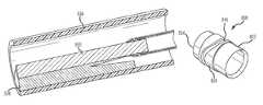
- FIG. 2is an elevation view of an embodiment of a surgical device
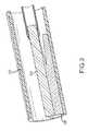
- FIG. 2Ais an elevation view of an alternative embodiment of a surgical device
- FIG. 3is a cross-sectional view of a cutting sheath assembly within a blood vessel with an extendable and rotatable blade for removing a lead according to an embodiment of the disclosure
- FIG. 4Ais an end view of the distal portion of the cutting sheath assembly according to an embodiment of the disclosure.
- FIG. 4Bis a cross-sectional view of the distal portion of the cutting sheath assembly according to an embodiment of the disclosure, wherein an inner member is in a retracted position within the cutting sheath assembly;
- FIG. 4Cis a cross-sectional view of the distal portion of the cutting sheath assembly according to an embodiment of the disclosure, wherein an inner member is in an extended position within the cutting sheath assembly;
- FIG. 5Ais a cross-sectional view of the distal portion of the cutting sheath assembly according to an embodiment of the disclosure, wherein an inner sheath is in a retracted position;
- FIG. 5Bis cross-sectional view of the distal portion of the cutting sheath assembly according to an alternate embodiment of the disclosure, wherein an inner sheath is in an extended position;
- FIG. 6Ais perspective view of an outer band member according to an embodiment of the disclosure.
- FIG. 6Bis an end view of the outer band member illustrated in FIG. 6A ;
- FIG. 6Cis cross-sectional view of the outer band member illustrated in FIG. 6A taken along line 6 C- 6 C of FIG. 6B ;
- FIG. 7Ais perspective view of an inner band member according to an embodiment of the disclosure.
- FIG. 7Bis side view of the inner band member illustrated in FIG. 7A ;
- FIG. 7Cis end view of the inner band member illustrated in FIG. 7A ;
- FIG. 7Dis cross-sectional view of the inner band member illustrated in FIG. 7A taken along line 7 D- 7 D in FIG. 7C ;
- FIG. 8Ais perspective view of an inner band member according to an embodiment of the disclosure.
- FIG. 8Bis side view of the inner band member illustrated in FIG. 8A ;
- FIG. 8Cis end view of the inner band member illustrated in FIG. 8A ;
- FIG. 8Dis cross-sectional view of the inner band member illustrated in FIG. 8A taken along line 8 D- 8 D in FIG. 8C ;
- FIG. 9Ais perspective view of an inner band member according to an embodiment of the disclosure.
- FIG. 9Bis side view of the inner band member illustrated in FIG. 9A ;
- FIG. 9Cis end view of the inner band member illustrated in FIG. 9A ;
- FIG. 9Dis cross-sectional view of the inner band member illustrated in FIG. 9A taken along line 9 D- 9 D in FIG. 9C ;
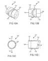
- FIG. 10Ais perspective view of an inner band member according to an embodiment of the disclosure.
- FIG. 10Bis side view of the inner band member illustrated in FIG. 10A ;
- FIG. 10Cis end view of the inner band member illustrated in FIG. 10A ;
- FIG. 10Dis cross-sectional view of the inner band member illustrated in FIG. 10A taken along line 10 D- 10 D in FIG. 10C ;
- FIG. 11Ais perspective view of an inner band member according to an embodiment of the disclosure.
- FIG. 11Bis side view of the inner band member illustrated in FIG. 11A ;
- FIG. 11Cis end view of the inner band member illustrated in FIG. 11A ;
- FIG. 11Dis cross-sectional view of the inner band member illustrated in FIG. 11A taken along line 11 D- 11 D in FIG. 11C ;
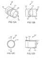
- FIG. 12Ais perspective view of an inner band member according to an embodiment of the disclosure.
- FIG. 12Bis side view of the inner band member illustrated in FIG. 12A ;
- FIG. 12Cis end view of the inner band member illustrated in FIG. 12A ;
- FIG. 12Dis cross-sectional view of the inner band member illustrated in FIG. 12A taken along line 12 D- 12 D in FIG. 12C ;
- FIG. 13Ais perspective view of an inner band member according to an embodiment of the disclosure.
- FIG. 13Bis side view of the inner band member illustrated in FIG. 13A ;
- FIG. 13Cis end view of the inner band member illustrated in FIG. 13A ;
- FIG. 13Dis cross-sectional view of the inner band member illustrated in FIG. 13A taken along line 13 D- 13 D in FIG. 13C ;
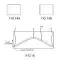
- FIG. 14Ais a side view of the outer member with the inner member of FIGS. 7A-7D positioned in a retracted position within the outer sheath;
- FIG. 14Bis a side view of the outer member with the inner member of FIGS. 7A-7D positioned in an extended position within the outer sheath;
- FIG. 15is an illustration of the geometry of the cam slot of the inner member illustrated in FIGS. 7A-7D portrayed on a single plane;
- FIG. 16Ais a side view of the outer member with the inner member of FIGS. 8A-8D positioned in a retracted position within the outer sheath;
- FIG. 16Bis a side view of the outer member with the inner member of FIGS. 8A-8D positioned in a partially extended position within the outer sheath;
- FIG. 16Cis a side view of the outer member with the inner sheath of FIGS. 8A-8D positioned in a fully extended position within the outer member;
- FIG. 17is an illustration of the geometry of the cam slot of the inner member illustrated in FIGS. 8A-8D portrayed on a single plane;
- FIG. 18is a perspective view of an inner member having a cam slot with an extended stow region
- FIG. 19Ais a side view of the outer member with the inner member of FIG. 18 positioned in a retracted position within the outer sheath;
- FIG. 19Bis a side view of the outer member with the inner member of FIG. 18 positioned in a partially extended position within the outer sheath;
- FIG. 19Cis a side view of the outer member with the inner member of FIG. 18 positioned in a fully extended position within the outer sheath;
- FIG. 20is an illustration of the geometry of the cam slot of the inner member illustrated in FIG. 18 portrayed on a single plane;
- FIG. 21is a perspective view of an inner member having a duplex cam slot
- FIG. 22Ais a side view of the outer member with the inner member of FIG. 21 positioned in a retracted position within the outer sheath;
- FIG. 22Bis a side view of the outer member with the inner member of FIG. 21 positioned in a partially extended position within the outer sheath.
- FIG. 22Cis a side view of the outer member with the inner member of FIG. 21 positioned in a fully extended position within the outer sheath;
- FIG. 23is an illustration of the geometry of the cam slot of the inner member illustrated in FIG. 21 portrayed on a single plane;
- FIG. 24is a perspective view of an embodiment of a handle portion, including an indicator, of the surgical device
- FIG. 25is a perspective view of an alternate embodiment of a handle portion, including an alternate indicator, of the surgical device
- FIG. 26is a side view of an alternate embodiment of a handle portion, including an alternate indicator, of the surgical device;
- FIG. 27is a perspective view of an alternate embodiment of a handle portion, including an alternate indicator, of the surgical device
- FIG. 28is a cross-sectional view of the distal portion of the cutting sheath assembly according to an alternate embodiment of the disclosure, wherein a cutting blade in a refracted position;
- FIG. 29Ais perspective view of a distal tip of the outer sheath according to an embodiment of the disclosure.
- FIG. 29Bis side view of the distal tip illustrated in FIG. 29A ;
- FIG. 29Cis proximal end view of the distal tip illustrated in FIG. 29A ;
- FIG. 29Dis distal end view of the distal tip illustrated in FIG. 29A ;
- FIG. 30Ais perspective view of a distal tip of the outer sheath according to an embodiment of the disclosure.
- FIG. 30Bis side view of the distal tip illustrated in FIG. 30A ;
- FIG. 30Cis proximal end view of the distal tip illustrated in FIG. 30A ;
- FIG. 30Dis distal end view of the distal tip illustrated in FIG. 30A ;
- FIG. 31Ais perspective view of a distal tip of the outer sheath according to an embodiment of the disclosure.
- FIG. 31Bis side view of the distal tip illustrated in FIG. 31A ;
- FIG. 31Cis proximal end view of the distal tip illustrated in FIG. 31A ;
- FIG. 31Dis distal end view of the distal tip illustrated in FIG. 31A ;
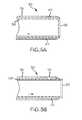
- FIG. 32Ais a perspective view of an inner member in a retracted position within a distal tip of an outer according to an embodiment of the disclosure.
- FIG. 32Bis a perspective view of the inner member of FIG. 32A in an extended or partially extended position with respect to the distal tip.
- Embodiments according to this disclosureprovide a surgical device that includes a sheath, which can be deployed safely within a vascular system of a patient and separate implanted objects, such as leads, from a patient's vasculature system.
- FIG. 1depicts a surgical device 108 having a sheath 112 inserted within an exemplary patient 104 .
- the sheath 112surrounds an implanted lead (not shown) running along the left innominate vein past the SVC and connected into, or about, the right ventricle of the heart.
- the user of the surgical devicemay actuate the handle, thereby extending a cutting blade (not shown) beyond the distal end of the sheath 112 to cut the tissue surrounding the lead within the patient's SVC.
- the cutting bladereturns within the sheath 112 , thereby allowing the clinician to force and advance the distal portion of the sheath against additional uncut tissue.
- the clinicianrepeats the actuation step, thereby causing the cutting blade to re-appear and extend beyond the distal end of the sheath 112 to cut the adjacent tissue.
- the proximal portion of the implanted lead and/or surrounding tissueenters into a hollow passageway within the sheath 112 . This process is again repeated until the implanted lead and/or surrounding tissue is completely or substantially separated from the tissue attached to the SVC. At that time, the implanted lead may safely be removed from the patient's SVC.
- the surgical device 200includes a handle 204 and an outer sheath 208 .
- the surgical devicealso includes an inner sheath (not shown) located within the outer sheath 208 . It may be preferable for the outer sheath 208 to remain stationary while the inner sheath is capable of moving (e.g., rotating and extending) with respect to the outer sheath 208 .
- the inner sheath and outer sheath 208can both be flexible, rigid or a combination thereof.
- the handle 204includes a trigger 212 which pivots about a pin (not shown) that attaches the trigger 212 to the handle 204 .
- Attached to the portion of the trigger 212 within the handle 204is a first gear (not shown).
- second gear and a third gearboth of which are not shown).
- the first gearmeshes with the second gear, which in turn meshes with the third gear.
- the third gearhas an opening through its center, wherein the opening is sized and configured to allow the inner sheath to be inserted and affixed thereto.
- a useri.e., clinician
- actuates the handle 204it pivots about the pin, thereby causing the handle 204 and first gear to move in a counter clockwise direction.
- the first gearengages the second gear and causes the second gear to rotate.
- the second gearengages the third gear initiating it and the inner sheath to rotate about the sheath's longitudinal axis A-A.
- the handlemay also include a spring (not shown) that is attached to the gears, sheath and/or some other member therein such that, upon the clinician's release of the handle, the spring facilitates rotation of the inner sheath in a direction opposite to that in which it rotated upon actuation of the handle 204 . It may be preferable for the inner sheath to rotate in a clockwise direction about its longitudinal axis from the perspective of the proximal end of the surgical device 200 . If so, the spring will facilitate the inner sheath rotation in a counter-clockwise direction upon the clinician's release of the trigger 212 .
- the trigger 212 and gearsare one example of an actuation means for causing the inner sheath to rotate about its longitudinal axis.
- a variety of different triggers and gearingmay cooperate to rotate the inner sheath.
- the trigger 212 depicted in FIG. 1includes two openings 216 , 220 .
- a triggermay have less than or more than two openings.
- a triggermay also be comprised of a straight or non-linear member without any openings.
- a triggermay be in the shape of a button capable of being depressed. As long as the trigger, either alone or in conjunction with the handle, is ergonomically correct and comfortable for the clinician, the trigger may have a variety of sizes and shapes.
- the actuation means discussed aboveincludes three gears. A lower or higher number of gears, however, may be used in lieu of three gears. Many different types of gears are available. Non-limiting examples of gears include, but are not limited to, spur gears, helical gears, double helical gears, bevel gears, spiral bevel gears, hypoid gears, crown gears, worm gears, non-circular gears, rack and pinion gears, epicyclic gears, sun and planet gears, harmonic drive gears, cage gears, and magnetic gears. Any one and/or combination of these types or other types of gears could be used.
- the trigger 212 and gear(s) configuration discussed aboveis an example of a mechanical actuation means to rotate the inner sheath.
- the actuation meansmay comprise electromechanical components.
- the actuation meansmay comprise an electric motor (not shown) having a driven shaft that is directly or indirectly coupled to the inner sheath.
- the motor's shaftmay be indirectly coupled to the inner sheath by one or more gears discussed hereinbefore.
- the motormay be controlled by a switch, thereby causing the inner sheath to rotate in a clockwise and/or a counterclockwise direction upon actuating a switch that may also act as the trigger.
- the electric motormay be either a direct current (DC) motor or an alternating current (AC) motor.
- the motormay be powered by a DC source, such as a battery, or an AC source, such as a conventional power cord.
- a DC sourcesuch as a battery
- AC sourcesuch as a conventional power cord
- an exemplary surgical device 200 ′comprising an outer sheath having a rigid outer portion 222 and a flexible outer portion 224 is depicted.
- Both the rigid outer portion 222 and a flexible outer portion 224are constructed of materials suitable for insertion into the human body.
- the rigid outer portion 222may be constructed of stainless steel
- the flexible outer portion 224may be constructed of a flexible polymer such as polytetrafluoroethylene or thermoplastic elastomers.
- the rigid outer portion 222 and flexible outer portion 224form a unitary outer sheath.
- the rigid outer portion 222has a proximal end 236 and a distal end 238 .
- the flexible outer portion 224has a proximal end 228 and a distal end 232 .
- the distal end 238 of the rigid outer portion 222is connected to the proximal end 228 of the flexible outer portion 224 , thereby forming a unitary outer sheath.
- the mechanism(s) to connect the distal end 238 of the rigid outer portion 222 and the proximal end 228 of the flexible outer portion 224are not described herein and are conventional, and need not be further explained or illustrated to enable one skilled in the art to utilize the mechanism for the purposes described.
- the configuration and/or shape of the proximal end 228may be such that it may interlock with the distal end 238 for example via a barbed joint.
- the interlock mechanism described hereinmay be preferred, it is not intended to represent the only way that such a connection can be accomplished. All such techniques within the knowledge of one skilled in the art are considered within the scope of this disclosure.
- the inner sheathis generally flexible in order to accept, accommodate and navigate the patient's vasculature system.
- the inner sheathmay also have a high degree of stiffness in order to receive the torque transferred from the actuation means and transfer sufficient torque to the cutting blades discussed in more detail below.
- the inner sheathmay be formed of a polymer extrusion, braided reinforced polymer extrusion, coils, bi-coils, tri-coils, laser cut metal tubing and any combination of the above.
- the inner sheathmay be a unitary structure comprised of multiple portions. If the inner sheath has multiple portions, some of those portions may be rigid.
- some or all of the portions of the inner sheath located within the rigid outer sheath 222may also be rigid. If the inner sheath has multiple portions, those multiple portions may be attached in a manner similar to the manner in which the rigid outer sheath 222 and flexible outer sheath 224 are connected.
- the assembly 400includes a flexible inner sheath 426 located within flexible outer sheath 404 .
- Attached to the distal portion of the flexible outer sheath 404is an outer cam member 408 , which is discussed in more detail below.
- the distal end of the flexible outer sheath 404is generally smooth and evenly rounded at its most distal point, thereby allowing it to act as a dilator when pressed and forced against tissue.
- the distal end of the outer cam member 408is also longitudinally aligned with the distal end of the flexible outer sheath 404 .
- the distal end 430 of the flexible inner sheath 426is connected to the proximal end 418 of inner cam member 412 , which is discussed in more detail below.
- the distal end 422 of inner cam member 412includes a cutting surface capable of cutting tissue.
- the inner sheath 426is coupled to the outer sheath 404 through the inner cam member 412 and the outer cam member 408 via pin 410 .
- One end of the pin 410is fixed within the outer cam member 412
- the other end of the pin 410is located within the cam slot 414 of the inner cam member 412 .
- the inner cam member 412extends distally in the direction of the arrow ( ⁇ ) and rotates according to the profile of the cam slot 414 .
- the outer sheath 404 , outer cam member 408 and pin 412remain stationary.
- the inner cam member 412extends distally (and potentially proximally according to the cam slot profile) and rotates the cutting surface at the distal end 422 of the inner cam member 412 is able to perform a slicing action against the tissue and cut it.
- FIG. 4Bdepicts the inner cam member 412 within a retracted (and un-actuated) position because the inner cam member 412 is in its most proximal position.
- the distal end 422 of the inner cam member 412 of FIG. 4Bis located within the interior of the outer cam member 408 and does not extend beyond the distal end of the outer cam member 408 .
- the inner cam member 412is depicted in an extended (and actuated) position because the inner cam member 412 is in its most distal position extending beyond the distal end of the flexible outer sheath 404 and the outer cam member 408 .
- FIG. 3depicts the distal portion of the flexible outer sheath and flexible inner sheath of FIG. 4C surrounding a lead 530 within a patient's vein 534 with the inner cam member 412 in its extended position.
- the circumferential nature of the cutting blade at the distal end of the inner cam membercauses the surgical device to act as a coring device, thereby cutting tissue 538 either partially (i.e., less than 360 degrees) or completely (i.e., 360 degrees) around the lead or implanted object being extracted.
- the amount of tissue that the blade cutsdepends upon the size, shape and configuration of the lead, as well as the diameter and thickness of the circular cutting blade.
- the bladewill cut and core more tissue in comparison to a cutting blade having a smaller diameter.
- the operatorreleases trigger and the inner cam member (including the blade) returns to its retracted position.
- the distal tip 408 of the cam member 404(and/or outer sheath) safely acts as a dilating device, thereby stretching tissue as the sheaths move over the lead or implanted object to be extracted.
- the sheathsmay be coupled to one another in other ways.
- those of skill in the artwill understand how to make and use the disclosed aspects, embodiments, and/or configurations after understanding the present disclosure to couple the sheaths in a manner to allow a cutting surface to extend and rotate beyond the distal end of the outer sheath. All such configurations within the knowledge of one skilled in the art are considered within the scope of this disclosure. For example, referring to FIGS.
- the assembly 500may include an outer sheath 504 and an inner sheath 526 coupled to one another via pin 510 without the use of an outer cam member or inner member as in FIGS. 4B and 4C .
- the outer sheath 504may have a pin 510 connected to it, and the inner sheath 526 may include cam slot 514 such that as the inner sheath 526 extends upon actuation of the actuation means discussed earlier herein, the inner sheath 526 along with its cutting surface, also rotates according to the cam slot 514 profile. While the inner sheath 526 extends and rotates, the outer sheath 504 and pin 510 remain stationary.
- FIG. 5Adepicts the inner sheath 526 (and cutting surface 522 ) of assembly 500 in an initially retracted and stowed position.
- FIG. 5Bdepicts the inner sheath 526 (and cutting surface 522 ) of assembly 500 ′ in an extended position.
- the actuation meansis actuated and un-actuated, the assembly moves from a refracted position to an extended position and vice versa.
- an exemplary outer cam member 600is depicted.
- the outer cam member 600is a sleeve in the shape of a hollow cylinder. Although the exterior of the outer cam member 600 is uniform, it need not be.
- the interior of the outer cam member 600is not uniform.
- the interior of the outer cam member 600includes an abutment 616 to prevent the inner cam member (not shown) from traveling further from the proximal end 612 to the distal end 608 within the outer cam member 600 .
- the outer cam member 600also includes a hole 604 for receipt and possible attachment of a pin (not shown) which protrudes radially inward. As discussed in more detail below, the pin engages the cam slot of the inner cam member.
- the size, shape and configuration of the outer cam member 600may differ depending upon how it is attached to the flexible outer sheath. As discussed above, the outer sheath may be stationary. If so, the outer cam member 600 and the pin remain stationary as the inner cam member moves relatively thereto.
- the inner cam member 700has a generally hollow cylindrical shape.
- the inner cam member 700comprises a proximal portion 724 , an intermediate portion 728 , and a distal portion 732 .
- the outside diameter of the proximal portion 724is sized to allow the distal end 704 of the inner cam member 700 to be inserted to and engage (or otherwise attached to) the interior diameter of the inner flexible sheath (not shown).
- the distal end 708 of the inner cam member 700comprises a cutting surface 712 having a flat, sharp blade profile.
- the intermediate portion 728comprises a cam slot 716 cut within its exterior surface.
- the outer sheath and pinmay remain stationary. If so, the inner sheath, which is connected to the inner cam member, forces the inner cam member to rotate and move toward the distal end of the outer sheath.
- the cam slot 716engages the pin, and the shape and profile of the cam slot 716 controls the rate and distance with which the inner cam member 700 travels. That is, the configuration of the cam slot controls how the inner cam member travels both laterally and rotationally.
- the cam slot 716 in FIGS. 7A, 7B, 7C and 7Dcan have a linear profile (not shown).
- An alternative example of a two dimensional representation of the profile of the cam slotis depicted in FIG. 15 .
- the inner cam member (and blade)is in the retracted position, as depicted in FIG. 14A .
- the cam slot 1504travels along the pin from position A to position B at a relatively constant rate because the slope of the cam slot between these two points is relatively linear.
- FIG. 15illustrates the cam slot 1504 in an open and continuous configuration.
- the inner cam membercontinues to rotate beyond 360 degrees, the path of inner cam member is repeated and it continues to travel from position A to position B to position A. And due to the substantially linear configuration of the cam slot profile from position A to position B, and vice versa, the inner cam member (and blade) extends and/or rotates at a substantially constant rate between positions.
- the inner cam member 700may also comprise a step up 720 such that the diameter of the intermediate portion 728 is greater than the distal portion 732 .
- the step up 720 of the inner cam member 700contacts the abutment of the outer cam member, thereby limiting the distance that the inner cam member 700 may travel and/or may prevent the inner cam member from exiting or extending beyond the distal tip of the outer sheath (or outer cam member) in the event that the pin is sheared.
- FIGS. 8A, 8B, 8C and 8Dan alternative exemplary inner cam member 800 is depicted.
- the inner cam member 800 depicted in FIGS. 8A-8Dis similar to the inner cam member 700 depicted in FIGS. 7A-7D because the inner cam member 800 has a proximal portion 824 , an intermediate portion 828 , a distal portion 832 and a sharp cutting surface 712 with a flat profile at its distal end 808 .
- the inner cam member 800has a cam slot 816 , which when extended in a two-dimensional plane, has a non-linear profile.
- FIG. 17an illustration of a two-dimensional, non-linear cam slot profile 1700 is depicted in FIG. 17 .
- cam slot 1704there is depicted cam slot 1704 .
- the cooperation between the pin and the cam slotcauses the inner cam member to also rotate and travel toward and beyond the distal end of the outer cam member.
- the rate and distance at which the inner cam member travelsis dependent upon the configuration of the cam slot, particularly the slope of the cam slot. If the profile of the cam slot, such as its slope, is non-linear, then the rate and distance at which the inner cam member travels will vary as the inner cam member rotates and moves over the pin along the cam slot path. For example, when the inner cam member is in its fully retracted position (see FIG.
- the pincontacts the cam slot 1704 at position A identified as a first point marked + within the left hand side of FIG. 17 .
- the pincontacts the cam slot 1704 at a second point marked + and identified as position B within FIG. 17 .
- the pincontacts the cam slot 1704 at another point marked + and identified as position C within FIG. 17 .
- This two-dimensional representation of the cam slot 1704illustrates a non-linear profile of the cam slot because in order for the inner cam member to fully extend, it must travel at more than one rate from position A to position C. That is, the blade rotates at a first predetermined rate from position A to position B (partially extended position), and the blade rotates at a second predetermined rate from position A′ to position C (fully extended position).
- the cutting surfacetravels at a rate according to the profile of the cam slot 1704 from its fully retracted position (see FIG. 16A ) to a position that is slightly beyond the distal end of the outer cam member (see FIG. 16B ) over about 90 degrees of rotation by the inner cam member.
- the profile of the cam slot from position A to position Bis generally linear, thereby causing the inner cam member to travel at a generally constant rate between those two positions.
- the bladeextends a predetermined distance for the about of rotation (90 degrees) from position A to position B.
- the bladeOnce the blade travels to its partially extended position B, the blade continues to rotate and the blade returns to its retracted position A′ over about 90 degrees of rotation by the inner cam member.
- the profile of the cam slot from position B to position A′is generally linear; therefore, the blade extends at a generally constant rate between these two positions.
- the bladeAs the as the inner cam member continues to rotate and the pin contacts the cam slot 1704 beyond position A′ and toward position C over about another 90 degrees of rotation, the blade extends a second predetermined distance. That is, the cutting surface travels beyond its partially extended position and to its fully extended position (see FIG. 16C ).
- the profile of the cam slot from position A′ to position Cis different than the profile of the cam slot from position A to position B.
- the profile of the cam slot from position A to position Bis generally linear, the first predetermined amount of extension (from position A to position B) is less than the second predetermined amount of extension (from position A′ to position C).
- the profile of the cam slot from position A to position Bis such that the blade extends a shorter distance in comparison to extending from position A′ to position C for a predetermined amount of rotation (90 degrees), thereby providing more precise and finer control of the blade as it rotates and extends.
- Moving and extending the inner cam member at a generally constant rate for a short distanceprovides the clinician precise control of the blade as it initially extends beyond the outer sheath.
- the profile of the cam slot from position A′ to position Cis such that the blade extends further and more quickly for a predetermined amount of rotation (90 degrees) after it is initially extended, thereby providing relatively less precision and coarser control of the blade in comparison to extending from position A to position B.
- the inner cam member and bladetravel at a faster rate from position to A′ to position C (and from position C to position A′′) in comparison to traveling from position A to position B.
- the bladetravels at more than one rate—one rate from position A to position B (and from position B to position A′) and another rate from position A′ to position C.
- the overall rate of travelis variable.
- the discussion abovediscusses that the inner cam member travels at certain rates (e.g., constant, variable). However, the rates are also dependent upon the speed at which the inner sheath extends, and in turn, upon the speed of the means for actuating. For example, if the means for actuation includes a handle and one or more gears connecting the handle to the elongated inner sheath, then the rate at which the inner cam member rotates and extends is dependent upon how quickly the clinician operating the surgical device compresses the handle. Accordingly, the discussion and/or comparison of the rates at which the blade extends travels assumes that the means for actuating extends the inner sheath at a relatively constant speed. Regardless of whether this assumption is correct, the greater the amount of blade extension per predetermined amount of rotation, the blade will extend at a greater rate and speed, thereby providing the surgical device with the ability to cut more tissue per rotation.
- ratesare also dependent upon the speed at which the inner sheath extends, and in turn, upon the speed of the means for actuating.
- the cam slot profile of FIG. 15is an open and continuous configuration, thereby allowing the inner cam member to continuously rotate.
- the cam slot profile of FIG. 17is a closed configuration such that when the inner cam member reaches its fully extended position (i.e., position C) or returns to position A′′, the actuation means must be releases or reversed so that the inner cam may return to initial retracted position A.
- FIGS. 9A, 9B, 9C and 9Dan alternative exemplary inner cam member 900 is depicted.
- the inner cam member 900 depicted in FIGS. 9A-9Dis similar to the inner cam member 900 depicted in FIGS. 8A-8D because the inner cam member 900 has a proximal portion 924 , an intermediate portion 928 , a distal portion 932 , and a cam slot 916 that is similar to cam slot 816 .
- inner cam member 900has a serrated cutting surface 912 .
- the cutting surface 912depicts fourteen (14) serrations. However, it may be preferable to have between twelve (12) and sixteen (16) serrations.
- FIGS. 9A-9Dare not intended to represent the only number and type of serrations that may be included in a serrated cutting surface.
- the surgical deviceincluding the sheaths, and cam members, those of skill in the art will understand how to make and use the disclosed aspects, embodiments, and/or configurations after understanding the present disclosure to adjust the number, size and configurations of the serrations. All such configurations within the knowledge of one skilled in the art are considered within the scope of this disclosure. For example, referring to FIGS.
- an alternative exemplary inner cam member 1100is depicted having a cutting surface 1112 comprising multiple serrations in the form of a crown.
- an alternative exemplary inner cam member 1200is depicted having a cutting surface 1212 comprising multiple serrations in the form of a hook crown.
- the cutting surfacealso need not be serrated, but merely include a plurality of notches formed therein.
- a further alternative exemplary inner cam member 1300is depicted having a cutting surface with four notches 1350 included therein.
- the notchesmay comprise a myriad of different shapes and configurations, including but not limited to any variation of a square, rectangle, rhombus, parallelogram, trapezoid, triangle, circle, ellipse, kite, etc.
- the cutting surfaces discussed hereinbefore with respect to FIGS. 7, 8, 9, 11, 12 and 13are substantially parallel to the proximal edge of the inner cam members.
- the plane of the proximal end of the inner cam member and the plane of the distal end (e.g., cutting surface) of the inner cam member in these figuresare substantially parallel.
- the proximal and distal ends of the inner cam memberneed not be parallel or co-planer. Rather, any of the cutting surfaced depicted in FIGS. 7, 8, 9, 11, 12 and 13 may be offset from the plane of the proximal end of the inner cam member.
- FIGS. 10A, 10B, 10C and 10Dan alternative exemplary inner cam member 1000 is depicted.
- the plane of the cutting surface 1008 of the inner cam member 1000is offset from a plane parallel to the plane of the proximal end 1004 of the inner cam member at an angle ⁇ . It may be preferable for angle ⁇ to be at an angle between zero degrees and ninety degrees.
- FIGS. 7-13surround the circumference of the inner cam member one time. It may advantageous, however, for the cam slot to surround the inner cam member's circumference more than once.
- an inner cam member 1800having a cam slot 1816 that travels more than 360 degrees around its circumference.
- the portion 1848 of the cam slot 1816 that is closest to the distal end 1808 of the inner cam member 1800 and that extends beyond the other end of the cam slot 1816is substantially parallel to the planes of the proximal end 1804 and distal end 1808 .
- the profile of cam slot 1816 depicted in one dimensionis illustrated in FIG. 20 as the inner cam member 1800 moves from a retracted position (see FIG. 19A ) to a partially extended position (see FIG. 19B ) and eventually to a fully extended position (see FIG. 19C ).
- portion 1848 of the cam slot 1816prevents the inner cam member 1800 from moving from its refracted position, even if the inner cam member 1800 begins to rotate. That is, the inner cam member 1800 remains stowed in its retracted position as long as the pin engages only portion 1848 of cam slot 1816 , thereby insuring that the blade is completely retracted as the clinician maneuvers the surgical device within the patient's vascular system.
- FIG. 20there is depicted a two-dimensional cam slot profile of the configuration of the cam slot 1816 of FIG. 18 .
- the cam slot profile depicted in FIG. 20is similar to the configuration of the cam slot profile depicted in FIG. 17 , with the exception that the cam slot profile depicted in FIG.
- FIG. 20further includes a portion that surrounds the circumference of the inner cam member more than once. That is, the cam slot is included in about another 90 degrees of travel around the circumference of the inner cam member over and above the 360 degrees of travel.
- This additional portionis depicted as the substantially flat profile portion to the bottom right hand side of FIG. 20 that begins with a point marked + and identified as position A.
- This substantially flat profile portioninsures that the blade remains stowed within the outer cam member as the inner cam member begins to rotate, thereby increasing the safety of the device and minimizing the likelihood of the blade being exposed beyond the distal end of the outer cam prior to actuation.
- the flat portion of the cam slotas an extended in an embodiment with a cam slot greater than 360 degrees around the circumference of the inner cam member
- the flat portionwhich creates the stowed position, can be included within a cam slot that is equal to or less than 360 degrees around the circumference of the inner cam member.
- FIG. 21there is depicted an inner cam member 2100 having a cam slot 2116 that travels about 720 degrees around its circumference.
- the profile of cam slot 2116 depicted in two dimensionsis illustrated in FIG. 23 as the inner cam member 2100 moves from a retracted position (see FIG. 22A ) to a partially extended position (see FIG. 22B ) and eventually to a fully extended position (see FIG. 22C ).
- the bladeextends from position A, which corresponds to the retracted position of FIG. 22A , to position B, which corresponds to the partially extended position of FIG. 22B over about 180 degrees of rotation by the inner cam member 2100 .
- the bladethen retracts from position B to position A′ over about 180 degrees of rotation by the inner cam member 2100 .
- the bladecan then extends from position A′, which corresponds to the retracted position of FIG. 22A , to position C, which corresponds to the fully extended position of FIG. 22C over about 180 degrees of rotation by the inner cam member 2100 .
- the bladeretracts from position C to position A′′ over about 180 degrees of rotation by the inner cam member 2100 .
- the blade and inner cam membercan rotate about twice as much for the same amount of extension. Accordingly, the blade has the ability to rotate and potentially create a greater amount of cutting action against the tissue for a predetermined amount of extension.
- the discussion above with respect to FIG. 23explains how the blade travels according to the cam slot profile for a full 720 degrees of rotation because the inner cam member includes a double lobe cam profile.
- the inner cam memberdoes not need to travel the entire 720 degrees of rotation.
- the clinician operating the surgical devicecan actuate the means for actuation such that the inner cam member repeats the travel from position A to position B rather than continuing onward to position C. Allowing the clinician to repeat the inner cam member's path of travel from position A to position B allows the clinician to operate the surgical device in a precision cutting mode for a longer period of time.
- the clinician operating the surgical devicecan actuate the means for actuation such that the inner cam member repeats the travel from position A′ to position C rather than restarting from position A and moving to position C. Allowing the clinician to repeat the inner cam member's path of travel from position A′ to position C allows the clinician to operate the surgical device in a coarser cutting mode for a longer period of time. This allows the clinician to alternate the use of the surgical device (1) in either a precision cutting mode or a coarse cutting mode, (2) by alternating between the precision cutting mode and the coarse cutting mode, and/or (3) using a variable mode, which includes the combination of both the precision cutting mode and coarse cutting mode.
- the distal end of the flexible outer sheath 404may be smooth and evenly rounded at its most distal point.
- the distal end of the outer sheathmay not be smooth. Rather, the distal end of the outer sheath may be uneven in order to increase the outer sheath's ability to engage tissue.
- the outer sheathmay increase its ability to remain stationary within the subject's vascular system as the inner cam member and blade rotate and extend into such tissue, thereby potentially minimizing undesirable rotation and/or movement of the outer sheath or surgical device.
- FIGS. 29A, 29B, 29C and 29Ddepict a distal tip 2900 of the outer sheath according to an embodiment of the disclosure.
- the distal tip 2900 illustrated in these figuresis depicted as a separate component.
- Those of skill in the artwill understand how to make and use the disclosed aspects, embodiments, and/or configurations of the distal tip after understanding the present disclosure to adjust the location, size, configuration and/or type of indicator.
- the distal tipparticularly its uneven configuration, may be created in the distal portion of the outer sheath, the outer cam member and/or a combination of the outer sheath and outer cam member. All such configurations within the knowledge of one skilled in the art are considered within the scope of this disclosure.
- distal tipparticularly the distal tip of the outer sheath, shall mean and include a separate component attached to the outer sheath, the distal portion of the outer sheath, the outer cam member located at the distal end of the sheath, a combination of any of the preceding, and/or any other distal portion or component of the surgical device intended to contact tissue.
- distal tip 2900has a proximal end 2908 and a distal end 2912 .
- the proximal end 2908 of the distal tip 2900extends from or is attached to the outer sheath, the outer cam member, etc., and/or a combination thereof.
- the distal tip 2900also includes a plurality of notches 2904 extending proximally from its distal end 2912 .
- the notches 2904create an uneven profile at the distal end 2912 of the distal tip, and this uneven profile facilitates the distal tip's engagement with the tissue or other material within the subject's vasculature, thereby holding the outer sheath stationary while the blade rotates and extends into the tissue.
- FIGS. 29A-29Ddepicts six notches 2904 that have a generally rectangular shape that taper upwardly from the distal end 2904 toward the proximal end 2908 until the notches intersect and become flush with the exterior surface of the distal tip 2900 .
- the notches 2904are formed by removing material from the distal end 2904 of the distal tip. Notches may also be formed by adding material at predetermined intervals along the perimeter of the distal tip, such that the notches are created and located between the additional materials.
- those of skill in the artwill understand how to make and use the disclosed aspects, embodiments, and/or configurations after understanding the present disclosure to adjust the number, location, size, configuration and/or type of notches. All such notch configurations within the knowledge of one skilled in the art are considered within the scope of this disclosure.
- an alternative exemplary distal tip 3000has a proximal end 3008 and a distal end 3012 .
- the notches 3104 included within this distal tip 3000have a generally narrower rectangular shape in comparison to the notches 2904 of distal tip 2900 depicted in FIGS. 29A-29D . Due to the narrower configuration of the notches 3014 illustrated in FIGS. 30A-30D , the distal tip 3000 includes three times as many notches, for a total of eighteen, in comparison to the number of notches 2904 in distal tip 2900 .
- FIGS. 31A-31Ddepict a further alternative exemplary distal tip 3100 having V-shaped notches 3104 extending from distal end 3112 toward proximal end 3108 .
- the notches 2904 , 3004 , and 3104 included in distal tips 2900 , 3000 , and 3100 , respectively,are configured to engage tissue and to prevent the outer sheath from rotating as the blade rotates and extends into such tissue. Inclusion of the notches in the outer sheath may also enhance the surgical devices ability to cut tissue because the combination of notches within the distal tip and notches within the cutting surface of the inner cam member may create a shearing force, thereby increasing the overall amount of cutting force applied to the tissue. Accordingly, the notches of the distal tip may also be configured to include a sharp blade profile, such as the serrated and notched blades depicted in FIGS. 9, 11, 12 and 13 and any equivalents thereof.
- FIGS. 32A and 32Bthere is depicted a distal tip 3202 and an inner cam member 3208 .
- the inner cam member 3208has a plurality of notches 3212 creating a serrated-type blade
- distal tip 3202has a plurality of notches 3204 that have a substantially similar size and shape as the notches 3212 within the inner cam member 3208 .
- FIG. 32Adepicts the inner cam member 3208 in a retracted position because the cutting surface does not extend beyond the distal end of the distal tip.
- the notches 3204 , 3212 of the inner cam member 3208 and the distal tip 3202substantially align in order to improve the surgical device's ability, particularly the distal tip's ability, to engage tissue.
- the serrations 3216begin to pass over the notches 3204 in the distal tip 3202 , thereby creating a shearing force against the tissue and potentially increasing the device's cutting ability.
- FIG. 24there is a depicted an alternative embodiment of surgical device 2400 that comprises an indicator 2440 indicative of how far the blade of the inner cam member has traveled and/or has traveled beyond the distal end of the outer sheath.
- the indicator 2440 in FIG. 24is located on the top of the distal portion of the handle 2404 .
- the indicator 2440is located between the distal end of the handle 2404 and a vertically extending portion 2438 of the handle that encases components, such as gears, within the handle 2404 .
- Indicator 2440may include indicia, such as numbers or dimensions indicative of the length that the blade has traveled and/or has traveled beyond the distal end of the outer sheath.
- the indicator 2440may include color coded regions (e.g., green, yellow, orange, red, etc.), such that differently colored regions convey to the clinician whether it is more or less safe to move the entire surgical device, including the sheaths, within the patient's vasculature depending upon whether the cutting blade is exposed and/or how much of it is exposed.
- the indicator 2440may also be directly and/or indirectly connected to the actuating means of the surgical device.
- FIG. 24is not intended to represent the only location and type of indicator that may be included in a serrated cutting surface.
- FIG. 25an alternative exemplary surgical device 2500 comprising an indicator 2540 depicted on the proximal, top portion of handle 2504 .
- an alternative exemplary surgical device 2600comprising an indicator 2640 depicted on the side of the handle 2640 , particularly, the indicator 2640 is located on a vertically extending portion 2638 of the handle 2604 that encases components, such as gears.
- the indicatoralso does not need to be a mechanically actuated indicator.
- the indicatorcan be a color-coded light, or other type of electrically based indicators, located on the top of the handle as depicted with reference to FIG. 27 .
- the color (e.g., green, yellow, orange, red, etc.) of the light, the brightness of the light and/or whether light remains constant or blinks (including the frequency of blinking)may change as the blade travels from its retracted position to its extended position.
- the indicatorneed not be located on the surgical device or any portion thereof, such as the handle. Rather, the indicator can be located external to the surgical device. That is, the surgical device may include a communication port that transmits the indictor signal(s) to a remote display and/or a remote device.
- the surgical devicemay be connected to a remote fluoroscopy monitor, either via a cable or wirelessly, thereby allowing the monitor to display the position of the cutting surface (i.e., blade), inner cam, inner sheath and/or any other component of the surgical device. Transmitting the device's positional information to the monitor potentially allows the clinician to view the position of the blade on the same monitor that the clinician is using to perform the surgical procedure while navigating the patient's vasculature.
- the device(s)may be electrical, mechanical, electro-mechanical, and/or combinations thereof.
- the systems and methods of this disclosuremay be implemented in conjunction with a special purpose computer, a programmed microprocessor or microcontroller and peripheral integrated circuit element(s), an ASIC or other integrated circuit, a digital signal processor, a hard-wired electronic or logic circuit such as discrete element circuit, a programmable logic device or gate array such as PLD, PLA, FPGA, PAL, special purpose computer, any comparable means, or the like.
- a special purpose computera programmed microprocessor or microcontroller and peripheral integrated circuit element(s), an ASIC or other integrated circuit, a digital signal processor, a hard-wired electronic or logic circuit such as discrete element circuit, a programmable logic device or gate array such as PLD, PLA, FPGA, PAL, special purpose computer, any comparable means, or the like.
- any device(s) or means capable of implementing the methodology illustrated hereinmay be used to implement the various aspects of this disclosure.
- Exemplary hardwarethat may be used for the disclosed embodiments, configurations and aspects includes computers, handheld devices, telephones (e.g., cellular, Internet enabled, digital, analog, hybrids, and others), and other hardware known in the art. Some of these devices include processors (e.g., a single or multiple microprocessors), memory, nonvolatile storage, input devices, and output devices.
- processorse.g., a single or multiple microprocessors
- memorye.g., a single or multiple microprocessors
- nonvolatile storagee.g., a single or multiple microprocessors
- input devicese.g., input devices
- output devicese.g., input devices, and output devices.
- alternative software implementationsincluding, but not limited to, distributed processing or component/object distributed processing, parallel processing, or virtual machine processing may also be constructed to implement the methods described herein.
- the present disclosurein various aspects, embodiments, and/or configurations, includes components, methods, processes, systems and/or apparatus substantially as depicted and described herein, including various aspects, embodiments, configurations embodiments, sub combinations, and/or subsets thereof.
- the present disclosurein various aspects, embodiments, and/or configurations, includes providing devices and processes in the absence of items not depicted and/or described herein or in various aspects, embodiments, and/or configurations hereof, including in the absence of such items as may have been used in previous devices or processes, e.g., for improving performance, achieving ease and/or reducing cost of implementation.
- FIG. 28depicts an alternate exemplary embodiment of the distal portion of the sheaths. This figure illustrates a flexible stationary outer sheath 2816 , a flexible extendable intermediate sheath 2804 , and a flexible extendable inner sheath 2826 . Coupled to the outer sheath 2816 is a rotatable outer cam member 2826 .
- Coupled to the intermediate sheath 2804is a rotatable intermediate cam member 2808 .
- Coupled to the inner sheath 2826is a rotatable inner cam member 2812 .
- the inner cam member 2812is connected to the intermediate cam member 2808 by pin 2810 .
- the intermediate cam member 2808is connected to the outer cam member by pin 2824 .
- the inner cam memberrotates and travels according to the profile of cam slot 2830 in which the pin 2810 sits.
- the intermediate sheath 2804extends distally, the intermediate cam member rotates and travels according to the profile of cam slot 2834 in which the pin 2824 sits.
- Utilizing multiple rotatable and extendable sheaths, as well as rotatable cam members,allows the device to increase the extension and rotation of the cutting surface.
- camssuch as single lobe cams and double lobe cams are discussed within this disclosure.
- Other lobe cam configurationssuch as triple lob cams, may be used.
- the increment of the additional length of cam slotneed not be 90 degrees beyond 360 degrees.
- the additional length of cam slotcan be in increments of 5, 10, 15, 30, 45, 60 degrees, etc.
- the slope of the cam slot between two positions and/or pointshas been described as generally linear, the slope between two points need not be linear. Rather, the cam slot and/or slope of the cam slot can be non-linear, such as a sinusoidal shape, which may or may not have a generally linear portion.
- the sinusoidal shapeparticularly at the transition points allows for a smooth transition of the inner cam member, inner sheath, and/or cutting surface from an extended direction to retracted direction through such positions while maintaining a relatively constant rate of rotation, thereby allowing the cutting surface to continue to rotate and cut the tissue through such transition.
- a captured ring cam configurationmay include a ring that is attached to one of the inner sheath (or inner member attached to the inner sheath) or the outer sheath (or outer member attached to the outer sheath) that is captured by two angled lobes on the other sheath (or member).
- the ringmay be captured by one lobe, it may be preferred for the ring to be captured by two lobes—one on each side of the ring—such that cutting surface may be forced in both a proximal direction (toward a refraction position) and distal direction (toward an extended direction).
Landscapes
- Health & Medical Sciences (AREA)
- Life Sciences & Earth Sciences (AREA)
- Surgery (AREA)
- Heart & Thoracic Surgery (AREA)
- Veterinary Medicine (AREA)
- Public Health (AREA)
- Engineering & Computer Science (AREA)
- Nuclear Medicine, Radiotherapy & Molecular Imaging (AREA)
- Biomedical Technology (AREA)
- Animal Behavior & Ethology (AREA)
- General Health & Medical Sciences (AREA)
- Molecular Biology (AREA)
- Medical Informatics (AREA)
- Cardiology (AREA)
- Orthopedic Medicine & Surgery (AREA)
- Radiology & Medical Imaging (AREA)
- Vascular Medicine (AREA)
- Surgical Instruments (AREA)
Abstract
Description
Claims (26)
Priority Applications (4)
| Application Number | Priority Date | Filing Date | Title |
|---|---|---|---|
| US13/834,405US9668765B2 (en) | 2013-03-15 | 2013-03-15 | Retractable blade for lead removal device |
| EP14770355.7AEP2967520B1 (en) | 2013-03-15 | 2014-03-06 | Retractable blade for lead removal device |
| PCT/US2014/021167WO2014149843A1 (en) | 2013-03-15 | 2014-03-06 | Retractable blade for lead removal device |
| US15/498,165US10219819B2 (en) | 2013-03-15 | 2017-04-26 | Retractable blade for lead removal device |
Applications Claiming Priority (1)
| Application Number | Priority Date | Filing Date | Title |
|---|---|---|---|
| US13/834,405US9668765B2 (en) | 2013-03-15 | 2013-03-15 | Retractable blade for lead removal device |
Related Child Applications (1)
| Application Number | Title | Priority Date | Filing Date |
|---|---|---|---|
| US15/498,165ContinuationUS10219819B2 (en) | 2013-03-15 | 2017-04-26 | Retractable blade for lead removal device |
Publications (2)
| Publication Number | Publication Date |
|---|---|
| US20140277037A1 US20140277037A1 (en) | 2014-09-18 |
| US9668765B2true US9668765B2 (en) | 2017-06-06 |
Family
ID=51531062
Family Applications (2)
| Application Number | Title | Priority Date | Filing Date |
|---|---|---|---|
| US13/834,405Active2033-08-18US9668765B2 (en) | 2013-03-15 | 2013-03-15 | Retractable blade for lead removal device |
| US15/498,165Active2033-07-06US10219819B2 (en) | 2013-03-15 | 2017-04-26 | Retractable blade for lead removal device |
Family Applications After (1)
| Application Number | Title | Priority Date | Filing Date |
|---|---|---|---|
| US15/498,165Active2033-07-06US10219819B2 (en) | 2013-03-15 | 2017-04-26 | Retractable blade for lead removal device |
Country Status (3)
| Country | Link |
|---|---|
| US (2) | US9668765B2 (en) |
| EP (1) | EP2967520B1 (en) |
| WO (1) | WO2014149843A1 (en) |
Cited By (139)
| Publication number | Priority date | Publication date | Assignee | Title |
|---|---|---|---|---|
| US20150105796A1 (en)* | 2013-03-15 | 2015-04-16 | The Spectranetics Corporation | Surgical instrument including an inwardly deflecting cutting tip for removing an implanted object |
| US10219819B2 (en) | 2013-03-15 | 2019-03-05 | The Spectranetics Corporation | Retractable blade for lead removal device |
| US10695081B2 (en) | 2017-12-28 | 2020-06-30 | Ethicon Llc | Controlling a surgical instrument according to sensed closure parameters |
| US10755813B2 (en) | 2017-12-28 | 2020-08-25 | Ethicon Llc | Communication of smoke evacuation system parameters to hub or cloud in smoke evacuation module for interactive surgical platform |
| US10758310B2 (en) | 2017-12-28 | 2020-09-01 | Ethicon Llc | Wireless pairing of a surgical device with another device within a sterile surgical field based on the usage and situational awareness of devices |
| US10772683B2 (en) | 2014-05-18 | 2020-09-15 | Eximo Medical Ltd. | System for tissue ablation using pulsed laser |
| US10842532B2 (en) | 2013-03-15 | 2020-11-24 | Spectranetics Llc | Medical device for removing an implanted object |
| US10849697B2 (en) | 2017-12-28 | 2020-12-01 | Ethicon Llc | Cloud interface for coupled surgical devices |
| US10892995B2 (en) | 2017-12-28 | 2021-01-12 | Ethicon Llc | Surgical network determination of prioritization of communication, interaction, or processing based on system or device needs |
| US10892899B2 (en) | 2017-12-28 | 2021-01-12 | Ethicon Llc | Self describing data packets generated at an issuing instrument |
| US10898622B2 (en) | 2017-12-28 | 2021-01-26 | Ethicon Llc | Surgical evacuation system with a communication circuit for communication between a filter and a smoke evacuation device |
| US10932806B2 (en) | 2017-10-30 | 2021-03-02 | Ethicon Llc | Reactive algorithm for surgical system |
| US10932812B2 (en) | 2018-03-30 | 2021-03-02 | Spectranetics Llc | Calibrated power-driven surgical cutting device |
| US10932872B2 (en) | 2017-12-28 | 2021-03-02 | Ethicon Llc | Cloud-based medical analytics for linking of local usage trends with the resource acquisition behaviors of larger data set |
| US10944728B2 (en) | 2017-12-28 | 2021-03-09 | Ethicon Llc | Interactive surgical systems with encrypted communication capabilities |
| US10966791B2 (en) | 2017-12-28 | 2021-04-06 | Ethicon Llc | Cloud-based medical analytics for medical facility segmented individualization of instrument function |
| US10973520B2 (en) | 2018-03-28 | 2021-04-13 | Ethicon Llc | Surgical staple cartridge with firing member driven camming assembly that has an onboard tissue cutting feature |
| US10987178B2 (en) | 2017-12-28 | 2021-04-27 | Ethicon Llc | Surgical hub control arrangements |
| US11013563B2 (en) | 2017-12-28 | 2021-05-25 | Ethicon Llc | Drive arrangements for robot-assisted surgical platforms |
| US11026751B2 (en) | 2017-12-28 | 2021-06-08 | Cilag Gmbh International | Display of alignment of staple cartridge to prior linear staple line |
| US11026687B2 (en) | 2017-10-30 | 2021-06-08 | Cilag Gmbh International | Clip applier comprising clip advancing systems |
| US11051876B2 (en) | 2017-12-28 | 2021-07-06 | Cilag Gmbh International | Surgical evacuation flow paths |
| US11056244B2 (en) | 2017-12-28 | 2021-07-06 | Cilag Gmbh International | Automated data scaling, alignment, and organizing based on predefined parameters within surgical networks |
| US11058498B2 (en) | 2017-12-28 | 2021-07-13 | Cilag Gmbh International | Cooperative surgical actions for robot-assisted surgical platforms |
| US11069012B2 (en) | 2017-12-28 | 2021-07-20 | Cilag Gmbh International | Interactive surgical systems with condition handling of devices and data capabilities |
| US11076921B2 (en) | 2017-12-28 | 2021-08-03 | Cilag Gmbh International | Adaptive control program updates for surgical hubs |
| US11090047B2 (en) | 2018-03-28 | 2021-08-17 | Cilag Gmbh International | Surgical instrument comprising an adaptive control system |
| US11096693B2 (en) | 2017-12-28 | 2021-08-24 | Cilag Gmbh International | Adjustment of staple height of at least one row of staples based on the sensed tissue thickness or force in closing |
| US11100631B2 (en) | 2017-12-28 | 2021-08-24 | Cilag Gmbh International | Use of laser light and red-green-blue coloration to determine properties of back scattered light |
| US11096688B2 (en) | 2018-03-28 | 2021-08-24 | Cilag Gmbh International | Rotary driven firing members with different anvil and channel engagement features |
| US11109866B2 (en) | 2017-12-28 | 2021-09-07 | Cilag Gmbh International | Method for circular stapler control algorithm adjustment based on situational awareness |
| US11114195B2 (en) | 2017-12-28 | 2021-09-07 | Cilag Gmbh International | Surgical instrument with a tissue marking assembly |
| US11129611B2 (en) | 2018-03-28 | 2021-09-28 | Cilag Gmbh International | Surgical staplers with arrangements for maintaining a firing member thereof in a locked configuration unless a compatible cartridge has been installed therein |
| US11132462B2 (en) | 2017-12-28 | 2021-09-28 | Cilag Gmbh International | Data stripping method to interrogate patient records and create anonymized record |
| US11147607B2 (en) | 2017-12-28 | 2021-10-19 | Cilag Gmbh International | Bipolar combination device that automatically adjusts pressure based on energy modality |
| US11160605B2 (en) | 2017-12-28 | 2021-11-02 | Cilag Gmbh International | Surgical evacuation sensing and motor control |
| US11166772B2 (en) | 2017-12-28 | 2021-11-09 | Cilag Gmbh International | Surgical hub coordination of control and communication of operating room devices |
| US11179208B2 (en) | 2017-12-28 | 2021-11-23 | Cilag Gmbh International | Cloud-based medical analytics for security and authentication trends and reactive measures |
| US11179175B2 (en) | 2017-12-28 | 2021-11-23 | Cilag Gmbh International | Controlling an ultrasonic surgical instrument according to tissue location |
| US11202570B2 (en) | 2017-12-28 | 2021-12-21 | Cilag Gmbh International | Communication hub and storage device for storing parameters and status of a surgical device to be shared with cloud based analytics systems |
| US11207067B2 (en) | 2018-03-28 | 2021-12-28 | Cilag Gmbh International | Surgical stapling device with separate rotary driven closure and firing systems and firing member that engages both jaws while firing |
| US11219453B2 (en) | 2018-03-28 | 2022-01-11 | Cilag Gmbh International | Surgical stapling devices with cartridge compatible closure and firing lockout arrangements |
| US11229436B2 (en) | 2017-10-30 | 2022-01-25 | Cilag Gmbh International | Surgical system comprising a surgical tool and a surgical hub |
| US11234756B2 (en) | 2017-12-28 | 2022-02-01 | Cilag Gmbh International | Powered surgical tool with predefined adjustable control algorithm for controlling end effector parameter |
| US11257589B2 (en) | 2017-12-28 | 2022-02-22 | Cilag Gmbh International | Real-time analysis of comprehensive cost of all instrumentation used in surgery utilizing data fluidity to track instruments through stocking and in-house processes |
| US11253315B2 (en) | 2017-12-28 | 2022-02-22 | Cilag Gmbh International | Increasing radio frequency to create pad-less monopolar loop |
| US11259806B2 (en) | 2018-03-28 | 2022-03-01 | Cilag Gmbh International | Surgical stapling devices with features for blocking advancement of a camming assembly of an incompatible cartridge installed therein |
| US11259830B2 (en) | 2018-03-08 | 2022-03-01 | Cilag Gmbh International | Methods for controlling temperature in ultrasonic device |
| US11259807B2 (en) | 2019-02-19 | 2022-03-01 | Cilag Gmbh International | Staple cartridges with cam surfaces configured to engage primary and secondary portions of a lockout of a surgical stapling device |
| US11266468B2 (en) | 2017-12-28 | 2022-03-08 | Cilag Gmbh International | Cooperative utilization of data derived from secondary sources by intelligent surgical hubs |
| US11273001B2 (en) | 2017-12-28 | 2022-03-15 | Cilag Gmbh International | Surgical hub and modular device response adjustment based on situational awareness |
| US11278281B2 (en) | 2017-12-28 | 2022-03-22 | Cilag Gmbh International | Interactive surgical system |
| US11278280B2 (en) | 2018-03-28 | 2022-03-22 | Cilag Gmbh International | Surgical instrument comprising a jaw closure lockout |
| US11284936B2 (en) | 2017-12-28 | 2022-03-29 | Cilag Gmbh International | Surgical instrument having a flexible electrode |
| US11291510B2 (en) | 2017-10-30 | 2022-04-05 | Cilag Gmbh International | Method of hub communication with surgical instrument systems |
| US11291495B2 (en) | 2017-12-28 | 2022-04-05 | Cilag Gmbh International | Interruption of energy due to inadvertent capacitive coupling |
| US11298148B2 (en) | 2018-03-08 | 2022-04-12 | Cilag Gmbh International | Live time tissue classification using electrical parameters |
| US11308075B2 (en) | 2017-12-28 | 2022-04-19 | Cilag Gmbh International | Surgical network, instrument, and cloud responses based on validation of received dataset and authentication of its source and integrity |
| US11304720B2 (en) | 2017-12-28 | 2022-04-19 | Cilag Gmbh International | Activation of energy devices |
| US11304763B2 (en) | 2017-12-28 | 2022-04-19 | Cilag Gmbh International | Image capturing of the areas outside the abdomen to improve placement and control of a surgical device in use |
| US11304745B2 (en) | 2017-12-28 | 2022-04-19 | Cilag Gmbh International | Surgical evacuation sensing and display |
| US11304699B2 (en) | 2017-12-28 | 2022-04-19 | Cilag Gmbh International | Method for adaptive control schemes for surgical network control and interaction |
| US11311306B2 (en) | 2017-12-28 | 2022-04-26 | Cilag Gmbh International | Surgical systems for detecting end effector tissue distribution irregularities |
| US11311342B2 (en) | 2017-10-30 | 2022-04-26 | Cilag Gmbh International | Method for communicating with surgical instrument systems |
| USD950728S1 (en) | 2019-06-25 | 2022-05-03 | Cilag Gmbh International | Surgical staple cartridge |
| US11317937B2 (en) | 2018-03-08 | 2022-05-03 | Cilag Gmbh International | Determining the state of an ultrasonic end effector |
| US11317919B2 (en) | 2017-10-30 | 2022-05-03 | Cilag Gmbh International | Clip applier comprising a clip crimping system |
| US11317915B2 (en) | 2019-02-19 | 2022-05-03 | Cilag Gmbh International | Universal cartridge based key feature that unlocks multiple lockout arrangements in different surgical staplers |
| US11324557B2 (en) | 2017-12-28 | 2022-05-10 | Cilag Gmbh International | Surgical instrument with a sensing array |
| USD952144S1 (en) | 2019-06-25 | 2022-05-17 | Cilag Gmbh International | Surgical staple cartridge retainer with firing system authentication key |
| US11337746B2 (en) | 2018-03-08 | 2022-05-24 | Cilag Gmbh International | Smart blade and power pulsing |
| US11357503B2 (en) | 2019-02-19 | 2022-06-14 | Cilag Gmbh International | Staple cartridge retainers with frangible retention features and methods of using same |
| US11364075B2 (en) | 2017-12-28 | 2022-06-21 | Cilag Gmbh International | Radio frequency energy device for delivering combined electrical signals |
| US11369377B2 (en) | 2019-02-19 | 2022-06-28 | Cilag Gmbh International | Surgical stapling assembly with cartridge based retainer configured to unlock a firing lockout |
| US11376002B2 (en) | 2017-12-28 | 2022-07-05 | Cilag Gmbh International | Surgical instrument cartridge sensor assemblies |
| US11389164B2 (en) | 2017-12-28 | 2022-07-19 | Cilag Gmbh International | Method of using reinforced flexible circuits with multiple sensors to optimize performance of radio frequency devices |
| US11410259B2 (en) | 2017-12-28 | 2022-08-09 | Cilag Gmbh International | Adaptive control program updates for surgical devices |
| US11419630B2 (en) | 2017-12-28 | 2022-08-23 | Cilag Gmbh International | Surgical system distributed processing |
| US11419667B2 (en) | 2017-12-28 | 2022-08-23 | Cilag Gmbh International | Ultrasonic energy device which varies pressure applied by clamp arm to provide threshold control pressure at a cut progression location |
| US11423007B2 (en) | 2017-12-28 | 2022-08-23 | Cilag Gmbh International | Adjustment of device control programs based on stratified contextual data in addition to the data |
| US11424027B2 (en) | 2017-12-28 | 2022-08-23 | Cilag Gmbh International | Method for operating surgical instrument systems |
| US11432885B2 (en) | 2017-12-28 | 2022-09-06 | Cilag Gmbh International | Sensing arrangements for robot-assisted surgical platforms |
| US11446052B2 (en) | 2017-12-28 | 2022-09-20 | Cilag Gmbh International | Variation of radio frequency and ultrasonic power level in cooperation with varying clamp arm pressure to achieve predefined heat flux or power applied to tissue |
| USD964564S1 (en) | 2019-06-25 | 2022-09-20 | Cilag Gmbh International | Surgical staple cartridge retainer with a closure system authentication key |
| US11464559B2 (en) | 2017-12-28 | 2022-10-11 | Cilag Gmbh International | Estimating state of ultrasonic end effector and control system therefor |
| US11464511B2 (en) | 2019-02-19 | 2022-10-11 | Cilag Gmbh International | Surgical staple cartridges with movable authentication key arrangements |
| US11464535B2 (en) | 2017-12-28 | 2022-10-11 | Cilag Gmbh International | Detection of end effector emersion in liquid |
| US11471156B2 (en) | 2018-03-28 | 2022-10-18 | Cilag Gmbh International | Surgical stapling devices with improved rotary driven closure systems |
| US11504192B2 (en) | 2014-10-30 | 2022-11-22 | Cilag Gmbh International | Method of hub communication with surgical instrument systems |
| US11510741B2 (en) | 2017-10-30 | 2022-11-29 | Cilag Gmbh International | Method for producing a surgical instrument comprising a smart electrical system |
| US11529187B2 (en) | 2017-12-28 | 2022-12-20 | Cilag Gmbh International | Surgical evacuation sensor arrangements |
| US11540855B2 (en) | 2017-12-28 | 2023-01-03 | Cilag Gmbh International | Controlling activation of an ultrasonic surgical instrument according to the presence of tissue |
| US11559307B2 (en) | 2017-12-28 | 2023-01-24 | Cilag Gmbh International | Method of robotic hub communication, detection, and control |
| US11559308B2 (en) | 2017-12-28 | 2023-01-24 | Cilag Gmbh International | Method for smart energy device infrastructure |
| US11564756B2 (en) | 2017-10-30 | 2023-01-31 | Cilag Gmbh International | Method of hub communication with surgical instrument systems |
| US11571234B2 (en) | 2017-12-28 | 2023-02-07 | Cilag Gmbh International | Temperature control of ultrasonic end effector and control system therefor |
| US11576677B2 (en) | 2017-12-28 | 2023-02-14 | Cilag Gmbh International | Method of hub communication, processing, display, and cloud analytics |
| US11576724B2 (en) | 2011-02-24 | 2023-02-14 | Eximo Medical Ltd. | Hybrid catheter for vascular intervention |
| US11589888B2 (en) | 2017-12-28 | 2023-02-28 | Cilag Gmbh International | Method for controlling smart energy devices |
| US11589932B2 (en) | 2017-12-28 | 2023-02-28 | Cilag Gmbh International | Usage and technique analysis of surgeon / staff performance against a baseline to optimize device utilization and performance for both current and future procedures |
| US11596291B2 (en) | 2017-12-28 | 2023-03-07 | Cilag Gmbh International | Method of compressing tissue within a stapling device and simultaneously displaying of the location of the tissue within the jaws |
| US11602393B2 (en) | 2017-12-28 | 2023-03-14 | Cilag Gmbh International | Surgical evacuation sensing and generator control |
| US11612444B2 (en) | 2017-12-28 | 2023-03-28 | Cilag Gmbh International | Adjustment of a surgical device function based on situational awareness |
| US11659023B2 (en) | 2017-12-28 | 2023-05-23 | Cilag Gmbh International | Method of hub communication |
| US11666331B2 (en) | 2017-12-28 | 2023-06-06 | Cilag Gmbh International | Systems for detecting proximity of surgical end effector to cancerous tissue |
| US11684420B2 (en) | 2016-05-05 | 2023-06-27 | Eximo Medical Ltd. | Apparatus and methods for resecting and/or ablating an undesired tissue |
| US11690644B2 (en) | 2013-03-15 | 2023-07-04 | Spectranetics, Llc | Surgical cutting device with shield drive mechanism |
| US11696760B2 (en) | 2017-12-28 | 2023-07-11 | Cilag Gmbh International | Safety systems for smart powered surgical stapling |
| US11744604B2 (en) | 2017-12-28 | 2023-09-05 | Cilag Gmbh International | Surgical instrument with a hardware-only control circuit |
| US11771487B2 (en) | 2017-12-28 | 2023-10-03 | Cilag Gmbh International | Mechanisms for controlling different electromechanical systems of an electrosurgical instrument |
| US11786251B2 (en) | 2017-12-28 | 2023-10-17 | Cilag Gmbh International | Method for adaptive control schemes for surgical network control and interaction |
| US11786245B2 (en) | 2017-12-28 | 2023-10-17 | Cilag Gmbh International | Surgical systems with prioritized data transmission capabilities |
| US11801098B2 (en) | 2017-10-30 | 2023-10-31 | Cilag Gmbh International | Method of hub communication with surgical instrument systems |
| US11818052B2 (en) | 2017-12-28 | 2023-11-14 | Cilag Gmbh International | Surgical network determination of prioritization of communication, interaction, or processing based on system or device needs |
| US11832899B2 (en) | 2017-12-28 | 2023-12-05 | Cilag Gmbh International | Surgical systems with autonomously adjustable control programs |
| US11832840B2 (en) | 2017-12-28 | 2023-12-05 | Cilag Gmbh International | Surgical instrument having a flexible circuit |
| US11857152B2 (en) | 2017-12-28 | 2024-01-02 | Cilag Gmbh International | Surgical hub spatial awareness to determine devices in operating theater |
| US11864728B2 (en) | 2017-12-28 | 2024-01-09 | Cilag Gmbh International | Characterization of tissue irregularities through the use of mono-chromatic light refractivity |
| US11871901B2 (en) | 2012-05-20 | 2024-01-16 | Cilag Gmbh International | Method for situational awareness for surgical network or surgical network connected device capable of adjusting function based on a sensed situation or usage |
| US11896322B2 (en) | 2017-12-28 | 2024-02-13 | Cilag Gmbh International | Sensing the patient position and contact utilizing the mono-polar return pad electrode to provide situational awareness to the hub |
| US11896443B2 (en) | 2017-12-28 | 2024-02-13 | Cilag Gmbh International | Control of a surgical system through a surgical barrier |
| US11903601B2 (en) | 2017-12-28 | 2024-02-20 | Cilag Gmbh International | Surgical instrument comprising a plurality of drive systems |
| US11911045B2 (en) | 2017-10-30 | 2024-02-27 | Cllag GmbH International | Method for operating a powered articulating multi-clip applier |
| US11937769B2 (en) | 2017-12-28 | 2024-03-26 | Cilag Gmbh International | Method of hub communication, processing, storage and display |
| US11969216B2 (en) | 2017-12-28 | 2024-04-30 | Cilag Gmbh International | Surgical network recommendations from real time analysis of procedure variables against a baseline highlighting differences from the optimal solution |
| US11998193B2 (en) | 2017-12-28 | 2024-06-04 | Cilag Gmbh International | Method for usage of the shroud as an aspect of sensing or controlling a powered surgical device, and a control algorithm to adjust its default operation |
| US12029506B2 (en) | 2017-12-28 | 2024-07-09 | Cilag Gmbh International | Method of cloud based data analytics for use with the hub |
| US12035890B2 (en) | 2017-12-28 | 2024-07-16 | Cilag Gmbh International | Method of sensing particulate from smoke evacuated from a patient, adjusting the pump speed based on the sensed information, and communicating the functional parameters of the system to the hub |
| US12038322B2 (en) | 2022-06-21 | 2024-07-16 | Eximo Medical Ltd. | Devices and methods for testing ablation systems |
| US12062442B2 (en) | 2017-12-28 | 2024-08-13 | Cilag Gmbh International | Method for operating surgical instrument systems |
| US12127729B2 (en) | 2017-12-28 | 2024-10-29 | Cilag Gmbh International | Method for smoke evacuation for surgical hub |
| US12133773B2 (en) | 2017-12-28 | 2024-11-05 | Cilag Gmbh International | Surgical hub and modular device response adjustment based on situational awareness |
| US12226151B2 (en) | 2017-12-28 | 2025-02-18 | Cilag Gmbh International | Capacitive coupled return path pad with separable array elements |
| US12303159B2 (en) | 2018-03-08 | 2025-05-20 | Cilag Gmbh International | Methods for estimating and controlling state of ultrasonic end effector |
| US12318152B2 (en) | 2017-12-28 | 2025-06-03 | Cilag Gmbh International | Computer implemented interactive surgical systems |
| US12376904B1 (en) | 2020-09-08 | 2025-08-05 | Angiodynamics, Inc. | Dynamic laser stabilization and calibration system |
| US12376855B2 (en) | 2017-12-28 | 2025-08-05 | Cilag Gmbh International | Safety systems for smart powered surgical stapling |
| US12396806B2 (en) | 2017-12-28 | 2025-08-26 | Cilag Gmbh International | Adjustment of a surgical device function based on situational awareness |
| US12433508B2 (en) | 2017-12-28 | 2025-10-07 | Cilag Gmbh International | Surgical system having a surgical instrument controlled based on comparison of sensor and database data |
Families Citing this family (18)
| Publication number | Priority date | Publication date | Assignee | Title |
|---|---|---|---|---|
| US8961551B2 (en) | 2006-12-22 | 2015-02-24 | The Spectranetics Corporation | Retractable separating systems and methods |
| US9413896B2 (en) | 2012-09-14 | 2016-08-09 | The Spectranetics Corporation | Tissue slitting methods and systems |
| US10835279B2 (en) | 2013-03-14 | 2020-11-17 | Spectranetics Llc | Distal end supported tissue slitting apparatus |
| US10448999B2 (en) | 2013-03-15 | 2019-10-22 | The Spectranetics Corporation | Surgical instrument for removing an implanted object |
| US9918737B2 (en) | 2013-03-15 | 2018-03-20 | The Spectranetics Corporation | Medical device for removing an implanted object |
| US9980743B2 (en) | 2013-03-15 | 2018-05-29 | The Spectranetics Corporation | Medical device for removing an implanted object using laser cut hypotubes |
| DE102015101418B4 (en)* | 2014-02-04 | 2018-05-30 | Takatoshi FURUYA | Venous valve cutting device and method for its production |
| EP3009075A1 (en)* | 2014-10-13 | 2016-04-20 | NeoDynamics AB | Distal tip tissue sampling arrangement |
| US10751529B2 (en) | 2015-08-28 | 2020-08-25 | Spectranetics Llc | Medical device for removing an implanted object using laser cut hypotubes |
| JP6859009B2 (en)* | 2015-08-28 | 2021-04-14 | ザ スペクトラネティックス コーポレイション | Medical device for removing implants using laser cutting hypotubes |
| EP3195891B1 (en)* | 2016-01-25 | 2021-10-06 | Roche Diabetes Care GmbH | Medical device and process for manufacturing |
| US12318116B2 (en) | 2017-08-25 | 2025-06-03 | Xcardia Innovation Ltd | Cardiac lead extraction device |
| US10943454B2 (en)* | 2017-12-28 | 2021-03-09 | Ethicon Llc | Detection and escalation of security responses of surgical instruments to increasing severity threats |
| US10441449B1 (en) | 2018-05-30 | 2019-10-15 | Vesper Medical, Inc. | Rotary handle stent delivery system and method |
| US10449073B1 (en) | 2018-09-18 | 2019-10-22 | Vesper Medical, Inc. | Rotary handle stent delivery system and method |
| US20220061802A1 (en) | 2019-01-15 | 2022-03-03 | Koninklijke Philips N.V. | Systems and methods for identifying features sensed by a vascular device |
| EP3914169A1 (en) | 2019-01-21 | 2021-12-01 | Koninklijke Philips N.V. | Vascular treatment systems and devices including intravascular imaging capabilities |
| US11219541B2 (en) | 2020-05-21 | 2022-01-11 | Vesper Medical, Inc. | Wheel lock for thumbwheel actuated device |
Citations (458)
| Publication number | Priority date | Publication date | Assignee | Title |
|---|---|---|---|---|
| US1663761A (en) | 1927-02-07 | 1928-03-27 | George A Johnson | Surgical instrument |
| US2708437A (en) | 1952-03-31 | 1955-05-17 | Elizabeth Painter Hutchins | Surgical instrument |
| US3400708A (en) | 1965-11-24 | 1968-09-10 | Robert A. Scheidt | Cytologic endocrine evaluation device |
| US3614953A (en) | 1968-01-30 | 1971-10-26 | Nat Res Dev | Drills for clearing obstructions in arteries |
| US3756242A (en) | 1972-01-04 | 1973-09-04 | Micro Motors Inc | Mechanical scarifier |
| US4051596A (en) | 1975-09-10 | 1977-10-04 | U.S. Philips Corporation | Wire cutter, particularly for cutting electrical connection wires |
| US4203444A (en) | 1977-11-07 | 1980-05-20 | Dyonics, Inc. | Surgical instrument suitable for closed surgery such as of the knee |
| US4246902A (en) | 1978-03-10 | 1981-01-27 | Miguel Martinez | Surgical cutting instrument |
| US4274414A (en) | 1979-02-21 | 1981-06-23 | Dyonics, Inc. | Surgical instrument |
| USD267145S (en) | 1979-09-28 | 1982-12-07 | Hogara Kaneko | Strap tightener and cutter |
| US4471777A (en) | 1983-03-30 | 1984-09-18 | Mccorkle Jr Charles E | Endocardial lead extraction apparatus and method |
| US4517977A (en) | 1981-07-24 | 1985-05-21 | Unisearch Limited | Co-axial tube surgical infusion/suction cutter tip |
| US4582056A (en) | 1983-03-30 | 1986-04-15 | Mccorkle Jr Charles E | Endocardial lead extraction apparatus and method |
| US4598710A (en) | 1984-01-20 | 1986-07-08 | Urban Engineering Company, Inc. | Surgical instrument and method of making same |
| US4601290A (en) | 1983-10-11 | 1986-07-22 | Cabot Medical Corporation | Surgical instrument for cutting body tissue from a body area having a restricted space |
| US4646738A (en) | 1985-12-05 | 1987-03-03 | Concept, Inc. | Rotary surgical tool |
| US4662869A (en) | 1984-11-19 | 1987-05-05 | Wright Kenneth W | Precision intraocular apparatus |
| US4674502A (en) | 1985-09-27 | 1987-06-23 | Coopervision, Inc. | Intraocular surgical instrument |
| US4729763A (en) | 1986-06-06 | 1988-03-08 | Henrie Rodney A | Catheter for removing occlusive material |
| US4754755A (en) | 1984-05-14 | 1988-07-05 | Husted Royce Hill | Catheter with a rotary blade |
| US4767403A (en) | 1987-02-09 | 1988-08-30 | The Boc Group, Inc. | Positive pulse device and system |
| US4932419A (en) | 1988-03-21 | 1990-06-12 | Boston Scientific Corporation | Multi-filar, cross-wound coil for medical devices |
| USD309350S (en) | 1987-06-01 | 1990-07-17 | Pfizer Hospital Products Group, Inc. | Surgical sternotomy band tightening instrument |
| US4943289A (en) | 1989-05-03 | 1990-07-24 | Cook Pacemaker Corporation | Apparatus for removing an elongated structure implanted in biological tissue |
| US4950277A (en) | 1989-01-23 | 1990-08-21 | Interventional Technologies, Inc. | Atherectomy cutting device with eccentric wire and method |
| US4988347A (en) | 1988-11-09 | 1991-01-29 | Cook Pacemaker Corporation | Method and apparatus for separating a coiled structure from biological tissue |
| US5011482A (en) | 1989-01-17 | 1991-04-30 | Cook Pacemaker Corporation | Apparatus for removing an elongated structure implanted in biological tissue |
| US5013310A (en) | 1988-11-09 | 1991-05-07 | Cook Pacemaker Corporation | Method and apparatus for removing an implanted pacemaker lead |
| US5031634A (en) | 1990-01-19 | 1991-07-16 | Beth Israel Hospital Assoc., Inc. | Adjustable biopsy needle-guide device |
| WO1991017711A1 (en) | 1990-05-21 | 1991-11-28 | Cardiovascular Imaging Systems, Inc. | Intravascular catheter having combined imaging abrasion head |
| US5152744A (en) | 1990-02-07 | 1992-10-06 | Smith & Nephew Dyonics | Surgical instrument |
| US5201316A (en) | 1991-03-18 | 1993-04-13 | Cardiovascular Imaging Systems, Inc. | Guide wire receptacle for catheters having rigid housings |
| US5207683A (en) | 1988-11-09 | 1993-05-04 | Cook Pacemaker Corporation | Apparatus for removing an elongated structure implanted in biological tissue |
| US5217454A (en) | 1991-08-01 | 1993-06-08 | Angiolaz, Incorporated | Laser delivery catheter |
| US5261877A (en) | 1991-07-22 | 1993-11-16 | Dow Corning Wright | Method of performing a thrombectomy procedure |
| US5263928A (en) | 1991-06-14 | 1993-11-23 | Baxter International Inc. | Catheter and endoscope assembly and method of use |
| US5275609A (en) | 1990-06-22 | 1994-01-04 | Vance Products Incorporated | Surgical cutting instrument |
| US5281220A (en) | 1992-01-13 | 1994-01-25 | Blake Joseph W Iii | Endoscopic instrument |
| US5290275A (en) | 1985-03-22 | 1994-03-01 | Massachusetts Institute Of Technology | Catheter for laser angiosurgery |
| US5290303A (en) | 1990-06-22 | 1994-03-01 | Vance Products Incorporated D/B/A Cook Urological Incorporated | Surgical cutting instrument |
| US5383199A (en) | 1992-07-02 | 1995-01-17 | Advanced Interventional Systems, Inc. | Apparatus and method for optically controlling the output energy of a pulsed laser source |
| US5395328A (en) | 1994-01-19 | 1995-03-07 | Daig Corporation | Steerable catheter tip having an X-shaped lumen |
| US5411513A (en) | 1994-02-24 | 1995-05-02 | Danek Medical, Inc. | Transmission mechanism for a surgical cutting instrument |
| US5423330A (en) | 1993-03-10 | 1995-06-13 | The University Of Miami | Capsule suction punch instrument and method of use |
| US5456680A (en) | 1993-09-14 | 1995-10-10 | Spectranetics Corp | Fiber optic catheter with shortened guide wire lumen |
| WO1995033513A1 (en) | 1994-06-08 | 1995-12-14 | Cook Pacemaker Corporation | Locally flexible dilator sheath |
| US5484433A (en) | 1993-12-30 | 1996-01-16 | The Spectranetics Corporation | Tissue ablating device having a deflectable ablation area and method of using same |
| US5562694A (en) | 1994-10-11 | 1996-10-08 | Lasersurge, Inc. | Morcellator |
| US5569284A (en) | 1994-09-23 | 1996-10-29 | United States Surgical Corporation | Morcellator |
| US5575797A (en) | 1993-09-24 | 1996-11-19 | Siemens Elema Ab | Device for explanting a medical electrode device |
| US5620451A (en) | 1995-04-25 | 1997-04-15 | Intermedics, Inc. | Lead extraction system for transvenous defibrillation leads and for endocardial pacing leads |
| US5651781A (en)* | 1995-04-20 | 1997-07-29 | Grace-Wells Technology Partners No. 1, L.P. | Surgical cutting instrument |
| US5697936A (en) | 1988-11-10 | 1997-12-16 | Cook Pacemaker Corporation | Device for removing an elongated structure implanted in biological tissue |
| US5718237A (en) | 1993-11-15 | 1998-02-17 | Haaga; John R. | Biopsy needle |
| US5725523A (en) | 1996-03-29 | 1998-03-10 | Mueller; Richard L. | Lateral-and posterior-aspect method and apparatus for laser-assisted transmyocardial revascularization and other surgical applications |
| US5766164A (en) | 1996-07-03 | 1998-06-16 | Eclipse Surgical Technologies, Inc. | Contiguous, branched transmyocardial revascularization (TMR) channel, method and device |
| US5782823A (en) | 1996-04-05 | 1998-07-21 | Eclipse Surgical Technologies, Inc. | Laser device for transmyocardial revascularization procedures including means for enabling a formation of a pilot hole in the epicardium |
| US5792151A (en) | 1996-01-24 | 1998-08-11 | The Ohio State University | Method and apparatus for ligating a blood vessel, tissue or other bodily duct |
| US5807399A (en) | 1996-10-23 | 1998-09-15 | Medtronic, Inc. | Method for removal of chronically implanted leads and leads optimized for use therewith |
| US5814044A (en) | 1995-02-10 | 1998-09-29 | Enable Medical Corporation | Apparatus and method for morselating and removing tissue from a patient |
| US5824026A (en) | 1996-06-12 | 1998-10-20 | The Spectranetics Corporation | Catheter for delivery of electric energy and a process for manufacturing same |
| US5823971A (en) | 1993-10-29 | 1998-10-20 | Boston Scientific Corporation | Multiple biopsy sampling coring device |
| US5863294A (en) | 1996-01-26 | 1999-01-26 | Femrx, Inc. | Folded-end surgical tubular cutter and method for fabrication |
| WO1999007295A1 (en) | 1997-08-05 | 1999-02-18 | Femrx, Inc. | Disposable laparoscopic morcellator |
| US5873886A (en) | 1995-04-04 | 1999-02-23 | United States Surgical Corporation | Surgical cutting apparatus |
| US5879365A (en) | 1995-04-04 | 1999-03-09 | United States Surgical Corporation | Surgical cutting apparatus |
| US5893862A (en) | 1997-04-10 | 1999-04-13 | Pratt; Arthur William | Surgical apparatus |
| US5899915A (en) | 1996-12-02 | 1999-05-04 | Angiotrax, Inc. | Apparatus and method for intraoperatively performing surgery |
| US5910150A (en) | 1996-12-02 | 1999-06-08 | Angiotrax, Inc. | Apparatus for performing surgery |
| US5916210A (en) | 1990-01-26 | 1999-06-29 | Intraluminal Therapeutics, Inc. | Catheter for laser treatment of atherosclerotic plaque and other tissue abnormalities |
| WO1999049937A1 (en) | 1998-03-27 | 1999-10-07 | The General Hospital Corporation | Method and apparatus for the selective targeting of lipid-rich tissues |
| US5972012A (en) | 1997-10-17 | 1999-10-26 | Angiotrax, Inc. | Cutting apparatus having articulable tip |
| US5980545A (en) | 1996-05-13 | 1999-11-09 | United States Surgical Corporation | Coring device and method |
| US5980515A (en) | 1997-12-19 | 1999-11-09 | Irvine Biomedical, Inc. | Devices and methods for lead extraction |
| WO1999058066A1 (en) | 1998-05-12 | 1999-11-18 | Med-En Ltd. | Device and method for evacuating refuse from tissues of the body |
| US6010476A (en) | 1996-12-02 | 2000-01-04 | Angiotrax, Inc. | Apparatus for performing transmyocardial revascularization |
| US6019756A (en) | 1996-04-05 | 2000-02-01 | Eclipse Surgical Technologies, Inc. | Laser device for transmyocardial revascularization procedures |
| US6022336A (en) | 1996-05-20 | 2000-02-08 | Percusurge, Inc. | Catheter system for emboli containment |
| US6027497A (en) | 1996-03-29 | 2000-02-22 | Eclipse Surgical Technologies, Inc. | TMR energy delivery system |
| US6033402A (en) | 1998-09-28 | 2000-03-07 | Irvine Biomedical, Inc. | Ablation device for lead extraction and methods thereof |
| US6042553A (en) | 1997-04-15 | 2000-03-28 | Symbiosis Corporation | Linear elastic member |
| US6051008A (en) | 1996-12-02 | 2000-04-18 | Angiotrax, Inc. | Apparatus having stabilization members for percutaneously performing surgery and methods of use |
| US6080175A (en) | 1998-07-29 | 2000-06-27 | Corvascular, Inc. | Surgical cutting instrument and method of use |
| US6083237A (en) | 1998-10-23 | 2000-07-04 | Ethico Endo-Surgery, Inc. | Biopsy instrument with tissue penetrating spiral |
| US6099537A (en) | 1996-02-26 | 2000-08-08 | Olympus Optical Co., Ltd. | Medical treatment instrument |
| US6102926A (en) | 1996-12-02 | 2000-08-15 | Angiotrax, Inc. | Apparatus for percutaneously performing myocardial revascularization having means for sensing tissue parameters and methods of use |
| US6117149A (en) | 1992-11-30 | 2000-09-12 | Optex Ophthalmologics, Inc. | Rotary device and method for removing ophthalmic lens |
| USD430781S (en) | 1999-11-01 | 2000-09-12 | Panduit Corp. | Cable tie application tool |
| US6120520A (en) | 1997-05-27 | 2000-09-19 | Angiotrax, Inc. | Apparatus and methods for stimulating revascularization and/or tissue growth |
| US6126654A (en) | 1997-04-04 | 2000-10-03 | Eclipse Surgical Technologies, Inc. | Method of forming revascularization channels in myocardium using a steerable catheter |
| US6136005A (en) | 1988-11-09 | 2000-10-24 | Cook Pacemaker Corporation | Apparatus for removing a coiled structure implanted in biological tissue, having expandable means including a laterally deflectable member |
| US6139543A (en) | 1998-07-22 | 2000-10-31 | Endovasix, Inc. | Flow apparatus for the disruption of occlusions |
| US6152918A (en) | 1996-04-05 | 2000-11-28 | Eclipse Surgical Technologies, Inc. | Laser device with auto-piercing tip for myocardial revascularization procedures |
| US6152909A (en) | 1996-05-20 | 2000-11-28 | Percusurge, Inc. | Aspiration system and method |
| US6156049A (en) | 1997-04-11 | 2000-12-05 | Coherent Inc. | Method and apparatus for transurethral resection of the prostate |
| US6159203A (en) | 1985-07-31 | 2000-12-12 | Cardiofocus, Inc. | Infrared laser catheter system |
| US6159225A (en) | 1995-10-13 | 2000-12-12 | Transvascular, Inc. | Device for interstitial transvascular intervention and revascularization |
| US6162214A (en) | 1997-10-30 | 2000-12-19 | Eclipse Surgical Technologies, Inc. | Corning device for myocardial revascularization |
| US6167315A (en) | 1999-04-05 | 2000-12-26 | Spectranetics Corporation | Lead locking device and method |
| US6165188A (en) | 1996-12-02 | 2000-12-26 | Angiotrax, Inc. | Apparatus for percutaneously performing myocardial revascularization having controlled cutting depth and methods of use |
| US6174307B1 (en) | 1996-03-29 | 2001-01-16 | Eclipse Surgical Technologies, Inc. | Viewing surgical scope for minimally invasive procedures |
| US6190353B1 (en) | 1995-10-13 | 2001-02-20 | Transvascular, Inc. | Methods and apparatus for bypassing arterial obstructions and/or performing other transvascular procedures |
| US6190352B1 (en) | 1997-10-01 | 2001-02-20 | Boston Scientific Corporation | Guidewire compatible port and method for inserting same |
| US6203537B1 (en) | 1999-02-04 | 2001-03-20 | Sorin Adrian | Laser-driven acoustic ablation catheter |
| US6210400B1 (en) | 1998-07-22 | 2001-04-03 | Endovasix, Inc. | Flexible flow apparatus and method for the disruption of occlusions |
| US6228076B1 (en) | 1999-01-09 | 2001-05-08 | Intraluminal Therapeutics, Inc. | System and method for controlling tissue ablation |
| US6235044B1 (en) | 1999-08-04 | 2001-05-22 | Scimed Life Systems, Inc. | Percutaneous catheter and guidewire for filtering during ablation of mycardial or vascular tissue |
| US6241692B1 (en) | 1998-10-06 | 2001-06-05 | Irvine Biomedical, Inc. | Ultrasonic ablation device and methods for lead extraction |
| US6245011B1 (en) | 1997-11-04 | 2001-06-12 | Karl Storz Gmbh & Co. Kg | Endoscopic instrument with cutting tool |
| US6290668B1 (en) | 1998-04-30 | 2001-09-18 | Kenton W. Gregory | Light delivery catheter and methods for the use thereof |
| US20010031981A1 (en) | 2000-03-31 | 2001-10-18 | Evans Michael A. | Method and device for locating guidewire and treating chronic total occlusions |
| WO2001076680A1 (en) | 2000-04-05 | 2001-10-18 | Stx Medical, Inc. | Intralumenal material removal systems and methods |
| US20010039427A1 (en)* | 1999-09-24 | 2001-11-08 | Dinger Fred B. | Suction rasp and handpiece adapter assembly and powered surgical handpiece assembly including a suction rasp |
| US6315774B1 (en) | 1996-03-29 | 2001-11-13 | Eclipse Surgical Technologies, Inc. | Minimally invasive apparatus for forming revascularization channels |
| US20010041899A1 (en) | 1998-03-27 | 2001-11-15 | James B. Hunt | Minimally-invasive medical retrieval device |
| US20010044568A1 (en) | 2000-01-31 | 2001-11-22 | Langberg Jonathan J. | Endoluminal ventricular retention |
| US20020002372A1 (en) | 2000-04-27 | 2002-01-03 | Medtronic, Inc. | Suction stabilized epicardial ablation devices |
| US20020007204A1 (en) | 2000-05-17 | 2002-01-17 | Cook Vascular Incorporated | Apparatus for removing an elongated structure implanted in biological tissue |
| US6348041B1 (en) | 1999-03-29 | 2002-02-19 | Cook Incorporated | Guidewire |
| US20020045811A1 (en) | 1985-03-22 | 2002-04-18 | Carter Kittrell | Laser ablation process and apparatus |
| US6379351B1 (en) | 1997-08-27 | 2002-04-30 | Arthrocare Corporation | Electrosurgical method for the removal of pacemaker leads |
| US6395002B1 (en)* | 2000-01-18 | 2002-05-28 | Alan G. Ellman | Electrosurgical instrument for ear surgery |
| US20020065543A1 (en) | 2000-11-29 | 2002-05-30 | Pacesetter, Inc. | Double threaded stylet for extraction of leads with a threaded electrode |
| US20020068954A1 (en) | 1999-03-26 | 2002-06-06 | Cook Urological Inc. | Minimally-invasive medical retrieval device |
| US6402771B1 (en) | 1999-12-23 | 2002-06-11 | Guidant Endovascular Solutions | Snare |
| WO2002049690A2 (en) | 2000-12-20 | 2002-06-27 | Fox Hollow Technologies, Inc. | Debulking catheter |
| US20020087151A1 (en) | 2000-12-29 | 2002-07-04 | Afx, Inc. | Tissue ablation apparatus with a sliding ablation instrument and method |
| US6419684B1 (en)* | 2000-05-16 | 2002-07-16 | Linvatec Corporation | End-cutting shaver blade for axial resection |
| US6419674B1 (en) | 1996-11-27 | 2002-07-16 | Cook Vascular Incorporated | Radio frequency dilator sheath |
| US6423051B1 (en) | 1999-09-16 | 2002-07-23 | Aaron V. Kaplan | Methods and apparatus for pericardial access |
| US20020103477A1 (en) | 1999-02-19 | 2002-08-01 | Michael Grasso | Laser lithotripsy device with suction |
| US20020103532A1 (en) | 2001-01-30 | 2002-08-01 | Langberg Jonathan J. | Transluminal mitral annuloplasty |
| US20020103459A1 (en) | 2000-12-05 | 2002-08-01 | Sparks Kurt D. | Catheter system for vascular re-entry from a sub-intimal space |
| US6428556B1 (en) | 1999-08-25 | 2002-08-06 | Origin Medsystems, Inc. | Longitudinal dilator and method |
| US6428539B1 (en) | 2000-03-09 | 2002-08-06 | Origin Medsystems, Inc. | Apparatus and method for minimally invasive surgery using rotational cutting tool |
| US6432119B1 (en) | 1999-03-17 | 2002-08-13 | Angiotrax, Inc. | Apparatus and methods for performing percutaneous myocardial revascularization and stimulating angiogenesis using autologous materials |
| US6436114B1 (en) | 1998-02-18 | 2002-08-20 | Storz Endoskop Gmbh | Apparatus for treating body tissue with ultrasound |
| US6436054B1 (en) | 1998-11-25 | 2002-08-20 | United States Surgical Corporation | Biopsy system |
| US20020123785A1 (en) | 2001-03-02 | 2002-09-05 | Cardiac Pacemakers, Inc. | Cardiac lead permitting easy extraction |
| US6454758B1 (en) | 1996-12-19 | 2002-09-24 | Ep Technologies, Inc. | Loop structures for supporting multiple electrode elements |
| US6454741B1 (en) | 1997-03-06 | 2002-09-24 | Medtronic Percusurge, Inc. | Aspiration method |
| US6461349B1 (en) | 1997-10-24 | 2002-10-08 | Carl Zeiss Meditec Ag | Medical handpiece with a light guide which can be displaced in an axial direction |
| US20020151961A1 (en) | 2000-01-31 | 2002-10-17 | Lashinski Randall T. | Medical system and method for remodeling an extravascular tissue structure |
| US20020165425A1 (en) | 2000-06-22 | 2002-11-07 | Yoon Gul Joong | Implantable left ventricular assist device with cylindrical cam |
| US6478777B1 (en) | 2000-05-25 | 2002-11-12 | Medtronic, Inc. | Introducer system for medical electrical lead |
| US6488693B2 (en) | 2000-01-26 | 2002-12-03 | Hearport, Inc. | Vascular incisor and method |
| US6488636B2 (en) | 1997-09-19 | 2002-12-03 | United States Surgical Corporation | Biopsy apparatus |
| US20020183735A1 (en) | 2000-04-25 | 2002-12-05 | Edwards Stuart D. | Ablation of rectal and other internal body structures |
| US20020188278A1 (en) | 2001-06-07 | 2002-12-12 | Bruce Tockman | Method and apparatus for an adjustable shape guide catheter |
| US6512959B1 (en) | 2000-11-28 | 2003-01-28 | Pacesetter, Inc. | Double threaded stylet for extraction of leads with a threaded electrode |
| US20030036788A1 (en) | 2000-12-04 | 2003-02-20 | The Spectranetics Corporation | Lead locking device and method |
| US6527752B1 (en) | 1999-09-24 | 2003-03-04 | Cook Urological, Inc. | Embryo transfer catheter |
| US6540865B1 (en) | 1996-09-27 | 2003-04-01 | Avery Dennison Corporation | Prelaminate pressure-sensitive adhesive constructions |
| US20030073985A1 (en) | 1996-06-13 | 2003-04-17 | Mueller Richard L. | Intraoperative myocardial device and stimulation procedure |
| US20030078562A1 (en) | 2001-01-17 | 2003-04-24 | Transvascular, Inc. | Methods and apparatus for acute or chronic delivery of substances or apparatus to extravascular treatment sites |
| US6554779B2 (en) | 1998-02-20 | 2003-04-29 | United States Surgical Corporation | Biopsy instrument driver apparatus |
| US6565588B1 (en) | 2000-04-05 | 2003-05-20 | Pathway Medical Technologies, Inc. | Intralumenal material removal using an expandable cutting device |
| US6569082B1 (en) | 1999-08-10 | 2003-05-27 | Origin Medsystems, Inc. | Apparatus and methods for cardiac restraint |
| US20030105451A1 (en) | 2001-12-04 | 2003-06-05 | Cardiac Pacemakers, Inc. | Adjustable length catheter assembly |
| US6575997B1 (en) | 1999-12-23 | 2003-06-10 | Endovascular Technologies, Inc. | Embolic basket |
| US20030125619A1 (en) | 2001-12-31 | 2003-07-03 | Cardiac Pacemakers, Inc. | Telescoping guide catheter with peel-away outer sheath |
| US6589227B2 (en) | 2000-01-28 | 2003-07-08 | William Cook Europe Aps | Endovascular medical device with plurality of wires |
| US6595982B2 (en) | 1996-06-03 | 2003-07-22 | Terumo Kabushiki Kaisha | Tubular medical device |
| US6599296B1 (en) | 2001-07-27 | 2003-07-29 | Advanced Cardiovascular Systems, Inc. | Ratcheting handle for intraluminal catheter systems |
| US6610046B1 (en) | 1999-04-30 | 2003-08-26 | Usaminanotechnology Inc. | Catheter and guide wire |
| US6620180B1 (en) | 1998-09-09 | 2003-09-16 | Medtronic Xomed, Inc. | Powered laryngeal cutting blade |
| US6620160B2 (en) | 1996-09-26 | 2003-09-16 | Nanoptics, Inc. | Method and device for electro microsurgery in a physiological liquid environment |
| US20030187460A1 (en) | 1999-08-10 | 2003-10-02 | Chin Albert K. | Methods and apparatus for endoscopic cardiac surgery |
| US20030187461A1 (en) | 1999-08-10 | 2003-10-02 | Chin Albert K. | Releasable guide and method for endoscopic cardiac lead placement |
| US20030199916A1 (en)* | 1997-11-14 | 2003-10-23 | Yee Carl E. | Multi-sheath delivery catheter |
| US20030208209A1 (en) | 2000-03-03 | 2003-11-06 | Gambale Richard A. | Endoscopic tissue apposition device with multiple suction ports |
| US6652480B1 (en) | 1997-03-06 | 2003-11-25 | Medtronic Ave., Inc. | Methods for reducing distal embolization |
| US6660021B1 (en) | 1999-12-23 | 2003-12-09 | Advanced Cardiovascular Systems, Inc. | Intravascular device and system |
| US20030229353A1 (en) | 2000-02-16 | 2003-12-11 | Cragg Andrew H. | Method and apparatus for providing posterior or anterior trans-sacral access to spinal vertebrae |
| US6663626B2 (en) | 1998-07-13 | 2003-12-16 | Novacept | Apparatuses and methods for interstitial tissue removal |
| US6669685B1 (en) | 1997-11-06 | 2003-12-30 | Biolase Technology, Inc. | Tissue remover and method |
| US20040006358A1 (en) | 2000-04-05 | 2004-01-08 | Pathway Medical Technologies, Inc. | Intralumenal material removal using a cutting device for differential cutting |
| US20040010248A1 (en) | 2002-07-10 | 2004-01-15 | Appling William M. | Endovascular treatment device having a fiber tip spacer |
| US20040015193A1 (en) | 2002-04-11 | 2004-01-22 | Transvascular, Inc. | Devices and methods for transluminal or transthoracic interstitial electrode placement |
| US20040019359A1 (en) | 2002-07-24 | 2004-01-29 | Worley Seth J. | Telescopic introducer with a compound curvature for inducing alignment and method of using the same |
| US20040049208A1 (en) | 2002-04-03 | 2004-03-11 | Thomas Fogarty, M.D. | Methods and systems for vein harvesting and fistula creation |
| US6706052B1 (en) | 1999-08-10 | 2004-03-16 | Origin Medsystems, Inc. | Longitudinal dilator and method |
| US20040054388A1 (en) | 2002-07-19 | 2004-03-18 | Osypka Thomas P. | Device and method for delivering cardiac leads |
| US20040059348A1 (en) | 2002-09-23 | 2004-03-25 | Geske Jeff B. | Non-sheath based medical device delivery system |
| US6712773B1 (en) | 2000-09-11 | 2004-03-30 | Tyco Healthcare Group Lp | Biopsy system |
| US20040064024A1 (en) | 2002-09-30 | 2004-04-01 | Sommer John L. | Cardiac vein lead and guide catheter |
| US20040097788A1 (en) | 2002-05-30 | 2004-05-20 | Mourlas Nicholas J. | Apparatus and methods for coronary sinus access |
| US20040102804A1 (en) | 1999-08-10 | 2004-05-27 | Chin Albert K. | Apparatus and methods for endoscopic surgical procedures |
| US20040111101A1 (en) | 1999-08-10 | 2004-06-10 | Chin Albert K. | Endoscopic subxiphoid surgical procedures |
| WO2004049956A2 (en) | 2002-11-27 | 2004-06-17 | The Anspach Effort | Powered kerrison-like rongeur system |
| US20040116992A1 (en) | 2002-09-26 | 2004-06-17 | Wardle John L. | Cardiovascular anchoring device and method of deploying same |
| US20040133220A1 (en) | 2000-01-31 | 2004-07-08 | Randall Lashinski | Adjustable transluminal annuloplasty system |
| US20040138562A1 (en) | 2002-01-17 | 2004-07-15 | Joshua Makower | Devices, systems and methods for acute or chronic delivery of substances or apparatus to extravascular treatment sites |
| US6764499B2 (en) | 2000-05-18 | 2004-07-20 | Cook Urological Incorporated | Medical device handle |
| US20040143284A1 (en) | 2003-01-17 | 2004-07-22 | Chin Albert K. | Subxiphoid procedures and apparatus for placement of cardiac defibrillator and pacer |
| US20040147913A1 (en) | 1999-08-25 | 2004-07-29 | Cardiofocus, Inc. | Surgical ablation instruments with irrigation features |
| US20040153098A1 (en) | 1999-08-10 | 2004-08-05 | Chin Albert K. | Apparatus and method for endoscopic cardiac mapping and lead placement |
| US20040153096A1 (en) | 2003-02-05 | 2004-08-05 | Goode Louis B. | Device for removing an elongated structure implanted in biological tissue |
| EP1120127B1 (en) | 2000-01-28 | 2004-08-11 | WILLIAM COOK EUROPE ApS | Catheter made of a multifilar row of wires |
| US20040172116A1 (en) | 2003-01-31 | 2004-09-02 | Medtronic, Inc. | Arrangement for implanting a miniaturized cardiac lead having a fixation helix |
| WO2004080345A2 (en) | 2003-03-10 | 2004-09-23 | Pathway Medical Technologies Inc. | Interventional catheters having differential cutting surfaces |
| US6802838B2 (en) | 2002-04-22 | 2004-10-12 | Trimedyne, Inc. | Devices and methods for directed, interstitial ablation of tissue |
| US20040216748A1 (en) | 1999-08-10 | 2004-11-04 | Chin Albert K. | Apparatus and method for endoscopic encirclement of pulmonary veins for epicardial ablation |
| US20040230212A1 (en) | 2000-04-05 | 2004-11-18 | Pathway Medical Technologies, Inc. | Medical sealed tubular structures |
| US20040230213A1 (en) | 2000-04-05 | 2004-11-18 | Pathway Medical Technologies, Inc. | Liquid seal assembly for a rotating torque tube |
| US20040236397A1 (en) | 1999-04-05 | 2004-11-25 | The Spectranetics Corporation | Lead locking device and method |
| US20040243162A1 (en) | 2000-04-05 | 2004-12-02 | Pathway Medical Technologies, Inc. | Interventional catheter assemblies and control systems |
| US20040254534A1 (en) | 2003-06-11 | 2004-12-16 | Bjorkman Bradford A. | Sliding connection assembly to facilitate lead stabilization |
| US20040260322A1 (en) | 2003-06-20 | 2004-12-23 | Rudko Robert I. | Endovascular tissue removal device |
| US20040267276A1 (en) | 2003-06-30 | 2004-12-30 | Camino Thomas S. | Slide and kit for delivering implants |
| US20040267304A1 (en) | 2003-06-30 | 2004-12-30 | Zannis Anthony D. | Instrument for delivery of implant |
| US20050004644A1 (en) | 2003-05-06 | 2005-01-06 | Enpath Medical, Inc. | Rotatable lead introducer |
| US20050025798A1 (en) | 2003-07-29 | 2005-02-03 | Harry Moulis | Medical liquid delivery device |
| US20050027337A1 (en) | 2003-07-28 | 2005-02-03 | Rudko Robert I. | Endovascular tissue removal device |
| US20050038419A9 (en) | 1994-09-09 | 2005-02-17 | Cardiofocus, Inc. | Coaxial catheter instruments for ablation with radiant energy |
| US6860860B2 (en) | 2000-11-27 | 2005-03-01 | Tyco Healthcare Group, Lp | Tissue sampling and removal apparatus and method |
| US20050054948A1 (en) | 2003-07-29 | 2005-03-10 | Goldenberg Alec S. | Biopsy needles |
| US20050060030A1 (en) | 2000-01-31 | 2005-03-17 | Lashinski Randall T. | Remotely activated mitral annuloplasty system and methods |
| US6884240B1 (en)* | 2001-12-07 | 2005-04-26 | Ronald Dykes | Protection system for surgical instruments |
| US20050096740A1 (en)* | 2001-01-30 | 2005-05-05 | Edwards Lifesciences Ag | Transluminal mitral annuloplasty |
| US20050131399A1 (en) | 2002-04-22 | 2005-06-16 | Loeb Marvin P. | Devices and methods for directed, interstitial ablation of tissue |
| US20050149105A1 (en) | 2003-10-03 | 2005-07-07 | Leeflang Stephen A. | Expandable guide sheath and apparatus and methods for making them |
| US20050197623A1 (en) | 2004-02-17 | 2005-09-08 | Leeflang Stephen A. | Variable steerable catheters and methods for using them |
| US20050228452A1 (en) | 2004-02-11 | 2005-10-13 | Mourlas Nicholas J | Steerable catheters and methods for using them |
| US20050228402A1 (en) | 2002-01-24 | 2005-10-13 | Lawrence Hofmann | Methods and devices for percutaneous and surgical interventions |
| US6962585B2 (en) | 2002-11-22 | 2005-11-08 | Poleo Jr Louis A | Catherization system and method |
| EP1120128B1 (en) | 2000-01-28 | 2005-11-09 | William Cook Europe ApS | A catheter system |
| US20050251116A1 (en) | 2004-05-05 | 2005-11-10 | Minnow Medical, Llc | Imaging and eccentric atherosclerotic material laser remodeling and/or ablation catheter |
| US20050259942A1 (en) | 2004-04-08 | 2005-11-24 | Burak Temelkuran | Photonic crystal fibers and medical systems including photonic crystal fibers |
| US20050267557A1 (en)* | 1998-07-22 | 2005-12-01 | Cardiac Pacemakers, Inc. | Extendable and retractable lead having a snap-fit terminal connector |
| US20050273090A1 (en) | 2004-06-07 | 2005-12-08 | Tim Nieman | Methods and devices for directionally ablating tissue |
| US6976955B2 (en) | 2003-06-19 | 2005-12-20 | Wilson-Cook Medical Inc. | Handle for medical devices, and medical device assemblies including a handle |
| US20050288596A1 (en) | 2002-09-26 | 2005-12-29 | Eigler Neal L | Implantable pressure transducer system optimized for reduced thrombosis effect |
| WO2006007410A2 (en) | 2004-06-16 | 2006-01-19 | Medtronic, Inc. | Minimally invasive coring vein harvester |
| US6999809B2 (en) | 2002-07-16 | 2006-02-14 | Edwards Lifesciences Corporation | Central venous catheter having a soft tip and fiber optics |
| US20060052660A1 (en) | 1999-08-10 | 2006-03-09 | Chin Albert K | Apparatus and methods for cardiac restraint |
| US7063693B2 (en) | 2003-01-15 | 2006-06-20 | Medtronic, Inc. | Methods and tools for accessing an anatomic space |
| EP1120094B1 (en) | 2000-01-28 | 2006-06-21 | William Cook Europe ApS | A delivery catheter for a self-expandable prosthesis |
| US7077856B2 (en) | 1999-06-02 | 2006-07-18 | Power Medical Interventions, Inc. | Electromechanical driver and remote surgical instrument attachment having computer assisted control capabilities |
| US20060167417A1 (en) | 2005-01-26 | 2006-07-27 | Thomas Medical Products, Inc. | Catheter sheath slitter and method of use |
| US20060173440A1 (en) | 2001-01-17 | 2006-08-03 | Medtronic Vascular, Inc. | Microcatheter Devices and Methods for Targeted Substance Delivery |
| US20060217755A1 (en) | 2004-10-04 | 2006-09-28 | Eversull Christian S | Expandable guide sheath with steerable backbone and methods for making and using them |
| US7114642B2 (en) | 1999-07-12 | 2006-10-03 | Power Medical Interventions, Inc. | Expanding parallel jaw device for use with an electromechanical driver device |
| US20060235431A1 (en)* | 2005-04-15 | 2006-10-19 | Cook Vascular Incorporated | Lead extraction device |
| US20060247751A1 (en) | 2005-04-28 | 2006-11-02 | Seifert Kevin R | Guide catheters for accessing cardiac sites |
| US20060265042A1 (en) | 2005-05-20 | 2006-11-23 | Exploramed Nc2, Inc. | Devices, systems and methods for retracting, lifting, compressing, supporting or repositioning tissues or anatomical structures |
| US20060276871A1 (en) | 2005-05-20 | 2006-12-07 | Exploramed Nc2, Inc. | Devices, systems and methods for treating benign prostatic hyperplasia and other conditions |
| US20060287574A1 (en) | 1999-08-25 | 2006-12-21 | Chin Albert K | Longitudinal dilator |
| US20070016130A1 (en) | 2005-05-06 | 2007-01-18 | Leeflang Stephen A | Complex Shaped Steerable Catheters and Methods for Making and Using Them |
| US20070049929A1 (en) | 2005-05-20 | 2007-03-01 | Catanese Joseph Iii | Apparatus and method for manipulating or retracting tissue and anatomical structure |
| US20070050003A1 (en) | 2005-08-30 | 2007-03-01 | Cardiac Pacemakers, Inc. | Device on lead to prevent perforation and/or fixate lead |
| US20070083217A1 (en) | 2002-05-30 | 2007-04-12 | Eversull Christian S | Apparatus and Methods for Placing Leads Using Direct Visualization |
| US20070123892A1 (en) | 2005-10-26 | 2007-05-31 | Joimax Gmbh | Facet joint reamer |
| US7226459B2 (en) | 2001-10-26 | 2007-06-05 | Smith & Nephew, Inc. | Reciprocating rotary arthroscopic surgical instrument |
| US20070142846A1 (en) | 2005-05-20 | 2007-06-21 | Neotract, Inc. | Integrated handle assembly for anchor delivery system |
| US7238179B2 (en) | 2003-10-30 | 2007-07-03 | Medical Cv, Inc. | Apparatus and method for guided ablation treatment |
| US7238180B2 (en) | 2003-10-30 | 2007-07-03 | Medicalcv Inc. | Guided ablation with end-fire fiber |
| US7252641B2 (en) | 2003-02-25 | 2007-08-07 | Ethicon Endo-Surgery, Inc. | Method of operating a biopsy device |
| US20070198020A1 (en) | 1998-04-06 | 2007-08-23 | Kyphon Inc. | Apparatus and method for creating cavities in interior body regions |
| US7276052B2 (en) | 2002-07-23 | 2007-10-02 | Nipro Corporation | Medical aspirator |
| US20070232981A1 (en) | 2005-11-10 | 2007-10-04 | Phase One Medical Llc | Catheter device |
| US20070276419A1 (en) | 2006-05-26 | 2007-11-29 | Fox Hollow Technologies, Inc. | Methods and devices for rotating an active element and an energy emitter on a catheter |
| US20080004643A1 (en) | 2006-06-30 | 2008-01-03 | Atheromed, Inc. | Atherectomy devices and methods |
| US20080004646A1 (en) | 2006-06-30 | 2008-01-03 | Atheromed, Inc. | Atherectomy devices and methods |
| US20080004647A1 (en) | 2006-06-30 | 2008-01-03 | Atheromed, Inc. | Atherectomy devices and methods |
| WO2008005891A2 (en) | 2006-06-30 | 2008-01-10 | Atheromed, Inc. | Atherectomy devices and methods |
| US20080015625A1 (en) | 2004-10-04 | 2008-01-17 | Acumen Medical, Inc. | Shapeable for steerable guide sheaths and methods for making and using them |
| US7328071B1 (en) | 2005-10-12 | 2008-02-05 | Pacesetter, Inc. | Lead placement device |
| US20080033458A1 (en) | 2005-05-20 | 2008-02-07 | Neotract, Inc. | Multi-actuating trigger anchor delivery system |
| US20080039893A1 (en) | 2005-05-20 | 2008-02-14 | Neotract, Inc. | Multi-actuating trigger anchor delivery system |
| US20080045986A1 (en) | 2006-06-30 | 2008-02-21 | Atheromed, Inc. | Atherectomy devices and methods |
| US20080071341A1 (en) | 2005-04-15 | 2008-03-20 | Cook Vascular Incorporated | Tip for lead extraction device |
| WO2008042987A2 (en) | 2006-10-04 | 2008-04-10 | Pathway Medical Technologies, Inc. | Interventional catheters |
| US20080097398A1 (en) | 2006-07-31 | 2008-04-24 | Vladimir Mitelberg | Interventional medical device component having an interrupted spiral section and method of making the same |
| US7369901B1 (en) | 2004-02-11 | 2008-05-06 | Pacesetter, Inc. | Myocardial lead and lead system |
| US20080125748A1 (en) | 2006-09-25 | 2008-05-29 | Medtronic Vascular, Inc. | High Torque, Low Profile Catheters and Methods for Transluminal Interventions |
| US20080147061A1 (en) | 2006-12-15 | 2008-06-19 | Cook Vascular Incorporated | Device for extracting an elongated structure implanted in biological tissue |
| US20080154296A1 (en)* | 2006-12-22 | 2008-06-26 | The Spectranetics Corporation | Tissue Separating Systems and Methods |
| US20080154293A1 (en)* | 2006-12-22 | 2008-06-26 | The Spectranetics Corporation | Retractable Separating Systems and Methods |
| US7396354B2 (en) | 2002-08-05 | 2008-07-08 | Rychnovsky Steven J | Light delivery catheter |
| US20080183163A1 (en) | 2007-01-30 | 2008-07-31 | Lampropoulos Fred P | Introducer sheath and hub assembly |
| US20080208105A1 (en) | 2006-12-12 | 2008-08-28 | Zelickson Brian D | Laser energy device for soft tissue removal |
| US20080221560A1 (en) | 2003-05-01 | 2008-09-11 | Keio University | Intravascular Diagnostic or Therapeutic Apparatus Using High-Intensity Pulsed Light |
| US20080234716A1 (en) | 2005-10-12 | 2008-09-25 | Kiester Douglas P | Apparatus And Method For A High Speed Rotation-To-Rotation Oscillation Converter For Surgical Use |
| US20080234602A1 (en) | 2007-03-19 | 2008-09-25 | Oostman Clifford A | Biological unit removal tools with retention mechanism |
| US20080249516A1 (en) | 2007-03-05 | 2008-10-09 | Amj Bv | Device for creating openings in pressurized vessels with deformable walls |
| US7449010B1 (en) | 2002-07-15 | 2008-11-11 | Motoya Hayase | Material removal catheter and method |
| US20080281308A1 (en) | 2007-05-07 | 2008-11-13 | Ceramoptec Industries, Inc. | Device and method for improved vascular laser treatment |
| US20080277445A1 (en) | 2007-05-07 | 2008-11-13 | Zergiebel Earl M | Single fire tacker instrument |
| US20080287888A1 (en) | 2005-11-10 | 2008-11-20 | Ravenscroft Adrian C | Catheter device |
| US20090012510A1 (en) | 2001-12-04 | 2009-01-08 | Endoscopic Technologies, Inc. | Cardiac ablation devices and methods |
| WO2009005779A1 (en) | 2007-06-29 | 2009-01-08 | Atheromed, Inc. | Atherectomy devices, systems, and methods |
| US20090018553A1 (en) | 2007-07-09 | 2009-01-15 | Neotract, Inc. | Multi-actuating trigger anchor delivery system |
| US7494484B2 (en) | 1999-12-10 | 2009-02-24 | Beck Robert C | Method of removing particulate debris with an interventional device |
| US20090054918A1 (en) | 2007-08-06 | 2009-02-26 | Henson Michael R | Thrombectomy System and Method |
| US20090071012A1 (en) | 2007-09-18 | 2009-03-19 | Ela Medical S.A.S., 98, Rue Maurice-Arnoux, F-9212 | Slitter tool for cutting a tubular sheath of a guide catheter |
| US20090076522A1 (en) | 2007-09-18 | 2009-03-19 | Ela Medical S.A.S. | Toolkit for implanting an intracorporeal lead such as for cardiac pacing or sensing |
| EP1120088B1 (en) | 2000-01-28 | 2009-04-29 | William Cook Europe ApS | An embolization device introducer |
| WO2009054968A1 (en) | 2007-10-22 | 2009-04-30 | Atheromed, Inc. | Atherectomy devices and methods |
| WO2009065082A1 (en) | 2007-11-14 | 2009-05-22 | Pathway Medical Technologies, Inc. | Methods and systems for biological sample collection and analysis |
| US7540865B2 (en) | 2003-03-27 | 2009-06-02 | Boston Scientific Scimed, Inc. | Medical device |
| USD594983S1 (en) | 2007-10-05 | 2009-06-23 | Ethicon Endo-Surgery, Inc. | Handle assembly for surgical instrument |
| US20090221994A1 (en) | 2006-05-11 | 2009-09-03 | Wolfgang Neuberger | Device and Method for Improved Vascular Laser Treatment |
| US20090227999A1 (en) | 2007-05-11 | 2009-09-10 | Voyage Medical, Inc. | Visual electrode ablation systems |
| US20090234378A1 (en) | 2007-10-22 | 2009-09-17 | Atheromed, Inc. | Atherectomy devices and methods |
| US7591790B2 (en) | 2001-03-23 | 2009-09-22 | Stryker Puerto Rico Limited | Micro-invasive device |
| USD600792S1 (en) | 2009-02-12 | 2009-09-22 | Pathway Medical Technologies, Inc. | Tubing cassette |
| WO2009126309A2 (en) | 2008-04-10 | 2009-10-15 | Atheromed, Inc. | Atherectomy devices and methods |
| US20090270862A1 (en) | 2008-04-25 | 2009-10-29 | Greg Arcenio | Medical device with one-way rotary drive mechanism |
| US7611474B2 (en) | 2004-12-29 | 2009-11-03 | Ethicon Endo-Surgery, Inc. | Core sampling biopsy device with short coupled MRI-compatible driver |
| US7637904B2 (en) | 2003-12-19 | 2009-12-29 | Vance Products Incorporated | Catheter with snap on feature |
| US20100004606A1 (en) | 2008-07-02 | 2010-01-07 | William Cook Europe Aps | Deployment assembly and introducer |
| US7648466B2 (en) | 2000-10-13 | 2010-01-19 | Ethicon Endo-Surgery, Inc. | Manually rotatable piercer |
| US7651503B1 (en) | 2005-10-26 | 2010-01-26 | The Spectranetics Corporation | Endocardial lead cutting apparatus |
| US20100030161A1 (en) | 2008-07-30 | 2010-02-04 | Niall Duffy | Integrated slitter for medical instrument inserter |
| US20100030263A1 (en) | 2005-05-20 | 2010-02-04 | Neotracrt, Inc. | Slotted anchor device |
| US20100030154A1 (en) | 2008-07-30 | 2010-02-04 | Niall Duffy | Medical instrument inserter |
| US20100030262A1 (en) | 2005-05-20 | 2010-02-04 | Neotract, Inc. | Anchor delivery system with replaceable cartridge |
| USD610259S1 (en) | 2008-10-23 | 2010-02-16 | Vertos Medical, Inc. | Tissue modification device |
| US20100049225A1 (en) | 2007-10-22 | 2010-02-25 | Atheromed, Inc. | Atherectomy devices and methods |
| USD611146S1 (en) | 2008-10-23 | 2010-03-02 | Vertos Medical, Inc. | Tissue modification device |
| US20100063488A1 (en) | 2008-09-09 | 2010-03-11 | Fischer Jr Frank J | Wire guided thrombectomy device |
| US7695485B2 (en) | 2001-11-30 | 2010-04-13 | Power Medical Interventions, Llc | Surgical device |
| US20100125253A1 (en) | 2008-11-17 | 2010-05-20 | Avinger | Dual-tip Catheter System for Boring through Blocked Vascular Passages |
| US7722549B2 (en) | 2004-11-29 | 2010-05-25 | Granit Medical Innovations, Llc | Rotating fine needle for core tissue sampling |
| US20100137873A1 (en) | 2004-11-03 | 2010-06-03 | Grady Jr Mark P | Aiming Arm for Bone Plates |
| US7740626B2 (en) | 2003-11-21 | 2010-06-22 | Terumo Kabushiki Kaisha | Laser induced liquid jet generating apparatus |
| US7743960B2 (en) | 2002-06-14 | 2010-06-29 | Power Medical Interventions, Llc | Surgical device |
| USD619252S1 (en) | 2008-10-23 | 2010-07-06 | Vertos Medical, Inc. | Tissue modification device |
| USD619253S1 (en) | 2008-10-23 | 2010-07-06 | Vertos Medical, Inc. | Tissue modification device |
| US20100191165A1 (en) | 2009-01-29 | 2010-07-29 | Angiodynamics, Inc. | Multilumen Catheters and Method of Manufacturing |
| US20100198229A1 (en) | 2009-01-13 | 2010-08-05 | Leadex Cardiac Ltd. | Lead extraction methods and apparatus |
| USD621939S1 (en) | 2008-10-23 | 2010-08-17 | Vertos Medical, Inc. | Tissue modification device |
| US20100217277A1 (en) | 2009-02-25 | 2010-08-26 | Pacesetter, Inc. | Device and method for the implantation of active fixation medical leads |
| US20100217081A1 (en) | 2004-05-12 | 2010-08-26 | Linvatec Corporation | Endoscope and related system |
| US20100222787A1 (en) | 2009-03-02 | 2010-09-02 | Cook Vascular Incorporated | Tension control device |
| US20100222737A1 (en) | 2007-04-24 | 2010-09-02 | Arizant Healthcare Inc. | High flow rate infusion unit and heat exchanger |
| US7794411B2 (en) | 1994-03-24 | 2010-09-14 | Devicor Medical Products, Inc. | Methods and devices for automated biopsy and collection of soft tissue |
| US7798813B1 (en) | 2007-11-20 | 2010-09-21 | Harrel Stephen K | Rotary tissue removing instrument |
| US20100240951A1 (en) | 2005-05-20 | 2010-09-23 | Neotract, Inc. | Integrated Handle Assembly for Anchor Delivery System |
| US7803151B2 (en) | 2001-12-04 | 2010-09-28 | Power Medical Interventions, Llc | System and method for calibrating a surgical instrument |
| US7806835B2 (en) | 2007-11-20 | 2010-10-05 | Devicor Medical Products, Inc. | Biopsy device with sharps reduction feature |
| US20100256616A1 (en) | 2007-09-26 | 2010-10-07 | Retrovascular, Inc. | Recanalizing occluded vessels using radiofrequency energy |
| US7811281B1 (en) | 2000-01-04 | 2010-10-12 | Peter Rentrop | Excimer laser catheter |
| US20100280496A1 (en) | 2009-05-01 | 2010-11-04 | Shippert Ronald D | Tissue transfer cannula |
| US20100305594A1 (en) | 2004-05-13 | 2010-12-02 | Scottsdale Medical Devices, Inc. | Percutaneous vein harvester with shielded blade |
| US20100324472A1 (en) | 2007-11-14 | 2010-12-23 | Pathway Medical Technologies, Inc. | Delivery and administration of compositions using interventional catheters |
| US7858038B2 (en) | 2007-11-20 | 2010-12-28 | Devicor Medical Products, Inc. | Biopsy device with illuminated tissue holder |
| US20100331793A1 (en) | 2008-02-21 | 2010-12-30 | Amj B.V. | Laser catheter for bypass surgery and assembly comprising said catheter |
| WO2011003113A1 (en) | 2009-07-03 | 2011-01-06 | Tactus Technology | User interface enhancement system |
| USD631155S1 (en) | 2010-02-23 | 2011-01-18 | Cambridge Endoscopic Devices, Inc. | Medical instrument |
| US20110022057A1 (en) | 2006-02-03 | 2011-01-27 | Pacesetter, Inc. | Apparatus and methods for transferring an implanted elongate body to a remote site |
| US20110028959A1 (en) | 2009-07-30 | 2011-02-03 | Paul Chasan | Surgical Apparatus and Method for Performing Minimally Invasive Surgery |
| US20110040312A1 (en) | 2005-05-20 | 2011-02-17 | Neotract, Inc. | Deforming anchor device |
| US20110040326A1 (en) | 2005-05-20 | 2011-02-17 | Neotract, Inc. | Coiled anchor device |
| US20110040238A1 (en) | 2009-08-12 | 2011-02-17 | Pathway Medical Technologies, Inc. | Interventional catheter assemblies incorporating guide wire brake and management systems |
| US20110046648A1 (en) | 2005-05-20 | 2011-02-24 | Neotract, Inc. | Latching anchor device |
| US7896879B2 (en) | 2004-07-29 | 2011-03-01 | Vertos Medical, Inc. | Spinal ligament modification |
| US20110054493A1 (en) | 2005-05-20 | 2011-03-03 | Neotract, Inc. | Multi-Actuating Trigger Anchor Delivery System |
| US7901367B2 (en) | 2005-06-30 | 2011-03-08 | Cook Incorporated | Wire guide advancement system |
| US20110060349A1 (en) | 2005-05-20 | 2011-03-10 | Neotract, Inc. | Anchor delivery system |
| US7914464B2 (en) | 1999-12-17 | 2011-03-29 | Devicor Medical Products, Inc. | Surgical biopsy system with control unit for selecting an operational mode |
| US7914520B2 (en) | 2005-12-19 | 2011-03-29 | Cook Medical Technologies Llc | Medical catheters of modular construction |
| US7914493B2 (en) | 2005-12-02 | 2011-03-29 | Cook Medical Technologies Llc | Wire guide with engaging portion |
| USD635671S1 (en) | 2008-10-23 | 2011-04-05 | Vertos Medical, Inc. | Tissue modification device |
| US7918230B2 (en) | 2007-09-21 | 2011-04-05 | Tyco Healthcare Group Lp | Surgical device having a rotatable jaw portion |
| US20110106004A1 (en) | 2009-08-12 | 2011-05-05 | Pathway Medical Technologies, Inc. | Systems and methods for operating interventional catheters using a common operating console and adaptive interface components |
| US20110105947A1 (en) | 2009-10-30 | 2011-05-05 | Wilson-Cook Medical Inc. | System and method for performing a full thickness tissue biopsy |
| US20110106099A1 (en) | 2009-10-29 | 2011-05-05 | Medtronic, Inc. | Lead extraction device |
| US7938786B2 (en) | 2006-12-13 | 2011-05-10 | Devicor Medical Products, Inc. | Vacuum timing algorithm for biopsy device |
| US20110112564A1 (en) | 2008-05-21 | 2011-05-12 | Wolf Yehuda G | Device And Method For Crossing Occlusions |
| US20110112563A1 (en) | 2006-06-30 | 2011-05-12 | Atheromed, Inc. | Atherectomy devices and methods |
| US20110112548A1 (en) | 2009-11-06 | 2011-05-12 | Daniel Fifer | Methods and systems for removal of implantable intravascular devices |
| US7942830B2 (en) | 2006-05-09 | 2011-05-17 | Vertos Medical, Inc. | Ipsilateral approach to minimally invasive ligament decompression procedure |
| US20110118660A1 (en) | 2006-10-04 | 2011-05-19 | Pathway Medical Technologies, Inc. | Interventional catheters incorporating an active aspiration system |
| US7951071B2 (en) | 1999-06-02 | 2011-05-31 | Tyco Healthcare Group Lp | Moisture-detecting shaft for use with an electro-mechanical surgical device |
| US20110144423A1 (en) | 2005-05-20 | 2011-06-16 | Neotract, Inc. | Median Lobe Retraction Apparatus and Method |
| US7963433B2 (en) | 2007-09-21 | 2011-06-21 | Tyco Healthcare Group Lp | Surgical device having multiple drivers |
| US20110152906A1 (en) | 2006-06-30 | 2011-06-23 | Atheromed, Inc. | Devices, systems, and methods for debulking restenosis of a blood vessel |
| US20110160747A1 (en) | 2005-05-20 | 2011-06-30 | Neotract, Inc. | Continuous Indentation Lateral Lobe Apparatus and Method |
| US20110160748A1 (en) | 2005-05-20 | 2011-06-30 | Neotract, Inc. | Median Lobe Band Implant Apparatus and Method |
| US20110166564A1 (en) | 2005-05-20 | 2011-07-07 | Neotract, Inc. | Median Lobe Destruction Apparatus and Method |
| WO2011084863A2 (en) | 2010-01-07 | 2011-07-14 | Cheetah Omni, Llc | Fiber lasers and mid-infrared light sources in methods and systems for selective biological tissue processing and spectroscopy |
| US7981049B2 (en) | 2006-12-13 | 2011-07-19 | Devicor Medical Products, Inc. | Engagement interface for biopsy system vacuum module |
| US20110178543A1 (en) | 2010-01-20 | 2011-07-21 | Pavilion Medical Innovations | Systems and methods for removal of intravascular leads |
| US7993359B1 (en) | 2005-07-27 | 2011-08-09 | The Spectrametics Corporation | Endocardial lead removing apparatus |
| US20110196355A1 (en) | 2008-11-18 | 2011-08-11 | Precise Light Surgical, Inc. | Flash vaporization surgical systems |
| US20110196298A1 (en) | 2008-10-31 | 2011-08-11 | Cathrx Ltd | Catheter Assembly |
| US20110208207A1 (en) | 2005-07-27 | 2011-08-25 | Bowe Wade A | Endocardial lead removing apparatus |
| US20110218528A1 (en) | 2010-03-05 | 2011-09-08 | Retro Vascular, Inc. | Anatomical structure access and penetration |
| US8016855B2 (en) | 2002-01-08 | 2011-09-13 | Tyco Healthcare Group Lp | Surgical device |
| US8016844B2 (en) | 1998-10-23 | 2011-09-13 | Devicor Medical Products, Inc. | Surgical device for the collection of soft tissue |
| US8025199B2 (en) | 2004-02-23 | 2011-09-27 | Tyco Healthcare Group Lp | Surgical cutting and stapling device |
| US20110238078A1 (en) | 2010-03-29 | 2011-09-29 | Cook Medical Technologies Llc | Device and method for positioning an implanted structure to facilitate removal |
| US20110238102A1 (en) | 2007-06-14 | 2011-09-29 | Pacesetter, Inc. | Transseptal delivery instrument |
| US20110270170A1 (en) | 2010-04-30 | 2011-11-03 | Medtronic, Inc. | Steerable Medical Device Having Means For Imparting Multiple Curves in the Device |
| US20110270169A1 (en) | 2010-04-30 | 2011-11-03 | Medtronic, Inc. | Steerable Stylet with Guidewire Tip |
| US8052616B2 (en) | 2007-11-20 | 2011-11-08 | Devicor Medical Products, Inc. | Biopsy device with fine pitch drive train |
| US8062316B2 (en) | 2008-04-23 | 2011-11-22 | Avinger, Inc. | Catheter system and method for boring through blocked vascular passages |
| USD650074S1 (en) | 2010-10-01 | 2011-12-06 | Ethicon Endo-Surgery, Inc. | Surgical instrument |
| US20110300010A1 (en) | 2009-08-12 | 2011-12-08 | Pathway Medical Technologies, Inc. | Peristaltic pump assemblies, tubing cassettes, and systems incorporating such pump assemblies |
| WO2011162595A1 (en) | 2010-06-24 | 2011-12-29 | Vascular Connect B.V. | Laser catheter for bypass surgery |
| WO2012009697A1 (en) | 2010-07-16 | 2012-01-19 | Pathway Medical Technologies, Inc. | Peristaltic pump assemblies and systems incorporating such pump assemblies |
| US20120029278A1 (en)* | 2009-11-09 | 2012-02-02 | Olympus Medical Systems Corp. | Implant placement device, coupling support, and endoscopic treatment tool |
| US20120035590A1 (en) | 2006-02-03 | 2012-02-09 | Pacesetter, Inc. | System and method for manipulating insertion pathways for accessing target sites |
| US8128636B2 (en) | 2006-02-13 | 2012-03-06 | Cook Medical Technologies Llc | Device and method for removing lumenless leads |
| US20120065659A1 (en) | 2009-02-09 | 2012-03-15 | To John T | Helical groove dilating device and related methods |
| WO2012040239A1 (en) | 2010-09-20 | 2012-03-29 | Spine View, Inc. | Cannulotome |
| US20120083826A1 (en) | 2009-04-03 | 2012-04-05 | The Board Of Trustees Of The Leland Stanford Junior University | Surgical device and methods |
| US20120095447A1 (en) | 2010-10-19 | 2012-04-19 | Occam Scientific, Llc | Apparatus for rotating medical devices, systems including the apparatus, and associated methods |
| US20120097174A1 (en) | 2009-07-07 | 2012-04-26 | The Trustees Of Columbia University In The City Of | Coronary Sinus Cannula With Left Ventricle Lead And Pressure Tent |
| US20120123411A1 (en) | 2010-11-12 | 2012-05-17 | Estech, Inc. (Endoscopic Technologies, Inc.) | Stabilized ablation systems and methods |
| US8187204B2 (en) | 2007-10-01 | 2012-05-29 | Suros Surgical Systems, Inc. | Surgical device and method for using same |
| US20120158117A1 (en) | 2010-12-16 | 2012-06-21 | Cook Medical Technologies Llc | Handle Control System for a Stent Delivery System |
| US20120165861A1 (en) | 1999-12-23 | 2012-06-28 | Abbott Laboratories | Snare |
| US20120165827A1 (en) | 2010-12-13 | 2012-06-28 | Alexander Khairkhahan | Pacemaker Retrieval Systems and Methods |
| US20120172907A1 (en) | 2010-12-30 | 2012-07-05 | Kimberly-Clark, Inc. | Tissue Removal Apparatus |
| US20120191015A1 (en) | 2004-10-29 | 2012-07-26 | Depuy Products, Inc. | Coordinate instrument set |
| WO2012098335A1 (en) | 2011-01-20 | 2012-07-26 | A Raymond Et Cie | Device for introducing elements into a body |
| US20120203240A1 (en) | 2011-02-07 | 2012-08-09 | Jacque Delahoussaye | Cuffed-catheter remover |
| US20120215305A1 (en) | 2007-08-10 | 2012-08-23 | Micardia Corporation | Adjustable annuloplasty ring and activation system |
| US8251916B2 (en) | 2006-12-13 | 2012-08-28 | Devicor Medical Products, Inc. | Revolving tissue sample holder for biopsy device |
| WO2012114333A1 (en) | 2011-02-24 | 2012-08-30 | Ilan Ben Oren | Hybrid catheter for vascular intervention |
| US8257314B2 (en) | 2005-11-16 | 2012-09-04 | Cook Medical Technologies Llc | Spiral shaft catheter |
| US20120239008A1 (en) | 2010-10-19 | 2012-09-20 | Distal Access, Llc | Apparatus for rotating medical devices, systems including the apparatus, and associated methods |
| US20120253229A1 (en) | 2011-04-01 | 2012-10-04 | Cook Medical Technologies Llc | Tissue Sampling Device And Method |
| US20120265183A1 (en) | 2009-09-11 | 2012-10-18 | Amj Bv | Catheter system for bypass surgery and a method for preparing a catheter system for bypass surgery |
| US8303570B2 (en) | 2005-09-02 | 2012-11-06 | Boston Scientific Scimed, Inc. | Adjustable stiffness catheter |
| US8326437B2 (en) | 2009-03-04 | 2012-12-04 | W. L. Gore & Associates, Inc. | Atraumatic lead removal sheath |
| US20120323252A1 (en)* | 2011-06-16 | 2012-12-20 | Cook Medical Technologies Llc | Tip for lead extraction device |
| US20120323253A1 (en) | 2010-09-28 | 2012-12-20 | Ellis Garai | Device and method for positioning an electrode in tissue |
| US20120330292A1 (en) | 2011-06-24 | 2012-12-27 | Arqos Surgical, Inc. | Tissue extraction devices and methods |
| WO2012177117A1 (en) | 2011-06-21 | 2012-12-27 | Amj B.V. | Laser catheter for bypass surgery, as well as assembly comprising such a catheter |
| US20130006167A1 (en) | 2011-06-30 | 2013-01-03 | Alvarez Jeffery B | Reentry Catheter and Method Thereof |
| US20130006228A1 (en) | 2000-07-25 | 2013-01-03 | Johnson Theododre C | Methods and apparatuses for tissue treatment |
| US8353899B1 (en) | 2007-03-18 | 2013-01-15 | Lockheed Martin Corporation | Multiple-mode device for high-power short-pulse laser ablation and CW cauterization of bodily tissues |
| US8364280B2 (en) | 2004-05-28 | 2013-01-29 | Boston Scientific Neuromodulation Corporation | Engagement tool for implantable medical devices |
| US8372098B2 (en) | 2006-02-08 | 2013-02-12 | Merit Medical Systems, Inc. | Fluid line removal device for removing a fluid line from a body and related methods |
| WO2013036588A1 (en) | 2011-09-07 | 2013-03-14 | Circulite, Inc. | Cannula tips, tissue attachment rings, and methods of delivering and using the same |
| USD679010S1 (en) | 2011-10-31 | 2013-03-26 | Olympus Medical Systems Corp. | Handle of surgical instrument |
| US20130090681A1 (en) | 2010-05-15 | 2013-04-11 | Cook Medical Technologies Llc | Dilating device |
| US8424535B2 (en)* | 2008-11-06 | 2013-04-23 | Covidien Lp | Circular surgical stapler with mating anvil and shell assembly |
| US20130103047A1 (en) | 2011-10-24 | 2013-04-25 | Medtronic, Inc. | Delivery system assemblies and associated methods for implantable medical devices |
| US20130131548A1 (en) | 2010-07-30 | 2013-05-23 | Cook Medical Technologies Llc | Coaxial incisional full-core biopsy needle |
| US8449573B2 (en) | 2008-12-05 | 2013-05-28 | Boston Scientific Scimed, Inc. | Insertion device and method for delivery of a mesh carrier |
| USD687549S1 (en) | 2011-10-24 | 2013-08-06 | Ethicon Endo-Surgery, Inc. | Surgical instrument |
| EP2451336B1 (en) | 2009-07-10 | 2013-08-21 | Cook Medical Technologies LLC | Medical device having one or more active strands |
| US8622275B2 (en)* | 2009-11-19 | 2014-01-07 | Ethicon Endo-Surgery, Inc. | Circular stapler introducer with rigid distal end portion |
| USD697618S1 (en) | 2010-06-04 | 2014-01-14 | Entrigue Surgical, Inc. | Insertion device |
| USD706928S1 (en) | 2013-03-05 | 2014-06-10 | Anchor Orthopedics Xt Inc. | Handle for suturing instrument |
| USD708742S1 (en) | 2012-06-12 | 2014-07-08 | Karl Storz Gmbh & Co. Kg | Handle for medical device |
| US20140277037A1 (en)* | 2013-03-15 | 2014-09-18 | The Spectranetics Corporation | Retractable blade for lead removal device |
| WO2014151814A1 (en) | 2013-03-15 | 2014-09-25 | The Spectranetics Corporation | Surgical instrument for removing an implanted object |
| US20150196297A1 (en) | 2007-06-18 | 2015-07-16 | Covidien Lp | Interlocking buttress material retention system |
| US20150305744A1 (en) | 2008-02-14 | 2015-10-29 | Ethicon Endo-Surgery, Inc. | Detachable motor powered surgical instrument |
| US9232945B2 (en)* | 2010-09-09 | 2016-01-12 | Ethicon Endo-Surgery, Inc. | Surgical stapling head assembly with firing lockout for a surgical stapler |
| US9283040B2 (en)* | 2013-03-13 | 2016-03-15 | The Spectranetics Corporation | Device and method of ablative cutting with helical tip |
| USD765243S1 (en) | 2015-02-20 | 2016-08-30 | The Spectranetics Corporation | Medical device handle |
Family Cites Families (29)
| Publication number | Priority date | Publication date | Assignee | Title |
|---|---|---|---|---|
| US3703767A (en) | 1971-07-02 | 1972-11-28 | Micro Mega Sa | Dental instrument for root canal work |
| US4210146A (en)* | 1978-06-01 | 1980-07-01 | Anton Banko | Surgical instrument with flexible blade |
| US4785826A (en) | 1987-03-02 | 1988-11-22 | Ward John L | Biopsy instrument |
| US5595186A (en) | 1992-04-06 | 1997-01-21 | Alan I. Rubinstein | Bone marrow biopsy needle |
| US20020087046A1 (en) | 1997-04-23 | 2002-07-04 | St. Jude Medical Cardiovascular Group, Inc. | Medical grafting methods and apparatus |
| US20050119615A1 (en) | 2000-04-06 | 2005-06-02 | Norborn Medical, Inc. | Guidewire for crossing occlusions or stenoses |
| US6063037A (en) | 1998-08-21 | 2000-05-16 | Manan Medical Products, Inc. | Bone marrow biopsy needle |
| IT1316915B1 (en) | 2000-07-20 | 2003-05-13 | Hs Hospital Service Spa | TRANSCUTANEOUS BIOPSY DEVICE FOR RIGID TISSUES. |
| IT1316978B1 (en) | 2000-12-28 | 2003-05-13 | Hs Hospital Service Spa | DEVICE FOR TRANSCUTANEOUS BIOPSY OF RIGID TISSUES, IN PARTICULAR OSTEOMIDOLLAR TISSUE. |
| US6500186B2 (en) | 2001-04-17 | 2002-12-31 | Scimed Life Systems, Inc. | In-stent ablative tool |
| US7294124B2 (en) | 2001-12-28 | 2007-11-13 | Boston Scientific Scimed, Inc. | Hypotube with improved strain relief |
| US7727227B2 (en) | 2003-09-18 | 2010-06-01 | Boston Scientific Scimed, Inc. | Medical retrieval devices with laser and retrieval assembly |
| US20060004346A1 (en) | 2004-06-17 | 2006-01-05 | Begg John D | Bend relief |
| DE602004010276D1 (en) | 2004-11-10 | 2008-01-03 | Creganna Technologies Ltd | Introducer catheter assembly for stents |
| US8007434B2 (en) | 2006-03-06 | 2011-08-30 | Boston Scientific Scimed, Inc. | Variable stiffness medical device shaft |
| US20080039883A1 (en) | 2006-08-10 | 2008-02-14 | Nohilly Martin J | Anti-coring device for a surgical morcellator |
| US8100928B2 (en) | 2006-08-10 | 2012-01-24 | Ethicon, Inc. | Morcellator with detachable handle |
| US9339632B2 (en) | 2006-09-27 | 2016-05-17 | Boston Scientific Scimed, Inc. | Catheter shaft designs |
| US8951274B2 (en) | 2007-04-06 | 2015-02-10 | Hologic, Inc. | Methods of high rate, low profile tissue removal |
| WO2009046356A1 (en) | 2007-10-05 | 2009-04-09 | Cardiodex Ltd. | Systems and methods for puncture closure |
| US9247953B2 (en) | 2008-08-01 | 2016-02-02 | Syntheon, Llc | Medical ultrasonic cauterization and cutting device and method |
| GB0906930D0 (en)* | 2009-04-23 | 2009-06-03 | Orthosonics Ltd | Improved bone resector |
| US8444648B2 (en)* | 2009-09-17 | 2013-05-21 | The Anspach Effort, Inc. | Surgical file |
| USD638935S1 (en) | 2010-06-25 | 2011-05-31 | Abbott Cardiovascular Systems Inc. | Medical device handle |
| US9095370B2 (en) | 2011-06-29 | 2015-08-04 | Cordis Corporation | System and method for dilating and adjusting flexibility in a guiding device |
| US9918737B2 (en) | 2013-03-15 | 2018-03-20 | The Spectranetics Corporation | Medical device for removing an implanted object |
| US10842532B2 (en) | 2013-03-15 | 2020-11-24 | Spectranetics Llc | Medical device for removing an implanted object |
| EP3035876B1 (en) | 2013-09-18 | 2018-11-14 | Xablecath Inc. | Device and system for crossing and treating an occlusion |
| USD786430S1 (en) | 2015-07-23 | 2017-05-09 | Baylis Medical Company Inc. | Medical device handle |
- 2013
- 2013-03-15USUS13/834,405patent/US9668765B2/enactiveActive
- 2014
- 2014-03-06WOPCT/US2014/021167patent/WO2014149843A1/enactiveApplication Filing
- 2014-03-06EPEP14770355.7Apatent/EP2967520B1/enactiveActive
- 2017
- 2017-04-26USUS15/498,165patent/US10219819B2/enactiveActive
Patent Citations (770)
| Publication number | Priority date | Publication date | Assignee | Title |
|---|---|---|---|---|
| US1663761A (en) | 1927-02-07 | 1928-03-27 | George A Johnson | Surgical instrument |
| US2708437A (en) | 1952-03-31 | 1955-05-17 | Elizabeth Painter Hutchins | Surgical instrument |
| US3400708A (en) | 1965-11-24 | 1968-09-10 | Robert A. Scheidt | Cytologic endocrine evaluation device |
| US3614953A (en) | 1968-01-30 | 1971-10-26 | Nat Res Dev | Drills for clearing obstructions in arteries |
| US3756242A (en) | 1972-01-04 | 1973-09-04 | Micro Motors Inc | Mechanical scarifier |
| US4051596A (en) | 1975-09-10 | 1977-10-04 | U.S. Philips Corporation | Wire cutter, particularly for cutting electrical connection wires |
| US4203444A (en) | 1977-11-07 | 1980-05-20 | Dyonics, Inc. | Surgical instrument suitable for closed surgery such as of the knee |
| US4203444B1 (en) | 1977-11-07 | 1987-07-21 | ||
| US4246902A (en) | 1978-03-10 | 1981-01-27 | Miguel Martinez | Surgical cutting instrument |
| US4274414A (en) | 1979-02-21 | 1981-06-23 | Dyonics, Inc. | Surgical instrument |
| USD267145S (en) | 1979-09-28 | 1982-12-07 | Hogara Kaneko | Strap tightener and cutter |
| US4517977A (en) | 1981-07-24 | 1985-05-21 | Unisearch Limited | Co-axial tube surgical infusion/suction cutter tip |
| US4471777A (en) | 1983-03-30 | 1984-09-18 | Mccorkle Jr Charles E | Endocardial lead extraction apparatus and method |
| US4582056A (en) | 1983-03-30 | 1986-04-15 | Mccorkle Jr Charles E | Endocardial lead extraction apparatus and method |
| US4601290A (en) | 1983-10-11 | 1986-07-22 | Cabot Medical Corporation | Surgical instrument for cutting body tissue from a body area having a restricted space |
| US4598710A (en) | 1984-01-20 | 1986-07-08 | Urban Engineering Company, Inc. | Surgical instrument and method of making same |
| US4754755A (en) | 1984-05-14 | 1988-07-05 | Husted Royce Hill | Catheter with a rotary blade |
| US4662869A (en) | 1984-11-19 | 1987-05-05 | Wright Kenneth W | Precision intraocular apparatus |
| US5290275A (en) | 1985-03-22 | 1994-03-01 | Massachusetts Institute Of Technology | Catheter for laser angiosurgery |
| US20020045811A1 (en) | 1985-03-22 | 2002-04-18 | Carter Kittrell | Laser ablation process and apparatus |
| US6159203A (en) | 1985-07-31 | 2000-12-12 | Cardiofocus, Inc. | Infrared laser catheter system |
| US4674502A (en) | 1985-09-27 | 1987-06-23 | Coopervision, Inc. | Intraocular surgical instrument |
| US4646738A (en) | 1985-12-05 | 1987-03-03 | Concept, Inc. | Rotary surgical tool |
| US4729763A (en) | 1986-06-06 | 1988-03-08 | Henrie Rodney A | Catheter for removing occlusive material |
| US4767403A (en) | 1987-02-09 | 1988-08-30 | The Boc Group, Inc. | Positive pulse device and system |
| USD309350S (en) | 1987-06-01 | 1990-07-17 | Pfizer Hospital Products Group, Inc. | Surgical sternotomy band tightening instrument |
| US4932419A (en) | 1988-03-21 | 1990-06-12 | Boston Scientific Corporation | Multi-filar, cross-wound coil for medical devices |
| US6136005A (en) | 1988-11-09 | 2000-10-24 | Cook Pacemaker Corporation | Apparatus for removing a coiled structure implanted in biological tissue, having expandable means including a laterally deflectable member |
| US4988347A (en) | 1988-11-09 | 1991-01-29 | Cook Pacemaker Corporation | Method and apparatus for separating a coiled structure from biological tissue |
| US5013310A (en) | 1988-11-09 | 1991-05-07 | Cook Pacemaker Corporation | Method and apparatus for removing an implanted pacemaker lead |
| US5632749A (en) | 1988-11-09 | 1997-05-27 | Cook Pacemaker Corporation | Apparatus for removing an elongated structure implanted in biological tissue |
| US5507751A (en) | 1988-11-09 | 1996-04-16 | Cook Pacemaker Corporation | Locally flexible dilator sheath |
| US5207683A (en) | 1988-11-09 | 1993-05-04 | Cook Pacemaker Corporation | Apparatus for removing an elongated structure implanted in biological tissue |
| US5697936A (en) | 1988-11-10 | 1997-12-16 | Cook Pacemaker Corporation | Device for removing an elongated structure implanted in biological tissue |
| US5011482A (en) | 1989-01-17 | 1991-04-30 | Cook Pacemaker Corporation | Apparatus for removing an elongated structure implanted in biological tissue |
| US4950277A (en) | 1989-01-23 | 1990-08-21 | Interventional Technologies, Inc. | Atherectomy cutting device with eccentric wire and method |
| US4943289A (en) | 1989-05-03 | 1990-07-24 | Cook Pacemaker Corporation | Apparatus for removing an elongated structure implanted in biological tissue |
| US5031634A (en) | 1990-01-19 | 1991-07-16 | Beth Israel Hospital Assoc., Inc. | Adjustable biopsy needle-guide device |
| US5916210A (en) | 1990-01-26 | 1999-06-29 | Intraluminal Therapeutics, Inc. | Catheter for laser treatment of atherosclerotic plaque and other tissue abnormalities |
| US5152744A (en) | 1990-02-07 | 1992-10-06 | Smith & Nephew Dyonics | Surgical instrument |
| WO1991017711A1 (en) | 1990-05-21 | 1991-11-28 | Cardiovascular Imaging Systems, Inc. | Intravascular catheter having combined imaging abrasion head |
| JPH05506382A (en) | 1990-05-21 | 1993-09-22 | ボストン・サイエンティフィック・リミテッド | Intravascular catheter with combined contrast imaging and scraping head |
| US5290303A (en) | 1990-06-22 | 1994-03-01 | Vance Products Incorporated D/B/A Cook Urological Incorporated | Surgical cutting instrument |
| US5275609A (en) | 1990-06-22 | 1994-01-04 | Vance Products Incorporated | Surgical cutting instrument |
| US5201316A (en) | 1991-03-18 | 1993-04-13 | Cardiovascular Imaging Systems, Inc. | Guide wire receptacle for catheters having rigid housings |
| US5263928A (en) | 1991-06-14 | 1993-11-23 | Baxter International Inc. | Catheter and endoscope assembly and method of use |
| US5261877A (en) | 1991-07-22 | 1993-11-16 | Dow Corning Wright | Method of performing a thrombectomy procedure |
| US5217454A (en) | 1991-08-01 | 1993-06-08 | Angiolaz, Incorporated | Laser delivery catheter |
| US5281220A (en) | 1992-01-13 | 1994-01-25 | Blake Joseph W Iii | Endoscopic instrument |
| US5383199A (en) | 1992-07-02 | 1995-01-17 | Advanced Interventional Systems, Inc. | Apparatus and method for optically controlling the output energy of a pulsed laser source |
| US6117149A (en) | 1992-11-30 | 2000-09-12 | Optex Ophthalmologics, Inc. | Rotary device and method for removing ophthalmic lens |
| US5423330A (en) | 1993-03-10 | 1995-06-13 | The University Of Miami | Capsule suction punch instrument and method of use |
| US5456680A (en) | 1993-09-14 | 1995-10-10 | Spectranetics Corp | Fiber optic catheter with shortened guide wire lumen |
| US5575797A (en) | 1993-09-24 | 1996-11-19 | Siemens Elema Ab | Device for explanting a medical electrode device |
| US5823971A (en) | 1993-10-29 | 1998-10-20 | Boston Scientific Corporation | Multiple biopsy sampling coring device |
| US5718237A (en) | 1993-11-15 | 1998-02-17 | Haaga; John R. | Biopsy needle |
| US5484433A (en) | 1993-12-30 | 1996-01-16 | The Spectranetics Corporation | Tissue ablating device having a deflectable ablation area and method of using same |
| US5395328A (en) | 1994-01-19 | 1995-03-07 | Daig Corporation | Steerable catheter tip having an X-shaped lumen |
| US5411513A (en) | 1994-02-24 | 1995-05-02 | Danek Medical, Inc. | Transmission mechanism for a surgical cutting instrument |
| US7918803B2 (en) | 1994-03-24 | 2011-04-05 | Devicor Medical Products, Inc. | Methods and devices for automated biopsy and collection of soft tissue |
| US7981050B2 (en) | 1994-03-24 | 2011-07-19 | Devicor Medical Products, Inc. | Methods and devices for automated biopsy and collection of soft tissue |
| US7794411B2 (en) | 1994-03-24 | 2010-09-14 | Devicor Medical Products, Inc. | Methods and devices for automated biopsy and collection of soft tissue |
| WO1995033513A1 (en) | 1994-06-08 | 1995-12-14 | Cook Pacemaker Corporation | Locally flexible dilator sheath |
| US20050038419A9 (en) | 1994-09-09 | 2005-02-17 | Cardiofocus, Inc. | Coaxial catheter instruments for ablation with radiant energy |
| US8241272B2 (en) | 1994-09-09 | 2012-08-14 | Cardiofocus, Inc. | Methods for ablation with radiant energy |
| US5569284A (en) | 1994-09-23 | 1996-10-29 | United States Surgical Corporation | Morcellator |
| US5562694A (en) | 1994-10-11 | 1996-10-08 | Lasersurge, Inc. | Morcellator |
| US6007512A (en) | 1995-02-10 | 1999-12-28 | Enable Medical Corporation | Apparatus and method for morselating and removing tissue from a patient |
| US5814044A (en) | 1995-02-10 | 1998-09-29 | Enable Medical Corporation | Apparatus and method for morselating and removing tissue from a patient |
| US5873886A (en) | 1995-04-04 | 1999-02-23 | United States Surgical Corporation | Surgical cutting apparatus |
| US5879365A (en) | 1995-04-04 | 1999-03-09 | United States Surgical Corporation | Surgical cutting apparatus |
| US5651781A (en)* | 1995-04-20 | 1997-07-29 | Grace-Wells Technology Partners No. 1, L.P. | Surgical cutting instrument |
| US5620451A (en) | 1995-04-25 | 1997-04-15 | Intermedics, Inc. | Lead extraction system for transvenous defibrillation leads and for endocardial pacing leads |
| US20050283143A1 (en) | 1995-08-31 | 2005-12-22 | Rizoiu Ioana M | Tissue remover and method |
| US6190353B1 (en) | 1995-10-13 | 2001-02-20 | Transvascular, Inc. | Methods and apparatus for bypassing arterial obstructions and/or performing other transvascular procedures |
| US6159225A (en) | 1995-10-13 | 2000-12-12 | Transvascular, Inc. | Device for interstitial transvascular intervention and revascularization |
| US5792151A (en) | 1996-01-24 | 1998-08-11 | The Ohio State University | Method and apparatus for ligating a blood vessel, tissue or other bodily duct |
| US5863294A (en) | 1996-01-26 | 1999-01-26 | Femrx, Inc. | Folded-end surgical tubular cutter and method for fabrication |
| US6099537A (en) | 1996-02-26 | 2000-08-08 | Olympus Optical Co., Ltd. | Medical treatment instrument |
| US5725523A (en) | 1996-03-29 | 1998-03-10 | Mueller; Richard L. | Lateral-and posterior-aspect method and apparatus for laser-assisted transmyocardial revascularization and other surgical applications |
| US6027497A (en) | 1996-03-29 | 2000-02-22 | Eclipse Surgical Technologies, Inc. | TMR energy delivery system |
| US6174307B1 (en) | 1996-03-29 | 2001-01-16 | Eclipse Surgical Technologies, Inc. | Viewing surgical scope for minimally invasive procedures |
| US6315774B1 (en) | 1996-03-29 | 2001-11-13 | Eclipse Surgical Technologies, Inc. | Minimally invasive apparatus for forming revascularization channels |
| US6258083B1 (en) | 1996-03-29 | 2001-07-10 | Eclipse Surgical Technologies, Inc. | Viewing surgical scope for minimally invasive procedures |
| US6036685A (en) | 1996-03-29 | 2000-03-14 | Eclipse Surgical Technologies. Inc. | Lateral- and posterior-aspect method for laser-assisted transmyocardial revascularization and other surgical applications |
| US20010025174A1 (en) | 1996-03-29 | 2001-09-27 | Daniel Steven A. | Viewing surgical scope for minimally invasive procedures |
| US6019756A (en) | 1996-04-05 | 2000-02-01 | Eclipse Surgical Technologies, Inc. | Laser device for transmyocardial revascularization procedures |
| US6152918A (en) | 1996-04-05 | 2000-11-28 | Eclipse Surgical Technologies, Inc. | Laser device with auto-piercing tip for myocardial revascularization procedures |
| US5782823A (en) | 1996-04-05 | 1998-07-21 | Eclipse Surgical Technologies, Inc. | Laser device for transmyocardial revascularization procedures including means for enabling a formation of a pilot hole in the epicardium |
| US5980545A (en) | 1996-05-13 | 1999-11-09 | United States Surgical Corporation | Coring device and method |
| US6022336A (en) | 1996-05-20 | 2000-02-08 | Percusurge, Inc. | Catheter system for emboli containment |
| US6398773B1 (en) | 1996-05-20 | 2002-06-04 | Medtronic Percusurge, Inc | Aspiration system and method |
| US6152909A (en) | 1996-05-20 | 2000-11-28 | Percusurge, Inc. | Aspiration system and method |
| US6595982B2 (en) | 1996-06-03 | 2003-07-22 | Terumo Kabushiki Kaisha | Tubular medical device |
| US5824026A (en) | 1996-06-12 | 1998-10-20 | The Spectranetics Corporation | Catheter for delivery of electric energy and a process for manufacturing same |
| US6620153B2 (en) | 1996-06-13 | 2003-09-16 | Richard L. Mueller | Intraoperative myocardial device and stimulation procedure |
| US20030073985A1 (en) | 1996-06-13 | 2003-04-17 | Mueller Richard L. | Intraoperative myocardial device and stimulation procedure |
| US6066131A (en) | 1996-07-03 | 2000-05-23 | Eclipse Surgical Technologies, Inc. | Contiguous, branched transmyocardial revascularization (TMR) channel, method and device |
| US5766164A (en) | 1996-07-03 | 1998-06-16 | Eclipse Surgical Technologies, Inc. | Contiguous, branched transmyocardial revascularization (TMR) channel, method and device |
| US6620160B2 (en) | 1996-09-26 | 2003-09-16 | Nanoptics, Inc. | Method and device for electro microsurgery in a physiological liquid environment |
| US6540865B1 (en) | 1996-09-27 | 2003-04-01 | Avery Dennison Corporation | Prelaminate pressure-sensitive adhesive constructions |
| US5807399A (en) | 1996-10-23 | 1998-09-15 | Medtronic, Inc. | Method for removal of chronically implanted leads and leads optimized for use therewith |
| US6419674B1 (en) | 1996-11-27 | 2002-07-16 | Cook Vascular Incorporated | Radio frequency dilator sheath |
| US6102926A (en) | 1996-12-02 | 2000-08-15 | Angiotrax, Inc. | Apparatus for percutaneously performing myocardial revascularization having means for sensing tissue parameters and methods of use |
| US5910150A (en) | 1996-12-02 | 1999-06-08 | Angiotrax, Inc. | Apparatus for performing surgery |
| US5931848A (en) | 1996-12-02 | 1999-08-03 | Angiotrax, Inc. | Methods for transluminally performing surgery |
| US5941893A (en) | 1996-12-02 | 1999-08-24 | Angiotrax, Inc. | Apparatus for transluminally performing surgery |
| US5899915A (en) | 1996-12-02 | 1999-05-04 | Angiotrax, Inc. | Apparatus and method for intraoperatively performing surgery |
| US6165188A (en) | 1996-12-02 | 2000-12-26 | Angiotrax, Inc. | Apparatus for percutaneously performing myocardial revascularization having controlled cutting depth and methods of use |
| US5951581A (en) | 1996-12-02 | 1999-09-14 | Angiotrax, Inc. | Cutting apparatus having disposable handpiece |
| USRE43300E1 (en) | 1996-12-02 | 2012-04-03 | Abbott Cardiovascular Systems Inc. | Apparatus having stabilization members for percutaneously performing surgery and methods of use |
| US6251121B1 (en) | 1996-12-02 | 2001-06-26 | Angiotrax, Inc. | Apparatus and methods for intraoperatively performing surgery |
| US6051008A (en) | 1996-12-02 | 2000-04-18 | Angiotrax, Inc. | Apparatus having stabilization members for percutaneously performing surgery and methods of use |
| USRE42959E1 (en) | 1996-12-02 | 2011-11-22 | Abbott Cardiovascular Systems Inc. | Apparatus and methods for stimulating revascularization and/or tissue growth |
| US6010476A (en) | 1996-12-02 | 2000-01-04 | Angiotrax, Inc. | Apparatus for performing transmyocardial revascularization |
| US6454758B1 (en) | 1996-12-19 | 2002-09-24 | Ep Technologies, Inc. | Loop structures for supporting multiple electrode elements |
| US20030009146A1 (en) | 1997-03-06 | 2003-01-09 | Muni Ketan P. | Aspiration method |
| US6805692B2 (en) | 1997-03-06 | 2004-10-19 | Medtronic Ave, Inc. | Aspiration method |
| US7033344B2 (en) | 1997-03-06 | 2006-04-25 | Medtronic Vascular, Inc. | Methods for reducing distal embolization |
| US6454741B1 (en) | 1997-03-06 | 2002-09-24 | Medtronic Percusurge, Inc. | Aspiration method |
| US6652480B1 (en) | 1997-03-06 | 2003-11-25 | Medtronic Ave., Inc. | Methods for reducing distal embolization |
| US6126654A (en) | 1997-04-04 | 2000-10-03 | Eclipse Surgical Technologies, Inc. | Method of forming revascularization channels in myocardium using a steerable catheter |
| US5893862A (en) | 1997-04-10 | 1999-04-13 | Pratt; Arthur William | Surgical apparatus |
| US6156049A (en) | 1997-04-11 | 2000-12-05 | Coherent Inc. | Method and apparatus for transurethral resection of the prostate |
| US6042553A (en) | 1997-04-15 | 2000-03-28 | Symbiosis Corporation | Linear elastic member |
| US6120520A (en) | 1997-05-27 | 2000-09-19 | Angiotrax, Inc. | Apparatus and methods for stimulating revascularization and/or tissue growth |
| WO1999007295A1 (en) | 1997-08-05 | 1999-02-18 | Femrx, Inc. | Disposable laparoscopic morcellator |
| US6379351B1 (en) | 1997-08-27 | 2002-04-30 | Arthrocare Corporation | Electrosurgical method for the removal of pacemaker leads |
| US6488636B2 (en) | 1997-09-19 | 2002-12-03 | United States Surgical Corporation | Biopsy apparatus |
| US7513892B1 (en) | 1997-10-01 | 2009-04-07 | Navilyst Medical, Inc. | Guidewire compatible port and method for inserting same |
| US20030229323A1 (en) | 1997-10-01 | 2003-12-11 | Boston Scientific Corporation | Guidewire compatible port and method for inserting same |
| US7033335B2 (en) | 1997-10-01 | 2006-04-25 | Boston Scientific Corporation | Guidewire compatible port and method for inserting same |
| US20010016717A1 (en) | 1997-10-01 | 2001-08-23 | Boston Scientific Corporation | Guidewire compatible port and method for inserting same |
| US6190352B1 (en) | 1997-10-01 | 2001-02-20 | Boston Scientific Corporation | Guidewire compatible port and method for inserting same |
| US6613013B2 (en) | 1997-10-01 | 2003-09-02 | Boston Scientific Corporation | Guidewire compatible port and method for inserting same |
| US20090157045A1 (en) | 1997-10-01 | 2009-06-18 | Brett Haarala | Guidewire Compatible Port and Method for Inserting the Same |
| US5972012A (en) | 1997-10-17 | 1999-10-26 | Angiotrax, Inc. | Cutting apparatus having articulable tip |
| US6461349B1 (en) | 1997-10-24 | 2002-10-08 | Carl Zeiss Meditec Ag | Medical handpiece with a light guide which can be displaced in an axial direction |
| US6162214A (en) | 1997-10-30 | 2000-12-19 | Eclipse Surgical Technologies, Inc. | Corning device for myocardial revascularization |
| US6245011B1 (en) | 1997-11-04 | 2001-06-12 | Karl Storz Gmbh & Co. Kg | Endoscopic instrument with cutting tool |
| US20040068256A1 (en) | 1997-11-06 | 2004-04-08 | Biolase Technology, Inc. | Tissue remover and method |
| US6669685B1 (en) | 1997-11-06 | 2003-12-30 | Biolase Technology, Inc. | Tissue remover and method |
| US20030199916A1 (en)* | 1997-11-14 | 2003-10-23 | Yee Carl E. | Multi-sheath delivery catheter |
| US7022133B2 (en) | 1997-11-14 | 2006-04-04 | Scimed Life Systems, Inc. | Multi-sheath delivery catheter |
| US5980515A (en) | 1997-12-19 | 1999-11-09 | Irvine Biomedical, Inc. | Devices and methods for lead extraction |
| US6436114B1 (en) | 1998-02-18 | 2002-08-20 | Storz Endoskop Gmbh | Apparatus for treating body tissue with ultrasound |
| US6554779B2 (en) | 1998-02-20 | 2003-04-29 | United States Surgical Corporation | Biopsy instrument driver apparatus |
| US6500182B2 (en) | 1998-03-27 | 2002-12-31 | Cook Urological, Incorporated | Minimally-invasive medical retrieval device |
| US20010041899A1 (en) | 1998-03-27 | 2001-11-15 | James B. Hunt | Minimally-invasive medical retrieval device |
| WO1999049937A1 (en) | 1998-03-27 | 1999-10-07 | The General Hospital Corporation | Method and apparatus for the selective targeting of lipid-rich tissues |
| US7060061B2 (en) | 1998-03-27 | 2006-06-13 | Palomar Medical Technologies, Inc. | Method and apparatus for the selective targeting of lipid-rich tissues |
| US20070197861A1 (en) | 1998-04-06 | 2007-08-23 | Kyphon Inc. | Systems and methods for creating cavities in interior body regions |
| US20070198020A1 (en) | 1998-04-06 | 2007-08-23 | Kyphon Inc. | Apparatus and method for creating cavities in interior body regions |
| US6290668B1 (en) | 1998-04-30 | 2001-09-18 | Kenton W. Gregory | Light delivery catheter and methods for the use thereof |
| WO1999058066A1 (en) | 1998-05-12 | 1999-11-18 | Med-En Ltd. | Device and method for evacuating refuse from tissues of the body |
| US7192430B2 (en) | 1998-07-13 | 2007-03-20 | Cytyc Corporation | Apparatuses and methods for interstitial tissue removal |
| US20040054368A1 (en) | 1998-07-13 | 2004-03-18 | Novacept | Apparatuses and methods for interstitial tissue removal |
| US20070293853A1 (en) | 1998-07-13 | 2007-12-20 | Cytyc Corporation | Apparatuses and Methods for Interstitial Tissue Removal |
| US6663626B2 (en) | 1998-07-13 | 2003-12-16 | Novacept | Apparatuses and methods for interstitial tissue removal |
| US6139543A (en) | 1998-07-22 | 2000-10-31 | Endovasix, Inc. | Flow apparatus for the disruption of occlusions |
| US6210400B1 (en) | 1998-07-22 | 2001-04-03 | Endovasix, Inc. | Flexible flow apparatus and method for the disruption of occlusions |
| US20050267557A1 (en)* | 1998-07-22 | 2005-12-01 | Cardiac Pacemakers, Inc. | Extendable and retractable lead having a snap-fit terminal connector |
| US7392095B2 (en) | 1998-07-22 | 2008-06-24 | Cardiac Pacemakers, Inc. | Extendable and retractable lead having a snap-fit terminal connector |
| US6080175A (en) | 1998-07-29 | 2000-06-27 | Corvascular, Inc. | Surgical cutting instrument and method of use |
| US6620180B1 (en) | 1998-09-09 | 2003-09-16 | Medtronic Xomed, Inc. | Powered laryngeal cutting blade |
| US6033402A (en) | 1998-09-28 | 2000-03-07 | Irvine Biomedical, Inc. | Ablation device for lead extraction and methods thereof |
| US6241692B1 (en) | 1998-10-06 | 2001-06-05 | Irvine Biomedical, Inc. | Ultrasonic ablation device and methods for lead extraction |
| US8016844B2 (en) | 1998-10-23 | 2011-09-13 | Devicor Medical Products, Inc. | Surgical device for the collection of soft tissue |
| US8206409B2 (en) | 1998-10-23 | 2012-06-26 | Devicor Medical Products, Inc. | Surgical device for the collection of soft tissue |
| US6083237A (en) | 1998-10-23 | 2000-07-04 | Ethico Endo-Surgery, Inc. | Biopsy instrument with tissue penetrating spiral |
| US6436054B1 (en) | 1998-11-25 | 2002-08-20 | United States Surgical Corporation | Biopsy system |
| US6228076B1 (en) | 1999-01-09 | 2001-05-08 | Intraluminal Therapeutics, Inc. | System and method for controlling tissue ablation |
| US6203537B1 (en) | 1999-02-04 | 2001-03-20 | Sorin Adrian | Laser-driven acoustic ablation catheter |
| US7104983B2 (en) | 1999-02-19 | 2006-09-12 | Boston Scientific Scimed, Inc. | Laser lithotripsy device with suction |
| US20020103477A1 (en) | 1999-02-19 | 2002-08-01 | Michael Grasso | Laser lithotripsy device with suction |
| US20040243123A1 (en) | 1999-02-19 | 2004-12-02 | Scimed Life Systems, Inc. | Laser lithotripsy device with suction |
| US6432119B1 (en) | 1999-03-17 | 2002-08-13 | Angiotrax, Inc. | Apparatus and methods for performing percutaneous myocardial revascularization and stimulating angiogenesis using autologous materials |
| US20020068954A1 (en) | 1999-03-26 | 2002-06-06 | Cook Urological Inc. | Minimally-invasive medical retrieval device |
| US6893450B2 (en) | 1999-03-26 | 2005-05-17 | Cook Urological Incorporated | Minimally-invasive medical retrieval device |
| US6502606B2 (en) | 1999-03-29 | 2003-01-07 | Cook Inc. | Guidewire |
| EP1040843B1 (en) | 1999-03-29 | 2005-09-28 | William Cook Europe A/S | A guidewire |
| US6348041B1 (en) | 1999-03-29 | 2002-02-19 | Cook Incorporated | Guidewire |
| US6324434B2 (en) | 1999-04-05 | 2001-11-27 | Spectranetics Corporation | Lead locking device and method |
| US20040236397A1 (en) | 1999-04-05 | 2004-11-25 | The Spectranetics Corporation | Lead locking device and method |
| US6167315A (en) | 1999-04-05 | 2000-12-26 | Spectranetics Corporation | Lead locking device and method |
| US6610046B1 (en) | 1999-04-30 | 2003-08-26 | Usaminanotechnology Inc. | Catheter and guide wire |
| US7077856B2 (en) | 1999-06-02 | 2006-07-18 | Power Medical Interventions, Inc. | Electromechanical driver and remote surgical instrument attachment having computer assisted control capabilities |
| US7951071B2 (en) | 1999-06-02 | 2011-05-31 | Tyco Healthcare Group Lp | Moisture-detecting shaft for use with an electro-mechanical surgical device |
| US8016858B2 (en) | 1999-06-02 | 2011-09-13 | Tyco Healthcare Group Ip | Electromechanical driver and remote surgical instrument attachment having computer assisted control capabilities |
| US7758613B2 (en) | 1999-06-02 | 2010-07-20 | Power Medical Interventions, Llc | Electromechanical driver and remote surgical instrument attachment having computer assisted control capabilities |
| US7537602B2 (en) | 1999-07-12 | 2009-05-26 | Power Medical Interventions, Inc. | Expanding parallel jaw device for use with an electromechanical driver device |
| US8118208B2 (en) | 1999-07-12 | 2012-02-21 | Tyco Healthcare Group Lp | Expanding parallel jaw device for use with an electromechanical driver device |
| US8056791B2 (en) | 1999-07-12 | 2011-11-15 | Tyco Healthcare Group Lp | Expanding parallel jaw device for use with an electromechanical driver device |
| US8186559B1 (en) | 1999-07-12 | 2012-05-29 | Tyco Healthcare Group Lp | Expanding parallel jaw device for use with an electromechanical driver device |
| US7845538B2 (en) | 1999-07-12 | 2010-12-07 | Power Medical Interventions, Llc | Expanding parallel jaw device for use with an electromechanical driver device |
| US7114642B2 (en) | 1999-07-12 | 2006-10-03 | Power Medical Interventions, Inc. | Expanding parallel jaw device for use with an electromechanical driver device |
| US6673090B2 (en) | 1999-08-04 | 2004-01-06 | Scimed Life Systems, Inc. | Percutaneous catheter and guidewire for filtering during ablation of myocardial or vascular tissue |
| US7326226B2 (en) | 1999-08-04 | 2008-02-05 | Boston Scientific Scimed, Inc. | Percutaneous catheter and guidewire for filtering during ablation of myocardial or vascular tissue |
| US6235044B1 (en) | 1999-08-04 | 2001-05-22 | Scimed Life Systems, Inc. | Percutaneous catheter and guidewire for filtering during ablation of mycardial or vascular tissue |
| US20040093016A1 (en) | 1999-08-04 | 2004-05-13 | Scimed Life Systems, Inc. | Percutaneous catheter and guidewire for filtering during ablation of myocardial or vascular tissue |
| US20010005789A1 (en) | 1999-08-04 | 2001-06-28 | Embol-X, Inc. | Percutaneous catheter and guidewire for filtering during ablation of myocardial or vascular tissue |
| US20080097426A1 (en) | 1999-08-04 | 2008-04-24 | Boston Scientific Scimed, Inc. | Percutaneous catheter and guidewire for filtering during ablation of myocardial or vascular tissue |
| US6569082B1 (en) | 1999-08-10 | 2003-05-27 | Origin Medsystems, Inc. | Apparatus and methods for cardiac restraint |
| US7264587B2 (en) | 1999-08-10 | 2007-09-04 | Origin Medsystems, Inc. | Endoscopic subxiphoid surgical procedures |
| US20060052660A1 (en) | 1999-08-10 | 2006-03-09 | Chin Albert K | Apparatus and methods for cardiac restraint |
| US20060229490A1 (en) | 1999-08-10 | 2006-10-12 | Chin Albert K | Method for cardiac restaint |
| US20040153098A1 (en) | 1999-08-10 | 2004-08-05 | Chin Albert K. | Apparatus and method for endoscopic cardiac mapping and lead placement |
| US20030187460A1 (en) | 1999-08-10 | 2003-10-02 | Chin Albert K. | Methods and apparatus for endoscopic cardiac surgery |
| US20030187461A1 (en) | 1999-08-10 | 2003-10-02 | Chin Albert K. | Releasable guide and method for endoscopic cardiac lead placement |
| US20090131907A1 (en) | 1999-08-10 | 2009-05-21 | Maquet Cardiovascular Llc | Endoscopic Cardiac Surgery |
| US7214180B2 (en) | 1999-08-10 | 2007-05-08 | Origin Medsystems, Inc. | Method for cardiac restraint |
| US7398781B1 (en) | 1999-08-10 | 2008-07-15 | Maquet Cardiovascular, Llc | Method for subxiphoid endoscopic access |
| US6706052B1 (en) | 1999-08-10 | 2004-03-16 | Origin Medsystems, Inc. | Longitudinal dilator and method |
| US20040111101A1 (en) | 1999-08-10 | 2004-06-10 | Chin Albert K. | Endoscopic subxiphoid surgical procedures |
| US7526342B2 (en) | 1999-08-10 | 2009-04-28 | Maquet Cardiovascular Llc | Apparatus for endoscopic cardiac mapping and lead placement |
| US20040102804A1 (en) | 1999-08-10 | 2004-05-27 | Chin Albert K. | Apparatus and methods for endoscopic surgical procedures |
| US20040216748A1 (en) | 1999-08-10 | 2004-11-04 | Chin Albert K. | Apparatus and method for endoscopic encirclement of pulmonary veins for epicardial ablation |
| US7597698B2 (en) | 1999-08-10 | 2009-10-06 | Maquet Cardiovascular Llc | Apparatus and method for endoscopic encirclement of pulmonary veins for epicardial ablation |
| US20080306333A1 (en) | 1999-08-10 | 2008-12-11 | Chin Albert K | Apparatus and Method for Endoscopic Surgical Procedures |
| US20040147913A1 (en) | 1999-08-25 | 2004-07-29 | Cardiofocus, Inc. | Surgical ablation instruments with irrigation features |
| US6607547B1 (en) | 1999-08-25 | 2003-08-19 | Origin Medsystems, Inc. | Longitudinal dilator and method |
| US20060287574A1 (en) | 1999-08-25 | 2006-12-21 | Chin Albert K | Longitudinal dilator |
| US6428556B1 (en) | 1999-08-25 | 2002-08-06 | Origin Medsystems, Inc. | Longitudinal dilator and method |
| US20040147911A1 (en) | 1999-08-25 | 2004-07-29 | Cardiofocus, Inc. | Surgical ablation instruments for forming an encircling lesion |
| US20040147912A1 (en) | 1999-08-25 | 2004-07-29 | Cardiofocus, Inc. | Surgical ablation system with sliding ablation device |
| US6423051B1 (en) | 1999-09-16 | 2002-07-23 | Aaron V. Kaplan | Methods and apparatus for pericardial access |
| US6527752B1 (en) | 1999-09-24 | 2003-03-04 | Cook Urological, Inc. | Embryo transfer catheter |
| US20010039427A1 (en)* | 1999-09-24 | 2001-11-08 | Dinger Fred B. | Suction rasp and handpiece adapter assembly and powered surgical handpiece assembly including a suction rasp |
| US6610066B2 (en) | 1999-09-24 | 2003-08-26 | Medtronic Xomed, Inc. | Suction rasp and handpiece adapter assembly and powered surgical handpiece assembly including a suction rasp |
| USD430781S (en) | 1999-11-01 | 2000-09-12 | Panduit Corp. | Cable tie application tool |
| US7494484B2 (en) | 1999-12-10 | 2009-02-24 | Beck Robert C | Method of removing particulate debris with an interventional device |
| US7914464B2 (en) | 1999-12-17 | 2011-03-29 | Devicor Medical Products, Inc. | Surgical biopsy system with control unit for selecting an operational mode |
| US6641590B1 (en) | 1999-12-23 | 2003-11-04 | Endovascular Technologies, Inc. | Snare |
| US7780694B2 (en) | 1999-12-23 | 2010-08-24 | Advanced Cardiovascular Systems, Inc. | Intravascular device and system |
| US6913612B2 (en) | 1999-12-23 | 2005-07-05 | Endovascular Technologies, Inc. | Snare |
| US20050222607A1 (en) | 1999-12-23 | 2005-10-06 | Olin Palmer | Snare |
| US6575997B1 (en) | 1999-12-23 | 2003-06-10 | Endovascular Technologies, Inc. | Embolic basket |
| US20080275497A1 (en) | 1999-12-23 | 2008-11-06 | Endosvascular Technologies, Inc. | Snare |
| US20080275498A1 (en) | 1999-12-23 | 2008-11-06 | Endosvascular Technologies, Inc. | Embolic basket |
| US20040068288A1 (en) | 1999-12-23 | 2004-04-08 | Olin Palmer | Intravascular device and system |
| US7004956B2 (en) | 1999-12-23 | 2006-02-28 | Endovascular Technologies, Inc. | Embolic basket |
| US8137377B2 (en) | 1999-12-23 | 2012-03-20 | Abbott Laboratories | Embolic basket |
| US8142442B2 (en) | 1999-12-23 | 2012-03-27 | Abbott Laboratories | Snare |
| US20030199921A1 (en) | 1999-12-23 | 2003-10-23 | Olin Palmer | Snare |
| US20030204202A1 (en) | 1999-12-23 | 2003-10-30 | Olin Palmer | Embolic basket |
| US20060100663A1 (en) | 1999-12-23 | 2006-05-11 | Olin Palmer | Embolic basket |
| US6660021B1 (en) | 1999-12-23 | 2003-12-09 | Advanced Cardiovascular Systems, Inc. | Intravascular device and system |
| US20120165861A1 (en) | 1999-12-23 | 2012-06-28 | Abbott Laboratories | Snare |
| US6592607B1 (en) | 1999-12-23 | 2003-07-15 | Endovascular Technologies, Inc. | Snare |
| US6402771B1 (en) | 1999-12-23 | 2002-06-11 | Guidant Endovascular Solutions | Snare |
| US20110004238A1 (en) | 1999-12-23 | 2011-01-06 | Abbott Laboratories | Intravascular device and system |
| US7811281B1 (en) | 2000-01-04 | 2010-10-12 | Peter Rentrop | Excimer laser catheter |
| US6395002B1 (en)* | 2000-01-18 | 2002-05-28 | Alan G. Ellman | Electrosurgical instrument for ear surgery |
| US6488693B2 (en) | 2000-01-26 | 2002-12-03 | Hearport, Inc. | Vascular incisor and method |
| EP1120127B1 (en) | 2000-01-28 | 2004-08-11 | WILLIAM COOK EUROPE ApS | Catheter made of a multifilar row of wires |
| US7025758B2 (en) | 2000-01-28 | 2006-04-11 | William Cook Europe Aps | Endovascular medical device with plurality of wires |
| EP1120128B1 (en) | 2000-01-28 | 2005-11-09 | William Cook Europe ApS | A catheter system |
| EP1120088B1 (en) | 2000-01-28 | 2009-04-29 | William Cook Europe ApS | An embolization device introducer |
| US6589227B2 (en) | 2000-01-28 | 2003-07-08 | William Cook Europe Aps | Endovascular medical device with plurality of wires |
| EP1120094B1 (en) | 2000-01-28 | 2006-06-21 | William Cook Europe ApS | A delivery catheter for a self-expandable prosthesis |
| US20040102841A1 (en) | 2000-01-31 | 2004-05-27 | Langberg Jonathan J. | Percutaneous mitral annuloplasty with cardiac rhythm management |
| US6989028B2 (en) | 2000-01-31 | 2006-01-24 | Edwards Lifesciences Ag | Medical system and method for remodeling an extravascular tissue structure |
| US20020151961A1 (en) | 2000-01-31 | 2002-10-17 | Lashinski Randall T. | Medical system and method for remodeling an extravascular tissue structure |
| US20110009957A1 (en) | 2000-01-31 | 2011-01-13 | Edwards Lifesciences Ag | Percutaneous mitral annulplasty with cardiac rhythm management |
| US20040176840A1 (en) | 2000-01-31 | 2004-09-09 | Langberg Jonathan J. | Percutaneous mitral annuloplasty with hemodynamic monitoring |
| US20040133220A1 (en) | 2000-01-31 | 2004-07-08 | Randall Lashinski | Adjustable transluminal annuloplasty system |
| US7935146B2 (en) | 2000-01-31 | 2011-05-03 | Edwards Lifesciences Ag | Percutaneous mitral annuloplasty with hemodynamic monitoring |
| US20020016628A1 (en) | 2000-01-31 | 2002-02-07 | Langberg Jonathan J. | Percutaneous mitral annuloplasty with hemodynamic monitoring |
| US7988726B2 (en) | 2000-01-31 | 2011-08-02 | Edward Lifesciences Llc | Percutaneous mitral annuloplasty with cardiac rhythm management |
| US20010044568A1 (en) | 2000-01-31 | 2001-11-22 | Langberg Jonathan J. | Endoluminal ventricular retention |
| US6709456B2 (en) | 2000-01-31 | 2004-03-23 | Ev3 Santa Rosa, Inc. | Percutaneous mitral annuloplasty with hemodynamic monitoring |
| US7695512B2 (en) | 2000-01-31 | 2010-04-13 | Edwards Lifesciences Ag | Remotely activated mitral annuloplasty system and methods |
| US20050060030A1 (en) | 2000-01-31 | 2005-03-17 | Lashinski Randall T. | Remotely activated mitral annuloplasty system and methods |
| US7011682B2 (en) | 2000-01-31 | 2006-03-14 | Edwards Lifesciences Ag | Methods and apparatus for remodeling an extravascular tissue structure |
| US20060116757A1 (en) | 2000-01-31 | 2006-06-01 | Randall Lashinski | Methods and apparatus for remodeling an extravascular tissue structure |
| US20040138744A1 (en) | 2000-01-31 | 2004-07-15 | Randall Lashinski | Transluminal mitral annuloplasty with active anchoring |
| US7296577B2 (en) | 2000-01-31 | 2007-11-20 | Edwards Lifescience Ag | Transluminal mitral annuloplasty with active anchoring |
| US6402781B1 (en) | 2000-01-31 | 2002-06-11 | Mitralife | Percutaneous mitral annuloplasty and cardiac reinforcement |
| US20020103533A1 (en) | 2000-01-31 | 2002-08-01 | Langberg Jonathan J. | Percutaneous mitral annuloplasty and cardiac reinforcement |
| US20040153146A1 (en) | 2000-01-31 | 2004-08-05 | Randall Lashinski | Methods and apparatus for remodeling an extravascular tissue structure |
| US6537314B2 (en) | 2000-01-31 | 2003-03-25 | Ev3 Santa Rosa, Inc. | Percutaneous mitral annuloplasty and cardiac reinforcement |
| US7507252B2 (en) | 2000-01-31 | 2009-03-24 | Edwards Lifesciences Ag | Adjustable transluminal annuloplasty system |
| US6706065B2 (en) | 2000-01-31 | 2004-03-16 | Ev3 Santa Rosa, Inc. | Endoluminal ventricular retention |
| US20030229353A1 (en) | 2000-02-16 | 2003-12-11 | Cragg Andrew H. | Method and apparatus for providing posterior or anterior trans-sacral access to spinal vertebrae |
| US8100920B2 (en) | 2000-03-03 | 2012-01-24 | C.R. Bard, Inc. | Endoscopic tissue apposition device with multiple suction ports |
| US20030208209A1 (en) | 2000-03-03 | 2003-11-06 | Gambale Richard A. | Endoscopic tissue apposition device with multiple suction ports |
| US20080262516A1 (en) | 2000-03-03 | 2008-10-23 | C.R. Bard, Inc. | Endoscopic tissue apposition device with multiple suction ports |
| US7033357B2 (en) | 2000-03-09 | 2006-04-25 | Origin Medsystems, Inc. | Apparatus and method for minimally invasive surgery using rotational cutting tool |
| US6702813B1 (en) | 2000-03-09 | 2004-03-09 | Origin Medsystems, Inc. | Apparatus and method for minimally invasive surgery using rotational cutting tool |
| US6428539B1 (en) | 2000-03-09 | 2002-08-06 | Origin Medsystems, Inc. | Apparatus and method for minimally invasive surgery using rotational cutting tool |
| US20030055445A1 (en) | 2000-03-31 | 2003-03-20 | Bacchus Vascular, Inc. | Expansible shearing catheters for thrombus and occlusive material removal |
| US20020010487A1 (en) | 2000-03-31 | 2002-01-24 | Evans Michael A. | Expansible shearing catheters for thrombus removal |
| US20030055444A1 (en) | 2000-03-31 | 2003-03-20 | Bacchus Vascular, Inc. | Expansible shearing catheters for thrombus and occlusive material removal |
| US6652548B2 (en) | 2000-03-31 | 2003-11-25 | Bacchus Vascular Inc. | Expansible shearing catheters for thrombus removal |
| US20010031981A1 (en) | 2000-03-31 | 2001-10-18 | Evans Michael A. | Method and device for locating guidewire and treating chronic total occlusions |
| US20040243162A1 (en) | 2000-04-05 | 2004-12-02 | Pathway Medical Technologies, Inc. | Interventional catheter assemblies and control systems |
| US20040230212A1 (en) | 2000-04-05 | 2004-11-18 | Pathway Medical Technologies, Inc. | Medical sealed tubular structures |
| US20040230213A1 (en) | 2000-04-05 | 2004-11-18 | Pathway Medical Technologies, Inc. | Liquid seal assembly for a rotating torque tube |
| WO2001076680A1 (en) | 2000-04-05 | 2001-10-18 | Stx Medical, Inc. | Intralumenal material removal systems and methods |
| US6818001B2 (en) | 2000-04-05 | 2004-11-16 | Pathway Medical Technologies, Inc. | Intralumenal material removal systems and methods |
| US7344546B2 (en) | 2000-04-05 | 2008-03-18 | Pathway Medical Technologies | Intralumenal material removal using a cutting device for differential cutting |
| US6565588B1 (en) | 2000-04-05 | 2003-05-20 | Pathway Medical Technologies, Inc. | Intralumenal material removal using an expandable cutting device |
| US20040006358A1 (en) | 2000-04-05 | 2004-01-08 | Pathway Medical Technologies, Inc. | Intralumenal material removal using a cutting device for differential cutting |
| US20020183735A1 (en) | 2000-04-25 | 2002-12-05 | Edwards Stuart D. | Ablation of rectal and other internal body structures |
| US20020002372A1 (en) | 2000-04-27 | 2002-01-03 | Medtronic, Inc. | Suction stabilized epicardial ablation devices |
| US6887238B2 (en) | 2000-04-27 | 2005-05-03 | Medtronic, Inc. | Suction stabilized epicardial ablation devices |
| US20030167056A1 (en) | 2000-04-27 | 2003-09-04 | Jahns Scott E. | Suction stabilized epicardial ablation devices |
| US6558382B2 (en) | 2000-04-27 | 2003-05-06 | Medtronic, Inc. | Suction stabilized epicardial ablation devices |
| US6419684B1 (en)* | 2000-05-16 | 2002-07-16 | Linvatec Corporation | End-cutting shaver blade for axial resection |
| US20040116939A1 (en) | 2000-05-17 | 2004-06-17 | Cook Vascular Incorporated | Apparatus for removing an elongated structure implanted in biological tissue |
| US20020010475A1 (en) | 2000-05-17 | 2002-01-24 | Cook Vascular Incorporated | Apparatus for removing an elongated structure implanted in biological tissue |
| US6687548B2 (en) | 2000-05-17 | 2004-02-03 | Cook Vascular Incorporated | Apparatus for removing an elongated structure implanted in biological tissue |
| US20020007204A1 (en) | 2000-05-17 | 2002-01-17 | Cook Vascular Incorporated | Apparatus for removing an elongated structure implanted in biological tissue |
| US6712826B2 (en) | 2000-05-17 | 2004-03-30 | Cook Vascular Incorporated | Apparatus for removing an elongated structure implanted in biological tissue |
| US7359756B2 (en) | 2000-05-17 | 2008-04-15 | Cook Vascular Incorporated | Method of removing an elongated structure implanted in biological tissue |
| US6764499B2 (en) | 2000-05-18 | 2004-07-20 | Cook Urological Incorporated | Medical device handle |
| US6478777B1 (en) | 2000-05-25 | 2002-11-12 | Medtronic, Inc. | Introducer system for medical electrical lead |
| US20020165425A1 (en) | 2000-06-22 | 2002-11-07 | Yoon Gul Joong | Implantable left ventricular assist device with cylindrical cam |
| US20130006228A1 (en) | 2000-07-25 | 2013-01-03 | Johnson Theododre C | Methods and apparatuses for tissue treatment |
| US6712773B1 (en) | 2000-09-11 | 2004-03-30 | Tyco Healthcare Group Lp | Biopsy system |
| US7189207B2 (en) | 2000-09-11 | 2007-03-13 | Tyco Healthcare Group Lp | Biopsy system having a single use loading unit operable with a trocar driver, a knife driver and firing module |
| US8128577B2 (en) | 2000-09-11 | 2012-03-06 | Tyco Healthcare Group Lp | Biopsy system |
| US7648466B2 (en) | 2000-10-13 | 2010-01-19 | Ethicon Endo-Surgery, Inc. | Manually rotatable piercer |
| US7513877B2 (en) | 2000-11-27 | 2009-04-07 | Tyco Healthcare Group Lp | Tissue sampling and removal apparatus and method |
| US6860860B2 (en) | 2000-11-27 | 2005-03-01 | Tyco Healthcare Group, Lp | Tissue sampling and removal apparatus and method |
| US6512959B1 (en) | 2000-11-28 | 2003-01-28 | Pacesetter, Inc. | Double threaded stylet for extraction of leads with a threaded electrode |
| US20020065543A1 (en) | 2000-11-29 | 2002-05-30 | Pacesetter, Inc. | Double threaded stylet for extraction of leads with a threaded electrode |
| US6772014B2 (en) | 2000-12-04 | 2004-08-03 | The Spectranetics Corporation | Lead locking device and method |
| US20030036788A1 (en) | 2000-12-04 | 2003-02-20 | The Spectranetics Corporation | Lead locking device and method |
| US20020103459A1 (en) | 2000-12-05 | 2002-08-01 | Sparks Kurt D. | Catheter system for vascular re-entry from a sub-intimal space |
| JP2004516073A (en) | 2000-12-20 | 2004-06-03 | フォックス ハロウ テクノロジーズ,インコーポレイティド | Reduced volume catheter |
| WO2002049690A9 (en) | 2000-12-20 | 2003-05-01 | Fox Hollow Technologies Inc | Debulking catheter |
| WO2002049690A2 (en) | 2000-12-20 | 2002-06-27 | Fox Hollow Technologies, Inc. | Debulking catheter |
| US20030069575A1 (en) | 2000-12-29 | 2003-04-10 | Afx, Inc. | Tissue ablation system with a sliding ablating device and method |
| US20030050631A1 (en) | 2000-12-29 | 2003-03-13 | Afx, Inc. | Tissue ablation apparatus with a sliding ablation instrument and method |
| US20030050630A1 (en) | 2000-12-29 | 2003-03-13 | Afx, Inc. | Tissue ablation apparatus with a sliding ablation instrument and method |
| US20020087151A1 (en) | 2000-12-29 | 2002-07-04 | Afx, Inc. | Tissue ablation apparatus with a sliding ablation instrument and method |
| US20100016836A1 (en) | 2001-01-17 | 2010-01-21 | Medtronic Vascular, Inc. | Methods and Apparatus for Acute or Chronic Delivery or Substances or Apparatus to Extravascular Treatment Sites |
| US20030078562A1 (en) | 2001-01-17 | 2003-04-24 | Transvascular, Inc. | Methods and apparatus for acute or chronic delivery of substances or apparatus to extravascular treatment sites |
| US8090430B2 (en) | 2001-01-17 | 2012-01-03 | Medtronic Vascular, Inc. | Methods and apparatus for acute or chronic delivery or substances or apparatus to extravascular treatment sites |
| US6602241B2 (en) | 2001-01-17 | 2003-08-05 | Transvascular, Inc. | Methods and apparatus for acute or chronic delivery of substances or apparatus to extravascular treatment sites |
| US7606615B2 (en) | 2001-01-17 | 2009-10-20 | Medtronic Vascular, Inc. | Methods and apparatus for acute or chronic delivery of substances or apparatus to extravascular treatment sites |
| US20050090748A1 (en) | 2001-01-17 | 2005-04-28 | Transvascular, Inc. | Methods and apparatus for acute or chronic delivery of substances or apparatus to extravascular treatment sites |
| US20060173440A1 (en) | 2001-01-17 | 2006-08-03 | Medtronic Vascular, Inc. | Microcatheter Devices and Methods for Targeted Substance Delivery |
| US20020103532A1 (en) | 2001-01-30 | 2002-08-01 | Langberg Jonathan J. | Transluminal mitral annuloplasty |
| US6810882B2 (en) | 2001-01-30 | 2004-11-02 | Ev3 Santa Rosa, Inc. | Transluminal mitral annuloplasty |
| US20050096740A1 (en)* | 2001-01-30 | 2005-05-05 | Edwards Lifesciences Ag | Transluminal mitral annuloplasty |
| US7510576B2 (en) | 2001-01-30 | 2009-03-31 | Edwards Lifesciences Ag | Transluminal mitral annuloplasty |
| US20020123785A1 (en) | 2001-03-02 | 2002-09-05 | Cardiac Pacemakers, Inc. | Cardiac lead permitting easy extraction |
| US7591790B2 (en) | 2001-03-23 | 2009-09-22 | Stryker Puerto Rico Limited | Micro-invasive device |
| US7875018B2 (en) | 2001-06-07 | 2011-01-25 | Cardiac Pacemakers, Inc. | Method for manipulating an adjustable shape guide catheter |
| US20020188278A1 (en) | 2001-06-07 | 2002-12-12 | Bruce Tockman | Method and apparatus for an adjustable shape guide catheter |
| US6599296B1 (en) | 2001-07-27 | 2003-07-29 | Advanced Cardiovascular Systems, Inc. | Ratcheting handle for intraluminal catheter systems |
| US7226459B2 (en) | 2001-10-26 | 2007-06-05 | Smith & Nephew, Inc. | Reciprocating rotary arthroscopic surgical instrument |
| US8021373B2 (en) | 2001-11-30 | 2011-09-20 | Tyco Healthcare Group Lp | Surgical device |
| US7695485B2 (en) | 2001-11-30 | 2010-04-13 | Power Medical Interventions, Llc | Surgical device |
| US20030105451A1 (en) | 2001-12-04 | 2003-06-05 | Cardiac Pacemakers, Inc. | Adjustable length catheter assembly |
| US20090012510A1 (en) | 2001-12-04 | 2009-01-08 | Endoscopic Technologies, Inc. | Cardiac ablation devices and methods |
| US6706018B2 (en) | 2001-12-04 | 2004-03-16 | Cardiac Pacemakers, Inc. | Adjustable length catheter assembly |
| US7803151B2 (en) | 2001-12-04 | 2010-09-28 | Power Medical Interventions, Llc | System and method for calibrating a surgical instrument |
| US6884240B1 (en)* | 2001-12-07 | 2005-04-26 | Ronald Dykes | Protection system for surgical instruments |
| US8126570B2 (en) | 2001-12-31 | 2012-02-28 | Cardiac Pacemakers, Inc. | Telescoping guide catheter with peel-away outer sheath |
| US7117039B2 (en) | 2001-12-31 | 2006-10-03 | Cardiac Pacemakers, Inc. | Methods of using a telescoping guide catheter with peel-away outer sheath |
| US6979319B2 (en) | 2001-12-31 | 2005-12-27 | Cardiac Pacemakers, Inc. | Telescoping guide catheter with peel-away outer sheath |
| US7697996B2 (en) | 2001-12-31 | 2010-04-13 | Cardiac Pacemakers, Inc. | Telescoping guide catheter with peel-away outer sheath |
| US20030125619A1 (en) | 2001-12-31 | 2003-07-03 | Cardiac Pacemakers, Inc. | Telescoping guide catheter with peel-away outer sheath |
| US20100198194A1 (en) | 2001-12-31 | 2010-08-05 | Manning Frank E | Telescoping Guide Catheter with Peel-Away Outer Sheath |
| US20050065561A1 (en) | 2001-12-31 | 2005-03-24 | Cardiac Pacemakers, Inc. | Methods of using a telescoping guide catheter with peel-away outer sheath |
| US20070021812A1 (en) | 2001-12-31 | 2007-01-25 | Cardiac Pacemakers, Inc. | Telescoping guide catheter with peel-away outer sheath |
| US8016855B2 (en) | 2002-01-08 | 2011-09-13 | Tyco Healthcare Group Lp | Surgical device |
| US20040138562A1 (en) | 2002-01-17 | 2004-07-15 | Joshua Makower | Devices, systems and methods for acute or chronic delivery of substances or apparatus to extravascular treatment sites |
| US20080051756A1 (en) | 2002-01-17 | 2008-02-28 | Medtronic Vascular, Inc. | Devices, Systems and Methods for Acute or Chronic Delivery of Substances or Apparatus to Extravascular Treatment Sites |
| US20080058759A1 (en) | 2002-01-17 | 2008-03-06 | Medtronic Vascular, Inc. | Devices, Systems and Methods for Acute or Chronic Delivery of Substances or Apparatus to Extravascular Treatment Sites |
| US7357794B2 (en) | 2002-01-17 | 2008-04-15 | Medtronic Vascular, Inc. | Devices, systems and methods for acute or chronic delivery of substances or apparatus to extravascular treatment sites |
| US20110245751A1 (en) | 2002-01-24 | 2011-10-06 | The John Hopkins University | Methods and devices for percutaneous and surgical interventions |
| US20050228402A1 (en) | 2002-01-24 | 2005-10-13 | Lawrence Hofmann | Methods and devices for percutaneous and surgical interventions |
| US20040049208A1 (en) | 2002-04-03 | 2004-03-11 | Thomas Fogarty, M.D. | Methods and systems for vein harvesting and fistula creation |
| US20040015193A1 (en) | 2002-04-11 | 2004-01-22 | Transvascular, Inc. | Devices and methods for transluminal or transthoracic interstitial electrode placement |
| US8295947B2 (en) | 2002-04-11 | 2012-10-23 | Medtronic Vascular, Inc. | Devices and methods for transluminal or transthoracic interstitial electrode placement |
| US7191015B2 (en) | 2002-04-11 | 2007-03-13 | Medtronic Vascular, Inc. | Devices and methods for transluminal or transthoracic interstitial electrode placement |
| US20070100410A1 (en) | 2002-04-11 | 2007-05-03 | Medtronic Vascular, Inc. | Devices and methods for transluminal or transthoracic interstitial electrode placement |
| US7306588B2 (en) | 2002-04-22 | 2007-12-11 | Trimedyne, Inc. | Devices and methods for directed, interstitial ablation of tissue |
| US6802838B2 (en) | 2002-04-22 | 2004-10-12 | Trimedyne, Inc. | Devices and methods for directed, interstitial ablation of tissue |
| US20050131399A1 (en) | 2002-04-22 | 2005-06-16 | Loeb Marvin P. | Devices and methods for directed, interstitial ablation of tissue |
| US20070083217A1 (en) | 2002-05-30 | 2007-04-12 | Eversull Christian S | Apparatus and Methods for Placing Leads Using Direct Visualization |
| US20070015964A1 (en) | 2002-05-30 | 2007-01-18 | Eversull Christian S | Apparatus and Methods for Coronary Sinus Access |
| US20060084839A1 (en) | 2002-05-30 | 2006-04-20 | Mourlas Nicholas J | Apparatus and methods for coronary sinus access |
| US6979290B2 (en) | 2002-05-30 | 2005-12-27 | The Board Of Trustees Of The Leland Stanford Junior University | Apparatus and methods for coronary sinus access |
| US20040097788A1 (en) | 2002-05-30 | 2004-05-20 | Mourlas Nicholas J. | Apparatus and methods for coronary sinus access |
| US20110301417A1 (en) | 2002-05-30 | 2011-12-08 | The Board Of Trustees Of The Leland Stanford Jr. University | Apparatus and methods for coronary sinus access |
| US20110034790A1 (en) | 2002-05-30 | 2011-02-10 | The Board Of Trustees Of The Leland Stanford Jr. University | Apparatus and methods for coronary sinus access |
| US8016748B2 (en) | 2002-05-30 | 2011-09-13 | The Board Of Trustees Of The Leland Stanford Jr. University | Apparatus and methods for coronary sinus access |
| US7743960B2 (en) | 2002-06-14 | 2010-06-29 | Power Medical Interventions, Llc | Surgical device |
| US8056786B2 (en) | 2002-06-14 | 2011-11-15 | Tyco Healthcare Group Lp | Surgical device |
| US20040010248A1 (en) | 2002-07-10 | 2004-01-15 | Appling William M. | Endovascular treatment device having a fiber tip spacer |
| US7273478B2 (en) | 2002-07-10 | 2007-09-25 | Angiodynamics, Inc. | Endovascular treatment device having a fiber tip spacer |
| US7449010B1 (en) | 2002-07-15 | 2008-11-11 | Motoya Hayase | Material removal catheter and method |
| US20120209173A1 (en) | 2002-07-15 | 2012-08-16 | Motoya Hayase | Material removal catheter and method |
| US8133214B2 (en) | 2002-07-15 | 2012-03-13 | Motoya Hayase | Material removal catheter and method |
| US20090036871A1 (en) | 2002-07-15 | 2009-02-05 | Motoya Hayase | Material removal catheter and method |
| US6999809B2 (en) | 2002-07-16 | 2006-02-14 | Edwards Lifesciences Corporation | Central venous catheter having a soft tip and fiber optics |
| US20040054388A1 (en) | 2002-07-19 | 2004-03-18 | Osypka Thomas P. | Device and method for delivering cardiac leads |
| US7151965B2 (en) | 2002-07-19 | 2006-12-19 | Oscor Inc. | Device and method for delivering cardiac leads |
| US7276052B2 (en) | 2002-07-23 | 2007-10-02 | Nipro Corporation | Medical aspirator |
| US7993351B2 (en) | 2002-07-24 | 2011-08-09 | Pressure Products Medical Supplies, Inc. | Telescopic introducer with a compound curvature for inducing alignment and method of using the same |
| US20040019359A1 (en) | 2002-07-24 | 2004-01-29 | Worley Seth J. | Telescopic introducer with a compound curvature for inducing alignment and method of using the same |
| US7396354B2 (en) | 2002-08-05 | 2008-07-08 | Rychnovsky Steven J | Light delivery catheter |
| US20040059348A1 (en) | 2002-09-23 | 2004-03-25 | Geske Jeff B. | Non-sheath based medical device delivery system |
| US7092765B2 (en) | 2002-09-23 | 2006-08-15 | Medtronic, Inc. | Non-sheath based medical device delivery system |
| US20050288604A1 (en) | 2002-09-26 | 2005-12-29 | Eigler Neal L | Implantable pressure transducer system optimized to correct environmental factors |
| US7890186B2 (en) | 2002-09-26 | 2011-02-15 | Pacesetter, Inc. | Retrieval devices for anchored cardiovascular sensors |
| US7149587B2 (en) | 2002-09-26 | 2006-12-12 | Pacesetter, Inc. | Cardiovascular anchoring device and method of deploying same |
| US7509169B2 (en) | 2002-09-26 | 2009-03-24 | Pacesetter, Inc. | Implantable pressure transducer system optimized for anchoring and positioning |
| US20040116992A1 (en) | 2002-09-26 | 2004-06-17 | Wardle John L. | Cardiovascular anchoring device and method of deploying same |
| US20050288596A1 (en) | 2002-09-26 | 2005-12-29 | Eigler Neal L | Implantable pressure transducer system optimized for reduced thrombosis effect |
| US8303511B2 (en) | 2002-09-26 | 2012-11-06 | Pacesetter, Inc. | Implantable pressure transducer system optimized for reduced thrombosis effect |
| US20070106328A1 (en) | 2002-09-26 | 2007-05-10 | Wardle John L | Retrieval devices for anchored cardiovascular sensors |
| US20050288722A1 (en) | 2002-09-26 | 2005-12-29 | Eigler Neal L | Implantable pressure transducer system optimized for anchoring and positioning |
| US6871085B2 (en) | 2002-09-30 | 2005-03-22 | Medtronic, Inc. | Cardiac vein lead and guide catheter |
| US20040064024A1 (en) | 2002-09-30 | 2004-04-01 | Sommer John L. | Cardiac vein lead and guide catheter |
| US20060041250A1 (en) | 2002-11-22 | 2006-02-23 | Poleo Louis A | Catherization system and method |
| US6962585B2 (en) | 2002-11-22 | 2005-11-08 | Poleo Jr Louis A | Catherization system and method |
| WO2004049956A2 (en) | 2002-11-27 | 2004-06-17 | The Anspach Effort | Powered kerrison-like rongeur system |
| US7063693B2 (en) | 2003-01-15 | 2006-06-20 | Medtronic, Inc. | Methods and tools for accessing an anatomic space |
| US7288096B2 (en) | 2003-01-17 | 2007-10-30 | Origin Medsystems, Inc. | Apparatus for placement of cardiac defibrillator and pacer |
| US20040143284A1 (en) | 2003-01-17 | 2004-07-22 | Chin Albert K. | Subxiphoid procedures and apparatus for placement of cardiac defibrillator and pacer |
| US20060116746A1 (en) | 2003-01-17 | 2006-06-01 | Chin Albert K | Cardiac electrode attachment procedure |
| US20040172116A1 (en) | 2003-01-31 | 2004-09-02 | Medtronic, Inc. | Arrangement for implanting a miniaturized cardiac lead having a fixation helix |
| US7651504B2 (en) | 2003-02-05 | 2010-01-26 | Cook Vascular Incorporated | Device for removing an elongated structure implanted in biological tissue |
| US20040153096A1 (en) | 2003-02-05 | 2004-08-05 | Goode Louis B. | Device for removing an elongated structure implanted in biological tissue |
| US7252641B2 (en) | 2003-02-25 | 2007-08-07 | Ethicon Endo-Surgery, Inc. | Method of operating a biopsy device |
| WO2004080507A2 (en) | 2003-03-10 | 2004-09-23 | Pathway Medical Technologies, Inc. | Interventional catheters assemblies and control systems |
| US20040236312A1 (en) | 2003-03-10 | 2004-11-25 | Pathway Medical Technologies, Inc. | Seal for a connector of a movable catheter system |
| US7485127B2 (en) | 2003-03-10 | 2009-02-03 | Pathway Medical Technologies, Inc. | Tubular torque transmitting system for medical device |
| US20040220519A1 (en) | 2003-03-10 | 2004-11-04 | Pathway Medical Technologies, Inc. | Interventional catheter assemblies and control systems |
| US20110112562A1 (en) | 2003-03-10 | 2011-05-12 | Pathway Medical Technologies, Inc. | Interventional catheter assemblies and control systems |
| US8323240B2 (en) | 2003-03-10 | 2012-12-04 | Medrad, Inc. | Interventional catheter assemblies and control systems |
| US7674272B2 (en) | 2003-03-10 | 2010-03-09 | Pathway Medical Technologies, Inc. | Bearing system to support a rotatable operating head in an intracorporeal device |
| US20040235611A1 (en) | 2003-03-10 | 2004-11-25 | Pathway Medical Technologies, Inc. | Tubular torque transmitting system for medical device |
| US20080228208A1 (en) | 2003-03-10 | 2008-09-18 | Pathway Medical Technologies, Inc. | Intralumenal material removal using a cutting device for differential cutting |
| US7713231B2 (en) | 2003-03-10 | 2010-05-11 | Pathway Medical Technologies, Inc. | Interventional catheter assemblies and control systems |
| WO2004080345A2 (en) | 2003-03-10 | 2004-09-23 | Pathway Medical Technologies Inc. | Interventional catheters having differential cutting surfaces |
| US20040181249A1 (en) | 2003-03-10 | 2004-09-16 | Pathway Medical Technologies, Inc. | Bearing system to support a rotatable operating head in an intracorporeal device |
| US7540865B2 (en) | 2003-03-27 | 2009-06-02 | Boston Scientific Scimed, Inc. | Medical device |
| US20080221560A1 (en) | 2003-05-01 | 2008-09-11 | Keio University | Intravascular Diagnostic or Therapeutic Apparatus Using High-Intensity Pulsed Light |
| US7890192B1 (en) | 2003-05-06 | 2011-02-15 | Greatbatch Ltd. | Method for inserting a lead electrode into body tissue using a rotatable lead introducer |
| US20050004644A1 (en) | 2003-05-06 | 2005-01-06 | Enpath Medical, Inc. | Rotatable lead introducer |
| US7544197B2 (en) | 2003-05-06 | 2009-06-09 | Greatbatch Ltd. | Rotatable lead introducer |
| US7930040B1 (en) | 2003-05-06 | 2011-04-19 | Greatbatch Ltd. | Rotatable lead introducer |
| US20040254534A1 (en) | 2003-06-11 | 2004-12-16 | Bjorkman Bradford A. | Sliding connection assembly to facilitate lead stabilization |
| US6976955B2 (en) | 2003-06-19 | 2005-12-20 | Wilson-Cook Medical Inc. | Handle for medical devices, and medical device assemblies including a handle |
| US20040260322A1 (en) | 2003-06-20 | 2004-12-23 | Rudko Robert I. | Endovascular tissue removal device |
| US20040267304A1 (en) | 2003-06-30 | 2004-12-30 | Zannis Anthony D. | Instrument for delivery of implant |
| US20040267276A1 (en) | 2003-06-30 | 2004-12-30 | Camino Thomas S. | Slide and kit for delivering implants |
| US7559941B2 (en) | 2003-06-30 | 2009-07-14 | Depuy Products, Inc. | Instrument for delivery of implant |
| US20050027337A1 (en) | 2003-07-28 | 2005-02-03 | Rudko Robert I. | Endovascular tissue removal device |
| US20070129710A1 (en) | 2003-07-28 | 2007-06-07 | Rudko Robert I | Endovascular tissue removal device |
| US7204824B2 (en) | 2003-07-29 | 2007-04-17 | Harry Moulis | Medical liquid delivery device |
| US20050025798A1 (en) | 2003-07-29 | 2005-02-03 | Harry Moulis | Medical liquid delivery device |
| US20050054948A1 (en) | 2003-07-29 | 2005-03-10 | Goldenberg Alec S. | Biopsy needles |
| US7713281B2 (en) | 2003-10-03 | 2010-05-11 | Medtronic, Inc. | Expandable guide sheath and apparatus and methods for making them |
| US8252015B2 (en) | 2003-10-03 | 2012-08-28 | Medtronic, Inc. | Expandable guide sheath and apparatus and methods for making them |
| US20050149105A1 (en) | 2003-10-03 | 2005-07-07 | Leeflang Stephen A. | Expandable guide sheath and apparatus and methods for making them |
| US20050149104A1 (en) | 2003-10-03 | 2005-07-07 | Leeflang Stephen A. | Expandable guide sheath and apparatus and methods for making them |
| US20100160952A1 (en) | 2003-10-03 | 2010-06-24 | Medtronic, Inc. | Expandable Guide Sheath and Apparatus and Methods for Making Them |
| US7238179B2 (en) | 2003-10-30 | 2007-07-03 | Medical Cv, Inc. | Apparatus and method for guided ablation treatment |
| US7238180B2 (en) | 2003-10-30 | 2007-07-03 | Medicalcv Inc. | Guided ablation with end-fire fiber |
| US7740626B2 (en) | 2003-11-21 | 2010-06-22 | Terumo Kabushiki Kaisha | Laser induced liquid jet generating apparatus |
| US7637904B2 (en) | 2003-12-19 | 2009-12-29 | Vance Products Incorporated | Catheter with snap on feature |
| US20050228452A1 (en) | 2004-02-11 | 2005-10-13 | Mourlas Nicholas J | Steerable catheters and methods for using them |
| US7369901B1 (en) | 2004-02-11 | 2008-05-06 | Pacesetter, Inc. | Myocardial lead and lead system |
| US20050197623A1 (en) | 2004-02-17 | 2005-09-08 | Leeflang Stephen A. | Variable steerable catheters and methods for using them |
| US8025199B2 (en) | 2004-02-23 | 2011-09-27 | Tyco Healthcare Group Lp | Surgical cutting and stapling device |
| US20090034927A1 (en) | 2004-04-08 | 2009-02-05 | Burak Temelkuran | Photonic crystal fibers and medical systems including photonic crystal fibers |
| US7991258B2 (en) | 2004-04-08 | 2011-08-02 | Omniguide, Inc. | Photonic crystal fibers and medical systems including photonic crystal fibers |
| US20050259942A1 (en) | 2004-04-08 | 2005-11-24 | Burak Temelkuran | Photonic crystal fibers and medical systems including photonic crystal fibers |
| US20050251116A1 (en) | 2004-05-05 | 2005-11-10 | Minnow Medical, Llc | Imaging and eccentric atherosclerotic material laser remodeling and/or ablation catheter |
| US20100217081A1 (en) | 2004-05-12 | 2010-08-26 | Linvatec Corporation | Endoscope and related system |
| US20100305594A1 (en) | 2004-05-13 | 2010-12-02 | Scottsdale Medical Devices, Inc. | Percutaneous vein harvester with shielded blade |
| US8364280B2 (en) | 2004-05-28 | 2013-01-29 | Boston Scientific Neuromodulation Corporation | Engagement tool for implantable medical devices |
| US20050288654A1 (en) | 2004-06-07 | 2005-12-29 | Tim Nieman | Methods and devices for delivering ablative energy |
| US20050273090A1 (en) | 2004-06-07 | 2005-12-08 | Tim Nieman | Methods and devices for directionally ablating tissue |
| WO2006007410A2 (en) | 2004-06-16 | 2006-01-19 | Medtronic, Inc. | Minimally invasive coring vein harvester |
| US7896879B2 (en) | 2004-07-29 | 2011-03-01 | Vertos Medical, Inc. | Spinal ligament modification |
| US20110257592A1 (en) | 2004-10-04 | 2011-10-20 | Medtronic, Inc. | Shapeable or Steerable Guide Sheaths and Methods for Making and Using Them |
| US20080015625A1 (en) | 2004-10-04 | 2008-01-17 | Acumen Medical, Inc. | Shapeable for steerable guide sheaths and methods for making and using them |
| US20060217755A1 (en) | 2004-10-04 | 2006-09-28 | Eversull Christian S | Expandable guide sheath with steerable backbone and methods for making and using them |
| US7875049B2 (en) | 2004-10-04 | 2011-01-25 | Medtronic, Inc. | Expandable guide sheath with steerable backbone and methods for making and using them |
| US7993350B2 (en) | 2004-10-04 | 2011-08-09 | Medtronic, Inc. | Shapeable or steerable guide sheaths and methods for making and using them |
| US20120191015A1 (en) | 2004-10-29 | 2012-07-26 | Depuy Products, Inc. | Coordinate instrument set |
| US20100137873A1 (en) | 2004-11-03 | 2010-06-03 | Grady Jr Mark P | Aiming Arm for Bone Plates |
| US7722549B2 (en) | 2004-11-29 | 2010-05-25 | Granit Medical Innovations, Llc | Rotating fine needle for core tissue sampling |
| US7611474B2 (en) | 2004-12-29 | 2009-11-03 | Ethicon Endo-Surgery, Inc. | Core sampling biopsy device with short coupled MRI-compatible driver |
| US20060167417A1 (en) | 2005-01-26 | 2006-07-27 | Thomas Medical Products, Inc. | Catheter sheath slitter and method of use |
| US7462167B2 (en) | 2005-01-26 | 2008-12-09 | Thomas Medical Products, Inc. | Catheter sheath slitter and method of use |
| US20060235431A1 (en)* | 2005-04-15 | 2006-10-19 | Cook Vascular Incorporated | Lead extraction device |
| EP1903957B1 (en) | 2005-04-15 | 2011-12-28 | Cook Medical Technologies LLC | Lead extraction device |
| US20080071341A1 (en) | 2005-04-15 | 2008-03-20 | Cook Vascular Incorporated | Tip for lead extraction device |
| US20060253179A1 (en) | 2005-04-15 | 2006-11-09 | Cook Vascular Incorporated | Tip for lead extraction device |
| US20080071342A1 (en) | 2005-04-15 | 2008-03-20 | Cook Vascular Incorporated | Vessel entry device |
| US7974710B2 (en) | 2005-04-28 | 2011-07-05 | Medtronic, Inc. | Guide catheters for accessing cardiac sites |
| US20060247751A1 (en) | 2005-04-28 | 2006-11-02 | Seifert Kevin R | Guide catheters for accessing cardiac sites |
| US20070016130A1 (en) | 2005-05-06 | 2007-01-18 | Leeflang Stephen A | Complex Shaped Steerable Catheters and Methods for Making and Using Them |
| US7758594B2 (en) | 2005-05-20 | 2010-07-20 | Neotract, Inc. | Devices, systems and methods for treating benign prostatic hyperplasia and other conditions |
| US20110144423A1 (en) | 2005-05-20 | 2011-06-16 | Neotract, Inc. | Median Lobe Retraction Apparatus and Method |
| US20100030262A1 (en) | 2005-05-20 | 2010-02-04 | Neotract, Inc. | Anchor delivery system with replaceable cartridge |
| US20080039876A1 (en) | 2005-05-20 | 2008-02-14 | Neotract, Inc. | Apparatus and method for manipulating or retracting tissue and anatomical structure |
| US20080039875A1 (en) | 2005-05-20 | 2008-02-14 | Neotract, Inc. | Apparatus and method for manipulating or retracting tissue and anatomical structure |
| US8007503B2 (en) | 2005-05-20 | 2011-08-30 | Neotract, Inc. | Apparatus and method for manipulating or retracting tissue and anatomical structure |
| US20090018523A1 (en) | 2005-05-20 | 2009-01-15 | Neotract, Inc. | Devices, systems and methods for treating benign prostatic hyperplasia and other conditions |
| US20100030263A1 (en) | 2005-05-20 | 2010-02-04 | Neotracrt, Inc. | Slotted anchor device |
| US20080039872A1 (en) | 2005-05-20 | 2008-02-14 | Neotract, Inc. | Apparatus and method for manipulating or retracting tissue and anatomical structure |
| US20110190758A1 (en) | 2005-05-20 | 2011-08-04 | Neotract, Inc. | Devices, systems and methods for treating benign prostatic hyperplasia and other conditions |
| US8157815B2 (en) | 2005-05-20 | 2012-04-17 | Neotract, Inc. | Integrated handle assembly for anchor delivery system |
| US20080039833A1 (en) | 2005-05-20 | 2008-02-14 | Neotract, Inc. | Apparatus and method for maniuplating or retracting tissue and anatomical structure |
| US20080039874A1 (en) | 2005-05-20 | 2008-02-14 | Neotract, Inc. | Devices, systems and methods for retracting, lifting, compressing, supporting or repositioning tissues or anatomical structures |
| US8211118B2 (en) | 2005-05-20 | 2012-07-03 | Neotract, Inc. | Apparatus and method for manipulating or retracting tissue and anatomical structure |
| US20080039889A1 (en) | 2005-05-20 | 2008-02-14 | Neotract, Inc. | Devices, systems and methods for treating benign prostatic hyperplasia and other conditions |
| US20080033488A1 (en) | 2005-05-20 | 2008-02-07 | Neotract, Inc. | Devices, systems and methods for retracting, lifting, compressing, supporting or repositioning tissues or anatomical structures |
| US20080033456A1 (en) | 2005-05-20 | 2008-02-07 | Neotract, Inc. | Integrated handle assembly for anchor delivery system |
| US8216254B2 (en) | 2005-05-20 | 2012-07-10 | Neotract, Inc. | Anchor delivery system with replaceable cartridge |
| US7645286B2 (en) | 2005-05-20 | 2010-01-12 | Neotract, Inc. | Devices, systems and methods for retracting, lifting, compressing, supporting or repositioning tissues or anatomical structures |
| US20070276412A1 (en) | 2005-05-20 | 2007-11-29 | Neotract, Inc. | Integrated handle assembly for anchor delivery system |
| US20110166564A1 (en) | 2005-05-20 | 2011-07-07 | Neotract, Inc. | Median Lobe Destruction Apparatus and Method |
| US20110040312A1 (en) | 2005-05-20 | 2011-02-17 | Neotract, Inc. | Deforming anchor device |
| US20090222025A1 (en) | 2005-05-20 | 2009-09-03 | Neotract, Inc. | Devices, systems and methods for retracting, lifting, compressing, supporting or repositioning tissues or anatomical structures |
| US20110160748A1 (en) | 2005-05-20 | 2011-06-30 | Neotract, Inc. | Median Lobe Band Implant Apparatus and Method |
| US20110160747A1 (en) | 2005-05-20 | 2011-06-30 | Neotract, Inc. | Continuous Indentation Lateral Lobe Apparatus and Method |
| US7766923B2 (en) | 2005-05-20 | 2010-08-03 | Neotract, Inc. | Integrated handle assembly for anchor delivery system |
| US20110152607A1 (en) | 2005-05-20 | 2011-06-23 | Neotract, Inc. | Apparatus and Method for Manipulating or Retracting Tissue and Anatomical Structure |
| US20080039893A1 (en) | 2005-05-20 | 2008-02-14 | Neotract, Inc. | Multi-actuating trigger anchor delivery system |
| US20110144425A1 (en) | 2005-05-20 | 2011-06-16 | Neotract, Inc. | Apparatus and Method for Manipulating or Retracting Tissue and Anatomical Structure |
| US20080039894A1 (en) | 2005-05-20 | 2008-02-14 | Neotract, Inc. | Devices, systems and methods for retracting, lifting, compressing, supporting or repositioning tissues or anatomical structures |
| US7780682B2 (en) | 2005-05-20 | 2010-08-24 | Neotract, Inc. | Apparatus and method for manipulating or retracting tissue and anatomical structure |
| US20090060977A1 (en) | 2005-05-20 | 2009-03-05 | Neotract, Inc. | Devices, systems and methods for treating benign prostatic hyperplasia and other conditions |
| US20080033458A1 (en) | 2005-05-20 | 2008-02-07 | Neotract, Inc. | Multi-actuating trigger anchor delivery system |
| US8043309B2 (en) | 2005-05-20 | 2011-10-25 | Neotract, Inc. | Devices, systems and methods for retracting, lifting, compressing, supporting or repositioning tissues or anatomical structures |
| US7951158B2 (en) | 2005-05-20 | 2011-05-31 | Neotract, Inc. | Devices, systems and methods for retracting, lifting, compressing, supporting or repositioning tissues or anatomical structures |
| US20120245600A1 (en) | 2005-05-20 | 2012-09-27 | Neotract, Inc. | Anchor delivery system with replaceable cartridge |
| US20080033232A1 (en) | 2005-05-20 | 2008-02-07 | Neotract, Inc. | Devices, systems and methods for retracting, lifting, compressing, supporting or repositioning tissues or anatomical structures |
| US20100240951A1 (en) | 2005-05-20 | 2010-09-23 | Neotract, Inc. | Integrated Handle Assembly for Anchor Delivery System |
| US20070142846A1 (en) | 2005-05-20 | 2007-06-21 | Neotract, Inc. | Integrated handle assembly for anchor delivery system |
| US20080021485A1 (en) | 2005-05-20 | 2008-01-24 | Neotract, Inc. | Apparatus and method for manipulating or retracting tissue and anatomical structure |
| US8333776B2 (en) | 2005-05-20 | 2012-12-18 | Neotract, Inc. | Anchor delivery system |
| US8343187B2 (en) | 2005-05-20 | 2013-01-01 | Neotract, Inc. | Devices, systems and methods for treating benign prostatic hyperplasia and other conditions |
| US7815655B2 (en) | 2005-05-20 | 2010-10-19 | Neotract, Inc. | Devices, systems and methods for retracting, lifting, compressing, supporting or repositioning tissues or anatomical structures |
| US20080021484A1 (en) | 2005-05-20 | 2008-01-24 | Neotract, Inc. | Apparatus and method for manipulating or retracting tissue and anatomical structure |
| US7914542B2 (en) | 2005-05-20 | 2011-03-29 | Neotract, Inc. | Devices, systems and methods for treating benign prostatic hyperplasia and other conditions |
| US8394110B2 (en) | 2005-05-20 | 2013-03-12 | Neotract, Inc. | Apparatus and method for manipulating or retracting tissue and anatomical structure |
| US20060265042A1 (en) | 2005-05-20 | 2006-11-23 | Exploramed Nc2, Inc. | Devices, systems and methods for retracting, lifting, compressing, supporting or repositioning tissues or anatomical structures |
| US7909836B2 (en) | 2005-05-20 | 2011-03-22 | Neotract, Inc. | Multi-actuating trigger anchor delivery system |
| US7905889B2 (en) | 2005-05-20 | 2011-03-15 | Neotract, Inc. | Integrated handle assembly for anchor delivery system |
| US20110060349A1 (en) | 2005-05-20 | 2011-03-10 | Neotract, Inc. | Anchor delivery system |
| US8394113B2 (en) | 2005-05-20 | 2013-03-12 | Neotract, Inc. | Coiled anchor device |
| US20060276871A1 (en) | 2005-05-20 | 2006-12-07 | Exploramed Nc2, Inc. | Devices, systems and methods for treating benign prostatic hyperplasia and other conditions |
| US20110054493A1 (en) | 2005-05-20 | 2011-03-03 | Neotract, Inc. | Multi-Actuating Trigger Anchor Delivery System |
| US20130096582A1 (en) | 2005-05-20 | 2013-04-18 | Neotract, Inc. | Anchor delivery system |
| US20070049929A1 (en) | 2005-05-20 | 2007-03-01 | Catanese Joseph Iii | Apparatus and method for manipulating or retracting tissue and anatomical structure |
| US20090192439A1 (en) | 2005-05-20 | 2009-07-30 | Neotract, Inc. | Devices, systems and methods for treating benign prostatic hyperplasia and other conditions |
| US7896891B2 (en) | 2005-05-20 | 2011-03-01 | Neotract, Inc. | Apparatus and method for manipulating or retracting tissue and anatomical structure |
| US20110046648A1 (en) | 2005-05-20 | 2011-02-24 | Neotract, Inc. | Latching anchor device |
| US20110040326A1 (en) | 2005-05-20 | 2011-02-17 | Neotract, Inc. | Coiled anchor device |
| US20090204128A1 (en) | 2005-05-20 | 2009-08-13 | Neotract, Inc. | Devices, systems and methods for treating benign prostatic hyperplasia and other conditions |
| US8425535B2 (en) | 2005-05-20 | 2013-04-23 | Neotract, Inc. | Multi-actuating trigger anchor delivery system |
| US7901367B2 (en) | 2005-06-30 | 2011-03-08 | Cook Incorporated | Wire guide advancement system |
| US20120095479A1 (en) | 2005-07-27 | 2012-04-19 | Bowe Wade A | Endocardial Lead Removing Apparatus |
| US8097012B2 (en) | 2005-07-27 | 2012-01-17 | The Spectranetics Corporation | Endocardial lead removing apparatus |
| US7993359B1 (en) | 2005-07-27 | 2011-08-09 | The Spectrametics Corporation | Endocardial lead removing apparatus |
| US20110208207A1 (en) | 2005-07-27 | 2011-08-25 | Bowe Wade A | Endocardial lead removing apparatus |
| US20070050003A1 (en) | 2005-08-30 | 2007-03-01 | Cardiac Pacemakers, Inc. | Device on lead to prevent perforation and/or fixate lead |
| US8239039B2 (en) | 2005-08-30 | 2012-08-07 | Cardiac Pacemakers, Inc. | Device on lead to prevent perforation and/or fixate lead |
| US8303570B2 (en) | 2005-09-02 | 2012-11-06 | Boston Scientific Scimed, Inc. | Adjustable stiffness catheter |
| US7328071B1 (en) | 2005-10-12 | 2008-02-05 | Pacesetter, Inc. | Lead placement device |
| US20080234716A1 (en) | 2005-10-12 | 2008-09-25 | Kiester Douglas P | Apparatus And Method For A High Speed Rotation-To-Rotation Oscillation Converter For Surgical Use |
| US7651503B1 (en) | 2005-10-26 | 2010-01-26 | The Spectranetics Corporation | Endocardial lead cutting apparatus |
| US20070123892A1 (en) | 2005-10-26 | 2007-05-31 | Joimax Gmbh | Facet joint reamer |
| US20120053564A1 (en) | 2005-11-10 | 2012-03-01 | Ravenscroft Adrian C | Catheter device |
| US8052659B2 (en) | 2005-11-10 | 2011-11-08 | Phase One Medical Llc | Catheter device |
| US20080287888A1 (en) | 2005-11-10 | 2008-11-20 | Ravenscroft Adrian C | Catheter device |
| US20070232981A1 (en) | 2005-11-10 | 2007-10-04 | Phase One Medical Llc | Catheter device |
| US8007488B2 (en) | 2005-11-10 | 2011-08-30 | Phase One Medical Llc | Catheter device |
| US8257314B2 (en) | 2005-11-16 | 2012-09-04 | Cook Medical Technologies Llc | Spiral shaft catheter |
| US7914493B2 (en) | 2005-12-02 | 2011-03-29 | Cook Medical Technologies Llc | Wire guide with engaging portion |
| US7914520B2 (en) | 2005-12-19 | 2011-03-29 | Cook Medical Technologies Llc | Medical catheters of modular construction |
| US20120035590A1 (en) | 2006-02-03 | 2012-02-09 | Pacesetter, Inc. | System and method for manipulating insertion pathways for accessing target sites |
| US8235916B2 (en) | 2006-02-03 | 2012-08-07 | Pacesetter, Inc. | System and method for manipulating insertion pathways for accessing target sites |
| US20120041422A1 (en) | 2006-02-03 | 2012-02-16 | Pacesetter, Inc. | System and method for manipulating insertion pathways for accessing target sites |
| US20110022057A1 (en) | 2006-02-03 | 2011-01-27 | Pacesetter, Inc. | Apparatus and methods for transferring an implanted elongate body to a remote site |
| US8372098B2 (en) | 2006-02-08 | 2013-02-12 | Merit Medical Systems, Inc. | Fluid line removal device for removing a fluid line from a body and related methods |
| US8128636B2 (en) | 2006-02-13 | 2012-03-06 | Cook Medical Technologies Llc | Device and method for removing lumenless leads |
| US7942830B2 (en) | 2006-05-09 | 2011-05-17 | Vertos Medical, Inc. | Ipsilateral approach to minimally invasive ligament decompression procedure |
| US20090221994A1 (en) | 2006-05-11 | 2009-09-03 | Wolfgang Neuberger | Device and Method for Improved Vascular Laser Treatment |
| US20070276419A1 (en) | 2006-05-26 | 2007-11-29 | Fox Hollow Technologies, Inc. | Methods and devices for rotating an active element and an energy emitter on a catheter |
| US7981128B2 (en) | 2006-06-30 | 2011-07-19 | Atheromed, Inc. | Atherectomy devices and methods |
| US20110270289A1 (en) | 2006-06-30 | 2011-11-03 | Atheromed, Inc. | Atherectomy devices and methods |
| US20080004646A1 (en) | 2006-06-30 | 2008-01-03 | Atheromed, Inc. | Atherectomy devices and methods |
| WO2008005891A2 (en) | 2006-06-30 | 2008-01-10 | Atheromed, Inc. | Atherectomy devices and methods |
| US20080004643A1 (en) | 2006-06-30 | 2008-01-03 | Atheromed, Inc. | Atherectomy devices and methods |
| US20080045986A1 (en) | 2006-06-30 | 2008-02-21 | Atheromed, Inc. | Atherectomy devices and methods |
| US20110112563A1 (en) | 2006-06-30 | 2011-05-12 | Atheromed, Inc. | Atherectomy devices and methods |
| US20080004647A1 (en) | 2006-06-30 | 2008-01-03 | Atheromed, Inc. | Atherectomy devices and methods |
| US20110040315A1 (en) | 2006-06-30 | 2011-02-17 | Atheromed, Inc. | Devices, systems, and methods for cutting and removing occlusive material from a body lumen |
| WO2008005888A2 (en) | 2006-06-30 | 2008-01-10 | Atheromed, Inc. | Atherectomy devices and methods |
| US20110152906A1 (en) | 2006-06-30 | 2011-06-23 | Atheromed, Inc. | Devices, systems, and methods for debulking restenosis of a blood vessel |
| US20110152907A1 (en) | 2006-06-30 | 2011-06-23 | Atheromed, Inc. | Devices, systems, and methods for performing atherectomy including delivery of a bioactive material |
| US8007506B2 (en) | 2006-06-30 | 2011-08-30 | Atheromed, Inc. | Atherectomy devices and methods |
| US20110301626A1 (en) | 2006-06-30 | 2011-12-08 | Atheromed, Inc. | Atherectomy devices and methods |
| US20080004644A1 (en) | 2006-06-30 | 2008-01-03 | Atheromed, Inc. | Atherectomy devices and methods |
| US20080004645A1 (en) | 2006-06-30 | 2008-01-03 | Atheromed, Inc. | Atherectomy devices and methods |
| US8361094B2 (en) | 2006-06-30 | 2013-01-29 | Atheromed, Inc. | Atherectomy devices and methods |
| US20080097398A1 (en) | 2006-07-31 | 2008-04-24 | Vladimir Mitelberg | Interventional medical device component having an interrupted spiral section and method of making the same |
| US20080125748A1 (en) | 2006-09-25 | 2008-05-29 | Medtronic Vascular, Inc. | High Torque, Low Profile Catheters and Methods for Transluminal Interventions |
| US20080103439A1 (en) | 2006-10-04 | 2008-05-01 | Pathway Medical Technologies, Inc. | Interventional catheters incorporating an active aspiration system |
| US20080103446A1 (en) | 2006-10-04 | 2008-05-01 | Pathway Medical Technologies, Inc. | Interventional catheters incorporating aspiration and/or infusion systems |
| WO2008042987A2 (en) | 2006-10-04 | 2008-04-10 | Pathway Medical Technologies, Inc. | Interventional catheters |
| US7713235B2 (en) | 2006-10-04 | 2010-05-11 | Pathway Medical Technologies, Inc. | Interventional catheters incorporating an active aspiration system |
| US20080103516A1 (en) | 2006-10-04 | 2008-05-01 | Pathway Medical Technologies, Inc. | Interventional catheters having cutter assemblies and differential cutting surfaces for use in such assemblies |
| US7842009B2 (en) | 2006-10-04 | 2010-11-30 | Pathway Medical Technologies, Inc. | Interventional catheters incorporating aspiration and/or infusion systems |
| US20110118660A1 (en) | 2006-10-04 | 2011-05-19 | Pathway Medical Technologies, Inc. | Interventional catheters incorporating an active aspiration system |
| US20110071440A1 (en) | 2006-10-04 | 2011-03-24 | Pathway Medical Technologies, Inc. | Interventional catheters incorporating aspiration and/or infusion systems |
| US20080208105A1 (en) | 2006-12-12 | 2008-08-28 | Zelickson Brian D | Laser energy device for soft tissue removal |
| US7981049B2 (en) | 2006-12-13 | 2011-07-19 | Devicor Medical Products, Inc. | Engagement interface for biopsy system vacuum module |
| US7938786B2 (en) | 2006-12-13 | 2011-05-10 | Devicor Medical Products, Inc. | Vacuum timing algorithm for biopsy device |
| US8251916B2 (en) | 2006-12-13 | 2012-08-28 | Devicor Medical Products, Inc. | Revolving tissue sample holder for biopsy device |
| US8192430B2 (en) | 2006-12-15 | 2012-06-05 | Cook Medical Technologies Llc | Device for extracting an elongated structure implanted in biological tissue |
| US20080147061A1 (en) | 2006-12-15 | 2008-06-19 | Cook Vascular Incorporated | Device for extracting an elongated structure implanted in biological tissue |
| US20080154293A1 (en)* | 2006-12-22 | 2008-06-26 | The Spectranetics Corporation | Retractable Separating Systems and Methods |
| US20080154296A1 (en)* | 2006-12-22 | 2008-06-26 | The Spectranetics Corporation | Tissue Separating Systems and Methods |
| US20160120562A1 (en) | 2006-12-22 | 2016-05-05 | The Spectranetics Corporation | Retractable separating systems and methods |
| US8961551B2 (en) | 2006-12-22 | 2015-02-24 | The Spectranetics Corporation | Retractable separating systems and methods |
| US20080183163A1 (en) | 2007-01-30 | 2008-07-31 | Lampropoulos Fred P | Introducer sheath and hub assembly |
| US20080249516A1 (en) | 2007-03-05 | 2008-10-09 | Amj Bv | Device for creating openings in pressurized vessels with deformable walls |
| US8273078B2 (en) | 2007-03-05 | 2012-09-25 | Amj Bv | Device for creating openings in pressurized vessels with deformable walls |
| US8353899B1 (en) | 2007-03-18 | 2013-01-15 | Lockheed Martin Corporation | Multiple-mode device for high-power short-pulse laser ablation and CW cauterization of bodily tissues |
| US20080234698A1 (en) | 2007-03-19 | 2008-09-25 | Oostman Clifford A | Harvesting tools for biological units |
| US20080234602A1 (en) | 2007-03-19 | 2008-09-25 | Oostman Clifford A | Biological unit removal tools with retention mechanism |
| US20100222737A1 (en) | 2007-04-24 | 2010-09-02 | Arizant Healthcare Inc. | High flow rate infusion unit and heat exchanger |
| US20080281308A1 (en) | 2007-05-07 | 2008-11-13 | Ceramoptec Industries, Inc. | Device and method for improved vascular laser treatment |
| US20080277445A1 (en) | 2007-05-07 | 2008-11-13 | Zergiebel Earl M | Single fire tacker instrument |
| US20090227999A1 (en) | 2007-05-11 | 2009-09-10 | Voyage Medical, Inc. | Visual electrode ablation systems |
| US20110238102A1 (en) | 2007-06-14 | 2011-09-29 | Pacesetter, Inc. | Transseptal delivery instrument |
| US20150196297A1 (en) | 2007-06-18 | 2015-07-16 | Covidien Lp | Interlocking buttress material retention system |
| WO2009005779A1 (en) | 2007-06-29 | 2009-01-08 | Atheromed, Inc. | Atherectomy devices, systems, and methods |
| US20090018553A1 (en) | 2007-07-09 | 2009-01-15 | Neotract, Inc. | Multi-actuating trigger anchor delivery system |
| US8343167B2 (en) | 2007-08-06 | 2013-01-01 | Reverse Medical Corporation | Thrombectomy system and method |
| US20090054918A1 (en) | 2007-08-06 | 2009-02-26 | Henson Michael R | Thrombectomy System and Method |
| US20120215305A1 (en) | 2007-08-10 | 2012-08-23 | Micardia Corporation | Adjustable annuloplasty ring and activation system |
| US20090076522A1 (en) | 2007-09-18 | 2009-03-19 | Ela Medical S.A.S. | Toolkit for implanting an intracorporeal lead such as for cardiac pacing or sensing |
| US8142446B2 (en) | 2007-09-18 | 2012-03-27 | Sorin Crm S.A.S. | Toolkit for implanting an intracorporeal lead such as for cardiac pacing or sensing |
| US7963040B2 (en) | 2007-09-18 | 2011-06-21 | Ela Medical S.A.S. | Slitter tool for cutting a tubular sheath of a guide catheter |
| US20090071012A1 (en) | 2007-09-18 | 2009-03-19 | Ela Medical S.A.S., 98, Rue Maurice-Arnoux, F-9212 | Slitter tool for cutting a tubular sheath of a guide catheter |
| US7918230B2 (en) | 2007-09-21 | 2011-04-05 | Tyco Healthcare Group Lp | Surgical device having a rotatable jaw portion |
| US7992758B2 (en) | 2007-09-21 | 2011-08-09 | Tyco Healthcare Group Lp | Surgical device having a rotatable jaw portion |
| US8272554B2 (en) | 2007-09-21 | 2012-09-25 | Tyco Healthcare Group Lp | Surgical device having multiple drivers |
| US7963433B2 (en) | 2007-09-21 | 2011-06-21 | Tyco Healthcare Group Lp | Surgical device having multiple drivers |
| US20100256616A1 (en) | 2007-09-26 | 2010-10-07 | Retrovascular, Inc. | Recanalizing occluded vessels using radiofrequency energy |
| US8202229B2 (en) | 2007-10-01 | 2012-06-19 | Suros Surgical Systems, Inc. | Surgical device |
| US8187204B2 (en) | 2007-10-01 | 2012-05-29 | Suros Surgical Systems, Inc. | Surgical device and method for using same |
| WO2009046002A1 (en) | 2007-10-05 | 2009-04-09 | Cook Vascular Incorporated | Tip for lead extraction device |
| USD631965S1 (en) | 2007-10-05 | 2011-02-01 | Ethicon Endo-Surgery, Inc. | Handle assembly for surgical instrument |
| USD594983S1 (en) | 2007-10-05 | 2009-06-23 | Ethicon Endo-Surgery, Inc. | Handle assembly for surgical instrument |
| US20120083810A1 (en) | 2007-10-22 | 2012-04-05 | Atheromed, Inc. | Atherectomy devices and methods |
| US20090234378A1 (en) | 2007-10-22 | 2009-09-17 | Atheromed, Inc. | Atherectomy devices and methods |
| US8070762B2 (en)* | 2007-10-22 | 2011-12-06 | Atheromed Inc. | Atherectomy devices and methods |
| US8337516B2 (en) | 2007-10-22 | 2012-12-25 | Atheromed, Inc. | Atherectomy devices and methods |
| WO2009054968A1 (en) | 2007-10-22 | 2009-04-30 | Atheromed, Inc. | Atherectomy devices and methods |
| US8236016B2 (en) | 2007-10-22 | 2012-08-07 | Atheromed, Inc. | Atherectomy devices and methods |
| US20100049225A1 (en) | 2007-10-22 | 2010-02-25 | Atheromed, Inc. | Atherectomy devices and methods |
| US20110151463A1 (en) | 2007-11-14 | 2011-06-23 | Pathway Medical Technologies, Inc. | Methods and systems for biological sample collection and analysis |
| US20100324472A1 (en) | 2007-11-14 | 2010-12-23 | Pathway Medical Technologies, Inc. | Delivery and administration of compositions using interventional catheters |
| WO2009065082A1 (en) | 2007-11-14 | 2009-05-22 | Pathway Medical Technologies, Inc. | Methods and systems for biological sample collection and analysis |
| US7806835B2 (en) | 2007-11-20 | 2010-10-05 | Devicor Medical Products, Inc. | Biopsy device with sharps reduction feature |
| US8052616B2 (en) | 2007-11-20 | 2011-11-08 | Devicor Medical Products, Inc. | Biopsy device with fine pitch drive train |
| US7858038B2 (en) | 2007-11-20 | 2010-12-28 | Devicor Medical Products, Inc. | Biopsy device with illuminated tissue holder |
| US7798813B1 (en) | 2007-11-20 | 2010-09-21 | Harrel Stephen K | Rotary tissue removing instrument |
| US20150305744A1 (en) | 2008-02-14 | 2015-10-29 | Ethicon Endo-Surgery, Inc. | Detachable motor powered surgical instrument |
| US20100331793A1 (en) | 2008-02-21 | 2010-12-30 | Amj B.V. | Laser catheter for bypass surgery and assembly comprising said catheter |
| WO2009126309A2 (en) | 2008-04-10 | 2009-10-15 | Atheromed, Inc. | Atherectomy devices and methods |
| US8062316B2 (en) | 2008-04-23 | 2011-11-22 | Avinger, Inc. | Catheter system and method for boring through blocked vascular passages |
| US20090270862A1 (en) | 2008-04-25 | 2009-10-29 | Greg Arcenio | Medical device with one-way rotary drive mechanism |
| US20110112564A1 (en) | 2008-05-21 | 2011-05-12 | Wolf Yehuda G | Device And Method For Crossing Occlusions |
| US20100004606A1 (en) | 2008-07-02 | 2010-01-07 | William Cook Europe Aps | Deployment assembly and introducer |
| US20100030161A1 (en) | 2008-07-30 | 2010-02-04 | Niall Duffy | Integrated slitter for medical instrument inserter |
| US20100030154A1 (en) | 2008-07-30 | 2010-02-04 | Niall Duffy | Medical instrument inserter |
| US8007469B2 (en) | 2008-07-30 | 2011-08-30 | Medtronic, Inc. | Medical instrument inserter |
| US8257312B2 (en) | 2008-07-30 | 2012-09-04 | Medtronic, Inc. | Integrated slitter for medical instrument inserter |
| US20100063488A1 (en) | 2008-09-09 | 2010-03-11 | Fischer Jr Frank J | Wire guided thrombectomy device |
| USD619252S1 (en) | 2008-10-23 | 2010-07-06 | Vertos Medical, Inc. | Tissue modification device |
| USD611146S1 (en) | 2008-10-23 | 2010-03-02 | Vertos Medical, Inc. | Tissue modification device |
| USD610259S1 (en) | 2008-10-23 | 2010-02-16 | Vertos Medical, Inc. | Tissue modification device |
| USD619253S1 (en) | 2008-10-23 | 2010-07-06 | Vertos Medical, Inc. | Tissue modification device |
| USD635671S1 (en) | 2008-10-23 | 2011-04-05 | Vertos Medical, Inc. | Tissue modification device |
| USD621939S1 (en) | 2008-10-23 | 2010-08-17 | Vertos Medical, Inc. | Tissue modification device |
| US20110196298A1 (en) | 2008-10-31 | 2011-08-11 | Cathrx Ltd | Catheter Assembly |
| US8424535B2 (en)* | 2008-11-06 | 2013-04-23 | Covidien Lp | Circular surgical stapler with mating anvil and shell assembly |
| US20100125253A1 (en) | 2008-11-17 | 2010-05-20 | Avinger | Dual-tip Catheter System for Boring through Blocked Vascular Passages |
| US20110196355A1 (en) | 2008-11-18 | 2011-08-11 | Precise Light Surgical, Inc. | Flash vaporization surgical systems |
| US8449573B2 (en) | 2008-12-05 | 2013-05-28 | Boston Scientific Scimed, Inc. | Insertion device and method for delivery of a mesh carrier |
| US20130253259A1 (en) | 2008-12-05 | 2013-09-26 | Boston Scientific Scimed, Inc. | Insertion device and method for delivery of a mesh carrier |
| US20100198229A1 (en) | 2009-01-13 | 2010-08-05 | Leadex Cardiac Ltd. | Lead extraction methods and apparatus |
| US20100191165A1 (en) | 2009-01-29 | 2010-07-29 | Angiodynamics, Inc. | Multilumen Catheters and Method of Manufacturing |
| US20120136341A1 (en) | 2009-01-29 | 2012-05-31 | Appling William M | Multilumen Catheters and Method of Manufacturing |
| US20120065659A1 (en) | 2009-02-09 | 2012-03-15 | To John T | Helical groove dilating device and related methods |
| USD600792S1 (en) | 2009-02-12 | 2009-09-22 | Pathway Medical Technologies, Inc. | Tubing cassette |
| US20100217277A1 (en) | 2009-02-25 | 2010-08-26 | Pacesetter, Inc. | Device and method for the implantation of active fixation medical leads |
| US20100222787A1 (en) | 2009-03-02 | 2010-09-02 | Cook Vascular Incorporated | Tension control device |
| US8326437B2 (en) | 2009-03-04 | 2012-12-04 | W. L. Gore & Associates, Inc. | Atraumatic lead removal sheath |
| US20120083826A1 (en) | 2009-04-03 | 2012-04-05 | The Board Of Trustees Of The Leland Stanford Junior University | Surgical device and methods |
| US8333740B2 (en) | 2009-05-01 | 2012-12-18 | Shippert Ronald D | Tissue transfer cannula |
| US20100280496A1 (en) | 2009-05-01 | 2010-11-04 | Shippert Ronald D | Tissue transfer cannula |
| WO2011003113A1 (en) | 2009-07-03 | 2011-01-06 | Tactus Technology | User interface enhancement system |
| US20120097174A1 (en) | 2009-07-07 | 2012-04-26 | The Trustees Of Columbia University In The City Of | Coronary Sinus Cannula With Left Ventricle Lead And Pressure Tent |
| US8568433B2 (en) | 2009-07-10 | 2013-10-29 | Cook Medical Technologies Llc | Medical device having one or more active strands |
| EP2451336B1 (en) | 2009-07-10 | 2013-08-21 | Cook Medical Technologies LLC | Medical device having one or more active strands |
| US20110028959A1 (en) | 2009-07-30 | 2011-02-03 | Paul Chasan | Surgical Apparatus and Method for Performing Minimally Invasive Surgery |
| US20110300010A1 (en) | 2009-08-12 | 2011-12-08 | Pathway Medical Technologies, Inc. | Peristaltic pump assemblies, tubing cassettes, and systems incorporating such pump assemblies |
| US20110040238A1 (en) | 2009-08-12 | 2011-02-17 | Pathway Medical Technologies, Inc. | Interventional catheter assemblies incorporating guide wire brake and management systems |
| US20110106004A1 (en) | 2009-08-12 | 2011-05-05 | Pathway Medical Technologies, Inc. | Systems and methods for operating interventional catheters using a common operating console and adaptive interface components |
| US20120265183A1 (en) | 2009-09-11 | 2012-10-18 | Amj Bv | Catheter system for bypass surgery and a method for preparing a catheter system for bypass surgery |
| US20110106099A1 (en) | 2009-10-29 | 2011-05-05 | Medtronic, Inc. | Lead extraction device |
| US20110105947A1 (en) | 2009-10-30 | 2011-05-05 | Wilson-Cook Medical Inc. | System and method for performing a full thickness tissue biopsy |
| US20110112548A1 (en) | 2009-11-06 | 2011-05-12 | Daniel Fifer | Methods and systems for removal of implantable intravascular devices |
| US20120029278A1 (en)* | 2009-11-09 | 2012-02-02 | Olympus Medical Systems Corp. | Implant placement device, coupling support, and endoscopic treatment tool |
| US8622275B2 (en)* | 2009-11-19 | 2014-01-07 | Ethicon Endo-Surgery, Inc. | Circular stapler introducer with rigid distal end portion |
| WO2011084863A2 (en) | 2010-01-07 | 2011-07-14 | Cheetah Omni, Llc | Fiber lasers and mid-infrared light sources in methods and systems for selective biological tissue processing and spectroscopy |
| US20110213398A1 (en) | 2010-01-20 | 2011-09-01 | Pavilion Medical Innovations | Systems and Methods for Removal of Intravascular Leads |
| US20110178543A1 (en) | 2010-01-20 | 2011-07-21 | Pavilion Medical Innovations | Systems and methods for removal of intravascular leads |
| USD631155S1 (en) | 2010-02-23 | 2011-01-18 | Cambridge Endoscopic Devices, Inc. | Medical instrument |
| US20110218528A1 (en) | 2010-03-05 | 2011-09-08 | Retro Vascular, Inc. | Anatomical structure access and penetration |
| US20110238078A1 (en) | 2010-03-29 | 2011-09-29 | Cook Medical Technologies Llc | Device and method for positioning an implanted structure to facilitate removal |
| WO2011133941A2 (en) | 2010-04-22 | 2011-10-27 | Precise Light Surgical, Inc. | Flash vaporization surgical systems |
| US20130035676A1 (en) | 2010-04-22 | 2013-02-07 | Precise Light Surgical, Inc. | Flash vaporization surgical systems |
| US20110270170A1 (en) | 2010-04-30 | 2011-11-03 | Medtronic, Inc. | Steerable Medical Device Having Means For Imparting Multiple Curves in the Device |
| US20110270169A1 (en) | 2010-04-30 | 2011-11-03 | Medtronic, Inc. | Steerable Stylet with Guidewire Tip |
| US20130090681A1 (en) | 2010-05-15 | 2013-04-11 | Cook Medical Technologies Llc | Dilating device |
| USD697618S1 (en) | 2010-06-04 | 2014-01-14 | Entrigue Surgical, Inc. | Insertion device |
| WO2011162595A1 (en) | 2010-06-24 | 2011-12-29 | Vascular Connect B.V. | Laser catheter for bypass surgery |
| WO2012009697A1 (en) | 2010-07-16 | 2012-01-19 | Pathway Medical Technologies, Inc. | Peristaltic pump assemblies and systems incorporating such pump assemblies |
| WO2012009697A4 (en) | 2010-07-16 | 2012-04-05 | Pathway Medical Technologies, Inc. | Peristaltic pump assemblies and systems incorporating such pump assemblies |
| US20130131548A1 (en) | 2010-07-30 | 2013-05-23 | Cook Medical Technologies Llc | Coaxial incisional full-core biopsy needle |
| US9232945B2 (en)* | 2010-09-09 | 2016-01-12 | Ethicon Endo-Surgery, Inc. | Surgical stapling head assembly with firing lockout for a surgical stapler |
| WO2012040239A1 (en) | 2010-09-20 | 2012-03-29 | Spine View, Inc. | Cannulotome |
| US20120323253A1 (en) | 2010-09-28 | 2012-12-20 | Ellis Garai | Device and method for positioning an electrode in tissue |
| USD650074S1 (en) | 2010-10-01 | 2011-12-06 | Ethicon Endo-Surgery, Inc. | Surgical instrument |
| US20120239008A1 (en) | 2010-10-19 | 2012-09-20 | Distal Access, Llc | Apparatus for rotating medical devices, systems including the apparatus, and associated methods |
| US20120095447A1 (en) | 2010-10-19 | 2012-04-19 | Occam Scientific, Llc | Apparatus for rotating medical devices, systems including the apparatus, and associated methods |
| US20120123411A1 (en) | 2010-11-12 | 2012-05-17 | Estech, Inc. (Endoscopic Technologies, Inc.) | Stabilized ablation systems and methods |
| US20120165827A1 (en) | 2010-12-13 | 2012-06-28 | Alexander Khairkhahan | Pacemaker Retrieval Systems and Methods |
| US20120158117A1 (en) | 2010-12-16 | 2012-06-21 | Cook Medical Technologies Llc | Handle Control System for a Stent Delivery System |
| US20120172907A1 (en) | 2010-12-30 | 2012-07-05 | Kimberly-Clark, Inc. | Tissue Removal Apparatus |
| WO2012098335A1 (en) | 2011-01-20 | 2012-07-26 | A Raymond Et Cie | Device for introducing elements into a body |
| US20120203240A1 (en) | 2011-02-07 | 2012-08-09 | Jacque Delahoussaye | Cuffed-catheter remover |
| WO2012114333A1 (en) | 2011-02-24 | 2012-08-30 | Ilan Ben Oren | Hybrid catheter for vascular intervention |
| US20120253229A1 (en) | 2011-04-01 | 2012-10-04 | Cook Medical Technologies Llc | Tissue Sampling Device And Method |
| US20120323252A1 (en)* | 2011-06-16 | 2012-12-20 | Cook Medical Technologies Llc | Tip for lead extraction device |
| WO2012177117A1 (en) | 2011-06-21 | 2012-12-27 | Amj B.V. | Laser catheter for bypass surgery, as well as assembly comprising such a catheter |
| US20120330292A1 (en) | 2011-06-24 | 2012-12-27 | Arqos Surgical, Inc. | Tissue extraction devices and methods |
| US20130006167A1 (en) | 2011-06-30 | 2013-01-03 | Alvarez Jeffery B | Reentry Catheter and Method Thereof |
| WO2013036588A1 (en) | 2011-09-07 | 2013-03-14 | Circulite, Inc. | Cannula tips, tissue attachment rings, and methods of delivering and using the same |
| USD687549S1 (en) | 2011-10-24 | 2013-08-06 | Ethicon Endo-Surgery, Inc. | Surgical instrument |
| US20130103047A1 (en) | 2011-10-24 | 2013-04-25 | Medtronic, Inc. | Delivery system assemblies and associated methods for implantable medical devices |
| USD679010S1 (en) | 2011-10-31 | 2013-03-26 | Olympus Medical Systems Corp. | Handle of surgical instrument |
| USD708742S1 (en) | 2012-06-12 | 2014-07-08 | Karl Storz Gmbh & Co. Kg | Handle for medical device |
| USD706928S1 (en) | 2013-03-05 | 2014-06-10 | Anchor Orthopedics Xt Inc. | Handle for suturing instrument |
| US9283040B2 (en)* | 2013-03-13 | 2016-03-15 | The Spectranetics Corporation | Device and method of ablative cutting with helical tip |
| US20150105796A1 (en)* | 2013-03-15 | 2015-04-16 | The Spectranetics Corporation | Surgical instrument including an inwardly deflecting cutting tip for removing an implanted object |
| WO2014151814A1 (en) | 2013-03-15 | 2014-09-25 | The Spectranetics Corporation | Surgical instrument for removing an implanted object |
| US20140277037A1 (en)* | 2013-03-15 | 2014-09-18 | The Spectranetics Corporation | Retractable blade for lead removal device |
| US20160015963A1 (en) | 2013-03-15 | 2016-01-21 | The Spectranetics Corporation | Surgical instrument for removing an implanted object |
| USD765243S1 (en) | 2015-02-20 | 2016-08-30 | The Spectranetics Corporation | Medical device handle |
Non-Patent Citations (86)
| Title |
|---|
| "Horizon Scanning Technology Prioritising Summary: Laser lead extraction systems," Australia and New Zealand Horizon Scanning Network, Aug. 2010, 15 pages. |
| Decision to Grant for European Patent Application No. 07255018.9, dated Aug. 8, 2013 , 2 pages. |
| Decision to Grant for European Patent Application No. 07255018.9, dated Aug. 8, 2013 2 pages. |
| Department of Health and Ageing in Australian Government, "Horizon Scanning Technology Prioritising: Laser Extraction Systems." 2010. 15 pages. |
| Design U.S. Appl. No. 29/519,239 entitled Medical Device Handle, filed Mar. 3, 2015. |
| Design U.S. Appl. No. 29/519,258 entitled Medical Device Handle, filed Mar. 3, 2015. |
| EP extented Search Report mailed Oct. 21, 2009; Application No. 07255019.7, 8 pages. |
| Extended European Search for European Application No. 07255018.9, dated Nov. 12, 2010. |
| Extended European Search Report for European Application No. 07255018.9, dated Nov. 12, 2010, 8 pages. |
| Extended European Search Report for European Patent Application No. 07255019.7, dated Oct. 21, 2009, 8 pages. |
| Extended European Search Report issued in EP Application No. 14770860.6, mailed Jan. 10, 2017, 14 pages. |
| Final Action for U.S. Appl. No. 11/615,005, mailed Nov. 21, 2013, 20 pages. |
| Final Action for U.S. Appl. No. 11/615,005, mailed Nov. 9, 2009, 10 pages. |
| Final Action for U.S. Appl. No. 11/615,006, mailed Jul. 20, 2010, 9 pages. |
| Final Action for U.S. Appl. No. 11/615,006, mailed Nov. 22, 2013, 16 pages. |
| Final Action for U.S. Appl. No. 11/615,006, mailed Oct. 26, 2009, 9 pages. |
| Intent to Grant for European Patent Application No. 07255018.9, dated Nov. 29, 2012, 7 pages. |
| International Preliminary Report on Patentability issued in PCT/US2015/016899, mailed Sep. 15, 2016, 7 pages. |
| International Search Report and Written Opinion for International Patent Application No. PCT/US2013/059434, dated Dec. 13, 2013, 14 pages. |
| International Search Report and Written Opinion issued in PCT/US2014/021167 mailed Jun. 26, 2014, 19 pages. |
| International Search Report and Written Opinion issued in PCT/US2014/026496 mailed Jul. 30, 2014, 16 pages. |
| International Search Report and Written Opinion issued in PCT/US2015/016899, mailed May 1, 2015. |
| International Search Report and Written Opinion issued in PCT/US2015/018305, mailed May 28, 2015, 14 pages. |
| International Search Report and Written Opinion issued in PCT/US2015/058227, mailed Feb. 3, 2016, 18 pages. |
| International Search Report and Written Opinion issued in PCT/US2016/049108, mailed Dec. 5, 2016, 9 pages. |
| Notice of Allowance for European Patent Application No. 07255018.9, dated Jul. 26, 2012 47 pages. |
| Notice of Allowance for European Patent Application No. 07255018.9, dated Jul. 26, 2012, 47 pages. |
| Notice of Allowance for Japan Patent Application No. 2007-333273, mailed Jan. 16, 2014 3 pages. |
| Notice of Allowance for Japan Patent Application No. 2007-333273, mailed Jan. 16, 2014, 3 pages. |
| Official Action for European Patent Application No. 07255018.9, dated Jul. 19, 2011, 3 pages. |
| Official Action for European Patent Application No. 07255019.7, dated Jul. 21, 2010, 4 pages. |
| Official Action for U.S. Appl. No. 11/615,005, mailed Apr. 16, 2009, 13 pages. |
| Official Action for U.S. Appl. No. 11/615,005, mailed Feb. 11, 2011, 12 pages. |
| Official Action for U.S. Appl. No. 11/615,005, mailed Jul. 21, 2010, 10 pages. |
| Official Action for U.S. Appl. No. 11/615,005, mailed Mar. 14, 2013, 16 pages. |
| Official Action for U.S. Appl. No. 11/615,006, mailed Apr. 24, 2009, 11 pages. |
| Official Action for U.S. Appl. No. 11/615,006, mailed Feb. 17, 2010, 8 pages. |
| Official Action for U.S. Appl. No. 11/615,006, mailed Mar. 14, 2013, 16 pages. |
| Official Action for U.S. Appl. No. 13/800,728, mailed Jan. 16, 2014, 14 pages. |
| Official Action with English translation for Japan Patent Application No. 2007-333173, mailed Apr. 30, 2013 5 pages. |
| Official Action with English translation for Japan Patent Application No. 2007-333173, mailed Apr. 30, 2013, 5 pages. |
| Official Action with English translation for Japan Patent Application No. 2007-333173, mailed Aug. 13, 2012 7 pages. |
| Official Action with English translation for Japan Patent Application No. 2007-333173, mailed Aug. 13, 2012, 7 pages. |
| Official Action with English translation for Japan Patent Application No. 2007-333273, mailed Jul. 30, 2012, 7 pages. |
| Official Action with English translation for Japan Patent Application No. 2007-333273, mailed Jul. 30, 3012 7 pages. |
| Official Action with English translation for Japan Patent Application No. 2007-333273, mailed Jun. 6, 2013 10 pages. |
| Official Action with English translation for Japan Patent Application No. 2007-333273, mailed Jun. 6, 2013, 10 pages. |
| PCT App. PCT/US2015/016899 entitled Medical Device for Removing an Implanted Object filed Feb. 20, 2015. |
| PCT App. PCT/US2015/018305 entitled Multiple Configuration Surgical Cutting Device filed Mar. 2, 2015. |
| PCT Application No. PCT/US2014026496, filed Mar. 13, 2014. |
| Supplemental European Search Report issued in EP Application 14770355 mailed Sep. 15, 2016, 7 pages. |
| Supplemental Partial European Search Report issued in EP Application No. EP14770860 mailed Sep. 15, 2016, 7 pages. |
| U.S. Appl. No. 13/800,651 entitled System and Method of Ablative Cutting and Pulsed Vacuum Aspiration, filed Mar. 13, 2013. |
| U.S. Appl. No. 13/800,651, filed Mar. 13, 2013, Hendrick et al. |
| U.S. Appl. No. 13/800,675 entitled Laser Catheter With Helical Internal Lumen, filed Mar. 13, 2013. |
| U.S. Appl. No. 13/800,675, filed Mar. 13, 2013, Hendrick et al. |
| U.S. Appl. No. 13/800,700 entitled Device and Method of Ablative Cutting With Helical Tip, filed Mar. 13, 2013. |
| U.S. Appl. No. 13/800,700, filed Mar. 13, 2013, Hendrick et al. |
| U.S. Appl. No. 13/800,728 entitled Laser Ablation Catheter, filed Mar. 13, 2013. |
| U.S. Appl. No. 13/800,728, filed Mar. 13, 2013, Hendrick et al. |
| U.S. Appl. No. 13/828,231 entitled Tissue Slitting Methods and Systems, filed Mar. 14, 2013. |
| U.S. Appl. No. 13/828,231, filed Mar. 14, 2013, Bowe et al. |
| U.S. Appl. No. 13/828,310 entitled Tissue Slitting Methods and Systems, filed Mar. 14, 2013. |
| U.S. Appl. No. 13/828,310, filed Mar. 14, 2013, Bowe et al. |
| U.S. Appl. No. 13/828,383 entitled Tissue Slitting Methods and Systems, filed Mar. 14, 2013. |
| U.S. Appl. No. 13/828,383, filed Mar. 14, 2013, Bowe et al. |
| U.S. Appl. No. 13/828,441 entitled Tissue Slitting Methods and Systems, filed Mar. 14, 2013. |
| U.S. Appl. No. 13/828,441, filed Mar. 14, 2013, Bowe et al. |
| U.S. Appl. No. 13/828,536 entitled Expandable Lead Jacket, filed Mar. 14, 2013. |
| U.S. Appl. No. 13/828,536, filed Mar. 14, 2013, Hendrick et al. |
| U.S. Appl. No. 13/828,638 entitled Lead Removal Sleeve, filed Mar. 14, 2013. |
| U.S. Appl. No. 13/828,638, filed Mar. 14, 2013, Fiser. |
| U.S. Appl. No. 13/834,405 entitled Retractable Blade for Lead Removal Device, filed Mar. 15, 2013. |
| U.S. Appl. No. 14/577,976 entitled Surgical Instrument Including an Inwardly Deflecting Cutting Tip for Removing an Implanted Object filed Dec. 19, 2014. |
| U.S. Appl. No. 14/589,688 entitled Retractable Separating Systems and Methods filed Jan. 5, 2015. |
| U.S. Appl. No. 14/627,851 entitled Medical Device for Removing an Implanted Object filed Feb. 20, 2015. |
| U.S. Appl. No. 14/627,950 entitled Medical Device for Removing an Implanted Object filed Feb. 20, 2015. |
| U.S. Appl. No. 14/635,742 entitled Multiple Configuration Surgical Cutting Device filed Mar. 2, 2015. |
| U.S. Appl. No. 14/725,781 entitled Surgical Instrument for Removing an Implanted Object, filed May 29, 2015. |
| U.S. Appl. No. 61/793,597 entitled Surgical Instrument for Removing an Implanted Object filed Mar. 15, 2013. |
| U.S. Appl. No. 61/947,377, filed Mar. 3, 2014. |
| U.S. Appl. No. 61/987,993 entitled Dual Mode Mechanical Catheter Cutting System filed May 2, 2014. |
| U.S. Appl. No. 62/005,315 entitled Surgical Instrument for Removing an Implanted Object filed May 30, 2014. |
| U.S. Appl. No. 62/058,790 entitled Medical Device for Removing an Implanted Object filed Oct. 2, 2014. |
| U.S. Appl. No. 62/094,808 entitled Multiple Configuration Surgical Cutting Device filed Dec. 19, 2014. |
| U.S. Appl. No. 62/113,865 entitled Medical Device for Removing an Implanted Object filed Feb. 9, 2015. |
Cited By (252)
| Publication number | Priority date | Publication date | Assignee | Title |
|---|---|---|---|---|
| US11576724B2 (en) | 2011-02-24 | 2023-02-14 | Eximo Medical Ltd. | Hybrid catheter for vascular intervention |
| US12042223B2 (en) | 2011-02-24 | 2024-07-23 | Eximo Medical Ltd. | Hybrid catheter for vascular intervention |
| US11871901B2 (en) | 2012-05-20 | 2024-01-16 | Cilag Gmbh International | Method for situational awareness for surgical network or surgical network connected device capable of adjusting function based on a sensed situation or usage |
| US10842532B2 (en) | 2013-03-15 | 2020-11-24 | Spectranetics Llc | Medical device for removing an implanted object |
| US10219819B2 (en) | 2013-03-15 | 2019-03-05 | The Spectranetics Corporation | Retractable blade for lead removal device |
| US10524817B2 (en)* | 2013-03-15 | 2020-01-07 | The Spectranetics Corporation | Surgical instrument including an inwardly deflecting cutting tip for removing an implanted object |
| US11690644B2 (en) | 2013-03-15 | 2023-07-04 | Spectranetics, Llc | Surgical cutting device with shield drive mechanism |
| US20150105796A1 (en)* | 2013-03-15 | 2015-04-16 | The Spectranetics Corporation | Surgical instrument including an inwardly deflecting cutting tip for removing an implanted object |
| US10772683B2 (en) | 2014-05-18 | 2020-09-15 | Eximo Medical Ltd. | System for tissue ablation using pulsed laser |
| US10792103B2 (en) | 2014-05-18 | 2020-10-06 | Eximo Medical Ltd. | System for tissue ablation using pulsed laser |
| US11116573B2 (en) | 2014-05-18 | 2021-09-14 | Eximo Medical Ltd | System for tissue ablation using pulsed laser |
| US11504192B2 (en) | 2014-10-30 | 2022-11-22 | Cilag Gmbh International | Method of hub communication with surgical instrument systems |
| US11684420B2 (en) | 2016-05-05 | 2023-06-27 | Eximo Medical Ltd. | Apparatus and methods for resecting and/or ablating an undesired tissue |
| US12121255B2 (en) | 2017-10-30 | 2024-10-22 | Cilag Gmbh International | Electrical power output control based on mechanical forces |
| US11207090B2 (en) | 2017-10-30 | 2021-12-28 | Cilag Gmbh International | Surgical instruments comprising a biased shifting mechanism |
| US11819231B2 (en) | 2017-10-30 | 2023-11-21 | Cilag Gmbh International | Adaptive control programs for a surgical system comprising more than one type of cartridge |
| US11801098B2 (en) | 2017-10-30 | 2023-10-31 | Cilag Gmbh International | Method of hub communication with surgical instrument systems |
| US10959744B2 (en) | 2017-10-30 | 2021-03-30 | Ethicon Llc | Surgical dissectors and manufacturing techniques |
| US11793537B2 (en) | 2017-10-30 | 2023-10-24 | Cilag Gmbh International | Surgical instrument comprising an adaptive electrical system |
| US11759224B2 (en) | 2017-10-30 | 2023-09-19 | Cilag Gmbh International | Surgical instrument systems comprising handle arrangements |
| US10980560B2 (en) | 2017-10-30 | 2021-04-20 | Ethicon Llc | Surgical instrument systems comprising feedback mechanisms |
| US11911045B2 (en) | 2017-10-30 | 2024-02-27 | Cllag GmbH International | Method for operating a powered articulating multi-clip applier |
| US11696778B2 (en) | 2017-10-30 | 2023-07-11 | Cilag Gmbh International | Surgical dissectors configured to apply mechanical and electrical energy |
| US11925373B2 (en) | 2017-10-30 | 2024-03-12 | Cilag Gmbh International | Surgical suturing instrument comprising a non-circular needle |
| US11026687B2 (en) | 2017-10-30 | 2021-06-08 | Cilag Gmbh International | Clip applier comprising clip advancing systems |
| US11026713B2 (en) | 2017-10-30 | 2021-06-08 | Cilag Gmbh International | Surgical clip applier configured to store clips in a stored state |
| US11026712B2 (en) | 2017-10-30 | 2021-06-08 | Cilag Gmbh International | Surgical instruments comprising a shifting mechanism |
| US11045197B2 (en) | 2017-10-30 | 2021-06-29 | Cilag Gmbh International | Clip applier comprising a movable clip magazine |
| US11648022B2 (en) | 2017-10-30 | 2023-05-16 | Cilag Gmbh International | Surgical instrument systems comprising battery arrangements |
| US11602366B2 (en) | 2017-10-30 | 2023-03-14 | Cilag Gmbh International | Surgical suturing instrument configured to manipulate tissue using mechanical and electrical power |
| US11564756B2 (en) | 2017-10-30 | 2023-01-31 | Cilag Gmbh International | Method of hub communication with surgical instrument systems |
| US11564703B2 (en) | 2017-10-30 | 2023-01-31 | Cilag Gmbh International | Surgical suturing instrument comprising a capture width which is larger than trocar diameter |
| US11510741B2 (en) | 2017-10-30 | 2022-11-29 | Cilag Gmbh International | Method for producing a surgical instrument comprising a smart electrical system |
| US12035983B2 (en) | 2017-10-30 | 2024-07-16 | Cilag Gmbh International | Method for producing a surgical instrument comprising a smart electrical system |
| US11071560B2 (en) | 2017-10-30 | 2021-07-27 | Cilag Gmbh International | Surgical clip applier comprising adaptive control in response to a strain gauge circuit |
| US11413042B2 (en) | 2017-10-30 | 2022-08-16 | Cilag Gmbh International | Clip applier comprising a reciprocating clip advancing member |
| US11406390B2 (en) | 2017-10-30 | 2022-08-09 | Cilag Gmbh International | Clip applier comprising interchangeable clip reloads |
| US11051836B2 (en) | 2017-10-30 | 2021-07-06 | Cilag Gmbh International | Surgical clip applier comprising an empty clip cartridge lockout |
| US11291465B2 (en) | 2017-10-30 | 2022-04-05 | Cilag Gmbh International | Surgical instruments comprising a lockable end effector socket |
| US12059218B2 (en) | 2017-10-30 | 2024-08-13 | Cilag Gmbh International | Method of hub communication with surgical instrument systems |
| US11103268B2 (en) | 2017-10-30 | 2021-08-31 | Cilag Gmbh International | Surgical clip applier comprising adaptive firing control |
| US11317919B2 (en) | 2017-10-30 | 2022-05-03 | Cilag Gmbh International | Clip applier comprising a clip crimping system |
| US11311342B2 (en) | 2017-10-30 | 2022-04-26 | Cilag Gmbh International | Method for communicating with surgical instrument systems |
| US11109878B2 (en) | 2017-10-30 | 2021-09-07 | Cilag Gmbh International | Surgical clip applier comprising an automatic clip feeding system |
| US10932806B2 (en) | 2017-10-30 | 2021-03-02 | Ethicon Llc | Reactive algorithm for surgical system |
| US11123070B2 (en) | 2017-10-30 | 2021-09-21 | Cilag Gmbh International | Clip applier comprising a rotatable clip magazine |
| US12329467B2 (en) | 2017-10-30 | 2025-06-17 | Cilag Gmbh International | Method of hub communication with surgical instrument systems |
| US11129636B2 (en) | 2017-10-30 | 2021-09-28 | Cilag Gmbh International | Surgical instruments comprising an articulation drive that provides for high articulation angles |
| US11291510B2 (en) | 2017-10-30 | 2022-04-05 | Cilag Gmbh International | Method of hub communication with surgical instrument systems |
| US11141160B2 (en) | 2017-10-30 | 2021-10-12 | Cilag Gmbh International | Clip applier comprising a motor controller |
| US11229436B2 (en) | 2017-10-30 | 2022-01-25 | Cilag Gmbh International | Surgical system comprising a surgical tool and a surgical hub |
| US11202570B2 (en) | 2017-12-28 | 2021-12-21 | Cilag Gmbh International | Communication hub and storage device for storing parameters and status of a surgical device to be shared with cloud based analytics systems |
| US12042207B2 (en) | 2017-12-28 | 2024-07-23 | Cilag Gmbh International | Estimating state of ultrasonic end effector and control system therefor |
| US11166772B2 (en) | 2017-12-28 | 2021-11-09 | Cilag Gmbh International | Surgical hub coordination of control and communication of operating room devices |
| US11179208B2 (en) | 2017-12-28 | 2021-11-23 | Cilag Gmbh International | Cloud-based medical analytics for security and authentication trends and reactive measures |
| US11179175B2 (en) | 2017-12-28 | 2021-11-23 | Cilag Gmbh International | Controlling an ultrasonic surgical instrument according to tissue location |
| US11179204B2 (en) | 2017-12-28 | 2021-11-23 | Cilag Gmbh International | Wireless pairing of a surgical device with another device within a sterile surgical field based on the usage and situational awareness of devices |
| US12310586B2 (en) | 2017-12-28 | 2025-05-27 | Cilag Gmbh International | Method for adaptive control schemes for surgical network control and interaction |
| US12433508B2 (en) | 2017-12-28 | 2025-10-07 | Cilag Gmbh International | Surgical system having a surgical instrument controlled based on comparison of sensor and database data |
| US12295674B2 (en) | 2017-12-28 | 2025-05-13 | Cilag Gmbh International | Usage and technique analysis of surgeon / staff performance against a baseline to optimize device utilization and performance for both current and future procedures |
| US11160605B2 (en) | 2017-12-28 | 2021-11-02 | Cilag Gmbh International | Surgical evacuation sensing and motor control |
| US11213359B2 (en) | 2017-12-28 | 2022-01-04 | Cilag Gmbh International | Controllers for robot-assisted surgical platforms |
| US12256995B2 (en) | 2017-12-28 | 2025-03-25 | Cilag Gmbh International | Surgical network recommendations from real time analysis of procedure variables against a baseline highlighting differences from the optimal solution |
| US12239320B2 (en) | 2017-12-28 | 2025-03-04 | Cilag Gmbh International | Method of using reinforced flexible circuits with multiple sensors to optimize performance of radio frequency devices |
| US11147607B2 (en) | 2017-12-28 | 2021-10-19 | Cilag Gmbh International | Bipolar combination device that automatically adjusts pressure based on energy modality |
| US11234756B2 (en) | 2017-12-28 | 2022-02-01 | Cilag Gmbh International | Powered surgical tool with predefined adjustable control algorithm for controlling end effector parameter |
| US11257589B2 (en) | 2017-12-28 | 2022-02-22 | Cilag Gmbh International | Real-time analysis of comprehensive cost of all instrumentation used in surgery utilizing data fluidity to track instruments through stocking and in-house processes |
| US11253315B2 (en) | 2017-12-28 | 2022-02-22 | Cilag Gmbh International | Increasing radio frequency to create pad-less monopolar loop |
| US12232729B2 (en) | 2017-12-28 | 2025-02-25 | Cilag Gmbh International | Systems for detecting proximity of surgical end effector to cancerous tissue |
| US12226166B2 (en) | 2017-12-28 | 2025-02-18 | Cilag Gmbh International | Surgical instrument with a sensing array |
| US12059124B2 (en) | 2017-12-28 | 2024-08-13 | Cilag Gmbh International | Surgical hub spatial awareness to determine devices in operating theater |
| US11266468B2 (en) | 2017-12-28 | 2022-03-08 | Cilag Gmbh International | Cooperative utilization of data derived from secondary sources by intelligent surgical hubs |
| US11273001B2 (en) | 2017-12-28 | 2022-03-15 | Cilag Gmbh International | Surgical hub and modular device response adjustment based on situational awareness |
| US12207817B2 (en) | 2017-12-28 | 2025-01-28 | Cilag Gmbh International | Safety systems for smart powered surgical stapling |
| US11278281B2 (en) | 2017-12-28 | 2022-03-22 | Cilag Gmbh International | Interactive surgical system |
| US12193636B2 (en) | 2017-12-28 | 2025-01-14 | Cilag Gmbh International | Characterization of tissue irregularities through the use of mono-chromatic light refractivity |
| US11284936B2 (en) | 2017-12-28 | 2022-03-29 | Cilag Gmbh International | Surgical instrument having a flexible electrode |
| US12059169B2 (en) | 2017-12-28 | 2024-08-13 | Cilag Gmbh International | Controlling an ultrasonic surgical instrument according to tissue location |
| US12193766B2 (en) | 2017-12-28 | 2025-01-14 | Cilag Gmbh International | Situationally aware surgical system configured for use during a surgical procedure |
| US12144518B2 (en) | 2017-12-28 | 2024-11-19 | Cilag Gmbh International | Surgical systems for detecting end effector tissue distribution irregularities |
| US11132462B2 (en) | 2017-12-28 | 2021-09-28 | Cilag Gmbh International | Data stripping method to interrogate patient records and create anonymized record |
| US11291495B2 (en) | 2017-12-28 | 2022-04-05 | Cilag Gmbh International | Interruption of energy due to inadvertent capacitive coupling |
| US12137991B2 (en) | 2017-12-28 | 2024-11-12 | Cilag Gmbh International | Display arrangements for robot-assisted surgical platforms |
| US12133773B2 (en) | 2017-12-28 | 2024-11-05 | Cilag Gmbh International | Surgical hub and modular device response adjustment based on situational awareness |
| US12133660B2 (en) | 2017-12-28 | 2024-11-05 | Cilag Gmbh International | Controlling a temperature of an ultrasonic electromechanical blade according to frequency |
| US11308075B2 (en) | 2017-12-28 | 2022-04-19 | Cilag Gmbh International | Surgical network, instrument, and cloud responses based on validation of received dataset and authentication of its source and integrity |
| US11304720B2 (en) | 2017-12-28 | 2022-04-19 | Cilag Gmbh International | Activation of energy devices |
| US11304763B2 (en) | 2017-12-28 | 2022-04-19 | Cilag Gmbh International | Image capturing of the areas outside the abdomen to improve placement and control of a surgical device in use |
| US11304745B2 (en) | 2017-12-28 | 2022-04-19 | Cilag Gmbh International | Surgical evacuation sensing and display |
| US11304699B2 (en) | 2017-12-28 | 2022-04-19 | Cilag Gmbh International | Method for adaptive control schemes for surgical network control and interaction |
| US11311306B2 (en) | 2017-12-28 | 2022-04-26 | Cilag Gmbh International | Surgical systems for detecting end effector tissue distribution irregularities |
| US11114195B2 (en) | 2017-12-28 | 2021-09-07 | Cilag Gmbh International | Surgical instrument with a tissue marking assembly |
| US12133709B2 (en) | 2017-12-28 | 2024-11-05 | Cilag Gmbh International | Communication hub and storage device for storing parameters and status of a surgical device to be shared with cloud based analytics systems |
| US12127729B2 (en) | 2017-12-28 | 2024-10-29 | Cilag Gmbh International | Method for smoke evacuation for surgical hub |
| US11109866B2 (en) | 2017-12-28 | 2021-09-07 | Cilag Gmbh International | Method for circular stapler control algorithm adjustment based on situational awareness |
| US10898622B2 (en) | 2017-12-28 | 2021-01-26 | Ethicon Llc | Surgical evacuation system with a communication circuit for communication between a filter and a smoke evacuation device |
| US11324557B2 (en) | 2017-12-28 | 2022-05-10 | Cilag Gmbh International | Surgical instrument with a sensing array |
| US12096985B2 (en) | 2017-12-28 | 2024-09-24 | Cilag Gmbh International | Surgical network recommendations from real time analysis of procedure variables against a baseline highlighting differences from the optimal solution |
| US12096916B2 (en) | 2017-12-28 | 2024-09-24 | Cilag Gmbh International | Method of sensing particulate from smoke evacuated from a patient, adjusting the pump speed based on the sensed information, and communicating the functional parameters of the system to the hub |
| US12076010B2 (en) | 2017-12-28 | 2024-09-03 | Cilag Gmbh International | Surgical instrument cartridge sensor assemblies |
| US12376855B2 (en) | 2017-12-28 | 2025-08-05 | Cilag Gmbh International | Safety systems for smart powered surgical stapling |
| US11100631B2 (en) | 2017-12-28 | 2021-08-24 | Cilag Gmbh International | Use of laser light and red-green-blue coloration to determine properties of back scattered light |
| US12226151B2 (en) | 2017-12-28 | 2025-02-18 | Cilag Gmbh International | Capacitive coupled return path pad with separable array elements |
| US11096693B2 (en) | 2017-12-28 | 2021-08-24 | Cilag Gmbh International | Adjustment of staple height of at least one row of staples based on the sensed tissue thickness or force in closing |
| US12062442B2 (en) | 2017-12-28 | 2024-08-13 | Cilag Gmbh International | Method for operating surgical instrument systems |
| US11376002B2 (en) | 2017-12-28 | 2022-07-05 | Cilag Gmbh International | Surgical instrument cartridge sensor assemblies |
| US11382697B2 (en) | 2017-12-28 | 2022-07-12 | Cilag Gmbh International | Surgical instruments comprising button circuits |
| US12053159B2 (en) | 2017-12-28 | 2024-08-06 | Cilag Gmbh International | Method of sensing particulate from smoke evacuated from a patient, adjusting the pump speed based on the sensed information, and communicating the functional parameters of the system to the hub |
| US11389164B2 (en) | 2017-12-28 | 2022-07-19 | Cilag Gmbh International | Method of using reinforced flexible circuits with multiple sensors to optimize performance of radio frequency devices |
| US12048496B2 (en) | 2017-12-28 | 2024-07-30 | Cilag Gmbh International | Adaptive control program updates for surgical hubs |
| US10892899B2 (en) | 2017-12-28 | 2021-01-12 | Ethicon Llc | Self describing data packets generated at an issuing instrument |
| US12383115B2 (en) | 2017-12-28 | 2025-08-12 | Cilag Gmbh International | Method for smart energy device infrastructure |
| US11410259B2 (en) | 2017-12-28 | 2022-08-09 | Cilag Gmbh International | Adaptive control program updates for surgical devices |
| US11076921B2 (en) | 2017-12-28 | 2021-08-03 | Cilag Gmbh International | Adaptive control program updates for surgical hubs |
| US11419630B2 (en) | 2017-12-28 | 2022-08-23 | Cilag Gmbh International | Surgical system distributed processing |
| US11419667B2 (en) | 2017-12-28 | 2022-08-23 | Cilag Gmbh International | Ultrasonic energy device which varies pressure applied by clamp arm to provide threshold control pressure at a cut progression location |
| US11423007B2 (en) | 2017-12-28 | 2022-08-23 | Cilag Gmbh International | Adjustment of device control programs based on stratified contextual data in addition to the data |
| US11424027B2 (en) | 2017-12-28 | 2022-08-23 | Cilag Gmbh International | Method for operating surgical instrument systems |
| US11432885B2 (en) | 2017-12-28 | 2022-09-06 | Cilag Gmbh International | Sensing arrangements for robot-assisted surgical platforms |
| US11446052B2 (en) | 2017-12-28 | 2022-09-20 | Cilag Gmbh International | Variation of radio frequency and ultrasonic power level in cooperation with varying clamp arm pressure to achieve predefined heat flux or power applied to tissue |
| US12318152B2 (en) | 2017-12-28 | 2025-06-03 | Cilag Gmbh International | Computer implemented interactive surgical systems |
| US12035890B2 (en) | 2017-12-28 | 2024-07-16 | Cilag Gmbh International | Method of sensing particulate from smoke evacuated from a patient, adjusting the pump speed based on the sensed information, and communicating the functional parameters of the system to the hub |
| US11464559B2 (en) | 2017-12-28 | 2022-10-11 | Cilag Gmbh International | Estimating state of ultrasonic end effector and control system therefor |
| US11069012B2 (en) | 2017-12-28 | 2021-07-20 | Cilag Gmbh International | Interactive surgical systems with condition handling of devices and data capabilities |
| US11464535B2 (en) | 2017-12-28 | 2022-10-11 | Cilag Gmbh International | Detection of end effector emersion in liquid |
| US10892995B2 (en) | 2017-12-28 | 2021-01-12 | Ethicon Llc | Surgical network determination of prioritization of communication, interaction, or processing based on system or device needs |
| US12029506B2 (en) | 2017-12-28 | 2024-07-09 | Cilag Gmbh International | Method of cloud based data analytics for use with the hub |
| US10849697B2 (en) | 2017-12-28 | 2020-12-01 | Ethicon Llc | Cloud interface for coupled surgical devices |
| US11058498B2 (en) | 2017-12-28 | 2021-07-13 | Cilag Gmbh International | Cooperative surgical actions for robot-assisted surgical platforms |
| US12009095B2 (en) | 2017-12-28 | 2024-06-11 | Cilag Gmbh International | Real-time analysis of comprehensive cost of all instrumentation used in surgery utilizing data fluidity to track instruments through stocking and in-house processes |
| US11529187B2 (en) | 2017-12-28 | 2022-12-20 | Cilag Gmbh International | Surgical evacuation sensor arrangements |
| US11998193B2 (en) | 2017-12-28 | 2024-06-04 | Cilag Gmbh International | Method for usage of the shroud as an aspect of sensing or controlling a powered surgical device, and a control algorithm to adjust its default operation |
| US11540855B2 (en) | 2017-12-28 | 2023-01-03 | Cilag Gmbh International | Controlling activation of an ultrasonic surgical instrument according to the presence of tissue |
| US11559307B2 (en) | 2017-12-28 | 2023-01-24 | Cilag Gmbh International | Method of robotic hub communication, detection, and control |
| US11559308B2 (en) | 2017-12-28 | 2023-01-24 | Cilag Gmbh International | Method for smart energy device infrastructure |
| US11056244B2 (en) | 2017-12-28 | 2021-07-06 | Cilag Gmbh International | Automated data scaling, alignment, and organizing based on predefined parameters within surgical networks |
| US11364075B2 (en) | 2017-12-28 | 2022-06-21 | Cilag Gmbh International | Radio frequency energy device for delivering combined electrical signals |
| US11571234B2 (en) | 2017-12-28 | 2023-02-07 | Cilag Gmbh International | Temperature control of ultrasonic end effector and control system therefor |
| US11576677B2 (en) | 2017-12-28 | 2023-02-14 | Cilag Gmbh International | Method of hub communication, processing, display, and cloud analytics |
| US10758310B2 (en) | 2017-12-28 | 2020-09-01 | Ethicon Llc | Wireless pairing of a surgical device with another device within a sterile surgical field based on the usage and situational awareness of devices |
| US11589888B2 (en) | 2017-12-28 | 2023-02-28 | Cilag Gmbh International | Method for controlling smart energy devices |
| US11969216B2 (en) | 2017-12-28 | 2024-04-30 | Cilag Gmbh International | Surgical network recommendations from real time analysis of procedure variables against a baseline highlighting differences from the optimal solution |
| US11969142B2 (en) | 2017-12-28 | 2024-04-30 | Cilag Gmbh International | Method of compressing tissue within a stapling device and simultaneously displaying the location of the tissue within the jaws |
| US11589932B2 (en) | 2017-12-28 | 2023-02-28 | Cilag Gmbh International | Usage and technique analysis of surgeon / staff performance against a baseline to optimize device utilization and performance for both current and future procedures |
| US11601371B2 (en) | 2017-12-28 | 2023-03-07 | Cilag Gmbh International | Surgical network determination of prioritization of communication, interaction, or processing based on system or device needs |
| US11596291B2 (en) | 2017-12-28 | 2023-03-07 | Cilag Gmbh International | Method of compressing tissue within a stapling device and simultaneously displaying of the location of the tissue within the jaws |
| US11051876B2 (en) | 2017-12-28 | 2021-07-06 | Cilag Gmbh International | Surgical evacuation flow paths |
| US11602393B2 (en) | 2017-12-28 | 2023-03-14 | Cilag Gmbh International | Surgical evacuation sensing and generator control |
| US11612408B2 (en) | 2017-12-28 | 2023-03-28 | Cilag Gmbh International | Determining tissue composition via an ultrasonic system |
| US11612444B2 (en) | 2017-12-28 | 2023-03-28 | Cilag Gmbh International | Adjustment of a surgical device function based on situational awareness |
| US11937769B2 (en) | 2017-12-28 | 2024-03-26 | Cilag Gmbh International | Method of hub communication, processing, storage and display |
| US11633237B2 (en) | 2017-12-28 | 2023-04-25 | Cilag Gmbh International | Usage and technique analysis of surgeon / staff performance against a baseline to optimize device utilization and performance for both current and future procedures |
| US11045591B2 (en) | 2017-12-28 | 2021-06-29 | Cilag Gmbh International | Dual in-series large and small droplet filters |
| US11659023B2 (en) | 2017-12-28 | 2023-05-23 | Cilag Gmbh International | Method of hub communication |
| US11666331B2 (en) | 2017-12-28 | 2023-06-06 | Cilag Gmbh International | Systems for detecting proximity of surgical end effector to cancerous tissue |
| US11672605B2 (en) | 2017-12-28 | 2023-06-13 | Cilag Gmbh International | Sterile field interactive control displays |
| US11931110B2 (en) | 2017-12-28 | 2024-03-19 | Cilag Gmbh International | Surgical instrument comprising a control system that uses input from a strain gage circuit |
| US11678881B2 (en) | 2017-12-28 | 2023-06-20 | Cilag Gmbh International | Spatial awareness of surgical hubs in operating rooms |
| US11026751B2 (en) | 2017-12-28 | 2021-06-08 | Cilag Gmbh International | Display of alignment of staple cartridge to prior linear staple line |
| US10755813B2 (en) | 2017-12-28 | 2020-08-25 | Ethicon Llc | Communication of smoke evacuation system parameters to hub or cloud in smoke evacuation module for interactive surgical platform |
| US10695081B2 (en) | 2017-12-28 | 2020-06-30 | Ethicon Llc | Controlling a surgical instrument according to sensed closure parameters |
| US11696760B2 (en) | 2017-12-28 | 2023-07-11 | Cilag Gmbh International | Safety systems for smart powered surgical stapling |
| US11013563B2 (en) | 2017-12-28 | 2021-05-25 | Ethicon Llc | Drive arrangements for robot-assisted surgical platforms |
| US11918302B2 (en) | 2017-12-28 | 2024-03-05 | Cilag Gmbh International | Sterile field interactive control displays |
| US10987178B2 (en) | 2017-12-28 | 2021-04-27 | Ethicon Llc | Surgical hub control arrangements |
| US11701185B2 (en) | 2017-12-28 | 2023-07-18 | Cilag Gmbh International | Wireless pairing of a surgical device with another device within a sterile surgical field based on the usage and situational awareness of devices |
| US11903587B2 (en) | 2017-12-28 | 2024-02-20 | Cilag Gmbh International | Adjustment to the surgical stapling control based on situational awareness |
| US11712303B2 (en) | 2017-12-28 | 2023-08-01 | Cilag Gmbh International | Surgical instrument comprising a control circuit |
| US11737668B2 (en) | 2017-12-28 | 2023-08-29 | Cilag Gmbh International | Communication hub and storage device for storing parameters and status of a surgical device to be shared with cloud based analytics systems |
| US11744604B2 (en) | 2017-12-28 | 2023-09-05 | Cilag Gmbh International | Surgical instrument with a hardware-only control circuit |
| US11751958B2 (en) | 2017-12-28 | 2023-09-12 | Cilag Gmbh International | Surgical hub coordination of control and communication of operating room devices |
| US11903601B2 (en) | 2017-12-28 | 2024-02-20 | Cilag Gmbh International | Surgical instrument comprising a plurality of drive systems |
| US12396806B2 (en) | 2017-12-28 | 2025-08-26 | Cilag Gmbh International | Adjustment of a surgical device function based on situational awareness |
| US11771487B2 (en) | 2017-12-28 | 2023-10-03 | Cilag Gmbh International | Mechanisms for controlling different electromechanical systems of an electrosurgical instrument |
| US11775682B2 (en) | 2017-12-28 | 2023-10-03 | Cilag Gmbh International | Data stripping method to interrogate patient records and create anonymized record |
| US11779337B2 (en) | 2017-12-28 | 2023-10-10 | Cilag Gmbh International | Method of using reinforced flexible circuits with multiple sensors to optimize performance of radio frequency devices |
| US11786251B2 (en) | 2017-12-28 | 2023-10-17 | Cilag Gmbh International | Method for adaptive control schemes for surgical network control and interaction |
| US11786245B2 (en) | 2017-12-28 | 2023-10-17 | Cilag Gmbh International | Surgical systems with prioritized data transmission capabilities |
| US10966791B2 (en) | 2017-12-28 | 2021-04-06 | Ethicon Llc | Cloud-based medical analytics for medical facility segmented individualization of instrument function |
| US10944728B2 (en) | 2017-12-28 | 2021-03-09 | Ethicon Llc | Interactive surgical systems with encrypted communication capabilities |
| US11818052B2 (en) | 2017-12-28 | 2023-11-14 | Cilag Gmbh International | Surgical network determination of prioritization of communication, interaction, or processing based on system or device needs |
| US10932872B2 (en) | 2017-12-28 | 2021-03-02 | Ethicon Llc | Cloud-based medical analytics for linking of local usage trends with the resource acquisition behaviors of larger data set |
| US11832899B2 (en) | 2017-12-28 | 2023-12-05 | Cilag Gmbh International | Surgical systems with autonomously adjustable control programs |
| US11832840B2 (en) | 2017-12-28 | 2023-12-05 | Cilag Gmbh International | Surgical instrument having a flexible circuit |
| US11896443B2 (en) | 2017-12-28 | 2024-02-13 | Cilag Gmbh International | Control of a surgical system through a surgical barrier |
| US11896322B2 (en) | 2017-12-28 | 2024-02-13 | Cilag Gmbh International | Sensing the patient position and contact utilizing the mono-polar return pad electrode to provide situational awareness to the hub |
| US11844579B2 (en) | 2017-12-28 | 2023-12-19 | Cilag Gmbh International | Adjustments based on airborne particle properties |
| US11857152B2 (en) | 2017-12-28 | 2024-01-02 | Cilag Gmbh International | Surgical hub spatial awareness to determine devices in operating theater |
| US11864845B2 (en) | 2017-12-28 | 2024-01-09 | Cilag Gmbh International | Sterile field interactive control displays |
| US11890065B2 (en) | 2017-12-28 | 2024-02-06 | Cilag Gmbh International | Surgical system to limit displacement |
| US11864728B2 (en) | 2017-12-28 | 2024-01-09 | Cilag Gmbh International | Characterization of tissue irregularities through the use of mono-chromatic light refractivity |
| US11464532B2 (en) | 2018-03-08 | 2022-10-11 | Cilag Gmbh International | Methods for estimating and controlling state of ultrasonic end effector |
| US11457944B2 (en) | 2018-03-08 | 2022-10-04 | Cilag Gmbh International | Adaptive advanced tissue treatment pad saver mode |
| US11844545B2 (en) | 2018-03-08 | 2023-12-19 | Cilag Gmbh International | Calcified vessel identification |
| US11839396B2 (en) | 2018-03-08 | 2023-12-12 | Cilag Gmbh International | Fine dissection mode for tissue classification |
| US12303159B2 (en) | 2018-03-08 | 2025-05-20 | Cilag Gmbh International | Methods for estimating and controlling state of ultrasonic end effector |
| US11707293B2 (en) | 2018-03-08 | 2023-07-25 | Cilag Gmbh International | Ultrasonic sealing algorithm with temperature control |
| US11701139B2 (en) | 2018-03-08 | 2023-07-18 | Cilag Gmbh International | Methods for controlling temperature in ultrasonic device |
| US11701162B2 (en) | 2018-03-08 | 2023-07-18 | Cilag Gmbh International | Smart blade application for reusable and disposable devices |
| US11678927B2 (en) | 2018-03-08 | 2023-06-20 | Cilag Gmbh International | Detection of large vessels during parenchymal dissection using a smart blade |
| US11259830B2 (en) | 2018-03-08 | 2022-03-01 | Cilag Gmbh International | Methods for controlling temperature in ultrasonic device |
| US11678901B2 (en) | 2018-03-08 | 2023-06-20 | Cilag Gmbh International | Vessel sensing for adaptive advanced hemostasis |
| US11298148B2 (en) | 2018-03-08 | 2022-04-12 | Cilag Gmbh International | Live time tissue classification using electrical parameters |
| US11317937B2 (en) | 2018-03-08 | 2022-05-03 | Cilag Gmbh International | Determining the state of an ultrasonic end effector |
| US11617597B2 (en) | 2018-03-08 | 2023-04-04 | Cilag Gmbh International | Application of smart ultrasonic blade technology |
| US11589915B2 (en) | 2018-03-08 | 2023-02-28 | Cilag Gmbh International | In-the-jaw classifier based on a model |
| US12121256B2 (en) | 2018-03-08 | 2024-10-22 | Cilag Gmbh International | Methods for controlling temperature in ultrasonic device |
| US11337746B2 (en) | 2018-03-08 | 2022-05-24 | Cilag Gmbh International | Smart blade and power pulsing |
| US11986233B2 (en) | 2018-03-08 | 2024-05-21 | Cilag Gmbh International | Adjustment of complex impedance to compensate for lost power in an articulating ultrasonic device |
| US11534196B2 (en) | 2018-03-08 | 2022-12-27 | Cilag Gmbh International | Using spectroscopy to determine device use state in combo instrument |
| US11344326B2 (en) | 2018-03-08 | 2022-05-31 | Cilag Gmbh International | Smart blade technology to control blade instability |
| US11389188B2 (en) | 2018-03-08 | 2022-07-19 | Cilag Gmbh International | Start temperature of blade |
| US11399858B2 (en) | 2018-03-08 | 2022-08-02 | Cilag Gmbh International | Application of smart blade technology |
| US11589865B2 (en) | 2018-03-28 | 2023-02-28 | Cilag Gmbh International | Methods for controlling a powered surgical stapler that has separate rotary closure and firing systems |
| US11986185B2 (en) | 2018-03-28 | 2024-05-21 | Cilag Gmbh International | Methods for controlling a surgical stapler |
| US11259806B2 (en) | 2018-03-28 | 2022-03-01 | Cilag Gmbh International | Surgical stapling devices with features for blocking advancement of a camming assembly of an incompatible cartridge installed therein |
| US11406382B2 (en) | 2018-03-28 | 2022-08-09 | Cilag Gmbh International | Staple cartridge comprising a lockout key configured to lift a firing member |
| US10973520B2 (en) | 2018-03-28 | 2021-04-13 | Ethicon Llc | Surgical staple cartridge with firing member driven camming assembly that has an onboard tissue cutting feature |
| US11471156B2 (en) | 2018-03-28 | 2022-10-18 | Cilag Gmbh International | Surgical stapling devices with improved rotary driven closure systems |
| US11090047B2 (en) | 2018-03-28 | 2021-08-17 | Cilag Gmbh International | Surgical instrument comprising an adaptive control system |
| US11096688B2 (en) | 2018-03-28 | 2021-08-24 | Cilag Gmbh International | Rotary driven firing members with different anvil and channel engagement features |
| US11129611B2 (en) | 2018-03-28 | 2021-09-28 | Cilag Gmbh International | Surgical staplers with arrangements for maintaining a firing member thereof in a locked configuration unless a compatible cartridge has been installed therein |
| US11278280B2 (en) | 2018-03-28 | 2022-03-22 | Cilag Gmbh International | Surgical instrument comprising a jaw closure lockout |
| US11166716B2 (en) | 2018-03-28 | 2021-11-09 | Cilag Gmbh International | Stapling instrument comprising a deactivatable lockout |
| US11197668B2 (en) | 2018-03-28 | 2021-12-14 | Cilag Gmbh International | Surgical stapling assembly comprising a lockout and an exterior access orifice to permit artificial unlocking of the lockout |
| US11207067B2 (en) | 2018-03-28 | 2021-12-28 | Cilag Gmbh International | Surgical stapling device with separate rotary driven closure and firing systems and firing member that engages both jaws while firing |
| US11213294B2 (en) | 2018-03-28 | 2022-01-04 | Cilag Gmbh International | Surgical instrument comprising co-operating lockout features |
| US11931027B2 (en) | 2018-03-28 | 2024-03-19 | Cilag Gmbh Interntional | Surgical instrument comprising an adaptive control system |
| US11937817B2 (en) | 2018-03-28 | 2024-03-26 | Cilag Gmbh International | Surgical instruments with asymmetric jaw arrangements and separate closure and firing systems |
| US11219453B2 (en) | 2018-03-28 | 2022-01-11 | Cilag Gmbh International | Surgical stapling devices with cartridge compatible closure and firing lockout arrangements |
| US11864789B2 (en) | 2018-03-30 | 2024-01-09 | Spectranetics Llc | Calibrated power-driven surgical cutting device |
| US10932812B2 (en) | 2018-03-30 | 2021-03-02 | Spectranetics Llc | Calibrated power-driven surgical cutting device |
| US11331100B2 (en) | 2019-02-19 | 2022-05-17 | Cilag Gmbh International | Staple cartridge retainer system with authentication keys |
| US11317915B2 (en) | 2019-02-19 | 2022-05-03 | Cilag Gmbh International | Universal cartridge based key feature that unlocks multiple lockout arrangements in different surgical staplers |
| US11291445B2 (en) | 2019-02-19 | 2022-04-05 | Cilag Gmbh International | Surgical staple cartridges with integral authentication keys |
| US11298129B2 (en) | 2019-02-19 | 2022-04-12 | Cilag Gmbh International | Method for providing an authentication lockout in a surgical stapler with a replaceable cartridge |
| US11272931B2 (en) | 2019-02-19 | 2022-03-15 | Cilag Gmbh International | Dual cam cartridge based feature for unlocking a surgical stapler lockout |
| US11259807B2 (en) | 2019-02-19 | 2022-03-01 | Cilag Gmbh International | Staple cartridges with cam surfaces configured to engage primary and secondary portions of a lockout of a surgical stapling device |
| US11925350B2 (en) | 2019-02-19 | 2024-03-12 | Cilag Gmbh International | Method for providing an authentication lockout in a surgical stapler with a replaceable cartridge |
| US11298130B2 (en) | 2019-02-19 | 2022-04-12 | Cilag Gmbh International | Staple cartridge retainer with frangible authentication key |
| US11464511B2 (en) | 2019-02-19 | 2022-10-11 | Cilag Gmbh International | Surgical staple cartridges with movable authentication key arrangements |
| US11291444B2 (en) | 2019-02-19 | 2022-04-05 | Cilag Gmbh International | Surgical stapling assembly with cartridge based retainer configured to unlock a closure lockout |
| US11331101B2 (en) | 2019-02-19 | 2022-05-17 | Cilag Gmbh International | Deactivator element for defeating surgical stapling device lockouts |
| US11751872B2 (en) | 2019-02-19 | 2023-09-12 | Cilag Gmbh International | Insertable deactivator element for surgical stapler lockouts |
| US11369377B2 (en) | 2019-02-19 | 2022-06-28 | Cilag Gmbh International | Surgical stapling assembly with cartridge based retainer configured to unlock a firing lockout |
| US11357503B2 (en) | 2019-02-19 | 2022-06-14 | Cilag Gmbh International | Staple cartridge retainers with frangible retention features and methods of using same |
| US11517309B2 (en) | 2019-02-19 | 2022-12-06 | Cilag Gmbh International | Staple cartridge retainer with retractable authentication key |
| USD952144S1 (en) | 2019-06-25 | 2022-05-17 | Cilag Gmbh International | Surgical staple cartridge retainer with firing system authentication key |
| USD950728S1 (en) | 2019-06-25 | 2022-05-03 | Cilag Gmbh International | Surgical staple cartridge |
| USD964564S1 (en) | 2019-06-25 | 2022-09-20 | Cilag Gmbh International | Surgical staple cartridge retainer with a closure system authentication key |
| US12376904B1 (en) | 2020-09-08 | 2025-08-05 | Angiodynamics, Inc. | Dynamic laser stabilization and calibration system |
| US12038322B2 (en) | 2022-06-21 | 2024-07-16 | Eximo Medical Ltd. | Devices and methods for testing ablation systems |
Also Published As
| Publication number | Publication date |
|---|---|
| US20140277037A1 (en) | 2014-09-18 |
| US20170224373A1 (en) | 2017-08-10 |
| EP2967520B1 (en) | 2022-07-20 |
| EP2967520A1 (en) | 2016-01-20 |
| EP2967520A4 (en) | 2016-10-19 |
| US10219819B2 (en) | 2019-03-05 |
| WO2014149843A1 (en) | 2014-09-25 |
Similar Documents
| Publication | Publication Date | Title |
|---|---|---|
| US10219819B2 (en) | Retractable blade for lead removal device | |
| US11925334B2 (en) | Surgical instrument for removing an implanted object | |
| US11160579B2 (en) | Multiple configuration surgical cutting device | |
| US10448999B2 (en) | Surgical instrument for removing an implanted object | |
| US20220015792A1 (en) | Medical device for removing an omplanted object using laser cut hypotubes | |
| US9980743B2 (en) | Medical device for removing an implanted object using laser cut hypotubes | |
| CN108348747B (en) | Medical device for removing implanted objects using laser cut hypotubes | |
| US20170172622A1 (en) | Medical device for removing an implanted object | |
| US12053203B2 (en) | Multiple configuration surgical cutting device |
Legal Events
| Date | Code | Title | Description |
|---|---|---|---|
| AS | Assignment | Owner name:THE SPECTRANETICS CORPORATION, COLORADO Free format text:ASSIGNMENT OF ASSIGNORS INTEREST;ASSIGNORS:GRACE, DUSTIN L.;GRACE, KENNETH P.;REEL/FRAME:030013/0120 Effective date:20130314 | |
| AS | Assignment | Owner name:WELLS FARGO BANK, NATIONAL ASSOCIATION, COLORADO Free format text:SECURITY INTEREST;ASSIGNOR:THE SPECTRANETICS CORPORATION;REEL/FRAME:036055/0156 Effective date:20150626 | |
| AS | Assignment | Owner name:THE SPECTRANETICS CORPORATION, COLORADO Free format text:RELEASE BY SECURED PARTY;ASSIGNOR:WELLS FARGO BANK, NATIONAL ASSOCIATION;REEL/FRAME:037268/0793 Effective date:20151208 Owner name:MIDCAP FINANCIAL TRUST, AS AGENT, MARYLAND Free format text:SECURITY INTEREST (REVOLVER);ASSIGNOR:THE SPECTRANETICS CORPORATION;REEL/FRAME:037269/0425 Effective date:20151207 Owner name:MIDCAP FINANCIAL TRUST, AS AGENT, MARYLAND Free format text:SECURITY INTEREST (TERM);ASSIGNOR:THE SPECTRANETICS CORPORATION;REEL/FRAME:037269/0506 Effective date:20151207 | |
| STCF | Information on status: patent grant | Free format text:PATENTED CASE | |
| AS | Assignment | Owner name:ANGIOSCORE INC., CALIFORNIA Free format text:RELEASE BY SECURED PARTY;ASSIGNOR:MIDCAP FINANCIAL TRUST;REEL/FRAME:043518/0066 Effective date:20170809 Owner name:THE SPECTRANETICS CORPORATION, COLORADO Free format text:RELEASE BY SECURED PARTY;ASSIGNOR:MIDCAP FINANCIAL TRUST;REEL/FRAME:043518/0066 Effective date:20170809 Owner name:ANGIOSCORE INC., CALIFORNIA Free format text:RELEASE BY SECURED PARTY;ASSIGNOR:MIDCAP FINANCIAL TRUST;REEL/FRAME:043518/0142 Effective date:20170809 Owner name:THE SPECTRANETICS CORPORATION, COLORADO Free format text:RELEASE BY SECURED PARTY;ASSIGNOR:MIDCAP FINANCIAL TRUST;REEL/FRAME:043518/0142 Effective date:20170809 | |
| CC | Certificate of correction | ||
| MAFP | Maintenance fee payment | Free format text:PAYMENT OF MAINTENANCE FEE, 4TH YEAR, LARGE ENTITY (ORIGINAL EVENT CODE: M1551); ENTITY STATUS OF PATENT OWNER: LARGE ENTITY Year of fee payment:4 | |
| MAFP | Maintenance fee payment | Free format text:PAYMENT OF MAINTENANCE FEE, 8TH YEAR, LARGE ENTITY (ORIGINAL EVENT CODE: M1552); ENTITY STATUS OF PATENT OWNER: LARGE ENTITY Year of fee payment:8 |