US9668759B2 - Surgical drill guide having keyway for axial alignment of a fastener for use for an orthopedic plate - Google Patents
Surgical drill guide having keyway for axial alignment of a fastener for use for an orthopedic plateDownload PDFInfo
- Publication number
- US9668759B2 US9668759B2US12/217,632US21763208AUS9668759B2US 9668759 B2US9668759 B2US 9668759B2US 21763208 AUS21763208 AUS 21763208AUS 9668759 B2US9668759 B2US 9668759B2
- Authority
- US
- United States
- Prior art keywords
- drill guide
- fastener
- tip
- recess
- aligning
- Prior art date
- Legal status (The legal status is an assumption and is not a legal conclusion. Google has not performed a legal analysis and makes no representation as to the accuracy of the status listed.)
- Active, expires
Links
Images


Classifications
- A—HUMAN NECESSITIES
- A61—MEDICAL OR VETERINARY SCIENCE; HYGIENE
- A61B—DIAGNOSIS; SURGERY; IDENTIFICATION
- A61B17/00—Surgical instruments, devices or methods
- A61B17/16—Instruments for performing osteoclasis; Drills or chisels for bones; Trepans
- A61B17/17—Guides or aligning means for drills, mills, pins or wires
- A61B17/1728—Guides or aligning means for drills, mills, pins or wires for holes for bone plates or plate screws
- A—HUMAN NECESSITIES
- A61—MEDICAL OR VETERINARY SCIENCE; HYGIENE
- A61B—DIAGNOSIS; SURGERY; IDENTIFICATION
- A61B17/00—Surgical instruments, devices or methods
- A61B17/56—Surgical instruments or methods for treatment of bones or joints; Devices specially adapted therefor
- A61B17/58—Surgical instruments or methods for treatment of bones or joints; Devices specially adapted therefor for osteosynthesis, e.g. bone plates, screws or setting implements
- A61B17/68—Internal fixation devices, including fasteners and spinal fixators, even if a part thereof projects from the skin
- A61B17/80—Cortical plates, i.e. bone plates; Instruments for holding or positioning cortical plates, or for compressing bones attached to cortical plates
- A61B17/8052—Cortical plates, i.e. bone plates; Instruments for holding or positioning cortical plates, or for compressing bones attached to cortical plates immobilised relative to screws by interlocking form of the heads and plate holes, e.g. conical or threaded
- A61B17/8057—Cortical plates, i.e. bone plates; Instruments for holding or positioning cortical plates, or for compressing bones attached to cortical plates immobilised relative to screws by interlocking form of the heads and plate holes, e.g. conical or threaded the interlocking form comprising a thread
- A—HUMAN NECESSITIES
- A61—MEDICAL OR VETERINARY SCIENCE; HYGIENE
- A61B—DIAGNOSIS; SURGERY; IDENTIFICATION
- A61B17/00—Surgical instruments, devices or methods
- A61B17/16—Instruments for performing osteoclasis; Drills or chisels for bones; Trepans
- A61B17/17—Guides or aligning means for drills, mills, pins or wires
- A61B17/1739—Guides or aligning means for drills, mills, pins or wires specially adapted for particular parts of the body
- A61B17/1782—Guides or aligning means for drills, mills, pins or wires specially adapted for particular parts of the body for the hand or wrist
- A—HUMAN NECESSITIES
- A61—MEDICAL OR VETERINARY SCIENCE; HYGIENE
- A61B—DIAGNOSIS; SURGERY; IDENTIFICATION
- A61B17/00—Surgical instruments, devices or methods
- A61B17/56—Surgical instruments or methods for treatment of bones or joints; Devices specially adapted therefor
- A61B17/58—Surgical instruments or methods for treatment of bones or joints; Devices specially adapted therefor for osteosynthesis, e.g. bone plates, screws or setting implements
- A61B17/68—Internal fixation devices, including fasteners and spinal fixators, even if a part thereof projects from the skin
- A61B17/80—Cortical plates, i.e. bone plates; Instruments for holding or positioning cortical plates, or for compressing bones attached to cortical plates
Definitions
- the present inventionrelates generally to surgical drill guides. More specifically, the present invention relates to surgical drill guides used with corresponding orthopedic implants for positioning and orienting holes to be drilled in bone tissue for receiving a fastener which has a locking relationship to the implant.
- an implantsuch as a plate
- plateswhich have a structure that is increasingly designed to function in the healing process, rather than merely acting as a scaffold.
- an orthopedic surgeoncan use an orthopedic implant to reduce a fracture or to rebuild a shattered bone, as well to hold segments of a joint in compression to allow for fusion.
- the implantis designed with the understanding that the biological environment is not ever exactly static, and the forces that are applied by the implant to the bone, and by the bone and soft tissue back to the implant will influence the healing or even the restructuring of a bone or bones.
- these platesare increasingly structured to have an anatomical contouring rather than a flat planar shape.
- fastening meansthat forms the attachment between the implant and the bone.
- These fastening meanscan include various types of screws, threaded and non-threaded pegs, k-wires, hooks and other anchoring means.
- the implantstypically include plates, rods, spacers, and cages and implants can include multiple fasteners.
- the fastenershave various types of interfaces with the implant, including a multiaxial relationship, or a locking relationship or a locking variable axial relationship. In the instance in which the fastener has a ball and socket interface with the implant, the angle at which the fastener is held in the bone is less critical since the implant can receive the fastener at a variety of angles.
- the platebe held to the plate at a defined angle.
- plate surfacesmight be planar, and the fastener simply resided in the bone more or less perpendicular to the plate.
- much more sophisticated plate designmay dictate fastener holes in the plate that are at a desired angle in a non-planar plate. In this instance, the plate surface is no longer a satisfactory reference for determining the angle to drill in the bone for receiving the fastener.
- Constructsare often designed so that the fasteners will reside in the bone and locked relative to the plate at a desired angle so that the construct achieves the optimal stability, the optimal pull-out values for the fasteners, and or the optimal fixation for typical fragments.
- distal radius platestypically where pegs are located and angled to capture various types of fragments that result from the most common breaks.
- These platesmight have a head design with 4 or 7 holes at designated angles so that a surgeon has the option of choosing one, two, all, or some number in between, in order to best set a broken radial fracture.
- the surgical procedureincludes a step of drilling holes in the bone or bones in order to accommodate fastening devices such as screws or pegs used to anchor implants within a patient's body.
- fastening devicessuch as screws or pegs used to anchor implants within a patient's body.
- screwshave been used to anchor plate systems to the long bones of patients for stabilizing a variety of fractures or correcting disorders.
- One commonly used technique for inserting a fastening screw into the boneincludes the preparation of a pilot hole through the cortical surface of the bone and into the cancellous portion before inserting the screw therein.
- the selection of the insertion pointis made based on the desired placement of the plate on the bone in relation to the break.
- a drill guidemay be used separately or in conjunction with the plate to guide the drill bit along a desired axis, and/or to set the depth to which the drill bit penetrates the bone.
- These guidestypically have a distal end, which may screw into an internal thread if the plate hole is threaded.
- the guidesmay include a tapered end, which can be jammed into the hole.
- One prior art guideinclude an overlay that is fixed to a distal radius plate to fix the angles of multiple holes for various screws or pegs used to fix the head to the distal portion of the radius bone.
- the present inventionrelates to a surgical drill guide having a drill guide body which receives and guides a drill bit and which has a distal end for placement through a mating opening in a bone implant so that the distal end is substantially adjacent an exterior surface of a bone which is intended to receive a bone fastener.
- the implantis specifically a plate.
- the drill guidecan be used with locking or non-locking fasteners, but is advantageously used with locking fasteners in which the angle of the fastener relative to the axis of the fastener hole is critical to proper functioning of the construct.
- the inventionrelates most specifically to a drill guide system comprising a drill guide used in conjunction with a plate having a threaded hole which receives the threaded head of a bone fastener.
- the distal end of the drill guideincludes an interface which mates with the plate so as to position the drill guide for placement and axial alignment of a hole in the bone that receives a fastener for the implant.
- the body of the drill guideis held in place relative to the implant so as to define the angle as well as the location of the fastener hole in the bone.
- the drill guide of the present inventionthat has the ease and simplicity of use of a single hole drill guide. This allows the surgeon the best visual access to the bone, but as it has an interface that forms a removable key fit with the plate so that the guide that can be easily inserted and locked from rotation, as well as into a specified angle relative to the screw hole.
- key fitit is meant that there is a relationship which is a sliding relationship in the longitudinal direction and in a radial direction about that longitudinal axis, there is a radial locking relationship such is formed between a channel having a complex or non circular cross-section.
- the key fitpreferably includes the mating interface between the longitudinal surface of the drill guide tip and recesses (which interrupt the thread) in or around the fastener hole in the plate, which can be a keyway and key that is formed by projections that are respectively hemi-cylindrical, or more ridge-like contiguous (meaning proximal to or adjacent in space) radial (meaning extending radially when viewed in a cross section) projections along the long axis of the drill guide tip that mate with corresponding female shaped recesses in or around the fastener hole.
- the drill guidemay include a flat shoulder that seats on a flat internal surface of the fastener recess.
- the fastener holemay include a counterbore defining a rim that captures a shoulder on the drill guide tip.
- the drill guidemay also include a means to determine the drill depth, such as a marked fenestration along the shaft of the drill guide body.
- the present inventionis directed to a surgical drill guide.
- the drill guidemay include a drill guide body having a distal end for placement through a fastening hole or holes in an implant, such as a plate and substantially adjacent a bone.
- the drill guide bodyfurther includes a proximal end with an opening into a through bore for receiving and guiding a drill bit.
- the distal end of the drill guideincludes an interface with the plate that releasably retains the position of the drill guide body with respect to the fastening hole.
- the interfacepreferably comprises a key having multiple lobes or projections (i.e., from 2 to 8 or preferably 6, and more preferably 3 or 4), which mates with corresponding females recesses that form key ways in or about the fastener recess to hold the drill guide in position in the recess. Further, the interface includes means to hold the axial positioning of the drill guide relative to the plate in order to fix the angle of the fastener relative to the plate. These lobes or projections may reside within the threads or any other location within the plate.
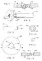
- FIG. 1is a perspective view of the drill guide in accordance with the present invention.
- FIG. 2is a side view of the drill guide of FIG. 1 ;
- FIG. 3is an end view showing the alignment tip of the drill guide of FIG. 1 ;
- FIG. 4is a view from the other end of the drill guide of FIG. 1 ;
- FIG. 5is a top view of a plate having a threaded recess for a locking screw and further being configured to receive the alignment tip of the drill guide of FIG. 1 ;
- FIG. 6is a detail of a threaded recess for a locking screw from FIG. 5 ;
- FIG. 7is a cross section of the recess of FIG. 6 taken at line 7 - 7 ;
- FIG. 8is a perspective view of an alternative embodiment of the drill guide with a mating threaded locking hole in accordance with the present invention.
- FIG. 9is a side view of the drill guide of FIG. 8 ;
- FIG. 10is an end view showing the alignment tip of the drill guide of FIG. 8 ;
- FIG. 11is a view from the other end of the drill guide of FIG. 8 ;
- FIG. 12is a top view of a detail from a plate showing the fastener recess which receives the detent tip of the drill guide of FIG. 8 ;
- FIG. 13is a cross section of the recess in a plate taken at line 13 - 13 of FIG. 12 ;
- FIG. 14is a side view of the drill guide with a drill in use to drill a hole through a recess in a plate into a bone;
- FIG. 15is a top view of a distal radius plate illustrating the use of the present invention in yet another implant
- FIG. 16is a side view of the distal radius plate of FIG. 15 and
- FIG. 17is a top side view of a threaded locking screw.
- Drill guide 10includes a drill guide body 12 with a proximal end and a distal end which includes a drill guide tip 14 .
- the drill guide body 12has an opening 18 that extends through the body 12 so as to form a substantially tubular shaft which defines a cannula for receiving a drill bit.
- the shaftterminates in the drill guide tip 14 which includes an aligning mechanism that defines the angle and position of the cannula so as to guide a drill bit for a desired angle and position for a pilot hole for a fastener.
- the aligning mechanism 20comprises a mating interface with the implant (which is preferably a plate) with which the drill guide is used.
- Thispreferably includes a mating interface between the longitudinal surfaces of the drill guide tip and recesses 21 in the fastener hole 19 of the plate 23 , which can comprise a key having a compound configuration in cross section and key way having a mating female configuration where the key is comprised of a center portion with hemi-cylindrical, or more ridge-like radial projections 22 which extend along the drill guide tip in the direction of the long axis of the drill guide tip and that mate with corresponding female shaped recesses 24 along the long axis and “contiguous with”, meaning adjacent to the periphery, of the screw hole.
- the drill guidemay include a shoulder 26 that seats on an internal surface 28 such as is formed by a counterbore at the opening to the fastener recess.
- the fastener recessalso includes internal threads 30 that receive external threads on the head of a locking screw.
- the alignment recessescan also be external to or longitudinally superior to the threads.
- FIG. 8An alternate embodiment of the drill guide 110 of the present invention is shown in FIG. 8 .
- This guideincludes a drill guide tip 114 with a similar aligning mechanism 120 in plate 123 .
- the projections 122are planar (i.e. forming a portion of a rectangle in cross-section) and the female aligning recesses 124 are also planar.
- the tipincludes the shoulder 126 which seats on a rim 128 formed in the fastening recess 119 .
- the recess 119also includes internal threads 130 that receive the external threads 138 of a locking screw or peg.
- FIG. 14shows a drill 40 engaged in a drill guide of the present invention boring a hole in a bone.
- FIGS. 15 and 16illustrate a distal radius plate 223 having threaded through holes 219 for locking fasteners 220 , shown in FIG. 17 and having head 232 with external threads 234 and which are designed to receive the fasteners at specific angles in order to facilitate the optimal restructuring of typical fractures during surgery.
- the inventionalso relates to a method of forming a bone construct for a bone that comprises a plate having one or more through holes for a fastener, and in particular where one of more of the holes include an internal thread that mates with a threaded portion on the fastener, comprising the step of placing the plate on the bone and using a drill guide having a distal end having at least one longitudinally extending projection that mates with a corresponding recess in the plate to hold the drill guide at a desired angle relative to the bone, and using the drill guide to guide the angle of a hole in the bone for a fastener which extends through the plate into the hole in the bone and which is locked at a desired angle relative to the plate by the mating of the internal thread in the hole in the plate with the threaded portion of the fastener.
Landscapes
- Health & Medical Sciences (AREA)
- Orthopedic Medicine & Surgery (AREA)
- Surgery (AREA)
- Life Sciences & Earth Sciences (AREA)
- Biomedical Technology (AREA)
- Public Health (AREA)
- Veterinary Medicine (AREA)
- Engineering & Computer Science (AREA)
- Nuclear Medicine, Radiotherapy & Molecular Imaging (AREA)
- Heart & Thoracic Surgery (AREA)
- Medical Informatics (AREA)
- Molecular Biology (AREA)
- Animal Behavior & Ethology (AREA)
- General Health & Medical Sciences (AREA)
- Dentistry (AREA)
- Oral & Maxillofacial Surgery (AREA)
- Neurology (AREA)
- Surgical Instruments (AREA)
Abstract
Description
Claims (12)
Priority Applications (8)
| Application Number | Priority Date | Filing Date | Title |
|---|---|---|---|
| US12/217,632US9668759B2 (en) | 2007-07-11 | 2008-07-08 | Surgical drill guide having keyway for axial alignment of a fastener for use for an orthopedic plate |
| PCT/US2008/008397WO2009009057A1 (en) | 2007-07-11 | 2008-07-09 | Surgical drill guide having keyway for axial alignment of fastener used for an orthopedic plate |
| EP08780046.2AEP2162082B1 (en) | 2007-07-11 | 2008-07-09 | Surgical drill guide having keyway for axial alignment of fastener used for an orthopedic plate |
| BRPI0813799-4A2ABRPI0813799A2 (en) | 2007-07-11 | 2008-07-09 | SURGICAL DRILL GUIDE WITH RIP KEY FOR AXIAL FIXER ALIGNMENT USED FOR ORTHOPEDIC DISH |
| AU2008275620AAU2008275620B2 (en) | 2007-07-11 | 2008-07-09 | Surgical drill guide having keyway for axial alignment of fastener used for an orthopedic plate |
| CA2693770ACA2693770C (en) | 2007-07-11 | 2008-07-09 | Surgical drill guide having keyway for axial alignment of fastener used for an orthopedic plate |
| IL202805AIL202805A0 (en) | 2007-07-11 | 2009-12-17 | Surgical drill guide having keyway for axial alignment of fastener used for an orthopedic plate |
| US15/593,860US20170245870A1 (en) | 2007-07-11 | 2017-05-12 | Surgical drill guide having keyway for axial alignment of a fastener for use for an orthopedic plate |
Applications Claiming Priority (2)
| Application Number | Priority Date | Filing Date | Title |
|---|---|---|---|
| US95909707P | 2007-07-11 | 2007-07-11 | |
| US12/217,632US9668759B2 (en) | 2007-07-11 | 2008-07-08 | Surgical drill guide having keyway for axial alignment of a fastener for use for an orthopedic plate |
Related Child Applications (1)
| Application Number | Title | Priority Date | Filing Date |
|---|---|---|---|
| US15/593,860ContinuationUS20170245870A1 (en) | 2007-07-11 | 2017-05-12 | Surgical drill guide having keyway for axial alignment of a fastener for use for an orthopedic plate |
Publications (2)
| Publication Number | Publication Date |
|---|---|
| US20090177208A1 US20090177208A1 (en) | 2009-07-09 |
| US9668759B2true US9668759B2 (en) | 2017-06-06 |
Family
ID=40228918
Family Applications (2)
| Application Number | Title | Priority Date | Filing Date |
|---|---|---|---|
| US12/217,632Active2031-08-29US9668759B2 (en) | 2007-07-11 | 2008-07-08 | Surgical drill guide having keyway for axial alignment of a fastener for use for an orthopedic plate |
| US15/593,860AbandonedUS20170245870A1 (en) | 2007-07-11 | 2017-05-12 | Surgical drill guide having keyway for axial alignment of a fastener for use for an orthopedic plate |
Family Applications After (1)
| Application Number | Title | Priority Date | Filing Date |
|---|---|---|---|
| US15/593,860AbandonedUS20170245870A1 (en) | 2007-07-11 | 2017-05-12 | Surgical drill guide having keyway for axial alignment of a fastener for use for an orthopedic plate |
Country Status (7)
| Country | Link |
|---|---|
| US (2) | US9668759B2 (en) |
| EP (1) | EP2162082B1 (en) |
| AU (1) | AU2008275620B2 (en) |
| BR (1) | BRPI0813799A2 (en) |
| CA (1) | CA2693770C (en) |
| IL (1) | IL202805A0 (en) |
| WO (1) | WO2009009057A1 (en) |
Families Citing this family (11)
| Publication number | Priority date | Publication date | Assignee | Title |
|---|---|---|---|---|
| US8986353B2 (en)* | 2009-07-09 | 2015-03-24 | Orthohelix Surgical Designs, Inc. | Osteotomy plate, plate driver and method for their use |
| EP2632349B1 (en) | 2010-10-29 | 2018-03-07 | The Cleveland Clinic Foundation | System for assisting with attachment of a stock implant to a patient tissue |
| US9907558B2 (en) | 2011-07-08 | 2018-03-06 | Smith & Nephew, Inc. | Osteotomy guide and method |
| US10064668B2 (en)* | 2015-02-13 | 2018-09-04 | Kls-Martin, L.P. | Bone plate locking cannula and drill guide assembly |
| CN106377309B (en)* | 2016-11-15 | 2020-03-20 | 温州医科大学附属第二医院 | One-side vertebral pedicle screw and opposite-side articular process screw locking guide inner fixing device |
| CN106667562B (en)* | 2016-11-15 | 2020-03-20 | 温州医科大学附属第二医院 | Fixator for lumbar fusion |
| CN106420026B (en)* | 2016-11-15 | 2020-01-07 | 温州医科大学附属第二医院 | Fixator special for repairing lumbar disc herniation |
| CN106420027B (en)* | 2016-11-15 | 2020-03-20 | 温州医科大学附属第二医院 | Fixator for treating lumbar disc herniation |
| CN106377308B (en)* | 2016-11-15 | 2020-01-07 | 温州医科大学附属第二医院 | Treatment fixer for protrusion of lumbar vertebral disc |
| USD977645S1 (en)* | 2020-01-08 | 2023-02-07 | Ortho Solutions Holdings Limited | Orthopedic plate |
| USD977646S1 (en)* | 2020-01-08 | 2023-02-07 | Ortho Solutions Holdings Limited | Orthopedic plate |
Citations (19)
| Publication number | Priority date | Publication date | Assignee | Title |
|---|---|---|---|---|
| US2494229A (en) | 1946-07-08 | 1950-01-10 | John G Collison | Bone surgery |
| US4870842A (en)* | 1987-12-28 | 1989-10-03 | Consolidated International Automotive, Inc. | Security locking system for vehicle wheel nuts |
| US5403322A (en) | 1993-07-08 | 1995-04-04 | Smith & Nephew Richards Inc. | Drill guide and method for avoiding intramedullary nails in the placement of bone pins |
| US5415502A (en) | 1994-02-24 | 1995-05-16 | Dahlin; Bernard A. | Drill and tap guide |
| US5928244A (en) | 1996-10-04 | 1999-07-27 | United States Surgical Corporation | Tissue fastener implantation apparatus and method |
| US6059789A (en) | 1998-06-22 | 2000-05-09 | Xomed Surgical Products, Inc. | Drill guide for creating a tunnel in bone for fixating soft tissue to the bone and kit and method for fixating soft tissue to bone |
| US6379364B1 (en) | 2000-04-28 | 2002-04-30 | Synthes (Usa) | Dual drill guide for a locking bone plate |
| WO2003015650A1 (en) | 2001-08-21 | 2003-02-27 | Depuy Products, Inc. | Method and apparatus for percutaneously securing a bone screw and a bone plate to a bone of a patient |
| US20040092947A1 (en) | 2002-09-30 | 2004-05-13 | Foley Kevin T. | Devices and methods for securing a bone plate to a bony segment |
| US20050038444A1 (en) | 2003-08-13 | 2005-02-17 | Binder Lawrence J. | Quick-release drill-guide assembly for bone-plate |
| US20060085077A1 (en) | 2004-10-18 | 2006-04-20 | Ebi, L.P. | Intervertebral implant and associated method |
| US20060235400A1 (en) | 2003-08-26 | 2006-10-19 | Rolf Schneider | Bone plate |
| US7278997B1 (en) | 2003-03-07 | 2007-10-09 | Theken Spine, Llc | Instrument guide and implant holder |
| US20080140130A1 (en) | 2004-01-26 | 2008-06-12 | Chan Jason S | Highly-versatile variable-angle bone plate system |
| US7392674B1 (en)* | 2005-01-06 | 2008-07-01 | Grote Jeff M | Lug nut locking device |
| US20090003967A1 (en)* | 2007-06-29 | 2009-01-01 | Acument Intellectual Properties, Llc | Lobular drive system with interference fit and method and apparatus for fabricating same |
| US20090204157A1 (en) | 2006-03-28 | 2009-08-13 | Fernandez Dell Oca Alberto A | Locking Bone Plates with Controlled Locking Screw Misalignment |
| US20100130983A1 (en) | 2008-11-26 | 2010-05-27 | Osteomed L.P. | Drill Guide for Angled Trajectories |
| US7763029B2 (en) | 2004-04-12 | 2010-07-27 | Synthes Usa, Llc | Drill-tap-screw drill guide |
Family Cites Families (3)
| Publication number | Priority date | Publication date | Assignee | Title |
|---|---|---|---|---|
| US20050049594A1 (en)* | 2001-04-20 | 2005-03-03 | Wack Michael A. | Dual locking plate and associated method |
| US6960216B2 (en)* | 2003-03-21 | 2005-11-01 | Depuy Acromed, Inc. | Modular drill guide |
| US8172886B2 (en)* | 2004-12-14 | 2012-05-08 | Depuy Products, Inc. | Bone plate with pre-assembled drill guide tips |
- 2008
- 2008-07-08USUS12/217,632patent/US9668759B2/enactiveActive
- 2008-07-09BRBRPI0813799-4A2Apatent/BRPI0813799A2/ennot_activeIP Right Cessation
- 2008-07-09AUAU2008275620Apatent/AU2008275620B2/enactiveActive
- 2008-07-09EPEP08780046.2Apatent/EP2162082B1/enactiveActive
- 2008-07-09CACA2693770Apatent/CA2693770C/enactiveActive
- 2008-07-09WOPCT/US2008/008397patent/WO2009009057A1/enactiveApplication Filing
- 2009
- 2009-12-17ILIL202805Apatent/IL202805A0/enunknown
- 2017
- 2017-05-12USUS15/593,860patent/US20170245870A1/ennot_activeAbandoned
Patent Citations (20)
| Publication number | Priority date | Publication date | Assignee | Title |
|---|---|---|---|---|
| US2494229A (en) | 1946-07-08 | 1950-01-10 | John G Collison | Bone surgery |
| US4870842A (en)* | 1987-12-28 | 1989-10-03 | Consolidated International Automotive, Inc. | Security locking system for vehicle wheel nuts |
| US5403322A (en) | 1993-07-08 | 1995-04-04 | Smith & Nephew Richards Inc. | Drill guide and method for avoiding intramedullary nails in the placement of bone pins |
| US5415502A (en) | 1994-02-24 | 1995-05-16 | Dahlin; Bernard A. | Drill and tap guide |
| US5928244A (en) | 1996-10-04 | 1999-07-27 | United States Surgical Corporation | Tissue fastener implantation apparatus and method |
| US6059789A (en) | 1998-06-22 | 2000-05-09 | Xomed Surgical Products, Inc. | Drill guide for creating a tunnel in bone for fixating soft tissue to the bone and kit and method for fixating soft tissue to bone |
| US6379364B1 (en) | 2000-04-28 | 2002-04-30 | Synthes (Usa) | Dual drill guide for a locking bone plate |
| WO2003015650A1 (en) | 2001-08-21 | 2003-02-27 | Depuy Products, Inc. | Method and apparatus for percutaneously securing a bone screw and a bone plate to a bone of a patient |
| US20040092947A1 (en) | 2002-09-30 | 2004-05-13 | Foley Kevin T. | Devices and methods for securing a bone plate to a bony segment |
| US7625378B2 (en) | 2002-09-30 | 2009-12-01 | Warsaw Orthopedic, Inc. | Devices and methods for securing a bone plate to a bony segment |
| US7278997B1 (en) | 2003-03-07 | 2007-10-09 | Theken Spine, Llc | Instrument guide and implant holder |
| US20050038444A1 (en) | 2003-08-13 | 2005-02-17 | Binder Lawrence J. | Quick-release drill-guide assembly for bone-plate |
| US20060235400A1 (en) | 2003-08-26 | 2006-10-19 | Rolf Schneider | Bone plate |
| US20080140130A1 (en) | 2004-01-26 | 2008-06-12 | Chan Jason S | Highly-versatile variable-angle bone plate system |
| US7763029B2 (en) | 2004-04-12 | 2010-07-27 | Synthes Usa, Llc | Drill-tap-screw drill guide |
| US20060085077A1 (en) | 2004-10-18 | 2006-04-20 | Ebi, L.P. | Intervertebral implant and associated method |
| US7392674B1 (en)* | 2005-01-06 | 2008-07-01 | Grote Jeff M | Lug nut locking device |
| US20090204157A1 (en) | 2006-03-28 | 2009-08-13 | Fernandez Dell Oca Alberto A | Locking Bone Plates with Controlled Locking Screw Misalignment |
| US20090003967A1 (en)* | 2007-06-29 | 2009-01-01 | Acument Intellectual Properties, Llc | Lobular drive system with interference fit and method and apparatus for fabricating same |
| US20100130983A1 (en) | 2008-11-26 | 2010-05-27 | Osteomed L.P. | Drill Guide for Angled Trajectories |
Non-Patent Citations (1)
| Title |
|---|
| International Search Reported dated Apr. 9, 2013. |
Also Published As
| Publication number | Publication date |
|---|---|
| EP2162082A1 (en) | 2010-03-17 |
| EP2162082A4 (en) | 2013-05-22 |
| WO2009009057A1 (en) | 2009-01-15 |
| BRPI0813799A2 (en) | 2014-12-30 |
| IL202805A0 (en) | 2010-06-30 |
| US20170245870A1 (en) | 2017-08-31 |
| US20090177208A1 (en) | 2009-07-09 |
| CA2693770A1 (en) | 2009-01-15 |
| AU2008275620A1 (en) | 2009-01-15 |
| AU2008275620B2 (en) | 2012-01-19 |
| CA2693770C (en) | 2013-05-07 |
| EP2162082B1 (en) | 2016-08-17 |
Similar Documents
| Publication | Publication Date | Title |
|---|---|---|
| US9668759B2 (en) | Surgical drill guide having keyway for axial alignment of a fastener for use for an orthopedic plate | |
| EP2568899B1 (en) | Bone screw assembly and instruments for implantation of the same | |
| EP1814476B1 (en) | Off-axis anchor guidance system | |
| EP1878394B1 (en) | Orthopaedic fixation plate having threaded guides | |
| US20060149245A1 (en) | Bone fixation system | |
| US20220257380A1 (en) | Systems and methods for fusion of anatomical joints | |
| CA2587373A1 (en) | Endosteal nail | |
| JP2007507296A (en) | Bone plate with holes for interchangeably receiving locking screws and compression screws | |
| US12310641B2 (en) | Bone fixation system and methods of use | |
| AU2005232698A1 (en) | Free hand drill guide | |
| US20120226278A1 (en) | Intramedullary Nail | |
| US20230338067A1 (en) | Plunging/Linkage Screw And Drill Sleeve System | |
| US10799270B2 (en) | Conical end cap for intramedullary nail | |
| WO2021130730A1 (en) | Bone anchor for fracture fixation | |
| JP7714854B2 (en) | Screw-in bone fixation system | |
| CN213249605U (en) | Pedicle screw fixing system and implanting solid bolt matching tool | |
| JP6927556B2 (en) | Bone fixation system | |
| US20200054373A1 (en) | System and method for fastening of two or more interacting elements |
Legal Events
| Date | Code | Title | Description |
|---|---|---|---|
| AS | Assignment | Owner name:ORTHOHELIX SURGICAL DESIGNS, INC., OHIO Free format text:ASSIGNMENT OF ASSIGNORS INTEREST;ASSIGNORS:STRNAD, LEE A.;DUCHARME, DUSTIN;LEITHER, ANDREW J.;AND OTHERS;SIGNING DATES FROM 20080703 TO 20080916;REEL/FRAME:021539/0106 Owner name:ORTHOHELIX SURGICAL DESIGNS, INC., OHIO Free format text:ASSIGNMENT OF ASSIGNORS INTEREST;ASSIGNORS:STRNAD, LEE A.;DUCHARME, DUSTIN;LEITHER, ANDREW J.;AND OTHERS;REEL/FRAME:021539/0106;SIGNING DATES FROM 20080703 TO 20080916 | |
| AS | Assignment | Owner name:BANK OF AMERICA, N.A., AS ADMINISTRATIVE AGENT, CA Free format text:PATENT SECURITY AGREEMENT;ASSIGNOR:ORTHOHELIX SURGICAL DESIGNS, INC.;REEL/FRAME:029076/0646 Effective date:20121004 | |
| AS | Assignment | Owner name:ORTHOHELIX SURGICAL DESIGNS, INC., OHIO Free format text:TERMINATION AND RELEASE OF SECURITY INTEREST IN PATENTS;ASSIGNOR:BANK OF AMERICA, N.A., AS ADMINISTRATIVE AGENT;REEL/FRAME:036900/0609 Effective date:20151001 | |
| AS | Assignment | Owner name:MIDCAP FINANCIAL TRUST, AS AGENT, MARYLAND Free format text:SECURITY INTEREST;ASSIGNOR:ORTHOHELIX SURGICAL DESIGNS, INC.;REEL/FRAME:041257/0203 Effective date:20161223 | |
| STCF | Information on status: patent grant | Free format text:PATENTED CASE | |
| MAFP | Maintenance fee payment | Free format text:PAYMENT OF MAINTENANCE FEE, 4TH YEAR, LARGE ENTITY (ORIGINAL EVENT CODE: M1551); ENTITY STATUS OF PATENT OWNER: LARGE ENTITY Year of fee payment:4 | |
| AS | Assignment | Owner name:WRIGHT MEDICAL GROUP N.V., NETHERLANDS Free format text:RELEASE BY SECURED PARTY;ASSIGNOR:MIDCAP FUNDING IV TRUST;REEL/FRAME:054480/0001 Effective date:20201112 Owner name:BIOMIMETIC THERAPEUTICS CANADA, INC., TENNESSEE Free format text:RELEASE BY SECURED PARTY;ASSIGNOR:MIDCAP FUNDING IV TRUST;REEL/FRAME:054480/0001 Effective date:20201112 Owner name:TORNIER, INC., MINNESOTA Free format text:RELEASE BY SECURED PARTY;ASSIGNOR:MIDCAP FUNDING IV TRUST;REEL/FRAME:054480/0001 Effective date:20201112 Owner name:WRIGHT MEDICAL GROUP, INC., TENNESSEE Free format text:RELEASE BY SECURED PARTY;ASSIGNOR:MIDCAP FUNDING IV TRUST;REEL/FRAME:054480/0001 Effective date:20201112 Owner name:ORTHOHELIX SURGICAL DESIGNS, INC., MINNESOTA Free format text:RELEASE BY SECURED PARTY;ASSIGNOR:MIDCAP FUNDING IV TRUST;REEL/FRAME:054480/0001 Effective date:20201112 Owner name:ORTHOPRO, L.L.C., TENNESSEE Free format text:RELEASE BY SECURED PARTY;ASSIGNOR:MIDCAP FUNDING IV TRUST;REEL/FRAME:054480/0001 Effective date:20201112 Owner name:SOLANA SURGICAL, LLC, TENNESSEE Free format text:RELEASE BY SECURED PARTY;ASSIGNOR:MIDCAP FUNDING IV TRUST;REEL/FRAME:054480/0001 Effective date:20201112 Owner name:TROOPER HOLDINGS INC., MINNESOTA Free format text:RELEASE BY SECURED PARTY;ASSIGNOR:MIDCAP FUNDING IV TRUST;REEL/FRAME:054480/0001 Effective date:20201112 Owner name:WRIGHT MEDICAL GROUP INTELLECTUAL PROPERTY, INC., TENNESSEE Free format text:RELEASE BY SECURED PARTY;ASSIGNOR:MIDCAP FUNDING IV TRUST;REEL/FRAME:054480/0001 Effective date:20201112 Owner name:TORNIER US HOLDINGS, INC., MINNESOTA Free format text:RELEASE BY SECURED PARTY;ASSIGNOR:MIDCAP FUNDING IV TRUST;REEL/FRAME:054480/0001 Effective date:20201112 Owner name:WHITE BOX ORTHOPEDICS, LLC, TENNESSEE Free format text:RELEASE BY SECURED PARTY;ASSIGNOR:MIDCAP FUNDING IV TRUST;REEL/FRAME:054480/0001 Effective date:20201112 Owner name:BIOMIMETIC THERAPEUTICS, LLC, TENNESSEE Free format text:RELEASE BY SECURED PARTY;ASSIGNOR:MIDCAP FUNDING IV TRUST;REEL/FRAME:054480/0001 Effective date:20201112 Owner name:BIOMIMETIC THERAPEUTICS USA, INC., TENNESSEE Free format text:RELEASE BY SECURED PARTY;ASSIGNOR:MIDCAP FUNDING IV TRUST;REEL/FRAME:054480/0001 Effective date:20201112 Owner name:WRIGHT MEDICAL CAPITAL, INC., TENNESSEE Free format text:RELEASE BY SECURED PARTY;ASSIGNOR:MIDCAP FUNDING IV TRUST;REEL/FRAME:054480/0001 Effective date:20201112 Owner name:WRIGHT MEDICAL TECHNOLOGY, INC., TENNESSEE Free format text:RELEASE BY SECURED PARTY;ASSIGNOR:MIDCAP FUNDING IV TRUST;REEL/FRAME:054480/0001 Effective date:20201112 Owner name:INBONE TECHNOLOGIES, INC., TENNESSEE Free format text:RELEASE BY SECURED PARTY;ASSIGNOR:MIDCAP FUNDING IV TRUST;REEL/FRAME:054480/0001 Effective date:20201112 | |
| MAFP | Maintenance fee payment | Free format text:PAYMENT OF MAINTENANCE FEE, 8TH YEAR, LARGE ENTITY (ORIGINAL EVENT CODE: M1552); ENTITY STATUS OF PATENT OWNER: LARGE ENTITY Year of fee payment:8 | |
| AS | Assignment | Owner name:STRYKER CORPORATION, MICHIGAN Free format text:NUNC PRO TUNC ASSIGNMENT;ASSIGNOR:ORTHOHELIX SURGICAL DESIGNS, INC.;REEL/FRAME:070793/0972 Effective date:20241205 |