US9668164B2 - Receiver processor for bandwidth management of a multiple receiver real-time location system (RTLS) - Google Patents
Receiver processor for bandwidth management of a multiple receiver real-time location system (RTLS)Download PDFInfo
- Publication number
- US9668164B2 US9668164B2US14/678,079US201514678079AUS9668164B2US 9668164 B2US9668164 B2US 9668164B2US 201514678079 AUS201514678079 AUS 201514678079AUS 9668164 B2US9668164 B2US 9668164B2
- Authority
- US
- United States
- Prior art keywords
- buffer
- receiver
- toa
- data
- tag
- Prior art date
- Legal status (The legal status is an assumption and is not a legal conclusion. Google has not performed a legal analysis and makes no representation as to the accuracy of the status listed.)
- Active, expires
Links
- 239000000872bufferSubstances0.000claimsabstractdescription102
- 238000000034methodMethods0.000claimsabstractdescription37
- 238000004590computer programMethods0.000claimsabstractdescription6
- 230000006870functionEffects0.000claimsdescription164
- 230000005540biological transmissionEffects0.000claimsdescription52
- 238000007726management methodMethods0.000claimsdescription41
- 238000013138pruningMethods0.000claimsdescription32
- 238000004891communicationMethods0.000claimsdescription13
- 238000013144data compressionMethods0.000claimsdescription10
- 238000011084recoveryMethods0.000description30
- 238000005259measurementMethods0.000description18
- 230000008569processEffects0.000description17
- 230000001360synchronised effectEffects0.000description15
- 238000001914filtrationMethods0.000description14
- 238000004422calculation algorithmMethods0.000description11
- 238000001514detection methodMethods0.000description11
- 239000000284extractSubstances0.000description10
- 238000012545processingMethods0.000description10
- 238000012935AveragingMethods0.000description8
- 238000012360testing methodMethods0.000description8
- 230000008901benefitEffects0.000description7
- 230000003139buffering effectEffects0.000description6
- 230000001105regulatory effectEffects0.000description6
- 230000004044responseEffects0.000description5
- 239000000470constituentSubstances0.000description4
- 230000009191jumpingEffects0.000description4
- 238000005457optimizationMethods0.000description4
- 238000004458analytical methodMethods0.000description3
- 238000004364calculation methodMethods0.000description3
- 238000007906compressionMethods0.000description3
- 230000006835compressionEffects0.000description3
- 230000001934delayEffects0.000description3
- 238000013507mappingMethods0.000description3
- 238000005070samplingMethods0.000description3
- 230000003044adaptive effectEffects0.000description2
- 238000013459approachMethods0.000description2
- 230000008859changeEffects0.000description2
- 230000001419dependent effectEffects0.000description2
- 230000000694effectsEffects0.000description2
- 238000012986modificationMethods0.000description2
- 230000004048modificationEffects0.000description2
- 230000000737periodic effectEffects0.000description2
- 230000009467reductionEffects0.000description2
- 238000012546transferMethods0.000description2
- 238000009825accumulationMethods0.000description1
- 238000003491arrayMethods0.000description1
- 230000003190augmentative effectEffects0.000description1
- 230000015572biosynthetic processEffects0.000description1
- 230000001143conditioned effectEffects0.000description1
- 230000007812deficiencyEffects0.000description1
- 238000010586diagramMethods0.000description1
- 238000002592echocardiographyMethods0.000description1
- 230000007717exclusionEffects0.000description1
- 238000000605extractionMethods0.000description1
- 238000009432framingMethods0.000description1
- 238000007689inspectionMethods0.000description1
- 230000004807localizationEffects0.000description1
- 239000000463materialSubstances0.000description1
- 239000003507refrigerantSubstances0.000description1
- 238000004904shorteningMethods0.000description1
- 239000007787solidSubstances0.000description1
- 230000003068static effectEffects0.000description1
- 230000007704transitionEffects0.000description1
- 230000001960triggered effectEffects0.000description1
Images


Classifications
- H—ELECTRICITY
- H04—ELECTRIC COMMUNICATION TECHNIQUE
- H04W—WIRELESS COMMUNICATION NETWORKS
- H04W28/00—Network traffic management; Network resource management
- H04W28/02—Traffic management, e.g. flow control or congestion control
- H04W28/0226—Traffic management, e.g. flow control or congestion control based on location or mobility
- H—ELECTRICITY
- H04—ELECTRIC COMMUNICATION TECHNIQUE
- H04W—WIRELESS COMMUNICATION NETWORKS
- H04W28/00—Network traffic management; Network resource management
- H04W28/02—Traffic management, e.g. flow control or congestion control
- H04W28/0278—Traffic management, e.g. flow control or congestion control using buffer status reports
- H—ELECTRICITY
- H04—ELECTRIC COMMUNICATION TECHNIQUE
- H04W—WIRELESS COMMUNICATION NETWORKS
- H04W4/00—Services specially adapted for wireless communication networks; Facilities therefor
- H04W4/02—Services making use of location information
- H04W4/023—Services making use of location information using mutual or relative location information between multiple location based services [LBS] targets or of distance thresholds
- H—ELECTRICITY
- H04—ELECTRIC COMMUNICATION TECHNIQUE
- H04W—WIRELESS COMMUNICATION NETWORKS
- H04W56/00—Synchronisation arrangements
- H04W56/001—Synchronization between nodes
- H—ELECTRICITY
- H04—ELECTRIC COMMUNICATION TECHNIQUE
- H04L—TRANSMISSION OF DIGITAL INFORMATION, e.g. TELEGRAPHIC COMMUNICATION
- H04L47/00—Traffic control in data switching networks
- H04L47/10—Flow control; Congestion control
- H04L47/34—Flow control; Congestion control ensuring sequence integrity, e.g. using sequence numbers
Definitions
- Embodiments discussed hereinare related to radio frequency locating and, more particularly, to systems, methods, apparatuses, computer readable media and other means for target location by high-resolution time-of-arrival (TOA) determination in a multiple receiver target location system.
- TOAtime-of-arrival
- Example embodiments of the present inventionmay include, which is described in detail below.
- systems, methods, apparatuses, and computer readable mediaare disclosed for providing a bandwidth management of a multiple receiver real-time target location system (RTLS).
- RTLSreal-time target location system
- a method, apparatus, and computer program product (CPP) for a bandwidth management of a multiple receiver target location systemis described herein, comprising determining a buffer fullness level for a receive buffer in a receiver in a set of one or more receivers, determining by the processor hub a set of buffer elements to be removed from the receive buffer in at least one of the receivers based on the buffer fullness level, and communicating to the one or more receivers to remove from the receive buffers the set of receive buffer elements identified by a sequence number.
- the method, apparatus, and CPPfurther comprises determining a buffer fullness level for a receive buffer comprises determining a total number of sequence numbers in the buffer.
- the sequence numbersare associated with tag transmitters.
- the determining the buffer fullness levelmay comprise a mapping of a total number of sequence numbers associated with each tag.
- determining the, the buffer fullness levelmay comprise receiving the buffer fullness level at the processor hub on one or more of an RF communication channel and an RS-422 communication channel.
- the determining the set of buffer elements to be removedcomprises determining of a time-of-arrival (TOA) invalidity at the multiple receivers.
- the TOA invaliditymay comprise one or more of determining an out-of-range TOA, an intermittent TOA, and an indeterminate TOA or the like.
- the determining the set of buffer elements to be removedcomprises, in some examples, a determining of a location estimate invalidity at a Central Processor/Hub.
- the method, apparatus, and CPPmay be further specified, whereby the determining the location estimate invalidity comprises one or more of determining a non-physical location estimate, an out-of-range location estimate, a location estimate intermittently ‘skipping’ between two or more location estimates, and an under-determined location estimate.
- the determining the location estimate invaliditymay further comprise a determining of an updated location estimate with a subset of the TOAs and receivers used make the location estimate.
- the determining the updated location estimatemay comprise an iterative feedback loop. The iterative feedback loop, in some examples, compares an error function associated with the updated location estimate and the location estimate to determine a minimum error.
- communicating to remove the set of receiver buffer elements identified by the sequence numbercomprises one or more of a data compression command and a pruning command.
- the data compression commandcomprises, in some examples, one or more of a data word compression, an RFID transmitter identification (TX ID) compression, and a CRC compression.
- the pruning commandcomprises a pruning as a function of invalid TOAs, invalid locations, and updated locations.
- the pruning commandmay comprise a mapping of an RFID TX ID, a sequence number, and a set of receivers.
- the pruning commandmay be indexed to remove one or more sequence numbers from the receive buffers of one or more receivers.
- FIG. 1illustrates an exemplary bandwidth management function, in accordance with some example embodiments described herein;
- FIG. 2Aillustrates an exemplary database prepared and stored at the Central Processor/Hub for the bandwidth management function of FIG. 1 , in accordance with some example embodiments described herein;
- FIG. 2Billustrates an exemplary database prepared and stored at the Central Processor/Hub for a bandwidth management function associated with TOA receiver subsets, in accordance with some example embodiments described herein;
- FIG. 3illustrates the command pruning associated with the bandwidth management function for the TOA receiver subsets prescribed in FIG. 2B , in accordance with some example embodiments described herein;
- FIG. 4illustrates a flow chart enabling the method for the active bandwidth management system of a multiple receiver real-time location system (RTLS), in accordance with some example embodiments described herein;
- RTLSreal-time location system
- FIG. 5illustrates an exemplary environment using a radio frequency locating system for providing performance analytics in accordance with some embodiments of the present invention
- FIG. 6illustrates an exemplary receiver in a RTLS system comprising a RTLS receiver that may be configured in accordance with some embodiments of the present invention.
- FIG. 7illustrates an example TOA and recovery circuit function from the exemplary receiver in the RTLS system of FIG. 6 , in accordance with some embodiments of the present invention.
- Example embodiments of the present inventionmay include now will be described more fully hereinafter with reference to the accompanying drawings, in which some, but not all embodiments of the inventions are shown. Indeed, these inventions may be embodied in many different forms and should not be construed as limited to the embodiments set forth herein; rather, these embodiments are provided so that this disclosure will satisfy applicable legal requirements. Like numbers refer to like elements throughout.
- Active radio frequency identification system (RFID) target location systemsprovide for transmitters incorporated with each target RFID tag and a grid of receivers to resolve a collection of time-of-arrival (TOA) measurements to locate a tag transmitter.
- active radio frequency identification (RFID) tag target location systemsprovide for approximately one nanosecond (ns) TOA accuracy and resolution at ranges up to 500 feet, depending on power requirements and regulations.
- the present inventionmay include an active bandwidth management of a high-resolution TOA-based multiple receiver real-time location system (RTLS).
- RTLSreal-time location system
- a communication between a central processor or hub, responsible for converting the TOA packet data from the multiple receivers in a receiver grid into the RFID tag location estimates, and the receivers themselves,may direct which subset of receivers and which subset of packet data from each receiver is to be requested as a minimum TOA packet data for an accurate RFID tag location estimate for the one or more tags in the system.
- the hubdetermines the minimum TOA packet data to request in conjunction with a channel capacity, a maximum bandwidth or data rate allowed by the communication channel associated with the multiple receiver target location system, and/or the like.
- the issues of correctly assembling critical and pertinent TOA packet data from each receiver, corresponding to location estimates for each RFID tag as a function of the data rate limitationare performed by the hub.
- the hubmay determine which TOA packet data to request from each receiver.
- the subset of TOA packet datamay exclude TOA packet data received from a subset of tags and/or the like.
- the subset of TOA packet datamay exclude, in some examples, a combination of TOA packet data from a subset of receivers in the receiver grid, wherein the subset of packet data from the subset of the receivers itself may be receiver dependent and vary from receiver to receiver.
- the hubmay determine a minimum required packet data set from the multiple receivers necessary to determine an RFID tag location for the RTLS, wherein each minimum required TOA packet data set may correspond to a specific RFID tag or set of RFID tags.
- FIG. 1illustrates an exemplary bandwidth management function 100 , in accordance with some example embodiments described herein.
- the bandwidth management function 100 for the real-time location system (RTLS)comprises a data packet 110 transmitted from one of one or more RFID tags in an RFID tag field ( 12 a - f ) to a receiver in a multiple receiver grid ( 13 a - i ), and a Central Processor/Hub 11 that communicates with the multiple receivers to determine location estimates for the RFID tags.
- the RFID tag field ( 12 a - f ), the multiple receiver grid ( 13 a - i ), and the Central Processor/Hub 11 physical layoutis illustrated in FIG. 5 .
- a receiver 13 aprocesses the data packet 110 transmitted from and RFID tag 12 a , for example, from the RFID tag field ( 12 a - f ), to determine a time-of-arrival (TOA) associated with the data packet 110 .
- TOAtime-of-arrival
- a collection of TOAs associated with the RFID tag 12 aattributed to one or more receivers, each similar to the receiver 13 a , from the receiver grid ( 13 a - i ), is used by the Central Processor/Hub 11 to estimate the location of the RFID tag 12 a .
- FIGS. 6-7A detailed block diagram illustrating the receiver 13 a functional blocks and communication with the Central Processor/Hub 11 is given in FIGS. 6-7 .
- FIG. 1provides for a set of receiver 13 a , for example, functions that communicate with the Control Processor/Hub 11 to determine which of the TOAs calculated by the receiver 13 a are sent to the Central Processor/Hub 11 to estimate the location for the RFID tag 14 a , for example.
- Functional blocks for the bandwidth management system 100include the data packet 110 and a TOA determination and data recovery function 24 , here shown separately to make clear the data flow emanating from the data packet 110 .
- a preamble code and a synchronization bits fields from the data packet 110are grouped and identified as transmitted (TX) pulse data 120 , used by the TOA determination function 24 to determine the TOA associated with the RFID tag 12 a .
- TXtransmitted
- a transmitter identification, a data words 1 - 2 , and a CRC fieldare grouped and identified as transmitter identification data (TX ID) 130 , used by the data recovery function 24 to identify the RFID tag 13 a , for example, and provide for augmenting data.
- Functional blocks for the bandwidth management systemfurther include an arbitrate buffer function 26 , which selects from a parallel set of TOAs provided for by the TOA determination function 24 a TOA best suited for the RF environment.
- the arbitrate buffer function 26prepares a tag message 27 , described in FIG. 6 , comprising the selected TOA, the TX ID, and other pertinent data associated with the data words and CRC, and sends the tag message 27 to a message filtering function 27 ′.
- the message filtering function 27 ′comprises a message queue 27 A′, a message filtering functional block 27 B′, and a transmit (TX) queue 27 C′, whereby a queue of tag messages 27 is filtered and pruned such that a tag message subset 27 is sent to a buffering/repeating/formatting/decoding functional block 30 to activate synchronous communication with the Central Processor/Hub 11 on data lines 30 A-B.
- Synchronous transmissions from the receiver 13 afor example, to the Central Processor/Hub 11 are summarized by the transmit (TX) TOA data block 140 .
- the bandwidth management system 100further includes a command decoder 44 that decodes commands sent from the Central Processor/Hub 11 to the receiver 13 a , for example, on data line 30 A-B, and distributes the decoded commands to the correct functional blocks in the receiver.
- the command decoder 44is shown relaying commands to the message filtering block 27 B′.
- Message filtering 27 B′ commandsare represented pictorially by the curved arrows associated with a command block (CMMD) 150 .
- CMMDcommand block
- the feedback loopis represented by the forward feed of the TX TOA data 140 from the receiver to the Central Processor/Hub 11 , and the feedback, the command block 150 , from the Central Processor/Hub 11 back to the receiver.
- the Central Processor/Hub 11acts as a function in the feedback, mapping TX TOA data 140 onto commands 150 .
- the feedback loopprovides for the precepts that govern the bandwidth management system 100 .
- the receiver 13 aprovides the Central Processor/Hub 11 with the TX TOA data block 140 that comprises at least an RFID tag identification (TX ID) and TOA, along with a sequence number (Seq. No.) to identify the TOA instance, the specific TOA defined by the RFID tag and time tag, any associated data contained in at least a data word header (00) and data words 01 - 04 , and a TX queue size message indicating the relative fullness of the TX queue 27 C′.
- TX IDRFID tag identification
- Seq. No.sequence number
- the TX queue 27 C′may repeatedly and periodically provide for a fullness level, the TX queue size, to be accessed by the buffering function 30 for transmission to the Central Processor/Hub 11 .
- the TX queue sizemay, in some examples, provide for a fullness level report that the TX queue 27 C′ is 1/16, 1 ⁇ 8, 1 ⁇ 4, and 1 ⁇ 2 full.
- the TOA TX data 140may be transmitted from the buffering function 30 resident at the receiver 13 a , for example, to the Central Processor/Hub 11 at a transmission (TX) rate approximately equal to a repetition rate associated with an RFID tag data packet.
- TXtransmission
- the tag messages 27 generated from the RFID data packetsmay enter the message queue 27 A′ at approximately the same rate that the tag messages exit the TX queue 27 C′, and are subsequently transmitted to the Central Processor/Hub 11 as a TOA TX data block 140 .
- any type of message filteringwould be required.
- the TX queue sizemay not be transmitted from the receiver 13 a , for example, each and every time there is a TX TOA data 140 transmission from the receiver to the Central Processor/Hub 11 .
- both the TX queue size and TX TOA data 140may be transmitted at approximately 1 Hz (1 TX/sec).
- the TX queue size transmission rate and the TX TOA data 140 transmission ratemay be 0.1 TX/sec and 1 TX/sec, respectively.
- the TX queue size transmission rate and the TX TOA data 140 transmission ratemay be 1 TX/sec and 12 Tx/sec, respectively.
- the TOA TX data 140may be transmitted from the buffering function 30 resident at the receiver 13 a , for example, to the Central Processor/Hub 11 at a transmission (TX) rate less than the repetition rate associated with an RFID tag data packet.
- TXtransmission
- the tag messages 27 generated from the RFID data packetsmay enter the message queue 27 A′ at a greater rate than the tag messages exit the TX queue 27 C′, and subsequently transmitted to the Central Processor/Hub 11 as the TOA TX data block 140 .
- TX queue size fullness level reportsis generated by the TX queue 27 C′.
- the Central Processor/Hub 11is activated to prepare a command block 150 message to feedback to the receiver 13 a , for example, to perform a data compression on any or all tag message 27 entries in the TX queue 27 C′ and to preempt the transmission of any and all TX TOA data and data blocks 140 deemed redundant or unnecessary in performing the RFID tag location estimates at the Central Processor/Hub 11 .
- the conditions that may require preemptively removing RFID tag message 27 entries from the TX queue 27 C′may be summarized by, but are not limited to, an insufficient channel capacity or data rate limit associated with the data lines 30 A-B; that is, insufficient to transmit tag messages 27 to the Central Processor/Hub 11 at a data rate at least as fast as the tag messages 27 fill the message buffer 27 A′.
- the TX queue sizeprovides for an indication of the message buffer and TX queue fullness, and may trigger the Central Processor/Hub 11 to send a command in the command block 150 to the receiver 13 a , for example, to perform a data compression on any or all the tag messages 27 or to reduce the number of tag messages 27 in the message queue 27 A′.
- the TX TOA data ratecoupled with the data compression of the tag messages 27 and the repeated removal from the message queue 27 A′ of redundant or unnecessary tag messages 27 , may effectively allow for the message queue 27 A′ to empty at a rate comparable to the TX data rate, restoring both the message and TX queues 27 A,C to a steady-state equilibrium.
- the message filtering method itselfthe collection of commands comprising the command block 140 , and their functions, may be selected strictly as a function of the TX queue size reported from the receiver 13 a , for example, or may be a function of a combination of the data in the TX TOA data block 140 transmitted to the Central Processor/Hub 11 .
- the message filteringmay be a combination of the TX queue size, the RFID tag TOA and associated ID and Seq. No., and an auxiliary data, all provided for by the TX TOA data block 140 .
- FIG. 1illustrates an example message filtering 27 B′ embodiment, whereby the Central Processor/Hub 11 has issued a command from the block 150 to remove the third and fifth tag message 27 entries from the message queue 27 A′.
- the third and fifth tag message 27 entriesare shown deleted from the TX queue 27 C′ in FIG. 1 .
- the command to remove the third and fifth tag message 27 entrieswas received by the receiver 13 a , for example, buffer block 30 by data lines 30 A-B, then decoded by the command decoder 44 to enact the removal process.
- Curved arrowsare shown in FIG. 1 as an abstraction to better represent the concept.
- the third and fifth tag message 27 entriesare assigned a sequence number (seq. no.).
- the seq. nos.are assigned according to an arrival time at the receiver 13 a , for example, of the TOA packet data 110 associated with the tag message 27 .
- the seq. no.may be assigned according to an arrival time of the associated TOA and tag message 27 at the head of the message queue 27 A′.
- the TX pulse data 120that is, the preamble code and synchronization bits from the TOA packet data 110 , arrives at each of the receivers 13 a - i in the receiver grid simultaneously.
- the commands in the command block 150 to perform a data compression of the tag message 27 entries and to remove the tag message 27 entries from the message and TX queues 27 A′,C′include at least the following: (1) compact mode, (2) shorten ID, (3) CRC:LSB, and (4) pruning.
- Commands (1)-(3)comprise the data compression commands; command (4), the pruning command, provides for a tag message 27 removal process.
- the Central Processor/Hub 11selects the appropriate command from the command block 150 according to one or more of the TX TOA block 140 data transmitted from the receivers 13 a - i in the receiver grid. A description of the commands comprising the command block 140 is given the next set of paragraphs.
- the compact mode commandremoves all seq. nos. from the message and TX queues 27 A′,C′ where the tag message 27 associated with the given seq. no. comprises a TX ID that is greater than four bytes (32 bits) long. Additionally, the compact mode command reduces the size of the header data field from 16 bits to 8 bits, and limits the number of data bytes transmitted from the receiver, for example receiver 13 a , buffer 30 , from a maximum of five data bytes 00-04, including the data byte header (00), to a minimum of zero data bytes (0 bits).
- the data byte headerincludes, in some examples, an indication of the number of data bytes transmitted.
- the shorten ID format commandremoves one byte (8 bits) from the two byte header information in the TOA packet data 110 , as indicated by the first bit of the header. Also, the shorten ID format command provides for a mask for the two most significant bytes (MSBs) for the TX ID in the TOA data packet 110 , such that the seq. no. with TX ID MSBs that do not match the mask are removed from the message and TX queues 27 A′,C′. Further, for seq. nos. remaining in the TX queue 27 C′, only the two least significant bytes (LSBs) are transmitted from the receiver, for example receiver 13 a , by buffer 30 , to the Central Processor/Hub 11 .
- MSBsmost significant bytes
- the CRC:LSB moderemoves the MSB (8 bits) from the CRC error correcting code from all seq. nos. in the message and TX queues 27 A′,C′.
- the CRC:LSB commandin some examples, is given in conjunction with the compact mode and shorten ID format commands.
- the necessary length of the CRCis a function of the length of the full tag message. Shortening the tag message by enacting one or more of the compact mode and shorten ID format commands allows for a shorter CRC.
- the CRC:LSB commandacknowledges this by explicitly commanding a shorter CRC for every seq. no. in the message and TX queues 27 A′,C′.
- the pruning commandprovides for several options of pruning collections or groupings of seq. nos. from the message queue 27 A′.
- a first option for pruning a collection of seq. nos. from the message queue 27 A′is for the Central Processor/Hub 11 to select a range of seq. nos for removal, whereby the seq. no. range directly corresponds to a time interval.
- the time interval selectedmay be periodic.
- the selected time range corresponding to the seq. no. rangemay coincide with a time frame deemed by the Central Processor/Hub 11 selection logic to be redundant or uninteresting.
- the selected time range corresponding to the seq. no. rangemay be arbitrary.
- the arbitrary seq. no. range or set of rangesmay provide for a fractional reduction in the total no. of seq. nos. present in the TX queue 27 C′.
- a six bit pruning codemay be included as part of the pruning command in the command block 150 to encode the fractional reduction in seq. nos.
- the pruning codemay provide for a command to reduce the number of seq. nos. in the TX queue 27 C′ by one of the fractional amounts 1/16, 1 ⁇ 8, and 1 ⁇ 4.
- Each of the aforementioned commands from the command block 150is provided for by the Central Processor/Hub 11 selection logic based strictly on the TX queue size data returned to the Central Processor/Hub 11 in the TX TOA data block 140 from the receivers 13 a - f in the receiver grid.
- the TX queue sizeprovides for, at each of the receivers 13 a - i in the receiver grid, a fullness level of 1/16, 1 ⁇ 8, 1 ⁇ 4, and 1 ⁇ 2 full.
- the Central Processor/Hub 11 selection logicdetermines which combination, if any, of the previously described commands from the command block 150 to prescribe to compress and reduce receiver 13 a - i TX TOA data block 140 transmissions in an effort to manage the bandwidth of the RTLS.
- a second option for pruning a collection of seq. nos. from the message queue 27 A′is for the Central Processor/hub 11 to select seq. nos. corresponding to unused and invalid RFID tags 12 a - f .
- an RFID tag 12 a - fmay be determined unused if a location estimate associated with the RFID tag 12 a , for example, is determined to be from an unused region.
- An examplemay be a static cargo inventory, whereby cargo located in a permanent storage may be no longer tracked.
- an RFID tag 12 a - fmay be determined invalid if a location estimate associate with the RFID tag 12 a , for example, is determined to be one or more of physically not possible, not stable, ‘skipping’ and ‘jumping’ intermittently between two or more location estimates, and indeterminate.
- the seq. no. selection logicas performed by the Central Processor/Hub 11 , requires the formation of a location estimate for the examined RFID tags 12 a - f.
- the second option for the pruning commandrequires a location estimate for each of the RFID tags 12 a - f represented in the TX queue 27 C′, resident at each of the pertinent receivers 13 a - i .
- the pruning command associated with the location estimates calculated by the Central Processor/Hub 11requires the IDs and TOAs from the TX TOA data block 140 , in addition to the TX queue size.
- the seq. nos.are required to tie the RFID tag identification and TOA back to the TX queue 27 C′.
- the TX queue sizeprovides an indication as to whether and when to activate the bandwidth management function 100 .
- Calculation of RFID tag 12 a - f location estimates provided for by the Central Processor/Hub 11may yield RFID tag location estimates that are one or more of physically not possible, not stable, ‘skipping’ and ‘jumping’ intermittently between two or more location estimates, and indeterminate.
- a pruning commandmay be issued by the command block 150 from the Central Processor/Hub 11 to the receivers 13 a - i , whereby the pruning may focus on seq. nos. determined or tagged as invalid by a data word in the TX TOA data block 140 .
- the invalidity of a seq. no. or set of set of seq. nos.may be determined by the arbitrate buffer function 26 in the receiver 13 a , for example, whereby the arbitrate buffer function 26 may determine that the TOA determination function 24 did not successfully converge to a solution or a realizable solution.
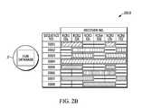
- FIG. 2Aillustrates an exemplary database 200 A prepared and stored at the Central Processor/Hub 11 for the bandwidth management function 100 of FIG. 1 , in accordance with some example embodiments described herein.
- the database 200 A prepared by the Central Processor/Hub 11prepared in direct response to the TX TOA data block 140 , comprising the RFID tag ID, seq. nos., corresponding TOAs, pertinent data words, and the TX queue size, reflects the effects of the command block 150 .
- Rows in FIG. 2Acorrespond to the RFID tags in the RFID tag field, and to specific instantiations of RFID tag TOAs, referenced by the corresponding seq. nos.
- Columns in FIG. 2Acorrespond to the constituent receivers 13 a - f , for example, in the receiver grid, whereby each receiver 13 a - f may potentially contribute a TOA measurement to the location estimate for the corresponding RFID tag.
- FIG. 2Aline segments represent seq. nos. to be removed from the TX queue 27 C′, solid blocks represent seq. nos. to remain in the TX queue 27 C′.
- FIG. 2shows the removal of the third and fifth tag message—that is, seq. nos. 0003 and 0005—for each of the receivers 13 a - f.
- FIG. 2Billustrates an exemplary database 200 B prepared and stored at the Central Processor/Hub 11 for a bandwidth management function associated with TOA receiver subsets, in accordance with some example embodiments described herein. It is immediately clear by inspection of FIG. 2B that the seq. nos. removed from the receivers 13 a - f TX queues 27 C′ vary from receiver to receiver. As such, the pruning command transmitted by the command block 150 itself may vary from receiver to receiver.
- receiver specific pruning outlined with respect to FIG. 2Bprovides for a more flexible bandwidth management function 200 .
- receiver specific pruningrather than the removing of RFID tags from TX queues 27 C′ across all receivers 13 a - i in the receiver grid, it may be inferred by the receiver specific pruning that receivers themselves can be removed that do not represent constituent TOAs for location determination at the Central Processor/Hub 11 for the given RFID tag 12 a - f or seq. no.
- This shift in pruning philosophy, from RFID tag based to receiver basedprovides for a much richer bandwidth management system 200 .
- Example embodiments of such a bandwidth management system, as outlined with respect to FIG. 2Bare presented in the following.
- an invalid TOA for a seq. no.required the invalidation of that seq. no. across all receivers 13 a - i in the receiver grid.
- an invalid seq. no. from given receivers, receivers 13 a,emay only invalidate those receivers for that seq. no., may only require the removal of the RFID tag message 27 for RFID tag 12 b , for example, for seq. no. 0002.
- a remaining subset of receivers 13 b - d,fmay represent a sufficient receiver subset to constitute a location estimate for the RFID tag 12 b.
- the invalidation of receivers 13 a,emay be specific to a limited number of RFID tags, RFID tags corresponding to seq. nos. 0002-3, 0006-8, in the example database 200 B, given in FIG. 2B . That means that for other seq. nos., specifically seq. nos. 0001, 0004-5, the TOAs in the TX TOA data block 140 associated with these seq. nos. are not invalid. As such it may be possible, by deleting only the invalid seq. nos. at the correctly identified receivers, that a location estimate can be made for each and every RFID tag in this example, whereby the RFID tags correspond to seq. nos. 0001-8.
- the invalidation of TOAs registered in the TX TOA data block 140may be determined by a location estimate, calculated at the Central Processor/Hub 11 , whereby the location estimate may be one or more of physically not possible or out-of-range, not stable, ‘skipping’ and ‘jumping’ intermittently between two or more location estimates, and indeterminate. Additionally, the TOA as an output of the TOA determination function 24 resident at the receiver 13 a , for example, may itself be determined invalid.
- An invalid TOAmay be due, for example, to excessive noise and echo or reverberation levels in the RF environment, which prevent an adaptive windowing function used at a detector to converge and register a TOA for the given RFID tag TX pulse data 120 associated with the RFID data packet 110 .
- an invalid TOAmay be due to a detection registered by the adaptive windowing function that represents a distance measurement that is clearly out-of-range.
- the TOA registered by the TOA determination function 24may itself ‘skip’ and ‘jump’ between two or more TOA registrations, providing for an intermittent TOA associated with a given RFID tag and receiver combination.
- the signal-to-noise ratio (SNR) of the TX pulse data 120may be too low to register a detection at the TOA determination function 24 .
- the arbitration buffer function 26determines an invalid TOA associated with the given RFID tag, receiver, and seq. no. combination, and encodes a data word in the TX TOA data block 140 accordingly for transmission to the Central Processor/Hub 11 .
- the invalidity of the TOA datais provided for as a first layer error check, effectively preempting the series of error checks relying on location estimates made by the Central Processor/Hub 11 , outlined previously, which may be considered as a second layer.
- the second layer error check for valid TOAs, TOAs as registered by the TOA determination function 24may be categorized by one or more of a location estimate that is physically not possible or out-of-range, not stable or ‘skipping’ and ‘jumping’ intermittently, and indeterminate or under-defined.
- the second layer error check for TOA invaliditymay function in conjunction with an iterative location estimate function, whereby the iterative location estimate function repeatedly estimates the location for the RFID tag 12 a , for example, as indexed seq. no. 0001, which is constituted by TOAs from receivers 13 a - b,e , in the example given in FIG. 2B .
- an iterative location estimate functionperformed at the Central Processor/Hub 11 , may not be provided with a sufficient number of TOAs to calculate a location estimate for the given RFID tag. As such, the location estimate for the given RFID tag is deemed indeterminate or under-defined.
- the iterative location estimate function at the Central Processor/Hub 11may, in another example, be provided more TOAs than necessary to determine a location estimate for the given RFID tag. As such, the location estimate for the given RFID tag is deemed over-determined.
- an over-determined location estimateit may be determined that a subset of the TOAs, each associated with the given RFID tag 12 a , for example, and a receiver 13 a - i in the receiver grid, may be unnecessary, or moreover, even contribute to a location estimate error that was heretofore not detected by the first two error check layers.
- the iterative location estimate functionacting effectively as a third layer error check, provides for redress of the TOAs that passed the first two error check layers, performed by the TOA arbitration function 26 and by the registration of gross location errors and anomalies by the Central Processor/Hub 11 . That is, for an over-determined location estimate, the iterative location estimate function may pare away unnecessary and less accurate TOA measurements to make a more accurate location estimate.
- the Central Processor/Hub 11may then collect all of the remaining associated seq. no. and receiver pairs in the pruning command for subsequent transmission as part of the command block 150 to the respective receivers.
- the remaining seq. no. and receiver pairs necessary for the calculation of the location estimatemay be considered a minimum subset of TOAs.
- the minimum subset TOA data packet 110 necessary for an accurate tag location estimate for each of the tags in the tag location system, the RTLS, alternatively or additionally,may be based on historical data, estimation, learning methods, Bayesian likelihood measures, messages from one or more receivers and/or some combination thereof.
- the functions describedare dynamic. That is, the feedback loop between the receivers 13 a - i in the receiver grid and the Central Processor/Hub 11 , defined principally by the TX TOA data block 140 and the command block 150 exchange, changes in time to adjust for the dynamic environment associated with the RFID tag field.
- One immediate advantage to a dynamic feedback systemis the data rate may effectively be adjusted dynamically.
- Thisprovides for a core tenet of the present active bandwidth management system.
- One example that demonstrates the advantage of a dynamic or active bandwidth management systemis a simple level two pruning command to periodically remove seq. nos. associated with a given RFID tag 12 a , for example, effectively lowering the TX TOA data block transmission rate for that given RFID tag.
- the periodic removal of seq. nos.may correspond to a lower velocity, as calculated by the Central Processor/Hub 11 for the given RFID tag, and as such, requires location estimate updates less frequently.
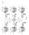
- FIG. 3illustrates the pruning command associated with the bandwidth management function 200 for the TOA receiver subsets prescribed in FIG. 2B , in accordance with some example embodiments described herein.
- FIG. 3essentially represents graphically or pictorially the information presented for the database 200 B associated with the aforementioned bandwidth management function 200 , as described previously.
- FIG. 4illustrates a flow chart 400 enabling the method for the active bandwidth management system 100 of a multiple receiver RTLS, in accordance with some example embodiments described herein.
- the flow chart 400provides for a step-by-step process 401 to apply the tenets of the three-layered error check that controls the TX queue 27 C′ fullness level, preventing overflow.
- the process 401starts with the receiver 13 a , for example, receiving the data packet 110 transmitted from the RFID tag 12 a , for example, step 405 in FIG. 4 .
- the receiver 13 aUpon reception, the receiver 13 a immediately begins processing the data packet 110 , registering the TOA and extracting the TX ID and associated data words and CRC, by the TOA determination and extract TX ID functions 24 .
- the TOA arbitration buffer 26selects from a set of parallel TOA determinations with varying threshold and detection levels. At this point, at least a detection failure, a detection inconsistency, a corrupted TOA, an out-of-range TOA, and combinations thereof provide for conditions whereby the TOA extracted and selected by the TOA determination 24 and arbitration 26 may be deemed invalid.
- the TOA validity check at the receiver 13 ais incorporated in the TOA arbitration buffer function 26 , and represented in the flow chart 400 as process 415 A.
- the TOA, TOA validity, and extracted TX ID and associated data wordsare collected in the tag message 27 and transferred serially to the message queue 27 A′, message filtering function 27 B′, and TX queue 27 C′, as shown in FIG. 1 .
- Flow chart 400contracts these three processes to the TX queue 27 C′, shown in FIG. 4 .
- the TX queue 27 C′functions as a first-in, first-out (FIFO) data buffer, as described previously in regard to FIG. 1 .
- a TX queue fullness 420 Afunctions to continually provide for a measure of the TX queue 27 C′ buffer fullness level.
- the TX queue fullness function 420 Areports one of at least five discrete fullness levels, that of 0 full, 1/16 full, 1 ⁇ 8 full, 1 ⁇ 4 full, and 1 ⁇ 2 full.
- the TX queue fullness level associated with the TX queue fullness function 420 Ais then combined in the TX TOA data block 140 with the tag messages 27 , comprising at least the TOA, TX ID, associated data words and the CRC associated with the TX TOA data block 140 transmission, and an additional seq. no. corresponding to the specific TOA instantiation or timing.
- the TX TOA data block 140is then transmitted in step 425 A by respective receivers 13 a - i to and received in step 425 B by the Central Processor/Hub 11 , as shown in FIG. 4 .
- the Central Processor/Hub 11Upon reception of the TX TOA data block 140 , the Central Processor/Hub 11 unpacks (not shown) the tag messages 27 , including seq. nos. and the TX queue fullness level 420 A, and immediately checks the TX queue fullness level 420 A by process 420 B to determine whether or not it is necessary to perform a pruning function on the TX queue 27 C′.
- the process 401is directed to perform a location estimate calculation 435 , a function to estimate the location of the RFID tag 12 a , for example, associated with the TOA, TX ID, and seq. no. received from receiver 13 a , for example, and from the multiple remaining receivers 13 b - i , for example, in the receiver grid.
- the location estimate 435uses TOAs from multiple receivers 13 a - i in the receiver grid, whereby the receivers in the receiver grid are approximately identical in form and function.
- the TOAs used by the location estimate function 435is conditioned by a TOA valid test 415 B, which evaluates the TOA validity associated with each RFID TX ID, seq. no., and receiver combination, as registered by the receiver-side TOA valid function 415 A, described previously. As such, TOAs determined invalid by function 415 A at the receiver and subsequently tested invalid by the TOA valid test 415 B are not used in the location estimate function 435 .
- the location estimate validity check 440checks for an RFID tag location estimate inconsistency, comprising one or more of a physically not possible location, an out-of-range location, an unstable location, a location that ‘skips’ and ‘jumps’ intermittently between two or more location estimates, and an indeterminate or under-defined location.
- RFID tag location inconsistenciesis described in detail in regard to FIG. 1 .
- the occurrence of an invalid TOA 415 B or an invalid location estimate 440may prompt the process 401 to activate a remove TOAs function 430 , whereby one or more TOAs associated with a specific tag message 27 , a specific RFID TX ID, seq. no., and receiver combination, may be designated for removal from the TX queue 27 C′ at the associated receiver.
- the removalin some cases, may be dependent on the status returned by the TX queue fullness test 420 B, described previously.
- the process 401 response to the TX queue fullness test 420 B, TOA validity test 415 B, and location estimate or first location estimate validity test 440comprises a variety of bandwidth management functions, including at least a compact mode, shorten ID, CRC:LSB, and pruning function.
- Each of the bandwidth management functionsare encapsulated in a command block 150 , transmitted from the Central Processor/Hub 11 to the correct, designated receivers, as summarized by the TX:prune command 455 , provided for in FIG. 4 .
- the TX:prune command 455provides for commands in the command block 150 to remove tag messages, TOAs, TX IDs, and corresponding instantiations or seq. nos., from the specific receivers wherein the TOA was deemed invalid or corrupted.
- the Central Processor/Hub 11 TX:prune command 455acts in anticipation of a TX queue 27 C′ overflow condition, commanding removal of tag message 27 entries in the TX queue in accordance with the guidelines provided for in FIG. 1 , when alerted to the TX queue fullness level 420 A, as reported from the multiple receivers 13 a - i in the receiver grid.
- the bandwidth management functionmay work in conjunction with an iterative location estimate function, whereby a new location estimate may be estimated with a subset of the original TOAs used to make the first location estimate, with the new location estimate compared to the first estimate and any preceding estimates by an error analysis.
- a feedback loop to summarize such an activity, described in regard to FIG. 1is represented in FIG. 4 by the feedback loop incorporating a TOA subset select function 445 and a recalculate location estimate 450 .
- a remaining subset of TOAsis deemed sufficient to constitute the best location estimate for the given RFID tag and instantiation or seq. no.
- the remaining TOAsmay be regarded as unnecessary for the location estimate functions 435 , 450 . As such, it may be possible at this point to remove the unnecessary TOAs, by the remove TOA function 430 , from the receiver-side TX queue 27 C′, by the TX:prune command 455 encapsulated in the command block 150 .
- the three layers of error check, the TOA validity 415 A-B, the location estimate validity 440 , and the recalculated or iterated location estimate comparison loop 445 , 450provides simple to sophisticated bandwidth control and management functions 100 to anticipate and prevent an overflow condition in the TX queues 27 C′ at the respective receivers 13 a - i in the receiver grid. These concepts are summarized by FIGS. 1 and 4 .
- the active bandwidth management systemmay provide for accurate and consistent tag location estimates with resolutions less than one foot, corresponding to a TOA resolution of less than one nanosecond ( ⁇ 1 ns), and may provide for such tag location estimates in a high-density tag field.
- FIG. 5illustrates an exemplary locating system 500 useful for calculating a location by an accumulation of location data or time of arrivals (TOAs) at a central processor/hub 11 , whereby the TOAs represent a relative time of flight (TOF) from RTLS tags 12 a - f as recorded at each receiver 13 a - 1 (e.g., UWB reader, etc.).
- TOFtime of flight
- a timing reference clockis used, in some examples, such that at least a subset of the receivers 13 a - 1 may be synchronized in frequency, whereby the relative TOA data associated with each of the RTLS tags 12 a - f may be registered by a counter associated with at least a subset of the receivers 13 a - 1 .
- a reference tag 14 a - bpreferably a UWB transmitter, positioned at known coordinates, is used to determine a phase offset between the counters associated with at least a subset of the of the receivers 13 a - 1 .
- the RTLS tags 12 a - f and the reference tags 14 a - breside in an active RTLS field 18 .
- the systems described hereinmay be referred to as either “multilateration” or “geolocation” systems, terms that refer to the process of locating a signal source by solving an error minimization function of a location estimate determined by the difference in time of arrival (DTOA) between TOA signals received at multiple receivers 13 a - 1 .
- DTOAdifference in time of arrival
- the systemcomprising at least the tags 12 a - f and the receivers 13 a - 1 is configured to provide two dimensional and/or three dimensional precision localization (e.g., subfoot resolutions), even in the presence of multipath interference, due in part to the use of short nanosecond duration pulses whose TOF can be accurately determined using detection circuitry, such as in the receivers 13 a - 1 , which can trigger on the leading edge of a received waveform.
- this short pulse characteristicallows necessary data to be conveyed by the system at a higher peak power, but lower average power levels, than a wireless system configured for high data rate communications, yet still operate within local regulatory requirements.
- the tags 12 a - fmay operate with an instantaneous ⁇ 3 dB bandwidth of approximately 400 MHz and an average transmission below 187 pulses in a 1 msec interval, provided that the rate is sufficiently low.
- the predicted maximum range of the system, operating with a center frequency of 6.55 GHzis roughly 200 meters in instances in which a 12 dbi directional antenna is used at the receiver, but the projected range will depend, in other examples, upon receiver antenna gain.
- the range of the systemallows for one or more tags 12 a - f to be detected with one or more receivers positioned throughout a football stadium used in a professional football context.
- Such a configurationadvantageously satisfies constraints applied by regulatory bodies related to peak and average power densities (e.g., effective isotropic radiated power density (“EIRP”)), while still optimizing system performance related to range and interference.
- EIRPeffective isotropic radiated power density
- tag transmissions with a ⁇ 3 dB bandwidth of approximately 400 MHzyields, in some examples, an instantaneous pulse width of roughly 2 nanoseconds that enables a location resolution to better than 30 centimeters.
- the object to be locatedhas an attached tag 12 a - f , preferably a tag having a UWB transmitter, that transmits a burst (e.g., multiple pulses at a 1 Mb/s burst rate, such as 112 bits of On-Off keying (OOK) at a rate of 1 Mb/s), and optionally, a burst comprising an information packet utilizing OOK that may include, but is not limited to, ID information, a sequential burst count or other desired information for object or personnel identification, inventory control, etc.
- a burste.g., multiple pulses at a 1 Mb/s burst rate, such as 112 bits of On-Off keying (OOK) at a rate of 1 Mb/s
- OOKOn-Off keying
- the sequential burst count(e.g., a packet sequence number) from each tag 12 a - f may be advantageously provided in order to permit, at a Central Processor/Hub 11 , correlation of TOA measurement data from various receivers 13 a - 1 .
- the tag 12 a - fmay employ UWB waveforms (e.g., low data rate waveforms) to achieve extremely fine resolution because of their extremely short pulse (i.e., sub-nanosecond to nanosecond, such as a 2 nsec (1 nsec up and 1 nsec down)) durations.
- the information packetmay be of a short length (e.g. 112 bits of OOK at a rate of 1 Mb/sec, in some example embodiments), that advantageously enables a higher packet rate. If each information packet is unique, a higher packet rate results in a higher data rate; if each information packet is transmitted repeatedly, the higher packet rate results in a higher packet repetition rate.
- higher packet repetition ratee.g., 12 Hz
- higher data ratese.g., 1 Mb/sec, 2 Mb/sec or the like
- the shorter length of the information packetsin conjunction with other packet rate, data rates and other system requirements, may also result in a longer battery life (e.g., 7 years battery life at a transmission rate of 1 Hz with a 300 mAh cell, in some present embodiments).
- Tag signalsmay be received at a receiver directly from RTLS tags, or may be received after being reflected en route. Reflected signals travel a longer path from the RTLS tag to the receiver than would a direct signal, and are thus received later than the corresponding direct signal. This delay is known as an echo delay or multipath delay. If reflected signals are sufficiently strong enough to be detected by the receiver, they can corrupt a data transmission through inter-symbol interference.
- the tag 12 a - fmay employ UWB waveforms to achieve extremely fine resolution because of their extremely short pulse (e.g., 2 nsec) durations.
- signalsmay comprise short information packets (e.g., 112 bits of OOK) at a somewhat high burst data rate (1 Mb/sec, in some example embodiments), that advantageously enable packet durations to be brief (e.g. 112 microsec) while allowing inter-pulse times (e.g., 998 nsec) sufficiently longer than expected echo delays. Echo (or multipath) delays result from reflections and, if sufficiently strong enough to be detected, avoiding data corruption
- Reflected signalscan be expected to become weaker as delay increases due to more reflections and the longer distances traveled.
- inter-pulse timee.g. 998 nsec
- path length differencee.g. 299.4 m.
- minimization of packet durationallows the battery life of a tag to be maximized, since its digital circuitry need only be active for a brief time. It will be understood that different environments can have different expected echo delays, so that different burst data rates and, hence, packet durations, may be appropriate in different situations depending on the environment.
- Minimization of the packet durationalso allows a tag to transmit more packets in a given time period, although in practice, regulatory average EIRP limits may often provide an overriding constraint.
- brief packet durationalso reduces the likelihood of packets from multiple tags overlapping in time, causing a data collision.
- minimal packet durationallows multiple tags to transmit a higher aggregate number of packets per second, allowing for the largest number of tags to be tracked, or a given number of tags to be tracked at the highest rate.
- a data packet length of 112 bits(e.g., OOK encoded), transmitted at a data rate of 1 Mb/sec (1 MHz), may be implemented with a transmit tag repetition rate of 1 transmission per second (1 TX/sec).
- Such an implementationmay accommodate a battery life of up to seven years, wherein the battery itself may be, for example, a compact, 3-volt coin cell of the series no. BR2335 (Rayovac), with a battery charge rating of 300 mAhr.
- An alternate implementationmay be a generic compact, 3-volt coin cell, series no. CR2032, with a battery charge rating of 220 mAhr, whereby the latter generic coin cell, as can be appreciated, may provide for a shorter battery life.
- some applicationsmay require higher transmit tag repetition rates to track a dynamic environment.
- the transmit tag repetition ratemay be 12 transmissions per second (12 TX/sec). In such applications, it can be further appreciated that the battery life may be shorter.
- the high burst data transmission rate(e.g., 1 MHz), coupled with the short data packet length (e.g., 112 bits) and the relatively low repetition rates (e.g., 1 TX/sec), provide for two distinct advantages in some examples: (1) a greater number of tags may transmit independently from the field of tags with a lower collision probability, and/or (2) each independent tag transmit power may be increased, with proper consideration given to a battery life constraint, such that a total energy for a single data packet is less that an regulated average power for a given time interval (e.g., a 1 msec time interval for an FCC regulated transmission).
- an regulated average power for a given time intervale.g., a 1 msec time interval for an FCC regulated transmission.
- additional sensor or telemetry datamay be transmitted from the tag 12 a - f to provide the receivers 13 a - 1 with information about the environment and/or operating conditions of the tag.
- the tagmay transmit a temperature to the receivers 13 a - 1 .
- Such informationmay be valuable, for example, in a system involving perishable goods or other refrigerant requirements.
- the temperaturemay be transmitted by the tag at a lower repetition rate than that of the rest of the data packet.
- the temperaturemay be transmitted from the tag to the receivers at a rate of one time per minute (e.g., 1 TX/min.), or in some examples, once every 720 times the data packet is transmitted, whereby the data packet in this example is transmitted at an example rate of 12 TX/sec.
- a rate of one time per minutee.g., 1 TX/min.
- the data packet in this exampleis transmitted at an example rate of 12 TX/sec.
- the tag 12 a - fmay be programmed to intermittently transmit data to the receivers 13 a - 1 in response to a signal from a magnetic command transmitter (not shown).
- the magnetic command transmittermay be a portable device, functioning to transmit a 125 kHz signal, in some example embodiments, with a range of approximately 15 feet or less, to one or more of the tags 12 a - f .
- the tags 12 a - fmay be equipped with at least a receiver tuned to the magnetic command transmitter transmit frequency (e.g., 125 kHz) and functional antenna to facilitate reception and decoding of the signal transmitted by the magnetic command transmitter.
- one or more other tagsmay be positioned within and/or about a monitored region.
- the reference tag 14 a - bmay be configured to transmit a signal that is used to measure the relative phase (e.g., the count of free-running counters) of non-resettable counters within the receivers 13 a - 1 .
- One or more (e.g., preferably four or more) receivers 13 a - 1are also positioned at predetermined coordinates within and/or around the monitored region.
- the receivers 13 a - 1may be connected in a “daisy chain” 19 fashion to advantageously allow for a large number of receivers 13 a - 1 to be interconnected over a significant monitored region in order to reduce and simplify cabling, provide power, and/or the like.
- Each of the receivers 13 a - 1includes a receiver for receiving transmissions, such as UWB transmissions, and preferably, a packet decoding circuit that extracts a time of arrival (TOA) timing pulse train, transmitter ID, packet number, and/or other information that may have been encoded in the tag transmission signal (e.g., material description, personnel information, etc.) and is configured to sense signals transmitted by the tags 12 a - f and one or more reference tags 14 a - b.
- TOAtime of arrival
- Each receiver 13 a - 1includes a time measuring circuit that measures times of arrival (TOA) of tag bursts, with respect to its internal counter.
- the time measuring circuitis phase-locked (e.g., phase differences do not change and therefore respective frequencies are identical) with a common digital reference clock signal distributed via cable connection from a Central Processor/Hub 11 having a central timing reference clock generator.
- the reference clock signalestablishes a common timing reference for the receivers 13 a - 1 .
- multiple time measuring circuits of the respective receivers 13 a - 1are synchronized in frequency, but not necessarily in phase.
- each receivermay be synchronized wirelessly via virtual synchronization without a dedicated physical timing channel.
- the receivers 13 a - 1are configured to determine various attributes of the received signal. Since measurements are determined at each receiver 13 a - 1 , in a digital format, rather than analog in some examples, signals are transmittable to the Central Processor/Hub 11 .
- the receivers 13 a - 1can receive and process tag (and corresponding object) locating signals on a nearly continuous basis.
- the receiver memoryallows for a high burst rate of tag events (i.e., information packets) to be captured.
- Data cables or wireless transmissionsmay convey measurement data from the receivers 13 a - 1 to the Central Processor/Hub 11 (e.g., the data cables may enable a transfer speed of 2 Mbps). In some examples, measurement data is transferred to the Central Processor/Hub at regular polling intervals.
- the Central Processor/Hub 11determines or otherwise computes tag location (i.e., object location) by processing TOA measurements relative to multiple data packets detected by the receivers 13 a - 1 .
- the Central Processor/Hub 11may be configured to resolve the coordinates of a tag using nonlinear optimization techniques.
- TOA measurements from multiple receivers 13 a - 1are processed by the Central Processor/Hub 11 to determine a location of the transmit tag 12 a - f by a differential time-of-arrival (DTOA) analysis of the multiple TOAs.
- the DTOA analysisincludes a determination of tag transmit time t 0 , whereby a time-of-flight (TOF), measured as the time elapsed from the estimate tag transmit time t 0 to the TOA, represents graphically the radii of spheres centered at respective receivers 13 a - 1 .
- TOFtime-of-flight
- the distance between the surfaces of the respective spheres to the estimated location coordinates (x 0 , y 0 , z 0 ) of the transmit tag 12 a - frepresents the measurement error for each respective TOA, and the minimization of the sum of the squares of the TOA measurement errors from each receiver participating in the DTOA location estimate provides for both the location coordinates (x 0 , y 0 , z 0 ) of the transmit tag and that tag's transmit time t 0 .
- the system described hereinmay be referred to as an “over-specified” or “over-determined” system.
- the Central Processor/Hub 11may calculate one or more valid (i.e., most correct) locations based on a set of measurements and/or one or more incorrect (i.e., less correct) locations. For example, a location may be calculated that is impossible due the laws of physics or may be an outlier when compared to other calculated locations. As such one or more algorithms or heuristics may be applied to minimize such error.
- the starting point for the minimizationmay be obtained by first doing an area search on a coarse grid of x, y and z over an area defined by the user and followed by a localized steepest descent search.
- the starting location for this algorithmis fixed, in some examples, at the mean location of all active receivers. No initial area search is needed, and optimization proceeds through the use of a Davidon-Fletcher-Powell (DFP) quasi-Newton algorithm in some examples. In other examples, a steepest descent algorithm may be used.
- DFPDavidon-Fletcher-Powell
- a steepest descent algorithmmay be used.
- Equation 1One such algorithm for error minimization, which may be referred to as a time error minimization algorithm, may be described in Equation 1:
- Nis the number of receivers
- cis the speed of light
- (x j , y j , z j )are the coordinates of the j th receiver
- t jis the arrival time at the j th receiver
- t 0is the tag transmit time.
- the variable t 0represents the time of transmission. Since t 0 is not initially known, the arrival times, t j , as well as t 0 , are related to a common time base, which in some examples, is derived from the arrival times. As a result, differences between the various arrival times have significance for determining location as well as t 0 .
- the optimization algorithm to minimize the error ⁇ in Equation 1may be the Davidon-Fletcher-Powell (DFP) quasi-Newton algorithm, for example.
- the optimization algorithm to minimize the error ⁇ in Equation 1may be a steepest descent algorithm.
- the algorithmsmay be seeded with an initial location estimate (x, y, z) that represents the two-dimensional (2D) or three-dimensional (3D) mean of the receiver positions of the receivers 13 a - 1 that participate in the tag location determination.
- the RTLS systemcomprises a receiver grid, whereby each of the receivers 13 a - 1 in the receiver grid keeps a receiver clock that is synchronized, with an initially unknown phase offset, to the other receiver clocks.
- the phase offset between any receiversmay be determined by use of a reference tag that is positioned at a known coordinate position (x T , y T , z T ).
- the phase offsetserves to resolve the constant offset between counters within the various receivers 13 a - 1 , as described below.
- Each receiver R jutilizes, for example, a synchronous clock signal derived from a common frequency time base, such as a clock generator. Because the receivers are not synchronously reset, an unknown, but constant offset O j exists for each receiver's internal free running counter. The value of the constant offset O j is measured in terms of the number of fine resolution count increments (e.g., a number of nanoseconds for a one nanosecond resolution system).
- the reference tagis used, in some examples, to calibrate the radio frequency locating system as follows:
- the reference tagemits a signal burst at an unknown time ⁇ R .
- Equation 6a-bEquation 6a-b
- Each arrival time, t jcan be referenced to a particular receiver (receiver “ 1 ”) as given in Equation 7:
- Equation 1The minimization, described in Equation 1, may then be performed over variables (x,y,z,t 0 ) to reach a solution (x′,y′,z′,t 0 ′).
- FIG. 6illustrates an exemplary receiver 13 a - 1 in a UWB receiver system 600 comprising a UWB receiver that may be configured in accordance with some embodiments of the present invention.
- data packets 120are transmitted to the receivers 13 a - 1 and intercepted by UWB antenna 21 .
- a UWB receiver 22is provided at each receiver 13 a - 1 .
- the UWB receivercan, for example, be designed in accordance with the system described in commonly-owned U.S. Pat. No. 5,901,172, which is incorporated by reference herein in its entirety.
- UWB receiver 22provided for at receivers 13 a - 1 , allows for an analog signal stream that is digitized, then processed by a UWB TOA and data recovery circuits 24 .
- the analog streamis digitized by up to three or more parallel, concurrent, independent analog-to-digital convertors (ADCs) functioning with three distinct threshold levels, resulting in up to three or more digital data streams 23 A-C that are sent to the UWB TOA and data recovery circuits 24 .
- the threshold levels applied to the analog signal stream in the UWB receiver 22are a function of a signal-to-noise ratio (SNR) present in the communication channel.
- the threshold levelsare set dynamically as a function of one or more of an antenna preamp gain and an estimated RTLS tag range.
- the UWB TOA and data recovery circuits 24perform as many as three or more parallel, concurrent, identical signal processing functions on the three or more digital data streams 23 A-C.
- the three or more UWB TOA and data recovery circuits 24may be configured to receive data packets 120 that correspond to RTLS tags 12 a - f .
- the UWB TOA and data recovery circuits 24may provide for a packet framing and extraction function as part of the data recovery circuit, whereby an RTLS tag 12 a - f identification may be extracted.
- the RTLS identificationmay be extracted by the TX identification field 120 B of the data packet 120 , as described previously.
- the UWB TOA and data recovery circuits 24are implemented by field programmable gate arrays (FPGAs).
- the TOA and extracted data packetis sent by TOA line 25 to an arbitrate/buffer function 26 .
- the arbitrate/buffer function 26effectively selects the TOA line 25 data provided by the UWB TOA and data recovery circuits 24 .
- the arbitrate/buffer function 26selects the TOA line 25 that converges to the earliest TOA from the up to three or more TOA and data recovery circuits 24 driven by the digital data stream 23 A-C.
- the arbitrate/buffer function 26provides for a series of serial messages, or tag message 27 , to send to a tag queue function 28 , whereby each of the tag messages 27 is identified by an RTLS tag 12 a - f and an associated TOA.
- the tag message 27may be temporarily stored by a tag message FIFO or queue to be filtered by a message filtering function 27 ′, as discussed and detailed in FIG. 1 .
- the tag queue function 28provides for a formatting and ordering of the collection of RTLS tag identifiers and TOAs, effectively a first-in first-out (FIFO) memory buffer awaiting a transmission to the central processor/hub 11 .
- a tag data packet 29is sent to a formatting and data coding/decoding function 30 that, in turn, repackages the tag data packet 29 and transmits a synchronous tag data packet 30 B to the central processor/hub 11 .
- the synchronous tag data packet 30 B transmitted by the formatting and data coding/decoding function 30 to the central processor/hub 11is synchronized by a 10 MHz receiver clock 40 , received from the previous receiver clock in the “daisy chain” 19 , and transmitted to the next receiver clock in the “daisy chain” 19 following a synchronous frequency up/down convert.
- the receiver clock 40drives a phase-locked loop (PLL) 41 , whereby a frequency divider in a feedback loop in conjunction with a voltage-controlled oscillator (VCO) provides for a 100 MHz receiver clock 42 - 43 that is synchronized in phase to the 10 MHz receiver clock 40 .
- PLLphase-locked loop
- VCOvoltage-controlled oscillator
- the 100 MHz receiver clock 42is provided to synchronize all logic blocks in the UWB receiver 13 a - 1 and to provide for a TOA coarse time 45 , sent by line 46 to the TOA and data recovery circuits 24 to be used in the TOA determination.
- the 100 MHz receiver clock 43provides for the parallel set of fine detector windows 340 , a basis of a set of receiver timing windows used to capture and register pulses transmitted by RTLS tags 12 a - f in the TOA determination, as described previously with respect to FIG. 3 .
- a second function of the formatting and data coding/decoding function 30is a buffering, reformatting, and repeating of a central processor data 30 A-B received and transmitted between the receiver 13 a - 1 and the central processor/hub 11 via the “daisy chain” 19 receiver network.
- the central processor data 30 A-B received and transmitted from and to the formatting and data coding/decoding function 30may provide for a series of commands that are decoded at a command decoder 44 to trigger receiver functions.
- a non-exhaustive list of such functionsmay include the following: an auto/manual control function 20 , a series of telemetry functions 60 , and the arbitrate/buffer function 26 to prune a data queue and to manage, delete, and reorder the data queue.
- the auto/manual control function 20may be commanded—from manual mode—to report sensor information such as temperature and other telemetry data recorded in the telemetry function 60 , and may be commanded to manually adjust one or more of an antenna preamp gain and the previously described threshold levels at the UWB receiver 22 .
- a power supply 50may be configured to power the receiver 13 a - 1 by way of an AC-DC convertor, whereby the AC power may be provided as an input from the central processor/hub 11 , shown in FIG. 5 .
- the power supply 50may be accompanied, in some embodiments, by a power delay circuit 51 to allow for an orderly ‘power up’ of sequential receivers 13 a - 1 , thus avoiding a power surge and over-current event in the central processor data 30 A-B transmission lines.
- An advantage, in some examples, to the present embodiment of the UWB receiver system 600is that packet data and measurement results can be transferred at high speeds to TOA measurement buffers, the arbitrate/buffer function 26 , such that the receivers 13 a - 1 can receive and process tag 12 a - f (and corresponding object) locating signals on a nearly continuous basis. That is, multiple UWB data packets 120 can be processed in close succession, thereby allowing the use of hundreds to thousands of tag transmitters.
- data stored in TOA measurement buffers, the arbitrate/buffer function 26is sent to a central processor/hub 11 , shown in FIG. 5 , over the central processor data transmission lines 30 A-B in response to a specific request from the central processor/hub 11 .
- the collection of the central processor data 30 A-B transmission lines, connecting a “daisy chain” 19 network of receiversis comprised of two bi-directional data links.
- these data linksmay be RS422 differential serial links.
- a network interfacemay receive command signals from a central processor/hub 11 on one link, for example, to instruct a transfer of the TOA measurement buffer, the arbitrate/buffer function 26 , to the central processor/hub 11 . Additional commands may include those to adjust UWB receiver 22 operating characteristics such as gain and detection thresholds.
- the bi-directional data linksmay also provide for a buffer for data signals linked between “daisy chain” 19 receivers, buffering sequential transmissions between the present and next receiver 13 a - 1 in a communications chain.
- the synchronous frequency up/down convert performed on the 10 MHz receiver clock 40provides for a driver for the receiver clock 40 transmitted to the next receiver in the “daisy chain” 19 .
- An advantage of this approachis that the 10 MHz receiver clock 40 transmitted to the next receiver—as with the original 10 MHz receiver clock 40 —may be made low enough in frequency so that it can be transmitted over low-cost cables (e.g., twisted pair wires). Since timing jitter of the local timing reference signal degrades as the PLL multiplier coefficient is increased, there is a necessary trade-off between frequency and jitter of the local timing reference signal and the frequency of the timing reference clock.
- a plurality of local timing reference signals(one in each receiver) can be precisely matched in frequency.
- additional receiverscan be connected without concern for clock loading. Buffer delay is also not an issue since the timing reference clock is used for frequency only, and not phase reference.
- the 10 MHz receiver clock 40may comprise differential signals.
- the use of differential clock signalsis advantageous since they avoid clock duty cycle distortion which can occur with the transmission of relatively high-speed clocks (e.g., >10 MHz) on long cables (e.g., >100 feet).
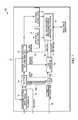
- FIG. 7illustrates an exemplary embodiment of the UWB TOA and data recovery circuits 700 , presented in the UWB receiver system 600 as TOA and data recovery circuits 24 , shown in FIG. 6 , in accordance with some embodiments of the present invention.
- the UWB TOA data and recovery circuits 700comprise a windowing/gating function 71 , a TOA function 72 , a window control clock and data recovery (PLL) function 73 , a TOA averaging function 74 , a data sync and extract function (1 MHz-2 MHz) 75 - 76 , and a tag data recovery and processing function 77 .
- the UWB TOA and data recovery circuits 700process the digital data stream 23 , shown in FIG. 6 , to provide an unpacked data packet and the TOA associated with the RTLS tag to the arbitrate/buffer function 26 .
- the windowing/gating function 71 and the window control clock and data recovery (PLL) function 73work as a feedback loop to recover the TX clock 101 and provide for the adjustable timing window function 200 , as presented in FIG. 2 , by tracking the RX pulses 111 R′ that comprise the RX pulse train 211 R corresponding to the TX pulses 111 T′ in the series of TX pulses 111 in the preamble 110 .
- the TOA function 72works in conjunction with the 100 MHz receiver clocks 42 - 43 .
- the RX clock 42 ( 201 )provides for the TOA coarse time 46 .
- the parallel set of fine detector windows 43 ( 340 )provides for a TOA fine time associated with the RX fine timing window function 300 , shown in FIG.
- the TOA fine time—the registration code 350 , the disjoint timing windows 231 A-C, as determined by the adjustable timing window function 200 , and the coarse time 46are sent to the TOA averaging function 74 , along with a latch TOA control signal indicating the end of a TOA determination.
- the TOA averaging function 74is activated by a calculate TOA trigger 78 , whereby the sub-window resolution function 400 , as previously described with regard to FIG. 4 , is initiated to determine the TOA with sub-window accuracy; that is, with resolution less than 1 nsec.
- the averaged TOA 80is then sent to the tag data recovery and processing function 77 .
- the data sync and extract functions (1 MHz-2 MHz) 75 - 76are triggered upon phase lock of the PLL associated with the window control clock and data recovery (PLL) function 73 .
- Phase lock of the PLLis determined by the previously described feedback loop comprising the windowing/gating function 71 and the window control clock and data recovery (PLL) function 73 , whereby the feedback loop effectively recovers the TX clock 101 by tracking the RX pulses 111 R′ corresponding to the preamble 110 .
- the data packet 120Upon phase lock, whereby the preamble 110 is synchronized to a recovered TX clock, the data packet 120 , beginning with the remainder of the preamble 110 , is extracted and unpacked by the data sync and extract function 75 ( 76 ) at a sampling rate of 1 Mhz (2 MHz), and sent to the tag data recovery and processing function 77 .
- the data sync and extract functions 75 - 76are both set to sample the data packet 120 with a sampling rate of 2 MHz, but the two functions may differ by a data format.
- the data extracted by function 75may follow a non-IOS format, where the data extracted by function 76 may follow an IOS format.
- the tag data recovery and processing function 77serves as a data processor for the data extracted by the data sync and extract functions 75 - 76 and as a communications control function, and also provides for data exchange associated with the arbitrate/buffer function 26 , shown in FIG. 6 .
- the data tag recovery and processing function 77sends the TOA and data packet 120 information from the TOA averaging function 74 and the data sync and extract functions 75 , 76 , respectively, on TOA line 25 to the arbitrate/buffer function 26 , which selects the earliest TOA from the three TOA functions running concurrently in the UWB TOA and data recovery circuits 700 , and combines the TOA with the data packet 120 data into a tag message 27 to send to the tag data queue 28 .
- the tag message 27comprises at least the average TOA 80 and TX ID 120 B extracted from the data packet 120 associated with the given tag transmission.
- the tag data queue 28as described previously with respect to FIG. 6 , effectively functions as a FIFO buffer for data transmission to the central processor/hub 11 .
- the tag data recovery and processing function 77also serves as a controller for the timing of a triggering of the TOA averaging function 74 and a locking/unlocking 79 of the PLL in the window control clock and data recovery (PLL) function 73 .
- the TOA averaging function 74is initiated by the calculate TOA trigger 78 set by the tag data memory and processing controller 77 , whereby the TOA trigger 78 is a function of a sync code 112 detection and a waiting interval associated with the data sync and extract function 75 - 76 .
- the locking/unlocking 79 of the PLLis a function of a PLL lock indication initiated at the window control clock and data recovery (PLL) function 73 , as described previously. And the locking/unlocking 79 of the PLL is reset to unlock the PLL upon detection in the sync and data extract functions 75 - 76 that the end of the data packet 120 has been reached, that the sampling of the data packet for the given tag transmission is complete.
- the TOA averaging function 74is elucidated by the sub-window resolution function 400 , as described with regard to FIG. 4 , and is initiated by the calculate TOA trigger 78 .
- the TOA averaging function 74may, in some examples, register a transition as successive RX pulses exhibit a change in detection registration, as demonstrated in FIG. 4 .
- a TOA numerical averagemay be constructed to assign a TOA with sub-window resolution.
- a TOA numerical averagemay be constructed, according to FIG.
- RX pulses 1 - 5are assigned a weight equal to 4 nsec greater than the leading edge of the final center disjoint timing window 233 B
- RX pulses 6 - 8are assigned a weight equal to 3 nsec greater than the leading edge of the final center disjoint timing window 233 B.
Landscapes
- Engineering & Computer Science (AREA)
- Computer Networks & Wireless Communication (AREA)
- Signal Processing (AREA)
- Mobile Radio Communication Systems (AREA)
- Computer Security & Cryptography (AREA)
Abstract
Description
dR
NR
Ni
Claims (11)
Priority Applications (1)
| Application Number | Priority Date | Filing Date | Title |
|---|---|---|---|
| US14/678,079US9668164B2 (en) | 2014-06-05 | 2015-04-03 | Receiver processor for bandwidth management of a multiple receiver real-time location system (RTLS) |
Applications Claiming Priority (2)
| Application Number | Priority Date | Filing Date | Title |
|---|---|---|---|
| US201462008243P | 2014-06-05 | 2014-06-05 | |
| US14/678,079US9668164B2 (en) | 2014-06-05 | 2015-04-03 | Receiver processor for bandwidth management of a multiple receiver real-time location system (RTLS) |
Publications (2)
| Publication Number | Publication Date |
|---|---|
| US20150358852A1 US20150358852A1 (en) | 2015-12-10 |
| US9668164B2true US9668164B2 (en) | 2017-05-30 |
Family
ID=54770663
Family Applications (1)
| Application Number | Title | Priority Date | Filing Date |
|---|---|---|---|
| US14/678,079Active2035-08-28US9668164B2 (en) | 2014-06-05 | 2015-04-03 | Receiver processor for bandwidth management of a multiple receiver real-time location system (RTLS) |
Country Status (1)
| Country | Link |
|---|---|
| US (1) | US9668164B2 (en) |
Cited By (4)
| Publication number | Priority date | Publication date | Assignee | Title |
|---|---|---|---|---|
| US11877058B1 (en) | 2022-08-25 | 2024-01-16 | Benjamin Slotznick | Computer program product and automated method for auto-focusing a camera on a person in a venue who is wearing, or carrying, or holding, or speaking into a microphone at the venue |
| US11889187B1 (en) | 2022-08-25 | 2024-01-30 | Benjamin Slotznick | Computer program product and method for auto-focusing one or more lighting fixtures on selected persons in a venue who are performers of a performance occurring at the venue |
| US11889188B1 (en) | 2022-08-25 | 2024-01-30 | Benjamin Slotznick | Computer program product and method for auto-focusing one or more cameras on selected persons in a venue who are performers of a performance occurring at the venue |
| US11902659B1 (en)* | 2022-08-25 | 2024-02-13 | Benjamin Slotznick | Computer program product and method for auto-focusing a lighting fixture on a person in a venue who is wearing, or carrying, or holding, or speaking into a microphone at the venue |
Families Citing this family (23)
| Publication number | Priority date | Publication date | Assignee | Title |
|---|---|---|---|---|
| US9699278B2 (en) | 2013-06-06 | 2017-07-04 | Zih Corp. | Modular location tag for a real time location system network |
| US10437658B2 (en) | 2013-06-06 | 2019-10-08 | Zebra Technologies Corporation | Method, apparatus, and computer program product for collecting and displaying sporting event data based on real time data for proximity and movement of objects |
| US20140365194A1 (en) | 2013-06-06 | 2014-12-11 | Zih Corp. | Method, apparatus, and computer program product for dynamics/kinetics model selection |
| US9715005B2 (en) | 2013-06-06 | 2017-07-25 | Zih Corp. | Method, apparatus, and computer program product improving real time location systems with multiple location technologies |
| US11423464B2 (en) | 2013-06-06 | 2022-08-23 | Zebra Technologies Corporation | Method, apparatus, and computer program product for enhancement of fan experience based on location data |
| US9517417B2 (en) | 2013-06-06 | 2016-12-13 | Zih Corp. | Method, apparatus, and computer program product for performance analytics determining participant statistical data and game status data |
| US10609762B2 (en) | 2013-06-06 | 2020-03-31 | Zebra Technologies Corporation | Method, apparatus, and computer program product improving backhaul of sensor and other data to real time location system network |
| US9661455B2 (en) | 2014-06-05 | 2017-05-23 | Zih Corp. | Method, apparatus, and computer program product for real time location system referencing in physically and radio frequency challenged environments |
| US20150375083A1 (en) | 2014-06-05 | 2015-12-31 | Zih Corp. | Method, Apparatus, And Computer Program Product For Enhancement Of Event Visualizations Based On Location Data |
| US9668164B2 (en)* | 2014-06-05 | 2017-05-30 | Zih Corp. | Receiver processor for bandwidth management of a multiple receiver real-time location system (RTLS) |
| CA2951154C (en) | 2014-06-05 | 2019-08-13 | Zih Corp. | Systems, apparatus and methods for variable rate ultra-wideband communications |
| US9626616B2 (en) | 2014-06-05 | 2017-04-18 | Zih Corp. | Low-profile real-time location system tag |
| CN106461754B (en) | 2014-06-05 | 2019-10-11 | 斑马技术公司 | For the receiver processor determined with high-resolution TOA that adaptively opens a window |
| US10261169B2 (en) | 2014-06-05 | 2019-04-16 | Zebra Technologies Corporation | Method for iterative target location in a multiple receiver target location system |
| US9759803B2 (en) | 2014-06-06 | 2017-09-12 | Zih Corp. | Method, apparatus, and computer program product for employing a spatial association model in a real time location system |
| EP3152585B1 (en) | 2014-06-06 | 2022-04-27 | Zebra Technologies Corporation | Method, apparatus, and computer program product improving real time location systems with multiple location technologies |
| US10103975B2 (en)* | 2016-08-25 | 2018-10-16 | Zih Corp. | Methods and apparatus to mitigate interference and to extend field of view in ultra-wideband systems |
| US10650621B1 (en) | 2016-09-13 | 2020-05-12 | Iocurrents, Inc. | Interfacing with a vehicular controller area network |
| US10606604B2 (en)* | 2017-08-22 | 2020-03-31 | Bank Of America Corporation | Predictive queue control and allocation |
| US10802109B1 (en)* | 2019-03-18 | 2020-10-13 | Bae Systems Information And Electronic Systems Integration Inc | Techniques for building pulse trains of emission sources |
| US11030505B1 (en) | 2019-12-27 | 2021-06-08 | Signify Holding B.V. | Alternative identification of objects for constrained networks |
| WO2022026400A1 (en)* | 2020-07-27 | 2022-02-03 | C3-Wireless, Llc | Systems for real time location services (rtls) |
| US11791925B2 (en)* | 2021-11-08 | 2023-10-17 | Huawei Technologies Co., Ltd. | Method, apparatus and system for determining multipath interference (MPI) on an optical link |
Citations (167)
| Publication number | Priority date | Publication date | Assignee | Title |
|---|---|---|---|---|
| US3732500A (en) | 1968-09-27 | 1973-05-08 | Itt | Selection and processing system for signals, including frequency discriminator |
| US5119104A (en) | 1990-05-04 | 1992-06-02 | Heller Alan C | Location system adapted for use in multipath environments |
| US5469409A (en) | 1994-03-14 | 1995-11-21 | Motorola, Inc. | Method for clock calibration in a position determination system |
| US5513854A (en) | 1993-04-19 | 1996-05-07 | Daver; Gil J. G. | System used for real time acquistion of data pertaining to persons in motion |
| US5645077A (en) | 1994-06-16 | 1997-07-08 | Massachusetts Institute Of Technology | Inertial orientation tracker apparatus having automatic drift compensation for tracking human head and other similarly sized body |
| US5699244A (en) | 1994-03-07 | 1997-12-16 | Monsanto Company | Hand-held GUI PDA with GPS/DGPS receiver for collecting agronomic and GPS position data |
| WO1998005977A1 (en) | 1996-08-01 | 1998-02-12 | Era A.S. | A process for location of objects, mainly aircraft, and a system for carrying out this process |
| US5901172A (en) | 1997-06-11 | 1999-05-04 | Multispectral Solutions, Inc. | Ultra wideband receiver with high speed noise and interference tracking threshold |
| US5920287A (en) | 1997-01-21 | 1999-07-06 | Widata Corporation | Radio location system for precisely tracking objects by RF transceiver tags which randomly and repetitively emit wideband identification signals |
| US5930741A (en) | 1995-02-28 | 1999-07-27 | Virtual Technologies, Inc. | Accurate, rapid, reliable position sensing using multiple sensing technologies |
| US5995046A (en) | 1998-01-30 | 1999-11-30 | Widata Corporation | Radio geo-location system with advanced first received wavefront arrival determination |
| WO1999061936A1 (en) | 1998-05-26 | 1999-12-02 | Time Domain Corporation | System and method for distance measurement by inphase and quadrature signals in a radio system |
| US6028626A (en) | 1995-01-03 | 2000-02-22 | Arc Incorporated | Abnormality detection and surveillance system |
| US6176837B1 (en) | 1998-04-17 | 2001-01-23 | Massachusetts Institute Of Technology | Motion tracking system |
| WO2001008417A1 (en) | 1999-07-26 | 2001-02-01 | Joseph Charles Bok | System, apparatus, and method for telemetry and monitoring of desired targets |
| US6204813B1 (en) | 1998-02-20 | 2001-03-20 | Trakus, Inc. | Local area multiple object tracking system |
| US20010010541A1 (en) | 1998-03-19 | 2001-08-02 | Fernandez Dennis Sunga | Integrated network for monitoring remote objects |
| US20010030625A1 (en) | 2000-01-12 | 2001-10-18 | Doles Daniel T. | Local clock-referenced DTOA geolocation system with wireless infrastructure |
| US20020004398A1 (en) | 2000-07-10 | 2002-01-10 | Hitachi, Ltd. | Method of providing location service using CDMA-based cellular phone system, a method of measuring location and location system |
| US6366242B1 (en) | 1997-01-21 | 2002-04-02 | Wherenet Corporation | Computer workstation tool for displaying performance estimate of tagged object geo-location system for proposed geometry layout of tag transmission readers |
| US20020041284A1 (en) | 1999-01-29 | 2002-04-11 | Scale Inc. | Time-series data processing device and method |
| US6380894B1 (en) | 1999-08-30 | 2002-04-30 | Wherenet Corporation | Multi-lateration system with automatic calibration and error removal |
| US20020116147A1 (en) | 1994-11-21 | 2002-08-22 | Vock Curtis A. | Methods and systems for assessing athletic performance |
| US20020114493A1 (en) | 2001-02-16 | 2002-08-22 | Golftec, Inc. | Method and system for physical motion analysis |
| EP1235077A2 (en) | 2001-02-27 | 2002-08-28 | Pioneer Corporation | Apparatus, method and system for positioning |
| EP1241616A2 (en) | 2001-03-16 | 2002-09-18 | Agilent Technologies, Inc. (a Delaware corporation) | Portable electronic device with mouse-like capabilities |
| US20020135479A1 (en) | 2000-03-07 | 2002-09-26 | Wherenet Corp | Ultra-sensitive magnetic field receiver capable of operating in high noise environments |
| EP1253438A2 (en) | 2001-04-23 | 2002-10-30 | Itt Manufacturing Enterprises, Inc. | Methods and apparatus for estimating accuracy of range measurement signals |
| US20030090387A1 (en) | 2001-07-20 | 2003-05-15 | James Lestienne | Badge for a locating and tracking system |
| US20030095186A1 (en) | 1998-11-20 | 2003-05-22 | Aman James A. | Optimizations for live event, real-time, 3D object tracking |
| US20030128100A1 (en) | 2001-11-26 | 2003-07-10 | Aero-Vision Technologies, Inc. | System and method for monitoring individuals and objects associated with wireless identification tags |
| US6593885B2 (en) | 2000-04-27 | 2003-07-15 | Wherenet Corp | Low cost DTOA location processing system based on multiple readers-to-single processor architecture |
| US6655582B2 (en) | 2001-01-02 | 2003-12-02 | Wherenet Corp | System and method for identifying objects using single connection line |
| US20030227453A1 (en) | 2002-04-09 | 2003-12-11 | Klaus-Peter Beier | Method, system and computer program product for automatically creating an animated 3-D scenario from human position and path data |
| US20040022227A1 (en)* | 2002-08-02 | 2004-02-05 | Lynch Randall Gene | System and method for asset tracking |
| US6710713B1 (en) | 2002-05-17 | 2004-03-23 | Tom Russo | Method and apparatus for evaluating athletes in competition |
| US20040062216A1 (en) | 2002-09-30 | 2004-04-01 | Nicholls Charles T. | Reducing narrowband interference in a wideband signal |
| US20040108954A1 (en) | 2001-10-18 | 2004-06-10 | Richley Edward A. | Object location system and method |
| US20040178960A1 (en) | 2002-12-09 | 2004-09-16 | Huei-Hsin Sun | Wide-band antenna |
| US6812884B2 (en) | 2003-03-12 | 2004-11-02 | Multispectral Solutions, Inc. | Transceiver system and method utilizing nanosecond pulses |
| US20040249969A1 (en)* | 2000-09-12 | 2004-12-09 | Price Harold Edward | Streaming media buffering system |
| US20040260828A1 (en)* | 2000-09-12 | 2004-12-23 | Sn Acquisition Inc. | Streaming media buffering system |
| US20040260470A1 (en) | 2003-06-14 | 2004-12-23 | Rast Rodger H. | Conveyance scheduling and logistics system |
| US6836744B1 (en) | 2000-08-18 | 2004-12-28 | Fareid A. Asphahani | Portable system for analyzing human gait |
| EP1503513A1 (en) | 2003-07-30 | 2005-02-02 | Mitsubishi Electric Information Technology Centre Europe B.V. | Method for identifying the beginning of a UWB pulse sequence |
| US20050026563A1 (en) | 2003-08-01 | 2005-02-03 | Leeper David G. | Apparatus and associated methods for precision ranging measurements in a wireless communication environment |
| US20050059998A1 (en) | 2003-09-12 | 2005-03-17 | Norte David A. | Ultra-high-frequency notch filter |
| US20050075079A1 (en) | 2003-10-07 | 2005-04-07 | Samsung Electronics Co., Ltd. | Mobile terminal circuit including an RFID tag and wireless identification method using the same |
| US20050093976A1 (en) | 2003-11-04 | 2005-05-05 | Eastman Kodak Company | Correlating captured images and timed 3D event data |
| US20050148281A1 (en) | 2003-11-17 | 2005-07-07 | Jorge Sanchez-Castro | Toy vehicles and play sets with contactless identification |
| US20050207617A1 (en) | 2004-03-03 | 2005-09-22 | Tim Sarnoff | Digital representation of a live event |
| WO2006022548A1 (en) | 2004-08-27 | 2006-03-02 | Nedap Agri B.V. | Ultra wide band system for animal location |
| US7009638B2 (en) | 2001-05-04 | 2006-03-07 | Vexcel Imaging Gmbh | Self-calibrating, digital, large format camera with single or multiple detector arrays and single or multiple optical systems |
| US20060067324A1 (en) | 2004-09-30 | 2006-03-30 | Samsung Electronics Co., Ltd. | Method and apparatus for supporting voice service through radio channel in mobile telecommunication system |
| US20060139167A1 (en) | 2002-12-19 | 2006-06-29 | Davie Alan J | Object positioning system, object positioning apparatus and object positioning method |
| US20060164213A1 (en) | 2005-01-26 | 2006-07-27 | Battelle Memorial Institute | Method for autonomous establishment and utilization of an active-RF tag network |
| US20060252476A1 (en) | 2005-05-09 | 2006-11-09 | Tarek Bahou | Fantasy sports system and method thereof |
| US20060271912A1 (en)* | 2005-04-18 | 2006-11-30 | University Of Pittsburgh-Of The Commonwealth System Of Higher Education | Method and software tool for automatic generation of software for integrated circuit processors |
| US20060281061A1 (en) | 2005-06-13 | 2006-12-14 | Tgds, Inc. | Sports Training Simulation System and Associated Methods |
| US7190271B2 (en) | 2003-11-07 | 2007-03-13 | Wherenet Corp | Location system and method that achieves time synchronized network performance using unsynchronized receiver clocks |
| US20070091292A1 (en) | 2005-09-15 | 2007-04-26 | Samsung Electronics Co., Ltd. | System, medium, and method controlling operation according to instructional movement |
| US20070176749A1 (en) | 2006-02-01 | 2007-08-02 | Wherenet Corp, Corporation Of The State Of California | System and method for determining signal source location in wireless local area network |
| US20070296723A1 (en) | 2006-06-26 | 2007-12-27 | Electronic Arts Inc. | Electronic simulation of events via computer-based gaming technologies |
| US20080065684A1 (en) | 2006-09-10 | 2008-03-13 | Zilberman Avraham | Method and a system for analyzing plays of sports teams |
| US20080106381A1 (en)* | 2006-11-08 | 2008-05-08 | Adamec Andrew J | Method and system for tuning an rfid interrogator |
| US20080113787A1 (en) | 2006-11-15 | 2008-05-15 | Alderucci Dean P | Biometric access sensitivity |
| US20080129825A1 (en) | 2006-12-04 | 2008-06-05 | Lynx System Developers, Inc. | Autonomous Systems And Methods For Still And Moving Picture Production |
| US20080140233A1 (en) | 2006-12-12 | 2008-06-12 | International Business Machines Corporation | Determining team effectiveness through sporting events |
| US20080186231A1 (en) | 2007-02-05 | 2008-08-07 | Daniel Aljadeff | Dual bandwidth time difference of arrival (tdoa) system |
| US20080204248A1 (en) | 2007-02-23 | 2008-08-28 | Nancy Cam Winget | Rfid tag management and operation |
| US20080262885A1 (en)* | 2007-04-17 | 2008-10-23 | Wherenet Corp | Flow metering of vehicles using rtls tracking |
| US20080269016A1 (en) | 2007-04-30 | 2008-10-30 | Joseph Ungari | Adaptive Training System with Aerial Mobility |
| US20080266131A1 (en) | 2007-02-13 | 2008-10-30 | Wherenet Corp. | System, apparatus and method for locating and/or tracking assets |
| US20080281443A1 (en) | 2007-05-13 | 2008-11-13 | James Neil Rodgers | Chip Referee |
| US20080285805A1 (en) | 2007-03-15 | 2008-11-20 | Xsens Technologies B.V. | Motion Tracking System |
| US20090048044A1 (en) | 2007-08-17 | 2009-02-19 | Adidas International Marketing B.V. | Sports electronic training system with sport ball, and applications thereof |
| US20090141736A1 (en) | 2007-11-30 | 2009-06-04 | Viasat, Inc. | Contention-based communications |
| US20090231198A1 (en) | 2008-03-17 | 2009-09-17 | Disney Enterprises, Inc. | Active player tracking |
| US20100026809A1 (en) | 2008-07-29 | 2010-02-04 | Gerald Curry | Camera-based tracking and position determination for sporting events |
| US7667604B2 (en) | 2002-01-11 | 2010-02-23 | Sap Ag | Context-aware and real-time item tracking system architecture and scenarios |
| US20100045508A1 (en) | 2008-08-20 | 2010-02-25 | Qualcomm Incorporated | Two-way ranging with inter-pulse transmission and reception |
| US20100054304A1 (en) | 2007-05-08 | 2010-03-04 | Time Domain Corporation | Enhanced system and method for detecting the leading edge of a waveform |
| US20100060452A1 (en) | 2008-09-05 | 2010-03-11 | DearlerMesh, Inc. | Using a mesh of radio frequency identification tags for tracking entities at a site |
| US7710322B1 (en) | 2005-05-10 | 2010-05-04 | Multispectral Solutions, Inc. | Extensible object location system and method using multiple references |
| US20100150117A1 (en) | 2008-12-17 | 2010-06-17 | Nortel Networks Limited | Method and system for wireless lan-based indoor position location |
| US7755541B2 (en) | 2007-02-13 | 2010-07-13 | Wherenet Corp. | System and method for tracking vehicles and containers |
| WO2010083943A1 (en) | 2009-01-22 | 2010-07-29 | Arieso Limited | Determining differences between base station timing offset for pairs of base stations in asynchronous networks using location estimates |
| US20100228314A1 (en) | 2007-10-24 | 2010-09-09 | Medtronic, Inc. | Remote titration of therapy delivered by an implantable medical device |
| US20100250305A1 (en) | 2009-03-31 | 2010-09-30 | Morris Lee | Methods and apparatus to monitor shoppers in a retail environment |
| US20100278386A1 (en) | 2007-07-11 | 2010-11-04 | Cairos Technologies Ag | Videotracking |
| US20100283603A1 (en) | 2005-06-08 | 2010-11-11 | Massey University | Pasture management |
| US20100283630A1 (en) | 2009-05-05 | 2010-11-11 | Advanced Technologies Group, LLC | Sports telemetry system for collecting performance metrics and data |
| US20100328073A1 (en) | 2009-06-30 | 2010-12-30 | Intermec Ip Corp. | Method and system to determine the position, orientation, size, and movement of rfid tagged objects |
| US20110002223A1 (en) | 2008-02-29 | 2011-01-06 | Koninklijke Philips Electronics N.V. | Optimizing physiologic monitoring based on available but variable signal quality |
| US20110025847A1 (en) | 2009-07-31 | 2011-02-03 | Johnson Controls Technology Company | Service management using video processing |
| US7899006B2 (en)* | 2006-12-05 | 2011-03-01 | Zebra Enterprise Solutions Corp. | Location system for wireless local area network (WLAN) using RSSI and time difference of arrival (TDOA) processing |
| US20110054782A1 (en) | 2009-08-27 | 2011-03-03 | Kaahui Keaka K A | Method and apparatus of measuring and analyzing user movement |
| US20110063114A1 (en) | 2009-09-15 | 2011-03-17 | Dikran Ikoyan | Posture training device |
| US20110084806A1 (en) | 2009-10-08 | 2011-04-14 | Awarepoint Corporation | Wireless Tracking System And Method For Backhaul Of Information |
| US20110134240A1 (en) | 2009-12-08 | 2011-06-09 | Trueposition, Inc. | Multi-Sensor Location and Identification |
| US20110140970A1 (en) | 2008-10-09 | 2011-06-16 | Panasonic Corporation | Base station device and distance measuring method |
| US7969348B2 (en) | 2007-11-02 | 2011-06-28 | Recon Dynamics, Llc | Systems and methods for obtaining and using data from a localized location and telemetry system in a wide area location and telemetry system |
| US20110169959A1 (en) | 2010-01-05 | 2011-07-14 | Isolynx, Llc | Systems And Methods For Analyzing Event Data |
| US20110188513A1 (en) | 2008-09-24 | 2011-08-04 | Telefonaktiebolaget Lm Ericsson (Publ) | Apparatus for Reduced Mode Transmission of DPCCH Signaling and Method Thereof |
| US20110195701A1 (en) | 2010-02-09 | 2011-08-11 | Joel Powell Cook | System and method for mobile monitoring of non-associated tags |
| US20110261195A1 (en) | 2010-04-26 | 2011-10-27 | Sensormatic Electronics, LLC | Method and system for security system tampering detection |
| US20110300905A1 (en) | 2010-06-04 | 2011-12-08 | Rami Levi | System and Method for Locating an Object Using a Mobile Device |
| US8077981B2 (en) | 2007-07-27 | 2011-12-13 | Sportvision, Inc. | Providing virtual inserts using image tracking with camera and position sensors |
| US20110320322A1 (en) | 2010-06-25 | 2011-12-29 | Symbol Technologies, Inc. | Inventory monitoring using complementary modes for item identification |
| US20120015665A1 (en) | 2010-07-16 | 2012-01-19 | Qualcomm Incorporated | Sensor node positioning for location determination |
| US20120014278A1 (en) | 2010-07-15 | 2012-01-19 | Aitan Ameti | Method and apparatus for determining system node positions |
| US20120024516A1 (en) | 2009-02-16 | 2012-02-02 | Tata Steel Limited | Method and Apparatus for Achieving Higher Cooling Rates of a Gas During Bypass Cooling in a Batch Annealing Furnace of Cold Rolling Mills |
| US20120042326A1 (en) | 2010-08-16 | 2012-02-16 | Fujitsu Limited | Identifying An Event Occurrence From Sensor Data Streams |
| US20120057634A1 (en) | 2010-09-02 | 2012-03-08 | Fang Shi | Systems and Methods for Video Content Analysis |
| US20120065483A1 (en) | 2010-09-10 | 2012-03-15 | Lg Innotek Co., Ltd. | Rtls tag, rtls reader and livestock management system using the same |
| US20120081531A1 (en) | 2009-03-13 | 2012-04-05 | Isolynx, Llc | System And Methods For Providing Performance Feedback |
| US20120112904A1 (en) | 2010-11-08 | 2012-05-10 | Hammel Companies, Inc. | System and Method for Tracking, Monitoring and Deriving the Location of Transient Objects by Monitoring the Location of Equipment Used to Move the Objects |
| US20120126973A1 (en) | 2010-11-19 | 2012-05-24 | Deangelis Douglas J | Associative object tracking systems and methods |
| US20120139708A1 (en) | 2010-12-06 | 2012-06-07 | Massachusetts Institute Of Technology | Wireless Hand Gesture Capture |
| EP2474939A1 (en) | 2010-09-15 | 2012-07-11 | Omron Corporation | Rfid tag and rfid system |
| US20120184878A1 (en) | 2011-01-13 | 2012-07-19 | Bijan Najafi | Intelligent device to monitor and remind patients with footwear, walking aids, braces, or orthotics |
| US20120212505A1 (en) | 2011-02-17 | 2012-08-23 | Nike, Inc. | Selecting And Correlating Physical Activity Data With Image Data |
| US20120218301A1 (en) | 2010-02-28 | 2012-08-30 | Osterhout Group, Inc. | See-through display with an optical assembly including a wedge-shaped illumination system |
| US20120225676A1 (en) | 2011-03-04 | 2012-09-06 | Zebra Enterprise Solutions Llc | Method, apparatus, and computer program product for processing received signals for locating |
| US8269835B2 (en) | 2007-12-07 | 2012-09-18 | International Business Machines Corporation | Modification of turf TV participant decorations based on multiple real-time factors |
| US8279051B2 (en) | 2008-04-14 | 2012-10-02 | Naser Mohammed Khan | Realtime coaching system |
| US20120246795A1 (en) | 2011-03-31 | 2012-10-04 | Adidas Ag | Sensor Garment |
| US20120256745A1 (en) | 2011-04-08 | 2012-10-11 | Rave Wireless, Inc. | Public safety analysis system |
| US20120268239A1 (en) | 2011-04-20 | 2012-10-25 | Peter Ljung | Methods, systems and computer program products for registration of and anonymous communications related to tagged objects |
| US20130003860A1 (en) | 2011-06-28 | 2013-01-03 | Hisao Sasai | Image decoding method, image coding method, image decoding apparatus, image coding apparatus, and image coding and decoding apparatus |
| US20130021206A1 (en) | 2011-05-16 | 2013-01-24 | Nanotron Technologies Gmbh | Method and System for Multipath Reduction for Wireless Synchronizing and/or Locating |
| US20130040574A1 (en) | 2011-08-12 | 2013-02-14 | Jason Edward Robert Hillyard | Systems and Methods for Low Power Short Range Wireless Device Communication Scanning |
| US20130041590A1 (en) | 2011-03-31 | 2013-02-14 | Adidas Ag | Group Performance Monitoring System and Method |
| US20130066448A1 (en) | 2009-05-05 | 2013-03-14 | Advanced Technologies Group, LLC | Sports telemetry system for collecting performance metrics and data |
| US20130076645A1 (en) | 2011-09-23 | 2013-03-28 | Motorola Solutions, Inc. | Fixed display system interaction with a communication device |
| US20130096704A1 (en) | 2006-04-20 | 2013-04-18 | Nike, Inc. | Systems for Activating Electronic Devices for Operation with Athletic Equipment |
| US20130138386A1 (en) | 2011-11-30 | 2013-05-30 | Arbitron Inc. | Movement/position monitoring and linking to media consumption |
| US20130142384A1 (en) | 2011-12-06 | 2013-06-06 | Microsoft Corporation | Enhanced navigation through multi-sensor positioning |
| US20130257598A1 (en) | 2012-03-29 | 2013-10-03 | Intelleflex Corporation | Interference detection and mitigation in rfid readers and systems |
| US8568278B2 (en) | 2006-09-07 | 2013-10-29 | Nike, Inc. | Athletic performance sensing and/or tracking systems and methods |
| US20130339156A1 (en) | 2012-04-05 | 2013-12-19 | Addicam V. Sanjay | Method and Apparatus for Selecting an Advertisement for Display on a Digital Sign According to an Approaching Object |
| US20140055588A1 (en) | 2012-08-24 | 2014-02-27 | Elwha LLC, a limited liability company of the State of Delaware | Computational systems and methods for monitoring medication events |
| US8696458B2 (en) | 2008-02-15 | 2014-04-15 | Thales Visionix, Inc. | Motion tracking system and method using camera and non-camera sensors |
| US20140145828A1 (en) | 2012-11-25 | 2014-05-29 | Amir Bassan-Eskenazi | Managing a sphere of wireless tags |
| US20140156036A1 (en) | 2012-11-30 | 2014-06-05 | Jung-Tang Huang | Sports competition application system |
| US20140170607A1 (en) | 2012-12-14 | 2014-06-19 | International Business Machines Corporation | Personalized compliance feedback via model-driven sensor data assessment |
| US8775916B2 (en) | 2010-12-17 | 2014-07-08 | Microsoft Corporation | Validation analysis of human target |
| US8795045B2 (en) | 2008-04-23 | 2014-08-05 | Four O'Clock Fantasy Sports Concepts LLC | “Old school” fantasy sports system and method |
| US20140221137A1 (en) | 2012-11-09 | 2014-08-07 | Wilson Sporting Goods Co. | Ball lighting |
| US8842002B2 (en) | 2006-01-31 | 2014-09-23 | Zih Corp. | System and method for tracking assets within a monitored environment |
| US20140361875A1 (en) | 2013-06-06 | 2014-12-11 | Zih Corp. | Method, apparatus, and computer program product for tag and individual correlation |
| US20140361906A1 (en) | 2013-06-06 | 2014-12-11 | Zih Corp. | Method, apparatus, and computer program product improving backhaul of sensor and other data to real time location system network |
| WO2014197600A1 (en) | 2013-06-04 | 2014-12-11 | Isolynx, Llc | Object tracking system optimization and tools |
| US20150057981A1 (en) | 2013-08-26 | 2015-02-26 | Specialty Electrical, Llc | Method and apparatus for multi-mode tracking and display of personnel locations in a graphical model |
| US20150085111A1 (en) | 2013-09-25 | 2015-03-26 | Symbol Technologies, Inc. | Identification using video analytics together with inertial sensor data |
| US20150097653A1 (en) | 2013-10-04 | 2015-04-09 | Cambridge Silicon Radio Limited | Determination of proximity using a plurality of transponders |
| WO2015051813A1 (en) | 2013-10-13 | 2015-04-16 | Mylaps B.V. | A wearable sports timing tag assembly |
| US9081076B2 (en) | 2012-11-12 | 2015-07-14 | Isolynx, Llc | System and method for object tracking anti-jitter filtering |
| US20150358852A1 (en)* | 2014-06-05 | 2015-12-10 | Zih Corp. | Receiver processor for bandwidth management of a multiple receiver real-time location system (rtls) |
| US20150355311A1 (en) | 2014-06-06 | 2015-12-10 | Zih Corp. | Method, Apparatus, and Computer Program Product for Employing a Spatial Association Model in a Real Time Location System |
| US20150360133A1 (en) | 2014-06-12 | 2015-12-17 | Michael Neil MACCALLUM | Fantasy sports manager for various devices |
| US20150379387A1 (en)* | 2014-06-05 | 2015-12-31 | Zih Corp. | Low-profile real-time location system tag |
| US20150375083A1 (en) | 2014-06-05 | 2015-12-31 | Zih Corp. | Method, Apparatus, And Computer Program Product For Enhancement Of Event Visualizations Based On Location Data |
| US20150378002A1 (en) | 2013-06-06 | 2015-12-31 | Zih Corp. | Method, Apparatus And Computer Program Product Improving Real Time Location Systems With Multiple Location Technologies |
| US20150375041A1 (en) | 2013-06-06 | 2015-12-31 | Zih Corp. | Modular location tag for a real time location system network |
| US20160097837A1 (en)* | 2014-06-05 | 2016-04-07 | Zih Corp. | Method for Iterative Target Location in a Multiple Receiver Target Location System |
| US9381645B1 (en) | 2014-12-08 | 2016-07-05 | Amazon Technologies, Inc. | System for automating manipulation of items |
- 2015
- 2015-04-03USUS14/678,079patent/US9668164B2/enactiveActive
Patent Citations (182)
| Publication number | Priority date | Publication date | Assignee | Title |
|---|---|---|---|---|
| US3732500A (en) | 1968-09-27 | 1973-05-08 | Itt | Selection and processing system for signals, including frequency discriminator |
| US5119104A (en) | 1990-05-04 | 1992-06-02 | Heller Alan C | Location system adapted for use in multipath environments |
| US5513854A (en) | 1993-04-19 | 1996-05-07 | Daver; Gil J. G. | System used for real time acquistion of data pertaining to persons in motion |
| US5699244A (en) | 1994-03-07 | 1997-12-16 | Monsanto Company | Hand-held GUI PDA with GPS/DGPS receiver for collecting agronomic and GPS position data |
| US5469409A (en) | 1994-03-14 | 1995-11-21 | Motorola, Inc. | Method for clock calibration in a position determination system |
| US5645077A (en) | 1994-06-16 | 1997-07-08 | Massachusetts Institute Of Technology | Inertial orientation tracker apparatus having automatic drift compensation for tracking human head and other similarly sized body |
| US20020116147A1 (en) | 1994-11-21 | 2002-08-22 | Vock Curtis A. | Methods and systems for assessing athletic performance |
| US6028626A (en) | 1995-01-03 | 2000-02-22 | Arc Incorporated | Abnormality detection and surveillance system |
| US5930741A (en) | 1995-02-28 | 1999-07-27 | Virtual Technologies, Inc. | Accurate, rapid, reliable position sensing using multiple sensing technologies |
| WO1998005977A1 (en) | 1996-08-01 | 1998-02-12 | Era A.S. | A process for location of objects, mainly aircraft, and a system for carrying out this process |
| US6366242B1 (en) | 1997-01-21 | 2002-04-02 | Wherenet Corporation | Computer workstation tool for displaying performance estimate of tagged object geo-location system for proposed geometry layout of tag transmission readers |
| US5920287A (en) | 1997-01-21 | 1999-07-06 | Widata Corporation | Radio location system for precisely tracking objects by RF transceiver tags which randomly and repetitively emit wideband identification signals |
| US6121926A (en) | 1997-01-21 | 2000-09-19 | Wherenet | Radio geo-location system with advanced first received wavefront arrival determination |
| US5901172A (en) | 1997-06-11 | 1999-05-04 | Multispectral Solutions, Inc. | Ultra wideband receiver with high speed noise and interference tracking threshold |
| US5995046A (en) | 1998-01-30 | 1999-11-30 | Widata Corporation | Radio geo-location system with advanced first received wavefront arrival determination |
| US6204813B1 (en) | 1998-02-20 | 2001-03-20 | Trakus, Inc. | Local area multiple object tracking system |
| US20010010541A1 (en) | 1998-03-19 | 2001-08-02 | Fernandez Dennis Sunga | Integrated network for monitoring remote objects |
| US6176837B1 (en) | 1998-04-17 | 2001-01-23 | Massachusetts Institute Of Technology | Motion tracking system |
| WO1999061936A1 (en) | 1998-05-26 | 1999-12-02 | Time Domain Corporation | System and method for distance measurement by inphase and quadrature signals in a radio system |
| US20030095186A1 (en) | 1998-11-20 | 2003-05-22 | Aman James A. | Optimizations for live event, real-time, 3D object tracking |
| US20020041284A1 (en) | 1999-01-29 | 2002-04-11 | Scale Inc. | Time-series data processing device and method |
| WO2001008417A1 (en) | 1999-07-26 | 2001-02-01 | Joseph Charles Bok | System, apparatus, and method for telemetry and monitoring of desired targets |
| US6380894B1 (en) | 1999-08-30 | 2002-04-30 | Wherenet Corporation | Multi-lateration system with automatic calibration and error removal |
| US20010030625A1 (en) | 2000-01-12 | 2001-10-18 | Doles Daniel T. | Local clock-referenced DTOA geolocation system with wireless infrastructure |
| US20020135479A1 (en) | 2000-03-07 | 2002-09-26 | Wherenet Corp | Ultra-sensitive magnetic field receiver capable of operating in high noise environments |
| US6593885B2 (en) | 2000-04-27 | 2003-07-15 | Wherenet Corp | Low cost DTOA location processing system based on multiple readers-to-single processor architecture |
| US20020004398A1 (en) | 2000-07-10 | 2002-01-10 | Hitachi, Ltd. | Method of providing location service using CDMA-based cellular phone system, a method of measuring location and location system |
| US6836744B1 (en) | 2000-08-18 | 2004-12-28 | Fareid A. Asphahani | Portable system for analyzing human gait |
| US20040260828A1 (en)* | 2000-09-12 | 2004-12-23 | Sn Acquisition Inc. | Streaming media buffering system |
| US20040249969A1 (en)* | 2000-09-12 | 2004-12-09 | Price Harold Edward | Streaming media buffering system |
| US6655582B2 (en) | 2001-01-02 | 2003-12-02 | Wherenet Corp | System and method for identifying objects using single connection line |
| US20020114493A1 (en) | 2001-02-16 | 2002-08-22 | Golftec, Inc. | Method and system for physical motion analysis |
| EP1235077A2 (en) | 2001-02-27 | 2002-08-28 | Pioneer Corporation | Apparatus, method and system for positioning |
| EP1241616A2 (en) | 2001-03-16 | 2002-09-18 | Agilent Technologies, Inc. (a Delaware corporation) | Portable electronic device with mouse-like capabilities |
| US20020130835A1 (en) | 2001-03-16 | 2002-09-19 | Brosnan Michael John | Portable electronic device with mouse-like capabilities |
| EP1253438A2 (en) | 2001-04-23 | 2002-10-30 | Itt Manufacturing Enterprises, Inc. | Methods and apparatus for estimating accuracy of range measurement signals |
| US7009638B2 (en) | 2001-05-04 | 2006-03-07 | Vexcel Imaging Gmbh | Self-calibrating, digital, large format camera with single or multiple detector arrays and single or multiple optical systems |
| US20030090387A1 (en) | 2001-07-20 | 2003-05-15 | James Lestienne | Badge for a locating and tracking system |
| US6882315B2 (en) | 2001-10-18 | 2005-04-19 | Multispectral Solutions, Inc. | Object location system and method |
| US20040108954A1 (en) | 2001-10-18 | 2004-06-10 | Richley Edward A. | Object location system and method |
| US20030128100A1 (en) | 2001-11-26 | 2003-07-10 | Aero-Vision Technologies, Inc. | System and method for monitoring individuals and objects associated with wireless identification tags |
| US7667604B2 (en) | 2002-01-11 | 2010-02-23 | Sap Ag | Context-aware and real-time item tracking system architecture and scenarios |
| US20030227453A1 (en) | 2002-04-09 | 2003-12-11 | Klaus-Peter Beier | Method, system and computer program product for automatically creating an animated 3-D scenario from human position and path data |
| US6710713B1 (en) | 2002-05-17 | 2004-03-23 | Tom Russo | Method and apparatus for evaluating athletes in competition |
| US20040022227A1 (en)* | 2002-08-02 | 2004-02-05 | Lynch Randall Gene | System and method for asset tracking |
| US20040062216A1 (en) | 2002-09-30 | 2004-04-01 | Nicholls Charles T. | Reducing narrowband interference in a wideband signal |
| US20040178960A1 (en) | 2002-12-09 | 2004-09-16 | Huei-Hsin Sun | Wide-band antenna |
| US20060139167A1 (en) | 2002-12-19 | 2006-06-29 | Davie Alan J | Object positioning system, object positioning apparatus and object positioning method |
| US6812884B2 (en) | 2003-03-12 | 2004-11-02 | Multispectral Solutions, Inc. | Transceiver system and method utilizing nanosecond pulses |
| US20040260470A1 (en) | 2003-06-14 | 2004-12-23 | Rast Rodger H. | Conveyance scheduling and logistics system |
| US20050031043A1 (en) | 2003-07-30 | 2005-02-10 | Mitsubishi Denki Kabushiki Kaisha | Method for identifying the beginning of a UWB pulse sequence |
| EP1503513A1 (en) | 2003-07-30 | 2005-02-02 | Mitsubishi Electric Information Technology Centre Europe B.V. | Method for identifying the beginning of a UWB pulse sequence |
| US20050026563A1 (en) | 2003-08-01 | 2005-02-03 | Leeper David G. | Apparatus and associated methods for precision ranging measurements in a wireless communication environment |
| US20050059998A1 (en) | 2003-09-12 | 2005-03-17 | Norte David A. | Ultra-high-frequency notch filter |
| US20050075079A1 (en) | 2003-10-07 | 2005-04-07 | Samsung Electronics Co., Ltd. | Mobile terminal circuit including an RFID tag and wireless identification method using the same |
| US20050093976A1 (en) | 2003-11-04 | 2005-05-05 | Eastman Kodak Company | Correlating captured images and timed 3D event data |
| US7190271B2 (en) | 2003-11-07 | 2007-03-13 | Wherenet Corp | Location system and method that achieves time synchronized network performance using unsynchronized receiver clocks |
| US20050148281A1 (en) | 2003-11-17 | 2005-07-07 | Jorge Sanchez-Castro | Toy vehicles and play sets with contactless identification |
| US20050207617A1 (en) | 2004-03-03 | 2005-09-22 | Tim Sarnoff | Digital representation of a live event |
| WO2006022548A1 (en) | 2004-08-27 | 2006-03-02 | Nedap Agri B.V. | Ultra wide band system for animal location |
| US20060067324A1 (en) | 2004-09-30 | 2006-03-30 | Samsung Electronics Co., Ltd. | Method and apparatus for supporting voice service through radio channel in mobile telecommunication system |
| US20060164213A1 (en) | 2005-01-26 | 2006-07-27 | Battelle Memorial Institute | Method for autonomous establishment and utilization of an active-RF tag network |
| US20060271912A1 (en)* | 2005-04-18 | 2006-11-30 | University Of Pittsburgh-Of The Commonwealth System Of Higher Education | Method and software tool for automatic generation of software for integrated circuit processors |
| US20060252476A1 (en) | 2005-05-09 | 2006-11-09 | Tarek Bahou | Fantasy sports system and method thereof |
| US7710322B1 (en) | 2005-05-10 | 2010-05-04 | Multispectral Solutions, Inc. | Extensible object location system and method using multiple references |
| US20100283603A1 (en) | 2005-06-08 | 2010-11-11 | Massey University | Pasture management |
| US20060281061A1 (en) | 2005-06-13 | 2006-12-14 | Tgds, Inc. | Sports Training Simulation System and Associated Methods |
| US20070091292A1 (en) | 2005-09-15 | 2007-04-26 | Samsung Electronics Co., Ltd. | System, medium, and method controlling operation according to instructional movement |
| US8842002B2 (en) | 2006-01-31 | 2014-09-23 | Zih Corp. | System and method for tracking assets within a monitored environment |
| US20070176749A1 (en) | 2006-02-01 | 2007-08-02 | Wherenet Corp, Corporation Of The State Of California | System and method for determining signal source location in wireless local area network |
| US20130096704A1 (en) | 2006-04-20 | 2013-04-18 | Nike, Inc. | Systems for Activating Electronic Devices for Operation with Athletic Equipment |
| US20070296723A1 (en) | 2006-06-26 | 2007-12-27 | Electronic Arts Inc. | Electronic simulation of events via computer-based gaming technologies |
| US8568278B2 (en) | 2006-09-07 | 2013-10-29 | Nike, Inc. | Athletic performance sensing and/or tracking systems and methods |
| US20080065684A1 (en) | 2006-09-10 | 2008-03-13 | Zilberman Avraham | Method and a system for analyzing plays of sports teams |
| US20080106381A1 (en)* | 2006-11-08 | 2008-05-08 | Adamec Andrew J | Method and system for tuning an rfid interrogator |
| US20080113787A1 (en) | 2006-11-15 | 2008-05-15 | Alderucci Dean P | Biometric access sensitivity |
| US20080129825A1 (en) | 2006-12-04 | 2008-06-05 | Lynx System Developers, Inc. | Autonomous Systems And Methods For Still And Moving Picture Production |
| US7899006B2 (en)* | 2006-12-05 | 2011-03-01 | Zebra Enterprise Solutions Corp. | Location system for wireless local area network (WLAN) using RSSI and time difference of arrival (TDOA) processing |
| US20080140233A1 (en) | 2006-12-12 | 2008-06-12 | International Business Machines Corporation | Determining team effectiveness through sporting events |
| US20080186231A1 (en) | 2007-02-05 | 2008-08-07 | Daniel Aljadeff | Dual bandwidth time difference of arrival (tdoa) system |
| US20080266131A1 (en) | 2007-02-13 | 2008-10-30 | Wherenet Corp. | System, apparatus and method for locating and/or tracking assets |
| US7755541B2 (en) | 2007-02-13 | 2010-07-13 | Wherenet Corp. | System and method for tracking vehicles and containers |
| US20080204248A1 (en) | 2007-02-23 | 2008-08-28 | Nancy Cam Winget | Rfid tag management and operation |
| US20080285805A1 (en) | 2007-03-15 | 2008-11-20 | Xsens Technologies B.V. | Motion Tracking System |
| US20080262885A1 (en)* | 2007-04-17 | 2008-10-23 | Wherenet Corp | Flow metering of vehicles using rtls tracking |
| US20080269016A1 (en) | 2007-04-30 | 2008-10-30 | Joseph Ungari | Adaptive Training System with Aerial Mobility |
| US20100054304A1 (en) | 2007-05-08 | 2010-03-04 | Time Domain Corporation | Enhanced system and method for detecting the leading edge of a waveform |
| US20080281443A1 (en) | 2007-05-13 | 2008-11-13 | James Neil Rodgers | Chip Referee |
| US20100278386A1 (en) | 2007-07-11 | 2010-11-04 | Cairos Technologies Ag | Videotracking |
| US8077981B2 (en) | 2007-07-27 | 2011-12-13 | Sportvision, Inc. | Providing virtual inserts using image tracking with camera and position sensors |
| US20090048044A1 (en) | 2007-08-17 | 2009-02-19 | Adidas International Marketing B.V. | Sports electronic training system with sport ball, and applications thereof |
| US20100228314A1 (en) | 2007-10-24 | 2010-09-09 | Medtronic, Inc. | Remote titration of therapy delivered by an implantable medical device |
| US7969348B2 (en) | 2007-11-02 | 2011-06-28 | Recon Dynamics, Llc | Systems and methods for obtaining and using data from a localized location and telemetry system in a wide area location and telemetry system |
| US20090141736A1 (en) | 2007-11-30 | 2009-06-04 | Viasat, Inc. | Contention-based communications |
| US8269835B2 (en) | 2007-12-07 | 2012-09-18 | International Business Machines Corporation | Modification of turf TV participant decorations based on multiple real-time factors |
| US8696458B2 (en) | 2008-02-15 | 2014-04-15 | Thales Visionix, Inc. | Motion tracking system and method using camera and non-camera sensors |
| US20110002223A1 (en) | 2008-02-29 | 2011-01-06 | Koninklijke Philips Electronics N.V. | Optimizing physiologic monitoring based on available but variable signal quality |
| US7671802B2 (en) | 2008-03-17 | 2010-03-02 | Disney Enterprises, Inc. | Active player tracking |
| US20090231198A1 (en) | 2008-03-17 | 2009-09-17 | Disney Enterprises, Inc. | Active player tracking |
| US8279051B2 (en) | 2008-04-14 | 2012-10-02 | Naser Mohammed Khan | Realtime coaching system |
| US8795045B2 (en) | 2008-04-23 | 2014-08-05 | Four O'Clock Fantasy Sports Concepts LLC | “Old school” fantasy sports system and method |
| US20100026809A1 (en) | 2008-07-29 | 2010-02-04 | Gerald Curry | Camera-based tracking and position determination for sporting events |
| US20100045508A1 (en) | 2008-08-20 | 2010-02-25 | Qualcomm Incorporated | Two-way ranging with inter-pulse transmission and reception |
| US20100060452A1 (en) | 2008-09-05 | 2010-03-11 | DearlerMesh, Inc. | Using a mesh of radio frequency identification tags for tracking entities at a site |
| US20110188513A1 (en) | 2008-09-24 | 2011-08-04 | Telefonaktiebolaget Lm Ericsson (Publ) | Apparatus for Reduced Mode Transmission of DPCCH Signaling and Method Thereof |
| US20110140970A1 (en) | 2008-10-09 | 2011-06-16 | Panasonic Corporation | Base station device and distance measuring method |
| US20100150117A1 (en) | 2008-12-17 | 2010-06-17 | Nortel Networks Limited | Method and system for wireless lan-based indoor position location |
| WO2010083943A1 (en) | 2009-01-22 | 2010-07-29 | Arieso Limited | Determining differences between base station timing offset for pairs of base stations in asynchronous networks using location estimates |
| US20120024516A1 (en) | 2009-02-16 | 2012-02-02 | Tata Steel Limited | Method and Apparatus for Achieving Higher Cooling Rates of a Gas During Bypass Cooling in a Batch Annealing Furnace of Cold Rolling Mills |
| US20120081531A1 (en) | 2009-03-13 | 2012-04-05 | Isolynx, Llc | System And Methods For Providing Performance Feedback |
| US20100250305A1 (en) | 2009-03-31 | 2010-09-30 | Morris Lee | Methods and apparatus to monitor shoppers in a retail environment |
| US8477046B2 (en) | 2009-05-05 | 2013-07-02 | Advanced Technologies Group, LLC | Sports telemetry system for collecting performance metrics and data |
| US20130066448A1 (en) | 2009-05-05 | 2013-03-14 | Advanced Technologies Group, LLC | Sports telemetry system for collecting performance metrics and data |
| US20100283630A1 (en) | 2009-05-05 | 2010-11-11 | Advanced Technologies Group, LLC | Sports telemetry system for collecting performance metrics and data |
| US20100328073A1 (en) | 2009-06-30 | 2010-12-30 | Intermec Ip Corp. | Method and system to determine the position, orientation, size, and movement of rfid tagged objects |
| US20110025847A1 (en) | 2009-07-31 | 2011-02-03 | Johnson Controls Technology Company | Service management using video processing |
| US20110054782A1 (en) | 2009-08-27 | 2011-03-03 | Kaahui Keaka K A | Method and apparatus of measuring and analyzing user movement |
| US20110063114A1 (en) | 2009-09-15 | 2011-03-17 | Dikran Ikoyan | Posture training device |
| US20110084806A1 (en) | 2009-10-08 | 2011-04-14 | Awarepoint Corporation | Wireless Tracking System And Method For Backhaul Of Information |
| US20110134240A1 (en) | 2009-12-08 | 2011-06-09 | Trueposition, Inc. | Multi-Sensor Location and Identification |
| US20110169959A1 (en) | 2010-01-05 | 2011-07-14 | Isolynx, Llc | Systems And Methods For Analyzing Event Data |
| US20140320660A1 (en) | 2010-01-05 | 2014-10-30 | Isolynx, Llc | Systems and methods for analyzing event data |
| US8780204B2 (en) | 2010-01-05 | 2014-07-15 | Isolynx, Llc | Systems and methods for analyzing event data |
| US20110195701A1 (en) | 2010-02-09 | 2011-08-11 | Joel Powell Cook | System and method for mobile monitoring of non-associated tags |
| US20120218301A1 (en) | 2010-02-28 | 2012-08-30 | Osterhout Group, Inc. | See-through display with an optical assembly including a wedge-shaped illumination system |
| US20110261195A1 (en) | 2010-04-26 | 2011-10-27 | Sensormatic Electronics, LLC | Method and system for security system tampering detection |
| US20110300905A1 (en) | 2010-06-04 | 2011-12-08 | Rami Levi | System and Method for Locating an Object Using a Mobile Device |
| US20110320322A1 (en) | 2010-06-25 | 2011-12-29 | Symbol Technologies, Inc. | Inventory monitoring using complementary modes for item identification |
| US8705671B2 (en) | 2010-07-15 | 2014-04-22 | Zebra Enterprise Solutions Corp. | Method and apparatus for performing temperature compensation |
| US20120014278A1 (en) | 2010-07-15 | 2012-01-19 | Aitan Ameti | Method and apparatus for determining system node positions |
| US20120015665A1 (en) | 2010-07-16 | 2012-01-19 | Qualcomm Incorporated | Sensor node positioning for location determination |
| US20120042326A1 (en) | 2010-08-16 | 2012-02-16 | Fujitsu Limited | Identifying An Event Occurrence From Sensor Data Streams |
| US20120057634A1 (en) | 2010-09-02 | 2012-03-08 | Fang Shi | Systems and Methods for Video Content Analysis |
| US20120057640A1 (en) | 2010-09-02 | 2012-03-08 | Fang Shi | Video Analytics for Security Systems and Methods |
| US20120065483A1 (en) | 2010-09-10 | 2012-03-15 | Lg Innotek Co., Ltd. | Rtls tag, rtls reader and livestock management system using the same |
| US20130021142A1 (en) | 2010-09-15 | 2013-01-24 | Omron Corporation | Rfid tag and rfid system |
| EP2474939A1 (en) | 2010-09-15 | 2012-07-11 | Omron Corporation | Rfid tag and rfid system |
| US20120112904A1 (en) | 2010-11-08 | 2012-05-10 | Hammel Companies, Inc. | System and Method for Tracking, Monitoring and Deriving the Location of Transient Objects by Monitoring the Location of Equipment Used to Move the Objects |
| US20120126973A1 (en) | 2010-11-19 | 2012-05-24 | Deangelis Douglas J | Associative object tracking systems and methods |
| US20120139708A1 (en) | 2010-12-06 | 2012-06-07 | Massachusetts Institute Of Technology | Wireless Hand Gesture Capture |
| US8775916B2 (en) | 2010-12-17 | 2014-07-08 | Microsoft Corporation | Validation analysis of human target |
| US20120184878A1 (en) | 2011-01-13 | 2012-07-19 | Bijan Najafi | Intelligent device to monitor and remind patients with footwear, walking aids, braces, or orthotics |
| US20120212505A1 (en) | 2011-02-17 | 2012-08-23 | Nike, Inc. | Selecting And Correlating Physical Activity Data With Image Data |
| US20120225676A1 (en) | 2011-03-04 | 2012-09-06 | Zebra Enterprise Solutions Llc | Method, apparatus, and computer program product for processing received signals for locating |
| US20120246795A1 (en) | 2011-03-31 | 2012-10-04 | Adidas Ag | Sensor Garment |
| US20130041590A1 (en) | 2011-03-31 | 2013-02-14 | Adidas Ag | Group Performance Monitoring System and Method |
| US20120256745A1 (en) | 2011-04-08 | 2012-10-11 | Rave Wireless, Inc. | Public safety analysis system |
| US20120268239A1 (en) | 2011-04-20 | 2012-10-25 | Peter Ljung | Methods, systems and computer program products for registration of and anonymous communications related to tagged objects |
| US20130021206A1 (en) | 2011-05-16 | 2013-01-24 | Nanotron Technologies Gmbh | Method and System for Multipath Reduction for Wireless Synchronizing and/or Locating |
| US20130003860A1 (en) | 2011-06-28 | 2013-01-03 | Hisao Sasai | Image decoding method, image coding method, image decoding apparatus, image coding apparatus, and image coding and decoding apparatus |
| US20130040574A1 (en) | 2011-08-12 | 2013-02-14 | Jason Edward Robert Hillyard | Systems and Methods for Low Power Short Range Wireless Device Communication Scanning |
| US20130076645A1 (en) | 2011-09-23 | 2013-03-28 | Motorola Solutions, Inc. | Fixed display system interaction with a communication device |
| US20130138386A1 (en) | 2011-11-30 | 2013-05-30 | Arbitron Inc. | Movement/position monitoring and linking to media consumption |
| US20130142384A1 (en) | 2011-12-06 | 2013-06-06 | Microsoft Corporation | Enhanced navigation through multi-sensor positioning |
| US20130257598A1 (en) | 2012-03-29 | 2013-10-03 | Intelleflex Corporation | Interference detection and mitigation in rfid readers and systems |
| US20130339156A1 (en) | 2012-04-05 | 2013-12-19 | Addicam V. Sanjay | Method and Apparatus for Selecting an Advertisement for Display on a Digital Sign According to an Approaching Object |
| US20140055588A1 (en) | 2012-08-24 | 2014-02-27 | Elwha LLC, a limited liability company of the State of Delaware | Computational systems and methods for monitoring medication events |
| US20140221137A1 (en) | 2012-11-09 | 2014-08-07 | Wilson Sporting Goods Co. | Ball lighting |
| US9081076B2 (en) | 2012-11-12 | 2015-07-14 | Isolynx, Llc | System and method for object tracking anti-jitter filtering |
| US20140145828A1 (en) | 2012-11-25 | 2014-05-29 | Amir Bassan-Eskenazi | Managing a sphere of wireless tags |
| US20140156036A1 (en) | 2012-11-30 | 2014-06-05 | Jung-Tang Huang | Sports competition application system |
| US20140170607A1 (en) | 2012-12-14 | 2014-06-19 | International Business Machines Corporation | Personalized compliance feedback via model-driven sensor data assessment |
| WO2014197600A1 (en) | 2013-06-04 | 2014-12-11 | Isolynx, Llc | Object tracking system optimization and tools |
| US20140361906A1 (en) | 2013-06-06 | 2014-12-11 | Zih Corp. | Method, apparatus, and computer program product improving backhaul of sensor and other data to real time location system network |
| US20140365415A1 (en) | 2013-06-06 | 2014-12-11 | Zih Corp. | System and method for predicting a criteria of interest |
| US20140364141A1 (en) | 2013-06-06 | 2014-12-11 | Zih Corp. | Method, Apparatus, and Computer Program Product Improving Registration With Real Time Location Services |
| US20150002272A1 (en) | 2013-06-06 | 2015-01-01 | Zih Corp. | Method and apparatus for associating radio frequency identification tags with participants |
| US20140361875A1 (en) | 2013-06-06 | 2014-12-11 | Zih Corp. | Method, apparatus, and computer program product for tag and individual correlation |
| US8989880B2 (en) | 2013-06-06 | 2015-03-24 | Zih Corp. | Performance analytics based on real-time data for proximity and movement of objects |
| US20150375041A1 (en) | 2013-06-06 | 2015-12-31 | Zih Corp. | Modular location tag for a real time location system network |
| US20150378002A1 (en) | 2013-06-06 | 2015-12-31 | Zih Corp. | Method, Apparatus And Computer Program Product Improving Real Time Location Systems With Multiple Location Technologies |
| US20150057981A1 (en) | 2013-08-26 | 2015-02-26 | Specialty Electrical, Llc | Method and apparatus for multi-mode tracking and display of personnel locations in a graphical model |
| US20150085111A1 (en) | 2013-09-25 | 2015-03-26 | Symbol Technologies, Inc. | Identification using video analytics together with inertial sensor data |
| US20150097653A1 (en) | 2013-10-04 | 2015-04-09 | Cambridge Silicon Radio Limited | Determination of proximity using a plurality of transponders |
| WO2015051813A1 (en) | 2013-10-13 | 2015-04-16 | Mylaps B.V. | A wearable sports timing tag assembly |
| US20150358852A1 (en)* | 2014-06-05 | 2015-12-10 | Zih Corp. | Receiver processor for bandwidth management of a multiple receiver real-time location system (rtls) |
| US20150379387A1 (en)* | 2014-06-05 | 2015-12-31 | Zih Corp. | Low-profile real-time location system tag |
| US20150375083A1 (en) | 2014-06-05 | 2015-12-31 | Zih Corp. | Method, Apparatus, And Computer Program Product For Enhancement Of Event Visualizations Based On Location Data |
| US20160097837A1 (en)* | 2014-06-05 | 2016-04-07 | Zih Corp. | Method for Iterative Target Location in a Multiple Receiver Target Location System |
| US20150355311A1 (en) | 2014-06-06 | 2015-12-10 | Zih Corp. | Method, Apparatus, and Computer Program Product for Employing a Spatial Association Model in a Real Time Location System |
| US20150360133A1 (en) | 2014-06-12 | 2015-12-17 | Michael Neil MACCALLUM | Fantasy sports manager for various devices |
| US9381645B1 (en) | 2014-12-08 | 2016-07-05 | Amazon Technologies, Inc. | System for automating manipulation of items |
Non-Patent Citations (36)
| Title |
|---|
| "A guide to Using NLIS Approved Ear Tags and Rumen Boluses", National Livestock Identification Scheme, Meat & Livestock Australia Limited, North Sydney, Australia, May 2003, pp. 1-4. |
| "RFID in the Australian Meat and Livestock Industry", Allflex Australia Pty Ltd., Capalaba, QLD (AU), Data Capture Suppliers Guide, 2003-2004, pp. 1-3. |
| "Seattleite wins top prize in Microsoft's Super Bowl tech Contest", San Francisco AP, Komonews.com, Feb. 6, 2016. <http://komonews.com/news/local/seattleite-wins-top-prize-in-micro softs-super-bowl-tech-contest>. |
| Bahle et al., "I See You: How to Improve Wearable Activity Recognition by Leveraging Information from Environmental Cameras," Pervasive Computing and Communications.Workshops, IEEE International Conference, (Mar. 18-22, 2013). |
| CattleLog Pro, eMerge Interactive, Inc., Sebastian, FL, 2004, pp. 1-2. |
| Cheong, P. et al., "Synchronization, TOA and Position Estimation for Low-Complexity LDR UWB Devices", Ultra-Wideband, 2005 IEEE International Conference, Zurich, Switzerland Sep. 05-08, 2005, Piscataway, NJ, USA, IEEE, Sep. 5, 2005, pp. 480-484. |
| Complaint before the United Stated District Court of Massachusetts, Civil Action No. 1:15-cv-12297, Lynx System Developers, Inc. et al. v. Zebra Enterprise Solutions Corporation et al., filed Jun. 10, 2015. |
| Complaint before the United States District Court of Massachusetts, Civil Action No. 1:15-cv-12297, Lynx System Developers, Inc. et al. V. Zebra Enterprise Solutions Corporation et al., filed Mar. 23, 2016. |
| Defendant's Answer to Complaint before the United States District Court of Massachusetts, Civil Action No. 1:15-cv-12297, Lynx System Developers, Inc. et al. V. Zebra Enterprise Solutions Corporation et al., filed Apr. 6, 2016. |
| European Search Report for European Patent Application No. 14806811.7 dated Dec. 9, 2016. |
| Fontana, R.J., Richley, E., Barney, J., "Commercialization of an Ultra Wideband Precision Assest Location System", 2003 IEEE Conference on Ultra Wideband Systems and Technologies, Nov. 16-19, 2003, pp. 369-373. |
| Guéziec, A., "Tracking a Baseball Pitch for Broadcast Television," Mar. 2002, <http://www.trianglesoftware.com/pitch-tracking. htm>, pp. 38-43. |
| Guéziec, A., "Tracking a Baseball Pitch for Broadcast Television," Mar. 2002, <http://www.trianglesoftware.com/pitch—tracking. htm>, pp. 38-43. |
| Guvenc, I. et al., "A Survey on TOA Based Wireless Localization and NLOA Mitigation Techniques", IEEE Communications Surveys, IEEE, New York, NY, US, vol. 11, No. 3, Oct. 1, 2009, pp. 107-124. |
| International Search Report and Written Opinion for International Application No. PCT/IB2015/054099 dated Dec. 9, 2015. |
| International Search Report and Written Opinion for International Application No. PCT/IB2015/054103 dated Aug. 14, 2015. |
| International Search Report and Written Opinion for International Application No. PCT/IB2015/054213 dated Aug. 6, 2015. |
| International Search Report and Written Opinion for International Application No. PCT/IB2015/059264 dated Feb. 10, 2016. |
| International Search Report and Written Opinion for International Application No. PCT/US2015/034267 dated Sep. 25, 2015. |
| International Search Report and Written Opinion for International Application No. PCT/US2016/035614 dated Sep. 15, 2016. |
| International Search Report and Written Opinion for International Application PCT/IB2015/054102 dated Nov. 4, 2015. |
| International Search Report and Written opinion from International Application No. PCT/US2014/040881 dated Nov. 4, 2014. |
| International Search Report and Written opinion from International Application No. PCT/US2014/040940 dated Dec. 17, 2014. |
| International Search Report and Written Opinion from International Application No. PCT/US2014/040947 dated Oct. 9, 2014. |
| International Search Report and Written Opinion from International Application No. PCT/US2014/041062 dated Oct. 1, 2014. |
| International Search Report for International Application No. PCT/US2014/053647 dated Dec. 19, 2014. |
| Invention to Pay Additional Fees/Partial International Search Report for PCT/IB2015/054099 dated Oct. 6, 2015. |
| Jinyun Zhang et al., "UWB Systems for Wireless Sensor Networks", Proceedings of the IEEE, IEEE. New York, US, vol. 97, No. 2, Feb. 1, 2009 (Feb. 1, 2009), pp. 313-331. |
| King L., "NAIS Cattle ID Pilot Projects Not Needed, Since Proven Advanced Technology Already Exisits", ScoringSystem, Inc., Sarasota, FL, Dec. 27, 2005(www.prweb.com/releases2005/12prweb325888.htm), pp. 1-2. |
| Marchant, J., "Secure Animal Indetification and Source Verification", JM Communications, UK, 2002, pp. 1-28. |
| Swedberg, Claire, "USDA Researchers Develop System to Track Livestock Feeding Behavior Unobtrusively", RFID Journal, Jul. 18, 2013, pp. 1-2. |
| Teixeira et al., "Tasking Networked CCTV Cameras and Mobile Phones to Identify and Localize Multiple People," Ubicomp '10 Proceedings of the 12th ACM International Conference on Ubiquitous Computing, pp. 213-222 (Sep. 26-29, 2010). |
| U.S. Appl. No. 14/296,703, filed Jun. 5, 2014; In re: Alonso et al., entitled Method and Apparatus for Associating Radio Frequency Identification Tags with Participants. |
| U.S. Appl. No. 61/895,548, filed Oct. 25, 2013, In re: Alonso et al., entitled "Method, Apparatus, and Computer Program Product for Collecting Sporting Event Data Based on Real Time Data for Proximity and Movement of Objects". |
| Wang, Y. et al., "An Algorithmic and Systematic Approach from Improving Robustness of TOA-Based Localization", 2013 IEEE 10th International Conference on High Performance Computing and Communications & 2013 IEEE, Nov. 13, 2013, pp. 2066-2073. |
| Zhu et al., "A Real-Time Articulated Human Motion Tracking Using Tri-Axis Inertial/Magnetic Sensors Package," IEEE Transactions on Neural Systems and Rehabilitation Engineering, vol. 12, No. 2, Jun. 2004, pp. 295-302. |
Cited By (5)
| Publication number | Priority date | Publication date | Assignee | Title |
|---|---|---|---|---|
| US11877058B1 (en) | 2022-08-25 | 2024-01-16 | Benjamin Slotznick | Computer program product and automated method for auto-focusing a camera on a person in a venue who is wearing, or carrying, or holding, or speaking into a microphone at the venue |
| US11889187B1 (en) | 2022-08-25 | 2024-01-30 | Benjamin Slotznick | Computer program product and method for auto-focusing one or more lighting fixtures on selected persons in a venue who are performers of a performance occurring at the venue |
| US11889188B1 (en) | 2022-08-25 | 2024-01-30 | Benjamin Slotznick | Computer program product and method for auto-focusing one or more cameras on selected persons in a venue who are performers of a performance occurring at the venue |
| US11902659B1 (en)* | 2022-08-25 | 2024-02-13 | Benjamin Slotznick | Computer program product and method for auto-focusing a lighting fixture on a person in a venue who is wearing, or carrying, or holding, or speaking into a microphone at the venue |
| US12267589B1 (en) | 2022-08-25 | 2025-04-01 | Benjamin Slotznick | Computer program product and automated method for auto-focusing a camera and/or a lighting fixture on one of a plurality of microphones in a venue that is being worn, carried, held, or spoken into by a person at the venue |
Also Published As
| Publication number | Publication date |
|---|---|
| US20150358852A1 (en) | 2015-12-10 |
Similar Documents
| Publication | Publication Date | Title |
|---|---|---|
| US9668164B2 (en) | Receiver processor for bandwidth management of a multiple receiver real-time location system (RTLS) | |
| US10520582B2 (en) | Method for iterative target location in a multiple receiver target location system | |
| US10285157B2 (en) | Receiver processor for adaptive windowing and high-resolution TOA determination in a multiple receiver target location system | |
| US9864946B2 (en) | Low-profile real-time location system tag | |
| US6882315B2 (en) | Object location system and method | |
| US10942248B2 (en) | Method, apparatus, and computer program product for real time location system referencing in physically and radio frequency challenged environments | |
| US10673746B2 (en) | Methods and apparatus to mitigate interference and to extend field of view in ultra-wideband systems | |
| US7492316B1 (en) | Wireless time reference system and method | |
| US10609762B2 (en) | Method, apparatus, and computer program product improving backhaul of sensor and other data to real time location system network | |
| US8786495B2 (en) | Frequency channel diversity for real-time locating systems, methods, and computer program products | |
| US6812884B2 (en) | Transceiver system and method utilizing nanosecond pulses | |
| CN106662632A (en) | Method, apparatus and computer program product for improving real-time location systems utilizing multiple location technologies | |
| US20160266234A1 (en) | Method, Apparatus, and Computer Program Product for Determining an Object Position based on Range Data and Determined Location Data | |
| US20130241774A1 (en) | Wireless positioning server using clock offset calibration and wireless positioning method using the same | |
| US10419884B2 (en) | Methods and apparatus for reference regeneration in real time location systems |
Legal Events
| Date | Code | Title | Description |
|---|---|---|---|
| AS | Assignment | Owner name:ZIH CORP., ILLINOIS Free format text:ASSIGNMENT OF ASSIGNORS INTEREST;ASSIGNORS:RICHLEY, EDWARD A.;TURNER, BELINDA;WANG, CHANG;AND OTHERS;REEL/FRAME:042176/0839 Effective date:20170202 | |
| STCF | Information on status: patent grant | Free format text:PATENTED CASE | |
| AS | Assignment | Owner name:JPMORGAN CHASE BANK, N.A., AS THE SUCCESSOR AGENT, NEW YORK Free format text:SECURITY INTEREST;ASSIGNOR:ZIH CORP.;REEL/FRAME:044616/0736 Effective date:20170907 Owner name:JPMORGAN CHASE BANK, N.A., AS THE SUCCESSOR AGENT, Free format text:SECURITY INTEREST;ASSIGNOR:ZIH CORP.;REEL/FRAME:044616/0736 Effective date:20170907 | |
| AS | Assignment | Owner name:ZEBRA TECHNOLOGIES CORPORATION, ILLINOIS Free format text:MERGER;ASSIGNOR:ZIH CORP.;REEL/FRAME:048884/0618 Effective date:20181220 | |
| AS | Assignment | Owner name:JPMORGAN CHASE BANK, N.A., AS COLLATERAL AGENT, NE Free format text:NOTICE OF TRANSFER OF SECURITY INTEREST IN PATENTS;ASSIGNOR:ZEBRA TECHNOLOGIES CORPORATION;REEL/FRAME:049675/0049 Effective date:20190701 Owner name:JPMORGAN CHASE BANK, N.A., AS COLLATERAL AGENT, NEW YORK Free format text:NOTICE OF TRANSFER OF SECURITY INTEREST IN PATENTS;ASSIGNOR:ZEBRA TECHNOLOGIES CORPORATION;REEL/FRAME:049675/0049 Effective date:20190701 | |
| AS | Assignment | Owner name:JPMORGAN CHASE BANK, N.A., NEW YORK Free format text:SECURITY INTEREST;ASSIGNORS:ZEBRA TECHNOLOGIES CORPORATION;LASER BAND, LLC;TEMPTIME CORPORATION;REEL/FRAME:053841/0212 Effective date:20200901 | |
| MAFP | Maintenance fee payment | Free format text:PAYMENT OF MAINTENANCE FEE, 4TH YEAR, LARGE ENTITY (ORIGINAL EVENT CODE: M1551); ENTITY STATUS OF PATENT OWNER: LARGE ENTITY Year of fee payment:4 | |
| AS | Assignment | Owner name:ZEBRA TECHNOLOGIES CORPORATION, ILLINOIS Free format text:RELEASE OF SECURITY INTEREST - 364 - DAY;ASSIGNOR:JPMORGAN CHASE BANK, N.A.;REEL/FRAME:056036/0590 Effective date:20210225 Owner name:LASER BAND, LLC, ILLINOIS Free format text:RELEASE OF SECURITY INTEREST - 364 - DAY;ASSIGNOR:JPMORGAN CHASE BANK, N.A.;REEL/FRAME:056036/0590 Effective date:20210225 Owner name:TEMPTIME CORPORATION, NEW JERSEY Free format text:RELEASE OF SECURITY INTEREST - 364 - DAY;ASSIGNOR:JPMORGAN CHASE BANK, N.A.;REEL/FRAME:056036/0590 Effective date:20210225 | |
| MAFP | Maintenance fee payment | Free format text:PAYMENT OF MAINTENANCE FEE, 8TH YEAR, LARGE ENTITY (ORIGINAL EVENT CODE: M1552); ENTITY STATUS OF PATENT OWNER: LARGE ENTITY Year of fee payment:8 |