US9668068B2 - Beamforming microphone system - Google Patents
Beamforming microphone systemDownload PDFInfo
- Publication number
- US9668068B2 US9668068B2US13/172,980US201113172980AUS9668068B2US 9668068 B2US9668068 B2US 9668068B2US 201113172980 AUS201113172980 AUS 201113172980AUS 9668068 B2US9668068 B2US 9668068B2
- Authority
- US
- United States
- Prior art keywords
- microphone
- response
- sound
- processing circuit
- signal
- Prior art date
- Legal status (The legal status is an assumption and is not a legal conclusion. Google has not performed a legal analysis and makes no representation as to the accuracy of the status listed.)
- Expired - Fee Related, expires
Links
- 230000004044responseEffects0.000claimsabstractdescription70
- 238000000034methodMethods0.000claimsabstractdescription45
- 238000012545processingMethods0.000claimsdescription76
- 238000001228spectrumMethods0.000claimsdescription24
- 230000005236sound signalEffects0.000claimsdescription16
- 239000007943implantSubstances0.000claimsdescription14
- 210000000624ear auricleAnatomy0.000claimsdescription13
- 230000006870functionEffects0.000claimsdescription7
- 230000001934delayEffects0.000claims2
- 230000003111delayed effectEffects0.000claims2
- 238000005070samplingMethods0.000description15
- 230000009466transformationEffects0.000description15
- 230000006854communicationEffects0.000description13
- 238000004891communicationMethods0.000description13
- 230000008569processEffects0.000description11
- 210000003128headAnatomy0.000description10
- 238000005457optimizationMethods0.000description10
- 238000013461designMethods0.000description9
- 230000003595spectral effectEffects0.000description9
- 230000000638stimulationEffects0.000description7
- 230000008901benefitEffects0.000description4
- 238000010586diagramMethods0.000description4
- 230000000694effectsEffects0.000description4
- 230000019491signal transductionEffects0.000description4
- 238000012546transferMethods0.000description4
- 210000003484anatomyAnatomy0.000description3
- 238000004590computer programMethods0.000description3
- 230000001066destructive effectEffects0.000description3
- 230000002452interceptive effectEffects0.000description3
- 230000004048modificationEffects0.000description3
- 238000012986modificationMethods0.000description3
- 230000003287optical effectEffects0.000description3
- 238000007493shaping processMethods0.000description3
- 101150052726DSP2 geneProteins0.000description2
- 230000003993interactionEffects0.000description2
- 230000035479physiological effects, processes and functionsEffects0.000description2
- 230000004936stimulating effectEffects0.000description2
- 102100036601Aggrecan core proteinHuman genes0.000description1
- 208000032041Hearing impairedDiseases0.000description1
- 101000893549Homo sapiens Growth/differentiation factor 15Proteins0.000description1
- 101000692878Homo sapiens Regulator of MON1-CCZ1 complexProteins0.000description1
- 102100026436Regulator of MON1-CCZ1 complexHuman genes0.000description1
- 108091006419SLC25A12Proteins0.000description1
- 108091006418SLC25A13Proteins0.000description1
- 238000013459approachMethods0.000description1
- 230000007175bidirectional communicationEffects0.000description1
- 238000004364calculation methodMethods0.000description1
- 239000000969carrierSubstances0.000description1
- 210000003477cochleaAnatomy0.000description1
- 230000000295complement effectEffects0.000description1
- 230000008878couplingEffects0.000description1
- 238000010168coupling processMethods0.000description1
- 238000005859coupling reactionMethods0.000description1
- 210000000883ear externalAnatomy0.000description1
- 210000005069earsAnatomy0.000description1
- 238000005516engineering processMethods0.000description1
- 230000003203everyday effectEffects0.000description1
- 238000002513implantationMethods0.000description1
- 239000004973liquid crystal related substanceSubstances0.000description1
- 230000000873masking effectEffects0.000description1
- 230000000737periodic effectEffects0.000description1
- 230000002093peripheral effectEffects0.000description1
- 230000001766physiological effectEffects0.000description1
- 239000000047productSubstances0.000description1
- 230000009467reductionEffects0.000description1
- 239000004065semiconductorSubstances0.000description1
- 230000001953sensory effectEffects0.000description1
- 238000010561standard procedureMethods0.000description1
- 239000013589supplementSubstances0.000description1
- 230000000007visual effectEffects0.000description1
Images


Classifications
- H—ELECTRICITY
- H04—ELECTRIC COMMUNICATION TECHNIQUE
- H04R—LOUDSPEAKERS, MICROPHONES, GRAMOPHONE PICK-UPS OR LIKE ACOUSTIC ELECTROMECHANICAL TRANSDUCERS; DEAF-AID SETS; PUBLIC ADDRESS SYSTEMS
- H04R25/00—Deaf-aid sets, i.e. electro-acoustic or electro-mechanical hearing aids; Electric tinnitus maskers providing an auditory perception
- H04R25/40—Arrangements for obtaining a desired directivity characteristic
- H04R25/407—Circuits for combining signals of a plurality of transducers
- H—ELECTRICITY
- H04—ELECTRIC COMMUNICATION TECHNIQUE
- H04R—LOUDSPEAKERS, MICROPHONES, GRAMOPHONE PICK-UPS OR LIKE ACOUSTIC ELECTROMECHANICAL TRANSDUCERS; DEAF-AID SETS; PUBLIC ADDRESS SYSTEMS
- H04R25/00—Deaf-aid sets, i.e. electro-acoustic or electro-mechanical hearing aids; Electric tinnitus maskers providing an auditory perception
- H04R25/60—Mounting or interconnection of hearing aid parts, e.g. inside tips, housings or to ossicles
- H04R25/604—Mounting or interconnection of hearing aid parts, e.g. inside tips, housings or to ossicles of acoustic or vibrational transducers
- H04R25/606—Mounting or interconnection of hearing aid parts, e.g. inside tips, housings or to ossicles of acoustic or vibrational transducers acting directly on the eardrum, the ossicles or the skull, e.g. mastoid, tooth, maxillary or mandibular bone, or mechanically stimulating the cochlea, e.g. at the oval window
Definitions
- the present disclosurerelates to implantable neurostimulator devices and systems, for example, cochlear stimulation systems, and to sound processing strategies employed in conjunction with such systems.
- the characteristics of a cochlear implant's front endplay an important role in the sound quality (and hence speech recognition or music appreciation) experienced by the cochlear implant (CI) user. These characteristics are governed by the components of the front-end including a microphone and an A/D converter in addition to the acoustical effects resulting from the placement of the CI microphone on the user's head.
- the acoustic characteristicsare unique to the CI user's anatomy and the placement of the CI microphone on his or her ear. Specifically, the unique shaping of the user's ears and head geometry can result in substantial shaping of the acoustic waveform picked up by the microphone. Because this shaping is unique to the user and his/her microphone placement, it typically cannot be compensated for with a generalized solution.
- the component characteristics of the microphonemust meet pre-defined standards, and this issue can be even more critical in beamforming applications where signals from two or more microphones are combined to achieve desired directivity. It is critical for the microphones in these applications to have matched responses. Differences in the microphone responses due to placement on the patient's head can make this challenging.
- Beamformingis an effective tool for focusing on the desired sound in a noisy environment.
- the interference of noise and undesirable soundtends to be very disturbing for speech recognition in everyday conditions, especially for hearing-impaired listeners. This is due to reduced hearing ability that lead, for example, to increased masking effects of the target signal speech.
- a number of techniques based on single and multiple microphone systemshave already been applied to suppress unwanted background noise.
- Single microphone techniquesgenerally perform poorly when the frequency spectra of the desired and the interfering sounds are similar, and when the spectrum of the interfering sound varies rapidly.
- soundscan be sampled spatially and the direction of arrival can be used for discriminating desired from undesired signals. In this way it is possible to suppress stationary and non-stationary noise sources independently of their spectra.
- An application for hearing aidsrequires a noise reduction approach with a microphone array that is small enough to fit into a Behind The Ear (BTE) device.
- BTEBehind The Ear
- the methods and systems described hereinimplement techniques for clarifying sound as perceived through a cochlear implant. More specifically, the methods and apparatus described here implement techniques to implement beamforming in the CI.
- a beamforming signalis generated by disposing a first microphone and a second microphone in horizontal coplanar alignment.
- the first and second microphonesare used to detect a known signal to generate a first response and a second response.
- the first responseis processed along a first signal path communicatively linked to the first microphone
- the second responseis processed along a second signal path communicatively linked to the second microphone.
- the first and second responsesare matched, and the matched responses are combined, to generate the beamforming signal on a combined signal path.
- matching the first and second responsescan include sampling the first response and the second response at one or more locations along the first and second signal paths.
- a first spectrum of the sampled first response, a second spectrum of the sampled second response, and a third spectrum of the known signalcan be generated.
- the first and second spectrumscan be compared against the third spectrum, and a first filter and a second filter can be generated based on the comparisons.
- the first filtercan be disposed on the first signal path and a second filter disposed on the second signal path.
- a third filtercan be disposed on the combined signal path to eliminate an undesired spectral transformation of the beamforming signal.
- the first and second microphones disposed in horizontal coplanar alignmentcan include a behind-the-ear microphone and an in-the-ear (ITE) microphone.
- the in-the-ear microphoneis located in a concha of a cochlear implant user in horizontal coplanar alignment with the user's pinnae to optimize directivity at a high frequency band.
- the first and second microphones disposed in horizontal coplanar alignmentcan include two in-the-ear microphones.
- the two in-the-ear microphonesare disposed in a concha of a cochlear implant user in horizontal coplanar alignment with the user's pinnae to optimize directivity at a high frequency band.
- the first and second microphones disposed in horizontal coplanar alignmentcan also include an in-the-ear microphone and a sound port communicatively linked to a behind-the-ear microphone.
- the sound portis located in horizontal coplanar alignment with the in-the-ear microphone
- the in-the-ear microphoneis located in a concha of a cochlear implant user in horizontal coplanar alignment with the user's pinnae to optimize directivity at a high frequency band.
- Implementationscan further include one or more of the following features.
- the first and second microphonescan be positioned to modulate a spacing between the first microphone and the second microphone to optimize directivity at a low frequency band.
- the behind-the-ear microphonecan also include a second sound port designed to eliminate a resonance generated by the first sound port.
- the first sound port and the second sound portcan be designed to have equal length and diameter in order to eliminate the resonance.
- a resonance filtercan be generated to eliminate a resonance generated by the first sound port.
- the resonance filterincludes a filter that generates a filter response having valleys at frequencies corresponding to locations of peaks of the resonance.
- the techniques described in this specificationcan be implemented to realize one or more of the following advantages.
- the techniquescan be implemented to allow the CI user to use the telephone due to the location of the ITE microphone.
- Most hearing aidsimplement microphones located behind the ear, and thus inhibit the CI user from using the telephone.
- the techniquesalso can be implemented to take advantage of the naturally beamforming ITE microphone due to its location and the shape of the ear.
- the techniquescan be implemented as an extension of the existing ITE microphone, which eliminates added costs and redesigns of existing CI.
- beamformingcan be implemented easily to current and future CI users alike.
- FIG. 1is a block diagram of a microphone system including a first in-the-ear microphone in horizontal coplanar alignment with a second in-the-ear microphone.
- FIG. 2shows a functional block diagram of a microphone system including an in-the-ear microphone in horizontal coplanar alignment with a sound port communicatively linked to an internal behind-the-ear microphone.
- FIG. 3is a chart representing a resonance created by a sound port.
- FIG. 4presents a functional diagram of a microphone system including an in-the-ear microphone in horizontal coplanar alignment with an internal behind-the-ear microphone.
- FIG. 5Ais a functional block diagram of a beamforming customization system.
- FIG. 5Bis a detailed view of a fitting portion.
- FIG. 5Cis a detailed view of two signal paths
- FIG. 5Dis a detailed view of sampling locations along the two signal paths.
- FIG. 5Eis a detailed view of a beamforming module.
- FIG. 6is a flow chart of a process for matching responses from the two signal paths.
- FIG. 7is a flow chart of a process for generating a beamforming signal.
- a method and system for implementing a beamforming systemare disclosed.
- a beamforming systemcombines sound signals received from two or more microphones to achieve directivity of the combined sound signal.
- CIcochlear implants
- BTEbehind-the-ear
- ITEin-the-ear
- the BTE microphoneis placed in the body of a BTE sound processor.
- the ITE microphoneis placed inside the concha near the pinna along the natural sound path.
- the ITE microphonepicks up the natural sound using the natural shape of the ear and provides natural directivity in the high frequency without any added signal processing. This occurs because the pinna is a natural beam former.
- the natural shape of the pinnaallows the pinna to preferentially pick up sound from the front and provides natural high frequency directivity.
- U.S. Pat. No. 6,775,389describes an ITE microphone that improves the acoustic response of a BTE Implantable Cochlear Stimulation (ICS) system during telephone use and is incorporated herein as a reference.
- ICSBTE Implantable Cochlear Stimulation
- the microphones implementedmust be aligned in a horizontal plane (coplanar).
- the spacing or distance between two microphonescan affect directivity and efficiency of beamforming. If the spacing is too large, the directivity at high frequencies can be destroyed or lost. For example, a microphone-to-microphone distance greater than four times the wavelength ( ⁇ ) cannot create effective beamforming. Also, the closer the distance, the higher the frequency at which beamforming can be created. However, the beamforming signal becomes weaker as the distance between the microphones is reduced since the signals from the two microphones are subtracted from each other. Therefore, the gain in directivity due to the closeness of the distance between the microphones also creates a loss in efficiency.
- the techniques disclosed hereinoptimize the tradeoff between directivity and efficiency.
- the microphonesare positioned horizontally coplanar to each other, which can be accomplished in one of several ways.
- an ITE microphonecan be positioned to be aligned with a BTE microphone, but such alignment would result in a loss of the natural beamforming at higher frequencies since the ITE microphone will no longer be placed near the pinna. Therefore, in one aspect of the techniques, the BTE microphone is positioned to align with the ITE microphone. Since the pinna provides free (without additional processing) and natural high frequency directivity, the BTE microphone can be moved in coplanar alignment with the ITE microphone. Directivity for lower frequencies can be designed by varying the distance between the two microphones.
- FIG. 1illustrates a beamforming strategy implementing two ITE microphones 130 , 140 positioned inside the concha near the pinna and in co-planar alignment 150 with each other.
- the ITE microphones 130 , 140can be communicatively linked to a sound processing portion 502 of a BTE headpiece 100 using a coaxial connection 110 , 120 or other suitable wired or wireless connections.
- the distance between the two ITE microphones 130 , 140are adjusted to optimize beamforming in the lower frequencies (e.g., 200-300 Hz). Because the ITE microphones 130 , 140 are in horizontal coplanar alignment 150 with the pinna, natural beamforming in the higher frequencies (e.g., 2-3 KHz) is achieved naturally. Additional benefits may be achieved from this implementation.
- the CI useris able to use the telephone.
- the earpiece of the telephoneWhen the earpiece of the telephone is placed on the ear, the earpiece seals against the outer ear and effectively creates a sound chamber, reducing the amount of outside noise that reaches the microphone located in the concha and near the pinnae.
- an ITE microphone 230is implemented in horizontal coplanar alignment 250 with a sound port 240 as shown in FIG. 2 .
- the sound port 240is communicatively linked to and channels the sound to a second microphone 260 located behind the ear or in other suitable locations.
- the second microphone 260can either be an ITE microphone or a BTE microphone.
- the sound port 240alleviates the need to reposition the BTE microphone and allows the beamforming to be implemented in existing CI users with an existing BTE microphone located in the body of the BTE headpiece 100 .
- both microphones 230 , 260are communicatively linked to a sound processing portion 502 located inside a BTE headpiece 100 using a coaxial connection 210 , 220 or other suitable wired or wireless connections.
- FIG. 3illustrates an existence of resonance 302 due to the sound port 240 .
- the sound port 240is a lossless tube.
- peakswill be present corresponding to 3 ⁇ 4, 5/4, 7/4, etc. resonances.
- a digital filtercan be implemented to compensate for the resonance created.
- the digital filtercan be designed to filter out the peaks of the resonance by generating valleys at frequency locations of the peaks.
- a smart acoustical port designcan be implemented with an anti-resonance acoustical structure.
- the smart acoustical port designincludes a second, complementary sound port 270 configured to create a destructive resonance to cancel out the original resonance.
- the second sound port 270is of equal length and diameter as the first sound port 240 .
- the shape or position of the tubedoes not affect the smart acoustical port design. Consequently, the second sound port 270 can be coiled up and hidden away.
- an existing microphone designis utilized to reposition an existing BTE microphone 440 located in the body of the BTE head piece 100 .
- the BTE microphone 440 and the ITE microphone 430are in a vertical (top-down) arrangement 410 .
- Such vertical arrangement 410fails to provide a horizontal coplanar alignment, and thus is not conducive to a beamforming strategy.
- the desired geometric arrangement of the BTE microphone and the ITE microphoneis a horizontal coplanar alignment 450 .
- the ITE microphone and the BTE microphonecan be arranged in a front-back (horizontal) arrangement to provide a coplanar alignment 450 .
- the ITE microphone 430is communicatively linked to a sound processing portion 502 located inside a BTE headpiece 100 using a coaxial connection 415 or other suitable wired or wireless connections.
- microphones used in beamforming applicationsare matched microphones. These matched microphones are sorted and selected by a microphone manufacturer for matching characteristics or specifications. This is not only time consuming but also increases the cost of the microphones. In addition, even if perfectly matching microphones could be implemented in a CI, the location of the microphones and shape and physiology of the CI user's head introduces uncertainties that create additional mismatches between the microphones.
- a signal processing strategyis implemented to match two unmatched microphones by compensating for inherent characteristic differences between the microphones in addition to the uncertainties due to the physiology of the CI user's head. Matching of the two microphones is accomplished by implementing a process for customizing an acoustical front end as disclosed in U.S. Pat. No. 7,864,968.
- the techniques of this patentcan be implemented to compensate for an undesired transformation of the known acoustical signal due to the location of the microphones and the shape of the CI user's head including the ear. The techniques also eliminate the need to implement perfectly matched microphones.
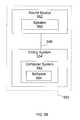
- FIG. 5Apresents a beamforming customization system 500 comprising a fitting portion 550 in communication with a sound processing portion 502 .
- the fitting portion 550can include a fitting system 554 communicatively linked with an external sound source 552 using a suitable communication link 556 .
- the fitting system 554may be substantially as shown and described in U.S. Pat. Nos. 5,626,629 and 6,289,247, both patents incorporated herein by reference.
- the fitting portion 550is implemented on a computer system located at an office of an audiologist or other medical personnel and is used to perform an initial fitting or customization of a cochlear implant for a particular user.
- the sound processing portion 502is implemented on a behind the ear (BTE) headpiece 100 ( FIGS. 1, 2 and 4 ), which is shown and described in U.S. Pat. No. 5,824,022, and U.S. Pat. No. 7,242,985, the patents incorporated herein by reference.
- the sound processing portion 502can include a microphone system 510 communicatively linked to a sound processing system 514 using a suitable communication link 512 .
- the sound processing system 514is coupled to the fitting system 554 through an interface unit (IU) 522 , or an equivalent device.
- a suitable communication link 524couples the interface unit 522 with the sound processing system 514 and the fitting system 554 .
- the IU 522can be included within a computer as a built-in I/O port including but not limited to an IR port, serial port, a parallel port, and a USB port.
- the fitting portion 550can generate an acoustic signal, which can be picked up and processed by the sound processing portion 502 .
- the processed acoustic signalcan be passed to an implantable cochlear stimulator (ICS) 518 through an appropriate communication link 516 .
- the ICS 518is coupled to an electrode array 520 configured to be inserted within the cochlea of a patient.
- the implantable cochlear stimulator 518can apply the processed acoustic signal as a plurality of stimulating inputs to a plurality of electrodes distributed along the electrode array 520 .
- the electrode array 520may be substantially as shown and described in U.S. Pat. Nos. 4,819,647 and 6,129,753, both patents incorporated herein by reference.
- both the fitting portion 550 and the sound processing portion 502are implemented in the external BTE headpiece 100 ( FIGS. 1, 2 and 4 ).
- the fitting portion 550can be controlled by a hand-held wired or wireless remote controller device (not shown) by medical personnel or the cochlear implant user.
- the implantable cochlear stimulator 518 and the electrode array 520can be an internal or implanted portion.
- a communication link 516 coupling the sound processing system 514 and the implanted portioncan be a transcutaneous (through the skin) link that allows power and control signals to be sent from the sound processing system 514 to the implantable cochlear stimulator 518 .
- the sound processing portion 502is incorporated into an internally located implantable cochlear system (not shown) as shown and described in a co-pending U.S. Patent Pub. No. 2007/0260292.
- the implantable cochlear stimulatorcan send information, such as data and status signals, to the sound processing system 514 over the communication link 516 .
- the communication link 516can include more than one channel. Additionally, interference can be reduced by transmitting information on a first channel using an amplitude-modulated carrier and transmitting information on a second channel using a frequency-modulated carrier.
- the communication links 556 and 524are wired links using standard data ports such as Universal Serial Bus interface, IEEE 1394 FireWire, or other suitable serial or parallel port connections.
- the communication links 556 and 524are wireless links such as the Bluetooth protocol.
- the Bluetooth protocolis a short-range, low-power 1 Mbit/sec wireless network technology operated in the 2.4 GHz band, which is appropriate for use in piconets.
- a piconetcan have a master and up to seven slaves. The master transmits in even time slots, while slaves transmit in odd time slots.
- the devices in a piconetshare a common communication data channel with total capacity of 1 Mbit/sec. Headers and handshaking information are used by Bluetooth devices to strike up a conversation and find each other to connect.
- Other standard wireless linkssuch as infrared, wireless fidelity (Wi-Fi), or any other suitable wireless connections can be implemented.
- Wi-Firefers to any type of IEEE 802.11 protocol including 802.11a/b/g/n.
- Wi-Figenerally provides wireless connectivity for a device to the Internet or connectivity between devices.
- Wi-Fioperates in the unlicensed 2.4 GHz radio bands, with an 11 Mbit/sec (802.11b) or 54 Mbit/sec (802.11a) data rate or with products that contain both bands.
- Infraredrefers to light waves of a lower frequency out of range of what a human eye can perceive. Used in most television remote control systems, information is carried between devices via beams of infrared light. The standard infrared system is called infrared data association (IrDA) and is used to connect some computers with peripheral devices in digital mode.
- IrDAinfrared data association
- the communication link 516can be realized through use of an antenna coil in the implantable cochlear stimulator and an external antenna coil coupled to the sound processing system 514 .
- the external antenna coilcan be positioned to be in alignment with the implantable cochlear stimulator, allowing the coils to be inductively coupled to each other and thereby permitting power and information, e.g., the stimulation signal, to be transmitted from the sound processing system 514 to the implantable cochlear stimulator 518 .
- the sound processing system 514 and the implantable cochlear stimulator 518are both implanted within the CI user, and the communication link 516 can be a direct-wired connection or other suitable links as shown in U.S. Pat. No. 6,308,101, incorporated herein by reference.
- FIG. 5Bdescribes the major subsystems of the fitting system 550 .
- the fitting system 550includes fitting software 564 executable on a computer system 562 such as a personal computer, a portable computer, a mobile device, or other equivalent device.
- the computer system 562with or without the IU 522 , generates input signals to the sound processing system 514 that stimulate acoustical signals detected by the microphone system 510 .
- input signals generated by the computer system 562can replace acoustic signals normally detected by the microphone system 510 or provide command signals that supplement the acoustic signals detected through the microphone system 510 .
- the fitting software 564 executable on the computer system 562can be configured to control reading, displaying, delivering, receiving, assessing, evaluating and/or modifying both acoustic and electric stimulation signals sent to the sound processing system 514 .
- the fitting software 564can generate a known acoustical signal, which can be outputted through the sound source 552 .
- the sound source 552can include one or more acoustical signal output devices such as a speaker 560 or equivalent device. In some implementations, multiple speakers 560 are positioned in a 2-D array to provide directivity of the acoustical signal.
- the computer system 562 executing the fitting software 564can include a display screen for displaying selection screens, stimulation templates and other information generated by the fitting software.
- the computer system 562includes a display device, a storage device, RAM, ROM, input/output (I/O) ports, a keyboard, and a mouse.
- the display screencan be implemented to display a graphical user interface (GUI) executed as a part of the software 564 including selection screens, stimulation templates and other information generated by the software 564 .
- GUIgraphical user interface
- An audiologist, other medical personnel, or even the CI usercan easily view and modify all information necessary to control a fitting process.
- the fitting portion 550is included within the sound processing system 514 and can allow the CI user to actively perform cochlear implant front end diagnostics and microphone matching.
- the fitting portion 550is implemented as a stand-alone system located at the office of the audiologist or other medical personnel.
- the fitting portion 550allows the audiologist or other medical personnel to customize a sound processing strategy and perform microphone matching for the CI user during an initial fitting process after the implantation of the CI.
- the CI usercan return to the office for subsequent adjustments as needed. Return visits may be required because the CI user may not be fully aware of his/her sound processing needs initially, and the user may need time to learn to discriminate between different sound signals and become more perceptive of the sound quality provided by the sound processing strategy.
- the microphone responsesmay need periodic calibrations and equalizations.
- the fitting system 554is implemented to include interfaces using hardware, software, or a combination of both hardware and software. For example, a simple set of hardware buttons, knobs, dials, slides, or similar interfaces can be implemented to select and adjust fitting parameters.
- the interfacescan also be implemented as a GUI displayed on a screen.
- the fitting portion 550is implemented as a portable system.
- the portable fitting systemcan be provided to the CI user as an accessory device for allowing the CI user to adjust the sound processing strategy and recalibrate the microphones as needed.
- the initial fitting processmay be performed by the CI user aided by the audiologist or other medical personnel. After the initial fitting process, the user may perform subsequent adjustments without having to visit the audiologist or other medical personnel.
- the portable fitting systemcan be implemented to include simple user interfaces using hardware, software, or a combination of both hardware and software to facilitate the adjustment process as described above for the stand alone system implementation.
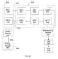
- FIG. 5Cshows a detailed view of the signal processing system 514 .
- a known acoustic signal (or stimulus) generated by a sound source 552is detected by microphones 530 , 532 .
- the detected signalis communicated along separate signal paths 512 , 515 and processed.
- Processing the known acoustical stimulusincludes converting the stimulus to an electrical signal by acoustic front ends (AFE 1 and AFE 2 ) 534 , 536 , along each signal path 512 , 515 .
- a converted electrical signalis presented along each signal path 512 , 515 of the sound processing system 514 .
- the electrical signalsDownstream from AFE 1 and AFE 2 , the electrical signals are converted to a digital signal by analog to digital converters (A/D 1 and A/D 2 ) 538 , 540 .
- the digitized signalsare amplified by automatic gain controls (AGC 1 and AGC 2 ) 542 , 544 and delivered to a beamforming module 528 to achieve a beamforming signal.
- the beamforming signalis processed by a digital signal processor (DSP) 546 to generate appropriate digital stimulations to an array of stimulating electrodes in a Micro Implantable Cochlear Stimulator (ICS) 518 .
- DSPdigital signal processor
- the microphone system 510can be implemented to use any of the three microphone design configurations as described with respect to FIGS. 1-4 above. In some implementations, the microphone system 510 can include more than two microphones positioned in multiple locations.
- Microphone matchingis accomplished by compensating for an undesired transformation of the known acoustical signal detected by the microphones 530 , 532 due to the inherent characteristic differences in the microphones 530 , 532 , locations of the microphones 530 , 532 and the physiological properties of the CI user's head and ear.
- a microphone matching processincludes sampling the detected signal along the signal paths 512 , 515 and matching the responses from the microphones 530 , 532 .
- FIG. 5Ddescribes multiple signal sampling locations along the signal paths 512 and 515 .
- signal sampling locations 531 and 537can be provided along the signal path 512 and signal sampling locations 541 and 547 can be provided along the signal path 515 .
- the fitting system 554generates a known audio signal, and the generated audio signal is received by the microphone system 510 using microphones 530 and 532 .
- the received signalis passed along signal paths 512 , 515 as microphone responses.
- the responses from the microphones 530 , 532are sampled at one or more locations (e.g., 537 ) along the signal pathways 512 and 515 of the sound processing system 514 .
- Response samplingcan be performed through the IU 522 and analyzed by the fitting system 554 .
- the sampled responsesare compared with the known audio signal generated by the fitting system 554 to determine an undesired spectral transformation of the sampled signal at each signal path 512 and 515 .
- the undesired spectral transformationcan depend at least on the positioning of the microphones 530 and 532 , mismatched characteristics of the microphones 530 and 532 , and physical anatomy of the user's head and ear.
- the undesired transformationis eliminated by implementing one or more appropriate digital equalization filters at the corresponding sampling location, 537 , to filter out the undesired spectral transformation at each signal path 512 , 515 . While only two sampling locations for each signal path 512 and 515 are illustrated in FIG. 5D , the total number of sampling locations per signal path can vary depending on the type of signal processing designed for a particular CI user. For example, one or more additional optional DSP units can be implemented.
- the sampling locations 531 , 541 , 537 , and 547 in the signal pathways 512 and 515can be determined by the system 500 to include one or more locations after the A/D converters 538 and 540 .
- the digitized signalcan be processed using one or more digital signal processing units (DSPs).
- FIG. 5Dshows one optional DSP (DSP 1 546 and DSP 2 548 ) on each signal pathway 512 and 515 , but the total number of DSPs implemented can vary based on the desired signal processing.
- DSP 1 546 and DSP 2 548can be implemented, for example, as a digital filter to perform spectral modulation of the digital signal.
- the system 500is capable of adapting to individual signal processing schemes unique to each CI user.
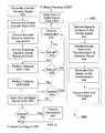
- FIG. 6represents a flowchart of a process 600 for matching the responses from the microphones 530 and 532 .
- a known acoustical signalis generated and outputted by the fitting portion 550 at 605 .
- the known acoustical signalis received by the microphone system 510 at 610 .
- the detected acoustical signalis transformed to an electrical signal by the acoustic front ends 534 , 536 .
- the electrical signalis digitized via the A/D 538 , 540 .
- a decisioncan be made to sample the signal at 625 . If the decision is made to sample the signal, the signal is processed for optimization at 640 before directing the signal to the AGC 542 and 544 at 655 .
- optimization of the sampled signal at 640is performed via the fitting system 550 .
- the sound processing system 514is implemented to perform the optimization by disposing a DSP module (not shown) within the sound processing system 514 .
- the existing DSP module 546can be configured to perform the optimization.
- Optimizing the sampled electrical signalcan be accomplished through at least three signal processing events.
- the electrical signalis sampled and a spectrum of the sampled signal is determined at 642 .
- the determined spectrum of the sampled signalis compared to the spectrum of the known acoustical signal to generate a ratio of the two spectrums at 644 .
- the generated ratiorepresents the undesired transformation of the sampled signal due to the positioning of the microphones, mismatched characteristics of the microphones, and physical anatomy of the user's head and ear.
- the ratio generatedis used as the basis for designing and generating an equalization filter to eliminate the undesired transformation of the sampled signal at 646 .
- the generated equalization filteris disposed at the corresponding sampling locations 531 , 541 , 537 , and 547 to filter the sampled signal at 648 .
- the filtered signalis directed to the next available signal processing unit on the signal pathways 512 , 515 .
- the available signal processing unitcan vary depending on the signal processing scheme designed for a particular CI user.
- the transfer functions and the equalization filter based on the transfer functions generated through optimization at 640is implemented using Equations 1 through 4.
- the acoustic signal or stimulus generated from the sound source 552is s(t) and has a corresponding Fourier transform S(j ⁇ ).
- the signal captured or recorded from the microphone system 510is r(t) and has a corresponding Fourier transform R(j ⁇ ).
- the acoustical transfer function from the source to the microphone, H(j ⁇ )can then be characterized by Equation (3) above. If the target frequency response is specified by T(j ⁇ ), then the equalization filter shape is given by Equation (4) above. This equalization filter is appropriately smoothed and then fit with a realizable equalization filter, which is then stored on the sound processing system 514 at the appropriate location(s).
- the digital filtercan be a finite-impulse-response (FIR) filter or an infinite-impulse-response (IIR) filter. Any one of several standard methods (see, e.g., Discrete Time Signal Processing , Oppenheim and Schafer, Prentice Hall (1989)) can be used to derive the digital filter. The entire sequence of operation just described is performed by the fitting system 554 .
- the processing events 642 , 644 , 646 , and 684are implemented as a single processing event, combined as two processing events or further subdivided into multiple processing events.
- the digital signalis forwarded directly to the AGC 542 , 544 .
- the digital signalcan be forwarded to the next signal processing unit.
- a first optional digital signal processingDSP 1
- another opportunity to sample the digital signalcan be presented at 635 .
- a decision to sample the digital signal at 635instructs the fitting system 554 to perform the signal optimization at 640 .
- the signal processing events 642 , 644 , 646 , 648are carried out on the digital signal to filter out the undesired transformation and match the microphone responses as described above.
- the filtered digital signalcan then be forwarded to the AGC 542 , 544 at 655 to provide protection against an overdriven or underdriven signal and to maintain an adequate demodulation signal amplitude while avoiding occasional noise spikes.
- the digital signalis forwarded directly to the AGCs 542 , 544 and processed as described above.
- the gain controlled digital signalis processed at 655 to allow for yet another sampling opportunity.
- the decision at 660is to sample the gain controlled digital signal, the sampled gain controlled digital signal is processed by the fitting system 554 to perform the optimization at 640 .
- the signal processing events 642 , 644 , 646 , and 648are carried out on the gain controlled digital signal to filter out the undesired transformation and match microphone responses as described above.
- the filtered digital signalis forwarded to a beamforming module 528 for combining the signals from each signal path 512 , 515 .
- the beamforming mathematical operationis performed on the two individual signals along the two signal paths 512 , 515 .
- the beamforming module 528combines the filtered signals from signal paths 512 and 515 to provide beamforming.
- Beamformingprovides directivity of the acoustical signal, which allows the individual CI user to focus on a desired portion of the acoustical signal. For example, in a noisy environment, the individual CI user can focus on the speech of a certain speaker to facilitate comprehension of such speech over confusing background noise.
- FIG. 5Ediscloses a detailed view of the beamforming module 528 .
- Beamforming of the two microphones 530 , 532 to achieve directivity of soundis implemented by subtracting the responses from the two microphones 530 , 532 .
- Directivityis a function of this signal subtraction.
- Two aspects of directivity, Focus and Strength,are modulated.
- a delay factor, ⁇defines the Focus or directivity of the beamforming, and
- ⁇defines the Strength of that Focus.
- Beamformingprovides a destructive combination of signals form the two microphones 530 , 532 .
- a first signal from the first microphone 530is subtracted from a second signal from the second microphone 532 .
- the second signal from the second microphone 532can be subtracted from the first signal from the first microphone 530 .
- a consequence of such destructive combinationcan include a spectrum shift in the combined signal.
- the beamforming signal(the combined signal) has directivity associated with the design parameters.
- a spectrum transformationis also generated, and a computed transformation of the beamforming signal can include a first order high pass filter. At the large wavelength (low frequency), more signal strength is lost than at the small wavelength (high frequency). In contrast, at the small wavelength, the signal strength is slightly larger than at the low frequency.
- a digital filtercan be provided to counter the high pass filter response of the beamforming signal.
- the digital filter to compensate for the spectral modificationcan be determined by sampling the combined beamforming signal and comparing the sampled beamforming signal against a target signal.
- a gain factor, ⁇is applied to the same response using a multiplier 560 located along the corresponding microphone signal paths 512 , 515 to provide Strength of the Focus. Varying ⁇ from 0 to 1 changes the Strength of the Focus. Therefore, the delay factor, ⁇ , provides Focus (direction), and the gain factor, ⁇ , provides Strength of that Focus.
- the resultant beamforming signalis forwarded to an optimization unit 575 along a combined signal path 570 .
- the optimization unit 575performs signal optimization 700 as described in FIG. 7 to eliminate undesired spectral transformation of the beamforming signal.
- the beamforming signalis sampled at 702 .
- a spectrum of the sampled beamforming signalis determined and compared to the spectrum of the known signal at 704 .
- a beamforming filteris generated based on the comparison at 706 .
- the generated beamforming filteris disposed at an appropriate location along the combined signal path 570 to compensate for an undesired spectral transformation of the beamforming signal at 708 .
- the beamforming signalcan be sampled at one or more locations and filtered using corresponding number of beamforming filters generated.
- Modulation of the delay and gain factors, ⁇ and ⁇can be implemented using physical selectors such as a switch or dials located on a wired or wireless control device.
- a graphical user interfacecan be implemented to include graphical selectors such as a button, a menu, and a tab to input and vary the delay and gain factors.
- the gain and delay factorscan be manually or automatically modified based on the perceived noise level. In other implementations, the gain and delay factors can be selectable for on/off modes.
- the techniques for achieving beamforming as described in FIGS. 1-7may be implemented using one or more computer programs comprising computer executable code stored on a computer readable medium and executing on the computer system 562 , the sound processor portion 502 , or the CI fitting portion 550 , or all three.
- the computer readable mediummay include a hard disk drive, a flash memory device, a random access memory device such as DRAM and SDRAM, removable storage medium such as CD-ROM and DVD-ROM, a tape, a floppy disk, a CompactFlash memory card, a secure digital (SD) memory card, or some other storage device.
- the computer executable codemay include multiple portions or modules, with each portion designed to perform a specific function described in connection with FIGS.
- the techniquesmay be implemented using hardware such as a microprocessor, a microcontroller, an embedded microcontroller with internal memory, or an erasable programmable read only memory (EPROM) encoding computer executable instructions for performing the techniques described in connection with FIGS. 5-7 .
- the techniquesmay be implemented using a combination of software and hardware.
- processors suitable for the execution of a computer programinclude, by way of example, both general and special purpose microprocessors, and any one or more processors of any kind of digital computer, including graphics processors, such as a GPU.
- the processorwill receive instructions and data from a read only memory or a random access memory or both.
- the essential elements of a computerare a processor for executing instructions and one or more memory devices for storing instructions and data.
- a computerwill also include, or be operatively coupled to receive data from or transfer data to, or both, one or more mass storage devices for storing data, e.g., magnetic, magneto optical disks, or optical disks.
- Information carriers suitable for embodying computer program instructions and datainclude all forms of non volatile memory, including by way of example semiconductor memory devices, e.g., EPROM, EEPROM, and flash memory devices; magnetic disks, e.g., internal hard disks or removable disks; magneto optical disks; and CD ROM and DVD-ROM disks.
- semiconductor memory devicese.g., EPROM, EEPROM, and flash memory devices
- magnetic diskse.g., internal hard disks or removable disks
- magneto optical diskse.g., CD ROM and DVD-ROM disks.
- the processor and the memorycan be supplemented by, or incorporated in, special purpose logic circuitry.
- the systems and techniques described herecan be implemented on a computer having a display device (e.g., a CRT (cathode ray tube) or LCD (liquid crystal display) monitor) for displaying information to the user and a keyboard and a pointing device (e.g., a mouse or a trackball) by which the user can provide input to the computer.
- a display devicee.g., a CRT (cathode ray tube) or LCD (liquid crystal display) monitor
- a keyboard and a pointing devicee.g., a mouse or a trackball
- Other kinds of devicescan be used to provide for interaction with a user as well; for example, feedback provided to the user can be any form of sensory feedback (e.g., visual feedback, auditory feedback, or tactile feedback); and input from the user can be received in any form, including acoustic, speech, or tactile input.
Landscapes
- Health & Medical Sciences (AREA)
- General Health & Medical Sciences (AREA)
- Neurosurgery (AREA)
- Otolaryngology (AREA)
- Physics & Mathematics (AREA)
- Engineering & Computer Science (AREA)
- Acoustics & Sound (AREA)
- Signal Processing (AREA)
- Circuit For Audible Band Transducer (AREA)
Abstract
Description
BFS=MIC2−α×(MIC1×Δ) (5)
Claims (25)
Priority Applications (1)
| Application Number | Priority Date | Filing Date | Title |
|---|---|---|---|
| US13/172,980US9668068B2 (en) | 2006-09-25 | 2011-06-30 | Beamforming microphone system |
Applications Claiming Priority (2)
| Application Number | Priority Date | Filing Date | Title |
|---|---|---|---|
| US11/534,933US7995771B1 (en) | 2006-09-25 | 2006-09-25 | Beamforming microphone system |
| US13/172,980US9668068B2 (en) | 2006-09-25 | 2011-06-30 | Beamforming microphone system |
Related Parent Applications (1)
| Application Number | Title | Priority Date | Filing Date |
|---|---|---|---|
| US11/534,933ContinuationUS7995771B1 (en) | 2006-09-25 | 2006-09-25 | Beamforming microphone system |
Publications (2)
| Publication Number | Publication Date |
|---|---|
| US20110255725A1 US20110255725A1 (en) | 2011-10-20 |
| US9668068B2true US9668068B2 (en) | 2017-05-30 |
Family
ID=44350819
Family Applications (2)
| Application Number | Title | Priority Date | Filing Date |
|---|---|---|---|
| US11/534,933Expired - Fee RelatedUS7995771B1 (en) | 2006-09-25 | 2006-09-25 | Beamforming microphone system |
| US13/172,980Expired - Fee RelatedUS9668068B2 (en) | 2006-09-25 | 2011-06-30 | Beamforming microphone system |
Family Applications Before (1)
| Application Number | Title | Priority Date | Filing Date |
|---|---|---|---|
| US11/534,933Expired - Fee RelatedUS7995771B1 (en) | 2006-09-25 | 2006-09-25 | Beamforming microphone system |
Country Status (1)
| Country | Link |
|---|---|
| US (2) | US7995771B1 (en) |
Families Citing this family (29)
| Publication number | Priority date | Publication date | Assignee | Title |
|---|---|---|---|---|
| US20040015205A1 (en) | 2002-06-20 | 2004-01-22 | Whitehurst Todd K. | Implantable microstimulators with programmable multielectrode configuration and uses thereof |
| US7860570B2 (en) | 2002-06-20 | 2010-12-28 | Boston Scientific Neuromodulation Corporation | Implantable microstimulators and methods for unidirectional propagation of action potentials |
| US7702396B2 (en)* | 2003-11-21 | 2010-04-20 | Advanced Bionics, Llc | Optimizing pitch allocation in a cochlear implant |
| US7522961B2 (en) | 2004-11-17 | 2009-04-21 | Advanced Bionics, Llc | Inner hair cell stimulation model for the use by an intra-cochlear implant |
| CN101641968B (en) | 2007-03-07 | 2015-01-21 | Gn瑞声达A/S | Sound enrichment for tinnitus relief |
| US8731211B2 (en)* | 2008-06-13 | 2014-05-20 | Aliphcom | Calibrated dual omnidirectional microphone array (DOMA) |
| US8233651B1 (en)* | 2008-09-02 | 2012-07-31 | Advanced Bionics, Llc | Dual microphone EAS system that prevents feedback |
| US8437859B1 (en) | 2009-09-03 | 2013-05-07 | Advanced Bionics, Llc | Dual microphone EAS system that prevents feedback |
| US9532151B2 (en) | 2012-04-30 | 2016-12-27 | Advanced Bionics Ag | Body worn sound processors with directional microphone apparatus |
| US10165372B2 (en) | 2012-06-26 | 2018-12-25 | Gn Hearing A/S | Sound system for tinnitus relief |
| US9678713B2 (en) | 2012-10-09 | 2017-06-13 | At&T Intellectual Property I, L.P. | Method and apparatus for processing commands directed to a media center |
| GB2510354A (en)* | 2013-01-31 | 2014-08-06 | Incus Lab Ltd | ANC-enabled earphones with ANC processing performed by host device |
| US9236050B2 (en)* | 2013-03-14 | 2016-01-12 | Vocollect Inc. | System and method for improving speech recognition accuracy in a work environment |
| US9812150B2 (en) | 2013-08-28 | 2017-11-07 | Accusonus, Inc. | Methods and systems for improved signal decomposition |
| US20150264505A1 (en) | 2014-03-13 | 2015-09-17 | Accusonus S.A. | Wireless exchange of data between devices in live events |
| US10468036B2 (en)* | 2014-04-30 | 2019-11-05 | Accusonus, Inc. | Methods and systems for processing and mixing signals using signal decomposition |
| EP2928211A1 (en)* | 2014-04-04 | 2015-10-07 | Oticon A/s | Self-calibration of multi-microphone noise reduction system for hearing assistance devices using an auxiliary device |
| WO2016122606A1 (en) | 2015-01-30 | 2016-08-04 | Advanced Bionics Ag | Audio accessory for auditory prosthesis system that includes body-worn sound processor apparatus |
| US10397710B2 (en) | 2015-12-18 | 2019-08-27 | Cochlear Limited | Neutralizing the effect of a medical device location |
| US9905241B2 (en) | 2016-06-03 | 2018-02-27 | Nxp B.V. | Method and apparatus for voice communication using wireless earbuds |
| US10085101B2 (en) | 2016-07-13 | 2018-09-25 | Hand Held Products, Inc. | Systems and methods for determining microphone position |
| JP6903933B2 (en)* | 2017-02-15 | 2021-07-14 | 株式会社Jvcケンウッド | Sound collecting device and sound collecting method |
| US10547937B2 (en)* | 2017-08-28 | 2020-01-28 | Bose Corporation | User-controlled beam steering in microphone array |
| US10536785B2 (en)* | 2017-12-05 | 2020-01-14 | Gn Hearing A/S | Hearing device and method with intelligent steering |
| DK3525488T3 (en)* | 2018-02-09 | 2020-11-30 | Oticon As | HEARING DEVICE WHICH INCLUDES A RADIATOR FILTER FILTER TO REDUCE FEEDBACK |
| CN112118888B (en) | 2018-02-15 | 2024-10-22 | 领先仿生公司 | Head-mounted device and implantable cochlear stimulation system including the same |
| CN110536193B (en)* | 2019-07-24 | 2020-12-22 | 华为技术有限公司 | Audio signal processing method and device |
| WO2022260646A1 (en)* | 2021-06-07 | 2022-12-15 | Hewlett-Packard Development Company, L.P. | Microphone directional beamforming adjustments |
| US11889261B2 (en) | 2021-10-06 | 2024-01-30 | Bose Corporation | Adaptive beamformer for enhanced far-field sound pickup |
Citations (102)
| Publication number | Priority date | Publication date | Assignee | Title |
|---|---|---|---|---|
| US3751605A (en) | 1972-02-04 | 1973-08-07 | Beckman Instruments Inc | Method for inducing hearing |
| US4051330A (en) | 1975-06-23 | 1977-09-27 | Unitron Industries Ltd. | Hearing aid having adjustable directivity |
| US4400590A (en) | 1980-12-22 | 1983-08-23 | The Regents Of The University Of California | Apparatus for multichannel cochlear implant hearing aid system |
| US4495384A (en) | 1982-08-23 | 1985-01-22 | Scott Instruments Corporation | Real time cochlear implant processor |
| US4532930A (en) | 1983-04-11 | 1985-08-06 | Commonwealth Of Australia, Dept. Of Science & Technology | Cochlear implant system for an auditory prosthesis |
| US4793353A (en) | 1981-06-30 | 1988-12-27 | Borkan William N | Non-invasive multiprogrammable tissue stimulator and method |
| US4819647A (en) | 1984-05-03 | 1989-04-11 | The Regents Of The University Of California | Intracochlear electrode array |
| US5033090A (en) | 1988-03-18 | 1991-07-16 | Oticon A/S | Hearing aid, especially of the in-the-ear type |
| US5201006A (en) | 1989-08-22 | 1993-04-06 | Oticon A/S | Hearing aid with feedback compensation |
| US5204917A (en) | 1990-04-19 | 1993-04-20 | Unitron Industries Ltd. | Modular hearing aid |
| US5357576A (en) | 1993-08-27 | 1994-10-18 | Unitron Industries Ltd. | In the canal hearing aid with protruding shell portion |
| US5500903A (en)* | 1992-12-30 | 1996-03-19 | Sextant Avionique | Method for vectorial noise-reduction in speech, and implementation device |
| WO1996034508A1 (en) | 1995-04-26 | 1996-10-31 | Advanced Bionics Corporation | A multichannel cochlear prosthesis with flexible control of stimulus waveforms |
| WO1996039005A1 (en) | 1995-05-31 | 1996-12-05 | Advanced Bionics Corporation | Programming of a speech processor for an implantable cochlear stimulator |
| US5597380A (en) | 1991-07-02 | 1997-01-28 | Cochlear Ltd. | Spectral maxima sound processor |
| US5603726A (en) | 1989-09-22 | 1997-02-18 | Alfred E. Mann Foundation For Scientific Research | Multichannel cochlear implant system including wearable speech processor |
| WO1997048447A1 (en) | 1996-06-20 | 1997-12-24 | Advanced Bionics Corporation | Self-adjusting cochlear implant system and method for fitting same |
| US5749912A (en) | 1994-10-24 | 1998-05-12 | House Ear Institute | Low-cost, four-channel cochlear implant |
| US5824022A (en) | 1996-03-07 | 1998-10-20 | Advanced Bionics Corporation | Cochlear stimulation system employing behind-the-ear speech processor with remote control |
| US5876425A (en) | 1989-09-22 | 1999-03-02 | Advanced Bionics Corporation | Power control loop for implantable tissue stimulator |
| US5938691A (en) | 1989-09-22 | 1999-08-17 | Alfred E. Mann Foundation | Multichannel implantable cochlear stimulator |
| US5991663A (en) | 1995-10-17 | 1999-11-23 | The University Of Melbourne | Multiple pulse stimulation |
| US6067474A (en) | 1997-08-01 | 2000-05-23 | Advanced Bionics Corporation | Implantable device with improved battery recharging and powering configuration |
| US6078838A (en) | 1998-02-13 | 2000-06-20 | University Of Iowa Research Foundation | Pseudospontaneous neural stimulation system and method |
| US6129753A (en) | 1998-03-27 | 2000-10-10 | Advanced Bionics Corporation | Cochlear electrode array with electrode contacts on medial side |
| US6154678A (en) | 1999-03-19 | 2000-11-28 | Advanced Neuromodulation Systems, Inc. | Stimulation lead connector |
| US6195585B1 (en) | 1998-06-26 | 2001-02-27 | Advanced Bionics Corporation | Remote monitoring of implantable cochlear stimulator |
| US6205360B1 (en) | 1995-09-07 | 2001-03-20 | Cochlear Limited | Apparatus and method for automatically determining stimulation parameters |
| US6208882B1 (en) | 1998-06-03 | 2001-03-27 | Advanced Bionics Corporation | Stapedius reflex electrode and connector |
| US6216045B1 (en) | 1999-04-26 | 2001-04-10 | Advanced Neuromodulation Systems, Inc. | Implantable lead and method of manufacture |
| US6219580B1 (en) | 1995-04-26 | 2001-04-17 | Advanced Bionics Corporation | Multichannel cochlear prosthesis with flexible control of stimulus waveforms |
| US6272382B1 (en) | 1998-07-31 | 2001-08-07 | Advanced Bionics Corporation | Fully implantable cochlear implant system |
| US6289247B1 (en) | 1998-06-02 | 2001-09-11 | Advanced Bionics Corporation | Strategy selector for multichannel cochlear prosthesis |
| US6295467B1 (en) | 1996-07-18 | 2001-09-25 | Birger Kollmeier | Method and device for detecting a reflex of the human stapedius muscle |
| WO2001074278A2 (en) | 2000-03-31 | 2001-10-11 | Advanced Bionics Corporation | High contact count, sub-miniature fully implantable cochlear prosthesis |
| US6308101B1 (en) | 1998-07-31 | 2001-10-23 | Advanced Bionics Corporation | Fully implantable cochlear implant system |
| US6415185B1 (en) | 1998-09-04 | 2002-07-02 | Advanced Bionics Corporation | Objective programming and operation of a Cochlear implant based on measured evoked potentials that precede the stapedius reflex |
| US6522764B1 (en) | 1998-10-07 | 2003-02-18 | Oticon A/S | Hearing aid |
| WO2003015863A2 (en) | 2001-08-17 | 2003-02-27 | Advanced Bionics Corporation | Gradual recruitment of muscle/neural excitable tissue using high-rate electrical stimulation parameters |
| WO2003018113A1 (en) | 2001-08-31 | 2003-03-06 | Biocontrol Medical Ltd. | Treatment of disorders by unidirectional nerve stimulation |
| US20030044034A1 (en) | 2001-08-27 | 2003-03-06 | The Regents Of The University Of California | Cochlear implants and apparatus/methods for improving audio signals by use of frequency-amplitude-modulation-encoding (FAME) strategies |
| WO2003030772A2 (en) | 2001-10-05 | 2003-04-17 | Advanced Bionics Corporation | A microphone module for use with a hearing aid or cochlear implant system |
| US6600955B1 (en) | 1999-07-21 | 2003-07-29 | Med-El Elektromedizinishe Geraete Gmbh | Multichannel cochlear implant with neural response telemetry |
| US6658125B1 (en) | 1998-10-07 | 2003-12-02 | Oticon A/S | Hearing aid |
| US20040015205A1 (en) | 2002-06-20 | 2004-01-22 | Whitehurst Todd K. | Implantable microstimulators with programmable multielectrode configuration and uses thereof |
| US6700983B1 (en) | 1998-10-07 | 2004-03-02 | Oticon A/S | Hearing aid |
| US6728578B1 (en) | 2000-06-01 | 2004-04-27 | Advanced Bionics Corporation | Envelope-based amplitude mapping for cochlear implant stimulus |
| US20040082980A1 (en) | 2000-10-19 | 2004-04-29 | Jaouhar Mouine | Programmable neurostimulator |
| US6735474B1 (en) | 1998-07-06 | 2004-05-11 | Advanced Bionics Corporation | Implantable stimulator system and method for treatment of incontinence and pain |
| WO2004043537A1 (en) | 2002-11-13 | 2004-05-27 | Advanced Bionics Corporation | Method and system to convey the within-channel fine structure with a cochlear implant |
| US6745155B1 (en) | 1999-11-05 | 2004-06-01 | Huq Speech Technologies B.V. | Methods and apparatuses for signal analysis |
| US6775389B2 (en) | 2001-08-10 | 2004-08-10 | Advanced Bionics Corporation | Ear auxiliary microphone for behind the ear hearing prosthetic |
| US6778858B1 (en) | 1999-09-16 | 2004-08-17 | Advanced Bionics N.V. | Cochlear implant |
| US20040230254A1 (en) | 1999-05-14 | 2004-11-18 | Harrison William Vanbrooks | Hybrid implantable cochlear stimulator hearing aid system |
| US6842647B1 (en) | 2000-10-20 | 2005-01-11 | Advanced Bionics Corporation | Implantable neural stimulator system including remote control unit for use therewith |
| US20050102006A1 (en) | 2003-09-25 | 2005-05-12 | Whitehurst Todd K. | Skull-mounted electrical stimulation system |
| US20050119716A1 (en) | 2002-06-28 | 2005-06-02 | Mcclure Kelly H. | Systems and methods for communicating with or providing power to an implantable stimulator |
| US20050143781A1 (en) | 2003-01-31 | 2005-06-30 | Rafael Carbunaru | Methods and systems for patient adjustment of parameters for an implanted stimulator |
| US20050213780A1 (en) | 2004-03-26 | 2005-09-29 | William Berardi | Dynamic equalizing |
| WO2005097255A1 (en) | 2004-04-02 | 2005-10-20 | Advanced Bionics Corporation | Electric and acoustic stimulation fitting systems and methods |
| US20050251225A1 (en) | 2004-05-07 | 2005-11-10 | Faltys Michael A | Cochlear stimulation device |
| US7039466B1 (en) | 2003-04-29 | 2006-05-02 | Advanced Bionics Corporation | Spatial decimation stimulation in an implantable neural stimulator, such as a cochlear implant |
| US7043303B1 (en) | 2002-08-30 | 2006-05-09 | Advanced Bionics Corporation | Enhanced methods for determining iso-loudness contours for fitting cochlear implant sound processors |
| US20060100672A1 (en) | 2004-11-05 | 2006-05-11 | Litvak Leonid M | Method and system of matching information from cochlear implants in two ears |
| US7054691B1 (en) | 2002-01-02 | 2006-05-30 | Advanced Bionics Corporation | Partitioned implantable system |
| US7076308B1 (en) | 2001-08-17 | 2006-07-11 | Advanced Bionics Corporation | Cochlear implant and simplified method of fitting same |
| US7082332B2 (en) | 2000-06-19 | 2006-07-25 | Cochlear Limited | Sound processor for a cochlear implant |
| US20060184212A1 (en) | 2004-05-07 | 2006-08-17 | Faltys Michael A | Cochlear Stimulation Device |
| US7107101B1 (en) | 2001-08-17 | 2006-09-12 | Advanced Bionics Corporation | Bionic ear programming system |
| US7110823B2 (en) | 2002-06-11 | 2006-09-19 | Advanced Bionics Corporation | RF telemetry link for establishment and maintenance of communications with an implantable device |
| US20070016267A1 (en) | 2005-07-08 | 2007-01-18 | Cochlear Limited | Directional sound processing in a cochlear implant |
| US20070021800A1 (en) | 2002-06-20 | 2007-01-25 | Advanced Bionics Corporation, A California Corporation | Cavernous nerve stimulation via unidirectional propagation of action potentials |
| US7171272B2 (en) | 2000-08-21 | 2007-01-30 | University Of Melbourne | Sound-processing strategy for cochlear implants |
| US20070055308A1 (en) | 2005-09-06 | 2007-03-08 | Haller Matthew I | Ultracapacitor powered implantable pulse generator with dedicated power supply |
| US7200504B1 (en) | 2005-05-16 | 2007-04-03 | Advanced Bionics Corporation | Measuring temperature change in an electronic biomedical implant |
| US7209568B2 (en)* | 2003-07-16 | 2007-04-24 | Siemens Audiologische Technik Gmbh | Hearing aid having an adjustable directional characteristic, and method for adjustment thereof |
| US7225028B2 (en) | 2004-05-28 | 2007-05-29 | Advanced Bionics Corporation | Dual cochlear/vestibular stimulator with control signals derived from motion and speech signals |
| US7242985B1 (en) | 2004-12-03 | 2007-07-10 | Advanced Bionics Corporation | Outer hair cell stimulation model for the use by an intra—cochlear implant |
| US7248926B2 (en) | 2002-08-30 | 2007-07-24 | Advanced Bionics Corporation | Status indicator for implantable systems |
| US7277760B1 (en) | 2004-11-05 | 2007-10-02 | Advanced Bionics Corporation | Encoding fine time structure in presence of substantial interaction across an electrode array |
| US7292892B2 (en) | 2003-11-21 | 2007-11-06 | Advanced Bionics Corporation | Methods and systems for fitting a cochlear implant to a patient |
| US7292890B2 (en) | 2002-06-20 | 2007-11-06 | Advanced Bionics Corporation | Vagus nerve stimulation via unidirectional propagation of action potentials |
| US7292891B2 (en) | 2001-08-20 | 2007-11-06 | Advanced Bionics Corporation | BioNet for bilateral cochlear implant systems |
| US20070260292A1 (en) | 2006-05-05 | 2007-11-08 | Faltys Michael A | Information processing and storage in a cochlear stimulation system |
| US7308303B2 (en) | 2001-11-01 | 2007-12-11 | Advanced Bionics Corporation | Thrombolysis and chronic anticoagulation therapy |
| US7310558B2 (en) | 2001-05-24 | 2007-12-18 | Hearworks Pty, Limited | Peak-derived timing stimulation strategy for a multi-channel cochlear implant |
| US7330557B2 (en)* | 2003-06-20 | 2008-02-12 | Siemens Audiologische Technik Gmbh | Hearing aid, method, and programmer for adjusting the directional characteristic dependent on the rest hearing threshold or masking threshold |
| US7349741B2 (en) | 2002-10-11 | 2008-03-25 | Advanced Bionics, Llc | Cochlear implant sound processor with permanently integrated replenishable power source |
| US7447549B2 (en) | 2005-06-01 | 2008-11-04 | Advanced Bionioics, Llc | Methods and systems for denoising a neural recording signal |
| US7450994B1 (en) | 2004-12-16 | 2008-11-11 | Advanced Bionics, Llc | Estimating flap thickness for cochlear implants |
| US7483540B2 (en) | 2002-03-25 | 2009-01-27 | Bose Corporation | Automatic audio system equalizing |
| US7490044B2 (en) | 2004-06-08 | 2009-02-10 | Bose Corporation | Audio signal processing |
| US7519188B2 (en) | 2003-09-18 | 2009-04-14 | Bose Corporation | Electroacoustical transducing |
| US7522961B2 (en) | 2004-11-17 | 2009-04-21 | Advanced Bionics, Llc | Inner hair cell stimulation model for the use by an intra-cochlear implant |
| US7599500B1 (en) | 2004-12-09 | 2009-10-06 | Advanced Bionics, Llc | Processing signals representative of sound based on the identity of an input element |
| US7702396B2 (en) | 2003-11-21 | 2010-04-20 | Advanced Bionics, Llc | Optimizing pitch allocation in a cochlear implant |
| US7729758B2 (en) | 2005-11-30 | 2010-06-01 | Boston Scientific Neuromodulation Corporation | Magnetically coupled microstimulators |
| US7801602B2 (en) | 2005-04-08 | 2010-09-21 | Boston Scientific Neuromodulation Corporation | Controlling stimulation parameters of implanted tissue stimulators |
| US7822480B2 (en) | 2002-06-28 | 2010-10-26 | Boston Scientific Neuromodulation Corporation | Systems and methods for communicating with an implantable stimulator |
| US7860570B2 (en) | 2002-06-20 | 2010-12-28 | Boston Scientific Neuromodulation Corporation | Implantable microstimulators and methods for unidirectional propagation of action potentials |
| US7864968B2 (en) | 2006-09-25 | 2011-01-04 | Advanced Bionics, Llc | Auditory front end customization |
| US7945064B2 (en) | 2003-04-09 | 2011-05-17 | Board Of Trustees Of The University Of Illinois | Intrabody communication with ultrasound |
Family Cites Families (1)
| Publication number | Priority date | Publication date | Assignee | Title |
|---|---|---|---|---|
| DE60325699D1 (en)* | 2003-05-13 | 2009-02-26 | Harman Becker Automotive Sys | Method and system for adaptive compensation of microphone inequalities |
- 2006
- 2006-09-25USUS11/534,933patent/US7995771B1/ennot_activeExpired - Fee Related
- 2011
- 2011-06-30USUS13/172,980patent/US9668068B2/ennot_activeExpired - Fee Related
Patent Citations (115)
| Publication number | Priority date | Publication date | Assignee | Title |
|---|---|---|---|---|
| US3751605A (en) | 1972-02-04 | 1973-08-07 | Beckman Instruments Inc | Method for inducing hearing |
| US4051330A (en) | 1975-06-23 | 1977-09-27 | Unitron Industries Ltd. | Hearing aid having adjustable directivity |
| US4400590A (en) | 1980-12-22 | 1983-08-23 | The Regents Of The University Of California | Apparatus for multichannel cochlear implant hearing aid system |
| US4793353A (en) | 1981-06-30 | 1988-12-27 | Borkan William N | Non-invasive multiprogrammable tissue stimulator and method |
| US4495384A (en) | 1982-08-23 | 1985-01-22 | Scott Instruments Corporation | Real time cochlear implant processor |
| US4532930A (en) | 1983-04-11 | 1985-08-06 | Commonwealth Of Australia, Dept. Of Science & Technology | Cochlear implant system for an auditory prosthesis |
| US4819647A (en) | 1984-05-03 | 1989-04-11 | The Regents Of The University Of California | Intracochlear electrode array |
| US5033090A (en) | 1988-03-18 | 1991-07-16 | Oticon A/S | Hearing aid, especially of the in-the-ear type |
| US5201006A (en) | 1989-08-22 | 1993-04-06 | Oticon A/S | Hearing aid with feedback compensation |
| US5938691A (en) | 1989-09-22 | 1999-08-17 | Alfred E. Mann Foundation | Multichannel implantable cochlear stimulator |
| US5876425A (en) | 1989-09-22 | 1999-03-02 | Advanced Bionics Corporation | Power control loop for implantable tissue stimulator |
| US5603726A (en) | 1989-09-22 | 1997-02-18 | Alfred E. Mann Foundation For Scientific Research | Multichannel cochlear implant system including wearable speech processor |
| US5204917A (en) | 1990-04-19 | 1993-04-20 | Unitron Industries Ltd. | Modular hearing aid |
| US5597380A (en) | 1991-07-02 | 1997-01-28 | Cochlear Ltd. | Spectral maxima sound processor |
| US5500903A (en)* | 1992-12-30 | 1996-03-19 | Sextant Avionique | Method for vectorial noise-reduction in speech, and implementation device |
| US5357576A (en) | 1993-08-27 | 1994-10-18 | Unitron Industries Ltd. | In the canal hearing aid with protruding shell portion |
| US5749912A (en) | 1994-10-24 | 1998-05-12 | House Ear Institute | Low-cost, four-channel cochlear implant |
| US6002966A (en) | 1995-04-26 | 1999-12-14 | Advanced Bionics Corporation | Multichannel cochlear prosthesis with flexible control of stimulus waveforms |
| US5601617A (en) | 1995-04-26 | 1997-02-11 | Advanced Bionics Corporation | Multichannel cochlear prosthesis with flexible control of stimulus waveforms |
| WO1996034508A1 (en) | 1995-04-26 | 1996-10-31 | Advanced Bionics Corporation | A multichannel cochlear prosthesis with flexible control of stimulus waveforms |
| US6219580B1 (en) | 1995-04-26 | 2001-04-17 | Advanced Bionics Corporation | Multichannel cochlear prosthesis with flexible control of stimulus waveforms |
| WO1996039005A1 (en) | 1995-05-31 | 1996-12-05 | Advanced Bionics Corporation | Programming of a speech processor for an implantable cochlear stimulator |
| US5626629A (en) | 1995-05-31 | 1997-05-06 | Advanced Bionics Corporation | Programming of a speech processor for an implantable cochlear stimulator |
| US6205360B1 (en) | 1995-09-07 | 2001-03-20 | Cochlear Limited | Apparatus and method for automatically determining stimulation parameters |
| US5991663A (en) | 1995-10-17 | 1999-11-23 | The University Of Melbourne | Multiple pulse stimulation |
| US5824022A (en) | 1996-03-07 | 1998-10-20 | Advanced Bionics Corporation | Cochlear stimulation system employing behind-the-ear speech processor with remote control |
| US6157861A (en) | 1996-06-20 | 2000-12-05 | Advanced Bionics Corporation | Self-adjusting cochlear implant system and method for fitting same |
| WO1997048447A1 (en) | 1996-06-20 | 1997-12-24 | Advanced Bionics Corporation | Self-adjusting cochlear implant system and method for fitting same |
| US6295467B1 (en) | 1996-07-18 | 2001-09-25 | Birger Kollmeier | Method and device for detecting a reflex of the human stapedius muscle |
| US6067474A (en) | 1997-08-01 | 2000-05-23 | Advanced Bionics Corporation | Implantable device with improved battery recharging and powering configuration |
| US6078838A (en) | 1998-02-13 | 2000-06-20 | University Of Iowa Research Foundation | Pseudospontaneous neural stimulation system and method |
| US6129753A (en) | 1998-03-27 | 2000-10-10 | Advanced Bionics Corporation | Cochlear electrode array with electrode contacts on medial side |
| US6289247B1 (en) | 1998-06-02 | 2001-09-11 | Advanced Bionics Corporation | Strategy selector for multichannel cochlear prosthesis |
| US6208882B1 (en) | 1998-06-03 | 2001-03-27 | Advanced Bionics Corporation | Stapedius reflex electrode and connector |
| US6195585B1 (en) | 1998-06-26 | 2001-02-27 | Advanced Bionics Corporation | Remote monitoring of implantable cochlear stimulator |
| US6735474B1 (en) | 1998-07-06 | 2004-05-11 | Advanced Bionics Corporation | Implantable stimulator system and method for treatment of incontinence and pain |
| US6308101B1 (en) | 1998-07-31 | 2001-10-23 | Advanced Bionics Corporation | Fully implantable cochlear implant system |
| US6272382B1 (en) | 1998-07-31 | 2001-08-07 | Advanced Bionics Corporation | Fully implantable cochlear implant system |
| US6415185B1 (en) | 1998-09-04 | 2002-07-02 | Advanced Bionics Corporation | Objective programming and operation of a Cochlear implant based on measured evoked potentials that precede the stapedius reflex |
| US6522764B1 (en) | 1998-10-07 | 2003-02-18 | Oticon A/S | Hearing aid |
| US6700983B1 (en) | 1998-10-07 | 2004-03-02 | Oticon A/S | Hearing aid |
| US6658125B1 (en) | 1998-10-07 | 2003-12-02 | Oticon A/S | Hearing aid |
| US6154678A (en) | 1999-03-19 | 2000-11-28 | Advanced Neuromodulation Systems, Inc. | Stimulation lead connector |
| US6216045B1 (en) | 1999-04-26 | 2001-04-10 | Advanced Neuromodulation Systems, Inc. | Implantable lead and method of manufacture |
| US20040230254A1 (en) | 1999-05-14 | 2004-11-18 | Harrison William Vanbrooks | Hybrid implantable cochlear stimulator hearing aid system |
| US6600955B1 (en) | 1999-07-21 | 2003-07-29 | Med-El Elektromedizinishe Geraete Gmbh | Multichannel cochlear implant with neural response telemetry |
| US6778858B1 (en) | 1999-09-16 | 2004-08-17 | Advanced Bionics N.V. | Cochlear implant |
| US6745155B1 (en) | 1999-11-05 | 2004-06-01 | Huq Speech Technologies B.V. | Methods and apparatuses for signal analysis |
| WO2001074278A2 (en) | 2000-03-31 | 2001-10-11 | Advanced Bionics Corporation | High contact count, sub-miniature fully implantable cochlear prosthesis |
| US6980864B2 (en) | 2000-03-31 | 2005-12-27 | Advanced Bionics Corporation | High contact count, sub-miniature, full implantable cochlear prosthesis |
| US6826430B2 (en) | 2000-03-31 | 2004-11-30 | Advanced Bionics Corporation | High contact count, sub-miniature, fully implantable cochlear prosthesis |
| US6728578B1 (en) | 2000-06-01 | 2004-04-27 | Advanced Bionics Corporation | Envelope-based amplitude mapping for cochlear implant stimulus |
| US7082332B2 (en) | 2000-06-19 | 2006-07-25 | Cochlear Limited | Sound processor for a cochlear implant |
| US7171272B2 (en) | 2000-08-21 | 2007-01-30 | University Of Melbourne | Sound-processing strategy for cochlear implants |
| US20040082980A1 (en) | 2000-10-19 | 2004-04-29 | Jaouhar Mouine | Programmable neurostimulator |
| US6842647B1 (en) | 2000-10-20 | 2005-01-11 | Advanced Bionics Corporation | Implantable neural stimulator system including remote control unit for use therewith |
| US7043304B1 (en) | 2000-10-20 | 2006-05-09 | Advanced Bionics Corporation | Method of controlling an implantable neural stimulator |
| US7310558B2 (en) | 2001-05-24 | 2007-12-18 | Hearworks Pty, Limited | Peak-derived timing stimulation strategy for a multi-channel cochlear implant |
| US6775389B2 (en) | 2001-08-10 | 2004-08-10 | Advanced Bionics Corporation | Ear auxiliary microphone for behind the ear hearing prosthetic |
| US7003876B2 (en) | 2001-08-10 | 2006-02-28 | Advanced Bionics Corporation | Method of constructing an in the ear auxiliary microphone for behind the ear hearing prosthetic |
| WO2003015863A2 (en) | 2001-08-17 | 2003-02-27 | Advanced Bionics Corporation | Gradual recruitment of muscle/neural excitable tissue using high-rate electrical stimulation parameters |
| US7076308B1 (en) | 2001-08-17 | 2006-07-11 | Advanced Bionics Corporation | Cochlear implant and simplified method of fitting same |
| US7107101B1 (en) | 2001-08-17 | 2006-09-12 | Advanced Bionics Corporation | Bionic ear programming system |
| US7292891B2 (en) | 2001-08-20 | 2007-11-06 | Advanced Bionics Corporation | BioNet for bilateral cochlear implant systems |
| US20030044034A1 (en) | 2001-08-27 | 2003-03-06 | The Regents Of The University Of California | Cochlear implants and apparatus/methods for improving audio signals by use of frequency-amplitude-modulation-encoding (FAME) strategies |
| WO2003018113A1 (en) | 2001-08-31 | 2003-03-06 | Biocontrol Medical Ltd. | Treatment of disorders by unidirectional nerve stimulation |
| WO2003030772A2 (en) | 2001-10-05 | 2003-04-17 | Advanced Bionics Corporation | A microphone module for use with a hearing aid or cochlear implant system |
| US7308303B2 (en) | 2001-11-01 | 2007-12-11 | Advanced Bionics Corporation | Thrombolysis and chronic anticoagulation therapy |
| US7054691B1 (en) | 2002-01-02 | 2006-05-30 | Advanced Bionics Corporation | Partitioned implantable system |
| US7483540B2 (en) | 2002-03-25 | 2009-01-27 | Bose Corporation | Automatic audio system equalizing |
| US7110823B2 (en) | 2002-06-11 | 2006-09-19 | Advanced Bionics Corporation | RF telemetry link for establishment and maintenance of communications with an implantable device |
| US7292890B2 (en) | 2002-06-20 | 2007-11-06 | Advanced Bionics Corporation | Vagus nerve stimulation via unidirectional propagation of action potentials |
| US7860570B2 (en) | 2002-06-20 | 2010-12-28 | Boston Scientific Neuromodulation Corporation | Implantable microstimulators and methods for unidirectional propagation of action potentials |
| US20040015205A1 (en) | 2002-06-20 | 2004-01-22 | Whitehurst Todd K. | Implantable microstimulators with programmable multielectrode configuration and uses thereof |
| US7203548B2 (en) | 2002-06-20 | 2007-04-10 | Advanced Bionics Corporation | Cavernous nerve stimulation via unidirectional propagation of action potentials |
| US20070021800A1 (en) | 2002-06-20 | 2007-01-25 | Advanced Bionics Corporation, A California Corporation | Cavernous nerve stimulation via unidirectional propagation of action potentials |
| US7822480B2 (en) | 2002-06-28 | 2010-10-26 | Boston Scientific Neuromodulation Corporation | Systems and methods for communicating with an implantable stimulator |
| US20050119716A1 (en) | 2002-06-28 | 2005-06-02 | Mcclure Kelly H. | Systems and methods for communicating with or providing power to an implantable stimulator |
| US7043303B1 (en) | 2002-08-30 | 2006-05-09 | Advanced Bionics Corporation | Enhanced methods for determining iso-loudness contours for fitting cochlear implant sound processors |
| US7248926B2 (en) | 2002-08-30 | 2007-07-24 | Advanced Bionics Corporation | Status indicator for implantable systems |
| US7349741B2 (en) | 2002-10-11 | 2008-03-25 | Advanced Bionics, Llc | Cochlear implant sound processor with permanently integrated replenishable power source |
| US7317945B2 (en) | 2002-11-13 | 2008-01-08 | Advanced Bionics Corporation | Method and system to convey the within-channel fine structure with a cochlear implant |
| WO2004043537A1 (en) | 2002-11-13 | 2004-05-27 | Advanced Bionics Corporation | Method and system to convey the within-channel fine structure with a cochlear implant |
| US20050143781A1 (en) | 2003-01-31 | 2005-06-30 | Rafael Carbunaru | Methods and systems for patient adjustment of parameters for an implanted stimulator |
| US7945064B2 (en) | 2003-04-09 | 2011-05-17 | Board Of Trustees Of The University Of Illinois | Intrabody communication with ultrasound |
| US7039466B1 (en) | 2003-04-29 | 2006-05-02 | Advanced Bionics Corporation | Spatial decimation stimulation in an implantable neural stimulator, such as a cochlear implant |
| US7330557B2 (en)* | 2003-06-20 | 2008-02-12 | Siemens Audiologische Technik Gmbh | Hearing aid, method, and programmer for adjusting the directional characteristic dependent on the rest hearing threshold or masking threshold |
| US7209568B2 (en)* | 2003-07-16 | 2007-04-24 | Siemens Audiologische Technik Gmbh | Hearing aid having an adjustable directional characteristic, and method for adjustment thereof |
| US7519188B2 (en) | 2003-09-18 | 2009-04-14 | Bose Corporation | Electroacoustical transducing |
| US20050102006A1 (en) | 2003-09-25 | 2005-05-12 | Whitehurst Todd K. | Skull-mounted electrical stimulation system |
| US7702396B2 (en) | 2003-11-21 | 2010-04-20 | Advanced Bionics, Llc | Optimizing pitch allocation in a cochlear implant |
| US7292892B2 (en) | 2003-11-21 | 2007-11-06 | Advanced Bionics Corporation | Methods and systems for fitting a cochlear implant to a patient |
| US20050213780A1 (en) | 2004-03-26 | 2005-09-29 | William Berardi | Dynamic equalizing |
| US7561920B2 (en) | 2004-04-02 | 2009-07-14 | Advanced Bionics, Llc | Electric and acoustic stimulation fitting systems and methods |
| WO2005097255A1 (en) | 2004-04-02 | 2005-10-20 | Advanced Bionics Corporation | Electric and acoustic stimulation fitting systems and methods |
| US20050251225A1 (en) | 2004-05-07 | 2005-11-10 | Faltys Michael A | Cochlear stimulation device |
| US20060184212A1 (en) | 2004-05-07 | 2006-08-17 | Faltys Michael A | Cochlear Stimulation Device |
| US7225028B2 (en) | 2004-05-28 | 2007-05-29 | Advanced Bionics Corporation | Dual cochlear/vestibular stimulator with control signals derived from motion and speech signals |
| US7490044B2 (en) | 2004-06-08 | 2009-02-10 | Bose Corporation | Audio signal processing |
| US20060100672A1 (en) | 2004-11-05 | 2006-05-11 | Litvak Leonid M | Method and system of matching information from cochlear implants in two ears |
| WO2006053101A1 (en) | 2004-11-05 | 2006-05-18 | Advanced Bionics Corporation | Method and system of matching information from cochlear implants in two ears |
| US7277760B1 (en) | 2004-11-05 | 2007-10-02 | Advanced Bionics Corporation | Encoding fine time structure in presence of substantial interaction across an electrode array |
| US7522961B2 (en) | 2004-11-17 | 2009-04-21 | Advanced Bionics, Llc | Inner hair cell stimulation model for the use by an intra-cochlear implant |
| US7242985B1 (en) | 2004-12-03 | 2007-07-10 | Advanced Bionics Corporation | Outer hair cell stimulation model for the use by an intra—cochlear implant |
| US7599500B1 (en) | 2004-12-09 | 2009-10-06 | Advanced Bionics, Llc | Processing signals representative of sound based on the identity of an input element |
| US7450994B1 (en) | 2004-12-16 | 2008-11-11 | Advanced Bionics, Llc | Estimating flap thickness for cochlear implants |
| US7801602B2 (en) | 2005-04-08 | 2010-09-21 | Boston Scientific Neuromodulation Corporation | Controlling stimulation parameters of implanted tissue stimulators |
| US7200504B1 (en) | 2005-05-16 | 2007-04-03 | Advanced Bionics Corporation | Measuring temperature change in an electronic biomedical implant |
| US7447549B2 (en) | 2005-06-01 | 2008-11-04 | Advanced Bionioics, Llc | Methods and systems for denoising a neural recording signal |
| US20070016267A1 (en) | 2005-07-08 | 2007-01-18 | Cochlear Limited | Directional sound processing in a cochlear implant |
| US20070055308A1 (en) | 2005-09-06 | 2007-03-08 | Haller Matthew I | Ultracapacitor powered implantable pulse generator with dedicated power supply |
| WO2007030496A1 (en) | 2005-09-06 | 2007-03-15 | Advanced Bionics Corporation | Ultracapacitor powered implantable pulse generator with dedicated power supply |
| US7729758B2 (en) | 2005-11-30 | 2010-06-01 | Boston Scientific Neuromodulation Corporation | Magnetically coupled microstimulators |
| US20070260292A1 (en) | 2006-05-05 | 2007-11-08 | Faltys Michael A | Information processing and storage in a cochlear stimulation system |
| US7864968B2 (en) | 2006-09-25 | 2011-01-04 | Advanced Bionics, Llc | Auditory front end customization |
Non-Patent Citations (16)
| Title |
|---|
| Carney, L.H., "A model for the responses of low-frequency auditory-nerve fibers in cat", Journal of the Acoustic Society of America, 93(1):401-417, 1993. |
| Deutsch, Sid, et al. (Eds.) "Understanding the Nervous System, An Engineering Perspective", New York, NY, IEEE Press, pp. 181-225, 1993. |
| Geurts, L. and J. Wouters, "Enhancing the speech envelope of continuous interleaved sampling processors for cochlear implants", Journal of the Acoustic Society of America, 105(4):2476-2484, 1999. |
| Moore, Brian C.J., "An Introduction to the Psychology of Hearing", San Diego, CA, Academic Press, pp. 9-12, 1997. |
| Rubinstein, J.T., et al., "The Neurophysiological Effects of Simulated Auditory Prosthesis Simulation", Second Quarterly Progress Report: NO1-DC-6-2111, May 27, 1997. |
| Srulovicz, P., et al., "A Central Spectrum Model: A Synthesis of Auditory-Nerve Timing and Place Cues in Monaural Communication of Frequency Spectrum", Journal of the Acoustic Society of America, 73(4): 1266-1276, 1983. |
| U.S. Appl. No. 11/089,171, Hahn, filed Mar. 24, 2005. |
| U.S. Appl. No. 11/122,648, Griffith, filed Mar. 5, 2005. |
| U.S. Appl. No. 11/178,054, Faltys, filed Jul. 8, 2005. |
| U.S. Appl. No. 11/226,777, Faltys, filed Sep. 13, 2005. |
| U.S. Appl. No. 11/261,432, Mann, filed Oct. 28, 2005. |
| U.S. Appl. No. 11/262,055, Fridman, filed Dec. 28, 2005. |
| U.S. Appl. No. 11/386,198, Saoji, filed Mar. 21, 2006. |
| U.S. Appl. No. 11/387,206, Harrison, filed Mar. 23, 2006. |
| van Wieringen, A., et al., "Comparison of Procedures to Determine Electrical Stimulation Thresholds in Cochlear Implant Users", Ear and Hearing, 22(6): 528-538, 2001. |
| Zeng, F.G., et al., "Loudness of Simple and Complex Stimuli in Electric Hearing", Annals of Otology, Rhinology & Laryngology, 104 (No. 9, part 2, suppl. 166): 235-238, 1995. |
Also Published As
| Publication number | Publication date |
|---|---|
| US7995771B1 (en) | 2011-08-09 |
| US20110255725A1 (en) | 2011-10-20 |
Similar Documents
| Publication | Publication Date | Title |
|---|---|---|
| US9668068B2 (en) | Beamforming microphone system | |
| US8503685B2 (en) | Auditory front end customization | |
| US9712933B2 (en) | Diminishing tinnitus loudness by hearing instrument treatment | |
| US9050467B2 (en) | Compensation current optimization for cochlear implant systems | |
| CN106911991A (en) | Hearing devices including microphone control system | |
| CN105872924A (en) | Binaural hearing system and a hearing device comprising a beamforming unit | |
| US11330375B2 (en) | Method of adaptive mixing of uncorrelated or correlated noisy signals, and a hearing device | |
| EP2880874B1 (en) | Hearing prosthesis system and method of operation therefof | |
| EP3600528A1 (en) | Bimodal hearing stimulation system | |
| US9358389B2 (en) | Two-piece sound processor system for use in an auditory prosthesis system | |
| EP2493559B1 (en) | Two-piece sound processor system for use in an auditory prosthesis system | |
| US20240015449A1 (en) | Magnified binaural cues in a binaural hearing system | |
| US9056205B2 (en) | Compensation current optimization for auditory prosthesis systems | |
| EP3928828B1 (en) | Harmonic allocation of cochlea implant frequencies | |
| US20250203299A1 (en) | Multi-band channel coordination |
Legal Events
| Date | Code | Title | Description |
|---|---|---|---|
| AS | Assignment | Owner name:ADVANCED BIONICS CORPORATION, CALIFORNIA Free format text:ASSIGNMENT OF ASSIGNORS INTEREST;ASSIGNORS:FALTYS, MICHAEL A.;KULKARNI, ABHIJIT;CRAWFORD, SCOTT A.;SIGNING DATES FROM 20060915 TO 20060921;REEL/FRAME:026526/0821 Owner name:ADVANCED BIONICS, LLC, CALIFORNIA Free format text:ASSIGNMENT OF ASSIGNORS INTEREST;ASSIGNOR:BOSTON SCIENTIFIC NEUROMODULATION CORPORATION;REEL/FRAME:026526/0859 Effective date:20080107 Owner name:BOSTON SCIENTIFIC NEUROMODULATION CORPORATION, CAL Free format text:CHANGE OF NAME;ASSIGNOR:ADVANCED BIONICS CORPORATION;REEL/FRAME:026526/0987 Effective date:20071116 | |
| AS | Assignment | Owner name:ADVANCED BIONICS AG, SWITZERLAND Free format text:ASSIGNMENT OF ASSIGNORS INTEREST;ASSIGNOR:ADVANCED BIONICS, LLC;REEL/FRAME:030552/0299 Effective date:20130605 | |
| STCF | Information on status: patent grant | Free format text:PATENTED CASE | |
| FEPP | Fee payment procedure | Free format text:MAINTENANCE FEE REMINDER MAILED (ORIGINAL EVENT CODE: REM.); ENTITY STATUS OF PATENT OWNER: LARGE ENTITY | |
| LAPS | Lapse for failure to pay maintenance fees | Free format text:PATENT EXPIRED FOR FAILURE TO PAY MAINTENANCE FEES (ORIGINAL EVENT CODE: EXP.); ENTITY STATUS OF PATENT OWNER: LARGE ENTITY | |
| STCH | Information on status: patent discontinuation | Free format text:PATENT EXPIRED DUE TO NONPAYMENT OF MAINTENANCE FEES UNDER 37 CFR 1.362 | |
| FP | Lapsed due to failure to pay maintenance fee | Effective date:20210530 |