US9665359B2 - Automatically resolving conflicts after installation of selected updates in a computer system - Google Patents
Automatically resolving conflicts after installation of selected updates in a computer systemDownload PDFInfo
- Publication number
- US9665359B2 US9665359B2US14/151,329US201414151329AUS9665359B2US 9665359 B2US9665359 B2US 9665359B2US 201414151329 AUS201414151329 AUS 201414151329AUS 9665359 B2US9665359 B2US 9665359B2
- Authority
- US
- United States
- Prior art keywords
- user
- conflict
- computer system
- update
- display
- Prior art date
- Legal status (The legal status is an assumption and is not a legal conclusion. Google has not performed a legal analysis and makes no representation as to the accuracy of the status listed.)
- Active
Links
Images


Classifications
- G—PHYSICS
- G06—COMPUTING OR CALCULATING; COUNTING
- G06F—ELECTRIC DIGITAL DATA PROCESSING
- G06F8/00—Arrangements for software engineering
- G06F8/60—Software deployment
- G06F8/65—Updates
- G—PHYSICS
- G06—COMPUTING OR CALCULATING; COUNTING
- G06F—ELECTRIC DIGITAL DATA PROCESSING
- G06F8/00—Arrangements for software engineering
- G06F8/60—Software deployment
- G06F8/61—Installation
- G—PHYSICS
- G06—COMPUTING OR CALCULATING; COUNTING
- G06F—ELECTRIC DIGITAL DATA PROCESSING
- G06F8/00—Arrangements for software engineering
- G06F8/60—Software deployment
- G06F8/61—Installation
- G06F8/62—Uninstallation
- G—PHYSICS
- G06—COMPUTING OR CALCULATING; COUNTING
- G06F—ELECTRIC DIGITAL DATA PROCESSING
- G06F16/00—Information retrieval; Database structures therefor; File system structures therefor
- G06F16/90—Details of database functions independent of the retrieved data types
- G06F16/95—Retrieval from the web
- G06F17/30861—
- G—PHYSICS
- G06—COMPUTING OR CALCULATING; COUNTING
- G06F—ELECTRIC DIGITAL DATA PROCESSING
- G06F8/00—Arrangements for software engineering
- G06F8/40—Transformation of program code
- G06F8/41—Compilation
- G06F8/42—Syntactic analysis
- G06F8/423—Preprocessors
- G—PHYSICS
- G06—COMPUTING OR CALCULATING; COUNTING
- G06F—ELECTRIC DIGITAL DATA PROCESSING
- G06F9/00—Arrangements for program control, e.g. control units
- G06F9/06—Arrangements for program control, e.g. control units using stored programs, i.e. using an internal store of processing equipment to receive or retain programs
- G06F9/44—Arrangements for executing specific programs
- G06F9/445—Program loading or initiating
- G06F9/44552—Conflict resolution, i.e. enabling coexistence of conflicting executables
Definitions
- Computer systemsare currently in wide use. Some such systems are customized (some significantly) before they are deployed at an end user's site. Such systems often also have updates which can be installed.
- CCMcustomer relations management
- ERPenterprise resource planning
- LOBline-of-business
- Such systemsoften have updates published for them.
- the updatescan include new releases, as well as bug fixes. For instance, when new releases of the business system are generated, they are often followed by a number of bug fixes for problems that were not fixed prior to release.
- the fixesare normally released, piecemeal, as they are generated. Periodically, however, a cumulative update package is released which includes all of the fixes generated, to that point. This may, for example, include hundreds or even thousands of fixes.
- a usermay apply multiple different fixes to their product over time. It can be difficult for the user to know the comprehensive update status of the product. This is not tracked or stored.
- a usermay be a developer that is operating in a development environment, and a test environment, or multiple development and test environments.
- a production environmentthere may be a production environment as well, among other environments.
- An update installergenerates an update display for a user that allows the user to select updates to be applied to a computer system. Conflicts that arise because of application of the updates to the computer system are automatically resolved and the results of the conflict resolution are displayed.
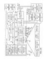
- FIG. 1is a block diagram of one illustrative update architecture.
- FIG. 1Ashows one example of a more detailed block diagram of an update installer component.
- FIGS. 1B-1 to 1B-3(collectively referred to as FIG. 1B ) show a flow diagram illustrating one embodiment of the overall operation of the architecture shown in FIG. 1 .
- FIG. 1Cis a flow diagram illustrating one embodiment of the operation of the architecture shown in FIG. 1 in generating a business process impact analysis.
- FIG. 1Dis a flow diagram illustrating one embodiment of the operation of the architecture shown in FIG. 1 in generating an object and layer level impact analysis.
- FIGS. 2-33are illustrative user interface displays.
- FIG. 34shows one embodiment of the architecture shown in FIG. 1 deployed in a cloud computing architecture.
- FIGS. 35-40show various embodiments of mobile devices.
- FIG. 41is a block diagram of one illustrative computing environment.
- FIG. 1shows a block diagram of one illustrative architecture 100 .
- Architecture 100includes customer business system 101 (which can be an on premise system, a cloud-based system, or another system).
- Architecture 100also illustratively includes life cycle system 200 .
- Business system 101 and life cycle system 200can illustratively be accessed by user 114 through user interface displays 115 generated either by systems 101 and 200 , themselves, or by user device 116 .
- user interface displays 115have user input mechanisms 117 that can be actuated by user 114 in order to manipulate and control systems 101 and 200 .
- Customer business system 101illustratively includes processor 102 , data store 104 , user interface component 105 , update installer component 106 , conflict resolution component 119 and business process component 121 .
- Data store 104itself, illustratively includes data 108 , applications 110 , business processes 112 , workflows 114 , and other items 116 .
- applications 110illustratively include the business logic used to run business processes 112 and workflows 114 in business system 101 .
- Applications 110illustratively operate on data 108 , which can include entities that represent items in the business system 101 .
- applications 110can include a general ledger application, inventory application, applications that allow a user to track business opportunities, track sales or production in a business system, or a wide variety of other business applications.
- the entitiesfor instance, include customer entities that represent customers, opportunity entities that represent business opportunities, inventory entities that represent inventory items, quote and proposal entities that represent quotes and proposals, etc.
- the data 108can include a wide variety of other entities and data, and those mentioned above are mentioned for the sake of example only.
- User 114(or other users) can illustratively access customer business system 101 in order to perform activities, tasks, workflows, etc. that are done in carrying out the business of the organization that deploys business system 101 .
- Life cycle system 200illustratively includes project information 206 , environment information 208 (which can include information representative of a set of business processes 209 that are used by the user in customer business system 101 ), update state tracking information 210 , services 202 - 204 , update information 203 , update recommendation service 212 , impact analysis information 211 , code merge information 213 and report generator service 214 .
- Services 202 - 204can be used by various persons in order to identify, track and resolve issues that arise during various life cycle stages of a project (e.g., from presale to implementation and maintenance).
- the various services 202 - 204illustratively allow the developers as well as the user organization to track issues which arise, and to determine whether the user's expectations are met when the final instance of business system 101 is deployed at the organization.
- services 202 - 204include a service that allows a user to identify the needs of an organization and the basic functionality that is provided with a business system and generate a fit gap list that identifies the functionality or customizations that need to be made, to the business system, in order to meet the needs of the customer that is deploying the business system.
- the servicesalso illustratively include a diagnostic service that allows life cycle system 200 to identify the particular environmental information that defines the environment of the deployed business system 101 .
- the environmental datamay identify the version number and identity of the operating system, the version number of the base system 101 , the particular fixes that have been applied to system 101 , the version number of the database and other application platforms used by business system 101 , whether business system 101 is in a production environment, a test environment, a user acceptance testing environment, etc., and a wide variety of other information.
- User 114can access life cycle system 200 to view project information 206 that defines the user's projects, environmental information 208 that includes the environmental data mentioned above, as well as an indication of the set of businesses processes 209 that are run on business system 101 , update tracking information 210 that identifies the update state of business system 101 (for example, which updates have been applied and when), update information 203 that indicates available updates or detailed information corresponding to updates that have been installed, update recommendation service 212 that recommends updates for business system 101 based upon the information gathered from business system 101 , impact analysis information 211 that shows the affect that selected updates have on business system 101 (such as the business processes 112 , the objects, layers, etc.), code merge information 213 that shows the affect of automatic conflict resolution. and report generator service 214 that can be used to generate various reports that are discussed in greater detail below.
- Cumulative updates 120may intermittently become available to update customer business system 101 , and specifically the applications 110 or information in data store 104 , in system 101 .
- the cumulative updates 120may include hot fixes or a variety of other updates as well.
- update installer component 106uses user interface component 105 , to generate user interface displays 115 that allow user 114 to select the various updates that are desired, and to also see an impact analysis which indicates the impact (e.g., in terms of potential conflicts) of those updates on the user's business system 101 .
- Update installer component 106also illustratively allows user 114 to search for various updates based on subject matter or otherwise, and to view the impact on the business processes 112 , as well as to save selected updates for replay (or application) in other environments. Update installer component 106 also illustratively installs the selected updates, and can automatically resolve conflicts, when commanded to.
- the update state of customer business system 101is illustratively uploaded to life cycle system 200 as update state tracking information 210 .
- user 114can also log on to life cycle system 200 in order to view the update state tracking information 210 and to receive recommended updates from update recommendation service 212 , and to view various other information and reports as described in greater detail below.
- FIG. 1Ais a block diagram of one example of a more detailed embodiment of update installer component 106 .
- update installer component 106illustratively includes update search component 130 , technical impact analyzer component (or impact analyzer component) 132 , business process analyzer component 134 , installation engine 136 , and reply component 138 . It can include other components 140 as well.
- Update search component 130allows the user to search for updates
- Impact analyzer component 132allows the user to see the impact of selected updates on objects and layers in business system 101 , before they are applied.
- Business process analyzer component 134allows the user to see the impact of selected updates on business processes in system 101 , before they are applied.
- Installation engine 136installs selected updates, and replay component 138 replays (or installs) the selected updates in other environments.
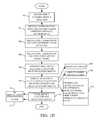
- FIGS. 1B-1 to 1B-3(collectively referred to as FIG. 1B ) show a flow diagram of one exemplary embodiment of the overall operation of component 106 and architecture 100 shown in FIG. 1 .
- FIGS. 1 to 1Bwill now be described in conjunction with one another.
- Update installer component 106In order to begin installing updates, user 114 first launches update installer component 106 . This is indicated by block 250 in FIG. 1B .
- Update installer component 106illustratively generates a variety of different preliminary user interface displays that can be viewed by the user. This is indicated by block 252 .
- Update installer component 106also generates user interface displays that allow the user to select a given environment to which the updates are to be applied. This is indicated by block 254 .
- the user interface displayscan also allow the user to select the type of installation (such as an express installation in which all updates are automatically applied, or an advanced installation in which user 114 can optionally log into user life cycle system 200 to identify the particular updates that the user wishes to apply). Selecting the type of installation is indicated by block 256 in FIG. 1B .
- FIGS. 2-12show exemplary user interface displays representative of update installer component 106 generating the preliminary user interface displays, and the set of user interface displays that allow the user to select the environment and the type of installation.
- FIG. 2shows one example of a user interface display 258 .
- Display 258illustratively includes an introductory display pane 260 that shows an introductory message that explains that the user can use the following user interface displays in order to apply selected updates from a cumulative update package.
- Display 258also illustratively includes a navigation pane 262 which displays the various steps that the user will go through in order to apply the updates.
- FIG. 3shows a user interface display that can be generated when the user actuates the “next” button 264 in the display of FIG. 2 .
- Some of the items shown in FIG. 3are similar to those shown in FIG. 2 , and they are similarly numbered.
- FIG. 3shows display 266 .
- Display 266shows that the user has advanced to the “software license terms” node in pane 262 .
- pane 260illustratively displays a set of license terms. The user can accept the license terms by actuating button 266 . The user can thus continue with the updating process.
- FIGS. 4-6are exemplary user interface displays that allow the user to select an update package that is to be applied (or from which certain updates are to be applied) to business system 101 .
- Display 268shows that the user has now advanced to the “select packages” node in pane 262 .
- Display 268also includes a packages display portion 270 and a details pane or display portion 272 .
- Packages display portion 270illustratively displays update packages that can be applied to the various components in business system 101 .
- Details pane 272illustratively displays details corresponding to the packages displayed in portion 270 . For instance, in the embodiment shown in FIG. 4 , details pane 272 indicates that the updates corresponding to the “application object server” node 274 in packages pane 270 have already been installed.
- FIG. 5shows an exemplary user interface display 276 where user 114 has selected or highlighted the “data import/export framework” node 278 in pane 270 . Selecting one or more update packages is indicated by block 257 in the flow diagram of FIG. 1B . It can thus be seen that the details pane 272 is updated to display detailed information about the highlighted node 278 .
- the userWhen the user actuates next button 280 , the user will illustratively be navigated to a prerequisite user interface display, such as display 282 shown in FIG. 6 .
- Display 282displays prerequisites (generally shown at 284 ) that are needed in order to install the update packages selected by the user in the display of FIG. 5 .
- update installer component 106illustratively generates a set of user interface displays that allow the user to specify the environments where the updates are to be applied. This is indicated by block 286 in FIG. 1B .
- FIGS. 7-11show exemplary user interface displays for doing this.
- FIG. 7shows user interface display 288 which asks user 114 to specify a particular account for the update installation process. For instance, in one embodiment, user 114 is asked to enter a username in field 290 and password in field 292 that correspond to an account that has read/write access and administration rights to the various models and other information in business system 101 , that are to be updated.
- update installer component 106illustratively generates a user interface display, such as display 294 shown in FIG. 8 , that allows the user to specify the name of the server that is running the database integration service that will be used to apply the updates. For instance, user 114 can enter a server name in field 296 .
- update installer component 106illustratively generates a user interface display (such as display 298 shown in FIG. 9 ) that allows the user to specify a model store that is to be updated with selected updates.
- user interface display 298allows the user to enter (such as by typing or through a drop down menu or otherwise) the data store that stores the models that are to be updated with user input mechanism 300 .
- the usercan also illustratively add a new model store by actuating user input mechanism 302 .
- update installer component 106illustratively generates a display (such as display 304 shown in FIG. 10 ) that allows the user to enter a server name in field 306 and a model store name in field 308 , in order to add a server for updating.
- update installer component 106can generate a user interface display such as display 310 shown in FIG. 11 that updates the user has to the progress of the processing being performed.
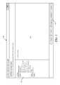
- update installer component 106illustratively generates a user interface display, such as display 312 shown in FIG. 12 , that allows user 114 to select a type of installation that is to be performed. Receiving a user input selecting the type of installation is indicated by block 317 in FIG. 1B .
- the usercan choose an express installation in which all updates in the selected update package are be applied. This can be done, for instance, by actuating user input mechanism 314 . Selecting all updates is indicated by block 313 in the flow diagram of FIG. 1B . However, user 114 can also select user input mechanism 316 which allows the user to perform an advanced installation in which the user can select specific application updates (from the selected package) for application to the identified environment. Selecting a subset of updates is indicated by block 315 in the flow diagram of FIG. 1B . When the user indicates that he or she will be selecting a subset of updates, component 106 generates a set of UI displays that allow the user to do this.
- Generating user interface display 312 to select a subset of updates to installis indicated by block 318 in the flow diagram of FIG. 1B .
- the usercan do this in a variety of different ways. For instance, in one embodiment, the user can actuate user input mechanism 320 in order to log into life cycle system 200 (shown in FIG. 1 ) to use the information in system 200 to select the updates. Logging into life cycle system 200 is indicated by block 322 in FIG. 1B .
- user 114may have already selected a set of updates for application to a different environment (other than the one that was chosen as described above). In that case, user 114 may have saved those selected updates as a list that can be applied to other environments. Thus, if the user actuates user input mechanism 324 , the user can input the update list for application to the newly selected environment.
- “browse” button 326becomes active and allows the user to enter a file in box 328 for importing into the update installation process Importing a saved list of updates is indicated by block 330 in the flow diagram of FIG. 1B .
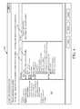
- update installer component 106illustratively generates a user interface display, such as display 332 in FIG. 13 , that allows the user to search for, and select, various updates that are to be applied in the identified environment.
- User interface display 332includes a first set of user input mechanisms 334 .
- User input mechanisms 334allow the user to either select all updates for application, or to select only applicable updates. When the user selects the user input mechanism to apply only applicable updates, then those which can be accessed, searched and viewed by the user are only the ones targeted for the environment that the user has selected, and for the various features that the user has licensed in business system 101 .
- Display 332also illustratively includes a set of filter user input mechanisms 336 .
- Each of the filter user input mechanism 336illustratively allow the user to select one or more items, upon which to filter the applicable updates.
- mechanisms 336include a “module” user input mechanism that is shown as a drop down menu. The module mechanism allows the user to filter the applicable updates by module. In the embodiment shown in FIG. 3 , the user has selected the “cash and bank management” module.
- the “license code” filter mechanism 336allows the user to filter the applicable updates by license code elements.
- Such elementscan include, for example, an electronic banking code element, the general ledger code element (or application), etc.
- the “country context” filter mechanism 336allows the user to filter the applicable updates by country context. For instance, systems that are deployed in one country may not be interested in some updates that were generated, in particular, for a system in another country. Thus, the applicable updates can be filtered by country context.
- the “business process” filter mechanism 336allows the user to filter the applicable updates based on the business processes to which they apply.
- life cycle system 200includes a service 202 - 204 that uses a business process modeler to generate a model of the business processes in a given customer business system 101 .
- the set of business processes 209 for the individual customer business system 101is stored so that the user can view the various business processes in system 101 .
- Update installer component 106illustratively accesses the set of business processes 209 from life cycle system 200 and displays those processes in the user input mechanism.
- the usercan select the particular business processes in business system 101 to filter applicable updates.
- user interface display 332also illustratively includes a search user input mechanism 338 .
- input mechanism 338is simply a text box that allows the user to type in keywords or search query terms that are used by update search component 130 in update installer component 106 in order to search through the updates based on the keywords.
- the usermay search for updates by title, or by update identifier number.
- the update identifier numbermay be a knowledge-base reference or another identifier.
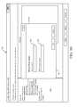
- Display 332also illustratively includes a results display pane 340 .
- Display pane 340illustratively displays information corresponding to the applicable updates that are identified by update search component 130 in update installer component 106 based upon all of the user selections, filters, and search terms.
- the returned results (or results update set) 342can be grouped in a variety of different ways. For instance, the grouping user input mechanism 344 allows the user to select one of a variety of different sets of sort criteria for sorting the returned update results displayed in pane 340 .
- FIG. 13shows that the resultant update set 342 that is displayed in pane 340 shows a hierarchical tree structure which includes parent nodes 346 and 348 . Each of the nodes can have child nodes, such as node 350 . Each node has an associated check box. In one embodiment, when a parent node is selected, all of the children nodes, from that parent node, are also selected. FIG. 13 also shows that each of the parent nodes includes a numerical identifier 352 and 354 . The numerical identifiers associated with each parent node identify the number of updates that are in the result set 342 that will be applied to each of those nodes. In the example shown in FIG. 13 , 12 updates in the result set apply to the bank node and 19 updates in the result set apply to the electronic banking node.
- FIG. 13shows that child node 350 corresponds to a given update set.
- the update sethas an update identifier 356 and an update description 358 .
- the identifieris a unique identifier for the given update (or update set) and the description describes how the update will affect the parent node.
- FIG. 13also illustratively includes a more detailed information section 360 .
- section 360includes a details tab 362 and a conflicts tab 364 .
- the details tab 362may illustratively be empty.
- Conflict resolution component 119 in business system 101illustratively generates a conflict summary display that shows a summary of conflicts for all of the updates under the selected parent node. This is described in greater detail below with respect to FIGS. 16 and 17 .
- details tab 362displays details corresponding to the selected non-parent node.
- details tab 362displays details corresponding to the update identified by update identifier 356 .
- the detailsillustratively include the update identifier 356 , the summary description 358 , the models 360 that are affected by the update, the layers 362 that are affected by the update, and any other updates 364 that are included within the selected node 350 .
- the conflicts tab 364illustratively shows a conflict summary for that particular non-parent node (e.g., corresponding to the particular update identified by identifier 356 ). Again, this is described in greater detail below.
- update installer component 106can display recommended updates, automatically, given the user's particular environment and configuration information stored in life cycle system 200 .
- showing recommended updatesis indicated by block 366
- showing a list of all available updates(such as when the user selects the “all updates” user input mechanism 334 ) is indicated by block 368
- displaying a search user input mechanism 338is indicated by block 370
- allowing the user to group and filter the search results by applicability, module, country context, configuration, etc.is indicated by block 372 and allowing the user to select available updates in other ways is indicated by block 374 .
- FIG. 14is similar to FIG. 13 , and similar items are similarly numbered. However, FIG. 14 is provided to explicitly illustrate that the filter user input mechanisms 336 can each allow the user to select multiple filters.
- the “license code” user input mechanismallows the user to choose one or all of the “bank” code element, the “electronic banking” code element, or the “general ledger” code element. These are exemplary only and other items can be used as well.
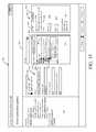
- FIG. 15shows another user interface display.
- Display 380is similar to display 332 (discussed above), and similar items are similarly numbered. However, it can be seen that display 380 also provides an indication as to what type of impact the selected updates in the result set displayed in result pane 340 will have on the underlying customer business system 101 , if they are applied. Generating the view of how the system will be affected if the selected updates are installed (or applied) is indicated by block 382 in the flow diagram of FIG. 1B .
- the impact of the selected updates on business system 101can be shown in these different ways: the impact on the business processes, the impact on the objects and layers of business system 101 , and the level of conflicts that will be generated.
- business process analyzer component 134 in update installer component 106illustratively generates a business process heat map that identifies the business processes in business system 101 that will be affected by the selected updates. This is indicated by block 384 in the flow diagram of FIG. 1B .
- impact analyzer component 132 in update installer component 106displays an analysis of which objects and layers in business system 101 will be most affected by the selected updates. This is indicated by block 386 in FIG. 2 .
- Conflict resolution component 119(in FIG. 1 ) can also generate a display of a conflict summary or conflict details that will arise if the selected updates are applied. This is indicated by block 388 .
- the affect of the selected updates on the underlying business processwill first be described. Referring again to the user interface display 380 of FIG. 15 , it can be seen that the user has elected to group the returned result set shown in pane 340 by business process. This can be done by making that selection using the sort or group-by user input mechanism 344 . Thus, the result set is grouped by business process.
- the set of parent nodes(with corresponding check boxes 392 ) each represent a business process that will be affected if the selected updates are installed.
- Each parent nodehas a numerical indicator 394 that identifies the number of updates that affect the corresponding business process. For example, the “develop vision and strategy” business process will be affected by 89 updates. On the other hand, the “manage customer service” business process will be affected by one update.
- each of the parent nodes in the result setincludes a heat map indicator 396 .
- the heat map indicatoris a color-coded visual element that identifies the underlying business processes in system 101 that will be affected by the selected updates, and the degree to which they will be affected. For instance, if the indicator 396 corresponding to a given parent node is colored red, that may indicate that the corresponding business process (corresponding to that parent node) will be greatly affected by the selected updates. If it is yellow or green, on the other hand, that may indicate that the underlying business process will be less affected or least affected, respectively.
- the thresholds for determining whether a parent node has a heat map indicator 396 indicating that it will be greatly affected or less affectedcan be set in a variety of different ways. For instance, they can be set anecdotally, they can be set based on user preference (for instance, a user may identify certain business processes as more important than others), they can be set heuristically, or in other ways. For example, in one embodiment, the top 20% most affected parent nodes may have a red heat map indicator 396 . That is, if the total number of updates that will be applied to a given process is in the top 20% of all of the business processes, that given process is assigned a heat map indicator 396 that indicates that it will be one of the most affected business processes.
- the parent nodes with the next 60% of updates appliedmay be assigned an intermediate heat map indicator 396 indicating that they will be less affected than the most severely affected business processes.
- the parent nodes with the bottom 20% of updates applied to themmay be given a heat map indicator 396 indicating that they will be least affected, among the various business processes.
- thisis an exemplary breakdown only, and a wide variety of other thresholds or breakdowns can be used.
- FIG. 1Cis a flow diagram illustrating one embodiment of the operation of business process analyzer component 134 in generating the business process heat map shown in FIG. 15 .
- user 114first accesses life cycle system 200 . This is indicated by block 400 . This can be done in a wide variety of ways, such as by providing authentication information 402 or other information 404 . This allows business process analyzer component 134 to access the information in system 200 in order to perform its analysis. The system then generates a view of the business processes in system 101 . For instance, when the user accesses the business process filter input mechanisms 336 , the various business processes that the user can choose from are displayed there.
- Generating a view of the business processesis indicated by block 406 in FIG. 1C .
- the update installer component 106then receives the various user inputs to select the business processes used in filtering, and to otherwise select the applicable updates. This is indicated by block 408 .
- Business process analyzer component 134then generates the display (e.g., the heat map) showing the impact of the selected updates on the business processes, as filtered by the user input selections with the business process filter input mechanisms 336 . This is indicated by block 410 .
- FIGS. 16-18show various user interface displays that can be generated by conflict resolution component 119 in order to display the various conflicts that will be encountered if the user applies the selected updates to the identified environment in business system 101 . It is first assumed that the user has selected parent node 348 in result display pane 340 (which will automatically select the child nodes, such as child node 350 ). It is also assumed that the user has actuated the conflicts tab 364 . Conflict resolution component 119 then analyzes the various conflicts that will be generated in the portions of business system 101 represented by parent node 348 , and its corresponding child nodes 350 . Of course, the system can generate a progress display 412 , as desired.
- FIG. 17shows that conflicts tab 364 is now populated with conflict summary information 414 that summarizes the various conflicts that will occur in the part of system 101 corresponding to parent node 348 and corresponding to child nodes 350 . It can be seen, for instance, that conflicts will be generated in two tables, five classes, four forms, no reports, and three other elements.
- Conflicts tab 364also illustratively includes a conflict details user input mechanism 416 . If the user actuates mechanism 416 , conflict resolution component 119 illustratively generates a conflict details display such as that shown in FIG. 18 . It can be seen that the display in FIG. 18 includes conflict details pane 418 .
- Conflict details pane 418identifies the update (or update model) generally at 420 that may conflict with objects in the model store (or environment) selected by the user.
- the conflict informationincludes, for instance, the particular layer 422 that may have a conflict, the affected model 424 , the object type 426 , the object name 428 , and an identification of the number of conflicts 430 .
- pane 418also includes user input mechanism 432 that allows the user to view the objects that are affected by the updates, even if there are no conflicts identified.
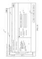
- a display showing object and layer level impactwill now be described. It may be that the user wishes to view a more detailed impact analysis that shows the particular layers, models, object types, and specific objects, that are affected by the selected updates. In doing so, the user can illustratively actuate impact analysis wizard user input mechanism 434 in order to invoke impact analyzer component 132 in update installer component 106 . When the user does this, impact analyzer component 132 generates an impact analysis pane such as pane 436 shown in FIG. 19 . Pane 436 illustratively includes a navigation section 438 that allows the user to see where the user is in the impact analysis flow. Pane 436 also illustratively includes an update display 440 that shows the particular updates 442 for which the impact analysis is being performed.
- Impact analyzer component 132then generates user interface display 446 that allows the user to select a client configuration or configuration file to be used in performing the impact analysis.
- the usercan illustratively select a client configuration using user input mechanism 448 and a configuration file using user input mechanism 450 .
- the usercan illustratively actuate next button 444 .
- Thiscauses impact analyzer component 132 to generate user interface display 452 shown in FIG. 21 , which allows the user to select a model store which will be used in performing the impact analysis.
- the usercan select one of a number of model stores that are detected in system 101 using user input mechanism 454 .
- the usercan also specifically identify a different model store using input mechanism 456 .
- the usercan then actuate next button 444 .
- Pane 458allows the user to select a baseline model store, associated with the selected client configuration, the model store holds the particular update or update set that is to be analyzed by impact analyzer component 132 .
- the usercan illustratively select a model store that has been detected using input mechanism 460 .
- the usercan also illustratively select an existing baseline model store using input mechanism 462 , or the user can create a new baseline model store using input mechanism 464 .
- the usercan illustratively actuate next button 444 .
- the systemcan illustratively generate a progress indicator, such as indicator 460 shown in FIG. 23 .
- impact analyzer component 132then displays the overall configuration that the user has identified for analysis. This can be done by generating a display, such as display 466 shown in FIG. 24 .
- Display 466illustratively displays a summary 468 of the selected configuration and explicitly indicates that the baseline model store will be written over at 470 .
- Display 466also illustratively allows the user to select the layers to be analyzed by impact analyzer component 132 using input mechanism 472 . For instance, the user can select the analysis to be performed on all layers that are affected by the selected updates, or on only those layers that have conflicts, as examples.
- impact analyzer component 132When the user actuates start analysis button 474 , impact analyzer component 132 performs the impact analysis, to generate information indicative of how the selected updates will impact the model files and other parts of system 101 , in the configuration specified by the user. In doing so, impact analyzer component 132 can generate progress update displays, such as display 476 shown in FIG. 25 . By way of example, display 476 is showing that impact analyzer component 132 is currently importing the update models into the baseline model store. This is shown generally at 478 .
- impact analyzer component 132Once impact analyzer component 132 has completed its analysis, it illustratively generates an impact display that displays the impact information.
- the impact informationgenerally indicates the impact that the selected updates will have on the objects identified by the user.
- One example of an impact analysis displayis display 480 shown in FIG. 26 .
- Display 480illustratively includes a hierarchical structure 482 that identifies the particular impacted objects.
- the structure 482not only identifies the model files at node 484 , but also the classes at node 486 and sub-classes at 488 .
- the usercan illustratively actuate results button 490 to view more detailed results.
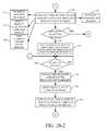
- FIG. 1Dis a flow diagram illustrating, in more detail, one embodiment of the overall operation of impact analyzer component 132 in performing the impact analysis that the selected updates will have on the identified configuration of system 101 .
- Impact analyzer component 132first receives an input invoking it to perform an analysis. This is indicated by block 492 . This can be done, for example, by having the user actuate the impact analysis wizard button in FIG. 18 .
- Component 132then receives configuration inputs from the user identifying a selected client configuration (or environment). This is indicated by block 494 and is described above with respect to FIG. 20 .
- Component 132receives user inputs identifying a location of the models to be analyzed. This is indicated by block 496 and is described above with respect to FIG. 21 .
- Component 132then receives an input identifying a location of the baseline model store that holds the updates to be analyzed. This is indicated by block 498 and is described above with respect to FIG. 22 .
- Impact analysis component 132then performs the analysis to identify the impact of the selected updates on the selected environment. This is indicated by block 500 .
- Component 132then displays the analysis of the affected objects based upon the selected updates and selected environment. This is indicated by block 502 .
- the displayed informationcan take a wide variety of different forms. For instance, it can identify the objects that will be changed as indicated by block 504 . It can identify objects or conflicts that exist as indicated by block 506 . It can also include a wide variety of other information such as the particular update identifier that caused the impact, the update model, the affected model, the layer, object type, object name, and number of conflicts, among other information. This is indicated at block 508 .
- Impact analyzer component 132can then store the impact analysis information, for the selected updates, for later use. This is indicated by block 510 in FIG. 1D . It can be stored on installation of the selected updates as indicated by block 512 , or it can be stored at other times as well, as indicated by block 514 .
- user 114can, at any time, view the current update state or history for system 101 by accessing update state tracking information 210 in life cycle system 200 . This is indicated by block 390 in the flow diagram of FIG. 1B .
- the userhas now selected a potential set of updates to be applied (or installed) and has reviewed not only the impact that the selected updates will have on the set of business processes in business system 101 , but the impact it will have on the object and layer levels as well.
- the userhas reviewed the conflicts that will be generated and can review even detailed information corresponding to the impact and to the conflicts. Thus, it may be that, after reviewing this information, the user wishes to select different updates and view the impact that they will have. This is indicated by block 516 in FIG. 1B . If this happens, processing reverts to block 318 , where the user can select different updates. If not, however, then the current update selection is saved.
- update installer component 106can generate a user interface display, such as display 520 shown in FIG. 27 .
- Display 520includes an updates display pane 522 that shows the updates that have been selected for installation by the user.
- Display 520also illustratively includes an export user input mechanism 524 that allows the user to export the selected updates so that they can be used later to speed up applying updates on another computer or in a different environment that the user accesses.
- export user input mechanism 524When the user actuates input mechanism 524 , the user is illustratively allowed to browse using user input mechanism 526 for a location where the list of updates is to be exported. The user can select the location for export and this will illustratively appear is box 528 .
- the selected updatesare exported (or saved) to that location.
- installation engine 136When the user is ready to install the updates, installation engine 136 illustratively generates a user interface display, such as display 528 that allows the user to confirm that the updates are to be installed.
- Display 528illustratively includes a components display pane 530 which identifies the particular components that will be updated by the selected updates.
- Details display pane 532displays relevant details corresponding to the installation process. For instance, in the embodiment shown in FIG. 28 , pane 532 indicates that some instances will be stopped during the update process, and it allows the user to automatically restart those instances after installation.
- install button 534This causes installation engine 136 to install the selected updates. This is also indicated by blocks 536 and 538 in the flow diagram of FIG. 1B .
- installation engine 136can generate a progress update display, such as display 540 shown in FIG. 29 . Of course, other progress update displays can be shown as well.
- installation engine 136When installation engine 136 completes installing the updates, it also illustratively updates the update state tracking information 210 in life cycle system 200 . This is indicated by block 542 in the flow diagram of FIG. 1B .
- Installation engine 136then generates a user interface display, such as display 544 shown in FIG. 30 that displays the status of the installation. It can be seen, for example, that the updates to some of the various components have been successfully installed, while the updates to others have not been successfully installed. If the user wishes to view more details, the user can illustratively actuate user input mechanism 546 to be navigated to a more detailed log file that shows the details of the corresponding installation.
- conflict resolution component 119illustratively generates a user interface display that allows the user to request that conflict resolution component 119 will automatically resolve as many conflicts as it can, without user intervention. Resolving conflicts is also referred to herein as performing a code merge. Displaying the user interface display allowing the user to select automatic conflict resolution (or code merging) is indicated by block 548 in the flow diagram of FIG. 1B . FIG. 31 shows one example of user interface display 550 that indicates this.
- Display 550includes user input mechanism 552 that can be actuated by the user in order to indicate that the user wishes conflict resolution component 119 to automatically resolve conflicts, where possible.
- conflict resolution component 119illustratively generates a display, such as display 554 shown in FIG. 32 .
- Display 554allows the user to name the particular merge project name using input mechanism 556 .
- Conflict resolution component 119then performs the automatic conflict resolution. This is indicated by blocks 558 and 560 in the flow diagram of FIG. 2 .
- the conflict resolution component 119can do this in a variety of different ways. For instance, it may be that the base system of business system 101 offered by the manufacturer of system 101 is being updated with cumulative update package 120 . Thus, there may be an original base version of system 101 , that is updated to obtain an updated version of system 101 . However, it may also be that the organization deploying system 101 has modified or otherwise customized the base version of system 101 . Thus, in one embodiment, conflict resolution component 119 does a three-way compare that compares the original base version of system 101 , with the updated version of system 101 , and with the customized version of system 101 that is actually deployed at the organization. Conflict resolution component 119 then performs operations so that the customized version of system 101 that is actually deployed will be updated in a way to eliminate conflicts.
- conflict resolution component 119does a three-way text based comparison to revise the update so that it is consistent with the user's customization of “string S clock” to “sting S+1 clock”. Performing a multi-level text based comparison is indicated by block 562 in the flow diagram of FIG. 1B .
- conflict resolution component 119can resolve conflicts in a wide variety of other ways as well, and this is indicated by block 564 .
- Conflict resolution component 119then stores conflict resolution (or code merge) results information so that it can be reviewed, or used, later. This is indicated by block 566 in the flow diagram of FIG. 1B .
- component 119can store the object path where the merge was performed as indicated by block 568 . It can store the total number of conflicts 570 , the number of resolved conflicts 572 , and a time stamp 574 . Of course, if can store other information 576 as well. This can be stored as code merge information 213 in life cycle system 200 , or elsewhere.
- the code merge information 213can be used by the manufacturer of business system 101 , update installer component 106 and/or conflict resolution component 119 , or others. For instance, it can be used to improve conflict resolution, add more features based on what is normally customized by the user, or other things.
- Conflict resolution component 119then generates a display of the conflict resolution (or code merge) results information for review by the user. This is indicated by block 578 .
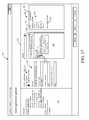
- FIG. 33shows one embodiment of such a display 580 .
- Display 580illustratively includes an unresolved conflicts display section 582 and a merged (or resolved) conflicts section 584 . Both sections show the items or elements where conflicts still exist or where they have been resolved.
- the information in sections 582 and 584is displayed in terms of user-actuatable input mechanisms. Therefore, when the user actuates one of the items, the user can be navigated to the code location in the code of business system 101 where the conflicts occurred. The user can thus view the details corresponding to those conflicts, or actually work to resolve the conflicts directly from that detailed display screen. For instance, if the user actuates the class declaration node 586 on display portion 582 , the user will be navigated to that particular class that contains an unresolved conflict, so that the user can view and work to resolve the conflict. Receiving a user drill down input in this manner is indicated by block 588 in the flow diagram of FIG. 2 , and navigating the user to the code location is indicated by block 590 .
- the usercan be applied using the overall operation shown in FIG. 1B , in other environments as well.
- the usercan import the saved list as indicated by block 330 .
- the processingthus continues to flow as shown in FIG. 1B , except that the selected updates will be those on the imported list, instead of other updates.
- processors and serversinclude computer processors with associated memory and timing circuitry, not separately shown. They are functional parts of the systems or devices to which they belong and are activated by, and facilitate the functionality of the other components or items in those systems.
- the user actuatable input mechanismscan be text boxes, check boxes, icons, links, drop-down menus, search boxes, etc. They can also be actuated in a wide variety of different ways. For instance, they can be actuated using a point and click device (such as a track ball or mouse). They can be actuated using hardware buttons, switches, a joystick or keyboard, thumb switches or thumb pads, etc. They can also be actuated using a virtual keyboard or other virtual actuators. In addition, where the screen on which they are displayed is a touch sensitive screen, they can be actuated using touch gestures. Also, where the device that displays them has speech recognition components, they can be actuated using speech commands.
- a number of data storeshave also been discussed. It will be noted they can each be broken into multiple data stores. All can be local to the systems accessing them, all can be remote, or some can be local while others are remote. All of these configurations are contemplated herein.
- the figuresshow a number of blocks with functionality ascribed to each block. It will be noted that fewer blocks can be used so the functionality is performed by fewer components. Also, more blocks can be used with the functionality distributed among more components.
- FIG. 34is a block diagram of architecture 100 , shown in FIG. 1 , except that its elements are disposed in a cloud computing architecture 500 .
- Cloud computingprovides computation, software, data access, and storage services that do not require end-user knowledge of the physical location or configuration of the system that delivers the services.
- cloud computingdelivers the services over a wide area network, such as the internet, using appropriate protocols.
- cloud computing providersdeliver applications over a wide area network and they can be accessed through a web browser or any other computing component.
- Software or components of architecture 100 as well as the corresponding datacan be stored on servers at a remote location.
- the computing resources in a cloud computing environmentcan be consolidated at a remote data center location or they can be dispersed.
- Cloud computing infrastructurescan deliver services through shared data centers, even though they appear as a single point of access for the user.
- the components and functions described hereincan be provided from a service provider at a remote location using a cloud computing architecture.
- theycan be provided from a conventional server, or they can be installed on client devices directly, or in other ways.
- Cloud computingboth public and private provides substantially seamless pooling of resources, as well as a reduced need to manage and configure underlying hardware infrastructure.
- a public cloudis managed by a vendor and typically supports multiple consumers using the same infrastructure. Also, a public cloud, as opposed to a private cloud, can free up the end users from managing the hardware.
- a private cloudmay be managed by the organization itself and the infrastructure is typically not shared with other organizations. The organization still maintains the hardware to some extent, such as installations and repairs, etc.
- FIG. 34specifically shows that systems 101 and 200 can be located in cloud 502 (which can be public, private, or a combination where portions are public while others are private). Therefore, user 114 uses a user device 116 to access those systems through cloud 502 .
- cloud 502which can be public, private, or a combination where portions are public while others are private. Therefore, user 114 uses a user device 116 to access those systems through cloud 502 .
- FIG. 34also depicts another embodiment of a cloud architecture.
- FIG. 34shows that it is also contemplated that some elements of architecture 100 are disposed in cloud 502 while others are not.
- data store 104can be disposed outside of cloud 502 , and accessed through cloud 502 .
- update installer componentcan also be outside of cloud 502 . Regardless of where they are located, they can be accessed directly by device 116 , through a network (either a wide area network or a local area network), they can be hosted at a remote site by a service, or they can be provided as a service through a cloud or accessed by a connection service that resides in the cloud. All of these architectures are contemplated herein.
- architecture 100can be disposed on a wide variety of different devices. Some of those devices include servers, desktop computers, laptop computers, tablet computers, or other mobile devices, such as palm top computers, cell phones, smart phones, multimedia players, personal digital assistants, etc.
- FIG. 35is a simplified block diagram of one illustrative embodiment of a handheld or mobile computing device that can be used as a user's or client's hand held device 16 , in which the present system (or parts of it) can be deployed.
- FIGS. 36-40are examples of handheld or mobile devices.
- FIG. 35provides a general block diagram of the components of a client device 16 that can run components of architecture 100 or that interacts with architecture 100 , or both.
- a communications link 13is provided that allows the handheld device to communicate with other computing devices and under some embodiments provides a channel for receiving information automatically, such as by scanning
- Examples of communications link 13include an infrared port, a serial/USB port, a cable network port such as an Ethernet port, and a wireless network port allowing communication though one or more communication protocols including General Packet Radio Service (GPRS), LTE, HSPA, HSPA+ and other 3G and 4G radio protocols, 1Xrtt, and Short Message Service, which are wireless services used to provide cellular access to a network, as well as 802.11 and 802.11b (Wi-Fi) protocols, and Bluetooth protocol, which provide local wireless connections to networks.
- GPRSGeneral Packet Radio Service
- LTELong Term Evolution
- HSPAHigh Speed Packet Access
- HSPA+High Speed Packet Access Plus
- SD card interface 15communicates with a processor 17 (which can also embody processor 102 or processors in system 200 or device 116 from FIG. 1 ) along a bus 19 that is also connected to memory 21 and input/output (I/O) components 23 , as well as clock 25 and location system 27 .
- processor 17which can also embody processor 102 or processors in system 200 or device 116 from FIG. 1
- bus 19that is also connected to memory 21 and input/output (I/O) components 23 , as well as clock 25 and location system 27 .
- I/O components 23are provided to facilitate input and output operations.
- I/O components 23 for various embodiments of the device 16can include input components such as buttons, touch sensors, multi-touch sensors, optical or video sensors, voice sensors, touch screens, proximity sensors, microphones, tilt sensors, and gravity switches and output components such as a display device, a speaker, and or a printer port.
- Other I/O components 23can be used as well.
- Clock 25illustratively comprises a real time clock component that outputs a time and date. It can also, illustratively, provide timing functions for processor 17 .
- Location system 27illustratively includes a component that outputs a current geographical location of device 16 .
- Thiscan include, for instance, a global positioning system (GPS) receiver, a LORAN system, a dead reckoning system, a cellular triangulation system, or other positioning system. It can also include, for example, mapping software or navigation software that generates desired maps, navigation routes and other geographic functions.
- GPSglobal positioning system
- Memory 21stores operating system 29 , network settings 31 , applications 33 , application configuration settings 35 , data store 37 , communication drivers 39 , and communication configuration settings 41 .
- Memory 21can include all types of tangible volatile and non-volatile computer-readable memory devices. It can also include computer storage media (described below).
- Memory 21stores computer readable instructions that, when executed by processor 17 , cause the processor to perform computer-implemented steps or functions according to the instructions. Processor 17 can be activated by other components to facilitate their functionality as well.
- Examples of the network settings 31include things such as proxy information, Internet connection information, and mappings.
- Application configuration settings 35include settings that tailor the application for a specific enterprise or user.
- Communication configuration settings 41provide parameters for communicating with other computers and include items such as GPRS parameters, SMS parameters, connection user names and passwords.
- Applications 33can be applications that have previously been stored on the device 16 or applications that are installed during use, although these can be part of operating system 29 , or hosted external to device 16 , as well.
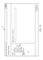
- FIG. 36shows one embodiment in which device 16 is a tablet computer 600 .
- computer 600is shown with user interface display 332 (From FIG. 13 ) displayed on the display screen 602 .
- Screen 602can be a touch screen (so touch gestures from a user's finger 604 can be used to interact with the application) or a pen-enabled interface that receives inputs from a pen or stylus. It can also use an on-screen virtual keyboard. Of course, it might also be attached to a keyboard or other user input device through a suitable attachment mechanism, such as a wireless link or USB port, for instance.
- Computer 600can also illustratively receive voice inputs as well.
- FIGS. 37 and 38provide additional examples of devices 16 that can be used, although others can be used as well.
- a feature phone, smart phone or mobile phone 45is provided as the device 16 .
- Phone 45includes a set of keypads 47 for dialing phone numbers, a display 49 capable of displaying images including application images, icons, web pages, photographs, and video, and control buttons 51 for selecting items shown on the display.
- the phoneincludes an antenna 53 for receiving cellular phone signals such as General Packet Radio Service (GPRS) and 1Xrtt, and Short Message Service (SMS) signals.
- GPRSGeneral Packet Radio Service
- 1Xrtt1Xrtt
- SMSShort Message Service
- phone 45also includes a Secure Digital (SD) card slot 55 that accepts a SD card 57 .
- SDSecure Digital
- the mobile device of FIG. 38is a personal digital assistant (PDA) 59 or a multimedia player or a tablet computing device, etc. (hereinafter referred to as PDA 59 ).
- PDA 59includes an inductive screen 61 that senses the position of a stylus 63 (or other pointers, such as a user's finger) when the stylus is positioned over the screen. This allows the user to select, highlight, and move items on the screen as well as draw and write.
- PDA 59also includes a number of user input keys or buttons (such as button 65 ) which allow the user to scroll through menu options or other display options which are displayed on display 61 , and allow the user to change applications or select user input functions, without contacting display 61 .
- PDA 59can include an internal antenna and an infrared transmitter/receiver that allow for wireless communication with other computers as well as connection ports that allow for hardware connections to other computing devices. Such hardware connections are typically made through a cradle that connects to the other computer through a serial or USB port. As such, these connections are non-network connections.
- mobile device 59also includes a SD card slot 67 that accepts a SD card 69 .
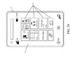
- FIG. 39is similar to FIG. 37 except that the phone is a smart phone 71 .
- Smart phone 71has a touch sensitive display 73 that displays icons or tiles or other user input mechanisms 75 .
- Mechanisms 75can be used by a user to run applications, make calls, perform data transfer operations, etc.
- smart phone 71is built on a mobile operating system and offers more advanced computing capability and connectivity than a feature phone.
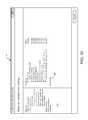
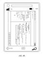
- FIG. 40shows phone 71 with the user interface display from FIG. 12 displayed thereon.
- FIG. 41is one embodiment of a computing environment in which architecture 100 , or parts of it, (for example) can be deployed.
- an exemplary system for implementing some embodimentsincludes a general-purpose computing device in the form of a computer 810 .
- Components of computer 810may include, but are not limited to, a processing unit 820 (which can comprise processor 102 or the processor in system 200 or device 116 ), a system memory 830 , and a system bus 821 that couples various system components including the system memory to the processing unit 820 .
- the system bus 821may be any of several types of bus structures including a memory bus or memory controller, a peripheral bus, and a local bus using any of a variety of bus architectures.
- such architecturesinclude Industry Standard Architecture (ISA) bus, Micro Channel Architecture (MCA) bus, Enhanced ISA (EISA) bus, Video Electronics Standards Association (VESA) local bus, and Peripheral Component Interconnect (PCI) bus also known as Mezzanine bus.
- ISAIndustry Standard Architecture
- MCAMicro Channel Architecture
- EISAEnhanced ISA
- VESAVideo Electronics Standards Association
- PCIPeripheral Component Interconnect
- Computer 810typically includes a variety of computer readable media.
- Computer readable mediacan be any available media that can be accessed by computer 810 and includes both volatile and nonvolatile media, removable and non-removable media.
- Computer readable mediamay comprise computer storage media and communication media.
- Computer storage mediais different from, and does not include, a modulated data signal or carrier wave. It includes hardware storage media including both volatile and nonvolatile, removable and non-removable media implemented in any method or technology for storage of information such as computer readable instructions, data structures, program modules or other data.
- Computer storage mediaincludes, but is not limited to, RAM, ROM, EEPROM, flash memory or other memory technology, CD-ROM, digital versatile disks (DVD) or other optical disk storage, magnetic cassettes, magnetic tape, magnetic disk storage or other magnetic storage devices, or any other medium which can be used to store the desired information and which can be accessed by computer 810 .
- Communication mediatypically embodies computer readable instructions, data structures, program modules or other data in a transport mechanism and includes any information delivery media.
- modulated data signalmeans a signal that has one or more of its characteristics set or changed in such a manner as to encode information in the signal.
- communication mediaincludes wired media such as a wired network or direct-wired connection, and wireless media such as acoustic, RF, infrared and other wireless media. Combinations of any of the above should also be included within the scope of computer readable media.
- the system memory 830includes computer storage media in the form of volatile and/or nonvolatile memory such as read only memory (ROM) 831 and random access memory (RAM) 832 .
- ROMread only memory
- RAMrandom access memory
- BIOSbasic input/output system 833
- RAM 832typically contains data and/or program modules that are immediately accessible to and/or presently being operated on by processing unit 820 .
- FIG. 41illustrates operating system 834 , application programs 835 , other program modules 836 , and program data 837 .
- the computer 810may also include other removable/non-removable volatile/nonvolatile computer storage media.
- FIG. 41illustrates a hard disk drive 841 that reads from or writes to non-removable, nonvolatile magnetic media, a magnetic disk drive 851 that reads from or writes to a removable, nonvolatile magnetic disk 852 , and an optical disk drive 855 that reads from or writes to a removable, nonvolatile optical disk 856 such as a CD ROM or other optical media.
- removable/non-removable, volatile/nonvolatile computer storage mediathat can be used in the exemplary operating environment include, but are not limited to, magnetic tape cassettes, flash memory cards, digital versatile disks, digital video tape, solid state RAM, solid state ROM, and the like.
- the hard disk drive 841is typically connected to the system bus 821 through a non-removable memory interface such as interface 840
- magnetic disk drive 851 and optical disk drive 855are typically connected to the system bus 821 by a removable memory interface, such as interface 850 .
- the functionality described hereincan be performed, at least in part, by one or more hardware logic components.
- illustrative types of hardware logic componentsinclude Field-programmable Gate Arrays (FPGAs), Program-specific Integrated Circuits (ASICs), Program-specific Standard Products (ASSPs), System-on-a-chip systems (SOCs), Complex Programmable Logic Devices (CPLDs), etc.
- the drives and their associated computer storage media discussed above and illustrated in FIG. 41provide storage of computer readable instructions, data structures, program modules and other data for the computer 810 .
- hard disk drive 841is illustrated as storing operating system 844 , application programs 845 , other program modules 846 , and program data 847 .
- operating system 844application programs 845 , other program modules 846 , and program data 847 are given different numbers here to illustrate that, at a minimum, they are different copies.
- a usermay enter commands and information into the computer 810 through input devices such as a keyboard 862 , a microphone 863 , and a pointing device 861 , such as a mouse, trackball or touch pad.
- Other input devicesmay include a joystick, game pad, satellite dish, scanner, or the like.
- These and other input devicesare often connected to the processing unit 820 through a user input interface 860 that is coupled to the system bus, but may be connected by other interface and bus structures, such as a parallel port, game port or a universal serial bus (USB).
- a visual display 891 or other type of display deviceis also connected to the system bus 821 via an interface, such as a video interface 890 .
- computersmay also include other peripheral output devices such as speakers 897 and printer 896 , which may be connected through an output peripheral interface 895 .
- the computer 810is operated in a networked environment using logical connections to one or more remote computers, such as a remote computer 880 .
- the remote computer 880may be a personal computer, a hand-held device, a server, a router, a network PC, a peer device or other common network node, and typically includes many or all of the elements described above relative to the computer 810 .
- the logical connections depicted in FIG. 41include a local area network (LAN) 871 and a wide area network (WAN) 873 , but may also include other networks.
- LANlocal area network
- WANwide area network
- Such networking environmentsare commonplace in offices, enterprise-wide computer networks, intranets and the Internet.
- the computer 810When used in a LAN networking environment, the computer 810 is connected to the LAN 871 through a network interface or adapter 870 .
- the computer 810When used in a WAN networking environment, the computer 810 typically includes a modem 872 or other means for establishing communications over the WAN 873 , such as the Internet.
- the modem 872which may be internal or external, may be connected to the system bus 821 via the user input interface 860 , or other appropriate mechanism.
- program modules depicted relative to the computer 810may be stored in the remote memory storage device.
- FIG. 41illustrates remote application programs 885 as residing on remote computer 880 . It will be appreciated that the network connections shown are exemplary and other means of establishing a communications link between the computers may be used.
Landscapes
- Engineering & Computer Science (AREA)
- Software Systems (AREA)
- General Engineering & Computer Science (AREA)
- Theoretical Computer Science (AREA)
- Physics & Mathematics (AREA)
- General Physics & Mathematics (AREA)
- Computer Security & Cryptography (AREA)
- User Interface Of Digital Computer (AREA)
- Stored Programmes (AREA)
Abstract
Description
Claims (18)
Priority Applications (4)
| Application Number | Priority Date | Filing Date | Title |
|---|---|---|---|
| US14/151,329US9665359B2 (en) | 2013-09-13 | 2014-01-09 | Automatically resolving conflicts after installation of selected updates in a computer system |
| CN201480050625.7ACN105612495B (en) | 2013-09-13 | 2014-09-09 | Selected update of installation solves conflict automatically later in computer systems |
| PCT/US2014/054632WO2015038483A1 (en) | 2013-09-13 | 2014-09-09 | Automatically resolving conflicts after installation of selected updates in a computer system |
| EP14772509.7AEP3044672A1 (en) | 2013-09-13 | 2014-09-09 | Automatically resolving conflicts after installation of selected updates in a computer system |
Applications Claiming Priority (3)
| Application Number | Priority Date | Filing Date | Title |
|---|---|---|---|
| US201361877856P | 2013-09-13 | 2013-09-13 | |
| US201361902093P | 2013-11-08 | 2013-11-08 | |
| US14/151,329US9665359B2 (en) | 2013-09-13 | 2014-01-09 | Automatically resolving conflicts after installation of selected updates in a computer system |
Publications (2)
| Publication Number | Publication Date |
|---|---|
| US20150082292A1 US20150082292A1 (en) | 2015-03-19 |
| US9665359B2true US9665359B2 (en) | 2017-05-30 |
Family
ID=51619289
Family Applications (1)
| Application Number | Title | Priority Date | Filing Date |
|---|---|---|---|
| US14/151,329ActiveUS9665359B2 (en) | 2013-09-13 | 2014-01-09 | Automatically resolving conflicts after installation of selected updates in a computer system |
Country Status (4)
| Country | Link |
|---|---|
| US (1) | US9665359B2 (en) |
| EP (1) | EP3044672A1 (en) |
| CN (1) | CN105612495B (en) |
| WO (1) | WO2015038483A1 (en) |
Cited By (6)
| Publication number | Priority date | Publication date | Assignee | Title |
|---|---|---|---|---|
| US10268473B2 (en) | 2013-09-13 | 2019-04-23 | Microsoft Technology Licensing, Llc | Update installer with process impact analysis |
| US10289403B1 (en)* | 2018-03-29 | 2019-05-14 | Microsoft Technology Licensing, Llc | Enhanced server farm patching system for enabling developers to override off-peak patching schedules |
| US10585659B2 (en) | 2018-03-29 | 2020-03-10 | Microsoft Technology Licensing, Llc | Enabling tenant administrators to initiate request driven peak-hour builds to override off-peak patching schedules |
| US20220326929A1 (en)* | 2021-04-12 | 2022-10-13 | EMC IP Holding Company LLC | Automated delivery of cloud native application updates using one or more user-connection gateways |
| US11567756B2 (en) | 2020-03-16 | 2023-01-31 | Microsoft Technology Licensing, Llc | Causality determination of upgrade regressions via comparisons of telemetry data |
| US11853746B2 (en)* | 2022-03-01 | 2023-12-26 | Microsoft Technology Licensing, Llc | Source code merge conflict resolution |
Families Citing this family (15)
| Publication number | Priority date | Publication date | Assignee | Title |
|---|---|---|---|---|
| US9489189B2 (en)* | 2013-02-21 | 2016-11-08 | Oracle International Corporation | Dynamically generate and execute a context-specific patch installation procedure on a computing system |
| US9405645B2 (en)* | 2013-11-14 | 2016-08-02 | Microsoft Technology Licensing, Llc | User support experience with automatically generated virtual environment |
| US9614724B2 (en) | 2014-04-21 | 2017-04-04 | Microsoft Technology Licensing, Llc | Session-based device configuration |
| US9606788B2 (en)* | 2014-04-30 | 2017-03-28 | Microsoft Technology Licensing, Llc | Dynamic update installer for customized software |
| US10111099B2 (en) | 2014-05-12 | 2018-10-23 | Microsoft Technology Licensing, Llc | Distributing content in managed wireless distribution networks |
| US9874914B2 (en) | 2014-05-19 | 2018-01-23 | Microsoft Technology Licensing, Llc | Power management contracts for accessory devices |
| US10037202B2 (en) | 2014-06-03 | 2018-07-31 | Microsoft Technology Licensing, Llc | Techniques to isolating a portion of an online computing service |
| US9717006B2 (en) | 2014-06-23 | 2017-07-25 | Microsoft Technology Licensing, Llc | Device quarantine in a wireless network |
| CN107832062B (en)* | 2017-09-08 | 2020-04-21 | 深圳壹账通智能科技有限公司 | A program update method and terminal device |
| US11113264B2 (en)* | 2018-04-27 | 2021-09-07 | Sap Se | Conflict resolution for database file merge |
| US10901721B2 (en)* | 2018-09-20 | 2021-01-26 | Vmware, Inc. | Methods and apparatus for version aliasing mechanisms and cumulative upgrades for software lifecycle management |
| JP7373563B2 (en) | 2018-11-14 | 2023-11-02 | ウィックス.コム リミテッド. | Systems and methods for creating and processing configurable applications for website building systems |
| US12175302B2 (en)* | 2020-11-27 | 2024-12-24 | Kyndryl, Inc. | Transitioning of computer-related services based on performance criteria with flow efficiency value |
| CN113094689B (en)* | 2021-04-06 | 2024-06-07 | 中科美络科技股份有限公司 | Configuration-based single sign-on method and system in government affair system |
| CN113808723B (en)* | 2021-09-30 | 2023-08-22 | 北京蓝海医信科技有限公司 | Service system information integration platform |
Citations (163)
| Publication number | Priority date | Publication date | Assignee | Title |
|---|---|---|---|---|
| US5495610A (en) | 1989-11-30 | 1996-02-27 | Seer Technologies, Inc. | Software distribution system to build and distribute a software release |
| US5790856A (en) | 1995-05-08 | 1998-08-04 | Apple Computer, Inc. | Methods, apparatus, and data structures for data driven computer patches and static analysis of same |
| US5860007A (en) | 1995-09-29 | 1999-01-12 | Siemens Corporate Research, Inc. | Automated software modification facilitator |
| US5892953A (en) | 1991-04-15 | 1999-04-06 | International Business Machines Corporation | Corrective service facility |
| US5898872A (en) | 1997-09-19 | 1999-04-27 | Tominy, Inc. | Software reconfiguration engine |
| US20010052108A1 (en) | 1999-08-31 | 2001-12-13 | Michel K. Bowman-Amuah | System, method and article of manufacturing for a development architecture framework |
| US6381694B1 (en)* | 1994-02-18 | 2002-04-30 | Apple Computer, Inc. | System for automatic recovery from software problems that cause computer failure |
| US6425126B1 (en)* | 1999-05-19 | 2002-07-23 | International Business Machines Corporation | Apparatus and method for synchronizing software between computers |
| US20020099728A1 (en)* | 2000-06-21 | 2002-07-25 | Lees William B. | Linked value replication |
| US6477703B1 (en) | 1999-06-29 | 2002-11-05 | Hewlett-Packard Company | Software patch selection tool |
| US20030028825A1 (en)* | 2001-08-01 | 2003-02-06 | George Hines | Service guru system and method for automated proactive and reactive computer system analysis |
| US20030046675A1 (en) | 1996-06-07 | 2003-03-06 | William Cheng | Automatic updating of diverse software products on multiple client computer systems |
| US20030051236A1 (en) | 2000-09-01 | 2003-03-13 | Pace Charles P. | Method, system, and structure for distributing and executing software and data on different network and computer devices, platforms, and environments |
| US20030172368A1 (en) | 2001-12-26 | 2003-09-11 | Elizabeth Alumbaugh | System and method for autonomously generating heterogeneous data source interoperability bridges based on semantic modeling derived from self adapting ontology |
| US20030218628A1 (en) | 2002-05-22 | 2003-11-27 | Sun Microsystems, Inc. | System and method for performing patch installation via a graphical user interface |
| US20030221182A1 (en) | 2002-05-21 | 2003-11-27 | International Business Machines Corporation | Semantics-based composition of class hierarchies |
| US20030221190A1 (en) | 2002-05-22 | 2003-11-27 | Sun Microsystems, Inc. | System and method for performing patch installation on multiple devices |
| US20040015918A1 (en) | 2001-02-28 | 2004-01-22 | Motohiro Kawahito | Program optimization method and compiler using the program optimization method |
| US6742141B1 (en)* | 1999-05-10 | 2004-05-25 | Handsfree Networks, Inc. | System for automated problem detection, diagnosis, and resolution in a software driven system |
| US20040123234A1 (en) | 2002-12-18 | 2004-06-24 | Schemalogic, Inc. | Method and system for change control management of shema definition objects |
| US20040122870A1 (en)* | 2002-12-24 | 2004-06-24 | Joong-Ki Park | Method for data synchronization and update conflict resolution between mobile clients and server in mobile system |
| WO2004057463A2 (en) | 2002-12-19 | 2004-07-08 | International Business Machines Corporation | System and method for installation and update of software components |
| US20040143811A1 (en)* | 2002-08-30 | 2004-07-22 | Elke Kaelicke | Development processes representation and management |
| US20040210653A1 (en) | 2003-04-16 | 2004-10-21 | Novadigm, Inc. | Method and system for patch management |
| US20040255290A1 (en)* | 2003-06-12 | 2004-12-16 | International Business Machines Corporation | Installing fixes based on usage |
| US20050044187A1 (en)* | 2003-08-21 | 2005-02-24 | Microsoft Corporation | Systems and methods for providing conflict handling for peer-to-peer synchronization of units of information manageable by a hardware/software interface system |
| US20050044164A1 (en)* | 2002-12-23 | 2005-02-24 | O'farrell Robert | Mobile data and software update system and method |
| US20050055686A1 (en) | 2003-09-08 | 2005-03-10 | Microsoft Corporation | Method and system for servicing software |
| WO2005033934A2 (en) | 2003-10-02 | 2005-04-14 | Siemens Aktiengesellschaft | Flexible software update for automation systems via internet |
| US20050132359A1 (en) | 2003-12-15 | 2005-06-16 | Mcguire Thomas D. | System and method for updating installation components in a networked environment |
| US20050132349A1 (en) | 2003-12-15 | 2005-06-16 | Jason Roberts | System and method for a software distribution service |
| US20050132348A1 (en) | 2003-12-15 | 2005-06-16 | Meulemans Michael E. | System and method for managing and communicating software updates |
| US20050144619A1 (en) | 2002-03-15 | 2005-06-30 | Patrick Newman | System and method for configuring software for distribution |
| US20050177617A1 (en)* | 2003-12-23 | 2005-08-11 | Intel Corporation | Conflict resolution during data synchronization |
| US20050223117A1 (en)* | 2004-04-01 | 2005-10-06 | Microsoft Corporation | Systems and methods for the propagation of conflict resolution to enforce item convergence (i.e., data convergence) |
| US6964044B1 (en) | 2000-10-06 | 2005-11-08 | Genworth Financial, Inc. | System and process for management of changes and modifications in a process |
| US20060020937A1 (en) | 2004-07-21 | 2006-01-26 | Softricity, Inc. | System and method for extraction and creation of application meta-information within a software application repository |
| US20060064666A1 (en) | 2001-05-25 | 2006-03-23 | Amaru Ruth M | Business rules for configurable metamodels and enterprise impact analysis |
| US7024471B2 (en) | 2000-12-12 | 2006-04-04 | International Business Machines Corporation | Mechanism to dynamically update a windows system with user specific application enablement support from a heterogeneous server environment |
| US20060080656A1 (en) | 2004-10-12 | 2006-04-13 | Microsoft Corporation | Methods and instructions for patch management |
| US20060106806A1 (en) | 2004-11-12 | 2006-05-18 | Smith Micro Software, Inc. | Software update for a plurality of mobile devices |
| US7055130B2 (en) | 1999-10-05 | 2006-05-30 | Borland Software Corporation | Methods and systems for identifying dependencies between object-oriented elements |
| US20060117310A1 (en) | 2004-11-24 | 2006-06-01 | Microsoft Corporation | Method and system for analyzing the impact of a software update |
| US20060130046A1 (en) | 2000-11-17 | 2006-06-15 | O'neill Patrick J | System and method for updating and distributing information |
| US20060130040A1 (en) | 2004-11-30 | 2006-06-15 | Oracle International Corporation | Patch Impact analyzer |
| US20060136327A1 (en) | 2003-04-01 | 2006-06-22 | You Cheng H | Risk control system |
| US7076778B2 (en)* | 1997-02-27 | 2006-07-11 | Siebel Systems, Inc. | Method and apparatus for upgrading a software application in the presence of user modifications |
| US7096464B1 (en) | 2002-12-02 | 2006-08-22 | Sap Aktiengesellschaft | Software update method and apparatus |
| US20060200658A1 (en) | 2005-03-07 | 2006-09-07 | Bitfone Corporation | Agent framework for mobile devices |
| US7127707B1 (en)* | 2002-10-10 | 2006-10-24 | Microsoft Corporation | Intellisense in project upgrade |
| US20060288053A1 (en)* | 2005-06-21 | 2006-12-21 | Apple Computer, Inc. | Apparatus and method for peer-to-peer N-way synchronization in a decentralized environment |
| US20070021116A1 (en) | 2003-04-22 | 2007-01-25 | Koichi Okita | Network management apparatus and method of selecting base station for software update |
| US20070033276A1 (en) | 2005-08-08 | 2007-02-08 | Southern Company Services, Inc. | Application portfolio and architecture research tool |
| US7194475B2 (en) | 2001-10-30 | 2007-03-20 | International Business Machines Corporation | Method, system, and program for performing an impact analysis of program statements in at least one source code file |
| US20070067354A1 (en)* | 2005-09-16 | 2007-03-22 | Microsoft Corporation | Productivity suite to line of business synchronization mechanism |
| US20070074172A1 (en)* | 2005-09-29 | 2007-03-29 | International Business Machines Corporation | Software problem administration |
| US20070106980A1 (en)* | 2005-10-11 | 2007-05-10 | Bea Systems, Inc. | Patch management system |
| US20070106979A1 (en) | 2005-10-11 | 2007-05-10 | Bea Systems, Inc. | Patch management system |
| US20070106978A1 (en) | 2005-10-11 | 2007-05-10 | Bea Systems, Inc. | Patch management system |
| US20070113225A1 (en) | 2005-10-11 | 2007-05-17 | Bea Systems, Inc. | Patch management system |
| US20070130561A1 (en) | 2005-12-01 | 2007-06-07 | Siddaramappa Nagaraja N | Automated relationship traceability between software design artifacts |
| US20070143735A1 (en) | 2005-12-15 | 2007-06-21 | International Business Machines Corporation | Activity-based software traceability management method and apparatus |
| US20070169079A1 (en) | 2005-11-08 | 2007-07-19 | Microsoft Corporation | Software update management |
| US20070180075A1 (en)* | 2002-04-25 | 2007-08-02 | Doug Chasman | System and method for synchronization of version annotated objects |
| US20070198599A1 (en)* | 2006-02-22 | 2007-08-23 | Microsoft Corporation | Distributed conflict resolution for replicated databases |
| US20070220510A1 (en) | 2006-03-14 | 2007-09-20 | Bell Denise A | Method for advanced management of software distribution tasks |
| US7278163B2 (en)* | 2005-02-22 | 2007-10-02 | Mcafee, Inc. | Security risk analysis system and method |
| US20070277167A1 (en)* | 2006-05-23 | 2007-11-29 | International Business Machines Corporation | System and method for computer system maintenance |
| US20070282914A1 (en)* | 2006-05-31 | 2007-12-06 | Microsoft Corporation | Resolving update-delete conflicts |
| US20070283321A1 (en)* | 2006-06-02 | 2007-12-06 | Microsoft Corporation | Collaborative code conflict detection, notification and resolution |
| US7318226B2 (en)* | 2003-10-16 | 2008-01-08 | International Business Machines Corporation | Distributed autonomic solutions repository |
| US20080033700A1 (en) | 2006-08-04 | 2008-02-07 | International Business Machines Corporation | Apparatus and method for analyzing design change impact on product development process |
| US7334222B2 (en) | 2002-09-11 | 2008-02-19 | International Business Machines Corporation | Methods and apparatus for dependency-based impact simulation and vulnerability analysis |
| US20080109791A1 (en) | 2006-11-03 | 2008-05-08 | Francesco Carteri | Method, System and Computer Program For Tracing Impact of Errors In Software Applications |
| US20080144669A1 (en)* | 2006-12-18 | 2008-06-19 | Microsoft Corporation | Propagation of conflict knowledge |
| US20080162509A1 (en) | 2006-12-29 | 2008-07-03 | Becker Wolfgang A | Methods for updating a tenant space in a mega-tenancy environment |
| US20080201701A1 (en) | 2006-10-03 | 2008-08-21 | Salesforce.Com, Inc. | Methods and systems for upgrading and installing application packages to an application platform |
| US20080215349A1 (en) | 2003-05-07 | 2008-09-04 | Cnet Networks | System and method for generating an alternative product recommendation |
| US20080262860A1 (en)* | 2007-04-20 | 2008-10-23 | Sap Ag | System and Method for Supporting Software |
| US20080276284A1 (en)* | 2007-05-04 | 2008-11-06 | United Video Properties, Inc. | Systems and methods for recording overlapping media content during scheduling conflicts |
| US20080288934A1 (en) | 2006-02-14 | 2008-11-20 | Fujitsu Limited | Patch application apparatus and program |
| US20080295086A1 (en) | 2002-06-12 | 2008-11-27 | Symantec Corporation | Systems and methods for patching computer programs |
| US20080313626A1 (en) | 2006-03-10 | 2008-12-18 | Fujitsu Limited | Applicable patch selection device and applicable patch selection method |
| US20090006498A1 (en)* | 2005-06-21 | 2009-01-01 | Apple Inc. | Peer-to-Peer Syncing in a Decentralized Environment |
| US7516367B1 (en)* | 2008-05-30 | 2009-04-07 | International Business Machines Corporation | Automated, distributed problem determination and upgrade planning tool |
| US7529780B1 (en)* | 2005-12-30 | 2009-05-05 | Google Inc. | Conflict management during data object synchronization between client and server |
| US7536678B2 (en) | 2003-12-04 | 2009-05-19 | International Business Machines Corporation | System and method for determining the possibility of adverse effect arising from a code change in a computer program |
| US20090144756A1 (en)* | 2005-08-18 | 2009-06-04 | Satoshi Inami | Conflict resolution apparatus |
| US20090182567A1 (en) | 2008-01-11 | 2009-07-16 | Microsoft Corporation | Exporting and importing business templates |
| US7565419B1 (en)* | 2002-11-22 | 2009-07-21 | Symantec Operating Corporation | Conflict resolution in a peer to peer network |
| US7577948B2 (en) | 2003-07-02 | 2009-08-18 | Upgradedetect, Inc. | System and method for providing computer upgrade information |
| US20090271696A1 (en)* | 2008-04-28 | 2009-10-29 | Microsoft Corporation | Conflict Resolution |
| US7624086B2 (en)* | 2005-03-04 | 2009-11-24 | Maxsp Corporation | Pre-install compliance system |
| US7624393B2 (en) | 2003-09-18 | 2009-11-24 | International Business Machines Corporation | Computer application and methods for autonomic upgrade maintenance of computer hardware, operating systems and application software |
| US20090307650A1 (en) | 2008-06-05 | 2009-12-10 | Accenture Global Services Gmbh | Software upgrade analysis system |
| US20100023919A1 (en) | 2008-07-23 | 2010-01-28 | International Business Machines Corporation | Application/service event root cause traceability causal and impact analyzer |
| US20100063855A1 (en)* | 2008-09-10 | 2010-03-11 | Microsoft Corporation | Flexible system health and remediation agent |
| US20100082803A1 (en)* | 2008-10-01 | 2010-04-01 | Microsoft Corporation | Flexible compliance agent with integrated remediation |
| US20100082534A1 (en)* | 2008-09-30 | 2010-04-01 | Microsoft Corporation | Method and System of Managing Conflicts for a Set of Synchronized Folders |
| US20100095273A1 (en) | 2008-10-15 | 2010-04-15 | International Businass Machines Corporation | Analysis of effects of a software maintenance patch on configuration items of a cmdb |
| US7702497B2 (en) | 2006-12-05 | 2010-04-20 | International Business Machines Corporation | Method for recommending upgrade components for a computer system |
| US7716077B1 (en) | 1999-11-22 | 2010-05-11 | Accenture Global Services Gmbh | Scheduling and planning maintenance and service in a network-based supply chain environment |
| US20100131939A1 (en) | 2008-11-25 | 2010-05-27 | Brandon Hieb | Systems and methods to provide customized release notes during a software system upgrade of a process control system |
| US20100138812A1 (en) | 2008-12-01 | 2010-06-03 | Wipro Limited | System and method for analyzing performance of a software testing system |
| US7735080B2 (en) | 2001-08-30 | 2010-06-08 | International Business Machines Corporation | Integrated system and method for the management of a complete end-to-end software delivery process |
| US20100153908A1 (en) | 2008-12-15 | 2010-06-17 | Accenture Global Services Gmbh | Impact analysis of software change requests |
| US7778963B2 (en)* | 2005-04-26 | 2010-08-17 | Microsoft Corporation | Constraint-based conflict handling for synchronization |
| US7788119B2 (en) | 2003-05-09 | 2010-08-31 | I2 Technologies Us, Inc. | System providing for inventory optimization in association with a centrally managed master repository for core reference data associated with an enterprise |
| US20100299653A1 (en) | 2009-05-20 | 2010-11-25 | Microsft Corporation | Serviceability and configuration management |
| US20100306651A1 (en) | 2009-06-02 | 2010-12-02 | Apple Inc. | Method for creating, exporting, sharing, and installing graphics functional blocks |
| US20100313179A1 (en) | 2009-06-05 | 2010-12-09 | Microsoft Corporation | Integrated work lists for engineering project change management |
| US20110016461A1 (en) | 2006-05-05 | 2011-01-20 | Microsoft Corporation | Techniques to perform gradual upgrades |
| US20110041124A1 (en) | 2009-08-17 | 2011-02-17 | Fishman Neil S | Version Management System |
| US20110055544A1 (en) | 2009-08-31 | 2011-03-03 | Seth Kelby Vidal | Systems and methods for tracking a history of changes associated with software packages and configuration management in a computing system |
| US20110099050A1 (en) | 2009-10-26 | 2011-04-28 | International Business Machines Corporation | Cross Repository Impact Analysis Using Topic Maps |
| US20110113493A1 (en) | 2009-11-11 | 2011-05-12 | International Business Machines Corporation | Software license management impact analysis |
| US7945906B2 (en)* | 2000-11-29 | 2011-05-17 | Microsoft Corporation | Method and software tools for intelligent service pack installation |
| US7966346B1 (en) | 2006-01-23 | 2011-06-21 | Coverity, Inc. | Updating groups of items |
| US7975265B2 (en)* | 2004-07-08 | 2011-07-05 | At&T Intellectual Property I, L.P. | System and method for providing installation support to a user |
| US20110167426A1 (en)* | 2005-01-12 | 2011-07-07 | Microsoft Corporation | Smart scheduler |
| US20110173266A1 (en) | 2008-09-18 | 2011-07-14 | Pioneer Corporation | Image sharing controller, image sharing system, image sharing controlling method, its program, and recording medium recorded with the program |
| US20110208805A1 (en)* | 2010-02-24 | 2011-08-25 | Microsoft Corporation | Multi-master text synchronization using deltas |
| US20110225575A1 (en)* | 2010-03-15 | 2011-09-15 | Oracle International Corporation | Change analysis on enterprise systems prior to deployment |
| US20110231828A1 (en) | 2010-03-18 | 2011-09-22 | Accenture Global Services Limited | Evaluating and enforcing software design quality |
| US20110265077A1 (en) | 2010-04-26 | 2011-10-27 | Vmware, Inc. | Rapid updating of cloud applications |
| US20110296394A1 (en) | 2010-05-26 | 2011-12-01 | Seth Kelby Vidal | Systems and methods for generating cached representations of encoded package profile |
| US8074213B1 (en) | 2006-08-11 | 2011-12-06 | Symantec Operating Corporation | Automatic software updates for computer systems in an enterprise environment |
| US20110307336A1 (en) | 2009-04-27 | 2011-12-15 | Bayerische Motoren Werke Aktiengesellschaft | Method for Updating Software Components |
| US20110307798A1 (en)* | 2010-06-11 | 2011-12-15 | Microsoft Corporation | Merging Modifications to User Interface Components While Preserving User Customizations |
| US20120030658A1 (en)* | 2010-07-30 | 2012-02-02 | International Business Machines Corporation | Software development assistant method and system |
| US20120053986A1 (en) | 2008-12-05 | 2012-03-01 | Business Intelligence Solutions Safe B.V. | Methods, apparatus and systems for data visualization and related applications |
| US20120089964A1 (en) | 2010-10-06 | 2012-04-12 | International Business Machines Corporation | Asynchronous code testing in integrated development environment (ide) |
| US8176483B2 (en)* | 2005-12-30 | 2012-05-08 | Sap Ag | Software maintenance management |
| US20120174073A1 (en)* | 2010-12-31 | 2012-07-05 | Accenture Global Services Limited | Brand impact verification system |
| US20120210294A1 (en)* | 2011-02-10 | 2012-08-16 | Software Ag | Systems and/or methods for identifying and resolving complex model merge conflicts based on atomic merge conflicts |
| US20130036415A1 (en) | 2011-08-02 | 2013-02-07 | Roche Diagnostics Operations, Inc. | Software distribution to medical devices via an intermediary which enforces maintenance of a transaction log |
| US20130042221A1 (en) | 2011-08-12 | 2013-02-14 | Tata Consultancy Services Limited | System and method for automatic impact variable analysis and field expansion in mainframe systems |
| US20130042227A1 (en) | 2011-08-11 | 2013-02-14 | International Business Machines Corporation | Software service notifications based upon software usage, configuration, and deployment topology |
| US20130061167A1 (en) | 2011-09-07 | 2013-03-07 | Microsoft Corporation | Process Management Views |
| US8402452B2 (en) | 2009-04-02 | 2013-03-19 | International Business Machines Corporation | Automatically recommending an upgrade approach for a customizable software product |
| US20130132777A1 (en) | 2011-11-23 | 2013-05-23 | Stephan Froehlich | Analysis of system test procedures for testing a modular system |
| US20130159989A1 (en) | 2011-12-20 | 2013-06-20 | International Business Machines Corporation | Fix delivery system |
| US20130179868A1 (en) | 2007-05-06 | 2013-07-11 | Compuware Corporation | System And Method For Extracting Instrumentation Relevant Inheritance Relationships For A Distributed, Inheritance Rule Based Instrumentation System |
| US8516308B1 (en) | 2011-03-09 | 2013-08-20 | Amazon Technologies, Inc. | Crash based incompatibility prediction for classes of mobile devices crash data |
| US8516477B1 (en) | 2010-03-12 | 2013-08-20 | Cellco Partnership | Automated deployment tool for multiple server environment |
| US8539477B2 (en) | 2009-02-24 | 2013-09-17 | Microsoft Corporation | Managed environment update selection |
| US8555273B1 (en)* | 2003-09-17 | 2013-10-08 | Palm. Inc. | Network for updating electronic devices |
| US20130268914A1 (en) | 2012-04-06 | 2013-10-10 | Microsoft Corporation | Service level objective for cloud hosted applications |
| US8566391B2 (en) | 2009-08-13 | 2013-10-22 | Hitachi, Ltd. | System and method for evaluating application suitability in execution environment |
| US20140047427A1 (en) | 2012-08-13 | 2014-02-13 | International Business Machines Corporation | Concurrent embedded application update and migration |
| US20140100676A1 (en) | 2012-10-08 | 2014-04-10 | Fisher-Rosemount Systems, Inc. | Dynamically reusable classes |
| US8701078B1 (en) | 2007-10-11 | 2014-04-15 | Versionone, Inc. | Customized settings for viewing and editing assets in agile software development |
| US8713525B2 (en) | 2010-03-25 | 2014-04-29 | International Business Machines Corporation | Software management system for network data processing systems |
| US8782606B1 (en) | 2010-08-22 | 2014-07-15 | Panaya Ltd. | Method and system for identifying non-executable human-readable test scenarios to be updated due to code changes |
| US8799044B2 (en) | 2009-01-23 | 2014-08-05 | Infosys Limited | System and method for customizing product lifecycle management process to improve product effectiveness |
| US8806450B1 (en) | 2008-06-26 | 2014-08-12 | Juniper Networks, Inc. | Static analysis in selective software regression testing |
| US8839222B1 (en) | 2011-09-21 | 2014-09-16 | Amazon Technologies, Inc. | Selecting updates for deployment to a programmable execution service application |
| US8881136B2 (en) | 2012-03-13 | 2014-11-04 | International Business Machines Corporation | Identifying optimal upgrade scenarios in a networked computing environment |
| US20140331200A1 (en) | 2013-05-01 | 2014-11-06 | Bank Of America Corporation | Computer Development Assessment System |
| US8886571B2 (en) | 2008-08-19 | 2014-11-11 | Oracle America, Inc. | System and method for service virtualization in a service governance framework |
| US20150058822A1 (en) | 2013-08-20 | 2015-02-26 | Red Hat, Inc. | System and method for estimating impact of software updates |
| US9026851B2 (en) | 2012-09-05 | 2015-05-05 | Wipro Limited | System and method for intelligent troubleshooting of in-service customer experience issues in communication networks |
| US9122422B2 (en) | 2008-01-17 | 2015-09-01 | International Business Machines Corporation | Representing models in systems development lifecycle (SDLC) tools using a network of internet resources |
Family Cites Families (2)
| Publication number | Priority date | Publication date | Assignee | Title |
|---|---|---|---|---|
| US20060242204A1 (en)* | 2005-04-22 | 2006-10-26 | Microsoft Corporation | Sync manager conflict resolution |
| US20100153866A1 (en)* | 2008-12-11 | 2010-06-17 | Accenture Global Services Gmbh | Method and system for modifying the execution of a native application running on a portable electronic device |
- 2014
- 2014-01-09USUS14/151,329patent/US9665359B2/enactiveActive
- 2014-09-09WOPCT/US2014/054632patent/WO2015038483A1/enactiveApplication Filing
- 2014-09-09EPEP14772509.7Apatent/EP3044672A1/ennot_activeCeased
- 2014-09-09CNCN201480050625.7Apatent/CN105612495B/enactiveActive
Patent Citations (170)
| Publication number | Priority date | Publication date | Assignee | Title |
|---|---|---|---|---|
| US5495610A (en) | 1989-11-30 | 1996-02-27 | Seer Technologies, Inc. | Software distribution system to build and distribute a software release |
| US5892953A (en) | 1991-04-15 | 1999-04-06 | International Business Machines Corporation | Corrective service facility |
| US6381694B1 (en)* | 1994-02-18 | 2002-04-30 | Apple Computer, Inc. | System for automatic recovery from software problems that cause computer failure |
| US5790856A (en) | 1995-05-08 | 1998-08-04 | Apple Computer, Inc. | Methods, apparatus, and data structures for data driven computer patches and static analysis of same |
| US5860007A (en) | 1995-09-29 | 1999-01-12 | Siemens Corporate Research, Inc. | Automated software modification facilitator |
| US20030046675A1 (en) | 1996-06-07 | 2003-03-06 | William Cheng | Automatic updating of diverse software products on multiple client computer systems |
| US7076778B2 (en)* | 1997-02-27 | 2006-07-11 | Siebel Systems, Inc. | Method and apparatus for upgrading a software application in the presence of user modifications |
| US5898872A (en) | 1997-09-19 | 1999-04-27 | Tominy, Inc. | Software reconfiguration engine |
| US6742141B1 (en)* | 1999-05-10 | 2004-05-25 | Handsfree Networks, Inc. | System for automated problem detection, diagnosis, and resolution in a software driven system |
| US6425126B1 (en)* | 1999-05-19 | 2002-07-23 | International Business Machines Corporation | Apparatus and method for synchronizing software between computers |
| US6477703B1 (en) | 1999-06-29 | 2002-11-05 | Hewlett-Packard Company | Software patch selection tool |
| US20010052108A1 (en) | 1999-08-31 | 2001-12-13 | Michel K. Bowman-Amuah | System, method and article of manufacturing for a development architecture framework |
| US7055130B2 (en) | 1999-10-05 | 2006-05-30 | Borland Software Corporation | Methods and systems for identifying dependencies between object-oriented elements |
| US7716077B1 (en) | 1999-11-22 | 2010-05-11 | Accenture Global Services Gmbh | Scheduling and planning maintenance and service in a network-based supply chain environment |
| US20020099728A1 (en)* | 2000-06-21 | 2002-07-25 | Lees William B. | Linked value replication |
| US20030051236A1 (en) | 2000-09-01 | 2003-03-13 | Pace Charles P. | Method, system, and structure for distributing and executing software and data on different network and computer devices, platforms, and environments |
| US6964044B1 (en) | 2000-10-06 | 2005-11-08 | Genworth Financial, Inc. | System and process for management of changes and modifications in a process |
| US20060130046A1 (en) | 2000-11-17 | 2006-06-15 | O'neill Patrick J | System and method for updating and distributing information |
| US7945906B2 (en)* | 2000-11-29 | 2011-05-17 | Microsoft Corporation | Method and software tools for intelligent service pack installation |
| US7024471B2 (en) | 2000-12-12 | 2006-04-04 | International Business Machines Corporation | Mechanism to dynamically update a windows system with user specific application enablement support from a heterogeneous server environment |
| US20040015918A1 (en) | 2001-02-28 | 2004-01-22 | Motohiro Kawahito | Program optimization method and compiler using the program optimization method |
| US20060064666A1 (en) | 2001-05-25 | 2006-03-23 | Amaru Ruth M | Business rules for configurable metamodels and enterprise impact analysis |
| US20030028825A1 (en)* | 2001-08-01 | 2003-02-06 | George Hines | Service guru system and method for automated proactive and reactive computer system analysis |
| US7735080B2 (en) | 2001-08-30 | 2010-06-08 | International Business Machines Corporation | Integrated system and method for the management of a complete end-to-end software delivery process |
| US7194475B2 (en) | 2001-10-30 | 2007-03-20 | International Business Machines Corporation | Method, system, and program for performing an impact analysis of program statements in at least one source code file |
| US20030172368A1 (en) | 2001-12-26 | 2003-09-11 | Elizabeth Alumbaugh | System and method for autonomously generating heterogeneous data source interoperability bridges based on semantic modeling derived from self adapting ontology |
| US20050144619A1 (en) | 2002-03-15 | 2005-06-30 | Patrick Newman | System and method for configuring software for distribution |
| US20070180075A1 (en)* | 2002-04-25 | 2007-08-02 | Doug Chasman | System and method for synchronization of version annotated objects |
| US20030221182A1 (en) | 2002-05-21 | 2003-11-27 | International Business Machines Corporation | Semantics-based composition of class hierarchies |
| US20030218628A1 (en) | 2002-05-22 | 2003-11-27 | Sun Microsystems, Inc. | System and method for performing patch installation via a graphical user interface |
| US20030221190A1 (en) | 2002-05-22 | 2003-11-27 | Sun Microsystems, Inc. | System and method for performing patch installation on multiple devices |
| US20080295086A1 (en) | 2002-06-12 | 2008-11-27 | Symantec Corporation | Systems and methods for patching computer programs |
| US20040143811A1 (en)* | 2002-08-30 | 2004-07-22 | Elke Kaelicke | Development processes representation and management |
| US7334222B2 (en) | 2002-09-11 | 2008-02-19 | International Business Machines Corporation | Methods and apparatus for dependency-based impact simulation and vulnerability analysis |
| US7127707B1 (en)* | 2002-10-10 | 2006-10-24 | Microsoft Corporation | Intellisense in project upgrade |
| US7565419B1 (en)* | 2002-11-22 | 2009-07-21 | Symantec Operating Corporation | Conflict resolution in a peer to peer network |
| US7096464B1 (en) | 2002-12-02 | 2006-08-22 | Sap Aktiengesellschaft | Software update method and apparatus |
| US20040123234A1 (en) | 2002-12-18 | 2004-06-24 | Schemalogic, Inc. | Method and system for change control management of shema definition objects |
| WO2004057463A2 (en) | 2002-12-19 | 2004-07-08 | International Business Machines Corporation | System and method for installation and update of software components |
| US20050044164A1 (en)* | 2002-12-23 | 2005-02-24 | O'farrell Robert | Mobile data and software update system and method |
| US20040122870A1 (en)* | 2002-12-24 | 2004-06-24 | Joong-Ki Park | Method for data synchronization and update conflict resolution between mobile clients and server in mobile system |
| US20060136327A1 (en) | 2003-04-01 | 2006-06-22 | You Cheng H | Risk control system |
| US20040210653A1 (en) | 2003-04-16 | 2004-10-21 | Novadigm, Inc. | Method and system for patch management |
| US20070021116A1 (en) | 2003-04-22 | 2007-01-25 | Koichi Okita | Network management apparatus and method of selecting base station for software update |
| US20080215349A1 (en) | 2003-05-07 | 2008-09-04 | Cnet Networks | System and method for generating an alternative product recommendation |
| US7788119B2 (en) | 2003-05-09 | 2010-08-31 | I2 Technologies Us, Inc. | System providing for inventory optimization in association with a centrally managed master repository for core reference data associated with an enterprise |
| US20040255290A1 (en)* | 2003-06-12 | 2004-12-16 | International Business Machines Corporation | Installing fixes based on usage |
| US7577948B2 (en) | 2003-07-02 | 2009-08-18 | Upgradedetect, Inc. | System and method for providing computer upgrade information |
| US20050044187A1 (en)* | 2003-08-21 | 2005-02-24 | Microsoft Corporation | Systems and methods for providing conflict handling for peer-to-peer synchronization of units of information manageable by a hardware/software interface system |
| US7313792B2 (en)* | 2003-09-08 | 2007-12-25 | Microsoft Corporation | Method and system for servicing software |
| US20050055686A1 (en) | 2003-09-08 | 2005-03-10 | Microsoft Corporation | Method and system for servicing software |
| US8555273B1 (en)* | 2003-09-17 | 2013-10-08 | Palm. Inc. | Network for updating electronic devices |
| US7624393B2 (en) | 2003-09-18 | 2009-11-24 | International Business Machines Corporation | Computer application and methods for autonomic upgrade maintenance of computer hardware, operating systems and application software |
| WO2005033934A2 (en) | 2003-10-02 | 2005-04-14 | Siemens Aktiengesellschaft | Flexible software update for automation systems via internet |
| US7318226B2 (en)* | 2003-10-16 | 2008-01-08 | International Business Machines Corporation | Distributed autonomic solutions repository |
| US7536678B2 (en) | 2003-12-04 | 2009-05-19 | International Business Machines Corporation | System and method for determining the possibility of adverse effect arising from a code change in a computer program |
| US20050132349A1 (en) | 2003-12-15 | 2005-06-16 | Jason Roberts | System and method for a software distribution service |
| US20050132359A1 (en) | 2003-12-15 | 2005-06-16 | Mcguire Thomas D. | System and method for updating installation components in a networked environment |
| US20050132348A1 (en) | 2003-12-15 | 2005-06-16 | Meulemans Michael E. | System and method for managing and communicating software updates |
| US20050177617A1 (en)* | 2003-12-23 | 2005-08-11 | Intel Corporation | Conflict resolution during data synchronization |
| US20050223117A1 (en)* | 2004-04-01 | 2005-10-06 | Microsoft Corporation | Systems and methods for the propagation of conflict resolution to enforce item convergence (i.e., data convergence) |
| US7975265B2 (en)* | 2004-07-08 | 2011-07-05 | At&T Intellectual Property I, L.P. | System and method for providing installation support to a user |
| US20060020937A1 (en) | 2004-07-21 | 2006-01-26 | Softricity, Inc. | System and method for extraction and creation of application meta-information within a software application repository |
| US20060080656A1 (en) | 2004-10-12 | 2006-04-13 | Microsoft Corporation | Methods and instructions for patch management |
| US20060106806A1 (en) | 2004-11-12 | 2006-05-18 | Smith Micro Software, Inc. | Software update for a plurality of mobile devices |
| US7614046B2 (en) | 2004-11-24 | 2009-11-03 | Microsoft Corporation | Method and system for analyzing the impact of a software update |
| US20060117310A1 (en) | 2004-11-24 | 2006-06-01 | Microsoft Corporation | Method and system for analyzing the impact of a software update |
| US7895592B2 (en) | 2004-11-30 | 2011-02-22 | Oracle International Corporation | Patch impact analyzer |
| US20060130040A1 (en) | 2004-11-30 | 2006-06-15 | Oracle International Corporation | Patch Impact analyzer |
| US8387051B2 (en)* | 2005-01-12 | 2013-02-26 | Microsoft Corporation | Smart scheduler |
| US20110167426A1 (en)* | 2005-01-12 | 2011-07-07 | Microsoft Corporation | Smart scheduler |
| US7278163B2 (en)* | 2005-02-22 | 2007-10-02 | Mcafee, Inc. | Security risk analysis system and method |
| US7624086B2 (en)* | 2005-03-04 | 2009-11-24 | Maxsp Corporation | Pre-install compliance system |
| US20060200658A1 (en) | 2005-03-07 | 2006-09-07 | Bitfone Corporation | Agent framework for mobile devices |
| US7778963B2 (en)* | 2005-04-26 | 2010-08-17 | Microsoft Corporation | Constraint-based conflict handling for synchronization |
| US20090006498A1 (en)* | 2005-06-21 | 2009-01-01 | Apple Inc. | Peer-to-Peer Syncing in a Decentralized Environment |
| US20060288053A1 (en)* | 2005-06-21 | 2006-12-21 | Apple Computer, Inc. | Apparatus and method for peer-to-peer N-way synchronization in a decentralized environment |
| US20070033276A1 (en) | 2005-08-08 | 2007-02-08 | Southern Company Services, Inc. | Application portfolio and architecture research tool |
| US20090144756A1 (en)* | 2005-08-18 | 2009-06-04 | Satoshi Inami | Conflict resolution apparatus |
| US20070067354A1 (en)* | 2005-09-16 | 2007-03-22 | Microsoft Corporation | Productivity suite to line of business synchronization mechanism |
| US20070074172A1 (en)* | 2005-09-29 | 2007-03-29 | International Business Machines Corporation | Software problem administration |
| US20070106978A1 (en) | 2005-10-11 | 2007-05-10 | Bea Systems, Inc. | Patch management system |
| US20070106979A1 (en) | 2005-10-11 | 2007-05-10 | Bea Systems, Inc. | Patch management system |
| US20070106980A1 (en)* | 2005-10-11 | 2007-05-10 | Bea Systems, Inc. | Patch management system |
| US20070113225A1 (en) | 2005-10-11 | 2007-05-17 | Bea Systems, Inc. | Patch management system |
| US8245216B2 (en) | 2005-10-11 | 2012-08-14 | Oracle International Corporation | Patch management system |
| US20070169079A1 (en) | 2005-11-08 | 2007-07-19 | Microsoft Corporation | Software update management |
| US20070130561A1 (en) | 2005-12-01 | 2007-06-07 | Siddaramappa Nagaraja N | Automated relationship traceability between software design artifacts |
| US20070143735A1 (en) | 2005-12-15 | 2007-06-21 | International Business Machines Corporation | Activity-based software traceability management method and apparatus |
| US8176483B2 (en)* | 2005-12-30 | 2012-05-08 | Sap Ag | Software maintenance management |
| US7529780B1 (en)* | 2005-12-30 | 2009-05-05 | Google Inc. | Conflict management during data object synchronization between client and server |
| US7966346B1 (en) | 2006-01-23 | 2011-06-21 | Coverity, Inc. | Updating groups of items |
| US20080288934A1 (en) | 2006-02-14 | 2008-11-20 | Fujitsu Limited | Patch application apparatus and program |
| US20070198599A1 (en)* | 2006-02-22 | 2007-08-23 | Microsoft Corporation | Distributed conflict resolution for replicated databases |
| US20080313626A1 (en) | 2006-03-10 | 2008-12-18 | Fujitsu Limited | Applicable patch selection device and applicable patch selection method |
| US20070220510A1 (en) | 2006-03-14 | 2007-09-20 | Bell Denise A | Method for advanced management of software distribution tasks |
| US20110016461A1 (en) | 2006-05-05 | 2011-01-20 | Microsoft Corporation | Techniques to perform gradual upgrades |
| US20070277167A1 (en)* | 2006-05-23 | 2007-11-29 | International Business Machines Corporation | System and method for computer system maintenance |
| US20070282914A1 (en)* | 2006-05-31 | 2007-12-06 | Microsoft Corporation | Resolving update-delete conflicts |
| US20070283321A1 (en)* | 2006-06-02 | 2007-12-06 | Microsoft Corporation | Collaborative code conflict detection, notification and resolution |
| US20080033700A1 (en) | 2006-08-04 | 2008-02-07 | International Business Machines Corporation | Apparatus and method for analyzing design change impact on product development process |
| US8074213B1 (en) | 2006-08-11 | 2011-12-06 | Symantec Operating Corporation | Automatic software updates for computer systems in an enterprise environment |
| US20080201701A1 (en) | 2006-10-03 | 2008-08-21 | Salesforce.Com, Inc. | Methods and systems for upgrading and installing application packages to an application platform |
| US20080109791A1 (en) | 2006-11-03 | 2008-05-08 | Francesco Carteri | Method, System and Computer Program For Tracing Impact of Errors In Software Applications |
| US7702497B2 (en) | 2006-12-05 | 2010-04-20 | International Business Machines Corporation | Method for recommending upgrade components for a computer system |
| US20080144669A1 (en)* | 2006-12-18 | 2008-06-19 | Microsoft Corporation | Propagation of conflict knowledge |
| US20080162509A1 (en) | 2006-12-29 | 2008-07-03 | Becker Wolfgang A | Methods for updating a tenant space in a mega-tenancy environment |
| US20080262860A1 (en)* | 2007-04-20 | 2008-10-23 | Sap Ag | System and Method for Supporting Software |
| US20080276284A1 (en)* | 2007-05-04 | 2008-11-06 | United Video Properties, Inc. | Systems and methods for recording overlapping media content during scheduling conflicts |
| US20130179868A1 (en) | 2007-05-06 | 2013-07-11 | Compuware Corporation | System And Method For Extracting Instrumentation Relevant Inheritance Relationships For A Distributed, Inheritance Rule Based Instrumentation System |
| US8701078B1 (en) | 2007-10-11 | 2014-04-15 | Versionone, Inc. | Customized settings for viewing and editing assets in agile software development |
| US20090182567A1 (en) | 2008-01-11 | 2009-07-16 | Microsoft Corporation | Exporting and importing business templates |
| US9122422B2 (en) | 2008-01-17 | 2015-09-01 | International Business Machines Corporation | Representing models in systems development lifecycle (SDLC) tools using a network of internet resources |
| US20090271696A1 (en)* | 2008-04-28 | 2009-10-29 | Microsoft Corporation | Conflict Resolution |
| US7516367B1 (en)* | 2008-05-30 | 2009-04-07 | International Business Machines Corporation | Automated, distributed problem determination and upgrade planning tool |
| US20090307650A1 (en) | 2008-06-05 | 2009-12-10 | Accenture Global Services Gmbh | Software upgrade analysis system |
| US8745611B2 (en) | 2008-06-05 | 2014-06-03 | Accenture Global Services Limited | Software upgrade analysis system |
| US8806450B1 (en) | 2008-06-26 | 2014-08-12 | Juniper Networks, Inc. | Static analysis in selective software regression testing |
| US20100023919A1 (en) | 2008-07-23 | 2010-01-28 | International Business Machines Corporation | Application/service event root cause traceability causal and impact analyzer |
| US8886571B2 (en) | 2008-08-19 | 2014-11-11 | Oracle America, Inc. | System and method for service virtualization in a service governance framework |
| US20100063855A1 (en)* | 2008-09-10 | 2010-03-11 | Microsoft Corporation | Flexible system health and remediation agent |
| US20110173266A1 (en) | 2008-09-18 | 2011-07-14 | Pioneer Corporation | Image sharing controller, image sharing system, image sharing controlling method, its program, and recording medium recorded with the program |
| US20100082534A1 (en)* | 2008-09-30 | 2010-04-01 | Microsoft Corporation | Method and System of Managing Conflicts for a Set of Synchronized Folders |
| US20100082803A1 (en)* | 2008-10-01 | 2010-04-01 | Microsoft Corporation | Flexible compliance agent with integrated remediation |
| US20100095273A1 (en) | 2008-10-15 | 2010-04-15 | International Businass Machines Corporation | Analysis of effects of a software maintenance patch on configuration items of a cmdb |
| US20100131939A1 (en) | 2008-11-25 | 2010-05-27 | Brandon Hieb | Systems and methods to provide customized release notes during a software system upgrade of a process control system |
| US20100138812A1 (en) | 2008-12-01 | 2010-06-03 | Wipro Limited | System and method for analyzing performance of a software testing system |
| US20120053986A1 (en) | 2008-12-05 | 2012-03-01 | Business Intelligence Solutions Safe B.V. | Methods, apparatus and systems for data visualization and related applications |
| US20100153908A1 (en) | 2008-12-15 | 2010-06-17 | Accenture Global Services Gmbh | Impact analysis of software change requests |
| US8799044B2 (en) | 2009-01-23 | 2014-08-05 | Infosys Limited | System and method for customizing product lifecycle management process to improve product effectiveness |
| US8539477B2 (en) | 2009-02-24 | 2013-09-17 | Microsoft Corporation | Managed environment update selection |
| US8402452B2 (en) | 2009-04-02 | 2013-03-19 | International Business Machines Corporation | Automatically recommending an upgrade approach for a customizable software product |
| US20110307336A1 (en) | 2009-04-27 | 2011-12-15 | Bayerische Motoren Werke Aktiengesellschaft | Method for Updating Software Components |
| US20100299653A1 (en) | 2009-05-20 | 2010-11-25 | Microsft Corporation | Serviceability and configuration management |
| US20100306651A1 (en) | 2009-06-02 | 2010-12-02 | Apple Inc. | Method for creating, exporting, sharing, and installing graphics functional blocks |
| US20100313179A1 (en) | 2009-06-05 | 2010-12-09 | Microsoft Corporation | Integrated work lists for engineering project change management |
| US8566391B2 (en) | 2009-08-13 | 2013-10-22 | Hitachi, Ltd. | System and method for evaluating application suitability in execution environment |
| US20110041124A1 (en) | 2009-08-17 | 2011-02-17 | Fishman Neil S | Version Management System |
| US20110055544A1 (en) | 2009-08-31 | 2011-03-03 | Seth Kelby Vidal | Systems and methods for tracking a history of changes associated with software packages and configuration management in a computing system |
| US20110099050A1 (en) | 2009-10-26 | 2011-04-28 | International Business Machines Corporation | Cross Repository Impact Analysis Using Topic Maps |
| US20110113493A1 (en) | 2009-11-11 | 2011-05-12 | International Business Machines Corporation | Software license management impact analysis |
| US20110208805A1 (en)* | 2010-02-24 | 2011-08-25 | Microsoft Corporation | Multi-master text synchronization using deltas |
| US8516477B1 (en) | 2010-03-12 | 2013-08-20 | Cellco Partnership | Automated deployment tool for multiple server environment |
| US20110225575A1 (en)* | 2010-03-15 | 2011-09-15 | Oracle International Corporation | Change analysis on enterprise systems prior to deployment |
| US20110231828A1 (en) | 2010-03-18 | 2011-09-22 | Accenture Global Services Limited | Evaluating and enforcing software design quality |
| US8713525B2 (en) | 2010-03-25 | 2014-04-29 | International Business Machines Corporation | Software management system for network data processing systems |
| US20110265077A1 (en) | 2010-04-26 | 2011-10-27 | Vmware, Inc. | Rapid updating of cloud applications |
| US20110296394A1 (en) | 2010-05-26 | 2011-12-01 | Seth Kelby Vidal | Systems and methods for generating cached representations of encoded package profile |
| US20110307798A1 (en)* | 2010-06-11 | 2011-12-15 | Microsoft Corporation | Merging Modifications to User Interface Components While Preserving User Customizations |
| US20120030658A1 (en)* | 2010-07-30 | 2012-02-02 | International Business Machines Corporation | Software development assistant method and system |
| US8782606B1 (en) | 2010-08-22 | 2014-07-15 | Panaya Ltd. | Method and system for identifying non-executable human-readable test scenarios to be updated due to code changes |
| US20120089964A1 (en) | 2010-10-06 | 2012-04-12 | International Business Machines Corporation | Asynchronous code testing in integrated development environment (ide) |
| US20120174073A1 (en)* | 2010-12-31 | 2012-07-05 | Accenture Global Services Limited | Brand impact verification system |
| US20120210294A1 (en)* | 2011-02-10 | 2012-08-16 | Software Ag | Systems and/or methods for identifying and resolving complex model merge conflicts based on atomic merge conflicts |
| US8516308B1 (en) | 2011-03-09 | 2013-08-20 | Amazon Technologies, Inc. | Crash based incompatibility prediction for classes of mobile devices crash data |
| US20130036415A1 (en) | 2011-08-02 | 2013-02-07 | Roche Diagnostics Operations, Inc. | Software distribution to medical devices via an intermediary which enforces maintenance of a transaction log |
| US20130042227A1 (en) | 2011-08-11 | 2013-02-14 | International Business Machines Corporation | Software service notifications based upon software usage, configuration, and deployment topology |
| US20130042221A1 (en) | 2011-08-12 | 2013-02-14 | Tata Consultancy Services Limited | System and method for automatic impact variable analysis and field expansion in mainframe systems |
| US20130061167A1 (en) | 2011-09-07 | 2013-03-07 | Microsoft Corporation | Process Management Views |
| US8839222B1 (en) | 2011-09-21 | 2014-09-16 | Amazon Technologies, Inc. | Selecting updates for deployment to a programmable execution service application |
| US20130132777A1 (en) | 2011-11-23 | 2013-05-23 | Stephan Froehlich | Analysis of system test procedures for testing a modular system |
| US20130159989A1 (en) | 2011-12-20 | 2013-06-20 | International Business Machines Corporation | Fix delivery system |
| US8881136B2 (en) | 2012-03-13 | 2014-11-04 | International Business Machines Corporation | Identifying optimal upgrade scenarios in a networked computing environment |
| US20130268914A1 (en) | 2012-04-06 | 2013-10-10 | Microsoft Corporation | Service level objective for cloud hosted applications |
| US20140047427A1 (en) | 2012-08-13 | 2014-02-13 | International Business Machines Corporation | Concurrent embedded application update and migration |
| US9026851B2 (en) | 2012-09-05 | 2015-05-05 | Wipro Limited | System and method for intelligent troubleshooting of in-service customer experience issues in communication networks |
| US20140100676A1 (en) | 2012-10-08 | 2014-04-10 | Fisher-Rosemount Systems, Inc. | Dynamically reusable classes |
| US20140331200A1 (en) | 2013-05-01 | 2014-11-06 | Bank Of America Corporation | Computer Development Assessment System |
| US20150058822A1 (en) | 2013-08-20 | 2015-02-26 | Red Hat, Inc. | System and method for estimating impact of software updates |
| US9348585B2 (en) | 2013-08-20 | 2016-05-24 | Red Hat, Inc. | System and method for estimating impact of software updates |
Non-Patent Citations (75)
| Title |
|---|
| "Apply Updates and Hotfixes [AX 2012]", Published on: Jun. 19, 2013, Available at: http://technet.microsoft.com/en-us/library/hh335183.aspx. |
| "Business Process Change Analyzer in SAP Solution Manager 7-1", retrieved from: <http://sapassets.edgesuite.net/sapcom/docs/2015/07/9a426487-5b7c-0010-82c7-eda71af511fa.pdf> accessed on Sep. 29, 2016, dated Jul. 11, 2012. Believed to have been publically available at least as of Aug. 2013, 13 pages. |
| "JD Edwards EnterpriseOne Tools-Software Updates Guide", Published on: Mar. 2011, Available at: http://docs.oracle.com/cd/E17984-01/doc.898/e14719.pdf. |
| "Managing Multiple Environments from Development to Production", Published on: Jan. 18, 2012, Available at: http://docs.oracle.com/cd/B28359-01/owb.111/b31280/configs-11.htm#WBINS12301. |
| "Oracle 6 Using the Software Update Impact Analysis Tool", retrieved from: <https://docs.oracle.com/cd/E24705-01/doc.91/e24260/impactanalysistool.htm#EOTSU00104> accessed on Sep. 29, 2016. Believed to have been publically available at leasr as of Aug. 2013, 10 pages. |
| "Prism Deploy", Published on: Jun. 3, 2002, Available at: http://amtsoft.com/prismdeploy/. |
| "SAP Solution Manager 7.1 Business Process Change Analyzer (BPCA)", retrieved from: <https://support.sap.com/content/dam/library/SAP%20Support%20Portal/support-programs-services/solution-manager/processes/Media%20Library/Test%20Management/Overview%20of%20Business%20Process%20Change%20Analyzer(BPCA).pdf>, accessed on Sep. 29, 2016. Believed to have been publically available at least as of Aug. 2013, 115 pages. |
| "SQL Server Distributed Replay", Published on Apr. 24, 2012, Available at: http://technet.microsoft.com/en-us/library/ff878183.aspx. |
| "Test Management with SAP Solution Manager 7.1", retrieved from: <https://support.sap.com/content/dam/library/SAP%20Support%20Portal/support-programs-services/solution-manager/processes/Media%20Library/Test%20Management/SAP%20Test%20Management%20with%20SAP%20SolMan%207.1.pdf>, accessed on Sep. 29, 2016. Believed to have been publically available at least as of Aug. 2013, 85 pages. |
| "Update System Center 2012 Configuration Manager", Published on: Aug. 1, 2013, Available at http://technet.microsoft.com/en-us/library/jj553405.aspx. |
| "JD Edwards EnterpriseOne Tools—Software Updates Guide", Published on: Mar. 2011, Available at: http://docs.oracle.com/cd/E17984—01/doc.898/e14719.pdf. |
| "Managing Multiple Environments from Development to Production", Published on: Jan. 18, 2012, Available at: http://docs.oracle.com/cd/B28359—01/owb.111/b31280/configs—11.htm#WBINS12301. |
| "Oracle 6 Using the Software Update Impact Analysis Tool", retrieved from: <https://docs.oracle.com/cd/E24705—01/doc.91/e24260/impactanalysistool.htm#EOTSU00104> accessed on Sep. 29, 2016. Believed to have been publically available at leasr as of Aug. 2013, 10 pages. |
| ALM Solution Management, "Test Automation with SAP Solution Manager 7.1 and HP QTP", Dated Sep. 2012 [Retrieved on Sep. 2, 2016]. Retrieved from the Internet: <URL:http://www.sdn.sap.com/irj/scn/go/portal/prtroot/docs/library/uuid/e01fcb07-691b-3010-48b8-cf2881e14a64?overridelayout=true>31 pages. |
| Amendment After Notice of Allowance for U.S. Appl. No. 14/151,306 dated Dec. 15, 2016, 9 pages. |
| Amendment for U.S. Appl. No, 14/152,694 dated Nov. 15, 2016, 15 pages. |
| Amendment for U.S. Appl. No. 14/151,289 dated Aug. 18, 2015, 15 pages. |
| Amendment for U.S. Appl. No. 14/151,296 dated Nov. 11, 2016, 12 pages. |
| Amendment for U.S. Appl. No. 14/151,306 dated Feb. 26, 2016, 13 pages. |
| Amendment for U.S. Appl. No. 14/151,306 dated Sep. 23, 2015, 12 pages. |
| Amendment for U.S. Appl. No. 14/152,694 dated Oct. 13, 2015, 13 pages. |
| Amendment With RCE for U.S. Appl. No. 14/151,289 dated Jan. 2, 2016, 19 pages. |
| Amendment with RCE for U.S. Appl. No. 14/151,306 dated Aug. 1, 2016, 16 pages. |
| Amendment With RCE for U.S. Appl. No. 14/152,694 dated Feb. 3, 2016, 16 pages. |
| Application and Drawings for U.S. Appl. No. 14/151,289, date of filing: Jan. 9, 2014, 84 pages. |
| Application and Drawings for U.S. Appl. No. 14/151,306, date of filing: Jan. 9, 2014, 84 pages. |
| Application and Drawings for U.S. Appl. No. 14/152,694, date of filing: Jan. 10, 2014, 84 pages. |
| Barbara G. Ryder et al., Change Impact Analysis for Object-Oriented Programs, Jun. 2001, [Retrieved on May 23, 2016]. Retrieved from the Internet: URL:http://delivery.acm.org/10.1145/380000/379661/p46-ryder.pdf?8 pages (46-53). |
| Chengzheng Sun et al., A Multi-version Approach to Conflict Resolution in Distributed Groupware Systems, 2000, [Retrieved on Jun. 8, 2016]. Retrieved from the internet: <URL: http://ieeexplore.ieee.org/stamp/stamp.jsp?tp=&arnumber=840944> 10 Pages (1-10).* |
| Chi-Keung Luk et al., "Pin: Building Customized Program Analysis Tools with Dynamic Instrumentation", ACM 2005, [Retrieved on Sep. 1, 2016], Retrieved from the Internet <URL:http://gram.eng.uci.edu/students/swallace/papers-wallace/pdf/PLDI-05-Pin.pdf> 11 pages. |
| Chi-Keung Luk et al., "Pin: Building Customized Program Analysis Tools with Dynamic Instrumentation", ACM 2005, [Retrieved on Sep. 1, 2016], Retrieved from the Internet <URL:http://gram.eng.uci.edu/students/swallace/papers—wallace/pdf/PLDI-05-Pin.pdf> 11 pages. |
| Cordero V, Randall, "Apply updates to database, AOS, and clients [AX 2012]", Published on: Dec. 21, 2013, Available at: http://technet.microsoft.com/en-us/library/hh538446.aspx. |
| Corrected Notice of Allowance for U.S. Appl. No. 14/151,289 dated Jul. 12, 2016, 6 pages. |
| David Marshall, "Patch Management Best Practices", Dated Apr. 23, 2013 [Retrieved on Sep. 2, 2016]. Retrieved from the Internet: <URL:http://www.infoworld.com/article/2614556/server-virtualization/vmware-sells-off-shavlik-patch-management-to-landesk.html>3 pages. |
| Dunagan, et al., "Towards a Self-Managing Software Patching Process Using Black-Box Persistent-State Manifests", In Technical Report, MSR-TR-2004-23, Mar. 21, 2004, 9 pages. |
| Enda O'Connor, "Patch Management Best Practicies", Dated Apr. 2008 [Retrieved on Sep. 2, 2016]. Retrieved from the Internet: <URL:http://www.oracle.com/technetwork/systems/articles/patch-management-jsp-135385.html>8 pages. |
| Final Office Action for U.S. Appl No. 14/152,694 dated Dec. 23, 2016, 25 pages. |
| Final Office Action for U.S. Appl. No. 14/151,289 dated Oct. 5, 2015, 26 pages. |
| Final Office Action for U.S. Appl. No. 14/151,296 dated Dec. 21, 2016, 18 pages. |
| Final Office Action for U.S. Appl. No. 14/151,306 dated Mar. 31, 2016, 18 pages. |
| Final Office Action for U.S. Appl. No. 14/152,694 dated Nov. 13, 2015, 27 pages. |
| International Preliminary Report on Patentability for International Application No. PCT/US2014/054631, date of mailing: Dec. 11, 2015, date of filing: Sep. 9, 2014, 21 pages. |
| International Preliminary Report on Patentability for International Application No. PCT/US2014/054632, date of mailing: Dec. 17, 2015, date of filing: Sep. 9, 2014, 16 pages. |
| International Search Report and Written Opinion for International Application No. PCT/US2014/054631. mailing date: Nov. 24, 2014, filing date: Sep. 9, 2014, 13 pages. |
| International Search Report and Written Opinion for International Application No. PCT/US2014/054632, mailing date: Nov. 24, 2014, filing date: Sep. 9, 2014, 12 pages. |
| International Search Report and Written Opinion for International Application No. PCT/US2014/055285. mailing date: Dec. 2, 2014, filing date: Sep. 12, 2014, 13 pages. |
| Jyotish Gogoi, "SAP Software Update Manager Tool-SPS Update Demo-Part I", Dated Mar. 20, 2012 [Retrieved on Sep. 2, 2016]. Retrieved from the Internet: <URL:http://scn.sap.com/docs/DOC-25113>6 pages. |
| Jyotish Gogoi, "SAP Software Update Manager Tool—SPS Update Demo—Part I", Dated Mar. 20, 2012 [Retrieved on Sep. 2, 2016]. Retrieved from the Internet: <URL:http://scn.sap.com/docs/DOC-25113>6 pages. |
| K.H. Bennett et al., Software Maintenance and Evolution: a Roadmap, ACM 2000, [Retrieved on May 23, 2016]. Retrieved from the Internet: <URL: http://delivery.acm.org/10.1145/340000/336534/p73-bennett.pdf?14 pages (73-87). |
| Konnie Daglis, et al. "Software Update Manager (SUM) for SAP Solutions", Dated May 14, 2012 [Retrieved on Sep. 2, 2016]. Retrieved from the Internet: <URL:http://events.asug.com/2012AC/1602-Software-Update-Manager-for-SAP-Solutions.pdf>26 pages. |
| Konnie Daglis, et al. "Software Update Manager (SUM) for SAP Solutions", Dated May 14, 2012 [Retrieved on Sep. 2, 2016]. Retrieved from the Internet: <URL:http://events.asug.com/2012AC/1602—Software—Update—Manager—for—SAP—Solutions.pdf>26 pages. |
| Law et al., "Whole Program Path-Based Dynamic Impact Analysis", 2003 IEEE, 11 pages. |
| ManageEngine, "Automated Patch Management for Windows", Undated [Retrieved on Sep. 2, 2016], Retrieved from the Internet: <URL: http://www.inforworld.com/article/2614556/server-virtualization.vmware-sells-off-shavlik-patch-management-to-landesk.html>2 pages. |
| Michael Fischer et al., Populating a Release History Database from Version Control and Bug Tracking Systems, 2003, [Retrieved on 2016-09-12]. Retrieved from the internet: <Url:.* |
| Michelle L. Lee "Change Impact Analysis of Object-Oriented Software", 1998, [Retrieved on Mar. 18, 2016], Retrieved from the Internet:<URL:http://cs.gmu.edu/˜offutt/rsrch/LiLiDiss.pdf>202 pages. |
| Microsoft, Software Update Management Using SMS 2003, Mar. 15, 2007, [Retrieved on Oct. 30, 2015]. Retrieved from the internet:<URL:http.//www.google.com/url?sa=t&rct=j&q=&esrc=s&source=web&cnload%2Ff%2F6%2Fa%2Ff6acc021-a05a-48a1-88e2->103 pages. |
| Non Final Office Action for U.S. Appl. No. 3, 14/152,694 dated Jul. 15, 2016, 33 pages. |
| Non-Final Office Action for U.S. Appl. No. 14/151,296 dated Aug. 12, 2016, 23 pages. |
| Non-Final Office Action for U.S. Appl. No. 14/151,306 dated Nov. 13, 2015, 23 pages. |
| Notice of Allowance for U.S. Appl. No. 14/151,289 dated Dec. 30, 2016, 12 pages. |
| Notice of Allowance for U.S. Appl. No. 14/151,289 dated Jun. 29, 2016, 25 pages. |
| Notice of Allowance for U.S. Appl. No. 14/151,306 dated Dec. 6, 2016, 25 pages. |
| Petra Brosch et al., We can work it out: Collaborative Conflict Resolution in Model Versioning, Sep. 2009, [Retrieved on Jun. 8, 2016]. Retrieved from the internet: <URL: http://download.springer.com/static/pdf/607/chp%253A10.1007%252F978-1-84882-854-4-12.pdf> 8 Pages (207-214).* |
| Petra Brosch et al., We can work it out: Collaborative Conflict Resolution in Model Versioning, Sep. 2009, [Retrieved on Jun. 8, 2016]. Retrieved from the internet: <URL: http://download.springer.com/static/pdf/607/chp%253A10.1007%252F978-1-84882-854-4—12.pdf> 8 Pages (207-214).* |
| Prosecution History for U.S. Appl. No. 14/151,289 including: Non-Final Office Action dated May 29, 2015, Response to Notice to File Missing Parts dated Apr. 8, 2014 and Notice to File Missing Parts dated Jan. 27, 2014, 22 pages. |
| Prosecution History for U.S. Appl. No. 14/151,296 including: Response to Notice to File Corrected Application Papers dated Apr. 15, 2014, Notice to File Corrected Application Papers dated Jan. 27, 2014 and Application and Drawings filed Jan. 9, 2014, 90 pages. |
| Prosecution History for U.S. Appl. No. 14/151,306 including: Non-Final Office Action dated Jun. 23, 2015, Response to Notice to File Missing Parts dated Mar. 6, 2014 and Notice to File Missing Parts dated Jan. 27, 2014, 24 pages. |
| Prosecution History for U.S. Appl. No. 14/152,694 including: Non-Final Office Action dated Jul. 14, 2015, Response to Notice to File Missing Parts dated Apr. 8, 2014 and Notice to File Missing Parts dated Jan. 28, 2014, 29 pages. |
| Second Written Opinion Received for PCT Patent Application No. PCT/US2014/054631, Mailed Date: Jul. 21, 2015, 6 Pages. |
| Shawn A. Bohner, "Impact Analysis in the Software Change Process: A Year 2000 Perspective", 1996 IEEE, 10 pages. |
| Sherriff, et al., "Empirical Software Change Impact Analysis using Singular Value Decomposition", In Proceedings of 1st International Conference on Software Testing, Verification, and Validation, Apr. 9, 2008, 10 pages. |
| Terry, et al., "Managing Update Conflicts in Bayou, a Weakly Connected Replicated Storage System", In Proceedings of the 15th ACM Symposium on Operating Systems Principles, Dec. 3, 1995, 12 pages. |
| The Second Written Opinion for International Application No. PCT/US2014/054632, mailing date: Aug. 25, 2015, filing date: Sep. 9, 2014, 9 pages. |
| Ulf Asklund et al., A Study of Configuration Management in Open Source Software Projects, 2002, [Retrieved on Sep. 12, 2016]. Retrieved from the internet: <URL: http://fileadmin.cs.lth.se/cs/personal/lars-bendix/publications/ab02/cm4oss.pdf> 10 Pages (1-10).* |
| Ulf Asklund et al., A Study of Configuration Management in Open Source Software Projects, 2002, [Retrieved on Sep. 12, 2016]. Retrieved from the internet: <URL: http://fileadmin.cs.lth.se/cs/personal/lars—bendix/publications/ab02/cm4oss.pdf> 10 Pages (1-10).* |
Cited By (8)
| Publication number | Priority date | Publication date | Assignee | Title |
|---|---|---|---|---|
| US10268473B2 (en) | 2013-09-13 | 2019-04-23 | Microsoft Technology Licensing, Llc | Update installer with process impact analysis |
| US10289403B1 (en)* | 2018-03-29 | 2019-05-14 | Microsoft Technology Licensing, Llc | Enhanced server farm patching system for enabling developers to override off-peak patching schedules |
| US10585659B2 (en) | 2018-03-29 | 2020-03-10 | Microsoft Technology Licensing, Llc | Enabling tenant administrators to initiate request driven peak-hour builds to override off-peak patching schedules |
| US10996941B2 (en) | 2018-03-29 | 2021-05-04 | Microsoft Technology Licensing, Llc | Enabling tenant administrators to initiate request driven peak-hour builds to override off-peak patching schedules |
| US11567756B2 (en) | 2020-03-16 | 2023-01-31 | Microsoft Technology Licensing, Llc | Causality determination of upgrade regressions via comparisons of telemetry data |
| US20220326929A1 (en)* | 2021-04-12 | 2022-10-13 | EMC IP Holding Company LLC | Automated delivery of cloud native application updates using one or more user-connection gateways |
| US11853100B2 (en)* | 2021-04-12 | 2023-12-26 | EMC IP Holding Company LLC | Automated delivery of cloud native application updates using one or more user-connection gateways |
| US11853746B2 (en)* | 2022-03-01 | 2023-12-26 | Microsoft Technology Licensing, Llc | Source code merge conflict resolution |
Also Published As
| Publication number | Publication date |
|---|---|
| US20150082292A1 (en) | 2015-03-19 |
| WO2015038483A1 (en) | 2015-03-19 |
| EP3044672A1 (en) | 2016-07-20 |
| CN105612495A (en) | 2016-05-25 |
| CN105612495B (en) | 2019-09-17 |
Similar Documents
| Publication | Publication Date | Title |
|---|---|---|
| US10268473B2 (en) | Update installer with process impact analysis | |
| US9830142B2 (en) | Automatic installation of selected updates in multiple environments | |
| US9665359B2 (en) | Automatically resolving conflicts after installation of selected updates in a computer system | |
| US10026064B2 (en) | Automatically recommending updates based on stored lifecycle information | |
| US9606788B2 (en) | Dynamic update installer for customized software | |
| US10642604B2 (en) | Workflow generation and editing | |
| EP3069250B1 (en) | User support experience with automatically generated virtual environment | |
| US9280319B2 (en) | Integrated visualization for modeled customizations | |
| US20160048383A1 (en) | Isv update delivery | |
| US20140279823A1 (en) | Lifecycle product analysis | |
| US20150113499A1 (en) | Runtime support for modeled customizations | |
| US10275440B2 (en) | Setup data extraction for deploying a solution package | |
| US20160328219A1 (en) | Mobile application development collaboration system | |
| US20160364909A1 (en) | Architecture impact analysis | |
| US10032203B2 (en) | Dynamic property surfacing | |
| US20160274871A1 (en) | Isolating components using method detouring |
Legal Events
| Date | Code | Title | Description |
|---|---|---|---|
| AS | Assignment | Owner name:MICROSOFT CORPORATION, WASHINGTON Free format text:ASSIGNMENT OF ASSIGNORS INTEREST;ASSIGNORS:THOMAS, SATISH;NACHIMUTHU, ARUNPRIYAA;SRINIVASAN, SRI;AND OTHERS;SIGNING DATES FROM 20140101 TO 20140103;REEL/FRAME:031954/0055 | |
| AS | Assignment | Owner name:MICROSOFT CORPORATION, WASHINGTON Free format text:CORRECTIVE ASSIGNMENT TO CORRECT THE ASSIGNOR NAME PREVIOUSLY RECORDED ON REEL 031954 FRAME 0055. ASSIGNOR(S) HEREBY CONFIRMS THE TO CORRECT THE ASSIGNOR CALAB BENNETT TO CALEB BENNETT;ASSIGNORS:THOMAS, SATISH;NACHIMUTHU, ARUNPRIYAA;SRINIVASAN, SRI;AND OTHERS;SIGNING DATES FROM 20140101 TO 20140103;REEL/FRAME:032376/0392 | |
| AS | Assignment | Owner name:MICROSOFT TECHNOLOGY LICENSING, LLC, WASHINGTON Free format text:ASSIGNMENT OF ASSIGNORS INTEREST;ASSIGNOR:MICROSOFT CORPORATION;REEL/FRAME:034747/0417 Effective date:20141014 Owner name:MICROSOFT TECHNOLOGY LICENSING, LLC, WASHINGTON Free format text:ASSIGNMENT OF ASSIGNORS INTEREST;ASSIGNOR:MICROSOFT CORPORATION;REEL/FRAME:039025/0454 Effective date:20141014 | |
| STCF | Information on status: patent grant | Free format text:PATENTED CASE | |
| MAFP | Maintenance fee payment | Free format text:PAYMENT OF MAINTENANCE FEE, 4TH YEAR, LARGE ENTITY (ORIGINAL EVENT CODE: M1551); ENTITY STATUS OF PATENT OWNER: LARGE ENTITY Year of fee payment:4 | |
| MAFP | Maintenance fee payment | Free format text:PAYMENT OF MAINTENANCE FEE, 8TH YEAR, LARGE ENTITY (ORIGINAL EVENT CODE: M1552); ENTITY STATUS OF PATENT OWNER: LARGE ENTITY Year of fee payment:8 |