US9664748B2 - Systems and methods for providing signal encoding representative of a signature region in a target - Google Patents
Systems and methods for providing signal encoding representative of a signature region in a targetDownload PDFInfo
- Publication number
- US9664748B2 US9664748B2US14/306,722US201414306722AUS9664748B2US 9664748 B2US9664748 B2US 9664748B2US 201414306722 AUS201414306722 AUS 201414306722AUS 9664748 B2US9664748 B2US 9664748B2
- Authority
- US
- United States
- Prior art keywords
- pulses
- magnetic field
- field sensor
- target
- signature
- Prior art date
- Legal status (The legal status is an assumption and is not a legal conclusion. Google has not performed a legal analysis and makes no representation as to the accuracy of the status listed.)
- Active, expires
Links
Images


Classifications
- G—PHYSICS
- G01—MEASURING; TESTING
- G01R—MEASURING ELECTRIC VARIABLES; MEASURING MAGNETIC VARIABLES
- G01R33/00—Arrangements or instruments for measuring magnetic variables
- G01R33/02—Measuring direction or magnitude of magnetic fields or magnetic flux
- G—PHYSICS
- G01—MEASURING; TESTING
- G01D—MEASURING NOT SPECIALLY ADAPTED FOR A SPECIFIC VARIABLE; ARRANGEMENTS FOR MEASURING TWO OR MORE VARIABLES NOT COVERED IN A SINGLE OTHER SUBCLASS; TARIFF METERING APPARATUS; MEASURING OR TESTING NOT OTHERWISE PROVIDED FOR
- G01D5/00—Mechanical means for transferring the output of a sensing member; Means for converting the output of a sensing member to another variable where the form or nature of the sensing member does not constrain the means for converting; Transducers not specially adapted for a specific variable
- G01D5/12—Mechanical means for transferring the output of a sensing member; Means for converting the output of a sensing member to another variable where the form or nature of the sensing member does not constrain the means for converting; Transducers not specially adapted for a specific variable using electric or magnetic means
- G01D5/244—Mechanical means for transferring the output of a sensing member; Means for converting the output of a sensing member to another variable where the form or nature of the sensing member does not constrain the means for converting; Transducers not specially adapted for a specific variable using electric or magnetic means influencing characteristics of pulses or pulse trains; generating pulses or pulse trains
- G01D5/24457—Failure detection
- G01D5/24461—Failure detection by redundancy or plausibility
- G—PHYSICS
- G01—MEASURING; TESTING
- G01D—MEASURING NOT SPECIALLY ADAPTED FOR A SPECIFIC VARIABLE; ARRANGEMENTS FOR MEASURING TWO OR MORE VARIABLES NOT COVERED IN A SINGLE OTHER SUBCLASS; TARIFF METERING APPARATUS; MEASURING OR TESTING NOT OTHERWISE PROVIDED FOR
- G01D5/00—Mechanical means for transferring the output of a sensing member; Means for converting the output of a sensing member to another variable where the form or nature of the sensing member does not constrain the means for converting; Transducers not specially adapted for a specific variable
- G01D5/12—Mechanical means for transferring the output of a sensing member; Means for converting the output of a sensing member to another variable where the form or nature of the sensing member does not constrain the means for converting; Transducers not specially adapted for a specific variable using electric or magnetic means
- G01D5/244—Mechanical means for transferring the output of a sensing member; Means for converting the output of a sensing member to another variable where the form or nature of the sensing member does not constrain the means for converting; Transducers not specially adapted for a specific variable using electric or magnetic means influencing characteristics of pulses or pulse trains; generating pulses or pulse trains
- G01D5/245—Mechanical means for transferring the output of a sensing member; Means for converting the output of a sensing member to another variable where the form or nature of the sensing member does not constrain the means for converting; Transducers not specially adapted for a specific variable using electric or magnetic means influencing characteristics of pulses or pulse trains; generating pulses or pulse trains using a variable number of pulses in a train
- G01D5/2454—Encoders incorporating incremental and absolute signals
- G01D5/2455—Encoders incorporating incremental and absolute signals with incremental and absolute tracks on the same encoder
- G01D5/2457—Incremental encoders having reference marks
- G—PHYSICS
- G01—MEASURING; TESTING
- G01P—MEASURING LINEAR OR ANGULAR SPEED, ACCELERATION, DECELERATION, OR SHOCK; INDICATING PRESENCE, ABSENCE, OR DIRECTION, OF MOVEMENT
- G01P13/00—Indicating or recording presence, absence, or direction, of movement
- G01P13/02—Indicating direction only, e.g. by weather vane
- G01P13/04—Indicating positive or negative direction of a linear movement or clockwise or anti-clockwise direction of a rotational movement
- G01P13/045—Indicating positive or negative direction of a linear movement or clockwise or anti-clockwise direction of a rotational movement with speed indication
- G—PHYSICS
- G01—MEASURING; TESTING
- G01P—MEASURING LINEAR OR ANGULAR SPEED, ACCELERATION, DECELERATION, OR SHOCK; INDICATING PRESENCE, ABSENCE, OR DIRECTION, OF MOVEMENT
- G01P3/00—Measuring linear or angular speed; Measuring differences of linear or angular speeds
- G01P3/42—Devices characterised by the use of electric or magnetic means
- G01P3/44—Devices characterised by the use of electric or magnetic means for measuring angular speed
- G01P3/48—Devices characterised by the use of electric or magnetic means for measuring angular speed by measuring frequency of generated current or voltage
- G01P3/4802—Devices characterised by the use of electric or magnetic means for measuring angular speed by measuring frequency of generated current or voltage by using electronic circuits in general
- G—PHYSICS
- G01—MEASURING; TESTING
- G01P—MEASURING LINEAR OR ANGULAR SPEED, ACCELERATION, DECELERATION, OR SHOCK; INDICATING PRESENCE, ABSENCE, OR DIRECTION, OF MOVEMENT
- G01P3/00—Measuring linear or angular speed; Measuring differences of linear or angular speeds
- G01P3/42—Devices characterised by the use of electric or magnetic means
- G01P3/44—Devices characterised by the use of electric or magnetic means for measuring angular speed
- G01P3/48—Devices characterised by the use of electric or magnetic means for measuring angular speed by measuring frequency of generated current or voltage
- G01P3/481—Devices characterised by the use of electric or magnetic means for measuring angular speed by measuring frequency of generated current or voltage of pulse signals
- G01P3/487—Devices characterised by the use of electric or magnetic means for measuring angular speed by measuring frequency of generated current or voltage of pulse signals delivered by rotating magnets
- G—PHYSICS
- G01—MEASURING; TESTING
- G01P—MEASURING LINEAR OR ANGULAR SPEED, ACCELERATION, DECELERATION, OR SHOCK; INDICATING PRESENCE, ABSENCE, OR DIRECTION, OF MOVEMENT
- G01P3/00—Measuring linear or angular speed; Measuring differences of linear or angular speeds
- G01P3/42—Devices characterised by the use of electric or magnetic means
- G01P3/44—Devices characterised by the use of electric or magnetic means for measuring angular speed
- G01P3/48—Devices characterised by the use of electric or magnetic means for measuring angular speed by measuring frequency of generated current or voltage
- G01P3/481—Devices characterised by the use of electric or magnetic means for measuring angular speed by measuring frequency of generated current or voltage of pulse signals
- G01P3/488—Devices characterised by the use of electric or magnetic means for measuring angular speed by measuring frequency of generated current or voltage of pulse signals delivered by variable reluctance detectors
- G—PHYSICS
- G01—MEASURING; TESTING
- G01P—MEASURING LINEAR OR ANGULAR SPEED, ACCELERATION, DECELERATION, OR SHOCK; INDICATING PRESENCE, ABSENCE, OR DIRECTION, OF MOVEMENT
- G01P3/00—Measuring linear or angular speed; Measuring differences of linear or angular speeds
- G01P3/42—Devices characterised by the use of electric or magnetic means
- G01P3/44—Devices characterised by the use of electric or magnetic means for measuring angular speed
- G01P3/48—Devices characterised by the use of electric or magnetic means for measuring angular speed by measuring frequency of generated current or voltage
- G01P3/481—Devices characterised by the use of electric or magnetic means for measuring angular speed by measuring frequency of generated current or voltage of pulse signals
- G01P3/489—Digital circuits therefor
- G—PHYSICS
- G01—MEASURING; TESTING
- G01R—MEASURING ELECTRIC VARIABLES; MEASURING MAGNETIC VARIABLES
- G01R33/00—Arrangements or instruments for measuring magnetic variables
- G01R33/02—Measuring direction or magnitude of magnetic fields or magnetic flux
- G01R33/06—Measuring direction or magnitude of magnetic fields or magnetic flux using galvano-magnetic devices
- G01R33/07—Hall effect devices
- G—PHYSICS
- G01—MEASURING; TESTING
- G01R—MEASURING ELECTRIC VARIABLES; MEASURING MAGNETIC VARIABLES
- G01R33/00—Arrangements or instruments for measuring magnetic variables
- G01R33/02—Measuring direction or magnitude of magnetic fields or magnetic flux
- G01R33/06—Measuring direction or magnitude of magnetic fields or magnetic flux using galvano-magnetic devices
- G01R33/09—Magnetoresistive devices
- G—PHYSICS
- G01—MEASURING; TESTING
- G01D—MEASURING NOT SPECIALLY ADAPTED FOR A SPECIFIC VARIABLE; ARRANGEMENTS FOR MEASURING TWO OR MORE VARIABLES NOT COVERED IN A SINGLE OTHER SUBCLASS; TARIFF METERING APPARATUS; MEASURING OR TESTING NOT OTHERWISE PROVIDED FOR
- G01D2205/00—Indexing scheme relating to details of means for transferring or converting the output of a sensing member
- G01D2205/85—Determining the direction of movement of an encoder, e.g. of an incremental encoder
Definitions
- This inventionrelates generally to integrated circuits and, more particularly, to integrated circuits for detecting movement, e.g., rotation, of a ferromagnetic object or a magnetic object.
- Proximity detectorsfor detecting ferromagnetic articles and/or magnetic articles are known.
- the magnetic field associated with the ferromagnetic article or magnetis detected by a magnetic field transducer, such as a Hall element or a magnetoresistance element, which provides a signal (i.e., a magnetic field signal) proportional to a detected magnetic field.
- a magnetic field transducersuch as a Hall element or a magnetoresistance element, which provides a signal (i.e., a magnetic field signal) proportional to a detected magnetic field.
- the magnetic field signalis an electrical signal.
- a proximity detectoris to detect the approach and retreat of each tooth of a rotating ferromagnetic gear.
- a ring magnet having magnetic regions (permanent or hard ferromagnetic material) with alternating polarityis coupled to the ferromagnetic gear or is used by itself and the magnetic field sensor is responsive to approach and retreat of the magnetic regions of the ring magnet.
- the proximity detectorprocesses the magnetic field signal to generate an output signal that changes state each time the magnetic field signal either reaches a peak (positive or negative peak) or crosses a threshold level. Therefore, the output signal, which has an edge rate or period, is indicative of a speed of rotation of the ferromagnetic gear or of the ring magnet.
- a threshold levelis equal to a percentage of the peak-to-peak magnetic field signal.
- a threshold levelis equal to a percentage of the peak-to-peak magnetic field signal.
- proximity detectorAnother type of proximity detector, sometimes referred to as a slope-activated detector or as a peak-referenced detector, is described in U.S. Pat. No. 6,091,239 entitled “Detection Of Passing Magnetic Articles With a Peak Referenced Threshold Detector,” which is assigned to the assignee of the present invention.
- Another such peak-referenced proximity detectoris described in U.S. Pat. No. 6,693,419, entitled “Proximity Detector,” which is assigned to the assignee of the present invention and incorporated herein by reference.
- Another such peak-referenced proximity detectoris described in U.S. Pat. No.
- the threshold signaldiffers from the positive and negative peaks (i.e., the peaks and valleys) of the magnetic field signal by a predetermined amount.
- the output signalchanges state when the magnetic field signal comes away from a peak or valley by the predetermined amount.
- Some proximity detectorsuse two types of detectors and switch between the two types, for example, as described in U.S. patent application Ser. No. 11/333,522, filed Jan. 13, 2006, entitled “Method and Apparatus for Magnetic Article Detection,” which is assigned to the assignee of the present invention and incorporated herein by reference.
- the peak-to-peak percentage detector and the above-described peak-referenced detectorboth have circuitry that can identify the positive and negative peaks of a magnetic field signal
- the peak-to-peak percentage detector and the peak-referenced detectorboth include a peak detector circuit adapted to detect a positive peak and a negative peak of the magnetic field signal. Each, however, uses the detected peaks in different ways.
- the proximity detectoris capable of tracking at least part of the magnetic field signal.
- one or more digital-to-analog converterscan be used to generate a tracking signal, which tracks the magnetic field signal.
- DACsdigital-to-analog converters
- Some types of proximity detectorsperform one or more types of calibration, typically at a time near to start up or power up of the proximity detector.
- the above-described threshold levelis determined.
- the thresholdmay have a value that results in an improper output from the proximity detector.
- the ferromagnetic gear or the ring magnetincludes a “signature structure” (also referred to herein as a “signature region”), which is different than other parts of the ferromagnetic gear or ring magnet.
- a signature structurealso referred to herein as a “signature region”
- the signature structurepasses near to the magnetic field sensor, resulting in a “signature region” in the magnetic field signal generated by the magnetic field sensor.
- the present inventionprovides a magnetic field sensor and related technique that generates an output signal with an affirmative indication of a signature region is a ferromagnetic rotating (or otherwise moving) object, for example, a gear, or in a magnetic rotating (or otherwise moving) object, for example, a ring magnet.
- a magnetic field sensorincludes two or more magnetic field sensing elements responsive to a moving target having a signature region, wherein the two or more magnetic field sensing elements are configured to generate at least two magnetic field signals.
- the magnetic field sensorcan also include at least two detector circuits coupled to the two or more magnetic field sensing elements.
- the at least two detector circuitsare configured to generate a respective at least two detector signals.
- Each detector signalhas respective state transitions with respective rates indicative of a rate of movement of the target.
- the state transitions of the at least two detector signalshave a relative phase indicative of a direction of movement of the target.
- the magnetic field sensorcan also include an output protocol processor coupled to the at least two detector circuits and configured to generate a magnetic field sensor output signal,
- the magnetic field sensor output signalhas a plurality of pulses with respective pulse widths, wherein first pulses with first pulse widths with a first time duration are indicative of the target moving in a first direction, wherein second pulses with second pulse widths with a second different time duration are indicative of the target moving in a second different direction, and wherein third pulses with identifiable encoding are indicative of the signature region passing by the magnetic field sensor.
- the magnetic field sensorcan include one or more of the following aspects in any combination.
- the third pulseshave third pulse widths with a third different time duration that are indicative of the signature region passing by the magnetic field sensor.
- the targethas at least one of a plurality of ferromagnetic teeth and a plurality of valleys, each with a respective width, or a plurality of north pole magnetic regions and a plurality of south pole magnetic regions, each with a respective width
- the signature regioncomprises a signature structure comprised of at least one signature ferromagnetic tooth, at least one valley, at least one north pole magnetic region, or at least one south pole magnetic region, with a width different than widths of the plurality of ferromagnetic teeth, or the widths of plurality of valleys, or the widths of the plurality of north pole magnetic regions, or the widths of the plurality of south pole magnetic regions.
- positions of the third pulses within the plurality of pulsesare determined according to threshold crossings of at least one of the magnetic field signals.
- positions of the third pulses within the plurality of pulsesare determined according to a time prediction of where one of the first pulses or one of the second pulses would occur if the signature region were not provided.
- positions of the third pulses within the plurality of pulsesare determined according to a position of a next one of the first pulses or a next one of the second pulses that would occur after the signature region passes by the magnetic field sensor.
- the third pulsesare spaced an equal distance in time between the first pulses or the second pulses and are substantially centered with respect to the signature region.
- the third pulsesare spaced an unequal distance in time between the first pulses or the second pulses and are not centered with respect to the signature region.
- positions of the third pulses within the plurality of pulsesare determined according to phase differences between two of the at least two magnetic field signals.
- the above magnetic field sensorfurther comprises a counter for counting a quantity of the first pulses or a quantity of the second pulses between two or more of the third pulses to identify a passing or a failing condition.
- a method used in a magnetic field sensorincludes generating at least two magnetic field signals with two or more magnetic field sensing elements responsive to a moving target having a signature region.
- the methodcan also include generating a respective at least two detector signals with at least two detector circuits coupled to the two or more magnetic field sensing elements, wherein each detector signal has respective state transitions with respective rates indicative of a rate of movement of the target, and wherein the state transitions of the at least two detector signals have a relative phase indicative of a direction of movement of the target.
- the methodcan also include generating a magnetic field sensor output signal with an output protocol processor coupled to the at least two detector circuits, wherein the magnetic field sensor output signal has a plurality of pulses with respective pulse widths, wherein first pulses with first pulse widths with a first time duration are indicative of the target moving in a first direction, wherein second pulses with second pulse widths with a second different time duration are indicative of the target moving in a second different direction, and wherein third pulses with identifiable encoding are indicative of the signature region passing by the magnetic field sensor.
- the methodcan include one or more of the following aspects in any combination.
- the third pulseshave third pulse widths with a third different time duration that are indicative of the signature region passing by the magnetic field sensor.
- the targethas at least one of a plurality of ferromagnetic teeth and a plurality of valleys, each with a respective width, or a plurality of north pole magnetic regions and a plurality of south pole magnetic regions, each with a respective width
- the signature regioncomprises a signature structure comprised of at least one signature ferromagnetic tooth, at least one valley, at least one north pole magnetic region, or at least one south pole magnetic region, with a width different than widths of the plurality of ferromagnetic teeth, or the widths of plurality of valleys, or the widths of the plurality of north pole magnetic regions, or the widths of the plurality of south pole magnetic regions.
- positions of the third pulses within the plurality of pulsesare determined according to threshold crossings of at least one of the magnetic field signals.
- positions of the third pulses within the plurality of pulsesare determined according to a time prediction of where one of the first pulses or one of the second pulses would occur if the signature region were not provided.
- positions of the third pulses within the plurality of pulsesare determined according to a position of a next one of the first pulses or a next one of the second pulses that would occur after the signature region passes by the magnetic field sensor.
- the third pulsesare spaced an equal distance in time between the first pulses or the second pulses and are substantially centered with respect to the signature region.
- the third pulsesare spaced an unequal distance in time between the first pulses or the second pulses and are not centered with respect to the signature region.
- positions of the third pulses within the plurality of pulsesare determined according to phase differences between two of the at least two magnetic field signals.
- the above methodfurther comprises:
- FIG. 1is a pictorial showing two target objects, one a ferromagnetic target having teeth and having a signature feature (or region) and the other a magnetic target object having alternating north and south poles with a signature feature (or region);
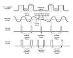
- FIG. 2is a pictorial showing a ferromagnetic target object having teeth and having another signature feature (or region), a graph of a magnetic field signal generated in a magnetic field sensor when sensing movement of the ferromagnetic target object, and a sensor output signal having pulses, and, in particular, having signature pulses indicative of the signature feature;
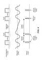
- FIG. 3is a pictorial showing the ferromagnetic target object of FIG. 2 , the graph of FIG. 2 , and sensor output signals having pulses, and, in particular, having one signature pulse indicative of the signature feature, and in an embodiment, having two signature pulses indicative of the signature feature;
- FIG. 4is a pictorial showing the ferromagnetic target object of FIG. 2 , the graph of FIG. 2 , and yet another sensor output signal having pulses, and, in particular, having still other signature pulses indicative of the signature feature;
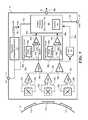
- FIG. 5is a block diagram showing a magnetic field sensor having two detector circuits for receiving the magnetic field signals of FIGS. 2-4 , and having an output protocol processor for generating the sensor output signals of FIGS. 2-4 .
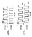
- FIG. 6Ais a pictorial showing exemplary left and right channel detector output signals (see, e.g., signals 46 a and 46 b of FIG. 5 ) of forward target object rotation according to an embodiment.
- FIG. 6Bis a pictorial showing exemplary left and right channel detector output signals (see, e.g., signals 46 a and 46 b of FIG. 5 ) of reverse target object rotation according to an embodiment.
- magnetic field sensing elementis used to describe a variety of electronic elements that can sense a magnetic field.
- the magnetic field sensing elementcan be, but is not limited to, a Hall effect element, a magnetoresistance element, or a magnetotransistor.
- Hall effect elementsfor example, a planar Hall element, a vertical Hall element, and a Circular Vertical Hall (CVH) element.
- magnetoresistance elementsfor example, a semiconductor magnetoresistance element such as Indium Antimonide (InSb), a giant magnetoresistance (GMR) element, for example, a spin valve, an anisotropic magnetoresistance element (AMR), a tunneling magnetoresistance (TMR) element, and a magnetic tunnel junction (MTJ).
- the magnetic field sensing elementmay be a single element or, alternatively, may include two or more magnetic field sensing elements arranged in various configurations, e.g., a half bridge or full (Wheatstone) bridge.
- the magnetic field sensing elementmay be a device made of a type IV semiconductor material such as Silicon (Si) or Germanium (Ge), or a type III-V semiconductor material like Gallium-Arsenide (GaAs) or an Indium compound, e.g., Indium-Antimonide (InSb).
- a type IV semiconductor materialsuch as Silicon (Si) or Germanium (Ge)
- a type III-V semiconductor materiallike Gallium-Arsenide (GaAs) or an Indium compound, e.g., Indium-Antimonide (InSb).
- some of the above-described magnetic field sensing elementstend to have an axis of maximum sensitivity parallel to a substrate that supports the magnetic field sensing element, and others of the above-described magnetic field sensing elements tend to have an axis of maximum sensitivity perpendicular to a substrate that supports the magnetic field sensing element.
- planar Hall elementstend to have axes of sensitivity perpendicular to a substrate
- metal based or metallic magnetoresistance elementse.g., GMR, TMR, AMR
- vertical Hall elementstend to have axes of sensitivity parallel to a substrate.
- magnetic field sensoris used to describe a circuit that uses a magnetic field sensing element, generally in combination with other circuits.
- Magnetic field sensorsare used in a variety of applications, including, but not limited to, an angle sensor that senses an angle of a direction of a magnetic field, a current sensor that senses a magnetic field generated by a current carried by a current-carrying conductor, a magnetic switch that senses the proximity of a ferromagnetic object, a rotation detector that senses passing ferromagnetic articles, for example, magnetic domains of a ring magnet or a ferromagnetic target (e.g., gear teeth) where the magnetic field sensor is used in combination with a back-biased or other magnet, and a magnetic field sensor that senses a magnetic field density of a magnetic field.
- an angle sensorthat senses an angle of a direction of a magnetic field
- a current sensorthat senses a magnetic field generated by a current carried by a current-carrying conductor
- a magnetic switchthat
- Exemplary ferromagnetic encodersused in automotive crankshaft applications may have a regular pattern of 60 teeth and valleys around the circumference of the ferromagnetic encoder wheel, with a synchronization area called a signature region (or signature feature), which can be provided, for example, as one missing tooth (60 ⁇ 1 target, meaning sixty minus one), two missing teeth (60 ⁇ 2 target), one missing valley (60+1 target) or two missing valleys (60+2 target).
- signature regionor signature feature
- each north/south pole pairspans six degrees, except for the signature region which may have span twelve degrees for a 60 ⁇ 1 or 60+1 target, or eighteen degrees for a 60 ⁇ 2 or 60+2 target.
- This conceptis valid for targets with any number of switching features spanning any number of degrees and that have one or more signature regions.
- the signature regiondoes not have to be (or span) an integer multiple of the standard switching feature size (or span).
- Crankshaft magnetic field sensorsthat provide speed information (i.e., a speed sensor) typically switch in the middle of every tooth and valley, or alternatively, in the middle of every north and south pole. On a 60 ⁇ 1 or 60+1 target, the sensor will, therefore, also switch from high to low (or from low to high depending on the sensor polarity) in the middle of the signature region. Some applications use this pulse to have information from the sensor every six degrees and to detect the signature region at the same time.
- Crankshaft sensors that provide both speed and direction informationtypically output a pulse only in the middle of the teeth (or valleys, depending on the sensor polarity), or alternatively, in the middle of north poles (or south poles, depending on the sensor polarity).
- the conventional direction sensordoes not output a pulse in the middle of the signature region.
- the direction (e.g., crankshaft) sensoroutputs a pulse in the signature region, e.g. in next generation engines in order to have information from the sensor every six degrees and to recognize the signature region.
- next generation directione.g., crankshaft
- next generation directione.g., crankshaft
- output an additional pulse in the signature region of a 60 ⁇ 1 or 60+1 targete.g., a pulse with dedicated codification at the place of a normal pulse to indicates that the signature region has been crossed and detected.
- the conceptscan be extended to larger signature regions (e.g. 60 ⁇ 2 or 60+2 targets).
- the conceptscan be further extended to targets with fewer then or more than sixty teeth and valleys, or alternatively, with fewer then or more than sixty north and south poles.
- the teeth, or ferromagnetic regions defining the north and south poles, of the targetmay not have the same spacing.
- the teeth, or magnetic poles with one polaritymay be two degrees apart and the valleys, or magnetic poles with the other polarity (south or north), may be four degrees apart.
- the valleysmay be smaller than the teeth in degrees, or the poles with different polarities may have different dimensions.
- Other targetsmay have other number of teeth (or poles) than sixty described above.
- a signature feature in a signature region upon a target objectcan be detected by a magnetic field sensor or an equivalent method used in a processor (or a circuit) to generate a specific signature pulse (SP) at that position (e.g. a 22.5 us signature pulse if a normal forward pulse is 45 us and a normal reverse pulse is 90 us).
- SPspecific signature pulse
- a small toothor a notch
- the shape of this toothcan be optimized in order for the magnetic field sensor to differentiate the signature tooth (or notch) from the standard teeth and valleys.
- a small pole of inverse polaritycan be magnetized in the signature region.
- FIGS. 2-5While only a ferromagnetic target (encoder) is shown below in FIGS. 2-5 below, it should be understood that a magnetic target (encoder) such as that shown in FIG. 1 can instead be used with the circuits and techniques described below in conjunction with FIGS. 2-5 . Furthermore, it should be understood that signals shown below in conjunction with FIGS. 2-4 as generated in conjunction with a ferromagnetic target, can instead be generated in conjunction with a magnetic target.
- a magnetic field sensor or an equivalent method used in a processorcan be implemented to detect target speed on one (or more) pulse(s). Acceleration can also be calculated for more accuracy. This information can be used to predict the position of a next output pulse.
- the method or the circuitcan define a time window in which the next output pulse should occur. If the output pulse does not occur in that time window, the sensor (or method) will output a specific signature pulse SP as soon as the time window is elapsed.
- a magnetic profile as showncan be representative of a signal in one channel of a direction magnetic field sensor when sensing teeth and valleys of the indicated ferromagnetic encoder.
- a signal representative of the magnetic profileis referred to herein as a magnetic field signal.
- the SPmay be output due to the elapse of a predicted time window shown. In this case it is permissible to output the SP even though it may not be in the same location in terms of target angle of the expected SP.
- the direction detection method or circuitcan determine that a direction change has occurred and can follow the SP with a pulse having a pulse width indicating the opposite direction of rotation.
- the normal forward direction pulseshave pulse widths of about forty-five microseconds
- the normal reverse direction pulseshave pulse widths of about ninety microseconds
- the signature region pulseshave pulse widths of about 22.5 microseconds.
- any other distinguishable pulse widthscan be used.
- the predicted time windowhas a time width approximately fifty percent of a period between pulses for a target rotating at a maximum expected speed. In other embodiments, the predicted time window has a time width approximately ten, twenty, thirty, forty, sixty, seventy, eighty, or ninety percent of a period between pulses for a target rotating at a maximum expected speed. In some other embodiments, the predicted time window has a time width of approximately one hundred microseconds, one hundred fifty microseconds, or two hundred microseconds.
- the SPcan be withheld and the normal direction detection method or circuit can output a pulse with a pulse width (e.g., ninety microseconds) indicating the change of direction.
- a pulse widthe.g. ninety microseconds
- the method or the circuitlearns where to expect the signature region, and based on the time intervals between the pulses leading up to the signature region, it outputs the signature pulses at predicted times.
- the signature pulsesmay not occur at exactly the right target angle based on acceleration or deceleration of the target after the exact predicted time has been calculated.
- a zero-crossing method or circuitcan be implemented that provides information on the position of every tooth and valley.
- the magnetic field sensortypically outputs a pulse associated with every tooth of a target object. If in normal rotation the pulses are generated on the rising slope, a threshold crossing (e.g., a zero crossing) on the falling slope within the predicted time window can be recognized as indicative of a signature region and a specific signature pulse SP can be sent to the output upon detection of the zero crossing. Conversely, if in normal rotation the pulses are generated on the falling slope, a threshold crossing (e.g., a zero crossing) on the rising slope within the predicted time window can be recognized as indicative of a signature region.
- a threshold crossinge.g., a zero crossing
- crankshaft sensors with direction detectiontypically use two phase shifted differential (DIFF) channels (i.e., two magnetic field signals, i.e., DIFF signals) to detect direction (see, e.g., FIG. 5 ).
- DIFFphase shifted differential
- the two DIFF signalstend to have a known or predetermined phase separation.
- the phase separation between the two DIFF signalscan be at less than the predetermined phase separation, or close to zero phase separation, due to the somewhat flat magnetic region shown in the.
- a phase detection method or circuitcan be used in combination with embodiments 2 or embodiment 3 to output a specific signature pulse SP in the signature region.
- a method or a circuitcan be implemented to detect target speed on one (or more) pulse(s). Acceleration can also be calculated for more accuracy.
- the method or the circuitdetects the signature region when the detected period is about double that of the previous period.
- a specific signature pulse SPis output on the first tooth after the signature region. This option doesn't output a pulse in the middle of the signature region but still allows for engine synchronization once per target revolution.
- the signature pulse SPhas optimized accuracy as it corresponds to a region of steep slope on the magnetic profile, like all other output pulses.
- Another advantageis that the number of pulses over one revolution remains the same as that of systems in use today, thus providing backward compatibility.
- an internal counter(e.g., 60 , FIG. 5 below) can be used to count the number of normal pulses between two or more signature pulses SP. This diagnostics feature can be used to validate that no pulses were missed, thus providing a level of Automotive Safety Integrity Level (ASIL) compliance that is not achieved with conventional sensors today.
- the above described output signals ( 48 a , 50 , 52 ) from the magnetic field sensor 10 of FIG. 5can include not only first (forward rotation), second (reverse rotation), and third (signature region) types of pulses, but can also indicate a failure (e.g., a wrong count), for example, with a fourth type of pulse having a fourth pulse width.
- the magnetic field sensor 10can generate any other type of output signal, including, but not limited to, a blank output signal.
- the Automotive Safety Integrity Level(ASIL) is generally applicable to safety levels in safety critical applications in autmobiles.
- a particular type of endoding of the pulse associated with the signature regionis shown, namely, a pulse having a shorter SP pulse width (e.g., 22.5 us), than other ones of the pulses associated with gear teeth or magnetic regions (e.g., 45 us and 90 us).
- the pulse associated with the signature regionis half as long as the shortest pulse associated with the gear teeth or magnetic regions.
- other encodingscan be used.
- the pulse associated with the signature regionhas a pulse width less than half that of the shortest pulse associated with the gear teeth or magnetic regions.
- the pulse associated with the signature regionhas a pulse width greater than half that of the shortest pulse associated with the gear teeth or magnetic regions.
- the pulse associated with the signature regionhas a pulse width greater than that of the shortest pulse associated with the gear teeth or magnetic regions.
- the pulse associated with the signature regionhas a pulse width between that of the shortest and longest pulses associated with the gear teeth or magnetic regions.
- the pulse associated with the signature regionhas a pulse width greater than the longest pulse associated with the gear teeth or magnetic regions.
- the encoding associated with the signature regionis provided as two or more adjacent pulses having equal pulse widths equal to, longer, shorter, or between the pulse widths associated with the gear teeth or magnetic regions.
- the encoding associated with the signature regionis provided as two or more adjacent pulses having unequal pulse widths equal to, longer, shorter or between the pulse widths associated with the gear teeth or magnetic regions.
- All of the above embodimentsprovide encodings having one or more identifiable pulses associated with the signature region that can identify passing of the signature region.
- signature regioncan occur at each rotation of a rotating object and a signature pulse can be generated at each occurrence of the signature region.
- an exemplary magnetic field sensor in the form of a rotation detector 10can be used, for example, to detect passing gear teeth, for example, gear teeth 12 a - 12 c of a ferromagnetic gear 12 .
- the exemplary magnetic field sensor in FIG. 5uses some analog circuitry to control switching on the output of the sensor, based on a magnetic input signal. In other embodiments, some of the analog functions shown could also be achieved using digital signal processing (not explicitly shown in FIG. 5 ).
- a permanent magnet(not shown) can be placed at a variety of positions proximate to the gear 12 , resulting in fluctuations of a magnetic field proximate to the gear 12 as the gear 12 having the gear teeth 12 a - 12 c rotates.
- the rotation detector 10can have a first port 14 coupled to a power supply denoted as Vcc.
- the rotation detector 10can also have a second port 16 coupled to a fixed voltage source, for example, a ground voltage source, denoted as GND.
- GNDa ground voltage source
- the rotation detector 10is a two port device, for which an output signal appears as a signal current at the first port 14 , superimposed upon the power supply voltage, Vcc, or at the second port 16 , superimposed upon the ground voltage.
- a rotation detector similar to the rotation detector 10can have a third port 15 at which an output signal 48 a can appear as a voltage rather than a current.
- the rotation detector 10can include first, second, and third magnetic field sensing elements 18 , 20 , 22 , respectively, here shown to be Hall Effect elements.
- the first Hall effect element 18generates a first differential voltage signal 24 a , 24 b
- the second Hall effect element 20generates a second differential voltage signal 26 a , 26 b
- the third Hall effect element 22generates a third differential voltage signal 28 a , 28 b , each having an AC signal component in response to the rotating gear 12 .
- each one of the Hall effect elements 18 , 20 , 22is shown to be a two port device, one of ordinary skill in the art will understand that each one of the Hall effect elements 18 , 20 , 22 is actually a four port device and the other two ports of the Hall effect elements can be coupled to receive and pass respective currents as might be provided, for example, by respective current sources or a voltage source (not shown).
- the first differential voltage signal 24 a , 24 bis received by a first differential preamplifier 30 a
- the second differential voltage signal 26 a , 26 bis received by a second differential preamplifier 30 b
- the third differential voltage signal 28 a , 28 bis received by a third differential preamplifier 30 c.
- First and second output signals 32 a , 32 b generated by the first and second differential preamplifiers 30 a , 30 b , respectively,are received by a “right” channel amplifier 34 a and the second output signal 32 b and a third output signals 32 c generated by the second and third differential preamplifiers 30 b , 30 c , respectively, are received by a “left” channel amplifier 34 b .
- Designations of “right” and “left”are arbitrary but are generally indicative of rotation of the gear 12 in first and second directions.
- a signal 38 a generated by the right channel amplifier 34 ais received by a right channel detector circuit 36 a and a signal 38 b generated by the left channel amplifier 34 b is received by a left channel detector circuit 36 b .
- the signals 38 a , 38 bcan be analog signals, generally sinusoidal in nature. Magnetic field signals to which reference is made above and which are shown in FIGS. 2-4 can correspond to the signals 38 a , 38 b when the target 12 includes a signature region.
- the signals 38 a , 38 bcan be converted to the digital domain by analog-to-digital converters or the like and the detector circuits 36 a , 36 b can instead be digital circuits.
- the right channel detector circuit 36 aincludes a peak detector circuit 40 a coupled to receive the signal 38 a .
- the peak detector circuit 40 ais configured to detect positive and negative peaks of the signal 38 a and to generate the threshold signal 42 a that, for example, takes on a first threshold value just below a positive peak of the signal 38 a or a second threshold value just above a negative peak of the signal 38 a , depending upon a direction of transition of the signal 38 a .
- a comparator 44 ais coupled to receive the threshold signal 42 a and is also coupled to receive the signal 38 a . As a result, the comparator 44 a generates a binary signal 46 a that has transitions when the signal 38 a crosses both the first and second static thresholds, near to a time when the signal 38 a achieves positive and negative peaks.
- phase differences 610 and 620 of signalse.g., signals 46 a and 46 b
- right and left detector outputse.g., from detector circuits 36 a and 36 b
- the detector circuitscan be operated to detect the forward and reverse directions (e.g., with Output Protocol Processor 48 ).
- the phase differences 610 , 620have different polarities, i.e., one positive and one negative.
- Distinct pulse widths 615 and 625are shown from detector outputs (e.g., from detector circuits 36 a and 36 b ), such that the detector circuits can be operated to detect the object rotation speeds (e.g., with Output Protocol Processor 48 ).
- a signal 46 b generated by the left channel detector circuit 36 bis generated in the same way as the signal 46 a .
- the signals 46 a , 46 bhave edges that differ in time (which is equivalent to phase for a particular signal frequency, i.e., particular rotation speed).
- a direction of rotation of the gear 12may be determined from a relative phase or relative time difference (e.g., lag or lead) of a particular edge transition in the signal 46 a compared with a particular corresponding edge transition in the signal 46 b . Therefore, a relative lag or a lead of edges of the signals 46 a , 46 b can be used to identify a direction of rotation of the gear 12 .
- the rotation detector 10can include an output protocol circuit 48 coupled to receive and process the signals 46 a , 46 b and configured to generate an output signal 52 as a current signal, which is indicative of the speed of rotation and the direction of rotation of the gear 12 .
- rotation detector 10is shown to include the detector circuits 36 a , 36 b , each having a particular topology, it should be understood that any form of peak-referenced detectors or peak-to-peak percentage detectors, including, but not limited to, the above-described peak-referenced detectors and peak-to-peak percentage detectors, can be used in place of or in addition to the detector circuits 36 a , 36 b.
- gear 12i.e., target
- gear 12can have a signature region. It will also be understood that the gear 12 can be replaced by a ring magnet with a signature region.
- the rotation detector 10i.e., the output protocol processor 48 , is configured to generate an output signal 52 (or 50 ) and/or 48 a having one or more of the signal formats described above in conjunction with FIGS. 1-4 .
- the processor 48can be replaced in full or in part with a different type of electronic circuit, which is not part of a processor per se.
- the output signals shown in FIGS. 2-4can be current signals.
- the output signals shown in FIGS. 2-4can be voltage (or current) signals.
- parts of the rotation detector 10are represented by analog circuit blocks.
- one or more of the circuit blocks represented in analog formcould instead be formed as digital circuits that do the same or similar functions.
- the output protocol processorcan be operable to identify the above-described predicted time window in accordance with transition edges in one of or both of the signals 46 a , 46 b .
- the output protocol processor 48can be operable to generate the above described signature pulses having pulse widths and at times according to embodiments described above.
- the output protocol processorcan also generate pulses with pulse widths according to direction of the target 12 .
- the magnetic field sensor 10can also include an analog-to-digital converter (ADC) 58 to provide a sampled digital signal 58 a to the output protocol processor 48 .
- ADCanalog-to-digital converter
- the output protocol processor 48can identify the above-described zero crossings within the sampled digital signal 58 a.
- the magnetic field sensor 10can include another ADC (not shown) to convert the other magnetic field signal 38 a and to provide another digital sampled signal (not shown) to the output protocol processor 48 .
- a magnetic field sensor and related techniquecan be used to sense a signature region in a ferromagnetic or magnetic target object operable to move in another fashion, for example, linearly.
Landscapes
- Physics & Mathematics (AREA)
- General Physics & Mathematics (AREA)
- Condensed Matter Physics & Semiconductors (AREA)
- Transmission And Conversion Of Sensor Element Output (AREA)
Abstract
Description
Claims (22)
Priority Applications (1)
| Application Number | Priority Date | Filing Date | Title |
|---|---|---|---|
| US14/306,722US9664748B2 (en) | 2013-06-20 | 2014-06-17 | Systems and methods for providing signal encoding representative of a signature region in a target |
Applications Claiming Priority (2)
| Application Number | Priority Date | Filing Date | Title |
|---|---|---|---|
| US201361837332P | 2013-06-20 | 2013-06-20 | |
| US14/306,722US9664748B2 (en) | 2013-06-20 | 2014-06-17 | Systems and methods for providing signal encoding representative of a signature region in a target |
Publications (2)
| Publication Number | Publication Date |
|---|---|
| US20140375312A1 US20140375312A1 (en) | 2014-12-25 |
| US9664748B2true US9664748B2 (en) | 2017-05-30 |
Family
ID=51179166
Family Applications (1)
| Application Number | Title | Priority Date | Filing Date |
|---|---|---|---|
| US14/306,722Active2035-04-11US9664748B2 (en) | 2013-06-20 | 2014-06-17 | Systems and methods for providing signal encoding representative of a signature region in a target |
Country Status (3)
| Country | Link |
|---|---|
| US (1) | US9664748B2 (en) |
| EP (1) | EP2999943B1 (en) |
| WO (1) | WO2014204919A1 (en) |
Cited By (20)
| Publication number | Priority date | Publication date | Assignee | Title |
|---|---|---|---|---|
| US10436606B2 (en) | 2017-07-20 | 2019-10-08 | Allegro Microsystems, Llc | Magnetic field sensor to detect speed and direction of angular rotation of a rotating magnetic structure |
| US10473486B2 (en) | 2017-07-20 | 2019-11-12 | Allegro Microsystems, Llc | Duty cycle of an output signal of a magnetic field sensor to detect speed and direction of angular rotation of a rotating magnetic structure or a fault |
| US10480957B2 (en) | 2017-07-20 | 2019-11-19 | Allegro Microsystems, Llc | Magnetic field sensor to detect direction of angular rotation of a rotating magnetic structure, speed of the rotating magnetic structure or fault |
| US10481218B2 (en) | 2016-09-08 | 2019-11-19 | Allegro Microsystems, Llc | Providing information about a target object in a formatted output signal |
| US10571301B2 (en) | 2017-07-20 | 2020-02-25 | Allegro Microsystems, Llc | Frequency of an output signal of a magnetic field sensor to detect speed and direction of angular rotation of a rotating magnetic structure or a fault |
| US10598514B2 (en) | 2017-07-20 | 2020-03-24 | Allegro Microsystems, Llc | Magnetic field sensor to detect speed of angular rotation of a rotating magnetic structure, direction of the rotating magnetic structure or fault |
| US10725122B2 (en) | 2018-07-20 | 2020-07-28 | Allegro Microsystems, Llc | Ratiometric sensor output topology and methods |
| US11029370B1 (en) | 2020-05-22 | 2021-06-08 | Allegro Microsystems, Llc | Sensor output control methods and apparatus |
| US11194004B2 (en) | 2020-02-12 | 2021-12-07 | Allegro Microsystems, Llc | Diagnostic circuits and methods for sensor test circuits |
| US11221203B1 (en)* | 2020-09-01 | 2022-01-11 | Allegro Microsystems, Llc | Magnetic field sensor with fault reporting |
| US11525705B1 (en) | 2021-07-13 | 2022-12-13 | Allegro Microsystems, Llc | Magnetic-field sensor with test pin for diagnostic assessment of target validity, target placement and/or control of signal range and/or offset |
| US11598655B2 (en) | 2021-07-13 | 2023-03-07 | Allegro Microsystems, Llc | Magnetic-field sensor with test pin for control of signal range and/or offset |
| US11719527B2 (en) | 2021-11-04 | 2023-08-08 | Allegro Microsystems, Llc | Angle sensor with a single die using a single target |
| US11885645B2 (en) | 2021-06-17 | 2024-01-30 | Allegro Microsystems, Llc | Supply voltage configurable sensor |
| US11942831B2 (en) | 2020-01-15 | 2024-03-26 | Allegro Microsystems, Llc | Three-phase BLDC motor driver/controller having diagnostic signal processing |
| US12104900B2 (en) | 2022-09-29 | 2024-10-01 | Allegro Microsystems, Llc | Sensor with estimated real-time parameter data |
| US12107710B2 (en) | 2020-11-19 | 2024-10-01 | Allegro Microsystems, Llc | Sensor signaling of absolute and incremental data |
| US12332273B2 (en) | 2022-05-18 | 2025-06-17 | Allegro Microsystems, Llc | High resolution sensing protocol |
| US12348243B2 (en) | 2022-05-18 | 2025-07-01 | Allegro Microsystems, Llc | Method and apparatus for transmitting data concurrently with a pulse-encoded signal |
| US12442874B2 (en) | 2023-06-20 | 2025-10-14 | Allegro Microsystems, Llc | Angle sensor with a single die using a single target |
Families Citing this family (14)
| Publication number | Priority date | Publication date | Assignee | Title |
|---|---|---|---|---|
| JP6213483B2 (en)* | 2015-01-09 | 2017-10-18 | トヨタ自動車株式会社 | Failure diagnosis device for crank angle sensor |
| US10436056B2 (en) | 2015-06-23 | 2019-10-08 | General Electric Company | Relative position measurement |
| FR3041426B1 (en)* | 2015-09-18 | 2019-03-22 | Continental Automotive France | AUTOMATIC CALIBRATION METHOD OF CAMSHAFT SENSOR FOR MOTOR VEHICLE ENGINE |
| DE202016008494U1 (en)* | 2016-02-19 | 2018-03-05 | Infineon Technologies Ag | Magnetic position sensor |
| US10216559B2 (en) | 2016-11-14 | 2019-02-26 | Allegro Microsystems, Llc | Diagnostic fault communication |
| KR101906003B1 (en)* | 2016-11-23 | 2018-10-08 | 현대자동차주식회사 | Method for starting engine |
| DE102017209586A1 (en)* | 2017-06-07 | 2018-12-13 | Volkswagen Aktiengesellschaft | Apparatus and method for communicating a change in position of a signal transmitter wheel |
| US10656170B2 (en)* | 2018-05-17 | 2020-05-19 | Allegro Microsystems, Llc | Magnetic field sensors and output signal formats for a magnetic field sensor |
| DE102018215938B4 (en)* | 2018-09-19 | 2024-11-07 | Infineon Technologies Ag | high-resolution mode for a magnetic field sensor |
| JP6973421B2 (en)* | 2019-01-14 | 2021-11-24 | 株式会社デンソー | Rotation detector |
| KR101987890B1 (en)* | 2019-04-09 | 2019-09-30 | 브이에스아이 주식회사 | Method for determining the transmission speed of a communication module in mediating connection of the communication module to a bus, and a device for said method |
| FR3101704B1 (en)* | 2019-10-08 | 2021-09-24 | Robert Bosch Automotive Steering Vendome | Method for detecting an absolute angular position or an absolute angular displacement stroke of a rotating member |
| US12135334B2 (en)* | 2021-11-17 | 2024-11-05 | Infineon Technologies Ag | Method for reducing a microbreak memory area and enhanced timing scheme for freezing microbreak feature for a speed sensor |
| US12424910B2 (en)* | 2022-12-31 | 2025-09-23 | Cooper-Standard Automotive Inc. | Apparatus and method for magnetically sensing the position of a rotating device |
Citations (38)
| Publication number | Priority date | Publication date | Assignee | Title |
|---|---|---|---|---|
| US3582932A (en) | 1968-10-11 | 1971-06-01 | Bell Inc F W | Magnetic-field-responsive proximity detector apparatus |
| US3944792A (en) | 1974-09-11 | 1976-03-16 | Jovill Manufacturing Company | Self-balancing bridge-type proximity detector |
| US4262251A (en)* | 1977-08-29 | 1981-04-14 | Nissan Motor Company, Limited | Device for measuring rotational angle of rotary member |
| EP0033902A2 (en) | 1980-02-12 | 1981-08-19 | BROWN, BOVERI & CIE Aktiengesellschaft Mannheim | Method for the surveillance of pulse trains |
| WO1985000551A1 (en)* | 1983-07-19 | 1985-02-14 | Co-Exx Pipe Company, Inc. | Apparatus and method for injection molding polymeric articles |
| US4553427A (en)* | 1983-03-08 | 1985-11-19 | Nippondenso Co., Ltd. | Rotational reference position detection apparatus |
| US4628269A (en)* | 1984-05-23 | 1986-12-09 | Motorola, Inc. | Pulse detector for missing or extra pulses |
| US5493219A (en) | 1993-04-15 | 1996-02-20 | Nippondenso Co., Ltd. | MRE sensor signal detector |
| US5650719A (en) | 1996-01-17 | 1997-07-22 | Allegro Microsystems, Inc. | Detection of passing magnetic articles while periodically adapting detection thresholds to changing amplitudes of the magnetic field |
| GB2309310A (en) | 1996-01-17 | 1997-07-23 | Allegro Microsystems Inc | Detection of passing magnetic articles at speeds down to zero |
| US5694038A (en) | 1996-01-17 | 1997-12-02 | Allegro Microsystems, Inc. | Detector of passing magnetic articles with automatic gain control |
| EP0875733A2 (en) | 1997-04-28 | 1998-11-04 | Allegro Microsystems Inc. | Detection of passing magnetic articles using a peak-on-peak percentage threshold detector |
| US5917320A (en) | 1996-01-17 | 1999-06-29 | Allegro Microsystems, Inc. | Detection of passing magnetic articles while periodically adapting detection threshold |
| US6091239A (en) | 1996-01-17 | 2000-07-18 | Allegro Microsystems, Inc. | Detection of passing magnetic articles with a peak referenced threshold detector |
| US6232768B1 (en) | 1996-01-17 | 2001-05-15 | Allegro Microsystems Inc. | Centering a signal within the dynamic range of a peak detecting proximity detector |
| US6242908B1 (en) | 1996-01-17 | 2001-06-05 | Allegro Microsystems, Inc. | Detection of passing magnetic articles while adapting the detection threshold |
| US6288567B1 (en) | 1999-03-19 | 2001-09-11 | Micronas Gmbh | Device for setting operating parameters in a plurality of programmable integrated circuits |
| US6320374B1 (en)* | 1999-06-24 | 2001-11-20 | Delphi Technologies, Inc. | Angular position and angular direction sensor |
| US6346808B1 (en)* | 2000-02-28 | 2002-02-12 | Delphi Technologies, Inc. | Crankshaft position sensor |
| US6525531B2 (en) | 1996-01-17 | 2003-02-25 | Allegro, Microsystems, Inc. | Detection of passing magnetic articles while adapting the detection threshold |
| US6542847B1 (en) | 1998-03-20 | 2003-04-01 | Continental Teves Ag & Co., Ohg | Sensor system for detecting movements |
| WO2003069358A2 (en) | 2002-01-31 | 2003-08-21 | Allegro Microsystems, Inc. | Method and apparatus for providing information from a speed and direction sensor |
| US20030222637A1 (en) | 2002-05-28 | 2003-12-04 | Stauth Jason T. | Proximity detector |
| US6687644B1 (en) | 1996-12-07 | 2004-02-03 | Continental Teves Ag & Co., Ohg | Method and circuit for transmitting information on rotational speed and additional data |
| US20040095130A1 (en)* | 2002-07-23 | 2004-05-20 | Mitsubishi Denki Kabushiki Kaisha | Magnetic detection apparatus |
| US20050194970A1 (en) | 2004-03-08 | 2005-09-08 | Karl Scheller | Proximity detector |
| US6968484B2 (en) | 1998-04-30 | 2005-11-22 | Micronas Gmbh | Method for parametrizing an integrated circuit and an integrated circuit therefor |
| US20060059702A1 (en)* | 2004-08-26 | 2006-03-23 | Robert Hammerl | Measuring device for the incremental measurement of positions, actuating displacements or actuating angles and industrial truck equipped with such a measuring device |
| US7184876B2 (en)* | 2004-06-18 | 2007-02-27 | Siemens Vdo Automotive | Device and process for determining the position of an engine |
| US20070164732A1 (en) | 2006-01-17 | 2007-07-19 | Allegro Microsystems, Inc. | Methods and apparatus for magnetic article detection |
| US7319418B2 (en) | 2004-02-13 | 2008-01-15 | Micronas Gmbh | Sensor with multiplex data output |
| US20080158039A1 (en) | 2006-12-27 | 2008-07-03 | Uwe Kassner | Method for coding an output signal of a sensor |
| US7466123B2 (en) | 2004-02-24 | 2008-12-16 | Aisin Seiki Kabushiki Kaisha | Rotation sensor, and method for outputting signals from rotation sensor |
| US20090058404A1 (en)* | 2007-08-30 | 2009-03-05 | Denso Corporation | Rotation detection sensor |
| US20100072988A1 (en)* | 2008-09-22 | 2010-03-25 | Infineon Technologies Ag | System that obtains a switching point with the encoder in a static position |
| US7982454B2 (en) | 2007-06-26 | 2011-07-19 | Allegro Microsystems, Inc. | Calibration circuits and methods for a proximity detector using a first rotation detector for a determined time period and a second rotation detector after the determined time period |
| US20130082693A1 (en)* | 2010-03-31 | 2013-04-04 | Eberhard Boehl | Device and method for processing signals which represent an angular position of a motor shaft |
| US20140084903A1 (en) | 2008-07-31 | 2014-03-27 | Allegro Microsystems, Llc | Apparatus and Method for Providing an Output Signal Indicative of a Speed of Rotation and a Direction of Rotation of a Ferromagnetic Object |
- 2014
- 2014-06-17EPEP14739308.6Apatent/EP2999943B1/enactiveActive
- 2014-06-17WOPCT/US2014/042669patent/WO2014204919A1/enactiveApplication Filing
- 2014-06-17USUS14/306,722patent/US9664748B2/enactiveActive
Patent Citations (48)
| Publication number | Priority date | Publication date | Assignee | Title |
|---|---|---|---|---|
| US3582932A (en) | 1968-10-11 | 1971-06-01 | Bell Inc F W | Magnetic-field-responsive proximity detector apparatus |
| US3944792A (en) | 1974-09-11 | 1976-03-16 | Jovill Manufacturing Company | Self-balancing bridge-type proximity detector |
| US4262251A (en)* | 1977-08-29 | 1981-04-14 | Nissan Motor Company, Limited | Device for measuring rotational angle of rotary member |
| EP0033902A2 (en) | 1980-02-12 | 1981-08-19 | BROWN, BOVERI & CIE Aktiengesellschaft Mannheim | Method for the surveillance of pulse trains |
| US4553427A (en)* | 1983-03-08 | 1985-11-19 | Nippondenso Co., Ltd. | Rotational reference position detection apparatus |
| WO1985000551A1 (en)* | 1983-07-19 | 1985-02-14 | Co-Exx Pipe Company, Inc. | Apparatus and method for injection molding polymeric articles |
| US4628269A (en)* | 1984-05-23 | 1986-12-09 | Motorola, Inc. | Pulse detector for missing or extra pulses |
| US5493219A (en) | 1993-04-15 | 1996-02-20 | Nippondenso Co., Ltd. | MRE sensor signal detector |
| US5650719A (en) | 1996-01-17 | 1997-07-22 | Allegro Microsystems, Inc. | Detection of passing magnetic articles while periodically adapting detection thresholds to changing amplitudes of the magnetic field |
| GB2309310A (en) | 1996-01-17 | 1997-07-23 | Allegro Microsystems Inc | Detection of passing magnetic articles at speeds down to zero |
| US5694038A (en) | 1996-01-17 | 1997-12-02 | Allegro Microsystems, Inc. | Detector of passing magnetic articles with automatic gain control |
| US5729130A (en) | 1996-01-17 | 1998-03-17 | Moody; Kristann L. | Tracking and holding in a DAC the peaks in the field-proportional voltage in a slope activated magnetic field sensor |
| US5917320A (en) | 1996-01-17 | 1999-06-29 | Allegro Microsystems, Inc. | Detection of passing magnetic articles while periodically adapting detection threshold |
| US6091239A (en) | 1996-01-17 | 2000-07-18 | Allegro Microsystems, Inc. | Detection of passing magnetic articles with a peak referenced threshold detector |
| US6297627B1 (en) | 1996-01-17 | 2001-10-02 | Allegro Microsystems, Inc. | Detection of passing magnetic articles with a peak-to-peak percentage threshold detector having a forcing circuit and automatic gain control |
| US6232768B1 (en) | 1996-01-17 | 2001-05-15 | Allegro Microsystems Inc. | Centering a signal within the dynamic range of a peak detecting proximity detector |
| US6242908B1 (en) | 1996-01-17 | 2001-06-05 | Allegro Microsystems, Inc. | Detection of passing magnetic articles while adapting the detection threshold |
| US6525531B2 (en) | 1996-01-17 | 2003-02-25 | Allegro, Microsystems, Inc. | Detection of passing magnetic articles while adapting the detection threshold |
| US6687644B1 (en) | 1996-12-07 | 2004-02-03 | Continental Teves Ag & Co., Ohg | Method and circuit for transmitting information on rotational speed and additional data |
| EP0875733A2 (en) | 1997-04-28 | 1998-11-04 | Allegro Microsystems Inc. | Detection of passing magnetic articles using a peak-on-peak percentage threshold detector |
| EP0875733A3 (en) | 1997-04-28 | 2000-08-23 | Allegro Microsystems Inc. | Detection of passing magnetic articles using a peak-on-peak percentage threshold detector |
| US6542847B1 (en) | 1998-03-20 | 2003-04-01 | Continental Teves Ag & Co., Ohg | Sensor system for detecting movements |
| US6968484B2 (en) | 1998-04-30 | 2005-11-22 | Micronas Gmbh | Method for parametrizing an integrated circuit and an integrated circuit therefor |
| US6288567B1 (en) | 1999-03-19 | 2001-09-11 | Micronas Gmbh | Device for setting operating parameters in a plurality of programmable integrated circuits |
| US6320374B1 (en)* | 1999-06-24 | 2001-11-20 | Delphi Technologies, Inc. | Angular position and angular direction sensor |
| US6346808B1 (en)* | 2000-02-28 | 2002-02-12 | Delphi Technologies, Inc. | Crankshaft position sensor |
| WO2003069358A2 (en) | 2002-01-31 | 2003-08-21 | Allegro Microsystems, Inc. | Method and apparatus for providing information from a speed and direction sensor |
| WO2003069358A3 (en) | 2002-01-31 | 2004-02-26 | Allegro Microsystems Inc | Method and apparatus for providing information from a speed and direction sensor |
| US6815944B2 (en) | 2002-01-31 | 2004-11-09 | Allegro Microsystems, Inc. | Method and apparatus for providing information from a speed and direction sensor |
| US7026808B2 (en) | 2002-01-31 | 2006-04-11 | Allegro Microsystems, Inc. | Method and apparatus for providing information from a speed and direction sensor |
| US20030222637A1 (en) | 2002-05-28 | 2003-12-04 | Stauth Jason T. | Proximity detector |
| US6693419B2 (en) | 2002-05-28 | 2004-02-17 | Allegro Microsystems, Inc. | Proximity detector |
| US20040095130A1 (en)* | 2002-07-23 | 2004-05-20 | Mitsubishi Denki Kabushiki Kaisha | Magnetic detection apparatus |
| US7319418B2 (en) | 2004-02-13 | 2008-01-15 | Micronas Gmbh | Sensor with multiplex data output |
| US7466123B2 (en) | 2004-02-24 | 2008-12-16 | Aisin Seiki Kabushiki Kaisha | Rotation sensor, and method for outputting signals from rotation sensor |
| US20050194970A1 (en) | 2004-03-08 | 2005-09-08 | Karl Scheller | Proximity detector |
| US7199579B2 (en) | 2004-03-08 | 2007-04-03 | Allegro Microsystems, Inc. | Proximity detector |
| US7184876B2 (en)* | 2004-06-18 | 2007-02-27 | Siemens Vdo Automotive | Device and process for determining the position of an engine |
| US20060059702A1 (en)* | 2004-08-26 | 2006-03-23 | Robert Hammerl | Measuring device for the incremental measurement of positions, actuating displacements or actuating angles and industrial truck equipped with such a measuring device |
| US20070164732A1 (en) | 2006-01-17 | 2007-07-19 | Allegro Microsystems, Inc. | Methods and apparatus for magnetic article detection |
| US7362094B2 (en) | 2006-01-17 | 2008-04-22 | Allegro Microsystems, Inc. | Methods and apparatus for magnetic article detection |
| US20080158039A1 (en) | 2006-12-27 | 2008-07-03 | Uwe Kassner | Method for coding an output signal of a sensor |
| US7982454B2 (en) | 2007-06-26 | 2011-07-19 | Allegro Microsystems, Inc. | Calibration circuits and methods for a proximity detector using a first rotation detector for a determined time period and a second rotation detector after the determined time period |
| US20090058404A1 (en)* | 2007-08-30 | 2009-03-05 | Denso Corporation | Rotation detection sensor |
| US20140084903A1 (en) | 2008-07-31 | 2014-03-27 | Allegro Microsystems, Llc | Apparatus and Method for Providing an Output Signal Indicative of a Speed of Rotation and a Direction of Rotation of a Ferromagnetic Object |
| US20140084904A1 (en) | 2008-07-31 | 2014-03-27 | Allegro Microsystems, Llc | Apparatus and Method for Providing an Output Signal Indicative of a Speed of Rotation and a Direction of Rotation of a Ferromagnetic Object |
| US20100072988A1 (en)* | 2008-09-22 | 2010-03-25 | Infineon Technologies Ag | System that obtains a switching point with the encoder in a static position |
| US20130082693A1 (en)* | 2010-03-31 | 2013-04-04 | Eberhard Boehl | Device and method for processing signals which represent an angular position of a motor shaft |
Non-Patent Citations (7)
| Title |
|---|
| Allegro Data Sheet; "ATS694LSG Chopper Stabilized Position Sensor IC With Speed and Direction Output;" dated Nov. 27, 2012; 18 pages. |
| Communication pursuant to Rules 161(1) and 162 EPC dated Jan. 11, 2016 for European Application No. 14739308.6; 2 pages. |
| Fericean; "New Noncontacting Inductive Analog Proximity and Inductive Linear Displacement Sensors for Industrial Automation;" IEEE Sensors Journal, vol. 7, No. 11; Nov. 2007; pp. 1538-1545. |
| PCT International Preliminary Report on Patentability and Written Opinion of the ISA dated Dec. 30, 2015; For PCT App. No. PCT/US2014/042669; 6 pages. |
| PCT Search Report and Written Opinion of the ISA dated Oct. 6, 2014; for PCT Pat. App. No. PCT/US2014/042669; 9 pages. |
| Response to Rules 161(1) and 162 EPC with amended claims filed Jul. 14, 2016 for European Application No. 14739308.6; 16 pages. |
| U.S. Appl. No. 11/768,370, filed Jun. 26, 2007. |
Cited By (21)
| Publication number | Priority date | Publication date | Assignee | Title |
|---|---|---|---|---|
| US10481218B2 (en) | 2016-09-08 | 2019-11-19 | Allegro Microsystems, Llc | Providing information about a target object in a formatted output signal |
| US10436606B2 (en) | 2017-07-20 | 2019-10-08 | Allegro Microsystems, Llc | Magnetic field sensor to detect speed and direction of angular rotation of a rotating magnetic structure |
| US10473486B2 (en) | 2017-07-20 | 2019-11-12 | Allegro Microsystems, Llc | Duty cycle of an output signal of a magnetic field sensor to detect speed and direction of angular rotation of a rotating magnetic structure or a fault |
| US10480957B2 (en) | 2017-07-20 | 2019-11-19 | Allegro Microsystems, Llc | Magnetic field sensor to detect direction of angular rotation of a rotating magnetic structure, speed of the rotating magnetic structure or fault |
| US10571301B2 (en) | 2017-07-20 | 2020-02-25 | Allegro Microsystems, Llc | Frequency of an output signal of a magnetic field sensor to detect speed and direction of angular rotation of a rotating magnetic structure or a fault |
| US10598514B2 (en) | 2017-07-20 | 2020-03-24 | Allegro Microsystems, Llc | Magnetic field sensor to detect speed of angular rotation of a rotating magnetic structure, direction of the rotating magnetic structure or fault |
| US10725122B2 (en) | 2018-07-20 | 2020-07-28 | Allegro Microsystems, Llc | Ratiometric sensor output topology and methods |
| US10908230B2 (en) | 2018-07-20 | 2021-02-02 | Allegro Microsystems, Llc | Ratiometric sensor output topology and methods |
| US11942831B2 (en) | 2020-01-15 | 2024-03-26 | Allegro Microsystems, Llc | Three-phase BLDC motor driver/controller having diagnostic signal processing |
| US11194004B2 (en) | 2020-02-12 | 2021-12-07 | Allegro Microsystems, Llc | Diagnostic circuits and methods for sensor test circuits |
| US11029370B1 (en) | 2020-05-22 | 2021-06-08 | Allegro Microsystems, Llc | Sensor output control methods and apparatus |
| US11221203B1 (en)* | 2020-09-01 | 2022-01-11 | Allegro Microsystems, Llc | Magnetic field sensor with fault reporting |
| US12107710B2 (en) | 2020-11-19 | 2024-10-01 | Allegro Microsystems, Llc | Sensor signaling of absolute and incremental data |
| US11885645B2 (en) | 2021-06-17 | 2024-01-30 | Allegro Microsystems, Llc | Supply voltage configurable sensor |
| US11525705B1 (en) | 2021-07-13 | 2022-12-13 | Allegro Microsystems, Llc | Magnetic-field sensor with test pin for diagnostic assessment of target validity, target placement and/or control of signal range and/or offset |
| US11598655B2 (en) | 2021-07-13 | 2023-03-07 | Allegro Microsystems, Llc | Magnetic-field sensor with test pin for control of signal range and/or offset |
| US11719527B2 (en) | 2021-11-04 | 2023-08-08 | Allegro Microsystems, Llc | Angle sensor with a single die using a single target |
| US12332273B2 (en) | 2022-05-18 | 2025-06-17 | Allegro Microsystems, Llc | High resolution sensing protocol |
| US12348243B2 (en) | 2022-05-18 | 2025-07-01 | Allegro Microsystems, Llc | Method and apparatus for transmitting data concurrently with a pulse-encoded signal |
| US12104900B2 (en) | 2022-09-29 | 2024-10-01 | Allegro Microsystems, Llc | Sensor with estimated real-time parameter data |
| US12442874B2 (en) | 2023-06-20 | 2025-10-14 | Allegro Microsystems, Llc | Angle sensor with a single die using a single target |
Also Published As
| Publication number | Publication date |
|---|---|
| US20140375312A1 (en) | 2014-12-25 |
| EP2999943A1 (en) | 2016-03-30 |
| WO2014204919A1 (en) | 2014-12-24 |
| EP2999943B1 (en) | 2022-04-06 |
Similar Documents
| Publication | Publication Date | Title |
|---|---|---|
| US9664748B2 (en) | Systems and methods for providing signal encoding representative of a signature region in a target | |
| US10495485B2 (en) | Magnetic field sensors and output signal formats for a magnetic field sensor | |
| US9719806B2 (en) | Magnetic field sensor for sensing a movement of a ferromagnetic target object | |
| US8624588B2 (en) | Apparatus and method for providing an output signal indicative of a speed of rotation and a direction of rotation as a ferromagnetic object | |
| US8754640B2 (en) | Magnetic field sensors and related techniques that can provide self-test information in a formatted output signal | |
| US10156461B2 (en) | Methods and apparatus for error detection in a magnetic field sensor | |
| US11686597B2 (en) | Magnetic field sensors and output signal formats for magnetic field sensors | |
| US9182456B2 (en) | Magnetic field sensor for sensing rotation of an object | |
| US8253413B2 (en) | System that obtains a switching point with the encoder in a static position | |
| US9823090B2 (en) | Magnetic field sensor for sensing a movement of a target object | |
| US9739637B2 (en) | Magnetic field motion sensor and related techniques | |
| US20120249126A1 (en) | Circuits and methods for motion detection | |
| US10578679B2 (en) | Magnetic field sensors having virtual signals | |
| KR20170074993A (en) | Magnetic field sensor providing a movement detector | |
| US11215681B2 (en) | Magnetic field sensor with stray field immunity and large air gap performance | |
| US10782366B2 (en) | Multi-channel sensor output signal protocols | |
| US20210247213A1 (en) | Multi-channel quadrature signaling with current mode interface | |
| US20080218159A1 (en) | Sensor System For Determining a Position or a Rotational Speed of an Object |
Legal Events
| Date | Code | Title | Description |
|---|---|---|---|
| AS | Assignment | Owner name:ALLEGRO MICROSYSTEMS LLC, MASSACHUSETTS Free format text:ASSIGNMENT OF ASSIGNORS INTEREST;ASSIGNORS:FRIEDRICH, ANDREAS P.;FOLETTO, ANDREA;TOWNE, JAY M.;AND OTHERS;SIGNING DATES FROM 20140609 TO 20140612;REEL/FRAME:033129/0771 | |
| STCF | Information on status: patent grant | Free format text:PATENTED CASE | |
| CC | Certificate of correction | ||
| MAFP | Maintenance fee payment | Free format text:PAYMENT OF MAINTENANCE FEE, 4TH YEAR, LARGE ENTITY (ORIGINAL EVENT CODE: M1551); ENTITY STATUS OF PATENT OWNER: LARGE ENTITY Year of fee payment:4 | |
| AS | Assignment | Owner name:MIZUHO BANK LTD., AS COLLATERAL AGENT, NEW YORK Free format text:PATENT SECURITY AGREEMENT;ASSIGNOR:ALLEGRO MICROSYSTEMS, LLC;REEL/FRAME:053957/0620 Effective date:20200930 Owner name:CREDIT SUISSE AG, CAYMAN ISLANDS BRANCH, AS COLLATERAL AGENT, NEW YORK Free format text:PATENT SECURITY AGREEMENT;ASSIGNOR:ALLEGRO MICROSYSTEMS, LLC;REEL/FRAME:053957/0874 Effective date:20200930 | |
| AS | Assignment | Owner name:MORGAN STANLEY SENIOR FUNDING, INC., AS THE COLLATERAL AGENT, MARYLAND Free format text:PATENT SECURITY AGREEMENT;ASSIGNOR:ALLEGRO MICROSYSTEMS, LLC;REEL/FRAME:064068/0459 Effective date:20230621 Owner name:ALLEGRO MICROSYSTEMS, LLC, NEW HAMPSHIRE Free format text:RELEASE OF SECURITY INTEREST IN PATENTS (R/F 053957/0620);ASSIGNOR:MIZUHO BANK, LTD., AS COLLATERAL AGENT;REEL/FRAME:064068/0360 Effective date:20230621 | |
| AS | Assignment | Owner name:ALLEGRO MICROSYSTEMS, LLC, NEW HAMPSHIRE Free format text:RELEASE OF SECURITY INTEREST IN PATENTS AT REEL 053957/FRAME 0874;ASSIGNOR:CREDIT SUISSE AG, CAYMAN ISLANDS BRANCH, AS COLLATERAL AGENT;REEL/FRAME:065420/0572 Effective date:20231031 | |
| MAFP | Maintenance fee payment | Free format text:PAYMENT OF MAINTENANCE FEE, 8TH YEAR, LARGE ENTITY (ORIGINAL EVENT CODE: M1552); ENTITY STATUS OF PATENT OWNER: LARGE ENTITY Year of fee payment:8 |