US9662427B2 - Intelligent therapy system with evaporation management - Google Patents
Intelligent therapy system with evaporation managementDownload PDFInfo
- Publication number
- US9662427B2 US9662427B2US13/954,658US201313954658AUS9662427B2US 9662427 B2US9662427 B2US 9662427B2US 201313954658 AUS201313954658 AUS 201313954658AUS 9662427 B2US9662427 B2US 9662427B2
- Authority
- US
- United States
- Prior art keywords
- pressure
- manifold
- conduit
- reduced
- fluid
- Prior art date
- Legal status (The legal status is an assumption and is not a legal conclusion. Google has not performed a legal analysis and makes no representation as to the accuracy of the status listed.)
- Expired - Fee Related, expires
Links
Images


Classifications
- A61M1/0031—
- A—HUMAN NECESSITIES
- A61—MEDICAL OR VETERINARY SCIENCE; HYGIENE
- A61M—DEVICES FOR INTRODUCING MEDIA INTO, OR ONTO, THE BODY; DEVICES FOR TRANSDUCING BODY MEDIA OR FOR TAKING MEDIA FROM THE BODY; DEVICES FOR PRODUCING OR ENDING SLEEP OR STUPOR
- A61M1/00—Suction or pumping devices for medical purposes; Devices for carrying-off, for treatment of, or for carrying-over, body-liquids; Drainage systems
- A61M1/90—Negative pressure wound therapy devices, i.e. devices for applying suction to a wound to promote healing, e.g. including a vacuum dressing
- A61M1/96—Suction control thereof
- A61M1/964—Suction control thereof having venting means on or near the dressing
- A—HUMAN NECESSITIES
- A61—MEDICAL OR VETERINARY SCIENCE; HYGIENE
- A61F—FILTERS IMPLANTABLE INTO BLOOD VESSELS; PROSTHESES; DEVICES PROVIDING PATENCY TO, OR PREVENTING COLLAPSING OF, TUBULAR STRUCTURES OF THE BODY, e.g. STENTS; ORTHOPAEDIC, NURSING OR CONTRACEPTIVE DEVICES; FOMENTATION; TREATMENT OR PROTECTION OF EYES OR EARS; BANDAGES, DRESSINGS OR ABSORBENT PADS; FIRST-AID KITS
- A61F13/00—Bandages or dressings; Absorbent pads
- A61F13/02—Adhesive bandages or dressings
- A61F13/0203—Adhesive bandages or dressings with fluid retention members
- A61F13/0206—Adhesive bandages or dressings with fluid retention members with absorbent fibrous layers, e.g. woven or non-woven absorbent pads or island dressings
- A—HUMAN NECESSITIES
- A61—MEDICAL OR VETERINARY SCIENCE; HYGIENE
- A61F—FILTERS IMPLANTABLE INTO BLOOD VESSELS; PROSTHESES; DEVICES PROVIDING PATENCY TO, OR PREVENTING COLLAPSING OF, TUBULAR STRUCTURES OF THE BODY, e.g. STENTS; ORTHOPAEDIC, NURSING OR CONTRACEPTIVE DEVICES; FOMENTATION; TREATMENT OR PROTECTION OF EYES OR EARS; BANDAGES, DRESSINGS OR ABSORBENT PADS; FIRST-AID KITS
- A61F13/00—Bandages or dressings; Absorbent pads
- A61F13/05—Bandages or dressings; Absorbent pads specially adapted for use with sub-pressure or over-pressure therapy, wound drainage or wound irrigation, e.g. for use with negative-pressure wound therapy [NPWT]
- A61M1/0084—
- A61M1/0088—
- A—HUMAN NECESSITIES
- A61—MEDICAL OR VETERINARY SCIENCE; HYGIENE
- A61M—DEVICES FOR INTRODUCING MEDIA INTO, OR ONTO, THE BODY; DEVICES FOR TRANSDUCING BODY MEDIA OR FOR TAKING MEDIA FROM THE BODY; DEVICES FOR PRODUCING OR ENDING SLEEP OR STUPOR
- A61M1/00—Suction or pumping devices for medical purposes; Devices for carrying-off, for treatment of, or for carrying-over, body-liquids; Drainage systems
- A61M1/71—Suction drainage systems
- A61M1/73—Suction drainage systems comprising sensors or indicators for physical values
- A61M1/732—Visual indicating means for vacuum pressure
- A—HUMAN NECESSITIES
- A61—MEDICAL OR VETERINARY SCIENCE; HYGIENE
- A61M—DEVICES FOR INTRODUCING MEDIA INTO, OR ONTO, THE BODY; DEVICES FOR TRANSDUCING BODY MEDIA OR FOR TAKING MEDIA FROM THE BODY; DEVICES FOR PRODUCING OR ENDING SLEEP OR STUPOR
- A61M1/00—Suction or pumping devices for medical purposes; Devices for carrying-off, for treatment of, or for carrying-over, body-liquids; Drainage systems
- A61M1/71—Suction drainage systems
- A61M1/74—Suction control
- A61M1/743—Suction control by changing the cross-section of the line, e.g. flow regulating valves
- A—HUMAN NECESSITIES
- A61—MEDICAL OR VETERINARY SCIENCE; HYGIENE
- A61M—DEVICES FOR INTRODUCING MEDIA INTO, OR ONTO, THE BODY; DEVICES FOR TRANSDUCING BODY MEDIA OR FOR TAKING MEDIA FROM THE BODY; DEVICES FOR PRODUCING OR ENDING SLEEP OR STUPOR
- A61M1/00—Suction or pumping devices for medical purposes; Devices for carrying-off, for treatment of, or for carrying-over, body-liquids; Drainage systems
- A61M1/84—Drainage tubes; Aspiration tips
- A61M1/85—Drainage tubes; Aspiration tips with gas or fluid supply means, e.g. for supplying rinsing fluids or anticoagulants
- A—HUMAN NECESSITIES
- A61—MEDICAL OR VETERINARY SCIENCE; HYGIENE
- A61M—DEVICES FOR INTRODUCING MEDIA INTO, OR ONTO, THE BODY; DEVICES FOR TRANSDUCING BODY MEDIA OR FOR TAKING MEDIA FROM THE BODY; DEVICES FOR PRODUCING OR ENDING SLEEP OR STUPOR
- A61M1/00—Suction or pumping devices for medical purposes; Devices for carrying-off, for treatment of, or for carrying-over, body-liquids; Drainage systems
- A61M1/90—Negative pressure wound therapy devices, i.e. devices for applying suction to a wound to promote healing, e.g. including a vacuum dressing
- A61M1/91—Suction aspects of the dressing
- A61M1/912—Connectors between dressing and drainage tube
- A—HUMAN NECESSITIES
- A61—MEDICAL OR VETERINARY SCIENCE; HYGIENE
- A61M—DEVICES FOR INTRODUCING MEDIA INTO, OR ONTO, THE BODY; DEVICES FOR TRANSDUCING BODY MEDIA OR FOR TAKING MEDIA FROM THE BODY; DEVICES FOR PRODUCING OR ENDING SLEEP OR STUPOR
- A61M1/00—Suction or pumping devices for medical purposes; Devices for carrying-off, for treatment of, or for carrying-over, body-liquids; Drainage systems
- A61M1/90—Negative pressure wound therapy devices, i.e. devices for applying suction to a wound to promote healing, e.g. including a vacuum dressing
- A61M1/92—Negative pressure wound therapy devices, i.e. devices for applying suction to a wound to promote healing, e.g. including a vacuum dressing with liquid supply means
- A—HUMAN NECESSITIES
- A61—MEDICAL OR VETERINARY SCIENCE; HYGIENE
- A61M—DEVICES FOR INTRODUCING MEDIA INTO, OR ONTO, THE BODY; DEVICES FOR TRANSDUCING BODY MEDIA OR FOR TAKING MEDIA FROM THE BODY; DEVICES FOR PRODUCING OR ENDING SLEEP OR STUPOR
- A61M1/00—Suction or pumping devices for medical purposes; Devices for carrying-off, for treatment of, or for carrying-over, body-liquids; Drainage systems
- A61M1/90—Negative pressure wound therapy devices, i.e. devices for applying suction to a wound to promote healing, e.g. including a vacuum dressing
- A61M1/96—Suction control thereof
- A61M1/966—Suction control thereof having a pressure sensor on or near the dressing
- A—HUMAN NECESSITIES
- A61—MEDICAL OR VETERINARY SCIENCE; HYGIENE
- A61M—DEVICES FOR INTRODUCING MEDIA INTO, OR ONTO, THE BODY; DEVICES FOR TRANSDUCING BODY MEDIA OR FOR TAKING MEDIA FROM THE BODY; DEVICES FOR PRODUCING OR ENDING SLEEP OR STUPOR
- A61M1/00—Suction or pumping devices for medical purposes; Devices for carrying-off, for treatment of, or for carrying-over, body-liquids; Drainage systems
- A61M1/90—Negative pressure wound therapy devices, i.e. devices for applying suction to a wound to promote healing, e.g. including a vacuum dressing
- A61M1/98—Containers specifically adapted for negative pressure wound therapy
- A61M1/984—Containers specifically adapted for negative pressure wound therapy portable on the body
- A61M1/985—Containers specifically adapted for negative pressure wound therapy portable on the body the dressing itself forming the collection container
- A—HUMAN NECESSITIES
- A61—MEDICAL OR VETERINARY SCIENCE; HYGIENE
- A61M—DEVICES FOR INTRODUCING MEDIA INTO, OR ONTO, THE BODY; DEVICES FOR TRANSDUCING BODY MEDIA OR FOR TAKING MEDIA FROM THE BODY; DEVICES FOR PRODUCING OR ENDING SLEEP OR STUPOR
- A61M1/00—Suction or pumping devices for medical purposes; Devices for carrying-off, for treatment of, or for carrying-over, body-liquids; Drainage systems
- A61M1/71—Suction drainage systems
- A61M1/79—Filters for solid matter
- A—HUMAN NECESSITIES
- A61—MEDICAL OR VETERINARY SCIENCE; HYGIENE
- A61M—DEVICES FOR INTRODUCING MEDIA INTO, OR ONTO, THE BODY; DEVICES FOR TRANSDUCING BODY MEDIA OR FOR TAKING MEDIA FROM THE BODY; DEVICES FOR PRODUCING OR ENDING SLEEP OR STUPOR
- A61M1/00—Suction or pumping devices for medical purposes; Devices for carrying-off, for treatment of, or for carrying-over, body-liquids; Drainage systems
- A61M1/90—Negative pressure wound therapy devices, i.e. devices for applying suction to a wound to promote healing, e.g. including a vacuum dressing
- A61M1/91—Suction aspects of the dressing
- A61M1/915—Constructional details of the pressure distribution manifold
- A—HUMAN NECESSITIES
- A61—MEDICAL OR VETERINARY SCIENCE; HYGIENE
- A61M—DEVICES FOR INTRODUCING MEDIA INTO, OR ONTO, THE BODY; DEVICES FOR TRANSDUCING BODY MEDIA OR FOR TAKING MEDIA FROM THE BODY; DEVICES FOR PRODUCING OR ENDING SLEEP OR STUPOR
- A61M1/00—Suction or pumping devices for medical purposes; Devices for carrying-off, for treatment of, or for carrying-over, body-liquids; Drainage systems
- A61M1/90—Negative pressure wound therapy devices, i.e. devices for applying suction to a wound to promote healing, e.g. including a vacuum dressing
- A61M1/98—Containers specifically adapted for negative pressure wound therapy
- A61M1/982—Containers specifically adapted for negative pressure wound therapy with means for detecting level of collected exudate
- A—HUMAN NECESSITIES
- A61—MEDICAL OR VETERINARY SCIENCE; HYGIENE
- A61M—DEVICES FOR INTRODUCING MEDIA INTO, OR ONTO, THE BODY; DEVICES FOR TRANSDUCING BODY MEDIA OR FOR TAKING MEDIA FROM THE BODY; DEVICES FOR PRODUCING OR ENDING SLEEP OR STUPOR
- A61M2205/00—General characteristics of the apparatus
- A61M2205/18—General characteristics of the apparatus with alarm
- A—HUMAN NECESSITIES
- A61—MEDICAL OR VETERINARY SCIENCE; HYGIENE
- A61M—DEVICES FOR INTRODUCING MEDIA INTO, OR ONTO, THE BODY; DEVICES FOR TRANSDUCING BODY MEDIA OR FOR TAKING MEDIA FROM THE BODY; DEVICES FOR PRODUCING OR ENDING SLEEP OR STUPOR
- A61M2205/00—General characteristics of the apparatus
- A61M2205/75—General characteristics of the apparatus with filters
- A61M2205/7536—General characteristics of the apparatus with filters allowing gas passage, but preventing liquid passage, e.g. liquophobic, hydrophobic, water-repellent membranes
Definitions
- reduced pressuremay be used for, among other things, reduced-pressure therapy to encourage granulation at a tissue site, draining fluids at a tissue site, closing a wound, reducing edema, promoting perfusion, or fluid management.
- Common dressings, systems, and methodstypically include tubing, external canisters, and other components for providing reduced-pressure therapy. These components may be cumbersome for the patient, expensive, and prone to leaking and blockages. Further, the dressing and associated components may require a particular orientation and installation in order for the patient to receive effective therapy.
- Effective management of fluids extracted from a tissue siteare important considerations for the patient to receive effective therapy.
- a leak or blockage in the systemcan cause a reduction in the effectiveness of the therapy or a complete loss of therapy. Such a situation can occur if too much fluid is present in the dressing.
- improvements that enhance patient comfort and usability while maintaining or exceeding current treatment capabilitiesare desirable.
- improvements in system monitoring capabilities during therapycan increase reliability by providing accurate information to a user regarding any unfavorable conditions that may require corrective action.
- a system for treating a tissue site on a patientincludes a dressing and a therapy device.
- the dressingincludes a manifold, a retention pouch, a sealing member, and conduit interface.
- the manifoldis adapted to be positioned adjacent the tissue site and is comprised of a hydrophobic material that is fluid permeable.
- the retention pouchis adapted to be positioned adjacent the manifold and adapted to retain fluid.
- the retention pouchincludes an expandable portion and a recess. The expandable portion is adapted to expand to retain fluid in the retention pouch, and the recess is adapted to substantially preclude expansion.
- the sealing memberhas an exterior surface and is adapted to cover the retention pouch and the manifold to provide a sealed space between the tissue site and the sealing member. At least a portion of the sealing member is comprised of a material that allows vapor to egress from the sealed space through the sealing member.
- the conduit interfaceis coupled to the sealing member.
- the conduit interface of the first embodimentincludes an evaporative flow conduit, a variable pressure conduit, a reduced-pressure conduit, and a manifold pressure conduit.
- the evaporative flow conduitis in fluid communication with the exterior surface of the sealing member.
- the variable pressure conduithas an inlet in fluid communication with the sealed space.
- the inlet of the variable pressure conduitis positioned to be in a spaced relationship relative to the expandable portion of the retention pouch.
- the reduced-pressure conduithas an inlet in fluid communication with the sealed space.
- the inlet of the reduced-pressure conduitis positioned to be in a spaced relationship relative to the recess in the retention pouch.
- the manifold pressure conduithas an inlet in fluid communication with the manifold.
- the inlet of the manifold pressure conduitis positioned between the retention pouch and the manifold.
- the therapy device of the first embodimentincludes a fluid flow source, a variable pressure sensor, a reduced-pressure source, a manifold pressure sensor, and a controller.
- the fluid flow sourceis in fluid communication with the evaporative flow conduit.
- the variable pressure sensoris in fluid communication with the variable pressure conduit.
- the reduced-pressure sourceis in fluid communication with the reduced-pressure conduit.
- the manifold pressure sensoris in fluid communication with the manifold pressure conduit.
- the controlleris adapted to receive a variable pressure signal from the variable pressure sensor and a manifold pressure signal from the manifold pressure sensor.
- the controlleris operable to provide a reduced pressure output from the reduced-pressure source when the manifold pressure signal is greater than a target reduced pressure. Further, the controller is operable to increase a fluid flow rate from the fluid flow source in response to an increase in a pressure differential between the variable pressure signal and the manifold pressure signal.
- a system for treating a tissue site on a patientincludes a dressing and a therapy device.
- the dressingincludes a manifold, a retention pouch, a sealing member, and a conduit interface.
- the manifoldhas a first side and a second side, the first side facing opposite the second side.
- the first side of the manifoldis adapted to be positioned adjacent the tissue site.
- the retention pouchis adapted to retain a fluid and to be positioned adjacent the second side of the manifold.
- the retention pouchincludes an absorbent core encapsulated between a first permeable layer and a second permeable layer. Additionally, the retention pouch includes an expandable portion and a recess.
- the sealing memberhas an exterior surface and is adapted to cover the retention pouch and the manifold to provide a sealed space between the sealing member and the tissue site.
- the conduit interfaceis coupled to the sealing member.
- the conduit interface in the second embodimentincludes an evaporative flow conduit, a variable pressure conduit, a reduced-pressure conduit, and a manifold pressure conduit.
- the evaporative flow conduitis in fluid communication with the exterior surface of the sealing member.
- the variable pressure conduithas an inlet in fluid communication with the sealed space.
- the inlet of the variable pressure conduitis substantially aligned with and separated from the expandable portion of the retention pouch.
- the reduced-pressure conduithas an inlet in fluid communication with the sealed space.
- the inlet of the reduced-pressure conduitis substantially aligned with and separated from the recess in the retention pouch.
- the manifold pressure conduithas an inlet in fluid communication with the manifold.
- the inlet of the manifold pressure conduitis positioned between the retention pouch and the second side of the manifold.
- the therapy device of the second embodimentincludes a fluid flow source, a variable pressure sensor, a reduced-pressure source, a manifold pressure sensor, and a controller.
- the fluid flow sourceis in fluid communication with the evaporative flow conduit.
- the variable pressure sensoris in fluid communication with the variable pressure conduit.
- the reduced-pressure sourceis in fluid communication with the reduced-pressure conduit.
- the manifold pressure sensoris in fluid communication with the manifold pressure conduit.
- the controlleris adapted to receive a variable pressure signal from the variable pressure sensor and a manifold pressure signal from the manifold pressure sensor.
- the controlleris operable to provide a reduced pressure output from the reduced-pressure source when the manifold pressure signal is greater than a target reduced pressure. Further, the controller is operable to increase a fluid flow rate from the fluid flow source in response to an increase in a pressure differential between the variable pressure signal and the manifold pressure signal.
- a dressing for treating a tissue site on a patientincludes a manifold, a retention pouch, a sealing member, and a conduit interface.
- the manifoldincludes a fluid permeable, hydrophobic material.
- the manifoldhas a first side and a second side. The first side of the manifold is adapted to be positioned adjacent the tissue site.
- the retention pouchis adapted to be positioned adjacent the second side of the manifold and to retain a fluid.
- the retention pouchincludes an expandable portion and a recess. The expandable portion is adapted to expand to retain the fluid, and the recess is adapted to substantially preclude expansion.
- the sealing memberhas an exterior surface and is adapted to cover the retention pouch and the manifold to provide a sealed space between the tissue site and the sealing member. At least a portion of the sealing member is comprised of a vapor-permeable material that allows vapor to egress from the sealed space through the sealing member.
- the conduit interfaceis coupled to the sealing member.
- the conduit interface of the third embodimentincludes an evaporative flow conduit, a variable pressure conduit, a reduced-pressure conduit, and a manifold pressure conduit.
- the evaporative flow conduitis in fluid communication with the exterior surface of the sealing member.
- the variable pressure conduithas an inlet in fluid communication with the sealed space.
- the inlet of the variable pressure conduitis positioned to be in a spaced relationship relative to the expandable portion of the retention pouch.
- the reduced-pressure conduithas an inlet in fluid communication with the sealed space.
- the inlet of the reduced-pressure conduitis positioned to be in a spaced relationship relative to the recess in the retention pouch.
- the manifold pressure conduithas an inlet in fluid communication with the manifold.
- the inlet of the manifold pressure conduitis positioned between the retention pouch and the manifold.
- a method of treating a tissue site on a patientincludes the steps of positioning a manifold over the tissue site, and positioning a retention pouch adapted to retain a fluid over the manifold.
- the retention pouchincludes an expandable portion and a recess. When the retention pouch retains a fluid, the expandable portion is adapted to increase in size and the recess is adapted to remain a substantially constant size.
- the methodadditionally includes the step of covering the retention pouch and the manifold with a sealing member to provide a sealed space between the tissue site and the sealing member.
- the sealing memberhas an exterior surface, and at least a portion of the sealing member is comprised of a vapor-permeable material that allows vapor to egress from the sealed space.
- the methodincludes the steps of providing a reduced-pressure conduit in fluid communication with the sealed space, and providing a variable pressure conduit in fluid communication with the sealed space.
- the reduced-pressure conduithas an inlet positioned in a spaced relationship relative to the recess in the retention pouch.
- the variable pressure conduithas an inlet positioned in a spaced relationship relative to the expandable portion of the retention pouch.
- the methodincludes the step of measuring a manifold pressure between the manifold and the retention pouch. The manifold pressure corresponds to a reduced pressure at the tissue site.
- the methodincludes the step of applying reduced pressure to the sealed space through the reduced-pressure conduit until the manifold pressure reaches a target reduced pressure.
- the application of reduced pressure to the sealed spaceextracts fluid from the tissue site.
- the expandable portion of the retention pouchexpands to retain the extracted fluid.
- the methodincludes the step of measuring a variable pressure between the expandable portion of the retention pouch and the sealing member at the inlet of the variable pressure conduit.
- the methodincludes the steps of calculating a differential pressure between the manifold pressure and the variable pressure, and providing a fluid flow over the exterior surface of the sealing member.
- the differential pressurecorresponds to the amount of fluid retained by the retention pouch.
- the fluid flowhas a flow rate substantially corresponding to the differential pressure.
- the fluid flow over the sealing memberevaporates the fluid extracted from the tissue site.
- FIG. 1is a schematic of an illustrative embodiment of a system for treating a tissue site on a patient
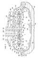
- FIG. 2is a cut-away view of an illustrative embodiment of a dressing depicted in FIG. 1 ;
- FIG. 3is a cut-away view of an another illustrative embodiment of a dressing
- FIG. 4is a side view of an illustrative embodiment of a conduit interface depicted in FIGS. 1-3 ;
- FIG. 5is a top view of the conduit interface depicted in FIG. 4 ;
- FIG. 6provides a chart illustrating a plot of differential pressure versus time, and a flow rate corresponding to the differential pressure
- FIG. 7is a schematic of an another illustrative embodiment of a system for treating a tissue site on a patient.
- FIG. 1depicts an illustrative embodiment of a treatment system 100 for treating a tissue site 102 on a patient 101 .
- the tissue site 102may be, for example, a wound, such as an open wound shown in FIG. 2 , or an incision as shown in FIG. 3 .
- the tissue site 102may extend through or otherwise involve an epidermis 106 , a dermis 108 , and a subcutaneous tissue 110 .
- the treatment system 100may also be used at other tissue sites without limitation.
- tissue site 102may be the bodily tissue of any human, animal, or other organism, including bone tissue, adipose tissue, muscle tissue, dermal tissue, vascular tissue, connective tissue, cartilage, tendons, ligaments, or any other tissue.
- the treatment of tissue site 102may include removal of fluids, such as exudate or ascites.
- the treatment system 100may include a dressing 112 and a therapy device 113 .
- a fluid communication conduit 115may provide fluid communication between the dressing 112 and the therapy device 113 .
- the therapy device 113may apply internal reduced pressure and an external fluid flow to the dressing 112 through the fluid communication conduit 115 for treating the tissue site 102 as will be described further below. Further, the therapy device 113 may control the application of reduced pressure and fluid flow according to pressure feedback signals received from the dressing 112 through the fluid communication conduit 115 .
- the dressing 112may include a manifold 114 , a retention pouch 116 , a sealing member 118 , and a conduit interface 119 .
- the manifold 114may have a first side 120 , a second side 122 , and edges 123 .
- the first side 120 and the second side 122may terminate at edges 123 and face in opposite directions from one another.
- the first side 120 of the manifold 114may be adapted to face inward toward the tissue site 102 .
- the manifold 114may include a plurality of flexibility notches or recesses (not shown) that may be lateral cuts in the manifold 114 .
- the manifold 114may include one or more longitudinal cuts or other cuts.
- the flexibility notchesmay enhance the flexibility of the manifold 114 .
- the enhanced flexibilitymay be particularly useful when the dressing 112 is applied over a joint or other area of movement.
- the manifold 114may also be referred to as a dressing bolster.
- the manifold 114may be formed from any manifold material or flexible bolster material that provides a vacuum space, or treatment space, such as, for example, a porous and permeable foam or foam-like material, a member formed with pathways, a graft, a gauze, or other similar material.
- the manifold 114may be a reticulated, open-cell polyurethane or polyether foam that provides good permeability of fluids while under a reduced pressure.
- One such foam materialis VAC® GranuFoam® material available from Kinetic Concepts, Inc. (KCI) of San Antonio, Tex.
- manifoldany material or combination of materials may be used as a manifold material for the manifold 114 provided that the manifold material is operable to distribute reduced pressure.
- manifoldgenerally refers to a substance or structure that is provided to assist in applying reduced pressure to, delivering fluids to, or removing fluids from a tissue site.
- a manifoldmay include a plurality of flow channels or pathways. The plurality of flow channels may be interconnected to improve distribution of fluids provided to and removed from the area of tissue around the manifold.
- Further examples of manifoldsmay include, without limitation, devices that have structural elements arranged to form flow channels, cellular foam, such as open-cell foam, porous tissue collections, and liquids, gels, and foams that include or cure to include flow channels.
- a material with a higher or lower density, or different pore size, than GranuFoam® materialmay be desirable for the manifold 114 depending on the application.
- GranuFoam® materialmay be used: GranuFoam® material; Foamex® technical foam (www.foamex.com); molded bed of nails structures; patterned grid material, such as those manufactured by Sercol Industrial Fabrics; 3D textiles, such as those manufactured by Baltex of Derby, U.K.; a gauze; a flexible channel-containing member; or a graft.
- the manifold 114may be a hydrophobic layer.
- the hydrophobic characteristics of the manifold 114may prevent the manifold 114 from directly absorbing fluid, such as exudate, from the tissue site 102 , but allow the fluid to pass through.
- the fluidmay be drawn away from the tissue site 102 as will be described below.
- the porous foam-like nature of the manifold 114 as described abovemay permit the manifold 114 to contract and apply a compressive force capable of closing a wound, such as the incision illustrated in FIG. 3 .
- a comfort layer 124may be coupled, for example, by a heat bond 125 or any other suitable technique, to the first side 120 of the manifold 114 .
- the comfort layer 124may provide comfort to the patient 101 when the manifold 114 is placed adjacent to the epidermis 106 of the patient 101 .
- the comfort layer 124may be any material that helps prevent skin irritation and discomfort while allowing fluid transmission through the comfort layer 124 .
- a woven elastic material or a polyester knit textile substratemay be used.
- an InterDryTM textile material from Milliken Chemical of Spartanburg, S.C.may be used.
- the comfort layer 124may include anti-microbial substances, such as silver.
- Coupledincludes coupling via a separate object and direct coupling.
- the term “coupled”also encompasses two or more components that are continuous with one another by virtue of each of the components being formed from the same piece of material.
- the term “coupled”may include chemical, such as via a chemical bond, mechanical, thermal, or electrical coupling.
- Fluid couplingmeans that fluid may be in communication between the designated parts or locations.
- the retention pouch 116may include a first permeable layer 126 , a second permeable layer 127 , and an absorbent core 128 .
- the absorbent core 128may be encapsulated between the first permeable layer 126 and the second permeable layer 127 .
- the first permeable layer 126may have edges 126 a,b secured respectively to edges 127 a,b of the second permeable layer 127 around or otherwise encapsulating the absorbent core 128 .
- the edges 126 a,b and 127 a,b of the first and the second permeable layers 126 , 127may be secured to one another in any suitable manner, such as, for example by the heat bond 125 described above.
- the retention pouch 116may be adapted to retain fluid, such as fluid extracted from the tissue site 102 .
- the first permeable layer 126 and the second permeable layer 127may each have a fluid acquisition surface 129 facing in an opposite direction from a wicking surface 130 .
- the wicking surfaces 130 of the first and second permeable layers 126 , 127may each have a grain (not shown) oriented in a longitudinal direction along the length of the dressing 112 .
- the orientation of the grain of the wicking surfaces 130may serve to wick fluid, such as fluid extracted from the tissue site 102 , along the length of the dressing 112 .
- the wicking of fluid in this mannermay enhance the ability of the retention pouch 116 to retain and manage fluid efficiently for preventing clogs as will be described in further detail below.
- the retention pouch 116may additionally include a recess 131 and an expandable portion 121 .
- the expandable portion 121may be adapted to increase in size, and the recess 131 may be adapted to remain a substantially constant size.
- the first and the second permeable layers 126 , 127may be coupled to one another in any suitable manner, such as with the heat bond 125 described above, to provide the recess 131 .
- the coupling of the first and the second permeable layers 126 , 127 to one anothermay substantially preclude expansion of the recess 131 .
- the expandable portion 121 of the retention pouch 116may be free of restriction and capable of expanding to accommodate fluid being retained in the retention pouch 116 and the absorbent core 128 . Further, in another embodiment, the expandable portion 121 may extend radially outward from the recess 131 . Additionally, in yet another illustrative embodiment, the recess 131 may be capable of receiving or otherwise accommodating a filter 133 . For example, the filter 133 may be positioned in a gap 135 that may be defined between the recess 131 and the sealing member 118 , described below. The recess 131 and the filter 133 may further enhance the ability of the dressing 112 to resist clogging.
- the first and the second permeable layers 126 , 127may be any material exhibiting the fluid acquisition and wicking characteristics described above, such as, for example, Libeltex TDL2, manufactured by Libeltex.
- the filter 133may comprise, for example, any hydrophobic material, and the filter 133 may have any suitable shape, such as a 3-dimensional shape.
- the absorbent core 128may be any absorbent material for retaining liquids and may, for example, include one or more of the following: Luquafleece® material; BASF 402c; Technical Absorbents 2317 available from Technical Absorbents (www.techabsorbents.com); sodium polyacrylate super absorbers; cellulosics (carboxy methyl cellulose and salts such as sodium CMC); or alginates.
- the absorbent core 128may allow fluids and exudate removed from the tissue site 102 to be stored within the retention pouch 116 rather than external to the dressing 112 .
- the absorbent core 128 of the retention pouch 116may include a plurality of flexibility notches (not shown) or recesses that may be lateral cuts in the absorbent core 128 .
- the absorbent core 128may include one or more longitudinal cuts or other cuts.
- the flexibility notchesmay enhance the flexibility of the retention pouch 116 , and may thereby increase the ability of the retention pouch 116 to conform to, for example, the joint of a patient. Further, the enhanced flexibility may assist in preventing any interference with the ability of the manifold 114 to contract as described above.
- the retention pouch 116may have a maximum fluid capacity. At the maximum fluid capacity of the retention pouch 116 , fluid communication through the retention pouch 116 may be substantially precluded.
- the retention pouch 116may have a maximum fluid capacity of any amount to suit a particular application.
- the manifold 114may be positioned between the tissue site 102 and the retention pouch 116 with the first side 120 of the manifold 114 facing the tissue site 102 .
- the fluid acquisition surface 129 of the first permeable layer 126may be positioned proximate to and facing the second side 122 of the manifold 114
- the fluid acquisition surface 129 of the second permeable layer 127may be positioned facing the absorbent core 128 .
- the sealing member 118may provide a cover over the manifold 114 , the retention pouch 116 , and at least a portion of the epidermis 106 of the patient 101 .
- the sealing member 118may be positioned over the manifold 114 and the retention pouch 116 , and may provide a sealed space 132 between the sealing member 118 and the tissue site 102 .
- the sealing member 118may have an exterior surface 134 exposed to ambient air. Further, a portion of the sealing member 118 may include a sealing member aperture 137 to allow fluid communication between the therapy device 113 and the sealed space 132 , the retention pouch 116 , the manifold 114 , and the tissue site 102 .
- the second permeable layer 127 of the retention pouch 116may face the sealing member 118 .
- the recess 131may be positioned on the second permeable layer 127 and facing the sealing member 118 .
- the sealing member 118may be formed from any material that allows for a fluid seal. “Fluid seal,” or “seal,” means a seal adequate to maintain reduced pressure at a desired site given the particular reduced pressure source or system involved.
- the sealing member 118may be sealed, for example, against the epidermis 106 or against a gasket or drape by a sealing apparatus, such as a pressure-sensitive adhesive.
- the sealing apparatusmay be, for example, an adhesive sealing tape, drape tape or strip, double-side drape tape, pressure-sensitive adhesive, paste, hydrocolloid, hydrogel, or other similar material. If a tape is used, the tape may be formed of the same material as the sealing member 118 with a pre-applied, pressure-sensitive adhesive.
- the pressure-sensitive adhesivemay be applied on a patient-facing side of the sealing-member 118 or portion thereof. Before the sealing member 118 is secured to the epidermis 106 , removable strips covering the pressure-sensitive adhesive may be removed.
- the sealing member 118comprises a liquid-impervious material that allows moisture vapor to egress from the sealed space 132 through the sealing member 118 and to the atmosphere.
- the sealing member 118may be formed from a high-moisture-vapor-transfer-rate material (high MVTR material) or a drape material that may be a flexible film.
- “Moisture Vapor Transmission Rate” or “MVTR”may represent the amount of moisture that can pass through a material in a given period of time.
- a high-moisture-vapor-transfer-rate materialmay have a moisture vapor transmission rate greater than about 300 g/m 2 per a 24 hour period, or more specifically, greater than about 1000 g/m 2 per a 24 hour period.
- the sealing member 118may comprise, for example, one or more of the following materials: hydrophilic polyurethane; cellulosics; hydrophilic polyamides; an INSPIRE 2301 material from Expopack Advanced Coatings of Wrexham, United Kingdom; a thin, uncoated polymer drape; natural rubbers; polyisoprene; styrene butadiene rubber; chloroprene rubber; polybutadiene; nitrile rubber; butyl rubber; ethylene propylene rubber; ethylene propylene diene monomer; chlorosulfonated polyethylene; polysulfide rubber; polyurethane (PU); EVA film; co-polyester; silicones; a silicone drape; a 3M Tegaderm® drape; a polyurethane (PU) drape such as one available from Avery Dennison Corporation of Pasadena, Calif.; polyether block polyamide copolymer (PEBAX), for example from Arkema, France; or other appropriate material.
- the conduit interface 119may be coupled to the sealing member 118 of the dressing 112 .
- the conduit interface 119may be in fluid communication with the exterior surface 134 of the sealing member 118 . Further, the conduit interface 119 may be in fluid communication with the sealed space 132 through the sealing member aperture 137 in the sealing member 118 .
- the fluid communication conduit 115may provide fluid communication between the therapy device 113 and the conduit interface 119 .
- the conduit interface 119may include an evaporative flow conduit 150 , a variable pressure conduit 154 , a reduced-pressure conduit 158 , and a manifold pressure conduit 162 .
- the evaporative flow conduit 150may be in fluid communication with the exterior surface 134 of the sealing member 118 .
- the conduit interface 119may include an evaporative flow outlet 166 in fluid communication with the evaporative flow conduit 150 .
- the evaporative flow outlet 166may be positioned circumferentially about the conduit interface 119 for providing circumferential fluid flow about the conduit interface 119 and over the exterior surface 134 of the sealing member 118 .
- the conduit interface 119may be formed from a medical-grade, soft polymer or other pliable material.
- the conduit interface 119may be formed from polyurethane, polyethylene, polyvinyl chloride (PVC), fluorosilicone, ethylene-propylene, or other similar materials.
- conduit interface 119may be molded from DEHP-free PVC.
- the conduit interface 119may be formed in any suitable manner such as by molding, casting, machining, or extruding. Further, the conduit interface 119 may be formed as an integral unit or as individual components.
- the variable pressure conduit 154may have an inlet 170 in fluid communication with the sealed space 132 .
- the inlet 170 of the variable pressure conduit 154may be positioned in a spaced relationship relative to the expandable portion 121 of the retention pouch 116 .
- the inlet 170 of the variable pressure conduit 154may be substantially aligned over the expandable portion 121 and the second permeable layer 127 of the retention pouch 116 . Further, the inlet 170 of the variable pressure conduit 154 may be positioned between the retention pouch 116 and the sealing member 118 .
- the reduced-pressure conduit 158may have an inlet 174 in fluid communication with the sealed space 132 .
- the inlet 174 of the reduced-pressure conduit 158may be positioned in a spaced relationship relative to the recess 131 in the retention pouch 116 .
- the recess 131may provide the gap 135 .
- the gap 135may be between the inlet 174 of the reduced-pressure conduit 158 and the retention pouch 116 .
- the inlet 174 of the reduced-pressure conduit 158may be substantially aligned over the recess 131 and the second permeable layer 127 of the retention pouch 116 . Further, the inlet 174 of the reduced-pressure conduit 158 may be positioned between the retention pouch 116 and the sealing member 118 .
- the manifold pressure conduit 162may have an inlet 176 in fluid communication with the manifold 114 .
- the inlet 176 of the manifold pressure conduit 162may be positioned between the retention pouch 116 and the manifold 114 .
- the inlet 176 of the manifold pressure conduit 162may be positioned adjacent to the second side 122 of the manifold 114 .
- the manifold pressure conduit 162may also be in fluid communication with the tissue site 102 , the sealed space 132 , and the components of the dressing 112 by virtue of the fluid permeability of the manifold 114 .
- the conduit interface 119may include a base 180 coupled at the inlet 176 of the manifold pressure conduit 162 .
- the manifold pressure conduit 162may have a length 183 between the base 180 and the exterior surface 134 of the sealing member 118 .
- the length 183may be a length that the manifold pressure conduit 162 extends into the sealed space 132 of the dressing 112 from the exterior surface 134 of the sealing member 118 .
- the manifold pressure conduit 162may extend through a retention pouch aperture 185 disposed, for example, through the recess 131 in the retention pouch 116 .
- the manifold pressure conduit 162may extend through a filter aperture 187 disposed through the filter 133 .
- the base 180may extend laterally outward from the inlet 176 of the manifold pressure conduit 162 and underneath the retention pouch 116 .
- the base 180may carry the retention pouch 116 between the base 180 and the sealing member 118 such that the expandable portion 121 of the retention pouch 116 extends laterally beyond the base 180 .
- the length 183 of the manifold pressure conduit 162may be sized according to the thickness of the retention pouch 116 .
- the length 183may provide space for the expandable portion 121 of the retention pouch 116 to increase in size prior to contacting the inlet 170 of the variable pressure conduit 154 , as described below.
- the length 183may be about 2.5 times the thickness of the retention pouch 116 .
- the conduit interface 119may include a membrane filter (not shown) in fluid communication with the sealing member aperture 137 for prevention of clogs and transmission of odors from the dressing 112 during therapy.
- the membrane filtermay be, for example, a hydrophobic or oleophobic filter.
- the membrane filtermay include a substance, such as, for example, charcoal for controlling odor.
- the membrane filtermay be replaceable or formed integrally with the conduit interface 119 .
- the membrane filtermay be positioned in any suitable location in fluid communication between the dressing 112 and the therapy device 113 .
- the therapy device 113may include a fluid flow source 184 , a variable pressure sensor 188 , a reduced-pressure source 192 , a manifold pressure sensor 196 , and a controller 200 .
- the fluid flow source 184may be in fluid communication with the evaporative flow conduit 150 .
- the variable pressure sensor 188may be in fluid communication with the variable pressure conduit 154 .
- the reduced-pressure source 192may be in fluid communication with the reduced-pressure conduit 158 .
- the manifold pressure sensor 196may be in fluid communication with the manifold pressure conduit 162 .
- the fluid communication conduit 115may include a plurality of fluid communication lumens 202 that provide fluid communication between each of the previously described components of the therapy device 113 and the conduit interface 119 .
- the fluid communication lumens 202may be provided as individual components rather than as a part of the fluid communication conduit 115 .
- the fluid flow source 184may provide fluid flow as a part of the therapy device 113 in the treatment system 100 .
- the fluid flow source 184may be a positive-pressure source 186 that provides a positive-pressure output to the evaporative flow conduit 150 for supplying fluid flow from the therapy device 113 to the exterior surface 134 of the sealing member 118 .
- the fluid flowmay have a variable flow rate as will be discussed below.
- the fluid flow source 184may be any suitable device or source for providing fluid flow, such as, for example, a pump or blower.
- the fluid flow source 184may be any source of fluid flow over the exterior surface 134 of the sealing member 118 .
- the fluid flow source 184may be ambient air directed over the exterior surface 134 of the sealing member 118 .
- the fluid flow source 184may be reduced pressure applied to the evaporative flow conduit 150 for drawing fluid across the exterior surface 134 of the sealing member 118 and back to the therapy device 113 .
- the reduced-pressure source 192may provide reduced pressure to the dressing 112 .
- the reduced-pressure source 192may provide a reduced pressure output to the reduced-pressure conduit 158 for applying reduced pressure to the sealed space 132 , the retention pouch 116 , the manifold 114 , and the tissue site 102 .
- the reduced-pressure source 192may be any suitable device for providing reduced pressure as described herein, such as, for example, a vacuum pump, wall suction, or other source.
- reduced pressuregenerally refers to a pressure less than the ambient pressure at the tissue site 102 being subjected to treatment. In one embodiment, the reduced pressure may be less than the atmospheric pressure. In another embodiment, the reduced pressure may be less than a hydrostatic pressure at a tissue site. Unless otherwise indicated, values of pressure stated herein are gauge pressures. While the amount and nature of reduced pressure applied to a tissue site may vary according to the application, the reduced pressure may be between about ⁇ 5 mm Hg to about ⁇ 500 mm Hg, and more specifically, between about ⁇ 100 mm Hg to about ⁇ 200 mm Hg.
- the reduced pressure deliveredmay be constant or varied (patterned or random) and may be delivered continuously or intermittently.
- vacuumand “negative pressure” may be used to describe the pressure applied to a tissue site, the actual pressure applied to the tissue site may be more than the pressure normally associated with a complete vacuum.
- an increase in reduced pressure or vacuum pressuremay refer to a relative reduction in absolute pressure.
- An increase in reduced pressurecorresponds to a reduction in pressure (more negative relative to ambient pressure) and a decrease in reduced pressure corresponds to an increase in pressure (less negative relative to ambient pressure).
- the controller 200may be a printed wire assembly (PWA) or an application specific integrated circuit (ASIC) or other control device.
- the controller 200may be adapted to receive a variable pressure signal from the variable pressure sensor 188 and a manifold pressure signal from the manifold pressure sensor 196 .
- Reduced pressure communicated from the variable pressure conduit 154 to the variable pressure sensor 188may provide the variable pressure signal
- reduced pressure communicated from the manifold pressure conduit 162 to the manifold pressure sensor 196may provide the manifold pressure signal.
- the controller 200may receive the variable pressure signal and the manifold pressure signal in any suitable manner, such as, for example, by wired or wireless electronic communication.
- the controller 200may be operable to provide the reduced pressure output from the reduced-pressure source 192 when the manifold pressure signal is greater than a target reduced pressure.
- the reduced pressure outputmay be provided when the reduced pressure corresponding to the manifold pressure signal is less negative relative to ambient pressure than the target reduced pressure.
- the controller 200may cease or preclude the reduced pressure output from the reduced-pressure source 192 when the manifold pressure signal has reached the target reduced pressure.
- the controller 200may control the reduced pressure output from the reduced-pressure source 192 to the dressing 112 when the manifold pressure signal falls within a threshold of the target reduced pressure. In this manner, the controller 200 may be capable of maintaining the reduced pressure in the dressing 112 at the target reduced pressure or within a threshold thereof.
- the target reduced pressuremay be any reduced pressure to suit a particular application for the dressing 112 .
- the target reduced pressuremay be input by a user into a control panel (not shown) or other input device associated with the controller 200 .
- the controller 200may be operable to increase the flow rate from the fluid flow source 184 in response to an increase in a pressure differential between the variable pressure signal and the manifold pressure signal.
- the controller 200may also be operable to decrease the flow rate from the fluid flow source 184 in response to a decrease in the pressure differential between the variable pressure signal and the manifold pressure signal.
- the pressure differential between the variable pressure signal and the manifold pressure signalis the difference between the variable pressure signal and the manifold pressure signal.
- an increase in the pressure differentialmay correspond to a pressure drop across the retention pouch 116 .
- the pressure differential and the pressure dropmay correspond to an increase in the amount of moisture in the dressing 112 .
- the controller 200may control the rate of evaporation of moisture retained in the dressing 112 by varying the flow rate of fluid across the sealing member 118 according to the level of moisture in the dressing 112 .
- a pump 204may provide both the fluid flow source 184 and the reduced-pressure source 192 .
- the pump 204may have a pump outlet 208 and a pump inlet 212 .
- the pump outlet 208may provide the positive-pressure source 186 as the fluid flow source 184
- the pump inlet 212may provide the reduced-pressure source 192 .
- the pump outlet 208may be in fluid communication with the evaporative flow conduit 150
- the pump inlet 212may be in fluid communication with the reduced-pressure conduit 158 .
- the therapy device 113may additionally include a valve 216 in fluid communication between the pump inlet 212 and the reduced-pressure conduit 158 .
- the valve 216may have a valve outlet 220 , a valve inlet 224 , and an ambient air inlet 228 .
- the valve outlet 220 and the valve inlet 224may be coupled in series between the pump inlet 212 and the reduced-pressure conduit 158 such that fluid communication between the pump inlet 212 and the reduced-pressure conduit 158 is provided through the valve 216 .
- the valve 216When the valve 216 is open, the valve 216 may permit fluid communication between the reduced-pressure source 192 at the pump inlet 212 and the reduced-pressure conduit 158 .
- valve 216When the valve 216 is closed, the valve 216 may preclude fluid communication between the reduced-pressure source 192 at the pump inlet 212 and the reduced-pressure conduit 158 . In one embodiment, when the valve 216 is closed, the valve 216 may provide fluid communication between the pump inlet 212 and the ambient air through the ambient air inlet 228 .
- the controller 200may be operable to vary a rotational rate of the pump 204 or the time period the pump 204 is on or off. Further, the controller 200 may be operable to simultaneously open and close the valve 216 while varying the rotational rate and/or the time period the pump is on or off.
- the rotational rate of the pump 204 or the time period the pump is on or offmay correspond to the positive pressure output at the pump outlet 208 and the reduced pressure output at the pump inlet 212 .
- the valve 216when the valve 216 is open, the valve 216 may permit reduced pressure from the pump inlet 212 to reach the reduced-pressure conduit 158 .
- the valve 216When the valve 216 is closed, the valve 216 may preclude reduced pressure from reaching the reduced-pressure conduit 158 .
- the controller 200may be operable to control the positive pressure output and the reduced pressure output independently utilizing valve 216 . Further, in one embodiment, when the valve 216 is closed, the valve 216 may permit ambient air to reach the pump inlet 212 in order to facilitate the positive pressure output from the pump outlet 208 .
- the controller 200may, for example, be electrically coupled in any suitable manner to a solenoid (not shown) operable to open and close the valve 212 . In this manner, the controller 200 may vary the voltage output to the solenoid such as, for example, by a binary output, Pulse Width Modulation (PWM), or other output. Further, the controller 200 may be operable to vary the rotational rate of the pump 204 and/or the time the pump 204 is on or off in any suitable manner, such as, for example, by the Pulse Width Modulation (PWM) discussed above.
- PWMPulse Width Modulation
- the rotational rate of the pump 204 , the time the pump 204 is on or off, and/or the solenoidmay be said to operate based on a duty cycle.
- An increase in the percentage of the duty cyclemay correspond to an increase in the rotational rate of the pump 204 or an increase in the amount of time the pump 204 is on for a given time period. For example, at a 100% duty cycle, the pump 204 may be operating at a maximum output or rotational rate.
- an increase in the percentage of the duty cyclemay correspond to an amount of time that the solenoid remains in either an open or a closed state. For example, at a 100% duty cycle, the solenoid may be remain in either an open or a closed state for an entire time period.
- the fluid flow source 184 and the reduced-pressure source 192may be separate devices individually controlled by the controller 200 .
- the controller 200may be coupled in any suitable manner to a first solenoid operated valve (not shown) and a second solenoid operated valve (not shown).
- the first solenoid operated valvemay be positioned in fluid communication between the dressing 112 and the fluid flow source 184 .
- the second solenoid operated valvemay be positioned in fluid communication between the dressing 112 and the reduced-pressure source 192 .
- the controller 200may control the flow rate through the first and second valves by, for example, the Pulse Width Modulation (PWM) discussed above.
- PWMPulse Width Modulation
- the controller 200may provide reduced pressure from the reduced-pressure source 192 to the reduced-pressure conduit 158 until the manifold pressure signal reaches the target reduced pressure.
- the controller 200may monitor the manifold pressure signal and provide reduced pressure accordingly to maintain the reduced pressure in the dressing 112 at the target reduced pressure, or within a threshold thereof. Further, the controller 200 may provide fluid flow from the fluid flow source 184 to the evaporative flow conduit 150 , thereby distributing the fluid flow across the exterior surface 134 of the sealing member 118 .
- the manifold 114 and the retention pouch 116may be formed of permeable materials that act as a manifold for providing fluid communication between the conduit interface 119 and the tissue site 102 .
- the reduced pressure distributed to the tissue site 102 by the manifold 114may draw fluid away from the tissue site 102 toward the retention pouch 116 where the fluid may be retained.
- the reduced-pressure conduit 158 in the conduit interface 119may be in fluid communication with the edges 123 of the manifold 114 along the sides of the dressing 112 .
- the dressing 112may not require fluid communication through the retention pouch 116 in order for reduced pressure applied to the dressing 112 through the reduced-pressure conduit 158 to reach the tissue site 102 . Accordingly, when the retention pouch 116 has reached the maximum fluid capacity, the reduced-pressure conduit 158 remains in fluid communication with the tissue site 102 at least by virtue of the fluid communication with the edges 123 of the manifold 114 .
- the fluid communication between the reduced-pressure conduit 158 and the edges 123may permit the manifold 114 to distribute reduced pressure to the tissue site 102 if, for example, the retention pouch 116 becomes substantially saturated with fluid, or otherwise clogged.
- the edges 123 of the manifold 114may provide an independent fluid communication path between the reduced-pressure conduit 158 and the tissue site 102 .
- the retention pouch 116may include the first and the second permeable layers 126 , 127 that encapsulate the absorbent core 128 for retaining fluid during treatment.
- the first permeable layer 126may be positioned proximate the manifold 114
- the second permeable layer 127may be positioned proximate the sealing member 118 .
- the fluid acquisition surface 129 of the first permeable layer 126may face the manifold 114
- the wicking surface 130 of the first permeable layer 126may face the absorbent core 128 .
- the fluid acquisition surface 129 of the second permeable layer 127may face the absorbent core 128
- the wicking surface 130 of the second permeable layer 127may face the sealing member 118 .
- the fluidmay be distributed by each of the wicking surfaces 130 along the length of the dressing 112 .
- the grain of each of the wicking surfaces 130may be oriented along the length of the dressing 112 such that the fluid will follow the direction of the grain by a wicking action without regard to the physical orientation of the dressing 112 at the tissue site 102 .
- the fluidmay be distributed and absorbed by the absorbent core 128 in a substantially even manner.
- the configuration of the first and the second permeable layers 126 , 127may be particularly useful in managing fluid extracted from the tissue site 102 within the dressing 112 .
- the fluidmay first be drawn into the retention pouch 116 and away from the manifold 114 . Subsequently, the fluid may be wicked along the wicking surface 130 of the first permeable layer 126 for absorption by the absorbent core 128 .
- the fluidmay be first wicked along the wicking surface 130 of the second permeable layer 127 , away from the sealing member aperture 137 .
- Fluid contacting the second permeable layer 127may first be wicked away from the sealing member aperture 137 to preclude clogging of the reduced-pressure conduit 158 near the sealing member aperture 137 . Clogging can occur, for example, from excess fluid near the sealing member aperture 137 . Subsequently, the fluid may be drawn into the retention pouch 116 through the second permeable layer 127 and absorbed by the absorbent core 128 .
- the configuration and positioning of the first and the second permeable layers 126 , 127 relative to one anothermay direct fluid away from the tissue site 102 and away from the sealing member aperture 137 for storage in the retention pouch 116 . In this manner, the tissue site 102 may be kept substantially free of fluids, and the reduced-pressure conduit 158 , may be kept substantially free of clogs.
- the recess 131 on the retention pouch 116may further enhance the ability of the dressing 112 to resist clogging.
- the recess 131may provide the gap 135 between the inlet 174 of the reduced-pressure conduit 158 and the retention pouch 116 as previously described.
- the gap 135may substantially preclude excess fluid from becoming lodged between the sealing member 118 and the retention pouch 116 near the reduced-pressure conduit 158 .
- the filter 133may be positioned in the gap 135 to further preclude excess fluids from reaching the reduced-pressure conduit 158 .
- the controller 200may vary the fluid flow rate from the fluid flow source 184 over the exterior surface 134 of the sealing member 118 according to the amount of fluid retained in the dressing 112 .
- the sealing member 118may comprise a material that has a high MVTR and is thus capable of allowing moisture vapor to egress from the sealed space 132 to the atmosphere through the sealing member 118 .
- Providing fluid flow over the exterior surface 134 of the sealing member 118may enhance the egress of moisture vapor from the sealed space 132 through the sealing member 118 .
- An increase in the flow rate of the fluidmay correspond to an increase in the rate of evaporation of moisture vapor from the sealed space 132 .
- the controller 200may vary the fluid flow rate from the fluid flow source 184 based on the previously described differential pressure between the manifold pressure signal and the variable pressure signal.
- the manifold pressure signalmay correspond to the pressure measured at the inlet 176 of the manifold pressure conduit 162 . Due to the positioning of the inlet 176 between the retention pouch 116 and the manifold 114 , the manifold pressure signal may approximate the reduced pressure at the tissue site 102 without regard to the level of fluid saturation in the retention pouch 116 .
- the variable pressure signalmay corresponds to the pressure measured at the inlet 170 of the variable pressure conduit 154 .
- the variable pressure signalmay vary with increased fluid retention in the retention pouch 116 and the dressing 112 .
- the differential pressuremay correspond to a pressure drop across the retention pouch 116 , providing an indication of the level of fluid saturation in the retention pouch 116 and the dressing 112 .
- An increase in the differential pressuremay correspond to an increase in the fluid saturation of the retention pouch 116 and the dressing 112 .
- the controller 200may increase the flow rate from the fluid flow source 184 in response to an increase in the differential pressure to accelerate the evaporation of the fluid through the sealing member 118 .
- the manifold pressure signal, the variable pressure signal, and the reduced pressure applied to the dressing 112 through the reduced-pressure conduit 158may closely approximate one another.
- the variable pressure signalmay increase in pressure.
- the variable pressure signalmay become less negative relative to ambient pressure due, at least in part, to the pressure drop created by the fluid in the retention pouch 116 .
- the expandable portion 121 of the retention pouch 116may increase in size to accommodate the fluid, causing the expandable portion 121 to approach the inlet 170 of the variable pressure conduit 154 .
- the expandable portion 121 of the retention pouch 116may contact the inlet 170 of the variable pressure conduit 154 and preclude fluid communication between the sealed space 132 and the variable pressure conduit 154 .
- the controller 200may provide maximum flow rate from the fluid flow source 184 to remediate the excess fluid.
- the controller 200may reduce the flow rate from the fluid flow source 184 as the excess fluid is evaporated and the differential pressure begins to return to a steady state or normal condition, with the variable pressure signal closely approximating the manifold pressure signal.
- the controller 200may provide an alarm indicating, for example, that the dressing 112 needs to be changed. Further, if the manifold pressure signal increases or becomes less negative relative to ambient pressure, the controller 200 may also provide an alarm. Such a variation in the manifold pressure signal may indicate that the manifold 114 has become saturated with fluid and that the tissue site 102 is no longer being provided effective therapy. In one embodiment, the controller 200 may provide an alarm if the manifold pressure signal increases above a threshold amount of the target reduced pressure, such as, for example, a threshold pressure that is about 50% greater than the target reduced pressure. In another embodiment, the controller 200 may provide an alarm after an elapse of a time period input by a user.
- the alarms provided by the controller 200may have varying degrees of priority set by a user. For example, a standard alarm may be provided for conditions indicating that the dressing 112 may need to be changed, and a full alarm may be provided for conditions indicating that the tissue site 102 may not be receiving effective treatment.
- a standard alarmmay be provided for conditions indicating that the dressing 112 may need to be changed
- a full alarmmay be provided for conditions indicating that the tissue site 102 may not be receiving effective treatment.
- This specificationcontemplates the use of any suitable devices for providing user inputs and outputs, such as, for example, display panels, key pads, electronic chimes, and other such devices.
- a chartis provided that illustrates an exemplary embodiment of the previously described evaporative control features of the treatment system 100 .
- the chartincludes the differential pressure (mm Hg) on the vertical axis and time (hours) on the horizontal axis.
- the plot line 189 on the chartdepicts the differential pressure between the manifold pressure signal and the variable pressure signal, or the pressure drop across the retention pouch 116 , versus time.
- the controller 200may provide a 20% duty cycle output for the fluid flow source 184 .
- a differential pressure of less than about 5 mm Hg in this examplemay require a low evaporation rate, or a low flow rate from the fluid flow source 184 , indicating a low or normal level of fluid saturation in the retention pouch 116 and the dressing 112 .
- the controller 200may provide a 60%-80% duty cycle output for the fluid flow source 184 .
- a 60%-80% duty cycle in this examplemay require a medium evaporation rate, or a medium flow rate from the fluid flow source 184 , indicating a medium level of fluid saturation in the retention pouch 116 and the dressing 112 .
- the controller 200may provide a 100% duty cycle output for the fluid flow source 184 .
- a 100% duty cycle in this examplemay require a maximum evaporation rate, or a maximum flow rate from the fluid flow source 184 , indicating that the retention pouch 116 and the dressing 112 are almost fully saturated with fluid.
- the flow rate of fluid from the fluid flow source 184increases, thereby increasing the evaporation rate of the fluid in the retention pouch 116 and the dressing 112 .
- a differential pressure setting input by a user and corresponding to a desired duty cycle or flow ratemay be used to trigger the evaporation rates described above.
- the storage, management, and disposition of extracted fluids in the dressing 112provides many benefits.
- the potential for clogging as discussed abovemay be reduced and the storage of fluids within the dressing 112 may eliminate the need for external storage components that could potentially leak or cause discomfort. Further, the reduction in the number of components lowers the volume that must be maintained at reduced pressure, thereby increasing efficiency.
- the dressing 112may be capable of managing fluids without regard to any particular physical orientation of the dressing 112 at a tissue site.
- the treatment system 100 employing the dressing 112may be capable of remediating excess fluids and providing valuable information to a user regarding the status of the therapy and the state of fluid saturation in the dressing 112 .
- the treatment system 100 and the dressing 112at least provide increased comfort, usability, efficiency, and confidence that a patient is receiving effective treatment.
- This specificationadditionally provides an illustrative embodiment of a method of treating a tissue site 102 on a patient 101 .
- one embodiment of the methodmay include the step of positioning the first side 120 of the manifold 114 over the tissue site 102 . Further, the method may include the steps of positioning the retention pouch 116 over the second side 122 of the manifold 114 , and positioning the sealing member 118 to cover the retention pouch 116 and the manifold 114 . The method may further include the step of sealingly securing the sealing member 118 to the portion of the epidermis 106 of the patient 101 , as described above, to provide the sealed space 132 between the tissue site 102 and the sealing member 118 .
- the methodmay include the step of providing the reduced-pressure conduit 158 in fluid communication with the sealed space 132 .
- the reduced-pressure conduit 158may have an inlet 176 positioned in a spaced relationship relative to the recess 131 in the retention pouch 116 .
- the recess 131may provide a gap 135 between the inlet 176 of the reduced-pressure conduit 158 and the recess 131 .
- the methodmay include the step of providing a variable pressure conduit 154 in fluid communication with the sealed space 132 .
- the variable pressure conduit 154may have an inlet 170 positioned in a spaced relationship relative to the expandable portion 121 of the retention pouch 116 .
- the methodmay further include the step of measuring a manifold pressure between the manifold 114 and the retention pouch 116 .
- the manifold pressuremay correspond to a reduced pressure at the tissue site 102 .
- the methodmay further include the step of applying reduced pressure to the sealed space 132 through the reduced-pressure conduit 158 until the manifold pressure reaches a target reduced pressure.
- the reduced pressuremay extract fluid from the tissue site 102 , and the expandable portion 121 of the retention pouch 116 may expand to retain the fluid.
- the methodmay additionally provide the step of measuring a variable pressure between the expandable portion 121 of the retention pouch 116 and the sealing member 118 .
- the methodmay provide the steps of calculating a differential pressure between the manifold pressure and the variable pressure, and providing a fluid flow over the exterior surface 134 of the sealing member 118 .
- the differential pressuremay correspond to the amount of fluid retained by the retention pouch 116 .
- the fluid flowmay have a flow rate corresponding to the differential pressure that evaporates the fluid extracted from the tissue site 102 .
- the methodmay include the step of signaling a full alarm if the manifold pressure is greater than a pressure threshold after the manifold pressure initially reaches the target reduced pressure. In another embodiment, the method may include the step of signaling a full alarm after an elapsed time setting input by a user.
- the step of providing a fluid flow over the exterior surface 134 of the sealing member 118may include the steps of matching the differential pressure with a plurality of differential pressure settings input by a user that correspond to a flow rate, and providing the corresponding fluid flow rate over the exterior surface 134 of the sealing member 118 .
- the methodincludes signaling a full alarm.
- the methodmay include the step of comparing an amount of power available to the treatment system 100 with an amount of power required to provide the corresponding fluid flow rate over the sealing member 118 for a time period set by a user. Further, the method may provide the step of signaling an alarm for a supplemental power source if the amount of power available to the treatment system 100 is less that the amount of power required to provide the corresponding fluid flow rate over the sealing member for the time period. Further, the method may provide the steps of canceling the alarm for the supplemental power source if the supplemental power source is provided, and signaling a full alarm if the supplemental power source is not provided.
- the methodmay provide the steps of reducing the fluid flow rate over the sealing member 118 according to the differential pressure settings if the differential pressure is less than the maximum differential pressure setting, and signaling a full alarm if the differential pressure is above the maximum differential pressure setting for an elapsed time input by a user.
- the treatment system 100may include a visual indicator 232 for providing a visual indication of the differential pressure.
- the visual indicator 232may include a first port 236 and a second port 240 .
- the first port 236may be fluidly coupled to the variable pressure conduit 154
- the second port 240may be fluidly coupled to the manifold pressure conduit 162 .
- the visual indicator 232may include a tube 246 having a piston 250 disposed in the tube 246 .
- the piston 250may be biased to one end of the tube 246 by a spring 256 .
- the tube 246may additionally include a transparent window 260 for providing a visual indication of the displacement of the piston 250 in the tube 246 .
- the transparent window 260may have a plurality of graduated indicators 264 that indicate the differential pressure based upon the displacement of the piston 250 in the tube 246 .
- reduced pressure from the variable pressure conduit 154may be applied to the first port 236
- reduced pressure from the manifold pressure conduit 162may be applied to the second port 240
- the differential pressure between the variable pressure conduit 154 and the manifold pressure conduit 162may displace the piston 250 in the tube 246 .
- the piston 250will be displaced in the tube 246 toward the first port 236 .
- the graduated indicators 264may indicate the differential pressure by the displacement of the piston 250 shown through the transparent window 260 .
- the visual indicator 232may include a sensing device such as, for example, a proportional valve, relief valve, or pressure switch (not shown) coupled to the tube 246 .
- the sensing devicemay detect the displacement of the piston 250 in the tube 246 and generate a signal corresponding to the differential pressure that may be input to the controller 200 and utilized in the evaporative control routine described above.
Landscapes
- Health & Medical Sciences (AREA)
- Heart & Thoracic Surgery (AREA)
- Public Health (AREA)
- Veterinary Medicine (AREA)
- Vascular Medicine (AREA)
- Life Sciences & Earth Sciences (AREA)
- Animal Behavior & Ethology (AREA)
- General Health & Medical Sciences (AREA)
- Engineering & Computer Science (AREA)
- Biomedical Technology (AREA)
- Anesthesiology (AREA)
- Hematology (AREA)
- Oral & Maxillofacial Surgery (AREA)
- Pulmonology (AREA)
- Surgery (AREA)
- External Artificial Organs (AREA)
- Media Introduction/Drainage Providing Device (AREA)
- Thermotherapy And Cooling Therapy Devices (AREA)
Abstract
Description
Claims (15)
Priority Applications (3)
| Application Number | Priority Date | Filing Date | Title |
|---|---|---|---|
| US13/954,658US9662427B2 (en) | 2012-08-13 | 2013-07-30 | Intelligent therapy system with evaporation management |
| US15/494,042US10625002B2 (en) | 2012-08-13 | 2017-04-21 | Intelligent therapy system with evaporation management |
| US16/812,895US20200206395A1 (en) | 2012-08-13 | 2020-03-09 | Intelligent therapy system with evaporation management |
Applications Claiming Priority (2)
| Application Number | Priority Date | Filing Date | Title |
|---|---|---|---|
| US201261682449P | 2012-08-13 | 2012-08-13 | |
| US13/954,658US9662427B2 (en) | 2012-08-13 | 2013-07-30 | Intelligent therapy system with evaporation management |
Related Child Applications (1)
| Application Number | Title | Priority Date | Filing Date |
|---|---|---|---|
| US15/494,042ContinuationUS10625002B2 (en) | 2012-08-13 | 2017-04-21 | Intelligent therapy system with evaporation management |
Publications (2)
| Publication Number | Publication Date |
|---|---|
| US20140163490A1 US20140163490A1 (en) | 2014-06-12 |
| US9662427B2true US9662427B2 (en) | 2017-05-30 |
Family
ID=50031495
Family Applications (3)
| Application Number | Title | Priority Date | Filing Date |
|---|---|---|---|
| US13/954,658Expired - Fee RelatedUS9662427B2 (en) | 2012-08-13 | 2013-07-30 | Intelligent therapy system with evaporation management |
| US15/494,042Expired - Fee RelatedUS10625002B2 (en) | 2012-08-13 | 2017-04-21 | Intelligent therapy system with evaporation management |
| US16/812,895AbandonedUS20200206395A1 (en) | 2012-08-13 | 2020-03-09 | Intelligent therapy system with evaporation management |
Family Applications After (2)
| Application Number | Title | Priority Date | Filing Date |
|---|---|---|---|
| US15/494,042Expired - Fee RelatedUS10625002B2 (en) | 2012-08-13 | 2017-04-21 | Intelligent therapy system with evaporation management |
| US16/812,895AbandonedUS20200206395A1 (en) | 2012-08-13 | 2020-03-09 | Intelligent therapy system with evaporation management |
Country Status (3)
| Country | Link |
|---|---|
| US (3) | US9662427B2 (en) |
| EP (1) | EP2882470B1 (en) |
| WO (1) | WO2014028212A2 (en) |
Families Citing this family (53)
| Publication number | Priority date | Publication date | Assignee | Title |
|---|---|---|---|---|
| ES2564519T3 (en)* | 2006-10-13 | 2016-03-23 | Bluesky Medical Group Inc. | Pressure control of a medical vacuum pump |
| ES2715605T3 (en) | 2007-11-21 | 2019-06-05 | Smith & Nephew | Wound dressing |
| WO2009067711A2 (en)* | 2007-11-21 | 2009-05-28 | T.J. Smith & Nephew, Limited | Suction device and dressing |
| GB0723855D0 (en) | 2007-12-06 | 2008-01-16 | Smith & Nephew | Apparatus and method for wound volume measurement |
| GB0808376D0 (en) | 2008-05-08 | 2008-06-18 | Bristol Myers Squibb Co | Wound dressing |
| GB0817796D0 (en) | 2008-09-29 | 2008-11-05 | Convatec Inc | wound dressing |
| GB201015656D0 (en) | 2010-09-20 | 2010-10-27 | Smith & Nephew | Pressure control apparatus |
| US9526920B2 (en) | 2010-10-12 | 2016-12-27 | Smith & Nephew, Inc. | Medical device |
| GB201020236D0 (en) | 2010-11-30 | 2011-01-12 | Convatec Technologies Inc | A composition for detecting biofilms on viable tissues |
| WO2012078724A1 (en) | 2010-12-08 | 2012-06-14 | Convatec Technologies Inc. | Apparatus and method for applying pressure to a wound site |
| US10207031B2 (en) | 2010-12-08 | 2019-02-19 | Convatec Technologies Inc. | Integrated system for assessing wound exudates |
| ES2748519T3 (en) | 2010-12-08 | 2020-03-17 | Convatec Technologies Inc | Wound exudate system accessory |
| WO2013066426A2 (en) | 2011-06-24 | 2013-05-10 | Kci Licensing, Inc. | Reduced-pressure dressings employing tissue-fixation elements |
| GB201115182D0 (en) | 2011-09-02 | 2011-10-19 | Trio Healthcare Ltd | Skin contact material |
| US9084845B2 (en) | 2011-11-02 | 2015-07-21 | Smith & Nephew Plc | Reduced pressure therapy apparatuses and methods of using same |
| GB2497406A (en) | 2011-11-29 | 2013-06-12 | Webtec Converting Llc | Dressing with a perforated binder layer |
| GB201120693D0 (en) | 2011-12-01 | 2012-01-11 | Convatec Technologies Inc | Wound dressing for use in vacuum therapy |
| AU2013237095B2 (en) | 2012-03-20 | 2017-10-05 | Smith & Nephew Plc | Controlling operation of a reduced pressure therapy system based on dynamic duty cycle threshold determination |
| US9427505B2 (en) | 2012-05-15 | 2016-08-30 | Smith & Nephew Plc | Negative pressure wound therapy apparatus |
| EP2852333B1 (en) | 2012-05-22 | 2021-12-15 | Smith & Nephew plc | Apparatuses for wound therapy |
| JP2016507663A (en) | 2012-12-20 | 2016-03-10 | コンバテック・テクノロジーズ・インコーポレイテッドConvatec Technologies Inc | Processing of chemically modified cellulosic fibers |
| US9737649B2 (en) | 2013-03-14 | 2017-08-22 | Smith & Nephew, Inc. | Systems and methods for applying reduced pressure therapy |
| JP2016517318A (en) | 2013-03-14 | 2016-06-16 | スミス アンド ネフュー インコーポレーテッド | System and method for administering decompression therapy |
| WO2015023515A1 (en) | 2013-08-13 | 2015-02-19 | Smith & Nephew, Inc. | Systems and methods for applying reduced pressure therapy |
| US10052416B2 (en)* | 2014-01-07 | 2018-08-21 | Mayo Foundation For Medical Education And Research | Enterocutaneous fistula treatment |
| US12133789B2 (en) | 2014-07-31 | 2024-11-05 | Smith & Nephew, Inc. | Reduced pressure therapy apparatus construction and control |
| CA3179001A1 (en) | 2014-07-31 | 2016-02-04 | Smith & Nephew, Inc. | Systems and methods for applying reduced pressure therapy |
| EP3237032B1 (en) | 2014-12-22 | 2024-08-07 | Smith & Nephew plc | Negative pressure wound therapy apparatus |
| CA2972701A1 (en) | 2014-12-30 | 2016-07-07 | Smith & Nephew, Inc. | Systems and methods for applying reduced pressure therapy |
| CN104815385A (en)* | 2015-04-23 | 2015-08-05 | 广州新诚生物科技有限公司 | Multi-functional negative pressure drainage system |
| AU2016294259A1 (en)* | 2015-07-14 | 2018-01-25 | Kci Licensing, Inc. | Medical dressing interface devices, systems, and methods |
| GB2543544A (en) | 2015-10-21 | 2017-04-26 | Brightwake Ltd | Wound dressing |
| US10246274B2 (en)* | 2015-11-04 | 2019-04-02 | Cnh Industrial Canada, Ltd. | Systems and methods for air cart pressurization monitoring |
| EP4393526A3 (en) | 2016-02-12 | 2024-08-14 | Smith & Nephew, Inc | Systems and methods for detecting operational conditions of reduced pressure therapy |
| PL3435941T3 (en) | 2016-03-30 | 2022-05-09 | Convatec Technologies Inc. | Detecting microbial infections in wounds |
| AU2017243601A1 (en) | 2016-03-30 | 2018-11-22 | Acib Gmbh | Detecting microbial infection in wounds |
| CA3022184A1 (en) | 2016-04-26 | 2017-11-02 | Smith & Nephew Plc | Wound dressings and methods of use with integrated negative pressure source having a fluid ingress inhibition component |
| DK3481349T3 (en) | 2016-07-08 | 2021-07-12 | Convatec Technologies Inc | Flexible vacuum system |
| MX2019000232A (en) | 2016-07-08 | 2019-11-12 | Convatec Technologies Inc | Fluid flow sensing. |
| EP3481348A4 (en) | 2016-07-08 | 2020-02-26 | ConvaTec Technologies Inc. | Fluid collection apparatus |
| EP3827795B1 (en)* | 2016-07-14 | 2023-08-23 | 3M Innovative Properties Co. | Medical dressing full indicator |
| JP2020508794A (en)* | 2017-03-06 | 2020-03-26 | ケーシーアイ ライセンシング インコーポレイテッド | System and method for improving battery life in portable negative pressure therapy through hysteresis control |
| EP3595736B1 (en) | 2017-03-15 | 2025-07-23 | Smith & Nephew, Inc | Pressure control in negative pressure wound therapy systems |
| GB201718014D0 (en)* | 2017-11-01 | 2017-12-13 | Smith & Nephew | Dressing for negative pressure wound therapy with filter |
| CN111836655A (en) | 2017-11-16 | 2020-10-27 | 康沃特克有限公司 | fluid collection equipment |
| WO2020061264A1 (en)* | 2018-09-19 | 2020-03-26 | Deroyal Industries, Inc. | Multiple-wound negative pressure wound therapy using multiple fluid collection volumes |
| US20200129339A1 (en)* | 2018-10-24 | 2020-04-30 | Hydrofera, Llc | Sterilization of medical devices with enhanced antimicrobial properties |
| EP4295869A3 (en) | 2019-06-03 | 2024-03-20 | Convatec Limited | Methods and devices to disrupt and contain pathogens |
| US20220218892A1 (en)* | 2019-07-26 | 2022-07-14 | Kci Licensing, Inc. | Low-profile fluid conductors with moisture management features |
| GB201914283D0 (en) | 2019-10-03 | 2019-11-20 | Smith & Nephew | Apparatuses and methods for negative pressure wound therapy |
| US11771819B2 (en) | 2019-12-27 | 2023-10-03 | Convatec Limited | Low profile filter devices suitable for use in negative pressure wound therapy systems |
| US11331221B2 (en) | 2019-12-27 | 2022-05-17 | Convatec Limited | Negative pressure wound dressing |
| WO2024116144A1 (en)* | 2022-12-01 | 2024-06-06 | Solventum Intellectual Properties Company | Device and system for negative pressure wound therapy |
Citations (127)
| Publication number | Priority date | Publication date | Assignee | Title |
|---|---|---|---|---|
| US1355846A (en) | 1920-02-06 | 1920-10-19 | David A Rannells | Medical appliance |
| US2547758A (en) | 1949-01-05 | 1951-04-03 | Wilmer B Keeling | Instrument for treating the male urethra |
| US2632443A (en) | 1949-04-18 | 1953-03-24 | Eleanor P Lesher | Surgical dressing |
| GB692578A (en) | 1949-09-13 | 1953-06-10 | Minnesota Mining & Mfg | Improvements in or relating to drape sheets for surgical use |
| US2682873A (en) | 1952-07-30 | 1954-07-06 | Johnson & Johnson | General purpose protective dressing |
| US2910763A (en) | 1955-08-17 | 1959-11-03 | Du Pont | Felt-like products |
| US2969057A (en) | 1957-11-04 | 1961-01-24 | Brady Co W H | Nematodic swab |
| US3066672A (en) | 1960-09-27 | 1962-12-04 | Jr William H Crosby | Method and apparatus for serial sampling of intestinal juice |
| US3367332A (en) | 1965-08-27 | 1968-02-06 | Gen Electric | Product and process for establishing a sterile area of skin |
| US3520300A (en) | 1967-03-15 | 1970-07-14 | Amp Inc | Surgical sponge and suction device |
| US3568675A (en) | 1968-08-30 | 1971-03-09 | Clyde B Harvey | Fistula and penetrating wound dressing |
| US3648692A (en) | 1970-12-07 | 1972-03-14 | Parke Davis & Co | Medical-surgical dressing for burns and the like |
| US3682180A (en) | 1970-06-08 | 1972-08-08 | Coilform Co Inc | Drain clip for surgical drain |
| US3826254A (en) | 1973-02-26 | 1974-07-30 | Verco Ind | Needle or catheter retaining appliance |
| DE2640413A1 (en) | 1976-09-08 | 1978-03-09 | Wolf Gmbh Richard | CATHETER MONITORING DEVICE |
| US4080970A (en) | 1976-11-17 | 1978-03-28 | Miller Thomas J | Post-operative combination dressing and internal drain tube with external shield and tube connector |
| US4096853A (en) | 1975-06-21 | 1978-06-27 | Hoechst Aktiengesellschaft | Device for the introduction of contrast medium into an anus praeter |
| US4139004A (en) | 1977-02-17 | 1979-02-13 | Gonzalez Jr Harry | Bandage apparatus for treating burns |
| US4165748A (en) | 1977-11-07 | 1979-08-28 | Johnson Melissa C | Catheter tube holder |
| US4184510A (en) | 1977-03-15 | 1980-01-22 | Fibra-Sonics, Inc. | Valued device for controlling vacuum in surgery |
| WO1980002182A1 (en) | 1979-04-06 | 1980-10-16 | J Moss | Portable suction device for collecting fluids from a closed wound |
| US4233969A (en) | 1976-11-11 | 1980-11-18 | Lock Peter M | Wound dressing materials |
| US4245630A (en) | 1976-10-08 | 1981-01-20 | T. J. Smith & Nephew, Ltd. | Tearable composite strip of materials |
| US4256109A (en) | 1978-07-10 | 1981-03-17 | Nichols Robert L | Shut off valve for medical suction apparatus |
| US4261363A (en) | 1979-11-09 | 1981-04-14 | C. R. Bard, Inc. | Retention clips for body fluid drains |
| US4275721A (en) | 1978-11-28 | 1981-06-30 | Landstingens Inkopscentral Lic, Ekonomisk Forening | Vein catheter bandage |
| US4284079A (en) | 1979-06-28 | 1981-08-18 | Adair Edwin Lloyd | Method for applying a male incontinence device |
| US4297995A (en) | 1980-06-03 | 1981-11-03 | Key Pharmaceuticals, Inc. | Bandage containing attachment post |
| US4333468A (en) | 1980-08-18 | 1982-06-08 | Geist Robert W | Mesentery tube holder apparatus |
| US4373519A (en) | 1981-06-26 | 1983-02-15 | Minnesota Mining And Manufacturing Company | Composite wound dressing |
| US4382441A (en) | 1978-12-06 | 1983-05-10 | Svedman Paul | Device for treating tissues, for example skin |
| US4392853A (en) | 1981-03-16 | 1983-07-12 | Rudolph Muto | Sterile assembly for protecting and fastening an indwelling device |
| US4392858A (en) | 1981-07-16 | 1983-07-12 | Sherwood Medical Company | Wound drainage device |
| US4419097A (en) | 1981-07-31 | 1983-12-06 | Rexar Industries, Inc. | Attachment for catheter tube |
| EP0100148A1 (en) | 1982-07-06 | 1984-02-08 | Dow Corning Limited | Medical-surgical dressing and a process for the production thereof |
| US4465485A (en) | 1981-03-06 | 1984-08-14 | Becton, Dickinson And Company | Suction canister with unitary shut-off valve and filter features |
| EP0117632A2 (en) | 1983-01-27 | 1984-09-05 | Johnson & Johnson Products Inc. | Adhesive film dressing |
| US4475909A (en) | 1982-05-06 | 1984-10-09 | Eisenberg Melvin I | Male urinary device and method for applying the device |
| US4480638A (en) | 1980-03-11 | 1984-11-06 | Eduard Schmid | Cushion for holding an element of grafted skin |
| US4525166A (en) | 1981-11-21 | 1985-06-25 | Intermedicat Gmbh | Rolled flexible medical suction drainage device |
| US4525374A (en) | 1984-02-27 | 1985-06-25 | Manresa, Inc. | Treating hydrophobic filters to render them hydrophilic |
| US4540412A (en) | 1983-07-14 | 1985-09-10 | The Kendall Company | Device for moist heat therapy |
| US4543100A (en) | 1983-11-01 | 1985-09-24 | Brodsky Stuart A | Catheter and drain tube retainer |
| US4548202A (en) | 1983-06-20 | 1985-10-22 | Ethicon, Inc. | Mesh tissue fasteners |
| US4551139A (en) | 1982-02-08 | 1985-11-05 | Marion Laboratories, Inc. | Method and apparatus for burn wound treatment |
| EP0161865A2 (en) | 1984-05-03 | 1985-11-21 | Smith and Nephew Associated Companies p.l.c. | Adhesive wound dressing |
| US4569348A (en) | 1980-02-22 | 1986-02-11 | Velcro Usa Inc. | Catheter tube holder strap |
| AU550575B2 (en) | 1981-08-07 | 1986-03-27 | Richard Christian Wright | Wound drainage device |
| US4605399A (en) | 1984-12-04 | 1986-08-12 | Complex, Inc. | Transdermal infusion device |
| US4608041A (en) | 1981-10-14 | 1986-08-26 | Frese Nielsen | Device for treatment of wounds in body tissue of patients by exposure to jets of gas |
| US4640688A (en) | 1985-08-23 | 1987-02-03 | Mentor Corporation | Urine collection catheter |
| US4655754A (en) | 1984-11-09 | 1987-04-07 | Stryker Corporation | Vacuum wound drainage system and lipids baffle therefor |
| US4664662A (en) | 1984-08-02 | 1987-05-12 | Smith And Nephew Associated Companies Plc | Wound dressing |
| WO1987004626A1 (en) | 1986-01-31 | 1987-08-13 | Osmond, Roger, L., W. | Suction system for wound and gastro-intestinal drainage |
| US4710165A (en) | 1985-09-16 | 1987-12-01 | Mcneil Charles B | Wearable, variable rate suction/collection device |
| US4733659A (en) | 1986-01-17 | 1988-03-29 | Seton Company | Foam bandage |
| GB2195255A (en) | 1986-09-30 | 1988-04-07 | Vacutec Uk Limited | Method and apparatus for vacuum treatment of an epidermal surface |
| US4743232A (en) | 1986-10-06 | 1988-05-10 | The Clinipad Corporation | Package assembly for plastic film bandage |
| GB2197789A (en) | 1986-11-28 | 1988-06-02 | Smiths Industries Plc | Anti-foaming disinfectants used in surgical suction apparatus |
| US4758220A (en) | 1985-09-26 | 1988-07-19 | Alcon Laboratories, Inc. | Surgical cassette proximity sensing and latching apparatus |
| US4787888A (en) | 1987-06-01 | 1988-11-29 | University Of Connecticut | Disposable piezoelectric polymer bandage for percutaneous delivery of drugs and method for such percutaneous delivery (a) |
| US4826494A (en) | 1984-11-09 | 1989-05-02 | Stryker Corporation | Vacuum wound drainage system |
| US4838883A (en) | 1986-03-07 | 1989-06-13 | Nissho Corporation | Urine-collecting device |
| US4840187A (en) | 1986-09-11 | 1989-06-20 | Bard Limited | Sheath applicator |
| US4863449A (en) | 1987-07-06 | 1989-09-05 | Hollister Incorporated | Adhesive-lined elastic condom cathether |
| US4872450A (en) | 1984-08-17 | 1989-10-10 | Austad Eric D | Wound dressing and method of forming same |
| US4878901A (en) | 1986-10-10 | 1989-11-07 | Sachse Hans Ernst | Condom catheter, a urethral catheter for the prevention of ascending infections |
| GB2220357A (en) | 1988-05-28 | 1990-01-10 | Smiths Industries Plc | Medico-surgical containers |
| US4897081A (en) | 1984-05-25 | 1990-01-30 | Thermedics Inc. | Percutaneous access device |
| US4906233A (en) | 1986-05-29 | 1990-03-06 | Terumo Kabushiki Kaisha | Method of securing a catheter body to a human skin surface |
| US4906240A (en) | 1988-02-01 | 1990-03-06 | Matrix Medica, Inc. | Adhesive-faced porous absorbent sheet and method of making same |
| US4919654A (en) | 1988-08-03 | 1990-04-24 | Kalt Medical Corporation | IV clamp with membrane |
| CA2005436A1 (en) | 1988-12-13 | 1990-06-13 | Glenda G. Kalt | Transparent tracheostomy tube dressing |
| US4941882A (en) | 1987-03-14 | 1990-07-17 | Smith And Nephew Associated Companies, P.L.C. | Adhesive dressing for retaining a cannula on the skin |
| US4953565A (en) | 1986-11-26 | 1990-09-04 | Shunro Tachibana | Endermic application kits for external medicines |
| WO1990010424A1 (en) | 1989-03-16 | 1990-09-20 | Smith & Nephew Plc | Absorbent devices and precursors therefor |
| US4969880A (en) | 1989-04-03 | 1990-11-13 | Zamierowski David S | Wound dressing and treatment method |
| US4985019A (en) | 1988-03-11 | 1991-01-15 | Michelson Gary K | X-ray marker |
| GB2235877A (en) | 1989-09-18 | 1991-03-20 | Antonio Talluri | Closed wound suction apparatus |
| US5037397A (en) | 1985-05-03 | 1991-08-06 | Medical Distributors, Inc. | Universal clamp |
| US5086170A (en) | 1989-01-16 | 1992-02-04 | Roussel Uclaf | Process for the preparation of azabicyclo compounds |
| US5092858A (en) | 1990-03-20 | 1992-03-03 | Becton, Dickinson And Company | Liquid gelling agent distributor device |
| US5100396A (en) | 1989-04-03 | 1992-03-31 | Zamierowski David S | Fluidic connection system and method |
| JPH04129536A (en) | 1990-09-19 | 1992-04-30 | Terumo Corp | Balance device |
| US5134994A (en) | 1990-02-12 | 1992-08-04 | Say Sam L | Field aspirator in a soft pack with externally mounted container |
| US5149331A (en) | 1991-05-03 | 1992-09-22 | Ariel Ferdman | Method and device for wound closure |
| US5167613A (en) | 1992-03-23 | 1992-12-01 | The Kendall Company | Composite vented wound dressing |
| US5176663A (en) | 1987-12-02 | 1993-01-05 | Pal Svedman | Dressing having pad with compressibility limiting elements |
| WO1993009727A1 (en) | 1991-11-14 | 1993-05-27 | Wake Forest University | Method and apparatus for treating tissue damage |
| US5215522A (en) | 1984-07-23 | 1993-06-01 | Ballard Medical Products | Single use medical aspirating device and method |
| US5232453A (en) | 1989-07-14 | 1993-08-03 | E. R. Squibb & Sons, Inc. | Catheter holder |
| US5261893A (en) | 1989-04-03 | 1993-11-16 | Zamierowski David S | Fastening system and method |
| US5278100A (en) | 1991-11-08 | 1994-01-11 | Micron Technology, Inc. | Chemical vapor deposition technique for depositing titanium silicide on semiconductor wafers |
| US5279550A (en) | 1991-12-19 | 1994-01-18 | Gish Biomedical, Inc. | Orthopedic autotransfusion system |
| US5298015A (en) | 1989-07-11 | 1994-03-29 | Nippon Zeon Co., Ltd. | Wound dressing having a porous structure |
| US5342376A (en) | 1993-05-03 | 1994-08-30 | Dermagraphics, Inc. | Inserting device for a barbed tissue connector |
| US5344415A (en) | 1993-06-15 | 1994-09-06 | Deroyal Industries, Inc. | Sterile system for dressing vascular access site |
| DE4306478A1 (en) | 1993-03-02 | 1994-09-08 | Wolfgang Dr Wagner | Drainage device, in particular pleural drainage device, and drainage method |
| WO1994020041A1 (en) | 1993-03-09 | 1994-09-15 | Wake Forest University | Wound treatment employing reduced pressure |
| US5358494A (en) | 1989-07-11 | 1994-10-25 | Svedman Paul | Irrigation dressing |
| US5437622A (en) | 1992-04-29 | 1995-08-01 | Laboratoire Hydrex (Sa) | Transparent adhesive dressing with reinforced starter cuts |
| US5437651A (en) | 1993-09-01 | 1995-08-01 | Research Medical, Inc. | Medical suction apparatus |
| DE29504378U1 (en) | 1995-03-15 | 1995-09-14 | MTG Medizinisch, technische Gerätebau GmbH, 66299 Friedrichsthal | Electronically controlled low-vacuum pump for chest and wound drainage |
| WO1996005873A1 (en) | 1994-08-22 | 1996-02-29 | Kinetic Concepts Inc. | Wound drainage equipment |
| US5527293A (en) | 1989-04-03 | 1996-06-18 | Kinetic Concepts, Inc. | Fastening system and method |
| US5549584A (en) | 1994-02-14 | 1996-08-27 | The Kendall Company | Apparatus for removing fluid from a wound |
| US5556375A (en) | 1994-06-16 | 1996-09-17 | Hercules Incorporated | Wound dressing having a fenestrated base layer |
| US5607388A (en) | 1994-06-16 | 1997-03-04 | Hercules Incorporated | Multi-purpose wound dressing |
| WO1997018007A1 (en) | 1995-11-14 | 1997-05-22 | Kci Medical Limited | Portable wound treatment apparatus |
| WO1999013793A1 (en) | 1997-09-12 | 1999-03-25 | Kci Medical Limited | Surgical drape and suction head for wound treatment |
| US6071267A (en) | 1998-02-06 | 2000-06-06 | Kinetic Concepts, Inc. | Medical patient fluid management interface system and method |
| US6135116A (en) | 1997-07-28 | 2000-10-24 | Kci Licensing, Inc. | Therapeutic method for treating ulcers |
| US6241747B1 (en) | 1993-05-03 | 2001-06-05 | Quill Medical, Inc. | Barbed Bodily tissue connector |
| US6287316B1 (en) | 1999-03-26 | 2001-09-11 | Ethicon, Inc. | Knitted surgical mesh |
| US20020077661A1 (en) | 2000-12-20 | 2002-06-20 | Vahid Saadat | Multi-barbed device for retaining tissue in apposition and methods of use |
| US20020115951A1 (en) | 2001-02-22 | 2002-08-22 | Core Products International, Inc. | Ankle brace providing upper and lower ankle adjustment |
| US20020120185A1 (en) | 2000-05-26 | 2002-08-29 | Kci Licensing, Inc. | System for combined transcutaneous blood gas monitoring and vacuum assisted wound closure |
| US20020143286A1 (en) | 2001-03-05 | 2002-10-03 | Kci Licensing, Inc. | Vacuum assisted wound treatment apparatus and infection identification system and method |
| US6488643B1 (en) | 1998-10-08 | 2002-12-03 | Kci Licensing, Inc. | Wound healing foot wrap |
| US6493568B1 (en) | 1994-07-19 | 2002-12-10 | Kci Licensing, Inc. | Patient interface system |
| US20050004534A1 (en)* | 2001-12-26 | 2005-01-06 | Lockwood Jeffery S | Vented vacuum bandage and method |
| US20060079852A1 (en)* | 2002-12-31 | 2006-04-13 | Bubb Stephen K | Externally-applied patient interface system and method |
| US20060129087A1 (en)* | 2004-03-31 | 2006-06-15 | Takefumi Uesugi | Method and apparatus for supplying predetermined gas into body cavities of a patient |
| WO2007031765A1 (en) | 2005-09-15 | 2007-03-22 | Smith & Nephew, Plc | Apparatus with actives from tissue |
| JP4129536B2 (en) | 2000-02-24 | 2008-08-06 | ヴェネテック インターナショナル,インコーポレイテッド | Highly compatible catheter anchoring system |
| US20080215019A1 (en) | 2004-11-23 | 2008-09-04 | Eugen Malamutmann | Device For Treatment Of Wounds |
| GB2482337A (en) | 2010-07-30 | 2012-02-01 | Salts Healthcare Ltd | Wound management device |
Family Cites Families (13)
| Publication number | Priority date | Publication date | Assignee | Title |
|---|---|---|---|---|
| AU755496B2 (en) | 1997-09-12 | 2002-12-12 | Kci Licensing, Inc. | Surgical drape and suction head for wound treatment |
| US6471685B1 (en)* | 2000-05-18 | 2002-10-29 | David James Johnson | Medical dressing assembly and associated method of using the same |
| US8574278B2 (en)* | 2006-05-09 | 2013-11-05 | Thermotek, Inc. | Wound care method and system with one or both of vacuum-light therapy and thermally augmented oxygenation |
| DE102006060990B4 (en)* | 2006-12-20 | 2010-01-07 | Entrak Energie- Und Antriebstechnik Gmbh & Co. Kg | Clothing for personal conditioning |
| MX2011002861A (en)* | 2008-09-18 | 2011-04-26 | Kci Licensing Inc | Therapy delivery systems and methods. |
| DK2387432T3 (en)* | 2009-01-15 | 2022-02-07 | Convatec Technologies Inc | Aspirated wound dressing |
| US8302421B2 (en)* | 2009-03-23 | 2012-11-06 | Enerfuel, Inc. | Wearable personal air conditioning system |
| US8758291B2 (en)* | 2009-08-07 | 2014-06-24 | Acute Ideas, Inc. | Wound ventilation system |
| WO2011043106A1 (en)* | 2009-10-09 | 2011-04-14 | 日本エー・シー・ピー株式会社 | Pressurised gas mist bathing system |
| US8604265B2 (en)* | 2010-04-16 | 2013-12-10 | Kci Licensing, Inc. | Dressings and methods for treating a tissue site on a patient |
| EP2912974A3 (en)* | 2010-05-28 | 2015-12-09 | Marlow Industries, Inc. | System for thermoelectric personal comfort controlled bedding |
| US9610389B2 (en)* | 2011-02-28 | 2017-04-04 | The United States Of America As Represented By The Secretary Of The Navy | Self-contained cryothetrapy and suction system |
| DE102011075844A1 (en)* | 2011-05-13 | 2012-11-15 | Paul Hartmann Ag | Device for providing negative pressure for the negative pressure treatment of wounds |
- 2013
- 2013-07-30USUS13/954,658patent/US9662427B2/ennot_activeExpired - Fee Related
- 2013-07-30WOPCT/US2013/052741patent/WO2014028212A2/enactiveApplication Filing
- 2013-07-30EPEP13826800.8Apatent/EP2882470B1/enactiveActive
- 2017
- 2017-04-21USUS15/494,042patent/US10625002B2/ennot_activeExpired - Fee Related
- 2020
- 2020-03-09USUS16/812,895patent/US20200206395A1/ennot_activeAbandoned
Patent Citations (136)
| Publication number | Priority date | Publication date | Assignee | Title |
|---|---|---|---|---|
| US1355846A (en) | 1920-02-06 | 1920-10-19 | David A Rannells | Medical appliance |
| US2547758A (en) | 1949-01-05 | 1951-04-03 | Wilmer B Keeling | Instrument for treating the male urethra |
| US2632443A (en) | 1949-04-18 | 1953-03-24 | Eleanor P Lesher | Surgical dressing |
| GB692578A (en) | 1949-09-13 | 1953-06-10 | Minnesota Mining & Mfg | Improvements in or relating to drape sheets for surgical use |
| US2682873A (en) | 1952-07-30 | 1954-07-06 | Johnson & Johnson | General purpose protective dressing |
| US2910763A (en) | 1955-08-17 | 1959-11-03 | Du Pont | Felt-like products |
| US2969057A (en) | 1957-11-04 | 1961-01-24 | Brady Co W H | Nematodic swab |
| US3066672A (en) | 1960-09-27 | 1962-12-04 | Jr William H Crosby | Method and apparatus for serial sampling of intestinal juice |
| US3367332A (en) | 1965-08-27 | 1968-02-06 | Gen Electric | Product and process for establishing a sterile area of skin |
| US3520300A (en) | 1967-03-15 | 1970-07-14 | Amp Inc | Surgical sponge and suction device |
| US3568675A (en) | 1968-08-30 | 1971-03-09 | Clyde B Harvey | Fistula and penetrating wound dressing |
| US3682180A (en) | 1970-06-08 | 1972-08-08 | Coilform Co Inc | Drain clip for surgical drain |
| US3648692A (en) | 1970-12-07 | 1972-03-14 | Parke Davis & Co | Medical-surgical dressing for burns and the like |
| US3826254A (en) | 1973-02-26 | 1974-07-30 | Verco Ind | Needle or catheter retaining appliance |
| US4096853A (en) | 1975-06-21 | 1978-06-27 | Hoechst Aktiengesellschaft | Device for the introduction of contrast medium into an anus praeter |
| DE2640413A1 (en) | 1976-09-08 | 1978-03-09 | Wolf Gmbh Richard | CATHETER MONITORING DEVICE |
| US4245630A (en) | 1976-10-08 | 1981-01-20 | T. J. Smith & Nephew, Ltd. | Tearable composite strip of materials |
| US4233969A (en) | 1976-11-11 | 1980-11-18 | Lock Peter M | Wound dressing materials |
| US4080970A (en) | 1976-11-17 | 1978-03-28 | Miller Thomas J | Post-operative combination dressing and internal drain tube with external shield and tube connector |
| US4139004A (en) | 1977-02-17 | 1979-02-13 | Gonzalez Jr Harry | Bandage apparatus for treating burns |
| US4184510A (en) | 1977-03-15 | 1980-01-22 | Fibra-Sonics, Inc. | Valued device for controlling vacuum in surgery |
| US4165748A (en) | 1977-11-07 | 1979-08-28 | Johnson Melissa C | Catheter tube holder |
| US4256109A (en) | 1978-07-10 | 1981-03-17 | Nichols Robert L | Shut off valve for medical suction apparatus |
| US4275721A (en) | 1978-11-28 | 1981-06-30 | Landstingens Inkopscentral Lic, Ekonomisk Forening | Vein catheter bandage |
| US4382441A (en) | 1978-12-06 | 1983-05-10 | Svedman Paul | Device for treating tissues, for example skin |
| WO1980002182A1 (en) | 1979-04-06 | 1980-10-16 | J Moss | Portable suction device for collecting fluids from a closed wound |
| US4284079A (en) | 1979-06-28 | 1981-08-18 | Adair Edwin Lloyd | Method for applying a male incontinence device |
| US4261363A (en) | 1979-11-09 | 1981-04-14 | C. R. Bard, Inc. | Retention clips for body fluid drains |
| US4569348A (en) | 1980-02-22 | 1986-02-11 | Velcro Usa Inc. | Catheter tube holder strap |
| US4480638A (en) | 1980-03-11 | 1984-11-06 | Eduard Schmid | Cushion for holding an element of grafted skin |
| US4297995A (en) | 1980-06-03 | 1981-11-03 | Key Pharmaceuticals, Inc. | Bandage containing attachment post |
| US4333468A (en) | 1980-08-18 | 1982-06-08 | Geist Robert W | Mesentery tube holder apparatus |
| US4465485A (en) | 1981-03-06 | 1984-08-14 | Becton, Dickinson And Company | Suction canister with unitary shut-off valve and filter features |
| US4392853A (en) | 1981-03-16 | 1983-07-12 | Rudolph Muto | Sterile assembly for protecting and fastening an indwelling device |
| US4373519A (en) | 1981-06-26 | 1983-02-15 | Minnesota Mining And Manufacturing Company | Composite wound dressing |
| US4392858A (en) | 1981-07-16 | 1983-07-12 | Sherwood Medical Company | Wound drainage device |
| US4419097A (en) | 1981-07-31 | 1983-12-06 | Rexar Industries, Inc. | Attachment for catheter tube |
| AU550575B2 (en) | 1981-08-07 | 1986-03-27 | Richard Christian Wright | Wound drainage device |
| US4608041A (en) | 1981-10-14 | 1986-08-26 | Frese Nielsen | Device for treatment of wounds in body tissue of patients by exposure to jets of gas |
| US4525166A (en) | 1981-11-21 | 1985-06-25 | Intermedicat Gmbh | Rolled flexible medical suction drainage device |
| US4551139A (en) | 1982-02-08 | 1985-11-05 | Marion Laboratories, Inc. | Method and apparatus for burn wound treatment |
| US4475909A (en) | 1982-05-06 | 1984-10-09 | Eisenberg Melvin I | Male urinary device and method for applying the device |
| EP0100148A1 (en) | 1982-07-06 | 1984-02-08 | Dow Corning Limited | Medical-surgical dressing and a process for the production thereof |
| EP0117632A2 (en) | 1983-01-27 | 1984-09-05 | Johnson & Johnson Products Inc. | Adhesive film dressing |
| US4548202A (en) | 1983-06-20 | 1985-10-22 | Ethicon, Inc. | Mesh tissue fasteners |
| US4540412A (en) | 1983-07-14 | 1985-09-10 | The Kendall Company | Device for moist heat therapy |
| US4543100A (en) | 1983-11-01 | 1985-09-24 | Brodsky Stuart A | Catheter and drain tube retainer |
| US4525374A (en) | 1984-02-27 | 1985-06-25 | Manresa, Inc. | Treating hydrophobic filters to render them hydrophilic |
| EP0161865A2 (en) | 1984-05-03 | 1985-11-21 | Smith and Nephew Associated Companies p.l.c. | Adhesive wound dressing |
| US4897081A (en) | 1984-05-25 | 1990-01-30 | Thermedics Inc. | Percutaneous access device |
| US5215522A (en) | 1984-07-23 | 1993-06-01 | Ballard Medical Products | Single use medical aspirating device and method |
| US4664662A (en) | 1984-08-02 | 1987-05-12 | Smith And Nephew Associated Companies Plc | Wound dressing |
| US4872450A (en) | 1984-08-17 | 1989-10-10 | Austad Eric D | Wound dressing and method of forming same |
| US4826494A (en) | 1984-11-09 | 1989-05-02 | Stryker Corporation | Vacuum wound drainage system |
| US4655754A (en) | 1984-11-09 | 1987-04-07 | Stryker Corporation | Vacuum wound drainage system and lipids baffle therefor |
| US4605399A (en) | 1984-12-04 | 1986-08-12 | Complex, Inc. | Transdermal infusion device |
| US5037397A (en) | 1985-05-03 | 1991-08-06 | Medical Distributors, Inc. | Universal clamp |
| US4640688A (en) | 1985-08-23 | 1987-02-03 | Mentor Corporation | Urine collection catheter |
| US4710165A (en) | 1985-09-16 | 1987-12-01 | Mcneil Charles B | Wearable, variable rate suction/collection device |
| US4758220A (en) | 1985-09-26 | 1988-07-19 | Alcon Laboratories, Inc. | Surgical cassette proximity sensing and latching apparatus |
| US4733659A (en) | 1986-01-17 | 1988-03-29 | Seton Company | Foam bandage |
| WO1987004626A1 (en) | 1986-01-31 | 1987-08-13 | Osmond, Roger, L., W. | Suction system for wound and gastro-intestinal drainage |
| US4838883A (en) | 1986-03-07 | 1989-06-13 | Nissho Corporation | Urine-collecting device |
| US4906233A (en) | 1986-05-29 | 1990-03-06 | Terumo Kabushiki Kaisha | Method of securing a catheter body to a human skin surface |
| US4840187A (en) | 1986-09-11 | 1989-06-20 | Bard Limited | Sheath applicator |
| GB2195255A (en) | 1986-09-30 | 1988-04-07 | Vacutec Uk Limited | Method and apparatus for vacuum treatment of an epidermal surface |
| US4743232A (en) | 1986-10-06 | 1988-05-10 | The Clinipad Corporation | Package assembly for plastic film bandage |
| US4878901A (en) | 1986-10-10 | 1989-11-07 | Sachse Hans Ernst | Condom catheter, a urethral catheter for the prevention of ascending infections |
| US4953565A (en) | 1986-11-26 | 1990-09-04 | Shunro Tachibana | Endermic application kits for external medicines |
| GB2197789A (en) | 1986-11-28 | 1988-06-02 | Smiths Industries Plc | Anti-foaming disinfectants used in surgical suction apparatus |
| US4941882A (en) | 1987-03-14 | 1990-07-17 | Smith And Nephew Associated Companies, P.L.C. | Adhesive dressing for retaining a cannula on the skin |
| US4787888A (en) | 1987-06-01 | 1988-11-29 | University Of Connecticut | Disposable piezoelectric polymer bandage for percutaneous delivery of drugs and method for such percutaneous delivery (a) |
| US4863449A (en) | 1987-07-06 | 1989-09-05 | Hollister Incorporated | Adhesive-lined elastic condom cathether |
| US5176663A (en) | 1987-12-02 | 1993-01-05 | Pal Svedman | Dressing having pad with compressibility limiting elements |
| US4906240A (en) | 1988-02-01 | 1990-03-06 | Matrix Medica, Inc. | Adhesive-faced porous absorbent sheet and method of making same |
| US4985019A (en) | 1988-03-11 | 1991-01-15 | Michelson Gary K | X-ray marker |
| EP0358302A2 (en) | 1988-05-28 | 1990-03-14 | Smiths Industries Public Limited Company | Medico-surgical suction container |
| GB2220357A (en) | 1988-05-28 | 1990-01-10 | Smiths Industries Plc | Medico-surgical containers |
| US4919654A (en) | 1988-08-03 | 1990-04-24 | Kalt Medical Corporation | IV clamp with membrane |
| CA2005436A1 (en) | 1988-12-13 | 1990-06-13 | Glenda G. Kalt | Transparent tracheostomy tube dressing |
| US5086170A (en) | 1989-01-16 | 1992-02-04 | Roussel Uclaf | Process for the preparation of azabicyclo compounds |
| WO1990010424A1 (en) | 1989-03-16 | 1990-09-20 | Smith & Nephew Plc | Absorbent devices and precursors therefor |
| US5527293A (en) | 1989-04-03 | 1996-06-18 | Kinetic Concepts, Inc. | Fastening system and method |
| US5100396A (en) | 1989-04-03 | 1992-03-31 | Zamierowski David S | Fluidic connection system and method |
| US5261893A (en) | 1989-04-03 | 1993-11-16 | Zamierowski David S | Fastening system and method |
| US4969880A (en) | 1989-04-03 | 1990-11-13 | Zamierowski David S | Wound dressing and treatment method |
| US5298015A (en) | 1989-07-11 | 1994-03-29 | Nippon Zeon Co., Ltd. | Wound dressing having a porous structure |
| US5358494A (en) | 1989-07-11 | 1994-10-25 | Svedman Paul | Irrigation dressing |
| US5232453A (en) | 1989-07-14 | 1993-08-03 | E. R. Squibb & Sons, Inc. | Catheter holder |
| GB2235877A (en) | 1989-09-18 | 1991-03-20 | Antonio Talluri | Closed wound suction apparatus |
| US5134994A (en) | 1990-02-12 | 1992-08-04 | Say Sam L | Field aspirator in a soft pack with externally mounted container |
| US5092858A (en) | 1990-03-20 | 1992-03-03 | Becton, Dickinson And Company | Liquid gelling agent distributor device |
| JPH04129536A (en) | 1990-09-19 | 1992-04-30 | Terumo Corp | Balance device |
| US5149331A (en) | 1991-05-03 | 1992-09-22 | Ariel Ferdman | Method and device for wound closure |
| US5278100A (en) | 1991-11-08 | 1994-01-11 | Micron Technology, Inc. | Chemical vapor deposition technique for depositing titanium silicide on semiconductor wafers |
| WO1993009727A1 (en) | 1991-11-14 | 1993-05-27 | Wake Forest University | Method and apparatus for treating tissue damage |
| US5645081A (en) | 1991-11-14 | 1997-07-08 | Wake Forest University | Method of treating tissue damage and apparatus for same |
| US5636643A (en) | 1991-11-14 | 1997-06-10 | Wake Forest University | Wound treatment employing reduced pressure |
| US5279550A (en) | 1991-12-19 | 1994-01-18 | Gish Biomedical, Inc. | Orthopedic autotransfusion system |
| US5167613A (en) | 1992-03-23 | 1992-12-01 | The Kendall Company | Composite vented wound dressing |
| US5437622A (en) | 1992-04-29 | 1995-08-01 | Laboratoire Hydrex (Sa) | Transparent adhesive dressing with reinforced starter cuts |
| DE4306478A1 (en) | 1993-03-02 | 1994-09-08 | Wolfgang Dr Wagner | Drainage device, in particular pleural drainage device, and drainage method |
| WO1994020041A1 (en) | 1993-03-09 | 1994-09-15 | Wake Forest University | Wound treatment employing reduced pressure |
| US6241747B1 (en) | 1993-05-03 | 2001-06-05 | Quill Medical, Inc. | Barbed Bodily tissue connector |
| US5342376A (en) | 1993-05-03 | 1994-08-30 | Dermagraphics, Inc. | Inserting device for a barbed tissue connector |
| US5344415A (en) | 1993-06-15 | 1994-09-06 | Deroyal Industries, Inc. | Sterile system for dressing vascular access site |
| US5437651A (en) | 1993-09-01 | 1995-08-01 | Research Medical, Inc. | Medical suction apparatus |
| US5549584A (en) | 1994-02-14 | 1996-08-27 | The Kendall Company | Apparatus for removing fluid from a wound |
| US5556375A (en) | 1994-06-16 | 1996-09-17 | Hercules Incorporated | Wound dressing having a fenestrated base layer |
| US5607388A (en) | 1994-06-16 | 1997-03-04 | Hercules Incorporated | Multi-purpose wound dressing |
| US6493568B1 (en) | 1994-07-19 | 2002-12-10 | Kci Licensing, Inc. | Patient interface system |
| WO1996005873A1 (en) | 1994-08-22 | 1996-02-29 | Kinetic Concepts Inc. | Wound drainage equipment |
| DE29504378U1 (en) | 1995-03-15 | 1995-09-14 | MTG Medizinisch, technische Gerätebau GmbH, 66299 Friedrichsthal | Electronically controlled low-vacuum pump for chest and wound drainage |
| WO1997018007A1 (en) | 1995-11-14 | 1997-05-22 | Kci Medical Limited | Portable wound treatment apparatus |
| US6135116A (en) | 1997-07-28 | 2000-10-24 | Kci Licensing, Inc. | Therapeutic method for treating ulcers |
| GB2329127B (en) | 1997-09-12 | 2000-08-16 | Kci Medical Ltd | Surgical drape and suction head for wound treatment |
| WO1999013793A1 (en) | 1997-09-12 | 1999-03-25 | Kci Medical Limited | Surgical drape and suction head for wound treatment |
| US6814079B2 (en) | 1997-09-12 | 2004-11-09 | Kci Licensing, Inc. | Surgical drape and suction head for wound treatment |
| EP1018967B1 (en) | 1997-09-12 | 2004-08-18 | KCI Licensing, Inc. | Suction head for wound treatment and combination with a surgical drape |
| US6345623B1 (en) | 1997-09-12 | 2002-02-12 | Keith Patrick Heaton | Surgical drape and suction head for wound treatment |
| US6553998B2 (en) | 1997-09-12 | 2003-04-29 | Kci Licensing, Inc. | Surgical drape and suction head for wound treatment |
| GB2333965A (en) | 1997-09-12 | 1999-08-11 | Kci Medical Ltd | Surgical drape |
| US6071267A (en) | 1998-02-06 | 2000-06-06 | Kinetic Concepts, Inc. | Medical patient fluid management interface system and method |
| US6488643B1 (en) | 1998-10-08 | 2002-12-03 | Kci Licensing, Inc. | Wound healing foot wrap |
| US6287316B1 (en) | 1999-03-26 | 2001-09-11 | Ethicon, Inc. | Knitted surgical mesh |
| JP4129536B2 (en) | 2000-02-24 | 2008-08-06 | ヴェネテック インターナショナル,インコーポレイテッド | Highly compatible catheter anchoring system |
| US20020120185A1 (en) | 2000-05-26 | 2002-08-29 | Kci Licensing, Inc. | System for combined transcutaneous blood gas monitoring and vacuum assisted wound closure |
| US20020077661A1 (en) | 2000-12-20 | 2002-06-20 | Vahid Saadat | Multi-barbed device for retaining tissue in apposition and methods of use |
| US20020115951A1 (en) | 2001-02-22 | 2002-08-22 | Core Products International, Inc. | Ankle brace providing upper and lower ankle adjustment |
| US20020143286A1 (en) | 2001-03-05 | 2002-10-03 | Kci Licensing, Inc. | Vacuum assisted wound treatment apparatus and infection identification system and method |
| US20050004534A1 (en)* | 2001-12-26 | 2005-01-06 | Lockwood Jeffery S | Vented vacuum bandage and method |
| US20060079852A1 (en)* | 2002-12-31 | 2006-04-13 | Bubb Stephen K | Externally-applied patient interface system and method |
| US20060129087A1 (en)* | 2004-03-31 | 2006-06-15 | Takefumi Uesugi | Method and apparatus for supplying predetermined gas into body cavities of a patient |
| US20080215019A1 (en) | 2004-11-23 | 2008-09-04 | Eugen Malamutmann | Device For Treatment Of Wounds |
| WO2007031765A1 (en) | 2005-09-15 | 2007-03-22 | Smith & Nephew, Plc | Apparatus with actives from tissue |
| GB2482337A (en) | 2010-07-30 | 2012-02-01 | Salts Healthcare Ltd | Wound management device |
Non-Patent Citations (40)
| Title |
|---|
| A.A. Safronov, Dissertation Abstract, Vacuum Therapy of Trophic Ulcers of the Lower Leg with Simultaneous Autoplasty of the Skin (Central Scientific Research Institute of Traumatology and Orthopedics, Moscow, U.S.S.R. 1967) (certified translation). |
| Arnljots, Björn et al.: "Irrigation Treatment in Split-Thickness Skin Grafting of Intractable Leg Ulcers", Scand J. Plast Reconstr. Surg., vol. 19, 1985, pp. 211-213. |
| C.E. Tennant, "The Use of Hypermia in the Postoperative Treatment of Lesions of the Extremities and Thorax," Journal of the American Medical Association 64 (1915), pp. 1548-1549. |
| Chariker, Mark E., M.D., et al; "Effective Management of incisional and cutaneous fistulae with closed suction wound drainage"; Contemporary Surgery, vol. 34, Jun. 1989, pp. 59-63. |
| Chinn, Steven D. et al.: "Closed Wound Suction Drainage", The Journal of Foot Surgery, vol. 24, No. 1, 1985, pp. 76-81. |
| D.E. Tribble, "An Improved Sump Drain-Irrigation Device of Simple Construction," Archives of Surgery 105 (1972) pp. 511-513. |
| Dattilo, Philip P., Jr., et al; "Medical Textiles: Application of an Absorbable Barbed Bi-directional Surgical Suture"; Journal of Textile and Apparel, Technology and Management, vol. 2, Issue 2, Spring 2002, pp. 1-5. |
| Davydov, Yu. A., et al; "Bacteriological and Cytological Assessment of Vacuum Therapy for Purulent Wounds"; Vestnik Khirurgi, Oct. 1988, pp. 48-52, and 8 page English translation thereof. |
| Davydov, Yu. A., et al; "Concepts for the Clinical-Biological Management of the Wound Process in the Treatment of Purulent Wounds by Means of Vacuum Therapy"; Vestnik Khirurgi, Jul. 7, 1980, pp. 132-136, and 8 page English translation thereof. |
| Davydov, Yu. A., et al; "Vacuum Therapy in the Treatment of Purulent Lactation Mastitis"; Vestnik Khirurgi, May 14, 1986, pp. 66-70, and 9 page English translation thereof. |
| Egnell Minor, Instruction Book, First Edition, 300 7502, Feb. 1975, pp. 24. |
| Egnell Minor: Addition to the Users Manual Concerning Overflow Protection—Concerns all Egnell Pumps, Feb. 3, 1983, p. 1. |
| F.E. Johnson, "An Improved Technique for Skin Graft Placement Using a Suction Drain," Surgery, Gynecology, and Obstetrics 159 (1984), pp. 584-585. |
| G. {hacek over (Z)}ivadinovic, V. ukić, {hacek over (Z)}. Maksimović, . Radak, and P. Pe{hacek over (s)}ka, "Vacuum Therapy in the Treatment of Peripheral Blood Vessels," Timok Medical Journal 11 (1986), pp. 161-164 (certified translation). |
| George V. Letsou, MD., et al; "Stimulation of Adenylate Cyclase Activity in Cultured Endothelial Cells Subjected to Cyclic Stretch"; Journal of Cardiovascular Surgery, vol. 31, 1990, pp. 634-639. |
| International Search Report and Written Opinion for corresponding PCT/US2013/052741 mailed May 19, 2014. |
| International Search Report for PCT International Application PCT/GB95/01983; Nov. 23, 1995. |
| James H. Blackburn, II, MD, et al; "Negative-Pressure Dressings as a Bolster for Skin Grafts"; Annals of Plastic Surgery, vol. 40, No. 5, May 1998, pp. 453-457. |
| John Masters; "Reliable, Inexpensive and Simple Suction Dressings"; Letters to the Editor, British Journal of Plastic Surgery, 1998, vol. 51 (3), p. 267; Elsevier Science/The British Association of Plastic Surgeons, UK. |
| K.F. Jeter, T.E. Tintle, and M. Chariker, "Managing Draining Wounds and Fistulae: New and Established Methods," Chronic Wound Care, edited by D. Krasner (Health Management Publications, Inc., King of Prussia, PA 1990), pp. 240-246. |
| Kostyuchenok, B.M., et al; "Vacuum Treatment in the Surgical Management of Purulent Wounds"; Vestnik Khirurgi, Sep. 1986, pp. 18-21 and 6 page English translation thereof. |
| Louis C. Argenta, MD and Michael J. Morykwas, PhD; "Vacuum-Assisted Closure: A New Method for Wound Control and Treatment: Animal Studies & Basic Foundation"; Annals of Plastic Surgery, vol. 38, No. 6, Jun. 1997; pp. 553-562. |
| M. Schein, R. Saadia, J.R. Jamieson, and G.A.G. Decker, "The ‘Sandwich Technique’ in the Management of the Open Abdomen," British Journal of Surgery 73 (1986), pp. 369-370. |
| N.A. Bagautdinov, "Variant of External Vacuum Aspiration in the Treatment of Purulent Diseases of the Soft Tissues," Current Problems in Modern Clinical Surgery: Interdepartmental Collection, edited by V. Ye Volkov et al. (Chuvashia State University, Cheboksary, U.S.S.R. 1986);pp. 94-96 (certified translation). |
| Orringer, Jay, et al; "Management of Wounds in Patients with Complex Enterocutaneous Fistulas"; Surgery, Gynecology & Obstetrics, Jul. 1987, vol. 165, pp. 79-80. |
| PCT International Examination and Search Report, PCT International Application PCT/GB96/02802; Jan. 15, 1998 & Apr. 29, 1997. |
| PCT International Search Report for PCT International Application PCT/GB98/02713; Jan. 8, 1999. |
| PCT Written Opinion, PCT International Application PCT/GB96/02802; Sep. 3, 1997. |
| PCT Written Opinion; PCT International Application PCT/GB98/02713; Jun. 8, 1999. |
| S.E. Greer, et al "The Use of Subatmospheric Pressure Dressing Therapy to Close Lymphocutaneous Fistulas of the Groin" British Journal of Plastic Surgery (2000), vol. 53, pp. 484-487. |
| Selections from W. Meyer and V. Schmieden, Bier's Hyperemic Treatment in Surgery, Medicine, and the Specialties: A Manual of Its Practical Application, (W.B. Saunders Co., Philadelphia, PA 1909), pp. 17-25, 44-64, 90-96, 167-170, and 210-211. |
| Susan Mendez-Eastmen, RN; "When Wounds Won't Heal" RN Jan. 1998, vol. 61 (1); Medical Economics Company, Inc., Montvale, NJ, USA; pp. 20-24. |
| Svedman, P. et al.: "A Dressing System Providing Fluid Supply and Suction Drainage Used for Continuous or Intermittent Irrigation", Annals of Plastic Surgery, vol. 17, No. 2, Aug. 1986, pp. 125-133. |
| Svedman, P.: "A Dressing Allowing Continuous Treatment of a Biosurface", IRCS Medical Science: Biomedical Technology, Clinical Medicine, Surgery and Transplantation, vol. 7, 1979, p. 221. |
| Svedman, P.: "Irrigation Treatment of Leg Ulcers", The Lancet, Sep. 3, 1983, pp. 532-534. |
| V.A. Kuznetsov & N.A. Bagautdinov, "Vacuum and Vacuum-Sorption Treatment of Open Septic Wounds," in II All-Union Conference on Wounds and Wound Infections: Presentation Abstracts, edited by B.M. Kostyuchenok et al. (Moscow, U.S.S.R. Oct. 28-29, 1986) pp. 91-92 ("Bagautdinov II"). |
| V.A. Solovev et al., Guidelines, The Method of Treatment of Immature External Fistulas in the Upper Gastrointestinal Tract, editor-in-chief Prov. V.I. Parahonyak (S.M. Kirov Gorky State Medical Institute, Gorky, U.S.S.R. 1987) ("Solovev Guidelines"). |
| V.A. Solovev, Dissertation Abstract, Treatment and Prevention of Suture Failures after Gastric Resection (S.M. Kirov Gorky State Medical Institute, Gorky, U.S.S.R. 1988) ("Solovev Abstract"). |
| V.A.C.® Therapy Clinical Guidelines: A Reference Source for Clinicians (Jul. 2007). |
| Yusupov. Yu. N., et al; "Active Wound Drainage", Vestnik Khirurgi, vol. 138, Issue 4, 1987, and 7 page English translation thereof. |
Also Published As
| Publication number | Publication date |
|---|---|
| US10625002B2 (en) | 2020-04-21 |
| WO2014028212A3 (en) | 2014-07-10 |
| US20170224891A1 (en) | 2017-08-10 |
| US20140163490A1 (en) | 2014-06-12 |
| EP2882470B1 (en) | 2020-03-18 |
| US20200206395A1 (en) | 2020-07-02 |
| WO2014028212A2 (en) | 2014-02-20 |
| EP2882470A2 (en) | 2015-06-17 |
Similar Documents
| Publication | Publication Date | Title |
|---|---|---|
| US10625002B2 (en) | Intelligent therapy system with evaporation management | |
| US11864980B2 (en) | Medical system and dressing for use under compression | |
| US10702419B2 (en) | Incisional absorbent dressing | |
| AU2015246172B2 (en) | Reduced-pressure dressing connection pads, systems, and methods | |
| EP2968012B1 (en) | Absorbent dressing with hybrid drape | |
| US20240148560A1 (en) | Medical dressing full indicator | |
| US20220168152A1 (en) | Absorbent dressing with remote measurement of dressing moisture | |
| US20240099897A1 (en) | Medical System And Dressing For Use Under Compression |
Legal Events
| Date | Code | Title | Description |
|---|---|---|---|
| AS | Assignment | Owner name:KCI LICENSING, INC., TEXAS Free format text:ASSIGNMENT OF ASSIGNORS INTEREST;ASSIGNORS:LOCKE, CHRISTOPHER BRIAN;COULTHARD, RICHARD DANIEL JOHN;PRATT, BENJAMIN A.;AND OTHERS;SIGNING DATES FROM 20130902 TO 20130903;REEL/FRAME:031136/0605 | |
| AS | Assignment | Owner name:WILMINGTON TRUST, NATIONAL ASSOCIATION, AS COLLATERAL AGENT, MINNESOTA Free format text:SECOND LIEN SECURITY AGREEMENT;ASSIGNORS:KCI USA, INC.;LIFECELL CORPORATION;KCI LICENSING, INC.;REEL/FRAME:040098/0268 Effective date:20160920 Owner name:WILMINGTON TRUST, NATIONAL ASSOCIATION, AS COLLATE Free format text:SECOND LIEN SECURITY AGREEMENT;ASSIGNORS:KCI USA, INC.;LIFECELL CORPORATION;KCI LICENSING, INC.;REEL/FRAME:040098/0268 Effective date:20160920 | |
| AS | Assignment | Owner name:WILMINGTON TRUST, NATIONAL ASSOCIATION, AS COLLATERAL AGENT, MINNESOTA Free format text:LIMITED THIRD LIEN INTELLECTUAL PROPERTY SECURITY AGREEMENT;ASSIGNORS:KCI USA, INC.;LIFECELL CORPORATION;KCI LICENSING, INC.;REEL/FRAME:040291/0237 Effective date:20161006 Owner name:WILMINGTON TRUST, NATIONAL ASSOCIATION, AS COLLATE Free format text:LIMITED THIRD LIEN INTELLECTUAL PROPERTY SECURITY AGREEMENT;ASSIGNORS:KCI USA, INC.;LIFECELL CORPORATION;KCI LICENSING, INC.;REEL/FRAME:040291/0237 Effective date:20161006 | |
| AS | Assignment | Owner name:KCI USA, INC., TEXAS Free format text:RELEASE OF SECURITY INTEREST REEL/FRAME 040098/0268;ASSIGNOR:WILMINGTON TRUST;REEL/FRAME:041666/0320 Effective date:20170203 | |
| STCF | Information on status: patent grant | Free format text:PATENTED CASE | |
| AS | Assignment | Owner name:KCI LICENSING, INC., TEXAS Free format text:RELEASE OF SECURITY INTEREST IN PATENTS;ASSIGNOR:WILMINGTON TRUST, NATIONAL ASSOCIATION;REEL/FRAME:050966/0547 Effective date:20191011 Owner name:KCI USA, INC., TEXAS Free format text:RELEASE OF SECURITY INTEREST IN PATENTS;ASSIGNOR:WILMINGTON TRUST, NATIONAL ASSOCIATION;REEL/FRAME:050966/0547 Effective date:20191011 | |
| MAFP | Maintenance fee payment | Free format text:PAYMENT OF MAINTENANCE FEE, 4TH YEAR, LARGE ENTITY (ORIGINAL EVENT CODE: M1551); ENTITY STATUS OF PATENT OWNER: LARGE ENTITY Year of fee payment:4 | |
| FEPP | Fee payment procedure | Free format text:MAINTENANCE FEE REMINDER MAILED (ORIGINAL EVENT CODE: REM.); ENTITY STATUS OF PATENT OWNER: LARGE ENTITY | |
| LAPS | Lapse for failure to pay maintenance fees | Free format text:PATENT EXPIRED FOR FAILURE TO PAY MAINTENANCE FEES (ORIGINAL EVENT CODE: EXP.); ENTITY STATUS OF PATENT OWNER: LARGE ENTITY | |
| STCH | Information on status: patent discontinuation | Free format text:PATENT EXPIRED DUE TO NONPAYMENT OF MAINTENANCE FEES UNDER 37 CFR 1.362 | |
| FP | Lapsed due to failure to pay maintenance fee | Effective date:20250530 |