US9662185B2 - Universal scanning member for use on dental implant and dental implant analogs - Google Patents
Universal scanning member for use on dental implant and dental implant analogsDownload PDFInfo
- Publication number
- US9662185B2 US9662185B2US14/503,247US201414503247AUS9662185B2US 9662185 B2US9662185 B2US 9662185B2US 201414503247 AUS201414503247 AUS 201414503247AUS 9662185 B2US9662185 B2US 9662185B2
- Authority
- US
- United States
- Prior art keywords
- dental implant
- scanning
- scanning member
- body portion
- rotational
- Prior art date
- Legal status (The legal status is an assumption and is not a legal conclusion. Google has not performed a legal analysis and makes no representation as to the accuracy of the status listed.)
- Expired - Fee Related, expires
Links
Images


Classifications
- A—HUMAN NECESSITIES
- A61—MEDICAL OR VETERINARY SCIENCE; HYGIENE
- A61C—DENTISTRY; APPARATUS OR METHODS FOR ORAL OR DENTAL HYGIENE
- A61C8/00—Means to be fixed to the jaw-bone for consolidating natural teeth or for fixing dental prostheses thereon; Dental implants; Implanting tools
- A61C8/0001—Impression means for implants, e.g. impression coping
- A—HUMAN NECESSITIES
- A61—MEDICAL OR VETERINARY SCIENCE; HYGIENE
- A61C—DENTISTRY; APPARATUS OR METHODS FOR ORAL OR DENTAL HYGIENE
- A61C19/00—Dental auxiliary appliances
- A61C19/04—Measuring instruments specially adapted for dentistry
- A—HUMAN NECESSITIES
- A61—MEDICAL OR VETERINARY SCIENCE; HYGIENE
- A61C—DENTISTRY; APPARATUS OR METHODS FOR ORAL OR DENTAL HYGIENE
- A61C9/00—Impression cups, i.e. impression trays; Impression methods
- A61C9/004—Means or methods for taking digitized impressions
- A—HUMAN NECESSITIES
- A61—MEDICAL OR VETERINARY SCIENCE; HYGIENE
- A61C—DENTISTRY; APPARATUS OR METHODS FOR ORAL OR DENTAL HYGIENE
- A61C9/00—Impression cups, i.e. impression trays; Impression methods
- A61C9/004—Means or methods for taking digitized impressions
- A61C9/0093—Workpiece support
Definitions
- the present disclosurerelates generally to a scanning member in a dental implant system. More particularly, the present disclosure relates to the use of a scanning member to identify characteristics of a dental implant installed in a jawbone of a mouth.
- the dental restoration of a partially or wholly edentulous patient with artificial dentitionis typically done in two stages.
- an incisionis made through the gingiva to expose the underlying bone.
- An artificial tooth rootin the form of a dental implant, is placed in the jawbone for integration.
- the dental implantgenerally includes a threaded bore to receive a retaining screw holding mating components therein.
- the gum tissue overlying the implantis sutured and heals as the osseointegration process continues.
- the second stageis initiated.
- the gum tissueis re-opened to expose the end of the dental implant.
- a healing component or healing abutmentis fastened to the exposed end of the dental implant to allow the gum tissue to heal therearound.
- the gum tissueheals such that the aperture that remains generally approximates the size and contour of the aperture that existed around the natural tooth that is being replaced.
- the healing abutment attached to the exposed end of the dental implantpreferably has a similar general contour as the gingival portion of the natural tooth being replaced. It should be noted that the healing abutment can be placed on the implant immediately after the implant has been installed and before osseointegration.
- impression copingshave been used in the past, modern dentistry has started to rely on scans of the mouth. The scans produce scan data that is typically analyzed to develop virtual three-dimensional models of the mouth, which is used in the production of the custom-abutment.
- the present disclosuredescribes several types of scanning members and a set of scanning members.
- Each scanning memberis configured to be coupled with a specific type and size of dental implant for use in developing a custom-abutment that is attached to the specific dental implant in the mouth of a patient.
- the healing abutmentis removed and one of the scanning members of the present disclosure is coupled with the exposed end of the dental implant.
- Each scanning memberhas a head portion physically attached to a body portion to form a generally “T” shape.
- Each head portionhas a top surface indicative of a first characteristic of the specific dental implant and a first side surface indicative of a second characteristic of the specific dental implant.
- One of several scanning techniquesis employed to determine the first and the second characteristics of the specific dental implants.
- the first and the second characteristicscan be determined via a mechanical contact scanner and via an optical scanner, which can be employed for in-mouth optical scanning, optical model scanning (e.g., scanning of a stone or plaster model), and mechanical-contact model scanning. Once determined, the first and the second characteristics are used to develop the custom-abutment, which is attached to the dental implant.
- the head portions of the scanning membersare substantially identical for all of the scanning members in the set.
- a method of developing a custom-abutment for attachment to a dental implant in a mouth of a patientincludes determining a type of the dental implant in the mouth of the patient.
- a scanning memberis selected from a set of scanning members based on the determined type of the dental implant.
- Each of the scanning members in the sethas a head portion coupled to a body portion.
- the head portionsare identical for each of the scanning members in the set.
- the body portionsare different for each of the scanning members in the set.
- Each of the body portionsare configured to be coupled with a different type of non-rotational dental implant feature.
- the head portionhas a top surface indicative of a first characteristic of the dental implant and a first side surface indicative of a second characteristic of the dental implant.
- the selected one of the scanning membersis attached to the dental implant in the mouth of the patient.
- the first characteristic and the second characteristic of the dental implantare determined by scanning the head portion of the attached scanning member to gather information for manufacturing the custom-abutment.
- the custom abutmentis developed based on the information from the first characteristic and the second characteristic of the attached scanning member.
- a method of developing a custom-abutment for attachment to a dental implant in a mouth of a patientincludes non-rotationally coupling a scanning member to the dental implant in the mouth of the patient.
- the scanning memberhas a head portion coupled to a body portion which forms a generally “T” shape.
- the head portionhas a top surface indicative of a first characteristic of the dental implant and a first side surface indicative of a second characteristic of the dental implant.
- At least a portion of the mouth of the patientis scanned to create scan data.
- the portion of the mouth scannedincludes the scanning member.
- the scan datais analyzed to determine the first characteristic and the second characteristic of the dental implant for use in manufacturing the custom-abutment.
- the custom abutmentis developed based on the scan data, the first characteristic, and the second characteristic.
- a set of scanning membersincludes a first scanning member and a second scanning member.
- the first scanning memberhas a first head portion coupled to a first body portion which forms a generally “T” shape.
- the first head portionhas a first top surface indicative of a first characteristic of a first dental implant and a first side surface indicative of a second characteristic of the first dental implant.
- the first body portionis configured to be non-rotationally coupled to the first dental implant.
- the second scanning memberhas a second head portion coupled to a second body portion which forms a generally “T” shape.
- the second head portionhas a second top surface indicative of a first characteristic of a second dental implant and a second side surface indicative of a second characteristic of the second dental implant.
- the second body portionis configured to be non-rotationally coupled to the second dental implant which is different than the first dental implant.
- the first and the second head portionsare substantially identical.
- a scanning member for use in developing a custom-abutment for attachment to a dental implant in a mouth of a patientincludes a generally rectangular head portion and a body portion.
- the generally rectangular head portionhas (i) a substantially-flat top surface indicative of a first characteristic of a dental implant configured to be coupled to the scanning member, (ii) a substantially-flat first side surface indicative of a second characteristic of the dental implant, the first side surface extending downward from the top surface towards a bottom surface of the head portion, and (iii) a curved second side surface that opposes the first side surface and extends downward from the top surface towards the bottom surface.
- the body portionhas a non-rotational feature configured to non-rotationally couple the body portion to the dental implant.
- the body portionis physically attached to the bottom surface of the head portion to form a generally “T” shape.
- the scanning memberhas an internal through hole for receiving a screw to threadably couple with a threaded bore within the dental implant.
- a method of manufacturing a custom dental abutment for mating with a dental implantincludes scanning a model of a patient's dental conditions.
- the modelincludes a dental implant analog, teeth models, and a scanning member having a head portion coupled to a body portion.
- the scanning memberhas a generally “T” shape.
- the body portionis non-rotationally coupled to the dental implant analog.
- the head portionhas a top surface indicative of a first characteristic of the dental implant analog and a first side surface indicative of a second characteristic of the dental implant analog.
- Scan datais generated from the scanning of the model.
- a virtual three-dimensional imageis created of the patient's dental conditions with the scan data.
- the first characteristic and the second characteristic of the dental implant analogare determined to gather information for manufacturing the custom-abutment.
- Custom-abutment dimensional informationis developed based on the virtual three-dimensional image and the information gathered.
- the custom-abutmentis fabricated utilizing the custom-abutment dimensional information.
- a set of scanning membersincludes a plurality of scanning members.
- Each of the scanning membershas a head portion coupled to a body portion which forms a generally “T” shape.
- the head portionsare configured to be scannable via a mechanical contact scanner and via an optical scanner to generate scan data for use in determining a first characteristic and a second characteristic of a dental implant.
- FIG. 1Ais a perspective view of a scanning member according to the present disclosure
- FIG. 1Bis a side view of the scanning member of FIG. 1A ;
- FIG. 1Cis a cross-sectional side view of the scanning member of FIG. 1B ;
- FIG. 1Dis a top view of the scanning member of FIG. 1A ;
- FIG. 1Eis a perspective view of the scanning member of FIG. 1A aligned with a dental implant
- FIG. 1Fis a side cross-sectional view of the scanning member of FIG. 1A coupled with the dental implant of FIG. 1E ;
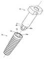
- FIG. 2Ais a perspective view of a second scanning member according to the present disclosure.
- FIG. 2Bis a side view of the scanning member of FIG. 2A ;
- FIG. 2Cis a cross-sectional side view of the scanning member of FIG. 2B ;
- FIG. 2Dis a top view of the scanning member of FIG. 2A ;
- FIG. 3Ais a perspective view of a third scanning member according to the present disclosure.
- FIG. 3Bis a side view of the scanning member of FIG. 3A ;
- FIG. 3Cis a cross-sectional side view of the scanning member of FIG. 3B ;
- FIG. 3Dis a top view of the scanning member of FIG. 3A ;
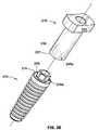
- FIG. 3Eis a perspective view of the scanning member of FIG. 3A aligned with a dental implant
- FIG. 3Fis a side cross-sectional view of the scanning member of FIG. 3A coupled with the dental implant of FIG. 3E ;
- FIG. 4Ais a perspective view of a fourth scanning member according to the present disclosure.
- FIG. 4Bis a side view of the scanning member of FIG. 4A ;
- FIG. 4Cis a cross-sectional side view of the scanning member of FIG. 4B ;
- FIG. 4Dis a top view of the scanning member of FIG. 4A ;
- FIG. 5is a side view of a set of scanning members according to the present disclosure.
- the scanning members of the present disclosurecan be used in two ways. First, the scanning members can be used directly in the mouth of a patient. In such a method, the scanning member is attached to a dental implant installed in the jawbone of the patient and scanned while in the mouth of the patient. Second, the scanning members can be used on a stone or plaster model of a mouth of a patient. In such a method, the scanning member is attached to a dental implant analog included in the model and scanned while on the model and not directly in the actual mouth of the patient. The context of each use will now be described.
- a healing abutment(not shown) is non-rotationally fastened to a dental implant through complimentary non-round fittings or non-rotational features on the dental implant and healing abutment, which usually take the form of a polygonal shaped boss and polygonal shaped socket (e.g., hexagonal boss and hexagonal socket).
- the healing abutmentis held on the dental implant via a screw that engages a threaded bore of the dental implant.
- scanning techniquescan be employed to determine information used to develop a custom-abutment for attachment to the dental implant.
- scanning techniquesinclude mechanical contact scanning, optical/image scanning, and laser scanning. All of these techniques can be applied to models of the mouth of the patient—which are typically stone models cast from impressions of the mouth—while the laser and optical scanning techniques can also be applied directly to the mouth of the patient.
- the healing abutmentis removed and an impression coping is fitted onto the exposed end of the dental implant.
- an impression copingis fitted onto the exposed end of the dental implant.
- an impression of the specific region of the mouth of the patientto be taken so that an artificial tooth (e.g., a custom-abutment) is accurately constructed.
- the impression copinghas the same gingival dimensions as the healing element so that there is no gap between the impression coping and the wall of the gum tissue defining the aperture. Otherwise, a less than accurate impression of the condition of the mouth is taken.
- the impression copingmay be a “pick-up”-type impression coping or a “transfer”-type impression coping.
- a dental implant analogis attached to the impression via the impression coping and a stone or plaster model of the mouth is poured.
- the implant analogis set/secured in the model with the same orientation and location as the dental implant in the mouth of the patient.
- a scanning memberis then attached to the dental implant analog and the entire area is scanned using anyone of the scanning techniques mentioned herein or other techniques used to scan dentition models to generate scan data.
- a laboratorycan create and manufacture a prosthesis (custom-abutment), usually using a computer-aided design (“CAD”) package, which uses the scan data generated from the scanning.
- CADcomputer-aided design
- the modelcan be laser scanned to create a virtual three-dimensional model of the patient's dentition.
- the modelis placed on a support table defining the X-Y plane.
- a scanning laser light probeis directed onto the model.
- the laser light probeemits a pulse of laser light that is reflected by the model.
- a detectorreceives light scattered from the impact of the beam with the impression to calculate a Z-axis measurement.
- the model and the beamare relatively translated within the X-Y plane to gather a plurality of contact points with known locations in the X-Y coordinate plane.
- the locations of several contact points in the Z-planeare determined by detecting reflected light.
- correlating data of the X-Y coordinates and the Z-direction contact pointscreates a digital image.
- the modelmay be tilted to raise one side of the mold relative to the opposite vertically away from the X-Y plane. Subsequent to the model's second scan, the model may be further rotated to allow for a more accurate reading of the model. After all scans are complete, the generated scan data may be fed into a CAD system for manipulation of this electronic data by known means.
- optical scanningcan be used to scan the model or directly in the mouth of the patient to create a virtual three-dimensional model of the patient's dentition.
- one systemtakes photographs or optical images at multiple angles in one exposure to scan a dental region, create a virtual three-dimensional model, and manufacture a prosthetic tooth.
- this processis generally initiated with the process of taking a stereophotograph with a camera from approximately 50 to 150 mm away from the patient's mouth or model.
- the resulting photographpresents multiple images of the same object.
- the images on the photographsare scanned with a reading device that digitizes the photographs to produce a digital image of the dental region.
- the generated scan data from the scanneris electronically transmitted to a graphical imaging program that creates the virtual three-dimensional model.
- a third scanning techniqueuses mechanical contact scanning to generate scan data.
- a mechanical contour sensing deviceas disclosed in U.S. Pat. No. 5,652,709, whose disclosure is hereby incorporated by reference herein in its entirety, is another method used to scan a model for use in developing a prosthetic tooth.
- the modelis secured to a table that may rotate about its longitudinal axis as well as translate along the same axis with variable speeds.
- a mechanical contact sensoris placed in contact with the model at a known angle and the sensing equipment is held firmly against the surface of the model by a spring.
- the mechanical contact scannermeasures the changes in the contour and generates scan data that can be used to create an electronic representation of the model (e.g., virtual three-dimensional model).
- One non-limiting example of a mechanical contact scanner suitable for use according to the present disclosureis a Series 2 RENISHAW® Dental Scanner sold by Renishaw plc of New Mills, Wotton-under-Edge, Gloucestershire, UK.
- a computer and/or software programis able to receive the scan data and to create a virtual three-dimensional model of the relevant jaw section of the patient, including the dental implant and attached scanning member. Due to the shape and construction of the scanning member attached to the dental implant, or dental implant analog, the computer and/or software program is able to accurately analyze and produce the appropriate dimensions and location of the dental implant and an orientation of the underlying non-rotational feature of the dental implant so that a dentist or clinician can instruct a milling machine to produce a custom-abutment that is configured properly to attach to and align with the dental implant when installed in the mouth of the patient.
- the scanning member 10includes a head portion 20 and a body portion 30 .
- the body portion 30is physically attached to the head portion 20 to form a generally “T” shape.
- the head portion 20 of the scanning member 10is configured to be scannable via a mechanical contact scanner, via an optical scanner, and a laser scanner to generate scan data for use in obtaining a first characteristic and a second characteristic of a dental implant (e.g., dental implant 70 in FIGS. 1E and 1F ). These characteristics can be used in developing a custom abutment (not shown). That is, the scanning member 10 of the present disclosure can be used with the mechanical scanning techniques, with the optical scanning techniques, and/or with the laser scanning techniques described above.
- the head portion 20has a generally rectangular shape with six surfaces 22 a - f . It is the specific shapes and orientations of these six surfaces 22 a - f that configure the scanning member 10 to be scannable via mechanical, optical, and laser scanning techniques.
- the head portion 20includes a top surface 22 a , a bottom surface 22 b that opposes the top surface 22 a , a first side surface 22 c , a second side surface 22 d that opposes the first side surface 22 c , a third side surface 22 e , and a fourth side surface 22 f that opposes the third side surface 22 e .
- the third and the fourth side surfaces 22 e,fare generally positioned between the first and the second side surfaces 22 c,d .
- the top surface 22 a of the head portion 20 and the first side surface 22 c of the head portion 20are perpendicular.
- the second side surface 22 d , the third side surface 22 e , and the fourth side surface 22 fare perpendicular to the top surface 22 a.
- the top surface 22 ahas four edges 23 a - d .
- the first side surface 22 cextends downward from a first one of the edges 23 a towards the bottom surface 22 b .
- the second side surface 22 dextends downward from a second one of the edges 23 b towards the bottom surface 22 b
- the third side surface 22 eextends downward from a third one of the edges 23 c towards the bottom surface 22 b
- the fourth side surface 22 fextends downward from a fourth one of the edges 23 d towards the bottom surface 22 b.
- a proximal end 30 a of the body portion 30extends from the head portion 20 in a shaft like manner and terminates at a distal end 30 b with a non-rotational feature 35 .
- the non-rotational feature 35is configured to non-rotationally couple to a complimentary non-rotational feature 76 of a dental implant 70 (or a dental implant analog).
- the non-rotational feature 35 of the scanning member 10is an external non-rotational boss feature and the non-rotational feature 76 of the dental implant 70 is an internal non-rotational socket feature; however, as will be explained below in reference to FIGS. 3A-F , the boss and socket can be reversed such that the scanning member includes an internal non-rotational socket feature and the dental implant includes an external non-rotational boss feature.
- the body portion 30further includes a lip surface 31 that is configured to abut and/or rest upon a supporting surface 74 of the dental implant 70 .
- a lip surface 31that is configured to abut and/or rest upon a supporting surface 74 of the dental implant 70 .
- the top surface 22 ais configured to indicate a first characteristic of the dental implant 70 used in developing a custom-abutment (not shown) for attachment to the dental implant 70 .
- the top surface 22 ais substantially flat and located a predetermined distance, D SS1 , from the lip surface 31 . Additionally, the substantially flat top surface 22 a of the scanning member 10 is positioned such that the top surface 22 a is parallel with the lip surface 31 of the scanning member 10 and with the supporting surface 74 of the dental implant 70 when the scanning member 10 is coupled to the dental implant 70 . Thus, when the scanning member 10 is coupled to the dental implant 70 , the top surface 22 a is located the predetermined distance, D SS1 , from the support surface 74 .
- the top surface 22 aindicates the location of the support surface 74 of the dental implant 70 (the first characteristic of the dental implant) when the scanning member 10 is coupled to the dental implant 70 . It is noted that in the case of a model being used with a dental implant analog therein, the scanning member 10 is coupled to the dental implant analog and the top surface 22 a indicates the location of a support surface of the dental implant analog in the same manner.
- the first side surface 22 cis configured to indicate a second characteristic of the dental implant 70 used in developing the custom-abutment (not shown). As best shown in FIGS. 1D and 1E , the first side surface 22 c is the only one of the four side surfaces 22 c - f of the head portion 20 that is substantially flat. That is, the second, the third, and the fourth side surfaces 22 d - f of the head portion 20 are curved surfaces or non-flat surfaces. Thus, the first side surface 22 c can be readily distinguished by a scanning system (e.g., mechanical contact scanner, optical scanner, laser scanner) from the other three side surfaces 22 d - f . It is contemplated that the curved second side surface 22 d can be a concave surface, a convex surface, or a combination thereof. Similarly, the third and the fourth side surfaces can be concave surfaces, convex surfaces, or combinations thereof.
- a scanning systeme.g., mechanical contact scanner, optical scanner, laser scanner
- the substantially flat first side surface 22 c and the non-rotational feature 35 of the scanning member 10are positioned relative to each other such that the first side surface 22 c is parallel with at least one side surface 35 a of the non-rotational feature 35 of the scanning member 10 and with at least one corresponding side surface 76 a of the complementary non-rotational feature 76 of the dental implant 70 when the scanning member 10 is coupled to the dental implant 70 .
- the first side surface 22 cindicates the orientation (rotational position) of the non-rotational feature 76 when the scanning member 10 is coupled to the dental implant 70 .
- the head portion 20has a length, L BP1 , a width, W HP1 , and a thickness, T HP1
- the body portion 30has a length, L BP1 , and a maximum diameter, d BP1 MAX .
- the length, L HP1 , of the head portion 20is larger than the width, W HP1 , which is larger than the thickness, T HP1 .
- the length, L HP1 , of the head portion 20is also larger than the maximum diameter, d BP1 MAX , of the body portion 30 which causes the scanning member 10 to have the generally “T” shape ( FIG. 1A ).
- the length, L BP1 , of the body portion 30is designed such that (1) the top surface 22 a is located the predetermined distance, D SS1 , from the lip surface 31 , and (2) the head portion 20 does not interfere with adjacent teeth (not shown) in the mouth of the patient irrespective of the orientation (rotational position) of the non-rotational feature 76 of the dental implant 70 .
- the head portion 20could prevent a proper connection between the scanning member 10 and the dental implant 70 , which would result in determining incorrect characteristics of the dental implant 70 during the scanning of the scanning member 10 .
- the length, L BP1 , of the body portion 30is at least about 6 millimeters, but preferably at least about 10 millimeters. It is further contemplated that the length of the body portion 30 from the proximal end 30 a to the lip surface 31 is at least about 5 millimeters, but preferably at least about 8 millimeters.
- the scanning member 10further includes an internal through hole 40 for receiving a screw 80 that threadably engages with a threaded bore 72 of the dental implant 70 .
- the screw 80removably couples the scanning member 10 to the dental implant 70 such that the lip surface 31 remains in contact with the supporting surface 74 .
- the top surface 22 ais located precisely at the predetermined distance from the support surface 74 .
- a scanning member 110is shown according to aspects of the present disclosure.
- the scanning member 110is similar to the scanning member 10 in that the scanning member 110 includes a head portion 120 with a top surface 122 a having four edges 123 a - d , a bottom surface 122 b , a first side surface 122 c , a second side surface 122 d , a third side surface 122 e , and a fourth side surface 122 f ; a body portion 130 with a proximal end 130 a and a distal end 130 b , a lip surface 131 , a non-rotational feature 135 ; and an internal through hole 140 , which are the same as, or similar to, respectively, the head portion 20 with the top surface 22 a having the four edges 23 a - d , the bottom surface 22 b , the first side surface 22 c , the second side surface 22 d , the third side surface 22 e , and
- the scanning member 110differs from the scanning member 10 in that the body portion 130 of the scanning member 110 includes a wide portion 132 to accommodate a larger and/or wider non-rotational feature 135 , as compared to the non-rotational feature 35 of the scanning member 10 .
- a maximum diameter, d BP2 MAXof the scanning member 110 is larger than the maximum diameter, d BP1 MAX , of the scanning member 10 .
- the maximum diameter, d BP2 MAX , and the non-rotational feature 135 of the scanning member 110are at least about 5 percent larger than the maximum diameter, d BP1 MAX , and the non-rotational feature 35 of the scanning member 10 .
- Such a larger non-rotational feature 135can be used to non-rotationally couple the scanning member 110 to a dental implant having a larger (greater diameter) corresponding non-rotational feature (not shown).
- the head portion 120is substantially identical to the head portion 20 . That is, a length, L HP2 , a width, W HP2 , and a thickness, T HP2 , of the head portion 120 are substantially identical to the length, L HP1 , the width, W HP1 , and the thickness, T HP1 of the head portion 20 . Additionally, the predetermined distance, D SS2 , from the top surface 122 a to the lip surface 131 is identical to the predetermined distance, D SS1 , from the top surface 22 a to the lip surface 31 .
- a scanning member 210is shown according to aspects of the present disclosure.
- the scanning member 210is similar to the scanning member 10 in that the scanning member 210 includes a head portion 220 with a top surface 222 a having four edges 223 a - d , a bottom surface 222 b , a first side surface 222 c , a second side surface 222 d , a third side surface 222 e , and a fourth side surface 222 f ; a body portion 230 with a proximal end 230 a and a distal end 230 b , a lip surface 231 , a non-rotational feature 235 ; and an internal through hole 240 , which are the same as, or similar to, respectively, the head portion 20 with the top surface 22 a having the four edges 23 a - d , the bottom surface 22 b , the first side surface 22 c , the second side surface 22 d , the third
- the scanning member 210differs from the scanning member 10 in that the body portion 230 of the scanning member 210 includes an internal non-rotational socket feature 235 to mate and/or couple to a dental implant 270 ( FIGS. 3E and 3F ) with an external non-rotational boss feature 276 , as compared to the internal non-rotational socket feature 76 ( FIG. 1E ) of the dental implant 70 .
- the internal through hole 240is configured to receive a screw 280 that threadably engages with a threaded bore 272 of the dental implant 270 .
- the screw 280removably couples the scanning member 210 to the dental implant 270 such that the lip surface 231 of the scanning member 210 remains in contact with a supporting surface 274 of the dental implant 270 .
- the substantially flat first side surface 222 c and the non-rotational feature 235 of the scanning member 210are positioned relative to each other such that the first side surface 222 c is parallel with at least one internal side surface 235 a of the non-rotational feature 235 of the scanning member 210 and with at least one corresponding side surface 276 a of the complementary non-rotational feature 276 of the dental implant 270 when the scanning member 210 is coupled to the dental implant 270 .
- the first side surface 222 cindicates the orientation (rotational position) of the non-rotational feature 276 when the scanning member 210 is coupled to the dental implant 270 .
- the head portion 220is substantially identical to the head portion 20 . That is, a length, L HP3 , a width, W HP3 , and a thickness, T HP3 , of the head portion 220 are substantially identical to the length, L HP1 , the width, W HP1 , and the thickness, T HP1 of the head portion 20 . Additionally, the predetermined distance, D SS3 , ( FIG. 3F ) from the top surface 222 a to the lip surface 231 is identical to the predetermined distance, D SS1 , from the top surface 22 a to the lip surface 31 .
- the length, L BP3 , of the body portion 230is less than the length, L BP1 , of the body portion 30 of the scanning member 10 .
- a scanning member 310is shown according to aspects of the present disclosure.
- the scanning member 310is similar to the scanning member 10 in that the scanning member 310 includes a head portion 320 with a top surface 322 a having four edges 323 a - d , a bottom surface 322 b , a first side surface 322 c , a second side surface 322 d , a third side surface 322 e , and a fourth side surface 322 f ; a body portion 330 with a proximal end 330 a and a distal end 330 b , a lip surface 331 , a non-rotational feature 335 ; and an internal through hole 340 , which are the same as, or similar to, respectively, the head portion 20 with the top surface 22 a having the four edges 23 a - d , the bottom surface 22 b , the first side surface 22 c , the second side surface 22 d , the third
- the scanning member 310differs from the scanning member 10 in that the body portion 330 of the scanning member 310 includes a wide portion 332 to accommodate a larger and/or wider non-rotational feature 335 , as compared to the non-rotational feature 35 of the scanning member 10 .
- a maximum diameter, d BP4 MAXof the scanning member 310 is larger than the maximum diameter, d BP1 MAX , of the scanning member 10 .
- the scanning member 310differs from the scanning member 10 in that the body portion 330 of the scanning member 310 includes an internal non-rotational socket feature 335 to mate and/or couple to a dental implant (not shown) with an external non-rotational boss feature, as compared to the internal non-rotational socket feature 76 ( FIG. 1E ) of the dental implant 70 .
- the head portion 320is substantially identical to the head portion 20 . That is, a length, L HP4 , a width, W HP4 , and a thickness, T HP4 , of the head portion 320 are substantially identical to the length, L HP1 , the width, W HP1 , and the thickness, T HP1 of the head portion 20 . Additionally, the predetermined distance, D SS4 , ( FIG. 4A ) from the top surface 322 a to the lip surface 331 is identical to the predetermined distance, D SS1 , from the top surface 22 a to the lip surface 31 .
- the length, L BP4 , of the body portion 330is less than the length, L BP1 , of the body portion 30 of the scanning member 10 .
- a set of scanning members 400is shown according to some aspects of the present disclosure.
- the set 400can be packaged together for a clinician or laboratory technician to select a scanning member based on a determination of what manufacturer, type, and/or size of dental implant is installed in the mouth of a patient being treated.
- the clinicianselects the appropriate scanning member having the non-rotational feature that is configured to mate with the complimentary non-rotational feature of the installed dental implant.
- the set 400includes the scanning members 10 , 110 , 210 , and 310 described above.
- the first scanning member 10includes the first head portion 20 and the first body portion 30 having the first non-rotational feature 35 , where the first non-rotational feature 35 is an external non-rotational boss feature.
- the second scanning member 110includes the second head portion 110 and the second body portion 130 having the second non-rotational feature 135 , where the second non-rotational feature 135 is an external non-rotational boss feature.
- the third scanning member 210includes the third head portion 220 and the third body portion 230 having the third non-rotational feature 235 , where the third non-rotational feature 235 is an internal non-rotational socket feature
- the fourth scanning member 310includes the fourth head portion 320 and the fourth body portion 330 having the fourth non-rotational feature 235 , where the fourth non-rotational feature 335 is an internal non-rotational socket feature.
- the first body portion 30has a first maximum diameter, d BP1 MAX
- the second body portion 130has a second maximum diameter, d BP2 MAX , that is greater than the first maximum diameter, d BP1 MAX
- the third body portion 230has a third maximum diameter, d BP3 MAX
- the fourth body portion 330has a fourth maximum diameter, d BP4 MAX , that is greater than the third maximum diameter, d BP3 MAX .
- the variously sized scanning members in the set 400can be configured to couple to variously sized dental implants supplied by one or more different manufacturers with different types of non-rotational features and/or different sizes (e.g., diameters).
- the first scanning member 10is configured to be non-rotationally coupled to a first dental implant.
- the second scanning member 110is configured to be non-rotationally coupled to a second dental implant
- the third scanning member 210is configured to be non-rotationally coupled to a third dental implant
- the fourth scanning member 310is configured to be non-rotationally coupled to a fourth dental implant.
- the head portions 20 , 120 , 220 , and 320are substantially identical and the distance, D SS , from the top surfaces 22 a , 122 a , 222 a , and 322 a to the lip surfaces 31 , 131 , 231 , and 331 are substantially identical for each of the scanning members 10 , 110 , 210 , and 310 .
- each one of the scanning members 10 , 110 , 210 , and 310is selected and used by the clinician or laboratory technician, the top surface 22 a , 122 a , 222 a , and 322 a is located the same distance, D SS , away from the supporting surface of the dental implant, and the first side surface 22 c , 122 c , 222 c , and 322 c is parallel with at least one side surface (e.g., side surfaces 76 a and 276 a ) of the non-rotational feature of the dental implant.
- each one of the scanning members 10 , 110 , 210 , and 310is configured to indicate two characteristics of a dental implant coupled thereto in the same manner as described herein.
- Each one of the scanning members 10 , 110 , 210 , and 310 in the set 400is configured to be scannable via a mechanical contact scanner, via an optical scanner, and via a laser scanner to determine the two characteristics for use in developing a custom-abutment (not shown).
- first, the second, the third, and the fourth dental implantsare each made by a different manufacturer.
- each of the scanning members 10 , 110 , 210 , and 310 in the set 400is configured to be coupled with a different dental implant provided by different manufacturers.
- each manufactureruses a different connection, such as, for example, each manufacture may use a different type or size non-rotational feature (e.g., octagon, hexagon, lobe, etc.).
- the scanning members of the present disclosureare used to provide information about a dental implant in a mouth of a patient or a dental implant analog in a model of the mouth.
- the informationis used to develop or construct a custom-abutment that is attached to the dental implant such that a prosthetic tooth is properly aligned in the mouth of the patient.
- a cliniciancan then determine a type of the dental implant in the mouth of the patient (e.g., manufacturer). Based on the determined type of dental implant, the clinician can select the corresponding type of scanning member (e.g., scanning members 10 , 110 , 210 , and 310 ) from a set of scanning members (e.g., set 400 ). The clinician or laboratory technician then attaches the selected scanning member to the dental implant in the mouth of the patient.
- a type of the dental implant in the mouth of the patiente.g., manufacturer
- the cliniciancan select the corresponding type of scanning member (e.g., scanning members 10 , 110 , 210 , and 310 ) from a set of scanning members (e.g., set 400 ).
- the clinician or laboratory technicianthen attaches the selected scanning member to the dental implant in the mouth of the patient.
- any of the above mentioned techniques for scanning the scanning member directly in the mouth of the patientcan be employed, such as, for example, optical scanning and laser scanning.
- the scanning of the scanning membergenerates scan data which is analyzed by a communicatively connected computer and/or software program to determine and/or gather information including a first characteristic and a second characteristic of the dental implant for use in manufacturing a custom-abutment.
- the computer and/or software programdetermines the distance from a top surface of the scanning member to the supporting surface of the dental implant and the rotational position of a non-rotational feature of the dental implant.
- the custom abutmentis developed using known methods, such as, for example, computer aided design (CAD) machines, mills, etc.
- CADcomputer aided design
- the orientation of the non-rotational feature of the dental implantis needed because the lower portion of the developed custom-abutment must mate with the non-rotational feature of the dental implant such that the prosthesis is aligned with the adjacent teeth in the mouth. If the orientation is unknown or incorrect, the developed custom-abutment, after being installed, might not align with the adjacent teeth, which can give the undesirable appearance of a crooked tooth.
- a scanning memberis non-rotationally attached to a dental implant analog in a model (e.g., stone or plaster model).
- the model and attached scanning memberare scanned using one of the aforementioned scanning techniques (e.g., mechanical contact scanning, optical scanning, laser scanning) to generate scan data.
- a communicatively connected computer and/or software programcreates a virtual three-dimensional image of the patient's dental conditions with the scan data.
- the computer and/or software programfurther determines and/or gathers information including the distance from a top surface of the scanning member to the supporting surface of the dental implant analog and the rotational position of a non-rotational feature of the dental implant analog for use in manufacturing a custom-abutment.
- the computer and/or softwaredevelops custom-abutment dimensional information based on the virtual three-dimensional image and the gathered information.
- the custom abutmentis fabricated using the custom-abutment dimensional information using known methods, such as, for example, computer aided design (CAD) machines, mills, etc.
- CADcomputer aided design
- non-rotational features 35 , 135 , 235 , and 335are included in the scanning members 10 , 110 , 210 , and 310 as being hexagonal features, it is contemplated that the non-rotational features 35 , 135 , 235 , and 335 can have any polygonal shape, such as, for example, triangular, square, rectangular, pentagonal, etc., or non-round shape, such as, for example, lobe shape.
- the set of scanning members 400 shown in FIG. 5may have some scanning members with different shaped connections.
- top surface 22 a , 122 a , 222 a , and 322 ais shown and described as being substantially flat and parallel with the lip surface 31 , 131 , 231 , and 331 to indicate the first characteristic of the dental implant (e.g., dental implant 70 ), it is contemplated that the top surface 22 a , 122 a , 222 a , and 322 a can indicate the first characteristic in other manners. For example, only a portion of the top surface 22 a , 122 a , 222 a , and 322 a may be flat while the rest is not.
- first side surface 22 c , 122 c , 222 c , and 322 cis shown and described as being substantially flat and parallel with the at least one side surface 35 a , 335 a to indicate the second characteristic of the dental implant (e.g., dental implant 70 ) when the scanning member 10 , 210 is coupled to the dental implant 70 , 270 , it is contemplated that the first side surface 22 c , 122 c , 222 c , and 322 c can indicate the second characteristic in other manners. For example, only a portion of the first side surface 22 c , 122 c , 222 c , and 322 c may be flat while the rest is not.
- first, the second, the third, and the fourth side surfaces 22 c - f , 122 c - f , 222 c - f , and 322 c - fare shown and described as being perpendicular to the top surface 22 a , 122 a , 222 a , and 322 a , various other arrangements are contemplated.
- first side surface 22 c , 122 c , 222 c , and 322 cmay be perpendicular to the top surface 22 a , 122 a , 222 a , and 322 a , or at least a portion of the first side surface 22 c , 122 c , 222 c , and 322 c may be perpendicular to the top surface 22 a , 122 a , 222 a , and 322 a .
- one or more of the second, the third, and the fourth side surfaces 22 d - f , 122 d - f , 222 d - f , and 322 d - fmay be slanted at one or more angles with respect to the top surface 22 a , 122 a , 222 a , and 322 a.
- the set 400is shown and described as including four scanning members, various other numbers and combinations of scanning members are contemplated.
- the set 400can include two or more scanning members according to aspects of the present disclosure.
- the set 400can include ten or more scanning members according to aspects of the present disclosure.
- the set 400can include one or more of the first scanning member 10 , one or more of the second scanning member 110 , one or more of the third scanning member 210 , and/or one or more of the fourth scanning member 310 .
- alphanumeric identification or identifierscan be included on any of the scanning members of the present disclosure to identify the manufacturer of the dental implant that the scanning member is configured to be coupled to and/or the size of such dental implant.
- a scanning membercan include the text “Biomet 3i, 3.4 mm” on the body portion to indicate that the scanning member is configured to be coupled to a Biomet 3i dental implant having a 3.4 mm size.
- the alphanumeric identifiercan be printed or laser etched onto the scanning member by any known method.
- the scanning members of the present disclosureare reusable scanning members. That is, the scanning members of the present disclosure can be sterilized using various methods, such as, for example, using an autoclave.
- two or more of the scanning members of the present disclosurecan be used with multiple dental implants in a mouth of a patient at once.
- two scanning members according to aspects of the present disclosurecan be attached to the dental implants in the mouth (or attached to two dental implant analogs in a model of the mouth) and scanned according to one of the aforementioned scanning methods.
- the generated scan data for both of the scanning memberscan be used together to create or develop a bar that is attached to the two dental implants.
- the baris configured to receive a denture structure such as shown in U.S. Pat. No. 6,382,975, which is hereby incorporated by references herein in its entirety.
Landscapes
- Health & Medical Sciences (AREA)
- Life Sciences & Earth Sciences (AREA)
- General Health & Medical Sciences (AREA)
- Epidemiology (AREA)
- Dentistry (AREA)
- Animal Behavior & Ethology (AREA)
- Oral & Maxillofacial Surgery (AREA)
- Public Health (AREA)
- Veterinary Medicine (AREA)
- Orthopedic Medicine & Surgery (AREA)
- Engineering & Computer Science (AREA)
- Biomedical Technology (AREA)
- Biophysics (AREA)
- Dental Prosthetics (AREA)
- Dental Tools And Instruments Or Auxiliary Dental Instruments (AREA)
Abstract
Description
Claims (20)
Priority Applications (1)
| Application Number | Priority Date | Filing Date | Title |
|---|---|---|---|
| US14/503,247US9662185B2 (en) | 2010-12-07 | 2014-09-30 | Universal scanning member for use on dental implant and dental implant analogs |
Applications Claiming Priority (3)
| Application Number | Priority Date | Filing Date | Title |
|---|---|---|---|
| US42054110P | 2010-12-07 | 2010-12-07 | |
| US13/312,900US8882508B2 (en) | 2010-12-07 | 2011-12-06 | Universal scanning member for use on dental implant and dental implant analogs |
| US14/503,247US9662185B2 (en) | 2010-12-07 | 2014-09-30 | Universal scanning member for use on dental implant and dental implant analogs |
Related Parent Applications (1)
| Application Number | Title | Priority Date | Filing Date |
|---|---|---|---|
| US13/312,900DivisionUS8882508B2 (en) | 2010-12-07 | 2011-12-06 | Universal scanning member for use on dental implant and dental implant analogs |
Publications (2)
| Publication Number | Publication Date |
|---|---|
| US20150017600A1 US20150017600A1 (en) | 2015-01-15 |
| US9662185B2true US9662185B2 (en) | 2017-05-30 |
Family
ID=45218372
Family Applications (2)
| Application Number | Title | Priority Date | Filing Date |
|---|---|---|---|
| US13/312,900Active2032-04-09US8882508B2 (en) | 2010-12-07 | 2011-12-06 | Universal scanning member for use on dental implant and dental implant analogs |
| US14/503,247Expired - Fee RelatedUS9662185B2 (en) | 2010-12-07 | 2014-09-30 | Universal scanning member for use on dental implant and dental implant analogs |
Family Applications Before (1)
| Application Number | Title | Priority Date | Filing Date |
|---|---|---|---|
| US13/312,900Active2032-04-09US8882508B2 (en) | 2010-12-07 | 2011-12-06 | Universal scanning member for use on dental implant and dental implant analogs |
Country Status (4)
| Country | Link |
|---|---|
| US (2) | US8882508B2 (en) |
| EP (1) | EP2462893B8 (en) |
| DK (1) | DK2462893T3 (en) |
| ES (1) | ES2477288T3 (en) |
Families Citing this family (36)
| Publication number | Priority date | Publication date | Assignee | Title |
|---|---|---|---|---|
| DE102006018726B4 (en)* | 2006-04-20 | 2019-01-31 | Holger Zipprich | Method for producing a dental implant |
| PL2566413T3 (en) | 2010-05-05 | 2017-07-31 | Holger Zipprich | Dental implant |
| EP2462893B8 (en)* | 2010-12-07 | 2014-12-10 | Biomet 3i, LLC | Universal scanning member for use on dental implant and dental implant analogs |
| DE102011009906A1 (en) | 2011-01-31 | 2012-08-02 | Holger Zipprich | Dental implant system |
| USD688799S1 (en)* | 2011-12-22 | 2013-08-27 | Exocad Gmbh | Detection body for a dental prosthetic |
| EP2865352A4 (en)* | 2012-06-26 | 2016-01-20 | G C Dental Ind Corp | SCANNING TEMPLATE |
| EP2700377A1 (en)* | 2012-08-20 | 2014-02-26 | Heraeus Kulzer GmbH | Scannable body for determining the orientation and position of a dental implant |
| WO2014081843A1 (en)* | 2012-11-20 | 2014-05-30 | Advanced Implant Intellectual Properties, Llc | Universal aligning adaptor system and methods |
| EP2762104B1 (en)* | 2013-01-31 | 2017-12-06 | SIC Invent AG | Impression post |
| KR20150130998A (en)* | 2013-02-20 | 2015-11-24 | 지씨 유럽 | Precalibrated dental implant aid |
| US20140295374A1 (en) | 2013-03-28 | 2014-10-02 | Dentsply International Inc. | Integrated dental implant component and tool for placement of a dental implant component |
| ES2910276T3 (en)* | 2013-04-09 | 2022-05-12 | Biomet 3I Llc | Method of using scan data of a dental implant |
| EP2842493B1 (en) | 2013-08-30 | 2016-04-06 | Zfx GmbH | Intraoral reference body |
| CN103499644B (en)* | 2013-09-03 | 2016-04-13 | 中国人民解放军第四军医大学 | The twisting vibration resonant frequency measuring method of assessment tooth implant stability and ultrasonic transformer |
| KR101592395B1 (en)* | 2013-10-08 | 2016-02-05 | 주식회사 메디트 | Method for making custom abutment |
| AT514320B1 (en)* | 2013-11-20 | 2014-12-15 | Steger Heinrich | scanbody |
| DE102014102923A1 (en)* | 2014-03-05 | 2015-09-10 | Ludwig-Maximilians-Universität München | Insertion post, system and method for detecting the position of an implanted implant |
| EP3583909B1 (en)* | 2014-05-27 | 2021-05-19 | Ivoclar Vivadent AG | Method for creating artificial teeth |
| ES2747224T3 (en) | 2014-06-13 | 2020-03-10 | Vp Innovato Holdings Ltd | Abutment molds and impression posts for custom dental implants |
| IL237946A0 (en)* | 2015-03-25 | 2015-11-30 | Mis Implants Technologies Ltd | Dental scan post and manufacturing process thereof |
| US9717570B2 (en) | 2015-05-27 | 2017-08-01 | Felix Chung | Scan body for a dental impression |
| US20180193114A1 (en)* | 2015-06-28 | 2018-07-12 | Optical Metrology Ltd. | Dental implant procedure by scanning a closed tray impression |
| US10912631B2 (en) | 2015-12-01 | 2021-02-09 | Evollution Ip Holdings, Inc. | Snap-coupling temporary abutment mount for dental prosthesis |
| US20180235734A1 (en)* | 2015-12-01 | 2018-08-23 | Evollution Ip Holdings, Inc. | Coping system with snap-in retention capability |
| US10433936B2 (en) | 2015-12-01 | 2019-10-08 | Evollution Ip Holdings, Inc. | Scan body with snap-in retention capability |
| US10959812B2 (en) | 2015-12-30 | 2021-03-30 | Thomas J. Balshi | Multi-functional coping |
| DE202016104885U1 (en)* | 2016-09-05 | 2016-09-29 | Karl Bloier | scanbody |
| US11273020B2 (en) | 2017-06-13 | 2022-03-15 | Biomet 3I, Llc | Implant analogs and methods |
| US20180353267A1 (en)* | 2017-06-13 | 2018-12-13 | Biomet 3I, Llc | Combination impression coping and scan body |
| GR20170100383A (en) | 2017-08-21 | 2019-04-22 | Vp Innovato Holdings Ltd | Dental abutment core and method for manufacturing a dental abutment |
| EP3788982B1 (en)* | 2018-05-02 | 2023-02-15 | Otawa, Naruto | Scanning jig, and method and system for specifying spatial position of implant, etc. |
| JP6507293B1 (en)* | 2018-06-22 | 2019-04-24 | 有限会社協和デンタル・ラボラトリー | Intraoral data acquisition system using dental scan attachment and intraoral data acquisition method using the same |
| GR1009730B (en)* | 2018-08-31 | 2020-05-15 | Vp Innovato Holdings Ltd | Scan posts system and method |
| CN109124794B (en)* | 2018-09-28 | 2024-04-26 | 江苏柯润玺医疗科技发展有限公司 | Dental implant scanning positioning structure |
| GR20200100312A (en) | 2020-06-04 | 2022-01-13 | Ιωαννης Αντωνιου Βεργουλλης | SCANNING SYSTEM SYSTEM AND METHOD |
| US20230025033A1 (en)* | 2021-07-26 | 2023-01-26 | United States Of American As Represented By The Secretary Of The Navy | Dental implant identification system |
Citations (397)
| Publication number | Priority date | Publication date | Assignee | Title |
|---|---|---|---|---|
| US3906634A (en) | 1974-12-19 | 1975-09-23 | Thomas E Aspel | Method of marking archwire with tooth width measurements |
| US3919772A (en) | 1973-06-04 | 1975-11-18 | Joseph J Lenczycki | Dental implant assembly and method for attaching the same to the jaw bone |
| US3958471A (en) | 1972-02-08 | 1976-05-25 | Paul-Heinz Wagner Maschinenfabrikation | Method of and apparatus for manufacturing workpieces having polygonyl inner and outer contours |
| US4011602A (en) | 1975-10-06 | 1977-03-15 | Battelle Memorial Institute | Porous expandable device for attachment to bone tissue |
| US4056585A (en) | 1976-05-20 | 1977-11-01 | Waltke Robert W | Tooth die and method and apparatus for making the same |
| US4086701A (en) | 1975-04-07 | 1978-05-02 | Kyoto Ceramic Kabushiki Kaisha | Device for implanting an artificial endosseous element of ceramics and an implant method for use of the same |
| US4177562A (en) | 1977-05-02 | 1979-12-11 | Miller Alvin L | Dental implant and method of inserting the same |
| US4294544A (en) | 1979-08-03 | 1981-10-13 | Altschuler Bruce R | Topographic comparator |
| US4306862A (en) | 1980-08-18 | 1981-12-22 | Knox Kathleen K | Dental burr tool block assembly |
| US4325373A (en) | 1978-08-01 | 1982-04-20 | Carbo Mediec Inc. | Apparatus for forming an osteotomy for a dental implant |
| US4341312A (en) | 1979-04-30 | 1982-07-27 | Arno Scholer | Holder for small instruments such as dental instruments |
| US4364381A (en) | 1980-01-31 | 1982-12-21 | Sher Jay H | Surgical clamp and drill-guiding instrument |
| US4439152A (en) | 1982-03-04 | 1984-03-27 | Small Irwin A | Method of jawbone abutment implant for dental prostheses and implant device |
| US4543953A (en) | 1983-07-18 | 1985-10-01 | Cordis Corporation | Analog telemetry system for biomedical implant |
| US4547157A (en) | 1983-04-20 | 1985-10-15 | Miter, Inc. | Submergible post-type dental implant system and method of using same |
| US4571180A (en) | 1984-03-08 | 1986-02-18 | Kulick Walter K | Dental instrument |
| US4611288A (en) | 1982-04-14 | 1986-09-09 | Francois Duret | Apparatus for taking odontological or medical impressions |
| US4624673A (en) | 1982-01-21 | 1986-11-25 | United States Medical Corporation | Device system for dental prosthesis fixation to bone |
| US4663720A (en) | 1984-02-21 | 1987-05-05 | Francois Duret | Method of and apparatus for making a prosthesis, especially a dental prosthesis |
| US4713004A (en) | 1986-09-04 | 1987-12-15 | Vent Plant Corporation | Submergible screw-type dental implant and method of utilization |
| US4756689A (en) | 1985-09-16 | 1988-07-12 | Dan Lundgren | Connecting devices |
| US4758161A (en) | 1987-01-28 | 1988-07-19 | Core-Vent Corporation | Coping insert for use with a dental implant |
| US4767331A (en) | 1987-05-28 | 1988-08-30 | Hoe Khin A | Dental crown manufacturing apparatus |
| US4772204A (en) | 1983-11-25 | 1988-09-20 | Astra Meditec Aktiebolag | Implant for attachment of dental prostheses |
| US4821200A (en) | 1986-04-14 | 1989-04-11 | Jonkopings Lans Landsting | Method and apparatus for manufacturing a modified, three-dimensional reproduction of a soft, deformable object |
| US4842518A (en) | 1986-09-04 | 1989-06-27 | Vent-Plant Corporation | Submergible screw-type dental implant and method of utilization |
| US4850873A (en) | 1988-04-04 | 1989-07-25 | Implant Innovations, Inc. | Prosthodontic restoration components |
| US4850870A (en) | 1987-10-23 | 1989-07-25 | Implant Innovations, Inc. | Prosthodontic restoration components |
| US4854872A (en) | 1987-09-24 | 1989-08-08 | Detsch Steven G | Prosthetic implant attachment system and method |
| US4856994A (en) | 1988-01-25 | 1989-08-15 | Implant Innovations, Inc. | Periodontal restoration components |
| US4872839A (en) | 1987-06-12 | 1989-10-10 | Nobelpharma Ab | Spacer for dental implants |
| US4906191A (en) | 1987-06-25 | 1990-03-06 | Astra Meditec Ab | Dental bridge |
| US4906420A (en) | 1987-05-22 | 1990-03-06 | Nobelpharma Ab | Method for producing prosthetic constructions |
| US4931016A (en) | 1989-02-24 | 1990-06-05 | Rannar Sillard | Fixed removable dental implant system |
| US4935635A (en) | 1988-12-09 | 1990-06-19 | Harra Dale G O | System for measuring objects in three dimensions |
| US4961674A (en) | 1989-07-21 | 1990-10-09 | Wang Edward A | Drill guide for precise drilling |
| US4964770A (en) | 1987-07-16 | 1990-10-23 | Hans Steinbichler | Process of making artificial teeth |
| US4986753A (en) | 1988-04-15 | 1991-01-22 | Sellers Grady C | Direct assembly framework for an osseointegrated implant |
| US4988297A (en) | 1988-03-01 | 1991-01-29 | Implant Innovations, Inc. | Alignment corrector for dental implants |
| US4988298A (en) | 1989-01-23 | 1991-01-29 | Implant Innovations, Inc. | Precision abutment base |
| US4998881A (en) | 1988-01-29 | 1991-03-12 | Nikola Lauks | Device and method for producing implant cavities |
| US5006069A (en) | 1988-11-02 | 1991-04-09 | Implant Innovations, Inc. | Periodontal restoration components |
| US5015183A (en) | 1989-08-07 | 1991-05-14 | Fenick Thomas J | Locating device and method of placing a tooth implant |
| US5015186A (en) | 1987-09-24 | 1991-05-14 | Detsch Steven G | Dental implant attachment system |
| US5030096A (en) | 1989-10-02 | 1991-07-09 | Steri-Oss, Inc. | Implant healing cap and holder |
| US5035619A (en) | 1989-10-20 | 1991-07-30 | Fereidoun Daftary | Anatomical restoration dental implant system with improved healing cap and abutment |
| US5040983A (en) | 1989-01-23 | 1991-08-20 | Implant Innovations, Inc. | Temporary dental coping |
| US5040982A (en) | 1990-06-28 | 1991-08-20 | Stefan Dogar Sorin | Dental implant and conversion assembly |
| US5064375A (en) | 1989-11-13 | 1991-11-12 | Nobelpharma Ab | Holder |
| US5071351A (en) | 1986-07-02 | 1991-12-10 | Collagen Corporation | Dental implant system |
| US5073111A (en) | 1989-10-20 | 1991-12-17 | Fereidoun Daftary | Anatomical restoration dental implant system |
| US5087200A (en) | 1987-06-12 | 1992-02-11 | Nobelpharma Ab | Spacer for dental implants |
| US5100323A (en) | 1990-09-05 | 1992-03-31 | Impla-Med Incorporated | Dental implant |
| US5104318A (en) | 1990-09-20 | 1992-04-14 | 2848-4293 Quebec Inc. | Implant assembly for anchoring an artificial tooth |
| US5106300A (en) | 1990-09-26 | 1992-04-21 | Voitik Anton J | Dental implant attachment structure and method |
| US5122059A (en) | 1990-09-08 | 1992-06-16 | Eberle Medizintechnische Element Gmbh | Enossal implant for a firmly seated tooth replacement |
| US5125841A (en) | 1990-01-18 | 1992-06-30 | Nobelpharma Ab | Impression top |
| US5125839A (en) | 1990-09-28 | 1992-06-30 | Abraham Ingber | Dental implant system |
| US5133660A (en) | 1989-08-07 | 1992-07-28 | Fenick Thomas J | Device for locating the optimum position for a tooth implant |
| US5135395A (en) | 1990-07-05 | 1992-08-04 | Marlin Gerald M | Implant collar and post system |
| US5145371A (en) | 1989-09-15 | 1992-09-08 | Nobelpharma Ab | Distance member |
| US5176516A (en) | 1990-09-26 | 1993-01-05 | Masayuki Koizumi | Instrument for measuring a remaining alveolar bone |
| US5188800A (en) | 1988-06-03 | 1993-02-23 | Implant Innovations, Inc. | Dental implant system |
| US5195892A (en) | 1990-07-23 | 1993-03-23 | Odontit S.A. | Bone-integrated dental implant system |
| US5205745A (en) | 1989-08-30 | 1993-04-27 | Tdk Corporation | Artificial dental root |
| US5209659A (en) | 1990-09-05 | 1993-05-11 | Impla-Med Incorporated | Method for installing a dental implant |
| US5209666A (en) | 1990-05-15 | 1993-05-11 | Calcitek, Inc. | Endosseous implant system wtih captured screw |
| US5213502A (en) | 1992-06-10 | 1993-05-25 | Fereidoun Daftary | Interlockable two-piece impression coping for anatomical dental abutment restorative systems |
| US5237998A (en) | 1988-11-18 | 1993-08-24 | Sopha Bioconcept S.A. | Method of correlating the three-dimensional images of human organs and device for implementation of the method |
| US5246370A (en) | 1992-11-27 | 1993-09-21 | Coatoam Gary W | Dental implant method |
| US5257184A (en) | 1990-04-10 | 1993-10-26 | Mushabac David R | Method and apparatus with multiple data input stylii for collecting curvilinear contour data |
| US5281140A (en) | 1991-01-02 | 1994-01-25 | Core-Vent Corporation | Multi-part, multi-positionable abutment for use with dental implants |
| US5286196A (en) | 1991-03-01 | 1994-02-15 | Nobelpharma Ab | System individually adaptable to elements implanted in the dentine and the like |
| US5286195A (en) | 1989-12-07 | 1994-02-15 | Zl Microdent-Attachment Gmbh | Screw element for threadedly connecting a multi-part dental prosthesis |
| US5292252A (en) | 1992-12-14 | 1994-03-08 | Impla-Med, Inc. | Stimulator healing cap |
| US5297963A (en) | 1993-05-17 | 1994-03-29 | Fereidoun Dafatry | Anatomical restoration dental implant system with interlockable elliptical healing cap assembly and matching abutment member |
| US5302125A (en) | 1992-10-22 | 1994-04-12 | Kownacki Charles D | Dental prosthetic implant |
| US5312409A (en) | 1992-06-01 | 1994-05-17 | Mclaughlin Robert E | Drill alignment guide |
| US5312254A (en) | 1993-03-26 | 1994-05-17 | Rosenlicht Joel L | Sterile application of implants in bone |
| US5316476A (en) | 1992-06-19 | 1994-05-31 | Krauser Jack T | Dental implant with a longitudinally grooved cylindrical surface |
| US5320529A (en) | 1992-09-09 | 1994-06-14 | Howard C. Weitzman | Method and apparatus for locating an ideal site for a dental implant and for the precise surgical placement of that implant |
| US5328371A (en) | 1992-10-23 | 1994-07-12 | Friatec Aktiengesellschaft | Dental implant |
| US5334024A (en) | 1990-03-21 | 1994-08-02 | Core-Vent Corporation | Transfer abutment |
| US5336090A (en) | 1993-11-30 | 1994-08-09 | Wilson Jr Richard S | Transmucosal healing cap and lockwasher for dental implants |
| US5338196A (en) | 1993-04-08 | 1994-08-16 | Implant Innovations, Inc. | Dental laboratory components and procedures for anatomical restoration on artificial root fixtures |
| US5338198A (en) | 1993-11-22 | 1994-08-16 | Dacim Laboratory Inc. | Dental modeling simulator |
| US5343391A (en) | 1990-04-10 | 1994-08-30 | Mushabac David R | Device for obtaining three dimensional contour data and for operating on a patient and related method |
| US5344457A (en) | 1986-05-19 | 1994-09-06 | The University Of Toronto Innovations Foundation | Porous surfaced implant |
| US5350297A (en) | 1991-12-24 | 1994-09-27 | Cohen Robert N | Method and apparatus for recording the position of dental implants |
| US5359511A (en) | 1992-04-03 | 1994-10-25 | Foster-Miller, Inc. | Method and apparatus for obtaining coordinates describing three-dimensional objects of complex and unique geometry using a sampling probe |
| US5362234A (en) | 1993-09-21 | 1994-11-08 | Alfred Salazar | Self-drilling endosteal hollow-basket implant system with shock-absorber |
| US5362235A (en) | 1993-05-17 | 1994-11-08 | Fereidoun Daftary | Anatomical restoration dental implant system with interlockable angled abutment assembly |
| WO1994026200A1 (en) | 1993-05-14 | 1994-11-24 | Antonio Cascione | Adjustable guiding device for positioning dental implants, implantation system comprising it and method employing same |
| US5368483A (en) | 1993-06-14 | 1994-11-29 | Institut Straumann Ag | Device-for fixing a dental prosthesis to a jaw bone |
| US5370692A (en) | 1992-08-14 | 1994-12-06 | Guild Associates, Inc. | Rapid, customized bone prosthesis |
| US5372502A (en) | 1988-09-02 | 1994-12-13 | Kaltenbach & Voight Gmbh & Co. | Optical probe and method for the three-dimensional surveying of teeth |
| US5386292A (en) | 1992-05-05 | 1995-01-31 | Kaltenbach & Voight Gmbh & Co. | Optical measurement of teeth |
| US5413481A (en) | 1992-05-06 | 1995-05-09 | G. Krieg | Method and apparatus for manufacturing fitting members |
| US5417570A (en) | 1994-01-03 | 1995-05-23 | Zest Anchors, Inc. | Dental anchor assembly |
| US5417569A (en) | 1990-04-20 | 1995-05-23 | Perisse; Jean | Multi-element dental implant |
| US5431567A (en) | 1993-05-17 | 1995-07-11 | Daftary; Fereidoun | Anatomical restoration dental implant system with interlockable various shaped healing cap assembly and matching abutment member |
| US5437551A (en) | 1991-12-30 | 1995-08-01 | Wellesley Research Associates, Inc. | Dental implant post and prosthesis construction |
| US5440393A (en) | 1990-03-13 | 1995-08-08 | Com Dent Gmbh | Process and device for measuring the dimensions of a space, in particular a buccal cavity |
| US5452219A (en) | 1990-06-11 | 1995-09-19 | Dentsply Research & Development Corp. | Method of making a tooth mold |
| US5458488A (en) | 1991-12-30 | 1995-10-17 | Wellesley Research Associates, Inc. | Dental implant and post construction |
| US5492471A (en) | 1994-03-23 | 1996-02-20 | Gary Singer | Healing cap system |
| US5516288A (en) | 1990-08-01 | 1996-05-14 | Accius B.V. | Device and method for attaching a member in replacement of part of a set of teeth |
| US5527182A (en) | 1993-12-23 | 1996-06-18 | Adt Advanced Dental Technologies, Ltd. | Implant abutment systems, devices, and techniques |
| US5533898A (en) | 1993-11-18 | 1996-07-09 | Mena; Raul | Dental implant device |
| US5538426A (en) | 1992-04-16 | 1996-07-23 | Stewart Peter Harding | Method of forming a dental prosthesis for mounting in an implant, a method of forming a dental model for use therein, a dental formation mounting arrangement |
| US5556278A (en) | 1994-09-07 | 1996-09-17 | Meitner; Sean W. | Method for making and using a template for a dental implant osteotomy and components relating thereto |
| US5564924A (en) | 1995-02-21 | 1996-10-15 | Kwan; Norman H. | Hexagonal abutment implant system |
| US5564921A (en) | 1990-07-05 | 1996-10-15 | Marlin; Gerald M. | Method of forming an abutment post |
| US5569578A (en) | 1990-04-10 | 1996-10-29 | Mushabac; David R. | Method and apparatus for effecting change in shape of pre-existing object |
| US5575656A (en) | 1994-10-21 | 1996-11-19 | Hajjar; Victor J. | Method and apparatus for tooth restoration |
| US5580246A (en) | 1995-01-30 | 1996-12-03 | Fried; Paula S. | Dental implants and methods for extending service life |
| US5580244A (en) | 1995-03-02 | 1996-12-03 | White; Dennis J. | Method and apparatus for taking dental impressions |
| US5595703A (en) | 1994-03-10 | 1997-01-21 | Materialise, Naamloze Vennootschap | Method for supporting an object made by means of stereolithography or another rapid prototype production method |
| US5613852A (en) | 1995-01-06 | 1997-03-25 | Board Of Regents Univ Of Ne At Lincoln | Dental implant drill guide system |
| US5613832A (en) | 1995-07-14 | 1997-03-25 | Su; Chih-Hai | Means for engaging a remote control unit to a ceiling fan |
| US5630717A (en) | 1995-05-01 | 1997-05-20 | Zest Anchors, Inc. | Dental implant bar system and method |
| US5636986A (en) | 1996-02-06 | 1997-06-10 | Pezeshkian; Alex A. | Drill guide for dental implants and method |
| US5652709A (en) | 1991-11-01 | 1997-07-29 | Nobel Biocare Ab | Scanning device for use in manufacturing implants |
| US5658147A (en) | 1995-09-19 | 1997-08-19 | Shopvest, Inc. | Working model for prosthodontic preparation of a crown for installation on an implant fixture |
| US5662476A (en) | 1992-06-29 | 1997-09-02 | Nobel Biocare Ab | Prosthetic implant restoration method |
| US5674073A (en) | 1996-01-30 | 1997-10-07 | Nobel Biocare Ab | Impression coping |
| US5674069A (en) | 1995-01-13 | 1997-10-07 | Osorio; Julian | Customized dental abutment |
| US5681167A (en) | 1996-01-05 | 1997-10-28 | Lazarof; Sargon | Dental assembly and process for preparing a tooth prosthesis |
| US5685715A (en) | 1995-03-10 | 1997-11-11 | Beaty; Keith D. | Self-indexing transfer impression coping |
| US5688283A (en) | 1995-11-17 | 1997-11-18 | Knapp; John G. | Drill guide for mandibular staple transosseous implants |
| US5704936A (en) | 1992-04-10 | 1998-01-06 | Eurosurgical | Spinal osteosynthesis device |
| US5718579A (en) | 1995-12-05 | 1998-02-17 | Kennedy; Brent D. | Drill guide kit |
| US5725376A (en) | 1996-02-27 | 1998-03-10 | Poirier; Michel | Methods for manufacturing a dental implant drill guide and a dental implant superstructure |
| US5733124A (en) | 1995-02-21 | 1998-03-31 | Kwan; Norman Ho-Kwong | Dental implant system |
| US5741215A (en) | 1993-09-10 | 1998-04-21 | The University Of Queensland | Stereolithographic anatomical modelling process |
| US5743916A (en) | 1990-07-13 | 1998-04-28 | Human Factors Industrial Design, Inc. | Drill guide with removable ferrules |
| US5759036A (en) | 1996-07-29 | 1998-06-02 | Hinds; Kenneth F. | Complete dental implant system and method |
| US5762125A (en) | 1996-09-30 | 1998-06-09 | Johnson & Johnson Professional, Inc. | Custom bioimplantable article |
| US5768134A (en) | 1994-04-19 | 1998-06-16 | Materialise, Naamloze Vennootschap | Method for making a perfected medical model on the basis of digital image information of a part of the body |
| US5769636A (en) | 1996-08-16 | 1998-06-23 | Di Sario; Francesco | System for diagnosis, placement and prosthetic restoration of root form implant |
| US5791902A (en) | 1995-09-30 | 1998-08-11 | Lauks; Nikola | Drill bit for producing bone cavities for dental implants |
| US5823778A (en) | 1996-06-14 | 1998-10-20 | The United States Of America As Represented By The Secretary Of The Air Force | Imaging method for fabricating dental devices |
| US5842859A (en) | 1994-05-31 | 1998-12-01 | Nobel Biocare Ab | Indicating device and a method for marking out and forming one or more attachment points for a fixture in an area of the human body, preferably the jaw |
| US5846079A (en) | 1996-02-29 | 1998-12-08 | Implant Innovations, Inc. | Single tooth dental restoration system |
| US5851115A (en) | 1993-12-06 | 1998-12-22 | Nobel Biocare Ab | Method and arrangement for collecting data for production of replacement dental parts for the human body |
| US5857853A (en) | 1993-07-26 | 1999-01-12 | Nobel Biocare Ab | Method of manufacturing a prosthesis to be fixed to implants in the jawbone of a patient, and a system for manufacturing such prostheses |
| US5873722A (en) | 1996-02-02 | 1999-02-23 | Implant Innovations, Inc. | Emergence profile system having a combined healing abutment and impression coping |
| US5876204A (en) | 1997-11-25 | 1999-03-02 | Sulzer Calcitek Inc. | Dental implant positioning guide |
| US5885078A (en) | 1997-08-28 | 1999-03-23 | Board Of Regents The University Of Texas System | Method for constructing accurately fitting frameworks for endosseous implant-supported dental prostheses |
| US5904483A (en) | 1995-11-17 | 1999-05-18 | Wade; Curtis K. | Dental implant systems and methods |
| US5915962A (en) | 1997-11-03 | 1999-06-29 | Rosenlicht; Joel L. | Dental implant and prosthesis positioning |
| WO1999032045A1 (en) | 1997-12-18 | 1999-07-01 | Michel Poirier | Manufacturing a dental implant drill guide and a dental implant superstructure |
| US5927982A (en) | 1998-09-29 | 1999-07-27 | Kruger; Bernard M. | Three dimensional guidance system for dental implant insertion |
| US5938443A (en) | 1994-11-08 | 1999-08-17 | Implant Innovations, Inc. | Impression coping for use in an open tray and closed tray impression methodology |
| US5954769A (en) | 1997-12-05 | 1999-09-21 | Rosenlicht; Joel L. | Surgical drill positioning guide |
| US5964591A (en) | 1997-04-09 | 1999-10-12 | Implant Innovations, Inc. | Implant delivery system |
| US5967777A (en) | 1997-11-24 | 1999-10-19 | Klein; Michael | Surgical template assembly and method for drilling and installing dental implants |
| US5984681A (en) | 1997-09-02 | 1999-11-16 | Huang; Barney K. | Dental implant and method of implanting |
| US5989258A (en) | 1997-09-16 | 1999-11-23 | Hattori; Morihiro | Apparatus for and method of bone drilling |
| US5989029A (en) | 1997-07-08 | 1999-11-23 | Atlantis Components, Inc. | Customized dental abutments and methods of preparing or selecting the same |
| US5989025A (en) | 1996-05-22 | 1999-11-23 | Conley; Roy | Drill guide |
| US5997681A (en) | 1997-03-26 | 1999-12-07 | Kinzie; Norman F. | Method and apparatus for the manufacture of three-dimensional objects |
| US6000939A (en) | 1999-02-08 | 1999-12-14 | Ray; Isaac | Universal alignment indicator |
| US6008905A (en) | 1998-12-22 | 1999-12-28 | Deus Ex Machina Inc. | Method and apparatus for determining the appearance of an object |
| WO2000008415A1 (en) | 1998-08-05 | 2000-02-17 | Cadent Ltd. | Imaging a three-dimensional structure by confocal focussing an array of light beams |
| US6068479A (en) | 1995-02-21 | 2000-05-30 | Kwan; Norman Ho-Kwong | Dental implant system |
| US6099313A (en) | 1996-06-28 | 2000-08-08 | Doerken; Wolfgang | Dental implant, a template for inserting a dental implant, and a process for producing them |
| US6099314A (en) | 1995-07-21 | 2000-08-08 | Cadent Ltd. | Method and system for acquiring three-dimensional teeth image |
| US6099311A (en) | 1999-07-28 | 2000-08-08 | Sulzer Calcitek Inc. | Abutment delivery system |
| US6120293A (en) | 1994-11-08 | 2000-09-19 | Implant Innovations, Inc. | Abutment for a temporary tooth |
| US6135773A (en) | 1997-01-27 | 2000-10-24 | Implant Innovations, Inc. | Single tooth alignment system |
| US6142782A (en) | 1996-01-05 | 2000-11-07 | Lazarof; Sargon | Implant assembly and process for preparing a prosthetic device |
| DE10029256A1 (en) | 2000-06-14 | 2000-11-30 | Stefan Wolz | Manufacture of drilling template for implanting artificial teeth involves laser scanning working model or negative shape to produce digital model, making drilling template former |
| US6175413B1 (en) | 1997-08-28 | 2001-01-16 | Proteus Corporation | Laser calibration of robotics systems |
| US6174168B1 (en) | 1995-09-15 | 2001-01-16 | Dentsply Research & Development Corp | Prosthetic teeth and mold making therefor |
| US6190169B1 (en) | 1999-01-22 | 2001-02-20 | CENDRES ET MéTAUX SA | Anchorage for dental prosthetics |
| US6197410B1 (en) | 1998-03-09 | 2001-03-06 | Stick Tech Oy | Prepreg |
| US6200125B1 (en) | 1998-06-12 | 2001-03-13 | Akutagawa Confectionery Co., Ltd. | Decorative food and method and apparatus for manufacturing the same |
| US6206693B1 (en) | 1997-01-28 | 2001-03-27 | Iris Development Corporation | Buccal impression registration apparatus, and method of use |
| US6210162B1 (en) | 1997-06-20 | 2001-04-03 | Align Technology, Inc. | Creating a positive mold of a patient's dentition for use in forming an orthodontic appliance |
| US6227859B1 (en) | 1997-05-24 | 2001-05-08 | Franz Sutter | Dental implant and device with a dental implant |
| WO2001058379A1 (en) | 2000-02-11 | 2001-08-16 | Wolfram Hein | Dental interstice cleaning device with an articulated cleaning tip and handle |
| US6283753B1 (en) | 1993-12-23 | 2001-09-04 | The Millennium Business Group Ltd. | Implant abutment systems, devices, and techniques |
| US6296483B1 (en) | 1997-03-07 | 2001-10-02 | Universite Joseph Fourier | System for preparing the placing of a dental implant |
| US20010034010A1 (en) | 2000-01-05 | 2001-10-25 | Macdougald Joseph A. | Method and apparatus for preparing dental restorations |
| US6319000B1 (en) | 1996-06-27 | 2001-11-20 | Medevelop Ab | Dental prosthesis system, components for dental prosthesis system and methods for such a dental prosthesis system |
| US6322728B1 (en) | 1998-07-10 | 2001-11-27 | Jeneric/Pentron, Inc. | Mass production of dental restorations by solid free-form fabrication methods |
| US20020010568A1 (en) | 1999-11-30 | 2002-01-24 | Rudger Rubbert | Orthodontic treatment planning with user-specified simulation of tooth movement |
| US20020028418A1 (en) | 2000-04-26 | 2002-03-07 | University Of Louisville Research Foundation, Inc. | System and method for 3-D digital reconstruction of an oral cavity from a sequence of 2-D images |
| US6382975B1 (en) | 1997-02-26 | 2002-05-07 | Technique D'usinage Sinlab Inc. | Manufacturing a dental implant drill guide and a dental implant superstructure |
| US6402707B1 (en) | 2000-06-28 | 2002-06-11 | Denupp Corporation Bvi | Method and system for real time intra-orally acquiring and registering three-dimensional measurements and images of intra-oral objects and features |
| WO2002053055A1 (en) | 2000-12-29 | 2002-07-11 | Nobel Biocare Ab (Publ) | Device for determining position |
| US20020160337A1 (en) | 2001-04-30 | 2002-10-31 | Michael Klein | Method of using computer data to modify or alter an existing cast or model |
| US20020167100A1 (en) | 2001-03-23 | 2002-11-14 | Ivoclar Vivadent Ag | Desktop process for producing dental products by means of 3-dimensional plotting |
| US6488503B1 (en) | 1999-12-21 | 2002-12-03 | Dentsply Research & Development Corp. | Prosthetic teeth and method of making therefor |
| US6497574B1 (en) | 2000-09-08 | 2002-12-24 | Align Technology, Inc. | Modified tooth positioning appliances and methods and systems for their manufacture |
| WO2003024352A1 (en) | 2001-09-19 | 2003-03-27 | Decim Ab | A method of producing a dental restoration fastened to a jawbone |
| US6540784B2 (en) | 1994-08-08 | 2003-04-01 | Board Of Regents, The University Of Texas System | Artificial bone implants |
| US6575751B1 (en) | 1998-11-03 | 2003-06-10 | Shade Analyzing Technologies, Inc. | Interactive dental restorative network |
| US20030130605A1 (en) | 2001-12-06 | 2003-07-10 | Kerrhawe Sa | Medical instrument for use with liquids |
| US6594539B1 (en) | 1999-03-29 | 2003-07-15 | Genex Technologies, Inc. | Three-dimensional dental imaging method and apparatus having a reflective member |
| US6610079B1 (en) | 1999-12-14 | 2003-08-26 | Linvatec Corporation | Fixation system and method |
| US6619958B2 (en) | 1997-04-09 | 2003-09-16 | Implant Innovations, Inc. | Implant delivery system |
| US6634883B2 (en) | 2000-06-16 | 2003-10-21 | Sebastian Luciano Ranalli | Device for designing and further implanting a dental implant, method for planning correct implantation of a dental implant using said device, and pre-tomographic guide and surgical template obtained with said method |
| US6648640B2 (en) | 1999-11-30 | 2003-11-18 | Ora Metrix, Inc. | Interactive orthodontic care system based on intra-oral scanning of teeth |
| US20030222366A1 (en) | 2001-12-21 | 2003-12-04 | Ivan Stangel | Production of dental restorations and other custom objects by free-form fabrication methods and systems therefor |
| US6671539B2 (en) | 2001-10-03 | 2003-12-30 | Board Of Regents University Of Texas System | Method and apparatus for fabricating orthognathic surgical splints |
| US6672870B2 (en) | 2001-03-20 | 2004-01-06 | John G. Knapp | Method and instrumentation for attaching dentures |
| US6688887B2 (en) | 2001-03-09 | 2004-02-10 | Debbie, Llc | Method and apparatus for replicating the position of intra-osseous implants and abutments relative to analogs thereof |
| US20040029074A1 (en) | 2000-12-29 | 2004-02-12 | Izidor Brajnovic | Device for forming holes and inserting sleeves in a unit incorporated in a dental attachment part |
| US6691764B2 (en) | 2001-08-31 | 2004-02-17 | Cynovad Inc. | Method for producing casting molds |
| US20040048227A1 (en) | 2000-12-29 | 2004-03-11 | Izidor Brajnovic | Method and device for a dental unit or unit intended for the human body |
| WO2004030565A1 (en) | 2002-10-03 | 2004-04-15 | Cadent Ltd. | A method for preparing a physical plaster model |
| US6743491B2 (en) | 2000-02-28 | 2004-06-01 | Owens-Brockway Glass Container Inc. | Flint/amber laminated glass container and method of manufacture |
| US6755652B2 (en) | 2002-02-15 | 2004-06-29 | Ivoclar Vivadent Ag | Method for producing dental restoration elements |
| US6772026B2 (en) | 2000-04-05 | 2004-08-03 | Therics, Inc. | System and method for rapidly customizing design, manufacture and/or selection of biomedical devices |
| US6776614B2 (en) | 2002-02-13 | 2004-08-17 | Lingualcare, Inc. | Modular system for customized orthodontic appliances |
| US6783359B2 (en) | 2002-07-03 | 2004-08-31 | Arthur L. Kapit | Orthodontic marginal ridge measurement device |
| WO2004075771A1 (en) | 2003-02-28 | 2004-09-10 | Materialise, Naamloze Vennootschap | Method for placing and manufacturing a dental superstructure, method for placing implants and accessories used thereby |
| US6790040B2 (en) | 1999-11-10 | 2004-09-14 | Implant Innovations, Inc. | Healing components for use in taking impressions and methods for making the same |
| US6793491B2 (en) | 2001-03-08 | 2004-09-21 | Implant Logic Systems | Stabilizing implant system |
| WO2004087000A1 (en) | 2003-04-03 | 2004-10-14 | Cadent Ltd. | Method and system for fabricating a dental coping, and a coping fabricated thereby |
| US6808659B2 (en) | 1998-07-10 | 2004-10-26 | Jeneric/Pentron Incorporated | Solid free-form fabrication methods for the production of dental restorations |
| US20040219490A1 (en) | 2003-02-05 | 2004-11-04 | Heraeus Kulzer Gmbh & Co.Kg | Device and method for manufacturing dental prosthesis |
| US20040220691A1 (en) | 2003-05-02 | 2004-11-04 | Andrew Hofmeister | Method and apparatus for constructing crowns, bridges and implants for dental use |
| US20040219477A1 (en) | 2003-05-02 | 2004-11-04 | Harter Robert J. | Spherical drill bushing for installing a dental implant |
| US20040219479A1 (en) | 2003-05-02 | 2004-11-04 | Malin Leo J. | Tool for installing a dental implant |
| US6814575B2 (en) | 1997-02-26 | 2004-11-09 | Technique D'usinage Sinlab Inc. | Manufacturing a dental implant drill guide and a dental implant superstructure |
| WO2004098435A2 (en) | 2003-05-02 | 2004-11-18 | Malin, Leo, J. | Dental implant and related methods |
| US6821462B2 (en) | 1998-07-10 | 2004-11-23 | Jeneric/Pentron, Inc. | Mass production of shells and models for dental restorations produced by solid free-form fabrication methods |
| US6829498B2 (en) | 2000-03-29 | 2004-12-07 | Arizona Board Of Regents | Device for creating a neural interface and method for making same |
| US20040259051A1 (en) | 2001-12-28 | 2004-12-23 | Nobel Biocare Ab | Arrangement and device for using a template to form holes for implants in bone, preferably jaw bone |
| US20050023710A1 (en) | 1998-07-10 | 2005-02-03 | Dmitri Brodkin | Solid free-form fabrication methods for the production of dental restorations |
| US20050056350A1 (en) | 1999-01-19 | 2005-03-17 | Haig Dolabdjian | Method for producing tooth replacements and auxiliary dental parts |
| US20050070782A1 (en) | 2003-07-17 | 2005-03-31 | Dmitri Brodkin | Digital technologies for planning and carrying out dental restorative procedures |
| USD503804S1 (en) | 2003-03-19 | 2005-04-05 | Sirona Dental Systems Gmbh | Control panel for dental x-ray machine |
| US6882894B2 (en) | 2003-01-06 | 2005-04-19 | Duane Milford Durbin | Method and system for automated mass manufacturing of custom tooth die models for use in the fabrication of dental prosthetics |
| US20050084144A1 (en) | 2002-01-16 | 2005-04-21 | Andrei Feldman | Oral implant template |
| US6885464B1 (en) | 1998-06-30 | 2005-04-26 | Sirona Dental Systems Gmbh | 3-D camera for recording surface structures, in particular for dental purposes |
| US20050100861A1 (en) | 2000-12-09 | 2005-05-12 | Young-Wook Choi | Dental implant and head for a compaction drill |
| US6902401B2 (en) | 2000-01-31 | 2005-06-07 | Nobel Biocare Ab | Method and arrangement for an implant superstructure |
| US6913463B2 (en) | 2002-02-20 | 2005-07-05 | Gordon D. Blacklock | Drilling guide for dental implantation |
| US20050170311A1 (en) | 2002-02-28 | 2005-08-04 | Philippe Tardieu | Method and device for placing dental implants |
| US6926442B2 (en) | 2001-11-06 | 2005-08-09 | Sirona Dental Systems Gmbh | Dental X-ray device comprising a mobile support structure |
| US6926525B1 (en) | 1999-11-10 | 2005-08-09 | Jørn Rønvig | Instrument for the parallel installation of dental implants |
| US6942699B2 (en) | 2001-07-11 | 2005-09-13 | Biomet, Inc. | Shoulder prosthesis |
| US6953383B2 (en) | 2001-01-30 | 2005-10-11 | Sirona Dental Systems Gmbh | Method of determining current position data of a machining tool and apparatus therefor |
| US6966772B2 (en) | 2003-05-02 | 2005-11-22 | Leo J. Malin | Method of adjusting a drill bushing for a dental implant |
| US6970760B2 (en) | 2001-07-13 | 2005-11-29 | Degudent Gmbh | Production of replacement teeth from a three-dimensionally determined and digitized positive model |
| US6971877B2 (en) | 2003-05-02 | 2005-12-06 | Leo J. Malin | Dental implant tool with attachment feature |
| US20050271996A1 (en) | 2001-04-13 | 2005-12-08 | Orametrix, Inc. | Method and system for comprehensive evaluation of orthodontic care using unified workstation |
| US20050277091A1 (en) | 2002-11-27 | 2005-12-15 | Matts Andersson | Arrangement for a tooth replacement or unit forming part thereof |
| US20050277090A1 (en) | 2002-11-28 | 2005-12-15 | Matts Anderson | Tooth implant arrangement |
| US20050277089A1 (en) | 2002-11-27 | 2005-12-15 | Izidor Brajnovic | Method and device for producing a carbon-fiber reinforced dental prosthesis |
| US20050283065A1 (en) | 2004-06-17 | 2005-12-22 | Noam Babayoff | Method for providing data associated with the intraoral cavity |
| US20050282106A1 (en) | 2004-06-16 | 2005-12-22 | Sussman Harold I | Hole guide for mini and standard dental implants |
| US20060008763A1 (en) | 2002-12-30 | 2006-01-12 | Izidor Brajnovic | Device and arrangement for fixture installation |
| US20060008770A1 (en) | 2002-12-30 | 2006-01-12 | Izidor Brajnovic | Device forming part of a dental screwing arrangement |
| US20060006561A1 (en) | 2002-12-30 | 2006-01-12 | Izidor Brajnovic | Arrangement for producing a unit for a dental bridge construction or template therefor |
| WO2006014130A1 (en) | 2004-08-05 | 2006-02-09 | Nobel Biocare Ab (Publ) | Guide device able to interact with a number of sleeves disposed in a tooth template |
| US7010153B2 (en) | 2001-02-21 | 2006-03-07 | Sirona Dental Systems Gmbh | Tooth identification digital X-ray images and assignment of information to digital X-ray images |
| US7010150B1 (en) | 1999-05-27 | 2006-03-07 | Sirona Dental Systems Gmbh | Method for detecting and representing one or more objects, for example teeth |
| US7012988B2 (en) | 2003-07-16 | 2006-03-14 | Sirona Dental Systems Gmbh | Method of controlling X-ray and X-ray apparatus therefor |
| US7018207B2 (en) | 2002-02-22 | 2006-03-28 | Implant Innovations, Inc. | Dental implant analog having retention groove for soft tissue modeling |
| US7021934B2 (en) | 2003-01-21 | 2006-04-04 | Zimmer Dental, Inc. | Multi-adjustable drill guide and framework system for dental prosthetics |
| US20060072810A1 (en) | 2001-05-24 | 2006-04-06 | Scharlack Ronald S | Registration of 3-D imaging of 3-D objects |
| US20060094951A1 (en) | 2003-06-11 | 2006-05-04 | David Dean | Computer-aided-design of skeletal implants |
| US7044735B2 (en) | 2003-05-02 | 2006-05-16 | Leo J. Malin | Method of installing a dental implant |
| US7056472B1 (en) | 2000-08-22 | 2006-06-06 | Sirona Dental Systems Gmbh | Device for feeding a treatment liquid to medical appliances |
| US7056115B2 (en) | 2003-02-26 | 2006-06-06 | Align Technology, Inc. | Systems and methods for fabricating a dental template |
| US7059856B2 (en) | 2001-08-31 | 2006-06-13 | Leonard Marotta | Stable dental analog |
| US20060127848A1 (en) | 2002-08-26 | 2006-06-15 | Osaka Industrial Promotion Organization | Artificial tooth root implantation position determining instrument, artificial tooth root implantation position determining method, guide member manufacturing device, sensor, drill, artificial tooth manufacturing device, computer program, and recorded medium |
| WO2006062459A1 (en) | 2004-12-08 | 2006-06-15 | Nobel Biocare Services Ag | Drill device for forming implant holes, preferably in jaw bone |
| US7066736B2 (en) | 2002-09-12 | 2006-06-27 | Zimmer Dental, Inc. | Dental impression coping with retention |
| US7086860B2 (en) | 2002-02-20 | 2006-08-08 | Schuman Walter F | Implant placement system |
| WO2006082198A1 (en) | 2005-02-03 | 2006-08-10 | De Moyer Philippe Albert Paul | Method for producing a dental prosthesis and a device for carrying out said method |
| US7097451B2 (en) | 2003-11-14 | 2006-08-29 | Brian Tang | Thermoplastic surgical template for performing dental implant osteotomies and method thereof |
| US7104795B2 (en) | 2003-02-04 | 2006-09-12 | Michel Dadi | Method and device for determining position of dental implants |
| US20060210949A1 (en) | 2003-03-13 | 2006-09-21 | Hans Stoop | Pilot drill, step drill, and drill set for dental implant technology |
| US7112065B2 (en) | 2002-07-22 | 2006-09-26 | Cadent Ltd. | Method for defining a finish line of a dental prosthesis |
| US7118375B2 (en) | 2004-01-08 | 2006-10-10 | Duane Milford Durbin | Method and system for dental model occlusal determination using a replicate bite registration impression |
| US20060263741A1 (en) | 2005-05-20 | 2006-11-23 | Orametrix, Inc. | Method and system for measuring tooth displacements on a virtual three-dimensional model |
| USD532991S1 (en) | 2005-09-30 | 2006-12-05 | Sirona Dental Systems LLC. | Cabinet |
| US20060281041A1 (en) | 2001-04-13 | 2006-12-14 | Orametrix, Inc. | Method and workstation for generating virtual tooth models from three-dimensional tooth data |
| US7153135B1 (en) | 1999-11-15 | 2006-12-26 | Thomas Richard J | Method for automatically creating a denture using laser altimetry to create a digital 3-D oral cavity model and using a digital internet connection to a rapid stereolithographic modeling machine |
| US7153132B2 (en) | 2005-05-23 | 2006-12-26 | Tedesco James L | Mini-dental implant surgical stent |
| US7163443B2 (en) | 2004-06-01 | 2007-01-16 | Sirona Dental Systems Gmbh | Method, tool, and matching equipment for producing dental prosthetic items |
| US20070015111A1 (en) | 2005-07-15 | 2007-01-18 | Avi Kopelman | Method for manipulating a dental virtual model, method for creating physical entities based on a dental virtual model thus manipulated, and dental models thus created |
| US20070031790A1 (en) | 2005-08-03 | 2007-02-08 | 3M Innovative Properties Company | Registering physical and virtual tooth structures with pedestals |
| US7175435B2 (en) | 2000-12-29 | 2007-02-13 | Nobel Biocare Ab | Method, arrangement and program for a prosthetic installation |
| US7175434B2 (en) | 2001-12-28 | 2007-02-13 | Nobel Biocare Ab (Publ.) | Implant arrangement and device |
| US7178731B2 (en) | 2002-07-22 | 2007-02-20 | Sirona Dental Systems Gmbh | Measuring device for a model and machining device equipped with the same |
| US20070065777A1 (en) | 2005-08-12 | 2007-03-22 | Robert Becker | Method and apparatus for performing dental implantation |
| WO2007033157A2 (en) | 2005-09-14 | 2007-03-22 | Mary Sue Stonisch | Dental template and method of visually demonstrating an overlay for a dental patient and setting the horizontal plane with an overlay |
| US20070092854A1 (en) | 2005-10-24 | 2007-04-26 | Powell Theodore M | Methods for manufacturing dental implant components |
| US20070141525A1 (en) | 2005-12-16 | 2007-06-21 | Cinader Jr David K | Registering banded appliances for digital orthodontics treatment planning |
| US7236842B2 (en) | 2004-12-02 | 2007-06-26 | Cadent Ltd. | System and method for manufacturing a dental prosthesis and a dental prosthesis manufactured thereby |
| US20070211081A1 (en) | 2006-03-06 | 2007-09-13 | D4D Technologies, Llc | Augmented reality system for a dental laboratory |
| WO2007104842A1 (en) | 2006-03-15 | 2007-09-20 | Obl | Device for guiding an implant drill, and method for fitting an axial implant using this device |
| US20070218426A1 (en) | 2006-03-06 | 2007-09-20 | D4D Technologies, Llc | Digital impression for remote manufacturing of dental impressions |
| US7286954B2 (en) | 2005-03-03 | 2007-10-23 | Cadent Ltd. | System and method for scanning an intraoral cavity |
| WO2007129955A1 (en) | 2006-05-04 | 2007-11-15 | Nobel Biocare Services Ag | A device for securing a dental implant in bone tissue, a method for making a surgical template and a method of securing a dental implant in bone tissue |
| US20070269769A1 (en) | 2006-05-18 | 2007-11-22 | Marcello Marchesi | Method for the guided regeneration of bone and/or periodontal tissues in the medical surgical and dental field and device thus obtainable |
| US7303420B2 (en) | 2005-09-30 | 2007-12-04 | Sirona Dental Systems Gmbh | Connecting device for a plug-and-socket connection containing two connectors |
| US20070281277A1 (en) | 2003-12-22 | 2007-12-06 | Izidor Brajnovic | Method and Arrangement for Orienting a Bridge in Position Relative to a Dental Implant |
| US7322746B2 (en) | 2003-03-24 | 2008-01-29 | Sirona Dental Systems Gmbh | X-ray sensitive camera comprising two image receivers and X-ray device |
| US7324680B2 (en) | 2002-02-21 | 2008-01-29 | Sirona Dental Systems Gmbh | Tooth identification in digital X-ray images and assignment of information to digital X-ray images |
| US7322824B2 (en) | 2004-08-17 | 2008-01-29 | Schmitt Stephen M | Design and manufacture of dental implant restorations |
| US7329122B1 (en) | 2004-11-30 | 2008-02-12 | Michael Glenn Scott | Accelerated orthodontic apparatus and method |
| US20080038692A1 (en) | 2003-12-10 | 2008-02-14 | Matts Andersson | System and Arrangement for Production and Insertion of a Dental Bridge Structure |
| US7333874B2 (en) | 2004-02-24 | 2008-02-19 | Cadent Ltd. | Method and system for designing and producing dental prostheses and appliances |
| US20080044794A1 (en) | 2003-12-10 | 2008-02-21 | Izidor Brajnovic | Arrangement And System For Anchoring Of An Implant And Installation On The Implant Or Implants |
| US7335876B2 (en) | 2004-11-12 | 2008-02-26 | Sirona Dental Systems Gmbh | Scanning device for carrying out a 3D scan of a dental model, sliding panel therefore, and method therefor |
| US20080057467A1 (en) | 2005-11-17 | 2008-03-06 | Gittelson Glenn L | Dental Implant Surgical Guide |
| US20080070181A1 (en) | 2006-08-22 | 2008-03-20 | Sonitus Medical, Inc. | Systems for manufacturing oral-based hearing aid appliances |
| USD565184S1 (en) | 2007-03-19 | 2008-03-25 | Sirona Dental Systems Gmbh | Intraoral sensor |
| US20080085489A1 (en) | 2006-10-07 | 2008-04-10 | Dental Implant Technologies, Inc. | Surgical guides and methods for positioning artificial teeth and dental implants |
| US20080090210A1 (en) | 2004-04-29 | 2008-04-17 | Izidor Brajnovic | Arrangement For Forming A Hole In A Jaw Bone, And Implant For Application In Said Hole |
| US7367801B2 (en) | 2002-10-25 | 2008-05-06 | Sirona Dental Systems Gmbh | Method for precisely-positioned production of a cavity, especially a bone cavity and instrument therefor |
| US20080114371A1 (en) | 2003-05-27 | 2008-05-15 | Ulrich Gmbh & Co. Kg | Instrument for placement and distraction of an implant |
| US20080118895A1 (en) | 2004-08-05 | 2008-05-22 | Nobel Biocare Services Ab | Device and Procedure for Facilitating the Fitting of a Tooth or Tooth Remnant Template Into the Right Position |
| US7379584B2 (en) | 2000-04-28 | 2008-05-27 | Orametrix, Inc. | Methods for registration of three-dimensional frames to create three-dimensional virtual models of objects |
| US20080124676A1 (en) | 2001-08-31 | 2008-05-29 | Leonard Marotta | Accurate analogs for prostheses using computer generated anatomical models |
| US7381191B2 (en) | 2005-03-21 | 2008-06-03 | Afshin Al Fallah | Sinus nerve locator |
| USD571471S1 (en) | 2005-05-08 | 2008-06-17 | Sirona Dental Systems Gmbh | X-ray apparatus |
| US20080153069A1 (en) | 2006-12-22 | 2008-06-26 | Stephan Holzner | Method, machine-readable medium and computer concerning the manufacture of dental prostheses |
| US20080153067A1 (en) | 2005-10-24 | 2008-06-26 | Biomet 3I, Inc. | Methods for placing an implant analog in a physical model of the patient's mouth |
| US20080153061A1 (en) | 2006-12-21 | 2008-06-26 | Marcello Marchesi | Method for planning and performing dental treatments |
| WO2008083857A1 (en) | 2007-01-10 | 2008-07-17 | Nobel Biocare Services Ag | Method and system for dental planning and production |
| US20080176188A1 (en) | 2006-11-07 | 2008-07-24 | Etkon Centrum Fur Dentale Cad/Cam-Technologie Ag | Method of detecting implants |
| US20080176189A1 (en) | 2005-04-01 | 2008-07-24 | Mary Sue Stonisch | Dental demonstration template and matching temporary overlay |
| USD575747S1 (en) | 2007-03-19 | 2008-08-26 | Sirona Dental Systems Gmbh | Remote module |
| US7421608B2 (en) | 2001-06-12 | 2008-09-02 | Sirona Dental Systems Gmbh | Method and system for operating a dental operating chair connected to a computer |
| US7429175B2 (en) | 2005-11-17 | 2008-09-30 | Gittelson Glenn L | Dental implant surgical guide |
| US20080241798A1 (en) | 2007-03-28 | 2008-10-02 | Institut Straumann Ag | Method for manufacturing dental prostheses, method for creating a data record and computer-readable medium |
| US20080261165A1 (en) | 2006-11-28 | 2008-10-23 | Bob Steingart | Systems for haptic design of dental restorations |
| US7476100B2 (en) | 2005-05-17 | 2009-01-13 | Align Technology, Inc. | Guide apparatus and methods for making tooth positioning appliances |
| US7481647B2 (en) | 2004-06-14 | 2009-01-27 | Align Technology, Inc. | Systems and methods for fabricating 3-D objects |
| US20090026643A1 (en) | 2005-11-22 | 2009-01-29 | Bego Bremer Goldschlagerei Wilh. Herbst Gmbh & Co. | Method and System for Producing a Dental Prosthesis |
| US20090042167A1 (en) | 2004-09-14 | 2009-02-12 | Oratio B.V. | Method of Manufacturing and Installing a Ceramic Dental Implant with an Aesthetic Implant Abutment |
| US7497619B2 (en) | 2002-10-25 | 2009-03-03 | Sirona Dental Systems Gmbh | Bite device used with a panorama X-ray device |
| US7497983B2 (en) | 2006-08-18 | 2009-03-03 | Pentron Ceramics, Inc. | Coloring of ceramics by atmosphere control |
| US20090081616A1 (en) | 2005-07-15 | 2009-03-26 | Sirona Dental Systems Gmbh | Method and Device for Producing Dental Prosthesis Elements |
| US20090087817A1 (en) | 2007-09-26 | 2009-04-02 | D4D Technologies, Llc | Method for producing a crown for an implant abutment |
| US20090098510A1 (en) | 2007-10-16 | 2009-04-16 | Kai Zhang | Dental implant and prosthetic device preparation kit |
| US20090098511A1 (en) | 2007-10-16 | 2009-04-16 | Kai Zhang | Method of making a dental implant and prosthetic device |
| US7522764B2 (en) | 2003-01-31 | 2009-04-21 | Sirona Dental Systems Gmbh | Method and system for imaging an object |
| US20090123045A1 (en) | 2007-11-08 | 2009-05-14 | D4D Technologies, Llc | Lighting Compensated Dynamic Texture Mapping of 3-D Models |
| US7536234B2 (en) | 2004-02-09 | 2009-05-19 | Cadent Ltd. | Method and system for manufacturing a dental prosthesis |
| US7545372B2 (en) | 2002-01-14 | 2009-06-09 | Cadent Ltd. | Method and system for imaging a patient's teeth arrangement |
| US7556496B2 (en) | 2005-04-04 | 2009-07-07 | 3M Innovative Properties Company | Method of making indirect bonding apparatus for orthodontic therapy |
| US20090187393A1 (en) | 2006-05-19 | 2009-07-23 | Materialise Dental N.V. | Method for creating a personalized digital planning file for simulation of dental implant placement |
| US7572058B2 (en) | 2006-09-28 | 2009-08-11 | Sirona Dental Systems Gmbh | Patient positioning device of a panoramic dental X-ray apparatus |
| USD597769S1 (en) | 2007-02-02 | 2009-08-11 | Sirona Dental Systems Gmbh | Headrest for a seat |
| US7580502B2 (en) | 2001-02-21 | 2009-08-25 | Sirona Dental Systems Gmbh | System and method for positioning dental digital X-ray apparatus |
| US7578673B2 (en) | 2003-02-26 | 2009-08-25 | Align Technology, Inc. | System and methods for combination treatments of dental patients |
| US7581951B2 (en) | 2003-07-01 | 2009-09-01 | Sirona Dental Systems Gmbh | Dental treatment element |
| US7582855B2 (en) | 2004-03-19 | 2009-09-01 | Sirona Dental Systems Gmbh | High-speed measuring device and method based on a confocal microscopy principle |
| US20090220917A1 (en) | 2008-03-03 | 2009-09-03 | Cao Group, Inc. | Thermoplastic/Thermoset Dental Restorative Prosthetics |
| US20090220916A1 (en) | 2005-11-30 | 2009-09-03 | 3Shape A/S | Impression scanning for manufacturing of dental restorations |
| US20090239200A1 (en) | 2002-12-30 | 2009-09-24 | Nobel Biocare Services Ag | Drill |
| US20090287332A1 (en) | 2006-07-06 | 2009-11-19 | Prasad Adusumilli | System and method for manufacturing full and partial dentures |
| US20090298017A1 (en) | 2006-01-20 | 2009-12-03 | 3M Innivative Properties Company | Digital dentistry |
| US7628537B2 (en) | 2007-02-21 | 2009-12-08 | Sirona Dental Systems Gmbh | Small dental X-ray apparatus and method for positioning an X-ray emitter |
| US7632097B2 (en) | 2001-07-06 | 2009-12-15 | Dental Vision B.V.B. | Method for manufacturing a suprastructure and a corresponding drill jig |
| US20090317763A1 (en) | 2005-06-03 | 2009-12-24 | Nobel Biocare Services Ag | Implant arrangement |
| US20090325122A1 (en) | 2005-06-03 | 2009-12-31 | Nobel Biocare Services Ag | Drill template arrangement |
| US7653455B2 (en) | 2006-07-28 | 2010-01-26 | 3M Innovative Properties Company | Computer-aided implanting of orthodontic anchorage devices using surgical guides |
| US7655586B1 (en) | 2003-05-29 | 2010-02-02 | Pentron Ceramics, Inc. | Dental restorations using nanocrystalline materials and methods of manufacture |
| US7658610B2 (en) | 2003-02-26 | 2010-02-09 | Align Technology, Inc. | Systems and methods for fabricating a dental template with a 3-D object placement |
| US7679723B2 (en) | 2004-12-09 | 2010-03-16 | Sirona Dental Systems Gmbh | Measuring device and method that operates according to the basic principles of confocal microscopy |
| US7689308B2 (en) | 2005-07-28 | 2010-03-30 | Institut Straumann Ag | Method, computer-readable medium, and computer program, concerning the manufacture of dental prostheses after breakage of initial prostheses |
| US7698014B2 (en) | 2006-01-20 | 2010-04-13 | 3M Innovative Properties Company | Local enforcement of accuracy in fabricated models |
| US20100092904A1 (en) | 2007-02-19 | 2010-04-15 | Materialise Dental N.V. | Device for positioning at least one orthodontic element |
| USD614210S1 (en) | 2007-03-19 | 2010-04-20 | Sirona Dental Systems Gmbh | Machine tool |
| US7780907B2 (en) | 2005-10-17 | 2010-08-24 | Sirona Dental Systems Gmbh | Method for producing a denture |
| US7787132B2 (en) | 2006-02-08 | 2010-08-31 | Sirona Dental Systems Gmbh | Method and arrangement for a rapid and robust chromatic confocal 3D measurement technique |
| US7796811B2 (en) | 2005-03-08 | 2010-09-14 | Sirona Dental Systems Gmbh | Method for obtaining a position match of 3D data sets in a dental CAD/CAM system |
| US7801632B2 (en) | 2004-07-08 | 2010-09-21 | Sirona Dental Systems Gmbh | Method of designing the surface of a dental prosthetic item consisting of three dimensional data |
| US7798708B2 (en) | 2003-03-24 | 2010-09-21 | Sirona Dental Systems Gmbh | X-ray device and X-ray sensitive camera for panoramic tomography and 3D shots |
| US7815371B2 (en) | 2007-11-02 | 2010-10-19 | Sirona Dental Systems Gmbh | X-ray emitter |
| US7824181B2 (en) | 2004-05-04 | 2010-11-02 | Materialise Dental Nv | Custom-fit implant surgery guide and associated milling cutter, method for their production, and their use |
| US20100280798A1 (en) | 2007-12-21 | 2010-11-04 | Materialise Dental N.V. | Tooth movement system and method |
| US20100296710A1 (en) | 2007-11-23 | 2010-11-25 | Sirona Dental Systems Gmbh | Measuring body for an implant and method for providing a 3d measurement drawing |
| US7855354B2 (en) | 2007-07-02 | 2010-12-21 | Sirona Dental Systems Gmbh | Measuring device and method for the 3D-measurement of dental models |
| USD629908S1 (en) | 2009-02-06 | 2010-12-28 | Sirona Dental Systems Gmbh | Laser control apparatus |
| US7876877B2 (en) | 2006-05-08 | 2011-01-25 | Sirona Dental Systems Gmbh | Dental X-ray apparatus comprising a patient-positioning system arranged on a support and provided with a forehead rest |
| US7901209B2 (en) | 2003-01-02 | 2011-03-08 | Sirona Dental Systems Gmbh | Method for automatically creating a dental superstructure for joining to an implant |
| DE202010017228U1 (en) | 2010-11-29 | 2011-05-05 | Nt-Trading Gmbh & Co. Kg | Scanbody for determining a positioning and orientation of a dental implant |
| US7982731B2 (en) | 2004-07-23 | 2011-07-19 | Sirona Dental Systems Gmbh | Method of processing a digitized workpiece, particularly a three-dimensional model of a dental prosthetic item to be produced therefrom, and apparatus therefor |
| US7986415B2 (en) | 2007-01-31 | 2011-07-26 | Sirona Dental Systems Gmbh | Apparatus and method for optical 3D measurement |
| US7985119B2 (en) | 2004-12-23 | 2011-07-26 | Sirona Dental Systems Gmbh | Blank for the production of a dental shaped body and method of producing said shaped body |
| US20110191081A1 (en) | 2008-04-29 | 2011-08-04 | Materialise Dental N.V. | Method to determine the impact of a proposed dental modification on the temporomandibular joint |
| US8047895B2 (en) | 2005-08-16 | 2011-11-01 | Sirona Dental Systems Gmbh | Machining device comprising a measuring device for a model |
| US8057912B2 (en) | 2003-07-07 | 2011-11-15 | Sirona Dental Systems Gmbh | Blank for producing dental shaped parts and method for producing the shaped part |
| US8062034B2 (en) | 2003-03-05 | 2011-11-22 | Sirona Dental Systems Gmbh | Device for selecting an area of a dental restoration body, which is depicted in a 3D representation, and method therefor |
| US8882508B2 (en)* | 2010-12-07 | 2014-11-11 | Biomet 3I, Llc | Universal scanning member for use on dental implant and dental implant analogs |
- 2011
- 2011-12-05EPEP20110191888patent/EP2462893B8/ennot_activeNot-in-force
- 2011-12-05ESES11191888.4Tpatent/ES2477288T3/enactiveActive
- 2011-12-05DKDK11191888Tpatent/DK2462893T3/enactive
- 2011-12-06USUS13/312,900patent/US8882508B2/enactiveActive
- 2014
- 2014-09-30USUS14/503,247patent/US9662185B2/ennot_activeExpired - Fee Related
Patent Citations (476)
| Publication number | Priority date | Publication date | Assignee | Title |
|---|---|---|---|---|
| US3958471A (en) | 1972-02-08 | 1976-05-25 | Paul-Heinz Wagner Maschinenfabrikation | Method of and apparatus for manufacturing workpieces having polygonyl inner and outer contours |
| US3919772A (en) | 1973-06-04 | 1975-11-18 | Joseph J Lenczycki | Dental implant assembly and method for attaching the same to the jaw bone |
| US3906634A (en) | 1974-12-19 | 1975-09-23 | Thomas E Aspel | Method of marking archwire with tooth width measurements |
| US4086701A (en) | 1975-04-07 | 1978-05-02 | Kyoto Ceramic Kabushiki Kaisha | Device for implanting an artificial endosseous element of ceramics and an implant method for use of the same |
| US4011602A (en) | 1975-10-06 | 1977-03-15 | Battelle Memorial Institute | Porous expandable device for attachment to bone tissue |
| US4056585A (en) | 1976-05-20 | 1977-11-01 | Waltke Robert W | Tooth die and method and apparatus for making the same |
| US4177562A (en) | 1977-05-02 | 1979-12-11 | Miller Alvin L | Dental implant and method of inserting the same |
| US4325373A (en) | 1978-08-01 | 1982-04-20 | Carbo Mediec Inc. | Apparatus for forming an osteotomy for a dental implant |
| US4341312A (en) | 1979-04-30 | 1982-07-27 | Arno Scholer | Holder for small instruments such as dental instruments |
| US4294544A (en) | 1979-08-03 | 1981-10-13 | Altschuler Bruce R | Topographic comparator |
| US4364381A (en) | 1980-01-31 | 1982-12-21 | Sher Jay H | Surgical clamp and drill-guiding instrument |
| US4306862A (en) | 1980-08-18 | 1981-12-22 | Knox Kathleen K | Dental burr tool block assembly |
| US4624673A (en) | 1982-01-21 | 1986-11-25 | United States Medical Corporation | Device system for dental prosthesis fixation to bone |
| US4439152A (en) | 1982-03-04 | 1984-03-27 | Small Irwin A | Method of jawbone abutment implant for dental prostheses and implant device |
| US4611288A (en) | 1982-04-14 | 1986-09-09 | Francois Duret | Apparatus for taking odontological or medical impressions |
| US4547157A (en) | 1983-04-20 | 1985-10-15 | Miter, Inc. | Submergible post-type dental implant system and method of using same |
| US4543953A (en) | 1983-07-18 | 1985-10-01 | Cordis Corporation | Analog telemetry system for biomedical implant |
| US4772204A (en) | 1983-11-25 | 1988-09-20 | Astra Meditec Aktiebolag | Implant for attachment of dental prostheses |
| US4663720A (en) | 1984-02-21 | 1987-05-05 | Francois Duret | Method of and apparatus for making a prosthesis, especially a dental prosthesis |
| US4571180A (en) | 1984-03-08 | 1986-02-18 | Kulick Walter K | Dental instrument |
| US4756689A (en) | 1985-09-16 | 1988-07-12 | Dan Lundgren | Connecting devices |
| US4821200A (en) | 1986-04-14 | 1989-04-11 | Jonkopings Lans Landsting | Method and apparatus for manufacturing a modified, three-dimensional reproduction of a soft, deformable object |
| US5344457A (en) | 1986-05-19 | 1994-09-06 | The University Of Toronto Innovations Foundation | Porous surfaced implant |
| US5071351A (en) | 1986-07-02 | 1991-12-10 | Collagen Corporation | Dental implant system |
| US4842518A (en) | 1986-09-04 | 1989-06-27 | Vent-Plant Corporation | Submergible screw-type dental implant and method of utilization |
| US4713004A (en) | 1986-09-04 | 1987-12-15 | Vent Plant Corporation | Submergible screw-type dental implant and method of utilization |
| US4758161A (en) | 1987-01-28 | 1988-07-19 | Core-Vent Corporation | Coping insert for use with a dental implant |
| US4906420A (en) | 1987-05-22 | 1990-03-06 | Nobelpharma Ab | Method for producing prosthetic constructions |
| US4767331A (en) | 1987-05-28 | 1988-08-30 | Hoe Khin A | Dental crown manufacturing apparatus |
| US5000685A (en) | 1987-06-12 | 1991-03-19 | Nobelpharma Ab | Spacer for dental implants |
| US5000685B1 (en) | 1987-06-12 | 1995-05-23 | Nobelpharma Ab | Spacer for dental implants |
| US5087200A (en) | 1987-06-12 | 1992-02-11 | Nobelpharma Ab | Spacer for dental implants |
| US4872839A (en) | 1987-06-12 | 1989-10-10 | Nobelpharma Ab | Spacer for dental implants |
| US5087200B1 (en) | 1987-06-12 | 1996-05-07 | Nobelpharma Ab | Spacer for dental implants |
| US4906191A (en) | 1987-06-25 | 1990-03-06 | Astra Meditec Ab | Dental bridge |
| US4964770A (en) | 1987-07-16 | 1990-10-23 | Hans Steinbichler | Process of making artificial teeth |
| US5015186A (en) | 1987-09-24 | 1991-05-14 | Detsch Steven G | Dental implant attachment system |
| US4854872B1 (en) | 1987-09-24 | 1995-06-27 | Steven G Detsch | Prosthetic implant attachment system and method |
| US4854872A (en) | 1987-09-24 | 1989-08-08 | Detsch Steven G | Prosthetic implant attachment system and method |
| US4850870C1 (en) | 1987-10-23 | 2001-07-24 | Implant Innovations Inc | Prosthodontic restoration components |
| US4850870A (en) | 1987-10-23 | 1989-07-25 | Implant Innovations, Inc. | Prosthodontic restoration components |
| US4856994A (en) | 1988-01-25 | 1989-08-15 | Implant Innovations, Inc. | Periodontal restoration components |
| US4998881A (en) | 1988-01-29 | 1991-03-12 | Nikola Lauks | Device and method for producing implant cavities |
| US4988297A (en) | 1988-03-01 | 1991-01-29 | Implant Innovations, Inc. | Alignment corrector for dental implants |
| US4850873A (en) | 1988-04-04 | 1989-07-25 | Implant Innovations, Inc. | Prosthodontic restoration components |
| US4986753A (en) | 1988-04-15 | 1991-01-22 | Sellers Grady C | Direct assembly framework for an osseointegrated implant |
| US5188800A (en) | 1988-06-03 | 1993-02-23 | Implant Innovations, Inc. | Dental implant system |
| US5372502A (en) | 1988-09-02 | 1994-12-13 | Kaltenbach & Voight Gmbh & Co. | Optical probe and method for the three-dimensional surveying of teeth |
| US5006069A (en) | 1988-11-02 | 1991-04-09 | Implant Innovations, Inc. | Periodontal restoration components |
| US5237998A (en) | 1988-11-18 | 1993-08-24 | Sopha Bioconcept S.A. | Method of correlating the three-dimensional images of human organs and device for implementation of the method |
| US4935635A (en) | 1988-12-09 | 1990-06-19 | Harra Dale G O | System for measuring objects in three dimensions |
| US4988298A (en) | 1989-01-23 | 1991-01-29 | Implant Innovations, Inc. | Precision abutment base |
| US5040983A (en) | 1989-01-23 | 1991-08-20 | Implant Innovations, Inc. | Temporary dental coping |
| US4931016A (en) | 1989-02-24 | 1990-06-05 | Rannar Sillard | Fixed removable dental implant system |
| US4961674A (en) | 1989-07-21 | 1990-10-09 | Wang Edward A | Drill guide for precise drilling |
| US5015183A (en) | 1989-08-07 | 1991-05-14 | Fenick Thomas J | Locating device and method of placing a tooth implant |
| US5133660A (en) | 1989-08-07 | 1992-07-28 | Fenick Thomas J | Device for locating the optimum position for a tooth implant |
| US5205745A (en) | 1989-08-30 | 1993-04-27 | Tdk Corporation | Artificial dental root |
| US5145371A (en) | 1989-09-15 | 1992-09-08 | Nobelpharma Ab | Distance member |
| US5030096A (en) | 1989-10-02 | 1991-07-09 | Steri-Oss, Inc. | Implant healing cap and holder |
| US5035619A (en) | 1989-10-20 | 1991-07-30 | Fereidoun Daftary | Anatomical restoration dental implant system with improved healing cap and abutment |
| US5145372A (en) | 1989-10-20 | 1992-09-08 | Fereidoun Daftary | Anatomical restoration dental implant system with reinforced healing cap and abutment |
| US5073111A (en) | 1989-10-20 | 1991-12-17 | Fereidoun Daftary | Anatomical restoration dental implant system |
| US5064375A (en) | 1989-11-13 | 1991-11-12 | Nobelpharma Ab | Holder |
| US5286195A (en) | 1989-12-07 | 1994-02-15 | Zl Microdent-Attachment Gmbh | Screw element for threadedly connecting a multi-part dental prosthesis |
| US5125841A (en) | 1990-01-18 | 1992-06-30 | Nobelpharma Ab | Impression top |
| US5440393A (en) | 1990-03-13 | 1995-08-08 | Com Dent Gmbh | Process and device for measuring the dimensions of a space, in particular a buccal cavity |
| US5334024A (en) | 1990-03-21 | 1994-08-02 | Core-Vent Corporation | Transfer abutment |
| US5569578A (en) | 1990-04-10 | 1996-10-29 | Mushabac; David R. | Method and apparatus for effecting change in shape of pre-existing object |
| US5343391A (en) | 1990-04-10 | 1994-08-30 | Mushabac David R | Device for obtaining three dimensional contour data and for operating on a patient and related method |
| US5257184A (en) | 1990-04-10 | 1993-10-26 | Mushabac David R | Method and apparatus with multiple data input stylii for collecting curvilinear contour data |
| US5417569A (en) | 1990-04-20 | 1995-05-23 | Perisse; Jean | Multi-element dental implant |
| US5209666A (en) | 1990-05-15 | 1993-05-11 | Calcitek, Inc. | Endosseous implant system wtih captured screw |
| US5452219A (en) | 1990-06-11 | 1995-09-19 | Dentsply Research & Development Corp. | Method of making a tooth mold |
| US5040982A (en) | 1990-06-28 | 1991-08-20 | Stefan Dogar Sorin | Dental implant and conversion assembly |
| US5135395A (en) | 1990-07-05 | 1992-08-04 | Marlin Gerald M | Implant collar and post system |
| US5564921A (en) | 1990-07-05 | 1996-10-15 | Marlin; Gerald M. | Method of forming an abutment post |
| US5888034A (en) | 1990-07-13 | 1999-03-30 | Greenberg; Alex M. | Drill mountable drill guide |
| US5743916A (en) | 1990-07-13 | 1998-04-28 | Human Factors Industrial Design, Inc. | Drill guide with removable ferrules |
| US5195892A (en) | 1990-07-23 | 1993-03-23 | Odontit S.A. | Bone-integrated dental implant system |
| US5516288A (en) | 1990-08-01 | 1996-05-14 | Accius B.V. | Device and method for attaching a member in replacement of part of a set of teeth |
| US5209659A (en) | 1990-09-05 | 1993-05-11 | Impla-Med Incorporated | Method for installing a dental implant |
| US5100323A (en) | 1990-09-05 | 1992-03-31 | Impla-Med Incorporated | Dental implant |
| US5122059A (en) | 1990-09-08 | 1992-06-16 | Eberle Medizintechnische Element Gmbh | Enossal implant for a firmly seated tooth replacement |
| US5104318A (en) | 1990-09-20 | 1992-04-14 | 2848-4293 Quebec Inc. | Implant assembly for anchoring an artificial tooth |
| US5176516A (en) | 1990-09-26 | 1993-01-05 | Masayuki Koizumi | Instrument for measuring a remaining alveolar bone |
| US5106300A (en) | 1990-09-26 | 1992-04-21 | Voitik Anton J | Dental implant attachment structure and method |
| US5125839A (en) | 1990-09-28 | 1992-06-30 | Abraham Ingber | Dental implant system |
| US5281140A (en) | 1991-01-02 | 1994-01-25 | Core-Vent Corporation | Multi-part, multi-positionable abutment for use with dental implants |
| US5286196A (en) | 1991-03-01 | 1994-02-15 | Nobelpharma Ab | System individually adaptable to elements implanted in the dentine and the like |
| US5652709A (en) | 1991-11-01 | 1997-07-29 | Nobel Biocare Ab | Scanning device for use in manufacturing implants |
| US5350297A (en) | 1991-12-24 | 1994-09-27 | Cohen Robert N | Method and apparatus for recording the position of dental implants |
| US5458488A (en) | 1991-12-30 | 1995-10-17 | Wellesley Research Associates, Inc. | Dental implant and post construction |
| US5437551A (en) | 1991-12-30 | 1995-08-01 | Wellesley Research Associates, Inc. | Dental implant post and prosthesis construction |
| US5359511A (en) | 1992-04-03 | 1994-10-25 | Foster-Miller, Inc. | Method and apparatus for obtaining coordinates describing three-dimensional objects of complex and unique geometry using a sampling probe |
| US5704936A (en) | 1992-04-10 | 1998-01-06 | Eurosurgical | Spinal osteosynthesis device |
| US5538426A (en) | 1992-04-16 | 1996-07-23 | Stewart Peter Harding | Method of forming a dental prosthesis for mounting in an implant, a method of forming a dental model for use therein, a dental formation mounting arrangement |
| US5386292A (en) | 1992-05-05 | 1995-01-31 | Kaltenbach & Voight Gmbh & Co. | Optical measurement of teeth |
| US5413481A (en) | 1992-05-06 | 1995-05-09 | G. Krieg | Method and apparatus for manufacturing fitting members |
| US5312409A (en) | 1992-06-01 | 1994-05-17 | Mclaughlin Robert E | Drill alignment guide |
| US5213502A (en) | 1992-06-10 | 1993-05-25 | Fereidoun Daftary | Interlockable two-piece impression coping for anatomical dental abutment restorative systems |
| US5316476B1 (en) | 1992-06-19 | 1996-06-18 | Jack T Krauser | Dental implant with a longitudinally grooved cylindrical surface |
| US5316476A (en) | 1992-06-19 | 1994-05-31 | Krauser Jack T | Dental implant with a longitudinally grooved cylindrical surface |
| US5871358A (en) | 1992-06-29 | 1999-02-16 | Nobel Biocare Ab | Prosthetic implant restoration method |
| US5662476A (en) | 1992-06-29 | 1997-09-02 | Nobel Biocare Ab | Prosthetic implant restoration method |
| US5370692A (en) | 1992-08-14 | 1994-12-06 | Guild Associates, Inc. | Rapid, customized bone prosthesis |
| US5320529A (en) | 1992-09-09 | 1994-06-14 | Howard C. Weitzman | Method and apparatus for locating an ideal site for a dental implant and for the precise surgical placement of that implant |
| US5302125A (en) | 1992-10-22 | 1994-04-12 | Kownacki Charles D | Dental prosthetic implant |
| US5328371A (en) | 1992-10-23 | 1994-07-12 | Friatec Aktiengesellschaft | Dental implant |
| US5246370A (en) | 1992-11-27 | 1993-09-21 | Coatoam Gary W | Dental implant method |
| US5292252A (en) | 1992-12-14 | 1994-03-08 | Impla-Med, Inc. | Stimulator healing cap |
| US5312254A (en) | 1993-03-26 | 1994-05-17 | Rosenlicht Joel L | Sterile application of implants in bone |
| US5476383A (en) | 1993-04-08 | 1995-12-19 | Implant Innovations, Inc. | Dental restoration on artificial root fixtures |
| US6129548A (en) | 1993-04-08 | 2000-10-10 | Implant Innovations, Inc. | Two-piece healing abutment system |
| US5419702A (en) | 1993-04-08 | 1995-05-30 | Implant Innovations, Inc. | Dental restoration on artificial root fixtures |
| US5338196A (en) | 1993-04-08 | 1994-08-16 | Implant Innovations, Inc. | Dental laboratory components and procedures for anatomical restoration on artificial root fixtures |
| US5674071A (en) | 1993-04-08 | 1997-10-07 | Beaty; Keith D. | Dental laboratory components and procedures for anatomical restoration on artificial root fixtures |
| US5800168A (en) | 1993-05-14 | 1998-09-01 | Cascione; Antonio | Adjustable guiding device for positioning dental implants, implantation system comprising it and method employing same |
| WO1994026200A1 (en) | 1993-05-14 | 1994-11-24 | Antonio Cascione | Adjustable guiding device for positioning dental implants, implantation system comprising it and method employing same |
| US5547377A (en) | 1993-05-17 | 1996-08-20 | Daftary; Fereidoun | Anatomical restoration dental implant system with interlockable various shaped healing cap assembly and matching abutment member |
| US5297963A (en) | 1993-05-17 | 1994-03-29 | Fereidoun Dafatry | Anatomical restoration dental implant system with interlockable elliptical healing cap assembly and matching abutment member |
| US5476382A (en) | 1993-05-17 | 1995-12-19 | Daftary; Fereidoun | Anatomical restoration dental implant system with interlockable various shaped healing cap assembly and matching abutment member |
| US5431567A (en) | 1993-05-17 | 1995-07-11 | Daftary; Fereidoun | Anatomical restoration dental implant system with interlockable various shaped healing cap assembly and matching abutment member |
| US5362235A (en) | 1993-05-17 | 1994-11-08 | Fereidoun Daftary | Anatomical restoration dental implant system with interlockable angled abutment assembly |
| US5368483A (en) | 1993-06-14 | 1994-11-29 | Institut Straumann Ag | Device-for fixing a dental prosthesis to a jaw bone |
| US5857853A (en) | 1993-07-26 | 1999-01-12 | Nobel Biocare Ab | Method of manufacturing a prosthesis to be fixed to implants in the jawbone of a patient, and a system for manufacturing such prostheses |
| US6287119B1 (en) | 1993-07-26 | 2001-09-11 | Nobel Biocare Ab | Method of manufacturing a prosthesis to be fixed to implants in the jawbone of a patient, and a system for manufacturing such prostheses |
| US5741215A (en) | 1993-09-10 | 1998-04-21 | The University Of Queensland | Stereolithographic anatomical modelling process |
| US5362234A (en) | 1993-09-21 | 1994-11-08 | Alfred Salazar | Self-drilling endosteal hollow-basket implant system with shock-absorber |
| US5533898A (en) | 1993-11-18 | 1996-07-09 | Mena; Raul | Dental implant device |
| US5338198A (en) | 1993-11-22 | 1994-08-16 | Dacim Laboratory Inc. | Dental modeling simulator |
| US5336090A (en) | 1993-11-30 | 1994-08-09 | Wilson Jr Richard S | Transmucosal healing cap and lockwasher for dental implants |
| US5851115A (en) | 1993-12-06 | 1998-12-22 | Nobel Biocare Ab | Method and arrangement for collecting data for production of replacement dental parts for the human body |
| US6283753B1 (en) | 1993-12-23 | 2001-09-04 | The Millennium Business Group Ltd. | Implant abutment systems, devices, and techniques |
| US5527182A (en) | 1993-12-23 | 1996-06-18 | Adt Advanced Dental Technologies, Ltd. | Implant abutment systems, devices, and techniques |
| US5417570A (en) | 1994-01-03 | 1995-05-23 | Zest Anchors, Inc. | Dental anchor assembly |
| US5595703A (en) | 1994-03-10 | 1997-01-21 | Materialise, Naamloze Vennootschap | Method for supporting an object made by means of stereolithography or another rapid prototype production method |
| US5492471A (en) | 1994-03-23 | 1996-02-20 | Gary Singer | Healing cap system |
| US5651675A (en) | 1994-03-23 | 1997-07-29 | Gary Singer | Healing cap system |
| US5813858A (en) | 1994-03-23 | 1998-09-29 | Phillip Singer | Healing cap system with implant alignment indicator |
| US5768134A (en) | 1994-04-19 | 1998-06-16 | Materialise, Naamloze Vennootschap | Method for making a perfected medical model on the basis of digital image information of a part of the body |
| US5842859A (en) | 1994-05-31 | 1998-12-01 | Nobel Biocare Ab | Indicating device and a method for marking out and forming one or more attachment points for a fixture in an area of the human body, preferably the jaw |
| US6540784B2 (en) | 1994-08-08 | 2003-04-01 | Board Of Regents, The University Of Texas System | Artificial bone implants |
| US5556278A (en) | 1994-09-07 | 1996-09-17 | Meitner; Sean W. | Method for making and using a template for a dental implant osteotomy and components relating thereto |
| US5575656A (en) | 1994-10-21 | 1996-11-19 | Hajjar; Victor J. | Method and apparatus for tooth restoration |
| US5938443A (en) | 1994-11-08 | 1999-08-17 | Implant Innovations, Inc. | Impression coping for use in an open tray and closed tray impression methodology |
| US6120293A (en) | 1994-11-08 | 2000-09-19 | Implant Innovations, Inc. | Abutment for a temporary tooth |
| US5613852A (en) | 1995-01-06 | 1997-03-25 | Board Of Regents Univ Of Ne At Lincoln | Dental implant drill guide system |
| US5674069A (en) | 1995-01-13 | 1997-10-07 | Osorio; Julian | Customized dental abutment |
| US5580246A (en) | 1995-01-30 | 1996-12-03 | Fried; Paula S. | Dental implants and methods for extending service life |
| US5733124A (en) | 1995-02-21 | 1998-03-31 | Kwan; Norman Ho-Kwong | Dental implant system |
| US6068479A (en) | 1995-02-21 | 2000-05-30 | Kwan; Norman Ho-Kwong | Dental implant system |
| US5564924A (en) | 1995-02-21 | 1996-10-15 | Kwan; Norman H. | Hexagonal abutment implant system |
| US5580244A (en) | 1995-03-02 | 1996-12-03 | White; Dennis J. | Method and apparatus for taking dental impressions |
| US5685715A (en) | 1995-03-10 | 1997-11-11 | Beaty; Keith D. | Self-indexing transfer impression coping |
| US5630717A (en) | 1995-05-01 | 1997-05-20 | Zest Anchors, Inc. | Dental implant bar system and method |
| US5613832A (en) | 1995-07-14 | 1997-03-25 | Su; Chih-Hai | Means for engaging a remote control unit to a ceiling fan |
| US6099314A (en) | 1995-07-21 | 2000-08-08 | Cadent Ltd. | Method and system for acquiring three-dimensional teeth image |
| US6174168B1 (en) | 1995-09-15 | 2001-01-16 | Dentsply Research & Development Corp | Prosthetic teeth and mold making therefor |
| US5658147A (en) | 1995-09-19 | 1997-08-19 | Shopvest, Inc. | Working model for prosthodontic preparation of a crown for installation on an implant fixture |
| US5791902A (en) | 1995-09-30 | 1998-08-11 | Lauks; Nikola | Drill bit for producing bone cavities for dental implants |
| US5904483A (en) | 1995-11-17 | 1999-05-18 | Wade; Curtis K. | Dental implant systems and methods |
| US5688283A (en) | 1995-11-17 | 1997-11-18 | Knapp; John G. | Drill guide for mandibular staple transosseous implants |
| US5718579A (en) | 1995-12-05 | 1998-02-17 | Kennedy; Brent D. | Drill guide kit |
| US5762500A (en) | 1996-01-05 | 1998-06-09 | Lazarof; Sargon | Process for preparing a tooth prosthesis for attachment to an abutment within a mouth of a patient |
| US5681167A (en) | 1996-01-05 | 1997-10-28 | Lazarof; Sargon | Dental assembly and process for preparing a tooth prosthesis |
| US6142782A (en) | 1996-01-05 | 2000-11-07 | Lazarof; Sargon | Implant assembly and process for preparing a prosthetic device |
| US5674073A (en) | 1996-01-30 | 1997-10-07 | Nobel Biocare Ab | Impression coping |
| US5873722A (en) | 1996-02-02 | 1999-02-23 | Implant Innovations, Inc. | Emergence profile system having a combined healing abutment and impression coping |
| US5636986A (en) | 1996-02-06 | 1997-06-10 | Pezeshkian; Alex A. | Drill guide for dental implants and method |
| US5725376A (en) | 1996-02-27 | 1998-03-10 | Poirier; Michel | Methods for manufacturing a dental implant drill guide and a dental implant superstructure |
| US5846079A (en) | 1996-02-29 | 1998-12-08 | Implant Innovations, Inc. | Single tooth dental restoration system |
| US5989025A (en) | 1996-05-22 | 1999-11-23 | Conley; Roy | Drill guide |
| US5823778A (en) | 1996-06-14 | 1998-10-20 | The United States Of America As Represented By The Secretary Of The Air Force | Imaging method for fabricating dental devices |
| US6319000B1 (en) | 1996-06-27 | 2001-11-20 | Medevelop Ab | Dental prosthesis system, components for dental prosthesis system and methods for such a dental prosthesis system |
| US6099313A (en) | 1996-06-28 | 2000-08-08 | Doerken; Wolfgang | Dental implant, a template for inserting a dental implant, and a process for producing them |
| US5759036A (en) | 1996-07-29 | 1998-06-02 | Hinds; Kenneth F. | Complete dental implant system and method |
| US5769636A (en) | 1996-08-16 | 1998-06-23 | Di Sario; Francesco | System for diagnosis, placement and prosthetic restoration of root form implant |
| US5762125A (en) | 1996-09-30 | 1998-06-09 | Johnson & Johnson Professional, Inc. | Custom bioimplantable article |
| US6135773A (en) | 1997-01-27 | 2000-10-24 | Implant Innovations, Inc. | Single tooth alignment system |
| US6206693B1 (en) | 1997-01-28 | 2001-03-27 | Iris Development Corporation | Buccal impression registration apparatus, and method of use |
| US6217334B1 (en) | 1997-01-28 | 2001-04-17 | Iris Development Corporation | Dental scanning method and apparatus |
| US6382975B1 (en) | 1997-02-26 | 2002-05-07 | Technique D'usinage Sinlab Inc. | Manufacturing a dental implant drill guide and a dental implant superstructure |
| US6814575B2 (en) | 1997-02-26 | 2004-11-09 | Technique D'usinage Sinlab Inc. | Manufacturing a dental implant drill guide and a dental implant superstructure |
| US6296483B1 (en) | 1997-03-07 | 2001-10-02 | Universite Joseph Fourier | System for preparing the placing of a dental implant |
| US5997681A (en) | 1997-03-26 | 1999-12-07 | Kinzie; Norman F. | Method and apparatus for the manufacture of three-dimensional objects |
| US6619958B2 (en) | 1997-04-09 | 2003-09-16 | Implant Innovations, Inc. | Implant delivery system |
| US5964591A (en) | 1997-04-09 | 1999-10-12 | Implant Innovations, Inc. | Implant delivery system |
| US6227859B1 (en) | 1997-05-24 | 2001-05-08 | Franz Sutter | Dental implant and device with a dental implant |
| US6629840B2 (en) | 1997-06-20 | 2003-10-07 | Align Technology, Inc. | Method and system for incrementally moving teeth |
| US6210162B1 (en) | 1997-06-20 | 2001-04-03 | Align Technology, Inc. | Creating a positive mold of a patient's dentition for use in forming an orthodontic appliance |
| US20010008751A1 (en) | 1997-06-20 | 2001-07-19 | Align Technology, Inc. | Method and system for incrementally moving teeth |
| US5989029A (en) | 1997-07-08 | 1999-11-23 | Atlantis Components, Inc. | Customized dental abutments and methods of preparing or selecting the same |
| US6175413B1 (en) | 1997-08-28 | 2001-01-16 | Proteus Corporation | Laser calibration of robotics systems |
| US5885078A (en) | 1997-08-28 | 1999-03-23 | Board Of Regents The University Of Texas System | Method for constructing accurately fitting frameworks for endosseous implant-supported dental prostheses |
| US5984681A (en) | 1997-09-02 | 1999-11-16 | Huang; Barney K. | Dental implant and method of implanting |
| US5989258A (en) | 1997-09-16 | 1999-11-23 | Hattori; Morihiro | Apparatus for and method of bone drilling |
| US5915962A (en) | 1997-11-03 | 1999-06-29 | Rosenlicht; Joel L. | Dental implant and prosthesis positioning |
| US5967777A (en) | 1997-11-24 | 1999-10-19 | Klein; Michael | Surgical template assembly and method for drilling and installing dental implants |
| US5876204A (en) | 1997-11-25 | 1999-03-02 | Sulzer Calcitek Inc. | Dental implant positioning guide |
| US5954769A (en) | 1997-12-05 | 1999-09-21 | Rosenlicht; Joel L. | Surgical drill positioning guide |
| WO1999032045A1 (en) | 1997-12-18 | 1999-07-01 | Michel Poirier | Manufacturing a dental implant drill guide and a dental implant superstructure |
| US6197410B1 (en) | 1998-03-09 | 2001-03-06 | Stick Tech Oy | Prepreg |
| US6200125B1 (en) | 1998-06-12 | 2001-03-13 | Akutagawa Confectionery Co., Ltd. | Decorative food and method and apparatus for manufacturing the same |
| US6885464B1 (en) | 1998-06-30 | 2005-04-26 | Sirona Dental Systems Gmbh | 3-D camera for recording surface structures, in particular for dental purposes |
| US6322728B1 (en) | 1998-07-10 | 2001-11-27 | Jeneric/Pentron, Inc. | Mass production of dental restorations by solid free-form fabrication methods |
| US20100038807A1 (en) | 1998-07-10 | 2010-02-18 | Pentron Ceramics, Inc. | Solid Free-Form Fabrication Methods For The Production Of Dental Restorations |
| US6994549B2 (en) | 1998-07-10 | 2006-02-07 | Jeneric/Pentron Incorporated | Dental restorations formed by solid free-form fabrication methods |
| US6808659B2 (en) | 1998-07-10 | 2004-10-26 | Jeneric/Pentron Incorporated | Solid free-form fabrication methods for the production of dental restorations |
| US6821462B2 (en) | 1998-07-10 | 2004-11-23 | Jeneric/Pentron, Inc. | Mass production of shells and models for dental restorations produced by solid free-form fabrication methods |
| US20050023710A1 (en) | 1998-07-10 | 2005-02-03 | Dmitri Brodkin | Solid free-form fabrication methods for the production of dental restorations |
| US7563397B2 (en) | 1998-07-10 | 2009-07-21 | Pentron Laboratory Technologies, Llc | Solid free-form fabrication methods for the production of dental restorations |
| WO2000008415A1 (en) | 1998-08-05 | 2000-02-17 | Cadent Ltd. | Imaging a three-dimensional structure by confocal focussing an array of light beams |
| US5927982A (en) | 1998-09-29 | 1999-07-27 | Kruger; Bernard M. | Three dimensional guidance system for dental implant insertion |
| US6575751B1 (en) | 1998-11-03 | 2003-06-10 | Shade Analyzing Technologies, Inc. | Interactive dental restorative network |
| US6008905A (en) | 1998-12-22 | 1999-12-28 | Deus Ex Machina Inc. | Method and apparatus for determining the appearance of an object |
| US20050056350A1 (en) | 1999-01-19 | 2005-03-17 | Haig Dolabdjian | Method for producing tooth replacements and auxiliary dental parts |
| US6190169B1 (en) | 1999-01-22 | 2001-02-20 | CENDRES ET MéTAUX SA | Anchorage for dental prosthetics |
| US6000939A (en) | 1999-02-08 | 1999-12-14 | Ray; Isaac | Universal alignment indicator |
| US6594539B1 (en) | 1999-03-29 | 2003-07-15 | Genex Technologies, Inc. | Three-dimensional dental imaging method and apparatus having a reflective member |
| US7010150B1 (en) | 1999-05-27 | 2006-03-07 | Sirona Dental Systems Gmbh | Method for detecting and representing one or more objects, for example teeth |
| US6099311A (en) | 1999-07-28 | 2000-08-08 | Sulzer Calcitek Inc. | Abutment delivery system |
| US6926525B1 (en) | 1999-11-10 | 2005-08-09 | Jørn Rønvig | Instrument for the parallel installation of dental implants |
| US6790040B2 (en) | 1999-11-10 | 2004-09-14 | Implant Innovations, Inc. | Healing components for use in taking impressions and methods for making the same |
| US7988449B2 (en) | 1999-11-10 | 2011-08-02 | Biomet 3I, Llc | Healing components for use in taking impressions and methods for making the same |
| US7425131B2 (en) | 1999-11-10 | 2008-09-16 | Biomet 31, Inc. | Healing components for use in taking impressions and methods for making the same |
| US20110244426A1 (en) | 1999-11-10 | 2011-10-06 | Biomet 3I, Llc | Healing components for use in taking impressions and methods for making the same |
| US7153135B1 (en) | 1999-11-15 | 2006-12-26 | Thomas Richard J | Method for automatically creating a denture using laser altimetry to create a digital 3-D oral cavity model and using a digital internet connection to a rapid stereolithographic modeling machine |
| US6648640B2 (en) | 1999-11-30 | 2003-11-18 | Ora Metrix, Inc. | Interactive orthodontic care system based on intra-oral scanning of teeth |
| US20020010568A1 (en) | 1999-11-30 | 2002-01-24 | Rudger Rubbert | Orthodontic treatment planning with user-specified simulation of tooth movement |
| US7029275B2 (en) | 1999-11-30 | 2006-04-18 | Orametrix, Inc. | Interactive orthodontic care system based on intra-oral scanning of teeth |
| US6610079B1 (en) | 1999-12-14 | 2003-08-26 | Linvatec Corporation | Fixation system and method |
| US6488503B1 (en) | 1999-12-21 | 2002-12-03 | Dentsply Research & Development Corp. | Prosthetic teeth and method of making therefor |
| US6568936B2 (en) | 2000-01-05 | 2003-05-27 | Pentron Laboratory Technologies, Llc. | Method and apparatus for preparing dental restorations |
| US20010034010A1 (en) | 2000-01-05 | 2001-10-25 | Macdougald Joseph A. | Method and apparatus for preparing dental restorations |
| US6902401B2 (en) | 2000-01-31 | 2005-06-07 | Nobel Biocare Ab | Method and arrangement for an implant superstructure |
| WO2001058379A1 (en) | 2000-02-11 | 2001-08-16 | Wolfram Hein | Dental interstice cleaning device with an articulated cleaning tip and handle |
| US6743491B2 (en) | 2000-02-28 | 2004-06-01 | Owens-Brockway Glass Container Inc. | Flint/amber laminated glass container and method of manufacture |
| US6829498B2 (en) | 2000-03-29 | 2004-12-07 | Arizona Board Of Regents | Device for creating a neural interface and method for making same |
| US6772026B2 (en) | 2000-04-05 | 2004-08-03 | Therics, Inc. | System and method for rapidly customizing design, manufacture and/or selection of biomedical devices |
| US20040243481A1 (en) | 2000-04-05 | 2004-12-02 | Therics, Inc. | System and method for rapidly customizing design, manufacture and/or selection of biomedical devices |
| US7084868B2 (en) | 2000-04-26 | 2006-08-01 | University Of Louisville Research Foundation, Inc. | System and method for 3-D digital reconstruction of an oral cavity from a sequence of 2-D images |
| US20020028418A1 (en) | 2000-04-26 | 2002-03-07 | University Of Louisville Research Foundation, Inc. | System and method for 3-D digital reconstruction of an oral cavity from a sequence of 2-D images |
| US7379584B2 (en) | 2000-04-28 | 2008-05-27 | Orametrix, Inc. | Methods for registration of three-dimensional frames to create three-dimensional virtual models of objects |
| DE10029256A1 (en) | 2000-06-14 | 2000-11-30 | Stefan Wolz | Manufacture of drilling template for implanting artificial teeth involves laser scanning working model or negative shape to produce digital model, making drilling template former |
| US6634883B2 (en) | 2000-06-16 | 2003-10-21 | Sebastian Luciano Ranalli | Device for designing and further implanting a dental implant, method for planning correct implantation of a dental implant using said device, and pre-tomographic guide and surgical template obtained with said method |
| US6402707B1 (en) | 2000-06-28 | 2002-06-11 | Denupp Corporation Bvi | Method and system for real time intra-orally acquiring and registering three-dimensional measurements and images of intra-oral objects and features |
| US7056472B1 (en) | 2000-08-22 | 2006-06-06 | Sirona Dental Systems Gmbh | Device for feeding a treatment liquid to medical appliances |
| US6497574B1 (en) | 2000-09-08 | 2002-12-24 | Align Technology, Inc. | Modified tooth positioning appliances and methods and systems for their manufacture |
| US20050100861A1 (en) | 2000-12-09 | 2005-05-12 | Young-Wook Choi | Dental implant and head for a compaction drill |
| US20040029074A1 (en) | 2000-12-29 | 2004-02-12 | Izidor Brajnovic | Device for forming holes and inserting sleeves in a unit incorporated in a dental attachment part |
| WO2002053055A1 (en) | 2000-12-29 | 2002-07-11 | Nobel Biocare Ab (Publ) | Device for determining position |
| US7175435B2 (en) | 2000-12-29 | 2007-02-13 | Nobel Biocare Ab | Method, arrangement and program for a prosthetic installation |
| US7435088B2 (en) | 2000-12-29 | 2008-10-14 | Nobel Biocare Ab | Device for determining position |
| US20040048227A1 (en) | 2000-12-29 | 2004-03-11 | Izidor Brajnovic | Method and device for a dental unit or unit intended for the human body |
| US20090123887A1 (en) | 2000-12-29 | 2009-05-14 | Nobel Biocare Ab | Device for determining position |
| US6953383B2 (en) | 2001-01-30 | 2005-10-11 | Sirona Dental Systems Gmbh | Method of determining current position data of a machining tool and apparatus therefor |
| US7010153B2 (en) | 2001-02-21 | 2006-03-07 | Sirona Dental Systems Gmbh | Tooth identification digital X-ray images and assignment of information to digital X-ray images |
| US7580502B2 (en) | 2001-02-21 | 2009-08-25 | Sirona Dental Systems Gmbh | System and method for positioning dental digital X-ray apparatus |
| US6793491B2 (en) | 2001-03-08 | 2004-09-21 | Implant Logic Systems | Stabilizing implant system |
| US6688887B2 (en) | 2001-03-09 | 2004-02-10 | Debbie, Llc | Method and apparatus for replicating the position of intra-osseous implants and abutments relative to analogs thereof |
| US7214062B2 (en) | 2001-03-09 | 2007-05-08 | Debbie, Llc | Method and apparatus for replicating the position of intra-osseous implants and abutments relative to analogs thereof |
| US6672870B2 (en) | 2001-03-20 | 2004-01-06 | John G. Knapp | Method and instrumentation for attaching dentures |
| US20020167100A1 (en) | 2001-03-23 | 2002-11-14 | Ivoclar Vivadent Ag | Desktop process for producing dental products by means of 3-dimensional plotting |
| US6939489B2 (en) | 2001-03-23 | 2005-09-06 | Ivoclar Vivadent Ag | Desktop process for producing dental products by means of 3-dimensional plotting |
| US20050271996A1 (en) | 2001-04-13 | 2005-12-08 | Orametrix, Inc. | Method and system for comprehensive evaluation of orthodontic care using unified workstation |
| US20060281041A1 (en) | 2001-04-13 | 2006-12-14 | Orametrix, Inc. | Method and workstation for generating virtual tooth models from three-dimensional tooth data |
| US20020160337A1 (en) | 2001-04-30 | 2002-10-31 | Michael Klein | Method of using computer data to modify or alter an existing cast or model |
| US20060072810A1 (en) | 2001-05-24 | 2006-04-06 | Scharlack Ronald S | Registration of 3-D imaging of 3-D objects |
| US7551760B2 (en) | 2001-05-24 | 2009-06-23 | Astra Tech Inc. | Registration of 3D imaging of 3D objects |
| US7421608B2 (en) | 2001-06-12 | 2008-09-02 | Sirona Dental Systems Gmbh | Method and system for operating a dental operating chair connected to a computer |
| US7632097B2 (en) | 2001-07-06 | 2009-12-15 | Dental Vision B.V.B. | Method for manufacturing a suprastructure and a corresponding drill jig |
| US6942699B2 (en) | 2001-07-11 | 2005-09-13 | Biomet, Inc. | Shoulder prosthesis |
| US6970760B2 (en) | 2001-07-13 | 2005-11-29 | Degudent Gmbh | Production of replacement teeth from a three-dimensionally determined and digitized positive model |
| US6691764B2 (en) | 2001-08-31 | 2004-02-17 | Cynovad Inc. | Method for producing casting molds |
| US7281927B2 (en) | 2001-08-31 | 2007-10-16 | Leonard Marotta | Stable dental analog |
| US20080124676A1 (en) | 2001-08-31 | 2008-05-29 | Leonard Marotta | Accurate analogs for prostheses using computer generated anatomical models |
| US7059856B2 (en) | 2001-08-31 | 2006-06-13 | Leonard Marotta | Stable dental analog |
| WO2003024352A1 (en) | 2001-09-19 | 2003-03-27 | Decim Ab | A method of producing a dental restoration fastened to a jawbone |
| US6671539B2 (en) | 2001-10-03 | 2003-12-30 | Board Of Regents University Of Texas System | Method and apparatus for fabricating orthognathic surgical splints |
| US6926442B2 (en) | 2001-11-06 | 2005-08-09 | Sirona Dental Systems Gmbh | Dental X-ray device comprising a mobile support structure |
| US20030130605A1 (en) | 2001-12-06 | 2003-07-10 | Kerrhawe Sa | Medical instrument for use with liquids |
| US20030222366A1 (en) | 2001-12-21 | 2003-12-04 | Ivan Stangel | Production of dental restorations and other custom objects by free-form fabrication methods and systems therefor |
| US20040259051A1 (en) | 2001-12-28 | 2004-12-23 | Nobel Biocare Ab | Arrangement and device for using a template to form holes for implants in bone, preferably jaw bone |
| US20100075275A1 (en) | 2001-12-28 | 2010-03-25 | Nobel Biocare Ab | Arrangement and device for using a template to form holes for implants in bone, preferably jaw bone |
| US7175434B2 (en) | 2001-12-28 | 2007-02-13 | Nobel Biocare Ab (Publ.) | Implant arrangement and device |
| US7545372B2 (en) | 2002-01-14 | 2009-06-09 | Cadent Ltd. | Method and system for imaging a patient's teeth arrangement |
| US7574025B2 (en) | 2002-01-16 | 2009-08-11 | I-Dent Imaging, Inc. | Oral implant template |
| US20050084144A1 (en) | 2002-01-16 | 2005-04-21 | Andrei Feldman | Oral implant template |
| US6776614B2 (en) | 2002-02-13 | 2004-08-17 | Lingualcare, Inc. | Modular system for customized orthodontic appliances |
| US6755652B2 (en) | 2002-02-15 | 2004-06-29 | Ivoclar Vivadent Ag | Method for producing dental restoration elements |
| US7086860B2 (en) | 2002-02-20 | 2006-08-08 | Schuman Walter F | Implant placement system |
| US6913463B2 (en) | 2002-02-20 | 2005-07-05 | Gordon D. Blacklock | Drilling guide for dental implantation |
| US7324680B2 (en) | 2002-02-21 | 2008-01-29 | Sirona Dental Systems Gmbh | Tooth identification in digital X-ray images and assignment of information to digital X-ray images |
| US7018207B2 (en) | 2002-02-22 | 2006-03-28 | Implant Innovations, Inc. | Dental implant analog having retention groove for soft tissue modeling |
| US20050170311A1 (en) | 2002-02-28 | 2005-08-04 | Philippe Tardieu | Method and device for placing dental implants |
| US20110275032A1 (en) | 2002-02-28 | 2011-11-10 | Materialise N.V. | Method and device for placing dental implants |
| US20100009314A1 (en) | 2002-02-28 | 2010-01-14 | Materialise Nv | Method and device for placing dental implants |
| US6783359B2 (en) | 2002-07-03 | 2004-08-31 | Arthur L. Kapit | Orthodontic marginal ridge measurement device |
| US7178731B2 (en) | 2002-07-22 | 2007-02-20 | Sirona Dental Systems Gmbh | Measuring device for a model and machining device equipped with the same |
| US7112065B2 (en) | 2002-07-22 | 2006-09-26 | Cadent Ltd. | Method for defining a finish line of a dental prosthesis |
| US7488174B2 (en) | 2002-07-22 | 2009-02-10 | Cadent Ltd. | Method for defining a finish line of a dental prosthesis |
| US20060127848A1 (en) | 2002-08-26 | 2006-06-15 | Osaka Industrial Promotion Organization | Artificial tooth root implantation position determining instrument, artificial tooth root implantation position determining method, guide member manufacturing device, sensor, drill, artificial tooth manufacturing device, computer program, and recorded medium |
| US20100173260A1 (en) | 2002-08-26 | 2010-07-08 | Icat Corporation | Artificial Tooth Root Implantation Position Determining Instrument, Artificial Tooth Root Implantation Position Determining Method, Guide Member Manufacturing Device, Sensor, Drill, Artificial Tooth Manufacturing Device, Computer Program, and Recording Medium |
| US7066736B2 (en) | 2002-09-12 | 2006-06-27 | Zimmer Dental, Inc. | Dental impression coping with retention |
| WO2004030565A1 (en) | 2002-10-03 | 2004-04-15 | Cadent Ltd. | A method for preparing a physical plaster model |
| US7220124B2 (en) | 2002-10-03 | 2007-05-22 | Cadent Ltd. | Method for preparing a physical plaster model |
| US7497619B2 (en) | 2002-10-25 | 2009-03-03 | Sirona Dental Systems Gmbh | Bite device used with a panorama X-ray device |
| US7785007B2 (en) | 2002-10-25 | 2010-08-31 | Sirona Dental Systems Gmbh | Bite device used with a panorama X-ray device |
| US7367801B2 (en) | 2002-10-25 | 2008-05-06 | Sirona Dental Systems Gmbh | Method for precisely-positioned production of a cavity, especially a bone cavity and instrument therefor |
| US20050277089A1 (en) | 2002-11-27 | 2005-12-15 | Izidor Brajnovic | Method and device for producing a carbon-fiber reinforced dental prosthesis |
| US20050277091A1 (en) | 2002-11-27 | 2005-12-15 | Matts Andersson | Arrangement for a tooth replacement or unit forming part thereof |
| US20050277090A1 (en) | 2002-11-28 | 2005-12-15 | Matts Anderson | Tooth implant arrangement |
| US20090253097A1 (en) | 2002-12-30 | 2009-10-08 | Nobel Biocare Services Ag | Device and arrangement for fixture installation |
| US20080153065A1 (en) | 2002-12-30 | 2008-06-26 | Nobel Biocare Ag | Device forming part of a dental screwing arrangement |
| US20060006561A1 (en) | 2002-12-30 | 2006-01-12 | Izidor Brajnovic | Arrangement for producing a unit for a dental bridge construction or template therefor |
| US20060008770A1 (en) | 2002-12-30 | 2006-01-12 | Izidor Brajnovic | Device forming part of a dental screwing arrangement |
| US20060008763A1 (en) | 2002-12-30 | 2006-01-12 | Izidor Brajnovic | Device and arrangement for fixture installation |
| US20090239200A1 (en) | 2002-12-30 | 2009-09-24 | Nobel Biocare Services Ag | Drill |
| US7665989B2 (en) | 2002-12-30 | 2010-02-23 | Nobel Biocare Services Ag | Drill |
| US7901209B2 (en) | 2003-01-02 | 2011-03-08 | Sirona Dental Systems Gmbh | Method for automatically creating a dental superstructure for joining to an implant |
| US6882894B2 (en) | 2003-01-06 | 2005-04-19 | Duane Milford Durbin | Method and system for automated mass manufacturing of custom tooth die models for use in the fabrication of dental prosthetics |
| US7021934B2 (en) | 2003-01-21 | 2006-04-04 | Zimmer Dental, Inc. | Multi-adjustable drill guide and framework system for dental prosthetics |
| US7522764B2 (en) | 2003-01-31 | 2009-04-21 | Sirona Dental Systems Gmbh | Method and system for imaging an object |
| US7654823B2 (en) | 2003-02-04 | 2010-02-02 | Michel Dadi | Method and device for determining position of dental implants |
| US7104795B2 (en) | 2003-02-04 | 2006-09-12 | Michel Dadi | Method and device for determining position of dental implants |
| US20040219490A1 (en) | 2003-02-05 | 2004-11-04 | Heraeus Kulzer Gmbh & Co.Kg | Device and method for manufacturing dental prosthesis |
| US7658610B2 (en) | 2003-02-26 | 2010-02-09 | Align Technology, Inc. | Systems and methods for fabricating a dental template with a 3-D object placement |
| US7056115B2 (en) | 2003-02-26 | 2006-06-06 | Align Technology, Inc. | Systems and methods for fabricating a dental template |
| US7578673B2 (en) | 2003-02-26 | 2009-08-25 | Align Technology, Inc. | System and methods for combination treatments of dental patients |
| US8038440B2 (en) | 2003-02-28 | 2011-10-18 | Materialise Dental N.V. | Method for placing and manufacturing a dental superstructure, method for placing implants and accessories used thereby |
| US20060093988A1 (en) | 2003-02-28 | 2006-05-04 | Swaelens Bart F J | Method for placing and manufacturing a dental superstructure, method for placing implants and accessories used thereby |
| US20120010740A1 (en) | 2003-02-28 | 2012-01-12 | Materialise Dental N.V. | Method for placing and manufacturing a dental superstructure, method for placing implants and accessories used thereby |
| WO2004075771A1 (en) | 2003-02-28 | 2004-09-10 | Materialise, Naamloze Vennootschap | Method for placing and manufacturing a dental superstructure, method for placing implants and accessories used thereby |
| US8062034B2 (en) | 2003-03-05 | 2011-11-22 | Sirona Dental Systems Gmbh | Device for selecting an area of a dental restoration body, which is depicted in a 3D representation, and method therefor |
| US20060210949A1 (en) | 2003-03-13 | 2006-09-21 | Hans Stoop | Pilot drill, step drill, and drill set for dental implant technology |
| USD503804S1 (en) | 2003-03-19 | 2005-04-05 | Sirona Dental Systems Gmbh | Control panel for dental x-ray machine |
| US7559692B2 (en) | 2003-03-24 | 2009-07-14 | Sirona Dental Systems Gmbh | X-ray sensitive camera comprising two image receivers and X-ray device |
| US7798708B2 (en) | 2003-03-24 | 2010-09-21 | Sirona Dental Systems Gmbh | X-ray device and X-ray sensitive camera for panoramic tomography and 3D shots |
| US7322746B2 (en) | 2003-03-24 | 2008-01-29 | Sirona Dental Systems Gmbh | X-ray sensitive camera comprising two image receivers and X-ray device |
| WO2004087000A1 (en) | 2003-04-03 | 2004-10-14 | Cadent Ltd. | Method and system for fabricating a dental coping, and a coping fabricated thereby |
| US6957118B2 (en) | 2003-04-03 | 2005-10-18 | Cadent Ltd. | Method and system for fabricating a dental coping, and a coping fabricated thereby |
| US7110844B2 (en) | 2003-04-03 | 2006-09-19 | Cadent Ltd. | Method and system for fabricating a dental prosthesis, and a prosthesis wax model |
| US7383094B2 (en) | 2003-04-03 | 2008-06-03 | Cadent Ltd. | Method for CNC milling a wax model of a dental prosthesis or coping |
| WO2004098435A2 (en) | 2003-05-02 | 2004-11-18 | Malin, Leo, J. | Dental implant and related methods |
| US20040220691A1 (en) | 2003-05-02 | 2004-11-04 | Andrew Hofmeister | Method and apparatus for constructing crowns, bridges and implants for dental use |
| US6966772B2 (en) | 2003-05-02 | 2005-11-22 | Leo J. Malin | Method of adjusting a drill bushing for a dental implant |
| US20040219479A1 (en) | 2003-05-02 | 2004-11-04 | Malin Leo J. | Tool for installing a dental implant |
| US7228191B2 (en) | 2003-05-02 | 2007-06-05 | Geodigm Corporation | Method and apparatus for constructing crowns, bridges and implants for dental use |
| US20040219477A1 (en) | 2003-05-02 | 2004-11-04 | Harter Robert J. | Spherical drill bushing for installing a dental implant |
| US6971877B2 (en) | 2003-05-02 | 2005-12-06 | Leo J. Malin | Dental implant tool with attachment feature |
| US20070077532A1 (en) | 2003-05-02 | 2007-04-05 | Harter Robert J | Spherical drill bushing for installing a dental implant |
| US7044735B2 (en) | 2003-05-02 | 2006-05-16 | Leo J. Malin | Method of installing a dental implant |
| US7534266B2 (en) | 2003-05-27 | 2009-05-19 | Ulrich Gmbh & Co. Kg | Implant and instrument for placement and distraction of the implant |
| US20080114371A1 (en) | 2003-05-27 | 2008-05-15 | Ulrich Gmbh & Co. Kg | Instrument for placement and distraction of an implant |
| US7655586B1 (en) | 2003-05-29 | 2010-02-02 | Pentron Ceramics, Inc. | Dental restorations using nanocrystalline materials and methods of manufacture |
| US20060094951A1 (en) | 2003-06-11 | 2006-05-04 | David Dean | Computer-aided-design of skeletal implants |
| US7581951B2 (en) | 2003-07-01 | 2009-09-01 | Sirona Dental Systems Gmbh | Dental treatment element |
| US8057912B2 (en) | 2003-07-07 | 2011-11-15 | Sirona Dental Systems Gmbh | Blank for producing dental shaped parts and method for producing the shaped part |
| US7012988B2 (en) | 2003-07-16 | 2006-03-14 | Sirona Dental Systems Gmbh | Method of controlling X-ray and X-ray apparatus therefor |
| US20050070782A1 (en) | 2003-07-17 | 2005-03-31 | Dmitri Brodkin | Digital technologies for planning and carrying out dental restorative procedures |
| US7097451B2 (en) | 2003-11-14 | 2006-08-29 | Brian Tang | Thermoplastic surgical template for performing dental implant osteotomies and method thereof |
| US20080044794A1 (en) | 2003-12-10 | 2008-02-21 | Izidor Brajnovic | Arrangement And System For Anchoring Of An Implant And Installation On The Implant Or Implants |
| US20080038692A1 (en) | 2003-12-10 | 2008-02-14 | Matts Andersson | System and Arrangement for Production and Insertion of a Dental Bridge Structure |
| US20100028827A1 (en) | 2003-12-10 | 2010-02-04 | Nobel Biocare Services Ag | System and arrangement for production and insertion of a dental bridge structure |
| US20070281277A1 (en) | 2003-12-22 | 2007-12-06 | Izidor Brajnovic | Method and Arrangement for Orienting a Bridge in Position Relative to a Dental Implant |
| US7118375B2 (en) | 2004-01-08 | 2006-10-10 | Duane Milford Durbin | Method and system for dental model occlusal determination using a replicate bite registration impression |
| US7536234B2 (en) | 2004-02-09 | 2009-05-19 | Cadent Ltd. | Method and system for manufacturing a dental prosthesis |
| US7333874B2 (en) | 2004-02-24 | 2008-02-19 | Cadent Ltd. | Method and system for designing and producing dental prostheses and appliances |
| US7582855B2 (en) | 2004-03-19 | 2009-09-01 | Sirona Dental Systems Gmbh | High-speed measuring device and method based on a confocal microscopy principle |
| US20080090210A1 (en) | 2004-04-29 | 2008-04-17 | Izidor Brajnovic | Arrangement For Forming A Hole In A Jaw Bone, And Implant For Application In Said Hole |
| US7824181B2 (en) | 2004-05-04 | 2010-11-02 | Materialise Dental Nv | Custom-fit implant surgery guide and associated milling cutter, method for their production, and their use |
| US7163443B2 (en) | 2004-06-01 | 2007-01-16 | Sirona Dental Systems Gmbh | Method, tool, and matching equipment for producing dental prosthetic items |
| US7481647B2 (en) | 2004-06-14 | 2009-01-27 | Align Technology, Inc. | Systems and methods for fabricating 3-D objects |
| US20050282106A1 (en) | 2004-06-16 | 2005-12-22 | Sussman Harold I | Hole guide for mini and standard dental implants |
| US7319529B2 (en) | 2004-06-17 | 2008-01-15 | Cadent Ltd | Method and apparatus for colour imaging a three-dimensional structure |
| US20050283065A1 (en) | 2004-06-17 | 2005-12-22 | Noam Babayoff | Method for providing data associated with the intraoral cavity |
| US7801632B2 (en) | 2004-07-08 | 2010-09-21 | Sirona Dental Systems Gmbh | Method of designing the surface of a dental prosthetic item consisting of three dimensional data |
| US7982731B2 (en) | 2004-07-23 | 2011-07-19 | Sirona Dental Systems Gmbh | Method of processing a digitized workpiece, particularly a three-dimensional model of a dental prosthetic item to be produced therefrom, and apparatus therefor |
| US7572125B2 (en) | 2004-08-05 | 2009-08-11 | Nobel Biocare Services Ag | Guide device able to interact with a number of sleeves disposed in a tooth template |
| WO2006014130A1 (en) | 2004-08-05 | 2006-02-09 | Nobel Biocare Ab (Publ) | Guide device able to interact with a number of sleeves disposed in a tooth template |
| US20090298009A1 (en) | 2004-08-05 | 2009-12-03 | Nobel Biocare Ab | Guide device able to interact with a number of sleeves disposed in a tooth template |
| US20080118895A1 (en) | 2004-08-05 | 2008-05-22 | Nobel Biocare Services Ab | Device and Procedure for Facilitating the Fitting of a Tooth or Tooth Remnant Template Into the Right Position |
| US20080206714A1 (en) | 2004-08-17 | 2008-08-28 | Schmitt Stephen M | Design and manufacture of dental implant restorations |
| US7322824B2 (en) | 2004-08-17 | 2008-01-29 | Schmitt Stephen M | Design and manufacture of dental implant restorations |
| US20090042167A1 (en) | 2004-09-14 | 2009-02-12 | Oratio B.V. | Method of Manufacturing and Installing a Ceramic Dental Implant with an Aesthetic Implant Abutment |
| US7687754B2 (en) | 2004-11-12 | 2010-03-30 | Sirona Dental Systems Gmbh | Scanning device for carrying out a 3D scan of a dental model, sliding panel therefore, and method therefor |
| US7335876B2 (en) | 2004-11-12 | 2008-02-26 | Sirona Dental Systems Gmbh | Scanning device for carrying out a 3D scan of a dental model, sliding panel therefore, and method therefor |
| US7329122B1 (en) | 2004-11-30 | 2008-02-12 | Michael Glenn Scott | Accelerated orthodontic apparatus and method |
| US7236842B2 (en) | 2004-12-02 | 2007-06-26 | Cadent Ltd. | System and method for manufacturing a dental prosthesis and a dental prosthesis manufactured thereby |
| WO2006062459A1 (en) | 2004-12-08 | 2006-06-15 | Nobel Biocare Services Ag | Drill device for forming implant holes, preferably in jaw bone |
| US7679723B2 (en) | 2004-12-09 | 2010-03-16 | Sirona Dental Systems Gmbh | Measuring device and method that operates according to the basic principles of confocal microscopy |
| US7985119B2 (en) | 2004-12-23 | 2011-07-26 | Sirona Dental Systems Gmbh | Blank for the production of a dental shaped body and method of producing said shaped body |
| WO2006082198A1 (en) | 2005-02-03 | 2006-08-10 | De Moyer Philippe Albert Paul | Method for producing a dental prosthesis and a device for carrying out said method |
| US7286954B2 (en) | 2005-03-03 | 2007-10-23 | Cadent Ltd. | System and method for scanning an intraoral cavity |
| US7796811B2 (en) | 2005-03-08 | 2010-09-14 | Sirona Dental Systems Gmbh | Method for obtaining a position match of 3D data sets in a dental CAD/CAM system |
| US7381191B2 (en) | 2005-03-21 | 2008-06-03 | Afshin Al Fallah | Sinus nerve locator |
| US7520747B2 (en) | 2005-04-01 | 2009-04-21 | Mary Sue Stonisch | Dental template and method of visually demonstrating an overlay for a dental patient and setting the horizontal plane with an overlay |
| US20080176189A1 (en) | 2005-04-01 | 2008-07-24 | Mary Sue Stonisch | Dental demonstration template and matching temporary overlay |
| US7556496B2 (en) | 2005-04-04 | 2009-07-07 | 3M Innovative Properties Company | Method of making indirect bonding apparatus for orthodontic therapy |
| USD571471S1 (en) | 2005-05-08 | 2008-06-17 | Sirona Dental Systems Gmbh | X-ray apparatus |
| US7476100B2 (en) | 2005-05-17 | 2009-01-13 | Align Technology, Inc. | Guide apparatus and methods for making tooth positioning appliances |
| US20060263741A1 (en) | 2005-05-20 | 2006-11-23 | Orametrix, Inc. | Method and system for measuring tooth displacements on a virtual three-dimensional model |
| US7153132B2 (en) | 2005-05-23 | 2006-12-26 | Tedesco James L | Mini-dental implant surgical stent |
| US20090317763A1 (en) | 2005-06-03 | 2009-12-24 | Nobel Biocare Services Ag | Implant arrangement |
| US20090325122A1 (en) | 2005-06-03 | 2009-12-31 | Nobel Biocare Services Ag | Drill template arrangement |
| US7865261B2 (en) | 2005-07-15 | 2011-01-04 | Sirona Dental Systems Gmbh | Method and device for producing dental prosthesis elements |
| US20080300716A1 (en) | 2005-07-15 | 2008-12-04 | Cadent Ltd. | Method for manipulating a dental virtual model, method for creating physical entities based on a dental virtual model thus manipulated, and dental models thus created |
| US7555403B2 (en) | 2005-07-15 | 2009-06-30 | Cadent Ltd. | Method for manipulating a dental virtual model, method for creating physical entities based on a dental virtual model thus manipulated, and dental models thus created |
| US20090081616A1 (en) | 2005-07-15 | 2009-03-26 | Sirona Dental Systems Gmbh | Method and Device for Producing Dental Prosthesis Elements |
| US20070015111A1 (en) | 2005-07-15 | 2007-01-18 | Avi Kopelman | Method for manipulating a dental virtual model, method for creating physical entities based on a dental virtual model thus manipulated, and dental models thus created |
| US7689308B2 (en) | 2005-07-28 | 2010-03-30 | Institut Straumann Ag | Method, computer-readable medium, and computer program, concerning the manufacture of dental prostheses after breakage of initial prostheses |
| US20070031790A1 (en) | 2005-08-03 | 2007-02-08 | 3M Innovative Properties Company | Registering physical and virtual tooth structures with pedestals |
| US20070065777A1 (en) | 2005-08-12 | 2007-03-22 | Robert Becker | Method and apparatus for performing dental implantation |
| US8047895B2 (en) | 2005-08-16 | 2011-11-01 | Sirona Dental Systems Gmbh | Machining device comprising a measuring device for a model |
| WO2007033157A2 (en) | 2005-09-14 | 2007-03-22 | Mary Sue Stonisch | Dental template and method of visually demonstrating an overlay for a dental patient and setting the horizontal plane with an overlay |
| US7303420B2 (en) | 2005-09-30 | 2007-12-04 | Sirona Dental Systems Gmbh | Connecting device for a plug-and-socket connection containing two connectors |
| USD532991S1 (en) | 2005-09-30 | 2006-12-05 | Sirona Dental Systems LLC. | Cabinet |
| US7780907B2 (en) | 2005-10-17 | 2010-08-24 | Sirona Dental Systems Gmbh | Method for producing a denture |
| US8011925B2 (en) | 2005-10-24 | 2011-09-06 | Biomet 3I, Llc | Methods for manufacturing dental implant components |
| US20080153067A1 (en) | 2005-10-24 | 2008-06-26 | Biomet 3I, Inc. | Methods for placing an implant analog in a physical model of the patient's mouth |
| US7661956B2 (en) | 2005-10-24 | 2010-02-16 | Biomet 3I, Llc | Methods for manufacturing dental implant components |
| US20110200970A1 (en) | 2005-10-24 | 2011-08-18 | Biomet 3I, Llc | Methods for placing an implant analog in a physical model of the patient's mouth |
| US20070092854A1 (en) | 2005-10-24 | 2007-04-26 | Powell Theodore M | Methods for manufacturing dental implant components |
| US7429175B2 (en) | 2005-11-17 | 2008-09-30 | Gittelson Glenn L | Dental implant surgical guide |
| US20090017418A1 (en) | 2005-11-17 | 2009-01-15 | Gittelson Glenn L | Dental implant surgical guide |
| US20080057467A1 (en) | 2005-11-17 | 2008-03-06 | Gittelson Glenn L | Dental Implant Surgical Guide |
| US20090026643A1 (en) | 2005-11-22 | 2009-01-29 | Bego Bremer Goldschlagerei Wilh. Herbst Gmbh & Co. | Method and System for Producing a Dental Prosthesis |
| US20090220916A1 (en) | 2005-11-30 | 2009-09-03 | 3Shape A/S | Impression scanning for manufacturing of dental restorations |
| US20070141525A1 (en) | 2005-12-16 | 2007-06-21 | Cinader Jr David K | Registering banded appliances for digital orthodontics treatment planning |
| US7698014B2 (en) | 2006-01-20 | 2010-04-13 | 3M Innovative Properties Company | Local enforcement of accuracy in fabricated models |
| US20090298017A1 (en) | 2006-01-20 | 2009-12-03 | 3M Innivative Properties Company | Digital dentistry |
| US7787132B2 (en) | 2006-02-08 | 2010-08-31 | Sirona Dental Systems Gmbh | Method and arrangement for a rapid and robust chromatic confocal 3D measurement technique |
| US20070211081A1 (en) | 2006-03-06 | 2007-09-13 | D4D Technologies, Llc | Augmented reality system for a dental laboratory |
| US20070218426A1 (en) | 2006-03-06 | 2007-09-20 | D4D Technologies, Llc | Digital impression for remote manufacturing of dental impressions |
| WO2007104842A1 (en) | 2006-03-15 | 2007-09-20 | Obl | Device for guiding an implant drill, and method for fitting an axial implant using this device |
| WO2007129955A1 (en) | 2006-05-04 | 2007-11-15 | Nobel Biocare Services Ag | A device for securing a dental implant in bone tissue, a method for making a surgical template and a method of securing a dental implant in bone tissue |
| US20090239197A1 (en) | 2006-05-04 | 2009-09-24 | Nobel Biocare Services Ag | Device for securing a dental implant in bone tissue, a method for making a surgical template and a method of securing a dental implant in bone tissue |
| US7876877B2 (en) | 2006-05-08 | 2011-01-25 | Sirona Dental Systems Gmbh | Dental X-ray apparatus comprising a patient-positioning system arranged on a support and provided with a forehead rest |
| US20070269769A1 (en) | 2006-05-18 | 2007-11-22 | Marcello Marchesi | Method for the guided regeneration of bone and/or periodontal tissues in the medical surgical and dental field and device thus obtainable |
| US20090187393A1 (en) | 2006-05-19 | 2009-07-23 | Materialise Dental N.V. | Method for creating a personalized digital planning file for simulation of dental implant placement |
| US20090287332A1 (en) | 2006-07-06 | 2009-11-19 | Prasad Adusumilli | System and method for manufacturing full and partial dentures |
| US7774084B2 (en) | 2006-07-28 | 2010-08-10 | 3M Innovative Properties Company | Computer-aided implanting of orthodontic anchorage devices using surgical guides |
| US7653455B2 (en) | 2006-07-28 | 2010-01-26 | 3M Innovative Properties Company | Computer-aided implanting of orthodontic anchorage devices using surgical guides |
| US7497983B2 (en) | 2006-08-18 | 2009-03-03 | Pentron Ceramics, Inc. | Coloring of ceramics by atmosphere control |
| US20080070181A1 (en) | 2006-08-22 | 2008-03-20 | Sonitus Medical, Inc. | Systems for manufacturing oral-based hearing aid appliances |
| US7572058B2 (en) | 2006-09-28 | 2009-08-11 | Sirona Dental Systems Gmbh | Patient positioning device of a panoramic dental X-ray apparatus |
| US20080085489A1 (en) | 2006-10-07 | 2008-04-10 | Dental Implant Technologies, Inc. | Surgical guides and methods for positioning artificial teeth and dental implants |
| US20080176188A1 (en) | 2006-11-07 | 2008-07-24 | Etkon Centrum Fur Dentale Cad/Cam-Technologie Ag | Method of detecting implants |
| WO2008057955A2 (en) | 2006-11-08 | 2008-05-15 | Gittelson Glenn L | Dental implant surgical guide |
| US20080261165A1 (en) | 2006-11-28 | 2008-10-23 | Bob Steingart | Systems for haptic design of dental restorations |
| US20080153061A1 (en) | 2006-12-21 | 2008-06-26 | Marcello Marchesi | Method for planning and performing dental treatments |
| US20080153069A1 (en) | 2006-12-22 | 2008-06-26 | Stephan Holzner | Method, machine-readable medium and computer concerning the manufacture of dental prostheses |
| US20110008751A1 (en) | 2007-01-10 | 2011-01-13 | Nobel Biocare Services Ag | Method and system for dental planning and production |
| WO2008083857A1 (en) | 2007-01-10 | 2008-07-17 | Nobel Biocare Services Ag | Method and system for dental planning and production |
| US7986415B2 (en) | 2007-01-31 | 2011-07-26 | Sirona Dental Systems Gmbh | Apparatus and method for optical 3D measurement |
| USD597769S1 (en) | 2007-02-02 | 2009-08-11 | Sirona Dental Systems Gmbh | Headrest for a seat |
| US20100092904A1 (en) | 2007-02-19 | 2010-04-15 | Materialise Dental N.V. | Device for positioning at least one orthodontic element |
| US7628537B2 (en) | 2007-02-21 | 2009-12-08 | Sirona Dental Systems Gmbh | Small dental X-ray apparatus and method for positioning an X-ray emitter |
| USD575747S1 (en) | 2007-03-19 | 2008-08-26 | Sirona Dental Systems Gmbh | Remote module |
| USD614210S1 (en) | 2007-03-19 | 2010-04-20 | Sirona Dental Systems Gmbh | Machine tool |
| USD565184S1 (en) | 2007-03-19 | 2008-03-25 | Sirona Dental Systems Gmbh | Intraoral sensor |
| US20080241798A1 (en) | 2007-03-28 | 2008-10-02 | Institut Straumann Ag | Method for manufacturing dental prostheses, method for creating a data record and computer-readable medium |
| US7855354B2 (en) | 2007-07-02 | 2010-12-21 | Sirona Dental Systems Gmbh | Measuring device and method for the 3D-measurement of dental models |
| US20090087817A1 (en) | 2007-09-26 | 2009-04-02 | D4D Technologies, Llc | Method for producing a crown for an implant abutment |
| US20090098510A1 (en) | 2007-10-16 | 2009-04-16 | Kai Zhang | Dental implant and prosthetic device preparation kit |
| US20090098511A1 (en) | 2007-10-16 | 2009-04-16 | Kai Zhang | Method of making a dental implant and prosthetic device |
| US7815371B2 (en) | 2007-11-02 | 2010-10-19 | Sirona Dental Systems Gmbh | X-ray emitter |
| US20090123045A1 (en) | 2007-11-08 | 2009-05-14 | D4D Technologies, Llc | Lighting Compensated Dynamic Texture Mapping of 3-D Models |
| US20100296710A1 (en) | 2007-11-23 | 2010-11-25 | Sirona Dental Systems Gmbh | Measuring body for an implant and method for providing a 3d measurement drawing |
| US20100280798A1 (en) | 2007-12-21 | 2010-11-04 | Materialise Dental N.V. | Tooth movement system and method |
| US20090220917A1 (en) | 2008-03-03 | 2009-09-03 | Cao Group, Inc. | Thermoplastic/Thermoset Dental Restorative Prosthetics |
| US20110191081A1 (en) | 2008-04-29 | 2011-08-04 | Materialise Dental N.V. | Method to determine the impact of a proposed dental modification on the temporomandibular joint |
| USD629908S1 (en) | 2009-02-06 | 2010-12-28 | Sirona Dental Systems Gmbh | Laser control apparatus |
| DE202010017228U1 (en) | 2010-11-29 | 2011-05-05 | Nt-Trading Gmbh & Co. Kg | Scanbody for determining a positioning and orientation of a dental implant |
| US8882508B2 (en)* | 2010-12-07 | 2014-11-11 | Biomet 3I, Llc | Universal scanning member for use on dental implant and dental implant analogs |
Non-Patent Citations (3)
| Title |
|---|
| Biomet 3i—Manual entitled "Navigator™ System for CT Guided Surgery Manual", Revision A Oct. 2007—34 pages. |
| Brochure: NobelProcera™ and Procera™ Abutment Titanium and Zirconia. Nobel Biocare™, Mar. 15, 2010, 10 pages. |
| Extended European Search Report and Opinion, EP Application No. 11191888.4, dated Mar. 22, 2012, 9 pages. |
Also Published As
| Publication number | Publication date |
|---|---|
| ES2477288T3 (en) | 2014-07-16 |
| US20150017600A1 (en) | 2015-01-15 |
| US8882508B2 (en) | 2014-11-11 |
| EP2462893B8 (en) | 2014-12-10 |
| EP2462893A1 (en) | 2012-06-13 |
| EP2462893B1 (en) | 2014-03-19 |
| DK2462893T3 (en) | 2014-06-30 |
| US20120141951A1 (en) | 2012-06-07 |
Similar Documents
| Publication | Publication Date | Title |
|---|---|---|
| US9662185B2 (en) | Universal scanning member for use on dental implant and dental implant analogs | |
| US6558162B1 (en) | Healing components for use in taking impressions and methods for making the same | |
| US9795288B2 (en) | Healing components for use in taking impressions and methods for making the same | |
| KR101214950B1 (en) | Method for positioning implant analogues and method for manufacturing rapid prototype overmolds | |
| EP2958514B1 (en) | Precalibrated dental implant aid | |
| US20070281279A1 (en) | Custom impression transfer coping | |
| AU2012216692B2 (en) | Methods of locating a dental implant analog in a model of a patient's mouth | |
| Gedrimienė | Accuracy of digital implant impressions and implant-supported restorations: in vitro and in vivo assessments | |
| CA2549434A1 (en) | Custom impression transfer coping |
Legal Events
| Date | Code | Title | Description |
|---|---|---|---|
| AS | Assignment | Owner name:BIOMET 3I, LLC, FLORIDA Free format text:ASSIGNMENT OF ASSIGNORS INTEREST;ASSIGNOR:RENISHAW PLC;REEL/FRAME:033859/0741 Effective date:20140103 Owner name:BIOMET 3I, LLC, FLORIDA Free format text:ASSIGNMENT OF ASSIGNORS INTEREST;ASSIGNORS:BELLANCA, JOHN J.;DAVIS, BRANDT M.;GOOLIK, ALEXIS C.;SIGNING DATES FROM 20111202 TO 20111206;REEL/FRAME:033859/0646 Owner name:RENISHAW PLC, UNITED KINGDOM Free format text:ASSIGNMENT OF ASSIGNORS INTEREST;ASSIGNOR:BEEBY, DAVID EDWARD;REEL/FRAME:033859/0684 Effective date:20131028 | |
| FEPP | Fee payment procedure | Free format text:PAYOR NUMBER ASSIGNED (ORIGINAL EVENT CODE: ASPN); ENTITY STATUS OF PATENT OWNER: LARGE ENTITY | |
| STCF | Information on status: patent grant | Free format text:PATENTED CASE | |
| MAFP | Maintenance fee payment | Free format text:PAYMENT OF MAINTENANCE FEE, 4TH YEAR, LARGE ENTITY (ORIGINAL EVENT CODE: M1551); ENTITY STATUS OF PATENT OWNER: LARGE ENTITY Year of fee payment:4 | |
| AS | Assignment | Owner name:JPMORGAN CHASE BANK, N.A., AS ADMINISTRATIVE AGENT, NEW YORK Free format text:SECURITY INTEREST;ASSIGNORS:BIOMET 3I, LLC;EBI, LLC;ZIMMER BIOMET SPINE, INC.;AND OTHERS;REEL/FRAME:059293/0213 Effective date:20220228 | |
| FEPP | Fee payment procedure | Free format text:MAINTENANCE FEE REMINDER MAILED (ORIGINAL EVENT CODE: REM.); ENTITY STATUS OF PATENT OWNER: LARGE ENTITY | |
| LAPS | Lapse for failure to pay maintenance fees | Free format text:PATENT EXPIRED FOR FAILURE TO PAY MAINTENANCE FEES (ORIGINAL EVENT CODE: EXP.); ENTITY STATUS OF PATENT OWNER: LARGE ENTITY | |
| STCH | Information on status: patent discontinuation | Free format text:PATENT EXPIRED DUE TO NONPAYMENT OF MAINTENANCE FEES UNDER 37 CFR 1.362 | |
| FP | Lapsed due to failure to pay maintenance fee | Effective date:20250530 |