US9662153B2 - Guide assembly for intramedullary fixation and method of using the same - Google Patents
Guide assembly for intramedullary fixation and method of using the sameDownload PDFInfo
- Publication number
- US9662153B2 US9662153B2US14/271,067US201414271067AUS9662153B2US 9662153 B2US9662153 B2US 9662153B2US 201414271067 AUS201414271067 AUS 201414271067AUS 9662153 B2US9662153 B2US 9662153B2
- Authority
- US
- United States
- Prior art keywords
- guide
- fastener
- guide member
- distal
- fixation
- Prior art date
- Legal status (The legal status is an assumption and is not a legal conclusion. Google has not performed a legal analysis and makes no representation as to the accuracy of the status listed.)
- Active, expires
Links
Images


Classifications
- A—HUMAN NECESSITIES
- A61—MEDICAL OR VETERINARY SCIENCE; HYGIENE
- A61B—DIAGNOSIS; SURGERY; IDENTIFICATION
- A61B17/00—Surgical instruments, devices or methods
- A61B17/56—Surgical instruments or methods for treatment of bones or joints; Devices specially adapted therefor
- A61B17/58—Surgical instruments or methods for treatment of bones or joints; Devices specially adapted therefor for osteosynthesis, e.g. bone plates, screws or setting implements
- A61B17/68—Internal fixation devices, including fasteners and spinal fixators, even if a part thereof projects from the skin
- A61B17/72—Intramedullary devices, e.g. pins or nails
- A—HUMAN NECESSITIES
- A61—MEDICAL OR VETERINARY SCIENCE; HYGIENE
- A61B—DIAGNOSIS; SURGERY; IDENTIFICATION
- A61B17/00—Surgical instruments, devices or methods
- A61B17/16—Instruments for performing osteoclasis; Drills or chisels for bones; Trepans
- A61B17/17—Guides or aligning means for drills, mills, pins or wires
- A61B17/1725—Guides or aligning means for drills, mills, pins or wires for applying transverse screws or pins through intramedullary nails or pins
- A—HUMAN NECESSITIES
- A61—MEDICAL OR VETERINARY SCIENCE; HYGIENE
- A61B—DIAGNOSIS; SURGERY; IDENTIFICATION
- A61B17/00—Surgical instruments, devices or methods
- A61B17/16—Instruments for performing osteoclasis; Drills or chisels for bones; Trepans
- A61B17/17—Guides or aligning means for drills, mills, pins or wires
- A61B17/1739—Guides or aligning means for drills, mills, pins or wires specially adapted for particular parts of the body
- A61B17/1782—Guides or aligning means for drills, mills, pins or wires specially adapted for particular parts of the body for the hand or wrist
- A—HUMAN NECESSITIES
- A61—MEDICAL OR VETERINARY SCIENCE; HYGIENE
- A61B—DIAGNOSIS; SURGERY; IDENTIFICATION
- A61B17/00—Surgical instruments, devices or methods
- A61B17/16—Instruments for performing osteoclasis; Drills or chisels for bones; Trepans
- A61B17/164—Instruments for performing osteoclasis; Drills or chisels for bones; Trepans intramedullary
- A—HUMAN NECESSITIES
- A61—MEDICAL OR VETERINARY SCIENCE; HYGIENE
- A61B—DIAGNOSIS; SURGERY; IDENTIFICATION
- A61B17/00—Surgical instruments, devices or methods
- A61B17/16—Instruments for performing osteoclasis; Drills or chisels for bones; Trepans
- A61B17/1662—Instruments for performing osteoclasis; Drills or chisels for bones; Trepans for particular parts of the body
- A61B17/1686—Instruments for performing osteoclasis; Drills or chisels for bones; Trepans for particular parts of the body for the hand or wrist
- A—HUMAN NECESSITIES
- A61—MEDICAL OR VETERINARY SCIENCE; HYGIENE
- A61B—DIAGNOSIS; SURGERY; IDENTIFICATION
- A61B17/00—Surgical instruments, devices or methods
- A61B17/16—Instruments for performing osteoclasis; Drills or chisels for bones; Trepans
- A61B17/17—Guides or aligning means for drills, mills, pins or wires
- A61B17/1735—Guides or aligning means for drills, mills, pins or wires for rasps or chisels
- A—HUMAN NECESSITIES
- A61—MEDICAL OR VETERINARY SCIENCE; HYGIENE
- A61B—DIAGNOSIS; SURGERY; IDENTIFICATION
- A61B17/00—Surgical instruments, devices or methods
- A61B17/56—Surgical instruments or methods for treatment of bones or joints; Devices specially adapted therefor
- A61B17/58—Surgical instruments or methods for treatment of bones or joints; Devices specially adapted therefor for osteosynthesis, e.g. bone plates, screws or setting implements
- A61B17/88—Osteosynthesis instruments; Methods or means for implanting or extracting internal or external fixation devices
- A61B17/90—Guides therefor
- A—HUMAN NECESSITIES
- A61—MEDICAL OR VETERINARY SCIENCE; HYGIENE
- A61B—DIAGNOSIS; SURGERY; IDENTIFICATION
- A61B17/00—Surgical instruments, devices or methods
- A61B17/56—Surgical instruments or methods for treatment of bones or joints; Devices specially adapted therefor
- A61B17/58—Surgical instruments or methods for treatment of bones or joints; Devices specially adapted therefor for osteosynthesis, e.g. bone plates, screws or setting implements
- A61B17/88—Osteosynthesis instruments; Methods or means for implanting or extracting internal or external fixation devices
- A61B17/92—Impactors or extractors, e.g. for removing intramedullary devices
- A61B17/921—Impactors or extractors, e.g. for removing intramedullary devices for intramedullary devices
- A—HUMAN NECESSITIES
- A61—MEDICAL OR VETERINARY SCIENCE; HYGIENE
- A61B—DIAGNOSIS; SURGERY; IDENTIFICATION
- A61B17/00—Surgical instruments, devices or methods
- A61B2017/00831—Material properties
- A61B2017/00902—Material properties transparent or translucent
- A61B2017/00915—Material properties transparent or translucent for radioactive radiation
- A61B2017/90—
- A—HUMAN NECESSITIES
- A61—MEDICAL OR VETERINARY SCIENCE; HYGIENE
- A61B—DIAGNOSIS; SURGERY; IDENTIFICATION
- A61B90/00—Instruments, implements or accessories specially adapted for surgery or diagnosis and not covered by any of the groups A61B1/00 - A61B50/00, e.g. for luxation treatment or for protecting wound edges
- A61B90/03—Automatic limiting or abutting means, e.g. for safety
- A61B2090/033—Abutting means, stops, e.g. abutting on tissue or skin
- A61B2090/034—Abutting means, stops, e.g. abutting on tissue or skin abutting on parts of the device itself
- A—HUMAN NECESSITIES
- A61—MEDICAL OR VETERINARY SCIENCE; HYGIENE
- A61B—DIAGNOSIS; SURGERY; IDENTIFICATION
- A61B90/00—Instruments, implements or accessories specially adapted for surgery or diagnosis and not covered by any of the groups A61B1/00 - A61B50/00, e.g. for luxation treatment or for protecting wound edges
- A61B90/06—Measuring instruments not otherwise provided for
- A61B2090/062—Measuring instruments not otherwise provided for penetration depth
Definitions
- the present inventionis related to the use of orthopedic fixation devices and devices for installing the same, and in particular, to intramedullary fixation devices and guides for facilitating installation and fixation of the same within the distal radius.
- Bone platesare fairly common in the elderly population, often due to the onset of osteoporosis. Long bone fractures may be reduced by the use of assorted conventional bone plates. For example, a bone plate may be attached to the outside surface of two adjacent fragments of a long bone and then secured by inserting bone screws through openings in the bone plate. Problems may arise with such bone plates, however, in that the soft tissues covering the bone plates may become irritated by passage or movement over the bone plates.
- An alternative to bone platesare intramedullary nails or rods that extend through a medullary canal defined within the fractured long bone.
- the nails or rodsare typically fastened to the fractured portions of the long bones with bone screws.
- the nails or rodsare placed into the medullary canal by insertion through a hole which is drilled into one end of the long bone. For instance, to reduce a fractured femur with an intramedullary rod or nail, a hole is drilled through the articular cartilage between the condyles to provide access for the rod. Because the intramedullary nails or rods are contained within the medullary canal, they avoid the problems with soft tissue associated with plates. However, insertion of these rods through holes in the ends of the longs bones requires damaging the articular cartilage on the ends of the long bones.
- the intramedullary fixation device 25includes an elongated axially extending rod 26 with a distal portion 27 and a proximal portion 28.
- the fixation devicealso includes a distal fixation member 30 and proximal fixation members 35.
- the distal fixation memberextends through the distal portion of the rod and into a distal fracture fragment 18.
- the proximal fixation membersextend through the proximal portion of the rod and the portion of the radius proximal the fracture line.
- the '775 patentdiscloses an insertion guide device 150 for guiding fixation members 35a, 35b into proximal fixation apertures 25a 1 , 25a 2 .
- the insertion guide deviceincludes visual indicia 153, 155 that function as drill guides that align with the fixation apertures 25a 1 , 25a 2 .
- the insertion guide 150attaches to a distal end portion 27 of the rod 26 and includes an axially extending arm residing external of the body.
- the insertion guide 150is attached to the rod 26 prior to inserting the rod within the medullary canal.
- the '775 patentdiscloses an insertion guide device for facilitating placement of the rod within the medullary canal, it would be advantageous to provide a guide assembly that facilitates easier placement of a fixation member within a radius. It would also be advantageous to provide a guide assembly that is capable of being easily assembled and disassembled and that provides a surgeon with more effective techniques for implanting a fixation member within a radius of a variety of patients.
- Embodiments of the present inventionmay address the above needs and achieve other advantages by providing a guide assembly for installing a fixation member within the medullary canal of the radius.
- the guide assemblygenerally provides an interchangeable guide assembly that allows the physician to more easily manipulate the fixation member, as well as adapt to patients of various sizes.
- the guide assemblymay also comprise lighter and radiolucent material, which may also improve the installation process.
- a guide assemblyin one embodiment includes a guide fastener configured to attach to a fixation member and a guide member configured to receive the guide fastener such that the guide member is secured to the fixation member.
- the guide assemblyalso includes an interchangeable distal guide member configured to engage and be disengaged from the guide member.
- the distal guide memberdefines a plurality of fastener guide openings for guiding respective fasteners through a plurality of fastener openings defined in the fixation member.
- the guide fasteneris configured to engage an exposed proximal end of the fixation member that is accessible through a side aperture defined in the radius.
- the guide fastenermay also include an opening configured to receive a drill guide therethrough.
- the guide membermay define an opening configured to allow passage of the guide fastener through the guide member and into the exposed end of the fixation member.
- the distal guide membermay include an opening configured to align with the opening defined in the guide member and to allow passage of the guide fastener therethrough.
- the guide membermay include a threaded opening for receiving a fastener to secure the proximal guide member to the guide member.
- the distal guide membermay include a slot for engaging at least a portion of the guide member so as to prevent rotation of the guide member with respect to the distal guide member.
- the guide assemblymay further include an interchangeable proximal guide member configured to engage and be disengaged from the distal guide member, wherein the proximal guide member defines a plurality of fastener guide openings for guiding respective fasteners into a plurality of fastener openings defined in the intramedullary fixation member that are located proximally of the plurality of fastener openings defined via the distal guide member.
- the distal guide membermay include a protrusion, and the proximal guide member may include a channel for receiving the protrusion therein.
- the proximal guide member and distal guide membermay be configured for threaded engagement.
- the distal guide membermay include an alignment pin configured to engage an opening defined in the proximal guide member.
- the guide assemblymay further include a plurality of tissue protectors, wherein each of the plurality of fastener guide openings of the proximal guide member and distal guide member may be configured to receive a respective tissue protector therethrough.
- the proximal and distal guide membersare spaced outwardly from the radius such that the tissue protectors are configured to extend through the proximal guide member and distal guide member and adjacent to the radius.
- the guide assemblymay include a plurality of drill guides, wherein each of the plurality of tissue protectors is configured to receive a respective one of the drill guides therein.
- An additional embodiment of the present inventionprovides an intramedullary fixation member kit for repairing a radius fracture.
- the kitincludes an intramedullary fixation device configured to be positioned within an intramedullary canal of a radius and defining a plurality of fastener openings for receiving respective fasteners therethrough.
- the kitalso includes a guide member configured to be coupled to the intramedullary fixation device and an interchangeable distal guide member configured to engage and be disengaged from the guide member.
- the distal guide memberdefines a plurality of fastener guide openings for guiding respective fasteners through a plurality of fastener openings defined in the intramedullary fixation member.
- the kitmay also include an interchangeable proximal guide member and/or a guide fastener, as described above.
- a further embodiment of the present inventionrelates to a method for placing a fixation member within a medullary canal of a radius.
- the methodincludes defining a side aperture in the radius that extends into a medullary canal thereof and attaching a guide member to the fixation member with a guide fastener.
- the methodfurther includes inserting the fixation member through the side aperture until the fixation member is positioned in the medullary canal and side aperture and attaching an interchangeable distal guide member to the guide member, wherein the distal guide member defines a plurality of fastener guide openings.
- the methodincludes defining a plurality of fastener openings within the radius via the plurality of fastener guide openings defined in the distal guide member that align with a plurality of fastener openings defined in the fixation member.
- the methodalso includes advancing a plurality of bone fasteners through the plurality of fastener guide openings defined in the distal guide member and the plurality of fastener openings defined in the fixation member and the radius.
- Variations of the methodinclude attaching an interchangeable proximal guide member to the distal guide member, wherein the proximal guide member defines a plurality of fastener guide openings.
- the methodmay further include defining a plurality of fastener openings within the radius via the plurality of fastener guide openings defined in the proximal guide member that align with a plurality of fastener openings defined in the fixation member that are located proximally of the plurality of fastener openings defined via the distal guide member.
- the methodmay include detaching the distal guide member from the guide member while the guide member is attached to the fixation member.
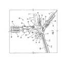
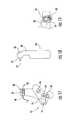
- FIG. 1is a perspective view of a guide assembly coupled to a fixation member according to one embodiment of the present invention
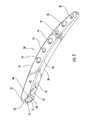
- FIG. 3is a perspective view of the fixation member of FIG. 1 ;
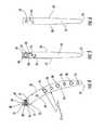
- FIG. 7is a perspective view of a guide member according to one embodiment of the present invention.
- FIG. 10is an elevation view of a distal guide member according to one embodiment of the present invention.
- FIG. 11is an elevation view of a distal guide member according to an embodiment of the present invention.
- FIG. 12is a perspective view of distal guide member of FIG. 11 ;
- FIG. 13is a perspective view of distal guide member of FIG. 10 ;
- FIGS. 14 and 15are side elevation views of a distal guide member of another embodiment of the present invention.
- FIG. 16is a cross-sectional view of the distal guide member of FIG. 14 ;
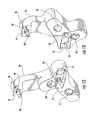
- FIG. 20is perspective view of a guide member coupled to a distal guide member according to one embodiment of the present invention.
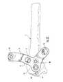
- FIG. 22is a side elevation view of a distal guide member coupled to a radius according to one embodiment of the present invention.
- FIG. 23is a side elevation view of a guide member coupled to radius, a distal guide member coupled to the guide member, and a proximal guide member prior to engaging the distal guide member, according to one embodiment of the present invention
- FIG. 24is a perspective view of the proximal guide member shown in FIG. 23 ;
- FIGS. 25 and 26are side elevation views of a proximal guide member according to one embodiment of the present invention.
- FIG. 27is a cross-sectional view of the proximal guide member of FIG. 25 ;
- FIG. 28is a side elevation view of a proximal guide member according to another embodiment of the present invention.
- FIGS. 30 and 31are side elevation views of a guide member coupled to a distal radius, a distal guide member coupled to the guide member, and the distal guide member coupled to a proximal guide member, according to one embodiment of the present invention
- FIG. 35is a perspective view of a drill guide according to one embodiment of the present invention.
- FIG. 36is a perspective view of a guide assembly including drill guides and respective drill guides positioned therein, according to one embodiment of the present invention.
- FIG. 37is a side elevation view of a guide assembly including drill guides and respective drill guides positioned therein, according to one embodiment of the present invention.
- FIGS. 38 and 39are cross-sectional views of a handle according to one embodiment of the present invention.
- a guide assembly 10 of one embodiment of the present inventionis shown coupled to a radius 11 of a patient in FIG. 1 .
- the guide assembly 10is employed to install a fixation member 20 within the radius 11 , as explained in further detail below.
- the fixation member 20is most suited for repairing fractures of the distal radius 11 wherein the fracture is at one end near an articular cartilage surface 12 and wherein it is desired to leave the articular surface undisrupted during the repair.
- reference is made herein to a guide assembly 10 and fixation member 20 suitable for the radiusit is understood that the guide assembly may be configured to install a fixation member within a variety of long bones, such as a femur, tibia, radius or humerus.
- the radius 11generally includes a widened end 13 that supports the articular cartilage surface which tapers to a more narrow shaft 14 . Extending within the shaft 14 and a portion of the widened end 13 is a medullary canal 15 .
- the guide assembly 10 and fixation member 20could be used to repair a variety of fractures of the long bones, but is shown being used to repair a first bone fragment 16 separated from a second bone fragment 17 by a single fracture line 18 .
- a side aperture 19is defined in a lateral surface of the widened end 13 , subjacent the articular cartilage surface 12 , to allow insertion of the fixation member 20 .
- a second pair of opposite, side surfaces 33extend between the convex side 29 and concave side 30 , as shown in FIGS. 3, 5, and 6 . Similar to the convex side 29 and concave side 30 , the side surfaces 33 taper slightly toward each other as they extend from the first end 22 to the second end 23 of the curved body 24 . However, the side surfaces 33 in the illustrated embodiment are relatively planar, as opposed to the curved shape of the sides 29 , 30 . Advantageously, the taper of the sides 29 , 30 , 33 , the continuous curve of the curved body 24 between the ends 22 , 23 and the rounded profile of the second end 23 help to facilitate insertion through the side aperture 19 and into the medullary canal 15 .
- a plurality of fastener openingsare defined in the fixation member. These fastener openings include a side aperture accessible fastener opening 34 , a pair of fastener openings 35 extending between the curved convex side 29 and concave side 30 , and fastener openings 36 extending between the side surfaces 33 .
- the fastener opening 34extends from the exposed first end surface 27 (which is accessible through the side aperture 19 when the fixation member 20 is installed) through a portion of the curved body 24 and to the convex side 29 , as shown in FIG. 4 .
- the fastener opening 34includes a guide portion 38 and a fastener portion 39 that is generally narrower than the guide portion.
- Both of the portionsmay be threaded to facilitate a secure fit by the fasteners 21 and various installation devices, as will be described in more detail below.
- the pair of fastener openings 35which extend between the sides 29 , 30 extend through the curved body 24 nearer the first end 22 so as to be within the first bone fragment 16 , as shown in FIGS. 2, 5, and 6 .
- Each of the fastener openings 35may have a threaded fastener portion similar to the fastener opening 34 , but a non-threaded fastener head portion which may define a counterbore.
- These fastener openings 35extend at different, divergent angles than each other and the orientation of the fastener opening 34 which is relatively orthogonal with respect to the exposed first end surface 27 and the convex side 29 , as shown in FIGS. 3, 5, and 6 .
- the fastener openings(such as the fastener openings 35 ) need not all be aligned with the axis of the fixation member.
- angles of the fastener openings 34 , 35may be configured so that the fasteners extend subjacent to the articular cartilage for improved fixation. Generally, this will require the fastener openings 34 , 35 to extend at some acute angle, such as an angle between about 50° and 85° (depending on the origin of the fastener opening), and preferably about 60° to 70°, with respect to the fixation member 20 . Basically, these angles are to match the inclination angle of the articular surface so as to provide a buttress effect for the articular cartilage.
- the ulnar inclination angle of the articular cartilage on the radiusis about 23° (resulting in a 67° fastener opening angle).
- the buttress effectis also improved by the sub-chondral placement of the first end surface 28 that is adjacent and at a right angle with respect to the exposed first end surface 27 so as to underlie the articular cartilage.
- fixation member 20may include any number of desired fastener openings.
- the fixation member 20may be configured to be a size 1 or 2 implant such that increasing to a size 3 or 4 implant may include additional fastener openings 35 and/or 36 .
- the fixation member 20could be a variety of configurations depending on the type of long bone, the patient, and/or other factors.
- Applicantshereby incorporate by reference U.S. Patent Appl. Publ. No. 2006/0015101, filed Jul. 15, 2004, herein in its entirety.
- the guide member 51 and its prongs 60which are also spaced in a cruciform or cross pattern similar to the indentations 40 , are advanced into the indentations.
- the cruciform patterncombined with the positive fit, firmly locks the guide member 51 to the fixation member 20 before attaching the distal 52 and proximal 53 guide members, as well as during guidance of insertion of the various fasteners 21 .
- the cruciform shape and positive fitmay be effective at restricting rotation between the guide assembly 10 and fixation member 20 , which can be a problem due to the relative length and cantilevered configuration of the guide assembly and fixation member.
- the guide member 51also includes a handle mount 62 and a threaded opening 64 extending therethrough that is configured to mate with a handle 114 , as shown in FIGS. 32-34, 36, and 37 .
- the handle 114is typically used to manipulate the fixation member 20 within the medullary canal 15 , as explained in additional detail below.
- the guide member 51includes a protrusion 66 that also includes a threaded opening 68 .
- the protrusionis configured to mate with a slot 76 defined in the distal guide member 52 .
- the protrusion 66is shown as being generally rectangular, but could be various sizes and configurations to mate with the slot 76 of the distal guide member 52 , such as tapered to engage a tapered slot in an interference type of fit.
- FIGS. 10-13illustrate distal guide members 52 according to particular embodiments of the present invention.
- the distal guide member 52 shown in FIGS. 10-13may be used for guiding fasteners 21 within the first end 22 of the fixation member 20 and the first bone fragment 16 .
- the distal guide member 52 shown in FIGS. 10 and 13may be configured to guide fasteners 21 within the patient's left radius 11
- the distal guide member 52 shown in FIGS. 11 and 12may be used to guide fasteners in the right radius.
- Each of the distal guide members 52 shown in FIGS. 10-13includes a plurality of openings 70 .
- the openings 70are oriented so as to have an axis collinear and aligned with the axes of the pair of openings 35 defined in the curved body 24 of the fixation member 20 .
- the openings 70are defined so that the fasteners 21 extend at an angle into the first bone fragment 16 below the articular cartilage surface 12 , as shown in FIG. 2 .
- each tissue protector 72includes a head 75 and a longitudinal shaft 77 , wherein the shaft is configured to extend through the openings 70 and adjacent to the radius.
- the distal end of the tissue protectoris capable of being inserted through the skin and abutting the radius.
- the offset distance between the distal guide member 52 and the patient's skinmay allow the distal guide member 52 to accommodate patients of a variety of sizes, while the tissue protectors 72 may protect the patient's skin from injury resulting from implanting the fixation member 20 , such as from drilling into the tissue.
- the distal guide members 52include an opening 74 configured to receive the guide fastener 54 therethrough, as shown in FIGS. 20 and 21 .
- FIGS. 1 and 34show that the tissue protectors 72 and guide fastener 54 include respective longitudinal openings 73 that are configured to receive drill bits, k-wires, drill guides, fasteners, and the like in order to facilitate placement of the fixation member 20 within the radius 11 .
- FIG. 1shows each of the tissue protectors 72 and guide fastener 54 may have a drill guide 78 positioned therein.
- Each distal guide member 52also includes a slot 76 that is configured to mate with the protrusion 66 of the guide member 51 .
- Extending within the slot 76is a fastener 80 having a threaded end 82 that is configured to engage with the threads 68 of the protrusion 66 .
- the engagement of the protrusion 66 and fastener 80 within the slot 76provides resistance to rotational movement between the guide member 51 and the distal guide member 52 , which may ensure more accurate placement of fasteners 21 within the radius 11 .
- the slot 76is generally rectangular in configuration but could be modified to a variety of sizes and configurations to mate with the protrusion 66 and resist rotational movement therebetween.
- Each distal guide member 52 shown in FIGS. 10-13includes a hook-shaped portion 84 that includes a curvature that is configured to extend partially about the circumference of the patient's wrist and engage a proximal guide member 53 .
- the distal guide members 52 of FIGS. 10-13include a fastener 86 and an associated threaded end 87 that is configured to thread an opening 92 defined in the proximal guide member 53 , as shown in FIG. 23 .
- the proximal guide member 53may include a fastener that is configured to engage threads defined in the distal guide member 52 such that the proximal and distal guide members are threadably engageable with one another.
- 10-13include an alignment pin 88 configured to engage an opening 94 defined in the proximal guide member 53
- the proximal guide member 53may also include an alignment pin 96 that is configured to engage an opening 90 defined in the distal guide member 52 .
- the combination of alignment pins and threaded engagement between the distal 52 and proximal 53 guide membersprovides a secure attachment, while also providing the surgeon with the option of removing the distal guide member, such as to replace the distal guide member with a different size.
- FIGS. 14-19illustrate additional embodiments of a distal guide member 52 , where the distal guide member 52 of FIGS. 14-16 may be employed for the right radius, while the distal guide member 52 of FIGS. 17-19 may be used for the left radius.
- the distal guide members 52 of FIGS. 14-19are similar to the proximal guide members of FIGS. 10-13 , but provide a different technique for coupling the distal guide member 52 to the proximal guide member 53 .
- the hook-shaped portion 84includes a protrusion 98 that extends across its width, as shown in FIGS. 14 and 17 .
- the protrusion 98is configured to engage a channel 100 defined in the proximal guide member 53 shown in FIGS. 25-27 .
- the engagement of the protrusion 98 within the channel 100may provide additional resistance to rotational movement between the distal 52 and proximal 53 guide members.
- the distal guide members 52 of FIGS. 14-19include a fastener 86 that is configured to engage a threaded opening 92 defined in the proximal guide member 53 , as well as an alignment pin 88 that is configured to engage an opening 94 defined in the proximal guide member 53 .
- the guide assembly 10further includes a proximal guide member 53 for guiding fasteners 21 within the second end 23 of the fixation member 20 and the second bone fragment 17 , as shown in FIGS. 24-28 according to additional embodiments of the present invention.
- the proximal guide member 53is configured to engage a respective distal guide member 52 , as shown in FIG. 29 .
- the proximal guide member 53 of FIG. 24is generally configured to be coupled to the distal guide members 52 shown in FIGS. 10-13 .
- the proximal guide member 53is generally L-shaped in configuration and includes a first portion 102 for engaging with the distal guide member 52 and a second portion 104 for guiding respective fasteners 21 into respective openings 36 defined in the fixation member 20 .
- the second portion 104includes a plurality of openings 106 that are configured to receive various devices for implanting the fixation member 20 , such as a tube protector 72 , as shown in FIG. 34 .
- the second portion 104includes a smaller opening 108 that could be configured to receive a k-wire 41 or similar device therein.
- FIGS. 25-27illustrate a proximal guide member 53 according to an additional embodiment of the present invention, which is configured to be coupled to the distal guide members 52 illustrated in FIGS. 14-19 .
- the proximal guide member 53includes a channel 100 that is configured to receive the protrusion 98 , as shown in FIGS. 32 and 33 .
- Different proximal guides 53can also be used for different sized fixation members 20 .
- FIG. 28shows a proximal guide member 53 having additional openings 106 for accommodating a longer fixation member 20 .
- the proximal guide member 53can be employed in right and left handed configurations depending on the type of long bone being treated and the orientation of the side aperture 19 .
- FIG. 29illustrates a wrench 110 that is configured to engage various fasteners of the guide assembly 10 .
- FIG. 29illustrates that the wrench 110 is configured to mate with the head of fastener 86 so as to tighten the threaded end 87 within the threaded opening 92 of the proximal guide member 53 .
- the wrench 110is also compatible with the head of the guide fastener 54 and fastener 80 .
- the wrench 110provides a universal tool that may be used with different fasteners used in assembling the guide assembly 10 , as well as securing the guide assembly to the fixation member 20 .
- the wrench 110may include a plurality of longitudinal slots 112 in order to reduce weight.
- the guide member 51includes a threaded opening 64 that is configured to receive a handle 114 .
- the handle 114is typically attached to the guide member 51 in order to facilitate installation of the fixation member 20 through the side aperture 19 and into the medullary canal 15 .
- the handle 114generally includes a body portion 116 and a plurality of slots 118 defined therein.
- the handle 114may include a strike plate 120 that includes a shaft 121 that extends the length of the body portion 116 and a threaded end 123 that is configured to mate with the threaded opening 64 of the guide member 51 , as shown in FIG. 38 .
- FIG. 39shows that the slots 118 may extend radially within the body portion 116 to the shaft 121 . There may be any number of slots 118 defined in the body portion 114 , and the slots may extend the entire length of the body portion or include a plurality of axially aligned slots, as shown in FIG. 33 .
- the guide assembly 10also includes a plurality of drill guides 78 as shown in FIG. 1 .
- the drill guides 78are employed to receive a drill bit, as well as facilitate measurement of the depth of holes drilled within the radius 11 .
- the drill guides 78may include a plurality of measurement indicators 122 that are used by the surgeon to determine a fastener 21 and/or k-wire 41 of the appropriate length based on the depth of the hole within the radius 11 .
- the drill guides 78include a shaft 124 that is configured to slide within the opening 73 of the tissue protectors 72 , through the holes 34 , 35 , and/or 36 , and into the radius 11 .
- the drill guides 78include a longitudinal slot 126 that extends the length of the drill guide, which is configured to slidably receive a drill bit or k-wire 41 therein.
- a guide shaft openingdefined within the elongate shaft 124 of the drill guide 78 is a guide shaft opening that tapers from a wider to narrower diameter near its distal end.
- a dual diameter drill bitcould be used to drill a hole within radius 11 , wherein the larger diameter of the drill bit prevents travel of the drill bit beyond the shoulder defined near the distal end of the drill guide 78 so as to prevent drilling past a selected depth. As shown in FIG.
- the depth of the hole drilled in the radius 11may be determined based on the alignment of a predetermined marking on the k-wire 41 with one of the measurement indicators 122 .
- the k-wire 41 and/or measurement indictors 122could also employ fluorescent paint or grooved notches to facilitate reading of the measurements.
- the drill guides 78are capable of being removed from respective tissue protectors 72 while k-wires 41 are inserted therein, which may aid the surgeon in viewing the k-wire within the radius 11 .
- the tissue protectors 72could also be removed from the distal 52 and proximal 53 guide members while the k-wires 41 are inserted within the radius 11 in order to visualize the radius 11 if desired.
- the distal 52 and proximal 53 membersmay be a radiolucent material.
- the distal 52 and proximal 53 guide membersdo not obstruct images taken of the radius during implantation of the fixation member 20 , such as images taken using radiographic techniques.
- the radiolucent materialcould be a carbon reinforced PEEK material, which is lighter than conventional stainless steel guide assemblies.
- a guide assembly 10 comprising a lighter materialmay be easier to handle by a surgeon and apply less torque on the bone fragments.
- other components of the guide assemblycould be a radiolucent material, such as the tissue protectors 72 , k-wires 41 , and/or handle body 116 , in order to reduce weight of the guide assembly 10 , as well as provide better visualization of the fixation member 20 within the radius during surgery.
- a side aperture 19is cleared in a lateral side of the radius 11 , and a conventional bone awl (not shown) may be used to open the medullary canal 15 of cancellous bone.
- a trialing broachmay be urged through the side aperture 19 and into the medullary canal 15 to approximate the size of the fixation member 20 .
- Other conventional toolscould also be employed to clear bone, such as reamers and awls.
- an appropriately sized fixation member 20may be selected.
- the handle 114is attached to the threaded opening 64 defined in the guide member 51 , as shown in FIGS. 32-34 .
- the guide member 51may then be attached to the fixation member 20 via the guide fastener 54 .
- the threaded tip 58 of the guide fastener 54may be advanced into the threaded opening 34 of the fixation member 20 , which mates the prongs 60 with the indentations 40 , thereby locking out micro-motion and rotation between the guide member 51 and the fixation member 20 .
- the handle 114may then be used to orient the fixation member 20 through the side aperture 19 and into the medullary canal 15 .
- the handle 114may then be then unscrewed from the guide member 51 .
- the distal guide member 52may then be attached to the guide member 51 by inserting the protrusion 66 within the slot 76 and tightening the fastener 80 to the threaded opening 68 , as shown in FIGS. 20 and 21 .
- the proximal guide member 53may then be attached to the distal guide member 52 by sliding the protrusion 98 within the channel 100 such that the alignment pin 88 aligns with the opening 94 .
- the fastener 86may then be tightened to secure the threaded end 87 within the threaded opening 92 .
- tissue protectors 72within each of the openings 70 of the distal guide member 52 and the openings 106 of the proximal guide member 53 .
- a k-wire 41may be inserted within the smaller guide openings 36 , 108 of the distal 52 and proximal 53 guide members, respectively.
- the drill guides 78may then be placed into respective tissue protectors 72 , as well as within the guide fastener 54 .
- a drill bit(not shown) may be advanced into the drill guides 78 to form pilot holes in the radius 11 .
- the depth of these holesmay then be tested using measurement indicators 122 by inserting a k-wire within the longitudinal slot 126 of the drill guides 78 , as shown in FIG. 1 .
- the depth measurementsfacilitate selection of fasteners 21 of the appropriate length.
- the drilled holesare then tapped to prepare them for insertion of threaded fasteners 21 .
- the threaded fasteners 21may be advanced through the aligned openings 34 , 35 , 36 , 106 in the fixation member 20 and the radius 11 so as to connect the bone fragments 16 , 17 , as shown in FIG. 2 .
- the guide assembly 10can then be removed by unscrewing the guide fastener 54 .
- the guide member 51may be coupled to the fixation member 20 without first having to attach the distal guide member 52 and/or proximal guide member 53 .
- the surgeonmay be able to more easily position the fixation member 20 within the radius 11 since the surgeon will have a better view of the radius and will have a lighter device to manipulate.
- the distal guide member 52is interchangeable with the guide member 51 such that the surgeon could remove the distal guide member 52 during surgery, such as for better visualization or to change to a different size.
- attachment of the guide member 51 to the fixation member 20 with the guide fastener 54provides a secure engagement that allows the distal guide member 52 to be attached and removed when desired.
- proximal guide member 53is interchangeable with the distal guide member 52 such that the proximal guide member may be selectively engaged to and disengaged from the proximal guide member. Therefore, the combination of the guide member 51 , distal guide member 52 , and proximal guide member 53 provides interchangeable components for a more universal guide assembly 10 .
- distal 52 and proximal 53 membersmay be a radiolucent material, which also enhances visualization during surgery, as well as reduces the weight of the guide assembly, thereby resulting in easier manipulation of the assembly and less torque on the bone fragments.
- the distal 52 and proximal 53 guide membersare also configured to be spaced away from the patient's radius 11 such that the guide assembly 10 is adaptable to various sized patients.
- the offset distance between the distal 52 and proximal 53 guide members from the patient's skinallows tissue protectors 72 to be placed within each of the holes 70 , 106 in order to provide additional protection from injuring the patient's skin during installation of the fixation member 20 .
Landscapes
- Health & Medical Sciences (AREA)
- Surgery (AREA)
- Life Sciences & Earth Sciences (AREA)
- Orthopedic Medicine & Surgery (AREA)
- Biomedical Technology (AREA)
- Public Health (AREA)
- Veterinary Medicine (AREA)
- Engineering & Computer Science (AREA)
- Nuclear Medicine, Radiotherapy & Molecular Imaging (AREA)
- Heart & Thoracic Surgery (AREA)
- Medical Informatics (AREA)
- Molecular Biology (AREA)
- Animal Behavior & Ethology (AREA)
- General Health & Medical Sciences (AREA)
- Dentistry (AREA)
- Oral & Maxillofacial Surgery (AREA)
- Neurology (AREA)
- Surgical Instruments (AREA)
Abstract
Description
Claims (19)
Priority Applications (1)
| Application Number | Priority Date | Filing Date | Title |
|---|---|---|---|
| US14/271,067US9662153B2 (en) | 2007-12-17 | 2014-05-06 | Guide assembly for intramedullary fixation and method of using the same |
Applications Claiming Priority (2)
| Application Number | Priority Date | Filing Date | Title |
|---|---|---|---|
| US11/957,742US8771283B2 (en) | 2007-12-17 | 2007-12-17 | Guide assembly for intramedullary fixation and method of using the same |
| US14/271,067US9662153B2 (en) | 2007-12-17 | 2014-05-06 | Guide assembly for intramedullary fixation and method of using the same |
Related Parent Applications (1)
| Application Number | Title | Priority Date | Filing Date |
|---|---|---|---|
| US11/957,742DivisionUS8771283B2 (en) | 2007-12-17 | 2007-12-17 | Guide assembly for intramedullary fixation and method of using the same |
Publications (2)
| Publication Number | Publication Date |
|---|---|
| US20140243839A1 US20140243839A1 (en) | 2014-08-28 |
| US9662153B2true US9662153B2 (en) | 2017-05-30 |
Family
ID=40380049
Family Applications (2)
| Application Number | Title | Priority Date | Filing Date |
|---|---|---|---|
| US11/957,742Active2031-09-16US8771283B2 (en) | 2007-12-17 | 2007-12-17 | Guide assembly for intramedullary fixation and method of using the same |
| US14/271,067Active2029-01-04US9662153B2 (en) | 2007-12-17 | 2014-05-06 | Guide assembly for intramedullary fixation and method of using the same |
Family Applications Before (1)
| Application Number | Title | Priority Date | Filing Date |
|---|---|---|---|
| US11/957,742Active2031-09-16US8771283B2 (en) | 2007-12-17 | 2007-12-17 | Guide assembly for intramedullary fixation and method of using the same |
Country Status (5)
| Country | Link |
|---|---|
| US (2) | US8771283B2 (en) |
| EP (1) | EP2231034B1 (en) |
| JP (2) | JP2011506044A (en) |
| AU (1) | AU2008338424B2 (en) |
| WO (1) | WO2009079503A1 (en) |
Cited By (3)
| Publication number | Priority date | Publication date | Assignee | Title |
|---|---|---|---|---|
| US10610270B2 (en) | 2018-01-15 | 2020-04-07 | Glw, Inc. | Hybrid intramedullary rods |
| USD894385S1 (en) | 2017-10-27 | 2020-08-25 | Orthopediatrics Corp. | Orthopedic tool |
| US11426220B2 (en) | 2017-10-11 | 2022-08-30 | Howmedica Osteonics Corp. | Humeral fixation plate guides |
Families Citing this family (31)
| Publication number | Priority date | Publication date | Assignee | Title |
|---|---|---|---|---|
| US8771283B2 (en) | 2007-12-17 | 2014-07-08 | Wright Medical Technology, Inc. | Guide assembly for intramedullary fixation and method of using the same |
| US8328806B2 (en) | 2008-06-24 | 2012-12-11 | Extremity Medical, Llc | Fixation system, an intramedullary fixation assembly and method of use |
| US9017329B2 (en)* | 2008-06-24 | 2015-04-28 | Extremity Medical, Llc | Intramedullary fixation assembly and method of use |
| US9289220B2 (en) | 2008-06-24 | 2016-03-22 | Extremity Medical Llc | Intramedullary fixation assembly and method of use |
| US8303589B2 (en) | 2008-06-24 | 2012-11-06 | Extremity Medical Llc | Fixation system, an intramedullary fixation assembly and method of use |
| US8343199B2 (en) | 2008-06-24 | 2013-01-01 | Extremity Medical, Llc | Intramedullary fixation screw, a fixation system, and method of fixation of the subtalar joint |
| US9044282B2 (en) | 2008-06-24 | 2015-06-02 | Extremity Medical Llc | Intraosseous intramedullary fixation assembly and method of use |
| US8313487B2 (en)* | 2008-06-24 | 2012-11-20 | Extremity Medical Llc | Fixation system, an intramedullary fixation assembly and method of use |
| GB2475491A (en) | 2009-11-18 | 2011-05-25 | Biomet Uk Ltd | Alignment tool for a femoral drill guide |
| US9662221B2 (en)* | 2011-01-26 | 2017-05-30 | Nextremity Solutions, Inc. | Upper extremity fusion devices and methods |
| JP2013066649A (en)* | 2011-09-26 | 2013-04-18 | Me System:Kk | Osteosynthesis plate holder |
| US11051864B2 (en)* | 2012-08-30 | 2021-07-06 | DePuy Synthes Products, Inc. | Intramedullary fixation assembly |
| ES2959525T3 (en)* | 2013-03-15 | 2024-02-26 | Paragon 28 Inc | intramedullary nail |
| WO2015017074A1 (en)* | 2013-07-02 | 2015-02-05 | Cmarr Enterprises | Curved tibiotalar fusion nail and method of use |
| USD904616S1 (en) | 2014-03-14 | 2020-12-08 | Paragon 28, Inc. | Intramedullary fastener |
| US10258328B2 (en) | 2015-01-12 | 2019-04-16 | Extremity Medical, Llc | Fixation assembly and method of use |
| CN106344143B (en)* | 2015-04-14 | 2018-09-28 | 青岛亿嘉诺日化有限公司 | Damp type dentoid process of axis sighting device |
| US10357314B2 (en) | 2015-07-08 | 2019-07-23 | Stryker European Holdings I, Llc | Instrumentation and method for repair of a bone fracture |
| US10485601B2 (en)* | 2015-12-11 | 2019-11-26 | Tornier | Surgical instrumentation and methods for implanting an elongated implant in a long bone |
| US10918412B2 (en)* | 2015-12-18 | 2021-02-16 | Boston Scientific Scimed, Inc. | Surgical guidance devices, methods, and systems |
| CN108697472B (en)* | 2016-02-19 | 2021-06-25 | 桑尼布鲁克研究所 | Positioning and Alignment Instruments for Introducing Surgical Devices into Bone |
| WO2018063329A1 (en) | 2016-09-30 | 2018-04-05 | Wright Medical Technology, Inc. | Targeting guide and method for an implant |
| US10251682B2 (en)* | 2017-03-22 | 2019-04-09 | DePuy Synthes Products, Inc. | Distal radius nail |
| WO2018187770A1 (en) | 2017-04-06 | 2018-10-11 | Extremity Medical, Llc | Orthopedic plate with modular peg and compression screw |
| US11446072B2 (en)* | 2017-10-10 | 2022-09-20 | DePuy Synthes Products, Inc. | Self-retaining nail to insertion handle interface |
| EP3773285A1 (en)* | 2018-04-12 | 2021-02-17 | Premia Spine Ltd. | K-wire depth measurement |
| US11000327B2 (en) | 2018-12-14 | 2021-05-11 | Nextremity Solutions, Inc. | Bone defect repair apparatus and method |
| US10987146B2 (en) | 2019-03-05 | 2021-04-27 | Nextremity Solutions, Inc. | Bone defect repair apparatus and method |
| US11517358B2 (en) | 2019-10-02 | 2022-12-06 | Arthrex, Inc. | Interfragmentary guide and plate system |
| US11759240B2 (en)* | 2020-04-01 | 2023-09-19 | Amr Abdelgawad | Adaptive tibiotalocalcaneal arthrodesis nail—nail, adapter system |
| US12349947B2 (en)* | 2021-10-14 | 2025-07-08 | Western Washington University | Distal-screw guiding system for interlocking intramedullary nail implants |
Citations (259)
| Publication number | Priority date | Publication date | Assignee | Title |
|---|---|---|---|---|
| US2500370A (en) | 1947-06-30 | 1950-03-14 | Mckibbin Genevieve | Repair of femur fracture |
| US2682265A (en) | 1951-12-28 | 1954-06-29 | Marie B Collison | Trochanteric plate and artificial femoral head |
| US3334624A (en) | 1963-09-26 | 1967-08-08 | Synthes Ag | Intramedullary nail |
| US3433220A (en) | 1966-12-30 | 1969-03-18 | Robert E Zickel | Intramedullary rod and cross-nail assembly for treating femur fractures |
| US3709218A (en) | 1970-04-24 | 1973-01-09 | W Halloran | Combination intramedullary fixation and external bone compression apparatus |
| US3781917A (en) | 1970-10-13 | 1974-01-01 | R Mathys | Hip joint prosthesis |
| DE7115713U (en) | 1971-02-26 | 1975-06-26 | Fischer A | |
| US3939498A (en) | 1974-05-29 | 1976-02-24 | National Research Development Corporation | Endoprosthetic femoral head |
| GB1428653A (en) | 1972-02-23 | 1976-03-17 | Nat Res Dev | Fracture fixing device |
| US3973278A (en) | 1974-07-08 | 1976-08-10 | Yakov Isaevich Shersher | Artificial hip-joint |
| US3977398A (en) | 1976-01-12 | 1976-08-31 | The Sampson Corporation | Fluted sub-trochanteric nail system |
| US4011863A (en) | 1976-07-19 | 1977-03-15 | Zickel Robert E | Supracondylar prosthetic nail |
| US4055172A (en) | 1973-07-18 | 1977-10-25 | Josef Ender | Nail and set for correctly resetting fractured bones for their immediate re-use |
| US4091806A (en) | 1976-01-13 | 1978-05-30 | Jacob Aginsky | Intramedullary compression nail for the treatment of bone fractures |
| US4101985A (en) | 1976-03-20 | 1978-07-25 | Friedrich Baumann | Hip-joint prosthesis |
| US4103683A (en) | 1977-06-03 | 1978-08-01 | Neufeld John A | Sub-trochanteric nail |
| US4135507A (en) | 1977-05-20 | 1979-01-23 | Harris Leslie J | Condylocephalic nail for fixation of pertrochanteric fractures |
| US4169470A (en) | 1977-10-19 | 1979-10-02 | Ender Hans G | Surgical nail for use in setting bone fractures, and tool for emplacing same |
| US4227518A (en) | 1978-02-12 | 1980-10-14 | Jacob Aginsky | Intramedullary retraction nail for fixation of comminuted fractured bones |
| US4237875A (en) | 1979-02-23 | 1980-12-09 | Towmotor Corporation | Dynamic intramedullary compression nailing |
| US4274754A (en) | 1979-10-31 | 1981-06-23 | Grumman Aerospace Corporation | Double locking device |
| US4338926A (en) | 1980-11-21 | 1982-07-13 | Howmedica, Inc. | Bone fracture prosthesis with controlled stiffness |
| US4393868A (en) | 1981-02-20 | 1983-07-19 | Ace Orthopedic Manufacturing Inc. | Colles fracture fixature device |
| EP0091499A1 (en) | 1982-04-10 | 1983-10-19 | Metallwerk Plansee Gesellschaft M.B.H. | Fluted intramedullary leg nail |
| US4423721A (en) | 1978-09-04 | 1984-01-03 | Schwarzkopf Development Corporation | Device for insertion and extraction of medullary nails |
| US4446857A (en) | 1978-09-04 | 1984-05-08 | Schwarzkopf Development Corporation | Medullary nail and process for the production thereof |
| US4453539A (en) | 1982-03-01 | 1984-06-12 | The University Of Toledo | Expandable intramedullary nail for the fixation of bone fractures |
| US4467793A (en) | 1979-12-14 | 1984-08-28 | Ender Hans G | Instrumentarium for reducing and fixing of pertrochanterous and subtrochanterous fractures as well as insert member forming part of this instrumentarium |
| EP0118778A1 (en) | 1983-03-09 | 1984-09-19 | HOWMEDICA INTERNATIONAL, INC. Zweigniederlassung Kiel | Fixing nail |
| US4473069A (en) | 1981-07-17 | 1984-09-25 | Lars Kolmert | Device for interconnecting an elastic nail and a cross screw |
| US4475545A (en) | 1982-12-06 | 1984-10-09 | Ender Hans G | Bone-nail |
| US4483335A (en) | 1982-06-02 | 1984-11-20 | Tornier S.A. | Nails for femoral fractures |
| US4493317A (en) | 1980-11-20 | 1985-01-15 | Synthes Ltd. (U.S.A.) | Surgical compression plate and drill guide |
| US4513744A (en) | 1981-03-16 | 1985-04-30 | Synthes Ag | Surgical compression plate |
| US4522202A (en) | 1981-01-12 | 1985-06-11 | Schwarzkopf Development Corporation | Curved intramedullary lower leg spike |
| US4541424A (en) | 1982-03-30 | 1985-09-17 | Howmedica International, Inc. | Distal aiming device for a locking nail |
| DE8531341U1 (en) | 1984-11-27 | 1985-12-12 | Rapido Wärmetechnik GmbH, 4060 Viersen | Articulated boiler or sheet steel boiler |
| US4590930A (en) | 1983-06-22 | 1986-05-27 | Lloyd A. Kurth | Fixation device and process for an intramedullary nail |
| US4622959A (en) | 1985-03-05 | 1986-11-18 | Marcus Randall E | Multi-use femoral intramedullary nail |
| US4630601A (en) | 1982-05-18 | 1986-12-23 | Howmedica International, Inc. | Bone nail for the treatment of fractures |
| FR2586554A1 (en) | 1985-08-27 | 1987-03-06 | Zimmer Sa | Probe for guiding, positioning and drilling for medullary nail and appropriate medullary nail |
| US4667663A (en) | 1983-07-13 | 1987-05-26 | Keizo Miyata | Intramedullary nail used to unite separated fragments of fractured long bone |
| US4697585A (en) | 1985-01-11 | 1987-10-06 | Williams Michael O | Appliance for fixing fractures of the femur |
| US4705027A (en) | 1984-05-14 | 1987-11-10 | Synthes Ltd. (U.S.A.) | Intramedullary nail |
| US4733654A (en) | 1986-05-29 | 1988-03-29 | Marino James F | Intramedullar nailing assembly |
| US4775381A (en) | 1985-05-06 | 1988-10-04 | Metripond Merleggyar | Hip prosthesis |
| US4781181A (en) | 1985-08-27 | 1988-11-01 | Zimmer, S.A. | Boring sensor for intramedullary nail and corresponding intramedullary nail |
| US4794919A (en) | 1986-01-31 | 1989-01-03 | Nilsson John S | Fixating device |
| US4805607A (en) | 1987-12-03 | 1989-02-21 | Boehringer Mannheim Corporation | Modular intramedullary nail system |
| US4846162A (en) | 1987-09-14 | 1989-07-11 | Moehring H David | Orthopedic nail and method of bone fracture fixation |
| US4854312A (en) | 1988-04-13 | 1989-08-08 | The University Of Toledo | Expanding intramedullary nail |
| US4858602A (en) | 1985-12-06 | 1989-08-22 | Howmedica GmbH Werk Schonkirchen | Bone nail for the treatment of upper arm fractures |
| US4875475A (en) | 1984-11-30 | 1989-10-24 | Synthes (U.S.A.) | Device for treating a bone |
| US4875474A (en) | 1988-01-29 | 1989-10-24 | Biomet, Inc. | Variable wall thickness interlocking intramedullary nail |
| US4877019A (en) | 1986-12-02 | 1989-10-31 | Pierre Vives | Intramedullary nail and apparatus for its insertion |
| EP0355411A1 (en) | 1988-08-10 | 1990-02-28 | Ace Medical Company | Intramedullary rod for femur stabilization |
| US4911153A (en) | 1988-02-04 | 1990-03-27 | Biomet, Inc. | Orthopedic surgical instrument |
| US4943291A (en) | 1987-12-18 | 1990-07-24 | Zimmer S.A. | Drilling feeler, in particular for positioning and securing a medullary nail |
| US4944764A (en) | 1988-04-26 | 1990-07-31 | Headcorn Instrumentation Ltd. | Hip prosthesis |
| US4946459A (en) | 1989-12-04 | 1990-08-07 | Georgia Tech Research Corporation | Intramedullary device |
| JPH02274243A (en) | 1989-02-02 | 1990-11-08 | Pfizer Hospital Prod Group Inc | Fractural part-fixing device |
| FR2647006A1 (en) | 1989-05-22 | 1990-11-23 | Zimmer Sa | Devices for fitting a reinforcement nail, and method using these devices |
| US4976714A (en) | 1988-07-07 | 1990-12-11 | Michael's France | Universal intramedullary nail, particularly for the thighbone |
| US4976258A (en) | 1983-03-09 | 1990-12-11 | Howmedica International, Inc. | Locking nail |
| US5013314A (en) | 1985-11-05 | 1991-05-07 | Intreprinderea Industria Tehnico-Medicala | Instrumentation and method for inserting flexible implants into fractured bones |
| US5035697A (en) | 1990-03-20 | 1991-07-30 | Synthes (U.S.A.) | Orthopedic medullary nail |
| US5041115A (en) | 1988-03-14 | 1991-08-20 | Synthes (U.S.A.) | Medullary nail for the tibia |
| US5057110A (en) | 1988-12-01 | 1991-10-15 | Johnson & Johnson | Intramedullar nail |
| US5057103A (en) | 1990-05-01 | 1991-10-15 | Davis Emsley A | Compressive intramedullary nail |
| US5084053A (en) | 1989-10-25 | 1992-01-28 | Ender Hans G | Bone nail and tool for the connection to the distal end area of such a bone nail |
| US5100404A (en) | 1990-09-04 | 1992-03-31 | Beth Israel Hospital | Intramedullary nailing method and apparatus |
| FR2668360A1 (en) | 1990-10-25 | 1992-04-30 | Armor | Device for the osteosynthesis of an upper or stepped fracture of the femur |
| US5122146A (en) | 1988-02-04 | 1992-06-16 | Pfizer Hospital Products Group, Inc. | Apparatus for reducing a fracture |
| US5135527A (en) | 1989-10-25 | 1992-08-04 | Ender Hans G | Instrumentarium for repositioning and fixing petrochanterous and subtrochanterous fractures |
| US5167666A (en) | 1987-07-10 | 1992-12-01 | Kernforschungszentrum Karlsruhe Gmbh | Endoprosthesis for the femoral part of a hip joint |
| US5190543A (en) | 1990-11-26 | 1993-03-02 | Synthes (U.S.A.) | Anchoring device |
| US5197966A (en) | 1992-05-22 | 1993-03-30 | Sommerkamp T Greg | Radiodorsal buttress blade plate implant for repairing distal radius fractures |
| US5211645A (en) | 1989-07-04 | 1993-05-18 | Rainer Baumgart | Device for guiding an internal saw for long tubular bone osteotomy |
| US5239569A (en) | 1989-03-10 | 1993-08-24 | Michael Saleh | Radiographic analysis of bones |
| US5248313A (en) | 1991-04-17 | 1993-09-28 | Greene Bruce L | Fibular intramedullary rod |
| US5263955A (en) | 1989-07-04 | 1993-11-23 | Rainer Baumgart | Medullary nail |
| WO1993022978A1 (en) | 1992-05-21 | 1993-11-25 | Putnam Matthew D | Apparatus for dividing transverse carpal ligament |
| US5268000A (en) | 1992-09-15 | 1993-12-07 | Ottieri Marco T | Intramedullary nail |
| US5281224A (en) | 1993-01-05 | 1994-01-25 | Orthofix S.R.L. | Centering means for holes of intramedullary nails |
| US5295991A (en) | 1991-05-24 | 1994-03-22 | Synthes (U.S.A.) | Surgical instrument for positioning osteosynthetic elements |
| US5334192A (en) | 1991-01-30 | 1994-08-02 | Homwedica Gmbh | Targeting device for an implant |
| US5352228A (en) | 1993-05-10 | 1994-10-04 | Kummer Frederick J | Apparatus and method to provide compression for a locked intramedullary nail |
| US5356410A (en) | 1991-12-13 | 1994-10-18 | Dietmar Pennig | Adjuvant for osteosynthesis in the case of pertrochanteric fracture of the neck of the femur |
| US5397328A (en) | 1991-12-07 | 1995-03-14 | Howmedica Gmbh | Bone nail for spoke bone fractures |
| US5403321A (en)* | 1993-12-15 | 1995-04-04 | Smith & Nephew Richards Inc. | Radiolucent drill guide |
| US5411503A (en) | 1993-06-18 | 1995-05-02 | Hollstien; Steven B. | Instrumentation for distal targeting of locking screws in intramedullary nails |
| US5415660A (en) | 1994-01-07 | 1995-05-16 | Regents Of The University Of Minnesota | Implantable limb lengthening nail driven by a shape memory alloy |
| US5429638A (en) | 1993-02-12 | 1995-07-04 | The Cleveland Clinic Foundation | Bone transport and lengthening system |
| US5433718A (en) | 1992-08-20 | 1995-07-18 | Brinker; Mark | Antibiotic eluding intramedullary nail apparatus |
| US5441500A (en) | 1991-01-30 | 1995-08-15 | Howmedica Gmbh | Bone nail |
| US5443466A (en) | 1991-12-13 | 1995-08-22 | Shah; Mrugesh K. | Method and apparatus for treating fractures of a bone |
| US5458654A (en) | 1993-07-14 | 1995-10-17 | Ao-Forschungsinstitut Davos | Screw-fixed femoral component for hip joint prosthesis |
| US5472444A (en) | 1994-05-13 | 1995-12-05 | Acumed, Inc. | Humeral nail for fixation of proximal humeral fractures |
| GB2290478A (en) | 1994-06-10 | 1996-01-03 | Michael Gordon Matthews | Intramedullary nail fracture stabilisation |
| EP0491138B1 (en) | 1990-12-17 | 1996-01-10 | Synthes AG, Chur | Device for holding broken bones in fixed position |
| US5484438A (en) | 1992-02-13 | 1996-01-16 | Pennig; Dietmar | Intramedullary nail with screw-receiving solid insert |
| US5499986A (en) | 1994-01-07 | 1996-03-19 | Smith & Nephew Richards Inc. | Quick release handle apparatus for removing and inserting intramedullary nails |
| US5536269A (en) | 1993-02-18 | 1996-07-16 | Genesis Orthopedics | Bone and tissue lengthening device |
| US5549610A (en) | 1994-10-31 | 1996-08-27 | Smith & Nephew Richards Inc. | Femoral intramedullary nail |
| US5569262A (en) | 1995-05-19 | 1996-10-29 | Carney; William P. | Guide tool for surgical devices |
| US5573536A (en) | 1991-08-09 | 1996-11-12 | Howmedica Gmbh | Locking nail for treating femoral fractures |
| US5578035A (en) | 1995-05-16 | 1996-11-26 | Lin; Chih-I | Expandable bone marrow cavity fixation device |
| US5586985A (en) | 1994-10-26 | 1996-12-24 | Regents Of The University Of Minnesota | Method and apparatus for fixation of distal radius fractures |
| US5620445A (en) | 1994-07-15 | 1997-04-15 | Brosnahan; Robert | Modular intramedullary nail |
| US5620449A (en) | 1994-07-28 | 1997-04-15 | Orthofix, S.R.L. | Mechanical system for blind nail-hole alignment of bone screws |
| US5626579A (en) | 1993-02-12 | 1997-05-06 | The Cleveland Clinic Foundation | Bone transport and lengthening system |
| US5643258A (en) | 1994-08-10 | 1997-07-01 | Howmedica Gmbh | Device for stabilizing long bones |
| US5645545A (en) | 1995-08-14 | 1997-07-08 | Zimmer, Inc. | Self reaming intramedullary nail and method for using the same |
| US5653709A (en) | 1992-12-04 | 1997-08-05 | Synthes (U.S.A.) | Modular marrow nail |
| US5658287A (en) | 1995-06-05 | 1997-08-19 | Gruppo Industriale Bioimpianti S.R.L. | Locked intramedullary nail, suitable in particular for fractures of the femur |
| US5658283A (en) | 1995-02-15 | 1997-08-19 | Huebner; Randall J. | External fixator for repairing fractures |
| US5665086A (en) | 1994-05-20 | 1997-09-09 | Asahi Kogaku Kogyo Kabushiki Kaisha | Instrument for inserting an intramedullary nail in a bone |
| US5681318A (en) | 1992-02-13 | 1997-10-28 | Orthofix S.R.L. | Medullary cavity template |
| US5690634A (en) | 1993-09-15 | 1997-11-25 | Synthes (U.S.A.) | Medullary drill head |
| US5697934A (en) | 1996-12-02 | 1997-12-16 | Huebner; Randall J. | Tension band wiring pin and method |
| US5697930A (en) | 1995-01-30 | 1997-12-16 | Asahi Kogaku Kogyo Kabushiki Kaisha | Intramedullary nail for humerus |
| US5713902A (en) | 1993-06-01 | 1998-02-03 | Endocare Ag | Osteosynthesis auxiliary for the treatment of subtrochanteric peritrochanteric and femoral-neck fractures |
| US5718704A (en) | 1995-02-14 | 1998-02-17 | Medoff; Robert J. | L-shape surgical buttress plate |
| WO1998018397A1 (en) | 1996-10-28 | 1998-05-07 | Smith & Nephew, Inc. | Cannulated modular intramedullary nail |
| US5766180A (en) | 1995-07-31 | 1998-06-16 | Winquist; Robert A. | Nail extraction kit and method |
| US5766174A (en) | 1995-09-26 | 1998-06-16 | Orthologic Corporation | Intramedullary bone fixation device |
| US5766179A (en) | 1997-03-05 | 1998-06-16 | Orthofix S.R.L. | Mechanical system for blind nail-hole alignment of bone screws |
| US5776194A (en) | 1996-04-25 | 1998-07-07 | Nuvana Medical Innovations, Llc | Intermedullary rod apparatus and methods of repairing proximal humerus fractures |
| US5853413A (en) | 1997-04-18 | 1998-12-29 | Bristol-Myers Squibb Company | Wrist fusion plate |
| US5941878A (en) | 1995-02-14 | 1999-08-24 | Medoff; Robert J. | Implantable, surgical buttressing device |
| US5954722A (en) | 1997-07-29 | 1999-09-21 | Depuy Acromed, Inc. | Polyaxial locking plate |
| US5961553A (en) | 1995-02-13 | 1999-10-05 | Medinov-Amp | Long bone elongation device |
| US5976134A (en) | 1995-06-01 | 1999-11-02 | Huebner; Randall J. | External fixator for repairing fractures |
| US5997490A (en) | 1997-02-12 | 1999-12-07 | Exogen, Inc. | Method and system for therapeutically treating bone fractures and osteoporosis |
| US6010505A (en) | 1996-09-05 | 2000-01-04 | Howmedica Gmbh | Supra condylus bone nail |
| US6010506A (en) | 1998-09-14 | 2000-01-04 | Smith & Nephew, Inc. | Intramedullary nail hybrid bow |
| US6019761A (en) | 1998-12-23 | 2000-02-01 | Gustilo; Ramon B. | Intramedullary nail and method of use |
| US6033407A (en) | 1998-01-27 | 2000-03-07 | Behrens; Alfred F. | Apparatus and method for intramedullary nailing and intramedullary nail therefor |
| US6039739A (en) | 1998-04-09 | 2000-03-21 | Howmedica Gmbh | Targeting apparatus for a locking nail |
| US6056755A (en) | 1996-05-09 | 2000-05-02 | Horas; Uwe Peter | Method for transporting a bone segment in order to bridge a bone defect and device for carrying out the method |
| WO2000025681A1 (en) | 1998-11-02 | 2000-05-11 | Grampian Healthcare National Health Service Trust | Fracture treatment |
| US6074392A (en) | 1998-09-01 | 2000-06-13 | Durham; Alfred A. | Method and devices for use in bone fixation procedures |
| US6077264A (en) | 1996-04-05 | 2000-06-20 | Chemello; Antonio | Intramedullary nail for the osteosynthesis of bone fractures |
| US6080159A (en) | 1996-07-16 | 2000-06-27 | Sulzer Orthopedics Ltd. | Ascending centromedullary thigh bone pin with mechanical clamping of its two ends |
| US6093192A (en) | 1998-04-24 | 2000-07-25 | Aap Implanate Aktiengesellschaft | Target device for proximal and distal locking of medullary nails without X-rays |
| US6096040A (en) | 1996-06-14 | 2000-08-01 | Depuy Ace Medical Company | Upper extremity bone plates |
| US6120504A (en) | 1998-12-10 | 2000-09-19 | Biomet Inc. | Intramedullary nail having dual distal bore formation |
| US6123709A (en) | 1997-07-25 | 2000-09-26 | Jones; Andrew R. | Bone buttress plate and method of using same |
| US6123708A (en) | 1999-02-03 | 2000-09-26 | Pioneer Laboratories, Inc. | Intramedullary bone fixation rod |
| US6126661A (en) | 1997-01-20 | 2000-10-03 | Orthofix S.R.L. | Intramedullary cavity nail and kit for the treatment of fractures of the hip |
| US6146384A (en) | 1995-10-13 | 2000-11-14 | Sdgi Holdings, Inc. | Orthopedic fixation device and method of implantation |
| US6168628B1 (en) | 1998-03-17 | 2001-01-02 | Acumed, Inc. | Shoulder Prosthesis |
| US6200321B1 (en) | 1998-09-10 | 2001-03-13 | Hand Innovations, Inc. | Fracture fixation system |
| US6206880B1 (en) | 2000-02-21 | 2001-03-27 | Abbas Karladani | Method for percutaneous intramedullary nailing of tibial shaft fractures |
| US6221074B1 (en) | 1999-06-10 | 2001-04-24 | Orthodyne, Inc. | Femoral intramedullary rod system |
| US6221073B1 (en) | 1999-08-20 | 2001-04-24 | Kinetikos Medical, Inc. | Wrist fusion apparatus and method |
| EP1095626A1 (en) | 1999-11-01 | 2001-05-02 | Sulzer Orthopedics Ltd. | Intramedullary nail for the radius |
| US6228086B1 (en) | 1997-03-19 | 2001-05-08 | Stryker Trauma-Selzach Ag | Modular intramedullary nail |
| US6231576B1 (en)* | 1996-12-02 | 2001-05-15 | Synthes (U.S.A.) | Flat intramedullary nail |
| US6245075B1 (en) | 1997-01-07 | 2001-06-12 | Wittenstein Motion Control Gmbh | Distraction device for moving apart two bone sections |
| US6248109B1 (en) | 1998-07-30 | 2001-06-19 | Waldemar Link (Gmbh & Co.) | Implant for interconnecting two bone fragments |
| US6261289B1 (en) | 1998-10-26 | 2001-07-17 | Mark Levy | Expandable orthopedic device |
| US20010011172A1 (en) | 2000-02-01 | 2001-08-02 | Hand Innovations, Inc. | Volar fixation system with articulating stabilization pegs |
| US6270499B1 (en)* | 1997-10-20 | 2001-08-07 | Synthes (U.S.A.) | Bone fixation device |
| WO2001056452A2 (en) | 2000-02-01 | 2001-08-09 | Hand Innovations, Inc. | Volar fixation system |
| US6283969B1 (en) | 2000-03-10 | 2001-09-04 | Wright Medical Technology, Inc. | Bone plating system |
| US6296645B1 (en) | 1999-04-09 | 2001-10-02 | Depuy Orthopaedics, Inc. | Intramedullary nail with non-metal spacers |
| JP2001286481A (en) | 2000-04-06 | 2001-10-16 | Homuzu Giken:Kk | Positioning device for bone nails |
| US6319253B1 (en) | 1998-03-05 | 2001-11-20 | Synthes (U.S.A) | Intramedullary nail with locking hole |
| US6355069B1 (en) | 1998-08-20 | 2002-03-12 | Depuys Orthopaedics, Inc. | Bone engaging prosthesis |
| US20020032446A1 (en) | 2000-02-01 | 2002-03-14 | Orbay Jorge L. | Fixation plate system for dorsal wrist fracture fixation |
| US6379360B1 (en) | 1998-03-11 | 2002-04-30 | Synthes (Usa) | Spiral blade insertion instrument |
| US6379359B1 (en) | 2000-05-05 | 2002-04-30 | University Of North Carolina At Chapel Hill | Percutaneous intrafocal plate system |
| US6383185B1 (en) | 1999-03-01 | 2002-05-07 | Rainer Baumgart | Medullary nail for the distraction of bones |
| US6387098B1 (en) | 1999-10-21 | 2002-05-14 | Peter Alexander Cole | Intramedullary catheter nail apparatus and method |
| US6395033B1 (en) | 2000-04-10 | 2002-05-28 | Tyco Healthcare Group Lp | Dynamic fusion mechanostat devices |
| US6409768B1 (en) | 2000-03-16 | 2002-06-25 | Slobodan Tepic | Screw anchored joint prosthesis |
| US6416516B1 (en) | 1999-02-16 | 2002-07-09 | Wittenstein Gmbh & Co. Kg | Active intramedullary nail for the distraction of bone parts |
| US6423066B1 (en) | 1998-12-28 | 2002-07-23 | Stryker Trauma Gmbh | Neck screw |
| US20020111629A1 (en) | 1999-05-27 | 2002-08-15 | Jonathan Phillips | Pediatric intramedullary nail and method |
| US6443954B1 (en) | 2001-04-24 | 2002-09-03 | Dale G. Bramlet | Femoral nail intramedullary system |
| US20020143338A1 (en) | 2000-02-01 | 2002-10-03 | Hand Innovations, Inc. | Fixation system with multidirectional stabilization pegs |
| US20020143337A1 (en) | 2000-02-01 | 2002-10-03 | Hand Innovations, Inc. | Fixation device for metaphyseal long bone fractures |
| US6461360B1 (en) | 1999-05-12 | 2002-10-08 | Sulzer Orthopedics Ltd. | Locking nail for the repair of femur shaft fractures |
| US20020151897A1 (en) | 2001-03-30 | 2002-10-17 | Zirkle Lewis G. | Method and apparatus for locating and stabilizing an orthopedic implant |
| US6488684B2 (en) | 2001-04-25 | 2002-12-03 | Dale G. Bramlet | Intramedullary nail |
| US20020183753A1 (en) | 1995-06-26 | 2002-12-05 | Manderson Easton L. | Rod implant for osteosynthesis of long bones |
| US6508819B1 (en) | 2001-08-28 | 2003-01-21 | Hand Innovations, Inc. | Method of dorsal wrist fracture fixation |
| US6508820B2 (en) | 2000-02-03 | 2003-01-21 | Joel Patrick Bales | Intramedullary interlock screw |
| US6514253B1 (en) | 2000-11-22 | 2003-02-04 | Meei-Huei Yao | Apparatus for locating interlocking intramedullary nails |
| US6524313B1 (en) | 1999-10-14 | 2003-02-25 | Pega Medical | Intramedullary nail system |
| US6524314B1 (en) | 2001-08-24 | 2003-02-25 | John C. Dean | Interlocking intramedullary nail |
| US6527775B1 (en)* | 2000-09-22 | 2003-03-04 | Piper Medical, Inc. | Intramedullary interlocking fixation device for the distal radius |
| US6533788B1 (en) | 2001-11-01 | 2003-03-18 | Hand Innovations, Inc. | Locking device for intramedullary pin fixation |
| US20030055428A1 (en) | 2001-09-12 | 2003-03-20 | Swanson Todd V. | Method and apparatus for treating supracondylar fractures of the femur |
| US20030069581A1 (en) | 2001-10-04 | 2003-04-10 | Stinson David T. | Universal intramedullary nails, systems and methods of use thereof |
| US6547791B1 (en) | 1998-07-27 | 2003-04-15 | Stryker Trauma - Selzach Ag | Retrograde tibial nail |
| US20030073999A1 (en) | 2001-10-12 | 2003-04-17 | Putnam Matthew D. | Intramedullary rod for wrist fixation |
| US6554833B2 (en) | 1998-10-26 | 2003-04-29 | Expanding Orthopedics, Inc. | Expandable orthopedic device |
| US20030083660A1 (en) | 2000-02-01 | 2003-05-01 | Hand Innovations, Inc. | Bone fracture fixation systems with both multidirectional and unidirectional stabilization pegs |
| US20030083661A1 (en)* | 2000-02-01 | 2003-05-01 | Hand Innovations, Inc. | Intramedullary fixation device for metaphyseal long bone fractures and methods of using the same |
| US6572620B1 (en) | 2001-11-16 | 2003-06-03 | Lew C. Schon | Modular, blade-rod, intramedullary fixation device |
| US20030105461A1 (en) | 2001-11-30 | 2003-06-05 | Putnam Matthew D. | Wrist surgery devices and techniques |
| US6579294B2 (en) | 2000-07-26 | 2003-06-17 | Stryker Trauma Gmbh | Locking nail for fracture fixation |
| EP1330988A2 (en) | 2002-01-18 | 2003-07-30 | Aesculap AG & Co. KG | Intramedullary implant for osteosynthesis |
| US6607531B2 (en) | 1998-11-17 | 2003-08-19 | Synthes (Usa) | Medullary nail for the surgical treatment of forearm fractures |
| US6629976B1 (en)* | 1999-11-01 | 2003-10-07 | Sulzer Orthopedics, Ltd. | Radius marrow nail |
| US6648889B2 (en) | 2001-04-24 | 2003-11-18 | Dale G. Bramlet | Intramedullary hip nail with bifurcated lock |
| US6656189B1 (en) | 2000-05-25 | 2003-12-02 | Synthes (Usa) | Radiolucent aiming guide |
| US6658189B2 (en) | 2000-05-25 | 2003-12-02 | Kyocera Corporation | Broadband amplified spontaneous emission light source |
| US6660009B1 (en) | 2002-05-15 | 2003-12-09 | Carlos A. Azar | Fracture fixation system |
| US6702823B2 (en) | 2002-01-14 | 2004-03-09 | Hit Medica S.R.L. | Device for identifying the position of intramedullary nail securement screw holes |
| US6702816B2 (en) | 2001-05-25 | 2004-03-09 | Sulzer Orthopedics Ltd. | Femur marrow nail for insertion at the knee joint |
| US20040082955A1 (en) | 2001-03-30 | 2004-04-29 | Zirkle Lewis G. | Method and apparatus for locating and stabilizing an orthopedic implant |
| US6730087B1 (en) | 1998-07-02 | 2004-05-04 | Michael Butsch | Bone distraction device |
| US6736818B2 (en) | 1999-11-11 | 2004-05-18 | Synthes (U.S.A.) | Radially expandable intramedullary nail |
| US6755862B2 (en) | 2000-01-03 | 2004-06-29 | Orthoscope Ltd. | Intramedullary support strut |
| US20040172026A1 (en) | 2002-08-28 | 2004-09-02 | Carl Ekholm | Humeral nail |
| US6796984B2 (en) | 2000-02-29 | 2004-09-28 | Soubeiran Andre Arnaud | Device for relative displacement of two bodies |
| US6808527B2 (en) | 2000-04-10 | 2004-10-26 | Depuy Orthopaedics, Inc. | Intramedullary nail with snap-in window insert |
| US6866665B2 (en) | 2003-03-27 | 2005-03-15 | Hand Innovations, Llc | Bone fracture fixation system with subchondral and articular surface support |
| US6926720B2 (en) | 2003-10-15 | 2005-08-09 | Hand Innovations, Llc | Jig assembly for implantation of a fracture fixation device |
| US20050277936A1 (en) | 2004-06-11 | 2005-12-15 | Mark Siravo | Intramedullary rod with spiraling flutes |
| US20060015123A1 (en)* | 2004-07-15 | 2006-01-19 | Wright Medical Technology, Inc. | Guide assembly for intramedullary fixation and method of using the same |
| US20060015101A1 (en)* | 2004-07-15 | 2006-01-19 | Wright Medical Technology, Inc. | Intramedullary fixation assembly and devices and methods for installing the same |
| US20060064106A1 (en) | 2004-09-23 | 2006-03-23 | Fernandez Alberto A | Coplanar X-ray guided aiming arm for locking of intramedullary nails |
| US7018380B2 (en) | 1999-06-10 | 2006-03-28 | Cole J Dean | Femoral intramedullary rod system |
| US7033365B2 (en) | 2004-06-02 | 2006-04-25 | Synthes (Usa) | Implant assembly device |
| WO2006091625A2 (en) | 2005-02-22 | 2006-08-31 | Smith & Nephew, Inc. | Instrument for targeting blocking screws |
| US20060200141A1 (en) | 2005-02-18 | 2006-09-07 | Si Janna | Hindfoot nail |
| US20060235394A1 (en) | 2002-09-27 | 2006-10-19 | Daniel Martin | Intramedullary nail |
| US20060241605A1 (en) | 2003-10-21 | 2006-10-26 | Andre Schlienger | Intramedullary nail |
| US20070016203A1 (en) | 2003-12-19 | 2007-01-18 | Andre Schlienger | Intramedullary nail |
| US7175633B2 (en) | 2001-10-17 | 2007-02-13 | Synthes (Usa) | Orthopedic implant insertion instruments |
| US20070049938A1 (en) | 2005-08-31 | 2007-03-01 | Wallace Matthew S | Intramedullary nail assembly with locking component, locking component and nail for use therewith |
| US20070049940A1 (en) | 2005-08-31 | 2007-03-01 | Wallace Matthew S | Intramedullary nail assembly with fixed securement and associated method |
| EP1759643A1 (en) | 2005-08-30 | 2007-03-07 | Orthofix International B.V. | Targeting device for intramedullary nails |
| WO2007035772A1 (en) | 2005-09-19 | 2007-03-29 | Synthes (U.S.A.) | Orthopedic implant insertion handle and aiming guide |
| US20070123874A1 (en) | 2005-10-31 | 2007-05-31 | Czartoski Timothy J | Multiple purpose nail with oblique openings |
| US20070123873A1 (en) | 2005-10-31 | 2007-05-31 | Czartoski Timothy J | Intramedullary nail with oblique openings |
| US20070123876A1 (en) | 2005-10-31 | 2007-05-31 | Czartoski Timothy J | Multiple purpose nail, nail assembly and associated method |
| US20070123875A1 (en) | 2005-10-31 | 2007-05-31 | Czartoski Timothy J | Intramedullary nail |
| US20070123878A1 (en) | 2005-10-21 | 2007-05-31 | Shaver Joseph A | Orthopedic rod with locking aperture |
| US20070156144A1 (en) | 2004-06-24 | 2007-07-05 | Dieter Ulrich | Intramedullary nail |
| US20070173835A1 (en)* | 2006-01-13 | 2007-07-26 | Medoff Robert J | Intramedullary implant for fracture fixation and method of using the same |
| US20070276385A1 (en) | 2004-02-23 | 2007-11-29 | Synthes Gmbh | Intramedullary Nail |
| US20070276382A1 (en) | 2006-05-09 | 2007-11-29 | Synthes (U.S.A.) | Nail System and Method for An Olecranon Osteotomy |
| US20070288019A1 (en) | 2004-06-22 | 2007-12-13 | Andre Schlienger | Intramedullary Nail |
| US20070288017A1 (en) | 2004-10-14 | 2007-12-13 | Thomas Kaup | Intramedullary pin for insertion into the medullary space of a femur |
| US20080004623A1 (en) | 2003-09-08 | 2008-01-03 | Joseph Ferrante | Orthopaedic Implant and Screw Assembly |
| US20080009869A1 (en) | 2004-12-31 | 2008-01-10 | Andre Schlienger | Intramedullary nail |
| US20080009873A1 (en) | 2006-07-05 | 2008-01-10 | Advanced Orthopaedic Solutions, Inc. | Trochanteric Nail with Locking Opening |
| US20080058813A1 (en) | 2003-07-08 | 2008-03-06 | Yechiel Gotfried | Apparatus and method fixing a fractured bone |
| US20080147066A1 (en) | 2006-12-19 | 2008-06-19 | Zimmer Technology, Inc. | Bone fixing system |
| US20080154264A1 (en) | 2006-12-22 | 2008-06-26 | Zimmer Technology, Inc. | Cannulated grooves to aid in cannula to guide quick connection |
| US20080195098A1 (en) | 2007-02-09 | 2008-08-14 | Yechiel Gotfried | Intramedullary nail system and method for fixation of a fractured bone |
| US20090157077A1 (en) | 2007-12-17 | 2009-06-18 | Wright Medical Technology, Inc. | Guide assembly for intramedullary fixation and method of using the same |
| US8303590B2 (en) | 2007-01-26 | 2012-11-06 | Ebi, Llc | Lockable intramedullary fixation device |
| EP2548523A1 (en) | 2011-07-22 | 2013-01-23 | Tornier, Inc. | Surgical instrumentation |
Family Cites Families (1)
| Publication number | Priority date | Publication date | Assignee | Title |
|---|---|---|---|---|
| US6726720B2 (en)* | 2002-03-27 | 2004-04-27 | Depuy Spine, Inc. | Modular disc prosthesis |
- 2007
- 2007-12-17USUS11/957,742patent/US8771283B2/enactiveActive
- 2008
- 2008-12-16JPJP2010539703Apatent/JP2011506044A/enactivePending
- 2008-12-16WOPCT/US2008/086983patent/WO2009079503A1/enactiveApplication Filing
- 2008-12-16EPEP08863097Apatent/EP2231034B1/ennot_activeNot-in-force
- 2008-12-16AUAU2008338424Apatent/AU2008338424B2/ennot_activeCeased
- 2013
- 2013-05-29JPJP2013113180Apatent/JP5752744B2/ennot_activeExpired - Fee Related
- 2014
- 2014-05-06USUS14/271,067patent/US9662153B2/enactiveActive
Patent Citations (301)
| Publication number | Priority date | Publication date | Assignee | Title |
|---|---|---|---|---|
| US2500370A (en) | 1947-06-30 | 1950-03-14 | Mckibbin Genevieve | Repair of femur fracture |
| US2682265A (en) | 1951-12-28 | 1954-06-29 | Marie B Collison | Trochanteric plate and artificial femoral head |
| US3334624A (en) | 1963-09-26 | 1967-08-08 | Synthes Ag | Intramedullary nail |
| US3433220A (en) | 1966-12-30 | 1969-03-18 | Robert E Zickel | Intramedullary rod and cross-nail assembly for treating femur fractures |
| US3709218A (en) | 1970-04-24 | 1973-01-09 | W Halloran | Combination intramedullary fixation and external bone compression apparatus |
| US3781917A (en) | 1970-10-13 | 1974-01-01 | R Mathys | Hip joint prosthesis |
| DE7115713U (en) | 1971-02-26 | 1975-06-26 | Fischer A | |
| GB1428653A (en) | 1972-02-23 | 1976-03-17 | Nat Res Dev | Fracture fixing device |
| US4055172A (en) | 1973-07-18 | 1977-10-25 | Josef Ender | Nail and set for correctly resetting fractured bones for their immediate re-use |
| US3939498A (en) | 1974-05-29 | 1976-02-24 | National Research Development Corporation | Endoprosthetic femoral head |
| US3973278A (en) | 1974-07-08 | 1976-08-10 | Yakov Isaevich Shersher | Artificial hip-joint |
| US3977398A (en) | 1976-01-12 | 1976-08-31 | The Sampson Corporation | Fluted sub-trochanteric nail system |
| US4091806A (en) | 1976-01-13 | 1978-05-30 | Jacob Aginsky | Intramedullary compression nail for the treatment of bone fractures |
| US4101985A (en) | 1976-03-20 | 1978-07-25 | Friedrich Baumann | Hip-joint prosthesis |
| US4011863A (en) | 1976-07-19 | 1977-03-15 | Zickel Robert E | Supracondylar prosthetic nail |
| US4135507A (en) | 1977-05-20 | 1979-01-23 | Harris Leslie J | Condylocephalic nail for fixation of pertrochanteric fractures |
| US4103683A (en) | 1977-06-03 | 1978-08-01 | Neufeld John A | Sub-trochanteric nail |
| US4169470A (en) | 1977-10-19 | 1979-10-02 | Ender Hans G | Surgical nail for use in setting bone fractures, and tool for emplacing same |
| US4227518A (en) | 1978-02-12 | 1980-10-14 | Jacob Aginsky | Intramedullary retraction nail for fixation of comminuted fractured bones |
| US4423721A (en) | 1978-09-04 | 1984-01-03 | Schwarzkopf Development Corporation | Device for insertion and extraction of medullary nails |
| US4446857A (en) | 1978-09-04 | 1984-05-08 | Schwarzkopf Development Corporation | Medullary nail and process for the production thereof |
| US4237875A (en) | 1979-02-23 | 1980-12-09 | Towmotor Corporation | Dynamic intramedullary compression nailing |
| US4274754A (en) | 1979-10-31 | 1981-06-23 | Grumman Aerospace Corporation | Double locking device |
| US4467793A (en) | 1979-12-14 | 1984-08-28 | Ender Hans G | Instrumentarium for reducing and fixing of pertrochanterous and subtrochanterous fractures as well as insert member forming part of this instrumentarium |
| US4493317A (en) | 1980-11-20 | 1985-01-15 | Synthes Ltd. (U.S.A.) | Surgical compression plate and drill guide |
| US4338926A (en) | 1980-11-21 | 1982-07-13 | Howmedica, Inc. | Bone fracture prosthesis with controlled stiffness |
| US4522202A (en) | 1981-01-12 | 1985-06-11 | Schwarzkopf Development Corporation | Curved intramedullary lower leg spike |
| US4393868A (en) | 1981-02-20 | 1983-07-19 | Ace Orthopedic Manufacturing Inc. | Colles fracture fixature device |
| US4513744A (en) | 1981-03-16 | 1985-04-30 | Synthes Ag | Surgical compression plate |
| US4473069A (en) | 1981-07-17 | 1984-09-25 | Lars Kolmert | Device for interconnecting an elastic nail and a cross screw |
| US4453539A (en) | 1982-03-01 | 1984-06-12 | The University Of Toledo | Expandable intramedullary nail for the fixation of bone fractures |
| US4541424A (en) | 1982-03-30 | 1985-09-17 | Howmedica International, Inc. | Distal aiming device for a locking nail |
| EP0091499A1 (en) | 1982-04-10 | 1983-10-19 | Metallwerk Plansee Gesellschaft M.B.H. | Fluted intramedullary leg nail |
| US4630601A (en) | 1982-05-18 | 1986-12-23 | Howmedica International, Inc. | Bone nail for the treatment of fractures |
| US4712541A (en) | 1982-05-18 | 1987-12-15 | Howmedica International, Inc. | Bone nail and instruments for the treatment of fractures |
| US4483335A (en) | 1982-06-02 | 1984-11-20 | Tornier S.A. | Nails for femoral fractures |
| US4475545A (en) | 1982-12-06 | 1984-10-09 | Ender Hans G | Bone-nail |
| EP0118778A1 (en) | 1983-03-09 | 1984-09-19 | HOWMEDICA INTERNATIONAL, INC. Zweigniederlassung Kiel | Fixing nail |
| US4976258A (en) | 1983-03-09 | 1990-12-11 | Howmedica International, Inc. | Locking nail |
| US4590930A (en) | 1983-06-22 | 1986-05-27 | Lloyd A. Kurth | Fixation device and process for an intramedullary nail |
| US4667663A (en) | 1983-07-13 | 1987-05-26 | Keizo Miyata | Intramedullary nail used to unite separated fragments of fractured long bone |
| US4705027A (en) | 1984-05-14 | 1987-11-10 | Synthes Ltd. (U.S.A.) | Intramedullary nail |
| DE8531341U1 (en) | 1984-11-27 | 1985-12-12 | Rapido Wärmetechnik GmbH, 4060 Viersen | Articulated boiler or sheet steel boiler |
| US4875475A (en) | 1984-11-30 | 1989-10-24 | Synthes (U.S.A.) | Device for treating a bone |
| US4697585A (en) | 1985-01-11 | 1987-10-06 | Williams Michael O | Appliance for fixing fractures of the femur |
| US4622959A (en) | 1985-03-05 | 1986-11-18 | Marcus Randall E | Multi-use femoral intramedullary nail |
| US4775381A (en) | 1985-05-06 | 1988-10-04 | Metripond Merleggyar | Hip prosthesis |
| US4781181A (en) | 1985-08-27 | 1988-11-01 | Zimmer, S.A. | Boring sensor for intramedullary nail and corresponding intramedullary nail |
| FR2586554A1 (en) | 1985-08-27 | 1987-03-06 | Zimmer Sa | Probe for guiding, positioning and drilling for medullary nail and appropriate medullary nail |
| US5013314A (en) | 1985-11-05 | 1991-05-07 | Intreprinderea Industria Tehnico-Medicala | Instrumentation and method for inserting flexible implants into fractured bones |
| US4858602A (en) | 1985-12-06 | 1989-08-22 | Howmedica GmbH Werk Schonkirchen | Bone nail for the treatment of upper arm fractures |
| US4794919A (en) | 1986-01-31 | 1989-01-03 | Nilsson John S | Fixating device |
| US4733654A (en) | 1986-05-29 | 1988-03-29 | Marino James F | Intramedullar nailing assembly |
| US4877019A (en) | 1986-12-02 | 1989-10-31 | Pierre Vives | Intramedullary nail and apparatus for its insertion |
| US5167666A (en) | 1987-07-10 | 1992-12-01 | Kernforschungszentrum Karlsruhe Gmbh | Endoprosthesis for the femoral part of a hip joint |
| US4846162A (en) | 1987-09-14 | 1989-07-11 | Moehring H David | Orthopedic nail and method of bone fracture fixation |
| US4805607A (en) | 1987-12-03 | 1989-02-21 | Boehringer Mannheim Corporation | Modular intramedullary nail system |
| US4943291A (en) | 1987-12-18 | 1990-07-24 | Zimmer S.A. | Drilling feeler, in particular for positioning and securing a medullary nail |
| US4875474A (en) | 1988-01-29 | 1989-10-24 | Biomet, Inc. | Variable wall thickness interlocking intramedullary nail |
| US4911153A (en) | 1988-02-04 | 1990-03-27 | Biomet, Inc. | Orthopedic surgical instrument |
| US5122146A (en) | 1988-02-04 | 1992-06-16 | Pfizer Hospital Products Group, Inc. | Apparatus for reducing a fracture |
| US5041115A (en) | 1988-03-14 | 1991-08-20 | Synthes (U.S.A.) | Medullary nail for the tibia |
| US4854312A (en) | 1988-04-13 | 1989-08-08 | The University Of Toledo | Expanding intramedullary nail |
| US4944764A (en) | 1988-04-26 | 1990-07-31 | Headcorn Instrumentation Ltd. | Hip prosthesis |
| US4976714A (en) | 1988-07-07 | 1990-12-11 | Michael's France | Universal intramedullary nail, particularly for the thighbone |
| EP0355411A1 (en) | 1988-08-10 | 1990-02-28 | Ace Medical Company | Intramedullary rod for femur stabilization |
| US5057110A (en) | 1988-12-01 | 1991-10-15 | Johnson & Johnson | Intramedullar nail |
| JPH02274243A (en) | 1989-02-02 | 1990-11-08 | Pfizer Hospital Prod Group Inc | Fractural part-fixing device |
| US5066296A (en) | 1989-02-02 | 1991-11-19 | Pfizer Hopsital Products Group, Inc. | Apparatus for treating a fracture |
| US5201735A (en) | 1989-02-02 | 1993-04-13 | Pfizer Hospital Products Group, Inc. | Apparatus and method for treating a fracture |
| US5239569A (en) | 1989-03-10 | 1993-08-24 | Michael Saleh | Radiographic analysis of bones |
| FR2647006A1 (en) | 1989-05-22 | 1990-11-23 | Zimmer Sa | Devices for fitting a reinforcement nail, and method using these devices |
| US5263955A (en) | 1989-07-04 | 1993-11-23 | Rainer Baumgart | Medullary nail |
| US5211645A (en) | 1989-07-04 | 1993-05-18 | Rainer Baumgart | Device for guiding an internal saw for long tubular bone osteotomy |
| US5084053A (en) | 1989-10-25 | 1992-01-28 | Ender Hans G | Bone nail and tool for the connection to the distal end area of such a bone nail |
| US5135527A (en) | 1989-10-25 | 1992-08-04 | Ender Hans G | Instrumentarium for repositioning and fixing petrochanterous and subtrochanterous fractures |
| US4946459A (en) | 1989-12-04 | 1990-08-07 | Georgia Tech Research Corporation | Intramedullary device |
| US5035697A (en) | 1990-03-20 | 1991-07-30 | Synthes (U.S.A.) | Orthopedic medullary nail |
| US5057103A (en) | 1990-05-01 | 1991-10-15 | Davis Emsley A | Compressive intramedullary nail |
| US5100404A (en) | 1990-09-04 | 1992-03-31 | Beth Israel Hospital | Intramedullary nailing method and apparatus |
| FR2668360A1 (en) | 1990-10-25 | 1992-04-30 | Armor | Device for the osteosynthesis of an upper or stepped fracture of the femur |
| US5190543A (en) | 1990-11-26 | 1993-03-02 | Synthes (U.S.A.) | Anchoring device |
| EP0491138B1 (en) | 1990-12-17 | 1996-01-10 | Synthes AG, Chur | Device for holding broken bones in fixed position |
| US5441500A (en) | 1991-01-30 | 1995-08-15 | Howmedica Gmbh | Bone nail |
| US5334192A (en) | 1991-01-30 | 1994-08-02 | Homwedica Gmbh | Targeting device for an implant |
| US5248313A (en) | 1991-04-17 | 1993-09-28 | Greene Bruce L | Fibular intramedullary rod |
| US5295991A (en) | 1991-05-24 | 1994-03-22 | Synthes (U.S.A.) | Surgical instrument for positioning osteosynthetic elements |
| US5573536A (en) | 1991-08-09 | 1996-11-12 | Howmedica Gmbh | Locking nail for treating femoral fractures |
| US5397328A (en) | 1991-12-07 | 1995-03-14 | Howmedica Gmbh | Bone nail for spoke bone fractures |
| US5443466A (en) | 1991-12-13 | 1995-08-22 | Shah; Mrugesh K. | Method and apparatus for treating fractures of a bone |
| US5356410A (en) | 1991-12-13 | 1994-10-18 | Dietmar Pennig | Adjuvant for osteosynthesis in the case of pertrochanteric fracture of the neck of the femur |
| US5484438A (en) | 1992-02-13 | 1996-01-16 | Pennig; Dietmar | Intramedullary nail with screw-receiving solid insert |
| US5681318A (en) | 1992-02-13 | 1997-10-28 | Orthofix S.R.L. | Medullary cavity template |
| WO1993022978A1 (en) | 1992-05-21 | 1993-11-25 | Putnam Matthew D | Apparatus for dividing transverse carpal ligament |
| US5197966A (en) | 1992-05-22 | 1993-03-30 | Sommerkamp T Greg | Radiodorsal buttress blade plate implant for repairing distal radius fractures |
| US5618286A (en) | 1992-08-20 | 1997-04-08 | Brinker; Mark | Antibiotic eluding intramedullary nail apparatus |
| US5433718A (en) | 1992-08-20 | 1995-07-18 | Brinker; Mark | Antibiotic eluding intramedullary nail apparatus |
| US5268000A (en) | 1992-09-15 | 1993-12-07 | Ottieri Marco T | Intramedullary nail |
| US5653709A (en) | 1992-12-04 | 1997-08-05 | Synthes (U.S.A.) | Modular marrow nail |
| US5281224A (en) | 1993-01-05 | 1994-01-25 | Orthofix S.R.L. | Centering means for holes of intramedullary nails |
| US5429638A (en) | 1993-02-12 | 1995-07-04 | The Cleveland Clinic Foundation | Bone transport and lengthening system |
| US5626579A (en) | 1993-02-12 | 1997-05-06 | The Cleveland Clinic Foundation | Bone transport and lengthening system |
| US5536269A (en) | 1993-02-18 | 1996-07-16 | Genesis Orthopedics | Bone and tissue lengthening device |
| US5352228A (en) | 1993-05-10 | 1994-10-04 | Kummer Frederick J | Apparatus and method to provide compression for a locked intramedullary nail |
| US5713902A (en) | 1993-06-01 | 1998-02-03 | Endocare Ag | Osteosynthesis auxiliary for the treatment of subtrochanteric peritrochanteric and femoral-neck fractures |
| US5928235A (en) | 1993-06-01 | 1999-07-27 | Endocare Ag | Osteosynthesis auxiliary for the treatment of subtrochanteric, peritrochanteric, and femoral-neck fractures |
| US6224601B1 (en) | 1993-06-01 | 2001-05-01 | Endocare Ag | Osteosynthesis auxiliary for the treatment of subtrochanteric, peritochanteric and femoral-neck fractures |
| US5411503A (en) | 1993-06-18 | 1995-05-02 | Hollstien; Steven B. | Instrumentation for distal targeting of locking screws in intramedullary nails |
| US5458654A (en) | 1993-07-14 | 1995-10-17 | Ao-Forschungsinstitut Davos | Screw-fixed femoral component for hip joint prosthesis |
| US5690634A (en) | 1993-09-15 | 1997-11-25 | Synthes (U.S.A.) | Medullary drill head |
| US5403321A (en)* | 1993-12-15 | 1995-04-04 | Smith & Nephew Richards Inc. | Radiolucent drill guide |
| US5499986A (en) | 1994-01-07 | 1996-03-19 | Smith & Nephew Richards Inc. | Quick release handle apparatus for removing and inserting intramedullary nails |
| US5415660A (en) | 1994-01-07 | 1995-05-16 | Regents Of The University Of Minnesota | Implantable limb lengthening nail driven by a shape memory alloy |
| US5472444A (en) | 1994-05-13 | 1995-12-05 | Acumed, Inc. | Humeral nail for fixation of proximal humeral fractures |
| US5665086A (en) | 1994-05-20 | 1997-09-09 | Asahi Kogaku Kogyo Kabushiki Kaisha | Instrument for inserting an intramedullary nail in a bone |
| US5779705A (en) | 1994-06-10 | 1998-07-14 | Matthews; Michael Gordon | Intramedullary nail |
| GB2290478A (en) | 1994-06-10 | 1996-01-03 | Michael Gordon Matthews | Intramedullary nail fracture stabilisation |
| US5620445A (en) | 1994-07-15 | 1997-04-15 | Brosnahan; Robert | Modular intramedullary nail |
| US5620449A (en) | 1994-07-28 | 1997-04-15 | Orthofix, S.R.L. | Mechanical system for blind nail-hole alignment of bone screws |
| US5643258A (en) | 1994-08-10 | 1997-07-01 | Howmedica Gmbh | Device for stabilizing long bones |
| US5586985A (en) | 1994-10-26 | 1996-12-24 | Regents Of The University Of Minnesota | Method and apparatus for fixation of distal radius fractures |
| US5549610A (en) | 1994-10-31 | 1996-08-27 | Smith & Nephew Richards Inc. | Femoral intramedullary nail |
| US5697930A (en) | 1995-01-30 | 1997-12-16 | Asahi Kogaku Kogyo Kabushiki Kaisha | Intramedullary nail for humerus |
| US5961553A (en) | 1995-02-13 | 1999-10-05 | Medinov-Amp | Long bone elongation device |
| US5941878A (en) | 1995-02-14 | 1999-08-24 | Medoff; Robert J. | Implantable, surgical buttressing device |
| US5718704A (en) | 1995-02-14 | 1998-02-17 | Medoff; Robert J. | L-shape surgical buttress plate |
| US5658283A (en) | 1995-02-15 | 1997-08-19 | Huebner; Randall J. | External fixator for repairing fractures |
| US5578035A (en) | 1995-05-16 | 1996-11-26 | Lin; Chih-I | Expandable bone marrow cavity fixation device |
| US5569262A (en) | 1995-05-19 | 1996-10-29 | Carney; William P. | Guide tool for surgical devices |
| US5976134A (en) | 1995-06-01 | 1999-11-02 | Huebner; Randall J. | External fixator for repairing fractures |
| US5658287A (en) | 1995-06-05 | 1997-08-19 | Gruppo Industriale Bioimpianti S.R.L. | Locked intramedullary nail, suitable in particular for fractures of the femur |
| US20020183753A1 (en) | 1995-06-26 | 2002-12-05 | Manderson Easton L. | Rod implant for osteosynthesis of long bones |
| US5766180A (en) | 1995-07-31 | 1998-06-16 | Winquist; Robert A. | Nail extraction kit and method |
| US5645545A (en) | 1995-08-14 | 1997-07-08 | Zimmer, Inc. | Self reaming intramedullary nail and method for using the same |
| US5766174A (en) | 1995-09-26 | 1998-06-16 | Orthologic Corporation | Intramedullary bone fixation device |
| US6146384A (en) | 1995-10-13 | 2000-11-14 | Sdgi Holdings, Inc. | Orthopedic fixation device and method of implantation |
| US6077264A (en) | 1996-04-05 | 2000-06-20 | Chemello; Antonio | Intramedullary nail for the osteosynthesis of bone fractures |
| US5776194A (en) | 1996-04-25 | 1998-07-07 | Nuvana Medical Innovations, Llc | Intermedullary rod apparatus and methods of repairing proximal humerus fractures |
| US6056755A (en) | 1996-05-09 | 2000-05-02 | Horas; Uwe Peter | Method for transporting a bone segment in order to bridge a bone defect and device for carrying out the method |
| US6096040A (en) | 1996-06-14 | 2000-08-01 | Depuy Ace Medical Company | Upper extremity bone plates |
| US6080159A (en) | 1996-07-16 | 2000-06-27 | Sulzer Orthopedics Ltd. | Ascending centromedullary thigh bone pin with mechanical clamping of its two ends |
| US6010505A (en) | 1996-09-05 | 2000-01-04 | Howmedica Gmbh | Supra condylus bone nail |
| WO1998018397A1 (en) | 1996-10-28 | 1998-05-07 | Smith & Nephew, Inc. | Cannulated modular intramedullary nail |
| US6231576B1 (en)* | 1996-12-02 | 2001-05-15 | Synthes (U.S.A.) | Flat intramedullary nail |
| US5697934A (en) | 1996-12-02 | 1997-12-16 | Huebner; Randall J. | Tension band wiring pin and method |
| US6245075B1 (en) | 1997-01-07 | 2001-06-12 | Wittenstein Motion Control Gmbh | Distraction device for moving apart two bone sections |
| US6126661A (en) | 1997-01-20 | 2000-10-03 | Orthofix S.R.L. | Intramedullary cavity nail and kit for the treatment of fractures of the hip |
| US6022349A (en) | 1997-02-12 | 2000-02-08 | Exogen, Inc. | Method and system for therapeutically treating bone fractures and osteoporosis |
| US5997490A (en) | 1997-02-12 | 1999-12-07 | Exogen, Inc. | Method and system for therapeutically treating bone fractures and osteoporosis |
| US6027506A (en) | 1997-03-05 | 2000-02-22 | Orthofix, S.R.L. | Mechanical system for blind nail-hole alignment of bone screws |
| US5766179A (en) | 1997-03-05 | 1998-06-16 | Orthofix S.R.L. | Mechanical system for blind nail-hole alignment of bone screws |
| US6228086B1 (en) | 1997-03-19 | 2001-05-08 | Stryker Trauma-Selzach Ag | Modular intramedullary nail |
| US5853413A (en) | 1997-04-18 | 1998-12-29 | Bristol-Myers Squibb Company | Wrist fusion plate |
| US6123709A (en) | 1997-07-25 | 2000-09-26 | Jones; Andrew R. | Bone buttress plate and method of using same |
| US5954722A (en) | 1997-07-29 | 1999-09-21 | Depuy Acromed, Inc. | Polyaxial locking plate |
| US6270499B1 (en)* | 1997-10-20 | 2001-08-07 | Synthes (U.S.A.) | Bone fixation device |
| US6033407A (en) | 1998-01-27 | 2000-03-07 | Behrens; Alfred F. | Apparatus and method for intramedullary nailing and intramedullary nail therefor |
| US6319253B1 (en) | 1998-03-05 | 2001-11-20 | Synthes (U.S.A) | Intramedullary nail with locking hole |
| US6379360B1 (en) | 1998-03-11 | 2002-04-30 | Synthes (Usa) | Spiral blade insertion instrument |
| US6168628B1 (en) | 1998-03-17 | 2001-01-02 | Acumed, Inc. | Shoulder Prosthesis |
| US6039739A (en) | 1998-04-09 | 2000-03-21 | Howmedica Gmbh | Targeting apparatus for a locking nail |
| US6093192A (en) | 1998-04-24 | 2000-07-25 | Aap Implanate Aktiengesellschaft | Target device for proximal and distal locking of medullary nails without X-rays |
| US6730087B1 (en) | 1998-07-02 | 2004-05-04 | Michael Butsch | Bone distraction device |
| US6547791B1 (en) | 1998-07-27 | 2003-04-15 | Stryker Trauma - Selzach Ag | Retrograde tibial nail |
| US6248109B1 (en) | 1998-07-30 | 2001-06-19 | Waldemar Link (Gmbh & Co.) | Implant for interconnecting two bone fragments |
| US6355069B1 (en) | 1998-08-20 | 2002-03-12 | Depuys Orthopaedics, Inc. | Bone engaging prosthesis |
| US6074392A (en) | 1998-09-01 | 2000-06-13 | Durham; Alfred A. | Method and devices for use in bone fixation procedures |
| US6273892B1 (en) | 1998-09-10 | 2001-08-14 | Hand Innovations, Inc. | Fracture fixation system |
| US6200321B1 (en) | 1998-09-10 | 2001-03-13 | Hand Innovations, Inc. | Fracture fixation system |
| US6010506A (en) | 1998-09-14 | 2000-01-04 | Smith & Nephew, Inc. | Intramedullary nail hybrid bow |
| US6261289B1 (en) | 1998-10-26 | 2001-07-17 | Mark Levy | Expandable orthopedic device |
| US6554833B2 (en) | 1998-10-26 | 2003-04-29 | Expanding Orthopedics, Inc. | Expandable orthopedic device |
| WO2000025681A1 (en) | 1998-11-02 | 2000-05-11 | Grampian Healthcare National Health Service Trust | Fracture treatment |
| JP2002528217A (en) | 1998-11-02 | 2002-09-03 | グランピアン ヘルスケア ナショナル ヘルス サービス トラスト | How to treat a fracture |
| US6607531B2 (en) | 1998-11-17 | 2003-08-19 | Synthes (Usa) | Medullary nail for the surgical treatment of forearm fractures |
| US6120504A (en) | 1998-12-10 | 2000-09-19 | Biomet Inc. | Intramedullary nail having dual distal bore formation |
| US6019761A (en) | 1998-12-23 | 2000-02-01 | Gustilo; Ramon B. | Intramedullary nail and method of use |
| US6423066B1 (en) | 1998-12-28 | 2002-07-23 | Stryker Trauma Gmbh | Neck screw |
| US6123708A (en) | 1999-02-03 | 2000-09-26 | Pioneer Laboratories, Inc. | Intramedullary bone fixation rod |
| US6416516B1 (en) | 1999-02-16 | 2002-07-09 | Wittenstein Gmbh & Co. Kg | Active intramedullary nail for the distraction of bone parts |
| US6383185B1 (en) | 1999-03-01 | 2002-05-07 | Rainer Baumgart | Medullary nail for the distraction of bones |
| US6786908B2 (en) | 1999-04-09 | 2004-09-07 | Depuy Orthopaedics, Inc. | Bone fracture support implant with non-metal spacers |
| US6296645B1 (en) | 1999-04-09 | 2001-10-02 | Depuy Orthopaedics, Inc. | Intramedullary nail with non-metal spacers |
| US6709436B1 (en) | 1999-04-09 | 2004-03-23 | Depuy Orthopaedics, Inc. | Non-metal spacers for intramedullary nail |
| US6461360B1 (en) | 1999-05-12 | 2002-10-08 | Sulzer Orthopedics Ltd. | Locking nail for the repair of femur shaft fractures |
| US20020111629A1 (en) | 1999-05-27 | 2002-08-15 | Jonathan Phillips | Pediatric intramedullary nail and method |
| US7018380B2 (en) | 1999-06-10 | 2006-03-28 | Cole J Dean | Femoral intramedullary rod system |
| US7041104B1 (en) | 1999-06-10 | 2006-05-09 | Orthodyne, Inc. | Femoral intramedullary rod system |
| US6221074B1 (en) | 1999-06-10 | 2001-04-24 | Orthodyne, Inc. | Femoral intramedullary rod system |
| US6402753B1 (en) | 1999-06-10 | 2002-06-11 | Orthodyne, Inc. | Femoral intramedullary rod system |
| US6221073B1 (en) | 1999-08-20 | 2001-04-24 | Kinetikos Medical, Inc. | Wrist fusion apparatus and method |
| US6524313B1 (en) | 1999-10-14 | 2003-02-25 | Pega Medical | Intramedullary nail system |
| US6387098B1 (en) | 1999-10-21 | 2002-05-14 | Peter Alexander Cole | Intramedullary catheter nail apparatus and method |
| EP1095626A1 (en) | 1999-11-01 | 2001-05-02 | Sulzer Orthopedics Ltd. | Intramedullary nail for the radius |
| US6629976B1 (en)* | 1999-11-01 | 2003-10-07 | Sulzer Orthopedics, Ltd. | Radius marrow nail |
| US6736818B2 (en) | 1999-11-11 | 2004-05-18 | Synthes (U.S.A.) | Radially expandable intramedullary nail |
| US6755862B2 (en) | 2000-01-03 | 2004-06-29 | Orthoscope Ltd. | Intramedullary support strut |
| US6767351B2 (en) | 2000-02-01 | 2004-07-27 | Hand Innovations, Inc. | Fixation system with multidirectional stabilization pegs |
| US20030083661A1 (en)* | 2000-02-01 | 2003-05-01 | Hand Innovations, Inc. | Intramedullary fixation device for metaphyseal long bone fractures and methods of using the same |
| WO2001056452A3 (en) | 2000-02-01 | 2002-01-24 | Hand Innovations Inc | Volar fixation system |
| US20020143338A1 (en) | 2000-02-01 | 2002-10-03 | Hand Innovations, Inc. | Fixation system with multidirectional stabilization pegs |
| US6893444B2 (en) | 2000-02-01 | 2005-05-17 | Hand Innovations, Llc | Bone fracture fixation systems with both multidirectional and unidirectional stabilization pegs |
| US6706046B2 (en) | 2000-02-01 | 2004-03-16 | Hand Innovations, Inc. | Intramedullary fixation device for metaphyseal long bone fractures and methods of using the same |
| US20020143337A1 (en) | 2000-02-01 | 2002-10-03 | Hand Innovations, Inc. | Fixation device for metaphyseal long bone fractures |
| US20030083660A1 (en) | 2000-02-01 | 2003-05-01 | Hand Innovations, Inc. | Bone fracture fixation systems with both multidirectional and unidirectional stabilization pegs |
| US6730090B2 (en) | 2000-02-01 | 2004-05-04 | Hand Innovations, Inc. | Fixation device for metaphyseal long bone fractures |
| US6364882B1 (en) | 2000-02-01 | 2002-04-02 | Hand Innovations, Inc. | Volar fixation system |
| US20010011172A1 (en) | 2000-02-01 | 2001-08-02 | Hand Innovations, Inc. | Volar fixation system with articulating stabilization pegs |
| US6440135B2 (en) | 2000-02-01 | 2002-08-27 | Hand Innovations, Inc. | Volar fixation system with articulating stabilization pegs |
| US6358250B1 (en) | 2000-02-01 | 2002-03-19 | Hand Innovations, Inc. | Volar fixation system |
| US20020032446A1 (en) | 2000-02-01 | 2002-03-14 | Orbay Jorge L. | Fixation plate system for dorsal wrist fracture fixation |
| WO2001056452A2 (en) | 2000-02-01 | 2001-08-09 | Hand Innovations, Inc. | Volar fixation system |
| US6508820B2 (en) | 2000-02-03 | 2003-01-21 | Joel Patrick Bales | Intramedullary interlock screw |
| US6206880B1 (en) | 2000-02-21 | 2001-03-27 | Abbas Karladani | Method for percutaneous intramedullary nailing of tibial shaft fractures |
| US6796984B2 (en) | 2000-02-29 | 2004-09-28 | Soubeiran Andre Arnaud | Device for relative displacement of two bodies |
| US6283969B1 (en) | 2000-03-10 | 2001-09-04 | Wright Medical Technology, Inc. | Bone plating system |
| US6409768B1 (en) | 2000-03-16 | 2002-06-25 | Slobodan Tepic | Screw anchored joint prosthesis |
| JP2001286481A (en) | 2000-04-06 | 2001-10-16 | Homuzu Giken:Kk | Positioning device for bone nails |
| US6808527B2 (en) | 2000-04-10 | 2004-10-26 | Depuy Orthopaedics, Inc. | Intramedullary nail with snap-in window insert |
| US6395033B1 (en) | 2000-04-10 | 2002-05-28 | Tyco Healthcare Group Lp | Dynamic fusion mechanostat devices |
| US6379359B1 (en) | 2000-05-05 | 2002-04-30 | University Of North Carolina At Chapel Hill | Percutaneous intrafocal plate system |
| US6658189B2 (en) | 2000-05-25 | 2003-12-02 | Kyocera Corporation | Broadband amplified spontaneous emission light source |
| US6656189B1 (en) | 2000-05-25 | 2003-12-02 | Synthes (Usa) | Radiolucent aiming guide |
| US6579294B2 (en) | 2000-07-26 | 2003-06-17 | Stryker Trauma Gmbh | Locking nail for fracture fixation |
| US7160302B2 (en) | 2000-09-22 | 2007-01-09 | Piper Medical, Inc. | Intramedullary interlocking fixation device for the distal radius |
| US20060200143A1 (en) | 2000-09-22 | 2006-09-07 | Piper Medical, Inc. | Kits with intramedullary interlocking fixation devices for the distal radius |
| US20060200144A1 (en) | 2000-09-22 | 2006-09-07 | Warburton Mark J | Intramedullary interlocking fixation devices for the distal radius |
| US6527775B1 (en)* | 2000-09-22 | 2003-03-04 | Piper Medical, Inc. | Intramedullary interlocking fixation device for the distal radius |
| US6514253B1 (en) | 2000-11-22 | 2003-02-04 | Meei-Huei Yao | Apparatus for locating interlocking intramedullary nails |
| US20040082955A1 (en) | 2001-03-30 | 2004-04-29 | Zirkle Lewis G. | Method and apparatus for locating and stabilizing an orthopedic implant |
| US20020151897A1 (en) | 2001-03-30 | 2002-10-17 | Zirkle Lewis G. | Method and apparatus for locating and stabilizing an orthopedic implant |
| US6648889B2 (en) | 2001-04-24 | 2003-11-18 | Dale G. Bramlet | Intramedullary hip nail with bifurcated lock |
| US6443954B1 (en) | 2001-04-24 | 2002-09-03 | Dale G. Bramlet | Femoral nail intramedullary system |
| US6488684B2 (en) | 2001-04-25 | 2002-12-03 | Dale G. Bramlet | Intramedullary nail |
| US6702816B2 (en) | 2001-05-25 | 2004-03-09 | Sulzer Orthopedics Ltd. | Femur marrow nail for insertion at the knee joint |
| US6524314B1 (en) | 2001-08-24 | 2003-02-25 | John C. Dean | Interlocking intramedullary nail |
| US6508819B1 (en) | 2001-08-28 | 2003-01-21 | Hand Innovations, Inc. | Method of dorsal wrist fracture fixation |
| US20030055428A1 (en) | 2001-09-12 | 2003-03-20 | Swanson Todd V. | Method and apparatus for treating supracondylar fractures of the femur |
| US6652529B2 (en) | 2001-09-12 | 2003-11-25 | Todd V. Swanson | Method and apparatus for treating supracondylar fractures of the femur |
| US20030069581A1 (en) | 2001-10-04 | 2003-04-10 | Stinson David T. | Universal intramedullary nails, systems and methods of use thereof |
| US20030073999A1 (en) | 2001-10-12 | 2003-04-17 | Putnam Matthew D. | Intramedullary rod for wrist fixation |
| US6793659B2 (en) | 2001-10-12 | 2004-09-21 | Regents Of The University Of Minnesota | Intramedullary rod for wrist fixation |
| US7175633B2 (en) | 2001-10-17 | 2007-02-13 | Synthes (Usa) | Orthopedic implant insertion instruments |
| US6533788B1 (en) | 2001-11-01 | 2003-03-18 | Hand Innovations, Inc. | Locking device for intramedullary pin fixation |
| WO2003037160A2 (en) | 2001-11-01 | 2003-05-08 | Hand Innovations, Inc. | Locking device for intramedullary pin fixation |
| US6572620B1 (en) | 2001-11-16 | 2003-06-03 | Lew C. Schon | Modular, blade-rod, intramedullary fixation device |
| US20030105461A1 (en) | 2001-11-30 | 2003-06-05 | Putnam Matthew D. | Wrist surgery devices and techniques |
| US6702823B2 (en) | 2002-01-14 | 2004-03-09 | Hit Medica S.R.L. | Device for identifying the position of intramedullary nail securement screw holes |
| EP1330988A2 (en) | 2002-01-18 | 2003-07-30 | Aesculap AG & Co. KG | Intramedullary implant for osteosynthesis |
| US6660009B1 (en) | 2002-05-15 | 2003-12-09 | Carlos A. Azar | Fracture fixation system |
| US7247156B2 (en) | 2002-08-28 | 2007-07-24 | Stryker Trauma Gmbh | Humeral nail |
| US20040172026A1 (en) | 2002-08-28 | 2004-09-02 | Carl Ekholm | Humeral nail |
| US20070255283A1 (en) | 2002-08-28 | 2007-11-01 | Stryker Trauma Gmbh | Humeral nail |
| US20060235394A1 (en) | 2002-09-27 | 2006-10-19 | Daniel Martin | Intramedullary nail |
| US6866665B2 (en) | 2003-03-27 | 2005-03-15 | Hand Innovations, Llc | Bone fracture fixation system with subchondral and articular surface support |
| US20080058813A1 (en) | 2003-07-08 | 2008-03-06 | Yechiel Gotfried | Apparatus and method fixing a fractured bone |
| US7455673B2 (en) | 2003-07-08 | 2008-11-25 | Yechiel Gotfried | Intramedullary nail system and method for fixation of a fractured bone |
| US20080004623A1 (en) | 2003-09-08 | 2008-01-03 | Joseph Ferrante | Orthopaedic Implant and Screw Assembly |
| US6926720B2 (en) | 2003-10-15 | 2005-08-09 | Hand Innovations, Llc | Jig assembly for implantation of a fracture fixation device |
| US20060241605A1 (en) | 2003-10-21 | 2006-10-26 | Andre Schlienger | Intramedullary nail |
| US20070016203A1 (en) | 2003-12-19 | 2007-01-18 | Andre Schlienger | Intramedullary nail |
| US20070276385A1 (en) | 2004-02-23 | 2007-11-29 | Synthes Gmbh | Intramedullary Nail |
| US7033365B2 (en) | 2004-06-02 | 2006-04-25 | Synthes (Usa) | Implant assembly device |
| US20050277936A1 (en) | 2004-06-11 | 2005-12-15 | Mark Siravo | Intramedullary rod with spiraling flutes |
| US20070288019A1 (en) | 2004-06-22 | 2007-12-13 | Andre Schlienger | Intramedullary Nail |
| US20070156144A1 (en) | 2004-06-24 | 2007-07-05 | Dieter Ulrich | Intramedullary nail |
| US7588577B2 (en) | 2004-07-15 | 2009-09-15 | Wright Medical Technology, Inc. | Guide assembly for intramedullary fixation and method of using the same |
| US20090157079A1 (en) | 2004-07-15 | 2009-06-18 | Wright Medical Technology, Inc. | Intramedullary fixation assembly and devices and methods for installing the same |
| US20080091203A1 (en) | 2004-07-15 | 2008-04-17 | Wright Medical Technology, Inc. | Intramedullary fixation assembly and devices and methods for installing the same |
| US20060015123A1 (en)* | 2004-07-15 | 2006-01-19 | Wright Medical Technology, Inc. | Guide assembly for intramedullary fixation and method of using the same |
| US20060015101A1 (en)* | 2004-07-15 | 2006-01-19 | Wright Medical Technology, Inc. | Intramedullary fixation assembly and devices and methods for installing the same |
| US20060064106A1 (en) | 2004-09-23 | 2006-03-23 | Fernandez Alberto A | Coplanar X-ray guided aiming arm for locking of intramedullary nails |
| US20070288017A1 (en) | 2004-10-14 | 2007-12-13 | Thomas Kaup | Intramedullary pin for insertion into the medullary space of a femur |
| US20080009869A1 (en) | 2004-12-31 | 2008-01-10 | Andre Schlienger | Intramedullary nail |
| US20060200141A1 (en) | 2005-02-18 | 2006-09-07 | Si Janna | Hindfoot nail |
| US7410488B2 (en) | 2005-02-18 | 2008-08-12 | Smith & Nephew, Inc. | Hindfoot nail |
| WO2006091625A2 (en) | 2005-02-22 | 2006-08-31 | Smith & Nephew, Inc. | Instrument for targeting blocking screws |
| EP1759643A1 (en) | 2005-08-30 | 2007-03-07 | Orthofix International B.V. | Targeting device for intramedullary nails |
| US20070049938A1 (en) | 2005-08-31 | 2007-03-01 | Wallace Matthew S | Intramedullary nail assembly with locking component, locking component and nail for use therewith |
| US20070049940A1 (en) | 2005-08-31 | 2007-03-01 | Wallace Matthew S | Intramedullary nail assembly with fixed securement and associated method |
| WO2007035772A1 (en) | 2005-09-19 | 2007-03-29 | Synthes (U.S.A.) | Orthopedic implant insertion handle and aiming guide |
| US20070123878A1 (en) | 2005-10-21 | 2007-05-31 | Shaver Joseph A | Orthopedic rod with locking aperture |
| US20070123875A1 (en) | 2005-10-31 | 2007-05-31 | Czartoski Timothy J | Intramedullary nail |
| US20070123876A1 (en) | 2005-10-31 | 2007-05-31 | Czartoski Timothy J | Multiple purpose nail, nail assembly and associated method |
| US20070123873A1 (en) | 2005-10-31 | 2007-05-31 | Czartoski Timothy J | Intramedullary nail with oblique openings |
| US20070123874A1 (en) | 2005-10-31 | 2007-05-31 | Czartoski Timothy J | Multiple purpose nail with oblique openings |
| US20070173835A1 (en)* | 2006-01-13 | 2007-07-26 | Medoff Robert J | Intramedullary implant for fracture fixation and method of using the same |
| US20080208261A1 (en) | 2006-01-13 | 2008-08-28 | Medoff Robert J | Method of using an intramedullary implant for fracture fixation |
| US20070276382A1 (en) | 2006-05-09 | 2007-11-29 | Synthes (U.S.A.) | Nail System and Method for An Olecranon Osteotomy |
| US20080009873A1 (en) | 2006-07-05 | 2008-01-10 | Advanced Orthopaedic Solutions, Inc. | Trochanteric Nail with Locking Opening |
| US20080147066A1 (en) | 2006-12-19 | 2008-06-19 | Zimmer Technology, Inc. | Bone fixing system |
| US20080154264A1 (en) | 2006-12-22 | 2008-06-26 | Zimmer Technology, Inc. | Cannulated grooves to aid in cannula to guide quick connection |
| US8303590B2 (en) | 2007-01-26 | 2012-11-06 | Ebi, Llc | Lockable intramedullary fixation device |
| US20080195098A1 (en) | 2007-02-09 | 2008-08-14 | Yechiel Gotfried | Intramedullary nail system and method for fixation of a fractured bone |
| US20090157077A1 (en) | 2007-12-17 | 2009-06-18 | Wright Medical Technology, Inc. | Guide assembly for intramedullary fixation and method of using the same |
| WO2009079503A1 (en) | 2007-12-17 | 2009-06-25 | Wright Medical Technology, Inc. | Guide assembly for intramedullary fixation and method of using the same |
| EP2231034A1 (en) | 2007-12-17 | 2010-09-29 | Wright Medical Technology, Inc. | Guide assembly for intramedullary fixation and method of using the same |
| JP2011506044A (en) | 2007-12-17 | 2011-03-03 | ライト メディカル テクノロジー インコーポレイテッド | Guide assembly for intramedullary fixation and method of using the same |
| JP2013223736A (en) | 2007-12-17 | 2013-10-31 | Wright Medical Technology Inc | Guide assembly for intramedullary fixation and method of using the same |
| US8771283B2 (en)* | 2007-12-17 | 2014-07-08 | Wright Medical Technology, Inc. | Guide assembly for intramedullary fixation and method of using the same |
| EP2548523A1 (en) | 2011-07-22 | 2013-01-23 | Tornier, Inc. | Surgical instrumentation |
Non-Patent Citations (18)
| Title |
|---|
| "Intramedullary Fixation: Metaphysical/Diaphyseal Solutions," Zimmer, 6 pages (2000). |
| "Intramedullary Nail for the Distal Radius," Aesculap Orthopaedics, Oct. 2006. |
| "Proximal Humeral Nailing System: Operative Technique," Stryker Corporation (2003), 20 pages. |
| "RAL Nail System: Titanium for Your Most Demanding Cases"; ACUMED 00674; 13 pages (date unknown, but thought to be before Sep. 2000 for the purposes of examination). |
| "The Alta Tibial/Humeral Rod Module for Reamed and Non-Reamed Procedures," Alta Modular Trauma System, (1992), 10 pages. |
| "The Next Generation in Nail Fixation: Symposium: Current Concepts in Femoral Nailing," vol. 26(2) (1993), 35 pages. |
| "Uniflex Humeral Nail System," Biomet Inc. (1991), 16 pages. |
| Charles P. Melone, Jr., MD, Distal Radius Fractures: Patterns of Articular Fragmentation, Orthopedic Clinics of North America, Apr. 1993, pp. 239-253, vol. 24 No. 2. |
| F. Fitoussi, W.Y. IP, S.P. Chow, Treatment of Displaced Intra-Articular Fractures of the Distal End of the Radius with Plates Article, JBJA Journal of Bone and Joint Surgery—American 1996-1998, Sep. 1997, 17 pgs., vol. 79-A, No. 9. |
| H. Drobetz, E. Kutscha-Lissberg, Osteosynthesis of distal radial fractures with a volar locking screw plate system, International Orthopaedics, Aug. 21, 2002, pp. 1-6, Springer-Verlag 2002. |
| International Preliminary Report on Patentability for corresponding International Application No. PCT/US2008/086983 issued Jun. 22, 2010. |
| International Search Report and Written Opinion of the International Searching Authority for corresponding International Application No. PCT/US2008/086983 issued Mar. 3, 2009. |
| Jorge L. Orbay, Diego L. Fernandez, Volar Fixation for Dorsally Displaced Fractures of the Distal Radius: A Preliminary Report, The Journal of Hand Surgery, 2002, pp. 205-215, Miami, Florida. |
| Jorge L. Orbay, The Treatment of Unstable Distal Radius Fractures with Volar Fixation, Hand Surgery, Dec. 2000, pp. 103-112, vol. 5 No. 2, World Scientific Publishing Company. |
| Nicholas J. Barton; "Smith's type I Fracture"; Fractures of the Hand and Wrist; 1988; p. 254; Churchill Livingstone. |
| Office action issued May 13, 2014 in corresponding Japanese Patent Application No. 2013-113180. |
| Richard S. Smith, John C. Crick, Jorge Alonso, Marshall Horowitz, Open Reduction and Internal Fixation of Volar Lip Fractures of the Distal Radius, Journal of Orthopaedic Trauma, 1988, pp. 181-187, vol. 2 No. 3, Raven Press, Ltd., New York. |
| Timothy A. Damron, MD, Peter J.L. Jebson, MD, Venkat K. Rao, MD, William D. Engber, MD, Mark A Norden, BS, Biomechanical Analysis of Dorsal Plate Fixation in Proximal Phalangeal Fractures, Annals of Plastic Surgery, Apr. 2, 1993, pp. 270-275, Little, Brown & Company. |
Cited By (5)
| Publication number | Priority date | Publication date | Assignee | Title |
|---|---|---|---|---|
| US11426220B2 (en) | 2017-10-11 | 2022-08-30 | Howmedica Osteonics Corp. | Humeral fixation plate guides |
| US12137953B2 (en) | 2017-10-11 | 2024-11-12 | Howmedica Osteonics Corp. | Humeral fixation plates |
| USD894385S1 (en) | 2017-10-27 | 2020-08-25 | Orthopediatrics Corp. | Orthopedic tool |
| US10610270B2 (en) | 2018-01-15 | 2020-04-07 | Glw, Inc. | Hybrid intramedullary rods |
| US11826083B2 (en) | 2018-01-15 | 2023-11-28 | Glw, Inc. | Hybrid intramedullary rods |
Also Published As
| Publication number | Publication date |
|---|---|
| JP2013223736A (en) | 2013-10-31 |
| JP2011506044A (en) | 2011-03-03 |
| JP5752744B2 (en) | 2015-07-22 |
| AU2008338424B2 (en) | 2014-08-21 |
| AU2008338424A1 (en) | 2009-06-25 |
| EP2231034B1 (en) | 2013-01-23 |
| US8771283B2 (en) | 2014-07-08 |
| WO2009079503A1 (en) | 2009-06-25 |
| US20140243839A1 (en) | 2014-08-28 |
| EP2231034A1 (en) | 2010-09-29 |
| US20090157077A1 (en) | 2009-06-18 |
Similar Documents
| Publication | Publication Date | Title |
|---|---|---|
| US9662153B2 (en) | Guide assembly for intramedullary fixation and method of using the same | |
| US8034056B2 (en) | Guide assembly for intramedullary fixation and method of using the same | |
| JP5174670B2 (en) | Orthopedic implant insertion handle and aiming guide | |
| US9451971B2 (en) | Intramedullary fixation assembly and devices and methods for installing the same | |
| US6926720B2 (en) | Jig assembly for implantation of a fracture fixation device | |
| EP1723917B1 (en) | Apparatus for bone fastener implantation | |
| US7686808B2 (en) | Fracture fixation device and implantation jig therefor | |
| US12082827B2 (en) | Minimally invasive surgery targeting guides and methods of use | |
| CA2640225A1 (en) | A fracture fixation device and implantation jig therefor | |
| AU2014265115B2 (en) | Guide assembly for intramedullary fixation and method of using the same | |
| WO2023086579A1 (en) | Interlocking screws for orthopedic surgery |
Legal Events
| Date | Code | Title | Description |
|---|---|---|---|
| AS | Assignment | Owner name:WRIGHT MEDICAL TECHNOLOGY, INC., TENNESSEE Free format text:ASSIGNMENT OF ASSIGNORS INTEREST;ASSIGNORS:LARSEN, SCOTT;TAN, VIRAK;WARBURTON, MARK J.;SIGNING DATES FROM 20080214 TO 20080225;REEL/FRAME:033117/0231 | |
| AS | Assignment | Owner name:MIDCAP FINANCIAL TRUST, AS AGENT, MARYLAND Free format text:SECURITY INTEREST;ASSIGNOR:WRIGHT MEDICAL TECHNOLOGY, INC.;REEL/FRAME:041257/0126 Effective date:20161223 | |
| STCF | Information on status: patent grant | Free format text:PATENTED CASE | |
| MAFP | Maintenance fee payment | Free format text:PAYMENT OF MAINTENANCE FEE, 4TH YEAR, LARGE ENTITY (ORIGINAL EVENT CODE: M1551); ENTITY STATUS OF PATENT OWNER: LARGE ENTITY Year of fee payment:4 | |
| AS | Assignment | Owner name:TROOPER HOLDINGS INC., MINNESOTA Free format text:RELEASE BY SECURED PARTY;ASSIGNOR:MIDCAP FUNDING IV TRUST;REEL/FRAME:054480/0001 Effective date:20201112 Owner name:WRIGHT MEDICAL GROUP INTELLECTUAL PROPERTY, INC., TENNESSEE Free format text:RELEASE BY SECURED PARTY;ASSIGNOR:MIDCAP FUNDING IV TRUST;REEL/FRAME:054480/0001 Effective date:20201112 Owner name:SOLANA SURGICAL, LLC, TENNESSEE Free format text:RELEASE BY SECURED PARTY;ASSIGNOR:MIDCAP FUNDING IV TRUST;REEL/FRAME:054480/0001 Effective date:20201112 Owner name:WRIGHT MEDICAL TECHNOLOGY, INC., TENNESSEE Free format text:RELEASE BY SECURED PARTY;ASSIGNOR:MIDCAP FUNDING IV TRUST;REEL/FRAME:054480/0001 Effective date:20201112 Owner name:WRIGHT MEDICAL GROUP N.V., NETHERLANDS Free format text:RELEASE BY SECURED PARTY;ASSIGNOR:MIDCAP FUNDING IV TRUST;REEL/FRAME:054480/0001 Effective date:20201112 Owner name:BIOMIMETIC THERAPEUTICS, LLC, TENNESSEE Free format text:RELEASE BY SECURED PARTY;ASSIGNOR:MIDCAP FUNDING IV TRUST;REEL/FRAME:054480/0001 Effective date:20201112 Owner name:ORTHOPRO, L.L.C., TENNESSEE Free format text:RELEASE BY SECURED PARTY;ASSIGNOR:MIDCAP FUNDING IV TRUST;REEL/FRAME:054480/0001 Effective date:20201112 Owner name:BIOMIMETIC THERAPEUTICS USA, INC., TENNESSEE Free format text:RELEASE BY SECURED PARTY;ASSIGNOR:MIDCAP FUNDING IV TRUST;REEL/FRAME:054480/0001 Effective date:20201112 Owner name:WHITE BOX ORTHOPEDICS, LLC, TENNESSEE Free format text:RELEASE BY SECURED PARTY;ASSIGNOR:MIDCAP FUNDING IV TRUST;REEL/FRAME:054480/0001 Effective date:20201112 Owner name:TORNIER, INC., MINNESOTA Free format text:RELEASE BY SECURED PARTY;ASSIGNOR:MIDCAP FUNDING IV TRUST;REEL/FRAME:054480/0001 Effective date:20201112 Owner name:TORNIER US HOLDINGS, INC., MINNESOTA Free format text:RELEASE BY SECURED PARTY;ASSIGNOR:MIDCAP FUNDING IV TRUST;REEL/FRAME:054480/0001 Effective date:20201112 Owner name:BIOMIMETIC THERAPEUTICS CANADA, INC., TENNESSEE Free format text:RELEASE BY SECURED PARTY;ASSIGNOR:MIDCAP FUNDING IV TRUST;REEL/FRAME:054480/0001 Effective date:20201112 Owner name:WRIGHT MEDICAL CAPITAL, INC., TENNESSEE Free format text:RELEASE BY SECURED PARTY;ASSIGNOR:MIDCAP FUNDING IV TRUST;REEL/FRAME:054480/0001 Effective date:20201112 Owner name:ORTHOHELIX SURGICAL DESIGNS, INC., MINNESOTA Free format text:RELEASE BY SECURED PARTY;ASSIGNOR:MIDCAP FUNDING IV TRUST;REEL/FRAME:054480/0001 Effective date:20201112 Owner name:INBONE TECHNOLOGIES, INC., TENNESSEE Free format text:RELEASE BY SECURED PARTY;ASSIGNOR:MIDCAP FUNDING IV TRUST;REEL/FRAME:054480/0001 Effective date:20201112 Owner name:WRIGHT MEDICAL GROUP, INC., TENNESSEE Free format text:RELEASE BY SECURED PARTY;ASSIGNOR:MIDCAP FUNDING IV TRUST;REEL/FRAME:054480/0001 Effective date:20201112 | |
| MAFP | Maintenance fee payment | Free format text:PAYMENT OF MAINTENANCE FEE, 8TH YEAR, LARGE ENTITY (ORIGINAL EVENT CODE: M1552); ENTITY STATUS OF PATENT OWNER: LARGE ENTITY Year of fee payment:8 |