US9662143B2 - Dynamic fixation assemblies with inner core and outer coil-like member - Google Patents
Dynamic fixation assemblies with inner core and outer coil-like memberDownload PDFInfo
- Publication number
- US9662143B2 US9662143B2US14/557,945US201414557945AUS9662143B2US 9662143 B2US9662143 B2US 9662143B2US 201414557945 AUS201414557945 AUS 201414557945AUS 9662143 B2US9662143 B2US 9662143B2
- Authority
- US
- United States
- Prior art keywords
- coil
- receiver
- shank
- assembly
- shaped
- Prior art date
- Legal status (The legal status is an assumption and is not a legal conclusion. Google has not performed a legal analysis and makes no representation as to the accuracy of the status listed.)
- Expired - Fee Related, expires
Links
Images


Classifications
- A—HUMAN NECESSITIES
- A61—MEDICAL OR VETERINARY SCIENCE; HYGIENE
- A61B—DIAGNOSIS; SURGERY; IDENTIFICATION
- A61B17/00—Surgical instruments, devices or methods
- A61B17/56—Surgical instruments or methods for treatment of bones or joints; Devices specially adapted therefor
- A61B17/58—Surgical instruments or methods for treatment of bones or joints; Devices specially adapted therefor for osteosynthesis, e.g. bone plates, screws or setting implements
- A61B17/68—Internal fixation devices, including fasteners and spinal fixators, even if a part thereof projects from the skin
- A61B17/70—Spinal positioners or stabilisers, e.g. stabilisers comprising fluid filler in an implant
- A61B17/7001—Screws or hooks combined with longitudinal elements which do not contact vertebrae
- A61B17/7035—Screws or hooks, wherein a rod-clamping part and a bone-anchoring part can pivot relative to each other
- A—HUMAN NECESSITIES
- A61—MEDICAL OR VETERINARY SCIENCE; HYGIENE
- A61B—DIAGNOSIS; SURGERY; IDENTIFICATION
- A61B17/00—Surgical instruments, devices or methods
- A61B17/56—Surgical instruments or methods for treatment of bones or joints; Devices specially adapted therefor
- A61B17/58—Surgical instruments or methods for treatment of bones or joints; Devices specially adapted therefor for osteosynthesis, e.g. bone plates, screws or setting implements
- A61B17/68—Internal fixation devices, including fasteners and spinal fixators, even if a part thereof projects from the skin
- A61B17/70—Spinal positioners or stabilisers, e.g. stabilisers comprising fluid filler in an implant
- A61B17/7001—Screws or hooks combined with longitudinal elements which do not contact vertebrae
- A61B17/7002—Longitudinal elements, e.g. rods
- A61B17/7019—Longitudinal elements having flexible parts, or parts connected together, such that after implantation the elements can move relative to each other
- A61B17/7026—Longitudinal elements having flexible parts, or parts connected together, such that after implantation the elements can move relative to each other with a part that is flexible due to its form
- A61B17/7028—Longitudinal elements having flexible parts, or parts connected together, such that after implantation the elements can move relative to each other with a part that is flexible due to its form the flexible part being a coil spring
- A—HUMAN NECESSITIES
- A61—MEDICAL OR VETERINARY SCIENCE; HYGIENE
- A61B—DIAGNOSIS; SURGERY; IDENTIFICATION
- A61B17/00—Surgical instruments, devices or methods
- A61B17/56—Surgical instruments or methods for treatment of bones or joints; Devices specially adapted therefor
- A61B17/58—Surgical instruments or methods for treatment of bones or joints; Devices specially adapted therefor for osteosynthesis, e.g. bone plates, screws or setting implements
- A61B17/68—Internal fixation devices, including fasteners and spinal fixators, even if a part thereof projects from the skin
- A61B17/70—Spinal positioners or stabilisers, e.g. stabilisers comprising fluid filler in an implant
- A61B17/7001—Screws or hooks combined with longitudinal elements which do not contact vertebrae
- A61B17/7032—Screws or hooks with U-shaped head or back through which longitudinal rods pass
- A—HUMAN NECESSITIES
- A61—MEDICAL OR VETERINARY SCIENCE; HYGIENE
- A61B—DIAGNOSIS; SURGERY; IDENTIFICATION
- A61B17/00—Surgical instruments, devices or methods
- A61B17/56—Surgical instruments or methods for treatment of bones or joints; Devices specially adapted therefor
- A61B17/58—Surgical instruments or methods for treatment of bones or joints; Devices specially adapted therefor for osteosynthesis, e.g. bone plates, screws or setting implements
- A61B17/68—Internal fixation devices, including fasteners and spinal fixators, even if a part thereof projects from the skin
- A61B17/70—Spinal positioners or stabilisers, e.g. stabilisers comprising fluid filler in an implant
- A61B17/7001—Screws or hooks combined with longitudinal elements which do not contact vertebrae
- A61B17/7035—Screws or hooks, wherein a rod-clamping part and a bone-anchoring part can pivot relative to each other
- A61B17/7037—Screws or hooks, wherein a rod-clamping part and a bone-anchoring part can pivot relative to each other wherein pivoting is blocked when the rod is clamped
- A—HUMAN NECESSITIES
- A61—MEDICAL OR VETERINARY SCIENCE; HYGIENE
- A61B—DIAGNOSIS; SURGERY; IDENTIFICATION
- A61B17/00—Surgical instruments, devices or methods
- A61B17/56—Surgical instruments or methods for treatment of bones or joints; Devices specially adapted therefor
- A61B17/58—Surgical instruments or methods for treatment of bones or joints; Devices specially adapted therefor for osteosynthesis, e.g. bone plates, screws or setting implements
- A61B17/68—Internal fixation devices, including fasteners and spinal fixators, even if a part thereof projects from the skin
- A61B17/84—Fasteners therefor or fasteners being internal fixation devices
- A61B17/86—Pins or screws or threaded wires; nuts therefor
- A61B17/8625—Shanks, i.e. parts contacting bone tissue
- A—HUMAN NECESSITIES
- A61—MEDICAL OR VETERINARY SCIENCE; HYGIENE
- A61B—DIAGNOSIS; SURGERY; IDENTIFICATION
- A61B17/00—Surgical instruments, devices or methods
- A61B17/56—Surgical instruments or methods for treatment of bones or joints; Devices specially adapted therefor
- A61B17/58—Surgical instruments or methods for treatment of bones or joints; Devices specially adapted therefor for osteosynthesis, e.g. bone plates, screws or setting implements
- A61B17/68—Internal fixation devices, including fasteners and spinal fixators, even if a part thereof projects from the skin
- A61B17/84—Fasteners therefor or fasteners being internal fixation devices
- A61B17/86—Pins or screws or threaded wires; nuts therefor
- A61B17/864—Pins or screws or threaded wires; nuts therefor hollow, e.g. with socket or cannulated
- A—HUMAN NECESSITIES
- A61—MEDICAL OR VETERINARY SCIENCE; HYGIENE
- A61B—DIAGNOSIS; SURGERY; IDENTIFICATION
- A61B17/00—Surgical instruments, devices or methods
- A61B17/56—Surgical instruments or methods for treatment of bones or joints; Devices specially adapted therefor
- A61B17/58—Surgical instruments or methods for treatment of bones or joints; Devices specially adapted therefor for osteosynthesis, e.g. bone plates, screws or setting implements
- A61B17/68—Internal fixation devices, including fasteners and spinal fixators, even if a part thereof projects from the skin
- A61B17/70—Spinal positioners or stabilisers, e.g. stabilisers comprising fluid filler in an implant
- A61B17/7001—Screws or hooks combined with longitudinal elements which do not contact vertebrae
- A61B17/7002—Longitudinal elements, e.g. rods
- A61B17/7011—Longitudinal element being non-straight, e.g. curved, angled or branched
- A—HUMAN NECESSITIES
- A61—MEDICAL OR VETERINARY SCIENCE; HYGIENE
- A61B—DIAGNOSIS; SURGERY; IDENTIFICATION
- A61B90/00—Instruments, implements or accessories specially adapted for surgery or diagnosis and not covered by any of the groups A61B1/00 - A61B50/00, e.g. for luxation treatment or for protecting wound edges
- A61B90/03—Automatic limiting or abutting means, e.g. for safety
- A61B2090/037—Automatic limiting or abutting means, e.g. for safety with a frangible part, e.g. by reduced diameter
Definitions
- U.S. Ser. No. 11/522,503is also a continuation-in-part of U.S. Ser. No. 11/328,481, filed Jan. 9, 2006, now U.S. Pat. No. 7,862,587, which is incorporated by reference herein.
- U.S. patent Ser. No. 11/328,481claims the benefit of priority to U.S. Provisional Patent Application Ser. Nos. 60/722,300, filed Sep. 30, 2005; 60/725,445, filed Oct.
- U.S. Ser. No. 11/328,481is a continuation-in-part of U.S. Ser. No. 11/272,508, filed Nov. 10, 2005 that claims the benefit of U.S. Provisional Application No. 60/630,536, filed Nov. 23, 2004, both of which are incorporated by reference herein.
- U.S. Ser. No. 11/328,481is a continuation-in-part of U.S. Ser. No. 10/996,289, filed Nov. 23, 2004, now U.S. Pat. No. 8,152,810, which is incorporated by reference herein.
- 11/328,481is a continuation-in-part of U.S. Ser. No. 10/789,149, filed Feb. 27, 2004, now U.S. Pat. No. 7,160,300, which is incorporated by reference herein.
- U.S. Ser. No. 11/522,503is a continuation-in-part of U.S. Ser. No. 11/178,854, filed Jul. 11, 2005, now U.S. Pat. No. 7,789,896, that claims benefit of U.S. Provisional Application No. 60/655,239, filed Feb. 22, 2005, both of which are incorporated by reference herein.
- U.S. Ser. No. 11/522,503is a continuation-in-part of U.S. Ser. No.
- the present inventionis directed to dynamic fixation assemblies for use in bone surgery, particularly spinal surgery, and in particular to longitudinal connecting members and cooperating bone anchors or fasteners for such assemblies, the connecting members being attached to at least two bone fasteners.
- longitudinal connecting membershave been designed that are of a material, size and shape to largely resist flexure, extension, torsion, distraction and compression, and thus substantially immobilize the portion of the spine that is to be fused.
- longitudinal connecting membersare typically uniform along an entire length thereof, and usually made from a single or integral piece of material having a uniform diameter or width of a size to provide substantially rigid support in all planes.
- Fusionhas some undesirable side effects.
- One apparent side effectis the immobilization of a portion of the spine.
- fusionmay result in a strengthened portion of the spine, it also has been linked to more rapid degeneration and even hyper-mobility and collapse of spinal motion segments that are adjacent to the portion of the spine being fused, reducing or eliminating the ability of such spinal joints to move in a more normal relation to one another. In certain instances, fusion has also failed to provide pain relief.
- Fatigue strengthcan be tensile or distraction, compression, shear, torsion, bending, or a combination of these.
- the complex dynamic conditions associated with spinal movementtherefore provide quite a challenge for the design of elongate elastic longitudinal connecting members that exhibit an adequate fatigue strength to provide stabilization and protected motion of the spine, without fusion, and allow for some natural movement of the portion of the spine being reinforced and supported by the elongate elastic or flexible connecting member.
- Polyaxial bone screw assembliesinclude longitudinal connecting members that provide dynamic, protected motion of the spine.
- One aspect of the inventionis a dynamic medical implant assembly that includes at least two bone attachment structures and further includes an elastic and flexible longitudinal connecting member having an inner cylindrical core and an outer coil-like member. In a neutral unloaded position, the outer coil-like member is in contact with and attached to the cylindrical core at only one location. The cylindrical core is receivable in the coil-like member along a substantial length thereof. The outer coil-like member is thus in sliding engagement with the inner cylindrical core in both an axial direction and torsionally about a substantial length of the core when the core is fixed with respect to coil-like member at a discrete location, for example at ends thereof.
- the inner cylindrical coreincludes a helical thread for cooperating with the outer coil-like member.
- the threadmay be integral with or otherwise fixed to the inner cylindrical core.
- the thread of the cylindrical corehas substantially the same pitch as the helical slit of the outer coil-like member and is thus threadably receivable in the outer member adjacent to the internal surface and extending along a substantial length of the outer member.
- the outer coil-like memberis in sliding engagement with the inner cylindrical core in a direction along the axis and torsionally when the core is fixed to and/or in contact with the coil-like member at one end thereof.
- the inner threadis sized and shaped to extend only partially into the helical slit of the outer core.
- the threadis spaced from the coil surfaces defining the helical slit, such that there is an axial gap between the core thread and the surfaces defining the helical slit.
- the threaded core and the coilmay be coated, using methods such as ion bonding, to provide an ultra hard, ultra thin, ultra smooth and ultra slick coating to provide wear resistant hardness and limited wear debris between the contact surfaces.
- one or more threaded insertsare provided that slidingly mate with the inner cylindrical core and threadably cooperate with the outer coil-like member.
- the inner corefurther includes a support structure fixedly attached or integral thereto, that may be, for example, a solid rod disposed at an end of the inner core and sized and shaped to extend outwardly away from the coil-like member.
- the support structuremay be in the form of a helical projection disposed at any desired location along the inner core and sized and shaped to protect the outer coil-like flexible member from being crushed or otherwise deformed by a closure member or compression insert pressing against the flexible member at the bone attachment structure.
- One or more tubular adjustable support structuresare also provided, each with a helical projection for cooperation with the outer coil-like member.
- the tubular support structuresare receivable on the inner core with the thread thereof receivable in the slit of the coil-like member and also extendible therethrough.
- the outer coil-like memberis clamped to each of the bone attachment structures at the location of the fixed and adjustable tubular supports, with the projection of each respective support extending through the slit in the outer flexible member directly resisting clamping pressure exerted by a closure structure or other compression member or insert that captures or otherwise connects with the longitudinal connecting member within a receiver of the attachment structure.
- the outer coil-like memberincludes an internal substantially cylindrical surface and an external substantially cylindrical surface.
- the outer coil-like memberfurther defines a helical slit extending through the internal surface and the external surface and also preferably runs along a substantial length of the coil-like member and may include the entire length of the coil-like member.
- the cylindrical coreis thus receivable in the outer member adjacent to the internal surface and extends along a substantial length of the outer member, the outer coil-like member being moveable with respect to the inner cylindrical core in a direction along the axis and torsionally when the core is fixed to and/or in contact with the coil-like member at least one location. While the illustrated embodiment of the invention are illustrated as linear, it is foreseen that they could be curvilinear.
- the inner cylindrical coremay be connected to the coil-like member with a snap-on, press fit, or other type of connection.
- an end portion of the helical threadmay be thickened to engage the coil-like member surfaces at the helical slit thereof, and be of a radial length to completely extend through the helical slit of the coil-like member.
- the thread winding along a remainder of the corehas an outer diameter that is reduced, such that any other bone attachment structures along the length of the core and coil combination do not press against the thread of the core, but press exclusively against the coil outer cylindrical surface.
- the outer coil-like member external surfaceis clamped to each of the bone attachment structures in such a manner that the inner cylindrical core remains movable with respect to the outer coil-like member internal surface and also with at least one bone attachment structure and therefore the cylindrical core does not participate in or provide any means for torsional elasticity or axial compression and distraction along the coil-like member.
- upper and lower compression members disposed in each of the bone attachment structureshave radiused inner surfaces sized and shaped for exclusive frictional engagement with the outer coil-like member external surface. The compression members cooperate to clamp only the outer coil to one or more of the bone attachment structures and not crush or otherwise press against the inner cylindrical core on at least one end thereof.
- the inner cylindrical coreremains in slidable relationship with respect to the outer coil-like member along a length thereof.
- the upper and lower compression membersdirectly contact one another, with the upper compression member pressing upon both the lower compression member and the outer coil-like member.
- the compression memberscooperate with a closure structure that includes an outer fastener and an inner set screw. The outer fastener is pressable upon the lower compression member while the inner set screw is pressable on the upper compression member, the upper and lower compression members being in slidable contact.
- the bone attachment structureincludes a shank or other anchor that has a surface altered by a surface roughening treatment and/or a coating to provide a bioactive interface between the bone attachment structure and a vertebra, or at least some component of bone bonding or bone ingrowth into the bone screw shank or other anchor.
- Such assembliesmay include bone screw shanks that are either treated to provide for a roughened or porous surface, such as by plasma spraying, cleaning or coating.
- such treatmentmay include coating with a metal to create a scaffold for bone ingrowth or coating with other materials such as calcium phosphate bio-ceramics including hydroxyapatite and tri-calcium phosphate that actively take part in bone bonding.
- a further aspect of the inventionincludes providing the longitudinal connecting member with a coating, slit filling and/or covering or sheath sized and shaped to prevent bone and/or soft tissue ingrowth on or in the coil-like member and the helical slit or slits formed thereby.
- the inner core and/or internal surface of the coil-like membercan be coated, chemically treated or sheathed with hard, low friction materials to improve performance and decrease wear debris.
- the smooth cylindrical or threaded inner coremay be fixedly attached or integral with an additional connecting member at one end thereof, that is illustrated herein as a rod having a length for attachment to at least one and up to a plurality of bone screws.
- the illustrated additional connecting memberis solid, but may be hollow, and typically has a diameter greater than a diameter of the inner core but of equal, greater or lesser diameter than an outer diameter of the coil-like member.
- the additional connecting memberis typically cylindrical, having a circular cross section, but may also be of other shapes including rectangular, square, or other polygonal or curved cross sections.
- An object of the present inventionis to overcome one or more of the problems with bone attachment assemblies described above.
- An object of the inventionis to provide dynamic medical implant stabilization assemblies having longitudinal connecting members that include an inner core insertable into an outer coil-like portion that is movable relative to the inner core when implanted.
- Another object of the inventionis to provide dynamic medical implant stabilization assemblies that include bone screws having an affinity to bone.
- a bone fixation assemblythat includes a receiver with an open channel, a shank pivotally, hingedly, or otherwise connected to the receiver, a longitudinal connecting member having a coil-like outer portion and an inner cylindrical core, a first lower compression structure disposed between the shank and the connecting member and a second upper compression structure disposed between the connecting member and a closure, the first and second compression members engaging the coil-like outer portion without engaging the inner cylindrical core.
- a further or alternative object of the inventionis to provide adjustable inserts for such longitudinal connecting members for placement within a bone screw receiver or other bone attachment member, providing for adequate gripping and clamping of the longitudinal assembly as well as directly resisting clamping pressure, thus protecting the longitudinal member from deformation due to clamping forces.
- Another object of the inventionis to provide a more rigid or solid connecting member surface, if desired, such as a solid rod portion integral or otherwise fixed to the inner core for bone screw attachment to such solid surface. Additionally, it is an object of the invention to provide a lightweight, reduced volume, low profile assembly including at least two bone screws and a longitudinal connecting member therebetween. Furthermore, it is an object of the invention to provide apparatus and methods that are easy to use and especially adapted for the intended use thereof and wherein the apparatus are comparatively inexpensive to make and suitable for use.
- FIG. 1is an exploded and partial front elevational view of a dynamic fixation connecting member assembly according to the invention including a coil-like member and a cylindrical core.
- FIG. 2is an exploded and partial cross-sectional view taken along the line 2 - 2 of FIG. 1 .
- FIG. 3is a cross-sectional view of the coil-like member, taken along the line 3 - 3 of FIG. 1 .
- FIG. 4is a cross-sectional view of the cylindrical core, taken along the line 4 - 4 of FIG. 1 .
- FIG. 5is a partial and exploded perspective view of a dynamic fixation bone screw assembly according to the invention including a bone screw shank, a receiver, a retaining structure, a first lower compression member, the dynamic fixation connecting member assembly of FIG. 1 , a second upper compression member and a closure member.
- FIG. 6is an enlarged perspective view of an assembled dynamic fixation assembly of FIG. 5 with portions broken away to show detail thereof.
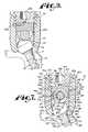
- FIG. 7is an enlarged and partial cross-sectional view taken along the line 7 - 7 of FIG. 6 of the receiver, the first and second compression members, the dynamic fixation connecting member assembly and the closure member, also shown with the shank in side elevation implanted in a vertebra and disposed at an angle with respect to the receiver.
- FIG. 8is an enlarged and partial cross-sectional view, similar to FIG. 7 , shown without the closure member and showing the dynamic fixation connecting member assembly and the second upper compression member removed and further showing a different sized connecting member and cooperating upper compression member for insertion in the receiver.
- FIG. 9is an enlarged and partial cross-sectional view, similar to FIGS. 7 and 8 , showing the different sized connecting member and cooperating upper compression member fully inserted in the receiver with the same closure top as illustrated in FIG. 7 .
- FIG. 10is an exploded and partial front elevational view of a second embodiment of a dynamic fixation connecting member assembly according to the invention including a coil-like outer member and an inner threaded core.
- FIG. 11is an exploded and partial cross-sectional view taken along the line 11 - 11 of FIG. 10 .
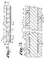
- FIG. 12is a partial front elevational view of the dynamic fixation connecting member of FIG. 10 , showing the threaded core fully inserted in the coil-like member.
- FIG. 13is an enlarged and partial cross-sectional view taken along the line 13 - 13 of FIG. 12 .
- FIG. 14is a partial and exploded perspective view of the dynamic fixation assembly according to the invention illustrated in FIG. 5 replacing the connecting member assembly of FIGS. 1-4 with the connecting member assembly of FIGS. 10-13 .
- FIG. 15is an enlarged perspective view of an assembled dynamic fixation assembly of FIG. 14 with portions broken away to show detail thereof.
- FIG. 16is an enlarged and partial cross-sectional view taken along the line 16 - 16 of FIG. 15 and along the line 16 - 16 of FIG. 12 , but shown with the shank in side elevation implanted in a vertebra and disposed at an angle with respect to the receiver.
- FIG. 17is an enlarged and partial cross-sectional view, similar to FIG. 16 , showing a second bone screw assembly attached to the dynamic fixation assembly of FIG. 1 near an end thereof, along the line 17 - 17 of FIG. 12 , and with a further portion broken away to show detail thereof.
- FIG. 18is an exploded front elevational view of a third embodiment of a dynamic fixation connecting member assembly according to the invention including an outer coil-like member and an inner threaded core.
- FIG. 19is an enlarged front elevational view of the dynamic fixation connecting member of FIG. 18 , showing the threaded core fully inserted in the coil-like member.
- FIG. 20is an enlarged cross-sectional view taken along the line 20 - 20 of FIG. 19 .
- FIG. 21is an enlarged and partial cross-sectional view of a portion of the assembly shown in FIG. 20 .
- FIG. 22is an enlarged, partial and exploded perspective view of a second, alternative dynamic fixation bone screw assembly according to the invention including a bone screw shank, a receiver, a retaining structure, a first lower compression member, the dynamic fixation connecting member assembly of FIG. 10 , a second upper compression member and a closure member.
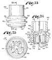
- FIG. 23is an enlarged front elevational view of the closure member of FIG. 22 .
- FIG. 24is a cross-sectional view taken along the line 24 - 24 of FIG. 23 .
- FIG. 25is an enlarged top plan view of the closure member of FIG. 23 .
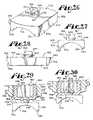
- FIG. 26is an enlarged perspective view of the upper compression member of FIG. 22 .
- FIG. 27is an enlarged front elevational view of the upper compression member of FIG. 26 .
- FIG. 28is an enlarged side elevational view of the upper compression member of FIG. 26 .
- FIG. 29is an enlarged and partial cross-sectional view of the closure member, similar to FIG. 24 and further showing the upper compression member in front elevation prior to attachment to the closure member.
- FIG. 30is an enlarged and partial cross-sectional view of the closure member and front elevational view of the upper compression member, similar to FIG. 29 , showing the upper compression member attached to the closure member and free to rotate with respect thereto.
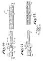
- FIG. 31is an enlarged and partial front elevational view of the assembly of FIG. 22 with portions broken away to show the detail thereof and further showing the upper compression member and closure member partially inserted in the receiver.
- FIG. 32is an enlarged and partial front elevational view similar to FIG. 31 showing the upper compression member and closure member fully seated in the receiver prior to removal of the closure member break-off head.
- FIG. 33is an enlarged and partial front elevational view of the assembly of FIG. 22 with portions broken away to show the detail thereof, and further showing the closure member break-off head removed.
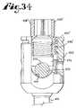
- FIG. 34is an enlarged and partial front elevational view, similar to FIG. 32 , with portions broken away to show the detail thereof and further showing the longitudinal connecting member assembly and upper compression structure of FIG. 32 being replaced by a solid rod and a replacement upper compression structure.
- FIG. 35is an exploded and partial front elevational view of a fourth embodiment of a dynamic fixation connecting member assembly according to the invention including a coil-like member, a cylindrical core with fixed integral and adjustable supports having helically wound projections.
- FIG. 36is a partial cross-sectional view taken along the line 36 - 36 of FIG. 35 .
- FIG. 37is a partial and exploded perspective view of a third embodiment of a dynamic fixation bone screw assembly according to the invention including a bone screw shank, a receiver, a retaining structure, the dynamic fixation connecting member assembly of FIG. 35 , and a closure member.
- FIG. 38is an enlarged perspective view of an adjustable support of FIG. 35 .
- FIG. 39is a perspective view showing three bone screw assemblies according to FIG. 37 with the dynamic fixation connecting member assembly of FIG. 35 and including two adjustable supports of FIG. 38 , with a portion exploded and portions broken away to show detail thereof.
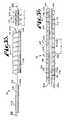
- FIG. 40is an exploded and partial front elevational view of a fifth embodiment of a dynamic fixation connecting member assembly according to the invention including an outer coil-like member, an inner cylindrical core and a solid rod integral to the cylindrical core.
- FIG. 41is an exploded and partial cross-sectional view taken along the line 41 - 41 of FIG. 40 .
- FIG. 42is a cross-sectional view of the inner coil-like member, taken along the line 42 - 42 of FIG. 40 .
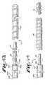
- FIG. 43is an exploded and partial front elevational view of a sixth embodiment of a dynamic fixation connecting member assembly according to the invention including an outer coil-like member a threaded inner cylindrical core and a solid rod integral with the threaded core.
- FIG. 44is an exploded and partial front elevational view of a seventh embodiment of a dynamic fixation connecting member assembly according to the invention including an outer coil-like member, an inner cylindrical core, at least one threaded insert and a solid rod integral with the cylindrical core.
- the reference numeral 1generally designates a non-fusion dynamic stabilization longitudinal connecting member assembly according to the present invention.
- the connecting member assembly 1includes an outer, cannulated coil-like connecting member 4 and a solid cylindrical core or insert 8 , receivable in the coil-like member 4 and fixed thereto at only one end of the inert 8 as will be described more fully below.
- the dynamic connecting member assembly 1cooperates with at least a pair of fixed or polyaxial bone screw assemblies according to the invention, one of such assemblies, generally 10 , being shown in the drawings.
- the assembly 10includes a shank 14 that further includes a body 16 integral with an upwardly extending, substantially cylindrical upper end or capture structure 18 ; a receiver or head 20 ; a retaining and articulating structure 22 ; a first lower compression structure 24 and a second upper compression structure 26 .
- the shank 14 , the receiver 20 , the retaining and articulating structure 22 and the first compression structure 24are preferably assembled prior to implantation of the shank body 16 into a vertebra 28 . It is noted that any reference to the words top, bottom, up and down, and the like, in this application refers to the alignment shown in the various drawings, as well as the normal connotations applied to such devices, and is not intended to restrict positioning of the assemblies 1 and 10 in actual use.
- FIGS. 5-7further show a closure structure, generally 30 , of the invention for capturing the longitudinal connecting member assembly 1 within the receiver 20 .
- the closure structure 30presses against the second compression structure 26 that in turn presses against the outer coil-like member 4 that in turn presses against the compression structure 24 .
- the compression structure 24in turn presses against the retaining and articulating structure 22 that is threadably mated or in other ways connected to the capture structure 18 .
- the compression structure 26also presses against the compression structure 24 and the compression structures 24 and 26 bias the retaining and articulating structure 22 into fixed frictional contact with the receiver 20 , so as to substantially attach and orient the longitudinal connecting member assembly 1 relative to the vertebra 28 and yet allow for relative movement of the outer coil-like member 4 with respect to the inner cylindrical core 8 , providing relief (e.g., shock absorption) and protected movement with respect to flexion, extension, distraction and compressive forces placed on the assembly 1 and two or more connected assemblies 10 .
- the coil-like member 4is also able to twist or turn with respect to the cylindrical core 8 , providing relief for torsional stresses.
- the solid inner core 8does not participate in or provide any means for torsional elasticity or axial compression and distraction along a length of the outer coil 4 .
- the receiver 20 , the shank 14 , the retaining and articulating structure 22 and the compression structures 24 and 26cooperate in such a manner that the receiver 20 and the shank 14 can be secured at any of a plurality of angles, articulations or rotational alignments relative to one another and within a selected range of angles both from side to side and from front to rear, to enable flexible or articulated engagement of the receiver 20 with the shank 14 until both are locked or fixed relative to each other.
- the connecting assembly 1could involve the use of an upper compression member in an open receiver that is integral or fixed in position with respect to a bone screw shank or bone hook, or that the receiver could have limited angular movement with respect to the shank, such as a hinged connection.
- the longitudinal connecting member assembly 1is elongate, with the outer coil-like member 4 being made from metal or metal alloys or other suitable materials, including plastic polymers, PEEK and UHMWP, and the inner cylindrical core 8 also made from plastics, such as polyurethanes, or metals, preferably from a metal or metal alloy that is coated or covered with a thin, hard slick material applied to it or chemically treated on it.
- the core 8includes a solid elongate, smooth-surfaced cylinder 40 having a central axis A. It may at times include a stop or rim 42 integral or fixedly attached to the cylinder 40 at an end 43 thereof. The stop 42 is substantially coaxial with the cylinder 40 .
- the stop 42includes a flat abutment surface 44 and an outer cylindrical surface 46 .
- a snap-on attachment nob or nub 48protrudes in a radial direction from a lower portion 49 of the elongate cylinder 40 and near the end 43 thereof. Near an opposite end 50 thereof, the cylinder 40 does not include structure for fixed attachment to the coil-like member 4 .
- the cylinder 40has a substantially uniform outer radius that is slightly smaller than an inner radius of an internal substantially cylindrical surface 54 of the coil-like member 4 , providing a slight gap 51 about the cylinder 40 ( FIG. 7 ), substantially annular in cross-section, located between the cylinder 40 and the surface 54 when the cylinder 40 is inserted into and fully received by the coil-like member 4 .
- the gap 51 that spans along a substantial length of the cylinder 40 from the lower portion 49 to the end 50allows for sliding, axial (back and forth) movement of the coil-like member 4 with respect to the cylinder 40 , along the axis A as well as twisting or torsional movement by the member 4 .
- the coil-like member 4is also substantially cylindrical with an external substantially cylindrical surface 52 and the internal substantially cylindrical and smooth surface 54 previously identified herein.
- the surface 54defines a bore 56 with a circular cross section, the bore 56 extending completely or substantially through the coil-like member 4 .
- the member 4has a substantially flat and annular end surface 58 and a substantially flat and annular opposite end surface 59 .
- the member 4further includes a helical slit 60 that extends therethrough from the external surface 52 to the internal surface 54 and beginning at a location 62 near the end surface 58 and winding along an entire or substantial length of the coil-like member 4 .
- the slit 60 illustrated in FIG. 1runs through the end surface 59 (shown in phantom).
- the slit 60may end at or near the end surface 59 . It is also foreseen that the slit 60 may extend through the end surface 58 .
- a circular, U-shaped surface 66defines a recess 68 at the internal surface 54 and located between the end surface 58 and the location 62 marking the beginning of the helical slit 60 .
- the recess 68is substantially annular and is sized and shaped to receive the nob 48 at any location therealong when the inner core 8 is received in the outer coil-like member 4 with the surface 58 abutting the surface 44 .
- the cooperation between the nob 48 and the recess 68provides a “snap” fit between the core 8 and the outer coil-like member 4 , fixing the core 8 to the member 4 at the respective ends 43 and 58 .
- the coil-like member internal cylindrical surface 54is of a slightly greater diameter than an outer diameter of the cylinder 40 , allowing for axially directed sliding movement of the coil-like member 4 with respect to the solid cylinder 40 . It is foreseen that the lower portion 49 of the cylinder 40 may have a diameter slightly greater than the diameter of a remainder of the solid cylinder 40 , providing for frictional engagement between the lower portion 49 and the internal surface 54 of the coil-like member 4 , giving some additional attachment and reinforcement of the snap fit between the member 4 and the core 8 near or at the nob 48 .
- the core 8When the cylindrical core 8 is inserted in the coil-like member 4 and the nob 48 engages the recess 68 , the core 8 extends completely or substantially through the bore 56 along the axis A and along a substantial length of the coil-like member 4 to near the end surface 59 , with the end surface 50 being near or adjacent the end surface 59 .
- the coil-like member 4is not fixed to the solid core 8 at or near the end surfaces 50 and 59 .
- the bone screw assembly 10is sized and shaped to frictionally engage the coil-like member 4 without crushing or otherwise frictionally engaging or fixing the coil-like member 4 against the core 8 within any cooperating bone screw assembly 10 , thus allowing for relative movement between the coil-like member 4 and the solid core 8 along a substantial length of the assembly 1 .
- the core 8may be sized and made from such materials as to provide for a relatively more rigid assembly 1 or a relatively more flexible assembly 1 with respect to flex or bendability along the assembly 1 . Such flexibility therefore may be varied by changing the outer diameter of the core 8 and thus likewise changing the diametric size of the coil-like member 4 . Also, it is noted that longer assemblies 1 may need to be stiffer and thus larger in diameter than shorter assemblies 1 . In addition, since the distance between the bone screw assembly receivers or heads can vary, the coil-case assembly may need to be more or less stiff.
- an inner or outer sleeve or sheath-like structuremay be placed, adhered or otherwise applied to either the external surface 52 or the internal surface 54 of the coil-like member 4 .
- Such a sheath-like structurewould be of a size and shape such that axial movement of the coil-like member 4 is not hindered and thus any relative movement between the coil-like member 4 and the cylindrical core 8 is not hindered or prevented.
- the shank 14 of the bone screw assembly 10is elongate, with the shank body 16 having a helically wound, radially outwardly extending bone implantable thread 122 axially extending from near a tip 124 of the body 16 to near a slanted or sloped surface 126 that is adjacent to a smooth cylindrical surface 128 located adjacent to the capture structure 18 .
- the laterally projecting cylindrical surface 128includes a buttress stop feature for frictional engagement with and placement of the retaining and articulating structure 22 .
- the body 16 utilizing the thread 122 for gripping and advancementis implanted into the vertebra 28 leading with the tip 124 and driven down into the vertebra 28 with an installation or driving tool so as to be implanted in the vertebra 28 to near the sloped surface 126 .
- an outer surface 129 of the shank body 16 that includes the thread 121 and extends between the surface 126 and the tip 124is coated, perforated, made porous or otherwise treated 130 .
- the treatment 130may include, but is not limited to a plasma spray coating or other type of coating of a metal or, for example, a calcium phosphate; or a roughening, perforation or indentation in the surface 129 , such as by sputtering, sand blasting or acid etching, that allows for bony ingrowth or ongrowth. Certain metal coatings act as a scaffold for bone ingrowth.
- Bio-ceramic calcium phosphate coatingsinclude, but are not limited to: alpha-tri-calcium phosphate and beta-tri-calcium phosphate (Ca 3 (PO 4 ) 2 , tetra-calcium phosphate (Ca 4 P 2 O 9 ), amorphous calcium phosphate and hydroxyapatite (Ca 10 (PO 4 ) 6 (OH) 2 ).
- Coating with hydroxyapatitefor example, is desirable as hydroxyapatite is chemically similar to bone with respect to mineral content and has been identified as being bioactive and thus not only supportive of bone ingrowth, but actively taking part in bone bonding.
- the sloped surface 126extends radially outward and axially upward from the shank body 16 to the cylindrical projection 128 . Further extending axially from the projection 128 is the capture structure 18 that provides a connective or capture apparatus disposed at a distance from the threaded shank body 16 and thus at a distance from the vertebra 28 when the body 16 is implanted in the vertebra 28 .
- the capture structure 18is configured for connecting the shank 14 to the receiver 20 and capturing the shank 14 in the receiver 20 .
- the capture structure 18has an outer substantially cylindrical surface 134 having a helically wound guide and advancement structure thereon which in the illustrated embodiment is a V-shaped thread 136 extending from adjacent the cylindrical surface 128 to adjacent an annular top or upper surface 138 .
- the upper surface 138is disposed substantially perpendicular to an axis of rotation B of the shank 14 .
- a diameter of the cylindrical surface 134 measured between roots of the thread 136is smaller than a diameter of the projected cylindrical surface 128 .
- a diameter measured between crests of the thread 136is illustrated equal to and may be smaller than the diameter of the cylindrical surface 128 .
- a hex-shaped driving formation 144extends from the upper surface 138 into the capture structure 18 .
- the driving formation 144is sized and shaped to cooperate with a hex-driver for rotating and driving the shank body 16 into bone. It is foreseen that other driving features or apertures, such as slotted, tri-wing, hexalobular (such as the 6-point star shaped pattern sold under the trademark TORX), spanner, or the like may also be utilized according to the invention.
- the shank 14is cannulated with a small central bore 149 extending an entire length of the shank along axis B.
- the bore 149is coaxial with the threaded body 16 and the capture structure outer surface 134 , providing a passage through the shank interior for a length of wire or pin inserted into the vertebra 28 prior to the insertion of the shank body 16 , the wire or pin providing a guide for insertion of the shank body 16 into the vertebra 28 .
- the receiver 20includes a base 150 integral with a pair of opposed upstanding arms 152 that extend from the base 150 to a top surface 154 .
- the arms 152form a U-shaped cradle and define a U-shaped channel 156 between the arms 152 and include an upper opening 157 and a lower seat 158 having substantially the same radius as the outer coil-like member 4 of the longitudinal connecting member assembly 1 for operably snugly receiving the member assembly 1 .
- Each of the arms 152has an interior surface that defines an inner cylindrical profile and includes a partial helically wound guide and advancement structure 162 .
- the guide and advancement structure 162is a partial helically wound flangeform configured to mate under rotation with a similar structure on the closure member 30 , as described more fully below.
- the guide and advancement structure 162could alternatively be a buttress thread, a square thread, a reverse angle thread or other thread like or non-thread like helically wound advancement structures for operably guiding under rotation and advancing the closure 30 downward between the arms 152 and having such a nature as to resist splaying of the arms 152 when the closure 30 is advanced into the U-shaped channel 156 .
- Each of the arms 152includes a V-shaped or undercut tool engagement groove 164 formed on a substantially planar outer surface 166 thereof which may be used for holding the receiver 20 with a holding tool (not shown) having projections that are received within the grooves 164 during implantation of the shank body 16 into the vertebra 28 .
- the grooves 164may also cooperate with a holding tool during bone screw assembly and during subsequent installation of the connecting member 1 and closure 30 . It is foreseen that tool receiving grooves or apertures may be configured in a variety of shapes and sizes and be disposed at other locations on the arms 152 .
- a chamber or cavity 178Communicating with the U-shaped channel 156 and located within the base 150 of the receiver 20 is a chamber or cavity 178 partially defined by an inner cylindrical surface 180 and a substantially spherical seating surface 182 , the cavity 178 opening upwardly into the U-shaped channel 156 .
- the base 150further includes a restrictive neck 183 adjacent the seating surface 182 .
- the neck 183defines an opening or bore communicating with the cavity 178 and a lower exterior 186 of the base 150 .
- the neck 183is conically counterbored or beveled to widen the angular range of the shank 14 .
- the neck 183is sized and shaped to be smaller than a radial dimension of a fixed or fully expanded retaining and articulating structure 22 so as to form a restriction at the location of the neck 183 relative to the retaining and articulating structure 22 , to prevent the structure 22 from passing from the cavity 178 and out into the lower exterior 186 of the receiver 20 when the retaining and articulating structure 22 is seated on the seating surface 182 .
- the retaining and articulating structurecould be compressible (such as where such structure has a missing section) and could be loaded through the neck 183 and then allowed to expand and fully seat in the spherical seating surface 182 .
- Other bottom loading capture structurescould be utilized.
- the retaining and articulating structure 22has an operational central axis that is the same as the elongate axis B associated with the shank 14 .
- the retaining and articulating structure 22has a central bore 190 that passes entirely through the structure 22 from a top surface 192 to a bottom surface 194 thereof.
- An inner cylindrical surface 196defines a substantial portion of the bore 190 , the surface 196 having a helically wound guide and advancement structure thereon as shown by a v-shaped helical rib or thread 198 extending from adjacent the top surface 192 to near the bottom surface 194 .
- helical rib 198Although a simple helical rib 198 is shown in the drawings, it is foreseen that other helical structures including other types of threads, such as buttress and reverse angle threads, and non threads, such as helically wound flanges with interlocking surfaces, may be alternatively used in an alternative embodiment of the present invention.
- the inner cylindrical surface 196 with the thread 198are configured to mate under rotation with the capture structure outer surface 134 and helical guide and advancement structure or thread 136 .
- the illustrated retaining and articulating structure 22has a radially outer partially spherically shaped surface 204 sized and shaped to mate with the partial spherically shaped seating surface 182 of the receiver and having a radius approximately equal to the radius associated with the surface 182 .
- the retaining and articulating structure radiusis larger than the radius of the neck 183 of the receiver 20 .
- the outer partially spherically shaped surface 204may be a high friction surface such as a knurled surface or the like.
- the retaining and articulating structure outer surfacemay be elliptical or ellipsoid in shape rather than spheroid in shape.
- Such an elliptical surfacewould be sized and shaped to contact and seat within a substantially spherical seating surface, such as the seating surface 182 .
- Such an ellipsoid structuremay be attachable to the shank upper portion by threads, a pin, compression, or the like as previously described with respect to the substantially spherical retaining and articulating structure 22 .
- an ellipsoid retaining structuremay be integral with the bone screw shank and may include threads that allow the ellipsoid to be threadably received into a base of a bone screw receiver.
- other types of retaining structure, articulating and not,could be used to keep the upper end of the shank contained within the receiver.
- the illustrated retaining and articulating structure top surface 192extends from the central bore 190 to the outer surface 204 .
- the top surface 192is disposed perpendicular to an axis of rotation of the structure 22 .
- the bottom surface 294also is disposed perpendicular to the structure 22 axis of rotation.
- the lower compression structure 24includes a body 210 of substantially circular cross-section integral with a pair of upstanding arms 212 .
- the body 210 and arms 212form a generally U-shaped, open, through-channel 214 having a partially U-shaped bottom seating surface 216 having a radius substantially conforming to an outer radius of the coil-like member 4 and thus configured to operably snugly engage the coil member 4 at the outer surface 52 thereof.
- the arms 212 disposed on either side of the channel 214each include a top surface 218 that is parallel to an annular bottom surface 220 .
- the compression structure 24includes a substantially cylindrical outer surface 222 and an inner cylindrical wall 224 defining a central through-bore extending along a central axis of the compression structure 24 .
- the top surface 218 and the bottom surface 220are substantially parallel. Extending between the inner cylindrical wall 224 and the bottom surface 220 is a curved or spherical surface 226 sized and shaped to frictionally engage and mate with the outer spherical surface 204 of the retaining and articulating structure 22 .
- the cylindrical surface 222has a diameter slightly smaller than a diameter between crests of the guide and advancement structure 162 allowing for top loading of the compression structure 24 .
- the cylindrical surface 222 diameter and a height of the compression structure 24 measured from the top surface 218 to the bottom surface 220are sized such that the compression structure 24 is received within the cylindrical surface 180 of the receiver 20 below the guide and advancement structure 162 , but the bottom surface 220 is spaced from a surface 227 of the receiver base 150 regardless of the angular position of the shank 14 with respect to the receiver 20 .
- the upper or second compression structure 26includes a body 230 of substantially circular cross-section integral with a pair of downwardly extending arms 232 .
- the body 230 and the arms 232form a generally U-shaped, open, through-channel having a substantially U-shaped seating surface 236 having a radius substantially conforming to the outer radius of the coil-like member 4 and thus configured to operably snugly engage the coil member 4 at the external surface 52 thereof opposite the first or lower compression structure 24 .
- the arms 232each included a bottom surface 238 that is parallel to a planar top surface 240 .
- the compression structure 26includes a substantially cylindrical outer surface 242 .
- a pin 244 of substantially circular cross sectionis disposed centrally on the top surface 240 and extends upwardly therefrom, being sized and shaped to fit within a central aperture of the closure 30 to be discussed more fully below.
- the cylindrical surface 242has a diameter slightly smaller than a diameter between crests of the guide and advancement structure 162 allowing for top loading of the compression structure 26 .
- the second compression structure 26is sized and shaped to abut against both the compression structure 24 and the coil-like member 4 when pressed upon by the closure 30 , allowing for clamping of the coil-like member 4 between the insert 26 and the insert 24 as well as additional compressive force being placed against the compression structure 24 that in turn presses the retaining and articulating structure 22 against the spherical seating surface 182 of the receiver 20 , clamping the bone screw shank 14 into a fixed angular position with respect to the receiver 20 as illustrated in FIG. 7 .
- the closure structure 30can be any of a variety of different types of closure structures for use in conjunction with the present invention with suitable mating structure on the upstanding arms 152 of the receiver 20 .
- the closure structure 30is rotatable between the spaced arms 152 , but could be a slide-in closure structure.
- the illustrated structure closure structure 30is substantially cylindrical and includes an outer helically wound guide and advancement structure in the form of a flange form 250 .
- the illustrated guide and advancement structure 250operably joins with the guide and advancement structure 162 disposed on the interior of the arms 152 .
- the flange form 250has a protrusion 251 that projects rearwardly from a trailing surface thereof that effectively locks the closure structure 30 to the structure 162 within which it is set so as to prevent splaying of the arms 152 upon which mating guide and advancement structure 162 is mounted.
- the guide and advancement structure 250 utilized in accordance with the present inventionmay take other forms, including those described in Applicant's U.S. Pat. No. 6,726,689, which is incorporated herein by reference.
- the guide and advancement structure 250could alternatively be a buttress thread, a square thread, a reverse angle thread or other thread like or non-thread like helically wound advancement structure for operably guiding under rotation and advancing the closure structure 30 downward between the arms 152 and having such a nature as to resist splaying of the arms 152 when the closure structure 30 is advanced into the U-shaped channel 156 .
- the closure structure 30includes a lower surface 256 having a central recess 258 formed thereon.
- the recess 258is substantially cylindrical having a central axis operationally coaxial with the receiver 20 and the second compression structure 26 .
- the lower surface 256is planar.
- the central recess 258is sized and shaped to receive the pin 244 of the compression structure 26 , with the lower surface 256 frictionally engaging the top planar surface 240 of the compression structure 26 when fully mated therewith, as illustrated in FIG. 7 .
- the closure structure 30has a top surface 260 with an internal drive in the form of an aperture 262 , illustrated as a star-shaped internal drive, for example, sold under the trademark TORX.
- a driving tool(not shown) sized and shaped for engagement with the internal drive 262 is used for both rotatable engagement and, if needed, disengagement of the closure 30 from the arms 152 .
- a star-shaped internal drive 258is shown in the drawings, the tool engagement structure may take a variety of tool-engaging forms and may include but is not limited to a hex shape or more than one aperture of various shapes.
- closure structure 30may alternatively include a break-off head designed to allow such a head to break from a base of the closure at a preselected torque, for example, 70 to 140 inch pounds.
- a closure structurewould also include a base having an internal drive to be used for closure removal.
- the lower surface 256engages the upper compression structure 26 that in turn engages the outer coil-like member 4 of the connecting assembly 1 .
- the closure structure 30is rotated, using a tool engaged with the inner drive 262 until a selected pressure is reached at which point the longitudinal connecting assembly 1 is urged toward, but not completely to the lower seat 158 of the channel 156 .
- the coil-like member 4braces against the lower compression structure 24 .
- the pressure placed on the outer surface of the coil-like member 4 by the closure structure 30is sufficient to clamp the member 4 between the upper and lower compression structures 24 and 26 , but not enough to crush or press the coil-like member 4 into fixed engagement with the cylinder 40 of the core 8 because of the engagement of the lower surfaces 238 of the compression structure 26 with the top surfaces 218 of the compression structure 24 .
- Engagement between the surfaces 238 and 218allow for additional torquing of the closure structure 30 to fix the bone screw shank 14 between the compression structure 24 and the receiver seating surface 182 , without crushing the coil-like member 4 against the core 8 .
- about 50 to about 80 inch pounds of pressureare required for fixing the connecting assembly 1 in place without crushing the coil-like member 4 against the core 8 .
- the retaining and articulating structure 22Prior to the polyaxial bone screw assembly 10 being implanted in the vertebra 28 , the retaining and articulating structure 22 is typically first inserted or top-loaded, into the receiver U-shaped channel 156 , and then into the cavity 178 to dispose the structure 22 adjacent the inner seating surface 182 of the receiver 20 .
- the shank capture structure 18is preloaded, inserted or bottom-loaded into the receiver 20 at the neck bore 183 .
- the retaining and articulating structure 22now disposed in the receiver 20 is coaxially aligned with the shank capture structure 18 so that the helical v-shaped thread 136 rotatingly mates with the thread 198 of the retaining and articulating structure 22 .
- the shank 14 and/or the retaining and articulating structure 22are rotated to fully mate the structures 136 and 198 , fixing the capture structure 18 to the retaining and articulating structure 22 .
- the shank 14is in slidable and rotatable engagement with respect to the receiver 20 , while the retaining and articulating structure 22 and the lower aperture or neck 183 of the receiver 20 cooperate to maintain the shank body 16 in rotational relation with the receiver 20 .
- the shank body 16can be rotated through a substantial angular rotation relative to the receiver 20 , both from side to side and from front to rear so as to substantially provide a universal or ball joint wherein the angle of rotation is only restricted by engagement of the sloped surface 126 of the shank body 16 with the neck 183 of the receiver 20 .
- the compression structure 24is then loaded into the receiver 20 with the U-shaped seating surface 216 aligned with the receiver 20 U-shaped channel 156 .
- the compression structure 24is initially top or down-loaded into the receiver 20 until the arms 212 are disposed adjacent to the surface 180 and the bottom spherical surface 226 is in contact with the surface 204 of the retaining and articulating structure 22 .
- the shank 14 , the receiver 20 and the compression structure 24 central axesare aligned along axis B, providing access to the hex-shaped formation 144 on the shank capture structure 18 through the central bore formed by the inner cylindrical wall 224 of the compression structure 24 .
- the assembly 10is then typically screwed into a bone, such as the vertebra 28 , by rotation of the shank 14 using a driving tool (not shown) with an Allen type driving formation that operably drives and rotates the shank 14 by engagement thereof with the shank at the driving formation 144 .
- a driving tool(not shown) with an Allen type driving formation that operably drives and rotates the shank 14 by engagement thereof with the shank at the driving formation 144 .
- the hex-shaped driving formation 144may be replaced by other types of foot print type tool engaging formations or recesses.
- the retaining structure and the shankmay also be crimped together so as to not come apart with rotation.
- each vertebra 28may be pre-drilled to minimize stressing the bone.
- each vertebrawill have a guide wire or pin (not shown) inserted therein that is shaped for the bone screw cannula 149 of the bone screw shank and provides a guide for the placement and angle of the shank 14 with respect to the vertebra 28 .
- a further tap holemay be made and the shank body 16 is then driven into the vertebra 28 , by rotation of the driving tool (not shown). It is foreseen that the screws and the longitudinal connecting member can be inserted in a percutaneous or minimally invasive surgical manner.
- the longitudinal connecting member assembly 1is assembled by inserting the cylinder 40 of the core 8 into the bore 56 defined by the inner cylindrical surface 54 of the coil-like member 4 .
- the end 50 of the core 8is placed into the open end 58 of the coil-like member 4 and the member 4 is moved toward the stop or rim 42 until the nub 48 snaps into the recess 68 , with the end 58 preferably in frictional contact with the flat abutment surface 44 .
- the connecting member assembly 1is eventually positioned in an open or percutaneous manner within the U-shaped channels 156 of two or more bone screw assemblies 10 .
- the assembly 1can be straight, pre-bent or curvilinear.
- the second or upper compression structure 24is then placed in each assembly 10 with the U-shaped seating surface 236 facing the coil-like member 4 .
- the closure structure 30is then inserted into and advanced between the arms 152 . As the closure structure 30 is rotated between the arms 152 , the central recess or aperture 258 receives the pin 244 of the compression member 26 , centering the member 26 with respect to the receiver 20 and the connecting member assembly 1 .
- the cylindrical surfaces 216 and 236 of the compression structures 24 and 26respectively, cradle and protect the coil-like member 4 from crushing against the core 8 .
- the upper and lower compression structures 24 and 26provide for the gap 51 to exist between the cylinder 40 of the core 8 and the coil-like member 4 such that relative movement between the cylinder 40 and the member 4 is possible, along substantially the entire length of the cylinder 40 with the exception of the end portion 49 that is attached to the member 4 with the snap-on nob 48 and cooperating recess 68 formed by the inner surface 66 .
- disassemblyis accomplished by using the driving tool (not shown) with a star-shaped driving formation on the closure structure 30 internal drive 262 to rotate and remove the closure structure 39 from the receiver 20 . Disassembly of the assembly 10 is accomplished in reverse order to the procedure described previously herein for assembly.
- the polyaxial bone screw assembly 10advantageously allows for the removal and replacement of the longitudinal connecting member assembly 1 with another longitudinal connecting member having a different overall or outer diameter, utilizing the same receiver 20 and the same lower compression structure 24 .
- the flexible longitudinal member connecting assembly 1 having an outer diameter Fmay be removed and replaced by a more rigid assembly, such as a solid rod 280 having an outer diameter G that is smaller than the diameter F of the outer coil-like member 4 .
- the rod 280is inserted into the receiver opening 157 followed by a cooperating upper compression structure 286 , and then the closure structure 30 is re-inserted and tightened within the receiver 20 .
- the upper compression structure 286is substantially similar to the compression structure 26 with the exception that the structure 286 is sized and shaped to include a mating surface 288 for closely cooperating with and contacting an outer cylindrical surface 290 of the longitudinal connecting member 280 .
- the surface 288has an inner radius of curvature almost identical to an outer radius of curvature of the surface 290 .
- the compression structure 286further includes an upper pin 292 identical or substantially similar to the pin 244 described previously with respect to the compression structure 26 .
- the pin 292is receivable in the central recess 258 of the closure structure 30 , ensuring that when fully assembled in the receiver 20 , the compression structure 26 is properly centered and in full contact with the rod 280 , which in turn centers the rod 280 with respect to the lower compression member 24 for optimum contact between the rod 280 and the lower compression member 24 . It is not necessary that the lower compression member 24 be in contact with the rod 280 along the entire surface 216 thereof for adequate capture and fixing of the solid rod 280 with respect to the receiver 20 and the shank 14 .
- the reference numeral 1 Agenerally designates a second embodiment of a non-fusion dynamic stabilization longitudinal connecting member assembly according to the present invention.
- the connecting member assembly 1 Aincludes an outer, cannulated coil-like connecting member 4 A and a substantially cylindrical core or insert 8 A, having an outer helical thread 9 A, the core being threadably receivable in the coil-like member 4 A and fixed thereto at only one end of the core 8 A as will be described more fully below.
- the dynamic connecting member assembly 1 Acooperates with at least a pair of polyaxial bone screw assemblies according to the invention, one of such assemblies, generally 10 , shown in FIGS. 14-17 and previously described herein with reference to FIGS. 5-9 .
- the closure structure 30also shown in FIGS.
- reliefe.g., shock absorption
- the coil-like member 4 Ais also able to twist or turn with respect to the cylindrical core 8 A, providing relief for torsional stresses.
- the inner core 8 Adoes not participate in or provide any means for torsional elasticity or axial compression and distraction along a length of the outer coil 4 A.
- the longitudinal connecting member assembly 1 Ais elongate, with both the outer coil-like member 4 A and the inner core 8 A being made from metal, metal alloys, composites or other suitable materials, including plastic polymers, such as ultra-high molecular weight polyethylene (UHMWP) and/or polyetheretherketone (PEEK). Also, in order to result in adequate hardness and low or no wear debris, the member 4 A surfaces and the core 8 A surfaces may be coated with an ultra thin, ultra hard, ultra slick and ultra smooth coating, such as may be obtained from ion bonding techniques and/or other gas or chemical treatments.
- UHMWPultra-high molecular weight polyethylene
- PEEKpolyetheretherketone
- the member 4 A surfaces and the core 8 A surfacesmay be coated with an ultra thin, ultra hard, ultra slick and ultra smooth coating, such as may be obtained from ion bonding techniques and/or other gas or chemical treatments.
- the core 8 A illustrated in the drawing figuresis solid, elongate cylinder, having a central axis AA. It is foreseen that the core 8 A may also be a hollow cylinder.
- the core 8 Aincludes a smooth cylindrical surface 40 A.
- the core 8 Amay include a stop or rim 42 A integral or fixedly attached to the core 8 A at an end 43 A thereof.
- the stop 42 Ais substantially coaxial with the cylinder 40 A. In the embodiment shown, the stop 42 A includes a flat abutment surface 44 A and an outer cylindrical surface 46 A.
- the stop 42 Amay be replaced by an elongate connecting member, such as a solid rod, allowing for more rigid support, and fusion, if desired, along a portion of the spine adjacent to the spine portion receiving dynamic stabilization by the connector 1 A.
- the helical thread 9 Aextends radially outwardly from the surface 40 A of the inner core 8 A and winds about the inner core 8 substantially along a length thereof.
- the illustrated thread 9 Aincludes an end portion 47 A having a thickness and radially length greater than a remainder portion 48 A of the thread 9 A.
- the end portion 47 Ais sized and shaped to have an axial length along the axis AA that corresponds to a width of the receiver 20 that receives and clamps the assembly 1 A into engagement with the assembly 10 .
- the core 8 Ais sized and shaped to attach to the coil-like member 4 A at the cylinder end 43 A, with the end portion 47 A of the thread 9 A frictionally engaging the coil-like member 4 A as will be described more fully below.
- the core 8 Adoes not include structure for fixed attachment to the coil-like member 4 A.
- the cylindrical surface 40 Ahas a substantially uniform outer radius that is slightly smaller than an inner radius of an internal substantially cylindrical surface 54 A of the coil-like member 4 A, providing a slight gap 51 A about the cylindrical surface 40 A, annular in cross-section, located between the cylindrical surface 40 A and the surface 54 A when the inner core 8 A is inserted and threaded into and fully received by the coil-like member 4 A.
- the gap 51 A that spans along the length of the cylinder 40 A from near the end stop 42 A to the end 50 Aallows for limited sliding, axial (back and forth) movement of the coil-like member 4 A with respect to the core 8 A, along the axis AA as well as some twisting or torsional movement by the member 4 A about the core 8 A.
- the outer coil-like member 4 Ais also substantially cylindrical with an external substantially cylindrical surface 52 A and the internal substantially cylindrical and smooth surface 54 A previously identified herein.
- the surface 54 Adefines a bore 56 A with a circular cross section, the bore 56 A extending completely or substantially through the coil-like member 4 A.
- the member 4 Ahas a substantially flat and annular end surface 58 A and a curved or bullet-nosed opposite end 59 A. It is noted that in some embodiments, the end surface 59 A may also be substantially flat and annular.
- the bullet-nosed end 59 Aallows for ease in implanting the assembly 1 A, particularly in minimally invasive or less invasive procedures, that may be percutaneous in nature.
- the member 4 Afurther includes a helical slit 60 A that extends therethrough from the external surface 52 A to the internal surface 54 A and beginning at a location 62 A at the end surface 58 A and winding along an entire or substantial length of the coil-like member 4 A.
- the slit 60 Aruns to near the bullet nose end 59 A.
- the slit 60 Aextends through the end surface 58 A to allow for threadably mating the thread 9 A of the inner core 8 A with the slit 60 A.
- the cooperation between the thickened end portion 47 A of the thread 9 A and the surfaces defining the slit 60 Aprovide a friction or press fit between the inner core 8 A and the outer coil-like member 4 A, fixing the core 8 A to the member 4 A near the respective ends 43 A and 58 A, but allowing for an axial gap or space between the remainder portion 48 A of the thread 9 A and the surfaces defining the slit 60 A.
- an outer surface 70 A of the thread portion 47 Ais flush with the outer coil surface 52 A.
- a bone screw assembly 10 receiving and fixing the dynamic fixation assembly 1 A near the stop or rim 42 Africtionally engages both the outer surface 52 A of the coil-like member 4 A and the outer surface 70 A of the thread 9 A of the inner core 8 A.
- the coil-like member internal cylindrical surface 54 Ais of a slightly greater diameter than an outer diameter of the cylindrical surface 40 A, allowing for axially directed sliding movement of the coil-like member 4 A with respect to the solid cylinder 40 A along the thread portion 48 A.
- a portion of the cylindrical surface 40 A near the end 43 Amay have a diameter slightly greater than the diameter of a remainder of the cylindrical surface 40 A, providing for frictional engagement between the surface 40 A and the internal surface 54 A of the coil-like member 4 A, giving some additional attachment and reinforcement of the friction fit between the thread portion 47 A and the member 4 A near the end 43 A.
- the core 8 AWhen the cylindrical inner core 8 A is inserted in the coil-like member 4 A and the thread portion 47 A frictionally engages the coil-like member 4 A at the slit 60 A, the core 8 A extends completely or substantially through the bore 56 A along the axis AA and along a substantial length of the coil-like member 4 A to near the end surface 59 A, with the end surface 50 A being near or adjacent the end surface 59 A.
- the coil-like member 4 Ais not fixed to the solid core 8 A at or near the end surfaces 50 A and 59 A.
- an outer surface 72 A of the portion 48 A of the thread 9 Ais not flush with the outer surface 52 A of the coil-like member, but rather inset or positioned radially inwardly of the surface 52 A, such that when the bone screw assembly 10 frictionally engages the surface 52 A, the surface 72 A is spaced from the bone screw assembly 10 .
- the bone screw assembly 10is sized and shaped to frictionally engage the coil-like member 4 A without crushing or otherwise frictionally engaging or fixing the coil-like member 4 A against the core 8 A within a cooperating bone screw assembly 10 located along the coil-like member 4 A receiving the portion 48 A of the thread 9 A, thus allowing for relative movement between the coil-like member 4 A and the core 8 A.
- the substantial portion 48 A of the thread 9 A of the inner core 8 Ais sized and shaped such that the thread portion 48 A is uniformly spaced from the surfaces defining the helical slit 60 A of the coil-like member 4 A.
- the substantially square thread 9 Aincludes a leading surface 74 A and a trailing surface 76 A.
- the coil-like memberhas surfaces 78 A and 80 A that form the helical slit 60 A. All along the thread portion 48 A, the thread surface 74 A is spaced from the surface coil surface 78 A and the thread surface 76 A is spaced from the coil surface 80 A.
- This spacingalong with the gap 51 A between the outer cylindrical surface 40 A of the thread 9 A and the inner surface 54 A of the coil-like member 4 A, allows for axial and twisting movement of the inner core 8 A with respect to the coil-like member 4 A until an axial movement or motion is sufficient to cause the surface 74 A to abut against the surface 78 A and/or the surface 76 A to abut against the surface 80 A.
- the square thread 48 Acould be V-shaped or some other shape.
- the pitch of the slit 60 Ais substantially the same as the pitch of the thread 9 A of the core 8 A.
- Pitchis the distance measured parallel to the axis AA, between corresponding points on adjacent thread forms in the same axial plane and on the same side of the axis.
- the amount or degree of pitch of the thread 9 A and the slit 60 Amay be chosen based upon the rigidity or stiffness requirements for the assembly 1 A and shock absorption desired.
- pitchi.e., forming a more acute angle between the slant of the thread 9 A and the slit 60 A with respect to the axis AA and therefore increasing the distance between corresponding points on adjacent thread forms in the same axial plane
- a benefit of increasing pitchis a lessening of impact loading between the thread 9 A and the surfaces of the member 4 A defining the helical slit 60 A.
- the inner core 8 Amay be sized and made from such materials as to provide for a relatively more rigid assembly 1 A or a relatively more flexible assembly 1 A with respect to flex or bendability along the assembly 1 A. Such flexibility therefore may be varied by changing the outer diameter of the inner core 8 A and thus likewise changing the diametric size of the coil-like member 4 A. Also, it is noted that longer assemblies 1 A may need to be stiffer and thus larger in diameter than shorter assemblies 1 A. In addition, since the distance between the bone screw assembly heads can vary, the coil-like assembly may need to be more or less stiff.
- an inner or outer sleeve or sheath-like structuremay be placed, adhered or otherwise applied to either the external surface 52 A or the internal surface 54 A of the coil-like member 4 A.
- Such a sheath-like structurewould be of a size and shape such that axial movement of the coil-like member 4 A is not hindered and thus any relative movement between the coil-like member 4 A and the cylindrical core 8 is not hindered or prevented.
- the longitudinal connecting member assembly 1 Acooperates with the bone screw assembly 10 and the closure structure 30 in the same manner as previously described herein with respect to the longitudinal connecting member assembly 1 .
- the longitudinal connecting member assembly 1 Ais first assembled by inserting the inner core 8 A into the bore 56 A defined by the inner cylindrical surface 54 A of the coil-like member 4 A.
- the end 50 A of the inner core 8 Ais placed into the open end 58 A of the coil-like member 4 A with the thread 9 A being received by the slit 60 A at the location 62 A.
- the core 8 Ais then rotated, advancing the thread portion 48 A toward the nose 59 A until the thread portion 47 A engages the surfaces 78 A and 80 A that form the slit 60 A, with the surface 44 A of the stop 42 A abutting against the end surface 58 A of the coil-like member.
- the thread portion 47 Ahaving a thickness greater than the portion 48 A, frictionally engages the surfaces 78 A and 80 A at respective surfaces 74 A and 76 A, fixing the core 8 A to the coil-like member 4 A near the stop 42 A.
- the connecting member assembly 1 Ais eventually positioned in an open or percutaneous manner within the U-shaped channels 156 of two or more bone screw assemblies 10 .
- the second or upper compression structure 24is then placed in each assembly 10 with the U-shaped seating surface 236 facing the coil-like member 4 A.
- the closure structure 30is then inserted into and advanced between the arms 152 . It is noted that it is also possible to insert the closure structure pre-attached to the upper compression structure with the two parts snapped together. As the closure structure 30 is rotated between the arms 152 , the central recess or aperture 258 receives the pin 244 of the compression member 26 , centering the member 26 with respect to the receiver 20 and the connecting member assembly 1 A.
- the compression structure 26also presses against the compression structure 24 at the surface 218 as the closure structure is torqued 30 , clamping the shank body 16 into a fixed position with respect to the receiver 20 .
- the cylindrical surfaces 216 and 236 of the compression structures 24 and 26respectively, cradle and protect the coil-like member 4 A from crushing against the inner core 8 A.
- the compression structures 24 and 26allow for maintaining the gap 51 A between the cylindrical surface 40 A of the core 8 A and the coil-like member 4 A, and also keep the thread portion 48 A spaced from the surfaces 78 A and 80 A that form the slit 60 A and the outer surface 72 A of the thread portion 48 A spaced from the compression members, such that relative movement between the inner core 8 A and the member 4 A is possible, along a length of the core 8 A having the thread portion 48 A thereon.
- a second bone screw assembly 10 ′is illustrated, attached to the assembly 1 A near the end stop 42 A at the location of the thicker thread portion 47 A.
- the assembly 10 ′includes a shank 14 ′, a receiver 20 ′, a retaining and articulating structure 22 ′, a first compression structure 24 ′, a second compression structure 26 ′ and a closure structure 30 ′ the same or substantially similar to the respective shank 14 , receiver 20 , retaining and articulating structure 22 , first compression structure 24 , second compression structure 26 and closure structure 30 of the assembly 10 , and all other corresponding structure previously described herein with respect to the assembly 10 .
- FIG. 17a second bone screw assembly 10 ′ is illustrated, attached to the assembly 1 A near the end stop 42 A at the location of the thicker thread portion 47 A.
- the assembly 10 ′includes a shank 14 ′, a receiver 20 ′, a retaining and articulating structure 22 ′, a first compression structure 24 ′, a second compression structure 26
- the outer surface 70 A of the thread portion 47 Ais flush with the outer surface 52 A of the coil-like member 4 A. Therefore, the compression structures 24 ′ and 26 ′ engage both the surfaces 52 A and 70 A when the closure structure 30 ′ engages the receiver 20 ′ and the compression structure 26 ′, fixing both the coil-like member 4 A and the inner core 8 A within the receiver 20 ′ of the assembly 10 ′.
- disassemblyis accomplished by using the driving tool (not shown) with a star-shaped driving formation on the closure structure 30 internal drive 262 to rotate and remove the closure structure 39 from the receiver 20 .
- Disassembly of the assembly 10 or 10 ′is accomplished in reverse order to the procedure described previously herein for assembly.
- the connecting member assembly 301includes an outer, cannulated coil-like connecting member 304 and a substantially cylindrical core or insert 308 , having an outer helical thread 309 extending radially from an outer cylindrical surface 340 , the core 308 being threadably receivable in the coil-like member 304 and fixed thereto at only one end near an end stop 342 , the thread 309 sized and shaped to be received in spaced relation to a helical slit 360 of the coil-like member 304 .
- the dynamic connecting member assembly 301cooperates with at least a pair of polyaxial bone screw assemblies according to the invention, such as the assembly 10 previously described herein.
- the connecting member assembly 301is substantially similar to the assembly 1 A with the exception that the thread 309 is substantially uniform in size and shape along an entire length thereof, having an outer surface 372 that is disposed radially inwardly of an outer surface 352 of the coil-like member 304 , similar to the surface 72 A of the thread portion 48 A of the assembly 1 A.
- the core 308Near the end stop 342 , the core 308 includes a cylindrical portion 384 of greater diameter than the remaining cylindrical surface 340 , the portion 384 sized and shaped to provide a frictional press fit between the coil-like member 304 and the core 308 at only the portion 384 , when the core 308 is fully received in the coil-like member 304 .
- the core cylindrical surface 340 and the thread 309are in slidable engagement with the coil-like member 304 .
- assemblies 1 A, 301 and 10advantageously allow for replacement of the assembly 1 A or 301 with other connecting member assemblies (dynamic or rigid) having the same or reduced outer diameter.
- the closure structures 30may be removed, followed by removal of the upper compression structure 26 , followed by removal of the assembly 1 A or 301 and then an assembly 1 A or 301 may be implanted having a slit with greater pitch but the same outer diameter.
- Such an assemblymay be more rigid, but would be sized and shaped to properly engage both the lower compression structure 24 and the upper compression structure 26 and be cradled, with the outer coil being held rigidly in place thereby.
- the reference numeral 401generally designates an alternative polyaxial bone screw assembly according to the invention for use with the dynamic stabilization longitudinal connecting member assemblies 1 , 1 A and 301 previously described herein and the assemblies 1 B, 1 C, 1 D and 1 E described below.
- the bone screw assembly 401includes a shank 414 that further includes a body 416 integral with an upwardly extending, substantially cylindrical upper end or capture structure 418 ; a receiver or head 420 having a central axis C; a retaining and articulating structure 422 ; a first lower compression structure 424 and a second upper compression structure 426 .
- the shank 414 , the receiver 420 , the retaining and articulating structure 422 and the first compression structure 424are preferably assembled prior to implantation of the shank body 416 into a vertebra (not shown).
- the shank 414 , the receiver 420 and the retaining and articulating structure 422are identical or substantially similar to the shank 14 , receiver 20 and retaining and articulating structure 22 previously described herein with respect to the bone screw assembly 10 and such discussion is incorporated by reference herein with respect to the assembly 401 .
- the lower compression structure 424 and the upper compression structure 426are substantially similar to the respective lower compression structure 24 and the upper compression structure 26 of the assembly 10 , with the exception that they cooperate with one another in a slidable fashion rather than abut one another.
- the upper compression structure 426is receivable in the lower compression structure 424 , with the compression structures cooperating independently with a nested set-screw type closure structure, generally 430 , in a manner that will be described in greater detail
- FIGS. 22-25show the nested set-screw type closure structure 430 of the invention for capturing the longitudinal connecting member assemblies according to the invention, such as the assembly 1 A, within the receiver 420 .
- the closure structure 430includes an outer fastener 432 and an uploaded set screw 434 .
- the fastener 432includes a base 436 integral or otherwise attached to a break-off head 438 .
- the base 436cooperates with the receiver 420 to capture the longitudinal connecting member 1 A (or any other longitudinal connecting member according to the invention) within the bone screw receiver 420 .
- the break-off installation head 438includes an internal drive or aperture 440 sized and shaped for engagement with a tool (not shown) for installing the fastener 432 to the bone screw receiver 420 and thereafter separating the break-off head 438 from a respective base 436 when installation torque exceeds selected levels.
- the base 436 of the fastener portion 432is substantially cylindrical, having an axis of rotation D and an external surface 450 having a guide and advancement structure 452 disposed thereon.
- the guide and advancement structure 452is matingly attachable to a guide and advancement structure 453 of the bone screw receiver 420 .
- the cooperating guide and advancement structures 452 and 453can be of any type, including V-type threads, buttress threads, reverse angle threads, or square threads, and are preferably helically wound flange forms that interlock and are splay resistant, and thus do not exert radially outward forces on the arms of the receiver 420 , thereby avoiding tendencies toward splaying of the receiver arms when the fastener portion 432 is tightly torqued into the receiver 420 .
- the fastener portion 432includes an internal, centrally located bore 454 .
- the bore 454is substantially defined by a guide and advancement structure, shown in FIG. 24 as an internal V-shaped thread 456 .
- the thread 456is sized and shaped to receive the threaded set screw 434 therein as will be discussed in more detail below.
- a traditional V-shaped thread 456is shown, it is foreseen that other types of helical guide and advancement structures may be used.
- an abutment shoulder 460Near a top of the base 436 , an abutment shoulder 460 , extends uniformly radially inwardly.
- the abutment shoulder 460is spaced from the V-shaped thread 456 and sized and shaped to be a stop for the set screw 434 , prohibiting the set screw 434 from advancing upwardly out of the base 436 .
- the set screwmay be equipped with an outwardly extending abutment feature near a base thereof, with complimentary alterations made in the fastener base 436 , such that the set screw 434 would be prohibited from advancing upwardly out of the top of the base 436 due to abutment of such outwardly extending feature against a surface of the base 436 .
- An inner cylindrical wall 462separates the abutment shoulder 460 from the thread 456 .
- the cylindrical wall 462has a diameter equal to or slightly greater than a root or major diameter of the internal thread 456 .
- the wall 462partially defines a cylindrical space or passage 464 for axial adjustable placement of the screw 434 with respect to the longitudinal connecting member 1 A.
- the fastener break-off head 438is integral or otherwise attached to the fastener 432 at a neck or weakened region 466 .
- the neck 466is dimensioned in thickness to control the torque at which the break-off head 438 separates from the fastener 432 .
- the preselected separation torque of the neck 466is designed to provide secure engagement between the fastener 432 and the lower compression structure 424 that in turn presses against the retaining and articulating structure 422 that is threadably mated to the shank 414 , clamping the shank 414 in a desired angular orientation with respect to the receiver 420 and the longitudinal connecting member 1 A.
- the fastener 432thus captures the longitudinal connecting member 1 A within the receiver 420 before the head 438 separates, by abutting against the lower compression member 512 without making contact with the coil-like member 4 A.
- 120 inch pounds of forcemay be a selected break-off torque to lock the bone screw shank in place without placing any pressure on the coil-like member 4 A.
- the illustrated internal driving feature 440 of the break-off head 438enables positive, non-slip engagement of the head 438 by an installation and torquing tool. Separation of the break-off head 438 leaves only the more compact base 436 of the fastener 432 installed in the bone screw receiver 420 , so that the installed fastener 432 has a low profile.
- the set screw 434may then be rotated and moved downwardly into secure engagement with the coil-like member 4 A without forcing the coil-like member into contact with the threaded core 8 A.
- the base 436 of the fastener 432preferably includes a ramped or incline surface or structure 468 for cooperating frictional engagement with an inclined surface 469 of the lower compression structure 424 as best illustrated in FIGS. 31 and 32 .
- Both surfaces 468 and 469slope downwardly radially from the guide and advancement structure 452 toward the axes C and D when the fastener and compression structures are assembled in the receiver 420 . Ramped contact between the fastener 432 and the lower compression structure 424 strengthens the structure 424 and prevents capture of the upper compression structure 426 .
- the uploadable set screw 434has a substantially annular and planar top 476 and a substantially annular and planar bottom 477 .
- the screw 434is substantially cylindrical in shape and coaxial with the fastener 432 .
- the screw 434includes an outer cylindrical surface 478 disposed near the bottom 477 and a threaded surface 480 extending from the top 476 to the cylindrical surface 478 .
- the v-shaped thread 480is sized and shaped to be received by and mated with the inner thread 456 of the fastener base 436 in a nested, coaxial relationship.
- the set screw 434includes a central aperture 486 formed in the top 476 and defined by side walls 488 that define a driving feature similar to but of smaller dimensions than the driving feature 440 of the fastener 432 .
- the driving featurefurther includes a seating surface or bottom 489 , aiding in a positive, non-slip engagement by a set screw installment and removal tool (not shown) that may be inserted through the aperture formed by the driving feature 440 of the fastener 432 and then into the aperture 486 and into engagement with the walls 488 defining the set screw driving feature.
- a lower central aperture or bore 490extends between the central aperture 486 and the bottom 477 of the set screw 434 .
- the bore 490is sized and shaped to receive and hold an upper portion of the upper compression structure 426 as will be described more fully below.
- the central set screw aperture 486cooperates with the central internal bore 454 of the fastener 432 for accessing and uploading the set screw 434 into the fastener 432 prior to engagement with the bone screw receiver 420 .
- the set screw 434is rotated by a tool engaging the drive feature walls 488 to place the set screw bottom 477 into frictional engagement with the outer coil-like member 4 A.
- Such frictional engagementis therefore readily controllable by a surgeon so that the coil-like member 4 A remains in slidable engagement with the thread 9 A of the core 8 A.
- the set screw 434may be rotated to a further extent to result in pressure being placed on the thread 9 A and/or the core 8 A by the coil-like member 4 A, resulting in a fixed engagement between the set screw, coil and core.
- the longitudinal connecting member 1 Athere are circumstances under which it is desirable or necessary to release the longitudinal connecting member 1 A from the bone screw assembly 401 .
- the tool that engages and rotates the set screw 434 at the driving feature 488may be used to remove both the set screw 434 and attached fastener base 436 as a single unit, with the set screw 434 contacting and contained within the base 436 by the abutment shoulder 460 .
- the lower compression structure 424includes a substantially cylindrical body 510 integral with a pair of upstanding arms 512 .
- the body 510 and arms 512form a generally U-shaped, open, through-channel 514 having a partially U-shaped bottom seating surface 516 having a radius substantially conforming to an outer radius of the coil-like member 4 A and thus configured to operably snugly engage the coil member 4 A at the outer surface 52 A thereof.
- the arms 512 disposed on either side of the channel 514each include a top flanged portion 518 , each portion 518 including the ramped or inclined surface 469 previously described herein, sized and shaped to engage the inclined surface 468 of the fastener 432 .
- the compression structure 424further includes a bottom surface 520 and a substantially cylindrical outer surface 522 .
- An inner cylindrical wall 524 defining a central through-boreextends along a central axis of the compression structure 424 and extends between the seating surface 516 and a substantially spherical surface 526 .
- the surface 526extends between the inner cylindrical wall 524 and the bottom surface 520 .
- the surface 526is substantially similar to the spherical surface 226 of the compression structure 24 previously described herein, the surface 526 being sized and shaped to frictionally engage and mate with the outer spherical surface of the retaining and articulating structure 422 .
- the cylindrical surface 522has an outer diameter slightly smaller than a diameter between crests of the guide and advancement structure 453 of the receiver 420 allowing for top loading of the compression structure 424 .
- the top surface portions 518 disposed on each of the upstanding arms 512may be snapped into place within the receiver 420 during installation as the arms 512 have sufficient flexibility so that the flanged arms 512 may be pressed toward one another during top loading, with the flanged top portions 518 clearing the guide and advancement structure 453 .
- the lower compression structure 424is sized such that the compression structure 424 is ultimately received within the cylindrical surface of the receiver 420 below the guide and advancement structure 453 with the flanged top portions 518 received in recesses formed below the guide and advancement structure 453 and the bottom surface 520 being spaced from the receiver base.
- the receiver 420fully receives the lower compression structure 424 and blocks the structure 424 from spreading or splaying in any direction. It is noted that assembly of the shank 414 and the retaining structure 422 within the receiver 420 , followed by insertion of the lower compression structure 424 into the receiver 420 are assembly steps typically performed at the factory, advantageously providing a surgeon with a polyaxial bone screw with the lower insert firmly snapped into place and thus ready for insertion into a vertebra.
- the through-channel 514is sized and shaped such that the upper compression structure 426 is receivable in the channel 514 between opposed upper substantially planar walls 528 that define an upper portion of the channel 514 near the top surfaces 469 , each wall 528 extending upwardly to a respective inclined surface 469 .
- Adequate clearanceis provided such that the upper compression structure 426 is in slightly spaced or in sliding relationship with the walls 528 , allowing for independent movement of the upper compression structure 426 with respect to the lower compression structure 424 and thus into greater or lesser frictional engagement with the coil-like member 4 A by pressure being placed directly on the upper compression structure 426 by the set screw 434 .
- the upper or second compression structure 426includes a body 530 having a pair of downwardly extending legs 532 .
- the body 530 and the legs 532form a generally U-shaped, open, through-channel having a substantially U-shaped seating surface 536 having a radius substantially conforming to the outer radius of the coil-like member 4 A and thus configured to operably snugly engage the coil member 4 A at the external surface 52 A thereof opposite the seating surface 516 of the lower compression structure 424 .
- the legs 532each include a bottom surface 538 that is substantially parallel to a planar top surface 540 .
- the compression structure 426includes a pair of opposed curved outer surfaces 542 substantially perpendicular to the top surface 540 and extending between the top surface 540 and the seating surface 536 .
- the curved surfaces 542further extend along the legs 532 and terminate at the bottom surfaces 538 .
- a pair of opposed substantially planar outer surfaces 543are disposed between the curved surfaces 542 and are also disposed substantially perpendicular to the top surface 540 , each planar surface 543 extending between the top surface 540 and a respective bottom surface 538 .
- a pin 544 of substantially circular cross sectionis disposed centrally on the top surface 540 and extends upwardly therefrom, being sized and shaped to fit within the centrally located lower bore 490 formed in the set screw 434 .
- the pin 544further includes a substantially cylindrical base 546 and a U-shaped channel 548 formed by a pair of opposed, flanged arms 550 that extend from the base 546 upwardly and substantially parallel to one another.
- Each of the flanged armsincludes a partially conical surface portion 551 and a flat bottom surface 552 that is substantially parallel to the top planar surface 540 of the compression structure body 530 . As illustrated in FIGS.
- the pin 544is receivable in the bore 440 with surfaces forming the bore pressing and deforming the flanged arms 550 toward one another as the upper compression structure 426 is pressed against the set screw 434 that has already been up-loaded into a fastener portion 432 .
- the flanged arms 550return to the original upright and substantially parallel form with the surfaces 552 being in contact with and seated upon a portion of the bottom surface 489 as illustrated in FIG. 30 .
- the flanged arms 550thus keep the compression structure 426 attached to the set screw 434 and yet rotatable with respect thereto about an axis of rotation E of the cylindrical base 546 of the structure that is coaxial with the axis D of the set screw 434 and fastener 432 , providing a centered relationship between the closure structure 430 and the compression structure 426 while allowing the compression structure 426 to freely rotate into a position centered over and in gripping engagement with the longitudinal connecting member 1 when assembled thereon. Furthermore, if removal of the fastener and uploaded set screw is desired, the attached compression structure 426 is advantageously removed along therewith.
- the set screw 434is assembled with the fastener 432 by inserting a set screw tool (not shown) through the bore 454 of the fastener 432 and into the aperture 486 of the set screw 434 , with outer features of the tool engaging the inner walls 488 of the set screw 434 .
- the set screw 434is then uploaded into the fastener 432 by rotation of the set screw 434 with respect to the fastener 432 to mate the set screw thread 480 with the fastener inner thread 456 until the set screw top surface 476 is spaced from the abutment shoulder 460 , but substantially nested in the fastener 432 , with only the cylindrical surface 478 extending from the fastener base 436 .
- the upper compression structure 424is then attached to the set screw 434 as previously described with the pin 544 being received by the bore 490 and inserted therethrough until the arms 550 are disposed within the aperture 486 , with the lower surfaces 552 of the flanged arms seated on the bottom 489 of the set screw aperture 486 , capturing the flanged arms 550 within the aperture 486 .
- the nested assembly shown in FIG. 24 and attached to an upper compression structure as shown in FIGS. 29 and 30is now pre-assembled and ready for use with a bone screw receiver 420 and cooperating longitudinal connecting member assembly 1 A.
- the longitudinal connecting member 1 Ais eventually placed in the bone screw receiver 420 that has been previously attached to the bone screw shank 414 , retaining and articulating structure 422 and lower compression structure 424 .
- a driving tool(not shown) is used to rotate the closure structure by engagement with the drive feature 440 of the break-off head 438 , mating the guide and advancement structures 452 and 453 .
- the fastener inclined surface 468frictionally engages the inclined surface 469 of the lower compression structure 424 , that in turn presses against the retaining and articulating structure 422 that is threadably mated to the capture structure at the shank upper end 418 , biasing the retaining and articulating structure 422 into fixed frictional contact with the receiver 420 , such that the receiver 420 and the shank 414 can be independently secured at a desired angle with respect to the receiver while the longitudinal connecting member 1 A remains movable within the receiver and yet substantially captured between the compression structures 424 and 426 .
- the closure structureis rotated until a selected pressure is reached at which time the head 438 breaks off, preferably about 80 to about 120 inch pounds that adequately fixes the bone screw shank 414 with respect to the receiver 420 .
- the upper compression structure 426is preferably in contact with the coil-like member 4 A, but placing little if any pressure thereon.
- a set screw driving tool(not shown) is inserted into the drive feature 488 and the set screw 434 is rotated downwardly, into contact with the coil-like member, pressing the coil-like member 4 A to a desired amount, preferably enough to substantially attach and orient the longitudinal connecting member assembly 1 A relative to the vertebrae and yet allow for some relative movement of the outer coil-like member 4 A with respect to the inner core 8 A, providing some relief (e.g., shock absorption) with respect to flexion, extension, compressive and distractive forces placed on the assembly 1 A and two or more connected bone screw assemblies 401 .
- the coil-like member 4 Ais also able to twist or turn with respect to the threaded core 8 A, providing relief for torsional stresses.
- the solid core 8 Adoes not participate in or provide any means for torsional elasticity or axial compression and distraction along a length of the outer coil 4 A.
- the pressure placed on the outer surface of the coil-like member 4 A by the set screw 434is sufficient to clamp the member 4 A between the upper and lower compression structures 424 and 426 , but not enough to crush or press the coil-like member 4 A into fixed engagement with the inner core 8 A.
- the cooperation between the compression members 424 and 426cradles the assembly 1 A therebetween due to the cylindrical inner surfaces thereof, with pressure from the independent set screw 434 upon the upper compression member 426 of preferably approximately only 50 to about 80 inch pounds, that in turn places such pressure on the coil-like member 4 A.
- the set screw 434may be rotated further, placing additional pressure on the coil-like member and further limiting or blocking relative movement between the core 8 A and the coil-like member 4 A.
- the polyaxial bone screw assembly 401advantageously allows for the removal and replacement of the longitudinal connecting member assembly 1 A with another longitudinal connecting member having a different overall or outer diameter, utilizing the same receiver 420 and the same lower compression structure 424 .
- the flexible longitudinal member connecting assembly 1 Ais removed and replaced by a more rigid assembly, such as a solid rod 570 having an outer diameter that is smaller than an outer diameter of the coil-like member 4 A.
- the rod 570is inserted into the receiver 420 followed by a cooperating upper compression structure 572 attached to a replacement break-off head closure structure 430 ′ identical to the closure structure 430 .
- the upper compression structure 572is substantially similar to the compression structure 426 with the exception that the structure 572 is sized and shaped to include a mating surface 574 for closely cooperating with and contacting an outer cylindrical surface of the replacement longitudinal connecting member 570 . It is not necessary that the lower compression member 424 be in full contact with the rod 570 for adequate capture and fixing of the solid rod 570 with respect to the receiver 420 and the shank 414 as the rod 570 is centered and received fully by the replacement upper compression structure 572 that also includes a pin (not shown) that is centrally received in the set screw 434 ′ of the replacement closure structure 430 ′.
- the reference numeral 1 Bgenerally designates a non-fusion dynamic stabilization flexible longitudinal connecting member assembly according to the present invention.
- the connecting member assembly 1 Bincludes an outer, cannulated coil-like connecting member 4 B and a solid cylindrical core 6 B receivable in the coil-like member 4 B.
- the cylindrical core 6 Bgenerally includes at least one integral support member 8 B and one or more adjustable support members 9 B slidably mountable on the core 6 B.
- Each support member 8 B and 9 Bincludes an outer helically wound projection 12 B and 13 B, respectively, adapted for cooperation with the coil-like member 4 B as will be described more fully below.
- the dynamic connecting member assembly 1 Bcooperates with at least a pair of polyaxial bone screw assemblies according to the invention, one such assembly, generally 10 B, is shown in FIG. 37 and three polyaxial bone screw assemblies 10 B are shown in FIG. 39 , cooperating with one dynamic connecting member assembly 1 B.
- the assembly 10 Bincludes a shank 14 B that further includes a body 16 B integral with an upwardly extending, substantially cylindrical upper end or capture structure 18 B; a receiver or head 20 B; and a retaining and articulating structure 22 B.
- the shank 14 B, the receiver 20 B, and the retaining and articulating structure 22 Bare preferably assembled prior to implantation of the shank body 16 B into a vertebra (not shown).
- FIGS. 37 and 39further show a closure structure 30 B of the invention for capturing the longitudinal connecting member assembly 1 B within the receiver 20 B.
- the closure structure 30 Bpresses against the outer coil-like member 4 B and also the helical projection 12 B or 13 B of a respective support 8 B or 9 B that is disposed within the coil-like member 4 B. Therefore, the flexible coil-like member 4 B is not crushed or otherwise deformed by the closure structure 30 B.
- the support 9 Bin addition to supporting the coil-like member 4 B, the support 9 B allows for relative movement between the core 6 B and the portion of the coil-like member 4 B supported by the support 9 B.
- the coil-like member 4 B supported by the support 8 B or 9 Bin turn presses against the shank upper portion 18 B that is threadably mated to the retaining and articulating structure 22 B.
- the retaining and articulating structure 22 Bis in turn pressed into fixed frictional contact with the receiver 20 B, so as to substantially attach and orient the longitudinal connecting member assembly 1 B relative to the vertebra and yet allow for relative movement of the coil-like member 4 B with respect to the inner cylindrical core 6 B, providing relief (e.g., shock absorption) with respect to tensile and compressive forces placed on the assembly 1 B and two or more connected assemblies 10 B.
- the adjustable supports 9 Bare slidably attached to the core 6 B, the coil-like member 4 B may twist or turn with respect to the cylindrical core 6 B, providing relief for torsional stresses.
- the solid inner core 6 Bdoes not participate in or provide any means for torsional elasticity or axial compression and distraction along a length of the outer coil-like member 4 B.
- the receiver 20 B, the shank 14 B, and the retaining and articulating structure 22 Bcooperate in such a manner that the receiver 20 B and the shank 14 B can be secured at any of a plurality of angles, articulations or rotational alignments relative to one another and within a selected range of angles both from side to side and from front to rear, to enable flexible or articulated engagement of the receiver 20 B with the shank 14 B until both are locked or fixed relative to each other.
- the connecting assembly 1 Bmay be inserted into a receiver for a hook or into a receiver that is fixed in position with respect to a bone screw shank, such as a bone screw receiver with an integral shank extending therefrom, or within a receiver with limited angular movement with respect to the shank, such as a hinged connection.
- the longitudinal connecting member assembly 1 Bis elongate, with the outer coil-like member 4 B being made from metal or metal alloy or other suitable materials, including plastics and composites; and the solid inner cylindrical core 6 B, and the supports 8 B and 9 B also being made from metal, metal alloy, plastic or composite material.
- the coil-like member 4 Bmay be made from a metallic material, such as titanium, while the core member 6 B and attached support 8 B may be made from polyethylene, such as an ultra high molecular weight polyethylene.
- the coremay be made from metal and the coil-like member made from some other material.
- Another alternativeis to coat either the coil-like member 4 B or the core 6 B with a material other than metal such that adjacent, sliding surfaces are not both metallic. Such metal to non-metal cooperation desirably results in at most, minor amounts of particulate matter formed between cooperating surfaces of the coil-like member 4 B, the core 6 B and the supports 8 B and 9 B.
- the core 6 Bis solid and elongate, having a central axis AB and a smooth cylindrical surface 40 B.
- the support 8 Bis integral or otherwise fixedly attached to the core 6 B at the cylindrical surface 40 B.
- the support 8 B that is integral to the core 6 Bis at a location 42 B disposed substantially centrally between an end 44 B and an opposite end 45 B of the elongate core 6 B. It is noted however, that the integral or fixed support 8 B may be at any location along the axis AB.
- the integral support 8 Bis typically located near the end 44 B or the end 45 B of the core (not shown) when only two bone screw assemblies 10 B are used to hold a connecting assembly 1 B. It may also be desirable to have the fixed support 8 B be near the end 44 B or the end 45 B when a longer assembly 1 B is implanted using three or more bone screw assemblies.
- the fixed or integral support 8 Bmay be at any location along a length of the core 6 B, providing support for the coil-like member 4 B at a particular bone screw assembly 10 B, the surgeon then readily adjusting the location of any other slidingly mountable support 9 B based upon the location or locations of the other bone screw assemblies 10 B being used to hold the connecting member assembly 1 B in place.
- the helical projections 12 B and 13 B of the respective supports 8 B and 9 Bare sized and shaped to extend radially from the cylindrical surface 40 B and wind about the surface 40 B along the axis AB.
- An axially directed length L of each helical form or projection 12 B and 13 Bis sized to fit partially or completely within the receiver 20 B of the bone screw assembly 10 B, providing stability to a portion of the coil-like member 4 B that is at least partially received within the receiver 20 B and pressed upon by the closure structure 30 B.
- the projections 12 B and 13 Bare sized and shaped to cooperate with the coil-like member 4 B in size and helical pitch, extending radially into a helical slit of the member 4 B as will be described in greater detail below.
- an inner cylindrical wall 48 Bdefines a through-bore 49 B sized and shaped to receive the core 6 B and slidingly mate with the outer cylindrical surface 40 B thereof.
- the support 9 Bhas an outer cylindrical surface 52 B from which the helical projection 13 B extends.
- the integral support 8 Balso includes an outer cylindrical surface 54 B from which the helical projection 12 B extends.
- the cylindrical surfaces 52 B and 54are both smooth and identical or substantially similar in outer radius and diameter. The radii of the cylindrical surfaces 52 B and 54 B are slightly smaller than an inner radius of an inner surface 55 B of the coil-like member 4 B, providing for sliding engagement between the surfaces 52 B, 54 B and the inner surface 55 B.
- the cylindrical surface 40 B of the core 6 Bhas a substantially uniform outer radius that is slightly smaller than the radii of the surfaces 52 B and 54 B, providing a gap of annular cross-section between the surface 40 B and the inner surface 55 B when the core 6 B is inserted in the coil-like member 4 B and fully received in the coil-like member 4 B.
- the core 6 Bcan move relative to the coil-like member 4 B along the axis AB, including the portions of the core 6 B within bone screw assemblies 10 B in which the coil-like member 4 B is supported by a sliding, adjustable support 9 B.
- the coil-like member 4 Bis substantially cylindrical with an outer substantially cylindrical surface 62 B and the inner substantially cylindrical and smooth surface 55 B previously identified herein.
- the surface 55 Bdefines a bore 66 B with a circular cross section, the bore 66 B extending completely through the coil-like member 4 B.
- the member 4 Bhas an end surface 68 B and an opposite end surface 69 B.
- the member 4 Bfurther includes a helical slit 72 B that extends therethrough from the outer surface 62 B to the inner surface 55 B and beginning near the end surface 68 B and winding along an entire length of the coil-like member 4 B to near the end surface 69 B.
- the slit 72 Bmay extend through one or both of the end surfaces 68 B and 69 B.
- a width measured across the slit 72 Bis only slightly larger than a width of the helical projections 12 B and 13 B, such that when the coil-like member 4 B engages the supports 8 B and 9 B, the respective projections 12 B and 13 B snugly fit with the member 4 B by extending there into at the slit 72 B, with respective end surfaces 76 B and 77 B of the projections 12 B and 13 B being substantially flush with the outer cylindrical surface 62 B of the member 4 B.
- the member 4 BWhen the cylindrical core 6 B is inserted in the coil-like member 4 B the member 4 B is rotated about the core 6 B at the fixed support 8 B until the core 6 B extends completely through the bore 66 B along the axis AB and substantially along an entire length of the coil-like member 4 B as shown in FIG. 36 . Initially, the coil-like member 4 B is only attached to the core 6 B by the projection 12 B of the support 8 B extending into the slit 72 B. The member 4 B is not otherwise fixedly attached to the solid core 6 B.
- a support 9 Bmay then be rotated about the core 6 B with the projection 13 B being fed through the slit 72 B until a desired location of the support 9 B is reached along the axis A corresponding to a location of a bone screw assembly 10 B relative to the bone screw assembly 10 B cooperating with the coil-like member 4 B at the support 8 B. Any additional supports 9 B (for supporting the member 4 B at any additional bone screw assemblies 10 B) are fed into the coil-like member in the same manner until such supports 9 B are at desired locations along the coil-like member 4 B.
- the core 6 Bmay be sized and/or made from such materials so as to provide for a relatively rigid assembly or a relatively flexible assembly with respect to flex or bendability along the assembly 1 B. Such flexibility therefore may be varied by changing the outer diameter of the core 6 B and thus likewise changing the diametric size of the coil-like member 4 B or by changing the material from which the core 6 B and/or coil-like member 4 B are made. Also, it is noted that longer assemblies 1 B may need to be stiffer and thus larger in diameter than shorter assemblies 1 B. The flexibility of the assembly 1 B may also be varied by varying the pitch of the helical slit 72 B.
- an inner or outer sleeve or sheath-like structuremay be placed, adhered or otherwise applied to either the outer surface 62 B or the inner surface 55 B of the coil-like member 4 B.
- Such a sheath-like structurewould be of a size and shape such that axial movement of the coil-like member 4 B is not hindered and thus any relative movement between the coil-like member 4 B and the cylindrical core 6 B is not hindered or prevented.
- Such a sheath-like structurecould also capture any wear debris.
- the shank 14 B of the bone screw assembly 10 Bis elongate, with the shank body 16 B having a helically wound bone implantable thread 124 B extending from near a neck 126 B located adjacent to the capture structure 18 B to a tip 128 B of the body 16 B and extending radially outward therefrom.
- the body 16 Butilizing the thread 124 B for gripping and advancement is implanted into a vertebra leading with the tip 128 B and driven down into the vertebra with an installation or driving tool (not shown), so as to be implanted in the vertebra to near the neck 126 B.
- the shank 14 Bhas an elongate axis of rotation generally identified by the reference letter BB.
- an outer surface 129 B of the shank body 16 B that includes the thread 124 B and extends between the neck 126 B and the tip 128 Bis coated, perforated, made porous or otherwise treated 130 B.
- the treatment 130 Bmay include, but is not limited to a plasma spray coating or other type of coating of a metal or, for example, a calcium phosphate; or a roughening, perforation or indentation in the surface 129 B, such as by sputtering, sand blasting or acid etching, that allows for bony ingrowth or ongrowth. Certain metal coatings act as a scaffold for bone ingrowth.
- Bio-ceramic calcium phosphate coatingsinclude, but are not limited to: alpha-tri-calcium phosphate and beta-tri-calcium phosphate (Ca 3 (PO 4 ) 2 , tetra-calcium phosphate (Ca 4 P 2 O 9 ), amorphous calcium phosphate and hydroxyapatite (Ca 10 (PO 4 ) 6 (OH) 2 ).
- Coating with hydroxyapatitefor example, is desirable as hydroxyapatite is chemically similar to bone with respect to mineral content and has been identified as being bioactive and thus not only supportive of bone ingrowth, but actively taking part in bone bonding.
- the neck 126 B of the shank 14 Bextends axially outward and upward from the shank body 16 B.
- the neck 126 Bis of reduced radius as compared to an adjacent top 132 B of the body 16 B.
- the capture structure 18 BFurther extending axially and outwardly from the neck 126 B is the capture structure 18 B that provides a connective or capture apparatus disposed at a distance from the body top 132 B and thus at a distance from the vertebra when the body 16 B is implanted in the vertebra.
- the capture structure 18 Bis configured for connecting the shank 14 B to the receiver 20 B and capturing the shank 14 B in the receiver 20 B.
- the capture structure 18 Bhas an outer substantially cylindrical surface having a helically wound guide and advancement structure thereon which in the illustrated embodiment is a V-shaped thread 136 B extending from near the neck 126 B to adjacent to a seating surface 138 B.
- a simple thread 136 Bis shown in the drawings, it is foreseen that other structures including other types of threads, such as buttress, square and reverse angle threads, and non threads, such as helically wound flanges with interlocking surfaces, may be alternatively used in alternative embodiments of the present invention.
- the shank 14 Bfurther includes a tool engagement structure 140 B disposed near a top end surface 142 B thereof for engagement of a driving tool (not shown).
- the driving toolis configured to fit about the tool engagement structure 140 B so as to form a socket and mating projection for both driving and rotating the shank body 16 B into the vertebra.
- the tool engagement structure 140 Bis in the shape of a hexagonally shaped extension head coaxial with both the threaded shank body 16 B and the threaded capture structure 18 B.
- the top end surface 142 B of the shank 14 Bis preferably curved or dome-shaped as shown in the drawings, for positive engagement with the longitudinal connecting assembly 1 B, when the bone screw assembly 10 B is assembled, as shown in FIG. 39 and in any alignment of the shank 14 B relative to the receiver 20 B.
- the surface 142 Bis smooth. While not required in accordance with the practice of the invention, the surface 142 B may be scored or knurled to further increase frictional engagement between the surface 142 B and the assembly 1 B.
- the shank 14 B shown in the drawingsis cannulated, having a small central bore 144 B extending an entire length of the shank 14 B along the axis BB.
- the bore 144 Bis of circular cross-section and has a first circular opening 146 B at the shank tip 128 and a second circular opening 148 B at the top surface 142 B.
- the bore 144 Bis coaxial with the threaded body 16 B and the capture structure outer surface.
- the bore 144 Bprovides a passage through the shank 14 B interior for a length of wire (not shown) inserted into the vertebra prior to the insertion of the shank body 16 B, the wire providing a guide for insertion of the shank body 16 B into the vertebra.
- the receiver 20 Bincludes a base 150 B integral with a pair of opposed upstanding arms 152 B that extend from the base 150 B to a top surface 154 B.
- the arms 152 Bform a U-shaped cradle and define a U-shaped channel 156 B between the arms 152 B and include an upper opening 157 B and a lower seat 158 B having substantially the same radius as the outer coil-like member 4 B of the longitudinal connecting member assembly 1 B for operably snugly receiving the member assembly 1 B.
- Each of the arms 152 Bhas an interior surface that defines an inner cylindrical profile and includes a partial helically wound guide and advancement structure 162 B.
- the guide and advancement structure 162 Bis a partial helically wound flangeform configured to mate under rotation with a similar structure on the closure member 30 B, as described more fully below.
- the guide and advancement structure 162 Bcould alternatively be a buttress thread, a square thread, a reverse angle thread or other thread like or non-thread like helically wound advancement structures for operably guiding under rotation and advancing the closure 30 B downward between the arms 152 B and having such a nature as to resist splaying of the arms 152 B when the closure 30 B is advanced into the U-shaped channel 156 B.
- Each of the arms 152 Bincludes a V-shaped-like undercut tool engagement groove 164 B formed on a substantially planar outer surface 166 B thereof which may be used for holding the receiver 20 B with a holding tool (not shown) having projections that are received within the grooves 164 B during implantation of the shank body 16 B into the vertebra.
- the grooves 164 Bmay also cooperate with a holding tool during bone screw assembly and during subsequent installation of the connecting member 1 B and closure 30 B. It is foreseen that tool attachment receiving grooves or apertures may be configured in a variety of sizes and shapes, including radiused, and be disposed at other locations on the arms 152 B.
- a chamber or cavity 178 BCommunicating with the U-shaped channel 156 B and located within the base 150 B of the receiver 20 B is a chamber or cavity 178 B partially defined by an inner substantially spherical seating surface 182 B, the cavity 178 B opening upwardly into the U-shaped channel 156 B.
- the base 150 Bfurther includes a restrictive neck 183 B adjacent the seating surface 182 B.
- the neck 183 Bdefines an opening or bore communicating with the cavity 178 B and a lower exterior 186 B of the base 150 B.
- the neck 183 Bis conically counterbored or beveled to widen the angular range of the shank 14 B.
- the neck 183 Bis sized and shaped to be smaller than a radial dimension of a fixed or fully expanded retaining and articulating structure 22 B so as to form a restriction at the location of the neck 183 B relative to the retaining and articulating structure 22 B, to prevent the structure 22 B from passing from the cavity 178 B and out into the lower exterior 186 B of the receiver 20 B when the retaining and articulating structure 22 B is seated on the seating surface 182 B.
- the retaining and articulating structurecould be compressible (such as where such structure has a missing section) and could be up-loaded through the neck 183 B and then allowed to expand and fully seat in the spherical seating surface 182 B.
- a retaining and articulating structuremay or may not articulate with respect to the receiver, but rather be in a collet or ring shape that is fixed or stationary with respect to the receiver and articulates with respect to the shank.
- the retaining and articulating structure 22 Bhas an operational central axis that is the same as the elongate axis BB associated with the shank 14 B.
- the retaining and articulating structure 22 Bhas a central bore 190 B that passes entirely through the structure 22 B from a top surface 192 B to a bottom surface 194 B thereof.
- An inner cylindrical surfacedefines a substantial portion of the bore 190 B and has a helically wound guide and advancement structure thereon as shown by a v-shaped helical rib or thread 198 B extending from adjacent the top surface 192 B to near the bottom surface 194 B.
- helical rib 198 Bis shown in the drawings, it is foreseen that other helical structures including other types of threads, such as buttress, square and reverse angle threads, and non threads, such as helically wound flanges with interlocking surfaces, may be alternatively used in an alternative embodiment of the present invention. Also, non-helical spline capture designs could be used.
- the inner thread 198 Bis configured to mate under rotation with the capture structure outer surface guide and advancement structure or thread 136 B.
- the illustrated retaining and articulating structure 22 Bhas a radially outer partially spherically shaped surface 200 B sized and shaped to mate with the partial spherically shaped seating surface 182 B of the receiver and having a radius approximately equal to the radius associated with the surface 182 B.
- the retaining and articulating structure radiusis larger than the radius of the neck 183 B of the receiver 20 B.
- the outer partially spherically shaped surface 200 Bmay be a high friction surface such as a knurled surface, a shot-pinging surface, sand-blasted surface or the like.
- the closure structure 30 Bcan be any of a variety of different types of closure structures for use in conjunction with the present invention with suitable mating structure on the upstanding arms 152 B of the receiver 20 B.
- the closure structure 30 Bis rotatable between the spaced arms 152 B. It is foreseen the closure structure could be slidingly side-loading.
- the illustrated structure closure structure 30 Bis substantially cylindrical and includes an outer helically wound guide and advancement structure in the form of a flange form 250 B.
- the illustrated guide and advancement structure 250 Boperably joins with the guide and advancement structure 162 B disposed on the interior of the arms 152 B.
- the guide and advancement structure 250 B utilized in accordance with the present inventionmay take the forms described in Applicant's U.S. Pat. No. 6,726,689, which is incorporated herein by reference. It is also foreseen that according to the invention the guide and advancement structure 250 B could alternatively be a buttress thread, a square head, a reverse angle thread or other thread like or non-thread-like helically wound advancement structure for operably guiding under rotation and advancing the closure structure 30 B downward between the arms 152 B and having such a nature as to resist splaying of the arms 152 B when the closure structure 30 B is advanced into the U-shaped channel 156 B. Again, the closure could be a side-loading wedge-like structure with a radiused bottom.
- the closure structure 30 Bincludes a lower substantially planar surface 256 B.
- the surface 256 Bfrictionally engages both the coil-like member 4 B and a surface 76 B or 77 B of a respective support 8 B or 9 B when rotated between the arms 152 B and fully mated with the receiver 20 B.
- the closure structure 30 Bhas a top surface 260 B having an internal drive in the form of an aperture 262 B, illustrated as a hex-shaped inner drive.
- a driving tool(not shown) sized and shaped for engagement with the internal drive 262 B is used for both rotatable engagement and, if needed, disengagement, of the closure 30 B from the arms 152 B.
- the tool engagement structuremay take a variety of tool-engaging forms and may include but is not limited to a star-shaped internal drive, for example, sold under the trademark TORX, or more than one aperture of various shapes. It is also foreseen that the closure structure 30 B may alternatively include a break-off head designed to allow such a head to break from a base of the closure at a preselected torque, for example, 80 to 140 inch pounds. Such a closure structure would also include a base having an internal drive to be used for closure removal.
- the lower surface 256 Bengages both the coil-like member 4 B and the projections 12 B or 13 B of a respective support 8 B or 9 B of the connecting assembly 1 B.
- the closure structure 30 Bis rotated, using a tool engaged with the inner drive 262 B until a selected pressure is reached at which point the longitudinal connecting assembly 1 B is urged toward, but not completely to the lower seat 158 B of the channel 156 B.
- the coil-like member 4 B and cooperating support 8 B or 9 Bpress directly against the upper surface 142 B of the shank 14 B.
- the pressure placed on the assembly 1 B by the closure structure 30 Bis sufficient to clamp the member 4 B between the structure 30 B and the shank 14 B, but the flexible coil-like member 4 B is not crushed or otherwise deformed because of the support provided by the projection 12 B or 13 B, with such projection directly resisting the clamping pressure as the projection 12 B or 13 B is flush with an outer surface of the coil-like member 4 B.
- the retaining and articulating structure 22 Bis typically first inserted or top-loaded, into the receiver U-shaped channel 156 B, and then into the cavity 178 B to dispose the structure 22 B adjacent the inner seating surface 182 B of the receiver 20 B.
- the shank capture structure 18 Bis preloaded, inserted or bottom-loaded into the receiver 20 B at the neck bore 183 B.
- the retaining and articulating structure 22 B, now disposed in the receiver 20 Bis coaxially aligned with the shank capture structure 18 B so that the helical v-shaped thread 136 B rotatingly mates with the thread 198 B of the retaining and articulating structure 22 B.
- the shank 14 B and/or the retaining and articulating structure 22 Bare rotated to fully mate the structures 136 B and 198 B, fixing the capture structure 18 B to the retaining and articulating structure 22 B. At this time the shank 14 B is in slidable and rotatable engagement with respect to the receiver 20 B, while the retaining and articulating structure 22 B and the lower aperture or neck 183 B of the receiver 20 B cooperate to maintain the shank body 16 B in rotational relation with the receiver 20 B.
- the shank body 16 Bcan be rotated through a substantial angular rotation relative to the receiver 20 B, both from side to side and from front to rear so as to substantially provide a universal or ball joint wherein the angle of rotation is only restricted by engagement of the neck 126 B of the shank body 16 B with the neck 183 B of the receiver 20 B.
- the assembly 10 Bis then typically screwed into a vertebra by rotation of the shank 14 B using a driving tool (not shown) with a socket that operably drives and rotates the shank 14 B by engagement thereof with the shank at the tool engagement structure 140 B.
- a driving tool(not shown) with a socket that operably drives and rotates the shank 14 B by engagement thereof with the shank at the tool engagement structure 140 B.
- the hex-shaped driving formation 140 Bmay be replaced by other types of outer or inner tool engaging formations or recesses.
- the retaining structure and the shankmay also be crimped together so as to not come apart with rotation or a one-way unlocking thread form could be used.
- At least two and up to a plurality of bone screw assemblies 10 Bare implanted into vertebrae for use with the longitudinal connecting member assembly 1 B.
- Each vertebramay be pre-drilled to minimize stressing the bone.
- each vertebrawill have a guide wire or pin (not shown) inserted therein that is shaped for the bone screw cannula 144 B of the bone screw shank and provides a guide for the placement and angle of the shank 14 B with respect to the vertebra.
- a further tap holemay be made and the shank body 16 B is then driven into the vertebra by rotation of the driving tool (not shown).
- the longitudinal connecting member assembly 1 Bis assembled by inserting the core 6 B into the bore 66 B defined by the inner cylindrical surface 55 B of the coil-like member 4 B.
- the end 44 B of the core 6 Bis placed into the open end 69 B of the coil-like member 4 B and the member 4 B is moved in an axial direction AB toward the fixed support 8 B.
- the support 8 Babuts the end 69 B, the coil-like member 4 B is rotated with respect to the core 6 B, with the projection 12 B extending into the slit 72 B and the coil-like member 4 B winding about the projection 12 B.
- Rotation of the coil-like member 4 B with respect to the core 6 Bis continued until the fixed support 8 B is at a desired location and the core 6 B is substantially received within the coil-like member 4 B along an entire length thereof.
- the location 42 B of the support 8 B along the core 6 Bcorresponds to a location of a bone screw assembly 10 B that has been implanted.
- An adjustable support 9 Bis then inserted onto the core 6 B at either end 44 B or 45 B, depending upon the relative location of a second bone screw assembly 10 B that has been implanted.
- the adjustable support 9 Bslidingly mounts on the core 6 B and is then rotated such that the projection 13 B is guided into the slit 72 B and wound therethrough, with the outer surface 77 B flush with the outer surface 62 B of the coil-like member 4 B.
- the support 9 Bis rotated until the support is at a distance from the support 8 B that corresponds to a distance between two implanted bone screw assemblies 10 B. If the assembly 1 B is to be connected to more than two bone screw assemblies 10 B, additional supports 9 B are mounted on the core 6 B and rotated within the coil-like member 4 B in similar fashion.
- a tool(not shown) sized and shaped to engage the support 9 B within the bore 66 B is utilized to rotate the supports 9 B.
- the connecting member assembly 1 Bis eventually positioned within the U-shaped channels 156 B of two or more bone screw assemblies 10 B with the supports 8 B and 9 B located within the receivers 20 B.
- the closure structure 30 Bis then inserted into and advanced between the arms 152 B.
- the surface 256 Bmakes contact with the coil-like member 4 B outer surface 62 B and either the outer surface 76 B of the projection 12 B or the outer surface 77 B of the projection 13 B uniformly pressing the assembly 1 B against the shank top surface 142 B, pressing the retaining and articulating structure outer surface 200 B against the seating surface 182 B to set the angle of articulation of the shank body 16 B with respect to the receiver 20 B.
- the supports 8 B and 9 Bprotect the coil-like member 4 B from being deformed and thus, at the support 9 B, the core 6 B remains in sliding engagement with the support 9 B.
- disassemblyis accomplished by using the closure driving tool (not shown) on the closure structure internal drive 262 B to rotate and remove the closure structure 30 B from the receiver 20 B.
- Disassembly of the assembly 10 Bis accomplished in reverse order to the procedure described previously herein for assembly. It is foreseen that the assembly could use fixed integral bone anchors, such as screws and hooks.
- a fifth embodiment of a dynamic longitudinal connecting member assembly according to the inventionis substantially identical to the assembly 1 illustrated in FIGS. 1-4 , with the exception that the stop 42 is replaced by a connecting member having a solid outer surface illustrated by a rod 42 C.
- the assembly 1 Cincludes an outer coil-like member 4 C and an inner solid cylindrical core 8 C identical or substantially similar to the respective coil-like member 4 and the inner core 8 of the connecting member assembly 1 previously described herein. Therefore details of the coil-like member 4 C and the inner core 8 C will not be repeated here.
- the inner core 8 Cis fixed or integral with a longitudinal connecting member extension or solid rod 42 C.
- the rod 42 Cis integral or fixedly attached to the inner core 8 C at a first end 43 C thereof.
- the rod 42 Cis substantially coaxial with the inner core 8 C and may be of any desired length, measured from the end 43 C to an opposite end 44 C, for attaching to one or more bone screw assemblies.
- the illustrated rod 42 Cis solid, but it is foreseen that it may be hollow.
- the rod 42 Chas a circular cross section, but may also be of other shapes including rectangular, square, and other polygonal and curved cross-sections. In the embodiment shown, the rod 42 C includes a flat abutment surface 45 C and an outer cylindrical surface 46 C.
- the cylindrical surface 46 Chas an outer diameter that is approximately the same as an outer diameter of the coil-like member 4 C allowing for attachment of the same size polyaxial bone screw assembly 10 or 401 .
- a variety of hook and bone screw assembliesmay cooperate with the solid rod surface 46 C, including, but not limited to the polyaxial bone screw assembly 10 B described herein and also the bone screw assembly described in detail in U.S. Pat. No. 6,716,214, incorporated by reference herein.
- the rod 42 Cis preferably of a length for secure attachment to at least one bone screw with at least one other cooperating bone screw assembly 10 or 401 being attached to the longitudinal connecting member at the coil-like member 4 C, similar to what is illustrated and described herein with respect to the coil-like member 4 and shown in FIGS. 5-7 and 14-15 .
- the rod 42 Cmay be of a longer length to cooperate and attach with two or more bone screws, each implanted on separate vertebra.
- an assembly 1 C according to the inventionmay be used to provide protected movement of the spine along the coil-like member 4 C and spinal fusion along the length of the rod 42 C. It is foreseen that the rods 42 C and 8 C could be curvilinear in use.
- the inner core 8 Cincludes a cylindrical portion 48 C of greater diameter than the remaining cylindrical surface of the core 8 C, the portion 48 C sized and shaped to provide a frictional press fit between the coil-like member 4 C and the inner core 8 C at only the portion 48 C, when the inner core 8 C is fully received in the coil-like member 4 C.
- the coil-like member 4 Cis movable or slidable along the inner core 8 C.
- Other structuremay be used to attach the coil-like member 4 C to the inner core 8 C at only one location, such as the snap-on nob 48 and cooperating recess 68 of the assembly 1 previously described herein.
- a sixth embodiment of a dynamic longitudinal connecting member assembly according to the inventionis substantially identical to the assembly 1 A illustrated in FIGS. 10-13 , with the exception that the stop 42 A has been replaced by a solid connecting member or rod 42 D.
- the assembly 1 Dincludes an outer coil-like member 4 D and an inner solid cylindrical core 8 D having a helical thread 9 D identical or substantially similar to the respective coil-like member 4 A, the inner core 8 A and the thread 9 A of the connecting member assembly 1 A previously described herein. Therefore details of the coil-like member 4 D and the inner threaded core 8 D will not be repeated here.
- the connecting memberscould be curvilinear.
- the inner core 8 Dis fixed or integral with a longitudinal connecting member extension illustrated as a solid rod 42 D.
- the rod 42 Dis attached to the inner core 8 D at a first end 43 D thereof.
- the rod 42 Dis substantially coaxial with the inner core 8 D and may be of any desired length, measured from the end 43 D to an opposite end 44 D, for attaching to one or more bone screw assemblies.
- the illustrated rod 42 Dis solid, but it is foreseen that it may be hollow.
- the rod 42 Dhas a circular cross section, but may also be of other shapes including rectangular, square, and other polygonal and/or curved cross-sections.
- the rod 42 Dincludes a flat abutment surface 45 D and an outer cylindrical surface 46 D.
- the cylindrical surface 46 Dhas an outer diameter that is approximately the same as an outer diameter of the coil-like member 4 D allowing for attachment of the same size polyaxial bone screw assembly 10 or 401 .
- a variety of bone screw assembliesmay cooperate with the solid rod surface 46 D, including, but not limited to the polyaxial bone screw assembly 10 B described herein and also the bone screw assembly described in detail in U.S. Pat. No. 6,716,214, incorporated by reference herein.
- the rod 42 Dis preferably of a length for secure attachment to at least one bone screw with at least one other cooperating bone screw assembly 10 or 401 being attached to the longitudinal connecting member at the coil-like member 4 D, similar to what is illustrated and described herein with respect to the coil-like member 4 A and shown, for example, in FIGS. 14-15 and 22 . If a patient requires more rigid support along a substantial portion of the spine, the rod 42 D may be of a longer length to cooperate and attach with two or more bone screws, each implanted on separate vertebra. Thus, an assembly 1 D according to the invention may be used to provide protected movement of the spine along the coil-like member 4 D and spinal fusion along the length of the rod 42 D.
- a seventh embodiment of a dynamic longitudinal connecting member assembly according to the inventionis substantially identical to the assembly 1 B illustrated in FIGS. 35-36 , with the exception that a solid connecting member or rod 42 E is integral or otherwise fixed to an inner cylindrical core 6 E.
- the assembly 1 Eincludes an outer coil-like member 4 E, the inner core 6 E, and at least one threaded insert 9 E receivable on the core 6 E, identical or substantially similar to the respective coil-like member 4 B, the inner core 6 B and the threaded inserts 9 B of the connecting member assembly 1 B previously described herein. Therefore details of the coil-like member 4 E, core 6 E and insert 9 E will not be repeated here.
- the core 6 Bmay also include one or more fixed threaded support similar or identical to the support 8 B previously described herein with respect to the core 6 B.
- the inner core 6 Eis fixed or integral with a longitudinal connecting member extension illustrated as a solid rod 42 E near an end 43 E thereof.
- the rod 42 Eis substantially coaxial with the inner core 6 E and may be of any desired length, measured from the end 43 E to an opposite end 44 E, for attaching to one or more bone screw assemblies.
- the illustrated rod 42 Eis identical or substantially similar to the rods 42 C and 42 D described previously herein with the respective assemblies 1 C and 1 D.
Landscapes
- Health & Medical Sciences (AREA)
- Orthopedic Medicine & Surgery (AREA)
- Life Sciences & Earth Sciences (AREA)
- Surgery (AREA)
- Neurology (AREA)
- Heart & Thoracic Surgery (AREA)
- Engineering & Computer Science (AREA)
- Biomedical Technology (AREA)
- Nuclear Medicine, Radiotherapy & Molecular Imaging (AREA)
- Medical Informatics (AREA)
- Molecular Biology (AREA)
- Animal Behavior & Ethology (AREA)
- General Health & Medical Sciences (AREA)
- Public Health (AREA)
- Veterinary Medicine (AREA)
- Surgical Instruments (AREA)
- Prostheses (AREA)
Abstract
Description
This application is a continuation of U.S. patent application Ser. No. 13/815,054, filed Jan. 28, 2013, now U.S. Pat. No. 8,900,272, which is a continuation of U.S. patent application Ser. No. 12/804,580, filed Jul. 23, 2010, now U.S. Pat. No. 8,394,133, which is a continuation of U.S. patent application Ser. No. 11/522,503, filed Sep. 14, 2006, now U.S. Pat. No. 7,766,915, all of which are incorporated by reference herein. U.S. Ser. No. 11/522,503 claims the benefit of the following U.S. Provisional Applications: No. 60/722,300, filed Sep. 30, 2005; No. 60/725,445, filed Oct. 11, 2005; No. 60/728,912, filed Oct. 21, 2005; No. 60/736,112, filed Nov. 10, 2005; and No. 60/832,644, filed Jul. 21, 2006, all of which are incorporated by reference herein. U.S. Ser. No. 11/522,503 is also a continuation-in-part of U.S. Ser. No. 11/328,481, filed Jan. 9, 2006, now U.S. Pat. No. 7,862,587, which is incorporated by reference herein. U.S. patent Ser. No. 11/328,481claims the benefit of priority to U.S. Provisional Patent Application Ser. Nos. 60/722,300, filed Sep. 30, 2005; 60/725,445, filed Oct. 11, 2005; 60/728,912, filed Oct. 21, 2005; 60/736,112 filed Nov. 10, 2005. U.S. Ser. No. 11/328,481 is a continuation-in-part of U.S. Ser. No. 11/272,508, filed Nov. 10, 2005 that claims the benefit of U.S. Provisional Application No. 60/630,536, filed Nov. 23, 2004, both of which are incorporated by reference herein. U.S. Ser. No. 11/328,481 is a continuation-in-part of U.S. Ser. No. 10/996,289, filed Nov. 23, 2004, now U.S. Pat. No. 8,152,810, which is incorporated by reference herein. U.S. Ser. No. 11/328,481 is a continuation-in-part of U.S. Ser. No. 10/789,149, filed Feb. 27, 2004, now U.S. Pat. No. 7,160,300, which is incorporated by reference herein. U.S. Ser. No. 11/522,503 is a continuation-in-part of U.S. Ser. No. 11/178,854, filed Jul. 11, 2005, now U.S. Pat. No. 7,789,896, that claims benefit of U.S. Provisional Application No. 60/655,239, filed Feb. 22, 2005, both of which are incorporated by reference herein. U.S. Ser. No. 11/522,503 is a continuation-in-part of U.S. Ser. No. 10/986,377, filed Nov. 10, 2004, now U.S. Pat. No. 7,833,250, which is incorporated by reference herein. U.S. Ser. No. 11/522,503 is a continuation-in-part of U.S. Ser. No. 11/024,543, filed Dec. 20, 2004, now U.S. Pat. No. 7,204,838, which is incorporated by reference herein.
The present invention is directed to dynamic fixation assemblies for use in bone surgery, particularly spinal surgery, and in particular to longitudinal connecting members and cooperating bone anchors or fasteners for such assemblies, the connecting members being attached to at least two bone fasteners.
Historically, it has been common to fuse adjacent vertebrae that are placed in fixed relation by the installation therealong of bone screws or other bone anchors and cooperating longitudinal connecting members or other elongate members. Fusion results in the permanent immobilization of one or more of the intervertebral joints. Because the anchoring of bone screws, hooks and other types of anchors directly to a vertebra can result in significant forces being placed on the vertebra, and such forces may ultimately result in the loosening of the bone screw or other anchor from the vertebra, fusion allows for the growth and development of a bone counterpart to the longitudinal connecting member that can maintain the spine in the desired position even if the implants ultimately fail or are removed. Because fusion has been a desired component of spinal stabilization procedures, longitudinal connecting members have been designed that are of a material, size and shape to largely resist flexure, extension, torsion, distraction and compression, and thus substantially immobilize the portion of the spine that is to be fused. Thus, longitudinal connecting members are typically uniform along an entire length thereof, and usually made from a single or integral piece of material having a uniform diameter or width of a size to provide substantially rigid support in all planes.
Fusion, however, has some undesirable side effects. One apparent side effect is the immobilization of a portion of the spine. Furthermore, although fusion may result in a strengthened portion of the spine, it also has been linked to more rapid degeneration and even hyper-mobility and collapse of spinal motion segments that are adjacent to the portion of the spine being fused, reducing or eliminating the ability of such spinal joints to move in a more normal relation to one another. In certain instances, fusion has also failed to provide pain relief.
An alternative to fusion and the use of more rigid longitudinal connecting members or other rigid structure has been a “soft” or “dynamic” stabilization approach in which a flexible loop-, S-, C- or U-shaped member or a coil-like and/or a spring-like member is utilized as an elastic longitudinal connecting member fixed between a pair of pedicle screws in an attempt to create, as much as possible, a normal loading pattern between the vertebrae in flexion, extension, distraction, compression, side bending and torsion. Problems may arise with such devices, however, including lack of adequate spinal support and lack of fatigue strength or endurance limit. Fatigue strength has been defined as the repeated loading and unloading of a specific stress on a material structure until it fails. Fatigue strength can be tensile or distraction, compression, shear, torsion, bending, or a combination of these. The complex dynamic conditions associated with spinal movement therefore provide quite a challenge for the design of elongate elastic longitudinal connecting members that exhibit an adequate fatigue strength to provide stabilization and protected motion of the spine, without fusion, and allow for some natural movement of the portion of the spine being reinforced and supported by the elongate elastic or flexible connecting member.
Polyaxial bone screw assemblies according to the invention include longitudinal connecting members that provide dynamic, protected motion of the spine. One aspect of the invention is a dynamic medical implant assembly that includes at least two bone attachment structures and further includes an elastic and flexible longitudinal connecting member having an inner cylindrical core and an outer coil-like member. In a neutral unloaded position, the outer coil-like member is in contact with and attached to the cylindrical core at only one location. The cylindrical core is receivable in the coil-like member along a substantial length thereof. The outer coil-like member is thus in sliding engagement with the inner cylindrical core in both an axial direction and torsionally about a substantial length of the core when the core is fixed with respect to coil-like member at a discrete location, for example at ends thereof.
According to another aspect of the invention, the inner cylindrical core includes a helical thread for cooperating with the outer coil-like member. The thread may be integral with or otherwise fixed to the inner cylindrical core. The thread of the cylindrical core has substantially the same pitch as the helical slit of the outer coil-like member and is thus threadably receivable in the outer member adjacent to the internal surface and extending along a substantial length of the outer member. The outer coil-like member is in sliding engagement with the inner cylindrical core in a direction along the axis and torsionally when the core is fixed to and/or in contact with the coil-like member at one end thereof. The inner thread is sized and shaped to extend only partially into the helical slit of the outer core. Furthermore, the thread is spaced from the coil surfaces defining the helical slit, such that there is an axial gap between the core thread and the surfaces defining the helical slit. The threaded core and the coil may be coated, using methods such as ion bonding, to provide an ultra hard, ultra thin, ultra smooth and ultra slick coating to provide wear resistant hardness and limited wear debris between the contact surfaces.
According to another aspect of the invention, one or more threaded inserts are provided that slidingly mate with the inner cylindrical core and threadably cooperate with the outer coil-like member. The inner core further includes a support structure fixedly attached or integral thereto, that may be, for example, a solid rod disposed at an end of the inner core and sized and shaped to extend outwardly away from the coil-like member. Alternatively or additionally, the support structure may be in the form of a helical projection disposed at any desired location along the inner core and sized and shaped to protect the outer coil-like flexible member from being crushed or otherwise deformed by a closure member or compression insert pressing against the flexible member at the bone attachment structure. One or more tubular adjustable support structures are also provided, each with a helical projection for cooperation with the outer coil-like member. The tubular support structures are receivable on the inner core with the thread thereof receivable in the slit of the coil-like member and also extendible therethrough. In one of the illustrated embodiments, the outer coil-like member is clamped to each of the bone attachment structures at the location of the fixed and adjustable tubular supports, with the projection of each respective support extending through the slit in the outer flexible member directly resisting clamping pressure exerted by a closure structure or other compression member or insert that captures or otherwise connects with the longitudinal connecting member within a receiver of the attachment structure.
In the illustrated embodiments, the outer coil-like member includes an internal substantially cylindrical surface and an external substantially cylindrical surface. The outer coil-like member further defines a helical slit extending through the internal surface and the external surface and also preferably runs along a substantial length of the coil-like member and may include the entire length of the coil-like member. The cylindrical core is thus receivable in the outer member adjacent to the internal surface and extends along a substantial length of the outer member, the outer coil-like member being moveable with respect to the inner cylindrical core in a direction along the axis and torsionally when the core is fixed to and/or in contact with the coil-like member at least one location. While the illustrated embodiment of the invention are illustrated as linear, it is foreseen that they could be curvilinear.
In certain embodiments of the invention, the inner cylindrical core may be connected to the coil-like member with a snap-on, press fit, or other type of connection. Alternatively or additionally, when the inner core includes a helical thread, an end portion of the helical thread may be thickened to engage the coil-like member surfaces at the helical slit thereof, and be of a radial length to completely extend through the helical slit of the coil-like member. This creates a type of press fit between the core and coil-like member that is reinforced when a bone attachment structure placed at the press fit location presses against both the coil and a portion of the thread of the core. The thread winding along a remainder of the core has an outer diameter that is reduced, such that any other bone attachment structures along the length of the core and coil combination do not press against the thread of the core, but press exclusively against the coil outer cylindrical surface.
According to an aspect of the invention, the outer coil-like member external surface is clamped to each of the bone attachment structures in such a manner that the inner cylindrical core remains movable with respect to the outer coil-like member internal surface and also with at least one bone attachment structure and therefore the cylindrical core does not participate in or provide any means for torsional elasticity or axial compression and distraction along the coil-like member. Specifically, upper and lower compression members disposed in each of the bone attachment structures have radiused inner surfaces sized and shaped for exclusive frictional engagement with the outer coil-like member external surface. The compression members cooperate to clamp only the outer coil to one or more of the bone attachment structures and not crush or otherwise press against the inner cylindrical core on at least one end thereof. Thus the inner cylindrical core remains in slidable relationship with respect to the outer coil-like member along a length thereof. In certain embodiments the upper and lower compression members directly contact one another, with the upper compression member pressing upon both the lower compression member and the outer coil-like member. In another illustrated embodiment, the compression members cooperate with a closure structure that includes an outer fastener and an inner set screw. The outer fastener is pressable upon the lower compression member while the inner set screw is pressable on the upper compression member, the upper and lower compression members being in slidable contact.
According to another aspect of the invention, the bone attachment structure includes a shank or other anchor that has a surface altered by a surface roughening treatment and/or a coating to provide a bioactive interface between the bone attachment structure and a vertebra, or at least some component of bone bonding or bone ingrowth into the bone screw shank or other anchor. Such assemblies may include bone screw shanks that are either treated to provide for a roughened or porous surface, such as by plasma spraying, cleaning or coating. Furthermore, such treatment may include coating with a metal to create a scaffold for bone ingrowth or coating with other materials such as calcium phosphate bio-ceramics including hydroxyapatite and tri-calcium phosphate that actively take part in bone bonding. A further aspect of the invention includes providing the longitudinal connecting member with a coating, slit filling and/or covering or sheath sized and shaped to prevent bone and/or soft tissue ingrowth on or in the coil-like member and the helical slit or slits formed thereby. In addition, the inner core and/or internal surface of the coil-like member can be coated, chemically treated or sheathed with hard, low friction materials to improve performance and decrease wear debris.
According to a further aspect of the invention, the smooth cylindrical or threaded inner core may be fixedly attached or integral with an additional connecting member at one end thereof, that is illustrated herein as a rod having a length for attachment to at least one and up to a plurality of bone screws. The illustrated additional connecting member is solid, but may be hollow, and typically has a diameter greater than a diameter of the inner core but of equal, greater or lesser diameter than an outer diameter of the coil-like member. The additional connecting member is typically cylindrical, having a circular cross section, but may also be of other shapes including rectangular, square, or other polygonal or curved cross sections.
Therefore, it is an object of the present invention to overcome one or more of the problems with bone attachment assemblies described above. An object of the invention is to provide dynamic medical implant stabilization assemblies having longitudinal connecting members that include an inner core insertable into an outer coil-like portion that is movable relative to the inner core when implanted. Another object of the invention is to provide dynamic medical implant stabilization assemblies that include bone screws having an affinity to bone. Also, it is an object of the invention to provide a bone fixation assembly that includes a receiver with an open channel, a shank pivotally, hingedly, or otherwise connected to the receiver, a longitudinal connecting member having a coil-like outer portion and an inner cylindrical core, a first lower compression structure disposed between the shank and the connecting member and a second upper compression structure disposed between the connecting member and a closure, the first and second compression members engaging the coil-like outer portion without engaging the inner cylindrical core. A further or alternative object of the invention is to provide adjustable inserts for such longitudinal connecting members for placement within a bone screw receiver or other bone attachment member, providing for adequate gripping and clamping of the longitudinal assembly as well as directly resisting clamping pressure, thus protecting the longitudinal member from deformation due to clamping forces. Another object of the invention is to provide a more rigid or solid connecting member surface, if desired, such as a solid rod portion integral or otherwise fixed to the inner core for bone screw attachment to such solid surface. Additionally, it is an object of the invention to provide a lightweight, reduced volume, low profile assembly including at least two bone screws and a longitudinal connecting member therebetween. Furthermore, it is an object of the invention to provide apparatus and methods that are easy to use and especially adapted for the intended use thereof and wherein the apparatus are comparatively inexpensive to make and suitable for use.
Other objects and advantages of this invention will become apparent from the following description taken in conjunction with the accompanying drawings wherein are set forth, by way of illustration and example, certain embodiments of this invention.
The drawings constitute a part of this specification and include exemplary embodiments of the present invention and illustrate various objects and features thereof.
As required, detailed embodiments of the present invention are disclosed herein; however, it is to be understood that the disclosed embodiments are merely exemplary of the invention, which may be embodied in various forms. Therefore, specific structural and functional details disclosed herein are not to be interpreted as limiting, but merely as a basis for the claims and as a representative basis for teaching one skilled in the art to variously employ the present invention in virtually any appropriately detailed structure.
With reference toFIGS. 1-7 , the reference numeral1 generally designates a non-fusion dynamic stabilization longitudinal connecting member assembly according to the present invention. The connecting member assembly1 includes an outer, cannulated coil-like connectingmember 4 and a solid cylindrical core orinsert 8, receivable in the coil-like member 4 and fixed thereto at only one end of the inert8 as will be described more fully below. The dynamic connecting member assembly1 cooperates with at least a pair of fixed or polyaxial bone screw assemblies according to the invention, one of such assemblies, generally10, being shown in the drawings. With reference toFIGS. 5-7 , theassembly 10 includes ashank 14 that further includes abody 16 integral with an upwardly extending, substantially cylindrical upper end or capturestructure 18; a receiver orhead 20; a retaining and articulatingstructure 22; a firstlower compression structure 24 and a secondupper compression structure 26. Theshank 14, thereceiver 20, the retaining and articulatingstructure 22 and thefirst compression structure 24 are preferably assembled prior to implantation of theshank body 16 into avertebra 28. It is noted that any reference to the words top, bottom, up and down, and the like, in this application refers to the alignment shown in the various drawings, as well as the normal connotations applied to such devices, and is not intended to restrict positioning of theassemblies 1 and10 in actual use.
Furthermore, thereceiver 20, theshank 14, the retaining and articulatingstructure 22 and thecompression structures receiver 20 and theshank 14 can be secured at any of a plurality of angles, articulations or rotational alignments relative to one another and within a selected range of angles both from side to side and from front to rear, to enable flexible or articulated engagement of thereceiver 20 with theshank 14 until both are locked or fixed relative to each other. Alternatively, it is foreseen that the connecting assembly1 could involve the use of an upper compression member in an open receiver that is integral or fixed in position with respect to a bone screw shank or bone hook, or that the receiver could have limited angular movement with respect to the shank, such as a hinged connection.
The longitudinal connecting member assembly1, best illustrated inFIGS. 1-4 is elongate, with the outer coil-like member 4 being made from metal or metal alloys or other suitable materials, including plastic polymers, PEEK and UHMWP, and the innercylindrical core 8 also made from plastics, such as polyurethanes, or metals, preferably from a metal or metal alloy that is coated or covered with a thin, hard slick material applied to it or chemically treated on it. Specifically, thecore 8 includes a solid elongate, smooth-surfacedcylinder 40 having a central axis A. It may at times include a stop or rim42 integral or fixedly attached to thecylinder 40 at anend 43 thereof. Thestop 42 is substantially coaxial with thecylinder 40. In the embodiment shown, thestop 42 includes aflat abutment surface 44 and an outercylindrical surface 46. A snap-on attachment nob ornub 48 protrudes in a radial direction from alower portion 49 of theelongate cylinder 40 and near theend 43 thereof. Near anopposite end 50 thereof, thecylinder 40 does not include structure for fixed attachment to the coil-like member 4. Thecylinder 40 has a substantially uniform outer radius that is slightly smaller than an inner radius of an internal substantiallycylindrical surface 54 of the coil-like member 4, providing aslight gap 51 about the cylinder40 (FIG. 7 ), substantially annular in cross-section, located between thecylinder 40 and thesurface 54 when thecylinder 40 is inserted into and fully received by the coil-like member 4. Thegap 51 that spans along a substantial length of thecylinder 40 from thelower portion 49 to theend 50 allows for sliding, axial (back and forth) movement of the coil-like member 4 with respect to thecylinder 40, along the axis A as well as twisting or torsional movement by themember 4.
The coil-like member 4 is also substantially cylindrical with an external substantiallycylindrical surface 52 and the internal substantially cylindrical andsmooth surface 54 previously identified herein. Thesurface 54 defines abore 56 with a circular cross section, thebore 56 extending completely or substantially through the coil-like member 4. Themember 4 has a substantially flat andannular end surface 58 and a substantially flat and annularopposite end surface 59. Themember 4 further includes ahelical slit 60 that extends therethrough from theexternal surface 52 to theinternal surface 54 and beginning at alocation 62 near theend surface 58 and winding along an entire or substantial length of the coil-like member 4. Theslit 60 illustrated inFIG. 1 runs through the end surface59 (shown in phantom). Alternatively, it is foreseen that theslit 60 may end at or near theend surface 59. It is also foreseen that theslit 60 may extend through theend surface 58. A circular,U-shaped surface 66 defines arecess 68 at theinternal surface 54 and located between theend surface 58 and thelocation 62 marking the beginning of thehelical slit 60. Therecess 68 is substantially annular and is sized and shaped to receive thenob 48 at any location therealong when theinner core 8 is received in the outer coil-like member 4 with thesurface 58 abutting thesurface 44. The cooperation between thenob 48 and therecess 68 provides a “snap” fit between thecore 8 and the outer coil-like member 4, fixing thecore 8 to themember 4 at the respective ends43 and58.
The coil-like member internalcylindrical surface 54 is of a slightly greater diameter than an outer diameter of thecylinder 40, allowing for axially directed sliding movement of the coil-like member 4 with respect to thesolid cylinder 40. It is foreseen that thelower portion 49 of thecylinder 40 may have a diameter slightly greater than the diameter of a remainder of thesolid cylinder 40, providing for frictional engagement between thelower portion 49 and theinternal surface 54 of the coil-like member 4, giving some additional attachment and reinforcement of the snap fit between themember 4 and thecore 8 near or at thenob 48. When thecylindrical core 8 is inserted in the coil-like member 4 and thenob 48 engages therecess 68, thecore 8 extends completely or substantially through thebore 56 along the axis A and along a substantial length of the coil-like member 4 to near theend surface 59, with theend surface 50 being near or adjacent theend surface 59. The coil-like member 4 is not fixed to thesolid core 8 at or near the end surfaces50 and59. Furthermore, as will be described more fully below, thebone screw assembly 10 is sized and shaped to frictionally engage the coil-like member 4 without crushing or otherwise frictionally engaging or fixing the coil-like member 4 against thecore 8 within any cooperatingbone screw assembly 10, thus allowing for relative movement between the coil-like member 4 and thesolid core 8 along a substantial length of the assembly1.
It is noted that thecore 8 may be sized and made from such materials as to provide for a relatively more rigid assembly1 or a relatively more flexible assembly1 with respect to flex or bendability along the assembly1. Such flexibility therefore may be varied by changing the outer diameter of thecore 8 and thus likewise changing the diametric size of the coil-like member 4. Also, it is noted that longer assemblies1 may need to be stiffer and thus larger in diameter than shorter assemblies1. In addition, since the distance between the bone screw assembly receivers or heads can vary, the coil-case assembly may need to be more or less stiff.
It is foreseen that in order to keep scar tissue from growing into the coil-like member 4 through thehelical slit 60, an inner or outer sleeve or sheath-like structure may be placed, adhered or otherwise applied to either theexternal surface 52 or theinternal surface 54 of the coil-like member 4. Such a sheath-like structure would be of a size and shape such that axial movement of the coil-like member 4 is not hindered and thus any relative movement between the coil-like member 4 and thecylindrical core 8 is not hindered or prevented.
Theshank 14 of thebone screw assembly 10, best illustrated inFIGS. 5-7 , is elongate, with theshank body 16 having a helically wound, radially outwardly extending boneimplantable thread 122 axially extending from near atip 124 of thebody 16 to near a slanted or slopedsurface 126 that is adjacent to a smoothcylindrical surface 128 located adjacent to thecapture structure 18. The laterally projectingcylindrical surface 128 includes a buttress stop feature for frictional engagement with and placement of the retaining and articulatingstructure 22. During use, thebody 16 utilizing thethread 122 for gripping and advancement is implanted into thevertebra 28 leading with thetip 124 and driven down into thevertebra 28 with an installation or driving tool so as to be implanted in thevertebra 28 to near thesloped surface 126.
To provide a biologically active interface with the bone, anouter surface 129 of theshank body 16 that includes the thread121 and extends between thesurface 126 and thetip 124 is coated, perforated, made porous or otherwise treated130. Thetreatment 130 may include, but is not limited to a plasma spray coating or other type of coating of a metal or, for example, a calcium phosphate; or a roughening, perforation or indentation in thesurface 129, such as by sputtering, sand blasting or acid etching, that allows for bony ingrowth or ongrowth. Certain metal coatings act as a scaffold for bone ingrowth. Bio-ceramic calcium phosphate coatings include, but are not limited to: alpha-tri-calcium phosphate and beta-tri-calcium phosphate (Ca3(PO4)2, tetra-calcium phosphate (Ca4P2O9), amorphous calcium phosphate and hydroxyapatite (Ca10(PO4)6(OH)2). Coating with hydroxyapatite, for example, is desirable as hydroxyapatite is chemically similar to bone with respect to mineral content and has been identified as being bioactive and thus not only supportive of bone ingrowth, but actively taking part in bone bonding.
Thesloped surface 126 extends radially outward and axially upward from theshank body 16 to thecylindrical projection 128. Further extending axially from theprojection 128 is thecapture structure 18 that provides a connective or capture apparatus disposed at a distance from the threadedshank body 16 and thus at a distance from thevertebra 28 when thebody 16 is implanted in thevertebra 28.
Thecapture structure 18 is configured for connecting theshank 14 to thereceiver 20 and capturing theshank 14 in thereceiver 20. Thecapture structure 18 has an outer substantiallycylindrical surface 134 having a helically wound guide and advancement structure thereon which in the illustrated embodiment is a V-shapedthread 136 extending from adjacent thecylindrical surface 128 to adjacent an annular top orupper surface 138. Theupper surface 138 is disposed substantially perpendicular to an axis of rotation B of theshank 14. A diameter of thecylindrical surface 134 measured between roots of thethread 136 is smaller than a diameter of the projectedcylindrical surface 128. A diameter measured between crests of thethread 136 is illustrated equal to and may be smaller than the diameter of thecylindrical surface 128. Although asimple thread 136 is shown in the drawings, it is foreseen that other structures including other types of threads, such as buttress, square and reverse angle threads, and non threads, such as helically wound flanges with interlocking surfaces, may be alternatively used in place of thethread 136 in alternative embodiments of the present invention.
A hex-shapeddriving formation 144 extends from theupper surface 138 into thecapture structure 18. The drivingformation 144 is sized and shaped to cooperate with a hex-driver for rotating and driving theshank body 16 into bone. It is foreseen that other driving features or apertures, such as slotted, tri-wing, hexalobular (such as the 6-point star shaped pattern sold under the trademark TORX), spanner, or the like may also be utilized according to the invention.
In the illustrated embodiment, theshank 14 is cannulated with a smallcentral bore 149 extending an entire length of the shank along axis B. Thebore 149 is coaxial with the threadedbody 16 and the capture structureouter surface 134, providing a passage through the shank interior for a length of wire or pin inserted into thevertebra 28 prior to the insertion of theshank body 16, the wire or pin providing a guide for insertion of theshank body 16 into thevertebra 28.
Also with reference toFIGS. 5-7 , thereceiver 20 includes a base150 integral with a pair of opposedupstanding arms 152 that extend from the base150 to atop surface 154. Thearms 152 form a U-shaped cradle and define aU-shaped channel 156 between thearms 152 and include anupper opening 157 and alower seat 158 having substantially the same radius as the outer coil-like member 4 of the longitudinal connecting member assembly1 for operably snugly receiving the member assembly1.
Each of thearms 152 has an interior surface that defines an inner cylindrical profile and includes a partial helically wound guide andadvancement structure 162. In the illustrated embodiment, the guide andadvancement structure 162 is a partial helically wound flangeform configured to mate under rotation with a similar structure on theclosure member 30, as described more fully below. However, it is foreseen that the guide andadvancement structure 162 could alternatively be a buttress thread, a square thread, a reverse angle thread or other thread like or non-thread like helically wound advancement structures for operably guiding under rotation and advancing theclosure 30 downward between thearms 152 and having such a nature as to resist splaying of thearms 152 when theclosure 30 is advanced into theU-shaped channel 156.
Each of thearms 152 includes a V-shaped or undercuttool engagement groove 164 formed on a substantially planarouter surface 166 thereof which may be used for holding thereceiver 20 with a holding tool (not shown) having projections that are received within thegrooves 164 during implantation of theshank body 16 into thevertebra 28. Thegrooves 164 may also cooperate with a holding tool during bone screw assembly and during subsequent installation of the connecting member1 andclosure 30. It is foreseen that tool receiving grooves or apertures may be configured in a variety of shapes and sizes and be disposed at other locations on thearms 152.
Communicating with theU-shaped channel 156 and located within thebase 150 of thereceiver 20 is a chamber orcavity 178 partially defined by an innercylindrical surface 180 and a substantiallyspherical seating surface 182, thecavity 178 opening upwardly into theU-shaped channel 156. The base150 further includes arestrictive neck 183 adjacent theseating surface 182. Theneck 183 defines an opening or bore communicating with thecavity 178 and alower exterior 186 of thebase 150. Theneck 183 is conically counterbored or beveled to widen the angular range of theshank 14. Theneck 183 is sized and shaped to be smaller than a radial dimension of a fixed or fully expanded retaining and articulatingstructure 22 so as to form a restriction at the location of theneck 183 relative to the retaining and articulatingstructure 22, to prevent thestructure 22 from passing from thecavity 178 and out into thelower exterior 186 of thereceiver 20 when the retaining and articulatingstructure 22 is seated on theseating surface 182. It is foreseen that the retaining and articulating structure could be compressible (such as where such structure has a missing section) and could be loaded through theneck 183 and then allowed to expand and fully seat in thespherical seating surface 182. Other bottom loading capture structures could be utilized.
The retaining and articulatingstructure 22 has an operational central axis that is the same as the elongate axis B associated with theshank 14. The retaining and articulatingstructure 22 has acentral bore 190 that passes entirely through thestructure 22 from atop surface 192 to abottom surface 194 thereof. An innercylindrical surface 196 defines a substantial portion of thebore 190, thesurface 196 having a helically wound guide and advancement structure thereon as shown by a v-shaped helical rib orthread 198 extending from adjacent thetop surface 192 to near thebottom surface 194. Although a simplehelical rib 198 is shown in the drawings, it is foreseen that other helical structures including other types of threads, such as buttress and reverse angle threads, and non threads, such as helically wound flanges with interlocking surfaces, may be alternatively used in an alternative embodiment of the present invention. The innercylindrical surface 196 with thethread 198 are configured to mate under rotation with the capture structureouter surface 134 and helical guide and advancement structure orthread 136.
The illustrated retaining and articulatingstructure 22 has a radially outer partially spherically shapedsurface 204 sized and shaped to mate with the partial spherically shapedseating surface 182 of the receiver and having a radius approximately equal to the radius associated with thesurface 182. The retaining and articulating structure radius is larger than the radius of theneck 183 of thereceiver 20. Although not required, it is foreseen that the outer partially spherically shapedsurface 204 may be a high friction surface such as a knurled surface or the like.
It is also foreseen that the retaining and articulating structure outer surface may be elliptical or ellipsoid in shape rather than spheroid in shape. Such an elliptical surface would be sized and shaped to contact and seat within a substantially spherical seating surface, such as theseating surface 182. Such an ellipsoid structure may be attachable to the shank upper portion by threads, a pin, compression, or the like as previously described with respect to the substantially spherical retaining and articulatingstructure 22. Furthermore, it is foreseen that an ellipsoid retaining structure may be integral with the bone screw shank and may include threads that allow the ellipsoid to be threadably received into a base of a bone screw receiver. Again, it is foreseen that other types of retaining structure, articulating and not, could be used to keep the upper end of the shank contained within the receiver.
The illustrated retaining and articulating structuretop surface 192 extends from thecentral bore 190 to theouter surface 204. Thetop surface 192 is disposed perpendicular to an axis of rotation of thestructure 22. The bottom surface294 also is disposed perpendicular to thestructure 22 axis of rotation.
Thelower compression structure 24 includes abody 210 of substantially circular cross-section integral with a pair ofupstanding arms 212. Thebody 210 andarms 212 form a generally U-shaped, open, through-channel 214 having a partially U-shapedbottom seating surface 216 having a radius substantially conforming to an outer radius of the coil-like member 4 and thus configured to operably snugly engage thecoil member 4 at theouter surface 52 thereof. Thearms 212 disposed on either side of thechannel 214 each include atop surface 218 that is parallel to anannular bottom surface 220. Thecompression structure 24 includes a substantially cylindricalouter surface 222 and an innercylindrical wall 224 defining a central through-bore extending along a central axis of thecompression structure 24. Thetop surface 218 and thebottom surface 220 are substantially parallel. Extending between the innercylindrical wall 224 and thebottom surface 220 is a curved orspherical surface 226 sized and shaped to frictionally engage and mate with the outerspherical surface 204 of the retaining and articulatingstructure 22. Thecylindrical surface 222 has a diameter slightly smaller than a diameter between crests of the guide andadvancement structure 162 allowing for top loading of thecompression structure 24. Thecylindrical surface 222 diameter and a height of thecompression structure 24 measured from thetop surface 218 to thebottom surface 220 are sized such that thecompression structure 24 is received within thecylindrical surface 180 of thereceiver 20 below the guide andadvancement structure 162, but thebottom surface 220 is spaced from asurface 227 of thereceiver base 150 regardless of the angular position of theshank 14 with respect to thereceiver 20.
The upper orsecond compression structure 26 includes abody 230 of substantially circular cross-section integral with a pair of downwardly extendingarms 232. Thebody 230 and thearms 232 form a generally U-shaped, open, through-channel having a substantiallyU-shaped seating surface 236 having a radius substantially conforming to the outer radius of the coil-like member 4 and thus configured to operably snugly engage thecoil member 4 at theexternal surface 52 thereof opposite the first orlower compression structure 24. Thearms 232 each included abottom surface 238 that is parallel to a planartop surface 240. Thecompression structure 26 includes a substantially cylindricalouter surface 242. Apin 244 of substantially circular cross section is disposed centrally on thetop surface 240 and extends upwardly therefrom, being sized and shaped to fit within a central aperture of theclosure 30 to be discussed more fully below. Thecylindrical surface 242 has a diameter slightly smaller than a diameter between crests of the guide andadvancement structure 162 allowing for top loading of thecompression structure 26. Thesecond compression structure 26 is sized and shaped to abut against both thecompression structure 24 and the coil-like member 4 when pressed upon by theclosure 30, allowing for clamping of the coil-like member 4 between theinsert 26 and theinsert 24 as well as additional compressive force being placed against thecompression structure 24 that in turn presses the retaining and articulatingstructure 22 against thespherical seating surface 182 of thereceiver 20, clamping thebone screw shank 14 into a fixed angular position with respect to thereceiver 20 as illustrated inFIG. 7 .
With reference toFIGS. 5-7 , theclosure structure 30 can be any of a variety of different types of closure structures for use in conjunction with the present invention with suitable mating structure on theupstanding arms 152 of thereceiver 20. Theclosure structure 30 is rotatable between the spacedarms 152, but could be a slide-in closure structure. The illustratedstructure closure structure 30 is substantially cylindrical and includes an outer helically wound guide and advancement structure in the form of aflange form 250. The illustrated guide andadvancement structure 250 operably joins with the guide andadvancement structure 162 disposed on the interior of thearms 152. In the illustrated embodiment, theflange form 250 has aprotrusion 251 that projects rearwardly from a trailing surface thereof that effectively locks theclosure structure 30 to thestructure 162 within which it is set so as to prevent splaying of thearms 152 upon which mating guide andadvancement structure 162 is mounted. The guide andadvancement structure 250 utilized in accordance with the present invention may take other forms, including those described in Applicant's U.S. Pat. No. 6,726,689, which is incorporated herein by reference. It is also foreseen that according to the invention the guide andadvancement structure 250 could alternatively be a buttress thread, a square thread, a reverse angle thread or other thread like or non-thread like helically wound advancement structure for operably guiding under rotation and advancing theclosure structure 30 downward between thearms 152 and having such a nature as to resist splaying of thearms 152 when theclosure structure 30 is advanced into theU-shaped channel 156.
Theclosure structure 30 includes alower surface 256 having acentral recess 258 formed thereon. Therecess 258 is substantially cylindrical having a central axis operationally coaxial with thereceiver 20 and thesecond compression structure 26. Thelower surface 256 is planar. Thecentral recess 258 is sized and shaped to receive thepin 244 of thecompression structure 26, with thelower surface 256 frictionally engaging the topplanar surface 240 of thecompression structure 26 when fully mated therewith, as illustrated inFIG. 7 .
Theclosure structure 30 has atop surface 260 with an internal drive in the form of anaperture 262, illustrated as a star-shaped internal drive, for example, sold under the trademark TORX. A driving tool (not shown) sized and shaped for engagement with theinternal drive 262 is used for both rotatable engagement and, if needed, disengagement of theclosure 30 from thearms 152. Although a star-shapedinternal drive 258 is shown in the drawings, the tool engagement structure may take a variety of tool-engaging forms and may include but is not limited to a hex shape or more than one aperture of various shapes. It is also foreseen that theclosure structure 30 may alternatively include a break-off head designed to allow such a head to break from a base of the closure at a preselected torque, for example, 70 to 140 inch pounds. Such a closure structure would also include a base having an internal drive to be used for closure removal.
During installation, thelower surface 256 engages theupper compression structure 26 that in turn engages the outer coil-like member 4 of the connecting assembly1. Theclosure structure 30 is rotated, using a tool engaged with theinner drive 262 until a selected pressure is reached at which point the longitudinal connecting assembly1 is urged toward, but not completely to thelower seat 158 of thechannel 156. In turn, the coil-like member 4 braces against thelower compression structure 24. The pressure placed on the outer surface of the coil-like member 4 by theclosure structure 30 is sufficient to clamp themember 4 between the upper andlower compression structures like member 4 into fixed engagement with thecylinder 40 of thecore 8 because of the engagement of thelower surfaces 238 of thecompression structure 26 with thetop surfaces 218 of thecompression structure 24. Engagement between thesurfaces closure structure 30 to fix thebone screw shank 14 between thecompression structure 24 and thereceiver seating surface 182, without crushing the coil-like member 4 against thecore 8. For example, about 50 to about 80 inch pounds of pressure are required for fixing the connecting assembly1 in place without crushing the coil-like member 4 against thecore 8. However, about 80 to about 120 inch pounds pressure may be required for fixing thebone screw shank 14 with respect to thereceiver 20. The cooperation between thecompression members surfaces compression members like member 4.
Prior to the polyaxialbone screw assembly 10 being implanted in thevertebra 28, the retaining and articulatingstructure 22 is typically first inserted or top-loaded, into the receiverU-shaped channel 156, and then into thecavity 178 to dispose thestructure 22 adjacent theinner seating surface 182 of thereceiver 20. Theshank capture structure 18 is preloaded, inserted or bottom-loaded into thereceiver 20 at the neck bore183. The retaining and articulatingstructure 22, now disposed in thereceiver 20 is coaxially aligned with theshank capture structure 18 so that the helical v-shapedthread 136 rotatingly mates with thethread 198 of the retaining and articulatingstructure 22. Theshank 14 and/or the retaining and articulatingstructure 22 are rotated to fully mate thestructures capture structure 18 to the retaining and articulatingstructure 22. At this time theshank 14 is in slidable and rotatable engagement with respect to thereceiver 20, while the retaining and articulatingstructure 22 and the lower aperture orneck 183 of thereceiver 20 cooperate to maintain theshank body 16 in rotational relation with thereceiver 20. Theshank body 16 can be rotated through a substantial angular rotation relative to thereceiver 20, both from side to side and from front to rear so as to substantially provide a universal or ball joint wherein the angle of rotation is only restricted by engagement of the slopedsurface 126 of theshank body 16 with theneck 183 of thereceiver 20.
In the embodiment shown, thecompression structure 24 is then loaded into thereceiver 20 with theU-shaped seating surface 216 aligned with thereceiver 20U-shaped channel 156. Thecompression structure 24 is initially top or down-loaded into thereceiver 20 until thearms 212 are disposed adjacent to thesurface 180 and the bottomspherical surface 226 is in contact with thesurface 204 of the retaining and articulatingstructure 22. To ready theassembly 10 for implantation into bone, theshank 14, thereceiver 20 and thecompression structure 24 central axes are aligned along axis B, providing access to the hex-shapedformation 144 on theshank capture structure 18 through the central bore formed by the innercylindrical wall 224 of thecompression structure 24.
Theassembly 10 is then typically screwed into a bone, such as thevertebra 28, by rotation of theshank 14 using a driving tool (not shown) with an Allen type driving formation that operably drives and rotates theshank 14 by engagement thereof with the shank at the drivingformation 144. It is foreseen that in other embodiments according to the invention, the hex-shapeddriving formation 144 may be replaced by other types of foot print type tool engaging formations or recesses. Through the driving formation aperture, the retaining structure and the shank may also be crimped together so as to not come apart with rotation.
At least two and up to a plurality ofbone screw assemblies 10 are implanted into vertebrae for use with the longitudinal connecting member assembly1. Eachvertebra 28 may be pre-drilled to minimize stressing the bone. Furthermore, when a cannulated bone screw shank is utilized, each vertebra will have a guide wire or pin (not shown) inserted therein that is shaped for thebone screw cannula 149 of the bone screw shank and provides a guide for the placement and angle of theshank 14 with respect to thevertebra 28. A further tap hole may be made and theshank body 16 is then driven into thevertebra 28, by rotation of the driving tool (not shown). It is foreseen that the screws and the longitudinal connecting member can be inserted in a percutaneous or minimally invasive surgical manner.
With particular reference toFIGS. 1-4 , the longitudinal connecting member assembly1 is assembled by inserting thecylinder 40 of thecore 8 into thebore 56 defined by the innercylindrical surface 54 of the coil-like member 4. Theend 50 of thecore 8 is placed into theopen end 58 of the coil-like member 4 and themember 4 is moved toward the stop or rim42 until the nub48 snaps into therecess 68, with theend 58 preferably in frictional contact with theflat abutment surface 44.
The connecting member assembly1 is eventually positioned in an open or percutaneous manner within theU-shaped channels 156 of two or morebone screw assemblies 10. The assembly1 can be straight, pre-bent or curvilinear. The second orupper compression structure 24 is then placed in eachassembly 10 with theU-shaped seating surface 236 facing the coil-like member 4. Theclosure structure 30 is then inserted into and advanced between thearms 152. As theclosure structure 30 is rotated between thearms 152, the central recess oraperture 258 receives thepin 244 of thecompression member 26, centering themember 26 with respect to thereceiver 20 and the connecting member assembly1. Continued rotation of theclosure structure 30 results in engagement between thesurfaces compression member 26 against the coil-like member 4 at theseating surface 236 of thecompression member 26 and the outer substantially cylindrical, butdiscontinuous surface 52 of the coil-like member 4. The coil-like member 4 in turn presses downwardly against theseating surface 216 of thelower compression structure 24, pressing thestructure 24 downwardly into engagement with the retaining and articulating structureouter surface 204 to set the angle of articulation of theshank body 16 with respect to thereceiver 20. As previously described, thecompression structure 26 also presses against thecompression structure 24 at thesurface 218 as the closure structure is torqued30, clamping theshank body 16 into a fixed position with respect to thereceiver 20. However, thecylindrical surfaces compression structures like member 4 from crushing against thecore 8. Thus, although torquing of theclosure structure 30 against thecompression structure 26 clamps the coil-like member 4 with enough force to keep themember 4 in a fixed position in thereceiver 20, the upper andlower compression structures gap 51 to exist between thecylinder 40 of thecore 8 and the coil-like member 4 such that relative movement between thecylinder 40 and themember 4 is possible, along substantially the entire length of thecylinder 40 with the exception of theend portion 49 that is attached to themember 4 with the snap-onnob 48 and cooperatingrecess 68 formed by theinner surface 66. As will be described more fully below, in some embodiments according to the invention it is possible to insert the closure structure pre-attached to the upper compression structure with the two parts snapped together.
If removal of the assembly1 from any of theassemblies 10 is necessary, or if it is desired to release the assembly1 at a particular location, disassembly is accomplished by using the driving tool (not shown) with a star-shaped driving formation on theclosure structure 30internal drive 262 to rotate and remove the closure structure39 from thereceiver 20. Disassembly of theassembly 10 is accomplished in reverse order to the procedure described previously herein for assembly.
The polyaxialbone screw assembly 10 according to the invention advantageously allows for the removal and replacement of the longitudinal connecting member assembly1 with another longitudinal connecting member having a different overall or outer diameter, utilizing thesame receiver 20 and the samelower compression structure 24. For example, as illustrated inFIGS. 8 and 9 , the flexible longitudinal member connecting assembly1 having an outer diameter F may be removed and replaced by a more rigid assembly, such as asolid rod 280 having an outer diameter G that is smaller than the diameter F of the outer coil-like member 4. Therod 280 is inserted into thereceiver opening 157 followed by a cooperatingupper compression structure 286, and then theclosure structure 30 is re-inserted and tightened within thereceiver 20. Theupper compression structure 286 is substantially similar to thecompression structure 26 with the exception that thestructure 286 is sized and shaped to include amating surface 288 for closely cooperating with and contacting an outercylindrical surface 290 of the longitudinal connectingmember 280. For example, in the embodiment shown, thesurface 288 has an inner radius of curvature almost identical to an outer radius of curvature of thesurface 290. Thecompression structure 286 further includes anupper pin 292 identical or substantially similar to thepin 244 described previously with respect to thecompression structure 26. Thepin 292 is receivable in thecentral recess 258 of theclosure structure 30, ensuring that when fully assembled in thereceiver 20, thecompression structure 26 is properly centered and in full contact with therod 280, which in turn centers therod 280 with respect to thelower compression member 24 for optimum contact between therod 280 and thelower compression member 24. It is not necessary that thelower compression member 24 be in contact with therod 280 along theentire surface 216 thereof for adequate capture and fixing of thesolid rod 280 with respect to thereceiver 20 and theshank 14.
With reference toFIGS. 10-13 , the reference numeral1A generally designates a second embodiment of a non-fusion dynamic stabilization longitudinal connecting member assembly according to the present invention. The connecting member assembly1A includes an outer, cannulated coil-like connectingmember 4A and a substantially cylindrical core or insert8A, having an outerhelical thread 9A, the core being threadably receivable in the coil-like member 4A and fixed thereto at only one end of thecore 8A as will be described more fully below. The dynamic connecting member assembly1A cooperates with at least a pair of polyaxial bone screw assemblies according to the invention, one of such assemblies, generally10, shown inFIGS. 14-17 and previously described herein with reference toFIGS. 5-9 . Theclosure structure 30 also shown inFIGS. 14-17 and previously described herein with respect toFIGS. 5-7 , also cooperates with the connecting member1A and thebone screw assembly 10 in the manner previously described herein with respect to the connecting member1. Thebone screw assembly 10 and cooperatingclosure 30, and in particular, thecompression structures structure 22 into fixed frictional contact with thereceiver 20, so as to substantially attach and orient the longitudinal connecting member assembly1A relative to thevertebra 28 and yet allow for some relative movement of the outer coil-like member 4A with respect to the innercylindrical core 8A, providing relief (e.g., shock absorption) with respect to flexion, extension and compressive and distractive forces placed on the assembly1A and two or moreconnected assemblies 10. The coil-like member 4A is also able to twist or turn with respect to thecylindrical core 8A, providing relief for torsional stresses. However, theinner core 8A does not participate in or provide any means for torsional elasticity or axial compression and distraction along a length of theouter coil 4A.
The longitudinal connecting member assembly1A, best illustrated inFIGS. 10-13 is elongate, with both the outer coil-like member 4A and theinner core 8A being made from metal, metal alloys, composites or other suitable materials, including plastic polymers, such as ultra-high molecular weight polyethylene (UHMWP) and/or polyetheretherketone (PEEK). Also, in order to result in adequate hardness and low or no wear debris, themember 4A surfaces and thecore 8A surfaces may be coated with an ultra thin, ultra hard, ultra slick and ultra smooth coating, such as may be obtained from ion bonding techniques and/or other gas or chemical treatments.
Thecore 8A illustrated in the drawing figures is solid, elongate cylinder, having a central axis AA. It is foreseen that thecore 8A may also be a hollow cylinder. Thecore 8A includes a smoothcylindrical surface 40A. Thecore 8A may include a stop orrim 42A integral or fixedly attached to thecore 8A at anend 43A thereof. Thestop 42A is substantially coaxial with thecylinder 40A. In the embodiment shown, thestop 42A includes aflat abutment surface 44A and an outercylindrical surface 46A. As will be described in more detail below, thestop 42A may be replaced by an elongate connecting member, such as a solid rod, allowing for more rigid support, and fusion, if desired, along a portion of the spine adjacent to the spine portion receiving dynamic stabilization by the connector1A.
Thehelical thread 9A extends radially outwardly from thesurface 40A of theinner core 8A and winds about theinner core 8 substantially along a length thereof. The illustratedthread 9A includes anend portion 47A having a thickness and radially length greater than aremainder portion 48A of thethread 9A. Theend portion 47A is sized and shaped to have an axial length along the axis AA that corresponds to a width of thereceiver 20 that receives and clamps the assembly1A into engagement with theassembly 10. Thecore 8A is sized and shaped to attach to the coil-like member 4A at thecylinder end 43A, with theend portion 47A of thethread 9A frictionally engaging the coil-like member 4A as will be described more fully below. Near anopposite end 50A thereof, thecore 8A does not include structure for fixed attachment to the coil-like member 4A. Thecylindrical surface 40A has a substantially uniform outer radius that is slightly smaller than an inner radius of an internal substantiallycylindrical surface 54A of the coil-like member 4A, providing a slight gap51A about thecylindrical surface 40A, annular in cross-section, located between thecylindrical surface 40A and thesurface 54A when theinner core 8A is inserted and threaded into and fully received by the coil-like member 4A. The gap51A that spans along the length of thecylinder 40A from near the end stop42A to theend 50A allows for limited sliding, axial (back and forth) movement of the coil-like member 4A with respect to thecore 8A, along the axis AA as well as some twisting or torsional movement by themember 4A about thecore 8A.
The outer coil-like member 4A is also substantially cylindrical with an external substantiallycylindrical surface 52A and the internal substantially cylindrical andsmooth surface 54A previously identified herein. Thesurface 54A defines abore 56A with a circular cross section, thebore 56A extending completely or substantially through the coil-like member 4A. Themember 4A has a substantially flat andannular end surface 58A and a curved or bullet-nosedopposite end 59A. It is noted that in some embodiments, theend surface 59A may also be substantially flat and annular. The bullet-nosed end 59A allows for ease in implanting the assembly1A, particularly in minimally invasive or less invasive procedures, that may be percutaneous in nature. Themember 4A further includes ahelical slit 60A that extends therethrough from theexternal surface 52A to theinternal surface 54A and beginning at alocation 62A at theend surface 58A and winding along an entire or substantial length of the coil-like member 4A. In the illustrated embodiment 1A, theslit 60A runs to near thebullet nose end 59A. Theslit 60A extends through theend surface 58A to allow for threadably mating thethread 9A of theinner core 8A with theslit 60A. The cooperation between thethickened end portion 47A of thethread 9A and the surfaces defining theslit 60A provide a friction or press fit between theinner core 8A and the outer coil-like member 4A, fixing thecore 8A to themember 4A near the respective ends43A and58A, but allowing for an axial gap or space between theremainder portion 48A of thethread 9A and the surfaces defining theslit 60A. When theinner core 8A is fully assembled within the coil-like member 4A, anouter surface 70A of thethread portion 47A is flush with theouter coil surface 52A. Thus, abone screw assembly 10 receiving and fixing the dynamic fixation assembly1A near the stop orrim 42A frictionally engages both theouter surface 52A of the coil-like member 4A and theouter surface 70A of thethread 9A of theinner core 8A. In the illustrated embodiment, the coil-like member internalcylindrical surface 54A is of a slightly greater diameter than an outer diameter of thecylindrical surface 40A, allowing for axially directed sliding movement of the coil-like member 4A with respect to thesolid cylinder 40A along thethread portion 48A. It is foreseen that a portion of thecylindrical surface 40A near theend 43A may have a diameter slightly greater than the diameter of a remainder of thecylindrical surface 40A, providing for frictional engagement between thesurface 40A and theinternal surface 54A of the coil-like member 4A, giving some additional attachment and reinforcement of the friction fit between thethread portion 47A and themember 4A near theend 43A. When the cylindricalinner core 8A is inserted in the coil-like member 4A and thethread portion 47A frictionally engages the coil-like member 4A at theslit 60A, thecore 8A extends completely or substantially through thebore 56A along the axis AA and along a substantial length of the coil-like member 4A to near theend surface 59A, with theend surface 50A being near or adjacent theend surface 59A. The coil-like member 4A is not fixed to thesolid core 8A at or near the end surfaces50A and59A. Also anouter surface 72A of theportion 48A of thethread 9A is not flush with theouter surface 52A of the coil-like member, but rather inset or positioned radially inwardly of thesurface 52A, such that when thebone screw assembly 10 frictionally engages thesurface 52A, thesurface 72A is spaced from thebone screw assembly 10. Furthermore, similar to what was previously described with respect to the connector1, thebone screw assembly 10 is sized and shaped to frictionally engage the coil-like member 4A without crushing or otherwise frictionally engaging or fixing the coil-like member 4A against thecore 8A within a cooperatingbone screw assembly 10 located along the coil-like member 4A receiving theportion 48A of thethread 9A, thus allowing for relative movement between the coil-like member 4A and thecore 8A.
As shown in the drawing figures, and in particular reference toFIGS. 13 and 16 , thesubstantial portion 48A of thethread 9A of theinner core 8A is sized and shaped such that thethread portion 48A is uniformly spaced from the surfaces defining thehelical slit 60A of the coil-like member 4A. In particular, the substantiallysquare thread 9A includes aleading surface 74A and a trailingsurface 76A. The coil-like member hassurfaces helical slit 60A. All along thethread portion 48A, thethread surface 74A is spaced from thesurface coil surface 78A and thethread surface 76A is spaced from thecoil surface 80A. This spacing, along with the gap51A between the outercylindrical surface 40A of thethread 9A and theinner surface 54A of the coil-like member 4A, allows for axial and twisting movement of theinner core 8A with respect to the coil-like member 4A until an axial movement or motion is sufficient to cause thesurface 74A to abut against thesurface 78A and/or thesurface 76A to abut against thesurface 80A. It is foreseen that thesquare thread 48A could be V-shaped or some other shape.
For the desired spacial alignment of thethread 9A with respect to theslit 60A to occur, the pitch of theslit 60A is substantially the same as the pitch of thethread 9A of thecore 8A. Pitch is the distance measured parallel to the axis AA, between corresponding points on adjacent thread forms in the same axial plane and on the same side of the axis. The amount or degree of pitch of thethread 9A and theslit 60A may be chosen based upon the rigidity or stiffness requirements for the assembly1A and shock absorption desired. For example, it is noted that increasing the pitch (i.e., forming a more acute angle between the slant of thethread 9A and theslit 60A with respect to the axis AA and therefore increasing the distance between corresponding points on adjacent thread forms in the same axial plane) results in a stiffer assembly with respect to bending and axial displacements. Furthermore, a benefit of increasing pitch is a lessening of impact loading between thethread 9A and the surfaces of themember 4A defining thehelical slit 60A. Stated in another way, when there is relative movement between the coil-like member 4A and thecore 8A such thatsurfaces thread portion 48A abut against or make momentary impact withsurfaces slit 60A, when the pitch is greater, the facingsurfaces surfaces thread portion 48A and the surfaces of themember 4A that define theslit 60A, thus improving shock absorption.
It is noted that theinner core 8A may be sized and made from such materials as to provide for a relatively more rigid assembly1A or a relatively more flexible assembly1A with respect to flex or bendability along the assembly1A. Such flexibility therefore may be varied by changing the outer diameter of theinner core 8A and thus likewise changing the diametric size of the coil-like member 4A. Also, it is noted that longer assemblies1A may need to be stiffer and thus larger in diameter than shorter assemblies1A. In addition, since the distance between the bone screw assembly heads can vary, the coil-like assembly may need to be more or less stiff.
It is foreseen that in order to keep scar tissue from growing into the coil-like member 4A through thehelical slit 60A, an inner or outer sleeve or sheath-like structure may be placed, adhered or otherwise applied to either theexternal surface 52A or theinternal surface 54A of the coil-like member 4A. Such a sheath-like structure would be of a size and shape such that axial movement of the coil-like member 4A is not hindered and thus any relative movement between the coil-like member 4A and thecylindrical core 8 is not hindered or prevented.
The longitudinal connecting member assembly1A cooperates with thebone screw assembly 10 and theclosure structure 30 in the same manner as previously described herein with respect to the longitudinal connecting member assembly1. With particular reference toFIGS. 10-13 , the longitudinal connecting member assembly1A is first assembled by inserting theinner core 8A into thebore 56A defined by the innercylindrical surface 54A of the coil-like member 4A. Theend 50A of theinner core 8A is placed into theopen end 58A of the coil-like member 4A with thethread 9A being received by theslit 60A at thelocation 62A. Thecore 8A is then rotated, advancing thethread portion 48A toward thenose 59A until thethread portion 47A engages thesurfaces slit 60A, with thesurface 44A of thestop 42A abutting against theend surface 58A of the coil-like member. As illustrated inFIG. 13 , thethread portion 47A, having a thickness greater than theportion 48A, frictionally engages thesurfaces respective surfaces core 8A to the coil-like member 4A near thestop 42A.
The connecting member assembly1A is eventually positioned in an open or percutaneous manner within theU-shaped channels 156 of two or morebone screw assemblies 10. The second orupper compression structure 24 is then placed in eachassembly 10 with theU-shaped seating surface 236 facing the coil-like member 4A. Theclosure structure 30 is then inserted into and advanced between thearms 152. It is noted that it is also possible to insert the closure structure pre-attached to the upper compression structure with the two parts snapped together. As theclosure structure 30 is rotated between thearms 152, the central recess oraperture 258 receives thepin 244 of thecompression member 26, centering themember 26 with respect to thereceiver 20 and the connecting member assembly1A. Continued rotation of theclosure structure 30 results in engagement between thesurfaces compression member 26 against the coil-like member 4A at theseating surface 236 of thecompression member 26 and the outer substantially cylindrical, butdiscontinuous surface 52A of the coil-like member 4A. The coil-like member 4A in turn presses downwardly against theseating surface 216 of thelower compression structure 24, pressing thestructure 24 downwardly into engagement with the retaining and articulating structureouter surface 204 to set the angle of articulation of theshank body 16 with respect to thereceiver 20.
With particular reference toFIG. 16 , thecompression structure 26 also presses against thecompression structure 24 at thesurface 218 as the closure structure is torqued30, clamping theshank body 16 into a fixed position with respect to thereceiver 20. However, thecylindrical surfaces compression structures like member 4A from crushing against theinner core 8A. Thus, although torquing of theclosure structure 30 against thecompression structure 26 clamps the coil-like member 4A with enough force to keep themember 4A in a fixed position in thereceiver 20, thecompression structures cylindrical surface 40A of thecore 8A and the coil-like member 4A, and also keep thethread portion 48A spaced from thesurfaces slit 60A and theouter surface 72A of thethread portion 48A spaced from the compression members, such that relative movement between theinner core 8A and themember 4A is possible, along a length of thecore 8A having thethread portion 48A thereon.
With reference toFIG. 17 , a secondbone screw assembly 10′ is illustrated, attached to the assembly1A near the end stop42A at the location of thethicker thread portion 47A. Theassembly 10′ includes ashank 14′, areceiver 20′, a retaining and articulatingstructure 22′, afirst compression structure 24′, asecond compression structure 26′ and aclosure structure 30′ the same or substantially similar to therespective shank 14,receiver 20, retaining and articulatingstructure 22,first compression structure 24,second compression structure 26 andclosure structure 30 of theassembly 10, and all other corresponding structure previously described herein with respect to theassembly 10. As illustrated inFIG. 17 , theouter surface 70A of thethread portion 47A is flush with theouter surface 52A of the coil-like member 4A. Therefore, thecompression structures 24′ and26′ engage both thesurfaces closure structure 30′ engages thereceiver 20′ and thecompression structure 26′, fixing both the coil-like member 4A and theinner core 8A within thereceiver 20′ of theassembly 10′.
If removal of the assembly1A from any of theassemblies closure structure 30internal drive 262 to rotate and remove the closure structure39 from thereceiver 20. Disassembly of theassembly
With reference toFIGS. 18-21 an alternative embodiment of a dynamic longitudinal connecting member assembly, generally301 is illustrated. The connectingmember assembly 301 includes an outer, cannulated coil-like connectingmember 304 and a substantially cylindrical core or insert308, having an outerhelical thread 309 extending radially from an outercylindrical surface 340, thecore 308 being threadably receivable in the coil-like member 304 and fixed thereto at only one end near anend stop 342, thethread 309 sized and shaped to be received in spaced relation to ahelical slit 360 of the coil-like member 304. The dynamic connectingmember assembly 301 cooperates with at least a pair of polyaxial bone screw assemblies according to the invention, such as theassembly 10 previously described herein.
The connectingmember assembly 301 is substantially similar to the assembly1A with the exception that thethread 309 is substantially uniform in size and shape along an entire length thereof, having anouter surface 372 that is disposed radially inwardly of anouter surface 352 of the coil-like member 304, similar to thesurface 72A of thethread portion 48A of the assembly1A. Near theend stop 342, thecore 308 includes acylindrical portion 384 of greater diameter than the remainingcylindrical surface 340, theportion 384 sized and shaped to provide a frictional press fit between the coil-like member 304 and thecore 308 at only theportion 384, when thecore 308 is fully received in the coil-like member 304. Thus, other than at theportion 384, the corecylindrical surface 340 and thethread 309 are in slidable engagement with the coil-like member 304.
It is noted thatassemblies assembly 1A or301 with other connecting member assemblies (dynamic or rigid) having the same or reduced outer diameter. For example, if it is found that a patient requires a connecting member with additional rigidity, theclosure structures 30 may be removed, followed by removal of theupper compression structure 26, followed by removal of theassembly 1A or301 and then anassembly 1A or301 may be implanted having a slit with greater pitch but the same outer diameter. Such an assembly may be more rigid, but would be sized and shaped to properly engage both thelower compression structure 24 and theupper compression structure 26 and be cradled, with the outer coil being held rigidly in place thereby. If, it is desired to replace theassembly 1A or301 with a rigid rod having an outer diameter that is smaller than the outer diameter of theassembly 1A or301, such a rod may be placed on thelower compression structure 24. Then, an upper compression structure sized and shaped to cooperate with both the rigid rod and theclosure structure 30 can be utilized to hold the rigid rod properly centered in place within thereceiver 20. The fact that such a rigid rod of reduced diameter would not be closely held by thelower compression structure 24 is not of concern because the upper compression structure in combination with theclosure structure 30 provides adequate centering support.
With reference toFIGS. 22-34 , thereference numeral 401 generally designates an alternative polyaxial bone screw assembly according to the invention for use with the dynamic stabilization longitudinal connectingmember assemblies 1,1A and301 previously described herein and the assemblies1B,1C,1D and1E described below. Thebone screw assembly 401 includes ashank 414 that further includes abody 416 integral with an upwardly extending, substantially cylindrical upper end or capturestructure 418; a receiver orhead 420 having a central axis C; a retaining and articulatingstructure 422; a firstlower compression structure 424 and a secondupper compression structure 426. Theshank 414, thereceiver 420, the retaining and articulatingstructure 422 and thefirst compression structure 424 are preferably assembled prior to implantation of theshank body 416 into a vertebra (not shown). Theshank 414, thereceiver 420 and the retaining and articulatingstructure 422 are identical or substantially similar to theshank 14,receiver 20 and retaining and articulatingstructure 22 previously described herein with respect to thebone screw assembly 10 and such discussion is incorporated by reference herein with respect to theassembly 401. Thelower compression structure 424 and theupper compression structure 426 are substantially similar to the respectivelower compression structure 24 and theupper compression structure 26 of theassembly 10, with the exception that they cooperate with one another in a slidable fashion rather than abut one another. In particular, theupper compression structure 426 is receivable in thelower compression structure 424, with the compression structures cooperating independently with a nested set-screw type closure structure, generally430, in a manner that will be described in greater detail below.
Thebase 436 of thefastener portion 432 is substantially cylindrical, having an axis of rotation D and anexternal surface 450 having a guide andadvancement structure 452 disposed thereon. The guide andadvancement structure 452 is matingly attachable to a guide andadvancement structure 453 of thebone screw receiver 420. The cooperating guide andadvancement structures receiver 420, thereby avoiding tendencies toward splaying of the receiver arms when thefastener portion 432 is tightly torqued into thereceiver 420.
Thefastener portion 432 includes an internal, centrally located bore454. At thebase 436 thebore 454 is substantially defined by a guide and advancement structure, shown inFIG. 24 as an internal V-shapedthread 456. Thethread 456 is sized and shaped to receive the threadedset screw 434 therein as will be discussed in more detail below. Although a traditional V-shapedthread 456 is shown, it is foreseen that other types of helical guide and advancement structures may be used. Near a top of thebase 436, an abutment shoulder460, extends uniformly radially inwardly. The abutment shoulder460 is spaced from the V-shapedthread 456 and sized and shaped to be a stop for theset screw 434, prohibiting theset screw 434 from advancing upwardly out of thebase 436. It is foreseen that alternatively, the set screw may be equipped with an outwardly extending abutment feature near a base thereof, with complimentary alterations made in thefastener base 436, such that theset screw 434 would be prohibited from advancing upwardly out of the top of thebase 436 due to abutment of such outwardly extending feature against a surface of thebase 436.
An innercylindrical wall 462 separates the abutment shoulder460 from thethread 456. Thecylindrical wall 462 has a diameter equal to or slightly greater than a root or major diameter of theinternal thread 456. Thewall 462 partially defines a cylindrical space orpassage 464 for axial adjustable placement of thescrew 434 with respect to the longitudinal connecting member1A.
The fastener break-offhead 438 is integral or otherwise attached to thefastener 432 at a neck or weakenedregion 466. Theneck 466 is dimensioned in thickness to control the torque at which the break-offhead 438 separates from thefastener 432. The preselected separation torque of theneck 466 is designed to provide secure engagement between thefastener 432 and thelower compression structure 424 that in turn presses against the retaining and articulatingstructure 422 that is threadably mated to theshank 414, clamping theshank 414 in a desired angular orientation with respect to thereceiver 420 and the longitudinal connecting member1A. Thefastener 432 thus captures the longitudinal connecting member1A within thereceiver 420 before thehead 438 separates, by abutting against thelower compression member 512 without making contact with the coil-like member 4A. For example, 120 inch pounds of force may be a selected break-off torque to lock the bone screw shank in place without placing any pressure on the coil-like member 4A. The illustratedinternal driving feature 440 of the break-offhead 438 enables positive, non-slip engagement of thehead 438 by an installation and torquing tool. Separation of the break-offhead 438 leaves only the morecompact base 436 of thefastener 432 installed in thebone screw receiver 420, so that the installedfastener 432 has a low profile. As will be described in greater detail below, theset screw 434 may then be rotated and moved downwardly into secure engagement with the coil-like member 4A without forcing the coil-like member into contact with the threadedcore 8A.
Thebase 436 of thefastener 432 preferably includes a ramped or incline surface orstructure 468 for cooperating frictional engagement with aninclined surface 469 of thelower compression structure 424 as best illustrated inFIGS. 31 and 32 . Bothsurfaces advancement structure 452 toward the axes C and D when the fastener and compression structures are assembled in thereceiver 420. Ramped contact between thefastener 432 and thelower compression structure 424 strengthens thestructure 424 and prevents capture of theupper compression structure 426.
Theuploadable set screw 434 has a substantially annular and planar top476 and a substantially annular andplanar bottom 477. Thescrew 434 is substantially cylindrical in shape and coaxial with thefastener 432. Thescrew 434 includes an outercylindrical surface 478 disposed near the bottom477 and a threadedsurface 480 extending from the top476 to thecylindrical surface 478. The v-shapedthread 480 is sized and shaped to be received by and mated with theinner thread 456 of thefastener base 436 in a nested, coaxial relationship.
As illustrated, for example, inFIGS. 24 and 25 , Theset screw 434 includes acentral aperture 486 formed in the top476 and defined byside walls 488 that define a driving feature similar to but of smaller dimensions than the drivingfeature 440 of thefastener 432. The driving feature further includes a seating surface orbottom 489, aiding in a positive, non-slip engagement by a set screw installment and removal tool (not shown) that may be inserted through the aperture formed by the drivingfeature 440 of thefastener 432 and then into theaperture 486 and into engagement with thewalls 488 defining the set screw driving feature. A lower central aperture or bore490 extends between thecentral aperture 486 and thebottom 477 of theset screw 434. Thebore 490 is sized and shaped to receive and hold an upper portion of theupper compression structure 426 as will be described more fully below.
With reference toFIG. 24 , the centralset screw aperture 486 cooperates with the centralinternal bore 454 of thefastener 432 for accessing and uploading theset screw 434 into thefastener 432 prior to engagement with thebone screw receiver 420. After theclosure structure 430 is inserted and rotated in thebone screw receiver 420, and the break-offhead 438 is broken off, theset screw 434 is rotated by a tool engaging thedrive feature walls 488 to place theset screw bottom 477 into frictional engagement with the outer coil-like member 4A. Such frictional engagement is therefore readily controllable by a surgeon so that the coil-like member 4A remains in slidable engagement with thethread 9A of thecore 8A. Furthermore, if desired, theset screw 434 may be rotated to a further extent to result in pressure being placed on thethread 9A and/or thecore 8A by the coil-like member 4A, resulting in a fixed engagement between the set screw, coil and core.
There are circumstances under which it is desirable or necessary to release the longitudinal connecting member1A from thebone screw assembly 401. For example, it might be necessary for a surgeon to re-adjust components of a spinal fixation system, including the longitudinal connecting member1A, during an implant procedure, following an injury to a person with such a system implanted. In such circumstances, the tool that engages and rotates theset screw 434 at thedriving feature 488 may be used to remove both theset screw 434 and attachedfastener base 436 as a single unit, with theset screw 434 contacting and contained within thebase 436 by the abutment shoulder460. Thus, rotation of the set screw tool engaged with theset screw 434 backs both theset screw 434 and thefastener base 436 out of the guide andadvancement structure 453 in thereceiver 420, thereby releasing the longitudinal connecting member1A for removal from thebone screw receiver 420 or repositioning of the longitudinal connecting member1A. It is foreseen that other removal structures such as side slots or other screw receiving and engagement structures may be used to engage theset screw 434 that is nested in thefastener base 436.
With reference toFIGS. 22, 31 and 32 , thelower compression structure 424 includes a substantiallycylindrical body 510 integral with a pair ofupstanding arms 512. Thebody 510 andarms 512 form a generally U-shaped, open, through-channel 514 having a partially U-shapedbottom seating surface 516 having a radius substantially conforming to an outer radius of the coil-like member 4A and thus configured to operably snugly engage thecoil member 4A at theouter surface 52A thereof. Thearms 512 disposed on either side of thechannel 514 each include a topflanged portion 518, eachportion 518 including the ramped orinclined surface 469 previously described herein, sized and shaped to engage theinclined surface 468 of thefastener 432. Thecompression structure 424 further includes abottom surface 520 and a substantially cylindricalouter surface 522. An innercylindrical wall 524 defining a central through-bore extends along a central axis of thecompression structure 424 and extends between theseating surface 516 and a substantiallyspherical surface 526. Thesurface 526 extends between the innercylindrical wall 524 and thebottom surface 520. Thesurface 526 is substantially similar to thespherical surface 226 of thecompression structure 24 previously described herein, thesurface 526 being sized and shaped to frictionally engage and mate with the outer spherical surface of the retaining and articulatingstructure 422. Thecylindrical surface 522 has an outer diameter slightly smaller than a diameter between crests of the guide andadvancement structure 453 of thereceiver 420 allowing for top loading of thecompression structure 424. Thetop surface portions 518 disposed on each of theupstanding arms 512 may be snapped into place within thereceiver 420 during installation as thearms 512 have sufficient flexibility so that theflanged arms 512 may be pressed toward one another during top loading, with the flangedtop portions 518 clearing the guide andadvancement structure 453. Thelower compression structure 424 is sized such that thecompression structure 424 is ultimately received within the cylindrical surface of thereceiver 420 below the guide andadvancement structure 453 with the flangedtop portions 518 received in recesses formed below the guide andadvancement structure 453 and thebottom surface 520 being spaced from the receiver base. Thereceiver 420 fully receives thelower compression structure 424 and blocks thestructure 424 from spreading or splaying in any direction. It is noted that assembly of theshank 414 and the retainingstructure 422 within thereceiver 420, followed by insertion of thelower compression structure 424 into thereceiver 420 are assembly steps typically performed at the factory, advantageously providing a surgeon with a polyaxial bone screw with the lower insert firmly snapped into place and thus ready for insertion into a vertebra. The through-channel 514 is sized and shaped such that theupper compression structure 426 is receivable in thechannel 514 between opposed upper substantiallyplanar walls 528 that define an upper portion of thechannel 514 near thetop surfaces 469, eachwall 528 extending upwardly to a respectiveinclined surface 469. Adequate clearance is provided such that theupper compression structure 426 is in slightly spaced or in sliding relationship with thewalls 528, allowing for independent movement of theupper compression structure 426 with respect to thelower compression structure 424 and thus into greater or lesser frictional engagement with the coil-like member 4A by pressure being placed directly on theupper compression structure 426 by theset screw 434.
With reference toFIGS. 26-30 , the upper orsecond compression structure 426 includes abody 530 having a pair of downwardly extendinglegs 532. Thebody 530 and thelegs 532 form a generally U-shaped, open, through-channel having a substantiallyU-shaped seating surface 536 having a radius substantially conforming to the outer radius of the coil-like member 4A and thus configured to operably snugly engage thecoil member 4A at theexternal surface 52A thereof opposite theseating surface 516 of thelower compression structure 424. Thelegs 532 each include abottom surface 538 that is substantially parallel to a planartop surface 540. Thecompression structure 426 includes a pair of opposed curvedouter surfaces 542 substantially perpendicular to thetop surface 540 and extending between thetop surface 540 and theseating surface 536. Thecurved surfaces 542 further extend along thelegs 532 and terminate at the bottom surfaces538. A pair of opposed substantially planarouter surfaces 543 are disposed between thecurved surfaces 542 and are also disposed substantially perpendicular to thetop surface 540, eachplanar surface 543 extending between thetop surface 540 and arespective bottom surface 538.
Apin 544 of substantially circular cross section is disposed centrally on thetop surface 540 and extends upwardly therefrom, being sized and shaped to fit within the centrally locatedlower bore 490 formed in theset screw 434. Thepin 544 further includes a substantiallycylindrical base 546 and aU-shaped channel 548 formed by a pair of opposed,flanged arms 550 that extend from the base546 upwardly and substantially parallel to one another. Each of the flanged arms includes a partiallyconical surface portion 551 and aflat bottom surface 552 that is substantially parallel to the topplanar surface 540 of thecompression structure body 530. As illustrated inFIGS. 29 and 30 , thepin 544 is receivable in thebore 440 with surfaces forming the bore pressing and deforming theflanged arms 550 toward one another as theupper compression structure 426 is pressed against theset screw 434 that has already been up-loaded into afastener portion 432. Once theconical surface portions 551 clear thebore 440 and enter theset screw aperture 486, theflanged arms 550 return to the original upright and substantially parallel form with thesurfaces 552 being in contact with and seated upon a portion of thebottom surface 489 as illustrated inFIG. 30 . Theflanged arms 550 thus keep thecompression structure 426 attached to theset screw 434 and yet rotatable with respect thereto about an axis of rotation E of thecylindrical base 546 of the structure that is coaxial with the axis D of theset screw 434 andfastener 432, providing a centered relationship between theclosure structure 430 and thecompression structure 426 while allowing thecompression structure 426 to freely rotate into a position centered over and in gripping engagement with the longitudinal connecting member1 when assembled thereon. Furthermore, if removal of the fastener and uploaded set screw is desired, the attachedcompression structure 426 is advantageously removed along therewith.
With reference toFIGS. 24 and 29-33 , in use, theset screw 434 is assembled with thefastener 432 by inserting a set screw tool (not shown) through thebore 454 of thefastener 432 and into theaperture 486 of theset screw 434, with outer features of the tool engaging theinner walls 488 of theset screw 434. Theset screw 434 is then uploaded into thefastener 432 by rotation of theset screw 434 with respect to thefastener 432 to mate theset screw thread 480 with the fastenerinner thread 456 until the setscrew top surface 476 is spaced from the abutment shoulder460, but substantially nested in thefastener 432, with only thecylindrical surface 478 extending from thefastener base 436. Theupper compression structure 424 is then attached to theset screw 434 as previously described with thepin 544 being received by thebore 490 and inserted therethrough until thearms 550 are disposed within theaperture 486, with thelower surfaces 552 of the flanged arms seated on thebottom 489 of theset screw aperture 486, capturing theflanged arms 550 within theaperture 486. The nested assembly shown inFIG. 24 and attached to an upper compression structure as shown inFIGS. 29 and 30 is now pre-assembled and ready for use with abone screw receiver 420 and cooperating longitudinal connecting member assembly1A.
With reference toFIGS. 31 and 32 , the longitudinal connecting member1A is eventually placed in thebone screw receiver 420 that has been previously attached to thebone screw shank 414, retaining and articulatingstructure 422 andlower compression structure 424. A driving tool (not shown) is used to rotate the closure structure by engagement with thedrive feature 440 of the break-offhead 438, mating the guide andadvancement structures surface 468 frictionally engages theinclined surface 469 of thelower compression structure 424, that in turn presses against the retaining and articulatingstructure 422 that is threadably mated to the capture structure at the shankupper end 418, biasing the retaining and articulatingstructure 422 into fixed frictional contact with thereceiver 420, such that thereceiver 420 and theshank 414 can be independently secured at a desired angle with respect to the receiver while the longitudinal connecting member1A remains movable within the receiver and yet substantially captured between thecompression structures FIG. 33 , the closure structure is rotated until a selected pressure is reached at which time thehead 438 breaks off, preferably about 80 to about 120 inch pounds that adequately fixes thebone screw shank 414 with respect to thereceiver 420. When the break-off head is removed, theupper compression structure 426 is preferably in contact with the coil-like member 4A, but placing little if any pressure thereon. Then, a set screw driving tool (not shown) is inserted into thedrive feature 488 and theset screw 434 is rotated downwardly, into contact with the coil-like member, pressing the coil-like member 4A to a desired amount, preferably enough to substantially attach and orient the longitudinal connecting member assembly1A relative to the vertebrae and yet allow for some relative movement of the outer coil-like member 4A with respect to theinner core 8A, providing some relief (e.g., shock absorption) with respect to flexion, extension, compressive and distractive forces placed on the assembly1A and two or more connectedbone screw assemblies 401. The coil-like member 4A is also able to twist or turn with respect to the threadedcore 8A, providing relief for torsional stresses. However, thesolid core 8A does not participate in or provide any means for torsional elasticity or axial compression and distraction along a length of theouter coil 4A. In most instances, the pressure placed on the outer surface of the coil-like member 4A by theset screw 434 is sufficient to clamp themember 4A between the upper andlower compression structures like member 4A into fixed engagement with theinner core 8A. The cooperation between thecompression members independent set screw 434 upon theupper compression member 426 of preferably approximately only 50 to about 80 inch pounds, that in turn places such pressure on the coil-like member 4A. However, if desired, theset screw 434 may be rotated further, placing additional pressure on the coil-like member and further limiting or blocking relative movement between thecore 8A and the coil-like member 4A.
The polyaxialbone screw assembly 401 according to the invention advantageously allows for the removal and replacement of the longitudinal connecting member assembly1A with another longitudinal connecting member having a different overall or outer diameter, utilizing thesame receiver 420 and the samelower compression structure 424. For example, as illustrated inFIG. 34 , the flexible longitudinal member connecting assembly1A is removed and replaced by a more rigid assembly, such as asolid rod 570 having an outer diameter that is smaller than an outer diameter of the coil-like member 4A. Therod 570 is inserted into thereceiver 420 followed by a cooperatingupper compression structure 572 attached to a replacement break-offhead closure structure 430′ identical to theclosure structure 430. Theupper compression structure 572 is substantially similar to thecompression structure 426 with the exception that thestructure 572 is sized and shaped to include amating surface 574 for closely cooperating with and contacting an outer cylindrical surface of the replacement longitudinal connectingmember 570. It is not necessary that thelower compression member 424 be in full contact with therod 570 for adequate capture and fixing of thesolid rod 570 with respect to thereceiver 420 and theshank 414 as therod 570 is centered and received fully by the replacementupper compression structure 572 that also includes a pin (not shown) that is centrally received in theset screw 434′ of thereplacement closure structure 430′.
With reference toFIGS. 35-39 , the reference numeral1B generally designates a non-fusion dynamic stabilization flexible longitudinal connecting member assembly according to the present invention. The connecting member assembly1B includes an outer, cannulated coil-like connectingmember 4B and a solidcylindrical core 6B receivable in the coil-like member 4B. Thecylindrical core 6B generally includes at least one integral support member8B and one or moreadjustable support members 9B slidably mountable on thecore 6B. Eachsupport member 8B and9B includes an outer helically woundprojection like member 4B as will be described more fully below.
The dynamic connecting member assembly1B cooperates with at least a pair of polyaxial bone screw assemblies according to the invention, one such assembly, generally10B, is shown inFIG. 37 and three polyaxial bone screw assemblies10B are shown inFIG. 39 , cooperating with one dynamic connecting member assembly1B. With reference toFIG. 37 , the assembly10B includes ashank 14B that further includes abody 16B integral with an upwardly extending, substantially cylindrical upper end or capturestructure 18B; a receiver orhead 20B; and a retaining and articulating structure22B. Theshank 14B, thereceiver 20B, and the retaining and articulating structure22B are preferably assembled prior to implantation of theshank body 16B into a vertebra (not shown).
As will be discussed in greater detail below, the retaining and articulating structure22B is in turn pressed into fixed frictional contact with thereceiver 20B, so as to substantially attach and orient the longitudinal connecting member assembly1B relative to the vertebra and yet allow for relative movement of the coil-like member 4B with respect to the innercylindrical core 6B, providing relief (e.g., shock absorption) with respect to tensile and compressive forces placed on the assembly1B and two or more connected assemblies10B. Also, because theadjustable supports 9B are slidably attached to thecore 6B, the coil-like member 4B may twist or turn with respect to thecylindrical core 6B, providing relief for torsional stresses. The solidinner core 6B, however, does not participate in or provide any means for torsional elasticity or axial compression and distraction along a length of the outer coil-like member 4B. Furthermore, thereceiver 20B, theshank 14B, and the retaining and articulating structure22B cooperate in such a manner that thereceiver 20B and theshank 14B can be secured at any of a plurality of angles, articulations or rotational alignments relative to one another and within a selected range of angles both from side to side and from front to rear, to enable flexible or articulated engagement of thereceiver 20B with theshank 14B until both are locked or fixed relative to each other. Alternatively, it is foreseen that the connecting assembly1B may be inserted into a receiver for a hook or into a receiver that is fixed in position with respect to a bone screw shank, such as a bone screw receiver with an integral shank extending therefrom, or within a receiver with limited angular movement with respect to the shank, such as a hinged connection.
The longitudinal connecting member assembly1B, illustrated inFIGS. 35-38 , is elongate, with the outer coil-like member 4B being made from metal or metal alloy or other suitable materials, including plastics and composites; and the solid innercylindrical core 6B, and thesupports 8B and9B also being made from metal, metal alloy, plastic or composite material. In order to reduce the production of micro wear debris, that in turn may cause inflammation, it is possible to make the coil-like member 4B from a different material than thecore 6B. For example, the coil-like member 4B may be made from a metallic material, such as titanium, while thecore member 6B and attached support8B may be made from polyethylene, such as an ultra high molecular weight polyethylene. Also, it may be desirable to coat the components with thin, hard, super-slick and super-smooth substances or otherwise design thesupport 9B such that wear debris does not occur between thesupport 9B and thecore 6B. Such combinations result in lower friction between thecomponents like member 4B or thecore 6B with a material other than metal such that adjacent, sliding surfaces are not both metallic. Such metal to non-metal cooperation desirably results in at most, minor amounts of particulate matter formed between cooperating surfaces of the coil-like member 4B, thecore 6B and thesupports 8B and9B.
With reference toFIGS. 35-39 , thecore 6B is solid and elongate, having a central axis AB and a smoothcylindrical surface 40B. The support8B is integral or otherwise fixedly attached to thecore 6B at thecylindrical surface 40B. In the illustrated embodiment of the assembly1B shown inFIGS. 35-39 , that is designed for use with three bone screw assemblies10B, the support8B that is integral to thecore 6B is at alocation 42B disposed substantially centrally between anend 44B and anopposite end 45B of theelongate core 6B. It is noted however, that the integral or fixed support8B may be at any location along the axis AB. For example, the integral support8B is typically located near theend 44B or theend 45B of the core (not shown) when only two bone screw assemblies10B are used to hold a connecting assembly1B. It may also be desirable to have the fixed support8B be near theend 44B or theend 45B when a longer assembly1B is implanted using three or more bone screw assemblies. Thus the fixed or integral support8B may be at any location along a length of thecore 6B, providing support for the coil-like member 4B at a particular bone screw assembly10B, the surgeon then readily adjusting the location of any other slidinglymountable support 9B based upon the location or locations of the other bone screw assemblies10B being used to hold the connecting member assembly1B in place.
Thehelical projections respective supports 8B and9B are sized and shaped to extend radially from thecylindrical surface 40B and wind about thesurface 40B along the axis AB. An axially directed length L of each helical form orprojection receiver 20B of the bone screw assembly10B, providing stability to a portion of the coil-like member 4B that is at least partially received within thereceiver 20B and pressed upon by theclosure structure 30B. Theprojections like member 4B in size and helical pitch, extending radially into a helical slit of themember 4B as will be described in greater detail below.
With respect to thesupport 9B, an innercylindrical wall 48B defines a through-bore 49B sized and shaped to receive thecore 6B and slidingly mate with the outercylindrical surface 40B thereof. Thesupport 9B has an outercylindrical surface 52B from which thehelical projection 13B extends. The integral support8B also includes an outercylindrical surface 54B from which thehelical projection 12B extends. Thecylindrical surfaces cylindrical surfaces inner surface 55B of the coil-like member 4B, providing for sliding engagement between thesurfaces inner surface 55B. Furthermore thecylindrical surface 40B of thecore 6B has a substantially uniform outer radius that is slightly smaller than the radii of thesurfaces surface 40B and theinner surface 55B when thecore 6B is inserted in the coil-like member 4B and fully received in the coil-like member 4B. Thus, with the exception of the one location wherein the fixed support8B engages the coil-like member 4B within a bone screw assembly10B, thecore 6B can move relative to the coil-like member 4B along the axis AB, including the portions of thecore 6B within bone screw assemblies10B in which the coil-like member 4B is supported by a sliding,adjustable support 9B. Twisting or torsional movement of the coil-like member 4B is possible between bone screw assemblies10B, with both the support8B and the support or supports9B fixing the coil-like member 4B within areceiver 20B. However, because of the helically wound nature of thesupports 8B and9B, the coil-like member 4B is not crushed by aclosure structure 30B pressing thereon.
The coil-like member 4B is substantially cylindrical with an outer substantiallycylindrical surface 62B and the inner substantially cylindrical andsmooth surface 55B previously identified herein. Thesurface 55B defines abore 66B with a circular cross section, thebore 66B extending completely through the coil-like member 4B. Themember 4B has anend surface 68B and anopposite end surface 69B. Themember 4B further includes ahelical slit 72B that extends therethrough from theouter surface 62B to theinner surface 55B and beginning near theend surface 68B and winding along an entire length of the coil-like member 4B to near theend surface 69B. Alternatively, it is foreseen that theslit 72B may extend through one or both of the end surfaces68B and69B. A width measured across theslit 72B is only slightly larger than a width of thehelical projections like member 4B engages thesupports 8B and9B, therespective projections member 4B by extending there into at theslit 72B, with respective end surfaces76B and77B of theprojections cylindrical surface 62B of themember 4B.
When thecylindrical core 6B is inserted in the coil-like member 4B themember 4B is rotated about thecore 6B at the fixed support8B until thecore 6B extends completely through thebore 66B along the axis AB and substantially along an entire length of the coil-like member 4B as shown inFIG. 36 . Initially, the coil-like member 4B is only attached to thecore 6B by theprojection 12B of the support8B extending into theslit 72B. Themember 4B is not otherwise fixedly attached to thesolid core 6B. Asupport 9B may then be rotated about thecore 6B with theprojection 13B being fed through theslit 72B until a desired location of thesupport 9B is reached along the axis A corresponding to a location of a bone screw assembly10B relative to the bone screw assembly10B cooperating with the coil-like member 4B at the support8B. Anyadditional supports 9B (for supporting themember 4B at any additional bone screw assemblies10B) are fed into the coil-like member in the same manner untilsuch supports 9B are at desired locations along the coil-like member 4B.
It is noted that thecore 6B may be sized and/or made from such materials so as to provide for a relatively rigid assembly or a relatively flexible assembly with respect to flex or bendability along the assembly1B. Such flexibility therefore may be varied by changing the outer diameter of thecore 6B and thus likewise changing the diametric size of the coil-like member 4B or by changing the material from which thecore 6B and/or coil-like member 4B are made. Also, it is noted that longer assemblies1B may need to be stiffer and thus larger in diameter than shorter assemblies1B. The flexibility of the assembly1B may also be varied by varying the pitch of thehelical slit 72B.
It is foreseen that in order to keep scar tissue from growing into the coil-like member 4B through thehelical slit 72B, an inner or outer sleeve or sheath-like structure may be placed, adhered or otherwise applied to either theouter surface 62B or theinner surface 55B of the coil-like member 4B. Such a sheath-like structure would be of a size and shape such that axial movement of the coil-like member 4B is not hindered and thus any relative movement between the coil-like member 4B and thecylindrical core 6B is not hindered or prevented. Such a sheath-like structure could also capture any wear debris.
Theshank 14B of the bone screw assembly10B, best illustrated inFIG. 37 , is elongate, with theshank body 16B having a helically wound boneimplantable thread 124B extending from near a neck126B located adjacent to thecapture structure 18B to atip 128B of thebody 16B and extending radially outward therefrom. During use, thebody 16B utilizing thethread 124B for gripping and advancement is implanted into a vertebra leading with thetip 128B and driven down into the vertebra with an installation or driving tool (not shown), so as to be implanted in the vertebra to near the neck126B. Theshank 14B has an elongate axis of rotation generally identified by the reference letter BB.
To provide a biologically active interface with the bone, anouter surface 129B of theshank body 16B that includes thethread 124B and extends between the neck126B and thetip 128B is coated, perforated, made porous or otherwise treated130B. Thetreatment 130B may include, but is not limited to a plasma spray coating or other type of coating of a metal or, for example, a calcium phosphate; or a roughening, perforation or indentation in thesurface 129B, such as by sputtering, sand blasting or acid etching, that allows for bony ingrowth or ongrowth. Certain metal coatings act as a scaffold for bone ingrowth. Bio-ceramic calcium phosphate coatings include, but are not limited to: alpha-tri-calcium phosphate and beta-tri-calcium phosphate (Ca3(PO4)2, tetra-calcium phosphate (Ca4P2O9), amorphous calcium phosphate and hydroxyapatite (Ca10(PO4)6(OH)2). Coating with hydroxyapatite, for example, is desirable as hydroxyapatite is chemically similar to bone with respect to mineral content and has been identified as being bioactive and thus not only supportive of bone ingrowth, but actively taking part in bone bonding.
The neck126B of theshank 14B extends axially outward and upward from theshank body 16B. The neck126B is of reduced radius as compared to an adjacent top132B of thebody 16B. Further extending axially and outwardly from the neck126B is thecapture structure 18B that provides a connective or capture apparatus disposed at a distance from the body top132B and thus at a distance from the vertebra when thebody 16B is implanted in the vertebra. Thecapture structure 18B is configured for connecting theshank 14B to thereceiver 20B and capturing theshank 14B in thereceiver 20B. Thecapture structure 18B has an outer substantially cylindrical surface having a helically wound guide and advancement structure thereon which in the illustrated embodiment is a V-shapedthread 136B extending from near the neck126B to adjacent to aseating surface 138B. Although asimple thread 136B is shown in the drawings, it is foreseen that other structures including other types of threads, such as buttress, square and reverse angle threads, and non threads, such as helically wound flanges with interlocking surfaces, may be alternatively used in alternative embodiments of the present invention.
Theshank 14B further includes atool engagement structure 140B disposed near a top end surface142B thereof for engagement of a driving tool (not shown). The driving tool is configured to fit about thetool engagement structure 140B so as to form a socket and mating projection for both driving and rotating theshank body 16B into the vertebra. Specifically in the embodiment shown inFIG. 37 , thetool engagement structure 140B is in the shape of a hexagonally shaped extension head coaxial with both the threadedshank body 16B and the threadedcapture structure 18B.
The top end surface142B of theshank 14B is preferably curved or dome-shaped as shown in the drawings, for positive engagement with the longitudinal connecting assembly1B, when the bone screw assembly10B is assembled, as shown inFIG. 39 and in any alignment of theshank 14B relative to thereceiver 20B. In certain embodiments, the surface142B is smooth. While not required in accordance with the practice of the invention, the surface142B may be scored or knurled to further increase frictional engagement between the surface142B and the assembly1B.
Theshank 14B shown in the drawings is cannulated, having a smallcentral bore 144B extending an entire length of theshank 14B along the axis BB. Thebore 144B is of circular cross-section and has a firstcircular opening 146B at theshank tip 128 and a secondcircular opening 148B at the top surface142B. Thebore 144B is coaxial with the threadedbody 16B and the capture structure outer surface. Particularly useful in minimally and less invasive surgery, thebore 144B provides a passage through theshank 14B interior for a length of wire (not shown) inserted into the vertebra prior to the insertion of theshank body 16B, the wire providing a guide for insertion of theshank body 16B into the vertebra.
Also with reference toFIGS. 37 and 39 , thereceiver 20B includes abase 150B integral with a pair of opposedupstanding arms 152B that extend from thebase 150B to atop surface 154B. Thearms 152B form a U-shaped cradle and define a U-shaped channel156B between thearms 152B and include anupper opening 157B and alower seat 158B having substantially the same radius as the outer coil-like member 4B of the longitudinal connecting member assembly1B for operably snugly receiving the member assembly1B.
Each of thearms 152B has an interior surface that defines an inner cylindrical profile and includes a partial helically wound guide andadvancement structure 162B. In the illustrated embodiment, the guide andadvancement structure 162B is a partial helically wound flangeform configured to mate under rotation with a similar structure on theclosure member 30B, as described more fully below. However, it is foreseen that the guide andadvancement structure 162B could alternatively be a buttress thread, a square thread, a reverse angle thread or other thread like or non-thread like helically wound advancement structures for operably guiding under rotation and advancing theclosure 30B downward between thearms 152B and having such a nature as to resist splaying of thearms 152B when theclosure 30B is advanced into the U-shaped channel156B.
Each of thearms 152B includes a V-shaped-like undercut tool engagement groove164B formed on a substantially planarouter surface 166B thereof which may be used for holding thereceiver 20B with a holding tool (not shown) having projections that are received within the grooves164B during implantation of theshank body 16B into the vertebra. The grooves164B may also cooperate with a holding tool during bone screw assembly and during subsequent installation of the connecting member1B andclosure 30B. It is foreseen that tool attachment receiving grooves or apertures may be configured in a variety of sizes and shapes, including radiused, and be disposed at other locations on thearms 152B.
Communicating with the U-shaped channel156B and located within thebase 150B of thereceiver 20B is a chamber or cavity178B partially defined by an inner substantially spherical seating surface182B, the cavity178B opening upwardly into the U-shaped channel156B. Thebase 150B further includes a restrictive neck183B adjacent the seating surface182B. The neck183B defines an opening or bore communicating with the cavity178B and a lower exterior186B of thebase 150B. The neck183B is conically counterbored or beveled to widen the angular range of theshank 14B. The neck183B is sized and shaped to be smaller than a radial dimension of a fixed or fully expanded retaining and articulating structure22B so as to form a restriction at the location of the neck183B relative to the retaining and articulating structure22B, to prevent the structure22B from passing from the cavity178B and out into the lower exterior186B of thereceiver 20B when the retaining and articulating structure22B is seated on the seating surface182B. It is foreseen that the retaining and articulating structure could be compressible (such as where such structure has a missing section) and could be up-loaded through the neck183B and then allowed to expand and fully seat in the spherical seating surface182B. It is further noted that a retaining and articulating structure may or may not articulate with respect to the receiver, but rather be in a collet or ring shape that is fixed or stationary with respect to the receiver and articulates with respect to the shank.
In the embodiment shown, the retaining and articulating structure22B has an operational central axis that is the same as the elongate axis BB associated with theshank 14B. The retaining and articulating structure22B has acentral bore 190B that passes entirely through the structure22B from a top surface192B to a bottom surface194B thereof. An inner cylindrical surface defines a substantial portion of thebore 190B and has a helically wound guide and advancement structure thereon as shown by a v-shaped helical rib or thread198B extending from adjacent the top surface192B to near the bottom surface194B. Although a simple helical rib198B is shown in the drawings, it is foreseen that other helical structures including other types of threads, such as buttress, square and reverse angle threads, and non threads, such as helically wound flanges with interlocking surfaces, may be alternatively used in an alternative embodiment of the present invention. Also, non-helical spline capture designs could be used. The inner thread198B is configured to mate under rotation with the capture structure outer surface guide and advancement structure orthread 136B.
The illustrated retaining and articulating structure22B has a radially outer partially spherically shaped surface200B sized and shaped to mate with the partial spherically shaped seating surface182B of the receiver and having a radius approximately equal to the radius associated with the surface182B. The retaining and articulating structure radius is larger than the radius of the neck183B of thereceiver 20B. Although not required, it is foreseen that the outer partially spherically shaped surface200B may be a high friction surface such as a knurled surface, a shot-pinging surface, sand-blasted surface or the like.
With reference toFIGS. 37 and 39 , theclosure structure 30B can be any of a variety of different types of closure structures for use in conjunction with the present invention with suitable mating structure on theupstanding arms 152B of thereceiver 20B. Theclosure structure 30B is rotatable between the spacedarms 152B. It is foreseen the closure structure could be slidingly side-loading. The illustratedstructure closure structure 30B is substantially cylindrical and includes an outer helically wound guide and advancement structure in the form of aflange form 250B. The illustrated guide andadvancement structure 250B operably joins with the guide andadvancement structure 162B disposed on the interior of thearms 152B. The guide andadvancement structure 250B utilized in accordance with the present invention may take the forms described in Applicant's U.S. Pat. No. 6,726,689, which is incorporated herein by reference. It is also foreseen that according to the invention the guide andadvancement structure 250B could alternatively be a buttress thread, a square head, a reverse angle thread or other thread like or non-thread-like helically wound advancement structure for operably guiding under rotation and advancing theclosure structure 30B downward between thearms 152B and having such a nature as to resist splaying of thearms 152B when theclosure structure 30B is advanced into the U-shaped channel156B. Again, the closure could be a side-loading wedge-like structure with a radiused bottom.
Theclosure structure 30B includes a lower substantiallyplanar surface 256B. Thesurface 256B frictionally engages both the coil-like member 4B and asurface respective support 8B or9B when rotated between thearms 152B and fully mated with thereceiver 20B. Theclosure structure 30B has atop surface 260B having an internal drive in the form of anaperture 262B, illustrated as a hex-shaped inner drive. A driving tool (not shown) sized and shaped for engagement with theinternal drive 262B is used for both rotatable engagement and, if needed, disengagement, of theclosure 30B from thearms 152B. Although a hex-shapedinternal drive 262B is shown in the drawings, the tool engagement structure may take a variety of tool-engaging forms and may include but is not limited to a star-shaped internal drive, for example, sold under the trademark TORX, or more than one aperture of various shapes. It is also foreseen that theclosure structure 30B may alternatively include a break-off head designed to allow such a head to break from a base of the closure at a preselected torque, for example, 80 to 140 inch pounds. Such a closure structure would also include a base having an internal drive to be used for closure removal.
During installation, thelower surface 256B engages both the coil-like member 4B and theprojections respective support 8B or9B of the connecting assembly1B. Theclosure structure 30B is rotated, using a tool engaged with theinner drive 262B until a selected pressure is reached at which point the longitudinal connecting assembly1B is urged toward, but not completely to thelower seat 158B of the channel156B. In turn, the coil-like member 4B and cooperatingsupport 8B or9B press directly against the upper surface142B of theshank 14B. The pressure placed on the assembly1B by theclosure structure 30B is sufficient to clamp themember 4B between thestructure 30B and theshank 14B, but the flexible coil-like member 4B is not crushed or otherwise deformed because of the support provided by theprojection projection like member 4B.
In use, prior to the polyaxial bone screw assembly10B being implanted in a vertebra, the retaining and articulating structure22B is typically first inserted or top-loaded, into the receiver U-shaped channel156B, and then into the cavity178B to dispose the structure22B adjacent the inner seating surface182B of thereceiver 20B. Theshank capture structure 18B is preloaded, inserted or bottom-loaded into thereceiver 20B at the neck bore183B. The retaining and articulating structure22B, now disposed in thereceiver 20B is coaxially aligned with theshank capture structure 18B so that the helical v-shapedthread 136B rotatingly mates with the thread198B of the retaining and articulating structure22B. Theshank 14B and/or the retaining and articulating structure22B are rotated to fully mate thestructures 136B and198B, fixing thecapture structure 18B to the retaining and articulating structure22B. At this time theshank 14B is in slidable and rotatable engagement with respect to thereceiver 20B, while the retaining and articulating structure22B and the lower aperture or neck183B of thereceiver 20B cooperate to maintain theshank body 16B in rotational relation with thereceiver 20B. Theshank body 16B can be rotated through a substantial angular rotation relative to thereceiver 20B, both from side to side and from front to rear so as to substantially provide a universal or ball joint wherein the angle of rotation is only restricted by engagement of the neck126B of theshank body 16B with the neck183B of thereceiver 20B.
The assembly10B is then typically screwed into a vertebra by rotation of theshank 14B using a driving tool (not shown) with a socket that operably drives and rotates theshank 14B by engagement thereof with the shank at thetool engagement structure 140B. It is foreseen that in other embodiments according to the invention, the hex-shapeddriving formation 140B may be replaced by other types of outer or inner tool engaging formations or recesses. The retaining structure and the shank may also be crimped together so as to not come apart with rotation or a one-way unlocking thread form could be used.
At least two and up to a plurality of bone screw assemblies10B are implanted into vertebrae for use with the longitudinal connecting member assembly1B. Each vertebra may be pre-drilled to minimize stressing the bone. Furthermore, when minimally invasive surgical techniques are followed and a cannulated bone screw shank is utilized, each vertebra will have a guide wire or pin (not shown) inserted therein that is shaped for thebone screw cannula 144B of the bone screw shank and provides a guide for the placement and angle of theshank 14B with respect to the vertebra. A further tap hole may be made and theshank body 16B is then driven into the vertebra by rotation of the driving tool (not shown).
With particular reference toFIG. 37 , the longitudinal connecting member assembly1B is assembled by inserting thecore 6B into thebore 66B defined by the innercylindrical surface 55B of the coil-like member 4B. Theend 44B of thecore 6B is placed into theopen end 69B of the coil-like member 4B and themember 4B is moved in an axial direction AB toward the fixed support8B. When the support8B abuts theend 69B, the coil-like member 4B is rotated with respect to thecore 6B, with theprojection 12B extending into theslit 72B and the coil-like member 4B winding about theprojection 12B. Rotation of the coil-like member 4B with respect to thecore 6B is continued until the fixed support8B is at a desired location and thecore 6B is substantially received within the coil-like member 4B along an entire length thereof. Thelocation 42B of the support8B along thecore 6B corresponds to a location of a bone screw assembly10B that has been implanted. Anadjustable support 9B is then inserted onto thecore 6B at eitherend adjustable support 9B slidingly mounts on thecore 6B and is then rotated such that theprojection 13B is guided into theslit 72B and wound therethrough, with theouter surface 77B flush with theouter surface 62B of the coil-like member 4B. Thesupport 9B is rotated until the support is at a distance from the support8B that corresponds to a distance between two implanted bone screw assemblies10B. If the assembly1B is to be connected to more than two bone screw assemblies10B,additional supports 9B are mounted on thecore 6B and rotated within the coil-like member 4B in similar fashion. A tool (not shown) sized and shaped to engage thesupport 9B within thebore 66B is utilized to rotate thesupports 9B.
The connecting member assembly1B is eventually positioned within the U-shaped channels156B of two or more bone screw assemblies10B with thesupports 8B and9B located within thereceivers 20B. Theclosure structure 30B is then inserted into and advanced between thearms 152B. As theclosure structure 30B is rotated between thearms 152B, thesurface 256B makes contact with the coil-like member 4Bouter surface 62B and either theouter surface 76B of theprojection 12B or theouter surface 77B of theprojection 13B uniformly pressing the assembly1B against the shank top surface142B, pressing the retaining and articulating structure outer surface200B against the seating surface182B to set the angle of articulation of theshank body 16B with respect to thereceiver 20B. However, thesupports 8B and9B protect the coil-like member 4B from being deformed and thus, at thesupport 9B, thecore 6B remains in sliding engagement with thesupport 9B.
If removal of the assembly1B from any of the assemblies10B is necessary, or if it is desired to release the assembly1B at a particular location, disassembly is accomplished by using the closure driving tool (not shown) on the closure structureinternal drive 262B to rotate and remove theclosure structure 30B from thereceiver 20B. Disassembly of the assembly10B is accomplished in reverse order to the procedure described previously herein for assembly. It is foreseen that the assembly could use fixed integral bone anchors, such as screws and hooks.
With reference toFIGS. 40-42 , a fifth embodiment of a dynamic longitudinal connecting member assembly according to the invention, generally1C, is substantially identical to the assembly1 illustrated inFIGS. 1-4 , with the exception that thestop 42 is replaced by a connecting member having a solid outer surface illustrated by arod 42C. In particular, the assembly1C includes an outer coil-like member 4C and an inner solidcylindrical core 8C identical or substantially similar to the respective coil-like member 4 and theinner core 8 of the connecting member assembly1 previously described herein. Therefore details of the coil-like member 4C and theinner core 8C will not be repeated here.
Theinner core 8C is fixed or integral with a longitudinal connecting member extension orsolid rod 42C. Therod 42C is integral or fixedly attached to theinner core 8C at afirst end 43C thereof. Therod 42C is substantially coaxial with theinner core 8C and may be of any desired length, measured from theend 43C to anopposite end 44C, for attaching to one or more bone screw assemblies. The illustratedrod 42C is solid, but it is foreseen that it may be hollow. Therod 42C has a circular cross section, but may also be of other shapes including rectangular, square, and other polygonal and curved cross-sections. In the embodiment shown, therod 42C includes a flat abutment surface45C and an outercylindrical surface 46C. In the illustrated embodiment, thecylindrical surface 46C has an outer diameter that is approximately the same as an outer diameter of the coil-like member 4C allowing for attachment of the same size polyaxialbone screw assembly flexible rod 42C that may be of smaller diameter than the diameter of the coil-like member 4C, or in other instances, a slightly larger diameter, stiffer rod, each requiring a different sized bone screw receiver or receiver components. It is noted that a variety of hook and bone screw assemblies may cooperate with thesolid rod surface 46C, including, but not limited to the polyaxial bone screw assembly10B described herein and also the bone screw assembly described in detail in U.S. Pat. No. 6,716,214, incorporated by reference herein. Therod 42C is preferably of a length for secure attachment to at least one bone screw with at least one other cooperatingbone screw assembly like member 4C, similar to what is illustrated and described herein with respect to the coil-like member 4 and shown inFIGS. 5-7 and 14-15 . If a patient requires more rigid support along a substantial portion of the spine, therod 42C may be of a longer length to cooperate and attach with two or more bone screws, each implanted on separate vertebra. Thus, an assembly1C according to the invention may be used to provide protected movement of the spine along the coil-like member 4C and spinal fusion along the length of therod 42C. It is foreseen that therods
Near theend 43C, theinner core 8C includes acylindrical portion 48C of greater diameter than the remaining cylindrical surface of thecore 8C, theportion 48C sized and shaped to provide a frictional press fit between the coil-like member 4C and theinner core 8C at only theportion 48C, when theinner core 8C is fully received in the coil-like member 4C. Thus, other than at theportion 48C, the coil-like member 4C is movable or slidable along theinner core 8C. Other structure may be used to attach the coil-like member 4C to theinner core 8C at only one location, such as the snap-onnob 48 and cooperatingrecess 68 of the assembly1 previously described herein.
With reference toFIG. 43 , a sixth embodiment of a dynamic longitudinal connecting member assembly according to the invention, generally1D, is substantially identical to the assembly1A illustrated inFIGS. 10-13 , with the exception that thestop 42A has been replaced by a solid connecting member orrod 42D. In particular, the assembly1D includes an outer coil-like member4D and an inner solidcylindrical core 8D having ahelical thread 9D identical or substantially similar to the respective coil-like member 4A, theinner core 8A and thethread 9A of the connecting member assembly1A previously described herein. Therefore details of the coil-like member4D and the inner threadedcore 8D will not be repeated here. Again, the connecting members could be curvilinear.
Theinner core 8D is fixed or integral with a longitudinal connecting member extension illustrated as asolid rod 42D. Therod 42D is attached to theinner core 8D at afirst end 43D thereof. In the embodiment shown, therod 42D is substantially coaxial with theinner core 8D and may be of any desired length, measured from theend 43D to anopposite end 44D, for attaching to one or more bone screw assemblies. The illustratedrod 42D is solid, but it is foreseen that it may be hollow. Therod 42D has a circular cross section, but may also be of other shapes including rectangular, square, and other polygonal and/or curved cross-sections. In the embodiment shown, therod 42D includes aflat abutment surface 45D and an outercylindrical surface 46D. In the illustrated embodiment, thecylindrical surface 46D has an outer diameter that is approximately the same as an outer diameter of the coil-like member4D allowing for attachment of the same size polyaxialbone screw assembly flexible rod 42D that may be of smaller diameter than the diameter of the coil-like member4D, or in other instances, a slightly larger diameter, stiffer rod, each requiring a different sized bone screw receiver or receiver components. It is noted that a variety of bone screw assemblies may cooperate with thesolid rod surface 46D, including, but not limited to the polyaxial bone screw assembly10B described herein and also the bone screw assembly described in detail in U.S. Pat. No. 6,716,214, incorporated by reference herein. Therod 42D is preferably of a length for secure attachment to at least one bone screw with at least one other cooperatingbone screw assembly like member 4A and shown, for example, inFIGS. 14-15 and 22 . If a patient requires more rigid support along a substantial portion of the spine, therod 42D may be of a longer length to cooperate and attach with two or more bone screws, each implanted on separate vertebra. Thus, an assembly1D according to the invention may be used to provide protected movement of the spine along the coil-like member4D and spinal fusion along the length of therod 42D.
With reference toFIG. 44 , a seventh embodiment of a dynamic longitudinal connecting member assembly according to the invention, generally1E, is substantially identical to the assembly1B illustrated inFIGS. 35-36 , with the exception that a solid connecting member orrod 42E is integral or otherwise fixed to an innercylindrical core 6E. In particular, the assembly1E includes an outer coil-like member 4E, theinner core 6E, and at least one threadedinsert 9E receivable on thecore 6E, identical or substantially similar to the respective coil-like member 4B, theinner core 6B and the threadedinserts 9B of the connecting member assembly1B previously described herein. Therefore details of the coil-like member 4E,core 6E and insert9E will not be repeated here. Although not shown inFIG. 44 , thecore 6B may also include one or more fixed threaded support similar or identical to the support8B previously described herein with respect to thecore 6B.
Theinner core 6E is fixed or integral with a longitudinal connecting member extension illustrated as asolid rod 42E near anend 43E thereof. Therod 42E is substantially coaxial with theinner core 6E and may be of any desired length, measured from theend 43E to an opposite end44E, for attaching to one or more bone screw assemblies. The illustratedrod 42E is identical or substantially similar to therods
It is to be understood that while certain forms of the present invention have been illustrated and described herein, it is not to be limited to the specific forms or arrangement of parts described and shown.
Claims (24)
1. A pivotal bone anchor assembly comprising:
a receiver having a lower body with a bottom opening and a pair of upwardly extending arms with opposed interior surfaces forming a receiver channel for receiving a longitudinal connecting member therebetween, the interior surfaces having a discontinuous helically wound guide and advancement structure thereon and at least one retaining recess formed into the interior surfaces below the helically wound guide and advancement structure, and the lower body having a cavity in communication with the receiver channel and partially defined by a partially spherical-shaped internal surface adjacent the bottom opening;
a shank having a body with an upper end portion and threaded lower portion, the upper end portion having a capture structure with a partially spherical-shaped lower surface that extends radially outward and axially upward from the threaded lower portion; and
an insert disposable within the receiver channel and having a connecting member- engaging upper surface, the insert being downwardly displaceable within the receiver channel and having at least one lateral projection configured to snap into the at least one retaining recess to prevent upward movement of the insert,
wherein the partially spherical-shaped lower surface of the capture structure engages the partially spherical-shaped internal surface of the cavity to provide pivotal motion of the shank with respect to the receiver.
2. The pivotal bone anchor assembly ofclaim 1 , wherein the helically wound guide and advancement structure prevents splaying of the two upright arms.
3. The pivotal bone anchor assembly ofclaim 1 , wherein the helically wound guide and advancement structure is a helical flange.
4. The pivotal bone anchor assembly ofclaim 1 , wherein the helically wound guide and advancement structure is a reverse angle thread.
5. The pivotal bone anchor assembly ofclaim 1 , further comprising a closure structure having a continuous helically wound external thread directly engaging the helically wound guide and advancement structure of the receiver.
6. The pivotal bone anchor assembly ofclaim 5 , wherein the closure structure further comprises a two-piece closure having a closed outer ring fastener with the continuous helically wound external thread positioned in the receiver channel above the connecting member, and an inner set screw extending from a bottom surface of the ring fastener, the inner set screw being configured to bias the connecting member toward and against the upper surface of the insert.
7. The pivotal bone anchor assembly ofclaim 1 , wherein the shank is cannulated.
8. The pivotal bone anchor assembly ofclaim 1 , wherein the shank capture structure mates with a retainer having a partially spherical-shaped outer surface that conforms with a profile of the partially spherical-shaped lower surface of the shank capture structure and engages the partially spherical-shaped internal surface of the cavity.
9. The pivotal bone anchor assembly ofclaim 8 , wherein a bottom surface of the insert engages the retainer.
10. The pivotal bone anchor assembly ofclaim 9 , wherein at least a portion of the insert bottom surface includes a partially spherical-shaped inner surface that is complimentary with the retainer partially spherical-shaped outer surface.
11. The pivotal bone anchor assembly ofclaim 1 , wherein a bottom surface of the insert is spaced from the upper end portion of the shank.
12. The pivotal bone anchor assembly ofclaim 1 , wherein the at least one lateral projection of the insert remains disposed within the retaining recess when the shank is secured at a desired angle with respect to the receiver.
13. The pivotal bone anchor assembly ofclaim 1 , wherein the insert has upwardly extending arms forming a U-shaped insert channel for receiving the longitudinal connecting member therebetween, and wherein the at least one lateral projection further comprises laterally-projecting top flange portions disposed on the upwardly extending arms.
14. The pivotal bone anchor assembly ofclaim 13 , wherein the laterally-projecting top flange portions include a slopped top surface that is operable to engage with a complimentary sloped lower surface of a closure.
15. The pivotal bone anchor assembly ofclaim 1 , wherein the receiver has a horizontal radiused groove tool attachment structure located near a top thereof, the groove extending above a top surface of a rod positioned within the receiver channel.
16. The pivotal bone anchor assembly ofclaim 1 , wherein the shank upper end portion is positioned within the receiver prior to the insert being disposed within the receiver.
17. A polyaxial bone anchor assembly comprising:
a receiver having a base with a bottom opening and a pair of upwardly extending arms with opposed interior surfaces forming a U-shaped receiver channel for receiving a longitudinal connecting member therebetween, the interior surfaces having a discontinuous helically wound guide and advancement structure thereon and at least one recess formed into the interior surfaces below the helically wound guide and advancement structure, and the lower body having a cavity in communication with the receiver channel and partially defined by a partially spherical-shaped internal surface adjacent the bottom opening;
a shank having a body with an upper end portion and threaded lower portion, the upper end portion having a capture structure with a partially spherical-shaped lower surface that extends radially outward and axially upward from the lower portion;
a retainer secured to the capture structure above the lower surface and having a partially spherical-shaped outer surface that conforms with and extends the partially spherical-shaped lower surface of the shank capture structure, with the retainer partially spherical-shaped outer surface and the shank partially spherical-shaped lower surface together having polyaxial engagement with the partially spherical-shaped internal surface of the cavity; and
an insert disposable within the receiver and having a connecting member-engaging upper surface and a bottom surface spaced apart from the shank upper end portion, the insert being downwardly displaceable within the receiver channel and having at least one lateral projection configured to snap into the at least one recess to prevent upward movement of the insert.
18. The polyaxial bone anchor assembly ofclaim 17 , wherein at least a portion of the insert bottom surface includes a partially spherical-shaped inner surface that is complimentary with the retainer partially spherical-shaped outer surface.
19. The polyaxial bone anchor assembly ofclaim 17 , wherein the insert has upwardly extending arms forming a U-shaped insert channel for receiving the longitudinal connecting member therebetween, and wherein the at least one lateral projection further comprises laterally-projecting top flange portions disposed on the upwardly extending arms.
20. The polyaxial bone anchor assembly ofclaim 19 , wherein the laterally-projecting top flange portions include an inclined top surface that is operable to engage with an complimentary inclined lower surface of a closure.
21. The polyaxial bone anchor assembly ofclaim 17 , further comprising a closure structure having a continuous helically wound external thread directly engaging the helically wound guide and advancement structure of the receiver.
22. The polyaxial bone anchor assembly ofclaim 17 , wherein the helically wound guide and advancement structure prevents splaying of the two upright arms.
23. The polyaxial bone anchor assembly ofclaim 17 , wherein the helically wound guide and advancement structure is a helical flange.
24. The polyaxial bone anchor assembly ofclaim 17 , wherein the helically wound guide and advancement structure is a reverse angle thread.
Priority Applications (15)
| Application Number | Priority Date | Filing Date | Title |
|---|---|---|---|
| US14/557,945US9662143B2 (en) | 2004-02-27 | 2014-12-02 | Dynamic fixation assemblies with inner core and outer coil-like member |
| US15/419,740US10039571B2 (en) | 2004-02-27 | 2017-01-30 | Bone anchor receiver with top loaded snap in place insert |
| US16/033,742US10299835B2 (en) | 2004-11-10 | 2018-07-12 | Pivotal bone anchor receiver assembly with rod and retainer engaging compression insert and bottom loaded shank |
| US16/057,563US10695101B2 (en) | 2005-02-22 | 2018-08-07 | Bone anchor assembly with bottom loaded shank and insert engaging retainer |
| US16/394,748US10543020B2 (en) | 2004-11-10 | 2019-04-25 | Pivotal bone anchor assembly with snap-in-place pressure insert spaced apart from shank |
| US16/671,527US11045229B2 (en) | 2005-09-30 | 2019-11-01 | Bone anchor receiver with outer tool engaging grooves above an internal insert constraining recess |
| US16/690,909US10874437B2 (en) | 2005-09-30 | 2019-11-21 | Pivotal bone anchor assembly with snap in place insert |
| US16/904,816US11013537B2 (en) | 2005-02-22 | 2020-06-18 | Pivotal bone anchor assembly with bottom loaded shank and insert engaging retainer |
| US17/136,779US11134993B2 (en) | 2005-09-30 | 2020-12-29 | Pivotal bone anchor assembly with snap-in-place insert |
| US17/328,737US11419638B2 (en) | 2005-02-22 | 2021-05-24 | Pivotal bone anchor assembly with cannulated shank having a planar top surface surrounding an internal drive socket |
| US17/493,190US11849977B2 (en) | 2005-09-30 | 2021-10-04 | Pivotal bone anchor assembly with receiver having horizontal and vertical tool engagement grooves |
| US17/878,780US11737790B2 (en) | 2005-02-22 | 2022-08-01 | Pivotal bone anchor assembly with preloaded articulating retainer and bottom loaded shank |
| US18/339,130US11957386B2 (en) | 2005-09-30 | 2023-06-21 | Pivotal bone anchor assembly having a downwardly-displaceable snap-in-place insert and method of assembly |
| US18/449,427US12102357B2 (en) | 2005-02-22 | 2023-08-14 | Pivotal bone anchor assembly with cannulated shank having a planar top surface and method of assembly |
| US18/635,994US12357348B2 (en) | 2005-09-30 | 2024-04-15 | Method of assembling a pivotal bone anchor assembly with press-in-place insert |
Applications Claiming Priority (18)
| Application Number | Priority Date | Filing Date | Title |
|---|---|---|---|
| US10/789,149US7160300B2 (en) | 2004-02-27 | 2004-02-27 | Orthopedic implant rod reduction tool set and method |
| US10/986,377US7833250B2 (en) | 2004-11-10 | 2004-11-10 | Polyaxial bone screw with helically wound capture connection |
| US63053604P | 2004-11-23 | 2004-11-23 | |
| US10/996,289US8152810B2 (en) | 2004-11-23 | 2004-11-23 | Spinal fixation tool set and method |
| US11/024,543US7204838B2 (en) | 2004-12-20 | 2004-12-20 | Medical implant fastener with nested set screw and method |
| US65523905P | 2005-02-22 | 2005-02-22 | |
| US11/178,854US7789896B2 (en) | 2005-02-22 | 2005-07-11 | Polyaxial bone screw assembly |
| US72230005P | 2005-09-30 | 2005-09-30 | |
| US72544505P | 2005-10-11 | 2005-10-11 | |
| US72891205P | 2005-10-21 | 2005-10-21 | |
| US73611205P | 2005-11-10 | 2005-11-10 | |
| US11/272,508US9050148B2 (en) | 2004-02-27 | 2005-11-10 | Spinal fixation tool attachment structure |
| US11/328,481US7862587B2 (en) | 2004-02-27 | 2006-01-09 | Dynamic stabilization assemblies, tool set and method |
| US83264406P | 2006-07-21 | 2006-07-21 | |
| US11/522,503US7766915B2 (en) | 2004-02-27 | 2006-09-14 | Dynamic fixation assemblies with inner core and outer coil-like member |
| US12/804,580US8394133B2 (en) | 2004-02-27 | 2010-07-23 | Dynamic fixation assemblies with inner core and outer coil-like member |
| US13/815,054US8900272B2 (en) | 2004-02-27 | 2013-01-28 | Dynamic fixation assemblies with inner core and outer coil-like member |
| US14/557,945US9662143B2 (en) | 2004-02-27 | 2014-12-02 | Dynamic fixation assemblies with inner core and outer coil-like member |
Related Parent Applications (1)
| Application Number | Title | Priority Date | Filing Date |
|---|---|---|---|
| US13/815,054ContinuationUS8900272B2 (en) | 2004-02-27 | 2013-01-28 | Dynamic fixation assemblies with inner core and outer coil-like member |
Related Child Applications (1)
| Application Number | Title | Priority Date | Filing Date |
|---|---|---|---|
| US15/419,740ContinuationUS10039571B2 (en) | 2004-02-27 | 2017-01-30 | Bone anchor receiver with top loaded snap in place insert |
Publications (3)
| Publication Number | Publication Date |
|---|---|
| US20150182258A1 US20150182258A1 (en) | 2015-07-02 |
| US20160256197A9 US20160256197A9 (en) | 2016-09-08 |
| US9662143B2true US9662143B2 (en) | 2017-05-30 |
Family
ID=39420704
Family Applications (12)
| Application Number | Title | Priority Date | Filing Date |
|---|---|---|---|
| US11/522,503Expired - Fee RelatedUS7766915B2 (en) | 2003-06-18 | 2006-09-14 | Dynamic fixation assemblies with inner core and outer coil-like member |
| US12/804,580Expired - Fee RelatedUS8394133B2 (en) | 2003-06-18 | 2010-07-23 | Dynamic fixation assemblies with inner core and outer coil-like member |
| US13/815,054Expired - LifetimeUS8900272B2 (en) | 2004-02-27 | 2013-01-28 | Dynamic fixation assemblies with inner core and outer coil-like member |
| US14/557,945Expired - Fee RelatedUS9662143B2 (en) | 2004-02-27 | 2014-12-02 | Dynamic fixation assemblies with inner core and outer coil-like member |
| US15/419,740Expired - LifetimeUS10039571B2 (en) | 2004-02-27 | 2017-01-30 | Bone anchor receiver with top loaded snap in place insert |
| US16/033,742Expired - LifetimeUS10299835B2 (en) | 2004-11-10 | 2018-07-12 | Pivotal bone anchor receiver assembly with rod and retainer engaging compression insert and bottom loaded shank |
| US16/394,748Expired - Fee RelatedUS10543020B2 (en) | 2004-11-10 | 2019-04-25 | Pivotal bone anchor assembly with snap-in-place pressure insert spaced apart from shank |
| US16/671,527ActiveUS11045229B2 (en) | 2005-09-30 | 2019-11-01 | Bone anchor receiver with outer tool engaging grooves above an internal insert constraining recess |
| US16/690,909Expired - Fee RelatedUS10874437B2 (en) | 2005-09-30 | 2019-11-21 | Pivotal bone anchor assembly with snap in place insert |
| US17/136,779ActiveUS11134993B2 (en) | 2005-09-30 | 2020-12-29 | Pivotal bone anchor assembly with snap-in-place insert |
| US17/493,190ActiveUS11849977B2 (en) | 2005-09-30 | 2021-10-04 | Pivotal bone anchor assembly with receiver having horizontal and vertical tool engagement grooves |
| US18/339,130ActiveUS11957386B2 (en) | 2005-09-30 | 2023-06-21 | Pivotal bone anchor assembly having a downwardly-displaceable snap-in-place insert and method of assembly |
Family Applications Before (3)
| Application Number | Title | Priority Date | Filing Date |
|---|---|---|---|
| US11/522,503Expired - Fee RelatedUS7766915B2 (en) | 2003-06-18 | 2006-09-14 | Dynamic fixation assemblies with inner core and outer coil-like member |
| US12/804,580Expired - Fee RelatedUS8394133B2 (en) | 2003-06-18 | 2010-07-23 | Dynamic fixation assemblies with inner core and outer coil-like member |
| US13/815,054Expired - LifetimeUS8900272B2 (en) | 2004-02-27 | 2013-01-28 | Dynamic fixation assemblies with inner core and outer coil-like member |
Family Applications After (8)
| Application Number | Title | Priority Date | Filing Date |
|---|---|---|---|
| US15/419,740Expired - LifetimeUS10039571B2 (en) | 2004-02-27 | 2017-01-30 | Bone anchor receiver with top loaded snap in place insert |
| US16/033,742Expired - LifetimeUS10299835B2 (en) | 2004-11-10 | 2018-07-12 | Pivotal bone anchor receiver assembly with rod and retainer engaging compression insert and bottom loaded shank |
| US16/394,748Expired - Fee RelatedUS10543020B2 (en) | 2004-11-10 | 2019-04-25 | Pivotal bone anchor assembly with snap-in-place pressure insert spaced apart from shank |
| US16/671,527ActiveUS11045229B2 (en) | 2005-09-30 | 2019-11-01 | Bone anchor receiver with outer tool engaging grooves above an internal insert constraining recess |
| US16/690,909Expired - Fee RelatedUS10874437B2 (en) | 2005-09-30 | 2019-11-21 | Pivotal bone anchor assembly with snap in place insert |
| US17/136,779ActiveUS11134993B2 (en) | 2005-09-30 | 2020-12-29 | Pivotal bone anchor assembly with snap-in-place insert |
| US17/493,190ActiveUS11849977B2 (en) | 2005-09-30 | 2021-10-04 | Pivotal bone anchor assembly with receiver having horizontal and vertical tool engagement grooves |
| US18/339,130ActiveUS11957386B2 (en) | 2005-09-30 | 2023-06-21 | Pivotal bone anchor assembly having a downwardly-displaceable snap-in-place insert and method of assembly |
Country Status (6)
| Country | Link |
|---|---|
| US (12) | US7766915B2 (en) |
| EP (1) | EP1933770A4 (en) |
| JP (3) | JP5161096B2 (en) |
| AU (2) | AU2006303888B2 (en) |
| CA (2) | CA2621997A1 (en) |
| WO (1) | WO2007047079A2 (en) |
Cited By (15)
| Publication number | Priority date | Publication date | Assignee | Title |
|---|---|---|---|---|
| US10039571B2 (en)* | 2004-02-27 | 2018-08-07 | Roger P. Jackson | Bone anchor receiver with top loaded snap in place insert |
| US10166049B2 (en) | 2004-02-27 | 2019-01-01 | Roger P. Jackson | Tool system for dynamic spinal implants |
| US10201377B2 (en) | 2008-02-04 | 2019-02-12 | Medos International Sarl | Methods for correction of spinal deformities |
| US10226282B2 (en) | 2012-09-28 | 2019-03-12 | Medos International Sarl | Bone anchor assemblies |
| US10238441B2 (en) | 2013-03-14 | 2019-03-26 | Medos International Sàrl | Bottom-loading bone anchor assemblies and methods |
| US10258391B2 (en) | 2004-02-27 | 2019-04-16 | Roger P. Jackson | Orthopedic implant rod reduction tool set and method |
| US10321938B2 (en) | 2013-03-14 | 2019-06-18 | Medos International Sàrl | Locking compression members for use with bone anchor assemblies and methods |
| US10342582B2 (en) | 2013-03-14 | 2019-07-09 | DePuy Synthes Products, Inc. | Bone anchor assemblies and methods with improved locking |
| US10413342B2 (en) | 2013-03-14 | 2019-09-17 | Medos International Sárl | Bone anchor assemblies with multiple component bottom loading bone anchors |
| US10695101B2 (en) | 2005-02-22 | 2020-06-30 | Roger P. Jackson | Bone anchor assembly with bottom loaded shank and insert engaging retainer |
| US11998247B2 (en) | 2009-06-15 | 2024-06-04 | Roger P. Jackson | Method of assembling a pivotal bone anchor assembly using insert tool deployment |
| US12127766B2 (en) | 2021-03-05 | 2024-10-29 | Medos International Sàrl | Selectively locking polyaxial screw |
| US12185984B2 (en) | 2005-05-27 | 2025-01-07 | Roger P. Jackson | Method of assembling a pivotal bone anchor screw with insert tool deployment |
| US12295621B2 (en) | 2014-06-13 | 2025-05-13 | Orthopediatrics Corp. | Bottom loaded pedicle screw |
| US12357348B2 (en) | 2005-09-30 | 2025-07-15 | Roger P. Jackson | Method of assembling a pivotal bone anchor assembly with press-in-place insert |
Families Citing this family (226)
| Publication number | Priority date | Publication date | Assignee | Title |
|---|---|---|---|---|
| FR2812185B1 (en)* | 2000-07-25 | 2003-02-28 | Spine Next Sa | SEMI-RIGID CONNECTION PIECE FOR RACHIS STABILIZATION |
| US7833250B2 (en) | 2004-11-10 | 2010-11-16 | Jackson Roger P | Polyaxial bone screw with helically wound capture connection |
| US20160242816A9 (en)* | 2001-05-09 | 2016-08-25 | Roger P. Jackson | Dynamic spinal stabilization assembly with elastic bumpers and locking limited travel closure mechanisms |
| US8353932B2 (en) | 2005-09-30 | 2013-01-15 | Jackson Roger P | Polyaxial bone anchor assembly with one-piece closure, pressure insert and plastic elongate member |
| US8292926B2 (en) | 2005-09-30 | 2012-10-23 | Jackson Roger P | Dynamic stabilization connecting member with elastic core and outer sleeve |
| US7862587B2 (en) | 2004-02-27 | 2011-01-04 | Jackson Roger P | Dynamic stabilization assemblies, tool set and method |
| US10729469B2 (en)* | 2006-01-09 | 2020-08-04 | Roger P. Jackson | Flexible spinal stabilization assembly with spacer having off-axis core member |
| US10258382B2 (en) | 2007-01-18 | 2019-04-16 | Roger P. Jackson | Rod-cord dynamic connection assemblies with slidable bone anchor attachment members along the cord |
| WO2006052796A2 (en) | 2004-11-10 | 2006-05-18 | Jackson Roger P | Helical guide and advancement flange with break-off extensions |
| US8876868B2 (en) | 2002-09-06 | 2014-11-04 | Roger P. Jackson | Helical guide and advancement flange with radially loaded lip |
| US8172885B2 (en) | 2003-02-05 | 2012-05-08 | Pioneer Surgical Technology, Inc. | Bone plate system |
| US6716214B1 (en) | 2003-06-18 | 2004-04-06 | Roger P. Jackson | Polyaxial bone screw with spline capture connection |
| US7621918B2 (en) | 2004-11-23 | 2009-11-24 | Jackson Roger P | Spinal fixation tool set and method |
| US7377923B2 (en) | 2003-05-22 | 2008-05-27 | Alphatec Spine, Inc. | Variable angle spinal screw assembly |
| US8366753B2 (en) | 2003-06-18 | 2013-02-05 | Jackson Roger P | Polyaxial bone screw assembly with fixed retaining structure |
| US7967850B2 (en)* | 2003-06-18 | 2011-06-28 | Jackson Roger P | Polyaxial bone anchor with helical capture connection, insert and dual locking assembly |
| US8926670B2 (en) | 2003-06-18 | 2015-01-06 | Roger P. Jackson | Polyaxial bone screw assembly |
| US8398682B2 (en) | 2003-06-18 | 2013-03-19 | Roger P. Jackson | Polyaxial bone screw assembly |
| US8137386B2 (en) | 2003-08-28 | 2012-03-20 | Jackson Roger P | Polyaxial bone screw apparatus |
| US8377102B2 (en)* | 2003-06-18 | 2013-02-19 | Roger P. Jackson | Polyaxial bone anchor with spline capture connection and lower pressure insert |
| US20050203513A1 (en)* | 2003-09-24 | 2005-09-15 | Tae-Ahn Jahng | Spinal stabilization device |
| US7179261B2 (en) | 2003-12-16 | 2007-02-20 | Depuy Spine, Inc. | Percutaneous access devices and bone anchor assemblies |
| US11419642B2 (en) | 2003-12-16 | 2022-08-23 | Medos International Sarl | Percutaneous access devices and bone anchor assemblies |
| US7527638B2 (en) | 2003-12-16 | 2009-05-05 | Depuy Spine, Inc. | Methods and devices for minimally invasive spinal fixation element placement |
| US7160300B2 (en) | 2004-02-27 | 2007-01-09 | Jackson Roger P | Orthopedic implant rod reduction tool set and method |
| US8152810B2 (en) | 2004-11-23 | 2012-04-10 | Jackson Roger P | Spinal fixation tool set and method |
| US11241261B2 (en) | 2005-09-30 | 2022-02-08 | Roger P Jackson | Apparatus and method for soft spinal stabilization using a tensionable cord and releasable end structure |
| US8475495B2 (en) | 2004-04-08 | 2013-07-02 | Globus Medical | Polyaxial screw |
| US7503924B2 (en) | 2004-04-08 | 2009-03-17 | Globus Medical, Inc. | Polyaxial screw |
| FR2870718B1 (en)* | 2004-05-25 | 2006-09-22 | Spine Next Sa | TREATMENT ASSEMBLY FOR THE DEGENERATION OF AN INTERVERTEBRAL DISC |
| US7651502B2 (en) | 2004-09-24 | 2010-01-26 | Jackson Roger P | Spinal fixation tool set and method for rod reduction and fastener insertion |
| US8926672B2 (en) | 2004-11-10 | 2015-01-06 | Roger P. Jackson | Splay control closure for open bone anchor |
| WO2006057837A1 (en) | 2004-11-23 | 2006-06-01 | Jackson Roger P | Spinal fixation tool attachment structure |
| US7875065B2 (en) | 2004-11-23 | 2011-01-25 | Jackson Roger P | Polyaxial bone screw with multi-part shank retainer and pressure insert |
| US9216041B2 (en) | 2009-06-15 | 2015-12-22 | Roger P. Jackson | Spinal connecting members with tensioned cords and rigid sleeves for engaging compression inserts |
| US8308782B2 (en) | 2004-11-23 | 2012-11-13 | Jackson Roger P | Bone anchors with longitudinal connecting member engaging inserts and closures for fixation and optional angulation |
| US9168069B2 (en) | 2009-06-15 | 2015-10-27 | Roger P. Jackson | Polyaxial bone anchor with pop-on shank and winged insert with lower skirt for engaging a friction fit retainer |
| US8444681B2 (en) | 2009-06-15 | 2013-05-21 | Roger P. Jackson | Polyaxial bone anchor with pop-on shank, friction fit retainer and winged insert |
| US9980753B2 (en) | 2009-06-15 | 2018-05-29 | Roger P Jackson | pivotal anchor with snap-in-place insert having rotation blocking extensions |
| EP1719468A1 (en)* | 2004-12-17 | 2006-11-08 | Zimmer GmbH | Intervertebral stabilization system |
| US12102357B2 (en) | 2005-02-22 | 2024-10-01 | Roger P. Jackson | Pivotal bone anchor assembly with cannulated shank having a planar top surface and method of assembly |
| US10076361B2 (en) | 2005-02-22 | 2018-09-18 | Roger P. Jackson | Polyaxial bone screw with spherical capture, compression and alignment and retention structures |
| US7901437B2 (en) | 2007-01-26 | 2011-03-08 | Jackson Roger P | Dynamic stabilization member with molded connection |
| US7794481B2 (en)* | 2005-04-22 | 2010-09-14 | Warsaw Orthopedic, Inc. | Force limiting coupling assemblies for spinal implants |
| US7625394B2 (en)* | 2005-08-05 | 2009-12-01 | Warsaw Orthopedic, Inc. | Coupling assemblies for spinal implants |
| AU2006283126A1 (en)* | 2005-08-24 | 2007-03-01 | Thomson Licensing | Method for graphical scaling of LCDs in mobile television devices |
| WO2007038429A1 (en) | 2005-09-27 | 2007-04-05 | Endius, Inc. | Methods and apparatuses for stabilizing the spine through an access device |
| US8105368B2 (en) | 2005-09-30 | 2012-01-31 | Jackson Roger P | Dynamic stabilization connecting member with slitted core and outer sleeve |
| US8057519B2 (en)* | 2006-01-27 | 2011-11-15 | Warsaw Orthopedic, Inc. | Multi-axial screw assembly |
| US7722652B2 (en) | 2006-01-27 | 2010-05-25 | Warsaw Orthopedic, Inc. | Pivoting joints for spinal implants including designed resistance to motion and methods of use |
| US7815663B2 (en)* | 2006-01-27 | 2010-10-19 | Warsaw Orthopedic, Inc. | Vertebral rods and methods of use |
| US7833252B2 (en) | 2006-01-27 | 2010-11-16 | Warsaw Orthopedic, Inc. | Pivoting joints for spinal implants including designed resistance to motion and methods of use |
| US7842072B2 (en)* | 2006-03-16 | 2010-11-30 | Zimmer Spine, Inc. | Spinal fixation device with variable stiffness |
| WO2007122494A2 (en)* | 2006-04-21 | 2007-11-01 | Precimed, S.A. | Dynamic intervertebral stabilization system |
| EP2308402A3 (en)* | 2006-05-15 | 2011-04-27 | Biomet Spain Orthopaedics S.L. | Surgical screw system |
| US7922748B2 (en)* | 2006-06-16 | 2011-04-12 | Zimmer Spine, Inc. | Removable polyaxial housing for a pedicle screw |
| US20080009863A1 (en)* | 2006-06-23 | 2008-01-10 | Zimmer Spine, Inc. | Pedicle screw distractor and associated method of use |
| EP1891904B1 (en)* | 2006-08-24 | 2013-12-25 | Biedermann Technologies GmbH & Co. KG | Bone anchoring device |
| WO2008039790A1 (en)* | 2006-09-25 | 2008-04-03 | Zimmer Spine, Inc. | Apparatus for connecting a longitudinal member to a bone portion |
| US7947045B2 (en) | 2006-10-06 | 2011-05-24 | Zimmer Spine, Inc. | Spinal stabilization system with flexible guides |
| US20080161853A1 (en) | 2006-12-28 | 2008-07-03 | Depuy Spine, Inc. | Spine stabilization system with dynamic screw |
| US8029544B2 (en)* | 2007-01-02 | 2011-10-04 | Zimmer Spine, Inc. | Spine stiffening device |
| US8475498B2 (en) | 2007-01-18 | 2013-07-02 | Roger P. Jackson | Dynamic stabilization connecting member with cord connection |
| US8366745B2 (en)* | 2007-05-01 | 2013-02-05 | Jackson Roger P | Dynamic stabilization assembly having pre-compressed spacers with differential displacements |
| US8435268B2 (en)* | 2007-01-19 | 2013-05-07 | Reduction Technologies, Inc. | Systems, devices and methods for the correction of spinal deformities |
| US10792074B2 (en) | 2007-01-22 | 2020-10-06 | Roger P. Jackson | Pivotal bone anchor assemly with twist-in-place friction fit insert |
| US20080195153A1 (en)* | 2007-02-08 | 2008-08-14 | Matthew Thompson | Dynamic spinal deformity correction |
| US10842535B2 (en)* | 2007-02-14 | 2020-11-24 | William R. Krause | Flexible spine components having multiple slots |
| US9138263B2 (en)* | 2007-02-14 | 2015-09-22 | William R. Krause | Flexible spine components |
| US8292929B2 (en)* | 2007-03-16 | 2012-10-23 | Zimmer Spine, Inc. | Dynamic spinal stabilization system and method of using the same |
| US8057516B2 (en)* | 2007-03-21 | 2011-11-15 | Zimmer Spine, Inc. | Spinal stabilization system with rigid and flexible elements |
| US8052727B2 (en) | 2007-03-23 | 2011-11-08 | Zimmer Gmbh | System and method for insertion of flexible spinal stabilization element |
| KR20100014881A (en)* | 2007-04-09 | 2010-02-11 | 신세스 게엠바하 | Bone fixation element |
| US7922725B2 (en)* | 2007-04-19 | 2011-04-12 | Zimmer Spine, Inc. | Method and associated instrumentation for installation of spinal dynamic stabilization system |
| US10085772B2 (en)* | 2007-04-30 | 2018-10-02 | Globus Medical, Inc. | Flexible spine stabilization system |
| US8979904B2 (en) | 2007-05-01 | 2015-03-17 | Roger P Jackson | Connecting member with tensioned cord, low profile rigid sleeve and spacer with torsion control |
| US10383660B2 (en) | 2007-05-01 | 2019-08-20 | Roger P. Jackson | Soft stabilization assemblies with pretensioned cords |
| US8016832B2 (en)* | 2007-05-02 | 2011-09-13 | Zimmer Spine, Inc. | Installation systems for spinal stabilization system and related methods |
| US20080312694A1 (en)* | 2007-06-15 | 2008-12-18 | Peterman Marc M | Dynamic stabilization rod for spinal implants and methods for manufacturing the same |
| US8292925B2 (en)* | 2007-06-19 | 2012-10-23 | Zimmer Spine, Inc. | Flexible member with variable flexibility for providing dynamic stability to a spine |
| US20110172708A1 (en)* | 2007-06-22 | 2011-07-14 | Simpirica Spine, Inc. | Methods and systems for increasing the bending stiffness of a spinal segment with elongation limit |
| US8361126B2 (en) | 2007-07-03 | 2013-01-29 | Pioneer Surgical Technology, Inc. | Bone plate system |
| US8623019B2 (en) | 2007-07-03 | 2014-01-07 | Pioneer Surgical Technology, Inc. | Bone plate system |
| WO2009011845A1 (en)* | 2007-07-13 | 2009-01-22 | George Frey | Systems and methods for spinal stabilization |
| EP2178451A2 (en)* | 2007-08-07 | 2010-04-28 | Synthes GmbH | Dynamic cable system |
| US8080038B2 (en)* | 2007-08-17 | 2011-12-20 | Jmea Corporation | Dynamic stabilization device for spine |
| US20090082815A1 (en)* | 2007-09-20 | 2009-03-26 | Zimmer Gmbh | Spinal stabilization system with transition member |
| US20090088782A1 (en)* | 2007-09-28 | 2009-04-02 | Missoum Moumene | Flexible Spinal Rod With Elastomeric Jacket |
| US20090093846A1 (en)* | 2007-10-04 | 2009-04-09 | Zimmer Spine Inc. | Pre-Curved Flexible Member For Providing Dynamic Stability To A Spine |
| US20090093843A1 (en)* | 2007-10-05 | 2009-04-09 | Lemoine Jeremy J | Dynamic spine stabilization system |
| ES2363562T3 (en)* | 2007-10-11 | 2011-08-09 | Biedermann Motech Gmbh | CONNECTION OF FORCED ADJUSTMENT TO SECURE A ROD IN A SURGICAL DEVICE, FOR EXAMPLE IN A SPINAL STABILIZATION DEVICE. |
| US20090099608A1 (en)* | 2007-10-12 | 2009-04-16 | Aesculap Implant Systems, Inc. | Rod assembly for dynamic posterior stabilization |
| US20090099606A1 (en)* | 2007-10-16 | 2009-04-16 | Zimmer Spine Inc. | Flexible member with variable flexibility for providing dynamic stability to a spine |
| AU2008318535B2 (en)* | 2007-10-31 | 2014-06-19 | Wright Medical Technology, Inc. | Orthopedic device |
| US7947064B2 (en)* | 2007-11-28 | 2011-05-24 | Zimmer Spine, Inc. | Stabilization system and method |
| US8252028B2 (en) | 2007-12-19 | 2012-08-28 | Depuy Spine, Inc. | Posterior dynamic stabilization device |
| US9232968B2 (en)* | 2007-12-19 | 2016-01-12 | DePuy Synthes Products, Inc. | Polymeric pedicle rods and methods of manufacturing |
| US7967848B2 (en)* | 2008-01-16 | 2011-06-28 | Custom Spine, Inc. | Spring-loaded dynamic pedicle screw assembly |
| FR2926976B1 (en)* | 2008-02-04 | 2011-01-14 | Spinevision | DYNAMIC STABILIZATION ELEMENT FOR VERTEBRATES. |
| USD620109S1 (en) | 2008-02-05 | 2010-07-20 | Zimmer Spine, Inc. | Surgical installation tool |
| US9277940B2 (en)* | 2008-02-05 | 2016-03-08 | Zimmer Spine, Inc. | System and method for insertion of flexible spinal stabilization element |
| US9060813B1 (en) | 2008-02-29 | 2015-06-23 | Nuvasive, Inc. | Surgical fixation system and related methods |
| US20090240284A1 (en)* | 2008-03-24 | 2009-09-24 | David Scott Randol | Stabilization rods |
| ES2353033T5 (en)* | 2008-03-28 | 2014-01-20 | Biedermann Technologies Gmbh & Co. Kg | Bone anchoring device |
| WO2009124196A2 (en)* | 2008-04-03 | 2009-10-08 | Life Spine, Inc. | Top loading polyaxial spine screw assembly with one step lockup |
| US20090326582A1 (en)* | 2008-04-10 | 2009-12-31 | Marcus Songer | Dynamic Rod |
| EP2265202B1 (en)* | 2008-04-22 | 2012-08-29 | Synthes GmbH | Bone fixation element with reduction tabs |
| EP2441404B1 (en)* | 2008-04-28 | 2013-07-31 | Biedermann Technologies GmbH & Co. KG | Rod-shaped implant, in particular for spinal stabilization, and method for producing the same |
| US20090326583A1 (en)* | 2008-06-25 | 2009-12-31 | Missoum Moumene | Posterior Dynamic Stabilization System With Flexible Ligament |
| US20090326584A1 (en)* | 2008-06-27 | 2009-12-31 | Michael Andrew Slivka | Spinal Dynamic Stabilization Rods Having Interior Bumpers |
| US20100004693A1 (en)* | 2008-07-01 | 2010-01-07 | Peter Thomas Miller | Cam locking spine stabilization system and method |
| US8118837B2 (en)* | 2008-07-03 | 2012-02-21 | Zimmer Spine, Inc. | Tapered-lock spinal rod connectors and methods for use |
| WO2010003139A1 (en)* | 2008-07-03 | 2010-01-07 | Krause William R | Flexible spine components having a concentric slot |
| US20100015456A1 (en) | 2008-07-16 | 2010-01-21 | Eastman Chemical Company | Thermoplastic formulations for enhanced paintability toughness and melt process ability |
| US8197512B1 (en)* | 2008-07-16 | 2012-06-12 | Zimmer Spine, Inc. | System and method for spine stabilization using resilient inserts |
| US8167914B1 (en) | 2008-07-16 | 2012-05-01 | Zimmer Spine, Inc. | Locking insert for spine stabilization and method of use |
| AU2010260521C1 (en) | 2008-08-01 | 2013-08-01 | Roger P. Jackson | Longitudinal connecting member with sleeved tensioned cords |
| US8287571B2 (en) | 2008-08-12 | 2012-10-16 | Blackstone Medical, Inc. | Apparatus for stabilizing vertebral bodies |
| EP2160988B1 (en)* | 2008-09-04 | 2012-12-26 | Biedermann Technologies GmbH & Co. KG | Rod-shaped implant in particular for stabilizing the spinal column and stabilization device including such a rod-shaped implant |
| EP2355725B1 (en) | 2008-09-05 | 2017-03-08 | Synthes GmbH | Bone fixation assembly |
| EP2484300B1 (en)* | 2008-09-05 | 2015-05-20 | Biedermann Technologies GmbH & Co. KG | Stabilization device for bones, in particular for the spinal column |
| US8083740B2 (en)* | 2008-09-28 | 2011-12-27 | Maryam Eslami | Device for facilitating the healing of bone including Olecranan |
| EP2174608B1 (en)* | 2008-10-08 | 2012-08-01 | Biedermann Technologies GmbH & Co. KG | Bone anchoring device and stabilization device for bone parts or vertebrae |
| US20100114165A1 (en)* | 2008-11-04 | 2010-05-06 | Abbott Spine, Inc. | Posterior dynamic stabilization system with pivoting collars |
| US20100137908A1 (en)* | 2008-12-01 | 2010-06-03 | Zimmer Spine, Inc. | Dynamic Stabilization System Components Including Readily Visualized Polymeric Compositions |
| US9055979B2 (en)* | 2008-12-03 | 2015-06-16 | Zimmer Gmbh | Cord for vertebral fixation having multiple stiffness phases |
| EP2198792A1 (en)* | 2008-12-19 | 2010-06-23 | Sepitec Foundation | Implant system for stabilising bones |
| US8137356B2 (en) | 2008-12-29 | 2012-03-20 | Zimmer Spine, Inc. | Flexible guide for insertion of a vertebral stabilization system |
| US8641734B2 (en)* | 2009-02-13 | 2014-02-04 | DePuy Synthes Products, LLC | Dual spring posterior dynamic stabilization device with elongation limiting elastomers |
| US8414630B2 (en)* | 2009-03-10 | 2013-04-09 | Marc Evan Richelsoph | Active bone screw |
| EP2410929B1 (en) | 2009-03-24 | 2019-06-26 | Stabiliz Orthopedics, LLC | Orthopedic fixation device with bioresorbable layer |
| EP2421454A4 (en)* | 2009-04-23 | 2013-12-11 | Spinal Elements Inc | Transverse connectors |
| EP2440145A4 (en)* | 2009-06-08 | 2013-12-11 | Reduction Technologies Inc | Systems, methods and devices for correcting spinal deformities |
| US8998959B2 (en) | 2009-06-15 | 2015-04-07 | Roger P Jackson | Polyaxial bone anchors with pop-on shank, fully constrained friction fit retainer and lock and release insert |
| US9668771B2 (en) | 2009-06-15 | 2017-06-06 | Roger P Jackson | Soft stabilization assemblies with off-set connector |
| CN103826560A (en) | 2009-06-15 | 2014-05-28 | 罗杰.P.杰克逊 | Polyaxial Bone Anchor with Socket Stem and Winged Inserts with Friction Fit Compression Collars |
| US8876869B1 (en) | 2009-06-19 | 2014-11-04 | Nuvasive, Inc. | Polyaxial bone screw assembly |
| US8876867B2 (en) | 2009-06-24 | 2014-11-04 | Zimmer Spine, Inc. | Spinal correction tensioning system |
| US9320543B2 (en)* | 2009-06-25 | 2016-04-26 | DePuy Synthes Products, Inc. | Posterior dynamic stabilization device having a mobile anchor |
| US20110009906A1 (en)* | 2009-07-13 | 2011-01-13 | Zimmer Spine, Inc. | Vertebral stabilization transition connector |
| US20110066187A1 (en)* | 2009-09-11 | 2011-03-17 | Zimmer Spine, Inc. | Spinal stabilization system |
| EP2485654B1 (en) | 2009-10-05 | 2021-05-05 | Jackson P. Roger | Polyaxial bone anchor with non-pivotable retainer and pop-on shank, some with friction fit |
| DE112010004338B4 (en) | 2009-11-10 | 2019-06-27 | Nuvasive, Inc. | DEVICE FOR IMPLEMENTING SPINE SURGERY |
| US8328849B2 (en)* | 2009-12-01 | 2012-12-11 | Zimmer Gmbh | Cord for vertebral stabilization system |
| US8636655B1 (en) | 2010-01-19 | 2014-01-28 | Ronald Childs | Tissue retraction system and related methods |
| US9445844B2 (en)* | 2010-03-24 | 2016-09-20 | DePuy Synthes Products, Inc. | Composite material posterior dynamic stabilization spring rod |
| US8740945B2 (en)* | 2010-04-07 | 2014-06-03 | Zimmer Spine, Inc. | Dynamic stabilization system using polyaxial screws |
| US12383311B2 (en) | 2010-05-14 | 2025-08-12 | Roger P. Jackson | Pivotal bone anchor assembly and method for use thereof |
| US9113960B2 (en)* | 2010-06-08 | 2015-08-25 | Globus Medical, Inc. | Conforming bone stabilization receiver |
| US8382803B2 (en) | 2010-08-30 | 2013-02-26 | Zimmer Gmbh | Vertebral stabilization transition connector |
| AU2011299558A1 (en) | 2010-09-08 | 2013-05-02 | Roger P. Jackson | Dynamic stabilization members with elastic and inelastic sections |
| EP2436325B1 (en)* | 2010-10-01 | 2013-11-27 | Spinelab AG | Spinal implant for stabilising and reinforcing spinal bodies |
| US8961569B2 (en)* | 2010-10-04 | 2015-02-24 | Genesys Spine | Locking pedicle screw devices, methods, and systems |
| AU2011324058A1 (en) | 2010-11-02 | 2013-06-20 | Roger P. Jackson | Polyaxial bone anchor with pop-on shank and pivotable retainer |
| AU2011342906B2 (en)* | 2010-12-15 | 2016-03-03 | Pinczewski, Leo | Peek-rich bone screw |
| US20140018867A1 (en)* | 2011-02-04 | 2014-01-16 | Stefan Freudiger | Precaution against jamming on open bone screws |
| US9198692B1 (en) | 2011-02-10 | 2015-12-01 | Nuvasive, Inc. | Spinal fixation anchor |
| US9387013B1 (en) | 2011-03-01 | 2016-07-12 | Nuvasive, Inc. | Posterior cervical fixation system |
| JP5865479B2 (en) | 2011-03-24 | 2016-02-17 | ロジャー・ピー・ジャクソン | Multiaxial bone anchor with compound joint and pop-mounted shank |
| EP2505154A1 (en)* | 2011-03-31 | 2012-10-03 | Spinelab AG | Spinal implant |
| EP2505155A1 (en)* | 2011-03-31 | 2012-10-03 | Spinelab AG | Spinal implant for stabilising and reinforcing spinal bodies of a spine |
| US9307972B2 (en) | 2011-05-10 | 2016-04-12 | Nuvasive, Inc. | Method and apparatus for performing spinal fusion surgery |
| US9358047B2 (en) | 2011-07-15 | 2016-06-07 | Globus Medical, Inc. | Orthopedic fixation devices and methods of installation thereof |
| US9993269B2 (en)* | 2011-07-15 | 2018-06-12 | Globus Medical, Inc. | Orthopedic fixation devices and methods of installation thereof |
| US8888827B2 (en) | 2011-07-15 | 2014-11-18 | Globus Medical, Inc. | Orthopedic fixation devices and methods of installation thereof |
| US9186187B2 (en) | 2011-07-15 | 2015-11-17 | Globus Medical, Inc. | Orthopedic fixation devices and methods of installation thereof |
| US9198694B2 (en) | 2011-07-15 | 2015-12-01 | Globus Medical, Inc. | Orthopedic fixation devices and methods of installation thereof |
| US10022171B2 (en)* | 2011-07-26 | 2018-07-17 | Scott & White Healthcare | Bone screws and bone screw systems |
| US9060818B2 (en) | 2011-09-01 | 2015-06-23 | DePuy Synthes Products, Inc. | Bone implants |
| US8956361B2 (en) | 2011-12-19 | 2015-02-17 | Amendia, Inc. | Extended tab bone screw system |
| US8911479B2 (en) | 2012-01-10 | 2014-12-16 | Roger P. Jackson | Multi-start closures for open implants |
| US20130211451A1 (en)* | 2012-02-09 | 2013-08-15 | Anulex Technologies, Inc. | Bone anchor and related instrumentation and methods |
| EP2846718B1 (en) | 2012-05-11 | 2019-11-20 | OrthoPediatrics Corp. | Surgical connectors and instrumentation |
| FR2990840B1 (en) | 2012-05-28 | 2017-01-20 | Safe Orthopaedics | INSTRUMENTATION SYSTEM FOR REALIZING A SURGICAL INTERVENTION ON VERTEBRATES COMPRISING MEANS OF TEMPORARY BLOCKING |
| CA2903160A1 (en)* | 2012-06-18 | 2014-12-27 | Bruce Francis HODGSON | Method and apparatus for the treatment of scoliosis |
| US10327818B2 (en) | 2012-06-18 | 2019-06-25 | Bruce Francis Hodgson | Method and apparatus for the treatment of scoliosis |
| US9572598B2 (en) | 2012-08-09 | 2017-02-21 | Spine Craft, LLC | Uniplanar surgical screw assembly |
| US9179957B2 (en) | 2012-08-09 | 2015-11-10 | Spinecraft, LLC | Systems, assemblies and methods for spinal derotation |
| US9339300B2 (en)* | 2012-11-05 | 2016-05-17 | University of Medical Center of Johannes Guten University Mainz | Dynamic stabilizing device for bones |
| US9763702B2 (en) | 2012-11-16 | 2017-09-19 | DePuy Synthes Products, Inc. | Bone fixation assembly |
| US20190274734A1 (en)* | 2012-11-21 | 2019-09-12 | Roger P. Jackson | Splay control closure for open bone anchor |
| US8911478B2 (en) | 2012-11-21 | 2014-12-16 | Roger P. Jackson | Splay control closure for open bone anchor |
| US8865261B2 (en) | 2012-12-06 | 2014-10-21 | Eastman Chemical Company | Extrusion coating of elongated substrates |
| US10058354B2 (en) | 2013-01-28 | 2018-08-28 | Roger P. Jackson | Pivotal bone anchor assembly with frictional shank head seating surfaces |
| US9737294B2 (en) | 2013-01-28 | 2017-08-22 | Cartiva, Inc. | Method and system for orthopedic repair |
| US10179012B2 (en) | 2013-01-28 | 2019-01-15 | Cartiva, Inc. | Systems and methods for orthopedic repair |
| US8852239B2 (en) | 2013-02-15 | 2014-10-07 | Roger P Jackson | Sagittal angle screw with integral shank and receiver |
| US20140277153A1 (en) | 2013-03-14 | 2014-09-18 | DePuy Synthes Products, LLC | Bone Anchor Assemblies and Methods With Improved Locking |
| US20140276895A1 (en)* | 2013-03-15 | 2014-09-18 | Roger P. Jackson | Tower tool for minimally invasive surgery |
| US9920526B2 (en)* | 2013-10-18 | 2018-03-20 | Eastman Chemical Company | Coated structural members having improved resistance to cracking |
| US9744707B2 (en) | 2013-10-18 | 2017-08-29 | Eastman Chemical Company | Extrusion-coated structural members having extruded profile members |
| US9566092B2 (en) | 2013-10-29 | 2017-02-14 | Roger P. Jackson | Cervical bone anchor with collet retainer and outer locking sleeve |
| US9717533B2 (en) | 2013-12-12 | 2017-08-01 | Roger P. Jackson | Bone anchor closure pivot-splay control flange form guide and advancement structure |
| US9498255B2 (en) | 2013-12-31 | 2016-11-22 | Blackstone Medical, Inc. | Translational pedicle screw systems |
| US9451993B2 (en) | 2014-01-09 | 2016-09-27 | Roger P. Jackson | Bi-radial pop-on cervical bone anchor |
| US20150297265A1 (en)* | 2014-04-22 | 2015-10-22 | Alan J. Arena | Remote Operated Adjustable Spine Device |
| US10758274B1 (en)* | 2014-05-02 | 2020-09-01 | Nuvasive, Inc. | Spinal fixation constructs and related methods |
| US10064658B2 (en) | 2014-06-04 | 2018-09-04 | Roger P. Jackson | Polyaxial bone anchor with insert guides |
| US9597119B2 (en) | 2014-06-04 | 2017-03-21 | Roger P. Jackson | Polyaxial bone anchor with polymer sleeve |
| US9795370B2 (en) | 2014-08-13 | 2017-10-24 | Nuvasive, Inc. | Minimally disruptive retractor and associated methods for spinal surgery |
| US11219471B2 (en) | 2014-10-21 | 2022-01-11 | Roger P. Jackson | Pivotal bone anchor receiver having an insert with post-placement tool deployment |
| US9742914B2 (en)* | 2014-10-21 | 2017-08-22 | Nexidia Inc. | Agent evaluation system |
| US10543021B2 (en) | 2014-10-21 | 2020-01-28 | Roger P. Jackson | Pivotal bone anchor assembly having an open ring positioner for a retainer |
| WO2017059941A1 (en)* | 2015-10-06 | 2017-04-13 | Joimax Gmbh | Device for securing a rod to a bone |
| US9861410B2 (en) | 2016-05-06 | 2018-01-09 | Medos International Sarl | Methods, devices, and systems for blood flow |
| US10485596B2 (en)* | 2016-12-06 | 2019-11-26 | Medos International Sàrl | Longitudinally-adjustable bone anchors and related methods |
| US20180228516A1 (en)* | 2017-02-14 | 2018-08-16 | Warsaw Orthopedic, Inc. | Spinal implant system and method |
| US20180303605A1 (en)* | 2017-04-25 | 2018-10-25 | Shaun Tanner | Tissue Fixation Systems, Delivery Tools, and Associated Kits and Methods |
| AU2018265427B2 (en) | 2017-05-12 | 2024-02-29 | Cutting Edge Spine Llc | Implants for tissue fixation and fusion |
| EP3501457A1 (en)* | 2017-12-20 | 2019-06-26 | Materialise N.V. | Flexible porous implant fixation system |
| WO2020040862A1 (en)* | 2018-08-24 | 2020-02-27 | Blue Sky Technologies, LLC | Surgical fastener |
| US11596449B2 (en) | 2018-09-13 | 2023-03-07 | Roger P. Jackson | Pivotal bone anchor assembly with modular receiver and universal shank head |
| WO2020102787A1 (en) | 2018-11-16 | 2020-05-22 | Surber, James L. | Pivotal bone anchor assembly having a deployable collet insert with internal pressure ring |
| US11712272B2 (en)* | 2018-12-18 | 2023-08-01 | Frank J. Schwab | Technologies for lines coupled to spines |
| US11583318B2 (en) | 2018-12-21 | 2023-02-21 | Paradigm Spine, Llc | Modular spine stabilization system and associated instruments |
| US20220104856A1 (en)* | 2019-01-07 | 2022-04-07 | Anjali Investments Llc | Screw bone implant |
| WO2021127251A1 (en) | 2019-12-17 | 2021-06-24 | Jackson Roger P | Bone anchor assembly with closed ring retainer and internal snap ring |
| US20210186565A1 (en)* | 2019-12-20 | 2021-06-24 | Warsaw Orthopedic, Inc. | Anti-Splay Head and Set Screw for Spinal Fixation |
| US11723691B2 (en)* | 2019-12-25 | 2023-08-15 | Apifix Ltd | Biasing device for spinal device |
| US11877779B2 (en) | 2020-03-26 | 2024-01-23 | Xtant Medical Holdings, Inc. | Bone plate system |
| USD956233S1 (en)* | 2020-04-24 | 2022-06-28 | Solco Biomedical Co., Ltd. | Cervical screw |
| WO2021263088A1 (en) | 2020-06-26 | 2021-12-30 | K2M, Inc. | Modular head assembly |
| WO2022108875A1 (en) | 2020-11-19 | 2022-05-27 | K2M, Inc. | Modular head assembly for spinal fixation |
| US11751915B2 (en) | 2021-07-09 | 2023-09-12 | Roger P. Jackson | Modular spinal fixation system with bottom-loaded universal shank heads |
| US11771473B2 (en)* | 2022-02-04 | 2023-10-03 | Phoenyx Spinal Technologies, Inc. | Polyaxial pedicle screw |
| CN117770931A (en)* | 2023-12-15 | 2024-03-29 | 山东威高骨科材料股份有限公司 | Split type spine pedicle screw opening device and application method thereof |
Citations (1424)
| Publication number | Priority date | Publication date | Assignee | Title |
|---|---|---|---|---|
| US154864A (en) | 1874-09-08 | Improvement in bolts and nuts | ||
| US791548A (en) | 1903-05-23 | 1905-06-06 | Hollow Screw Company | Set-screw. |
| US854956A (en) | 1906-11-16 | 1907-05-28 | Charles F Martin | Veterinary surgical instrument. |
| US1300275A (en) | 1914-09-03 | 1919-04-15 | Johnson Service Co | Screw-threaded fastening. |
| US1330673A (en) | 1919-07-16 | 1920-02-10 | Anderson Ross | Drift for staybolt-sleeves |
| DE373809C (en) | 1923-04-16 | Willy Seck | Fuel sucker | |
| GB203508A (en) | 1922-08-24 | 1923-09-13 | Thomas Turner Hindle | Improvements in and relating to set screws for securing wheels, bosses, collars, and the like, upon shafts and the like |
| US1472464A (en) | 1922-06-13 | 1923-10-30 | David F Murphy | Inside pipe wrench |
| US2083092A (en) | 1936-01-20 | 1937-06-08 | Joseph R Richer | Screw |
| US2201087A (en) | 1938-04-28 | 1940-05-14 | Standard Pressed Steel Co | Self-locking setscrew |
| US2239352A (en) | 1939-02-23 | 1941-04-22 | Economy Screw Corp | Setscrew and method of producing same |
| US2243717A (en) | 1938-09-20 | 1941-05-27 | Moreira Franciseo Elias Godoy | Surgical device |
| US2295314A (en) | 1940-05-04 | 1942-09-08 | Ernest C Whitney | Setscrew |
| US2346346A (en) | 1941-01-21 | 1944-04-11 | Anderson Roger | Fracture immobilization splint |
| US2362999A (en) | 1943-06-28 | 1944-11-21 | Hewitt Elmer Spencer | Screwhead |
| US2445978A (en) | 1945-05-07 | 1948-07-27 | Domnic V Stellin | Socket head screw |
| US2524095A (en) | 1946-11-26 | 1950-10-03 | Robert D Powers | Screw driver with elementgripping jaws |
| US2531892A (en) | 1947-01-27 | 1950-11-28 | Richard T Reese | Bolt and nut fixture |
| US2532972A (en) | 1947-04-18 | 1950-12-05 | Donald D Vertin | Screw holder and starter |
| US2532815A (en) | 1947-08-29 | 1950-12-05 | Hagerstown Engineering Company | Special lock screw |
| US2537029A (en) | 1946-08-06 | 1951-01-09 | Phillips Screw Co | Method for manufacturing screw drivers |
| US2553337A (en) | 1948-09-21 | 1951-05-15 | Julius E Shafer | Bearing assembly |
| US2579438A (en) | 1946-02-15 | 1951-12-18 | Puy Mfg Company Inc De | Screw holding screw driver |
| US2669896A (en) | 1951-01-19 | 1954-02-23 | Robert S Clough | Retractable jaw wrench having parallel resilient jaws |
| US2778265A (en) | 1953-06-15 | 1957-01-22 | Set Screw & Mfg Company | Solid cup-point set screw |
| US2813450A (en) | 1954-05-03 | 1957-11-19 | Dzus William | Rotatable fastener having circular toothed tool receiving groove |
| US2877681A (en) | 1954-04-16 | 1959-03-17 | Set Screw & Mfg Company | Screw having deformable temporary head disposed in a groove |
| US2927332A (en) | 1957-11-12 | 1960-03-08 | Moore Harrington | Method of making a setscrew |
| US2969250A (en) | 1959-01-05 | 1961-01-24 | Standard Pressed Steel Co | Socket drive |
| US3013244A (en) | 1957-05-01 | 1961-12-12 | Verdugo Products Company | Clamp connection and spacer for electrical transmission lines |
| US3143029A (en) | 1960-03-28 | 1964-08-04 | Set Screw & Mfg Company | Set screw with center of gravity located to permit orientation |
| US3236275A (en) | 1962-10-24 | 1966-02-22 | Robert D Smith | Screw driver with an h-shaped drawing bit |
| US3370341A (en) | 1965-12-20 | 1968-02-27 | G K N Serews & Fasteners Ltd | Method of and apparatus for use in tightening a nut and bolt assembly |
| US3444775A (en) | 1968-02-16 | 1969-05-20 | Lockheed Aircraft Corp | Nut formed with multiple torque-off collars |
| US3498174A (en) | 1968-11-19 | 1970-03-03 | Hi Shear Corp | Inherently torque-limited bolt having removal means |
| US3584667A (en) | 1966-09-19 | 1971-06-15 | Textron Inc | Coupling arrangement and tools for same |
| US3604487A (en) | 1969-03-10 | 1971-09-14 | Richard S Gilbert | Orthopedic screw driving means |
| US3640416A (en) | 1970-10-16 | 1972-02-08 | John J Temple | Reverse angle thread system for containers |
| SU371359A1 (en) | 1971-06-15 | 1973-02-22 | В. И. Соколовский, В. П. Банков , В. С. Паршин Уральский политехнический институт С. М. Кирова | SCREW PAIR |
| JPS4867159A (en) | 1971-12-20 | 1973-09-13 | ||
| US3812757A (en) | 1969-11-04 | 1974-05-28 | Textron Inc | Threaded fastener with torque control head |
| JPS50106061A (en) | 1974-01-29 | 1975-08-21 | ||
| US3963322A (en) | 1975-01-23 | 1976-06-15 | Ite Imperial Corporation | Torque controlling set screw for use with the cable of solderless connectors, or the like |
| US3989284A (en) | 1975-04-23 | 1976-11-02 | Hydril Company | Tubular connection |
| US3997138A (en) | 1974-06-18 | 1976-12-14 | Henry Vernon Crock | Securing devices and structures |
| US4013071A (en) | 1974-11-11 | 1977-03-22 | Lior Rosenberg | Fasteners particularly useful as orthopedic screws |
| US4033139A (en) | 1974-02-08 | 1977-07-05 | Frederick Leonard L | Pile driving hammer, apparatus and method |
| US4041939A (en) | 1975-04-28 | 1977-08-16 | Downs Surgical Limited | Surgical implant spinal screw |
| US4103422A (en) | 1975-03-07 | 1978-08-01 | Oratronics, Inc. | Threaded self-tapping endodontic stabilizer |
| US4190091A (en) | 1978-09-26 | 1980-02-26 | Sebastian Zuppichin | Screw, screwdriver and screw-holding attachment therefor |
| FR2467312A1 (en) | 1979-10-08 | 1981-04-17 | Boulay Ste Indle | Lock nut for screw - has double, internal, hexagonal key drive hole to facilitate complete dismantling |
| US4269246A (en) | 1979-05-10 | 1981-05-26 | Textron Inc. | Fastener and driver assembly |
| US4269178A (en) | 1979-06-04 | 1981-05-26 | Keene James S | Hook assembly for engaging a spinal column |
| GB2082709A (en) | 1980-08-23 | 1982-03-10 | Robinson Derek Hugh | Disc nut and disc-headed bolt |
| US4323326A (en) | 1979-01-17 | 1982-04-06 | Mitsuo Okada | Self-drilling screw |
| US4347845A (en) | 1981-03-23 | 1982-09-07 | Mayfield Jack K | Hook inserter device |
| US4369769A (en) | 1980-06-13 | 1983-01-25 | Edwards Charles C | Spinal fixation device and method |
| US4373754A (en) | 1978-08-09 | 1983-02-15 | Hydril Company | Threaded connector |
| US4409968A (en) | 1980-02-04 | 1983-10-18 | Drummond Denis S | Method and apparatus for engaging a hook assembly to a spinal column |
| US4448191A (en) | 1981-07-07 | 1984-05-15 | Rodnyansky Lazar I | Implantable correctant of a spinal curvature and a method for treatment of a spinal curvature |
| US4484570A (en) | 1980-05-28 | 1984-11-27 | Synthes Ltd. | Device comprising an implant and screws for fastening said implant to a bone, and a device for connecting two separated pieces of bone |
| GB2140523A (en) | 1983-05-17 | 1984-11-28 | Hepworth Electrical Developmen | Shear head screws or bolts, or shear head adapter |
| US4492500A (en) | 1983-02-10 | 1985-01-08 | Ewing Peter D | Torque limiting set screw |
| US4506917A (en) | 1982-07-22 | 1985-03-26 | Interfit, Inc. | Pipe connection fitting |
| EP0172130A2 (en) | 1984-06-15 | 1986-02-19 | Mecron Medizinische Produkte Gmbh | Screw for orthopaedic fixation |
| US4577448A (en) | 1981-06-17 | 1986-03-25 | The British Picker Company, Ltd. | Floors |
| US4600224A (en) | 1983-12-23 | 1986-07-15 | Interlock Technologies Corporation | Tubular connection having a chevron wedge thread |
| US4600225A (en) | 1983-12-23 | 1986-07-15 | Interlock Technologies Corporation | Tubular connection having a parallel chevron thread |
| EP0195455A1 (en) | 1985-03-22 | 1986-09-24 | CODMAN & SHURTLEFF INC. | Cranial screw |
| US4641636A (en) | 1983-05-04 | 1987-02-10 | Cotrel Yves P C A | Device for supporting the rachis |
| US4653481A (en) | 1985-07-24 | 1987-03-31 | Howland Robert S | Advanced spine fixation system and method |
| US4653486A (en) | 1984-04-12 | 1987-03-31 | Coker Tom P | Fastener, particularly suited for orthopedic use |
| US4703954A (en) | 1985-11-08 | 1987-11-03 | Hydril Company | Threaded pipe connection having wedge threads |
| US4707001A (en) | 1986-06-20 | 1987-11-17 | Seal-Tech, Inc. | Liner connection |
| DE3630863A1 (en) | 1986-09-08 | 1988-03-17 | Mecron Med Prod Gmbh | Bone screw |
| US4743260A (en) | 1985-06-10 | 1988-05-10 | Burton Charles V | Method for a flexible stabilization system for a vertebral column |
| US4748260A (en) | 1986-12-22 | 1988-05-31 | Ethyl Corporation | Preparation of amine alanes |
| US4759672A (en) | 1987-05-08 | 1988-07-26 | Illinois Tool Works Inc. | Fastener head with stabilizing ring |
| EP0276153A2 (en) | 1987-01-22 | 1988-07-27 | Ethicon, Inc. | Bone screw |
| US4764068A (en) | 1987-03-06 | 1988-08-16 | Sps Technologies, Inc. | Knurled cup-point set screw |
| US4763644A (en) | 1984-02-28 | 1988-08-16 | Webb Peter J | Spinal fixation |
| US4790297A (en) | 1987-07-24 | 1988-12-13 | Biotechnology, Inc. | Spinal fixation method and system |
| US4805602A (en) | 1986-11-03 | 1989-02-21 | Danninger Medical Technology | Transpedicular screw and rod system |
| US4836196A (en) | 1988-01-11 | 1989-06-06 | Acromed Corporation | Surgically implantable spinal correction system |
| US4838264A (en) | 1987-08-18 | 1989-06-13 | Bremer Orthopedics, Inc. | Torque limiting device for use with bone penetrating pins |
| US4850775A (en) | 1988-04-26 | 1989-07-25 | Lee Jae B | Screw-type fastening device |
| WO1989009030A1 (en) | 1988-04-02 | 1989-10-05 | Aesculap Ag | Bone screw |
| US4877020A (en) | 1984-11-30 | 1989-10-31 | Vich Jose M O | Apparatus for bone graft |
| US4887596A (en) | 1988-03-02 | 1989-12-19 | Synthes (U.S.A.) | Open backed pedicle screw |
| WO1989012431A1 (en) | 1988-06-13 | 1989-12-28 | Michelson Gary K | Threaded spinal implant |
| US4917606A (en) | 1988-05-09 | 1990-04-17 | Ipco Corporation | Threaded dental anchor |
| US4946458A (en) | 1986-04-25 | 1990-08-07 | Harms Juergen | Pedicle screw |
| US4950269A (en) | 1988-06-13 | 1990-08-21 | Acromed Corporation | Spinal column fixation device |
| US4961740A (en) | 1988-10-17 | 1990-10-09 | Surgical Dynamics, Inc. | V-thread fusion cage and method of fusing a bone joint |
| US5005562A (en) | 1988-06-24 | 1991-04-09 | Societe De Fabrication De Material Orthopedique | Implant for spinal osteosynthesis device, in particular in traumatology |
| US5019080A (en) | 1990-02-13 | 1991-05-28 | Trextron Inc. | Drive system for prosthetic fasteners |
| US5020519A (en) | 1990-12-07 | 1991-06-04 | Zimmer, Inc. | Sagittal approximator |
| US5022791A (en) | 1989-02-06 | 1991-06-11 | H. Weidmann Ag | Process, anchoring member, and clamping device for clamping a rod |
| US5034011A (en) | 1990-08-09 | 1991-07-23 | Advanced Spine Fixation Systems Incorporated | Segmental instrumentation of the posterior spine |
| US5042982A (en) | 1987-07-08 | 1991-08-27 | Harms Juergen | Positioning device |
| US5056492A (en) | 1989-08-11 | 1991-10-15 | Ford Motor Company | Fuel tank |
| WO1991016020A1 (en) | 1990-04-26 | 1991-10-31 | Danninger Medical Technology, Inc. | Transpedicular screw system and method of use |
| WO1991016018A1 (en) | 1989-02-03 | 1991-10-31 | Francis Henri Breard | Flexible intervertebral stabilizer, and method and apparatus for determining or controlling its tension before it is placed on the back bone |
| US5067428A (en) | 1990-09-21 | 1991-11-26 | Dickerson Mack F | Portable boat dock |
| US5067955A (en) | 1989-04-13 | 1991-11-26 | Societe De Fabrication De Material Orthopedique | Vertebral implant for osteosynthesis device |
| US5073074A (en) | 1990-07-26 | 1991-12-17 | Sps Technologies, Inc. | Set screw |
| US5084048A (en) | 1989-07-12 | 1992-01-28 | Sulzer Brothers Limited | Implant for vertebrae with spinal stabilizer |
| US5092635A (en) | 1990-04-27 | 1992-03-03 | Baker Hughes Incorporated | Buttress thread form |
| WO1992003100A1 (en) | 1990-08-21 | 1992-03-05 | Synthes Ag, Chur | Implant for osteosynthesis device, in particular for correcting the vertebral column |
| US5102412A (en) | 1990-06-19 | 1992-04-07 | Chaim Rogozinski | System for instrumentation of the spine in the treatment of spinal deformities |
| DE9202745U1 (en) | 1992-03-02 | 1992-04-30 | Howmedica Gmbh, 2314 Schoenkirchen | Device for bracing vertebrae of the human spine |
| US5129899A (en) | 1991-03-27 | 1992-07-14 | Smith & Nephew Richards Inc. | Bone fixation apparatus |
| US5129388A (en) | 1989-02-09 | 1992-07-14 | Vignaud Jean Louis | Device for supporting the spinal column |
| US5147363A (en) | 1989-12-21 | 1992-09-15 | Haerle Anton | Screw for use in osteosynthesis |
| US5147360A (en) | 1990-02-19 | 1992-09-15 | Societe De Fabrication De Materiel Orthopedique | Osteosynthesis device for the correction of spinal curvatures |
| US5154719A (en) | 1990-02-19 | 1992-10-13 | Societe De Fabrication De Materiel Orthopedique - Sofamor | Implant for a device for osteosynthesis, in particular of the spine |
| US5176680A (en) | 1990-02-08 | 1993-01-05 | Vignaud Jean Louis | Device for the adjustable fixing of spinal osteosynthesis rods |
| US5176483A (en) | 1991-01-21 | 1993-01-05 | Inq. Walter Hengst Gmbh & Co. | Detachment lock for a bolt connection |
| US5176679A (en) | 1991-09-23 | 1993-01-05 | Lin Chih I | Vertebral locking and retrieving system |
| US5176678A (en) | 1991-03-14 | 1993-01-05 | Tsou Paul M | Orthopaedic device with angularly adjustable anchor attachments to the vertebrae |
| US5180393A (en) | 1990-09-21 | 1993-01-19 | Polyclinique De Bourgogne & Les Hortensiad | Artificial ligament for the spine |
| US5201734A (en) | 1988-12-21 | 1993-04-13 | Zimmer, Inc. | Spinal locking sleeve assembly |
| US5207678A (en) | 1989-07-20 | 1993-05-04 | Prufer | Pedicle screw and receiver member therefore |
| US5217497A (en) | 1990-07-04 | 1993-06-08 | Mehdian Seyed M H | Apparatus for use in the treatment of spinal disorders |
| US5257993A (en) | 1991-10-04 | 1993-11-02 | Acromed Corporation | Top-entry rod retainer |
| WO1993021848A1 (en) | 1992-04-28 | 1993-11-11 | Huene Donald R | Absorbable bone screw and tool for its insertion |
| US5261907A (en) | 1991-05-17 | 1993-11-16 | Vignaud Jean L | Interconnecting device able to lock spinal osteosynthesis fasteners |
| US5263953A (en) | 1991-12-31 | 1993-11-23 | Spine-Tech, Inc. | Apparatus and system for fusing bone joints |
| WO1993025161A2 (en) | 1992-06-08 | 1993-12-23 | Campbell Robert M Jr | Segmental rib carriage instrumentation and associated methods |
| US5275601A (en) | 1991-09-03 | 1994-01-04 | Synthes (U.S.A) | Self-locking resorbable screws and plates for internal fixation of bone fractures and tendon-to-bone attachment |
| US5282862A (en) | 1991-12-03 | 1994-02-01 | Artifex Ltd. | Spinal implant system and a method for installing the implant onto a vertebral column |
| US5282707A (en) | 1993-02-22 | 1994-02-01 | Detroit Tool Industries Corporation | Fastening system for locking nut with torque indicating marks |
| USD346217S (en) | 1992-07-13 | 1994-04-19 | Acromed Corporation | Combined hook holder and rod mover for spinal surgery |
| US5306275A (en) | 1992-12-31 | 1994-04-26 | Bryan Donald W | Lumbar spine fixation apparatus and method |
| US5312404A (en) | 1990-07-24 | 1994-05-17 | Acromed Corporation | Spinal column retaining apparatus |
| WO1994010927A1 (en) | 1992-11-10 | 1994-05-26 | Sofamor S.N.C. | Spine osteosynthesis instrumentation for an anterior approach |
| WO1994010944A1 (en) | 1992-11-09 | 1994-05-26 | Sofamor, S.N.C. | Apparatus and method for spinal fixation |
| US5321901A (en) | 1990-04-03 | 1994-06-21 | Trisport Limited | Studs and sockets for studded footwear |
| US5330472A (en) | 1990-06-13 | 1994-07-19 | Howmedica Gmbh | Device for applying a tensional force between vertebrae of the human vertebral column |
| US5334203A (en) | 1992-09-30 | 1994-08-02 | Amei Technologies Inc. | Spinal fixation system and methods |
| US5354292A (en) | 1993-03-02 | 1994-10-11 | Braeuer Harry L | Surgical mesh introduce with bone screw applicator for the repair of an inguinal hernia |
| US5354299A (en) | 1992-12-07 | 1994-10-11 | Linvatec Corporation | Method of revising a screw in a tunnel |
| US5358289A (en) | 1992-03-13 | 1994-10-25 | Nkk Corporation | Buttress-threaded tubular connection |
| US5364400A (en) | 1992-02-14 | 1994-11-15 | American Cyanamid Co. | Interference implant |
| WO1994026191A1 (en) | 1993-05-18 | 1994-11-24 | Schäfer Micomed GmbH | Osteosynthesis device |
| WO1994028824A2 (en) | 1988-06-13 | 1994-12-22 | Karlin Technology, Inc. | Apparatus and method of inserting spinal implants |
| US5375823A (en) | 1992-06-25 | 1994-12-27 | Societe Psi | Application of an improved damper to an intervertebral stabilization device |
| WO1995001132A1 (en) | 1993-07-02 | 1995-01-12 | Synthes Ag, Chur | Posterior vertebral column implant |
| US5382248A (en) | 1992-09-10 | 1995-01-17 | H. D. Medical, Inc. | System and method for stabilizing bone segments |
| US5385583A (en) | 1991-08-19 | 1995-01-31 | Sofamor | Implant for an osteosynthesis device, particular for the spine |
| US5387212A (en) | 1993-01-26 | 1995-02-07 | Yuan; Hansen A. | Vertebral locking and retrieving system with central locking rod |
| US5387211A (en) | 1993-03-10 | 1995-02-07 | Trimedyne, Inc. | Multi-head laser assembly |
| US5395371A (en) | 1991-07-15 | 1995-03-07 | Danek Group, Inc. | Spinal fixation system |
| US5409488A (en) | 1992-01-16 | 1995-04-25 | Ulrich; Heinrich | Spondylodesis implant |
| US5409489A (en) | 1993-01-12 | 1995-04-25 | Sioufi; Georges | Surgical instrument for cone-shaped sub-trochanteric rotational osteotomy |
| US5415661A (en) | 1993-03-24 | 1995-05-16 | University Of Miami | Implantable spinal assist device |
| WO1995013755A1 (en) | 1993-11-19 | 1995-05-26 | Cross Medical Products, Inc. | Rod anchor seat having sliding closure member |
| US5423816A (en) | 1993-07-29 | 1995-06-13 | Lin; Chih I. | Intervertebral locking device |
| US5427418A (en) | 1986-07-18 | 1995-06-27 | Watts; John D. | High strength, low torque threaded tubular connection |
| US5429639A (en) | 1993-05-17 | 1995-07-04 | Tornier S.A. | Spine fixator for holding a vertebral column |
| US5434001A (en) | 1990-06-23 | 1995-07-18 | Sumitomo Electric Industries, Ltd. | Fluororesin-coated article |
| FR2715825A1 (en) | 1994-02-09 | 1995-08-11 | Soprane Sa | Self-aligning rod for spinal osteosynthesis apparatus |
| EP0667127A1 (en) | 1994-02-10 | 1995-08-16 | Acromed B.V. | Device for implantation for the purpose of limiting the movements between two vertebrae |
| US5443467A (en) | 1993-03-10 | 1995-08-22 | Biedermann Motech Gmbh | Bone screw |
| EP0669109A1 (en) | 1994-02-28 | 1995-08-30 | SULZER Medizinaltechnik AG | Stabilizer for adjacent vertebrae |
| FR2717370A1 (en) | 1994-03-18 | 1995-09-22 | Moreau Patrice | Intervertebral stabilising prosthesis for spinal reinforcement inserted during spinal surgery |
| EP0677277A2 (en) | 1994-03-18 | 1995-10-18 | Patrice Moreau | Spinal prosthetic assembly |
| FR2718946A1 (en) | 1994-04-25 | 1995-10-27 | Soprane Sa | Lumbar-sacral osteosynthesis fixing |
| DE4425392A1 (en) | 1994-04-28 | 1995-11-02 | Schaefer Micomed Gmbh | Holder for fixing bar in bone surgery |
| WO1995028889A1 (en) | 1994-04-20 | 1995-11-02 | Pierre Roussouly | Device for stabilizing orthopedic anchors |
| US5466238A (en) | 1993-08-27 | 1995-11-14 | Lin; Chih-I | Vertebral locking and retrieving system having a fixation crossbar |
| US5466237A (en) | 1993-11-19 | 1995-11-14 | Cross Medical Products, Inc. | Variable locking stabilizer anchor seat and screw |
| US5468241A (en) | 1988-02-18 | 1995-11-21 | Howmedica Gmbh | Support device for the human vertebral column |
| WO1995031947A1 (en) | 1994-05-23 | 1995-11-30 | Spine-Tech, Inc. | Intervertebral fusion implant |
| US5474551A (en) | 1994-11-18 | 1995-12-12 | Smith & Nephew Richards, Inc. | Universal coupler for spinal fixation |
| US5476464A (en) | 1993-02-25 | 1995-12-19 | Howmedica Gmbh | Device for setting a spine |
| US5476462A (en) | 1992-06-30 | 1995-12-19 | Zimmer, Inc. | Spinal implant system |
| WO1995035067A2 (en) | 1994-06-17 | 1995-12-28 | Sven Olerud | A bone screw for osteosynthesis |
| US5480401A (en) | 1993-02-17 | 1996-01-02 | Psi | Extra-discal inter-vertebral prosthesis for controlling the variations of the inter-vertebral distance by means of a double damper |
| US5484440A (en) | 1992-11-03 | 1996-01-16 | Zimmer, Inc. | Bone screw and screwdriver |
| US5487742A (en) | 1990-03-08 | 1996-01-30 | Sofamore Danek Group | Transverse fixation device for a spinal osteosynthesis system |
| US5489307A (en) | 1993-02-10 | 1996-02-06 | Spine-Tech, Inc. | Spinal stabilization surgical method |
| US5490750A (en) | 1994-06-09 | 1996-02-13 | Gundy; William P. | Anchoring device for a threaded member |
| WO1996006576A1 (en) | 1994-08-29 | 1996-03-07 | Societe De Fabrication De Materiel Orthopedique - Sofamor | Osteosynthesis instrument |
| US5499892A (en) | 1993-06-16 | 1996-03-19 | Lock-N-Stitch International | Apparatus for repairing cracks |
| US5501684A (en) | 1992-06-25 | 1996-03-26 | Synthes (U.S.A.) | Osteosynthetic fixation device |
| US5505731A (en) | 1993-09-01 | 1996-04-09 | Tornier Sa | Screw for lumbar-sacral fixator |
| US5507745A (en) | 1994-02-18 | 1996-04-16 | Sofamor, S.N.C. | Occipito-cervical osteosynthesis instrumentation |
| US5507747A (en) | 1994-03-09 | 1996-04-16 | Yuan; Hansen A. | Vertebral fixation device |
| US5534001A (en) | 1993-05-11 | 1996-07-09 | Synthes (U.S.A.) | Osteosynthetic fixation element and manipulation device |
| WO1996021396A1 (en) | 1995-01-12 | 1996-07-18 | Euros | Spinal fixator |
| US5540688A (en) | 1991-05-30 | 1996-07-30 | Societe "Psi" | Intervertebral stabilization device incorporating dampers |
| US5545165A (en) | 1992-10-09 | 1996-08-13 | Biedermann Motech Gmbh | Anchoring member |
| WO1996025104A1 (en) | 1995-02-15 | 1996-08-22 | Stone Kevin R | Improved suture anchor assembly |
| US5549608A (en) | 1995-07-13 | 1996-08-27 | Fastenetix, L.L.C. | Advanced polyaxial locking screw and coupling element device for use with rod fixation apparatus |
| US5549607A (en) | 1993-02-19 | 1996-08-27 | Alphatec Manufacturing, Inc, | Apparatus for spinal fixation system |
| US5554157A (en) | 1995-07-13 | 1996-09-10 | Fastenetix, L.L.C. | Rod securing polyaxial locking screw and coupling element assembly |
| WO1996028105A1 (en) | 1995-03-15 | 1996-09-19 | Harms Juergen | Cervical vertebra stabilisation |
| WO1996028118A1 (en) | 1995-03-15 | 1996-09-19 | Kuslich Stephen D | Spinal fixation device |
| US5562663A (en) | 1995-06-07 | 1996-10-08 | Danek Medical, Inc. | Implant interconnection mechanism |
| US5562660A (en) | 1993-02-09 | 1996-10-08 | Plus Endoprothetik Ag | Apparatus for stiffening and/or correcting the vertebral column |
| US5569247A (en) | 1995-03-27 | 1996-10-29 | Smith & Nephew Richards, Inc. | Enhanced variable angle bone bolt |
| US5569251A (en) | 1993-07-16 | 1996-10-29 | Bhc Engineering, L.P. | Implant device and method of installing |
| US5578033A (en) | 1995-07-13 | 1996-11-26 | Fastenetix, L.L.C. | Advanced polyaxial locking hook and coupling element device for use with side loading rod fixation devices |
| US5584834A (en) | 1995-07-13 | 1996-12-17 | Fastenetix, L.L.C. | Polyaxial locking screw and coupling element assembly for use with side loading rod fixation apparatus |
| US5586984A (en) | 1995-07-13 | 1996-12-24 | Fastenetix, L.L.C. | Polyaxial locking screw and coupling element assembly for use with rod fixation apparatus |
| WO1996041582A1 (en) | 1995-06-13 | 1996-12-27 | Societe De Fabrication De Materiel Orthopedique En Abrege - Sofamor | Implant for surgically treating a vertebral isthmic fracture |
| US5591166A (en) | 1995-03-27 | 1997-01-07 | Smith & Nephew Richards, Inc. | Multi angle bone bolt |
| US5601553A (en) | 1994-10-03 | 1997-02-11 | Synthes (U.S.A.) | Locking plate and bone screw |
| US5605458A (en) | 1995-03-06 | 1997-02-25 | Crystal Medical Technology, A Division Of Folsom Metal Products, Inc. | Negative load flank implant connector |
| US5607426A (en) | 1995-04-13 | 1997-03-04 | Fastenletix, L.L.C. | Threaded polyaxial locking screw plate assembly |
| US5607425A (en) | 1993-10-08 | 1997-03-04 | Rogozinski; Chaim | Apparatus, method and system for the treatment of spinal conditions |
| US5607428A (en) | 1995-05-01 | 1997-03-04 | Lin; Kwan C. | Orthopedic fixation device having a double-threaded screw |
| US5607304A (en) | 1995-04-17 | 1997-03-04 | Crystal Medical Technology, A Division Of Folsom Metal Products, Inc. | Implant connector |
| US5609593A (en) | 1995-07-13 | 1997-03-11 | Fastenetix, Llc | Advanced polyaxial locking hook and coupling element device for use with top loading rod fixation devices |
| US5609594A (en) | 1995-07-13 | 1997-03-11 | Fastenetix Llc | Extending hook and polyaxial coupling element device for use with side loading road fixation devices |
| US5611800A (en) | 1994-02-15 | 1997-03-18 | Alphatec Manufacturing, Inc. | Spinal fixation system |
| WO1997014366A1 (en) | 1995-10-18 | 1997-04-24 | Cross Medical Products, Inc. | Self-limiting set screw for use with spinal implant systems |
| WO1997014368A1 (en) | 1995-10-17 | 1997-04-24 | Wright Medical Technology, Inc. | Multi-planar locking mechanism for bone fixation |
| US5628740A (en) | 1993-12-23 | 1997-05-13 | Mullane; Thomas S. | Articulating toggle bolt bone screw |
| US5630817A (en) | 1992-11-18 | 1997-05-20 | Eurosurgical | Rod attachment device for rachidian orthopaedy |
| US5641256A (en) | 1994-06-09 | 1997-06-24 | Npc, Inc. | Anchoring device for a threaded member |
| US5643260A (en) | 1995-02-14 | 1997-07-01 | Smith & Nephew, Inc. | Orthopedic fixation system |
| US5643261A (en) | 1994-03-10 | 1997-07-01 | Schafer Micomed Gmbh | Osteosynthesis device |
| US5653710A (en) | 1993-11-23 | 1997-08-05 | Haerle; Anton | Osteosynthetic force transmitting member |
| WO1997027812A1 (en) | 1996-01-31 | 1997-08-07 | Axel Kirsch | Screw for insertion into a bone and tool for removing this screw |
| WO1997030649A1 (en) | 1996-02-20 | 1997-08-28 | Medicinelodge, Inc. | Ligament bone anchor and method for its use |
| US5662653A (en) | 1996-02-22 | 1997-09-02 | Pioneer Laboratories, Inc. | Surgical rod-to-bone attachment |
| US5662652A (en) | 1994-04-28 | 1997-09-02 | Schafer Micomed Gmbh | Bone surgery holding apparatus |
| US5667508A (en) | 1996-05-01 | 1997-09-16 | Fastenetix, Llc | Unitary locking cap for use with a pedicle screw |
| US5669909A (en) | 1995-03-27 | 1997-09-23 | Danek Medical, Inc. | Interbody fusion device and method for restoration of normal spinal anatomy |
| US5669911A (en) | 1995-04-13 | 1997-09-23 | Fastenetix, L.L.C. | Polyaxial pedicle screw |
| US5672176A (en) | 1995-03-15 | 1997-09-30 | Biedermann; Lutz | Anchoring member |
| US5672175A (en) | 1993-08-27 | 1997-09-30 | Martin; Jean Raymond | Dynamic implanted spinal orthosis and operative procedure for fitting |
| US5676703A (en) | 1994-05-11 | 1997-10-14 | Gelbard; Steven D. | Spinal stabilization implant system |
| US5676665A (en) | 1995-06-23 | 1997-10-14 | Bryan; Donald W. | Spinal fixation apparatus and method |
| WO1997037605A1 (en) | 1996-04-03 | 1997-10-16 | Aesculap - Jbs | Cap for locking a member into a groove |
| WO1997037604A1 (en) | 1996-04-09 | 1997-10-16 | Waldemar Link (Gmbh & Co.) | Spinal fixing device |
| US5681319A (en) | 1995-03-01 | 1997-10-28 | Biedermann; Lutz | Locking tool |
| US5683390A (en) | 1994-02-22 | 1997-11-04 | Howmedica Gmbh | Correcting a spinal column |
| US5683391A (en) | 1995-06-07 | 1997-11-04 | Danek Medical, Inc. | Anterior spinal instrumentation and method for implantation and revision |
| US5702393A (en) | 1995-12-07 | 1997-12-30 | Groupe Lepine | Assembly device for elongate components of osteosynthesis, especially spinal, equipment |
| US5711709A (en) | 1996-03-07 | 1998-01-27 | Douville-Johnston Corporation | Self-aligning rod end coupler |
| US5713705A (en) | 1996-03-01 | 1998-02-03 | Gruenbichler; Carl | Fastener bolt with limited torque head |
| US5713898A (en) | 1993-05-18 | 1998-02-03 | Schafer Micomed Gmbh | Orthopedic surgical holding device |
| US5716356A (en) | 1994-07-18 | 1998-02-10 | Biedermann; Lutz | Anchoring member and adjustment tool therefor |
| US5720751A (en) | 1996-11-27 | 1998-02-24 | Jackson; Roger P. | Tools for use in seating spinal rods in open ended implants |
| US5723013A (en) | 1995-02-06 | 1998-03-03 | Jbs S.A. | Spacer implant for substituting missing vertebrae |
| US5725528A (en) | 1997-02-12 | 1998-03-10 | Third Millennium Engineering, Llc | Modular polyaxial locking pedicle screw |
| US5728098A (en) | 1996-11-07 | 1998-03-17 | Sdgi Holdings, Inc. | Multi-angle bone screw assembly using shape-memory technology |
| US5733286A (en) | 1997-02-12 | 1998-03-31 | Third Millennium Engineering, Llc | Rod securing polyaxial locking screw and coupling element assembly |
| WO1998012977A1 (en) | 1996-09-24 | 1998-04-02 | Sdgi Holdings, Inc. | Multi-axial bone screw assembly |
| WO1998015233A1 (en) | 1996-10-09 | 1998-04-16 | Third Millennium Engineering, L.L.C. | A modular polyaxial locking pedicle screw |
| US5741254A (en) | 1993-04-19 | 1998-04-21 | Stryker Corporation | Implant for an ostheosynthesis device, in particular for the spine |
| US5752957A (en) | 1997-02-12 | 1998-05-19 | Third Millennium Engineering, Llc | Polyaxial mechanism for use with orthopaedic implant devices |
| WO1998025534A1 (en) | 1996-12-12 | 1998-06-18 | Synthes Ag Chur | Device for connecting a longitudinal support to a pedicle screw |
| DE29806563U1 (en) | 1998-04-09 | 1998-06-18 | Howmedica GmbH, 24232 Schönkirchen | Pedicle screw and assembly aid for it |
| US5782833A (en) | 1996-12-20 | 1998-07-21 | Haider; Thomas T. | Pedicle screw system for osteosynthesis |
| WO1998032386A1 (en) | 1997-01-22 | 1998-07-30 | Synthes Ag Chur | Device for connecting a longitudinal bar to a pedicle screw |
| WO1998034556A1 (en) | 1997-02-11 | 1998-08-13 | Michelson Gary K | Skeletal plating system |
| WO1998034554A1 (en) | 1997-02-11 | 1998-08-13 | Sdgi Holdings, Inc. | Multi-axial bone screw assembly |
| US5797911A (en) | 1996-09-24 | 1998-08-25 | Sdgi Holdings, Inc. | Multi-axial bone screw assembly |
| US5800435A (en) | 1996-10-09 | 1998-09-01 | Techsys, Llc | Modular spinal plate for use with modular polyaxial locking pedicle screws |
| US5800547A (en) | 1994-08-20 | 1998-09-01 | Schafer Micomed Gmbh | Ventral intervertebral implant |
| WO1998038924A2 (en) | 1997-03-06 | 1998-09-11 | Sulzer Spine-Tech, Inc. | Lordotic spinal implant |
| JPH10277070A (en) | 1997-04-09 | 1998-10-20 | Shigeo Sano | Artificial intervertebral joint |
| US5863293A (en) | 1996-10-18 | 1999-01-26 | Spinal Innovations | Spinal implant fixation assembly |
| WO1999003415A1 (en) | 1997-07-14 | 1999-01-28 | Sdgi Holdings, Inc. | Multi-axial bone screw |
| WO1999005980A1 (en) | 1997-07-31 | 1999-02-11 | Plus Endoprothetik Ag | Device for stiffening and/or correcting a vertebral column or such like |
| US5873878A (en) | 1996-04-30 | 1999-02-23 | Harms; Juergen | Anchoring member |
| US5879351A (en) | 1998-04-03 | 1999-03-09 | Eurosurgical | Spinal osteosynthesis device adaptable to differences of alignment, angulation and depth of penetration of pedicle screws |
| US5882350A (en) | 1995-04-13 | 1999-03-16 | Fastenetix, Llc | Polyaxial pedicle screw having a threaded and tapered compression locking mechanism |
| USD407302S (en) | 1997-05-15 | 1999-03-30 | R & B, Inc. | Supplemental restraint system (SRS) anti-theft fastener |
| US5902303A (en) | 1997-01-23 | 1999-05-11 | Aesculap Ag & Co. Kg | Pin-type holding element for an orthopaedic holding system |
| USRE36221E (en) | 1989-02-03 | 1999-06-01 | Breard; Francis Henri | Flexible inter-vertebral stabilizer as well as process and apparatus for determining or verifying its tension before installation on the spinal column |
| US5910141A (en) | 1997-02-12 | 1999-06-08 | Sdgi Holdings, Inc. | Rod introduction apparatus |
| US5910142A (en) | 1998-10-19 | 1999-06-08 | Bones Consulting, Llc | Polyaxial pedicle screw having a rod clamping split ferrule coupling element |
| WO1999032084A1 (en) | 1997-12-22 | 1999-07-01 | Edko Trading And Representation Company Limited | Compositions for the treatment of skin and anorectal conditions |
| US5928236A (en) | 1994-07-04 | 1999-07-27 | Depuy France | Locking pin or screw device for an osteosynthesis plate or for the coaptation of bone fragments |
| WO1999038463A2 (en) | 1998-01-28 | 1999-08-05 | Sdgi Holdings, Inc. | Methods and instruments for interbody fusion |
| US5938663A (en) | 1995-03-06 | 1999-08-17 | Stryker France, S.A. | Spinal instruments, particularly for a rod |
| US5941880A (en) | 1998-01-02 | 1999-08-24 | The J7 Summit Medical Group, Lll | Coupling member for cross-linking intervertebral cage devices |
| US5944465A (en) | 1997-08-04 | 1999-08-31 | Janitzki; Bernhard M. | Low tolerance threaded fastener |
| US5951553A (en) | 1997-07-14 | 1999-09-14 | Sdgi Holdings, Inc. | Methods and apparatus for fusionless treatment of spinal deformities |
| WO1999047083A1 (en) | 1998-03-20 | 1999-09-23 | Sulzer Spine-Tech Inc. | Intervertebral implant with reduced contact area and method |
| US5961517A (en) | 1994-07-18 | 1999-10-05 | Biedermann; Lutz | Anchoring member and adjustment tool therefor |
| WO1999049802A1 (en) | 1998-03-31 | 1999-10-07 | Bianchi | Connecting device for osteosynthesis |
| US5964767A (en) | 1997-09-12 | 1999-10-12 | Tapia; Eduardo Armando | Hollow sealable device for temporary or permanent surgical placement through a bone to provide a passageway into a cavity or internal anatomic site in a mammal |
| US5964760A (en) | 1996-10-18 | 1999-10-12 | Spinal Innovations | Spinal implant fixation assembly |
| DE29810798U1 (en) | 1998-06-17 | 1999-10-28 | SCHÄFER micomed GmbH, 73035 Göppingen | Osteosynthesis device |
| US5997539A (en) | 1997-05-15 | 1999-12-07 | Spinal Concepts, Inc. | Polyaxial pedicle screw having a compression locking rod gripping mechanism |
| US6001098A (en) | 1997-01-17 | 1999-12-14 | Howmedica Gmbh | Connecting element for spinal stabilizing system |
| US6004349A (en) | 1997-01-06 | 1999-12-21 | Jackson; Roger P. | Set screw for use with osteosynthesis apparatus |
| US6010503A (en) | 1998-04-03 | 2000-01-04 | Spinal Innovations, Llc | Locking mechanism |
| US6019759A (en) | 1996-07-29 | 2000-02-01 | Rogozinski; Chaim | Multi-Directional fasteners or attachment devices for spinal implant elements |
| US6022350A (en) | 1996-05-13 | 2000-02-08 | Stryker France S.A. | Bone fixing device, in particular for fixing to the sacrum during osteosynthesis of the backbone |
| WO2000015125A1 (en) | 1998-09-11 | 2000-03-23 | Synthes Ag Chur | Variable angle spinal fixation system |
| US6053078A (en) | 1996-09-18 | 2000-04-25 | Pst Products, Inc. | Wrench for soft golf spikes |
| WO2000022997A1 (en) | 1998-10-22 | 2000-04-27 | Jackson Roger P | Set screw for medical implants |
| US6056753A (en) | 1998-07-13 | 2000-05-02 | Jackson; Roger P. | Set screw for use with osteosynthesis apparatus |
| US6063088A (en) | 1997-03-24 | 2000-05-16 | United States Surgical Corporation | Method and instrumentation for implant insertion |
| WO2000027297A1 (en) | 1998-11-09 | 2000-05-18 | Sdgi Holdings, Inc. | Reverse angle thread for preventing splaying in medical devices |
| US6074391A (en) | 1997-06-16 | 2000-06-13 | Howmedica Gmbh | Receiving part for a retaining component of a vertebral column implant |
| US6077262A (en) | 1993-06-04 | 2000-06-20 | Synthes (U.S.A.) | Posterior spinal implant |
| US6086588A (en) | 1997-05-07 | 2000-07-11 | Aesculap Ag & Co. Kg | Osteosynthesis system for vertebra arthrodesis |
| US6090111A (en) | 1998-06-17 | 2000-07-18 | Surgical Dynamics, Inc. | Device for securing spinal rods |
| US6099528A (en) | 1997-05-29 | 2000-08-08 | Sofamor S.N.C. | Vertebral rod for spinal osteosynthesis instrumentation and osteosynthesis instrumentation, including said rod |
| US6110172A (en) | 1998-07-31 | 2000-08-29 | Jackson; Roger P. | Closure system for open ended osteosynthesis apparatus |
| US6113601A (en) | 1998-06-12 | 2000-09-05 | Bones Consulting, Llc | Polyaxial pedicle screw having a loosely coupled locking cap |
| US6117137A (en) | 1998-04-07 | 2000-09-12 | Schafer Micomed Gmbh | Osteosynthesis device |
| US6129763A (en) | 1996-09-13 | 2000-10-10 | Chauvin; Jean-Luc | Expandable osteosynthesis cage |
| US6132431A (en) | 1996-04-18 | 2000-10-17 | Tresona Instrument Ab | Device and method for correcting and stabilizing a deviating curvature of a spinal column |
| US6136002A (en) | 1999-02-05 | 2000-10-24 | Industrial Technology Research Institute | Anterior spinal fixation system |
| US6136003A (en) | 1995-06-06 | 2000-10-24 | Sdgi Holdings, Inc. | Device for linking adjacent rods in spinal instrumentation |
| WO2000065268A1 (en) | 1999-04-23 | 2000-11-02 | John Gandy Corporation | Thread form with multifaceted flanks |
| US6143032A (en) | 1997-11-12 | 2000-11-07 | Schafer Micomed Gmbh | Intervertebral implant |
| WO2000066045A1 (en) | 1999-05-05 | 2000-11-09 | Michelson Gary K | Spinal fusion implants with opposed locking screws |
| US6146383A (en) | 1998-02-02 | 2000-11-14 | Sulzer Orthopadie Ag | Pivotal securing system at a bone screw |
| US6149533A (en) | 1996-09-13 | 2000-11-21 | Finn; Charles A. | Golf club |
| JP2000325358A (en) | 1999-05-17 | 2000-11-28 | Robert Riido Shokai:Kk | Wire rod fixing device |
| WO2000072769A1 (en) | 1999-05-28 | 2000-12-07 | Sdgi Holdings, Inc. | Device selectively preventing locking of shape-memory couplings |
| US6162223A (en) | 1999-04-09 | 2000-12-19 | Smith & Nephew, Inc. | Dynamic wrist fixation apparatus for early joint motion in distal radius fractures |
| US6168597B1 (en) | 1996-02-28 | 2001-01-02 | Lutz Biedermann | Bone screw |
| WO2001006940A1 (en) | 1999-07-22 | 2001-02-01 | Stryker Spine | Multiaxial connection for osteosynthesis |
| WO2001008574A1 (en) | 1999-08-02 | 2001-02-08 | Lutz Biedermann | Bone screw |
| US6186718B1 (en) | 1998-06-18 | 2001-02-13 | Northrop Grumman Corporation | Threaded fastener having a head with a triangle centerpost within a triangle recess |
| WO2001010317A1 (en) | 1999-08-05 | 2001-02-15 | Traiber, S.A. | Intervertebral fixing system used in treatments of the spinal column |
| US6193720B1 (en) | 1998-11-30 | 2001-02-27 | Depuy Orthopaedics, Inc. | Cervical spine stabilization method and system |
| US6193719B1 (en) | 1995-08-24 | 2001-02-27 | Sofamor S.N.C. | Threaded clamping plug for interconnecting two implants of a spinal osteosynthesis instrumentation or other implants |
| WO2001015612A1 (en) | 1999-09-01 | 2001-03-08 | Sdgi Holdings, Inc. | Multi-axial bone screw assembly |
| WO2001022893A1 (en) | 1999-09-27 | 2001-04-05 | Blackstone Medical, Inc. | A surgical screw system and related methods |
| US6214012B1 (en) | 1998-11-13 | 2001-04-10 | Harrington Arthritis Research Center | Method and apparatus for delivering material to a desired location |
| WO2001028436A1 (en) | 1999-10-20 | 2001-04-26 | Sdgi Holdings, Inc. | Instruments and methods for stabilization of bony structures |
| WO2001028435A1 (en) | 1999-10-15 | 2001-04-26 | Sdgi Holdings, Inc. | Distraction instrument with fins for maintaining insertion location |
| FR2799949A1 (en) | 1999-10-22 | 2001-04-27 | Abder Benazza | Spinal osteosynthesis apparatus has lengthwise supports in form of single or double spiral springs to allow for movement |
| US6224596B1 (en) | 1997-01-06 | 2001-05-01 | Roger P. Jackson | Set screw for use with osteosynthesis apparatus |
| US6224598B1 (en) | 2000-02-16 | 2001-05-01 | Roger P. Jackson | Bone screw threaded plug closure with central set screw |
| US6235034B1 (en) | 1997-10-24 | 2001-05-22 | Robert S. Bray | Bone plate and bone screw guide mechanism |
| US6235028B1 (en) | 2000-02-14 | 2001-05-22 | Sdgi Holdings, Inc. | Surgical guide rod |
| DE19951145A1 (en) | 1999-10-23 | 2001-05-31 | Schaefer Micomed Gmbh | Osteosynthetic device has bone-screw, with fork head with groove for holding correction bar, notches , snap-on cap, lugs and holders |
| US6241731B1 (en) | 1998-08-11 | 2001-06-05 | Daniel Fiz | Plate and screw assembly for fixing bones |
| US6241730B1 (en) | 1997-11-26 | 2001-06-05 | Scient'x (Societe A Responsabilite Limitee) | Intervertebral link device capable of axial and angular displacement |
| US6248105B1 (en) | 1997-05-17 | 2001-06-19 | Synthes (U.S.A.) | Device for connecting a longitudinal support with a pedicle screw |
| US6248107B1 (en) | 2000-03-15 | 2001-06-19 | Sdgi Holdings, Inc. | System for reducing the displacement of a vertebra |
| US6251112B1 (en) | 2000-04-18 | 2001-06-26 | Roger P. Jackson | Thin profile closure cap for open ended medical implant |
| WO2001045576A1 (en) | 1999-12-20 | 2001-06-28 | Synthes Ag Chur | Device for the stabilisation of two adjacent verterbral bodies of the spine |
| US6254602B1 (en) | 1999-05-28 | 2001-07-03 | Sdgi Holdings, Inc. | Advanced coupling device using shape-memory technology |
| WO2001049191A1 (en) | 2000-01-06 | 2001-07-12 | Spinal Concepts, Inc. | System and method for stabilizing the human spine with a bone plate |
| US20010007941A1 (en) | 1998-08-21 | 2001-07-12 | Beatrice Steiner | Bone anchoring assembly with a snap-in ballhead |
| US6261039B1 (en) | 1996-10-02 | 2001-07-17 | Gary Jack Reed | Thread repair insert |
| US20010010000A1 (en) | 1995-01-25 | 2001-07-26 | Stanley Gertzbein | Spinal rod transverse connectors |
| US6267765B1 (en) | 1997-06-03 | 2001-07-31 | Jean Taylor | Multidirectional adaptable vertebral osteosyntsis device with reduced space requirement |
| US6267764B1 (en) | 1996-11-15 | 2001-07-31 | Stryker France S.A. | Osteosynthesis system with elastic deformation for spinal column |
| US20010011172A1 (en) | 2000-02-01 | 2001-08-02 | Hand Innovations, Inc. | Volar fixation system with articulating stabilization pegs |
| US20010012937A1 (en) | 2000-02-07 | 2001-08-09 | Ulrich Gmbh & Co. Kg | Polyaxial pedicle screw |
| WO2001058370A1 (en) | 2000-02-08 | 2001-08-16 | Cross Medical Products, Inc. | Self-aligning cap nut for use with a spinal rod anchor |
| US6280445B1 (en) | 1999-04-16 | 2001-08-28 | Sdgi Holdings, Inc. | Multi-axial bone anchor system |
| US6287308B1 (en) | 1997-07-14 | 2001-09-11 | Sdgi Holdings, Inc. | Methods and apparatus for fusionless treatment of spinal deformities |
| US20010023350A1 (en) | 2000-03-15 | 2001-09-20 | Gil-Woon Choi | Spine supporting system |
| WO2001067972A2 (en) | 2000-03-15 | 2001-09-20 | Sdgi Holdings, Inc. | Spinal implant connection assembly |
| WO2001067974A1 (en) | 2000-03-15 | 2001-09-20 | Sdgi Holdings, Inc. | Multi-axial bone anchor system |
| US6296643B1 (en) | 1999-04-23 | 2001-10-02 | Sdgi Holdings, Inc. | Device for the correction of spinal deformities through vertebral body tethering without fusion |
| US6299616B1 (en) | 1998-11-07 | 2001-10-09 | Aesculap Ag & Co. Kg | Endoscopic insertion apparatus |
| US6299613B1 (en) | 1999-04-23 | 2001-10-09 | Sdgi Holdings, Inc. | Method for the correction of spinal deformities through vertebral body tethering without fusion |
| US6302888B1 (en) | 1999-03-19 | 2001-10-16 | Interpore Cross International | Locking dovetail and self-limiting set screw assembly for a spinal stabilization member |
| US6309391B1 (en) | 2000-03-15 | 2001-10-30 | Sdgi Holding, Inc. | Multidirectional pivoting bone screw and fixation system |
| US20010037111A1 (en) | 2000-05-08 | 2001-11-01 | Dixon Robert A. | Method and apparatus for dynamized spinal stabilization |
| US6315564B1 (en) | 2000-03-21 | 2001-11-13 | Ricardo Levisman | Bone implant |
| US20010041894A1 (en) | 1998-05-19 | 2001-11-15 | Campbell Christopher M. | Anterior cervical plate and fixation system |
| US6322108B1 (en) | 1998-09-12 | 2001-11-27 | Hewing Gmbh | Pipe fitting |
| US20010047173A1 (en) | 1998-09-29 | 2001-11-29 | Fridolin Schlapfer | Device for connecting a longitudinal support to a bone anchor |
| US20010047175A1 (en) | 2000-03-14 | 2001-11-29 | Doubler Robert L. | Method of making a bonescrew |
| US20010047174A1 (en) | 2000-05-12 | 2001-11-29 | Cosimo Donno | Connection of a bone screw to a bone plate |
| US20010052438A1 (en) | 1999-04-30 | 2001-12-20 | Robert Tucker | Protection plug |
| US20020004683A1 (en) | 2000-07-10 | 2002-01-10 | Michelson Gary K. | Flanged interbody spinal fusion implants |
| US20020010467A1 (en) | 2000-07-22 | 2002-01-24 | Corin Spinal Systems Limited | Pedicle attachment assembly |
| US20020013586A1 (en) | 2000-03-01 | 2002-01-31 | Justis Jeff R. | Superelastic spinal stabilization system and method |
| US20020016594A1 (en) | 1998-11-26 | 2002-02-07 | Schlapfer Fridolin J. | Bone screw |
| JP2002052030A (en) | 2000-08-07 | 2002-02-19 | Peter Muller | Stem screw |
| GB2365345A (en) | 2000-07-22 | 2002-02-20 | Corin Spinal Systems Ltd | A pedicle attachment assembly |
| US20020022842A1 (en) | 2000-04-18 | 2002-02-21 | Horvath Andres A. | Medical fastener cap system |
| US20020022764A1 (en) | 1996-03-22 | 2002-02-21 | Smith Maurice M. | Devices and methods for percutaneous surgery |
| US20020035366A1 (en) | 2000-09-18 | 2002-03-21 | Reto Walder | Pedicle screw for intervertebral support elements |
| US20020035365A1 (en) | 2000-07-28 | 2002-03-21 | Kumar Kris G. | Spinal fixation system |
| WO2002022030A2 (en) | 2000-09-15 | 2002-03-21 | Sdgi Holdings, Inc. | Posterior fixation system |
| US20020035367A1 (en) | 2000-06-30 | 2002-03-21 | Stephen Ritland | Polyaxial connection device and method |
| US6368321B1 (en) | 2000-12-04 | 2002-04-09 | Roger P. Jackson | Lockable swivel head bone screw |
| FR2814936A1 (en) | 2000-10-11 | 2002-04-12 | Frederic Fortin | Supple one-piece vertebral connector has central core with elastic fibres, fixings and polymerised resin covering |
| US20020045899A1 (en) | 1995-04-13 | 2002-04-18 | Errico Joseph P. | Anterior cervical plate having polyaxial locking screws and sliding coupling elements |
| US20020049446A1 (en) | 2000-08-08 | 2002-04-25 | Harkey Haynes Louis | Orthopaedic rod/plate locking mechanisms and surgical methods |
| FR2815535A1 (en) | 2000-10-23 | 2002-04-26 | Patrice Moreau | Pedicular implant has screw with threaded rod on head, two hemispherical washers and nut |
| US6379356B1 (en) | 2000-04-26 | 2002-04-30 | Roger P. Jackson | Closure for open ended medical implant |
| WO2002034150A2 (en) | 2000-10-23 | 2002-05-02 | Sdgi Holdings, Inc. | Spinal implant connection assembly |
| US20020055740A1 (en) | 2000-11-08 | 2002-05-09 | The Cleveland Clinic Foundation | Method and apparatus for correcting spinal deformity |
| US20020055741A1 (en) | 1999-05-14 | 2002-05-09 | Schlapfer Fridolin J. | Bone fixation device with a rotation joint |
| US20020058942A1 (en) | 2000-11-10 | 2002-05-16 | Biedermann Motech Gmbh | Bone screw |
| US20020068975A1 (en) | 2000-06-23 | 2002-06-06 | Teitelbaum George P. | Formable orthopedic fixation system with cross linking |
| US6402757B1 (en) | 1999-03-12 | 2002-06-11 | Biomet, Inc. | Cannulated fastener system for repair of bone fracture |
| US20020072751A1 (en) | 2000-12-08 | 2002-06-13 | Jackson Roger P. | Closure plug for open-headed medical implant |
| US20020072750A1 (en) | 2000-12-08 | 2002-06-13 | Jackson Roger P. | Set screw for medical implant with gripping side slots |
| US20020082602A1 (en) | 2000-12-22 | 2002-06-27 | Lutz Biedermann | Fixing element |
| US20020082603A1 (en) | 2000-11-22 | 2002-06-27 | Dixon Robert A. | Method and device utilizing tapered screw shanks for spinal stabilization |
| US20020087161A1 (en) | 2001-01-03 | 2002-07-04 | Randall Bernard L. | Cannulated locking screw system especially for transiliac implant |
| US20020087159A1 (en) | 2000-12-29 | 2002-07-04 | James Thomas | Vertebral alignment system |
| US20020091386A1 (en) | 2001-01-05 | 2002-07-11 | Greg Martin | Pedicle screw assembly |
| WO2002054966A2 (en) | 2001-01-12 | 2002-07-18 | Depuy Acromed, Inc. | Polyaxial screw with improved locking |
| US20020095154A1 (en) | 2000-04-04 | 2002-07-18 | Atkinson Robert E. | Devices and methods for the treatment of spinal disorders |
| US20020095153A1 (en) | 2001-09-12 | 2002-07-18 | Jones Robert J. | Spinal rod translation instrument |
| US20020095881A1 (en) | 2001-01-22 | 2002-07-25 | Shreiner Thomas A. | Handrail and end member assembly |
| US20020103487A1 (en) | 2001-01-30 | 2002-08-01 | Errico Thomas J. | Porous interbody fusion device having integrated polyaxial locking interference screws |
| JP2002221218A (en) | 2002-02-21 | 2002-08-09 | Maruzen Seisakusho:Kk | Resin-made ball joint |
| US20020111627A1 (en) | 2001-01-23 | 2002-08-15 | Philippe Vincent-Prestigiacomo | Position-adjustment system for an instrument for surgery of the spine |
| US20020116001A1 (en) | 2001-02-17 | 2002-08-22 | Bernd Schafer | Bone screw |
| US6440133B1 (en) | 2001-07-03 | 2002-08-27 | Sdgi Holdings, Inc. | Rod reducer instruments and methods |
| US20020120270A1 (en) | 2001-02-28 | 2002-08-29 | Hai Trieu | Flexible systems for spinal stabilization and fixation |
| US6443956B1 (en) | 2000-09-22 | 2002-09-03 | Mekanika, Inc. | Vertebral drill bit and inserter |
| US20020123752A1 (en) | 1999-08-14 | 2002-09-05 | Aesculap Ag & Co. Kg | Bone screw |
| US20020133154A1 (en) | 2001-03-15 | 2002-09-19 | Saint Martin Pierre Henri | Anchoring member with safety ring |
| US20020133159A1 (en) | 2000-12-08 | 2002-09-19 | Jackson Roger P. | Closure for open-headed medical implant |
| US20020133158A1 (en) | 2001-03-15 | 2002-09-19 | Saint Martin Pierre Henri | Anchoring member with packer |
| US20020138076A1 (en) | 2000-12-27 | 2002-09-26 | Biederman Motech Gmbh | Screw |
| US20020138077A1 (en) | 2001-03-26 | 2002-09-26 | Ferree Bret A. | Spinal alignment apparatus and methods |
| US20020143338A1 (en) | 2000-02-01 | 2002-10-03 | Hand Innovations, Inc. | Fixation system with multidirectional stabilization pegs |
| US20020143332A1 (en) | 1997-05-15 | 2002-10-03 | Chih-I Lin | Clamping connector for spinal fixation systems |
| US20020143330A1 (en) | 2001-04-02 | 2002-10-03 | Endius Incorporated | Polyaxial transverse connector |
| US20020143328A1 (en) | 2001-03-29 | 2002-10-03 | Endius Incorporated | Apparatus for retaining bone portions in a desired spatial relationship |
| US20020143341A1 (en)* | 2001-03-27 | 2002-10-03 | Lutz Biedermann | Anchoring element |
| DE20207850U1 (en) | 2002-05-21 | 2002-10-10 | Metz-Stavenhagen, Peter, Dr.med., 34537 Bad Wildungen | Anchoring element for fastening a rod of a device for setting up a human or animal spine to a vertebral bone |
| US6467958B1 (en) | 1999-11-22 | 2002-10-22 | Minebea Co., Ltd. | Free spherical ball bearing |
| US6471703B1 (en) | 1999-04-21 | 2002-10-29 | Sdgi Holdings, Inc. | Variable angle connection assembly for a spinal implant system |
| US20020161370A1 (en) | 1999-07-07 | 2002-10-31 | Robert Frigg | Bone screw with two-part screw head |
| US6478797B1 (en) | 2001-05-16 | 2002-11-12 | Kamaljit S. Paul | Spinal fixation device |
| US6478798B1 (en) | 2001-05-17 | 2002-11-12 | Robert S. Howland | Spinal fixation apparatus and methods for use |
| US20020173791A1 (en) | 2001-05-17 | 2002-11-21 | Howland Robert S. | Spinal fixation apparatus with enhanced axial support and methods for use |
| US6485492B1 (en) | 1998-08-08 | 2002-11-26 | Bernd Schafer | Osteosynthesis device |
| US20020183747A1 (en) | 2001-05-30 | 2002-12-05 | Merries International Inc. | Spinal fixation apparatus |
| US20020198526A1 (en) | 2000-06-23 | 2002-12-26 | Shaolian Samuel M. | Formed in place fixation system with thermal acceleration |
| WO2002102259A2 (en) | 2001-06-16 | 2002-12-27 | Dilip Kumar Sengupta | An assembly for the stabilisation of vertebral bodies of the spine |
| US20030004519A1 (en) | 2001-06-29 | 2003-01-02 | Ian Torode | Tool and system for aligning and applying fastener to implanted anchor |
| EP1277444A2 (en) | 2001-07-20 | 2003-01-22 | Werner Hermann | Threaded bolt, threaded nut and threaded connection |
| US20030023243A1 (en) | 2001-07-27 | 2003-01-30 | Biedermann Motech Gmbh | Bone screw and fastening tool for same |
| WO2003007828A1 (en) | 2001-07-18 | 2003-01-30 | Frederic Fortin | Flexible vertebral linking device |
| US20030028191A1 (en) | 2001-08-02 | 2003-02-06 | Endius Incorporated | Apparatus for retaining bone portions in a desired spatial relationship |
| US20030032957A1 (en) | 2001-08-13 | 2003-02-13 | Mckinley Laurence M. | Vertebral alignment and fixation assembly |
| US6520962B1 (en) | 2000-10-23 | 2003-02-18 | Sdgi Holdings, Inc. | Taper-locked adjustable connector |
| US6527804B1 (en) | 1998-12-11 | 2003-03-04 | Dimso (Distribution Medicale Du Sud-Quest) | Intervertebral disk prosthesis |
| US6533786B1 (en) | 1999-10-13 | 2003-03-18 | Sdgi Holdings, Inc. | Anterior cervical plating system |
| US20030055426A1 (en) | 2001-09-14 | 2003-03-20 | John Carbone | Biased angulation bone fixation assembly |
| US20030055427A1 (en) | 1999-12-01 | 2003-03-20 | Henry Graf | Intervertebral stabilising device |
| WO2003026523A1 (en) | 2001-09-28 | 2003-04-03 | Stephen Ritland | Connection rod for screw or hook polyaxial system and method of use |
| US20030073995A1 (en) | 2001-10-15 | 2003-04-17 | Reed Gary Jack | Orthopedic stabilization device and method |
| US20030073996A1 (en) | 2001-10-17 | 2003-04-17 | Doubler Robert L. | Split ring bone screw for a spinal fixation system |
| US20030073998A1 (en) | 2000-08-01 | 2003-04-17 | Endius Incorporated | Method of securing vertebrae |
| US20030078580A1 (en) | 2000-04-28 | 2003-04-24 | Hideo Shitoto | Spinal-rod connecting apparatus and a connector thereof |
| US6554831B1 (en) | 2000-09-01 | 2003-04-29 | Hopital Sainte-Justine | Mobile dynamic system for treating spinal disorder |
| US6554834B1 (en) | 1999-10-07 | 2003-04-29 | Stryker Spine | Slotted head pedicle screw assembly |
| US20030083667A1 (en) | 2001-10-31 | 2003-05-01 | Ralph James D. | Polyaxial drill guide |
| US20030083657A1 (en) | 2001-10-30 | 2003-05-01 | Drewry Troy D. | Flexible spinal stabilization system and method |
| WO2003037199A1 (en) | 2001-10-31 | 2003-05-08 | U & I Co., Ltd. | Bone fixation apparatus |
| US6562040B1 (en) | 1996-10-24 | 2003-05-13 | Spinal Concepts, Inc. | Spinal fixation system |
| US20030093077A1 (en) | 2000-04-19 | 2003-05-15 | Schlapfer Fridolin J. | Device for the articulated connection of two bodies |
| US6565565B1 (en) | 1998-06-17 | 2003-05-20 | Howmedica Osteonics Corp. | Device for securing spinal rods |
| GB2382304A (en) | 2001-10-10 | 2003-05-28 | Dilip Kumar Sengupta | An assembly for soft stabilisation of vertebral bodies of the spine |
| US20030100896A1 (en) | 2001-11-27 | 2003-05-29 | Lutz Biedermann | Element with a shank and a holding element connected to it for connecting to a rod |
| US20030100904A1 (en) | 2001-11-27 | 2003-05-29 | Lutz Biedermann | Locking device for securing a rod-shaped element in a holding element connected to a shank |
| US20030105460A1 (en) | 2000-03-15 | 2003-06-05 | Dennis Crandall | Multidirectional pivoting bone screw and fixation system |
| WO2003047442A1 (en) | 2001-12-07 | 2003-06-12 | Mathys Medizinaltechnik Ag | Damping element and device for stabilisation of adjacent vertebral bodies |
| US20030109880A1 (en) | 2001-08-01 | 2003-06-12 | Showa Ika Kohgyo Co., Ltd. | Bone connector |
| US20030114852A1 (en) | 2001-01-12 | 2003-06-19 | Lutz Biedermann | Connector element for bone rods or spinal rods |
| US20030120275A1 (en) | 2000-07-31 | 2003-06-26 | Lenke Lawrence G. | Contourable spinal staple with centralized and unilateral prongs |
| US20030125749A1 (en) | 2001-12-27 | 2003-07-03 | Ethicon, Inc. | Cannulated screw and associated driver system |
| US20030125741A1 (en) | 2001-12-28 | 2003-07-03 | Biedermann Motech Gmbh | Locking device for securing a rod-shaped element in a holding element connected to a shank |
| US20030130659A1 (en) | 2002-01-10 | 2003-07-10 | Haider Thomas T. | Orthopedic hook system |
| US20030130661A1 (en) | 2002-01-08 | 2003-07-10 | Osman Said G. | Uni-directional dynamic spinal fixation device |
| US20030135217A1 (en) | 2002-01-14 | 2003-07-17 | Buttermann Glenn Robin | Apparatus and method for performing spinal surgery |
| US20030135210A1 (en) | 2002-01-14 | 2003-07-17 | Dixon Robert A. | Dynamized vertebral stabilized using an outrigger implant |
| US20030139745A1 (en) | 2002-01-23 | 2003-07-24 | Ashman Richard B. | Variable angle spinal implant connection assembly |
| US6602255B1 (en) | 2000-06-26 | 2003-08-05 | Stryker Spine | Bone screw retaining system |
| US20030149430A1 (en) | 2002-02-04 | 2003-08-07 | Joseph Ferrante | Devices, systems, and methods for placing and positioning fixation elements in external fixation systems |
| US20030149431A1 (en) | 2002-02-01 | 2003-08-07 | Varieur Michael S. | Closure system for spinal fixation instrumentation |
| US20030149432A1 (en) | 2000-08-24 | 2003-08-07 | Robert Frigg | Apparatus for connecting a bone fastener to a longitudinal rod |
| US20030149435A1 (en) | 2002-02-01 | 2003-08-07 | Baynham Bret O?Apos;Neil | Polyaxial modular skeletal hook |
| US20030153920A1 (en) | 2002-02-13 | 2003-08-14 | Ralph James D. | Longitudinal plate assembly having an adjustable length |
| US20030153911A1 (en) | 2002-02-13 | 2003-08-14 | Endius Incorporated | Apparatus for connecting a longitudinal member to a bone portion |
| US20030153912A1 (en) | 2000-06-30 | 2003-08-14 | Henry Graf | Intervertebral connecting device |
| WO2003068088A1 (en) | 2002-02-13 | 2003-08-21 | Cross Medical Products, Inc. | Posterior polyaxial system for the spine |
| US20030163133A1 (en) | 2002-02-13 | 2003-08-28 | Moti Altarac | Posterior rod system |
| US6613050B1 (en) | 1996-10-24 | 2003-09-02 | Spinal Concepts, Inc. | Method and apparatus for spinal fixation |
| US20030167058A1 (en) | 2002-03-01 | 2003-09-04 | Endius Incorporated | Apparatus for connecting a longitudinal member to a bone portion |
| US6616667B1 (en) | 1999-11-25 | 2003-09-09 | Sulzer Orthopedics, Ltd. | Surgical instrument for tensioning a cable-like tensioning element |
| US20030171749A1 (en) | 2000-07-25 | 2003-09-11 | Regis Le Couedic | Semirigid linking piece for stabilizing the spine |
| US20030176863A1 (en) | 2000-09-22 | 2003-09-18 | Showa Ika Kohgyo Co., Ltd. | Rod for cervical vertebra and connecting system thereof |
| US20030181913A1 (en) | 2000-10-05 | 2003-09-25 | The Cleveland Clinic Foundation | Apparatus for implantation into bone |
| US20030187434A1 (en) | 2002-01-24 | 2003-10-02 | A-Spine Inc. | Rotary device for fixing spinal column under treatment |
| US20030187433A1 (en) | 2002-01-17 | 2003-10-02 | A-Spine Inc. | Rotary device for fixing vertebrae under treatment |
| US20030191470A1 (en) | 2002-04-05 | 2003-10-09 | Stephen Ritland | Dynamic fixation device and method of use |
| WO2003084415A1 (en) | 2002-04-04 | 2003-10-16 | Kiscomedica | Spinal osteosynthesis system |
| US20030199872A1 (en) | 2002-04-17 | 2003-10-23 | Stryker Spine | Rod persuader |
| US20030199873A1 (en) | 2002-04-18 | 2003-10-23 | Marc Richelsoph | Screw and rod fixation assembly and device |
| US20030208204A1 (en) | 2001-04-17 | 2003-11-06 | Bailey Kirk J. | Anterior cervical plating system |
| US20030212398A1 (en) | 2002-05-09 | 2003-11-13 | Jackson Roger P. | Multiple diameter tangential set screw |
| US6648885B1 (en) | 1998-11-12 | 2003-11-18 | Sdgi Holdings, Inc. | Device for the osteosynthesis of a spinal segment |
| US6648888B1 (en) | 2002-09-06 | 2003-11-18 | Endius Incorporated | Surgical instrument for moving a vertebra |
| WO2003094699A2 (en) | 2002-05-08 | 2003-11-20 | Stephen Ritland | Dynamic fixation device and method of use |
| US20030216735A1 (en) | 2002-05-15 | 2003-11-20 | Moti Altarac | Variable locking spinal screw having a knurled collar |
| US6652765B1 (en) | 1994-11-30 | 2003-11-25 | Implant Innovations, Inc. | Implant surface preparation |
| US6652526B1 (en) | 2001-10-05 | 2003-11-25 | Ruben P. Arafiles | Spinal stabilization rod fastener |
| US20030220643A1 (en) | 2002-05-24 | 2003-11-27 | Ferree Bret A. | Devices to prevent spinal extension |
| US20030220642A1 (en) | 2002-05-21 | 2003-11-27 | Stefan Freudiger | Elastic stabilization system for vertebral columns |
| US6656179B1 (en) | 1999-10-18 | 2003-12-02 | Bernd Schaefer | Bone plate |
| US20030225408A1 (en) | 2002-06-04 | 2003-12-04 | Howmedica Osteonics Corp. | Apparatus for securing a spinal rod system |
| US20030229345A1 (en) | 2002-06-11 | 2003-12-11 | Stahurski Terrence M. | Connector assembly with multidimensional accommodation and associated method |
| US6663632B1 (en) | 1998-05-19 | 2003-12-16 | Synthes (U.S.A.) | Osteosynthetic implant with an embedded hinge joint |
| US20030236529A1 (en) | 2002-06-24 | 2003-12-25 | Endius Incorporated | Surgical instrument for moving vertebrae |
| US6673073B1 (en) | 1999-11-29 | 2004-01-06 | Schaefer Bernd | Transverse connector |
| US20040006342A1 (en) | 2002-02-13 | 2004-01-08 | Moti Altarac | Posterior polyaxial plate system for the spine |
| US6676661B1 (en) | 1999-07-23 | 2004-01-13 | Antonio Martin Benlloch | Multiaxial connector for spinal implant |
| US20040039385A1 (en) | 2000-12-07 | 2004-02-26 | Keyvan Mazda | Device for fixing a rod and a spherical symmetry screw head |
| US20040039383A1 (en) | 2002-08-26 | 2004-02-26 | Jackson Roger P | Nested closure plug and set screw with break-off heads |
| US20040039384A1 (en) | 2002-08-21 | 2004-02-26 | Boehm Frank H. | Device and method for pertcutaneous placement of lumbar pedicle screws and connecting rods |
| US20040049189A1 (en) | 2000-07-25 | 2004-03-11 | Regis Le Couedic | Flexible linking piece for stabilising the spine |
| US20040049190A1 (en) | 2002-08-09 | 2004-03-11 | Biedermann Motech Gmbh | Dynamic stabilization device for bones, in particular for vertebrae |
| WO2004021900A1 (en) | 2002-09-06 | 2004-03-18 | Jackson Roger P | Helical wound mechanically interlocking mating guide and advancement structure |
| US6712818B1 (en) | 1997-02-11 | 2004-03-30 | Gary K. Michelson | Method for connecting adjacent vertebral bodies of a human spine with a plating system |
| US6716214B1 (en) | 2003-06-18 | 2004-04-06 | Roger P. Jackson | Polyaxial bone screw with spline capture connection |
| US20040073218A1 (en) | 2002-10-15 | 2004-04-15 | The University Of North Carolina At Chapel Hill | Multi-angular fastening apparatus and method for surgical bone screw/plate systems |
| US20040073215A1 (en) | 2002-10-14 | 2004-04-15 | Scient ' X | Dynamic intervertebral connection device with controlled multidirectional deflection |
| US20040078051A1 (en) | 1998-08-20 | 2004-04-22 | Davison Thomas W. | Cannula for receiving surgical instruments |
| US20040078082A1 (en) | 2001-02-28 | 2004-04-22 | Lange Eric C. | Flexible spine stabilization systems |
| FR2846223A1 (en) | 2002-10-24 | 2004-04-30 | Frederic Fortin | Flexible intervertebral connection device has two screws and connection acting as damper with three degrees of freedom and heads with radii at ends enabling rotation in connection opening |
| US20040087949A1 (en) | 2002-10-31 | 2004-05-06 | Bono Frank S. | Snap-in washers and assemblies thereof |
| US20040087952A1 (en) | 2002-10-31 | 2004-05-06 | Amie Borgstrom | Universal polyaxial washer assemblies |
| US20040087950A1 (en) | 2000-06-23 | 2004-05-06 | Teitelbaum George P. | Percutaneous vertebral fusion system |
| US20040092934A1 (en) | 2002-04-24 | 2004-05-13 | Howland Robert S. | Multi selective axis spinal fixation system |
| US20040092938A1 (en) | 2002-11-08 | 2004-05-13 | Scient ' X | Clamping nut for an osteosynthesis device |
| US20040097933A1 (en) | 2002-11-19 | 2004-05-20 | Rodolphe Lourdel | Vertebral anchoring device and its blocking device on a polyaxial screw |
| WO2004041100A1 (en) | 2002-10-30 | 2004-05-21 | Spinal Concepts, Inc. | Spinal stabilization system insertion and methods |
| US6743231B1 (en) | 2000-10-02 | 2004-06-01 | Sulzer Spine-Tech Inc. | Temporary spinal fixation apparatuses and methods |
| US20040106925A1 (en) | 2002-11-25 | 2004-06-03 | Culbert Brad S. | Soft tissue anchor and method of using same |
| US20040111091A1 (en) | 2002-05-21 | 2004-06-10 | James Ogilvie | Reduction cable and bone anchor |
| US20040122442A1 (en) | 2002-12-20 | 2004-06-24 | High Plains Technology Group, Llc | Bone screw fastener and apparatus for inserting and removing same |
| US6755829B1 (en) | 2000-09-22 | 2004-06-29 | Depuy Acromed, Inc. | Lock cap anchor assembly for orthopaedic fixation |
| US20040127904A1 (en) | 2002-12-31 | 2004-07-01 | Konieczynski David D. | Bone plate and resilient screw system allowing bi-directional assembly |
| US20040133207A1 (en) | 2002-10-11 | 2004-07-08 | Abdou M. Samy | Distraction screw for skeletal surgery and method of use |
| US20040138660A1 (en) | 2003-01-10 | 2004-07-15 | Serhan Hassan A. | Locking cap assembly for spinal fixation instrumentation |
| US20040147929A1 (en) | 2002-12-20 | 2004-07-29 | Biedermann Motech Gmbh | Tubular element for an implant for use in spine or bone surgery and implant having such an element |
| US20040147928A1 (en) | 2002-10-30 | 2004-07-29 | Landry Michael E. | Spinal stabilization system using flexible members |
| US20040147937A1 (en) | 2003-01-24 | 2004-07-29 | Depuy Spine, Inc. | Spinal rod approximators |
| US20040153068A1 (en) | 2003-02-05 | 2004-08-05 | Pioneer Laboratories, Inc. | Low profile spinal fixation system |
| US20040158258A1 (en) | 2003-02-12 | 2004-08-12 | Bonati Alfred O. | Method for removing orthopaedic hardware |
| US20040158247A1 (en) | 2003-02-07 | 2004-08-12 | Arthit Sitiso | Polyaxial pedicle screw system |
| US20040158245A1 (en) | 2003-02-11 | 2004-08-12 | Chin Kingsley Richard | Apparatus and method for connecting spinal vertebrae |
| US6778861B1 (en) | 1999-06-23 | 2004-08-17 | Geot Gesellschaft Fur Elektro-Osteo-Therapie G.M.B.H. | Bone screw comprising a device for electrostimulation |
| US20040162560A1 (en) | 2003-02-19 | 2004-08-19 | Raynor Donald E. | Implant device including threaded locking mechanism |
| US20040167523A1 (en) | 2000-12-08 | 2004-08-26 | Jackson Roger P. | Closure for rod receiving orthopedic implant having a pair of spaced apertures for removal |
| US20040167525A1 (en) | 2002-09-06 | 2004-08-26 | Jackson Roger P. | Anti-splay medical implant closure with multi-stepped removal counterbore |
| US20040172032A1 (en) | 2002-09-06 | 2004-09-02 | Jackson Roger P. | Anti-splay medical implant closure with multi-surface removal aperture |
| US20040172031A1 (en) | 2003-02-27 | 2004-09-02 | Reinhard Rubecamp | Compression bone screw and screwdriver blade therefor |
| US20040176776A1 (en) | 2003-03-06 | 2004-09-09 | Rafail Zubok | Instrumentation and methods for use in implanting a cervical disc replacement device |
| WO2004075778A2 (en) | 2003-02-25 | 2004-09-10 | Stephen Ritland | Adjustable rod and connector device and method of use |
| US20040186474A1 (en) | 2002-12-02 | 2004-09-23 | Biedermann Motech Gmbh | Implant having a shaft and a holding element connected therewith for connecting with a rod |
| US20040186475A1 (en) | 2003-03-20 | 2004-09-23 | Falahee Mark H. | Posterior spinal reconstruction system |
| US20040186473A1 (en) | 2003-03-21 | 2004-09-23 | Cournoyer John R. | Spinal fixation devices of improved strength and rigidity |
| US20040210227A1 (en) | 2003-02-03 | 2004-10-21 | Kinetikos Medical, Inc. | Compression screw apparatuses, systems and methods |
| US20040210216A1 (en) | 2003-04-17 | 2004-10-21 | Farris Robert A | Spinal fixation system and method |
| WO2004089245A2 (en) | 2003-04-04 | 2004-10-21 | Theken Surgical, Llc | Bone anchor |
| US20040215191A1 (en) | 2003-04-25 | 2004-10-28 | Kitchen Michael S. | Spinal curvature correction device |
| US20040215190A1 (en) | 2003-04-25 | 2004-10-28 | Nguyen Thanh V. | System and method for minimally invasive posterior fixation |
| US20040220671A1 (en) | 2001-10-01 | 2004-11-04 | Ralph James D | Intervertebral spacer device utilizing a spirally slotted belleville washer and a rotational mounting |
| US20040220567A1 (en) | 2003-02-12 | 2004-11-04 | Sdgi Holdings, Inc. | Instruments and methods for aligning implants for insertion |
| US20040225289A1 (en) | 2003-05-07 | 2004-11-11 | Biedermann Motech Gmbh | Dynamic anchoring device and dynamic stabilization device for bones, in particular for vertebrae, with such an anchoring device |
| WO2004098452A2 (en) | 2003-05-02 | 2004-11-18 | Yale University | Dynamic spine stabilizer |
| US20040230100A1 (en) | 2003-05-16 | 2004-11-18 | Shluzas Alan E. | Access device for minimally invasive surgery |
| US20040236328A1 (en) | 2003-05-23 | 2004-11-25 | Paul David C. | Spine stabilization system |
| US20040236330A1 (en) | 2003-05-22 | 2004-11-25 | Thomas Purcell | Variable angle spinal screw assembly |
| US20040249378A1 (en) | 2001-10-04 | 2004-12-09 | Saint Martin Pierre Henri | Spinal osteosynthesis assembly comprising the head of an anchoring member and a tool for fixing said head |
| WO2004105577A2 (en) | 2003-05-23 | 2004-12-09 | Globus Medical, Inc. | Spine stabilization system |
| US20040254574A1 (en) | 2003-06-11 | 2004-12-16 | Morrison Matthew M. | Variable offset spinal fixation system |
| WO2004107997A2 (en) | 2003-05-28 | 2004-12-16 | Spinevision | Connecting device for spinal osteosynthesis |
| US20040260283A1 (en) | 2003-06-19 | 2004-12-23 | Shing-Cheng Wu | Multi-axis spinal fixation device |
| US20040267264A1 (en) | 2003-06-27 | 2004-12-30 | Konieczynski David D. | Polyaxial bone screw |
| FR2856578A1 (en) | 2003-06-27 | 2004-12-31 | Medicrea | Vertebral osteosynthesis material, has screw with deformable elastic circular wall interposed between connection piece and threaded distal screw body, where wall permits mobility of piece with respect to body |
| WO2005000137A1 (en) | 2003-06-27 | 2005-01-06 | Medicrea Technologies | Vertebral osteosynthesis equipment |
| WO2005000136A1 (en) | 2003-06-27 | 2005-01-06 | Medicrea Technologies | Vertebral osteosynthesis equipment |
| US20050010219A1 (en) | 2003-07-07 | 2005-01-13 | Dalton Brain E. | Bone fixation assembly and method of securement |
| US20050021036A1 (en) | 2003-07-21 | 2005-01-27 | Whitmore Robin C. | Self-drilling, self-tapping bone screw |
| FR2857850A1 (en) | 2003-06-27 | 2005-01-28 | Medicrea International | Vertebral osteosynthesis material for immobilizing vertebras, has flange located such that coupling unit coupling connection rod and pedicle screw, allows articulated movement of proximal slug with respect to base part |
| US20050027296A1 (en) | 2002-06-24 | 2005-02-03 | Jeffrey Thramann | Cervical plate with backout protection |
| US20050033439A1 (en) | 2003-08-05 | 2005-02-10 | Charles Gordon | Artificial functional spinal unit assemblies |
| US20050033436A1 (en) | 2001-12-31 | 2005-02-10 | Synthes U.S.A. | Device for a ball-and-socket joint type connection of two members |
| US20050033298A1 (en) | 2001-10-31 | 2005-02-10 | Ortho Development Corporation | Cervical plate for stabilizing the human spine |
| US20050038433A1 (en) | 2000-10-23 | 2005-02-17 | Stewart Young | Multi-planar adjustable connector |
| WO2005013839A2 (en) | 2003-08-08 | 2005-02-17 | Sdgi Holdings, Inc. | Implants formed of shape memory polymeric material for spinal fixation |
| US20050038430A1 (en) | 2003-08-11 | 2005-02-17 | Mckinley Laurence M. | Low profile vertebral alignment and fixation assembly |
| WO2005018471A1 (en) | 2003-08-20 | 2005-03-03 | Sdgi Holdings, Inc. | Multi-axial orthopedic device and system, e.g. for spinal surgery |
| WO2005018466A2 (en) | 2003-08-26 | 2005-03-03 | Endius, Inc. | Access systems and methods for minimally invasive surgery |
| US20050049589A1 (en) | 2003-08-28 | 2005-03-03 | Jackson Roger P. | Polyaxial bone screw apparatus |
| US20050049588A1 (en) | 2003-08-28 | 2005-03-03 | Jackson Roger P. | Polyaxial bone screw with split retainer ring |
| US20050055026A1 (en) | 2002-10-02 | 2005-03-10 | Biedermann Motech Gmbh | Bone anchoring element |
| WO2005020829A1 (en) | 2003-09-01 | 2005-03-10 | Ldr Medical | Osseous anchoring implant with a polyaxial head and method for installing the implant |
| US20050065515A1 (en) | 2003-09-24 | 2005-03-24 | Tae-Ahn Jahng | Marking and guidance method and system for flexible fixation of a spine |
| US20050065517A1 (en) | 2003-09-24 | 2005-03-24 | Chin Kingsley Richard | Methods and devices for improving percutaneous access in minimally invasive surgeries |
| US6872208B1 (en) | 2000-10-06 | 2005-03-29 | Spinal Concepts, Inc. | Adjustable transverse connector |
| US20050070899A1 (en) | 2003-09-26 | 2005-03-31 | Doubler Robert L. | Polyaxial bone screw with torqueless fastening |
| US20050070901A1 (en) | 2003-09-26 | 2005-03-31 | Stryker Spine | Bone fixation assembly and method |
| WO2005030068A1 (en) | 2003-09-29 | 2005-04-07 | Synthes Gmbh | Dynamic damping element for two bones |
| US20050080415A1 (en) | 2003-10-14 | 2005-04-14 | Keyer Thomas R. | Polyaxial bone anchor and method of spinal fixation |
| US20050085815A1 (en) | 2003-10-17 | 2005-04-21 | Biedermann Motech Gmbh | Rod-shaped implant element for application in spine surgery or trauma surgery, stabilization apparatus comprising said rod-shaped implant element, and production method for the rod-shaped implant element |
| US20050085812A1 (en) | 2003-10-21 | 2005-04-21 | Sherman Michael C. | Apparatus and method for providing dynamizable translations to orthopedic implants |
| US20050085816A1 (en) | 2001-06-04 | 2005-04-21 | Michelson Gary K. | Method for installation of dynamic anterior cervical plate system having moveable segments |
| US20050085813A1 (en) | 2003-10-21 | 2005-04-21 | Innovative Spinal Technologies | System and method for stabilizing of internal structures |
| US20050090821A1 (en) | 2003-10-22 | 2005-04-28 | Gregory Berrevoets | Crosslink for securing spinal rods |
| US20050096652A1 (en) | 2003-10-31 | 2005-05-05 | Burton Charles V. | Integral flexible spine stabilization device and method |
| US20050096654A1 (en) | 2003-11-03 | 2005-05-05 | A-Spine Holding Group Corp. | Plug-type device for retrieving spinal column under treatment |
| US20050096653A1 (en) | 2003-11-03 | 2005-05-05 | Doubler Robert L. | Bone fixation system with low profile fastener |
| US20050107788A1 (en) | 2001-12-12 | 2005-05-19 | Jacques Beaurain | Implant for osseous anchoring with polyaxial head |
| US6896677B1 (en) | 2003-12-11 | 2005-05-24 | A-Spine Holding Group Corp. | Rotary device for retrieving spinal column under treatment |
| US20050113927A1 (en) | 2003-11-25 | 2005-05-26 | Malek Michel H. | Spinal stabilization systems |
| US20050119658A1 (en) | 2001-02-15 | 2005-06-02 | K2 Medical Llc | Polyaxial pedicle screw having a rotating locking element |
| US20050124991A1 (en) | 2003-12-05 | 2005-06-09 | Tae-Ahn Jahng | Method and apparatus for flexible fixation of a spine |
| US20050131407A1 (en) | 2003-12-16 | 2005-06-16 | Sicvol Christopher W. | Flexible spinal fixation elements |
| US20050131413A1 (en) | 2003-06-20 | 2005-06-16 | O'driscoll Shawn W. | Bone plate with interference fit screw |
| US20050131405A1 (en) | 2003-12-10 | 2005-06-16 | Sdgi Holdings, Inc. | Method and apparatus for replacing the function of facet joints |
| US20050131422A1 (en) | 2003-12-16 | 2005-06-16 | Anderson David G. | Methods and devices for spinal fixation element placement |
| US20050131408A1 (en) | 2003-12-16 | 2005-06-16 | Sicvol Christopher W. | Percutaneous access devices and bone anchor assemblies |
| US20050131406A1 (en) | 2003-12-15 | 2005-06-16 | Archus Orthopedics, Inc. | Polyaxial adjustment of facet joint prostheses |
| US20050131404A1 (en) | 2002-02-25 | 2005-06-16 | Keyvan Mazda | Device for the connection between a shaft and a screw head with spherical symmetry |
| US20050131419A1 (en) | 2003-12-16 | 2005-06-16 | Mccord David | Pivoting implant holder |
| US20050137597A1 (en) | 2003-12-22 | 2005-06-23 | Life Spine | Dynamic cervical plates and cervical plate constructs |
| US20050137594A1 (en) | 2002-02-04 | 2005-06-23 | Doubler Robert L. | Spinal fixation assembly |
| US20050143737A1 (en) | 2003-12-31 | 2005-06-30 | John Pafford | Dynamic spinal stabilization system |
| US20050141986A1 (en) | 2003-10-24 | 2005-06-30 | Flesher Robert W. | Tamper-resistant fastener and method and tool for use with same |
| US20050144389A1 (en) | 2003-12-29 | 2005-06-30 | Trika Sanjeev N. | Method, system, and apparatus for explicit control over a disk cache memory |
| US20050143823A1 (en) | 2003-12-31 | 2005-06-30 | Boyd Lawrence M. | Dynamic spinal stabilization system |
| US20050149053A1 (en) | 2003-12-17 | 2005-07-07 | Varieur Michael S. | Instruments and methods for bone anchor engagement and spinal rod reduction |
| US20050154391A1 (en) | 2003-12-30 | 2005-07-14 | Thomas Doherty | Bone anchor assemblies |
| US20050154390A1 (en) | 2003-11-07 | 2005-07-14 | Lutz Biedermann | Stabilization device for bones comprising a spring element and manufacturing method for said spring element |
| US20050159750A1 (en) | 2003-12-30 | 2005-07-21 | Thomas Doherty | Bone anchor assemblies and methods of manufacturing bone anchor assemblies |
| US20050165400A1 (en) | 2004-01-26 | 2005-07-28 | Fernandez Alberto A. | Variable angle locked bone fixation system |
| FR2865377A1 (en) | 2004-01-27 | 2005-07-29 | Medicrea | Vertebral osteosynthesis equipment for use in correcting position of vertebrae has polyaxial anchor with nut that is elastically deformable and is interposed between the connecting portion and a bearing surface of the base |
| US20050171540A1 (en) | 2004-01-30 | 2005-08-04 | Roy Lim | Instruments and methods for minimally invasive spinal stabilization |
| US20050171543A1 (en) | 2003-05-02 | 2005-08-04 | Timm Jens P. | Spine stabilization systems and associated devices, assemblies and methods |
| WO2005072632A1 (en) | 2004-01-27 | 2005-08-11 | Medicrea International | Vertebral osteosynthesis equipment |
| US20050177166A1 (en) | 2003-05-02 | 2005-08-11 | Timm Jens P. | Mounting mechanisms for pedicle screws and related assemblies |
| US20050182410A1 (en) | 2002-09-06 | 2005-08-18 | Jackson Roger P. | Helical guide and advancement flange with radially loaded lip |
| US20050182401A1 (en) | 2003-05-02 | 2005-08-18 | Timm Jens P. | Systems and methods for spine stabilization including a dynamic junction |
| US6932822B2 (en) | 2000-03-28 | 2005-08-23 | Showa Ika Kohgyo Co., Ltd. | Spinal implant, driver tool and nut guide |
| US20050187548A1 (en) | 2004-01-13 | 2005-08-25 | Butler Michael S. | Pedicle screw constructs for spine fixation systems |
| US20050187555A1 (en) | 2004-02-24 | 2005-08-25 | Biedermann Motech Gmbh | Bone anchoring element |
| US20050192589A1 (en) | 2004-02-06 | 2005-09-01 | Douglas Raymond | Devices and methods for inserting a spinal fixation element |
| US20050192580A1 (en) | 2004-02-26 | 2005-09-01 | Dalton Brian E. | Polyaxial locking screw plate assembly |
| US20050192572A1 (en) | 2004-02-27 | 2005-09-01 | Custom Spine, Inc. | Medialised rod pedicle screw assembly |
| US20050192573A1 (en) | 2004-02-27 | 2005-09-01 | Custom Spine, Inc. | Biased angle polyaxial pedicle screw assembly |
| US20050192571A1 (en) | 2004-02-27 | 2005-09-01 | Custom Spine, Inc. | Polyaxial pedicle screw assembly |
| US20050192579A1 (en) | 2004-02-27 | 2005-09-01 | Jackson Roger P. | Orthopedic implant rod reduction tool set and method |
| WO2005082262A2 (en) | 2004-01-27 | 2005-09-09 | Medicrea International | Vertebral osteosynthesys device |
| US20050203511A1 (en) | 2004-03-02 | 2005-09-15 | Wilson-Macdonald James | Orthopaedics device and system |
| US20050203518A1 (en) | 2004-03-05 | 2005-09-15 | Biedermann Motech Gmbh | Stabilization device for the dynamic stabilization of vertebrae or bones and rod like element for such a stabilization device |
| US20050203513A1 (en) | 2003-09-24 | 2005-09-15 | Tae-Ahn Jahng | Spinal stabilization device |
| US20050203519A1 (en) | 2004-03-09 | 2005-09-15 | Jurgen Harms | Rod-like element for application in spinal or trauma surgery, and stabilization device with such a rod-like element |
| US20050203514A1 (en) | 2003-09-24 | 2005-09-15 | Tae-Ahn Jahng | Adjustable spinal stabilization system |
| US20050203516A1 (en) | 2004-03-03 | 2005-09-15 | Biedermann Motech Gmbh | Anchoring element and stabilization device for the dynamic stabilization of vertebrae or bones using such anchoring elements |
| WO2005087121A1 (en) | 2004-03-02 | 2005-09-22 | Spinevision | Dynamic linking element for a spinal attachment system, and spinal attachment system including said linking element |
| US20050216000A1 (en) | 2004-03-22 | 2005-09-29 | Innovative Spinal Technologies | Closure member for a medical implant device |
| US20050216001A1 (en) | 2004-03-23 | 2005-09-29 | Stryker Spine | Sphere and bone plate |
| US20050215999A1 (en) | 2004-03-19 | 2005-09-29 | Depuy Spine, Inc. | Spinal fixation element and methods |
| US20050216003A1 (en) | 2004-03-03 | 2005-09-29 | Biedermann Motech Gmbh | Bone anchoring element for anchoring in a bone or vertebra, and stabilization device with such a bone anchoring element |
| US20050228400A1 (en) | 2004-03-31 | 2005-10-13 | Chao Nam T | Instrument for inserting, adjusting and removing pedicle screws and other orthopedic implants |
| US20050228501A1 (en) | 2003-09-15 | 2005-10-13 | Sdgi Holdings, Inc. | Spinal implant system |
| US20050228326A1 (en) | 2004-03-31 | 2005-10-13 | Depuy Spine, Inc. | Head-to-head connector spinal fixation system |
| US20050228385A1 (en) | 2004-04-08 | 2005-10-13 | Globus Medical Inc. | Polyaxial screw |
| US20050228379A1 (en) | 2003-06-18 | 2005-10-13 | Jackson Roger P | Upload shank swivel head bone screw spinal implant |
| US20050234452A1 (en) | 2004-04-16 | 2005-10-20 | Malandain Hugues F | Subcutaneous support |
| US20050234456A1 (en) | 2004-04-16 | 2005-10-20 | Malandain Hugues F | Plate system for minimally invasive support of the spine |
| US20050234454A1 (en) | 2003-09-24 | 2005-10-20 | Chin Kingsley R | Multi-axial screw with a spherical landing |
| US20050234451A1 (en) | 2004-04-16 | 2005-10-20 | Markworth Aaron D | Pedicle screw assembly |
| US20050234450A1 (en) | 2004-04-15 | 2005-10-20 | Barker B T | Transfer ring for offset tapered 3D connector |
| US20050234459A1 (en) | 2002-10-10 | 2005-10-20 | U.S. Spinal Technologies, Llc | Bone fixation implant system and method |
| US20050240183A1 (en) | 2001-10-03 | 2005-10-27 | Vaughan Medical Technologies, Inc. | Vertebral stabilization assembly and method |
| US20050240181A1 (en) | 2004-04-23 | 2005-10-27 | Boomer Mark C | Spinal implant connectors |
| US20050245930A1 (en) | 2003-05-02 | 2005-11-03 | Timm Jens P | Dynamic spine stabilizer |
| WO2005102195A1 (en) | 2004-04-20 | 2005-11-03 | Allez Spine, Llc | Pedicle screw assembly |
| US20050251139A1 (en) | 2004-05-07 | 2005-11-10 | Roh Jeffrey S | Systems and methods that facilitate minimally invasive spine surgery |
| US20050251137A1 (en) | 2003-12-12 | 2005-11-10 | Kinetikos Medical Inc. | Apparatuses, systems and methods for bone fixation |
| WO2005104969A1 (en) | 2004-04-28 | 2005-11-10 | Synthes Gmbh | Device for dynamic bone stabilization |
| US20050260058A1 (en) | 2004-05-18 | 2005-11-24 | Cassagne Alphonse G Iii | Hex fastener |
| US20050267477A1 (en) | 2000-06-06 | 2005-12-01 | Jackson Roger P | Removable medical implant closure |
| US20050267471A1 (en) | 2004-05-04 | 2005-12-01 | Lutz Biedermann | Flexible space holder |
| US20050267472A1 (en) | 2002-03-27 | 2005-12-01 | Biedermann Motech Gmbh | Bone anchoring device for stabilising bone segments and seat part of a bone anchoring device |
| US20050267470A1 (en) | 2004-05-13 | 2005-12-01 | Mcbride Duncan Q | Spinal stabilization system to flexibly connect vertebrae |
| US20050273101A1 (en) | 2004-05-28 | 2005-12-08 | Aesculap Ag & Co. Kg | Bone screw and osteosynthesis device |
| US20050273099A1 (en) | 2002-10-07 | 2005-12-08 | Christian Baccelli | Plate fixing system |
| US20050277919A1 (en) | 2004-05-28 | 2005-12-15 | Depuy Spine, Inc. | Anchoring systems and methods for correcting spinal deformities |
| US20050277927A1 (en) | 2004-06-14 | 2005-12-15 | Guenther Kevin V | Fastening system for spinal stabilization system |
| US20050277931A1 (en) | 2004-06-09 | 2005-12-15 | Spinal Generations, Llc | Spinal fixation system |
| US20050278023A1 (en) | 2004-06-10 | 2005-12-15 | Zwirkoski Paul A | Method and apparatus for filling a cavity |
| US20050277922A1 (en) | 2004-06-09 | 2005-12-15 | Trieu Hai H | Systems and methods for flexible spinal stabilization |
| US20050277934A1 (en) | 2004-06-10 | 2005-12-15 | Vardiman Arnold B | Rod delivery device and method |
| US20050277925A1 (en) | 2004-06-09 | 2005-12-15 | Mujwid James R | Spinal fixation device with internal drive structure |
| US20050277923A1 (en) | 2004-06-09 | 2005-12-15 | Sweeney Patrick J | Spinal fixation system |
| US20050277928A1 (en) | 2004-06-14 | 2005-12-15 | Boschert Paul F | Spinal implant fixation assembly |
| US20050283157A1 (en) | 2004-06-17 | 2005-12-22 | Coates Bradley J | Multi-axial bone attachment assembly |
| US20050283152A1 (en) | 2004-06-17 | 2005-12-22 | Lindemann Gary S | Method and apparatus for retaining screws in a plate |
| US20050283238A1 (en) | 1999-10-22 | 2005-12-22 | Reiley Mark A | Facet arthroplasty devices and methods |
| US20050283244A1 (en) | 2003-08-05 | 2005-12-22 | Gordon Charles R | Method of insertion of an expandable intervertebral implant |
| US20050288670A1 (en) | 2004-06-23 | 2005-12-29 | Panjabi Manohar M | Dynamic stabilization device including overhanging stabilizing member |
| US20050288673A1 (en) | 2003-12-19 | 2005-12-29 | Adrian Catbagan | Low profile anterior thoracic and thoracolumbar plate |
| US20050288669A1 (en) | 2004-06-14 | 2005-12-29 | Abdou M S | Occipito fixation system and method of use |
| US20060004359A1 (en) | 2002-09-04 | 2006-01-05 | Aesculap Ag & Co. Kg | Orthopedic fixation device |
| US20060004363A1 (en) | 2004-05-25 | 2006-01-05 | University Of Utah Research Foundation | Occipitocervical plate |
| US20060009767A1 (en) | 2004-07-02 | 2006-01-12 | Kiester P D | Expandable rod system to treat scoliosis and method of using the same |
| US20060009770A1 (en) | 2003-11-18 | 2006-01-12 | Andrew Speirs | Bone plate and bone screw system |
| US20060009780A1 (en) | 1997-09-24 | 2006-01-12 | Foley Kevin T | Percutaneous registration apparatus and method for use in computer-assisted surgical navigation |
| US20060015099A1 (en) | 2004-07-14 | 2006-01-19 | Cannon Bradley J | Force diffusion spinal hook |
| WO2006005198A1 (en) | 2004-07-12 | 2006-01-19 | Synthes Gmbh | Device for the dynamic fixation of bones |
| US20060025771A1 (en) | 2000-08-23 | 2006-02-02 | Jackson Roger P | Helical reverse angle guide and advancement structure with break-off extensions |
| US20060025768A1 (en) | 2003-07-03 | 2006-02-02 | Andy Iott | Top loading spinal fixation device and instruments for loading and handling the same |
| US20060025767A1 (en) | 2002-11-04 | 2006-02-02 | Khalili Farid B | Orthopedic rod system |
| US20060025770A1 (en) | 2002-12-06 | 2006-02-02 | Fridolin Schlapfer | Device for stabilizing bones |
| US20060030850A1 (en) | 2004-07-23 | 2006-02-09 | Keegan Thomas E | Methods and apparatuses for percutaneous implant delivery |
| US20060036259A1 (en) | 2004-08-03 | 2006-02-16 | Carl Allen L | Spine treatment devices and methods |
| US20060036240A1 (en) | 2004-08-09 | 2006-02-16 | Innovative Spinal Technologies | System and method for dynamic skeletal stabilization |
| US20060036323A1 (en) | 2004-08-03 | 2006-02-16 | Carl Alan L | Facet device and method |
| US20060036324A1 (en) | 2004-08-03 | 2006-02-16 | Dan Sachs | Adjustable spinal implant device and method |
| US20060036243A1 (en) | 2004-08-13 | 2006-02-16 | Ricardo Sasso | Replacement facet joint and method |
| US20060036242A1 (en) | 2004-08-10 | 2006-02-16 | Nilsson C M | Screw and rod fixation system |
| US20060036252A1 (en)* | 2004-08-12 | 2006-02-16 | Baynham Bret O | Polyaxial screw |
| US20060036254A1 (en) | 2004-08-10 | 2006-02-16 | Roy Lim | Reducing instrument for spinal surgery |
| US20060036244A1 (en) | 2003-10-21 | 2006-02-16 | Innovative Spinal Technologies | Implant assembly and method for use in an internal structure stabilization system |
| US7001389B1 (en) | 2002-07-05 | 2006-02-21 | Navarro Richard R | Fixed and variable locking fixation assembly |
| WO2006020530A2 (en) | 2004-08-09 | 2006-02-23 | Innovative Spinal Technologies | System and method for dynamic skeletal stabilization |
| US20060052784A1 (en) | 2004-08-17 | 2006-03-09 | Zimmer Spine, Inc. | Polyaxial device for spine stabilization during osteosynthesis |
| US20060052780A1 (en) | 2001-02-15 | 2006-03-09 | Spinecore, Inc. | Wedge plate inserter/impactor and related methods for use in implanting an artificial intervertebral disc |
| US20060052783A1 (en) | 2004-08-17 | 2006-03-09 | Dant Jack A | Polyaxial device for spine stabilization during osteosynthesis |
| US20060052786A1 (en) | 2004-08-17 | 2006-03-09 | Zimmer Spine, Inc. | Polyaxial device for spine stabilization during osteosynthesis |
| US20060058788A1 (en) | 2004-08-27 | 2006-03-16 | Hammer Michael A | Multi-axial connection system |
| US20060058790A1 (en) | 2004-08-03 | 2006-03-16 | Carl Allen L | Spinous process reinforcement device and method |
| US20060064090A1 (en) | 2004-09-22 | 2006-03-23 | Kyung-Woo Park | Bio-flexible spinal fixation apparatus with shape memory alloy |
| US20060064091A1 (en) | 2004-03-31 | 2006-03-23 | Depuy Spine, Inc. | Rod attachment for head to head cross connector |
| US20060064092A1 (en) | 2001-05-17 | 2006-03-23 | Howland Robert S | Selective axis serrated rod low profile spinal fixation system |
| US20060069390A1 (en) | 2003-04-15 | 2006-03-30 | Robert Frigg | Bone fixation device |
| US20060074418A1 (en) | 2004-09-24 | 2006-04-06 | Jackson Roger P | Spinal fixation tool set and method for rod reduction and fastener insertion |
| US20060074419A1 (en) | 2004-10-05 | 2006-04-06 | Taylor Harold S | Spinal implants with multi-axial anchor assembly and methods |
| US20060079895A1 (en) | 2004-09-30 | 2006-04-13 | Mcleer Thomas J | Methods and devices for improved bonding of devices to bone |
| US20060079898A1 (en) | 2003-10-23 | 2006-04-13 | Trans1 Inc. | Spinal motion preservation assemblies |
| US20060079896A1 (en) | 2004-09-30 | 2006-04-13 | Depuy Spine, Inc. | Methods and devices for posterior stabilization |
| US20060079909A1 (en) | 2003-12-17 | 2006-04-13 | Runco Thomas J | Instruments and methods for bone anchor engagement and spinal rod reduction |
| US20060079894A1 (en) | 2003-10-21 | 2006-04-13 | Innovative Spinal Technologies | Connector transfer tool for internal structure stabilization systems |
| US20060084982A1 (en) | 2004-10-20 | 2006-04-20 | The Board Of Trustees Of The Leland Stanford Junior University | Systems and methods for posterior dynamic stabilization of the spine |
| US20060084981A1 (en) | 2004-10-20 | 2006-04-20 | Endius Incorporated | Apparatus for connecting a longitudinal member to a bone portion |
| US20060084983A1 (en) | 2004-10-20 | 2006-04-20 | The Board Of Trustees Of The Leland Stanford Junior University | Systems and methods for posterior dynamic stabilization of the spine |
| US20060084980A1 (en) | 2004-10-05 | 2006-04-20 | Melkent Anthony J | Spinal implants and methods with extended multi-axial anchor assemblies |
| US20060084991A1 (en) | 2004-09-30 | 2006-04-20 | Depuy Spine, Inc. | Posterior dynamic stabilizer devices |
| US20060085070A1 (en) | 2004-10-20 | 2006-04-20 | Vertiflex, Inc. | Systems and methods for posterior dynamic stabilization of the spine |
| US20060085069A1 (en) | 2004-10-20 | 2006-04-20 | The Board Of Trustees Of The Leland Stanford Junior University | Systems and methods for posterior dynamic stabilization of the spine |
| US20060084977A1 (en) | 2004-09-29 | 2006-04-20 | The Cleveland Clinic Foundation | Minimally invasive method and apparatus for fusing adjacent vertebrae |
| US20060084985A1 (en) | 2004-10-20 | 2006-04-20 | The Board Of Trustees Of The Leland Stanford Junior University | Systems and methods for posterior dynamic stabilization of the spine |
| US20060084988A1 (en) | 2004-10-20 | 2006-04-20 | The Board Of Trustees Of The Leland Stanford Junior University | Systems and methods for posterior dynamic stabilization of the spine |
| US20060089645A1 (en) | 2004-10-26 | 2006-04-27 | Concept Matrix, Llc | Internal fixation system for spine surgery |
| US20060089643A1 (en) | 2004-06-09 | 2006-04-27 | Mujwid James R | Spinal fixation device |
| US20060089644A1 (en) | 2004-10-27 | 2006-04-27 | Felix Brent A | Spinal stabilizing system |
| WO2006047711A2 (en) | 2004-10-25 | 2006-05-04 | Alphaspine, Inc. | Pedicle screw systems and methods |
| US20060095038A1 (en) | 2004-11-03 | 2006-05-04 | Jackson Roger P | Polyaxial bone screw |
| US20060095035A1 (en) | 2004-11-03 | 2006-05-04 | Jones Robert J | Instruments and methods for reduction of vertebral bodies |
| US20060095037A1 (en) | 2004-10-29 | 2006-05-04 | Jones Bryan S | Connector assemblies for connecting a bone anchor to a fixation element |
| US20060100622A1 (en) | 2004-11-10 | 2006-05-11 | Jackson Roger P | Polyaxial bone screw with helically wound capture connection |
| US20060100621A1 (en) | 2004-11-10 | 2006-05-11 | Jackson Roger P | Polyaxial bone screw with discontinuous helically wound capture connection |
| US20060106394A1 (en) | 2004-11-16 | 2006-05-18 | Innovative Spinal Technologies, Inc. | Off-axis anchor guidance system |
| US20060106381A1 (en) | 2004-11-18 | 2006-05-18 | Ferree Bret A | Methods and apparatus for treating spinal stenosis |
| US20060111713A1 (en) | 2004-11-23 | 2006-05-25 | Jackson Roger P | Spinal fixation tool set and method |
| US20060111715A1 (en) | 2004-02-27 | 2006-05-25 | Jackson Roger P | Dynamic stabilization assemblies, tool set and method |
| WO2006054111A1 (en) | 2004-11-20 | 2006-05-26 | Dajue Wang | Spinal prostheses |
| US20060116677A1 (en) | 2004-12-01 | 2006-06-01 | Burd Brian A | Side-loading bone anchor |
| US20060122597A1 (en) | 2004-12-02 | 2006-06-08 | Jones Robert J | Instruments and methods for adjusting separation distance of vertebral bodies with a minimally invasive spinal stabilization procedure |
| US20060129149A1 (en) | 2004-04-08 | 2006-06-15 | Andrew Iott | Polyaxial screw |
| US20060129147A1 (en) | 2004-04-16 | 2006-06-15 | Biedermann Motech Gmbh | Elastic element for the use in a stabilization device for bones and vertebrae and method for the manufacture of such elastic element |
| US20060129239A1 (en) | 2004-12-13 | 2006-06-15 | Kwak Seungkyu D | Artificial facet joint device having a compression spring |
| US20060131421A1 (en) | 2004-12-20 | 2006-06-22 | Ncr Corporation | Document stacker apparatus and method of stacking documents |
| WO2006065607A1 (en) | 2004-12-15 | 2006-06-22 | Orthopaedic Innovations, Inc. | Multi-axial bone screw mechanism |
| WO2006068711A2 (en) | 2004-12-20 | 2006-06-29 | Jackson Roger P | Medical implant fastener with nested set screw and method |
| WO2006066685A1 (en) | 2004-12-17 | 2006-06-29 | Zimmer Gmbh | Intervertebral stabilisation system |
| US20060142758A1 (en) | 2002-09-11 | 2006-06-29 | Dominique Petit | Linking element for dynamically stabilizing a spinal fixing system and spinal fixing system comprising same |
| US20060142760A1 (en) | 2004-12-15 | 2006-06-29 | Stryker Spine | Methods and apparatus for modular and variable spinal fixation |
| US20060149241A1 (en) | 2002-04-18 | 2006-07-06 | Marc Richelsoph | Screw and rod fixation assembly and device |
| US20060149229A1 (en) | 2004-12-30 | 2006-07-06 | Kwak Seungkyu Daniel | Artificial facet joint |
| US20060149238A1 (en) | 2005-01-04 | 2006-07-06 | Sherman Michael C | Systems and methods for spinal stabilization with flexible elements |
| US20060149240A1 (en) | 2004-11-23 | 2006-07-06 | Jackson Roger P | Polyaxial bone screw with multi-part shank retainer |
| US20060149228A1 (en) | 2003-06-12 | 2006-07-06 | Stratec Medical | Device for dynamically stabilizing bones or bone fragments, especially thoracic vertebral bodies |
| US20060149251A1 (en) | 2004-12-22 | 2006-07-06 | Tara Ziolo | Bone fixation system |
| WO2006071742A2 (en) | 2004-12-27 | 2006-07-06 | N Spine, Inc. | Adjustable spinal stabilization system |
| US20060155277A1 (en) | 2002-03-21 | 2006-07-13 | Peter Metz-Stavenhagen | Anchoring element for securing a rod of a device for adjusting a human or animal vertrebal column on a vertreba |
| US20060161152A1 (en) | 2004-10-25 | 2006-07-20 | Alphaspine, Inc. | Bone fixation systems and methods of assembling and/or installing the same |
| US7081116B1 (en) | 1999-06-14 | 2006-07-25 | Scient'x | Implant for osteosynthesis device in particular of the backbone |
| US20060167455A1 (en) | 2003-06-27 | 2006-07-27 | Mecidrea Technologies | Vertebral osteosynthesis equipment |
| US20060167454A1 (en) | 2004-11-09 | 2006-07-27 | Depuy Spine, Inc. | Minimally invasive spinal fixation guide systems and methods |
| US20060166535A1 (en) | 2005-01-26 | 2006-07-27 | Brumfield David L | Reducing instrument for spinal surgery |
| US20060173456A1 (en) | 2005-01-31 | 2006-08-03 | Hawkes David T | Polyaxial pedicle screw assembly |
| WO2006079531A1 (en) | 2005-01-26 | 2006-08-03 | Aesculap Ag & Co. Kg | Self-contouring spinal rod |
| US20060184171A1 (en) | 2004-11-17 | 2006-08-17 | Lutz Biedermann | Flexible element for use in a stabilization device for bones or vertebrae |
| US20060184180A1 (en) | 2004-04-22 | 2006-08-17 | Augostino Teena M | Facet Joint Prosthesis Measurement and Implant Tools |
| US20060189985A1 (en) | 2005-02-09 | 2006-08-24 | Lewis David W | Device for providing a combination of flexibility and variable force to the spinal column for the treatment of scoliosis |
| US20060189983A1 (en) | 2005-02-22 | 2006-08-24 | Medicinelodge, Inc. | Apparatus and method for dynamic vertebral stabilization |
| US20060195090A1 (en) | 2005-02-10 | 2006-08-31 | Loubert Suddaby | Apparatus for and method of aligning a spine |
| US20060195198A1 (en) | 2005-02-22 | 2006-08-31 | Anthony James | Interactive orthopaedic biomechanics system |
| US20060200131A1 (en) | 2005-03-04 | 2006-09-07 | Depuy Spine Sarl | Constrained motion bone screw assembly |
| US20060200132A1 (en) | 2005-03-04 | 2006-09-07 | Chao Nam T | Instruments and methods for manipulating a vertebra |
| US20060200130A1 (en) | 2005-02-18 | 2006-09-07 | Hawkins Nathaniel E | Spinal fixation device and associated method |
| US20060200023A1 (en) | 2005-03-04 | 2006-09-07 | Sdgi Holdings, Inc. | Instruments and methods for nerve monitoring in spinal surgical procedures |
| US20060200149A1 (en) | 2005-02-22 | 2006-09-07 | Hoy Robert W | Polyaxial orhtopedic fastening apparatus |
| US20060200133A1 (en) | 2005-02-22 | 2006-09-07 | Jackson Roger P | Polyaxial bone screw assembly |
| WO2006096351A1 (en) | 2005-03-03 | 2006-09-14 | Accelerated Innovation, Llc | Spinal stabilization using bone anchor and anchor seat with tangential locking feature |
| WO2006096240A2 (en) | 2005-03-03 | 2006-09-14 | Accelerated Innovation, Llc | Methods and apparatus for vertebral stabilization using sleeved springs |
| US20060212033A1 (en) | 2005-03-03 | 2006-09-21 | Accin Corporation | Vertebral stabilization using flexible rods |
| US20060217719A1 (en) | 2005-03-24 | 2006-09-28 | Accin Corporation | Method and apparatus for bone stabilization |
| US20060217716A1 (en) | 2005-03-22 | 2006-09-28 | Baker Daniel R | Spinal fixation locking mechanism |
| US20060217713A1 (en) | 2005-03-24 | 2006-09-28 | Serhan Hassan A | Low profile spinal tethering devices |
| WO2006104874A2 (en) | 2005-03-25 | 2006-10-05 | Blackstone Medical, Inc. | Multi-axial connection system |
| US20060229609A1 (en) | 2005-03-18 | 2006-10-12 | Chao-Jan Wang | Microadjustment spinal joint fixture |
| US20060229615A1 (en) | 2005-02-18 | 2006-10-12 | Abdou M S | Devices and methods for dynamic fixation of skeletal structure |
| US20060229613A1 (en) | 2004-12-31 | 2006-10-12 | Timm Jens P | Sheath assembly for spinal stabilization device |
| US20060229608A1 (en) | 2005-03-17 | 2006-10-12 | Foster Thomas A | Apparatus and methods for spinal implant with dynamic stabilization system |
| WO2006110463A1 (en) | 2005-04-08 | 2006-10-19 | Warsaw Orthopedic, Inc. | Systems, devices and methods for stabilization of the spinal column |
| US20060241601A1 (en) | 2005-04-08 | 2006-10-26 | Trautwein Frank T | Interspinous vertebral and lumbosacral stabilization devices and methods of use |
| US20060241603A1 (en) | 2003-06-18 | 2006-10-26 | Jackson Roger P | Polyaxial bone screw assembly with fixed retaining structure |
| US20060241595A1 (en) | 2005-04-22 | 2006-10-26 | Sdgi Holdings, Inc. | Force limiting coupling assemblies for spinal implants |
| US20060241600A1 (en) | 2005-03-23 | 2006-10-26 | Ensign Michael D | Percutaneous pedicle screw assembly |
| US20060241593A1 (en) | 2005-04-08 | 2006-10-26 | Sdgi Holdings, Inc. | Multi-piece vertebral attachment device |
| US20060247779A1 (en) | 2003-08-05 | 2006-11-02 | Gordon Charles R | Artificial functional spinal unit system and method for use |
| US20060247633A1 (en) | 2004-12-13 | 2006-11-02 | St. Francis Medical Technologies, Inc. | Inter-cervical facet implant with surface enhancements |
| US20060247630A1 (en) | 2005-04-27 | 2006-11-02 | Andrew Iott | Percutaneous vertebral stabilization system |
| US20060247658A1 (en) | 2005-04-28 | 2006-11-02 | Pond John D Jr | Instrument and method for guiding surgical implants and instruments during surgery |
| WO2006116437A2 (en) | 2005-04-25 | 2006-11-02 | Synthes (U.S.A.) | Bone anchor with locking cap and method of spinal fixation |
| US20060247631A1 (en) | 2005-04-27 | 2006-11-02 | Ahn Sae Y | Spinal pedicle screw assembly |
| US20060247624A1 (en) | 2005-04-29 | 2006-11-02 | Ezzine Banouskou | Orthopedic implant apparatus |
| WO2006119447A1 (en) | 2005-05-04 | 2006-11-09 | K2M, Inc. | Mobile spine stabilization device |
| US20060264962A1 (en) | 2003-09-24 | 2006-11-23 | Chin Kingsley R | System and method for spinal implant placement |
| US20060260483A1 (en) | 2003-09-29 | 2006-11-23 | Stephan Hartmann | Device for elastically stabilizing vertebral bodies |
| US20060264935A1 (en) | 2005-05-04 | 2006-11-23 | White Patrick M | Orthopedic stabilization device |
| US20060264933A1 (en) | 2005-05-04 | 2006-11-23 | Baker Daniel R | Multistage spinal fixation locking mechanism |
| US20060264936A1 (en) | 2004-11-30 | 2006-11-23 | Partin Jason I | Systems and methods for bone fixation |
| US20060264934A1 (en) | 2005-05-18 | 2006-11-23 | Medicinelodge, Inc. | System and method for orthopedic implant configuration |
| US20060276787A1 (en) | 2005-05-26 | 2006-12-07 | Accin Corporation | Pedicle screw, cervical screw and rod |
| US20060276792A1 (en) | 2005-05-25 | 2006-12-07 | Ensign Michael D | Low profile pedicle screw and rod assembly |
| US20060276789A1 (en) | 2005-05-27 | 2006-12-07 | Jackson Roger P | Polyaxial bone screw with shank articulation pressure insert and method |
| US20060276791A1 (en) | 2002-02-13 | 2006-12-07 | Shluzas Alan E | Methods for connecting a longitudinal member to a bone portion |
| US20060282079A1 (en) | 2005-06-10 | 2006-12-14 | Depuy Spine, Inc. | Posterior dynamic stabilization systems and methods |
| US20060282080A1 (en) | 2005-06-08 | 2006-12-14 | Accin Corporation | Vertebral facet stabilizer |
| US20060293693A1 (en) | 2005-06-08 | 2006-12-28 | Innovative Spine, Llc | Sleeve assembly for spinal stabilization system and methods of use |
| US20060293666A1 (en) | 2005-05-27 | 2006-12-28 | Wilfried Matthis | Receiving part for connecting a shank of a bone anchoring element to a rod and bone anchoring device with such a receiving part |
| US20060293659A1 (en) | 2003-07-25 | 2006-12-28 | Alvarez Luis M | Vertebral fixation device for the treatment of spondylolisthesis |
| US20060293663A1 (en) | 2005-04-21 | 2006-12-28 | Spine Wave, Inc. | Dynamic stabilization system for the spine |
| US20060293657A1 (en) | 2003-09-29 | 2006-12-28 | Stephan Hartmann | Damping element |
| US20070005137A1 (en) | 2005-06-30 | 2007-01-04 | Depuy Spine, Inc. | Non-linear artificial ligament system |
| US20070005062A1 (en) | 2005-06-20 | 2007-01-04 | Sdgi Holdings, Inc. | Multi-directional spinal stabilization systems and methods |
| US20070005063A1 (en) | 2005-06-20 | 2007-01-04 | Sdgi Holdings, Inc. | Multi-level multi-functional spinal stabilization systems and methods |
| WO2007002409A2 (en) | 2005-06-22 | 2007-01-04 | Stephen Ritland | Dynamic fixation device and method of use |
| US7160300B2 (en) | 2004-02-27 | 2007-01-09 | Jackson Roger P | Orthopedic implant rod reduction tool set and method |
| US20070016190A1 (en) | 2005-07-14 | 2007-01-18 | Medical Device Concepts Llc | Dynamic spinal stabilization system |
| US20070016200A1 (en) | 2003-04-09 | 2007-01-18 | Jackson Roger P | Dynamic stabilization medical implant assemblies and methods |
| US20070032123A1 (en) | 2005-08-03 | 2007-02-08 | Timm Jens P | Spring junction and assembly methods for spinal device |
| US20070043357A1 (en) | 2005-07-29 | 2007-02-22 | X-Spine Systems, Inc. | Capless multiaxial screw and spinal fixation assembly and method |
| US20070043359A1 (en) | 2005-07-22 | 2007-02-22 | Moti Altarac | Systems and methods for stabilization of bone structures |
| US20070043364A1 (en) | 2005-06-17 | 2007-02-22 | Cawley Trace R | Spinal correction system with multi-stage locking mechanism |
| US20070043356A1 (en) | 2005-07-26 | 2007-02-22 | Timm Jens P | Dynamic spine stabilization device with travel-limiting functionality |
| US20070043358A1 (en) | 2005-08-05 | 2007-02-22 | Sdgi Holdings, Inc. | Coupling assemblies for spinal implants |
| US20070049933A1 (en) | 2005-08-30 | 2007-03-01 | Ahn Sae Y | Multi-axial spinal pedicle screw |
| US20070049931A1 (en) | 2005-08-26 | 2007-03-01 | Sdgi Holdings, Inc. | Instruments for minimally invasive stabilization of bony structures |
| US20070049936A1 (en) | 2005-08-26 | 2007-03-01 | Dennis Colleran | Alignment instrument for dynamic spinal stabilization systems |
| US20070055244A1 (en) | 2004-02-27 | 2007-03-08 | Jackson Roger P | Dynamic fixation assemblies with inner core and outer coil-like member |
| US20070055241A1 (en) | 2005-07-12 | 2007-03-08 | Wilfried Matthis | Bone anchoring device |
| US20070055240A1 (en) | 2005-07-08 | 2007-03-08 | Wilfried Matthis | Bone anchoring device |
| US20070055239A1 (en) | 2004-06-09 | 2007-03-08 | Spinal Generations, Llc | Spinal fixation system |
| US20070055242A1 (en) | 2005-07-27 | 2007-03-08 | Bailly Frank E | Device for securing spinal rods |
| US20070055236A1 (en) | 2005-09-02 | 2007-03-08 | Zimmer Spine, Inc. | Translaminar facet augmentation and flexible spinal stabilization |
| US20070073290A1 (en) | 2005-09-13 | 2007-03-29 | Boehm Frank H Jr | Insertion of artificial/prosthetic facet joints with ballotable/compressible joint space component |
| US20070073291A1 (en) | 2005-09-12 | 2007-03-29 | Seaspine, Inc. | Implant system for Osteosynthesis |
| US20070073289A1 (en) | 2005-09-27 | 2007-03-29 | Depuy Spine, Inc. | Posterior dynamic stabilization systems and methods |
| US20070073293A1 (en) | 2003-10-16 | 2007-03-29 | Martz Erik O | System and method for flexible correction of bony motion segment |
| US20070073294A1 (en) | 2003-09-24 | 2007-03-29 | Spinefrontier Lls | System and method for implanting spinal stabilization devices |
| WO2007038350A2 (en) | 2005-09-23 | 2007-04-05 | Synthes (Usa) | Bone support apparatus |
| US20070078461A1 (en) | 2005-09-27 | 2007-04-05 | Shluzas Alan E | Methods and apparatuses for stabilizing the spine through an access device |
| US20070078460A1 (en) | 2005-08-25 | 2007-04-05 | Robert Frigg | Methods of spinal fixation and instrumentation |
| US20070083199A1 (en) | 2003-09-04 | 2007-04-12 | Abbott Spine | Spinal implant |
| WO2007040750A2 (en) | 2005-09-29 | 2007-04-12 | K2M, Inc. | Spinal fixation system having locking and unlocking devices for use with a multi-planar taper lock screw |
| WO2007041702A2 (en) | 2005-10-04 | 2007-04-12 | Alphaspine, Inc. | Pedicle screw system with provisional locking aspects |
| WO2007040888A2 (en) | 2005-09-29 | 2007-04-12 | K2M, Inc. | Single action anti-torque rod reducer |
| US20070088357A1 (en) | 2005-10-18 | 2007-04-19 | Sdgi Holdings, Inc. | Adjustable bone anchor assembly |
| US20070088359A1 (en) | 2005-02-07 | 2007-04-19 | Woods Richard W | Universal dynamic spine stabilization device and method of use |
| US20070093818A1 (en) | 2005-08-03 | 2007-04-26 | Lutz Biedermann | Bone anchoring device |
| US20070093814A1 (en) | 2005-10-11 | 2007-04-26 | Callahan Ronald Ii | Dynamic spinal stabilization systems |
| US20070090238A1 (en) | 2005-10-20 | 2007-04-26 | Sdgi Holdings, Inc. | Bottom loading multi-axial screw assembly |
| US20070093833A1 (en) | 2004-05-03 | 2007-04-26 | Kuiper Mark K | Crossbar spinal prosthesis having a modular design and related implantation methods |
| US20070093815A1 (en) | 2005-10-11 | 2007-04-26 | Callahan Ronald Ii | Dynamic spinal stabilizer |
| US20070093819A1 (en) | 2005-09-19 | 2007-04-26 | Albert Todd J | Bone screw apparatus, system and method |
| US20070093824A1 (en) | 2005-09-22 | 2007-04-26 | Hestad Hugh D | Pedicle fixation rod alignment system |
| US20070093826A1 (en) | 2005-10-04 | 2007-04-26 | Hawkes David T | Modular pedicle screw systems and methods of intra-operatively assembling the same |
| US20070093813A1 (en) | 2005-10-11 | 2007-04-26 | Callahan Ronald Ii | Dynamic spinal stabilizer |
| US20070100341A1 (en) | 2004-10-20 | 2007-05-03 | Reglos Joey C | Systems and methods for stabilization of bone structures |
| WO2007053566A2 (en) | 2005-10-31 | 2007-05-10 | Stryker Spine | System and method for dynamic vertebral stabilization |
| US20070118122A1 (en) | 2005-11-18 | 2007-05-24 | Life Spine, Llc | Dynamic spinal stabilization device and systems |
| US20070118124A1 (en) | 2001-10-23 | 2007-05-24 | Lutz Biedermann | Bone fixation device and screw therefor |
| US20070118123A1 (en) | 2005-11-21 | 2007-05-24 | Strausbaugh William L | Polyaxial bone anchors with increased angulation |
| US20070118119A1 (en) | 2005-11-18 | 2007-05-24 | Zimmer Spine, Inc. | Methods and device for dynamic stabilization |
| US20070118118A1 (en) | 2005-10-21 | 2007-05-24 | Depuy Spine, Inc. | Adjustable bone screw assembly |
| US20070118117A1 (en) | 2005-10-20 | 2007-05-24 | Ebi, L.P. | Bone fixation assembly |
| US20070123870A1 (en) | 2005-07-18 | 2007-05-31 | Jeon Dong M | Bi-polar screw assembly |
| WO2007060534A2 (en) | 2005-11-24 | 2007-05-31 | Giuseppe Calvosa | Modular vertebral stabilizer |
| WO2007075454A1 (en) | 2005-12-19 | 2007-07-05 | Synthes (U.S.A) | Polyaxial bone anchor with headless pedicle screw |
| US20070156142A1 (en) | 2005-12-30 | 2007-07-05 | Sdgi Holdings, Inc. | Top-tightening side-locking spinal connector assembly |
| US20070161986A1 (en) | 2005-12-13 | 2007-07-12 | Levy Mark M | Polyaxial fastener assembly |
| US20070161999A1 (en) | 2005-11-17 | 2007-07-12 | Lutz Biedermann | Bone anchoring device |
| US20070161995A1 (en) | 2005-10-06 | 2007-07-12 | Trautwein Frank T | Polyaxial Screw |
| US20070161997A1 (en) | 2005-05-12 | 2007-07-12 | Lanx, Llc | Dynamic spinal stabilization |
| US20070161994A1 (en) | 2005-09-30 | 2007-07-12 | Lowery Gary L | Hinged Polyaxial Screw and methods of use |
| US20070161996A1 (en) | 2005-10-12 | 2007-07-12 | Lutz Biedermann | Bone anchoring device |
| US20070161991A1 (en) | 2004-10-20 | 2007-07-12 | Moti Altarac | Systems and methods for posterior dynamic stabilization of the spine |
| US20070167948A1 (en) | 2005-12-19 | 2007-07-19 | Abdou M S | Devices and methods for inter-vertebral orthopedic device placement |
| US20070167949A1 (en) | 2004-10-20 | 2007-07-19 | Moti Altarac | Screw systems and methods for use in stabilization of bone structures |
| WO2007081849A2 (en) | 2006-01-06 | 2007-07-19 | Alpinespine, Llc. | Bone fixation system and method for using the same |
| US20070173828A1 (en) | 2006-01-20 | 2007-07-26 | Depuy Spine, Inc. | Spondylolistheses correction system and method of correcting spondylolistheses |
| US20070173819A1 (en) | 2006-01-11 | 2007-07-26 | Robin Sandlin | Spinal implant fixation assembly |
| US20070173820A1 (en) | 2006-01-13 | 2007-07-26 | Sdgi Holdings, Inc. | Materials, devices, and methods for treating multiple spinal regions including the anterior region |
| US20070173818A1 (en) | 2006-01-09 | 2007-07-26 | Zimmer Spine, Inc. | Posterior dynamic stabilization of spine |
| US20070173822A1 (en) | 2006-01-13 | 2007-07-26 | Sdgi Holdings, Inc. | Use of a posterior dynamic stabilization system with an intradiscal device |
| US20070173832A1 (en) | 2004-10-20 | 2007-07-26 | Vertiflex, Inc. | Systems and methods for posterior dynamic stabilization of the spine |
| WO2007087469A1 (en) | 2006-01-26 | 2007-08-02 | Warsaw Orthopedic, Inc. | Spinal anchor assemblies having extended receivers |
| WO2007087628A1 (en) | 2006-01-27 | 2007-08-02 | Warsaw Orthopedic, Inc. | Pivoting joints for spinal implants including designed resistance to motion and methods of use |
| WO2007090021A1 (en) | 2006-01-31 | 2007-08-09 | Warsaw Orthopedic, Inc | Expandable spinal rods and methods of use |
| US20070191841A1 (en) | 2006-01-27 | 2007-08-16 | Sdgi Holdings, Inc. | Spinal rods having different flexural rigidities about different axes and methods of use |
| US20070191832A1 (en) | 2006-01-27 | 2007-08-16 | Sdgi Holdings, Inc. | Vertebral rods and methods of use |
| WO2007092056A1 (en) | 2006-02-06 | 2007-08-16 | Stryker Spine | Rod contouring apparatus and method for percutaneous pedicle screw extension |
| WO2007092870A2 (en) | 2006-02-07 | 2007-08-16 | Warsaw Orthopedic, Inc. | Surgical instruments and techniques for percutaneous placement of spinal stabilization elements |
| US20070191846A1 (en) | 2006-01-31 | 2007-08-16 | Aurelien Bruneau | Expandable spinal rods and methods of use |
| US20070191839A1 (en) | 2006-01-27 | 2007-08-16 | Sdgi Holdings, Inc. | Non-locking multi-axial joints in a vertebral implant and methods of use |
| US20070198014A1 (en) | 2006-02-07 | 2007-08-23 | Sdgi Holdings, Inc. | Articulating connecting member and anchor systems for spinal stabilization |
| WO2007097905A2 (en) | 2006-02-17 | 2007-08-30 | Holt Development L.L.C. | Apparatus and method for flexible spinal fixation |
| US20070208344A1 (en) | 2006-03-01 | 2007-09-06 | Sdgi Holdings, Inc. | Devices for securing elongated spinal connecting elements in bone anchors |
| US20070213720A1 (en) | 2006-03-08 | 2007-09-13 | Southwest Research Institute | Dynamic interbody device |
| WO2007109470A2 (en) | 2006-03-16 | 2007-09-27 | Zimmer Spine, Inc. | Spinal fixation device with variable stiffness |
| US20070225707A1 (en) | 2006-03-22 | 2007-09-27 | Sdgi Holdings, Inc. | Orthopedic spinal devices fabricated from two or more materials |
| US20070225708A1 (en) | 2005-12-23 | 2007-09-27 | Lutz Biedermann | Dynamic stabilization device for bones or vertebrae |
| US20070225711A1 (en) | 2006-03-22 | 2007-09-27 | Ensign Michael D | Low top bone fixation system and method for using the same |
| US20070233078A1 (en) | 2006-01-27 | 2007-10-04 | Justis Jeff R | Pivoting joints for spinal implants including designed resistance to motion and methods of use |
| US20070233080A1 (en) | 2006-03-20 | 2007-10-04 | Sean Joo Na | Poly-axial bone screw mating seat |
| US20070233085A1 (en) | 2005-12-23 | 2007-10-04 | Lutz Biedermann | Flexible stabilization device for dynamic stabilization of bones or vertebrae |
| US20070233089A1 (en) | 2006-02-17 | 2007-10-04 | Endius, Inc. | Systems and methods for reducing adjacent level disc disease |
| US20070233095A1 (en) | 2004-10-07 | 2007-10-04 | Schlaepfer Fridolin J | Device for dynamic stabilization of bones or bone fragments |
| US20070233073A1 (en) | 2006-03-02 | 2007-10-04 | Sdgi Holdings, Inc. | Spinal rod characterized by a time-varying stiffness |
| US20070233092A1 (en) | 2006-02-24 | 2007-10-04 | Falahee Mark H | Dynamic/static facet fixation device and method |
| US20070233086A1 (en) | 2006-01-11 | 2007-10-04 | Jurgen Harms | Bone anchoring assembly |
| US20070233155A1 (en) | 2005-12-07 | 2007-10-04 | Lovell John R | Device and method for holding and inserting one or more components of a pedicle screw assembly |
| US20070233094A1 (en) | 2006-03-29 | 2007-10-04 | Dennis Colleran | Dynamic motion spinal stabilization system |
| WO2007114834A1 (en) | 2006-04-05 | 2007-10-11 | Dong Myung Jeon | Multi-axial, double locking bone screw assembly |
| US20070244482A1 (en) | 2006-04-18 | 2007-10-18 | Joseph Aferzon | Pedicle screw with vertical adjustment |
| WO2007118045A1 (en) | 2006-04-07 | 2007-10-18 | Warsaw Orthopedic, Inc. | Devices and methods for receiving spinal connecting elements |
| US20070244481A1 (en) | 2006-04-17 | 2007-10-18 | Timm Jens P | Spinal stabilization device with weld cap |
| US20070250061A1 (en) | 2006-04-24 | 2007-10-25 | Spinefrontier Lls | Spine fixation method and apparatus |
| WO2007121057A1 (en) | 2006-04-10 | 2007-10-25 | Warsaw Orthopedic, Inc. | Multi-piece circumferential retaining ring |
| WO2007121030A1 (en) | 2006-04-11 | 2007-10-25 | Warsaw Orthopedic, Inc. | Pedicle screw spinal rod connector arrangement |
| WO2007121271A2 (en) | 2006-04-11 | 2007-10-25 | Synthes (U.S.A) | Minimally invasive fixation system |
| WO2007124249A1 (en) | 2006-04-20 | 2007-11-01 | Warsaw Orthopedic, Inc | Vertebral stabilizer |
| WO2007124222A1 (en) | 2006-04-20 | 2007-11-01 | Warsaw Orthopedic, Inc. | Polyaxial bone anchor and method of spinal fixation |
| WO2007123920A2 (en) | 2006-04-18 | 2007-11-01 | Joseph Nicholas Logan | Spinal rod system |
| US20070260243A1 (en) | 2004-11-02 | 2007-11-08 | Kazuo Kagami | Bone Correction Device |
| WO2007127595A2 (en) | 2006-04-28 | 2007-11-08 | Warsaw Orthopedic, Inc. | Open axle surgical implant |
| WO2007127604A2 (en) | 2006-04-25 | 2007-11-08 | Warsaw Orthopedic, Inc. | Surgical instruments and techniques for controlling spinal motion segments with positioning of spinal stabilization elements |
| WO2007130941A2 (en) | 2006-05-05 | 2007-11-15 | Warsaw Orthopedic, Inc. | Bone attachment devices with a threaded interconnection including a solid lubricious material |
| WO2007130835A2 (en) | 2006-05-01 | 2007-11-15 | Warsaw Orthopedic, Inc | Bone anchor system utilizing a molded coupling member for coupling a bone anchor to a stabilization member and method therefor |
| WO2007130840A1 (en) | 2006-05-01 | 2007-11-15 | Warsaw Orthopedic, Inc | Locking device and method, for use in a bone stabilization system, employing a set screw member and deformable saddle member |
| US20070270821A1 (en) | 2006-04-28 | 2007-11-22 | Sdgi Holdings, Inc. | Vertebral stabilizer |
| US20070270837A1 (en) | 2006-05-08 | 2007-11-22 | Sdgi Holdings, Inc. | Load bearing flexible spinal connecting element |
| US20070270813A1 (en) | 2006-04-12 | 2007-11-22 | Laszlo Garamszegi | Pedicle screw assembly |
| US20070270869A1 (en) | 2006-04-25 | 2007-11-22 | Young John S | Surgical instrumentation for rod reduction |
| US20070270836A1 (en) | 2006-05-08 | 2007-11-22 | Sdgi Holdings, Inc. | Dynamic spinal stabilization members and methods |
| US20070270838A1 (en) | 2006-05-08 | 2007-11-22 | Sdgi Holdings, Inc. | Dynamic spinal stabilization device with dampener |
| US20070270843A1 (en) | 2006-05-16 | 2007-11-22 | Wilfried Matthis | Longitudinal member for use in spinal or trauma surgery and stabilization device with such a longitudinal member |
| US20070276380A1 (en) | 2003-09-24 | 2007-11-29 | Tae-Ahn Jahng | Spinal stabilization device |
| US20070276379A1 (en) | 2005-02-09 | 2007-11-29 | Miller Keith E | Reducing instrument for spinal surgery |
| US20070276371A1 (en) | 2004-02-10 | 2007-11-29 | Baynham Bret O | Dynamic cervical plate |
| WO2007138270A2 (en) | 2006-05-26 | 2007-12-06 | Mark Richard Cunliffe | A bone fixation device |
| US20070288012A1 (en) | 2006-04-21 | 2007-12-13 | Dennis Colleran | Dynamic motion spinal stabilization system and device |
| US20070288004A1 (en) | 2006-06-05 | 2007-12-13 | Luis Marquez Alvarez | Vertebral fixation device and tool for assembling the device |
| US20070293862A1 (en) | 2005-09-30 | 2007-12-20 | Jackson Roger P | Dynamic stabilization connecting member with elastic core and outer sleeve |
| WO2007146032A2 (en) | 2006-06-07 | 2007-12-21 | Disc Motion Technologies, Inc. | Pedicle screw system |
| US20080009862A1 (en) | 2006-06-16 | 2008-01-10 | Zimmer Spine, Inc. | Removable polyaxial housing for a pedicle screw |
| WO2008005740A1 (en) | 2006-07-07 | 2008-01-10 | Warsaw Orthopedic, Inc | Minimal spacing spinal stabilization device and method |
| WO2008006098A2 (en) | 2006-07-07 | 2008-01-10 | Warsaw Orthopedic, Inc. | Dynamic constructs for spinal stablization |
| US20080015579A1 (en) | 2006-04-28 | 2008-01-17 | Whipple Dale E | Large diameter bone anchor assembly |
| WO2008008511A2 (en) | 2006-07-14 | 2008-01-17 | Laszlo Garamszegi | Pedicle screw assembly with inclined surface seat |
| US20080015597A1 (en) | 2006-04-28 | 2008-01-17 | Whipple Dale E | Large diameter bone anchor assembly |
| US20080015580A1 (en) | 2006-04-28 | 2008-01-17 | Nam Chao | Large diameter bone anchor assembly |
| US20080015578A1 (en) | 2006-07-12 | 2008-01-17 | Dave Erickson | Orthopedic implants comprising bioabsorbable metal |
| US20080021454A1 (en) | 2006-07-21 | 2008-01-24 | Depuy Spine, Inc. | Sacral or iliac connector |
| US20080021464A1 (en) | 2006-07-19 | 2008-01-24 | Joshua Morin | System and method for a spinal implant locking assembly |
| US20080021465A1 (en) | 2006-07-20 | 2008-01-24 | Shadduck John H | Spine treatment devices and methods |
| US20080021462A1 (en) | 2006-07-24 | 2008-01-24 | Warsaw Orthopedic Inc. | Spinal stabilization implants |
| US20080021455A1 (en) | 2006-07-21 | 2008-01-24 | Depuy Spine, Inc. | Articulating Sacral or Iliac Connector |
| WO2008013892A2 (en) | 2006-07-24 | 2008-01-31 | Nuvasive, Inc. | Systems and methods for dynamic spinal stabilization |
| US20080027432A1 (en) | 2006-07-27 | 2008-01-31 | Strauss Kevin R | Multi-planar, taper lock screw |
| US20080039843A1 (en) | 2006-08-11 | 2008-02-14 | Abdou M S | Spinal motion preservation devices and methods of use |
| US20080045955A1 (en) | 2006-08-16 | 2008-02-21 | Berrevoets Gregory A | Spinal Rod Anchor Device and Method |
| US20080045951A1 (en) | 2006-08-16 | 2008-02-21 | Depuy Spine, Inc. | Modular multi-level spine stabilization system and method |
| US20080051787A1 (en) | 2006-08-22 | 2008-02-28 | Neuropro Technologies, Inc. | Percutaneous system for dynamic spinal stabilization |
| US20080051780A1 (en) | 2006-08-04 | 2008-02-28 | Zimmer Spine, Inc. | Spinal rod connector |
| WO2008027860A2 (en) | 2006-08-31 | 2008-03-06 | Warsaw Orthopedic, Inc. | Polymer rods for spinal applications |
| US20080058811A1 (en) | 2002-04-09 | 2008-03-06 | Nas Medical Technologies, Inc. | Bone fixation apparatus |
| US20080058812A1 (en) | 2006-02-03 | 2008-03-06 | Thomas Zehnder | Vertebral column implant |
| US20080065073A1 (en) | 2006-09-08 | 2008-03-13 | Michael Perriello | Offset dynamic motion spinal stabilization system |
| US20080065079A1 (en) | 2006-09-11 | 2008-03-13 | Aurelien Bruneau | Spinal Stabilization Devices and Methods of Use |
| US20080065071A1 (en) | 2006-09-07 | 2008-03-13 | Kyung-Woo Park | Flexible rod manufacturing apparatus and method for a spinal fixation and the flexible rod manufactured through the same |
| WO2008033742A1 (en) | 2006-09-14 | 2008-03-20 | Warsaw Orthopedic, Inc. | Hybrid bone fixation apparatus |
| US20080071273A1 (en) | 2006-09-15 | 2008-03-20 | Hawkes David T | Dynamic Pedicle Screw System |
| US20080071274A1 (en) | 2006-09-15 | 2008-03-20 | Ensign Michael D | Percutaneous Screw Assembly and Placement Method |
| US20080077136A1 (en) | 2006-09-25 | 2008-03-27 | Stryker Spine | Rod inserter and rod with reduced diameter end |
| US20080077138A1 (en) | 2006-09-26 | 2008-03-27 | Cohen Dan S | Percutaneous instrument assembly |
| US20080077143A1 (en) | 2006-09-25 | 2008-03-27 | Zimmer Spine, Inc. | Apparatus for connecting a longitudinal member to a bone portion |
| US20080077139A1 (en) | 2002-10-30 | 2008-03-27 | Landry Michael E | Spinal stabilization systems with quick-connect sleeve assemblies for use in surgical procedures |
| WO2008036975A2 (en) | 2006-09-22 | 2008-03-27 | Vessa Paul P | Flexible spinal stabilization |
| WO2008037256A2 (en) | 2006-09-28 | 2008-04-03 | 3L-Ludvigsen A/S | Rotary ultrasonic sealer |
| WO2008039777A2 (en) | 2006-09-26 | 2008-04-03 | Synthes Usa, Llc | Transconnector |
| WO2008042948A2 (en) | 2006-10-05 | 2008-04-10 | Javin Pierce | Anchor assembly for spinal implant system |
| US20080086132A1 (en) | 2006-08-24 | 2008-04-10 | Lutz Biedermann | Bone anchoring device |
| US20080086131A1 (en) | 2006-10-06 | 2008-04-10 | Depuy Spine, Inc. | Bone screw fixation |
| US20080091213A1 (en) | 2004-02-27 | 2008-04-17 | Jackson Roger P | Tool system for dynamic spinal implants |
| US20080097441A1 (en) | 2004-10-20 | 2008-04-24 | Stanley Kyle Hayes | Systems and methods for posterior dynamic stabilization of the spine |
| WO2008048953A2 (en) | 2006-10-16 | 2008-04-24 | Innovative Delta Technology Llc | Bone screw and associated assembly and methods of use thereof |
| WO2008048923A2 (en) | 2006-10-17 | 2008-04-24 | Warsaw Orthopedic, Inc. | Central rod connector and t-rod |
| US20080103502A1 (en) | 2006-04-26 | 2008-05-01 | Warsaw Orthopedic, Inc. | Revision Fixation Plate and Method of Use |
| WO2008051737A1 (en) | 2006-10-26 | 2008-05-02 | Warsaw Orthopedic, Inc. | Bone screw |
| US20080108992A1 (en) | 2006-11-08 | 2008-05-08 | Ebi, L.P. | Multi-axial bone fixation apparatus |
| US20080114403A1 (en) | 2006-11-09 | 2008-05-15 | Zimmer Spine, Inc. | Minimally invasive pedicle screw access system and associated method |
| US20080114362A1 (en) | 2006-11-10 | 2008-05-15 | Warsaw Orthopedic, Inc. | Keyed Crown Orientation For Multi-Axial Screws |
| US20080119858A1 (en) | 2006-11-16 | 2008-05-22 | Spine Wave, Inc. | Multi-Axial Spinal Fixation System |
| US20080119849A1 (en) | 2006-11-20 | 2008-05-22 | Depuy Spine Inc. | Break-off screw extensions |
| US20080125777A1 (en) | 2006-11-27 | 2008-05-29 | Warsaw Orthopedic, Inc. | Vertebral Stabilizer Having Adjustable Rigidity |
| US20080125787A1 (en) | 2006-11-27 | 2008-05-29 | Doubler Robert L | Dynamic rod |
| US20080125813A1 (en) | 2006-09-21 | 2008-05-29 | Warsaw Orthopedic, Inc. | Low profile vertebral stabilization systems and methods |
| US20080132957A1 (en) | 2006-11-22 | 2008-06-05 | Wilfried Matthis | Bone anchoring device |
| US20080140075A1 (en) | 2006-12-07 | 2008-06-12 | Ensign Michael D | Press-On Pedicle Screw Assembly |
| WO2008069420A1 (en) | 2006-12-07 | 2008-06-12 | Soo-Kyung Kim | Spinal stabilization apparatus |
| US20080140076A1 (en) | 2005-09-30 | 2008-06-12 | Jackson Roger P | Dynamic stabilization connecting member with slitted segment and surrounding external elastomer |
| US20080140136A1 (en) | 2003-06-18 | 2008-06-12 | Jackson Roger P | Polyaxial bone screw with cam capture |
| WO2008070716A2 (en) | 2006-12-05 | 2008-06-12 | Spine Wave, Inc. | Dynamic stabilization devices and methods |
| US20080140133A1 (en) | 2006-12-08 | 2008-06-12 | Randall Noel Allard | Methods and Devices for Treating a Multi-Level Spinal Deformity |
| US20080147129A1 (en) | 2006-11-17 | 2008-06-19 | Lutz Biedermann | Bone anchoring device |
| US20080147122A1 (en) | 2006-10-12 | 2008-06-19 | Jackson Roger P | Dynamic stabilization connecting member with molded inner segment and surrounding external elastomer |
| US20080147195A1 (en) | 2006-12-15 | 2008-06-19 | Depuy Spine, Inc. | Facet joint prosthesis |
| US20080147121A1 (en) | 2006-01-27 | 2008-06-19 | Warsaw Orthopedic, Inc. | Multi-Axial Screw Assembly |
| US20080154315A1 (en) | 2005-02-22 | 2008-06-26 | Jackson Roger P | Polyaxial bone screw with spherical capture, compression and alignment and retention structures |
| US20080154279A1 (en) | 2006-12-22 | 2008-06-26 | Joerg Schumacher | Surgical instrument and osteosynthesis device |
| US20080154308A1 (en) | 2006-12-21 | 2008-06-26 | Warsaw Orthopedic, Inc. | Spinal fixation system |
| US20080161857A1 (en) | 2006-10-06 | 2008-07-03 | Zimmer Spine, Inc. | Spinal stabilization system with flexible guides |
| US20080161863A1 (en) | 2006-12-28 | 2008-07-03 | Depuy Spine, Inc. | Spinal anchoring screw |
| WO2008078163A2 (en) | 2006-12-21 | 2008-07-03 | Ldr Medical | Vertebral support device |
| US20080167687A1 (en) | 2007-01-03 | 2008-07-10 | Dennis Colleran | Dynamic linking member for spine stabilization system |
| WO2008082737A2 (en) | 2007-01-02 | 2008-07-10 | Zimmer Spine, Inc. | Spine stiffening device and associated method |
| US20080172090A1 (en) | 2007-01-12 | 2008-07-17 | Warsaw Orthopedic, Inc. | Spinal Prosthesis Systems |
| US20080172096A1 (en) | 2007-01-15 | 2008-07-17 | Ebi, L.P. | Spinal fixation device |
| US20080172091A1 (en) | 2007-01-12 | 2008-07-17 | Warsaw Orthopedic, Inc. | Spinal Stabilization System |
| US20080177317A1 (en) | 2007-01-18 | 2008-07-24 | Jackson Roger P | Dynamic stabilization connecting member with cord connection |
| US20080177321A1 (en) | 2006-10-17 | 2008-07-24 | Warsaw Orthopedic, Inc. | Multi-axial bone attachment member |
| US20080177323A1 (en) | 2006-10-18 | 2008-07-24 | Null William B | Orthopedic revision connector |
| US20080177388A1 (en) | 2007-01-18 | 2008-07-24 | Warsaw Orthopedic, Inc. | Variable Stiffness Support Members |
| US20080177316A1 (en) | 2006-11-30 | 2008-07-24 | Bergeron Brian J | Apparatus and methods for spinal implant |
| US20080177322A1 (en) | 2006-12-29 | 2008-07-24 | Melissa Davis | Spinal stabilization systems and methods |
| US20080183219A1 (en) | 2003-12-17 | 2008-07-31 | Morton Bertram | Anti-backout arthroscopic uni-compartmental prosthesis |
| US20080183212A1 (en) | 2007-01-30 | 2008-07-31 | Warsaw Orthopedic, Inc. | Dynamic Spinal Stabilization Assembly with Sliding Collars |
| DE102007055745A1 (en) | 2006-12-10 | 2008-07-31 | Paradigm Spine, Llc | Spinal stabilization unit for treating spinal pathologies in patient, has anchoring system with anchors to cooperate with arms of coupler to attach coupler to bone, where one arm is connected to body of coupler at connection |
| US20080183223A1 (en) | 2005-09-26 | 2008-07-31 | Jeon Dong M | Hybrid jointed bone screw system |
| US20080183213A1 (en) | 2007-01-30 | 2008-07-31 | Warsaw Orthopedic, Inc. | Collar Bore Configuration for Dynamic Spinal Stabilization Assembly |
| US20080183216A1 (en) | 2007-01-26 | 2008-07-31 | Jackson Roger P | Dynamic stabilization member with molded connection |
| US20080183215A1 (en) | 2004-10-20 | 2008-07-31 | Moti Altarac | Multi-level minimally invasive spinal stabilization system |
| US20080188898A1 (en) | 2004-11-23 | 2008-08-07 | Jackson Roger P | Polyaxial bone screw with multi-part shank retainer and pressure insert |
| US20080195155A1 (en) | 2007-02-12 | 2008-08-14 | Jeffrey Hoffman | Locking instrument for implantable fixation device |
| US20080195153A1 (en) | 2007-02-08 | 2008-08-14 | Matthew Thompson | Dynamic spinal deformity correction |
| US20080195159A1 (en) | 2005-02-08 | 2008-08-14 | Henning Kloss | Spine Fixator |
| WO2008100590A1 (en) | 2007-02-14 | 2008-08-21 | Flex Technology Inc | Flexible spine components |
| US20080200918A1 (en) | 2007-02-12 | 2008-08-21 | James Spitler | Pedicle screw driver |
| US20080200956A1 (en) | 2007-02-19 | 2008-08-21 | Tutela Medicus, Llc | Low Profile Orthopedic Fastener Assembly Having Enhanced Flexibility |
| US20080215095A1 (en) | 2007-02-23 | 2008-09-04 | Lutz Biedermann | Stabilization device for stabilizing bones of a vertebra and rod connector used therefor |
| US20080228184A1 (en) | 2007-03-15 | 2008-09-18 | Zimmer Spine, Inc. | System and method for minimally invasive spinal surgery |
| US20080234736A1 (en) | 2007-02-28 | 2008-09-25 | Warsaw Orthopedic, Inc. | Vertebral Stabilizer |
| US20080234738A1 (en) | 2007-03-23 | 2008-09-25 | Zimmer Gmbh | System and method for insertion of flexible spinal stabilization element |
| US20080234756A1 (en) | 2002-11-19 | 2008-09-25 | John Sutcliffe | Pedicle Screw |
| US20080234737A1 (en) | 2007-03-16 | 2008-09-25 | Zimmer Spine, Inc. | Dynamic spinal stabilization system and method of using the same |
| US20080234739A1 (en) | 2007-03-13 | 2008-09-25 | Zimmer Spine, Inc. | Dynamic spinal stabilization system and method of using the same |
| US20080234744A1 (en) | 2007-03-21 | 2008-09-25 | Emmanuel Zylber | Spinal stabilization system with rigid and flexible elements |
| US20080234759A1 (en) | 2005-04-27 | 2008-09-25 | Trinity Orthopedics, Llc | Mono-Planar Pedicle Screw Method, System and Kit |
| WO2008119006A1 (en) | 2007-03-27 | 2008-10-02 | Alpinespine Llc | Pedicle screw system configured to receive a straight or a curved rod |
| US20080243052A1 (en) | 2007-03-26 | 2008-10-02 | Warsaw Orthopedic, Inc. | Guide and Method for Inserting an Elongated Member Into a Patient |
| US20080243185A1 (en) | 2006-09-27 | 2008-10-02 | Felix Brent A | Spinal stabilizing system |
| WO2008118295A2 (en) | 2007-03-26 | 2008-10-02 | Laszlo Garamszegi | Bottom-loading pedicle screw assembly |
| US20080243193A1 (en) | 2005-05-25 | 2008-10-02 | Ensign Michael D | Low Profile Pedicle Screw Assembly |
| US20080249570A1 (en) | 2007-04-06 | 2008-10-09 | Warsaw Orthopedic, Inc. | Adjustable multi-axial spinal coupling assemblies |
| WO2008124772A1 (en) | 2007-04-09 | 2008-10-16 | Synthes Usa, Llc | Bone fixation element |
| US20080262551A1 (en) | 2007-04-19 | 2008-10-23 | Zimmer Spine, Inc. | Method and associated instrumentation for installation of spinal dynamic stabilization system |
| US20080262554A1 (en) | 2004-10-20 | 2008-10-23 | Stanley Kyle Hayes | Dyanamic rod |
| US20080262548A1 (en) | 2007-03-23 | 2008-10-23 | Coligne Ag | Elongated stabilization member and bone anchor useful in bone and especially spinal repair processes |
| US20080262556A1 (en) | 2007-02-27 | 2008-10-23 | Jacofsky Marc C | Modular polyaxial pedicle screw system |
| US20080269805A1 (en) | 2007-04-25 | 2008-10-30 | Warsaw Orthopedic, Inc. | Methods for correcting spinal deformities |
| US20080269742A1 (en) | 2007-04-25 | 2008-10-30 | Levy Mark M | Connector assembly for bone anchoring element |
| US20080269804A1 (en) | 2006-02-17 | 2008-10-30 | Holt Development L.L.C. | Apparatus and method for flexible spinal fixation |
| US20080275456A1 (en) | 2007-05-02 | 2008-11-06 | Zimmer Spine, Inc. | Installation systems for spinal stabilization system and related methods |
| WO2008134703A2 (en) | 2007-04-30 | 2008-11-06 | Globus Medical, Inc. | Flexible spine stabilization system |
| US20080275504A1 (en) | 2007-05-02 | 2008-11-06 | Bonin Henry K | Constructs for dynamic spinal stabilization |
| US20080288002A1 (en) | 2006-12-29 | 2008-11-20 | Abbott Spine Inc. | Spinal Stabilization Systems and Methods |
| US20080287994A1 (en) | 2007-04-19 | 2008-11-20 | Mi4Spine, Llc | Pedicle Screw and Rod System |
| WO2008140756A2 (en) | 2007-05-09 | 2008-11-20 | Vertiflex, Inc. | Systems and methods for posterior dynamic stabilization of the spine |
| US20080294203A1 (en) | 2007-05-24 | 2008-11-27 | Aesculap Implant Systems, Inc. | Pedicle screw fixation system |
| US20080300631A1 (en) | 2007-05-31 | 2008-12-04 | Phusis | Device and unit for the posterior dynamic guidance of the spine and treatment system comprising such a device |
| US20080300630A1 (en) | 2007-05-31 | 2008-12-04 | Baat Holding B.V. | Medical device for positioning bone elements, in particular vertebrae, relative to each other, as well as a tool for the placement, part by part, of such a medical device |
| US20080300633A1 (en) | 2007-05-31 | 2008-12-04 | Jackson Roger P | Dynamic stabilization connecting member with pre-tensioned solid core |
| US20080306536A1 (en) | 2007-06-08 | 2008-12-11 | Robert Frigg | Dynamic stabilization system |
| US20080306533A1 (en) | 2007-06-05 | 2008-12-11 | Spartek Medical, Inc. | Deflection rod system for use with a vertebral fusion implant for dynamic stabilization and motion preservation spinal implantation system and method |
| US20080306526A1 (en) | 2007-06-05 | 2008-12-11 | Spartek Medical, Inc. | Deflection rod system with a deflection contouring shield for a spine implant and method |
| US20080306540A1 (en) | 2007-06-05 | 2008-12-11 | Spartek Medical, Inc. | Spine implant with a defelction rod system anchored to a bone anchor and method |
| US20080306543A1 (en) | 2007-06-05 | 2008-12-11 | Spartek Medical, Inc. | Super-elastic deflection rod for a dynamic stabilization and motion preservation spinal implantation system and method |
| US20080312655A1 (en) | 2007-06-14 | 2008-12-18 | X-Spine Systems, Inc. | Polyaxial screw system and method having a hinged receiver |
| US20080312692A1 (en) | 2007-06-15 | 2008-12-18 | Terrence Brennan | Multi-level spinal stabilization system |
| US20080312701A1 (en) | 2007-06-15 | 2008-12-18 | Robert Reid, Inc. | System and Method for Polyaxially Adjustable Bone Anchorage |
| US20080312703A1 (en) | 2007-06-12 | 2008-12-18 | Zimmer Spine, Inc. | Instrumentation and associated techniques for minimally invasive vertebral rod installation |
| US20080312704A1 (en) | 2007-06-12 | 2008-12-18 | Zimmer Spine, Inc. | Instrumentation and associated techniques for minimally invasive spinal construct installation |
| WO2008157589A1 (en) | 2007-06-19 | 2008-12-24 | Zimmer Spine, Inc. | Flexible member with variable flexibility for providing dynamic stability to a spine |
| US20080319482A1 (en) | 2007-01-18 | 2008-12-25 | Jackson Roger P | Dynamic fixation assemblies with pre-tensioned cord segments |
| US20080319490A1 (en) | 2005-09-30 | 2008-12-25 | Jackson Roger P | Polyaxial bone anchor assembly with one-piece closure, pressure insert and plastic elongate member |
| WO2009003153A2 (en) | 2007-06-27 | 2008-12-31 | Spinefrontier, Inc. | Dynamic facet replacement system |
| US20090005813A1 (en) | 2007-06-28 | 2009-01-01 | Angela Crall | Apparatus and methods for spinal implants |
| US20090005787A1 (en) | 2007-06-28 | 2009-01-01 | Angela Crall | Device and system for implanting polyaxial bone fasteners |
| US20090005814A1 (en) | 2007-06-28 | 2009-01-01 | Peter Thomas Miller | Stabilization system and method |
| US20090012567A1 (en) | 2006-03-31 | 2009-01-08 | Lutz Biedermann | Locking assembly for securing a rod member in a receiver part for use in spinal or trauma surgery, bone anchoring device with such a locking assembly and tool therefor |
| WO2009006225A2 (en) | 2007-06-28 | 2009-01-08 | Spinal Elements, Inc. | Spinal stabilization device |
| US20090018583A1 (en) | 2007-07-12 | 2009-01-15 | Vermillion Technologies, Llc | Dynamic spinal stabilization system incorporating a wire rope |
| US20090018557A1 (en) | 2007-07-11 | 2009-01-15 | Perumala Corporation | Multi-axis connection and methods for internal spinal stabilizers |
| US20090024169A1 (en) | 2004-06-02 | 2009-01-22 | Facet Solutions, Inc. | System and method for multiple level facet joint arthroplasty and fusion |
| US20090024165A1 (en) | 2007-07-17 | 2009-01-22 | Ferree Bret A | Methods of annulus and ligament reconstruction using flexible devices |
| WO2009011845A1 (en) | 2007-07-13 | 2009-01-22 | George Frey | Systems and methods for spinal stabilization |
| US20090030457A1 (en) | 2003-02-05 | 2009-01-29 | Janowski Brian P | Spinal Fixation Systems |
| WO2009014540A1 (en) | 2007-07-26 | 2009-01-29 | Biotechni America Spine Group Inc. | Spinal fixation assembly |
| WO2009015100A2 (en) | 2007-07-20 | 2009-01-29 | Synthes (U.S.A.) | Polyaxial bone fixation element |
| US20090036929A1 (en) | 2005-07-22 | 2009-02-05 | Joey Camia Reglos | Offset connector for a spinal stabilization rod |
| US20090036934A1 (en) | 2007-07-31 | 2009-02-05 | Lutz Biedermann | Bone anchoring device |
| US20090036932A1 (en) | 2007-06-21 | 2009-02-05 | Guillaume Francois Rouyer | Fixation kit for medical or surgical use |
| WO2009018086A2 (en) | 2007-07-27 | 2009-02-05 | The Cleveland Clinic Foundation | Oblique lumbar interbody fusion |
| US20090048631A1 (en) | 2007-08-17 | 2009-02-19 | Bhatnagar Mohit K | Dynamic Stabilization Device for Spine |
| US20090048601A1 (en) | 2007-08-15 | 2009-02-19 | Forton Charles R | Mis crosslink apparatus and methods for spinal implant |
| US20090062866A1 (en) | 2003-06-18 | 2009-03-05 | Jackson Roger P | Polyaxial bone anchor with helical capture connection, insert and dual locking assembly |
| US20090062867A1 (en) | 2007-08-30 | 2009-03-05 | Aesculap Ag | Surgical retaining system |
| WO2009029928A1 (en) | 2007-08-31 | 2009-03-05 | University Of South Florida | Translational manipulation polyaxial screw head |
| US20090062860A1 (en) | 2007-08-31 | 2009-03-05 | Frasier William J | Spinal fixation implants |
| US20090062914A1 (en) | 2007-08-29 | 2009-03-05 | Marino James F | Devices and methods for intervertebral therapy |
| US20090062865A1 (en) | 2007-08-30 | 2009-03-05 | Aesculap Ag | Orthopedic retaining system |
| US20090069853A1 (en) | 2007-08-30 | 2009-03-12 | Aesculap Ag | Surgical retaining screw |
| US20090069849A1 (en) | 2007-09-10 | 2009-03-12 | Oh Younghoon | Dynamic screw system |
| US20090069852A1 (en) | 2007-09-06 | 2009-03-12 | Warsaw Orthopedic, Inc. | Multi-Axial Bone Anchor Assembly |
| US20090076552A1 (en) | 2007-09-17 | 2009-03-19 | Clariance | Vertebral anchoring device |
| US20090076550A1 (en) | 2007-09-18 | 2009-03-19 | Ortho Development Corporation | Spinal fixation system connectors |
| US20090082815A1 (en) | 2007-09-20 | 2009-03-26 | Zimmer Gmbh | Spinal stabilization system with transition member |
| US20090082812A1 (en) | 2007-09-21 | 2009-03-26 | Lewis Trevor K | Provisional locking pedicle screw system and method |
| US20090082666A1 (en) | 2006-08-04 | 2009-03-26 | Wyatt Drake Geist | Magnetic targeting system for facilitating navigation |
| US20090088807A1 (en) | 2007-09-27 | 2009-04-02 | Castaneda Javier E | Locking Screw System With Relatively Hard Spiked Polyaxial Bushing |
| US20090088803A1 (en) | 2007-10-01 | 2009-04-02 | Warsaw Orthopedic, Inc. | Flexible members for correcting spinal deformities |
| US20090088799A1 (en) | 2007-10-01 | 2009-04-02 | Chung-Chun Yeh | Spinal fixation device having a flexible cable and jointed components received thereon |
| US20090088769A1 (en) | 2007-09-28 | 2009-04-02 | Poletti Steven C | Spinal Fixation Alignment Apparatus |
| US20090093820A1 (en) | 2007-10-09 | 2009-04-09 | Warsaw Orthopedic, Inc. | Adjustable spinal stabilization systems |
| US20090093846A1 (en) | 2007-10-04 | 2009-04-09 | Zimmer Spine Inc. | Pre-Curved Flexible Member For Providing Dynamic Stability To A Spine |
| US20090093843A1 (en) | 2007-10-05 | 2009-04-09 | Lemoine Jeremy J | Dynamic spine stabilization system |
| US20090099606A1 (en) | 2007-10-16 | 2009-04-16 | Zimmer Spine Inc. | Flexible member with variable flexibility for providing dynamic stability to a spine |
| US20090099608A1 (en) | 2007-10-12 | 2009-04-16 | Aesculap Implant Systems, Inc. | Rod assembly for dynamic posterior stabilization |
| US20090105769A1 (en) | 2007-10-22 | 2009-04-23 | Andy Rock | Uni-planar, taper lock bone screw |
| US20090105771A1 (en) | 2006-05-18 | 2009-04-23 | Wei Lei | Multi-Axial Expandable Pedicle Screw and an Expansion Method Thereof |
| US20090105820A1 (en) | 2007-10-23 | 2009-04-23 | Jackson Roger P | Dynamic stabilization member with fin support and cable core extension |
| US20090105770A1 (en) | 2007-10-23 | 2009-04-23 | Gregory Berrevoets | Rod Coupling Assembly and Methods for Bone Fixation |
| US20090112265A1 (en) | 2007-10-24 | 2009-04-30 | Zimmer Spine, Inc. | Flexible member for use in a spinal column and method for making |
| WO2009055028A2 (en) | 2007-10-23 | 2009-04-30 | Arch Day Design, Llc | Shape-changing anatomical anchor |
| WO2009055407A1 (en) | 2007-10-23 | 2009-04-30 | K2M, Inc. | Posterior pedicle screw having a taper lock |
| US20090112269A1 (en) | 2007-10-24 | 2009-04-30 | The Cleveland Clinic Foundation | Apparatus and method for affixing body structures |
| US20090112266A1 (en) | 2007-10-25 | 2009-04-30 | Industrial Technology Research Institute | Spinal dynamic stabilization device |
| WO2009055400A1 (en) | 2007-10-23 | 2009-04-30 | K2M, Inc. | Polyaxial screw assembly |
| US20090118772A1 (en) | 2007-06-01 | 2009-05-07 | Jennifer Diederich | Polyaxial bone anchor with increased angulation |
| US20090131983A1 (en) | 2007-10-11 | 2009-05-21 | Lutz Biedermann | Bone anchoring device and bone stabilization device including the same |
| US20090138052A1 (en) | 2007-07-20 | 2009-05-28 | Lutz Biedermann | Bone anchoring device |
| US20090138044A1 (en) | 2007-11-28 | 2009-05-28 | Bergeron Brian J | Stabilization system and method |
| US20090143828A1 (en) | 2007-10-04 | 2009-06-04 | Shawn Stad | Methods and Devices For Minimally Invasive Spinal Connection Element Delivery |
| US20090143827A1 (en) | 2007-12-04 | 2009-06-04 | Levy Mark M | Double collet connector assembly for bone anchoring element |
| US20090149885A1 (en) | 2007-12-10 | 2009-06-11 | Custom Spine, Inc. | Spinal flexion and extension motion damper |
| US20090149892A1 (en) | 2007-12-05 | 2009-06-11 | Depuy Spine, Inc. | System and method of manipulating spinal constructs |
| US20090157120A1 (en) | 2007-12-13 | 2009-06-18 | Marino James F | Spinal transverse connector |
| US20090163901A1 (en) | 2007-12-19 | 2009-06-25 | Depuy Spine, Inc. | Smart pedicle tool |
| US20090163963A1 (en) | 2005-09-26 | 2009-06-25 | Gregory Berrevoets | Apparatus and Method for Implantation of Surgical Devices |
| US20090163961A1 (en) | 2007-12-19 | 2009-06-25 | X-Spine Systems, Inc. | Offset multiaxial or polyaxial screw, system and assembly |
| US20090163956A1 (en) | 2007-12-13 | 2009-06-25 | Lutz Biedermann | Anchoring device for anchoring a rod in bones or vertebrae |
| US20090163953A1 (en) | 2007-10-11 | 2009-06-25 | Lutz Biedermann | Rod assembly and modular rod system for spinal stabilization |
| US20090163954A1 (en) | 2007-12-19 | 2009-06-25 | Kwak Seungkyu Daniel | Posterior Dynamic Stabilization Device |
| US20090163955A1 (en) | 2007-12-19 | 2009-06-25 | Missoum Moumene | Polymeric Pedicle Rods and Methods of Manufacturing |
| FR2925288A1 (en) | 2007-12-21 | 2009-06-26 | Michel Timoteo | Pivotal connecting device for connecting backbone osteosynthesis screw to bone body of vertebra of spinal section to instrument vertebral column, has nut cooperating with element to allow locking of rod in position at interior of screw |
| US20090171395A1 (en) | 2007-12-28 | 2009-07-02 | Jeon Dong M | Dynamic spinal rod system |
| US20090171392A1 (en) | 2007-12-04 | 2009-07-02 | Javier Garcia-Bengochea | Guide wire mounting collar for spinal fixation using minimally invasive surgical techniques |
| US20090177237A1 (en) | 2008-01-04 | 2009-07-09 | Spartek Medical, Inc. | Cervical spine implant system and method |
| US20090177232A1 (en) | 2008-01-03 | 2009-07-09 | Kiester P Douglas | Spine reconstruction rod extender |
| US20090182380A1 (en) | 2008-01-16 | 2009-07-16 | Custom Spine, Inc. | Spring-loaded dynamic pedicle screw assembly |
| US20090182430A1 (en) | 2008-01-16 | 2009-07-16 | Aesculap Implant Systems, Inc. | Dynamic interbody |
| EP2082709A1 (en) | 2008-01-24 | 2009-07-29 | Bort GmbH | Orthopaedic ankle joint support |
| US20090192551A1 (en) | 2008-01-24 | 2009-07-30 | Jason Cianfrani | Facet Fixation Prosthesis |
| US20090192548A1 (en) | 2008-01-25 | 2009-07-30 | Jeon Dong M | Pedicle-laminar dynamic spinal stabilization device |
| US20090198280A1 (en) | 2007-10-24 | 2009-08-06 | Frank Spratt | Assembly for Orthopaedic Surgery |
| US20090198291A1 (en) | 2006-10-26 | 2009-08-06 | Warsaw Orthopedic, Inc. | Bone screw |
| US20090198281A1 (en) | 2008-02-05 | 2009-08-06 | Zimmer Spine, Inc. | System and method for insertion of flexible spinal stabilization element |
| US20090198289A1 (en) | 2008-02-02 | 2009-08-06 | Manderson Easton L | Fortified cannulated screw |
| US20090216278A1 (en) | 2008-02-25 | 2009-08-27 | Dr. John K. Song | Method and device for stabilization |
| US20090216280A1 (en) | 2008-02-04 | 2009-08-27 | John Hutchinson | Methods for Correction of Spinal Deformities |
| US20090221877A1 (en) | 2008-02-28 | 2009-09-03 | K2M, Inc. | Minimally Invasive Retraction Device Having Detachable Blades |
| US20090228045A1 (en) | 2004-10-20 | 2009-09-10 | Stanley Kyle Hayes | Dynamic rod |
| US20090240292A1 (en) | 2008-03-21 | 2009-09-24 | Butler Michael S | Spinal Rod Guide For A Vertebral Screw Spinal Rod Connector Assembly |
| US20090248030A1 (en) | 2008-03-27 | 2009-10-01 | Butler Michael S | Self-Contained Assembly For Installation of Orthopedic Implant Components Onto an Orthopedic Implant |
| US20090248083A1 (en) | 2008-03-26 | 2009-10-01 | Warsaw Orthopedic, Inc. | Elongated connecting element with varying modulus of elasticity |
| US20090248075A1 (en) | 2008-03-26 | 2009-10-01 | Warsaw Orthopedic, Inc. | Devices and methods for correcting spinal deformities |
| US20090248088A1 (en) | 2008-03-28 | 2009-10-01 | Lutz Biedermann | Bone anchoring device |
| US20090248077A1 (en) | 2008-03-31 | 2009-10-01 | Derrick William Johns | Hybrid dynamic stabilization |
| US20090254125A1 (en) | 2008-04-03 | 2009-10-08 | Daniel Predick | Top Loading Polyaxial Spine Screw Assembly With One Step Lockup |
| US20090259258A1 (en) | 2006-12-28 | 2009-10-15 | M14Spine, Llc | Vertebral disc tensioning device |
| US20090259254A1 (en) | 2008-04-15 | 2009-10-15 | Madhavan Pisharodi | Apparatus ans method for aligning and/or stabilizing the spine |
| US20090259257A1 (en) | 2008-04-15 | 2009-10-15 | Warsaw Orthopedic, Inc. | Pedicule-Based Motion- Preserving Device |
| US20090264933A1 (en) | 2008-04-22 | 2009-10-22 | Warsaw Orthopedic, Inc. | Anchors for securing a rod to a vertebral member |
| US20090264930A1 (en) | 2008-04-16 | 2009-10-22 | Warsaw Orthopedic, Inc. | Minimally invasive Systems and Methods for Insertion of a Connecting Member Adjacent the Spinal Column |
| US20090264895A1 (en) | 2008-04-22 | 2009-10-22 | Warsaw Orthopedic, Inc. | Systems and methods for implanting a bone fastener and delivering a bone filling material |
| US20090264896A1 (en) | 2008-04-22 | 2009-10-22 | Lutz Biedermann | Instrument for assembling a bone anchoring device |
| US20090270921A1 (en) | 2008-02-14 | 2009-10-29 | Krause William R | Flexible spine components having a concentric slot |
| US20090270916A1 (en) | 2008-04-28 | 2009-10-29 | Ramsay Christopher L | Implants for securing spinal fixation elements |
| US20090270917A1 (en) | 2005-09-13 | 2009-10-29 | Boehm Frank H | Device and method for implantation that restores physiologic range of motion by establishing an adjustable constrained motion of the spine without intrusion of associated facet joints |
| US20090270922A1 (en) | 2008-04-28 | 2009-10-29 | Lutz Biedermann | Rod-shaped implant, in particular for spinal stabilization, method and tool for producing the same |
| US20090270920A1 (en) | 2008-04-24 | 2009-10-29 | Zimmer Spine S.A.S. | System for Stabilizing at Least a Portion of the Spine |
| US20090275986A1 (en) | 2008-05-05 | 2009-11-05 | Warsaw Orthopedic, Inc. | Flexible spinal stabilization element and system |
| US20090275983A1 (en) | 2008-05-05 | 2009-11-05 | Warsaw Orthopedic, Inc. | Dynamic stabilization rod |
| US20090275981A1 (en) | 2008-05-01 | 2009-11-05 | Custom Spine, Inc. | Artificial Ligament Assembly |
| US20090275985A1 (en) | 2007-05-01 | 2009-11-05 | Jackson Roger P | Dynamic stabilization assembly having pre-compressed spacers with differential displacements |
| US20090281574A1 (en) | 2007-02-12 | 2009-11-12 | Jackson Roger P | Dynamic stabilization assembly with frusto-conical connection |
| US20090281571A1 (en) | 2008-05-08 | 2009-11-12 | Aesculap Implant Systems, Inc. | Minimally invasive spinal stabilization system |
| US20090281573A1 (en) | 2008-05-06 | 2009-11-12 | Lutz Biedermann | Rod-shaped implant, in particular for the dynamic stabilization of the spine |
| US20090281572A1 (en) | 2006-04-21 | 2009-11-12 | Patrick White | Dynamic intervertebral stabilization system |
| US20090281542A1 (en) | 2008-05-12 | 2009-11-12 | Warsaw Orthopedics, Inc. | Elongated members with expansion chambers for treating bony memebers |
| US20090287252A1 (en) | 2008-05-14 | 2009-11-19 | Warsaw Orthopedic, Inc. | Connecting Element and System for Flexible Spinal Stabilization |
| US20090287253A1 (en) | 2008-05-15 | 2009-11-19 | Innovasis, Inc. | Polyaxial screw system |
| US20090299411A1 (en) | 2008-05-30 | 2009-12-03 | Daniel Laskowitz | System and Method for Replacement of Spinal Motion Segment |
| US20090299415A1 (en) | 2008-05-29 | 2009-12-03 | Luis Henrique Mattos Pimenta | Pedicular percutaneous minimally invasive screw |
| US20090306720A1 (en) | 2007-05-16 | 2009-12-10 | Doubler Robert L | Polyaxial bone screw |
| US20090306719A1 (en) | 2008-06-06 | 2009-12-10 | Syberspine Limited | Structure and method for driving a pedicle screw with an attached support rod for spinal osteosynthesis |
| US20090312804A1 (en) | 2008-06-17 | 2009-12-17 | Thomas Gamache | Adjustable implant assembly |
| WO2009152302A1 (en) | 2008-06-11 | 2009-12-17 | K2M, Inc. | Rod reduction device |
| WO2009155360A2 (en) | 2008-06-20 | 2009-12-23 | Neil Duggal | Systems and methods for posterior dynamic stabilization |
| US20090326583A1 (en) | 2008-06-25 | 2009-12-31 | Missoum Moumene | Posterior Dynamic Stabilization System With Flexible Ligament |
| US20090326586A1 (en) | 2008-06-30 | 2009-12-31 | Duarte Luis E | Percutaneous spinal rod insertion system and related methods |
| US20090326582A1 (en) | 2008-04-10 | 2009-12-31 | Marcus Songer | Dynamic Rod |
| US20100004692A1 (en) | 2008-07-01 | 2010-01-07 | Lutz Biedermann | Bone anchor with plug member and tool for inserting the plug member into the bone anchor |
| US20100004694A1 (en) | 2008-07-01 | 2010-01-07 | Alphatec Spine, Inc. | Screw assembly |
| US20100004695A1 (en) | 2008-07-07 | 2010-01-07 | Depuy Spine, Inc. | System and method for manipulating a spinal construct |
| US20100010543A1 (en) | 2007-05-01 | 2010-01-14 | Jackson Roger P | Dynamic stabilization connecting member with floating core, compression spacer and over-mold |
| US20100010540A1 (en) | 2008-07-09 | 2010-01-14 | Gi-Hoon Park | Device for vertebral stabilization |
| US20100010542A1 (en) | 2006-01-09 | 2010-01-14 | Jackson Roger P | Flexible spinal stbilization assembly with spacer having off-axis core member |
| US20100023061A1 (en) | 2008-07-24 | 2010-01-28 | Randol David S | Locking mechanism with two-piece washer |
| US20100030272A1 (en) | 2007-06-05 | 2010-02-04 | Spartek Medical Inc. | Spinal prosthesis having a three bar linkage for motion preservation and dynamic stabilization of the spine |
| US20100030283A1 (en) | 2008-07-31 | 2010-02-04 | Zimmer Spine Austin, Inc. | Surgical instrument with integrated compression and distraction mechanisms |
| US20100030224A1 (en) | 2008-02-26 | 2010-02-04 | Spartek Medical, Inc. | Surgical tool and method for connecting a dynamic bone anchor and dynamic vertical rod |
| US20100036425A1 (en) | 2008-08-06 | 2010-02-11 | K2M, Inc. | Anti-torsion spine fixation device |
| US20100036432A1 (en) | 2008-08-05 | 2010-02-11 | Abbott Spine Inc. | Twist off reduction screw |
| US20100036422A1 (en) | 2008-02-26 | 2010-02-11 | Spartek Medical, Inc. | Load-sharing component having a deflectable post and centering spring and method for dynamic stabilization of the spine |
| US20100036443A1 (en) | 2007-10-23 | 2010-02-11 | Alphatec Spine, Inc. | Systems and methods for spinal fixation |
| US20100036423A1 (en) | 2004-10-20 | 2010-02-11 | Stanley Kyle Hayes | Dynamic rod |
| US20100036417A1 (en) | 2008-08-06 | 2010-02-11 | Spine Wave, Inc. | Multi-axial spinal fixation system |
| US20100042149A1 (en) | 2008-08-18 | 2010-02-18 | Chao Nam T | Pelvic obliquity correction instrument |
| WO2010017631A1 (en) | 2008-08-15 | 2010-02-18 | Kinetic Spine Technologies Inc. | Dynamic pedicle screw |
| US20100042152A1 (en) | 2008-08-12 | 2010-02-18 | Blackstone Medical Inc. | Apparatus for Stabilizing Vertebral Bodies |
| WO2010019857A2 (en) | 2008-08-14 | 2010-02-18 | Synthes Usa, Llc | Posterior dynamic stabilization system |
| WO2010018316A1 (en) | 2008-08-14 | 2010-02-18 | Henry Graf | Extra-discal assembly for intervertebral stabilisation for arthrodesis |
| WO2010018317A1 (en) | 2008-08-14 | 2010-02-18 | Henry Graf | Dynamic prosthesis for the extra-discal stabilisation of the intervertebral articulation |
| US20100042155A1 (en) | 2008-08-12 | 2010-02-18 | Lutz Biedermann | Modular system for the stabilization of the spinal column |
| US20100057131A1 (en) | 2008-08-29 | 2010-03-04 | Abbott Spine Inc. | Polyaxial transverse connector |
| US20100057126A1 (en) | 2008-09-04 | 2010-03-04 | Zimmer Spine, Inc. | Dynamic vertebral fastener |
| US20100057125A1 (en) | 2008-09-03 | 2010-03-04 | Zimmer Spine Inc. | Vertebral fixation system |
| US20100063550A1 (en) | 2008-09-11 | 2010-03-11 | Innovasis, Inc, | Radiolucent screw with radiopaque marker |
| US20100063547A1 (en) | 2008-05-02 | 2010-03-11 | Joshua Morin | Dynamic motion spinal stabilization system and device |
| US20100063546A1 (en) | 2008-09-09 | 2010-03-11 | Warsaw Orthopedic, Inc. | Offset vertebral rod connector |
| US20100063544A1 (en) | 2008-09-10 | 2010-03-11 | Butler Michael S | Spinal Rod |
| US20100063552A1 (en) | 2005-05-04 | 2010-03-11 | Spinefrontier, Inc | Spinal screw assembly and screw insertion tool |
| US20100063545A1 (en) | 2008-09-09 | 2010-03-11 | Richelsoph Marc E | Polyaxial screw assembly |
| US20100069919A1 (en) | 2008-09-16 | 2010-03-18 | Warsaw Orthopedic, Inc. | Electronic Guidance of Spinal Instrumentation |
| US20100069969A1 (en) | 2008-09-15 | 2010-03-18 | Ampuero Eduardo A | Low Profile Screw and Washer System for Bone Plating |
| WO2010030916A2 (en) | 2008-09-12 | 2010-03-18 | Synthes Usa, Llc | Reduction tool |
| US7686833B1 (en) | 2004-04-02 | 2010-03-30 | Muhanna Nabil L | Ball jointed pedicle screw and rod system |
| US20100082066A1 (en) | 2008-09-30 | 2010-04-01 | Ashok Biyani | Posterior fixation device for percutaneous stabilization of thoracic and lumbar burst fractures |
| US20100087858A1 (en) | 2008-09-18 | 2010-04-08 | Abdou M Samy | Dynamic connector for spinal stabilization and method of use |
| US20100087863A1 (en) | 2008-09-04 | 2010-04-08 | Lutz Biedermann | Rod-shaped implant in particular for stabilizing the spinal column and stabilization device including such a rod-shaped implant |
| US20100087865A1 (en) | 2008-10-08 | 2010-04-08 | Lutz Biedermann | Bone anchoring device and stabilization device for bone parts or vertebrae comprising such a bone anchoring device |
| US20100087862A1 (en) | 2008-10-08 | 2010-04-08 | Lutz Biedermann | Elongated implant device and bone stabilization device including the same |
| US20100087864A1 (en) | 2008-10-03 | 2010-04-08 | Assaf Klein | Fastener assembly that fastens to polyaxial pedicle screw |
| US20100094343A1 (en) | 2008-10-10 | 2010-04-15 | Khiem Pham | Uniplanar screw |
| US20100094353A1 (en) | 2008-10-09 | 2010-04-15 | Korea Bone Bank, Inc. | Pedicle screw |
| US20100094349A1 (en) | 2004-08-27 | 2010-04-15 | Michael Hammer | Multi-Axial Connection System |
| US20100094352A1 (en) | 2008-10-10 | 2010-04-15 | Andrew Iott | Bone screw |
| US20100094348A1 (en) | 2008-09-05 | 2010-04-15 | Lutz Biedermann | Bone anchoring element and stabilization device for bones, in particular for the spinal column |
| WO2010045383A2 (en) | 2008-10-14 | 2010-04-22 | Trinity Orthopedics, Llc | Insertion and reduction tool for pedicle screw assembly |
| US20100100137A1 (en) | 2008-10-17 | 2010-04-22 | Warsaw Orthopedics, Inc. | Dynamic Anchor Assembly for Connecting Elements in Spinal Surgical Procedures |
| US20100100136A1 (en) | 2008-10-17 | 2010-04-22 | Omni Surgical, D/B/A Spine 360 | Poly-axial pedicle scre implements and lock screw therefor |
| US20100106192A1 (en) | 2008-10-27 | 2010-04-29 | Barry Mark A | System and method for aligning vertebrae in the amelioration of aberrant spinal column deviation condition in patients requiring the accomodation of spinal column growth or elongation |
| US20100106189A1 (en) | 2008-10-29 | 2010-04-29 | Warsaw Orthopedic, Inc. | Anchor with two member securing mechanism for attaching an elongated member to a bone |
| US20100114171A1 (en) | 2008-11-05 | 2010-05-06 | K2M, Inc. | Multi-planar spinal fixation assembly with locking element |
| US20100114179A1 (en) | 2008-11-03 | 2010-05-06 | Shawn Moore | System And Method For Micro-Invasive Transfacet Lumbar Interbody Fusion |
| US20100114180A1 (en) | 2008-11-05 | 2010-05-06 | K2M, Inc. | Multi-planar, taper lock screw with additional lock |
| US20100114165A1 (en) | 2008-11-04 | 2010-05-06 | Abbott Spine, Inc. | Posterior dynamic stabilization system with pivoting collars |
| US20100114182A1 (en) | 2008-11-05 | 2010-05-06 | Warsaw Orthopedic, Inc. | Surgical instruments for delivering forces to bony strucures |
| US20100114170A1 (en) | 2008-11-05 | 2010-05-06 | K2M, Inc. | Multi-planar taper lock screw with increased rod friction |
| US20100121386A1 (en) | 2008-11-05 | 2010-05-13 | Warsaw Orthopedic, Inc. | Progressive Reduction Instrument for Reduction of a Vertebral Rod and Method of Use |
| US20100125302A1 (en) | 2008-11-14 | 2010-05-20 | Hammill Sr John E | Locking Polyaxial Ball And Socket Fastener |
| US20100137908A1 (en) | 2008-12-01 | 2010-06-03 | Zimmer Spine, Inc. | Dynamic Stabilization System Components Including Readily Visualized Polymeric Compositions |
| US20100137912A1 (en) | 2008-12-03 | 2010-06-03 | Zimmer Gmbh | Cord for Vertebral Fixation Having Multiple Stiffness Phases |
| US20100137918A1 (en) | 2008-12-03 | 2010-06-03 | Warsaw Orthopedic, Inc. | Rod and anchor system and method for using |
| US20100137920A1 (en) | 2007-05-16 | 2010-06-03 | Hammill Sr John E | Pedicle screw implant system |
| WO2010065648A1 (en) | 2008-12-02 | 2010-06-10 | Eminent Spine Llc | Pedicle screw fixation system and method for use of same |
| US20100152776A1 (en) | 2008-12-17 | 2010-06-17 | Synthes Usa, Llc | Posterior spine dynamic stabilizer |
| US20100152785A1 (en) | 2008-12-16 | 2010-06-17 | Abbott Spine Inc. | Coaxially lockable poly-axial bone fastener assemblies |
| US20100160965A1 (en) | 2008-12-22 | 2010-06-24 | Zimmer Spine, Inc. | Bone Anchor Assembly and Methods of Use |
| US20100160968A1 (en) | 2008-12-19 | 2010-06-24 | Abbott Spine Inc. | Systems and methods for pedicle screw-based spine stabilization using flexible bands |
| US20100160974A1 (en) | 2008-12-22 | 2010-06-24 | Zimmer Spine, Inc. | Method of Bone Anchor Assembly |
| US20100160976A1 (en) | 2008-12-23 | 2010-06-24 | Lutz Biedermann | Receiving part for receiving a rod for coupling the rod to a bone anchoring element and a bone anchoring device with such a receiving part |
| US20100160967A1 (en) | 2008-12-22 | 2010-06-24 | Joseph Capozzoli | Variable tension spine fixation rod |
| US20100168801A1 (en) | 2008-12-29 | 2010-07-01 | Lutz Biedermann | Receiving part for receiving a rod for coupling the rod to a bone anchoring element and bone anchoring device with such a receiving part |
| US20100168803A1 (en) | 2008-12-29 | 2010-07-01 | Zimmer Spine, Inc. | Flexible Guide for Insertion of a Vertebral Stabilization System |
| US20100168796A1 (en) | 2008-07-29 | 2010-07-01 | Kenneth Arden Eliasen | Bone anchoring member with clamp mechanism |
| US20100168800A1 (en) | 2008-12-30 | 2010-07-01 | Lutz Biedermann | Receiving part for receiving a rod for coupling the rod to a bone anchoring element and a bone anchoring device with such a receiving part |
| US20100174322A1 (en) | 2009-01-03 | 2010-07-08 | Custom Spine, Inc. | Biased Bumper Mechanism and Method |
| WO2010078901A1 (en) | 2008-12-19 | 2010-07-15 | Sepitec Foundation | Implant system for stabilizing bones |
| US20100179602A1 (en) | 2009-01-15 | 2010-07-15 | Aesculap Implant Systems, Inc. | Receiver body for spinal fixation system |
| US20100191293A1 (en) | 2003-06-18 | 2010-07-29 | Jackson Roger P | Polyaxial bone anchor with spline capture connection and lower pressure insert |
| US7766943B1 (en) | 2005-08-11 | 2010-08-03 | Medicine Lodge Inc. | Modular percutaneous spinal fusion system and method |
| US20100204735A1 (en) | 2009-02-11 | 2010-08-12 | Gephart Matthew P | Wide Angulation Coupling Members For Bone Fixation System |
| US20100211104A1 (en) | 2009-02-13 | 2010-08-19 | Missoum Moumene | Dual Spring Posterior Dynamic Stabilization Device With Elongation Limiting Elastomers |
| US20100211114A1 (en) | 2003-06-18 | 2010-08-19 | Jackson Roger P | Polyaxial bone anchor with shelf capture connection |
| US20100211105A1 (en) | 2009-02-13 | 2010-08-19 | Missoum Moumene | Telescopic Rod For Posterior Dynamic Stabilization |
| US20100222828A1 (en) | 2009-02-27 | 2010-09-02 | Depuy Spine, Inc. | Spinal fixation element rotation instrument |
| US20100222822A1 (en) | 2002-08-28 | 2010-09-02 | Warsaw Orthopedic, Inc. | Posterior Fixation System |
| US20100234902A1 (en) | 2009-02-20 | 2010-09-16 | Lutz Biedermann | Receiving part for receiving a rod for coupling the rod to a bone anchoring element and a bone anchoring device with such a receiving part |
| US20100249846A1 (en) | 2009-03-25 | 2010-09-30 | Simonson Peter M | Variable height, multi-axial bone screw assembly |
| WO2010111500A2 (en) | 2009-03-26 | 2010-09-30 | Kspine, Inc. | Semi-constrained anchoring system |
| US20100249856A1 (en) | 2009-03-27 | 2010-09-30 | Andrew Iott | Devices and Methods for Inserting a Vertebral Fixation Member |
| US20100249843A1 (en) | 2009-03-24 | 2010-09-30 | Wegrzyn Iii Thomas J | Supplementary Spinal Fixation/Stabilization Apparatus With Dynamic Inter-Vertebral Connection |
| US20100262190A1 (en) | 2009-04-09 | 2010-10-14 | Warsaw Orthopedic, Inc. | Spinal rod translation device |
| US20100262185A1 (en) | 2009-04-10 | 2010-10-14 | Suspension Orthopaedic Solutions, Llc | Method and apparatus for aperture fixation by securing flexible material with a knotless fixation device |
| US20100262192A1 (en) | 2009-04-13 | 2010-10-14 | Warsaw Orthopedic, Inc. | Systems and Devices for Dynamic Stabilization of the Spine |
| US20100262191A1 (en) | 2009-04-13 | 2010-10-14 | Warsaw Orthopedic, Inc. | Systems and devices for dynamic stabilization of the spine |
| US20100262187A1 (en) | 2009-04-13 | 2010-10-14 | Warsaw Orthopedic, Inc. | Systems and devices for dynamic stabilization of the spine |
| WO2010120989A1 (en) | 2009-04-15 | 2010-10-21 | Synthes Usa, Llc | Revision connector for spinal constructs |
| US20100274287A1 (en) | 2009-04-24 | 2010-10-28 | Warsaw Orthopedic, Inc. | Flexible Articulating Spinal Rod |
| US20100274285A1 (en) | 2009-04-24 | 2010-10-28 | Medtronic, Inc. | Elastomeric spinal implant with limit element |
| US20100274288A1 (en) | 2009-04-24 | 2010-10-28 | Warsaw Orthopedic, Inc. | Dynamic spinal rod and implantation method |
| US7833251B1 (en) | 2004-01-06 | 2010-11-16 | Nuvasive, Inc. | System and method for performing spinal fixation |
| US20100298891A1 (en) | 2004-11-23 | 2010-11-25 | Jackson Roger P | Bone anchors with longitudinal connecting member engaging inserts and closures for fixation and optional angulation |
| US20100305621A1 (en) | 2009-06-02 | 2010-12-02 | Alphatec Spine, Inc. | Bone screw assembly for limited angulation |
| US20100312288A1 (en) | 2007-05-16 | 2010-12-09 | Hammill Sr John E | Thread-thru polyaxial pedicle screw system |
| WO2010147639A1 (en) | 2008-08-01 | 2010-12-23 | Jackson Roger P | Longitudinal connecting member with sleeved tensioned cords |
| US20100331885A1 (en) | 2009-06-24 | 2010-12-30 | Neuropro Technologies, Inc. | Percutaneous system for dynamic spinal stabilization |
| US20110004256A1 (en) | 2009-07-01 | 2011-01-06 | Lutz Biedermann | Instruments for use with a bone anchor with plug member |
| US20110009911A1 (en) | 2008-11-14 | 2011-01-13 | Hammill Sr John E | Locking polyaxial ball and socket fastener |
| US20110009906A1 (en) | 2009-07-13 | 2011-01-13 | Zimmer Spine, Inc. | Vertebral stabilization transition connector |
| US20110029022A1 (en) | 2009-07-28 | 2011-02-03 | Thomas Zehnder | Spinal column implant |
| US20110040338A1 (en) | 2003-08-28 | 2011-02-17 | Jackson Roger P | Polyaxial bone anchor having an open retainer with conical, cylindrical or curvate capture |
| US20110046683A1 (en) | 2009-08-20 | 2011-02-24 | Lutz Biedermann | Bone anchoring device, tool and method for assembling the same and tool for use with the same |
| WO2011043805A1 (en) | 2009-10-05 | 2011-04-14 | Roger Jackson P | Polyaxial bone anchor with non-pivotable retainer and pop-on shank, some with friction fit |
| US20110093021A1 (en) | 2009-10-16 | 2011-04-21 | Jonathan Fanger | Bone Anchor Assemblies and Methods of Manufacturing and Use Thereof |
| US20110093015A1 (en) | 2009-10-20 | 2011-04-21 | Ramsay Christopher L | Spinal implant with a flexible extension element |
| US20110106175A1 (en) | 2009-10-30 | 2011-05-05 | Warsaw Orthopedic, Inc. | Bone Engaging Implant With Adjustment Saddle |
| US20110106174A1 (en) | 2009-10-30 | 2011-05-05 | Warsaw Orthopedic, Inc. | Direct Control Spinal Implant |
| US20110130792A1 (en) | 2009-12-01 | 2011-06-02 | Zimmer Gmbh | Cord for vertebral stabilization system |
| WO2011068818A1 (en) | 2009-12-01 | 2011-06-09 | Osteomed, L.P. | Polyaxial facet fixation screw system |
| US20110152939A1 (en) | 2009-12-19 | 2011-06-23 | Aldridge James H | Apparatus and system for vertebrae stabilization and curvature correction, and methods of making and using same |
| US20110152949A1 (en) | 2009-12-21 | 2011-06-23 | Lutz Biedermann | Bone anchoring device |
| US20110160778A1 (en) | 2009-11-16 | 2011-06-30 | Nexxt Spine, LLC | Poly-Axial Implant Fixation System |
| US20110166610A1 (en) | 2009-08-07 | 2011-07-07 | Moti Altarac | Systems and methods for stabilization of bone structures, including thorocolumbar stabilization systems and methods |
| US20110178560A1 (en) | 2008-03-21 | 2011-07-21 | Life Spine, Inc. | Systems and methods for spinal rod insertion and reduction |
| US20110178558A1 (en) | 2010-01-15 | 2011-07-21 | Ebi, Llc | Uniplanar bone anchor system |
| US20110184471A1 (en) | 2010-01-28 | 2011-07-28 | Warsaw Orthopedic, Inc. | Bone anchor with predetermined break point and removal features |
| US20110184469A1 (en) | 2010-01-28 | 2011-07-28 | Warsaw Orthopedic, Inc. | Set screw alignment tool |
| US20110190822A1 (en) | 2004-11-16 | 2011-08-04 | James Spitler | Internal Structure Stabilization System for Spanning Three or More Structures |
| US20110196430A1 (en) | 2010-02-10 | 2011-08-11 | Walsh David A | Spinal fixation assembly with intermediate element |
| US20110202095A1 (en) | 2010-02-17 | 2011-08-18 | Blackstone Medical, Inc. | Anti-splay apparatus |
| US20110202094A1 (en) | 2009-11-11 | 2011-08-18 | Pereira Mario L | Trans-polyaxial screw |
| US20110230915A1 (en) | 2002-03-19 | 2011-09-22 | Anderson D Greg | Device and Method for Expanding the Spinal Canal With Spinal Column Stabilization and Spinal Deformity Correction |
| US20110238119A1 (en) | 2010-03-24 | 2011-09-29 | Missoum Moumene | Composite Material Posterior Dynamic Stabilization Spring Rod |
| US20110251644A1 (en) | 2010-04-07 | 2011-10-13 | Zimmer Spine, Inc. | Dynamic stabilization system using polyaxial screws |
| US20110257690A1 (en) | 2010-04-20 | 2011-10-20 | Warsaw Orthopedic, Inc. | Transverse and Sagittal Adjusting Screw |
| US20110257687A1 (en) | 2010-04-19 | 2011-10-20 | Warsaw Orthopedic, Inc. | Load sharing bone fastener and methods of use |
| US20110257685A1 (en) | 2010-04-15 | 2011-10-20 | Hay J Scott | Pre-stressed spinal stabilization system |
| US20110257689A1 (en) | 2008-12-19 | 2011-10-20 | Meinrad Fiechter | Bone screw |
| US8043340B1 (en) | 2008-06-09 | 2011-10-25 | Melvin Law | Dynamic spinal stabilization system |
| US20110263945A1 (en) | 2010-04-23 | 2011-10-27 | Synthes Usa, Llc | Minimally invasive instrument set, devices and related methods |
| US20110313460A1 (en) | 2010-06-18 | 2011-12-22 | Spine Wave, Inc. | System for Percutaneously Fixing a Connecting Rod to a Spine |
| US20110313463A1 (en) | 2010-06-18 | 2011-12-22 | Spine Wave, Inc. | Method of Percutaneously Fixing a Connecting Rod to a Spine |
| US20110313471A1 (en) | 2010-06-18 | 2011-12-22 | Spine Wave, Inc. | Screw driver for a multiaxial bone screw |
| US8092499B1 (en) | 2008-01-11 | 2012-01-10 | Roth Herbert J | Skeletal flexible/rigid rod for treating skeletal curvature |
| US8100915B2 (en) | 2004-02-27 | 2012-01-24 | Jackson Roger P | Orthopedic implant rod reduction tool set and method |
| US20120029568A1 (en) | 2006-01-09 | 2012-02-02 | Jackson Roger P | Spinal connecting members with radiused rigid sleeves and tensioned cords |
| US20120046699A1 (en) | 2010-08-20 | 2012-02-23 | K2M, Inc. | Spinal fixation system |
| US20120053636A1 (en) | 2010-08-30 | 2012-03-01 | Zimmer Gmbh | Vertebral stabilization transition connector |
| WO2012033532A1 (en) | 2010-09-08 | 2012-03-15 | Roger Jackson P | Dynamic stabilization members with elastic and inelastic sections |
| US20120078307A1 (en) | 2010-09-28 | 2012-03-29 | Raj Nihalani | Pedicle screws and dynamic adaptors |
| US8167914B1 (en) | 2008-07-16 | 2012-05-01 | Zimmer Spine, Inc. | Locking insert for spine stabilization and method of use |
| US8197517B1 (en) | 2007-05-08 | 2012-06-12 | Theken Spine, Llc | Frictional polyaxial screw assembly |
| WO2012075827A1 (en) | 2010-12-10 | 2012-06-14 | 上海微创骨科医疗科技有限公司 | Polyaxial pedicle screw |
| EP2468198A1 (en) | 2010-12-23 | 2012-06-27 | Biedermann Technologies GmbH & Co. KG | Bone anchoring device |
| US8211110B1 (en) | 2006-11-10 | 2012-07-03 | Lanx, Inc. | Minimally invasive tool to facilitate implanting a pedicle screw and housing |
| WO2012088890A1 (en) | 2010-12-31 | 2012-07-05 | 上海微创骨科医疗科技有限公司 | Dynamic pedicel screw implant for vertebral arch |
| ES2384773T3 (en) | 2003-11-07 | 2012-07-12 | Biedermann Technologies Gmbh & Co. Kg | Spring element for a bone stabilization device and procedure for its production |
| US20120197314A1 (en) | 2011-01-28 | 2012-08-02 | Warsaw Orthopedic, Inc. | Provisional fixation for a multi-axial screw assembly |
| AU2012203959A1 (en) | 2009-12-28 | 2012-08-02 | Safe Orthopaedics | Device and method for spinal surgery |
| US8236035B1 (en) | 2009-06-16 | 2012-08-07 | Bedor Bernard M | Spinal fixation system and method |
| US20120232598A1 (en) | 2011-03-09 | 2012-09-13 | Zimmer Spine, Inc. | Polyaxial pedicle screw with increased angulation |
| US20120310284A1 (en) | 2011-06-03 | 2012-12-06 | Royal Oak Industries | Polyaxial pedicle screw |
| US8388659B1 (en) | 2008-10-17 | 2013-03-05 | Theken Spine, Llc | Spondylolisthesis screw and instrument for implantation |
| US20130103097A1 (en) | 2011-10-24 | 2013-04-25 | Warsaw Orthopedic, Inc | Dynamic multi-axial fastener |
| US8439922B1 (en) | 2008-02-06 | 2013-05-14 | NiVasive, Inc. | Systems and methods for holding and implanting bone anchors |
| US8439924B1 (en) | 2012-04-02 | 2013-05-14 | Warsaw Orthopedic, Inc. | Spinal implant system and method |
| US8444681B2 (en) | 2009-06-15 | 2013-05-21 | Roger P. Jackson | Polyaxial bone anchor with pop-on shank, friction fit retainer and winged insert |
| US20130150852A1 (en) | 2010-08-30 | 2013-06-13 | Zimmer Spine, Inc. | Polyaxial pedicle screw |
| US8470009B1 (en) | 2012-03-08 | 2013-06-25 | Warsaw Orthopedic, Inc. | Bone fastener and method of use |
| US20140031872A1 (en) | 2004-02-27 | 2014-01-30 | Roger P. Jackson | Spinal fixation tool set and method |
| US20150142060A1 (en) | 2004-02-27 | 2015-05-21 | Roger P. Jackson | Spinal fixation tool attachment structure |
Family Cites Families (80)
| Publication number | Priority date | Publication date | Assignee | Title |
|---|---|---|---|---|
| NL136200C (en) | 1962-09-22 | |||
| US5772661A (en) | 1988-06-13 | 1998-06-30 | Michelson; Gary Karlin | Methods and instrumentation for the surgical correction of human thoracic and lumbar spinal disease from the antero-lateral aspect of the spine |
| US6770074B2 (en) | 1988-06-13 | 2004-08-03 | Gary Karlin Michelson | Apparatus for use in inserting spinal implants |
| DE4132994C2 (en)* | 1991-10-04 | 1995-04-06 | Bodenseewerk Geraetetech | Device structure for an electrical or electronic device |
| DE4239716C1 (en) | 1992-11-26 | 1994-08-04 | Kernforschungsz Karlsruhe | Elastic implant for stabilising degenerated spinal column segments |
| DE19509141C2 (en) | 1995-03-14 | 1997-09-04 | Juergen Machate | Method and arrangement for exchanging data |
| US5782830A (en) | 1995-10-16 | 1998-07-21 | Sdgi Holdings, Inc. | Implant insertion device |
| US5792044A (en) | 1996-03-22 | 1998-08-11 | Danek Medical, Inc. | Devices and methods for percutaneous surgery |
| FR2759893B1 (en)* | 1997-02-26 | 1999-10-22 | Stryker France Sa | RING FOR A ANGULATED OSTEOSYNTHESIS DEVICE, AND AN OSTEOSYNTHESIS DEVICE INCORPORATING THE SAME |
| DE19712783C2 (en) | 1997-03-26 | 2000-11-09 | Sfs Ind Holding Ag Heerbrugg | Screwdriver element |
| US6399334B1 (en) | 1997-09-24 | 2002-06-04 | Invitrogen Corporation | Normalized nucleic acid libraries and methods of production thereof |
| DE19832303C2 (en) | 1998-07-17 | 2000-05-18 | Storz Karl Gmbh & Co Kg | screwdriver |
| FR2787014B1 (en) | 1998-12-11 | 2001-03-02 | Dimso Sa | INTERVERTEBRAL DISC PROSTHESIS WITH REDUCED FRICTION |
| DE19903762C1 (en) | 1999-01-30 | 2000-11-16 | Aesculap Ag & Co Kg | Surgical instrument for inserting intervertebral implants |
| FR2795623B1 (en) | 1999-07-01 | 2001-11-30 | Gerard Vanacker | SYSTEM FOR OSTEOSYNTHESIS ON THE SPINE, PARTICULARLY FOR THE STABILIZATION OF VERTEBRAES, FIXING AND ANCILLARY ELEMENT FOR SUCH A SYSTEM |
| US6716247B2 (en)* | 2000-02-04 | 2004-04-06 | Gary K. Michelson | Expandable push-in interbody spinal fusion implant |
| JP3936118B2 (en) | 2000-03-28 | 2007-06-27 | 昭和医科工業株式会社 | Rod gripper |
| US6641582B1 (en) | 2000-07-06 | 2003-11-04 | Sulzer Spine-Tech Inc. | Bone preparation instruments and methods |
| EP1303701B1 (en)* | 2000-07-27 | 2005-08-31 | LuK Fahrzeug-Hydraulik GmbH & Co. KG | Pump |
| CA2429149C (en) | 2000-12-15 | 2010-08-24 | Spineology, Inc. | Annulus-reinforcing band |
| AU2002235351A1 (en) | 2001-01-26 | 2002-08-06 | Osteotech, Inc. | Implant insertion tool |
| AU2002247230B9 (en) | 2001-03-01 | 2007-05-10 | Warsaw Orthopedic, Inc. | Dynamic lordotic guard with movable extensions for creating an implantation space posteriorly in the lumbar spine and method for use thereof |
| US20090009852A1 (en)* | 2001-05-15 | 2009-01-08 | E Ink Corporation | Electrophoretic particles and processes for the production thereof |
| US6478801B1 (en) | 2001-07-16 | 2002-11-12 | Third Millennium Engineering, Llc | Insertion tool for use with tapered trial intervertebral distraction spacers |
| US6616659B1 (en) | 2001-07-27 | 2003-09-09 | Starion Instruments Corporation | Polypectomy device and method |
| GB0119154D0 (en) | 2001-08-06 | 2001-09-26 | Southampton Photonics Ltd | An optical demultiplexer |
| US6626347B2 (en) | 2002-02-11 | 2003-09-30 | Kim Kwee Ng | Fastener retaining device for fastener driver |
| US7294127B2 (en) | 2002-03-05 | 2007-11-13 | Baylis Medical Company Inc. | Electrosurgical tissue treatment method |
| US7572276B2 (en) | 2002-05-06 | 2009-08-11 | Warsaw Orthopedic, Inc. | Minimally invasive instruments and methods for inserting implants |
| US7118576B2 (en) | 2002-05-15 | 2006-10-10 | Nevmet Corporation | Multiportal device with linked cannulae and method for percutaneous surgery |
| US7052497B2 (en) | 2002-08-14 | 2006-05-30 | Sdgi Holdings, Inc. | Techniques for spinal surgery and attaching constructs to vertebral elements |
| EP1551320B1 (en) | 2002-09-04 | 2005-12-07 | Aesculap AG & Co. KG | Orthopedic fixation device |
| JP4047112B2 (en) | 2002-09-12 | 2008-02-13 | 昭和医科工業株式会社 | Rod part fixing structure of vertebra connecting member |
| US6982108B2 (en)* | 2002-10-02 | 2006-01-03 | 3M Innovative Properties Company | Color-matching article |
| US20080221692A1 (en) | 2002-10-29 | 2008-09-11 | Zucherman James F | Interspinous process implants and methods of use |
| KR100495876B1 (en) | 2002-11-25 | 2005-06-16 | 유앤아이 주식회사 | bone fixation appratus and assembling method and tool |
| DE10327358A1 (en)* | 2003-06-16 | 2005-01-05 | Ulrich Gmbh & Co. Kg | Implant for correction and stabilization of the spine |
| KR100579153B1 (en)* | 2003-07-11 | 2006-05-12 | 김종오 | Radiomagnetic fluids for the treatment of cancer or diagnostics of cancer, methods and uses for the preparation thereof |
| US7743391B2 (en)* | 2003-07-15 | 2010-06-22 | Lsi Corporation | Flexible architecture component (FAC) for efficient data integration and information interchange using web services |
| US6857343B1 (en) | 2003-09-30 | 2005-02-22 | Codman & Shurtleff, Inc. | Spring-loaded threaded fastener holder |
| CA2544516C (en) | 2003-11-04 | 2014-04-29 | Pax Scientific, Inc. | Fluid circulation system |
| US7527638B2 (en) | 2003-12-16 | 2009-05-05 | Depuy Spine, Inc. | Methods and devices for minimally invasive spinal fixation element placement |
| US7766941B2 (en) | 2004-05-14 | 2010-08-03 | Paul Kamaljit S | Spinal support, stabilization |
| BRPI0418941A (en) | 2004-07-06 | 2007-12-04 | Synthes Gmbh | surgical instrument for forcing a longitudinal spinal rod into a bone fixator |
| US7572281B2 (en) | 2004-08-06 | 2009-08-11 | Depuy Spine, Inc. | Instrument for guiding a rod into an implant in a spinal fixation system |
| US7572280B2 (en) | 2004-10-05 | 2009-08-11 | Warsaw Orthopedic, Inc. | Multi-axial anchor assemblies for spinal implants and methods |
| US20090030465A1 (en)* | 2004-10-20 | 2009-01-29 | Moti Altarac | Dynamic rod |
| US8097018B2 (en) | 2005-02-17 | 2012-01-17 | Kyphon Sarl | Percutaneous spinal implants and methods |
| DE102005009282A1 (en) | 2005-02-22 | 2006-08-24 | Aesculap Ag & Co. Kg | Fixing element for a bone implant system comprises a fixing part with a fixing section on the distal side and a receiving part connected to the fixing part |
| US8403962B2 (en) | 2005-02-22 | 2013-03-26 | Roger P. Jackson | Polyaxial bone screw assembly |
| US7914536B2 (en) | 2005-03-11 | 2011-03-29 | Aesculap Ag | Bone repair device and method |
| US8491936B2 (en)* | 2005-03-16 | 2013-07-23 | North Carolina State University | Functionally graded biocompatible coating and coated implant |
| US7993376B2 (en) | 2005-09-29 | 2011-08-09 | Depuy Spine, Inc. | Methods of implanting a motion segment repair system |
| US7646524B2 (en)* | 2005-09-30 | 2010-01-12 | The United States Of America As Represented By The Secretary Of The Navy | Photoconductive metamaterials with tunable index of refraction and frequency |
| US8870920B2 (en) | 2005-10-07 | 2014-10-28 | M. Samy Abdou | Devices and methods for inter-vertebral orthopedic device placement |
| US20070124249A1 (en) | 2005-11-30 | 2007-05-31 | Naveen Aerrabotu | Methods and devices for image and digital rights management |
| US7695514B2 (en) | 2005-12-29 | 2010-04-13 | Depuy Spine, Inc. | Facet joint and spinal ligament replacement |
| EP2308402A3 (en) | 2006-05-15 | 2011-04-27 | Biomet Spain Orthopaedics S.L. | Surgical screw system |
| US20070288009A1 (en) | 2006-06-08 | 2007-12-13 | Steven Brown | Dynamic spinal stabilization device |
| WO2008003047A2 (en) | 2006-06-28 | 2008-01-03 | Synthes (U.S.A.) | Dynamic fixation system |
| US20080021466A1 (en)* | 2006-07-20 | 2008-01-24 | Shadduck John H | Spine treatment devices and methods |
| US8663292B2 (en) | 2006-08-22 | 2014-03-04 | DePuy Synthes Products, LLC | Reduction sleeve |
| US8308770B2 (en) | 2006-09-22 | 2012-11-13 | Depuy Spine, Inc. | Dynamic stabilization system |
| US20080177319A1 (en) | 2006-12-09 | 2008-07-24 | Helmut Schwab | Expansion Rod, Self-Adjusting |
| ES2395948T3 (en)* | 2006-12-22 | 2013-02-18 | Biedermann Technologies Gmbh & Co. Kg | Bone anchoring device |
| US10792074B2 (en) | 2007-01-22 | 2020-10-06 | Roger P. Jackson | Pivotal bone anchor assemly with twist-in-place friction fit insert |
| US8372121B2 (en) | 2007-02-08 | 2013-02-12 | Warsaw Orthopedic, Inc. | Adjustable coupling systems for spinal stabilization members |
| US20080234691A1 (en) | 2007-02-21 | 2008-09-25 | Helmut Schwab | Flex-Rod, Curvature-Adaptable |
| EP2492345A3 (en) | 2007-05-04 | 2012-12-12 | BASF Plant Science GmbH | Seed enhancement by combinations of pyruvate kinases |
| US20080312694A1 (en) | 2007-06-15 | 2008-12-18 | Peterman Marc M | Dynamic stabilization rod for spinal implants and methods for manufacturing the same |
| US20100036424A1 (en) | 2007-06-22 | 2010-02-11 | Simpirica Spine, Inc. | Methods and systems for increasing the bending stiffness and constraining the spreading of a spinal segment |
| WO2009026519A1 (en) | 2007-08-23 | 2009-02-26 | Life Spine Inc. | Resilient spinal rod system with controllable angulation |
| EP2211742A4 (en) | 2007-10-24 | 2012-12-19 | Nuvasive Inc | Surgical fixation system and related methods |
| US8048125B2 (en) | 2008-02-26 | 2011-11-01 | Spartek Medical, Inc. | Versatile offset polyaxial connector and method for dynamic stabilization of the spine |
| US20090248081A1 (en) | 2008-03-31 | 2009-10-01 | Warsaw Orthopedic, Inc. | Spinal Stabilization Devices and Methods |
| US9017384B2 (en) | 2008-05-13 | 2015-04-28 | Stryker Spine | Composite spinal rod |
| EP2355725B1 (en) | 2008-09-05 | 2017-03-08 | Synthes GmbH | Bone fixation assembly |
| EP3047812B1 (en)* | 2010-11-22 | 2020-01-01 | Biedermann Technologies GmbH & Co. KG | Polyaxial bone anchoring device |
| EP2837347B1 (en) | 2012-01-30 | 2018-10-03 | Biedermann Technologies GmbH & Co. KG | Bone anchoring device |
| CA2968861C (en)* | 2017-05-30 | 2022-10-11 | University Of Saskatchewan | Topical nifedipine formulations and uses thereof |
- 2006
- 2006-09-14USUS11/522,503patent/US7766915B2/ennot_activeExpired - Fee Related
- 2006-09-29EPEP06816027Apatent/EP1933770A4/ennot_activeWithdrawn
- 2006-09-29JPJP2008535560Apatent/JP5161096B2/ennot_activeExpired - Fee Related
- 2006-09-29CACA002621997Apatent/CA2621997A1/ennot_activeAbandoned
- 2006-09-29AUAU2006303888Apatent/AU2006303888B2/ennot_activeCeased
- 2006-09-29CACA2815595Apatent/CA2815595C/enactiveActive
- 2006-09-29WOPCT/US2006/038446patent/WO2007047079A2/enactiveApplication Filing
- 2010
- 2010-07-23USUS12/804,580patent/US8394133B2/ennot_activeExpired - Fee Related
- 2011
- 2011-02-22AUAU2011200755Apatent/AU2011200755B2/ennot_activeCeased
- 2011-12-16JPJP2011275848Apatent/JP2012096047A/enactivePending
- 2012
- 2012-10-26JPJP2012236925Apatent/JP2013046790A/enactivePending
- 2013
- 2013-01-28USUS13/815,054patent/US8900272B2/ennot_activeExpired - Lifetime
- 2014
- 2014-12-02USUS14/557,945patent/US9662143B2/ennot_activeExpired - Fee Related
- 2017
- 2017-01-30USUS15/419,740patent/US10039571B2/ennot_activeExpired - Lifetime
- 2018
- 2018-07-12USUS16/033,742patent/US10299835B2/ennot_activeExpired - Lifetime
- 2019
- 2019-04-25USUS16/394,748patent/US10543020B2/ennot_activeExpired - Fee Related
- 2019-11-01USUS16/671,527patent/US11045229B2/enactiveActive
- 2019-11-21USUS16/690,909patent/US10874437B2/ennot_activeExpired - Fee Related
- 2020
- 2020-12-29USUS17/136,779patent/US11134993B2/enactiveActive
- 2021
- 2021-10-04USUS17/493,190patent/US11849977B2/enactiveActive
- 2023
- 2023-06-21USUS18/339,130patent/US11957386B2/enactiveActive
Patent Citations (1564)
| Publication number | Priority date | Publication date | Assignee | Title |
|---|---|---|---|---|
| US154864A (en) | 1874-09-08 | Improvement in bolts and nuts | ||
| DE373809C (en) | 1923-04-16 | Willy Seck | Fuel sucker | |
| US791548A (en) | 1903-05-23 | 1905-06-06 | Hollow Screw Company | Set-screw. |
| US854956A (en) | 1906-11-16 | 1907-05-28 | Charles F Martin | Veterinary surgical instrument. |
| US1300275A (en) | 1914-09-03 | 1919-04-15 | Johnson Service Co | Screw-threaded fastening. |
| US1330673A (en) | 1919-07-16 | 1920-02-10 | Anderson Ross | Drift for staybolt-sleeves |
| US1472464A (en) | 1922-06-13 | 1923-10-30 | David F Murphy | Inside pipe wrench |
| GB203508A (en) | 1922-08-24 | 1923-09-13 | Thomas Turner Hindle | Improvements in and relating to set screws for securing wheels, bosses, collars, and the like, upon shafts and the like |
| US2083092A (en) | 1936-01-20 | 1937-06-08 | Joseph R Richer | Screw |
| US2201087A (en) | 1938-04-28 | 1940-05-14 | Standard Pressed Steel Co | Self-locking setscrew |
| US2243717A (en) | 1938-09-20 | 1941-05-27 | Moreira Franciseo Elias Godoy | Surgical device |
| US2239352A (en) | 1939-02-23 | 1941-04-22 | Economy Screw Corp | Setscrew and method of producing same |
| US2295314A (en) | 1940-05-04 | 1942-09-08 | Ernest C Whitney | Setscrew |
| US2346346A (en) | 1941-01-21 | 1944-04-11 | Anderson Roger | Fracture immobilization splint |
| US2362999A (en) | 1943-06-28 | 1944-11-21 | Hewitt Elmer Spencer | Screwhead |
| US2445978A (en) | 1945-05-07 | 1948-07-27 | Domnic V Stellin | Socket head screw |
| US2579438A (en) | 1946-02-15 | 1951-12-18 | Puy Mfg Company Inc De | Screw holding screw driver |
| US2537029A (en) | 1946-08-06 | 1951-01-09 | Phillips Screw Co | Method for manufacturing screw drivers |
| US2524095A (en) | 1946-11-26 | 1950-10-03 | Robert D Powers | Screw driver with elementgripping jaws |
| US2531892A (en) | 1947-01-27 | 1950-11-28 | Richard T Reese | Bolt and nut fixture |
| US2532972A (en) | 1947-04-18 | 1950-12-05 | Donald D Vertin | Screw holder and starter |
| US2532815A (en) | 1947-08-29 | 1950-12-05 | Hagerstown Engineering Company | Special lock screw |
| US2553337A (en) | 1948-09-21 | 1951-05-15 | Julius E Shafer | Bearing assembly |
| US2669896A (en) | 1951-01-19 | 1954-02-23 | Robert S Clough | Retractable jaw wrench having parallel resilient jaws |
| US2778265A (en) | 1953-06-15 | 1957-01-22 | Set Screw & Mfg Company | Solid cup-point set screw |
| US2877681A (en) | 1954-04-16 | 1959-03-17 | Set Screw & Mfg Company | Screw having deformable temporary head disposed in a groove |
| US2813450A (en) | 1954-05-03 | 1957-11-19 | Dzus William | Rotatable fastener having circular toothed tool receiving groove |
| US3013244A (en) | 1957-05-01 | 1961-12-12 | Verdugo Products Company | Clamp connection and spacer for electrical transmission lines |
| US2927332A (en) | 1957-11-12 | 1960-03-08 | Moore Harrington | Method of making a setscrew |
| US2969250A (en) | 1959-01-05 | 1961-01-24 | Standard Pressed Steel Co | Socket drive |
| US3143029A (en) | 1960-03-28 | 1964-08-04 | Set Screw & Mfg Company | Set screw with center of gravity located to permit orientation |
| US3236275A (en) | 1962-10-24 | 1966-02-22 | Robert D Smith | Screw driver with an h-shaped drawing bit |
| US3370341A (en) | 1965-12-20 | 1968-02-27 | G K N Serews & Fasteners Ltd | Method of and apparatus for use in tightening a nut and bolt assembly |
| US3584667A (en) | 1966-09-19 | 1971-06-15 | Textron Inc | Coupling arrangement and tools for same |
| US3444775A (en) | 1968-02-16 | 1969-05-20 | Lockheed Aircraft Corp | Nut formed with multiple torque-off collars |
| US3498174A (en) | 1968-11-19 | 1970-03-03 | Hi Shear Corp | Inherently torque-limited bolt having removal means |
| US3604487A (en) | 1969-03-10 | 1971-09-14 | Richard S Gilbert | Orthopedic screw driving means |
| US3812757A (en) | 1969-11-04 | 1974-05-28 | Textron Inc | Threaded fastener with torque control head |
| US3640416A (en) | 1970-10-16 | 1972-02-08 | John J Temple | Reverse angle thread system for containers |
| SU371359A1 (en) | 1971-06-15 | 1973-02-22 | В. И. Соколовский, В. П. Банков , В. С. Паршин Уральский политехнический институт С. М. Кирова | SCREW PAIR |
| JPS4867159A (en) | 1971-12-20 | 1973-09-13 | ||
| JPS50106061A (en) | 1974-01-29 | 1975-08-21 | ||
| US4033139A (en) | 1974-02-08 | 1977-07-05 | Frederick Leonard L | Pile driving hammer, apparatus and method |
| US3997138A (en) | 1974-06-18 | 1976-12-14 | Henry Vernon Crock | Securing devices and structures |
| US4013071A (en) | 1974-11-11 | 1977-03-22 | Lior Rosenberg | Fasteners particularly useful as orthopedic screws |
| US3963322A (en) | 1975-01-23 | 1976-06-15 | Ite Imperial Corporation | Torque controlling set screw for use with the cable of solderless connectors, or the like |
| US4103422A (en) | 1975-03-07 | 1978-08-01 | Oratronics, Inc. | Threaded self-tapping endodontic stabilizer |
| US3989284A (en) | 1975-04-23 | 1976-11-02 | Hydril Company | Tubular connection |
| US4041939A (en) | 1975-04-28 | 1977-08-16 | Downs Surgical Limited | Surgical implant spinal screw |
| US4373754A (en) | 1978-08-09 | 1983-02-15 | Hydril Company | Threaded connector |
| US4190091A (en) | 1978-09-26 | 1980-02-26 | Sebastian Zuppichin | Screw, screwdriver and screw-holding attachment therefor |
| US4323326A (en) | 1979-01-17 | 1982-04-06 | Mitsuo Okada | Self-drilling screw |
| US4269246A (en) | 1979-05-10 | 1981-05-26 | Textron Inc. | Fastener and driver assembly |
| US4269178A (en) | 1979-06-04 | 1981-05-26 | Keene James S | Hook assembly for engaging a spinal column |
| FR2467312A1 (en) | 1979-10-08 | 1981-04-17 | Boulay Ste Indle | Lock nut for screw - has double, internal, hexagonal key drive hole to facilitate complete dismantling |
| US4409968A (en) | 1980-02-04 | 1983-10-18 | Drummond Denis S | Method and apparatus for engaging a hook assembly to a spinal column |
| US4484570A (en) | 1980-05-28 | 1984-11-27 | Synthes Ltd. | Device comprising an implant and screws for fastening said implant to a bone, and a device for connecting two separated pieces of bone |
| US4369769A (en) | 1980-06-13 | 1983-01-25 | Edwards Charles C | Spinal fixation device and method |
| GB2082709A (en) | 1980-08-23 | 1982-03-10 | Robinson Derek Hugh | Disc nut and disc-headed bolt |
| US4347845A (en) | 1981-03-23 | 1982-09-07 | Mayfield Jack K | Hook inserter device |
| US4577448A (en) | 1981-06-17 | 1986-03-25 | The British Picker Company, Ltd. | Floors |
| US4448191A (en) | 1981-07-07 | 1984-05-15 | Rodnyansky Lazar I | Implantable correctant of a spinal curvature and a method for treatment of a spinal curvature |
| US4506917A (en) | 1982-07-22 | 1985-03-26 | Interfit, Inc. | Pipe connection fitting |
| US4492500A (en) | 1983-02-10 | 1985-01-08 | Ewing Peter D | Torque limiting set screw |
| US4641636A (en) | 1983-05-04 | 1987-02-10 | Cotrel Yves P C A | Device for supporting the rachis |
| US4815453A (en) | 1983-05-04 | 1989-03-28 | Societe De Fabrication De Materiel Orthopedique (Sofamor) | Device for supporting the rachis |
| GB2140523A (en) | 1983-05-17 | 1984-11-28 | Hepworth Electrical Developmen | Shear head screws or bolts, or shear head adapter |
| US4600224A (en) | 1983-12-23 | 1986-07-15 | Interlock Technologies Corporation | Tubular connection having a chevron wedge thread |
| US4600225A (en) | 1983-12-23 | 1986-07-15 | Interlock Technologies Corporation | Tubular connection having a parallel chevron thread |
| US4763644A (en) | 1984-02-28 | 1988-08-16 | Webb Peter J | Spinal fixation |
| US4653486A (en) | 1984-04-12 | 1987-03-31 | Coker Tom P | Fastener, particularly suited for orthopedic use |
| EP0172130A2 (en) | 1984-06-15 | 1986-02-19 | Mecron Medizinische Produkte Gmbh | Screw for orthopaedic fixation |
| US4877020A (en) | 1984-11-30 | 1989-10-31 | Vich Jose M O | Apparatus for bone graft |
| EP0195455A1 (en) | 1985-03-22 | 1986-09-24 | CODMAN & SHURTLEFF INC. | Cranial screw |
| US5282863A (en) | 1985-06-10 | 1994-02-01 | Charles V. Burton | Flexible stabilization system for a vertebral column |
| US4743260A (en) | 1985-06-10 | 1988-05-10 | Burton Charles V | Method for a flexible stabilization system for a vertebral column |
| US4653481A (en) | 1985-07-24 | 1987-03-31 | Howland Robert S | Advanced spine fixation system and method |
| US4703954A (en) | 1985-11-08 | 1987-11-03 | Hydril Company | Threaded pipe connection having wedge threads |
| US4946458A (en) | 1986-04-25 | 1990-08-07 | Harms Juergen | Pedicle screw |
| US4707001A (en) | 1986-06-20 | 1987-11-17 | Seal-Tech, Inc. | Liner connection |
| US5427418A (en) | 1986-07-18 | 1995-06-27 | Watts; John D. | High strength, low torque threaded tubular connection |
| DE3630863A1 (en) | 1986-09-08 | 1988-03-17 | Mecron Med Prod Gmbh | Bone screw |
| US4805602A (en) | 1986-11-03 | 1989-02-21 | Danninger Medical Technology | Transpedicular screw and rod system |
| US4748260A (en) | 1986-12-22 | 1988-05-31 | Ethyl Corporation | Preparation of amine alanes |
| EP0276153A2 (en) | 1987-01-22 | 1988-07-27 | Ethicon, Inc. | Bone screw |
| US4764068A (en) | 1987-03-06 | 1988-08-16 | Sps Technologies, Inc. | Knurled cup-point set screw |
| US4759672A (en) | 1987-05-08 | 1988-07-26 | Illinois Tool Works Inc. | Fastener head with stabilizing ring |
| US5042982A (en) | 1987-07-08 | 1991-08-27 | Harms Juergen | Positioning device |
| US4790297A (en) | 1987-07-24 | 1988-12-13 | Biotechnology, Inc. | Spinal fixation method and system |
| US4838264A (en) | 1987-08-18 | 1989-06-13 | Bremer Orthopedics, Inc. | Torque limiting device for use with bone penetrating pins |
| US4836196A (en) | 1988-01-11 | 1989-06-06 | Acromed Corporation | Surgically implantable spinal correction system |
| US5468241A (en) | 1988-02-18 | 1995-11-21 | Howmedica Gmbh | Support device for the human vertebral column |
| US4887596A (en) | 1988-03-02 | 1989-12-19 | Synthes (U.S.A.) | Open backed pedicle screw |
| WO1989009030A1 (en) | 1988-04-02 | 1989-10-05 | Aesculap Ag | Bone screw |
| US4850775A (en) | 1988-04-26 | 1989-07-25 | Lee Jae B | Screw-type fastening device |
| US4917606A (en) | 1988-05-09 | 1990-04-17 | Ipco Corporation | Threaded dental anchor |
| US4950269A (en) | 1988-06-13 | 1990-08-21 | Acromed Corporation | Spinal column fixation device |
| WO1994028824A2 (en) | 1988-06-13 | 1994-12-22 | Karlin Technology, Inc. | Apparatus and method of inserting spinal implants |
| WO1989012431A1 (en) | 1988-06-13 | 1989-12-28 | Michelson Gary K | Threaded spinal implant |
| US5005562A (en) | 1988-06-24 | 1991-04-09 | Societe De Fabrication De Material Orthopedique | Implant for spinal osteosynthesis device, in particular in traumatology |
| US4961740A (en) | 1988-10-17 | 1990-10-09 | Surgical Dynamics, Inc. | V-thread fusion cage and method of fusing a bone joint |
| US4961740B1 (en) | 1988-10-17 | 1997-01-14 | Surgical Dynamics Inc | V-thread fusion cage and method of fusing a bone joint |
| US5201734A (en) | 1988-12-21 | 1993-04-13 | Zimmer, Inc. | Spinal locking sleeve assembly |
| USRE36221E (en) | 1989-02-03 | 1999-06-01 | Breard; Francis Henri | Flexible inter-vertebral stabilizer as well as process and apparatus for determining or verifying its tension before installation on the spinal column |
| WO1991016018A1 (en) | 1989-02-03 | 1991-10-31 | Francis Henri Breard | Flexible intervertebral stabilizer, and method and apparatus for determining or controlling its tension before it is placed on the back bone |
| US5022791A (en) | 1989-02-06 | 1991-06-11 | H. Weidmann Ag | Process, anchoring member, and clamping device for clamping a rod |
| US5129388A (en) | 1989-02-09 | 1992-07-14 | Vignaud Jean Louis | Device for supporting the spinal column |
| US5067955A (en) | 1989-04-13 | 1991-11-26 | Societe De Fabrication De Material Orthopedique | Vertebral implant for osteosynthesis device |
| US5084048A (en) | 1989-07-12 | 1992-01-28 | Sulzer Brothers Limited | Implant for vertebrae with spinal stabilizer |
| US5207678A (en) | 1989-07-20 | 1993-05-04 | Prufer | Pedicle screw and receiver member therefore |
| US5056492A (en) | 1989-08-11 | 1991-10-15 | Ford Motor Company | Fuel tank |
| US5147363A (en) | 1989-12-21 | 1992-09-15 | Haerle Anton | Screw for use in osteosynthesis |
| US5176680A (en) | 1990-02-08 | 1993-01-05 | Vignaud Jean Louis | Device for the adjustable fixing of spinal osteosynthesis rods |
| US5019080A (en) | 1990-02-13 | 1991-05-28 | Trextron Inc. | Drive system for prosthetic fasteners |
| US5147360A (en) | 1990-02-19 | 1992-09-15 | Societe De Fabrication De Materiel Orthopedique | Osteosynthesis device for the correction of spinal curvatures |
| US5154719A (en) | 1990-02-19 | 1992-10-13 | Societe De Fabrication De Materiel Orthopedique - Sofamor | Implant for a device for osteosynthesis, in particular of the spine |
| US5487742A (en) | 1990-03-08 | 1996-01-30 | Sofamore Danek Group | Transverse fixation device for a spinal osteosynthesis system |
| US5321901A (en) | 1990-04-03 | 1994-06-21 | Trisport Limited | Studs and sockets for studded footwear |
| WO1991016020A1 (en) | 1990-04-26 | 1991-10-31 | Danninger Medical Technology, Inc. | Transpedicular screw system and method of use |
| US5360431A (en) | 1990-04-26 | 1994-11-01 | Cross Medical Products | Transpedicular screw system and method of use |
| US5474555A (en) | 1990-04-26 | 1995-12-12 | Cross Medical Products | Spinal implant system |
| US5092635A (en) | 1990-04-27 | 1992-03-03 | Baker Hughes Incorporated | Buttress thread form |
| US5330472A (en) | 1990-06-13 | 1994-07-19 | Howmedica Gmbh | Device for applying a tensional force between vertebrae of the human vertebral column |
| US5102412A (en) | 1990-06-19 | 1992-04-07 | Chaim Rogozinski | System for instrumentation of the spine in the treatment of spinal deformities |
| US5434001A (en) | 1990-06-23 | 1995-07-18 | Sumitomo Electric Industries, Ltd. | Fluororesin-coated article |
| US5217497A (en) | 1990-07-04 | 1993-06-08 | Mehdian Seyed M H | Apparatus for use in the treatment of spinal disorders |
| US5312404A (en) | 1990-07-24 | 1994-05-17 | Acromed Corporation | Spinal column retaining apparatus |
| US5073074A (en) | 1990-07-26 | 1991-12-17 | Sps Technologies, Inc. | Set screw |
| US5034011A (en) | 1990-08-09 | 1991-07-23 | Advanced Spine Fixation Systems Incorporated | Segmental instrumentation of the posterior spine |
| WO1992003100A1 (en) | 1990-08-21 | 1992-03-05 | Synthes Ag, Chur | Implant for osteosynthesis device, in particular for correcting the vertebral column |
| US5067428A (en) | 1990-09-21 | 1991-11-26 | Dickerson Mack F | Portable boat dock |
| US5180393A (en) | 1990-09-21 | 1993-01-19 | Polyclinique De Bourgogne & Les Hortensiad | Artificial ligament for the spine |
| US5020519A (en) | 1990-12-07 | 1991-06-04 | Zimmer, Inc. | Sagittal approximator |
| US5176483A (en) | 1991-01-21 | 1993-01-05 | Inq. Walter Hengst Gmbh & Co. | Detachment lock for a bolt connection |
| US5176678A (en) | 1991-03-14 | 1993-01-05 | Tsou Paul M | Orthopaedic device with angularly adjustable anchor attachments to the vertebrae |
| US5129899A (en) | 1991-03-27 | 1992-07-14 | Smith & Nephew Richards Inc. | Bone fixation apparatus |
| US5261907A (en) | 1991-05-17 | 1993-11-16 | Vignaud Jean L | Interconnecting device able to lock spinal osteosynthesis fasteners |
| US5540688A (en) | 1991-05-30 | 1996-07-30 | Societe "Psi" | Intervertebral stabilization device incorporating dampers |
| US5395371A (en) | 1991-07-15 | 1995-03-07 | Danek Group, Inc. | Spinal fixation system |
| US5385583A (en) | 1991-08-19 | 1995-01-31 | Sofamor | Implant for an osteosynthesis device, particular for the spine |
| US5275601A (en) | 1991-09-03 | 1994-01-04 | Synthes (U.S.A) | Self-locking resorbable screws and plates for internal fixation of bone fractures and tendon-to-bone attachment |
| US5176679A (en) | 1991-09-23 | 1993-01-05 | Lin Chih I | Vertebral locking and retrieving system |
| US5346493A (en) | 1991-10-04 | 1994-09-13 | Acromed Corporation | Top-entry rod retainer |
| US5257993A (en) | 1991-10-04 | 1993-11-02 | Acromed Corporation | Top-entry rod retainer |
| US5282862A (en) | 1991-12-03 | 1994-02-01 | Artifex Ltd. | Spinal implant system and a method for installing the implant onto a vertebral column |
| US5263953A (en) | 1991-12-31 | 1993-11-23 | Spine-Tech, Inc. | Apparatus and system for fusing bone joints |
| US5409488A (en) | 1992-01-16 | 1995-04-25 | Ulrich; Heinrich | Spondylodesis implant |
| US5364400A (en) | 1992-02-14 | 1994-11-15 | American Cyanamid Co. | Interference implant |
| US6090110A (en) | 1992-03-02 | 2000-07-18 | Howmedica Gmbh | Apparatus for bracing vertebrae |
| DE9202745U1 (en) | 1992-03-02 | 1992-04-30 | Howmedica Gmbh, 2314 Schoenkirchen | Device for bracing vertebrae of the human spine |
| US20030100897A1 (en) | 1992-03-02 | 2003-05-29 | Stryker Trauma Gmbh | Apparatus for bracing vertebrae |
| US5358289A (en) | 1992-03-13 | 1994-10-25 | Nkk Corporation | Buttress-threaded tubular connection |
| WO1993021848A1 (en) | 1992-04-28 | 1993-11-11 | Huene Donald R | Absorbable bone screw and tool for its insertion |
| WO1993025161A2 (en) | 1992-06-08 | 1993-12-23 | Campbell Robert M Jr | Segmental rib carriage instrumentation and associated methods |
| US5375823A (en) | 1992-06-25 | 1994-12-27 | Societe Psi | Application of an improved damper to an intervertebral stabilization device |
| US5501684A (en) | 1992-06-25 | 1996-03-26 | Synthes (U.S.A.) | Osteosynthetic fixation device |
| US5476462A (en) | 1992-06-30 | 1995-12-19 | Zimmer, Inc. | Spinal implant system |
| USD346217S (en) | 1992-07-13 | 1994-04-19 | Acromed Corporation | Combined hook holder and rod mover for spinal surgery |
| US5382248A (en) | 1992-09-10 | 1995-01-17 | H. D. Medical, Inc. | System and method for stabilizing bone segments |
| US5725527A (en) | 1992-09-10 | 1998-03-10 | Biedermann Motech Gmbh | Anchoring member |
| US5334203A (en) | 1992-09-30 | 1994-08-02 | Amei Technologies Inc. | Spinal fixation system and methods |
| US5545165A (en) | 1992-10-09 | 1996-08-13 | Biedermann Motech Gmbh | Anchoring member |
| US5484440A (en) | 1992-11-03 | 1996-01-16 | Zimmer, Inc. | Bone screw and screwdriver |
| WO1994010944A1 (en) | 1992-11-09 | 1994-05-26 | Sofamor, S.N.C. | Apparatus and method for spinal fixation |
| WO1994010927A1 (en) | 1992-11-10 | 1994-05-26 | Sofamor S.N.C. | Spine osteosynthesis instrumentation for an anterior approach |
| US5630817A (en) | 1992-11-18 | 1997-05-20 | Eurosurgical | Rod attachment device for rachidian orthopaedy |
| US5354299A (en) | 1992-12-07 | 1994-10-11 | Linvatec Corporation | Method of revising a screw in a tunnel |
| US5306275A (en) | 1992-12-31 | 1994-04-26 | Bryan Donald W | Lumbar spine fixation apparatus and method |
| US5409489A (en) | 1993-01-12 | 1995-04-25 | Sioufi; Georges | Surgical instrument for cone-shaped sub-trochanteric rotational osteotomy |
| US5387212A (en) | 1993-01-26 | 1995-02-07 | Yuan; Hansen A. | Vertebral locking and retrieving system with central locking rod |
| US5562660A (en) | 1993-02-09 | 1996-10-08 | Plus Endoprothetik Ag | Apparatus for stiffening and/or correcting the vertebral column |
| US5489307A (en) | 1993-02-10 | 1996-02-06 | Spine-Tech, Inc. | Spinal stabilization surgical method |
| US5480401A (en) | 1993-02-17 | 1996-01-02 | Psi | Extra-discal inter-vertebral prosthesis for controlling the variations of the inter-vertebral distance by means of a double damper |
| US5549607A (en) | 1993-02-19 | 1996-08-27 | Alphatec Manufacturing, Inc, | Apparatus for spinal fixation system |
| US5282707A (en) | 1993-02-22 | 1994-02-01 | Detroit Tool Industries Corporation | Fastening system for locking nut with torque indicating marks |
| US5476464A (en) | 1993-02-25 | 1995-12-19 | Howmedica Gmbh | Device for setting a spine |
| US5354292A (en) | 1993-03-02 | 1994-10-11 | Braeuer Harry L | Surgical mesh introduce with bone screw applicator for the repair of an inguinal hernia |
| US5443467A (en) | 1993-03-10 | 1995-08-22 | Biedermann Motech Gmbh | Bone screw |
| US5387211A (en) | 1993-03-10 | 1995-02-07 | Trimedyne, Inc. | Multi-head laser assembly |
| US5387211B1 (en) | 1993-03-10 | 1996-12-31 | Trimedyne Inc | Multi-head laser assembly |
| US5415661A (en) | 1993-03-24 | 1995-05-16 | University Of Miami | Implantable spinal assist device |
| US5741254A (en) | 1993-04-19 | 1998-04-21 | Stryker Corporation | Implant for an ostheosynthesis device, in particular for the spine |
| US5534001A (en) | 1993-05-11 | 1996-07-09 | Synthes (U.S.A.) | Osteosynthetic fixation element and manipulation device |
| US5429639A (en) | 1993-05-17 | 1995-07-04 | Tornier S.A. | Spine fixator for holding a vertebral column |
| WO1994026191A1 (en) | 1993-05-18 | 1994-11-24 | Schäfer Micomed GmbH | Osteosynthesis device |
| US5738685A (en) | 1993-05-18 | 1998-04-14 | Schafer Micomed Gmbh | Osteosynthesis device |
| US5713898A (en) | 1993-05-18 | 1998-02-03 | Schafer Micomed Gmbh | Orthopedic surgical holding device |
| US6077262A (en) | 1993-06-04 | 2000-06-20 | Synthes (U.S.A.) | Posterior spinal implant |
| US5499892A (en) | 1993-06-16 | 1996-03-19 | Lock-N-Stitch International | Apparatus for repairing cracks |
| WO1995001132A1 (en) | 1993-07-02 | 1995-01-12 | Synthes Ag, Chur | Posterior vertebral column implant |
| US5569251A (en) | 1993-07-16 | 1996-10-29 | Bhc Engineering, L.P. | Implant device and method of installing |
| US5423816A (en) | 1993-07-29 | 1995-06-13 | Lin; Chih I. | Intervertebral locking device |
| US5672175A (en) | 1993-08-27 | 1997-09-30 | Martin; Jean Raymond | Dynamic implanted spinal orthosis and operative procedure for fitting |
| US5466238A (en) | 1993-08-27 | 1995-11-14 | Lin; Chih-I | Vertebral locking and retrieving system having a fixation crossbar |
| US5505731A (en) | 1993-09-01 | 1996-04-09 | Tornier Sa | Screw for lumbar-sacral fixator |
| US5607425A (en) | 1993-10-08 | 1997-03-04 | Rogozinski; Chaim | Apparatus, method and system for the treatment of spinal conditions |
| US5466237A (en) | 1993-11-19 | 1995-11-14 | Cross Medical Products, Inc. | Variable locking stabilizer anchor seat and screw |
| WO1995013755A1 (en) | 1993-11-19 | 1995-05-26 | Cross Medical Products, Inc. | Rod anchor seat having sliding closure member |
| US5653710A (en) | 1993-11-23 | 1997-08-05 | Haerle; Anton | Osteosynthetic force transmitting member |
| US5628740A (en) | 1993-12-23 | 1997-05-13 | Mullane; Thomas S. | Articulating toggle bolt bone screw |
| FR2715825A1 (en) | 1994-02-09 | 1995-08-11 | Soprane Sa | Self-aligning rod for spinal osteosynthesis apparatus |
| EP0667127A1 (en) | 1994-02-10 | 1995-08-16 | Acromed B.V. | Device for implantation for the purpose of limiting the movements between two vertebrae |
| US5611800A (en) | 1994-02-15 | 1997-03-18 | Alphatec Manufacturing, Inc. | Spinal fixation system |
| US5507745A (en) | 1994-02-18 | 1996-04-16 | Sofamor, S.N.C. | Occipito-cervical osteosynthesis instrumentation |
| US5683390A (en) | 1994-02-22 | 1997-11-04 | Howmedica Gmbh | Correcting a spinal column |
| EP0669109A1 (en) | 1994-02-28 | 1995-08-30 | SULZER Medizinaltechnik AG | Stabilizer for adjacent vertebrae |
| US5507747A (en) | 1994-03-09 | 1996-04-16 | Yuan; Hansen A. | Vertebral fixation device |
| US5643261A (en) | 1994-03-10 | 1997-07-01 | Schafer Micomed Gmbh | Osteosynthesis device |
| EP0677277A2 (en) | 1994-03-18 | 1995-10-18 | Patrice Moreau | Spinal prosthetic assembly |
| FR2717370A1 (en) | 1994-03-18 | 1995-09-22 | Moreau Patrice | Intervertebral stabilising prosthesis for spinal reinforcement inserted during spinal surgery |
| WO1995028889A1 (en) | 1994-04-20 | 1995-11-02 | Pierre Roussouly | Device for stabilizing orthopedic anchors |
| FR2718946A1 (en) | 1994-04-25 | 1995-10-27 | Soprane Sa | Lumbar-sacral osteosynthesis fixing |
| DE4425392A1 (en) | 1994-04-28 | 1995-11-02 | Schaefer Micomed Gmbh | Holder for fixing bar in bone surgery |
| US5662652A (en) | 1994-04-28 | 1997-09-02 | Schafer Micomed Gmbh | Bone surgery holding apparatus |
| US5676703A (en) | 1994-05-11 | 1997-10-14 | Gelbard; Steven D. | Spinal stabilization implant system |
| WO1995031947A1 (en) | 1994-05-23 | 1995-11-30 | Spine-Tech, Inc. | Intervertebral fusion implant |
| US5641256A (en) | 1994-06-09 | 1997-06-24 | Npc, Inc. | Anchoring device for a threaded member |
| US5490750A (en) | 1994-06-09 | 1996-02-13 | Gundy; William P. | Anchoring device for a threaded member |
| WO1995035067A2 (en) | 1994-06-17 | 1995-12-28 | Sven Olerud | A bone screw for osteosynthesis |
| US5928236A (en) | 1994-07-04 | 1999-07-27 | Depuy France | Locking pin or screw device for an osteosynthesis plate or for the coaptation of bone fragments |
| US5961517A (en) | 1994-07-18 | 1999-10-05 | Biedermann; Lutz | Anchoring member and adjustment tool therefor |
| US5716356A (en) | 1994-07-18 | 1998-02-10 | Biedermann; Lutz | Anchoring member and adjustment tool therefor |
| US5800547A (en) | 1994-08-20 | 1998-09-01 | Schafer Micomed Gmbh | Ventral intervertebral implant |
| WO1996006576A1 (en) | 1994-08-29 | 1996-03-07 | Societe De Fabrication De Materiel Orthopedique - Sofamor | Osteosynthesis instrument |
| US5601553A (en) | 1994-10-03 | 1997-02-11 | Synthes (U.S.A.) | Locking plate and bone screw |
| US5474551A (en) | 1994-11-18 | 1995-12-12 | Smith & Nephew Richards, Inc. | Universal coupler for spinal fixation |
| USRE39035E1 (en) | 1994-11-18 | 2006-03-21 | Howmedica Osteonics Corp. | Universal coupler for spinal fixation |
| US6652765B1 (en) | 1994-11-30 | 2003-11-25 | Implant Innovations, Inc. | Implant surface preparation |
| WO1996021396A1 (en) | 1995-01-12 | 1996-07-18 | Euros | Spinal fixator |
| US20010010000A1 (en) | 1995-01-25 | 2001-07-26 | Stanley Gertzbein | Spinal rod transverse connectors |
| US5723013A (en) | 1995-02-06 | 1998-03-03 | Jbs S.A. | Spacer implant for substituting missing vertebrae |
| US5643260A (en) | 1995-02-14 | 1997-07-01 | Smith & Nephew, Inc. | Orthopedic fixation system |
| WO1996025104A1 (en) | 1995-02-15 | 1996-08-22 | Stone Kevin R | Improved suture anchor assembly |
| US5681319A (en) | 1995-03-01 | 1997-10-28 | Biedermann; Lutz | Locking tool |
| US5938663A (en) | 1995-03-06 | 1999-08-17 | Stryker France, S.A. | Spinal instruments, particularly for a rod |
| US5605458A (en) | 1995-03-06 | 1997-02-25 | Crystal Medical Technology, A Division Of Folsom Metal Products, Inc. | Negative load flank implant connector |
| WO1996028118A1 (en) | 1995-03-15 | 1996-09-19 | Kuslich Stephen D | Spinal fixation device |
| WO1996028105A1 (en) | 1995-03-15 | 1996-09-19 | Harms Juergen | Cervical vertebra stabilisation |
| US5672176A (en) | 1995-03-15 | 1997-09-30 | Biedermann; Lutz | Anchoring member |
| US5569247A (en) | 1995-03-27 | 1996-10-29 | Smith & Nephew Richards, Inc. | Enhanced variable angle bone bolt |
| US5591166A (en) | 1995-03-27 | 1997-01-07 | Smith & Nephew Richards, Inc. | Multi angle bone bolt |
| US5669909A (en) | 1995-03-27 | 1997-09-23 | Danek Medical, Inc. | Interbody fusion device and method for restoration of normal spinal anatomy |
| US5669911A (en) | 1995-04-13 | 1997-09-23 | Fastenetix, L.L.C. | Polyaxial pedicle screw |
| US5647873A (en) | 1995-04-13 | 1997-07-15 | Fastenetix, L.L.C. | Bicentric polyaxial locking screw and coupling element |
| USRE37665E1 (en) | 1995-04-13 | 2002-04-16 | Fastenetix, Llc | Polyaxial pedicle screw having a threaded and tapered compression locking mechanism |
| US5882350A (en) | 1995-04-13 | 1999-03-16 | Fastenetix, Llc | Polyaxial pedicle screw having a threaded and tapered compression locking mechanism |
| USRE39089E1 (en) | 1995-04-13 | 2006-05-02 | Fastenetix, Llc | Polyaxial pedicle screw having a threaded and tapered compression locking mechanism |
| US5876402A (en) | 1995-04-13 | 1999-03-02 | Errico; Joseph P. | Anterior spinal polyaxial locking screw plate assembly having recessed retaining rings |
| US5690630A (en) | 1995-04-13 | 1997-11-25 | Fastenetix, Llc | Polyaxial pedicle screw |
| US20020045899A1 (en) | 1995-04-13 | 2002-04-18 | Errico Joseph P. | Anterior cervical plate having polyaxial locking screws and sliding coupling elements |
| US5817094A (en) | 1995-04-13 | 1998-10-06 | Fastenetix, Llc | Polyaxial locking screw and coupling element |
| US5607426A (en) | 1995-04-13 | 1997-03-04 | Fastenletix, L.L.C. | Threaded polyaxial locking screw plate assembly |
| US5607304A (en) | 1995-04-17 | 1997-03-04 | Crystal Medical Technology, A Division Of Folsom Metal Products, Inc. | Implant connector |
| US5607428A (en) | 1995-05-01 | 1997-03-04 | Lin; Kwan C. | Orthopedic fixation device having a double-threaded screw |
| US6136003A (en) | 1995-06-06 | 2000-10-24 | Sdgi Holdings, Inc. | Device for linking adjacent rods in spinal instrumentation |
| USRE37161E1 (en) | 1995-06-07 | 2001-05-01 | Gary Karlin Michelson | Anterior spinal instrumentation and method for implantation and revision |
| US5683391A (en) | 1995-06-07 | 1997-11-04 | Danek Medical, Inc. | Anterior spinal instrumentation and method for implantation and revision |
| US5562663A (en) | 1995-06-07 | 1996-10-08 | Danek Medical, Inc. | Implant interconnection mechanism |
| WO1996041582A1 (en) | 1995-06-13 | 1996-12-27 | Societe De Fabrication De Materiel Orthopedique En Abrege - Sofamor | Implant for surgically treating a vertebral isthmic fracture |
| US5676665A (en) | 1995-06-23 | 1997-10-14 | Bryan; Donald W. | Spinal fixation apparatus and method |
| US5549608A (en) | 1995-07-13 | 1996-08-27 | Fastenetix, L.L.C. | Advanced polyaxial locking screw and coupling element device for use with rod fixation apparatus |
| US5584834A (en) | 1995-07-13 | 1996-12-17 | Fastenetix, L.L.C. | Polyaxial locking screw and coupling element assembly for use with side loading rod fixation apparatus |
| US5609593A (en) | 1995-07-13 | 1997-03-11 | Fastenetix, Llc | Advanced polyaxial locking hook and coupling element device for use with top loading rod fixation devices |
| US5586984A (en) | 1995-07-13 | 1996-12-24 | Fastenetix, L.L.C. | Polyaxial locking screw and coupling element assembly for use with rod fixation apparatus |
| US5554157A (en) | 1995-07-13 | 1996-09-10 | Fastenetix, L.L.C. | Rod securing polyaxial locking screw and coupling element assembly |
| US5609594A (en) | 1995-07-13 | 1997-03-11 | Fastenetix Llc | Extending hook and polyaxial coupling element device for use with side loading road fixation devices |
| US5578033A (en) | 1995-07-13 | 1996-11-26 | Fastenetix, L.L.C. | Advanced polyaxial locking hook and coupling element device for use with side loading rod fixation devices |
| US6193719B1 (en) | 1995-08-24 | 2001-02-27 | Sofamor S.N.C. | Threaded clamping plug for interconnecting two implants of a spinal osteosynthesis instrumentation or other implants |
| WO1997014368A1 (en) | 1995-10-17 | 1997-04-24 | Wright Medical Technology, Inc. | Multi-planar locking mechanism for bone fixation |
| WO1997014366A1 (en) | 1995-10-18 | 1997-04-24 | Cross Medical Products, Inc. | Self-limiting set screw for use with spinal implant systems |
| US5702393A (en) | 1995-12-07 | 1997-12-30 | Groupe Lepine | Assembly device for elongate components of osteosynthesis, especially spinal, equipment |
| WO1997027812A1 (en) | 1996-01-31 | 1997-08-07 | Axel Kirsch | Screw for insertion into a bone and tool for removing this screw |
| WO1997030649A1 (en) | 1996-02-20 | 1997-08-28 | Medicinelodge, Inc. | Ligament bone anchor and method for its use |
| US5662653A (en) | 1996-02-22 | 1997-09-02 | Pioneer Laboratories, Inc. | Surgical rod-to-bone attachment |
| US6168597B1 (en) | 1996-02-28 | 2001-01-02 | Lutz Biedermann | Bone screw |
| US5713705A (en) | 1996-03-01 | 1998-02-03 | Gruenbichler; Carl | Fastener bolt with limited torque head |
| US5711709A (en) | 1996-03-07 | 1998-01-27 | Douville-Johnston Corporation | Self-aligning rod end coupler |
| US20020022764A1 (en) | 1996-03-22 | 2002-02-21 | Smith Maurice M. | Devices and methods for percutaneous surgery |
| WO1997037605A1 (en) | 1996-04-03 | 1997-10-16 | Aesculap - Jbs | Cap for locking a member into a groove |
| US6139549A (en) | 1996-04-09 | 2000-10-31 | Waldemar Link (Gmbh & Co.) | Spinal fixing device |
| WO1997037604A1 (en) | 1996-04-09 | 1997-10-16 | Waldemar Link (Gmbh & Co.) | Spinal fixing device |
| US6132431A (en) | 1996-04-18 | 2000-10-17 | Tresona Instrument Ab | Device and method for correcting and stabilizing a deviating curvature of a spinal column |
| US5873878A (en) | 1996-04-30 | 1999-02-23 | Harms; Juergen | Anchoring member |
| US5667508A (en) | 1996-05-01 | 1997-09-16 | Fastenetix, Llc | Unitary locking cap for use with a pedicle screw |
| US6022350A (en) | 1996-05-13 | 2000-02-08 | Stryker France S.A. | Bone fixing device, in particular for fixing to the sacrum during osteosynthesis of the backbone |
| US6019759A (en) | 1996-07-29 | 2000-02-01 | Rogozinski; Chaim | Multi-Directional fasteners or attachment devices for spinal implant elements |
| US6129763A (en) | 1996-09-13 | 2000-10-10 | Chauvin; Jean-Luc | Expandable osteosynthesis cage |
| US6149533A (en) | 1996-09-13 | 2000-11-21 | Finn; Charles A. | Golf club |
| US6053078A (en) | 1996-09-18 | 2000-04-25 | Pst Products, Inc. | Wrench for soft golf spikes |
| WO1998012977A1 (en) | 1996-09-24 | 1998-04-02 | Sdgi Holdings, Inc. | Multi-axial bone screw assembly |
| US5797911A (en) | 1996-09-24 | 1998-08-25 | Sdgi Holdings, Inc. | Multi-axial bone screw assembly |
| US6261039B1 (en) | 1996-10-02 | 2001-07-17 | Gary Jack Reed | Thread repair insert |
| US5800435A (en) | 1996-10-09 | 1998-09-01 | Techsys, Llc | Modular spinal plate for use with modular polyaxial locking pedicle screws |
| WO1998015233A1 (en) | 1996-10-09 | 1998-04-16 | Third Millennium Engineering, L.L.C. | A modular polyaxial locking pedicle screw |
| US5863293A (en) | 1996-10-18 | 1999-01-26 | Spinal Innovations | Spinal implant fixation assembly |
| US5964760A (en) | 1996-10-18 | 1999-10-12 | Spinal Innovations | Spinal implant fixation assembly |
| US6595992B1 (en) | 1996-10-24 | 2003-07-22 | Spinal Concepts, Inc. | Method and apparatus for spinal fixation |
| US6613050B1 (en) | 1996-10-24 | 2003-09-02 | Spinal Concepts, Inc. | Method and apparatus for spinal fixation |
| US6562040B1 (en) | 1996-10-24 | 2003-05-13 | Spinal Concepts, Inc. | Spinal fixation system |
| US5728098A (en) | 1996-11-07 | 1998-03-17 | Sdgi Holdings, Inc. | Multi-angle bone screw assembly using shape-memory technology |
| US6267764B1 (en) | 1996-11-15 | 2001-07-31 | Stryker France S.A. | Osteosynthesis system with elastic deformation for spinal column |
| US5720751A (en) | 1996-11-27 | 1998-02-24 | Jackson; Roger P. | Tools for use in seating spinal rods in open ended implants |
| WO1998025534A1 (en) | 1996-12-12 | 1998-06-18 | Synthes Ag Chur | Device for connecting a longitudinal support to a pedicle screw |
| US6485494B1 (en) | 1996-12-20 | 2002-11-26 | Thomas T. Haider | Pedicle screw system for osteosynthesis |
| US6565567B1 (en) | 1996-12-20 | 2003-05-20 | Thomas T. Haider | Pedicle screw for osteosynthesis |
| US5782833A (en) | 1996-12-20 | 1998-07-21 | Haider; Thomas T. | Pedicle screw system for osteosynthesis |
| US6224596B1 (en) | 1997-01-06 | 2001-05-01 | Roger P. Jackson | Set screw for use with osteosynthesis apparatus |
| US6004349A (en) | 1997-01-06 | 1999-12-21 | Jackson; Roger P. | Set screw for use with osteosynthesis apparatus |
| US6001098A (en) | 1997-01-17 | 1999-12-14 | Howmedica Gmbh | Connecting element for spinal stabilizing system |
| WO1998032386A1 (en) | 1997-01-22 | 1998-07-30 | Synthes Ag Chur | Device for connecting a longitudinal bar to a pedicle screw |
| US6371957B1 (en) | 1997-01-22 | 2002-04-16 | Synthes (Usa) | Device for connecting a longitudinal bar to a pedicle screw |
| US20030023240A1 (en) | 1997-01-22 | 2003-01-30 | Synthes (Usa) | Device for connecting a longitudinal bar to a pedicle screw |
| US5902303A (en) | 1997-01-23 | 1999-05-11 | Aesculap Ag & Co. Kg | Pin-type holding element for an orthopaedic holding system |
| WO1998034556A1 (en) | 1997-02-11 | 1998-08-13 | Michelson Gary K | Skeletal plating system |
| US6712818B1 (en) | 1997-02-11 | 2004-03-30 | Gary K. Michelson | Method for connecting adjacent vertebral bodies of a human spine with a plating system |
| WO1998034554A1 (en) | 1997-02-11 | 1998-08-13 | Sdgi Holdings, Inc. | Multi-axial bone screw assembly |
| US5910141A (en) | 1997-02-12 | 1999-06-08 | Sdgi Holdings, Inc. | Rod introduction apparatus |
| US5733286A (en) | 1997-02-12 | 1998-03-31 | Third Millennium Engineering, Llc | Rod securing polyaxial locking screw and coupling element assembly |
| US5725528A (en) | 1997-02-12 | 1998-03-10 | Third Millennium Engineering, Llc | Modular polyaxial locking pedicle screw |
| US5752957A (en) | 1997-02-12 | 1998-05-19 | Third Millennium Engineering, Llc | Polyaxial mechanism for use with orthopaedic implant devices |
| WO1998038924A2 (en) | 1997-03-06 | 1998-09-11 | Sulzer Spine-Tech, Inc. | Lordotic spinal implant |
| US6063088A (en) | 1997-03-24 | 2000-05-16 | United States Surgical Corporation | Method and instrumentation for implant insertion |
| JPH10277070A (en) | 1997-04-09 | 1998-10-20 | Shigeo Sano | Artificial intervertebral joint |
| US6086588A (en) | 1997-05-07 | 2000-07-11 | Aesculap Ag & Co. Kg | Osteosynthesis system for vertebra arthrodesis |
| USD407302S (en) | 1997-05-15 | 1999-03-30 | R & B, Inc. | Supplemental restraint system (SRS) anti-theft fastener |
| US5997539A (en) | 1997-05-15 | 1999-12-07 | Spinal Concepts, Inc. | Polyaxial pedicle screw having a compression locking rod gripping mechanism |
| US20020143332A1 (en) | 1997-05-15 | 2002-10-03 | Chih-I Lin | Clamping connector for spinal fixation systems |
| US6248105B1 (en) | 1997-05-17 | 2001-06-19 | Synthes (U.S.A.) | Device for connecting a longitudinal support with a pedicle screw |
| US6099528A (en) | 1997-05-29 | 2000-08-08 | Sofamor S.N.C. | Vertebral rod for spinal osteosynthesis instrumentation and osteosynthesis instrumentation, including said rod |
| US6267765B1 (en) | 1997-06-03 | 2001-07-31 | Jean Taylor | Multidirectional adaptable vertebral osteosyntsis device with reduced space requirement |
| US6074391A (en) | 1997-06-16 | 2000-06-13 | Howmedica Gmbh | Receiving part for a retaining component of a vertebral column implant |
| WO1999003415A1 (en) | 1997-07-14 | 1999-01-28 | Sdgi Holdings, Inc. | Multi-axial bone screw |
| US5951553A (en) | 1997-07-14 | 1999-09-14 | Sdgi Holdings, Inc. | Methods and apparatus for fusionless treatment of spinal deformities |
| US6287308B1 (en) | 1997-07-14 | 2001-09-11 | Sdgi Holdings, Inc. | Methods and apparatus for fusionless treatment of spinal deformities |
| WO1999005980A1 (en) | 1997-07-31 | 1999-02-11 | Plus Endoprothetik Ag | Device for stiffening and/or correcting a vertebral column or such like |
| US5944465A (en) | 1997-08-04 | 1999-08-31 | Janitzki; Bernhard M. | Low tolerance threaded fastener |
| US5964767A (en) | 1997-09-12 | 1999-10-12 | Tapia; Eduardo Armando | Hollow sealable device for temporary or permanent surgical placement through a bone to provide a passageway into a cavity or internal anatomic site in a mammal |
| US20060009780A1 (en) | 1997-09-24 | 2006-01-12 | Foley Kevin T | Percutaneous registration apparatus and method for use in computer-assisted surgical navigation |
| US6235034B1 (en) | 1997-10-24 | 2001-05-22 | Robert S. Bray | Bone plate and bone screw guide mechanism |
| US6143032A (en) | 1997-11-12 | 2000-11-07 | Schafer Micomed Gmbh | Intervertebral implant |
| US6241730B1 (en) | 1997-11-26 | 2001-06-05 | Scient'x (Societe A Responsabilite Limitee) | Intervertebral link device capable of axial and angular displacement |
| WO1999032084A1 (en) | 1997-12-22 | 1999-07-01 | Edko Trading And Representation Company Limited | Compositions for the treatment of skin and anorectal conditions |
| US5941880A (en) | 1998-01-02 | 1999-08-24 | The J7 Summit Medical Group, Lll | Coupling member for cross-linking intervertebral cage devices |
| WO1999038463A2 (en) | 1998-01-28 | 1999-08-05 | Sdgi Holdings, Inc. | Methods and instruments for interbody fusion |
| US6146383A (en) | 1998-02-02 | 2000-11-14 | Sulzer Orthopadie Ag | Pivotal securing system at a bone screw |
| WO1999047083A1 (en) | 1998-03-20 | 1999-09-23 | Sulzer Spine-Tech Inc. | Intervertebral implant with reduced contact area and method |
| WO1999049802A1 (en) | 1998-03-31 | 1999-10-07 | Bianchi | Connecting device for osteosynthesis |
| US5879351A (en) | 1998-04-03 | 1999-03-09 | Eurosurgical | Spinal osteosynthesis device adaptable to differences of alignment, angulation and depth of penetration of pedicle screws |
| US6010503A (en) | 1998-04-03 | 2000-01-04 | Spinal Innovations, Llc | Locking mechanism |
| US6117137A (en) | 1998-04-07 | 2000-09-12 | Schafer Micomed Gmbh | Osteosynthesis device |
| DE29806563U1 (en) | 1998-04-09 | 1998-06-18 | Howmedica GmbH, 24232 Schönkirchen | Pedicle screw and assembly aid for it |
| US6183472B1 (en) | 1998-04-09 | 2001-02-06 | Howmedica Gmbh | Pedicle screw and an assembly aid therefor |
| US20010041894A1 (en) | 1998-05-19 | 2001-11-15 | Campbell Christopher M. | Anterior cervical plate and fixation system |
| US6663632B1 (en) | 1998-05-19 | 2003-12-16 | Synthes (U.S.A.) | Osteosynthetic implant with an embedded hinge joint |
| US6113601A (en) | 1998-06-12 | 2000-09-05 | Bones Consulting, Llc | Polyaxial pedicle screw having a loosely coupled locking cap |
| US6565565B1 (en) | 1998-06-17 | 2003-05-20 | Howmedica Osteonics Corp. | Device for securing spinal rods |
| DE29810798U1 (en) | 1998-06-17 | 1999-10-28 | SCHÄFER micomed GmbH, 73035 Göppingen | Osteosynthesis device |
| US6090111A (en) | 1998-06-17 | 2000-07-18 | Surgical Dynamics, Inc. | Device for securing spinal rods |
| US6186718B1 (en) | 1998-06-18 | 2001-02-13 | Northrop Grumman Corporation | Threaded fastener having a head with a triangle centerpost within a triangle recess |
| US6056753A (en) | 1998-07-13 | 2000-05-02 | Jackson; Roger P. | Set screw for use with osteosynthesis apparatus |
| US6110172A (en) | 1998-07-31 | 2000-08-29 | Jackson; Roger P. | Closure system for open ended osteosynthesis apparatus |
| US6485492B1 (en) | 1998-08-08 | 2002-11-26 | Bernd Schafer | Osteosynthesis device |
| US6241731B1 (en) | 1998-08-11 | 2001-06-05 | Daniel Fiz | Plate and screw assembly for fixing bones |
| US20040078051A1 (en) | 1998-08-20 | 2004-04-22 | Davison Thomas W. | Cannula for receiving surgical instruments |
| US20010007941A1 (en) | 1998-08-21 | 2001-07-12 | Beatrice Steiner | Bone anchoring assembly with a snap-in ballhead |
| WO2000015125A1 (en) | 1998-09-11 | 2000-03-23 | Synthes Ag Chur | Variable angle spinal fixation system |
| US6322108B1 (en) | 1998-09-12 | 2001-11-27 | Hewing Gmbh | Pipe fitting |
| US20010047173A1 (en) | 1998-09-29 | 2001-11-29 | Fridolin Schlapfer | Device for connecting a longitudinal support to a bone anchor |
| US5910142A (en) | 1998-10-19 | 1999-06-08 | Bones Consulting, Llc | Polyaxial pedicle screw having a rod clamping split ferrule coupling element |
| WO2000022997A1 (en) | 1998-10-22 | 2000-04-27 | Jackson Roger P | Set screw for medical implants |
| US6299616B1 (en) | 1998-11-07 | 2001-10-09 | Aesculap Ag & Co. Kg | Endoscopic insertion apparatus |
| US6296642B1 (en) | 1998-11-09 | 2001-10-02 | Sdgi Holdings, Inc. | Reverse angle thread for preventing splaying in medical devices |
| WO2000027297A1 (en) | 1998-11-09 | 2000-05-18 | Sdgi Holdings, Inc. | Reverse angle thread for preventing splaying in medical devices |
| US6648885B1 (en) | 1998-11-12 | 2003-11-18 | Sdgi Holdings, Inc. | Device for the osteosynthesis of a spinal segment |
| US6214012B1 (en) | 1998-11-13 | 2001-04-10 | Harrington Arthritis Research Center | Method and apparatus for delivering material to a desired location |
| US20020016594A1 (en) | 1998-11-26 | 2002-02-07 | Schlapfer Fridolin J. | Bone screw |
| US6193720B1 (en) | 1998-11-30 | 2001-02-27 | Depuy Orthopaedics, Inc. | Cervical spine stabilization method and system |
| US6527804B1 (en) | 1998-12-11 | 2003-03-04 | Dimso (Distribution Medicale Du Sud-Quest) | Intervertebral disk prosthesis |
| US6136002A (en) | 1999-02-05 | 2000-10-24 | Industrial Technology Research Institute | Anterior spinal fixation system |
| US6402757B1 (en) | 1999-03-12 | 2002-06-11 | Biomet, Inc. | Cannulated fastener system for repair of bone fracture |
| US6302888B1 (en) | 1999-03-19 | 2001-10-16 | Interpore Cross International | Locking dovetail and self-limiting set screw assembly for a spinal stabilization member |
| US6162223A (en) | 1999-04-09 | 2000-12-19 | Smith & Nephew, Inc. | Dynamic wrist fixation apparatus for early joint motion in distal radius fractures |
| US20020029040A1 (en) | 1999-04-16 | 2002-03-07 | Morrison Matthew M. | Multi-axial bone anchor system |
| US6280445B1 (en) | 1999-04-16 | 2001-08-28 | Sdgi Holdings, Inc. | Multi-axial bone anchor system |
| US6471703B1 (en) | 1999-04-21 | 2002-10-29 | Sdgi Holdings, Inc. | Variable angle connection assembly for a spinal implant system |
| US6296643B1 (en) | 1999-04-23 | 2001-10-02 | Sdgi Holdings, Inc. | Device for the correction of spinal deformities through vertebral body tethering without fusion |
| US6299613B1 (en) | 1999-04-23 | 2001-10-09 | Sdgi Holdings, Inc. | Method for the correction of spinal deformities through vertebral body tethering without fusion |
| WO2000065268A1 (en) | 1999-04-23 | 2000-11-02 | John Gandy Corporation | Thread form with multifaceted flanks |
| US20020007184A1 (en) | 1999-04-23 | 2002-01-17 | James Ogilvie | Method for the correction of spinal deformities through vertebral body tethering without fusion |
| US20010052438A1 (en) | 1999-04-30 | 2001-12-20 | Robert Tucker | Protection plug |
| WO2000066045A1 (en) | 1999-05-05 | 2000-11-09 | Michelson Gary K | Spinal fusion implants with opposed locking screws |
| US20020055741A1 (en) | 1999-05-14 | 2002-05-09 | Schlapfer Fridolin J. | Bone fixation device with a rotation joint |
| JP2000325358A (en) | 1999-05-17 | 2000-11-28 | Robert Riido Shokai:Kk | Wire rod fixing device |
| US6254602B1 (en) | 1999-05-28 | 2001-07-03 | Sdgi Holdings, Inc. | Advanced coupling device using shape-memory technology |
| WO2000072769A1 (en) | 1999-05-28 | 2000-12-07 | Sdgi Holdings, Inc. | Device selectively preventing locking of shape-memory couplings |
| US7081116B1 (en) | 1999-06-14 | 2006-07-25 | Scient'x | Implant for osteosynthesis device in particular of the backbone |
| US6778861B1 (en) | 1999-06-23 | 2004-08-17 | Geot Gesellschaft Fur Elektro-Osteo-Therapie G.M.B.H. | Bone screw comprising a device for electrostimulation |
| US20020161370A1 (en) | 1999-07-07 | 2002-10-31 | Robert Frigg | Bone screw with two-part screw head |
| US7316684B1 (en) | 1999-07-22 | 2008-01-08 | Stryker Spine | Multiaxial connection for osteosynthesis |
| WO2001006940A1 (en) | 1999-07-22 | 2001-02-01 | Stryker Spine | Multiaxial connection for osteosynthesis |
| US6676661B1 (en) | 1999-07-23 | 2004-01-13 | Antonio Martin Benlloch | Multiaxial connector for spinal implant |
| WO2001008574A1 (en) | 1999-08-02 | 2001-02-08 | Lutz Biedermann | Bone screw |
| WO2001010317A1 (en) | 1999-08-05 | 2001-02-15 | Traiber, S.A. | Intervertebral fixing system used in treatments of the spinal column |
| US20020123752A1 (en) | 1999-08-14 | 2002-09-05 | Aesculap Ag & Co. Kg | Bone screw |
| US6280442B1 (en) | 1999-09-01 | 2001-08-28 | Sdgi Holdings, Inc. | Multi-axial bone screw assembly |
| WO2001015612A1 (en) | 1999-09-01 | 2001-03-08 | Sdgi Holdings, Inc. | Multi-axial bone screw assembly |
| US20020026193A1 (en) | 1999-09-01 | 2002-02-28 | B. Thomas Barker | Multi-axial bone screw assembly |
| WO2001022893A1 (en) | 1999-09-27 | 2001-04-05 | Blackstone Medical, Inc. | A surgical screw system and related methods |
| US6554834B1 (en) | 1999-10-07 | 2003-04-29 | Stryker Spine | Slotted head pedicle screw assembly |
| US6533786B1 (en) | 1999-10-13 | 2003-03-18 | Sdgi Holdings, Inc. | Anterior cervical plating system |
| WO2001028435A1 (en) | 1999-10-15 | 2001-04-26 | Sdgi Holdings, Inc. | Distraction instrument with fins for maintaining insertion location |
| US6656179B1 (en) | 1999-10-18 | 2003-12-02 | Bernd Schaefer | Bone plate |
| US20060229614A1 (en) | 1999-10-20 | 2006-10-12 | Foley Kevin T | Instruments and methods for stabilization of bony structures |
| US6530929B1 (en) | 1999-10-20 | 2003-03-11 | Sdgi Holdings, Inc. | Instruments for stabilization of bony structures |
| US20030060826A1 (en) | 1999-10-20 | 2003-03-27 | Foley Kevin T. | Instruments and methods for stabilization of bony structures |
| US20030229347A1 (en) | 1999-10-20 | 2003-12-11 | Sherman Michael C. | Instruments and methods for stabilization of bony structures |
| WO2001028436A1 (en) | 1999-10-20 | 2001-04-26 | Sdgi Holdings, Inc. | Instruments and methods for stabilization of bony structures |
| US20020161368A1 (en) | 1999-10-20 | 2002-10-31 | Foley Kevin T. | Instruments and methods for stabilization of bony structures |
| FR2799949A1 (en) | 1999-10-22 | 2001-04-27 | Abder Benazza | Spinal osteosynthesis apparatus has lengthwise supports in form of single or double spiral springs to allow for movement |
| US20050283238A1 (en) | 1999-10-22 | 2005-12-22 | Reiley Mark A | Facet arthroplasty devices and methods |
| DE19951145A1 (en) | 1999-10-23 | 2001-05-31 | Schaefer Micomed Gmbh | Osteosynthetic device has bone-screw, with fork head with groove for holding correction bar, notches , snap-on cap, lugs and holders |
| US6467958B1 (en) | 1999-11-22 | 2002-10-22 | Minebea Co., Ltd. | Free spherical ball bearing |
| US6616667B1 (en) | 1999-11-25 | 2003-09-09 | Sulzer Orthopedics, Ltd. | Surgical instrument for tensioning a cable-like tensioning element |
| US6673073B1 (en) | 1999-11-29 | 2004-01-06 | Schaefer Bernd | Transverse connector |
| US20030055427A1 (en) | 1999-12-01 | 2003-03-20 | Henry Graf | Intervertebral stabilising device |
| WO2001045576A1 (en) | 1999-12-20 | 2001-06-28 | Synthes Ag Chur | Device for the stabilisation of two adjacent verterbral bodies of the spine |
| US20040127897A1 (en) | 2000-01-06 | 2004-07-01 | Jim Freid | System and method for stabilizing the human spine with a bone plate |
| WO2001049191A1 (en) | 2000-01-06 | 2001-07-12 | Spinal Concepts, Inc. | System and method for stabilizing the human spine with a bone plate |
| US20020045898A1 (en) | 2000-01-06 | 2002-04-18 | Spinal Concepts, Inc. | System and method for stabilizing the human spine with a bone plate |
| US20020143338A1 (en) | 2000-02-01 | 2002-10-03 | Hand Innovations, Inc. | Fixation system with multidirectional stabilization pegs |
| US20010011172A1 (en) | 2000-02-01 | 2001-08-02 | Hand Innovations, Inc. | Volar fixation system with articulating stabilization pegs |
| US20010012937A1 (en) | 2000-02-07 | 2001-08-09 | Ulrich Gmbh & Co. Kg | Polyaxial pedicle screw |
| WO2001058370A1 (en) | 2000-02-08 | 2001-08-16 | Cross Medical Products, Inc. | Self-aligning cap nut for use with a spinal rod anchor |
| US6235028B1 (en) | 2000-02-14 | 2001-05-22 | Sdgi Holdings, Inc. | Surgical guide rod |
| US6224598B1 (en) | 2000-02-16 | 2001-05-01 | Roger P. Jackson | Bone screw threaded plug closure with central set screw |
| US20020013586A1 (en) | 2000-03-01 | 2002-01-31 | Justis Jeff R. | Superelastic spinal stabilization system and method |
| US20010047175A1 (en) | 2000-03-14 | 2001-11-29 | Doubler Robert L. | Method of making a bonescrew |
| WO2001067972A2 (en) | 2000-03-15 | 2001-09-20 | Sdgi Holdings, Inc. | Spinal implant connection assembly |
| US6248107B1 (en) | 2000-03-15 | 2001-06-19 | Sdgi Holdings, Inc. | System for reducing the displacement of a vertebra |
| US6309391B1 (en) | 2000-03-15 | 2001-10-30 | Sdgi Holding, Inc. | Multidirectional pivoting bone screw and fixation system |
| US20030105460A1 (en) | 2000-03-15 | 2003-06-05 | Dennis Crandall | Multidirectional pivoting bone screw and fixation system |
| WO2001067974A1 (en) | 2000-03-15 | 2001-09-20 | Sdgi Holdings, Inc. | Multi-axial bone anchor system |
| US20010023350A1 (en) | 2000-03-15 | 2001-09-20 | Gil-Woon Choi | Spine supporting system |
| US6315564B1 (en) | 2000-03-21 | 2001-11-13 | Ricardo Levisman | Bone implant |
| US6932822B2 (en) | 2000-03-28 | 2005-08-23 | Showa Ika Kohgyo Co., Ltd. | Spinal implant, driver tool and nut guide |
| US20020095154A1 (en) | 2000-04-04 | 2002-07-18 | Atkinson Robert E. | Devices and methods for the treatment of spinal disorders |
| US6251112B1 (en) | 2000-04-18 | 2001-06-26 | Roger P. Jackson | Thin profile closure cap for open ended medical implant |
| US20020022842A1 (en) | 2000-04-18 | 2002-02-21 | Horvath Andres A. | Medical fastener cap system |
| US20030093077A1 (en) | 2000-04-19 | 2003-05-15 | Schlapfer Fridolin J. | Device for the articulated connection of two bodies |
| US6379356B1 (en) | 2000-04-26 | 2002-04-30 | Roger P. Jackson | Closure for open ended medical implant |
| US20030078580A1 (en) | 2000-04-28 | 2003-04-24 | Hideo Shitoto | Spinal-rod connecting apparatus and a connector thereof |
| US20010037111A1 (en) | 2000-05-08 | 2001-11-01 | Dixon Robert A. | Method and apparatus for dynamized spinal stabilization |
| US20010047174A1 (en) | 2000-05-12 | 2001-11-29 | Cosimo Donno | Connection of a bone screw to a bone plate |
| US20050267477A1 (en) | 2000-06-06 | 2005-12-01 | Jackson Roger P | Removable medical implant closure |
| US20050234453A1 (en) | 2000-06-23 | 2005-10-20 | Shaolian Samuel M | Formed in place fixation system with thermal acceleration |
| US20020068975A1 (en) | 2000-06-23 | 2002-06-06 | Teitelbaum George P. | Formable orthopedic fixation system with cross linking |
| US20050251140A1 (en) | 2000-06-23 | 2005-11-10 | Shaolian Samuel M | Formed in place fixation system with thermal acceleration |
| US20040087950A1 (en) | 2000-06-23 | 2004-05-06 | Teitelbaum George P. | Percutaneous vertebral fusion system |
| US20020198526A1 (en) | 2000-06-23 | 2002-12-26 | Shaolian Samuel M. | Formed in place fixation system with thermal acceleration |
| US6602255B1 (en) | 2000-06-26 | 2003-08-05 | Stryker Spine | Bone screw retaining system |
| US20020035367A1 (en) | 2000-06-30 | 2002-03-21 | Stephen Ritland | Polyaxial connection device and method |
| US20030153912A1 (en) | 2000-06-30 | 2003-08-14 | Henry Graf | Intervertebral connecting device |
| US20020004683A1 (en) | 2000-07-10 | 2002-01-10 | Michelson Gary K. | Flanged interbody spinal fusion implants |
| US20020010467A1 (en) | 2000-07-22 | 2002-01-24 | Corin Spinal Systems Limited | Pedicle attachment assembly |
| GB2365345A (en) | 2000-07-22 | 2002-02-20 | Corin Spinal Systems Ltd | A pedicle attachment assembly |
| US20040049189A1 (en) | 2000-07-25 | 2004-03-11 | Regis Le Couedic | Flexible linking piece for stabilising the spine |
| US20030171749A1 (en) | 2000-07-25 | 2003-09-11 | Regis Le Couedic | Semirigid linking piece for stabilizing the spine |
| US20020035365A1 (en) | 2000-07-28 | 2002-03-21 | Kumar Kris G. | Spinal fixation system |
| US20030120275A1 (en) | 2000-07-31 | 2003-06-26 | Lenke Lawrence G. | Contourable spinal staple with centralized and unilateral prongs |
| US20030073998A1 (en) | 2000-08-01 | 2003-04-17 | Endius Incorporated | Method of securing vertebrae |
| JP2002052030A (en) | 2000-08-07 | 2002-02-19 | Peter Muller | Stem screw |
| US20020049446A1 (en) | 2000-08-08 | 2002-04-25 | Harkey Haynes Louis | Orthopaedic rod/plate locking mechanisms and surgical methods |
| US20060025771A1 (en) | 2000-08-23 | 2006-02-02 | Jackson Roger P | Helical reverse angle guide and advancement structure with break-off extensions |
| US20030149432A1 (en) | 2000-08-24 | 2003-08-07 | Robert Frigg | Apparatus for connecting a bone fastener to a longitudinal rod |
| US20050251141A1 (en) | 2000-08-24 | 2005-11-10 | Synthes Usa | Apparatus for connecting a bone fastener to a longitudinal rod |
| US6554831B1 (en) | 2000-09-01 | 2003-04-29 | Hopital Sainte-Justine | Mobile dynamic system for treating spinal disorder |
| WO2002022030A2 (en) | 2000-09-15 | 2002-03-21 | Sdgi Holdings, Inc. | Posterior fixation system |
| US6485491B1 (en) | 2000-09-15 | 2002-11-26 | Sdgi Holdings, Inc. | Posterior fixation system |
| US20020035366A1 (en) | 2000-09-18 | 2002-03-21 | Reto Walder | Pedicle screw for intervertebral support elements |
| US6443956B1 (en) | 2000-09-22 | 2002-09-03 | Mekanika, Inc. | Vertebral drill bit and inserter |
| US20030176863A1 (en) | 2000-09-22 | 2003-09-18 | Showa Ika Kohgyo Co., Ltd. | Rod for cervical vertebra and connecting system thereof |
| US6755829B1 (en) | 2000-09-22 | 2004-06-29 | Depuy Acromed, Inc. | Lock cap anchor assembly for orthopaedic fixation |
| US20050177154A1 (en) | 2000-09-22 | 2005-08-11 | Missoum Moumene | Locking cap assembly for spinal fixation instrumentation |
| US6743231B1 (en) | 2000-10-02 | 2004-06-01 | Sulzer Spine-Tech Inc. | Temporary spinal fixation apparatuses and methods |
| US20060009769A1 (en) | 2000-10-05 | 2006-01-12 | The Cleveland Clinic Foundation | Apparatus for implantation into bone |
| US20030181913A1 (en) | 2000-10-05 | 2003-09-25 | The Cleveland Clinic Foundation | Apparatus for implantation into bone |
| US6872208B1 (en) | 2000-10-06 | 2005-03-29 | Spinal Concepts, Inc. | Adjustable transverse connector |
| FR2814936A1 (en) | 2000-10-11 | 2002-04-12 | Frederic Fortin | Supple one-piece vertebral connector has central core with elastic fibres, fixings and polymerised resin covering |
| FR2815535A1 (en) | 2000-10-23 | 2002-04-26 | Patrice Moreau | Pedicular implant has screw with threaded rod on head, two hemispherical washers and nut |
| WO2002034150A2 (en) | 2000-10-23 | 2002-05-02 | Sdgi Holdings, Inc. | Spinal implant connection assembly |
| US6520962B1 (en) | 2000-10-23 | 2003-02-18 | Sdgi Holdings, Inc. | Taper-locked adjustable connector |
| US20050038433A1 (en) | 2000-10-23 | 2005-02-17 | Stewart Young | Multi-planar adjustable connector |
| US20020055740A1 (en) | 2000-11-08 | 2002-05-09 | The Cleveland Clinic Foundation | Method and apparatus for correcting spinal deformity |
| US20020058942A1 (en) | 2000-11-10 | 2002-05-16 | Biedermann Motech Gmbh | Bone screw |
| US20020082603A1 (en) | 2000-11-22 | 2002-06-27 | Dixon Robert A. | Method and device utilizing tapered screw shanks for spinal stabilization |
| US6368321B1 (en) | 2000-12-04 | 2002-04-09 | Roger P. Jackson | Lockable swivel head bone screw |
| US20040039385A1 (en) | 2000-12-07 | 2004-02-26 | Keyvan Mazda | Device for fixing a rod and a spherical symmetry screw head |
| US20040167523A1 (en) | 2000-12-08 | 2004-08-26 | Jackson Roger P. | Closure for rod receiving orthopedic implant having a pair of spaced apertures for removal |
| US20020072750A1 (en) | 2000-12-08 | 2002-06-13 | Jackson Roger P. | Set screw for medical implant with gripping side slots |
| US20020072751A1 (en) | 2000-12-08 | 2002-06-13 | Jackson Roger P. | Closure plug for open-headed medical implant |
| US20020133159A1 (en) | 2000-12-08 | 2002-09-19 | Jackson Roger P. | Closure for open-headed medical implant |
| US20020082602A1 (en) | 2000-12-22 | 2002-06-27 | Lutz Biedermann | Fixing element |
| US20020138076A1 (en) | 2000-12-27 | 2002-09-26 | Biederman Motech Gmbh | Screw |
| US20020087159A1 (en) | 2000-12-29 | 2002-07-04 | James Thomas | Vertebral alignment system |
| US20020087161A1 (en) | 2001-01-03 | 2002-07-04 | Randall Bernard L. | Cannulated locking screw system especially for transiliac implant |
| US20020091386A1 (en) | 2001-01-05 | 2002-07-11 | Greg Martin | Pedicle screw assembly |
| US20030114852A1 (en) | 2001-01-12 | 2003-06-19 | Lutz Biedermann | Connector element for bone rods or spinal rods |
| WO2002054966A2 (en) | 2001-01-12 | 2002-07-18 | Depuy Acromed, Inc. | Polyaxial screw with improved locking |
| US20020095881A1 (en) | 2001-01-22 | 2002-07-25 | Shreiner Thomas A. | Handrail and end member assembly |
| US20020111627A1 (en) | 2001-01-23 | 2002-08-15 | Philippe Vincent-Prestigiacomo | Position-adjustment system for an instrument for surgery of the spine |
| US20020103487A1 (en) | 2001-01-30 | 2002-08-01 | Errico Thomas J. | Porous interbody fusion device having integrated polyaxial locking interference screws |
| US20050119658A1 (en) | 2001-02-15 | 2005-06-02 | K2 Medical Llc | Polyaxial pedicle screw having a rotating locking element |
| US20060052780A1 (en) | 2001-02-15 | 2006-03-09 | Spinecore, Inc. | Wedge plate inserter/impactor and related methods for use in implanting an artificial intervertebral disc |
| US20020116001A1 (en) | 2001-02-17 | 2002-08-22 | Bernd Schafer | Bone screw |
| US20020120270A1 (en) | 2001-02-28 | 2002-08-29 | Hai Trieu | Flexible systems for spinal stabilization and fixation |
| US20040078082A1 (en) | 2001-02-28 | 2004-04-22 | Lange Eric C. | Flexible spine stabilization systems |
| US20020133158A1 (en) | 2001-03-15 | 2002-09-19 | Saint Martin Pierre Henri | Anchoring member with packer |
| US20020133154A1 (en) | 2001-03-15 | 2002-09-19 | Saint Martin Pierre Henri | Anchoring member with safety ring |
| US20080065077A1 (en) | 2001-03-26 | 2008-03-13 | Nuvasive, Inc. | Spinal alignment system and related methods |
| US20020138077A1 (en) | 2001-03-26 | 2002-09-26 | Ferree Bret A. | Spinal alignment apparatus and methods |
| US6835196B2 (en) | 2001-03-27 | 2004-12-28 | Biedermann Motech Gmbh | Anchoring element |
| US20020143341A1 (en)* | 2001-03-27 | 2002-10-03 | Lutz Biedermann | Anchoring element |
| US20020143328A1 (en) | 2001-03-29 | 2002-10-03 | Endius Incorporated | Apparatus for retaining bone portions in a desired spatial relationship |
| US20020143330A1 (en) | 2001-04-02 | 2002-10-03 | Endius Incorporated | Polyaxial transverse connector |
| US20030208204A1 (en) | 2001-04-17 | 2003-11-06 | Bailey Kirk J. | Anterior cervical plating system |
| US6478797B1 (en) | 2001-05-16 | 2002-11-12 | Kamaljit S. Paul | Spinal fixation device |
| US20020173791A1 (en) | 2001-05-17 | 2002-11-21 | Howland Robert S. | Spinal fixation apparatus with enhanced axial support and methods for use |
| US20060064092A1 (en) | 2001-05-17 | 2006-03-23 | Howland Robert S | Selective axis serrated rod low profile spinal fixation system |
| US6478798B1 (en) | 2001-05-17 | 2002-11-12 | Robert S. Howland | Spinal fixation apparatus and methods for use |
| US20020183747A1 (en) | 2001-05-30 | 2002-12-05 | Merries International Inc. | Spinal fixation apparatus |
| US20050085816A1 (en) | 2001-06-04 | 2005-04-21 | Michelson Gary K. | Method for installation of dynamic anterior cervical plate system having moveable segments |
| WO2002102259A2 (en) | 2001-06-16 | 2002-12-27 | Dilip Kumar Sengupta | An assembly for the stabilisation of vertebral bodies of the spine |
| US20030004519A1 (en) | 2001-06-29 | 2003-01-02 | Ian Torode | Tool and system for aligning and applying fastener to implanted anchor |
| US6440133B1 (en) | 2001-07-03 | 2002-08-27 | Sdgi Holdings, Inc. | Rod reducer instruments and methods |
| WO2003007828A1 (en) | 2001-07-18 | 2003-01-30 | Frederic Fortin | Flexible vertebral linking device |
| EP1277444A2 (en) | 2001-07-20 | 2003-01-22 | Werner Hermann | Threaded bolt, threaded nut and threaded connection |
| US20030023243A1 (en) | 2001-07-27 | 2003-01-30 | Biedermann Motech Gmbh | Bone screw and fastening tool for same |
| US20030109880A1 (en) | 2001-08-01 | 2003-06-12 | Showa Ika Kohgyo Co., Ltd. | Bone connector |
| US20030028191A1 (en) | 2001-08-02 | 2003-02-06 | Endius Incorporated | Apparatus for retaining bone portions in a desired spatial relationship |
| US20030032957A1 (en) | 2001-08-13 | 2003-02-13 | Mckinley Laurence M. | Vertebral alignment and fixation assembly |
| US20020095153A1 (en) | 2001-09-12 | 2002-07-18 | Jones Robert J. | Spinal rod translation instrument |
| US20030055426A1 (en) | 2001-09-14 | 2003-03-20 | John Carbone | Biased angulation bone fixation assembly |
| WO2003026523A1 (en) | 2001-09-28 | 2003-04-03 | Stephen Ritland | Connection rod for screw or hook polyaxial system and method of use |
| US20030093078A1 (en) | 2001-09-28 | 2003-05-15 | Stephen Ritland | Connection rod for screw or hook polyaxial system and method of use |
| US20060079899A1 (en) | 2001-09-28 | 2006-04-13 | Stephen Ritland | Connection rod for screw or hook polyaxial system and method of use |
| US20040220671A1 (en) | 2001-10-01 | 2004-11-04 | Ralph James D | Intervertebral spacer device utilizing a spirally slotted belleville washer and a rotational mounting |
| US20050240183A1 (en) | 2001-10-03 | 2005-10-27 | Vaughan Medical Technologies, Inc. | Vertebral stabilization assembly and method |
| US7090679B2 (en) | 2001-10-04 | 2006-08-15 | Pierre Henri Saint-Martin | Spinal osteosynthesis assembly comprising the head of an anchoring member and a tool for fixing said head |
| US20040249378A1 (en) | 2001-10-04 | 2004-12-09 | Saint Martin Pierre Henri | Spinal osteosynthesis assembly comprising the head of an anchoring member and a tool for fixing said head |
| US6652526B1 (en) | 2001-10-05 | 2003-11-25 | Ruben P. Arafiles | Spinal stabilization rod fastener |
| GB2382304A (en) | 2001-10-10 | 2003-05-28 | Dilip Kumar Sengupta | An assembly for soft stabilisation of vertebral bodies of the spine |
| US20030073995A1 (en) | 2001-10-15 | 2003-04-17 | Reed Gary Jack | Orthopedic stabilization device and method |
| US20030073996A1 (en) | 2001-10-17 | 2003-04-17 | Doubler Robert L. | Split ring bone screw for a spinal fixation system |
| US20070118124A1 (en) | 2001-10-23 | 2007-05-24 | Lutz Biedermann | Bone fixation device and screw therefor |
| US20030083657A1 (en) | 2001-10-30 | 2003-05-01 | Drewry Troy D. | Flexible spinal stabilization system and method |
| US20040172025A1 (en) | 2001-10-30 | 2004-09-02 | Drewry Troy D. | Flexible spinal stabilization system and method |
| US20060122599A1 (en) | 2001-10-30 | 2006-06-08 | Sdgi Holdings, Inc. | Flexible spinal stabilization system and method |
| WO2003037199A1 (en) | 2001-10-31 | 2003-05-08 | U & I Co., Ltd. | Bone fixation apparatus |
| US20050033298A1 (en) | 2001-10-31 | 2005-02-10 | Ortho Development Corporation | Cervical plate for stabilizing the human spine |
| US20030083667A1 (en) | 2001-10-31 | 2003-05-01 | Ralph James D. | Polyaxial drill guide |
| US20030100904A1 (en) | 2001-11-27 | 2003-05-29 | Lutz Biedermann | Locking device for securing a rod-shaped element in a holding element connected to a shank |
| US20030100896A1 (en) | 2001-11-27 | 2003-05-29 | Lutz Biedermann | Element with a shank and a holding element connected to it for connecting to a rod |
| WO2003047442A1 (en) | 2001-12-07 | 2003-06-12 | Mathys Medizinaltechnik Ag | Damping element and device for stabilisation of adjacent vertebral bodies |
| US20050065514A1 (en) | 2001-12-07 | 2005-03-24 | Armin Studer | Damping element |
| US20050107788A1 (en) | 2001-12-12 | 2005-05-19 | Jacques Beaurain | Implant for osseous anchoring with polyaxial head |
| US20030125749A1 (en) | 2001-12-27 | 2003-07-03 | Ethicon, Inc. | Cannulated screw and associated driver system |
| US20030125741A1 (en) | 2001-12-28 | 2003-07-03 | Biedermann Motech Gmbh | Locking device for securing a rod-shaped element in a holding element connected to a shank |
| US20050033436A1 (en) | 2001-12-31 | 2005-02-10 | Synthes U.S.A. | Device for a ball-and-socket joint type connection of two members |
| US20030130661A1 (en) | 2002-01-08 | 2003-07-10 | Osman Said G. | Uni-directional dynamic spinal fixation device |
| US20030130659A1 (en) | 2002-01-10 | 2003-07-10 | Haider Thomas T. | Orthopedic hook system |
| US20030135217A1 (en) | 2002-01-14 | 2003-07-17 | Buttermann Glenn Robin | Apparatus and method for performing spinal surgery |
| US20030135210A1 (en) | 2002-01-14 | 2003-07-17 | Dixon Robert A. | Dynamized vertebral stabilized using an outrigger implant |
| US20030187433A1 (en) | 2002-01-17 | 2003-10-02 | A-Spine Inc. | Rotary device for fixing vertebrae under treatment |
| US20030139745A1 (en) | 2002-01-23 | 2003-07-24 | Ashman Richard B. | Variable angle spinal implant connection assembly |
| US20030187434A1 (en) | 2002-01-24 | 2003-10-02 | A-Spine Inc. | Rotary device for fixing spinal column under treatment |
| US20030149435A1 (en) | 2002-02-01 | 2003-08-07 | Baynham Bret O?Apos;Neil | Polyaxial modular skeletal hook |
| US20030149431A1 (en) | 2002-02-01 | 2003-08-07 | Varieur Michael S. | Closure system for spinal fixation instrumentation |
| US20050137594A1 (en) | 2002-02-04 | 2005-06-23 | Doubler Robert L. | Spinal fixation assembly |
| US20030149430A1 (en) | 2002-02-04 | 2003-08-07 | Joseph Ferrante | Devices, systems, and methods for placing and positioning fixation elements in external fixation systems |
| US20030153920A1 (en) | 2002-02-13 | 2003-08-14 | Ralph James D. | Longitudinal plate assembly having an adjustable length |
| US20030163133A1 (en) | 2002-02-13 | 2003-08-28 | Moti Altarac | Posterior rod system |
| US20030153911A1 (en) | 2002-02-13 | 2003-08-14 | Endius Incorporated | Apparatus for connecting a longitudinal member to a bone portion |
| US20040006342A1 (en) | 2002-02-13 | 2004-01-08 | Moti Altarac | Posterior polyaxial plate system for the spine |
| WO2003068083A1 (en) | 2002-02-13 | 2003-08-21 | Endius Incorporated | An apparatus for connecting a longitudinal member to a bone portion |
| US20060276791A1 (en) | 2002-02-13 | 2006-12-07 | Shluzas Alan E | Methods for connecting a longitudinal member to a bone portion |
| WO2003068088A1 (en) | 2002-02-13 | 2003-08-21 | Cross Medical Products, Inc. | Posterior polyaxial system for the spine |
| JP2002221218A (en) | 2002-02-21 | 2002-08-09 | Maruzen Seisakusho:Kk | Resin-made ball joint |
| US20050131404A1 (en) | 2002-02-25 | 2005-06-16 | Keyvan Mazda | Device for the connection between a shaft and a screw head with spherical symmetry |
| US6837889B2 (en) | 2002-03-01 | 2005-01-04 | Endius Incorporated | Apparatus for connecting a longitudinal member to a bone portion |
| US20030167058A1 (en) | 2002-03-01 | 2003-09-04 | Endius Incorporated | Apparatus for connecting a longitudinal member to a bone portion |
| US20110230915A1 (en) | 2002-03-19 | 2011-09-22 | Anderson D Greg | Device and Method for Expanding the Spinal Canal With Spinal Column Stabilization and Spinal Deformity Correction |
| US20060155277A1 (en) | 2002-03-21 | 2006-07-13 | Peter Metz-Stavenhagen | Anchoring element for securing a rod of a device for adjusting a human or animal vertrebal column on a vertreba |
| US20050267472A1 (en) | 2002-03-27 | 2005-12-01 | Biedermann Motech Gmbh | Bone anchoring device for stabilising bone segments and seat part of a bone anchoring device |
| WO2003084415A1 (en) | 2002-04-04 | 2003-10-16 | Kiscomedica | Spinal osteosynthesis system |
| US20030191470A1 (en) | 2002-04-05 | 2003-10-09 | Stephen Ritland | Dynamic fixation device and method of use |
| US20080058811A1 (en) | 2002-04-09 | 2008-03-06 | Nas Medical Technologies, Inc. | Bone fixation apparatus |
| US20030199872A1 (en) | 2002-04-17 | 2003-10-23 | Stryker Spine | Rod persuader |
| US20060149241A1 (en) | 2002-04-18 | 2006-07-06 | Marc Richelsoph | Screw and rod fixation assembly and device |
| US20030199873A1 (en) | 2002-04-18 | 2003-10-23 | Marc Richelsoph | Screw and rod fixation assembly and device |
| US20040092934A1 (en) | 2002-04-24 | 2004-05-13 | Howland Robert S. | Multi selective axis spinal fixation system |
| WO2003094699A2 (en) | 2002-05-08 | 2003-11-20 | Stephen Ritland | Dynamic fixation device and method of use |
| US20030212398A1 (en) | 2002-05-09 | 2003-11-13 | Jackson Roger P. | Multiple diameter tangential set screw |
| US20030216735A1 (en) | 2002-05-15 | 2003-11-20 | Moti Altarac | Variable locking spinal screw having a knurled collar |
| DE20207850U1 (en) | 2002-05-21 | 2002-10-10 | Metz-Stavenhagen, Peter, Dr.med., 34537 Bad Wildungen | Anchoring element for fastening a rod of a device for setting up a human or animal spine to a vertebral bone |
| US20040111091A1 (en) | 2002-05-21 | 2004-06-10 | James Ogilvie | Reduction cable and bone anchor |
| US20030220642A1 (en) | 2002-05-21 | 2003-11-27 | Stefan Freudiger | Elastic stabilization system for vertebral columns |
| US20030220643A1 (en) | 2002-05-24 | 2003-11-27 | Ferree Bret A. | Devices to prevent spinal extension |
| US20030225408A1 (en) | 2002-06-04 | 2003-12-04 | Howmedica Osteonics Corp. | Apparatus for securing a spinal rod system |
| US20030229345A1 (en) | 2002-06-11 | 2003-12-11 | Stahurski Terrence M. | Connector assembly with multidimensional accommodation and associated method |
| US20050027296A1 (en) | 2002-06-24 | 2005-02-03 | Jeffrey Thramann | Cervical plate with backout protection |
| US20030236529A1 (en) | 2002-06-24 | 2003-12-25 | Endius Incorporated | Surgical instrument for moving vertebrae |
| US7001389B1 (en) | 2002-07-05 | 2006-02-21 | Navarro Richard R | Fixed and variable locking fixation assembly |
| US20040049190A1 (en) | 2002-08-09 | 2004-03-11 | Biedermann Motech Gmbh | Dynamic stabilization device for bones, in particular for vertebrae |
| US20040039384A1 (en) | 2002-08-21 | 2004-02-26 | Boehm Frank H. | Device and method for pertcutaneous placement of lumbar pedicle screws and connecting rods |
| US6730089B2 (en) | 2002-08-26 | 2004-05-04 | Roger P. Jackson | Nested closure plug and set screw with break-off heads |
| US20040039383A1 (en) | 2002-08-26 | 2004-02-26 | Jackson Roger P | Nested closure plug and set screw with break-off heads |
| US20100222822A1 (en) | 2002-08-28 | 2010-09-02 | Warsaw Orthopedic, Inc. | Posterior Fixation System |
| US20060004359A1 (en) | 2002-09-04 | 2006-01-05 | Aesculap Ag & Co. Kg | Orthopedic fixation device |
| US20050182410A1 (en) | 2002-09-06 | 2005-08-18 | Jackson Roger P. | Helical guide and advancement flange with radially loaded lip |
| WO2004022108A2 (en) | 2002-09-06 | 2004-03-18 | Endius Incorporated | Surgical instrument for moving a vertebra |
| WO2004021900A1 (en) | 2002-09-06 | 2004-03-18 | Jackson Roger P | Helical wound mechanically interlocking mating guide and advancement structure |
| US6648888B1 (en) | 2002-09-06 | 2003-11-18 | Endius Incorporated | Surgical instrument for moving a vertebra |
| US20040167525A1 (en) | 2002-09-06 | 2004-08-26 | Jackson Roger P. | Anti-splay medical implant closure with multi-stepped removal counterbore |
| US20040172032A1 (en) | 2002-09-06 | 2004-09-02 | Jackson Roger P. | Anti-splay medical implant closure with multi-surface removal aperture |
| US20060142758A1 (en) | 2002-09-11 | 2006-06-29 | Dominique Petit | Linking element for dynamically stabilizing a spinal fixing system and spinal fixing system comprising same |
| US20050055026A1 (en) | 2002-10-02 | 2005-03-10 | Biedermann Motech Gmbh | Bone anchoring element |
| US20050273099A1 (en) | 2002-10-07 | 2005-12-08 | Christian Baccelli | Plate fixing system |
| US20050234459A1 (en) | 2002-10-10 | 2005-10-20 | U.S. Spinal Technologies, Llc | Bone fixation implant system and method |
| US20040133207A1 (en) | 2002-10-11 | 2004-07-08 | Abdou M. Samy | Distraction screw for skeletal surgery and method of use |
| US20040073215A1 (en) | 2002-10-14 | 2004-04-15 | Scient ' X | Dynamic intervertebral connection device with controlled multidirectional deflection |
| US20040073218A1 (en) | 2002-10-15 | 2004-04-15 | The University Of North Carolina At Chapel Hill | Multi-angular fastening apparatus and method for surgical bone screw/plate systems |
| FR2846223A1 (en) | 2002-10-24 | 2004-04-30 | Frederic Fortin | Flexible intervertebral connection device has two screws and connection acting as damper with three degrees of freedom and heads with radii at ends enabling rotation in connection opening |
| US20070219554A1 (en) | 2002-10-30 | 2007-09-20 | Landry Michael E | Spinal stabilization systems and methods |
| US7250052B2 (en) | 2002-10-30 | 2007-07-31 | Abbott Spine Inc. | Spinal stabilization systems and methods |
| US20080077139A1 (en) | 2002-10-30 | 2008-03-27 | Landry Michael E | Spinal stabilization systems with quick-connect sleeve assemblies for use in surgical procedures |
| WO2004041100A1 (en) | 2002-10-30 | 2004-05-21 | Spinal Concepts, Inc. | Spinal stabilization system insertion and methods |
| US20080009864A1 (en) | 2002-10-30 | 2008-01-10 | Charlie Forton | Instruments and methods for reduction of vertebral bodies |
| US20040172022A1 (en) | 2002-10-30 | 2004-09-02 | Landry Michael E. | Bone fastener assembly for a spinal stabilization system |
| US20040138662A1 (en) | 2002-10-30 | 2004-07-15 | Landry Michael E. | Spinal stabilization systems and methods |
| US7985242B2 (en) | 2002-10-30 | 2011-07-26 | Zimmer Spine, Inc. | Instruments and methods for reduction of vertebral bodies |
| US20040147928A1 (en) | 2002-10-30 | 2004-07-29 | Landry Michael E. | Spinal stabilization system using flexible members |
| US20040143265A1 (en) | 2002-10-30 | 2004-07-22 | Landry Michael E. | Spinal stabilization systems and methods using minimally invasive surgical procedures |
| US20040087952A1 (en) | 2002-10-31 | 2004-05-06 | Amie Borgstrom | Universal polyaxial washer assemblies |
| US20040087949A1 (en) | 2002-10-31 | 2004-05-06 | Bono Frank S. | Snap-in washers and assemblies thereof |
| US20060025767A1 (en) | 2002-11-04 | 2006-02-02 | Khalili Farid B | Orthopedic rod system |
| US20040092938A1 (en) | 2002-11-08 | 2004-05-13 | Scient ' X | Clamping nut for an osteosynthesis device |
| US20040097933A1 (en) | 2002-11-19 | 2004-05-20 | Rodolphe Lourdel | Vertebral anchoring device and its blocking device on a polyaxial screw |
| US20080234756A1 (en) | 2002-11-19 | 2008-09-25 | John Sutcliffe | Pedicle Screw |
| US20040106925A1 (en) | 2002-11-25 | 2004-06-03 | Culbert Brad S. | Soft tissue anchor and method of using same |
| US20040186474A1 (en) | 2002-12-02 | 2004-09-23 | Biedermann Motech Gmbh | Implant having a shaft and a holding element connected therewith for connecting with a rod |
| US20060025770A1 (en) | 2002-12-06 | 2006-02-02 | Fridolin Schlapfer | Device for stabilizing bones |
| US20040122442A1 (en) | 2002-12-20 | 2004-06-24 | High Plains Technology Group, Llc | Bone screw fastener and apparatus for inserting and removing same |
| US20040147929A1 (en) | 2002-12-20 | 2004-07-29 | Biedermann Motech Gmbh | Tubular element for an implant for use in spine or bone surgery and implant having such an element |
| US20040127904A1 (en) | 2002-12-31 | 2004-07-01 | Konieczynski David D. | Bone plate and resilient screw system allowing bi-directional assembly |
| US20040138660A1 (en) | 2003-01-10 | 2004-07-15 | Serhan Hassan A. | Locking cap assembly for spinal fixation instrumentation |
| US20040147937A1 (en) | 2003-01-24 | 2004-07-29 | Depuy Spine, Inc. | Spinal rod approximators |
| US20040210227A1 (en) | 2003-02-03 | 2004-10-21 | Kinetikos Medical, Inc. | Compression screw apparatuses, systems and methods |
| US20090030457A1 (en) | 2003-02-05 | 2009-01-29 | Janowski Brian P | Spinal Fixation Systems |
| US20040153068A1 (en) | 2003-02-05 | 2004-08-05 | Pioneer Laboratories, Inc. | Low profile spinal fixation system |
| US20040158247A1 (en) | 2003-02-07 | 2004-08-12 | Arthit Sitiso | Polyaxial pedicle screw system |
| US20040158245A1 (en) | 2003-02-11 | 2004-08-12 | Chin Kingsley Richard | Apparatus and method for connecting spinal vertebrae |
| US20040158258A1 (en) | 2003-02-12 | 2004-08-12 | Bonati Alfred O. | Method for removing orthopaedic hardware |
| US20040220567A1 (en) | 2003-02-12 | 2004-11-04 | Sdgi Holdings, Inc. | Instruments and methods for aligning implants for insertion |
| US20040162560A1 (en) | 2003-02-19 | 2004-08-19 | Raynor Donald E. | Implant device including threaded locking mechanism |
| WO2004075778A2 (en) | 2003-02-25 | 2004-09-10 | Stephen Ritland | Adjustable rod and connector device and method of use |
| US20040172031A1 (en) | 2003-02-27 | 2004-09-02 | Reinhard Rubecamp | Compression bone screw and screwdriver blade therefor |
| US20040176776A1 (en) | 2003-03-06 | 2004-09-09 | Rafail Zubok | Instrumentation and methods for use in implanting a cervical disc replacement device |
| US20040186475A1 (en) | 2003-03-20 | 2004-09-23 | Falahee Mark H. | Posterior spinal reconstruction system |
| US20040186473A1 (en) | 2003-03-21 | 2004-09-23 | Cournoyer John R. | Spinal fixation devices of improved strength and rigidity |
| US20060200128A1 (en) | 2003-04-04 | 2006-09-07 | Richard Mueller | Bone anchor |
| WO2004089245A2 (en) | 2003-04-04 | 2004-10-21 | Theken Surgical, Llc | Bone anchor |
| US20070016200A1 (en) | 2003-04-09 | 2007-01-18 | Jackson Roger P | Dynamic stabilization medical implant assemblies and methods |
| US20060069390A1 (en) | 2003-04-15 | 2006-03-30 | Robert Frigg | Bone fixation device |
| US20040210216A1 (en) | 2003-04-17 | 2004-10-21 | Farris Robert A | Spinal fixation system and method |
| US20040215190A1 (en) | 2003-04-25 | 2004-10-28 | Nguyen Thanh V. | System and method for minimally invasive posterior fixation |
| US20040215191A1 (en) | 2003-04-25 | 2004-10-28 | Kitchen Michael S. | Spinal curvature correction device |
| US20070016194A1 (en) | 2003-04-25 | 2007-01-18 | Shaolian Samuel M | Articulating spinal fixation rod and system |
| US20050038432A1 (en) | 2003-04-25 | 2005-02-17 | Shaolian Samuel M. | Articulating spinal fixation rod and system |
| US20050245930A1 (en) | 2003-05-02 | 2005-11-03 | Timm Jens P | Dynamic spine stabilizer |
| US20050171543A1 (en) | 2003-05-02 | 2005-08-04 | Timm Jens P. | Spine stabilization systems and associated devices, assemblies and methods |
| US20050182401A1 (en) | 2003-05-02 | 2005-08-18 | Timm Jens P. | Systems and methods for spine stabilization including a dynamic junction |
| WO2004098452A2 (en) | 2003-05-02 | 2004-11-18 | Yale University | Dynamic spine stabilizer |
| US20050177166A1 (en) | 2003-05-02 | 2005-08-11 | Timm Jens P. | Mounting mechanisms for pedicle screws and related assemblies |
| US20040225289A1 (en) | 2003-05-07 | 2004-11-11 | Biedermann Motech Gmbh | Dynamic anchoring device and dynamic stabilization device for bones, in particular for vertebrae, with such an anchoring device |
| US20040230100A1 (en) | 2003-05-16 | 2004-11-18 | Shluzas Alan E. | Access device for minimally invasive surgery |
| US20040236330A1 (en) | 2003-05-22 | 2004-11-25 | Thomas Purcell | Variable angle spinal screw assembly |
| US20040236328A1 (en) | 2003-05-23 | 2004-11-25 | Paul David C. | Spine stabilization system |
| US20040236327A1 (en) | 2003-05-23 | 2004-11-25 | Paul David C. | Spine stabilization system |
| WO2004105577A2 (en) | 2003-05-23 | 2004-12-09 | Globus Medical, Inc. | Spine stabilization system |
| US20050288672A1 (en) | 2003-05-23 | 2005-12-29 | Nuvasive, Inc. | Devices to prevent spinal extension |
| WO2004107997A2 (en) | 2003-05-28 | 2004-12-16 | Spinevision | Connecting device for spinal osteosynthesis |
| US20040254574A1 (en) | 2003-06-11 | 2004-12-16 | Morrison Matthew M. | Variable offset spinal fixation system |
| US20060149228A1 (en) | 2003-06-12 | 2006-07-06 | Stratec Medical | Device for dynamically stabilizing bones or bone fragments, especially thoracic vertebral bodies |
| US20080234761A1 (en) | 2003-06-18 | 2008-09-25 | Jackson Roger P | Polyaxial bone screw with shank-retainer insert capture |
| US20060241603A1 (en) | 2003-06-18 | 2006-10-26 | Jackson Roger P | Polyaxial bone screw assembly with fixed retaining structure |
| US20080140136A1 (en) | 2003-06-18 | 2008-06-12 | Jackson Roger P | Polyaxial bone screw with cam capture |
| US20050228379A1 (en) | 2003-06-18 | 2005-10-13 | Jackson Roger P | Upload shank swivel head bone screw spinal implant |
| US6716214B1 (en) | 2003-06-18 | 2004-04-06 | Roger P. Jackson | Polyaxial bone screw with spline capture connection |
| US20100211114A1 (en) | 2003-06-18 | 2010-08-19 | Jackson Roger P | Polyaxial bone anchor with shelf capture connection |
| US20100191293A1 (en) | 2003-06-18 | 2010-07-29 | Jackson Roger P | Polyaxial bone anchor with spline capture connection and lower pressure insert |
| US20090062866A1 (en) | 2003-06-18 | 2009-03-05 | Jackson Roger P | Polyaxial bone anchor with helical capture connection, insert and dual locking assembly |
| US20040260283A1 (en) | 2003-06-19 | 2004-12-23 | Shing-Cheng Wu | Multi-axis spinal fixation device |
| US20050131413A1 (en) | 2003-06-20 | 2005-06-16 | O'driscoll Shawn W. | Bone plate with interference fit screw |
| FR2857850A1 (en) | 2003-06-27 | 2005-01-28 | Medicrea International | Vertebral osteosynthesis material for immobilizing vertebras, has flange located such that coupling unit coupling connection rod and pedicle screw, allows articulated movement of proximal slug with respect to base part |
| FR2856578A1 (en) | 2003-06-27 | 2004-12-31 | Medicrea | Vertebral osteosynthesis material, has screw with deformable elastic circular wall interposed between connection piece and threaded distal screw body, where wall permits mobility of piece with respect to body |
| WO2005000137A1 (en) | 2003-06-27 | 2005-01-06 | Medicrea Technologies | Vertebral osteosynthesis equipment |
| WO2005000136A1 (en) | 2003-06-27 | 2005-01-06 | Medicrea Technologies | Vertebral osteosynthesis equipment |
| US20040267264A1 (en) | 2003-06-27 | 2004-12-30 | Konieczynski David D. | Polyaxial bone screw |
| US20060167455A1 (en) | 2003-06-27 | 2006-07-27 | Mecidrea Technologies | Vertebral osteosynthesis equipment |
| US20060025768A1 (en) | 2003-07-03 | 2006-02-02 | Andy Iott | Top loading spinal fixation device and instruments for loading and handling the same |
| US20050267474A1 (en) | 2003-07-07 | 2005-12-01 | Dalton Brian E | Bone fixation assembly and method of securement |
| US20050010219A1 (en) | 2003-07-07 | 2005-01-13 | Dalton Brain E. | Bone fixation assembly and method of securement |
| US20050021036A1 (en) | 2003-07-21 | 2005-01-27 | Whitmore Robin C. | Self-drilling, self-tapping bone screw |
| US20060293659A1 (en) | 2003-07-25 | 2006-12-28 | Alvarez Luis M | Vertebral fixation device for the treatment of spondylolisthesis |
| US20060247779A1 (en) | 2003-08-05 | 2006-11-02 | Gordon Charles R | Artificial functional spinal unit system and method for use |
| US20050283244A1 (en) | 2003-08-05 | 2005-12-22 | Gordon Charles R | Method of insertion of an expandable intervertebral implant |
| US20060247635A1 (en) | 2003-08-05 | 2006-11-02 | Gordon Charles R | Dynamic posterior stabilization systems and methods of use |
| US20050033439A1 (en) | 2003-08-05 | 2005-02-10 | Charles Gordon | Artificial functional spinal unit assemblies |
| WO2005013839A2 (en) | 2003-08-08 | 2005-02-17 | Sdgi Holdings, Inc. | Implants formed of shape memory polymeric material for spinal fixation |
| US20050038430A1 (en) | 2003-08-11 | 2005-02-17 | Mckinley Laurence M. | Low profile vertebral alignment and fixation assembly |
| WO2005018471A1 (en) | 2003-08-20 | 2005-03-03 | Sdgi Holdings, Inc. | Multi-axial orthopedic device and system, e.g. for spinal surgery |
| WO2005018466A2 (en) | 2003-08-26 | 2005-03-03 | Endius, Inc. | Access systems and methods for minimally invasive surgery |
| US20110040338A1 (en) | 2003-08-28 | 2011-02-17 | Jackson Roger P | Polyaxial bone anchor having an open retainer with conical, cylindrical or curvate capture |
| US20050049588A1 (en) | 2003-08-28 | 2005-03-03 | Jackson Roger P. | Polyaxial bone screw with split retainer ring |
| US20050049589A1 (en) | 2003-08-28 | 2005-03-03 | Jackson Roger P. | Polyaxial bone screw apparatus |
| WO2005020829A1 (en) | 2003-09-01 | 2005-03-10 | Ldr Medical | Osseous anchoring implant with a polyaxial head and method for installing the implant |
| US20070083199A1 (en) | 2003-09-04 | 2007-04-12 | Abbott Spine | Spinal implant |
| US20050228501A1 (en) | 2003-09-15 | 2005-10-13 | Sdgi Holdings, Inc. | Spinal implant system |
| US20070073294A1 (en) | 2003-09-24 | 2007-03-29 | Spinefrontier Lls | System and method for implanting spinal stabilization devices |
| US20060264962A1 (en) | 2003-09-24 | 2006-11-23 | Chin Kingsley R | System and method for spinal implant placement |
| US20070276380A1 (en) | 2003-09-24 | 2007-11-29 | Tae-Ahn Jahng | Spinal stabilization device |
| US20050065516A1 (en) | 2003-09-24 | 2005-03-24 | Tae-Ahn Jahng | Method and apparatus for flexible fixation of a spine |
| US20050065517A1 (en) | 2003-09-24 | 2005-03-24 | Chin Kingsley Richard | Methods and devices for improving percutaneous access in minimally invasive surgeries |
| US20050065515A1 (en) | 2003-09-24 | 2005-03-24 | Tae-Ahn Jahng | Marking and guidance method and system for flexible fixation of a spine |
| US20050203514A1 (en) | 2003-09-24 | 2005-09-15 | Tae-Ahn Jahng | Adjustable spinal stabilization system |
| US20050203513A1 (en) | 2003-09-24 | 2005-09-15 | Tae-Ahn Jahng | Spinal stabilization device |
| US20060195093A1 (en) | 2003-09-24 | 2006-08-31 | Tae-Ahn Jahng | Method and apparatus for flexible fixation of a spine |
| US20050234454A1 (en) | 2003-09-24 | 2005-10-20 | Chin Kingsley R | Multi-axial screw with a spherical landing |
| US20050070899A1 (en) | 2003-09-26 | 2005-03-31 | Doubler Robert L. | Polyaxial bone screw with torqueless fastening |
| US20050070901A1 (en) | 2003-09-26 | 2005-03-31 | Stryker Spine | Bone fixation assembly and method |
| US20060260483A1 (en) | 2003-09-29 | 2006-11-23 | Stephan Hartmann | Device for elastically stabilizing vertebral bodies |
| US20060293657A1 (en) | 2003-09-29 | 2006-12-28 | Stephan Hartmann | Damping element |
| WO2005030068A1 (en) | 2003-09-29 | 2005-04-07 | Synthes Gmbh | Dynamic damping element for two bones |
| US20050080415A1 (en) | 2003-10-14 | 2005-04-14 | Keyer Thomas R. | Polyaxial bone anchor and method of spinal fixation |
| US20070073293A1 (en) | 2003-10-16 | 2007-03-29 | Martz Erik O | System and method for flexible correction of bony motion segment |
| US20100042156A1 (en) | 2003-10-17 | 2010-02-18 | Biedermann Motech Gmbh | Rod-shaped implant element with flexible section |
| US20050085815A1 (en) | 2003-10-17 | 2005-04-21 | Biedermann Motech Gmbh | Rod-shaped implant element for application in spine surgery or trauma surgery, stabilization apparatus comprising said rod-shaped implant element, and production method for the rod-shaped implant element |
| US20050085812A1 (en) | 2003-10-21 | 2005-04-21 | Sherman Michael C. | Apparatus and method for providing dynamizable translations to orthopedic implants |
| US20060173454A1 (en) | 2003-10-21 | 2006-08-03 | Innovative Spinal Technologies | Internal structure stabilization system for spanning three or more structures |
| US20060079894A1 (en) | 2003-10-21 | 2006-04-13 | Innovative Spinal Technologies | Connector transfer tool for internal structure stabilization systems |
| US20050085813A1 (en) | 2003-10-21 | 2005-04-21 | Innovative Spinal Technologies | System and method for stabilizing of internal structures |
| US20060036244A1 (en) | 2003-10-21 | 2006-02-16 | Innovative Spinal Technologies | Implant assembly and method for use in an internal structure stabilization system |
| US20050090821A1 (en) | 2003-10-22 | 2005-04-28 | Gregory Berrevoets | Crosslink for securing spinal rods |
| US20060079898A1 (en) | 2003-10-23 | 2006-04-13 | Trans1 Inc. | Spinal motion preservation assemblies |
| US20050141986A1 (en) | 2003-10-24 | 2005-06-30 | Flesher Robert W. | Tamper-resistant fastener and method and tool for use with same |
| US20050096652A1 (en) | 2003-10-31 | 2005-05-05 | Burton Charles V. | Integral flexible spine stabilization device and method |
| US20050096654A1 (en) | 2003-11-03 | 2005-05-05 | A-Spine Holding Group Corp. | Plug-type device for retrieving spinal column under treatment |
| US20050096653A1 (en) | 2003-11-03 | 2005-05-05 | Doubler Robert L. | Bone fixation system with low profile fastener |
| US20050154390A1 (en) | 2003-11-07 | 2005-07-14 | Lutz Biedermann | Stabilization device for bones comprising a spring element and manufacturing method for said spring element |
| ES2384773T3 (en) | 2003-11-07 | 2012-07-12 | Biedermann Technologies Gmbh & Co. Kg | Spring element for a bone stabilization device and procedure for its production |
| US20060009770A1 (en) | 2003-11-18 | 2006-01-12 | Andrew Speirs | Bone plate and bone screw system |
| US20050113927A1 (en) | 2003-11-25 | 2005-05-26 | Malek Michel H. | Spinal stabilization systems |
| US20050149020A1 (en) | 2003-12-05 | 2005-07-07 | Tae-Ahn Jahng | Method and apparatus for flexible fixation of a spine |
| US20050124991A1 (en) | 2003-12-05 | 2005-06-09 | Tae-Ahn Jahng | Method and apparatus for flexible fixation of a spine |
| US20050131405A1 (en) | 2003-12-10 | 2005-06-16 | Sdgi Holdings, Inc. | Method and apparatus for replacing the function of facet joints |
| US6896677B1 (en) | 2003-12-11 | 2005-05-24 | A-Spine Holding Group Corp. | Rotary device for retrieving spinal column under treatment |
| US20050251137A1 (en) | 2003-12-12 | 2005-11-10 | Kinetikos Medical Inc. | Apparatuses, systems and methods for bone fixation |
| US20050131406A1 (en) | 2003-12-15 | 2005-06-16 | Archus Orthopedics, Inc. | Polyaxial adjustment of facet joint prostheses |
| US20050131407A1 (en) | 2003-12-16 | 2005-06-16 | Sicvol Christopher W. | Flexible spinal fixation elements |
| US20050131422A1 (en) | 2003-12-16 | 2005-06-16 | Anderson David G. | Methods and devices for spinal fixation element placement |
| US20050131408A1 (en) | 2003-12-16 | 2005-06-16 | Sicvol Christopher W. | Percutaneous access devices and bone anchor assemblies |
| US20050131419A1 (en) | 2003-12-16 | 2005-06-16 | Mccord David | Pivoting implant holder |
| US7179261B2 (en)* | 2003-12-16 | 2007-02-20 | Depuy Spine, Inc. | Percutaneous access devices and bone anchor assemblies |
| US20050149036A1 (en) | 2003-12-17 | 2005-07-07 | Varieur Michael S. | Instruments and methods for bone anchor engagement and spinal rod reduction |
| US20060079909A1 (en) | 2003-12-17 | 2006-04-13 | Runco Thomas J | Instruments and methods for bone anchor engagement and spinal rod reduction |
| US20080183219A1 (en) | 2003-12-17 | 2008-07-31 | Morton Bertram | Anti-backout arthroscopic uni-compartmental prosthesis |
| US20050149053A1 (en) | 2003-12-17 | 2005-07-07 | Varieur Michael S. | Instruments and methods for bone anchor engagement and spinal rod reduction |
| US20050288673A1 (en) | 2003-12-19 | 2005-12-29 | Adrian Catbagan | Low profile anterior thoracic and thoracolumbar plate |
| US20050137597A1 (en) | 2003-12-22 | 2005-06-23 | Life Spine | Dynamic cervical plates and cervical plate constructs |
| US20050144389A1 (en) | 2003-12-29 | 2005-06-30 | Trika Sanjeev N. | Method, system, and apparatus for explicit control over a disk cache memory |
| US20050154391A1 (en) | 2003-12-30 | 2005-07-14 | Thomas Doherty | Bone anchor assemblies |
| US20050159750A1 (en) | 2003-12-30 | 2005-07-21 | Thomas Doherty | Bone anchor assemblies and methods of manufacturing bone anchor assemblies |
| US20050143823A1 (en) | 2003-12-31 | 2005-06-30 | Boyd Lawrence M. | Dynamic spinal stabilization system |
| WO2005065374A2 (en) | 2003-12-31 | 2005-07-21 | Spine Wave, Inc. | Dynamic spinal stabilization system |
| US20050143737A1 (en) | 2003-12-31 | 2005-06-30 | John Pafford | Dynamic spinal stabilization system |
| US7833251B1 (en) | 2004-01-06 | 2010-11-16 | Nuvasive, Inc. | System and method for performing spinal fixation |
| US20050187548A1 (en) | 2004-01-13 | 2005-08-25 | Butler Michael S. | Pedicle screw constructs for spine fixation systems |
| US20050165400A1 (en) | 2004-01-26 | 2005-07-28 | Fernandez Alberto A. | Variable angle locked bone fixation system |
| WO2005082262A2 (en) | 2004-01-27 | 2005-09-09 | Medicrea International | Vertebral osteosynthesys device |
| WO2005072632A1 (en) | 2004-01-27 | 2005-08-11 | Medicrea International | Vertebral osteosynthesis equipment |
| FR2865377A1 (en) | 2004-01-27 | 2005-07-29 | Medicrea | Vertebral osteosynthesis equipment for use in correcting position of vertebrae has polyaxial anchor with nut that is elastically deformable and is interposed between the connecting portion and a bearing surface of the base |
| US20050171540A1 (en) | 2004-01-30 | 2005-08-04 | Roy Lim | Instruments and methods for minimally invasive spinal stabilization |
| US20050192589A1 (en) | 2004-02-06 | 2005-09-01 | Douglas Raymond | Devices and methods for inserting a spinal fixation element |
| US20070276371A1 (en) | 2004-02-10 | 2007-11-29 | Baynham Bret O | Dynamic cervical plate |
| US20050187555A1 (en) | 2004-02-24 | 2005-08-25 | Biedermann Motech Gmbh | Bone anchoring element |
| US20050192580A1 (en) | 2004-02-26 | 2005-09-01 | Dalton Brian E. | Polyaxial locking screw plate assembly |
| US7862587B2 (en) | 2004-02-27 | 2011-01-04 | Jackson Roger P | Dynamic stabilization assemblies, tool set and method |
| US9216039B2 (en) | 2004-02-27 | 2015-12-22 | Roger P. Jackson | Dynamic spinal stabilization assemblies, tool set and method |
| US9050148B2 (en) | 2004-02-27 | 2015-06-09 | Roger P. Jackson | Spinal fixation tool attachment structure |
| US20150142060A1 (en) | 2004-02-27 | 2015-05-21 | Roger P. Jackson | Spinal fixation tool attachment structure |
| US20150080974A1 (en) | 2004-02-27 | 2015-03-19 | Roger P. Jackson | Tool system for dynamic spinal implants |
| US20140222090A1 (en) | 2004-02-27 | 2014-08-07 | Roger P. Jackson | Bone anchor configured to anchor an elongated implant to a patient bone |
| US9101415B2 (en) | 2004-02-27 | 2015-08-11 | Roger P. Jackson | Method for implanting an elongated implant along a spine of a patient |
| US20140031872A1 (en) | 2004-02-27 | 2014-01-30 | Roger P. Jackson | Spinal fixation tool set and method |
| US9265537B2 (en) | 2004-02-27 | 2016-02-23 | Roger P. Jackson | System for implanting a rod implant along a spine of a patient |
| US20150265322A1 (en) | 2004-02-27 | 2015-09-24 | Roger P Jackson | Spinal implantation tool set and method |
| US9271767B2 (en) | 2004-02-27 | 2016-03-01 | Roger P. Jackson | System for anchoring an elongated implant to a vertebra of a patient spine |
| US20130304130A1 (en) | 2004-02-27 | 2013-11-14 | Roger P. Jackson | Tool system for dynamic spinal implants |
| US8394133B2 (en) | 2004-02-27 | 2013-03-12 | Roger P. Jackson | Dynamic fixation assemblies with inner core and outer coil-like member |
| US8377067B2 (en) | 2004-02-27 | 2013-02-19 | Roger P. Jackson | Orthopedic implant rod reduction tool set and method |
| US9265536B2 (en) | 2004-02-27 | 2016-02-23 | Roger P. Jackson | System for implanting a rod implant along a spine of a patient |
| US20150272631A1 (en) | 2004-02-27 | 2015-10-01 | Roger P Jackson | Orthopedic implant rod reduction tool set and method |
| US9173682B2 (en) | 2004-02-27 | 2015-11-03 | Roger P. Jackson | Method for implanting a rod implant along a spine of a patient |
| US20070055244A1 (en) | 2004-02-27 | 2007-03-08 | Jackson Roger P | Dynamic fixation assemblies with inner core and outer coil-like member |
| US20060111715A1 (en) | 2004-02-27 | 2006-05-25 | Jackson Roger P | Dynamic stabilization assemblies, tool set and method |
| US8162948B2 (en) | 2004-02-27 | 2012-04-24 | Jackson Roger P | Orthopedic implant rod reduction tool set and method |
| US20120071886A1 (en) | 2004-02-27 | 2012-03-22 | Jackson Roger P | Tool system for dynamic spinal implants |
| US8100915B2 (en) | 2004-02-27 | 2012-01-24 | Jackson Roger P | Orthopedic implant rod reduction tool set and method |
| US8066739B2 (en) | 2004-02-27 | 2011-11-29 | Jackson Roger P | Tool system for dynamic spinal implants |
| US20160015433A1 (en) | 2004-02-27 | 2016-01-21 | Roger P. Jackson | Method for implanting a rod implant along a spine of a patient |
| US20050192572A1 (en) | 2004-02-27 | 2005-09-01 | Custom Spine, Inc. | Medialised rod pedicle screw assembly |
| US20050192573A1 (en) | 2004-02-27 | 2005-09-01 | Custom Spine, Inc. | Biased angle polyaxial pedicle screw assembly |
| US20080091213A1 (en) | 2004-02-27 | 2008-04-17 | Jackson Roger P | Tool system for dynamic spinal implants |
| US20050192571A1 (en) | 2004-02-27 | 2005-09-01 | Custom Spine, Inc. | Polyaxial pedicle screw assembly |
| US20050192579A1 (en) | 2004-02-27 | 2005-09-01 | Jackson Roger P. | Orthopedic implant rod reduction tool set and method |
| US7160300B2 (en) | 2004-02-27 | 2007-01-09 | Jackson Roger P | Orthopedic implant rod reduction tool set and method |
| US9265535B2 (en) | 2004-02-27 | 2016-02-23 | Roger P. Jackson | System for implanting a rod implant along a spine of a patient |
| US9265534B2 (en) | 2004-02-27 | 2016-02-23 | Roger P. Jackson | Method for implanting a rod implant along a spine of a patient |
| US20160074077A1 (en) | 2004-02-27 | 2016-03-17 | Roger P Jackson | Dynamic spinal stabilization assemblies, tool set and method |
| US20050203511A1 (en) | 2004-03-02 | 2005-09-15 | Wilson-Macdonald James | Orthopaedics device and system |
| WO2005087121A1 (en) | 2004-03-02 | 2005-09-22 | Spinevision | Dynamic linking element for a spinal attachment system, and spinal attachment system including said linking element |
| US20070129729A1 (en) | 2004-03-02 | 2007-06-07 | Spinevision, A Corporation Of France | Dynamic linking element for a spinal attachment system, and spinal attachment system including said linking element |
| US20050216003A1 (en) | 2004-03-03 | 2005-09-29 | Biedermann Motech Gmbh | Bone anchoring element for anchoring in a bone or vertebra, and stabilization device with such a bone anchoring element |
| US20050203516A1 (en) | 2004-03-03 | 2005-09-15 | Biedermann Motech Gmbh | Anchoring element and stabilization device for the dynamic stabilization of vertebrae or bones using such anchoring elements |
| US20050203518A1 (en) | 2004-03-05 | 2005-09-15 | Biedermann Motech Gmbh | Stabilization device for the dynamic stabilization of vertebrae or bones and rod like element for such a stabilization device |
| US20050203519A1 (en) | 2004-03-09 | 2005-09-15 | Jurgen Harms | Rod-like element for application in spinal or trauma surgery, and stabilization device with such a rod-like element |
| US20050215999A1 (en) | 2004-03-19 | 2005-09-29 | Depuy Spine, Inc. | Spinal fixation element and methods |
| US20050216000A1 (en) | 2004-03-22 | 2005-09-29 | Innovative Spinal Technologies | Closure member for a medical implant device |
| US20050216001A1 (en) | 2004-03-23 | 2005-09-29 | Stryker Spine | Sphere and bone plate |
| US20050228400A1 (en) | 2004-03-31 | 2005-10-13 | Chao Nam T | Instrument for inserting, adjusting and removing pedicle screws and other orthopedic implants |
| US20050228326A1 (en) | 2004-03-31 | 2005-10-13 | Depuy Spine, Inc. | Head-to-head connector spinal fixation system |
| US20060064091A1 (en) | 2004-03-31 | 2006-03-23 | Depuy Spine, Inc. | Rod attachment for head to head cross connector |
| US7686833B1 (en) | 2004-04-02 | 2010-03-30 | Muhanna Nabil L | Ball jointed pedicle screw and rod system |
| WO2005099400A2 (en) | 2004-04-08 | 2005-10-27 | Globus Medical | Polyaxial screw |
| US20050228385A1 (en) | 2004-04-08 | 2005-10-13 | Globus Medical Inc. | Polyaxial screw |
| US20060129149A1 (en) | 2004-04-08 | 2006-06-15 | Andrew Iott | Polyaxial screw |
| US20050234450A1 (en) | 2004-04-15 | 2005-10-20 | Barker B T | Transfer ring for offset tapered 3D connector |
| US20060129147A1 (en) | 2004-04-16 | 2006-06-15 | Biedermann Motech Gmbh | Elastic element for the use in a stabilization device for bones and vertebrae and method for the manufacture of such elastic element |
| US20050234451A1 (en) | 2004-04-16 | 2005-10-20 | Markworth Aaron D | Pedicle screw assembly |
| US20050234456A1 (en) | 2004-04-16 | 2005-10-20 | Malandain Hugues F | Plate system for minimally invasive support of the spine |
| US20050234452A1 (en) | 2004-04-16 | 2005-10-20 | Malandain Hugues F | Subcutaneous support |
| WO2005102195A1 (en) | 2004-04-20 | 2005-11-03 | Allez Spine, Llc | Pedicle screw assembly |
| US20050261687A1 (en) | 2004-04-20 | 2005-11-24 | Laszlo Garamszegi | Pedicle screw assembly |
| US20060184180A1 (en) | 2004-04-22 | 2006-08-17 | Augostino Teena M | Facet Joint Prosthesis Measurement and Implant Tools |
| US20050240181A1 (en) | 2004-04-23 | 2005-10-27 | Boomer Mark C | Spinal implant connectors |
| WO2005104969A1 (en) | 2004-04-28 | 2005-11-10 | Synthes Gmbh | Device for dynamic bone stabilization |
| US20070093833A1 (en) | 2004-05-03 | 2007-04-26 | Kuiper Mark K | Crossbar spinal prosthesis having a modular design and related implantation methods |
| US20050267471A1 (en) | 2004-05-04 | 2005-12-01 | Lutz Biedermann | Flexible space holder |
| US20050251139A1 (en) | 2004-05-07 | 2005-11-10 | Roh Jeffrey S | Systems and methods that facilitate minimally invasive spine surgery |
| US20050267470A1 (en) | 2004-05-13 | 2005-12-01 | Mcbride Duncan Q | Spinal stabilization system to flexibly connect vertebrae |
| US20050260058A1 (en) | 2004-05-18 | 2005-11-24 | Cassagne Alphonse G Iii | Hex fastener |
| US20060004363A1 (en) | 2004-05-25 | 2006-01-05 | University Of Utah Research Foundation | Occipitocervical plate |
| US20050273101A1 (en) | 2004-05-28 | 2005-12-08 | Aesculap Ag & Co. Kg | Bone screw and osteosynthesis device |
| US20050277919A1 (en) | 2004-05-28 | 2005-12-15 | Depuy Spine, Inc. | Anchoring systems and methods for correcting spinal deformities |
| US20090024169A1 (en) | 2004-06-02 | 2009-01-22 | Facet Solutions, Inc. | System and method for multiple level facet joint arthroplasty and fusion |
| US20060089643A1 (en) | 2004-06-09 | 2006-04-27 | Mujwid James R | Spinal fixation device |
| US20070055239A1 (en) | 2004-06-09 | 2007-03-08 | Spinal Generations, Llc | Spinal fixation system |
| US20050277931A1 (en) | 2004-06-09 | 2005-12-15 | Spinal Generations, Llc | Spinal fixation system |
| US20050277922A1 (en) | 2004-06-09 | 2005-12-15 | Trieu Hai H | Systems and methods for flexible spinal stabilization |
| US20050277925A1 (en) | 2004-06-09 | 2005-12-15 | Mujwid James R | Spinal fixation device with internal drive structure |
| US20050277923A1 (en) | 2004-06-09 | 2005-12-15 | Sweeney Patrick J | Spinal fixation system |
| US20050278023A1 (en) | 2004-06-10 | 2005-12-15 | Zwirkoski Paul A | Method and apparatus for filling a cavity |
| US20050277934A1 (en) | 2004-06-10 | 2005-12-15 | Vardiman Arnold B | Rod delivery device and method |
| US20050277927A1 (en) | 2004-06-14 | 2005-12-15 | Guenther Kevin V | Fastening system for spinal stabilization system |
| US20050288669A1 (en) | 2004-06-14 | 2005-12-29 | Abdou M S | Occipito fixation system and method of use |
| US20050277928A1 (en) | 2004-06-14 | 2005-12-15 | Boschert Paul F | Spinal implant fixation assembly |
| US20050283157A1 (en) | 2004-06-17 | 2005-12-22 | Coates Bradley J | Multi-axial bone attachment assembly |
| US20050283152A1 (en) | 2004-06-17 | 2005-12-22 | Lindemann Gary S | Method and apparatus for retaining screws in a plate |
| US20050288670A1 (en) | 2004-06-23 | 2005-12-29 | Panjabi Manohar M | Dynamic stabilization device including overhanging stabilizing member |
| US20060009767A1 (en) | 2004-07-02 | 2006-01-12 | Kiester P D | Expandable rod system to treat scoliosis and method of using the same |
| WO2006005198A1 (en) | 2004-07-12 | 2006-01-19 | Synthes Gmbh | Device for the dynamic fixation of bones |
| US20060015099A1 (en) | 2004-07-14 | 2006-01-19 | Cannon Bradley J | Force diffusion spinal hook |
| US20060030850A1 (en) | 2004-07-23 | 2006-02-09 | Keegan Thomas E | Methods and apparatuses for percutaneous implant delivery |
| US20060036259A1 (en) | 2004-08-03 | 2006-02-16 | Carl Allen L | Spine treatment devices and methods |
| US20060036323A1 (en) | 2004-08-03 | 2006-02-16 | Carl Alan L | Facet device and method |
| US20060036324A1 (en) | 2004-08-03 | 2006-02-16 | Dan Sachs | Adjustable spinal implant device and method |
| US20060036246A1 (en) | 2004-08-03 | 2006-02-16 | Carl Allen L | Device and method for correcting a spinal deformity |
| US20060058790A1 (en) | 2004-08-03 | 2006-03-16 | Carl Allen L | Spinous process reinforcement device and method |
| US20060036256A1 (en) | 2004-08-03 | 2006-02-16 | Carl Allen L | Spine stabilization device and method |
| WO2006017616A1 (en) | 2004-08-05 | 2006-02-16 | Zimmer Spine, Inc. | Spinal fixation assembly |
| US20060036240A1 (en) | 2004-08-09 | 2006-02-16 | Innovative Spinal Technologies | System and method for dynamic skeletal stabilization |
| WO2006020530A2 (en) | 2004-08-09 | 2006-02-23 | Innovative Spinal Technologies | System and method for dynamic skeletal stabilization |
| US20060036254A1 (en) | 2004-08-10 | 2006-02-16 | Roy Lim | Reducing instrument for spinal surgery |
| US20060036242A1 (en) | 2004-08-10 | 2006-02-16 | Nilsson C M | Screw and rod fixation system |
| US20060036252A1 (en)* | 2004-08-12 | 2006-02-16 | Baynham Bret O | Polyaxial screw |
| US20060036243A1 (en) | 2004-08-13 | 2006-02-16 | Ricardo Sasso | Replacement facet joint and method |
| US20060052784A1 (en) | 2004-08-17 | 2006-03-09 | Zimmer Spine, Inc. | Polyaxial device for spine stabilization during osteosynthesis |
| US20060052786A1 (en) | 2004-08-17 | 2006-03-09 | Zimmer Spine, Inc. | Polyaxial device for spine stabilization during osteosynthesis |
| US20060052783A1 (en) | 2004-08-17 | 2006-03-09 | Dant Jack A | Polyaxial device for spine stabilization during osteosynthesis |
| US20080065075A1 (en) | 2004-08-17 | 2008-03-13 | Zimmer Spine, Inc. | METHOD FOR SPINE STABILIZATION DURING OSTEOSYNTHESIS (As Amended) |
| US20100094349A1 (en) | 2004-08-27 | 2010-04-15 | Michael Hammer | Multi-Axial Connection System |
| US20060058788A1 (en) | 2004-08-27 | 2006-03-16 | Hammer Michael A | Multi-axial connection system |
| US20060064090A1 (en) | 2004-09-22 | 2006-03-23 | Kyung-Woo Park | Bio-flexible spinal fixation apparatus with shape memory alloy |
| US20060074418A1 (en) | 2004-09-24 | 2006-04-06 | Jackson Roger P | Spinal fixation tool set and method for rod reduction and fastener insertion |
| US20060084977A1 (en) | 2004-09-29 | 2006-04-20 | The Cleveland Clinic Foundation | Minimally invasive method and apparatus for fusing adjacent vertebrae |
| US20060079896A1 (en) | 2004-09-30 | 2006-04-13 | Depuy Spine, Inc. | Methods and devices for posterior stabilization |
| US20060084991A1 (en) | 2004-09-30 | 2006-04-20 | Depuy Spine, Inc. | Posterior dynamic stabilizer devices |
| US20060079895A1 (en) | 2004-09-30 | 2006-04-13 | Mcleer Thomas J | Methods and devices for improved bonding of devices to bone |
| US20060074419A1 (en) | 2004-10-05 | 2006-04-06 | Taylor Harold S | Spinal implants with multi-axial anchor assembly and methods |
| US20060084980A1 (en) | 2004-10-05 | 2006-04-20 | Melkent Anthony J | Spinal implants and methods with extended multi-axial anchor assemblies |
| US20070233095A1 (en) | 2004-10-07 | 2007-10-04 | Schlaepfer Fridolin J | Device for dynamic stabilization of bones or bone fragments |
| WO2006042188A2 (en) | 2004-10-08 | 2006-04-20 | Innovative Spinal Technologies | A spinal implant stabilization system |
| US20060085070A1 (en) | 2004-10-20 | 2006-04-20 | Vertiflex, Inc. | Systems and methods for posterior dynamic stabilization of the spine |
| US20060084984A1 (en) | 2004-10-20 | 2006-04-20 | The Board Of Trustees For The Leland Stanford Junior University | Systems and methods for posterior dynamic stabilization of the spine |
| US20100036423A1 (en) | 2004-10-20 | 2010-02-11 | Stanley Kyle Hayes | Dynamic rod |
| US20080262554A1 (en) | 2004-10-20 | 2008-10-23 | Stanley Kyle Hayes | Dyanamic rod |
| US20070173832A1 (en) | 2004-10-20 | 2007-07-26 | Vertiflex, Inc. | Systems and methods for posterior dynamic stabilization of the spine |
| US20080097441A1 (en) | 2004-10-20 | 2008-04-24 | Stanley Kyle Hayes | Systems and methods for posterior dynamic stabilization of the spine |
| US20060084981A1 (en) | 2004-10-20 | 2006-04-20 | Endius Incorporated | Apparatus for connecting a longitudinal member to a bone portion |
| US20060084987A1 (en) | 2004-10-20 | 2006-04-20 | Kim Daniel H | Systems and methods for posterior dynamic stabilization of the spine |
| US20060084982A1 (en) | 2004-10-20 | 2006-04-20 | The Board Of Trustees Of The Leland Stanford Junior University | Systems and methods for posterior dynamic stabilization of the spine |
| US20060084983A1 (en) | 2004-10-20 | 2006-04-20 | The Board Of Trustees Of The Leland Stanford Junior University | Systems and methods for posterior dynamic stabilization of the spine |
| US20090228045A1 (en) | 2004-10-20 | 2009-09-10 | Stanley Kyle Hayes | Dynamic rod |
| US20060085069A1 (en) | 2004-10-20 | 2006-04-20 | The Board Of Trustees Of The Leland Stanford Junior University | Systems and methods for posterior dynamic stabilization of the spine |
| US20070167949A1 (en) | 2004-10-20 | 2007-07-19 | Moti Altarac | Screw systems and methods for use in stabilization of bone structures |
| US20060084988A1 (en) | 2004-10-20 | 2006-04-20 | The Board Of Trustees Of The Leland Stanford Junior University | Systems and methods for posterior dynamic stabilization of the spine |
| US20080183215A1 (en) | 2004-10-20 | 2008-07-31 | Moti Altarac | Multi-level minimally invasive spinal stabilization system |
| US20070161991A1 (en) | 2004-10-20 | 2007-07-12 | Moti Altarac | Systems and methods for posterior dynamic stabilization of the spine |
| US20060084985A1 (en) | 2004-10-20 | 2006-04-20 | The Board Of Trustees Of The Leland Stanford Junior University | Systems and methods for posterior dynamic stabilization of the spine |
| US20070100341A1 (en) | 2004-10-20 | 2007-05-03 | Reglos Joey C | Systems and methods for stabilization of bone structures |
| US20060161152A1 (en) | 2004-10-25 | 2006-07-20 | Alphaspine, Inc. | Bone fixation systems and methods of assembling and/or installing the same |
| WO2006047711A2 (en) | 2004-10-25 | 2006-05-04 | Alphaspine, Inc. | Pedicle screw systems and methods |
| US20060089645A1 (en) | 2004-10-26 | 2006-04-27 | Concept Matrix, Llc | Internal fixation system for spine surgery |
| US20060089644A1 (en) | 2004-10-27 | 2006-04-27 | Felix Brent A | Spinal stabilizing system |
| US20060095037A1 (en) | 2004-10-29 | 2006-05-04 | Jones Bryan S | Connector assemblies for connecting a bone anchor to a fixation element |
| US20070260243A1 (en) | 2004-11-02 | 2007-11-08 | Kazuo Kagami | Bone Correction Device |
| US20060095038A1 (en) | 2004-11-03 | 2006-05-04 | Jackson Roger P | Polyaxial bone screw |
| US20060095035A1 (en) | 2004-11-03 | 2006-05-04 | Jones Robert J | Instruments and methods for reduction of vertebral bodies |
| US20060167454A1 (en) | 2004-11-09 | 2006-07-27 | Depuy Spine, Inc. | Minimally invasive spinal fixation guide systems and methods |
| US20060100621A1 (en) | 2004-11-10 | 2006-05-11 | Jackson Roger P | Polyaxial bone screw with discontinuous helically wound capture connection |
| US20060100622A1 (en) | 2004-11-10 | 2006-05-11 | Jackson Roger P | Polyaxial bone screw with helically wound capture connection |
| US20060106394A1 (en) | 2004-11-16 | 2006-05-18 | Innovative Spinal Technologies, Inc. | Off-axis anchor guidance system |
| US20110190822A1 (en) | 2004-11-16 | 2011-08-04 | James Spitler | Internal Structure Stabilization System for Spanning Three or More Structures |
| US20060184171A1 (en) | 2004-11-17 | 2006-08-17 | Lutz Biedermann | Flexible element for use in a stabilization device for bones or vertebrae |
| US20060106381A1 (en) | 2004-11-18 | 2006-05-18 | Ferree Bret A | Methods and apparatus for treating spinal stenosis |
| WO2006054111A1 (en) | 2004-11-20 | 2006-05-26 | Dajue Wang | Spinal prostheses |
| US20060111713A1 (en) | 2004-11-23 | 2006-05-25 | Jackson Roger P | Spinal fixation tool set and method |
| US20080188898A1 (en) | 2004-11-23 | 2008-08-07 | Jackson Roger P | Polyaxial bone screw with multi-part shank retainer and pressure insert |
| US20060149240A1 (en) | 2004-11-23 | 2006-07-06 | Jackson Roger P | Polyaxial bone screw with multi-part shank retainer |
| US20100298891A1 (en) | 2004-11-23 | 2010-11-25 | Jackson Roger P | Bone anchors with longitudinal connecting member engaging inserts and closures for fixation and optional angulation |
| US20060264936A1 (en) | 2004-11-30 | 2006-11-23 | Partin Jason I | Systems and methods for bone fixation |
| US20060116677A1 (en) | 2004-12-01 | 2006-06-01 | Burd Brian A | Side-loading bone anchor |
| US20060122597A1 (en) | 2004-12-02 | 2006-06-08 | Jones Robert J | Instruments and methods for adjusting separation distance of vertebral bodies with a minimally invasive spinal stabilization procedure |
| US20060247632A1 (en) | 2004-12-13 | 2006-11-02 | St. Francis Medical Technologies, Inc. | Inter-cervical facet implant with surface enhancements |
| US20060247633A1 (en) | 2004-12-13 | 2006-11-02 | St. Francis Medical Technologies, Inc. | Inter-cervical facet implant with surface enhancements |
| US20060129239A1 (en) | 2004-12-13 | 2006-06-15 | Kwak Seungkyu D | Artificial facet joint device having a compression spring |
| WO2006065607A1 (en) | 2004-12-15 | 2006-06-22 | Orthopaedic Innovations, Inc. | Multi-axial bone screw mechanism |
| US20060149232A1 (en) | 2004-12-15 | 2006-07-06 | Sasing Jude L | Multi-axial bone screw mechanism |
| US20060142760A1 (en) | 2004-12-15 | 2006-06-29 | Stryker Spine | Methods and apparatus for modular and variable spinal fixation |
| WO2006066685A1 (en) | 2004-12-17 | 2006-06-29 | Zimmer Gmbh | Intervertebral stabilisation system |
| US20060149235A1 (en) | 2004-12-20 | 2006-07-06 | Jackson Roger P | Medical implant fastener with nested set screw and method |
| US20060131421A1 (en) | 2004-12-20 | 2006-06-22 | Ncr Corporation | Document stacker apparatus and method of stacking documents |
| WO2006068711A2 (en) | 2004-12-20 | 2006-06-29 | Jackson Roger P | Medical implant fastener with nested set screw and method |
| US20060149251A1 (en) | 2004-12-22 | 2006-07-06 | Tara Ziolo | Bone fixation system |
| WO2006071742A2 (en) | 2004-12-27 | 2006-07-06 | N Spine, Inc. | Adjustable spinal stabilization system |
| US20060149229A1 (en) | 2004-12-30 | 2006-07-06 | Kwak Seungkyu Daniel | Artificial facet joint |
| US20060229613A1 (en) | 2004-12-31 | 2006-10-12 | Timm Jens P | Sheath assembly for spinal stabilization device |
| US20060149238A1 (en) | 2005-01-04 | 2006-07-06 | Sherman Michael C | Systems and methods for spinal stabilization with flexible elements |
| US20060166535A1 (en) | 2005-01-26 | 2006-07-27 | Brumfield David L | Reducing instrument for spinal surgery |
| WO2006079531A1 (en) | 2005-01-26 | 2006-08-03 | Aesculap Ag & Co. Kg | Self-contouring spinal rod |
| US20060173456A1 (en) | 2005-01-31 | 2006-08-03 | Hawkes David T | Polyaxial pedicle screw assembly |
| US20070088359A1 (en) | 2005-02-07 | 2007-04-19 | Woods Richard W | Universal dynamic spine stabilization device and method of use |
| US20080195159A1 (en) | 2005-02-08 | 2008-08-14 | Henning Kloss | Spine Fixator |
| US20060189985A1 (en) | 2005-02-09 | 2006-08-24 | Lewis David W | Device for providing a combination of flexibility and variable force to the spinal column for the treatment of scoliosis |
| US20070276379A1 (en) | 2005-02-09 | 2007-11-29 | Miller Keith E | Reducing instrument for spinal surgery |
| US20060195090A1 (en) | 2005-02-10 | 2006-08-31 | Loubert Suddaby | Apparatus for and method of aligning a spine |
| US20060200130A1 (en) | 2005-02-18 | 2006-09-07 | Hawkins Nathaniel E | Spinal fixation device and associated method |
| US20060229615A1 (en) | 2005-02-18 | 2006-10-12 | Abdou M S | Devices and methods for dynamic fixation of skeletal structure |
| US20060200133A1 (en) | 2005-02-22 | 2006-09-07 | Jackson Roger P | Polyaxial bone screw assembly |
| US20060212034A1 (en) | 2005-02-22 | 2006-09-21 | Triplett Daniel J | Polyaxial orhtopedic fastening apparatus with independent locking modes |
| US20060195198A1 (en) | 2005-02-22 | 2006-08-31 | Anthony James | Interactive orthopaedic biomechanics system |
| US20060200149A1 (en) | 2005-02-22 | 2006-09-07 | Hoy Robert W | Polyaxial orhtopedic fastening apparatus |
| US20060189983A1 (en) | 2005-02-22 | 2006-08-24 | Medicinelodge, Inc. | Apparatus and method for dynamic vertebral stabilization |
| US20080154315A1 (en) | 2005-02-22 | 2008-06-26 | Jackson Roger P | Polyaxial bone screw with spherical capture, compression and alignment and retention structures |
| US20060212033A1 (en) | 2005-03-03 | 2006-09-21 | Accin Corporation | Vertebral stabilization using flexible rods |
| WO2006096351A1 (en) | 2005-03-03 | 2006-09-14 | Accelerated Innovation, Llc | Spinal stabilization using bone anchor and anchor seat with tangential locking feature |
| WO2006096240A2 (en) | 2005-03-03 | 2006-09-14 | Accelerated Innovation, Llc | Methods and apparatus for vertebral stabilization using sleeved springs |
| US20060200131A1 (en) | 2005-03-04 | 2006-09-07 | Depuy Spine Sarl | Constrained motion bone screw assembly |
| US20060200132A1 (en) | 2005-03-04 | 2006-09-07 | Chao Nam T | Instruments and methods for manipulating a vertebra |
| US20060200023A1 (en) | 2005-03-04 | 2006-09-07 | Sdgi Holdings, Inc. | Instruments and methods for nerve monitoring in spinal surgical procedures |
| US20060229608A1 (en) | 2005-03-17 | 2006-10-12 | Foster Thomas A | Apparatus and methods for spinal implant with dynamic stabilization system |
| US20060229609A1 (en) | 2005-03-18 | 2006-10-12 | Chao-Jan Wang | Microadjustment spinal joint fixture |
| US20060217716A1 (en) | 2005-03-22 | 2006-09-28 | Baker Daniel R | Spinal fixation locking mechanism |
| US20060241600A1 (en) | 2005-03-23 | 2006-10-26 | Ensign Michael D | Percutaneous pedicle screw assembly |
| US20060217719A1 (en) | 2005-03-24 | 2006-09-28 | Accin Corporation | Method and apparatus for bone stabilization |
| US20060217713A1 (en) | 2005-03-24 | 2006-09-28 | Serhan Hassan A | Low profile spinal tethering devices |
| WO2006104874A2 (en) | 2005-03-25 | 2006-10-05 | Blackstone Medical, Inc. | Multi-axial connection system |
| WO2006110463A1 (en) | 2005-04-08 | 2006-10-19 | Warsaw Orthopedic, Inc. | Systems, devices and methods for stabilization of the spinal column |
| US20060241593A1 (en) | 2005-04-08 | 2006-10-26 | Sdgi Holdings, Inc. | Multi-piece vertebral attachment device |
| US20060241601A1 (en) | 2005-04-08 | 2006-10-26 | Trautwein Frank T | Interspinous vertebral and lumbosacral stabilization devices and methods of use |
| US20060293663A1 (en) | 2005-04-21 | 2006-12-28 | Spine Wave, Inc. | Dynamic stabilization system for the spine |
| US20060241595A1 (en) | 2005-04-22 | 2006-10-26 | Sdgi Holdings, Inc. | Force limiting coupling assemblies for spinal implants |
| WO2006116437A2 (en) | 2005-04-25 | 2006-11-02 | Synthes (U.S.A.) | Bone anchor with locking cap and method of spinal fixation |
| US20080234759A1 (en) | 2005-04-27 | 2008-09-25 | Trinity Orthopedics, Llc | Mono-Planar Pedicle Screw Method, System and Kit |
| US20060247631A1 (en) | 2005-04-27 | 2006-11-02 | Ahn Sae Y | Spinal pedicle screw assembly |
| US20060247630A1 (en) | 2005-04-27 | 2006-11-02 | Andrew Iott | Percutaneous vertebral stabilization system |
| US20060247658A1 (en) | 2005-04-28 | 2006-11-02 | Pond John D Jr | Instrument and method for guiding surgical implants and instruments during surgery |
| US20060247624A1 (en) | 2005-04-29 | 2006-11-02 | Ezzine Banouskou | Orthopedic implant apparatus |
| US20060264933A1 (en) | 2005-05-04 | 2006-11-23 | Baker Daniel R | Multistage spinal fixation locking mechanism |
| US20060264935A1 (en) | 2005-05-04 | 2006-11-23 | White Patrick M | Orthopedic stabilization device |
| US20100063552A1 (en) | 2005-05-04 | 2010-03-11 | Spinefrontier, Inc | Spinal screw assembly and screw insertion tool |
| WO2006119447A1 (en) | 2005-05-04 | 2006-11-09 | K2M, Inc. | Mobile spine stabilization device |
| US20070161997A1 (en) | 2005-05-12 | 2007-07-12 | Lanx, Llc | Dynamic spinal stabilization |
| US20060264934A1 (en) | 2005-05-18 | 2006-11-23 | Medicinelodge, Inc. | System and method for orthopedic implant configuration |
| US20060276792A1 (en) | 2005-05-25 | 2006-12-07 | Ensign Michael D | Low profile pedicle screw and rod assembly |
| US20080243193A1 (en) | 2005-05-25 | 2008-10-02 | Ensign Michael D | Low Profile Pedicle Screw Assembly |
| US20060276787A1 (en) | 2005-05-26 | 2006-12-07 | Accin Corporation | Pedicle screw, cervical screw and rod |
| US20060276789A1 (en) | 2005-05-27 | 2006-12-07 | Jackson Roger P | Polyaxial bone screw with shank articulation pressure insert and method |
| US20060293666A1 (en) | 2005-05-27 | 2006-12-28 | Wilfried Matthis | Receiving part for connecting a shank of a bone anchoring element to a rod and bone anchoring device with such a receiving part |
| US20060282080A1 (en) | 2005-06-08 | 2006-12-14 | Accin Corporation | Vertebral facet stabilizer |
| US20060293693A1 (en) | 2005-06-08 | 2006-12-28 | Innovative Spine, Llc | Sleeve assembly for spinal stabilization system and methods of use |
| US20060282079A1 (en) | 2005-06-10 | 2006-12-14 | Depuy Spine, Inc. | Posterior dynamic stabilization systems and methods |
| US20060282075A1 (en) | 2005-06-10 | 2006-12-14 | Depuy Spine, Inc. | Posterior dynamic stabilization x-device |
| US20060282076A1 (en) | 2005-06-10 | 2006-12-14 | Depuy Spine, Inc. | Posterior dynamic stabilization y-device |
| US20060282078A1 (en) | 2005-06-10 | 2006-12-14 | Depuy Spine, Inc. | Posterior dynamic stabilization cross connectors |
| US20060282077A1 (en) | 2005-06-10 | 2006-12-14 | Depuy Spine, Inc. | Multi-level posterior dynamic stabilization systems and methods |
| US20070043364A1 (en) | 2005-06-17 | 2007-02-22 | Cawley Trace R | Spinal correction system with multi-stage locking mechanism |
| US20070005063A1 (en) | 2005-06-20 | 2007-01-04 | Sdgi Holdings, Inc. | Multi-level multi-functional spinal stabilization systems and methods |
| US20070005062A1 (en) | 2005-06-20 | 2007-01-04 | Sdgi Holdings, Inc. | Multi-directional spinal stabilization systems and methods |
| WO2007002409A2 (en) | 2005-06-22 | 2007-01-04 | Stephen Ritland | Dynamic fixation device and method of use |
| US20070005137A1 (en) | 2005-06-30 | 2007-01-04 | Depuy Spine, Inc. | Non-linear artificial ligament system |
| US20070055240A1 (en) | 2005-07-08 | 2007-03-08 | Wilfried Matthis | Bone anchoring device |
| US20070055241A1 (en) | 2005-07-12 | 2007-03-08 | Wilfried Matthis | Bone anchoring device |
| US20070016190A1 (en) | 2005-07-14 | 2007-01-18 | Medical Device Concepts Llc | Dynamic spinal stabilization system |
| US20070123870A1 (en) | 2005-07-18 | 2007-05-31 | Jeon Dong M | Bi-polar screw assembly |
| US20070021750A1 (en) | 2005-07-20 | 2007-01-25 | Shluzas Alan E | Apparatus for connecting a longitudinal member to a bone portion |
| US20070043359A1 (en) | 2005-07-22 | 2007-02-22 | Moti Altarac | Systems and methods for stabilization of bone structures |
| US20090036929A1 (en) | 2005-07-22 | 2009-02-05 | Joey Camia Reglos | Offset connector for a spinal stabilization rod |
| US20070043356A1 (en) | 2005-07-26 | 2007-02-22 | Timm Jens P | Dynamic spine stabilization device with travel-limiting functionality |
| US20070055242A1 (en) | 2005-07-27 | 2007-03-08 | Bailly Frank E | Device for securing spinal rods |
| US20070043357A1 (en) | 2005-07-29 | 2007-02-22 | X-Spine Systems, Inc. | Capless multiaxial screw and spinal fixation assembly and method |
| US20070123867A1 (en) | 2005-07-29 | 2007-05-31 | X-Spine Systems, Inc. | Capless multiaxial screw and spinal fixation assembly and method |
| US20070093818A1 (en) | 2005-08-03 | 2007-04-26 | Lutz Biedermann | Bone anchoring device |
| US20070032123A1 (en) | 2005-08-03 | 2007-02-08 | Timm Jens P | Spring junction and assembly methods for spinal device |
| US7625394B2 (en) | 2005-08-05 | 2009-12-01 | Warsaw Orthopedic, Inc. | Coupling assemblies for spinal implants |
| US20070043358A1 (en) | 2005-08-05 | 2007-02-22 | Sdgi Holdings, Inc. | Coupling assemblies for spinal implants |
| US7766943B1 (en) | 2005-08-11 | 2010-08-03 | Medicine Lodge Inc. | Modular percutaneous spinal fusion system and method |
| US20070078460A1 (en) | 2005-08-25 | 2007-04-05 | Robert Frigg | Methods of spinal fixation and instrumentation |
| US20070049936A1 (en) | 2005-08-26 | 2007-03-01 | Dennis Colleran | Alignment instrument for dynamic spinal stabilization systems |
| US20070049931A1 (en) | 2005-08-26 | 2007-03-01 | Sdgi Holdings, Inc. | Instruments for minimally invasive stabilization of bony structures |
| US20070049933A1 (en) | 2005-08-30 | 2007-03-01 | Ahn Sae Y | Multi-axial spinal pedicle screw |
| US20070055236A1 (en) | 2005-09-02 | 2007-03-08 | Zimmer Spine, Inc. | Translaminar facet augmentation and flexible spinal stabilization |
| US20070073291A1 (en) | 2005-09-12 | 2007-03-29 | Seaspine, Inc. | Implant system for Osteosynthesis |
| US20070073290A1 (en) | 2005-09-13 | 2007-03-29 | Boehm Frank H Jr | Insertion of artificial/prosthetic facet joints with ballotable/compressible joint space component |
| US20090270917A1 (en) | 2005-09-13 | 2009-10-29 | Boehm Frank H | Device and method for implantation that restores physiologic range of motion by establishing an adjustable constrained motion of the spine without intrusion of associated facet joints |
| US20070093819A1 (en) | 2005-09-19 | 2007-04-26 | Albert Todd J | Bone screw apparatus, system and method |
| US20070093824A1 (en) | 2005-09-22 | 2007-04-26 | Hestad Hugh D | Pedicle fixation rod alignment system |
| WO2007038350A2 (en) | 2005-09-23 | 2007-04-05 | Synthes (Usa) | Bone support apparatus |
| US20080183223A1 (en) | 2005-09-26 | 2008-07-31 | Jeon Dong M | Hybrid jointed bone screw system |
| US20090163963A1 (en) | 2005-09-26 | 2009-06-25 | Gregory Berrevoets | Apparatus and Method for Implantation of Surgical Devices |
| US20070073289A1 (en) | 2005-09-27 | 2007-03-29 | Depuy Spine, Inc. | Posterior dynamic stabilization systems and methods |
| US20070078461A1 (en) | 2005-09-27 | 2007-04-05 | Shluzas Alan E | Methods and apparatuses for stabilizing the spine through an access device |
| WO2007040888A2 (en) | 2005-09-29 | 2007-04-12 | K2M, Inc. | Single action anti-torque rod reducer |
| WO2007040750A2 (en) | 2005-09-29 | 2007-04-12 | K2M, Inc. | Spinal fixation system having locking and unlocking devices for use with a multi-planar taper lock screw |
| US20070293862A1 (en) | 2005-09-30 | 2007-12-20 | Jackson Roger P | Dynamic stabilization connecting member with elastic core and outer sleeve |
| US20080140076A1 (en) | 2005-09-30 | 2008-06-12 | Jackson Roger P | Dynamic stabilization connecting member with slitted segment and surrounding external elastomer |
| US20070161994A1 (en) | 2005-09-30 | 2007-07-12 | Lowery Gary L | Hinged Polyaxial Screw and methods of use |
| US20080319490A1 (en) | 2005-09-30 | 2008-12-25 | Jackson Roger P | Polyaxial bone anchor assembly with one-piece closure, pressure insert and plastic elongate member |
| WO2007041702A2 (en) | 2005-10-04 | 2007-04-12 | Alphaspine, Inc. | Pedicle screw system with provisional locking aspects |
| US20070093826A1 (en) | 2005-10-04 | 2007-04-26 | Hawkes David T | Modular pedicle screw systems and methods of intra-operatively assembling the same |
| US20070161995A1 (en) | 2005-10-06 | 2007-07-12 | Trautwein Frank T | Polyaxial Screw |
| US20070093813A1 (en) | 2005-10-11 | 2007-04-26 | Callahan Ronald Ii | Dynamic spinal stabilizer |
| US20070093815A1 (en) | 2005-10-11 | 2007-04-26 | Callahan Ronald Ii | Dynamic spinal stabilizer |
| US20070093814A1 (en) | 2005-10-11 | 2007-04-26 | Callahan Ronald Ii | Dynamic spinal stabilization systems |
| US20070161996A1 (en) | 2005-10-12 | 2007-07-12 | Lutz Biedermann | Bone anchoring device |
| US20070088357A1 (en) | 2005-10-18 | 2007-04-19 | Sdgi Holdings, Inc. | Adjustable bone anchor assembly |
| US20070090238A1 (en) | 2005-10-20 | 2007-04-26 | Sdgi Holdings, Inc. | Bottom loading multi-axial screw assembly |
| US20070118117A1 (en) | 2005-10-20 | 2007-05-24 | Ebi, L.P. | Bone fixation assembly |
| US20070118118A1 (en) | 2005-10-21 | 2007-05-24 | Depuy Spine, Inc. | Adjustable bone screw assembly |
| WO2007053566A2 (en) | 2005-10-31 | 2007-05-10 | Stryker Spine | System and method for dynamic vertebral stabilization |
| US20070161999A1 (en) | 2005-11-17 | 2007-07-12 | Lutz Biedermann | Bone anchoring device |
| US20070118119A1 (en) | 2005-11-18 | 2007-05-24 | Zimmer Spine, Inc. | Methods and device for dynamic stabilization |
| US20070118122A1 (en) | 2005-11-18 | 2007-05-24 | Life Spine, Llc | Dynamic spinal stabilization device and systems |
| US20070118123A1 (en) | 2005-11-21 | 2007-05-24 | Strausbaugh William L | Polyaxial bone anchors with increased angulation |
| WO2007060534A2 (en) | 2005-11-24 | 2007-05-31 | Giuseppe Calvosa | Modular vertebral stabilizer |
| US20070233155A1 (en) | 2005-12-07 | 2007-10-04 | Lovell John R | Device and method for holding and inserting one or more components of a pedicle screw assembly |
| US20070161986A1 (en) | 2005-12-13 | 2007-07-12 | Levy Mark M | Polyaxial fastener assembly |
| US20070167948A1 (en) | 2005-12-19 | 2007-07-19 | Abdou M S | Devices and methods for inter-vertebral orthopedic device placement |
| WO2007075454A1 (en) | 2005-12-19 | 2007-07-05 | Synthes (U.S.A) | Polyaxial bone anchor with headless pedicle screw |
| US20090204155A1 (en)* | 2005-12-19 | 2009-08-13 | Felix Aschmann | Polyaxial bone anchor with headless pedicle screw |
| US20070225708A1 (en) | 2005-12-23 | 2007-09-27 | Lutz Biedermann | Dynamic stabilization device for bones or vertebrae |
| US20070233085A1 (en) | 2005-12-23 | 2007-10-04 | Lutz Biedermann | Flexible stabilization device for dynamic stabilization of bones or vertebrae |
| US20070156142A1 (en) | 2005-12-30 | 2007-07-05 | Sdgi Holdings, Inc. | Top-tightening side-locking spinal connector assembly |
| WO2007081849A2 (en) | 2006-01-06 | 2007-07-19 | Alpinespine, Llc. | Bone fixation system and method for using the same |
| US20120029568A1 (en) | 2006-01-09 | 2012-02-02 | Jackson Roger P | Spinal connecting members with radiused rigid sleeves and tensioned cords |
| US20100010542A1 (en) | 2006-01-09 | 2010-01-14 | Jackson Roger P | Flexible spinal stbilization assembly with spacer having off-axis core member |
| US20070173818A1 (en) | 2006-01-09 | 2007-07-26 | Zimmer Spine, Inc. | Posterior dynamic stabilization of spine |
| US20070173819A1 (en) | 2006-01-11 | 2007-07-26 | Robin Sandlin | Spinal implant fixation assembly |
| US20070233086A1 (en) | 2006-01-11 | 2007-10-04 | Jurgen Harms | Bone anchoring assembly |
| US20070173822A1 (en) | 2006-01-13 | 2007-07-26 | Sdgi Holdings, Inc. | Use of a posterior dynamic stabilization system with an intradiscal device |
| US20070173820A1 (en) | 2006-01-13 | 2007-07-26 | Sdgi Holdings, Inc. | Materials, devices, and methods for treating multiple spinal regions including the anterior region |
| US20070173828A1 (en) | 2006-01-20 | 2007-07-26 | Depuy Spine, Inc. | Spondylolistheses correction system and method of correcting spondylolistheses |
| WO2007087469A1 (en) | 2006-01-26 | 2007-08-02 | Warsaw Orthopedic, Inc. | Spinal anchor assemblies having extended receivers |
| US20070233078A1 (en) | 2006-01-27 | 2007-10-04 | Justis Jeff R | Pivoting joints for spinal implants including designed resistance to motion and methods of use |
| US20080147121A1 (en) | 2006-01-27 | 2008-06-19 | Warsaw Orthopedic, Inc. | Multi-Axial Screw Assembly |
| US20070191832A1 (en) | 2006-01-27 | 2007-08-16 | Sdgi Holdings, Inc. | Vertebral rods and methods of use |
| WO2007087628A1 (en) | 2006-01-27 | 2007-08-02 | Warsaw Orthopedic, Inc. | Pivoting joints for spinal implants including designed resistance to motion and methods of use |
| US20070191841A1 (en) | 2006-01-27 | 2007-08-16 | Sdgi Holdings, Inc. | Spinal rods having different flexural rigidities about different axes and methods of use |
| US20070191839A1 (en) | 2006-01-27 | 2007-08-16 | Sdgi Holdings, Inc. | Non-locking multi-axial joints in a vertebral implant and methods of use |
| WO2007090021A1 (en) | 2006-01-31 | 2007-08-09 | Warsaw Orthopedic, Inc | Expandable spinal rods and methods of use |
| US20070191846A1 (en) | 2006-01-31 | 2007-08-16 | Aurelien Bruneau | Expandable spinal rods and methods of use |
| US20080058812A1 (en) | 2006-02-03 | 2008-03-06 | Thomas Zehnder | Vertebral column implant |
| WO2007092056A1 (en) | 2006-02-06 | 2007-08-16 | Stryker Spine | Rod contouring apparatus and method for percutaneous pedicle screw extension |
| US20070198014A1 (en) | 2006-02-07 | 2007-08-23 | Sdgi Holdings, Inc. | Articulating connecting member and anchor systems for spinal stabilization |
| WO2007092870A2 (en) | 2006-02-07 | 2007-08-16 | Warsaw Orthopedic, Inc. | Surgical instruments and techniques for percutaneous placement of spinal stabilization elements |
| WO2007097905A2 (en) | 2006-02-17 | 2007-08-30 | Holt Development L.L.C. | Apparatus and method for flexible spinal fixation |
| US20080269804A1 (en) | 2006-02-17 | 2008-10-30 | Holt Development L.L.C. | Apparatus and method for flexible spinal fixation |
| US20070233089A1 (en) | 2006-02-17 | 2007-10-04 | Endius, Inc. | Systems and methods for reducing adjacent level disc disease |
| US20070233092A1 (en) | 2006-02-24 | 2007-10-04 | Falahee Mark H | Dynamic/static facet fixation device and method |
| US20070208344A1 (en) | 2006-03-01 | 2007-09-06 | Sdgi Holdings, Inc. | Devices for securing elongated spinal connecting elements in bone anchors |
| US20070233073A1 (en) | 2006-03-02 | 2007-10-04 | Sdgi Holdings, Inc. | Spinal rod characterized by a time-varying stiffness |
| US20070213720A1 (en) | 2006-03-08 | 2007-09-13 | Southwest Research Institute | Dynamic interbody device |
| WO2007109470A2 (en) | 2006-03-16 | 2007-09-27 | Zimmer Spine, Inc. | Spinal fixation device with variable stiffness |
| US20070233080A1 (en) | 2006-03-20 | 2007-10-04 | Sean Joo Na | Poly-axial bone screw mating seat |
| US20070225711A1 (en) | 2006-03-22 | 2007-09-27 | Ensign Michael D | Low top bone fixation system and method for using the same |
| US20070225707A1 (en) | 2006-03-22 | 2007-09-27 | Sdgi Holdings, Inc. | Orthopedic spinal devices fabricated from two or more materials |
| US20070233094A1 (en) | 2006-03-29 | 2007-10-04 | Dennis Colleran | Dynamic motion spinal stabilization system |
| US7972364B2 (en) | 2006-03-31 | 2011-07-05 | Biedermann Motech Gmbh | Locking assembly for securing a rod member in a receiver part for use in spinal or trauma surgery, bone anchoring device with such a locking assembly and tool therefor |
| US20090012567A1 (en) | 2006-03-31 | 2009-01-08 | Lutz Biedermann | Locking assembly for securing a rod member in a receiver part for use in spinal or trauma surgery, bone anchoring device with such a locking assembly and tool therefor |
| WO2007114834A1 (en) | 2006-04-05 | 2007-10-11 | Dong Myung Jeon | Multi-axial, double locking bone screw assembly |
| WO2007118045A1 (en) | 2006-04-07 | 2007-10-18 | Warsaw Orthopedic, Inc. | Devices and methods for receiving spinal connecting elements |
| WO2007121057A1 (en) | 2006-04-10 | 2007-10-25 | Warsaw Orthopedic, Inc. | Multi-piece circumferential retaining ring |
| WO2007121271A2 (en) | 2006-04-11 | 2007-10-25 | Synthes (U.S.A) | Minimally invasive fixation system |
| WO2007121030A1 (en) | 2006-04-11 | 2007-10-25 | Warsaw Orthopedic, Inc. | Pedicle screw spinal rod connector arrangement |
| US20070270813A1 (en) | 2006-04-12 | 2007-11-22 | Laszlo Garamszegi | Pedicle screw assembly |
| US20070244481A1 (en) | 2006-04-17 | 2007-10-18 | Timm Jens P | Spinal stabilization device with weld cap |
| US8114133B2 (en) | 2006-04-18 | 2012-02-14 | Joseph Nicholas Logan | Spinal rod system |
| WO2007123920A2 (en) | 2006-04-18 | 2007-11-01 | Joseph Nicholas Logan | Spinal rod system |
| US20070244482A1 (en) | 2006-04-18 | 2007-10-18 | Joseph Aferzon | Pedicle screw with vertical adjustment |
| WO2007124222A1 (en) | 2006-04-20 | 2007-11-01 | Warsaw Orthopedic, Inc. | Polyaxial bone anchor and method of spinal fixation |
| WO2007124249A1 (en) | 2006-04-20 | 2007-11-01 | Warsaw Orthopedic, Inc | Vertebral stabilizer |
| US20090281572A1 (en) | 2006-04-21 | 2009-11-12 | Patrick White | Dynamic intervertebral stabilization system |
| US20070288012A1 (en) | 2006-04-21 | 2007-12-13 | Dennis Colleran | Dynamic motion spinal stabilization system and device |
| US20070250061A1 (en) | 2006-04-24 | 2007-10-25 | Spinefrontier Lls | Spine fixation method and apparatus |
| US20070270869A1 (en) | 2006-04-25 | 2007-11-22 | Young John S | Surgical instrumentation for rod reduction |
| WO2007127604A2 (en) | 2006-04-25 | 2007-11-08 | Warsaw Orthopedic, Inc. | Surgical instruments and techniques for controlling spinal motion segments with positioning of spinal stabilization elements |
| US20080103502A1 (en) | 2006-04-26 | 2008-05-01 | Warsaw Orthopedic, Inc. | Revision Fixation Plate and Method of Use |
| WO2007127595A2 (en) | 2006-04-28 | 2007-11-08 | Warsaw Orthopedic, Inc. | Open axle surgical implant |
| US20080015579A1 (en) | 2006-04-28 | 2008-01-17 | Whipple Dale E | Large diameter bone anchor assembly |
| US8133262B2 (en) | 2006-04-28 | 2012-03-13 | Depuy Spine, Inc. | Large diameter bone anchor assembly |
| US20080015580A1 (en) | 2006-04-28 | 2008-01-17 | Nam Chao | Large diameter bone anchor assembly |
| US20070270821A1 (en) | 2006-04-28 | 2007-11-22 | Sdgi Holdings, Inc. | Vertebral stabilizer |
| US20080015597A1 (en) | 2006-04-28 | 2008-01-17 | Whipple Dale E | Large diameter bone anchor assembly |
| WO2007130835A2 (en) | 2006-05-01 | 2007-11-15 | Warsaw Orthopedic, Inc | Bone anchor system utilizing a molded coupling member for coupling a bone anchor to a stabilization member and method therefor |
| WO2007130840A1 (en) | 2006-05-01 | 2007-11-15 | Warsaw Orthopedic, Inc | Locking device and method, for use in a bone stabilization system, employing a set screw member and deformable saddle member |
| WO2007130941A2 (en) | 2006-05-05 | 2007-11-15 | Warsaw Orthopedic, Inc. | Bone attachment devices with a threaded interconnection including a solid lubricious material |
| US20070270837A1 (en) | 2006-05-08 | 2007-11-22 | Sdgi Holdings, Inc. | Load bearing flexible spinal connecting element |
| US20070270836A1 (en) | 2006-05-08 | 2007-11-22 | Sdgi Holdings, Inc. | Dynamic spinal stabilization members and methods |
| US20070270838A1 (en) | 2006-05-08 | 2007-11-22 | Sdgi Holdings, Inc. | Dynamic spinal stabilization device with dampener |
| US20070270843A1 (en) | 2006-05-16 | 2007-11-22 | Wilfried Matthis | Longitudinal member for use in spinal or trauma surgery and stabilization device with such a longitudinal member |
| US20090105771A1 (en) | 2006-05-18 | 2009-04-23 | Wei Lei | Multi-Axial Expandable Pedicle Screw and an Expansion Method Thereof |
| WO2007138270A2 (en) | 2006-05-26 | 2007-12-06 | Mark Richard Cunliffe | A bone fixation device |
| US20070288004A1 (en) | 2006-06-05 | 2007-12-13 | Luis Marquez Alvarez | Vertebral fixation device and tool for assembling the device |
| WO2007146032A2 (en) | 2006-06-07 | 2007-12-21 | Disc Motion Technologies, Inc. | Pedicle screw system |
| US20080009862A1 (en) | 2006-06-16 | 2008-01-10 | Zimmer Spine, Inc. | Removable polyaxial housing for a pedicle screw |
| WO2008006098A2 (en) | 2006-07-07 | 2008-01-10 | Warsaw Orthopedic, Inc. | Dynamic constructs for spinal stablization |
| WO2008005740A1 (en) | 2006-07-07 | 2008-01-10 | Warsaw Orthopedic, Inc | Minimal spacing spinal stabilization device and method |
| US20080015578A1 (en) | 2006-07-12 | 2008-01-17 | Dave Erickson | Orthopedic implants comprising bioabsorbable metal |
| WO2008008511A2 (en) | 2006-07-14 | 2008-01-17 | Laszlo Garamszegi | Pedicle screw assembly with inclined surface seat |
| US20080021464A1 (en) | 2006-07-19 | 2008-01-24 | Joshua Morin | System and method for a spinal implant locking assembly |
| US20080021465A1 (en) | 2006-07-20 | 2008-01-24 | Shadduck John H | Spine treatment devices and methods |
| US20080021455A1 (en) | 2006-07-21 | 2008-01-24 | Depuy Spine, Inc. | Articulating Sacral or Iliac Connector |
| US20080021454A1 (en) | 2006-07-21 | 2008-01-24 | Depuy Spine, Inc. | Sacral or iliac connector |
| US20100228292A1 (en) | 2006-07-24 | 2010-09-09 | Nuvasive, Inc. | Systems and methods for dynamic spinal stabilization |
| US20080021462A1 (en) | 2006-07-24 | 2008-01-24 | Warsaw Orthopedic Inc. | Spinal stabilization implants |
| WO2008013892A2 (en) | 2006-07-24 | 2008-01-31 | Nuvasive, Inc. | Systems and methods for dynamic spinal stabilization |
| US20080027432A1 (en) | 2006-07-27 | 2008-01-31 | Strauss Kevin R | Multi-planar, taper lock screw |
| US20080051780A1 (en) | 2006-08-04 | 2008-02-28 | Zimmer Spine, Inc. | Spinal rod connector |
| US20090082666A1 (en) | 2006-08-04 | 2009-03-26 | Wyatt Drake Geist | Magnetic targeting system for facilitating navigation |
| US20080039843A1 (en) | 2006-08-11 | 2008-02-14 | Abdou M S | Spinal motion preservation devices and methods of use |
| US20080045955A1 (en) | 2006-08-16 | 2008-02-21 | Berrevoets Gregory A | Spinal Rod Anchor Device and Method |
| US20080045951A1 (en) | 2006-08-16 | 2008-02-21 | Depuy Spine, Inc. | Modular multi-level spine stabilization system and method |
| US20080051787A1 (en) | 2006-08-22 | 2008-02-28 | Neuropro Technologies, Inc. | Percutaneous system for dynamic spinal stabilization |
| US20080086132A1 (en) | 2006-08-24 | 2008-04-10 | Lutz Biedermann | Bone anchoring device |
| WO2008027860A2 (en) | 2006-08-31 | 2008-03-06 | Warsaw Orthopedic, Inc. | Polymer rods for spinal applications |
| US20080065071A1 (en) | 2006-09-07 | 2008-03-13 | Kyung-Woo Park | Flexible rod manufacturing apparatus and method for a spinal fixation and the flexible rod manufactured through the same |
| US20080065073A1 (en) | 2006-09-08 | 2008-03-13 | Michael Perriello | Offset dynamic motion spinal stabilization system |
| US20080065079A1 (en) | 2006-09-11 | 2008-03-13 | Aurelien Bruneau | Spinal Stabilization Devices and Methods of Use |
| WO2008033742A1 (en) | 2006-09-14 | 2008-03-20 | Warsaw Orthopedic, Inc. | Hybrid bone fixation apparatus |
| US20080071273A1 (en) | 2006-09-15 | 2008-03-20 | Hawkes David T | Dynamic Pedicle Screw System |
| US20080071274A1 (en) | 2006-09-15 | 2008-03-20 | Ensign Michael D | Percutaneous Screw Assembly and Placement Method |
| US20080125813A1 (en) | 2006-09-21 | 2008-05-29 | Warsaw Orthopedic, Inc. | Low profile vertebral stabilization systems and methods |
| WO2008036975A2 (en) | 2006-09-22 | 2008-03-27 | Vessa Paul P | Flexible spinal stabilization |
| US20080077136A1 (en) | 2006-09-25 | 2008-03-27 | Stryker Spine | Rod inserter and rod with reduced diameter end |
| US20080077143A1 (en) | 2006-09-25 | 2008-03-27 | Zimmer Spine, Inc. | Apparatus for connecting a longitudinal member to a bone portion |
| WO2008039777A2 (en) | 2006-09-26 | 2008-04-03 | Synthes Usa, Llc | Transconnector |
| US20080077138A1 (en) | 2006-09-26 | 2008-03-27 | Cohen Dan S | Percutaneous instrument assembly |
| US20080243185A1 (en) | 2006-09-27 | 2008-10-02 | Felix Brent A | Spinal stabilizing system |
| WO2008037256A2 (en) | 2006-09-28 | 2008-04-03 | 3L-Ludvigsen A/S | Rotary ultrasonic sealer |
| WO2008042948A2 (en) | 2006-10-05 | 2008-04-10 | Javin Pierce | Anchor assembly for spinal implant system |
| US20080161857A1 (en) | 2006-10-06 | 2008-07-03 | Zimmer Spine, Inc. | Spinal stabilization system with flexible guides |
| US20080228228A1 (en) | 2006-10-06 | 2008-09-18 | Zimmer Spine, Inc. | Spinal stabilization system with flexible guides |
| US20080086131A1 (en) | 2006-10-06 | 2008-04-10 | Depuy Spine, Inc. | Bone screw fixation |
| US20080147122A1 (en) | 2006-10-12 | 2008-06-19 | Jackson Roger P | Dynamic stabilization connecting member with molded inner segment and surrounding external elastomer |
| WO2008048953A2 (en) | 2006-10-16 | 2008-04-24 | Innovative Delta Technology Llc | Bone screw and associated assembly and methods of use thereof |
| US20080177321A1 (en) | 2006-10-17 | 2008-07-24 | Warsaw Orthopedic, Inc. | Multi-axial bone attachment member |
| WO2008048923A2 (en) | 2006-10-17 | 2008-04-24 | Warsaw Orthopedic, Inc. | Central rod connector and t-rod |
| US20080177323A1 (en) | 2006-10-18 | 2008-07-24 | Null William B | Orthopedic revision connector |
| WO2008051737A1 (en) | 2006-10-26 | 2008-05-02 | Warsaw Orthopedic, Inc. | Bone screw |
| US20090198291A1 (en) | 2006-10-26 | 2009-08-06 | Warsaw Orthopedic, Inc. | Bone screw |
| US20080108992A1 (en) | 2006-11-08 | 2008-05-08 | Ebi, L.P. | Multi-axial bone fixation apparatus |
| US20080114403A1 (en) | 2006-11-09 | 2008-05-15 | Zimmer Spine, Inc. | Minimally invasive pedicle screw access system and associated method |
| US8211110B1 (en) | 2006-11-10 | 2012-07-03 | Lanx, Inc. | Minimally invasive tool to facilitate implanting a pedicle screw and housing |
| US20080114362A1 (en) | 2006-11-10 | 2008-05-15 | Warsaw Orthopedic, Inc. | Keyed Crown Orientation For Multi-Axial Screws |
| US20080119857A1 (en) | 2006-11-16 | 2008-05-22 | Spine Wave, Inc. | Multi-Axial Spinal Fixation System |
| US20080119858A1 (en) | 2006-11-16 | 2008-05-22 | Spine Wave, Inc. | Multi-Axial Spinal Fixation System |
| US20080147129A1 (en) | 2006-11-17 | 2008-06-19 | Lutz Biedermann | Bone anchoring device |
| US20080119849A1 (en) | 2006-11-20 | 2008-05-22 | Depuy Spine Inc. | Break-off screw extensions |
| US20080132957A1 (en) | 2006-11-22 | 2008-06-05 | Wilfried Matthis | Bone anchoring device |
| US20080125777A1 (en) | 2006-11-27 | 2008-05-29 | Warsaw Orthopedic, Inc. | Vertebral Stabilizer Having Adjustable Rigidity |
| US20080125787A1 (en) | 2006-11-27 | 2008-05-29 | Doubler Robert L | Dynamic rod |
| US20080177316A1 (en) | 2006-11-30 | 2008-07-24 | Bergeron Brian J | Apparatus and methods for spinal implant |
| WO2008070716A2 (en) | 2006-12-05 | 2008-06-12 | Spine Wave, Inc. | Dynamic stabilization devices and methods |
| WO2008069420A1 (en) | 2006-12-07 | 2008-06-12 | Soo-Kyung Kim | Spinal stabilization apparatus |
| US20080140075A1 (en) | 2006-12-07 | 2008-06-12 | Ensign Michael D | Press-On Pedicle Screw Assembly |
| US20080140133A1 (en) | 2006-12-08 | 2008-06-12 | Randall Noel Allard | Methods and Devices for Treating a Multi-Level Spinal Deformity |
| DE102007055745A1 (en) | 2006-12-10 | 2008-07-31 | Paradigm Spine, Llc | Spinal stabilization unit for treating spinal pathologies in patient, has anchoring system with anchors to cooperate with arms of coupler to attach coupler to bone, where one arm is connected to body of coupler at connection |
| US20080147195A1 (en) | 2006-12-15 | 2008-06-19 | Depuy Spine, Inc. | Facet joint prosthesis |
| US20080154308A1 (en) | 2006-12-21 | 2008-06-26 | Warsaw Orthopedic, Inc. | Spinal fixation system |
| WO2008078163A2 (en) | 2006-12-21 | 2008-07-03 | Ldr Medical | Vertebral support device |
| US20080154279A1 (en) | 2006-12-22 | 2008-06-26 | Joerg Schumacher | Surgical instrument and osteosynthesis device |
| US20090259258A1 (en) | 2006-12-28 | 2009-10-15 | M14Spine, Llc | Vertebral disc tensioning device |
| US20080161863A1 (en) | 2006-12-28 | 2008-07-03 | Depuy Spine, Inc. | Spinal anchoring screw |
| US20080177322A1 (en) | 2006-12-29 | 2008-07-24 | Melissa Davis | Spinal stabilization systems and methods |
| US20080288002A1 (en) | 2006-12-29 | 2008-11-20 | Abbott Spine Inc. | Spinal Stabilization Systems and Methods |
| US20090030464A1 (en) | 2007-01-02 | 2009-01-29 | Zimmer Spine, Inc. | Spine stiffening device and associated method |
| WO2008082737A2 (en) | 2007-01-02 | 2008-07-10 | Zimmer Spine, Inc. | Spine stiffening device and associated method |
| US20090012562A1 (en) | 2007-01-02 | 2009-01-08 | Zimmer Spine, Inc. | Spine stiffening device and associated method |
| US8206422B2 (en) | 2007-01-02 | 2012-06-26 | Zimmer Spine, Inc. | Spine stiffening device and associated method |
| US20080167687A1 (en) | 2007-01-03 | 2008-07-10 | Dennis Colleran | Dynamic linking member for spine stabilization system |
| US20080172090A1 (en) | 2007-01-12 | 2008-07-17 | Warsaw Orthopedic, Inc. | Spinal Prosthesis Systems |
| US20080172091A1 (en) | 2007-01-12 | 2008-07-17 | Warsaw Orthopedic, Inc. | Spinal Stabilization System |
| US20080172096A1 (en) | 2007-01-15 | 2008-07-17 | Ebi, L.P. | Spinal fixation device |
| US20120071928A1 (en) | 2007-01-18 | 2012-03-22 | Jackson Roger P | Dynamic stabilization members with elastic and inelastic sections |
| US20080177388A1 (en) | 2007-01-18 | 2008-07-24 | Warsaw Orthopedic, Inc. | Variable Stiffness Support Members |
| US20080319482A1 (en) | 2007-01-18 | 2008-12-25 | Jackson Roger P | Dynamic fixation assemblies with pre-tensioned cord segments |
| US20080177317A1 (en) | 2007-01-18 | 2008-07-24 | Jackson Roger P | Dynamic stabilization connecting member with cord connection |
| US20080183216A1 (en) | 2007-01-26 | 2008-07-31 | Jackson Roger P | Dynamic stabilization member with molded connection |
| US20080183212A1 (en) | 2007-01-30 | 2008-07-31 | Warsaw Orthopedic, Inc. | Dynamic Spinal Stabilization Assembly with Sliding Collars |
| US20080183213A1 (en) | 2007-01-30 | 2008-07-31 | Warsaw Orthopedic, Inc. | Collar Bore Configuration for Dynamic Spinal Stabilization Assembly |
| US20080195153A1 (en) | 2007-02-08 | 2008-08-14 | Matthew Thompson | Dynamic spinal deformity correction |
| US20090281574A1 (en) | 2007-02-12 | 2009-11-12 | Jackson Roger P | Dynamic stabilization assembly with frusto-conical connection |
| US20080200918A1 (en) | 2007-02-12 | 2008-08-21 | James Spitler | Pedicle screw driver |
| US20080195155A1 (en) | 2007-02-12 | 2008-08-14 | Jeffrey Hoffman | Locking instrument for implantable fixation device |
| WO2008100590A1 (en) | 2007-02-14 | 2008-08-21 | Flex Technology Inc | Flexible spine components |
| US20080200956A1 (en) | 2007-02-19 | 2008-08-21 | Tutela Medicus, Llc | Low Profile Orthopedic Fastener Assembly Having Enhanced Flexibility |
| US20080215095A1 (en) | 2007-02-23 | 2008-09-04 | Lutz Biedermann | Stabilization device for stabilizing bones of a vertebra and rod connector used therefor |
| US20080262556A1 (en) | 2007-02-27 | 2008-10-23 | Jacofsky Marc C | Modular polyaxial pedicle screw system |
| US20080234736A1 (en) | 2007-02-28 | 2008-09-25 | Warsaw Orthopedic, Inc. | Vertebral Stabilizer |
| US20080234739A1 (en) | 2007-03-13 | 2008-09-25 | Zimmer Spine, Inc. | Dynamic spinal stabilization system and method of using the same |
| US20080228184A1 (en) | 2007-03-15 | 2008-09-18 | Zimmer Spine, Inc. | System and method for minimally invasive spinal surgery |
| US20080234737A1 (en) | 2007-03-16 | 2008-09-25 | Zimmer Spine, Inc. | Dynamic spinal stabilization system and method of using the same |
| US20080234744A1 (en) | 2007-03-21 | 2008-09-25 | Emmanuel Zylber | Spinal stabilization system with rigid and flexible elements |
| US20080262548A1 (en) | 2007-03-23 | 2008-10-23 | Coligne Ag | Elongated stabilization member and bone anchor useful in bone and especially spinal repair processes |
| US20080234738A1 (en) | 2007-03-23 | 2008-09-25 | Zimmer Gmbh | System and method for insertion of flexible spinal stabilization element |
| WO2008118295A2 (en) | 2007-03-26 | 2008-10-02 | Laszlo Garamszegi | Bottom-loading pedicle screw assembly |
| US20080243052A1 (en) | 2007-03-26 | 2008-10-02 | Warsaw Orthopedic, Inc. | Guide and Method for Inserting an Elongated Member Into a Patient |
| WO2008119006A1 (en) | 2007-03-27 | 2008-10-02 | Alpinespine Llc | Pedicle screw system configured to receive a straight or a curved rod |
| US20080249570A1 (en) | 2007-04-06 | 2008-10-09 | Warsaw Orthopedic, Inc. | Adjustable multi-axial spinal coupling assemblies |
| WO2008124772A1 (en) | 2007-04-09 | 2008-10-16 | Synthes Usa, Llc | Bone fixation element |
| US20080287994A1 (en) | 2007-04-19 | 2008-11-20 | Mi4Spine, Llc | Pedicle Screw and Rod System |
| US20080262551A1 (en) | 2007-04-19 | 2008-10-23 | Zimmer Spine, Inc. | Method and associated instrumentation for installation of spinal dynamic stabilization system |
| US20080269742A1 (en) | 2007-04-25 | 2008-10-30 | Levy Mark M | Connector assembly for bone anchoring element |
| US20080269805A1 (en) | 2007-04-25 | 2008-10-30 | Warsaw Orthopedic, Inc. | Methods for correcting spinal deformities |
| WO2008134703A2 (en) | 2007-04-30 | 2008-11-06 | Globus Medical, Inc. | Flexible spine stabilization system |
| US20090275985A1 (en) | 2007-05-01 | 2009-11-05 | Jackson Roger P | Dynamic stabilization assembly having pre-compressed spacers with differential displacements |
| US20100010543A1 (en) | 2007-05-01 | 2010-01-14 | Jackson Roger P | Dynamic stabilization connecting member with floating core, compression spacer and over-mold |
| US20080275456A1 (en) | 2007-05-02 | 2008-11-06 | Zimmer Spine, Inc. | Installation systems for spinal stabilization system and related methods |
| US20080275504A1 (en) | 2007-05-02 | 2008-11-06 | Bonin Henry K | Constructs for dynamic spinal stabilization |
| US8197517B1 (en) | 2007-05-08 | 2012-06-12 | Theken Spine, Llc | Frictional polyaxial screw assembly |
| WO2008140756A2 (en) | 2007-05-09 | 2008-11-20 | Vertiflex, Inc. | Systems and methods for posterior dynamic stabilization of the spine |
| US20100312288A1 (en) | 2007-05-16 | 2010-12-09 | Hammill Sr John E | Thread-thru polyaxial pedicle screw system |
| US20100137920A1 (en) | 2007-05-16 | 2010-06-03 | Hammill Sr John E | Pedicle screw implant system |
| US20090306720A1 (en) | 2007-05-16 | 2009-12-10 | Doubler Robert L | Polyaxial bone screw |
| US20080294203A1 (en) | 2007-05-24 | 2008-11-27 | Aesculap Implant Systems, Inc. | Pedicle screw fixation system |
| US20080300630A1 (en) | 2007-05-31 | 2008-12-04 | Baat Holding B.V. | Medical device for positioning bone elements, in particular vertebrae, relative to each other, as well as a tool for the placement, part by part, of such a medical device |
| US20080300631A1 (en) | 2007-05-31 | 2008-12-04 | Phusis | Device and unit for the posterior dynamic guidance of the spine and treatment system comprising such a device |
| US20080300633A1 (en) | 2007-05-31 | 2008-12-04 | Jackson Roger P | Dynamic stabilization connecting member with pre-tensioned solid core |
| US20090118772A1 (en) | 2007-06-01 | 2009-05-07 | Jennifer Diederich | Polyaxial bone anchor with increased angulation |
| US20100030272A1 (en) | 2007-06-05 | 2010-02-04 | Spartek Medical Inc. | Spinal prosthesis having a three bar linkage for motion preservation and dynamic stabilization of the spine |
| US20080306533A1 (en) | 2007-06-05 | 2008-12-11 | Spartek Medical, Inc. | Deflection rod system for use with a vertebral fusion implant for dynamic stabilization and motion preservation spinal implantation system and method |
| US8114134B2 (en) | 2007-06-05 | 2012-02-14 | Spartek Medical, Inc. | Spinal prosthesis having a three bar linkage for motion preservation and dynamic stabilization of the spine |
| US20080306526A1 (en) | 2007-06-05 | 2008-12-11 | Spartek Medical, Inc. | Deflection rod system with a deflection contouring shield for a spine implant and method |
| US20080306540A1 (en) | 2007-06-05 | 2008-12-11 | Spartek Medical, Inc. | Spine implant with a defelction rod system anchored to a bone anchor and method |
| US20080306525A1 (en) | 2007-06-05 | 2008-12-11 | Spartek Medical, Inc. | Spine implant with a deflection rod system including a deflection limiting shield associated with a bone screw and method |
| US20080306543A1 (en) | 2007-06-05 | 2008-12-11 | Spartek Medical, Inc. | Super-elastic deflection rod for a dynamic stabilization and motion preservation spinal implantation system and method |
| US20080306513A1 (en) | 2007-06-05 | 2008-12-11 | Spartek Medical, Inc. | Shaped horizontal rod for dynamic stabilization and motion preservation spinal implantation system and method |
| US20080306536A1 (en) | 2007-06-08 | 2008-12-11 | Robert Frigg | Dynamic stabilization system |
| US20080312704A1 (en) | 2007-06-12 | 2008-12-18 | Zimmer Spine, Inc. | Instrumentation and associated techniques for minimally invasive spinal construct installation |
| US20080312703A1 (en) | 2007-06-12 | 2008-12-18 | Zimmer Spine, Inc. | Instrumentation and associated techniques for minimally invasive vertebral rod installation |
| US20080312655A1 (en) | 2007-06-14 | 2008-12-18 | X-Spine Systems, Inc. | Polyaxial screw system and method having a hinged receiver |
| US20080312692A1 (en) | 2007-06-15 | 2008-12-18 | Terrence Brennan | Multi-level spinal stabilization system |
| US20080312701A1 (en) | 2007-06-15 | 2008-12-18 | Robert Reid, Inc. | System and Method for Polyaxially Adjustable Bone Anchorage |
| US20080312696A1 (en) | 2007-06-15 | 2008-12-18 | Robert Reid, Inc. | System and Method for Polyaxially Adjustable Bone Anchorage |
| WO2008157589A1 (en) | 2007-06-19 | 2008-12-24 | Zimmer Spine, Inc. | Flexible member with variable flexibility for providing dynamic stability to a spine |
| US20090036932A1 (en) | 2007-06-21 | 2009-02-05 | Guillaume Francois Rouyer | Fixation kit for medical or surgical use |
| WO2009003153A2 (en) | 2007-06-27 | 2008-12-31 | Spinefrontier, Inc. | Dynamic facet replacement system |
| US20090005813A1 (en) | 2007-06-28 | 2009-01-01 | Angela Crall | Apparatus and methods for spinal implants |
| US20090005787A1 (en) | 2007-06-28 | 2009-01-01 | Angela Crall | Device and system for implanting polyaxial bone fasteners |
| US20090005814A1 (en) | 2007-06-28 | 2009-01-01 | Peter Thomas Miller | Stabilization system and method |
| WO2009006225A2 (en) | 2007-06-28 | 2009-01-08 | Spinal Elements, Inc. | Spinal stabilization device |
| US20090082819A1 (en) | 2007-06-28 | 2009-03-26 | Spinal Elements, Inc. | Spinal stabilization device |
| US20090018557A1 (en) | 2007-07-11 | 2009-01-15 | Perumala Corporation | Multi-axis connection and methods for internal spinal stabilizers |
| US20090018583A1 (en) | 2007-07-12 | 2009-01-15 | Vermillion Technologies, Llc | Dynamic spinal stabilization system incorporating a wire rope |
| WO2009011845A1 (en) | 2007-07-13 | 2009-01-22 | George Frey | Systems and methods for spinal stabilization |
| US20090024165A1 (en) | 2007-07-17 | 2009-01-22 | Ferree Bret A | Methods of annulus and ligament reconstruction using flexible devices |
| WO2009015100A2 (en) | 2007-07-20 | 2009-01-29 | Synthes (U.S.A.) | Polyaxial bone fixation element |
| US20090138052A1 (en) | 2007-07-20 | 2009-05-28 | Lutz Biedermann | Bone anchoring device |
| WO2009014540A1 (en) | 2007-07-26 | 2009-01-29 | Biotechni America Spine Group Inc. | Spinal fixation assembly |
| WO2009018086A2 (en) | 2007-07-27 | 2009-02-05 | The Cleveland Clinic Foundation | Oblique lumbar interbody fusion |
| US20090036934A1 (en) | 2007-07-31 | 2009-02-05 | Lutz Biedermann | Bone anchoring device |
| US20090048601A1 (en) | 2007-08-15 | 2009-02-19 | Forton Charles R | Mis crosslink apparatus and methods for spinal implant |
| US20090048631A1 (en) | 2007-08-17 | 2009-02-19 | Bhatnagar Mohit K | Dynamic Stabilization Device for Spine |
| US20090062914A1 (en) | 2007-08-29 | 2009-03-05 | Marino James F | Devices and methods for intervertebral therapy |
| US20090062867A1 (en) | 2007-08-30 | 2009-03-05 | Aesculap Ag | Surgical retaining system |
| US20090062865A1 (en) | 2007-08-30 | 2009-03-05 | Aesculap Ag | Orthopedic retaining system |
| US20090069853A1 (en) | 2007-08-30 | 2009-03-12 | Aesculap Ag | Surgical retaining screw |
| US20090062860A1 (en) | 2007-08-31 | 2009-03-05 | Frasier William J | Spinal fixation implants |
| WO2009029928A1 (en) | 2007-08-31 | 2009-03-05 | University Of South Florida | Translational manipulation polyaxial screw head |
| US20090069852A1 (en) | 2007-09-06 | 2009-03-12 | Warsaw Orthopedic, Inc. | Multi-Axial Bone Anchor Assembly |
| US20090069849A1 (en) | 2007-09-10 | 2009-03-12 | Oh Younghoon | Dynamic screw system |
| US20090076552A1 (en) | 2007-09-17 | 2009-03-19 | Clariance | Vertebral anchoring device |
| US20090076550A1 (en) | 2007-09-18 | 2009-03-19 | Ortho Development Corporation | Spinal fixation system connectors |
| US20090082815A1 (en) | 2007-09-20 | 2009-03-26 | Zimmer Gmbh | Spinal stabilization system with transition member |
| US20090082812A1 (en) | 2007-09-21 | 2009-03-26 | Lewis Trevor K | Provisional locking pedicle screw system and method |
| US20090088807A1 (en) | 2007-09-27 | 2009-04-02 | Castaneda Javier E | Locking Screw System With Relatively Hard Spiked Polyaxial Bushing |
| US20090088769A1 (en) | 2007-09-28 | 2009-04-02 | Poletti Steven C | Spinal Fixation Alignment Apparatus |
| US20090088803A1 (en) | 2007-10-01 | 2009-04-02 | Warsaw Orthopedic, Inc. | Flexible members for correcting spinal deformities |
| US20090088799A1 (en) | 2007-10-01 | 2009-04-02 | Chung-Chun Yeh | Spinal fixation device having a flexible cable and jointed components received thereon |
| US20090093846A1 (en) | 2007-10-04 | 2009-04-09 | Zimmer Spine Inc. | Pre-Curved Flexible Member For Providing Dynamic Stability To A Spine |
| US20090143828A1 (en) | 2007-10-04 | 2009-06-04 | Shawn Stad | Methods and Devices For Minimally Invasive Spinal Connection Element Delivery |
| US20090093843A1 (en) | 2007-10-05 | 2009-04-09 | Lemoine Jeremy J | Dynamic spine stabilization system |
| US20090093820A1 (en) | 2007-10-09 | 2009-04-09 | Warsaw Orthopedic, Inc. | Adjustable spinal stabilization systems |
| US20090131983A1 (en) | 2007-10-11 | 2009-05-21 | Lutz Biedermann | Bone anchoring device and bone stabilization device including the same |
| US20090163953A1 (en) | 2007-10-11 | 2009-06-25 | Lutz Biedermann | Rod assembly and modular rod system for spinal stabilization |
| US20090099608A1 (en) | 2007-10-12 | 2009-04-16 | Aesculap Implant Systems, Inc. | Rod assembly for dynamic posterior stabilization |
| US20090099606A1 (en) | 2007-10-16 | 2009-04-16 | Zimmer Spine Inc. | Flexible member with variable flexibility for providing dynamic stability to a spine |
| US20090105769A1 (en) | 2007-10-22 | 2009-04-23 | Andy Rock | Uni-planar, taper lock bone screw |
| US20100036443A1 (en) | 2007-10-23 | 2010-02-11 | Alphatec Spine, Inc. | Systems and methods for spinal fixation |
| WO2009055028A2 (en) | 2007-10-23 | 2009-04-30 | Arch Day Design, Llc | Shape-changing anatomical anchor |
| WO2009055407A1 (en) | 2007-10-23 | 2009-04-30 | K2M, Inc. | Posterior pedicle screw having a taper lock |
| US20090105820A1 (en) | 2007-10-23 | 2009-04-23 | Jackson Roger P | Dynamic stabilization member with fin support and cable core extension |
| US20090105770A1 (en) | 2007-10-23 | 2009-04-23 | Gregory Berrevoets | Rod Coupling Assembly and Methods for Bone Fixation |
| WO2009055400A1 (en) | 2007-10-23 | 2009-04-30 | K2M, Inc. | Polyaxial screw assembly |
| US20090198280A1 (en) | 2007-10-24 | 2009-08-06 | Frank Spratt | Assembly for Orthopaedic Surgery |
| US20090112265A1 (en) | 2007-10-24 | 2009-04-30 | Zimmer Spine, Inc. | Flexible member for use in a spinal column and method for making |
| US20090112269A1 (en) | 2007-10-24 | 2009-04-30 | The Cleveland Clinic Foundation | Apparatus and method for affixing body structures |
| US20090112266A1 (en) | 2007-10-25 | 2009-04-30 | Industrial Technology Research Institute | Spinal dynamic stabilization device |
| US20090138044A1 (en) | 2007-11-28 | 2009-05-28 | Bergeron Brian J | Stabilization system and method |
| US20090143827A1 (en) | 2007-12-04 | 2009-06-04 | Levy Mark M | Double collet connector assembly for bone anchoring element |
| US20090171392A1 (en) | 2007-12-04 | 2009-07-02 | Javier Garcia-Bengochea | Guide wire mounting collar for spinal fixation using minimally invasive surgical techniques |
| US20090149892A1 (en) | 2007-12-05 | 2009-06-11 | Depuy Spine, Inc. | System and method of manipulating spinal constructs |
| US20090149885A1 (en) | 2007-12-10 | 2009-06-11 | Custom Spine, Inc. | Spinal flexion and extension motion damper |
| US20090157120A1 (en) | 2007-12-13 | 2009-06-18 | Marino James F | Spinal transverse connector |
| US20090163956A1 (en) | 2007-12-13 | 2009-06-25 | Lutz Biedermann | Anchoring device for anchoring a rod in bones or vertebrae |
| US20090163961A1 (en) | 2007-12-19 | 2009-06-25 | X-Spine Systems, Inc. | Offset multiaxial or polyaxial screw, system and assembly |
| US20090163954A1 (en) | 2007-12-19 | 2009-06-25 | Kwak Seungkyu Daniel | Posterior Dynamic Stabilization Device |
| US20090163955A1 (en) | 2007-12-19 | 2009-06-25 | Missoum Moumene | Polymeric Pedicle Rods and Methods of Manufacturing |
| US20090163901A1 (en) | 2007-12-19 | 2009-06-25 | Depuy Spine, Inc. | Smart pedicle tool |
| FR2925288A1 (en) | 2007-12-21 | 2009-06-26 | Michel Timoteo | Pivotal connecting device for connecting backbone osteosynthesis screw to bone body of vertebra of spinal section to instrument vertebral column, has nut cooperating with element to allow locking of rod in position at interior of screw |
| US20090171395A1 (en) | 2007-12-28 | 2009-07-02 | Jeon Dong M | Dynamic spinal rod system |
| US20090177232A1 (en) | 2008-01-03 | 2009-07-09 | Kiester P Douglas | Spine reconstruction rod extender |
| US20090177237A1 (en) | 2008-01-04 | 2009-07-09 | Spartek Medical, Inc. | Cervical spine implant system and method |
| US8092499B1 (en) | 2008-01-11 | 2012-01-10 | Roth Herbert J | Skeletal flexible/rigid rod for treating skeletal curvature |
| US20090182430A1 (en) | 2008-01-16 | 2009-07-16 | Aesculap Implant Systems, Inc. | Dynamic interbody |
| US20090182380A1 (en) | 2008-01-16 | 2009-07-16 | Custom Spine, Inc. | Spring-loaded dynamic pedicle screw assembly |
| US20090192551A1 (en) | 2008-01-24 | 2009-07-30 | Jason Cianfrani | Facet Fixation Prosthesis |
| EP2082709A1 (en) | 2008-01-24 | 2009-07-29 | Bort GmbH | Orthopaedic ankle joint support |
| US20090192548A1 (en) | 2008-01-25 | 2009-07-30 | Jeon Dong M | Pedicle-laminar dynamic spinal stabilization device |
| US20090198289A1 (en) | 2008-02-02 | 2009-08-06 | Manderson Easton L | Fortified cannulated screw |
| US20090216280A1 (en) | 2008-02-04 | 2009-08-27 | John Hutchinson | Methods for Correction of Spinal Deformities |
| US20090198281A1 (en) | 2008-02-05 | 2009-08-06 | Zimmer Spine, Inc. | System and method for insertion of flexible spinal stabilization element |
| US8439922B1 (en) | 2008-02-06 | 2013-05-14 | NiVasive, Inc. | Systems and methods for holding and implanting bone anchors |
| US20090270921A1 (en) | 2008-02-14 | 2009-10-29 | Krause William R | Flexible spine components having a concentric slot |
| US20090216278A1 (en) | 2008-02-25 | 2009-08-27 | Dr. John K. Song | Method and device for stabilization |
| US20100030224A1 (en) | 2008-02-26 | 2010-02-04 | Spartek Medical, Inc. | Surgical tool and method for connecting a dynamic bone anchor and dynamic vertical rod |
| US20100036422A1 (en) | 2008-02-26 | 2010-02-11 | Spartek Medical, Inc. | Load-sharing component having a deflectable post and centering spring and method for dynamic stabilization of the spine |
| US20090221877A1 (en) | 2008-02-28 | 2009-09-03 | K2M, Inc. | Minimally Invasive Retraction Device Having Detachable Blades |
| US20090240292A1 (en) | 2008-03-21 | 2009-09-24 | Butler Michael S | Spinal Rod Guide For A Vertebral Screw Spinal Rod Connector Assembly |
| US20110178560A1 (en) | 2008-03-21 | 2011-07-21 | Life Spine, Inc. | Systems and methods for spinal rod insertion and reduction |
| US20090248075A1 (en) | 2008-03-26 | 2009-10-01 | Warsaw Orthopedic, Inc. | Devices and methods for correcting spinal deformities |
| US20090248083A1 (en) | 2008-03-26 | 2009-10-01 | Warsaw Orthopedic, Inc. | Elongated connecting element with varying modulus of elasticity |
| US20090248030A1 (en) | 2008-03-27 | 2009-10-01 | Butler Michael S | Self-Contained Assembly For Installation of Orthopedic Implant Components Onto an Orthopedic Implant |
| US20090248088A1 (en) | 2008-03-28 | 2009-10-01 | Lutz Biedermann | Bone anchoring device |
| US20090248077A1 (en) | 2008-03-31 | 2009-10-01 | Derrick William Johns | Hybrid dynamic stabilization |
| US20090254125A1 (en) | 2008-04-03 | 2009-10-08 | Daniel Predick | Top Loading Polyaxial Spine Screw Assembly With One Step Lockup |
| US20090326582A1 (en) | 2008-04-10 | 2009-12-31 | Marcus Songer | Dynamic Rod |
| US20090259254A1 (en) | 2008-04-15 | 2009-10-15 | Madhavan Pisharodi | Apparatus ans method for aligning and/or stabilizing the spine |
| US20090259257A1 (en) | 2008-04-15 | 2009-10-15 | Warsaw Orthopedic, Inc. | Pedicule-Based Motion- Preserving Device |
| US20090264930A1 (en) | 2008-04-16 | 2009-10-22 | Warsaw Orthopedic, Inc. | Minimally invasive Systems and Methods for Insertion of a Connecting Member Adjacent the Spinal Column |
| US20090264895A1 (en) | 2008-04-22 | 2009-10-22 | Warsaw Orthopedic, Inc. | Systems and methods for implanting a bone fastener and delivering a bone filling material |
| US20090264933A1 (en) | 2008-04-22 | 2009-10-22 | Warsaw Orthopedic, Inc. | Anchors for securing a rod to a vertebral member |
| US20090264896A1 (en) | 2008-04-22 | 2009-10-22 | Lutz Biedermann | Instrument for assembling a bone anchoring device |
| US20090270920A1 (en) | 2008-04-24 | 2009-10-29 | Zimmer Spine S.A.S. | System for Stabilizing at Least a Portion of the Spine |
| US20090270922A1 (en) | 2008-04-28 | 2009-10-29 | Lutz Biedermann | Rod-shaped implant, in particular for spinal stabilization, method and tool for producing the same |
| US20090270916A1 (en) | 2008-04-28 | 2009-10-29 | Ramsay Christopher L | Implants for securing spinal fixation elements |
| US20090275981A1 (en) | 2008-05-01 | 2009-11-05 | Custom Spine, Inc. | Artificial Ligament Assembly |
| US20100063547A1 (en) | 2008-05-02 | 2010-03-11 | Joshua Morin | Dynamic motion spinal stabilization system and device |
| US20090275986A1 (en) | 2008-05-05 | 2009-11-05 | Warsaw Orthopedic, Inc. | Flexible spinal stabilization element and system |
| US20090275983A1 (en) | 2008-05-05 | 2009-11-05 | Warsaw Orthopedic, Inc. | Dynamic stabilization rod |
| US20090281573A1 (en) | 2008-05-06 | 2009-11-12 | Lutz Biedermann | Rod-shaped implant, in particular for the dynamic stabilization of the spine |
| US20090281571A1 (en) | 2008-05-08 | 2009-11-12 | Aesculap Implant Systems, Inc. | Minimally invasive spinal stabilization system |
| US20090281542A1 (en) | 2008-05-12 | 2009-11-12 | Warsaw Orthopedics, Inc. | Elongated members with expansion chambers for treating bony memebers |
| US20090287252A1 (en) | 2008-05-14 | 2009-11-19 | Warsaw Orthopedic, Inc. | Connecting Element and System for Flexible Spinal Stabilization |
| US20090287253A1 (en) | 2008-05-15 | 2009-11-19 | Innovasis, Inc. | Polyaxial screw system |
| US20090299415A1 (en) | 2008-05-29 | 2009-12-03 | Luis Henrique Mattos Pimenta | Pedicular percutaneous minimally invasive screw |
| US20090299411A1 (en) | 2008-05-30 | 2009-12-03 | Daniel Laskowitz | System and Method for Replacement of Spinal Motion Segment |
| US20090306719A1 (en) | 2008-06-06 | 2009-12-10 | Syberspine Limited | Structure and method for driving a pedicle screw with an attached support rod for spinal osteosynthesis |
| US8043340B1 (en) | 2008-06-09 | 2011-10-25 | Melvin Law | Dynamic spinal stabilization system |
| WO2009152302A1 (en) | 2008-06-11 | 2009-12-17 | K2M, Inc. | Rod reduction device |
| US20090312804A1 (en) | 2008-06-17 | 2009-12-17 | Thomas Gamache | Adjustable implant assembly |
| WO2009155360A2 (en) | 2008-06-20 | 2009-12-23 | Neil Duggal | Systems and methods for posterior dynamic stabilization |
| US20090326583A1 (en) | 2008-06-25 | 2009-12-31 | Missoum Moumene | Posterior Dynamic Stabilization System With Flexible Ligament |
| US20090326586A1 (en) | 2008-06-30 | 2009-12-31 | Duarte Luis E | Percutaneous spinal rod insertion system and related methods |
| US20100004692A1 (en) | 2008-07-01 | 2010-01-07 | Lutz Biedermann | Bone anchor with plug member and tool for inserting the plug member into the bone anchor |
| US20100004694A1 (en) | 2008-07-01 | 2010-01-07 | Alphatec Spine, Inc. | Screw assembly |
| US20100004695A1 (en) | 2008-07-07 | 2010-01-07 | Depuy Spine, Inc. | System and method for manipulating a spinal construct |
| US20100010540A1 (en) | 2008-07-09 | 2010-01-14 | Gi-Hoon Park | Device for vertebral stabilization |
| US8167914B1 (en) | 2008-07-16 | 2012-05-01 | Zimmer Spine, Inc. | Locking insert for spine stabilization and method of use |
| US20100023061A1 (en) | 2008-07-24 | 2010-01-28 | Randol David S | Locking mechanism with two-piece washer |
| US20100168796A1 (en) | 2008-07-29 | 2010-07-01 | Kenneth Arden Eliasen | Bone anchoring member with clamp mechanism |
| US20100030283A1 (en) | 2008-07-31 | 2010-02-04 | Zimmer Spine Austin, Inc. | Surgical instrument with integrated compression and distraction mechanisms |
| WO2010147639A1 (en) | 2008-08-01 | 2010-12-23 | Jackson Roger P | Longitudinal connecting member with sleeved tensioned cords |
| US20100036432A1 (en) | 2008-08-05 | 2010-02-11 | Abbott Spine Inc. | Twist off reduction screw |
| US20100036425A1 (en) | 2008-08-06 | 2010-02-11 | K2M, Inc. | Anti-torsion spine fixation device |
| US20100036417A1 (en) | 2008-08-06 | 2010-02-11 | Spine Wave, Inc. | Multi-axial spinal fixation system |
| US20100042155A1 (en) | 2008-08-12 | 2010-02-18 | Lutz Biedermann | Modular system for the stabilization of the spinal column |
| US20100042152A1 (en) | 2008-08-12 | 2010-02-18 | Blackstone Medical Inc. | Apparatus for Stabilizing Vertebral Bodies |
| WO2010019857A2 (en) | 2008-08-14 | 2010-02-18 | Synthes Usa, Llc | Posterior dynamic stabilization system |
| WO2010018316A1 (en) | 2008-08-14 | 2010-02-18 | Henry Graf | Extra-discal assembly for intervertebral stabilisation for arthrodesis |
| WO2010018317A1 (en) | 2008-08-14 | 2010-02-18 | Henry Graf | Dynamic prosthesis for the extra-discal stabilisation of the intervertebral articulation |
| WO2010017631A1 (en) | 2008-08-15 | 2010-02-18 | Kinetic Spine Technologies Inc. | Dynamic pedicle screw |
| US20100042149A1 (en) | 2008-08-18 | 2010-02-18 | Chao Nam T | Pelvic obliquity correction instrument |
| US20100057131A1 (en) | 2008-08-29 | 2010-03-04 | Abbott Spine Inc. | Polyaxial transverse connector |
| US20100057125A1 (en) | 2008-09-03 | 2010-03-04 | Zimmer Spine Inc. | Vertebral fixation system |
| US20100087863A1 (en) | 2008-09-04 | 2010-04-08 | Lutz Biedermann | Rod-shaped implant in particular for stabilizing the spinal column and stabilization device including such a rod-shaped implant |
| US20100057126A1 (en) | 2008-09-04 | 2010-03-04 | Zimmer Spine, Inc. | Dynamic vertebral fastener |
| US20100094348A1 (en) | 2008-09-05 | 2010-04-15 | Lutz Biedermann | Bone anchoring element and stabilization device for bones, in particular for the spinal column |
| US20100063546A1 (en) | 2008-09-09 | 2010-03-11 | Warsaw Orthopedic, Inc. | Offset vertebral rod connector |
| US20100063545A1 (en) | 2008-09-09 | 2010-03-11 | Richelsoph Marc E | Polyaxial screw assembly |
| US20100063544A1 (en) | 2008-09-10 | 2010-03-11 | Butler Michael S | Spinal Rod |
| US20100063550A1 (en) | 2008-09-11 | 2010-03-11 | Innovasis, Inc, | Radiolucent screw with radiopaque marker |
| WO2010030916A2 (en) | 2008-09-12 | 2010-03-18 | Synthes Usa, Llc | Reduction tool |
| US20100069969A1 (en) | 2008-09-15 | 2010-03-18 | Ampuero Eduardo A | Low Profile Screw and Washer System for Bone Plating |
| US20100069919A1 (en) | 2008-09-16 | 2010-03-18 | Warsaw Orthopedic, Inc. | Electronic Guidance of Spinal Instrumentation |
| US20100087858A1 (en) | 2008-09-18 | 2010-04-08 | Abdou M Samy | Dynamic connector for spinal stabilization and method of use |
| US20100082066A1 (en) | 2008-09-30 | 2010-04-01 | Ashok Biyani | Posterior fixation device for percutaneous stabilization of thoracic and lumbar burst fractures |
| US20100087864A1 (en) | 2008-10-03 | 2010-04-08 | Assaf Klein | Fastener assembly that fastens to polyaxial pedicle screw |
| US20100087865A1 (en) | 2008-10-08 | 2010-04-08 | Lutz Biedermann | Bone anchoring device and stabilization device for bone parts or vertebrae comprising such a bone anchoring device |
| US20100087862A1 (en) | 2008-10-08 | 2010-04-08 | Lutz Biedermann | Elongated implant device and bone stabilization device including the same |
| US20100094353A1 (en) | 2008-10-09 | 2010-04-15 | Korea Bone Bank, Inc. | Pedicle screw |
| US20100094352A1 (en) | 2008-10-10 | 2010-04-15 | Andrew Iott | Bone screw |
| US20100094343A1 (en) | 2008-10-10 | 2010-04-15 | Khiem Pham | Uniplanar screw |
| WO2010045383A2 (en) | 2008-10-14 | 2010-04-22 | Trinity Orthopedics, Llc | Insertion and reduction tool for pedicle screw assembly |
| US20100100137A1 (en) | 2008-10-17 | 2010-04-22 | Warsaw Orthopedics, Inc. | Dynamic Anchor Assembly for Connecting Elements in Spinal Surgical Procedures |
| US20100100136A1 (en) | 2008-10-17 | 2010-04-22 | Omni Surgical, D/B/A Spine 360 | Poly-axial pedicle scre implements and lock screw therefor |
| US8388659B1 (en) | 2008-10-17 | 2013-03-05 | Theken Spine, Llc | Spondylolisthesis screw and instrument for implantation |
| US20100106192A1 (en) | 2008-10-27 | 2010-04-29 | Barry Mark A | System and method for aligning vertebrae in the amelioration of aberrant spinal column deviation condition in patients requiring the accomodation of spinal column growth or elongation |
| US20100106189A1 (en) | 2008-10-29 | 2010-04-29 | Warsaw Orthopedic, Inc. | Anchor with two member securing mechanism for attaching an elongated member to a bone |
| US20100114179A1 (en) | 2008-11-03 | 2010-05-06 | Shawn Moore | System And Method For Micro-Invasive Transfacet Lumbar Interbody Fusion |
| US20100114165A1 (en) | 2008-11-04 | 2010-05-06 | Abbott Spine, Inc. | Posterior dynamic stabilization system with pivoting collars |
| US20100114171A1 (en) | 2008-11-05 | 2010-05-06 | K2M, Inc. | Multi-planar spinal fixation assembly with locking element |
| US20100114180A1 (en) | 2008-11-05 | 2010-05-06 | K2M, Inc. | Multi-planar, taper lock screw with additional lock |
| US20100114182A1 (en) | 2008-11-05 | 2010-05-06 | Warsaw Orthopedic, Inc. | Surgical instruments for delivering forces to bony strucures |
| US20100114170A1 (en) | 2008-11-05 | 2010-05-06 | K2M, Inc. | Multi-planar taper lock screw with increased rod friction |
| US20100121386A1 (en) | 2008-11-05 | 2010-05-13 | Warsaw Orthopedic, Inc. | Progressive Reduction Instrument for Reduction of a Vertebral Rod and Method of Use |
| US7947065B2 (en) | 2008-11-14 | 2011-05-24 | Ortho Innovations, Llc | Locking polyaxial ball and socket fastener |
| US20110009911A1 (en) | 2008-11-14 | 2011-01-13 | Hammill Sr John E | Locking polyaxial ball and socket fastener |
| US20100125302A1 (en) | 2008-11-14 | 2010-05-20 | Hammill Sr John E | Locking Polyaxial Ball And Socket Fastener |
| US20100137908A1 (en) | 2008-12-01 | 2010-06-03 | Zimmer Spine, Inc. | Dynamic Stabilization System Components Including Readily Visualized Polymeric Compositions |
| WO2010065648A1 (en) | 2008-12-02 | 2010-06-10 | Eminent Spine Llc | Pedicle screw fixation system and method for use of same |
| US20100137912A1 (en) | 2008-12-03 | 2010-06-03 | Zimmer Gmbh | Cord for Vertebral Fixation Having Multiple Stiffness Phases |
| US20100137918A1 (en) | 2008-12-03 | 2010-06-03 | Warsaw Orthopedic, Inc. | Rod and anchor system and method for using |
| US20100152785A1 (en) | 2008-12-16 | 2010-06-17 | Abbott Spine Inc. | Coaxially lockable poly-axial bone fastener assemblies |
| US20100152776A1 (en) | 2008-12-17 | 2010-06-17 | Synthes Usa, Llc | Posterior spine dynamic stabilizer |
| US20100160968A1 (en) | 2008-12-19 | 2010-06-24 | Abbott Spine Inc. | Systems and methods for pedicle screw-based spine stabilization using flexible bands |
| US20110257689A1 (en) | 2008-12-19 | 2011-10-20 | Meinrad Fiechter | Bone screw |
| WO2010078901A1 (en) | 2008-12-19 | 2010-07-15 | Sepitec Foundation | Implant system for stabilizing bones |
| US20100160967A1 (en) | 2008-12-22 | 2010-06-24 | Joseph Capozzoli | Variable tension spine fixation rod |
| US20100160965A1 (en) | 2008-12-22 | 2010-06-24 | Zimmer Spine, Inc. | Bone Anchor Assembly and Methods of Use |
| US20100160974A1 (en) | 2008-12-22 | 2010-06-24 | Zimmer Spine, Inc. | Method of Bone Anchor Assembly |
| US20100160976A1 (en) | 2008-12-23 | 2010-06-24 | Lutz Biedermann | Receiving part for receiving a rod for coupling the rod to a bone anchoring element and a bone anchoring device with such a receiving part |
| US20100168803A1 (en) | 2008-12-29 | 2010-07-01 | Zimmer Spine, Inc. | Flexible Guide for Insertion of a Vertebral Stabilization System |
| US20100168801A1 (en) | 2008-12-29 | 2010-07-01 | Lutz Biedermann | Receiving part for receiving a rod for coupling the rod to a bone anchoring element and bone anchoring device with such a receiving part |
| US20100168800A1 (en) | 2008-12-30 | 2010-07-01 | Lutz Biedermann | Receiving part for receiving a rod for coupling the rod to a bone anchoring element and a bone anchoring device with such a receiving part |
| US20100174322A1 (en) | 2009-01-03 | 2010-07-08 | Custom Spine, Inc. | Biased Bumper Mechanism and Method |
| US20100179602A1 (en) | 2009-01-15 | 2010-07-15 | Aesculap Implant Systems, Inc. | Receiver body for spinal fixation system |
| US20100204735A1 (en) | 2009-02-11 | 2010-08-12 | Gephart Matthew P | Wide Angulation Coupling Members For Bone Fixation System |
| US20100211105A1 (en) | 2009-02-13 | 2010-08-19 | Missoum Moumene | Telescopic Rod For Posterior Dynamic Stabilization |
| US20100211104A1 (en) | 2009-02-13 | 2010-08-19 | Missoum Moumene | Dual Spring Posterior Dynamic Stabilization Device With Elongation Limiting Elastomers |
| US20100234902A1 (en) | 2009-02-20 | 2010-09-16 | Lutz Biedermann | Receiving part for receiving a rod for coupling the rod to a bone anchoring element and a bone anchoring device with such a receiving part |
| US20100222828A1 (en) | 2009-02-27 | 2010-09-02 | Depuy Spine, Inc. | Spinal fixation element rotation instrument |
| US20100249843A1 (en) | 2009-03-24 | 2010-09-30 | Wegrzyn Iii Thomas J | Supplementary Spinal Fixation/Stabilization Apparatus With Dynamic Inter-Vertebral Connection |
| US20100249846A1 (en) | 2009-03-25 | 2010-09-30 | Simonson Peter M | Variable height, multi-axial bone screw assembly |
| WO2010111500A2 (en) | 2009-03-26 | 2010-09-30 | Kspine, Inc. | Semi-constrained anchoring system |
| US20100249856A1 (en) | 2009-03-27 | 2010-09-30 | Andrew Iott | Devices and Methods for Inserting a Vertebral Fixation Member |
| US20100262190A1 (en) | 2009-04-09 | 2010-10-14 | Warsaw Orthopedic, Inc. | Spinal rod translation device |
| US20100262185A1 (en) | 2009-04-10 | 2010-10-14 | Suspension Orthopaedic Solutions, Llc | Method and apparatus for aperture fixation by securing flexible material with a knotless fixation device |
| US20100262191A1 (en) | 2009-04-13 | 2010-10-14 | Warsaw Orthopedic, Inc. | Systems and devices for dynamic stabilization of the spine |
| US20100262192A1 (en) | 2009-04-13 | 2010-10-14 | Warsaw Orthopedic, Inc. | Systems and Devices for Dynamic Stabilization of the Spine |
| US20100262187A1 (en) | 2009-04-13 | 2010-10-14 | Warsaw Orthopedic, Inc. | Systems and devices for dynamic stabilization of the spine |
| WO2010120989A1 (en) | 2009-04-15 | 2010-10-21 | Synthes Usa, Llc | Revision connector for spinal constructs |
| US20100274287A1 (en) | 2009-04-24 | 2010-10-28 | Warsaw Orthopedic, Inc. | Flexible Articulating Spinal Rod |
| US20100274285A1 (en) | 2009-04-24 | 2010-10-28 | Medtronic, Inc. | Elastomeric spinal implant with limit element |
| US20100274288A1 (en) | 2009-04-24 | 2010-10-28 | Warsaw Orthopedic, Inc. | Dynamic spinal rod and implantation method |
| US20100305621A1 (en) | 2009-06-02 | 2010-12-02 | Alphatec Spine, Inc. | Bone screw assembly for limited angulation |
| US8444681B2 (en) | 2009-06-15 | 2013-05-21 | Roger P. Jackson | Polyaxial bone anchor with pop-on shank, friction fit retainer and winged insert |
| US8236035B1 (en) | 2009-06-16 | 2012-08-07 | Bedor Bernard M | Spinal fixation system and method |
| US20100331885A1 (en) | 2009-06-24 | 2010-12-30 | Neuropro Technologies, Inc. | Percutaneous system for dynamic spinal stabilization |
| US20110004256A1 (en) | 2009-07-01 | 2011-01-06 | Lutz Biedermann | Instruments for use with a bone anchor with plug member |
| US20110009906A1 (en) | 2009-07-13 | 2011-01-13 | Zimmer Spine, Inc. | Vertebral stabilization transition connector |
| US20110029022A1 (en) | 2009-07-28 | 2011-02-03 | Thomas Zehnder | Spinal column implant |
| US20110166610A1 (en) | 2009-08-07 | 2011-07-07 | Moti Altarac | Systems and methods for stabilization of bone structures, including thorocolumbar stabilization systems and methods |
| US20110046683A1 (en) | 2009-08-20 | 2011-02-24 | Lutz Biedermann | Bone anchoring device, tool and method for assembling the same and tool for use with the same |
| WO2011043805A1 (en) | 2009-10-05 | 2011-04-14 | Roger Jackson P | Polyaxial bone anchor with non-pivotable retainer and pop-on shank, some with friction fit |
| US20110093021A1 (en) | 2009-10-16 | 2011-04-21 | Jonathan Fanger | Bone Anchor Assemblies and Methods of Manufacturing and Use Thereof |
| US20110093015A1 (en) | 2009-10-20 | 2011-04-21 | Ramsay Christopher L | Spinal implant with a flexible extension element |
| US20110106174A1 (en) | 2009-10-30 | 2011-05-05 | Warsaw Orthopedic, Inc. | Direct Control Spinal Implant |
| US20110106175A1 (en) | 2009-10-30 | 2011-05-05 | Warsaw Orthopedic, Inc. | Bone Engaging Implant With Adjustment Saddle |
| US20110202094A1 (en) | 2009-11-11 | 2011-08-18 | Pereira Mario L | Trans-polyaxial screw |
| US20110160778A1 (en) | 2009-11-16 | 2011-06-30 | Nexxt Spine, LLC | Poly-Axial Implant Fixation System |
| US20110130792A1 (en) | 2009-12-01 | 2011-06-02 | Zimmer Gmbh | Cord for vertebral stabilization system |
| WO2011068818A1 (en) | 2009-12-01 | 2011-06-09 | Osteomed, L.P. | Polyaxial facet fixation screw system |
| US20110152939A1 (en) | 2009-12-19 | 2011-06-23 | Aldridge James H | Apparatus and system for vertebrae stabilization and curvature correction, and methods of making and using same |
| US20110152949A1 (en) | 2009-12-21 | 2011-06-23 | Lutz Biedermann | Bone anchoring device |
| AU2012203959A1 (en) | 2009-12-28 | 2012-08-02 | Safe Orthopaedics | Device and method for spinal surgery |
| US20110178558A1 (en) | 2010-01-15 | 2011-07-21 | Ebi, Llc | Uniplanar bone anchor system |
| US20110184471A1 (en) | 2010-01-28 | 2011-07-28 | Warsaw Orthopedic, Inc. | Bone anchor with predetermined break point and removal features |
| US20110184469A1 (en) | 2010-01-28 | 2011-07-28 | Warsaw Orthopedic, Inc. | Set screw alignment tool |
| US20110196430A1 (en) | 2010-02-10 | 2011-08-11 | Walsh David A | Spinal fixation assembly with intermediate element |
| US20110202095A1 (en) | 2010-02-17 | 2011-08-18 | Blackstone Medical, Inc. | Anti-splay apparatus |
| US20110238119A1 (en) | 2010-03-24 | 2011-09-29 | Missoum Moumene | Composite Material Posterior Dynamic Stabilization Spring Rod |
| US20110251644A1 (en) | 2010-04-07 | 2011-10-13 | Zimmer Spine, Inc. | Dynamic stabilization system using polyaxial screws |
| US20110257685A1 (en) | 2010-04-15 | 2011-10-20 | Hay J Scott | Pre-stressed spinal stabilization system |
| US20110257687A1 (en) | 2010-04-19 | 2011-10-20 | Warsaw Orthopedic, Inc. | Load sharing bone fastener and methods of use |
| US20110257690A1 (en) | 2010-04-20 | 2011-10-20 | Warsaw Orthopedic, Inc. | Transverse and Sagittal Adjusting Screw |
| US20110263945A1 (en) | 2010-04-23 | 2011-10-27 | Synthes Usa, Llc | Minimally invasive instrument set, devices and related methods |
| US20110313460A1 (en) | 2010-06-18 | 2011-12-22 | Spine Wave, Inc. | System for Percutaneously Fixing a Connecting Rod to a Spine |
| US20110313463A1 (en) | 2010-06-18 | 2011-12-22 | Spine Wave, Inc. | Method of Percutaneously Fixing a Connecting Rod to a Spine |
| US20110313471A1 (en) | 2010-06-18 | 2011-12-22 | Spine Wave, Inc. | Screw driver for a multiaxial bone screw |
| US20120046699A1 (en) | 2010-08-20 | 2012-02-23 | K2M, Inc. | Spinal fixation system |
| US20130150852A1 (en) | 2010-08-30 | 2013-06-13 | Zimmer Spine, Inc. | Polyaxial pedicle screw |
| US20120053636A1 (en) | 2010-08-30 | 2012-03-01 | Zimmer Gmbh | Vertebral stabilization transition connector |
| WO2012033532A1 (en) | 2010-09-08 | 2012-03-15 | Roger Jackson P | Dynamic stabilization members with elastic and inelastic sections |
| US20120078307A1 (en) | 2010-09-28 | 2012-03-29 | Raj Nihalani | Pedicle screws and dynamic adaptors |
| WO2012075827A1 (en) | 2010-12-10 | 2012-06-14 | 上海微创骨科医疗科技有限公司 | Polyaxial pedicle screw |
| EP2468198A1 (en) | 2010-12-23 | 2012-06-27 | Biedermann Technologies GmbH & Co. KG | Bone anchoring device |
| WO2012088890A1 (en) | 2010-12-31 | 2012-07-05 | 上海微创骨科医疗科技有限公司 | Dynamic pedicel screw implant for vertebral arch |
| US20120197314A1 (en) | 2011-01-28 | 2012-08-02 | Warsaw Orthopedic, Inc. | Provisional fixation for a multi-axial screw assembly |
| US20120232598A1 (en) | 2011-03-09 | 2012-09-13 | Zimmer Spine, Inc. | Polyaxial pedicle screw with increased angulation |
| US20120310284A1 (en) | 2011-06-03 | 2012-12-06 | Royal Oak Industries | Polyaxial pedicle screw |
| US20130103097A1 (en) | 2011-10-24 | 2013-04-25 | Warsaw Orthopedic, Inc | Dynamic multi-axial fastener |
| US8470009B1 (en) | 2012-03-08 | 2013-06-25 | Warsaw Orthopedic, Inc. | Bone fastener and method of use |
| US8439924B1 (en) | 2012-04-02 | 2013-05-14 | Warsaw Orthopedic, Inc. | Spinal implant system and method |
Non-Patent Citations (10)
| Title |
|---|
| Brochure of DePuySpine on Surgical Technique, Published 2004, pp. 1-36. |
| Brochure of Tyco/Healthcare/Surgical Dynamics on Spiral Radius 90D, Publication Date: Sep. 2001, pp. 1-8. |
| Claris Instrumentation Brochure, G Med, pub. 1997 |
| EBI Omega 21 Brochure, EBI Spine Systems, pub. 1999. |
| European Search Report, EP14189707.4, dated Feb. 25, 2015. |
| SDRS Surgical Dynamics Rod System Brochure, Surgical Dynamics, pub. 1998-1999. |
| Spine, Lipcott, Williams & Wilkins, Inc. vol. 24, No. 15, p. 1495. |
| The Rod Plate System Brochure, Stryker Howmedica Osteonics, pub. Oct. 1999. |
| Versalok Low Back Fixation System Brochure, Wright Medical Technology, Inc., pub. 1997. |
| VLS System Variable Locking Screw Brochure, Interpore Cross International, 1999. |
Cited By (34)
| Publication number | Priority date | Publication date | Assignee | Title |
|---|---|---|---|---|
| US10166049B2 (en) | 2004-02-27 | 2019-01-01 | Roger P. Jackson | Tool system for dynamic spinal implants |
| US11058465B2 (en) | 2004-02-27 | 2021-07-13 | Nuvasive, Inc. | Tool system for dynamic spinal implants |
| US10258391B2 (en) | 2004-02-27 | 2019-04-16 | Roger P. Jackson | Orthopedic implant rod reduction tool set and method |
| US10039571B2 (en)* | 2004-02-27 | 2018-08-07 | Roger P. Jackson | Bone anchor receiver with top loaded snap in place insert |
| US10653460B2 (en) | 2004-02-27 | 2020-05-19 | Roger P. Jackson | Orthopedic implant rod reduction tool set and method |
| US10299835B2 (en) | 2004-11-10 | 2019-05-28 | Roger P. Jackson | Pivotal bone anchor receiver assembly with rod and retainer engaging compression insert and bottom loaded shank |
| US20190247095A1 (en)* | 2004-11-10 | 2019-08-15 | Roger P. Jackson | Pivotal bone anchor assembly with snap-in-place pressure insert spaced apart from shank |
| US10543020B2 (en)* | 2004-11-10 | 2020-01-28 | Roger P. Jackson | Pivotal bone anchor assembly with snap-in-place pressure insert spaced apart from shank |
| US11419638B2 (en) | 2005-02-22 | 2022-08-23 | Roger P. Jackson | Pivotal bone anchor assembly with cannulated shank having a planar top surface surrounding an internal drive socket |
| US11013537B2 (en) | 2005-02-22 | 2021-05-25 | Roger P. Jackson | Pivotal bone anchor assembly with bottom loaded shank and insert engaging retainer |
| US10695101B2 (en) | 2005-02-22 | 2020-06-30 | Roger P. Jackson | Bone anchor assembly with bottom loaded shank and insert engaging retainer |
| US12185984B2 (en) | 2005-05-27 | 2025-01-07 | Roger P. Jackson | Method of assembling a pivotal bone anchor screw with insert tool deployment |
| US20200069343A1 (en)* | 2005-09-30 | 2020-03-05 | Roger P. Jackson | Bone anchor receiver with outer tool engaging grooves above an internal insert constraining recess |
| US20200085472A1 (en)* | 2005-09-30 | 2020-03-19 | Roger P. Jackson | Pivotal bone anchor assembly with snap in place insert |
| US12357348B2 (en) | 2005-09-30 | 2025-07-15 | Roger P. Jackson | Method of assembling a pivotal bone anchor assembly with press-in-place insert |
| US10874437B2 (en)* | 2005-09-30 | 2020-12-29 | Roger P. Jackson | Pivotal bone anchor assembly with snap in place insert |
| US11957386B2 (en) | 2005-09-30 | 2024-04-16 | Roger P. Jackson | Pivotal bone anchor assembly having a downwardly-displaceable snap-in-place insert and method of assembly |
| US11045229B2 (en)* | 2005-09-30 | 2021-06-29 | Roger P. Jackson | Bone anchor receiver with outer tool engaging grooves above an internal insert constraining recess |
| US11134993B2 (en)* | 2005-09-30 | 2021-10-05 | Roger P. Jackson | Pivotal bone anchor assembly with snap-in-place insert |
| US11849977B2 (en) | 2005-09-30 | 2023-12-26 | Roger P. Jackson | Pivotal bone anchor assembly with receiver having horizontal and vertical tool engagement grooves |
| US10987145B2 (en) | 2008-02-04 | 2021-04-27 | Medos International Sarl | Methods for correction of spinal deformities |
| US10201377B2 (en) | 2008-02-04 | 2019-02-12 | Medos International Sarl | Methods for correction of spinal deformities |
| US11998247B2 (en) | 2009-06-15 | 2024-06-04 | Roger P. Jackson | Method of assembling a pivotal bone anchor assembly using insert tool deployment |
| US10786284B2 (en) | 2012-09-28 | 2020-09-29 | Medos International Sarl | Bone anchor assemblies |
| US10226282B2 (en) | 2012-09-28 | 2019-03-12 | Medos International Sarl | Bone anchor assemblies |
| US10342582B2 (en) | 2013-03-14 | 2019-07-09 | DePuy Synthes Products, Inc. | Bone anchor assemblies and methods with improved locking |
| US11311318B2 (en) | 2013-03-14 | 2022-04-26 | DePuy Synthes Products, Inc. | Bone anchor assemblies and methods with improved locking |
| US10987138B2 (en) | 2013-03-14 | 2021-04-27 | Medos International Sari | Locking compression members for use with bone anchor assemblies and methods |
| US10413342B2 (en) | 2013-03-14 | 2019-09-17 | Medos International Sárl | Bone anchor assemblies with multiple component bottom loading bone anchors |
| US12082852B2 (en) | 2013-03-14 | 2024-09-10 | Medos International Sàrl | Locking compression members for use with bone anchor assemblies and methods |
| US10321938B2 (en) | 2013-03-14 | 2019-06-18 | Medos International Sàrl | Locking compression members for use with bone anchor assemblies and methods |
| US10238441B2 (en) | 2013-03-14 | 2019-03-26 | Medos International Sàrl | Bottom-loading bone anchor assemblies and methods |
| US12295621B2 (en) | 2014-06-13 | 2025-05-13 | Orthopediatrics Corp. | Bottom loaded pedicle screw |
| US12127766B2 (en) | 2021-03-05 | 2024-10-29 | Medos International Sàrl | Selectively locking polyaxial screw |
Also Published As
Similar Documents
| Publication | Publication Date | Title |
|---|---|---|
| US11957386B2 (en) | Pivotal bone anchor assembly having a downwardly-displaceable snap-in-place insert and method of assembly | |
| US20220168018A1 (en) | Dynamic stabilization member | |
| US10561444B2 (en) | Pivotal bone anchor assembly with twist-in-place insert having radially offset receiver engaging structures | |
| US8308782B2 (en) | Bone anchors with longitudinal connecting member engaging inserts and closures for fixation and optional angulation | |
| US12357348B2 (en) | Method of assembling a pivotal bone anchor assembly with press-in-place insert |
Legal Events
| Date | Code | Title | Description |
|---|---|---|---|
| STCF | Information on status: patent grant | Free format text:PATENTED CASE | |
| RF | Reissue application filed | Effective date:20190530 | |
| MAFP | Maintenance fee payment | Free format text:PAYMENT OF MAINTENANCE FEE, 4TH YR, SMALL ENTITY (ORIGINAL EVENT CODE: M2551); ENTITY STATUS OF PATENT OWNER: SMALL ENTITY Year of fee payment:4 | |
| FEPP | Fee payment procedure | Free format text:MAINTENANCE FEE REMINDER MAILED (ORIGINAL EVENT CODE: REM.); ENTITY STATUS OF PATENT OWNER: SMALL ENTITY | |
| LAPS | Lapse for failure to pay maintenance fees | Free format text:PATENT EXPIRED FOR FAILURE TO PAY MAINTENANCE FEES (ORIGINAL EVENT CODE: EXP.); ENTITY STATUS OF PATENT OWNER: SMALL ENTITY | |
| STCH | Information on status: patent discontinuation | Free format text:PATENT EXPIRED DUE TO NONPAYMENT OF MAINTENANCE FEES UNDER 37 CFR 1.362 | |
| FP | Lapsed due to failure to pay maintenance fee | Effective date:20250530 |