US9662131B2 - Manipulator for medical use - Google Patents
Manipulator for medical useDownload PDFInfo
- Publication number
- US9662131B2 US9662131B2US11/939,287US93928707AUS9662131B2US 9662131 B2US9662131 B2US 9662131B2US 93928707 AUS93928707 AUS 93928707AUS 9662131 B2US9662131 B2US 9662131B2
- Authority
- US
- United States
- Prior art keywords
- distal end
- working unit
- driven
- wire
- end effector
- Prior art date
- Legal status (The legal status is an assumption and is not a legal conclusion. Google has not performed a legal analysis and makes no representation as to the accuracy of the status listed.)
- Active, expires
Links
- 238000005096rolling processMethods0.000claimsdescription12
- 238000001356surgical procedureMethods0.000claimsdescription12
- 238000002357laparoscopic surgeryMethods0.000claimsdescription8
- 210000004556brainAnatomy0.000claimsdescription3
- 239000012636effectorSubstances0.000abstractdescription188
- 230000007246mechanismEffects0.000abstractdescription173
- 230000008878couplingEffects0.000abstractdescription106
- 238000010168coupling processMethods0.000abstractdescription106
- 238000005859coupling reactionMethods0.000abstractdescription106
- 238000005452bendingMethods0.000abstractdescription48
- 230000009471actionEffects0.000description49
- 230000004048modificationEffects0.000description24
- 238000012986modificationMethods0.000description24
- 239000002131composite materialSubstances0.000description23
- 230000033001locomotionEffects0.000description17
- 238000000034methodMethods0.000description9
- 230000008859changeEffects0.000description7
- 239000007787solidSubstances0.000description7
- 230000002093peripheral effectEffects0.000description5
- 210000000683abdominal cavityAnatomy0.000description4
- 238000013461designMethods0.000description4
- 238000012423maintenanceMethods0.000description4
- -1polyethylenePolymers0.000description4
- 239000011347resinSubstances0.000description4
- 229920005989resinPolymers0.000description4
- 239000000835fiberSubstances0.000description3
- 239000000463materialSubstances0.000description3
- 230000004043responsivenessEffects0.000description3
- 239000004698PolyethyleneSubstances0.000description2
- 230000002159abnormal effectEffects0.000description2
- 229910045601alloyInorganic materials0.000description2
- 239000000956alloySubstances0.000description2
- 238000013459approachMethods0.000description2
- 230000006835compressionEffects0.000description2
- 238000007906compressionMethods0.000description2
- 230000005489elastic deformationEffects0.000description2
- 239000012530fluidSubstances0.000description2
- 230000002452interceptive effectEffects0.000description2
- 239000007788liquidSubstances0.000description2
- 239000002184metalSubstances0.000description2
- 229910052751metalInorganic materials0.000description2
- 238000011017operating methodMethods0.000description2
- 229920000728polyesterPolymers0.000description2
- 229920000573polyethylenePolymers0.000description2
- 230000004044responseEffects0.000description2
- 238000007665saggingMethods0.000description2
- 239000010935stainless steelSubstances0.000description2
- 229910001220stainless steelInorganic materials0.000description2
- WFKWXMTUELFFGS-UHFFFAOYSA-NtungstenChemical compound[W]WFKWXMTUELFFGS-UHFFFAOYSA-N0.000description2
- 229910052721tungstenInorganic materials0.000description2
- 239000010937tungstenSubstances0.000description2
- 238000003466weldingMethods0.000description2
- 229910001369BrassInorganic materials0.000description1
- 229920000049Carbon (fiber)Polymers0.000description1
- 229910000975Carbon steelInorganic materials0.000description1
- 229930182556PolyacetalNatural products0.000description1
- 239000004952PolyamideSubstances0.000description1
- 239000004743PolypropyleneSubstances0.000description1
- 239000004699Ultra-high molecular weight polyethyleneSubstances0.000description1
- 230000003187abdominal effectEffects0.000description1
- 238000012084abdominal surgeryMethods0.000description1
- 210000003815abdominal wallAnatomy0.000description1
- 230000001154acute effectEffects0.000description1
- 229910052782aluminiumInorganic materials0.000description1
- XAGFODPZIPBFFR-UHFFFAOYSA-NaluminiumChemical compound[Al]XAGFODPZIPBFFR-UHFFFAOYSA-N0.000description1
- 239000004760aramidSubstances0.000description1
- 229920003235aromatic polyamidePolymers0.000description1
- 230000000712assemblyEffects0.000description1
- 238000000429assemblyMethods0.000description1
- 230000005540biological transmissionEffects0.000description1
- 210000000746body regionAnatomy0.000description1
- 239000010951brassSubstances0.000description1
- 239000004917carbon fiberSubstances0.000description1
- 239000010962carbon steelSubstances0.000description1
- 210000000080chela (arthropods)Anatomy0.000description1
- 238000004140cleaningMethods0.000description1
- 238000004891communicationMethods0.000description1
- 238000010276constructionMethods0.000description1
- 238000001514detection methodMethods0.000description1
- 239000003814drugSubstances0.000description1
- 229940079593drugDrugs0.000description1
- 239000013013elastic materialSubstances0.000description1
- 239000002783friction materialSubstances0.000description1
- 210000000232gallbladderAnatomy0.000description1
- 238000009434installationMethods0.000description1
- 239000000314lubricantSubstances0.000description1
- 239000010687lubricating oilSubstances0.000description1
- 238000002483medicationMethods0.000description1
- 239000007769metal materialSubstances0.000description1
- 230000007935neutral effectEffects0.000description1
- 230000003287optical effectEffects0.000description1
- 229920002647polyamidePolymers0.000description1
- 229920000515polycarbonatePolymers0.000description1
- 239000004417polycarbonateSubstances0.000description1
- 229920006324polyoxymethylenePolymers0.000description1
- 229920001155polypropylenePolymers0.000description1
- 229920001296polysiloxanePolymers0.000description1
- 229920001343polytetrafluoroethylenePolymers0.000description1
- 239000004810polytetrafluoroethyleneSubstances0.000description1
- 229920000915polyvinyl chloridePolymers0.000description1
- 239000004800polyvinyl chlorideSubstances0.000description1
- 238000003825pressingMethods0.000description1
- 230000009467reductionEffects0.000description1
- 238000004904shorteningMethods0.000description1
- 230000001954sterilising effectEffects0.000description1
- 238000004659sterilization and disinfectionMethods0.000description1
- 229920000785ultra high molecular weight polyethylenePolymers0.000description1
Images


Classifications
- A—HUMAN NECESSITIES
- A61—MEDICAL OR VETERINARY SCIENCE; HYGIENE
- A61B—DIAGNOSIS; SURGERY; IDENTIFICATION
- A61B17/00—Surgical instruments, devices or methods
- A61B17/28—Surgical forceps
- A61B17/29—Forceps for use in minimally invasive surgery
- A—HUMAN NECESSITIES
- A61—MEDICAL OR VETERINARY SCIENCE; HYGIENE
- A61B—DIAGNOSIS; SURGERY; IDENTIFICATION
- A61B34/00—Computer-aided surgery; Manipulators or robots specially adapted for use in surgery
- A61B34/70—Manipulators specially adapted for use in surgery
- A—HUMAN NECESSITIES
- A61—MEDICAL OR VETERINARY SCIENCE; HYGIENE
- A61B—DIAGNOSIS; SURGERY; IDENTIFICATION
- A61B34/00—Computer-aided surgery; Manipulators or robots specially adapted for use in surgery
- A61B34/70—Manipulators specially adapted for use in surgery
- A61B34/71—Manipulators operated by drive cable mechanisms
- A—HUMAN NECESSITIES
- A61—MEDICAL OR VETERINARY SCIENCE; HYGIENE
- A61B—DIAGNOSIS; SURGERY; IDENTIFICATION
- A61B17/00—Surgical instruments, devices or methods
- A61B2017/00367—Details of actuation of instruments, e.g. relations between pushing buttons, or the like, and activation of the tool, working tip, or the like
- A61B2017/00398—Details of actuation of instruments, e.g. relations between pushing buttons, or the like, and activation of the tool, working tip, or the like using powered actuators, e.g. stepper motors, solenoids
- A—HUMAN NECESSITIES
- A61—MEDICAL OR VETERINARY SCIENCE; HYGIENE
- A61B—DIAGNOSIS; SURGERY; IDENTIFICATION
- A61B17/00—Surgical instruments, devices or methods
- A61B2017/0046—Surgical instruments, devices or methods with a releasable handle; with handle and operating part separable
- A—HUMAN NECESSITIES
- A61—MEDICAL OR VETERINARY SCIENCE; HYGIENE
- A61B—DIAGNOSIS; SURGERY; IDENTIFICATION
- A61B17/00—Surgical instruments, devices or methods
- A61B17/28—Surgical forceps
- A61B17/29—Forceps for use in minimally invasive surgery
- A61B2017/2926—Details of heads or jaws
- A61B2017/2927—Details of heads or jaws the angular position of the head being adjustable with respect to the shaft
- A61B2017/2929—Details of heads or jaws the angular position of the head being adjustable with respect to the shaft with a head rotatable about the longitudinal axis of the shaft
- A—HUMAN NECESSITIES
- A61—MEDICAL OR VETERINARY SCIENCE; HYGIENE
- A61B—DIAGNOSIS; SURGERY; IDENTIFICATION
- A61B17/00—Surgical instruments, devices or methods
- A61B17/28—Surgical forceps
- A61B17/29—Forceps for use in minimally invasive surgery
- A61B2017/2926—Details of heads or jaws
- A61B2017/2932—Transmission of forces to jaw members
- A—HUMAN NECESSITIES
- A61—MEDICAL OR VETERINARY SCIENCE; HYGIENE
- A61B—DIAGNOSIS; SURGERY; IDENTIFICATION
- A61B34/00—Computer-aided surgery; Manipulators or robots specially adapted for use in surgery
- A61B34/70—Manipulators specially adapted for use in surgery
- A61B34/74—Manipulators with manual electric input means
- A61B2034/742—Joysticks
Definitions
- the present inventionrelates to a medical manipulator for use in laparoscopic surgery, for example.
- the applicanthas proposed a surgical instrument (medical manipulator) for use in such laparoscopic surgery.
- the proposed surgical instrumentcomprises a long instrument body and a tip end portion, which can be rotated with respect to the long instrument body, for bringing a medical working unit on the tip end portion into a desired attitude while keeping the medical working unit close to a body region to be surgically treated.
- Japanese Patent No. 3421117For details, reference should be made to Japanese Patent No. 3421117.
- the medical manipulatoris required to allow the surgeon to perform various appropriate techniques quickly depending on the position and size of the affected part, for removing, suturing, and tying-knot the affected part.
- Japanese Laid-Open Patent Publication Nos. 2002-102248 and 2004-301275there have been proposed medical manipulators, which can be manipulated simply, with a high degree of freedom.
- the medical manipulator disclosed in Japanese Patent No. 3421117allows the operator to manipulate a rotary manipulating member to directly rotate the medical working unit on the tip end portion. It has been desired that the medical manipulator be operable with greater ease, in order to perform appropriate techniques quickly depending on the position and size of the affected part.
- a medical manipulatorcomprising a distal end working unit including an end effector, an operating unit for operating the distal end working unit, a coupling interconnecting the distal end working unit and the operating unit, and an attitude changing mechanism for changing an attitude of the distal end working unit, wherein the end effector is mechanically operated by a transmitting member when the operating unit is operated by the operator, and wherein the attitude changing mechanism is operated by an actuator which is operated when the operating unit is operated by the operator.
- the end effectoris opened, closed, turned, and otherwise operated mechanically manually by the operator, and the attitude of the distal end working unit is changed by the actuator, which operates the attitude changing mechanism. Therefore, while the end effector can easily and reliably be operated to treat an affected region with desired gripping forces, the attitude of the end effector can quickly and easily be changed by the actuator.
- the operability of the medical manipulatorcan thus be increased.
- the medical manipulatorcan easily be operated to open, close, turn, and otherwise operate the end effector, and also to change the attitude of the distal end working unit, whereby the operability of the medical manipulator is increased.
- the attitude changing mechanismmay comprise a bending mechanism for bending a portion of the coupling, and a rotating mechanism for rotating the distal end working unit about an axis.
- the rotating mechanismis capable of rotating the distal end working unit about a bent axis when the distal end working unit is bent out of parallelism with an axis of the coupling by the bending mechanism.
- the couplingis detachably mounted on the operating unit, then the distal end working unit, depending on the type of the end effector, can be replaced on the single operating unit. Also, the coupling and the distal end working unit can be sterilized at a high temperature.
- the medical manipulatorcan thus have increased versatility and maintainability.
- the operating unitincludes a handle that is angularly movable by the operator to move the transmitting member back and forth, then the operability of the medical manipulator for opening and closing the end effector is increased.
- the transmitting membermay include a flexible member and a cylindrical member around which the flexible member is wound.
- the cylindrical member around which the flexible member is woundprovides a simple and lightweight structure for allowing the attitude of the attitude changing mechanism to be changed so as to not interfere with the state of the end effector.
- the attitude changing mechanismmay include a rotational shaft comprising a cylindrical member
- the transmitting membermay include a flexible member having a portion wound around the cylindrical member, whereby the transmitting member operates the end effector through the flexible member.
- the flexible member that is wound around the cylindrical memberprovides a simple and lightweight structure for actuating the end effector through the flexible member, and for changing the attitude of the attitude changing mechanism so as not to interfere with the state of the end effector, using the cylindrical member as the rotational shaft.
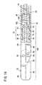
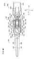
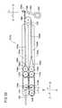
- FIG. 1is a side elevational view showing an overall structure of a medical manipulator according to an embodiment of the present invention
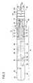
- FIG. 2is an enlarged side elevational view, partly in cross section, of a distal end portion of the medical manipulator shown in FIG. 1 ;
- FIG. 3is an enlarged side elevational view, partly in cross section, of the distal end portion, with a gripper being opened from the state shown in FIG. 2 ;
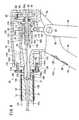
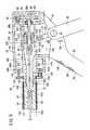
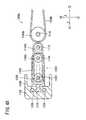
- FIG. 4is an enlarged side elevational view, partly in cross section, of an operating unit of the medical manipulator shown in FIG. 1 ;
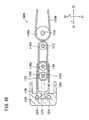
- FIG. 5is an enlarged side elevational view, partly in cross section, of the operating unit, with the gripper being opened from the state shown in FIG. 4 ;
- FIG. 6is a cross-sectional view taken along line VI-VI of FIG. 2 ;
- FIG. 7is a cross-sectional view taken along line VII-VII of FIG. 5 ;
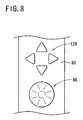
- FIG. 8is a front elevational view, partially omitted from illustration, as viewed in the direction indicated by the arrow VIII in FIG. 4 ;
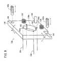
- FIG. 9is an exploded perspective view showing a structural example of a bending mechanism for bending a curvable portion of a coupling
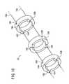
- FIG. 10is an exploded perspective view showing a portion of a structural example of the curvable portion of the coupling
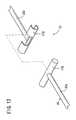
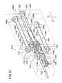
- FIG. 11is a side elevational view of the medical manipulator shown in FIG. 1 , which is separated at the coupling;
- FIG. 12is a perspective view of a linear body of a transmitting member, which is separated at a connector;
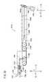
- FIG. 13is a side elevational view showing another structural example of the medical manipulator shown in FIG. 1 ;
- FIG. 14is an enlarged side elevational view, partly in cross section, showing another structural example of the distal end portion of the medical manipulator shown in FIG. 1 ;
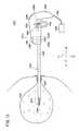
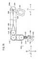
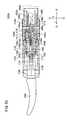
- FIG. 15is a side elevational view of a medical manipulator according to another embodiment of the present invention.
- FIG. 16is a plan view of the medical manipulator shown in FIG. 15 ;
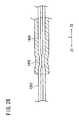
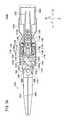
- FIG. 17is a sectional side elevational view of a distal end working unit according to a first structural example
- FIG. 18is a sectional plan view of the distal end working unit according to the first structural example
- FIG. 19is a sectional side elevational view of the distal end working unit according to the first structural example, with a gripper being closed;
- FIG. 20is an exploded perspective view of the distal end working unit according to the first structural example
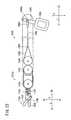
- FIG. 21is a schematic structural view of the distal end working unit according to the first structural example
- FIG. 22is a schematic side elevational view of the distal end working unit according to the first structural example, with a trigger lever being in a non-operated state;
- FIG. 23is a schematic side elevational view of the distal end working unit according to the first structural example, with the trigger lever being fully pulled;
- FIG. 24is a schematic side elevational view of the distal end working unit according to the first structural example, with the trigger lever being pulled to an intermediate position;
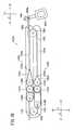
- FIG. 25is a schematic side elevational view of the distal end working unit according to the first structural example, with a roll axis being operated in one direction;
- FIG. 26is a schematic view of a connected portion of an end of a passive wire according to a first modification
- FIG. 27is a schematic view of a connected portion of an end of a passive wire according to a second modification
- FIG. 28is a schematic plan view of a connected portion of an end of a passive wire according to a third modification
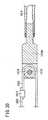
- FIG. 29is a schematic sectional side elevational view of the connected portion of the end of the passive wire according to the third modification.
- FIG. 30is a schematic sectional plan view of a connected portion of an end of a passive wire according to a fourth modification
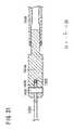
- FIG. 31is a schematic sectional side elevational view of the connected portion of the end of the passive wire according to the fourth modification
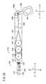
- FIG. 32is a schematic structural view of a distal end working unit according to a second structural example
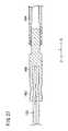
- FIG. 33is a sectional side elevational view of a distal end working unit according to a third structural example.
- FIG. 34is a sectional side elevational view of the distal end working unit according to the third structural example, with a gripper being closed;
- FIG. 35is a schematic side elevational view of the distal end working unit according to the third structural example, with a roll axis being operated in one direction;
- FIG. 36is a schematic side elevational view of a distal end working unit according to a fourth structural example, with a trigger lever being pushed out;
- FIG. 37is a schematic side elevational view of the distal end working unit according to the fourth structural example, with the trigger lever being fully pulled;
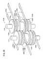
- FIG. 38is a schematic structural view of a distal end working unit according to a fourth structural example.
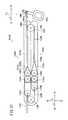
- FIG. 39is an enlarged perspective view of an idle pulley and a guide pulley of the distal end working unit according to the fourth structural example.
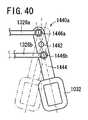
- FIG. 40is a schematic view of a drive member advancing and retracting mechanism according to a first example
- FIG. 41is a schematic view of a drive member advancing and retracting mechanism according to a second example
- FIG. 42is a schematic view of a drive member advancing and retracting mechanism according to a third example.
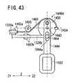
- FIG. 43is a schematic view of a drive member advancing and retracting mechanism according to a fourth example.
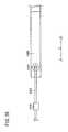
- FIG. 44is a sectional side elevational view of a distal end working unit according to a fifth structural example.
- FIG. 45is a sectional plan view of the distal end working unit according to the fifth structural example.
- FIG. 46is a sectional side elevational view of the distal end working unit according to the fifth structural example, with a gripper being closed;
- FIG. 47is an exploded perspective view of the distal end working unit according to the fifth structural example.
- FIG. 48is a plan view, partly in cross section, of a second end effector drive mechanism with a trigger lever being pushed out;
- FIG. 49is a plan view, partly in cross section, of the second end effector drive mechanism with the trigger lever being fully pulled;
- FIG. 50is a side elevational view, partly in cross section, of the second end effector drive mechanism with the trigger lever being pushed out;
- FIG. 51is a schematic structural view of the distal end working unit according to the fifth structural example.
- FIG. 52is a schematic side elevational view of the distal end working unit according to the fifth structural example, with the trigger lever being fully pulled;
- FIG. 53is a schematic side elevational view of the distal end working unit according to the fifth structural example, with the trigger lever being pushed out;
- FIG. 54is a sectional side elevational view of a distal end working unit according to a first modification of the fifth structural example
- FIG. 55is a sectional side elevational view of a distal end working unit according to a second modification of the fifth structural example
- FIG. 56Ais a schematic sectional side elevational view of a distal end working unit, with a gripper link portion thereof being omitted from illustration;
- FIG. 56Bis a schematic sectional side elevational view of the distal end working unit, with the gripper link portion thereof being omitted from illustration, and with a gripper being opened;
- FIG. 57is a schematic perspective view of a surgical robot system with a working unit connected to the distal end of a robot arm.
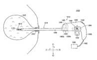
- FIG. 1is a side elevational view showing an overall structure of a medical manipulator 10 according to an embodiment of the present invention.
- the medical manipulator 10will be described for use as a forceps, which is used mainly in laparoscopic surgery.
- the present inventionis applicable to various surgical instruments such as pincers, and electric electrosurgical knives, for example, other than forceps.
- the right hand end of the medical manipulator 10 shown in FIG. 1will be referred to as a proximal end, and the left hand end as a distal end, as well as in the other figures.
- the medical manipulator 10comprises a distal end working unit 14 having a gripper 22 on its distal end as an end effector for performing a surgical operation on the affected part, a working unit (main manipulator body) 15 including an elongate small-diameter coupling 12 coupled to a proximal end of the distal end working unit 14 , an operating unit 16 coupled to a proximal end of the coupling 12 , and an elongate transmitting member 18 (see FIG. 2 ) extending through the coupling 12 and connecting the distal end working unit 14 and the operating unit 16 to each other.
- a controller 20serving as a control unit for driving and controlling various actuators housed in the medical manipulator 10 is connected to the operating unit 16 .
- FIG. 2is an enlarged side elevational view, partly in cross section, of the distal end working unit 14 of the medical manipulator 10 shown in FIG. 1 , showing a condition in which the gripper 22 on the distal end working unit 14 is closed.
- FIG. 3is an enlarged side elevational view, partly in cross section, with the gripper 22 being opened from the state shown in FIG. 2 .
- FIG. 4is an enlarged side elevational view, partly in cross section, of the operating unit 16 of the medical manipulator shown in FIG. 1 , showing a condition in which the gripper 22 on the distal end working unit 14 is closed.
- FIG. 5is an enlarged side elevational view, partly in cross section, with the gripper 22 being opened from the state shown in FIG. 4 .
- the coupling 12comprises a hollow elongate small-diameter member having a space 24 formed therein, which accommodates the transmitting member 18 , etc.
- a joint (an attitude changing mechanism, a rotating mechanism) 26 rotatably coupled to the distal end working unit 14is disposed on a distal end of the coupling 12 (see FIGS. 1 and 2 ).
- the coupling 12has a proximal end coupled to a main operating unit body 28 of the operating unit 16 (see FIGS. 1 and 4 ).
- the coupling 12has a transverse cross-sectional shape (a cross-sectional shape perpendicular to the axial direction thereof), which may be a circular shape, an elliptical shape, a polygonal shape, or the like, and is not limited to any particular shape.
- the coupling 12has a circular transverse cross-sectional shape, and has an outside diameter that enables the coupling to be inserted into a trocar (not shown), e.g., in the range of from 5 to 10 mm.
- the coupling 12has a straight shape, as shown in FIG. 1 , but the coupling 12 may be curved or bent in any desired shape.
- the coupling 12has at least one curvable portion (an attitude changing mechanism, a bending mechanism) 30 , which can be curved (bent) to a desired shape (see FIG. 1 ), for increasing the range at which a living tissue can be surgically treated with the gripper 22 , and for making it possible to perform a surgical treatment at a proper attitude.
- the transmitting member 18 that extends through the coupling 12comprises a linear body 32 , a first coupling member 34 coupled to a proximal end of the linear body 32 , and a rod-shaped second coupling member 36 coupled to a distal end of the linear body 32 .
- the linear body 32has a connector 37 (see FIGS. 4 and 12 ) positioned near to a detachable joint 35 by which the coupling 12 and the operating unit 16 are detachably joined to each other.
- the connector 37allows a distal end portion 32 a and a proximal end portion 32 b to be detachably joined to each other.
- the distal end portion 32 aextends into the distal end working unit 14
- the proximal end portion 32 bextends into the main operating unit body 28 (see FIGS. 2 and 4 ).
- the linear body 32should preferably be flexible (bendable) over its entire length or over a portion thereof, at least a portion thereof corresponding to the curvable portion 30 .
- the linear body 32may comprise wires such as metal wires made of stainless steel, tungsten, superelastic alloy, or the like, piano wires, ropes, chains, or the like, or fibers made of a polymeric material that can withstand relatively high tension, such as polyamide (wholly aromatic polyamide), polyester, ultrahigh molecular weight polyethylene, carbon fibers (hereinafter referred to as high-tension fibers), or a cluster of any of such wires, or other composites.
- the straight portion, other than the portion that corresponds to the curvable portion 30may comprise a rigid non-flexible body.
- the linear body 32in the form of a cluster of wires, should preferably be made up of one or more wires (particularly metal wires), having one or more wires of the same or different types wound (e.g., helically) around the wires, and one or more wires of the same or different types wound therearound in a direction opposite to the last-mentioned one or more wires.
- the linear body thus constructedis advantageous in that it is excellent in following a pulling action of the operating unit 16 , while suppressing a change in length (distortion) due to twisting and bending when the linear body 32 is rotated.
- the outside diameter of the linear body 32is not limited to any particular value, but may preferably be in the range of from about 1.0 to 2.5 mm, particularly in the range of from about 1.0 to 1.5 mm, according to the present embodiment.
- the second coupling member 36has a square transverse cross-sectional shape.
- the joint 26includes a protrusion 38 having a passage 40 formed centrally therein.
- the second coupling member 36is slidably inserted inside the passage 40 .
- the passage 40has a transverse cross-sectional shape that is substantially identical to the transverse cross-sectional shape of the second coupling member 36 .
- the second coupling member 36has a distal end portion extending into the distal end working unit 14 , and which is coupled to or integrally combined with the proximal end of a slider 44 , described later.
- the transverse cross-sectional shape of the second coupling member 36may be a noncircular shape, e.g., a triangular shape, a hexagonal shape, a semicircular shape, a straight-line shape, a crisscross shape, an L shape, or the like, rather than a square shape, for preventing the second coupling member 36 from rotating with respect to the passage 40 .
- the second coupling member 36may be made of a metal material such as aluminum, brass, stainless steel, tungsten, carbon steel, a superelastic alloy, or the like, or from a relatively hard resin such as polycarbonate, polyethylene, polypropylene, hard polyvinyl chloride, polyester, or the like, or the high-tension fibers described above.
- the distal end working unit 14includes a gripper 22 as an end effector for treating the affected part, and a coil spring 46 for biasing the slider 44 to move in one direction (toward the distal end).
- the gripper 22serves as a forceps mechanism for gripping a living tissue, and includes a pair of openable/closable members, one of which is movable, i.e., a fixed pinching member 48 and a movable pinching member 50 that is angularly movable with respect to the fixed pinching member 48 .
- the movable pinching member 50has a proximal end angularly movably mounted on a main distal end body 54 by a pin 52 .
- the gripper 22has only one of its pinching members openable in the present embodiment, both of the pinching members thereof may be openable.
- the main distal end body 54has a recess 56 formed in a lower portion thereof (i.e., the lower portion as shown in FIG. 2 ).
- the slider 44is disposed in the recess 56 so as to be slidable in the longitudinal direction of the distal end working unit 14 .
- the slider 44has a pin 58 projecting on a distal end thereof, which is inserted in an oblong hole 60 that is formed in a lower portion of the proximal end of the movable pinching member 50 .
- a handle unit 62When a handle unit 62 , described later, is operated to pull the transmitting member 18 toward the proximal end so as to position the slider 44 in the proximal end portion of the recess 56 , the fixed pinching member 48 and the movable pinching member 50 are in a closed position (see FIG. 2 ).
- the transmitting member 18When the gripping force on the handle unit 62 is reduced or removed, the transmitting member 18 is moved toward the distal end, thereby moving the slider 44 toward the distal end of the recess 56 .
- the pin 58presses an inner peripheral surface of the oblong hole 60 , turning and opening the movable pinching member 50 about the pin 52 (see FIG. 3 ).
- the oblong hole 60may be dispensed with, and as the slider 44 moves, the slider 44 may be distorted to absorb the vertical movement in FIG. 2 of the pin 58 .
- the coil spring 46is housed in a compressed state within a recess 64 formed in the main distal end body 54 and a recess 66 formed in the slider 44 .
- the coil spring 46comprises a biasing means for biasing the slider 44 toward the distal end under a resilient force thereof, i.e., for biasing the movable pinching member 50 in an opening direction. Since the medical manipulator 10 according to the present embodiment includes the coil spring 46 as the biasing means in the distal end working unit 14 , it is unnecessary to provide a leaf spring or the like inside the handle unit 62 for biasing a movable handle 68 in an opening direction, for example. Thus, the operating unit 16 is simple in structure for enabling better operability.
- the joint 26includes a recess 70 having a circular transverse cross-sectional shape, which communicates with the space 24 in the coupling 12 and which is open at the distal end face of the coupling 12 .
- the protrusion 38has a circular transverse cross-sectional shape, which projects from the proximal end of the main distal end body 54 and is inserted into the recess 70 .
- the protrusion 38includes the passage 40 formed axially centrally therein and having a transverse cross-sectional shape, which is substantially identical to the transverse cross-sectional shape of the second coupling member 36 .
- Two ring-shaped grooves 74which are axially spaced from each other by a predetermined distance, are formed in the inner circumferential surface of the recess 70 .
- the protrusion 38has two ring-shaped lands 75 extending circumferentially at respective positions corresponding to the grooves 74 .
- the lands 75are inserted respectively into the grooves 74 .
- the lands 75are not limited to having continuous ring shapes, but may be disposed intermittently in the circumferential direction.
- the joint 26 of the above structureallows the distal end working unit 14 to rotate (roll) with respect to the coupling 12 , but makes the distal end working unit 14 unable to move axially. Therefore, the joint 26 is reliably capable of preventing the distal end working unit 14 from becoming dislodged or experiencing wobbling.
- the joint 26may have a rotational resistance reducing means (not shown) for reducing the rotational resistance of the distal end working unit 14 .
- the rotational resistance reducing meansmay comprise a lubricant, such as lubricating oil or a layer of a low-friction material such as polytetrafluoroethylene, silicone, polyethylene, polyacetal, or the like, interposed between the recess 70 and the protrusion 38 .
- a lubricantsuch as lubricating oil
- a layer of a low-friction materialsuch as polytetrafluoroethylene, silicone, polyethylene, polyacetal, or the like, interposed between the recess 70 and the protrusion 38 .
- the rotational resistance reducing meansallows the distal end working unit 14 to rotate more smoothly.
- the operating unit 16is mounted on the proximal end of the coupling 12 for remotely opening and closing (turning) the gripper 22 , bending the distal end working unit 14 in the curvable portion 30 , and rotating the distal end working unit 14 with respect to the coupling 12 .
- the operating unit 16includes the handle unit 62 , which comprises a fixed handle 80 fixed to or integrally combined with the main operating unit body 28 , and a movable handle 68 which can be opened and closed (turned) with respect to the fixed handle 80 .
- the movable handle 68has an upper end thereof angularly movably mounted on the main operating unit body 28 by a shaft member 82 .
- a stopper 84projects from the outer surface of a lower portion of the main operating unit body 28 , for engaging the movable handle 68 so as to limit an angularly movable range thereof, for thereby preventing the transmitting member 18 from being broken when an excessive gripping force is applied to the handle unit 62 .
- the fixed handle 80 and the movable handle 68may be switched in position.
- a rotating action input unit 86 and a bending action input unit 128may be placed on an upper portion of the proximal end of the main operating unit body 28 , for enabling better operability.
- the operating unit 16has a rotating action mechanism 88 disposed in the proximal end of the main operating unit body 28 , which can be actuated by operation of a disk-shaped rotating action input unit 86 (see FIG. 8 ) mounted on the fixed handle 80 .
- the rotating action mechanism 88comprises a rotational drive source (actuator) 90 such as a motor, for example, a small-diameter drive gear 92 coupled to the rotational shaft of the rotational drive source 90 , a large-diameter driven gear 94 held in mesh with the drive gear 92 , and a bearing 96 by which the driven gear 94 is rotatably supported on the proximal end of the main operating unit body 28 .
- the rotational drive source 90is energized under the control of the controller 20 , based on operation of the rotating action input unit 86 .
- the driven gear 94has a rotational shaft 98 , comprising a cylindrical portion 98 a on its proximal end portion and a prismatic portion 98 b on its distal end portion.
- the cylindrical portion 98 ais supported by the bearing 96 .
- the main operating unit body 28houses therein a converting means 100 for converting angular movement of the movable handle 68 into longitudinal movement of the transmitting member 18 , and transmitting a rotational force produced by rotation of the driven gear 94 to the transmitting member 18 .
- the converting means 100comprises a support member 102 by which the first coupling member 34 is rotatably supported, and a rotational force transmitting mechanism 104 for transmitting rotational force from the driven gear 94 to the first coupling member 34 .
- the proximal end portion 32 b of the linear body 32is fixed to the distal end portion of the first coupling member 34 by a pin 106 .
- the first coupling member 34comprises a hollow cylindrical member having a passage 108 with a square transverse cross-sectional shape formed centrally therein (see FIG. 7 ), in which the prismatic portion 98 b of the rotational shaft 98 of the driven gear 94 is inserted.
- the first coupling member 34includes a flange 110 on a proximal end thereof, which engages with the proximal end face of the support member 102 .
- the support member 102has a through hole 112 with a circular transverse cross-sectional shape formed therein, in which the first coupling member 34 is inserted.
- a tongue 116 with an oblong hole 114 formed thereinprojects from a lower portion of the support member 102 .
- the support member 102is supported by guide members 118 , 120 disposed in the main operating unit body 28 , for enabling sliding movement in the longitudinal direction of the transmitting member 18 .
- the tongue 116projects downwardly through a slit 122 formed in the lower guide member 120 .
- the movable handle 68has a projecting member 124 on an upper portion thereof, which is inserted into the main operating unit body 28 .
- a pin 126 mounted on the upper end of the projecting member 124is inserted into the oblong hole 114 of the tongue 116 (see FIGS. 4 and 7 ).
- the rotational force transmitting mechanism 104is made up of the prismatic portion 98 b of the rotational shaft 98 of the driven gear 94 , together with the passage 108 into which the prismatic portion 98 b is inserted.
- the prismatic portion 98 bis axially movable with respect to the passage 108 , but cannot be rotated with respect to the passage 108 regardless of the depth at which the prismatic portion 98 b is inserted into the passage 108 . Therefore, the rotational force of the driven gear 94 is transmitted through the prismatic portion 98 b and the passage 108 to the first coupling member 34 , thereby rotating the transmitting member 18 in its entirety.
- the transverse cross-sectional shape of the prismatic portion 98 bmay be a noncircular shape, e.g., a triangular shape, a hexagonal shape, a semicircular shape, a straight-line shape, a crisscross shape, an L shape, or the like, rather than a square shape, for preventing the prismatic portion 98 b from rotating with respect to the passage 108 .
- the rotational force transmitting mechanism 104comprises a mechanism for mechanically transmitting rotational force from the rotational drive source 90 to the transmitting member 18 .
- the rotational force transmitting mechanism 104may be actuated by a wire, a chain, a timing belt, a link, a rod, a gear, or the like.
- the rotational force transmitting mechanism 104is actuated by a mechanical component in the form of a solid body that is nonelastic in the power transmitting direction.
- a wire, a chain, or the likeis slightly elongatable inevitably under tension, it is still regarded as a mechanical component in the form of a nonelastic solid body.
- the actuating mechanismsmay be used to allow the rotating action mechanism 88 and the distal end working unit 14 to rotate in opposite directions, or at different speeds.
- the operating unit 16has a bending action mechanism 130 disposed on the distal end of the main operating unit body 28 , which can be actuated by operation of the bending action input unit 128 for bending the curvable portion 30 .
- the bending action input unit 128is mounted on the fixed handle 80 and comprises four triangular buttons pointing in upper, lower (front, rear), left, and right directions.
- the bending action mechanism 130comprises two coil springs 132 , 134 projecting from the distal end face of the main operating unit body 28 , a pivotal shaft (bearing ball) 136 disposed parallel to the coil springs 132 , 134 , and a tilt plate (swing plate) 138 coupled to distal ends of the coil springs 132 , 134 , and spaced a predetermined distance from the distal end face of the main operating unit body 28 , in confronting relation thereto.
- the tilt plate 138has a hole 138 a formed centrally therein, through which there is inserted a protrusion 139 having a substantially hollow cylindrical shape that projects on the distal end of the main operating unit body 28 , and which is coupled to the coupling 12 .
- the bending action mechanism 130also includes two bending drive sources (actuators) 140 , 142 disposed in the main operating unit body 28 , comprising geared motors, for example.
- the bending drive sources 140 , 142have respective drive shafts with respective axially movable screws 140 a , 142 a coupled thereto.
- the axially movable screws 140 a , 142 aare threaded respectively into threaded holes 144 , 146 formed in the distal end of the main operating unit body 28 , and have distal ends held respectively in abutment against two respective bearing surfaces 148 , 150 on diagonally opposite corners of the tilt plate 138 .
- the bending action mechanism 130operates as follows: When the bending drive sources 140 , 142 are energized under the control of the controller 20 , the axially movable screws 140 a , 142 a are moved axially so as to tilt the tilt plate 138 through a desired angle in desired directions (the directions indicated by the arrows A, B in FIG. 9 ) about the spherical distal end surface of the pivotal shaft 136 , while being resiliently supported by the coil springs 132 , 134 .
- the tilt plate 138 of the bending action mechanism 130may be tilted using a mechanism that includes a general structure for swinging an optical mirror.
- the hole 138 a of the tilt plate 138includes four slits 152 formed in upper, lower, left, and right directions thereof, as shown.
- Wires 154are inserted from the inner circumferential portion of the hole 138 a into the respective slits 152 .
- the wires 154have larger-diameter portions 154 a on respective proximal ends thereof, which engage the proximal end face of the tilt plate 138 .
- the wires 154extend through four respective through holes 156 formed axially in the coupling 12 , and extend to the curvable portion 30 .
- FIG. 10is an exploded perspective view showing a portion of a structural example of the curvable portion 30 of the coupling 12 .
- the curvable portion 30comprises a plurality of nodal rings 158 , which are joined together and angularly movable with respect to each other.
- the curvable portion 30will be described as comprising three nodal rings 158 , for example.
- the curvable portion 30is not limited to being made up of three nodal rings 158 , but may comprise four through thirty nodal rings 158 .
- Each of the nodal rings 158includes a pair of V-shaped slots 160 formed in one of the surfaces, in diametrically opposite relation to each other across the center of the nodal ring 158 , and a pair of semicylindrical ridges 162 disposed on the other surface, in diametrically opposite relation to each other across the center of the nodal ring 158 .
- the semicylindrical ridges 162are angularly displaced by 90° from the slots 160 .
- Two adjacent nodal rings 158are oriented such that the slots 160 thereof are angularly displaced from each other by 90°.
- the nodal rings 158are joined such that the ridges 162 of one of the nodal rings 158 are inserted into corresponding slots 160 of the other nodal ring 158 .
- Each of the nodal rings 158has through holes 164 formed therein at the slots 160 and the ridges 162 .
- the four wires 154whose larger-diameter portions 154 a engage with the tilt plate 138 , are inserted through the corresponding through holes 164 of the nodal rings 158 .
- the wires 154have respective distal ends coupled to the nodal ring 158 disposed in the distal end of the curvable portion 30 (see FIGS. 2 and 3 ). In this manner, the nodal rings 158 are placed together and combined substantially integrally with one another.
- the angle through which the adjacent pair of nodal rings 158 is angularly movableis small, the sum of the angles of a plurality of adjacent pairs of nodal rings 158 is large enough so as to allow the entire curvable portion 30 to be curved through a desired angle (e.g., in a range of from 60 to 120°), thus making it possible to bend the distal end working unit 14 (gripper 22 ) such that it is not parallel to the longitudinal axis of the coupling 12 .
- a desired anglee.g., in a range of from 60 to 120°
- each nodal ring 158When the bending action input unit 128 is operated, the bending action mechanism 130 is actuated under the control of the controller 20 to tilt the tilt plate 138 through a desired angle, and to axially move the wires 154 respective distances for thereby bending the curvable portion 30 upwardly, downwardly (forwardly, rearwardly), leftwardly, and rightwardly through desired angles on the transverse cross-sectional plane of the coupling 12 .
- the curvable portion 30is actively bent or curved when pulled by the tilt plate 138 through the wires 154 .
- the directions in which the curvable portion 30 is curved, and the number of such directions (the degree of freedom),are not limited to any particular values.
- the outer circumferential surface of each nodal ring 158may be covered with a layer made up of an elastic or a flexible material.
- the curvable portion 30is not limited to having the illustrated structure, but may comprise a bellows tube or a flexible tube.
- the coupling 12may comprise a hard pipe serving as the distal end portion together with a hard pipe serving as the proximal end portion, wherein the hard pipes are angularly movably connected by a single shaft or a plurality of shafts for bending the curvable portion 30 .
- the curvable portion 30may comprise a bending mechanism having a pivot shaft.
- the operating unit 16 and the coupling 12are detachably (separably) connected to each other by means of the detachable joint 35 .
- the detachable joint 35by which the coupling 12 and the operating unit 16 are detachably joined to each other, the protrusion 139 that projects on the distal end of the operating unit 16 is inserted into a hole 166 formed in the proximal end of the coupling 12 , and a setscrew 168 is tightened against the protrusion 139 from the outer circumferential surface toward the inner circumferential surface of the coupling 12 , thereby fastening the coupling 12 and the operating unit 16 together (see FIGS. 4 and 5 ).
- the linear body 32can easily be divided when the distal end portion 32 a and the proximal end portion 32 b are separated from each other at the connector 37 , by releasing a T-shaped bar 170 on the distal end of the distal end portion 32 a from a T-shaped hook 172 provided on the distal end of the proximal end portion 32 b (see FIG. 12 ).
- various working units 15may easily be replaced and used on a single operating unit 16 , so that the medical manipulator 10 has increased versatility and is low in cost. Since the working unit 15 can easily be separated from the operating unit 16 , the working unit 15 (the distal end working unit 14 ) is easily maintained, enabling replacement, cleaning, and/or high-temperature sterilization thereof.
- the medical manipulator 10With the medical manipulator 10 thus constructed, as the gripper 22 is operated (opened and closed or angularly rotated), and the distal end working unit 14 is rotated by the single transmitting member 18 , the installation space of the transmitting member 18 within the coupling 12 may be small. Accordingly, the coupling 12 may be thinner, while the distal end working unit 14 and the operating unit 16 may both be simpler in structure.
- the medical manipulator 10 according to the present embodimentcan thus appropriately be used for performing laparoscopic surgery, brain surgery, thoracoscopic surgery, urologic surgery, or the like.
- the gripper 22In an initial state (non-operated state), the gripper 22 is open under the bias of the coil spring 46 , and the movable handle 68 is open (see FIGS. 1, 3, and 5 ).
- the projecting member 124When the operator grips the handle unit 62 by the hand, and turns the movable handle 68 in the direction indicated by the arrow in FIG. 1 , the projecting member 124 is turned clockwise about the shaft member 82 , thus causing the pin 126 to be pressed against the inner peripheral surface of the proximal end of the oblong hole 114 in order to move the tongue 116 and the support member 102 along the guide members 118 , 120 (the state shown in FIG. 4 ).
- the first coupling member 34moves in the same direction as the support member 102 , thereby pulling the transmitting member 18 toward the proximal end. Since the support member 102 moves toward the proximal end, the distal end of the prismatic portion 98 b is inserted relatively deeply into the passage 108 .
- the slider 44moves within the recess 56 toward the distal end thereof under the bias of the coil spring 46 . Therefore, the pin 58 presses the inner peripheral surface of the distal end of the oblong hole 60 , turning the movable pinching member 50 clockwise in FIG. 3 about the pin 52 , and hence opening the movable pinching member 50 (the state shown in FIG. 3 ).
- the transmitting member 18also moves in the same direction.
- the flange 110presses the support member 102 , thereby moving the support member 102 and the tongue 116 toward the distal end along the guide members 118 , 120 .
- the inner peripheral surface of the proximal end of the oblong hole 114presses the pin 126 , turning the projecting member 124 and the movable handle 68 clockwise in FIG. 5 about the shaft member 82 .
- the movable handle 68now returns to its original open state (the state shown in FIG. 5 ).
- the support member 102moves toward the direction of the distal end, the distal end of the prismatic portion 98 b moves nearly to the center of the passage 108 along the longitudinal direction thereof.
- the movable pinching member 50is opened and closed in mechanically (directly) ganged relation to the movable handle 68 when it is opened and closed. Therefore, if the gripper 22 grips an object (a surgical instrument or living tissue) when the movable handle 68 is manually pulled to a certain extent, then the gripper 22 and the slider 44 are unable to move further, so that the operator can feel through the fingertips that the object has been gripped.
- an objecta surgical instrument or living tissue
- the movable handle 68is no longer movable at all in the closing direction.
- the operatorcan feel that the hard object has been gripped, and can reliably grip the object with strong forces, because the operator can transmit manual forces mechanically and directly to the gripper 22 , rather than via an electromagnetic means. If gripping forces equivalent to manual forces were to be generated by a motor, then the motor would need to be considerably large in size and heavy, such a motor could not be housed readily in the main operating unit body 28 , and would make the medical manipulator 10 heavier.
- the movable handle 68can be displaced slightly in the closing direction, depending on the elasticity of the object. Therefore, the operator can feel that the soft object has been gripped, while recognizing how soft the object is, and can adjust the forces at which the object is gripped.
- the opening (gripping) forces of the fixed pinching member 48 and the movable pinching member 50correspond to the opening (gripping) forces of the fixed handle 80 and the movable handle 68 . Therefore, the operator can easily operate the gripper 22 with any desired opening (gripping) forces.
- the manual operation of the movable handle 68is mechanically transmitted so as to open and close the gripper 22 .
- the transmitting member 18 , the slider 44 , etc.provide an operation transmitting unit, which serves as a means for mechanically transmitting manual operations between the movable handle 68 and the gripper 22 .
- the term “mechanically” as used hereinrefers to a system for transmitting manual operations via a wire, a chain, a timing belt, a link, a rod, a gear, or the like, which is actuated primarily by a mechanical component in the form of a nonelastic solid body in the power transmitting direction, as described above.
- a wire, a chain, or the likeis slightly elongatable inevitably under tension, it is still regarded as a mechanical component in the form of a nonelastic solid body.
- the transmitting member 18has a flexible portion corresponding to at least the curvable portion 30 , the transmitting member 18 is placed under an appropriate tension by the coil spring 46 .
- the transmitting member 18When the gripper 22 is closed, the transmitting member 18 is pulled toward the operating unit 16 by the movable handle 68 , and the transmitting member 18 essentially is not elastically deformed, or is inevitably elastically deformed only to an extent that is trouble-free in operation, thereby providing a mechanical connecting means (mechanical transferring means).
- the rotating action input unit 86When the rotating action input unit 86 is operated in order to energize the rotational drive source 90 to rotate the driven gear 94 , regardless of whether the movable pinching member 50 is opened or closed (regardless of the degree of opening thereof), rotating forces are transmitted successively to the prismatic portion 98 b of the rotational shaft 98 , the passage 108 , the first coupling member 34 , the linear body 32 , the second coupling member 36 , the passage 40 , the protrusion 38 , and the main distal end body 54 , thereby rotating the distal end working unit 14 .
- the rotating action mechanism 88 and the joint 26function as a rotating mechanism, for rotating the distal end working unit 14 about its own axis.
- the direction that the driven gear 94 is drivenis the same as the direction in which the distal end working unit 14 rotates.
- the gripper 22can be opened and closed, and the distal end working unit 14 can be rotated, when the coupling 12 is straight, bent, or curved.
- the medical manipulator 10since the curvable portion 30 is not rotated, but rather only the distal end working unit 14 is rotated, even when the coupling 12 is bent or curved (i.e., the state indicated by the two-dot-and-dash lines in FIG. 1 ), as it rotates, the distal end working unit 14 is not swung about an axis that extends from the curvable portion 30 toward the proximal end. Therefore, the attitude of the gripper 22 (the direction in which the living tissue is gripped) can be changed, while the gripper 22 remains proximate to the region that is to be surgically treated.
- the bending action mechanism 130With respect to the bending action mechanism 130 , by simply operating the bending action input unit 128 to energize the bending drive sources 140 , 142 , regardless of whether the movable pinching member 50 is opened or closed (regardless of the degree of opening thereof), it is possible to tilt the tilt plate 138 to any desired angle, thereby easily bending the coupling 12 to a desired angle at the curvable portion 30 .
- the curvable portion 30 and the bending action mechanism 130function as a bending mechanism for bending the gripper 22 in a direction crossing the axial direction of the coupling 12 , so as to change the attitude of the gripper 22 easily and quickly.
- the coupling 12can be bent by the bending action mechanism 130 , and the curvable portion 30 and the distal end working unit 14 can be rotated by the rotating action mechanism 88 easily and quickly through the bending drive sources 140 , 142 and the rotational drive source 90 , which serve as actuators, under the control of the controller 20 , simply when the operator uses his fingertips to operate the bending action input unit 128 and the rotating action input unit 86 on the operating unit 16 . Accordingly, the medical manipulator 10 has high operability.
- the bending mechanism for bending a portion (the curvable portion 30 ) of the coupling 12 , and the rotating mechanism for rotating the distal end working unit 14function cooperatively as an attitude changing mechanism, for changing the attitude of the distal end working unit 14 , and such mechanisms operate through the actuators.
- the gripper 22 of the distal end working unit 14is opened and closed (angularly moved) by the operator, who manually operates the fixed handle 80 and the movable handle 68 mechanically (directly) independently of the operation of the bending action mechanism 130 , etc. Since the gripper 22 can be operated for acquiring desired gripping forces, the operator can treat the affected part more appropriately, while feeling the hardness of the gripped object.
- the end effector(the gripper 22 ) by transmitting a manual action mechanically and directly thereto.
- the best approachis to simplify operations of the bending action mechanism 130 , the curvable portion 30 , and the rotating action mechanism 88 , which provide other attitude axes, i.e., the operation of the attitude changing mechanism, using the actuators (the bending drive sources 140 , 142 and the rotational drive source 90 ).
- the distal end working unit 14can easily be changed in attitude simply by pressing buttons with a single fingertip, for example, the attitude changing actions do not interfere with other actions of the operator to open and close the gripper 22 and to move the medical manipulator 10 in its entirety using the arm, thereby allowing the operator to perform a more intuitive surgical treatment.
- FIG. 14is an enlarged side elevational view, partly in cross section, showing another structural example of the distal end portion of the medical manipulator 10 shown in FIG. 1 .
- a distal end working unit 180is arranged to have a biasing means, for biasing the movable pinching member 50 in the opening direction, disposed in the vicinity of the distal end working unit 14 .
- the coil spring 46is housed in a large-diameter portion 182 , which is greater in diameter than the space 24 , formed at a position adjacent to the proximal end of the joint 26 of the coupling 12 .
- the second coupling member 36extends through the coil spring 46 , and a disk-shaped flange 184 is fixed to or integrally combined with a portion of the second coupling member 36 , which extends from the coil spring 46 toward the distal end.
- the coil spring 46 in the compressed statehas a proximal end thereof held against the proximal end face of the large-diameter portion 182 , and a distal end held against the flange 184 , and biases the second coupling member 36 toward the distal end.
- the biasing meansis not limited to the coil spring 46 , but may comprise another spring, such as a torsion spring, a leaf spring, or the like, or an elastic material such as rubber, or a permanent magnet or an electromagnet.
- the biasing meansmay be disposed within the operating unit 16 .
- a large peeling forcemay be required in the direction (peeling direction) in order to open the gripper 22 for peeling off tissue.
- the coil spring 46is replaced with a tension spring, and the pushing action of the movable handle 68 is transmitted directly to the gripper 22 via the slider 44 , then a large peeling force can be produced.
- the force applied in the opening direction of the gripper 22is transmitted to the movable handle 68 .
- the gripper 22abuts against a living tissue or a surgical instrument in the opening direction thereof at the time the gripper 22 is opened, the movable handle 68 stops moving in the opening direction.
- the operatorcan feel that the gripper 22 has come into abutment against something.
- the surgical operation meansmay comprise a pair of opening and closing members, which are angularly movable, or which may be openable and closable by being translated. Further, the surgical operation means may comprise a single member, which is angularly movable, such as a bendable forceps, an electrosurgical knife, an ultrasonic knife, or the like.
- the rotational drive source 90 and the bending drive sources 140 , 142which are actuators for actuating the rotating action mechanism 88 and the bending action mechanism 130 , may comprise fluid-pressure actuators, using a fluid such as a gas, a liquid, or the like, for example, rather than electric motors.
- the rotating action input unit 86 and the bending action input unit 128may also be constructed as foot switches, rather than being provided on the operating unit 16 .
- foot switchesmay be placed at the operator's feet for allowing the operator to perform manual techniques more smoothly.
- the movable handle 68 , the rotating action input unit 86 , and the bending action input unit 128 on the operating unit 16are not limited to the positions, forms, and operating methods that have been illustrated above.
- the rotating action input unit 86may be replaced with operating rollers, buttons, or a joystick. Further, various positions and methods that allow the manipulator to be easily operated may be selected and designed.
- a medical manipulator 1010 according to another embodimentwill be described below with reference to FIGS. 15 to 57 .
- the medical manipulator 1010makes up part of a medical manipulator system, and is connected to a controller 1045 .
- the controller 1045which serves to control the medical manipulator 1010 electrically, is connected via a connector to a cable 1062 extending from a lower end of a grip handle 1026 .
- the controller 1045can control a plurality of medical manipulators 1010 independently of each other.
- a controller for controlling a single medical manipulator 1010may also be used.
- the medical manipulator 1010includes a distal end working unit 1012 for gripping a portion of a living tissue, and a curved needle, or the like for performing a given surgical treatment.
- the medical manipulator 1010usually is referred to as a gripping forceps or a needle driver (needle holder).
- the medical manipulator 1010comprises an operating unit 1014 , which is held and operated by the hand, and a working unit 1016 fixed to the operating unit 1014 .
- the operating unit 1014 and the working unit 1016are integrally combined with each other. However, depending on conditions, the operating unit 1014 and the working unit 1016 may be separable from each other.
- transverse directions in FIGS. 15 and 16are referred to as X directions, vertical directions as Y directions, and longitudinal directions of a connector shaft 1048 as Z directions.
- X directionsthe rightward direction as viewed from the distal end is referred to as an X 1 direction
- Y directionsthe upward direction is referred to as a Y 1 direction
- the downward directionas a Y 2 direction.
- Z directionsthe forward direction is referred to as a Z 1 direction
- these directionsrepresent directions of the medical manipulator 1010 when it is in a neutral posture.
- the above definitions of directionsare for illustrative purposes only.
- the medical manipulator 1010can be used in any of various orientations, e.g., it may be used upside down.
- the working unit 1016comprises a distal end working unit 1012 for performing working operations, and an elongate hollow connector shaft (coupling) 1048 coupling the distal end working unit 1012 and the operating unit 1014 to each other.
- the distal end working unit 1012 and the connector shaft 1048have a small diameter, and can be inserted into a body cavity 1022 through a trocar 1020 in the form of a hollow cylinder mounted inside an abdominal region or the like of the patient.
- the working unit 1012is actuated by a composite input unit 1034 in order to perform various techniques to grip, remove, suture, or tie-knot an affected part of the patient's body within the body cavity 1022 .
- the operating unit 1014includes a grip handle 1026 , which is gripped by the hand, a bridge 1028 extending from an upper portion of the grip handle 1026 , and an actuator block 1030 and a trigger lever (input unit) 1032 , which are connected to a distal end of the bridge 1028 .
- the grip handle 1026 of the operating unit 1014extends in the Y 2 direction from the end of the bridge 1028 , and has a length suitable for being gripped by the hand.
- the composite input unit 1034is disposed on the grip handle 1026 .
- the cable 1062 connected to the controller 1045is disposed on a lower end of the grip handle 1026 while being integrally connected to the grip handle 1026 .
- the grip handle 1026 and the cable 1062may be connected to each other by a connector.
- the composite input unit 1034makes up a composite input means for imparting rotational commands in rolling (shaft rotating) and yawing (left and right) directions to the distal end working unit 1012 .
- commands in the yawing directionare given by a first input means 1034 a , which operate in the lateral direction
- commands in the rolling directionare given by a second input means 1034 b , which operate in the shaft rotating direction.
- the trigger lever 1032comprises an input means for imparting opening and closing commands for an end effector 1104 (see FIG. 15 ) of the distal end working unit 1012 .
- the end effector 1104is available in various forms, the medical manipulator 1010 employs an openable and closable gripper.
- the composite input unit 1034includes an input sensor for detecting a control variable, and supplies a detection operation signal (e.g., an analog signal) to the controller 1045 .
- a detection operation signale.g., an analog signal
- the trigger lever 1032comprises a lever disposed below the bridge 1028 and is disposed at a position where it can easily be operated by the index finger.
- the trigger lever 1032is connected to the actuator block 1030 by a first link 1064 and a second link 1066 , and is movable toward and away from the grip handle 1026 .
- the first link 1064pivots swingably about a portion of the bridge 1028 , and the trigger lever 1032 is mounted on the end of the first link 1064 in the Y 2 direction.
- the second link 1066projects in the Z 2 direction from the actuator block 1030 and engages in an oblong hole 1064 a formed in the first link 1064 .
- the second link 1066is movable back and forth in the longitudinal direction in the oblong hole 1064 a when the trigger lever 1032 is moved.
- the second link 1066is connected to an end of a wire (drive member) 1056 .
- a wiredrive member
- the wire 1056also is pulled in unison therewith. Since the wire 1056 is used as a drive member (transmitting member) connected to the second link 1066 , the number of parts used can be reduced, and the medical manipulator 1010 is reduced in weight.
- the drive member connected to the second link 1066may comprise a rigid linearly movable rod (or link), for example, rather than the wire 1056 . Since a rod is generally more rigid than the wire, the rod may be used as a linearly movable member for producing large gripping forces.
- the rod and the second link 1066may be combined integrally with each other.
- Links, gears, etc.may be operatively disposed between the second link 1066 and the wire 1056 , for adjusting the operating forces and strokes of the operator.
- the actuator block 1030houses motors (attitude axis actuators) 1040 , 1041 therein corresponding to the respective mechanisms of two out of three degrees of freedom, which are incorporated in the distal end working unit 1012 .
- the motors 1040 , 1041are arrayed in parallel with each other in the longitudinal direction of the connector shaft 1048 .
- the motors 1040 , 1041correspond to movements in both rolling and yawing directions of the distal end working unit 1012 , i.e., movements of the attitude changing mechanism, for changing the attitude of the distal end working unit 1012 .
- the motors 1040 , 1041are small in size and diameter, thus enabling the actuator block 1030 to be compact and flat in shape.
- the motors 1040 , 1041can be energized to rotate the drive shafts under the control of the controller 1045 , based on operation of the operating unit 1014 .
- the motors 1040 , 1041are combined with angle sensors, for detecting rotational angles and supplying the detected angle signals to the controller 1045 .
- the angle sensorsmay comprise rotary encoders, for example.
- the actuatorsmay comprise fluid-pressure actuators, using a fluid such as a gas, liquid, or the like, for example.
- the actuator block 1030houses pulleys 1050 a , 1050 b therein, which are connected, respectively, to the drive shafts of the motors 1040 , 1041 .
- Wires 1052 , 1054are wound respectively around the pulleys 1050 a , 1050 b , and extend through a hollow region 1048 a (see FIG. 20 ) in the connector shaft 1048 toward the distal end working unit 1012 .
- the wires 1052 , 1054may both be of the same type and have the same diameter.
- the composite input unit 1034 and the trigger lever 1032 of the operating unit 1014are not limited to the above-described and illustrated positions, forms, and operating methods.
- the composite input unit 1034may be replaced with operating rollers, buttons, or a joystick.
- other positions and methods, which allow the manipulator to be easily operated,may be selected and designed.
- a manual operation applied to the trigger lever 1032is mechanically transmitted to open and close the end effector 1104 .
- the first link 1064 , the second link 1066 , the wire 1056 , and an end effector driving mechanism 1260serve as a means (transmitting members) for mechanically transmitting a manual action between the trigger lever 1032 and the end effector 1104 , and make up an operation transmitting unit.
- the term “mechanically”refers to a system for transmitting manual operations via a wire, a chain, a timing belt, a link, a rod, a gear, or the like, which is mainly actuated in the power transmitting direction by a mechanical component in the form of a nonelastic solid body.
- a wire, a chain, or the likeis slightly elongatable inevitably under tension, it is still regarded as a mechanical component in the form of a nonelastic solid body.
- the distal end working unit 1012 aaccording to the first structural example comprises a wire-driven mechanism 1100 , a composite mechanism 1102 , and an end effector 1104 .
- the distal end working unit 1012incorporates therein mechanisms providing three degrees of freedom.
- These mechanismsinclude a mechanism having a first degree of freedom for angularly moving a portion of the distal end working unit 1012 that is positioned ahead of a first rotational axis Oy extending along the Y direction, in a yawing direction about the first rotational axis Oy, a mechanism having a second degree of freedom for angularly moving the portion of the distal end working unit 1012 in a rolling direction about a second rotational axis Or, and a mechanism having a third degree of freedom for opening and closing the end effector 1104 on the distal end of the distal end working unit 1012 about a third rotational axis Og.
- the first rotational axis Oy of the mechanism having the first degree of freedommay be angularly movable out of parallelism with an axis C, which extends from the proximal end to the distal end of the connector shaft 1048 .
- the second rotational axis Or of the mechanism having the second degree of freedommay be angularly movable, about an axis along the direction in which the distal end (the end effector 1104 ) of the distal end working unit 1012 extends, with the distal end portion thereof being rotatable in the rolling direction.
- the mechanism having the first degree of freedom(i.e., which is movable in the yawing direction) comprises a bending mechanism having an operable range of ⁇ 90° or greater, for example.
- the mechanism having the second degree of freedom(i.e., which is movable in the rolling direction) comprises a rotating mechanism having an operable range of ⁇ 180° or greater, for example.
- the mechanism having the third degree of freedom(i.e., the end effector 1104 ) may be opened through 400 or greater, for example.
- the end effector 1104comprises a member for performing actual work during an operation.
- the first rotational axis Oy and the second rotational axis Orare attitude axes of the attitude changing mechanism, for changing the attitude of the end effector 1104 for facilitating the work.
- the mechanism having the third degree of freedom for opening and closing the end effector 1104is referred to as a gripper (or a gripper axis).
- the mechanism having the first degree of freedom for turning in a yawing directionis referred to as a yaw axis
- the mechanism having the second degree of freedom for turning in a rolling directionis referred to as a roll axis.
- the wire-driven mechanism 1100is disposed between a pair of tongue pieces 1058 and serves to convert reciprocating movement of the respective wires 1052 , 1054 into rotational movement, and to transmit such rotational movement to a composite mechanism 1102 .
- the wire-driven mechanism 1100includes a shaft 1110 , which is inserted into shaft holes 1060 a , 1060 a , and a shaft 1112 , which is inserted into shaft holes 1060 b , 1060 b .
- the shafts 1110 , 1112are press-fitted or welded securely to the shaft holes 1060 a , 1060 b .
- the shaft 1112is aligned axially with the first rotational axis Oy.
- Gear bodies 1126 , 1130which are symmetrically shaped in the Y direction, are mounted respectively on both ends of the shaft 1112 , respectively, in the Y direction.
- the gear body 1126comprises a tubular member 1132 and a first gear 1134 disposed concentrically on an upper portion of the tubular member 1132 .
- the gear body 1130is essentially identical in shape to the gear body 1126 , and is aligned with the gear body 1126 in the Y direction.
- the gear body 1130comprises a tubular member 1136 and a second gear 1138 disposed concentrically on a lower portion of the tubular member 1136 .
- the gears 1134 , 1138are held in mesh with upper and lower ends of the face gear 1165 of a gear body 1146 , to be described later.
- the tubular member 1136is substantially identical in diameter and shape to the tubular member 1132 .
- Wires 1052 , 1054are wound around the tubular members 1132 , 1136 and have portions fastened thereto by a securing means.
- the wires 1052 , 1054are wound 1.5 turns (540°) around the tubular members 1132 , 1136 .
- the gear bodies 1126 , 1130are rotated about the shaft 1112 .
- the gear bodies 1126 , 1130are rotated at the same speed and in the same direction, the gear body 1146 swings with respect to the shaft 1112 and moves in a yawing direction.
- the gear bodies 1126 , 1130are rotated at the same speed and in the opposite direction, the gear body 1146 is rotated about the second rotational axis Or and moves in a rolling direction.
- the gear body 1146undergoes a composite motion in both yawing and rolling directions.
- the gear body 1126 , the gear body 1130 , and the gear body 1146collectively make up a differential mechanism.
- An idle pulley (a cylindrical member, a transmitting member) 1140is rotatably supported substantially centrally on the shaft 1110 .
- a guide pulley (a cylindrical member, a transmitting member) 1142is rotatably supported substantially centrally on the shaft 1112 .
- the idle pulley 1140serves to keep a driven wire (a flexible member, a transmitting member) 1252 wound around the guide pulley 1142 through a constant angle (about 180° on both sides) at all times.
- the driven wire 1252may also be wound one or more turns around the guide pulley 1142 .
- the idle pulley 1140 and the guide pulley 1142may have a smooth surface, and may be made of a material having a small coefficient of friction, in order to reduce slippage and frictional wear on the driven wire 1252 (see FIG. 22 ).
- the guide pulley 1142is disposed around the yaw axis Oy of the attitude changing mechanism.
- a main shaft 1144is rotatably supported on the shaft 1112 between the gear body 1126 and the guide pulley 1142 , as well as between the guide pulley 1142 and the gear body 1130 .
- the main shaft 1144has a sleeve projecting toward the composite mechanism 1102 .
- the main shaft 1144has a square hole 1144 a formed axially therein.
- the main shaft 1144includes two auxiliary plates 1144 b disposed on one end in the Z 2 direction for holding both surfaces of the guide pulley 1142 in the Y direction.
- the auxiliary plates 1144 bhave respective holes through which the shaft 1112 extends.
- the auxiliary plates 1144 bhave chevron shapes, which become progressively wider in the Z 1 direction, for preventing foreign matter such as threads from entering therein.
- the composite mechanism 1102includes an opening/closing mechanism for opening and closing the end effector 1104 , and an attitude changing mechanism for changing the attitude of the end effector 1104 .
- the composite mechanism 1102comprises a gear body 1146 rotatably fitted over the circumferential surface of the sleeve of the main shaft 1144 , a nut 1148 mounted on the distal end of the main shaft 1144 , a spring 1150 , a rod (a transmitting member) 1152 with a square cross-sectional shape and having an end in the Z 2 direction, which is inserted into the hole 1144 a , a driven pulley (a cylindrical member, a transmitting member) 1156 rotatably supported on the end in the Z 2 direction of the rod 1152 by a pin 1154 , a driven plate (a transmitting member) 1158 , and a hollow cylindrical cover 1160 .
- the spring 1150comprises a compression spring.
- the end in the Z 2 direction of the rod 1152is channel-shaped for improving slidability thereof with respect to the driven pulley 1156 , and the end of the rod 1152 projects largely in the Z 2 direction.
- a thrust bearing 1144 c made of resinis disposed on the portion of the main shaft 1144 that abuts against the gear body 1146 .
- a further thrust bearing 1148 a made of resinis disposed on the portion of the nut 1148 that abuts against the gear body 1146 .
- the thrust bearings 1144 c and 1148 ahave a low coefficient of friction, for reducing wear and torque on the abutting portions, and for preventing loads from being applied directly to the face gear 1165 .
- the thrust bearings 1144 c , 1148 acomprise slide bearings, for example, but may comprise rolling bearings, thereby allowing the medical manipulator to operate smoothly about the roll axis even when the end effector 1104 is strongly closed or opened, i.e., even when the gear body 1146 abuts firmly against the main shaft 1144 .
- the gear body 1146is of a stepped shape, comprising a large-diameter portion 1162 in the Z 2 direction, a small-diameter portion 1164 in the Z 1 direction, and a face gear 1165 on the end of the large-diameter portion 1162 in the Z 2 direction.
- the face gear 1165is held in mesh with the gears 1134 , 1138 .
- the gear body 1146prevents the nut 1148 from becoming dislodged from the main shaft 1144 .
- the large-diameter portion 1162has an externally threaded outer circumferential surface.
- the driven plate 1158has a recess 1166 in the Z 2 direction, an engaging cavity 1168 formed in the bottom of the recess 1166 , axial ribs 1170 disposed respectively on both surfaces in the Y direction, and a link hole 1172 .
- the engaging cavity 1168has a shape that is engageable with a mushroom-shaped knob 1174 on the distal end of the rod 1152 . When the mushroom-shaped knob 1174 engages in the engaging cavity 1168 , the driven plate 1158 and the rod 1152 are capable of rotating relatively with respect to each other about the roll axis.
- the driven plate 1158has a width that is substantially equal to the inside diameter of the cover 1160 .
- the cover 1160has a size that is large enough to cover the composite mechanism 1102 substantially in its entirety, and serves to prevent foreign matter (living tissue, medications, threads, etc.) from entering into the composite mechanism 1102 and the end effector 1104 .
- the cover 1160has two axial grooves 1175 formed in an inner circumferential surface thereof in diametrically confronting relation to each other.
- the ribs 1170 of the driven plate 1158are fitted respectively in the grooves 1175 for axially guiding the driven plate 1158 .
- the driven pulley 1156Since the knob 1174 engages in the engaging cavity 1168 of the driven plate 1158 , the driven pulley 1156 is axially movable back and forth within the hole 1144 a , in unison with the driven plate 1158 and the rod 1152 , and can roll about the rod 1152 .
- the cover 1160is fixed to the large-diameter portion 1162 of the gear body 1146 by threaded engagement therewith, or by a press-fitted engagement, or the like.
- the spring 1150is fitted between the step of the gear body 1146 and the recess 1166 of the driven plate 1158 , for normally biasing the driven plate 1158 to move forward into abutment against a stopper.
- the end effector 1104comprises a first end effector member 1190 , a second end effector member 1192 , and a pin 1196 .
- the pin 1196is disposed on the third rotational axis Og.
- the first end effector member 1190has a pair of side walls 1200 facing each other laterally, holes 1200 a formed respectively in the distal ends of the side walls 1200 , and a first gripper 1202 projecting in the Z 1 direction from lower portions of the distal ends of the side walls 1200 .
- the hole 1200 ahas a diameter such that the pin 1196 can be press-fitted into the hole 1200 a .
- the first gripper 1202becomes progressively narrower in the Z 1 direction and includes an arcuate distal end portion.
- the first gripper 1202has a number of conical teeth disposed closely together over the entire surface thereof, which faces in the Y 1 direction.
- the first end effector member 1190is coupled to the cover 1160 by a given coupling means.
- the first end effector member 1190 and the cover 1160may be of an integral structure, providing a composite tubular body 1230 .
- the cover 1160is coupled at a proximal portion to the gear body 1146 (by threaded engagement, press-fitted engagement, welding, or the like). When the gear body 1146 is rotated, the cover 1160 and the first end effector member 1190 operate about the roll axis.
- the second end effector member 1192is L-shaped, comprising a second gripper 1212 extending in the Z direction, and a lever 1214 bent about 60° with respect to the second gripper 1212 .
- the second end effector member 1192has a hole 1216 formed in the L-shaped bent corner, and the lever 1214 has a hole 1218 formed therein near to the end portion thereof.
- the pin 1196is inserted into the hole 1216 , the second end effector member 1192 is swingable about the third rotational axis Og.
- the second gripper 1212has a shape that is identical to the first gripper 1202 , yet is disposed in an inverted fashion.
- the second end effector member 1192is angularly moved about the third rotational axis Og, the second end effector member 1192 abuts against the first gripper 1202 for gripping a curved needle or the like.
- the lever 1214 and the driven plate 1158are joined to each other by two parallel gripper links 1220 .
- a pin 1222is inserted into holes 1220 a formed in respective ends of the gripper links 1220 and the hole 1218
- a pin 1124is inserted into holes 1220 b formed respectively in other ends of the gripper links 1220 and the hole 1172 .
- the position of the pin 1124by which the gripper links 1220 are pivotally supported, is slightly offset from the central axis in FIG. 19 (as viewed in side elevation). However, the pin 1124 may be positioned on the central axis as viewed in side elevation. The position of the pin 1124 may be determined in view of the balance of acting forces, the space, and the ease with which to assemble the parts.
- the pinsmay be integrally combined with the gripper links 1220 .
- Two gripper links 1220are disposed in parallel to each other, for adequately balancing the forces, and for preventing the application of inadvertent moment loads. Depending on design conditions, only one gripper link may be employed.
- the lever 1214When the driven pulley 1156 , the rod 1152 , and the driven plate 1158 are moved in the Z 2 direction, the lever 1214 also is pulled in the Z 2 direction, causing the second gripper 1212 to move toward the first gripper 1202 so as to grip an object therebetween. Conversely, when the driven pulley 1156 , the rod 1152 , and the driven plate 1158 are moved in the Z 1 direction by action of the spring 1150 , the lever 1214 also is pushed in the Z 1 direction, causing the second gripper 1212 to move away from the first gripper 1202 and open the end effector 1104 .
- the driven plate 1158is normally biased by the spring 1150 to move in the Z 1 direction, when the medical manipulator is not manually operated, the second gripper 1212 is spaced from the first gripper 1202 thereby opening the end effector 1104 .
- the spring 1150is effective to keep the wire 1056 and the driven wire 1252 under a suitable tension and prevent them from sagging. Therefore, play between the various parts is prevented and the medical manipulator is capable of gripping objects with high responsiveness.
- end effector 1104will hereinafter be used to refer to the first gripper 1202 and the second gripper 1212 .
- the idle pulley 1140comprises two parallel pulleys, i.e., a first layer idle pulley (first layer idle cylindrical body) 1232 and a second layer idle pulley (second layer idle cylindrical body) 1234 , which are aligned coaxially with each other.
- the guide pulley 1142comprises two parallel pulleys, i.e., a first layer guide pulley (first layer guide cylindrical body) 1236 and a second layer guide pulley (second layer guide cylindrical body) 1238 , which are aligned coaxially with each other.
- one of the stretches of the driven wire 1252is held against surfaces of the first layer idle pulley 1232 in the X 1 and Z 1 directions, and also is held against surfaces of the first layer guide pulley 1236 in the Z 2 and X 2 directions, while extending to the driven pulley 1156 .
- the other stretch of the driven wire 1252is held against surfaces of the second layer idle pulley 1234 in the X 2 and Z 1 directions, and also is held against surfaces of the second layer guide pulley 1238 in the Z 2 and X 1 directions, while extending to the driven pulley 1156 .
- the first layer idle pulley 1232 and the second layer guide pulley 1238are rotated counterclockwise as viewed in plan, whereas the second layer idle pulley 1234 and the first layer guide pulley 1236 are rotated clockwise as viewed in plan. Since each of the idle pulley 1140 and the guide pulley 1142 comprises two parallel coaxial pulleys, the pulleys are rotatable in opposite directions when the driven wire 1252 held thereagainst is moved, and hence the pulleys operate smoothly.
- the end of the wire 1056 in the Z 1 directionis connected to both ends of the driven wire (a flexible member) 1252 by a terminal 1250 (or welding, through hole, etc.).
- the driven wire 1252is in the form of a ring-like flexible member, having a portion thereof connected to the wire 1056 , and may alternatively comprise a rope, a resin wire, a piano wire, a chain, or the like.
- the term “ring-shaped”should be interpreted in a broad sense.
- the flexible memberdoes not necessarily need to be applied to the entire length. That is, at least the portion of the driven wire 1252 , which is wound around each of the pulleys, may be a flexible member with the linear portion thereof being connected by a rigid member.
- the driven wire 1252may make up part of the wire 1056 .
- the driven wire 1252passes from the wire 1056 , serving as a drive member, along the idle pulley 1140 in the X 1 direction (first side) and extends to the X 2 direction (second side), and then passes along the guide pulley 1142 in the X 2 direction and extends to the surface of the driven pulley 1156 in the X 2 direction.
- the driven wire 1252is then wound in a half turn around the surface of the driven pulley 1156 in the Z 1 direction and extends to the surface thereof in the X 1 direction, and while oriented in the X 2 direction, the driven wire 1252 passes along the idle pulley 1140 in the X 2 direction and extends to the terminal 1250 .
- the driven wire 1252thus passes through a circulatory path, having its starting and ending points at the terminal 1250 .
- the driven wire 1252passes along both sides of the idle pulley 1140 and is wound around the driven pulley 1156 , while crossing over itself between the idle pulley 1140 and the guide pulley 1142 , thereby making up a substantially 8-shaped configuration.
- the terminal 1250 and the driven wire 1252are mechanically connected to the trigger lever 1032 by the wire 1056 .
- the term “mechanically”refers to a system for actuating members via a mechanical component, in the form of a solid body that is nonelastic in the power transmitting direction.
- the wire 1056is a flexible member, it is appropriately tensioned by the spring 1150 .
- the wire 1056is pulled in the Z 2 direction by the trigger lever 1032 and essentially is not elastically deformed, or inevitably is elastically deformed only to an extent that is trouble-free in operation, thereby providing a mechanical connecting means.
- the driven wire 1252crosses over itself as viewed in plan.
- the idle pulley 1140 , the guide pulley 1142 , and the driven pulley 1156have substantially the same diameter, which is a sufficiently large diameter, to the extent possible by the layout, such that the driven wire 1252 will not become bent.
- the terminal 1250is disposed in a position appropriately spaced from the idle pulley 1140 , so that the driven wire 1252 will not be bent excessively. Both ends of the driven wire 1252 form an acute angle at the terminal 1250 . Since the spring 1150 (see FIG. 18 ) biases the driven plate 1158 to move in the Z 1 direction, the driven pulley 1156 and the driven plate 1158 undergo forces in the Z 1 direction.
- the driven wire 1252 and the wire 1056are thus placed appropriately in a state of tension, and are not slackened.
- the gap between the idle pulley 1140 and the guide pulley 1142is small, e.g., substantially the same as the width of the driven wire 1252 .
- the idle pulley 1140 , the guide pulley 1142 , and the driven pulley 1156may have flanges on upper and lower surfaces thereof, or may have concave side surfaces for preventing the driven wire 1252 from dropping off.
- the wire 1056 , the driven wire 1252 , the idle pulley 1140 , the guide pulley 1142 , the driven pulley 1156 , and the end effector 1104shall be referred to collectively as an end effector driving mechanism 1260 .
- the driven wire 1252 , the idle pulley 1140 , the guide pulley 1142 , and the driven pulley 1156are arranged along the central line from a proximal end to a distal end.
- the end effector 1104is coupled to the driven pulley 1156 by the rod 1152 .
- the end effector 1104is opened under the resiliency of the spring 1150 .
- the X direction in FIGS. 22, 23, 24, 25, 36, 37, 52, 53, and 55is indicated with respect to the distal end working unit 1012 a , and the vertical direction of the trigger lever 1032 corresponds to the Y directions.
- the wire 1056pulls the driven wire 1252 , moving the driven pulley 1156 and the rod 1152 in the Z 2 direction while compressing the spring 1150 , thereby closing the end effector 1104 .
- the end effector 1104is closed when the transmitting members, including the wire 1056 , the driven wire 1252 , and the driven pulley 1156 , are pulled.
- the trigger lever 1032requires forces for compressing the spring 1150 .
- the force applied to the trigger lever 1032is released, thereby allowing the rod 1152 to be pushed toward the distal end under the restorative force of the spring 1150 , and returning the end effector 1104 to the open state.
- the driven wire 1252Since the driven wire 1252 is ring-shaped, it provides two left and right stretches. Therefore, the forces applied to close the end effector 1104 are divided into substantially equal forces, which act as tensile forces on respective stretches of the driven wire 1252 . Therefore, the driven wire 1252 may have a diameter that is smaller than the wire 1056 , and may be sufficiently flexible.
- the end effector 1104grips an object (a surgical instrument, a living tissue, or the like) W at the time the trigger lever 1032 is pulled to a certain extent by the hand
- the end effector 1104 , the driven plate 1158 , the rod 1152 , and the driven pulley 1156are essentially no longer moved further, or are moved only a distance corresponding to the elastic deformation of the driven wire 1252 and other components and the elastic deformation of the object W.
- the driven wire 1252 , the wire 1056 , and the trigger lever 1032are not moved further in the Z 2 direction, thereby allowing the operator to feel, with the fingertip, that the end effector 1104 has gripped the object W.
- the trigger lever 1032is essentially unable to move in the Z 2 direction.
- the operatorcan thus feel that the end effector 1104 has gripped something hard, and the end effector 1104 can reliably grip the object W with strong forces, because the operator can transmit manual forces mechanically and directly to the end effector 1104 , rather than via electromagnetic means. If gripping forces equivalent to such manual forces were to be generated by a motor, then the motor would need to be considerably large and heavy, and could not be housed readily inside the actuator block 1030 , and further, would make the medical manipulator 1010 heavier.
- the trigger lever 1032is slightly displaceable in the Z 2 direction depending on the resiliency of the object W. The operator can thus feel that the end effector 1104 has gripped something soft, and can recognize how soft the object W is as well as adjust the forces with which the object W is gripped.
- the driven pulley 1156rotates about itself, while revolving around the guide pulley 1142 . Since the distance between the driven pulley 1156 and the guide pulley 1142 remains unchanged, the rod 1152 is not relatively actuated and there is no mechanical interference.
- the effector driving mechanism 1260provides a non-interfering construction.
- the idle pulley 1140 and the guide pulley 1142are sufficiently close to each other, even when the end effector 1104 is actuated 90° about the yaw axis, the angle through which the driven wire 1252 is wound around the driven pulley 1156 remains essentially unchanged, and substantially no torque that interferes with the yaw and roll axes is generated in response to the gripping action.
- the driven wire 1252is spaced from one of the surfaces of the guide pulley 1142 .
- the driven wire 1252is thus brought out of balance in the X direction (reference state) about the yaw axis, producing an interference torque about the yaw axis.
- the gap between portions of those pulleys (except for the flanges on the upper and lower surfaces) around which the driven wire 1252 is woundmay be of a size that is 1 to 2 times the thickness of the driven wire 1252 .
- the idle pulley 1140 and the guide pulley 1142may be appropriately spaced from each other. Even if the yaw axis is bent, the end effector 1104 can be opened and closed by operating the trigger lever 1032 , so as to cause the driven wire 1252 to actuate the driven pulley 1156 .
- the drive mechanism of the distal end working unit 1012 a for actuating the end effector 1104does not require any correcting means for compensating for interference, or any other type of correcting means (e.g., corrective actuators and assisting mechanisms) including mechanisms and actuators. Therefore, the medical manipulator 1010 is simple and lightweight in structure. Operating forces applied to the trigger lever 1032 can efficiently be transmitted to the end effector 1104 without affecting other drive systems. Consequently, the end effector 1104 can exert strong gripping (or peeling) forces.
- the operatorcan reduce the forces needed to support the medical manipulator 1010 .
- the medical manipulator 1010enables the operator to perform techniques suitably over a long period of time, and also to better feel the forces at which tissue is pierced with a suture needle, along with reactive forces from the tissue.
- the medical manipulator 1010is an energy saver because the end effector 1104 can be opened and closed manually by the trigger lever 1032 .
- a link mechanismwhich is a reversal of the above link mechanism, may be used, such that the end effector 1104 is closed when it is not operated on by the hand.
- the end effector 1104can be opened when the trigger lever 1032 is pulled.
- the reversal link mechanismmay be such that the closed state of the end effector 1104 , i.e., the state in which the second gripper 1212 is superposed on the first gripper 1202 , as shown in FIG. 22 for example, is an initial state.
- the second gripper 1212is turned counterclockwise and spaced from the first gripper 1202 , thereby opening the end effector 1104 .
- a large peeling forcemay be required in a direction (peeling direction) to open the end effector 1104 , for the purpose of peeling off tissue. If the pulling action of the trigger lever 1032 is directly transmitted to the end effector 1104 through the reversal link structure, then a large peeling force can be produced.
- the forces in the opening direction of the end effector 1104are transmitted to the trigger lever 1032 .
- the trigger lever 1032is unable to move in the Z 1 direction. The operator thus can sense that the end effector 1104 abuts against something.
- the distal end working unit 1012Since the difference between the yaw axis and the pitch axis of the distal end working unit 1012 represents an initial attitude or a relative attitude with respect to the operating unit, the yaw axis may be replaced with the pitch axis. Therefore, the distal end working unit 1012 may have the yaw axis and the pitch axis.
- the attitude axes(corresponding to the yaw axis and the roll axis on the distal end working unit 1012 ) may be actuated by rods, links, torque tubes, or the like, for example, or any combination thereof, rather than by means of wires (flexible members) and gears.
- the idle pulley 1140 , the guide pulley 1142 , and the driven pulley 1156may not necessarily be pulleys, but may comprise cylindrical bodies (cylindrical members) around which wires can be wound, if they allow the flexible member to slip thereon.
- the cylindrical bodiesare to be interpreted in a broad sense, and include hollow cylindrical bodies and arcuate columnar bodies. If the angle of the operational range of a pulley is small according to design conditions, then the wire may be wound in less than one turn around the pulley. In this case, the pulley may be an arcuate columnar body.
- the driven pulley 1156is nonrotatable with respect to the pin 1154 (the driven pulley 1156 is fixed to the rod 1152 ), then since the driven wire 1252 is not held in abutment against a semiarcuate portion of the driven pulley 1156 that is closer to the guide pulley (in the Z 2 direction), the semiarcuate portion of the driven pulley 1156 is not required, and hence the driven pulley 1156 may be in the form of a cylindrical body, having only a semiarcuate portion closer to the distal end thereof.
- the return pulley 1350may be a partly arcuate cylindrical body, thereby enabling the composite mechanism 1102 to be reduced in length.
- both ends of the driven wire 1252are inserted into the opening at the distal end of a pipe (driving member) 1400 , and a portion 1402 proximate the opening at the distal end is pressed so as to compress the inserted ends.
- the driven wire 1252can thus be secured in place easily.
- a pipe 1406is threaded into the distal end of a rod (driving member) 1404 . Similar to the pipe 1400 shown in FIG. 26 , the pipe 1406 compresses both ends of the driven wire 1252 .
- the rod 1404 and the pipe 1406are detachably connected to each other, for facilitating assembly and maintenance. Such threaded engagement allows the pipe 1406 to project adjustably from the rod 1404 , for adjusting the length and tension of the driven wire 1252 .
- the pipe 1406may further be secured by a double-nut structure.
- the driven wire 1252is inserted through a hole 1410 formed in the distal end of a rod (driving member) 1408 .
- the hole 1410has an arcuate wall 1410 a facing in the Z 2 direction, which is engaged by the driven wire 1252 .
- the driven wire 1252slides against the arcuate wall 1410 a .
- the driven wire 1252can be pulled in the X direction with good balance.
- the driven wire 1252which comprises a single wire, has both ends thereof fixed to a securing member 1412 , and hence is of a ring shape.
- the securing member 1412is disposed in a location other than the junction to the rod 1408 as a driving member, and allows the length and tension of the driven wire 1252 to be adjusted.
- the third modificationis simple in structure.
- a roller 1416is mounted at a distal end portion 1414 a of a rod (driving member) 1414 , and the driven wire 1252 is wound around the roller 1416 .
- the roller 1416is rotatably supported on a pin 1418 .
- the driven wire 1252as it is wound around the roller 1416 , is movable back and forth.
- the driven wire 1252can be pulled in the X direction with good balance, even if the yaw axis is not bent.
- the distal end portion 1414 ais threaded into the rod 1414 .
- the paired stretches of the driven wire 1252which are spaced in the Y direction, are tensioned uniformly so as to lengthen the service life of the driven wire 1252 and to make the paired upper and lower stretches of the driven wire 1252 parallel to each other.
- the rod 1414may be disposed in a position close to the distal end working unit 1012 a , thereby shortening the driven wire 1252 and reducing elongation of the driven wire 1252 , so as to increase the responsiveness thereof.
- a distal end working unit 1012 baccording to a second structural example will be described below. Those parts of the distal end working unit 1012 b (as well as the distal end working units 1012 c through 1012 f ) that are identical to those of the distal end working unit 1012 a shall be denoted by identical reference characters, and these features will not be described in detail below.
- the distal end working unit 1012 bis of a structure that is similar to the distal end working unit 1012 a , except that the idle pulley 1140 (see FIG. 21 ) is dispensed with.
- the driven wire 1252is wound in one turn or more around the guide pulley 1142 from two directions. Specifically, the driven wire 1252 is wound around the first layer guide pulley 1236 from the X 2 direction, and is wound around the second layer guide pulley 1238 from the X 1 direction.
- the distal end working unit 1012 boperates in the same manner as the distal end working unit 1012 a .
- the guide pulley 1142 and the driven pulley 1156are pulled to operate the end effector 1104 , and also to operate the end effector 1104 in the yawing directions, about the shaft 1112 (see the imaginary lines in FIG. 32 ). If the operation range about the yaw axis is one-sided (0° to 90°), then only one stretch of the driven wire 1252 may be wound in one turn or more around the guide pulley 1142 . For example, in FIG.
- the turn 1253 of the driven wire 1252which is wound around the first layer guide pulley 1236 in the X 1 direction, is not required.
- the driven wire 1252may be held only against the surface of the first layer guide pulley 1236 , which faces in the X 2 direction.
- the distal end working unit 1012 bis simpler in structure than the distal end working unit 1012 a , because it does not require the idle pulley 1140 .
- the length of the driven wire 1252which is wound around the guide pulley 1142 , is shorter for providing less friction, and the overall length of the driven wire 1252 is shorter than in the case of the distal end working unit 1012 b . Since the number of turns around the guide pulley 1142 is smaller, the guide pulley 1142 may be thinner. Whether the distal end working unit 1012 a or the distal end working unit 1012 b is to be employed may be determined depending on design conditions.
- FIGS. 26 to 32are also applicable to the distal end working units 1012 c through 1012 f , to be described below.
- the distal end working unit 1012 caccording to a third structural example will be described below.
- the distal end working unit 1012 cis different from the distal end working unit 1012 a in terms of the structure of the end effector 1104 .
- the distal end working unit 1012 cincludes an end effector 1300 having a double-sided-open type structure, with a pair of grippers 1302 being movable thereon.
- the end effector 1300comprises a gripper base 1304 integrally combined with the cover 1160 , a pair of end effector members 1308 movable about a pin 1196 mounted on the gripper base 1304 , and a pair of gripper links 1220 .
- Each of the end effector members 1308has an L shape, similar to the second end effector member 1192 , and comprises a gripper 1302 extending in the Z 1 direction and a lever 1310 bent about 35° and extending from the gripper 1302 .
- the L-shaped bent cornerincludes a hole 1216 formed therein, and the pin 1196 is inserted into the hole 1216 , so that the end effector members 1308 are swingable about the third rotational axis Og.
- Each of the end effector members 1308is coupled to a pin 1224 on the driven plate 1158 by a single side gripper link 1220 .
- the driven plate 1158has two link holes 1172 disposed in symmetrical positions with respect to the Y direction in FIG. 33 .
- the gripper links 1220cross each other, as viewed in side elevation.
- the wire-driven mechanism 1100 and the composite mechanism 1102 , other than the end effector 1300 of the distal end working unit 1012 c ,are identical in structure to those of the distal end working unit 1012 a described above.
- the distal end working unit 1012 cis capable of exerting well-balanced forces, without imposing inadvertent moment loads.
- the end effector members 1308are basically actuated in synchronism in response to operation of the rod 1152 . Therefore, the end effector members 1308 are openable and closable symmetrically with respect to the central axis.
- the end effector 1300Since the end effector 1300 is mechanically connected directly to the trigger lever 1032 , the end effector 1300 produces strong gripping forces, wherein the forces applied to the end effector 1300 are transmitted to the trigger lever 1032 .
- the distal end working unit 1012 daccording to a fourth structural example will be described below.
- the trigger lever 1032is pulled actively (i.e., the grippers are closed/opened) by a manual force, and the trigger lever 1032 is passively returned by the force of the spring 1150 , so that the force is applied in one direction only for opening/closing the grippers.
- a manual forceis applied actively to pull and return the trigger lever 1032 , whereby a force is applied in both directions.
- the spring 1150 for generating forcesis dispensed with.
- the distal end working unit 1012 dmay be used as a gripping forceps as well as a peeling forceps.
- the distal end working unit 1012 dincludes two mechanisms, i.e., a first end effector driving mechanism 1320 a and a second end effector driving mechanism 1320 b , corresponding to the end effector driving mechanism 1260 (see FIG. 22 ).
- Components of the first end effector driving mechanism 1320 aare denoted by reference characters with an “a” appended thereto, and components of the second end effector driving mechanism 1320 b are denoted by reference characters with a “b” appended thereto, so that they can be distinguished from each other.
- FIGS. 36 and 37(as well as FIGS.
- the first end effector driving mechanism 1320 a and the second end effector driving mechanism 1320 bare shown in parallel with each other on the sheets, for facilitating understanding. If the distal end working unit 1012 d is incorporated in an actual medical manipulator 1010 , then, as shown in FIG. 38 (and FIG.
- the pulleysare juxtaposed axially (i.e., in the Y direction) such that the rotational shafts of the idle pulleys (cylindrical members, transmitting members) 1140 a , 1140 b are disposed coaxially with each other, and the rotational shafts of the guide pulleys (cylindrical members, transmitting members) 1142 a , 1142 b also are disposed coaxially with each other.
- the idle pulleys 1140 a , 1140 bare supported commonly on the shaft 1110 (see FIG. 38 )
- the guide pulleys 1142 a , 1142 bare supported commonly on the shaft 1112 .
- the guide pulleys 1142 a , 1142 bwhich are coaxial with each other, simplify the yaw axis operating mechanism.
- the distal end working unit 1012 dcomprises a first end effector driving mechanism 1320 a , a second end effector driving mechanism 1320 b , a drive coupling wire (a drive coupling flexible member, a transmitting member) 1322 , and a drive coupling pulley (a cylindrical member, a transmitting member) 1324 , around which the drive coupling wire 1322 is wound.
- the first end effector driving mechanism 1320 a and the second end effector driving mechanism 1320 bcan be operated in opposite phase, so as to move a drive link (a transmitting member) 1326 a and a drive link (a transmitting member) 1326 b easily in opposite directions.
- the distal end working unit 1012 dincludes a wire-driven mechanism 1100 , a composite mechanism 1102 , and an end effector 1104 , which are identical to those of the distal end working unit 1012 a.
- the drive coupling wire 1322has one end thereof connected to the proximal end of the drive link 1326 a of the first end effector driving mechanism 1320 a , and the other end thereof connected to the proximal end of the drive link 1326 b of the second end effector driving mechanism 1320 b .
- the drive links 1326 a , 1326 bcorrespond to the wire 1056 , and are connected to terminals 1250 a , 1250 b at respective ends of driven wires 1252 a , 1252 b .
- the drive links 1326 a , 1326 bmay be replaced with wires. In such a case, the drive coupling wire 1322 may have both ends thereof directly connected to the terminals 1250 a , 1250 b.
- the second link 1066(see FIG. 22 ) has one end connected to the drive link 1326 a , which can be moved back and forth by the trigger lever 1032 . Since the drive coupling wire 1322 and the drive link 1326 b are connected to the drive link 1326 a around the drive coupling pulley 1324 , the drive link 1326 a and the drive link 1326 b are moved back and forth in opposite directions when the second link 1066 is moved back and forth.
- the trigger lever 1032can actuate the drive link 1326 a and the drive link 1326 b through a rack and pinion mechanism, which includes a rack mounted on the second link 1066 , and a pinion mounted on the drive coupling pulley 1324 .
- the drive coupling pulley 1324may be disposed in the distal end working unit 1012 d (i.e., on a distal end of the connector shaft 1048 ), or may be disposed in the operating unit 1014 .
- the distal end working unit 1012 dalso includes a driven coupling wire (a driven coupling flexible member, a transmitting member) 1328 , having one end connected to a driven pulley (a flexible member, a transmitting member) 1156 a of the first end effector driving mechanism 1320 a and another end connected to a driven pulley (a flexible member, a transmitting member) 1156 b of the second end effector driving mechanism 1320 b , and a driven coupling pulley (a cylindrical member, a transmitting member) 1330 around which the driven coupling wire 1328 is wound.
- the first end effector driving mechanism 1320 a and the second end effector driving mechanism 1320 bcan be operated in opposite phase so as to move the rod 1152 back and forth.
- Either one of the driven pulley 1156 a and the driven pulley 1156 bis rotatably held by the rod 1152 .
- the rod 1152may be fixed to a linear portion of the driven coupling wire 1328 .
- the rod 1152may also be connected to the driven coupling pulley 1330 by a rack and pinion mechanism. In other words, the rod 1152 may bring about back-and-forth movement of the driven pulleys 1156 a , 1156 b or the driven coupling wire 1328 .
- drive coupling wire 1322 and the driven coupling wire 1328are placed under an initial tension of ON or higher, and are made free from sagging, various parts of the distal end working unit are prevented from having play, and the distal end working unit can grip the object with high responsiveness.
- the drive link 1326 apulls the driven wire 1252 a in order to move the driven pulley 1156 a and the rod 1152 in the Z 2 direction, thereby closing the end effector 1104 .
- the end effector 1104is closed by pulling the transmitting members, including the drive link 1326 a , the driven wire 1252 a , and the driven pulley 1156 a.
- the drive link 1326 bsince the drive link 1326 b is disposed such that it is pushed outward, the drive link 1326 b does not obstruct the operation of the rod 1152 . Since the driven wire 1252 b produces only tensile forces (i.e., the driven wire 1252 b does not transmit compressive forces), the driven wire 1252 b basically does not contribute to the transmission of power.
- the drive coupling wire 1322is moved counterclockwise in FIG. 37 , and the drive link 1326 b pulls the driven wire 1252 b in order to move the driven pulley 1156 b in the Z 2 direction.
- the driven coupling wire 1328moves in a counterclockwise direction, and the rod 1152 and the driven pulley 1156 a move in the Z 1 direction toward the distal end, thereby opening the end effector 1104 .
- the end effector 1104can be opened with a desired strong force, rather than given forces such as from an elastic body. Therefore, using an outer side surface of the end effector 1104 , the distal end working unit can appropriately be used to perform techniques for peeling off living tissue or for opening a hole.
- the driven wire 1252 bWhen the object W is brought into contact with the outer side surface of the end effector 1104 , the driven wire 1252 b , the drive link 1326 b , and the trigger lever 1032 are no longer moved further in the Z 1 direction, thereby allowing the operator to feel, with the fingertip, that the outer side surface of the end effector 1104 has contacted the object W.
- the operatoralso can sense the hardness of the object W.
- the distal end working unit 1012 dcan operate about the yaw axis and the roll axis, in the same manner as the distal end working unit 1012 a .
- the composite mechanism 1102 and the end effector 1104which are closer to the distal end than the shafts (see FIG. 38 ) of the guide pulleys 1142 a and 1042 b , swing in yawing directions about the shafts of the guide pulleys 1142 a and 1042 b .
- the distal end working unit 1012 dmakes up a non-interference mechanism, similar to the distal end working unit 1012 a , when the distal end working unit 1012 d operates about the yaw axis, the degree at which the end effector 1104 is opened remains unchanged. Conversely, when the degree of opening of the end effector 1104 is changed, the yaw axis is not operated.
- the end effector 1104 and the roll axisare related to each other in the same manner.
- the distal end working unit 1012 d(as well as the distal end working unit 1012 e ) does not require the spring 1150 .
- the spring 1150may be provided to bias the rod 1152 to move toward either the distal end or the proximal end. This arrangement makes it possible to hold the end effector open or closed when the trigger lever 1032 is not operated. If sufficient space is not available in the distal end working unit 1012 d , then the spring 1150 may also be disposed in the trigger lever 1032 .
- the idle pulleys 1140 a , 1140 bhave respective outer first layer idle pulleys 1232 a , 1232 b , which are coaxial with each other, and respective inner second layer idle pulleys 1234 a , 1234 b , which also are coaxial with each other.
- the guide pulleys 1142 a , 1142 bhave respective outer first layer guide pulleys 1236 a , 1236 b , which are coaxial with each other, and respective inner second layer guide pulleys 1238 a , 1238 b , which also are coaxial with each other.
- This structureis similar to the structure shown in FIG. 21 , allowing the paired pulleys to rotate in opposite directions for enabling smooth operation.
- the inner two second layer idle pulleys 1234 a , 1234 bmay be formed integrally with each other, jointly making up a central common idle pulley 1430 .
- the inner two second layer guide pulleys 1238 a , 1238 bmay be formed integrally with each other, jointly making up a central common guide pulley 1432 .
- the second layer guide pulley 1238 a and the second layer guide pulley 1238 bare shown as being slightly spaced from each other, whereas the second layer idle pulley 1234 a and the second layer idle pulley 1234 b also are shown as being slightly spaced from each other, for facilitating understanding. However, the distance between them may essentially be nil.
- Drive member advancing and retracting mechanisms 1440 a through 1440 dfor moving the first end effector driving mechanism 1320 a and the second end effector driving mechanism 1320 b over substantially the same distance and in opposite directions, shall be described below with reference to FIGS. 40 to 43 .
- the drive member advancing and retracting mechanism 1440 acomprises an arm 1444 rotatable about a pivot 1442 , a rotational engaging member 1446 a , which is slightly spaced from the pivot 1442 in the Y 1 direction, and a rotational engaging member 1446 b , which is slightly spaced from the pivot 1442 in the Y 2 direction.
- the distances from the pivot 1442 to the two rotational engaging members 1446 a , 1446 bare substantially equal to each other.
- the drive link 1326 ahas a proximal end thereof that rotatably engages with the rotational engaging member 1446 a .
- the drive link 1326 bhas a proximal end thereof that rotatably engages with the rotational engaging member 1446 b.
- the arm 1444corresponds to the first link 1064 described above.
- the trigger lever 1032is mounted on the lower end of the arm 1444 .
- the drive member advancing and retracting mechanism 1440 bcomprises the arm 1444 , the pivot 1442 , and the rotational engaging members 1446 a , 1446 b .
- a wire 1448 ais connected to the rotational engaging member 1446 a
- a wire 1448 bis connected to the rotational engaging member 1446 b .
- the other end of the wire 1448 ais connected to the driven wire 1252 a (see FIG. 36 ) by the terminal 1250 a
- the other end of the wire 1448 bis connected to the driven wire 1252 b (see FIG. 36 ) by the terminal 1250 b.
- the drive member advancing and retracting mechanism 1440 ccomprises the arm 1444 , a rotary operating member 1450 fixed to the arm 1444 , a wire 1452 wound around the rotary operating member 1450 , a securing member 1454 securing a portion of the wire 1452 to the rotary operating member 1450 , and an idler 1456 that is held against a portion of the wire 1452 near to the rotary operating member 1450 .
- the rotary operating member 1450is in the form of a thin cylindrical body and operates as a pulley.
- the wire 1452has a portion 1452 a thereof that is held in contact with an upper portion of the rotary operating member 1450 , and another portion 1452 b thereof held in contact with a portion of the rotary operating member 1450 , which faces in the Y 2 direction.
- the rotary operating member 1450rotates in unison with the arm 1444 about the pivot 1442 .
- the portion 1452 a of the wire 1452 from the securing member 1454is connected to the driven wire 1252 a (see FIG. 36 ) by the terminal 1250 a .
- the other portion 1452 b of the wire 1452is connected to the driven wire 1252 b (see FIG. 36 ) by the terminal 1250 b.
- the rotary operating member 1450has an appropriate large diameter, so as to be capable of fully pulling the driven wire 1252 a and the driven wire 1252 b .
- the securing member 1454is disposed in a position such that it does not prevent the wire 1452 from being drawn in and fed out.
- the idler 1456is held against the wire 1452 , thereby defining the layout and path of the wire 1452 through the hollow region 1048 a in the connector shaft 1048 to hold the portions 1452 a , 1452 b of the wire 1452 closely to each other.
- the idler 1456may double as a tensioner for the wire 1452 .
- the drive member advancing and retracting mechanism 1440 dcomprises the arm 1444 , the rotary operating member 1450 , a wire 1460 , the securing member 1454 , and the idler 1456 .
- the wire 1460has a distal end thereof connected to the proximal end of the drive link 1326 a , and a proximal end portion wound around the upper portion of the rotary operating member 1450 .
- the proximal endis fixed to the rotary operating member 1450 by the securing member 1454 .
- the idler 1456is disposed in engagement with the wire 1460 , for defining the layout and path of the wire 1460 and the drive link 1326 a.
- the proximal end of the drive link 1326 bis rotatably supported on a lower engaging member 1464 of the rotary operating member 1450 .
- the arm 1444has an oblong hole 1064 a formed therein for guiding the lower engaging member 1464 .
- the drive link 1326 a and the drive link 1326 bare supported for back and forth movement in the Z direction by means of guides 1462 a , 1462 b.
- the drive member advancing and retracting mechanisms 1440 a through 1440 dmake it possible to move the first end effector driving mechanism 1320 a and the second end effector driving mechanism 1320 b over substantially the same distance in opposite directions.
- the drive member advancing and retracting mechanisms 1440 a through 1440 dmay also be applied to the distal end working unit 1012 e , as shall be described below.
- the distal end working unit 1012 eincludes a first end effector driving mechanism 1340 a and a second end effector driving mechanism 1340 b.
- the first end effector driving mechanism 1340 ais essentially the same as the above-described first end effector driving mechanism 1320 a (see FIG. 36 ).
- the second end effector driving mechanism 1340 bdiffers from the second end effector driving mechanism 1320 b (see FIG. 36 ) described above, in that a return pulley (a cylindrical member, a transmitting member) 1350 is added thereto, and the driven coupling wire 1328 and the driven coupling pulley 1330 are dispensed with.
- the driven pulley 1156 a and the driven pulley 1156 bare disposed coaxially.
- the main shaft 1144has a diametrical hole 1354 formed therein, with a pin 1352 inserted and fixed therein.
- the hole 1354extends through the sleeve of the main shaft 1144 across the hole 1144 a.
- the rod (transmitting member) 1152has an oblong hole 1356 formed therein, which extends axially and has a width large enough to allow the pin 1352 to be inserted therethrough.
- the rod 1152is disposed at a position that is slightly offset from the axis of the working unit 1016 in the Y 1 direction.
- the knob 1174 on the distal endis disposed on the axis (see FIG. 22 ). However, the rod 1152 may also be positioned centrally.
- the driven pulley 1156 ais rotatably supported by the pin 1154 on the end of the rod 1152 , in the Z 2 direction.
- the pin 1154extends through the rod 1152 and projects in the Y 2 direction, with the driven pulley 1156 b being supported on the projecting end thereof.
- the driven pulley 1156 bhas a width large enough to support two turns of the driven wire 1252 b .
- the hole 1144 ahas a height large enough so that the driven pulleys 1156 a , 1156 b and the rod 1152 may be inserted therein.
- the driven pulleys 1156 a , 1156 bare coaxially supported by the pin 1154 in the hole 1144 a for independent rotation.
- the pin 1352is inserted into the oblong hole 1356 and the central hole in the return pulley 1350 from the Y 1 direction and toward the Y 2 direction, thus allowing the rod 1152 and the driven pulleys 1156 a , 1156 b to move axially back and forth.
- the return pulley 1350is supported rotatably by the pin 1352 , is fixed in position, and has a width large enough to support two turns of the driven wire 1252 b . If the return pulley 1350 is of a two-layer structure, then the return pulley 1350 can be rotated in opposite directions when the end effector is opened and closed, thereby reducing friction between the wire and the pulley.
- the return pulley 1350is disposed more closely to the distal end than the driven pulley 1156 b , and the driven wire 1252 b is wound around the driven pulley 1156 b and the return pulley 1350 .
- the driven wire 1252 bpasses from the terminal 1250 b of the drive link 1326 b of the driving member, through the side of the idle pulley 1140 b that faces in the X 1 direction, and then extends in the X 2 direction, passing through the side of the guide pulley 1142 b that faces in the X 2 direction, and extends to the surface of the driven pulley 1156 b , which faces in the X 2 direction.
- the driven wire 1252 bextends in the Z 1 direction to the surface of the return pulley 1350 that faces the X 2 direction, is wound in a half turn around the surface of the return pulley 1350 that faces the X 1 direction, and then returns in the Z 2 direction.
- the driven wire 1252 bis wound in a half turn around the surface of the driven pulley 1156 b , which faces the Z 2 direction.
- the driven wire 1252 bpasses through the side thereof, which faces in the X 2 direction, and extends again toward the return pulley 1350 .
- the driven wire 1252 bis wound in a half turn around the surface of the return pulley 1350 , which faces the Z 1 direction, and returns toward the X 2 direction.
- the driven wire 1252 bextends from the side of the guide pulley 1142 b , which faces in the X 1 direction, to the side of the idle pulley 1140 b , which faces in the X 2 direction, and is connected to the terminal 1250 b of the drive link 1326 b .
- the terminal 1250 and the driven wire 1252 bare mechanically connected to the trigger lever 1032 by the drive link 1326 b.
- the idle pulley 1140 bis greater in diameter than the guide pulley 1142 b in FIGS. 48, 49, and 50 , for preventing the gears 1134 , 1138 (see FIG. 20 ) disposed adjacent to the guide pulley 1142 b from interfering with the shaft 1110 , and for holding the idle pulley 1140 b and the guide pulley 1142 b close to each other.
- FIG. 51schematically shows the distal end working unit 1012 e , for facilitating understanding of the structure thereof.
- the rod 1152moves in the Z 2 direction to close the end effector 1300 .
- the operations and advantages of the distal end working unit 1012 eare the same as those of the distal end working units shown in FIGS. 23 and 36 , and such features will not be described in detail below.
- the driven pulley 1156 bSince the driven pulley 1156 b is arranged coaxially with the driven pulley 1156 a , the driven pulley 1156 b is displaced in unison with the driven pulley 1156 a in the Z 2 direction. Since the drive link 1326 b is displaced and pushed out, the driven wire 1252 b and the drive coupling wire 1322 do not sag.
- the distance between the driven pulley 1156 b and the return pulley 1350is represented by L.
- the drive coupling wire 1322moves counterclockwise in FIG. 53 , and the drive link 1326 b acts to pull the driven wire 1252 b .
- the driven wire 1252 aSince the distal end portion of the driven wire 1252 a is wound around the return pulley 1350 , which is fixed in position, the driven wire 1252 a does not move in its entirety, and the driven pulley 1156 b moves in the Z 1 direction depending on the distance that the drive link 1326 b moves, thereby reducing the distance L. Since the distance L is reduced, the driven wire 1252 a is fed out accordingly toward the drive link 1326 b , which is allowed to move.
- the driven pulley 1156 bthus acts as a movable pulley, whereas the return pulley 1350 acts as a fixed pulley.
- the driven pulley 1156 aSince the driven pulley 1156 a is coaxial with the driven pulley 1156 b , the driven pulley 1156 a is displaced in unison with the driven pulley 1156 b in the Z 1 direction, thereby pushing the rod 1152 in the Z 1 direction to open the end effector 1300 .
- the end effector 1300can be opened with a desired strong force, rather than by given forces such as from an elastic body. Therefore, the distal end working unit can appropriately be used to perform techniques for peeling off living tissue or for opening a hole using an outer side surface of the end effector 1300 .
- the driven wire 1252 bWhen the object W is brought into contact with the outer side surface of the end effector 1300 , the driven wire 1252 b , the drive link 1326 b , and the trigger lever 1032 are no longer moved further in the Z 1 direction, thus allowing the operator to feel, with the fingertip, that the outer side surface of the end effector 1300 has contacted the object W. The operator also can feel the hardness of the object W.
- the distal end working units 1012 d , 1012 ecan operate about the yaw axis and the roll axis in the same manner as the distal end working unit 1012 a .
- the composite mechanism 1102 and the end effector 1300which are positioned more closely to the distal end than the shafts (see FIG. 51 ) of the guide pulley 1142 a and the guide pulley 1042 b , swing in the yawing direction about the shafts of the guide pulley 1142 a and the guide pulley 1042 b .
- the distal end working unit 1012 eis a non-interference mechanism, as with the distal end working unit 1012 a , when the distal end working unit 1012 e operates about the yaw axis, the degree at which the end effector 1300 is opened remains unchanged. Conversely, when the degree of opening of the end effector 1300 is changed, the yaw axis is not operated.
- the end effector 1300 and the roll axisare related to each other in the same manner.
- the driven pulleys 1156 a , 1156 bslide over the same distance and in the same direction, they can be disposed coaxially with each other, such that the distal end working unit 1012 e enables increased housing and space efficiency. Further, the distal end working unit 1012 e is made up of a reduced number of parts, and can easily be assembled and serviced for maintenance. Since the driven pulleys 1156 a , 1156 b slide in unison with each other, only one sliding movement assembly is sufficient. With the distal end working unit 1012 d , however, since the driven pulleys 1156 a , 1156 b slide in opposite directions, two sliding movement assemblies are required.
- All the pulleys of the distal end working unit 1012 ei.e., the idle pulleys 1140 a , 1140 b , the guide pulleys 1142 a , 1142 b , the driven pulleys 1156 a , 1156 b , and the return pulley 1350 , have their rotational shafts positioned parallel to each other (in the Y directions), and the pulleys are laid out efficiently without dead spaces.
- the driven coupling pulley 1330 of the distal end working unit 1012 dhas an axis that extends perpendicularly to the other pulleys.
- the distal end working unit 1012 edoes not require the driven coupling wire 1328 or the wire fastening means thereof, which are provided in the distal end working unit 1012 d .
- the distal end working unit 1012 eis simpler in structure, since it does not require the driven coupling pulley 1330 in the distal end working unit 1012 d.
- the wire drive ratio of the distal end working unit 1012 e at the time the end effector 1300 is operated to grip and openis 1:1, as with the distal end working unit 1012 d , and is well balanced.
- the face gear 1165together with the gears 1134 , 1138 make up a differential gear.
- the face gear 1165is held in mesh with the gear 1134 only, and portions thereof corresponding to the main shaft 1144 and the gear body 1130 (see FIG. 20 ) may be of an integral structure.
- the distal end working unitthus operates about the roll axis based on the action of the wire 1052 via the gear 1134 , and operates about the yaw axis by swinging the main shaft 1144 , based on a coordinated operation of the wires 1052 , 1054 .
- the second end effector driving mechanism 1340 b having the return pulley 1350is employed, and the first end effector driving mechanism 1340 a is dispensed with.
- the spring 1150may be provided to make up for the action of the first end effector driving mechanism 1340 a , which is dispensed with. While the spring 1150 is a compression spring in the distal end working unit 1012 a (see FIG. 22 ) according to the first structural example, according to the second modification, the spring 1150 comprises a tension spring for resiliently biasing the end effector to close itself.
- the trigger lever 1032is connected to the drive link 1326 a .
- the idle pulley 1140 bmay be dispensed with.
- the driven wire 1252may be wound in one turn or more around the guide pulley 1142 b from at least one direction. If two distal end working units 1012 e according to the second embodiment shown in FIG. 55 are combined in parallel with each other, then manual forces work actively when the trigger lever 1032 is pulled and returned, and forces are produced in both directions. Hence, the spring 1150 for producing forces may be dispensed with.
- the distal end working unitmay be used as a gripping forceps as well as a peeling forceps.
- distal end working unit 1012 ecomprises a double-sided-open-type of end effector 1300
- the distal end working unit 1012 emay also incorporate a single-sided-open-type of end effector 1104 (see FIG. 19 ), or another type of end effector.
- the distal end working units 1012 a through 1012 eare not limited to the above structures, but may consist of various other structures as well.
- a distal end working unit 1012 fdoes not include the gripper links 1220 (see FIG. 19 ), but rather, the driven plate 1158 and the lever 1214 are connected to each other by the pin 1222 and an oblong hole 1360 .
- the pin 1222is fixed to the lever 1214 .
- the second gripper 1212is turned so as to open and close the end effector (see FIG. 56B ).
- the distal end working unit 1012 fcan be made up of a reduced number of parts, since the gripper link 1220 and the pin 1224 (see FIG. 19 ) are dispensed with.
- the distal end working unit 1012 fincludes a wire-and-pulley non-interference mechanism (i.e., composite mechanism 1102 ), which is basically of the same structure as the distal end working unit 1012 f , and has the same length Ls.
- the length Lg from the pin 1196 forming the gripper axis to the distal endcan be of the same dimension as the distal end working unit 1012 a shown in FIG. 19 .
- the connector length Lx′ from the front surface of the driven plate 1158 to the pin 1196can be considerably smaller than the connector length Lx (see FIG. 19 ) of the distal end working unit 1012 a , thus resulting in a reduction in the overall length Lt of the distal end working unit 1012 f.
- the distal end working unit 1012 fcan easily be operated by bending the yaw-axis joint in the body cavity 1022 , even if the body cavity 1022 is small, and makes it possible to perform operations in deeper and smaller spaces.
- the distal end working unit 1012 fmay be applied to a structure in which two grippers, such as gripping forceps, are opened and closed.
- linear motion of the rod 1152may be converted into rotary motion by gears for gripping objects.
- the end effectoris not limited to being a gripper type, but may comprise rotary electrodes or the like having scissors, or an opening and closing unit.
- the wire-and-pulley non-interference mechanismhas a wider operable range (e.g., of +90°) and a more compact structure than the conventional type (e.g., a soft mirror type) including a curved portion corresponding to the connector shaft 1048 and other non-interference mechanisms. Therefore, the distance from the curved or bent portion, corresponding to a joint, to the distal end may be reduced, thereby allowing the end effector to approach the living body freely and without limitations, and to operate in small spaces.
- the conventional typee.g., a soft mirror type
- the end effector driving mechanisms 1260 , 1320 a , 1320 b , 1340 a and 1340 b of the medical manipulator 1010have structures that are kept out of interference with the other operating axes, thereby making it possible to easily construct the distal end working unit with high degrees of freedom, and to realize strong gripping forces (or peeling forces).
- the transmitting members(drive members, the wire 1056 , etc.), which are mechanically connected to the manually operated input unit, allow the operator to feel the external forces that are applied to the distal end working unit 1012 reliably and easily.
- the end effector driving mechanisms 1260 , 1320 a , 1320 b , 1340 a , 1340 bare made up of a simple structure that is free of gears.
- the transmitting members involved in opening and closing the gripperinclude the driven wire 1252 , which comprises a flexible member, together with the guide pulley 1142 and the driven pulley 1156 , which form cylindrical members around which the driven wire 1252 is wound.
- the cylindrical members around which the flexible member is woundare made up of a simple and lightweight structure, and can change the attitude of the attitude changing mechanism so as not to interfere with the state of the end effector.
- the guide pulley 1142forming a cylindrical member, is provided as a rotational shaft in the attitude changing mechanism, and the transmitting members include the driven wire 1252 , making up a flexible member that is partially wound around the guide pulley 1142 , and the end effector that is operable through the driven wire 1252 . Since a flexible member is used, which is wound around the cylindrical member, the medical manipulator is simple and lightweight in structure, and the end effector can be actuated through the flexible member. The attitude of the attitude changing mechanism can be changed so as not to interfere with the state of the end effector, using the cylindrical member as a rotational shaft.
- the above embodimentmay be applied to the surgical robot system 1700 shown in FIG. 57 , for example.
- the surgical robot system 1700includes an articulated robot arm 1702 , and a console 1704 with the working unit 1016 connected to the distal end of the robot arm 1702 .
- the distal end of the robot arm 1702incorporates therein a mechanism, which operates the same as the medical manipulator 1010 .
- the robot arm 1702may be any means for moving the working unit 1016 , and is not limited to an installed type, but may also be of an autonomous movable type.
- the console 1704may be of a table type, a control panel type, or the like.
- the robot arm 1702preferably has six or more independent joints (rotary shafts, slide shafts, etc.) for setting the position and orientation of the working unit 1016 as desired.
- the medical manipulator 1010is integrally combined with the distal end 1708 of the robot arm 1702 .
- the medical manipulator 1010includes a motor 1042 (an actuator ganged with the manually operable input unit) instead of the trigger lever 1032 (see FIG. 22 ).
- the motor 1042actuates the wire 1056 (see FIG. 22 ) or the drive coupling pulley 1324 (see FIG. 36 ).
- the robot arm 1702operates under control of the console 1704 , and may be automatically actuatable according to a program, or actuated by joysticks 1706 mounted on the console 1704 , or by a combination of the program and the joysticks 1706 .
- the console 1704includes functions of the controller 1045 .
- the working unit 1016includes the distal end working unit 1012 ( 1012 a through 1012 f ).
- the console 1704includes the two joysticks 1706 serving as an operation commander, and a monitor 1710 .
- the two joysticks 1706are capable of individually operating two robot arms 1702 .
- the two joysticks 1706are disposed in respective positions where they can easily be operated by both hands of the operator.
- the monitor 1710displays information such as an image produced by a soft mirror.
- the joysticks 1706can be moved vertically and horizontally, twisted, and tilted.
- the robot arm 1702can be moved depending on movements of the joysticks 1706 .
- the joysticks 1706may be master arms.
- a communication means between the robot arm 1702 and the consoleincludes a wired system, a wireless system, a network system, and a combination thereof.
- the joysticks 1706have respective trigger levers 1032 , which can be operated to energize the motor 1042 .
- the type of medical manipulatoris not limited to a forceps, but may be scissors, a tying-knot device, a needle holder, or a knife such as an electrosurgical knife, an ultrasonic knife, a laser knife, or the like.
- the medical manipulatoris not limited to one that is used in performing laparoscopic surgery.
- the medical manipulator according to the present inventionis not limited to the above-described embodiments, but may include any of various additional and/or modified structures without departing from the gist of the present invention.
Landscapes
- Health & Medical Sciences (AREA)
- Surgery (AREA)
- Life Sciences & Earth Sciences (AREA)
- Engineering & Computer Science (AREA)
- Medical Informatics (AREA)
- General Health & Medical Sciences (AREA)
- Biomedical Technology (AREA)
- Heart & Thoracic Surgery (AREA)
- Nuclear Medicine, Radiotherapy & Molecular Imaging (AREA)
- Molecular Biology (AREA)
- Animal Behavior & Ethology (AREA)
- Veterinary Medicine (AREA)
- Public Health (AREA)
- Robotics (AREA)
- Ophthalmology & Optometry (AREA)
- Surgical Instruments (AREA)
- Manipulator (AREA)
- Endoscopes (AREA)
Abstract
Description
Claims (5)
Applications Claiming Priority (2)
| Application Number | Priority Date | Filing Date | Title |
|---|---|---|---|
| JP2007-283313 | 2007-10-31 | ||
| JP2007283313AJP5364255B2 (en) | 2007-10-31 | 2007-10-31 | Medical manipulator |
Publications (2)
| Publication Number | Publication Date |
|---|---|
| US20090112229A1 US20090112229A1 (en) | 2009-04-30 |
| US9662131B2true US9662131B2 (en) | 2017-05-30 |
Family
ID=39711103
Family Applications (1)
| Application Number | Title | Priority Date | Filing Date |
|---|---|---|---|
| US11/939,287Active2031-01-23US9662131B2 (en) | 2007-10-31 | 2007-11-13 | Manipulator for medical use |
Country Status (9)
| Country | Link |
|---|---|
| US (1) | US9662131B2 (en) |
| EP (1) | EP2211733B1 (en) |
| JP (1) | JP5364255B2 (en) |
| KR (1) | KR101509275B1 (en) |
| CN (1) | CN101820824B (en) |
| BR (1) | BRPI0818311A2 (en) |
| CA (1) | CA2703920C (en) |
| RU (1) | RU2445933C2 (en) |
| WO (1) | WO2009057347A1 (en) |
Cited By (588)
| Publication number | Priority date | Publication date | Assignee | Title |
|---|---|---|---|---|
| US20170105747A1 (en)* | 2015-10-19 | 2017-04-20 | Karl Storz Gmbh & Co. Kg | Medical Instrument |
| US9833241B2 (en) | 2014-04-16 | 2017-12-05 | Ethicon Llc | Surgical fastener cartridges with driver stabilizing arrangements |
| US10117667B2 (en) | 2010-02-11 | 2018-11-06 | Ethicon Llc | Control systems for ultrasonically powered surgical instruments |
| US10149682B2 (en) | 2010-09-30 | 2018-12-11 | Ethicon Llc | Stapling system including an actuation system |
| US10154852B2 (en) | 2015-07-01 | 2018-12-18 | Ethicon Llc | Ultrasonic surgical blade with improved cutting and coagulation features |
| US10159483B2 (en) | 2015-02-27 | 2018-12-25 | Ethicon Llc | Surgical apparatus configured to track an end-of-life parameter |
| US10166026B2 (en) | 2015-08-26 | 2019-01-01 | Ethicon Llc | Staple cartridge assembly including features for controlling the rotation of staples when being ejected therefrom |
| US10172619B2 (en) | 2015-09-02 | 2019-01-08 | Ethicon Llc | Surgical staple driver arrays |
| US10172669B2 (en) | 2009-10-09 | 2019-01-08 | Ethicon Llc | Surgical instrument comprising an energy trigger lockout |
| US10172620B2 (en) | 2015-09-30 | 2019-01-08 | Ethicon Llc | Compressible adjuncts with bonding nodes |
| US10180463B2 (en) | 2015-02-27 | 2019-01-15 | Ethicon Llc | Surgical apparatus configured to assess whether a performance parameter of the surgical apparatus is within an acceptable performance band |
| US10179022B2 (en) | 2015-12-30 | 2019-01-15 | Ethicon Llc | Jaw position impedance limiter for electrosurgical instrument |
| US10188385B2 (en) | 2014-12-18 | 2019-01-29 | Ethicon Llc | Surgical instrument system comprising lockable systems |
| US10194973B2 (en) | 2015-09-30 | 2019-02-05 | Ethicon Llc | Generator for digitally generating electrical signal waveforms for electrosurgical and ultrasonic surgical instruments |
| US10201364B2 (en) | 2014-03-26 | 2019-02-12 | Ethicon Llc | Surgical instrument comprising a rotatable shaft |
| US10201349B2 (en) | 2013-08-23 | 2019-02-12 | Ethicon Llc | End effector detection and firing rate modulation systems for surgical instruments |
| US10201382B2 (en) | 2009-10-09 | 2019-02-12 | Ethicon Llc | Surgical generator for ultrasonic and electrosurgical devices |
| US10201363B2 (en) | 2006-01-31 | 2019-02-12 | Ethicon Llc | Motor-driven surgical instrument |
| US10206677B2 (en) | 2014-09-26 | 2019-02-19 | Ethicon Llc | Surgical staple and driver arrangements for staple cartridges |
| US10206605B2 (en) | 2015-03-06 | 2019-02-19 | Ethicon Llc | Time dependent evaluation of sensor data to determine stability, creep, and viscoelastic elements of measures |
| US10206676B2 (en) | 2008-02-14 | 2019-02-19 | Ethicon Llc | Surgical cutting and fastening instrument |
| US10211586B2 (en) | 2017-06-28 | 2019-02-19 | Ethicon Llc | Surgical shaft assemblies with watertight housings |
| US10206678B2 (en) | 2006-10-03 | 2019-02-19 | Ethicon Llc | Surgical stapling instrument with lockout features to prevent advancement of a firing assembly unless an unfired surgical staple cartridge is operably mounted in an end effector portion of the instrument |
| US10213201B2 (en) | 2015-03-31 | 2019-02-26 | Ethicon Llc | Stapling end effector configured to compensate for an uneven gap between a first jaw and a second jaw |
| US10213262B2 (en) | 2006-03-23 | 2019-02-26 | Ethicon Llc | Manipulatable surgical systems with selectively articulatable fastening device |
| US10226249B2 (en) | 2013-03-01 | 2019-03-12 | Ethicon Llc | Articulatable surgical instruments with conductive pathways for signal communication |
| US10231794B2 (en) | 2011-05-27 | 2019-03-19 | Ethicon Llc | Surgical stapling instruments with rotatable staple deployment arrangements |
| US10238391B2 (en) | 2013-03-14 | 2019-03-26 | Ethicon Llc | Drive train control arrangements for modular surgical instruments |
| US10238386B2 (en) | 2015-09-23 | 2019-03-26 | Ethicon Llc | Surgical stapler having motor control based on an electrical parameter related to a motor current |
| US10245029B2 (en) | 2016-02-09 | 2019-04-02 | Ethicon Llc | Surgical instrument with articulating and axially translatable end effector |
| US10245064B2 (en) | 2016-07-12 | 2019-04-02 | Ethicon Llc | Ultrasonic surgical instrument with piezoelectric central lumen transducer |
| US10245027B2 (en) | 2014-12-18 | 2019-04-02 | Ethicon Llc | Surgical instrument with an anvil that is selectively movable about a discrete non-movable axis relative to a staple cartridge |
| US10245065B2 (en) | 2007-11-30 | 2019-04-02 | Ethicon Llc | Ultrasonic surgical blades |
| US10245033B2 (en) | 2015-03-06 | 2019-04-02 | Ethicon Llc | Surgical instrument comprising a lockable battery housing |
| US10245032B2 (en) | 2005-08-31 | 2019-04-02 | Ethicon Llc | Staple cartridges for forming staples having differing formed staple heights |
| US10245035B2 (en) | 2005-08-31 | 2019-04-02 | Ethicon Llc | Stapling assembly configured to produce different formed staple heights |
| US10251664B2 (en) | 2016-01-15 | 2019-04-09 | Ethicon Llc | Modular battery powered handheld surgical instrument with multi-function motor via shifting gear assembly |
| US10258333B2 (en) | 2012-06-28 | 2019-04-16 | Ethicon Llc | Surgical fastening apparatus with a rotary end effector drive shaft for selective engagement with a motorized drive system |
| US10258331B2 (en) | 2016-02-12 | 2019-04-16 | Ethicon Llc | Mechanisms for compensating for drivetrain failure in powered surgical instruments |
| US10258418B2 (en) | 2017-06-29 | 2019-04-16 | Ethicon Llc | System for controlling articulation forces |
| US10258336B2 (en) | 2008-09-19 | 2019-04-16 | Ethicon Llc | Stapling system configured to produce different formed staple heights |
| US10258332B2 (en) | 2010-09-30 | 2019-04-16 | Ethicon Llc | Stapling system comprising an adjunct and a flowable adhesive |
| US10265068B2 (en) | 2015-12-30 | 2019-04-23 | Ethicon Llc | Surgical instruments with separable motors and motor control circuits |
| US10265065B2 (en) | 2013-12-23 | 2019-04-23 | Ethicon Llc | Surgical staples and staple cartridges |
| US10265074B2 (en) | 2010-09-30 | 2019-04-23 | Ethicon Llc | Implantable layers for surgical stapling devices |
| US10271846B2 (en) | 2005-08-31 | 2019-04-30 | Ethicon Llc | Staple cartridge for use with a surgical stapler |
| US10271851B2 (en) | 2016-04-01 | 2019-04-30 | Ethicon Llc | Modular surgical stapling system comprising a display |
| US10271849B2 (en) | 2015-09-30 | 2019-04-30 | Ethicon Llc | Woven constructs with interlocked standing fibers |
| USD847989S1 (en) | 2016-06-24 | 2019-05-07 | Ethicon Llc | Surgical fastener cartridge |
| US10278721B2 (en) | 2010-07-22 | 2019-05-07 | Ethicon Llc | Electrosurgical instrument with separate closure and cutting members |
| US10278702B2 (en) | 2004-07-28 | 2019-05-07 | Ethicon Llc | Stapling system comprising a firing bar and a lockout |
| USD847990S1 (en) | 2016-08-16 | 2019-05-07 | Ethicon Llc | Surgical instrument |
| US10285724B2 (en) | 2014-07-31 | 2019-05-14 | Ethicon Llc | Actuation mechanisms and load adjustment assemblies for surgical instruments |
| US10285705B2 (en) | 2016-04-01 | 2019-05-14 | Ethicon Llc | Surgical stapling system comprising a grooved forming pocket |
| US10285723B2 (en) | 2016-08-09 | 2019-05-14 | Ethicon Llc | Ultrasonic surgical blade with improved heel portion |
| US10292704B2 (en) | 2015-12-30 | 2019-05-21 | Ethicon Llc | Mechanisms for compensating for battery pack failure in powered surgical instruments |
| US10293100B2 (en) | 2004-07-28 | 2019-05-21 | Ethicon Llc | Surgical stapling instrument having a medical substance dispenser |
| US10299787B2 (en) | 2007-06-04 | 2019-05-28 | Ethicon Llc | Stapling system comprising rotary inputs |
| US10299878B2 (en) | 2015-09-25 | 2019-05-28 | Ethicon Llc | Implantable adjunct systems for determining adjunct skew |
| US10299810B2 (en) | 2010-02-11 | 2019-05-28 | Ethicon Llc | Rotatable cutting implements with friction reducing material for ultrasonic surgical instruments |
| US10307163B2 (en) | 2008-02-14 | 2019-06-04 | Ethicon Llc | Detachable motor powered surgical instrument |
| US10307170B2 (en) | 2017-06-20 | 2019-06-04 | Ethicon Llc | Method for closed loop control of motor velocity of a surgical stapling and cutting instrument |
| USD850617S1 (en) | 2016-06-24 | 2019-06-04 | Ethicon Llc | Surgical fastener cartridge |
| US10307159B2 (en) | 2016-04-01 | 2019-06-04 | Ethicon Llc | Surgical instrument handle assembly with reconfigurable grip portion |
| US10314638B2 (en) | 2015-04-07 | 2019-06-11 | Ethicon Llc | Articulating radio frequency (RF) tissue seal with articulating state sensing |
| US10314589B2 (en) | 2006-06-27 | 2019-06-11 | Ethicon Llc | Surgical instrument including a shifting assembly |
| USD851762S1 (en) | 2017-06-28 | 2019-06-18 | Ethicon Llc | Anvil |
| US10321950B2 (en) | 2015-03-17 | 2019-06-18 | Ethicon Llc | Managing tissue treatment |
| US10327769B2 (en) | 2015-09-23 | 2019-06-25 | Ethicon Llc | Surgical stapler having motor control based on a drive system component |
| US10327767B2 (en) | 2017-06-20 | 2019-06-25 | Ethicon Llc | Control of motor velocity of a surgical stapling and cutting instrument based on angle of articulation |
| US10335182B2 (en) | 2012-06-29 | 2019-07-02 | Ethicon Llc | Surgical instruments with articulating shafts |
| US10335145B2 (en) | 2016-04-15 | 2019-07-02 | Ethicon Llc | Modular surgical instrument with configurable operating mode |
| US10335148B2 (en) | 2010-09-30 | 2019-07-02 | Ethicon Llc | Staple cartridge including a tissue thickness compensator for a surgical stapler |
| US10335614B2 (en) | 2008-08-06 | 2019-07-02 | Ethicon Llc | Devices and techniques for cutting and coagulating tissue |
| US10335183B2 (en) | 2012-06-29 | 2019-07-02 | Ethicon Llc | Feedback devices for surgical control systems |
| US10342602B2 (en) | 2015-03-17 | 2019-07-09 | Ethicon Llc | Managing tissue treatment |
| USD854151S1 (en) | 2017-06-28 | 2019-07-16 | Ethicon Llc | Surgical instrument shaft |
| US10349999B2 (en) | 2014-03-31 | 2019-07-16 | Ethicon Llc | Controlling impedance rise in electrosurgical medical devices |
| US10357247B2 (en) | 2016-04-15 | 2019-07-23 | Ethicon Llc | Surgical instrument with multiple program responses during a firing motion |
| US10357303B2 (en) | 2015-06-30 | 2019-07-23 | Ethicon Llc | Translatable outer tube for sealing using shielded lap chole dissector |
| US10363037B2 (en) | 2016-04-18 | 2019-07-30 | Ethicon Llc | Surgical instrument system comprising a magnetic lockout |
| US10363031B2 (en) | 2010-09-30 | 2019-07-30 | Ethicon Llc | Tissue thickness compensators for surgical staplers |
| US10363036B2 (en) | 2015-09-23 | 2019-07-30 | Ethicon Llc | Surgical stapler having force-based motor control |
| US10368864B2 (en) | 2017-06-20 | 2019-08-06 | Ethicon Llc | Systems and methods for controlling displaying motor velocity for a surgical instrument |
| US10368865B2 (en) | 2015-12-30 | 2019-08-06 | Ethicon Llc | Mechanisms for compensating for drivetrain failure in powered surgical instruments |
| US10376305B2 (en) | 2016-08-05 | 2019-08-13 | Ethicon Llc | Methods and systems for advanced harmonic energy |
| US10390841B2 (en) | 2017-06-20 | 2019-08-27 | Ethicon Llc | Control of motor velocity of a surgical stapling and cutting instrument based on angle of articulation |
| US10398433B2 (en) | 2007-03-28 | 2019-09-03 | Ethicon Llc | Laparoscopic clamp load measuring devices |
| US10398466B2 (en) | 2007-07-27 | 2019-09-03 | Ethicon Llc | Ultrasonic end effectors with increased active length |
| US10398434B2 (en) | 2017-06-29 | 2019-09-03 | Ethicon Llc | Closed loop velocity control of closure member for robotic surgical instrument |
| US10405857B2 (en) | 2013-04-16 | 2019-09-10 | Ethicon Llc | Powered linear surgical stapler |
| US10405859B2 (en) | 2016-04-15 | 2019-09-10 | Ethicon Llc | Surgical instrument with adjustable stop/start control during a firing motion |
| US10413294B2 (en) | 2012-06-28 | 2019-09-17 | Ethicon Llc | Shaft assembly arrangements for surgical instruments |
| US10420579B2 (en) | 2007-07-31 | 2019-09-24 | Ethicon Llc | Surgical instruments |
| US10420549B2 (en) | 2008-09-23 | 2019-09-24 | Ethicon Llc | Motorized surgical instrument |
| US10420550B2 (en) | 2009-02-06 | 2019-09-24 | Ethicon Llc | Motor driven surgical fastener device with switching system configured to prevent firing initiation until activated |
| US10420580B2 (en) | 2016-08-25 | 2019-09-24 | Ethicon Llc | Ultrasonic transducer for surgical instrument |
| US10426507B2 (en) | 2007-07-31 | 2019-10-01 | Ethicon Llc | Ultrasonic surgical instruments |
| US10426471B2 (en) | 2016-12-21 | 2019-10-01 | Ethicon Llc | Surgical instrument with multiple failure response modes |
| US10426467B2 (en) | 2016-04-15 | 2019-10-01 | Ethicon Llc | Surgical instrument with detection sensors |
| US10426463B2 (en) | 2006-01-31 | 2019-10-01 | Ehticon LLC | Surgical instrument having a feedback system |
| US10426481B2 (en) | 2014-02-24 | 2019-10-01 | Ethicon Llc | Implantable layer assemblies |
| US10433918B2 (en) | 2007-01-10 | 2019-10-08 | Ethicon Llc | Surgical instrument system configured to evaluate the load applied to a firing member at the initiation of a firing stroke |
| US10433900B2 (en) | 2011-07-22 | 2019-10-08 | Ethicon Llc | Surgical instruments for tensioning tissue |
| US10441310B2 (en) | 2012-06-29 | 2019-10-15 | Ethicon Llc | Surgical instruments with curved section |
| US10441308B2 (en) | 2007-11-30 | 2019-10-15 | Ethicon Llc | Ultrasonic surgical instrument blades |
| US10441345B2 (en) | 2009-10-09 | 2019-10-15 | Ethicon Llc | Surgical generator for ultrasonic and electrosurgical devices |
| US10441279B2 (en) | 2015-03-06 | 2019-10-15 | Ethicon Llc | Multiple level thresholds to modify operation of powered surgical instruments |
| US10448952B2 (en) | 2006-09-29 | 2019-10-22 | Ethicon Llc | End effector for use with a surgical fastening instrument |
| US10448948B2 (en) | 2016-02-12 | 2019-10-22 | Ethicon Llc | Mechanisms for compensating for drivetrain failure in powered surgical instruments |
| US10448950B2 (en) | 2016-12-21 | 2019-10-22 | Ethicon Llc | Surgical staplers with independently actuatable closing and firing systems |
| US10456137B2 (en) | 2016-04-15 | 2019-10-29 | Ethicon Llc | Staple formation detection mechanisms |
| US10456193B2 (en) | 2016-05-03 | 2019-10-29 | Ethicon Llc | Medical device with a bilateral jaw configuration for nerve stimulation |
| US10463370B2 (en) | 2008-02-14 | 2019-11-05 | Ethicon Llc | Motorized surgical instrument |
| US10463421B2 (en) | 2014-03-27 | 2019-11-05 | Ethicon Llc | Two stage trigger, clamp and cut bipolar vessel sealer |
| US10485607B2 (en) | 2016-04-29 | 2019-11-26 | Ethicon Llc | Jaw structure with distal closure for electrosurgical instruments |
| US10485536B2 (en) | 2010-09-30 | 2019-11-26 | Ethicon Llc | Tissue stapler having an anti-microbial agent |
| US10485543B2 (en) | 2016-12-21 | 2019-11-26 | Ethicon Llc | Anvil having a knife slot width |
| US10485539B2 (en) | 2006-01-31 | 2019-11-26 | Ethicon Llc | Surgical instrument with firing lockout |
| US10492785B2 (en) | 2016-12-21 | 2019-12-03 | Ethicon Llc | Shaft assembly comprising a lockout |
| US10492783B2 (en) | 2016-04-15 | 2019-12-03 | Ethicon, Llc | Surgical instrument with improved stop/start control during a firing motion |
| US10499914B2 (en) | 2016-12-21 | 2019-12-10 | Ethicon Llc | Staple forming pocket arrangements |
| USD869655S1 (en) | 2017-06-28 | 2019-12-10 | Ethicon Llc | Surgical fastener cartridge |
| US10517590B2 (en) | 2007-01-10 | 2019-12-31 | Ethicon Llc | Powered surgical instrument having a transmission system |
| US10517595B2 (en) | 2016-12-21 | 2019-12-31 | Ethicon Llc | Jaw actuated lock arrangements for preventing advancement of a firing member in a surgical end effector unless an unfired cartridge is installed in the end effector |
| US10517627B2 (en) | 2012-04-09 | 2019-12-31 | Ethicon Llc | Switch arrangements for ultrasonic surgical instruments |
| US10517594B2 (en) | 2014-10-29 | 2019-12-31 | Ethicon Llc | Cartridge assemblies for surgical staplers |
| US10524872B2 (en) | 2012-06-29 | 2020-01-07 | Ethicon Llc | Closed feedback control for electrosurgical device |
| US10524854B2 (en) | 2010-07-23 | 2020-01-07 | Ethicon Llc | Surgical instrument |
| US10524787B2 (en) | 2015-03-06 | 2020-01-07 | Ethicon Llc | Powered surgical instrument with parameter-based firing rate |
| US10524790B2 (en) | 2011-05-27 | 2020-01-07 | Ethicon Llc | Robotically-controlled surgical stapling devices that produce formed staples having different lengths |
| US10531910B2 (en) | 2007-07-27 | 2020-01-14 | Ethicon Llc | Surgical instruments |
| US10531887B2 (en) | 2015-03-06 | 2020-01-14 | Ethicon Llc | Powered surgical instrument including speed display |
| US10537324B2 (en) | 2016-12-21 | 2020-01-21 | Ethicon Llc | Stepped staple cartridge with asymmetrical staples |
| US10537352B2 (en) | 2004-10-08 | 2020-01-21 | Ethicon Llc | Tissue pads for use with surgical instruments |
| US10537325B2 (en) | 2016-12-21 | 2020-01-21 | Ethicon Llc | Staple forming pocket arrangement to accommodate different types of staples |
| US10542979B2 (en) | 2016-06-24 | 2020-01-28 | Ethicon Llc | Stamped staples and staple cartridges using the same |
| US10543008B2 (en) | 2012-06-29 | 2020-01-28 | Ethicon Llc | Ultrasonic surgical instruments with distally positioned jaw assemblies |
| US10555769B2 (en) | 2016-02-22 | 2020-02-11 | Ethicon Llc | Flexible circuits for electrosurgical instrument |
| US10568625B2 (en) | 2016-12-21 | 2020-02-25 | Ethicon Llc | Staple cartridges and arrangements of staples and staple cavities therein |
| US10568652B2 (en) | 2006-09-29 | 2020-02-25 | Ethicon Llc | Surgical staples having attached drivers of different heights and stapling instruments for deploying the same |
| US10568626B2 (en) | 2016-12-21 | 2020-02-25 | Ethicon Llc | Surgical instruments with jaw opening features for increasing a jaw opening distance |
| US10575868B2 (en) | 2013-03-01 | 2020-03-03 | Ethicon Llc | Surgical instrument with coupler assembly |
| US10575892B2 (en) | 2015-12-31 | 2020-03-03 | Ethicon Llc | Adapter for electrical surgical instruments |
| US10588612B2 (en) | 2011-03-14 | 2020-03-17 | Ethicon Llc | Collapsible anvil plate assemblies for circular surgical stapling devices |
| US10588633B2 (en) | 2017-06-28 | 2020-03-17 | Ethicon Llc | Surgical instruments with open and closable jaws and axially movable firing member that is initially parked in close proximity to the jaws prior to firing |
| US10588626B2 (en) | 2014-03-26 | 2020-03-17 | Ethicon Llc | Surgical instrument displaying subsequent step of use |
| US10588632B2 (en) | 2016-12-21 | 2020-03-17 | Ethicon Llc | Surgical end effectors and firing members thereof |
| US10588623B2 (en) | 2010-09-30 | 2020-03-17 | Ethicon Llc | Adhesive film laminate |
| US10595930B2 (en) | 2015-10-16 | 2020-03-24 | Ethicon Llc | Electrode wiping surgical device |
| US10595929B2 (en) | 2015-03-24 | 2020-03-24 | Ethicon Llc | Surgical instruments with firing system overload protection mechanisms |
| US10603064B2 (en) | 2016-11-28 | 2020-03-31 | Ethicon Llc | Ultrasonic transducer |
| USD879809S1 (en) | 2017-06-20 | 2020-03-31 | Ethicon Llc | Display panel with changeable graphical user interface |
| USD879808S1 (en) | 2017-06-20 | 2020-03-31 | Ethicon Llc | Display panel with graphical user interface |
| US10603117B2 (en) | 2017-06-28 | 2020-03-31 | Ethicon Llc | Articulation state detection mechanisms |
| US10617416B2 (en) | 2013-03-14 | 2020-04-14 | Ethicon Llc | Control systems for surgical instruments |
| US10617412B2 (en) | 2015-03-06 | 2020-04-14 | Ethicon Llc | System for detecting the mis-insertion of a staple cartridge into a surgical stapler |
| US10617413B2 (en) | 2016-04-01 | 2020-04-14 | Ethicon Llc | Closure system arrangements for surgical cutting and stapling devices with separate and distinct firing shafts |
| US10617417B2 (en) | 2014-11-06 | 2020-04-14 | Ethicon Llc | Staple cartridge comprising a releasable adjunct material |
| US10617418B2 (en) | 2015-08-17 | 2020-04-14 | Ethicon Llc | Implantable layers for a surgical instrument |
| US10624861B2 (en) | 2010-09-30 | 2020-04-21 | Ethicon Llc | Tissue thickness compensator configured to redistribute compressive forces |
| US10624633B2 (en) | 2017-06-20 | 2020-04-21 | Ethicon Llc | Systems and methods for controlling motor velocity of a surgical stapling and cutting instrument |
| US10631859B2 (en) | 2017-06-27 | 2020-04-28 | Ethicon Llc | Articulation systems for surgical instruments |
| US10639115B2 (en) | 2012-06-28 | 2020-05-05 | Ethicon Llc | Surgical end effectors having angled tissue-contacting surfaces |
| US10639092B2 (en) | 2014-12-08 | 2020-05-05 | Ethicon Llc | Electrode configurations for surgical instruments |
| US10646220B2 (en) | 2017-06-20 | 2020-05-12 | Ethicon Llc | Systems and methods for controlling displacement member velocity for a surgical instrument |
| US10646269B2 (en) | 2016-04-29 | 2020-05-12 | Ethicon Llc | Non-linear jaw gap for electrosurgical instruments |
| US10667809B2 (en) | 2016-12-21 | 2020-06-02 | Ethicon Llc | Staple cartridge and staple cartridge channel comprising windows defined therein |
| US10667808B2 (en) | 2012-03-28 | 2020-06-02 | Ethicon Llc | Staple cartridge comprising an absorbable adjunct |
| US10675035B2 (en) | 2010-09-09 | 2020-06-09 | Ethicon Llc | Surgical stapling head assembly with firing lockout for a surgical stapler |
| US10675028B2 (en) | 2006-01-31 | 2020-06-09 | Ethicon Llc | Powered surgical instruments with firing system lockout arrangements |
| US10682134B2 (en) | 2017-12-21 | 2020-06-16 | Ethicon Llc | Continuous use self-propelled stapling instrument |
| US10682142B2 (en) | 2008-02-14 | 2020-06-16 | Ethicon Llc | Surgical stapling apparatus including an articulation system |
| US10688321B2 (en) | 2009-07-15 | 2020-06-23 | Ethicon Llc | Ultrasonic surgical instruments |
| US10687813B2 (en) | 2017-12-15 | 2020-06-23 | Ethicon Llc | Adapters with firing stroke sensing arrangements for use in connection with electromechanical surgical instruments |
| US10687810B2 (en) | 2016-12-21 | 2020-06-23 | Ethicon Llc | Stepped staple cartridge with tissue retention and gap setting features |
| US10687806B2 (en) | 2015-03-06 | 2020-06-23 | Ethicon Llc | Adaptive tissue compression techniques to adjust closure rates for multiple tissue types |
| US10695062B2 (en) | 2010-10-01 | 2020-06-30 | Ethicon Llc | Surgical instrument including a retractable firing member |
| US10695058B2 (en) | 2014-12-18 | 2020-06-30 | Ethicon Llc | Surgical instrument systems comprising an articulatable end effector and means for adjusting the firing stroke of a firing member |
| US10695063B2 (en) | 2012-02-13 | 2020-06-30 | Ethicon Llc | Surgical cutting and fastening instrument with apparatus for determining cartridge and firing motion status |
| US10695053B2 (en) | 2006-09-29 | 2020-06-30 | Ethicon Llc | Surgical end effectors with staple cartridges |
| US10702329B2 (en) | 2016-04-29 | 2020-07-07 | Ethicon Llc | Jaw structure with distal post for electrosurgical instruments |
| US10702267B2 (en) | 2007-03-15 | 2020-07-07 | Ethicon Llc | Surgical stapling instrument having a releasable buttress material |
| US10709906B2 (en) | 2009-05-20 | 2020-07-14 | Ethicon Llc | Coupling arrangements and methods for attaching tools to ultrasonic surgical instruments |
| US10716615B2 (en) | 2016-01-15 | 2020-07-21 | Ethicon Llc | Modular battery powered handheld surgical instrument with curved end effectors having asymmetric engagement between jaw and blade |
| USD890784S1 (en) | 2017-06-20 | 2020-07-21 | Ethicon Llc | Display panel with changeable graphical user interface |
| US10716614B2 (en) | 2017-06-28 | 2020-07-21 | Ethicon Llc | Surgical shaft assemblies with slip ring assemblies with increased contact pressure |
| US10716565B2 (en) | 2017-12-19 | 2020-07-21 | Ethicon Llc | Surgical instruments with dual articulation drivers |
| US10722261B2 (en) | 2007-03-22 | 2020-07-28 | Ethicon Llc | Surgical instruments |
| US10729501B2 (en) | 2017-09-29 | 2020-08-04 | Ethicon Llc | Systems and methods for language selection of a surgical instrument |
| US10729494B2 (en) | 2012-02-10 | 2020-08-04 | Ethicon Llc | Robotically controlled surgical instrument |
| US10729509B2 (en) | 2017-12-19 | 2020-08-04 | Ethicon Llc | Surgical instrument comprising closure and firing locking mechanism |
| US10736636B2 (en) | 2014-12-10 | 2020-08-11 | Ethicon Llc | Articulatable surgical instrument system |
| US10736628B2 (en) | 2008-09-23 | 2020-08-11 | Ethicon Llc | Motor-driven surgical cutting instrument |
| US10736630B2 (en) | 2014-10-13 | 2020-08-11 | Ethicon Llc | Staple cartridge |
| US10743874B2 (en) | 2017-12-15 | 2020-08-18 | Ethicon Llc | Sealed adapters for use with electromechanical surgical instruments |
| US10743873B2 (en) | 2014-12-18 | 2020-08-18 | Ethicon Llc | Drive arrangements for articulatable surgical instruments |
| US10743851B2 (en) | 2008-02-14 | 2020-08-18 | Ethicon Llc | Interchangeable tools for surgical instruments |
| US10743849B2 (en) | 2006-01-31 | 2020-08-18 | Ethicon Llc | Stapling system including an articulation system |
| US10743872B2 (en) | 2017-09-29 | 2020-08-18 | Ethicon Llc | System and methods for controlling a display of a surgical instrument |
| US10743870B2 (en) | 2008-02-14 | 2020-08-18 | Ethicon Llc | Surgical stapling apparatus with interlockable firing system |
| US10743875B2 (en) | 2017-12-15 | 2020-08-18 | Ethicon Llc | Surgical end effectors with jaw stiffener arrangements configured to permit monitoring of firing member |
| US10751117B2 (en) | 2016-09-23 | 2020-08-25 | Ethicon Llc | Electrosurgical instrument with fluid diverter |
| US10751076B2 (en) | 2009-12-24 | 2020-08-25 | Ethicon Llc | Motor-driven surgical cutting instrument with electric actuator directional control assembly |
| US10751109B2 (en) | 2014-12-22 | 2020-08-25 | Ethicon Llc | High power battery powered RF amplifier topology |
| USD894389S1 (en) | 2016-06-24 | 2020-08-25 | Ethicon Llc | Surgical fastener |
| US10758229B2 (en) | 2016-12-21 | 2020-09-01 | Ethicon Llc | Surgical instrument comprising improved jaw control |
| US10758230B2 (en) | 2016-12-21 | 2020-09-01 | Ethicon Llc | Surgical instrument with primary and safety processors |
| US10765424B2 (en) | 2008-02-13 | 2020-09-08 | Ethicon Llc | Surgical stapling instrument |
| US10765470B2 (en) | 2015-06-30 | 2020-09-08 | Ethicon Llc | Surgical system with user adaptable techniques employing simultaneous energy modalities based on tissue parameters |
| US10765429B2 (en) | 2017-09-29 | 2020-09-08 | Ethicon Llc | Systems and methods for providing alerts according to the operational state of a surgical instrument |
| US10765427B2 (en) | 2017-06-28 | 2020-09-08 | Ethicon Llc | Method for articulating a surgical instrument |
| US10765425B2 (en) | 2008-09-23 | 2020-09-08 | Ethicon Llc | Robotically-controlled motorized surgical instrument with an end effector |
| US10772625B2 (en) | 2015-03-06 | 2020-09-15 | Ethicon Llc | Signal and power communication system positioned on a rotatable shaft |
| US10772629B2 (en) | 2017-06-27 | 2020-09-15 | Ethicon Llc | Surgical anvil arrangements |
| US10779820B2 (en) | 2017-06-20 | 2020-09-22 | Ethicon Llc | Systems and methods for controlling motor speed according to user input for a surgical instrument |
| US10779825B2 (en) | 2017-12-15 | 2020-09-22 | Ethicon Llc | Adapters with end effector position sensing and control arrangements for use in connection with electromechanical surgical instruments |
| US10779848B2 (en) | 2006-01-20 | 2020-09-22 | Ethicon Llc | Ultrasound medical instrument having a medical ultrasonic blade |
| US10779876B2 (en) | 2011-10-24 | 2020-09-22 | Ethicon Llc | Battery powered surgical instrument |
| US10779821B2 (en) | 2018-08-20 | 2020-09-22 | Ethicon Llc | Surgical stapler anvils with tissue stop features configured to avoid tissue pinch |
| US10779824B2 (en) | 2017-06-28 | 2020-09-22 | Ethicon Llc | Surgical instrument comprising an articulation system lockable by a closure system |
| US10779826B2 (en) | 2017-12-15 | 2020-09-22 | Ethicon Llc | Methods of operating surgical end effectors |
| US10779879B2 (en) | 2014-03-18 | 2020-09-22 | Ethicon Llc | Detecting short circuits in electrosurgical medical devices |
| US10780539B2 (en) | 2011-05-27 | 2020-09-22 | Ethicon Llc | Stapling instrument for use with a robotic system |
| US10779845B2 (en) | 2012-06-29 | 2020-09-22 | Ethicon Llc | Ultrasonic surgical instruments with distally positioned transducers |
| US10779903B2 (en) | 2017-10-31 | 2020-09-22 | Ethicon Llc | Positive shaft rotation lock activated by jaw closure |
| US10796471B2 (en) | 2017-09-29 | 2020-10-06 | Ethicon Llc | Systems and methods of displaying a knife position for a surgical instrument |
| US10799284B2 (en) | 2017-03-15 | 2020-10-13 | Ethicon Llc | Electrosurgical instrument with textured jaws |
| US10806449B2 (en) | 2005-11-09 | 2020-10-20 | Ethicon Llc | End effectors for surgical staplers |
| US10806448B2 (en) | 2014-12-18 | 2020-10-20 | Ethicon Llc | Surgical instrument assembly comprising a flexible articulation system |
| US10813639B2 (en) | 2017-06-20 | 2020-10-27 | Ethicon Llc | Closed loop feedback control of motor velocity of a surgical stapling and cutting instrument based on system conditions |
| US10820920B2 (en) | 2017-07-05 | 2020-11-03 | Ethicon Llc | Reusable ultrasonic medical devices and methods of their use |
| US10828057B2 (en) | 2007-03-22 | 2020-11-10 | Ethicon Llc | Ultrasonic surgical instruments |
| US10828033B2 (en) | 2017-12-15 | 2020-11-10 | Ethicon Llc | Handheld electromechanical surgical instruments with improved motor control arrangements for positioning components of an adapter coupled thereto |
| US10828059B2 (en) | 2007-10-05 | 2020-11-10 | Ethicon Llc | Ergonomic surgical instruments |
| US10828028B2 (en) | 2016-04-15 | 2020-11-10 | Ethicon Llc | Surgical instrument with multiple program responses during a firing motion |
| US10835307B2 (en) | 2001-06-12 | 2020-11-17 | Ethicon Llc | Modular battery powered handheld surgical instrument containing elongated multi-layered shaft |
| US10835768B2 (en) | 2010-02-11 | 2020-11-17 | Ethicon Llc | Dual purpose surgical instrument for cutting and coagulating tissue |
| US10835330B2 (en) | 2017-12-19 | 2020-11-17 | Ethicon Llc | Method for determining the position of a rotatable jaw of a surgical instrument attachment assembly |
| US10842522B2 (en) | 2016-07-15 | 2020-11-24 | Ethicon Llc | Ultrasonic surgical instruments having offset blades |
| US10842580B2 (en) | 2012-06-29 | 2020-11-24 | Ethicon Llc | Ultrasonic surgical instruments with control mechanisms |
| US10842490B2 (en) | 2017-10-31 | 2020-11-24 | Ethicon Llc | Cartridge body design with force reduction based on firing completion |
| US10842492B2 (en) | 2018-08-20 | 2020-11-24 | Ethicon Llc | Powered articulatable surgical instruments with clutching and locking arrangements for linking an articulation drive system to a firing drive system |
| US10842491B2 (en) | 2006-01-31 | 2020-11-24 | Ethicon Llc | Surgical system with an actuation console |
| US10856896B2 (en) | 2005-10-14 | 2020-12-08 | Ethicon Llc | Ultrasonic device for cutting and coagulating |
| US10856869B2 (en) | 2017-06-27 | 2020-12-08 | Ethicon Llc | Surgical anvil arrangements |
| US10856929B2 (en) | 2014-01-07 | 2020-12-08 | Ethicon Llc | Harvesting energy from a surgical generator |
| US10856870B2 (en) | 2018-08-20 | 2020-12-08 | Ethicon Llc | Switching arrangements for motor powered articulatable surgical instruments |
| US10856934B2 (en) | 2016-04-29 | 2020-12-08 | Ethicon Llc | Electrosurgical instrument with electrically conductive gap setting and tissue engaging members |
| US10863986B2 (en) | 2015-09-23 | 2020-12-15 | Ethicon Llc | Surgical stapler having downstream current-based motor control |
| US10869666B2 (en) | 2017-12-15 | 2020-12-22 | Ethicon Llc | Adapters with control systems for controlling multiple motors of an electromechanical surgical instrument |
| USD906355S1 (en) | 2017-06-28 | 2020-12-29 | Ethicon Llc | Display screen or portion thereof with a graphical user interface for a surgical instrument |
| US10874418B2 (en) | 2004-02-27 | 2020-12-29 | Ethicon Llc | Ultrasonic surgical shears and method for sealing a blood vessel using same |
| US10881449B2 (en) | 2012-09-28 | 2021-01-05 | Ethicon Llc | Multi-function bi-polar forceps |
| US10881399B2 (en) | 2017-06-20 | 2021-01-05 | Ethicon Llc | Techniques for adaptive control of motor velocity of a surgical stapling and cutting instrument |
| US10881396B2 (en) | 2017-06-20 | 2021-01-05 | Ethicon Llc | Surgical instrument with variable duration trigger arrangement |
| USD907648S1 (en) | 2017-09-29 | 2021-01-12 | Ethicon Llc | Display screen or portion thereof with animated graphical user interface |
| US10888321B2 (en) | 2017-06-20 | 2021-01-12 | Ethicon Llc | Systems and methods for controlling velocity of a displacement member of a surgical stapling and cutting instrument |
| USD907647S1 (en) | 2017-09-29 | 2021-01-12 | Ethicon Llc | Display screen or portion thereof with animated graphical user interface |
| US10893883B2 (en) | 2016-07-13 | 2021-01-19 | Ethicon Llc | Ultrasonic assembly for use with ultrasonic surgical instruments |
| US10898256B2 (en) | 2015-06-30 | 2021-01-26 | Ethicon Llc | Surgical system with user adaptable techniques based on tissue impedance |
| US10898183B2 (en) | 2017-06-29 | 2021-01-26 | Ethicon Llc | Robotic surgical instrument with closed loop feedback techniques for advancement of closure member during firing |
| US10903685B2 (en) | 2017-06-28 | 2021-01-26 | Ethicon Llc | Surgical shaft assemblies with slip ring assemblies forming capacitive channels |
| US10905423B2 (en) | 2014-09-05 | 2021-02-02 | Ethicon Llc | Smart cartridge wake up operation and data retention |
| US10905418B2 (en) | 2014-10-16 | 2021-02-02 | Ethicon Llc | Staple cartridge comprising a tissue thickness compensator |
| US10912575B2 (en) | 2007-01-11 | 2021-02-09 | Ethicon Llc | Surgical stapling device having supports for a flexible drive mechanism |
| US10912559B2 (en) | 2018-08-20 | 2021-02-09 | Ethicon Llc | Reinforced deformable anvil tip for surgical stapler anvil |
| US10912603B2 (en) | 2013-11-08 | 2021-02-09 | Ethicon Llc | Electrosurgical devices |
| US10912580B2 (en) | 2013-12-16 | 2021-02-09 | Ethicon Llc | Medical device |
| US10918380B2 (en) | 2006-01-31 | 2021-02-16 | Ethicon Llc | Surgical instrument system including a control system |
| USD910847S1 (en) | 2017-12-19 | 2021-02-16 | Ethicon Llc | Surgical instrument assembly |
| US10925599B2 (en) | 2013-12-23 | 2021-02-23 | Ethicon Llc | Modular surgical instruments |
| US10925659B2 (en) | 2013-09-13 | 2021-02-23 | Ethicon Llc | Electrosurgical (RF) medical instruments for cutting and coagulating tissue |
| US10932772B2 (en) | 2017-06-29 | 2021-03-02 | Ethicon Llc | Methods for closed loop velocity control for robotic surgical instrument |
| US10932778B2 (en) | 2008-10-10 | 2021-03-02 | Ethicon Llc | Powered surgical cutting and stapling apparatus with manually retractable firing system |
| US10945728B2 (en) | 2014-12-18 | 2021-03-16 | Ethicon Llc | Locking arrangements for detachable shaft assemblies with articulatable surgical end effectors |
| US10945727B2 (en) | 2016-12-21 | 2021-03-16 | Ethicon Llc | Staple cartridge with deformable driver retention features |
| US10945731B2 (en) | 2010-09-30 | 2021-03-16 | Ethicon Llc | Tissue thickness compensator comprising controlled release and expansion |
| US10952788B2 (en) | 2015-06-30 | 2021-03-23 | Ethicon Llc | Surgical instrument with user adaptable algorithms |
| US10952759B2 (en) | 2016-08-25 | 2021-03-23 | Ethicon Llc | Tissue loading of a surgical instrument |
| US10959806B2 (en) | 2015-12-30 | 2021-03-30 | Ethicon Llc | Energized medical device with reusable handle |
| US10959725B2 (en) | 2012-06-15 | 2021-03-30 | Ethicon Llc | Articulatable surgical instrument comprising a firing drive |
| US10959771B2 (en) | 2015-10-16 | 2021-03-30 | Ethicon Llc | Suction and irrigation sealing grasper |
| USD914878S1 (en) | 2018-08-20 | 2021-03-30 | Ethicon Llc | Surgical instrument anvil |
| US10966718B2 (en) | 2017-12-15 | 2021-04-06 | Ethicon Llc | Dynamic clamping assemblies with improved wear characteristics for use in connection with electromechanical surgical instruments |
| US10980539B2 (en) | 2015-09-30 | 2021-04-20 | Ethicon Llc | Implantable adjunct comprising bonded layers |
| US10980537B2 (en) | 2017-06-20 | 2021-04-20 | Ethicon Llc | Closed loop feedback control of motor velocity of a surgical stapling and cutting instrument based on measured time over a specified number of shaft rotations |
| US10987102B2 (en) | 2010-09-30 | 2021-04-27 | Ethicon Llc | Tissue thickness compensator comprising a plurality of layers |
| USD917500S1 (en) | 2017-09-29 | 2021-04-27 | Ethicon Llc | Display screen or portion thereof with graphical user interface |
| US10987123B2 (en) | 2012-06-28 | 2021-04-27 | Ethicon Llc | Surgical instruments with articulating shafts |
| US10987156B2 (en) | 2016-04-29 | 2021-04-27 | Ethicon Llc | Electrosurgical instrument with electrically conductive gap setting member and electrically insulative tissue engaging members |
| US10993715B2 (en) | 2016-12-21 | 2021-05-04 | Ethicon Llc | Staple cartridge comprising staples with different clamping breadths |
| US10993763B2 (en) | 2012-06-29 | 2021-05-04 | Ethicon Llc | Lockout mechanism for use with robotic electrosurgical device |
| US10993716B2 (en) | 2017-06-27 | 2021-05-04 | Ethicon Llc | Surgical anvil arrangements |
| US11006955B2 (en) | 2017-12-15 | 2021-05-18 | Ethicon Llc | End effectors with positive jaw opening features for use with adapters for electromechanical surgical instruments |
| US11007004B2 (en) | 2012-06-28 | 2021-05-18 | Ethicon Llc | Powered multi-axial articulable electrosurgical device with external dissection features |
| US11007022B2 (en) | 2017-06-29 | 2021-05-18 | Ethicon Llc | Closed loop velocity control techniques based on sensed tissue parameters for robotic surgical instrument |
| US11013511B2 (en) | 2007-06-22 | 2021-05-25 | Ethicon Llc | Surgical stapling instrument with an articulatable end effector |
| US11020115B2 (en) | 2014-02-12 | 2021-06-01 | Cilag Gmbh International | Deliverable surgical instrument |
| US11020140B2 (en) | 2015-06-17 | 2021-06-01 | Cilag Gmbh International | Ultrasonic surgical blade for use with ultrasonic surgical instruments |
| US11020112B2 (en) | 2017-12-19 | 2021-06-01 | Ethicon Llc | Surgical tools configured for interchangeable use with different controller interfaces |
| US11020109B2 (en) | 2013-12-23 | 2021-06-01 | Ethicon Llc | Surgical stapling assembly for use with a powered surgical interface |
| US11033323B2 (en) | 2017-09-29 | 2021-06-15 | Cilag Gmbh International | Systems and methods for managing fluid and suction in electrosurgical systems |
| US11033325B2 (en) | 2017-02-16 | 2021-06-15 | Cilag Gmbh International | Electrosurgical instrument with telescoping suction port and debris cleaner |
| US11033292B2 (en) | 2013-12-16 | 2021-06-15 | Cilag Gmbh International | Medical device |
| US11033267B2 (en) | 2017-12-15 | 2021-06-15 | Ethicon Llc | Systems and methods of controlling a clamping member firing rate of a surgical instrument |
| US11039834B2 (en) | 2018-08-20 | 2021-06-22 | Cilag Gmbh International | Surgical stapler anvils with staple directing protrusions and tissue stability features |
| US11039836B2 (en) | 2007-01-11 | 2021-06-22 | Cilag Gmbh International | Staple cartridge for use with a surgical stapling instrument |
| US11045270B2 (en) | 2017-12-19 | 2021-06-29 | Cilag Gmbh International | Robotic attachment comprising exterior drive actuator |
| US11045192B2 (en) | 2018-08-20 | 2021-06-29 | Cilag Gmbh International | Fabricating techniques for surgical stapler anvils |
| US11051873B2 (en) | 2015-06-30 | 2021-07-06 | Cilag Gmbh International | Surgical system with user adaptable techniques employing multiple energy modalities based on tissue parameters |
| US11051813B2 (en) | 2006-01-31 | 2021-07-06 | Cilag Gmbh International | Powered surgical instruments with firing system lockout arrangements |
| US11051807B2 (en) | 2019-06-28 | 2021-07-06 | Cilag Gmbh International | Packaging assembly including a particulate trap |
| US11058447B2 (en) | 2007-07-31 | 2021-07-13 | Cilag Gmbh International | Temperature controlled ultrasonic surgical instruments |
| US11071545B2 (en) | 2014-09-05 | 2021-07-27 | Cilag Gmbh International | Smart cartridge wake up operation and data retention |
| US11071543B2 (en) | 2017-12-15 | 2021-07-27 | Cilag Gmbh International | Surgical end effectors with clamping assemblies configured to increase jaw aperture ranges |
| US11071554B2 (en) | 2017-06-20 | 2021-07-27 | Cilag Gmbh International | Closed loop feedback control of motor velocity of a surgical stapling and cutting instrument based on magnitude of velocity error measurements |
| US11076853B2 (en) | 2017-12-21 | 2021-08-03 | Cilag Gmbh International | Systems and methods of displaying a knife position during transection for a surgical instrument |
| US11083458B2 (en) | 2018-08-20 | 2021-08-10 | Cilag Gmbh International | Powered surgical instruments with clutching arrangements to convert linear drive motions to rotary drive motions |
| US11090104B2 (en) | 2009-10-09 | 2021-08-17 | Cilag Gmbh International | Surgical generator for ultrasonic and electrosurgical devices |
| US11090103B2 (en) | 2010-05-21 | 2021-08-17 | Cilag Gmbh International | Medical device |
| US11090075B2 (en) | 2017-10-30 | 2021-08-17 | Cilag Gmbh International | Articulation features for surgical end effector |
| US11090046B2 (en) | 2017-06-20 | 2021-08-17 | Cilag Gmbh International | Systems and methods for controlling displacement member motion of a surgical stapling and cutting instrument |
| US11123065B2 (en) | 2013-12-23 | 2021-09-21 | Cilag Gmbh International | Surgical cutting and stapling instruments with independent jaw control features |
| US11129670B2 (en) | 2016-01-15 | 2021-09-28 | Cilag Gmbh International | Modular battery powered handheld surgical instrument with selective application of energy based on button displacement, intensity, or local tissue characterization |
| US11133106B2 (en) | 2013-08-23 | 2021-09-28 | Cilag Gmbh International | Surgical instrument assembly comprising a retraction assembly |
| US11129615B2 (en) | 2009-02-05 | 2021-09-28 | Cilag Gmbh International | Surgical stapling system |
| US11129669B2 (en) | 2015-06-30 | 2021-09-28 | Cilag Gmbh International | Surgical system with user adaptable techniques based on tissue type |
| US11129680B2 (en) | 2017-12-21 | 2021-09-28 | Cilag Gmbh International | Surgical instrument comprising a projector |
| US11134944B2 (en) | 2017-10-30 | 2021-10-05 | Cilag Gmbh International | Surgical stapler knife motion controls |
| US11134942B2 (en) | 2016-12-21 | 2021-10-05 | Cilag Gmbh International | Surgical stapling instruments and staple-forming anvils |
| US11141153B2 (en) | 2014-10-29 | 2021-10-12 | Cilag Gmbh International | Staple cartridges comprising driver arrangements |
| US11147553B2 (en) | 2019-03-25 | 2021-10-19 | Cilag Gmbh International | Firing drive arrangements for surgical systems |
| US11147551B2 (en) | 2019-03-25 | 2021-10-19 | Cilag Gmbh International | Firing drive arrangements for surgical systems |
| US11154301B2 (en) | 2015-02-27 | 2021-10-26 | Cilag Gmbh International | Modular stapling assembly |
| US11172929B2 (en) | 2019-03-25 | 2021-11-16 | Cilag Gmbh International | Articulation drive arrangements for surgical systems |
| US11179150B2 (en) | 2016-04-15 | 2021-11-23 | Cilag Gmbh International | Systems and methods for controlling a surgical stapling and cutting instrument |
| US11179173B2 (en) | 2012-10-22 | 2021-11-23 | Cilag Gmbh International | Surgical instrument |
| US11197670B2 (en) | 2017-12-15 | 2021-12-14 | Cilag Gmbh International | Surgical end effectors with pivotal jaws configured to touch at their respective distal ends when fully closed |
| US11197671B2 (en) | 2012-06-28 | 2021-12-14 | Cilag Gmbh International | Stapling assembly comprising a lockout |
| US11202633B2 (en) | 2014-09-26 | 2021-12-21 | Cilag Gmbh International | Surgical stapling buttresses and adjunct materials |
| US11207064B2 (en) | 2011-05-27 | 2021-12-28 | Cilag Gmbh International | Automated end effector component reloading system for use with a robotic system |
| US11207065B2 (en) | 2018-08-20 | 2021-12-28 | Cilag Gmbh International | Method for fabricating surgical stapler anvils |
| US11213295B2 (en) | 2015-09-02 | 2022-01-04 | Cilag Gmbh International | Surgical staple configurations with camming surfaces located between portions supporting surgical staples |
| US11213293B2 (en) | 2016-02-09 | 2022-01-04 | Cilag Gmbh International | Articulatable surgical instruments with single articulation link arrangements |
| US11219455B2 (en) | 2019-06-28 | 2022-01-11 | Cilag Gmbh International | Surgical instrument including a lockout key |
| US11219456B2 (en) | 2015-08-26 | 2022-01-11 | Cilag Gmbh International | Surgical staple strips for permitting varying staple properties and enabling easy cartridge loading |
| US11224497B2 (en) | 2019-06-28 | 2022-01-18 | Cilag Gmbh International | Surgical systems with multiple RFID tags |
| US11224423B2 (en) | 2015-03-06 | 2022-01-18 | Cilag Gmbh International | Smart sensors with local signal processing |
| US11224426B2 (en) | 2016-02-12 | 2022-01-18 | Cilag Gmbh International | Mechanisms for compensating for drivetrain failure in powered surgical instruments |
| US11224428B2 (en) | 2016-12-21 | 2022-01-18 | Cilag Gmbh International | Surgical stapling systems |
| US11224427B2 (en) | 2006-01-31 | 2022-01-18 | Cilag Gmbh International | Surgical stapling system including a console and retraction assembly |
| US11229471B2 (en) | 2016-01-15 | 2022-01-25 | Cilag Gmbh International | Modular battery powered handheld surgical instrument with selective application of energy based on tissue characterization |
| US11229437B2 (en) | 2019-06-28 | 2022-01-25 | Cilag Gmbh International | Method for authenticating the compatibility of a staple cartridge with a surgical instrument |
| US11234698B2 (en) | 2019-12-19 | 2022-02-01 | Cilag Gmbh International | Stapling system comprising a clamp lockout and a firing lockout |
| US11241230B2 (en) | 2012-06-28 | 2022-02-08 | Cilag Gmbh International | Clip applier tool for use with a robotic surgical system |
| US11246678B2 (en) | 2019-06-28 | 2022-02-15 | Cilag Gmbh International | Surgical stapling system having a frangible RFID tag |
| US11246592B2 (en) | 2017-06-28 | 2022-02-15 | Cilag Gmbh International | Surgical instrument comprising an articulation system lockable to a frame |
| US11246590B2 (en) | 2005-08-31 | 2022-02-15 | Cilag Gmbh International | Staple cartridge including staple drivers having different unfired heights |
| US11253254B2 (en) | 2019-04-30 | 2022-02-22 | Cilag Gmbh International | Shaft rotation actuator on a surgical instrument |
| US11253256B2 (en) | 2018-08-20 | 2022-02-22 | Cilag Gmbh International | Articulatable motor powered surgical instruments with dedicated articulation motor arrangements |
| US11259799B2 (en) | 2014-03-26 | 2022-03-01 | Cilag Gmbh International | Interface systems for use with surgical instruments |
| US11259803B2 (en) | 2019-06-28 | 2022-03-01 | Cilag Gmbh International | Surgical stapling system having an information encryption protocol |
| US11259805B2 (en) | 2017-06-28 | 2022-03-01 | Cilag Gmbh International | Surgical instrument comprising firing member supports |
| US11266409B2 (en) | 2014-04-16 | 2022-03-08 | Cilag Gmbh International | Fastener cartridge comprising a sled including longitudinally-staggered ramps |
| US11266405B2 (en) | 2017-06-27 | 2022-03-08 | Cilag Gmbh International | Surgical anvil manufacturing methods |
| US11266430B2 (en) | 2016-11-29 | 2022-03-08 | Cilag Gmbh International | End effector control and calibration |
| US11272927B2 (en) | 2008-02-15 | 2022-03-15 | Cilag Gmbh International | Layer arrangements for surgical staple cartridges |
| US11272952B2 (en) | 2013-03-14 | 2022-03-15 | Cilag Gmbh International | Mechanical fasteners for use with surgical energy devices |
| US11278279B2 (en) | 2006-01-31 | 2022-03-22 | Cilag Gmbh International | Surgical instrument assembly |
| US11284898B2 (en) | 2014-09-18 | 2022-03-29 | Cilag Gmbh International | Surgical instrument including a deployable knife |
| US11284890B2 (en) | 2016-04-01 | 2022-03-29 | Cilag Gmbh International | Circular stapling system comprising an incisable tissue support |
| US11291449B2 (en) | 2009-12-24 | 2022-04-05 | Cilag Gmbh International | Surgical cutting instrument that analyzes tissue thickness |
| US11291447B2 (en) | 2019-12-19 | 2022-04-05 | Cilag Gmbh International | Stapling instrument comprising independent jaw closing and staple firing systems |
| US11291440B2 (en) | 2018-08-20 | 2022-04-05 | Cilag Gmbh International | Method for operating a powered articulatable surgical instrument |
| US11291451B2 (en) | 2019-06-28 | 2022-04-05 | Cilag Gmbh International | Surgical instrument with battery compatibility verification functionality |
| US11291441B2 (en) | 2007-01-10 | 2022-04-05 | Cilag Gmbh International | Surgical instrument with wireless communication between control unit and remote sensor |
| US11298127B2 (en) | 2019-06-28 | 2022-04-12 | Cilag GmbH Interational | Surgical stapling system having a lockout mechanism for an incompatible cartridge |
| US11298125B2 (en) | 2010-09-30 | 2022-04-12 | Cilag Gmbh International | Tissue stapler having a thickness compensator |
| US11298132B2 (en) | 2019-06-28 | 2022-04-12 | Cilag GmbH Inlernational | Staple cartridge including a honeycomb extension |
| US11304695B2 (en) | 2017-08-03 | 2022-04-19 | Cilag Gmbh International | Surgical system shaft interconnection |
| US11304696B2 (en) | 2019-12-19 | 2022-04-19 | Cilag Gmbh International | Surgical instrument comprising a powered articulation system |
| US11311326B2 (en) | 2015-02-06 | 2022-04-26 | Cilag Gmbh International | Electrosurgical instrument with rotation and articulation mechanisms |
| US11311294B2 (en) | 2014-09-05 | 2022-04-26 | Cilag Gmbh International | Powered medical device including measurement of closure state of jaws |
| US11311290B2 (en) | 2017-12-21 | 2022-04-26 | Cilag Gmbh International | Surgical instrument comprising an end effector dampener |
| US11317917B2 (en) | 2016-04-18 | 2022-05-03 | Cilag Gmbh International | Surgical stapling system comprising a lockable firing assembly |
| US11317913B2 (en) | 2016-12-21 | 2022-05-03 | Cilag Gmbh International | Lockout arrangements for surgical end effectors and replaceable tool assemblies |
| US11324527B2 (en) | 2012-11-15 | 2022-05-10 | Cilag Gmbh International | Ultrasonic and electrosurgical devices |
| US11324501B2 (en) | 2018-08-20 | 2022-05-10 | Cilag Gmbh International | Surgical stapling devices with improved closure members |
| US11324503B2 (en) | 2017-06-27 | 2022-05-10 | Cilag Gmbh International | Surgical firing member arrangements |
| US11337747B2 (en) | 2014-04-15 | 2022-05-24 | Cilag Gmbh International | Software algorithms for electrosurgical instruments |
| US11350928B2 (en) | 2016-04-18 | 2022-06-07 | Cilag Gmbh International | Surgical instrument comprising a tissue thickness lockout and speed control system |
| US11350929B2 (en) | 2007-01-10 | 2022-06-07 | Cilag Gmbh International | Surgical instrument with wireless communication between control unit and sensor transponders |
| US11376098B2 (en) | 2019-06-28 | 2022-07-05 | Cilag Gmbh International | Surgical instrument system comprising an RFID system |
| US11382627B2 (en) | 2014-04-16 | 2022-07-12 | Cilag Gmbh International | Surgical stapling assembly comprising a firing member including a lateral extension |
| US11382638B2 (en) | 2017-06-20 | 2022-07-12 | Cilag Gmbh International | Closed loop feedback control of motor velocity of a surgical stapling and cutting instrument based on measured time over a specified displacement distance |
| US11399829B2 (en) | 2017-09-29 | 2022-08-02 | Cilag Gmbh International | Systems and methods of initiating a power shutdown mode for a surgical instrument |
| US11399837B2 (en) | 2019-06-28 | 2022-08-02 | Cilag Gmbh International | Mechanisms for motor control adjustments of a motorized surgical instrument |
| US11399855B2 (en) | 2014-03-27 | 2022-08-02 | Cilag Gmbh International | Electrosurgical devices |
| US11419606B2 (en) | 2016-12-21 | 2022-08-23 | Cilag Gmbh International | Shaft assembly comprising a clutch configured to adapt the output of a rotary firing member to two different systems |
| US11426251B2 (en) | 2019-04-30 | 2022-08-30 | Cilag Gmbh International | Articulation directional lights on a surgical instrument |
| US11426167B2 (en) | 2019-06-28 | 2022-08-30 | Cilag Gmbh International | Mechanisms for proper anvil attachment surgical stapling head assembly |
| US11432816B2 (en) | 2019-04-30 | 2022-09-06 | Cilag Gmbh International | Articulation pin for a surgical instrument |
| US11446029B2 (en) | 2019-12-19 | 2022-09-20 | Cilag Gmbh International | Staple cartridge comprising projections extending from a curved deck surface |
| US11452526B2 (en) | 2020-10-29 | 2022-09-27 | Cilag Gmbh International | Surgical instrument comprising a staged voltage regulation start-up system |
| US11452528B2 (en) | 2019-04-30 | 2022-09-27 | Cilag Gmbh International | Articulation actuators for a surgical instrument |
| US11452525B2 (en) | 2019-12-30 | 2022-09-27 | Cilag Gmbh International | Surgical instrument comprising an adjustment system |
| USD966512S1 (en) | 2020-06-02 | 2022-10-11 | Cilag Gmbh International | Staple cartridge |
| US11464512B2 (en) | 2019-12-19 | 2022-10-11 | Cilag Gmbh International | Staple cartridge comprising a curved deck surface |
| US11464601B2 (en) | 2019-06-28 | 2022-10-11 | Cilag Gmbh International | Surgical instrument comprising an RFID system for tracking a movable component |
| US11464513B2 (en) | 2012-06-28 | 2022-10-11 | Cilag Gmbh International | Surgical instrument system including replaceable end effectors |
| USD967421S1 (en) | 2020-06-02 | 2022-10-18 | Cilag Gmbh International | Staple cartridge |
| US11471157B2 (en) | 2019-04-30 | 2022-10-18 | Cilag Gmbh International | Articulation control mapping for a surgical instrument |
| US11471155B2 (en) | 2017-08-03 | 2022-10-18 | Cilag Gmbh International | Surgical system bailout |
| US11478241B2 (en) | 2019-06-28 | 2022-10-25 | Cilag Gmbh International | Staple cartridge including projections |
| US11478247B2 (en) | 2010-07-30 | 2022-10-25 | Cilag Gmbh International | Tissue acquisition arrangements and methods for surgical stapling devices |
| US11484358B2 (en) | 2017-09-29 | 2022-11-01 | Cilag Gmbh International | Flexible electrosurgical instrument |
| US11484312B2 (en) | 2005-08-31 | 2022-11-01 | Cilag Gmbh International | Staple cartridge comprising a staple driver arrangement |
| US11490951B2 (en) | 2017-09-29 | 2022-11-08 | Cilag Gmbh International | Saline contact with electrodes |
| US11497492B2 (en) | 2019-06-28 | 2022-11-15 | Cilag Gmbh International | Surgical instrument including an articulation lock |
| US11497488B2 (en) | 2014-03-26 | 2022-11-15 | Cilag Gmbh International | Systems and methods for controlling a segmented circuit |
| US11497546B2 (en) | 2017-03-31 | 2022-11-15 | Cilag Gmbh International | Area ratios of patterned coatings on RF electrodes to reduce sticking |
| US11504122B2 (en) | 2019-12-19 | 2022-11-22 | Cilag Gmbh International | Surgical instrument comprising a nested firing member |
| US11504116B2 (en) | 2011-04-29 | 2022-11-22 | Cilag Gmbh International | Layer of material for a surgical end effector |
| US11517390B2 (en) | 2020-10-29 | 2022-12-06 | Cilag Gmbh International | Surgical instrument comprising a limited travel switch |
| US11517325B2 (en) | 2017-06-20 | 2022-12-06 | Cilag Gmbh International | Closed loop feedback control of motor velocity of a surgical stapling and cutting instrument based on measured displacement distance traveled over a specified time interval |
| US11523822B2 (en) | 2019-06-28 | 2022-12-13 | Cilag Gmbh International | Battery pack including a circuit interrupter |
| US11523821B2 (en) | 2014-09-26 | 2022-12-13 | Cilag Gmbh International | Method for creating a flexible staple line |
| US11523823B2 (en) | 2016-02-09 | 2022-12-13 | Cilag Gmbh International | Surgical instruments with non-symmetrical articulation arrangements |
| US11529139B2 (en) | 2019-12-19 | 2022-12-20 | Cilag Gmbh International | Motor driven surgical instrument |
| US11529137B2 (en) | 2019-12-19 | 2022-12-20 | Cilag Gmbh International | Staple cartridge comprising driver retention members |
| US11534259B2 (en) | 2020-10-29 | 2022-12-27 | Cilag Gmbh International | Surgical instrument comprising an articulation indicator |
| USD974560S1 (en) | 2020-06-02 | 2023-01-03 | Cilag Gmbh International | Staple cartridge |
| USD975278S1 (en) | 2020-06-02 | 2023-01-10 | Cilag Gmbh International | Staple cartridge |
| US11553971B2 (en) | 2019-06-28 | 2023-01-17 | Cilag Gmbh International | Surgical RFID assemblies for display and communication |
| USD975850S1 (en) | 2020-06-02 | 2023-01-17 | Cilag Gmbh International | Staple cartridge |
| USD975851S1 (en) | 2020-06-02 | 2023-01-17 | Cilag Gmbh International | Staple cartridge |
| USD976401S1 (en) | 2020-06-02 | 2023-01-24 | Cilag Gmbh International | Staple cartridge |
| US11559304B2 (en) | 2019-12-19 | 2023-01-24 | Cilag Gmbh International | Surgical instrument comprising a rapid closure mechanism |
| US11564686B2 (en) | 2017-06-28 | 2023-01-31 | Cilag Gmbh International | Surgical shaft assemblies with flexible interfaces |
| US11564682B2 (en) | 2007-06-04 | 2023-01-31 | Cilag Gmbh International | Surgical stapler device |
| US11571215B2 (en) | 2010-09-30 | 2023-02-07 | Cilag Gmbh International | Layer of material for a surgical end effector |
| US11571212B2 (en) | 2008-02-14 | 2023-02-07 | Cilag Gmbh International | Surgical stapling system including an impedance sensor |
| US11576672B2 (en) | 2019-12-19 | 2023-02-14 | Cilag Gmbh International | Surgical instrument comprising a closure system including a closure member and an opening member driven by a drive screw |
| US11589916B2 (en) | 2019-12-30 | 2023-02-28 | Cilag Gmbh International | Electrosurgical instruments with electrodes having variable energy densities |
| USD980425S1 (en) | 2020-10-29 | 2023-03-07 | Cilag Gmbh International | Surgical instrument assembly |
| US11607219B2 (en) | 2019-12-19 | 2023-03-21 | Cilag Gmbh International | Staple cartridge comprising a detachable tissue cutting knife |
| US11607239B2 (en) | 2016-04-15 | 2023-03-21 | Cilag Gmbh International | Systems and methods for controlling a surgical stapling and cutting instrument |
| US11617577B2 (en) | 2020-10-29 | 2023-04-04 | Cilag Gmbh International | Surgical instrument comprising a sensor configured to sense whether an articulation drive of the surgical instrument is actuatable |
| US11622763B2 (en) | 2013-04-16 | 2023-04-11 | Cilag Gmbh International | Stapling assembly comprising a shiftable drive |
| US11622766B2 (en) | 2012-06-28 | 2023-04-11 | Cilag Gmbh International | Empty clip cartridge lockout |
| US11627959B2 (en) | 2019-06-28 | 2023-04-18 | Cilag Gmbh International | Surgical instruments including manual and powered system lockouts |
| US11627960B2 (en) | 2020-12-02 | 2023-04-18 | Cilag Gmbh International | Powered surgical instruments with smart reload with separately attachable exteriorly mounted wiring connections |
| US11638582B2 (en) | 2020-07-28 | 2023-05-02 | Cilag Gmbh International | Surgical instruments with torsion spine drive arrangements |
| US11638587B2 (en) | 2019-06-28 | 2023-05-02 | Cilag Gmbh International | RFID identification systems for surgical instruments |
| US11648005B2 (en) | 2008-09-23 | 2023-05-16 | Cilag Gmbh International | Robotically-controlled motorized surgical instrument with an end effector |
| US11648009B2 (en) | 2019-04-30 | 2023-05-16 | Cilag Gmbh International | Rotatable jaw tip for a surgical instrument |
| US11653920B2 (en) | 2020-12-02 | 2023-05-23 | Cilag Gmbh International | Powered surgical instruments with communication interfaces through sterile barrier |
| US11653914B2 (en) | 2017-06-20 | 2023-05-23 | Cilag Gmbh International | Systems and methods for controlling motor velocity of a surgical stapling and cutting instrument according to articulation angle of end effector |
| US11653915B2 (en) | 2020-12-02 | 2023-05-23 | Cilag Gmbh International | Surgical instruments with sled location detection and adjustment features |
| US11660163B2 (en) | 2019-06-28 | 2023-05-30 | Cilag Gmbh International | Surgical system with RFID tags for updating motor assembly parameters |
| US11660089B2 (en) | 2019-12-30 | 2023-05-30 | Cilag Gmbh International | Surgical instrument comprising a sensing system |
| US11678882B2 (en) | 2020-12-02 | 2023-06-20 | Cilag Gmbh International | Surgical instruments with interactive features to remedy incidental sled movements |
| US11678877B2 (en) | 2014-12-18 | 2023-06-20 | Cilag Gmbh International | Surgical instrument including a flexible support configured to support a flexible firing member |
| US11684367B2 (en) | 2016-12-21 | 2023-06-27 | Cilag Gmbh International | Stepped assembly having and end-of-life indicator |
| US11684434B2 (en) | 2019-06-28 | 2023-06-27 | Cilag Gmbh International | Surgical RFID assemblies for instrument operational setting control |
| US11684412B2 (en) | 2019-12-30 | 2023-06-27 | Cilag Gmbh International | Surgical instrument with rotatable and articulatable surgical end effector |
| US11690619B2 (en) | 2016-06-24 | 2023-07-04 | Cilag Gmbh International | Staple cartridge comprising staples having different geometries |
| US11696757B2 (en) | 2021-02-26 | 2023-07-11 | Cilag Gmbh International | Monitoring of internal systems to detect and track cartridge motion status |
| US11696761B2 (en) | 2019-03-25 | 2023-07-11 | Cilag Gmbh International | Firing drive arrangements for surgical systems |
| US11696776B2 (en) | 2019-12-30 | 2023-07-11 | Cilag Gmbh International | Articulatable surgical instrument |
| US11701113B2 (en) | 2021-02-26 | 2023-07-18 | Cilag Gmbh International | Stapling instrument comprising a separate power antenna and a data transfer antenna |
| US11701111B2 (en) | 2019-12-19 | 2023-07-18 | Cilag Gmbh International | Method for operating a surgical stapling instrument |
| US11717294B2 (en) | 2014-04-16 | 2023-08-08 | Cilag Gmbh International | End effector arrangements comprising indicators |
| US11717289B2 (en) | 2020-10-29 | 2023-08-08 | Cilag Gmbh International | Surgical instrument comprising an indicator which indicates that an articulation drive is actuatable |
| US11717291B2 (en) | 2021-03-22 | 2023-08-08 | Cilag Gmbh International | Staple cartridge comprising staples configured to apply different tissue compression |
| US11723657B2 (en) | 2021-02-26 | 2023-08-15 | Cilag Gmbh International | Adjustable communication based on available bandwidth and power capacity |
| US11723716B2 (en) | 2019-12-30 | 2023-08-15 | Cilag Gmbh International | Electrosurgical instrument with variable control mechanisms |
| US11723658B2 (en) | 2021-03-22 | 2023-08-15 | Cilag Gmbh International | Staple cartridge comprising a firing lockout |
| US11723662B2 (en) | 2021-05-28 | 2023-08-15 | Cilag Gmbh International | Stapling instrument comprising an articulation control display |
| US11730473B2 (en) | 2021-02-26 | 2023-08-22 | Cilag Gmbh International | Monitoring of manufacturing life-cycle |
| US11737749B2 (en) | 2021-03-22 | 2023-08-29 | Cilag Gmbh International | Surgical stapling instrument comprising a retraction system |
| US11737751B2 (en) | 2020-12-02 | 2023-08-29 | Cilag Gmbh International | Devices and methods of managing energy dissipated within sterile barriers of surgical instrument housings |
| US11744583B2 (en) | 2021-02-26 | 2023-09-05 | Cilag Gmbh International | Distal communication array to tune frequency of RF systems |
| US11744581B2 (en) | 2020-12-02 | 2023-09-05 | Cilag Gmbh International | Powered surgical instruments with multi-phase tissue treatment |
| US11744603B2 (en) | 2021-03-24 | 2023-09-05 | Cilag Gmbh International | Multi-axis pivot joints for surgical instruments and methods for manufacturing same |
| US11749877B2 (en) | 2021-02-26 | 2023-09-05 | Cilag Gmbh International | Stapling instrument comprising a signal antenna |
| US11751869B2 (en) | 2021-02-26 | 2023-09-12 | Cilag Gmbh International | Monitoring of multiple sensors over time to detect moving characteristics of tissue |
| US11759202B2 (en) | 2021-03-22 | 2023-09-19 | Cilag Gmbh International | Staple cartridge comprising an implantable layer |
| US11759251B2 (en) | 2019-12-30 | 2023-09-19 | Cilag Gmbh International | Control program adaptation based on device status and user input |
| US11766259B2 (en) | 2016-12-21 | 2023-09-26 | Cilag Gmbh International | Method of deforming staples from two different types of staple cartridges with the same surgical stapling instrument |
| US11766260B2 (en) | 2016-12-21 | 2023-09-26 | Cilag Gmbh International | Methods of stapling tissue |
| US11771419B2 (en) | 2019-06-28 | 2023-10-03 | Cilag Gmbh International | Packaging for a replaceable component of a surgical stapling system |
| US11779330B2 (en) | 2020-10-29 | 2023-10-10 | Cilag Gmbh International | Surgical instrument comprising a jaw alignment system |
| US11779329B2 (en) | 2019-12-30 | 2023-10-10 | Cilag Gmbh International | Surgical instrument comprising a flex circuit including a sensor system |
| US11779387B2 (en) | 2019-12-30 | 2023-10-10 | Cilag Gmbh International | Clamp arm jaw to minimize tissue sticking and improve tissue control |
| US11786291B2 (en) | 2019-12-30 | 2023-10-17 | Cilag Gmbh International | Deflectable support of RF energy electrode with respect to opposing ultrasonic blade |
| US11786239B2 (en) | 2021-03-24 | 2023-10-17 | Cilag Gmbh International | Surgical instrument articulation joint arrangements comprising multiple moving linkage features |
| US11786243B2 (en) | 2021-03-24 | 2023-10-17 | Cilag Gmbh International | Firing members having flexible portions for adapting to a load during a surgical firing stroke |
| US11793522B2 (en) | 2015-09-30 | 2023-10-24 | Cilag Gmbh International | Staple cartridge assembly including a compressible adjunct |
| US11793516B2 (en) | 2021-03-24 | 2023-10-24 | Cilag Gmbh International | Surgical staple cartridge comprising longitudinal support beam |
| US11793518B2 (en) | 2006-01-31 | 2023-10-24 | Cilag Gmbh International | Powered surgical instruments with firing system lockout arrangements |
| US11793514B2 (en) | 2021-02-26 | 2023-10-24 | Cilag Gmbh International | Staple cartridge comprising sensor array which may be embedded in cartridge body |
| US11806011B2 (en) | 2021-03-22 | 2023-11-07 | Cilag Gmbh International | Stapling instrument comprising tissue compression systems |
| US11812964B2 (en) | 2021-02-26 | 2023-11-14 | Cilag Gmbh International | Staple cartridge comprising a power management circuit |
| US11812957B2 (en) | 2019-12-30 | 2023-11-14 | Cilag Gmbh International | Surgical instrument comprising a signal interference resolution system |
| US11826012B2 (en) | 2021-03-22 | 2023-11-28 | Cilag Gmbh International | Stapling instrument comprising a pulsed motor-driven firing rack |
| US11826048B2 (en) | 2017-06-28 | 2023-11-28 | Cilag Gmbh International | Surgical instrument comprising selectively actuatable rotatable couplers |
| US11826042B2 (en) | 2021-03-22 | 2023-11-28 | Cilag Gmbh International | Surgical instrument comprising a firing drive including a selectable leverage mechanism |
| US11826132B2 (en) | 2015-03-06 | 2023-11-28 | Cilag Gmbh International | Time dependent evaluation of sensor data to determine stability, creep, and viscoelastic elements of measures |
| US11832816B2 (en) | 2021-03-24 | 2023-12-05 | Cilag Gmbh International | Surgical stapling assembly comprising nonplanar staples and planar staples |
| US11844520B2 (en) | 2019-12-19 | 2023-12-19 | Cilag Gmbh International | Staple cartridge comprising driver retention members |
| US11844518B2 (en) | 2020-10-29 | 2023-12-19 | Cilag Gmbh International | Method for operating a surgical instrument |
| US11849941B2 (en) | 2007-06-29 | 2023-12-26 | Cilag Gmbh International | Staple cartridge having staple cavities extending at a transverse angle relative to a longitudinal cartridge axis |
| US11849943B2 (en) | 2020-12-02 | 2023-12-26 | Cilag Gmbh International | Surgical instrument with cartridge release mechanisms |
| US11849945B2 (en) | 2021-03-24 | 2023-12-26 | Cilag Gmbh International | Rotary-driven surgical stapling assembly comprising eccentrically driven firing member |
| US11849952B2 (en) | 2010-09-30 | 2023-12-26 | Cilag Gmbh International | Staple cartridge comprising staples positioned within a compressible portion thereof |
| US11849944B2 (en) | 2021-03-24 | 2023-12-26 | Cilag Gmbh International | Drivers for fastener cartridge assemblies having rotary drive screws |
| US11857183B2 (en) | 2021-03-24 | 2024-01-02 | Cilag Gmbh International | Stapling assembly components having metal substrates and plastic bodies |
| US11877745B2 (en) | 2021-10-18 | 2024-01-23 | Cilag Gmbh International | Surgical stapling assembly having longitudinally-repeating staple leg clusters |
| USD1013170S1 (en) | 2020-10-29 | 2024-01-30 | Cilag Gmbh International | Surgical instrument assembly |
| US11883026B2 (en) | 2014-04-16 | 2024-01-30 | Cilag Gmbh International | Fastener cartridge assemblies and staple retainer cover arrangements |
| US11890010B2 (en) | 2020-12-02 | 2024-02-06 | Cllag GmbH International | Dual-sided reinforced reload for surgical instruments |
| US11890012B2 (en) | 2004-07-28 | 2024-02-06 | Cilag Gmbh International | Staple cartridge comprising cartridge body and attached support |
| US11896218B2 (en) | 2021-03-24 | 2024-02-13 | Cilag Gmbh International | Method of using a powered stapling device |
| US11896219B2 (en) | 2021-03-24 | 2024-02-13 | Cilag Gmbh International | Mating features between drivers and underside of a cartridge deck |
| US11896217B2 (en) | 2020-10-29 | 2024-02-13 | Cilag Gmbh International | Surgical instrument comprising an articulation lock |
| US11903582B2 (en) | 2021-03-24 | 2024-02-20 | Cilag Gmbh International | Leveraging surfaces for cartridge installation |
| US11903581B2 (en) | 2019-04-30 | 2024-02-20 | Cilag Gmbh International | Methods for stapling tissue using a surgical instrument |
| US11911063B2 (en) | 2019-12-30 | 2024-02-27 | Cilag Gmbh International | Techniques for detecting ultrasonic blade to electrode contact and reducing power to ultrasonic blade |
| US11911032B2 (en) | 2019-12-19 | 2024-02-27 | Cilag Gmbh International | Staple cartridge comprising a seating cam |
| US11918220B2 (en) | 2012-03-28 | 2024-03-05 | Cilag Gmbh International | Tissue thickness compensator comprising tissue ingrowth features |
| US11925349B2 (en) | 2021-02-26 | 2024-03-12 | Cilag Gmbh International | Adjustment to transfer parameters to improve available power |
| US11931025B2 (en) | 2020-10-29 | 2024-03-19 | Cilag Gmbh International | Surgical instrument comprising a releasable closure drive lock |
| US11931033B2 (en) | 2019-12-19 | 2024-03-19 | Cilag Gmbh International | Staple cartridge comprising a latch lockout |
| US11937863B2 (en) | 2019-12-30 | 2024-03-26 | Cilag Gmbh International | Deflectable electrode with variable compression bias along the length of the deflectable electrode |
| US11937816B2 (en) | 2021-10-28 | 2024-03-26 | Cilag Gmbh International | Electrical lead arrangements for surgical instruments |
| US11937866B2 (en) | 2019-12-30 | 2024-03-26 | Cilag Gmbh International | Method for an electrosurgical procedure |
| US11944296B2 (en) | 2020-12-02 | 2024-04-02 | Cilag Gmbh International | Powered surgical instruments with external connectors |
| US11944306B2 (en) | 2008-09-19 | 2024-04-02 | Cilag Gmbh International | Surgical stapler including a replaceable staple cartridge |
| US11944366B2 (en) | 2019-12-30 | 2024-04-02 | Cilag Gmbh International | Asymmetric segmented ultrasonic support pad for cooperative engagement with a movable RF electrode |
| US11944300B2 (en) | 2017-08-03 | 2024-04-02 | Cilag Gmbh International | Method for operating a surgical system bailout |
| US11944336B2 (en) | 2021-03-24 | 2024-04-02 | Cilag Gmbh International | Joint arrangements for multi-planar alignment and support of operational drive shafts in articulatable surgical instruments |
| US11950779B2 (en) | 2021-02-26 | 2024-04-09 | Cilag Gmbh International | Method of powering and communicating with a staple cartridge |
| US11950777B2 (en) | 2021-02-26 | 2024-04-09 | Cilag Gmbh International | Staple cartridge comprising an information access control system |
| US11950797B2 (en) | 2019-12-30 | 2024-04-09 | Cilag Gmbh International | Deflectable electrode with higher distal bias relative to proximal bias |
| US11957337B2 (en) | 2021-10-18 | 2024-04-16 | Cilag Gmbh International | Surgical stapling assembly with offset ramped drive surfaces |
| US11957342B2 (en) | 2021-11-01 | 2024-04-16 | Cilag Gmbh International | Devices, systems, and methods for detecting tissue and foreign objects during a surgical operation |
| US11963682B2 (en) | 2015-08-26 | 2024-04-23 | Cilag Gmbh International | Surgical staples comprising hardness variations for improved fastening of tissue |
| US11974742B2 (en) | 2017-08-03 | 2024-05-07 | Cilag Gmbh International | Surgical system comprising an articulation bailout |
| US11980366B2 (en) | 2006-10-03 | 2024-05-14 | Cilag Gmbh International | Surgical instrument |
| US11980363B2 (en) | 2021-10-18 | 2024-05-14 | Cilag Gmbh International | Row-to-row staple array variations |
| US11980362B2 (en) | 2021-02-26 | 2024-05-14 | Cilag Gmbh International | Surgical instrument system comprising a power transfer coil |
| US11986183B2 (en) | 2008-02-14 | 2024-05-21 | Cilag Gmbh International | Surgical cutting and fastening instrument comprising a plurality of sensors to measure an electrical parameter |
| US11986201B2 (en) | 2019-12-30 | 2024-05-21 | Cilag Gmbh International | Method for operating a surgical instrument |
| US11998198B2 (en) | 2004-07-28 | 2024-06-04 | Cilag Gmbh International | Surgical stapling instrument incorporating a two-piece E-beam firing mechanism |
| US12004740B2 (en) | 2019-06-28 | 2024-06-11 | Cilag Gmbh International | Surgical stapling system having an information decryption protocol |
| US12004745B2 (en) | 2016-12-21 | 2024-06-11 | Cilag Gmbh International | Surgical instrument system comprising an end effector lockout and a firing assembly lockout |
| US12023086B2 (en) | 2019-12-30 | 2024-07-02 | Cilag Gmbh International | Electrosurgical instrument for delivering blended energy modalities to tissue |
| US12035913B2 (en) | 2019-12-19 | 2024-07-16 | Cilag Gmbh International | Staple cartridge comprising a deployable knife |
| US12053224B2 (en) | 2019-12-30 | 2024-08-06 | Cilag Gmbh International | Variation in electrode parameters and deflectable electrode to modify energy density and tissue interaction |
| US12053175B2 (en) | 2020-10-29 | 2024-08-06 | Cilag Gmbh International | Surgical instrument comprising a stowed closure actuator stop |
| US12064109B2 (en) | 2019-12-30 | 2024-08-20 | Cilag Gmbh International | Surgical instrument comprising a feedback control circuit |
| US12076006B2 (en) | 2019-12-30 | 2024-09-03 | Cilag Gmbh International | Surgical instrument comprising an orientation detection system |
| US12082808B2 (en) | 2019-12-30 | 2024-09-10 | Cilag Gmbh International | Surgical instrument comprising a control system responsive to software configurations |
| US12089841B2 (en) | 2021-10-28 | 2024-09-17 | Cilag CmbH International | Staple cartridge identification systems |
| US12102323B2 (en) | 2021-03-24 | 2024-10-01 | Cilag Gmbh International | Rotary-driven surgical stapling assembly comprising a floatable component |
| US12108951B2 (en) | 2021-02-26 | 2024-10-08 | Cilag Gmbh International | Staple cartridge comprising a sensing array and a temperature control system |
| US12114912B2 (en) | 2019-12-30 | 2024-10-15 | Cilag Gmbh International | Non-biased deflectable electrode to minimize contact between ultrasonic blade and electrode |
| US12137913B2 (en) | 2015-08-26 | 2024-11-12 | Cilag Gmbh International | Staple cartridge assembly comprising various tissue compression gaps and staple forming gaps |
| US12171507B2 (en) | 2016-08-16 | 2024-12-24 | Cilag Gmbh International | Surgical tool with manual control of end effector jaws |
| US12193698B2 (en) | 2016-01-15 | 2025-01-14 | Cilag Gmbh International | Method for self-diagnosing operation of a control switch in a surgical instrument system |
| US12213666B2 (en) | 2010-09-30 | 2025-02-04 | Cilag Gmbh International | Tissue thickness compensator comprising layers |
| US12232723B2 (en) | 2014-03-26 | 2025-02-25 | Cilag Gmbh International | Systems and methods for controlling a segmented circuit |
| US12239317B2 (en) | 2021-10-18 | 2025-03-04 | Cilag Gmbh International | Anvil comprising an arrangement of forming pockets proximal to tissue stop |
| US12245764B2 (en) | 2016-12-21 | 2025-03-11 | Cilag Gmbh International | Shaft assembly comprising a lockout |
| US12262888B2 (en) | 2018-08-20 | 2025-04-01 | Cilag Gmbh International | Surgical instruments with progressive jaw closure arrangements |
| US12262937B2 (en) | 2019-12-30 | 2025-04-01 | Cilag Gmbh International | User interface for surgical instrument with combination energy modality end-effector |
| US12274442B2 (en) | 2016-12-21 | 2025-04-15 | Cilag Gmbh International | Surgical staple cartridge alignment features |
| US12324580B2 (en) | 2021-02-26 | 2025-06-10 | Cilag Gmbh International | Method of powering and communicating with a staple cartridge |
| US12336747B2 (en) | 2019-12-30 | 2025-06-24 | Cilag Gmbh International | Method of operating a combination ultrasonic / bipolar RF surgical device with a combination energy modality end-effector |
| US12336705B2 (en) | 2017-12-21 | 2025-06-24 | Cilag Gmbh International | Continuous use self-propelled stapling instrument |
| US12343063B2 (en) | 2019-12-30 | 2025-07-01 | Cilag Gmbh International | Multi-layer clamp arm pad for enhanced versatility and performance of a surgical device |
| US12383267B2 (en) | 2012-06-28 | 2025-08-12 | Cilag Gmbh International | Robotically powered surgical device with manually-actuatable reversing system |
| US12419637B2 (en) | 2016-04-01 | 2025-09-23 | Cilag Gmbh International | Surgical stapling instrument |
| US12432790B2 (en) | 2021-10-28 | 2025-09-30 | Cilag Gmbh International | Method and device for transmitting UART communications over a security short range wireless communication |
| US12433590B2 (en) | 2016-06-24 | 2025-10-07 | Cilag Gmbh International | Stapling system for use with wire staples and stamped staples |
| US12440208B2 (en) | 2023-08-23 | 2025-10-14 | Cilag Gmbh International | Powered surgical instrument |
Families Citing this family (208)
| Publication number | Priority date | Publication date | Assignee | Title |
|---|---|---|---|---|
| US7364577B2 (en) | 2002-02-11 | 2008-04-29 | Sherwood Services Ag | Vessel sealing system |
| EP1372507B1 (en) | 2001-04-06 | 2006-06-28 | Sherwood Services AG | Vessel sealer and divider with non-conductive stop members |
| US7367976B2 (en) | 2003-11-17 | 2008-05-06 | Sherwood Services Ag | Bipolar forceps having monopolar extension |
| US7628791B2 (en) | 2005-08-19 | 2009-12-08 | Covidien Ag | Single action tissue sealer |
| US8800838B2 (en) | 2005-08-31 | 2014-08-12 | Ethicon Endo-Surgery, Inc. | Robotically-controlled cable-based surgical end effectors |
| US8317070B2 (en) | 2005-08-31 | 2012-11-27 | Ethicon Endo-Surgery, Inc. | Surgical stapling devices that produce formed staples having different lengths |
| US9861359B2 (en) | 2006-01-31 | 2018-01-09 | Ethicon Llc | Powered surgical instruments with firing system lockout arrangements |
| US8161977B2 (en) | 2006-01-31 | 2012-04-24 | Ethicon Endo-Surgery, Inc. | Accessing data stored in a memory of a surgical instrument |
| US8763879B2 (en) | 2006-01-31 | 2014-07-01 | Ethicon Endo-Surgery, Inc. | Accessing data stored in a memory of surgical instrument |
| US8236010B2 (en) | 2006-03-23 | 2012-08-07 | Ethicon Endo-Surgery, Inc. | Surgical fastener and cutter with mimicking end effector |
| CA2861159C (en) | 2006-06-22 | 2018-02-27 | Board Of Regents Of The University Of Nebraska | Magnetically coupleable robotic devices and related methods |
| US8679096B2 (en) | 2007-06-21 | 2014-03-25 | Board Of Regents Of The University Of Nebraska | Multifunctional operational component for robotic devices |
| US9579088B2 (en) | 2007-02-20 | 2017-02-28 | Board Of Regents Of The University Of Nebraska | Methods, systems, and devices for surgical visualization and device manipulation |
| US8459520B2 (en)* | 2007-01-10 | 2013-06-11 | Ethicon Endo-Surgery, Inc. | Surgical instrument with wireless communication between control unit and remote sensor |
| US8226675B2 (en) | 2007-03-22 | 2012-07-24 | Ethicon Endo-Surgery, Inc. | Surgical instruments |
| US8534528B2 (en) | 2007-06-04 | 2013-09-17 | Ethicon Endo-Surgery, Inc. | Surgical instrument having a multiple rate directional switching mechanism |
| US8408439B2 (en) | 2007-06-22 | 2013-04-02 | Ethicon Endo-Surgery, Inc. | Surgical stapling instrument with an articulatable end effector |
| US8343171B2 (en) | 2007-07-12 | 2013-01-01 | Board Of Regents Of The University Of Nebraska | Methods and systems of actuation in robotic devices |
| US8882791B2 (en) | 2007-07-27 | 2014-11-11 | Ethicon Endo-Surgery, Inc. | Ultrasonic surgical instruments |
| EP2178431A4 (en) | 2007-08-15 | 2017-01-18 | Board of Regents of the University of Nebraska | Medical inflation, attachment, and delivery devices and related methods |
| JP5128904B2 (en)* | 2007-10-31 | 2013-01-23 | 株式会社東芝 | manipulator |
| US8584919B2 (en) | 2008-02-14 | 2013-11-19 | Ethicon Endo-Sugery, Inc. | Surgical stapling apparatus with load-sensitive firing mechanism |
| US8622274B2 (en) | 2008-02-14 | 2014-01-07 | Ethicon Endo-Surgery, Inc. | Motorized cutting and fastening instrument having control circuit for optimizing battery usage |
| US8657174B2 (en) | 2008-02-14 | 2014-02-25 | Ethicon Endo-Surgery, Inc. | Motorized surgical cutting and fastening instrument having handle based power source |
| US8752749B2 (en) | 2008-02-14 | 2014-06-17 | Ethicon Endo-Surgery, Inc. | Robotically-controlled disposable motor-driven loading unit |
| US7793812B2 (en) | 2008-02-14 | 2010-09-14 | Ethicon Endo-Surgery, Inc. | Disposable motor-driven loading unit for use with a surgical cutting and stapling apparatus |
| US20100016883A1 (en)* | 2008-07-18 | 2010-01-21 | Christoudias George C | Double grasper and trigger control mechanism |
| US9050083B2 (en) | 2008-09-23 | 2015-06-09 | Ethicon Endo-Surgery, Inc. | Motorized surgical instrument |
| US8142473B2 (en) | 2008-10-03 | 2012-03-27 | Tyco Healthcare Group Lp | Method of transferring rotational motion in an articulating surgical instrument |
| US8114122B2 (en) | 2009-01-13 | 2012-02-14 | Tyco Healthcare Group Lp | Apparatus, system, and method for performing an electrosurgical procedure |
| WO2010090292A2 (en)* | 2009-02-03 | 2010-08-12 | Terumo Kabushiki Kaisha | Medical manipulator |
| US8453907B2 (en) | 2009-02-06 | 2013-06-04 | Ethicon Endo-Surgery, Inc. | Motor driven surgical fastener device with cutting member reversing mechanism |
| US8187273B2 (en) | 2009-05-07 | 2012-05-29 | Tyco Healthcare Group Lp | Apparatus, system, and method for performing an electrosurgical procedure |
| US8319400B2 (en) | 2009-06-24 | 2012-11-27 | Ethicon Endo-Surgery, Inc. | Ultrasonic surgical instruments |
| US8246618B2 (en) | 2009-07-08 | 2012-08-21 | Tyco Healthcare Group Lp | Electrosurgical jaws with offset knife |
| WO2011008922A2 (en)* | 2009-07-16 | 2011-01-20 | Hansen Medical, Inc. | Endoscopic robotic catheter system |
| US20110015484A1 (en)* | 2009-07-16 | 2011-01-20 | Alvarez Jeffrey B | Endoscopic robotic catheter system |
| US20110015483A1 (en)* | 2009-07-16 | 2011-01-20 | Federico Barbagli | Endoscopic robotic catheter system |
| US20110015648A1 (en)* | 2009-07-16 | 2011-01-20 | Hansen Medical, Inc. | Endoscopic robotic catheter system |
| WO2011033874A1 (en) | 2009-09-15 | 2011-03-24 | オリンパスメディカルシステムズ株式会社 | Treatment instrument for endoscope |
| US8133254B2 (en) | 2009-09-18 | 2012-03-13 | Tyco Healthcare Group Lp | In vivo attachable and detachable end effector assembly and laparoscopic surgical instrument and methods therefor |
| US8112871B2 (en) | 2009-09-28 | 2012-02-14 | Tyco Healthcare Group Lp | Method for manufacturing electrosurgical seal plates |
| USRE47996E1 (en) | 2009-10-09 | 2020-05-19 | Ethicon Llc | Surgical generator for ultrasonic and electrosurgical devices |
| US9168054B2 (en) | 2009-10-09 | 2015-10-27 | Ethicon Endo-Surgery, Inc. | Surgical generator for ultrasonic and electrosurgical devices |
| ES2388867B1 (en)* | 2009-10-27 | 2013-09-18 | Universitat Politècnica De Catalunya | MINIMALLY INVASIVE LAPAROSCOPIC SURGERY CLAMPS. |
| CN102596088B (en) | 2009-11-13 | 2015-05-27 | 直观外科手术操作公司 | Surgical tool with a compact wrist |
| KR102109626B1 (en) | 2009-11-13 | 2020-05-12 | 인튜어티브 서지컬 오퍼레이션즈 인코포레이티드 | End effector with redundant closing mechanisms |
| US9259275B2 (en) | 2009-11-13 | 2016-02-16 | Intuitive Surgical Operations, Inc. | Wrist articulation by linked tension members |
| KR101800723B1 (en) | 2009-11-13 | 2017-11-23 | 인튜어티브 서지컬 오퍼레이션즈 인코포레이티드 | Motor interface for parallel drive shafts within an independently rotating member |
| KR101146407B1 (en) | 2009-12-30 | 2012-05-17 | 국립암센터 | Manipulator for surgical operation |
| US8961547B2 (en) | 2010-02-11 | 2015-02-24 | Ethicon Endo-Surgery, Inc. | Ultrasonic surgical instruments with moving cutting implement |
| US8579928B2 (en) | 2010-02-11 | 2013-11-12 | Ethicon Endo-Surgery, Inc. | Outer sheath and blade arrangements for ultrasonic surgical instruments |
| WO2011114924A1 (en)* | 2010-03-15 | 2011-09-22 | テルモ株式会社 | Medical manipulator |
| US8834518B2 (en) | 2010-04-12 | 2014-09-16 | Ethicon Endo-Surgery, Inc. | Electrosurgical cutting and sealing instruments with cam-actuated jaws |
| US11278345B2 (en)* | 2010-05-25 | 2022-03-22 | Covidien Lp | Accurate jaw closure force in a catheter based instrument |
| US8540749B2 (en) | 2010-06-02 | 2013-09-24 | Covidien Lp | Apparatus for performing an electrosurgical procedure |
| EP2474273B1 (en)* | 2010-06-28 | 2013-05-29 | Olympus Medical Systems Corp. | Forceps for endoscope |
| CN101933825A (en)* | 2010-08-20 | 2011-01-05 | 上海祥秀医药科技有限公司 | Needle holder used for surgical minimally invasive surgery |
| US20120078244A1 (en) | 2010-09-24 | 2012-03-29 | Worrell Barry C | Control features for articulating surgical device |
| US9301753B2 (en) | 2010-09-30 | 2016-04-05 | Ethicon Endo-Surgery, Llc | Expandable tissue thickness compensator |
| US9414838B2 (en) | 2012-03-28 | 2016-08-16 | Ethicon Endo-Surgery, Llc | Tissue thickness compensator comprised of a plurality of materials |
| US8893949B2 (en) | 2010-09-30 | 2014-11-25 | Ethicon Endo-Surgery, Inc. | Surgical stapler with floating anvil |
| US9433419B2 (en) | 2010-09-30 | 2016-09-06 | Ethicon Endo-Surgery, Inc. | Tissue thickness compensator comprising a plurality of layers |
| US9220501B2 (en) | 2010-09-30 | 2015-12-29 | Ethicon Endo-Surgery, Inc. | Tissue thickness compensators |
| US20120080498A1 (en) | 2010-09-30 | 2012-04-05 | Ethicon Endo-Surgery, Inc. | Curved end effector for a stapling instrument |
| US9332974B2 (en) | 2010-09-30 | 2016-05-10 | Ethicon Endo-Surgery, Llc | Layered tissue thickness compensator |
| CN103140178B (en) | 2010-09-30 | 2015-09-23 | 伊西康内外科公司 | Comprise the closure system keeping matrix and alignment matrix |
| US9314246B2 (en) | 2010-09-30 | 2016-04-19 | Ethicon Endo-Surgery, Llc | Tissue stapler having a thickness compensator incorporating an anti-inflammatory agent |
| US9307989B2 (en) | 2012-03-28 | 2016-04-12 | Ethicon Endo-Surgery, Llc | Tissue stapler having a thickness compensator incorportating a hydrophobic agent |
| US8979890B2 (en) | 2010-10-01 | 2015-03-17 | Ethicon Endo-Surgery, Inc. | Surgical instrument with jaw member |
| CN103237633B (en)* | 2010-11-30 | 2015-07-22 | 奥林巴斯株式会社 | Master operation input device and master-slave manipulator |
| US9113940B2 (en) | 2011-01-14 | 2015-08-25 | Covidien Lp | Trigger lockout and kickback mechanism for surgical instruments |
| US9730717B2 (en) | 2011-02-03 | 2017-08-15 | Karl Storz Gmbh & Co. Kg | Medical manipulator system |
| DE102011011497A1 (en)* | 2011-02-17 | 2012-08-23 | Kuka Roboter Gmbh | Surgical instrument |
| CN103561667B (en)* | 2011-05-31 | 2016-08-17 | 直观外科手术操作公司 | Gripping Force Control in Robotic Surgical Instruments |
| EP3977951B1 (en) | 2011-06-10 | 2023-11-08 | Board of Regents of the University of Nebraska | Surgical end effector |
| CA3082073C (en) | 2011-07-11 | 2023-07-25 | Board Of Regents Of The University Of Nebraska | Robotic surgical devices, systems, and related methods |
| EP2744427B1 (en)* | 2011-08-15 | 2019-06-05 | Intuitive Surgical Operations, Inc. | Medical instrument with flexible jaw mechanisms |
| US9044243B2 (en) | 2011-08-30 | 2015-06-02 | Ethcon Endo-Surgery, Inc. | Surgical cutting and fastening device with descendible second trigger arrangement |
| US9113938B2 (en) | 2011-09-09 | 2015-08-25 | Covidien Lp | Apparatus for performing electrosurgical procedures having a spring mechanism associated with the jaw members |
| US9050084B2 (en) | 2011-09-23 | 2015-06-09 | Ethicon Endo-Surgery, Inc. | Staple cartridge including collapsible deck arrangement |
| JP6502848B2 (en) | 2011-10-03 | 2019-04-17 | ボード オブ リージェンツ オブ ザ ユニバーシティ オブ ネブラスカ | Modular surgical robot system |
| US8968312B2 (en) | 2011-11-16 | 2015-03-03 | Covidien Lp | Surgical device with powered articulation wrist rotation |
| RU2491161C1 (en)* | 2012-01-10 | 2013-08-27 | Олег Владимирович Галимов | Robotic system for minimally invasive surgery |
| WO2013106569A2 (en) | 2012-01-10 | 2013-07-18 | Board Of Regents Of The University Of Nebraska | Methods, systems, and devices for surgical access and insertion |
| USD680220S1 (en) | 2012-01-12 | 2013-04-16 | Coviden IP | Slider handle for laparoscopic device |
| JP5856865B2 (en)* | 2012-02-08 | 2016-02-10 | オリンパス株式会社 | Electric bending endoscope |
| US9198662B2 (en) | 2012-03-28 | 2015-12-01 | Ethicon Endo-Surgery, Inc. | Tissue thickness compensator having improved visibility |
| US9724118B2 (en) | 2012-04-09 | 2017-08-08 | Ethicon Endo-Surgery, Llc | Techniques for cutting and coagulating tissue for ultrasonic surgical instruments |
| US9237921B2 (en) | 2012-04-09 | 2016-01-19 | Ethicon Endo-Surgery, Inc. | Devices and techniques for cutting and coagulating tissue |
| US9226766B2 (en) | 2012-04-09 | 2016-01-05 | Ethicon Endo-Surgery, Inc. | Serial communication protocol for medical device |
| US9241731B2 (en) | 2012-04-09 | 2016-01-26 | Ethicon Endo-Surgery, Inc. | Rotatable electrical connection for ultrasonic surgical instruments |
| JP5921943B2 (en)* | 2012-04-12 | 2016-05-24 | カール シュトルツ ゲゼルシャフト ミット ベシュレンクテル ハフツング ウント コンパニー コマンディートゲゼルシャフト | Medical manipulator |
| JP5990026B2 (en)* | 2012-04-12 | 2016-09-07 | カール シュトルツ ゲゼルシャフト ミット ベシュレンクテル ハフツング ウント コンパニー コマンディートゲゼルシャフト | Medical manipulator |
| US9498292B2 (en) | 2012-05-01 | 2016-11-22 | Board Of Regents Of The University Of Nebraska | Single site robotic device and related systems and methods |
| US9010214B2 (en) | 2012-06-22 | 2015-04-21 | Board Of Regents Of The University Of Nebraska | Local control robotic surgical devices and related methods |
| US9119657B2 (en) | 2012-06-28 | 2015-09-01 | Ethicon Endo-Surgery, Inc. | Rotary actuatable closure arrangement for surgical end effector |
| US9561038B2 (en) | 2012-06-28 | 2017-02-07 | Ethicon Endo-Surgery, Llc | Interchangeable clip applier |
| US8747238B2 (en) | 2012-06-28 | 2014-06-10 | Ethicon Endo-Surgery, Inc. | Rotary drive shaft assemblies for surgical instruments with articulatable end effectors |
| US9125662B2 (en) | 2012-06-28 | 2015-09-08 | Ethicon Endo-Surgery, Inc. | Multi-axis articulating and rotating surgical tools |
| US9101385B2 (en) | 2012-06-28 | 2015-08-11 | Ethicon Endo-Surgery, Inc. | Electrode connections for rotary driven surgical tools |
| US9072536B2 (en) | 2012-06-28 | 2015-07-07 | Ethicon Endo-Surgery, Inc. | Differential locking arrangements for rotary powered surgical instruments |
| US9028494B2 (en) | 2012-06-28 | 2015-05-12 | Ethicon Endo-Surgery, Inc. | Interchangeable end effector coupling arrangement |
| US9283045B2 (en) | 2012-06-29 | 2016-03-15 | Ethicon Endo-Surgery, Llc | Surgical instruments with fluid management system |
| EP2882331A4 (en) | 2012-08-08 | 2016-03-23 | Univ Nebraska | ROBOTIC SURGICAL SYSTEMS AND DEVICES, AND ASSOCIATED METHODS |
| US9770305B2 (en) | 2012-08-08 | 2017-09-26 | Board Of Regents Of The University Of Nebraska | Robotic surgical devices, systems, and related methods |
| US12295680B2 (en) | 2012-08-08 | 2025-05-13 | Board Of Regents Of The University Of Nebraska | Robotic surgical devices, systems and related methods |
| US10201365B2 (en) | 2012-10-22 | 2019-02-12 | Ethicon Llc | Surgeon feedback sensing and display methods |
| EP2953770B1 (en)* | 2013-02-08 | 2018-05-30 | Olympus Corporation | Manipulator |
| EP2953521A4 (en)* | 2013-02-08 | 2016-09-21 | Olympus Corp | Manipulator |
| US9386984B2 (en) | 2013-02-08 | 2016-07-12 | Ethicon Endo-Surgery, Llc | Staple cartridge comprising a releasable cover |
| US10092292B2 (en) | 2013-02-28 | 2018-10-09 | Ethicon Llc | Staple forming features for surgical stapling instrument |
| US9326767B2 (en) | 2013-03-01 | 2016-05-03 | Ethicon Endo-Surgery, Llc | Joystick switch assemblies for surgical instruments |
| US20140263552A1 (en) | 2013-03-13 | 2014-09-18 | Ethicon Endo-Surgery, Inc. | Staple cartridge tissue thickness sensor system |
| US9888966B2 (en) | 2013-03-14 | 2018-02-13 | Board Of Regents Of The University Of Nebraska | Methods, systems, and devices relating to force control surgical systems |
| US9743987B2 (en) | 2013-03-14 | 2017-08-29 | Board Of Regents Of The University Of Nebraska | Methods, systems, and devices relating to robotic surgical devices, end effectors, and controllers |
| US9241728B2 (en) | 2013-03-15 | 2016-01-26 | Ethicon Endo-Surgery, Inc. | Surgical instrument with multiple clamping mechanisms |
| US10667883B2 (en) | 2013-03-15 | 2020-06-02 | Virtual Incision Corporation | Robotic surgical devices, systems, and related methods |
| US9572577B2 (en) | 2013-03-27 | 2017-02-21 | Ethicon Endo-Surgery, Llc | Fastener cartridge comprising a tissue thickness compensator including openings therein |
| US9795384B2 (en) | 2013-03-27 | 2017-10-24 | Ethicon Llc | Fastener cartridge comprising a tissue thickness compensator and a gap setting element |
| US9332984B2 (en) | 2013-03-27 | 2016-05-10 | Ethicon Endo-Surgery, Llc | Fastener cartridge assemblies |
| US9574644B2 (en) | 2013-05-30 | 2017-02-21 | Ethicon Endo-Surgery, Llc | Power module for use with a surgical instrument |
| US10966700B2 (en) | 2013-07-17 | 2021-04-06 | Virtual Incision Corporation | Robotic surgical devices, systems and related methods |
| JP6150672B2 (en) | 2013-08-26 | 2017-06-21 | オリンパス株式会社 | Medical manipulator |
| JP6329560B2 (en)* | 2013-10-29 | 2018-05-23 | オリンパス株式会社 | Endoscopic treatment tool and endoscope system |
| KR102111621B1 (en) | 2013-11-05 | 2020-05-18 | 삼성전자주식회사 | Manipulator |
| US9775608B2 (en) | 2014-02-24 | 2017-10-03 | Ethicon Llc | Fastening system comprising a firing member lockout |
| US9913642B2 (en) | 2014-03-26 | 2018-03-13 | Ethicon Llc | Surgical instrument comprising a sensor system |
| US10524852B1 (en) | 2014-03-28 | 2020-01-07 | Ethicon Llc | Distal sealing end effector with spacers |
| US9757186B2 (en) | 2014-04-17 | 2017-09-12 | Ethicon Llc | Device status feedback for bipolar tissue spacer |
| WO2015171614A1 (en) | 2014-05-05 | 2015-11-12 | Vicarious Surgical Inc. | Virtual reality surgical device |
| US10045781B2 (en) | 2014-06-13 | 2018-08-14 | Ethicon Llc | Closure lockout systems for surgical instruments |
| US9700333B2 (en) | 2014-06-30 | 2017-07-11 | Ethicon Llc | Surgical instrument with variable tissue compression |
| WO2016018618A1 (en) | 2014-07-28 | 2016-02-04 | Intuitive Surgical Operations, Inc. | Guide apparatus for delivery of a flexible instrument and methods of use |
| US9877776B2 (en) | 2014-08-25 | 2018-01-30 | Ethicon Llc | Simultaneous I-beam and spring driven cam jaw closure mechanism |
| US10194976B2 (en) | 2014-08-25 | 2019-02-05 | Ethicon Llc | Lockout disabling mechanism |
| US10194972B2 (en) | 2014-08-26 | 2019-02-05 | Ethicon Llc | Managing tissue treatment |
| JP6710199B2 (en) | 2014-09-12 | 2020-06-17 | ボード オブ リージェンツ オブ ザ ユニバーシティ オブ ネブラスカ | Quick release end effector and related systems and methods |
| CA2967593C (en) | 2014-11-11 | 2024-02-27 | Board Of Regents Of The University Of Nebraska | Robotic device with compact joint design and related systems and methods |
| US10117649B2 (en) | 2014-12-18 | 2018-11-06 | Ethicon Llc | Surgical instrument assembly comprising a lockable articulation system |
| US10111699B2 (en) | 2014-12-22 | 2018-10-30 | Ethicon Llc | RF tissue sealer, shear grip, trigger lock mechanism and energy activation |
| US9848937B2 (en) | 2014-12-22 | 2017-12-26 | Ethicon Llc | End effector with detectable configurations |
| US10092348B2 (en) | 2014-12-22 | 2018-10-09 | Ethicon Llc | RF tissue sealer, shear grip, trigger lock mechanism and energy activation |
| JP6033516B1 (en)* | 2015-02-26 | 2016-11-30 | オリンパス株式会社 | Medical treatment tool |
| US9993258B2 (en) | 2015-02-27 | 2018-06-12 | Ethicon Llc | Adaptable surgical instrument handle |
| US9895148B2 (en) | 2015-03-06 | 2018-02-20 | Ethicon Endo-Surgery, Llc | Monitoring speed control and precision incrementing of motor for powered surgical instruments |
| US10045776B2 (en) | 2015-03-06 | 2018-08-14 | Ethicon Llc | Control techniques and sub-processor contained within modular shaft with select control processing from handle |
| US10117702B2 (en) | 2015-04-10 | 2018-11-06 | Ethicon Llc | Surgical generator systems and related methods |
| US10130410B2 (en) | 2015-04-17 | 2018-11-20 | Ethicon Llc | Electrosurgical instrument including a cutting member decouplable from a cutting member trigger |
| US9872725B2 (en) | 2015-04-29 | 2018-01-23 | Ethicon Llc | RF tissue sealer with mode selection |
| WO2016194067A1 (en) | 2015-05-29 | 2016-12-08 | オリンパス株式会社 | Gripping mechanism and gripping tool |
| US10034684B2 (en) | 2015-06-15 | 2018-07-31 | Ethicon Llc | Apparatus and method for dissecting and coagulating tissue |
| US10368861B2 (en) | 2015-06-18 | 2019-08-06 | Ethicon Llc | Dual articulation drive system arrangements for articulatable surgical instruments |
| US10806538B2 (en) | 2015-08-03 | 2020-10-20 | Virtual Incision Corporation | Robotic surgical devices, systems, and related methods |
| CN105181366B (en)* | 2015-08-11 | 2017-12-08 | 重庆驰山机械有限公司 | A testing method for sofa durability |
| US10076326B2 (en) | 2015-09-23 | 2018-09-18 | Ethicon Llc | Surgical stapler having current mirror-based motor control |
| US10085751B2 (en) | 2015-09-23 | 2018-10-02 | Ethicon Llc | Surgical stapler having temperature-based motor control |
| US12178532B2 (en) | 2015-11-24 | 2024-12-31 | Think Surgical, Inc. | Robotic alignment of a tool or pin with a virtual plane |
| US12220137B2 (en) | 2015-11-24 | 2025-02-11 | Think Surgical, Inc. | Cut guide for arthroplasty procedures |
| US12082893B2 (en) | 2015-11-24 | 2024-09-10 | Think Surgical, Inc. | Robotic pin placement |
| US11457980B2 (en) | 2015-11-24 | 2022-10-04 | Think Surgical, Inc. | Active robotic pin placement |
| JP2017176584A (en)* | 2016-03-31 | 2017-10-05 | 株式会社麻生 | Surgical treatment instrument |
| US11167412B2 (en) | 2016-04-01 | 2021-11-09 | Delaware Capital Formation, Inc. | Manipulator with detachable handle |
| JPWO2017195246A1 (en) | 2016-05-09 | 2019-03-07 | オリンパス株式会社 | Grip mechanism and gripper |
| CN114098975A (en) | 2016-05-18 | 2022-03-01 | 虚拟切割有限公司 | Robotic surgical devices, systems, and related methods |
| CN109310447B (en)* | 2016-06-08 | 2021-01-01 | 奥林巴斯株式会社 | Gripping mechanism and gripping tool |
| EP3260063A1 (en)* | 2016-06-21 | 2017-12-27 | Topos Medical Limited | A surgical device |
| WO2018039606A1 (en) | 2016-08-25 | 2018-03-01 | Virtual Incision Corporation | Quick-release tool coupler and related systems and methods |
| CA3035064A1 (en) | 2016-08-30 | 2018-03-08 | Board Of Regents Of The University Of Nebraska | Robotic device with compact joint design and an additional degree of freedom and related systems and methods |
| US11039835B2 (en)* | 2016-09-15 | 2021-06-22 | Intuitive Surgical Operations, Inc. | Medical device drive system |
| WO2018052810A1 (en) | 2016-09-15 | 2018-03-22 | Intuitive Surgical Operations, Inc. | Medical device drive system |
| KR101838182B1 (en) | 2016-11-11 | 2018-03-13 | 비앤알(주) | Surgical Clip Applier |
| EP3544539A4 (en) | 2016-11-22 | 2020-08-05 | Board of Regents of the University of Nebraska | IMPROVED COARSE POSITIONING DEVICE AND ASSOCIATED SYSTEMS AND PROCEDURES |
| WO2018096625A1 (en)* | 2016-11-24 | 2018-05-31 | オリンパス株式会社 | Medical manipulator |
| WO2018096689A1 (en)* | 2016-11-28 | 2018-05-31 | オリンパス株式会社 | Medical treatment tool |
| CN110462259B (en) | 2016-11-29 | 2022-10-28 | 虚拟切割有限公司 | User controller with user presence detection and related systems and methods |
| JP2018089076A (en)* | 2016-12-01 | 2018-06-14 | 株式会社 田中医科器械製作所 | forceps |
| WO2018112199A1 (en) | 2016-12-14 | 2018-06-21 | Virtual Incision Corporation | Releasable attachment device for coupling to medical devices and related systems and methods |
| US10799308B2 (en) | 2017-02-09 | 2020-10-13 | Vicarious Surgical Inc. | Virtual reality surgical tools system |
| CN107320191B (en)* | 2017-07-31 | 2021-10-15 | 成都博恩思医学机器人有限公司 | Transmission assembly, surgical instrument of surgical robot and surgical robot |
| KR102042684B1 (en)* | 2017-08-18 | 2019-11-08 | (의료)길의료재단 | Laparoscopic Surgery Apparatus |
| CN117731218A (en) | 2017-09-14 | 2024-03-22 | 维卡瑞斯外科手术股份有限公司 | Virtual reality surgical camera system |
| JP7405432B2 (en) | 2017-09-27 | 2023-12-26 | バーチャル インシジョン コーポレイション | Robotic surgical device with tracking camera technology and related systems and methods |
| US10881422B2 (en)* | 2017-12-29 | 2021-01-05 | The Board Of Regents Of The University Of Texas | End effector and end effector drive apparatus |
| WO2019136360A1 (en) | 2018-01-05 | 2019-07-11 | Board Of Regents Of The University Of Nebraska | Single-arm robotic device with compact joint design and related systems and methods |
| JP7347774B2 (en)* | 2018-07-06 | 2023-09-20 | 地方独立行政法人神奈川県立産業技術総合研究所 | medical gripping device |
| JP7193271B2 (en)* | 2018-08-23 | 2022-12-20 | 周 中村 | Bent forceps for percutaneous endoscopic surgery of the spine |
| KR20210047871A (en)* | 2018-08-24 | 2021-04-30 | 네셔날 인더스트리 인포메이션 리서치 인스티튜트 씨오., 엘티디. | Gripper, guide device, clamping device |
| JP7546926B2 (en) | 2019-01-07 | 2024-09-09 | バーチャル インシジョン コーポレイション | ROBOTIC-ASSISTED SURGERY SYSTEMS AND RELATED APPARATUS AND METHODS |
| JP7253062B2 (en)* | 2019-09-06 | 2023-04-05 | 富士フイルム株式会社 | endoscopic instrument |
| US11684383B2 (en)* | 2019-10-29 | 2023-06-27 | Boston Scientific Scimed, Inc. | Distally generated ultrasonic motion resection tool |
| US20210177506A1 (en)* | 2019-12-16 | 2021-06-17 | Biosense Webster (Israel) Ltd. | Catheter deflection control assembly |
| WO2021140624A1 (en)* | 2020-01-09 | 2021-07-15 | オリンパス株式会社 | Treatment system, control device, and control method |
| WO2021192255A1 (en)* | 2020-03-27 | 2021-09-30 | リバーフィールド株式会社 | Surgical tool |
| CN111568553B (en)* | 2020-04-26 | 2021-05-11 | 青岛大学附属医院 | A quick-change minimally invasive robotic end surgical instrument |
| CN111544116B (en)* | 2020-04-26 | 2021-05-11 | 高胜利 | Minimally invasive robot assembly |
| EP4175576A4 (en) | 2020-07-06 | 2024-08-07 | Virtual Incision Corporation | Surgical robot positioning system and related devices and methods |
| EP4180000B1 (en)* | 2020-07-09 | 2025-01-01 | Sony Group Corporation | Medical arm device |
| JP7498611B2 (en) | 2020-07-16 | 2024-06-12 | 日本発條株式会社 | Joint function area |
| EP4192368A1 (en)* | 2020-08-07 | 2023-06-14 | Alma Mater Studiorum - Universita' Di Bologna | Laparoscopic surgical instrument |
| CN112244944B (en)* | 2020-11-18 | 2024-06-11 | 福建医科大学附属协和医院 | Visual ultrasonic knife |
| CN114931402B (en)* | 2020-12-30 | 2025-05-27 | 炳硕生医(新加坡)私人有限公司 | Medical Devices |
| CN112807089B (en)* | 2021-02-10 | 2022-05-03 | 诺创智能医疗科技(杭州)有限公司 | Surgical Instruments and Surgical Robots |
| CN113288267B (en)* | 2021-05-17 | 2022-04-15 | 苏州法兰克曼医疗器械有限公司 | Surgical cutting anastomat with rigid member |
| KR102305703B1 (en)* | 2021-07-13 | 2021-09-29 | 주식회사 딥큐어 | Electrode apparatus for blocking or controlling nerve inside body |
| KR102841239B1 (en)* | 2022-11-24 | 2025-08-01 | 안영엽 | Distal end angle adjustable electrosurgical handpiece |
| CN116549041A (en)* | 2023-04-13 | 2023-08-08 | 江苏风和医疗器材股份有限公司 | Surgical instrument |
| WO2025141372A1 (en)* | 2023-12-27 | 2025-07-03 | Medical Microinstruments, Inc. | Surgical or microsurgical instrument for a robotic teleoperation system |
Citations (25)
| Publication number | Priority date | Publication date | Assignee | Title |
|---|---|---|---|---|
| US2765930A (en)* | 1953-09-14 | 1956-10-09 | Greer Hydraulics Inc | Material handling manipulator |
| US4782833A (en)* | 1987-02-19 | 1988-11-08 | Thomas A. Einhorn | Bone boring instrument |
| JPS63176092U (en) | 1986-10-21 | 1988-11-15 | ||
| JPS63288147A (en) | 1987-05-21 | 1988-11-25 | Olympus Optical Co Ltd | Clip device |
| DE4136861A1 (en) | 1991-11-11 | 1993-05-13 | Kernforschungsz Karlsruhe | Controllable surgical instrument within trocar for min. invasive surgery - has manipulating and insertion parts, flexible part connected to end of insertion part which is movable and controllable, and effector fitted to flexible part |
| EP0677275A2 (en) | 1994-03-17 | 1995-10-18 | Terumo Kabushiki Kaisha | Surgical instrument |
| JPH0833628A (en) | 1994-02-18 | 1996-02-06 | Ethicon Inc | Jaw assembly for surgical operation apparatus which is operated by cable |
| JPH10179601A (en) | 1996-11-01 | 1998-07-07 | Kaijirushi Hamono Kaihatsu Center:Kk | Structure of treating part in treating implement for endoscope |
| US5792165A (en)* | 1993-07-21 | 1998-08-11 | Charles H. Klieman | Endoscopic instrument with detachable end effector |
| US5938678A (en)* | 1997-06-11 | 1999-08-17 | Endius Incorporated | Surgical instrument |
| US6077287A (en)* | 1997-06-11 | 2000-06-20 | Endius Incorporated | Surgical instrument |
| JP2001276091A (en) | 2000-03-29 | 2001-10-09 | Toshiba Corp | Medical manipulator |
| JP2002102248A (en) | 2000-09-29 | 2002-04-09 | Toshiba Corp | manipulator |
| JP2002282257A (en) | 2001-03-26 | 2002-10-02 | Medicraft:Kk | Medical needle-holder |
| JP2003061969A (en) | 2001-08-22 | 2003-03-04 | Toshiba Corp | manipulator |
| JP2003111765A (en) | 2001-10-09 | 2003-04-15 | Olympus Optical Co Ltd | Apparatus for operating endoscope treating implement |
| JP3421117B2 (en) | 1994-03-17 | 2003-06-30 | テルモ株式会社 | Surgical instruments |
| US20030236549A1 (en) | 2000-07-21 | 2003-12-25 | Frank Bonadio | Surgical instrument |
| JP2004122286A (en) | 2002-10-02 | 2004-04-22 | Hitachi Ltd | manipulator |
| JP2004301275A (en) | 2003-03-31 | 2004-10-28 | Toshiba Corp | Power transmission mechanism and manipulator |
| US20050090809A1 (en) | 2001-06-29 | 2005-04-28 | Intuitive Surgical, Inc. | Surgical tool having positively positionable tendon-actuated multi-disk wrist joint |
| JP2006247804A (en) | 2005-03-14 | 2006-09-21 | Hitachi Ltd | Robot arm |
| EP1707153A1 (en) | 2005-03-29 | 2006-10-04 | Kabushiki Kaisha Toshiba | Manipulator |
| US20070208375A1 (en) | 2006-02-23 | 2007-09-06 | Kouji Nishizawa | Surgical device |
| US20090112230A1 (en) | 2007-10-31 | 2009-04-30 | Kabushiki Kaisha Toshiba | Manipulator |
Family Cites Families (8)
| Publication number | Priority date | Publication date | Assignee | Title |
|---|---|---|---|---|
| US4641657A (en)* | 1985-02-08 | 1987-02-10 | University Patents, Inc. | Probe swivel mechanism |
| RU2098025C1 (en)* | 1993-10-11 | 1997-12-10 | Аркадий Вениаминович Дубровский | Rotary device |
| US6119913A (en)* | 1996-06-14 | 2000-09-19 | Boston Scientific Corporation | Endoscopic stapler |
| RU2144791C1 (en)* | 1997-04-14 | 2000-01-27 | Дубровский Аркадий Вениаминович | Gently sloping turning device |
| US6394998B1 (en)* | 1999-01-22 | 2002-05-28 | Intuitive Surgical, Inc. | Surgical tools for use in minimally invasive telesurgical applications |
| WO2003099137A2 (en)* | 1999-06-22 | 2003-12-04 | Ndo Surgical, Inc. | Method and devices for tissue reconfiguration |
| RU2181566C2 (en)* | 2000-01-10 | 2002-04-27 | Дубровский Аркадий Вениаминович | Controllable pivoting mechanism |
| US7651017B2 (en)* | 2005-11-23 | 2010-01-26 | Ethicon Endo-Surgery, Inc. | Surgical stapler with a bendable end effector |
- 2007
- 2007-10-31JPJP2007283313Apatent/JP5364255B2/enactiveActive
- 2007-11-13USUS11/939,287patent/US9662131B2/enactiveActive
- 2008
- 2008-06-16KRKR1020107009484Apatent/KR101509275B1/ennot_activeExpired - Fee Related
- 2008-06-16WOPCT/JP2008/061374patent/WO2009057347A1/enactiveApplication Filing
- 2008-06-16BRBRPI0818311Apatent/BRPI0818311A2/ennot_activeIP Right Cessation
- 2008-06-16CACA2703920Apatent/CA2703920C/enactiveActive
- 2008-06-16CNCN200880110972.9Apatent/CN101820824B/enactiveActive
- 2008-06-16EPEP08777494.9Apatent/EP2211733B1/enactiveActive
- 2008-06-16RURU2010121772/14Apatent/RU2445933C2/enactive
Patent Citations (28)
| Publication number | Priority date | Publication date | Assignee | Title |
|---|---|---|---|---|
| US2765930A (en)* | 1953-09-14 | 1956-10-09 | Greer Hydraulics Inc | Material handling manipulator |
| JPS63176092U (en) | 1986-10-21 | 1988-11-15 | ||
| US4782833A (en)* | 1987-02-19 | 1988-11-08 | Thomas A. Einhorn | Bone boring instrument |
| JPS63288147A (en) | 1987-05-21 | 1988-11-25 | Olympus Optical Co Ltd | Clip device |
| DE4136861A1 (en) | 1991-11-11 | 1993-05-13 | Kernforschungsz Karlsruhe | Controllable surgical instrument within trocar for min. invasive surgery - has manipulating and insertion parts, flexible part connected to end of insertion part which is movable and controllable, and effector fitted to flexible part |
| US5792165A (en)* | 1993-07-21 | 1998-08-11 | Charles H. Klieman | Endoscopic instrument with detachable end effector |
| JPH0833628A (en) | 1994-02-18 | 1996-02-06 | Ethicon Inc | Jaw assembly for surgical operation apparatus which is operated by cable |
| EP0677275A2 (en) | 1994-03-17 | 1995-10-18 | Terumo Kabushiki Kaisha | Surgical instrument |
| US5649955A (en)* | 1994-03-17 | 1997-07-22 | Terumo Kabushiki Kaisha | Surgical instrument |
| JP3421117B2 (en) | 1994-03-17 | 2003-06-30 | テルモ株式会社 | Surgical instruments |
| JPH10179601A (en) | 1996-11-01 | 1998-07-07 | Kaijirushi Hamono Kaihatsu Center:Kk | Structure of treating part in treating implement for endoscope |
| US6077287A (en)* | 1997-06-11 | 2000-06-20 | Endius Incorporated | Surgical instrument |
| US5938678A (en)* | 1997-06-11 | 1999-08-17 | Endius Incorporated | Surgical instrument |
| JP2001276091A (en) | 2000-03-29 | 2001-10-09 | Toshiba Corp | Medical manipulator |
| US20030236549A1 (en) | 2000-07-21 | 2003-12-25 | Frank Bonadio | Surgical instrument |
| JP2002102248A (en) | 2000-09-29 | 2002-04-09 | Toshiba Corp | manipulator |
| US6889116B2 (en)* | 2000-09-29 | 2005-05-03 | Kabushiki Kaisha Toshiba | Manipulator |
| JP2002282257A (en) | 2001-03-26 | 2002-10-02 | Medicraft:Kk | Medical needle-holder |
| US20050090809A1 (en) | 2001-06-29 | 2005-04-28 | Intuitive Surgical, Inc. | Surgical tool having positively positionable tendon-actuated multi-disk wrist joint |
| JP2003061969A (en) | 2001-08-22 | 2003-03-04 | Toshiba Corp | manipulator |
| JP2003111765A (en) | 2001-10-09 | 2003-04-15 | Olympus Optical Co Ltd | Apparatus for operating endoscope treating implement |
| JP2004122286A (en) | 2002-10-02 | 2004-04-22 | Hitachi Ltd | manipulator |
| JP2004301275A (en) | 2003-03-31 | 2004-10-28 | Toshiba Corp | Power transmission mechanism and manipulator |
| US20040266574A1 (en) | 2003-03-31 | 2004-12-30 | Kabushiki Kaisha Toshiba | Power transmission mechanism and manipulator |
| JP2006247804A (en) | 2005-03-14 | 2006-09-21 | Hitachi Ltd | Robot arm |
| EP1707153A1 (en) | 2005-03-29 | 2006-10-04 | Kabushiki Kaisha Toshiba | Manipulator |
| US20070208375A1 (en) | 2006-02-23 | 2007-09-06 | Kouji Nishizawa | Surgical device |
| US20090112230A1 (en) | 2007-10-31 | 2009-04-30 | Kabushiki Kaisha Toshiba | Manipulator |
Non-Patent Citations (4)
| Title |
|---|
| Japanese Office Action issued Apr. 24, 2012, in Patent Application No. 2007-283323 (with Partial English-language translation). |
| Office Action issued Apr. 16, 2013 in Japanese Application No. 2007-283313 (With Partial English Translation). |
| Office Action issued Dec. 18, 2012 in Japanese Application No. 2007-283313 (With Partial English Translation). |
| Office Action mailed Sep. 19, 2011, in co-pending U.S. Appl. No. 12/261,829. |
Cited By (1328)
| Publication number | Priority date | Publication date | Assignee | Title |
|---|---|---|---|---|
| US11229472B2 (en) | 2001-06-12 | 2022-01-25 | Cilag Gmbh International | Modular battery powered handheld surgical instrument with multiple magnetic position sensors |
| US10835307B2 (en) | 2001-06-12 | 2020-11-17 | Ethicon Llc | Modular battery powered handheld surgical instrument containing elongated multi-layered shaft |
| US11730507B2 (en) | 2004-02-27 | 2023-08-22 | Cilag Gmbh International | Ultrasonic surgical shears and method for sealing a blood vessel using same |
| US10874418B2 (en) | 2004-02-27 | 2020-12-29 | Ethicon Llc | Ultrasonic surgical shears and method for sealing a blood vessel using same |
| US11083456B2 (en) | 2004-07-28 | 2021-08-10 | Cilag Gmbh International | Articulating surgical instrument incorporating a two-piece firing mechanism |
| US11684365B2 (en) | 2004-07-28 | 2023-06-27 | Cilag Gmbh International | Replaceable staple cartridges for surgical instruments |
| US10383634B2 (en) | 2004-07-28 | 2019-08-20 | Ethicon Llc | Stapling system incorporating a firing lockout |
| US12029423B2 (en) | 2004-07-28 | 2024-07-09 | Cilag Gmbh International | Surgical stapling instrument comprising a staple cartridge |
| US10314590B2 (en) | 2004-07-28 | 2019-06-11 | Ethicon Llc | Articulating surgical stapling instrument incorporating a two-piece e-beam firing mechanism |
| US12011165B2 (en) | 2004-07-28 | 2024-06-18 | Cilag Gmbh International | Surgical stapling instrument comprising replaceable staple cartridge |
| US11135352B2 (en) | 2004-07-28 | 2021-10-05 | Cilag Gmbh International | End effector including a gradually releasable medical adjunct |
| US11812960B2 (en) | 2004-07-28 | 2023-11-14 | Cilag Gmbh International | Method of segmenting the operation of a surgical stapling instrument |
| US10485547B2 (en) | 2004-07-28 | 2019-11-26 | Ethicon Llc | Surgical staple cartridges |
| US11116502B2 (en) | 2004-07-28 | 2021-09-14 | Cilag Gmbh International | Surgical stapling instrument incorporating a two-piece firing mechanism |
| US10687817B2 (en) | 2004-07-28 | 2020-06-23 | Ethicon Llc | Stapling device comprising a firing member lockout |
| US11896225B2 (en) | 2004-07-28 | 2024-02-13 | Cilag Gmbh International | Staple cartridge comprising a pan |
| US10293100B2 (en) | 2004-07-28 | 2019-05-21 | Ethicon Llc | Surgical stapling instrument having a medical substance dispenser |
| US11882987B2 (en) | 2004-07-28 | 2024-01-30 | Cilag Gmbh International | Articulating surgical stapling instrument incorporating a two-piece E-beam firing mechanism |
| US10292707B2 (en) | 2004-07-28 | 2019-05-21 | Ethicon Llc | Articulating surgical stapling instrument incorporating a firing mechanism |
| US11963679B2 (en) | 2004-07-28 | 2024-04-23 | Cilag Gmbh International | Articulating surgical stapling instrument incorporating a two-piece E-beam firing mechanism |
| US11998198B2 (en) | 2004-07-28 | 2024-06-04 | Cilag Gmbh International | Surgical stapling instrument incorporating a two-piece E-beam firing mechanism |
| US10278702B2 (en) | 2004-07-28 | 2019-05-07 | Ethicon Llc | Stapling system comprising a firing bar and a lockout |
| US11890012B2 (en) | 2004-07-28 | 2024-02-06 | Cilag Gmbh International | Staple cartridge comprising cartridge body and attached support |
| US10799240B2 (en) | 2004-07-28 | 2020-10-13 | Ethicon Llc | Surgical instrument comprising a staple firing lockout |
| US10716563B2 (en) | 2004-07-28 | 2020-07-21 | Ethicon Llc | Stapling system comprising an instrument assembly including a lockout |
| US10568629B2 (en) | 2004-07-28 | 2020-02-25 | Ethicon Llc | Articulating surgical stapling instrument |
| US10537352B2 (en) | 2004-10-08 | 2020-01-21 | Ethicon Llc | Tissue pads for use with surgical instruments |
| US11006971B2 (en) | 2004-10-08 | 2021-05-18 | Ethicon Llc | Actuation mechanism for use with an ultrasonic surgical instrument |
| US11134947B2 (en) | 2005-08-31 | 2021-10-05 | Cilag Gmbh International | Fastener cartridge assembly comprising a camming sled with variable cam arrangements |
| US10245032B2 (en) | 2005-08-31 | 2019-04-02 | Ethicon Llc | Staple cartridges for forming staples having differing formed staple heights |
| US11272928B2 (en) | 2005-08-31 | 2022-03-15 | Cilag GmbH Intemational | Staple cartridges for forming staples having differing formed staple heights |
| US11793512B2 (en) | 2005-08-31 | 2023-10-24 | Cilag Gmbh International | Staple cartridges for forming staples having differing formed staple heights |
| US10271846B2 (en) | 2005-08-31 | 2019-04-30 | Ethicon Llc | Staple cartridge for use with a surgical stapler |
| US11246590B2 (en) | 2005-08-31 | 2022-02-15 | Cilag Gmbh International | Staple cartridge including staple drivers having different unfired heights |
| US10420553B2 (en) | 2005-08-31 | 2019-09-24 | Ethicon Llc | Staple cartridge comprising a staple driver arrangement |
| US11771425B2 (en) | 2005-08-31 | 2023-10-03 | Cilag Gmbh International | Stapling assembly for forming staples to different formed heights |
| US10869664B2 (en) | 2005-08-31 | 2020-12-22 | Ethicon Llc | End effector for use with a surgical stapling instrument |
| US10271845B2 (en) | 2005-08-31 | 2019-04-30 | Ethicon Llc | Fastener cartridge assembly comprising a cam and driver arrangement |
| US11839375B2 (en) | 2005-08-31 | 2023-12-12 | Cilag Gmbh International | Fastener cartridge assembly comprising an anvil and different staple heights |
| US11179153B2 (en) | 2005-08-31 | 2021-11-23 | Cilag Gmbh International | Staple cartridges for forming staples having differing formed staple heights |
| US11172927B2 (en) | 2005-08-31 | 2021-11-16 | Cilag Gmbh International | Staple cartridges for forming staples having differing formed staple heights |
| US11730474B2 (en) | 2005-08-31 | 2023-08-22 | Cilag Gmbh International | Fastener cartridge assembly comprising a movable cartridge and a staple driver arrangement |
| US10463369B2 (en) | 2005-08-31 | 2019-11-05 | Ethicon Llc | Disposable end effector for use with a surgical instrument |
| US10842488B2 (en) | 2005-08-31 | 2020-11-24 | Ethicon Llc | Fastener cartridge assembly comprising a fixed anvil and different staple heights |
| US10245035B2 (en) | 2005-08-31 | 2019-04-02 | Ethicon Llc | Stapling assembly configured to produce different formed staple heights |
| US10321909B2 (en) | 2005-08-31 | 2019-06-18 | Ethicon Llc | Staple cartridge comprising a staple including deformable members |
| US11576673B2 (en) | 2005-08-31 | 2023-02-14 | Cilag Gmbh International | Stapling assembly for forming staples to different heights |
| US11484312B2 (en) | 2005-08-31 | 2022-11-01 | Cilag Gmbh International | Staple cartridge comprising a staple driver arrangement |
| US11484311B2 (en) | 2005-08-31 | 2022-11-01 | Cilag Gmbh International | Staple cartridge comprising a staple driver arrangement |
| US10932774B2 (en) | 2005-08-31 | 2021-03-02 | Ethicon Llc | Surgical end effector for forming staples to different heights |
| US11399828B2 (en) | 2005-08-31 | 2022-08-02 | Cilag Gmbh International | Fastener cartridge assembly comprising a fixed anvil and different staple heights |
| US10842489B2 (en) | 2005-08-31 | 2020-11-24 | Ethicon Llc | Fastener cartridge assembly comprising a cam and driver arrangement |
| US10278697B2 (en) | 2005-08-31 | 2019-05-07 | Ethicon Llc | Staple cartridge comprising a staple driver arrangement |
| US10729436B2 (en) | 2005-08-31 | 2020-08-04 | Ethicon Llc | Robotically-controlled surgical stapling devices that produce formed staples having different lengths |
| US11090045B2 (en) | 2005-08-31 | 2021-08-17 | Cilag Gmbh International | Staple cartridges for forming staples having differing formed staple heights |
| US11998229B2 (en) | 2005-10-14 | 2024-06-04 | Cilag Gmbh International | Ultrasonic device for cutting and coagulating |
| US10856896B2 (en) | 2005-10-14 | 2020-12-08 | Ethicon Llc | Ultrasonic device for cutting and coagulating |
| US10806449B2 (en) | 2005-11-09 | 2020-10-20 | Ethicon Llc | End effectors for surgical staplers |
| US10993713B2 (en) | 2005-11-09 | 2021-05-04 | Ethicon Llc | Surgical instruments |
| US11793511B2 (en) | 2005-11-09 | 2023-10-24 | Cilag Gmbh International | Surgical instruments |
| US12042168B2 (en) | 2006-01-20 | 2024-07-23 | Cilag Gmbh International | Ultrasound medical instrument having a medical ultrasonic blade |
| US10779848B2 (en) | 2006-01-20 | 2020-09-22 | Ethicon Llc | Ultrasound medical instrument having a medical ultrasonic blade |
| US10959722B2 (en) | 2006-01-31 | 2021-03-30 | Ethicon Llc | Surgical instrument for deploying fasteners by way of rotational motion |
| US11660110B2 (en) | 2006-01-31 | 2023-05-30 | Cilag Gmbh International | Motor-driven surgical cutting and fastening instrument with tactile position feedback |
| US12433584B2 (en) | 2006-01-31 | 2025-10-07 | Cilag Gmbh International | Robotically-controlled end effector |
| US11278279B2 (en) | 2006-01-31 | 2022-03-22 | Cilag Gmbh International | Surgical instrument assembly |
| US11890029B2 (en) | 2006-01-31 | 2024-02-06 | Cilag Gmbh International | Motor-driven surgical cutting and fastening instrument |
| US10201363B2 (en) | 2006-01-31 | 2019-02-12 | Ethicon Llc | Motor-driven surgical instrument |
| US11020113B2 (en) | 2006-01-31 | 2021-06-01 | Cilag Gmbh International | Surgical instrument having force feedback capabilities |
| US10893853B2 (en) | 2006-01-31 | 2021-01-19 | Ethicon Llc | Stapling assembly including motor drive systems |
| US10278722B2 (en) | 2006-01-31 | 2019-05-07 | Ethicon Llc | Motor-driven surgical cutting and fastening instrument |
| US11051811B2 (en) | 2006-01-31 | 2021-07-06 | Ethicon Llc | End effector for use with a surgical instrument |
| US11051813B2 (en) | 2006-01-31 | 2021-07-06 | Cilag Gmbh International | Powered surgical instruments with firing system lockout arrangements |
| US11944299B2 (en) | 2006-01-31 | 2024-04-02 | Cilag Gmbh International | Surgical instrument having force feedback capabilities |
| US11058420B2 (en) | 2006-01-31 | 2021-07-13 | Cilag Gmbh International | Surgical stapling apparatus comprising a lockout system |
| US11883020B2 (en) | 2006-01-31 | 2024-01-30 | Cilag Gmbh International | Surgical instrument having a feedback system |
| US11246616B2 (en) | 2006-01-31 | 2022-02-15 | Cilag Gmbh International | Motor-driven surgical cutting and fastening instrument with tactile position feedback |
| US11612393B2 (en) | 2006-01-31 | 2023-03-28 | Cilag Gmbh International | Robotically-controlled end effector |
| US11000275B2 (en) | 2006-01-31 | 2021-05-11 | Ethicon Llc | Surgical instrument |
| US11793518B2 (en) | 2006-01-31 | 2023-10-24 | Cilag Gmbh International | Powered surgical instruments with firing system lockout arrangements |
| US10842491B2 (en) | 2006-01-31 | 2020-11-24 | Ethicon Llc | Surgical system with an actuation console |
| US10709468B2 (en) | 2006-01-31 | 2020-07-14 | Ethicon Llc | Motor-driven surgical cutting and fastening instrument |
| US10993717B2 (en) | 2006-01-31 | 2021-05-04 | Ethicon Llc | Surgical stapling system comprising a control system |
| US11103269B2 (en) | 2006-01-31 | 2021-08-31 | Cilag Gmbh International | Motor-driven surgical cutting and fastening instrument with tactile position feedback |
| US10299817B2 (en) | 2006-01-31 | 2019-05-28 | Ethicon Llc | Motor-driven fastening assembly |
| US10743849B2 (en) | 2006-01-31 | 2020-08-18 | Ethicon Llc | Stapling system including an articulation system |
| US11801051B2 (en) | 2006-01-31 | 2023-10-31 | Cilag Gmbh International | Accessing data stored in a memory of a surgical instrument |
| US10485539B2 (en) | 2006-01-31 | 2019-11-26 | Ethicon Llc | Surgical instrument with firing lockout |
| US10675028B2 (en) | 2006-01-31 | 2020-06-09 | Ethicon Llc | Powered surgical instruments with firing system lockout arrangements |
| US11224454B2 (en) | 2006-01-31 | 2022-01-18 | Cilag Gmbh International | Motor-driven surgical cutting and fastening instrument with tactile position feedback |
| US10952728B2 (en) | 2006-01-31 | 2021-03-23 | Ethicon Llc | Powered surgical instruments with firing system lockout arrangements |
| US11350916B2 (en) | 2006-01-31 | 2022-06-07 | Cilag Gmbh International | Endoscopic surgical instrument with a handle that can articulate with respect to the shaft |
| US11224427B2 (en) | 2006-01-31 | 2022-01-18 | Cilag Gmbh International | Surgical stapling system including a console and retraction assembly |
| US10918380B2 (en) | 2006-01-31 | 2021-02-16 | Ethicon Llc | Surgical instrument system including a control system |
| US10426463B2 (en) | 2006-01-31 | 2019-10-01 | Ehticon LLC | Surgical instrument having a feedback system |
| US10463384B2 (en) | 2006-01-31 | 2019-11-05 | Ethicon Llc | Stapling assembly |
| US11890008B2 (en) | 2006-01-31 | 2024-02-06 | Cilag Gmbh International | Surgical instrument with firing lockout |
| US10463383B2 (en) | 2006-01-31 | 2019-11-05 | Ethicon Llc | Stapling instrument including a sensing system |
| US11648008B2 (en) | 2006-01-31 | 2023-05-16 | Cilag Gmbh International | Surgical instrument having force feedback capabilities |
| US12161329B2 (en) | 2006-01-31 | 2024-12-10 | Cilag Gmbh International | Surgical systems comprising a control circuit including a timer |
| US11364046B2 (en) | 2006-01-31 | 2022-06-21 | Cilag Gmbh International | Motor-driven surgical cutting and fastening instrument with tactile position feedback |
| US11166717B2 (en) | 2006-01-31 | 2021-11-09 | Cilag Gmbh International | Surgical instrument with firing lockout |
| US10806479B2 (en) | 2006-01-31 | 2020-10-20 | Ethicon Llc | Motor-driven surgical cutting and fastening instrument with tactile position feedback |
| US10653435B2 (en) | 2006-01-31 | 2020-05-19 | Ethicon Llc | Motor-driven surgical cutting and fastening instrument with tactile position feedback |
| US11648024B2 (en) | 2006-01-31 | 2023-05-16 | Cilag Gmbh International | Motor-driven surgical cutting and fastening instrument with position feedback |
| US10653417B2 (en) | 2006-01-31 | 2020-05-19 | Ethicon Llc | Surgical instrument |
| US10213262B2 (en) | 2006-03-23 | 2019-02-26 | Ethicon Llc | Manipulatable surgical systems with selectively articulatable fastening device |
| US12171508B2 (en) | 2006-03-23 | 2024-12-24 | Cilag Gmbh International | Robotically-controlled surgical instrument with selectively articulatable end effector |
| US11272938B2 (en) | 2006-06-27 | 2022-03-15 | Cilag Gmbh International | Surgical instrument including dedicated firing and retraction assemblies |
| US10420560B2 (en) | 2006-06-27 | 2019-09-24 | Ethicon Llc | Manually driven surgical cutting and fastening instrument |
| US10314589B2 (en) | 2006-06-27 | 2019-06-11 | Ethicon Llc | Surgical instrument including a shifting assembly |
| US11633182B2 (en) | 2006-09-29 | 2023-04-25 | Cilag Gmbh International | Surgical stapling assemblies |
| US10695053B2 (en) | 2006-09-29 | 2020-06-30 | Ethicon Llc | Surgical end effectors with staple cartridges |
| US10448952B2 (en) | 2006-09-29 | 2019-10-22 | Ethicon Llc | End effector for use with a surgical fastening instrument |
| US11406379B2 (en) | 2006-09-29 | 2022-08-09 | Cilag Gmbh International | Surgical end effectors with staple cartridges |
| US11678876B2 (en) | 2006-09-29 | 2023-06-20 | Cilag Gmbh International | Powered surgical instrument |
| US11571231B2 (en) | 2006-09-29 | 2023-02-07 | Cilag Gmbh International | Staple cartridge having a driver for driving multiple staples |
| US12137901B2 (en) | 2006-09-29 | 2024-11-12 | Cilag Gmbh International | Surgical staples having compressible or crushable members for securing tissue therein and stapling instruments for deploying the same |
| US10595862B2 (en) | 2006-09-29 | 2020-03-24 | Ethicon Llc | Staple cartridge including a compressible member |
| US10568652B2 (en) | 2006-09-29 | 2020-02-25 | Ethicon Llc | Surgical staples having attached drivers of different heights and stapling instruments for deploying the same |
| US11622785B2 (en) | 2006-09-29 | 2023-04-11 | Cilag Gmbh International | Surgical staples having attached drivers and stapling instruments for deploying the same |
| US10342541B2 (en) | 2006-10-03 | 2019-07-09 | Ethicon Llc | Surgical instruments with E-beam driver and rotary drive arrangements |
| US10206678B2 (en) | 2006-10-03 | 2019-02-19 | Ethicon Llc | Surgical stapling instrument with lockout features to prevent advancement of a firing assembly unless an unfired surgical staple cartridge is operably mounted in an end effector portion of the instrument |
| US11877748B2 (en) | 2006-10-03 | 2024-01-23 | Cilag Gmbh International | Robotically-driven surgical instrument with E-beam driver |
| US11980366B2 (en) | 2006-10-03 | 2024-05-14 | Cilag Gmbh International | Surgical instrument |
| US12178434B2 (en) | 2006-10-03 | 2024-12-31 | Cilag Gmbh International | Surgical stapling system including control circuit to monitor clamping pressure |
| US11382626B2 (en) | 2006-10-03 | 2022-07-12 | Cilag Gmbh International | Surgical system including a knife bar supported for rotational and axial travel |
| US11134943B2 (en) | 2007-01-10 | 2021-10-05 | Cilag Gmbh International | Powered surgical instrument including a control unit and sensor |
| US10751138B2 (en) | 2007-01-10 | 2020-08-25 | Ethicon Llc | Surgical instrument for use with a robotic system |
| US12004743B2 (en) | 2007-01-10 | 2024-06-11 | Cilag Gmbh International | Staple cartridge comprising a sloped wall |
| US10517682B2 (en) | 2007-01-10 | 2019-12-31 | Ethicon Llc | Surgical instrument with wireless communication between control unit and remote sensor |
| US12082806B2 (en) | 2007-01-10 | 2024-09-10 | Cilag Gmbh International | Surgical instrument with wireless communication between control unit and sensor transponders |
| US10517590B2 (en) | 2007-01-10 | 2019-12-31 | Ethicon Llc | Powered surgical instrument having a transmission system |
| US11000277B2 (en) | 2007-01-10 | 2021-05-11 | Ethicon Llc | Surgical instrument with wireless communication between control unit and remote sensor |
| US11918211B2 (en) | 2007-01-10 | 2024-03-05 | Cilag Gmbh International | Surgical stapling instrument for use with a robotic system |
| US11350929B2 (en) | 2007-01-10 | 2022-06-07 | Cilag Gmbh International | Surgical instrument with wireless communication between control unit and sensor transponders |
| US10952727B2 (en) | 2007-01-10 | 2021-03-23 | Ethicon Llc | Surgical instrument for assessing the state of a staple cartridge |
| US11849947B2 (en) | 2007-01-10 | 2023-12-26 | Cilag Gmbh International | Surgical system including a control circuit and a passively-powered transponder |
| US11937814B2 (en) | 2007-01-10 | 2024-03-26 | Cilag Gmbh International | Surgical instrument for use with a robotic system |
| US11666332B2 (en) | 2007-01-10 | 2023-06-06 | Cilag Gmbh International | Surgical instrument comprising a control circuit configured to adjust the operation of a motor |
| US10945729B2 (en) | 2007-01-10 | 2021-03-16 | Ethicon Llc | Interlock and surgical instrument including same |
| US11166720B2 (en) | 2007-01-10 | 2021-11-09 | Cilag Gmbh International | Surgical instrument including a control module for assessing an end effector |
| US10433918B2 (en) | 2007-01-10 | 2019-10-08 | Ethicon Llc | Surgical instrument system configured to evaluate the load applied to a firing member at the initiation of a firing stroke |
| US11291441B2 (en) | 2007-01-10 | 2022-04-05 | Cilag Gmbh International | Surgical instrument with wireless communication between control unit and remote sensor |
| US11771426B2 (en) | 2007-01-10 | 2023-10-03 | Cilag Gmbh International | Surgical instrument with wireless communication |
| US11844521B2 (en) | 2007-01-10 | 2023-12-19 | Cilag Gmbh International | Surgical instrument for use with a robotic system |
| US11931032B2 (en) | 2007-01-10 | 2024-03-19 | Cilag Gmbh International | Surgical instrument with wireless communication between a control unit of a robotic system and remote sensor |
| US11812961B2 (en) | 2007-01-10 | 2023-11-14 | Cilag Gmbh International | Surgical instrument including a motor control system |
| US10918386B2 (en) | 2007-01-10 | 2021-02-16 | Ethicon Llc | Interlock and surgical instrument including same |
| US10912575B2 (en) | 2007-01-11 | 2021-02-09 | Ethicon Llc | Surgical stapling device having supports for a flexible drive mechanism |
| US11839352B2 (en) | 2007-01-11 | 2023-12-12 | Cilag Gmbh International | Surgical stapling device with an end effector |
| US11039836B2 (en) | 2007-01-11 | 2021-06-22 | Cilag Gmbh International | Staple cartridge for use with a surgical stapling instrument |
| US11337693B2 (en) | 2007-03-15 | 2022-05-24 | Cilag Gmbh International | Surgical stapling instrument having a releasable buttress material |
| US10702267B2 (en) | 2007-03-15 | 2020-07-07 | Ethicon Llc | Surgical stapling instrument having a releasable buttress material |
| US10828057B2 (en) | 2007-03-22 | 2020-11-10 | Ethicon Llc | Ultrasonic surgical instruments |
| US10722261B2 (en) | 2007-03-22 | 2020-07-28 | Ethicon Llc | Surgical instruments |
| US10398433B2 (en) | 2007-03-28 | 2019-09-03 | Ethicon Llc | Laparoscopic clamp load measuring devices |
| US10327765B2 (en) | 2007-06-04 | 2019-06-25 | Ethicon Llc | Drive systems for surgical instruments |
| US11648006B2 (en) | 2007-06-04 | 2023-05-16 | Cilag Gmbh International | Robotically-controlled shaft based rotary drive systems for surgical instruments |
| US12035906B2 (en) | 2007-06-04 | 2024-07-16 | Cilag Gmbh International | Surgical instrument including a handle system for advancing a cutting member |
| US11559302B2 (en) | 2007-06-04 | 2023-01-24 | Cilag Gmbh International | Surgical instrument including a firing member movable at different speeds |
| US10299787B2 (en) | 2007-06-04 | 2019-05-28 | Ethicon Llc | Stapling system comprising rotary inputs |
| US11564682B2 (en) | 2007-06-04 | 2023-01-31 | Cilag Gmbh International | Surgical stapler device |
| US11992208B2 (en) | 2007-06-04 | 2024-05-28 | Cilag Gmbh International | Rotary drive systems for surgical instruments |
| US11134938B2 (en) | 2007-06-04 | 2021-10-05 | Cilag Gmbh International | Robotically-controlled shaft based rotary drive systems for surgical instruments |
| US11857181B2 (en) | 2007-06-04 | 2024-01-02 | Cilag Gmbh International | Robotically-controlled shaft based rotary drive systems for surgical instruments |
| US11154298B2 (en) | 2007-06-04 | 2021-10-26 | Cilag Gmbh International | Stapling system for use with a robotic surgical system |
| US11147549B2 (en) | 2007-06-04 | 2021-10-19 | Cilag Gmbh International | Stapling instrument including a firing system and a closure system |
| US10363033B2 (en) | 2007-06-04 | 2019-07-30 | Ethicon Llc | Robotically-controlled surgical instruments |
| US12023024B2 (en) | 2007-06-04 | 2024-07-02 | Cilag Gmbh International | Robotically-controlled shaft based rotary drive systems for surgical instruments |
| US11672531B2 (en) | 2007-06-04 | 2023-06-13 | Cilag Gmbh International | Rotary drive systems for surgical instruments |
| US11911028B2 (en) | 2007-06-04 | 2024-02-27 | Cilag Gmbh International | Surgical instruments for use with a robotic surgical system |
| US10368863B2 (en) | 2007-06-04 | 2019-08-06 | Ethicon Llc | Robotically-controlled shaft based rotary drive systems for surgical instruments |
| US11013511B2 (en) | 2007-06-22 | 2021-05-25 | Ethicon Llc | Surgical stapling instrument with an articulatable end effector |
| US11998200B2 (en) | 2007-06-22 | 2024-06-04 | Cilag Gmbh International | Surgical stapling instrument with an articulatable end effector |
| US11849941B2 (en) | 2007-06-29 | 2023-12-26 | Cilag Gmbh International | Staple cartridge having staple cavities extending at a transverse angle relative to a longitudinal cartridge axis |
| US11925346B2 (en) | 2007-06-29 | 2024-03-12 | Cilag Gmbh International | Surgical staple cartridge including tissue supporting surfaces |
| US12023025B2 (en) | 2007-06-29 | 2024-07-02 | Cilag Gmbh International | Surgical stapling instrument having a releasable buttress material |
| US12324602B2 (en) | 2007-07-27 | 2025-06-10 | Cilag Gmbh International | Ultrasonic end effectors with increased active length |
| US10531910B2 (en) | 2007-07-27 | 2020-01-14 | Ethicon Llc | Surgical instruments |
| US10398466B2 (en) | 2007-07-27 | 2019-09-03 | Ethicon Llc | Ultrasonic end effectors with increased active length |
| US11607268B2 (en) | 2007-07-27 | 2023-03-21 | Cilag Gmbh International | Surgical instruments |
| US11690641B2 (en) | 2007-07-27 | 2023-07-04 | Cilag Gmbh International | Ultrasonic end effectors with increased active length |
| US12220143B2 (en) | 2007-07-31 | 2025-02-11 | Cilag Gmbh International | Temperature controlled ultrasonic surgical instruments |
| US11666784B2 (en) | 2007-07-31 | 2023-06-06 | Cilag Gmbh International | Surgical instruments |
| US11877734B2 (en) | 2007-07-31 | 2024-01-23 | Cilag Gmbh International | Ultrasonic surgical instruments |
| US10420579B2 (en) | 2007-07-31 | 2019-09-24 | Ethicon Llc | Surgical instruments |
| US10426507B2 (en) | 2007-07-31 | 2019-10-01 | Ethicon Llc | Ultrasonic surgical instruments |
| US11058447B2 (en) | 2007-07-31 | 2021-07-13 | Cilag Gmbh International | Temperature controlled ultrasonic surgical instruments |
| US12268900B2 (en) | 2007-07-31 | 2025-04-08 | Cilag Gmbh International | Surgical instruments |
| US10828059B2 (en) | 2007-10-05 | 2020-11-10 | Ethicon Llc | Ergonomic surgical instruments |
| US10441308B2 (en) | 2007-11-30 | 2019-10-15 | Ethicon Llc | Ultrasonic surgical instrument blades |
| US10433865B2 (en) | 2007-11-30 | 2019-10-08 | Ethicon Llc | Ultrasonic surgical blades |
| US11266433B2 (en) | 2007-11-30 | 2022-03-08 | Cilag Gmbh International | Ultrasonic surgical instrument blades |
| US11766276B2 (en) | 2007-11-30 | 2023-09-26 | Cilag Gmbh International | Ultrasonic surgical blades |
| US10245065B2 (en) | 2007-11-30 | 2019-04-02 | Ethicon Llc | Ultrasonic surgical blades |
| US11690643B2 (en) | 2007-11-30 | 2023-07-04 | Cilag Gmbh International | Ultrasonic surgical blades |
| US10433866B2 (en) | 2007-11-30 | 2019-10-08 | Ethicon Llc | Ultrasonic surgical blades |
| US10463887B2 (en) | 2007-11-30 | 2019-11-05 | Ethicon Llc | Ultrasonic surgical blades |
| US10265094B2 (en) | 2007-11-30 | 2019-04-23 | Ethicon Llc | Ultrasonic surgical blades |
| US12369939B2 (en) | 2007-11-30 | 2025-07-29 | Cilag Gmbh International | Ultrasonic surgical blades |
| US12383296B2 (en) | 2007-11-30 | 2025-08-12 | Cilag Gmbh International | Ultrasonic surgical instrument blades |
| US11439426B2 (en) | 2007-11-30 | 2022-09-13 | Cilag Gmbh International | Ultrasonic surgical blades |
| US11253288B2 (en) | 2007-11-30 | 2022-02-22 | Cilag Gmbh International | Ultrasonic surgical instrument blades |
| US10888347B2 (en) | 2007-11-30 | 2021-01-12 | Ethicon Llc | Ultrasonic surgical blades |
| US10765424B2 (en) | 2008-02-13 | 2020-09-08 | Ethicon Llc | Surgical stapling instrument |
| US10470763B2 (en) | 2008-02-14 | 2019-11-12 | Ethicon Llc | Surgical cutting and fastening instrument including a sensing system |
| US10888330B2 (en) | 2008-02-14 | 2021-01-12 | Ethicon Llc | Surgical system |
| US11998206B2 (en) | 2008-02-14 | 2024-06-04 | Cilag Gmbh International | Detachable motor powered surgical instrument |
| US10238385B2 (en) | 2008-02-14 | 2019-03-26 | Ethicon Llc | Surgical instrument system for evaluating tissue impedance |
| US10307163B2 (en) | 2008-02-14 | 2019-06-04 | Ethicon Llc | Detachable motor powered surgical instrument |
| US10905427B2 (en) | 2008-02-14 | 2021-02-02 | Ethicon Llc | Surgical System |
| US10905426B2 (en) | 2008-02-14 | 2021-02-02 | Ethicon Llc | Detachable motor powered surgical instrument |
| US10682141B2 (en) | 2008-02-14 | 2020-06-16 | Ethicon Llc | Surgical device including a control system |
| US10682142B2 (en) | 2008-02-14 | 2020-06-16 | Ethicon Llc | Surgical stapling apparatus including an articulation system |
| US10779822B2 (en) | 2008-02-14 | 2020-09-22 | Ethicon Llc | System including a surgical cutting and fastening instrument |
| US10806450B2 (en) | 2008-02-14 | 2020-10-20 | Ethicon Llc | Surgical cutting and fastening instrument having a control system |
| US10925605B2 (en) | 2008-02-14 | 2021-02-23 | Ethicon Llc | Surgical stapling system |
| US10639036B2 (en) | 2008-02-14 | 2020-05-05 | Ethicon Llc | Robotically-controlled motorized surgical cutting and fastening instrument |
| US11484307B2 (en) | 2008-02-14 | 2022-11-01 | Cilag Gmbh International | Loading unit coupleable to a surgical stapling system |
| US10898195B2 (en) | 2008-02-14 | 2021-01-26 | Ethicon Llc | Detachable motor powered surgical instrument |
| US10238387B2 (en) | 2008-02-14 | 2019-03-26 | Ethicon Llc | Surgical instrument comprising a control system |
| US11638583B2 (en) | 2008-02-14 | 2023-05-02 | Cilag Gmbh International | Motorized surgical system having a plurality of power sources |
| US10898194B2 (en) | 2008-02-14 | 2021-01-26 | Ethicon Llc | Detachable motor powered surgical instrument |
| US11571212B2 (en) | 2008-02-14 | 2023-02-07 | Cilag Gmbh International | Surgical stapling system including an impedance sensor |
| US11986183B2 (en) | 2008-02-14 | 2024-05-21 | Cilag Gmbh International | Surgical cutting and fastening instrument comprising a plurality of sensors to measure an electrical parameter |
| US10743851B2 (en) | 2008-02-14 | 2020-08-18 | Ethicon Llc | Interchangeable tools for surgical instruments |
| US10743870B2 (en) | 2008-02-14 | 2020-08-18 | Ethicon Llc | Surgical stapling apparatus with interlockable firing system |
| US10888329B2 (en) | 2008-02-14 | 2021-01-12 | Ethicon Llc | Detachable motor powered surgical instrument |
| US10765432B2 (en) | 2008-02-14 | 2020-09-08 | Ethicon Llc | Surgical device including a control system |
| US12213671B2 (en) | 2008-02-14 | 2025-02-04 | Cilag Gmbh International | Motorized system having a plurality of power sources |
| US11801047B2 (en) | 2008-02-14 | 2023-10-31 | Cilag Gmbh International | Surgical stapling system comprising a control circuit configured to selectively monitor tissue impedance and adjust control of a motor |
| US10206676B2 (en) | 2008-02-14 | 2019-02-19 | Ethicon Llc | Surgical cutting and fastening instrument |
| US10542974B2 (en) | 2008-02-14 | 2020-01-28 | Ethicon Llc | Surgical instrument including a control system |
| US11446034B2 (en) | 2008-02-14 | 2022-09-20 | Cilag Gmbh International | Surgical stapling assembly comprising first and second actuation systems configured to perform different functions |
| US10265067B2 (en) | 2008-02-14 | 2019-04-23 | Ethicon Llc | Surgical instrument including a regulator and a control system |
| US10874396B2 (en) | 2008-02-14 | 2020-12-29 | Ethicon Llc | Stapling instrument for use with a surgical robot |
| US10716568B2 (en) | 2008-02-14 | 2020-07-21 | Ethicon Llc | Surgical stapling apparatus with control features operable with one hand |
| US11717285B2 (en) | 2008-02-14 | 2023-08-08 | Cilag Gmbh International | Surgical cutting and fastening instrument having RF electrodes |
| US11464514B2 (en) | 2008-02-14 | 2022-10-11 | Cilag Gmbh International | Motorized surgical stapling system including a sensing array |
| US10722232B2 (en) | 2008-02-14 | 2020-07-28 | Ethicon Llc | Surgical instrument for use with different cartridges |
| US10463370B2 (en) | 2008-02-14 | 2019-11-05 | Ethicon Llc | Motorized surgical instrument |
| US11612395B2 (en) | 2008-02-14 | 2023-03-28 | Cilag Gmbh International | Surgical system including a control system having an RFID tag reader |
| US11058418B2 (en) | 2008-02-15 | 2021-07-13 | Cilag Gmbh International | Surgical end effector having buttress retention features |
| US10856866B2 (en) | 2008-02-15 | 2020-12-08 | Ethicon Llc | Surgical end effector having buttress retention features |
| US11272927B2 (en) | 2008-02-15 | 2022-03-15 | Cilag Gmbh International | Layer arrangements for surgical staple cartridges |
| US11154297B2 (en) | 2008-02-15 | 2021-10-26 | Cilag Gmbh International | Layer arrangements for surgical staple cartridges |
| US11998194B2 (en) | 2008-02-15 | 2024-06-04 | Cilag Gmbh International | Surgical stapling assembly comprising an adjunct applicator |
| US10335614B2 (en) | 2008-08-06 | 2019-07-02 | Ethicon Llc | Devices and techniques for cutting and coagulating tissue |
| US11890491B2 (en) | 2008-08-06 | 2024-02-06 | Cilag Gmbh International | Devices and techniques for cutting and coagulating tissue |
| US11123071B2 (en) | 2008-09-19 | 2021-09-21 | Cilag Gmbh International | Staple cartridge for us with a surgical instrument |
| US10258336B2 (en) | 2008-09-19 | 2019-04-16 | Ethicon Llc | Stapling system configured to produce different formed staple heights |
| US11944306B2 (en) | 2008-09-19 | 2024-04-02 | Cilag Gmbh International | Surgical stapler including a replaceable staple cartridge |
| US12029415B2 (en) | 2008-09-23 | 2024-07-09 | Cilag Gmbh International | Motor-driven surgical cutting instrument |
| US11871923B2 (en) | 2008-09-23 | 2024-01-16 | Cilag Gmbh International | Motorized surgical instrument |
| US10736628B2 (en) | 2008-09-23 | 2020-08-11 | Ethicon Llc | Motor-driven surgical cutting instrument |
| US11517304B2 (en) | 2008-09-23 | 2022-12-06 | Cilag Gmbh International | Motor-driven surgical cutting instrument |
| US10420549B2 (en) | 2008-09-23 | 2019-09-24 | Ethicon Llc | Motorized surgical instrument |
| US11045189B2 (en) | 2008-09-23 | 2021-06-29 | Cilag Gmbh International | Robotically-controlled motorized surgical instrument with an end effector |
| US11103241B2 (en) | 2008-09-23 | 2021-08-31 | Cilag Gmbh International | Motor-driven surgical cutting instrument |
| US11617576B2 (en) | 2008-09-23 | 2023-04-04 | Cilag Gmbh International | Motor-driven surgical cutting instrument |
| US10898184B2 (en) | 2008-09-23 | 2021-01-26 | Ethicon Llc | Motor-driven surgical cutting instrument |
| US10485537B2 (en) | 2008-09-23 | 2019-11-26 | Ethicon Llc | Motorized surgical instrument |
| US11684361B2 (en) | 2008-09-23 | 2023-06-27 | Cilag Gmbh International | Motor-driven surgical cutting instrument |
| US11648005B2 (en) | 2008-09-23 | 2023-05-16 | Cilag Gmbh International | Robotically-controlled motorized surgical instrument with an end effector |
| US11812954B2 (en) | 2008-09-23 | 2023-11-14 | Cilag Gmbh International | Robotically-controlled motorized surgical instrument with an end effector |
| US10456133B2 (en) | 2008-09-23 | 2019-10-29 | Ethicon Llc | Motorized surgical instrument |
| US11617575B2 (en) | 2008-09-23 | 2023-04-04 | Cilag Gmbh International | Motor-driven surgical cutting instrument |
| US11406380B2 (en) | 2008-09-23 | 2022-08-09 | Cilag Gmbh International | Motorized surgical instrument |
| US10765425B2 (en) | 2008-09-23 | 2020-09-08 | Ethicon Llc | Robotically-controlled motorized surgical instrument with an end effector |
| US10980535B2 (en) | 2008-09-23 | 2021-04-20 | Ethicon Llc | Motorized surgical instrument with an end effector |
| US11583279B2 (en) | 2008-10-10 | 2023-02-21 | Cilag Gmbh International | Powered surgical cutting and stapling apparatus with manually retractable firing system |
| US11730477B2 (en) | 2008-10-10 | 2023-08-22 | Cilag Gmbh International | Powered surgical system with manually retractable firing system |
| US10932778B2 (en) | 2008-10-10 | 2021-03-02 | Ethicon Llc | Powered surgical cutting and stapling apparatus with manually retractable firing system |
| US11793521B2 (en) | 2008-10-10 | 2023-10-24 | Cilag Gmbh International | Powered surgical cutting and stapling apparatus with manually retractable firing system |
| US11129615B2 (en) | 2009-02-05 | 2021-09-28 | Cilag Gmbh International | Surgical stapling system |
| US10420550B2 (en) | 2009-02-06 | 2019-09-24 | Ethicon Llc | Motor driven surgical fastener device with switching system configured to prevent firing initiation until activated |
| US10709906B2 (en) | 2009-05-20 | 2020-07-14 | Ethicon Llc | Coupling arrangements and methods for attaching tools to ultrasonic surgical instruments |
| US11717706B2 (en) | 2009-07-15 | 2023-08-08 | Cilag Gmbh International | Ultrasonic surgical instruments |
| US10688321B2 (en) | 2009-07-15 | 2020-06-23 | Ethicon Llc | Ultrasonic surgical instruments |
| US11871982B2 (en) | 2009-10-09 | 2024-01-16 | Cilag Gmbh International | Surgical generator for ultrasonic and electrosurgical devices |
| US10172669B2 (en) | 2009-10-09 | 2019-01-08 | Ethicon Llc | Surgical instrument comprising an energy trigger lockout |
| US10201382B2 (en) | 2009-10-09 | 2019-02-12 | Ethicon Llc | Surgical generator for ultrasonic and electrosurgical devices |
| US12408967B2 (en) | 2009-10-09 | 2025-09-09 | Cilag Gmbh International | Surgical generator for ultrasonic and electrosurgical devices |
| US11090104B2 (en) | 2009-10-09 | 2021-08-17 | Cilag Gmbh International | Surgical generator for ultrasonic and electrosurgical devices |
| US10441345B2 (en) | 2009-10-09 | 2019-10-15 | Ethicon Llc | Surgical generator for ultrasonic and electrosurgical devices |
| US10265117B2 (en) | 2009-10-09 | 2019-04-23 | Ethicon Llc | Surgical generator method for controlling and ultrasonic transducer waveform for ultrasonic and electrosurgical devices |
| US10751076B2 (en) | 2009-12-24 | 2020-08-25 | Ethicon Llc | Motor-driven surgical cutting instrument with electric actuator directional control assembly |
| US11291449B2 (en) | 2009-12-24 | 2022-04-05 | Cilag Gmbh International | Surgical cutting instrument that analyzes tissue thickness |
| US12207835B2 (en) | 2009-12-24 | 2025-01-28 | Cilag Gmbh International | Motor-driven surgical cutting instrument with electric actuator directional control assembly |
| US10299810B2 (en) | 2010-02-11 | 2019-05-28 | Ethicon Llc | Rotatable cutting implements with friction reducing material for ultrasonic surgical instruments |
| US10117667B2 (en) | 2010-02-11 | 2018-11-06 | Ethicon Llc | Control systems for ultrasonically powered surgical instruments |
| US11369402B2 (en) | 2010-02-11 | 2022-06-28 | Cilag Gmbh International | Control systems for ultrasonically powered surgical instruments |
| US10835768B2 (en) | 2010-02-11 | 2020-11-17 | Ethicon Llc | Dual purpose surgical instrument for cutting and coagulating tissue |
| US11382642B2 (en) | 2010-02-11 | 2022-07-12 | Cilag Gmbh International | Rotatable cutting implements with friction reducing material for ultrasonic surgical instruments |
| US11090103B2 (en) | 2010-05-21 | 2021-08-17 | Cilag Gmbh International | Medical device |
| US10278721B2 (en) | 2010-07-22 | 2019-05-07 | Ethicon Llc | Electrosurgical instrument with separate closure and cutting members |
| US10524854B2 (en) | 2010-07-23 | 2020-01-07 | Ethicon Llc | Surgical instrument |
| US11478247B2 (en) | 2010-07-30 | 2022-10-25 | Cilag Gmbh International | Tissue acquisition arrangements and methods for surgical stapling devices |
| US10675035B2 (en) | 2010-09-09 | 2020-06-09 | Ethicon Llc | Surgical stapling head assembly with firing lockout for a surgical stapler |
| US11672536B2 (en) | 2010-09-30 | 2023-06-13 | Cilag Gmbh International | Layer of material for a surgical end effector |
| US11395651B2 (en) | 2010-09-30 | 2022-07-26 | Cilag Gmbh International | Adhesive film laminate |
| US10398436B2 (en) | 2010-09-30 | 2019-09-03 | Ethicon Llc | Staple cartridge comprising staples positioned within a compressible portion thereof |
| US10335148B2 (en) | 2010-09-30 | 2019-07-02 | Ethicon Llc | Staple cartridge including a tissue thickness compensator for a surgical stapler |
| US11925354B2 (en) | 2010-09-30 | 2024-03-12 | Cilag Gmbh International | Staple cartridge comprising staples positioned within a compressible portion thereof |
| US11583277B2 (en) | 2010-09-30 | 2023-02-21 | Cilag Gmbh International | Layer of material for a surgical end effector |
| US10149682B2 (en) | 2010-09-30 | 2018-12-11 | Ethicon Llc | Stapling system including an actuation system |
| US11406377B2 (en) | 2010-09-30 | 2022-08-09 | Cilag Gmbh International | Adhesive film laminate |
| US11857187B2 (en) | 2010-09-30 | 2024-01-02 | Cilag Gmbh International | Tissue thickness compensator comprising controlled release and expansion |
| US11083452B2 (en) | 2010-09-30 | 2021-08-10 | Cilag Gmbh International | Staple cartridge including a tissue thickness compensator |
| US10335150B2 (en) | 2010-09-30 | 2019-07-02 | Ethicon Llc | Staple cartridge comprising an implantable layer |
| US10485536B2 (en) | 2010-09-30 | 2019-11-26 | Ethicon Llc | Tissue stapler having an anti-microbial agent |
| US12178432B2 (en) | 2010-09-30 | 2024-12-31 | Cilag Gmbh International | Tissue thickness compensator comprising laterally offset layers |
| US11812965B2 (en) | 2010-09-30 | 2023-11-14 | Cilag Gmbh International | Layer of material for a surgical end effector |
| US10945731B2 (en) | 2010-09-30 | 2021-03-16 | Ethicon Llc | Tissue thickness compensator comprising controlled release and expansion |
| US11849952B2 (en) | 2010-09-30 | 2023-12-26 | Cilag Gmbh International | Staple cartridge comprising staples positioned within a compressible portion thereof |
| US10624861B2 (en) | 2010-09-30 | 2020-04-21 | Ethicon Llc | Tissue thickness compensator configured to redistribute compressive forces |
| US10363031B2 (en) | 2010-09-30 | 2019-07-30 | Ethicon Llc | Tissue thickness compensators for surgical staplers |
| US10898193B2 (en) | 2010-09-30 | 2021-01-26 | Ethicon Llc | End effector for use with a surgical instrument |
| US11602340B2 (en) | 2010-09-30 | 2023-03-14 | Cilag Gmbh International | Adhesive film laminate |
| US11298125B2 (en) | 2010-09-30 | 2022-04-12 | Cilag Gmbh International | Tissue stapler having a thickness compensator |
| US11571215B2 (en) | 2010-09-30 | 2023-02-07 | Cilag Gmbh International | Layer of material for a surgical end effector |
| US11883025B2 (en) | 2010-09-30 | 2024-01-30 | Cilag Gmbh International | Tissue thickness compensator comprising a plurality of layers |
| US10258332B2 (en) | 2010-09-30 | 2019-04-16 | Ethicon Llc | Stapling system comprising an adjunct and a flowable adhesive |
| US11944292B2 (en) | 2010-09-30 | 2024-04-02 | Cilag Gmbh International | Anvil layer attached to a proximal end of an end effector |
| US10835251B2 (en) | 2010-09-30 | 2020-11-17 | Ethicon Llc | Surgical instrument assembly including an end effector configurable in different positions |
| US10548600B2 (en) | 2010-09-30 | 2020-02-04 | Ethicon Llc | Multiple thickness implantable layers for surgical stapling devices |
| US11684360B2 (en) | 2010-09-30 | 2023-06-27 | Cilag Gmbh International | Staple cartridge comprising a variable thickness compressible portion |
| US10888328B2 (en) | 2010-09-30 | 2021-01-12 | Ethicon Llc | Surgical end effector |
| US11540824B2 (en) | 2010-09-30 | 2023-01-03 | Cilag Gmbh International | Tissue thickness compensator |
| US10265074B2 (en) | 2010-09-30 | 2019-04-23 | Ethicon Llc | Implantable layers for surgical stapling devices |
| US10987102B2 (en) | 2010-09-30 | 2021-04-27 | Ethicon Llc | Tissue thickness compensator comprising a plurality of layers |
| US11957795B2 (en) | 2010-09-30 | 2024-04-16 | Cilag Gmbh International | Tissue thickness compensator configured to redistribute compressive forces |
| US10182819B2 (en) | 2010-09-30 | 2019-01-22 | Ethicon Llc | Implantable layer assemblies |
| US12213666B2 (en) | 2010-09-30 | 2025-02-04 | Cilag Gmbh International | Tissue thickness compensator comprising layers |
| US10743877B2 (en) | 2010-09-30 | 2020-08-18 | Ethicon Llc | Surgical stapler with floating anvil |
| US10258330B2 (en) | 2010-09-30 | 2019-04-16 | Ethicon Llc | End effector including an implantable arrangement |
| US10265072B2 (en) | 2010-09-30 | 2019-04-23 | Ethicon Llc | Surgical stapling system comprising an end effector including an implantable layer |
| US11154296B2 (en) | 2010-09-30 | 2021-10-26 | Cilag Gmbh International | Anvil layer attached to a proximal end of an end effector |
| US11911027B2 (en) | 2010-09-30 | 2024-02-27 | Cilag Gmbh International | Adhesive film laminate |
| US11850310B2 (en) | 2010-09-30 | 2023-12-26 | Cilag Gmbh International | Staple cartridge including an adjunct |
| US10869669B2 (en) | 2010-09-30 | 2020-12-22 | Ethicon Llc | Surgical instrument assembly |
| US11737754B2 (en) | 2010-09-30 | 2023-08-29 | Cilag Gmbh International | Surgical stapler with floating anvil |
| US11559496B2 (en) | 2010-09-30 | 2023-01-24 | Cilag Gmbh International | Tissue thickness compensator configured to redistribute compressive forces |
| US10588623B2 (en) | 2010-09-30 | 2020-03-17 | Ethicon Llc | Adhesive film laminate |
| US10463372B2 (en) | 2010-09-30 | 2019-11-05 | Ethicon Llc | Staple cartridge comprising multiple regions |
| US10695062B2 (en) | 2010-10-01 | 2020-06-30 | Ethicon Llc | Surgical instrument including a retractable firing member |
| US11529142B2 (en) | 2010-10-01 | 2022-12-20 | Cilag Gmbh International | Surgical instrument having a power control circuit |
| US10987094B2 (en) | 2011-03-14 | 2021-04-27 | Ethicon Llc | Surgical bowel retractor devices |
| US11864747B2 (en) | 2011-03-14 | 2024-01-09 | Cilag Gmbh International | Anvil assemblies for circular staplers |
| US10898177B2 (en) | 2011-03-14 | 2021-01-26 | Ethicon Llc | Collapsible anvil plate assemblies for circular surgical stapling devices |
| US10751040B2 (en) | 2011-03-14 | 2020-08-25 | Ethicon Llc | Anvil assemblies with collapsible frames for circular staplers |
| US11478238B2 (en) | 2011-03-14 | 2022-10-25 | Cilag Gmbh International | Anvil assemblies with collapsible frames for circular staplers |
| US10588612B2 (en) | 2011-03-14 | 2020-03-17 | Ethicon Llc | Collapsible anvil plate assemblies for circular surgical stapling devices |
| US11504116B2 (en) | 2011-04-29 | 2022-11-22 | Cilag Gmbh International | Layer of material for a surgical end effector |
| US11583278B2 (en) | 2011-05-27 | 2023-02-21 | Cilag Gmbh International | Surgical stapling system having multi-direction articulation |
| US10524790B2 (en) | 2011-05-27 | 2020-01-07 | Ethicon Llc | Robotically-controlled surgical stapling devices that produce formed staples having different lengths |
| US12256930B2 (en) | 2011-05-27 | 2025-03-25 | Cilag Gmbh International | Robotically-driven surgical instrument with E-beam driver |
| US10617420B2 (en) | 2011-05-27 | 2020-04-14 | Ethicon Llc | Surgical system comprising drive systems |
| US10420561B2 (en) | 2011-05-27 | 2019-09-24 | Ethicon Llc | Robotically-driven surgical instrument |
| US10980534B2 (en) | 2011-05-27 | 2021-04-20 | Ethicon Llc | Robotically-controlled motorized surgical instrument with an end effector |
| US11266410B2 (en) | 2011-05-27 | 2022-03-08 | Cilag Gmbh International | Surgical device for use with a robotic system |
| US10780539B2 (en) | 2011-05-27 | 2020-09-22 | Ethicon Llc | Stapling instrument for use with a robotic system |
| US11974747B2 (en) | 2011-05-27 | 2024-05-07 | Cilag Gmbh International | Surgical stapling instruments with rotatable staple deployment arrangements |
| US11129616B2 (en) | 2011-05-27 | 2021-09-28 | Cilag Gmbh International | Surgical stapling system |
| US10383633B2 (en) | 2011-05-27 | 2019-08-20 | Ethicon Llc | Robotically-driven surgical assembly |
| US10231794B2 (en) | 2011-05-27 | 2019-03-19 | Ethicon Llc | Surgical stapling instruments with rotatable staple deployment arrangements |
| US11918208B2 (en) | 2011-05-27 | 2024-03-05 | Cilag Gmbh International | Robotically-controlled shaft based rotary drive systems for surgical instruments |
| US12239316B2 (en) | 2011-05-27 | 2025-03-04 | Cilag Gmbh International | Automated end effector component reloading system for use with a robotic system |
| US11439470B2 (en) | 2011-05-27 | 2022-09-13 | Cilag Gmbh International | Robotically-controlled surgical instrument with selectively articulatable end effector |
| US11612394B2 (en) | 2011-05-27 | 2023-03-28 | Cilag Gmbh International | Automated end effector component reloading system for use with a robotic system |
| US12059154B2 (en) | 2011-05-27 | 2024-08-13 | Cilag Gmbh International | Surgical instrument with detachable motor control unit |
| US10426478B2 (en) | 2011-05-27 | 2019-10-01 | Ethicon Llc | Surgical stapling systems |
| US10485546B2 (en) | 2011-05-27 | 2019-11-26 | Ethicon Llc | Robotically-driven surgical assembly |
| US10813641B2 (en) | 2011-05-27 | 2020-10-27 | Ethicon Llc | Robotically-driven surgical instrument |
| US12290261B2 (en) | 2011-05-27 | 2025-05-06 | Cilag Gmbh International | Robotically-driven surgical instrument with E-beam driver |
| US10335151B2 (en) | 2011-05-27 | 2019-07-02 | Ethicon Llc | Robotically-driven surgical instrument |
| US10736634B2 (en) | 2011-05-27 | 2020-08-11 | Ethicon Llc | Robotically-driven surgical instrument including a drive system |
| US11207064B2 (en) | 2011-05-27 | 2021-12-28 | Cilag Gmbh International | Automated end effector component reloading system for use with a robotic system |
| US10433900B2 (en) | 2011-07-22 | 2019-10-08 | Ethicon Llc | Surgical instruments for tensioning tissue |
| US10779876B2 (en) | 2011-10-24 | 2020-09-22 | Ethicon Llc | Battery powered surgical instrument |
| US10729494B2 (en) | 2012-02-10 | 2020-08-04 | Ethicon Llc | Robotically controlled surgical instrument |
| US10695063B2 (en) | 2012-02-13 | 2020-06-30 | Ethicon Llc | Surgical cutting and fastening instrument with apparatus for determining cartridge and firing motion status |
| US12121234B2 (en) | 2012-03-28 | 2024-10-22 | Cilag Gmbh International | Staple cartridge assembly comprising a compensator |
| US10667808B2 (en) | 2012-03-28 | 2020-06-02 | Ethicon Llc | Staple cartridge comprising an absorbable adjunct |
| US11793509B2 (en) | 2012-03-28 | 2023-10-24 | Cilag Gmbh International | Staple cartridge including an implantable layer |
| US11918220B2 (en) | 2012-03-28 | 2024-03-05 | Cilag Gmbh International | Tissue thickness compensator comprising tissue ingrowth features |
| US11406378B2 (en) | 2012-03-28 | 2022-08-09 | Cilag Gmbh International | Staple cartridge comprising a compressible tissue thickness compensator |
| US10517627B2 (en) | 2012-04-09 | 2019-12-31 | Ethicon Llc | Switch arrangements for ultrasonic surgical instruments |
| US11419626B2 (en) | 2012-04-09 | 2022-08-23 | Cilag Gmbh International | Switch arrangements for ultrasonic surgical instruments |
| US12167866B2 (en) | 2012-04-09 | 2024-12-17 | Cilag Gmbh International | Switch arrangements for ultrasonic surgical instruments |
| US10959725B2 (en) | 2012-06-15 | 2021-03-30 | Ethicon Llc | Articulatable surgical instrument comprising a firing drive |
| US11707273B2 (en) | 2012-06-15 | 2023-07-25 | Cilag Gmbh International | Articulatable surgical instrument comprising a firing drive |
| US11202631B2 (en) | 2012-06-28 | 2021-12-21 | Cilag Gmbh International | Stapling assembly comprising a firing lockout |
| US10383630B2 (en) | 2012-06-28 | 2019-08-20 | Ethicon Llc | Surgical stapling device with rotary driven firing member |
| US12343013B2 (en) | 2012-06-28 | 2025-07-01 | Cilag Gmbh International | Interconnected joint segments forming drive tube for stapling assembly |
| US11510671B2 (en) | 2012-06-28 | 2022-11-29 | Cilag Gmbh International | Firing system lockout arrangements for surgical instruments |
| US11109860B2 (en) | 2012-06-28 | 2021-09-07 | Cilag Gmbh International | Surgical end effectors for use with hand-held and robotically-controlled rotary powered surgical systems |
| US10485541B2 (en) | 2012-06-28 | 2019-11-26 | Ethicon Llc | Robotically powered surgical device with manually-actuatable reversing system |
| US11857189B2 (en) | 2012-06-28 | 2024-01-02 | Cilag Gmbh International | Surgical instrument including first and second articulation joints |
| US10258333B2 (en) | 2012-06-28 | 2019-04-16 | Ethicon Llc | Surgical fastening apparatus with a rotary end effector drive shaft for selective engagement with a motorized drive system |
| US11464513B2 (en) | 2012-06-28 | 2022-10-11 | Cilag Gmbh International | Surgical instrument system including replaceable end effectors |
| US10932775B2 (en) | 2012-06-28 | 2021-03-02 | Ethicon Llc | Firing system lockout arrangements for surgical instruments |
| US11141156B2 (en) | 2012-06-28 | 2021-10-12 | Cilag Gmbh International | Surgical stapling assembly comprising flexible output shaft |
| US10639115B2 (en) | 2012-06-28 | 2020-05-05 | Ethicon Llc | Surgical end effectors having angled tissue-contacting surfaces |
| US11141155B2 (en) | 2012-06-28 | 2021-10-12 | Cilag Gmbh International | Drive system for surgical tool |
| US11154299B2 (en) | 2012-06-28 | 2021-10-26 | Cilag Gmbh International | Stapling assembly comprising a firing lockout |
| US11918213B2 (en) | 2012-06-28 | 2024-03-05 | Cilag Gmbh International | Surgical stapler including couplers for attaching a shaft to an end effector |
| US11602346B2 (en) | 2012-06-28 | 2023-03-14 | Cilag Gmbh International | Robotically powered surgical device with manually-actuatable reversing system |
| US12369911B2 (en) | 2012-06-28 | 2025-07-29 | Cilag Gmbh International | Firing system lockout arrangements for surgical instruments |
| US11083457B2 (en) | 2012-06-28 | 2021-08-10 | Cilag Gmbh International | Surgical instrument system including replaceable end effectors |
| US10874391B2 (en) | 2012-06-28 | 2020-12-29 | Ethicon Llc | Surgical instrument system including replaceable end effectors |
| US11534162B2 (en) | 2012-06-28 | 2022-12-27 | Cilag GmbH Inlernational | Robotically powered surgical device with manually-actuatable reversing system |
| US11540829B2 (en) | 2012-06-28 | 2023-01-03 | Cilag Gmbh International | Surgical instrument system including replaceable end effectors |
| US11197671B2 (en) | 2012-06-28 | 2021-12-14 | Cilag Gmbh International | Stapling assembly comprising a lockout |
| US10987123B2 (en) | 2012-06-28 | 2021-04-27 | Ethicon Llc | Surgical instruments with articulating shafts |
| US11058423B2 (en) | 2012-06-28 | 2021-07-13 | Cilag Gmbh International | Stapling system including first and second closure systems for use with a surgical robot |
| US11806013B2 (en) | 2012-06-28 | 2023-11-07 | Cilag Gmbh International | Firing system arrangements for surgical instruments |
| US11241230B2 (en) | 2012-06-28 | 2022-02-08 | Cilag Gmbh International | Clip applier tool for use with a robotic surgical system |
| US10420555B2 (en) | 2012-06-28 | 2019-09-24 | Ethicon Llc | Hand held rotary powered surgical instruments with end effectors that are articulatable about multiple axes |
| US10413294B2 (en) | 2012-06-28 | 2019-09-17 | Ethicon Llc | Shaft assembly arrangements for surgical instruments |
| US11622766B2 (en) | 2012-06-28 | 2023-04-11 | Cilag Gmbh International | Empty clip cartridge lockout |
| US11007004B2 (en) | 2012-06-28 | 2021-05-18 | Ethicon Llc | Powered multi-axial articulable electrosurgical device with external dissection features |
| US12383267B2 (en) | 2012-06-28 | 2025-08-12 | Cilag Gmbh International | Robotically powered surgical device with manually-actuatable reversing system |
| US11779420B2 (en) | 2012-06-28 | 2023-10-10 | Cilag Gmbh International | Robotic surgical attachments having manually-actuated retraction assemblies |
| US11278284B2 (en) | 2012-06-28 | 2022-03-22 | Cilag Gmbh International | Rotary drive arrangements for surgical instruments |
| US11039837B2 (en) | 2012-06-28 | 2021-06-22 | Cilag Gmbh International | Firing system lockout arrangements for surgical instruments |
| US10441310B2 (en) | 2012-06-29 | 2019-10-15 | Ethicon Llc | Surgical instruments with curved section |
| US10966747B2 (en) | 2012-06-29 | 2021-04-06 | Ethicon Llc | Haptic feedback devices for surgical robot |
| US10779845B2 (en) | 2012-06-29 | 2020-09-22 | Ethicon Llc | Ultrasonic surgical instruments with distally positioned transducers |
| US11583306B2 (en) | 2012-06-29 | 2023-02-21 | Cilag Gmbh International | Surgical instruments with articulating shafts |
| US12268408B2 (en) | 2012-06-29 | 2025-04-08 | Cilag Gmbh International | Haptic feedback devices for surgical robot |
| US10842580B2 (en) | 2012-06-29 | 2020-11-24 | Ethicon Llc | Ultrasonic surgical instruments with control mechanisms |
| US11871955B2 (en) | 2012-06-29 | 2024-01-16 | Cilag Gmbh International | Surgical instruments with articulating shafts |
| US10993763B2 (en) | 2012-06-29 | 2021-05-04 | Ethicon Llc | Lockout mechanism for use with robotic electrosurgical device |
| US10335183B2 (en) | 2012-06-29 | 2019-07-02 | Ethicon Llc | Feedback devices for surgical control systems |
| US10524872B2 (en) | 2012-06-29 | 2020-01-07 | Ethicon Llc | Closed feedback control for electrosurgical device |
| US11096752B2 (en) | 2012-06-29 | 2021-08-24 | Cilag Gmbh International | Closed feedback control for electrosurgical device |
| US10543008B2 (en) | 2012-06-29 | 2020-01-28 | Ethicon Llc | Ultrasonic surgical instruments with distally positioned jaw assemblies |
| US10335182B2 (en) | 2012-06-29 | 2019-07-02 | Ethicon Llc | Surgical instruments with articulating shafts |
| US11602371B2 (en) | 2012-06-29 | 2023-03-14 | Cilag Gmbh International | Ultrasonic surgical instruments with control mechanisms |
| US11426191B2 (en) | 2012-06-29 | 2022-08-30 | Cilag Gmbh International | Ultrasonic surgical instruments with distally positioned jaw assemblies |
| US11717311B2 (en) | 2012-06-29 | 2023-08-08 | Cilag Gmbh International | Surgical instruments with articulating shafts |
| US11373755B2 (en) | 2012-08-23 | 2022-06-28 | Cilag Gmbh International | Surgical device drive system including a ratchet mechanism |
| US10881449B2 (en) | 2012-09-28 | 2021-01-05 | Ethicon Llc | Multi-function bi-polar forceps |
| US11179173B2 (en) | 2012-10-22 | 2021-11-23 | Cilag Gmbh International | Surgical instrument |
| US11324527B2 (en) | 2012-11-15 | 2022-05-10 | Cilag Gmbh International | Ultrasonic and electrosurgical devices |
| US12433627B2 (en) | 2013-03-01 | 2025-10-07 | Cilag Gmbh International | Surgical instrument soft stop |
| US10285695B2 (en) | 2013-03-01 | 2019-05-14 | Ethicon Llc | Articulatable surgical instruments with conductive pathways |
| US10226249B2 (en) | 2013-03-01 | 2019-03-12 | Ethicon Llc | Articulatable surgical instruments with conductive pathways for signal communication |
| US11957345B2 (en) | 2013-03-01 | 2024-04-16 | Cilag Gmbh International | Articulatable surgical instruments with conductive pathways for signal communication |
| US11529138B2 (en) | 2013-03-01 | 2022-12-20 | Cilag Gmbh International | Powered surgical instrument including a rotary drive screw |
| US11246618B2 (en) | 2013-03-01 | 2022-02-15 | Cilag Gmbh International | Surgical instrument soft stop |
| US10575868B2 (en) | 2013-03-01 | 2020-03-03 | Ethicon Llc | Surgical instrument with coupler assembly |
| US10617416B2 (en) | 2013-03-14 | 2020-04-14 | Ethicon Llc | Control systems for surgical instruments |
| US10238391B2 (en) | 2013-03-14 | 2019-03-26 | Ethicon Llc | Drive train control arrangements for modular surgical instruments |
| US10893867B2 (en) | 2013-03-14 | 2021-01-19 | Ethicon Llc | Drive train control arrangements for modular surgical instruments |
| US11266406B2 (en) | 2013-03-14 | 2022-03-08 | Cilag Gmbh International | Control systems for surgical instruments |
| US11992214B2 (en) | 2013-03-14 | 2024-05-28 | Cilag Gmbh International | Control systems for surgical instruments |
| US11272952B2 (en) | 2013-03-14 | 2022-03-15 | Cilag Gmbh International | Mechanical fasteners for use with surgical energy devices |
| US11633183B2 (en) | 2013-04-16 | 2023-04-25 | Cilag International GmbH | Stapling assembly comprising a retraction drive |
| US10888318B2 (en) | 2013-04-16 | 2021-01-12 | Ethicon Llc | Powered surgical stapler |
| US11622763B2 (en) | 2013-04-16 | 2023-04-11 | Cilag Gmbh International | Stapling assembly comprising a shiftable drive |
| US12161320B2 (en) | 2013-04-16 | 2024-12-10 | Cilag Gmbh International | Powered surgical stapler |
| US11406381B2 (en) | 2013-04-16 | 2022-08-09 | Cilag Gmbh International | Powered surgical stapler |
| US11690615B2 (en) | 2013-04-16 | 2023-07-04 | Cilag Gmbh International | Surgical system including an electric motor and a surgical instrument |
| US11638581B2 (en) | 2013-04-16 | 2023-05-02 | Cilag Gmbh International | Powered surgical stapler |
| US12178429B2 (en) | 2013-04-16 | 2024-12-31 | Cilag Gmbh International | Surgical instruments having modular end effector selectively coupleable to housing assembly |
| US10702266B2 (en) | 2013-04-16 | 2020-07-07 | Ethicon Llc | Surgical instrument system |
| US10405857B2 (en) | 2013-04-16 | 2019-09-10 | Ethicon Llc | Powered linear surgical stapler |
| US11395652B2 (en) | 2013-04-16 | 2022-07-26 | Cilag Gmbh International | Powered surgical stapler |
| US11564679B2 (en) | 2013-04-16 | 2023-01-31 | Cilag Gmbh International | Powered surgical stapler |
| US10898190B2 (en) | 2013-08-23 | 2021-01-26 | Ethicon Llc | Secondary battery arrangements for powered surgical instruments |
| US11109858B2 (en) | 2013-08-23 | 2021-09-07 | Cilag Gmbh International | Surgical instrument including a display which displays the position of a firing element |
| US10201349B2 (en) | 2013-08-23 | 2019-02-12 | Ethicon Llc | End effector detection and firing rate modulation systems for surgical instruments |
| US11701110B2 (en) | 2013-08-23 | 2023-07-18 | Cilag Gmbh International | Surgical instrument including a drive assembly movable in a non-motorized mode of operation |
| US11389160B2 (en) | 2013-08-23 | 2022-07-19 | Cilag Gmbh International | Surgical system comprising a display |
| US11918209B2 (en) | 2013-08-23 | 2024-03-05 | Cilag Gmbh International | Torque optimization for surgical instruments |
| US11376001B2 (en) | 2013-08-23 | 2022-07-05 | Cilag Gmbh International | Surgical stapling device with rotary multi-turn retraction mechanism |
| US10869665B2 (en) | 2013-08-23 | 2020-12-22 | Ethicon Llc | Surgical instrument system including a control system |
| US10828032B2 (en) | 2013-08-23 | 2020-11-10 | Ethicon Llc | End effector detection systems for surgical instruments |
| US11134940B2 (en) | 2013-08-23 | 2021-10-05 | Cilag Gmbh International | Surgical instrument including a variable speed firing member |
| US11133106B2 (en) | 2013-08-23 | 2021-09-28 | Cilag Gmbh International | Surgical instrument assembly comprising a retraction assembly |
| US11000274B2 (en) | 2013-08-23 | 2021-05-11 | Ethicon Llc | Powered surgical instrument |
| US12053176B2 (en) | 2013-08-23 | 2024-08-06 | Cilag Gmbh International | End effector detention systems for surgical instruments |
| US11026680B2 (en) | 2013-08-23 | 2021-06-08 | Cilag Gmbh International | Surgical instrument configured to operate in different states |
| US10441281B2 (en) | 2013-08-23 | 2019-10-15 | Ethicon Llc | surgical instrument including securing and aligning features |
| US11504119B2 (en) | 2013-08-23 | 2022-11-22 | Cilag Gmbh International | Surgical instrument including an electronic firing lockout |
| US10925659B2 (en) | 2013-09-13 | 2021-02-23 | Ethicon Llc | Electrosurgical (RF) medical instruments for cutting and coagulating tissue |
| US10912603B2 (en) | 2013-11-08 | 2021-02-09 | Ethicon Llc | Electrosurgical devices |
| US10912580B2 (en) | 2013-12-16 | 2021-02-09 | Ethicon Llc | Medical device |
| US11033292B2 (en) | 2013-12-16 | 2021-06-15 | Cilag Gmbh International | Medical device |
| US11364028B2 (en) | 2013-12-23 | 2022-06-21 | Cilag Gmbh International | Modular surgical system |
| US11896223B2 (en) | 2013-12-23 | 2024-02-13 | Cilag Gmbh International | Surgical cutting and stapling instruments with independent jaw control features |
| US10925599B2 (en) | 2013-12-23 | 2021-02-23 | Ethicon Llc | Modular surgical instruments |
| US11779327B2 (en) | 2013-12-23 | 2023-10-10 | Cilag Gmbh International | Surgical stapling system including a push bar |
| US11950776B2 (en) | 2013-12-23 | 2024-04-09 | Cilag Gmbh International | Modular surgical instruments |
| US11020109B2 (en) | 2013-12-23 | 2021-06-01 | Ethicon Llc | Surgical stapling assembly for use with a powered surgical interface |
| US11123065B2 (en) | 2013-12-23 | 2021-09-21 | Cilag Gmbh International | Surgical cutting and stapling instruments with independent jaw control features |
| US11759201B2 (en) | 2013-12-23 | 2023-09-19 | Cilag Gmbh International | Surgical stapling system comprising an end effector including an anvil with an anvil cap |
| US10588624B2 (en) | 2013-12-23 | 2020-03-17 | Ethicon Llc | Surgical staples, staple cartridges and surgical end effectors |
| US11246587B2 (en) | 2013-12-23 | 2022-02-15 | Cilag Gmbh International | Surgical cutting and stapling instruments |
| US11583273B2 (en) | 2013-12-23 | 2023-02-21 | Cilag Gmbh International | Surgical stapling system including a firing beam extending through an articulation region |
| US10265065B2 (en) | 2013-12-23 | 2019-04-23 | Ethicon Llc | Surgical staples and staple cartridges |
| US11026677B2 (en) | 2013-12-23 | 2021-06-08 | Cilag Gmbh International | Surgical stapling assembly |
| US10856929B2 (en) | 2014-01-07 | 2020-12-08 | Ethicon Llc | Harvesting energy from a surgical generator |
| US11020115B2 (en) | 2014-02-12 | 2021-06-01 | Cilag Gmbh International | Deliverable surgical instrument |
| US10426481B2 (en) | 2014-02-24 | 2019-10-01 | Ethicon Llc | Implantable layer assemblies |
| US10779879B2 (en) | 2014-03-18 | 2020-09-22 | Ethicon Llc | Detecting short circuits in electrosurgical medical devices |
| US10932847B2 (en) | 2014-03-18 | 2021-03-02 | Ethicon Llc | Detecting short circuits in electrosurgical medical devices |
| US11259799B2 (en) | 2014-03-26 | 2022-03-01 | Cilag Gmbh International | Interface systems for use with surgical instruments |
| US11497488B2 (en) | 2014-03-26 | 2022-11-15 | Cilag Gmbh International | Systems and methods for controlling a segmented circuit |
| US10201364B2 (en) | 2014-03-26 | 2019-02-12 | Ethicon Llc | Surgical instrument comprising a rotatable shaft |
| US12023022B2 (en) | 2014-03-26 | 2024-07-02 | Cilag Gmbh International | Systems and methods for controlling a segmented circuit |
| US10863981B2 (en) | 2014-03-26 | 2020-12-15 | Ethicon Llc | Interface systems for use with surgical instruments |
| US12023023B2 (en) | 2014-03-26 | 2024-07-02 | Cilag Gmbh International | Interface systems for use with surgical instruments |
| US12232723B2 (en) | 2014-03-26 | 2025-02-25 | Cilag Gmbh International | Systems and methods for controlling a segmented circuit |
| US10588626B2 (en) | 2014-03-26 | 2020-03-17 | Ethicon Llc | Surgical instrument displaying subsequent step of use |
| US12285166B2 (en) | 2014-03-26 | 2025-04-29 | Cilag Gmbh International | Feedback algorithms for manual bailout systems for surgical instruments |
| US10898185B2 (en) | 2014-03-26 | 2021-01-26 | Ethicon Llc | Surgical instrument power management through sleep and wake up control |
| US10463421B2 (en) | 2014-03-27 | 2019-11-05 | Ethicon Llc | Two stage trigger, clamp and cut bipolar vessel sealer |
| US11399855B2 (en) | 2014-03-27 | 2022-08-02 | Cilag Gmbh International | Electrosurgical devices |
| US10349999B2 (en) | 2014-03-31 | 2019-07-16 | Ethicon Llc | Controlling impedance rise in electrosurgical medical devices |
| US11471209B2 (en) | 2014-03-31 | 2022-10-18 | Cilag Gmbh International | Controlling impedance rise in electrosurgical medical devices |
| US11337747B2 (en) | 2014-04-15 | 2022-05-24 | Cilag Gmbh International | Software algorithms for electrosurgical instruments |
| US10561422B2 (en) | 2014-04-16 | 2020-02-18 | Ethicon Llc | Fastener cartridge comprising deployable tissue engaging members |
| US11974746B2 (en) | 2014-04-16 | 2024-05-07 | Cilag Gmbh International | Anvil for use with a surgical stapling assembly |
| US11963678B2 (en) | 2014-04-16 | 2024-04-23 | Cilag Gmbh International | Fastener cartridges including extensions having different configurations |
| US12274445B2 (en) | 2014-04-16 | 2025-04-15 | Cilag Gmbh International | Fastener cartridges including extensions having different configurations |
| US11382627B2 (en) | 2014-04-16 | 2022-07-12 | Cilag Gmbh International | Surgical stapling assembly comprising a firing member including a lateral extension |
| US12324585B2 (en) | 2014-04-16 | 2025-06-10 | Cilag Gmbh International | Fastener cartridges including extensions having different configurations |
| US9833241B2 (en) | 2014-04-16 | 2017-12-05 | Ethicon Llc | Surgical fastener cartridges with driver stabilizing arrangements |
| US11266409B2 (en) | 2014-04-16 | 2022-03-08 | Cilag Gmbh International | Fastener cartridge comprising a sled including longitudinally-staggered ramps |
| US11918222B2 (en) | 2014-04-16 | 2024-03-05 | Cilag Gmbh International | Stapling assembly having firing member viewing windows |
| US11382625B2 (en) | 2014-04-16 | 2022-07-12 | Cilag Gmbh International | Fastener cartridge comprising non-uniform fasteners |
| US10542988B2 (en) | 2014-04-16 | 2020-01-28 | Ethicon Llc | End effector comprising an anvil including projections extending therefrom |
| US11717294B2 (en) | 2014-04-16 | 2023-08-08 | Cilag Gmbh International | End effector arrangements comprising indicators |
| US11925353B2 (en) | 2014-04-16 | 2024-03-12 | Cilag Gmbh International | Surgical stapling instrument comprising internal passage between stapling cartridge and elongate channel |
| US12089849B2 (en) | 2014-04-16 | 2024-09-17 | Cilag Gmbh International | Staple cartridges including a projection |
| US11517315B2 (en) | 2014-04-16 | 2022-12-06 | Cilag Gmbh International | Fastener cartridges including extensions having different configurations |
| US11596406B2 (en) | 2014-04-16 | 2023-03-07 | Cilag Gmbh International | Fastener cartridges including extensions having different configurations |
| US10299792B2 (en) | 2014-04-16 | 2019-05-28 | Ethicon Llc | Fastener cartridge comprising non-uniform fasteners |
| US11298134B2 (en) | 2014-04-16 | 2022-04-12 | Cilag Gmbh International | Fastener cartridge comprising non-uniform fasteners |
| US11883026B2 (en) | 2014-04-16 | 2024-01-30 | Cilag Gmbh International | Fastener cartridge assemblies and staple retainer cover arrangements |
| US11944307B2 (en) | 2014-04-16 | 2024-04-02 | Cilag Gmbh International | Surgical stapling system including jaw windows |
| US11185330B2 (en) | 2014-04-16 | 2021-11-30 | Cilag Gmbh International | Fastener cartridge assemblies and staple retainer cover arrangements |
| US12285171B2 (en) | 2014-04-16 | 2025-04-29 | Cilag Gmbh International | Fastener cartridges including extensions having different configurations |
| US12256931B2 (en) | 2014-04-16 | 2025-03-25 | Cilag Gmbh International | Fastener cartridges including extensions having different configurations |
| US11413060B2 (en) | 2014-07-31 | 2022-08-16 | Cilag Gmbh International | Actuation mechanisms and load adjustment assemblies for surgical instruments |
| US10285724B2 (en) | 2014-07-31 | 2019-05-14 | Ethicon Llc | Actuation mechanisms and load adjustment assemblies for surgical instruments |
| US11311294B2 (en) | 2014-09-05 | 2022-04-26 | Cilag Gmbh International | Powered medical device including measurement of closure state of jaws |
| US12414768B2 (en) | 2014-09-05 | 2025-09-16 | Cilag Gmbh International | Staple cartridge electrical contacts |
| US12336709B2 (en) | 2014-09-05 | 2025-06-24 | Cilag Gmbh International | Smart cartridge wake up operation and data retention |
| US11653918B2 (en) | 2014-09-05 | 2023-05-23 | Cilag Gmbh International | Local display of tissue parameter stabilization |
| US11076854B2 (en) | 2014-09-05 | 2021-08-03 | Cilag Gmbh International | Smart cartridge wake up operation and data retention |
| US11717297B2 (en) | 2014-09-05 | 2023-08-08 | Cilag Gmbh International | Smart cartridge wake up operation and data retention |
| US12042147B2 (en) | 2014-09-05 | 2024-07-23 | Cllag GmbH International | Smart cartridge wake up operation and data retention |
| US11071545B2 (en) | 2014-09-05 | 2021-07-27 | Cilag Gmbh International | Smart cartridge wake up operation and data retention |
| US11389162B2 (en) | 2014-09-05 | 2022-07-19 | Cilag Gmbh International | Smart cartridge wake up operation and data retention |
| US10905423B2 (en) | 2014-09-05 | 2021-02-02 | Ethicon Llc | Smart cartridge wake up operation and data retention |
| US11406386B2 (en) | 2014-09-05 | 2022-08-09 | Cilag Gmbh International | End effector including magnetic and impedance sensors |
| US11284898B2 (en) | 2014-09-18 | 2022-03-29 | Cilag Gmbh International | Surgical instrument including a deployable knife |
| US12076017B2 (en) | 2014-09-18 | 2024-09-03 | Cilag Gmbh International | Surgical instrument including a deployable knife |
| US11202633B2 (en) | 2014-09-26 | 2021-12-21 | Cilag Gmbh International | Surgical stapling buttresses and adjunct materials |
| US10426477B2 (en) | 2014-09-26 | 2019-10-01 | Ethicon Llc | Staple cartridge assembly including a ramp |
| US12383259B2 (en) | 2014-09-26 | 2025-08-12 | Cilag Gmbh International | Method for creating a flexible staple line |
| US11523821B2 (en) | 2014-09-26 | 2022-12-13 | Cilag Gmbh International | Method for creating a flexible staple line |
| US10751053B2 (en) | 2014-09-26 | 2020-08-25 | Ethicon Llc | Fastener cartridges for applying expandable fastener lines |
| US10426476B2 (en) | 2014-09-26 | 2019-10-01 | Ethicon Llc | Circular fastener cartridges for applying radially expandable fastener lines |
| US12016564B2 (en) | 2014-09-26 | 2024-06-25 | Cilag Gmbh International | Circular fastener cartridges for applying radially expandable fastener lines |
| US10206677B2 (en) | 2014-09-26 | 2019-02-19 | Ethicon Llc | Surgical staple and driver arrangements for staple cartridges |
| US10327764B2 (en) | 2014-09-26 | 2019-06-25 | Ethicon Llc | Method for creating a flexible staple line |
| US10736630B2 (en) | 2014-10-13 | 2020-08-11 | Ethicon Llc | Staple cartridge |
| US11185325B2 (en) | 2014-10-16 | 2021-11-30 | Cilag Gmbh International | End effector including different tissue gaps |
| US11701114B2 (en) | 2014-10-16 | 2023-07-18 | Cilag Gmbh International | Staple cartridge |
| US12004741B2 (en) | 2014-10-16 | 2024-06-11 | Cilag Gmbh International | Staple cartridge comprising a tissue thickness compensator |
| US10905418B2 (en) | 2014-10-16 | 2021-02-02 | Ethicon Llc | Staple cartridge comprising a tissue thickness compensator |
| US11931031B2 (en) | 2014-10-16 | 2024-03-19 | Cilag Gmbh International | Staple cartridge comprising a deck including an upper surface and a lower surface |
| US11918210B2 (en) | 2014-10-16 | 2024-03-05 | Cilag Gmbh International | Staple cartridge comprising a cartridge body including a plurality of wells |
| US10517594B2 (en) | 2014-10-29 | 2019-12-31 | Ethicon Llc | Cartridge assemblies for surgical staplers |
| US11931038B2 (en) | 2014-10-29 | 2024-03-19 | Cilag Gmbh International | Cartridge assemblies for surgical staplers |
| US11241229B2 (en) | 2014-10-29 | 2022-02-08 | Cilag Gmbh International | Staple cartridges comprising driver arrangements |
| US11457918B2 (en) | 2014-10-29 | 2022-10-04 | Cilag Gmbh International | Cartridge assemblies for surgical staplers |
| US11141153B2 (en) | 2014-10-29 | 2021-10-12 | Cilag Gmbh International | Staple cartridges comprising driver arrangements |
| US11864760B2 (en) | 2014-10-29 | 2024-01-09 | Cilag Gmbh International | Staple cartridges comprising driver arrangements |
| US10617417B2 (en) | 2014-11-06 | 2020-04-14 | Ethicon Llc | Staple cartridge comprising a releasable adjunct material |
| US11337698B2 (en) | 2014-11-06 | 2022-05-24 | Cilag Gmbh International | Staple cartridge comprising a releasable adjunct material |
| US10639092B2 (en) | 2014-12-08 | 2020-05-05 | Ethicon Llc | Electrode configurations for surgical instruments |
| US11382628B2 (en) | 2014-12-10 | 2022-07-12 | Cilag Gmbh International | Articulatable surgical instrument system |
| US12114859B2 (en) | 2014-12-10 | 2024-10-15 | Cilag Gmbh International | Articulatable surgical instrument system |
| US10736636B2 (en) | 2014-12-10 | 2020-08-11 | Ethicon Llc | Articulatable surgical instrument system |
| US10695058B2 (en) | 2014-12-18 | 2020-06-30 | Ethicon Llc | Surgical instrument systems comprising an articulatable end effector and means for adjusting the firing stroke of a firing member |
| US10188385B2 (en) | 2014-12-18 | 2019-01-29 | Ethicon Llc | Surgical instrument system comprising lockable systems |
| US11812958B2 (en) | 2014-12-18 | 2023-11-14 | Cilag Gmbh International | Locking arrangements for detachable shaft assemblies with articulatable surgical end effectors |
| US10245027B2 (en) | 2014-12-18 | 2019-04-02 | Ethicon Llc | Surgical instrument with an anvil that is selectively movable about a discrete non-movable axis relative to a staple cartridge |
| US11083453B2 (en) | 2014-12-18 | 2021-08-10 | Cilag Gmbh International | Surgical stapling system including a flexible firing actuator and lateral buckling supports |
| US10945728B2 (en) | 2014-12-18 | 2021-03-16 | Ethicon Llc | Locking arrangements for detachable shaft assemblies with articulatable surgical end effectors |
| US11553911B2 (en) | 2014-12-18 | 2023-01-17 | Cilag Gmbh International | Surgical instrument assembly comprising a flexible articulation system |
| US12029419B2 (en) | 2014-12-18 | 2024-07-09 | Cilag Gmbh International | Surgical instrument including a flexible support configured to support a flexible firing member |
| US11547404B2 (en) | 2014-12-18 | 2023-01-10 | Cilag Gmbh International | Surgical instrument assembly comprising a flexible articulation system |
| US11517311B2 (en) | 2014-12-18 | 2022-12-06 | Cilag Gmbh International | Surgical instrument systems comprising an articulatable end effector and means for adjusting the firing stroke of a firing member |
| US11399831B2 (en) | 2014-12-18 | 2022-08-02 | Cilag Gmbh International | Drive arrangements for articulatable surgical instruments |
| US10743873B2 (en) | 2014-12-18 | 2020-08-18 | Ethicon Llc | Drive arrangements for articulatable surgical instruments |
| US10806448B2 (en) | 2014-12-18 | 2020-10-20 | Ethicon Llc | Surgical instrument assembly comprising a flexible articulation system |
| US12108950B2 (en) | 2014-12-18 | 2024-10-08 | Cilag Gmbh International | Surgical instrument assembly comprising a flexible articulation system |
| US11547403B2 (en) | 2014-12-18 | 2023-01-10 | Cilag Gmbh International | Surgical instrument having a laminate firing actuator and lateral buckling supports |
| US11571207B2 (en) | 2014-12-18 | 2023-02-07 | Cilag Gmbh International | Surgical system including lateral supports for a flexible drive member |
| US11678877B2 (en) | 2014-12-18 | 2023-06-20 | Cilag Gmbh International | Surgical instrument including a flexible support configured to support a flexible firing member |
| US10751109B2 (en) | 2014-12-22 | 2020-08-25 | Ethicon Llc | High power battery powered RF amplifier topology |
| US11311326B2 (en) | 2015-02-06 | 2022-04-26 | Cilag Gmbh International | Electrosurgical instrument with rotation and articulation mechanisms |
| US10180463B2 (en) | 2015-02-27 | 2019-01-15 | Ethicon Llc | Surgical apparatus configured to assess whether a performance parameter of the surgical apparatus is within an acceptable performance band |
| US10245028B2 (en) | 2015-02-27 | 2019-04-02 | Ethicon Llc | Power adapter for a surgical instrument |
| US12076018B2 (en) | 2015-02-27 | 2024-09-03 | Cilag Gmbh International | Modular stapling assembly |
| US11744588B2 (en) | 2015-02-27 | 2023-09-05 | Cilag Gmbh International | Surgical stapling instrument including a removably attachable battery pack |
| US11324506B2 (en) | 2015-02-27 | 2022-05-10 | Cilag Gmbh International | Modular stapling assembly |
| US11154301B2 (en) | 2015-02-27 | 2021-10-26 | Cilag Gmbh International | Modular stapling assembly |
| US10159483B2 (en) | 2015-02-27 | 2018-12-25 | Ethicon Llc | Surgical apparatus configured to track an end-of-life parameter |
| US10182816B2 (en) | 2015-02-27 | 2019-01-22 | Ethicon Llc | Charging system that enables emergency resolutions for charging a battery |
| US10617412B2 (en) | 2015-03-06 | 2020-04-14 | Ethicon Llc | System for detecting the mis-insertion of a staple cartridge into a surgical stapler |
| US11944338B2 (en) | 2015-03-06 | 2024-04-02 | Cilag Gmbh International | Multiple level thresholds to modify operation of powered surgical instruments |
| US10206605B2 (en) | 2015-03-06 | 2019-02-19 | Ethicon Llc | Time dependent evaluation of sensor data to determine stability, creep, and viscoelastic elements of measures |
| US11109859B2 (en) | 2015-03-06 | 2021-09-07 | Cilag Gmbh International | Surgical instrument comprising a lockable battery housing |
| US11224423B2 (en) | 2015-03-06 | 2022-01-18 | Cilag Gmbh International | Smart sensors with local signal processing |
| US10729432B2 (en) | 2015-03-06 | 2020-08-04 | Ethicon Llc | Methods for operating a powered surgical instrument |
| US10548504B2 (en) | 2015-03-06 | 2020-02-04 | Ethicon Llc | Overlaid multi sensor radio frequency (RF) electrode system to measure tissue compression |
| US11426160B2 (en) | 2015-03-06 | 2022-08-30 | Cilag Gmbh International | Smart sensors with local signal processing |
| US11826132B2 (en) | 2015-03-06 | 2023-11-28 | Cilag Gmbh International | Time dependent evaluation of sensor data to determine stability, creep, and viscoelastic elements of measures |
| US10966627B2 (en) | 2015-03-06 | 2021-04-06 | Ethicon Llc | Time dependent evaluation of sensor data to determine stability, creep, and viscoelastic elements of measures |
| US10531887B2 (en) | 2015-03-06 | 2020-01-14 | Ethicon Llc | Powered surgical instrument including speed display |
| US11350843B2 (en) | 2015-03-06 | 2022-06-07 | Cilag Gmbh International | Time dependent evaluation of sensor data to determine stability, creep, and viscoelastic elements of measures |
| US10245033B2 (en) | 2015-03-06 | 2019-04-02 | Ethicon Llc | Surgical instrument comprising a lockable battery housing |
| US10441279B2 (en) | 2015-03-06 | 2019-10-15 | Ethicon Llc | Multiple level thresholds to modify operation of powered surgical instruments |
| US10772625B2 (en) | 2015-03-06 | 2020-09-15 | Ethicon Llc | Signal and power communication system positioned on a rotatable shaft |
| US10524787B2 (en) | 2015-03-06 | 2020-01-07 | Ethicon Llc | Powered surgical instrument with parameter-based firing rate |
| US10687806B2 (en) | 2015-03-06 | 2020-06-23 | Ethicon Llc | Adaptive tissue compression techniques to adjust closure rates for multiple tissue types |
| US10321950B2 (en) | 2015-03-17 | 2019-06-18 | Ethicon Llc | Managing tissue treatment |
| US10342602B2 (en) | 2015-03-17 | 2019-07-09 | Ethicon Llc | Managing tissue treatment |
| US10595929B2 (en) | 2015-03-24 | 2020-03-24 | Ethicon Llc | Surgical instruments with firing system overload protection mechanisms |
| US11918212B2 (en) | 2015-03-31 | 2024-03-05 | Cilag Gmbh International | Surgical instrument with selectively disengageable drive systems |
| US10433844B2 (en) | 2015-03-31 | 2019-10-08 | Ethicon Llc | Surgical instrument with selectively disengageable threaded drive systems |
| US10213201B2 (en) | 2015-03-31 | 2019-02-26 | Ethicon Llc | Stapling end effector configured to compensate for an uneven gap between a first jaw and a second jaw |
| US10314638B2 (en) | 2015-04-07 | 2019-06-11 | Ethicon Llc | Articulating radio frequency (RF) tissue seal with articulating state sensing |
| US12156674B2 (en) | 2015-06-17 | 2024-12-03 | Cilag Gmbh International | Ultrasonic surgical blade for use with ultrasonic surgical instruments |
| US11020140B2 (en) | 2015-06-17 | 2021-06-01 | Cilag Gmbh International | Ultrasonic surgical blade for use with ultrasonic surgical instruments |
| US11051873B2 (en) | 2015-06-30 | 2021-07-06 | Cilag Gmbh International | Surgical system with user adaptable techniques employing multiple energy modalities based on tissue parameters |
| US11129669B2 (en) | 2015-06-30 | 2021-09-28 | Cilag Gmbh International | Surgical system with user adaptable techniques based on tissue type |
| US11141213B2 (en) | 2015-06-30 | 2021-10-12 | Cilag Gmbh International | Surgical instrument with user adaptable techniques |
| US10357303B2 (en) | 2015-06-30 | 2019-07-23 | Ethicon Llc | Translatable outer tube for sealing using shielded lap chole dissector |
| US10898256B2 (en) | 2015-06-30 | 2021-01-26 | Ethicon Llc | Surgical system with user adaptable techniques based on tissue impedance |
| US10765470B2 (en) | 2015-06-30 | 2020-09-08 | Ethicon Llc | Surgical system with user adaptable techniques employing simultaneous energy modalities based on tissue parameters |
| US11553954B2 (en) | 2015-06-30 | 2023-01-17 | Cilag Gmbh International | Translatable outer tube for sealing using shielded lap chole dissector |
| US11903634B2 (en) | 2015-06-30 | 2024-02-20 | Cilag Gmbh International | Surgical instrument with user adaptable techniques |
| US10952788B2 (en) | 2015-06-30 | 2021-03-23 | Ethicon Llc | Surgical instrument with user adaptable algorithms |
| US10154852B2 (en) | 2015-07-01 | 2018-12-18 | Ethicon Llc | Ultrasonic surgical blade with improved cutting and coagulation features |
| US10835249B2 (en) | 2015-08-17 | 2020-11-17 | Ethicon Llc | Implantable layers for a surgical instrument |
| US10617418B2 (en) | 2015-08-17 | 2020-04-14 | Ethicon Llc | Implantable layers for a surgical instrument |
| US11058425B2 (en) | 2015-08-17 | 2021-07-13 | Ethicon Llc | Implantable layers for a surgical instrument |
| US10966724B2 (en) | 2015-08-26 | 2021-04-06 | Ethicon Llc | Surgical staples comprising a guide |
| US10980538B2 (en) | 2015-08-26 | 2021-04-20 | Ethicon Llc | Surgical stapling configurations for curved and circular stapling instruments |
| US10166026B2 (en) | 2015-08-26 | 2019-01-01 | Ethicon Llc | Staple cartridge assembly including features for controlling the rotation of staples when being ejected therefrom |
| US12035915B2 (en) | 2015-08-26 | 2024-07-16 | Cilag Gmbh International | Surgical staples comprising hardness variations for improved fastening of tissue |
| US11510675B2 (en) | 2015-08-26 | 2022-11-29 | Cilag Gmbh International | Surgical end effector assembly including a connector strip interconnecting a plurality of staples |
| US10517599B2 (en) | 2015-08-26 | 2019-12-31 | Ethicon Llc | Staple cartridge assembly comprising staple cavities for providing better staple guidance |
| US10357251B2 (en) | 2015-08-26 | 2019-07-23 | Ethicon Llc | Surgical staples comprising hardness variations for improved fastening of tissue |
| US10188394B2 (en) | 2015-08-26 | 2019-01-29 | Ethicon Llc | Staples configured to support an implantable adjunct |
| US11051817B2 (en) | 2015-08-26 | 2021-07-06 | Cilag Gmbh International | Method for forming a staple against an anvil of a surgical stapling instrument |
| US11058426B2 (en) | 2015-08-26 | 2021-07-13 | Cilag Gmbh International | Staple cartridge assembly comprising various tissue compression gaps and staple forming gaps |
| US10390829B2 (en) | 2015-08-26 | 2019-08-27 | Ethicon Llc | Staples comprising a cover |
| US10470769B2 (en) | 2015-08-26 | 2019-11-12 | Ethicon Llc | Staple cartridge assembly comprising staple alignment features on a firing member |
| US11963682B2 (en) | 2015-08-26 | 2024-04-23 | Cilag Gmbh International | Surgical staples comprising hardness variations for improved fastening of tissue |
| US10433845B2 (en) | 2015-08-26 | 2019-10-08 | Ethicon Llc | Surgical staple strips for permitting varying staple properties and enabling easy cartridge loading |
| US12137913B2 (en) | 2015-08-26 | 2024-11-12 | Cilag Gmbh International | Staple cartridge assembly comprising various tissue compression gaps and staple forming gaps |
| US10213203B2 (en) | 2015-08-26 | 2019-02-26 | Ethicon Llc | Staple cartridge assembly without a bottom cover |
| US11103248B2 (en) | 2015-08-26 | 2021-08-31 | Cilag Gmbh International | Surgical staples for minimizing staple roll |
| US11219456B2 (en) | 2015-08-26 | 2022-01-11 | Cilag Gmbh International | Surgical staple strips for permitting varying staple properties and enabling easy cartridge loading |
| US10251648B2 (en) | 2015-09-02 | 2019-04-09 | Ethicon Llc | Surgical staple cartridge staple drivers with central support features |
| US12156656B2 (en) | 2015-09-02 | 2024-12-03 | Cilag Gmbh International | Surgical staple configurations with camming surfaces located between portions supporting surgical staples |
| US11213295B2 (en) | 2015-09-02 | 2022-01-04 | Cilag Gmbh International | Surgical staple configurations with camming surfaces located between portions supporting surgical staples |
| US11382624B2 (en) | 2015-09-02 | 2022-07-12 | Cilag Gmbh International | Surgical staple cartridge with improved staple driver configurations |
| US10172619B2 (en) | 2015-09-02 | 2019-01-08 | Ethicon Llc | Surgical staple driver arrays |
| US11589868B2 (en) | 2015-09-02 | 2023-02-28 | Cilag Gmbh International | Surgical staple configurations with camming surfaces located between portions supporting surgical staples |
| US10357252B2 (en) | 2015-09-02 | 2019-07-23 | Ethicon Llc | Surgical staple configurations with camming surfaces located between portions supporting surgical staples |
| US10238390B2 (en) | 2015-09-02 | 2019-03-26 | Ethicon Llc | Surgical staple cartridges with driver arrangements for establishing herringbone staple patterns |
| US10314587B2 (en) | 2015-09-02 | 2019-06-11 | Ethicon Llc | Surgical staple cartridge with improved staple driver configurations |
| US10863986B2 (en) | 2015-09-23 | 2020-12-15 | Ethicon Llc | Surgical stapler having downstream current-based motor control |
| US10327769B2 (en) | 2015-09-23 | 2019-06-25 | Ethicon Llc | Surgical stapler having motor control based on a drive system component |
| US11849946B2 (en) | 2015-09-23 | 2023-12-26 | Cilag Gmbh International | Surgical stapler having downstream current-based motor control |
| US11344299B2 (en) | 2015-09-23 | 2022-05-31 | Cilag Gmbh International | Surgical stapler having downstream current-based motor control |
| US11490889B2 (en) | 2015-09-23 | 2022-11-08 | Cilag Gmbh International | Surgical stapler having motor control based on an electrical parameter related to a motor current |
| US10238386B2 (en) | 2015-09-23 | 2019-03-26 | Ethicon Llc | Surgical stapler having motor control based on an electrical parameter related to a motor current |
| US10363036B2 (en) | 2015-09-23 | 2019-07-30 | Ethicon Llc | Surgical stapler having force-based motor control |
| US11026678B2 (en) | 2015-09-23 | 2021-06-08 | Cilag Gmbh International | Surgical stapler having motor control based on an electrical parameter related to a motor current |
| US10299878B2 (en) | 2015-09-25 | 2019-05-28 | Ethicon Llc | Implantable adjunct systems for determining adjunct skew |
| US12245901B2 (en) | 2015-09-25 | 2025-03-11 | Cilag Gmbh International | Implantable layer comprising boundary indicators |
| US11076929B2 (en) | 2015-09-25 | 2021-08-03 | Cilag Gmbh International | Implantable adjunct systems for determining adjunct skew |
| US10932779B2 (en) | 2015-09-30 | 2021-03-02 | Ethicon Llc | Compressible adjunct with crossing spacer fibers |
| US11553916B2 (en) | 2015-09-30 | 2023-01-17 | Cilag Gmbh International | Compressible adjunct with crossing spacer fibers |
| US10980539B2 (en) | 2015-09-30 | 2021-04-20 | Ethicon Llc | Implantable adjunct comprising bonded layers |
| US10736633B2 (en) | 2015-09-30 | 2020-08-11 | Ethicon Llc | Compressible adjunct with looping members |
| US11690623B2 (en) | 2015-09-30 | 2023-07-04 | Cilag Gmbh International | Method for applying an implantable layer to a fastener cartridge |
| US10561420B2 (en) | 2015-09-30 | 2020-02-18 | Ethicon Llc | Tubular absorbable constructs |
| US10172620B2 (en) | 2015-09-30 | 2019-01-08 | Ethicon Llc | Compressible adjuncts with bonding nodes |
| US10610286B2 (en) | 2015-09-30 | 2020-04-07 | Ethicon Llc | Techniques for circuit topologies for combined generator |
| US10327777B2 (en) | 2015-09-30 | 2019-06-25 | Ethicon Llc | Implantable layer comprising plastically deformed fibers |
| US11890015B2 (en) | 2015-09-30 | 2024-02-06 | Cilag Gmbh International | Compressible adjunct with crossing spacer fibers |
| US10736685B2 (en) | 2015-09-30 | 2020-08-11 | Ethicon Llc | Generator for digitally generating combined electrical signal waveforms for ultrasonic surgical instruments |
| US11033322B2 (en) | 2015-09-30 | 2021-06-15 | Ethicon Llc | Circuit topologies for combined generator |
| US11793522B2 (en) | 2015-09-30 | 2023-10-24 | Cilag Gmbh International | Staple cartridge assembly including a compressible adjunct |
| US10603039B2 (en) | 2015-09-30 | 2020-03-31 | Ethicon Llc | Progressively releasable implantable adjunct for use with a surgical stapling instrument |
| US10524788B2 (en) | 2015-09-30 | 2020-01-07 | Ethicon Llc | Compressible adjunct with attachment regions |
| US10751108B2 (en) | 2015-09-30 | 2020-08-25 | Ethicon Llc | Protection techniques for generator for digitally generating electrosurgical and ultrasonic electrical signal waveforms |
| US10433846B2 (en) | 2015-09-30 | 2019-10-08 | Ethicon Llc | Compressible adjunct with crossing spacer fibers |
| US11766287B2 (en) | 2015-09-30 | 2023-09-26 | Cilag Gmbh International | Methods for operating generator for digitally generating electrical signal waveforms and surgical instruments |
| US10307160B2 (en) | 2015-09-30 | 2019-06-04 | Ethicon Llc | Compressible adjunct assemblies with attachment layers |
| US10285699B2 (en) | 2015-09-30 | 2019-05-14 | Ethicon Llc | Compressible adjunct |
| US11559347B2 (en) | 2015-09-30 | 2023-01-24 | Cilag Gmbh International | Techniques for circuit topologies for combined generator |
| US10194973B2 (en) | 2015-09-30 | 2019-02-05 | Ethicon Llc | Generator for digitally generating electrical signal waveforms for electrosurgical and ultrasonic surgical instruments |
| US12137912B2 (en) | 2015-09-30 | 2024-11-12 | Cilag Gmbh International | Compressible adjunct with attachment regions |
| US11944308B2 (en) | 2015-09-30 | 2024-04-02 | Cilag Gmbh International | Compressible adjunct with crossing spacer fibers |
| US11058475B2 (en) | 2015-09-30 | 2021-07-13 | Cilag Gmbh International | Method and apparatus for selecting operations of a surgical instrument based on user intention |
| US10478188B2 (en) | 2015-09-30 | 2019-11-19 | Ethicon Llc | Implantable layer comprising a constricted configuration |
| US10687884B2 (en) | 2015-09-30 | 2020-06-23 | Ethicon Llc | Circuits for supplying isolated direct current (DC) voltage to surgical instruments |
| US11712244B2 (en) | 2015-09-30 | 2023-08-01 | Cilag Gmbh International | Implantable layer with spacer fibers |
| US10624691B2 (en) | 2015-09-30 | 2020-04-21 | Ethicon Llc | Techniques for operating generator for digitally generating electrical signal waveforms and surgical instruments |
| US10271849B2 (en) | 2015-09-30 | 2019-04-30 | Ethicon Llc | Woven constructs with interlocked standing fibers |
| US11903586B2 (en) | 2015-09-30 | 2024-02-20 | Cilag Gmbh International | Compressible adjunct with crossing spacer fibers |
| US10595930B2 (en) | 2015-10-16 | 2020-03-24 | Ethicon Llc | Electrode wiping surgical device |
| US11666375B2 (en) | 2015-10-16 | 2023-06-06 | Cilag Gmbh International | Electrode wiping surgical device |
| US10959771B2 (en) | 2015-10-16 | 2021-03-30 | Ethicon Llc | Suction and irrigation sealing grasper |
| US20170105747A1 (en)* | 2015-10-19 | 2017-04-20 | Karl Storz Gmbh & Co. Kg | Medical Instrument |
| US10149696B2 (en)* | 2015-10-19 | 2018-12-11 | Karl Storz Se & Co. Kg | Medical instrument |
| US10959806B2 (en) | 2015-12-30 | 2021-03-30 | Ethicon Llc | Energized medical device with reusable handle |
| US10368865B2 (en) | 2015-12-30 | 2019-08-06 | Ethicon Llc | Mechanisms for compensating for drivetrain failure in powered surgical instruments |
| US12324579B2 (en) | 2015-12-30 | 2025-06-10 | Cilag Gmbh International | Mechanisms for compensating for battery pack failure in powered surgical instruments |
| US12156653B2 (en) | 2015-12-30 | 2024-12-03 | Cilag Gmbh International | Surgical instruments with motor control circuits |
| US11129613B2 (en) | 2015-12-30 | 2021-09-28 | Cilag Gmbh International | Surgical instruments with separable motors and motor control circuits |
| US10292704B2 (en) | 2015-12-30 | 2019-05-21 | Ethicon Llc | Mechanisms for compensating for battery pack failure in powered surgical instruments |
| US11058422B2 (en) | 2015-12-30 | 2021-07-13 | Cilag Gmbh International | Mechanisms for compensating for battery pack failure in powered surgical instruments |
| US11484309B2 (en) | 2015-12-30 | 2022-11-01 | Cilag Gmbh International | Surgical stapling system comprising a controller configured to cause a motor to reset a firing sequence |
| US11759208B2 (en) | 2015-12-30 | 2023-09-19 | Cilag Gmbh International | Mechanisms for compensating for battery pack failure in powered surgical instruments |
| US11083454B2 (en) | 2015-12-30 | 2021-08-10 | Cilag Gmbh International | Mechanisms for compensating for drivetrain failure in powered surgical instruments |
| US10179022B2 (en) | 2015-12-30 | 2019-01-15 | Ethicon Llc | Jaw position impedance limiter for electrosurgical instrument |
| US10265068B2 (en) | 2015-12-30 | 2019-04-23 | Ethicon Llc | Surgical instruments with separable motors and motor control circuits |
| US10575892B2 (en) | 2015-12-31 | 2020-03-03 | Ethicon Llc | Adapter for electrical surgical instruments |
| US11051840B2 (en) | 2016-01-15 | 2021-07-06 | Ethicon Llc | Modular battery powered handheld surgical instrument with reusable asymmetric handle housing |
| US10537351B2 (en) | 2016-01-15 | 2020-01-21 | Ethicon Llc | Modular battery powered handheld surgical instrument with variable motor control limits |
| US11974772B2 (en) | 2016-01-15 | 2024-05-07 | Cilag GmbH Intemational | Modular battery powered handheld surgical instrument with variable motor control limits |
| US12402906B2 (en) | 2016-01-15 | 2025-09-02 | Cilag Gmbh International | Modular battery powered handheld surgical instrument and methods therefor |
| US11134978B2 (en) | 2016-01-15 | 2021-10-05 | Cilag Gmbh International | Modular battery powered handheld surgical instrument with self-diagnosing control switches for reusable handle assembly |
| US11751929B2 (en) | 2016-01-15 | 2023-09-12 | Cilag Gmbh International | Modular battery powered handheld surgical instrument with selective application of energy based on tissue characterization |
| US11896280B2 (en) | 2016-01-15 | 2024-02-13 | Cilag Gmbh International | Clamp arm comprising a circuit |
| US11229471B2 (en) | 2016-01-15 | 2022-01-25 | Cilag Gmbh International | Modular battery powered handheld surgical instrument with selective application of energy based on tissue characterization |
| US12193698B2 (en) | 2016-01-15 | 2025-01-14 | Cilag Gmbh International | Method for self-diagnosing operation of a control switch in a surgical instrument system |
| US11058448B2 (en) | 2016-01-15 | 2021-07-13 | Cilag Gmbh International | Modular battery powered handheld surgical instrument with multistage generator circuits |
| US11229450B2 (en) | 2016-01-15 | 2022-01-25 | Cilag Gmbh International | Modular battery powered handheld surgical instrument with motor drive |
| US12239360B2 (en) | 2016-01-15 | 2025-03-04 | Cilag Gmbh International | Modular battery powered handheld surgical instrument with selective application of energy based on button displacement, intensity, or local tissue characterization |
| US11129670B2 (en) | 2016-01-15 | 2021-09-28 | Cilag Gmbh International | Modular battery powered handheld surgical instrument with selective application of energy based on button displacement, intensity, or local tissue characterization |
| US10251664B2 (en) | 2016-01-15 | 2019-04-09 | Ethicon Llc | Modular battery powered handheld surgical instrument with multi-function motor via shifting gear assembly |
| US10716615B2 (en) | 2016-01-15 | 2020-07-21 | Ethicon Llc | Modular battery powered handheld surgical instrument with curved end effectors having asymmetric engagement between jaw and blade |
| US10299821B2 (en) | 2016-01-15 | 2019-05-28 | Ethicon Llc | Modular battery powered handheld surgical instrument with motor control limit profile |
| US11684402B2 (en) | 2016-01-15 | 2023-06-27 | Cilag Gmbh International | Modular battery powered handheld surgical instrument with selective application of energy based on tissue characterization |
| US10709469B2 (en) | 2016-01-15 | 2020-07-14 | Ethicon Llc | Modular battery powered handheld surgical instrument with energy conservation techniques |
| US10828058B2 (en) | 2016-01-15 | 2020-11-10 | Ethicon Llc | Modular battery powered handheld surgical instrument with motor control limits based on tissue characterization |
| US10842523B2 (en) | 2016-01-15 | 2020-11-24 | Ethicon Llc | Modular battery powered handheld surgical instrument and methods therefor |
| US10779849B2 (en) | 2016-01-15 | 2020-09-22 | Ethicon Llc | Modular battery powered handheld surgical instrument with voltage sag resistant battery pack |
| US12201339B2 (en) | 2016-01-15 | 2025-01-21 | Cilag Gmbh International | Modular battery powered handheld surgical instrument with selective application of energy based on tissue characterization |
| US11213293B2 (en) | 2016-02-09 | 2022-01-04 | Cilag Gmbh International | Articulatable surgical instruments with single articulation link arrangements |
| US11523823B2 (en) | 2016-02-09 | 2022-12-13 | Cilag Gmbh International | Surgical instruments with non-symmetrical articulation arrangements |
| US10245030B2 (en) | 2016-02-09 | 2019-04-02 | Ethicon Llc | Surgical instruments with tensioning arrangements for cable driven articulation systems |
| US10413291B2 (en) | 2016-02-09 | 2019-09-17 | Ethicon Llc | Surgical instrument articulation mechanism with slotted secondary constraint |
| US11730471B2 (en) | 2016-02-09 | 2023-08-22 | Cilag Gmbh International | Articulatable surgical instruments with single articulation link arrangements |
| US10653413B2 (en) | 2016-02-09 | 2020-05-19 | Ethicon Llc | Surgical instruments with an end effector that is highly articulatable relative to an elongate shaft assembly |
| US10588625B2 (en) | 2016-02-09 | 2020-03-17 | Ethicon Llc | Articulatable surgical instruments with off-axis firing beam arrangements |
| US10433837B2 (en) | 2016-02-09 | 2019-10-08 | Ethicon Llc | Surgical instruments with multiple link articulation arrangements |
| US10245029B2 (en) | 2016-02-09 | 2019-04-02 | Ethicon Llc | Surgical instrument with articulating and axially translatable end effector |
| US10470764B2 (en) | 2016-02-09 | 2019-11-12 | Ethicon Llc | Surgical instruments with closure stroke reduction arrangements |
| US11224426B2 (en) | 2016-02-12 | 2022-01-18 | Cilag Gmbh International | Mechanisms for compensating for drivetrain failure in powered surgical instruments |
| US10448948B2 (en) | 2016-02-12 | 2019-10-22 | Ethicon Llc | Mechanisms for compensating for drivetrain failure in powered surgical instruments |
| US11344303B2 (en) | 2016-02-12 | 2022-05-31 | Cilag Gmbh International | Mechanisms for compensating for drivetrain failure in powered surgical instruments |
| US11779336B2 (en) | 2016-02-12 | 2023-10-10 | Cilag Gmbh International | Mechanisms for compensating for drivetrain failure in powered surgical instruments |
| US10258331B2 (en) | 2016-02-12 | 2019-04-16 | Ethicon Llc | Mechanisms for compensating for drivetrain failure in powered surgical instruments |
| US11826045B2 (en) | 2016-02-12 | 2023-11-28 | Cilag Gmbh International | Mechanisms for compensating for drivetrain failure in powered surgical instruments |
| US10555769B2 (en) | 2016-02-22 | 2020-02-11 | Ethicon Llc | Flexible circuits for electrosurgical instrument |
| US11202670B2 (en) | 2016-02-22 | 2021-12-21 | Cilag Gmbh International | Method of manufacturing a flexible circuit electrode for electrosurgical instrument |
| US10456140B2 (en) | 2016-04-01 | 2019-10-29 | Ethicon Llc | Surgical stapling system comprising an unclamping lockout |
| US10376263B2 (en) | 2016-04-01 | 2019-08-13 | Ethicon Llc | Anvil modification members for surgical staplers |
| US10307159B2 (en) | 2016-04-01 | 2019-06-04 | Ethicon Llc | Surgical instrument handle assembly with reconfigurable grip portion |
| US11064997B2 (en) | 2016-04-01 | 2021-07-20 | Cilag Gmbh International | Surgical stapling instrument |
| US10357246B2 (en) | 2016-04-01 | 2019-07-23 | Ethicon Llc | Rotary powered surgical instrument with manually actuatable bailout system |
| US10478190B2 (en) | 2016-04-01 | 2019-11-19 | Ethicon Llc | Surgical stapling system comprising a spent cartridge lockout |
| US10709446B2 (en) | 2016-04-01 | 2020-07-14 | Ethicon Llc | Staple cartridges with atraumatic features |
| US10342543B2 (en) | 2016-04-01 | 2019-07-09 | Ethicon Llc | Surgical stapling system comprising a shiftable transmission |
| US11766257B2 (en) | 2016-04-01 | 2023-09-26 | Cilag Gmbh International | Surgical instrument comprising a display |
| US10314582B2 (en) | 2016-04-01 | 2019-06-11 | Ethicon Llc | Surgical instrument comprising a shifting mechanism |
| US12419637B2 (en) | 2016-04-01 | 2025-09-23 | Cilag Gmbh International | Surgical stapling instrument |
| US11337694B2 (en) | 2016-04-01 | 2022-05-24 | Cilag Gmbh International | Surgical cutting and stapling end effector with anvil concentric drive member |
| US11284890B2 (en) | 2016-04-01 | 2022-03-29 | Cilag Gmbh International | Circular stapling system comprising an incisable tissue support |
| US10485542B2 (en) | 2016-04-01 | 2019-11-26 | Ethicon Llc | Surgical stapling instrument comprising multiple lockouts |
| US10856867B2 (en) | 2016-04-01 | 2020-12-08 | Ethicon Llc | Surgical stapling system comprising a tissue compression lockout |
| US10542991B2 (en) | 2016-04-01 | 2020-01-28 | Ethicon Llc | Surgical stapling system comprising a jaw attachment lockout |
| US10531874B2 (en) | 2016-04-01 | 2020-01-14 | Ethicon Llc | Surgical cutting and stapling end effector with anvil concentric drive member |
| US11058421B2 (en) | 2016-04-01 | 2021-07-13 | Cilag Gmbh International | Modular surgical stapling system comprising a display |
| US10568632B2 (en) | 2016-04-01 | 2020-02-25 | Ethicon Llc | Surgical stapling system comprising a jaw closure lockout |
| US10675021B2 (en) | 2016-04-01 | 2020-06-09 | Ethicon Llc | Circular stapling system comprising rotary firing system |
| US10271851B2 (en) | 2016-04-01 | 2019-04-30 | Ethicon Llc | Modular surgical stapling system comprising a display |
| US11045191B2 (en) | 2016-04-01 | 2021-06-29 | Cilag Gmbh International | Method for operating a surgical stapling system |
| US10413297B2 (en) | 2016-04-01 | 2019-09-17 | Ethicon Llc | Surgical stapling system configured to apply annular rows of staples having different heights |
| US10617413B2 (en) | 2016-04-01 | 2020-04-14 | Ethicon Llc | Closure system arrangements for surgical cutting and stapling devices with separate and distinct firing shafts |
| US10413293B2 (en) | 2016-04-01 | 2019-09-17 | Ethicon Llc | Interchangeable surgical tool assembly with a surgical end effector that is selectively rotatable about a shaft axis |
| US10285705B2 (en) | 2016-04-01 | 2019-05-14 | Ethicon Llc | Surgical stapling system comprising a grooved forming pocket |
| US10420552B2 (en) | 2016-04-01 | 2019-09-24 | Ethicon Llc | Surgical stapling system configured to provide selective cutting of tissue |
| US10433849B2 (en) | 2016-04-01 | 2019-10-08 | Ethicon Llc | Surgical stapling system comprising a display including a re-orientable display field |
| US10682136B2 (en) | 2016-04-01 | 2020-06-16 | Ethicon Llc | Circular stapling system comprising load control |
| US11350932B2 (en) | 2016-04-15 | 2022-06-07 | Cilag Gmbh International | Surgical instrument with improved stop/start control during a firing motion |
| US10456137B2 (en) | 2016-04-15 | 2019-10-29 | Ethicon Llc | Staple formation detection mechanisms |
| US10492783B2 (en) | 2016-04-15 | 2019-12-03 | Ethicon, Llc | Surgical instrument with improved stop/start control during a firing motion |
| US12144500B2 (en) | 2016-04-15 | 2024-11-19 | Cilag Gmbh International | Surgical instrument with multiple program responses during a firing motion |
| US11026684B2 (en) | 2016-04-15 | 2021-06-08 | Ethicon Llc | Surgical instrument with multiple program responses during a firing motion |
| US11771454B2 (en) | 2016-04-15 | 2023-10-03 | Cilag Gmbh International | Stapling assembly including a controller for monitoring a clamping laod |
| US11311292B2 (en) | 2016-04-15 | 2022-04-26 | Cilag Gmbh International | Surgical instrument with detection sensors |
| US11317910B2 (en) | 2016-04-15 | 2022-05-03 | Cilag Gmbh International | Surgical instrument with detection sensors |
| US11931028B2 (en) | 2016-04-15 | 2024-03-19 | Cilag Gmbh International | Surgical instrument with multiple program responses during a firing motion |
| US11642125B2 (en) | 2016-04-15 | 2023-05-09 | Cilag Gmbh International | Robotic surgical system including a user interface and a control circuit |
| US11517306B2 (en) | 2016-04-15 | 2022-12-06 | Cilag Gmbh International | Surgical instrument with detection sensors |
| US10426467B2 (en) | 2016-04-15 | 2019-10-01 | Ethicon Llc | Surgical instrument with detection sensors |
| US10828028B2 (en) | 2016-04-15 | 2020-11-10 | Ethicon Llc | Surgical instrument with multiple program responses during a firing motion |
| US11607239B2 (en) | 2016-04-15 | 2023-03-21 | Cilag Gmbh International | Systems and methods for controlling a surgical stapling and cutting instrument |
| US10357247B2 (en) | 2016-04-15 | 2019-07-23 | Ethicon Llc | Surgical instrument with multiple program responses during a firing motion |
| US11179150B2 (en) | 2016-04-15 | 2021-11-23 | Cilag Gmbh International | Systems and methods for controlling a surgical stapling and cutting instrument |
| US10335145B2 (en) | 2016-04-15 | 2019-07-02 | Ethicon Llc | Modular surgical instrument with configurable operating mode |
| US10405859B2 (en) | 2016-04-15 | 2019-09-10 | Ethicon Llc | Surgical instrument with adjustable stop/start control during a firing motion |
| US11191545B2 (en) | 2016-04-15 | 2021-12-07 | Cilag Gmbh International | Staple formation detection mechanisms |
| US11284891B2 (en) | 2016-04-15 | 2022-03-29 | Cilag Gmbh International | Surgical instrument with multiple program responses during a firing motion |
| US11051810B2 (en) | 2016-04-15 | 2021-07-06 | Cilag Gmbh International | Modular surgical instrument with configurable operating mode |
| US11350928B2 (en) | 2016-04-18 | 2022-06-07 | Cilag Gmbh International | Surgical instrument comprising a tissue thickness lockout and speed control system |
| US12261471B2 (en) | 2016-04-18 | 2025-03-25 | Cilag Gmbh International | Technologies for detection of drive train failures in a surgical instrument |
| US11811253B2 (en) | 2016-04-18 | 2023-11-07 | Cilag Gmbh International | Surgical robotic system with fault state detection configurations based on motor current draw |
| US11559303B2 (en) | 2016-04-18 | 2023-01-24 | Cilag Gmbh International | Cartridge lockout arrangements for rotary powered surgical cutting and stapling instruments |
| US10363037B2 (en) | 2016-04-18 | 2019-07-30 | Ethicon Llc | Surgical instrument system comprising a magnetic lockout |
| US10478181B2 (en) | 2016-04-18 | 2019-11-19 | Ethicon Llc | Cartridge lockout arrangements for rotary powered surgical cutting and stapling instruments |
| US10426469B2 (en) | 2016-04-18 | 2019-10-01 | Ethicon Llc | Surgical instrument comprising a primary firing lockout and a secondary firing lockout |
| US10433840B2 (en) | 2016-04-18 | 2019-10-08 | Ethicon Llc | Surgical instrument comprising a replaceable cartridge jaw |
| US11147554B2 (en) | 2016-04-18 | 2021-10-19 | Cilag Gmbh International | Surgical instrument system comprising a magnetic lockout |
| US10368867B2 (en) | 2016-04-18 | 2019-08-06 | Ethicon Llc | Surgical instrument comprising a lockout |
| US11317917B2 (en) | 2016-04-18 | 2022-05-03 | Cilag Gmbh International | Surgical stapling system comprising a lockable firing assembly |
| US10646269B2 (en) | 2016-04-29 | 2020-05-12 | Ethicon Llc | Non-linear jaw gap for electrosurgical instruments |
| US10702329B2 (en) | 2016-04-29 | 2020-07-07 | Ethicon Llc | Jaw structure with distal post for electrosurgical instruments |
| US10856934B2 (en) | 2016-04-29 | 2020-12-08 | Ethicon Llc | Electrosurgical instrument with electrically conductive gap setting and tissue engaging members |
| US10987156B2 (en) | 2016-04-29 | 2021-04-27 | Ethicon Llc | Electrosurgical instrument with electrically conductive gap setting member and electrically insulative tissue engaging members |
| US10485607B2 (en) | 2016-04-29 | 2019-11-26 | Ethicon Llc | Jaw structure with distal closure for electrosurgical instruments |
| US10456193B2 (en) | 2016-05-03 | 2019-10-29 | Ethicon Llc | Medical device with a bilateral jaw configuration for nerve stimulation |
| US11864820B2 (en) | 2016-05-03 | 2024-01-09 | Cilag Gmbh International | Medical device with a bilateral jaw configuration for nerve stimulation |
| USD948043S1 (en) | 2016-06-24 | 2022-04-05 | Cilag Gmbh International | Surgical fastener |
| US12433590B2 (en) | 2016-06-24 | 2025-10-07 | Cilag Gmbh International | Stapling system for use with wire staples and stamped staples |
| US11786246B2 (en) | 2016-06-24 | 2023-10-17 | Cilag Gmbh International | Stapling system for use with wire staples and stamped staples |
| USD896380S1 (en) | 2016-06-24 | 2020-09-15 | Ethicon Llc | Surgical fastener cartridge |
| US11000278B2 (en) | 2016-06-24 | 2021-05-11 | Ethicon Llc | Staple cartridge comprising wire staples and stamped staples |
| USD847989S1 (en) | 2016-06-24 | 2019-05-07 | Ethicon Llc | Surgical fastener cartridge |
| US10675024B2 (en) | 2016-06-24 | 2020-06-09 | Ethicon Llc | Staple cartridge comprising overdriven staples |
| USD896379S1 (en) | 2016-06-24 | 2020-09-15 | Ethicon Llc | Surgical fastener cartridge |
| US10893863B2 (en) | 2016-06-24 | 2021-01-19 | Ethicon Llc | Staple cartridge comprising offset longitudinal staple rows |
| US11690619B2 (en) | 2016-06-24 | 2023-07-04 | Cilag Gmbh International | Staple cartridge comprising staples having different geometries |
| US10702270B2 (en) | 2016-06-24 | 2020-07-07 | Ethicon Llc | Stapling system for use with wire staples and stamped staples |
| US12161328B2 (en) | 2016-06-24 | 2024-12-10 | Cilag Gmbh International | Staple cartridge comprising wire staples and stamped staples |
| US10542979B2 (en) | 2016-06-24 | 2020-01-28 | Ethicon Llc | Stamped staples and staple cartridges using the same |
| USD850617S1 (en) | 2016-06-24 | 2019-06-04 | Ethicon Llc | Surgical fastener cartridge |
| USD894389S1 (en) | 2016-06-24 | 2020-08-25 | Ethicon Llc | Surgical fastener |
| US10245064B2 (en) | 2016-07-12 | 2019-04-02 | Ethicon Llc | Ultrasonic surgical instrument with piezoelectric central lumen transducer |
| US10966744B2 (en) | 2016-07-12 | 2021-04-06 | Ethicon Llc | Ultrasonic surgical instrument with piezoelectric central lumen transducer |
| US11883055B2 (en) | 2016-07-12 | 2024-01-30 | Cilag Gmbh International | Ultrasonic surgical instrument with piezoelectric central lumen transducer |
| US10893883B2 (en) | 2016-07-13 | 2021-01-19 | Ethicon Llc | Ultrasonic assembly for use with ultrasonic surgical instruments |
| US10842522B2 (en) | 2016-07-15 | 2020-11-24 | Ethicon Llc | Ultrasonic surgical instruments having offset blades |
| US12114914B2 (en) | 2016-08-05 | 2024-10-15 | Cilag Gmbh International | Methods and systems for advanced harmonic energy |
| US11344362B2 (en) | 2016-08-05 | 2022-05-31 | Cilag Gmbh International | Methods and systems for advanced harmonic energy |
| US10376305B2 (en) | 2016-08-05 | 2019-08-13 | Ethicon Llc | Methods and systems for advanced harmonic energy |
| US10285723B2 (en) | 2016-08-09 | 2019-05-14 | Ethicon Llc | Ultrasonic surgical blade with improved heel portion |
| US12171507B2 (en) | 2016-08-16 | 2024-12-24 | Cilag Gmbh International | Surgical tool with manual control of end effector jaws |
| USD847990S1 (en) | 2016-08-16 | 2019-05-07 | Ethicon Llc | Surgical instrument |
| USD1049376S1 (en) | 2016-08-16 | 2024-10-29 | Cilag Gmbh International | Surgical instrument |
| USD924400S1 (en) | 2016-08-16 | 2021-07-06 | Cilag Gmbh International | Surgical instrument |
| US11350959B2 (en) | 2016-08-25 | 2022-06-07 | Cilag Gmbh International | Ultrasonic transducer techniques for ultrasonic surgical instrument |
| US10952759B2 (en) | 2016-08-25 | 2021-03-23 | Ethicon Llc | Tissue loading of a surgical instrument |
| US11925378B2 (en) | 2016-08-25 | 2024-03-12 | Cilag Gmbh International | Ultrasonic transducer for surgical instrument |
| US10420580B2 (en) | 2016-08-25 | 2019-09-24 | Ethicon Llc | Ultrasonic transducer for surgical instrument |
| US10779847B2 (en) | 2016-08-25 | 2020-09-22 | Ethicon Llc | Ultrasonic transducer to waveguide joining |
| US12295644B2 (en) | 2016-09-23 | 2025-05-13 | Cilag Gmbh International | Electrosurgical instrument with fluid diverter |
| US11839422B2 (en) | 2016-09-23 | 2023-12-12 | Cilag Gmbh International | Electrosurgical instrument with fluid diverter |
| US10751117B2 (en) | 2016-09-23 | 2020-08-25 | Ethicon Llc | Electrosurgical instrument with fluid diverter |
| US10603064B2 (en) | 2016-11-28 | 2020-03-31 | Ethicon Llc | Ultrasonic transducer |
| US11998230B2 (en) | 2016-11-29 | 2024-06-04 | Cilag Gmbh International | End effector control and calibration |
| US11266430B2 (en) | 2016-11-29 | 2022-03-08 | Cilag Gmbh International | End effector control and calibration |
| US11191543B2 (en) | 2016-12-21 | 2021-12-07 | Cilag Gmbh International | Assembly comprising a lock |
| US11992213B2 (en) | 2016-12-21 | 2024-05-28 | Cilag Gmbh International | Surgical stapling instruments with replaceable staple cartridges |
| US10898186B2 (en) | 2016-12-21 | 2021-01-26 | Ethicon Llc | Staple forming pocket arrangements comprising primary sidewalls and pocket sidewalls |
| US10893864B2 (en) | 2016-12-21 | 2021-01-19 | Ethicon | Staple cartridges and arrangements of staples and staple cavities therein |
| US11931034B2 (en) | 2016-12-21 | 2024-03-19 | Cilag Gmbh International | Surgical stapling instruments with smart staple cartridges |
| US10905422B2 (en) | 2016-12-21 | 2021-02-02 | Ethicon Llc | Surgical instrument for use with a robotic surgical system |
| US11571210B2 (en) | 2016-12-21 | 2023-02-07 | Cilag Gmbh International | Firing assembly comprising a multiple failed-state fuse |
| US10918385B2 (en) | 2016-12-21 | 2021-02-16 | Ethicon Llc | Surgical system comprising a firing member rotatable into an articulation state to articulate an end effector of the surgical system |
| US11564688B2 (en) | 2016-12-21 | 2023-01-31 | Cilag Gmbh International | Robotic surgical tool having a retraction mechanism |
| US10945727B2 (en) | 2016-12-21 | 2021-03-16 | Ethicon Llc | Staple cartridge with deformable driver retention features |
| US10959727B2 (en) | 2016-12-21 | 2021-03-30 | Ethicon Llc | Articulatable surgical end effector with asymmetric shaft arrangement |
| US10973516B2 (en) | 2016-12-21 | 2021-04-13 | Ethicon Llc | Surgical end effectors and adaptable firing members therefor |
| US10980536B2 (en) | 2016-12-21 | 2021-04-20 | Ethicon Llc | No-cartridge and spent cartridge lockout arrangements for surgical staplers |
| US10993715B2 (en) | 2016-12-21 | 2021-05-04 | Ethicon Llc | Staple cartridge comprising staples with different clamping breadths |
| US11918215B2 (en) | 2016-12-21 | 2024-03-05 | Cilag Gmbh International | Staple cartridge with array of staple pockets |
| US11000276B2 (en) | 2016-12-21 | 2021-05-11 | Ethicon Llc | Stepped staple cartridge with asymmetrical staples |
| US10888322B2 (en) | 2016-12-21 | 2021-01-12 | Ethicon Llc | Surgical instrument comprising a cutting member |
| US10426471B2 (en) | 2016-12-21 | 2019-10-01 | Ethicon Llc | Surgical instrument with multiple failure response modes |
| US10448950B2 (en) | 2016-12-21 | 2019-10-22 | Ethicon Llc | Surgical staplers with independently actuatable closing and firing systems |
| US10485543B2 (en) | 2016-12-21 | 2019-11-26 | Ethicon Llc | Anvil having a knife slot width |
| US10492785B2 (en) | 2016-12-21 | 2019-12-03 | Ethicon Llc | Shaft assembly comprising a lockout |
| US10881401B2 (en) | 2016-12-21 | 2021-01-05 | Ethicon Llc | Staple firing member comprising a missing cartridge and/or spent cartridge lockout |
| US11957344B2 (en) | 2016-12-21 | 2024-04-16 | Cilag Gmbh International | Surgical stapler having rows of obliquely oriented staples |
| US10499914B2 (en) | 2016-12-21 | 2019-12-10 | Ethicon Llc | Staple forming pocket arrangements |
| US10856868B2 (en) | 2016-12-21 | 2020-12-08 | Ethicon Llc | Firing member pin configurations |
| US10517595B2 (en) | 2016-12-21 | 2019-12-31 | Ethicon Llc | Jaw actuated lock arrangements for preventing advancement of a firing member in a surgical end effector unless an unfired cartridge is installed in the end effector |
| US10517596B2 (en) | 2016-12-21 | 2019-12-31 | Ethicon Llc | Articulatable surgical instruments with articulation stroke amplification features |
| US11090048B2 (en) | 2016-12-21 | 2021-08-17 | Cilag Gmbh International | Method for resetting a fuse of a surgical instrument shaft |
| US11096689B2 (en) | 2016-12-21 | 2021-08-24 | Cilag Gmbh International | Shaft assembly comprising a lockout |
| US10524789B2 (en) | 2016-12-21 | 2020-01-07 | Ethicon Llc | Laterally actuatable articulation lock arrangements for locking an end effector of a surgical instrument in an articulated configuration |
| US11134942B2 (en) | 2016-12-21 | 2021-10-05 | Cilag Gmbh International | Surgical stapling instruments and staple-forming anvils |
| US10537324B2 (en) | 2016-12-21 | 2020-01-21 | Ethicon Llc | Stepped staple cartridge with asymmetrical staples |
| US11653917B2 (en) | 2016-12-21 | 2023-05-23 | Cilag Gmbh International | Surgical stapling systems |
| US10537325B2 (en) | 2016-12-21 | 2020-01-21 | Ethicon Llc | Staple forming pocket arrangement to accommodate different types of staples |
| US10542982B2 (en) | 2016-12-21 | 2020-01-28 | Ethicon Llc | Shaft assembly comprising first and second articulation lockouts |
| US10835245B2 (en) | 2016-12-21 | 2020-11-17 | Ethicon Llc | Method for attaching a shaft assembly to a surgical instrument and, alternatively, to a surgical robot |
| US11160553B2 (en) | 2016-12-21 | 2021-11-02 | Cilag Gmbh International | Surgical stapling systems |
| US12274442B2 (en) | 2016-12-21 | 2025-04-15 | Cilag Gmbh International | Surgical staple cartridge alignment features |
| US11497499B2 (en) | 2016-12-21 | 2022-11-15 | Cilag Gmbh International | Articulatable surgical stapling instruments |
| US10568625B2 (en) | 2016-12-21 | 2020-02-25 | Ethicon Llc | Staple cartridges and arrangements of staples and staple cavities therein |
| US10568624B2 (en) | 2016-12-21 | 2020-02-25 | Ethicon Llc | Surgical instruments with jaws that are pivotable about a fixed axis and include separate and distinct closure and firing systems |
| US11160551B2 (en) | 2016-12-21 | 2021-11-02 | Cilag Gmbh International | Articulatable surgical stapling instruments |
| US10835247B2 (en) | 2016-12-21 | 2020-11-17 | Ethicon Llc | Lockout arrangements for surgical end effectors |
| US11849948B2 (en) | 2016-12-21 | 2023-12-26 | Cilag Gmbh International | Method for resetting a fuse of a surgical instrument shaft |
| US11179155B2 (en) | 2016-12-21 | 2021-11-23 | Cilag Gmbh International | Anvil arrangements for surgical staplers |
| US11350935B2 (en) | 2016-12-21 | 2022-06-07 | Cilag Gmbh International | Surgical tool assemblies with closure stroke reduction features |
| US11191540B2 (en) | 2016-12-21 | 2021-12-07 | Cilag Gmbh International | Protective cover arrangements for a joint interface between a movable jaw and actuator shaft of a surgical instrument |
| US10568626B2 (en) | 2016-12-21 | 2020-02-25 | Ethicon Llc | Surgical instruments with jaw opening features for increasing a jaw opening distance |
| US11191539B2 (en) | 2016-12-21 | 2021-12-07 | Cilag Gmbh International | Shaft assembly comprising a manually-operable retraction system for use with a motorized surgical instrument system |
| US10813638B2 (en) | 2016-12-21 | 2020-10-27 | Ethicon Llc | Surgical end effectors with expandable tissue stop arrangements |
| US11684367B2 (en) | 2016-12-21 | 2023-06-27 | Cilag Gmbh International | Stepped assembly having and end-of-life indicator |
| US10582928B2 (en) | 2016-12-21 | 2020-03-10 | Ethicon Llc | Articulation lock arrangements for locking an end effector in an articulated position in response to actuation of a jaw closure system |
| US12004745B2 (en) | 2016-12-21 | 2024-06-11 | Cilag Gmbh International | Surgical instrument system comprising an end effector lockout and a firing assembly lockout |
| US10588630B2 (en) | 2016-12-21 | 2020-03-17 | Ethicon Llc | Surgical tool assemblies with closure stroke reduction features |
| US12245764B2 (en) | 2016-12-21 | 2025-03-11 | Cilag Gmbh International | Shaft assembly comprising a lockout |
| US10588632B2 (en) | 2016-12-21 | 2020-03-17 | Ethicon Llc | Surgical end effectors and firing members thereof |
| US10588631B2 (en) | 2016-12-21 | 2020-03-17 | Ethicon Llc | Surgical instruments with positive jaw opening features |
| US11224428B2 (en) | 2016-12-21 | 2022-01-18 | Cilag Gmbh International | Surgical stapling systems |
| US12011166B2 (en) | 2016-12-21 | 2024-06-18 | Cilag Gmbh International | Articulatable surgical stapling instruments |
| US12226100B2 (en) | 2016-12-21 | 2025-02-18 | Cilag Gmbh International | Method of deforming staples from two different types of staple cartridges with the same surgical stapling instrument |
| US10779823B2 (en) | 2016-12-21 | 2020-09-22 | Ethicon Llc | Firing member pin angle |
| US10675026B2 (en) | 2016-12-21 | 2020-06-09 | Ethicon Llc | Methods of stapling tissue |
| US11369376B2 (en) | 2016-12-21 | 2022-06-28 | Cilag Gmbh International | Surgical stapling systems |
| US10675025B2 (en) | 2016-12-21 | 2020-06-09 | Ethicon Llc | Shaft assembly comprising separately actuatable and retractable systems |
| US10603036B2 (en) | 2016-12-21 | 2020-03-31 | Ethicon Llc | Articulatable surgical instrument with independent pivotable linkage distal of an articulation lock |
| US10758230B2 (en) | 2016-12-21 | 2020-09-01 | Ethicon Llc | Surgical instrument with primary and safety processors |
| US10758229B2 (en) | 2016-12-21 | 2020-09-01 | Ethicon Llc | Surgical instrument comprising improved jaw control |
| US11766260B2 (en) | 2016-12-21 | 2023-09-26 | Cilag Gmbh International | Methods of stapling tissue |
| US10610224B2 (en) | 2016-12-21 | 2020-04-07 | Ethicon Llc | Lockout arrangements for surgical end effectors and replaceable tool assemblies |
| US10617414B2 (en) | 2016-12-21 | 2020-04-14 | Ethicon Llc | Closure member arrangements for surgical instruments |
| US11701115B2 (en) | 2016-12-21 | 2023-07-18 | Cilag Gmbh International | Methods of stapling tissue |
| US10624635B2 (en) | 2016-12-21 | 2020-04-21 | Ethicon Llc | Firing members with non-parallel jaw engagement features for surgical end effectors |
| US12185946B2 (en) | 2016-12-21 | 2025-01-07 | Cilag Gmbh International | Articulatable surgical stapling instruments |
| US11317913B2 (en) | 2016-12-21 | 2022-05-03 | Cilag Gmbh International | Lockout arrangements for surgical end effectors and replaceable tool assemblies |
| US11766259B2 (en) | 2016-12-21 | 2023-09-26 | Cilag Gmbh International | Method of deforming staples from two different types of staple cartridges with the same surgical stapling instrument |
| US10736629B2 (en) | 2016-12-21 | 2020-08-11 | Ethicon Llc | Surgical tool assemblies with clutching arrangements for shifting between closure systems with closure stroke reduction features and articulation and firing systems |
| US11419606B2 (en) | 2016-12-21 | 2022-08-23 | Cilag Gmbh International | Shaft assembly comprising a clutch configured to adapt the output of a rotary firing member to two different systems |
| US10639035B2 (en) | 2016-12-21 | 2020-05-05 | Ethicon Llc | Surgical stapling instruments and replaceable tool assemblies thereof |
| US10695055B2 (en) | 2016-12-21 | 2020-06-30 | Ethicon Llc | Firing assembly comprising a lockout |
| US10687810B2 (en) | 2016-12-21 | 2020-06-23 | Ethicon Llc | Stepped staple cartridge with tissue retention and gap setting features |
| US10639034B2 (en) | 2016-12-21 | 2020-05-05 | Ethicon Llc | Surgical instruments with lockout arrangements for preventing firing system actuation unless an unspent staple cartridge is present |
| US10687809B2 (en) | 2016-12-21 | 2020-06-23 | Ethicon Llc | Surgical staple cartridge with movable camming member configured to disengage firing member lockout features |
| US10682138B2 (en) | 2016-12-21 | 2020-06-16 | Ethicon Llc | Bilaterally asymmetric staple forming pocket pairs |
| US11350934B2 (en) | 2016-12-21 | 2022-06-07 | Cilag Gmbh International | Staple forming pocket arrangement to accommodate different types of staples |
| US10667809B2 (en) | 2016-12-21 | 2020-06-02 | Ethicon Llc | Staple cartridge and staple cartridge channel comprising windows defined therein |
| US10667811B2 (en) | 2016-12-21 | 2020-06-02 | Ethicon Llc | Surgical stapling instruments and staple-forming anvils |
| US10667810B2 (en) | 2016-12-21 | 2020-06-02 | Ethicon Llc | Closure members with cam surface arrangements for surgical instruments with separate and distinct closure and firing systems |
| US11033325B2 (en) | 2017-02-16 | 2021-06-15 | Cilag Gmbh International | Electrosurgical instrument with telescoping suction port and debris cleaner |
| US12023087B2 (en) | 2017-03-15 | 2024-07-02 | Cilag Gmbh International | Electrosurgical instrument with textured jaws |
| US10799284B2 (en) | 2017-03-15 | 2020-10-13 | Ethicon Llc | Electrosurgical instrument with textured jaws |
| US11497546B2 (en) | 2017-03-31 | 2022-11-15 | Cilag Gmbh International | Area ratios of patterned coatings on RF electrodes to reduce sticking |
| US11090046B2 (en) | 2017-06-20 | 2021-08-17 | Cilag Gmbh International | Systems and methods for controlling displacement member motion of a surgical stapling and cutting instrument |
| US10980537B2 (en) | 2017-06-20 | 2021-04-20 | Ethicon Llc | Closed loop feedback control of motor velocity of a surgical stapling and cutting instrument based on measured time over a specified number of shaft rotations |
| US11653914B2 (en) | 2017-06-20 | 2023-05-23 | Cilag Gmbh International | Systems and methods for controlling motor velocity of a surgical stapling and cutting instrument according to articulation angle of end effector |
| US11517325B2 (en) | 2017-06-20 | 2022-12-06 | Cilag Gmbh International | Closed loop feedback control of motor velocity of a surgical stapling and cutting instrument based on measured displacement distance traveled over a specified time interval |
| US10646220B2 (en) | 2017-06-20 | 2020-05-12 | Ethicon Llc | Systems and methods for controlling displacement member velocity for a surgical instrument |
| US11672532B2 (en) | 2017-06-20 | 2023-06-13 | Cilag Gmbh International | Techniques for adaptive control of motor velocity of a surgical stapling and cutting instrument |
| US11382638B2 (en) | 2017-06-20 | 2022-07-12 | Cilag Gmbh International | Closed loop feedback control of motor velocity of a surgical stapling and cutting instrument based on measured time over a specified displacement distance |
| US11871939B2 (en) | 2017-06-20 | 2024-01-16 | Cilag Gmbh International | Method for closed loop control of motor velocity of a surgical stapling and cutting instrument |
| US10813639B2 (en) | 2017-06-20 | 2020-10-27 | Ethicon Llc | Closed loop feedback control of motor velocity of a surgical stapling and cutting instrument based on system conditions |
| US11071554B2 (en) | 2017-06-20 | 2021-07-27 | Cilag Gmbh International | Closed loop feedback control of motor velocity of a surgical stapling and cutting instrument based on magnitude of velocity error measurements |
| US11213302B2 (en) | 2017-06-20 | 2022-01-04 | Cilag Gmbh International | Method for closed loop control of motor velocity of a surgical stapling and cutting instrument |
| USD890784S1 (en) | 2017-06-20 | 2020-07-21 | Ethicon Llc | Display panel with changeable graphical user interface |
| US10595882B2 (en) | 2017-06-20 | 2020-03-24 | Ethicon Llc | Methods for closed loop control of motor velocity of a surgical stapling and cutting instrument |
| US10307170B2 (en) | 2017-06-20 | 2019-06-04 | Ethicon Llc | Method for closed loop control of motor velocity of a surgical stapling and cutting instrument |
| USD879809S1 (en) | 2017-06-20 | 2020-03-31 | Ethicon Llc | Display panel with changeable graphical user interface |
| US10888321B2 (en) | 2017-06-20 | 2021-01-12 | Ethicon Llc | Systems and methods for controlling velocity of a displacement member of a surgical stapling and cutting instrument |
| USD879808S1 (en) | 2017-06-20 | 2020-03-31 | Ethicon Llc | Display panel with graphical user interface |
| US10779820B2 (en) | 2017-06-20 | 2020-09-22 | Ethicon Llc | Systems and methods for controlling motor speed according to user input for a surgical instrument |
| US11793513B2 (en) | 2017-06-20 | 2023-10-24 | Cilag Gmbh International | Systems and methods for controlling motor speed according to user input for a surgical instrument |
| US10881399B2 (en) | 2017-06-20 | 2021-01-05 | Ethicon Llc | Techniques for adaptive control of motor velocity of a surgical stapling and cutting instrument |
| US10881396B2 (en) | 2017-06-20 | 2021-01-05 | Ethicon Llc | Surgical instrument with variable duration trigger arrangement |
| US12274438B2 (en) | 2017-06-20 | 2025-04-15 | Cilag Gmbh International | Systems and methods for controlling motor velocity of a surgical stapling and cutting instrument according to articulation angle of end effector |
| US10624633B2 (en) | 2017-06-20 | 2020-04-21 | Ethicon Llc | Systems and methods for controlling motor velocity of a surgical stapling and cutting instrument |
| US10390841B2 (en) | 2017-06-20 | 2019-08-27 | Ethicon Llc | Control of motor velocity of a surgical stapling and cutting instrument based on angle of articulation |
| USD1039559S1 (en) | 2017-06-20 | 2024-08-20 | Cilag Gmbh International | Display panel with changeable graphical user interface |
| US10327767B2 (en) | 2017-06-20 | 2019-06-25 | Ethicon Llc | Control of motor velocity of a surgical stapling and cutting instrument based on angle of articulation |
| US10368864B2 (en) | 2017-06-20 | 2019-08-06 | Ethicon Llc | Systems and methods for controlling displaying motor velocity for a surgical instrument |
| US10631859B2 (en) | 2017-06-27 | 2020-04-28 | Ethicon Llc | Articulation systems for surgical instruments |
| US12207820B2 (en) | 2017-06-27 | 2025-01-28 | Cilag Gmbh International | Surgical anvil arrangements |
| US11141154B2 (en) | 2017-06-27 | 2021-10-12 | Cilag Gmbh International | Surgical end effectors and anvils |
| US10993716B2 (en) | 2017-06-27 | 2021-05-04 | Ethicon Llc | Surgical anvil arrangements |
| US11766258B2 (en) | 2017-06-27 | 2023-09-26 | Cilag Gmbh International | Surgical anvil arrangements |
| US12161326B2 (en) | 2017-06-27 | 2024-12-10 | Cilag Gmbh International | Surgical anvil manufacturing methods |
| US11090049B2 (en) | 2017-06-27 | 2021-08-17 | Cilag Gmbh International | Staple forming pocket arrangements |
| US10856869B2 (en) | 2017-06-27 | 2020-12-08 | Ethicon Llc | Surgical anvil arrangements |
| US11324503B2 (en) | 2017-06-27 | 2022-05-10 | Cilag Gmbh International | Surgical firing member arrangements |
| US10772629B2 (en) | 2017-06-27 | 2020-09-15 | Ethicon Llc | Surgical anvil arrangements |
| US11266405B2 (en) | 2017-06-27 | 2022-03-08 | Cilag Gmbh International | Surgical anvil manufacturing methods |
| US11564686B2 (en) | 2017-06-28 | 2023-01-31 | Cilag Gmbh International | Surgical shaft assemblies with flexible interfaces |
| US10588633B2 (en) | 2017-06-28 | 2020-03-17 | Ethicon Llc | Surgical instruments with open and closable jaws and axially movable firing member that is initially parked in close proximity to the jaws prior to firing |
| US10639037B2 (en) | 2017-06-28 | 2020-05-05 | Ethicon Llc | Surgical instrument with axially movable closure member |
| US10765427B2 (en) | 2017-06-28 | 2020-09-08 | Ethicon Llc | Method for articulating a surgical instrument |
| US10211586B2 (en) | 2017-06-28 | 2019-02-19 | Ethicon Llc | Surgical shaft assemblies with watertight housings |
| US11259805B2 (en) | 2017-06-28 | 2022-03-01 | Cilag Gmbh International | Surgical instrument comprising firing member supports |
| US10758232B2 (en) | 2017-06-28 | 2020-09-01 | Ethicon Llc | Surgical instrument with positive jaw opening features |
| US11529140B2 (en) | 2017-06-28 | 2022-12-20 | Cilag Gmbh International | Surgical instrument lockout arrangement |
| US11484310B2 (en) | 2017-06-28 | 2022-11-01 | Cilag Gmbh International | Surgical instrument comprising a shaft including a closure tube profile |
| USD851762S1 (en) | 2017-06-28 | 2019-06-18 | Ethicon Llc | Anvil |
| US12324581B2 (en) | 2017-06-28 | 2025-06-10 | Cilag Gmbh International | Surgical instrument comprising selectively actuatable rotatable couplers |
| US11246592B2 (en) | 2017-06-28 | 2022-02-15 | Cilag Gmbh International | Surgical instrument comprising an articulation system lockable to a frame |
| USD854151S1 (en) | 2017-06-28 | 2019-07-16 | Ethicon Llc | Surgical instrument shaft |
| US10779824B2 (en) | 2017-06-28 | 2020-09-22 | Ethicon Llc | Surgical instrument comprising an articulation system lockable by a closure system |
| US10603117B2 (en) | 2017-06-28 | 2020-03-31 | Ethicon Llc | Articulation state detection mechanisms |
| USD906355S1 (en) | 2017-06-28 | 2020-12-29 | Ethicon Llc | Display screen or portion thereof with a graphical user interface for a surgical instrument |
| US11696759B2 (en) | 2017-06-28 | 2023-07-11 | Cilag Gmbh International | Surgical stapling instruments comprising shortened staple cartridge noses |
| US11642128B2 (en) | 2017-06-28 | 2023-05-09 | Cilag Gmbh International | Method for articulating a surgical instrument |
| US10716614B2 (en) | 2017-06-28 | 2020-07-21 | Ethicon Llc | Surgical shaft assemblies with slip ring assemblies with increased contact pressure |
| US11058424B2 (en) | 2017-06-28 | 2021-07-13 | Cilag Gmbh International | Surgical instrument comprising an offset articulation joint |
| US10786253B2 (en) | 2017-06-28 | 2020-09-29 | Ethicon Llc | Surgical end effectors with improved jaw aperture arrangements |
| US11020114B2 (en) | 2017-06-28 | 2021-06-01 | Cilag Gmbh International | Surgical instruments with articulatable end effector with axially shortened articulation joint configurations |
| US10903685B2 (en) | 2017-06-28 | 2021-01-26 | Ethicon Llc | Surgical shaft assemblies with slip ring assemblies forming capacitive channels |
| US10695057B2 (en) | 2017-06-28 | 2020-06-30 | Ethicon Llc | Surgical instrument lockout arrangement |
| USD869655S1 (en) | 2017-06-28 | 2019-12-10 | Ethicon Llc | Surgical fastener cartridge |
| US11478242B2 (en) | 2017-06-28 | 2022-10-25 | Cilag Gmbh International | Jaw retainer arrangement for retaining a pivotable surgical instrument jaw in pivotable retaining engagement with a second surgical instrument jaw |
| US11826048B2 (en) | 2017-06-28 | 2023-11-28 | Cilag Gmbh International | Surgical instrument comprising selectively actuatable rotatable couplers |
| US11389161B2 (en) | 2017-06-28 | 2022-07-19 | Cilag Gmbh International | Surgical instrument comprising selectively actuatable rotatable couplers |
| US11083455B2 (en) | 2017-06-28 | 2021-08-10 | Cilag Gmbh International | Surgical instrument comprising an articulation system ratio |
| USD1018577S1 (en) | 2017-06-28 | 2024-03-19 | Cilag Gmbh International | Display screen or portion thereof with a graphical user interface for a surgical instrument |
| US11000279B2 (en) | 2017-06-28 | 2021-05-11 | Ethicon Llc | Surgical instrument comprising an articulation system ratio |
| US11678880B2 (en) | 2017-06-28 | 2023-06-20 | Cilag Gmbh International | Surgical instrument comprising a shaft including a housing arrangement |
| US10898183B2 (en) | 2017-06-29 | 2021-01-26 | Ethicon Llc | Robotic surgical instrument with closed loop feedback techniques for advancement of closure member during firing |
| US10398434B2 (en) | 2017-06-29 | 2019-09-03 | Ethicon Llc | Closed loop velocity control of closure member for robotic surgical instrument |
| US10932772B2 (en) | 2017-06-29 | 2021-03-02 | Ethicon Llc | Methods for closed loop velocity control for robotic surgical instrument |
| US10258418B2 (en) | 2017-06-29 | 2019-04-16 | Ethicon Llc | System for controlling articulation forces |
| US11890005B2 (en) | 2017-06-29 | 2024-02-06 | Cilag Gmbh International | Methods for closed loop velocity control for robotic surgical instrument |
| US11007022B2 (en) | 2017-06-29 | 2021-05-18 | Ethicon Llc | Closed loop velocity control techniques based on sensed tissue parameters for robotic surgical instrument |
| US10820920B2 (en) | 2017-07-05 | 2020-11-03 | Ethicon Llc | Reusable ultrasonic medical devices and methods of their use |
| US11471155B2 (en) | 2017-08-03 | 2022-10-18 | Cilag Gmbh International | Surgical system bailout |
| US11304695B2 (en) | 2017-08-03 | 2022-04-19 | Cilag Gmbh International | Surgical system shaft interconnection |
| US11974742B2 (en) | 2017-08-03 | 2024-05-07 | Cilag Gmbh International | Surgical system comprising an articulation bailout |
| US11944300B2 (en) | 2017-08-03 | 2024-04-02 | Cilag Gmbh International | Method for operating a surgical system bailout |
| US10765429B2 (en) | 2017-09-29 | 2020-09-08 | Ethicon Llc | Systems and methods for providing alerts according to the operational state of a surgical instrument |
| USD917500S1 (en) | 2017-09-29 | 2021-04-27 | Ethicon Llc | Display screen or portion thereof with graphical user interface |
| US11490951B2 (en) | 2017-09-29 | 2022-11-08 | Cilag Gmbh International | Saline contact with electrodes |
| US11033323B2 (en) | 2017-09-29 | 2021-06-15 | Cilag Gmbh International | Systems and methods for managing fluid and suction in electrosurgical systems |
| US11484358B2 (en) | 2017-09-29 | 2022-11-01 | Cilag Gmbh International | Flexible electrosurgical instrument |
| US11399829B2 (en) | 2017-09-29 | 2022-08-02 | Cilag Gmbh International | Systems and methods of initiating a power shutdown mode for a surgical instrument |
| USD907647S1 (en) | 2017-09-29 | 2021-01-12 | Ethicon Llc | Display screen or portion thereof with animated graphical user interface |
| USD907648S1 (en) | 2017-09-29 | 2021-01-12 | Ethicon Llc | Display screen or portion thereof with animated graphical user interface |
| US10743872B2 (en) | 2017-09-29 | 2020-08-18 | Ethicon Llc | System and methods for controlling a display of a surgical instrument |
| US10796471B2 (en) | 2017-09-29 | 2020-10-06 | Ethicon Llc | Systems and methods of displaying a knife position for a surgical instrument |
| US12390264B2 (en) | 2017-09-29 | 2025-08-19 | Cilag Gmbh International | Systems and methods for managing fluid and suction in electrosurgical systems |
| US10729501B2 (en) | 2017-09-29 | 2020-08-04 | Ethicon Llc | Systems and methods for language selection of a surgical instrument |
| US11998199B2 (en) | 2017-09-29 | 2024-06-04 | Cllag GmbH International | System and methods for controlling a display of a surgical instrument |
| US11134944B2 (en) | 2017-10-30 | 2021-10-05 | Cilag Gmbh International | Surgical stapler knife motion controls |
| US12076011B2 (en) | 2017-10-30 | 2024-09-03 | Cilag Gmbh International | Surgical stapler knife motion controls |
| US11090075B2 (en) | 2017-10-30 | 2021-08-17 | Cilag Gmbh International | Articulation features for surgical end effector |
| US10779903B2 (en) | 2017-10-31 | 2020-09-22 | Ethicon Llc | Positive shaft rotation lock activated by jaw closure |
| US10842490B2 (en) | 2017-10-31 | 2020-11-24 | Ethicon Llc | Cartridge body design with force reduction based on firing completion |
| US11478244B2 (en) | 2017-10-31 | 2022-10-25 | Cilag Gmbh International | Cartridge body design with force reduction based on firing completion |
| US11963680B2 (en) | 2017-10-31 | 2024-04-23 | Cilag Gmbh International | Cartridge body design with force reduction based on firing completion |
| US11071543B2 (en) | 2017-12-15 | 2021-07-27 | Cilag Gmbh International | Surgical end effectors with clamping assemblies configured to increase jaw aperture ranges |
| US11033267B2 (en) | 2017-12-15 | 2021-06-15 | Ethicon Llc | Systems and methods of controlling a clamping member firing rate of a surgical instrument |
| US10743874B2 (en) | 2017-12-15 | 2020-08-18 | Ethicon Llc | Sealed adapters for use with electromechanical surgical instruments |
| US11197670B2 (en) | 2017-12-15 | 2021-12-14 | Cilag Gmbh International | Surgical end effectors with pivotal jaws configured to touch at their respective distal ends when fully closed |
| US10687813B2 (en) | 2017-12-15 | 2020-06-23 | Ethicon Llc | Adapters with firing stroke sensing arrangements for use in connection with electromechanical surgical instruments |
| US11896222B2 (en) | 2017-12-15 | 2024-02-13 | Cilag Gmbh International | Methods of operating surgical end effectors |
| US10779825B2 (en) | 2017-12-15 | 2020-09-22 | Ethicon Llc | Adapters with end effector position sensing and control arrangements for use in connection with electromechanical surgical instruments |
| US11006955B2 (en) | 2017-12-15 | 2021-05-18 | Ethicon Llc | End effectors with positive jaw opening features for use with adapters for electromechanical surgical instruments |
| US10966718B2 (en) | 2017-12-15 | 2021-04-06 | Ethicon Llc | Dynamic clamping assemblies with improved wear characteristics for use in connection with electromechanical surgical instruments |
| US10828033B2 (en) | 2017-12-15 | 2020-11-10 | Ethicon Llc | Handheld electromechanical surgical instruments with improved motor control arrangements for positioning components of an adapter coupled thereto |
| US10869666B2 (en) | 2017-12-15 | 2020-12-22 | Ethicon Llc | Adapters with control systems for controlling multiple motors of an electromechanical surgical instrument |
| US10779826B2 (en) | 2017-12-15 | 2020-09-22 | Ethicon Llc | Methods of operating surgical end effectors |
| US10743875B2 (en) | 2017-12-15 | 2020-08-18 | Ethicon Llc | Surgical end effectors with jaw stiffener arrangements configured to permit monitoring of firing member |
| US11045270B2 (en) | 2017-12-19 | 2021-06-29 | Cilag Gmbh International | Robotic attachment comprising exterior drive actuator |
| US12076096B2 (en) | 2017-12-19 | 2024-09-03 | Cilag Gmbh International | Method for determining the position of a rotatable jaw of a surgical instrument attachment assembly |
| US11020112B2 (en) | 2017-12-19 | 2021-06-01 | Ethicon Llc | Surgical tools configured for interchangeable use with different controller interfaces |
| US11284953B2 (en) | 2017-12-19 | 2022-03-29 | Cilag Gmbh International | Method for determining the position of a rotatable jaw of a surgical instrument attachment assembly |
| US10729509B2 (en) | 2017-12-19 | 2020-08-04 | Ethicon Llc | Surgical instrument comprising closure and firing locking mechanism |
| US10716565B2 (en) | 2017-12-19 | 2020-07-21 | Ethicon Llc | Surgical instruments with dual articulation drivers |
| USD910847S1 (en) | 2017-12-19 | 2021-02-16 | Ethicon Llc | Surgical instrument assembly |
| US10835330B2 (en) | 2017-12-19 | 2020-11-17 | Ethicon Llc | Method for determining the position of a rotatable jaw of a surgical instrument attachment assembly |
| US12336705B2 (en) | 2017-12-21 | 2025-06-24 | Cilag Gmbh International | Continuous use self-propelled stapling instrument |
| US11751867B2 (en) | 2017-12-21 | 2023-09-12 | Cilag Gmbh International | Surgical instrument comprising sequenced systems |
| US11364027B2 (en) | 2017-12-21 | 2022-06-21 | Cilag Gmbh International | Surgical instrument comprising speed control |
| US11369368B2 (en) | 2017-12-21 | 2022-06-28 | Cilag Gmbh International | Surgical instrument comprising synchronized drive systems |
| US11583274B2 (en) | 2017-12-21 | 2023-02-21 | Cilag Gmbh International | Self-guiding stapling instrument |
| US10682134B2 (en) | 2017-12-21 | 2020-06-16 | Ethicon Llc | Continuous use self-propelled stapling instrument |
| US11576668B2 (en) | 2017-12-21 | 2023-02-14 | Cilag Gmbh International | Staple instrument comprising a firing path display |
| US11849939B2 (en) | 2017-12-21 | 2023-12-26 | Cilag Gmbh International | Continuous use self-propelled stapling instrument |
| US10743868B2 (en) | 2017-12-21 | 2020-08-18 | Ethicon Llc | Surgical instrument comprising a pivotable distal head |
| US11337691B2 (en) | 2017-12-21 | 2022-05-24 | Cilag Gmbh International | Surgical instrument configured to determine firing path |
| US11883019B2 (en) | 2017-12-21 | 2024-01-30 | Cilag Gmbh International | Stapling instrument comprising a staple feeding system |
| US11129680B2 (en) | 2017-12-21 | 2021-09-28 | Cilag Gmbh International | Surgical instrument comprising a projector |
| US11076853B2 (en) | 2017-12-21 | 2021-08-03 | Cilag Gmbh International | Systems and methods of displaying a knife position during transection for a surgical instrument |
| US11179151B2 (en) | 2017-12-21 | 2021-11-23 | Cilag Gmbh International | Surgical instrument comprising a display |
| US11311290B2 (en) | 2017-12-21 | 2022-04-26 | Cilag Gmbh International | Surgical instrument comprising an end effector dampener |
| US11179152B2 (en) | 2017-12-21 | 2021-11-23 | Cilag Gmbh International | Surgical instrument comprising a tissue grasping system |
| US10842492B2 (en) | 2018-08-20 | 2020-11-24 | Ethicon Llc | Powered articulatable surgical instruments with clutching and locking arrangements for linking an articulation drive system to a firing drive system |
| US12262888B2 (en) | 2018-08-20 | 2025-04-01 | Cilag Gmbh International | Surgical instruments with progressive jaw closure arrangements |
| US12076008B2 (en) | 2018-08-20 | 2024-09-03 | Cilag Gmbh International | Method for operating a powered articulatable surgical instrument |
| US11083458B2 (en) | 2018-08-20 | 2021-08-10 | Cilag Gmbh International | Powered surgical instruments with clutching arrangements to convert linear drive motions to rotary drive motions |
| US11324501B2 (en) | 2018-08-20 | 2022-05-10 | Cilag Gmbh International | Surgical stapling devices with improved closure members |
| USD914878S1 (en) | 2018-08-20 | 2021-03-30 | Ethicon Llc | Surgical instrument anvil |
| US11207065B2 (en) | 2018-08-20 | 2021-12-28 | Cilag Gmbh International | Method for fabricating surgical stapler anvils |
| US10779821B2 (en) | 2018-08-20 | 2020-09-22 | Ethicon Llc | Surgical stapler anvils with tissue stop features configured to avoid tissue pinch |
| US11253256B2 (en) | 2018-08-20 | 2022-02-22 | Cilag Gmbh International | Articulatable motor powered surgical instruments with dedicated articulation motor arrangements |
| US11291440B2 (en) | 2018-08-20 | 2022-04-05 | Cilag Gmbh International | Method for operating a powered articulatable surgical instrument |
| US11045192B2 (en) | 2018-08-20 | 2021-06-29 | Cilag Gmbh International | Fabricating techniques for surgical stapler anvils |
| US11957339B2 (en) | 2018-08-20 | 2024-04-16 | Cilag Gmbh International | Method for fabricating surgical stapler anvils |
| US10856870B2 (en) | 2018-08-20 | 2020-12-08 | Ethicon Llc | Switching arrangements for motor powered articulatable surgical instruments |
| US10912559B2 (en) | 2018-08-20 | 2021-02-09 | Ethicon Llc | Reinforced deformable anvil tip for surgical stapler anvil |
| US11039834B2 (en) | 2018-08-20 | 2021-06-22 | Cilag Gmbh International | Surgical stapler anvils with staple directing protrusions and tissue stability features |
| US11147553B2 (en) | 2019-03-25 | 2021-10-19 | Cilag Gmbh International | Firing drive arrangements for surgical systems |
| US11147551B2 (en) | 2019-03-25 | 2021-10-19 | Cilag Gmbh International | Firing drive arrangements for surgical systems |
| US12290259B2 (en) | 2019-03-25 | 2025-05-06 | Cilag Gmbh International | Firing drive arrangements for surgical systems |
| US11696761B2 (en) | 2019-03-25 | 2023-07-11 | Cilag Gmbh International | Firing drive arrangements for surgical systems |
| US11172929B2 (en) | 2019-03-25 | 2021-11-16 | Cilag Gmbh International | Articulation drive arrangements for surgical systems |
| US11903581B2 (en) | 2019-04-30 | 2024-02-20 | Cilag Gmbh International | Methods for stapling tissue using a surgical instrument |
| US11426251B2 (en) | 2019-04-30 | 2022-08-30 | Cilag Gmbh International | Articulation directional lights on a surgical instrument |
| US11253254B2 (en) | 2019-04-30 | 2022-02-22 | Cilag Gmbh International | Shaft rotation actuator on a surgical instrument |
| US11452528B2 (en) | 2019-04-30 | 2022-09-27 | Cilag Gmbh International | Articulation actuators for a surgical instrument |
| US11432816B2 (en) | 2019-04-30 | 2022-09-06 | Cilag Gmbh International | Articulation pin for a surgical instrument |
| US11648009B2 (en) | 2019-04-30 | 2023-05-16 | Cilag Gmbh International | Rotatable jaw tip for a surgical instrument |
| US11471157B2 (en) | 2019-04-30 | 2022-10-18 | Cilag Gmbh International | Articulation control mapping for a surgical instrument |
| US11478241B2 (en) | 2019-06-28 | 2022-10-25 | Cilag Gmbh International | Staple cartridge including projections |
| US11298132B2 (en) | 2019-06-28 | 2022-04-12 | Cilag GmbH Inlernational | Staple cartridge including a honeycomb extension |
| US12004740B2 (en) | 2019-06-28 | 2024-06-11 | Cilag Gmbh International | Surgical stapling system having an information decryption protocol |
| US11219455B2 (en) | 2019-06-28 | 2022-01-11 | Cilag Gmbh International | Surgical instrument including a lockout key |
| US11224497B2 (en) | 2019-06-28 | 2022-01-18 | Cilag Gmbh International | Surgical systems with multiple RFID tags |
| US11399837B2 (en) | 2019-06-28 | 2022-08-02 | Cilag Gmbh International | Mechanisms for motor control adjustments of a motorized surgical instrument |
| US11229437B2 (en) | 2019-06-28 | 2022-01-25 | Cilag Gmbh International | Method for authenticating the compatibility of a staple cartridge with a surgical instrument |
| US11376098B2 (en) | 2019-06-28 | 2022-07-05 | Cilag Gmbh International | Surgical instrument system comprising an RFID system |
| US11241235B2 (en) | 2019-06-28 | 2022-02-08 | Cilag Gmbh International | Method of using multiple RFID chips with a surgical assembly |
| US11464601B2 (en) | 2019-06-28 | 2022-10-11 | Cilag Gmbh International | Surgical instrument comprising an RFID system for tracking a movable component |
| US11553919B2 (en) | 2019-06-28 | 2023-01-17 | Cilag Gmbh International | Method for authenticating the compatibility of a staple cartridge with a surgical instrument |
| US11684369B2 (en) | 2019-06-28 | 2023-06-27 | Cilag Gmbh International | Method of using multiple RFID chips with a surgical assembly |
| US11350938B2 (en) | 2019-06-28 | 2022-06-07 | Cilag Gmbh International | Surgical instrument comprising an aligned rfid sensor |
| US11684434B2 (en) | 2019-06-28 | 2023-06-27 | Cilag Gmbh International | Surgical RFID assemblies for instrument operational setting control |
| US11744593B2 (en) | 2019-06-28 | 2023-09-05 | Cilag Gmbh International | Method for authenticating the compatibility of a staple cartridge with a surgical instrument |
| US11553971B2 (en) | 2019-06-28 | 2023-01-17 | Cilag Gmbh International | Surgical RFID assemblies for display and communication |
| US11426167B2 (en) | 2019-06-28 | 2022-08-30 | Cilag Gmbh International | Mechanisms for proper anvil attachment surgical stapling head assembly |
| US11051807B2 (en) | 2019-06-28 | 2021-07-06 | Cilag Gmbh International | Packaging assembly including a particulate trap |
| US11638587B2 (en) | 2019-06-28 | 2023-05-02 | Cilag Gmbh International | RFID identification systems for surgical instruments |
| US11523822B2 (en) | 2019-06-28 | 2022-12-13 | Cilag Gmbh International | Battery pack including a circuit interrupter |
| US11771419B2 (en) | 2019-06-28 | 2023-10-03 | Cilag Gmbh International | Packaging for a replaceable component of a surgical stapling system |
| US11246678B2 (en) | 2019-06-28 | 2022-02-15 | Cilag Gmbh International | Surgical stapling system having a frangible RFID tag |
| US11298127B2 (en) | 2019-06-28 | 2022-04-12 | Cilag GmbH Interational | Surgical stapling system having a lockout mechanism for an incompatible cartridge |
| US11291451B2 (en) | 2019-06-28 | 2022-04-05 | Cilag Gmbh International | Surgical instrument with battery compatibility verification functionality |
| US11259803B2 (en) | 2019-06-28 | 2022-03-01 | Cilag Gmbh International | Surgical stapling system having an information encryption protocol |
| US11660163B2 (en) | 2019-06-28 | 2023-05-30 | Cilag Gmbh International | Surgical system with RFID tags for updating motor assembly parameters |
| US11497492B2 (en) | 2019-06-28 | 2022-11-15 | Cilag Gmbh International | Surgical instrument including an articulation lock |
| US11627959B2 (en) | 2019-06-28 | 2023-04-18 | Cilag Gmbh International | Surgical instruments including manual and powered system lockouts |
| US11464512B2 (en) | 2019-12-19 | 2022-10-11 | Cilag Gmbh International | Staple cartridge comprising a curved deck surface |
| US11234698B2 (en) | 2019-12-19 | 2022-02-01 | Cilag Gmbh International | Stapling system comprising a clamp lockout and a firing lockout |
| US11291447B2 (en) | 2019-12-19 | 2022-04-05 | Cilag Gmbh International | Stapling instrument comprising independent jaw closing and staple firing systems |
| US11504122B2 (en) | 2019-12-19 | 2022-11-22 | Cilag Gmbh International | Surgical instrument comprising a nested firing member |
| US11446029B2 (en) | 2019-12-19 | 2022-09-20 | Cilag Gmbh International | Staple cartridge comprising projections extending from a curved deck surface |
| US11701111B2 (en) | 2019-12-19 | 2023-07-18 | Cilag Gmbh International | Method for operating a surgical stapling instrument |
| US11931033B2 (en) | 2019-12-19 | 2024-03-19 | Cilag Gmbh International | Staple cartridge comprising a latch lockout |
| US11304696B2 (en) | 2019-12-19 | 2022-04-19 | Cilag Gmbh International | Surgical instrument comprising a powered articulation system |
| US12035913B2 (en) | 2019-12-19 | 2024-07-16 | Cilag Gmbh International | Staple cartridge comprising a deployable knife |
| US11844520B2 (en) | 2019-12-19 | 2023-12-19 | Cilag Gmbh International | Staple cartridge comprising driver retention members |
| US11559304B2 (en) | 2019-12-19 | 2023-01-24 | Cilag Gmbh International | Surgical instrument comprising a rapid closure mechanism |
| US11529137B2 (en) | 2019-12-19 | 2022-12-20 | Cilag Gmbh International | Staple cartridge comprising driver retention members |
| US11529139B2 (en) | 2019-12-19 | 2022-12-20 | Cilag Gmbh International | Motor driven surgical instrument |
| US11911032B2 (en) | 2019-12-19 | 2024-02-27 | Cilag Gmbh International | Staple cartridge comprising a seating cam |
| US11607219B2 (en) | 2019-12-19 | 2023-03-21 | Cilag Gmbh International | Staple cartridge comprising a detachable tissue cutting knife |
| US11576672B2 (en) | 2019-12-19 | 2023-02-14 | Cilag Gmbh International | Surgical instrument comprising a closure system including a closure member and an opening member driven by a drive screw |
| US12114912B2 (en) | 2019-12-30 | 2024-10-15 | Cilag Gmbh International | Non-biased deflectable electrode to minimize contact between ultrasonic blade and electrode |
| US11786291B2 (en) | 2019-12-30 | 2023-10-17 | Cilag Gmbh International | Deflectable support of RF energy electrode with respect to opposing ultrasonic blade |
| US11937866B2 (en) | 2019-12-30 | 2024-03-26 | Cilag Gmbh International | Method for an electrosurgical procedure |
| US12336747B2 (en) | 2019-12-30 | 2025-06-24 | Cilag Gmbh International | Method of operating a combination ultrasonic / bipolar RF surgical device with a combination energy modality end-effector |
| US11696776B2 (en) | 2019-12-30 | 2023-07-11 | Cilag Gmbh International | Articulatable surgical instrument |
| US11937863B2 (en) | 2019-12-30 | 2024-03-26 | Cilag Gmbh International | Deflectable electrode with variable compression bias along the length of the deflectable electrode |
| US11944366B2 (en) | 2019-12-30 | 2024-04-02 | Cilag Gmbh International | Asymmetric segmented ultrasonic support pad for cooperative engagement with a movable RF electrode |
| US11707318B2 (en) | 2019-12-30 | 2023-07-25 | Cilag Gmbh International | Surgical instrument with jaw alignment features |
| US12023086B2 (en) | 2019-12-30 | 2024-07-02 | Cilag Gmbh International | Electrosurgical instrument for delivering blended energy modalities to tissue |
| US11911063B2 (en) | 2019-12-30 | 2024-02-27 | Cilag Gmbh International | Techniques for detecting ultrasonic blade to electrode contact and reducing power to ultrasonic blade |
| US11452525B2 (en) | 2019-12-30 | 2022-09-27 | Cilag Gmbh International | Surgical instrument comprising an adjustment system |
| US12343063B2 (en) | 2019-12-30 | 2025-07-01 | Cilag Gmbh International | Multi-layer clamp arm pad for enhanced versatility and performance of a surgical device |
| US11986201B2 (en) | 2019-12-30 | 2024-05-21 | Cilag Gmbh International | Method for operating a surgical instrument |
| US12349961B2 (en) | 2019-12-30 | 2025-07-08 | Cilag Gmbh International | Electrosurgical instrument with electrodes operable in bipolar and monopolar modes |
| US11986234B2 (en) | 2019-12-30 | 2024-05-21 | Cilag Gmbh International | Surgical system communication pathways |
| US11759251B2 (en) | 2019-12-30 | 2023-09-19 | Cilag Gmbh International | Control program adaptation based on device status and user input |
| US11723716B2 (en) | 2019-12-30 | 2023-08-15 | Cilag Gmbh International | Electrosurgical instrument with variable control mechanisms |
| US12262937B2 (en) | 2019-12-30 | 2025-04-01 | Cilag Gmbh International | User interface for surgical instrument with combination energy modality end-effector |
| US12076006B2 (en) | 2019-12-30 | 2024-09-03 | Cilag Gmbh International | Surgical instrument comprising an orientation detection system |
| US12082808B2 (en) | 2019-12-30 | 2024-09-10 | Cilag Gmbh International | Surgical instrument comprising a control system responsive to software configurations |
| US11589916B2 (en) | 2019-12-30 | 2023-02-28 | Cilag Gmbh International | Electrosurgical instruments with electrodes having variable energy densities |
| US11812957B2 (en) | 2019-12-30 | 2023-11-14 | Cilag Gmbh International | Surgical instrument comprising a signal interference resolution system |
| US11786294B2 (en) | 2019-12-30 | 2023-10-17 | Cilag Gmbh International | Control program for modular combination energy device |
| US11660089B2 (en) | 2019-12-30 | 2023-05-30 | Cilag Gmbh International | Surgical instrument comprising a sensing system |
| US11779387B2 (en) | 2019-12-30 | 2023-10-10 | Cilag Gmbh International | Clamp arm jaw to minimize tissue sticking and improve tissue control |
| US11779329B2 (en) | 2019-12-30 | 2023-10-10 | Cilag Gmbh International | Surgical instrument comprising a flex circuit including a sensor system |
| US11684412B2 (en) | 2019-12-30 | 2023-06-27 | Cilag Gmbh International | Surgical instrument with rotatable and articulatable surgical end effector |
| US12053224B2 (en) | 2019-12-30 | 2024-08-06 | Cilag Gmbh International | Variation in electrode parameters and deflectable electrode to modify energy density and tissue interaction |
| US11950797B2 (en) | 2019-12-30 | 2024-04-09 | Cilag Gmbh International | Deflectable electrode with higher distal bias relative to proximal bias |
| US11974801B2 (en) | 2019-12-30 | 2024-05-07 | Cilag Gmbh International | Electrosurgical instrument with flexible wiring assemblies |
| US12064109B2 (en) | 2019-12-30 | 2024-08-20 | Cilag Gmbh International | Surgical instrument comprising a feedback control circuit |
| US11744636B2 (en) | 2019-12-30 | 2023-09-05 | Cilag Gmbh International | Electrosurgical systems with integrated and external power sources |
| USD975851S1 (en) | 2020-06-02 | 2023-01-17 | Cilag Gmbh International | Staple cartridge |
| USD975850S1 (en) | 2020-06-02 | 2023-01-17 | Cilag Gmbh International | Staple cartridge |
| USD974560S1 (en) | 2020-06-02 | 2023-01-03 | Cilag Gmbh International | Staple cartridge |
| USD967421S1 (en) | 2020-06-02 | 2022-10-18 | Cilag Gmbh International | Staple cartridge |
| USD975278S1 (en) | 2020-06-02 | 2023-01-10 | Cilag Gmbh International | Staple cartridge |
| USD966512S1 (en) | 2020-06-02 | 2022-10-11 | Cilag Gmbh International | Staple cartridge |
| USD976401S1 (en) | 2020-06-02 | 2023-01-24 | Cilag Gmbh International | Staple cartridge |
| US11857182B2 (en) | 2020-07-28 | 2024-01-02 | Cilag Gmbh International | Surgical instruments with combination function articulation joint arrangements |
| US11737748B2 (en) | 2020-07-28 | 2023-08-29 | Cilag Gmbh International | Surgical instruments with double spherical articulation joints with pivotable links |
| US11638582B2 (en) | 2020-07-28 | 2023-05-02 | Cilag Gmbh International | Surgical instruments with torsion spine drive arrangements |
| US12220126B2 (en) | 2020-07-28 | 2025-02-11 | Cilag Gmbh International | Surgical instruments with double pivot articulation joint arrangements |
| US11883024B2 (en) | 2020-07-28 | 2024-01-30 | Cilag Gmbh International | Method of operating a surgical instrument |
| US11826013B2 (en) | 2020-07-28 | 2023-11-28 | Cilag Gmbh International | Surgical instruments with firing member closure features |
| US12161323B2 (en) | 2020-07-28 | 2024-12-10 | Cilag Gmbh International | Surgical instruments with torsion spine drive arrangements |
| US11871925B2 (en) | 2020-07-28 | 2024-01-16 | Cilag Gmbh International | Surgical instruments with dual spherical articulation joint arrangements |
| US11660090B2 (en) | 2020-07-28 | 2023-05-30 | Cllag GmbH International | Surgical instruments with segmented flexible drive arrangements |
| US11864756B2 (en) | 2020-07-28 | 2024-01-09 | Cilag Gmbh International | Surgical instruments with flexible ball chain drive arrangements |
| US11974741B2 (en) | 2020-07-28 | 2024-05-07 | Cilag Gmbh International | Surgical instruments with differential articulation joint arrangements for accommodating flexible actuators |
| US12064107B2 (en) | 2020-07-28 | 2024-08-20 | Cilag Gmbh International | Articulatable surgical instruments with articulation joints comprising flexible exoskeleton arrangements |
| US12029421B2 (en) | 2020-10-29 | 2024-07-09 | Cilag Gmbh International | Surgical instrument comprising a staged voltage regulation start-up system |
| US11534259B2 (en) | 2020-10-29 | 2022-12-27 | Cilag Gmbh International | Surgical instrument comprising an articulation indicator |
| US12076194B2 (en) | 2020-10-29 | 2024-09-03 | Cilag Gmbh International | Surgical instrument comprising an articulation indicator |
| US11896217B2 (en) | 2020-10-29 | 2024-02-13 | Cilag Gmbh International | Surgical instrument comprising an articulation lock |
| US11779330B2 (en) | 2020-10-29 | 2023-10-10 | Cilag Gmbh International | Surgical instrument comprising a jaw alignment system |
| US12053175B2 (en) | 2020-10-29 | 2024-08-06 | Cilag Gmbh International | Surgical instrument comprising a stowed closure actuator stop |
| US11617577B2 (en) | 2020-10-29 | 2023-04-04 | Cilag Gmbh International | Surgical instrument comprising a sensor configured to sense whether an articulation drive of the surgical instrument is actuatable |
| US11452526B2 (en) | 2020-10-29 | 2022-09-27 | Cilag Gmbh International | Surgical instrument comprising a staged voltage regulation start-up system |
| USD1013170S1 (en) | 2020-10-29 | 2024-01-30 | Cilag Gmbh International | Surgical instrument assembly |
| US12226099B2 (en) | 2020-10-29 | 2025-02-18 | Cilag Gmbh International | Surgical stapler with pulse width modulated driven adjustable speed staple firing stroke |
| US11931025B2 (en) | 2020-10-29 | 2024-03-19 | Cilag Gmbh International | Surgical instrument comprising a releasable closure drive lock |
| USD980425S1 (en) | 2020-10-29 | 2023-03-07 | Cilag Gmbh International | Surgical instrument assembly |
| US11844518B2 (en) | 2020-10-29 | 2023-12-19 | Cilag Gmbh International | Method for operating a surgical instrument |
| US11717289B2 (en) | 2020-10-29 | 2023-08-08 | Cilag Gmbh International | Surgical instrument comprising an indicator which indicates that an articulation drive is actuatable |
| US11517390B2 (en) | 2020-10-29 | 2022-12-06 | Cilag Gmbh International | Surgical instrument comprising a limited travel switch |
| US11678882B2 (en) | 2020-12-02 | 2023-06-20 | Cilag Gmbh International | Surgical instruments with interactive features to remedy incidental sled movements |
| US11653920B2 (en) | 2020-12-02 | 2023-05-23 | Cilag Gmbh International | Powered surgical instruments with communication interfaces through sterile barrier |
| US12171427B2 (en) | 2020-12-02 | 2024-12-24 | Cilag Gmbh International | Powered surgical instruments with smart reload with separately attachable exteriorly mounted wiring connections |
| US11849943B2 (en) | 2020-12-02 | 2023-12-26 | Cilag Gmbh International | Surgical instrument with cartridge release mechanisms |
| US12133648B2 (en) | 2020-12-02 | 2024-11-05 | Cilag Gmbh International | Surgical instrument with cartridge release mechanisms |
| US11890010B2 (en) | 2020-12-02 | 2024-02-06 | Cllag GmbH International | Dual-sided reinforced reload for surgical instruments |
| US12232724B2 (en) | 2020-12-02 | 2025-02-25 | Cilag Gmbh International | Surgical instruments with sled location detection and adjustment features |
| US11737751B2 (en) | 2020-12-02 | 2023-08-29 | Cilag Gmbh International | Devices and methods of managing energy dissipated within sterile barriers of surgical instrument housings |
| US12369912B2 (en) | 2020-12-02 | 2025-07-29 | Cilag Gmbh International | Surgical instruments with interactive features to remedy incidental sled movements |
| US11944296B2 (en) | 2020-12-02 | 2024-04-02 | Cilag Gmbh International | Powered surgical instruments with external connectors |
| US11653915B2 (en) | 2020-12-02 | 2023-05-23 | Cilag Gmbh International | Surgical instruments with sled location detection and adjustment features |
| US11627960B2 (en) | 2020-12-02 | 2023-04-18 | Cilag Gmbh International | Powered surgical instruments with smart reload with separately attachable exteriorly mounted wiring connections |
| US11744581B2 (en) | 2020-12-02 | 2023-09-05 | Cilag Gmbh International | Powered surgical instruments with multi-phase tissue treatment |
| US11751869B2 (en) | 2021-02-26 | 2023-09-12 | Cilag Gmbh International | Monitoring of multiple sensors over time to detect moving characteristics of tissue |
| US11696757B2 (en) | 2021-02-26 | 2023-07-11 | Cilag Gmbh International | Monitoring of internal systems to detect and track cartridge motion status |
| US11701113B2 (en) | 2021-02-26 | 2023-07-18 | Cilag Gmbh International | Stapling instrument comprising a separate power antenna and a data transfer antenna |
| US11812964B2 (en) | 2021-02-26 | 2023-11-14 | Cilag Gmbh International | Staple cartridge comprising a power management circuit |
| US11723657B2 (en) | 2021-02-26 | 2023-08-15 | Cilag Gmbh International | Adjustable communication based on available bandwidth and power capacity |
| US11793514B2 (en) | 2021-02-26 | 2023-10-24 | Cilag Gmbh International | Staple cartridge comprising sensor array which may be embedded in cartridge body |
| US11925349B2 (en) | 2021-02-26 | 2024-03-12 | Cilag Gmbh International | Adjustment to transfer parameters to improve available power |
| US11730473B2 (en) | 2021-02-26 | 2023-08-22 | Cilag Gmbh International | Monitoring of manufacturing life-cycle |
| US12144501B2 (en) | 2021-02-26 | 2024-11-19 | Cilag Gmbh International | Monitoring of manufacturing life-cycle |
| US11950779B2 (en) | 2021-02-26 | 2024-04-09 | Cilag Gmbh International | Method of powering and communicating with a staple cartridge |
| US12324580B2 (en) | 2021-02-26 | 2025-06-10 | Cilag Gmbh International | Method of powering and communicating with a staple cartridge |
| US11744583B2 (en) | 2021-02-26 | 2023-09-05 | Cilag Gmbh International | Distal communication array to tune frequency of RF systems |
| US11950777B2 (en) | 2021-02-26 | 2024-04-09 | Cilag Gmbh International | Staple cartridge comprising an information access control system |
| US12108951B2 (en) | 2021-02-26 | 2024-10-08 | Cilag Gmbh International | Staple cartridge comprising a sensing array and a temperature control system |
| US11749877B2 (en) | 2021-02-26 | 2023-09-05 | Cilag Gmbh International | Stapling instrument comprising a signal antenna |
| US12357309B2 (en) | 2021-02-26 | 2025-07-15 | Cilag Gmbh International | Staple cartridge comprising a power management circuit |
| US12369909B2 (en) | 2021-02-26 | 2025-07-29 | Cilag Gmbh International | Monitoring of multiple sensors over time to detect moving characteristics of tissue |
| US11980362B2 (en) | 2021-02-26 | 2024-05-14 | Cilag Gmbh International | Surgical instrument system comprising a power transfer coil |
| US12035912B2 (en) | 2021-02-26 | 2024-07-16 | Cilag Gmbh International | Adjustable communication based on available bandwidth and power capacity |
| US12035910B2 (en) | 2021-02-26 | 2024-07-16 | Cllag GmbH International | Monitoring of internal systems to detect and track cartridge motion status |
| US12035911B2 (en) | 2021-02-26 | 2024-07-16 | Cilag Gmbh International | Stapling instrument comprising a separate power antenna and a data transfer antenna |
| US12042146B2 (en) | 2021-03-22 | 2024-07-23 | Cilag Gmbh International | Surgical stapling instrument comprising a retraction system |
| US11759202B2 (en) | 2021-03-22 | 2023-09-19 | Cilag Gmbh International | Staple cartridge comprising an implantable layer |
| US11826012B2 (en) | 2021-03-22 | 2023-11-28 | Cilag Gmbh International | Stapling instrument comprising a pulsed motor-driven firing rack |
| US11826042B2 (en) | 2021-03-22 | 2023-11-28 | Cilag Gmbh International | Surgical instrument comprising a firing drive including a selectable leverage mechanism |
| US11737749B2 (en) | 2021-03-22 | 2023-08-29 | Cilag Gmbh International | Surgical stapling instrument comprising a retraction system |
| US11723658B2 (en) | 2021-03-22 | 2023-08-15 | Cilag Gmbh International | Staple cartridge comprising a firing lockout |
| US12023026B2 (en) | 2021-03-22 | 2024-07-02 | Cilag Gmbh International | Staple cartridge comprising a firing lockout |
| US11806011B2 (en) | 2021-03-22 | 2023-11-07 | Cilag Gmbh International | Stapling instrument comprising tissue compression systems |
| US11717291B2 (en) | 2021-03-22 | 2023-08-08 | Cilag Gmbh International | Staple cartridge comprising staples configured to apply different tissue compression |
| US12102323B2 (en) | 2021-03-24 | 2024-10-01 | Cilag Gmbh International | Rotary-driven surgical stapling assembly comprising a floatable component |
| US11744603B2 (en) | 2021-03-24 | 2023-09-05 | Cilag Gmbh International | Multi-axis pivot joints for surgical instruments and methods for manufacturing same |
| US11786243B2 (en) | 2021-03-24 | 2023-10-17 | Cilag Gmbh International | Firing members having flexible portions for adapting to a load during a surgical firing stroke |
| US11944336B2 (en) | 2021-03-24 | 2024-04-02 | Cilag Gmbh International | Joint arrangements for multi-planar alignment and support of operational drive shafts in articulatable surgical instruments |
| US11832816B2 (en) | 2021-03-24 | 2023-12-05 | Cilag Gmbh International | Surgical stapling assembly comprising nonplanar staples and planar staples |
| US11793516B2 (en) | 2021-03-24 | 2023-10-24 | Cilag Gmbh International | Surgical staple cartridge comprising longitudinal support beam |
| US11849945B2 (en) | 2021-03-24 | 2023-12-26 | Cilag Gmbh International | Rotary-driven surgical stapling assembly comprising eccentrically driven firing member |
| US11849944B2 (en) | 2021-03-24 | 2023-12-26 | Cilag Gmbh International | Drivers for fastener cartridge assemblies having rotary drive screws |
| US11786239B2 (en) | 2021-03-24 | 2023-10-17 | Cilag Gmbh International | Surgical instrument articulation joint arrangements comprising multiple moving linkage features |
| US11903582B2 (en) | 2021-03-24 | 2024-02-20 | Cilag Gmbh International | Leveraging surfaces for cartridge installation |
| US11896219B2 (en) | 2021-03-24 | 2024-02-13 | Cilag Gmbh International | Mating features between drivers and underside of a cartridge deck |
| US11896218B2 (en) | 2021-03-24 | 2024-02-13 | Cilag Gmbh International | Method of using a powered stapling device |
| US11857183B2 (en) | 2021-03-24 | 2024-01-02 | Cilag Gmbh International | Stapling assembly components having metal substrates and plastic bodies |
| US11826047B2 (en) | 2021-05-28 | 2023-11-28 | Cilag Gmbh International | Stapling instrument comprising jaw mounts |
| US11918217B2 (en) | 2021-05-28 | 2024-03-05 | Cilag Gmbh International | Stapling instrument comprising a staple cartridge insertion stop |
| US11723662B2 (en) | 2021-05-28 | 2023-08-15 | Cilag Gmbh International | Stapling instrument comprising an articulation control display |
| US11998201B2 (en) | 2021-05-28 | 2024-06-04 | Cilag CmbH International | Stapling instrument comprising a firing lockout |
| US11957337B2 (en) | 2021-10-18 | 2024-04-16 | Cilag Gmbh International | Surgical stapling assembly with offset ramped drive surfaces |
| US11877745B2 (en) | 2021-10-18 | 2024-01-23 | Cilag Gmbh International | Surgical stapling assembly having longitudinally-repeating staple leg clusters |
| US12239317B2 (en) | 2021-10-18 | 2025-03-04 | Cilag Gmbh International | Anvil comprising an arrangement of forming pockets proximal to tissue stop |
| US11980363B2 (en) | 2021-10-18 | 2024-05-14 | Cilag Gmbh International | Row-to-row staple array variations |
| US11937816B2 (en) | 2021-10-28 | 2024-03-26 | Cilag Gmbh International | Electrical lead arrangements for surgical instruments |
| US12089841B2 (en) | 2021-10-28 | 2024-09-17 | Cilag CmbH International | Staple cartridge identification systems |
| US12432790B2 (en) | 2021-10-28 | 2025-09-30 | Cilag Gmbh International | Method and device for transmitting UART communications over a security short range wireless communication |
| US11957342B2 (en) | 2021-11-01 | 2024-04-16 | Cilag Gmbh International | Devices, systems, and methods for detecting tissue and foreign objects during a surgical operation |
| US12440213B2 (en) | 2022-12-05 | 2025-10-14 | Cilag Gmbh International | Surgical instrument having a power control circuit |
| US12440209B2 (en) | 2023-05-09 | 2025-10-14 | Cilag Gmbh International | Surgical instrument with multiple program responses during a firing motion |
| US12440208B2 (en) | 2023-08-23 | 2025-10-14 | Cilag Gmbh International | Powered surgical instrument |
Also Published As
| Publication number | Publication date |
|---|---|
| BRPI0818311A2 (en) | 2018-10-16 |
| CN101820824A (en) | 2010-09-01 |
| CA2703920C (en) | 2014-10-28 |
| CN101820824B (en) | 2014-03-12 |
| JP5364255B2 (en) | 2013-12-11 |
| CA2703920A1 (en) | 2009-05-07 |
| EP2211733B1 (en) | 2018-08-01 |
| US20090112229A1 (en) | 2009-04-30 |
| JP2009106606A (en) | 2009-05-21 |
| KR101509275B1 (en) | 2015-04-07 |
| EP2211733A1 (en) | 2010-08-04 |
| RU2445933C2 (en) | 2012-03-27 |
| WO2009057347A1 (en) | 2009-05-07 |
| KR20100091952A (en) | 2010-08-19 |
| RU2010121772A (en) | 2011-12-10 |
Similar Documents
| Publication | Publication Date | Title |
|---|---|---|
| US9662131B2 (en) | Manipulator for medical use | |
| US8277443B2 (en) | Manipulator | |
| US8523900B2 (en) | Medical manipulator | |
| US10321900B2 (en) | Operating self-antagonistic drives of medical instruments | |
| JP5323578B2 (en) | Medical robot system | |
| US8137339B2 (en) | Working mechanism and manipulator | |
| US10265131B2 (en) | Surgical instrument | |
| US20080255420A1 (en) | Surgical instrument | |
| JP2018529468A (en) | Handle mechanism to give unlimited roll | |
| US20090110533A1 (en) | Manipulator system and manipulator control method | |
| US20210038865A1 (en) | Handle Assembly Providing Unlimited Roll | |
| US12303226B2 (en) | Low-friction medical tools having roller-assisted tension members | |
| US20100249818A1 (en) | Method of manufacturing medical instrument and medical instrument | |
| KR20190091494A (en) | Surgical instruments list | |
| JP3679440B2 (en) | Medical manipulator | |
| KR20230037045A (en) | Handle assembly providing unlimited-roll |
Legal Events
| Date | Code | Title | Description |
|---|---|---|---|
| AS | Assignment | Owner name:TERUMO KABUSHIKI KAISHA, JAPAN Free format text:ASSIGNMENT OF ASSIGNORS INTEREST;ASSIGNORS:OMORI, SHIGERU;UENOHARA, SHUICHI;JINNO, MAKOTO;SIGNING DATES FROM 20080111 TO 20080131;REEL/FRAME:020727/0286 Owner name:TERUMO KABUSHIKI KAISHA, JAPAN Free format text:ASSIGNMENT OF ASSIGNORS INTEREST;ASSIGNORS:OMORI, SHIGERU;UENOHARA, SHUICHI;JINNO, MAKOTO;REEL/FRAME:020727/0286;SIGNING DATES FROM 20080111 TO 20080131 | |
| AS | Assignment | Owner name:KARL STORZ GMBH & CO. KG, GERMANY Free format text:ASSIGNMENT OF ASSIGNORS INTEREST;ASSIGNOR:TERUMO KABUSHIKI KAISHA;REEL/FRAME:032635/0899 Effective date:20140331 | |
| STCF | Information on status: patent grant | Free format text:PATENTED CASE | |
| AS | Assignment | Owner name:KARL STORZ SE & CO. KG, GERMANY Free format text:CHANGE OF NAME;ASSIGNOR:KARL STORZ GMBH & CO. KG;REEL/FRAME:045373/0627 Effective date:20170911 | |
| MAFP | Maintenance fee payment | Free format text:PAYMENT OF MAINTENANCE FEE, 4TH YEAR, LARGE ENTITY (ORIGINAL EVENT CODE: M1551); ENTITY STATUS OF PATENT OWNER: LARGE ENTITY Year of fee payment:4 | |
| MAFP | Maintenance fee payment | Free format text:PAYMENT OF MAINTENANCE FEE, 8TH YEAR, LARGE ENTITY (ORIGINAL EVENT CODE: M1552); ENTITY STATUS OF PATENT OWNER: LARGE ENTITY Year of fee payment:8 |