US9662130B2 - Surgical forceps which can be taken apart - Google Patents
Surgical forceps which can be taken apartDownload PDFInfo
- Publication number
- US9662130B2 US9662130B2US14/115,246US201214115246AUS9662130B2US 9662130 B2US9662130 B2US 9662130B2US 201214115246 AUS201214115246 AUS 201214115246AUS 9662130 B2US9662130 B2US 9662130B2
- Authority
- US
- United States
- Prior art keywords
- forceps
- pivot joint
- pair
- guide
- thickening
- Prior art date
- Legal status (The legal status is an assumption and is not a legal conclusion. Google has not performed a legal analysis and makes no representation as to the accuracy of the status listed.)
- Expired - Fee Related
Links
Images


Classifications
- A—HUMAN NECESSITIES
- A61—MEDICAL OR VETERINARY SCIENCE; HYGIENE
- A61B—DIAGNOSIS; SURGERY; IDENTIFICATION
- A61B17/00—Surgical instruments, devices or methods
- A61B17/28—Surgical forceps
- A61B17/2812—Surgical forceps with a single pivotal connection
- A61B17/2816—Pivots
- A—HUMAN NECESSITIES
- A61—MEDICAL OR VETERINARY SCIENCE; HYGIENE
- A61B—DIAGNOSIS; SURGERY; IDENTIFICATION
- A61B17/00—Surgical instruments, devices or methods
- A61B17/28—Surgical forceps
- A61B17/2812—Surgical forceps with a single pivotal connection
- A61B17/2833—Locking means
- A—HUMAN NECESSITIES
- A61—MEDICAL OR VETERINARY SCIENCE; HYGIENE
- A61B—DIAGNOSIS; SURGERY; IDENTIFICATION
- A61B17/00—Surgical instruments, devices or methods
- A61B2017/00831—Material properties
- A61B2017/00836—Material properties corrosion-resistant
- A—HUMAN NECESSITIES
- A61—MEDICAL OR VETERINARY SCIENCE; HYGIENE
- A61B—DIAGNOSIS; SURGERY; IDENTIFICATION
- A61B90/00—Instruments, implements or accessories specially adapted for surgery or diagnosis and not covered by any of the groups A61B1/00 - A61B50/00, e.g. for luxation treatment or for protecting wound edges
- A61B90/08—Accessories or related features not otherwise provided for
- A61B2090/0813—Accessories designed for easy sterilising, i.e. re-usable
Definitions
- the inventionrelates to a pair of surgical forceps which can be taken apart and which has a pivot joint element with a thickening element.
- Tools with a gripping or cutting functionsuch as, for example, scissors or forceps are used in many areas.
- said toolsconsist of two parts which are connected together by means of a screw. If said two parts need to be cleaned, which among other things is necessary in medical application, the screw has to be undone.
- the surgical instrumenthas to meet the demands of the operation.
- the instrument, in particular surgical forcepshas to be sturdy, functional and easy to handle. In addition, it should have a resilient end position in order to limit the force onto the held objects. Part of the easy handling is the rapid and simple dismantling of the surgical instrument. This is necessary so that the surgical instrument is able to be disinfected and cleaned in an autoclave.
- U.S. Pat. No. 2,632,661discloses a pivot joint for a pair of scissors or forceps, one pivot part including a guide rail which is able to be coupled into a guide groove of the other pivot part.
- the coupling of the two pivot partsis only possible with the joint at a certain angle of opening.
- the guide rails of the one pivot partare no longer encompassed by the guide groove of the other pivot joint, the two pivot parts being able to be released in said position.
- the disadvantage of said apparatusis that the guide grooves are only able to be cleaned in a very poor manner as they are very deep and narrow.
- tissue parts or tissue fluidsare able to be deposited in said grooves such that bacteria and viruses are able to reproduce there or said bacteria and viruses are not able to be killed off even in a disinfecting autoclave.
- said apparatushas the disadvantage that when opened wide, the two pivot parts are unintentionally uncoupled. This makes the handling of the tool more difficult and can also provide a safety risk in the case of surgical interventions.
- U.S. Pat. No. 5,197,879discloses a pivot joint for scissor-like tools in the medical area which consists of two identically formed halves. Each half includes a guide recess and a guide rail, in the coupled state the guide rail of the one part engaging in the guide groove of the other part.
- the pivot jointcan be uncoupled in a certain position of opening, the guide rails in said position of opening no longer engaging in the guide grooves.
- the disadvantage of said apparatusis that it can also result in unintentional uncoupling when opened wide.
- an aspect of the inventionis providing a pair of forceps or scissors which has a pivot joint, can be taken apart, has no small parts, has as few individual parts as possible, is easy to handle and avoids the above-described disadvantages.
- the inventionrelates to a pair of forceps which includes a handle, a pivot joint and a jaw.
- ithas two forceps parts, each of which has two identically realized, releasably coupled, pin-less pivot joint elements, wherein the first pivot joint element has a first guide rail and a first guide recess, and the second pivot joint element has a second guide rail and a second guide recess, wherein the guide rails, which engage in an undercut of the guide recesses on the pivot joint elements, form a sliding guide for the pivot joint.
- the first pivot joint elementhas a first thickening element and the second pivot joint element has a second surface element, wherein the pivot joint elements are mounted in the coupled state so as to be rotatable about a central rotational axis in relation to one another between an end position and a safety position.
- the first thickening elementinteracts with the second surface element such that the two pivot joint elements are jammed. In this case, the jamming can be over-pressed by increased force being expended.
- the inventionmakes simple separation of the forceps parts possible and does not require any small parts such as screws or pins for this purpose. It is realizable in two parts and has a pivot joint which does not have a pin. As a result, effective and simple disinfection and cleaning, for example in an autoclave, is made possible.
- the guide recesscan be developed in a very flat and wide manner such that in the medical area tissue remains and tissue fluid remains are easily able to be removed. As a result, bacteria and viruses are deprived of the ability to infect. By jamming the thickening element of the one pivot joint element with the surface element of the other pivot joint element, unintentional opening and uncoupling of the two pivot joint elements is prevented. This simplifies the handling of the tool in a considerable manner. In this way, the invention links the advantage of the uncouplability of the two forceps parts with a safe method of operation.
- the apparatushas an open position in which the first and the second pivot joint elements are able to be released from one another or coupled together.
- No guide railis arranged in a guide recess anymore in said open position.
- the guide railsengage in the guide recess and couple the first and the second pivot joint elements together.
- the apparatusis moved into the safety position as a result.
- the safety positionthe first and the second thickening elements are jammed with the first or second surface elements. Said jamming can be overcome by means of further rotation expending increased force.
- the apparatusmoves into the end position by means of further rotation. In the end position, the jaw of the forceps or the blades of the scissors is or are closed. From the end position, the apparatus can only be opened so far until the safety position is achieved.
- the pivot joint elementsare preferably realized in a resilient manner. With the jaw closed and when an object is being held in the jaw, the pivot joint elements absorb part of the force exerted onto the control elements.
- the two pivot joint elementspreferably have in each case a slotted annular spring.
- the axis of the annular springin this case, coincides with the rotational axis of the pivot joint.
- the slot of the annular springis arranged on the side on which the control elements of the tool are arranged.
- the annular springsdevelop their action in the end position. If the control elements are actuated in said position, in which the jaw of the forceps is closed, the slot of the annular spring is pressed together and the force is transmitted to the annular spring. As a result, a transmission of excessive force from the control elements to the closed jaw of a pair of forceps is prevented.
- Damage to the objects held by a pair of forcepscan be avoided by said tactile feedback.
- Thisis advantageous in particular in the medical area when, for example, needles for sewing wounds are to be held by way of a pair of forceps.
- the advantage of the embodiment with the annular springis that in the case of a rotation, less friction occurs between the two pivot joint elements than in the case of an embodiment without an annular spring. This increases the smooth-running of the tool in a considerable manner. In addition, additional surfaces which have to be cleaned are avoided.
- the control elementsare preferably provided with recesses in which the fingers are able to be positioned during use. As a result, the fingers are prevented from slipping. In this way, the manipulability of the tool is increased.
- the guide railis arranged on the edge of the annular spring.
- the thickening elementis also arranged on the edge of the slotted annular spring.
- the thickening elementis arranged separately from the guide rail.
- the guide recessis arranged in two parts on the jaw element and on the control element.
- the guide recess and the thickening elementare arranged on the edge of the annular spring.
- the guide railis arranged in two parts on the jaw element and on the control element.
- the guide rail or the guide recesscan have a thickening element.
- the thickening elementin this case, is arranged such that, in the safety position, it interacts with the surface element of the other pivot joint element and forms jamming.
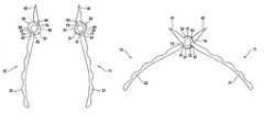
- FIGS. 1 a - dshow views from the front, from the left, from the right and from behind of a first forceps part
- FIG. 2shows forceps parts which have been released from one another
- FIG. 3shows the two forceps parts in the open position
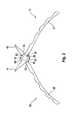
- FIG. 4shows the two forceps parts in the safety position
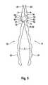
- FIG. 5shows the two forceps parts in the end position
- FIG. 6shows an enlarged representation of the pivot joint element.
- the exemplary embodiment of the surgical forcepsincludes a handle 2 , a pivot joint 3 , a jaw 4 and a first and a second forceps part 11 , 12 .
- the first forceps part 11includes a first control element 21 , a first pivot joint element 31 and a first jaw element 41 .
- a forcecan be transmitted via the first control element 21 and a second control element 22 , which is arranged on the second forceps part 12 , by means of the first pivot joint element 31 and a second pivot joint element 32 onto the first jaw element 41 and a second jaw element 42 .
- the first and the second jaw elements 41 , 42can be developed either as scissor blades or as forceps jaws.
- the first pivot joint element 31has a first guide rail 51 as well as a first thickening element 81 .
- the first thickening element 81can be arranged on the guide rail 51 and in another embodiment it can be arranged next to the guide rail 51 .
- the first pivot joint elementincludes a first guide recess 61 as well as a first surface element 71 .
- the first surface element 71is arranged next to the first guide recess 61 and in another embodiment it is arranged in the guide recess 61 .
- the second forceps part 12includes a second control element 22 , a second pivot joint element 32 and a second jaw element 42 .
- ithas a second guide rail 52 as well as a second thickening element 82 .
- the guide recesses 61 , 62in this case, form an undercut in which the guide rails 51 , 52 are arranged in the coupled state, said guide rails forming a sliding guide for the pivot joint 3 .
- the second guide rail 52is arranged in the first guide recess 61 and the first guide rail 51 is arranged in the second guide recess 62 .
- the guide rails 51 , 52which are mounted in the guide recesses 61 , 62 , bring about the coupling between the first forceps part 11 and the second forceps part 12 by means of the undercut.
- the guide rails 51 , 52 and the guide recesses 61 , 62guide the two forceps parts 11 , 12 during rotation about the central axis Z.
- first and the second pivot joint elements 31 , 32have a central axis Z which, in the coupled state, coincides with the rotational axis of the forceps parts 11 , 12 .
- the pivot joint elements 31 , 32are realized as annular springs, the annular springs having slots 91 , 92 on the side of the pivot joint elements 31 , 32 on which the control elements 21 , 22 are arranged.
- the curved faces of the annular springare arranged in a plane at right angles to the axis Z.
- the first slot 91 of the first pivot joint element 31is arranged on the first control element 21 and the second slot 92 of the second pivot joint element 32 is arranged on the second control element 22 .
- the two pivot joint elements 31 , 32are mounted so as still to be rotatable in relation to one another about the axis Z.
- the slots 91 , 92make spring action onto the control elements 21 , 22 possible in the end position.
- introduction of increased force onto the control elements 22 , 22is absorbed such that the two jaw elements 41 , 42 are pressed together in a manner which is only negligibly stronger.
- FIG. 3shows the open position of the two forceps parts 11 , 12 .
- the two forceps parts 11 , 12are arranged side by side so as to be releasable.
- the guide rails 51 , 52are not arranged in the guide recesses 61 , 62 . This make the release of the two forceps parts 11 , 12 possible.
- the first thickening element 81is not in contact with the second surface element 72 .
- the second thickening element 82in contact with the first surface element 71 .
- the first guide rail 51 of the first forceps part 11is inserted into the second guide recess 62 of the second forceps part 12 .
- the second guide rail 52 of the second forceps part 12is inserted into the first guide recess 61 of the first forceps part 11 .
- the first thickening element 81 of the first forceps part 11comes into contact with the second surface element 72 of the second forceps part 12 .
- the second thickening element 82 of the second forceps part 12comes into contact with the first surface element 71 of the first forceps part 11 .
- the safety position of the tool shown in FIG. 4is achieved.
- the first thickening element 81interacts with the second surface element 72 and the second thickening element 82 interacts with the first surface element 71 such that jamming occurs.
- rotation of the two forceps parts 11 , 12 in relation to one another about the axis Zis made more difficult. It is only possible to achieve further rotation by expending increased force. If the rotation is continued further in such a manner that the first thickening element 81 no longer contacts the second surface element 72 and the second thickening element 82 no longer contacts the first surface element 71 , further rotation is possible without increased expenditure of force as far as up to the end position shown in FIG. 5 . From the end position, the two forceps parts 11 and 12 can only still be rotated in relation to one another in the direction of the safety position.
- the first forceps part 11includes a first pivot joint element 31 with a first surface element 71 , a third guide rail 53 , a third thickening element 83 , a third surface element 73 and a third guide recess 63 .
- the second forceps part 12includes a pivot joint element 32 with a second thickening element 82 , a fourth guide rail 54 , a fourth surface element 74 and a fourth thickening element 84 as well as a fourth guide recess 64 .
- the third guide recess 63 , the third guide rail 53 , the third surface element 73 and the third thickening element 83are arranged in such a manner that they proceed from a rotation of the first guide recess 61 or the first guide rail 51 or the first surface element 71 or of the first thickening element 81 .
- the fourth guide recess 64 , the fourth surface element 74 and the fourth guide rail 54 as well as the fourth thickening element 84proceed from a rotation about the axis Z of the second guide recess 62 or the second surface element 72 or the second guide rail 52 or of the second thickening element 82 .
- the guide rails 51 , 52 and 53 , 54are in each case arranged on the outer surfaces of the annular springs.
- the guide rails 51 , 52 , 53 , 54in this case, are developed in such a manner that they just cover a maximum angle of 90° with reference to the axis Z.
- the third guide rail 53 of the first pivot joint element 31is arranged in the fourth guide recess 64 and the fourth guide rail 54 of the second pivot joint element 32 is arranged in the third guide recess 63 of the first pivot joint element 31 .
- the third thickening element 83 of the first pivot joint element 31interacts with the fourth surface element 74 .
- the fourth thickening element 84 of the second pivot joint element 32interacts in said position with the third surface element 73 of the first pivot joint element 31 .
- the two forceps parts 11 and 12are identical. As a result, the production costs of the tool can be reduced. In addition, this has the advantage that if one forceps part 11 , 12 is lost the respectively remaining forceps part is able to be combined with a third forceps part which is designed identically. The same applies in the case of any damage to one forceps part 11 , 12 . In addition, they can have recesses 101 for gripping by fingers, by means of which the fingers are prevented from slipping during operation.
- the thickening elements 81 , 82 , 83 , 84can be arranged on the guide rails 51 , 52 , 53 , 54 and the surface elements 71 , 72 , 73 , 74 can be arranged in the guide recesses 61 , 62 , 63 , 64 .
- the thickening elements 81 , 82 , 83 , 84can also be arranged in the guide recesses 61 , 62 , 63 , 64 and the surface elements 71 , 72 , 73 , 74 can be arranged on the guide rails 51 , 52 , 53 , 54 .
- the material, from which the first and the second forceps parts 11 , 12 are producedpreferably has a non-corroding characteristic and only allows for a very limited colonization of bacteria and germs.
- Such types of materialsare, for example, stainless steels, non-corroding alloys or also special plastics materials.
Landscapes
- Health & Medical Sciences (AREA)
- Surgery (AREA)
- Life Sciences & Earth Sciences (AREA)
- Biomedical Technology (AREA)
- Nuclear Medicine, Radiotherapy & Molecular Imaging (AREA)
- Engineering & Computer Science (AREA)
- Ophthalmology & Optometry (AREA)
- Heart & Thoracic Surgery (AREA)
- Medical Informatics (AREA)
- Molecular Biology (AREA)
- Animal Behavior & Ethology (AREA)
- General Health & Medical Sciences (AREA)
- Public Health (AREA)
- Veterinary Medicine (AREA)
- Surgical Instruments (AREA)
Abstract
Description
Claims (14)
Applications Claiming Priority (1)
| Application Number | Priority Date | Filing Date | Title |
|---|---|---|---|
| PCT/EP2012/057189WO2013156071A1 (en) | 2012-04-19 | 2012-04-19 | Disassemblable surgical forceps |
Publications (2)
| Publication Number | Publication Date |
|---|---|
| US20140088639A1 US20140088639A1 (en) | 2014-03-27 |
| US9662130B2true US9662130B2 (en) | 2017-05-30 |
Family
ID=45998354
Family Applications (1)
| Application Number | Title | Priority Date | Filing Date |
|---|---|---|---|
| US14/115,246Expired - Fee RelatedUS9662130B2 (en) | 2012-04-19 | 2012-04-19 | Surgical forceps which can be taken apart |
Country Status (5)
| Country | Link |
|---|---|
| US (1) | US9662130B2 (en) |
| CN (1) | CN103702625B (en) |
| AU (1) | AU2012377127B2 (en) |
| RU (1) | RU2611949C2 (en) |
| WO (1) | WO2013156071A1 (en) |
Cited By (143)
| Publication number | Priority date | Publication date | Assignee | Title |
|---|---|---|---|---|
| US10245709B2 (en)* | 2014-10-28 | 2019-04-02 | Kabushiki Kaisya Leben Hanbai | Gripping tool |
| US20220133312A1 (en)* | 2020-10-29 | 2022-05-05 | Ethicon Llc | Surgical instrument comprising a jaw alignment system |
| US11701135B2 (en) | 2016-09-06 | 2023-07-18 | Karl Leibinger Medizintechnik Gmbh & Co. Kg | Medical instrument with cleaning gap in the closure region |
| US11712244B2 (en) | 2015-09-30 | 2023-08-01 | Cilag Gmbh International | Implantable layer with spacer fibers |
| US11717294B2 (en) | 2014-04-16 | 2023-08-08 | Cilag Gmbh International | End effector arrangements comprising indicators |
| US11717297B2 (en) | 2014-09-05 | 2023-08-08 | Cilag Gmbh International | Smart cartridge wake up operation and data retention |
| US11717291B2 (en) | 2021-03-22 | 2023-08-08 | Cilag Gmbh International | Staple cartridge comprising staples configured to apply different tissue compression |
| US11723658B2 (en) | 2021-03-22 | 2023-08-15 | Cilag Gmbh International | Staple cartridge comprising a firing lockout |
| US11723657B2 (en) | 2021-02-26 | 2023-08-15 | Cilag Gmbh International | Adjustable communication based on available bandwidth and power capacity |
| US11723662B2 (en) | 2021-05-28 | 2023-08-15 | Cilag Gmbh International | Stapling instrument comprising an articulation control display |
| US11730474B2 (en) | 2005-08-31 | 2023-08-22 | Cilag Gmbh International | Fastener cartridge assembly comprising a movable cartridge and a staple driver arrangement |
| US11730477B2 (en) | 2008-10-10 | 2023-08-22 | Cilag Gmbh International | Powered surgical system with manually retractable firing system |
| US11730473B2 (en) | 2021-02-26 | 2023-08-22 | Cilag Gmbh International | Monitoring of manufacturing life-cycle |
| US11730471B2 (en) | 2016-02-09 | 2023-08-22 | Cilag Gmbh International | Articulatable surgical instruments with single articulation link arrangements |
| US11737751B2 (en) | 2020-12-02 | 2023-08-29 | Cilag Gmbh International | Devices and methods of managing energy dissipated within sterile barriers of surgical instrument housings |
| US11737754B2 (en) | 2010-09-30 | 2023-08-29 | Cilag Gmbh International | Surgical stapler with floating anvil |
| US11737749B2 (en) | 2021-03-22 | 2023-08-29 | Cilag Gmbh International | Surgical stapling instrument comprising a retraction system |
| US11744583B2 (en) | 2021-02-26 | 2023-09-05 | Cilag Gmbh International | Distal communication array to tune frequency of RF systems |
| US11744593B2 (en) | 2019-06-28 | 2023-09-05 | Cilag Gmbh International | Method for authenticating the compatibility of a staple cartridge with a surgical instrument |
| US11744581B2 (en) | 2020-12-02 | 2023-09-05 | Cilag Gmbh International | Powered surgical instruments with multi-phase tissue treatment |
| US11744588B2 (en) | 2015-02-27 | 2023-09-05 | Cilag Gmbh International | Surgical stapling instrument including a removably attachable battery pack |
| US11749877B2 (en) | 2021-02-26 | 2023-09-05 | Cilag Gmbh International | Stapling instrument comprising a signal antenna |
| US11744603B2 (en) | 2021-03-24 | 2023-09-05 | Cilag Gmbh International | Multi-axis pivot joints for surgical instruments and methods for manufacturing same |
| US11751869B2 (en) | 2021-02-26 | 2023-09-12 | Cilag Gmbh International | Monitoring of multiple sensors over time to detect moving characteristics of tissue |
| US11751867B2 (en) | 2017-12-21 | 2023-09-12 | Cilag Gmbh International | Surgical instrument comprising sequenced systems |
| US11759202B2 (en) | 2021-03-22 | 2023-09-19 | Cilag Gmbh International | Staple cartridge comprising an implantable layer |
| US11759208B2 (en) | 2015-12-30 | 2023-09-19 | Cilag Gmbh International | Mechanisms for compensating for battery pack failure in powered surgical instruments |
| US11771419B2 (en) | 2019-06-28 | 2023-10-03 | Cilag Gmbh International | Packaging for a replaceable component of a surgical stapling system |
| US11779420B2 (en) | 2012-06-28 | 2023-10-10 | Cilag Gmbh International | Robotic surgical attachments having manually-actuated retraction assemblies |
| US11779336B2 (en) | 2016-02-12 | 2023-10-10 | Cilag Gmbh International | Mechanisms for compensating for drivetrain failure in powered surgical instruments |
| US11793509B2 (en) | 2012-03-28 | 2023-10-24 | Cilag Gmbh International | Staple cartridge including an implantable layer |
| US11793512B2 (en) | 2005-08-31 | 2023-10-24 | Cilag Gmbh International | Staple cartridges for forming staples having differing formed staple heights |
| US11793518B2 (en) | 2006-01-31 | 2023-10-24 | Cilag Gmbh International | Powered surgical instruments with firing system lockout arrangements |
| US11793513B2 (en) | 2017-06-20 | 2023-10-24 | Cilag Gmbh International | Systems and methods for controlling motor speed according to user input for a surgical instrument |
| US11801047B2 (en) | 2008-02-14 | 2023-10-31 | Cilag Gmbh International | Surgical stapling system comprising a control circuit configured to selectively monitor tissue impedance and adjust control of a motor |
| US11806013B2 (en) | 2012-06-28 | 2023-11-07 | Cilag Gmbh International | Firing system arrangements for surgical instruments |
| US11811253B2 (en) | 2016-04-18 | 2023-11-07 | Cilag Gmbh International | Surgical robotic system with fault state detection configurations based on motor current draw |
| US11806011B2 (en) | 2021-03-22 | 2023-11-07 | Cilag Gmbh International | Stapling instrument comprising tissue compression systems |
| US11812961B2 (en) | 2007-01-10 | 2023-11-14 | Cilag Gmbh International | Surgical instrument including a motor control system |
| US11812954B2 (en) | 2008-09-23 | 2023-11-14 | Cilag Gmbh International | Robotically-controlled motorized surgical instrument with an end effector |
| US11812964B2 (en) | 2021-02-26 | 2023-11-14 | Cilag Gmbh International | Staple cartridge comprising a power management circuit |
| US11812965B2 (en) | 2010-09-30 | 2023-11-14 | Cilag Gmbh International | Layer of material for a surgical end effector |
| US11826042B2 (en) | 2021-03-22 | 2023-11-28 | Cilag Gmbh International | Surgical instrument comprising a firing drive including a selectable leverage mechanism |
| US11826012B2 (en) | 2021-03-22 | 2023-11-28 | Cilag Gmbh International | Stapling instrument comprising a pulsed motor-driven firing rack |
| US11839352B2 (en) | 2007-01-11 | 2023-12-12 | Cilag Gmbh International | Surgical stapling device with an end effector |
| US11839375B2 (en) | 2005-08-31 | 2023-12-12 | Cilag Gmbh International | Fastener cartridge assembly comprising an anvil and different staple heights |
| US11849945B2 (en) | 2021-03-24 | 2023-12-26 | Cilag Gmbh International | Rotary-driven surgical stapling assembly comprising eccentrically driven firing member |
| US11849946B2 (en) | 2015-09-23 | 2023-12-26 | Cilag Gmbh International | Surgical stapler having downstream current-based motor control |
| US11849941B2 (en) | 2007-06-29 | 2023-12-26 | Cilag Gmbh International | Staple cartridge having staple cavities extending at a transverse angle relative to a longitudinal cartridge axis |
| US11849943B2 (en) | 2020-12-02 | 2023-12-26 | Cilag Gmbh International | Surgical instrument with cartridge release mechanisms |
| US11849952B2 (en) | 2010-09-30 | 2023-12-26 | Cilag Gmbh International | Staple cartridge comprising staples positioned within a compressible portion thereof |
| US11850310B2 (en) | 2010-09-30 | 2023-12-26 | Cilag Gmbh International | Staple cartridge including an adjunct |
| US11857181B2 (en) | 2007-06-04 | 2024-01-02 | Cilag Gmbh International | Robotically-controlled shaft based rotary drive systems for surgical instruments |
| US11857187B2 (en) | 2010-09-30 | 2024-01-02 | Cilag Gmbh International | Tissue thickness compensator comprising controlled release and expansion |
| US11871939B2 (en) | 2017-06-20 | 2024-01-16 | Cilag Gmbh International | Method for closed loop control of motor velocity of a surgical stapling and cutting instrument |
| US11871923B2 (en) | 2008-09-23 | 2024-01-16 | Cilag Gmbh International | Motorized surgical instrument |
| US11877748B2 (en) | 2006-10-03 | 2024-01-23 | Cilag Gmbh International | Robotically-driven surgical instrument with E-beam driver |
| US11883026B2 (en) | 2014-04-16 | 2024-01-30 | Cilag Gmbh International | Fastener cartridge assemblies and staple retainer cover arrangements |
| US11882987B2 (en) | 2004-07-28 | 2024-01-30 | Cilag Gmbh International | Articulating surgical stapling instrument incorporating a two-piece E-beam firing mechanism |
| USD1013170S1 (en) | 2020-10-29 | 2024-01-30 | Cilag Gmbh International | Surgical instrument assembly |
| US11883025B2 (en) | 2010-09-30 | 2024-01-30 | Cilag Gmbh International | Tissue thickness compensator comprising a plurality of layers |
| US11883020B2 (en) | 2006-01-31 | 2024-01-30 | Cilag Gmbh International | Surgical instrument having a feedback system |
| US11890029B2 (en) | 2006-01-31 | 2024-02-06 | Cilag Gmbh International | Motor-driven surgical cutting and fastening instrument |
| US11890012B2 (en) | 2004-07-28 | 2024-02-06 | Cilag Gmbh International | Staple cartridge comprising cartridge body and attached support |
| US11890008B2 (en) | 2006-01-31 | 2024-02-06 | Cilag Gmbh International | Surgical instrument with firing lockout |
| US11890005B2 (en) | 2017-06-29 | 2024-02-06 | Cilag Gmbh International | Methods for closed loop velocity control for robotic surgical instrument |
| US11890015B2 (en) | 2015-09-30 | 2024-02-06 | Cilag Gmbh International | Compressible adjunct with crossing spacer fibers |
| US11896222B2 (en) | 2017-12-15 | 2024-02-13 | Cilag Gmbh International | Methods of operating surgical end effectors |
| US11896218B2 (en) | 2021-03-24 | 2024-02-13 | Cilag Gmbh International | Method of using a powered stapling device |
| US11896217B2 (en) | 2020-10-29 | 2024-02-13 | Cilag Gmbh International | Surgical instrument comprising an articulation lock |
| US11896219B2 (en) | 2021-03-24 | 2024-02-13 | Cilag Gmbh International | Mating features between drivers and underside of a cartridge deck |
| US11903581B2 (en) | 2019-04-30 | 2024-02-20 | Cilag Gmbh International | Methods for stapling tissue using a surgical instrument |
| US11911027B2 (en) | 2010-09-30 | 2024-02-27 | Cilag Gmbh International | Adhesive film laminate |
| US11918212B2 (en) | 2015-03-31 | 2024-03-05 | Cilag Gmbh International | Surgical instrument with selectively disengageable drive systems |
| US11918215B2 (en) | 2016-12-21 | 2024-03-05 | Cilag Gmbh International | Staple cartridge with array of staple pockets |
| US11918222B2 (en) | 2014-04-16 | 2024-03-05 | Cilag Gmbh International | Stapling assembly having firing member viewing windows |
| US11918220B2 (en) | 2012-03-28 | 2024-03-05 | Cilag Gmbh International | Tissue thickness compensator comprising tissue ingrowth features |
| US11918210B2 (en) | 2014-10-16 | 2024-03-05 | Cilag Gmbh International | Staple cartridge comprising a cartridge body including a plurality of wells |
| US11918208B2 (en) | 2011-05-27 | 2024-03-05 | Cilag Gmbh International | Robotically-controlled shaft based rotary drive systems for surgical instruments |
| US11931028B2 (en) | 2016-04-15 | 2024-03-19 | Cilag Gmbh International | Surgical instrument with multiple program responses during a firing motion |
| USD1018577S1 (en) | 2017-06-28 | 2024-03-19 | Cilag Gmbh International | Display screen or portion thereof with a graphical user interface for a surgical instrument |
| US11931034B2 (en) | 2016-12-21 | 2024-03-19 | Cilag Gmbh International | Surgical stapling instruments with smart staple cartridges |
| US11931025B2 (en) | 2020-10-29 | 2024-03-19 | Cilag Gmbh International | Surgical instrument comprising a releasable closure drive lock |
| US11937816B2 (en) | 2021-10-28 | 2024-03-26 | Cilag Gmbh International | Electrical lead arrangements for surgical instruments |
| US11944296B2 (en) | 2020-12-02 | 2024-04-02 | Cilag Gmbh International | Powered surgical instruments with external connectors |
| US11944338B2 (en) | 2015-03-06 | 2024-04-02 | Cilag Gmbh International | Multiple level thresholds to modify operation of powered surgical instruments |
| US11950777B2 (en) | 2021-02-26 | 2024-04-09 | Cilag Gmbh International | Staple cartridge comprising an information access control system |
| US11957339B2 (en) | 2018-08-20 | 2024-04-16 | Cilag Gmbh International | Method for fabricating surgical stapler anvils |
| US11957345B2 (en) | 2013-03-01 | 2024-04-16 | Cilag Gmbh International | Articulatable surgical instruments with conductive pathways for signal communication |
| US11963680B2 (en) | 2017-10-31 | 2024-04-23 | Cilag Gmbh International | Cartridge body design with force reduction based on firing completion |
| US11974746B2 (en) | 2014-04-16 | 2024-05-07 | Cilag Gmbh International | Anvil for use with a surgical stapling assembly |
| US11974747B2 (en) | 2011-05-27 | 2024-05-07 | Cilag Gmbh International | Surgical stapling instruments with rotatable staple deployment arrangements |
| US11974742B2 (en) | 2017-08-03 | 2024-05-07 | Cilag Gmbh International | Surgical system comprising an articulation bailout |
| US11980362B2 (en) | 2021-02-26 | 2024-05-14 | Cilag Gmbh International | Surgical instrument system comprising a power transfer coil |
| US11980363B2 (en) | 2021-10-18 | 2024-05-14 | Cilag Gmbh International | Row-to-row staple array variations |
| US11980366B2 (en) | 2006-10-03 | 2024-05-14 | Cilag Gmbh International | Surgical instrument |
| US11986183B2 (en) | 2008-02-14 | 2024-05-21 | Cilag Gmbh International | Surgical cutting and fastening instrument comprising a plurality of sensors to measure an electrical parameter |
| US11992213B2 (en) | 2016-12-21 | 2024-05-28 | Cilag Gmbh International | Surgical stapling instruments with replaceable staple cartridges |
| US11992214B2 (en) | 2013-03-14 | 2024-05-28 | Cilag Gmbh International | Control systems for surgical instruments |
| US11998194B2 (en) | 2008-02-15 | 2024-06-04 | Cilag Gmbh International | Surgical stapling assembly comprising an adjunct applicator |
| US11998206B2 (en) | 2008-02-14 | 2024-06-04 | Cilag Gmbh International | Detachable motor powered surgical instrument |
| US11998198B2 (en) | 2004-07-28 | 2024-06-04 | Cilag Gmbh International | Surgical stapling instrument incorporating a two-piece E-beam firing mechanism |
| US12011166B2 (en) | 2016-12-21 | 2024-06-18 | Cilag Gmbh International | Articulatable surgical stapling instruments |
| US12016564B2 (en) | 2014-09-26 | 2024-06-25 | Cilag Gmbh International | Circular fastener cartridges for applying radially expandable fastener lines |
| US12023022B2 (en) | 2014-03-26 | 2024-07-02 | Cilag Gmbh International | Systems and methods for controlling a segmented circuit |
| US12029415B2 (en) | 2008-09-23 | 2024-07-09 | Cilag Gmbh International | Motor-driven surgical cutting instrument |
| US12035913B2 (en) | 2019-12-19 | 2024-07-16 | Cilag Gmbh International | Staple cartridge comprising a deployable knife |
| US12053176B2 (en) | 2013-08-23 | 2024-08-06 | Cilag Gmbh International | End effector detention systems for surgical instruments |
| US12053175B2 (en) | 2020-10-29 | 2024-08-06 | Cilag Gmbh International | Surgical instrument comprising a stowed closure actuator stop |
| US12076096B2 (en) | 2017-12-19 | 2024-09-03 | Cilag Gmbh International | Method for determining the position of a rotatable jaw of a surgical instrument attachment assembly |
| US12076008B2 (en) | 2018-08-20 | 2024-09-03 | Cilag Gmbh International | Method for operating a powered articulatable surgical instrument |
| US12076017B2 (en) | 2014-09-18 | 2024-09-03 | Cilag Gmbh International | Surgical instrument including a deployable knife |
| US12076011B2 (en) | 2017-10-30 | 2024-09-03 | Cilag Gmbh International | Surgical stapler knife motion controls |
| US12082806B2 (en) | 2007-01-10 | 2024-09-10 | Cilag Gmbh International | Surgical instrument with wireless communication between control unit and sensor transponders |
| US12089841B2 (en) | 2021-10-28 | 2024-09-17 | Cilag CmbH International | Staple cartridge identification systems |
| US12108950B2 (en) | 2014-12-18 | 2024-10-08 | Cilag Gmbh International | Surgical instrument assembly comprising a flexible articulation system |
| US12108951B2 (en) | 2021-02-26 | 2024-10-08 | Cilag Gmbh International | Staple cartridge comprising a sensing array and a temperature control system |
| US12114859B2 (en) | 2014-12-10 | 2024-10-15 | Cilag Gmbh International | Articulatable surgical instrument system |
| US12137912B2 (en) | 2015-09-30 | 2024-11-12 | Cilag Gmbh International | Compressible adjunct with attachment regions |
| US12144500B2 (en) | 2016-04-15 | 2024-11-19 | Cilag Gmbh International | Surgical instrument with multiple program responses during a firing motion |
| US12156653B2 (en) | 2015-12-30 | 2024-12-03 | Cilag Gmbh International | Surgical instruments with motor control circuits |
| US12161320B2 (en) | 2013-04-16 | 2024-12-10 | Cilag Gmbh International | Powered surgical stapler |
| US12171508B2 (en) | 2006-03-23 | 2024-12-24 | Cilag Gmbh International | Robotically-controlled surgical instrument with selectively articulatable end effector |
| US12171507B2 (en) | 2016-08-16 | 2024-12-24 | Cilag Gmbh International | Surgical tool with manual control of end effector jaws |
| US12213666B2 (en) | 2010-09-30 | 2025-02-04 | Cilag Gmbh International | Tissue thickness compensator comprising layers |
| US12213671B2 (en) | 2008-02-14 | 2025-02-04 | Cilag Gmbh International | Motorized system having a plurality of power sources |
| US12232723B2 (en) | 2014-03-26 | 2025-02-25 | Cilag Gmbh International | Systems and methods for controlling a segmented circuit |
| US12239316B2 (en) | 2011-05-27 | 2025-03-04 | Cilag Gmbh International | Automated end effector component reloading system for use with a robotic system |
| US12245901B2 (en) | 2015-09-25 | 2025-03-11 | Cilag Gmbh International | Implantable layer comprising boundary indicators |
| US12245764B2 (en) | 2016-12-21 | 2025-03-11 | Cilag Gmbh International | Shaft assembly comprising a lockout |
| US12262888B2 (en) | 2018-08-20 | 2025-04-01 | Cilag Gmbh International | Surgical instruments with progressive jaw closure arrangements |
| US12285166B2 (en) | 2014-03-26 | 2025-04-29 | Cilag Gmbh International | Feedback algorithms for manual bailout systems for surgical instruments |
| US12324581B2 (en) | 2017-06-28 | 2025-06-10 | Cilag Gmbh International | Surgical instrument comprising selectively actuatable rotatable couplers |
| US12324580B2 (en) | 2021-02-26 | 2025-06-10 | Cilag Gmbh International | Method of powering and communicating with a staple cartridge |
| US12329381B2 (en) | 2019-04-30 | 2025-06-17 | Cilag Gmbh International | Stapling instrument comprising a mounted shaft orientation sensor |
| US12336705B2 (en) | 2017-12-21 | 2025-06-24 | Cilag Gmbh International | Continuous use self-propelled stapling instrument |
| US12383267B2 (en) | 2012-06-28 | 2025-08-12 | Cilag Gmbh International | Robotically powered surgical device with manually-actuatable reversing system |
| US12383259B2 (en) | 2014-09-26 | 2025-08-12 | Cilag Gmbh International | Method for creating a flexible staple line |
| US12414768B2 (en) | 2014-09-05 | 2025-09-16 | Cilag Gmbh International | Staple cartridge electrical contacts |
| US12432790B2 (en) | 2021-10-28 | 2025-09-30 | Cilag Gmbh International | Method and device for transmitting UART communications over a security short range wireless communication |
| US12433584B2 (en) | 2006-01-31 | 2025-10-07 | Cilag Gmbh International | Robotically-controlled end effector |
| US12433627B2 (en) | 2013-03-01 | 2025-10-07 | Cilag Gmbh International | Surgical instrument soft stop |
| US12440208B2 (en) | 2023-08-23 | 2025-10-14 | Cilag Gmbh International | Powered surgical instrument |
Families Citing this family (7)
| Publication number | Priority date | Publication date | Assignee | Title |
|---|---|---|---|---|
| US11439422B2 (en)* | 2004-08-02 | 2022-09-13 | Robert F. Biolchini, Jr. | Ambidextrous locking clamp system |
| USD762302S1 (en) | 2014-04-24 | 2016-07-26 | University Of Massachusetts | Surgical forceps |
| US10201362B2 (en) | 2014-04-24 | 2019-02-12 | University Of Massachusetts | Contoured surgical forceps |
| CN105215870A (en)* | 2015-10-21 | 2016-01-06 | 和弘手术器械(上海)有限公司 | A kind of edge joins formula medical calm |
| CN108577932B (en)* | 2018-05-21 | 2020-10-30 | 王国伟 | Multi-functional operating forceps of orthopedics |
| RU202351U1 (en)* | 2019-10-10 | 2021-02-12 | Общество С Ограниченной Ответственностью "Инновационные Технологии, Радиоэлектроника - Медицина" (Ооо "Интера-Мед") | CLIP PLIERS |
| US20250114160A1 (en)* | 2023-10-04 | 2025-04-10 | 4S Medical, Llc | Surgical instruments |
Citations (12)
| Publication number | Priority date | Publication date | Assignee | Title |
|---|---|---|---|---|
| US168012A (en)* | 1875-09-21 | Improvement in dental forceps | ||
| US1475569A (en) | 1922-04-10 | 1923-11-27 | Dondero John | Pliers |
| US2611288A (en)* | 1950-01-27 | 1952-09-23 | Schiffbauer Max | Mesh joint for pliers and like instruments |
| US2632661A (en) | 1948-08-14 | 1953-03-24 | Cristofv Cristjo | Joint for surgical instruments |
| US3982450A (en)* | 1974-05-20 | 1976-09-28 | Haffenden-Richborough Limited | Plastic forceps hinge |
| US4932955A (en)* | 1984-06-29 | 1990-06-12 | Baxter International Inc. | Clip |
| US5197879A (en)* | 1991-09-06 | 1993-03-30 | Fowler Iii Hudson D | Orthodontic, medical, dental tool |
| US5232360A (en)* | 1991-09-16 | 1993-08-03 | Luis Ingels | Orthodontic pliers |
| US7399101B2 (en)* | 2005-07-20 | 2008-07-15 | Streamworks, Inc. | Lighted plier hand tool apparatus |
| DE102009003273A1 (en) | 2009-05-20 | 2010-11-25 | Peter Lazic Gmbh | Aneurysm clip |
| US8210845B1 (en)* | 2011-05-04 | 2012-07-03 | Luis Ingels | Orthodontic pliers |
| EP2508140A1 (en) | 2011-04-07 | 2012-10-10 | Deru GmbH | Dismountable surgical clipper |
Family Cites Families (2)
| Publication number | Priority date | Publication date | Assignee | Title |
|---|---|---|---|---|
| SU524994A1 (en)* | 1972-05-22 | 1976-08-15 | Проектно-Конструкторское И Технологическое Бюро По Машиностроению Министерства Тяжелого И Транспортного Машиностроения | Stand for testing springs |
| RU74796U1 (en)* | 2008-02-21 | 2008-07-20 | Александр Витальевич Притыкин | SURGICAL TONGS FOR CREATION OF A DEFECT ON THE BEAM IN ANIMALS IN AN EXPERIMENT |
- 2012
- 2012-04-19WOPCT/EP2012/057189patent/WO2013156071A1/enactiveApplication Filing
- 2012-04-19CNCN201280021861.7Apatent/CN103702625B/ennot_activeExpired - Fee Related
- 2012-04-19AUAU2012377127Apatent/AU2012377127B2/ennot_activeCeased
- 2012-04-19RURU2013148076Apatent/RU2611949C2/enactive
- 2012-04-19USUS14/115,246patent/US9662130B2/ennot_activeExpired - Fee Related
Patent Citations (14)
| Publication number | Priority date | Publication date | Assignee | Title |
|---|---|---|---|---|
| US168012A (en)* | 1875-09-21 | Improvement in dental forceps | ||
| US1475569A (en) | 1922-04-10 | 1923-11-27 | Dondero John | Pliers |
| US2632661A (en) | 1948-08-14 | 1953-03-24 | Cristofv Cristjo | Joint for surgical instruments |
| US2611288A (en)* | 1950-01-27 | 1952-09-23 | Schiffbauer Max | Mesh joint for pliers and like instruments |
| US3982450A (en)* | 1974-05-20 | 1976-09-28 | Haffenden-Richborough Limited | Plastic forceps hinge |
| US4932955A (en)* | 1984-06-29 | 1990-06-12 | Baxter International Inc. | Clip |
| US5197879A (en)* | 1991-09-06 | 1993-03-30 | Fowler Iii Hudson D | Orthodontic, medical, dental tool |
| US5232360A (en)* | 1991-09-16 | 1993-08-03 | Luis Ingels | Orthodontic pliers |
| US7399101B2 (en)* | 2005-07-20 | 2008-07-15 | Streamworks, Inc. | Lighted plier hand tool apparatus |
| DE102009003273A1 (en) | 2009-05-20 | 2010-11-25 | Peter Lazic Gmbh | Aneurysm clip |
| US20100298849A1 (en) | 2009-05-20 | 2010-11-25 | Daniel Lazic | Aneurysm Clip |
| US8273096B2 (en)* | 2009-05-20 | 2012-09-25 | Peter Lazic Gmbh | Aneurysm clip |
| EP2508140A1 (en) | 2011-04-07 | 2012-10-10 | Deru GmbH | Dismountable surgical clipper |
| US8210845B1 (en)* | 2011-05-04 | 2012-07-03 | Luis Ingels | Orthodontic pliers |
Non-Patent Citations (1)
| Title |
|---|
| International Search Report and Written Opinion mailed Feb. 13, 2013, directed to International Application No. PCT/EP2012/057189; 11 pages. |
Cited By (201)
| Publication number | Priority date | Publication date | Assignee | Title |
|---|---|---|---|---|
| US12011165B2 (en) | 2004-07-28 | 2024-06-18 | Cilag Gmbh International | Surgical stapling instrument comprising replaceable staple cartridge |
| US11963679B2 (en) | 2004-07-28 | 2024-04-23 | Cilag Gmbh International | Articulating surgical stapling instrument incorporating a two-piece E-beam firing mechanism |
| US12029423B2 (en) | 2004-07-28 | 2024-07-09 | Cilag Gmbh International | Surgical stapling instrument comprising a staple cartridge |
| US11882987B2 (en) | 2004-07-28 | 2024-01-30 | Cilag Gmbh International | Articulating surgical stapling instrument incorporating a two-piece E-beam firing mechanism |
| US11896225B2 (en) | 2004-07-28 | 2024-02-13 | Cilag Gmbh International | Staple cartridge comprising a pan |
| US11998198B2 (en) | 2004-07-28 | 2024-06-04 | Cilag Gmbh International | Surgical stapling instrument incorporating a two-piece E-beam firing mechanism |
| US11890012B2 (en) | 2004-07-28 | 2024-02-06 | Cilag Gmbh International | Staple cartridge comprising cartridge body and attached support |
| US11839375B2 (en) | 2005-08-31 | 2023-12-12 | Cilag Gmbh International | Fastener cartridge assembly comprising an anvil and different staple heights |
| US11730474B2 (en) | 2005-08-31 | 2023-08-22 | Cilag Gmbh International | Fastener cartridge assembly comprising a movable cartridge and a staple driver arrangement |
| US11793512B2 (en) | 2005-08-31 | 2023-10-24 | Cilag Gmbh International | Staple cartridges for forming staples having differing formed staple heights |
| US11771425B2 (en) | 2005-08-31 | 2023-10-03 | Cilag Gmbh International | Stapling assembly for forming staples to different formed heights |
| US11944299B2 (en) | 2006-01-31 | 2024-04-02 | Cilag Gmbh International | Surgical instrument having force feedback capabilities |
| US11890029B2 (en) | 2006-01-31 | 2024-02-06 | Cilag Gmbh International | Motor-driven surgical cutting and fastening instrument |
| US11890008B2 (en) | 2006-01-31 | 2024-02-06 | Cilag Gmbh International | Surgical instrument with firing lockout |
| US11883020B2 (en) | 2006-01-31 | 2024-01-30 | Cilag Gmbh International | Surgical instrument having a feedback system |
| US12433584B2 (en) | 2006-01-31 | 2025-10-07 | Cilag Gmbh International | Robotically-controlled end effector |
| US11793518B2 (en) | 2006-01-31 | 2023-10-24 | Cilag Gmbh International | Powered surgical instruments with firing system lockout arrangements |
| US12161329B2 (en) | 2006-01-31 | 2024-12-10 | Cilag Gmbh International | Surgical systems comprising a control circuit including a timer |
| US12171508B2 (en) | 2006-03-23 | 2024-12-24 | Cilag Gmbh International | Robotically-controlled surgical instrument with selectively articulatable end effector |
| US12178434B2 (en) | 2006-10-03 | 2024-12-31 | Cilag Gmbh International | Surgical stapling system including control circuit to monitor clamping pressure |
| US11980366B2 (en) | 2006-10-03 | 2024-05-14 | Cilag Gmbh International | Surgical instrument |
| US11877748B2 (en) | 2006-10-03 | 2024-01-23 | Cilag Gmbh International | Robotically-driven surgical instrument with E-beam driver |
| US12004743B2 (en) | 2007-01-10 | 2024-06-11 | Cilag Gmbh International | Staple cartridge comprising a sloped wall |
| US12082806B2 (en) | 2007-01-10 | 2024-09-10 | Cilag Gmbh International | Surgical instrument with wireless communication between control unit and sensor transponders |
| US11918211B2 (en) | 2007-01-10 | 2024-03-05 | Cilag Gmbh International | Surgical stapling instrument for use with a robotic system |
| US11812961B2 (en) | 2007-01-10 | 2023-11-14 | Cilag Gmbh International | Surgical instrument including a motor control system |
| US11931032B2 (en) | 2007-01-10 | 2024-03-19 | Cilag Gmbh International | Surgical instrument with wireless communication between a control unit of a robotic system and remote sensor |
| US11844521B2 (en) | 2007-01-10 | 2023-12-19 | Cilag Gmbh International | Surgical instrument for use with a robotic system |
| US11937814B2 (en) | 2007-01-10 | 2024-03-26 | Cilag Gmbh International | Surgical instrument for use with a robotic system |
| US11849947B2 (en) | 2007-01-10 | 2023-12-26 | Cilag Gmbh International | Surgical system including a control circuit and a passively-powered transponder |
| US11839352B2 (en) | 2007-01-11 | 2023-12-12 | Cilag Gmbh International | Surgical stapling device with an end effector |
| US11857181B2 (en) | 2007-06-04 | 2024-01-02 | Cilag Gmbh International | Robotically-controlled shaft based rotary drive systems for surgical instruments |
| US11992208B2 (en) | 2007-06-04 | 2024-05-28 | Cilag Gmbh International | Rotary drive systems for surgical instruments |
| US11911028B2 (en) | 2007-06-04 | 2024-02-27 | Cilag Gmbh International | Surgical instruments for use with a robotic surgical system |
| US12035906B2 (en) | 2007-06-04 | 2024-07-16 | Cilag Gmbh International | Surgical instrument including a handle system for advancing a cutting member |
| US12023024B2 (en) | 2007-06-04 | 2024-07-02 | Cilag Gmbh International | Robotically-controlled shaft based rotary drive systems for surgical instruments |
| US12023025B2 (en) | 2007-06-29 | 2024-07-02 | Cilag Gmbh International | Surgical stapling instrument having a releasable buttress material |
| US11849941B2 (en) | 2007-06-29 | 2023-12-26 | Cilag Gmbh International | Staple cartridge having staple cavities extending at a transverse angle relative to a longitudinal cartridge axis |
| US11801047B2 (en) | 2008-02-14 | 2023-10-31 | Cilag Gmbh International | Surgical stapling system comprising a control circuit configured to selectively monitor tissue impedance and adjust control of a motor |
| US11998206B2 (en) | 2008-02-14 | 2024-06-04 | Cilag Gmbh International | Detachable motor powered surgical instrument |
| US11986183B2 (en) | 2008-02-14 | 2024-05-21 | Cilag Gmbh International | Surgical cutting and fastening instrument comprising a plurality of sensors to measure an electrical parameter |
| US12213671B2 (en) | 2008-02-14 | 2025-02-04 | Cilag Gmbh International | Motorized system having a plurality of power sources |
| US11998194B2 (en) | 2008-02-15 | 2024-06-04 | Cilag Gmbh International | Surgical stapling assembly comprising an adjunct applicator |
| US11871923B2 (en) | 2008-09-23 | 2024-01-16 | Cilag Gmbh International | Motorized surgical instrument |
| US11812954B2 (en) | 2008-09-23 | 2023-11-14 | Cilag Gmbh International | Robotically-controlled motorized surgical instrument with an end effector |
| US12029415B2 (en) | 2008-09-23 | 2024-07-09 | Cilag Gmbh International | Motor-driven surgical cutting instrument |
| US11730477B2 (en) | 2008-10-10 | 2023-08-22 | Cilag Gmbh International | Powered surgical system with manually retractable firing system |
| US11849952B2 (en) | 2010-09-30 | 2023-12-26 | Cilag Gmbh International | Staple cartridge comprising staples positioned within a compressible portion thereof |
| US11857187B2 (en) | 2010-09-30 | 2024-01-02 | Cilag Gmbh International | Tissue thickness compensator comprising controlled release and expansion |
| US12178432B2 (en) | 2010-09-30 | 2024-12-31 | Cilag Gmbh International | Tissue thickness compensator comprising laterally offset layers |
| US11812965B2 (en) | 2010-09-30 | 2023-11-14 | Cilag Gmbh International | Layer of material for a surgical end effector |
| US11957795B2 (en) | 2010-09-30 | 2024-04-16 | Cilag Gmbh International | Tissue thickness compensator configured to redistribute compressive forces |
| US11883025B2 (en) | 2010-09-30 | 2024-01-30 | Cilag Gmbh International | Tissue thickness compensator comprising a plurality of layers |
| US11925354B2 (en) | 2010-09-30 | 2024-03-12 | Cilag Gmbh International | Staple cartridge comprising staples positioned within a compressible portion thereof |
| US11944292B2 (en) | 2010-09-30 | 2024-04-02 | Cilag Gmbh International | Anvil layer attached to a proximal end of an end effector |
| US11911027B2 (en) | 2010-09-30 | 2024-02-27 | Cilag Gmbh International | Adhesive film laminate |
| US12213666B2 (en) | 2010-09-30 | 2025-02-04 | Cilag Gmbh International | Tissue thickness compensator comprising layers |
| US11850310B2 (en) | 2010-09-30 | 2023-12-26 | Cilag Gmbh International | Staple cartridge including an adjunct |
| US11737754B2 (en) | 2010-09-30 | 2023-08-29 | Cilag Gmbh International | Surgical stapler with floating anvil |
| US12059154B2 (en) | 2011-05-27 | 2024-08-13 | Cilag Gmbh International | Surgical instrument with detachable motor control unit |
| US12256930B2 (en) | 2011-05-27 | 2025-03-25 | Cilag Gmbh International | Robotically-driven surgical instrument with E-beam driver |
| US11918208B2 (en) | 2011-05-27 | 2024-03-05 | Cilag Gmbh International | Robotically-controlled shaft based rotary drive systems for surgical instruments |
| US11974747B2 (en) | 2011-05-27 | 2024-05-07 | Cilag Gmbh International | Surgical stapling instruments with rotatable staple deployment arrangements |
| US12239316B2 (en) | 2011-05-27 | 2025-03-04 | Cilag Gmbh International | Automated end effector component reloading system for use with a robotic system |
| US12290261B2 (en) | 2011-05-27 | 2025-05-06 | Cilag Gmbh International | Robotically-driven surgical instrument with E-beam driver |
| US11793509B2 (en) | 2012-03-28 | 2023-10-24 | Cilag Gmbh International | Staple cartridge including an implantable layer |
| US12121234B2 (en) | 2012-03-28 | 2024-10-22 | Cilag Gmbh International | Staple cartridge assembly comprising a compensator |
| US11918220B2 (en) | 2012-03-28 | 2024-03-05 | Cilag Gmbh International | Tissue thickness compensator comprising tissue ingrowth features |
| US12369911B2 (en) | 2012-06-28 | 2025-07-29 | Cilag Gmbh International | Firing system lockout arrangements for surgical instruments |
| US12383267B2 (en) | 2012-06-28 | 2025-08-12 | Cilag Gmbh International | Robotically powered surgical device with manually-actuatable reversing system |
| US12343013B2 (en) | 2012-06-28 | 2025-07-01 | Cilag Gmbh International | Interconnected joint segments forming drive tube for stapling assembly |
| US11779420B2 (en) | 2012-06-28 | 2023-10-10 | Cilag Gmbh International | Robotic surgical attachments having manually-actuated retraction assemblies |
| US11806013B2 (en) | 2012-06-28 | 2023-11-07 | Cilag Gmbh International | Firing system arrangements for surgical instruments |
| US11918213B2 (en) | 2012-06-28 | 2024-03-05 | Cilag Gmbh International | Surgical stapler including couplers for attaching a shaft to an end effector |
| US12433627B2 (en) | 2013-03-01 | 2025-10-07 | Cilag Gmbh International | Surgical instrument soft stop |
| US11957345B2 (en) | 2013-03-01 | 2024-04-16 | Cilag Gmbh International | Articulatable surgical instruments with conductive pathways for signal communication |
| US11992214B2 (en) | 2013-03-14 | 2024-05-28 | Cilag Gmbh International | Control systems for surgical instruments |
| US12161320B2 (en) | 2013-04-16 | 2024-12-10 | Cilag Gmbh International | Powered surgical stapler |
| US12178429B2 (en) | 2013-04-16 | 2024-12-31 | Cilag Gmbh International | Surgical instruments having modular end effector selectively coupleable to housing assembly |
| US12053176B2 (en) | 2013-08-23 | 2024-08-06 | Cilag Gmbh International | End effector detention systems for surgical instruments |
| US12232723B2 (en) | 2014-03-26 | 2025-02-25 | Cilag Gmbh International | Systems and methods for controlling a segmented circuit |
| US12023022B2 (en) | 2014-03-26 | 2024-07-02 | Cilag Gmbh International | Systems and methods for controlling a segmented circuit |
| US12285166B2 (en) | 2014-03-26 | 2025-04-29 | Cilag Gmbh International | Feedback algorithms for manual bailout systems for surgical instruments |
| US11974746B2 (en) | 2014-04-16 | 2024-05-07 | Cilag Gmbh International | Anvil for use with a surgical stapling assembly |
| US11918222B2 (en) | 2014-04-16 | 2024-03-05 | Cilag Gmbh International | Stapling assembly having firing member viewing windows |
| US11944307B2 (en) | 2014-04-16 | 2024-04-02 | Cilag Gmbh International | Surgical stapling system including jaw windows |
| US11963678B2 (en) | 2014-04-16 | 2024-04-23 | Cilag Gmbh International | Fastener cartridges including extensions having different configurations |
| US11883026B2 (en) | 2014-04-16 | 2024-01-30 | Cilag Gmbh International | Fastener cartridge assemblies and staple retainer cover arrangements |
| US11717294B2 (en) | 2014-04-16 | 2023-08-08 | Cilag Gmbh International | End effector arrangements comprising indicators |
| US11925353B2 (en) | 2014-04-16 | 2024-03-12 | Cilag Gmbh International | Surgical stapling instrument comprising internal passage between stapling cartridge and elongate channel |
| US12274445B2 (en) | 2014-04-16 | 2025-04-15 | Cilag Gmbh International | Fastener cartridges including extensions having different configurations |
| US11717297B2 (en) | 2014-09-05 | 2023-08-08 | Cilag Gmbh International | Smart cartridge wake up operation and data retention |
| US12336709B2 (en) | 2014-09-05 | 2025-06-24 | Cilag Gmbh International | Smart cartridge wake up operation and data retention |
| US12042147B2 (en) | 2014-09-05 | 2024-07-23 | Cllag GmbH International | Smart cartridge wake up operation and data retention |
| US12414768B2 (en) | 2014-09-05 | 2025-09-16 | Cilag Gmbh International | Staple cartridge electrical contacts |
| US12076017B2 (en) | 2014-09-18 | 2024-09-03 | Cilag Gmbh International | Surgical instrument including a deployable knife |
| US12383259B2 (en) | 2014-09-26 | 2025-08-12 | Cilag Gmbh International | Method for creating a flexible staple line |
| US12016564B2 (en) | 2014-09-26 | 2024-06-25 | Cilag Gmbh International | Circular fastener cartridges for applying radially expandable fastener lines |
| US11918210B2 (en) | 2014-10-16 | 2024-03-05 | Cilag Gmbh International | Staple cartridge comprising a cartridge body including a plurality of wells |
| US12004741B2 (en) | 2014-10-16 | 2024-06-11 | Cilag Gmbh International | Staple cartridge comprising a tissue thickness compensator |
| US10245709B2 (en)* | 2014-10-28 | 2019-04-02 | Kabushiki Kaisya Leben Hanbai | Gripping tool |
| US12114859B2 (en) | 2014-12-10 | 2024-10-15 | Cilag Gmbh International | Articulatable surgical instrument system |
| US12108950B2 (en) | 2014-12-18 | 2024-10-08 | Cilag Gmbh International | Surgical instrument assembly comprising a flexible articulation system |
| US12076018B2 (en) | 2015-02-27 | 2024-09-03 | Cilag Gmbh International | Modular stapling assembly |
| US11744588B2 (en) | 2015-02-27 | 2023-09-05 | Cilag Gmbh International | Surgical stapling instrument including a removably attachable battery pack |
| US11944338B2 (en) | 2015-03-06 | 2024-04-02 | Cilag Gmbh International | Multiple level thresholds to modify operation of powered surgical instruments |
| US11918212B2 (en) | 2015-03-31 | 2024-03-05 | Cilag Gmbh International | Surgical instrument with selectively disengageable drive systems |
| US11849946B2 (en) | 2015-09-23 | 2023-12-26 | Cilag Gmbh International | Surgical stapler having downstream current-based motor control |
| US12245901B2 (en) | 2015-09-25 | 2025-03-11 | Cilag Gmbh International | Implantable layer comprising boundary indicators |
| US11944308B2 (en) | 2015-09-30 | 2024-04-02 | Cilag Gmbh International | Compressible adjunct with crossing spacer fibers |
| US11890015B2 (en) | 2015-09-30 | 2024-02-06 | Cilag Gmbh International | Compressible adjunct with crossing spacer fibers |
| US11903586B2 (en) | 2015-09-30 | 2024-02-20 | Cilag Gmbh International | Compressible adjunct with crossing spacer fibers |
| US12137912B2 (en) | 2015-09-30 | 2024-11-12 | Cilag Gmbh International | Compressible adjunct with attachment regions |
| US11712244B2 (en) | 2015-09-30 | 2023-08-01 | Cilag Gmbh International | Implantable layer with spacer fibers |
| US11759208B2 (en) | 2015-12-30 | 2023-09-19 | Cilag Gmbh International | Mechanisms for compensating for battery pack failure in powered surgical instruments |
| US12156653B2 (en) | 2015-12-30 | 2024-12-03 | Cilag Gmbh International | Surgical instruments with motor control circuits |
| US12324579B2 (en) | 2015-12-30 | 2025-06-10 | Cilag Gmbh International | Mechanisms for compensating for battery pack failure in powered surgical instruments |
| US11730471B2 (en) | 2016-02-09 | 2023-08-22 | Cilag Gmbh International | Articulatable surgical instruments with single articulation link arrangements |
| US11779336B2 (en) | 2016-02-12 | 2023-10-10 | Cilag Gmbh International | Mechanisms for compensating for drivetrain failure in powered surgical instruments |
| US11931028B2 (en) | 2016-04-15 | 2024-03-19 | Cilag Gmbh International | Surgical instrument with multiple program responses during a firing motion |
| US12144500B2 (en) | 2016-04-15 | 2024-11-19 | Cilag Gmbh International | Surgical instrument with multiple program responses during a firing motion |
| US11811253B2 (en) | 2016-04-18 | 2023-11-07 | Cilag Gmbh International | Surgical robotic system with fault state detection configurations based on motor current draw |
| US12261471B2 (en) | 2016-04-18 | 2025-03-25 | Cilag Gmbh International | Technologies for detection of drive train failures in a surgical instrument |
| US12171507B2 (en) | 2016-08-16 | 2024-12-24 | Cilag Gmbh International | Surgical tool with manual control of end effector jaws |
| US11701135B2 (en) | 2016-09-06 | 2023-07-18 | Karl Leibinger Medizintechnik Gmbh & Co. Kg | Medical instrument with cleaning gap in the closure region |
| US12245764B2 (en) | 2016-12-21 | 2025-03-11 | Cilag Gmbh International | Shaft assembly comprising a lockout |
| US12185946B2 (en) | 2016-12-21 | 2025-01-07 | Cilag Gmbh International | Articulatable surgical stapling instruments |
| US11992213B2 (en) | 2016-12-21 | 2024-05-28 | Cilag Gmbh International | Surgical stapling instruments with replaceable staple cartridges |
| US12011166B2 (en) | 2016-12-21 | 2024-06-18 | Cilag Gmbh International | Articulatable surgical stapling instruments |
| US11931034B2 (en) | 2016-12-21 | 2024-03-19 | Cilag Gmbh International | Surgical stapling instruments with smart staple cartridges |
| US11918215B2 (en) | 2016-12-21 | 2024-03-05 | Cilag Gmbh International | Staple cartridge with array of staple pockets |
| US11871939B2 (en) | 2017-06-20 | 2024-01-16 | Cilag Gmbh International | Method for closed loop control of motor velocity of a surgical stapling and cutting instrument |
| US11793513B2 (en) | 2017-06-20 | 2023-10-24 | Cilag Gmbh International | Systems and methods for controlling motor speed according to user input for a surgical instrument |
| USD1018577S1 (en) | 2017-06-28 | 2024-03-19 | Cilag Gmbh International | Display screen or portion thereof with a graphical user interface for a surgical instrument |
| US12324581B2 (en) | 2017-06-28 | 2025-06-10 | Cilag Gmbh International | Surgical instrument comprising selectively actuatable rotatable couplers |
| US11890005B2 (en) | 2017-06-29 | 2024-02-06 | Cilag Gmbh International | Methods for closed loop velocity control for robotic surgical instrument |
| US11974742B2 (en) | 2017-08-03 | 2024-05-07 | Cilag Gmbh International | Surgical system comprising an articulation bailout |
| US12076011B2 (en) | 2017-10-30 | 2024-09-03 | Cilag Gmbh International | Surgical stapler knife motion controls |
| US11963680B2 (en) | 2017-10-31 | 2024-04-23 | Cilag Gmbh International | Cartridge body design with force reduction based on firing completion |
| US11896222B2 (en) | 2017-12-15 | 2024-02-13 | Cilag Gmbh International | Methods of operating surgical end effectors |
| US12076096B2 (en) | 2017-12-19 | 2024-09-03 | Cilag Gmbh International | Method for determining the position of a rotatable jaw of a surgical instrument attachment assembly |
| US12336705B2 (en) | 2017-12-21 | 2025-06-24 | Cilag Gmbh International | Continuous use self-propelled stapling instrument |
| US11751867B2 (en) | 2017-12-21 | 2023-09-12 | Cilag Gmbh International | Surgical instrument comprising sequenced systems |
| US11849939B2 (en) | 2017-12-21 | 2023-12-26 | Cilag Gmbh International | Continuous use self-propelled stapling instrument |
| US11957339B2 (en) | 2018-08-20 | 2024-04-16 | Cilag Gmbh International | Method for fabricating surgical stapler anvils |
| US12262888B2 (en) | 2018-08-20 | 2025-04-01 | Cilag Gmbh International | Surgical instruments with progressive jaw closure arrangements |
| US12076008B2 (en) | 2018-08-20 | 2024-09-03 | Cilag Gmbh International | Method for operating a powered articulatable surgical instrument |
| US11903581B2 (en) | 2019-04-30 | 2024-02-20 | Cilag Gmbh International | Methods for stapling tissue using a surgical instrument |
| US12329381B2 (en) | 2019-04-30 | 2025-06-17 | Cilag Gmbh International | Stapling instrument comprising a mounted shaft orientation sensor |
| US11744593B2 (en) | 2019-06-28 | 2023-09-05 | Cilag Gmbh International | Method for authenticating the compatibility of a staple cartridge with a surgical instrument |
| US11771419B2 (en) | 2019-06-28 | 2023-10-03 | Cilag Gmbh International | Packaging for a replaceable component of a surgical stapling system |
| US12035913B2 (en) | 2019-12-19 | 2024-07-16 | Cilag Gmbh International | Staple cartridge comprising a deployable knife |
| US11779330B2 (en)* | 2020-10-29 | 2023-10-10 | Cilag Gmbh International | Surgical instrument comprising a jaw alignment system |
| US12053175B2 (en) | 2020-10-29 | 2024-08-06 | Cilag Gmbh International | Surgical instrument comprising a stowed closure actuator stop |
| US11931025B2 (en) | 2020-10-29 | 2024-03-19 | Cilag Gmbh International | Surgical instrument comprising a releasable closure drive lock |
| US20220133312A1 (en)* | 2020-10-29 | 2022-05-05 | Ethicon Llc | Surgical instrument comprising a jaw alignment system |
| USD1013170S1 (en) | 2020-10-29 | 2024-01-30 | Cilag Gmbh International | Surgical instrument assembly |
| US11896217B2 (en) | 2020-10-29 | 2024-02-13 | Cilag Gmbh International | Surgical instrument comprising an articulation lock |
| US11737751B2 (en) | 2020-12-02 | 2023-08-29 | Cilag Gmbh International | Devices and methods of managing energy dissipated within sterile barriers of surgical instrument housings |
| US11944296B2 (en) | 2020-12-02 | 2024-04-02 | Cilag Gmbh International | Powered surgical instruments with external connectors |
| US12133648B2 (en) | 2020-12-02 | 2024-11-05 | Cilag Gmbh International | Surgical instrument with cartridge release mechanisms |
| US11849943B2 (en) | 2020-12-02 | 2023-12-26 | Cilag Gmbh International | Surgical instrument with cartridge release mechanisms |
| US11744581B2 (en) | 2020-12-02 | 2023-09-05 | Cilag Gmbh International | Powered surgical instruments with multi-phase tissue treatment |
| US11730473B2 (en) | 2021-02-26 | 2023-08-22 | Cilag Gmbh International | Monitoring of manufacturing life-cycle |
| US11812964B2 (en) | 2021-02-26 | 2023-11-14 | Cilag Gmbh International | Staple cartridge comprising a power management circuit |
| US12369909B2 (en) | 2021-02-26 | 2025-07-29 | Cilag Gmbh International | Monitoring of multiple sensors over time to detect moving characteristics of tissue |
| US11751869B2 (en) | 2021-02-26 | 2023-09-12 | Cilag Gmbh International | Monitoring of multiple sensors over time to detect moving characteristics of tissue |
| US12357309B2 (en) | 2021-02-26 | 2025-07-15 | Cilag Gmbh International | Staple cartridge comprising a power management circuit |
| US11749877B2 (en) | 2021-02-26 | 2023-09-05 | Cilag Gmbh International | Stapling instrument comprising a signal antenna |
| US12144501B2 (en) | 2021-02-26 | 2024-11-19 | Cilag Gmbh International | Monitoring of manufacturing life-cycle |
| US11980362B2 (en) | 2021-02-26 | 2024-05-14 | Cilag Gmbh International | Surgical instrument system comprising a power transfer coil |
| US12108951B2 (en) | 2021-02-26 | 2024-10-08 | Cilag Gmbh International | Staple cartridge comprising a sensing array and a temperature control system |
| US11723657B2 (en) | 2021-02-26 | 2023-08-15 | Cilag Gmbh International | Adjustable communication based on available bandwidth and power capacity |
| US11744583B2 (en) | 2021-02-26 | 2023-09-05 | Cilag Gmbh International | Distal communication array to tune frequency of RF systems |
| US12324580B2 (en) | 2021-02-26 | 2025-06-10 | Cilag Gmbh International | Method of powering and communicating with a staple cartridge |
| US12035912B2 (en) | 2021-02-26 | 2024-07-16 | Cilag Gmbh International | Adjustable communication based on available bandwidth and power capacity |
| US11950777B2 (en) | 2021-02-26 | 2024-04-09 | Cilag Gmbh International | Staple cartridge comprising an information access control system |
| US11737749B2 (en) | 2021-03-22 | 2023-08-29 | Cilag Gmbh International | Surgical stapling instrument comprising a retraction system |
| US12042146B2 (en) | 2021-03-22 | 2024-07-23 | Cilag Gmbh International | Surgical stapling instrument comprising a retraction system |
| US12023026B2 (en) | 2021-03-22 | 2024-07-02 | Cilag Gmbh International | Staple cartridge comprising a firing lockout |
| US11717291B2 (en) | 2021-03-22 | 2023-08-08 | Cilag Gmbh International | Staple cartridge comprising staples configured to apply different tissue compression |
| US11806011B2 (en) | 2021-03-22 | 2023-11-07 | Cilag Gmbh International | Stapling instrument comprising tissue compression systems |
| US11759202B2 (en) | 2021-03-22 | 2023-09-19 | Cilag Gmbh International | Staple cartridge comprising an implantable layer |
| US11826042B2 (en) | 2021-03-22 | 2023-11-28 | Cilag Gmbh International | Surgical instrument comprising a firing drive including a selectable leverage mechanism |
| US11723658B2 (en) | 2021-03-22 | 2023-08-15 | Cilag Gmbh International | Staple cartridge comprising a firing lockout |
| US11826012B2 (en) | 2021-03-22 | 2023-11-28 | Cilag Gmbh International | Stapling instrument comprising a pulsed motor-driven firing rack |
| US11744603B2 (en) | 2021-03-24 | 2023-09-05 | Cilag Gmbh International | Multi-axis pivot joints for surgical instruments and methods for manufacturing same |
| US11849945B2 (en) | 2021-03-24 | 2023-12-26 | Cilag Gmbh International | Rotary-driven surgical stapling assembly comprising eccentrically driven firing member |
| US11896218B2 (en) | 2021-03-24 | 2024-02-13 | Cilag Gmbh International | Method of using a powered stapling device |
| US11896219B2 (en) | 2021-03-24 | 2024-02-13 | Cilag Gmbh International | Mating features between drivers and underside of a cartridge deck |
| US11826047B2 (en) | 2021-05-28 | 2023-11-28 | Cilag Gmbh International | Stapling instrument comprising jaw mounts |
| US11918217B2 (en) | 2021-05-28 | 2024-03-05 | Cilag Gmbh International | Stapling instrument comprising a staple cartridge insertion stop |
| US11723662B2 (en) | 2021-05-28 | 2023-08-15 | Cilag Gmbh International | Stapling instrument comprising an articulation control display |
| US11998201B2 (en) | 2021-05-28 | 2024-06-04 | Cilag CmbH International | Stapling instrument comprising a firing lockout |
| US11980363B2 (en) | 2021-10-18 | 2024-05-14 | Cilag Gmbh International | Row-to-row staple array variations |
| US12089841B2 (en) | 2021-10-28 | 2024-09-17 | Cilag CmbH International | Staple cartridge identification systems |
| US11937816B2 (en) | 2021-10-28 | 2024-03-26 | Cilag Gmbh International | Electrical lead arrangements for surgical instruments |
| US12432790B2 (en) | 2021-10-28 | 2025-09-30 | Cilag Gmbh International | Method and device for transmitting UART communications over a security short range wireless communication |
| US12440213B2 (en) | 2022-12-05 | 2025-10-14 | Cilag Gmbh International | Surgical instrument having a power control circuit |
| US12440209B2 (en) | 2023-05-09 | 2025-10-14 | Cilag Gmbh International | Surgical instrument with multiple program responses during a firing motion |
| US12440208B2 (en) | 2023-08-23 | 2025-10-14 | Cilag Gmbh International | Powered surgical instrument |
Also Published As
| Publication number | Publication date |
|---|---|
| AU2012377127A1 (en) | 2013-11-14 |
| RU2611949C2 (en) | 2017-03-01 |
| US20140088639A1 (en) | 2014-03-27 |
| RU2013148076A (en) | 2015-11-27 |
| CN103702625A (en) | 2014-04-02 |
| WO2013156071A1 (en) | 2013-10-24 |
| CN103702625B (en) | 2016-06-22 |
| AU2012377127B2 (en) | 2015-08-20 |
Similar Documents
| Publication | Publication Date | Title |
|---|---|---|
| US9662130B2 (en) | Surgical forceps which can be taken apart | |
| US11547394B2 (en) | Adapter assemblies for interconnecting surgical loading units and handle assemblies | |
| US10314579B2 (en) | Adapter assemblies for interconnecting surgical loading units and handle assemblies | |
| EP1723916B1 (en) | Patellar resection tool | |
| EP2881045A1 (en) | Adapter direct drive push button retention mechanism | |
| ES2663859T3 (en) | Handheld Electromechanical Surgical System | |
| US9974540B2 (en) | Adapter direct drive twist-lock retention mechanism | |
| CN103747752B (en) | Energy-based scissor device | |
| US8808288B2 (en) | Surgical forceps including belt blade reverser mechanism | |
| US10335178B2 (en) | Anvil grasper | |
| US20110046661A1 (en) | Surgical instrument which can be disassembled | |
| KR20180038501A (en) | Surgical stapler with locking joint | |
| JP2012232140A (en) | Surgical forceps | |
| CN104434298A (en) | Bipolar surgical instrument with tissue limiting piece | |
| EP3136995A1 (en) | Surgical grasper | |
| JP2015043976A (en) | Hand held electromechanical surgical handle assembly for use with surgical end effectors, and methods of use | |
| WO2008046981A3 (en) | Forceps for gripping and transporting small objects and usable in particular in dental surgery | |
| JP2007021717A (en) | Side loading type needle depth stop | |
| AU2013220641B2 (en) | Surgical sliding shaft instrument that can be dismantled | |
| CN107427312A (en) | Combined Medical Devices | |
| US20200008864A1 (en) | Surgical instrument with stopper assembly | |
| CN107536634A (en) | There is the surgical instruments of point contact in coupling area | |
| CN107155297B (en) | Surgical instrument to assist in disposable component replacement and/or sterilization of reusable components | |
| EP2508140B1 (en) | Dismountable surgical forceps | |
| US9554858B2 (en) | Tool for a medical instrument |
Legal Events
| Date | Code | Title | Description |
|---|---|---|---|
| AS | Assignment | Owner name:DERU GMBH, GERMANY Free format text:ASSIGNMENT OF ASSIGNORS INTEREST;ASSIGNORS:BARTELS, CAROLIN;DMUSCHEWSKY, KLAUS;REEL/FRAME:038046/0873 Effective date:20150121 | |
| AS | Assignment | Owner name:WALDEMAR LINK GMBH & CO. KG, GERMANY Free format text:ASSIGNMENT OF ASSIGNORS INTEREST;ASSIGNOR:DERU GMBH;REEL/FRAME:038316/0647 Effective date:20160114 | |
| FEPP | Fee payment procedure | Free format text:PAYOR NUMBER ASSIGNED (ORIGINAL EVENT CODE: ASPN); ENTITY STATUS OF PATENT OWNER: LARGE ENTITY | |
| STCF | Information on status: patent grant | Free format text:PATENTED CASE | |
| MAFP | Maintenance fee payment | Free format text:PAYMENT OF MAINTENANCE FEE, 4TH YEAR, LARGE ENTITY (ORIGINAL EVENT CODE: M1551); ENTITY STATUS OF PATENT OWNER: LARGE ENTITY Year of fee payment:4 | |
| FEPP | Fee payment procedure | Free format text:MAINTENANCE FEE REMINDER MAILED (ORIGINAL EVENT CODE: REM.); ENTITY STATUS OF PATENT OWNER: LARGE ENTITY | |
| LAPS | Lapse for failure to pay maintenance fees | Free format text:PATENT EXPIRED FOR FAILURE TO PAY MAINTENANCE FEES (ORIGINAL EVENT CODE: EXP.); ENTITY STATUS OF PATENT OWNER: LARGE ENTITY | |
| STCH | Information on status: patent discontinuation | Free format text:PATENT EXPIRED DUE TO NONPAYMENT OF MAINTENANCE FEES UNDER 37 CFR 1.362 | |
| FP | Lapsed due to failure to pay maintenance fee | Effective date:20250530 |