US9661197B2 - Quick-release ball-and-socket joint camera mount - Google Patents
Quick-release ball-and-socket joint camera mountDownload PDFInfo
- Publication number
- US9661197B2 US9661197B2US14/521,458US201414521458AUS9661197B2US 9661197 B2US9661197 B2US 9661197B2US 201414521458 AUS201414521458 AUS 201414521458AUS 9661197 B2US9661197 B2US 9661197B2
- Authority
- US
- United States
- Prior art keywords
- component
- mount component
- socket
- camera
- ball
- Prior art date
- Legal status (The legal status is an assumption and is not a legal conclusion. Google has not performed a legal analysis and makes no representation as to the accuracy of the status listed.)
- Active
Links
Images


Classifications
- G—PHYSICS
- G03—PHOTOGRAPHY; CINEMATOGRAPHY; ANALOGOUS TECHNIQUES USING WAVES OTHER THAN OPTICAL WAVES; ELECTROGRAPHY; HOLOGRAPHY
- G03B—APPARATUS OR ARRANGEMENTS FOR TAKING PHOTOGRAPHS OR FOR PROJECTING OR VIEWING THEM; APPARATUS OR ARRANGEMENTS EMPLOYING ANALOGOUS TECHNIQUES USING WAVES OTHER THAN OPTICAL WAVES; ACCESSORIES THEREFOR
- G03B17/00—Details of cameras or camera bodies; Accessories therefor
- G03B17/56—Accessories
- G03B17/561—Support related camera accessories
- H04N5/2253—
- F—MECHANICAL ENGINEERING; LIGHTING; HEATING; WEAPONS; BLASTING
- F16—ENGINEERING ELEMENTS AND UNITS; GENERAL MEASURES FOR PRODUCING AND MAINTAINING EFFECTIVE FUNCTIONING OF MACHINES OR INSTALLATIONS; THERMAL INSULATION IN GENERAL
- F16M—FRAMES, CASINGS OR BEDS OF ENGINES, MACHINES OR APPARATUS, NOT SPECIFIC TO ENGINES, MACHINES OR APPARATUS PROVIDED FOR ELSEWHERE; STANDS; SUPPORTS
- F16M11/00—Stands or trestles as supports for apparatus or articles placed thereon ; Stands for scientific apparatus such as gravitational force meters
- F16M11/02—Heads
- F16M11/04—Means for attachment of apparatus; Means allowing adjustment of the apparatus relatively to the stand
- F16M11/041—Allowing quick release of the apparatus
- F—MECHANICAL ENGINEERING; LIGHTING; HEATING; WEAPONS; BLASTING
- F16—ENGINEERING ELEMENTS AND UNITS; GENERAL MEASURES FOR PRODUCING AND MAINTAINING EFFECTIVE FUNCTIONING OF MACHINES OR INSTALLATIONS; THERMAL INSULATION IN GENERAL
- F16M—FRAMES, CASINGS OR BEDS OF ENGINES, MACHINES OR APPARATUS, NOT SPECIFIC TO ENGINES, MACHINES OR APPARATUS PROVIDED FOR ELSEWHERE; STANDS; SUPPORTS
- F16M11/00—Stands or trestles as supports for apparatus or articles placed thereon ; Stands for scientific apparatus such as gravitational force meters
- F16M11/02—Heads
- F16M11/04—Means for attachment of apparatus; Means allowing adjustment of the apparatus relatively to the stand
- F16M11/06—Means for attachment of apparatus; Means allowing adjustment of the apparatus relatively to the stand allowing pivoting
- F16M11/12—Means for attachment of apparatus; Means allowing adjustment of the apparatus relatively to the stand allowing pivoting in more than one direction
- F16M11/14—Means for attachment of apparatus; Means allowing adjustment of the apparatus relatively to the stand allowing pivoting in more than one direction with ball-joint
- F—MECHANICAL ENGINEERING; LIGHTING; HEATING; WEAPONS; BLASTING
- F16—ENGINEERING ELEMENTS AND UNITS; GENERAL MEASURES FOR PRODUCING AND MAINTAINING EFFECTIVE FUNCTIONING OF MACHINES OR INSTALLATIONS; THERMAL INSULATION IN GENERAL
- F16M—FRAMES, CASINGS OR BEDS OF ENGINES, MACHINES OR APPARATUS, NOT SPECIFIC TO ENGINES, MACHINES OR APPARATUS PROVIDED FOR ELSEWHERE; STANDS; SUPPORTS
- F16M11/00—Stands or trestles as supports for apparatus or articles placed thereon ; Stands for scientific apparatus such as gravitational force meters
- F16M11/20—Undercarriages with or without wheels
- F16M11/22—Undercarriages with or without wheels with approximately constant height, e.g. with constant length of column or of legs
- G—PHYSICS
- G03—PHOTOGRAPHY; CINEMATOGRAPHY; ANALOGOUS TECHNIQUES USING WAVES OTHER THAN OPTICAL WAVES; ELECTROGRAPHY; HOLOGRAPHY
- G03B—APPARATUS OR ARRANGEMENTS FOR TAKING PHOTOGRAPHS OR FOR PROJECTING OR VIEWING THEM; APPARATUS OR ARRANGEMENTS EMPLOYING ANALOGOUS TECHNIQUES USING WAVES OTHER THAN OPTICAL WAVES; ACCESSORIES THEREFOR
- G03B17/00—Details of cameras or camera bodies; Accessories therefor
- G03B17/02—Bodies
- G03B17/08—Waterproof bodies or housings
- G—PHYSICS
- G03—PHOTOGRAPHY; CINEMATOGRAPHY; ANALOGOUS TECHNIQUES USING WAVES OTHER THAN OPTICAL WAVES; ELECTROGRAPHY; HOLOGRAPHY
- G03B—APPARATUS OR ARRANGEMENTS FOR TAKING PHOTOGRAPHS OR FOR PROJECTING OR VIEWING THEM; APPARATUS OR ARRANGEMENTS EMPLOYING ANALOGOUS TECHNIQUES USING WAVES OTHER THAN OPTICAL WAVES; ACCESSORIES THEREFOR
- G03B17/00—Details of cameras or camera bodies; Accessories therefor
- G03B17/56—Accessories
- G03B17/566—Accessory clips, holders, shoes to attach accessories to camera
- H—ELECTRICITY
- H04—ELECTRIC COMMUNICATION TECHNIQUE
- H04N—PICTORIAL COMMUNICATION, e.g. TELEVISION
- H04N23/00—Cameras or camera modules comprising electronic image sensors; Control thereof
- H04N23/50—Constructional details
- H—ELECTRICITY
- H04—ELECTRIC COMMUNICATION TECHNIQUE
- H04N—PICTORIAL COMMUNICATION, e.g. TELEVISION
- H04N23/00—Cameras or camera modules comprising electronic image sensors; Control thereof
- H04N23/50—Constructional details
- H04N23/51—Housings
- H—ELECTRICITY
- H04—ELECTRIC COMMUNICATION TECHNIQUE
- H04N—PICTORIAL COMMUNICATION, e.g. TELEVISION
- H04N23/00—Cameras or camera modules comprising electronic image sensors; Control thereof
- H04N23/50—Constructional details
- H04N23/54—Mounting of pick-up tubes, electronic image sensors, deviation or focusing coils
- H04N5/2251—
- H04N5/2252—
- F—MECHANICAL ENGINEERING; LIGHTING; HEATING; WEAPONS; BLASTING
- F16—ENGINEERING ELEMENTS AND UNITS; GENERAL MEASURES FOR PRODUCING AND MAINTAINING EFFECTIVE FUNCTIONING OF MACHINES OR INSTALLATIONS; THERMAL INSULATION IN GENERAL
- F16M—FRAMES, CASINGS OR BEDS OF ENGINES, MACHINES OR APPARATUS, NOT SPECIFIC TO ENGINES, MACHINES OR APPARATUS PROVIDED FOR ELSEWHERE; STANDS; SUPPORTS
- F16M2200/00—Details of stands or supports
- F16M2200/02—Locking means
- F16M2200/021—Locking means for rotational movement
- F16M2200/022—Locking means for rotational movement by friction
- F—MECHANICAL ENGINEERING; LIGHTING; HEATING; WEAPONS; BLASTING
- F16—ENGINEERING ELEMENTS AND UNITS; GENERAL MEASURES FOR PRODUCING AND MAINTAINING EFFECTIVE FUNCTIONING OF MACHINES OR INSTALLATIONS; THERMAL INSULATION IN GENERAL
- F16M—FRAMES, CASINGS OR BEDS OF ENGINES, MACHINES OR APPARATUS, NOT SPECIFIC TO ENGINES, MACHINES OR APPARATUS PROVIDED FOR ELSEWHERE; STANDS; SUPPORTS
- F16M2200/00—Details of stands or supports
- F16M2200/08—Foot or support base
Definitions
- This disclosurerelates to a camera mounting system, and more specifically, to a ball-and-socket joint camera mounting system.
- Digital camerasare increasingly used in outdoors and sports environments.
- camerascan be coupled to mounts that are mounted on the sports equipment.
- Conventional mounting systemscan be limited in the directions and orientations in which a camera can be configured, limiting the utility and flexibility of the camera, and potentially decreasing a user's satisfaction with the camera and mounting system.
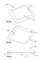
- FIG. 1 aillustrates a perspective view of a camera system, according to one embodiment.
- FIG. 1 billustrates a perspective view of a rear of the camera system, according to one embodiment.
- FIG. 2 aillustrates a perspective view of a camera for use with the camera system, according to one embodiment.
- FIG. 2 billustrates a perspective view of a rear of a camera for use with the camera system, according to one embodiment.
- FIGS. 3 a and 3 billustrate exploded views of a camera mount with a ball-and-socket joint, according to one embodiment.
- FIGS. 4 a through 4 eillustrate assembled views of a camera mount with a ball-and-socket joint, according to one embodiment.
- FIG. 5illustrates a camera mount with a ball-and-socket joint and a mount base, according to one embodiment.
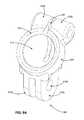
- FIGS. 6 a through 6 cillustrate views of a camera mount base, according to one embodiment.
- FIGS. 7 a and 7 billustrate views of an adapter for a camera mount with a ball-and-socket joint, according to one embodiment.
- FIGS. 8 a and 8 billustrate views of an adapter for a camera mount with a ball-and-socket joint, according to another embodiment.
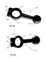
- FIGS. 9 a and 9 billustrate views of an extension arm for a camera mount with a ball-and-socket joint, according to one embodiment.
- a camera systemcan include a camera and a camera housing structured to at least partially enclose the camera.
- the cameracan include a camera body having a camera lens structured on a front surface of the camera body, various indicators on the front of the surface of the camera body (such as LEDs, displays, and the like), various input mechanisms (such as buttons, switches, and touch-screen mechanisms), and electronics (e.g., imaging electronics, power electronics, etc.) internal to the camera body for capturing images via the camera lens and/or performing other functions.
- the camera housingcan include a lens window structured on the front surface of the camera housing and configured to substantially align with the camera lens, and one or more indicator windows structured on the front surface of the camera housing and configured to substantially align with the camera indicators.
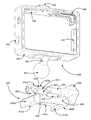
- FIGS. 1 a and 1 billustrate various views of a camera system according to one example embodiment.
- the camera systemincludes, among other components, a camera housing 100 .
- a first housing portion 101includes a front face with four sides (i.e., a top side, bottom side, left side, and right side) structured to form a cavity that receives a camera (e.g. a still camera or video camera), and a second housing portion 102 structured to couple to the first housing portion 101 and securely enclose a camera within the camera housing 100 .
- the first housing portion 101 and second housing portion 102can be pivotally coupled via a hinge mechanism (described in greater detail in FIG. 1 b ), and can securely couple via a latch mechanism 103 .
- the camera housing 100may not include one or more sides or faces.
- the camera housing 100may not include a front or back face, allowing the front face and rear face of the camera to be exposed when partially enclosed by the top side, bottom side, left side, and right side of the camera housing 100 .
- the camera housing 100has a small form factor (e.g., a height of approximately 4 to 6 centimeters, a width of approximately 5 to 7 centimeters, and a depth of approximately 1 to 4 centimeters), and is lightweight (e.g., approximately 50 to 150 grams).
- the camera housing 100can be rigid (or substantially rigid) (e.g., plastic, metal, fiberglass, etc.) or pliable (or substantially pliable) (e.g., leather, vinyl, neoprene, etc.).
- the camera housing 100may be appropriately configured for use in various elements.
- the camera housing 100may comprise a waterproof enclosure that protects a camera from water when used, for example, while surfing or scuba diving.
- Portions of the camera housing 100may include exposed areas to allow a user to manipulate buttons on the camera that are associated with the camera functionality. Alternatively, such areas may be covered with a pliable material to allow the user to manipulate the buttons through the camera housing 100 .
- the top face of the camera housing 100includes an outer shutter button 112 structured so that a shutter button of the camera is substantially aligned with the outer shutter button 112 when the camera is secured within the camera housing 100 .
- the shutter button 112 of the camerais operationally coupled to the outer shutter button 112 so that pressing the outer shutter button 112 allows the user to operate the camera shutter button.
- the front face of the camera housing 100includes a lens window 104 structured so that a lens of the camera is substantially aligned with the lens windows 104 when the camera is secured within the camera housing 100 .
- the lens window 104can be adapted for use with a conventional lens, a wide angle lens, a flat lens, or any other specialized camera lens.
- the camera housing 100includes one or more securing structures 120 for securing the camera housing 100 to one of a variety of mounting devices such as a clip-style mount.
- the camera housing 100includes a plurality of protrusions 124 , each including a hole 126 configured to receive a coupling mechanism, for instance, a turnable handscrew to pivotally couple the camera housing 100 to a mounting device including a plurality of reciprocal protrusions.
- the camera housing 100can be secured to a different type of mounting structure, and can be secured to a mounting structure via a different type of coupling mechanism.
- the camera housing 100includes an indicator window 106 structured so that one or more camera indicators are substantially aligned with the indicator window 106 when the camera is secured within the camera housing 100 .
- the indicator window 106can be any shape or size, and can be made of the same material as the remainder of the camera housing 100 , or can be made of any other material, for instance a transparent or translucent material and/or a non-reflective material.
- the described housing 100may also be adapted for a wider range of devices of varying shapes, sizes and dimensions besides cameras.
- an expansion modulemay be attached to housing 100 to add expanded features to electronic devices such as cell phones, music players, personal digital assistants (“PDAs”), global positioning system (“GPS”) units, or other portable electronic devices.
- PDAspersonal digital assistants
- GPSglobal positioning system
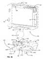
- FIG. 1 bis a rear perspective view of camera housing 100 , according to one example embodiment.
- the second housing portion 102detachably couples with the first housing portion 101 opposite the front face of the first housing portion 101 .
- the first housing portion 101 and second housing portion 102are collectively structured to enclose a camera within the cavity formed when the second housing portion 102 is securely coupled to the first housing portion 101 in a closed position.
- the second housing portion 102pivots around a hinge mechanism 130 , allowing the second housing portion 102 to be either in a closed position relative to the first housing portion 101 (for instance, when the second housing portion 102 is securely coupled to the first housing portion 101 via the latch mechanism 103 ), or in an open position (when the first housing portion 101 and the second housing portion 102 are not coupled via the latch mechanism 103 ).
- a cameracan be removed from or placed into the camera housing 100 , and in the closed position, the camera can be securely enclosed within the camera housing 100 .
- the latch mechanism 103includes a hook-shaped lateral bar configured to securely couple around a reciprocal structure of the second housing portion 102 .
- the latch mechanism 103includes different fastening structures for securing the second housing portion 102 to the first housing portion 101 , for example a button assembly, a buckle assembly, a clip assembly, a hook and loop assembly, a magnet assembly, a ball and catch assembly, and an adhesive assembly, or any other type of securing mechanism.
- the hinge 130is instead located on the top face of the housing 100
- the latch mechanism 103is located on the bottom face of the housing 100
- the hinge 130 and the latch mechanism 103may be located on opposite side faces of the camera housing 100 .
- the housing 100includes a watertight seal so that the housing 100 is waterproof when the second housing portion 102 is in the closed position.
- the second housing portion 102includes a sealing structure positioned on interior edges of the second housing portion 102 . The sealing structure provides a watertight seal between the first housing portion 101 and the second housing portion when the latch mechanism securely couples the housing portions.
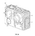
- FIG. 2 aillustrates a camera 200 for use with the camera systems described herein, according to one example embodiment.
- the camera 200is configured to capture images and video, and to store captured images and video for subsequent display or playback.
- the camera 200is adapted to fit within a camera housing, such as the housing 100 discussed above or any other housing described herein.
- the camera 200includes a lens 202 configured to receive light incident upon the lens and to direct received light onto an image sensor internal to the lens for capture by the image sensor.
- the lens 202is enclosed by a lens ring 204 .
- the camera 200can include various indicators, including the LED lights 206 and the LED display 208 shown in FIG. 2 a . When the camera 200 is enclosed within the housing 100 , the LED lights and the LED display 208 are configured to substantially align with the indicator window 106 and be visible through the housing 100 .
- the camera 200can also include buttons 210 configured to allow a user of the camera to interact with the camera, to turn the camera on, to initiate the capture of video or images, and to otherwise configure the operating mode of the camera.
- the camera 200can also include one or more microphones 212 configured to receive and record audio signals in conjunction with recording video.
- the camera 200includes one or more sets of microphones, with each set of microphones including a first microphone and a second, dampened microphone, where the second dampened microphone is configured to capture audio at approximately 20 dB (or any other suitable magnitude) less than the first microphone.
- the side of the camera 200includes an I/O interface 214 . Though the embodiment of FIG. 2 a illustrates the I/O interface 214 enclosed by a protective door, the I/O interface can include any type or number of I/O ports or mechanisms, such as USC ports, HDMI ports, memory card slots, and the like.
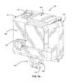
- FIG. 2 billustrates a perspective view of a rear of a camera 200 for use with the camera systems described herein, according to one embodiment.
- the camera 200includes a display 218 (such as an LCD or LED display) on the rear surface of the camera 200 .
- the display 218can be configured for use, for example, as an electronic view finder, to preview captured images or videos, or to perform any other suitable function.
- the camera 200also includes an expansion pack interface 220 configured to receive a removable expansion pack, such as an extra battery module, a wireless module, and the like. Removable expansion packs, when coupled to the camera 200 , provide additional functionality to the camera via the expansion pack interface 220 .
- a camera mountcan include a ball-and-socket joint that allows for a larger range of motion of one mount portion relative to another when compared to other camera mounts.
- FIGS. 3 a and 3 billustrate exploded views of a camera mount with a ball-and-socket joint, according to one embodiment.
- An upper mount component 300is configured to partially enclose a camera 200 .
- the upper mount componenthas four sides: a top side, a bottom side, a right side, and a left side.
- the upper mount component 300has six sides and fully encloses the camera 200 (for example, similarly to the camera mount of FIGS. 1 a and 1 b ).
- the upper mount component 300has a bottom surface 326 from which a protrusion 322 extends.
- the protrusion 322includes a ball 320 , and is securely or removably coupled to the bottom surface 326 of the upper mount component 300 , for instance with a screw 324 or other securing mechanism.
- the protrusion 322extends downward and backward relative to the bottom surface 326 , though in other embodiments, the protrusion can extend straight downward or any other suitable angle relative to the bottom surface.
- the sides of the upper mount component 300can include various cutouts that accommodate features, input/output mechanisms, user interaction mechanisms, or other structures of the camera 200 .
- the upper mount component 300can also include a latch 308 configured to cause portions of the upper mount component to flex apart in an open configuration (allowing for the insertion or removal of a camera from the upper mount component), or to cause the portions of the upper mount component to securely abut in a closed configuration (allowing for the securing of a camera within the upper mount component).
- the camera mountalso includes a lower mount component 400 .
- the lower mount component 400has a top surface 406 , on which a socket 420 is positioned.
- the socket 420includes a top ring surface 422 and an inside surface 424 .
- the inside surface 424is semi-spherical or partially spherical in shape, and can include cut-outs or holes removed from the inside surface as described herein.
- the top ring surface 422 of the socket 420can be positioned at an angle relative to the top surface 406 of the lower mount component 400 , for instance an angle between 0 and 90 degrees.
- the angle of the top ring surface 422 relative to the top surface 406 of the lower mount component 400is substantially the same as or is complementary to the angle of the protrusion 322 relative to the bottom surface 326 of the upper mount component 300 .
- the top ring surface 422can be positioned at a 35 degree angle relative to the surface 406
- the protrusion 322can be protrude at a 55 degree angle from the surface 326 .
- the ball 320 of the upper mount componentis configured for insertion into the socket 420 .
- the ball 320can be inserted into or removed from the socket 420 when the socket is configured in an open configuration, and can be secured within the socket 420 when the socket is configured in a closed configuration.
- the coefficient of static friction between the outer surface of the ball 320 and the inside surface 424 of the socket 420is large enough to prevent the movement of the upper mount component 300 relative to the lower mount component 400 when the socket is configured in a closed configuration.
- the coefficient of static friction between the outer surface of the ball 320 and the inside surface 424 of the socket 420is large enough to prevent the movement of the upper mount component 300 relative to the lower mount component 400 when the mount is exposed to wind or other small external forces, but is small enough to allow for a user to manually rotate upper mount component relative to the lower mount component, for instance by exerting force on the upper mount component.
- the moment arm resulting from the exertion of force on the upper mount componentis great enough to overcome the friction force between the ball 320 and the inside surface 424 , allowing for manual movement by a user, but not from wind, water, or other forces.
- the upper mount component 300can rotate 360 degrees relative to the lower mount component 400 within the horizontal plane defined by the surface 406 .
- the surface 326remains substantially parallel to the surface 406 .
- the upper mount component 300can also pivot within one or more vertical planes relative to the lower mount component 400 .
- the angle between the surface 326 and the surface 406changes.
- the upper mount component 300can be pivoted up to 90 degrees or more forward relative to the lower mount component 400 .
- the upper mount component 300is pivoted forward such that a front face of the upper mount component is substantially parallel with the surface 406 .
- the upper mount component 300can be pivoted up to 60 degrees or more backwards relative to the lower mount component 400 .
- the upper mount component 300can be pivoted up to 60 degrees or more to the left or to the right relative to the lower mount component 400 .
- the upper mount componentcan be both rotated within the horizontal plane defined by the surface 406 and pivoted within one or more vertical planes relative to the lower mount component 300 .
- the upper mount component 400can be rotated 180 degrees horizontally such that a front face of the upper mount component faces towards a rear side of the lower mount component 300 , and pivoted 90 degrees towards a front side 404 of the lower mount component, causing the front face of the upper mount component to face upwards, in a direction substantially perpendicular to the surface 406 .
- the ability of the upper mount component 300 to rotate and pivot relative to the lower mount component 400beneficially allows a camera secured within the upper mount component to capture images and videos from a wide variety of perspectives.
- a camera within the upper mount component 300can be adjusted to capture image and video in any combination of a 360 degree horizontal rotation and a 90 degree or more pivot towards a front side 404 of the lower mount component 400 , a 60 degree or more pivot towards a rear of the lower mount component, a 60 degree or more pivot towards a left side 402 b of the lower mount component, or a 60 degree or more pivot towards a right side 402 a of the lower mount component.
- the “front” or “front side” of the lower mount component 400refers to the side of the lower mount component towards which the top ring surface 422 is angled
- the “rear” or “rear side” of the lower mount componentrefers to the side of the lower mount component away from which the top ring surface is angled.
- the inside surface 424includes a hole 426 at the bottom of the inside surface to accommodate the curvature of the ball 320 when the ball 320 is inserted within the socket 420 , beneficially allowing the upper mount component 300 to rotate and pivot within the socket 420 without requiring a deeper socket.
- the socket 420can include a split 430 , which extends from the top ring surface 422 down through a portion of the inside surface 424 (for instance, through 40% or more of the inside surface 424 ).
- a split 430On either side of the split 430 and extending outward from the top ring surface 422 are screwhole protrusions 432 a and 432 b .
- the screwhole protrusions 432align such that a screw 434 with a handle 436 can be inserted through the screwhole protrusions.
- the screw 434tightens and causes the screwhole protrusions 432 a and 432 b to flexibly compress towards each other, lessening the width of the split 430 .
- FIGS. 4 a - eillustrate assembled views of the mount with the ball-and-socket joint as described herein.
- the socket 420encompasses 50% or more of the surface of the ball 320 when the ball is secured within the socket.
- the circumference of the top ring surface 422can be decreased to less than the circumference of the ball 320 .
- the ballis at least 50% encompassed by the socket 420 , such a configuration prevents the ball 320 from being removed from the socket 420 .
- the screw 434loosens, causing the screwhole protrusions to separate, and increasing the width of the split 430 .
- Thisincreases the surface area of the inner surface 424 of the socket 420 , decreasing the friction force exerted upon the ball 320 by the inner surface, allowing the upper mount component 300 to be rotated or pivoted relative to the lower mount component 400 more easily.
- Such a configurationis referred to herein as the “open configuration”.
- the open configurationAs the width of the split 430 is increased, the circumference of the top ring surface 422 can be increased to greater than the circumference of the ball 320 , allowing for the insertion of the ball into or removal of the ball from the socket 420 .
- the lower mount component 400couples to a base mount component 500 , as shown in FIG. 5 .
- a bottom side of the lower mount component 400can include ledges 412 a and 412 b protruding inward from a bottom of the sides 402 of the lower mount component, creating a space between a top side of the ledges 412 and a bottom surface 413 of the lower mount component.
- the base mount component 500can be inserted into the space between the ledges 412 and the bottom surface 413 .
- the bottom surface 413includes lips 414 a and 414 b protruding downward from the bottom surface.
- the lips 414can be triangular in shape such that a first face protrudes diagonally downward from the bottom surface 413 and facing outward from the lower mount component 400 , and such that a second face protrudes perpendicularly downward from the bottom surface. As described below, the lips 414 are configured to catch on and secure the base mount component 500 .
- the top surface 406 of the lower mount component 400includes a tab 408 with a lip 418 configured to exert downward force on the base mount component 500 in a released configuration when the base mount component is inserted into the lower mount component, causing the base mount component to exert reciprocal force on a top surface of the ledges 412 .
- the lip 418is configured to catch and abut a reciprocal ledge on a top surface of the base mount component 500 when the tab 408 is in the released configuration, securing the base mount component to the lower mount component 400 .
- the tab 408can be lifted by a user in a lifted configuration such that the lip 418 does not exert downward force on the base mount component 500 , allowing for the removal of the base mount component from the lower mount component 400 .
- the base mount component 500is illustrated from various perspectives in FIGS. 6 a - c .
- the base mount component 500has a top surface 510 and a bottom surface 520 .
- the top surface 510has a ridge 512 around its perimeter, extending perpendicularly upward from the top surface and diagonally upward from the outside perimeter of the ridge.
- the ridge 512catches and abuts the lip 418 , securing the base mount component within the lower mount component.
- the lips 414 a and 414 b of the lower mount component 400exert a downward force onto the ridge 512 of the base mount component 500 when the base mount component is inserted into the lower mount component, further securing the base mount component within the lower mount component.
- the bottom surface 520 of the base mount component 500protrudes downward and outward from the ledge 522 .
- the ledge 522can abut the top sides of the ledges 412 when the base mount component is inserted into the lower mount component 400 .
- the bottom surface 520can be coupled to a surface to secure the base mount component in place.
- the bottom surfacecan be coupled to a surface adhesively, mechanically, with suction, with an attachment device (such as a screw), or using any other suitable mechanism or means.
- the bottom surface 520can be removably or temporarily coupled to a surface, allowing a user to remove the base mount component 500 from a surface and to re-couple the base mount component to another surface.
- the base mount component 500can couple to any suitable surface, such as a sports board, a wall, a ledge, a vehicle, a user, and the like.
- the base mount component 500is substantially square in shape, such that base mount component is symmetric across the width and height of the base mount component. Such a configuration beneficially allows for the insertion of the base mount component 500 into the lower mount component 400 in any of four directions, allowing a user to position the lower mount component such that the lower mount component is facing any of the four directions. It should be noted that although reference is made herein to the insertion and removal of the base mount component 500 into/from the lower mount component 400 , generally the base mount component will be secured to a surface, and the lower mount component will be inserted over/removed from the base mount component.
- a usercan capture images and video with a camera secured within the upper mount component, at any of a number of angles and orientations as described herein.
- the usercan simply lift upwards on the tab 408 and slide the coupled mount components off of the base mount component.
- adapters 700 and 800 shown in FIGS. 7 and 8have been created. Both adapters 700 and 800 couple to the upper mount 300 in the way described above but include an alternative mechanism for coupling with a base mount that is different from base mount 500 .
- Adapter 700is configured to connect, via the groove 710 to a planar base mount that can accommodate the prongs 712 a and 712 b .
- Adapter 800is configured to couple with a base mount that comprises a plurality of protrusions 810 a and 810 b with holes 812 a and 812 b that align such that a pin can be inserted through the holes in both the base mount and the adapter 800 .
- FIG. 9illustrates an extension arm 900 that can be used to further extend the range of the camera mount system described herein.
- the extension arm 900includes a ball protrusion 320 that couples to the lower mount component 400 as described above with regards to the ball 320 of FIGS. 3-5 , and includes a modified socket 950 that couples to the upper mount component 300 .
- the modified socket 950is configured to securely enclose around a circumference of the ball 320 , as well as a portion on either side of the enclosed circumference of the ball 320 .
- the modified socket 950includes a split 960 . On either side of the split 960 are screwhole protrusions 955 a and 955 b that align such that a screw can be inserted through the screwhole protrusions.
- the screwcan then be tightened to flexibly compress the screwhole protrusions 955 a and 955 b towards each other and lessen the width of the split 960 , decreasing the circumference of the inner surface of the modified socket 950 and increasing the radially inward normal force exerted on the ball 320 by the modified socket 950 , securing the ball 320 within the modified socket 950 .
- a socket ring 960 including a semi-spherical profileis included within the modified socket 950 in order to better match the contours of the ball 320 .
- the socket ring 960can also include a split 965 that decreases in width when a screw is inserted and tightened, causing the screwhole protrusions 955 a and 955 b flexibly compress towards each other.
- the inner surface of the modified socket 950includes a semi-spherical profile to match the contours of the ball 320 .
- Coupledalong with its derivatives.
- the term “coupled” as used hereinis not necessarily limited to two or more elements being in direct physical or electrical contact. Rather, the term “coupled” may also encompass two or more elements are not in direct contact with each other, but yet still co-operate or interact with each other, or are structured to provide a thermal conduction path between the elements.
- the terms “comprises,” “comprising,” “includes,” “including,” “has,” “having” or any other variation thereof,are intended to cover a non-exclusive inclusion.
- a process, method, article, or apparatus that comprises a list of elementsis not necessarily limited to only those elements but may include other elements not expressly listed or inherent to such process, method, article, or apparatus.
- any reference to “one embodiment” or “an embodiment”means that a particular element, feature, structure, or characteristic described in connection with the embodiment is included in at least one embodiment.
- the appearances of the phrase “in one embodiment” in various places in the specificationare not necessarily all referring to the same embodiment.
Landscapes
- Engineering & Computer Science (AREA)
- General Engineering & Computer Science (AREA)
- Physics & Mathematics (AREA)
- General Physics & Mathematics (AREA)
- Multimedia (AREA)
- Signal Processing (AREA)
- Mechanical Engineering (AREA)
- Accessories Of Cameras (AREA)
- Studio Devices (AREA)
Abstract
Description
Claims (16)
Priority Applications (6)
| Application Number | Priority Date | Filing Date | Title |
|---|---|---|---|
| US14/521,458US9661197B2 (en) | 2014-10-22 | 2014-10-22 | Quick-release ball-and-socket joint camera mount |
| PCT/US2015/045403WO2016064468A1 (en) | 2014-10-22 | 2015-08-14 | Quick-release ball-and-socket joint camera mount |
| US14/922,157US9423673B2 (en) | 2014-10-22 | 2015-10-25 | Quick-release ball-and-socket joint camera mount |
| US15/582,356US9880451B2 (en) | 2014-10-22 | 2017-04-28 | Quick-release ball-and-socket joint camera mount |
| US15/834,941US10416538B2 (en) | 2014-10-22 | 2017-12-07 | Quick-release ball-and-socket joint camera mount |
| US16/541,498US10642133B2 (en) | 2014-10-22 | 2019-08-15 | Quick-release ball-and-socket joint camera mount |
Applications Claiming Priority (1)
| Application Number | Priority Date | Filing Date | Title |
|---|---|---|---|
| US14/521,458US9661197B2 (en) | 2014-10-22 | 2014-10-22 | Quick-release ball-and-socket joint camera mount |
Related Child Applications (2)
| Application Number | Title | Priority Date | Filing Date |
|---|---|---|---|
| US14/922,157Continuation-In-PartUS9423673B2 (en) | 2014-10-22 | 2015-10-25 | Quick-release ball-and-socket joint camera mount |
| US15/582,356ContinuationUS9880451B2 (en) | 2014-10-22 | 2017-04-28 | Quick-release ball-and-socket joint camera mount |
Publications (2)
| Publication Number | Publication Date |
|---|---|
| US20160119516A1 US20160119516A1 (en) | 2016-04-28 |
| US9661197B2true US9661197B2 (en) | 2017-05-23 |
Family
ID=55761296
Family Applications (4)
| Application Number | Title | Priority Date | Filing Date |
|---|---|---|---|
| US14/521,458ActiveUS9661197B2 (en) | 2014-10-22 | 2014-10-22 | Quick-release ball-and-socket joint camera mount |
| US15/582,356ActiveUS9880451B2 (en) | 2014-10-22 | 2017-04-28 | Quick-release ball-and-socket joint camera mount |
| US15/834,941Active2034-10-24US10416538B2 (en) | 2014-10-22 | 2017-12-07 | Quick-release ball-and-socket joint camera mount |
| US16/541,498ActiveUS10642133B2 (en) | 2014-10-22 | 2019-08-15 | Quick-release ball-and-socket joint camera mount |
Family Applications After (3)
| Application Number | Title | Priority Date | Filing Date |
|---|---|---|---|
| US15/582,356ActiveUS9880451B2 (en) | 2014-10-22 | 2017-04-28 | Quick-release ball-and-socket joint camera mount |
| US15/834,941Active2034-10-24US10416538B2 (en) | 2014-10-22 | 2017-12-07 | Quick-release ball-and-socket joint camera mount |
| US16/541,498ActiveUS10642133B2 (en) | 2014-10-22 | 2019-08-15 | Quick-release ball-and-socket joint camera mount |
Country Status (2)
| Country | Link |
|---|---|
| US (4) | US9661197B2 (en) |
| WO (1) | WO2016064468A1 (en) |
Cited By (19)
| Publication number | Priority date | Publication date | Assignee | Title |
|---|---|---|---|---|
| US20170242322A1 (en)* | 2016-02-23 | 2017-08-24 | Lenovo (Singapore) Pte. Ltd. | Camera and task light on adjustable arm and weighted base |
| US10302244B2 (en)* | 2017-10-31 | 2019-05-28 | Ningbo Nest E-commerce Co., Ltd. | Multi-purpose camera stand |
| US20190369466A1 (en)* | 2014-10-22 | 2019-12-05 | Gopro, Inc. | Quick-Release Ball-and-Socket Joint Camera Mount |
| USD894256S1 (en) | 2018-08-31 | 2020-08-25 | Gopro, Inc. | Camera mount |
| USD905786S1 (en) | 2018-08-31 | 2020-12-22 | Gopro, Inc. | Camera mount |
| US10928711B2 (en) | 2018-08-07 | 2021-02-23 | Gopro, Inc. | Camera and camera mount |
| US10935872B1 (en)* | 2017-10-18 | 2021-03-02 | JTrent, LLC | Camera cover |
| US11092883B2 (en)* | 2017-09-27 | 2021-08-17 | Zhejiang Dahua Technology Co., Ltd. | Surveillance device |
| USD928863S1 (en)* | 2019-09-17 | 2021-08-24 | Gopro, Inc. | Camera light |
| US11221542B2 (en)* | 2019-05-14 | 2022-01-11 | Chicony Electronics Co., Ltd. | Electronic device and lens module thereof |
| US11448246B2 (en) | 2018-07-26 | 2022-09-20 | Hewlett-Packard Development Company, L.P. | Magnetic multiple axis mounts |
| USD991318S1 (en) | 2020-08-14 | 2023-07-04 | Gopro, Inc. | Camera |
| USD997232S1 (en) | 2019-09-17 | 2023-08-29 | Gopro, Inc. | Camera |
| USD1023118S1 (en) | 2019-09-13 | 2024-04-16 | Gopro, Inc. | Screw of a camera mount |
| USD1036536S1 (en) | 2017-12-28 | 2024-07-23 | Gopro, Inc. | Camera |
| USD1069539S1 (en) | 2022-08-10 | 2025-04-08 | Gopro, Inc. | Screw assembly |
| US12321084B2 (en) | 2022-08-12 | 2025-06-03 | Gopro, Inc. | Interconnect mechanism for image capture device |
| US12379650B2 (en) | 2023-02-15 | 2025-08-05 | Gopro, Inc. | Reinforced image capture devices including interconnect mechanisms with a threaded accessory interface |
| USD1096914S1 (en) | 2024-03-15 | 2025-10-07 | Gopro, Inc. | Camera mount |
Families Citing this family (56)
| Publication number | Priority date | Publication date | Assignee | Title |
|---|---|---|---|---|
| USD785069S1 (en)* | 2015-09-01 | 2017-04-25 | Avant Technology, Inc. | Camera housing |
| US10101637B2 (en) | 2015-09-11 | 2018-10-16 | Avant Technology, Inc. | Camera case with removable carrier, filter receiver, external battery and supplemental memory storage |
| USD830446S1 (en) | 2015-12-15 | 2018-10-09 | Gopro, Inc. | Multi-lens camera |
| US10620507B2 (en) | 2016-02-25 | 2020-04-14 | William Conn Lefever | Remote controlled rotating camera mount |
| USD810175S1 (en)* | 2016-05-02 | 2018-02-13 | Hanwha Techwin Co., Ltd. | Camera |
| US10122904B2 (en) | 2016-07-11 | 2018-11-06 | Gopro, Inc. | Drain mechanism for camera controller |
| USD827697S1 (en)* | 2016-08-09 | 2018-09-04 | Gopro, Inc. | Camera housing |
| USD827696S1 (en)* | 2016-08-09 | 2018-09-04 | Gopro, Inc. | Camera housing |
| USD833505S1 (en)* | 2016-09-13 | 2018-11-13 | Shenzhen Baker Av Digital Technology Co., Ltd. | Sports camera |
| US9864257B1 (en)* | 2016-09-19 | 2018-01-09 | Gopro, Inc. | Camera frame with side door |
| US11036295B2 (en) | 2016-11-23 | 2021-06-15 | Microsoft Technology Licensing, Llc | Electrostatic slide clutch |
| USD843431S1 (en) | 2017-01-04 | 2019-03-19 | Google Llc | Camera |
| US10697583B2 (en) | 2017-01-04 | 2020-06-30 | Google Llc | Mount attachment for an electronic device |
| US10277785B2 (en) | 2017-01-04 | 2019-04-30 | Google Llc | Camera assembly with concave-shaped front face |
| US11924532B2 (en) | 2017-01-04 | 2024-03-05 | Google Llc | Camera assembly with concave-shaped front face |
| DE102017210265A1 (en)* | 2017-06-20 | 2018-12-20 | Biketec Ag | Display unit and electric bicycle |
| US10401710B2 (en)* | 2017-06-30 | 2019-09-03 | Google Llc | Mount hinge for an electronic device |
| US10602035B2 (en) | 2017-09-19 | 2020-03-24 | Google Llc | Temperature-controlled camera assembly |
| USD861592S1 (en) | 2017-09-28 | 2019-10-01 | Gopro, Inc. | Battery |
| JP7073182B2 (en)* | 2018-04-25 | 2022-05-23 | キヤノン株式会社 | Imaging device |
| US11023047B2 (en) | 2018-05-01 | 2021-06-01 | Microsoft Technology Licensing, Llc | Electrostatic slide clutch with bidirectional drive circuit |
| US10556553B2 (en)* | 2018-05-15 | 2020-02-11 | Veoneer Us, Inc. | Vehicle camera mounting interfaces |
| USD907101S1 (en) | 2019-06-11 | 2021-01-05 | Gopro, Inc. | Camera |
| USD907680S1 (en) | 2018-08-31 | 2021-01-12 | Gopro, Inc. | Camera |
| USD903740S1 (en) | 2018-09-14 | 2020-12-01 | Gopro, Inc. | Camera |
| US10909823B2 (en)* | 2018-12-27 | 2021-02-02 | Heidi Bear Enterprises, Llc | Home security light bulb adapter |
| US11061476B2 (en) | 2019-05-24 | 2021-07-13 | Microsoft Technology Licensing, Llc | Haptic feedback apparatus |
| US11054905B2 (en)* | 2019-05-24 | 2021-07-06 | Microsoft Technology Licensing, Llc | Motion-restricting apparatus with common base electrode |
| USD911412S1 (en) | 2019-09-13 | 2021-02-23 | Gopro, Inc. | Camera housing |
| USD911411S1 (en) | 2019-09-13 | 2021-02-23 | Gopro, Inc. | Camera housing |
| US11696004B2 (en) | 2019-09-13 | 2023-07-04 | Gopro, Inc. | Image capture device |
| USD1029745S1 (en) | 2019-09-13 | 2024-06-04 | Gopro, Inc. | Camera battery |
| USD921084S1 (en) | 2019-09-13 | 2021-06-01 | Gopro, Inc. | Camera housing |
| DE212020000722U1 (en) | 2019-09-18 | 2022-04-26 | Gopro, Inc. | door assemblies for imaging devices |
| US12066748B2 (en) | 2019-09-18 | 2024-08-20 | Gopro, Inc. | Door assemblies for image capture devices |
| US11786025B2 (en) | 2019-09-30 | 2023-10-17 | Gopro, Inc. | Camera case |
| USD912120S1 (en) | 2019-09-30 | 2021-03-02 | Gopro, Inc. | Camera housing |
| CN113568257B (en)* | 2020-04-10 | 2025-07-11 | 新思考电机有限公司 | Camera and electronic equipment |
| USD946071S1 (en) | 2020-06-30 | 2022-03-15 | Gopro, Inc. | Camera housing |
| WO2022000417A1 (en) | 2020-07-02 | 2022-01-06 | Gopro, Inc. | Removable battery door assemblies for image capture devices |
| USD963016S1 (en) | 2020-07-31 | 2022-09-06 | Gopro, Inc. | Camera housing |
| USD1029746S1 (en) | 2020-07-31 | 2024-06-04 | Gopro, Inc. | Battery |
| USD946072S1 (en) | 2020-08-10 | 2022-03-15 | Gopro, Inc. | Camera housing |
| USD1050227S1 (en) | 2020-08-14 | 2024-11-05 | Gopro, Inc. | Camera door |
| USD953404S1 (en) | 2020-08-14 | 2022-05-31 | Gopro, Inc. | Camera housing |
| US20220112909A1 (en)* | 2020-10-09 | 2022-04-14 | Ryan Fleming | Device mounting system, securement system, versatile action mount device, a retrofit system and method of use |
| US11448944B2 (en) | 2021-01-09 | 2022-09-20 | Christian A. Goeller | Moldable and flexible mount for a curved surface |
| USD1010427S1 (en) | 2021-01-09 | 2024-01-09 | Christian A. Goeller | Mounting bracket |
| CN114487312A (en)* | 2021-01-14 | 2022-05-13 | 九天起宏(江苏)检测有限公司 | Food detection equipment |
| USD1066462S1 (en) | 2021-02-12 | 2025-03-11 | Gopro, Inc. | Camera door |
| US12126152B2 (en) | 2021-04-29 | 2024-10-22 | APG Vision LLC | Ball mount with integrated cable gland |
| CN113154216B (en)* | 2021-05-15 | 2022-06-28 | 江苏运玛项目管理有限公司 | An informatization device for engineering supervision, construction and management |
| USD1061682S1 (en) | 2022-08-04 | 2025-02-11 | Gopro, Inc. | Camera door |
| EP4336055B1 (en)* | 2022-09-08 | 2025-03-26 | CSEM Centre Suisse d'Electronique et de Microtechnique SA - Recherche et Développement | Mounting device for sport accessories |
| US12055842B1 (en) | 2024-01-30 | 2024-08-06 | Greatest Generation, LLC | Cold-weather resilience cover for electronics assembly |
| USD1092591S1 (en)* | 2024-05-22 | 2025-09-09 | Gopro, Inc. | Camera housing |
Citations (14)
| Publication number | Priority date | Publication date | Assignee | Title |
|---|---|---|---|---|
| US2962251A (en)* | 1957-11-29 | 1960-11-29 | Karpf Nikolaus | Tilting tripod-head |
| US20010017339A1 (en) | 1999-11-22 | 2001-08-30 | Brotz Ralph T. | Apparatus for camera mount on tripod platform |
| US20050122424A1 (en) | 2003-12-09 | 2005-06-09 | Overstreet Frank R. | Positioning accessory for camera-equipped wireless terminals |
| WO2005098304A1 (en) | 2004-04-09 | 2005-10-20 | Metrie Spol. Sr. O. | Positioning joint system, especially for set-up of horizontal position |
| US20080011344A1 (en)* | 2004-03-17 | 2008-01-17 | Barker John C | Compactible walking staff having tripod base and adaptable mount |
| US20080023607A1 (en)* | 2004-03-17 | 2008-01-31 | Trek Technologies, Llc, Dba Trek Tech | Magnetic-based releasable, adjustable camera or other device mount apparatus |
| US20080267613A1 (en)* | 2007-04-27 | 2008-10-30 | Tocad America, Inc. | Apparatuses and systems for supporting and positioning cameras and other equipment |
| US8014656B2 (en) | 2008-07-07 | 2011-09-06 | Woodman Labs | Mount system for attaching camera to a sport board |
| US20110224798A1 (en)* | 2010-03-09 | 2011-09-15 | James Thompson Caillouette | Hip replacement process |
| US20120070223A1 (en) | 2006-11-29 | 2012-03-22 | Wimberley David L | Pivoting ball mount having four equally spaced contact points |
| US8267361B1 (en)* | 2007-10-18 | 2012-09-18 | Acratech, Inc. | Attachment to a long lens support device which functions as both a ball head and a gimble head |
| US20120288269A1 (en)* | 2011-05-13 | 2012-11-15 | Justin Jensen | Systems and methods for adapting a mounting device to facilitate capturing of images |
| US20140099093A1 (en)* | 2012-10-04 | 2014-04-10 | Joseph M. JOHNSON, SR. | Extendible l-plate for camera equipment |
| US20160100083A1 (en)* | 2014-10-02 | 2016-04-07 | Gopro, Inc. | Swivel Camera Mount |
Family Cites Families (10)
| Publication number | Priority date | Publication date | Assignee | Title |
|---|---|---|---|---|
| US7370983B2 (en)* | 2000-03-02 | 2008-05-13 | Donnelly Corporation | Interior mirror assembly with display |
| JP3870183B2 (en)* | 2003-08-01 | 2007-01-17 | キヤノン株式会社 | Intermediate adapter and camera system |
| US20070154254A1 (en)* | 2006-01-03 | 2007-07-05 | Bevirt Joeben | Mounting apparatus using ball and socket joints with gripping features |
| CN101276650B (en)* | 2007-03-30 | 2010-09-29 | 群康科技(深圳)有限公司 | Height regulating device and display device using the same |
| JP4906954B1 (en)* | 2010-10-25 | 2012-03-28 | 株式会社ホンダエレシス | In-vehicle structure of camera |
| TW201306402A (en)* | 2011-07-27 | 2013-02-01 | Excel Cell Elect Co Ltd | USB3.0 connector and manufacturing method thereof |
| CN103575944A (en)* | 2012-07-26 | 2014-02-12 | 鸿富锦精密工业(深圳)有限公司 | Anechoic chamber |
| US9033596B2 (en)* | 2012-10-15 | 2015-05-19 | Gopro, Inc. | Camera mount vibration dampener |
| US9173533B1 (en)* | 2014-06-25 | 2015-11-03 | Emerson Electric Co. | Upright vacuum cleaner |
| US9661197B2 (en)* | 2014-10-22 | 2017-05-23 | Gopro, Inc. | Quick-release ball-and-socket joint camera mount |
- 2014
- 2014-10-22USUS14/521,458patent/US9661197B2/enactiveActive
- 2015
- 2015-08-14WOPCT/US2015/045403patent/WO2016064468A1/enactiveApplication Filing
- 2017
- 2017-04-28USUS15/582,356patent/US9880451B2/enactiveActive
- 2017-12-07USUS15/834,941patent/US10416538B2/enactiveActive
- 2019
- 2019-08-15USUS16/541,498patent/US10642133B2/enactiveActive
Patent Citations (14)
| Publication number | Priority date | Publication date | Assignee | Title |
|---|---|---|---|---|
| US2962251A (en)* | 1957-11-29 | 1960-11-29 | Karpf Nikolaus | Tilting tripod-head |
| US20010017339A1 (en) | 1999-11-22 | 2001-08-30 | Brotz Ralph T. | Apparatus for camera mount on tripod platform |
| US20050122424A1 (en) | 2003-12-09 | 2005-06-09 | Overstreet Frank R. | Positioning accessory for camera-equipped wireless terminals |
| US20080011344A1 (en)* | 2004-03-17 | 2008-01-17 | Barker John C | Compactible walking staff having tripod base and adaptable mount |
| US20080023607A1 (en)* | 2004-03-17 | 2008-01-31 | Trek Technologies, Llc, Dba Trek Tech | Magnetic-based releasable, adjustable camera or other device mount apparatus |
| WO2005098304A1 (en) | 2004-04-09 | 2005-10-20 | Metrie Spol. Sr. O. | Positioning joint system, especially for set-up of horizontal position |
| US20120070223A1 (en) | 2006-11-29 | 2012-03-22 | Wimberley David L | Pivoting ball mount having four equally spaced contact points |
| US20080267613A1 (en)* | 2007-04-27 | 2008-10-30 | Tocad America, Inc. | Apparatuses and systems for supporting and positioning cameras and other equipment |
| US8267361B1 (en)* | 2007-10-18 | 2012-09-18 | Acratech, Inc. | Attachment to a long lens support device which functions as both a ball head and a gimble head |
| US8014656B2 (en) | 2008-07-07 | 2011-09-06 | Woodman Labs | Mount system for attaching camera to a sport board |
| US20110224798A1 (en)* | 2010-03-09 | 2011-09-15 | James Thompson Caillouette | Hip replacement process |
| US20120288269A1 (en)* | 2011-05-13 | 2012-11-15 | Justin Jensen | Systems and methods for adapting a mounting device to facilitate capturing of images |
| US20140099093A1 (en)* | 2012-10-04 | 2014-04-10 | Joseph M. JOHNSON, SR. | Extendible l-plate for camera equipment |
| US20160100083A1 (en)* | 2014-10-02 | 2016-04-07 | Gopro, Inc. | Swivel Camera Mount |
Non-Patent Citations (1)
| Title |
|---|
| PCT International Search Report and Written Opinion for PCT/US15/45403, Nov. 19, 2015, 12 Pages. |
Cited By (33)
| Publication number | Priority date | Publication date | Assignee | Title |
|---|---|---|---|---|
| US20190369466A1 (en)* | 2014-10-22 | 2019-12-05 | Gopro, Inc. | Quick-Release Ball-and-Socket Joint Camera Mount |
| US10642133B2 (en)* | 2014-10-22 | 2020-05-05 | Gopro, Inc. | Quick-release ball-and-socket joint camera mount |
| US10216068B2 (en)* | 2016-02-23 | 2019-02-26 | Lenovo (Signapore) Pte. Ltd. | Camera and task light on adjustable arm and weighted base |
| US20170242322A1 (en)* | 2016-02-23 | 2017-08-24 | Lenovo (Singapore) Pte. Ltd. | Camera and task light on adjustable arm and weighted base |
| US11092883B2 (en)* | 2017-09-27 | 2021-08-17 | Zhejiang Dahua Technology Co., Ltd. | Surveillance device |
| US11860516B2 (en) | 2017-09-27 | 2024-01-02 | Zhejiang Dahua Technology Co., Ltd. | Surveillance device |
| US11835847B2 (en) | 2017-09-27 | 2023-12-05 | Zhejiang Dahua Technology Co., Ltd. | Surveillance device |
| US10935872B1 (en)* | 2017-10-18 | 2021-03-02 | JTrent, LLC | Camera cover |
| US10302244B2 (en)* | 2017-10-31 | 2019-05-28 | Ningbo Nest E-commerce Co., Ltd. | Multi-purpose camera stand |
| USD1036536S1 (en) | 2017-12-28 | 2024-07-23 | Gopro, Inc. | Camera |
| USD1079788S1 (en) | 2017-12-28 | 2025-06-17 | Gopro, Inc. | Camera |
| US11448246B2 (en) | 2018-07-26 | 2022-09-20 | Hewlett-Packard Development Company, L.P. | Magnetic multiple axis mounts |
| US11662651B2 (en) | 2018-08-07 | 2023-05-30 | Gopro, Inc. | Camera and camera mount |
| US12399419B2 (en) | 2018-08-07 | 2025-08-26 | Gopro, Inc. | Camera and camera mount |
| US10928711B2 (en) | 2018-08-07 | 2021-02-23 | Gopro, Inc. | Camera and camera mount |
| USD1023115S1 (en) | 2018-08-31 | 2024-04-16 | Gopro, Inc. | Camera mount |
| USD989165S1 (en) | 2018-08-31 | 2023-06-13 | Gopro, Inc. | Camera mount |
| USD894256S1 (en) | 2018-08-31 | 2020-08-25 | Gopro, Inc. | Camera mount |
| USD905786S1 (en) | 2018-08-31 | 2020-12-22 | Gopro, Inc. | Camera mount |
| US11221542B2 (en)* | 2019-05-14 | 2022-01-11 | Chicony Electronics Co., Ltd. | Electronic device and lens module thereof |
| USD1023118S1 (en) | 2019-09-13 | 2024-04-16 | Gopro, Inc. | Screw of a camera mount |
| USD1054472S1 (en) | 2019-09-17 | 2024-12-17 | Gopro, Inc. | Camera light |
| USD1024165S1 (en) | 2019-09-17 | 2024-04-23 | Gopro, Inc. | Camera |
| USD1003979S1 (en) | 2019-09-17 | 2023-11-07 | Gopro, Inc. | Camera accessory mount |
| USD928863S1 (en)* | 2019-09-17 | 2021-08-24 | Gopro, Inc. | Camera light |
| USD997232S1 (en) | 2019-09-17 | 2023-08-29 | Gopro, Inc. | Camera |
| USD1090676S1 (en) | 2019-09-17 | 2025-08-26 | Gopro, Inc. | Camera |
| USD1004676S1 (en) | 2020-08-14 | 2023-11-14 | Gopro, Inc. | Camera |
| USD991318S1 (en) | 2020-08-14 | 2023-07-04 | Gopro, Inc. | Camera |
| USD1069539S1 (en) | 2022-08-10 | 2025-04-08 | Gopro, Inc. | Screw assembly |
| US12321084B2 (en) | 2022-08-12 | 2025-06-03 | Gopro, Inc. | Interconnect mechanism for image capture device |
| US12379650B2 (en) | 2023-02-15 | 2025-08-05 | Gopro, Inc. | Reinforced image capture devices including interconnect mechanisms with a threaded accessory interface |
| USD1096914S1 (en) | 2024-03-15 | 2025-10-07 | Gopro, Inc. | Camera mount |
Also Published As
| Publication number | Publication date |
|---|---|
| US10416538B2 (en) | 2019-09-17 |
| US20160119516A1 (en) | 2016-04-28 |
| US20190369466A1 (en) | 2019-12-05 |
| US10642133B2 (en) | 2020-05-05 |
| US20170235213A1 (en) | 2017-08-17 |
| US20180136546A1 (en) | 2018-05-17 |
| US9880451B2 (en) | 2018-01-30 |
| WO2016064468A1 (en) | 2016-04-28 |
Similar Documents
| Publication | Publication Date | Title |
|---|---|---|
| US10642133B2 (en) | Quick-release ball-and-socket joint camera mount | |
| US9423673B2 (en) | Quick-release ball-and-socket joint camera mount | |
| US10025166B2 (en) | Swivel wrist mount | |
| US11029584B2 (en) | Camera mount | |
| US9360742B1 (en) | Swivel camera mount | |
| US10547769B2 (en) | Swivel camera mount | |
| US9389491B2 (en) | Camera mount with spring clamp | |
| US9482931B1 (en) | Detachable camera mount | |
| US9369614B2 (en) | Camera mountable arm | |
| US9122133B2 (en) | Camera mount for sports board | |
| US9383628B1 (en) | Humidity prevention system within a camera housing | |
| US9389487B2 (en) | Protective lens attachment | |
| CN105474089A (en) | camera case |
Legal Events
| Date | Code | Title | Description |
|---|---|---|---|
| AS | Assignment | Owner name:GOPRO, INC., CALIFORNIA Free format text:ASSIGNMENT OF ASSIGNORS INTEREST;ASSIGNOR:CLEARMAN, CHRISTOPHER AARON;REEL/FRAME:034571/0955 Effective date:20141216 | |
| AS | Assignment | Owner name:JPMORGAN CHASE BANK, N.A., AS ADMINISTRATIVE AGENT, ILLINOIS Free format text:SECURITY AGREEMENT;ASSIGNOR:GOPRO, INC.;REEL/FRAME:038184/0779 Effective date:20160325 Owner name:JPMORGAN CHASE BANK, N.A., AS ADMINISTRATIVE AGENT Free format text:SECURITY AGREEMENT;ASSIGNOR:GOPRO, INC.;REEL/FRAME:038184/0779 Effective date:20160325 | |
| STCF | Information on status: patent grant | Free format text:PATENTED CASE | |
| MAFP | Maintenance fee payment | Free format text:PAYMENT OF MAINTENANCE FEE, 4TH YEAR, LARGE ENTITY (ORIGINAL EVENT CODE: M1551); ENTITY STATUS OF PATENT OWNER: LARGE ENTITY Year of fee payment:4 | |
| AS | Assignment | Owner name:GOPRO, INC., CALIFORNIA Free format text:RELEASE OF PATENT SECURITY INTEREST;ASSIGNOR:JPMORGAN CHASE BANK, N.A., AS ADMINISTRATIVE AGENT;REEL/FRAME:055106/0434 Effective date:20210122 | |
| MAFP | Maintenance fee payment | Free format text:PAYMENT OF MAINTENANCE FEE, 8TH YEAR, LARGE ENTITY (ORIGINAL EVENT CODE: M1552); ENTITY STATUS OF PATENT OWNER: LARGE ENTITY Year of fee payment:8 | |
| AS | Assignment | Owner name:WELLS FARGO BANK, NATIONAL ASSOCIATION, AS AGENT, CALIFORNIA Free format text:SECURITY INTEREST;ASSIGNOR:GOPRO, INC.;REEL/FRAME:072358/0001 Effective date:20250804 Owner name:FARALLON CAPITAL MANAGEMENT, L.L.C., AS AGENT, CALIFORNIA Free format text:SECURITY INTEREST;ASSIGNOR:GOPRO, INC.;REEL/FRAME:072340/0676 Effective date:20250804 |