US9660540B2 - Digital error signal comparator - Google Patents
Digital error signal comparatorDownload PDFInfo
- Publication number
- US9660540B2 US9660540B2US13/669,229US201213669229AUS9660540B2US 9660540 B2US9660540 B2US 9660540B2US 201213669229 AUS201213669229 AUS 201213669229AUS 9660540 B2US9660540 B2US 9660540B2
- Authority
- US
- United States
- Prior art keywords
- digital
- signal
- output voltage
- power converter
- control signal
- Prior art date
- Legal status (The legal status is an assumption and is not a legal conclusion. Google has not performed a legal analysis and makes no representation as to the accuracy of the status listed.)
- Active, expires
Links
Images

Classifications
- H—ELECTRICITY
- H02—GENERATION; CONVERSION OR DISTRIBUTION OF ELECTRIC POWER
- H02M—APPARATUS FOR CONVERSION BETWEEN AC AND AC, BETWEEN AC AND DC, OR BETWEEN DC AND DC, AND FOR USE WITH MAINS OR SIMILAR POWER SUPPLY SYSTEMS; CONVERSION OF DC OR AC INPUT POWER INTO SURGE OUTPUT POWER; CONTROL OR REGULATION THEREOF
- H02M3/00—Conversion of DC power input into DC power output
- H02M3/22—Conversion of DC power input into DC power output with intermediate conversion into AC
- H02M3/24—Conversion of DC power input into DC power output with intermediate conversion into AC by static converters
- H02M3/28—Conversion of DC power input into DC power output with intermediate conversion into AC by static converters using discharge tubes with control electrode or semiconductor devices with control electrode to produce the intermediate AC
- H02M3/325—Conversion of DC power input into DC power output with intermediate conversion into AC by static converters using discharge tubes with control electrode or semiconductor devices with control electrode to produce the intermediate AC using devices of a triode or a transistor type requiring continuous application of a control signal
- H02M3/335—Conversion of DC power input into DC power output with intermediate conversion into AC by static converters using discharge tubes with control electrode or semiconductor devices with control electrode to produce the intermediate AC using devices of a triode or a transistor type requiring continuous application of a control signal using semiconductor devices only
- H02M3/33507—Conversion of DC power input into DC power output with intermediate conversion into AC by static converters using discharge tubes with control electrode or semiconductor devices with control electrode to produce the intermediate AC using devices of a triode or a transistor type requiring continuous application of a control signal using semiconductor devices only with automatic control of the output voltage or current, e.g. flyback converters
- H02M3/33515—Conversion of DC power input into DC power output with intermediate conversion into AC by static converters using discharge tubes with control electrode or semiconductor devices with control electrode to produce the intermediate AC using devices of a triode or a transistor type requiring continuous application of a control signal using semiconductor devices only with automatic control of the output voltage or current, e.g. flyback converters with digital control
- H—ELECTRICITY
- H02—GENERATION; CONVERSION OR DISTRIBUTION OF ELECTRIC POWER
- H02M—APPARATUS FOR CONVERSION BETWEEN AC AND AC, BETWEEN AC AND DC, OR BETWEEN DC AND DC, AND FOR USE WITH MAINS OR SIMILAR POWER SUPPLY SYSTEMS; CONVERSION OF DC OR AC INPUT POWER INTO SURGE OUTPUT POWER; CONTROL OR REGULATION THEREOF
- H02M3/00—Conversion of DC power input into DC power output
- H02M3/22—Conversion of DC power input into DC power output with intermediate conversion into AC
- H02M3/24—Conversion of DC power input into DC power output with intermediate conversion into AC by static converters
- H02M3/28—Conversion of DC power input into DC power output with intermediate conversion into AC by static converters using discharge tubes with control electrode or semiconductor devices with control electrode to produce the intermediate AC
- H02M3/325—Conversion of DC power input into DC power output with intermediate conversion into AC by static converters using discharge tubes with control electrode or semiconductor devices with control electrode to produce the intermediate AC using devices of a triode or a transistor type requiring continuous application of a control signal
- H02M3/335—Conversion of DC power input into DC power output with intermediate conversion into AC by static converters using discharge tubes with control electrode or semiconductor devices with control electrode to produce the intermediate AC using devices of a triode or a transistor type requiring continuous application of a control signal using semiconductor devices only
- H02M3/33507—Conversion of DC power input into DC power output with intermediate conversion into AC by static converters using discharge tubes with control electrode or semiconductor devices with control electrode to produce the intermediate AC using devices of a triode or a transistor type requiring continuous application of a control signal using semiconductor devices only with automatic control of the output voltage or current, e.g. flyback converters
- H02M3/33523—Conversion of DC power input into DC power output with intermediate conversion into AC by static converters using discharge tubes with control electrode or semiconductor devices with control electrode to produce the intermediate AC using devices of a triode or a transistor type requiring continuous application of a control signal using semiconductor devices only with automatic control of the output voltage or current, e.g. flyback converters with galvanic isolation between input and output of both the power stage and the feedback loop
Definitions
- Power convertersare devices that receive power from a power source and converter that power into an output power that is suitable for powering a load that is coupled to the power converter.
- conventional power convertersinclude analog feedback components. These analog components measure the output voltage on the load and compare that voltage to a controlled reference voltage that is known to be at the desired voltage to determine the error or how different the actual output voltage is from the desired output voltage. The analog components then utilize this determined error to adjust the operation of the power converter to compensate for the measured error.
- analog feedback componentsTo maintain a stable output power converters. These analog components measure the output voltage on the load and compare that voltage to a controlled reference voltage that is known to be at the desired voltage to determine the error or how different the actual output voltage is from the desired output voltage. The analog components then utilize this determined error to adjust the operation of the power converter to compensate for the measured error.
- analog feedback componentsresult from numerous drawbacks due to their use of analog feedback.
- the analog signals used to transmit the reference and output voltagesrequire temperature, noise, response time and other types of compensation for the systems to operate
- the systemcomprises a power supply for supplying an input power.
- a power converteris coupled with the power supply.
- the power converterproduces an output voltage on a load using the input power.
- a first digital signal generatorgenerates a digital reference signal which is coupled to a digital comparator. Based on the digital reference signal and a digital error signal representing the output voltage, the digital comparator produces a control signal that causes the power converter to adjust the output voltage.
- the systemfurther comprises a second digital signal generator coupled with the power converter and the digital comparator, wherein the second digital signal generator detects the output voltage and generates the digital error signal based on the detected output voltage level.
- the digital comparatorproduces the control signal by determining a difference in frequency between the digital reference signal and the digital error signal and adjusting the control signal based on the determined difference.
- the power convertercomprises a controller wherein the digital error signal is based on a pulse width modulated converter signal output by the controller in order to produce the output voltage on the load.
- the digital comparatorproduces the control signal by determining a number of cycles of the digital reference signal that occur during each high pulse of the digital error signal and adjusting the control signal based on the determined number of cycles per high pulse.
- the frequency of the digital reference signalis associated with a desired voltage that is required by the load.
- the first digital signal generatorenables the frequency of the digital reference signal to be adjusted.
- the first digital signal generator and the digital comparatorare a part of a separate integrated circuit that is coupled with the power converter.
- the power converter, the first digital signal generator and the digital comparatorare a part of a single integrated circuit.
- a second aspect of the present inventionis directed to a digital error feedback device.
- the devicecomprises a power converter coupled with a power supply.
- the power converterproduces an output voltage on a load using input power provided by the power supply.
- a first digital signal generatorgenerates a digital reference signal.
- a digital comparatoris coupled with the first digital signal generator. Based on the digital reference signal and a digital error signal representing the output voltage, the digital comparator produces a control signal that causes the power converter to adjust the output voltage.
- the devicefurther comprises a second digital signal generator coupled with the power converter and the digital comparator, wherein the second digital generator detects the output voltage and generates the digital error signal based on the detected output voltage level.
- the digital comparatorproduces the control signal by determining the difference in frequency between the digital reference signal and the digital error signal and adjusting the control signal based on the determined difference.
- the power convertercomprises a controller and the digital error signal is based on a pulse width modulated converter signal output by the controller in order to produce the output voltage on the load.
- the digital comparatorproduces the control signal by determining a number of cycles of the digital reference signal that occur during each high pulse of the digital error signal and adjusting the control signal based on the determined number of cycles per high pulse.
- the frequency of the digital reference signalis associated with a desired voltage that is required by the load.
- the first digital signal generatorenables the frequency of the digital reference signal to be adjusted.
- the first digital signal generator and the digital comparatorare a part of a separate integrated circuit that is coupled with the power converter.
- the power converter, the first digital signal generator and the digital comparatorare a part of a single integrated circuit.
- a third aspect of the present inventionis directed to a method of adjusting the output voltage of a power converter using digital error feedback.
- the methodcomprises producing an output voltage on a load with a power converter using the input power of a power source.
- a digital reference signalis generated by a first digital signal generator.
- the digital reference signal and a digital error signal representing the output voltageare received by a digital comparator for producing a control signal that causes the power converter to adjust the output voltage.
- the control signalis adjusted in response to the digital reference signal and the digital error signal.
- the methodfurther comprises detecting the output voltage and generating the digital error signal with a second digital signal generator based on the detected output voltage level.
- producing the control signalcomprises determining the difference in frequency between the digital reference signal and the digital error signal and adjusting the control signal based on the determined difference. In some embodiments, the method further comprises outputting a pulse width modulated converter signal with a controller of the power converter to produce the output voltage on the load, wherein the digital error signal is based on the pulse width modulated converter signal. In some embodiments, producing the control signal comprises determining a number of cycles of the digital reference signal that occur during each high pulse of the digital error signal and adjusting the control signal based on the determined number of cycles per high pulse. In some embodiments, the method further comprises associating a frequency of the digital reference signal with a desired voltage that is required by the load.
- the associatingcomprises adjusting the frequency of the digital reference signal with the first digital signal generator.
- the first digital signal generator and the digital comparatorare a part of a separate integrated circuit that is coupled with the power converter.
- the power converter, the first digital signal generator and the digital comparatorare a part of a single integrated circuit.
- FIG. 1illustrates a functional block diagram of a digital error feedback system according to some embodiments.
- FIG. 3illustrates a flowchart of a method of adjusting the output voltage of a power converter using digital error feedback according to some embodiments.
- FIG. 4illustrates a flowchart of a method of adjusting the output voltage of a power converter using digital error feedback according to some embodiments.
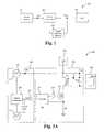
- FIG. 1illustrates a functional block diagram of a digital error feedback system 100 according to some embodiments.
- the system 100comprises a power source 102 , a power converter 104 , a load 106 and a digital feedback element 108 .
- the power source 102is electrically coupled with the power converter 104 which is electrically coupled with the load 106 in order to provide the output voltage V out to the load 106 .
- the digital feedback element 108is electrically coupled with the power converter 104 such that the digital feedback element 108 is able to detect the output voltage V out and transmit a command signal to the power converter 104 .
- two or more of the power converter 104 , digital feedback element 108 and load 106are integrated on a single integrated circuit.
- one or more of the power converter 104 , digital feedback element 108 and load 106are able to be on separate integrated circuits.
- the power source 102is able to comprise an AC power source such as a main line or plug outlet. Alternatively, the power source 102 is able to comprise a DC power supply.
- the power converter 104is able to comprise a power converter circuit, such as a flyback converter. Alternatively, the power converter 104 is able to comprise other types of circuits that include power converters as are well known in the art. For example, the power converter 104 is able to comprise a forward converter, a push-pull converter, a half-bridge converter, a full-bridge converter and/or other configurations of switch mode power supplies as are well known in the art.
- the digital feedback element 108is able to comprise a low power consuming voltage sensing circuit that is able to monitor the output voltage V out , compare a digital signal associated with the output voltage V out to a digital reference signal and control the operation of the power converter 104 accordingly.
- the load 106is able to comprise a mobile phone, laptop, set top box, television or other type of electronic device.
- the power converter 104draws power from the power source 102 and produces an output voltage V out that is able to be used to power the load 106 .
- the digital feedback element 108monitors the output voltage V out and compares a digital error signal associated with the output voltage V out with a digital reference signal associated with a desired output voltage which is determined based on the needs of the load 106 . Based on this comparison of the digital error signal and the digital reference signal, the digital feedback element 108 determines the current amount of error in the output voltage V out (e.g. the difference between the desired output voltage and the actual output voltage) and produces a control signal for transmission to the power converter 104 .
- the current amount of error in the output voltage V oute.g. the difference between the desired output voltage and the actual output voltage
- control signalis configured to cause the power converter 104 to alter operation such that the detected amount of error is compensated for and the output voltage V out equals the desired output voltage.
- digital reference signalis able to be adjusted dynamically before or during operation of the system 100 to correspond to different desired output voltages.
- the system 100is able to be dynamically configured to produce different output voltages V out as needed by different types of loads 106 .
- the system 100provides the advantage of enabling the use of robust digital signals to compensate for the error on the output voltage V out of the power converter 104 instead of relatively sensitive analog signals.
- the power source 202comprises an input voltage V in that is electrically coupled to the power converter 204 .
- the load 206comprises a resistor R load that represents the resistance provided by the load 206 .
- the load 206is able to comprise numerous different combination of circuitry that are able to be represented by the resistance of the resistor R load and the details of which are omitted for the sake of brevity.
- the digital feedback element 208comprises a digital comparator 220 , a first digital signal generator 218 , a second digital signal generator 222 and a digital to analog converter (DAC) 210 .
- DACdigital to analog converter
- the power converter 204comprises a transformer T 1 , a transistor 212 , a resistor R 1 , a controller device 214 , a capacitor C out , a diode D 1 and a buffer 216 . It is understood however, that one or more of the components of the power source 202 , the power converter 204 , the load 206 and/or the digital feedback element 208 are able to be positioned or duplicated on one or more of the other elements 202 - 208 .
- a primary end of the transformer T 1is electrically coupled between the input voltage V in and the drain terminal of the transistor 212 whose gate terminal is electrically coupled with the controller 214 via the buffer 216 and source terminal is electrically coupled with ground via the resistor R 1 and with the controller 214 .
- Thisenables the controller 214 to draw power into the transformer T 1 by outputting a transistor drive signal to the gate terminal of the transistor 212 .
- the secondary end of the transformer T 1is electrically coupled across the diode D 1 and capacitor C out and the load resistance R load is electrically coupled across the output capacitor C out such that the load 206 is able to receive the output voltage V out on the output capacitor C out .
- the second digital signal generator 222is electrically coupled with the output capacitor C out and the digital comparator 220 such that the second digital signal generator 222 is able to detect the output voltage V out and transmit a digital feedback/error signal 221 to the digital comparator 220 .
- the first digital signal generator 218is also electrically coupled with the digital comparator 220 such that the first digital signal generator 218 is able to transmit a digital reference signal 217 to the digital comparator 220 .
- the digital comparator 220is electrically coupled with the controller 214 via the DAC 210 such that the digital comparator 220 is able to transmit a digital control signal (which is subsequently converted to an analog signal by the DAC 210 ) to the controller 214 .
- the digital comparator 220is able to comprise one or more components and/or integrated circuits capable of comparing two or more digital signals as are well known in the art.
- the transformer T 1is a flyback transformer. Alternatively, the transformer T 1 is able to be other types of transformers or load isolating circuitry as are well known in the art.
- the transistor 212is a field effect transistor such as a n-type metal-oxide-semiconductor field-effect transistor (MOSFET). Alternatively, the transistor 212 is able to be other types of transistors or switching circuitry as are well known in the art.
- the controller device 214is a SR-NOR latch flip flop.
- the controller device 214is able to be other types of flip flops, pulse width modulation circuits or signal logic circuitry able to regulate the duty cycle or operation of the transistor 212 as are well known in the art.
- the first digital signal generator 218comprises a digital clock such as the system 200 clock.
- the first digital signal generator 218is able to comprise one or more of a digital clock, a voltage controlled oscillator and/or other electrical components capable of generating a digital reference signal as are well known in the art.
- the second digital signal generator 222comprises a voltage controlled oscillator.
- the second digital signal generator 222is able to comprise one or more of a digital clock, a voltage controlled oscillator, ring oscillator, and/or other electrical components capable of generating a digital signal based on a sensed voltage as are well known in the art.
- the controller device 214 of the power converter 204outputs a transistor drive signal having one or more pulse cycles to the gate terminal of the transistor 212 that causes the transistor 212 to repeatedly turn on and off as the pulse cycles alternate between high and low states.
- power from the power source 202is alternately drawn into the transformer T 1 and discharged to the output capacitor C out such that the output capacitor C out is charged to an output voltage V out that is supplied to the load 206 .
- the second digital signal generator 222detects/determines the output voltage V out on the output capacitor C out and generates a digital feedback/error signal that is based on the detected/determined output voltage V out .
- the digital feedback/error signalis dynamically adjusted by the second digital signal generator 222 such that the frequency of the digital feedback/error signal is corresponds to the detected/determined output voltage V out .
- the first digital signal generator 218generates a digital reference signal having a frequency that corresponds to a desired output voltage V out level.
- the desired output voltage V out level and corresponding digital reference signal frequencyis able to be dynamically adjusted automatically by the digital feedback element 208 based on one or more detected parameters of the load 206 and/or manually by a user adjusting or reprogramming the digital feedback element 208 .
- both the digital feedback/error signal and the digital reference signalare received by the digital comparator 220 such that the digital comparator 220 is able to compare the two signals in order to determine the current error in the output voltage V out .
- the digital comparator 220compares the frequencies or number of pulses in a predetermined period of the two signals and determines the current error based on the detected difference in frequency or number of pulses in the period.
- other methods of comparing the digital reference and feedback/error signalsare able to be used to determine the current error in the output voltage V out as are well known in the art.
- the comparator 220After determining the current error in the output voltage V out , the comparator 220 generates a digital control signal that is converted to analog and transmitted to the controller 214 via the DAC 210 . Alternatively, the comparator 220 is able to generate an analog control signal for direct transmission to the controller 214 such that the DAC 210 is able to be omitted.
- the digital control signalis generated based on the determined current error such that the digital control signal will cause the controller 214 to alter in operation in order to compensate for the detected error on the output voltage V out and cause the output voltage V out to equal the desired output voltage V out level.
- the digital control signalis configured to cause the controller 214 to modulate the pulse width of the transistor drive signal in order to compensate for the detected current error.
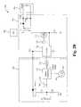
- FIG. 2Billustrates an alternate schematic diagram of the digital error feedback system 200 according to some embodiments.
- the schematic diagramis substantially similar to the schematic diagram shown in FIG. 2A except the additional details described herein. However, it is understood that alternative schematics are able to be used to implement the functional blocks of FIG. 2B .
- the digital feedback element 208instead of the second digital signal generator 222 , the digital feedback element 208 comprises a second secondary end of the transformer T 1 , one or more resistors R 2 , R 3 , a diode D 2 and a capacitor C 1 .
- the second secondary end of the transformer T 1is electrically coupled in parallel with a pair of resistors R 2 , R 3 between ground and the anode of the diode D 2 .
- the capacitor C 1is electrically coupled between ground and the cathode of the diode D 2 which is electrically coupled with the controller 214 in order to provide recycled power V cc to the controller 214 .
- the digital comparator 220is coupled to a node N 1 between the pair of resistors R 2 , R 3 such that the digital comparator 220 is able to receive a digital feedback/error signal 221 produced on the node N 1 . It is understood however, that one or more of the components of the power source 202 , the power converter 204 , the load 206 and/or the digital feedback element 208 are able to be positioned or duplicated on one or more of the other elements 202 - 208 .
- the controller device 214 of the power converter 204outputs a transistor drive signal having one or more pulse cycles to the gate terminal of the transistor 212 that causes the transistor 212 to repeatedly turn on and off as the pulse cycles alternate between high and low states.
- power from the power source 202is alternately drawn into the transformer T 1 and discharged to the output capacitor C out such that the output capacitor C out is charged to an output voltage V out that is supplied to the load 206 .
- a portion of the poweris discharged to the capacitor C 1 and the controller 214 via the diode D 2 . This portion of the power is able to be used/recycled by the controller 214 in order to continue to output the transistor drive signal.
- the digital comparator 220detects/receives a pulsed or digital feedback/error signal produced on the node N 1 by the switching of the transistor 212 and corresponding discharging of the portion of the power from the second secondary end of the transformer T 1 to the capacitor C 1 and the controller 214 .
- the first digital signal generator 218generates a digital reference signal having a frequency that corresponds to a desired output voltage V out level.
- the desired output voltage V out level and corresponding digital reference signal frequencyis able to be dynamically adjusted automatically by the digital feedback element 208 based on one or more detected parameters of the load 206 and/or manually by a user adjusting or reprogramming the digital feedback element 208 .
- both the digital feedback/error signal and the digital reference signalare received by the digital comparator 220 such that the digital comparator 220 is able to compare the two signals in order to determine the current error in the output voltage V out .
- the comparison performed by the digital comparator 220comprises counting the number of cycles of the digital reference signal that occur while the pulsed or digital feedback/error signal is in a high state (e.g. the number of cycles per pulse of the digital feedback/error signal).
- other methods of comparing the digital reference and feedback/error signalsare able to be used to determine the current error in the output voltage V out as are well known in the art.
- the comparator 220After determining the current error in the output voltage V out , the comparator 220 generates a digital control signal that is converted to analog and transmitted to the controller 214 via the DAC 210 . Alternatively, the comparator 220 is able to generate an analog control signal for direct transmission to the controller 214 such that the DAC 210 is able to be omitted.
- the digital control signalis generated based on the determined current error such that the digital control signal will cause the controller 214 to alter in operation in order to compensate for the detected error on the output voltage V out and cause the output voltage V out to equal the desired output voltage V out level.
- the digital control signalis configured to cause the controller 214 to modulate the pulse width of the transistor drive signal in order to compensate for the detected current error.
- FIG. 3illustrates a flow chart of a method of adjusting the output voltage of a power converter using digital error feedback according to some embodiments.
- the power converter 104produces an output voltage V out on the load 106 using the input power of a power source 102 .
- the first digital signal generator 218generates a digital reference signal.
- the digital comparator 220receives the digital reference signal and a digital feedback/error signal representing the output voltage V out .
- the digital comparator 220produces a control signal that causes the power converter 104 to adjust the output voltage V out , wherein the control signal is based on the digital reference signal and the digital feedback/error signal.
- the second digital signal generator 222detects the output voltage V out and generates the digital feedback/error signal with based on the detected output voltage V out level.
- the controller 214outputs a pulse width modulated transistor drive signal in order to produce the output voltage on the load 106 and the digital error signal is based on the pulse width modulated transistor drive signal.
- producing the control signalcomprises determining the difference in frequency between the digital reference signal and the digital error signal and adjusting the control signal based on the determined difference.
- producing the control signalcomprises determining a number of cycles of the digital reference signal that occur during each high pulse of the digital feedback/error signal and adjusting the control signal based on the determined number of cycles per high pulse.
- the methodfurther comprises associating a frequency of the digital reference signal with a desired output voltage level that is required by the load 106 , wherein the associating comprises adjusting the frequency of the digital reference signal with the first digital signal generator 218 .
- the methodprovides the benefit of producing and maintaining a desired output voltage V out while utilizing robust digital signals as feedback instead of analog signals.
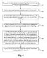
- FIG. 4illustrates a flow chart of a method of adjusting the output voltage of a power converter using digital error feedback according to some embodiments.
- the power converter 104produces an output voltage V out on the load 106 using the input power of a power source 102 .
- the first digital signal generator 218generates a digital reference signal.
- the second digital signal generator 222detects the output voltage V out and generates a digital feedback/error signal based on the detected output voltage V out .
- the digital comparator 220receives the digital reference signal and the digital feedback/error signal representing the output voltage V out .
- the digital comparator 220either: produces a control signal that causes the power converter 104 to adjust the output voltage V out by determining the difference in frequency between the digital reference signal and the digital feedback/error signal and adjusting the control signal based on the determined difference; or produces a control signal that causes the power converter 104 to adjust the output voltage V out by determining a number of cycles of the digital reference signal that occur during each high pulse of the digital feedback/error signal and adjusting the control signal based on the determined number of cycles per high pulse.
- the first digital signal generator 218enables the frequency of the digital reference signal to be adjusted.
- the controller 214outputs a pulse width modulated transistor drive signal in order to produce the output voltage on the load 106 and the digital error signal is based on the pulse width modulated transistor drive signal.
- the methodfurther comprises associating a frequency of the digital reference signal with a desired output voltage level that is required by the load 106 , wherein the associating comprises adjusting the frequency of the digital reference signal with the first digital signal generator 218 .
- the digital error feedback method, apparatus and system described hereinhas many advantages. Specifically, the system benefits from the relative robustness of digital pulse signals which enable accurate determination of error on the output voltage. Further, the system does not incur the costs associated with analog feedback such as noise suppression, temperature compensation, reference voltage control, sufficient response time, the use of tightly tolerated components and other steps necessary to maintain analog signal integrity. Accordingly, the digital error feedback method, system and apparatus described herein has numerous advantages.
Landscapes
- Engineering & Computer Science (AREA)
- Power Engineering (AREA)
- Dc-Dc Converters (AREA)
Abstract
Description
The present invention relates to the field of power supplies. More particularly, the present invention relates to a power converter system with a digital error feedback feature.
Power converters are devices that receive power from a power source and converter that power into an output power that is suitable for powering a load that is coupled to the power converter. To maintain a stable output power, conventional power converters include analog feedback components. These analog components measure the output voltage on the load and compare that voltage to a controlled reference voltage that is known to be at the desired voltage to determine the error or how different the actual output voltage is from the desired output voltage. The analog components then utilize this determined error to adjust the operation of the power converter to compensate for the measured error. However, these systems result from numerous drawbacks due to their use of analog feedback. In particular, the analog signals used to transmit the reference and output voltages require temperature, noise, response time and other types of compensation for the systems to operate accurately. These requirements add cost and limit the capabilities of the power converters.
A digital error feedback system, method and device adjusts the output voltage of a power converter. The digital error feedback system uses a digital comparator and one or more digital signal generators to generate and compare a digital signal corresponding to the output voltage to a reference digital signal to determine the current amount of error in the output voltage. The error is then able to be compensated for using a control signal generated based on the determined error. As a result, the digital error feedback system is able to maintain the desired output voltage without needing to incur the added expense of adjusting for the numerous problems associated with analog error feedback signals.
One aspect of the present invention is directed to a digital error feedback system. The system comprises a power supply for supplying an input power. A power converter is coupled with the power supply. The power converter produces an output voltage on a load using the input power. A first digital signal generator generates a digital reference signal which is coupled to a digital comparator. Based on the digital reference signal and a digital error signal representing the output voltage, the digital comparator produces a control signal that causes the power converter to adjust the output voltage. In some embodiments, the system further comprises a second digital signal generator coupled with the power converter and the digital comparator, wherein the second digital signal generator detects the output voltage and generates the digital error signal based on the detected output voltage level. In some embodiments, the digital comparator produces the control signal by determining a difference in frequency between the digital reference signal and the digital error signal and adjusting the control signal based on the determined difference. In some embodiments, the power converter comprises a controller wherein the digital error signal is based on a pulse width modulated converter signal output by the controller in order to produce the output voltage on the load. In some embodiments, the digital comparator produces the control signal by determining a number of cycles of the digital reference signal that occur during each high pulse of the digital error signal and adjusting the control signal based on the determined number of cycles per high pulse. In some embodiments, the frequency of the digital reference signal is associated with a desired voltage that is required by the load. In some embodiments, the first digital signal generator enables the frequency of the digital reference signal to be adjusted. In some embodiments, the first digital signal generator and the digital comparator are a part of a separate integrated circuit that is coupled with the power converter. In some embodiments, the power converter, the first digital signal generator and the digital comparator are a part of a single integrated circuit.
A second aspect of the present invention is directed to a digital error feedback device. The device comprises a power converter coupled with a power supply. The power converter produces an output voltage on a load using input power provided by the power supply. A first digital signal generator generates a digital reference signal. A digital comparator is coupled with the first digital signal generator. Based on the digital reference signal and a digital error signal representing the output voltage, the digital comparator produces a control signal that causes the power converter to adjust the output voltage. In some embodiments, the device further comprises a second digital signal generator coupled with the power converter and the digital comparator, wherein the second digital generator detects the output voltage and generates the digital error signal based on the detected output voltage level. In some embodiments, the digital comparator produces the control signal by determining the difference in frequency between the digital reference signal and the digital error signal and adjusting the control signal based on the determined difference. In some embodiments, the power converter comprises a controller and the digital error signal is based on a pulse width modulated converter signal output by the controller in order to produce the output voltage on the load. In some embodiments, the digital comparator produces the control signal by determining a number of cycles of the digital reference signal that occur during each high pulse of the digital error signal and adjusting the control signal based on the determined number of cycles per high pulse. In some embodiments, the frequency of the digital reference signal is associated with a desired voltage that is required by the load. In some embodiments, the first digital signal generator enables the frequency of the digital reference signal to be adjusted. In some embodiments, the first digital signal generator and the digital comparator are a part of a separate integrated circuit that is coupled with the power converter. In some embodiments, the power converter, the first digital signal generator and the digital comparator are a part of a single integrated circuit.
A third aspect of the present invention is directed to a method of adjusting the output voltage of a power converter using digital error feedback. The method comprises producing an output voltage on a load with a power converter using the input power of a power source. A digital reference signal is generated by a first digital signal generator. The digital reference signal and a digital error signal representing the output voltage are received by a digital comparator for producing a control signal that causes the power converter to adjust the output voltage. The control signal is adjusted in response to the digital reference signal and the digital error signal. In some embodiments, the method further comprises detecting the output voltage and generating the digital error signal with a second digital signal generator based on the detected output voltage level. In some embodiments, producing the control signal comprises determining the difference in frequency between the digital reference signal and the digital error signal and adjusting the control signal based on the determined difference. In some embodiments, the method further comprises outputting a pulse width modulated converter signal with a controller of the power converter to produce the output voltage on the load, wherein the digital error signal is based on the pulse width modulated converter signal. In some embodiments, producing the control signal comprises determining a number of cycles of the digital reference signal that occur during each high pulse of the digital error signal and adjusting the control signal based on the determined number of cycles per high pulse. In some embodiments, the method further comprises associating a frequency of the digital reference signal with a desired voltage that is required by the load. In some embodiments, the associating comprises adjusting the frequency of the digital reference signal with the first digital signal generator. In some embodiments, the first digital signal generator and the digital comparator are a part of a separate integrated circuit that is coupled with the power converter. In some embodiments, the power converter, the first digital signal generator and the digital comparator are a part of a single integrated circuit.
In the following description, numerous details and alternatives are set forth for the purpose of explanation. However, one of ordinary skill in the art will realize that the invention can be practiced without the use of these specific details. In other instances, well-known structures and devices are shown in block diagram form in order not to obscure the description of the invention with unnecessary detail. In particular, it should be noted that although the digital error feedback system, device and method is described herein in reference to input, output and reference voltages, it is understood that the system, device and method are able to similarly operate in reference to input, output and reference currents and/or voltages.
Embodiments of a digital error feedback system, method and device for adjusting the output voltage of a power converter are described herein. The digital error feedback system uses a digital comparator and one or more digital signal generators to generate and compare a digital signal corresponding to the output voltage to a reference digital signal in order to determine the current amount of error in the output voltage. The error is then able to be compensated for using a control signal generated based on the determined error. As a result, the digital error feedback system is able to maintain the desired output voltage without needing to incur the added expense of adjusting for the numerous problems associated with analog error feedback signals.
Thepower source 102 is able to comprise an AC power source such as a main line or plug outlet. Alternatively, thepower source 102 is able to comprise a DC power supply. Thepower converter 104 is able to comprise a power converter circuit, such as a flyback converter. Alternatively, thepower converter 104 is able to comprise other types of circuits that include power converters as are well known in the art. For example, thepower converter 104 is able to comprise a forward converter, a push-pull converter, a half-bridge converter, a full-bridge converter and/or other configurations of switch mode power supplies as are well known in the art. Thedigital feedback element 108 is able to comprise a low power consuming voltage sensing circuit that is able to monitor the output voltage Vout, compare a digital signal associated with the output voltage Voutto a digital reference signal and control the operation of thepower converter 104 accordingly. Theload 106 is able to comprise a mobile phone, laptop, set top box, television or other type of electronic device.
In operation, thepower converter 104 draws power from thepower source 102 and produces an output voltage Voutthat is able to be used to power theload 106. Thedigital feedback element 108 monitors the output voltage Voutand compares a digital error signal associated with the output voltage Voutwith a digital reference signal associated with a desired output voltage which is determined based on the needs of theload 106. Based on this comparison of the digital error signal and the digital reference signal, thedigital feedback element 108 determines the current amount of error in the output voltage Vout(e.g. the difference between the desired output voltage and the actual output voltage) and produces a control signal for transmission to thepower converter 104. In particular, the control signal is configured to cause thepower converter 104 to alter operation such that the detected amount of error is compensated for and the output voltage Voutequals the desired output voltage. In some embodiments, the digital reference signal is able to be adjusted dynamically before or during operation of thesystem 100 to correspond to different desired output voltages. In such embodiments, thesystem 100 is able to be dynamically configured to produce different output voltages Voutas needed by different types ofloads 106. As a result, thesystem 100 provides the advantage of enabling the use of robust digital signals to compensate for the error on the output voltage Voutof thepower converter 104 instead of relatively sensitive analog signals.
Thepower source 202 comprises an input voltage Vinthat is electrically coupled to thepower converter 204. Theload 206 comprises a resistor Rloadthat represents the resistance provided by theload 206. In particular, it is understood that theload 206 is able to comprise numerous different combination of circuitry that are able to be represented by the resistance of the resistor Rloadand the details of which are omitted for the sake of brevity. Thedigital feedback element 208 comprises adigital comparator 220, a firstdigital signal generator 218, a seconddigital signal generator 222 and a digital to analog converter (DAC)210. Thepower converter 204 comprises a transformer T1, atransistor 212, a resistor R1, acontroller device 214, a capacitor Cout, a diode D1 and abuffer 216. It is understood however, that one or more of the components of thepower source 202, thepower converter 204, theload 206 and/or thedigital feedback element 208 are able to be positioned or duplicated on one or more of the other elements202-208.
A primary end of the transformer T1 is electrically coupled between the input voltage Vinand the drain terminal of thetransistor 212 whose gate terminal is electrically coupled with thecontroller 214 via thebuffer 216 and source terminal is electrically coupled with ground via the resistor R1 and with thecontroller 214. This enables thecontroller 214 to draw power into the transformer T1 by outputting a transistor drive signal to the gate terminal of thetransistor 212. The secondary end of the transformer T1 is electrically coupled across the diode D1 and capacitor Coutand the load resistance Rloadis electrically coupled across the output capacitor Coutsuch that theload 206 is able to receive the output voltage Vouton the output capacitor Cout. The seconddigital signal generator 222 is electrically coupled with the output capacitor Coutand thedigital comparator 220 such that the seconddigital signal generator 222 is able to detect the output voltage Voutand transmit a digital feedback/error signal 221 to thedigital comparator 220. The firstdigital signal generator 218 is also electrically coupled with thedigital comparator 220 such that the firstdigital signal generator 218 is able to transmit adigital reference signal 217 to thedigital comparator 220. Thedigital comparator 220 is electrically coupled with thecontroller 214 via theDAC 210 such that thedigital comparator 220 is able to transmit a digital control signal (which is subsequently converted to an analog signal by the DAC210) to thecontroller 214.
Thedigital comparator 220 is able to comprise one or more components and/or integrated circuits capable of comparing two or more digital signals as are well known in the art. In some embodiments, the transformer T1 is a flyback transformer. Alternatively, the transformer T1 is able to be other types of transformers or load isolating circuitry as are well known in the art. In some embodiments, thetransistor 212 is a field effect transistor such as a n-type metal-oxide-semiconductor field-effect transistor (MOSFET). Alternatively, thetransistor 212 is able to be other types of transistors or switching circuitry as are well known in the art. In some embodiments, thecontroller device 214 is a SR-NOR latch flip flop. Alternatively, thecontroller device 214 is able to be other types of flip flops, pulse width modulation circuits or signal logic circuitry able to regulate the duty cycle or operation of thetransistor 212 as are well known in the art. In some embodiments, the firstdigital signal generator 218 comprises a digital clock such as thesystem 200 clock. Alternatively, the firstdigital signal generator 218 is able to comprise one or more of a digital clock, a voltage controlled oscillator and/or other electrical components capable of generating a digital reference signal as are well known in the art. In some embodiments, the seconddigital signal generator 222 comprises a voltage controlled oscillator. Alternatively, the seconddigital signal generator 222 is able to comprise one or more of a digital clock, a voltage controlled oscillator, ring oscillator, and/or other electrical components capable of generating a digital signal based on a sensed voltage as are well known in the art.
In operation, when theload 206 is coupled to thepower converter 204, thecontroller device 214 of thepower converter 204 outputs a transistor drive signal having one or more pulse cycles to the gate terminal of thetransistor 212 that causes thetransistor 212 to repeatedly turn on and off as the pulse cycles alternate between high and low states. As a result, power from thepower source 202 is alternately drawn into the transformer T1 and discharged to the output capacitor Coutsuch that the output capacitor Coutis charged to an output voltage Voutthat is supplied to theload 206. Concurrently, the seconddigital signal generator 222 detects/determines the output voltage Vouton the output capacitor Coutand generates a digital feedback/error signal that is based on the detected/determined output voltage Vout. In particular, the digital feedback/error signal is dynamically adjusted by the seconddigital signal generator 222 such that the frequency of the digital feedback/error signal is corresponds to the detected/determined output voltage Vout. Similarly, the firstdigital signal generator 218 generates a digital reference signal having a frequency that corresponds to a desired output voltage Voutlevel. In particular, the desired output voltage Voutlevel and corresponding digital reference signal frequency is able to be dynamically adjusted automatically by thedigital feedback element 208 based on one or more detected parameters of theload 206 and/or manually by a user adjusting or reprogramming thedigital feedback element 208.
As a result, both the digital feedback/error signal and the digital reference signal are received by thedigital comparator 220 such that thedigital comparator 220 is able to compare the two signals in order to determine the current error in the output voltage Vout. In some embodiments, thedigital comparator 220 compares the frequencies or number of pulses in a predetermined period of the two signals and determines the current error based on the detected difference in frequency or number of pulses in the period. Alternatively, other methods of comparing the digital reference and feedback/error signals are able to be used to determine the current error in the output voltage Voutas are well known in the art. After determining the current error in the output voltage Vout, thecomparator 220 generates a digital control signal that is converted to analog and transmitted to thecontroller 214 via theDAC 210. Alternatively, thecomparator 220 is able to generate an analog control signal for direct transmission to thecontroller 214 such that theDAC 210 is able to be omitted. The digital control signal is generated based on the determined current error such that the digital control signal will cause thecontroller 214 to alter in operation in order to compensate for the detected error on the output voltage Voutand cause the output voltage Voutto equal the desired output voltage Voutlevel. For example, in some embodiments the digital control signal is configured to cause thecontroller 214 to modulate the pulse width of the transistor drive signal in order to compensate for the detected current error. Alternatively, other compensation alterations are able to be made to the operation of thecontroller 214 as are well known in the art. This cycle of output voltage Voutdetection and correction repeats throughout the operation of thesystem 200 such that the output voltage is substantially maintained at the desired output voltage Voutlevel. As a result, thesystem 200 is able to utilize digital feedback to avoid the problems with analog signal integrity while still maintaining the desired operation of thepower converter 204.
In operation, when theload 206 is coupled to thepower converter 204, thecontroller device 214 of thepower converter 204 outputs a transistor drive signal having one or more pulse cycles to the gate terminal of thetransistor 212 that causes thetransistor 212 to repeatedly turn on and off as the pulse cycles alternate between high and low states. As a result, power from thepower source 202 is alternately drawn into the transformer T1 and discharged to the output capacitor Coutsuch that the output capacitor Coutis charged to an output voltage Voutthat is supplied to theload 206. Additionally, a portion of the power is discharged to the capacitor C1 and thecontroller 214 via the diode D2. This portion of the power is able to be used/recycled by thecontroller 214 in order to continue to output the transistor drive signal. Concurrently, thedigital comparator 220 detects/receives a pulsed or digital feedback/error signal produced on the node N1 by the switching of thetransistor 212 and corresponding discharging of the portion of the power from the second secondary end of the transformer T1 to the capacitor C1 and thecontroller 214. Additionally, the firstdigital signal generator 218 generates a digital reference signal having a frequency that corresponds to a desired output voltage Voutlevel. In particular, the desired output voltage Voutlevel and corresponding digital reference signal frequency is able to be dynamically adjusted automatically by thedigital feedback element 208 based on one or more detected parameters of theload 206 and/or manually by a user adjusting or reprogramming thedigital feedback element 208.
As a result, both the digital feedback/error signal and the digital reference signal are received by thedigital comparator 220 such that thedigital comparator 220 is able to compare the two signals in order to determine the current error in the output voltage Vout. In some embodiments, the comparison performed by thedigital comparator 220 comprises counting the number of cycles of the digital reference signal that occur while the pulsed or digital feedback/error signal is in a high state (e.g. the number of cycles per pulse of the digital feedback/error signal). Alternatively, other methods of comparing the digital reference and feedback/error signals are able to be used to determine the current error in the output voltage Voutas are well known in the art. After determining the current error in the output voltage Vout, thecomparator 220 generates a digital control signal that is converted to analog and transmitted to thecontroller 214 via theDAC 210. Alternatively, thecomparator 220 is able to generate an analog control signal for direct transmission to thecontroller 214 such that theDAC 210 is able to be omitted. The digital control signal is generated based on the determined current error such that the digital control signal will cause thecontroller 214 to alter in operation in order to compensate for the detected error on the output voltage Voutand cause the output voltage Voutto equal the desired output voltage Voutlevel. For example, in some embodiments the digital control signal is configured to cause thecontroller 214 to modulate the pulse width of the transistor drive signal in order to compensate for the detected current error. Alternatively, other compensation alterations are able to be made to the operation of thecontroller 214 as are well known in the art. This cycle of output voltage Voutdetection and correction repeats throughout the operation of thesystem 200 such that the output voltage is substantially maintained at the desired output voltage Voutlevel. As a result, thesystem 200 is able to utilize digital feedback to avoid the problems with analog signal integrity while still maintaining the desired operation of thepower converter 204.
Accordingly, the digital error feedback method, apparatus and system described herein has many advantages. Specifically, the system benefits from the relative robustness of digital pulse signals which enable accurate determination of error on the output voltage. Further, the system does not incur the costs associated with analog feedback such as noise suppression, temperature compensation, reference voltage control, sufficient response time, the use of tightly tolerated components and other steps necessary to maintain analog signal integrity. Accordingly, the digital error feedback method, system and apparatus described herein has numerous advantages.
The digital error feedback system has been described in terms of specific embodiments incorporating details to facilitate the understanding of the principles of construction and operation of the digital error feedback system. The specific configurations shown and the methodologies described in relation to the various modules and the interconnections therebetween are for exemplary purposes only. Such reference herein to specific embodiments and details thereof is not intended to limit the scope of the claims appended hereto. It will be apparent to those skilled in the art that modifications may be made in the embodiments chosen for illustration without departing from the spirit and scope of the digital error feedback system.
Claims (27)
1. A digital error feedback system comprising:
a power supply for supplying an input power;
a power converter coupled with the power supply, wherein the power converter produces an output voltage on a load using the input power;
a digital-to-analog converter (DAC) coupled to the power converter;
a first digital signal generator that generates a digital reference signal; and
a digital comparator coupled with the first digital signal generator and the DAC, wherein, based on the digital reference signal and a frequency of a digital feedback signal representing the output voltage, the digital comparator produces a digitally compared control signal that is received by the DAC and converted to an analog signal, and further wherein the DAC transmits the analog signal to the power converter such that the digitally compared control signal, as converted to the analog signal, causes the power converter to adjust the output voltage.
2. The system ofclaim 1 , further comprising a second digital signal generator coupled with the power converter and the digital comparator, wherein the second digital generator detects the output voltage and generates the digital feedback signal based on the detected output voltage level.
3. The system ofclaim 2 , wherein the digital comparator produces the digitally controlled control signal by determining the difference in frequency between the digital reference signal and the digital feedback signal and adjusting the digitally compared control signal based on the determined difference.
4. The system ofclaim 1 , wherein the power converter comprises a controller and the digital feedback signal is based on a pulse width modulated converter signal output by the controller in order to produce the output voltage on the load.
5. The system ofclaim 4 , wherein the digital comparator produces the digitally compared control signal by determining a number of cycles of the digital reference signal that occur during each high pulse of the digital feedback signal and adjusting the digitally compared control signal based on the determined number of cycles per high pulse.
6. The system ofclaim 3 , wherein the frequency of the digital reference signal is associated with a desired voltage that is required by the load.
7. The system ofclaim 6 , wherein the first digital signal generator enables the frequency of the digital reference signal to be adjusted.
8. The system ofclaim 1 , wherein the first digital signal generator and the digital comparator are a part of a separate integrated circuit that is coupled with the power converter.
9. The system ofclaim 1 , wherein the power converter, the first digital signal generator and the digital comparator are a part of a single integrated circuit.
10. A digital error feedback device comprising:
a power converter coupled with a power supply, wherein the power converter produces an output voltage on a load using input power provided by the power supply;
a digital-to-analog converter (DAC) coupled to the power converter;
a first digital signal generator that generates a digital reference signal; and
a digital comparator coupled with the first digital signal generator and the DAC, wherein, based on the digital reference signal and a frequency of a digital feedback signal representing the output voltage, the digital comparator produces a digitally compared control signal that is received by the DAC and converted to an analog signal, and further wherein the DAC transmits the analog signal to the power converter such that the digitally compared control signal, as converted to the analog signal, causes the power converter to adjust the output voltage.
11. The device ofclaim 10 , further comprising a second digital signal generator coupled with the power converter and the digital comparator, wherein the second digital generator detects the output voltage and generates the digital feedback signal based on the detected output voltage level.
12. The device ofclaim 11 , wherein the digital comparator produces the digitally compared control signal by determining the difference in frequency between the digital reference signal and the digital feedback signal and adjusting the digitally compared control signal based on the determined difference.
13. The device ofclaim 10 , wherein the power converter comprises a controller and the digital feedback signal is based on a pulse width modulated converter signal output by the controller in order to produce the output voltage on the load.
14. The device ofclaim 13 , wherein the digital comparator produces the digitally compared control signal by determining a number of cycles of the digital reference signal that occur during each high pulse of the digital feedback signal and adjusting the digitally compared control signal based on the determined number of cycles per high pulse.
15. The device ofclaim 12 , wherein the frequency of the digital reference signal is associated with a desired voltage that is required by the load.
16. The device ofclaim 15 , wherein the first digital signal generator enables the frequency of the digital reference signal to be adjusted.
17. The device ofclaim 10 , wherein the first digital signal generator and the digital comparator are a part of a separate integrated circuit that is coupled with the power converter.
18. The device ofclaim 10 , wherein the power converter, the first digital signal generator and the digital comparator are a part of a single integrated circuit.
19. A method of adjusting the output voltage of a power converter using digital error feedback, the method comprising:
producing an output voltage on a load with a power converter using the input power of a power source;
generating a digital reference signal with a first digital signal generator;
receiving the digital reference signal and a digital feedback signal representing the output voltage with a digital comparator;
producing a digitally compared control signal with the digital comparator;
forwarding the digitally compared control signal from the digital comparator to a digital to analog converter; and
converting the digitally compared control signal to an analog signal with the digital to analog converter such that the digitally compared control signal, as converted to the analog signal, causes the power converter to adjust the output voltage, wherein the digitally compared control signal is based on the digital reference signal and a frequency of the digital feedback signal.
20. The method ofclaim 19 , further comprising detecting the output voltage and generating the digital feedback signal with a second digital signal generator based on the detected output voltage level.
21. The method ofclaim 20 , wherein producing the digitally compared control signal comprises determining the difference in frequency between the digital reference signal and the digital feedback signal and adjusting the digitally compared control signal based on the determined difference.
22. The method ofclaim 19 , further comprising outputting a pulse width modulated converter signal with a controller of the power converter in order to produce the output voltage on the load, wherein the digital feedback signal is based on the pulse width modulated converter signal.
23. The method ofclaim 22 , wherein producing the digitally compared control signal comprises determining a number of cycles of the digital reference signal that occur during each high pulse of the digital feedback signal and adjusting the digitally compared control signal based on the determined number of cycles per high pulse.
24. The method ofclaim 21 , further comprising associating a frequency of the digital reference signal with a desired voltage that is required by the load.
25. The method ofclaim 24 , wherein the associating comprises adjusting the frequency of the digital reference signal with the first digital signal generator.
26. The method ofclaim 19 , wherein the first digital signal generator and the digital comparator are a part of a separate integrated circuit that is coupled with the power converter.
27. The method ofclaim 19 , wherein the power converter, the first digital signal generator and the digital comparator are a part of a single integrated circuit.
Priority Applications (2)
| Application Number | Priority Date | Filing Date | Title |
|---|---|---|---|
| US13/669,229US9660540B2 (en) | 2012-11-05 | 2012-11-05 | Digital error signal comparator |
| CN201310548619.1ACN103812347B (en) | 2012-11-05 | 2013-11-05 | Digital error signal comparator |
Applications Claiming Priority (1)
| Application Number | Priority Date | Filing Date | Title |
|---|---|---|---|
| US13/669,229US9660540B2 (en) | 2012-11-05 | 2012-11-05 | Digital error signal comparator |
Publications (2)
| Publication Number | Publication Date |
|---|---|
| US20140125305A1 US20140125305A1 (en) | 2014-05-08 |
| US9660540B2true US9660540B2 (en) | 2017-05-23 |
Family
ID=50621761
Family Applications (1)
| Application Number | Title | Priority Date | Filing Date |
|---|---|---|---|
| US13/669,229Active2034-01-16US9660540B2 (en) | 2012-11-05 | 2012-11-05 | Digital error signal comparator |
Country Status (2)
| Country | Link |
|---|---|
| US (1) | US9660540B2 (en) |
| CN (1) | CN103812347B (en) |
Families Citing this family (2)
| Publication number | Priority date | Publication date | Assignee | Title |
|---|---|---|---|---|
| CN108450047B (en)* | 2015-10-23 | 2019-10-25 | 戴洛格半导体公司 | Primary side with calibrated output voltage adjusts flyback converter |
| US10218279B2 (en)* | 2016-10-26 | 2019-02-26 | Texas Instruments Incorporated | Methods and circuitry for operating switching power supplies based on switching frequency comparison |
Citations (249)
| Publication number | Priority date | Publication date | Assignee | Title |
|---|---|---|---|---|
| US4077061A (en) | 1977-03-25 | 1978-02-28 | Westinghouse Electric Corporation | Digital processing and calculating AC electric energy metering system |
| US4122359A (en) | 1977-04-27 | 1978-10-24 | Honeywell Inc. | Memory protection arrangement |
| US4234920A (en) | 1978-11-24 | 1980-11-18 | Engineered Systems, Inc. | Power failure detection and restart system |
| US4245289A (en) | 1978-10-25 | 1981-01-13 | Rockwell International Corporation | Power supply monitor |
| US4273406A (en) | 1978-12-28 | 1981-06-16 | Mitsuoka Electric Mfg. Co., Ltd. | Electrical cord adapter |
| US4327298A (en) | 1979-12-14 | 1982-04-27 | Borg-Warner Corporation | Battery backup system for a microcomputer |
| US4370703A (en) | 1981-07-20 | 1983-01-25 | Park-Ohio Industries, Inc. | Solid state frequency converter |
| US4381457A (en) | 1981-04-23 | 1983-04-26 | Ladco Development Co., Inc. | Method and apparatus for preventing loss of data from volatile memory |
| US4489394A (en) | 1982-04-21 | 1984-12-18 | Zenith Electronics Corporation | Microprocessor power on reset system |
| US4535410A (en) | 1982-07-06 | 1985-08-13 | Intersil, Inc. | Power supply failure early warning detector |
| US4563731A (en) | 1982-01-07 | 1986-01-07 | Matsushita Electric Industrial Co., Ltd. | Resonant type constant voltage supply apparatus |
| US4607323A (en) | 1984-04-17 | 1986-08-19 | Sokal Nathan O | Class E high-frequency high-efficiency dc/dc power converter |
| US4611289A (en) | 1983-09-29 | 1986-09-09 | Coppola Anthony F | Computer power management system |
| US4642616A (en) | 1985-02-14 | 1987-02-10 | Prime Computer, Inc. | Method and apparatus for detection of AC power failure conditions |
| US4645278A (en) | 1985-09-09 | 1987-02-24 | Texas Instruments Incorporated | Circuit panel connector, panel system using the connector, and method for making the panel system |
| US4658204A (en) | 1986-02-07 | 1987-04-14 | Prime Computer, Inc. | Anticipatory power failure detection apparatus and method |
| US4703191A (en) | 1985-12-09 | 1987-10-27 | Control Technology, Inc. | Reserve power source with power failure detection apparatus |
| US4712160A (en) | 1985-07-02 | 1987-12-08 | Matsushita Electric Industrial Co., Ltd. | Power supply module |
| US4742424A (en) | 1987-04-28 | 1988-05-03 | General Electric Company | Power status monitor for electronic system |
| US4750040A (en) | 1985-08-23 | 1988-06-07 | Sony Corporation | Apparatus controlled by a micro-computer and including power loss data checking |
| US4788626A (en) | 1986-02-15 | 1988-11-29 | Brown, Boveri & Cie Ag | Power semiconductor module |
| US4806110A (en) | 1986-06-19 | 1989-02-21 | Labinal Components And Systems, Inc. | Electrical connectors |
| US4841220A (en) | 1987-09-23 | 1989-06-20 | Tabisz Wojciech A | Dc-to-Dc converters using multi-resonant switches |
| US4857822A (en) | 1987-09-23 | 1989-08-15 | Virginia Tech Intellectual Properties, Inc. | Zero-voltage-switched multi-resonant converters including the buck and forward type |
| US4866367A (en) | 1988-04-11 | 1989-09-12 | Virginia Tech Intellectual Properties, Inc. | Multi-loop control for quasi-resonant converters |
| US4884242A (en) | 1988-05-26 | 1989-11-28 | Applied Automation, Inc. | Backup power system for dynamic memory |
| US4890217A (en) | 1988-07-26 | 1989-12-26 | Norand Corporation | Universal power supply, independent converter stages for respective hardware components of a computerized system |
| US4893227A (en) | 1988-07-08 | 1990-01-09 | Venus Scientific, Inc. | Push pull resonant flyback switchmode power supply converter |
| US4899256A (en) | 1988-06-01 | 1990-02-06 | Chrysler Motors Corporation | Power module |
| US4901069A (en) | 1987-07-16 | 1990-02-13 | Schlumberger Technology Corporation | Apparatus for electromagnetically coupling power and data signals between a first unit and a second unit and in particular between well bore apparatus and the surface |
| US4985804A (en) | 1988-01-27 | 1991-01-15 | Codar Technology, Inc. | Microcomputer housing and ventilation arrangement |
| US5065302A (en) | 1989-07-28 | 1991-11-12 | Kabushiki Kaisha Toshiba | Adjustable ac power supply equipment for air-conditioner system |
| US5090919A (en) | 1989-01-26 | 1992-02-25 | Omron Corporation | Terminal piece sealing structure |
| US5101322A (en) | 1990-03-07 | 1992-03-31 | Motorola, Inc. | Arrangement for electronic circuit module |
| US5105182A (en) | 1990-02-15 | 1992-04-14 | Mitsubishi Denki K.K. | Direct current power supply device having an alarm provided for power failure under varying load conditions |
| US5126931A (en) | 1990-09-07 | 1992-06-30 | Itt Corporation | Fixed frequency single ended forward converter switching at zero voltage |
| US5132890A (en) | 1991-01-09 | 1992-07-21 | Koss Corporation | Power supply based on normally parasitic resistance of solid state switch |
| JPH04217869A (en) | 1990-12-20 | 1992-08-07 | Nemitsuku Ramuda Kk | Power supply |
| US5235491A (en) | 1990-05-10 | 1993-08-10 | Bicc-Vero Electronics Gmbh | Safety power supply |
| US5266952A (en)* | 1992-03-30 | 1993-11-30 | Hughes Aircraft Company | Feed forward predictive analog-to-digital converter |
| US5283792A (en) | 1990-10-19 | 1994-02-01 | Benchmarq Microelectronics, Inc. | Power up/power down controller and power fail detector for processor |
| US5325283A (en) | 1992-06-08 | 1994-06-28 | Center For Innovative Technology | Novel zero-voltage-switching family of isolated converters |
| US5365403A (en) | 1992-07-17 | 1994-11-15 | Vlt Corporation | Packaging electrical components |
| US5373432A (en) | 1992-12-10 | 1994-12-13 | Hughes Aircraft Company | Fixed frequency DC to DC converter with a variable inductance controller |
| US5434768A (en) | 1993-02-12 | 1995-07-18 | Rompower | Fixed frequency converter switching at zero voltage |
| US5437040A (en) | 1991-12-20 | 1995-07-25 | Codar Technology | Electronic system with variable threshold power failure signaling |
| US5442540A (en) | 1992-06-12 | 1995-08-15 | The Center For Innovative Technology | Soft-switching PWM converters |
| US5459652A (en) | 1994-01-28 | 1995-10-17 | Compaq Computer Corp. | Boot strap circuit for power up control of power supplies |
| US5673185A (en) | 1995-04-07 | 1997-09-30 | U.S. Philips Corporation | Circuit arrangement for generating a DC-separated output voltage |
| US5712772A (en) | 1995-02-03 | 1998-01-27 | Ericsson Raynet | Controller for high efficiency resonant switching converters |
| US5717936A (en) | 1995-12-19 | 1998-02-10 | Motorola, Inc. | Data terminal and method of protecting memory items stored in non-persistent memory in a data terminal |
| US5724026A (en) | 1996-04-24 | 1998-03-03 | International Business Machines Corporation | Multiple output level power supply with overpower detection circuit |
| US5768118A (en) | 1996-05-01 | 1998-06-16 | Compaq Computer Corporation | Reciprocating converter |
| US5786992A (en) | 1994-04-08 | 1998-07-28 | Vlt Corporation | Efficient power conversion |
| US5790395A (en) | 1997-02-27 | 1998-08-04 | Hagen; Thomas E. | Low in-rush current power factor control circuit |
| JPH10243640A (en) | 1997-02-25 | 1998-09-11 | Funai Electric Co Ltd | Step-up chopper type switching power supply |
| US5811895A (en) | 1994-08-12 | 1998-09-22 | International Business Machines Corp. | Power supply circuit for use with a battery and an AC power adaptor |
| US5838171A (en) | 1996-11-22 | 1998-11-17 | National Semiconductor Corporation | Low power real-time clock circuit having system and battery power arbitration |
| US5838554A (en) | 1994-04-26 | 1998-11-17 | Comarco Wireless Technologies, Inc. | Small form factor power supply |
| US5859771A (en) | 1996-07-31 | 1999-01-12 | Transtechnik Gmbh | Half/full bridge converter |
| US5874841A (en) | 1997-07-28 | 1999-02-23 | Philips Electronics North America Corporation | Sample-and-hold circuit for a switched-mode power supply |
| US5905369A (en) | 1996-10-17 | 1999-05-18 | Matsushita Electric Industrial Co., Ltd. | Variable frequency switching of synchronized interleaved switching converters |
| US5923543A (en) | 1996-12-14 | 1999-07-13 | Samsung Electronics Co., Ltd. | Resonance-type power switching device |
| US5949672A (en) | 1996-09-27 | 1999-09-07 | Abb Patent Gmbh | Three-phase matrix converter and method for operation thereof |
| US5974551A (en) | 1995-10-10 | 1999-10-26 | Samsung Electronics Co., Ltd. | Power supply device and a power supply method for a computer system |
| US5978238A (en) | 1998-04-02 | 1999-11-02 | Lucent Technologies Inc. | Active clamp for buck-based converter and method of operation thereof |
| US5999419A (en) | 1998-08-07 | 1999-12-07 | National Semiconductor Corporation | Non-isolated boost converter with current steering |
| US6009008A (en) | 1997-03-31 | 1999-12-28 | International Rectifier Corporation | Soft strat bridge rectifier circuit |
| JP2000083374A (en) | 1999-10-13 | 2000-03-21 | Nippon Protector:Kk | Switching regulator |
| US6091611A (en) | 1994-04-26 | 2000-07-18 | Comarco Wireless Technologies, Inc. | Connectors adapted for controlling a small form factor power supply |
| JP2000253648A (en) | 1999-03-02 | 2000-09-14 | Nec Corp | Dc-dc converter circuit |
| US6183302B1 (en) | 1998-08-20 | 2001-02-06 | Fujitsu Takamisawa Component Limited | Plug connector |
| US6191957B1 (en) | 2000-01-31 | 2001-02-20 | Bae Systems Controls, Inc. | Extended range boost converter circuit |
| US6272015B1 (en) | 1997-11-24 | 2001-08-07 | International Rectifier Corp. | Power semiconductor module with insulation shell support for plural separate substrates |
| US6275397B1 (en) | 2000-06-27 | 2001-08-14 | Power-One, Inc. | Power factor correction control circuit for regulating the current waveshape in a switching power supply |
| US6301133B1 (en) | 1999-04-07 | 2001-10-09 | Astec International Limited | Power supply system with ORing element and control circuit |
| EP1146630A2 (en) | 2000-04-12 | 2001-10-17 | Friwo Gerätebau Gmbh | Method for regulating the output current and/or the output voltage of a switched mode power supply |
| US6307761B1 (en) | 1998-03-23 | 2001-10-23 | Fidelix Y.K. | Single stage high power-factor converter |
| US20010036091A1 (en) | 2000-04-28 | 2001-11-01 | Masayuki Yasumura | Switching power supply apparatus with active clamp circuit |
| US6323627B1 (en) | 1998-02-28 | 2001-11-27 | Robert Bosch Gmbh | D.C.-d.c. converter with a transformer and a reactance coil |
| US6333650B1 (en) | 2000-12-05 | 2001-12-25 | Juniper Networks, Inc. | Voltage sequencing circuit for powering-up sensitive electrical components |
| US20020008963A1 (en) | 1999-07-15 | 2002-01-24 | Dibene, Ii Joseph T. | Inter-circuit encapsulated packaging |
| US20020011823A1 (en) | 2000-07-28 | 2002-01-31 | Lg Electronics Inc. | Smart battery, secondary smart battery connection apparatus of portable computer system, AC adapter implementing same, and connection method thereof |
| US20020036200A1 (en) | 1997-07-16 | 2002-03-28 | Illinois Tool Works Inc. | Method and apparatus for producing power for an induction heating system |
| US6366476B1 (en) | 2000-05-17 | 2002-04-02 | Sony Corporation | Switching power supply apparatus with active clamp circuit |
| US6385059B1 (en) | 2000-11-14 | 2002-05-07 | Iwatt, Inc. | Transformer-coupled switching power converter having primary feedback control |
| US6388897B1 (en) | 2000-11-30 | 2002-05-14 | Delta Electronics, Inc. | DC-to-DC converter and method for converting direct current to direct current |
| US6390854B2 (en) | 2000-07-13 | 2002-05-21 | Denso Corporation | Resin shield circuit device |
| US6396716B1 (en) | 2001-09-20 | 2002-05-28 | The University Of Hong Kong | Apparatus for improving stability and dynamic response of half-bridge converter |
| US20020121882A1 (en) | 2001-02-15 | 2002-09-05 | Masahiro Matsuo | Method and apparatus for power supply capable of effectively reducing a power consumption |
| US6452816B2 (en) | 2000-06-01 | 2002-09-17 | Matsushita Electric Industrial Co., Ltd. | Switching power supply with delay circuit for light-load period |
| US6459175B1 (en) | 1997-11-17 | 2002-10-01 | Patrick H. Potega | Universal power supply |
| US6466460B1 (en) | 2001-08-24 | 2002-10-15 | Northrop Grumman Corporation | High efficiency, low voltage to high voltage power converter |
| US6480809B1 (en) | 1999-09-23 | 2002-11-12 | Intel Corporation | Computer system monitoring |
| US6487098B2 (en) | 2001-02-01 | 2002-11-26 | International Business Machines Corporation | Power factor correction (PFC) circuit that eliminates an inrush current limit circuit |
| US20030035303A1 (en) | 2000-03-02 | 2003-02-20 | Power Integrations, Inc. | Switched mode power supply responsive to current derived from voltage across energy transfer element input |
| US6535996B1 (en) | 1999-10-07 | 2003-03-18 | International Business Machines Corporation | Method and apparatus for protecting user data during power failures in a data processing system |
| US6549409B1 (en) | 2000-08-21 | 2003-04-15 | Vlt Corporation | Power converter assembly |
| US6578253B1 (en) | 1991-10-04 | 2003-06-17 | Fmtt, Inc. | Transformer and inductor modules having directly bonded terminals and heat-sink fins |
| US20030112645A1 (en) | 1997-01-24 | 2003-06-19 | Synqor, Inc. | High efficiency power converter |
| US20030201758A1 (en) | 2002-04-25 | 2003-10-30 | Seng-Feng Chen | Voltage regulator with pulse width modulation in dual frequencies |
| US20040062061A1 (en) | 2002-09-26 | 2004-04-01 | Koninklijke Philips Electronics N. V. | Regulation of bi-directional flyback converter |
| US6721192B1 (en) | 2003-03-24 | 2004-04-13 | System General Corp. | PWM controller regulating output voltage and output current in primary side |
| JP2004208357A (en) | 2002-12-24 | 2004-07-22 | Matsushita Electric Works Ltd | Power supply unit |
| US6768222B1 (en) | 2000-07-11 | 2004-07-27 | Advanced Micro Devices, Inc. | System and method for delaying power supply power-up |
| US20040149551A1 (en) | 2002-11-12 | 2004-08-05 | Catena Networks, Inc. | Silent ringing with reduced device sizes |
| US6775162B2 (en) | 2001-12-11 | 2004-08-10 | Cellex Power Products, Inc. | Self-regulated cooling system for switching power supplies using parasitic effects of switching |
| US20040183510A1 (en) | 2002-07-10 | 2004-09-23 | Marvell World Trade Ltd. | Power array system and method |
| US20040252529A1 (en) | 2003-05-13 | 2004-12-16 | Laszlo Huber | AC/DC flyback converter |
| US20050024016A1 (en) | 2003-07-29 | 2005-02-03 | Dell Products L.P. | AC-DC adapter and battery charger integration scheme |
| US20050036338A1 (en) | 1999-03-23 | 2005-02-17 | Advanced Energy Industries, Inc. | Waveform independent high frequency power system |
| US6894461B1 (en) | 2002-10-11 | 2005-05-17 | Linear Technology Corp. | Bidirectional power conversion with multiple control loops |
| US20050117376A1 (en) | 2001-12-03 | 2005-06-02 | John Wilson | Power converter with retractable cable system |
| US20050138437A1 (en) | 2003-12-19 | 2005-06-23 | Robert Allen | Intelligent power supply for information processing system |
| US6919715B2 (en) | 2000-03-27 | 2005-07-19 | Intersil Corporation | Methods to control the droop when powering dual mode processors and associated circuits |
| US20050218942A1 (en) | 2004-03-31 | 2005-10-06 | Matsushita Elec Ind. Co., Ltd. | Semiconductor device for controlling switching power supply |
| US20050225257A1 (en) | 2004-04-08 | 2005-10-13 | International Rectifier Corporation | Applications of halogen convertor control IC |
| US20050254268A1 (en) | 2003-03-10 | 2005-11-17 | Friwo Mobile Power Gmbh | Control circuit for switched mode power supply unit |
| US20050253636A1 (en) | 2004-05-12 | 2005-11-17 | Ta-Yung Yang | PWM controller having frequency jitter for power supplies |
| US20050270001A1 (en) | 2002-04-12 | 2005-12-08 | Jitaru Ionel D | Soft switching high efficiency flyback converter |
| US20060002155A1 (en) | 2003-06-30 | 2006-01-05 | Anatoly Shteynberg | System and method for input current shaping in a power converter |
| US6989997B2 (en) | 2003-06-25 | 2006-01-24 | Virginia Tech Intellectual Properties, Inc. | Quasi-resonant DC-DC converters with reduced body diode loss |
| US20060022637A1 (en) | 2004-07-29 | 2006-02-02 | Dell Products L.P. | Method for detecting a defective charger circuit |
| US7035126B1 (en) | 2002-06-10 | 2006-04-25 | Comarco Wireless Technologies, Inc. | Programmable power supply capable of receiving AC and DC power input |
| US7038406B2 (en) | 2003-02-07 | 2006-05-02 | Visteon Global Technologies, Inc. | Bi-directional field control for proportional control based generator/alternator voltage regulator |
| US7061195B2 (en) | 2002-07-25 | 2006-06-13 | International Rectifier Corporation | Global closed loop control system with dv/dt control and EMI/switching loss reduction |
| US20060146461A1 (en) | 2005-01-06 | 2006-07-06 | Jones Carl E | Apparatus, system, and method for maximizing power system holdup time during loss of input power |
| US20060152947A1 (en) | 2005-01-07 | 2006-07-13 | Baker Eric M | Current controlled switch mode power supply |
| US7102251B2 (en) | 2003-08-22 | 2006-09-05 | Distributed Power, Inc. | Bi-directional multi-port inverter with high frequency link transformer |
| US20060198172A1 (en) | 2003-10-01 | 2006-09-07 | International Rectifier Corporation | Bridgeless boost converter with PFC circuit |
| US20060208711A1 (en) | 2004-12-14 | 2006-09-21 | International Rectifier Corp. | EMI noise reduction circuit and method for bridgeless PFC circuit |
| US20060213890A1 (en) | 2005-03-24 | 2006-09-28 | Lincoln Global, Inc. | Three stage power source for electric ARC welding |
| US20060232220A1 (en) | 2005-04-13 | 2006-10-19 | Ballastronic, Inc. | Low frequency electronic ballast for gas discharge lamps |
| US7139180B1 (en) | 2004-09-15 | 2006-11-21 | Edward Herbert | Three phase buck power converters having input current control |
| US20070040516A1 (en) | 2005-08-15 | 2007-02-22 | Liang Chen | AC to DC power supply with PFC for lamp |
| US20070067659A1 (en) | 2005-08-31 | 2007-03-22 | Apple Computer, Inc. | Charging of mobile devices |
| US7202640B2 (en) | 2003-09-30 | 2007-04-10 | Sanken Electric Co., Ltd. | Power factor improving circuit |
| US7208833B2 (en) | 2001-01-17 | 2007-04-24 | Matsushita Electric Industrial Co., Ltd. | Electronic circuit device having circuit board electrically connected to semiconductor element via metallic plate |
| US7212420B2 (en) | 2002-02-12 | 2007-05-01 | Sheng Hsin Liao | Universal serial bus voltage transformer |
| US20070120542A1 (en) | 2005-11-28 | 2007-05-31 | Lemay Charles R | Pulse signal drive circuit |
| US20070121981A1 (en) | 2005-11-26 | 2007-05-31 | Koh You-Kyung | Portable speaker of portable multimedia device |
| US20070138971A1 (en) | 2005-08-15 | 2007-06-21 | Liang Chen | AC-to-DC voltage converter as power supply for lamp |
| US7239532B1 (en) | 2006-12-27 | 2007-07-03 | Niko Semiconductor Ltd. | Primary-side feedback switching power supply |
| US7274175B2 (en) | 2005-08-03 | 2007-09-25 | Mihai-Costin Manolescu | Multiple output power supply that configures itself to multiple loads |
| US20070242487A1 (en) | 2006-04-04 | 2007-10-18 | Orr Raymond K | Dc converters |
| US20070247091A1 (en) | 2003-07-22 | 2007-10-25 | Maiocchi Sergio A | System for Operating Dc Motors and Power Converters |
| US20070263415A1 (en) | 2006-02-14 | 2007-11-15 | Arian Jansen | Two terminals quasi resonant tank circuit |
| US20070279955A1 (en) | 2006-05-30 | 2007-12-06 | Delta Electronics, Inc. | Bridgeless pfc converter with low common-mode noise and high power density |
| US7315460B2 (en) | 2005-06-23 | 2008-01-01 | Sanken Electric Co., Ltd. | Switching power supply device |
| US20080002444A1 (en) | 2006-06-30 | 2008-01-03 | Sampat Shekhawat | High-efficiency power converter system |
| US20080018265A1 (en) | 2006-07-20 | 2008-01-24 | Industrial Technology Research Institute | Single-stage electronic ballast device |
| US20080043496A1 (en) | 2006-08-15 | 2008-02-21 | System General Corp. | Linear-predict sampling for measuring demagnetized voltage of transformer |
| US20080130322A1 (en) | 2006-12-01 | 2008-06-05 | Artusi Daniel A | Power system with power converters having an adaptive controller |
| US7386286B2 (en) | 2001-06-01 | 2008-06-10 | Broadband Innovations, Inc. | High frequency low noise phase-frequency detector and phase noise reduction method and apparatus |
| US7395452B2 (en) | 2004-09-24 | 2008-07-01 | Microsoft Corporation | Method and system for improved reliability in storage devices |
| US20080191667A1 (en) | 2007-02-12 | 2008-08-14 | Fyrestorm, Inc. | Method for charging a battery using a constant current adapted to provide a constant rate of change of open circuit battery voltage |
| US7443700B2 (en)* | 2006-11-09 | 2008-10-28 | Iwatt Inc. | On-time control for constant current mode in a flyback power supply |
| US20080270809A1 (en) | 2007-04-30 | 2008-10-30 | Hoffer Cary J | I/O port power control system and method |
| US7450388B2 (en) | 2002-01-16 | 2008-11-11 | Rockwell Automation Technologies, Inc. | Power converter connection configuration |
| US7459893B2 (en) | 2006-04-20 | 2008-12-02 | Mark E Jacobs | Optimal feedback control of switch-mode power converters |
| US20090034299A1 (en) | 2007-07-31 | 2009-02-05 | Dubitsky Lev | Apparatus and method for high efficiency isolated power converter |
| US20090045889A1 (en) | 2007-08-13 | 2009-02-19 | Force 10 Networks, Inc. | High-speed router with backplane using muli-diameter drilled thru-holes and vias |
| US20090089604A1 (en) | 2007-09-28 | 2009-04-02 | Malik Randhir S | Apparatus, system, and method for event, time, and failure state recording mechanism in a power supply |
| US20090147547A1 (en) | 2007-12-07 | 2009-06-11 | Panasonic Corporation | Energy transfer device and energy transfer control semiconductor device |
| US7554310B2 (en)* | 2005-03-18 | 2009-06-30 | Power-One, Inc. | Digital double-loop output voltage regulation |
| US20090168472A1 (en) | 2007-12-28 | 2009-07-02 | International Business Machines Corporation | Apparatus, system, and method for a low cost self-healing power supply |
| US7564706B1 (en) | 2006-06-23 | 2009-07-21 | Edward Herbert | Power factor corrected single-phase AC-DC power converter using natural modulation |
| US20090196073A1 (en) | 2005-08-31 | 2009-08-06 | Tdk Corporation | Switching power supply unit |
| US20090207637A1 (en) | 2006-05-29 | 2009-08-20 | Koninklijke Philips Electronics N.V. | Generating drive signals for a synchronous rectification switch of a flyback converter |
| US7579919B1 (en)* | 2007-10-13 | 2009-08-25 | Weixun Cao | Method and apparatus for compensating temperature changes in an oscillator-based frequency synthesizer |
| US20090230929A1 (en) | 2008-03-11 | 2009-09-17 | Delta Electronics, Inc. | Bridgeless pfc circuit for crm and controlling method thereof |
| US7596007B2 (en) | 2005-10-14 | 2009-09-29 | Astec International Limited | Multiphase DC to DC converter |
| US20090290384A1 (en) | 2008-05-21 | 2009-11-26 | Flextronics, Ap, Llc | High power factor isolated buck-type power factor correction converter |
| US20090300400A1 (en) | 2008-05-29 | 2009-12-03 | Igo, Inc. | Primary side control circuit and method for ultra-low idle power operation |
| US7652463B2 (en) | 2007-06-14 | 2010-01-26 | System General Corp | Power converter for compensating a maximum output power |
| US20100039833A1 (en) | 2004-12-21 | 2010-02-18 | Cambridge Semiconductor Limited | Power supply control system |
| US7679347B2 (en) | 2004-07-13 | 2010-03-16 | Marvell World Trade Ltd. | Closed-loop digital control system for a DC/DC converter |
| US7679938B2 (en) | 2006-08-16 | 2010-03-16 | On-Bright Electronics (Shanghai) Co., Ltd. | System and method for providing control for switch-mode power supply |
| US7701305B2 (en) | 2007-05-11 | 2010-04-20 | Richtek Technology Corp. | Frequency jittering control for varying the switching frequency of a power supply |
| US20100103711A1 (en) | 2008-10-23 | 2010-04-29 | Tdk-Lambda Corporation | Uninterruptible power supply and method for tripping thereof |
| US20100110732A1 (en) | 2008-11-03 | 2010-05-06 | Moyer James C | Tail current control of isolated converter and apparatus thereof |
| US20100115150A1 (en) | 2008-10-31 | 2010-05-06 | Kabushiki Kaisha Toshiba | Information processor |
| US20100202161A1 (en) | 2009-02-12 | 2010-08-12 | Sims Nicholas A | Power converter with automatic mode switching |
| US20100253310A1 (en) | 2009-04-07 | 2010-10-07 | Maxim Integrated Products, Inc. | Efficient power regulation for class-e amplifiers |
| US20100254057A1 (en) | 2009-04-01 | 2010-10-07 | Hsiao-Han Chen | Overload power cut-off device and method thereof |
| US7830684B2 (en) | 2007-12-12 | 2010-11-09 | Lineage Power Corporation | Reverse biasing active snubber |
| US20100289466A1 (en) | 2009-05-15 | 2010-11-18 | Flextronics Ap, Llc | Closed loop negative feedback system with low frequency modulated gain |
| US20100317216A1 (en) | 2006-10-23 | 2010-12-16 | Pocrass Alan L | Multiple Function RJ Connector with Split Internal Housing Opening Cavity |
| US20100322441A1 (en) | 2009-06-23 | 2010-12-23 | Flextronics Ap, Llc | Notebook power supply with integrated subwoofer |
| US20100332857A1 (en) | 2009-06-30 | 2010-12-30 | Vogman Viktor D | Reducing power losses in a redundant power supply system |
| US20110037444A1 (en) | 2009-08-11 | 2011-02-17 | Astec International Limited | Bridgeless Boost PFC Circuits and Systems With Reduced Common Mode EMI |
| US20110112700A1 (en) | 2009-11-06 | 2011-05-12 | Sony Corporation | Electric power supply device, electric power receiving device, electric power supply system, and failure recovery method |
| US7956592B2 (en)* | 2008-06-13 | 2011-06-07 | The Regents Of The University Of Colorado | Monitoring and control of power converters |
| US20110132899A1 (en) | 2008-09-01 | 2011-06-09 | Mitsubishi Electric Corporation | Converter circuit and motor drive apparatus, air-conditioner, refrigerator, and induction heating cooker provided with the circuit |
| US7990122B2 (en)* | 2006-10-02 | 2011-08-02 | Hitachi, Ltd. | Digital control switching power-supply device and information processing equipment |
| US20110211376A1 (en) | 2010-03-01 | 2011-09-01 | Murata Manufacturing Co., Ltd. | Switching control circuit and switching power supply device |
| US20110213999A1 (en) | 2010-02-03 | 2011-09-01 | Bull Sas | System and method of supplying an electrical system with direct current |
| US20110215647A1 (en) | 2010-03-02 | 2011-09-08 | Bull Sas | Electrical assembly and method for supplying without interruption an installation with alternating current |
| US8018743B2 (en)* | 2009-03-05 | 2011-09-13 | Iwatt Inc. | Adaptive control for transition between multiple modulation modes in a switching power converter |
| US20110222318A1 (en) | 2010-03-09 | 2011-09-15 | Murata Manufacturing Co., Ltd. | Isolated switching power supply apparatus |
| US20110261590A1 (en) | 2010-04-22 | 2011-10-27 | Flextronics Ap, Llc | Two stage resonant converter |
| US8049481B2 (en)* | 2008-12-29 | 2011-11-01 | Iwatt Inc. | Adaptive multi-mode digital control improving light-load efficiency in switching power converters |
| US8059434B2 (en) | 2008-12-08 | 2011-11-15 | Industrial Technology Research Institute | Power conversion device and control method thereof |
| US8077489B2 (en) | 2008-05-15 | 2011-12-13 | Lockheed Martin Corporation | System and method of cancelling noise radiated from a switch-mode power converter |
| US8094473B2 (en) | 2007-12-28 | 2012-01-10 | Samsung Electro-Mechanics Co., Ltd. | Bridgeless power factor correction circuit |
| US20120042185A1 (en) | 2010-08-10 | 2012-02-16 | Samsung Electronics Co., Ltd | Computer system and control method thereof |
| US8126181B2 (en) | 2005-10-13 | 2012-02-28 | Sony Corporation | Acoustic system |
| US8125181B2 (en) | 2008-09-17 | 2012-02-28 | Toyota Motor Engineering & Manufacturing North America, Inc. | Method and apparatus for hybrid vehicle auxiliary battery state of charge control |
| US8134848B2 (en) | 2009-08-12 | 2012-03-13 | Alcatel Lucent | Closed-loop efficiency modulation for use in AC powered applications |
| US8155368B2 (en) | 2008-04-30 | 2012-04-10 | George Cheung | Shoulder/neck supporting electronic application |
| US20120113692A1 (en) | 2010-11-09 | 2012-05-10 | Flextronics Ap, Llc | Cascade power system architecture |
| US20120113686A1 (en) | 2010-11-09 | 2012-05-10 | Flextronics Ap, Llc | Virtual parametric high side mosfet driver |
| US20120112657A1 (en) | 2009-07-03 | 2012-05-10 | Koninklijke Philips Electronics N.V. | Low cost power supply circuit and method |
| US20120126764A1 (en) | 2009-08-05 | 2012-05-24 | Mitsubishi Electric Corporation | Dc/dc power conversion apparatus |
| US8194417B2 (en) | 2009-03-09 | 2012-06-05 | Delta Electronics, Inc. | Two-stage switching power supply |
| US8193662B1 (en) | 2011-10-17 | 2012-06-05 | Google Inc. | Power supply source blending and smoothing |
| US20120144183A1 (en) | 2008-12-08 | 2012-06-07 | Fujitsu Technology Solutions Intellectual Property Gmbh | Apparatus and method for controlling a computer system with at least two power supply units |
| US8199541B2 (en) | 2008-04-11 | 2012-06-12 | System General Corp. | High efficiency bridgeless PFC power converter |
| US20120153917A1 (en)* | 2010-12-20 | 2012-06-21 | Adell Philippe C | Low-to-medium power single chip digital controlled dc-dc regulator for point-of-load applications |
| US8207717B2 (en) | 2006-10-25 | 2012-06-26 | Hitachi, Ltd. | Buck-boost DC-DC converter with auxiliary inductors for zero current switching |
| US8233298B2 (en) | 2008-06-05 | 2012-07-31 | Delta Electronics, Inc. | Power factor correction rectifier that operates efficiently over a range of input voltage conditions |
| US8243472B2 (en) | 2008-12-29 | 2012-08-14 | Acbel Polytech Inc. | Power supply having a two-way DC to DC converter |
| US20120235507A1 (en) | 2011-02-15 | 2012-09-20 | Sungkyunkwan University Foundation For Corporate Collaboration | Apparatus and method for high efficiency variable power transmission |
| US20120268084A1 (en) | 2011-04-21 | 2012-10-25 | Emerson Network Power, Energy Systems, Noth America, Inc. | Bridgeless power factor correction circuit |
| US8344689B2 (en) | 2008-05-13 | 2013-01-01 | Siemens Medical Instruments Pte. Ltd. | Hearing aid and energy charger as well as associated method |
| US20130003427A1 (en) | 2011-07-01 | 2013-01-03 | Huawei Technologies Co., Ltd. | Power factor correction converter and power factor correction conversion device |
| US20130016545A1 (en) | 2011-07-12 | 2013-01-17 | Fsp-Powerland Technology Inc. | Ac-to-dc conversion apparatus and related control manner thereof |
| US8363434B2 (en) | 2009-12-22 | 2013-01-29 | Logah Technology Corp. | Interleaved bridgeless power factor corrector and controlling method thereof |
| US20130027011A1 (en) | 2011-07-29 | 2013-01-31 | Yi-Chang Shih | Power supplying circuit and power supplying method |
| US8369111B2 (en) | 2010-08-02 | 2013-02-05 | Power Integrations, Inc. | Ultra low standby consumption in a high power power converter |
| US8385032B1 (en) | 2011-08-23 | 2013-02-26 | Futurewei Technologies, Inc. | High efficiency bridgeless PFC converter and method |
| US20130049709A1 (en) | 2011-08-26 | 2013-02-28 | Futurewei Technologies, Inc. | Holdup Time Circuit and Method for Bridgeless PFC Converter |
| US8400801B2 (en) | 2009-04-27 | 2013-03-19 | Murata Manufacturing Co., Ltd. | Wireless power transfer terminal |
| US8410768B2 (en) | 2010-01-19 | 2013-04-02 | Delta Electronics, Inc. | Switch-mode power supply having reduced audible noise |
| US20130148385A1 (en) | 2011-12-13 | 2013-06-13 | Apple Inc. | Zero voltage switching in flyback converters with variable input voltages |
| US20130155728A1 (en) | 2011-12-14 | 2013-06-20 | Cirrus Logic, Inc. | Isolation of Secondary Transformer Winding Current During Auxiliary Power Supply Generation |
| US20130250629A1 (en) | 2012-03-26 | 2013-09-26 | Silergy Semiconductor Technology (Hangzhou) Ltd | Constant voltage constant current control circuits and methods with improved load regulation |
| US20130329469A1 (en) | 2012-06-08 | 2013-12-12 | Canon Kabushiki Kaisha | Power supply apparatus and image forming apparatus |
| US20140008979A1 (en) | 2012-07-03 | 2014-01-09 | Oracle International Corporation | Autonomous Power System with Variable Sources and Loads and Associated Methods |
| US8654553B1 (en) | 2013-03-15 | 2014-02-18 | Flextronics Ap, Llc | Adaptive digital control of power factor correction front end |
| US8743565B2 (en) | 2012-07-27 | 2014-06-03 | Flextronics Ap, Llc | High power converter architecture |
| US20140153299A1 (en) | 2012-12-05 | 2014-06-05 | Samsung Electro-Mechanics Co., Ltd. | Power factor correction device |
| US8749210B1 (en) | 2012-12-19 | 2014-06-10 | Fujitsu Limited | Power supply device |
| US8767357B2 (en)* | 2012-06-14 | 2014-07-01 | Analog Devices, Inc. | Overvoltage protection system for power system with multiple parallel-connected switching power supplies |
| US20140211515A1 (en) | 2013-01-25 | 2014-07-31 | Tdk Corporation | Dc-dc converter and power supply device having dc-dc converter |
| US20150002108A1 (en) | 2013-06-28 | 2015-01-01 | Hyundai Motor Company | Bridgeless power factor correction boost converter |
| US20150052390A1 (en) | 2013-08-13 | 2015-02-19 | Breakaway Systems | Apparatus and Method for Microprocessor File System Protection |
| US9007087B2 (en) | 2012-10-11 | 2015-04-14 | Hamilton Sundstrand Corporation | System and method for automated failure detection of hold-up power storage devices |
| US9049028B2 (en) | 2007-10-31 | 2015-06-02 | Sony Corporation | Power supplying system, monitoring apparatus, monitoring method and computer program |
- 2012
- 2012-11-05USUS13/669,229patent/US9660540B2/enactiveActive
- 2013
- 2013-11-05CNCN201310548619.1Apatent/CN103812347B/ennot_activeExpired - Fee Related
Patent Citations (257)
| Publication number | Priority date | Publication date | Assignee | Title |
|---|---|---|---|---|
| US4077061A (en) | 1977-03-25 | 1978-02-28 | Westinghouse Electric Corporation | Digital processing and calculating AC electric energy metering system |
| US4122359A (en) | 1977-04-27 | 1978-10-24 | Honeywell Inc. | Memory protection arrangement |
| US4245289A (en) | 1978-10-25 | 1981-01-13 | Rockwell International Corporation | Power supply monitor |
| US4234920A (en) | 1978-11-24 | 1980-11-18 | Engineered Systems, Inc. | Power failure detection and restart system |
| US4273406A (en) | 1978-12-28 | 1981-06-16 | Mitsuoka Electric Mfg. Co., Ltd. | Electrical cord adapter |
| US4327298A (en) | 1979-12-14 | 1982-04-27 | Borg-Warner Corporation | Battery backup system for a microcomputer |
| US4381457A (en) | 1981-04-23 | 1983-04-26 | Ladco Development Co., Inc. | Method and apparatus for preventing loss of data from volatile memory |
| US4370703A (en) | 1981-07-20 | 1983-01-25 | Park-Ohio Industries, Inc. | Solid state frequency converter |
| US4563731A (en) | 1982-01-07 | 1986-01-07 | Matsushita Electric Industrial Co., Ltd. | Resonant type constant voltage supply apparatus |
| US4489394A (en) | 1982-04-21 | 1984-12-18 | Zenith Electronics Corporation | Microprocessor power on reset system |
| US4535410A (en) | 1982-07-06 | 1985-08-13 | Intersil, Inc. | Power supply failure early warning detector |
| US4611289A (en) | 1983-09-29 | 1986-09-09 | Coppola Anthony F | Computer power management system |
| US4607323A (en) | 1984-04-17 | 1986-08-19 | Sokal Nathan O | Class E high-frequency high-efficiency dc/dc power converter |
| US4642616A (en) | 1985-02-14 | 1987-02-10 | Prime Computer, Inc. | Method and apparatus for detection of AC power failure conditions |
| US4712160A (en) | 1985-07-02 | 1987-12-08 | Matsushita Electric Industrial Co., Ltd. | Power supply module |
| US4750040A (en) | 1985-08-23 | 1988-06-07 | Sony Corporation | Apparatus controlled by a micro-computer and including power loss data checking |
| US4645278A (en) | 1985-09-09 | 1987-02-24 | Texas Instruments Incorporated | Circuit panel connector, panel system using the connector, and method for making the panel system |
| US4703191A (en) | 1985-12-09 | 1987-10-27 | Control Technology, Inc. | Reserve power source with power failure detection apparatus |
| US4658204A (en) | 1986-02-07 | 1987-04-14 | Prime Computer, Inc. | Anticipatory power failure detection apparatus and method |
| US4788626A (en) | 1986-02-15 | 1988-11-29 | Brown, Boveri & Cie Ag | Power semiconductor module |
| US4806110A (en) | 1986-06-19 | 1989-02-21 | Labinal Components And Systems, Inc. | Electrical connectors |
| US4742424A (en) | 1987-04-28 | 1988-05-03 | General Electric Company | Power status monitor for electronic system |
| US4901069A (en) | 1987-07-16 | 1990-02-13 | Schlumberger Technology Corporation | Apparatus for electromagnetically coupling power and data signals between a first unit and a second unit and in particular between well bore apparatus and the surface |
| US4857822A (en) | 1987-09-23 | 1989-08-15 | Virginia Tech Intellectual Properties, Inc. | Zero-voltage-switched multi-resonant converters including the buck and forward type |
| US4841220A (en) | 1987-09-23 | 1989-06-20 | Tabisz Wojciech A | Dc-to-Dc converters using multi-resonant switches |
| US4985804A (en) | 1988-01-27 | 1991-01-15 | Codar Technology, Inc. | Microcomputer housing and ventilation arrangement |
| US4866367A (en) | 1988-04-11 | 1989-09-12 | Virginia Tech Intellectual Properties, Inc. | Multi-loop control for quasi-resonant converters |
| US4884242A (en) | 1988-05-26 | 1989-11-28 | Applied Automation, Inc. | Backup power system for dynamic memory |
| US4899256A (en) | 1988-06-01 | 1990-02-06 | Chrysler Motors Corporation | Power module |
| US4893227A (en) | 1988-07-08 | 1990-01-09 | Venus Scientific, Inc. | Push pull resonant flyback switchmode power supply converter |
| US4890217A (en) | 1988-07-26 | 1989-12-26 | Norand Corporation | Universal power supply, independent converter stages for respective hardware components of a computerized system |
| US5090919A (en) | 1989-01-26 | 1992-02-25 | Omron Corporation | Terminal piece sealing structure |
| US5065302A (en) | 1989-07-28 | 1991-11-12 | Kabushiki Kaisha Toshiba | Adjustable ac power supply equipment for air-conditioner system |
| US5105182A (en) | 1990-02-15 | 1992-04-14 | Mitsubishi Denki K.K. | Direct current power supply device having an alarm provided for power failure under varying load conditions |
| US5101322A (en) | 1990-03-07 | 1992-03-31 | Motorola, Inc. | Arrangement for electronic circuit module |
| US5235491A (en) | 1990-05-10 | 1993-08-10 | Bicc-Vero Electronics Gmbh | Safety power supply |
| US5126931A (en) | 1990-09-07 | 1992-06-30 | Itt Corporation | Fixed frequency single ended forward converter switching at zero voltage |
| US5283792A (en) | 1990-10-19 | 1994-02-01 | Benchmarq Microelectronics, Inc. | Power up/power down controller and power fail detector for processor |
| JPH04217869A (en) | 1990-12-20 | 1992-08-07 | Nemitsuku Ramuda Kk | Power supply |
| US5132890A (en) | 1991-01-09 | 1992-07-21 | Koss Corporation | Power supply based on normally parasitic resistance of solid state switch |
| US6578253B1 (en) | 1991-10-04 | 2003-06-17 | Fmtt, Inc. | Transformer and inductor modules having directly bonded terminals and heat-sink fins |
| US5437040A (en) | 1991-12-20 | 1995-07-25 | Codar Technology | Electronic system with variable threshold power failure signaling |
| US5266952A (en)* | 1992-03-30 | 1993-11-30 | Hughes Aircraft Company | Feed forward predictive analog-to-digital converter |
| US5325283A (en) | 1992-06-08 | 1994-06-28 | Center For Innovative Technology | Novel zero-voltage-switching family of isolated converters |
| US5442540A (en) | 1992-06-12 | 1995-08-15 | The Center For Innovative Technology | Soft-switching PWM converters |
| US5365403A (en) | 1992-07-17 | 1994-11-15 | Vlt Corporation | Packaging electrical components |
| US5373432A (en) | 1992-12-10 | 1994-12-13 | Hughes Aircraft Company | Fixed frequency DC to DC converter with a variable inductance controller |
| US5434768A (en) | 1993-02-12 | 1995-07-18 | Rompower | Fixed frequency converter switching at zero voltage |
| US5459652A (en) | 1994-01-28 | 1995-10-17 | Compaq Computer Corp. | Boot strap circuit for power up control of power supplies |
| US5786992A (en) | 1994-04-08 | 1998-07-28 | Vlt Corporation | Efficient power conversion |
| US6091611A (en) | 1994-04-26 | 2000-07-18 | Comarco Wireless Technologies, Inc. | Connectors adapted for controlling a small form factor power supply |
| US5838554A (en) | 1994-04-26 | 1998-11-17 | Comarco Wireless Technologies, Inc. | Small form factor power supply |
| US5811895A (en) | 1994-08-12 | 1998-09-22 | International Business Machines Corp. | Power supply circuit for use with a battery and an AC power adaptor |
| US5712772A (en) | 1995-02-03 | 1998-01-27 | Ericsson Raynet | Controller for high efficiency resonant switching converters |
| US5673185A (en) | 1995-04-07 | 1997-09-30 | U.S. Philips Corporation | Circuit arrangement for generating a DC-separated output voltage |
| US5974551A (en) | 1995-10-10 | 1999-10-26 | Samsung Electronics Co., Ltd. | Power supply device and a power supply method for a computer system |
| US5717936A (en) | 1995-12-19 | 1998-02-10 | Motorola, Inc. | Data terminal and method of protecting memory items stored in non-persistent memory in a data terminal |
| US5724026A (en) | 1996-04-24 | 1998-03-03 | International Business Machines Corporation | Multiple output level power supply with overpower detection circuit |
| US5768118A (en) | 1996-05-01 | 1998-06-16 | Compaq Computer Corporation | Reciprocating converter |
| US5859771A (en) | 1996-07-31 | 1999-01-12 | Transtechnik Gmbh | Half/full bridge converter |
| US5949672A (en) | 1996-09-27 | 1999-09-07 | Abb Patent Gmbh | Three-phase matrix converter and method for operation thereof |
| US5905369A (en) | 1996-10-17 | 1999-05-18 | Matsushita Electric Industrial Co., Ltd. | Variable frequency switching of synchronized interleaved switching converters |
| US5838171A (en) | 1996-11-22 | 1998-11-17 | National Semiconductor Corporation | Low power real-time clock circuit having system and battery power arbitration |
| US5923543A (en) | 1996-12-14 | 1999-07-13 | Samsung Electronics Co., Ltd. | Resonance-type power switching device |
| US20030112645A1 (en) | 1997-01-24 | 2003-06-19 | Synqor, Inc. | High efficiency power converter |
| JPH10243640A (en) | 1997-02-25 | 1998-09-11 | Funai Electric Co Ltd | Step-up chopper type switching power supply |
| US5790395A (en) | 1997-02-27 | 1998-08-04 | Hagen; Thomas E. | Low in-rush current power factor control circuit |
| US6009008A (en) | 1997-03-31 | 1999-12-28 | International Rectifier Corporation | Soft strat bridge rectifier circuit |
| US20020036200A1 (en) | 1997-07-16 | 2002-03-28 | Illinois Tool Works Inc. | Method and apparatus for producing power for an induction heating system |
| US5874841A (en) | 1997-07-28 | 1999-02-23 | Philips Electronics North America Corporation | Sample-and-hold circuit for a switched-mode power supply |
| US6459175B1 (en) | 1997-11-17 | 2002-10-01 | Patrick H. Potega | Universal power supply |
| US6272015B1 (en) | 1997-11-24 | 2001-08-07 | International Rectifier Corp. | Power semiconductor module with insulation shell support for plural separate substrates |
| US6323627B1 (en) | 1998-02-28 | 2001-11-27 | Robert Bosch Gmbh | D.C.-d.c. converter with a transformer and a reactance coil |
| US6307761B1 (en) | 1998-03-23 | 2001-10-23 | Fidelix Y.K. | Single stage high power-factor converter |
| US5978238A (en) | 1998-04-02 | 1999-11-02 | Lucent Technologies Inc. | Active clamp for buck-based converter and method of operation thereof |
| US5999419A (en) | 1998-08-07 | 1999-12-07 | National Semiconductor Corporation | Non-isolated boost converter with current steering |
| US6183302B1 (en) | 1998-08-20 | 2001-02-06 | Fujitsu Takamisawa Component Limited | Plug connector |
| JP2000253648A (en) | 1999-03-02 | 2000-09-14 | Nec Corp | Dc-dc converter circuit |
| US20050036338A1 (en) | 1999-03-23 | 2005-02-17 | Advanced Energy Industries, Inc. | Waveform independent high frequency power system |
| US6301133B1 (en) | 1999-04-07 | 2001-10-09 | Astec International Limited | Power supply system with ORing element and control circuit |
| US20020008963A1 (en) | 1999-07-15 | 2002-01-24 | Dibene, Ii Joseph T. | Inter-circuit encapsulated packaging |
| US6480809B1 (en) | 1999-09-23 | 2002-11-12 | Intel Corporation | Computer system monitoring |
| US6535996B1 (en) | 1999-10-07 | 2003-03-18 | International Business Machines Corporation | Method and apparatus for protecting user data during power failures in a data processing system |
| JP2000083374A (en) | 1999-10-13 | 2000-03-21 | Nippon Protector:Kk | Switching regulator |
| US6191957B1 (en) | 2000-01-31 | 2001-02-20 | Bae Systems Controls, Inc. | Extended range boost converter circuit |
| US20030035303A1 (en) | 2000-03-02 | 2003-02-20 | Power Integrations, Inc. | Switched mode power supply responsive to current derived from voltage across energy transfer element input |
| US6919715B2 (en) | 2000-03-27 | 2005-07-19 | Intersil Corporation | Methods to control the droop when powering dual mode processors and associated circuits |
| EP1146630A2 (en) | 2000-04-12 | 2001-10-17 | Friwo Gerätebau Gmbh | Method for regulating the output current and/or the output voltage of a switched mode power supply |
| US6356465B2 (en) | 2000-04-28 | 2002-03-12 | Sony Corporation | Switching power supply apparatus with active clamp circuit |
| US20010036091A1 (en) | 2000-04-28 | 2001-11-01 | Masayuki Yasumura | Switching power supply apparatus with active clamp circuit |
| US6366476B1 (en) | 2000-05-17 | 2002-04-02 | Sony Corporation | Switching power supply apparatus with active clamp circuit |
| US6452816B2 (en) | 2000-06-01 | 2002-09-17 | Matsushita Electric Industrial Co., Ltd. | Switching power supply with delay circuit for light-load period |
| US6275397B1 (en) | 2000-06-27 | 2001-08-14 | Power-One, Inc. | Power factor correction control circuit for regulating the current waveshape in a switching power supply |
| US6768222B1 (en) | 2000-07-11 | 2004-07-27 | Advanced Micro Devices, Inc. | System and method for delaying power supply power-up |
| US6390854B2 (en) | 2000-07-13 | 2002-05-21 | Denso Corporation | Resin shield circuit device |
| US20020011823A1 (en) | 2000-07-28 | 2002-01-31 | Lg Electronics Inc. | Smart battery, secondary smart battery connection apparatus of portable computer system, AC adapter implementing same, and connection method thereof |
| US6549409B1 (en) | 2000-08-21 | 2003-04-15 | Vlt Corporation | Power converter assembly |
| US6385059B1 (en) | 2000-11-14 | 2002-05-07 | Iwatt, Inc. | Transformer-coupled switching power converter having primary feedback control |
| US6388897B1 (en) | 2000-11-30 | 2002-05-14 | Delta Electronics, Inc. | DC-to-DC converter and method for converting direct current to direct current |
| US6333650B1 (en) | 2000-12-05 | 2001-12-25 | Juniper Networks, Inc. | Voltage sequencing circuit for powering-up sensitive electrical components |
| US7208833B2 (en) | 2001-01-17 | 2007-04-24 | Matsushita Electric Industrial Co., Ltd. | Electronic circuit device having circuit board electrically connected to semiconductor element via metallic plate |
| US6487098B2 (en) | 2001-02-01 | 2002-11-26 | International Business Machines Corporation | Power factor correction (PFC) circuit that eliminates an inrush current limit circuit |
| US20020121882A1 (en) | 2001-02-15 | 2002-09-05 | Masahiro Matsuo | Method and apparatus for power supply capable of effectively reducing a power consumption |
| US7386286B2 (en) | 2001-06-01 | 2008-06-10 | Broadband Innovations, Inc. | High frequency low noise phase-frequency detector and phase noise reduction method and apparatus |
| US6466460B1 (en) | 2001-08-24 | 2002-10-15 | Northrop Grumman Corporation | High efficiency, low voltage to high voltage power converter |
| US6396716B1 (en) | 2001-09-20 | 2002-05-28 | The University Of Hong Kong | Apparatus for improving stability and dynamic response of half-bridge converter |
| US20050117376A1 (en) | 2001-12-03 | 2005-06-02 | John Wilson | Power converter with retractable cable system |
| US6775162B2 (en) | 2001-12-11 | 2004-08-10 | Cellex Power Products, Inc. | Self-regulated cooling system for switching power supplies using parasitic effects of switching |
| US7450388B2 (en) | 2002-01-16 | 2008-11-11 | Rockwell Automation Technologies, Inc. | Power converter connection configuration |
| US7212420B2 (en) | 2002-02-12 | 2007-05-01 | Sheng Hsin Liao | Universal serial bus voltage transformer |
| US20050270001A1 (en) | 2002-04-12 | 2005-12-08 | Jitaru Ionel D | Soft switching high efficiency flyback converter |
| US20030201758A1 (en) | 2002-04-25 | 2003-10-30 | Seng-Feng Chen | Voltage regulator with pulse width modulation in dual frequencies |
| US7035126B1 (en) | 2002-06-10 | 2006-04-25 | Comarco Wireless Technologies, Inc. | Programmable power supply capable of receiving AC and DC power input |
| US20040183510A1 (en) | 2002-07-10 | 2004-09-23 | Marvell World Trade Ltd. | Power array system and method |
| US7061195B2 (en) | 2002-07-25 | 2006-06-13 | International Rectifier Corporation | Global closed loop control system with dv/dt control and EMI/switching loss reduction |
| US20040062061A1 (en) | 2002-09-26 | 2004-04-01 | Koninklijke Philips Electronics N. V. | Regulation of bi-directional flyback converter |
| US6894461B1 (en) | 2002-10-11 | 2005-05-17 | Linear Technology Corp. | Bidirectional power conversion with multiple control loops |
| US20050194942A1 (en) | 2002-10-11 | 2005-09-08 | Linear Technology Corporation | Bidirectional power conversion with multiple control loops |
| US20040149551A1 (en) | 2002-11-12 | 2004-08-05 | Catena Networks, Inc. | Silent ringing with reduced device sizes |
| JP2004208357A (en) | 2002-12-24 | 2004-07-22 | Matsushita Electric Works Ltd | Power supply unit |
| US7038406B2 (en) | 2003-02-07 | 2006-05-02 | Visteon Global Technologies, Inc. | Bi-directional field control for proportional control based generator/alternator voltage regulator |
| US20050254268A1 (en) | 2003-03-10 | 2005-11-17 | Friwo Mobile Power Gmbh | Control circuit for switched mode power supply unit |
| US6721192B1 (en) | 2003-03-24 | 2004-04-13 | System General Corp. | PWM controller regulating output voltage and output current in primary side |
| US20040252529A1 (en) | 2003-05-13 | 2004-12-16 | Laszlo Huber | AC/DC flyback converter |
| US6989997B2 (en) | 2003-06-25 | 2006-01-24 | Virginia Tech Intellectual Properties, Inc. | Quasi-resonant DC-DC converters with reduced body diode loss |
| US20060002155A1 (en) | 2003-06-30 | 2006-01-05 | Anatoly Shteynberg | System and method for input current shaping in a power converter |
| US20070247091A1 (en) | 2003-07-22 | 2007-10-25 | Maiocchi Sergio A | System for Operating Dc Motors and Power Converters |
| US20050024016A1 (en) | 2003-07-29 | 2005-02-03 | Dell Products L.P. | AC-DC adapter and battery charger integration scheme |
| US7102251B2 (en) | 2003-08-22 | 2006-09-05 | Distributed Power, Inc. | Bi-directional multi-port inverter with high frequency link transformer |
| US7202640B2 (en) | 2003-09-30 | 2007-04-10 | Sanken Electric Co., Ltd. | Power factor improving circuit |
| US20060198172A1 (en) | 2003-10-01 | 2006-09-07 | International Rectifier Corporation | Bridgeless boost converter with PFC circuit |
| US20050138437A1 (en) | 2003-12-19 | 2005-06-23 | Robert Allen | Intelligent power supply for information processing system |
| US20050218942A1 (en) | 2004-03-31 | 2005-10-06 | Matsushita Elec Ind. Co., Ltd. | Semiconductor device for controlling switching power supply |
| US20050225257A1 (en) | 2004-04-08 | 2005-10-13 | International Rectifier Corporation | Applications of halogen convertor control IC |
| US20050253636A1 (en) | 2004-05-12 | 2005-11-17 | Ta-Yung Yang | PWM controller having frequency jitter for power supplies |
| US7679347B2 (en) | 2004-07-13 | 2010-03-16 | Marvell World Trade Ltd. | Closed-loop digital control system for a DC/DC converter |
| US20060022637A1 (en) | 2004-07-29 | 2006-02-02 | Dell Products L.P. | Method for detecting a defective charger circuit |
| US7139180B1 (en) | 2004-09-15 | 2006-11-21 | Edward Herbert | Three phase buck power converters having input current control |
| US7395452B2 (en) | 2004-09-24 | 2008-07-01 | Microsoft Corporation | Method and system for improved reliability in storage devices |
| US20060208711A1 (en) | 2004-12-14 | 2006-09-21 | International Rectifier Corp. | EMI noise reduction circuit and method for bridgeless PFC circuit |
| US7215560B2 (en) | 2004-12-14 | 2007-05-08 | International Rectifier Corporation | EMI noise reduction circuit and method for bridgeless PFC circuit |
| US20100039833A1 (en) | 2004-12-21 | 2010-02-18 | Cambridge Semiconductor Limited | Power supply control system |
| US20060146461A1 (en) | 2005-01-06 | 2006-07-06 | Jones Carl E | Apparatus, system, and method for maximizing power system holdup time during loss of input power |
| US20060152947A1 (en) | 2005-01-07 | 2006-07-13 | Baker Eric M | Current controlled switch mode power supply |
| US7554310B2 (en)* | 2005-03-18 | 2009-06-30 | Power-One, Inc. | Digital double-loop output voltage regulation |
| US20060213890A1 (en) | 2005-03-24 | 2006-09-28 | Lincoln Global, Inc. | Three stage power source for electric ARC welding |
| US20060232220A1 (en) | 2005-04-13 | 2006-10-19 | Ballastronic, Inc. | Low frequency electronic ballast for gas discharge lamps |
| US7315460B2 (en) | 2005-06-23 | 2008-01-01 | Sanken Electric Co., Ltd. | Switching power supply device |
| US7274175B2 (en) | 2005-08-03 | 2007-09-25 | Mihai-Costin Manolescu | Multiple output power supply that configures itself to multiple loads |
| US20070138971A1 (en) | 2005-08-15 | 2007-06-21 | Liang Chen | AC-to-DC voltage converter as power supply for lamp |
| US20070040516A1 (en) | 2005-08-15 | 2007-02-22 | Liang Chen | AC to DC power supply with PFC for lamp |
| US20090196073A1 (en) | 2005-08-31 | 2009-08-06 | Tdk Corporation | Switching power supply unit |
| US20070067659A1 (en) | 2005-08-31 | 2007-03-22 | Apple Computer, Inc. | Charging of mobile devices |
| US8126181B2 (en) | 2005-10-13 | 2012-02-28 | Sony Corporation | Acoustic system |
| US7596007B2 (en) | 2005-10-14 | 2009-09-29 | Astec International Limited | Multiphase DC to DC converter |
| US20070121981A1 (en) | 2005-11-26 | 2007-05-31 | Koh You-Kyung | Portable speaker of portable multimedia device |
| US20070120542A1 (en) | 2005-11-28 | 2007-05-31 | Lemay Charles R | Pulse signal drive circuit |
| US7924578B2 (en) | 2006-02-14 | 2011-04-12 | Flextronics Ap, Llc | Two terminals quasi resonant tank circuit |
| US20070263415A1 (en) | 2006-02-14 | 2007-11-15 | Arian Jansen | Two terminals quasi resonant tank circuit |
| US7924577B2 (en) | 2006-02-14 | 2011-04-12 | Flextronics Ap, Llc | Two terminals quasi resonant tank circuit |
| US20070242487A1 (en) | 2006-04-04 | 2007-10-18 | Orr Raymond K | Dc converters |
| US7459893B2 (en) | 2006-04-20 | 2008-12-02 | Mark E Jacobs | Optimal feedback control of switch-mode power converters |
| US20090207637A1 (en) | 2006-05-29 | 2009-08-20 | Koninklijke Philips Electronics N.V. | Generating drive signals for a synchronous rectification switch of a flyback converter |
| US20070279955A1 (en) | 2006-05-30 | 2007-12-06 | Delta Electronics, Inc. | Bridgeless pfc converter with low common-mode noise and high power density |
| US7605570B2 (en) | 2006-05-30 | 2009-10-20 | Delta Electronics, Inc. | Bridgeless PFC converter with low common-mode noise and high power density |
| US7564706B1 (en) | 2006-06-23 | 2009-07-21 | Edward Herbert | Power factor corrected single-phase AC-DC power converter using natural modulation |
| US20080002444A1 (en) | 2006-06-30 | 2008-01-03 | Sampat Shekhawat | High-efficiency power converter system |
| US20080018265A1 (en) | 2006-07-20 | 2008-01-24 | Industrial Technology Research Institute | Single-stage electronic ballast device |
| US20080043496A1 (en) | 2006-08-15 | 2008-02-21 | System General Corp. | Linear-predict sampling for measuring demagnetized voltage of transformer |
| US7679938B2 (en) | 2006-08-16 | 2010-03-16 | On-Bright Electronics (Shanghai) Co., Ltd. | System and method for providing control for switch-mode power supply |
| US7990122B2 (en)* | 2006-10-02 | 2011-08-02 | Hitachi, Ltd. | Digital control switching power-supply device and information processing equipment |
| US20100317216A1 (en) | 2006-10-23 | 2010-12-16 | Pocrass Alan L | Multiple Function RJ Connector with Split Internal Housing Opening Cavity |
| US8207717B2 (en) | 2006-10-25 | 2012-06-26 | Hitachi, Ltd. | Buck-boost DC-DC converter with auxiliary inductors for zero current switching |
| US7443700B2 (en)* | 2006-11-09 | 2008-10-28 | Iwatt Inc. | On-time control for constant current mode in a flyback power supply |
| US20080130322A1 (en) | 2006-12-01 | 2008-06-05 | Artusi Daniel A | Power system with power converters having an adaptive controller |
| US7239532B1 (en) | 2006-12-27 | 2007-07-03 | Niko Semiconductor Ltd. | Primary-side feedback switching power supply |
| US20080191667A1 (en) | 2007-02-12 | 2008-08-14 | Fyrestorm, Inc. | Method for charging a battery using a constant current adapted to provide a constant rate of change of open circuit battery voltage |
| US20080270809A1 (en) | 2007-04-30 | 2008-10-30 | Hoffer Cary J | I/O port power control system and method |
| US7701305B2 (en) | 2007-05-11 | 2010-04-20 | Richtek Technology Corp. | Frequency jittering control for varying the switching frequency of a power supply |
| US7652463B2 (en) | 2007-06-14 | 2010-01-26 | System General Corp | Power converter for compensating a maximum output power |
| US20090034299A1 (en) | 2007-07-31 | 2009-02-05 | Dubitsky Lev | Apparatus and method for high efficiency isolated power converter |
| US20090045889A1 (en) | 2007-08-13 | 2009-02-19 | Force 10 Networks, Inc. | High-speed router with backplane using muli-diameter drilled thru-holes and vias |
| US20090089604A1 (en) | 2007-09-28 | 2009-04-02 | Malik Randhir S | Apparatus, system, and method for event, time, and failure state recording mechanism in a power supply |
| US7579919B1 (en)* | 2007-10-13 | 2009-08-25 | Weixun Cao | Method and apparatus for compensating temperature changes in an oscillator-based frequency synthesizer |
| US9049028B2 (en) | 2007-10-31 | 2015-06-02 | Sony Corporation | Power supplying system, monitoring apparatus, monitoring method and computer program |
| US20090147547A1 (en) | 2007-12-07 | 2009-06-11 | Panasonic Corporation | Energy transfer device and energy transfer control semiconductor device |
| US7830684B2 (en) | 2007-12-12 | 2010-11-09 | Lineage Power Corporation | Reverse biasing active snubber |
| US8094473B2 (en) | 2007-12-28 | 2012-01-10 | Samsung Electro-Mechanics Co., Ltd. | Bridgeless power factor correction circuit |
| US20090168472A1 (en) | 2007-12-28 | 2009-07-02 | International Business Machines Corporation | Apparatus, system, and method for a low cost self-healing power supply |
| US20090230929A1 (en) | 2008-03-11 | 2009-09-17 | Delta Electronics, Inc. | Bridgeless pfc circuit for crm and controlling method thereof |
| US7630221B2 (en) | 2008-03-11 | 2009-12-08 | Delta Electronics, Inc. | Bridgeless PFC circuit for CRM and controlling method thereof |
| US8199541B2 (en) | 2008-04-11 | 2012-06-12 | System General Corp. | High efficiency bridgeless PFC power converter |
| US8155368B2 (en) | 2008-04-30 | 2012-04-10 | George Cheung | Shoulder/neck supporting electronic application |
| US8344689B2 (en) | 2008-05-13 | 2013-01-01 | Siemens Medical Instruments Pte. Ltd. | Hearing aid and energy charger as well as associated method |
| US8077489B2 (en) | 2008-05-15 | 2011-12-13 | Lockheed Martin Corporation | System and method of cancelling noise radiated from a switch-mode power converter |
| US8102678B2 (en) | 2008-05-21 | 2012-01-24 | Flextronics Ap, Llc | High power factor isolated buck-type power factor correction converter |
| US20090290384A1 (en) | 2008-05-21 | 2009-11-26 | Flextronics, Ap, Llc | High power factor isolated buck-type power factor correction converter |
| US20090300400A1 (en) | 2008-05-29 | 2009-12-03 | Igo, Inc. | Primary side control circuit and method for ultra-low idle power operation |
| US8233298B2 (en) | 2008-06-05 | 2012-07-31 | Delta Electronics, Inc. | Power factor correction rectifier that operates efficiently over a range of input voltage conditions |
| US7956592B2 (en)* | 2008-06-13 | 2011-06-07 | The Regents Of The University Of Colorado | Monitoring and control of power converters |
| US20110132899A1 (en) | 2008-09-01 | 2011-06-09 | Mitsubishi Electric Corporation | Converter circuit and motor drive apparatus, air-conditioner, refrigerator, and induction heating cooker provided with the circuit |
| US8125181B2 (en) | 2008-09-17 | 2012-02-28 | Toyota Motor Engineering & Manufacturing North America, Inc. | Method and apparatus for hybrid vehicle auxiliary battery state of charge control |
| US20100103711A1 (en) | 2008-10-23 | 2010-04-29 | Tdk-Lambda Corporation | Uninterruptible power supply and method for tripping thereof |
| US20100115150A1 (en) | 2008-10-31 | 2010-05-06 | Kabushiki Kaisha Toshiba | Information processor |
| US20100110732A1 (en) | 2008-11-03 | 2010-05-06 | Moyer James C | Tail current control of isolated converter and apparatus thereof |
| US20120144183A1 (en) | 2008-12-08 | 2012-06-07 | Fujitsu Technology Solutions Intellectual Property Gmbh | Apparatus and method for controlling a computer system with at least two power supply units |
| US8059434B2 (en) | 2008-12-08 | 2011-11-15 | Industrial Technology Research Institute | Power conversion device and control method thereof |
| US8049481B2 (en)* | 2008-12-29 | 2011-11-01 | Iwatt Inc. | Adaptive multi-mode digital control improving light-load efficiency in switching power converters |
| US8243472B2 (en) | 2008-12-29 | 2012-08-14 | Acbel Polytech Inc. | Power supply having a two-way DC to DC converter |
| US20100202161A1 (en) | 2009-02-12 | 2010-08-12 | Sims Nicholas A | Power converter with automatic mode switching |
| US8018743B2 (en)* | 2009-03-05 | 2011-09-13 | Iwatt Inc. | Adaptive control for transition between multiple modulation modes in a switching power converter |
| US8194417B2 (en) | 2009-03-09 | 2012-06-05 | Delta Electronics, Inc. | Two-stage switching power supply |
| US20100254057A1 (en) | 2009-04-01 | 2010-10-07 | Hsiao-Han Chen | Overload power cut-off device and method thereof |
| US20100253310A1 (en) | 2009-04-07 | 2010-10-07 | Maxim Integrated Products, Inc. | Efficient power regulation for class-e amplifiers |
| US8400801B2 (en) | 2009-04-27 | 2013-03-19 | Murata Manufacturing Co., Ltd. | Wireless power transfer terminal |
| US20100289466A1 (en) | 2009-05-15 | 2010-11-18 | Flextronics Ap, Llc | Closed loop negative feedback system with low frequency modulated gain |
| US20100322441A1 (en) | 2009-06-23 | 2010-12-23 | Flextronics Ap, Llc | Notebook power supply with integrated subwoofer |
| US20100332857A1 (en) | 2009-06-30 | 2010-12-30 | Vogman Viktor D | Reducing power losses in a redundant power supply system |
| US20120112657A1 (en) | 2009-07-03 | 2012-05-10 | Koninklijke Philips Electronics N.V. | Low cost power supply circuit and method |
| US20120126764A1 (en) | 2009-08-05 | 2012-05-24 | Mitsubishi Electric Corporation | Dc/dc power conversion apparatus |
| US20110037444A1 (en) | 2009-08-11 | 2011-02-17 | Astec International Limited | Bridgeless Boost PFC Circuits and Systems With Reduced Common Mode EMI |
| US8134848B2 (en) | 2009-08-12 | 2012-03-13 | Alcatel Lucent | Closed-loop efficiency modulation for use in AC powered applications |
| US20110112700A1 (en) | 2009-11-06 | 2011-05-12 | Sony Corporation | Electric power supply device, electric power receiving device, electric power supply system, and failure recovery method |
| US8363434B2 (en) | 2009-12-22 | 2013-01-29 | Logah Technology Corp. | Interleaved bridgeless power factor corrector and controlling method thereof |
| US8410768B2 (en) | 2010-01-19 | 2013-04-02 | Delta Electronics, Inc. | Switch-mode power supply having reduced audible noise |
| US20110213999A1 (en) | 2010-02-03 | 2011-09-01 | Bull Sas | System and method of supplying an electrical system with direct current |
| US20110211376A1 (en) | 2010-03-01 | 2011-09-01 | Murata Manufacturing Co., Ltd. | Switching control circuit and switching power supply device |
| US20110215647A1 (en) | 2010-03-02 | 2011-09-08 | Bull Sas | Electrical assembly and method for supplying without interruption an installation with alternating current |
| US20110222318A1 (en) | 2010-03-09 | 2011-09-15 | Murata Manufacturing Co., Ltd. | Isolated switching power supply apparatus |
| US20110261590A1 (en) | 2010-04-22 | 2011-10-27 | Flextronics Ap, Llc | Two stage resonant converter |
| US8369111B2 (en) | 2010-08-02 | 2013-02-05 | Power Integrations, Inc. | Ultra low standby consumption in a high power power converter |
| US20120042185A1 (en) | 2010-08-10 | 2012-02-16 | Samsung Electronics Co., Ltd | Computer system and control method thereof |
| US20120113692A1 (en) | 2010-11-09 | 2012-05-10 | Flextronics Ap, Llc | Cascade power system architecture |
| US20120113686A1 (en) | 2010-11-09 | 2012-05-10 | Flextronics Ap, Llc | Virtual parametric high side mosfet driver |
| US20120153917A1 (en)* | 2010-12-20 | 2012-06-21 | Adell Philippe C | Low-to-medium power single chip digital controlled dc-dc regulator for point-of-load applications |
| US20120235507A1 (en) | 2011-02-15 | 2012-09-20 | Sungkyunkwan University Foundation For Corporate Collaboration | Apparatus and method for high efficiency variable power transmission |
| US20120268084A1 (en) | 2011-04-21 | 2012-10-25 | Emerson Network Power, Energy Systems, Noth America, Inc. | Bridgeless power factor correction circuit |
| US20130003427A1 (en) | 2011-07-01 | 2013-01-03 | Huawei Technologies Co., Ltd. | Power factor correction converter and power factor correction conversion device |
| US20130016545A1 (en) | 2011-07-12 | 2013-01-17 | Fsp-Powerland Technology Inc. | Ac-to-dc conversion apparatus and related control manner thereof |
| US20130027011A1 (en) | 2011-07-29 | 2013-01-31 | Yi-Chang Shih | Power supplying circuit and power supplying method |
| US8385032B1 (en) | 2011-08-23 | 2013-02-26 | Futurewei Technologies, Inc. | High efficiency bridgeless PFC converter and method |
| US20130049709A1 (en) | 2011-08-26 | 2013-02-28 | Futurewei Technologies, Inc. | Holdup Time Circuit and Method for Bridgeless PFC Converter |
| US8193662B1 (en) | 2011-10-17 | 2012-06-05 | Google Inc. | Power supply source blending and smoothing |
| US20130148385A1 (en) | 2011-12-13 | 2013-06-13 | Apple Inc. | Zero voltage switching in flyback converters with variable input voltages |
| US20130155728A1 (en) | 2011-12-14 | 2013-06-20 | Cirrus Logic, Inc. | Isolation of Secondary Transformer Winding Current During Auxiliary Power Supply Generation |
| US20130250629A1 (en) | 2012-03-26 | 2013-09-26 | Silergy Semiconductor Technology (Hangzhou) Ltd | Constant voltage constant current control circuits and methods with improved load regulation |
| US20130329469A1 (en) | 2012-06-08 | 2013-12-12 | Canon Kabushiki Kaisha | Power supply apparatus and image forming apparatus |
| US8767357B2 (en)* | 2012-06-14 | 2014-07-01 | Analog Devices, Inc. | Overvoltage protection system for power system with multiple parallel-connected switching power supplies |
| US20140008979A1 (en) | 2012-07-03 | 2014-01-09 | Oracle International Corporation | Autonomous Power System with Variable Sources and Loads and Associated Methods |
| US8743565B2 (en) | 2012-07-27 | 2014-06-03 | Flextronics Ap, Llc | High power converter architecture |
| US9007087B2 (en) | 2012-10-11 | 2015-04-14 | Hamilton Sundstrand Corporation | System and method for automated failure detection of hold-up power storage devices |
| US20140153299A1 (en) | 2012-12-05 | 2014-06-05 | Samsung Electro-Mechanics Co., Ltd. | Power factor correction device |
| US8749210B1 (en) | 2012-12-19 | 2014-06-10 | Fujitsu Limited | Power supply device |
| US20140211515A1 (en) | 2013-01-25 | 2014-07-31 | Tdk Corporation | Dc-dc converter and power supply device having dc-dc converter |
| US8654553B1 (en) | 2013-03-15 | 2014-02-18 | Flextronics Ap, Llc | Adaptive digital control of power factor correction front end |
| US20150002108A1 (en) | 2013-06-28 | 2015-01-01 | Hyundai Motor Company | Bridgeless power factor correction boost converter |
| US20150052390A1 (en) | 2013-08-13 | 2015-02-19 | Breakaway Systems | Apparatus and Method for Microprocessor File System Protection |
Non-Patent Citations (8)
| Title |
|---|
| "Analysis and Special Characteristics of a Spread-Spectrum Technique for Conducted EMI Suppression", K.K. tse, et al. Member IEEE, IEEE Transactions on Power Electronics, vol. 15., No. 2, Mar. 2000, pp. 399-410. |
| "New Architectures for Radio-Frequency dc/dc Power Conversion", Juan Rivas et al., Laboratory for Electromagnetic and Electronic Systems, Jan. 2004, Massachusetts Institute of Technology, Room 10-171 Cambridge, MA 02139, pp. 4074-4084. |
| "Randomized Modulation in Power Electronic Converters". Aleksander M. Stankovic, member IEEE, and Hanoch Lev-Ari, vol. 90, No. 5, May 2002, pp. 782-799. |
| EE Times. com—"Wireless Beacon Could Recharge Consumer Devices", by R. Colin Johnson, 3 pages, Nov. 6, 2007. |
| EE Times.com—"Team Claims Midrange Wireless Energy Transfer", by R. Colin Johnson, 4 pages, Nov. 6, 2007. |
| Non-Final Office Action mailed Jul. 12, 2016. U.S. Appl. No. 13/924,402, filed Jun. 21, 2013, Art Unit: 2838, 12 pages. |
| Non-Final Office Action mailed Jul. 21, 2016. U.S. Appl. No. 13/924,388, filed Jun. 21, 2013, Art Unit; 2838, 16 pages. |
| Novel Zero-Voltage and Zero-Current Switching (ZVZCS) Full Bridge PWM converter Using Coupled Output Inductor, Sep. 2002 IEEE, pp. 641-648. |
Also Published As
| Publication number | Publication date |
|---|---|
| CN103812347A (en) | 2014-05-21 |
| US20140125305A1 (en) | 2014-05-08 |
| CN103812347B (en) | 2018-05-29 |
Similar Documents
| Publication | Publication Date | Title |
|---|---|---|
| US9473032B2 (en) | Power converter system with synchronous rectifier output stage and reduced no-load power consumption | |
| TWI385907B (en) | Dc-dc converter | |
| US7492615B2 (en) | Switching power supply | |
| US9030131B2 (en) | Insulated power supply device and lighting device | |
| CN101291113B (en) | Method and apparatus for integrated cable drop compensation for power converters | |
| KR102062566B1 (en) | Led emitting device and driving method thereof | |
| US20140036549A1 (en) | Switching Power Converter Dynamic Load Detection | |
| US9692307B2 (en) | Power conversion apparatus | |
| TWI571038B (en) | A regulation circuit having output cable compensation for power converters | |
| TW201407944A (en) | Control circuit with deep burst mode for power converter | |
| US9276460B2 (en) | Power converter with noise immunity | |
| JP2011166941A (en) | Switching power supply device | |
| US20100033992A1 (en) | Switching power supply controller and semiconductor device used for the same | |
| US9660540B2 (en) | Digital error signal comparator | |
| CN103023357B (en) | Method for controlling power converter and power converter | |
| KR20150019066A (en) | Circuit for driving power switch, power supply apparatus and method for driving power switch | |
| US10141867B2 (en) | Switching control circuit with signal process to accommodate the synchronous rectifier of power converters | |
| EP3278439B1 (en) | Constant on-time (cot) control in isolated converter | |
| KR102062567B1 (en) | Led emitting device and driving method thereof | |
| KR20120025329A (en) | Duty adjuster curcuit and converter comprising the same | |
| US8254149B2 (en) | Power supply module providing feedback voltage stabilization to eliminate inductor spike | |
| US20250317052A1 (en) | Emi emission control on dc-dc converters in a motor drive application with multiple isolated input voltages and output voltages | |
| TWI770696B (en) | Switching conversion circuit controlled by the secondary side | |
| US20250317080A1 (en) | Emi emission control on low power supplies in a motor drive application | |
| JP2006042474A (en) | Dc power supply device |
Legal Events
| Date | Code | Title | Description |
|---|---|---|---|
| AS | Assignment | Owner name:FLEXTRONICS AP, LLC, COLORADO Free format text:ASSIGNMENT OF ASSIGNORS INTEREST;ASSIGNOR:TELEFUS, MARK;REEL/FRAME:030654/0255 Effective date:20130619 | |
| STCF | Information on status: patent grant | Free format text:PATENTED CASE | |
| MAFP | Maintenance fee payment | Free format text:PAYMENT OF MAINTENANCE FEE, 4TH YEAR, LARGE ENTITY (ORIGINAL EVENT CODE: M1551); ENTITY STATUS OF PATENT OWNER: LARGE ENTITY Year of fee payment:4 | |
| MAFP | Maintenance fee payment | Free format text:PAYMENT OF MAINTENANCE FEE, 8TH YEAR, LARGE ENTITY (ORIGINAL EVENT CODE: M1552); ENTITY STATUS OF PATENT OWNER: LARGE ENTITY Year of fee payment:8 |