US9660451B1 - Islanded operation of distributed power sources - Google Patents
Islanded operation of distributed power sourcesDownload PDFInfo
- Publication number
- US9660451B1 US9660451B1US13/251,890US201113251890AUS9660451B1US 9660451 B1US9660451 B1US 9660451B1US 201113251890 AUS201113251890 AUS 201113251890AUS 9660451 B1US9660451 B1US 9660451B1
- Authority
- US
- United States
- Prior art keywords
- local
- power sources
- loads
- utility grid
- energy
- Prior art date
- Legal status (The legal status is an assumption and is not a legal conclusion. Google has not performed a legal analysis and makes no representation as to the accuracy of the status listed.)
- Active, expires
Links
- 238000000034methodMethods0.000claimsabstractdescription26
- 238000003860storageMethods0.000claimsdescription21
- 238000004891communicationMethods0.000claimsdescription14
- 238000004146energy storageMethods0.000claimsdescription8
- 238000012546transferMethods0.000claimsdescription8
- 238000005457optimizationMethods0.000claimsdescription6
- 230000002441reversible effectEffects0.000claimsdescription6
- 230000000694effectsEffects0.000claimsdescription3
- 238000010248power generationMethods0.000description5
- 238000012545processingMethods0.000description3
- 230000003190augmentative effectEffects0.000description2
- 238000007726management methodMethods0.000description2
- 1021000262051-phosphatidylinositol 4,5-bisphosphate phosphodiesterase gamma-1Human genes0.000description1
- 101100190617Arabidopsis thaliana PLC2 geneProteins0.000description1
- 101100408456Arabidopsis thaliana PLC8 geneProteins0.000description1
- 101100464304Caenorhabditis elegans plk-3 geneProteins0.000description1
- 101000691599Homo sapiens 1-phosphatidylinositol 4,5-bisphosphate phosphodiesterase gamma-1Proteins0.000description1
- 101100093534Saccharomyces cerevisiae (strain ATCC 204508 / S288c) RPS1B geneProteins0.000description1
- 238000004378air conditioningMethods0.000description1
- 238000003491arrayMethods0.000description1
- 230000005540biological transmissionEffects0.000description1
- 239000012141concentrateSubstances0.000description1
- 238000001514detection methodMethods0.000description1
- 238000007599dischargingMethods0.000description1
- 238000005516engineering processMethods0.000description1
- 239000000446fuelSubstances0.000description1
- 238000003306harvestingMethods0.000description1
- 230000006698inductionEffects0.000description1
- 238000004519manufacturing processMethods0.000description1
- 238000012986modificationMethods0.000description1
- 230000004048modificationEffects0.000description1
- 238000012544monitoring processMethods0.000description1
- 238000013021overheatingMethods0.000description1
- 238000012358sourcingMethods0.000description1
- 230000001052transient effectEffects0.000description1
- 230000001960triggered effectEffects0.000description1
Images


Classifications
- H—ELECTRICITY
- H02—GENERATION; CONVERSION OR DISTRIBUTION OF ELECTRIC POWER
- H02J—CIRCUIT ARRANGEMENTS OR SYSTEMS FOR SUPPLYING OR DISTRIBUTING ELECTRIC POWER; SYSTEMS FOR STORING ELECTRIC ENERGY
- H02J3/00—Circuit arrangements for AC mains or AC distribution networks
- H02J3/38—Arrangements for parallely feeding a single network by two or more generators, converters or transformers
- H02J3/381—Dispersed generators
- H—ELECTRICITY
- H02—GENERATION; CONVERSION OR DISTRIBUTION OF ELECTRIC POWER
- H02J—CIRCUIT ARRANGEMENTS OR SYSTEMS FOR SUPPLYING OR DISTRIBUTING ELECTRIC POWER; SYSTEMS FOR STORING ELECTRIC ENERGY
- H02J3/00—Circuit arrangements for AC mains or AC distribution networks
- H02J3/38—Arrangements for parallely feeding a single network by two or more generators, converters or transformers
- H—ELECTRICITY
- H02—GENERATION; CONVERSION OR DISTRIBUTION OF ELECTRIC POWER
- H02J—CIRCUIT ARRANGEMENTS OR SYSTEMS FOR SUPPLYING OR DISTRIBUTING ELECTRIC POWER; SYSTEMS FOR STORING ELECTRIC ENERGY
- H02J13/00—Circuit arrangements for providing remote indication of network conditions, e.g. an instantaneous record of the open or closed condition of each circuitbreaker in the network; Circuit arrangements for providing remote control of switching means in a power distribution network, e.g. switching in and out of current consumers by using a pulse code signal carried by the network
- H02J13/00006—Circuit arrangements for providing remote indication of network conditions, e.g. an instantaneous record of the open or closed condition of each circuitbreaker in the network; Circuit arrangements for providing remote control of switching means in a power distribution network, e.g. switching in and out of current consumers by using a pulse code signal carried by the network characterised by information or instructions transport means between the monitoring, controlling or managing units and monitored, controlled or operated power network element or electrical equipment
- H02J13/00007—Circuit arrangements for providing remote indication of network conditions, e.g. an instantaneous record of the open or closed condition of each circuitbreaker in the network; Circuit arrangements for providing remote control of switching means in a power distribution network, e.g. switching in and out of current consumers by using a pulse code signal carried by the network characterised by information or instructions transport means between the monitoring, controlling or managing units and monitored, controlled or operated power network element or electrical equipment using the power network as support for the transmission
- H02J13/00009—Circuit arrangements for providing remote indication of network conditions, e.g. an instantaneous record of the open or closed condition of each circuitbreaker in the network; Circuit arrangements for providing remote control of switching means in a power distribution network, e.g. switching in and out of current consumers by using a pulse code signal carried by the network characterised by information or instructions transport means between the monitoring, controlling or managing units and monitored, controlled or operated power network element or electrical equipment using the power network as support for the transmission using pulsed signals
- H02J2003/388—
- H—ELECTRICITY
- H02—GENERATION; CONVERSION OR DISTRIBUTION OF ELECTRIC POWER
- H02J—CIRCUIT ARRANGEMENTS OR SYSTEMS FOR SUPPLYING OR DISTRIBUTING ELECTRIC POWER; SYSTEMS FOR STORING ELECTRIC ENERGY
- H02J2300/00—Systems for supplying or distributing electric power characterised by decentralized, dispersed, or local generation
- H02J2300/20—The dispersed energy generation being of renewable origin
- H02J2300/22—The renewable source being solar energy
- H02J2300/24—The renewable source being solar energy of photovoltaic origin
- H—ELECTRICITY
- H02—GENERATION; CONVERSION OR DISTRIBUTION OF ELECTRIC POWER
- H02J—CIRCUIT ARRANGEMENTS OR SYSTEMS FOR SUPPLYING OR DISTRIBUTING ELECTRIC POWER; SYSTEMS FOR STORING ELECTRIC ENERGY
- H02J3/00—Circuit arrangements for AC mains or AC distribution networks
- H02J3/28—Arrangements for balancing of the load in a network by storage of energy
- H02J3/32—Arrangements for balancing of the load in a network by storage of energy using batteries with converting means
- H—ELECTRICITY
- H02—GENERATION; CONVERSION OR DISTRIBUTION OF ELECTRIC POWER
- H02J—CIRCUIT ARRANGEMENTS OR SYSTEMS FOR SUPPLYING OR DISTRIBUTING ELECTRIC POWER; SYSTEMS FOR STORING ELECTRIC ENERGY
- H02J3/00—Circuit arrangements for AC mains or AC distribution networks
- H02J3/38—Arrangements for parallely feeding a single network by two or more generators, converters or transformers
- H02J3/388—Islanding, i.e. disconnection of local power supply from the network
- Y—GENERAL TAGGING OF NEW TECHNOLOGICAL DEVELOPMENTS; GENERAL TAGGING OF CROSS-SECTIONAL TECHNOLOGIES SPANNING OVER SEVERAL SECTIONS OF THE IPC; TECHNICAL SUBJECTS COVERED BY FORMER USPC CROSS-REFERENCE ART COLLECTIONS [XRACs] AND DIGESTS
- Y02—TECHNOLOGIES OR APPLICATIONS FOR MITIGATION OR ADAPTATION AGAINST CLIMATE CHANGE
- Y02E—REDUCTION OF GREENHOUSE GAS [GHG] EMISSIONS, RELATED TO ENERGY GENERATION, TRANSMISSION OR DISTRIBUTION
- Y02E10/00—Energy generation through renewable energy sources
- Y02E10/50—Photovoltaic [PV] energy
- Y02E10/56—Power conversion systems, e.g. maximum power point trackers
- Y—GENERAL TAGGING OF NEW TECHNOLOGICAL DEVELOPMENTS; GENERAL TAGGING OF CROSS-SECTIONAL TECHNOLOGIES SPANNING OVER SEVERAL SECTIONS OF THE IPC; TECHNICAL SUBJECTS COVERED BY FORMER USPC CROSS-REFERENCE ART COLLECTIONS [XRACs] AND DIGESTS
- Y02—TECHNOLOGIES OR APPLICATIONS FOR MITIGATION OR ADAPTATION AGAINST CLIMATE CHANGE
- Y02E—REDUCTION OF GREENHOUSE GAS [GHG] EMISSIONS, RELATED TO ENERGY GENERATION, TRANSMISSION OR DISTRIBUTION
- Y02E40/00—Technologies for an efficient electrical power generation, transmission or distribution
- Y02E40/70—Smart grids as climate change mitigation technology in the energy generation sector
- Y—GENERAL TAGGING OF NEW TECHNOLOGICAL DEVELOPMENTS; GENERAL TAGGING OF CROSS-SECTIONAL TECHNOLOGIES SPANNING OVER SEVERAL SECTIONS OF THE IPC; TECHNICAL SUBJECTS COVERED BY FORMER USPC CROSS-REFERENCE ART COLLECTIONS [XRACs] AND DIGESTS
- Y02—TECHNOLOGIES OR APPLICATIONS FOR MITIGATION OR ADAPTATION AGAINST CLIMATE CHANGE
- Y02E—REDUCTION OF GREENHOUSE GAS [GHG] EMISSIONS, RELATED TO ENERGY GENERATION, TRANSMISSION OR DISTRIBUTION
- Y02E60/00—Enabling technologies; Technologies with a potential or indirect contribution to GHG emissions mitigation
- Y—GENERAL TAGGING OF NEW TECHNOLOGICAL DEVELOPMENTS; GENERAL TAGGING OF CROSS-SECTIONAL TECHNOLOGIES SPANNING OVER SEVERAL SECTIONS OF THE IPC; TECHNICAL SUBJECTS COVERED BY FORMER USPC CROSS-REFERENCE ART COLLECTIONS [XRACs] AND DIGESTS
- Y04—INFORMATION OR COMMUNICATION TECHNOLOGIES HAVING AN IMPACT ON OTHER TECHNOLOGY AREAS
- Y04S—SYSTEMS INTEGRATING TECHNOLOGIES RELATED TO POWER NETWORK OPERATION, COMMUNICATION OR INFORMATION TECHNOLOGIES FOR IMPROVING THE ELECTRICAL POWER GENERATION, TRANSMISSION, DISTRIBUTION, MANAGEMENT OR USAGE, i.e. SMART GRIDS
- Y04S10/00—Systems supporting electrical power generation, transmission or distribution
- Y04S10/12—Monitoring or controlling equipment for energy generation units, e.g. distributed energy generation [DER] or load-side generation
- Y04S10/123—Monitoring or controlling equipment for energy generation units, e.g. distributed energy generation [DER] or load-side generation the energy generation units being or involving renewable energy sources
- Y—GENERAL TAGGING OF NEW TECHNOLOGICAL DEVELOPMENTS; GENERAL TAGGING OF CROSS-SECTIONAL TECHNOLOGIES SPANNING OVER SEVERAL SECTIONS OF THE IPC; TECHNICAL SUBJECTS COVERED BY FORMER USPC CROSS-REFERENCE ART COLLECTIONS [XRACs] AND DIGESTS
- Y04—INFORMATION OR COMMUNICATION TECHNOLOGIES HAVING AN IMPACT ON OTHER TECHNOLOGY AREAS
- Y04S—SYSTEMS INTEGRATING TECHNOLOGIES RELATED TO POWER NETWORK OPERATION, COMMUNICATION OR INFORMATION TECHNOLOGIES FOR IMPROVING THE ELECTRICAL POWER GENERATION, TRANSMISSION, DISTRIBUTION, MANAGEMENT OR USAGE, i.e. SMART GRIDS
- Y04S10/00—Systems supporting electrical power generation, transmission or distribution
- Y04S10/14—Energy storage units
- Y—GENERAL TAGGING OF NEW TECHNOLOGICAL DEVELOPMENTS; GENERAL TAGGING OF CROSS-SECTIONAL TECHNOLOGIES SPANNING OVER SEVERAL SECTIONS OF THE IPC; TECHNICAL SUBJECTS COVERED BY FORMER USPC CROSS-REFERENCE ART COLLECTIONS [XRACs] AND DIGESTS
- Y04—INFORMATION OR COMMUNICATION TECHNOLOGIES HAVING AN IMPACT ON OTHER TECHNOLOGY AREAS
- Y04S—SYSTEMS INTEGRATING TECHNOLOGIES RELATED TO POWER NETWORK OPERATION, COMMUNICATION OR INFORMATION TECHNOLOGIES FOR IMPROVING THE ELECTRICAL POWER GENERATION, TRANSMISSION, DISTRIBUTION, MANAGEMENT OR USAGE, i.e. SMART GRIDS
- Y04S10/00—Systems supporting electrical power generation, transmission or distribution
- Y04S10/20—Systems supporting electrical power generation, transmission or distribution using protection elements, arrangements or systems
- Y—GENERAL TAGGING OF NEW TECHNOLOGICAL DEVELOPMENTS; GENERAL TAGGING OF CROSS-SECTIONAL TECHNOLOGIES SPANNING OVER SEVERAL SECTIONS OF THE IPC; TECHNICAL SUBJECTS COVERED BY FORMER USPC CROSS-REFERENCE ART COLLECTIONS [XRACs] AND DIGESTS
- Y04—INFORMATION OR COMMUNICATION TECHNOLOGIES HAVING AN IMPACT ON OTHER TECHNOLOGY AREAS
- Y04S—SYSTEMS INTEGRATING TECHNOLOGIES RELATED TO POWER NETWORK OPERATION, COMMUNICATION OR INFORMATION TECHNOLOGIES FOR IMPROVING THE ELECTRICAL POWER GENERATION, TRANSMISSION, DISTRIBUTION, MANAGEMENT OR USAGE, i.e. SMART GRIDS
- Y04S10/00—Systems supporting electrical power generation, transmission or distribution
- Y04S10/50—Systems or methods supporting the power network operation or management, involving a certain degree of interaction with the load-side end user applications
- Y04S10/52—Outage or fault management, e.g. fault detection or location
- Y04S10/525—
- Y04S10/54—
- Y04S10/58—
- Y—GENERAL TAGGING OF NEW TECHNOLOGICAL DEVELOPMENTS; GENERAL TAGGING OF CROSS-SECTIONAL TECHNOLOGIES SPANNING OVER SEVERAL SECTIONS OF THE IPC; TECHNICAL SUBJECTS COVERED BY FORMER USPC CROSS-REFERENCE ART COLLECTIONS [XRACs] AND DIGESTS
- Y04—INFORMATION OR COMMUNICATION TECHNOLOGIES HAVING AN IMPACT ON OTHER TECHNOLOGY AREAS
- Y04S—SYSTEMS INTEGRATING TECHNOLOGIES RELATED TO POWER NETWORK OPERATION, COMMUNICATION OR INFORMATION TECHNOLOGIES FOR IMPROVING THE ELECTRICAL POWER GENERATION, TRANSMISSION, DISTRIBUTION, MANAGEMENT OR USAGE, i.e. SMART GRIDS
- Y04S20/00—Management or operation of end-user stationary applications or the last stages of power distribution; Controlling, monitoring or operating thereof
- Y04S20/14—Protecting elements, switches, relays or circuit breakers
- Y—GENERAL TAGGING OF NEW TECHNOLOGICAL DEVELOPMENTS; GENERAL TAGGING OF CROSS-SECTIONAL TECHNOLOGIES SPANNING OVER SEVERAL SECTIONS OF THE IPC; TECHNICAL SUBJECTS COVERED BY FORMER USPC CROSS-REFERENCE ART COLLECTIONS [XRACs] AND DIGESTS
- Y04—INFORMATION OR COMMUNICATION TECHNOLOGIES HAVING AN IMPACT ON OTHER TECHNOLOGY AREAS
- Y04S—SYSTEMS INTEGRATING TECHNOLOGIES RELATED TO POWER NETWORK OPERATION, COMMUNICATION OR INFORMATION TECHNOLOGIES FOR IMPROVING THE ELECTRICAL POWER GENERATION, TRANSMISSION, DISTRIBUTION, MANAGEMENT OR USAGE, i.e. SMART GRIDS
- Y04S40/00—Systems for electrical power generation, transmission, distribution or end-user application management characterised by the use of communication or information technologies, or communication or information technology specific aspects supporting them
- Y04S40/12—Systems for electrical power generation, transmission, distribution or end-user application management characterised by the use of communication or information technologies, or communication or information technology specific aspects supporting them characterised by data transport means between the monitoring, controlling or managing units and monitored, controlled or operated electrical equipment
- Y04S40/121—Systems for electrical power generation, transmission, distribution or end-user application management characterised by the use of communication or information technologies, or communication or information technology specific aspects supporting them characterised by data transport means between the monitoring, controlling or managing units and monitored, controlled or operated electrical equipment using the power network as support for the transmission
Definitions
- Electric utility gridshave traditionally been supplied by large centralized power plants. These large power plants are interconnected by high capacity transmission lines that provide improved grid stability, increased fault tolerance, and increased flexibility in load profile management. In these traditional systems, power is distributed outward from the centralized power plants through a hierarchy of power line networks to multiple points of usage.
- DG power sourcesmay be located anywhere on the grid, typically close to a local power load.
- Examples of DG power sourcesinclude photovoltaic (PV) panels and wind turbines which are scattered at customer locations throughout the grid.
- DG sourcescan vary in size from a few watts to several mega-watts.
- the amount of power available from these sourcescan vary based on various factors such as available solar irradiation and wind speeds. At certain times, all of the power from these sources may be consumed by local building loads, while at other times, excess power is fed back into the grid.
- utility gridshave become complex, interconnected structures with power flowing in multiple directions depending on the availability of power from multiple sources and demand from multiple loads at any specific time.
- Islandingis a condition in which a portion of a grid containing some power generation capacity and some amount of load becomes isolated from the remainder of the grid, but continues to operate independently because the phase-locked loop (PLL) or other synchronization functionality continues to provide a reference for the power flowing in the isolated portion of the grid.
- PLLphase-locked loop
- islandingmay be problematic because the local power generation capacity loses synchronization with the grid.
- an assumptionis typically made that there is no point in harvesting power from the local power generation capacity because the power cannot be fed back into the grid.
- the local power generation capacityis disabled and disconnected from the grid. This is referred to as anti-islanding (AI) protection, and the detection of islanding conditions is an ongoing challenge.
- AIanti-islanding
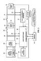
- FIG. 1illustrates an embodiment of a system capable of islanded operation according to some inventive principles of this patent disclosure.
- FIG. 2illustrates another embodiment of a system capable of islanded operation according to some inventive principles of this patent disclosure.
- FIG. 3illustrates an embodiment of a local load arrangement according to some inventive principles of this patent disclosure.
- FIG. 4illustrates an embodiment of current in-rush limiting functionality according to some inventive principles of this patent disclosure.
- FIG. 5illustrates an example embodiment of a controllable current limiting element according to some inventive principles of this patent disclosure.
- FIG. 6illustrates an embodiment of a method for controlling a system having local loads and local power sources connected to a utility grid through a point of common connection according to some inventive principles of this patent disclosure
- islandingis typically considered a condition to be avoided, in some situations, it may actually be an acceptable or even desirable condition. For example, if a local electrical load is present and capable of consuming power, it may be wasteful to disable the local power generation capacity and let otherwise useful and available energy go unharvested. Moreover, in locations such as developing nations where power grids may be unreliable, harvested energy from solar, wind, and other sources may continue to be used locally when the utility grid is down.
- a local grid-tied power sourcemay continue to operate even when an islanding condition is detected.
- This continued operationmay be used, for example, to provide power to a local load, a local energy storage device, etc.
- the continued operationmay be facilitated with a local electronic reference to provide a frequency and/or phase reference for the local power source or sources.
- Smart communicationsmay also be used on the installed system to coordinate the operation of the components.
- one local referencemay serve as a master reference while the references for the other local power sources may synchronize to the master reference.
- multiple distributed generatorsmay be able to form a self-sustaining island without relying on the grid.
- Islanded operationmay be augmented with the use of power-line communications (PLC) and/or wireless communications among the power sources, as well as smart circuit breakers on the main feed lines or at the point of common connection (PCC).
- PLCpower-line communications
- PCCwireless circuit breakers on the main feed lines or at the point of common connection
- FIG. 1illustrates an embodiment of a system capable of islanded operation according to some inventive principles of this patent disclosure.
- the system of FIG. 1includes a local power source 10 and a local load 12 connected to a grid 14 through a disconnect switch 16 at a point of common connection 18 .
- a local controller 20can control the local power source in response to either a grid-synchronized reference 22 when the grid is available or a local reference 24 when the grid is down.
- a first set of voltage and current sensors 28 and 30provide feedback on the local load to the local controller.
- a second set of voltage and current sensors 32 and 34provide feedback on the grid to the grid-synchronized reference.
- a communication interface 27enables the local controller to be controlled remotely and to report operating conditions to remote control centers.
- An additional manual or automatic switch 38may be included to isolate the load from the local power source.
- the disconnect switch 16may be operated automatically or manually.
- a gateway 21may be included to concentrate data and/or interface the system components to other network functionality such as Internet access, data-servers, remote network management, etc.
- the gatewaymay enable the implementation of a system-wide control algorithm as described below with respect to FIG. 6 .
- the gatewayis connected to the communication interfaces 27 and 47 on the local controller 20 and local battery storage device 42 , respectively.
- the gatewayis shown connected to the utility grid 14 through a power line communication (PLC) or wireless interface 15 .
- PLCpower line communication
- interface 15may be connected to the local controller 20 as shown with the dashed line so the gateway receives grid information indirectly through the local controller 20 .
- the local power source 10may include a PV panel or array of PV panels, and centralized or panel-attached or panel-integrated microinverters.
- the PV arrayin its entirety, or in parts, can operate in an islanded environment.
- the inventive principlesmay also be applied to other types of power sources including wind turbines, geothermal sources, fuel cells, battery arrays, etc.
- FIG. 2illustrates another embodiment of a system capable of islanded operation according to some inventive principles of this patent disclosure.
- the system of FIG. 2includes a second local power source 10 A, a second local controller 20 A, and a second local reference 24 A. It also includes a third local power source 10 B, a third local controller 20 B, and a third local reference 24 B.
- the local reference 24 for the first local power source 10operates as a master reference that controls the second local reference 24 A and the third local reference 24 B.
- the first, second and third local power sourcesmay be disconnected from the local load 12 by disonnect switches 40 , 36 and 37 , respectively.
- the switchesare preferably automated and may be triggered by control signals from the gateway or any of the local controllers. In some embodiments, some or all of the disconnect switches may be manually operated.
- FIG. 3illustrates an embodiment of a local load arrangement according to some inventive principles of this patent disclosure.
- the embodiment of FIG. 3which may be used to implement local load 12 above, includes multiple loads LOAD 1, LOAD 2, . . . LOAD n, each of which may be connected to the point of common connection 18 by one of switches S1, S2, . . . Sn, respectively.
- switches S1, S2, . . . Snswitches
- Providing individual control of portions of the local loadenables the implementation of additional features according to the inventive principles of this patent disclosure. For example, when the local load is connected to the local power source or the grid, the individual loads may be connected sequentially in stages, thereby reducing in-rush current.
- the use of individual switchesenables the individual loads to be energized based on a system of priorities or other parameters in view of the limited amount of power that may be available from the local power source.
- production equipmentmay be given priority over heating, air conditioning and/or lighting.
- lighting or communication and display equipmentmay be given priority in areas with large amounts of pedestrian traffic, in retail spaces, etc.
- switches S1, S2, . . . Snare controlled by power-line communication (PLC) modules PLC1, PLC2, . . . PLCn, but other control technologies may be used.
- PLCpower-line communication
- the PLC modulesare connected to a smart communications gateway 37 which enables a controller to implement a control scheme based on priority and/or other parameters.
- FIG. 3includes a voltage sensor 68 and a current sensor 70 to measure the load voltage and current of LOADn.
- the outputs from the sensorsare transmitted to the gateway through the associated PLC module.
- Voltage, current and other types of sensorsmay be coupled to any of the other loads and interfaced to the gateway through the associated PLC modules.
- some or all of the local load or loadsmay be implemented with one or more power converters such as an AC-to-DC converter to charge batteries or other energy storage devices, such as device 42 illustrated in FIG. 1 , either from the grid or one or more local power sources.
- the power from the energy storage devicesmay then be used as a local power source during islanded operation.
- the converters used for chargingmay be implemented as reversible power trains to enable the same converters to be used for both charging and discharging the batteries.
- separate power convertersmay be used to transfer power from the batteries or other energy storage devices during islanded operation.
- a local power source 10 as shown in FIG. 1may be implemented with a reversible power converter for a local battery storage array.
- a local power sourcemay store energy while the system is connected to the grid, then reverse its operation to supply power during an islanding operation.
- a smart communication interfacemay be included in some or all of the components to enable the implementation of various centralized and/or distributed control schemes according to some inventive principles of this patent disclosure.
- a centralized controllermay monitor the condition of the local load(s) and/or local power source(s) through the gateway 21 prior to a grid disconnection event. Based on the prior load conditions, the local load may be connected to a local power source in a transparent hand-off, e.g., if the local load has enough power sourcing capacity and/or if the load does not draw a large amount of in-rush current.
- an augmented hand-offmay be implemented in which only certain loads are energized if the local power source capacity is less than the total demand by the local loads, or to implement a current in-rush limiting feature.
- FIG. 4illustrates some additional current in-rush limiting functionality according to some inventive principles of this patent disclosure.
- In-rush protection circuit 44may include one or more controllable current limiting elements 46 which may be controlled by one or more control signals CTRL.
- the control signalsmay be generated by one of the local controllers, or by a centralized controller through a communication interface.
- the embodiment of FIG. 4includes three current limiting elements 46 arranged in a ⁇ -network, but the elements may be arranged in a T-network or any other suitable arrangement, and any number of elements may be used.
- An in-rush limiting circuitsuch as the one illustrated in FIG. 4 may be inserted at any suitable point in the system.
- an in-rush limiting circuitmay be inserted between the local load 12 and the local power source 10 in FIG. 1 , or it may be inserted in series with any of the local power sources 10 , 10 A or 10 B in FIG. 2 .
- FIG. 5illustrates an example embodiment of one of the controllable current limiting elements 46 .
- a switch 48is initially open so that a resistor R limits the amount of in-rush current flowing through the element. For example, if the local load includes an input capacitance, or an induction motor that draws a large amount of start-up current, the resistor limits the in-rush current through an RC or RL time constant. After the in-rush current subsides, the control signal CTRL closes the switch 48 , thereby eliminating the series resistance R from the circuit.
- FIG. 6illustrates an embodiment of a method for controlling a system having local loads and local power sources connected to a utility grid through a point of common connection according to some inventive principles of this patent disclosure.
- the local loads and local power sourcesmay become islanded if the utility grid becomes disconnected at the point of common connection.
- the methodinvolves evaluating the power available from the local power sources, and adaptively controlling the local loads according to an algorithm in response to the power available from the local power sources.
- the local loads and local power sourcesmay be operated as an islanded system while the utility grid is disconnected from the point of common connection.
- an algorithm 50generates load control signals 52 in response to operator determined inputs 54 and externally determined inputs 56 .
- operator determined inputsinclude local load priorities 54 A, desired up-times of local loads 54 B, and optimization objectives 54 C.
- externally determined inputsinclude effects of meteorology on local loads 56 A, energy currently available from local power sources 56 B, predicted future energy available from local power sources 56 C, energy available in local storage 56 D, remaining local energy storage capacity 56 E, load shedding profile from the utility grid 56 F, load tariff rates 56 G, and feed-in tariff rates 56 H.
- the algorithmmay implement one or more of the following objectives simultaneously and/or individually under different operating conditions: (1) maximizing the local use of power from the local power sources; (2) minimizing the overall cost of energy; (3) maximizing the amount of locally stored energy; and (4) optimizing the use of locally stored energy to maximize the up-time of local loads when sufficient energy is not available from the utility grid and the local power sources, e.g., during an islanding event.
- the algorithm 50may operate as a software loop that begins by executing a process 58 for processing the various inputs.
- processing inputsinclude checking for updates to local load priorities, checking for updates to the desired up-time of various local loads, checking for updates to the optimization priorities, using meteorology data to update the effects of weather on current and predicted future local load levels and energy available from local power sources, determining the amount of energy currently available from local power sources, predicting the future energy available from local power sources for the longest possible duration into the future, determining the amount of energy currently available in local storage, determining the additional remaining local energy storage capacity, requesting the utility grid load shedding profile, requesting load tariff rates, and requesting feed-in tariff rates for the longest possible duration into the future.
- algorithmexecutes a process 60 to determine the current energy flow between the various system elements. Examples include energy flow from the local power sources to the utility grid, from the local power sources to local storage, from the local power sources to local loads, from the utility grid to the local loads, from the utility grid to local storage, from local storage to the local loads, and from local storage to the utility grid.
- the algorithmexecutes a process 62 to determine the cost of energy transfer between the system elements. This may include the cost of the same examples of energy transfer described above with respect to process 60 .
- the algorithmexecutes a process 64 to determine the optimum local load levels based on the local load priorities, desired up-times of various local loads, and/or the optimization objectives.
- the algorithmexecutes a process 66 to determine the optimum target energy flow between the system elements. This may include the same examples of energy transfer described above with respect to process 60 .
- the algorithmexecutes a process 67 to determine and minimize system losses.
- the algorithmgenerates the load control signals 52 to energize or de-energize specific local loads and prepare and set the new target energy flow between the system elements based on the determinations in the previous processes.
- the target local loads and target energy flowsmay optionally be achieved using optimum transient behavior characteristics.
- the processes 58 through 66may be repeated in a continuous loop running at any suitable repetition rate.
Landscapes
- Engineering & Computer Science (AREA)
- Power Engineering (AREA)
- Supply And Distribution Of Alternating Current (AREA)
Abstract
Description
Claims (12)
Priority Applications (1)
| Application Number | Priority Date | Filing Date | Title |
|---|---|---|---|
| US13/251,890US9660451B1 (en) | 2010-11-29 | 2011-10-03 | Islanded operation of distributed power sources |
Applications Claiming Priority (2)
| Application Number | Priority Date | Filing Date | Title |
|---|---|---|---|
| US41787510P | 2010-11-29 | 2010-11-29 | |
| US13/251,890US9660451B1 (en) | 2010-11-29 | 2011-10-03 | Islanded operation of distributed power sources |
Publications (1)
| Publication Number | Publication Date |
|---|---|
| US9660451B1true US9660451B1 (en) | 2017-05-23 |
Family
ID=58708327
Family Applications (1)
| Application Number | Title | Priority Date | Filing Date |
|---|---|---|---|
| US13/251,890Active2033-03-01US9660451B1 (en) | 2010-11-29 | 2011-10-03 | Islanded operation of distributed power sources |
Country Status (1)
| Country | Link |
|---|---|
| US (1) | US9660451B1 (en) |
Cited By (11)
| Publication number | Priority date | Publication date | Assignee | Title |
|---|---|---|---|---|
| US20160006244A1 (en)* | 2014-07-04 | 2016-01-07 | Schneider Electric Industries Sas | Method for controlling the electrical power delivered over an electrical supply network by at least two electrical energy sources and associated electrical system |
| US20160248261A1 (en)* | 2013-11-14 | 2016-08-25 | Sony Corporation | Power supplying device and power receiving device |
| US20170331292A1 (en)* | 2016-05-12 | 2017-11-16 | Solarcity Corporation | Energy generation interactions bypassing the grid |
| CN107591798A (en)* | 2017-08-23 | 2018-01-16 | 湖北省电力勘测设计院 | The security and stability appraisal procedure of island network |
| EP3503337A1 (en)* | 2017-12-20 | 2019-06-26 | General Electric Company | Grid isolating wind farm control |
| US20190288610A1 (en)* | 2018-03-14 | 2019-09-19 | Industrial Technology Research Institute | Dc to ac converter and control method thereof |
| CN111049185A (en)* | 2019-12-29 | 2020-04-21 | 国网辽宁省电力有限公司电力科学研究院 | A method for dividing distribution network islands including distributed power sources |
| US20200153250A1 (en)* | 2018-11-14 | 2020-05-14 | OnGrid Options, LLC | Technologies for temporary islanding operations of electric grid sections |
| CN113922409A (en)* | 2021-10-19 | 2022-01-11 | 国网江苏省电力有限公司 | Constant volume method for multi-partition flexible interconnected converter station of urban power grid |
| US11472307B2 (en)* | 2018-09-26 | 2022-10-18 | Aquanovis Holdings Limited | Dispatchable renewable power supply |
| US12374887B1 (en) | 2025-04-01 | 2025-07-29 | Genesis Grid Consulting, Llc | System and method for restoration of a power system |
Citations (21)
| Publication number | Priority date | Publication date | Assignee | Title |
|---|---|---|---|---|
| US5638295A (en)* | 1995-08-08 | 1997-06-10 | Eaton Corporation | Transfer switch system with subnetwork |
| US20030080741A1 (en)* | 2001-10-26 | 2003-05-01 | Lerow Kevin E. | Anti-islanding techniques for distributed power generation |
| US20050057950A1 (en)* | 2003-09-11 | 2005-03-17 | Colby Roy Stephen | Power regulator for power inverter |
| US6882904B1 (en)* | 2000-12-29 | 2005-04-19 | Abb Technology Ag | Communication and control network for distributed power resource units |
| US20070010916A1 (en)* | 2003-10-24 | 2007-01-11 | Rodgers Barry N | Method for adaptively managing a plurality of loads |
| US20080071427A1 (en)* | 2006-09-19 | 2008-03-20 | General Electric Company | Method and system for detection and transfer to electrical island operation |
| US20080094860A1 (en)* | 2005-05-20 | 2008-04-24 | Sma Technologie Ag | Bidirectional battery power inverter |
| US20080157538A1 (en)* | 2006-12-09 | 2008-07-03 | Eric Anthony Lewis | Methods of synchronizing a plurality of generators |
| US20080231114A1 (en)* | 2007-03-23 | 2008-09-25 | Bpl Global, Ltd. | System and Method for Adaptive Islanding for Stored/Distributed Energy Devices |
| US20090000654A1 (en)* | 2007-05-17 | 2009-01-01 | Larankelo, Inc. | Distributed inverter and intelligent gateway |
| US20100073175A1 (en)* | 2008-02-08 | 2010-03-25 | Lontka Karen D | Methods and apparatus for controlling and testing a notification applicance circuit |
| US20100106641A1 (en)* | 2008-09-29 | 2010-04-29 | Battelle Memorial Institute | Using one-way communications in a market-based resource allocation system |
| US20100259955A1 (en)* | 2007-12-11 | 2010-10-14 | Tokyo Institute Of Technology | Soft switching power converter |
| US20100309692A1 (en)* | 2006-01-13 | 2010-12-09 | Lesley Chisenga | Power conditioning units |
| US20100315850A1 (en)* | 2009-06-12 | 2010-12-16 | Veranda Solar, Inc. | Power inverter |
| US20110043160A1 (en)* | 2009-08-21 | 2011-02-24 | Xantrex Technology Inc. | Ac connected modules with line frequency or voltage variation pattern for energy control |
| US20110071697A1 (en)* | 2010-10-06 | 2011-03-24 | William Vincent Torre | Smart transformer |
| US20110187200A1 (en)* | 2010-02-03 | 2011-08-04 | Xantrex Technology Inc. | Anti-islanding for grid-tie inverter using covariance estimation and logic decision maker |
| US20110298305A1 (en)* | 2010-06-07 | 2011-12-08 | Lesley Chisenga | Solar photovoltaic systems |
| US20120080942A1 (en)* | 2010-10-04 | 2012-04-05 | Carralero Michael A | Smart microgrid |
| US20140324235A1 (en)* | 2010-04-15 | 2014-10-30 | Science Applications International Corporation | System and Method For Controlling States of a DC and AC Bus Microgrid |
- 2011
- 2011-10-03USUS13/251,890patent/US9660451B1/enactiveActive
Patent Citations (22)
| Publication number | Priority date | Publication date | Assignee | Title |
|---|---|---|---|---|
| US5638295A (en)* | 1995-08-08 | 1997-06-10 | Eaton Corporation | Transfer switch system with subnetwork |
| US6882904B1 (en)* | 2000-12-29 | 2005-04-19 | Abb Technology Ag | Communication and control network for distributed power resource units |
| US20030080741A1 (en)* | 2001-10-26 | 2003-05-01 | Lerow Kevin E. | Anti-islanding techniques for distributed power generation |
| US20050057950A1 (en)* | 2003-09-11 | 2005-03-17 | Colby Roy Stephen | Power regulator for power inverter |
| US20070010916A1 (en)* | 2003-10-24 | 2007-01-11 | Rodgers Barry N | Method for adaptively managing a plurality of loads |
| US20080094860A1 (en)* | 2005-05-20 | 2008-04-24 | Sma Technologie Ag | Bidirectional battery power inverter |
| US20100309692A1 (en)* | 2006-01-13 | 2010-12-09 | Lesley Chisenga | Power conditioning units |
| US20080071427A1 (en)* | 2006-09-19 | 2008-03-20 | General Electric Company | Method and system for detection and transfer to electrical island operation |
| US7457688B2 (en)* | 2006-09-19 | 2008-11-25 | General Electric Company | Method and system for detection and transfer to electrical island operation |
| US20080157538A1 (en)* | 2006-12-09 | 2008-07-03 | Eric Anthony Lewis | Methods of synchronizing a plurality of generators |
| US20080231114A1 (en)* | 2007-03-23 | 2008-09-25 | Bpl Global, Ltd. | System and Method for Adaptive Islanding for Stored/Distributed Energy Devices |
| US20090000654A1 (en)* | 2007-05-17 | 2009-01-01 | Larankelo, Inc. | Distributed inverter and intelligent gateway |
| US20100259955A1 (en)* | 2007-12-11 | 2010-10-14 | Tokyo Institute Of Technology | Soft switching power converter |
| US20100073175A1 (en)* | 2008-02-08 | 2010-03-25 | Lontka Karen D | Methods and apparatus for controlling and testing a notification applicance circuit |
| US20100106641A1 (en)* | 2008-09-29 | 2010-04-29 | Battelle Memorial Institute | Using one-way communications in a market-based resource allocation system |
| US20100315850A1 (en)* | 2009-06-12 | 2010-12-16 | Veranda Solar, Inc. | Power inverter |
| US20110043160A1 (en)* | 2009-08-21 | 2011-02-24 | Xantrex Technology Inc. | Ac connected modules with line frequency or voltage variation pattern for energy control |
| US20110187200A1 (en)* | 2010-02-03 | 2011-08-04 | Xantrex Technology Inc. | Anti-islanding for grid-tie inverter using covariance estimation and logic decision maker |
| US20140324235A1 (en)* | 2010-04-15 | 2014-10-30 | Science Applications International Corporation | System and Method For Controlling States of a DC and AC Bus Microgrid |
| US20110298305A1 (en)* | 2010-06-07 | 2011-12-08 | Lesley Chisenga | Solar photovoltaic systems |
| US20120080942A1 (en)* | 2010-10-04 | 2012-04-05 | Carralero Michael A | Smart microgrid |
| US20110071697A1 (en)* | 2010-10-06 | 2011-03-24 | William Vincent Torre | Smart transformer |
Non-Patent Citations (15)
| Title |
|---|
| Dola, H. M. et al., "Intentional Islanding and Adaptive Load Shedding to Avoid Cascading Outages," IEEE, 2006, 8 pages. |
| Hirodontis, S. et al., "An Adaptive Load Shedding Method for Intentional Islanding," Conference on Clean Electrical Power, Abstract, Jun. 9, 2009, 1 page. |
| Hirodontis, S. et al., "Dynamic Study for Islanded Distribution Network," The International Conference on Electrical Engineering, Oct. 31, 2009, 6 pages. |
| Issicaba, D. et al., "Islanding Operation of Active Distribution Grids Using an Agent-based Architecture," Innovative Smart Grid Technologies Conference Europe, Oct. 11, 2010, Abstract, 1 page. |
| Koch, S. et al., "Mitigation of Cascading Failures by Real-Time Controlled Islanding and Graceful Load Shedding," Symposium on Bulk Power System Dynamics and Control, Aug. 1, 2010, Abstract, 1 page. |
| Lei, Q. et al., "Islanding Control of DG in Microgrids," Power Electronics and Motion Control Conference, May 17, 2009, Abstract, 1 page. |
| Li, X. et al., "On-line Islanding Operation Based on CSP," Power and Energy Engineering Conference, Asia-Pacific, Mar. 28, 2010, Abstract, 1 page. |
| Mahat, P. et al., "Control Strategies for Gas Turbine Generators for Grid Connected and Islanding Operations," Transmission and Distribution Conference and Exposition, Apr. 19, 2010, Abstract, 1 page. |
| Mulhausen, J. et al., "Anti-Islanding Today, Successful Islanding in the Future," IEEE, Mar. 29, 2010, 8 pages. |
| Mynam, V. et al. "Islanding Detection and Adaptive Load Shedding," Schweitzer Engineering Laboratories, Inc. Application Note, AN2009-59, 2009, 2 pages. |
| Ng, E. J. et al., "Multi-Microgrid Control System," Power and Energy Society General Meeting, Jul. 25, 2010, Abstract, 1 page. |
| Tantimaporn, T. et al., "Islanding Operation of Mini-Hydro Generation in Real Distribution Network," Energy and Sustainable Development: Issues and Strategies, Abstract, Jun. 2, 2010, 1 page. |
| Walker, G.R. et al., "PV String Per-Module Maximum Power Point Enabling Converters," School of Information Technology and Electrical Engineering, The University of Queensland, 2003, 6 pages. |
| Wikipedia, "Definition of Islanding," downloading from Internet Oct. 1, 2011, 8 pages. |
| Zhang, S. et al., "Impact Study on International Islanding Strategies of Distribution Networks Based on Distributed Generation," International Conference on Computer Design and Applications, Jun. 25, 2010, Abstract, 1 page. |
Cited By (19)
| Publication number | Priority date | Publication date | Assignee | Title |
|---|---|---|---|---|
| US20160248261A1 (en)* | 2013-11-14 | 2016-08-25 | Sony Corporation | Power supplying device and power receiving device |
| US10193350B2 (en)* | 2013-11-14 | 2019-01-29 | Sony Corporation | Power supplying device and power receiving device |
| US9948097B2 (en)* | 2014-07-04 | 2018-04-17 | Schneider Electric Industries Sas | Method for controlling the electrical power delivered over an electrical supply network by at least two electrical energy sources and associated electrical system |
| US20160006244A1 (en)* | 2014-07-04 | 2016-01-07 | Schneider Electric Industries Sas | Method for controlling the electrical power delivered over an electrical supply network by at least two electrical energy sources and associated electrical system |
| US20170331292A1 (en)* | 2016-05-12 | 2017-11-16 | Solarcity Corporation | Energy generation interactions bypassing the grid |
| US10128659B2 (en)* | 2016-05-12 | 2018-11-13 | Solarcity Corporation | Energy generation interactions bypassing the grid |
| CN107591798A (en)* | 2017-08-23 | 2018-01-16 | 湖北省电力勘测设计院 | The security and stability appraisal procedure of island network |
| US11025067B2 (en) | 2017-12-20 | 2021-06-01 | General Electric Company | Grid isolating wind farm control |
| EP3503337A1 (en)* | 2017-12-20 | 2019-06-26 | General Electric Company | Grid isolating wind farm control |
| US20190288610A1 (en)* | 2018-03-14 | 2019-09-19 | Industrial Technology Research Institute | Dc to ac converter and control method thereof |
| US11152872B2 (en)* | 2018-03-14 | 2021-10-19 | Industrial Technology Research Institute | DC to AC converter and control method thereof |
| US11472307B2 (en)* | 2018-09-26 | 2022-10-18 | Aquanovis Holdings Limited | Dispatchable renewable power supply |
| US20200153250A1 (en)* | 2018-11-14 | 2020-05-14 | OnGrid Options, LLC | Technologies for temporary islanding operations of electric grid sections |
| US11955801B2 (en)* | 2018-11-14 | 2024-04-09 | OnGrid Options, LLC | Technologies for temporary islanding operations of electric grid sections |
| CN111049185A (en)* | 2019-12-29 | 2020-04-21 | 国网辽宁省电力有限公司电力科学研究院 | A method for dividing distribution network islands including distributed power sources |
| CN111049185B (en)* | 2019-12-29 | 2023-02-14 | 国网辽宁省电力有限公司电力科学研究院 | A method for dividing islands of distribution network including distributed power generation |
| CN113922409A (en)* | 2021-10-19 | 2022-01-11 | 国网江苏省电力有限公司 | Constant volume method for multi-partition flexible interconnected converter station of urban power grid |
| CN113922409B (en)* | 2021-10-19 | 2024-03-22 | 国网江苏省电力有限公司 | Constant volume method for urban power grid multi-partition flexible interconnection converter station |
| US12374887B1 (en) | 2025-04-01 | 2025-07-29 | Genesis Grid Consulting, Llc | System and method for restoration of a power system |
Similar Documents
| Publication | Publication Date | Title |
|---|---|---|
| US9660451B1 (en) | Islanded operation of distributed power sources | |
| US11728655B2 (en) | Load management in hybrid electrical systems | |
| EP4170847B1 (en) | Smart outlet | |
| CN103650285B (en) | A system and method for integrating and managing demand/response between alternative energy sources, grid power, and loads | |
| US10404072B2 (en) | Method and apparatus for bidirectional storage and renewable power converter | |
| US9755430B2 (en) | Virtual inverter for power generation units | |
| EP3806265A1 (en) | Device and method for intelligent control of power supply source connection | |
| CN102055241B (en) | Integrated realtime power and solar-electricity station control system | |
| US9651971B2 (en) | Control device, power control system, and power control method | |
| CN102203897B (en) | Systems and methods for energy optimization in photovoltaic generators | |
| AU2013101461A4 (en) | Grid stability control system and method | |
| KR20200138348A (en) | Utility-scale renewable picker power plants, tightly coupled photovoltaic and energy storage | |
| US10432019B2 (en) | Power connection control system and method | |
| CN103733474A (en) | System for the generation, storage and supply of electrical energy produced by modular dc generators, and method for managing said system | |
| KR20210005502A (en) | PV module serial/parallel conversion system for MPPT operating voltage optimization based on machine learning | |
| WO2020218191A1 (en) | Power control device, method of controlling power control device, and distributed power generation system | |
| EP3011653A1 (en) | Dynamic power distribution in photovoltaic installations | |
| WO2009146065A2 (en) | Energy interface module and power conversion system | |
| Yi et al. | A Centralized Power Control and Management Method for Grid-Connected Photovoltaic (PV)-Battery Systems | |
| JP6258774B2 (en) | Power control system, power control apparatus, and control method of power control system | |
| AU2021103175A4 (en) | Solar Energy Management for Agriculture and Rural Transformation (SMART) | |
| CA2728619A1 (en) | A renewable power control system |
Legal Events
| Date | Code | Title | Description |
|---|---|---|---|
| AS | Assignment | Owner name:AZURAY TECHNOLOGIES, INC., OREGON Free format text:ASSIGNMENT OF ASSIGNORS INTEREST;ASSIGNOR:NAIKNAWARE, RAVINDRANATH;REEL/FRAME:027196/0573 Effective date:20111004 | |
| AS | Assignment | Owner name:SOLARBRIDGE TECHNOLOGIES, INC, TEXAS Free format text:ASSIGNMENT OF ASSIGNORS INTEREST;ASSIGNOR:AZURAY TECHNOLOGIES, INC.;REEL/FRAME:029871/0875 Effective date:20121208 | |
| AS | Assignment | Owner name:SOLARBRIDGE TECHNOLOGIES, INC., TEXAS Free format text:ASSIGNMENT OF ASSIGNORS INTEREST;ASSIGNOR:AZURAY TECHNOLOGIES, INC.;REEL/FRAME:029881/0470 Effective date:20121208 | |
| AS | Assignment | Owner name:SUNPOWER CORPORATION, CALIFORNIA Free format text:ASSIGNMENT OF ASSIGNORS INTEREST;ASSIGNOR:SOLARBRIDGE TECHNOLOGIES, INC.;REEL/FRAME:034687/0232 Effective date:20141218 | |
| STCF | Information on status: patent grant | Free format text:PATENTED CASE | |
| AS | Assignment | Owner name:ENPHASE ENERGY, INC., CALIFORNIA Free format text:ASSIGNMENT OF ASSIGNORS INTEREST;ASSIGNOR:SUNPOWER CORPORATION;REEL/FRAME:046964/0203 Effective date:20180809 | |
| MAFP | Maintenance fee payment | Free format text:PAYMENT OF MAINTENANCE FEE, 4TH YEAR, LARGE ENTITY (ORIGINAL EVENT CODE: M1551); ENTITY STATUS OF PATENT OWNER: LARGE ENTITY Year of fee payment:4 | |
| MAFP | Maintenance fee payment | Free format text:PAYMENT OF MAINTENANCE FEE, 8TH YEAR, LARGE ENTITY (ORIGINAL EVENT CODE: M1552); ENTITY STATUS OF PATENT OWNER: LARGE ENTITY Year of fee payment:8 |