US9658081B2 - Methods and system for utility network outage detection - Google Patents
Methods and system for utility network outage detectionDownload PDFInfo
- Publication number
- US9658081B2 US9658081B2US12/966,298US96629810AUS9658081B2US 9658081 B2US9658081 B2US 9658081B2US 96629810 AUS96629810 AUS 96629810AUS 9658081 B2US9658081 B2US 9658081B2
- Authority
- US
- United States
- Prior art keywords
- electronic devices
- polling
- outage
- exception
- message
- Prior art date
- Legal status (The legal status is an assumption and is not a legal conclusion. Google has not performed a legal analysis and makes no representation as to the accuracy of the status listed.)
- Active, expires
Links
- 238000000034methodMethods0.000titleclaimsdescription37
- 238000001514detection methodMethods0.000titleclaimsdescription15
- 230000004044responseEffects0.000claimsabstractdescription33
- 238000007726management methodMethods0.000claimsdescription39
- 230000036541healthEffects0.000claimsdescription17
- 238000012544monitoring processMethods0.000claimsdescription11
- 230000007704transitionEffects0.000claimsdescription2
- 238000004891communicationMethods0.000abstractdescription36
- 230000037361pathwayEffects0.000abstractdescription10
- 238000004458analytical methodMethods0.000abstractdescription4
- 238000011156evaluationMethods0.000abstractdescription2
- 230000009471actionEffects0.000description10
- 230000006870functionEffects0.000description9
- 241000287219Serinus canariaSpecies0.000description8
- 238000000254composite pulse decoupling sequenceMethods0.000description7
- 230000008569processEffects0.000description7
- 239000003795chemical substances by applicationSubstances0.000description6
- 238000011144upstream manufacturingMethods0.000description6
- 230000008859changeEffects0.000description4
- 230000000737periodic effectEffects0.000description4
- 230000008901benefitEffects0.000description3
- 230000005540biological transmissionEffects0.000description3
- 230000003068static effectEffects0.000description3
- 230000001960triggered effectEffects0.000description3
- 230000000694effectsEffects0.000description2
- 238000012423maintenanceMethods0.000description2
- 238000001228spectrumMethods0.000description2
- 240000007320Pinus strobusSpecies0.000description1
- 239000008186active pharmaceutical agentSubstances0.000description1
- 208000030963borderline personality diseaseDiseases0.000description1
- 206010006475bronchopulmonary dysplasiaDiseases0.000description1
- 238000004364calculation methodMethods0.000description1
- 239000003990capacitorSubstances0.000description1
- 238000007906compressionMethods0.000description1
- 230000006835compressionEffects0.000description1
- 238000010276constructionMethods0.000description1
- 230000001276controlling effectEffects0.000description1
- 238000013144data compressionMethods0.000description1
- 238000010586diagramMethods0.000description1
- 238000005265energy consumptionMethods0.000description1
- 230000003862health statusEffects0.000description1
- 230000000977initiatory effectEffects0.000description1
- 230000010354integrationEffects0.000description1
- 238000002955isolationMethods0.000description1
- 230000007257malfunctionEffects0.000description1
- 230000001105regulatory effectEffects0.000description1
- 230000011664signalingEffects0.000description1
- 239000000344soapSubstances0.000description1
- 230000002194synthesizing effectEffects0.000description1
- 238000012360testing methodMethods0.000description1
- 238000012546transferMethods0.000description1
- XLYOFNOQVPJJNP-UHFFFAOYSA-NwaterSubstancesOXLYOFNOQVPJJNP-UHFFFAOYSA-N0.000description1
Images


Classifications
- G—PHYSICS
- G01—MEASURING; TESTING
- G01D—MEASURING NOT SPECIALLY ADAPTED FOR A SPECIFIC VARIABLE; ARRANGEMENTS FOR MEASURING TWO OR MORE VARIABLES NOT COVERED IN A SINGLE OTHER SUBCLASS; TARIFF METERING APPARATUS; MEASURING OR TESTING NOT OTHERWISE PROVIDED FOR
- G01D4/00—Tariff metering apparatus
- G01D4/002—Remote reading of utility meters
- G01D4/004—Remote reading of utility meters to a fixed location
- H—ELECTRICITY
- H04—ELECTRIC COMMUNICATION TECHNIQUE
- H04Q—SELECTING
- H04Q9/00—Arrangements in telecontrol or telemetry systems for selectively calling a substation from a main station, in which substation desired apparatus is selected for applying a control signal thereto or for obtaining measured values therefrom
- H—ELECTRICITY
- H04—ELECTRIC COMMUNICATION TECHNIQUE
- H04Q—SELECTING
- H04Q2209/00—Arrangements in telecontrol or telemetry systems
- H04Q2209/60—Arrangements in telecontrol or telemetry systems for transmitting utility meters data, i.e. transmission of data from the reader of the utility meter
- H—ELECTRICITY
- H04—ELECTRIC COMMUNICATION TECHNIQUE
- H04Q—SELECTING
- H04Q2209/00—Arrangements in telecontrol or telemetry systems
- H04Q2209/80—Arrangements in the sub-station, i.e. sensing device
- H04Q2209/86—Performing a diagnostic of the sensing device
- Y—GENERAL TAGGING OF NEW TECHNOLOGICAL DEVELOPMENTS; GENERAL TAGGING OF CROSS-SECTIONAL TECHNOLOGIES SPANNING OVER SEVERAL SECTIONS OF THE IPC; TECHNICAL SUBJECTS COVERED BY FORMER USPC CROSS-REFERENCE ART COLLECTIONS [XRACs] AND DIGESTS
- Y02—TECHNOLOGIES OR APPLICATIONS FOR MITIGATION OR ADAPTATION AGAINST CLIMATE CHANGE
- Y02B—CLIMATE CHANGE MITIGATION TECHNOLOGIES RELATED TO BUILDINGS, e.g. HOUSING, HOUSE APPLIANCES OR RELATED END-USER APPLICATIONS
- Y02B90/00—Enabling technologies or technologies with a potential or indirect contribution to GHG emissions mitigation
- Y02B90/20—Smart grids as enabling technology in buildings sector
- Y02B90/242—
- Y02B90/246—
- Y—GENERAL TAGGING OF NEW TECHNOLOGICAL DEVELOPMENTS; GENERAL TAGGING OF CROSS-SECTIONAL TECHNOLOGIES SPANNING OVER SEVERAL SECTIONS OF THE IPC; TECHNICAL SUBJECTS COVERED BY FORMER USPC CROSS-REFERENCE ART COLLECTIONS [XRACs] AND DIGESTS
- Y04—INFORMATION OR COMMUNICATION TECHNOLOGIES HAVING AN IMPACT ON OTHER TECHNOLOGY AREAS
- Y04S—SYSTEMS INTEGRATING TECHNOLOGIES RELATED TO POWER NETWORK OPERATION, COMMUNICATION OR INFORMATION TECHNOLOGIES FOR IMPROVING THE ELECTRICAL POWER GENERATION, TRANSMISSION, DISTRIBUTION, MANAGEMENT OR USAGE, i.e. SMART GRIDS
- Y04S20/00—Management or operation of end-user stationary applications or the last stages of power distribution; Controlling, monitoring or operating thereof
- Y04S20/30—Smart metering, e.g. specially adapted for remote reading
- Y04S20/322—
- Y04S20/36—
- Y04S20/42—
Definitions
- the present inventionrelates to utility networks and, more particularly, to a utility network management system and a method of operating a utility management system for monitoring and controlling the utility grid and automated reading of utility meters.
- the present inventionprovides a utility network management system including an outage detection system (“ODS”), which manages identification of some or substantially all outage events in a utility grid.
- ODScan also manage restoration actions.
- the ODScan also or alternatively maintain extensive up-to-date topology information of the grid-service area.
- the term “outage”includes, among other things, a loss of power or utility service to electronic utility devices and locations supported by those devices within a utility grid, and the term “restoration” includes, among other things, the reestablishment of power or other utility service to such devices and locations.
- the term “utility devices”includes, among other things, electric meters, other communications devices, faulted circuit indicators, and other distribution automation devices, such as, for example, capacitor bank controllers, transformers, switch reclosures, etc.
- the present inventionprovides a method and an end-to-end system, components, and information flow architecture used to assist in outage and restoration management of a utility network.
- the method and system of the present inventioncan also or alternatively be used to gather information rapidly and accurately, and manage outages (e.g., failures) and restoration events of a network used to deliver services and/or utilities to end users across a networked infrastructure.
- the method and system of the present inventioncan be efficiently used for outage and restoration management of an electrical utility grid infrastructure.
- ODS functionor “ODS”, restoration-management inclusive.
- ODScan be tightly coupled or integrated with a network management function.
- ODS capabilityis implemented as a third-party, external system. To date, ODS are limited due to the fact that there is very little in terms of outage sensing/monitoring instrumentation in devices downstream from the substation. And, where there is instrumentation, providing network connectivity to these devices has been cost-prohibitive historically, and therefore is rather limited or non-existent.
- ODSat set up time, has information in an underlying database that relates a premise/premise_id/service_point to components in the utility's physical topology (i.e., the physical layout of a distribution network infrastructure with specific identification of some or substantially all of the components of the network arranged in a hierarchical manner).
- These componentscan be relatively static devices, such as, for example, feeders and transformers.
- Outage and restoration data input into ODShave historically been generated by customer phone calls.
- the callcan be fielded by a human operator, and the state of the premise (e.g., incorrectly energized or not energized meter) is manually input into the ODS.
- the customercan indicate with a dial tone entry whether or not service is being provided at the customer location.
- the ODS moduleonce populated with this information, can attempt to perform a basic correlation (i.e., a “prediction”) as to the extent of the outage or the remainder of the outage, when restoration is occurring. This is accomplished by synthesizing customer-call information received at the ODS.
- a simple example of an outage event sequenceworks as follows: Caller #1 from premise_id ‘0001’ calls in to report an interruption of service.
- the ODS moduleflags this instance as being related to “feeder 1 ” and “transformer X”. Subsequently, other callers from that same feeder call in, also reporting outages.
- the ODS moduletries to relate the outage to a particular transformer, for instance, by “walking up” a hierarchical topology tree within the ODS module that represents the connectivity structure of the power grid.
- the utility topologiescan be more complex than the one described above and, in many cases, can include more complex topology, automated switch closures, etc.
- Regulatorsreward utilities based on reliability metrics, such as, for example, sum of all customer interruption durations (“SAIDI,” which refers to the sum of all customer interruption durations), customer average interruption duration index (“CAIDI,” which is derived from SAIDI), and/or system average interruption frequency index (“SAIFI,” which refers to the total number of customer service interruptions), etc.
- SAIDIsum of all customer interruption durations
- CAIDIcustomer average interruption duration index
- SAIFIsystem average interruption frequency index
- Utilitiescan benefit from achieving better control over outage management, quicker fault isolation, and service restoration.
- the method and system of the present inventioncan make use of the networked meters and other devices of the transmission and distribution infrastructure.
- the method and system of the present inventioncan achieve an improved dynamic network management system or system-backup, by leveraging a larger number of “sensors” (e.g., smart, networked meters) distributed broadly (i.e., at a number of different locations) and deeply (i.e., at or adjacent a variety of different elements) throughout the utility grid. Reachability information from these sensors is used to assist in outage/restoration management.
- the term “reachability”refers to a measure of the ability to send data to and receive data from an electronic utility device or another network infrastructure device.
- the method and system of the present inventioncan notify a utility company ODS of an outage, verify an outage and detect the extent of the outage, verify a restoration and detect the extent of any secondary outages, and/or calculate key outage statistics that regulated utilities are required to maintain.
- the method and system of the present inventioncan operate as an ODS in an autonomous manner, or it can serve as a support infrastructure to facilitate a smart ODS system to detect and manage outage and restoration events.
- the method and system of the present inventioncan have at least two different network topologies.
- the first of these topologiescan include a “smart” gateway between a utility network management center (“NMC,” which can also or alternatively be referred to as the Network Back Office System or “BOS”) and a meter.
- the second of these topologiescan operate without a “smart” gateway between the NMC and the meter.
- the NMCcan be a radio network management controller that interfaces with a utility control system and can execute some or all of the functions designated (e.g., remote automated meter reading, consumption data gathering and analysis, outage and service restoration management support, and others).
- the NMCcan also or alternatively control the two-way information flow between the electronic utility devices (e.g., customer premise meters) and network control.
- the present inventionprovides a system including a utility network having a product distribution pathway for delivering a product, a plurality of electronic utility devices associated with the utility network to monitor at least one parameter associated with the product distribution pathway, a management processor in communication with the devices and operable to poll at least a subset of the electronic utility devices in response to an input to evaluate performance of one of the utility network and the system in response to information relating to the at least one parameter.
- the evaluationcan include a rule-based analysis of one of the parameter and the information relating to the parameter.
- the present inventionalso provides a method of monitoring a utility network.
- the methodcan include the acts of monitoring at least one parameter associated with performance of the utility network with a plurality of electronic utility devices associated with a product distribution pathway of the utility network, communicating information relating to the parameter to a management processor, and polling at least some of the electronic utility devices in response to an input to determine whether there is a performance problem associated with the utility network.
- the methodcan also include the act of performing a rule-based analysis of one of the parameter and the information relating to the parameter.
- the present inventionprovides a software program stored in machine readable code and used to manage a utility network.
- the utility networkcan include a product distribution pathway and a plurality of electronic utility devices associated with the product distribution pathway.
- the electronic utility devicescan monitor at least one parameter associated with performance of the utility network and can communicate information relating to the parameter to a management processor.
- the softwarecan include a control module for evaluating the performance of the utility network based on the parameter, and program code operable to poll at least a subset of the electronic utility devices in response to an input to confirm whether the information relating to the parameter indicates a problem associated with the utility network.
- the present inventionalso provides a method of managing performance problems in a utility network.
- the methodcan include the acts of polling a subset of a plurality of electronic utility devices associated with a product distribution pathway of the utility network for information relating to at least one parameter associated with performance of the polled utility meters, and determining whether there is a performance problem from the information received in response to polling.
- FIG. 1is a schematic illustration of a utility grid topology and an outage detection system according to some embodiments of the present invention.
- FIG. 2is a detailed schematic illustration of the utility grid topology and the outage detection system show in FIG. 1 .
- FIG. 3is a schematic illustration of a management module and an outage detection module of the outage detection system shown in FIGS. 1 and 2 .
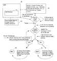
- FIG. 4is a process flow diagram of the outage detection system shown in FIGS. 1-3 .
- FIGS. 5-7illustrate outage events and operation of the outage detection system of the present invention.
- FIGS. 1 and 2illustrate an outage detection system 10 (“ODS”) for managing the identification of some or substantially all outage events in a utility grid or utility network 14 having a number of electronic utility devices 26 deployed along product distribution pathways of the utility grid 14 .
- the electronic utility devices 26monitor at least one parameter associated with the product distribution pathways.
- the ODS 10can also or alternatively manage restoration activities and/or maintain up-to-date topology information of the grid service area.
- the utility grid 14is deployed by a utility company in a topology designed to serve customers in a service area, with a distributed hierarchical network of network infrastructure devices 18 (e.g., communication nodes, gateways 42 , relays 44 , substations 20 , transformers 22 , and feeder stations 24 ), a utility grid distribution operations center 36 , and regional control centers 30 .
- a communications networkcan facilitate communications between the elements of the outage detection system 10 . As shown in FIGS.
- the communications networkcan include a first network (e.g., a local area network (“LAN”)) 16 , which can overlay and provide communication between elements of the utility grid 14 , and a second network 34 (e.g., a wide area network (“WAN”), which can link the electronic utility devices 26 , relays 44 , and gateways 42 in the field with a utility grid distribution operation center 36 and a network interface of a network management center 38 (“NMC”) to provide automated meter reading, grid control and monitoring operations.
- a single network or three or more networkscan facilitate communications between the elements of the ODS 10 (e.g., the network infrastructure devices 18 , the utility grid distribution operations center 36 , and the NMC 38 ).
- the NMC 38can communicate with gateways 42 over the second network 34 , and the gateways 42 can communicate with relays 44 and/or electronic utility devices 26 over the first network 16 .
- the first network 16may cover the utility grid area and its topology and may or may not match the grid infrastructure topology.
- the electronic utility devices 26 , the relays 44 , and gateways 42 , the NMC 38 an agent of the NMC 38 , and/or the network infrastructure devices 18include frequency-hopping spread spectrum communication protocol capability, broadband communication capability, IPv4 communication capability, IPv6 communication capability, modulation, direct-sequence spread spectrum modulation, and/or orthogonal frequency-division multiplexing modulation capability.
- the gateways 42 , relays 44 and/or one or more of the electronic utility devices 26can act as an agent of the NMC 30 to extend the operational reach of the first network 16 and/or the second network 34 .
- the relays 44can be placed high for best line-of-sight to electronic utility devices 26 .
- Several electronic utility devices 26can be associated with each relay 44 and several relays 44 can be associated with a gateway 42 .
- an electronic utility device 26can also or alternatively function as a relay 44 .
- the electronic utility devices 26can include a network interface card (“NIC”) that enables the electronic utility devices 26 to maintain two-way communications with the NMC 38 via relays 44 and/or gateways 42 .
- NICnetwork interface card
- the electronic utility devices 26 and/or the relays 44may have direct two-way communications over a private network such that the electronic utility devices 26 can communicate with other elements of the ODS 10 without sending transmissions through the gateways 42 and/or the first network 34 .
- the gateways 42can execute schedules (i.e., a listing of which electronic utility devices 26 are read and when, including, for example, a start date and time, an optional end date and time), collect data from the electronic utility devices 26 over the first network 16 , and/or forward read data upstream to the NMC 38 .
- schedulesi.e., a listing of which electronic utility devices 26 are read and when, including, for example, a start date and time, an optional end date and time
- collect data from the electronic utility devices 26 over the first network 16and/or forward read data upstream to the NMC 38 .
- the gateways 42can also or alternatively perform network management functions such as route calculation and reachability pings or queries, which test the reachability of electronic utility devices 26 on the first and second networks 16 , 34 .
- a ping programsends a packet (which can include, among other things, a header containing data, such as, for example, destination address, and a payload including application data, such as, for example, interval read results) to an electronic utility device 26 and returns data indicating how long, in milliseconds, the packet took to reach the electronic utility device 26 and return.
- a packetwhich can include, among other things, a header containing data, such as, for example, destination address, and a payload including application data, such as, for example, interval read results
- a reachable electronic utility device 26is usually readable. However, in some instances, an electronic utility device 26 may be reachable with small packet sizes, but may not be reachable with the larger packet sizes.
- Communication routescan be established between the gateways 42 , the associated relays 44 , and one or more electronic utility devices 26 .
- the routescan be network-discovered.
- a network-discovered routecan be determined automatically by a gateway 42 when a new electronic utility device 26 is activated and it broadcasts a discovery message across the first network 16 .
- a static routecan be a user-defined route saved and used for subsequent communications.
- a user-defined static routecan override some or all network-discovered routes.
- the electronic utility devices 26receive, evaluate, and use path cost and link cost information from neighboring elements to determine a prioritized list of next-hop neighboring elements. The electronic utility devices 26 then send packet information to the next-hop neighboring elements, which forward the information through a gateway 42 and across the first and second networks 16 , 34 to the NMC 38 .
- the NMC 38can interface with the utility grid distribution center 36 .
- the NMC 38with its two-way communications access to the electronic utility devices 26 at customer premises in the utility grid 14 via the first network 16 , performs the functions of ODS.
- the ODS functionsare efficiently performed by leveraging the inherent features and capabilities of the two-way communications of the first and second networks 16 , 34 linking the NMC 38 with the electronic utility devices 26 .
- Some of the embodiments of the ODS 10 disclosed hereinmay include an NMC 38 and customer-premise electronic utility devices 26 consisting of constant powered devices (“CPDs) with or without battery backup, and battery powered devices (“BPDs”), which communicate with the NMC 38 via relays 44 and gateways 42 over the first and second networks 16 , 34 .
- the NMC 38can maintain accurate status data relating to the utility grid 16 and scheduled and unscheduled retrieval/reporting of meter readings and utility consumption data resident in the electronic utility devices 26 .
- the CPDscan also or alternatively powered by the utility grid 14 .
- the NMC 38can include a first logic component (e.g., an ODS module 54 ) and a second logic component (e.g., a back office management module 58 ), which in the illustrated embodiment of FIG. 3 manage, in tandem, downstream utility devices 26 .
- the NMC 38can also communicate with other components of the utility grid 14 via the first and second networks 16 , 34 , including some or all of the network infrastructure devices 18 and some or all of the electronic utility devices 26 .
- the ODS module 54can communicate with elements of the utility grid 14 through the management module 58 , which can include a communications module operable to transmit queries to the utility grid 14 through a communications network interface and the first and second networks 16 , 34 .
- the NMC 38 and the individual elements of the NMC 38can have a number of different locations, can be distributed between multiple locations, or can be stored in a single combined location.
- downstreamrefers to a direction of a communications route whereby data travels towards an electronic utility device 26
- upstreamrefers to a direction of a communications route whereby data travels towards the NMC 38 from an electronic utility device 26 .
- the NMC module 58can communicate over a WAN backhaul with other components of the utility grid 14 covered by the first network 16 .
- Gateways 42 distributed throughout the utility grid 14e.g., mounted on pole tops
- Relays 44can be distributed throughout the utility grid 14 (e.g., mounted on pole tops), and can communicate with other network infrastructure devices 18 and the electronic utility devices 26 .
- Networked electronic utility devices 26can be positioned at customer locations and/or other locations needed for monitoring throughout the utility grid 14 .
- IP suites of protocolsare suites of communications protocols used to connect hosts on the Internet. The IP protocol suite can be built into a UNIX operating system and can be used with the Internet, making it a standard for transmitting data over networks. IPv4 and IPv6 are among the packet protocols used in the ODS system 10 .
- protocolincludes, among other things, an agreed-upon format for transmitting data between two or more elements of the utility grid 14 .
- a protocolcan be a convention or standard that controls or enables the connection, communication, and data transfer between two computing endpoints.
- a protocolcan also or alternatively include the rules governing the syntax, semantics, and/or synchronization of communication data. Protocols can be implemented by hardware, software, or a combination of the two.
- a protocolcan also or alternatively define the behavior of a hardware connection.
- a communications protocolcan include a set of standard rules for data representation, signaling, authentication, and error detection required to send information over a communications channel.
- a network protocolcan define a “language” of rules and conventions for communication between network infrastructure devices 18 and electronic utility devices 26 .
- a protocolcan also or alternatively include formatting rules that specify how data is packaged into messages.
- a protocolcan include conventions, such as, for example, message acknowledgement or data compression to support reliable and/or high-performance network communication.
- the Internet protocol familycan include IP and other higher-level network protocols built on top of it, such as, for example, TCP, UDP, HTTP, FTP, ICMP, and SNMP.
- the ODS module 54 and the management module 58can be tightly coupled or integrated, such as, for example, within a given program or residing on a given computer.
- the ODS module 54 and the management module 58can communicate using other protocols or interfaces.
- the NMC 38 and the gateways 42communicate over TCP/IP on a variety of physical media (1 ⁇ RTT, POTS dialup, Ethernet, etc.) across the second network 34 , and the gateways 42 , relays 44 and/or electronic utility devices 26 communicate over IPv4 and IPv6 across the first network (e.g., a wireless network) 16 .
- the electronic utility devices 26 and/or the network infrastructure devices 18can communicate directly with the NMC 38 via a wireless network (CDMA 1 ⁇ RTT, GPRS, CDMA-EVDO, CDMA-2000, WCDMA, WiMax, and the like).
- a wireless networkCDMA 1 ⁇ RTT, GPRS, CDMA-EVDO, CDMA-2000, WCDMA, WiMax, and the like.
- the ODS module 54can upload utility grid topology data to the NMC 38 , via a simple object access protocol (“SOAP”) 50 , which sends extensible markup language-formatted (“XML-formatted”) requests to a server over HTTP and receives a response back in XML-format.
- SOAPsimple object access protocol
- XML-formattedextensible markup language-formatted
- HTTPis a standard and accepted mode of communication on the Internet and most web servers recognize and respond to HTTP requests
- XMLis a standard mode of communication to exchange information over various systems. Therefore, the use of XML to send and/or receive messages enables any system on any platform to read and process the messages, unlike proprietary formats.
- the ODS module 54 or elements of the ODS module 54can also or alternatively send or receive messages having other formats, which can be proprietary or non-proprietary. Additionally, HTTPS may be used for security.
- a customer information system (“CIS”) 46can also or alternatively upload utility topology information to the NMC 38 .
- a CIS 46is a database which, alone or in combination with other system elements, stores meter and customer data and profiles. The data in the CIS database can also or alternatively include grid topology data.
- a legacy utility OMS or grid information system (“GIS”)i.e., hardware and/or software used to facilitate management of resources may provide topology data.
- the NMC 38generates “reachability polling schedules” and polling reports 64 (as shown in FIG. 4 ) for key parts of the topology (e.g., Feeder 1 ).
- the polling schedulescan include a set of devices 26 that are identified as reliable by virtue of application layer network reachability statistics and network access criteria.
- the length of the polling scheduleis configurable based on the extent and/or distribution of the utility infrastructure. For example, the length of a polling schedule can be configurable based on the number of highly reliable devices per feeder and/or the percentage of highly reliable devices per feeder.
- FCIfaulted circuit indicator
- CPDConstant Power Device
- the FCIcan flag a failed utility condition (e.g., for a power failure).
- the FCIcan offer a number of electrical options to meet the changing requirements of modern distribution systems.
- the NMC 38can communicate with the gateways 42 within a utility topology area (e.g., a feeder coverage area) across the second network 34 . As shown in FIG. 3 , the NMC 38 can transmit the reachability polling schedules to the appropriate gateways 42 .
- Feeder 1spans multiple gateways 42 (e.g., Gateway 1 and Gateway 2 ).
- CPDs M 1 and M 3are associated with Gateway 1
- CPD M 6is associated with Gateway 2 and is an FCI.
- any number of electronic utility devices 26can be selected by either a gateway 42 or the NMC 38 , to participate in the ODS task.
- the identified electronic utility devices 26 in a gateway coverage areatransmit information at preset polling schedules.
- the reachability schedulecan also or alternatively be pre-transmitted to the electronic utility devices 26 .
- Gateway 1 and/or Gateway 2can add electronic utility devices 26 to a preset reachability polling schedule at regular intervals (e.g., every 5 minutes), or on ad-hoc schedule basis.
- the FCIcan be an NIC-enabled faulted circuit indicator.
- the electronic utility devices 26e.g., M 8
- the electronic utility devices 26can be a top-of-line, highly instrumented meter such as a GE kV2c. These types of devices in the gateway coverage area are ideal devices to participate in the ODS task.
- the transmitted message formatsare explained below separately. In a normal polling sequence in decentralized operations, all or substantially all of the information necessary for the NMC 38 to identify the source, retrieve its operational status, and obtain meter locale power on/off conditions can be transmitted by the electronic utility device 26 .
- the NMC 38 and/or a gateway 42can access the identified utility devices 26 in the coverage area at any time and can extract status information.
- Status informationcan include any information on the electronic utility devices 26 being polled and/or any information the electronic utility devices 26 collect (e.g., metered commodities, temperature, messages or traffic from other electronic utility devices 26 connected across the first network 16 , etc.). Message formats in both directions are explained herein separately.
- the NMC 38 and/or the gateway 42can determine whether the identified electronic utility devices 26 being polled are reachable.
- the electronic utility devices 26can send (either on their own or in response to a request) a follow-on message back to NMC 38 , giving further operational status information.
- the NMC 38 or the gateway 42can poll neighboring electronic utility devices 26 of the non-responding electronic utility device 26 , to obtain any available updates on the status of the non-responding electronic utility devices 26 .
- the NMC 38can establish which electronic utility devices 26 and which part of the utility grid 14 are unreachable due to a power outage, network failure, or for other reasons. This information can be further supplemented by battery-powered electronic utility devices 26 .
- the battery-powered electronic utility devices 26are self-reporting. Alternatively or in addition, the battery-powered electronic utility devices 26 can report in response to requests from the NMC 38 .
- Determining whether an outage has occurredcan be a configurable process.
- utilitiescan input their own criteria and thresholds for different aspects of the measurable first network 16 .
- utilitiescan specify what percentage of the electronic utility devices 26 being polled as unreachable in a pre-designated area of the utility grid 14 covered by the first network 16 is within operational norms.
- utilitiescan specify a configurable threshold, such that a possible outage event is triggered only when the percentage of the electronic utility devices 26 which are unreachable rises above the configurable threshold.
- the utilitiescan specify a number of electronic utility devices 26 being polled as unreachable that is within operational norms or a configurable threshold, such that a possible outage event is triggered only when the number of electronic utility devices 26 which are unreachable rises above the configurable threshold.
- outage determinationcan be configured to include the number of electronic utility devices 26 (or the percentage of electronic utility devices 26 ) that respond with an indication of normal operation, or an indication indicating that there is no problem from an outage perspective. In some cases, an electronic utility device 26 may have a problem unrelated to outage determination.
- the ODS module 54may be configured to include or exclude conditions, information, responses, etc. that are included in poll responses (or excluded from poll responses) as problems to more accurately classify outage events and to disregard non-outage events.
- the ODS module 54monitors the first network 16 , which may involve any mix of passive or active monitoring.
- the electronic utility devices 26can be polled at some configurable interval/schedule. Alternatively or in addition, polling can be initiated in response to customer inquiries (e.g., telephone calls) or by a message received from one or more of the electronic utility devices 26 (e.g., when a battery-backed up device 26 begins operating on battery power).
- the response from monitoring the first network 16is applied against configurable outage threshold criteria.
- the ODS module 54can declare a possible outage and take prescribed action.
- the prescribed actioncan include conducting additional polling of electronic utility devices 26 in the first network 16 , correlating the information obtained with additional information obtained from other sources (e.g., neighboring electronic utility devices 26 ), and/or comparing measured attributes from reachable electronic utility devices 26 on the first network 16 .
- the criteria for determining whether a possible outage exists, or declaring that an actual outage (e.g., a local service outage, a network-wide service outage, an equipment malfunction, or a power failure at a specific utility device 26 ) has occurred, as well as the actions taken in response to either conditioncan depend upon any criteria available to the first network 16 .
- the first network 16can be divided regionally, by communication type, meter type, premise type (residential, commercial, government, etc.), premise usage (high, low, intermittent), etc.
- different criteria for declaring an outagemay be applied to different information received from the first network 16 , and the outage declared may be declared for any portion of the first network 16 , as defined by the configurable outage rules and criteria.
- the criteria for declaring an outagecan also or alternatively include weighting values for some or all of the electronic utility devices 26 based on the reliability of the various electronic utility devices 26 and/or the location of the electronic utility devices 26 .
- the criteria for declaring an outagecan be adaptable or variable based on prior information received from each of the electronic utility devices 26 and/or the relative proximity of unreachable electronic utility devices 26 . In these embodiments, prior information can be used to establish confidence or reliability levels for the various electronic utility devices 26 .
- the response to a determinationcan also be configurable, allowing different responses to be taken for any electronic utility device 26 , region or subset of the first network 16 .
- the ODS module 54can choose not to suspend normal operations (e.g., meter reading, etc.) and can conduct ODS-related demand polling and normal operations in parallel, with the ODS polling task given higher priority in the first network 16 .
- This parallel operationutilizes an IPv6-based automated meter reading (“AMR”) network.
- the AMR networkcan include simple energy consumption data retrieval capabilities, and can also or alternatively include other capabilities such as outage detection and over-the-air meter programming.
- IPv4may be used as the packet format.
- the ODS module 54can define an outage, utilizing a criterion that can be changed geographically (e.g., based on past history, weather, trees, etc.).
- the outage conditioncan be translated into outage threshold criteria (e.g., X devices per feeder coverage out).
- This informationcan be made available to the utility grid operations center 36 , so that the utility can create its own ODS determination thresholds, establish canary devices 66 in the first network 16 , and/or receive imminent failure (e.g., “last gasp”) and async messages from any electronic utility devices 26 in the first network 16 informing the NMC 38 that it is facing power loss.
- the NMC 38sets its own outage criteria for covering the polling (e.g., n % of electronic utility devices 26 per feeder or m electronic utility devices 26 per feeder).
- the criteria for programmatically configuring the polling listcan be changed and/or updated as necessary.
- Canary devices 66 and/or gateways 42can also or alternatively ping or query the electronic utility devices 26 . If the canary devices 66 , gateways 42 , and utility devices 26 involved in exception polling, return negative data (i.e., data indicating that an outage has not occurred), the NMC 38 ignores the previously received data and returns to normal operation. In some embodiments, even after receiving negative data, the NMC 38 can continue to poll at least some of the electronic utility devices 26 to confirm that an outage has not occurred.
- the NMC 38If a number of electronic utility devices 26 greater than a threshold number do not respond to the pings and/or if the NMC 38 receives additional last gasp and async messages from electronic utility devices 26 alerting to a possible outage, the NMC 38 goes into full alert and triggers an “Exception Polling” mode.
- the NMC 38can then suspend normal operations (e.g., automatic meter reading (“AMR”) polling and the like), or slow normal operations.
- AMRautomatic meter reading
- the NMC 38polls suspected electronic utility device groups and neighbors with short and/or quick polling messages directly and via neighboring electronic utility devices 26 to determine whether the reachability threshold is exceeded and whether the trigger percentage of electronic utility devices 26 are withdrawing from the feeder. In alternate embodiments, other conditions may trigger an “exception polling” mode.
- the exception polling modemay be triggered according to one or more exception polling mode rules.
- the NMC 38can operate according to predetermined performance rules and can poll pre-selected electronic utility devices 26 , at least some of which may be rated as highly reliable.
- the NMC 38processes the polling information to determine the outage situation. If an outage condition is found, the NMC 38 can determine the extent of the outage condition and the location of the outage within the utility grid 14 . The NMC 38 can also or alternatively identify the grid nodes (feeders, sub-stations, etc.) which are in the outage area, and can also or alternatively include the status of the grid nodes.
- canary devices 66may be installed at key grid nodes such as feeders, sub-stations 20 , transformers 22 and the like. In some embodiments the canary devices 66 can include battery backup capability. In other embodiments, the canary devices 66 may not have battery backup capability.
- the NMC 38can perform outage control and restoration operations. During such outage control and restoration operations, canary polling can be performed to confirm that the electronic utility devices 26 are back up and that information is passed on to the NMC 38 . This information is used to return the first network 16 to normal operation, and some or substantially all exception polling is terminated. In the event of extensive outage and restoration (e.g., at least 5% of the electronic utility devices 26 experience failure conditions at any given time), the NMC 38 can conduct periodic check ups to reconfirm the network status.
- canary pollingcan be performed to confirm that the electronic utility devices 26 are back up and that information is passed on to the NMC 38 . This information is used to return the first network 16 to normal operation, and some or substantially all exception polling is terminated.
- the NMC 38can conduct periodic check ups to reconfirm the network status.
- Each of the electronic utility devices 26can respond to different types of messages sent to the electronic utility device(s) 26 by the NMC 38 and/or the gateways 42 .
- the electronic utility devices 26can change the structure of the messages based on normal operations or emergency operations (e.g., an outage).
- the type and content of messages, as well as the change in messages,can be configurable.
- the electronic utility devices 26can also or alternatively be configured to send out “last gasp” messages following the occurrence of certain conditions, such as, for example, loss of power, tampering. Each message can have a different code.
- the NMC 38can establish the status of electric power distribution within the utility grid 14 and develop a “usage status map” of the whole grid service area. This data can be regularly updated.
- the selected electronic utility devices 26 in the fieldcan report back to the NMC 38 regularly whether selected electronic utility devices 26 and their locations are receiving service (e.g., electric power, gas, etc.) or facing outage conditions.
- the NMC 38can ping any CPD in the gateway areas and check for response (i.e., normal condition) or non-response (i.e., outage condition).
- An exceptioncan be described as either a receipt by a network management component (e.g., a gateway 42 and/or the NMC 38 ) of an asynchronous event (e.g., a TRAP or NOTIFICATION from a electronic utility device 26 that a power failure has occurred), a missed poll (i.e., a polled electronic utility device 26 does not respond to a poll), and/or a set or series of missed polls.
- the NMC 38can send exceptions upstream to the ODS module 54 and the ODS module 54 , in turn, can initiate “exception” and/or “demand” polling.
- the NMC 38 and/or the gateways 42can undertake this task independently, and report the results to ODS module 54 .
- An “exception”can occur when a gateway 42 transitions from AC power to DC power (i.e., when the gateway 42 is running on battery power).
- such an exceptioncan trigger a set of exception-based polls.
- such an exceptioncan warrant interrupting some or all of the regularly scheduled activities (e.g., meter reads), and instead performing target sweeps/strobes of downstream infrastructure. It makes little sense to continue to attempt to read electronic utility devices 26 when the electronic utility devices 26 are unreachable or are likely to be unreadable.
- the electronic utility devices 26determine what triggers “storm” or “outage management” modes such that the ODS module 54 and the NMC 38 can focus on determining the extent of an outage and not contending with normal meter read traffic.
- a gateway 42 going from AC to DC powercan trigger operation in the storm mode. Operation in the storm mode can also or alternatively be initiated when an FCI becomes unreachable, a battery-equipped end-of-line electronic utility device 26 becomes unreachable, and when ‘n’ percent of canary polling targets become unreachable.
- Messages exchanged between an ODS systeme.g., a gateway 42 NMC 38 , or a 3 rd party ODS
- electronic utility devices 26 within the utility grid 14can be designed to quickly assess network failures, and to provide the ability to correlate the messages with outage topologies.
- Protocol efficiencycan be gained by reducing message size, and also by providing correlation and compression within the first network 16 .
- utility topologiescan vary in terms of physical media, and therefore protocols can be stored at higher system layers, to allow the same application infrastructure to be reused and overlaid on many different physical media.
- the NMC 38can guide product implementers so that their products will consistently work with other products.
- the reference modeldefines seven layers of functions that take place at each end of a communication.
- Layer 2can be a data link layer of a multilayered communication model.
- the data link layercan move data across the physical links in the first network 16 .
- the data link layercan ensure that an initial connection has been set up, divide output data into data frames, and handle the acknowledgements.
- a switchcan redirect data messages at the Layer 2 level, using destination media access control (“MAC”) addresses to determine where to direct the message.
- the data link layercan contain two sub layers (i.e., MAC and logical link control (“LLC”)).
- LLClogical link control
- MACcan be one of the sub-layers of the data link layer.
- the MAC protocolscan ensure that signals sent from different stations across the same channel do not collide.
- MAC layer functionalitycan be built into the network adapter and can include a unique serial number that identifies each NIC.
- Layer 3refers to the communications protocol that contains the logical address of a client or server station.
- Layer 3can also be referred to as the “network layer” and can contain the address (IPv4, IPv6, etc.) inspected by a router that forwards it through the second network 34 .
- Layer 3can contain a type field so that traffic can be prioritized and forwarded based on message type as well as network destination.
- Layer 7At another layer of the NMC 38 (“Layer 7”) messages are exchanged in order to assess grid metrics associated with the electronic utility devices 26 , such as, for example, whether a device 26 is powered and/or whether neighboring network electronic utility devices 26 have dropped off the first network 16 .
- Layer 2 link maintenance with neighboring electronic utility devices 26can constantly take place or can occur substantially constantly. Accordingly, network infrastructure devices 18 within the first network 16 will very quickly know if electronic utility devices 26 become unreachable or reboot. When an event affecting outage detection occurs, Layer 2 processes can provide an up call to Layer 7, and further outage detection logic can be completed.
- Layer 3 messagescan be used as an efficient method for assessing whether an electronic utility device 26 is responding to network traffic over multiple physical media.
- Layer 3 messagescan be sent in the form of Internet control message protocol (“ICMP”) echo traffic.
- ICMPInternet control message protocol
- ICMPis a protocol of the Internet protocol suite. ICMP can be used by the operating systems of networked computers to send error messages indicating, for example, that a requested service is not available or that a host or router could not be reached.
- the ODS module 54 or an agent of the ODS module 54e.g., a gateway 42 ) can send ICMP echo request messages and/or receive echo response messages to determine whether a device is reachable and how long packets take to get to and from that host.
- Correlation of network failures to outagescan be performed at the application layer.
- Information provided by operator loaded topologies, physically by an electronic utility device 26 and discovered by Layer 2 and/or Layer 3 messages,can be used to generate targeted messages to report and collect outage information.
- there can be two categories of outage types(device status poll and device health exception).
- the device status poll class of messagesis acknowledged unicast messages, encapsulated in IPv6 and UDP, which are initiated by an upstream application to assess the “grid health” of an electronic utility device 26 .
- An upstream applicationsends a “device status poll” request to an electronic utility device 26 , and the electronic utility device 26 then responds with a set of health indicators, specifying local health (e.g. is the electronic utility device 26 powered), and neighborhood health (e.g. have neighboring electronic utility devices 26 recently become unreachable).
- Device health exception messagesare either acknowledged or unacknowledged unicast messages sent upstream to indicate a change in physical state of an electronic utility device 26 (e.g. whether the device 26 has lost power) or to indicate a change in network topology that may indicate an outage “in the neighborhood” (e.g. ten neighboring electronic utility devices 26 disappeared within a short time frame).
- Device health exceptionsmay be sent multiple times by a single electronic utility device 26 , and can be proxied and coalesced by intermediate, “smart” electronic utility devices 26 which can correlate a large number of device health exceptions into a single health status representing an entire neighborhood of electronic utility devices 26 .
- FIG. 5illustrates operation of the ODS module 54 during an outage event.
- a single electronic utility device 26 A at a customer locatione.g., a residential building
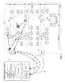
- FIGS. 5-7fuses or circuit-breakers are identified with the character “S”
- underground power linesare illustrated with long dashed lines
- service linesare illustrated with short dashed lines
- feedersare illustrated with solid lines. This is not to be confused with bold dashed lines which indicate ODS information flow.
- the electronic utility device 26 A associated with the customer locationsends an imminent failure warning across the first network 16 to the ODS module 54 to report the outage event.
- an outage eventcan be discovered and reported in a number of different manners. Accordingly, while reference is made herein to an imminent failure warning, it should be understood that the outage event could also or alternatively be reported and/or discovered in response to scheduled polling, customer telephone calls, periodic polling conducted by neighboring electronic utility devices 26 or neighboring network infrastructure devices 18 , and/or other events and operations described above.
- the electronic utility device 26 Acan transmit a Layer 2 imminent failure warning (e.g., a so-called “last gasp” message) directly to the ODS module 54 or an agent of the ODS module 54 using a predefined route.
- the electronic utility device 26 Acan also or alternatively transmit the imminent failure warning to a neighboring electronic utility device 26 or a neighboring network infrastructure device 18 (e.g., relay 44 A in FIG. 5 ), which can then forward the message to the ODS module 54 .
- the agent of the ODS module 54can convert the Layer 2 message to a SNMP Layer 3 and forward the message to a gateway 42 (e.g., gateway 42 A in FIG. 5 ) or the NMC 38 .
- the gateway 42 Acan forward the message to an event receiver 72 of the ODS module 54 .
- a poller 74 of the ODS module 54transmits poll requests to and receives poll responses from electronic utility devices 26 similar to and in the neighborhood of the initiating electronic utility device 26 A based on stored utility topology information.
- the ODS module 54correlates the results of the imminent failure warning and the polling requests to confirm that an outage has occurred at a single electronic utility device 26 A corresponding to a single customer location.
- the ODS module 54can then display the imminent failure warning and the source location corresponding to the reporting electronic utility device 26 A in an event summary 76 so that appropriate corrective action can be initiated.
- ODS module 54can utilize additional polling data from the poller 74 to confirm that the service has been restored and can then display a message confirming that normal service has been restored.
- FIG. 6illustrates operation of the ODS module 54 during another outage event, which may be broader in scope and extent than the outage event illustrated in FIG. 5 .
- a transformer 22 Aproviding service to a number of utility devices 26 A, 26 B, 26 C at different customer locations is experiencing an outage.
- the transformer 22 A and/or the affected utility devices 26 A, 26 B, 26 Ccan send imminent failure warning messages across the first network 16 to the ODS module 54 to report the outage event.
- a neighboring utility device 26which is served by another normally functioning transformer 22 , can send an outage report to the ODS module 54 via gateway 42 A.
- an outage eventcan be discovered and reported in a number of different manners.
- the outage eventcould also or alternatively be reported and/or discovered in response to scheduled polling, customer telephone calls, periodic polling conducted by neighboring electronic utility devices 26 or neighboring network infrastructure devices 18 , and/or other events and operations described above.
- the transformer 22 A and/or the affected electronic utility devices 26 A, 26 B, 26 Ccan transmit a Layer 2 imminent failure warning directly to the ODS module 54 using a predefined route.
- the affected electronic utility devices 26 A, 26 B, 26 C and the transformer 22 Acan also or alternatively transmit the imminent failure warning to neighboring electronic utility devices 26 or neighboring network infrastructure devices 18 (e.g., relay 44 A in FIG. 6 ), which can then forward the message to the ODS module 54 .
- the network infrastructure device 18e.g., the relay 44 A
- the gateway 42 Acan then forward the message to the event receiver 72 of the ODS module 54 .
- the poller 74 of the ODS module 54transmits poll requests to and receives poll responses from the affected electronic utility devices 26 A, 26 B, 26 C and the affected transformer 22 A and electronic utility devices 26 similar to and neighboring the affected electronic utility devices 26 A, 26 B, 26 C and the affected transformer 22 A based on stored utility topology information.
- the ODS module 54correlates the results of the imminent failure warning and the polling requests to confirm that a transformer-level outage has occurred and that the outage affects multiple customer locations.
- the ODS module 54can then display the imminent failure warning and the source location corresponding to the transformer 22 A in the event summary 76 so that appropriate corrective action can be initiated.
- the ODS module 54can utilize additional polling data from the poller 74 to confirm that normal service has been restored and can then display a message confirming that normal service has been restored.
- the use of the term “transformer-level outage”refers to an occurrence of an outage at some “level” of the utility hierarchy topology (e.g., a feeder, a lateral, a sub-station, etc.)
- FIG. 7illustrates operation of the ODS module 54 during yet another outage event, which may be broader in scope and extent than the outage events illustrated in FIGS. 5 and 6 .
- a feeder 80 Aproviding service to a number of transformers 22 A- 22 G and a number of utility devices (collectively “the affected utility devices 26 A) at different customer locations within a neighborhood experiences an outage.
- the transformers 22 A- 22 G and/or one or more of the affected utility devices 26 Acan send imminent failure warning messages across the first network 16 to the ODS module 54 to report the outage event.
- an outage eventcan be discovered and reported in a number of different manners.
- the outage eventcould also or alternatively be reported and/or discovered in response to scheduled polling, customer telephone calls, periodic polling conducted by neighboring electronic utility devices 26 or neighboring network infrastructure devices 18 , and/or other events and operations described above.
- the transformers 22 A- 22 G and/or the affected electronic utility devices 26 Acan transmit a Layer 2 imminent failure warning to the ODS module 54 via other electronic utility devices 26 and/or other network infrastructure devices 18 (e.g., transformer 22 H) not connected to the feeder 80 A experiencing the outage.
- the network infrastructure device 18e.g., transformer 22 H
- the gateway 42 Acan then forward the message to the event receiver 72 of the ODS module 54 .
- the poller 74 of the ODS module 54transmits poll requests to and receives poll responses from transformers 22 A- 22 G, the affected electronic utility devices 26 A, and electronic utility devices 26 and transformers 22 similar to and neighboring of the affected electronic utility devices 26 A and the affected transformers 22 A- 22 G based on stored utility topology information.
- the ODS module 54correlates the results of the imminent failure warning and the polling requests to confirm that a feeder outage has occurred and that the outage affects multiple transformers and multiple customer locations.
- the ODS module 54can then display the imminent failure warning and the source location corresponding to the feeder 80 A in the event summary 76 so that appropriate corrective action can be initiated. Further, as the restoration action is taken and is completed, the ODS module 54 can utilize additional polling data from the poller 74 to confirm that normal service has been restored and can then display a message confirming that normal service has been restored.
Landscapes
- Physics & Mathematics (AREA)
- General Physics & Mathematics (AREA)
- Engineering & Computer Science (AREA)
- Computer Networks & Wireless Communication (AREA)
- Data Exchanges In Wide-Area Networks (AREA)
- Telephonic Communication Services (AREA)
- Small-Scale Networks (AREA)
Abstract
Description
Claims (23)
Priority Applications (1)
| Application Number | Priority Date | Filing Date | Title |
|---|---|---|---|
| US12/966,298US9658081B2 (en) | 2007-01-30 | 2010-12-13 | Methods and system for utility network outage detection |
Applications Claiming Priority (3)
| Application Number | Priority Date | Filing Date | Title |
|---|---|---|---|
| US89855107P | 2007-01-30 | 2007-01-30 | |
| US11/804,223US7853417B2 (en) | 2007-01-30 | 2007-05-17 | Methods and system for utility network outage detection |
| US12/966,298US9658081B2 (en) | 2007-01-30 | 2010-12-13 | Methods and system for utility network outage detection |
Related Parent Applications (1)
| Application Number | Title | Priority Date | Filing Date |
|---|---|---|---|
| US11/804,223ContinuationUS7853417B2 (en) | 2007-01-30 | 2007-05-17 | Methods and system for utility network outage detection |
Publications (2)
| Publication Number | Publication Date |
|---|---|
| US20110077790A1 US20110077790A1 (en) | 2011-03-31 |
| US9658081B2true US9658081B2 (en) | 2017-05-23 |
Family
ID=39668889
Family Applications (2)
| Application Number | Title | Priority Date | Filing Date |
|---|---|---|---|
| US11/804,223Active2028-10-04US7853417B2 (en) | 2007-01-30 | 2007-05-17 | Methods and system for utility network outage detection |
| US12/966,298Active2029-10-27US9658081B2 (en) | 2007-01-30 | 2010-12-13 | Methods and system for utility network outage detection |
Family Applications Before (1)
| Application Number | Title | Priority Date | Filing Date |
|---|---|---|---|
| US11/804,223Active2028-10-04US7853417B2 (en) | 2007-01-30 | 2007-05-17 | Methods and system for utility network outage detection |
Country Status (13)
| Country | Link |
|---|---|
| US (2) | US7853417B2 (en) |
| EP (1) | EP2108127A4 (en) |
| JP (1) | JP5249950B2 (en) |
| CN (1) | CN101617233B (en) |
| AU (1) | AU2007345624B2 (en) |
| BR (1) | BRPI0721266A2 (en) |
| CA (1) | CA2675069C (en) |
| MX (1) | MX2009008029A (en) |
| MY (1) | MY150322A (en) |
| RO (1) | RO126243A2 (en) |
| RU (1) | RU2456725C2 (en) |
| TW (1) | TWI364543B (en) |
| WO (2) | WO2008094296A1 (en) |
Cited By (5)
| Publication number | Priority date | Publication date | Assignee | Title |
|---|---|---|---|---|
| US20160276831A1 (en)* | 2015-03-17 | 2016-09-22 | General Electric Technology Gmbh | Outage management and prediction for a power grid system |
| WO2021173466A1 (en)* | 2020-02-25 | 2021-09-02 | Landis+Gyr Innovations, Inc. | Automatic discovery of electrical supply network topology and phase |
| US11183878B2 (en) | 2017-08-07 | 2021-11-23 | Landis+Gyr Innovations, Inc. | Maintaining connectivity information for meters and transformers located in a power distribution network |
| US11646602B2 (en) | 2020-03-11 | 2023-05-09 | Landis+Gyr Innovations, Inc. | Topology and phase detection for electrical supply network |
| US20240289553A1 (en)* | 2023-02-23 | 2024-08-29 | Insight Direct Usa, Inc. | Conversational inclusion/exclusion detection |
Families Citing this family (95)
| Publication number | Priority date | Publication date | Assignee | Title |
|---|---|---|---|---|
| US8560476B2 (en) | 2003-08-26 | 2013-10-15 | The Trustees Of Columbia University In The City Of New York | Martingale control of production for optimal profitability of oil and gas fields |
| US20080219239A1 (en)* | 2007-03-05 | 2008-09-11 | Grid Net, Inc. | Policy-based utility networking |
| US8130700B2 (en) | 2007-06-15 | 2012-03-06 | Silver Spring Networks, Inc. | Method and system for providing network and routing protocols for utility services |
| US7769888B2 (en) | 2007-06-15 | 2010-08-03 | Silver Spring Networks, Inc. | Method and system for providing network and routing protocols for utility services |
| US8233905B2 (en) | 2007-06-15 | 2012-07-31 | Silver Spring Networks, Inc. | Load management in wireless mesh communications networks |
| US8072951B2 (en) | 2007-06-15 | 2011-12-06 | Silver Spring Networks, Inc. | Method and system for providing routing protocols in a frequency hopping spread spectrum network |
| US8279870B2 (en) | 2007-08-01 | 2012-10-02 | Silver Spring Networks, Inc. | Method and system of routing in a utility smart-grid network |
| US9194899B2 (en)* | 2007-08-13 | 2015-11-24 | Fair Isaac Corporation | Utility network and revenue assurance |
| US8334787B2 (en) | 2007-10-25 | 2012-12-18 | Trilliant Networks, Inc. | Gas meter having ultra-sensitive magnetic material retrofitted onto meter dial and method for performing meter retrofit |
| EP2215556B1 (en) | 2007-11-25 | 2019-08-28 | Trilliant Networks, Inc. | System and method for transmitting power status notifications in an advanced metering infrastructure network |
| CA2705090A1 (en) | 2007-11-25 | 2009-05-28 | Trilliant Networks, Inc. | System and method for operating mesh devices in multi-tree overlapping mesh networks |
| US8138934B2 (en) | 2007-11-25 | 2012-03-20 | Trilliant Networks, Inc. | System and method for false alert filtering of event messages within a network |
| WO2009067257A1 (en) | 2007-11-25 | 2009-05-28 | Trilliant Networks, Inc. | Energy use control system and method |
| US20090187579A1 (en)* | 2008-01-20 | 2009-07-23 | Brancaccio Daniel S | System, Method and Product for Processing Utility Data |
| US8000913B2 (en) | 2008-01-21 | 2011-08-16 | Current Communications Services, Llc | System and method for providing power distribution system information |
| WO2009117741A1 (en)* | 2008-03-21 | 2009-09-24 | The Trustees Of Columbia University In The City Of New York | Decision support control centers |
| WO2009117742A1 (en)* | 2008-03-21 | 2009-09-24 | The Trustees Of Columbia University In The City Of New York | Methods and systems of determining the effectiveness of capital improvement projects |
| US8121741B2 (en)* | 2008-05-09 | 2012-02-21 | International Business Machines Corporation | Intelligent monitoring of an electrical utility grid |
| US8086905B2 (en) | 2008-05-27 | 2011-12-27 | Hitachi, Ltd. | Method of collecting information in system network |
| EP2321983B1 (en) | 2008-09-04 | 2018-05-09 | Trilliant Networks, Inc. | Method for implementing mesh network communications using a mesh network protocol |
| US8289182B2 (en) | 2008-11-21 | 2012-10-16 | Trilliant Networks, Inc. | Methods and systems for virtual energy management display |
| BRPI0923751A2 (en) | 2008-12-31 | 2016-01-19 | Abb Research Ltd | power distribution control of hybrid distribution network |
| WO2010096783A1 (en) | 2009-02-20 | 2010-08-26 | The Trustees Of Columbia University In The City Of New York | Dynamic contingency avoidance and mitigation system |
| EP2406778A4 (en) | 2009-03-11 | 2014-06-25 | Trilliant Networks Inc | Process, device and system for mapping transformers to meters and locating non-technical line losses |
| US8040812B1 (en)* | 2009-05-05 | 2011-10-18 | Sprint Communications Company L.P. | Network outage assessment |
| US8725625B2 (en) | 2009-05-28 | 2014-05-13 | The Trustees Of Columbia University In The City Of New York | Capital asset planning system |
| CN102055186B (en)* | 2009-10-30 | 2013-07-10 | 国际商业机器公司 | Method and device for processing power system topology structure information |
| US20110264276A1 (en)* | 2009-10-30 | 2011-10-27 | Rudin Management Co. Inc. | Interconnected electrical network and building management system and method of operation |
| US8285519B2 (en)* | 2009-12-03 | 2012-10-09 | Osocad Remote Limited Liability Company | System and method for operating a network of sensors |
| WO2011106511A1 (en) | 2010-02-24 | 2011-09-01 | The Trustees Of Columbia University In The City Of New York | Metric monitoring and financial validation system for tracking performance of improvement to an infrastructure |
| US7920983B1 (en) | 2010-03-04 | 2011-04-05 | TaKaDu Ltd. | System and method for monitoring resources in a water utility network |
| US8583405B2 (en) | 2010-05-11 | 2013-11-12 | Maggie Chow | Contingency analysis information for utility service network |
| CN101951031B (en)* | 2010-07-02 | 2012-09-05 | 北京航空航天大学 | Distribution network automatic system based on broadband wireless communication and realization method thereof |
| MX2013000577A (en) | 2010-07-16 | 2013-06-05 | Univ Columbia | Machine learning for power grids. |
| JP5925774B2 (en)* | 2010-07-30 | 2016-05-25 | アクセンチュア グローバル サービスィズ リミテッド | Intelligent core engine |
| WO2012027634A1 (en) | 2010-08-27 | 2012-03-01 | Trilliant Networkd, Inc. | System and method for interference free operation of co-located tranceivers |
| WO2012033854A2 (en)* | 2010-09-07 | 2012-03-15 | Grid Net, Inc. | Power outage notification |
| US9013173B2 (en) | 2010-09-13 | 2015-04-21 | Trilliant Networks, Inc. | Process for detecting energy theft |
| WO2012068045A2 (en) | 2010-11-15 | 2012-05-24 | Trilliant Holdings Inc. | System and method for securely communicating across multiple networks using a single radio |
| US9282383B2 (en) | 2011-01-14 | 2016-03-08 | Trilliant Incorporated | Process, device and system for volt/VAR optimization |
| US8970394B2 (en) | 2011-01-25 | 2015-03-03 | Trilliant Holdings Inc. | Aggregated real-time power outages/restoration reporting (RTPOR) in a secure mesh network |
| US8774975B2 (en)* | 2011-02-08 | 2014-07-08 | Avista Corporation | Outage management algorithm |
| US8928489B2 (en)* | 2011-02-08 | 2015-01-06 | Avista Corporation | Ping server |
| US20120200423A1 (en)* | 2011-02-08 | 2012-08-09 | Avista Corporation | Outage Prediction With Next Generation Smart Grid |
| EP3285459B1 (en) | 2011-02-10 | 2022-10-26 | Trilliant Holdings, Inc. | Device and method for coordinating firmware updates |
| US8781129B2 (en)* | 2011-02-23 | 2014-07-15 | General Electric Company | Systems, methods, and apparatus for electrical grid quantum key distribution |
| US9041349B2 (en) | 2011-03-08 | 2015-05-26 | Trilliant Networks, Inc. | System and method for managing load distribution across a power grid |
| US8462641B2 (en)* | 2011-03-23 | 2013-06-11 | General Electric Company | Power loss packet priority |
| US20120265358A1 (en)* | 2011-04-13 | 2012-10-18 | Thoppay Rajeshbabu Kb | Systems and methods for use in correcting intermittent utility service outages |
| US8868360B2 (en)* | 2011-04-29 | 2014-10-21 | General Electric Company | System and device for detecting defects in underground cables |
| US8553536B2 (en) | 2011-07-12 | 2013-10-08 | General Electric Company | Mesh network management system |
| EP2555141A1 (en)* | 2011-08-03 | 2013-02-06 | Alcatel Lucent | A method, a system, a server, a control element, a computer program and a computer program product for operating a power grid having decentralized control elements |
| US9001787B1 (en) | 2011-09-20 | 2015-04-07 | Trilliant Networks Inc. | System and method for implementing handover of a hybrid communications module |
| US8341106B1 (en) | 2011-12-07 | 2012-12-25 | TaKaDu Ltd. | System and method for identifying related events in a resource network monitoring system |
| US20130184878A1 (en)* | 2012-01-13 | 2013-07-18 | General Electric Company | Systems and Methods for Tracing Nodes in an Electrical Network |
| US9053519B2 (en) | 2012-02-13 | 2015-06-09 | TaKaDu Ltd. | System and method for analyzing GIS data to improve operation and monitoring of water distribution networks |
| US20130219279A1 (en)* | 2012-02-21 | 2013-08-22 | Ambient Corporation | Aggregating nodes for efficient network management system visualization and operations |
| US9158035B2 (en)* | 2012-04-05 | 2015-10-13 | General Electric Company | System and method of automated acquisition, correlation and display of power distribution grid operational parameters and weather events |
| TWI436081B (en)* | 2012-05-07 | 2014-05-01 | Univ Ishou | An analyzing method for fault indicators of power networks |
| US20130307694A1 (en)* | 2012-05-15 | 2013-11-21 | Roni AMAR | Electricity/power metering system and method |
| US9318920B2 (en) | 2012-06-01 | 2016-04-19 | Baltimore Gas And Electric Company | Method and system for the installation of fault circuit indicators on an electrical feeder |
| US10242414B2 (en) | 2012-06-12 | 2019-03-26 | TaKaDu Ltd. | Method for locating a leak in a fluid network |
| US9088994B2 (en) | 2012-08-31 | 2015-07-21 | Fujitsu Limited | Method and system for last gasp device detection |
| US8867396B2 (en)* | 2012-08-31 | 2014-10-21 | Fujitsu Limtied | Method and system for last gasp device identification |
| US9689710B2 (en) | 2012-09-21 | 2017-06-27 | Silver Spring Networks, Inc. | Power outage notification and determination |
| US20150264776A1 (en)* | 2012-09-24 | 2015-09-17 | Petra Solar, Inc. | Distributed street lights energy remote monitoring, command and control |
| EP2901603B1 (en) | 2012-09-28 | 2019-11-13 | Intel Corporation | Dynamic hybrid automatic repeat request-acknowledgement (harq-ack) transmission with enhanced physical downlink control channels |
| WO2014052905A1 (en) | 2012-09-28 | 2014-04-03 | Yiu Candy | Rsrp mobility state estimation for cellular device |
| EP2901740B1 (en) | 2012-09-28 | 2019-03-06 | Intel Corporation | Discontinuous reception (drx) enhancements in lte systems |
| CN104737619B (en) | 2012-09-28 | 2018-12-25 | 英特尔公司 | Permanent online bearer for small data transmission in L TE system |
| US9578635B2 (en)* | 2012-09-28 | 2017-02-21 | Intel Corporation | Method and apparatus for autonomous cluster head selection for machine-type-communications (MTC) |
| US9553455B2 (en)* | 2012-10-11 | 2017-01-24 | Siemens Aktiengesellschaft | Use of demand response to enable improved power supply restoration planning |
| US9439145B2 (en)* | 2012-11-05 | 2016-09-06 | Silver Spring Networks, Inc. | Approach for extended battery life network nodes |
| US10014681B2 (en) | 2013-12-03 | 2018-07-03 | International Business Machines Corporation | Providing electricity to essential equipment during an emergency |
| US9791485B2 (en) | 2014-03-10 | 2017-10-17 | Silver Spring Networks, Inc. | Determining electric grid topology via a zero crossing technique |
| CN106537356B (en)* | 2014-07-17 | 2020-03-10 | 3M创新有限公司 | System and method for signal injection in a utility grid |
| TWI556076B (en)* | 2014-10-30 | 2016-11-01 | 台達電子工業股份有限公司 | Zone controller system and auto-configuration method for the zone controller system |
| CN105578461B (en)* | 2014-11-10 | 2019-08-02 | 阿里巴巴集团控股有限公司 | Communication, communication access/call-out method, apparatus and system are established between mobile terminal |
| MX367112B (en)* | 2014-11-12 | 2019-08-05 | Arris Entpr Llc | Auto-configuration of wireless network extender. |
| US9489281B2 (en)* | 2014-12-02 | 2016-11-08 | Dell Products L.P. | Access point group controller failure notification system |
| JP6436440B2 (en) | 2014-12-19 | 2018-12-12 | インターナショナル・ビジネス・マシーンズ・コーポレーションInternational Business Machines Corporation | Generating apparatus, generating method, and program |
| US10002504B2 (en)* | 2015-10-01 | 2018-06-19 | Honeywell International Inc. | System and method of providing intelligent system trouble notifications using localization |
| US20170301044A1 (en)* | 2016-04-15 | 2017-10-19 | Oracle International Corporation | Systems and methods for managing outages in utility systems |
| CN106155876B (en)* | 2016-07-26 | 2018-07-06 | 北京蓝海讯通科技股份有限公司 | A kind of canary analysis method, application and computing device |
| US10229577B2 (en)* | 2017-02-01 | 2019-03-12 | Florida Power & Light Company | Proactive power outage alerts management system and methods |
| DE102017110000B4 (en)* | 2017-05-09 | 2019-01-17 | Minol Messtechnik W. Lehmann Gmbh & Co. Kg | Method for operating a building-side installable communication unit and a building-side installable communication unit |
| ES2945538T3 (en)* | 2017-06-05 | 2023-07-04 | Abb Spa | A computer-implemented method of configuring an electronic relay |
| US10715886B2 (en)* | 2017-06-06 | 2020-07-14 | Landis+Gyr Technologies, Llc | Power outage-assessment apparatuses and methods |
| US11287285B2 (en)* | 2017-12-18 | 2022-03-29 | Landis+Gyr Innovations, Inc. | Methods and systems for distributed verification and control of a resource distribution network |
| US10655984B2 (en) | 2017-12-20 | 2020-05-19 | Florida Power & Light Company | Power state estimation for power grid serviced premises |
| CO2018008437A1 (en) | 2018-08-11 | 2019-02-19 | Integrated Measurement Systems S A S | Modular data concentrator device for public service measurement systems and process for information collection and management |
| WO2020095420A1 (en)* | 2018-11-08 | 2020-05-14 | 中国電力株式会社 | Information processing device and abnormality visualization system |
| US10917288B2 (en)* | 2019-06-25 | 2021-02-09 | Bank Of America Corporation | Adaptive edge-shift for enterprise contingency operations |
| CN111680962A (en)* | 2020-04-30 | 2020-09-18 | 国网吉林省电力有限公司电力科学研究院 | A method for managing the comparison experiment of live detection instruments |
| DE102021112179A1 (en)* | 2021-05-10 | 2022-11-10 | retesol GmbH | Monitoring device for a data router and method for monitoring a data router |
Citations (31)
| Publication number | Priority date | Publication date | Assignee | Title |
|---|---|---|---|---|
| US3411140A (en) | 1965-03-17 | 1968-11-12 | Itt | Network status intelligence acquisition, assessment and communication |
| EP0493964A2 (en) | 1990-12-31 | 1992-07-08 | Raytheon Company | Automated power system |
| JPH05236544A (en) | 1992-02-21 | 1993-09-10 | Hitachi Cable Ltd | Remote initialization device for electronic equipment |
| US5553094A (en) | 1990-02-15 | 1996-09-03 | Iris Systems, Inc. | Radio communication network for remote data generating stations |
| US5568399A (en) | 1995-01-31 | 1996-10-22 | Puget Consultants Inc. | Method and apparatus for power outage determination using distribution system information |
| WO1997029466A1 (en) | 1996-02-07 | 1997-08-14 | Cellnet Data Systems, Inc. | A metering system |
| US5673252A (en) | 1990-02-15 | 1997-09-30 | Itron, Inc. | Communications protocol for remote data generating stations |
| US6362745B1 (en) | 1997-03-26 | 2002-03-26 | Comverge Technologies, Inc. | Method of detecting tamper of an electric meter |
| US6392996B1 (en) | 1998-04-13 | 2002-05-21 | At&T Corp. | Method and apparatus for frame peeking |
| US20020082748A1 (en) | 2000-06-15 | 2002-06-27 | Internet Energy Systems, Inc. | Utility monitoring and control systems |
| US6424248B1 (en) | 1993-12-09 | 2002-07-23 | Steelcase Development Corporation | Furniture unit having a modular communication network |
| JP2002369412A (en) | 2001-06-06 | 2002-12-20 | Chubu Electric Power Co Inc | Accident point information collection system for distribution lines |
| US6590928B1 (en) | 1997-09-17 | 2003-07-08 | Telefonaktiebolaget Lm Ericsson (Publ) | Frequency hopping piconets in an uncoordinated wireless multi-user system |
| US20040024717A1 (en) | 1998-04-03 | 2004-02-05 | Enerwise Global Technologies, Inc. | Computer assisted and/or implemented process and architecture for web-based monitoring of energy related usage, and client accessibility therefor |
| US20040139038A1 (en) | 2002-03-28 | 2004-07-15 | Ehlers Gregory A. | System and method for controlling delivering of a commodity |
| US20040138787A1 (en) | 1994-12-30 | 2004-07-15 | Power Measurement Ltd. | System and method for implementing XML on an energy management device |
| TW200422629A (en) | 2002-12-20 | 2004-11-01 | Zarlink Semiconductor Vn Inc | Apparatus for link failure detection on high availability ethernet backplane |
| US20050078660A1 (en) | 2002-02-18 | 2005-04-14 | Ian Wood | Distributed message transmission system and method |
| TW200521442A (en) | 2003-12-25 | 2005-07-01 | Ind Tech Res Inst | A universal power measurement soc and measuring method |
| US20060064485A1 (en) | 2004-09-17 | 2006-03-23 | Microsoft Corporation | Methods for service monitoring and control |
| US20060168191A1 (en) | 2003-09-23 | 2006-07-27 | Ives Edward M | Power status notification |
| US20060202854A1 (en)* | 2005-03-09 | 2006-09-14 | Quentin Spencer | Extremely fast polling method for determining the presence of individual electric meters on a power line |
| WO2006102172A2 (en) | 2005-03-22 | 2006-09-28 | Elster Electricity Llc | Using a fixed network wireless data collection system to improve utility responsiveness to power outages |
| US7149917B2 (en)* | 2002-07-30 | 2006-12-12 | Cisco Technology, Inc. | Method and apparatus for outage measurement |
| US7290037B2 (en) | 2002-08-22 | 2007-10-30 | Clark Todd A | Scalable wireless remote control and monitoring system with automatic registration and automatic time synchronization |
| US7304587B2 (en) | 2003-02-14 | 2007-12-04 | Energy Technology Group, Inc. | Automated meter reading system, communication and control network for automated meter reading, meter data collector program product, and associated methods |
| US20080036622A1 (en)* | 2006-08-11 | 2008-02-14 | Quentin Spencer | Detection of fast poll responses in a twacs inbound receiver |
| US20080048883A1 (en)* | 2003-02-14 | 2008-02-28 | Energy Technology Group, Inc. | Methods of performing automated meter reading and processing meter data |
| US7379981B2 (en) | 2000-01-31 | 2008-05-27 | Kenneth W. Garrard | Wireless communication enabled meter and network |
| US7394394B2 (en) | 2002-06-19 | 2008-07-01 | Tarma, L.L.C. | Battery monitor with wireless remote communication |
| US20080189225A1 (en)* | 2000-11-28 | 2008-08-07 | David Herring | Method and System for Predicting Causes of Network Service Outages Using Time Domain Correlation |
Family Cites Families (7)
| Publication number | Priority date | Publication date | Assignee | Title |
|---|---|---|---|---|
| JPH08307957A (en)* | 1995-05-01 | 1996-11-22 | Nissin Electric Co Ltd | Method for polling communication |
| JP3451440B2 (en)* | 2002-01-18 | 2003-09-29 | 富士通株式会社 | Polling communication system and polling control method |
| CN2715413Y (en)* | 2003-12-12 | 2005-08-03 | 上海东云信息技术发展有限公司 | Power network electricity transmission line fault monitoring system |
| JP2005275540A (en)* | 2004-03-23 | 2005-10-06 | Tokyo Gas Co Ltd | Earthquake disaster prevention system and earthquake disaster prevention communication method |
| JP4637549B2 (en)* | 2004-11-09 | 2011-02-23 | 中国電力株式会社 | Communications system |
| RU2005112309A (en)* | 2005-04-25 | 2006-10-27 | Самсунг Электроникс Ко., Лтд. (KR) | SYSTEM AND METHOD OF REMOTE ELECTRICAL APPLIANCES |
| RU51175U1 (en)* | 2005-09-27 | 2006-01-27 | Георгий Константинович Росаткевич | APARTMENT SYSTEM FOR ENERGY RESOURCES OF RESIDENTIAL HOUSES AND CONTROL OF THEIR USE |
- 2007
- 2007-05-17USUS11/804,223patent/US7853417B2/enactiveActive
- 2007-07-13RURU2009132513/07Apatent/RU2456725C2/enactive
- 2007-07-13AUAU2007345624Apatent/AU2007345624B2/enactiveActive
- 2007-07-13CACA2675069Apatent/CA2675069C/enactiveActive
- 2007-07-13WOPCT/US2007/073457patent/WO2008094296A1/enactiveApplication Filing
- 2007-07-13EPEP07799567Apatent/EP2108127A4/ennot_activeWithdrawn
- 2007-07-13ROROA200900584Apatent/RO126243A2/enunknown
- 2007-07-13MXMX2009008029Apatent/MX2009008029A/enactiveIP Right Grant
- 2007-07-13JPJP2009548237Apatent/JP5249950B2/enactiveActive
- 2007-07-13CNCN2007800506204Apatent/CN101617233B/enactiveActive
- 2007-07-13BRBRPI0721266-6Apatent/BRPI0721266A2/ennot_activeApplication Discontinuation
- 2007-07-13MYMYPI20093137Apatent/MY150322A/enunknown
- 2007-07-17TWTW096126011Apatent/TWI364543B/enactive
- 2008
- 2008-01-30WOPCT/US2008/001163patent/WO2008094551A2/enactiveApplication Filing
- 2010
- 2010-12-13USUS12/966,298patent/US9658081B2/enactiveActive
Patent Citations (37)
| Publication number | Priority date | Publication date | Assignee | Title |
|---|---|---|---|---|
| US3411140A (en) | 1965-03-17 | 1968-11-12 | Itt | Network status intelligence acquisition, assessment and communication |
| US5553094A (en) | 1990-02-15 | 1996-09-03 | Iris Systems, Inc. | Radio communication network for remote data generating stations |
| US20030001754A1 (en)* | 1990-02-15 | 2003-01-02 | Itron, Inc. | Wide area communications network for remote data generating stations |
| US5673252A (en) | 1990-02-15 | 1997-09-30 | Itron, Inc. | Communications protocol for remote data generating stations |
| EP0493964A2 (en) | 1990-12-31 | 1992-07-08 | Raytheon Company | Automated power system |
| JPH05236544A (en) | 1992-02-21 | 1993-09-10 | Hitachi Cable Ltd | Remote initialization device for electronic equipment |
| US6424248B1 (en) | 1993-12-09 | 2002-07-23 | Steelcase Development Corporation | Furniture unit having a modular communication network |
| US20040138787A1 (en) | 1994-12-30 | 2004-07-15 | Power Measurement Ltd. | System and method for implementing XML on an energy management device |
| US5568399A (en) | 1995-01-31 | 1996-10-22 | Puget Consultants Inc. | Method and apparatus for power outage determination using distribution system information |
| WO1997029466A1 (en) | 1996-02-07 | 1997-08-14 | Cellnet Data Systems, Inc. | A metering system |
| US6195018B1 (en) | 1996-02-07 | 2001-02-27 | Cellnet Data Systems, Inc. | Metering system |
| US6492910B1 (en) | 1996-02-07 | 2002-12-10 | Schlumberger Resources Management Systems, Inc. | Metering system |
| US6362745B1 (en) | 1997-03-26 | 2002-03-26 | Comverge Technologies, Inc. | Method of detecting tamper of an electric meter |
| US6590928B1 (en) | 1997-09-17 | 2003-07-08 | Telefonaktiebolaget Lm Ericsson (Publ) | Frequency hopping piconets in an uncoordinated wireless multi-user system |
| US20040024717A1 (en) | 1998-04-03 | 2004-02-05 | Enerwise Global Technologies, Inc. | Computer assisted and/or implemented process and architecture for web-based monitoring of energy related usage, and client accessibility therefor |
| US6392996B1 (en) | 1998-04-13 | 2002-05-21 | At&T Corp. | Method and apparatus for frame peeking |
| US7379981B2 (en) | 2000-01-31 | 2008-05-27 | Kenneth W. Garrard | Wireless communication enabled meter and network |
| US20020082748A1 (en) | 2000-06-15 | 2002-06-27 | Internet Energy Systems, Inc. | Utility monitoring and control systems |
| US20080189225A1 (en)* | 2000-11-28 | 2008-08-07 | David Herring | Method and System for Predicting Causes of Network Service Outages Using Time Domain Correlation |
| JP2002369412A (en) | 2001-06-06 | 2002-12-20 | Chubu Electric Power Co Inc | Accident point information collection system for distribution lines |
| US20050078660A1 (en) | 2002-02-18 | 2005-04-14 | Ian Wood | Distributed message transmission system and method |
| US20040139038A1 (en) | 2002-03-28 | 2004-07-15 | Ehlers Gregory A. | System and method for controlling delivering of a commodity |
| US20050033707A1 (en) | 2002-03-28 | 2005-02-10 | Ehlers Gregory A. | Configurable architecture for controlling delivery and/or usage of a commodity |
| US7394394B2 (en) | 2002-06-19 | 2008-07-01 | Tarma, L.L.C. | Battery monitor with wireless remote communication |
| US7149917B2 (en)* | 2002-07-30 | 2006-12-12 | Cisco Technology, Inc. | Method and apparatus for outage measurement |
| US7290037B2 (en) | 2002-08-22 | 2007-10-30 | Clark Todd A | Scalable wireless remote control and monitoring system with automatic registration and automatic time synchronization |
| TW200422629A (en) | 2002-12-20 | 2004-11-01 | Zarlink Semiconductor Vn Inc | Apparatus for link failure detection on high availability ethernet backplane |
| US20080048883A1 (en)* | 2003-02-14 | 2008-02-28 | Energy Technology Group, Inc. | Methods of performing automated meter reading and processing meter data |
| US7304587B2 (en) | 2003-02-14 | 2007-12-04 | Energy Technology Group, Inc. | Automated meter reading system, communication and control network for automated meter reading, meter data collector program product, and associated methods |
| US20060168191A1 (en) | 2003-09-23 | 2006-07-27 | Ives Edward M | Power status notification |
| TW200521442A (en) | 2003-12-25 | 2005-07-01 | Ind Tech Res Inst | A universal power measurement soc and measuring method |
| US20060064485A1 (en) | 2004-09-17 | 2006-03-23 | Microsoft Corporation | Methods for service monitoring and control |
| US7227462B2 (en) | 2005-03-09 | 2007-06-05 | Quentin Spencer | Extremely fast polling method for determining the presence of individual electric meters on a power line |
| US20060202854A1 (en)* | 2005-03-09 | 2006-09-14 | Quentin Spencer | Extremely fast polling method for determining the presence of individual electric meters on a power line |
| WO2006102172A2 (en) | 2005-03-22 | 2006-09-28 | Elster Electricity Llc | Using a fixed network wireless data collection system to improve utility responsiveness to power outages |
| US7308370B2 (en) | 2005-03-22 | 2007-12-11 | Elster Electricity Llc | Using a fixed network wireless data collection system to improve utility responsiveness to power outages |
| US20080036622A1 (en)* | 2006-08-11 | 2008-02-14 | Quentin Spencer | Detection of fast poll responses in a twacs inbound receiver |
Non-Patent Citations (22)
| Title |
|---|
| C. Edward Chow, John Bicknell, Steve McCaughey and Sami Syed; "A Fast Distributed Network Restoration Algorithm", 1993 IEEE, pp. 261-267, 0-7803-0922, Jul. 1993, USA. |
| Document entitled "Outage Reporting Example" from Schneider Electric, publicly available prior to May 17, 2007. |
| Examination Report from the Australian Patent Office for Application No. 2011213894 dated Mar. 29, 2012 (2 pages). |
| Examination Report from the Hungarian Intellectual Property Office for Application No. 200905059-2 dated Jun. 14, 2011 (6 pages). |
| Examination Report from the Malaysian Patent Office for Application No. 20093137 dated Mar. 23, 2012 (Translation, 3 pages). |
| John Bicknell, C. Edward Chow and Sami Syed, "Performance Analysis of Fast Distributed Network Restoration Algorithms", 1993 IEEE, pp. 1596-1600, 0-7803-0917-0/93, USA. |
| Krishna Sridharan, Noeln N. Schulz, "Outage Management Through AMR Systems Using an Intelligent Data Filter", IEEE Transactions on Power Delivey, vol. 16, No. 4, pp. 669-675, Oct. 2001, USA. |
| Liu et al.: "Integrated Fuzzy Filter for Distribution Outage Information" Oct. 28, 2002, Electric Power Systems Research, vol. 63, Issue 3 whole document, especially pp. 3 and 6. |
| Office Action from the Intellectual Property Office Philippines for Application No. 12009501405 dated Jan. 21, 2012 (1 page). |
| Office action from the Japanese Patent Office for Application No. 2009-548237, issued Jul. 2012, 5 pages. |
| Office Action from the Mexican Patent Office for Application No. MX/a/2008/006309 dated Jun. 15, 2010 (2 pages). |
| Patti Harper-Slaboszewicz, How to Improve Outage Management (UtiliPoint.com-Jan. 18, 2006),Powermarketers Industry Publications, Jan. 18, 2006, USA. |
| Patti Harper-Slaboszewicz, How to Improve Outage Management (UtiliPoint.com—Jan. 18, 2006),Powermarketers Industry Publications, Jan. 18, 2006, USA. |
| PCT/US2007/73457 International Search Report and Written Opinion, dated Mar. 14, 2008. |
| PCT/US2008/001163 International Search Report and Written Opinion, dated Nov. 26, 2008. |
| Rochelle A. Fischer, Aaron S. Laakonen, Noel N. Schulz, "A General Polling Algorithm Using a Wireless AMR System for Restoration Confirmation", IEEE Transactions on Power Systems, May 2001, pp. 312-316, vol. 16, No. 2, USA. |
| SG Search Report, dated Oct. 22, 2010, (6 pages). |
| Sioe T. Mak, "A Synergistic Approach to Using AMR and Intelligent Electronic Devices to Determine Outages in a Distribution Network", Mar. 2006, IEEE, pp. 447-453. |
| TW 096126011 Taiwan Search Report dated Mar. 25, 2011 (English Translation-7 pages). |
| TW 096126011 Taiwan Search Report dated Mar. 25, 2011 (English Translation—7 pages). |
| US Office Action for U.S. Appl. No. 11/804,223, dated Jul. 14, 2009, (63 pages). |
| Yan Liu, "Distribution System Outage and Restoration Analysis Using A Wireless AMR System", 2002, IEEE, pp. 871-875. |
Cited By (10)
| Publication number | Priority date | Publication date | Assignee | Title |
|---|---|---|---|---|
| US20160276831A1 (en)* | 2015-03-17 | 2016-09-22 | General Electric Technology Gmbh | Outage management and prediction for a power grid system |
| US10164431B2 (en)* | 2015-03-17 | 2018-12-25 | General Electric Technology Gmbh | Outage management and prediction for a power grid system |
| US11183878B2 (en) | 2017-08-07 | 2021-11-23 | Landis+Gyr Innovations, Inc. | Maintaining connectivity information for meters and transformers located in a power distribution network |
| US11916380B2 (en) | 2017-08-07 | 2024-02-27 | Landis+Gyr Technology, Inc. | Maintaining connectivity information for meters and transformers located in a power distribution network |
| WO2021173466A1 (en)* | 2020-02-25 | 2021-09-02 | Landis+Gyr Innovations, Inc. | Automatic discovery of electrical supply network topology and phase |
| US11245260B2 (en)* | 2020-02-25 | 2022-02-08 | Landis+Gyr Innovations, Inc. | Automatic discovery of electrical supply network topology and phase |
| US20220149623A1 (en)* | 2020-02-25 | 2022-05-12 | Landis+Gyr Innovations, Inc. | Automatic discovery of electrical supply network topology and phase |
| US11721977B2 (en)* | 2020-02-25 | 2023-08-08 | Landis+Gyr Innovations, Inc. | Automatic discovery of electrical supply network topology and phase |
| US11646602B2 (en) | 2020-03-11 | 2023-05-09 | Landis+Gyr Innovations, Inc. | Topology and phase detection for electrical supply network |
| US20240289553A1 (en)* | 2023-02-23 | 2024-08-29 | Insight Direct Usa, Inc. | Conversational inclusion/exclusion detection |
Also Published As
| Publication number | Publication date |
|---|---|
| MX2009008029A (en) | 2009-10-28 |
| MY150322A (en) | 2013-12-31 |
| EP2108127A1 (en) | 2009-10-14 |
| WO2008094296A1 (en) | 2008-08-07 |
| BRPI0721266A2 (en) | 2013-03-26 |
| US20110077790A1 (en) | 2011-03-31 |
| CA2675069A1 (en) | 2008-08-07 |
| EP2108127A4 (en) | 2013-02-20 |
| TWI364543B (en) | 2012-05-21 |
| WO2008094551A3 (en) | 2009-01-08 |
| AU2007345624B2 (en) | 2011-05-26 |
| US20080183339A1 (en) | 2008-07-31 |
| CA2675069C (en) | 2014-03-04 |
| US7853417B2 (en) | 2010-12-14 |
| WO2008094551A2 (en) | 2008-08-07 |
| RU2009132513A (en) | 2011-03-10 |
| JP2010517473A (en) | 2010-05-20 |
| TW200832252A (en) | 2008-08-01 |
| RU2456725C2 (en) | 2012-07-20 |
| CN101617233B (en) | 2013-06-26 |
| JP5249950B2 (en) | 2013-07-31 |
| AU2007345624A1 (en) | 2008-08-07 |
| CN101617233A (en) | 2009-12-30 |
| RO126243A2 (en) | 2011-04-29 |
Similar Documents
| Publication | Publication Date | Title |
|---|---|---|
| US9658081B2 (en) | Methods and system for utility network outage detection | |
| KR101180660B1 (en) | Methods and system for utility network outage detection | |
| US8451739B2 (en) | Method and system for detecting failures of network nodes | |
| US7308370B2 (en) | Using a fixed network wireless data collection system to improve utility responsiveness to power outages | |
| US9829343B2 (en) | System and method for controlling a connection of a meter to a power line | |
| US20140085105A1 (en) | Power Outage Notification and Determination | |
| AU2011213894B2 (en) | Methods and system for utility newtork outage detection | |
| McPherson et al. | Using LoRaWAN technology to enhance remote power network monitoring | |
| CN119787631A (en) | A decentralized monitoring system for secondary distribution networks |
Legal Events
| Date | Code | Title | Description |
|---|---|---|---|
| AS | Assignment | Owner name:SILVER SPRING NETWORKS, CALIFORNIA Free format text:ASSIGNMENT OF ASSIGNORS INTEREST;ASSIGNORS:VASWANI, RAJ;PACE, JAMES;HUGHES, STERLING;REEL/FRAME:025476/0412 Effective date:20070515 | |
| STCF | Information on status: patent grant | Free format text:PATENTED CASE | |
| AS | Assignment | Owner name:WELLS FARGO BANK, NATIONAL ASSOCIATION, NORTH CAROLINA Free format text:SECURITY INTEREST;ASSIGNORS:ITRON, INC.;ITRON NETWORKED SOLUTIONS, INC.;REEL/FRAME:045017/0893 Effective date:20180105 Owner name:WELLS FARGO BANK, NATIONAL ASSOCIATION, NORTH CARO Free format text:SECURITY INTEREST;ASSIGNORS:ITRON, INC.;ITRON NETWORKED SOLUTIONS, INC.;REEL/FRAME:045017/0893 Effective date:20180105 | |
| AS | Assignment | Owner name:ITRON NETWORKED SOLUTIONS, INC., WASHINGTON Free format text:CHANGE OF NAME;ASSIGNOR:SILVER SPRING NETWORKS, INC.;REEL/FRAME:045221/0804 Effective date:20180105 | |
| MAFP | Maintenance fee payment | Free format text:PAYMENT OF MAINTENANCE FEE, 4TH YEAR, LARGE ENTITY (ORIGINAL EVENT CODE: M1551); ENTITY STATUS OF PATENT OWNER: LARGE ENTITY Year of fee payment:4 | |
| MAFP | Maintenance fee payment | Free format text:PAYMENT OF MAINTENANCE FEE, 8TH YEAR, LARGE ENTITY (ORIGINAL EVENT CODE: M1552); ENTITY STATUS OF PATENT OWNER: LARGE ENTITY Year of fee payment:8 |