US9655652B2 - Bone anchoring device - Google Patents
Bone anchoring deviceDownload PDFInfo
- Publication number
- US9655652B2 US9655652B2US11/895,364US89536407AUS9655652B2US 9655652 B2US9655652 B2US 9655652B2US 89536407 AUS89536407 AUS 89536407AUS 9655652 B2US9655652 B2US 9655652B2
- Authority
- US
- United States
- Prior art keywords
- rod
- filling piece
- receiving part
- pressure element
- anchoring device
- Prior art date
- Legal status (The legal status is an assumption and is not a legal conclusion. Google has not performed a legal analysis and makes no representation as to the accuracy of the status listed.)
- Expired - Fee Related, expires
Links
Images


Classifications
- A—HUMAN NECESSITIES
- A61—MEDICAL OR VETERINARY SCIENCE; HYGIENE
- A61B—DIAGNOSIS; SURGERY; IDENTIFICATION
- A61B17/00—Surgical instruments, devices or methods
- A61B17/56—Surgical instruments or methods for treatment of bones or joints; Devices specially adapted therefor
- A61B17/58—Surgical instruments or methods for treatment of bones or joints; Devices specially adapted therefor for osteosynthesis, e.g. bone plates, screws or setting implements
- A61B17/68—Internal fixation devices, including fasteners and spinal fixators, even if a part thereof projects from the skin
- A61B17/70—Spinal positioners or stabilisers, e.g. stabilisers comprising fluid filler in an implant
- A61B17/7001—Screws or hooks combined with longitudinal elements which do not contact vertebrae
- A61B17/7032—Screws or hooks with U-shaped head or back through which longitudinal rods pass
- A—HUMAN NECESSITIES
- A61—MEDICAL OR VETERINARY SCIENCE; HYGIENE
- A61B—DIAGNOSIS; SURGERY; IDENTIFICATION
- A61B17/00—Surgical instruments, devices or methods
- A61B17/56—Surgical instruments or methods for treatment of bones or joints; Devices specially adapted therefor
- A61B17/58—Surgical instruments or methods for treatment of bones or joints; Devices specially adapted therefor for osteosynthesis, e.g. bone plates, screws or setting implements
- A61B17/68—Internal fixation devices, including fasteners and spinal fixators, even if a part thereof projects from the skin
- A61B17/70—Spinal positioners or stabilisers, e.g. stabilisers comprising fluid filler in an implant
- A61B17/7001—Screws or hooks combined with longitudinal elements which do not contact vertebrae
- A61B17/7035—Screws or hooks, wherein a rod-clamping part and a bone-anchoring part can pivot relative to each other
- A61B17/7037—Screws or hooks, wherein a rod-clamping part and a bone-anchoring part can pivot relative to each other wherein pivoting is blocked when the rod is clamped
- A—HUMAN NECESSITIES
- A61—MEDICAL OR VETERINARY SCIENCE; HYGIENE
- A61B—DIAGNOSIS; SURGERY; IDENTIFICATION
- A61B17/00—Surgical instruments, devices or methods
- A61B17/56—Surgical instruments or methods for treatment of bones or joints; Devices specially adapted therefor
- A61B17/58—Surgical instruments or methods for treatment of bones or joints; Devices specially adapted therefor for osteosynthesis, e.g. bone plates, screws or setting implements
- A61B17/68—Internal fixation devices, including fasteners and spinal fixators, even if a part thereof projects from the skin
- A61B17/70—Spinal positioners or stabilisers, e.g. stabilisers comprising fluid filler in an implant
- A61B17/7001—Screws or hooks combined with longitudinal elements which do not contact vertebrae
- A61B17/7002—Longitudinal elements, e.g. rods
- A61B17/7019—Longitudinal elements having flexible parts, or parts connected together, such that after implantation the elements can move relative to each other
- A61B17/7026—Longitudinal elements having flexible parts, or parts connected together, such that after implantation the elements can move relative to each other with a part that is flexible due to its form
Definitions
- the applicationrelates to a bone anchoring device having a bone anchoring element and a rod for connecting at least two bone anchoring elements wherein the rod has at least in a part thereof a tubular structure.
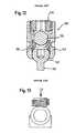
- FIG. 12shows a known polyaxial bone screw 100 with a screw element 101 having a bone thread and a spherical segment-shaped head 102 which is pivotably held in a receiving part 103 .
- the receiving parthas a recess for receiving a rod 104 .
- a pressure element 105is provided which is slidable in the receiving part.
- An inner screw 106is used to clamp the rod in the receiving part and to exert pressure onto the head via the rod and the pressure element to lock the head.
- a flexible rod having a tubular structure for stabilizing the spineis known for example from US 2005/0154390 A1.
- US 2004/0138660 A1discloses a locking cap assembly for locking a rod which is made from a full metal cylinder to a receiving body of a bone screw.
- the locking cap assemblyincludes an inner and an outer locking element.
- the outer locking elementis a nut-like member to which the inner locking element is rotatably connected.
- the inner locking elementhas on its side facing the rod a ring-shaped deformable contacting element which comes into contact with the rod.
- the deformable contacting elementis deformed which provides feed-back to the surgeon to allow him to determine whether the locking cap assembly is tightened to the required extent.
- FR 2 810 533discloses a bone anchoring device with a rod which is made from a full cylinder.
- a locking cap assemblycomprises a rotatably supported member which presses from above onto the rod. The shape of the rod contacting surface of said member is adapted to the contour of the rod.
- a bone anchoring deviceprovides a fixation of a tubular rod wherein a deformation of the tubular rod is minimized even in the case when a large clamping force is exerted.
- FIG. 1shows an exploded view of the bone anchoring device according to a first embodiment.
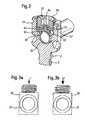
- FIG. 2shows a perspective sectional view of the bone anchoring device according to FIG. 1 in an assembled and fixed state.
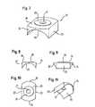
- FIGS. 3 a and 3 bschematically show the clamping of the rod under the action of a smaller and a larger clamping force F.
- FIG. 4shows an exploded view of the bone anchoring device according to a second embodiment.
- FIG. 5shows a perspective view of the bone anchoring device of FIG. 4 in an assembled state.
- FIG. 6shows a sectional view of the bone anchoring device in an assembled and fixed state as shown in FIG. 4 .
- FIG. 7shows a perspective view of a filling piece which is part of the bone anchoring device of FIG. 4 .
- FIG. 8shows a side view of the filling piece of FIG. 7 in the direction of the rod axis.
- FIG. 9shows a side view of the filling piece of FIG. 7 rotated by 90°.
- FIG. 10shows a top view of the filling piece of FIG. 7 .
- FIG. 11shows a perspective view of the filling piece of FIG. 7 from the bottom.
- FIG. 12shows a schematic cross-sectional view of a prior art polyaxial bone screw with a rod.
- FIG. 13shows a schematic view of the rod clamping in the case of using the polyaxial screw of FIG. 12 with a tubular rod.
- FIGS. 1 and 2show a bone anchoring device 1 according to a first embodiment.
- the bone anchoring device 1includes a monoaxial bone screw 2 and a tubular rod 20 .
- the bone screw 2has a shank 3 with a bone thread for anchoring in the bone, a tip at one end (not shown) and a receiving part 5 at the opposite end.
- the receiving part 5comprises a substantially U-shaped recess 5 a for receiving the rod 20 .
- two free legs 5 b , 5 b ′are formed which have an internal thread 5 c for receiving a locking element to secure the rod 20 in the recess.
- the locking elementis an inner screw 50 which can be screwed-in between the legs.
- the threadcan be a flat thread to prevent splaying of the legs when tightening the inner screw.
- any other thread shapesuch as a metric thread, a saw tooth thread or a negative angle thread can be used.
- a filling piece 60is provided between the inner screw 50 and the rod.
- the outer contour of the filling piece 60 when viewed from aboveis substantially rectangular with two opposite long straight sides and two opposite outwardly curved short sides.
- the filling pieceOn its side facing the rod the filling piece has a rod contacting surface 61 the shape of which is adapted to the shape of the rod surface.
- the rod 20is cylindrically-shaped.
- the rod contacting surface 61is formed by a cylinder segment-shaped recess in the filling piece.
- the size of the rod contacting surface 61is selected so as to provide a desired load distribution when the rod is clamped between the filling piece and the bottom of the U-shaped recess 4 a .
- the surface 62 opposite to the rod contacting surface 61is substantially flat with a cylindrical projection 63 in the center.
- the cylindrical projection 63is insertable in a corresponding cylindrical bore 51 of the inner screw 50 provided at the underside of the inner screw.
- the inner screwis rotatable with respect to the filling piece.
- the projection 63can have an outwardly projecting rim 64 cooperating with a corresponding circular recess in the inner screw so that the filling piece is rotatably supported in the inner screw.
- the inner screwfurther has a recess 52 on the opposite side for engagement with a tool.
- the rod 20is formed as a cylindrical tube.
- All parts of the bone anchoring deviceare made of a biocompatible material, for example of a metal such as titanium or a metal alloy or a biocompatible plastic material.
- At least two bone anchoring elementsare anchored into two vertebrae or two bone parts which are to be stabilized with the rod. Thereafter the rod is inserted into the receiving parts. Then the inner screw with the filling piece is inserted and the inner screw is tightened. As can be seen in FIGS. 3 a and 3 b a deformation of the tubular rod is minimized or does even not occur when the filling piece presses with its rod contacting surface 61 against the surface of the rod. The homogeneous load distribution on the surface of the rod prevents a deformation of the rod.
- the bone anchoring device 1 ′is of the polyaxial type and includes a bone anchoring element 2 ′ in the form of a bone screw having a shank 3 with a bone thread and a tip (not shown) and a head 4 .
- the head 4has a spherical segment shape.
- a recess (not shown) for the engagement with a screwing-in toolis provided at the free end of the head 4 .
- the bone anchoring devicefurther comprises a receiving part 5 ′ which has a first end 6 and an opposite second end 7 , a central axis C going through the planes defined by the first end and the second end, respectively, and a coaxial bore 8 extending from the first end to a distance from the second end.
- a receiving part 5 ′which has a first end 6 and an opposite second end 7 , a central axis C going through the planes defined by the first end and the second end, respectively, and a coaxial bore 8 extending from the first end to a distance from the second end.
- an opening 9is provided the diameter of which is smaller than the diameter of the bore 8 .
- a spherically shaped section 10is provided adjacent to the opening 9 which forms a seat for the head 4 .
- the section which forms the seatcan have other shapes, for example, a conical shape.
- the receiving part 5 ′has a substantially U-shaped recess 11 which starts at the first end 6 and extends to a distance from the second end 7 for receiving the rod 20 ′.
- the U-shaped recess 11two free legs 12 , 13 are formed.
- the receiving part 5 ′further comprises an internal thread 14 on the legs 12 , 13 .
- the bone anchoring device 1further comprises a pressure element 15 .
- the pressure element 15has a substantially cylindrical construction with an outer diameter which is only slightly smaller than the inner diameter of the bore 8 to allow the pressure element 15 to be introduced into the bore 8 and to be moved in the axial direction.
- the pressure element 15On its lower side facing towards the second end 7 the pressure element 15 comprises a spherical recess 16 the radius of which corresponds substantially to the radius of the head 4 of the bone screw.
- a substantially U-shaped recess 17is provided the depth of which is larger than the diameter of a rod 20 .
- the rod 20connects at least two bone screws.
- the pressure element 15further comprises a coaxial bore 21 for allowing access with a screwing-in tool to the screw head 4 .
- the bone anchoring devicefurther comprises a filling piece 22 which is depicted in more detail in FIGS. 7 to 11 .
- the filling pieceis sized so as to be slidable in the U-shaped recess 17 of the pressure element. It has two opposite flat side walls facing the inner side of the legs 18 , 19 of the pressure element 15 . Further, it has two opposite rounded sides 24 , 24 ′.
- the filling piece 22comprises a recess 25 for accommodating the rod 20 .
- the rod 20is a cylindrical rod and the recess 25 is adapted to the shape and size of the rod 20 .
- the depth of the recessis smaller or equal to the radius of the rod 20 so that the filling piece 22 is able to exert pressure from above on the surface of the rod 20 .
- the filling piece 22On the opposite side of the recess 25 the filling piece 22 comprises a substantially flat surface 26 . Further, it comprises a coaxial bore 27 . Around the coaxial bore a contact surface 28 is provided which projects from the flat surface 26 .
- the contact surfaceis, for example, ring-shaped.
- the dimension of the filling piece 22 in this embodiment as shown in FIG. 4can be such that in the assembled state when the rod 20 rests in the U-shaped recess 17 of the pressure element 15 and the filling piece 22 is placed on top of the rod, the surface 26 is located slightly below the end surface of the legs 18 , 19 of the pressure element 15 .
- the bone anchoring devicecomprises a locking device 29 for fixation of the rod and of the head.
- the locking device 29consists of a first locking element 30 in form of an inner screw cooperating the internal thread 14 of the receiving part 5 ′.
- the cooperating threadsare shaped as flat threads.
- the first locking element 30comprises an engagement structure 32 for engaging a screwing-in tool and a coaxial threaded bore 33 for the reception of the second locking element 31 which is shaped as a set screw.
- the second locking element 31also comprises an engagement structure 34 for engagement with a screwing-in tool.
- On the side facing the roda projection 35 which is shaped so as to fit into the bore 27 of the filling piece 22 and to allow a rotational movement between the filling piece 22 and the second locking element 31 is provided.
- the dimensions of the locking device 29 , the pressure element 15 and the filling piece 22are such that in an assembled state as shown in FIG. 6 the first locking element 30 contacts the upper surface of the free legs 18 , 19 of the pressure element but does not contact the filling piece 22 .
- the second locking element 31contacts the contact surface 28 of the filing piece 22 but does not contact the pressure element.
- the material from which the bone anchoring element is madeis preferably a body compatible material, such as titanium or a titanium alloy.
- the rod 20 ′is shaped as a tube having a helix-shaped recess 40 in at least a part of its wall.
- the helix-shaped recess 40provides elasticity against axial and bending forces and in specific applications also against torsional forces.
- the characteristics of the helix-shaped recess 40such as the pitch, the width of the recess, the exact shape of the helix and other parameters vary according to the desired flexible properties of the rod 20 ′.
- the rod 20 ′further can have a core 41 with a diameter which is smaller than the inner diameter of the tube.
- the core 41can be designed to be slidable within the tube.
- the material from which the core 41 is made and its diameter or detailed shapeis selected in such a way that the desired elastic properties of the rod 20 ′ are achieved.
- the core 41may be provided for enhancing the stiffness of the flexible tubular rod 20 ′, for example to avoid kinking.
- the tubular rod 20 ′can be made of the same material as the bone anchoring element or from another material.
- the rodcan be made from a material which exhibits an enhanced elasticity per se.
- a materialmay be a plastic material or a shape memory alloy having shape memory and/or superelastic properties.
- the bone screw 2 , the receiving part 5 ′ and the pressure element 15can be preassembled in such a way that the head 4 is pivotably held in the receiving part 5 ′ and the pressure element 15 is loosely held and secured against rotation in the receiving part 5 ′.
- the preassembled bone anchoring elementsare screwed into adjacent vertebrae of a spinal motion segment.
- the rod 20 ′is inserted into the receiving part so that it rests in the pressure element and in the bottom of the U-shaped recess 11 of the receiving part.
- the second filling piece 22can be loosely connected to the second locking element 31 by means of the projection 35 of the second locking element extending through the bore 27 of the filling piece.
- the preassembled locking device 29 together with the filling piece 22is inserted into the receiving part.
- the angular position of the receiving part relative to the bone screwis finally adjusted and the head 4 of the bone screw locked in this position by tightening down the first locking element 30 . Since the first locking element 30 abuts with its lower surface the upper surface of the legs 18 , 19 of the pressure element without touching the filling piece 22 , the head can be fixed by the pressure element 15 . Thereafter, the position of the rod 20 is adjusted. Finally the second locking element 31 is tightened down until it presses on the contact surface 28 of the filling piece. The frictional forces acting between the pressure element and the rod, respectively, hold the rod in place.
- the homogeneous load distribution on the surface of the rod which is provided by the filling pieceprevents deformation. Therefore, a core 41 which is movable within the tubular rod is not jammed by a deformation of the rod.
- the locking devicecomprises only one single locking element.
- the pressure element 15does not have legs 8 , 19 which extend over the surface of the rod. The filling piece presses onto the rod and the rod presses onto the pressure element so that the head and the rod are fixed simultaneously.
- the locking deviceis possible, for example, a locking element having an outer nut or a cap.
- the filling piece 22is then rotatably connected with an element of the locking device.
- the two part locking device as described abovecan be modified, for example the first locking element 30 can have threadless section in its coaxial bore with a diameter greater than that of the filling piece such that the first locking element 30 does not touch the surface 26 of the filling piece. In this case the filling piece can extend above the legs 18 , 19 .
- the receiving partcan be designed so as to allow the introduction of the screw element from the bottom.
- the rodcan be totally or partially tubular.
- the corecan be omitted.
- the rodcan be rigid or fully or partially flexible.
- a hook or nail-like anchoring elementcan be provided instead of a bone screw.
- the elements of the various embodiments describedcan be combined.
- the two part locking devicecan also be used with a monoaxial screw.
Landscapes
- Health & Medical Sciences (AREA)
- Orthopedic Medicine & Surgery (AREA)
- Life Sciences & Earth Sciences (AREA)
- Neurology (AREA)
- Surgery (AREA)
- Heart & Thoracic Surgery (AREA)
- Engineering & Computer Science (AREA)
- Biomedical Technology (AREA)
- Nuclear Medicine, Radiotherapy & Molecular Imaging (AREA)
- Medical Informatics (AREA)
- Molecular Biology (AREA)
- Animal Behavior & Ethology (AREA)
- General Health & Medical Sciences (AREA)
- Public Health (AREA)
- Veterinary Medicine (AREA)
- Surgical Instruments (AREA)
Abstract
Description
Claims (16)
Priority Applications (1)
| Application Number | Priority Date | Filing Date | Title |
|---|---|---|---|
| US11/895,364US9655652B2 (en) | 2006-08-24 | 2007-08-24 | Bone anchoring device |
Applications Claiming Priority (5)
| Application Number | Priority Date | Filing Date | Title |
|---|---|---|---|
| US84009906P | 2006-08-24 | 2006-08-24 | |
| EP06017651.8AEP1891904B1 (en) | 2006-08-24 | 2006-08-24 | Bone anchoring device |
| EP06017651.8 | 2006-08-24 | ||
| EP06017651 | 2006-08-24 | ||
| US11/895,364US9655652B2 (en) | 2006-08-24 | 2007-08-24 | Bone anchoring device |
Publications (2)
| Publication Number | Publication Date |
|---|---|
| US20080086132A1 US20080086132A1 (en) | 2008-04-10 |
| US9655652B2true US9655652B2 (en) | 2017-05-23 |
Family
ID=37670801
Family Applications (1)
| Application Number | Title | Priority Date | Filing Date |
|---|---|---|---|
| US11/895,364Expired - Fee RelatedUS9655652B2 (en) | 2006-08-24 | 2007-08-24 | Bone anchoring device |
Country Status (6)
| Country | Link |
|---|---|
| US (1) | US9655652B2 (en) |
| EP (1) | EP1891904B1 (en) |
| JP (1) | JP5275594B2 (en) |
| CN (1) | CN101129272B (en) |
| ES (1) | ES2453196T3 (en) |
| TW (1) | TWI441613B (en) |
Cited By (32)
| Publication number | Priority date | Publication date | Assignee | Title |
|---|---|---|---|---|
| US20170281237A1 (en)* | 2016-03-29 | 2017-10-05 | Globus Medical, Inc. | Revision connectors, systems and methods thereof |
| US20180064469A1 (en)* | 2015-04-24 | 2018-03-08 | K2M, Inc. | Tethering screw system |
| US20180296250A1 (en)* | 2015-10-06 | 2018-10-18 | Joimax Gmbh | Device for fixating a rod to a bone |
| US20210186565A1 (en)* | 2019-12-20 | 2021-06-24 | Warsaw Orthopedic, Inc. | Anti-Splay Head and Set Screw for Spinal Fixation |
| US11337734B2 (en) | 2019-05-22 | 2022-05-24 | Nuvasive, Inc. | Posterior spinal fixation screws |
| US20220313332A1 (en)* | 2019-12-17 | 2022-10-06 | Roger P. Jackson | Bone anchor assembly with ring retainer and internal snap ring |
| US11559335B2 (en) | 2009-06-15 | 2023-01-24 | Roger P Jackson | Pivotal bone anchor assembly with insert tool deployment |
| US11627995B2 (en) | 2020-12-21 | 2023-04-18 | Warsaw Orthopedic, Inc. | Locking-cap module and connector |
| US11627992B2 (en) | 2020-12-21 | 2023-04-18 | Warsaw Orthopedic, Inc. | Locking-cap module and connector |
| US11751915B2 (en) | 2021-07-09 | 2023-09-12 | Roger P. Jackson | Modular spinal fixation system with bottom-loaded universal shank heads |
| US11751916B2 (en) | 2009-06-15 | 2023-09-12 | Roger P. Jackson | Pivotal bone anchor assembly with polyaxial screw having frusto-conical upper surface |
| US11793553B2 (en) | 2014-10-21 | 2023-10-24 | Roger P. Jackson | Pivotal bone anchor assembly having first and second split rings and an insert with post-placement tool deployment |
| US11911075B2 (en) | 2012-01-10 | 2024-02-27 | Roger P. Jackson | Pivotal bone anchor assembly with increased shank angulation |
| US11925392B2 (en) | 2007-05-23 | 2024-03-12 | Roger P. Jackson | Pivotal bone anchor assembly with bottom loaded spherical shank head having a planar upper surface |
| US11957386B2 (en) | 2005-09-30 | 2024-04-16 | Roger P. Jackson | Pivotal bone anchor assembly having a downwardly-displaceable snap-in-place insert and method of assembly |
| US11957391B2 (en) | 2021-11-01 | 2024-04-16 | Warsaw Orthopedic, Inc. | Bone screw having an overmold of a shank |
| US12042185B2 (en) | 2010-05-14 | 2024-07-23 | Roger P. Jackson | Pivotal bone anchor assembly with resiliently biased friction fit insert |
| US12070249B2 (en) | 2014-06-04 | 2024-08-27 | Jackson Roger P | Pivotal bone anchor assembly with bottom loaded shank head engaging retainer and closure engaging insert |
| US12082853B2 (en) | 2014-10-21 | 2024-09-10 | Roger P. Jackson | Pivotal bone anchor assembly with positioner-retainer containment and insert tool deployment |
| US12082854B2 (en) | 2009-06-15 | 2024-09-10 | Roger P. Jackson | Method of assembling a pivotable bone anchor assembly with a slidable retaining structure |
| US12082850B2 (en) | 2007-09-17 | 2024-09-10 | Roger P. Jackson | Pivotal bone anchor assembly having twist-in-place insert and receiver with pre-formed axial rotation insert stops |
| US12102357B2 (en) | 2005-02-22 | 2024-10-01 | Roger P. Jackson | Pivotal bone anchor assembly with cannulated shank having a planar top surface and method of assembly |
| US12137945B2 (en) | 2018-09-13 | 2024-11-12 | Roger P. Jackson | Pivotal bone anchor system with modular receiver sub-assemblies and universal bone anchors |
| US12137944B2 (en) | 2018-11-16 | 2024-11-12 | Jackson Roger P | Bone anchor assembly having a tool deployable insert in compressive overlapping engagement with a retainer |
| US12185983B2 (en) | 2009-06-15 | 2025-01-07 | Roger P. Jackson | Receiver assembly having a vertical tool-engaging slot for independent lock via tooling |
| US12185984B2 (en) | 2005-05-27 | 2025-01-07 | Roger P. Jackson | Method of assembling a pivotal bone anchor screw with insert tool deployment |
| US12262920B2 (en) | 2004-11-23 | 2025-04-01 | Roger P. Jackson | Method of assembling a bottom-loaded pivotal bone anchor assembly with compression insert and two-part shank retainer |
| US12357348B2 (en) | 2005-09-30 | 2025-07-15 | Roger P. Jackson | Method of assembling a pivotal bone anchor assembly with press-in-place insert |
| US12376886B2 (en) | 2008-08-01 | 2025-08-05 | Roger P. Jackson | Pivotal bone anchor assembly with retainer pre-positioned in expansion chamber and tool-deployable insert |
| US12376894B2 (en) | 2005-07-14 | 2025-08-05 | Roger P. Jackson | Pivotal bone anchor assembly with ring retainer and twist-in-place pressure insert |
| US12402917B2 (en) | 2009-06-15 | 2025-09-02 | Roger P. Jackson | Pivotal bone anchor assembly with independent provisional locking |
| US12440245B2 (en) | 2023-09-06 | 2025-10-14 | Pivotable bone anchor assembly with independent provisional locking by insert compressing member |
Families Citing this family (95)
| Publication number | Priority date | Publication date | Assignee | Title |
|---|---|---|---|---|
| US7833250B2 (en) | 2004-11-10 | 2010-11-16 | Jackson Roger P | Polyaxial bone screw with helically wound capture connection |
| US10258382B2 (en) | 2007-01-18 | 2019-04-16 | Roger P. Jackson | Rod-cord dynamic connection assemblies with slidable bone anchor attachment members along the cord |
| US8292926B2 (en) | 2005-09-30 | 2012-10-23 | Jackson Roger P | Dynamic stabilization connecting member with elastic core and outer sleeve |
| US10729469B2 (en) | 2006-01-09 | 2020-08-04 | Roger P. Jackson | Flexible spinal stabilization assembly with spacer having off-axis core member |
| US7862587B2 (en) | 2004-02-27 | 2011-01-04 | Jackson Roger P | Dynamic stabilization assemblies, tool set and method |
| US8876868B2 (en) | 2002-09-06 | 2014-11-04 | Roger P. Jackson | Helical guide and advancement flange with radially loaded lip |
| WO2006052796A2 (en) | 2004-11-10 | 2006-05-18 | Jackson Roger P | Helical guide and advancement flange with break-off extensions |
| US7621918B2 (en) | 2004-11-23 | 2009-11-24 | Jackson Roger P | Spinal fixation tool set and method |
| US7377923B2 (en) | 2003-05-22 | 2008-05-27 | Alphatec Spine, Inc. | Variable angle spinal screw assembly |
| US8926670B2 (en) | 2003-06-18 | 2015-01-06 | Roger P. Jackson | Polyaxial bone screw assembly |
| US8377102B2 (en) | 2003-06-18 | 2013-02-19 | Roger P. Jackson | Polyaxial bone anchor with spline capture connection and lower pressure insert |
| US8137386B2 (en) | 2003-08-28 | 2012-03-20 | Jackson Roger P | Polyaxial bone screw apparatus |
| US8398682B2 (en) | 2003-06-18 | 2013-03-19 | Roger P. Jackson | Polyaxial bone screw assembly |
| US7967850B2 (en) | 2003-06-18 | 2011-06-28 | Jackson Roger P | Polyaxial bone anchor with helical capture connection, insert and dual locking assembly |
| US7179261B2 (en) | 2003-12-16 | 2007-02-20 | Depuy Spine, Inc. | Percutaneous access devices and bone anchor assemblies |
| US11419642B2 (en) | 2003-12-16 | 2022-08-23 | Medos International Sarl | Percutaneous access devices and bone anchor assemblies |
| US7527638B2 (en) | 2003-12-16 | 2009-05-05 | Depuy Spine, Inc. | Methods and devices for minimally invasive spinal fixation element placement |
| US11241261B2 (en) | 2005-09-30 | 2022-02-08 | Roger P Jackson | Apparatus and method for soft spinal stabilization using a tensionable cord and releasable end structure |
| JP2007525274A (en) | 2004-02-27 | 2007-09-06 | ロジャー・ピー・ジャクソン | Orthopedic implant rod reduction instrument set and method |
| US7160300B2 (en) | 2004-02-27 | 2007-01-09 | Jackson Roger P | Orthopedic implant rod reduction tool set and method |
| US8152810B2 (en) | 2004-11-23 | 2012-04-10 | Jackson Roger P | Spinal fixation tool set and method |
| US7503924B2 (en) | 2004-04-08 | 2009-03-17 | Globus Medical, Inc. | Polyaxial screw |
| US8475495B2 (en) | 2004-04-08 | 2013-07-02 | Globus Medical | Polyaxial screw |
| US7651502B2 (en) | 2004-09-24 | 2010-01-26 | Jackson Roger P | Spinal fixation tool set and method for rod reduction and fastener insertion |
| US8926672B2 (en) | 2004-11-10 | 2015-01-06 | Roger P. Jackson | Splay control closure for open bone anchor |
| US9216041B2 (en) | 2009-06-15 | 2015-12-22 | Roger P. Jackson | Spinal connecting members with tensioned cords and rigid sleeves for engaging compression inserts |
| US8308782B2 (en) | 2004-11-23 | 2012-11-13 | Jackson Roger P | Bone anchors with longitudinal connecting member engaging inserts and closures for fixation and optional angulation |
| WO2006057837A1 (en) | 2004-11-23 | 2006-06-01 | Jackson Roger P | Spinal fixation tool attachment structure |
| US9168069B2 (en) | 2009-06-15 | 2015-10-27 | Roger P. Jackson | Polyaxial bone anchor with pop-on shank and winged insert with lower skirt for engaging a friction fit retainer |
| US7901437B2 (en) | 2007-01-26 | 2011-03-08 | Jackson Roger P | Dynamic stabilization member with molded connection |
| US10076361B2 (en) | 2005-02-22 | 2018-09-18 | Roger P. Jackson | Polyaxial bone screw with spherical capture, compression and alignment and retention structures |
| US8105368B2 (en) | 2005-09-30 | 2012-01-31 | Jackson Roger P | Dynamic stabilization connecting member with slitted core and outer sleeve |
| WO2007121271A2 (en) | 2006-04-11 | 2007-10-25 | Synthes (U.S.A) | Minimally invasive fixation system |
| CA2670988C (en) | 2006-12-08 | 2014-03-25 | Roger P. Jackson | Tool system for dynamic spinal implants |
| US8475498B2 (en) | 2007-01-18 | 2013-07-02 | Roger P. Jackson | Dynamic stabilization connecting member with cord connection |
| US8366745B2 (en) | 2007-05-01 | 2013-02-05 | Jackson Roger P | Dynamic stabilization assembly having pre-compressed spacers with differential displacements |
| US10792074B2 (en) | 2007-01-22 | 2020-10-06 | Roger P. Jackson | Pivotal bone anchor assemly with twist-in-place friction fit insert |
| US8167912B2 (en) | 2007-02-27 | 2012-05-01 | The Center for Orthopedic Research and Education, Inc | Modular pedicle screw system |
| US8926669B2 (en) | 2007-02-27 | 2015-01-06 | The Center For Orthopedic Research And Education, Inc. | Modular polyaxial pedicle screw system |
| US10383660B2 (en) | 2007-05-01 | 2019-08-20 | Roger P. Jackson | Soft stabilization assemblies with pretensioned cords |
| US7947065B2 (en) | 2008-11-14 | 2011-05-24 | Ortho Innovations, Llc | Locking polyaxial ball and socket fastener |
| US7942910B2 (en)* | 2007-05-16 | 2011-05-17 | Ortho Innovations, Llc | Polyaxial bone screw |
| US7942911B2 (en)* | 2007-05-16 | 2011-05-17 | Ortho Innovations, Llc | Polyaxial bone screw |
| US8998958B2 (en)* | 2007-12-20 | 2015-04-07 | Aesculap Implant Systems, Llc | Locking device introducer instrument |
| US8439922B1 (en) | 2008-02-06 | 2013-05-14 | NiVasive, Inc. | Systems and methods for holding and implanting bone anchors |
| EP2265202B1 (en)* | 2008-04-22 | 2012-08-29 | Synthes GmbH | Bone fixation element with reduction tabs |
| EP2441404B1 (en) | 2008-04-28 | 2013-07-31 | Biedermann Technologies GmbH & Co. KG | Rod-shaped implant, in particular for spinal stabilization, and method for producing the same |
| ES2375526T3 (en)* | 2008-06-19 | 2012-03-01 | Biedermann Motech Gmbh | BONE ANCHORAGE ASSEMBLY. |
| EP2160988B1 (en)* | 2008-09-04 | 2012-12-26 | Biedermann Technologies GmbH & Co. KG | Rod-shaped implant in particular for stabilizing the spinal column and stabilization device including such a rod-shaped implant |
| EP2484300B1 (en)* | 2008-09-05 | 2015-05-20 | Biedermann Technologies GmbH & Co. KG | Stabilization device for bones, in particular for the spinal column |
| CN102497828B (en)* | 2009-05-20 | 2015-09-09 | 斯恩蒂斯有限公司 | What patient installed retracts part |
| US9668771B2 (en) | 2009-06-15 | 2017-06-06 | Roger P Jackson | Soft stabilization assemblies with off-set connector |
| US8998959B2 (en) | 2009-06-15 | 2015-04-07 | Roger P Jackson | Polyaxial bone anchors with pop-on shank, fully constrained friction fit retainer and lock and release insert |
| US11464549B2 (en) | 2009-06-15 | 2022-10-11 | Roger P. Jackson | Pivotal bone anchor assembly with horizontal tool engagement grooves and insert with upright arms having flared outer portions |
| US8876867B2 (en)* | 2009-06-24 | 2014-11-04 | Zimmer Spine, Inc. | Spinal correction tensioning system |
| CA2767274C (en)* | 2009-07-16 | 2017-11-28 | Spinesave Ag | Anchorage arrangement for a connecting rod for the stabilization of the spine |
| CN101692983B (en)* | 2009-09-29 | 2013-07-31 | 北京市奥斯比利克新技术开发有限公司 | Bone screw component and locking nut thereof |
| EP2485654B1 (en) | 2009-10-05 | 2021-05-05 | Jackson P. Roger | Polyaxial bone anchor with non-pivotable retainer and pop-on shank, some with friction fit |
| US8535318B2 (en) | 2010-04-23 | 2013-09-17 | DePuy Synthes Products, LLC | Minimally invasive instrument set, devices and related methods |
| US9345519B1 (en)* | 2010-07-02 | 2016-05-24 | Presidio Surgical, Inc. | Pedicle screw |
| AU2011299558A1 (en) | 2010-09-08 | 2013-05-02 | Roger P. Jackson | Dynamic stabilization members with elastic and inelastic sections |
| AU2011324058A1 (en) | 2010-11-02 | 2013-06-20 | Roger P. Jackson | Polyaxial bone anchor with pop-on shank and pivotable retainer |
| US20140018867A1 (en)* | 2011-02-04 | 2014-01-16 | Stefan Freudiger | Precaution against jamming on open bone screws |
| US9198698B1 (en) | 2011-02-10 | 2015-12-01 | Nuvasive, Inc. | Minimally invasive spinal fixation system and related methods |
| JP5865479B2 (en) | 2011-03-24 | 2016-02-17 | ロジャー・ピー・ジャクソン | Multiaxial bone anchor with compound joint and pop-mounted shank |
| CN103717159B (en) | 2011-05-27 | 2016-08-17 | 新特斯有限责任公司 | Minimally Invasive Spinal Fixation System Including Vertebral Alignment Features |
| US9198694B2 (en) | 2011-07-15 | 2015-12-01 | Globus Medical, Inc. | Orthopedic fixation devices and methods of installation thereof |
| US9993269B2 (en) | 2011-07-15 | 2018-06-12 | Globus Medical, Inc. | Orthopedic fixation devices and methods of installation thereof |
| US9358047B2 (en) | 2011-07-15 | 2016-06-07 | Globus Medical, Inc. | Orthopedic fixation devices and methods of installation thereof |
| US9186187B2 (en) | 2011-07-15 | 2015-11-17 | Globus Medical, Inc. | Orthopedic fixation devices and methods of installation thereof |
| US8888827B2 (en) | 2011-07-15 | 2014-11-18 | Globus Medical, Inc. | Orthopedic fixation devices and methods of installation thereof |
| US9655655B2 (en) | 2011-08-16 | 2017-05-23 | Aesculap Implant Systems, Llc | Two step locking screw assembly |
| US8911478B2 (en) | 2012-11-21 | 2014-12-16 | Roger P. Jackson | Splay control closure for open bone anchor |
| CN103040515A (en)* | 2012-12-27 | 2013-04-17 | 苏州欣荣博尔特医疗器械有限公司 | Multi-axial spinal screw |
| CN103110452B (en)* | 2013-01-14 | 2016-01-20 | 史亚民 | Growth adjustable single is to nail |
| US10058354B2 (en) | 2013-01-28 | 2018-08-28 | Roger P. Jackson | Pivotal bone anchor assembly with frictional shank head seating surfaces |
| US8852239B2 (en) | 2013-02-15 | 2014-10-07 | Roger P Jackson | Sagittal angle screw with integral shank and receiver |
| US9486256B1 (en) | 2013-03-15 | 2016-11-08 | Nuvasive, Inc. | Rod reduction assemblies and related methods |
| DE102013107498A1 (en) | 2013-03-22 | 2014-09-25 | Aesculap Ag | Spine stabilization system and surgical fastener for a spine stabilization system |
| TWI572319B (en)* | 2013-03-27 | 2017-03-01 | 梓源生技有限公司 | Pedicle screw system |
| EP2826429B1 (en) | 2013-07-19 | 2016-09-14 | Biedermann Technologies GmbH & Co. KG | Polyaxial bone anchoring device |
| US9566092B2 (en) | 2013-10-29 | 2017-02-14 | Roger P. Jackson | Cervical bone anchor with collet retainer and outer locking sleeve |
| US9717533B2 (en) | 2013-12-12 | 2017-08-01 | Roger P. Jackson | Bone anchor closure pivot-splay control flange form guide and advancement structure |
| US9451993B2 (en) | 2014-01-09 | 2016-09-27 | Roger P. Jackson | Bi-radial pop-on cervical bone anchor |
| US9597119B2 (en) | 2014-06-04 | 2017-03-21 | Roger P. Jackson | Polyaxial bone anchor with polymer sleeve |
| US9974577B1 (en) | 2015-05-21 | 2018-05-22 | Nuvasive, Inc. | Methods and instruments for performing leveraged reduction during single position spine surgery |
| CN104958100A (en)* | 2015-05-25 | 2015-10-07 | 创生医疗器械(中国)有限公司 | Anti-screwing jackscrew for pedicle screw |
| US9968378B1 (en)* | 2015-07-22 | 2018-05-15 | University Of South Florida | Adaptation sphere saddle |
| CN105581831B (en)* | 2015-12-24 | 2017-03-15 | 建湖县人民医院 | A kind of novel combination type pedicle screw-rod locking system |
| US10413330B2 (en)* | 2016-08-09 | 2019-09-17 | Warsaw Orthopedic, Inc. | Spinal implant system and method |
| US10398481B2 (en) | 2016-10-03 | 2019-09-03 | Nuvasive, Inc. | Spinal fixation system |
| US11051861B2 (en) | 2018-06-13 | 2021-07-06 | Nuvasive, Inc. | Rod reduction assemblies and related methods |
| EP3695796B1 (en)* | 2019-02-13 | 2022-08-03 | Biedermann Technologies GmbH & Co. KG | Anchoring assembly for anchoring a rod to a bone or a vertebra |
| USD929214S1 (en)* | 2019-04-04 | 2021-08-31 | Next Orthosurgical, Inc. | Straight conical set screw |
| USD926560S1 (en)* | 2019-04-04 | 2021-08-03 | Next Orthosurgical, Inc. | Curved conical set screw |
Citations (44)
| Publication number | Priority date | Publication date | Assignee | Title |
|---|---|---|---|---|
| EP0528706A1 (en) | 1991-08-19 | 1993-02-24 | Societe De Fabrication De Materiel Orthopedique Sofamor | Implant for osteosynthesis device, notable for the spine, and associated device for application the same |
| US5443467A (en) | 1993-03-10 | 1995-08-22 | Biedermann Motech Gmbh | Bone screw |
| US5520689A (en)* | 1992-06-04 | 1996-05-28 | Synthes (U.S.A.) | Osteosynthetic fastening device |
| WO1998027884A1 (en) | 1996-12-20 | 1998-07-02 | Haider Thomas T | Pedicle screw system for osteosynthesis |
| FR2810533A1 (en) | 2000-06-22 | 2001-12-28 | Emmanuel Bockx | Adjustable fixing for spinal tie rod and pedicular screw comprises supporting cushion with slotted hole for rod set in cup on screw head |
| US20020143341A1 (en)* | 2001-03-27 | 2002-10-03 | Lutz Biedermann | Anchoring element |
| FR2829014A1 (en) | 2001-09-03 | 2003-03-07 | Stryker Spine | Osteosynthesis frame for spinal surgery has anchor with locking grub screw pressing retaining saddle against connector rod |
| US6565565B1 (en)* | 1998-06-17 | 2003-05-20 | Howmedica Osteonics Corp. | Device for securing spinal rods |
| US20030100904A1 (en)* | 2001-11-27 | 2003-05-29 | Lutz Biedermann | Locking device for securing a rod-shaped element in a holding element connected to a shank |
| US20030100896A1 (en)* | 2001-11-27 | 2003-05-29 | Lutz Biedermann | Element with a shank and a holding element connected to it for connecting to a rod |
| US20030125741A1 (en)* | 2001-12-28 | 2003-07-03 | Biedermann Motech Gmbh | Locking device for securing a rod-shaped element in a holding element connected to a shank |
| US20030187434A1 (en)* | 2002-01-24 | 2003-10-02 | A-Spine Inc. | Rotary device for fixing spinal column under treatment |
| US20040049190A1 (en)* | 2002-08-09 | 2004-03-11 | Biedermann Motech Gmbh | Dynamic stabilization device for bones, in particular for vertebrae |
| US20040138660A1 (en) | 2003-01-10 | 2004-07-15 | Serhan Hassan A. | Locking cap assembly for spinal fixation instrumentation |
| WO2004105577A2 (en) | 2003-05-23 | 2004-12-09 | Globus Medical, Inc. | Spine stabilization system |
| US20040260284A1 (en)* | 2003-06-23 | 2004-12-23 | Matthew Parker | Anti-splay pedicle screw |
| US20040260283A1 (en)* | 2003-06-19 | 2004-12-23 | Shing-Cheng Wu | Multi-axis spinal fixation device |
| US20050055026A1 (en)* | 2002-10-02 | 2005-03-10 | Biedermann Motech Gmbh | Bone anchoring element |
| US20050085815A1 (en)* | 2003-10-17 | 2005-04-21 | Biedermann Motech Gmbh | Rod-shaped implant element for application in spine surgery or trauma surgery, stabilization apparatus comprising said rod-shaped implant element, and production method for the rod-shaped implant element |
| US6896677B1 (en)* | 2003-12-11 | 2005-05-24 | A-Spine Holding Group Corp. | Rotary device for retrieving spinal column under treatment |
| US20050154390A1 (en) | 2003-11-07 | 2005-07-14 | Lutz Biedermann | Stabilization device for bones comprising a spring element and manufacturing method for said spring element |
| US20050187548A1 (en)* | 2004-01-13 | 2005-08-25 | Butler Michael S. | Pedicle screw constructs for spine fixation systems |
| US20050203517A1 (en) | 2003-09-24 | 2005-09-15 | N Spine, Inc. | Spinal stabilization device |
| JP2005253971A (en) | 2004-03-09 | 2005-09-22 | Biedermann Motech Gmbh | Bar-like element and stabilizing device used in operation for spinal cord and external injury |
| US20050261687A1 (en)* | 2004-04-20 | 2005-11-24 | Laszlo Garamszegi | Pedicle screw assembly |
| EP1604617A1 (en) | 2004-06-08 | 2005-12-14 | A-Spine Holding Group Corp. | Rotary device for retrieving spinal column under treatment |
| US20050283244A1 (en)* | 2003-08-05 | 2005-12-22 | Gordon Charles R | Method of insertion of an expandable intervertebral implant |
| US20060036244A1 (en)* | 2003-10-21 | 2006-02-16 | Innovative Spinal Technologies | Implant assembly and method for use in an internal structure stabilization system |
| WO2006071742A2 (en) | 2004-12-27 | 2006-07-06 | N Spine, Inc. | Adjustable spinal stabilization system |
| US20060241595A1 (en)* | 2005-04-22 | 2006-10-26 | Sdgi Holdings, Inc. | Force limiting coupling assemblies for spinal implants |
| WO2006116437A2 (en)* | 2005-04-25 | 2006-11-02 | Synthes (U.S.A.) | Bone anchor with locking cap and method of spinal fixation |
| US20070049937A1 (en) | 2005-08-24 | 2007-03-01 | Wilfried Matthis | Rod-shaped implant element for the application in spine surgery or trauma surgery and stabilization device with such a rod-shaped implant element |
| US20070055244A1 (en)* | 2004-02-27 | 2007-03-08 | Jackson Roger P | Dynamic fixation assemblies with inner core and outer coil-like member |
| US20070161999A1 (en)* | 2005-11-17 | 2007-07-12 | Lutz Biedermann | Bone anchoring device |
| US20070270832A1 (en)* | 2006-05-01 | 2007-11-22 | Sdgi Holdings, Inc. | Locking device and method, for use in a bone stabilization system, employing a set screw member and deformable saddle member |
| US20070288002A1 (en)* | 2006-05-30 | 2007-12-13 | Carls Thomas A | Locking device and method employing a posted member to control positioning of a stabilization member of a bone stabilization system |
| US20080161863A1 (en)* | 2006-12-28 | 2008-07-03 | Depuy Spine, Inc. | Spinal anchoring screw |
| US7625394B2 (en)* | 2005-08-05 | 2009-12-01 | Warsaw Orthopedic, Inc. | Coupling assemblies for spinal implants |
| US7722651B2 (en)* | 2005-10-21 | 2010-05-25 | Depuy Spine, Inc. | Adjustable bone screw assembly |
| US7780706B2 (en)* | 2005-04-27 | 2010-08-24 | Trinity Orthopedics, Llc | Mono-planar pedicle screw method, system and kit |
| US20110040335A1 (en)* | 2008-04-22 | 2011-02-17 | Synthes Usa, Llc | Bone fixation element with reduction tabs |
| US7967850B2 (en)* | 2003-06-18 | 2011-06-28 | Jackson Roger P | Polyaxial bone anchor with helical capture connection, insert and dual locking assembly |
| US8157843B2 (en) | 2005-12-23 | 2012-04-17 | Biedermann Motech Gmbh & Co. Kg | Flexible stabilization device for dynamic stabilization of bones or vertebrae |
| US8282672B2 (en) | 2005-08-29 | 2012-10-09 | Bird Biedermann Ag | Frictional screw-rod connection having an indirect form-locking portion |
- 2006
- 2006-08-24EPEP06017651.8Apatent/EP1891904B1/ennot_activeNot-in-force
- 2006-08-24ESES06017651.8Tpatent/ES2453196T3/enactiveActive
- 2007
- 2007-08-21JPJP2007214943Apatent/JP5275594B2/ennot_activeExpired - Fee Related
- 2007-08-21TWTW096130811Apatent/TWI441613B/ennot_activeIP Right Cessation
- 2007-08-21CNCN200710141696XApatent/CN101129272B/ennot_activeExpired - Fee Related
- 2007-08-24USUS11/895,364patent/US9655652B2/ennot_activeExpired - Fee Related
Patent Citations (56)
| Publication number | Priority date | Publication date | Assignee | Title |
|---|---|---|---|---|
| EP0528706A1 (en) | 1991-08-19 | 1993-02-24 | Societe De Fabrication De Materiel Orthopedique Sofamor | Implant for osteosynthesis device, notable for the spine, and associated device for application the same |
| AU2047892A (en) | 1991-08-19 | 1993-02-25 | Societe De Fabrication De Materiel Orthopedique - Sofamor | Implant for an osteosynthesis device, in particular for the backbone, and corresponding device for placing it in position |
| US5385583A (en) | 1991-08-19 | 1995-01-31 | Sofamor | Implant for an osteosynthesis device, particular for the spine |
| US5520689A (en)* | 1992-06-04 | 1996-05-28 | Synthes (U.S.A.) | Osteosynthetic fastening device |
| US5443467A (en) | 1993-03-10 | 1995-08-22 | Biedermann Motech Gmbh | Bone screw |
| WO1998027884A1 (en) | 1996-12-20 | 1998-07-02 | Haider Thomas T | Pedicle screw system for osteosynthesis |
| US6565565B1 (en)* | 1998-06-17 | 2003-05-20 | Howmedica Osteonics Corp. | Device for securing spinal rods |
| FR2810533A1 (en) | 2000-06-22 | 2001-12-28 | Emmanuel Bockx | Adjustable fixing for spinal tie rod and pedicular screw comprises supporting cushion with slotted hole for rod set in cup on screw head |
| US20020143341A1 (en)* | 2001-03-27 | 2002-10-03 | Lutz Biedermann | Anchoring element |
| US6835196B2 (en)* | 2001-03-27 | 2004-12-28 | Biedermann Motech Gmbh | Anchoring element |
| FR2829014A1 (en) | 2001-09-03 | 2003-03-07 | Stryker Spine | Osteosynthesis frame for spinal surgery has anchor with locking grub screw pressing retaining saddle against connector rod |
| US20050240180A1 (en)* | 2001-09-03 | 2005-10-27 | Cecile Vienney | Spinal osteosynthesis system comprising a support pad |
| US20030100896A1 (en)* | 2001-11-27 | 2003-05-29 | Lutz Biedermann | Element with a shank and a holding element connected to it for connecting to a rod |
| US20030100904A1 (en)* | 2001-11-27 | 2003-05-29 | Lutz Biedermann | Locking device for securing a rod-shaped element in a holding element connected to a shank |
| US20030125741A1 (en)* | 2001-12-28 | 2003-07-03 | Biedermann Motech Gmbh | Locking device for securing a rod-shaped element in a holding element connected to a shank |
| US20030187434A1 (en)* | 2002-01-24 | 2003-10-02 | A-Spine Inc. | Rotary device for fixing spinal column under treatment |
| US20040049190A1 (en)* | 2002-08-09 | 2004-03-11 | Biedermann Motech Gmbh | Dynamic stabilization device for bones, in particular for vertebrae |
| US20050055026A1 (en)* | 2002-10-02 | 2005-03-10 | Biedermann Motech Gmbh | Bone anchoring element |
| US20040138660A1 (en) | 2003-01-10 | 2004-07-15 | Serhan Hassan A. | Locking cap assembly for spinal fixation instrumentation |
| WO2004105577A2 (en) | 2003-05-23 | 2004-12-09 | Globus Medical, Inc. | Spine stabilization system |
| JP2007502692A (en) | 2003-05-23 | 2007-02-15 | グローバス メディカル インコーポレイティッド | Spine stabilization system |
| US7967850B2 (en)* | 2003-06-18 | 2011-06-28 | Jackson Roger P | Polyaxial bone anchor with helical capture connection, insert and dual locking assembly |
| US20040260283A1 (en)* | 2003-06-19 | 2004-12-23 | Shing-Cheng Wu | Multi-axis spinal fixation device |
| US20040260284A1 (en)* | 2003-06-23 | 2004-12-23 | Matthew Parker | Anti-splay pedicle screw |
| US20050283244A1 (en)* | 2003-08-05 | 2005-12-22 | Gordon Charles R | Method of insertion of an expandable intervertebral implant |
| US20050203517A1 (en) | 2003-09-24 | 2005-09-15 | N Spine, Inc. | Spinal stabilization device |
| US20050085815A1 (en)* | 2003-10-17 | 2005-04-21 | Biedermann Motech Gmbh | Rod-shaped implant element for application in spine surgery or trauma surgery, stabilization apparatus comprising said rod-shaped implant element, and production method for the rod-shaped implant element |
| US20060036244A1 (en)* | 2003-10-21 | 2006-02-16 | Innovative Spinal Technologies | Implant assembly and method for use in an internal structure stabilization system |
| US20050154390A1 (en) | 2003-11-07 | 2005-07-14 | Lutz Biedermann | Stabilization device for bones comprising a spring element and manufacturing method for said spring element |
| US20050131410A1 (en)* | 2003-12-11 | 2005-06-16 | A-Spine Holding Group Corp. | Rotary device for retrieving spinal column under treatment |
| US6896677B1 (en)* | 2003-12-11 | 2005-05-24 | A-Spine Holding Group Corp. | Rotary device for retrieving spinal column under treatment |
| US20050187548A1 (en)* | 2004-01-13 | 2005-08-25 | Butler Michael S. | Pedicle screw constructs for spine fixation systems |
| US7766915B2 (en)* | 2004-02-27 | 2010-08-03 | Jackson Roger P | Dynamic fixation assemblies with inner core and outer coil-like member |
| US20070055244A1 (en)* | 2004-02-27 | 2007-03-08 | Jackson Roger P | Dynamic fixation assemblies with inner core and outer coil-like member |
| JP2005253971A (en) | 2004-03-09 | 2005-09-22 | Biedermann Motech Gmbh | Bar-like element and stabilizing device used in operation for spinal cord and external injury |
| US20100069962A1 (en) | 2004-03-09 | 2010-03-18 | Biedermann Motech Gmbh | Rod-like element for application in spinal or trauma surgery, and stabilization device with such a rod-like element |
| US20050261687A1 (en)* | 2004-04-20 | 2005-11-24 | Laszlo Garamszegi | Pedicle screw assembly |
| EP1604617A1 (en) | 2004-06-08 | 2005-12-14 | A-Spine Holding Group Corp. | Rotary device for retrieving spinal column under treatment |
| WO2006071742A2 (en) | 2004-12-27 | 2006-07-06 | N Spine, Inc. | Adjustable spinal stabilization system |
| US7794481B2 (en)* | 2005-04-22 | 2010-09-14 | Warsaw Orthopedic, Inc. | Force limiting coupling assemblies for spinal implants |
| US20060241595A1 (en)* | 2005-04-22 | 2006-10-26 | Sdgi Holdings, Inc. | Force limiting coupling assemblies for spinal implants |
| WO2006116437A2 (en)* | 2005-04-25 | 2006-11-02 | Synthes (U.S.A.) | Bone anchor with locking cap and method of spinal fixation |
| US7780706B2 (en)* | 2005-04-27 | 2010-08-24 | Trinity Orthopedics, Llc | Mono-planar pedicle screw method, system and kit |
| US7625394B2 (en)* | 2005-08-05 | 2009-12-01 | Warsaw Orthopedic, Inc. | Coupling assemblies for spinal implants |
| US20070049937A1 (en) | 2005-08-24 | 2007-03-01 | Wilfried Matthis | Rod-shaped implant element for the application in spine surgery or trauma surgery and stabilization device with such a rod-shaped implant element |
| JP2007054628A (en) | 2005-08-24 | 2007-03-08 | Biedermann Motech Gmbh | Bar-like implant element and stabilizing device |
| US8282672B2 (en) | 2005-08-29 | 2012-10-09 | Bird Biedermann Ag | Frictional screw-rod connection having an indirect form-locking portion |
| US7722651B2 (en)* | 2005-10-21 | 2010-05-25 | Depuy Spine, Inc. | Adjustable bone screw assembly |
| US7731749B2 (en) | 2005-11-17 | 2010-06-08 | Biedermann Motech Gmbh | Bone anchoring device |
| US20070161999A1 (en)* | 2005-11-17 | 2007-07-12 | Lutz Biedermann | Bone anchoring device |
| US8157843B2 (en) | 2005-12-23 | 2012-04-17 | Biedermann Motech Gmbh & Co. Kg | Flexible stabilization device for dynamic stabilization of bones or vertebrae |
| US20070270832A1 (en)* | 2006-05-01 | 2007-11-22 | Sdgi Holdings, Inc. | Locking device and method, for use in a bone stabilization system, employing a set screw member and deformable saddle member |
| US20070288002A1 (en)* | 2006-05-30 | 2007-12-13 | Carls Thomas A | Locking device and method employing a posted member to control positioning of a stabilization member of a bone stabilization system |
| US7914559B2 (en)* | 2006-05-30 | 2011-03-29 | Warsaw Orthopedic, Inc. | Locking device and method employing a posted member to control positioning of a stabilization member of a bone stabilization system |
| US20080161863A1 (en)* | 2006-12-28 | 2008-07-03 | Depuy Spine, Inc. | Spinal anchoring screw |
| US20110040335A1 (en)* | 2008-04-22 | 2011-02-17 | Synthes Usa, Llc | Bone fixation element with reduction tabs |
Non-Patent Citations (3)
| Title |
|---|
| English translation of Office action for EP priority application No. 06 017 651.8, issued Feb. 2, 2013, 2 pages. |
| English translation of Office action for parallel TW Application No. 096130811, dated Jan. 31, 2013, 4 pages. |
| European search report dated Feb. 1, 2007 for EPO Application No. 06017651.8, European Search Report mailed Feb. 13, 2007; Biedermann Motech GmbH (6 pp.). |
Cited By (48)
| Publication number | Priority date | Publication date | Assignee | Title |
|---|---|---|---|---|
| US12262920B2 (en) | 2004-11-23 | 2025-04-01 | Roger P. Jackson | Method of assembling a bottom-loaded pivotal bone anchor assembly with compression insert and two-part shank retainer |
| US12102357B2 (en) | 2005-02-22 | 2024-10-01 | Roger P. Jackson | Pivotal bone anchor assembly with cannulated shank having a planar top surface and method of assembly |
| US12185984B2 (en) | 2005-05-27 | 2025-01-07 | Roger P. Jackson | Method of assembling a pivotal bone anchor screw with insert tool deployment |
| US12376894B2 (en) | 2005-07-14 | 2025-08-05 | Roger P. Jackson | Pivotal bone anchor assembly with ring retainer and twist-in-place pressure insert |
| US12357348B2 (en) | 2005-09-30 | 2025-07-15 | Roger P. Jackson | Method of assembling a pivotal bone anchor assembly with press-in-place insert |
| US11957386B2 (en) | 2005-09-30 | 2024-04-16 | Roger P. Jackson | Pivotal bone anchor assembly having a downwardly-displaceable snap-in-place insert and method of assembly |
| US12251139B2 (en) | 2007-05-23 | 2025-03-18 | Roger P. Jackson | Pivotal bone anchor screw with nested two-piece closure and independent locking twist-in-place insert |
| US11925392B2 (en) | 2007-05-23 | 2024-03-12 | Roger P. Jackson | Pivotal bone anchor assembly with bottom loaded spherical shank head having a planar upper surface |
| US12082850B2 (en) | 2007-09-17 | 2024-09-10 | Roger P. Jackson | Pivotal bone anchor assembly having twist-in-place insert and receiver with pre-formed axial rotation insert stops |
| US12376886B2 (en) | 2008-08-01 | 2025-08-05 | Roger P. Jackson | Pivotal bone anchor assembly with retainer pre-positioned in expansion chamber and tool-deployable insert |
| US11751916B2 (en) | 2009-06-15 | 2023-09-12 | Roger P. Jackson | Pivotal bone anchor assembly with polyaxial screw having frusto-conical upper surface |
| US12207847B2 (en) | 2009-06-15 | 2025-01-28 | Roger P. Jackson | Modular pivotal bone anchor assembly having pre-loaded insert engageable with restrained pre-loaded expandable retainer |
| US12185983B2 (en) | 2009-06-15 | 2025-01-07 | Roger P. Jackson | Receiver assembly having a vertical tool-engaging slot for independent lock via tooling |
| US11559335B2 (en) | 2009-06-15 | 2023-01-24 | Roger P Jackson | Pivotal bone anchor assembly with insert tool deployment |
| US12402917B2 (en) | 2009-06-15 | 2025-09-02 | Roger P. Jackson | Pivotal bone anchor assembly with independent provisional locking |
| US12082854B2 (en) | 2009-06-15 | 2024-09-10 | Roger P. Jackson | Method of assembling a pivotable bone anchor assembly with a slidable retaining structure |
| US11998247B2 (en) | 2009-06-15 | 2024-06-04 | Roger P. Jackson | Method of assembling a pivotal bone anchor assembly using insert tool deployment |
| US12042185B2 (en) | 2010-05-14 | 2024-07-23 | Roger P. Jackson | Pivotal bone anchor assembly with resiliently biased friction fit insert |
| US12329422B2 (en) | 2010-05-14 | 2025-06-17 | Roger P. Jackson | Pivotal bone anchor assembly with resiliently axially compressible shank head and rod engaging insert |
| US11911075B2 (en) | 2012-01-10 | 2024-02-27 | Roger P. Jackson | Pivotal bone anchor assembly with increased shank angulation |
| US12070249B2 (en) | 2014-06-04 | 2024-08-27 | Jackson Roger P | Pivotal bone anchor assembly with bottom loaded shank head engaging retainer and closure engaging insert |
| US12167872B2 (en) | 2014-10-21 | 2024-12-17 | Roger P. Jackson | Bottom loaded pivotal bone anchor assembly with locking and blocking rings and insert tool deployment |
| US11793553B2 (en) | 2014-10-21 | 2023-10-24 | Roger P. Jackson | Pivotal bone anchor assembly having first and second split rings and an insert with post-placement tool deployment |
| US12251138B2 (en) | 2014-10-21 | 2025-03-18 | Roger P. Jackson | Pivotal bone anchor assembly with biasing members for pre-lock friction fit |
| US12082853B2 (en) | 2014-10-21 | 2024-09-10 | Roger P. Jackson | Pivotal bone anchor assembly with positioner-retainer containment and insert tool deployment |
| US20200138481A1 (en)* | 2015-04-24 | 2020-05-07 | K2M, Inc. | Tethering Screw System |
| US20180064469A1 (en)* | 2015-04-24 | 2018-03-08 | K2M, Inc. | Tethering screw system |
| US12376887B2 (en)* | 2015-04-24 | 2025-08-05 | K2M, Inc. | Tethering screw system |
| US10548639B2 (en)* | 2015-04-24 | 2020-02-04 | K2M, Inc. | Tethering screw system |
| US20180296250A1 (en)* | 2015-10-06 | 2018-10-18 | Joimax Gmbh | Device for fixating a rod to a bone |
| US10667846B2 (en)* | 2015-10-06 | 2020-06-02 | Joimax Gmbh | Device for fixating a rod to a bone |
| US10624679B2 (en)* | 2016-03-29 | 2020-04-21 | Globus Medical, Inc. | Revision connectors, systems and methods thereof |
| US20170281237A1 (en)* | 2016-03-29 | 2017-10-05 | Globus Medical, Inc. | Revision connectors, systems and methods thereof |
| US12137945B2 (en) | 2018-09-13 | 2024-11-12 | Roger P. Jackson | Pivotal bone anchor system with modular receiver sub-assemblies and universal bone anchors |
| US12137944B2 (en) | 2018-11-16 | 2024-11-12 | Jackson Roger P | Bone anchor assembly having a tool deployable insert in compressive overlapping engagement with a retainer |
| US11337734B2 (en) | 2019-05-22 | 2022-05-24 | Nuvasive, Inc. | Posterior spinal fixation screws |
| US11571244B2 (en) | 2019-05-22 | 2023-02-07 | Nuvasive, Inc. | Posterior spinal fixation screws |
| US11684395B2 (en) | 2019-05-22 | 2023-06-27 | Nuvasive, Inc. | Posterior spinal fixation screws |
| US12053217B2 (en) | 2019-12-17 | 2024-08-06 | Roger P. Jackson | Receiver assembly with rotation blocking side pockets for twist-in-place insert and method of assembly |
| US20220313332A1 (en)* | 2019-12-17 | 2022-10-06 | Roger P. Jackson | Bone anchor assembly with ring retainer and internal snap ring |
| US11730526B2 (en)* | 2019-12-17 | 2023-08-22 | Roger P. Jackson | Bone anchor assembly with ring retainer and internal snap ring |
| US20210186565A1 (en)* | 2019-12-20 | 2021-06-24 | Warsaw Orthopedic, Inc. | Anti-Splay Head and Set Screw for Spinal Fixation |
| US11627992B2 (en) | 2020-12-21 | 2023-04-18 | Warsaw Orthopedic, Inc. | Locking-cap module and connector |
| US11627995B2 (en) | 2020-12-21 | 2023-04-18 | Warsaw Orthopedic, Inc. | Locking-cap module and connector |
| US12096964B2 (en) | 2021-07-09 | 2024-09-24 | Roger P. Jackson | Modular bone anchor system with bottom loaded shank heads having a single shank head shape |
| US11751915B2 (en) | 2021-07-09 | 2023-09-12 | Roger P. Jackson | Modular spinal fixation system with bottom-loaded universal shank heads |
| US11957391B2 (en) | 2021-11-01 | 2024-04-16 | Warsaw Orthopedic, Inc. | Bone screw having an overmold of a shank |
| US12440245B2 (en) | 2023-09-06 | 2025-10-14 | Pivotable bone anchor assembly with independent provisional locking by insert compressing member |
Also Published As
| Publication number | Publication date |
|---|---|
| JP5275594B2 (en) | 2013-08-28 |
| CN101129272A (en) | 2008-02-27 |
| TWI441613B (en) | 2014-06-21 |
| TW200812541A (en) | 2008-03-16 |
| CN101129272B (en) | 2012-11-28 |
| EP1891904B1 (en) | 2013-12-25 |
| US20080086132A1 (en) | 2008-04-10 |
| ES2453196T3 (en) | 2014-04-04 |
| EP1891904A1 (en) | 2008-02-27 |
| JP2008049166A (en) | 2008-03-06 |
Similar Documents
| Publication | Publication Date | Title |
|---|---|---|
| US9655652B2 (en) | Bone anchoring device | |
| US8568458B2 (en) | Bone anchoring device | |
| US8277494B2 (en) | Bone anchoring device | |
| US7731749B2 (en) | Bone anchoring device | |
| EP2085040B1 (en) | Tool for holding or guiding a receiving part for connecting a shank of a bone anchoring element to a rod | |
| JP5220575B2 (en) | System for stabilizing the spine | |
| US8162990B2 (en) | Multi-axial spinal fixation system | |
| EP2604204B1 (en) | Monoplanar bone anchoring device with selectable pivot plane | |
| US7972364B2 (en) | Locking assembly for securing a rod member in a receiver part for use in spinal or trauma surgery, bone anchoring device with such a locking assembly and tool therefor | |
| US20080215095A1 (en) | Stabilization device for stabilizing bones of a vertebra and rod connector used therefor | |
| US20130172935A1 (en) | Bone anchoring device | |
| KR101507574B1 (en) | Bone fixation device | |
| KR101486978B1 (en) | Bone fixation device |
Legal Events
| Date | Code | Title | Description |
|---|---|---|---|
| AS | Assignment | Owner name:BIEDERMANN MOTECH GMBH, GERMANY Free format text:ASSIGNMENT OF ASSIGNORS INTEREST;ASSIGNORS:BIEDERMANN, LUTZ;MATTHIS, WILFRIED;HARMS, JURGEN;SIGNING DATES FROM 20071119 TO 20071204;REEL/FRAME:020349/0281 Owner name:BIEDERMANN MOTECH GMBH, GERMANY Free format text:ASSIGNMENT OF ASSIGNORS INTEREST;ASSIGNORS:BIEDERMANN, LUTZ;MATTHIS, WILFRIED;HARMS, JURGEN;REEL/FRAME:020349/0281;SIGNING DATES FROM 20071119 TO 20071204 | |
| AS | Assignment | Owner name:BIEDERMANN MOTECH GMBH & CO. KG, GERMANY Free format text:CHANGE OF LEGAL FORM;ASSIGNOR:BIEDERMANN MOTECH GMBH;REEL/FRAME:027603/0504 Effective date:20090720 | |
| AS | Assignment | Owner name:BIEDERMANN TECHNOLOGIES GMBH & CO. KG, GERMANY Free format text:ASSIGNMENT OF ASSIGNORS INTEREST;ASSIGNOR:BIEDERMANN MOTECH GMBH & CO. KG;REEL/FRAME:027873/0551 Effective date:20120308 | |
| STCF | Information on status: patent grant | Free format text:PATENTED CASE | |
| CC | Certificate of correction | ||
| MAFP | Maintenance fee payment | Free format text:PAYMENT OF MAINTENANCE FEE, 4TH YEAR, LARGE ENTITY (ORIGINAL EVENT CODE: M1551); ENTITY STATUS OF PATENT OWNER: LARGE ENTITY Year of fee payment:4 | |
| FEPP | Fee payment procedure | Free format text:MAINTENANCE FEE REMINDER MAILED (ORIGINAL EVENT CODE: REM.); ENTITY STATUS OF PATENT OWNER: LARGE ENTITY | |
| LAPS | Lapse for failure to pay maintenance fees | Free format text:PATENT EXPIRED FOR FAILURE TO PAY MAINTENANCE FEES (ORIGINAL EVENT CODE: EXP.); ENTITY STATUS OF PATENT OWNER: LARGE ENTITY | |
| STCH | Information on status: patent discontinuation | Free format text:PATENT EXPIRED DUE TO NONPAYMENT OF MAINTENANCE FEES UNDER 37 CFR 1.362 | |
| FP | Lapsed due to failure to pay maintenance fee | Effective date:20250523 |