US9655167B2 - Wireless peripheral interconnect bus - Google Patents
Wireless peripheral interconnect busDownload PDFInfo
- Publication number
- US9655167B2 US9655167B2US13/242,110US201113242110AUS9655167B2US 9655167 B2US9655167 B2US 9655167B2US 201113242110 AUS201113242110 AUS 201113242110AUS 9655167 B2US9655167 B2US 9655167B2
- Authority
- US
- United States
- Prior art keywords
- wireless
- peripheral component
- wireless transceiver
- tlps
- wphy
- Prior art date
- Legal status (The legal status is an assumption and is not a legal conclusion. Google has not performed a legal analysis and makes no representation as to the accuracy of the status listed.)
- Expired - Fee Related
Links
Images


Classifications
- H—ELECTRICITY
- H04—ELECTRIC COMMUNICATION TECHNIQUE
- H04W—WIRELESS COMMUNICATION NETWORKS
- H04W99/00—Subject matter not provided for in other groups of this subclass
Definitions
- the present inventionrelates generally to peripheral component interconnect buses.
- Peripheral component interconnect PCI Express(or “PCIe”) is a high performance, generic and scalable system interconnect bus for a wide variety of applications ranging from personal computers to embedded applications.
- PCIeimplements a serial, full duplex, multi-lane, point-to-point interconnect, packet-based, and switch based technology.
- Current versions of PCIe busesallow for a transfer rate of 2.5 Gb/Sec per lane, with a total of 32 lanes.
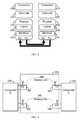
- FIG. 1shows an illustration of a typical architecture 100 of a computing device that includes a PCIe fabric.
- a host bridge 110is coupled to endpoints 120 , a CPU 130 , a memory 140 , and a switch 150 .
- the peripheral componentsare connected through endpoints 120 - 1 to 120 -N ( 120 ). Multiple point-to-point connections are accomplished by the switch 150 , which provides the fanout for the I/O bus.
- the switch 150provides peer-to-peer communication between different endpoints 120 . That is, traffic between the switch 150 and endpoints 120 that does not involve cache-coherent memory transfers, is not forwarded to the host bridge 110 .
- the switch 150is shown as a separate logical element but it could be integrated into the host bridge 110 .
- the PCIeis a layered protocol bus, consisting of a transaction layer 210 , a data link layer 220 , and a physical layer 230 .
- the PCIeimplements split transactions, i.e., transactions with request and response separated by time, allowing the link to carry other traffic while the target device gathers data for the response.
- the primary function of the transaction layer 210is to assemble and disassemble transaction layer packets (TLPs). TLPs are used to carry transactions, where each TLP has a unique identifier that enables a response directed at the originator.
- the data link layer 220acts as an intermediate between the transaction layer 210 and the physical layer 230 and provides a reliable mechanism for exchanging TLPs.
- the data link layer 220implements error checking (known as “LCRC”) and retransmission mechanisms. LCRC and sequencing are applied on received TLPs and if an error is detected, a data link retry is activated.
- the physical layer 230consists of an electrical sub-layer 234 and logical sub-layer 232 .
- the sub-layer 232is a transmitter and receiver pair implementing symbol mapping, serialization and de-serialization of data.
- each laneutilizes two unidirectional low-voltage differential signaling (LVDS) pairs at 2.5 Gbit/s or 5 Gbit/s for transmit and receive symbols from the logical sub-block 232 .
- LVDSlow-voltage differential signaling
- peripheral componentsare physically coupled to the PCIe.
- the UWBis a wireless technology for USB
- Wi-Fiis a standard for Ethernet connection.
- each such wireless interconnect solutioncan only support the connectivity of a limited set of peripheral devices.
- the Wi-Fi standardaims to decouple Ethernet cards and the UWB allows the wireless connection of USB devices, such as a mouse, a keyboard, a printer and the like.
- Certain embodiments disclosed hereininclude a wireless peripheral interconnect bus capable of providing a high rate data transfer between peripheral devices and a host bridge of a computing device over a wireless medium.
- the wireless peripheral interconnect buscomprises a first wireless pair for transferring data from a first peripheral component to a second peripheral component and receiving data transmitted from the second peripheral component to the first peripheral component, wherein the first wireless pair implements at least a layered protocol; and a second wireless pair for transferring data from the second peripheral component and the first peripheral component and receiving data transmitted from the first peripheral component to a second peripheral component, wherein the second wireless pair implements at least a layered protocol.
- PCIewireless peripheral component interconnect PCI Express
- the PCI Express (PCIe) fabriccomprises a switch coupled to a host bridge of a computing device and a plurality of PCIe endpoints; a first wireless pair of a wireless peripheral interconnect bus connected to the switch; and a second wireless pair of a wireless peripheral interconnect bus connected to a PCIe component, wherein the first wireless pair and the second wireless pair communicates over a wireless link.
- FIG. 1is a block diagram showing a conventional architecture of a computer computing device
- FIG. 2is a diagram of layered protocol of a conventional PCIe bus
- FIG. 3is a diagram of a wireless peripheral interconnect bus realized in accordance with an embodiment of the invention.
- FIG. 4is a diagram of layered protocol of a wireless peripheral interconnect bus implemented in accordance with an embodiment of the invention.
- FIG. 5Ais a diagram of a WPAP structure
- FIG. 5Bis a diagram of a WPHY frame structure
- FIG. 6is a block diagram of a wireless PCIe fabric constructed according to an embodiment of the invention.
- FIG. 7is a flowchart describing the method of transporting a PCIe packet over a wireless medium.
- FIG. 3shows an exemplary and non-limiting diagram of a wireless peripheral interconnect bus 300 implemented in accordance with one embodiment of the invention.
- the operation of the wireless peripheral interconnect bus 300will be described with reference to a specific non-limiting embodiment where the bus 300 is a PCIe.
- the wireless bus 300implements a standard PCIe over the air by replacing the low-voltage differential signaling (LVDS) pairs with two wireless links 340 .
- Each wireless link 340includes a wireless receiver 310 and a wireless transmitter 320 , which are coupled to PCIe components 330 .
- a PCIe component 330may be an endpoint (e.g., endpoint 120 ), a switch (e.g., switch 150 ), a host bridge (e.g., bridge 110 ), and so on.
- the endpointscan be utilized to provide for a connection to any type of peripheral devices including, but not limited to, storage devices, displays, projectors, monitors, input devices, PDAs, printers, optical disks, and so on.
- a wireless link 340is unidirectional and capable of transferring data at a high rate with limited latency.
- the wireless bus 300enables a transfer data rate of 2.5 Gb/s per lane over an unlicensed frequency band such as 57-64 GHz or 5-6 GHz.
- the links 340aggregate an unbound number of PCIe lanes, for example, the number of aggregated lanes is 32.
- the wireless receiver 310 and wireless transmitter 320implement a wireless modem, such as an orthogonal frequency division multiplexing (OFDM) modem, a single-carrier modem, a multi-carrier modem, and the like.
- the wireless receiver 310 and wireless transmitter 320can implement sophisticated communication techniques, such as multiple-input-multiple-output (MIMO), beam forming, advanced coding, space time block codes, and so on.
- MIMOmultiple-input-multiple-output
- the wireless peripheral interconnect bus 300also supports a layered protocol such as the PCIe.
- the layered protocol 400 of the wireless peripheral interconnect bus 300includes two new layers: a wireless physical (WPHY) layer 410 and a wireless adaptation layer 420 .
- the layer protocol 400also comprises a data link layer 430 , a transaction layer 440 , and a physical layer 450 .
- the layers 430 , 440 and 450have functionality similar to the transaction layer 210 , data link layer 220 , and physical layer 230 described in greater detail above.
- the wireless adaptation layer 420controls and manages the access to the wireless link 340 in either a full-duplex or half-duplex mode of operation. Specifically, the wireless adaptation layer 420 is responsible for accessing the link and serves as a medium access controller (MAC), by establishing the link between the components 330 and preferably using authentication and encryption techniques to secure the established link.
- MACmedium access controller
- the adaptation layer 420receives transaction layer packets (TLPs) from the transaction link layer 440 and assembles the TLPs in a wireless PCIe adaptation packet (WPAP).
- TLPstransaction layer packets
- WPAPwireless PCIe adaptation packet
- An exemplary structure of a WPAP 500 as generated by the wireless adaptation layer 420is provided in FIG. 5A .
- the WPAP 500includes a header field 510 , a data portion 520 and a cyclic redundancy check (CRC) field 530 with the CRC code computed for the data portion 520 .
- the headermay include a source address, a destination address, a lane ID, a peripheral component ID, or any other type of information used for managing the wireless link 340 .
- the wireless adaptation layer 420may also perform aggregation of TPLs for better efficiency.
- the CRC codeis utilized to reduce the error rate of the wireless adaptation layer 420 , as the error rate in data transmitted over a wireless medium is higher than data transferred by means of wires. Therefore, the adaptation layer further provides a reliable link for the transaction link layer 440 .
- the WPHY layer 410receives the WPAP 500 and constructs a WPHY frame 550 , such as shown in FIG. 5B .
- the WPHY frame 550includes a plurality of symbols 560 - 1 to 560 -N, such as OFDM or other modulation symbols and a preamble field 570 .
- the preamble field 570is a predefined sequence utilized for signal detection, energy measurements, time, frequency and phase synchronization, channel estimation, antenna steering, calibrations, and so on. Different types of preambles may be defined, each of which has different characteristics. For example, a short preamble and a long preamble can be defined, where the long preamble is used for antenna steering and the short preamble is used to increase the link efficiency.
- Each symbol 560includes at least one WPAP 500 .
- Both the wireless adaptation layer 420 and the WPHY layer 410 in the transmitter 320 and receiver 310apply a re-transmission mechanism to ensure a reliable wireless link.
- the transmittermaintains a retransmission buffer to include all packets that have not been acknowledged by the receiver 310 , and non-acknowledged packets are retransmitted by the transmitter 320 .
- the WPHY layer 410controls the transmission rate of re-transmitted symbols 560 in order to avoid situations of the transmitting of out-of-order TLPs provided by the transaction link layer 440 .
- the wireless bus 300can be integrated in a computing device to wirelessly connect a plurality of peripheral components to the device.
- the computing devicemay be, but is not limited to, a personal computer, a laptop, a media player, a mobile phone, a personal digital assistant (PDA), and the like.
- FIG. 6is a block diagram of a fabric 600 used for connecting peripheral components using a wireless peripheral interconnect bus 300 constructed in accordance with the principles of the invention.
- the host bridge 610identifies wireless peripheral interconnect bus 300 as a standard bus terminator (e.g., a PCIe endpoint, a PCIe switch, etc.).
- a first wireless pair of the bus 300is connected to a switch 650 and a second wireless pair of the bus 300 is coupled to an endpoint 620 - 5 . Therefore, data is transferred between the switch 650 and endpoint 620 - 5 over a wireless link (e.g., link 340 ), where the underlying wireless specifics are transparent to any component connected to fabric 600 .
- Each wireless pair of the bus 300includes a wireless receiver and transmitter and implements a layered protocol as discussed in greater detail above.
- the endpoint 620 - 5may be, but is not limited to, a legacy endpoint, a PCIe endpoint, and so on.
- the fabric 600may further include a wireless peripheral interconnect switch 640 formed by coupling a first wireless pair of the bus 300 to the switch 650 and a second wireless pair to a PCIe switch 620 - 6 .
- FIG. 7shows an exemplary and non-limiting flowchart 700 describing a method of transporting PCIe packets over a wireless medium implemented according to one embodiment of the present invention.
- PCIe packetsare sent as TLPs, where each TLP has a unique identifier that enables a response directed at the originator.
- the methodreceives TPLs from the transaction link layer 440 .
- the TPLsare assembled into a WPAP (e.g., WPAP 500 ) where the data and identifier number of a TPL are together saved in the data portion of the WPAP.
- WPAPe.g., WPAP 500
- the data portion of the WPAPincludes a number of ‘n’ TPLs, where ‘n’ is an integer number greater than one.
- a CRC codeis computed and added to the CRC field of the WPAP.
- the WPAPis wrapped as a data symbol and inserted to a WPHY frame (e.g., frame 550 ) by the WPHY layer 410 .
- the WPHY frameis transmitted over a wireless link (e.g., link 340 ) using a first wireless pair of the bus to the second wireless pair which is coupled to a peripheral component.
- the WPHY frameis received as a series of symbols at the WHPY layer 410 which, at S 760 , transfers the symbols to the wireless adaptation layer 420 as WPAPs.
- the wireless adoption layercomputes the CRC value on the data portion and compares the computed value to the value stored in the CRC field. If the CRC values are not equal, the adoption layer 420 corrects the data according to the CRC code.
- the TPLs in the WPAPare disassembled and forwarded to the transaction layer 430 .
- the wireless peripheral interconnect busis implemented as a wireless PCIe.
- the wireless peripheral interconnect buscan be adapted for the use with peripheral devices utilizing connection formats, such as PCIe second generation, PCIe third generation, and the like.
- some or all of the method componentsare implemented as a computer executable code.
- a computer executable codecontains a plurality of computer instructions that when performed result with the execution of the tasks disclosed herein.
- Such computer executable codemay be available as source code or in object code, and may be further comprised as part of, for example, a portable memory device or downloaded from the Internet, or embodied on a program storage unit or computer readable medium.
- the principles of the present inventionmay be implemented as a combination of hardware and software and because some of the constituent system components and methods depicted in the accompanying drawings may be implemented in software, the actual connections between the system components or the process function blocks may differ depending upon the manner in which the present invention is programmed.
- the computer executable codemay be uploaded to, and executed by, a machine comprising any suitable architecture.
- the machineis implemented on a computer platform having hardware such as one or more central processing units (“CPUs”), a random access memory (“RAM”), and input/output interfaces.
- the computer platformmay also include an operating system and microinstruction code.
- the various processes and functions described hereinmay be either part of the microinstruction code or part of the application program, or any combination thereof, which may be executed by a CPU, whether or not such computer or processor is explicitly shown.
- various other peripheral unitsmay be connected to the computer platform such as an additional data storage unit and a printing unit.
- Explicit use of the term CPU, “processor” or “controller”should not be construed to refer exclusively to hardware capable of executing software, and may implicitly include, without limitation, digital signal processor hardware, ROM, RAM, and non-volatile storage.
Landscapes
- Engineering & Computer Science (AREA)
- Computer Networks & Wireless Communication (AREA)
- Signal Processing (AREA)
- Information Transfer Systems (AREA)
Abstract
Description
Claims (20)
Priority Applications (1)
| Application Number | Priority Date | Filing Date | Title |
|---|---|---|---|
| US13/242,110US9655167B2 (en) | 2007-05-16 | 2011-09-23 | Wireless peripheral interconnect bus |
Applications Claiming Priority (3)
| Application Number | Priority Date | Filing Date | Title |
|---|---|---|---|
| US93819007P | 2007-05-16 | 2007-05-16 | |
| US12/034,645US8050290B2 (en) | 2007-05-16 | 2008-02-20 | Wireless peripheral interconnect bus |
| US13/242,110US9655167B2 (en) | 2007-05-16 | 2011-09-23 | Wireless peripheral interconnect bus |
Related Parent Applications (1)
| Application Number | Title | Priority Date | Filing Date |
|---|---|---|---|
| US12/034,645ContinuationUS8050290B2 (en) | 2007-05-16 | 2008-02-20 | Wireless peripheral interconnect bus |
Publications (2)
| Publication Number | Publication Date |
|---|---|
| US20120017015A1 US20120017015A1 (en) | 2012-01-19 |
| US9655167B2true US9655167B2 (en) | 2017-05-16 |
Family
ID=40028689
Family Applications (2)
| Application Number | Title | Priority Date | Filing Date |
|---|---|---|---|
| US12/034,645Expired - Fee RelatedUS8050290B2 (en) | 2007-05-16 | 2008-02-20 | Wireless peripheral interconnect bus |
| US13/242,110Expired - Fee RelatedUS9655167B2 (en) | 2007-05-16 | 2011-09-23 | Wireless peripheral interconnect bus |
Family Applications Before (1)
| Application Number | Title | Priority Date | Filing Date |
|---|---|---|---|
| US12/034,645Expired - Fee RelatedUS8050290B2 (en) | 2007-05-16 | 2008-02-20 | Wireless peripheral interconnect bus |
Country Status (1)
| Country | Link |
|---|---|
| US (2) | US8050290B2 (en) |
Families Citing this family (12)
| Publication number | Priority date | Publication date | Assignee | Title |
|---|---|---|---|---|
| US8050290B2 (en) | 2007-05-16 | 2011-11-01 | Wilocity, Ltd. | Wireless peripheral interconnect bus |
| US9075926B2 (en)* | 2007-07-19 | 2015-07-07 | Qualcomm Incorporated | Distributed interconnect bus apparatus |
| US20090125662A1 (en)* | 2007-11-09 | 2009-05-14 | J-Three International Holding Co., Ltd. | Switch having integrated connectors |
| US8472436B2 (en)* | 2007-12-27 | 2013-06-25 | Wilocity, Ltd. | Modular wireless docking station |
| US8199759B2 (en)* | 2009-05-29 | 2012-06-12 | Intel Corporation | Method and apparatus for enabling ID based streams over PCI express |
| US8443126B2 (en)* | 2010-09-22 | 2013-05-14 | Wilocity, Ltd. | Hot plug process in a distributed interconnect bus |
| TWI528161B (en) | 2010-09-30 | 2016-04-01 | 瑞昱半導體股份有限公司 | Data transmitting system and data transmitting method |
| US20120324139A1 (en)* | 2011-06-14 | 2012-12-20 | Advanced Micro Devices, Inc. | Wireless communication for point-to-point serial link protocol |
| US8626982B2 (en)* | 2011-06-29 | 2014-01-07 | Broadcom Corporation | Dynamically configurable wireless data bus switch for coupling a data bus to a wireless link |
| US8972640B2 (en)* | 2012-06-27 | 2015-03-03 | Intel Corporation | Controlling a physical link of a first protocol using an extended capability structure of a second protocol |
| MY169964A (en) | 2012-06-29 | 2019-06-19 | Intel Corp | An architected protocol for changing link operating mode |
| US20160093960A1 (en)* | 2014-09-26 | 2016-03-31 | Intel Corporation | Press-Fit Internal Cable |
Citations (67)
| Publication number | Priority date | Publication date | Assignee | Title |
|---|---|---|---|---|
| US4862454A (en) | 1988-07-15 | 1989-08-29 | International Business Machines Corporation | Switching method for multistage interconnection networks with hot spot traffic |
| US5825617A (en) | 1992-10-02 | 1998-10-20 | Teletransactions, Inc. | Workslate computer having modular device docking stations on horizontal and vertical side portions |
| US5923757A (en) | 1994-08-25 | 1999-07-13 | International Business Machines Corporation | Docking method for establishing secure wireless connection between computer devices using a docket port |
| US5926629A (en) | 1997-02-18 | 1999-07-20 | Advanced Micro Devices, Inc. | Continuously operating interconnection bus |
| US6170026B1 (en) | 1998-06-16 | 2001-01-02 | Modubility Llc | Mobile computing systems which automatically reconfigure to operate any devices attached to a docking module upon connection to the docking station |
| WO2001011476A1 (en) | 1999-08-11 | 2001-02-15 | Henry Milan | Universal serial bus hub with wireless communication to remote peripheral devices |
| US6226700B1 (en) | 1998-03-13 | 2001-05-01 | Compaq Computer Corporation | Computer system with bridge logic that includes an internal modular expansion bus and a common master interface for internal master devices |
| US6396809B1 (en) | 1996-12-12 | 2002-05-28 | Pmc-Sierra, Inc. | Method for signaling in a high speed communication system |
| US20020080756A1 (en)* | 2000-09-28 | 2002-06-27 | Giuseppe Coppola | Wireless network interface |
| US20020138565A1 (en)* | 2001-03-26 | 2002-09-26 | First Hop Oy | Methods & arrangements for providing efficient information transfer over a limited-speed communications link |
| US6499079B1 (en) | 1998-11-23 | 2002-12-24 | Advanced Micro Devices, Inc. | Subordinate bridge structure for a point-to-point computer interconnection bus |
| US20030198015A1 (en) | 2002-04-19 | 2003-10-23 | Edwin Vogt | Mobile docking station |
| US20030219034A1 (en)* | 2002-02-19 | 2003-11-27 | Lotter Michiel Petrus | Method and apparatus optimizing a radio link |
| US20040122771A1 (en) | 2002-12-19 | 2004-06-24 | International Business Machines Corporation | Automated teller machine for use with computing devices |
| US6798775B1 (en) | 1999-06-10 | 2004-09-28 | Cisco Technology, Inc. | Virtual LANs over a DLSw network |
| US20040208130A1 (en) | 2003-04-21 | 2004-10-21 | Nec Corporation | Data processing apparatus and data processing method |
| US20040220803A1 (en) | 2003-04-30 | 2004-11-04 | Motorola, Inc. | Method and apparatus for transferring data over a voice channel |
| US20050047079A1 (en) | 2003-08-26 | 2005-03-03 | Gasbarro Henry Frank | Computer system with configurable docking station |
| US20050075080A1 (en) | 2003-10-03 | 2005-04-07 | Nanyang Technological University | Inter-chip and intra-chip wireless communications systems |
| US6898766B2 (en) | 2001-10-30 | 2005-05-24 | Texas Instruments Incorporated | Simplifying integrated circuits with a common communications bus |
| US6937468B2 (en) | 2003-11-20 | 2005-08-30 | Tatung Co., Ltd. | Portable computer and portable docking station arrangement |
| US20050220173A1 (en) | 2004-03-12 | 2005-10-06 | Conexant Systems, Inc. | Methods and systems for frequency shift keyed modulation for broadband ultra wideband communication |
| US20050246470A1 (en) | 2004-04-28 | 2005-11-03 | Brenner David G | Wireless docking station |
| US20050248502A1 (en) | 2002-12-20 | 2005-11-10 | James Okuley | Method, apparatus and system for a secondary personal computer display |
| US20050262269A1 (en) | 2004-05-20 | 2005-11-24 | Pike Jimmy D | System and method for information handling system PCI express advanced switching |
| US20050278756A1 (en)* | 2004-06-12 | 2005-12-15 | Brown Alan E | Information processing apparatus featuring a multi-subsystem wireless bus architecture |
| US20060050707A1 (en) | 2004-09-09 | 2006-03-09 | Intel Corporation | Methods and apparatus for multiple bit rate serial communication |
| US20060061963A1 (en) | 2004-09-21 | 2006-03-23 | Schrum Sidney B | Wireless virtual docking |
| US20060080722A1 (en) | 2004-10-12 | 2006-04-13 | John Santhoff | Buffered waveforms for high speed digital to analog conversion |
| US7058738B2 (en) | 2004-04-28 | 2006-06-06 | Microsoft Corporation | Configurable PCI express switch which allows multiple CPUs to be connected to multiple I/O devices |
| US20060126612A1 (en)* | 2004-11-23 | 2006-06-15 | Sandy Douglas L | Method of transporting a PCI express packet over an IP packet network |
| US20060129709A1 (en) | 2004-12-09 | 2006-06-15 | International Business Machines Corporation | Multipurpose scalable server communication link |
| US20060143338A1 (en) | 2004-12-29 | 2006-06-29 | Hunsaker Mikal C | Autodetection of a PCI express device operating at a wireless RF mitigation frequency |
| US7079544B2 (en) | 2000-06-02 | 2006-07-18 | Hitachi, Ltd. | Apparatus and method for interworking between MPLS network and non-MPLS network |
| US7096310B2 (en) | 2004-03-16 | 2006-08-22 | Hewlett-Packard Development, L.P. | Switch configurable for a plurality of communication protocols |
| US20060206655A1 (en) | 2004-12-10 | 2006-09-14 | Chappell Christopher L | Packet processing in switched fabric networks |
| US20060222125A1 (en) | 2005-03-31 | 2006-10-05 | Edwards John W Jr | Systems and methods for maintaining synchronicity during signal transmission |
| US20060233191A1 (en) | 2005-04-15 | 2006-10-19 | Pirzada Fahd B | Systems and methods for managing wireless communication |
| US20060251096A1 (en) | 2005-04-18 | 2006-11-09 | Cisco Technonogy, Inc. | PCI express switch with encryption and queues for performance enhancement |
| TW200709616A (en) | 2005-08-19 | 2007-03-01 | Emine Technology Company Ltd | Switch hub connected with peripheral device bus |
| US20070067551A1 (en) | 2005-09-21 | 2007-03-22 | Junichi Ikeda | Information processor |
| US20070173202A1 (en) | 2006-01-11 | 2007-07-26 | Serconet Ltd. | Apparatus and method for frequency shifting of a wireless signal and systems using frequency shifting |
| US20070189270A1 (en) | 2006-02-15 | 2007-08-16 | Borislow Daniel M | Network adapter |
| US20070198763A1 (en) | 2006-02-17 | 2007-08-23 | Nec Corporation | Switch and network bridge apparatus |
| US7293129B2 (en) | 2005-04-22 | 2007-11-06 | Sun Microsystems, Inc. | Flexible routing and addressing |
| US20070283181A1 (en) | 2005-12-30 | 2007-12-06 | Avocent Corporation | Packet-switched split computer |
| US20070291636A1 (en) | 2006-06-14 | 2007-12-20 | Wiquest Communications, Inc. | System, Method and Computer-Readable Medium for Detection and Avoidance of Victim Services in Ultra-Wideband Systems |
| US7320080B2 (en) | 2003-10-15 | 2008-01-15 | Intel Corporation | Power management over switching fabrics |
| US20080018491A1 (en)* | 2000-04-14 | 2008-01-24 | Berkman William H | Automated Meter Reading Communication System And Method |
| US7340555B2 (en) | 2001-09-28 | 2008-03-04 | Dot Hill Systems Corporation | RAID system for performing efficient mirrored posted-write operations |
| US20080071961A1 (en) | 2006-09-20 | 2008-03-20 | Nec Corporation | Shared system of i/o equipment, shared system of information processing apparatus, and method used thereto |
| US7356635B2 (en) | 2004-09-24 | 2008-04-08 | Cypress Semiconductor Corp. | Compressed report descriptors for USB devices |
| US7363404B2 (en) | 2005-10-27 | 2008-04-22 | International Business Machines Corporation | Creation and management of destination ID routing structures in multi-host PCI topologies |
| US20080147904A1 (en) | 2006-12-19 | 2008-06-19 | Freimuth Douglas M | System and method for communication between host systems using a socket connection and shared memories |
| US20080219376A1 (en)* | 2007-03-05 | 2008-09-11 | Xiao-Feng Qi | Methods and arrangements for communicating in a multiple input multiple output system |
| US7467313B2 (en) | 2005-03-15 | 2008-12-16 | Nvidia Corporation | Method for transmitting a power-saving command between a computer system and peripheral system chips |
| US7469366B1 (en) | 2005-12-13 | 2008-12-23 | Nvidia Corporation | Measurement of health statistics for a high-speed interface |
| US20090024782A1 (en) | 2007-07-19 | 2009-01-22 | Wilocity Ltd. | Distributed interconnect bus apparatus |
| US7519761B2 (en) | 2006-10-10 | 2009-04-14 | International Business Machines Corporation | Transparent PCI-based multi-host switch |
| US7525986B2 (en) | 2004-10-28 | 2009-04-28 | Intel Corporation | Starvation prevention scheme for a fixed priority PCI-Express arbiter with grant counters using arbitration pools |
| US7543096B2 (en) | 2005-01-20 | 2009-06-02 | Dot Hill Systems Corporation | Safe message transfers on PCI-Express link from RAID controller to receiver-programmable window of partner RAID controller CPU memory |
| US7596646B2 (en)* | 2005-09-15 | 2009-09-29 | Electronics And Telecommunications Research Institute | Wireless USB host apparatus supporting UWB |
| US7916750B2 (en) | 2005-12-28 | 2011-03-29 | Intel Corporation | Transaction layer packet compression |
| US8006014B2 (en) | 2008-08-14 | 2011-08-23 | Via Technologies, Inc. | PCI-Express data link transmitter employing a plurality of dynamically selectable data transmission priority rules |
| US8050290B2 (en) | 2007-05-16 | 2011-11-01 | Wilocity, Ltd. | Wireless peripheral interconnect bus |
| US8374157B2 (en) | 2007-02-12 | 2013-02-12 | Wilocity, Ltd. | Wireless docking station |
| US8472436B2 (en) | 2007-12-27 | 2013-06-25 | Wilocity, Ltd. | Modular wireless docking station |
- 2008
- 2008-02-20USUS12/034,645patent/US8050290B2/ennot_activeExpired - Fee Related
- 2011
- 2011-09-23USUS13/242,110patent/US9655167B2/ennot_activeExpired - Fee Related
Patent Citations (69)
| Publication number | Priority date | Publication date | Assignee | Title |
|---|---|---|---|---|
| US4862454A (en) | 1988-07-15 | 1989-08-29 | International Business Machines Corporation | Switching method for multistage interconnection networks with hot spot traffic |
| US5825617A (en) | 1992-10-02 | 1998-10-20 | Teletransactions, Inc. | Workslate computer having modular device docking stations on horizontal and vertical side portions |
| US5930368A (en) | 1994-08-25 | 1999-07-27 | International Business Machines Corporation | Docking method for establishing secure wireless connection between computer devices |
| US5923757A (en) | 1994-08-25 | 1999-07-13 | International Business Machines Corporation | Docking method for establishing secure wireless connection between computer devices using a docket port |
| US6396809B1 (en) | 1996-12-12 | 2002-05-28 | Pmc-Sierra, Inc. | Method for signaling in a high speed communication system |
| US5926629A (en) | 1997-02-18 | 1999-07-20 | Advanced Micro Devices, Inc. | Continuously operating interconnection bus |
| US6226700B1 (en) | 1998-03-13 | 2001-05-01 | Compaq Computer Corporation | Computer system with bridge logic that includes an internal modular expansion bus and a common master interface for internal master devices |
| US6170026B1 (en) | 1998-06-16 | 2001-01-02 | Modubility Llc | Mobile computing systems which automatically reconfigure to operate any devices attached to a docking module upon connection to the docking station |
| US6499079B1 (en) | 1998-11-23 | 2002-12-24 | Advanced Micro Devices, Inc. | Subordinate bridge structure for a point-to-point computer interconnection bus |
| US6798775B1 (en) | 1999-06-10 | 2004-09-28 | Cisco Technology, Inc. | Virtual LANs over a DLSw network |
| WO2001011476A1 (en) | 1999-08-11 | 2001-02-15 | Henry Milan | Universal serial bus hub with wireless communication to remote peripheral devices |
| US20080018491A1 (en)* | 2000-04-14 | 2008-01-24 | Berkman William H | Automated Meter Reading Communication System And Method |
| US7079544B2 (en) | 2000-06-02 | 2006-07-18 | Hitachi, Ltd. | Apparatus and method for interworking between MPLS network and non-MPLS network |
| US20020080756A1 (en)* | 2000-09-28 | 2002-06-27 | Giuseppe Coppola | Wireless network interface |
| US20020138565A1 (en)* | 2001-03-26 | 2002-09-26 | First Hop Oy | Methods & arrangements for providing efficient information transfer over a limited-speed communications link |
| US7340555B2 (en) | 2001-09-28 | 2008-03-04 | Dot Hill Systems Corporation | RAID system for performing efficient mirrored posted-write operations |
| US6898766B2 (en) | 2001-10-30 | 2005-05-24 | Texas Instruments Incorporated | Simplifying integrated circuits with a common communications bus |
| US20030219034A1 (en)* | 2002-02-19 | 2003-11-27 | Lotter Michiel Petrus | Method and apparatus optimizing a radio link |
| US20030198015A1 (en) | 2002-04-19 | 2003-10-23 | Edwin Vogt | Mobile docking station |
| US20040122771A1 (en) | 2002-12-19 | 2004-06-24 | International Business Machines Corporation | Automated teller machine for use with computing devices |
| US20050248502A1 (en) | 2002-12-20 | 2005-11-10 | James Okuley | Method, apparatus and system for a secondary personal computer display |
| US20040208130A1 (en) | 2003-04-21 | 2004-10-21 | Nec Corporation | Data processing apparatus and data processing method |
| US20040220803A1 (en) | 2003-04-30 | 2004-11-04 | Motorola, Inc. | Method and apparatus for transferring data over a voice channel |
| US20050047079A1 (en) | 2003-08-26 | 2005-03-03 | Gasbarro Henry Frank | Computer system with configurable docking station |
| US20050075080A1 (en) | 2003-10-03 | 2005-04-07 | Nanyang Technological University | Inter-chip and intra-chip wireless communications systems |
| US7320080B2 (en) | 2003-10-15 | 2008-01-15 | Intel Corporation | Power management over switching fabrics |
| US6937468B2 (en) | 2003-11-20 | 2005-08-30 | Tatung Co., Ltd. | Portable computer and portable docking station arrangement |
| US20050220173A1 (en) | 2004-03-12 | 2005-10-06 | Conexant Systems, Inc. | Methods and systems for frequency shift keyed modulation for broadband ultra wideband communication |
| US7096310B2 (en) | 2004-03-16 | 2006-08-22 | Hewlett-Packard Development, L.P. | Switch configurable for a plurality of communication protocols |
| US7058738B2 (en) | 2004-04-28 | 2006-06-06 | Microsoft Corporation | Configurable PCI express switch which allows multiple CPUs to be connected to multiple I/O devices |
| US20050246470A1 (en) | 2004-04-28 | 2005-11-03 | Brenner David G | Wireless docking station |
| US20050262269A1 (en) | 2004-05-20 | 2005-11-24 | Pike Jimmy D | System and method for information handling system PCI express advanced switching |
| US20050278756A1 (en)* | 2004-06-12 | 2005-12-15 | Brown Alan E | Information processing apparatus featuring a multi-subsystem wireless bus architecture |
| US20060050707A1 (en) | 2004-09-09 | 2006-03-09 | Intel Corporation | Methods and apparatus for multiple bit rate serial communication |
| US20060061963A1 (en) | 2004-09-21 | 2006-03-23 | Schrum Sidney B | Wireless virtual docking |
| US7356635B2 (en) | 2004-09-24 | 2008-04-08 | Cypress Semiconductor Corp. | Compressed report descriptors for USB devices |
| US20060080722A1 (en) | 2004-10-12 | 2006-04-13 | John Santhoff | Buffered waveforms for high speed digital to analog conversion |
| US7525986B2 (en) | 2004-10-28 | 2009-04-28 | Intel Corporation | Starvation prevention scheme for a fixed priority PCI-Express arbiter with grant counters using arbitration pools |
| US20060126612A1 (en)* | 2004-11-23 | 2006-06-15 | Sandy Douglas L | Method of transporting a PCI express packet over an IP packet network |
| US20060129709A1 (en) | 2004-12-09 | 2006-06-15 | International Business Machines Corporation | Multipurpose scalable server communication link |
| US20060206655A1 (en) | 2004-12-10 | 2006-09-14 | Chappell Christopher L | Packet processing in switched fabric networks |
| US20060143338A1 (en) | 2004-12-29 | 2006-06-29 | Hunsaker Mikal C | Autodetection of a PCI express device operating at a wireless RF mitigation frequency |
| US7543096B2 (en) | 2005-01-20 | 2009-06-02 | Dot Hill Systems Corporation | Safe message transfers on PCI-Express link from RAID controller to receiver-programmable window of partner RAID controller CPU memory |
| US7467313B2 (en) | 2005-03-15 | 2008-12-16 | Nvidia Corporation | Method for transmitting a power-saving command between a computer system and peripheral system chips |
| US20060222125A1 (en) | 2005-03-31 | 2006-10-05 | Edwards John W Jr | Systems and methods for maintaining synchronicity during signal transmission |
| US20060233191A1 (en) | 2005-04-15 | 2006-10-19 | Pirzada Fahd B | Systems and methods for managing wireless communication |
| US20060251096A1 (en) | 2005-04-18 | 2006-11-09 | Cisco Technonogy, Inc. | PCI express switch with encryption and queues for performance enhancement |
| US7293129B2 (en) | 2005-04-22 | 2007-11-06 | Sun Microsystems, Inc. | Flexible routing and addressing |
| TW200709616A (en) | 2005-08-19 | 2007-03-01 | Emine Technology Company Ltd | Switch hub connected with peripheral device bus |
| US7596646B2 (en)* | 2005-09-15 | 2009-09-29 | Electronics And Telecommunications Research Institute | Wireless USB host apparatus supporting UWB |
| US20070067551A1 (en) | 2005-09-21 | 2007-03-22 | Junichi Ikeda | Information processor |
| US7363404B2 (en) | 2005-10-27 | 2008-04-22 | International Business Machines Corporation | Creation and management of destination ID routing structures in multi-host PCI topologies |
| US7469366B1 (en) | 2005-12-13 | 2008-12-23 | Nvidia Corporation | Measurement of health statistics for a high-speed interface |
| US7916750B2 (en) | 2005-12-28 | 2011-03-29 | Intel Corporation | Transaction layer packet compression |
| US20070283181A1 (en) | 2005-12-30 | 2007-12-06 | Avocent Corporation | Packet-switched split computer |
| US20070173202A1 (en) | 2006-01-11 | 2007-07-26 | Serconet Ltd. | Apparatus and method for frequency shifting of a wireless signal and systems using frequency shifting |
| US20070189270A1 (en) | 2006-02-15 | 2007-08-16 | Borislow Daniel M | Network adapter |
| US20070198763A1 (en) | 2006-02-17 | 2007-08-23 | Nec Corporation | Switch and network bridge apparatus |
| US20070291636A1 (en) | 2006-06-14 | 2007-12-20 | Wiquest Communications, Inc. | System, Method and Computer-Readable Medium for Detection and Avoidance of Victim Services in Ultra-Wideband Systems |
| US20080071961A1 (en) | 2006-09-20 | 2008-03-20 | Nec Corporation | Shared system of i/o equipment, shared system of information processing apparatus, and method used thereto |
| US7519761B2 (en) | 2006-10-10 | 2009-04-14 | International Business Machines Corporation | Transparent PCI-based multi-host switch |
| US20080147904A1 (en) | 2006-12-19 | 2008-06-19 | Freimuth Douglas M | System and method for communication between host systems using a socket connection and shared memories |
| US8374157B2 (en) | 2007-02-12 | 2013-02-12 | Wilocity, Ltd. | Wireless docking station |
| US20130124762A1 (en) | 2007-02-12 | 2013-05-16 | Wilocity, Ltd. | Wireless docking station |
| US20080219376A1 (en)* | 2007-03-05 | 2008-09-11 | Xiao-Feng Qi | Methods and arrangements for communicating in a multiple input multiple output system |
| US8050290B2 (en) | 2007-05-16 | 2011-11-01 | Wilocity, Ltd. | Wireless peripheral interconnect bus |
| US20090024782A1 (en) | 2007-07-19 | 2009-01-22 | Wilocity Ltd. | Distributed interconnect bus apparatus |
| US8472436B2 (en) | 2007-12-27 | 2013-06-25 | Wilocity, Ltd. | Modular wireless docking station |
| US8006014B2 (en) | 2008-08-14 | 2011-08-23 | Via Technologies, Inc. | PCI-Express data link transmitter employing a plurality of dynamically selectable data transmission priority rules |
Non-Patent Citations (6)
| Title |
|---|
| Chiang J., et al., "Advanced Switching Versus PCI-Express for Peer-to-Peer Communications," May 2004, ASI-SIG, Vitesse Semiconductor Corp., Camarillo, CA. Retrieved Mar. 12, 2009. |
| Digital-Logic AG: "Solution Guide Embedded Computer 2008, vol. II" (Fall issue), Sep. 5, 2008,Digital-Logic AG, Switzerland, Retrieved date Oct. 8, 2009. |
| International Search Report and the Written Opinion of the International Searching Authority for the corresponding International Application No. PCT/US2008/070405, dated Jan. 28, 2009. |
| PC/104 Embedded Consortium: "What is PCI/104-Express (TM)?", Rev. A, published Apr. 3, 2008. |
| PCI Express Base Specification Revision 1.0 Jul. 22, 2002. |
| PCI Express* Ethernet Networking, Sep. 2005 Intel White Paper. |
Also Published As
| Publication number | Publication date |
|---|---|
| US8050290B2 (en) | 2011-11-01 |
| US20080288705A1 (en) | 2008-11-20 |
| US20120017015A1 (en) | 2012-01-19 |
Similar Documents
| Publication | Publication Date | Title |
|---|---|---|
| US9655167B2 (en) | Wireless peripheral interconnect bus | |
| US9081905B2 (en) | Low latency interconnect bus protocol | |
| US9830292B2 (en) | Architected protocol for changing link operating mode | |
| US9396152B2 (en) | Device, system and method for communication with heterogenous physical layers | |
| JP2011501483A (en) | Millimeter-wave communication for peripheral devices | |
| US7793030B2 (en) | Association of multiple PCI express links with a single PCI express port | |
| US9390046B2 (en) | Controlling a physical link of a first protocol using an extended capability structure of a second protocol | |
| US9032105B2 (en) | Scalable method and apparatus to configure a link | |
| AU2009281668B2 (en) | Method and apparatus for connecting USB devices to a remote computer | |
| KR20070087547A (en) | Variable Length Integration Verification System and Method in Shared Resource Network | |
| US20130318279A1 (en) | Providing A Load/Store Communication Protocol With A Low Power Physical Unit | |
| CN101006673A (en) | System and method for variable length aggregate acknowledgements in a shared resource network | |
| US9075926B2 (en) | Distributed interconnect bus apparatus | |
| CN102681957A (en) | Enhanced wireless USB protocol and hub | |
| EP3035713B1 (en) | Close proximity transport configuration | |
| RU2009144275A (en) | METHOD AND DEVICE FOR INTERVIEW IN A WIRELESS COMMUNICATION SYSTEM | |
| US9477615B1 (en) | Bi-directional low latency bus mode | |
| US20040203371A1 (en) | Error control in a bluetooth wireless communication system | |
| US7400640B2 (en) | Partitioned medium access control implementation | |
| CN117941411A (en) | Communication method and multi-link device | |
| Huang et al. | OBEX and high speed IrDA links | |
| GB2394151A (en) | Error control in a Bluetooth (RTM) wireless communication system |
Legal Events
| Date | Code | Title | Description |
|---|---|---|---|
| AS | Assignment | Owner name:QUALCOMM ATHEROS, INC., CALIFORNIA Free format text:ASSIGNMENT OF ASSIGNORS INTEREST;ASSIGNOR:WILOCITY LTD.;REEL/FRAME:033521/0593 Effective date:20140707 Owner name:QUALCOMM INCORPORATED, CALIFORNIA Free format text:ASSIGNMENT OF ASSIGNORS INTEREST;ASSIGNOR:QUALCOMM ATHEROS, INC.;REEL/FRAME:033521/0834 Effective date:20140801 | |
| FEPP | Fee payment procedure | Free format text:PAYOR NUMBER ASSIGNED (ORIGINAL EVENT CODE: ASPN); ENTITY STATUS OF PATENT OWNER: LARGE ENTITY | |
| STCF | Information on status: patent grant | Free format text:PATENTED CASE | |
| FEPP | Fee payment procedure | Free format text:ENTITY STATUS SET TO UNDISCOUNTED (ORIGINAL EVENT CODE: BIG.); ENTITY STATUS OF PATENT OWNER: LARGE ENTITY | |
| MAFP | Maintenance fee payment | Free format text:PAYMENT OF MAINTENANCE FEE, 4TH YEAR, LARGE ENTITY (ORIGINAL EVENT CODE: M1551); ENTITY STATUS OF PATENT OWNER: LARGE ENTITY Year of fee payment:4 | |
| FEPP | Fee payment procedure | Free format text:MAINTENANCE FEE REMINDER MAILED (ORIGINAL EVENT CODE: REM.); ENTITY STATUS OF PATENT OWNER: LARGE ENTITY | |
| LAPS | Lapse for failure to pay maintenance fees | Free format text:PATENT EXPIRED FOR FAILURE TO PAY MAINTENANCE FEES (ORIGINAL EVENT CODE: EXP.); ENTITY STATUS OF PATENT OWNER: LARGE ENTITY | |
| STCH | Information on status: patent discontinuation | Free format text:PATENT EXPIRED DUE TO NONPAYMENT OF MAINTENANCE FEES UNDER 37 CFR 1.362 | |
| FP | Lapsed due to failure to pay maintenance fee | Effective date:20250516 |