US9651142B2 - Differential carrier temperature sensing method - Google Patents
Differential carrier temperature sensing methodDownload PDFInfo
- Publication number
- US9651142B2 US9651142B2US14/197,586US201414197586AUS9651142B2US 9651142 B2US9651142 B2US 9651142B2US 201414197586 AUS201414197586 AUS 201414197586AUS 9651142 B2US9651142 B2US 9651142B2
- Authority
- US
- United States
- Prior art keywords
- housing
- package
- differential carrier
- temperature
- differential
- Prior art date
- Legal status (The legal status is an assumption and is not a legal conclusion. Google has not performed a legal analysis and makes no representation as to the accuracy of the status listed.)
- Expired - Fee Related, expires
Links
- 238000000034methodMethods0.000titleabstractdescription6
- 239000002470thermal conductorSubstances0.000claimsabstractdescription47
- 239000012530fluidSubstances0.000claimsabstractdescription36
- 239000000314lubricantSubstances0.000claimsdescription7
- 229910052782aluminiumInorganic materials0.000claimsdescription5
- XAGFODPZIPBFFR-UHFFFAOYSA-NaluminiumChemical compound[Al]XAGFODPZIPBFFR-UHFFFAOYSA-N0.000claimsdescription5
- 229910052751metalInorganic materials0.000claimsdescription2
- 239000002184metalSubstances0.000claimsdescription2
- 238000012544monitoring processMethods0.000description6
- 239000004020conductorSubstances0.000description5
- 238000010586diagramMethods0.000description4
- 239000007788liquidSubstances0.000description4
- 230000009286beneficial effectEffects0.000description2
- 230000008901benefitEffects0.000description2
- 239000000969carrierSubstances0.000description2
- 239000002923metal particleSubstances0.000description2
- 238000009529body temperature measurementMethods0.000description1
- 238000001514detection methodMethods0.000description1
- 230000007774longtermEffects0.000description1
- 238000005461lubricationMethods0.000description1
- 238000003754machiningMethods0.000description1
- 239000000463materialSubstances0.000description1
- 238000007789sealingMethods0.000description1
Images


Classifications
- F—MECHANICAL ENGINEERING; LIGHTING; HEATING; WEAPONS; BLASTING
- F16—ENGINEERING ELEMENTS AND UNITS; GENERAL MEASURES FOR PRODUCING AND MAINTAINING EFFECTIVE FUNCTIONING OF MACHINES OR INSTALLATIONS; THERMAL INSULATION IN GENERAL
- F16H—GEARING
- F16H57/00—General details of gearing
- F16H57/01—Monitoring wear or stress of gearing elements, e.g. for triggering maintenance
- F—MECHANICAL ENGINEERING; LIGHTING; HEATING; WEAPONS; BLASTING
- F16—ENGINEERING ELEMENTS AND UNITS; GENERAL MEASURES FOR PRODUCING AND MAINTAINING EFFECTIVE FUNCTIONING OF MACHINES OR INSTALLATIONS; THERMAL INSULATION IN GENERAL
- F16H—GEARING
- F16H57/00—General details of gearing
- F16H57/04—Features relating to lubrication or cooling or heating
- F16H57/0405—Monitoring quality of lubricant or hydraulic fluids
- F—MECHANICAL ENGINEERING; LIGHTING; HEATING; WEAPONS; BLASTING
- F16—ENGINEERING ELEMENTS AND UNITS; GENERAL MEASURES FOR PRODUCING AND MAINTAINING EFFECTIVE FUNCTIONING OF MACHINES OR INSTALLATIONS; THERMAL INSULATION IN GENERAL
- F16H—GEARING
- F16H59/00—Control inputs to control units of change-speed- or reversing-gearings for conveying rotary motion
- F16H59/68—Inputs being a function of gearing status
- F16H59/72—Inputs being a function of gearing status dependent on oil characteristics, e.g. temperature, viscosity
- F—MECHANICAL ENGINEERING; LIGHTING; HEATING; WEAPONS; BLASTING
- F16—ENGINEERING ELEMENTS AND UNITS; GENERAL MEASURES FOR PRODUCING AND MAINTAINING EFFECTIVE FUNCTIONING OF MACHINES OR INSTALLATIONS; THERMAL INSULATION IN GENERAL
- F16H—GEARING
- F16H61/00—Control functions within control units of change-speed- or reversing-gearings for conveying rotary motion ; Control of exclusively fluid gearing, friction gearing, gearings with endless flexible members or other particular types of gearing
- F16H61/0003—Arrangement or mounting of elements of the control apparatus, e.g. valve assemblies or snapfittings of valves; Arrangements of the control unit on or in the transmission gearbox
- F16H61/0006—Electronic control units for transmission control, e.g. connectors, casings or circuit boards
- G—PHYSICS
- G01—MEASURING; TESTING
- G01K—MEASURING TEMPERATURE; MEASURING QUANTITY OF HEAT; THERMALLY-SENSITIVE ELEMENTS NOT OTHERWISE PROVIDED FOR
- G01K7/00—Measuring temperature based on the use of electric or magnetic elements directly sensitive to heat ; Power supply therefor, e.g. using thermoelectric elements
- G01K7/42—Circuits effecting compensation of thermal inertia; Circuits for predicting the stationary value of a temperature
- G01K7/427—Temperature calculation based on spatial modeling, e.g. spatial inter- or extrapolation
- G—PHYSICS
- G01—MEASURING; TESTING
- G01N—INVESTIGATING OR ANALYSING MATERIALS BY DETERMINING THEIR CHEMICAL OR PHYSICAL PROPERTIES
- G01N25/00—Investigating or analyzing materials by the use of thermal means
- G01N25/72—Investigating presence of flaws
- H—ELECTRICITY
- H05—ELECTRIC TECHNIQUES NOT OTHERWISE PROVIDED FOR
- H05K—PRINTED CIRCUITS; CASINGS OR CONSTRUCTIONAL DETAILS OF ELECTRIC APPARATUS; MANUFACTURE OF ASSEMBLAGES OF ELECTRICAL COMPONENTS
- H05K7/00—Constructional details common to different types of electric apparatus
- H05K7/20—Modifications to facilitate cooling, ventilating, or heating
- H05K7/20845—Modifications to facilitate cooling, ventilating, or heating for automotive electronic casings
- H05K7/20854—Heat transfer by conduction from internal heat source to heat radiating structure
Definitions
- the present inventionrelates to a temperature sensing method for the inside of a vehicle differential.
- a vehicle differentialis a device employing differential gears within a housing called a differential carrier.
- the vehicle differentialis connected to three shafts.
- An input shafttransmits torque and rotation from a vehicle engine into the differential gears.
- each of the other two shaftsseparately transmits a portion of the torque and rotation from the differential gears out to separate external wheels.
- the differential gears within the differential carrierare at least partially submerged in a lubricant, for example, a mineral—standard base lubricant or a synthetic—premium lubricant.
- a lubricantfor example, a mineral—standard base lubricant or a synthetic—premium lubricant.
- the lubricantmay be certified as an API GL5 classification oil or SAE J2360 standard oil, and sealed within the differential carrier housing.
- a differential carrier temperature sensing packageis used to determine the internal temperature T INT of a differential carrier by utilizing a sensed differential fluid temperature T SNS , an internal package temperature T PCB , a thermal resistance of the package plus a thermal conductor R ENC , and a thermal resistance at an electronic circuit board R PCB within the package.
- a differential carrier temperature sensing packagecomprises a differential package housing that comprises an upper portion and a lower portion that are sealed together.
- the two package portionsmay be unitary.
- the upper portion and the lower portionare in thermal contact with an environment that is external to a differential carrier housing.
- the lower portionis also in thermally conductive contact with an outer surface of the differential carrier housing, where the lower portion of the differential package housing extends through an opening in the differential housing, thereby being in thermally conductive contact with a fluid within the differential housing.
- the fluidmay be in a form of a liquid and/or vapor.
- the package housingfurther comprises an electronic circuit, and first and second temperature sensors.
- the electronic circuitis attached to the upper portion within the package housing and is in thermally conductive contact with the upper portion.
- the first temperature sensoris disposed on the electronic circuit and is in thermally conductive contact with a thermal conductor that is disposed within the package housing.
- the thermal conductoris imbedded in, and consequently, is in thermally conductive contact with the lower portion, which in turn is in thermally conductive contact with the fluid within the differential housing.
- the differential fluid temperature T SNSis determined by thermal conduction through the electronic circuit, the first sensor, the thermally conductive conductor, and the lower portion of the package housing.
- the second temperature sensoris disposed on the electronic circuit.
- the temperature at the electronic board T PCBwhich is taken to be the temperature within the package housing, is determined by thermal conduction from the electronic circuit tp the second sensor.
- the electronic circuitcan determine an internal carrier temperature T INT , which can be communicated outside of the package housing, for monitoring and controlling a vehicle within which the differential carrier resides.
- a differential carrier temperature sensing packagecomprises a package housing that comprises an upper portion and a lower portion that are sealed together.
- the two package housing portionsmay be unitary.
- the upper portion and the lower portionare in thermal contact with an environment that is external to a differential carrier housing.
- the lower portionis also in thermally conductive contact with an outer surface of the differential housing, where the lower portion of the package housing extends through an opening in the differential housing, thereby being in thermally conductive contact with a fluid within the differential housing.
- the fluidmay be in a form of a liquid and/or vapor.
- the package housingfurther comprises an electronic circuit, and first and second temperature sensors.
- the electronic circuitis attached to and is in thermally conductive contact with the upper portion within the package housing.
- the first temperature sensoris disposed on the electronic circuit and is in thermally conductive contact with an outward projection of the lower portion, which in turn is in thermally conductive contact with a thermally conductive conductor.
- the thermal conductoris disposed in the fluid that is within the differential housing, with the outward projection surrounding the thermally conductive conductor.
- the thermal conductormay have a lower thermal conductor portion that has a larger surface area than the upper portion, so as to make it more capable of quickly responding to thermal changes within the fluid.
- the second temperature sensoris disposed on the electronic circuit for sensing the temperature within the package housing (i.e., not in contact with the thermal conductor).
- the temperature at the electronic board T PCBis determined by way of the electronic circuit and the second sensor.
- the electronic circuitcan determine an internal carrier temperature T INT .
- This internal carrier temperature T INTcan be communicated outside of the package housing for monitoring and controlling a vehicle within which the differential carrier resides.
- the internal carrier temperature T INTcan be determined based on the below-stated equation 2 using the below-found temperatures T SNS and T PCB , for this embodiment, along with the given known R ENC and R PCB .
- FIG. 1is a first thermal circuit schematic diagram in accordance with the present invention
- FIG. 2is a second thermal circuit schematic diagram in accordance with the present invention.
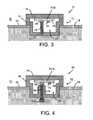
- FIG. 3is a cross sectional view of a first differential carrier temperature sensing package in accordance with the present invention.
- FIG. 4is a cross sectional view of a second differential carrier temperature sensing package in accordance with the present invention.
- FIG. 1illustrates a simplified thermal circuit schematic diagram of an internal differential carrier temperature T INT that is determined by utilizing a measured differential carrier fluid temperature T SNS and an internal housing package temperature T PCB , in combination with a given known thermally conductive resistance R ENC of a housing and a thermal conductor, and a given known thermal resistance R PCB of the housing at an electronic circuit board.
- the thermal energy Qflows through circuit 5 in a direction that is determined by the temperatures of the inside and outside of a differential carrier.
- the inside temperatureis higher than the outside temperature
- thermal energyflows from T INT to T PCB , because the temperature at the point of the T PCB is close to that on the outside of the differential carrier.
- the outside temperatureis higher than the inside temperature
- thermal energyflows from the outside temperature point T PCB to T INT within the differential carrier.
- the following equation 1expresses the circuit thermal flow.
- T INTT SNS (1+ R ENC /R PCB ) ⁇ T PCB ( R ENC /R PCB ) (eq. 2)
- FIG. 3illustrates a first embodiment of a differential carrier temperature sensing package 10 having a package housing 12 that comprises an upper portion 14 and a lower portion 16 that are sealed together.
- the two package portions 14 , 16may be unitary.
- the upper portion 14comprises very conductive thermal material, for example, a thermally conductive metal like aluminum.
- the lower portion 16comprises a significantly less thermally conductive material than that of the upper portion 14 , for example, a high temperature plastic. Both portions 14 , 16 are in thermally conductive contact with an environment E 1 that is external to a differential carrier housing 18 .
- the lower portion 16is also in thermally conductive contact with an outer surface 20 of the differential housing 18 , where the lower portion 16 of the package housing 12 extends through an opening 22 in the differential housing 18 , thereby allowing the lower portion 16 to be in thermally conductive contact with a fluid F 1 within the differential housing 18 .
- the fluid F 1may be in a form of a liquid and/or vapor.
- the package housing 12further comprises an electronic circuit 24 with first and second temperature sensors 26 , 30 disposed thereon.
- the electronic circuit 24is in close thermally conductive contact with the first and second temperature sensors 26 , 30 that preferably are common negative temperature coefficient (NTC) thermistors.
- NTCcommon negative temperature coefficient
- the electronic circuit 24is also in thermally conductive contact with and attached to the upper portion 14 within the package housing 12 .
- the first temperature sensor 26is also in close thermally conductive contact with a thermal conductor 28 , which may be a simple aluminum rod that is disposed within the package housing 12 .
- the thermal conductor 28is imbedded in and consequently in thermally conductive contact with the lower portion 16 but not in contact with the outer surface 17 of the lower portion 16 .
- the lower portion 16is in thermally conductive contact with the fluid F 1 within the differential housing 18 .
- the differential fluid temperature T SNSis determined by way the thermal conduction between the electronic circuit 24 , the first sensor 26 , the thermal conductor 28 , and the lower portion 16 of the package housing 12 .
- the second temperature sensor 30is disposed on the electronic circuit 24 .
- the temperature TPCB at the electronic circuit 24is determined by the electronic circuit 24 sensing the second sensor 30 .
- the electronic circuit 24with a given known thermal resistance RENC of the combination of the package housing 12 and the thermal conductor 28 , along with a given known thermal resistance RPCB of the electronic circuit board, the electronic circuit 24 , wherein the electronic circuit 24 is disposed on the electronic circuit board PCB, can determine an internal carrier temperature TINT. Then, the temperature TINT can be communicated outside of the package housing 12 for monitoring and controlling a vehicle within which the differential carrier sensing package 10 is installed.
- a differential carrier temperature sensing package 50comprises a package housing 52 that comprises an upper portion 54 and a lower portion 56 that are sealed together.
- the two package housing portions 54 , 56may be unitary.
- the upper portion 54 and the lower portion 56are in thermally conductive contact with an environment E 2 that is external to a differential carrier housing 58 .
- the lower portion 56is also in thermally conductive contact with an outer surface 60 of the differential housing 58 , where the lower portion 56 of the package housing 52 extends through an opening 62 in the differential housing 58 , thereby being in thermally conductive contact with a fluid F 2 within the differential housing 58 .
- the fluid F 2may be in a form of a liquid and/or vapor.
- the package housing 52further comprises an electronic circuit 64 , and first and second temperature sensors 66 , 70 .
- the electronic circuit 64is attached to the upper portion 54 within the package housing 52 and is in thermally conductive contact therewith.
- the first temperature sensor 66is disposed on the electronic circuit 64 and is in thermally conductive contact with an outward projection 74 of the lower portion 56 , which in turn is in thermally conductive contact with a thermal conductor 68 .
- the thermal conductor 68is disposed in the fluid F 2 that is within the differential housing 58 , with the outward projection 74 surrounding the thermal conductor 68 and with fluid F 2 therebetween.
- the thermal conductor 68may have an inward thermal conductor portion 72 that has a larger surface area than the upper thermal conductor 68 , so as to make it more capable of quickly responding to thermal changes within the fluid F 2 .
- the differential fluid temperature T SNSis determined by way of thermal conduction between the electronic circuit 64 , the first sensor 66 , outward projection 74 of the lower portion 56 , thermal conductor 68 , and possibly the inward thermal conductor portion 72 .
- the second temperature sensor 70is disposed on the electronic circuit 64 for sensing the temperature within the package housing 52 .
- the temperature at the electronic board T PCBis determined by way of the electronic circuit 64 and the second sensor 70 .
- the electronic circuit 64can determine an internal carrier temperature T INT .
- T INTcan be communicated outside of the package housing 52 for monitoring and controlling a vehicle within which the differential carrier 50 resides, by the electronic control circuit 64 .
- the internal carrier temperature T INTcan be determined based on the above-stated equation (eq. 2), while using the above-found temperatures T SNS and T PCB , for this embodiment, along with the known R ENC and R PCB .
- FIG. 2illustrates a more accurate thermal schematic diagram for deriving an internal differential carrier temperature.
- This modelprovides for an expression of the dynamic behavior of the thermal circuit 8 , which modifies FIG. 1 by adding the components C PCB1 , R PCB1 in parallel with R PCB so as to result in a base R′ PCB that more closely matches the thermal operation of the differential carriers 10 , 60 .
- R′ PCBis equal to:
- R PCB ′R PCB ( R PCB ⁇ ⁇ 1 S ⁇ C PCB ⁇ ⁇ 1 + 1 C PCB ⁇ ⁇ 1 S ⁇ ( R PCB + R PCB ⁇ ⁇ 1 ) + 1 ( eq . ⁇ 4 )
- the factor “s”is defined to be a Laplace complex argument.
- the capacitance C PCB1 in this dynamic model equationprovides for the description of the rate of thermal flow in the assembly. This rate can be used to provide predictive information thereby functioning to effectively increase the response time of an internal differential carrier temperature measurement.
Landscapes
- Engineering & Computer Science (AREA)
- General Engineering & Computer Science (AREA)
- Mechanical Engineering (AREA)
- Physics & Mathematics (AREA)
- General Physics & Mathematics (AREA)
- Quality & Reliability (AREA)
- Oil, Petroleum & Natural Gas (AREA)
- Analytical Chemistry (AREA)
- Life Sciences & Earth Sciences (AREA)
- Chemical & Material Sciences (AREA)
- Health & Medical Sciences (AREA)
- Biochemistry (AREA)
- General Health & Medical Sciences (AREA)
- Immunology (AREA)
- Pathology (AREA)
- Microelectronics & Electronic Packaging (AREA)
- Thermal Sciences (AREA)
- Measuring Temperature Or Quantity Of Heat (AREA)
- Cooling Or The Like Of Electrical Apparatus (AREA)
- General Details Of Gearings (AREA)
Abstract
Description
Q=(TINT−TSNS)/RENC=(TSNS−TPCB)/RPCB (eq. 1)
TINT=TSNS(1+RENC/RPCB)−TPCB(RENC/RPCB) (eq. 2)
Q=(TINT−TSNS)/RENC=(TSNS−TPCS)/R′Pcs (eq. 3)
Claims (16)
Priority Applications (2)
| Application Number | Priority Date | Filing Date | Title |
|---|---|---|---|
| US14/197,586US9651142B2 (en) | 2013-03-11 | 2014-03-05 | Differential carrier temperature sensing method |
| US15/478,497US9976644B2 (en) | 2013-03-11 | 2017-04-04 | Differential carrier temperature sensing method |
Applications Claiming Priority (3)
| Application Number | Priority Date | Filing Date | Title |
|---|---|---|---|
| US201361775929P | 2013-03-11 | 2013-03-11 | |
| US201361775959P | 2013-03-11 | 2013-03-11 | |
| US14/197,586US9651142B2 (en) | 2013-03-11 | 2014-03-05 | Differential carrier temperature sensing method |
Related Child Applications (1)
| Application Number | Title | Priority Date | Filing Date |
|---|---|---|---|
| US15/478,497DivisionUS9976644B2 (en) | 2013-03-11 | 2017-04-04 | Differential carrier temperature sensing method |
Publications (2)
| Publication Number | Publication Date |
|---|---|
| US20140254623A1 US20140254623A1 (en) | 2014-09-11 |
| US9651142B2true US9651142B2 (en) | 2017-05-16 |
Family
ID=50389541
Family Applications (3)
| Application Number | Title | Priority Date | Filing Date |
|---|---|---|---|
| US14/197,586Expired - Fee RelatedUS9651142B2 (en) | 2013-03-11 | 2014-03-05 | Differential carrier temperature sensing method |
| US14/197,684Expired - Fee RelatedUS9334950B2 (en) | 2013-03-11 | 2014-03-05 | Differential carrier electronics package |
| US15/478,497ActiveUS9976644B2 (en) | 2013-03-11 | 2017-04-04 | Differential carrier temperature sensing method |
Family Applications After (2)
| Application Number | Title | Priority Date | Filing Date |
|---|---|---|---|
| US14/197,684Expired - Fee RelatedUS9334950B2 (en) | 2013-03-11 | 2014-03-05 | Differential carrier electronics package |
| US15/478,497ActiveUS9976644B2 (en) | 2013-03-11 | 2017-04-04 | Differential carrier temperature sensing method |
Country Status (4)
| Country | Link |
|---|---|
| US (3) | US9651142B2 (en) |
| EP (2) | EP2971866B1 (en) |
| JP (1) | JP6032514B2 (en) |
| WO (2) | WO2014164259A1 (en) |
Cited By (1)
| Publication number | Priority date | Publication date | Assignee | Title |
|---|---|---|---|---|
| US20170204959A1 (en)* | 2013-03-11 | 2017-07-20 | Dana Automotive Systems Group, Llc | Differential carrier temperature sensing method |
Families Citing this family (9)
| Publication number | Priority date | Publication date | Assignee | Title |
|---|---|---|---|---|
| EP2899519B1 (en)* | 2014-01-24 | 2016-11-16 | Siemens Schweiz AG | Temperature sensing apparatus |
| US9382992B2 (en)* | 2014-09-26 | 2016-07-05 | Ford Global Technologies, Llc | Control of locking differential |
| GB2542791A (en)* | 2015-09-29 | 2017-04-05 | Bae Systems Plc | Temperature measurement device |
| WO2017055821A1 (en) | 2015-09-29 | 2017-04-06 | Bae Systems Plc | Temperature measurement device |
| WO2019063519A1 (en) | 2017-09-27 | 2019-04-04 | Abb Schweiz Ag | TEMPERATURE MEASURING DEVICE AND METHOD FOR TEMPERATURE DETERMINATION |
| EP3803723A4 (en) | 2018-06-01 | 2022-03-09 | Stress Engineering Services, Inc. | SYSTEMS AND PROCEDURES FOR MONITORING, TRACKING AND TRACEBACK OF LOGISTICS |
| DE102018119857A1 (en) | 2018-08-15 | 2020-02-20 | Abb Schweiz Ag | Temperature measuring device and method for temperature determination |
| KR20220110308A (en)* | 2019-12-20 | 2022-08-05 | 엔테그리스, 아이엔씨. | Accurate temperature reading of the fluid near the interface |
| US11773626B2 (en)* | 2022-02-15 | 2023-10-03 | Stress Engineering Services, Inc. | Systems and methods for facilitating logistics |
Citations (18)
| Publication number | Priority date | Publication date | Assignee | Title |
|---|---|---|---|---|
| US4901061A (en)* | 1987-06-05 | 1990-02-13 | Westinghouse Electric Corp. | Instrumentation and monitoring systems employing differential temperature sensors |
| US5288147A (en)* | 1992-11-09 | 1994-02-22 | Ta Instruments, Inc. | Thermopile differential thermal analysis sensor |
| WO1999028149A1 (en) | 1997-12-03 | 1999-06-10 | Kavlico Corporation | High-sensitivity capacitive oil deterioration and level sensor |
| US6092926A (en)* | 1998-09-17 | 2000-07-25 | International Business Machines Corporation | Thermal monitoring system for semiconductor devices |
| DE10016640C1 (en) | 2000-04-04 | 2001-09-27 | Daimler Chrysler Ag | Transmission for motor vehicle has oil pipe located completely inside oil-filled space of gear case, and electrical power is supplied to heater element in communication with oil pipe |
| EP1508915A2 (en) | 2003-08-18 | 2005-02-23 | Delphi Technologies, Inc. | Process and electronic assembly for removing heat from a circuit device |
| US20060054411A1 (en) | 2002-05-14 | 2006-03-16 | Fett Gregory A | Heat pipe cooler for differential assembly |
| EP1637847A1 (en) | 2003-06-18 | 2006-03-22 | Hitachi, Ltd. | Thermal air meter |
| US7077563B2 (en)* | 2003-11-19 | 2006-07-18 | General Electric Company | Deposition sensor based on differential heat flux measurement |
| US7698090B2 (en)* | 2004-05-25 | 2010-04-13 | Lima Jose Augusto Pedro | System for the measure of thermal properties of fluids |
| WO2012074112A1 (en) | 2010-12-02 | 2012-06-07 | ナブテスコ株式会社 | Speed reducer for industrial robot |
| EP2482050A2 (en) | 2011-01-31 | 2012-08-01 | Hitachi Automotive Systems, Ltd. | Intake air temperature sensor and thermal airflow meter including the same |
| US8248800B2 (en)* | 2007-05-28 | 2012-08-21 | Aisin Aw Co., Ltd. | Automatic transmission control unit cooling apparatus |
| US8746966B2 (en)* | 2008-06-13 | 2014-06-10 | Mettler-Toledo Ag | Thermoanalytical instrument |
| US9022158B2 (en)* | 2012-02-29 | 2015-05-05 | Jtekt Corporation | Four-wheel-drive vehicle and control unit for four-wheel-drive vehicle |
| US20150308293A1 (en)* | 2013-12-04 | 2015-10-29 | General Electric Company | System and method for a gas turbine engine |
| US9182262B2 (en)* | 2012-10-19 | 2015-11-10 | Endress + Hauser Flowtec Ag | Temperature sensor and thermal flow-measuring device |
| US9334950B2 (en)* | 2013-03-11 | 2016-05-10 | Dana Automotive Systems Group, Llc | Differential carrier electronics package |
Family Cites Families (28)
| Publication number | Priority date | Publication date | Assignee | Title |
|---|---|---|---|---|
| US3548683A (en)* | 1968-11-29 | 1970-12-22 | Ford Motor Co | Differential gear mechanism with wobbling inertia ring |
| US3550724A (en)* | 1968-12-02 | 1970-12-29 | Eaton Yale & Towne | Pressure lubrication system for geared drive mechanism |
| JP2501514Y2 (en)* | 1989-03-31 | 1996-06-19 | トヨタ自動車株式会社 | Two-wheel / four-wheel switching control device for four-wheel drive vehicle |
| US5076708A (en)* | 1990-05-14 | 1991-12-31 | Pierson Mark W | Threaded temperature indicating plug for hot oil housings such as transmissions and the like |
| US5662007A (en)* | 1993-05-12 | 1997-09-02 | Siemens Aktiengesellschaft | Motor vehicle gearbox control system in an oil-filled casing |
| JPH07208589A (en)* | 1994-01-18 | 1995-08-11 | Suzuki Motor Corp | Bearing lubricating device for differential gear |
| JPH10103454A (en)* | 1996-09-30 | 1998-04-21 | Suzuki Motor Corp | Differential bearing device |
| JPH11182655A (en)* | 1997-12-17 | 1999-07-06 | Mitsubishi Motors Corp | Lubrication structure of final reduction gear |
| DE19855321A1 (en)* | 1998-12-01 | 2000-06-08 | Zf Batavia Llc | Cooling a control unit of a motor vehicle transmission |
| US6186277B1 (en)* | 1998-12-02 | 2001-02-13 | Chrysler Corporation | Front axle differential bearing cap and lubrication/cooling method |
| US6763881B1 (en)* | 2000-02-18 | 2004-07-20 | Agilent Technologies, Inc. | Thermally matched gradient heat sink |
| US7077463B2 (en) | 2004-04-06 | 2006-07-18 | Lear Corporation | Rear fold down cargo seat with tilt down cushion |
| JP4617725B2 (en)* | 2004-06-03 | 2011-01-26 | マツダ株式会社 | Differential equipment for four-wheel drive vehicles |
| US20060042379A1 (en) | 2004-08-30 | 2006-03-02 | Ireland Hugh W | Sealed fuel level sensor |
| JP4619257B2 (en)* | 2005-10-03 | 2011-01-26 | トヨタ自動車株式会社 | Automatic transmission |
| US8198712B2 (en)* | 2006-06-07 | 2012-06-12 | International Rectifier Corporation | Hermetically sealed semiconductor device module |
| DE102006049592A1 (en)* | 2006-10-20 | 2008-04-30 | Conti Temic Microelectronic Gmbh | Control device for a motor vehicle |
| US7932217B2 (en)* | 2007-08-28 | 2011-04-26 | Chevron U.S.A., Inc. | Gear oil compositions, methods of making and using thereof |
| DE102007061116A1 (en)* | 2007-12-19 | 2009-06-25 | Robert Bosch Gmbh | Control unit housing |
| US7980983B2 (en)* | 2008-02-25 | 2011-07-19 | Chrysler Group Llc | Hydraulically locking limited slip differential |
| US20120103132A1 (en)* | 2010-11-01 | 2012-05-03 | GM Global Technology Operations LLC | Transmission case for hybrid vehicles |
| JP5839436B2 (en)* | 2010-12-02 | 2016-01-06 | ナブテスコ株式会社 | Optical sensor |
| JP5840843B2 (en)* | 2011-01-12 | 2016-01-06 | ナブテスコ株式会社 | Industrial robot reducer |
| CN103339789B (en)* | 2011-02-03 | 2015-06-24 | 日本碍子株式会社 | battery housing structure |
| DE102011088031A1 (en)* | 2011-12-08 | 2013-06-13 | Robert Bosch Gmbh | Transmission control module |
| JP2014035250A (en)* | 2012-08-08 | 2014-02-24 | Canon Inc | Radiographic device |
| US9163716B2 (en)* | 2012-12-12 | 2015-10-20 | Modine Manufacturing Company | Gear casing heat exchanger |
| JP2016138575A (en)* | 2015-01-27 | 2016-08-04 | 富士重工業株式会社 | Vehicular differential device |
- 2014
- 2014-03-05USUS14/197,586patent/US9651142B2/ennot_activeExpired - Fee Related
- 2014-03-05USUS14/197,684patent/US9334950B2/ennot_activeExpired - Fee Related
- 2014-03-07EPEP14713339.1Apatent/EP2971866B1/ennot_activeNot-in-force
- 2014-03-07WOPCT/US2014/021547patent/WO2014164259A1/enactiveApplication Filing
- 2014-03-07WOPCT/US2014/021519patent/WO2014164251A1/enactiveApplication Filing
- 2014-03-07EPEP14714045.3Apatent/EP2971867B1/ennot_activeNot-in-force
- 2014-03-07JPJP2016500783Apatent/JP6032514B2/ennot_activeExpired - Fee Related
- 2017
- 2017-04-04USUS15/478,497patent/US9976644B2/enactiveActive
Patent Citations (18)
| Publication number | Priority date | Publication date | Assignee | Title |
|---|---|---|---|---|
| US4901061A (en)* | 1987-06-05 | 1990-02-13 | Westinghouse Electric Corp. | Instrumentation and monitoring systems employing differential temperature sensors |
| US5288147A (en)* | 1992-11-09 | 1994-02-22 | Ta Instruments, Inc. | Thermopile differential thermal analysis sensor |
| WO1999028149A1 (en) | 1997-12-03 | 1999-06-10 | Kavlico Corporation | High-sensitivity capacitive oil deterioration and level sensor |
| US6092926A (en)* | 1998-09-17 | 2000-07-25 | International Business Machines Corporation | Thermal monitoring system for semiconductor devices |
| DE10016640C1 (en) | 2000-04-04 | 2001-09-27 | Daimler Chrysler Ag | Transmission for motor vehicle has oil pipe located completely inside oil-filled space of gear case, and electrical power is supplied to heater element in communication with oil pipe |
| US20060054411A1 (en) | 2002-05-14 | 2006-03-16 | Fett Gregory A | Heat pipe cooler for differential assembly |
| EP1637847A1 (en) | 2003-06-18 | 2006-03-22 | Hitachi, Ltd. | Thermal air meter |
| EP1508915A2 (en) | 2003-08-18 | 2005-02-23 | Delphi Technologies, Inc. | Process and electronic assembly for removing heat from a circuit device |
| US7077563B2 (en)* | 2003-11-19 | 2006-07-18 | General Electric Company | Deposition sensor based on differential heat flux measurement |
| US7698090B2 (en)* | 2004-05-25 | 2010-04-13 | Lima Jose Augusto Pedro | System for the measure of thermal properties of fluids |
| US8248800B2 (en)* | 2007-05-28 | 2012-08-21 | Aisin Aw Co., Ltd. | Automatic transmission control unit cooling apparatus |
| US8746966B2 (en)* | 2008-06-13 | 2014-06-10 | Mettler-Toledo Ag | Thermoanalytical instrument |
| WO2012074112A1 (en) | 2010-12-02 | 2012-06-07 | ナブテスコ株式会社 | Speed reducer for industrial robot |
| EP2482050A2 (en) | 2011-01-31 | 2012-08-01 | Hitachi Automotive Systems, Ltd. | Intake air temperature sensor and thermal airflow meter including the same |
| US9022158B2 (en)* | 2012-02-29 | 2015-05-05 | Jtekt Corporation | Four-wheel-drive vehicle and control unit for four-wheel-drive vehicle |
| US9182262B2 (en)* | 2012-10-19 | 2015-11-10 | Endress + Hauser Flowtec Ag | Temperature sensor and thermal flow-measuring device |
| US9334950B2 (en)* | 2013-03-11 | 2016-05-10 | Dana Automotive Systems Group, Llc | Differential carrier electronics package |
| US20150308293A1 (en)* | 2013-12-04 | 2015-10-29 | General Electric Company | System and method for a gas turbine engine |
Non-Patent Citations (6)
| Title |
|---|
| Communication Relating to Results of Partial International Search-PCT/US2014/021519. |
| Communication Relating to Results of Partial International Search—PCT/US2014/021519. |
| English Language Abstract-DE10016640. |
| English Language Abstract—DE10016640. |
| International Search Report with Written Opinion-PCT/US2014/021547. |
| International Search Report with Written Opinion—PCT/US2014/021547. |
Cited By (2)
| Publication number | Priority date | Publication date | Assignee | Title |
|---|---|---|---|---|
| US20170204959A1 (en)* | 2013-03-11 | 2017-07-20 | Dana Automotive Systems Group, Llc | Differential carrier temperature sensing method |
| US9976644B2 (en)* | 2013-03-11 | 2018-05-22 | Dana Automotive Systems Group, Llc | Differential carrier temperature sensing method |
Also Published As
| Publication number | Publication date |
|---|---|
| US20170204959A1 (en) | 2017-07-20 |
| JP6032514B2 (en) | 2016-11-30 |
| JP2016513779A (en) | 2016-05-16 |
| WO2014164251A1 (en) | 2014-10-09 |
| US9334950B2 (en) | 2016-05-10 |
| US20140254102A1 (en) | 2014-09-11 |
| EP2971866A1 (en) | 2016-01-20 |
| EP2971866B1 (en) | 2017-05-03 |
| EP2971867B1 (en) | 2017-12-06 |
| EP2971867A1 (en) | 2016-01-20 |
| US9976644B2 (en) | 2018-05-22 |
| WO2014164259A1 (en) | 2014-10-09 |
| US20140254623A1 (en) | 2014-09-11 |
Similar Documents
| Publication | Publication Date | Title |
|---|---|---|
| US9976644B2 (en) | Differential carrier temperature sensing method | |
| US8600636B2 (en) | Method for determining wet clutch temperature | |
| AU2017235215B2 (en) | Track pin communication system and method | |
| US9618407B2 (en) | Magnetic sensor packaging for transmissions | |
| CN105723105B (en) | Wheel bearing assembly with temperature measuring equipment | |
| US10465625B2 (en) | Method for monitoring an exhaust-gas sensor | |
| US8199021B2 (en) | Fluid level detection system | |
| CN101852636A (en) | Fuel Quantity Calculation Method for UAV Fuel Tank | |
| CN106415224B (en) | Temperature Sensor | |
| CN109974802B (en) | Method for avoiding measurement errors of air flow sensors | |
| CN105723089B (en) | For sensing the oily method and apparatus in compressor | |
| CN110132614A (en) | The experimental rig and its method that a kind of automatic transmission influences vehicle thermal balance | |
| CN110654366B (en) | Method and system for estimating the moisture content of brake fluid in a brake system | |
| EP1398616B1 (en) | Determining change of viscosity from measuring velocity | |
| US11208925B2 (en) | Diagnostic system for a lubrication circuit | |
| JP2017133950A (en) | Determination device, bearing test device, and vehicle | |
| KR101855299B1 (en) | Method and apparatus for detecting drive derection of transmission | |
| CN106197530A (en) | Measure the method for lubricating oil dilution degree, sensor and the method for detection oil level | |
| Arunachalam et al. | Resolution of Engine Oil Mixing with Power Steering Oil in Steering Pump by Behavioral Study | |
| CN106932054A (en) | A kind of oil level indicator | |
| KR20010113100A (en) | Oil level measurement by using unsteady hot-wire method |
Legal Events
| Date | Code | Title | Description |
|---|---|---|---|
| AS | Assignment | Owner name:DANA AUTOMOTIVE SYSTEMS GROUP, LLC, OHIO Free format text:ASSIGNMENT OF ASSIGNORS INTEREST;ASSIGNORS:PAIELLI, PERRY M.;BEESLEY, PETER A.;REEL/FRAME:032354/0145 Effective date:20140305 | |
| STCF | Information on status: patent grant | Free format text:PATENTED CASE | |
| AS | Assignment | Owner name:CITIBANK, N.A., NEW YORK Free format text:SECURITY AGREEMENT (BRIDGE);ASSIGNORS:DANA HEAVY VEHICLE SYSTEMS GROUP, LLC;DANA LIMITED;DANA AUTOMOTIVE SYSTEMS GROUP, LLC;AND OTHERS;REEL/FRAME:052459/0001 Effective date:20200416 Owner name:CITIBANK, N.A., NEW YORK Free format text:SECURITY AGREEMENT SUPPLEMENT;ASSIGNORS:DANA HEAVY VEHICLE SYSTEMS GROUP, LLC;DANA LIMITED;DANA AUTOMOTIVE SYSTEMS GROUP, LLC;AND OTHERS;REEL/FRAME:052459/0224 Effective date:20200416 | |
| AS | Assignment | Owner name:FAIRFIELD MANUFACTURING COMPANY, INC., OHIO Free format text:RELEASE BY SECURED PARTY;ASSIGNOR:CITIBANK, N.A.;REEL/FRAME:053309/0686 Effective date:20200619 Owner name:DANA AUTOMOTIVE SYSTEMS GROUP, LLC, OHIO Free format text:RELEASE BY SECURED PARTY;ASSIGNOR:CITIBANK, N.A.;REEL/FRAME:053309/0686 Effective date:20200619 Owner name:DANA HEAVY VEHICLE SYSTEMS GROUP, LLC, OHIO Free format text:RELEASE BY SECURED PARTY;ASSIGNOR:CITIBANK, N.A.;REEL/FRAME:053309/0686 Effective date:20200619 Owner name:DANA LIMITED, OHIO Free format text:RELEASE BY SECURED PARTY;ASSIGNOR:CITIBANK, N.A.;REEL/FRAME:053309/0686 Effective date:20200619 | |
| FEPP | Fee payment procedure | Free format text:MAINTENANCE FEE REMINDER MAILED (ORIGINAL EVENT CODE: REM.); ENTITY STATUS OF PATENT OWNER: LARGE ENTITY | |
| LAPS | Lapse for failure to pay maintenance fees | Free format text:PATENT EXPIRED FOR FAILURE TO PAY MAINTENANCE FEES (ORIGINAL EVENT CODE: EXP.); ENTITY STATUS OF PATENT OWNER: LARGE ENTITY | |
| STCH | Information on status: patent discontinuation | Free format text:PATENT EXPIRED DUE TO NONPAYMENT OF MAINTENANCE FEES UNDER 37 CFR 1.362 | |
| FP | Lapsed due to failure to pay maintenance fee | Effective date:20210516 |