US9651032B2 - Submersible power generators and method of operating thereof - Google Patents
Submersible power generators and method of operating thereofDownload PDFInfo
- Publication number
- US9651032B2 US9651032B2US14/564,563US201414564563AUS9651032B2US 9651032 B2US9651032 B2US 9651032B2US 201414564563 AUS201414564563 AUS 201414564563AUS 9651032 B2US9651032 B2US 9651032B2
- Authority
- US
- United States
- Prior art keywords
- hybrid working
- power generation
- accordance
- liquid
- lvg
- Prior art date
- Legal status (The legal status is an assumption and is not a legal conclusion. Google has not performed a legal analysis and makes no representation as to the accuracy of the status listed.)
- Expired - Fee Related, expires
Links
- 238000000034methodMethods0.000titleclaimsdescription22
- 239000007788liquidSubstances0.000claimsabstractdescription48
- 239000012530fluidSubstances0.000claimsabstractdescription44
- 239000002105nanoparticleSubstances0.000claimsabstractdescription38
- 238000004891communicationMethods0.000claimsabstractdescription24
- 238000010248power generationMethods0.000claimsdescription53
- 230000005465channelingEffects0.000claimsdescription8
- 229910052751metalInorganic materials0.000claimsdescription6
- 239000002184metalSubstances0.000claimsdescription6
- 230000009471actionEffects0.000claimsdescription5
- 238000009835boilingMethods0.000claimsdescription3
- 229910010293ceramic materialInorganic materials0.000claimsdescription3
- 239000004020conductorSubstances0.000claimsdescription3
- 230000001939inductive effectEffects0.000claimsdescription3
- 238000001704evaporationMethods0.000claimsdescription2
- 238000007789sealingMethods0.000claims1
- 238000011084recoveryMethods0.000description12
- 239000000463materialSubstances0.000description7
- 229910052761rare earth metalInorganic materials0.000description7
- 150000002910rare earth metalsChemical class0.000description7
- OKKJLVBELUTLKV-UHFFFAOYSA-NMethanolChemical compoundOCOKKJLVBELUTLKV-UHFFFAOYSA-N0.000description6
- 238000004519manufacturing processMethods0.000description6
- XLYOFNOQVPJJNP-UHFFFAOYSA-NwaterSubstancesOXLYOFNOQVPJJNP-UHFFFAOYSA-N0.000description5
- 239000011148porous materialSubstances0.000description4
- UHOVQNZJYSORNB-UHFFFAOYSA-NBenzeneChemical compoundC1=CC=CC=C1UHOVQNZJYSORNB-UHFFFAOYSA-N0.000description3
- KFZMGEQAYNKOFK-UHFFFAOYSA-NIsopropanolChemical compoundCC(C)OKFZMGEQAYNKOFK-UHFFFAOYSA-N0.000description3
- 230000000712assemblyEffects0.000description3
- 238000000429assemblyMethods0.000description3
- 230000008901benefitEffects0.000description3
- 230000006870functionEffects0.000description3
- 239000000696magnetic materialSubstances0.000description3
- 239000002923metal particleSubstances0.000description3
- 150000002739metalsChemical class0.000description3
- 239000002245particleSubstances0.000description3
- QGZKDVFQNNGYKY-UHFFFAOYSA-NAmmoniaChemical compoundNQGZKDVFQNNGYKY-UHFFFAOYSA-N0.000description2
- XEEYBQQBJWHFJM-UHFFFAOYSA-NIronChemical compound[Fe]XEEYBQQBJWHFJM-UHFFFAOYSA-N0.000description2
- 230000008878couplingEffects0.000description2
- 238000010168coupling processMethods0.000description2
- 238000005859coupling reactionMethods0.000description2
- 230000000694effectsEffects0.000description2
- 239000003574free electronSubstances0.000description2
- 150000002500ionsChemical class0.000description2
- 239000002122magnetic nanoparticleSubstances0.000description2
- 238000002844meltingMethods0.000description2
- 230000008018meltingEffects0.000description2
- 239000007769metal materialSubstances0.000description2
- 239000004033plasticSubstances0.000description2
- 229920003023plasticPolymers0.000description2
- 239000000126substanceSubstances0.000description2
- 229910000521B alloyInorganic materials0.000description1
- ZOXJGFHDIHLPTG-UHFFFAOYSA-NBoronChemical compound[B]ZOXJGFHDIHLPTG-UHFFFAOYSA-N0.000description1
- WKBOTKDWSSQWDR-UHFFFAOYSA-NBromine atomChemical compound[Br]WKBOTKDWSSQWDR-UHFFFAOYSA-N0.000description1
- RYGMFSIKBFXOCR-UHFFFAOYSA-NCopperChemical compound[Cu]RYGMFSIKBFXOCR-UHFFFAOYSA-N0.000description1
- 229910000640Fe alloyInorganic materials0.000description1
- GYHNNYVSQQEPJS-UHFFFAOYSA-NGalliumChemical compound[Ga]GYHNNYVSQQEPJS-UHFFFAOYSA-N0.000description1
- DGAQECJNVWCQMB-PUAWFVPOSA-MIlexoside XXIXChemical compoundC[C@@H]1CC[C@@]2(CC[C@@]3(C(=CC[C@H]4[C@]3(CC[C@@H]5[C@@]4(CC[C@@H](C5(C)C)OS(=O)(=O)[O-])C)C)[C@@H]2[C@]1(C)O)C)C(=O)O[C@H]6[C@@H]([C@H]([C@@H]([C@H](O6)CO)O)O)O.[Na+]DGAQECJNVWCQMB-PUAWFVPOSA-M0.000description1
- 229910000583Nd alloyInorganic materials0.000description1
- ZLMJMSJWJFRBEC-UHFFFAOYSA-NPotassiumChemical compound[K]ZLMJMSJWJFRBEC-UHFFFAOYSA-N0.000description1
- BQCADISMDOOEFD-UHFFFAOYSA-NSilverChemical compound[Ag]BQCADISMDOOEFD-UHFFFAOYSA-N0.000description1
- 229910052783alkali metalInorganic materials0.000description1
- 150000001340alkali metalsChemical class0.000description1
- 229910045601alloyInorganic materials0.000description1
- 239000000956alloySubstances0.000description1
- 229910052782aluminiumInorganic materials0.000description1
- XAGFODPZIPBFFR-UHFFFAOYSA-NaluminiumChemical compound[Al]XAGFODPZIPBFFR-UHFFFAOYSA-N0.000description1
- 229910021529ammoniaInorganic materials0.000description1
- GDTBXPJZTBHREO-UHFFFAOYSA-NbromineSubstancesBrBrGDTBXPJZTBHREO-UHFFFAOYSA-N0.000description1
- 229910052794bromiumInorganic materials0.000description1
- 239000001273butaneSubstances0.000description1
- 229910052792caesiumInorganic materials0.000description1
- TVFDJXOCXUVLDH-UHFFFAOYSA-Ncaesium atomChemical compound[Cs]TVFDJXOCXUVLDH-UHFFFAOYSA-N0.000description1
- 239000000919ceramicSubstances0.000description1
- 230000008859changeEffects0.000description1
- 238000006243chemical reactionMethods0.000description1
- 229910052802copperInorganic materials0.000description1
- 239000010949copperSubstances0.000description1
- 238000005260corrosionMethods0.000description1
- 230000007797corrosionEffects0.000description1
- 238000009826distributionMethods0.000description1
- 230000007613environmental effectEffects0.000description1
- 238000007667floatingMethods0.000description1
- 230000004907fluxEffects0.000description1
- 239000002803fossil fuelSubstances0.000description1
- 229910052733galliumInorganic materials0.000description1
- PCHJSUWPFVWCPO-UHFFFAOYSA-NgoldChemical compound[Au]PCHJSUWPFVWCPO-UHFFFAOYSA-N0.000description1
- 229910052737goldInorganic materials0.000description1
- 239000010931goldSubstances0.000description1
- 230000005484gravityEffects0.000description1
- 238000002347injectionMethods0.000description1
- 239000007924injectionSubstances0.000description1
- 229910001338liquidmetalInorganic materials0.000description1
- 238000012423maintenanceMethods0.000description1
- QSHDDOUJBYECFT-UHFFFAOYSA-NmercuryChemical compound[Hg]QSHDDOUJBYECFT-UHFFFAOYSA-N0.000description1
- 229910052753mercuryInorganic materials0.000description1
- 239000000203mixtureSubstances0.000description1
- IJDNQMDRQITEOD-UHFFFAOYSA-Nn-butaneChemical compoundCCCCIJDNQMDRQITEOD-UHFFFAOYSA-N0.000description1
- OFBQJSOFQDEBGM-UHFFFAOYSA-Nn-pentaneNatural productsCCCCCOFBQJSOFQDEBGM-UHFFFAOYSA-N0.000description1
- 229910001172neodymium magnetInorganic materials0.000description1
- 238000009428plumbingMethods0.000description1
- 229910052700potassiumInorganic materials0.000description1
- 239000011591potassiumSubstances0.000description1
- 238000005086pumpingMethods0.000description1
- 229910000938samarium–cobalt magnetInorganic materials0.000description1
- 229920006395saturated elastomerPolymers0.000description1
- 238000000926separation methodMethods0.000description1
- 229910052709silverInorganic materials0.000description1
- 239000004332silverSubstances0.000description1
- 229910052708sodiumInorganic materials0.000description1
- 239000011734sodiumSubstances0.000description1
- 238000009834vaporizationMethods0.000description1
- 230000008016vaporizationEffects0.000description1
- 238000003466weldingMethods0.000description1
Images


Classifications
- F—MECHANICAL ENGINEERING; LIGHTING; HEATING; WEAPONS; BLASTING
- F03—MACHINES OR ENGINES FOR LIQUIDS; WIND, SPRING, OR WEIGHT MOTORS; PRODUCING MECHANICAL POWER OR A REACTIVE PROPULSIVE THRUST, NOT OTHERWISE PROVIDED FOR
- F03G—SPRING, WEIGHT, INERTIA OR LIKE MOTORS; MECHANICAL-POWER PRODUCING DEVICES OR MECHANISMS, NOT OTHERWISE PROVIDED FOR OR USING ENERGY SOURCES NOT OTHERWISE PROVIDED FOR
- F03G7/00—Mechanical-power-producing mechanisms, not otherwise provided for or using energy sources not otherwise provided for
- F03G7/04—Mechanical-power-producing mechanisms, not otherwise provided for or using energy sources not otherwise provided for using pressure differences or thermal differences occurring in nature
- F03G7/05—Ocean thermal energy conversion, i.e. OTEC
- E—FIXED CONSTRUCTIONS
- E21—EARTH OR ROCK DRILLING; MINING
- E21B—EARTH OR ROCK DRILLING; OBTAINING OIL, GAS, WATER, SOLUBLE OR MELTABLE MATERIALS OR A SLURRY OF MINERALS FROM WELLS
- E21B41/00—Equipment or details not covered by groups E21B15/00 - E21B40/00
- E21B41/0085—Adaptations of electric power generating means for use in boreholes
- F—MECHANICAL ENGINEERING; LIGHTING; HEATING; WEAPONS; BLASTING
- F01—MACHINES OR ENGINES IN GENERAL; ENGINE PLANTS IN GENERAL; STEAM ENGINES
- F01K—STEAM ENGINE PLANTS; STEAM ACCUMULATORS; ENGINE PLANTS NOT OTHERWISE PROVIDED FOR; ENGINES USING SPECIAL WORKING FLUIDS OR CYCLES
- F01K25/00—Plants or engines characterised by use of special working fluids, not otherwise provided for; Plants operating in closed cycles and not otherwise provided for
- F01K25/08—Plants or engines characterised by use of special working fluids, not otherwise provided for; Plants operating in closed cycles and not otherwise provided for using special vapours
- F01K25/12—Plants or engines characterised by use of special working fluids, not otherwise provided for; Plants operating in closed cycles and not otherwise provided for using special vapours the vapours being metallic, e.g. mercury
- H—ELECTRICITY
- H02—GENERATION; CONVERSION OR DISTRIBUTION OF ELECTRIC POWER
- H02K—DYNAMO-ELECTRIC MACHINES
- H02K44/00—Machines in which the dynamo-electric interaction between a plasma or flow of conductive liquid or of fluid-borne conductive or magnetic particles and a coil system or magnetic field converts energy of mass flow into electrical energy or vice versa
- H02K44/08—Magnetohydrodynamic [MHD] generators
- H02K44/085—Magnetohydrodynamic [MHD] generators with conducting liquids
- H—ELECTRICITY
- H02—GENERATION; CONVERSION OR DISTRIBUTION OF ELECTRIC POWER
- H02K—DYNAMO-ELECTRIC MACHINES
- H02K44/00—Machines in which the dynamo-electric interaction between a plasma or flow of conductive liquid or of fluid-borne conductive or magnetic particles and a coil system or magnetic field converts energy of mass flow into electrical energy or vice versa
- H02K44/08—Magnetohydrodynamic [MHD] generators
- H02K44/12—Constructional details of fluid channels
- Y—GENERAL TAGGING OF NEW TECHNOLOGICAL DEVELOPMENTS; GENERAL TAGGING OF CROSS-SECTIONAL TECHNOLOGIES SPANNING OVER SEVERAL SECTIONS OF THE IPC; TECHNICAL SUBJECTS COVERED BY FORMER USPC CROSS-REFERENCE ART COLLECTIONS [XRACs] AND DIGESTS
- Y02—TECHNOLOGIES OR APPLICATIONS FOR MITIGATION OR ADAPTATION AGAINST CLIMATE CHANGE
- Y02E—REDUCTION OF GREENHOUSE GAS [GHG] EMISSIONS, RELATED TO ENERGY GENERATION, TRANSMISSION OR DISTRIBUTION
- Y02E10/00—Energy generation through renewable energy sources
- Y02E10/30—Energy from the sea, e.g. using wave energy or salinity gradient
- Y02E10/34—
Definitions
- the field of the disclosurerelates generally to electric power generation equipment and, more particularly, to submersible liquid-vapor generators (LVGs).
- LVGssubmersible liquid-vapor generators
- thermoelectricthermoelectric
- PETphoton enhanced thermionic
- TPVthermophotovoltaic
- MHDmagnetohydrodynamic
- a submersible liquid-vapor generatorincludes an evaporator portion in heat transfer communication with a heat energy source.
- the LVGalso includes a magnetic field apparatus coupled in flow communication with the evaporator portion.
- the LVGfurther includes a condenser portion coupled in flow communication with the magnetic field apparatus.
- the LVGalso includes a hybrid working fluid including nanoparticles.
- the evaporator portion, the magnetic field portion, and the condenser portionat least partially define a hybrid working vapor flow path.
- the LVGfurther includes an electrically non-conductive wick structure coupled in flow communication with the evaporator portion and the condenser portion. The wick structure at least partially defines a hybrid working liquid flow path extending between the condenser portion and the evaporator portion.
- a method of generating power in an undersea environmentincludes forming a hybrid working liquid including combining a liquid and nanoparticles. The method also includes transferring heat energy from a heat source into the hybrid working liquid, thereby evaporating the hybrid working liquid into a hybrid working vapor. The method further includes channeling the hybrid working vapor through a magnetic field, thereby inducing a voltage on an electric current carrying conductor. The method also includes transferring heat energy from the hybrid working vapor, thereby condensing the hybrid working vapor into the hybrid working liquid. The method further includes channeling the hybrid working liquid toward the heat source.
- a subsea power generation assemblyin another aspect, includes a heat exchanger and a plurality of submersible liquid-vapor generators (LVGs) coupled to the heat exchanger.
- LVGssubmersible liquid-vapor generators
- Each LVG of the plurality of LVGsincludes an evaporator portion in heat transfer communication with a heat energy source.
- Each LVGalso includes a magnetic field apparatus coupled in flow communication with the evaporator portion.
- Each LVGfurther includes a condenser portion coupled in flow communication with the magnetic field apparatus.
- Each LVGalso includes a hybrid working fluid including nanoparticles. The evaporator portion, the magnetic field portion, and the condenser portion at least partially define a hybrid working vapor flow path.
- Each LVGfurther includes an electrically non-conductive wick structure coupled in flow communication with the evaporator portion and the condenser portion.
- the wick structureat least partially defines a hybrid working liquid flow path extending between the condenser portion and the evaporator portion.
- FIG. 1is a schematic view of a portion of an exemplary submersible resource recovery system
- FIG. 2is a perspective view of an exemplary subsea power generation assembly that may be used with the submersible resource recovery system shown in FIG. 1 ;
- FIG. 3is another perspective view of the subsea power generation assembly shown in FIG. 2 ;
- FIG. 4is a perspective view of an exemplary liquid vapor generator (LVG) that may be used with the subsea power generation assembly shown in FIGS. 2 and 3 ;
- LVGliquid vapor generator
- FIG. 5is another perspective view of the LVG shown in FIG. 4 ;
- FIG. 6is a schematic perspective view of the LVG shown in FIGS. 4 and 5 ;
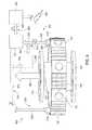
- FIG. 7is another schematic perspective view of the LVG shown in FIG. 6 ;
- FIG. 8is a perspective view of an alternative subsea power generation assembly that may be used with the submersible resource recovery system shown in FIG. 1 .
- Approximating languagemay be applied to modify any quantitative representation that could permissibly vary without resulting in a change in the basic function to which it is related. Accordingly, a value modified by a term or terms, such as “about”, “approximately”, and “substantially”, are not to be limited to the precise value specified. In at least some instances, the approximating language may correspond to the precision of an instrument for measuring the value.
- range limitationsmay be combined and/or interchanged, such ranges are identified and include all the sub-ranges contained therein unless context or language indicates otherwise.
- the submersible electric power generators described hereinfacilitate extended operation in undersea environments, including submersible resource recovery systems.
- the submersible liquid-vapor generators (LVGs) described hereinuse magnetohydrodynamic (MHD) apparatus with nanoparticles entrained in a two-phase fluid that is channeled through a magnetic field to generate a voltage.
- MHDmagnetohydrodynamic
- Such nanoparticlesare substantially electrically-conducting and substantially non-magnetic materials.
- the nanoparticlesremain entrained in the fluid as it proceeds through a hermetically closed loop cycle, i.e., as they transit through a condenser and evaporator.
- the LVGs disclosed hereinare simpler, lighter, more reliable, and cheaper to assemble than known MHD systems. Entrainment of the nanoparticles is facilitated by configuring the interior channels such that transonic flow from the evaporator to the condenser through the magnetic field is enabled. Moreover, the entrained nanoparticles are configured to be light enough to facilitate the transonic flow.
- the hermetically-sealed configuration as described hereinsubstantially eliminates moving parts, thereby facilitating reliability for extended submerged power generation operations. The heat transferred into the liquid and the nanoparticles and subsequently removed in the condenser is transferred to any of a variety of bottoming systems for secondary electric power generation.
- the LVGs as described hereinare both scalable and stackable to meet the electric power needs of most known undersea configurations.
- FIG. 1is a schematic view of a portion of an exemplary submersible resource recovery system 100 .
- System 100includes a subsea pipeline 102 that couples system 100 in flow communication with a topside production rig (not shown).
- System 100includes a blowout preventer system 104 coupled to a subsea power generation assembly 106 that includes at least one submersible liquid-vapor generation assembly (not shown in FIG. 1 and discussed further below) that includes at least one liquid-vapor generator (LVG) (not shown in FIG. 1 and discussed further below).
- Subsea power generation assembly 106is coupled in flow communication with a subsea tree 108 .
- Subsea tree 108includes the necessary equipment, such as, and without limitation, valving, spools, manifolds, pressure gauges, and chokes to enable operation and control production of system 100 as described herein.
- System 100further includes a subsea wellhead 110 extending from a subsea floor 112 up to subsea tree 108 and extending down to a reservoir (not shown).
- submersible resource recovery system 100is any resource recovery system including, without limitation, subsea oil and gas production systems.
- submersible resource recovery system 100is any subsea system that enables operation of subsea power generation assembly 106 as described herein.
- serial order of blowout preventer system 104 , subsea power generation assembly 106 , and subsea tree 108may be rearranged as a function of circumstances including, without limitation, the nature of the material being recovered, the depth of the water, and the subsea geography.
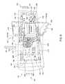
- FIG. 2is a perspective view of subsea power generation assembly 106 that may be used with submersible resource recovery system (shown in FIG. 1 ).
- FIG. 3is another perspective view of subsea power generation assembly 106 .
- Assembly 106includes a spool piece 120 .
- Spool piece 120includes a first flange 122 for coupling assembly 106 to blowout preventer system 104 and a second flange 124 for coupling assembly 106 to subsea tree 108 .
- Spool piece 120also includes a pipeline portion 126 extending between first flange 122 and second flange 124 .
- Pipeline portion 126includes an outside wall 128 and an inside wall 130 that defines a fluid channel 132 .
- inside wall 130includes alternating grooves and ridges 134 defined therein (only two grooves and one ridge shown in FIG. 3 ) for increasing the surface area of inside wall 130 , thereby facilitating an increase in the rate of heat transfer into pipeline portion 126 .
- Grooves and ridges 134are configured to not inhibit a flow of fluid therein.
- subsea power generation assembly 106includes a heat exchanger 140 .
- Heat exchanger 140is substantially annular with, and extends about, pipeline portion 126 .
- heat exchanger 140includes an inner wall 142 opposite outside wall 128 and an outer wall 144 defining plurality of alternating grooves and ridges 146 similar to those grooves and ridges 134 defined on inside wall 130 . Grooves and ridges 146 increase the surface area of outer wall 144 , thereby facilitating an increase in the rate of heat transfer into the surrounding environment.
- Heat exchanger 140is configured to transmit heat energy to the water surrounding subsea power generation assembly 106 .
- heat exchanger 140is configured to transmit heat energy to other apparatus for collection and further practical use (described further below).
- subsea power generation assembly 106includes a plurality of submersible liquid-vapor generation assemblies, i.e., liquid-vapor generator (LVGs) 150 .
- Each LVG 150is substantially cylindrical and extends radially outward from fluid channel 132 to outer wall 144 .
- LVG 150includes an evaporator portion 152 that protrudes into fluid channel 132 and a condenser portion 154 that extends into the surrounding subsea environment.
- a hot fluid 160is channeled upward through fluid channel 132 from subsea wellhead 110 .
- Hot fluid 160transfers heat energy 162 to pipeline portion 126 and evaporator portion 152 .
- a portion of heat energy 162is transferred radially outward from pipeline portion 126 through each LVG 150 to condenser portion 154 .
- a portion of heat energy 162is transferred to heat exchanger 144 and a portion of heat energy 162 is transferred to the surrounding subsea environment.
- all of the heat energyis transferred to the surrounding subsea environment.
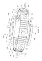
- rare earth permanent magnets 174have a magnetic field strength, i.e., a remanence of approximately 1 Tesla (T). Further, magnets are positioned opposite each other in LVG 150 . Alternatively, any number of rare earth permanent magnets 174 in any configuration are formed from any materials and with any remanence that enables operation of LVG 150 as described herein, including, without limitation, samarium-cobalt magnet alloys. Rare earth permanent magnets 174 have an advantage over electromagnetic devices in that rare earth permanent magnets 174 , with a known remanence life span, require less maintenance and no external power sources. Further, in the exemplary embodiment, power generator 170 includes a plurality of Hall generator electrodes 176 (only one shown in FIG. 4 and two shown in FIG. 5 ) positioned opposite each other and orthogonally with magnets 174 . Alternative embodiments include any number and any orientation of Hall generator electrodes 176 that enables operation of LVG 150 as described herein.
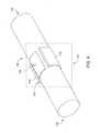
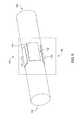
- FIG. 6is a schematic perspective view of LVG 150 and FIG. 7 is another schematic perspective view of LVG 150 .
- LVG 150includes a casing 178 that hermetically seals the interior of LVG 150 from the subsea environment.
- casing 178is formed from a ceramic material.
- any material that enables operation of LVG 150 as described hereinis used, including, without limitation, pressure-resistant and water-resistant plastics.
- LVG 150also includes an electrically non-conductive wick structure 180 .
- Casing 178is coupled to, and extends about, wick structure 180 .
- Wick structure 180is a porous, sintered ceramic material configured to channel a hybrid working liquid (discussed further below) from condenser portion 154 to evaporator portion 152 through capillary action. Wick structure 180 defines an interior cavity 182 of LVG 150 .
- a fill tube 184extends from, and extends through, casing 178 and to wick structure 180 . Alternatively, fill tube 184 extends through wick structure 180 into interior cavity 182 .
- the pressure in interior cavity 182is adjusted to facilitate two-phase operation, i.e., and without limitation, a vacuum is pulled on interior cavity 182 to a predetermined value. Vacuum on interior cavity 182 may be pulled using a vacuum connection (not shown).
- a hybrid working fluid 186is channeled through fill tube 184 and fill tube 184 is sealed through welding.
- hybrid working fluid 186includes nanoparticles 188 that are formed from a metallic material that is substantially non-magnetic and substantially electrically-conducting.
- metallic materialsare selected based on their characteristics that include forming free electrons and include, without limitation, gold, silver, aluminum, and copper.
- such fluidincludes a metal with a relatively low melting point, i.e., a melting point less than 100 degrees Celsius (° C.) (212 degrees Fahrenheit (° F.)) at atmospheric pressure.
- metalsinclude, without limitation, alkali metals such as sodium, cesium, and potassium, and other metals such as mercury and gallium.
- metals with any liquefaction temperature at any pressure that enable operation of LVG 150 as described hereinare used.
- Some of the embodiments with liquid metalsdo not require the use of nanoparticles, however, such metallic nanoparticles may enhance operation of LVG 150 .
- hybrid working fluid 186includes a non-metallic fluid that has a boiling point less than 100° C.
- non-metallic liquidsinclude, without limitation, ammonia, methyl alcohol, benzene, bromine, butane, isopropyl alcohol, and methanol.
- the embodiments with such non-metallic liquidsrequire the addition of nanoparticles 188 .
- Hybrid working fluid 186will operate as a two-phase working fluid, i.e., in liquid and gaseous states.
- the materials for wick structure 180 , the metallic liquid, the non-metallic liquid, and metallic nanoparticles 188are selected for characteristics that include, without limitation, chemical compatibility, liquefaction temperatures, and vaporization temperatures.
- metallic nanoparticles 188are chemically bound to molecules of hybrid working fluid 186 .
- nanoparticles 188 and the pores of wick structure 180are mutually sized to facilitate channeling nanoparticles 188 through wick structure 180 from condenser portion 154 to evaporator portion 152 .
- the predetermined sizes of the pores within wick structure 180are enlarged as a function of increases in predetermined heat flux 162 into interior cavity 182 .
- the size of the pores and the dimensions of wick structure 180are selected to facilitate transonic flow of hybrid working vapor 204 .
- the poresare sized in a range between an order of magnitude of hundreds of microns and thousands of microns. In FIGS. 6 and 7 , only a portion of nanoparticles 188 are shown within LVG 150 for clarity.
- Electrodes 176include a metallic positive electrode 192 and a metallic negative electrode 194 with at least one electrical load 196 coupled to electrodes 192 and 194 to define an electrical circuit 198 .
- load 196include, without limitation, auxiliary electric power for motors and lighting on the production rig, and undersea motors for facilitating subsea pumping operation.
- At least a portion of casing 178is electrically non-conductive. Specifically, a portion of casing 178 proximate electrodes 192 and 194 is electrically non-conductive. Also, at least a portion of casing 178 is non-magnetic. Specifically, a portion of casing 178 proximate magnets 174 is non-magnetic. Any electrically non-conductive and non-magnetic material that enables operation of LVG 150 as described herein is used, including, without limitation, pressure-resistant and water-resistant plastics and ceramics.
- LVG 150Operation of LVG 150 to generate power in an undersea environment is described using either a metallic liquid or a non-metallic liquid, both with entrained nanoparticles 188 . Operation of LVG 150 with a metallic liquid and without metallic nanoparticles is similar.
- hot fluid flow 160(shown in FIGS. 2 and 3 ) is initiated from subsea wellhead 110 through subsea tree 108 (both shown in FIG. 1 ) to fluid channel 132 (shown in FIGS. 2 and 3 ).
- Hot fluid 160transfers heat energy 162 to evaporator portion 152 .
- Heat energy 162enters evaporator portion 152 and converts, i.e., evaporates a hybrid working liquid 202 in wick structure 180 and in interior cavity 182 proximate evaporator portion 152 to a hybrid working vapor 204 .
- the operating temperature of hybrid working vapor 204is within the range of approximately 600° C. (1112° F.) and 900° C. (1652° F.).
- any temperature range for the predetermined pressure within interior cavity 182 that enables operation of LVG 150 as described hereinis used.
- vapor 204is channeled at a high velocity, e.g., without limitation, at approximately sonic velocities and transonic velocities in a direction shown by flow arrow 205 that is approximately orthogonal with respect to magnetic field 190 .
- Lorentz forces induced by field 190separate free electrons 206 from positive ions 208 (only shown in FIG. 6 ).
- An electromagnetic Hall potential across positive electrode 192 and negative electrode 194is generated and induces electric current flow 210 to power load 196 , thereby facilitating magnetohydrodynamic (MHD) power generation in LVG 150 .
- MHDmagnetohydrodynamic
- hybrid working vapor 204continues to flow into condenser portion 154 , where heat energy 162 is transferred from hybrid working vapor 204 to the surrounding subsea environment.
- Hybrid working vapor 204is condensed into hybrid working liquid 202 that is channeled into wick structure 180 and hybrid working liquid 202 is channeled, using capillary action as shown by arrows 212 , from condenser portion 154 to evaporator portion 152 , thereby establishing a hybrid working liquid flow path extending between condenser portion 154 to evaporator portion 152 , and further establishing a natural circulation heat transfer cycle with two-phase hybrid working fluid 186 .
- LVG 150is substantially orthogonal to gravitational forces, such gravitational forces facilitate downward travel of hybrid working fluid 186 such that a bottom portion of wick structure 180 may channel more fluid 186 from condenser portion 154 to evaporator portion 152 than an upper portion of wick structure 180 .
- LVG 150is configured to be positioned at a predetermined angle with respect to subsea floor 112 (shown in FIG. 1 ) such that condenser portion 154 is higher than evaporator portion 152 .
- vapor 204is channeled upward from evaporator portion 152 toward condenser portion 152 and gravitational forces assist the wick-assisted capillary action of channeling condensed liquid 202 downward from condenser portion 154 to evaporator portion 152 .
- wick structure 180may not be necessary and condensed liquid 202 is channeled downward from condenser portion 154 to evaporator portion 152 along interior walls of casing 178 .
- FIG. 8is a perspective view of an alternative a subsea power generation assembly 300 that may be used with subsea production facility 100 (shown in FIG. 1 ).
- Subsea power generation assembly 300is a portion of a larger subsea power generation system 302 that includes a plurality of assemblies 300 (only one shown) and a turbomachine 304 .
- Subsea power generation assemblies 300are positioned in any configuration that enables operation of subsea power generation system 302 as described herein, including, without limitation, one of stacked in a serial relationship such that fluid flow 160 is received by each assembly 302 , and positioned in parallel to each other and each assembly 300 receiving a separate fluid flow 160 from a different wellhead 110 (shown in FIG. 1 ).
- Subsea power generation assembly 300is similar to subsea power generation assembly 106 (shown in FIGS. 2 and 3 ) with the differences set forth below.
- Each assembly 300includes a heat transfer medium inlet connection 310 and a heat transfer medium outlet connection 312 coupled to heat exchanger 140 .
- Connections 310 and 312are coupled in flow communication with turbomachine 304 , and connections 310 and 312 at least partially define a steam generation system 320 .
- the heat transfer mediumis demineralized water.
- the heat transfer mediumis any fluid that enables operation of assembly 300 as described herein.
- Turbomachine 304includes a steam turbine 322 rotatably coupled to an electric power generator 324 through a rotatable shaft 326 .
- Turbomachine 304has any configuration that enables operation of assembly 300 and subsea power generation system 302 as described herein.
- Turbomachine 304is on one of an associated production rig, a separate floating platform or barge, or a land-based facility.
- fluid flow 160transfers heat energy to LVGs 150 that operate as described above.
- the heat energy in LVGs 150is transferred to a condensate 330 channeled through heat exchanger 140 .
- Steam 332is generated in heat exchanger 140 , where steam 332 is either saturated steam or superheated steam. Steam 332 is channeled to steam turbine 322 that drives generator 324 through rotation of shaft 326 . Steam 332 is condensed into condensate 330 upon exit from steam turbine 322 for return to heat exchangers 140 .
- Generator 324generates electric power 334 for distribution in a manner similar to the electric power generated by LVGs 150 .
- the submersible electric power generators described hereinfacilitate extended operation in undersea environments, including submersible resource recovery system.
- the submersible liquid-vapor generators (LVGs) described hereinuse magnetohydrodynamic (MHD) apparatus with nanoparticles entrained in a two-phase fluid that is channeled through a magnetic field to generate a voltage.
- MHDmagnetohydrodynamic
- Such nanoparticlesare substantially electrically-conducting and substantially non-magnetic materials.
- the nanoparticlesremain entrained in the fluid as it proceeds through a hermetically closed loop cycle, i.e., as they transit through a condenser and evaporator.
- the LVGs disclosed hereinare simpler, lighter, more reliable, and cheaper to assemble than known MHD systems. Entrainment of the nanoparticles is facilitated by configuring the interior channels such that transonic flow from the evaporator to the condenser through the magnetic field is enabled. Moreover, the entrained nanoparticles are configured to be light enough to facilitate the transonic flow.
- the hermetically-sealed configuration as described hereinsubstantially eliminates moving parts, thereby facilitating reliability for extended submerged power generation operations. The heat transferred into the liquid and the nanoparticles and subsequently removed in the condenser is transferred to any of a variety of bottoming systems for secondary electric power generation.
- the LVGs as described hereinare both scalable and stackable to meet the electric power needs of most known undersea configurations.
- An exemplary technical effect of the methods, systems, and apparatus described hereinincludes at least one of: (a) electrically-conducting, non-magnetic nanoparticles remain entrained in a two-phase fluid as it transits through a hermetically closed loop cycle, i.e., as they transit through a condenser and evaporator; (b) eliminating the need for particle mixers and separators for injecting and removing nanoparticles from a working fluid therein; (c) facilitating entrainment of nanoparticles in a working fluid with interior channels that are configured such that transonic flow from an evaporator to a condenser through the magnetic field is enabled; and facilitating extended power generation support for submersible resource recovery systems.
- Exemplary embodiments of methods, systems, and apparatus for operating power generation systemsare not limited to the specific embodiments described herein, but rather, components of systems and/or steps of the methods may be utilized independently and separately from other components and/or steps described herein.
- the methods, systems, and apparatusmay also be used in combination with other systems requiring a heat pipe for heat transfer and power generation, and the associated methods, and are not limited to practice with only the systems and methods as described herein.
- the exemplary embodimentcan be implemented and utilized in connection with many other applications, equipment, and systems that may benefit from using a heat pipe for heat transfer and power generation.
Landscapes
- Engineering & Computer Science (AREA)
- Physics & Mathematics (AREA)
- Fluid Mechanics (AREA)
- Life Sciences & Earth Sciences (AREA)
- Chemical & Material Sciences (AREA)
- Combustion & Propulsion (AREA)
- Power Engineering (AREA)
- General Life Sciences & Earth Sciences (AREA)
- Mining & Mineral Resources (AREA)
- Geology (AREA)
- Mechanical Engineering (AREA)
- General Engineering & Computer Science (AREA)
- Sustainable Development (AREA)
- Oceanography (AREA)
- Biodiversity & Conservation Biology (AREA)
- Environmental & Geological Engineering (AREA)
- Geochemistry & Mineralogy (AREA)
- Engine Equipment That Uses Special Cycles (AREA)
Abstract
Description
The field of the disclosure relates generally to electric power generation equipment and, more particularly, to submersible liquid-vapor generators (LVGs).
Continued exploration of undersea environments requires submerged, proximate, compact, and reliable electric power generation sources with sufficient capacity to provide a high power density for extended periods of time. As such, most standard power generation devices that rely on fossil fuels are not practical for undersea operations. Also, more standard renewable power sources, e.g., wind and solar are also not available. Other exotic power generation systems include thermoelectric (TE), photon enhanced thermionic (PET), and thermophotovoltaic (TPV). In general, TE-based systems require a large temperature drop to be effective, a condition not typically found in undersea environments. PET systems and TPV systems require exposure to the sun. Nuclear and chemical conversion power generation systems are also impractical for widespread use in undersea applications (other than submarines) due to practical considerations, e.g., environmental regulations.
Many known magnetohydrodynamic (MHD) power generators have been developed for a variety of applications. These known MHD generators use a liquid metal-seeded plasma stream channeled through a Hall generator and have demonstrated efficiencies approaching 40%. However, since greater efficiencies are found with higher temperatures, such MHD systems are limited by the materials available, and such materials, excluding expensive exotic materials, are susceptible to temperature and corrosion effects. Furthermore, such known MHD systems use a two-phase fluid mixture, some with metal particles injected into and entrained therein, accelerated to high velocities and channeled through a magnetic field to generate the Hall voltage potential. However, such known MHD systems require intricate plumbing configurations for multiple flow circuits that include metal particle injection and mixing apparatus and metal particle separation apparatus. As such, known MHD systems are not suitable for extended deployments in undersea environments.
In one aspect, a submersible liquid-vapor generator (LVG) is provided. The submersible liquid-vapor generator (LVG) includes an evaporator portion in heat transfer communication with a heat energy source. The LVG also includes a magnetic field apparatus coupled in flow communication with the evaporator portion. The LVG further includes a condenser portion coupled in flow communication with the magnetic field apparatus. The LVG also includes a hybrid working fluid including nanoparticles. The evaporator portion, the magnetic field portion, and the condenser portion at least partially define a hybrid working vapor flow path. The LVG further includes an electrically non-conductive wick structure coupled in flow communication with the evaporator portion and the condenser portion. The wick structure at least partially defines a hybrid working liquid flow path extending between the condenser portion and the evaporator portion.
In a further aspect, a method of generating power in an undersea environment is provided. The method includes forming a hybrid working liquid including combining a liquid and nanoparticles. The method also includes transferring heat energy from a heat source into the hybrid working liquid, thereby evaporating the hybrid working liquid into a hybrid working vapor. The method further includes channeling the hybrid working vapor through a magnetic field, thereby inducing a voltage on an electric current carrying conductor. The method also includes transferring heat energy from the hybrid working vapor, thereby condensing the hybrid working vapor into the hybrid working liquid. The method further includes channeling the hybrid working liquid toward the heat source.
In another aspect, a subsea power generation assembly is provided. The assembly includes a heat exchanger and a plurality of submersible liquid-vapor generators (LVGs) coupled to the heat exchanger. Each LVG of the plurality of LVGs includes an evaporator portion in heat transfer communication with a heat energy source. Each LVG also includes a magnetic field apparatus coupled in flow communication with the evaporator portion. Each LVG further includes a condenser portion coupled in flow communication with the magnetic field apparatus. Each LVG also includes a hybrid working fluid including nanoparticles. The evaporator portion, the magnetic field portion, and the condenser portion at least partially define a hybrid working vapor flow path. Each LVG further includes an electrically non-conductive wick structure coupled in flow communication with the evaporator portion and the condenser portion. The wick structure at least partially defines a hybrid working liquid flow path extending between the condenser portion and the evaporator portion.
These and other features, aspects, and advantages of the present disclosure will become better understood when the following detailed description is read with reference to the accompanying drawings in which like characters represent like parts throughout the drawings, wherein:
Unless otherwise indicated, the drawings provided herein are meant to illustrate features of embodiments of this disclosure. These features are believed to be applicable in a wide variety of systems comprising one or more embodiments of this disclosure. As such, the drawings are not meant to include all conventional features known by those of ordinary skill in the art to be required for the practice of the embodiments disclosed herein.
In the following specification and the claims, reference will be made to a number of terms, which shall be defined to have the following meanings.
The singular forms “a”, “an”, and “the” include plural references unless the context clearly dictates otherwise.
“Optional” or “optionally” means that the subsequently described event or circumstance may or may not occur, and that the description includes instances where the event occurs and instances where it does not.
Approximating language, as used herein throughout the specification and claims, may be applied to modify any quantitative representation that could permissibly vary without resulting in a change in the basic function to which it is related. Accordingly, a value modified by a term or terms, such as “about”, “approximately”, and “substantially”, are not to be limited to the precise value specified. In at least some instances, the approximating language may correspond to the precision of an instrument for measuring the value. Here and throughout the specification and claims, range limitations may be combined and/or interchanged, such ranges are identified and include all the sub-ranges contained therein unless context or language indicates otherwise.
As used herein, the terms “subsea”, “undersea”, and “submersible” are interchangeable.
The submersible electric power generators described herein facilitate extended operation in undersea environments, including submersible resource recovery systems. Specifically, the submersible liquid-vapor generators (LVGs) described herein use magnetohydrodynamic (MHD) apparatus with nanoparticles entrained in a two-phase fluid that is channeled through a magnetic field to generate a voltage. Such nanoparticles are substantially electrically-conducting and substantially non-magnetic materials. In contrast to known MHD systems, the nanoparticles remain entrained in the fluid as it proceeds through a hermetically closed loop cycle, i.e., as they transit through a condenser and evaporator. Particle mixers and separators are no longer required, therefore the LVGs disclosed herein are simpler, lighter, more reliable, and cheaper to assemble than known MHD systems. Entrainment of the nanoparticles is facilitated by configuring the interior channels such that transonic flow from the evaporator to the condenser through the magnetic field is enabled. Moreover, the entrained nanoparticles are configured to be light enough to facilitate the transonic flow. The hermetically-sealed configuration as described herein substantially eliminates moving parts, thereby facilitating reliability for extended submerged power generation operations. The heat transferred into the liquid and the nanoparticles and subsequently removed in the condenser is transferred to any of a variety of bottoming systems for secondary electric power generation. The LVGs as described herein are both scalable and stackable to meet the electric power needs of most known undersea configurations.
Also, in the exemplary embodiment, subseapower generation assembly 106 includes aheat exchanger 140.Heat exchanger 140 is substantially annular with, and extends about,pipeline portion 126. Also,heat exchanger 140 includes aninner wall 142 oppositeoutside wall 128 and anouter wall 144 defining plurality of alternating grooves andridges 146 similar to those grooves andridges 134 defined oninside wall 130. Grooves andridges 146 increase the surface area ofouter wall 144, thereby facilitating an increase in the rate of heat transfer into the surrounding environment.Heat exchanger 140 is configured to transmit heat energy to the water surrounding subseapower generation assembly 106. Alternatively,heat exchanger 140 is configured to transmit heat energy to other apparatus for collection and further practical use (described further below).
Further, in the exemplary embodiment, subseapower generation assembly 106 includes a plurality of submersible liquid-vapor generation assemblies, i.e., liquid-vapor generator (LVGs)150. EachLVG 150 is substantially cylindrical and extends radially outward fromfluid channel 132 toouter wall 144.LVG 150 includes anevaporator portion 152 that protrudes intofluid channel 132 and acondenser portion 154 that extends into the surrounding subsea environment.
In operation, ahot fluid 160 is channeled upward throughfluid channel 132 fromsubsea wellhead 110.Hot fluid 160 transfers heatenergy 162 topipeline portion 126 andevaporator portion 152. A portion ofheat energy 162 is transferred radially outward frompipeline portion 126 through eachLVG 150 tocondenser portion 154. A portion ofheat energy 162 is transferred toheat exchanger 144 and a portion ofheat energy 162 is transferred to the surrounding subsea environment. Ultimately, all of the heat energy is transferred to the surrounding subsea environment.
Also, in the exemplary embodiment, the pressure ininterior cavity 182 is adjusted to facilitate two-phase operation, i.e., and without limitation, a vacuum is pulled oninterior cavity 182 to a predetermined value. Vacuum oninterior cavity 182 may be pulled using a vacuum connection (not shown). Ahybrid working fluid 186 is channeled throughfill tube 184 and filltube 184 is sealed through welding.
In some embodiments,hybrid working fluid 186 includesnanoparticles 188 that are formed from a metallic material that is substantially non-magnetic and substantially electrically-conducting. Such metallic materials are selected based on their characteristics that include forming free electrons and include, without limitation, gold, silver, aluminum, and copper.
In some embodiments, such fluid includes a metal with a relatively low melting point, i.e., a melting point less than 100 degrees Celsius (° C.) (212 degrees Fahrenheit (° F.)) at atmospheric pressure. Such metals include, without limitation, alkali metals such as sodium, cesium, and potassium, and other metals such as mercury and gallium. Alternatively, metals with any liquefaction temperature at any pressure that enable operation ofLVG 150 as described herein are used. Some of the embodiments with liquid metals do not require the use of nanoparticles, however, such metallic nanoparticles may enhance operation ofLVG 150. Alternatively, in some embodiments,hybrid working fluid 186 includes a non-metallic fluid that has a boiling point less than 100° C. (212° F.) at atmospheric pressure. Such non-metallic liquids include, without limitation, ammonia, methyl alcohol, benzene, bromine, butane, isopropyl alcohol, and methanol. The embodiments with such non-metallic liquids require the addition ofnanoparticles 188.Hybrid working fluid 186 will operate as a two-phase working fluid, i.e., in liquid and gaseous states.
In the exemplary embodiment, the materials forwick structure 180, the metallic liquid, the non-metallic liquid, andmetallic nanoparticles 188 are selected for characteristics that include, without limitation, chemical compatibility, liquefaction temperatures, and vaporization temperatures. For example, and without limitation, in some embodiments,metallic nanoparticles 188 are chemically bound to molecules ofhybrid working fluid 186.
Also, in the exemplary embodiment,nanoparticles 188 and the pores ofwick structure 180 are mutually sized to facilitate channelingnanoparticles 188 throughwick structure 180 fromcondenser portion 154 toevaporator portion 152. Furthermore, the predetermined sizes of the pores withinwick structure 180 are enlarged as a function of increases inpredetermined heat flux 162 intointerior cavity 182. As such, the size of the pores and the dimensions ofwick structure 180 are selected to facilitate transonic flow ofhybrid working vapor 204. For example, and without limitation, the pores are sized in a range between an order of magnitude of hundreds of microns and thousands of microns. InFIGS. 6 and 7 , only a portion ofnanoparticles 188 are shown withinLVG 150 for clarity.
Further, in the exemplary embodiment, rare earthpermanent magnets 174 generate amagnetic field 190.Electrodes 176 include a metallic positive electrode192 and a metallic negative electrode194 with at least oneelectrical load 196 coupled to electrodes192 and194 to define anelectrical circuit 198. Examples ofload 196 include, without limitation, auxiliary electric power for motors and lighting on the production rig, and undersea motors for facilitating subsea pumping operation.
At least a portion ofcasing 178 is electrically non-conductive. Specifically, a portion ofcasing 178 proximate electrodes192 and194 is electrically non-conductive. Also, at least a portion ofcasing 178 is non-magnetic. Specifically, a portion ofcasing 178proximate magnets 174 is non-magnetic. Any electrically non-conductive and non-magnetic material that enables operation ofLVG 150 as described herein is used, including, without limitation, pressure-resistant and water-resistant plastics and ceramics.
Operation ofLVG 150 to generate power in an undersea environment is described using either a metallic liquid or a non-metallic liquid, both with entrainednanoparticles 188. Operation ofLVG 150 with a metallic liquid and without metallic nanoparticles is similar.
Referring toFIGS. 6 and 7 , in operation, hot fluid flow160 (shown inFIGS. 2 and 3 ) is initiated fromsubsea wellhead 110 through subsea tree108 (both shown inFIG. 1 ) to fluid channel132 (shown inFIGS. 2 and 3 ).Hot fluid 160 transfers heatenergy 162 toevaporator portion 152.Heat energy 162 entersevaporator portion 152 and converts, i.e., evaporates ahybrid working liquid 202 inwick structure 180 and ininterior cavity 182proximate evaporator portion 152 to ahybrid working vapor 204. In the exemplary embodiment, the operating temperature ofhybrid working vapor 204 is within the range of approximately 600° C. (1112° F.) and 900° C. (1652° F.). Alternatively, any temperature range for the predetermined pressure withininterior cavity 182 that enables operation ofLVG 150 as described herein is used.
Also, in operation,vapor 204 is channeled at a high velocity, e.g., without limitation, at approximately sonic velocities and transonic velocities in a direction shown byflow arrow 205 that is approximately orthogonal with respect tomagnetic field 190. Lorentz forces induced byfield 190 separatefree electrons 206 from positive ions208 (only shown inFIG. 6 ). An electromagnetic Hall potential across positive electrode192 and negative electrode194 is generated and induces electriccurrent flow 210 topower load 196, thereby facilitating magnetohydrodynamic (MHD) power generation inLVG 150.
Further, in operation,hybrid working vapor 204 continues to flow intocondenser portion 154, whereheat energy 162 is transferred from hybrid workingvapor 204 to the surrounding subsea environment.Hybrid working vapor 204 is condensed intohybrid working liquid 202 that is channeled intowick structure 180 andhybrid working liquid 202 is channeled, using capillary action as shown byarrows 212, fromcondenser portion 154 toevaporator portion 152, thereby establishing a hybrid working liquid flow path extending betweencondenser portion 154 toevaporator portion 152, and further establishing a natural circulation heat transfer cycle with two-phasehybrid working fluid 186.
In the embodiments discussed above, gravity plays a small role in the flow ofhybrid working fluid 186 as hybrid workingliquid 202 andhybrid working vapor 204, includingmagnetic nanoparticles 188. Specifically, assumingLVG 150 is substantially orthogonal to gravitational forces, such gravitational forces facilitate downward travel ofhybrid working fluid 186 such that a bottom portion ofwick structure 180 may channel more fluid186 fromcondenser portion 154 toevaporator portion 152 than an upper portion ofwick structure 180. Alternatively,LVG 150 is configured to be positioned at a predetermined angle with respect to subsea floor112 (shown inFIG. 1 ) such thatcondenser portion 154 is higher thanevaporator portion 152. In some such alternative embodiments,vapor 204 is channeled upward fromevaporator portion 152 towardcondenser portion 152 and gravitational forces assist the wick-assisted capillary action of channelingcondensed liquid 202 downward fromcondenser portion 154 toevaporator portion 152. In other such alternative embodiments,wick structure 180 may not be necessary andcondensed liquid 202 is channeled downward fromcondenser portion 154 toevaporator portion 152 along interior walls ofcasing 178.
Subseapower generation assembly 300 is similar to subsea power generation assembly106 (shown inFIGS. 2 and 3 ) with the differences set forth below. Eachassembly 300 includes a heat transfermedium inlet connection 310 and a heat transfermedium outlet connection 312 coupled toheat exchanger 140.Connections turbomachine 304, andconnections steam generation system 320. As such, in the exemplary embodiment, the heat transfer medium is demineralized water. Alternatively, the heat transfer medium is any fluid that enables operation ofassembly 300 as described herein.
In operation,fluid flow 160 transfers heat energy toLVGs 150 that operate as described above. The heat energy inLVGs 150 is transferred to acondensate 330 channeled throughheat exchanger 140.Steam 332 is generated inheat exchanger 140, wheresteam 332 is either saturated steam or superheated steam.Steam 332 is channeled tosteam turbine 322 that drivesgenerator 324 through rotation ofshaft 326.Steam 332 is condensed intocondensate 330 upon exit fromsteam turbine 322 for return toheat exchangers 140.Generator 324 generateselectric power 334 for distribution in a manner similar to the electric power generated byLVGs 150.
The above-described submersible electric power generators described herein facilitate extended operation in undersea environments, including submersible resource recovery system. Specifically, the submersible liquid-vapor generators (LVGs) described herein use magnetohydrodynamic (MHD) apparatus with nanoparticles entrained in a two-phase fluid that is channeled through a magnetic field to generate a voltage. Such nanoparticles are substantially electrically-conducting and substantially non-magnetic materials. In contrast to known MHD systems, the nanoparticles remain entrained in the fluid as it proceeds through a hermetically closed loop cycle, i.e., as they transit through a condenser and evaporator. Particle mixers and separators are no longer required, therefore the LVGs disclosed herein are simpler, lighter, more reliable, and cheaper to assemble than known MHD systems. Entrainment of the nanoparticles is facilitated by configuring the interior channels such that transonic flow from the evaporator to the condenser through the magnetic field is enabled. Moreover, the entrained nanoparticles are configured to be light enough to facilitate the transonic flow. The hermetically-sealed configuration as described herein substantially eliminates moving parts, thereby facilitating reliability for extended submerged power generation operations. The heat transferred into the liquid and the nanoparticles and subsequently removed in the condenser is transferred to any of a variety of bottoming systems for secondary electric power generation. The LVGs as described herein are both scalable and stackable to meet the electric power needs of most known undersea configurations.
An exemplary technical effect of the methods, systems, and apparatus described herein includes at least one of: (a) electrically-conducting, non-magnetic nanoparticles remain entrained in a two-phase fluid as it transits through a hermetically closed loop cycle, i.e., as they transit through a condenser and evaporator; (b) eliminating the need for particle mixers and separators for injecting and removing nanoparticles from a working fluid therein; (c) facilitating entrainment of nanoparticles in a working fluid with interior channels that are configured such that transonic flow from an evaporator to a condenser through the magnetic field is enabled; and facilitating extended power generation support for submersible resource recovery systems.
Exemplary embodiments of methods, systems, and apparatus for operating power generation systems are not limited to the specific embodiments described herein, but rather, components of systems and/or steps of the methods may be utilized independently and separately from other components and/or steps described herein. For example, the methods, systems, and apparatus may also be used in combination with other systems requiring a heat pipe for heat transfer and power generation, and the associated methods, and are not limited to practice with only the systems and methods as described herein. Rather, the exemplary embodiment can be implemented and utilized in connection with many other applications, equipment, and systems that may benefit from using a heat pipe for heat transfer and power generation.
Although specific features of various embodiments of the disclosure may be shown in some drawings and not in others, this is for convenience only. In accordance with the principles of the disclosure, any feature of a drawing may be referenced and/or claimed in combination with any feature of any other drawing.
This written description uses examples to disclose the embodiments, including the best mode, and also to enable any person skilled in the art to practice the embodiments, including making and using any devices or systems and performing any incorporated methods. The patentable scope of the disclosure is defined by the claims, and may include other examples that occur to those skilled in the art. Such other examples are intended to be within the scope of the claims if they have structural elements that do not differ from the literal language of the claims, or if they include equivalent structural elements with insubstantial differences from the literal language of the claims.
Claims (21)
1. A method of generating power in an undersea environment, said method comprising:
submerging a subsea power generation assembly in the undersea environment, the subsea power generation assembly including:
a substantially annular heat exchanger at least partially extending about a heat source; and
a plurality of submersible liquid-vapor generators (LVGs) coupled to the heat exchanger and the heat source, each LVG of the plurality of LVGs extending radially outward from the heat source to the substantially annular heat exchanger, each LVG including:
an evaporator portion in heat transfer communication with the heat energy source:
a magnetic field apparatus coupled in flow communication with the evaporator portion;
a condenser portion coupled in flow communication with the magnetic field apparatus;
a hybrid working fluid including nanoparticles, wherein the evaporator portion, the magnetic field apparatus, and the condenser portion at least partially define a hybrid working vapor flow path; and
an electrically non-conductive wick structure coupled in flow communication with the evaporator portion and the condenser portion, the wick structure at least partially defining a hybrid working liquid flow path extending between the condenser portion and the evaporator portion;
forming the hybrid working liquid comprising combining a liquid and the nanoparticles;
transferring heat energy from the heat source into the hybrid working liquid, thereby evaporating the hybrid working liquid into a hybrid working vapor;
channeling the hybrid working vapor through a magnetic field, thereby inducing a voltage on an electric current carrying conductor;
transferring heat energy from the hybrid working vapor, thereby condensing the hybrid working vapor into the hybrid working liquid; and
channeling the hybrid working liquid toward the heat source.
2. The method in accordance theclaim 1 , wherein combining a liquid and nanoparticles comprises mixing substantially non-magnetic and substantially electrically-conducting nanoparticles with a metal liquid.
3. The method in accordance theclaim 1 , wherein combining a liquid and nanoparticles comprises mixing substantially non-magnetic and substantially electrically-conducting nanoparticles with a fluid having a boiling point less than 100° C. at atmospheric pressure.
4. The method in accordance theclaim 1 , wherein transferring heat energy from a heat source comprises transferring heat from a fluid channeled from a subsea wellhead into the hybrid working liquid in the evaporator portion of each LVG.
5. The method in accordance withclaim 1 , wherein inducing a voltage on an electric current carrying conductor comprises powering an electric load.
6. The method in accordance withclaim 1 , wherein condensing the hybrid working vapor into the hybrid working liquid comprises transferring the heat energy from the hybrid working vapor into a steam generation system configured to drive a turbomachine including an electric generator.
7. The method in accordance withclaim 1 , wherein channeling the hybrid working liquid toward the heat source comprises channeling the hybrid working liquid through the electrically non-conductive wick structure using capillary action.
8. A subsea power generation assembly comprising:
a substantially annular heat exchanger at least partially extending about a heat source; and
a plurality of submersible liquid-vapor generators (LVGs) coupled to said heat exchanger and said heat source, each LVG of said plurality of LVGs extending radially outward from said heat source to said substantially annular heat exchanger, said each LVG comprising:
an evaporator portion in heat transfer communication with a heat energy source;
a magnetic field apparatus coupled in flow communication with said evaporator portion;
a condenser portion coupled in flow communication with said magnetic field apparatus;
a hybrid working fluid comprising nanoparticles, wherein said evaporator portion, said magnetic field apparatus, and said condenser portion at least partially define a hybrid working vapor flow path; and
an electrically non-conductive wick structure coupled in flow communication with said evaporator portion and said condenser portion, said wick structure at least partially defining a hybrid working liquid flow path extending between said condenser portion and said evaporator portion.
9. The subsea power generation assembly in accordance withclaim 8 , wherein said heat exchanger comprises:
a heat transfer medium inlet connection; and
a heat transfer medium outlet connection, wherein said heat transfer medium inlet connection and said heat transfer medium outlet connection are coupled to at least one turbomachine.
10. The subsea power generation assembly in accordance withclaim 9 , wherein said heat transfer medium inlet connection and said heat transfer medium outlet connection at least partially define a steam generation system.
11. The subsea power generation assembly in accordance withclaim 8 , wherein said condenser portion is coupled in heat transfer communication with said heat exchanger.
12. The subsea power generation assembly in accordance withclaim 8 , wherein said hybrid working fluid further comprises a metal in one of liquid and gaseous states and said nanoparticles are substantially non-magnetic and substantially electrically-conducting.
13. The subsea power generation assembly in accordance withclaim 8 further comprising a power generator comprising said magnetic field apparatus and a plurality of electrodes.
14. The subsea power generation assembly in accordance withclaim 8 , wherein said hybrid working fluid further comprises a fluid having a boiling point less than 100° C. at atmospheric pressure in one of liquid and gaseous states and said nanoparticles are substantially non-magnetic and substantially electrically-conducting.
15. The subsea power generation assembly in accordance withclaim 8 , wherein said substantially annular heat exchanger comprises a plurality of ridges defining a plurality of grooves, thereby increasing a heat transfer surface area of said substantially annular heat exchanger.
16. The subsea power generation assembly in accordance withclaim 8 , wherein said heat source comprises a pipeline portion comprising a plurality of flanges, said plurality of flanges facilitating scalability and stackability of said plurality of LVGs.
17. The subsea power generation assembly in accordance withclaim 8 , wherein said magnetic field apparatus comprises a permanent magnet.
18. The subsea power generation assembly in accordance withclaim 8 further comprising a casing coupled to and extending about said electrically non-conductive wick structure, at least a portion of said casing electrically non-conductive.
19. The subsea power generation assembly in accordance withclaim 18 , wherein said casing comprises a ceramic material that facilitates hermetically sealing said each LVG of said plurality of LVGs.
20. The subsea power generation assembly in accordance withclaim 8 , wherein said evaporator portion and said condenser portion define opposite ends of said each LVG of said plurality of LVGs, said magnetic field apparatus positioned therebetween.
21. The subsea power generation assembly in accordance withclaim 8 , said electrically non-conductive wick structure configured to channel said hybrid working liquid using capillary action.
Priority Applications (2)
| Application Number | Priority Date | Filing Date | Title |
|---|---|---|---|
| US14/564,563US9651032B2 (en) | 2014-12-09 | 2014-12-09 | Submersible power generators and method of operating thereof |
| PCT/US2015/063370WO2016094143A1 (en) | 2014-12-09 | 2015-12-02 | Submersible power generators and method of operating thereof |
Applications Claiming Priority (1)
| Application Number | Priority Date | Filing Date | Title |
|---|---|---|---|
| US14/564,563US9651032B2 (en) | 2014-12-09 | 2014-12-09 | Submersible power generators and method of operating thereof |
Publications (2)
| Publication Number | Publication Date |
|---|---|
| US20160160845A1 US20160160845A1 (en) | 2016-06-09 |
| US9651032B2true US9651032B2 (en) | 2017-05-16 |
Family
ID=55069076
Family Applications (1)
| Application Number | Title | Priority Date | Filing Date |
|---|---|---|---|
| US14/564,563Expired - Fee RelatedUS9651032B2 (en) | 2014-12-09 | 2014-12-09 | Submersible power generators and method of operating thereof |
Country Status (2)
| Country | Link |
|---|---|
| US (1) | US9651032B2 (en) |
| WO (1) | WO2016094143A1 (en) |
Cited By (202)
| Publication number | Priority date | Publication date | Assignee | Title |
|---|---|---|---|---|
| US11547404B2 (en) | 2014-12-18 | 2023-01-10 | Cilag Gmbh International | Surgical instrument assembly comprising a flexible articulation system |
| US11553916B2 (en) | 2015-09-30 | 2023-01-17 | Cilag Gmbh International | Compressible adjunct with crossing spacer fibers |
| US11559303B2 (en) | 2016-04-18 | 2023-01-24 | Cilag Gmbh International | Cartridge lockout arrangements for rotary powered surgical cutting and stapling instruments |
| US11559304B2 (en) | 2019-12-19 | 2023-01-24 | Cilag Gmbh International | Surgical instrument comprising a rapid closure mechanism |
| US11559302B2 (en) | 2007-06-04 | 2023-01-24 | Cilag Gmbh International | Surgical instrument including a firing member movable at different speeds |
| US11564682B2 (en) | 2007-06-04 | 2023-01-31 | Cilag Gmbh International | Surgical stapler device |
| US11564686B2 (en) | 2017-06-28 | 2023-01-31 | Cilag Gmbh International | Surgical shaft assemblies with flexible interfaces |
| US11571207B2 (en) | 2014-12-18 | 2023-02-07 | Cilag Gmbh International | Surgical system including lateral supports for a flexible drive member |
| US11576673B2 (en) | 2005-08-31 | 2023-02-14 | Cilag Gmbh International | Stapling assembly for forming staples to different heights |
| US11576668B2 (en) | 2017-12-21 | 2023-02-14 | Cilag Gmbh International | Staple instrument comprising a firing path display |
| US11576672B2 (en) | 2019-12-19 | 2023-02-14 | Cilag Gmbh International | Surgical instrument comprising a closure system including a closure member and an opening member driven by a drive screw |
| US11583279B2 (en) | 2008-10-10 | 2023-02-21 | Cilag Gmbh International | Powered surgical cutting and stapling apparatus with manually retractable firing system |
| US11596406B2 (en) | 2014-04-16 | 2023-03-07 | Cilag Gmbh International | Fastener cartridges including extensions having different configurations |
| US11602340B2 (en) | 2010-09-30 | 2023-03-14 | Cilag Gmbh International | Adhesive film laminate |
| US11612395B2 (en) | 2008-02-14 | 2023-03-28 | Cilag Gmbh International | Surgical system including a control system having an RFID tag reader |
| US11612394B2 (en) | 2011-05-27 | 2023-03-28 | Cilag Gmbh International | Automated end effector component reloading system for use with a robotic system |
| US11612393B2 (en) | 2006-01-31 | 2023-03-28 | Cilag Gmbh International | Robotically-controlled end effector |
| US11617575B2 (en) | 2008-09-23 | 2023-04-04 | Cilag Gmbh International | Motor-driven surgical cutting instrument |
| US11617577B2 (en) | 2020-10-29 | 2023-04-04 | Cilag Gmbh International | Surgical instrument comprising a sensor configured to sense whether an articulation drive of the surgical instrument is actuatable |
| US11622763B2 (en) | 2013-04-16 | 2023-04-11 | Cilag Gmbh International | Stapling assembly comprising a shiftable drive |
| US11622785B2 (en) | 2006-09-29 | 2023-04-11 | Cilag Gmbh International | Surgical staples having attached drivers and stapling instruments for deploying the same |
| US11627959B2 (en) | 2019-06-28 | 2023-04-18 | Cilag Gmbh International | Surgical instruments including manual and powered system lockouts |
| US11627960B2 (en) | 2020-12-02 | 2023-04-18 | Cilag Gmbh International | Powered surgical instruments with smart reload with separately attachable exteriorly mounted wiring connections |
| US11638587B2 (en) | 2019-06-28 | 2023-05-02 | Cilag Gmbh International | RFID identification systems for surgical instruments |
| US11642128B2 (en) | 2017-06-28 | 2023-05-09 | Cilag Gmbh International | Method for articulating a surgical instrument |
| US11642125B2 (en) | 2016-04-15 | 2023-05-09 | Cilag Gmbh International | Robotic surgical system including a user interface and a control circuit |
| US11648008B2 (en) | 2006-01-31 | 2023-05-16 | Cilag Gmbh International | Surgical instrument having force feedback capabilities |
| US11648024B2 (en) | 2006-01-31 | 2023-05-16 | Cilag Gmbh International | Motor-driven surgical cutting and fastening instrument with position feedback |
| US11648005B2 (en) | 2008-09-23 | 2023-05-16 | Cilag Gmbh International | Robotically-controlled motorized surgical instrument with an end effector |
| US11653915B2 (en) | 2020-12-02 | 2023-05-23 | Cilag Gmbh International | Surgical instruments with sled location detection and adjustment features |
| US11653914B2 (en) | 2017-06-20 | 2023-05-23 | Cilag Gmbh International | Systems and methods for controlling motor velocity of a surgical stapling and cutting instrument according to articulation angle of end effector |
| US11653920B2 (en) | 2020-12-02 | 2023-05-23 | Cilag Gmbh International | Powered surgical instruments with communication interfaces through sterile barrier |
| US11653918B2 (en) | 2014-09-05 | 2023-05-23 | Cilag Gmbh International | Local display of tissue parameter stabilization |
| US11660163B2 (en) | 2019-06-28 | 2023-05-30 | Cilag Gmbh International | Surgical system with RFID tags for updating motor assembly parameters |
| US11666332B2 (en) | 2007-01-10 | 2023-06-06 | Cilag Gmbh International | Surgical instrument comprising a control circuit configured to adjust the operation of a motor |
| US11672532B2 (en) | 2017-06-20 | 2023-06-13 | Cilag Gmbh International | Techniques for adaptive control of motor velocity of a surgical stapling and cutting instrument |
| US11672536B2 (en) | 2010-09-30 | 2023-06-13 | Cilag Gmbh International | Layer of material for a surgical end effector |
| US11678877B2 (en) | 2014-12-18 | 2023-06-20 | Cilag Gmbh International | Surgical instrument including a flexible support configured to support a flexible firing member |
| US11678880B2 (en) | 2017-06-28 | 2023-06-20 | Cilag Gmbh International | Surgical instrument comprising a shaft including a housing arrangement |
| US11678882B2 (en) | 2020-12-02 | 2023-06-20 | Cilag Gmbh International | Surgical instruments with interactive features to remedy incidental sled movements |
| US11684434B2 (en) | 2019-06-28 | 2023-06-27 | Cilag Gmbh International | Surgical RFID assemblies for instrument operational setting control |
| US11684365B2 (en) | 2004-07-28 | 2023-06-27 | Cilag Gmbh International | Replaceable staple cartridges for surgical instruments |
| US11684360B2 (en) | 2010-09-30 | 2023-06-27 | Cilag Gmbh International | Staple cartridge comprising a variable thickness compressible portion |
| US11684369B2 (en) | 2019-06-28 | 2023-06-27 | Cilag Gmbh International | Method of using multiple RFID chips with a surgical assembly |
| US11696757B2 (en) | 2021-02-26 | 2023-07-11 | Cilag Gmbh International | Monitoring of internal systems to detect and track cartridge motion status |
| US11696761B2 (en) | 2019-03-25 | 2023-07-11 | Cilag Gmbh International | Firing drive arrangements for surgical systems |
| US11701110B2 (en) | 2013-08-23 | 2023-07-18 | Cilag Gmbh International | Surgical instrument including a drive assembly movable in a non-motorized mode of operation |
| US11701111B2 (en) | 2019-12-19 | 2023-07-18 | Cilag Gmbh International | Method for operating a surgical stapling instrument |
| US11701113B2 (en) | 2021-02-26 | 2023-07-18 | Cilag Gmbh International | Stapling instrument comprising a separate power antenna and a data transfer antenna |
| US11701115B2 (en) | 2016-12-21 | 2023-07-18 | Cilag Gmbh International | Methods of stapling tissue |
| US11707273B2 (en) | 2012-06-15 | 2023-07-25 | Cilag Gmbh International | Articulatable surgical instrument comprising a firing drive |
| US11717294B2 (en) | 2014-04-16 | 2023-08-08 | Cilag Gmbh International | End effector arrangements comprising indicators |
| US11717297B2 (en) | 2014-09-05 | 2023-08-08 | Cilag Gmbh International | Smart cartridge wake up operation and data retention |
| US11717289B2 (en) | 2020-10-29 | 2023-08-08 | Cilag Gmbh International | Surgical instrument comprising an indicator which indicates that an articulation drive is actuatable |
| US11717291B2 (en) | 2021-03-22 | 2023-08-08 | Cilag Gmbh International | Staple cartridge comprising staples configured to apply different tissue compression |
| US11723658B2 (en) | 2021-03-22 | 2023-08-15 | Cilag Gmbh International | Staple cartridge comprising a firing lockout |
| US11723662B2 (en) | 2021-05-28 | 2023-08-15 | Cilag Gmbh International | Stapling instrument comprising an articulation control display |
| US11723657B2 (en) | 2021-02-26 | 2023-08-15 | Cilag Gmbh International | Adjustable communication based on available bandwidth and power capacity |
| US11730471B2 (en) | 2016-02-09 | 2023-08-22 | Cilag Gmbh International | Articulatable surgical instruments with single articulation link arrangements |
| US11730473B2 (en) | 2021-02-26 | 2023-08-22 | Cilag Gmbh International | Monitoring of manufacturing life-cycle |
| US11737751B2 (en) | 2020-12-02 | 2023-08-29 | Cilag Gmbh International | Devices and methods of managing energy dissipated within sterile barriers of surgical instrument housings |
| US11737749B2 (en) | 2021-03-22 | 2023-08-29 | Cilag Gmbh International | Surgical stapling instrument comprising a retraction system |
| US11737754B2 (en) | 2010-09-30 | 2023-08-29 | Cilag Gmbh International | Surgical stapler with floating anvil |
| US11749877B2 (en) | 2021-02-26 | 2023-09-05 | Cilag Gmbh International | Stapling instrument comprising a signal antenna |
| US11744583B2 (en) | 2021-02-26 | 2023-09-05 | Cilag Gmbh International | Distal communication array to tune frequency of RF systems |
| US11744603B2 (en) | 2021-03-24 | 2023-09-05 | Cilag Gmbh International | Multi-axis pivot joints for surgical instruments and methods for manufacturing same |
| US11744581B2 (en) | 2020-12-02 | 2023-09-05 | Cilag Gmbh International | Powered surgical instruments with multi-phase tissue treatment |
| US11744588B2 (en) | 2015-02-27 | 2023-09-05 | Cilag Gmbh International | Surgical stapling instrument including a removably attachable battery pack |
| US11751869B2 (en) | 2021-02-26 | 2023-09-12 | Cilag Gmbh International | Monitoring of multiple sensors over time to detect moving characteristics of tissue |
| US11759202B2 (en) | 2021-03-22 | 2023-09-19 | Cilag Gmbh International | Staple cartridge comprising an implantable layer |
| US11759208B2 (en) | 2015-12-30 | 2023-09-19 | Cilag Gmbh International | Mechanisms for compensating for battery pack failure in powered surgical instruments |
| US11766258B2 (en) | 2017-06-27 | 2023-09-26 | Cilag Gmbh International | Surgical anvil arrangements |
| US11766259B2 (en) | 2016-12-21 | 2023-09-26 | Cilag Gmbh International | Method of deforming staples from two different types of staple cartridges with the same surgical stapling instrument |
| US11771419B2 (en) | 2019-06-28 | 2023-10-03 | Cilag Gmbh International | Packaging for a replaceable component of a surgical stapling system |
| US11779420B2 (en) | 2012-06-28 | 2023-10-10 | Cilag Gmbh International | Robotic surgical attachments having manually-actuated retraction assemblies |
| US11779336B2 (en) | 2016-02-12 | 2023-10-10 | Cilag Gmbh International | Mechanisms for compensating for drivetrain failure in powered surgical instruments |
| US11779330B2 (en) | 2020-10-29 | 2023-10-10 | Cilag Gmbh International | Surgical instrument comprising a jaw alignment system |
| US11786239B2 (en) | 2021-03-24 | 2023-10-17 | Cilag Gmbh International | Surgical instrument articulation joint arrangements comprising multiple moving linkage features |
| US11786243B2 (en) | 2021-03-24 | 2023-10-17 | Cilag Gmbh International | Firing members having flexible portions for adapting to a load during a surgical firing stroke |
| US11793516B2 (en) | 2021-03-24 | 2023-10-24 | Cilag Gmbh International | Surgical staple cartridge comprising longitudinal support beam |
| US11793518B2 (en) | 2006-01-31 | 2023-10-24 | Cilag Gmbh International | Powered surgical instruments with firing system lockout arrangements |
| US11793511B2 (en) | 2005-11-09 | 2023-10-24 | Cilag Gmbh International | Surgical instruments |
| US11793509B2 (en) | 2012-03-28 | 2023-10-24 | Cilag Gmbh International | Staple cartridge including an implantable layer |
| US11793512B2 (en) | 2005-08-31 | 2023-10-24 | Cilag Gmbh International | Staple cartridges for forming staples having differing formed staple heights |
| US11793514B2 (en) | 2021-02-26 | 2023-10-24 | Cilag Gmbh International | Staple cartridge comprising sensor array which may be embedded in cartridge body |
| US11793513B2 (en) | 2017-06-20 | 2023-10-24 | Cilag Gmbh International | Systems and methods for controlling motor speed according to user input for a surgical instrument |
| US11801051B2 (en) | 2006-01-31 | 2023-10-31 | Cilag Gmbh International | Accessing data stored in a memory of a surgical instrument |
| US11801047B2 (en) | 2008-02-14 | 2023-10-31 | Cilag Gmbh International | Surgical stapling system comprising a control circuit configured to selectively monitor tissue impedance and adjust control of a motor |
| US11806013B2 (en) | 2012-06-28 | 2023-11-07 | Cilag Gmbh International | Firing system arrangements for surgical instruments |
| US11811253B2 (en) | 2016-04-18 | 2023-11-07 | Cilag Gmbh International | Surgical robotic system with fault state detection configurations based on motor current draw |
| US11806011B2 (en) | 2021-03-22 | 2023-11-07 | Cilag Gmbh International | Stapling instrument comprising tissue compression systems |
| US11812964B2 (en) | 2021-02-26 | 2023-11-14 | Cilag Gmbh International | Staple cartridge comprising a power management circuit |
| US11812958B2 (en) | 2014-12-18 | 2023-11-14 | Cilag Gmbh International | Locking arrangements for detachable shaft assemblies with articulatable surgical end effectors |
| US11812954B2 (en) | 2008-09-23 | 2023-11-14 | Cilag Gmbh International | Robotically-controlled motorized surgical instrument with an end effector |
| US11826132B2 (en) | 2015-03-06 | 2023-11-28 | Cilag Gmbh International | Time dependent evaluation of sensor data to determine stability, creep, and viscoelastic elements of measures |
| US11826048B2 (en) | 2017-06-28 | 2023-11-28 | Cilag Gmbh International | Surgical instrument comprising selectively actuatable rotatable couplers |
| US11826042B2 (en) | 2021-03-22 | 2023-11-28 | Cilag Gmbh International | Surgical instrument comprising a firing drive including a selectable leverage mechanism |
| US11826012B2 (en) | 2021-03-22 | 2023-11-28 | Cilag Gmbh International | Stapling instrument comprising a pulsed motor-driven firing rack |
| US11832816B2 (en) | 2021-03-24 | 2023-12-05 | Cilag Gmbh International | Surgical stapling assembly comprising nonplanar staples and planar staples |
| US11839352B2 (en) | 2007-01-11 | 2023-12-12 | Cilag Gmbh International | Surgical stapling device with an end effector |
| US11839375B2 (en) | 2005-08-31 | 2023-12-12 | Cilag Gmbh International | Fastener cartridge assembly comprising an anvil and different staple heights |
| US11844520B2 (en) | 2019-12-19 | 2023-12-19 | Cilag Gmbh International | Staple cartridge comprising driver retention members |
| US11844518B2 (en) | 2020-10-29 | 2023-12-19 | Cilag Gmbh International | Method for operating a surgical instrument |
| US11849945B2 (en) | 2021-03-24 | 2023-12-26 | Cilag Gmbh International | Rotary-driven surgical stapling assembly comprising eccentrically driven firing member |
| US11849952B2 (en) | 2010-09-30 | 2023-12-26 | Cilag Gmbh International | Staple cartridge comprising staples positioned within a compressible portion thereof |
| US11850310B2 (en) | 2010-09-30 | 2023-12-26 | Cilag Gmbh International | Staple cartridge including an adjunct |
| US11849946B2 (en) | 2015-09-23 | 2023-12-26 | Cilag Gmbh International | Surgical stapler having downstream current-based motor control |
| US11849943B2 (en) | 2020-12-02 | 2023-12-26 | Cilag Gmbh International | Surgical instrument with cartridge release mechanisms |
| US11849941B2 (en) | 2007-06-29 | 2023-12-26 | Cilag Gmbh International | Staple cartridge having staple cavities extending at a transverse angle relative to a longitudinal cartridge axis |
| US11849944B2 (en) | 2021-03-24 | 2023-12-26 | Cilag Gmbh International | Drivers for fastener cartridge assemblies having rotary drive screws |
| US11857183B2 (en) | 2021-03-24 | 2024-01-02 | Cilag Gmbh International | Stapling assembly components having metal substrates and plastic bodies |
| US11857187B2 (en) | 2010-09-30 | 2024-01-02 | Cilag Gmbh International | Tissue thickness compensator comprising controlled release and expansion |
| US11871939B2 (en) | 2017-06-20 | 2024-01-16 | Cilag Gmbh International | Method for closed loop control of motor velocity of a surgical stapling and cutting instrument |
| US11871923B2 (en) | 2008-09-23 | 2024-01-16 | Cilag Gmbh International | Motorized surgical instrument |
| US11871925B2 (en) | 2020-07-28 | 2024-01-16 | Cilag Gmbh International | Surgical instruments with dual spherical articulation joint arrangements |
| US11877748B2 (en) | 2006-10-03 | 2024-01-23 | Cilag Gmbh International | Robotically-driven surgical instrument with E-beam driver |
| US11883025B2 (en) | 2010-09-30 | 2024-01-30 | Cilag Gmbh International | Tissue thickness compensator comprising a plurality of layers |
| US11883026B2 (en) | 2014-04-16 | 2024-01-30 | Cilag Gmbh International | Fastener cartridge assemblies and staple retainer cover arrangements |
| US11883020B2 (en) | 2006-01-31 | 2024-01-30 | Cilag Gmbh International | Surgical instrument having a feedback system |
| USD1013170S1 (en) | 2020-10-29 | 2024-01-30 | Cilag Gmbh International | Surgical instrument assembly |
| US11890010B2 (en) | 2020-12-02 | 2024-02-06 | Cllag GmbH International | Dual-sided reinforced reload for surgical instruments |
| US11890005B2 (en) | 2017-06-29 | 2024-02-06 | Cilag Gmbh International | Methods for closed loop velocity control for robotic surgical instrument |
| US11890015B2 (en) | 2015-09-30 | 2024-02-06 | Cilag Gmbh International | Compressible adjunct with crossing spacer fibers |
| US11890012B2 (en) | 2004-07-28 | 2024-02-06 | Cilag Gmbh International | Staple cartridge comprising cartridge body and attached support |
| US11896222B2 (en) | 2017-12-15 | 2024-02-13 | Cilag Gmbh International | Methods of operating surgical end effectors |
| US11896219B2 (en) | 2021-03-24 | 2024-02-13 | Cilag Gmbh International | Mating features between drivers and underside of a cartridge deck |
| US11896217B2 (en) | 2020-10-29 | 2024-02-13 | Cilag Gmbh International | Surgical instrument comprising an articulation lock |
| US11896218B2 (en) | 2021-03-24 | 2024-02-13 | Cilag Gmbh International | Method of using a powered stapling device |
| US11903582B2 (en) | 2021-03-24 | 2024-02-20 | Cilag Gmbh International | Leveraging surfaces for cartridge installation |
| US11903581B2 (en) | 2019-04-30 | 2024-02-20 | Cilag Gmbh International | Methods for stapling tissue using a surgical instrument |
| US11911032B2 (en) | 2019-12-19 | 2024-02-27 | Cilag Gmbh International | Staple cartridge comprising a seating cam |
| US11918215B2 (en) | 2016-12-21 | 2024-03-05 | Cilag Gmbh International | Staple cartridge with array of staple pockets |
| US11918220B2 (en) | 2012-03-28 | 2024-03-05 | Cilag Gmbh International | Tissue thickness compensator comprising tissue ingrowth features |
| US11918212B2 (en) | 2015-03-31 | 2024-03-05 | Cilag Gmbh International | Surgical instrument with selectively disengageable drive systems |
| US11918210B2 (en) | 2014-10-16 | 2024-03-05 | Cilag Gmbh International | Staple cartridge comprising a cartridge body including a plurality of wells |
| US11925349B2 (en) | 2021-02-26 | 2024-03-12 | Cilag Gmbh International | Adjustment to transfer parameters to improve available power |
| US11931038B2 (en) | 2014-10-29 | 2024-03-19 | Cilag Gmbh International | Cartridge assemblies for surgical staplers |
| USD1018577S1 (en) | 2017-06-28 | 2024-03-19 | Cilag Gmbh International | Display screen or portion thereof with a graphical user interface for a surgical instrument |
| US11931034B2 (en) | 2016-12-21 | 2024-03-19 | Cilag Gmbh International | Surgical stapling instruments with smart staple cartridges |
| US11931028B2 (en) | 2016-04-15 | 2024-03-19 | Cilag Gmbh International | Surgical instrument with multiple program responses during a firing motion |
| US11931025B2 (en) | 2020-10-29 | 2024-03-19 | Cilag Gmbh International | Surgical instrument comprising a releasable closure drive lock |
| US11937816B2 (en) | 2021-10-28 | 2024-03-26 | Cilag Gmbh International | Electrical lead arrangements for surgical instruments |
| US11944300B2 (en) | 2017-08-03 | 2024-04-02 | Cilag Gmbh International | Method for operating a surgical system bailout |
| US11944296B2 (en) | 2020-12-02 | 2024-04-02 | Cilag Gmbh International | Powered surgical instruments with external connectors |
| US11944338B2 (en) | 2015-03-06 | 2024-04-02 | Cilag Gmbh International | Multiple level thresholds to modify operation of powered surgical instruments |
| US11944336B2 (en) | 2021-03-24 | 2024-04-02 | Cilag Gmbh International | Joint arrangements for multi-planar alignment and support of operational drive shafts in articulatable surgical instruments |
| US11950779B2 (en) | 2021-02-26 | 2024-04-09 | Cilag Gmbh International | Method of powering and communicating with a staple cartridge |
| US11950777B2 (en) | 2021-02-26 | 2024-04-09 | Cilag Gmbh International | Staple cartridge comprising an information access control system |
| US11957339B2 (en) | 2018-08-20 | 2024-04-16 | Cilag Gmbh International | Method for fabricating surgical stapler anvils |
| US11957345B2 (en) | 2013-03-01 | 2024-04-16 | Cilag Gmbh International | Articulatable surgical instruments with conductive pathways for signal communication |
| US11963680B2 (en) | 2017-10-31 | 2024-04-23 | Cilag Gmbh International | Cartridge body design with force reduction based on firing completion |
| US11974747B2 (en) | 2011-05-27 | 2024-05-07 | Cilag Gmbh International | Surgical stapling instruments with rotatable staple deployment arrangements |
| US11974746B2 (en) | 2014-04-16 | 2024-05-07 | Cilag Gmbh International | Anvil for use with a surgical stapling assembly |
| US11974742B2 (en) | 2017-08-03 | 2024-05-07 | Cilag Gmbh International | Surgical system comprising an articulation bailout |
| US11980363B2 (en) | 2021-10-18 | 2024-05-14 | Cilag Gmbh International | Row-to-row staple array variations |
| US11980362B2 (en) | 2021-02-26 | 2024-05-14 | Cilag Gmbh International | Surgical instrument system comprising a power transfer coil |
| US11980366B2 (en) | 2006-10-03 | 2024-05-14 | Cilag Gmbh International | Surgical instrument |
| US11986183B2 (en) | 2008-02-14 | 2024-05-21 | Cilag Gmbh International | Surgical cutting and fastening instrument comprising a plurality of sensors to measure an electrical parameter |
| US11992213B2 (en) | 2016-12-21 | 2024-05-28 | Cilag Gmbh International | Surgical stapling instruments with replaceable staple cartridges |
| US11992214B2 (en) | 2013-03-14 | 2024-05-28 | Cilag Gmbh International | Control systems for surgical instruments |
| US11998198B2 (en) | 2004-07-28 | 2024-06-04 | Cilag Gmbh International | Surgical stapling instrument incorporating a two-piece E-beam firing mechanism |
| US11998200B2 (en) | 2007-06-22 | 2024-06-04 | Cilag Gmbh International | Surgical stapling instrument with an articulatable end effector |
| US11998206B2 (en) | 2008-02-14 | 2024-06-04 | Cilag Gmbh International | Detachable motor powered surgical instrument |
| US11998194B2 (en) | 2008-02-15 | 2024-06-04 | Cilag Gmbh International | Surgical stapling assembly comprising an adjunct applicator |
| US12004740B2 (en) | 2019-06-28 | 2024-06-11 | Cilag Gmbh International | Surgical stapling system having an information decryption protocol |
| US12011166B2 (en) | 2016-12-21 | 2024-06-18 | Cilag Gmbh International | Articulatable surgical stapling instruments |
| US12016564B2 (en) | 2014-09-26 | 2024-06-25 | Cilag Gmbh International | Circular fastener cartridges for applying radially expandable fastener lines |
| US12023022B2 (en) | 2014-03-26 | 2024-07-02 | Cilag Gmbh International | Systems and methods for controlling a segmented circuit |
| US12035913B2 (en) | 2019-12-19 | 2024-07-16 | Cilag Gmbh International | Staple cartridge comprising a deployable knife |
| US12053175B2 (en) | 2020-10-29 | 2024-08-06 | Cilag Gmbh International | Surgical instrument comprising a stowed closure actuator stop |
| US12076194B2 (en) | 2020-10-29 | 2024-09-03 | Cilag Gmbh International | Surgical instrument comprising an articulation indicator |
| US12076011B2 (en) | 2017-10-30 | 2024-09-03 | Cilag Gmbh International | Surgical stapler knife motion controls |
| US12076017B2 (en) | 2014-09-18 | 2024-09-03 | Cilag Gmbh International | Surgical instrument including a deployable knife |
| US12076008B2 (en) | 2018-08-20 | 2024-09-03 | Cilag Gmbh International | Method for operating a powered articulatable surgical instrument |
| US12076096B2 (en) | 2017-12-19 | 2024-09-03 | Cilag Gmbh International | Method for determining the position of a rotatable jaw of a surgical instrument attachment assembly |
| US12082806B2 (en) | 2007-01-10 | 2024-09-10 | Cilag Gmbh International | Surgical instrument with wireless communication between control unit and sensor transponders |
| US12089841B2 (en) | 2021-10-28 | 2024-09-17 | Cilag CmbH International | Staple cartridge identification systems |
| US12102323B2 (en) | 2021-03-24 | 2024-10-01 | Cilag Gmbh International | Rotary-driven surgical stapling assembly comprising a floatable component |
| US12108951B2 (en) | 2021-02-26 | 2024-10-08 | Cilag Gmbh International | Staple cartridge comprising a sensing array and a temperature control system |
| US12114859B2 (en) | 2014-12-10 | 2024-10-15 | Cilag Gmbh International | Articulatable surgical instrument system |
| US12137912B2 (en) | 2015-09-30 | 2024-11-12 | Cilag Gmbh International | Compressible adjunct with attachment regions |
| US12156653B2 (en) | 2015-12-30 | 2024-12-03 | Cilag Gmbh International | Surgical instruments with motor control circuits |
| US12161326B2 (en) | 2017-06-27 | 2024-12-10 | Cilag Gmbh International | Surgical anvil manufacturing methods |
| US12171508B2 (en) | 2006-03-23 | 2024-12-24 | Cilag Gmbh International | Robotically-controlled surgical instrument with selectively articulatable end effector |
| US12171507B2 (en) | 2016-08-16 | 2024-12-24 | Cilag Gmbh International | Surgical tool with manual control of end effector jaws |
| US12207835B2 (en) | 2009-12-24 | 2025-01-28 | Cilag Gmbh International | Motor-driven surgical cutting instrument with electric actuator directional control assembly |
| US12213666B2 (en) | 2010-09-30 | 2025-02-04 | Cilag Gmbh International | Tissue thickness compensator comprising layers |
| US12232723B2 (en) | 2014-03-26 | 2025-02-25 | Cilag Gmbh International | Systems and methods for controlling a segmented circuit |
| US12239316B2 (en) | 2011-05-27 | 2025-03-04 | Cilag Gmbh International | Automated end effector component reloading system for use with a robotic system |
| US12245901B2 (en) | 2015-09-25 | 2025-03-11 | Cilag Gmbh International | Implantable layer comprising boundary indicators |
| US12245764B2 (en) | 2016-12-21 | 2025-03-11 | Cilag Gmbh International | Shaft assembly comprising a lockout |
| US12262888B2 (en) | 2018-08-20 | 2025-04-01 | Cilag Gmbh International | Surgical instruments with progressive jaw closure arrangements |
| US12285166B2 (en) | 2014-03-26 | 2025-04-29 | Cilag Gmbh International | Feedback algorithms for manual bailout systems for surgical instruments |
| US12324580B2 (en) | 2021-02-26 | 2025-06-10 | Cilag Gmbh International | Method of powering and communicating with a staple cartridge |
| US12329381B2 (en) | 2019-04-30 | 2025-06-17 | Cilag Gmbh International | Stapling instrument comprising a mounted shaft orientation sensor |
| US12336705B2 (en) | 2017-12-21 | 2025-06-24 | Cilag Gmbh International | Continuous use self-propelled stapling instrument |
| US12383267B2 (en) | 2012-06-28 | 2025-08-12 | Cilag Gmbh International | Robotically powered surgical device with manually-actuatable reversing system |
| US12383259B2 (en) | 2014-09-26 | 2025-08-12 | Cilag Gmbh International | Method for creating a flexible staple line |
| US12414768B2 (en) | 2014-09-05 | 2025-09-16 | Cilag Gmbh International | Staple cartridge electrical contacts |
| US12432790B2 (en) | 2021-10-28 | 2025-09-30 | Cilag Gmbh International | Method and device for transmitting UART communications over a security short range wireless communication |
| US12433627B2 (en) | 2013-03-01 | 2025-10-07 | Cilag Gmbh International | Surgical instrument soft stop |
| US12440209B2 (en) | 2023-05-09 | 2025-10-14 | Cilag Gmbh International | Surgical instrument with multiple program responses during a firing motion |
Families Citing this family (5)
| Publication number | Priority date | Publication date | Assignee | Title |
|---|---|---|---|---|
| KR101603316B1 (en)* | 2014-12-19 | 2016-03-15 | 한국생산기술연구원 | Boiler using liquid metal as functioning medium and power generating system comprising the same |
| US10923998B2 (en)* | 2017-06-27 | 2021-02-16 | Saudi Arabian Oil Company | Systems and methods to harvest energy and determine water holdup using the magnetohydrodynamic principle |
| CN107724978A (en)* | 2017-11-01 | 2018-02-23 | 中石化石油工程技术服务有限公司 | Coiled tubing work vehicle and roller unit, roller |
| CN107724977A (en)* | 2017-11-01 | 2018-02-23 | 中石化石油工程技术服务有限公司 | Coiled tubing work vehicle and its roller unit, roller |
| AU2019417595B2 (en)* | 2018-12-27 | 2025-08-21 | National Oilwell Varco, L.P. | Systems and methods for electrical power generation |
Citations (32)
| Publication number | Priority date | Publication date | Assignee | Title |
|---|---|---|---|---|
| US3099131A (en)* | 1958-04-03 | 1963-07-30 | Avco Mfg Corp | Power generation system for propulsion and method of operating same |
| US3407316A (en)* | 1964-04-02 | 1968-10-22 | Nihon Genshiryoku Kenkyu Sho | Method of and apparatus for alternating current to direct current conversion utilizing a liquid metal circulation loop |
| US3532159A (en) | 1968-07-24 | 1970-10-06 | Trw Inc | High performance heat pipe |
| US3682239A (en) | 1971-02-25 | 1972-08-08 | Momtaz M Abu Romia | Electrokinetic heat pipe |
| US3708704A (en)* | 1971-09-09 | 1973-01-02 | Gen Electric | Thermionic cathodes for mhd generators |
| WO1979001086A1 (en) | 1978-05-18 | 1979-12-13 | F Duncan | Magnetohydrodynamic method and apparatus for converting solar radiation to electrical energy |
| US4388542A (en) | 1981-05-15 | 1983-06-14 | Lovelace Alan M Administrator | Solar driven liquid metal MHD power generator |
| US4519447A (en) | 1980-08-04 | 1985-05-28 | Fine Particle Technology Corporation | Substrate cooling |
| US4851722A (en) | 1986-09-24 | 1989-07-25 | Coal Tech Corp. | Magnetohydrodynamic system and method |
| CN2063316U (en) | 1990-04-14 | 1990-10-03 | 王安惠 | Gravity backflow type small power generation tube |
| US5086234A (en)* | 1989-07-31 | 1992-02-04 | Tokyo Institute Of Technology | Method and apparatus for combined-closed-cycle magnetohydrodynamic generation |
| US5803161A (en) | 1996-09-04 | 1998-09-08 | The Babcock & Wilcox Company | Heat pipe heat exchanger for cooling or heating high temperature/high-pressure sub-sea well streams |
| DE19921066A1 (en) | 1999-05-08 | 1999-11-25 | Alexander Luchinskiy | Solar energy conversion system |
| WO2003026109A2 (en) | 2001-09-14 | 2003-03-27 | Alexander Luchinskiy | Power conversion method and device |
| US20050167987A1 (en)* | 2003-12-18 | 2005-08-04 | C.R.F. Societa Consortile Per Azioni | Electric generator having a magnetohydrodynamic effect |
| US20090206697A1 (en)* | 2007-08-06 | 2009-08-20 | Marshall Bruce C | Method for generating, transmitting and receiving power |
| US7982360B2 (en) | 2009-05-14 | 2011-07-19 | The Neothermal Energy Company | Apparatus and method for ferroelectric conversion of heat to electrical energy |
| US7982343B2 (en) | 2007-09-14 | 2011-07-19 | Kay Thomas P | Magnetohydrodynamic engergy conversion device using solar radiation as an energy source |
| WO2011091482A2 (en) | 2010-01-28 | 2011-08-04 | Aslanov Sardar Rza Oglu | Method and device for converting thermal energy into mechanical energy |
| US20120019098A1 (en) | 2009-05-14 | 2012-01-26 | Neothermal Energy Company | Method and apparatus for generating electricity by thermally cycling an electrically polarizable material using heat from various sources and a vehicle comprising the apparatus |
| US8188638B2 (en) | 2009-07-27 | 2012-05-29 | The United States Of America As Represented By The Secretary Of The Navy | Cooling acoustic transducer with heat pipes |
| US8253008B2 (en) | 2008-07-25 | 2012-08-28 | Korea Institute Of Energy Research | AMTEC with heat pipe |
| US8283613B2 (en) | 2006-01-05 | 2012-10-09 | Industrial Technology Research Institute | Heat-pipe electric-power generating device |
| US8336611B2 (en) | 2005-12-21 | 2012-12-25 | Oracle America, Inc. | Enhanced heat pipe cooling with MHD fluid flow |
| US20130049040A1 (en)* | 2011-08-30 | 2013-02-28 | Abl Ip Holding Llc | Phosphor incorporated in a thermal conductivity and phase transition heat transfer mechanism |
| CN103001533A (en) | 2012-11-27 | 2013-03-27 | 华北电力大学 | Method and system for realizing direct thermal power generation by using loop-type duplex pulsating heat pipe |
| US8418456B2 (en) | 2008-12-25 | 2013-04-16 | Industrial Technology Research Institute | Heat-pipe electric power generating device and hydrogen/oxygen gas generating apparatus and internal combustion engine system having the same |
| CN202889248U (en) | 2012-11-27 | 2013-04-17 | 华北电力大学 | System for realizing direct thermal power generation by loop-type double-working-medium pulsating heat pipe |
| US8438847B2 (en) | 2008-12-25 | 2013-05-14 | Industrial Technology Research Institute | Heat-pipe electric power generating device and hydrogen/oxygen gas generating apparatus and internal combustion engine system having the same |
| CN103334868A (en) | 2013-06-18 | 2013-10-02 | 中国科学院电工研究所 | Magnetofluid wave energy underwater charge platform |
| US8601816B2 (en)* | 2007-07-19 | 2013-12-10 | Babcock & Wilcox Power Generation Group, Inc. | Closed-cycle MHD-faraday generation of electric power using steam as the gaseous medium |
| US9404392B2 (en)* | 2012-12-21 | 2016-08-02 | Elwha Llc | Heat engine system |
- 2014
- 2014-12-09USUS14/564,563patent/US9651032B2/ennot_activeExpired - Fee Related
- 2015
- 2015-12-02WOPCT/US2015/063370patent/WO2016094143A1/enactiveApplication Filing
Patent Citations (32)
| Publication number | Priority date | Publication date | Assignee | Title |
|---|---|---|---|---|
| US3099131A (en)* | 1958-04-03 | 1963-07-30 | Avco Mfg Corp | Power generation system for propulsion and method of operating same |
| US3407316A (en)* | 1964-04-02 | 1968-10-22 | Nihon Genshiryoku Kenkyu Sho | Method of and apparatus for alternating current to direct current conversion utilizing a liquid metal circulation loop |
| US3532159A (en) | 1968-07-24 | 1970-10-06 | Trw Inc | High performance heat pipe |
| US3682239A (en) | 1971-02-25 | 1972-08-08 | Momtaz M Abu Romia | Electrokinetic heat pipe |
| US3708704A (en)* | 1971-09-09 | 1973-01-02 | Gen Electric | Thermionic cathodes for mhd generators |
| WO1979001086A1 (en) | 1978-05-18 | 1979-12-13 | F Duncan | Magnetohydrodynamic method and apparatus for converting solar radiation to electrical energy |
| US4519447A (en) | 1980-08-04 | 1985-05-28 | Fine Particle Technology Corporation | Substrate cooling |
| US4388542A (en) | 1981-05-15 | 1983-06-14 | Lovelace Alan M Administrator | Solar driven liquid metal MHD power generator |
| US4851722A (en) | 1986-09-24 | 1989-07-25 | Coal Tech Corp. | Magnetohydrodynamic system and method |
| US5086234A (en)* | 1989-07-31 | 1992-02-04 | Tokyo Institute Of Technology | Method and apparatus for combined-closed-cycle magnetohydrodynamic generation |
| CN2063316U (en) | 1990-04-14 | 1990-10-03 | 王安惠 | Gravity backflow type small power generation tube |
| US5803161A (en) | 1996-09-04 | 1998-09-08 | The Babcock & Wilcox Company | Heat pipe heat exchanger for cooling or heating high temperature/high-pressure sub-sea well streams |
| DE19921066A1 (en) | 1999-05-08 | 1999-11-25 | Alexander Luchinskiy | Solar energy conversion system |
| WO2003026109A2 (en) | 2001-09-14 | 2003-03-27 | Alexander Luchinskiy | Power conversion method and device |
| US20050167987A1 (en)* | 2003-12-18 | 2005-08-04 | C.R.F. Societa Consortile Per Azioni | Electric generator having a magnetohydrodynamic effect |
| US8336611B2 (en) | 2005-12-21 | 2012-12-25 | Oracle America, Inc. | Enhanced heat pipe cooling with MHD fluid flow |
| US8283613B2 (en) | 2006-01-05 | 2012-10-09 | Industrial Technology Research Institute | Heat-pipe electric-power generating device |
| US8601816B2 (en)* | 2007-07-19 | 2013-12-10 | Babcock & Wilcox Power Generation Group, Inc. | Closed-cycle MHD-faraday generation of electric power using steam as the gaseous medium |
| US20090206697A1 (en)* | 2007-08-06 | 2009-08-20 | Marshall Bruce C | Method for generating, transmitting and receiving power |
| US7982343B2 (en) | 2007-09-14 | 2011-07-19 | Kay Thomas P | Magnetohydrodynamic engergy conversion device using solar radiation as an energy source |
| US8253008B2 (en) | 2008-07-25 | 2012-08-28 | Korea Institute Of Energy Research | AMTEC with heat pipe |
| US8438847B2 (en) | 2008-12-25 | 2013-05-14 | Industrial Technology Research Institute | Heat-pipe electric power generating device and hydrogen/oxygen gas generating apparatus and internal combustion engine system having the same |
| US8418456B2 (en) | 2008-12-25 | 2013-04-16 | Industrial Technology Research Institute | Heat-pipe electric power generating device and hydrogen/oxygen gas generating apparatus and internal combustion engine system having the same |
| US7982360B2 (en) | 2009-05-14 | 2011-07-19 | The Neothermal Energy Company | Apparatus and method for ferroelectric conversion of heat to electrical energy |
| US20120019098A1 (en) | 2009-05-14 | 2012-01-26 | Neothermal Energy Company | Method and apparatus for generating electricity by thermally cycling an electrically polarizable material using heat from various sources and a vehicle comprising the apparatus |
| US8188638B2 (en) | 2009-07-27 | 2012-05-29 | The United States Of America As Represented By The Secretary Of The Navy | Cooling acoustic transducer with heat pipes |
| WO2011091482A2 (en) | 2010-01-28 | 2011-08-04 | Aslanov Sardar Rza Oglu | Method and device for converting thermal energy into mechanical energy |
| US20130049040A1 (en)* | 2011-08-30 | 2013-02-28 | Abl Ip Holding Llc | Phosphor incorporated in a thermal conductivity and phase transition heat transfer mechanism |
| CN103001533A (en) | 2012-11-27 | 2013-03-27 | 华北电力大学 | Method and system for realizing direct thermal power generation by using loop-type duplex pulsating heat pipe |
| CN202889248U (en) | 2012-11-27 | 2013-04-17 | 华北电力大学 | System for realizing direct thermal power generation by loop-type double-working-medium pulsating heat pipe |
| US9404392B2 (en)* | 2012-12-21 | 2016-08-02 | Elwha Llc | Heat engine system |
| CN103334868A (en) | 2013-06-18 | 2013-10-02 | 中国科学院电工研究所 | Magnetofluid wave energy underwater charge platform |
Non-Patent Citations (9)
| Title |
|---|
| Branover et al., "Promising applications of the liquid metal MHD energy conversion technology," Proceedings of the 24th Intersociety Energy Conversion Engineering Conference, 1989, IECEC-89, Washington, D.C., Aug. 6-11, 1989, vol. 2, pp. 1051-1058. |
| Deng et al., "Recent advances in direct solar thermal power generation," Journal of Renewable and Sustainable Energy, AIP Publishing, Apr. 14, 2009, vol. 1, Issue 5, 24 pgs. |
| Dunning et al., "Towards a high-temperature solar electric converter," Journal of Applied Physics, AIP Publishing, vol. 52, Issue 12 (1981), pp. 7086-7091. |
| International Search Report and Written Opinion issued in connection with corresponding PCT Application No. PCT/US2015/063370 dated Apr. 21, 2016. |
| Kaushik et al., "Solar-Assisted Liquid Metal MHD Power Generation: A State of the Art Study", Centre for Energy Studies, vol. No. 15, Issue No. 7, pp. 675-689, 1995. |
| LaVerne, M.E., "Performance Characteristics of Cylindrical Heat Pipes for Nuclear Electric Space and Undersea Power Plants," Oak Ridge National Laboratory, TN, N. p. 1971. Web. doi:10.2172/4069606. |
| Wang et al.,"Experimental study on effect of magnetic fields on heat transfer performance of nanofluid heat pipe", Consumer Electronics, Communications and Networks (CECNet), IEEE-Xplore, Apr. 16-18, 2011, pp. 1268-1271 Conference Location: XianNing. |
| Wang et al.,"Experimental study on effect of magnetic fields on heat transfer performance of nanofluid heat pipe", Consumer Electronics, Communications and Networks (CECNet), IEEE—Xplore, Apr. 16-18, 2011, pp. 1268-1271 Conference Location: XianNing. |
| Zhao et al., "Experimental Investigation of Magnetic Field Effect on the Magnetic Nanofluid Oscillating Heat Pipe", Journal of Thermal Science and Engineering Applications, ASME, Feb. 22, 2012, pp. 5. |
Cited By (316)
| Publication number | Priority date | Publication date | Assignee | Title |
|---|---|---|---|---|
| US11963679B2 (en) | 2004-07-28 | 2024-04-23 | Cilag Gmbh International | Articulating surgical stapling instrument incorporating a two-piece E-beam firing mechanism |
| US11812960B2 (en) | 2004-07-28 | 2023-11-14 | Cilag Gmbh International | Method of segmenting the operation of a surgical stapling instrument |
| US11896225B2 (en) | 2004-07-28 | 2024-02-13 | Cilag Gmbh International | Staple cartridge comprising a pan |
| US12011165B2 (en) | 2004-07-28 | 2024-06-18 | Cilag Gmbh International | Surgical stapling instrument comprising replaceable staple cartridge |
| US11684365B2 (en) | 2004-07-28 | 2023-06-27 | Cilag Gmbh International | Replaceable staple cartridges for surgical instruments |
| US11890012B2 (en) | 2004-07-28 | 2024-02-06 | Cilag Gmbh International | Staple cartridge comprising cartridge body and attached support |
| US11998198B2 (en) | 2004-07-28 | 2024-06-04 | Cilag Gmbh International | Surgical stapling instrument incorporating a two-piece E-beam firing mechanism |
| US12029423B2 (en) | 2004-07-28 | 2024-07-09 | Cilag Gmbh International | Surgical stapling instrument comprising a staple cartridge |
| US11882987B2 (en) | 2004-07-28 | 2024-01-30 | Cilag Gmbh International | Articulating surgical stapling instrument incorporating a two-piece E-beam firing mechanism |
| US11576673B2 (en) | 2005-08-31 | 2023-02-14 | Cilag Gmbh International | Stapling assembly for forming staples to different heights |
| US11793512B2 (en) | 2005-08-31 | 2023-10-24 | Cilag Gmbh International | Staple cartridges for forming staples having differing formed staple heights |
| US11771425B2 (en) | 2005-08-31 | 2023-10-03 | Cilag Gmbh International | Stapling assembly for forming staples to different formed heights |
| US11839375B2 (en) | 2005-08-31 | 2023-12-12 | Cilag Gmbh International | Fastener cartridge assembly comprising an anvil and different staple heights |
| US11730474B2 (en) | 2005-08-31 | 2023-08-22 | Cilag Gmbh International | Fastener cartridge assembly comprising a movable cartridge and a staple driver arrangement |
| US11793511B2 (en) | 2005-11-09 | 2023-10-24 | Cilag Gmbh International | Surgical instruments |
| US11801051B2 (en) | 2006-01-31 | 2023-10-31 | Cilag Gmbh International | Accessing data stored in a memory of a surgical instrument |
| US11660110B2 (en) | 2006-01-31 | 2023-05-30 | Cilag Gmbh International | Motor-driven surgical cutting and fastening instrument with tactile position feedback |
| US11890029B2 (en) | 2006-01-31 | 2024-02-06 | Cilag Gmbh International | Motor-driven surgical cutting and fastening instrument |
| US11612393B2 (en) | 2006-01-31 | 2023-03-28 | Cilag Gmbh International | Robotically-controlled end effector |
| US11890008B2 (en) | 2006-01-31 | 2024-02-06 | Cilag Gmbh International | Surgical instrument with firing lockout |
| US11883020B2 (en) | 2006-01-31 | 2024-01-30 | Cilag Gmbh International | Surgical instrument having a feedback system |
| US11648024B2 (en) | 2006-01-31 | 2023-05-16 | Cilag Gmbh International | Motor-driven surgical cutting and fastening instrument with position feedback |
| US11648008B2 (en) | 2006-01-31 | 2023-05-16 | Cilag Gmbh International | Surgical instrument having force feedback capabilities |
| US12161329B2 (en) | 2006-01-31 | 2024-12-10 | Cilag Gmbh International | Surgical systems comprising a control circuit including a timer |
| US11793518B2 (en) | 2006-01-31 | 2023-10-24 | Cilag Gmbh International | Powered surgical instruments with firing system lockout arrangements |
| US12433584B2 (en) | 2006-01-31 | 2025-10-07 | Cilag Gmbh International | Robotically-controlled end effector |
| US11944299B2 (en) | 2006-01-31 | 2024-04-02 | Cilag Gmbh International | Surgical instrument having force feedback capabilities |
| US12171508B2 (en) | 2006-03-23 | 2024-12-24 | Cilag Gmbh International | Robotically-controlled surgical instrument with selectively articulatable end effector |
| US11622785B2 (en) | 2006-09-29 | 2023-04-11 | Cilag Gmbh International | Surgical staples having attached drivers and stapling instruments for deploying the same |
| US11877748B2 (en) | 2006-10-03 | 2024-01-23 | Cilag Gmbh International | Robotically-driven surgical instrument with E-beam driver |
| US11980366B2 (en) | 2006-10-03 | 2024-05-14 | Cilag Gmbh International | Surgical instrument |
| US12178434B2 (en) | 2006-10-03 | 2024-12-31 | Cilag Gmbh International | Surgical stapling system including control circuit to monitor clamping pressure |
| US12082806B2 (en) | 2007-01-10 | 2024-09-10 | Cilag Gmbh International | Surgical instrument with wireless communication between control unit and sensor transponders |
| US11771426B2 (en) | 2007-01-10 | 2023-10-03 | Cilag Gmbh International | Surgical instrument with wireless communication |
| US11812961B2 (en) | 2007-01-10 | 2023-11-14 | Cilag Gmbh International | Surgical instrument including a motor control system |
| US11918211B2 (en) | 2007-01-10 | 2024-03-05 | Cilag Gmbh International | Surgical stapling instrument for use with a robotic system |
| US11844521B2 (en) | 2007-01-10 | 2023-12-19 | Cilag Gmbh International | Surgical instrument for use with a robotic system |
| US11937814B2 (en) | 2007-01-10 | 2024-03-26 | Cilag Gmbh International | Surgical instrument for use with a robotic system |
| US11931032B2 (en) | 2007-01-10 | 2024-03-19 | Cilag Gmbh International | Surgical instrument with wireless communication between a control unit of a robotic system and remote sensor |
| US12004743B2 (en) | 2007-01-10 | 2024-06-11 | Cilag Gmbh International | Staple cartridge comprising a sloped wall |
| US11666332B2 (en) | 2007-01-10 | 2023-06-06 | Cilag Gmbh International | Surgical instrument comprising a control circuit configured to adjust the operation of a motor |
| US11849947B2 (en) | 2007-01-10 | 2023-12-26 | Cilag Gmbh International | Surgical system including a control circuit and a passively-powered transponder |
| US11839352B2 (en) | 2007-01-11 | 2023-12-12 | Cilag Gmbh International | Surgical stapling device with an end effector |
| US11992208B2 (en) | 2007-06-04 | 2024-05-28 | Cilag Gmbh International | Rotary drive systems for surgical instruments |
| US12023024B2 (en) | 2007-06-04 | 2024-07-02 | Cilag Gmbh International | Robotically-controlled shaft based rotary drive systems for surgical instruments |
| US11564682B2 (en) | 2007-06-04 | 2023-01-31 | Cilag Gmbh International | Surgical stapler device |
| US11559302B2 (en) | 2007-06-04 | 2023-01-24 | Cilag Gmbh International | Surgical instrument including a firing member movable at different speeds |
| US11672531B2 (en) | 2007-06-04 | 2023-06-13 | Cilag Gmbh International | Rotary drive systems for surgical instruments |
| US11648006B2 (en) | 2007-06-04 | 2023-05-16 | Cilag Gmbh International | Robotically-controlled shaft based rotary drive systems for surgical instruments |
| US11911028B2 (en) | 2007-06-04 | 2024-02-27 | Cilag Gmbh International | Surgical instruments for use with a robotic surgical system |
| US11857181B2 (en) | 2007-06-04 | 2024-01-02 | Cilag Gmbh International | Robotically-controlled shaft based rotary drive systems for surgical instruments |
| US12035906B2 (en) | 2007-06-04 | 2024-07-16 | Cilag Gmbh International | Surgical instrument including a handle system for advancing a cutting member |
| US11998200B2 (en) | 2007-06-22 | 2024-06-04 | Cilag Gmbh International | Surgical stapling instrument with an articulatable end effector |
| US11849941B2 (en) | 2007-06-29 | 2023-12-26 | Cilag Gmbh International | Staple cartridge having staple cavities extending at a transverse angle relative to a longitudinal cartridge axis |
| US12023025B2 (en) | 2007-06-29 | 2024-07-02 | Cilag Gmbh International | Surgical stapling instrument having a releasable buttress material |
| US11986183B2 (en) | 2008-02-14 | 2024-05-21 | Cilag Gmbh International | Surgical cutting and fastening instrument comprising a plurality of sensors to measure an electrical parameter |
| US11998206B2 (en) | 2008-02-14 | 2024-06-04 | Cilag Gmbh International | Detachable motor powered surgical instrument |
| US11612395B2 (en) | 2008-02-14 | 2023-03-28 | Cilag Gmbh International | Surgical system including a control system having an RFID tag reader |
| US11801047B2 (en) | 2008-02-14 | 2023-10-31 | Cilag Gmbh International | Surgical stapling system comprising a control circuit configured to selectively monitor tissue impedance and adjust control of a motor |
| US12213671B2 (en) | 2008-02-14 | 2025-02-04 | Cilag Gmbh International | Motorized system having a plurality of power sources |
| US11998194B2 (en) | 2008-02-15 | 2024-06-04 | Cilag Gmbh International | Surgical stapling assembly comprising an adjunct applicator |
| US11648005B2 (en) | 2008-09-23 | 2023-05-16 | Cilag Gmbh International | Robotically-controlled motorized surgical instrument with an end effector |
| US11684361B2 (en) | 2008-09-23 | 2023-06-27 | Cilag Gmbh International | Motor-driven surgical cutting instrument |
| US11871923B2 (en) | 2008-09-23 | 2024-01-16 | Cilag Gmbh International | Motorized surgical instrument |
| US11812954B2 (en) | 2008-09-23 | 2023-11-14 | Cilag Gmbh International | Robotically-controlled motorized surgical instrument with an end effector |
| US11617576B2 (en) | 2008-09-23 | 2023-04-04 | Cilag Gmbh International | Motor-driven surgical cutting instrument |
| US11617575B2 (en) | 2008-09-23 | 2023-04-04 | Cilag Gmbh International | Motor-driven surgical cutting instrument |
| US12029415B2 (en) | 2008-09-23 | 2024-07-09 | Cilag Gmbh International | Motor-driven surgical cutting instrument |
| US11583279B2 (en) | 2008-10-10 | 2023-02-21 | Cilag Gmbh International | Powered surgical cutting and stapling apparatus with manually retractable firing system |
| US11730477B2 (en) | 2008-10-10 | 2023-08-22 | Cilag Gmbh International | Powered surgical system with manually retractable firing system |
| US12207835B2 (en) | 2009-12-24 | 2025-01-28 | Cilag Gmbh International | Motor-driven surgical cutting instrument with electric actuator directional control assembly |
| US11737754B2 (en) | 2010-09-30 | 2023-08-29 | Cilag Gmbh International | Surgical stapler with floating anvil |
| US11911027B2 (en) | 2010-09-30 | 2024-02-27 | Cilag Gmbh International | Adhesive film laminate |
| US11883025B2 (en) | 2010-09-30 | 2024-01-30 | Cilag Gmbh International | Tissue thickness compensator comprising a plurality of layers |
| US11672536B2 (en) | 2010-09-30 | 2023-06-13 | Cilag Gmbh International | Layer of material for a surgical end effector |
| US11944292B2 (en) | 2010-09-30 | 2024-04-02 | Cilag Gmbh International | Anvil layer attached to a proximal end of an end effector |
| US11684360B2 (en) | 2010-09-30 | 2023-06-27 | Cilag Gmbh International | Staple cartridge comprising a variable thickness compressible portion |
| US11849952B2 (en) | 2010-09-30 | 2023-12-26 | Cilag Gmbh International | Staple cartridge comprising staples positioned within a compressible portion thereof |
| US11602340B2 (en) | 2010-09-30 | 2023-03-14 | Cilag Gmbh International | Adhesive film laminate |
| US11850310B2 (en) | 2010-09-30 | 2023-12-26 | Cilag Gmbh International | Staple cartridge including an adjunct |
| US11957795B2 (en) | 2010-09-30 | 2024-04-16 | Cilag Gmbh International | Tissue thickness compensator configured to redistribute compressive forces |
| US12178432B2 (en) | 2010-09-30 | 2024-12-31 | Cilag Gmbh International | Tissue thickness compensator comprising laterally offset layers |
| US11925354B2 (en) | 2010-09-30 | 2024-03-12 | Cilag Gmbh International | Staple cartridge comprising staples positioned within a compressible portion thereof |
| US12213666B2 (en) | 2010-09-30 | 2025-02-04 | Cilag Gmbh International | Tissue thickness compensator comprising layers |
| US11857187B2 (en) | 2010-09-30 | 2024-01-02 | Cilag Gmbh International | Tissue thickness compensator comprising controlled release and expansion |
| US11812965B2 (en) | 2010-09-30 | 2023-11-14 | Cilag Gmbh International | Layer of material for a surgical end effector |
| US12059154B2 (en) | 2011-05-27 | 2024-08-13 | Cilag Gmbh International | Surgical instrument with detachable motor control unit |
| US11612394B2 (en) | 2011-05-27 | 2023-03-28 | Cilag Gmbh International | Automated end effector component reloading system for use with a robotic system |
| US12290261B2 (en) | 2011-05-27 | 2025-05-06 | Cilag Gmbh International | Robotically-driven surgical instrument with E-beam driver |
| US12239316B2 (en) | 2011-05-27 | 2025-03-04 | Cilag Gmbh International | Automated end effector component reloading system for use with a robotic system |
| US11974747B2 (en) | 2011-05-27 | 2024-05-07 | Cilag Gmbh International | Surgical stapling instruments with rotatable staple deployment arrangements |
| US11918208B2 (en) | 2011-05-27 | 2024-03-05 | Cilag Gmbh International | Robotically-controlled shaft based rotary drive systems for surgical instruments |
| US12256930B2 (en) | 2011-05-27 | 2025-03-25 | Cilag Gmbh International | Robotically-driven surgical instrument with E-beam driver |
| US11918220B2 (en) | 2012-03-28 | 2024-03-05 | Cilag Gmbh International | Tissue thickness compensator comprising tissue ingrowth features |
| US11793509B2 (en) | 2012-03-28 | 2023-10-24 | Cilag Gmbh International | Staple cartridge including an implantable layer |
| US12121234B2 (en) | 2012-03-28 | 2024-10-22 | Cilag Gmbh International | Staple cartridge assembly comprising a compensator |
| US11707273B2 (en) | 2012-06-15 | 2023-07-25 | Cilag Gmbh International | Articulatable surgical instrument comprising a firing drive |
| US12343013B2 (en) | 2012-06-28 | 2025-07-01 | Cilag Gmbh International | Interconnected joint segments forming drive tube for stapling assembly |
| US11779420B2 (en) | 2012-06-28 | 2023-10-10 | Cilag Gmbh International | Robotic surgical attachments having manually-actuated retraction assemblies |
| US12383267B2 (en) | 2012-06-28 | 2025-08-12 | Cilag Gmbh International | Robotically powered surgical device with manually-actuatable reversing system |
| US12369911B2 (en) | 2012-06-28 | 2025-07-29 | Cilag Gmbh International | Firing system lockout arrangements for surgical instruments |
| US11918213B2 (en) | 2012-06-28 | 2024-03-05 | Cilag Gmbh International | Surgical stapler including couplers for attaching a shaft to an end effector |
| US11857189B2 (en) | 2012-06-28 | 2024-01-02 | Cilag Gmbh International | Surgical instrument including first and second articulation joints |
| US11806013B2 (en) | 2012-06-28 | 2023-11-07 | Cilag Gmbh International | Firing system arrangements for surgical instruments |
| US11957345B2 (en) | 2013-03-01 | 2024-04-16 | Cilag Gmbh International | Articulatable surgical instruments with conductive pathways for signal communication |
| US12433627B2 (en) | 2013-03-01 | 2025-10-07 | Cilag Gmbh International | Surgical instrument soft stop |
| US11992214B2 (en) | 2013-03-14 | 2024-05-28 | Cilag Gmbh International | Control systems for surgical instruments |
| US12178429B2 (en) | 2013-04-16 | 2024-12-31 | Cilag Gmbh International | Surgical instruments having modular end effector selectively coupleable to housing assembly |
| US11622763B2 (en) | 2013-04-16 | 2023-04-11 | Cilag Gmbh International | Stapling assembly comprising a shiftable drive |
| US11690615B2 (en) | 2013-04-16 | 2023-07-04 | Cilag Gmbh International | Surgical system including an electric motor and a surgical instrument |
| US11638581B2 (en) | 2013-04-16 | 2023-05-02 | Cilag Gmbh International | Powered surgical stapler |
| US12161320B2 (en) | 2013-04-16 | 2024-12-10 | Cilag Gmbh International | Powered surgical stapler |
| US11633183B2 (en) | 2013-04-16 | 2023-04-25 | Cilag International GmbH | Stapling assembly comprising a retraction drive |
| US11918209B2 (en) | 2013-08-23 | 2024-03-05 | Cilag Gmbh International | Torque optimization for surgical instruments |
| US12053176B2 (en) | 2013-08-23 | 2024-08-06 | Cilag Gmbh International | End effector detention systems for surgical instruments |
| US11701110B2 (en) | 2013-08-23 | 2023-07-18 | Cilag Gmbh International | Surgical instrument including a drive assembly movable in a non-motorized mode of operation |
| US12023022B2 (en) | 2014-03-26 | 2024-07-02 | Cilag Gmbh International | Systems and methods for controlling a segmented circuit |
| US12285166B2 (en) | 2014-03-26 | 2025-04-29 | Cilag Gmbh International | Feedback algorithms for manual bailout systems for surgical instruments |
| US12232723B2 (en) | 2014-03-26 | 2025-02-25 | Cilag Gmbh International | Systems and methods for controlling a segmented circuit |
| US12274445B2 (en) | 2014-04-16 | 2025-04-15 | Cilag Gmbh International | Fastener cartridges including extensions having different configurations |
| US12089849B2 (en) | 2014-04-16 | 2024-09-17 | Cilag Gmbh International | Staple cartridges including a projection |
| US11925353B2 (en) | 2014-04-16 | 2024-03-12 | Cilag Gmbh International | Surgical stapling instrument comprising internal passage between stapling cartridge and elongate channel |
| US11717294B2 (en) | 2014-04-16 | 2023-08-08 | Cilag Gmbh International | End effector arrangements comprising indicators |
| US11963678B2 (en) | 2014-04-16 | 2024-04-23 | Cilag Gmbh International | Fastener cartridges including extensions having different configurations |
| US11883026B2 (en) | 2014-04-16 | 2024-01-30 | Cilag Gmbh International | Fastener cartridge assemblies and staple retainer cover arrangements |
| US12256931B2 (en) | 2014-04-16 | 2025-03-25 | Cilag Gmbh International | Fastener cartridges including extensions having different configurations |
| US11596406B2 (en) | 2014-04-16 | 2023-03-07 | Cilag Gmbh International | Fastener cartridges including extensions having different configurations |
| US12285171B2 (en) | 2014-04-16 | 2025-04-29 | Cilag Gmbh International | Fastener cartridges including extensions having different configurations |
| US12324585B2 (en) | 2014-04-16 | 2025-06-10 | Cilag Gmbh International | Fastener cartridges including extensions having different configurations |
| US11944307B2 (en) | 2014-04-16 | 2024-04-02 | Cilag Gmbh International | Surgical stapling system including jaw windows |
| US11974746B2 (en) | 2014-04-16 | 2024-05-07 | Cilag Gmbh International | Anvil for use with a surgical stapling assembly |
| US11918222B2 (en) | 2014-04-16 | 2024-03-05 | Cilag Gmbh International | Stapling assembly having firing member viewing windows |
| US12336709B2 (en) | 2014-09-05 | 2025-06-24 | Cilag Gmbh International | Smart cartridge wake up operation and data retention |
| US12414768B2 (en) | 2014-09-05 | 2025-09-16 | Cilag Gmbh International | Staple cartridge electrical contacts |
| US12042147B2 (en) | 2014-09-05 | 2024-07-23 | Cllag GmbH International | Smart cartridge wake up operation and data retention |
| US11717297B2 (en) | 2014-09-05 | 2023-08-08 | Cilag Gmbh International | Smart cartridge wake up operation and data retention |
| US11653918B2 (en) | 2014-09-05 | 2023-05-23 | Cilag Gmbh International | Local display of tissue parameter stabilization |
| US12076017B2 (en) | 2014-09-18 | 2024-09-03 | Cilag Gmbh International | Surgical instrument including a deployable knife |
| US12383259B2 (en) | 2014-09-26 | 2025-08-12 | Cilag Gmbh International | Method for creating a flexible staple line |
| US12016564B2 (en) | 2014-09-26 | 2024-06-25 | Cilag Gmbh International | Circular fastener cartridges for applying radially expandable fastener lines |
| US11918210B2 (en) | 2014-10-16 | 2024-03-05 | Cilag Gmbh International | Staple cartridge comprising a cartridge body including a plurality of wells |
| US12004741B2 (en) | 2014-10-16 | 2024-06-11 | Cilag Gmbh International | Staple cartridge comprising a tissue thickness compensator |
| US11931038B2 (en) | 2014-10-29 | 2024-03-19 | Cilag Gmbh International | Cartridge assemblies for surgical staplers |
| US12114859B2 (en) | 2014-12-10 | 2024-10-15 | Cilag Gmbh International | Articulatable surgical instrument system |
| US12108950B2 (en) | 2014-12-18 | 2024-10-08 | Cilag Gmbh International | Surgical instrument assembly comprising a flexible articulation system |
| US11547404B2 (en) | 2014-12-18 | 2023-01-10 | Cilag Gmbh International | Surgical instrument assembly comprising a flexible articulation system |
| US11553911B2 (en) | 2014-12-18 | 2023-01-17 | Cilag Gmbh International | Surgical instrument assembly comprising a flexible articulation system |
| US11812958B2 (en) | 2014-12-18 | 2023-11-14 | Cilag Gmbh International | Locking arrangements for detachable shaft assemblies with articulatable surgical end effectors |
| US12029419B2 (en) | 2014-12-18 | 2024-07-09 | Cilag Gmbh International | Surgical instrument including a flexible support configured to support a flexible firing member |
| US11571207B2 (en) | 2014-12-18 | 2023-02-07 | Cilag Gmbh International | Surgical system including lateral supports for a flexible drive member |
| US11678877B2 (en) | 2014-12-18 | 2023-06-20 | Cilag Gmbh International | Surgical instrument including a flexible support configured to support a flexible firing member |
| US12076018B2 (en) | 2015-02-27 | 2024-09-03 | Cilag Gmbh International | Modular stapling assembly |
| US11744588B2 (en) | 2015-02-27 | 2023-09-05 | Cilag Gmbh International | Surgical stapling instrument including a removably attachable battery pack |
| US11826132B2 (en) | 2015-03-06 | 2023-11-28 | Cilag Gmbh International | Time dependent evaluation of sensor data to determine stability, creep, and viscoelastic elements of measures |
| US11944338B2 (en) | 2015-03-06 | 2024-04-02 | Cilag Gmbh International | Multiple level thresholds to modify operation of powered surgical instruments |
| US11918212B2 (en) | 2015-03-31 | 2024-03-05 | Cilag Gmbh International | Surgical instrument with selectively disengageable drive systems |
| US11849946B2 (en) | 2015-09-23 | 2023-12-26 | Cilag Gmbh International | Surgical stapler having downstream current-based motor control |
| US12245901B2 (en) | 2015-09-25 | 2025-03-11 | Cilag Gmbh International | Implantable layer comprising boundary indicators |
| US11944308B2 (en) | 2015-09-30 | 2024-04-02 | Cilag Gmbh International | Compressible adjunct with crossing spacer fibers |
| US11553916B2 (en) | 2015-09-30 | 2023-01-17 | Cilag Gmbh International | Compressible adjunct with crossing spacer fibers |
| US11903586B2 (en) | 2015-09-30 | 2024-02-20 | Cilag Gmbh International | Compressible adjunct with crossing spacer fibers |
| US11712244B2 (en) | 2015-09-30 | 2023-08-01 | Cilag Gmbh International | Implantable layer with spacer fibers |
| US12137912B2 (en) | 2015-09-30 | 2024-11-12 | Cilag Gmbh International | Compressible adjunct with attachment regions |
| US11890015B2 (en) | 2015-09-30 | 2024-02-06 | Cilag Gmbh International | Compressible adjunct with crossing spacer fibers |
| US12156653B2 (en) | 2015-12-30 | 2024-12-03 | Cilag Gmbh International | Surgical instruments with motor control circuits |
| US12324579B2 (en) | 2015-12-30 | 2025-06-10 | Cilag Gmbh International | Mechanisms for compensating for battery pack failure in powered surgical instruments |
| US11759208B2 (en) | 2015-12-30 | 2023-09-19 | Cilag Gmbh International | Mechanisms for compensating for battery pack failure in powered surgical instruments |
| US11730471B2 (en) | 2016-02-09 | 2023-08-22 | Cilag Gmbh International | Articulatable surgical instruments with single articulation link arrangements |
| US11779336B2 (en) | 2016-02-12 | 2023-10-10 | Cilag Gmbh International | Mechanisms for compensating for drivetrain failure in powered surgical instruments |
| US12144500B2 (en) | 2016-04-15 | 2024-11-19 | Cilag Gmbh International | Surgical instrument with multiple program responses during a firing motion |
| US11642125B2 (en) | 2016-04-15 | 2023-05-09 | Cilag Gmbh International | Robotic surgical system including a user interface and a control circuit |
| US11931028B2 (en) | 2016-04-15 | 2024-03-19 | Cilag Gmbh International | Surgical instrument with multiple program responses during a firing motion |
| US12261471B2 (en) | 2016-04-18 | 2025-03-25 | Cilag Gmbh International | Technologies for detection of drive train failures in a surgical instrument |
| US11559303B2 (en) | 2016-04-18 | 2023-01-24 | Cilag Gmbh International | Cartridge lockout arrangements for rotary powered surgical cutting and stapling instruments |
| US11811253B2 (en) | 2016-04-18 | 2023-11-07 | Cilag Gmbh International | Surgical robotic system with fault state detection configurations based on motor current draw |
| US12171507B2 (en) | 2016-08-16 | 2024-12-24 | Cilag Gmbh International | Surgical tool with manual control of end effector jaws |
| US11992213B2 (en) | 2016-12-21 | 2024-05-28 | Cilag Gmbh International | Surgical stapling instruments with replaceable staple cartridges |
| US12226100B2 (en) | 2016-12-21 | 2025-02-18 | Cilag Gmbh International | Method of deforming staples from two different types of staple cartridges with the same surgical stapling instrument |
| US11918215B2 (en) | 2016-12-21 | 2024-03-05 | Cilag Gmbh International | Staple cartridge with array of staple pockets |
| US12011166B2 (en) | 2016-12-21 | 2024-06-18 | Cilag Gmbh International | Articulatable surgical stapling instruments |
| US11931034B2 (en) | 2016-12-21 | 2024-03-19 | Cilag Gmbh International | Surgical stapling instruments with smart staple cartridges |
| US11766259B2 (en) | 2016-12-21 | 2023-09-26 | Cilag Gmbh International | Method of deforming staples from two different types of staple cartridges with the same surgical stapling instrument |
| US12185946B2 (en) | 2016-12-21 | 2025-01-07 | Cilag Gmbh International | Articulatable surgical stapling instruments |
| US12245764B2 (en) | 2016-12-21 | 2025-03-11 | Cilag Gmbh International | Shaft assembly comprising a lockout |
| US11701115B2 (en) | 2016-12-21 | 2023-07-18 | Cilag Gmbh International | Methods of stapling tissue |
| US12167849B2 (en) | 2017-06-20 | 2024-12-17 | Cilag Gmbh International | Techniques for adaptive control of motor velocity of a surgical stapling and cutting instrument |
| US11653914B2 (en) | 2017-06-20 | 2023-05-23 | Cilag Gmbh International | Systems and methods for controlling motor velocity of a surgical stapling and cutting instrument according to articulation angle of end effector |
| US11672532B2 (en) | 2017-06-20 | 2023-06-13 | Cilag Gmbh International | Techniques for adaptive control of motor velocity of a surgical stapling and cutting instrument |
| US12274438B2 (en) | 2017-06-20 | 2025-04-15 | Cilag Gmbh International | Systems and methods for controlling motor velocity of a surgical stapling and cutting instrument according to articulation angle of end effector |
| US11793513B2 (en) | 2017-06-20 | 2023-10-24 | Cilag Gmbh International | Systems and methods for controlling motor speed according to user input for a surgical instrument |
| US11871939B2 (en) | 2017-06-20 | 2024-01-16 | Cilag Gmbh International | Method for closed loop control of motor velocity of a surgical stapling and cutting instrument |
| US11766258B2 (en) | 2017-06-27 | 2023-09-26 | Cilag Gmbh International | Surgical anvil arrangements |
| US12207820B2 (en) | 2017-06-27 | 2025-01-28 | Cilag Gmbh International | Surgical anvil arrangements |
| US12161326B2 (en) | 2017-06-27 | 2024-12-10 | Cilag Gmbh International | Surgical anvil manufacturing methods |
| US11642128B2 (en) | 2017-06-28 | 2023-05-09 | Cilag Gmbh International | Method for articulating a surgical instrument |
| US12324581B2 (en) | 2017-06-28 | 2025-06-10 | Cilag Gmbh International | Surgical instrument comprising selectively actuatable rotatable couplers |
| US11678880B2 (en) | 2017-06-28 | 2023-06-20 | Cilag Gmbh International | Surgical instrument comprising a shaft including a housing arrangement |
| US11696759B2 (en) | 2017-06-28 | 2023-07-11 | Cilag Gmbh International | Surgical stapling instruments comprising shortened staple cartridge noses |
| US11826048B2 (en) | 2017-06-28 | 2023-11-28 | Cilag Gmbh International | Surgical instrument comprising selectively actuatable rotatable couplers |
| US11564686B2 (en) | 2017-06-28 | 2023-01-31 | Cilag Gmbh International | Surgical shaft assemblies with flexible interfaces |
| USD1018577S1 (en) | 2017-06-28 | 2024-03-19 | Cilag Gmbh International | Display screen or portion thereof with a graphical user interface for a surgical instrument |
| US11890005B2 (en) | 2017-06-29 | 2024-02-06 | Cilag Gmbh International | Methods for closed loop velocity control for robotic surgical instrument |
| US11974742B2 (en) | 2017-08-03 | 2024-05-07 | Cilag Gmbh International | Surgical system comprising an articulation bailout |
| US11944300B2 (en) | 2017-08-03 | 2024-04-02 | Cilag Gmbh International | Method for operating a surgical system bailout |
| US12076011B2 (en) | 2017-10-30 | 2024-09-03 | Cilag Gmbh International | Surgical stapler knife motion controls |
| US11963680B2 (en) | 2017-10-31 | 2024-04-23 | Cilag Gmbh International | Cartridge body design with force reduction based on firing completion |
| US11896222B2 (en) | 2017-12-15 | 2024-02-13 | Cilag Gmbh International | Methods of operating surgical end effectors |
| US12076096B2 (en) | 2017-12-19 | 2024-09-03 | Cilag Gmbh International | Method for determining the position of a rotatable jaw of a surgical instrument attachment assembly |
| US12336705B2 (en) | 2017-12-21 | 2025-06-24 | Cilag Gmbh International | Continuous use self-propelled stapling instrument |
| US11751867B2 (en) | 2017-12-21 | 2023-09-12 | Cilag Gmbh International | Surgical instrument comprising sequenced systems |
| US11583274B2 (en) | 2017-12-21 | 2023-02-21 | Cilag Gmbh International | Self-guiding stapling instrument |
| US11576668B2 (en) | 2017-12-21 | 2023-02-14 | Cilag Gmbh International | Staple instrument comprising a firing path display |
| US11849939B2 (en) | 2017-12-21 | 2023-12-26 | Cilag Gmbh International | Continuous use self-propelled stapling instrument |
| US12076008B2 (en) | 2018-08-20 | 2024-09-03 | Cilag Gmbh International | Method for operating a powered articulatable surgical instrument |
| US12262888B2 (en) | 2018-08-20 | 2025-04-01 | Cilag Gmbh International | Surgical instruments with progressive jaw closure arrangements |
| US11957339B2 (en) | 2018-08-20 | 2024-04-16 | Cilag Gmbh International | Method for fabricating surgical stapler anvils |
| US11696761B2 (en) | 2019-03-25 | 2023-07-11 | Cilag Gmbh International | Firing drive arrangements for surgical systems |
| US12290259B2 (en) | 2019-03-25 | 2025-05-06 | Cilag Gmbh International | Firing drive arrangements for surgical systems |
| US12329381B2 (en) | 2019-04-30 | 2025-06-17 | Cilag Gmbh International | Stapling instrument comprising a mounted shaft orientation sensor |
| US11903581B2 (en) | 2019-04-30 | 2024-02-20 | Cilag Gmbh International | Methods for stapling tissue using a surgical instrument |
| US11684369B2 (en) | 2019-06-28 | 2023-06-27 | Cilag Gmbh International | Method of using multiple RFID chips with a surgical assembly |
| US12004740B2 (en) | 2019-06-28 | 2024-06-11 | Cilag Gmbh International | Surgical stapling system having an information decryption protocol |
| US11638587B2 (en) | 2019-06-28 | 2023-05-02 | Cilag Gmbh International | RFID identification systems for surgical instruments |
| US11627959B2 (en) | 2019-06-28 | 2023-04-18 | Cilag Gmbh International | Surgical instruments including manual and powered system lockouts |
| US11744593B2 (en) | 2019-06-28 | 2023-09-05 | Cilag Gmbh International | Method for authenticating the compatibility of a staple cartridge with a surgical instrument |
| US11771419B2 (en) | 2019-06-28 | 2023-10-03 | Cilag Gmbh International | Packaging for a replaceable component of a surgical stapling system |
| US11684434B2 (en) | 2019-06-28 | 2023-06-27 | Cilag Gmbh International | Surgical RFID assemblies for instrument operational setting control |
| US11660163B2 (en) | 2019-06-28 | 2023-05-30 | Cilag Gmbh International | Surgical system with RFID tags for updating motor assembly parameters |
| US11576672B2 (en) | 2019-12-19 | 2023-02-14 | Cilag Gmbh International | Surgical instrument comprising a closure system including a closure member and an opening member driven by a drive screw |
| US11559304B2 (en) | 2019-12-19 | 2023-01-24 | Cilag Gmbh International | Surgical instrument comprising a rapid closure mechanism |
| US12035913B2 (en) | 2019-12-19 | 2024-07-16 | Cilag Gmbh International | Staple cartridge comprising a deployable knife |
| US11844520B2 (en) | 2019-12-19 | 2023-12-19 | Cilag Gmbh International | Staple cartridge comprising driver retention members |
| US11911032B2 (en) | 2019-12-19 | 2024-02-27 | Cilag Gmbh International | Staple cartridge comprising a seating cam |
| US11701111B2 (en) | 2019-12-19 | 2023-07-18 | Cilag Gmbh International | Method for operating a surgical stapling instrument |
| US11871925B2 (en) | 2020-07-28 | 2024-01-16 | Cilag Gmbh International | Surgical instruments with dual spherical articulation joint arrangements |
| US12220126B2 (en) | 2020-07-28 | 2025-02-11 | Cilag Gmbh International | Surgical instruments with double pivot articulation joint arrangements |
| US12064107B2 (en) | 2020-07-28 | 2024-08-20 | Cilag Gmbh International | Articulatable surgical instruments with articulation joints comprising flexible exoskeleton arrangements |
| US11974741B2 (en) | 2020-07-28 | 2024-05-07 | Cilag Gmbh International | Surgical instruments with differential articulation joint arrangements for accommodating flexible actuators |
| US12161323B2 (en) | 2020-07-28 | 2024-12-10 | Cilag Gmbh International | Surgical instruments with torsion spine drive arrangements |
| US12053175B2 (en) | 2020-10-29 | 2024-08-06 | Cilag Gmbh International | Surgical instrument comprising a stowed closure actuator stop |
| US11896217B2 (en) | 2020-10-29 | 2024-02-13 | Cilag Gmbh International | Surgical instrument comprising an articulation lock |
| US11617577B2 (en) | 2020-10-29 | 2023-04-04 | Cilag Gmbh International | Surgical instrument comprising a sensor configured to sense whether an articulation drive of the surgical instrument is actuatable |
| US12076194B2 (en) | 2020-10-29 | 2024-09-03 | Cilag Gmbh International | Surgical instrument comprising an articulation indicator |
| USD1013170S1 (en) | 2020-10-29 | 2024-01-30 | Cilag Gmbh International | Surgical instrument assembly |
| US11931025B2 (en) | 2020-10-29 | 2024-03-19 | Cilag Gmbh International | Surgical instrument comprising a releasable closure drive lock |
| US11844518B2 (en) | 2020-10-29 | 2023-12-19 | Cilag Gmbh International | Method for operating a surgical instrument |
| US12226099B2 (en) | 2020-10-29 | 2025-02-18 | Cilag Gmbh International | Surgical stapler with pulse width modulated driven adjustable speed staple firing stroke |
| US11779330B2 (en) | 2020-10-29 | 2023-10-10 | Cilag Gmbh International | Surgical instrument comprising a jaw alignment system |
| US11717289B2 (en) | 2020-10-29 | 2023-08-08 | Cilag Gmbh International | Surgical instrument comprising an indicator which indicates that an articulation drive is actuatable |
| US11744581B2 (en) | 2020-12-02 | 2023-09-05 | Cilag Gmbh International | Powered surgical instruments with multi-phase tissue treatment |
| US11737751B2 (en) | 2020-12-02 | 2023-08-29 | Cilag Gmbh International | Devices and methods of managing energy dissipated within sterile barriers of surgical instrument housings |
| US12369912B2 (en) | 2020-12-02 | 2025-07-29 | Cilag Gmbh International | Surgical instruments with interactive features to remedy incidental sled movements |
| US12232724B2 (en) | 2020-12-02 | 2025-02-25 | Cilag Gmbh International | Surgical instruments with sled location detection and adjustment features |
| US11678882B2 (en) | 2020-12-02 | 2023-06-20 | Cilag Gmbh International | Surgical instruments with interactive features to remedy incidental sled movements |
| US11653920B2 (en) | 2020-12-02 | 2023-05-23 | Cilag Gmbh International | Powered surgical instruments with communication interfaces through sterile barrier |
| US11944296B2 (en) | 2020-12-02 | 2024-04-02 | Cilag Gmbh International | Powered surgical instruments with external connectors |
| US12133648B2 (en) | 2020-12-02 | 2024-11-05 | Cilag Gmbh International | Surgical instrument with cartridge release mechanisms |
| US11849943B2 (en) | 2020-12-02 | 2023-12-26 | Cilag Gmbh International | Surgical instrument with cartridge release mechanisms |
| US12171427B2 (en) | 2020-12-02 | 2024-12-24 | Cilag Gmbh International | Powered surgical instruments with smart reload with separately attachable exteriorly mounted wiring connections |
| US11653915B2 (en) | 2020-12-02 | 2023-05-23 | Cilag Gmbh International | Surgical instruments with sled location detection and adjustment features |
| US11627960B2 (en) | 2020-12-02 | 2023-04-18 | Cilag Gmbh International | Powered surgical instruments with smart reload with separately attachable exteriorly mounted wiring connections |
| US11890010B2 (en) | 2020-12-02 | 2024-02-06 | Cllag GmbH International | Dual-sided reinforced reload for surgical instruments |
| US11812964B2 (en) | 2021-02-26 | 2023-11-14 | Cilag Gmbh International | Staple cartridge comprising a power management circuit |
| US11751869B2 (en) | 2021-02-26 | 2023-09-12 | Cilag Gmbh International | Monitoring of multiple sensors over time to detect moving characteristics of tissue |
| US12035911B2 (en) | 2021-02-26 | 2024-07-16 | Cilag Gmbh International | Stapling instrument comprising a separate power antenna and a data transfer antenna |
| US12035912B2 (en) | 2021-02-26 | 2024-07-16 | Cilag Gmbh International | Adjustable communication based on available bandwidth and power capacity |
| US12035910B2 (en) | 2021-02-26 | 2024-07-16 | Cllag GmbH International | Monitoring of internal systems to detect and track cartridge motion status |
| US11925349B2 (en) | 2021-02-26 | 2024-03-12 | Cilag Gmbh International | Adjustment to transfer parameters to improve available power |
| US12144501B2 (en) | 2021-02-26 | 2024-11-19 | Cilag Gmbh International | Monitoring of manufacturing life-cycle |
| US11696757B2 (en) | 2021-02-26 | 2023-07-11 | Cilag Gmbh International | Monitoring of internal systems to detect and track cartridge motion status |
| US11980362B2 (en) | 2021-02-26 | 2024-05-14 | Cilag Gmbh International | Surgical instrument system comprising a power transfer coil |
| US12369909B2 (en) | 2021-02-26 | 2025-07-29 | Cilag Gmbh International | Monitoring of multiple sensors over time to detect moving characteristics of tissue |
| US12357309B2 (en) | 2021-02-26 | 2025-07-15 | Cilag Gmbh International | Staple cartridge comprising a power management circuit |
| US11701113B2 (en) | 2021-02-26 | 2023-07-18 | Cilag Gmbh International | Stapling instrument comprising a separate power antenna and a data transfer antenna |
| US11723657B2 (en) | 2021-02-26 | 2023-08-15 | Cilag Gmbh International | Adjustable communication based on available bandwidth and power capacity |
| US11730473B2 (en) | 2021-02-26 | 2023-08-22 | Cilag Gmbh International | Monitoring of manufacturing life-cycle |
| US12324580B2 (en) | 2021-02-26 | 2025-06-10 | Cilag Gmbh International | Method of powering and communicating with a staple cartridge |
| US11950777B2 (en) | 2021-02-26 | 2024-04-09 | Cilag Gmbh International | Staple cartridge comprising an information access control system |
| US11749877B2 (en) | 2021-02-26 | 2023-09-05 | Cilag Gmbh International | Stapling instrument comprising a signal antenna |
| US12108951B2 (en) | 2021-02-26 | 2024-10-08 | Cilag Gmbh International | Staple cartridge comprising a sensing array and a temperature control system |
| US11744583B2 (en) | 2021-02-26 | 2023-09-05 | Cilag Gmbh International | Distal communication array to tune frequency of RF systems |
| US11950779B2 (en) | 2021-02-26 | 2024-04-09 | Cilag Gmbh International | Method of powering and communicating with a staple cartridge |
| US11793514B2 (en) | 2021-02-26 | 2023-10-24 | Cilag Gmbh International | Staple cartridge comprising sensor array which may be embedded in cartridge body |
| US11826042B2 (en) | 2021-03-22 | 2023-11-28 | Cilag Gmbh International | Surgical instrument comprising a firing drive including a selectable leverage mechanism |
| US11717291B2 (en) | 2021-03-22 | 2023-08-08 | Cilag Gmbh International | Staple cartridge comprising staples configured to apply different tissue compression |
| US12023026B2 (en) | 2021-03-22 | 2024-07-02 | Cilag Gmbh International | Staple cartridge comprising a firing lockout |
| US11723658B2 (en) | 2021-03-22 | 2023-08-15 | Cilag Gmbh International | Staple cartridge comprising a firing lockout |
| US11759202B2 (en) | 2021-03-22 | 2023-09-19 | Cilag Gmbh International | Staple cartridge comprising an implantable layer |
| US11826012B2 (en) | 2021-03-22 | 2023-11-28 | Cilag Gmbh International | Stapling instrument comprising a pulsed motor-driven firing rack |
| US11737749B2 (en) | 2021-03-22 | 2023-08-29 | Cilag Gmbh International | Surgical stapling instrument comprising a retraction system |
| US12042146B2 (en) | 2021-03-22 | 2024-07-23 | Cilag Gmbh International | Surgical stapling instrument comprising a retraction system |
| US11806011B2 (en) | 2021-03-22 | 2023-11-07 | Cilag Gmbh International | Stapling instrument comprising tissue compression systems |
| US11786243B2 (en) | 2021-03-24 | 2023-10-17 | Cilag Gmbh International | Firing members having flexible portions for adapting to a load during a surgical firing stroke |
| US11944336B2 (en) | 2021-03-24 | 2024-04-02 | Cilag Gmbh International | Joint arrangements for multi-planar alignment and support of operational drive shafts in articulatable surgical instruments |
| US11786239B2 (en) | 2021-03-24 | 2023-10-17 | Cilag Gmbh International | Surgical instrument articulation joint arrangements comprising multiple moving linkage features |
| US11896218B2 (en) | 2021-03-24 | 2024-02-13 | Cilag Gmbh International | Method of using a powered stapling device |
| US11793516B2 (en) | 2021-03-24 | 2023-10-24 | Cilag Gmbh International | Surgical staple cartridge comprising longitudinal support beam |
| US11832816B2 (en) | 2021-03-24 | 2023-12-05 | Cilag Gmbh International | Surgical stapling assembly comprising nonplanar staples and planar staples |
| US11857183B2 (en) | 2021-03-24 | 2024-01-02 | Cilag Gmbh International | Stapling assembly components having metal substrates and plastic bodies |
| US12102323B2 (en) | 2021-03-24 | 2024-10-01 | Cilag Gmbh International | Rotary-driven surgical stapling assembly comprising a floatable component |
| US11903582B2 (en) | 2021-03-24 | 2024-02-20 | Cilag Gmbh International | Leveraging surfaces for cartridge installation |
| US11896219B2 (en) | 2021-03-24 | 2024-02-13 | Cilag Gmbh International | Mating features between drivers and underside of a cartridge deck |
| US11849944B2 (en) | 2021-03-24 | 2023-12-26 | Cilag Gmbh International | Drivers for fastener cartridge assemblies having rotary drive screws |
| US11849945B2 (en) | 2021-03-24 | 2023-12-26 | Cilag Gmbh International | Rotary-driven surgical stapling assembly comprising eccentrically driven firing member |
| US11744603B2 (en) | 2021-03-24 | 2023-09-05 | Cilag Gmbh International | Multi-axis pivot joints for surgical instruments and methods for manufacturing same |
| US11723662B2 (en) | 2021-05-28 | 2023-08-15 | Cilag Gmbh International | Stapling instrument comprising an articulation control display |
| US11998201B2 (en) | 2021-05-28 | 2024-06-04 | Cilag CmbH International | Stapling instrument comprising a firing lockout |
| US11826047B2 (en) | 2021-05-28 | 2023-11-28 | Cilag Gmbh International | Stapling instrument comprising jaw mounts |
| US11918217B2 (en) | 2021-05-28 | 2024-03-05 | Cilag Gmbh International | Stapling instrument comprising a staple cartridge insertion stop |
| US11980363B2 (en) | 2021-10-18 | 2024-05-14 | Cilag Gmbh International | Row-to-row staple array variations |
| US11937816B2 (en) | 2021-10-28 | 2024-03-26 | Cilag Gmbh International | Electrical lead arrangements for surgical instruments |
| US12432790B2 (en) | 2021-10-28 | 2025-09-30 | Cilag Gmbh International | Method and device for transmitting UART communications over a security short range wireless communication |
| US12089841B2 (en) | 2021-10-28 | 2024-09-17 | Cilag CmbH International | Staple cartridge identification systems |
| US12440213B2 (en) | 2022-12-05 | 2025-10-14 | Cilag Gmbh International | Surgical instrument having a power control circuit |
| US12440209B2 (en) | 2023-05-09 | 2025-10-14 | Cilag Gmbh International | Surgical instrument with multiple program responses during a firing motion |
| US12440208B2 (en) | 2023-08-23 | 2025-10-14 | Cilag Gmbh International | Powered surgical instrument |
Also Published As
| Publication number | Publication date |
|---|---|
| WO2016094143A1 (en) | 2016-06-16 |
| US20160160845A1 (en) | 2016-06-09 |
Similar Documents
| Publication | Publication Date | Title |
|---|---|---|
| US9651032B2 (en) | Submersible power generators and method of operating thereof | |
| US20220282716A1 (en) | Systems and methods of generating electricity using heat from within the earth | |
| US20200217304A1 (en) | Systems and methods of generating electricity using heat from within the earth | |
| EP1051570B1 (en) | Magneto hydro dynamical tidal and ocean current converter | |
| WO2019005508A1 (en) | Systems and methods to harvest energy and determine water holdup using the magnetohydrodynamic principle | |
| US10020524B2 (en) | Pressure density differential device | |
| CN101511445B (en) | Systems and methods for extracting and collecting substances from molecular assemblies | |
| WO2016206445A1 (en) | Cold fusion power generating apparatus | |
| US20180078872A1 (en) | Electrical energy generation system combining use of a desalination facility and an aquifer | |
| US9719485B2 (en) | Buoyancy-driven power generation system | |
| CN101225756A (en) | Heat pipe type power generation element | |
| US4465964A (en) | Energy conversion system | |
| CN114649921B (en) | Induction type thermo-acoustic liquid metal magnetohydrodynamic power generation method | |
| US20180254153A1 (en) | Apparatus for plasma confinement and for ion separation | |
| WO2016206444A1 (en) | High-voltage thermoelectric power generation tube | |
| KR101942041B1 (en) | Generating device using ferrofluid | |
| CN105321590B (en) | The nuclear battery of Magneto separate ionized gas electric charge | |
| Kapooria | Possible developments in energy conversion using liquid metal magnetohydrodynamics | |
| US7705513B1 (en) | Thermal to electricity conversion using thermal magnetic properties | |
| CN114649923B (en) | An inductive thermoacoustic liquid metal magnetic fluid multiphase AC power generation system | |
| Anumaka | Explicit Technology of Magnetohydrodynamic (Mhd) Power Generation | |
| WO2011091482A2 (en) | Method and device for converting thermal energy into mechanical energy | |
| WO2022225483A1 (en) | A generator | |
| US20200212788A1 (en) | System for generating electrical energy by efficient movement of a specialized inductive medium | |
| RU27153U1 (en) | THERMOELECTRIC AUTONOMOUS POWER SUPPLY |
Legal Events
| Date | Code | Title | Description |
|---|---|---|---|
| AS | Assignment | Owner name:GENERAL ELECTRIC COMPANY, NEW YORK Free format text:ASSIGNMENT OF ASSIGNORS INTEREST;ASSIGNORS:WEAVER, STANTON EARL;BRAY, JAMES WILLIAM;BOWMAN, MICHAEL JOHN;SIGNING DATES FROM 20141204 TO 20141220;REEL/FRAME:034789/0820 | |
| STCF | Information on status: patent grant | Free format text:PATENTED CASE | |
| FEPP | Fee payment procedure | Free format text:MAINTENANCE FEE REMINDER MAILED (ORIGINAL EVENT CODE: REM.); ENTITY STATUS OF PATENT OWNER: LARGE ENTITY | |
| LAPS | Lapse for failure to pay maintenance fees | Free format text:PATENT EXPIRED FOR FAILURE TO PAY MAINTENANCE FEES (ORIGINAL EVENT CODE: EXP.); ENTITY STATUS OF PATENT OWNER: LARGE ENTITY | |
| STCH | Information on status: patent discontinuation | Free format text:PATENT EXPIRED DUE TO NONPAYMENT OF MAINTENANCE FEES UNDER 37 CFR 1.362 | |
| FP | Lapsed due to failure to pay maintenance fee | Effective date:20210516 |