US9649140B1 - Minimally invasive spinal fixation system and related methods - Google Patents
Minimally invasive spinal fixation system and related methodsDownload PDFInfo
- Publication number
- US9649140B1 US9649140B1US14/949,280US201514949280AUS9649140B1US 9649140 B1US9649140 B1US 9649140B1US 201514949280 AUS201514949280 AUS 201514949280AUS 9649140 B1US9649140 B1US 9649140B1
- Authority
- US
- United States
- Prior art keywords
- rod
- guide
- distal
- guide assembly
- reduction
- Prior art date
- Legal status (The legal status is an assumption and is not a legal conclusion. Google has not performed a legal analysis and makes no representation as to the accuracy of the status listed.)
- Active
Links
Images


Classifications
- A—HUMAN NECESSITIES
- A61—MEDICAL OR VETERINARY SCIENCE; HYGIENE
- A61B—DIAGNOSIS; SURGERY; IDENTIFICATION
- A61B17/00—Surgical instruments, devices or methods
- A61B17/56—Surgical instruments or methods for treatment of bones or joints; Devices specially adapted therefor
- A61B17/58—Surgical instruments or methods for treatment of bones or joints; Devices specially adapted therefor for osteosynthesis, e.g. bone plates, screws or setting implements
- A61B17/68—Internal fixation devices, including fasteners and spinal fixators, even if a part thereof projects from the skin
- A61B17/70—Spinal positioners or stabilisers, e.g. stabilisers comprising fluid filler in an implant
- A61B17/7074—Tools specially adapted for spinal fixation operations other than for bone removal or filler handling
- A61B17/7076—Tools specially adapted for spinal fixation operations other than for bone removal or filler handling for driving, positioning or assembling spinal clamps or bone anchors specially adapted for spinal fixation
- A61B17/7082—Tools specially adapted for spinal fixation operations other than for bone removal or filler handling for driving, positioning or assembling spinal clamps or bone anchors specially adapted for spinal fixation for driving, i.e. rotating, screws or screw parts specially adapted for spinal fixation, e.g. for driving polyaxial or tulip-headed screws
- A—HUMAN NECESSITIES
- A61—MEDICAL OR VETERINARY SCIENCE; HYGIENE
- A61B—DIAGNOSIS; SURGERY; IDENTIFICATION
- A61B17/00—Surgical instruments, devices or methods
- A61B17/56—Surgical instruments or methods for treatment of bones or joints; Devices specially adapted therefor
- A61B17/58—Surgical instruments or methods for treatment of bones or joints; Devices specially adapted therefor for osteosynthesis, e.g. bone plates, screws or setting implements
- A61B17/68—Internal fixation devices, including fasteners and spinal fixators, even if a part thereof projects from the skin
- A61B17/70—Spinal positioners or stabilisers, e.g. stabilisers comprising fluid filler in an implant
- A61B17/7001—Screws or hooks combined with longitudinal elements which do not contact vertebrae
- A61B17/7002—Longitudinal elements, e.g. rods
- A61B17/7004—Longitudinal elements, e.g. rods with a cross-section which varies along its length
- A—HUMAN NECESSITIES
- A61—MEDICAL OR VETERINARY SCIENCE; HYGIENE
- A61B—DIAGNOSIS; SURGERY; IDENTIFICATION
- A61B17/00—Surgical instruments, devices or methods
- A61B17/56—Surgical instruments or methods for treatment of bones or joints; Devices specially adapted therefor
- A61B17/58—Surgical instruments or methods for treatment of bones or joints; Devices specially adapted therefor for osteosynthesis, e.g. bone plates, screws or setting implements
- A61B17/68—Internal fixation devices, including fasteners and spinal fixators, even if a part thereof projects from the skin
- A61B17/70—Spinal positioners or stabilisers, e.g. stabilisers comprising fluid filler in an implant
- A61B17/7001—Screws or hooks combined with longitudinal elements which do not contact vertebrae
- A61B17/7002—Longitudinal elements, e.g. rods
- A61B17/7011—Longitudinal element being non-straight, e.g. curved, angled or branched
- A—HUMAN NECESSITIES
- A61—MEDICAL OR VETERINARY SCIENCE; HYGIENE
- A61B—DIAGNOSIS; SURGERY; IDENTIFICATION
- A61B17/00—Surgical instruments, devices or methods
- A61B17/56—Surgical instruments or methods for treatment of bones or joints; Devices specially adapted therefor
- A61B17/58—Surgical instruments or methods for treatment of bones or joints; Devices specially adapted therefor for osteosynthesis, e.g. bone plates, screws or setting implements
- A61B17/68—Internal fixation devices, including fasteners and spinal fixators, even if a part thereof projects from the skin
- A61B17/70—Spinal positioners or stabilisers, e.g. stabilisers comprising fluid filler in an implant
- A61B17/7074—Tools specially adapted for spinal fixation operations other than for bone removal or filler handling
- A61B17/7076—Tools specially adapted for spinal fixation operations other than for bone removal or filler handling for driving, positioning or assembling spinal clamps or bone anchors specially adapted for spinal fixation
- A61B17/7077—Tools specially adapted for spinal fixation operations other than for bone removal or filler handling for driving, positioning or assembling spinal clamps or bone anchors specially adapted for spinal fixation for moving bone anchors attached to vertebrae, thereby displacing the vertebrae
- A61B17/708—Tools specially adapted for spinal fixation operations other than for bone removal or filler handling for driving, positioning or assembling spinal clamps or bone anchors specially adapted for spinal fixation for moving bone anchors attached to vertebrae, thereby displacing the vertebrae with tubular extensions coaxially mounted on the bone anchors
- A—HUMAN NECESSITIES
- A61—MEDICAL OR VETERINARY SCIENCE; HYGIENE
- A61B—DIAGNOSIS; SURGERY; IDENTIFICATION
- A61B17/00—Surgical instruments, devices or methods
- A61B17/56—Surgical instruments or methods for treatment of bones or joints; Devices specially adapted therefor
- A61B17/58—Surgical instruments or methods for treatment of bones or joints; Devices specially adapted therefor for osteosynthesis, e.g. bone plates, screws or setting implements
- A61B17/68—Internal fixation devices, including fasteners and spinal fixators, even if a part thereof projects from the skin
- A61B17/70—Spinal positioners or stabilisers, e.g. stabilisers comprising fluid filler in an implant
- A61B17/7074—Tools specially adapted for spinal fixation operations other than for bone removal or filler handling
- A61B17/7083—Tools for guidance or insertion of tethers, rod-to-anchor connectors, rod-to-rod connectors, or longitudinal elements
- A61B17/7085—Tools for guidance or insertion of tethers, rod-to-anchor connectors, rod-to-rod connectors, or longitudinal elements for insertion of a longitudinal element down one or more hollow screw or hook extensions, i.e. at least a part of the element within an extension has a component of movement parallel to the extension's axis
- A—HUMAN NECESSITIES
- A61—MEDICAL OR VETERINARY SCIENCE; HYGIENE
- A61B—DIAGNOSIS; SURGERY; IDENTIFICATION
- A61B17/00—Surgical instruments, devices or methods
- A61B17/56—Surgical instruments or methods for treatment of bones or joints; Devices specially adapted therefor
- A61B17/58—Surgical instruments or methods for treatment of bones or joints; Devices specially adapted therefor for osteosynthesis, e.g. bone plates, screws or setting implements
- A61B17/68—Internal fixation devices, including fasteners and spinal fixators, even if a part thereof projects from the skin
- A61B17/70—Spinal positioners or stabilisers, e.g. stabilisers comprising fluid filler in an implant
- A61B17/7074—Tools specially adapted for spinal fixation operations other than for bone removal or filler handling
- A61B17/7083—Tools for guidance or insertion of tethers, rod-to-anchor connectors, rod-to-rod connectors, or longitudinal elements
- A61B17/7086—Rod reducers, i.e. devices providing a mechanical advantage to allow a user to force a rod into or onto an anchor head other than by means of a rod-to-bone anchor locking element; rod removers
- A61B17/7088—Rod reducers, i.e. devices providing a mechanical advantage to allow a user to force a rod into or onto an anchor head other than by means of a rod-to-bone anchor locking element; rod removers wherein the rod is moved transverse to the axis of the bone anchor
- A—HUMAN NECESSITIES
- A61—MEDICAL OR VETERINARY SCIENCE; HYGIENE
- A61B—DIAGNOSIS; SURGERY; IDENTIFICATION
- A61B17/00—Surgical instruments, devices or methods
- A61B17/56—Surgical instruments or methods for treatment of bones or joints; Devices specially adapted therefor
- A61B17/58—Surgical instruments or methods for treatment of bones or joints; Devices specially adapted therefor for osteosynthesis, e.g. bone plates, screws or setting implements
- A61B17/68—Internal fixation devices, including fasteners and spinal fixators, even if a part thereof projects from the skin
- A61B17/70—Spinal positioners or stabilisers, e.g. stabilisers comprising fluid filler in an implant
- A61B17/7074—Tools specially adapted for spinal fixation operations other than for bone removal or filler handling
- A61B17/7083—Tools for guidance or insertion of tethers, rod-to-anchor connectors, rod-to-rod connectors, or longitudinal elements
- A61B17/7089—Tools for guidance or insertion of tethers, rod-to-anchor connectors, rod-to-rod connectors, or longitudinal elements wherein insertion is along an arcuate path
- A—HUMAN NECESSITIES
- A61—MEDICAL OR VETERINARY SCIENCE; HYGIENE
- A61B—DIAGNOSIS; SURGERY; IDENTIFICATION
- A61B17/00—Surgical instruments, devices or methods
- A61B17/56—Surgical instruments or methods for treatment of bones or joints; Devices specially adapted therefor
- A61B17/58—Surgical instruments or methods for treatment of bones or joints; Devices specially adapted therefor for osteosynthesis, e.g. bone plates, screws or setting implements
- A61B17/68—Internal fixation devices, including fasteners and spinal fixators, even if a part thereof projects from the skin
- A61B17/70—Spinal positioners or stabilisers, e.g. stabilisers comprising fluid filler in an implant
- A61B17/7074—Tools specially adapted for spinal fixation operations other than for bone removal or filler handling
- A61B17/7091—Tools specially adapted for spinal fixation operations other than for bone removal or filler handling for applying, tightening or removing longitudinal element-to-bone anchor locking elements, e.g. caps, set screws, nuts or wedges
- A—HUMAN NECESSITIES
- A61—MEDICAL OR VETERINARY SCIENCE; HYGIENE
- A61B—DIAGNOSIS; SURGERY; IDENTIFICATION
- A61B90/00—Instruments, implements or accessories specially adapted for surgery or diagnosis and not covered by any of the groups A61B1/00 - A61B50/00, e.g. for luxation treatment or for protecting wound edges
- A61B90/03—Automatic limiting or abutting means, e.g. for safety
- A61B2090/037—Automatic limiting or abutting means, e.g. for safety with a frangible part, e.g. by reduced diameter
Definitions
- This applicationdescribes surgical instruments and implants for building a posterior fixation construct across one or more segments of the spinal column.
- Fixation constructsare utilized to provide stability to the spine. Most often the fixation construct is used as an adjunct to fusion surgery during which adjacent vertebrae are prepared to facilitate bone growth between them, thereby eliminating motion between the vertebrae. Because motion between the vertebrae tends to inhibit bone growth, the fixation constructs are employed to prevent motion so that bone can grow and achieve a solid fusion. When the position of one or more vertebrae must be adjusted to restore a more natural alignment of the spinal column, the fixation construct also serves to maintain the new alignment until fusion is achieved. Fixation constructs of various forms are well known in the art.
- the fixation constructis a plate anchored to the anterior column with multiple bone anchors or a posterior fixation construct including multiple anchors and a connecting rod anchored to the posterior elements of the spine.
- the anchorstypically pedicle screws
- the anchorsare then connected by a fixation rod that is locked to each anchor, thus eliminating motion between the adjacent vertebrae of the motion segment.
- the posterior fixation constructmay be applied unilaterally or bilaterally. Additionally the posterior fixation construct may be applied across multiple levels or motion segments.
- the fixation anchors utilized in posterior fixation constructsgenerally include an anchor portion and a rod housing.
- the rod housingincludes a pair of upstanding arms separated by a rod channel in which the fixation rod is captured and locked.
- the surgeonWhen constructing the posterior fixation construct the surgeon must align and seat the rod in the rod channel. This can be a challenge, particularly when one or more of the vertebrae to be connected is out of alignment leaving the associated anchor offset vertically and/or horizontally from the remaining anchor(s) of the construct.
- Constructing the posterior fixation construct under minimally invasive access conditionse.g. minimizing overall incision length and muscle stripping as compared to traditional open procedures
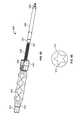
- FIG. 1is a perspective view of the spinal fixation anchor according to an example embodiment
- FIG. 2is a perspective view of an implantable portion of the fixation anchor of FIG. 1 after removal of an extension guide;
- FIGS. 3-4are side and front views, respectively, of the spinal fixation anchor of FIG. 1 ;
- FIG. 5is an enlarged perspective view of the junction between the implantable portion and extension guide of the fixation anchor of FIG. 1 ;
- FIG. 6is an enlarged front view of the junction region between the implantable portion and extension guide of the fixation anchor of FIG. 1 ;
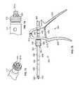
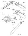
- FIG. 7is a side view of a breaking tool, according to an example embodiment
- FIG. 8is an exploded perspective view of the breaking tool of FIG. 7 ;
- FIG. 9is a front view of the fixation anchor of FIG. 1 , after proximal joints are broken to allow the arms to separate;
- FIG. 10is a perspective view of a guide cap for use with the fixation anchor of FIG. 1 , according to one example embodiment
- FIG. 11is another perspective view of the guide cap of FIG. 10 ;
- FIG. 12is a side view of the guide cap of FIG. 10 ;
- FIG. 13is a cross section view of the guide cap as shown in FIG. 12 ;
- FIG. 14is a perspective view of the guide cap of FIG. 10 coupled to the fixation anchor of FIG. 1 ;
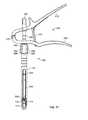
- FIG. 15is a perspective view of an independent reduction tool that may be used with the guide cap and fixation anchor of FIG. 14 ;
- FIG. 16is a front view of the independent reduction tool coupled to the guide cap and fixation anchor of FIG. 14 ;
- FIG. 17is a perspective view of a lumbar spine illustrating the use of spinal fixation anchors of FIG. 1 with the guide cap of FIG. 10 and independent reduction instrument of FIG. 15 to implant a two level fixation construct, according to one example;
- FIG. 18is a perspective view of the lumbar spine of FIG. 17 after the locking caps have been deployed and extension guides have been removed to leave the final fixation construct;
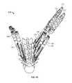
- FIGS. 19-20are perspective and side views, respectively, of a lumbar spine illustrating the use of a spinal fixation system according to one example embodiment
- FIG. 21is a perspective view of an example of a guide assembly forming part of the spinal fixation system of FIG. 19 ;
- FIG. 22is a perspective view of the distal end of the guide assembly of FIG. 21 ;
- FIGS. 23-24are perspective views of an inner member forming part of the guide assembly of FIG. 21 , shown without the outer sleeve;
- FIGS. 25-26are sectional views of the inner member of FIG. 23 ;
- FIG. 27is a plan view of the distal end of the guide assembly of FIG. 21 ;
- FIGS. 28-29are perspective views of an example of a pedicle screw forming part of the spinal fixation system of FIG. 19 ;
- FIGS. 30-31are perspective and plan views, respectively, of one example of a tulip forming part of the pedicle screw of FIG. 28 ;
- FIG. 32is a perspective view of the guide assembly of FIG. 21 engaged with a pedicle screw of FIG. 28 ;
- FIG. 33is a plan view of the distal end of the guide assembly of FIG. 21 engaged with the tulip of FIG. 30 ;
- FIG. 34is a sectional view of the distal end of the guide assembly of FIG. 21 engaged with the tulip of FIG. 30 ;
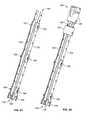
- FIG. 35is a plan view of a second example of a guide assembly forming part of the spinal fixation system of FIG. 19 , shown in an unlocked configuration;
- FIG. 36is a plan view of the guide assembly of FIG. 35 , shown in a locked configuration
- FIG. 37is a plan view of the distal end of the guide assembly of FIG. 35 ;
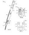
- FIGS. 38-39are plan and perspective views, respectively, of a second example of a tulip forming part of the pedicle screw of FIG. 28 ;
- FIGS. 40-41are plan and sectional views, respectively, of the distal end of the guide assembly of FIG. 35 coupled with the tulip of FIG. 38 ;
- FIGS. 42-44are plan, perspective, and exploded perspective views, respectively, of a third example of a guide assembly forming part of the spinal fixation system of FIG. 19 ;
- FIG. 45is one example of a spinal rod forming part of the spinal fixation system of FIG. 19 ;
- FIGS. 46-48are perspective, side plan, and end plan views of one end of the spinal rod of FIG. 45 ;
- FIG. 49is another example of a spinal rod forming part of the spinal fixation system of FIG. 19 ;
- FIGS. 50-52are perspective, side plan, and end plan views of one end of the spinal rod of FIG. 49 ;
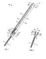
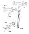
- FIG. 53is a plan view of an example of an adjustable angle rod inserter configured for use with the spinal fixation system of FIG. 19 , shown in a first position;
- FIG. 54is a plan view of the rod inserter of FIG. 53 , shown in a second position;
- FIG. 55is a plan view of the rod inserter of FIG. 53 coupled with a guide assembly of FIG. 21 ;
- FIG. 56is a sectional view of the rod inserter of FIG. 53 ;
- FIGS. 57-58are sectional views of the distal end of the rod inserter of FIG. 53 ;
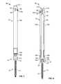
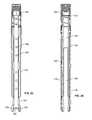
- FIG. 59is a plan view of one example of a fixed angle rod inserter configured for use with the spinal fixation system of FIG. 19 ;
- FIG. 60is a plan view of the rod inserter of FIG. 59 coupled with a guide assembly of FIG. 21 ;
- FIG. 61is a sectional view of the distal end of the rod inserter of FIG. 59 ;
- FIG. 62is a plan view of another example of a fixed angle rod inserter configured for use with the spinal fixation system of FIG. 19 ;
- FIG. 63is a sectional view of the distal end of the rod inserter of FIG. 62 ;
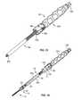
- FIGS. 64-65are perspective views of one example of a reduction instrument configured for use with the spinal fixation system of FIG. 19 ;
- FIG. 66is a top plan view of an example of a lock screw forming part of the spinal fixation system of FIG. 19 ;
- FIG. 67is a sectional view of the reduction instrument of FIG. 64 ;
- FIG. 68is a plan view of the reduction instrument of FIG. 64 coupled with a guide assembly of FIG. 21 , which in turn is coupled to a pedicle screw of FIG. 28 ;
- FIG. 69is a sectional view of the distal end of the reduction instrument of FIG. 64 coupled with the lock screw of FIG. 66 ;
- FIG. 70is a sectional view of the reduction instrument and lock screw of FIG. 69 in combination with the guide assembly and pedicle screw of FIG. 68 upon reduction of the spinal rod and before engagement of the lock screw to the tulip;
- FIGS. 71-72are sectional views of the distal end of another example of a reduction instrument configured for use with the spinal fixation system of FIG. 19 , shown coupled with a lock screw of FIG. 66 ;
- FIGS. 73-74are perspective and plan views, respectively, of the reduction instrument of FIG. 71 coupled with a lock screw of FIG. 66 ;
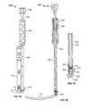
- FIGS. 75-77are plan views of another example of a reduction instrument configured for use with the spinal fixation system of FIG. 19 ;
- FIGS. 78-79are plan and perspective views, respectively, of yet another example of a reduction instrument configured for use with the spinal fixation system of FIG. 19 ;
- FIG. 80is a plan view of the distal end of the reduction instrument of FIG. 78 ;
- FIG. 81is a sectional view of the reduction instrument of FIG. 78 ;
- FIG. 82is a plan view of still another example of a reduction instrument configured for use with the spinal fixation system of FIG. 19 ;
- FIG. 82Ais a sectional view of the reduction instrument of FIG. 82 ;
- FIG. 83is a plan view of the reduction instrument of FIG. 82 coupled with a pedicle screw of FIG. 28 ;
- FIGS. 84-85are perspective and sectional views, respectively, of the distal end of the reduction instrument and pedicle screw combination of FIG. 83 shown during reduction of a spinal rod;
- FIG. 86is an example of a compression instrument configured for use with the spinal fixation system of FIG. 19 ;
- FIGS. 87-88are perspective views of another example of a compression instrument configured for use with the spinal fixation system of FIG. 19 ;
- FIG. 89is a top view of the compression instrument of FIG. 87 ;
- FIG. 90is a plan view of an example of a multi-load lock screw inserter configured for use with the spinal fixation system of FIG. 19 ;
- FIGS. 91-93are plan views of the lock screw inserter of FIG. 90 coupled to various numbers of lock screws;
- FIG. 94is plan view of the lock screw inserter of FIG. 90 in use with the guide assembly of FIG. 21 ;
- FIG. 95is a perspective view of the lock screw inserter of FIG. 90 with the outer shaft removed for illustration;
- FIG. 96is a perspective view of the lock screw inserter of FIG. 90 with the outer shaft and the spring shaft removed for illustration;
- FIG. 97is a perspective view of an example of a guide adjuster configured for use with the guide assembly of FIG. 21 ;
- FIG. 98is a perspective view of the guide adjuster of FIG. 97 coupled with the guide assembly of FIG. 21 ;
- FIGS. 99-100are perspective and sectional views, respectively, of an example of a tap guide for use with the spinal fixation system of FIG. 19 ;
- FIG. 101is a perspective view of an example of an offset dilator configured for use with the spinal fixation system of FIG. 19 ;
- FIGS. 102-103are perspective views of another example of an offset dilator configured for use with the spinal fixation system of FIG. 19 ;
- FIG. 104is a plan view of a secondary dilator configured for use with the spinal fixation system of FIG. 19 ;
- FIGS. 105-106are perspective views of an example of a rod inserter configured for use with the spinal fixation system of FIG. 19 ;
- FIGS. 107-108are sectional views of the rod inserter of FIG. 105 .
- the present applicationdescribes a spinal fixation system that may be utilized to form a fixation construct across one or more spinal levels of a patient.
- the spinal fixation systemmay be especially useful in forming fixation constructs across multiple spinal levels and/or spines with alignment deformities requiring correction.
- the spinal fixation systemincludes bone anchors (e.g. anchors 16 , 112 , 206 ), anchor guides (e.g. 18 , 116 , 188 , 224 ), rods ( 50 , 114 ), and various instruments (e.g. reduction instruments, rod inserters, compression instruments, etc. . . . ) that can be used in various combinations to form the fixation construct.
- the spinal fixation systemmay used for the installation of the fixation construct under minimally invasive conditions.
- the spinal fixation systemincludes a guide that extends distally out of the patient when the anchor is engaged to the spine.
- An elongated rod channel through the guidehelps direct the rod into the proper position without requiring the extended incisions needed to fully expose the spinal segments to be fixated.
- the spinal fixation anchor 10includes integral reduction features that may be utilized to seat a fixation rod in the anchor while realigning the position of the associated vertebra relative to other vertebra associated with the fixation construct. Additionally, separate reduction tools that cooperate with the spinal fixation anchor may be utilized to help seat the rod and realign the associated spinal segment.
- the fixation anchor 10includes a bone anchor 12 (e.g. shank with thread feature 14 ) suitable for stable fixation to vertebral bone and a housing 16 for capturing and locking a fixation rod 50 . Attached to the housing 16 is a break-off extension guide 18 .
- the extension guide 18helps align the rod 50 with the housing 16 and also helps reduce the rod into the housing when necessary. After the rod 50 is locked within housing 16 the extension guide 18 can be removed from the housing so the incision can be closed over the fixation construct ( FIG. 2 depicts the fixation anchor with the extension guide 18 completely removed).
- the housing 16has a base 20 that mates with the bone anchor 12 and a pair of upstanding arms 22 a and 22 b separated by a rod channel 24 .
- the arms 22 a and 22 bare equipped with a locking cap guide and advancement feature 26 , such as by way of example, a helically wound flange feature disposed on the interior face of each arm 22 a and 22 b .
- the locking cap guide and advancement featuremates with a complementary guide and advancement feature on a locking cap 51 .
- the locking cap 51engages the upstanding arms via the complementary guide and advancement features to press and lock the fixation rod 50 into the housing 16 .
- the housing 16 and anchor 12may be mated with a polyaxial engagement such that the housing 16 can pivot relative to the anchor 12 in any direction.
- the engagementmay also be such that the pivoting movement may be inhibited in one or more directions.
- the housing 16 and anchor 12may be mated with a uniplanar engagement such that the housing pivots relative to the anchor 12 in a single plane.
- the housing 16 and anchor 12may also be fixed such that no movement is possible between the housing 16 and anchor 12 .
- Break-off extension guide 18extends from the top of housing 16 and includes a pair of extension arms 30 a and 30 b .
- Extension arm 30 aattaches to housing arm 22 a via an integral but breakable distal joint 32 a .
- Extension arm 30 battaches to the housing arm 22 b via an integral but breakable distal joint 32 b .
- the breakable distal joints 32 a and 32 bare formed by surface grooves which reduce the material thickness along the entire junction between the extension arms 30 a , 30 b and housing arms 22 a , 22 b , respectively, such that directing an appropriate force to the extension arm will snap the associated breakable joint.
- the extension arms 30 a and 30 bare dimensioned with a length such that the extension guide 18 extends from the housing 16 to a location outside of the patient when the fixation anchor 10 is in a fully implanted position and securely anchored to the vertebra. At a proximal end 34 of the extension guide 18 the extension arms 30 a and 30 b come together to form a pair of integral but breakable proximal joints 36 . Opposed vertical surface grooves above the guide slots 38 reduce material thickness along each junction between the extension arms 30 a and 30 b to form the breakable proximal joints 36 .
- Opposed guide slots 38 formed between arms 30 a and 30 balign with the rod channel 24 of the anchor housing 16 to define an enclosed guide channel 40 which is dimensioned to allow passage of a fixation rod 50 .
- Utilizing the guide channel 40 to align the rod 50 with the housing rod channel 24reduces the need for fiddlesome manipulation of the housing and/or rod down near the target site, as well as the associated need to fully visualize the housing 16 during rod insertion.
- the overall size of the incision required to implant a fixation construct using fixation anchors 10is significantly reduced compared to open procedures.
- the proximal joints 36may be broken, thereby severing the proximal connection of the extension arms 30 a and 30 b and allowing the arms 30 a and 30 b to flex apart ( FIG. 9 ).
- a guide cap 71(described below) may be used to reassociate the extension arms 30 a and 30 b if desired. Recess 40 a on the proximal end of extension arm 30 a and recess 40 b on the proximal end of extension arm 30 b facilitate the releasable coupling of the guide cap 71 to the proximal end 34 of the extension guide 18 .
- the fixation anchor 10includes an integral reduction feature which provides for effective, single step reduction and locking when the spinal alignment necessitates the rod be reduced into the housing 16 .
- the distal ends of extension arms 30 a and 30 bare appointed with a locking cap guide and advancement feature 42 situated adjacent to the breakable distal joints 32 a and 32 b .
- the guide and advancement feature 42matches the guide and advancement feature 26 on the interior face of arms 22 a and 22 b .
- the guide and advancement feature 42is timed with the guide and advancement feature 26 such that the locking cap 51 advances seamlessly from the extension guide 18 to the housing 16 .
- This configurationprovides a mechanical advantage when advancing the locking cap 51 along the guide and advancement features 42 and 26 , allowing the locking cap 51 to drive the rod into the housing 16 until it is fully seated and locked in position.
- the breakable distal joints 32 a , 32 b and the breakable proximal joints 36must be broken in order to remove the break-off extension guide 18 .
- the distal joints 32 a and 32 bare preferably broken only after the rod 50 is seated in the housing 16 and the locking cap 51 is fully engaged.
- an attachment groove 39 ais formed in the housing arm 22 a and an attachment groove 39 b is formed in housing arm 22 b .
- a slip on guide structuremay be advanced and releasably coupled to the housing via the attachment grooves 39 a , 39 b .
- the proximal breaking joints 36are preferably broken first before attempting break the distal joints 32 a , 32 b . This may be done just prior to breaking the distal joints to remove the extension guide after the rod 50 is seated and the locking cap 51 fully engaged in the housing 16 . Alternatively, the surgeon may want to sever the connection between the extension arms 30 a , 30 b at an earlier point during the procedure. By way of example, the proximal joints 36 may be severed prior to rod insertion in order to facilitate easier rod insertion.
- the breaking tool 44is designed to apply an outwardly directed force to the proximal joints 36 from inside the extension guide 18 .
- the breaking tool 44is a cam driver and includes a handle 46 , rotating drive shaft 48 , a cam 64 coupled to a distal end of the drive shaft 48 , a hub 50 , and a counter torque handle 52 .
- the hub 50has central cap 54 from which a cylinder 56 extends distally and a faceted block 58 extends proximally.
- the cylinder 56has an exterior diameter that is slightly smaller than an interior diameter of the extension guide 18 such that the cylinder 56 can be passed into the extension guide 18 .
- the central cap 54has a diameter that is larger than the extension guide 18 such that the cap 54 controls the depth of insertion into the extension guide 18 , ensuring force is applied in the right locations (i.e. on or near the proximal joints 36 ).
- the faceted block 58mates with a complementary receptacle 60 attached to the counter torque handle 52 to prevent rotation of the hub 50 when the drive shaft 48 is operated.
- a tunnel 66 dimensioned to receive a portion of the drive shaft 48 therethroughextends through the hub 50 along a line offset from a center axis of the cylinder 56 .
- the cam 64has a diameter that matches approximately the diameter of the cylinder 56 and a tunnel 68 for receiving the drive shaft 48 that is offset from the center axis of the cam.
- the cam 64is fixed to the drive shaft 48 via pin 70 such that rotation of the drive shaft 48 causes the cam 64 to rotate relative to the cylinder 56 . When the cam 64 and cylinder 56 are aligned they can slide together into the extension guide 18 .
- the cam 64As the cam 64 is rotated relative to the cylinder 56 the combined diameter of the two components expands, directing an outward force onto the extension arms 30 a , 30 b which causes the breakable proximal joints 36 to break, allowing the extension arms 30 a , 30 b to separate, as shown in FIG. 9 .
- the proximal joints 36 severedthe distal breakable joints 32 a and 32 b can be broken simply by bending the associated extension arm until the joint snaps. This can be done using a common grasping tool, such as forceps for example, or grasping the extensions arms directly with the hand.
- a guide cap 71is provided which may be used to hold the arm extensions 30 a and 30 b together and restore the rigidity of the unbroken guide extension 18 .
- the guide cap 71has a body 72 with a first internal cavity 73 opening out to a distal end 74 and a second internal cavity 76 opening out to a proximal end 78 .
- the first internal cavity 73has an internal diameter that is just larger than the external diameter of the extension guide 18 such that the proximal end of the extension guide may be received in the first internal cavity 73 .
- the second internal cavity 76has a diameter smaller than the first internal cavity 73 , to provide a shelf for spring 88 , approximating the internal diameter of the extension guide 18 and large enough to pass a locking cap 51 therethrough.
- a pair of opposed projections 80extend into the first internal cavity 73 and engage with the recesses 40 a and 40 b on the extension arms 30 a and 30 b to releasably couple the guide cap 71 to the extension guide 18 .
- the recesses 40 a and 40 beach include an open vertical slot 82 connected to one end of a horizontal slot 84 , and a closed vertical slot 86 connected to the opposite end of the horizontal slot.
- the projections 80are aligned with the open vertical slots 82 and pressure is applied to the guide cap 71 such that the cap advances onto the extension guide 18 .
- the projections 80reach the bottom of the open vertical slot 82 the cap is rotated until the projections 80 reach the end of the horizontal slot 84 .
- Pressureis then released from the guide cap 71 and a spring 88 working against proximal tabs 41 a , 41 b of the extension arms draws the projections 80 into the closed vertical slots 86 , thereby securing the guide cap 71 to the extension guide 18 .
- the reduction capabilities of the extension guide 18are enhanced with the use of the guide cap 71 .
- the integral reduction features described aboveare less effective when the extension arms 40 a and 40 b are flexible and allowed to splay.
- the guide cap 71negates this challenge such that the surgeon is not required to choose between easier rod insertion or better reduction.
- the body 72 of the guide cap 71is adapted to releasably mate with independent reduction instruments should such an instrument be desired over the integral reduction features of the extension guide 18 .
- FIG. 15One example of such an independent reduction instrument is depicted in FIG. 15 .
- the reduction instrument 92includes a connector 96 that releasably couples the reduction instrument to the extension guide (via guide cap 71 ).
- the connector 96has a receptacle 100 into which the proximal end 78 of the guide cap 71 is received.
- the proximal end 78is keyed to the receptacle 100 so as to prevent rotation of the guide cap 71 and attached extension guide 18 relative to reduction instrument 92 .
- Spring clips 102 on the connectorengage a groove 90 situated below the proximal end 78 to prevent translation of the guide cap 71 and attached extension guide 18 relative to the reduction instrument 92 .
- the spring clips 102have a tapered distal edge that extends into the receptacle 100 .
- the tapered edgeallows the proximal end 78 to push past the spring clips 102 until the tapered edge returns to rest in groove 90 .
- the proximal ends of the spring clipscan be depressed and the connector 96 lifted off the proximal end 78 .
- the reduction shaft 94is inserted through the guide cap 71 into extension guide 18 until the proximal end 78 of the guide cap 71 is locked into the receptacle 100 , as illustrated in FIGS. 16-17 .
- a reduction handle 104may then be operated to translate the reduction shaft 94 distally relative to the extension guide 18 to drive the rod 50 through the guide channel 40 until the rod is fully seated in the housing 16 .
- a locking cap driver 105may then be operated to advance the locking cap 51 into the housing 16 and lock the rod 50 in place.
- a spinal fixation anchoris anchored through the pedicle of each vertebra to be fixated (e.g. three vertebra as shown in FIG. 17 ). At least one of the spinal fixation anchors is the spinal fixation anchor 10 .
- the remaining fixation anchorsmay also be the fixation anchor 10 (as in FIG. 17 ). Alternatively, the remaining fixation anchors may be anchors adapted for use with independent guide structures that releasably couple to the anchors, as are generally known in the art.
- a rod 50 appropriately sized to span the distance between the end anchorsis selected.
- the proximal joints 36 on one or more of the fixation anchors 10may be broken if the surgeon chooses to do so.
- the surgeonmay choose to break the proximal joints 36 of the fixation anchor 10 at the opposite end of the construct from which rod insertion will be directed.
- the rodis inserted into the guide channel of the first fixation anchor 10 generally parallel to the extension guide while the insertion instrument is angled back towards the remainder of the extension guides 18 . As the inserter is rocked towards the insertion end, the rod advances through each guide.
- Severing the proximal joints 36 on the extension guide 18 at the opposite end of the construct from rod insertionallows the inserter to advance between the extension arms 30 a , 30 b of the end anchor (instead of having to work the inserter around the outside of the guide extension 18 ). This simplifies passage of the rod by facilitating proper alignment of the rod during insertion. If the surgeon chooses to break the proximal joints 36 , the cam 64 and cylinder 56 of the breaking tool 44 are aligned and inserted into the extension guide 18 until the cap 54 rests on the proximal end of the extension guide 18 . The cam 64 is then rotated with one hand while the counter torque handle 52 is held in the other hand until the proximal joints 36 break apart. The rod 50 is then inserted through the guide channels 40 .
- one or more of the reduction methods described abovemay be employed to reduce the rod 50 . If the rod 50 is seated low enough in the guide channel 40 that the guide and advancement features 42 are accessible above the rod then reduction may be accomplished by engaging a locking cap 51 with the guide and advancement features 42 and advancing the locking cap 51 until the rod 50 and locking cap 51 are fully seated in the housing 16 . If this reduction is to be carried out on a fixation anchor 10 whose proximal joints 36 had been previously broken, the guide cap 71 should preferably be coupled to the extension guide 18 prior to reduction.
- the guide cap 71should be attached to the appropriate fixation anchor 10 whether or not the proximal joints 36 of that anchor have been broken.
- the independent reduction instrument 92is then coupled to the extension guide 18 and operated to reduce the rod 50 into the housing 16 and a locking cap 51 is engaged to lock the rod 50 in place.
- the surgeonmay choose to utilize both the integral reduction features for reduction at one fixation anchor 10 and the independent reduction instrument for reduction at another of the fixation anchors 10 . Reduction (when necessary) and locking cap engagement is completed for each spinal fixation anchor in the construct.
- extension guide 18With the rod 50 locked down along the entire construct the extension guide 18 should be removed. First, any guide caps 71 utilized during the procedure should be removed. Then the breaking tool 44 is used to break the proximal joints 36 of all extension guides 18 whose proximal joints 36 remain intact. Finally, the extension arms 30 a and 30 b of each spinal anchor 10 are removed by breaking the distal joints 40 a and 40 b , respectively. According to an alternative sequence, the extension guide 18 can be removed from each fixation anchor 10 in sequence as the rod 50 is locked to each anchor 10 . Once the extension guides 18 are removed from each anchor 12 , the final fixation construct is complete, as illustrated in FIG. 18 , and the incision(s) can be closed.
- FIGS. 19 and 20illustrate a spinal fixation system 110 configured for introducing and building a posterior spinal fixation construct such as that described above, according to one example embodiment.
- the spinal fixation system 110includes a pedicle screw 112 , an elongated spinal rod 114 , and a guide assembly 116 .
- Pedicle screws 112are inserted bilaterally or unilaterally into multiple vertebra across one or more levels.
- fixation anchor 10can be utilized in place of pedicle screw 112 in one or more vertebra.
- the spinal fixation system 110may further include any of a variety of instruments configured to perform the installation and assembly of the spinal fixation construct, including by way of example a reduction instrument 117 shown in FIGS. 19 and 20 , as well as rod inserters, compression instruments, lock screw inserters, guide adjusters, tap guides, and dilators, of which various embodiments are described in further detail below.
- FIGS. 21-27illustrate one example of a guide assembly 116 for minimally invasive implantation of the pedicle screw 112 and for guiding the spinal rod 114 into position.
- the guide assembly 116includes an outer sleeve 118 and a pair of inner arm members 120 positioned within the outer sleeve 118 .
- the arm members 120are configured to releasably engage the housing 172 of the pedicle screw 112 .
- the arm members 120are moveable between a first position and a second position. When in the first “unlocked” position, the arm members 120 are not engaged with in the pedicle screw 112 . In the second, “locked” position, the arm members 120 are engaged with the pedicle screw 112 , and the pedicle screw 112 is “locked” to the guide assembly 116 .
- the outer sleeve 118is a generally tubular member having a proximal end 122 , a distal end 124 , and a lumen 126 extending longitudinally through the outer sleeve 118 .
- the proximal end 124includes a cap 128 that is configured to engage the inner arm members 120 (on the inside of the cap 128 ) and a reduction instrument 117 (on the outside of the cap 128 ).
- a circumferential groove 130is positioned near the proximal end 122 and configured to receive the ridges 346 of the spring lock 344 of the reduction instrument 117 . In this fashion, the guide assembly 116 may be releasably coupled to the reduction instrument 117 .
- the outer sleeve 118further includes a cylindrical recess 132 formed distally of the circumferential groove 130 but in the proximal half of the outer sleeve 118 .
- the cylindrical recess 132is configured to receive an actuator 134 and is further configured to allow translation of the actuator 134 in a proximal/distal direction within the cylindrical recess 132 .
- the outer sleeve 118further includes a pair of longitudinal slots 136 extending proximally from the distal end 124 of the outer sleeve 118 .
- the longitudinal slots 136act in concert for form a channel 149 to guide the spinal rod 114 to the surgical target site during implantation of the surgical fixation construct.
- the slots 136extend a little over half way along the outer sleeve 118 .
- the slots 136effectively divide the distal portion of the outer sleeve 118 into first and second outer arms 138 .
- the distal end of the outer arms 138each includes a distal extension 140 .
- the distal extension 140is an extension of the outer sleeve 118 however it is narrower in width than the outer sleeve 118 .
- a ridge 142 dimensioned to engage the housing 172 of the pedicle screw 112is positioned on the interior surface of the distal extension 140 .
- the ridge 142is configured to engage the attachment groove 182 of the housing 172 to releasably lock the guide assembly 116 to the pedicle screw 112 .
- the ridge 142includes a tapered surface 144 that enables the ridge 142 to slide over the top of the housing 172 of the pedicle screw 112 during the engagement process.
- the outer sleeve 118is further provided with a plurality of elongated apertures 146 positioned opposite one another on either side of the outer sleeve 118 and configured to receive protrusions 154 of the inner arm members 120 to facilitate the secure engagement of the inner arms 120 to the outer sleeve 118 .
- the arm members 120are each comprised of an elongated partially-cylindrical member having a proximal end 148 and a distal end 150 .
- the proximal ends 148 of the arm members 120are dimensioned to be received within the cap 128 of the outer sleeve 118 .
- the arm members 120each include a proximal protrusion 152 extending laterally from the outer surface of the arm member 120 and dimensioned to extend through a corresponding slot 146 positioned within the cylindrical recess 132 of the outer sleeve 118 and fixedly engage the actuator 134 . In this fashion, translation of the actuator 134 causes translation the first and second arm members 120 .
- Additional protrusions 156are positioned along the arm members 120 such that they are aligned with and received within corresponding slots 146 in the outer sleeve 118 .
- the distal ends 150 of the members 120are configured to securely receive the top of the housing 172 of the pedicle screw 112 .
- the distal ends 150 of the arm members 120include a plurality of prongs 158 configured to extend vertically along the sides of the housing 172 upon engagement, as will be explained in further detail below.
- a raised protrusion 160is provided between the prongs 158 to engage a recess 184 in the top of the pedicle screw 112 .
- the prongs 158 and raised protrusion 160act in concert to prevent rotation of the housing 172 of the pedicle screw 112 during implantation of the spinal fixation construct.
- the actuator 134is positioned on the outside of the outer sleeve 118 and is fixedly attached to the inner arms 120 . As stated previously, translation of the actuator 134 causes translation the inner arms 120 .
- a spring 162is provided that exerts a force distally the actuator and the inner arms 120 in order to bias the actuator 134 and inner arms 120 in a “locked” position.
- a stopper 164is provided within the cap 132 to provide a distal stop for the spring 162 and the inner arms 120 .
- the inner arms 120may optionally be provided with a plurality of smaller apertures 166 to aid in the sterilization process.
- the pedicle screw 112includes a bone anchor 168 (e.g. shank with thread feature 170 ) suitable for stable fixation to vertebral bone and a housing 172 for capturing and locking a spinal rod 114 .
- the housing 172has a base 174 that mates with the bone anchor 168 and a pair of upstanding arms 176 separated by a rod channel 178 .
- the arms 176are equipped with a locking cap guide and advancement feature 180 , such as by way of example, a helically wound flange feature disposed on the interior face of each arm 176 .
- the locking cap guide and advancement feature 180mates with a complementary guide and advancement feature on a lock screw (not shown, but similar to the lock screw 119 shown and described in relation to FIGS. 69-74 ).
- the lock screw 119engages the upstanding arms 176 via the complementary guide and advancement features 180 , 376 to press and lock the fixation rod 114 into the housing 172 .
- the housing 172 and anchor 168may be mated with a polyaxial engagement such that the housing 172 can pivot relative to the anchor 168 in any direction.
- the engagementmay also be such that the pivoting movement may be inhibited in one or more directions.
- the housing 172 and anchor 168may be mated with a uniplanar engagement such that the housing pivots relative to the anchor 168 in a single plane.
- the housing 172 and anchor 168may also be fixed such that no movement is possible between the housing 172 and anchor 168 .
- the housing 172further includes a pair of attachment grooves 182 , one attachment groove 182 formed in each of the upstanding arms 176 .
- the attachment groovesare dimensioned to receive the ridges 142 on the outer sleeve 118 of the guide assembly 116 to releasably lock the guide assembly 116 to the pedicle screw 112 .
- the top of each arm 176further includes a recess 184 formed therein.
- the recesses 184have a corresponding shape and are dimensioned to receive the raised protrusions 160 on the distal end of the inner arm members 120 of the guide assembly 116 . This interaction helps to prevent rotation of the housing 172 of the pedicle screw 112 during implantation of the spinal fixation construct.
- FIGS. 32-34illustrate the guide assembly 116 engaged to a pedicle screw 112 .
- the guide assembly 116is advanced distally along the operative corridor until the distal end of the outer sleeve 118 contacts the housing 172 of the pedicle screw 112 .
- the guide assembly 116is then further advanced such that the ridges 142 snap into the attachment grooves 182 on the housing 172 .
- the outer sleeve 118is secured to the pedicle screw 112 .
- the actuator 134is then advanced in a distal direction, which causes the simultaneous distal advancement of the inner arms 120 of the guide assembly 116 .
- the inner arms 120are advanced such that and until each pair of prongs 158 are positioned on either side of the upstanding arms 176 of the housing 172 and the raised protrusions 160 are seated within recesses 184 on the housing 172 . At this point the inner arms 120 are secured to the pedicle screw 112 and the housing 172 is prevented from rotation relative to the guide assembly 116 .
- the opposed guide slots 168 formed between the outer arms 138 of the outer sleeve 118 of the guide assembly 116align with the rod channel 178 of the housing 172 to define an enclosed guide channel 186 that is dimensioned to allow passage of a fixation rod 114 .
- Utilizing the guide channel 186 to align the rod 114 with the housing rod channel 178reduces the need for fiddlesome manipulation of the housing 172 and/or rod 114 near the surgical target site, as well as the associated need to fully visualize the pedicle screw 112 and/or the housing 172 during rod insertion.
- the overall size of the incision required to implant a fixation construct using the described fixation system 110is significantly reduced compared to open procedures.
- the outer sleeve 118may be disengaged from the housing 172 by applying an appropriate amount of proximal force on the guide assembly 116 . Once both the outer sleeve 118 and the inner arms 120 have been disengaged from the housing 172 , the guide assembly 116 may be removed from the operative corridor.
- FIGS. 35-37illustrate an example of a guide assembly 188 according to an alternative embodiment of the present invention for use with the spinal fixation system 110 described above.
- the guide assembly 188is substantially similar to the guide assembly 116 described above, such that repeat description of like parts is unnecessary.
- the guide assembly 188includes an outer sleeve 190 and a pair of inner arm members 192 positioned within the outer sleeve 190 .
- the arm members 192are configured to releasably engage the housing 208 of the pedicle screw 206 ( FIGS. 38-39 ).
- the arm members 192are moveable between a first position and a second position.
- the arm members 192When in the first “unlocked” position, the arm members 192 are not engaged with in the pedicle screw 206 . In the second, “locked” position, the arm members 192 are engaged with the pedicle screw 206 , and the pedicle screw 206 is “locked” to the guide assembly 116 . As with the guide assembly 116 , the guide assembly 188 includes an actuator 194 that facilitates the movement of the arm members 192 from the first to the second position.
- the guide assembly 188is substantially identical to the guide assembly 116 with the exception of two features that will be discussed in detail below. It is to be understood that any or all of other features described in conjunction with the guide assembly 116 may be present with respect to the guide assembly 188 in both structure and function. Therefore, repeat description of common features is not necessary.
- the guide assembly 188includes a castle nut 196 protruding from the top of the outer sleeve 190 . The castle nut 196 interacts with the actuator 194 and serves as a visual indicator of whether the guide assembly 188 is locked to the pedicle screw 206 .
- the castle nut 196protrudes from the top of the outer sleeve 190 ( FIG. 35 ).
- the castle nutcan be advanced (blocking return of the inner arm members), making the second position the “locked” position as the guides cannot be disengaged from the pedicle screw 206 .
- the guideis “locked” when the castle nut 196 sits flush the top of the outer sleeve 190 ( FIG. 36 ) and thus serves as a visual indication as to whether the guide assembly 188 is locked to the pedicle screw 206 .
- the second major difference between the guide assembly 188 and the guide assembly 116is in the distal engagement ends 198 of the inner arm members 192 .
- the distal ends 198 of the arm members 192are configured to securely receive the top of the housing 208 of the pedicle screw 206 .
- the distal ends 198 of the arm members 192include a plurality of prongs 200 configured to extend vertically along the sides of the housing 208 upon engagement.
- the prongs 200differ from the prongs 158 in that each prong 200 includes an additional cutout area 202 on a pedicle screw engagement surface that interacts with the pedicle screw 206 to provide a more secure engagement, as will be described below.
- a raised protrusion 204is provided between the prongs 200 to engage a recess 220 in the top of the pedicle screw 206 .
- the prongs 200 and raised protrusion 204act in concert to prevent rotation of the housing 208 of the pedicle screw 206 during implantation of the spinal fixation construct.
- FIGS. 38-39illustrate a pedicle screw 206 configured for use with the guide assembly 188 according to an alternative example.
- the pedicle screw 206is similar to the pedicle screw 112 described above in that it includes a bone anchor (e.g. shank with thread feature—not shown) suitable for stable fixation to vertebral bone and a housing 208 for capturing and locking a spinal rod 114 .
- the bone anchor portion of the pedicle screw 206is identical to the bone anchor portion of pedicle screw 112 described above.
- the housing 208has a base 210 that mates with the bone anchor and a pair of upstanding arms 212 separated by a rod channel 214 .
- the arms 212are equipped with a locking cap guide and advancement feature 216 , such as by way of example, a helically wound flange feature disposed on the interior face of each arm 212 .
- the locking cap guide and advancement feature 216mates with a complementary guide and advancement feature on a lock screw (not shown, but similar to the lock screw 119 shown and described in relation to FIGS. 69-74 ).
- the lock screwengages the upstanding arms 212 via the complementary guide and advancement features 216 , 376 to press and lock the fixation rod 114 into the housing 208 .
- the housing 208further includes a pair of attachment grooves 218 , one attachment groove 218 formed in each of the upstanding arms 212 .
- the attachment grooves 218are dimensioned to receive the ridges 195 ( FIG. 35 ) on the outer sleeve 190 of the guide assembly 188 to releasably lock the guide assembly 188 to the pedicle screw 206 .
- the top of each arm 212further includes a recess 220 formed therein.
- the recesses 220have a corresponding shape and are dimensioned to receive the raised protrusions 204 on the distal end of the inner arm members 192 of the guide assembly 188 .
- the housing 208also includes a plurality of vertical cutouts 222 formed in each upstanding arm 212 on either side of the rod channel 214 .
- the vertical cutouts 222interact with the prongs 200 of the inner arm members 192 to provide a more secure engagement between the guide assembly 188 and the pedicle screw 206 .
- the cutout areas 202 of the prongs 200are complimentary in shape to the vertical cutouts 222 on the arms 212 such that upon engagement, each prong 200 will contact at least three distinct surfaces of the corresponding upstanding arm 212 .
- FIGS. 40-41illustrate the guide assembly 188 engaged to the housing 208 of a pedicle screw 206 .
- FIGS. 42-44illustrate an example of a guide assembly 224 according to a third example embodiment of the present invention for use with the spinal fixation system 110 described above.
- the guide assembly 224is substantially similar to the guide assemblies 116 , 188 described above, such that repeat description of like parts is unnecessary. It is to be understood that any or all of other features described in conjunction with the guide assemblies 116 , 188 may be present with respect to the guide assembly 224 in both structure and function.
- the guide assembly 224includes an outer sleeve 226 and a pair of independent inner arm members 228 positioned within the outer sleeve 224 .
- the arm members 228are configured to releasably engage the housing 228 of the pedicle screw 206 ( FIGS.
- the distal engagement region of the arm members 228 and the interaction with the pedicle screw 206is identical to that described in relation to the guide assembly 188 .
- the arm members 228are moveable between a first position and a second position. When in the first “unlocked” position, the arm members 228 are not engaged with in the pedicle screw 206 . In the second, “locked” position, the arm members 228 are engaged with the pedicle screw 206 , and the pedicle screw 206 is “locked” to the guide assembly 224 .
- the guide assembly 224does not include the same actuator to facilitate the movement of the arm members 228 from the first to the second position.
- the guide assembly 224instead has a castle nut 230 that acts as the actuator. The castle nut 230 attaches directly to the arm members 228 , and controls the advancement (and retreat) of the arms.
- the guide assembly 224includes a castle nut 230 protruding from the top of the outer sleeve 226 .
- the castle nut 230serves as a visual indicator of whether the guide assembly 224 is locked to the pedicle screw 206 . More specifically, when the inner arm members 228 are in the first, “unlocked” position, the castle nut 230 protrudes from the top of the outer sleeve 226 .
- the castle nut 230not only locks the position of the inner arms after the arms move into position, the castle nut 230 also acts as the actuator to control the translation of the inner arms 228 .
- the inner arms 228are attached directly to the castle nut 230 .
- the proximal ends 232 of the inner arms 228include a groove 234 that is dimensioned to engage a corresponding ridge 236 in the interior of the castle nut 230 .
- the proximal ends 232 of the inner arms 228may be provided with ridges that are received within corresponding grooves formed in the interior of the castle nut (not shown).
- any combination of grooves and ridgesmay be employed to mate the inner arms 228 with the castle nut 230 .
- the inner arms 228may be mated with the castle nut 230 via a ridge/groove interaction.
- a tool(not shown) may be attached to the castle nut 230 (for example via slot 238 ) to help rotate the nut and lock or unlock the inner arms 228 and pedicle screw 206 .
- the groove/ridge interaction between the castle nut 230 and the inner arms 228ensure that the castle nut 230 is able to rotate freely relative to the inner arms 228 while still controlling translation.
- the guide assembly 224may be provided with guide slots 240 that extend substantially the length of the outer sleeve 226 . Relative to guide assemblies 116 , 188 , the longer guide slots 240 on the guide assembly 224 are possible due to the absence of an actuator to control translation of the inner arms 228 .
- FIGS. 45-52illustrate several examples of spinal rods 114 , 114 a configured for use with the surgical fixation system described herein.
- the spinal rod 114 , 114 amay be provided in any length corresponding to the number of spinal levels to be fixed.
- the spinal rods 114 , 114 aare generally cylindrical elongated rods.
- the spinal rods 114 , 114 amay be straight or curved.
- the spinal rods 114 , 114 ahave a first end 242 , 242 a that is generally rounded and a second end 244 , 244 a that is configured to engage a rod inserter such as the rod inserter 250 shown and described below in relation to FIG. 53 .
- the second end 244 , 244 aincludes a post 246 , 246 a having a shape corresponding to the shape of the rod cavity 266 on the rod inserter 250 .
- the spinal rod 114includes a post 246 having a generally octagonal cross-sectional footprint.
- Post 246 ais similar but is wider and has a rounded edge.
- the post 246 , 246 aalso includes a recess 248 , 248 a formed on an upper surface of the post 246 , 246 a and configured to receive the distal lip 278 of the locking element 268 on the rod inserter 250 .
- the recess 248 , 248 a and distal lip 278cooperate to temporarily secure the rod 114 , 114 a to the rod inserter 250 .
- FIGS. 53-58illustrate a first example of a rod inserter 250 configured for use with the spinal fixation system 110 according to one embodiment of the present invention.
- the rod inserter 250is an adjustable-angle rod inserter that introduces the spinal rod 114 through the operative corridor at one angle (relative to the inserter), and then pivots the rod at the surgical target site. This enables longer spinal rods 114 to be inserted through an operative corridor, and it also allows for smaller incisions because less room is needed to insert the spinal rod.
- the rod inserter 250includes an outer sleeve 252 , an inner shaft 254 , a handle 256 , and a rod holder 258 .
- the outer sleeve 252is an elongated cylindrical member having an inner lumen extending throughout.
- the inner shaft 254is an elongated rod member having a knob 260 at the proximal end and an engagement post 262 at the distal end.
- the knob 260is configured for handling by a user, and allows to user to pull up (proximally) on the knob to disengage the post 262 from the first and/or second shaft recesses 270 , 274 .
- the knob 260can also be rotated in a clockwise or counterclockwise direction in order to lock or unlock the setscrew 272 , as will be described below.
- the engagement post 262is configured to engage the first and second shaft recesses 270 , 274 to maintain the rod inserter 250 in either the first or second position.
- a spring 264is located within the handle 256 and acts to bias the inner shaft 254 in a distal direction. This ensures that the rod inserter 250 is secured in either the first or second positions, and a positive action is required by the user to effect a change in position.
- the rod holder 258is pivotably attached to the distal end of the outer sleeve 252 , and is configured to be pivoted from a first position to a second position and then back to the first position.
- the rod holder 258includes a rod cavity 266 , a locking element 268 , first shaft recess 270 , a setscrew 272 , and second shaft recess 274 .
- the rod cavity 266is configured to receive the post 246 of the spinal rod 114 .
- the locking element 268is positioned within the rod holder 258 and is moveable from a first unlocked position to a second locked position.
- the locking element 268includes a proximal recess 276 , a distal lip 278 , and a central cavity 280 .
- the proximal recess 276is configured to receive the setscrew 272 , and is firmly attached to the setscrew via a snap ring 282 .
- the snap ringallows the setscrew 272 to rotate within the proximal recess 276 while being advanced or retreated by the inner shaft 254 , and also ensures that the locking element 268 is advanced and/or retreated along with the setscrew 272 .
- a lockstop 284 in the form of a pin (by way of example only) extending through the cavityprevents the locking element 268 (and setscrew 272 ) from being retreated so much that it becomes disengaged entirely from the rod holder 258 .
- the distal lip 278is configured to be seated within the recess 248 of the spinal rod 114 such that when the rod inserter is in the locked position, the spinal rod 114 is secured within the rod cavity 266 and will not become dislodged therefrom.
- the setscrew 272is positioned within the first shaft recess 270 .
- the second shaft recess 274is configured to receive engagement post 262 when the rod holder 250 is in the second position. This interaction temporarily locks the rod holder 250 in the second position.
- the rod inserter 250is initially provided in a first position ( FIG. 53 ) without the spinal rod 114 and the rod holder 258 in an unlocked position.
- the first shaft recess 270(and consequently the setscrew 272 ) is in alignment with the central lumen of the outer shaft 252 .
- the spinal rod 114is then mated with the rod holder 258 by inserting the post 246 into the rod cavity 266 such that the recess 248 is facing the locking element 268 .
- the knob 260is rotated in a clockwise direction, which advances the setscrew 272 and locking element 268 in a distal direction until the distal lip 278 of the locking element 268 is seated within the recess 248 .
- the spinal rod 114is secured to the rod inserter 250 .
- the userthen exerts a proximal force on the knob 260 causing the inner shaft 254 to move in a proximal direction and further causing the engagement post 262 to become disengaged from the first shaft recess 270 .
- the rod holder 258will then pivot (due to the pull of gravity on the spinal rod 114 ) such that the second shaft recess 274 becomes aligned with the outer shaft 252 .
- the usermay then release the knob 260 , which due to the spring 264 advances the inner shaft 254 distally and causes the engagement post 262 to be received within the second shaft recess 274 .
- the rod holder 258is now secured in the second position ( FIG. 54 ).
- the spinal rod 114In the second position, the spinal rod 114 is positioned at an obtuse angle relative to the rod inserter 250 , which reduces the size of the operative corridor required to advance the rod.
- the rod 114may be advanced through the operative corridor using a guide assembly such as the guide assembly 116 (or any of the other examples) described above.
- the knob 260is turned counterclockwise to translate the setscrew 272 (and locking element 268 ) in a distal direction, which removes the distal lip 278 from the recess 248 and unlocks the rod 114 .
- the rod inserter 250may then be safely removed from the surgical target site through the operative corridor.
- FIGS. 59-61illustrate a second example of a rod inserter 290 configured for use with the spinal fixation system 110 according to another embodiment of the present invention.
- the rod inserter 290is a fixed-angle rod inserter that introduces the spinal rod 114 through the operative corridor at one angle (relative to the inserter).
- the rod inserter 290includes a housing tube 292 , a center screw 294 , a handle 296 , and a rod holder 298 .
- the housing tube 292is an elongated cylindrical member having an inner lumen extending throughout.
- the center screw 294is an elongated rod member having a driver engagement recess 300 at the proximal end and an engagement post 302 at the distal end.
- the driver engagement recess 300is configured to receive an engagement end of a suitable driver instrument (not shown).
- the center screw 294can be rotated in a clockwise or counterclockwise direction in order to lock or unlock the spinal rod 114 to the rod inserter 290 , as will be described below.
- the engagement post 302is configured to engage the locking element 306 .
- a spring(not shown) is located within the housing tube 292 and acts to bias the locking element 306 in an unlocked position.
- the rod holder 298is formed in the distal end of the housing tube 292 .
- the rod holder 298includes a rod cavity 304 and a locking element 306 .
- the rod cavity 304is configured to receive the post 246 of the spinal rod 114 .
- the locking element 306is positioned within the rod holder 298 and is moveable from a first unlocked position to a second locked position.
- the locking element 298includes a proximal recess 308 and a distal lip 310 .
- the proximal recess 308is configured to receive the engagement post 302 .
- the distal lip 310is configured to be seated within the recess 248 of the spinal rod 114 such that when the rod inserter 290 is in the locked position, the spinal rod 114 is secured within the rod cavity 266 and will not become dislodged therefrom.
- the rod inserter 290is initially provided without the spinal rod 114 and the rod holder 298 in an unlocked position.
- the spinal rod 114is then mated with the rod holder 298 by inserting the post 246 into the rod cavity 304 such that the recess 248 is facing the locking element 306 .
- the center screw 294is rotated in a clockwise direction, which advances the locking element 306 in a distal direction until the distal lip 310 of the locking element 306 is seated within the recess 248 .
- the spinal rod 114is secured to the rod inserter 290 .
- the rod 114may be advanced through the operative corridor using a guide assembly such as the guide assembly 116 (or any of the other examples) described above.
- the rod 114is ready to be detached from the rod inserter 290 .
- the center screw 294is turned counterclockwise to translate the locking element 306 in a distal direction, which removes the distal lip 310 from the recess 248 and unlocks the rod 114 .
- the rod inserter 290may then be safely removed from the surgical target site through the operative corridor.
- FIGS. 62-63illustrate a third example of a rod inserter 312 configured for use with the spinal fixation system 110 according to another embodiment of the present invention.
- the rod inserter 312is a mostly fixed-angle rod inserter that capable of slight variation in the introduction angle that introduces the spinal rod 114 through the operative corridor at one angle (relative to the inserter), and then allows for a slight adjustment in the angle (for example ⁇ 15°) for easier final seating of the rod 114 within the pedicle screw 112 .
- the rod inserter 312includes a handle 314 , a housing tube 316 , a rod holder 318 , an attached driver 320 , and a ball linkage 322 .
- the housing tube 316is an elongated cylindrical member having an inner lumen extending throughout.
- the housing tube 316may be curved so that the handle 314 is oriented at an angle (as opposed to linear) relative to the operative corridor. This allows for improved visualization of the surgical target site by the surgeon as the rod is being inserted.
- the rod holder 318is formed in the distal end of the housing tube 316 .
- the rod holder 318includes a rod cavity 324 and a locking element 326 .
- the rod cavity 324is configured to receive the post 246 of the spinal rod 114 .
- the locking element 326is positioned partially within the rod holder 318 and partially within the inner lumen of the housing tube 316 , and is moveable from a first unlocked position to a second locked position.
- the locking element 326includes a proximal recess 328 , a spring element 330 , and a distal lip 332 .
- the proximal recess 328is configured to receive the distal end of the ball linkage 322 .
- the spring element 330helps to bias the locking element 326 in a distal direction.
- the distal lip 332is configured to be seated within the recess 248 of the spinal rod 114 such that when the rod inserter 312 is in the locked position, the spinal rod 114 is secured within the rod cavity 324 and will not become dislodged therefrom.
- the rod inserter 312includes an attached driver 320 at the proximal end of the handle 314 .
- the driver 320includes a drive shaft 334 , a driver handle 336 , and a push button 338 .
- the drive shaft 334is partially threaded (and interacts with a partially threaded lumen inside the handle 314 ) such that rotating the driver handle 336 in a clockwise direction advances the drive shaft 334 in a distal direction, and rotating the driver handle 336 in a counterclockwise direction retreats the drive shaft 334 in a proximal direction.
- the distal end of the drive shaft 334abuts with the ball linkage 322 , and thus distal advancement of the drive shaft 334 causes distal advancement of the ball linkage 322 .
- the ball linkageis a series of spheres abutting one another that extend between the distal end of the drive shaft 334 and the proximal recess 328 of the locking element 326 . Further advancement of the drive shaft 334 will then cause the locking element 326 to engage the spinal rod 112 and lock it within the rod holder 318 .
- the ball linkage 322enables direct control of the locking element 326 even though the housing tube 316 is curved.
- the push button 338provides an internal stop which allows the user to loosen the rod slightly (while still retaining the rod) which allows for a slight adjustment in the angle (for example ⁇ 15°) for easier final seating of the rod 114 within the pedicle screw 112 .
- the rod inserter 312is initially provided without the spinal rod 114 and the rod holder 318 in an unlocked position.
- the spinal rod 114is then mated with the rod holder 318 by inserting the post 246 into the rod cavity 324 such that the recess 248 is facing the locking element 326 .
- the driver handle 336is rotated in a clockwise direction, which as described above advances the locking element 326 in a distal direction until the distal lip 332 of the locking element 326 is seated within the recess 248 .
- the spinal rod 114is secured to the rod inserter 312 .
- the rod 114may be advanced through the operative corridor using a guide assembly such as the guide assembly 116 (or any of the other examples) described above.
- the rod 114may become desirable to have a slight variation of the angle of insertion. This may be accomplished by pressing the push button 338 , which loosens the rod 114 slightly (while still retaining the rod) which allows for a slight adjustment in the angle (for example ⁇ 15°).
- the rod 114is ready to be detached from the rod inserter 312 .
- the driver handle 336is turned counterclockwise to translate the locking element 326 in a distal direction, which removes the distal lip 332 from the recess 248 and unlocks the rod 114 .
- the rod inserter 312may then be safely removed from the surgical target site through the operative corridor.
- FIGS. 64-70illustrate a reduction instrument 117 according to one example embodiment of the spinal fixation system 110 .
- the reduction instrument 117is used to fully seat (“reduce”) the spinal rod 114 into the pedicle screw 112 and thereafter insert a lock screw 119 to secure the rod 114 to the screw 112 .
- the reduction instrument 117is configured for use with any of the guide assemblies described above (e.g. 18 , 116 , 188 , 224 ), however for the purpose of illustration the reduction instrument 117 will be described in use with the guide assembly 116 shown and described in relation to FIG. 21 et seq.
- the reduction instrument 117includes a connector 340 that releasably couples the reduction instrument 117 to the guide assembly 116 (via the cap 128 ).
- the connector 340has a guide cavity 342 into which the proximal end 122 of the outer sleeve 118 (featuring the cap 128 ) is received.
- the proximal end 122is keyed to the guide cavity 342 so as to prevent rotation of the guide assembly 116 relative to the reduction instrument 117 .
- Spring locks 344 on the connector 340are provided to prevent translation of the guide cap 128 and attached guide assembly 116 relative to the reduction instrument 117 .
- the spring locks 344include ridges 346 that extend through the connector 340 into the guide cavity 342 and engage the circumferential groove 130 situated below the proximal end 122 when the guide assembly 116 is mated with the reduction tool 117 .
- the ridges 346allow the proximal end 122 of the guide assembly 116 to push past the spring locks 344 until the ridges 346 snap into place within the circumferential groove 130 .
- the proximal ends of the spring locks 344can be depressed causing the ridges 346 to lift out of the circumferential groove 130 , thus allowing the removal of the connector 128 from the guide cavity 342 .
- the reduction instrument 117has an elongated central shaft 348 extending longitudinally through the entire length of reduction instrument 117 .
- the reduction instrument 117further includes a rotation handle 352 , a translation handle 354 , a threaded shaft 358 , a spring 362 , an inner sleeve 364 , and an outer sleeve 366 .
- the central shaft 348has a proximal portion 349 , a distal portion 350 , and a block portion 351 that is situated between the proximal portion 349 and the distal portion 350 .
- the proximal portion 349is generally cylindrical and extends proximally from the block portion 351 through the threaded shaft 358 , translation handle 354 , and rotation handle 352 .
- the distal portion 350is generally cylindrical (with a greater diameter than the proximal portion 349 ) and extends distally from the block portion 351 .
- the rotation handle 352extends through the translation handle 354 and has a proximal knob 353 configured for manipulation by a user.
- the rotation handleis fixedly attached to the central shaft 348 , and thus rotation of the rotation handle causes rotation of the central shaft 348 .
- the rotation handle 352may be provided with band markers 355 spaced apart at a specific distance (e.g. 10 mm) to indicate the amount of reduction.
- the translation handle 354has a threaded aperture 356 that is dimensioned to receive the proximal end of the threaded shaft 358 .
- the translation handle 354is rotatable in both clockwise and counterclockwise directions. As will be explained, turning the translation handle 354 in a clockwise direction ultimately advances the central shaft 348 and reduces the spinal rod 114 into the pedicle screw 112 . As will be explained, the rotation handle 352 rotates independently of the translation handle 354 in both a clockwise and counterclockwise direction, and turning the rotation handle 352 in a clockwise direction advances the lock screw 119 into the housing 172 of the pedicle screw 112 .
- the threaded shaft 358is mated at its proximal end with the threaded aperture 356 of the translation handle 354 and engages with the central shaft 348 at the proximal side of the block portion 351 .
- An abutment insert 357is positioned proximally of the block portion 351 and provides an abutment surface for the threaded shaft 358 .
- Rotation of the translation handle 354causes the threaded shaft 358 to translate up or down through the threaded aperture 356 , translating the central shaft 348 and rotation handle 352 up or down with it.
- the distal portion 350 of the central shaft 348extends distally from the block portion 351 .
- the distal portion 350extends through a spring 362 and an inner sleeve 364 .
- the spring 362is positioned just distally of the block portion 351 , between the block portion 351 and the inner sleeve 364 .
- the spring 362 and inner sleeve 364are contained within an outer sleeve 366 .
- the distal portion 350 of the central shaft 348has a distal rounded reduction end 361 that is configured to engage the spinal rod 114 and reduce it into the housing 172 .
- the distal reduction end 361may be a generally planar rather than rounded (for example, FIGS. 71-74 illustrate a reduction instrument 117 with a generally planar reduction end 361 a ).
- a snap ring 368is positioned within a recess 370 formed just proximally of the distal rounded reduction end 361 .
- the snap ring 368is sized and configured to prohibit passage of the lock screw 119 until the spinal rod 114 is fully reduced into the housing 172 and an appropriate distal force is applied to the lock screw 119 by the inner shaft (as will be explained below).
- a lock screw engagement feature 363is provided on the distal portion 350 just proximally of the recess 370 .
- the lock screw engagement feature 363is configured to temporarily hold a lock screw 119 while preventing rotation of the lock screw 119 relative to the central shaft 348 .
- the lock screw engagement feature 363may have a hexalobe shape as shown in FIGS.
- One or more windows 372may be formed in the outer sleeve 366 near the top of the inner sleeve 364 .
- the windows 372may provide a visual indication (for example, a color coded indication) of when the rod 114 is fully reduced and the lock screw 119 is in position at the top of the housing 172 awaiting engagement.
- the lock screw 119has a central aperture 374 configured to allow passage of the distal portion 350 of the central shaft 348 therethrough.
- the central aperture 374has a shape complimentary to the lock screw engagement feature 363 of the central shaft 348 .
- that shapeis hexalobe, however other shapes are possible.
- the lock screw 119also has a guide and advancement feature 376 such as by way of example, a helically wound flange feature disposed on the outer circumference of the lock screw 119 .
- the guide and advancement feature 376mates with a complementary locking cap guide and advancement feature 180 on the housing 172 .
- the lock screw 119engages the housing 172 via the complementary guide and advancement features 180 , 376 to press and lock the fixation rod 114 into the housing 172 .
- the reduction instrument 117is engaged to a guide assembly 116 as previously described.
- At least one lock screw 119is attached to the lock screw engagement feature 363 of the central shaft 348 .
- the translation handle 354is operated in a clockwise direction to advance the central shaft 348 in a distal direction such that the distal engagement end 361 contacts the spinal rod 114 .
- the lock screw 119will come into contact with the top of the housing 172 .
- the central shaft 348(and thus the set screw) is not rotating at this point, the set screw does not engage the guide and advancement feature and advance into housing 172 .
- the block portion 351 of the central shaft 348continues to translate distally, advancing the engagement end 361 through the central aperture 374 of the lock screw 119 while the lock screw 119 remains stationary atop the housing 172 .
- the inner sleeve 364which abuts the lock screw 119 and extends proximally therefrom also remains stationary during this time.
- Spring 362allows this movement the of the engagement end 351 relative to the lock screw 119 .
- the spring 362which is positioned between the block portion 351 and the inner sleeve 364 , compresses due to the transfer of translational energy from the block portion 351 to the spring 362 .
- the spinal rod 114is fully reduced within the housing 172 of the pedicle screw 114 , which may be indicated with a marker on the rotation handle (e.g. a green band near the top of the rotation handle that becomes hidden within the translation handle when the rod is fully reduced—not shown).
- the rod 114may be fully reduced just before the rod bottoms out in the housing 172 . This prevents excessive loads on the reducer from over reduction.
- a stopmay be provided to ensure reduction stops just prior to bottoming out.
- the proximal end of the threaded shaft 358may have a larger diameter than the threaded aperture 356 such that the proximal end can't pass out of the translation handle, thereby stopping translation of the threaded shaft.
- the rotation handle 352may be briefly rotated in a clockwise or counterclockwise direction to align the guide and advancement features on the lock screw 119 and housing 172 . Though not necessarily, an audible “click” may be heard, indicating that the guide and advancement features 180 , 376 have initially mated and are ready for full installation. The rotation handle 352 is then rotated in a clockwise direction. The engagement of the guide and advancement features 180 , 376 combined with the release of the energy contained in the compressed spring push the lock screw 119 down the central shaft 348 and into the housing 172 .
- the rotation handle 354When the lock screw 119 is fully seated, the rotation handle 354 will cease to rotate. To effect removal of the reduction instrument 117 , the translation handle 354 is briefly turned counterclockwise (e.g. 10 mm) to back off reduction. The spring locks 344 are disengaged as described above and the reduction instrument 117 may be removed from the operative corridor.
- FIGS. 75-77illustrate a reduction instrument 380 according to another example embodiment of the spinal fixation system 110 .
- the reduction instrument 380is used to fully seat (“reduce”) the spinal rod 114 into the pedicle screw 112 and thereafter insert a lock screw 119 to secure the rod 114 to the screw 112 .
- the reduction instrument 380is configured for use with any of the guide assemblies described above (e.g. 18 , 116 , 188 , 224 ), however for the purpose of illustration the reduction instrument 380 will be described in use with the guide assembly 116 shown and described in relation to FIG. 21 et seq.
- the reduction instrument 380differs from the reduction instrument 117 previously described in that the reduction instrument 380 uses a “pistol grip” mechanism to cause translation of the central shaft 390 to reduce the rod 114 . All other features are identical and it is to be understood that any feature previously described with respect to the reduction instrument 117 may be provided on the reduction instrument 380 without departing from the scope of the present invention.
- the reduction instrument 380includes a connector 382 that releasably couples the reduction instrument 380 to the guide assembly 116 (via the cap 128 ).
- the connector 382has a guide cavity 384 into which the proximal end 122 of the outer sleeve 118 (featuring the cap 128 ) is received.
- the proximal end 122is keyed to the guide cavity 384 so as to prevent rotation of the guide assembly 116 relative to the reduction instrument 380 .
- Spring locks 386 on the connector 382are provided to prevent translation of the guide cap 128 and attached guide assembly 116 relative to the reduction instrument 380 .
- the spring locks 386include ridges 388 that extend through the connector 382 into the guide cavity 384 and engage the circumferential groove 130 situated below the proximal end 122 when the guide assembly 116 is mated with the reduction tool 380 .
- the ridges 388allow the proximal end 122 of the guide assembly 116 to push past the spring locks 386 until the ridges 388 snap into place within the circumferential groove 130 .
- the proximal ends of the spring locks 386can be depressed causing the ridges 388 to lift out of the circumferential groove 130 , thus allowing the removal of the connector 128 from the guide cavity 384 .
- the reduction instrument 380has an elongated central shaft 390 extending longitudinally through the entire length of reduction instrument 380 .
- the reduction instrument 380further includes a rotation handle 392 , a translation handle 394 , a translation shaft 396 , a spring (not pictured), an inner sleeve 398 , and an outer sleeve 400 .
- the central shaft 390has a proximal portion (not shown), a distal portion 402 , and a block portion 404 that is situated between the proximal portion and the distal portion 402 .
- the proximal portionis generally cylindrical and extends proximally from the block portion 404 through the translation shaft 396 and rotation handle 392 .
- the distal portion 402is generally cylindrical (with a greater diameter than the proximal portion) and extends distally from the block portion 404 .
- the rotation handle 392extends through the translation handle 394 and has a proximal knob 393 configured for manipulation by a user.
- the rotation handleis fixedly attached to the central shaft 390 , and thus rotation of the rotation handle causes rotation of the central shaft 390 .
- the rotation handle 392rotates independently of the translation handle 394 in both a clockwise and counterclockwise direction, and turning the rotation handle 392 in a clockwise direction advances the lock screw 119 into the housing 172 of the pedicle screw 112 .
- the rotation handle 392may be provided with band markers 406 spaced apart at a specific distance (e.g.
- the translation handle 394is provided in the form of a “pistol grip” handle, and includes a stationary arm 408 joined with a pivot arm 410 at a first pivot point 412 .
- the stationary arm 408is fixedly connected to the top of the connector 382 .
- the pivot arm 410is connected to the stationary arm 408 at a first pivot point 412 , which comprises the distal ends of both the stationary arm 408 and the pivot arm 410 .
- the pivot arm 410is also connected to the rotation handle 392 at a second pivot point 414 , which causes advancement of the central shaft 390 when the pivot arm 410 is moved.
- a lock bar 416is pivotably attached to the pivot arm 410 and is provided to maintain the translation handle 394 in a locked position when the rod is fully reduced.
- the lock bar 416extends through an aperture 418 formed in the stationary handle 408 .
- the lock par 416may have a ratchet-type engagement with the aperture 418 . Other locking engagements are possible.
- the translation shaft 396is mated at its proximal end with the rotation handle 392 and engages with the central shaft 390 at the proximal side of the block portion 404 .
- the distal portion 402 of the central shaft 390extends distally from the block portion 404 .
- the distal portion 402extends through a spring (not shown) and an inner sleeve 398 .
- the springis positioned just distally of the block portion 404 , between the block portion 404 and the inner sleeve 398 .
- the spring and inner sleeve 398are contained within an outer sleeve 400 .
- the distal portion 402 of the central shaft 390has a distal rounded reduction end 420 that is configured to engage the spinal rod 114 and reduce it into the housing 172 .
- the distal reduction end 420may be a generally planar rather than rounded (for example, FIGS. 71-74 illustrate a generally planar reduction end 361 a ).
- a snap ring 422is positioned within a recess formed just proximally of the distal rounded reduction end 420 .
- the snap ring 422is sized and configured to prohibit passage of the lock screw 119 until the spinal rod 114 is fully seated in the housing 172 and an appropriate distal force is applied to the lock screw 119 by the inner shaft (as will be explained below).
- the distal portion 420has a lock screw engagement feature as described above.
- One or more windows 424may be formed in the outer sleeve 400 near the top of the inner sleeve 398 .
- the windows 424may provide a visual indication (for example, a color coded indication) of when the rod 114 is fully reduced and the lock screw 119 is in position at the top of the housing 172 awaiting engagement.
- the final band marker 406may be positioned to disappear below the stationary handle 408 when the rod is fully reduced.
- the final band marker 406may be colored (e.g. green) to aid visualization.
- the reduction instrument 380is engaged to a guide assembly 116 as previously described.
- At least one lock screw 119is attached to the lock screw engagement feature of the central shaft 390 .
- the translation handle 394is operated by squeezing the pivot arm 410 , which advances the central shaft 390 in a distal direction such that the distal engagement end 420 contacts the spinal rod 114 .
- the lock screw 119will come into contact with the top of the housing 172 .
- the distal engagement end 420continues to advance through the central aperture 374 of the lock screw 119 while the lock screw 119 remains stationary atop the housing 172 .
- the inner sleeve 398which abuts the lock screw 119 and extends proximally therefrom, consequently also remains stationary during this time as well.
- the block portion 404 of the central shaft 390continues to advance distally.
- the springwhich is positioned between the block portion 404 and the inner shaft 398 , compresses due to the transfer of translational energy from the block portion 404 to the spring.
- the rotation handle 352may be briefly rotated in a clockwise or counterclockwise direction to align the guide and advancement features on the lock screw 119 and housing 172 . Though not necessarily, an audible “click” may be heard, indicating that the guide and advancement features 180 , 376 have initially mated and are ready for full installation. The rotation handle 352 is then rotated in a clockwise direction.
- FIGS. 78-81illustrate an example of an alternative reduction instrument 430 according to another embodiment of the spinal fixation 110 .
- the reduction instrument 430may preferably be used for reduction in a single-level construct.
- the reduction instrument 430is configured for use with any of the guide assemblies described above (e.g. 18 , 116 , 188 , 224 ), however for the purpose of illustration the reduction instrument 430 will be described in use with the guide assembly 116 shown and described in relation to FIG. 21 et seq.
- the reduction instrument 430includes a body 432 , a handle 434 , a fixed attachment assembly 436 , and a translating attachment assembly 438 .
- the body 432includes a pair of elongated racks 440 arranged parallel to one another and joined at a proximal end by a generally curved connector 442 .
- the racks 440each include a translation slot 444 configured to allow the translating attachment assembly 438 to translate freely in both the proximal and distal directions.
- Each translation slot 444includes a plurality of rounded openings 446 configured to allow the translating attachment assembly 438 to rest easily in a single selected position without inhibiting the overall ability to translate.
- the handle 434is connected to the curved connector 442 via a shaft 448 .
- the fixed attachment assembly 436is positioned between the distal ends of each of the racks 440 and is pivotably attached to each rack 440 via a swivel pin 450 .
- the translating attachment assembly 438is positioned between the racks 440 and is capable of freely translating therealong.
- the translating attachment assembly 438includes a swivel pin 452 extending therethrough and having circular ends 454 that engage the translation slots 444 and rest in the rounded openings 446 .
- the fixed attachment assembly 436 and translating attachment assembly 438each comprise a connector 456 that attaches to the guide assembly 116 (via the cap 128 ).
- the connector 456has a guide cavity 458 into which the proximal end 122 of the outer sleeve 118 (featuring the cap 128 ) is received.
- the proximal end 122is keyed to the guide cavity 458 so as to prevent rotation of the guide assembly 116 relative to the reduction instrument 430 .
- Spring locks 460 on the connector 456are provided to prevent translation of the guide cap 128 and attached guide assembly 116 relative to the reduction instrument 430 .
- the spring locks 460include ridges 462 that extend through the connector 456 into the guide cavity 458 and engage the circumferential groove 130 situated below the proximal end 122 when the guide assembly 116 is mated with the reduction tool 430 .
- the ridges 462allow the proximal end 122 of the guide assembly 116 to push past the spring locks 460 until the ridges 462 snap into place within the circumferential groove 130 .
- the connector 456has a central aperture 464 formed there to allow passage of a lock screw driver (not shown). To release the connection between the reduction instrument 430 and the guide assembly 116 , the proximal ends of the spring locks 460 can be depressed causing the ridges 462 to lift out of the circumferential groove 130 , thus allowing the removal of the connector 128 from the guide cavity 458 .
- the reduction instrument 430is employed by attaching the fixed attachment assembly 436 to a first guide assembly 116 at a first vertebral level and attaching the translating attachment assembly 438 to a second guide assembly 116 on a adjacent vertebral level.
- the attachment assembliesare attached to the guide assemblies in the manner described above.
- the handle 434is then pushed downward (e.g. toward the spine), causing the body 432 to pivot around the translating attachment assembly 438 , thus lifting the fixed translation assembly 436 .
- the screw 112 , guide 116 , and ultimately vertebraare lifted upward (i.e. reduced) to the desired position.
- a lock screw 119is introduced via a lock screw inserter (not shown) and attached to the housing 172 of the pedicle screw 112 .
- the reduction instrument 430can then be removed and the lock screw 119 tightened via a final tightening device (not shown).
- FIGS. 82-85illustrate another alternative reduction instrument 470 according to still another example embodiment of the spinal fixation system 110 .
- the reduction instrument 470is used to fully seat (“reduce”) the spinal rod 114 into the pedicle screw 112 and thereafter insert a lock screw 119 to secure the rod 114 to the screw 112 .
- the reduction instrument 470is configured for use with any of the guide assemblies described above (e.g. 18 , 116 , 188 , 224 ), however for the purpose of illustration the reduction instrument 470 will be described in use with the guide assembly 116 shown and described in relation to FIG. 21 et seq.
- the reduction instrument 470includes a connector body 472 that releasably couples the reduction instrument 470 to the guide assembly 116 (via the cap 128 ).
- the connector body 472has a guide cavity 474 into which the proximal end 122 of the outer sleeve 118 (featuring the cap 128 ) is received.
- the proximal end 122is keyed to the guide cavity 474 so as to prevent rotation of the guide assembly 116 relative to the reduction instrument 470 .
- Spring locks 476 on the connector body 472are provided to prevent translation of the guide cap 128 and attached guide assembly 116 relative to the reduction instrument 470 .
- the spring locks 476include ridges 477 , as depicted in FIG.
- the proximal ends 475 of the spring locks 476can be depressed causing the ridges to lift out of the circumferential groove 130 , thus allowing the removal of the connector 128 from the guide cavity 474 .
- the reduction instrument 470includes a reduction assembly 478 and a lock screw inserter 480 .
- the reduction assemblyincludes a reduction tube 482 , a threaded tubular shaft 484 , and a reduction knob 486 .
- the reduction tube 482has a proximal segment 488 , a distal segment 490 , and a lumen extending through the reduction tube 482 from the end of the proximal segment 488 to the end of the distal segment 490 .
- the lumen at proximal segment 488is threaded to threadedly engage the threaded tubular shaft 484 .
- the distal segment 490is configured to engage the spinal rod 114 in two points.
- the threaded tubular shaft 484is connected to the reduction knob 486 at its proximal end and the connector body 472 at its distal end.
- the connection with the reduction knob 486is fixed such that the rotation of the reduction knob 486 causes the threaded tubular shaft 484 to rotate.
- the connection with the connector body 472is fixed axially but not fixed rotationally, such that the threaded tubular shaft 484 freely rotates against the connector body 472 without causing any rotation of the connector body 472 .
- the result of this interactionis that upon rotation of the reduction knob 486 (and threaded tubular shaft 484 ), the reduction tube 482 translates in a distal direction relative to the connector body 472 (and attached guide assembly 116 ).
- the end of the distal segment 490will engage a spinal rod 114 placed within the guide assembly 116 (as described above) and reduce the spinal rod 114 into the pedicle screw 112 .
- the lock screw inserter 480extends through the reduction assembly 478 lock screw knob 492 , a distal engagement post 494 , and an elongated shaft 496 extending between the lock screw knob 492 and distal engagement post 494 .
- the distal engagement post 494is configured to receive a lock screw 119 .
- the distal engagement post 494has a hexalobe configuration that is complementary to the aperture 374 of the lock screw 119 ( FIG. 66 ).
- the distal engagement post 494further includes a snap ring 498 positioned within a recess 499 . The snap ring 498 prevents premature ejection of the lock screw 119 during the implantation process.
- the reduction instrument 470is engaged to a guide assembly 116 as previously described.
- At least one lock screw 119is attached to the distal engagement post 494 of the lock screw inserter 480 .
- the reduction knob 486is operated in a clockwise direction (using an appropriate attachment device) to advance the reduction tube 482 in a distal direction such that the distal engagement end 490 contacts the spinal rod 114 . Operation of the reduction knob 486 is continued until the rod is fully reduced and seated within the housing 172 of the pedicle screw 112 .
- the lock screw knob 492may be briefly rotated in a clockwise or counterclockwise direction until an audible “click” is heard, indicating that the guide and advancement features have initially mated and are ready for full installation.
- the lock screw knob 492is then rotated in a clockwise direction and the lock screw 119 is introduced into the housing 172 .
- the lock screw knob 492will cease to rotate.
- the reduction knob 486is briefly turned counterclockwise (e.g. 10 mm) to back off reduction.
- the spring locks 476are disengaged as described above and the reduction instrument 470 may be removed from the operative corridor.
- FIG. 86illustrates an example of a compression instrument 500 configured for use with the spinal fixation system 110 according to one embodiment of the present invention.
- the compression instrument 500is a fulcrum pistol grip compressor with a main body 502 , a rack 504 , and a handle 506 .
- the main body 502includes a track 508 configured to receive the rack 504 and allow translation therein.
- the rack 504is an elongated body configured to be received within the track 508 .
- the distal end of the rack 504includes a tubular shaft 510 oriented generally orthogonally relative to the rack 504 .
- a lock screw driver 512extends through the tubular shaft 510 and is configured to be mated with a lock screw 119 .
- the handle 506is pivotably attached to the main body 502 via a pivot 514 .
- a handle shaft 516extends from the distal end of the handle 506 and is configured to be received within a guide assembly 116 .
- the lock screw driver 512 and handle shaft 516are oriented in a generally parallel manner relative to one another.
- a push button 518is provided on the distal end of the main body 502 and is configured to release the rack 504 when activated.
- the compression instrument 500may be used when at least one vertebral level to be fixed is in need of compression. Prior to using the compression instrument 500 , the pedicle screws 112 are put in place and a spinal rod 114 is seated therein. At one vertebral level, the spinal rod 114 is fully reduced and the lock screw 119 is secured to the pedicle screw. A first guide assembly 116 is attached to the pedicle screw at this first level. At the adjacent level to be compressed, the spinal rod 114 is fully reduced and the lock screw 119 is applied to the pedicle screw but not finally tightened. A second guide assembly 116 is attached to the pedicle screw 112 at this second level.
- the handle shaft 516is inserted into the first guide assembly 116 and the lock screw driver 512 is inserted into the second guide assembly 116 such that the distal end 519 of the lock screw driver 512 engages the lock screw 119 .
- the push button 518is depressed so that the rack 504 can move freely within the main body 502 . This ensures proper alignment of the lock screw driver 512 and the guide assembly 116 , and engagement with the lock screw 119 .
- the push button 518is released.
- the usersqueezes the handle 506 , which compresses the vertebra by driving the first and second guide assemblies 116 (and attached screws and vertebrae) toward one another. Once the desired compression is achieved, the second lock screw 119 is tightened using the lock screw driver 512 .
- FIGS. 87-89illustrate an alternative example of a compression instrument 520 according to another embodiment of the spinal fixation system 110 .
- the compression instrument 520is a rack compressor for compressing the distance between adjacent vertebra prior to locking the spinal rod 114 in both pedicle screws 112 .
- the compression instrument 520includes a rack 522 with a fixed arm 524 and a moveable arm 526 .
- the rack 522includes a plurality of teeth 523 provided along one side of the rack 522 and extending substantially the length of the rack 522 .
- the fixed arm 524is positioned at a first end of the rack 522 and includes a fixed base 528 that is attached to the rack 522 and a removable arm member 530 that includes an attachment elbow 532 , an elongated arm 534 , and a hoop 536 .
- the fixed base 528includes a cylindrical post 538 extending laterally from the fixed base 528 and a fixed gear wheel 540 at the base of the post 538 and adjacent the fixed base 528 .
- the attachment elbow 532extends laterally from the proximal end of the elongated arm 534 and has an aperture 542 and associated lumen for receiving the post 538 .
- the aperture 542contains gear slots that mate with the gear wheel 540 .
- the hoop 536is positioned at the distal end of the elongated arm 534 and is configured for advancement over a guide assembly 116 .
- the moveable arm 526includes a translating base 544 that is capable of translating along the rack 522 and a removable arm member 546 that includes an attachment elbow 548 , an elongated arm 550 , and a hoop 552 .
- the translating base 544includes a cylindrical post 554 extending laterally from the translating base 544 and a fixed gear wheel 556 at the base of the post 554 and adjacent the base 544 .
- the attachment elbow 548extends laterally from the proximal end of the elongated arm 550 and has an aperture 558 and associated lumen for receiving the post 554 .
- the aperture 558contains gear slots that mate with the gear wheel 556 .
- the hoop 552is positioned at the distal end of the elongated arm 550 and is configured for advancement over a guide assembly 116 . This configuration allows the compressor arms to be attached to the rack assembly at a variety of angles.
- the translating base 544includes a user selectable lock 560 that prevents translation in an undesired direction (e.g. moving arms away from each other when compression is desired and moving arms toward each other when distraction is desired).
- the lock 560includes a selector switch 562 , a first pawl 564 , a second pawl 566 .
- the selector switch 562is pivotably attached to the translating base 544 and includes generally smooth rounded pawl interface 568 and a recess 570 formed therein.
- the first pawl 564is pivotably connected to the translating base 544 and includes a first end 572 and a second end 574 .
- the first end 572is generally rounded and dimensioned to be received within the recess 570 on the selector switch 562 .
- the second end 574includes a ratchet and is configured to engage the ridges 523 of the rack 522 to prevent movement of the translating arm 526 away from the fixed arm 524 .
- the second pawl 566is pivotably connected to the translating base 544 and includes a first end 576 and a second end 578 .
- the first end 576is generally rounded and dimensioned to be received within the recess 570 on the selector switch 562 .
- the second end 578includes a ratchet and is configured to engage the ridges 523 of the rack 522 to prevent movement of the moveable arm 526 toward the fixed arm 524 .
- the translating base 544further includes a turnkey 580 that a user may manipulate to cause the translating arm 526 to translate along the rack 522 .
- the turnkey 580is attached to the translating base 544 and interacts with the teeth 523 of the rack 522 via a rotating gear 582 .
- the selector switch 562is configured to adjust the lock 560 between a compression position (which allows compression and prevents distraction), a distraction position (which allows distraction and prevents compression), and an open position (which allows the moveable arm 526 to move in either direction along the rack 522 ).
- the selector switch 562is configured to point in the general direction of the desired movement.
- the recess 570When the lock 560 is in the compression position, the recess 570 is engaged with the first end 572 of the first pawl 564 . This will force the second end 574 to engage the teeth 523 of the rack 522 and prevent movement of the moveable arm 526 away from the fixed arm 524 . Simultaneously, the rounded surface 568 of the selector switch 562 forces the first end 576 end of the second pawl 566 (relatively) down, such that the second end 578 is unable to engage the teeth 523 of the rack 522 . This allows for translation of the moveable arm 526 in the compression direction while preventing such movement in the distraction direction.
- the recess 570is engaged with the first end 576 of the second pawl 566 . This will force the second end 578 to engage the teeth 523 of the rack 522 and prevent movement of the moveable arm 526 toward the fixed arm 524 . Simultaneously, the rounded surface 568 of the selector switch 562 forces the first end 572 end of the first pawl 564 (relatively) down, such that the second end 574 is unable to engage the teeth 523 of the rack 522 . This allows for translation of the moveable arm 526 in the distraction direction while preventing such movement in the compression direction.
- the recess 570does not engage either of the first and second pawls 564 , 566 .
- the rounded surface 568engages the first end 572 of the first pawl 564 and also the first end 576 of the second pawl 566 , forcing them both (relatively) down.
- the resultis that neither pawl 564 , 566 is engaged with the teeth 523 of the rack 522 , and the moveable arm 526 is able to translate in either direction and effect both distraction and compression.
- FIGS. 90-96illustrate an example of a multi-load lock screw inserter 590 configured for use with the spinal fixation system 110 according to one embodiment of the present invention.
- the multi-load lock screw inserter 590is useful in that multiple lock screws 119 may be loaded on to the driver 590 such that a user may quickly move among multiple guide assemblies 116 and anchors 112 without having to load a new lock screw 119 each time.
- the multi-load lock screw inserter 590includes a handle 592 and a central shaft 594 extending distally from the handle 592 .
- the multi-load lock screw inserter 590further includes a spring 596 , an inner sleeve 598 , and an outer sleeve 600 .
- the spring 596is positioned between the handle 592 and the inner sleeve 598 .
- the springis contained within the outer sleeve 600 .
- the central shaft 594extends through the spring 596 , inner sleeve 598 , and outer sleeve 600 .
- the proximal end of the inner sleeve 598abuts the distal end of the spring 596 .
- the distal end of the inner sleeve 598is always in contact with the proximal-most lock screw 119 .
- the distal portion of the central shaft 594includes a drive feature 602 that is configured to retain and control the rotation of the attached lock screws 119 .
- the drive feature 602may have a hexalobe shape, however other shapes that prevent rotation of the lock screw 119 relative to the central shaft 594 are possible.
- a snap ring 604is positioned within a recess formed just proximally of the distal end of the central shaft 594 .
- the snap ring 604is sized and configured to prohibit passage of the lock screw(s) 119 until an appropriate distal force is applied to the lock screw 119 by the inner sleeve 598 and/or a rotational engagement with a pedicle screw.
- the proximal-most lock screw 119forces the inner sleeve 598 in proximal direction, which causes the spring 596 to compress.
- the spring 596exerts a distal force on the inner sleeve 598 , which in turn pushes the next lock screw 119 into position. In this fashion, a user may quickly move among multiple guide assemblies 116 and anchors 112 without having to load a new lock screw 119 each time.
- FIGS. 97-98illustrate an example of a guide adjuster 610 for use with the spinal fixation system 110 of the present invention.
- the guide adjuster 610is configured for use with any of the guide assemblies described above, however for the purpose of illustration the guide adjuster 610 will be described in use with the guide assembly 116 shown and described in relation to FIG. 21 et seq.
- the guide adjuster 610is useful when the guide assemblies 116 are in need of twisting in order to align the guide channels.
- the guide adjuster 610includes a handle 612 and a guide cavity 614 .
- the handle 612includes a pair of arms 616 enabling a user to manipulate the guide adjuster 610 .
- the guide cavity 614is configured to receive the proximal end 122 of the outer sleeve 118 (featuring the cap 128 ).
- the proximal end 122is keyed to the guide cavity 614 so as to prevent rotation of the guide assembly 116 relative to the guide adjuster 610 .
- FIGS. 99-100illustrate an example of a tap guide 620 including a catch mechanism for use with the spinal fixation system of the present invention.
- the catch mechanismis spring loaded to catch the tap in a contained position (distal end contained within dilator). Pressing the catch release allows the tap to be advanced past the distal end of the dilator. Once the hole is tapped, the tap can be pulled back and again locked in the contained position for removal.
- the tap guide 620is a generally tubular elongated member having a shaft 622 with a lumen 624 extending therethrough. The outer surface 626 of the shaft 622 includes rifling 628 , which facilitates insertion into the operative corridor.
- the proximal end of the shaft 622is equipped with a catch mechanism which includes a retention tab 630 , a spring 632 , a retaining pin 634 , and a catch release button 636 .
- the retention tab 630retains the tap (not shown) in the tap guide 620 during insertion into and removal from the surgical target site. This retention is facilitated by the spring 632 .
- the catch release button 636may be pressed, allowing the tap to pass such that the distal end of the tap can extend past the end of the tap guide 620 for tapping of the pedicle.
- the distal end 638 of the shaft 622includes a choke feature which facilitates the alignment of the tool.
- FIG. 101illustrates an example of an offset dilator 640 configured for use with the spinal fixation system 110 according to one embodiment of the present invention.
- the offset dilator 640includes a tubular shaft 642 having a lumen 644 extending therethrough.
- a longitudinal groove 646is formed along the outer surface of the offset dilator 640 and is configured to receive a K-wire (not shown).
- the offset dilator 640may have a shaped proximal end 648 for ease of manipulation.
- the offset dilator 640may be used to expose the facet for decortications and fusion.
- the offset dilator 640is advanced over the K-wire via the longitudinal groove 646 .
- the offset dilator 640can then be rotated around the K-wire until the lumen 644 is centered over the facet.
- FIGS. 102-103illustrate an alternative example of an offset dilator 650 configured for use with the spinal fixation system 110 according to another embodiment of the present invention.
- the offset dilator 650includes a tubular shaft 652 having a lumen 654 extending therethrough.
- a longitudinal groove 656is formed along the outer surface of the offset dilator 650 and is configured to receive a K-wire (not shown).
- the offset dilator 650may have a shaped proximal end 658 for ease of manipulation.
- the offset dilator 650further includes a lateral slot 659 that is dimensioned to receive a light cable (not shown).
- the offset dilator 650may be used to expose the facet for decortications and fusion.
- the offset dilator 650is advanced over the K-wire via the longitudinal groove 656 .
- the offset dilator 650can then be rotated around the K-wire until the lumen 654 is centered over the facet.
- a light cablemay be employed in the lateral slot 659 to introduce light to the surgical target site.
- FIG. 104is an example of a secondary dilator 660 positioned within the offset dilators 640 , 650 to facilitate advancement to the surgical target site.
- the secondary dilator 660has an elongated tubular shaft 662 and a lumen 664 extending therethrough.
- FIGS. 105-108illustrate an example of an alternative rod inserter 670 for use with the spinal fixation system 110 according to another embodiment of the present invention.
- the rod inserter 670is capable of lockingly engaging the cylindrical body portion of a spinal rod (as opposed to one of the ends).
- the rod inserter 670includes a handle 672 , a shaft sleeve 674 , and a shaft 676 .
- the handle 672has an interior lumen 678 .
- the shaft 676is an elongated cylindrical member having a proximal threaded region 680 and a distal rod retaining head 682 .
- the proximal threaded region 680is threadedly received within a rotating knob 684 positioned on the proximal end of the handle 672 .
- the distal rod retaining head 682is formed from a pair of prongs 686 that cooperate to form a semi-cylindrical recess 688 that is configured to receive a spinal rod (not shown).
- a small slot 690is formed in the shaft 676 at the distal end to allow for expansion and/or contraction of the rod retaining head 682 during rod engagement.
- the outer sleeve 674includes a distal cavity 692 for receiving the rod retaining head 682 when a spinal rod is engaged and the rod inserter 670 is in a locked position.
- the shaft 694includes a translation slot 694 configured to receive a translation pin 696 that is secured to the outer sleeve 674 .
- the translation slot 694 and pin 696 combinationserve to control and limit the amount of translation the shaft 676 is capable of.
- the slot 694allows for approximately 5 mm of translation.
- the rotating knob 684is secured to the handle 672 by way of an internal ring 698 .
- a spinal rodis placed into the recess 688 at the distal end of the shaft 676 .
- the rotating knob 684is turned clockwise, which causes the shaft 676 to translate in a proximal direction.
- the distal rod retaining head 682is then drawn into the distal cavity 692 of the outer sleeve 674 . This effectively locks the spinal rod to the rod holder 670 as the prongs 686 are squeezed together by the distal cavity 692 .
Landscapes
- Health & Medical Sciences (AREA)
- Orthopedic Medicine & Surgery (AREA)
- Neurology (AREA)
- Life Sciences & Earth Sciences (AREA)
- Surgery (AREA)
- Heart & Thoracic Surgery (AREA)
- Engineering & Computer Science (AREA)
- Biomedical Technology (AREA)
- Nuclear Medicine, Radiotherapy & Molecular Imaging (AREA)
- Medical Informatics (AREA)
- Molecular Biology (AREA)
- Animal Behavior & Ethology (AREA)
- General Health & Medical Sciences (AREA)
- Public Health (AREA)
- Veterinary Medicine (AREA)
- Surgical Instruments (AREA)
Abstract
Description
Claims (8)
Priority Applications (5)
| Application Number | Priority Date | Filing Date | Title |
|---|---|---|---|
| US14/949,280US9649140B1 (en) | 2011-02-10 | 2015-11-23 | Minimally invasive spinal fixation system and related methods |
| US15/486,103US10426527B2 (en) | 2011-02-10 | 2017-04-12 | Minimally invasive spinal fixation system and related methods |
| US16/546,067US11406429B2 (en) | 2011-02-10 | 2019-08-20 | Minimally invasive spinal fixation system and related methods |
| US17/875,461US11723698B2 (en) | 2011-02-10 | 2022-07-28 | Minimally invasive spinal fixation system and related methods |
| US18/338,714US20230404634A1 (en) | 2011-02-10 | 2023-06-21 | Minimally invasive spinal fixation system and related methods |
Applications Claiming Priority (7)
| Application Number | Priority Date | Filing Date | Title |
|---|---|---|---|
| US201161441283P | 2011-02-10 | 2011-02-10 | |
| US201161444698P | 2011-02-18 | 2011-02-18 | |
| US201161478658P | 2011-04-25 | 2011-04-25 | |
| US201161553052P | 2011-10-28 | 2011-10-28 | |
| US13/371,370US9198692B1 (en) | 2011-02-10 | 2012-02-10 | Spinal fixation anchor |
| US13/456,210US9198698B1 (en) | 2011-02-10 | 2012-04-25 | Minimally invasive spinal fixation system and related methods |
| US14/949,280US9649140B1 (en) | 2011-02-10 | 2015-11-23 | Minimally invasive spinal fixation system and related methods |
Related Parent Applications (1)
| Application Number | Title | Priority Date | Filing Date |
|---|---|---|---|
| US13/456,210ContinuationUS9198698B1 (en) | 2011-02-10 | 2012-04-25 | Minimally invasive spinal fixation system and related methods |
Related Child Applications (1)
| Application Number | Title | Priority Date | Filing Date |
|---|---|---|---|
| US15/486,103ContinuationUS10426527B2 (en) | 2011-02-10 | 2017-04-12 | Minimally invasive spinal fixation system and related methods |
Publications (1)
| Publication Number | Publication Date |
|---|---|
| US9649140B1true US9649140B1 (en) | 2017-05-16 |
Family
ID=54609073
Family Applications (6)
| Application Number | Title | Priority Date | Filing Date |
|---|---|---|---|
| US13/456,210Active2033-01-03US9198698B1 (en) | 2011-02-10 | 2012-04-25 | Minimally invasive spinal fixation system and related methods |
| US14/949,280ActiveUS9649140B1 (en) | 2011-02-10 | 2015-11-23 | Minimally invasive spinal fixation system and related methods |
| US15/486,103ActiveUS10426527B2 (en) | 2011-02-10 | 2017-04-12 | Minimally invasive spinal fixation system and related methods |
| US16/546,067Active2033-02-03US11406429B2 (en) | 2011-02-10 | 2019-08-20 | Minimally invasive spinal fixation system and related methods |
| US17/875,461ActiveUS11723698B2 (en) | 2011-02-10 | 2022-07-28 | Minimally invasive spinal fixation system and related methods |
| US18/338,714PendingUS20230404634A1 (en) | 2011-02-10 | 2023-06-21 | Minimally invasive spinal fixation system and related methods |
Family Applications Before (1)
| Application Number | Title | Priority Date | Filing Date |
|---|---|---|---|
| US13/456,210Active2033-01-03US9198698B1 (en) | 2011-02-10 | 2012-04-25 | Minimally invasive spinal fixation system and related methods |
Family Applications After (4)
| Application Number | Title | Priority Date | Filing Date |
|---|---|---|---|
| US15/486,103ActiveUS10426527B2 (en) | 2011-02-10 | 2017-04-12 | Minimally invasive spinal fixation system and related methods |
| US16/546,067Active2033-02-03US11406429B2 (en) | 2011-02-10 | 2019-08-20 | Minimally invasive spinal fixation system and related methods |
| US17/875,461ActiveUS11723698B2 (en) | 2011-02-10 | 2022-07-28 | Minimally invasive spinal fixation system and related methods |
| US18/338,714PendingUS20230404634A1 (en) | 2011-02-10 | 2023-06-21 | Minimally invasive spinal fixation system and related methods |
Country Status (1)
| Country | Link |
|---|---|
| US (6) | US9198698B1 (en) |
Cited By (11)
| Publication number | Priority date | Publication date | Assignee | Title |
|---|---|---|---|---|
| US20160143672A1 (en)* | 2014-11-26 | 2016-05-26 | Degen Medical, Inc. | Anchor Assembly Tools, Kits, and Methods |
| US20170135735A1 (en)* | 2007-12-07 | 2017-05-18 | Nexus Spine, LLC | Instruments, tools, and methods for presson pedicle screws |
| US20190105085A1 (en)* | 2017-10-10 | 2019-04-11 | Nexus Spine, LLC | Instruments, Tools, and Methods for PressOn Pedicle Screws |
| USD896384S1 (en) | 2019-06-07 | 2020-09-15 | GetSet Surgical SA | Spinal fusion cage |
| US10898239B2 (en) | 2016-07-01 | 2021-01-26 | Nuvasive, Inc. | Spinal trauma correction and fixation |
| USD926312S1 (en) | 2019-06-07 | 2021-07-27 | GetSet Surgical SA | Surgical instrument handle |
| USD926978S1 (en) | 2019-06-07 | 2021-08-03 | GetSet Surgical SA | Surgical instrument handle |
| USD927687S1 (en) | 2019-06-07 | 2021-08-10 | GetSet Surgical SA | Surgical instrument handle |
| US11311314B2 (en) | 2018-07-31 | 2022-04-26 | GetSet Surgical SA | Spinal surgery systems and methods |
| US11553947B2 (en) | 2019-07-16 | 2023-01-17 | Aesculap Implant Systems, Llc | Spinal deformity sequential persuader |
| US11723698B2 (en) | 2011-02-10 | 2023-08-15 | Nuvasive, Inc. | Minimally invasive spinal fixation system and related methods |
Families Citing this family (61)
| Publication number | Priority date | Publication date | Assignee | Title |
|---|---|---|---|---|
| JP2007525274A (en) | 2004-02-27 | 2007-09-06 | ロジャー・ピー・ジャクソン | Orthopedic implant rod reduction instrument set and method |
| CA2670988C (en) | 2006-12-08 | 2014-03-25 | Roger P. Jackson | Tool system for dynamic spinal implants |
| CA2739431C (en) | 2008-10-01 | 2016-12-06 | Sherwin Hua | System and method for wire-guided pedicle screw stabilization of spinal vertebrae |
| US20150105831A1 (en)* | 2009-10-09 | 2015-04-16 | Synthes Usa, Lla | Tightening device for spine surgery |
| US8545505B2 (en)* | 2010-01-15 | 2013-10-01 | Pioneer Surgical Technology, Inc. | Low friction rod persuader |
| US9827020B2 (en)* | 2013-03-14 | 2017-11-28 | Stryker European Holdings I, Llc | Percutaneous spinal cross link system and method |
| US9370383B2 (en)* | 2013-03-15 | 2016-06-21 | Zimmer Biomet Spine, Inc. | Minimally invasive splitable pedicle screw extender |
| US9271768B2 (en)* | 2013-12-20 | 2016-03-01 | Globus Medical, Inc. | Orthopedic fixation devices and instruments for installation thereof |
| FR3018678B1 (en)* | 2014-03-20 | 2016-03-11 | Spineway | SURGICAL ASSEMBLY, BONE ANCHORING SCREW AND DEVICE FOR EXTENSION OF SUCH SCREWS FORMING PART OF SAID SURGICAL ASSEMBLY |
| WO2015145343A1 (en)* | 2014-03-26 | 2015-10-01 | Medacta International Sa | Device for implanting a surgical screw |
| US9993177B2 (en) | 2014-08-28 | 2018-06-12 | DePuy Synthes Products, Inc. | Systems and methods for intraoperatively measuring anatomical orientation |
| EP3193755B1 (en)* | 2014-09-19 | 2022-02-09 | In Queue Innovations, LLC | Fusion systems of assembly and use |
| US9700358B2 (en)* | 2014-10-20 | 2017-07-11 | FloSpine LLC | Guided rod and anchor system for use in a minimally invasive surgery spinal procedure or the like |
| EP3047811B1 (en)* | 2015-01-15 | 2022-05-18 | K2M, Inc. | Rod reducer |
| US11672575B2 (en)* | 2015-03-11 | 2023-06-13 | Warsaw Orthopedic, Inc. | Surgical instrument and method |
| US9974577B1 (en)* | 2015-05-21 | 2018-05-22 | Nuvasive, Inc. | Methods and instruments for performing leveraged reduction during single position spine surgery |
| US20190336182A1 (en)* | 2015-10-27 | 2019-11-07 | Ctl Medical Corporation | Modular rod reduction tower and related methods |
| US10335241B2 (en) | 2015-12-30 | 2019-07-02 | DePuy Synthes Products, Inc. | Method and apparatus for intraoperative measurements of anatomical orientation |
| US9554411B1 (en) | 2015-12-30 | 2017-01-24 | DePuy Synthes Products, Inc. | Systems and methods for wirelessly powering or communicating with sterile-packed devices |
| US9968387B2 (en)* | 2016-01-06 | 2018-05-15 | Aesculap Implant Systems, Llc | Rod inserter, system and method |
| DE102016106608A1 (en)* | 2016-04-11 | 2017-10-12 | Aesculap Ag | Instrument for guiding a rod into an implant receptacle |
| WO2017139556A1 (en) | 2016-02-12 | 2017-08-17 | Medos International Sarl | Systems and methods for intraoperatively measuring anatomical orientation |
| US10524843B2 (en)* | 2016-05-06 | 2020-01-07 | K2M, Inc. | Rotation shaft for a rod reducer |
| US20170348029A1 (en)* | 2016-06-01 | 2017-12-07 | Spinecraft, LLC | RCDF Instrument, Apparatus and Procedures |
| US10820835B2 (en) | 2016-09-12 | 2020-11-03 | Medos International Sarl | Systems and methods for anatomical alignment |
| US20190262044A1 (en)* | 2016-09-16 | 2019-08-29 | Noah Roth | Bone anchor, instruments, and methods for use |
| DE102016118718A1 (en)* | 2016-10-04 | 2018-04-05 | Zbigniew Combrowski | Surgical instrument |
| US10820936B2 (en) | 2016-11-04 | 2020-11-03 | Orthopedic Renovation Technologies, Llc | Pedicle screw removal tool and method of use |
| US11534223B2 (en) | 2016-11-04 | 2022-12-27 | Orthopedic Renovation Technologies, Llc | Pedicle screw removal tool and method of use |
| US10779866B2 (en)* | 2016-12-29 | 2020-09-22 | K2M, Inc. | Rod reducer assembly |
| US10485590B2 (en) | 2017-01-18 | 2019-11-26 | K2M, Inc. | Rod reducing device |
| US11089975B2 (en) | 2017-03-31 | 2021-08-17 | DePuy Synthes Products, Inc. | Systems, devices and methods for enhancing operative accuracy using inertial measurement units |
| EP3415107B1 (en)* | 2017-06-12 | 2021-08-04 | Biedermann Technologies GmbH & Co. KG | Bone anchor |
| DE102017120110B4 (en)* | 2017-08-31 | 2019-05-29 | Silony Medical International AG | Extension device for a bone anchor, in particular for a pedicle screw |
| US10610269B2 (en) | 2017-09-05 | 2020-04-07 | Medos International Sarl | Modular surgical instruments and related methods |
| US11730522B2 (en) | 2017-10-20 | 2023-08-22 | Spine Wave, Inc. | Threaded spinal rod reducer |
| US11890061B2 (en) | 2017-12-27 | 2024-02-06 | Mazor Robotics Ltd. | Generic depth indicator for surgical navigational tools |
| EP3517062B1 (en)* | 2018-01-26 | 2021-03-17 | Aesculap AG | Spinal repositioning instrument and spinal repositioning system |
| GB2588551B (en) | 2018-05-09 | 2022-11-09 | Zimmer Biomet Spine Inc | Anchoring device with extended tabs |
| US10959859B2 (en)* | 2018-07-25 | 2021-03-30 | Warsaw Orthopedic, Inc. | Spinal implant system and method |
| US20200093521A1 (en)* | 2018-09-24 | 2020-03-26 | Astura Medical Inc. | Rod reducer |
| US10779893B2 (en)* | 2018-10-18 | 2020-09-22 | Warsaw Orthopedic, Inc. | Spinal implant system and method |
| US10799300B2 (en)* | 2018-10-18 | 2020-10-13 | Warsaw Orthopedic, Inc. | Spinal implant system and method |
| US10893910B2 (en) | 2018-10-18 | 2021-01-19 | Warsaw Orthopedic, Inc. | Spinal implant system and method |
| US11484350B2 (en) | 2018-12-13 | 2022-11-01 | Zimmer Biomet Spine, Inc. | Split tower for a bone anchor |
| US11559337B2 (en)* | 2018-12-14 | 2023-01-24 | Zimmer Biomet Spine, Inc. | Expended tab reinforcement sleeve |
| US12082849B2 (en) | 2019-04-12 | 2024-09-10 | Orthopediatrics Corp. | Dual tether support of vertebra |
| US11160580B2 (en) | 2019-04-24 | 2021-11-02 | Spine23 Inc. | Systems and methods for pedicle screw stabilization of spinal vertebrae |
| WO2021046235A1 (en)* | 2019-09-04 | 2021-03-11 | Warsaw Orthopedic, Inc. | Surgical instrument and method |
| EP4065016A1 (en)* | 2019-11-27 | 2022-10-05 | Spine23 Inc. | Systems, devices and methods for treating a lateral curvature of a spine |
| WO2021230871A1 (en)* | 2020-05-14 | 2021-11-18 | Dignity Health | Systems and methods for spinal realignment |
| WO2021257046A1 (en) | 2020-06-14 | 2021-12-23 | Nuvasive, Inc. | Systems and methods for correcting spinal curvature and associated instruments |
| EP3949881B1 (en)* | 2020-08-04 | 2023-11-01 | Biedermann Technologies GmbH & Co. KG | System of a rod insertion device and a rod |
| CN112370137A (en)* | 2020-10-20 | 2021-02-19 | 广东施泰宝医疗科技有限公司 | Rod holding system for minimally invasive spine surgery |
| WO2022096753A1 (en)* | 2020-11-09 | 2022-05-12 | Medos International Sarl | Multiple set screw insertion instrument and methods |
| US11903620B2 (en)* | 2021-01-25 | 2024-02-20 | Medos International Sarl | Flexible sleeve for bone fixation, and related systems and methods |
| JP2024508548A (en) | 2021-03-05 | 2024-02-27 | メドス・インターナショナル・エスエイアールエル | sequential reducer |
| WO2022241140A1 (en) | 2021-05-12 | 2022-11-17 | Spine23 Inc. | Systems and methods for pedicle screw stabilization of spinal vertebrae |
| JP2024530323A (en) | 2021-08-31 | 2024-08-16 | ニューヴェイジヴ,インコーポレイテッド | Rod reduction device feedback system |
| US20240081876A1 (en)* | 2022-09-13 | 2024-03-14 | Medos International Sarl | Surgical implant instruments and methods of use |
| CN221814693U (en)* | 2023-10-24 | 2024-10-11 | 百特国际有限公司 | Device for breaking fragile parts |
Citations (180)
| Publication number | Priority date | Publication date | Assignee | Title |
|---|---|---|---|---|
| US4282217A (en) | 1979-12-28 | 1981-08-04 | Italfarmaco S.P.A. | Pharmaceutical compositions containing a corticosteroid substance |
| US4316169A (en) | 1979-11-19 | 1982-02-16 | Tokyo Shibaura Denki Kabushiki Kaisha | Windings for electrical inductive apparatus |
| US4450899A (en) | 1980-10-27 | 1984-05-29 | Flakt Aktiebolag | Method of regulating an outdoor steam condensor and apparatus for performing said method |
| EP0234787A2 (en) | 1986-02-21 | 1987-09-02 | Trw Cam Gears Limited | A bearing assembly |
| US5217497A (en) | 1990-07-04 | 1993-06-08 | Mehdian Seyed M H | Apparatus for use in the treatment of spinal disorders |
| US5360431A (en) | 1990-04-26 | 1994-11-01 | Cross Medical Products | Transpedicular screw system and method of use |
| US5496321A (en) | 1993-11-19 | 1996-03-05 | Cross Medical Products, Inc. | Rod anchor seat having a sliding interlocking rod connector |
| US5681319A (en) | 1995-03-01 | 1997-10-28 | Biedermann; Lutz | Locking tool |
| US5716356A (en) | 1994-07-18 | 1998-02-10 | Biedermann; Lutz | Anchoring member and adjustment tool therefor |
| US5910141A (en) | 1997-02-12 | 1999-06-08 | Sdgi Holdings, Inc. | Rod introduction apparatus |
| US5941885A (en) | 1996-10-08 | 1999-08-24 | Jackson; Roger P. | Tools for use in installing osteosynthesis apparatus utilizing set screw with break-off head |
| US6059786A (en) | 1998-10-22 | 2000-05-09 | Jackson; Roger P. | Set screw for medical implants |
| US6139549A (en) | 1996-04-09 | 2000-10-31 | Waldemar Link (Gmbh & Co.) | Spinal fixing device |
| US6179841B1 (en) | 1997-01-06 | 2001-01-30 | Medtronic Sofamor Danek, Incorporated | Set screw for use with osteosynthesis apparatus |
| US6189422B1 (en) | 1998-07-17 | 2001-02-20 | Karl Storz Gmbh & Co. Kg | Screwdriver |
| US6224598B1 (en) | 2000-02-16 | 2001-05-01 | Roger P. Jackson | Bone screw threaded plug closure with central set screw |
| US6251112B1 (en) | 2000-04-18 | 2001-06-26 | Roger P. Jackson | Thin profile closure cap for open ended medical implant |
| US6258090B1 (en) | 2000-04-28 | 2001-07-10 | Roger P. Jackson | Closure for open ended medical implant and removal tool |
| US6379356B1 (en) | 2000-04-26 | 2002-04-30 | Roger P. Jackson | Closure for open ended medical implant |
| US20020072751A1 (en) | 2000-12-08 | 2002-06-13 | Jackson Roger P. | Closure plug for open-headed medical implant |
| US6440133B1 (en) | 2001-07-03 | 2002-08-27 | Sdgi Holdings, Inc. | Rod reducer instruments and methods |
| US6440132B1 (en) | 2000-05-24 | 2002-08-27 | Roger P. Jackson | Open head bone screw closure with threaded boss |
| US20020133159A1 (en) | 2000-12-08 | 2002-09-19 | Jackson Roger P. | Closure for open-headed medical implant |
| US6485494B1 (en) | 1996-12-20 | 2002-11-26 | Thomas T. Haider | Pedicle screw system for osteosynthesis |
| WO2002094114A1 (en) | 2001-05-21 | 2002-11-28 | Karl Storz Gmbh & Co. Kg | Manipulator for handling a pedicule screw |
| US6530929B1 (en) | 1999-10-20 | 2003-03-11 | Sdgi Holdings, Inc. | Instruments for stabilization of bony structures |
| US6554834B1 (en) | 1999-10-07 | 2003-04-29 | Stryker Spine | Slotted head pedicle screw assembly |
| JP2003265492A (en) | 2002-03-19 | 2003-09-24 | Robert Reed Shokai Co Ltd | Operation tool for implant |
| US20030199872A1 (en) | 2002-04-17 | 2003-10-23 | Stryker Spine | Rod persuader |
| US6648888B1 (en) | 2002-09-06 | 2003-11-18 | Endius Incorporated | Surgical instrument for moving a vertebra |
| US20030224327A1 (en)* | 2002-06-03 | 2003-12-04 | Aziz Constantino | Dental implant installation method and device |
| US20030225408A1 (en)* | 2002-06-04 | 2003-12-04 | Howmedica Osteonics Corp. | Apparatus for securing a spinal rod system |
| US20030236529A1 (en) | 2002-06-24 | 2003-12-25 | Endius Incorporated | Surgical instrument for moving vertebrae |
| US20040039383A1 (en) | 2002-08-26 | 2004-02-26 | Jackson Roger P | Nested closure plug and set screw with break-off heads |
| US20040049196A1 (en) | 2002-09-06 | 2004-03-11 | Jackson Roger P. | Helical wound mechanically interlocking mating guide and advancement structure |
| US6723100B2 (en) | 2001-07-27 | 2004-04-20 | Biedermann Motech Gmbh | Bone screw and fastening tool for same |
| US6743231B1 (en) | 2000-10-02 | 2004-06-01 | Sulzer Spine-Tech Inc. | Temporary spinal fixation apparatuses and methods |
| US20040147937A1 (en) | 2003-01-24 | 2004-07-29 | Depuy Spine, Inc. | Spinal rod approximators |
| US20040158247A1 (en) | 2003-02-07 | 2004-08-12 | Arthit Sitiso | Polyaxial pedicle screw system |
| US20040167523A1 (en) | 2000-12-08 | 2004-08-26 | Jackson Roger P. | Closure for rod receiving orthopedic implant having a pair of spaced apertures for removal |
| US20040254576A1 (en) | 2003-06-16 | 2004-12-16 | Depuy Acromed, Inc. | Rod reduction nut and driver tool |
| US20040267275A1 (en) | 2003-06-26 | 2004-12-30 | Cournoyer John R. | Spinal implant holder and rod reduction systems and methods |
| US6884244B1 (en) | 2000-06-06 | 2005-04-26 | Roger P. Jackson | Removable medical implant closure for open headed implants |
| US20050176468A1 (en) | 2004-02-07 | 2005-08-11 | Interdigital Technology Corporation | Wireless communication method and apparatus for selecting and reselecting cells based on measurements performed using directional beams and an omni-directional beam pattern |
| US20050182410A1 (en) | 2002-09-06 | 2005-08-18 | Jackson Roger P. | Helical guide and advancement flange with radially loaded lip |
| US20050192570A1 (en) | 2004-02-27 | 2005-09-01 | Jackson Roger P. | Orthopedic implant rod reduction tool set and method |
| US20050192579A1 (en) | 2004-02-27 | 2005-09-01 | Jackson Roger P. | Orthopedic implant rod reduction tool set and method |
| US20050228380A1 (en) | 2004-04-09 | 2005-10-13 | Depuy Spine Inc. | Instruments and methods for minimally invasive spine surgery |
| US20060036254A1 (en) | 2004-08-10 | 2006-02-16 | Roy Lim | Reducing instrument for spinal surgery |
| US20060069391A1 (en) | 2004-02-27 | 2006-03-30 | Jackson Roger P | Spinal fixation tool attachment structure |
| US20060074418A1 (en) | 2004-09-24 | 2006-04-06 | Jackson Roger P | Spinal fixation tool set and method for rod reduction and fastener insertion |
| US20060089651A1 (en) | 2004-10-26 | 2006-04-27 | Trudeau Jeffrey L | Apparatus and method for anchoring a surgical rod |
| US20060095035A1 (en) | 2004-11-03 | 2006-05-04 | Jones Robert J | Instruments and methods for reduction of vertebral bodies |
| US20060100622A1 (en) | 2004-11-10 | 2006-05-11 | Jackson Roger P | Polyaxial bone screw with helically wound capture connection |
| US20060111715A1 (en) | 2004-02-27 | 2006-05-25 | Jackson Roger P | Dynamic stabilization assemblies, tool set and method |
| US20060111713A1 (en)* | 2004-11-23 | 2006-05-25 | Jackson Roger P | Spinal fixation tool set and method |
| US20060111712A1 (en)* | 2004-11-23 | 2006-05-25 | Jackson Roger P | Spinal fixation tool set and method |
| US7073415B2 (en) | 2003-04-24 | 2006-07-11 | Centerpulse Orthopedics Ltd. | Instrument system for pedicle screws |
| US7094239B1 (en) | 1999-05-05 | 2006-08-22 | Sdgi Holdings, Inc. | Screws of cortical bone and method of manufacture thereof |
| US20060200132A1 (en) | 2005-03-04 | 2006-09-07 | Chao Nam T | Instruments and methods for manipulating a vertebra |
| US20060247630A1 (en) | 2005-04-27 | 2006-11-02 | Andrew Iott | Percutaneous vertebral stabilization system |
| US20060276789A1 (en) | 2005-05-27 | 2006-12-07 | Jackson Roger P | Polyaxial bone screw with shank articulation pressure insert and method |
| US20060293692A1 (en) | 2005-06-02 | 2006-12-28 | Whipple Dale E | Instruments and methods for manipulating a spinal fixation element |
| US7179261B2 (en) | 2003-12-16 | 2007-02-20 | Depuy Spine, Inc. | Percutaneous access devices and bone anchor assemblies |
| US20070043378A1 (en) | 2005-07-21 | 2007-02-22 | Rakesh Kumar | Instrument for inserting, adjusting and removing a surgical implant |
| US20070055240A1 (en) | 2005-07-08 | 2007-03-08 | Wilfried Matthis | Bone anchoring device |
| US20070065692A1 (en) | 2005-09-16 | 2007-03-22 | Lg Electronics Inc. | Purge system for fuel cell |
| US7204838B2 (en) | 2004-12-20 | 2007-04-17 | Jackson Roger P | Medical implant fastener with nested set screw and method |
| US7250052B2 (en)* | 2002-10-30 | 2007-07-31 | Abbott Spine Inc. | Spinal stabilization systems and methods |
| US20070213722A1 (en) | 2006-03-09 | 2007-09-13 | Jones Scott A | Dual action rod reducing and locking device and method |
| EP1839606A1 (en) | 2006-03-31 | 2007-10-03 | BIEDERMANN MOTECH GmbH | Locking assembly for securing a rod member in a receiver part for use in spinal or trauma surgery, bone anchoring device with such a locking assembly and tool therefor |
| US20070270811A1 (en) | 2006-04-14 | 2007-11-22 | Sdgi Holdings, Inc. | Reducing device |
| US20070288002A1 (en) | 2006-05-30 | 2007-12-13 | Carls Thomas A | Locking device and method employing a posted member to control positioning of a stabilization member of a bone stabilization system |
| US20070288007A1 (en) | 1999-02-04 | 2007-12-13 | Burkus J K | Methods and instrument for vertebral interbody fusion |
| US20070299450A1 (en) | 2004-12-31 | 2007-12-27 | Ji-Hoon Her | Pedicle Screw and Device for Injecting Bone Cement into Bone |
| US20080015601A1 (en) | 2006-06-14 | 2008-01-17 | Michael Castro | Reduction device and method of use |
| USD560128S1 (en) | 2006-06-13 | 2008-01-22 | Innovative Spinal Technologies | Rod length indicator |
| US20080039844A1 (en) | 2003-04-09 | 2008-02-14 | Jackson Roger P | Polyaxial bone screw with uploaded threaded shank and method of assembly and use |
| US20080045970A1 (en) | 2006-08-17 | 2008-02-21 | Sean Saidha | Push-off driver and method for inserting bone screws |
| EP1891904A1 (en) | 2006-08-24 | 2008-02-27 | BIEDERMANN MOTECH GmbH | Bone anchoring device |
| US20080051794A1 (en) | 2006-08-22 | 2008-02-28 | Brian Dec | Reduction sleeve |
| US20080091213A1 (en)* | 2004-02-27 | 2008-04-17 | Jackson Roger P | Tool system for dynamic spinal implants |
| US20080172062A1 (en) | 2007-01-12 | 2008-07-17 | Depuy Spine, Inc. | Bone anchor manipulation device |
| US20080234678A1 (en)* | 2007-03-20 | 2008-09-25 | Robert Gutierrez | Rod reducer |
| US20080243190A1 (en) | 2007-03-29 | 2008-10-02 | Depuy Spine, Inc. | In-line rod reduction device and methods |
| US20080275456A1 (en) | 2007-05-02 | 2008-11-06 | Zimmer Spine, Inc. | Installation systems for spinal stabilization system and related methods |
| US20080288005A1 (en) | 2004-02-27 | 2008-11-20 | Jackson Roger P | Orthopedic implant rod reduction tool set and method |
| US20080300638A1 (en) | 2006-11-20 | 2008-12-04 | Depuy Spine, Inc. | Break-off screw extensions |
| US7476240B2 (en) | 2004-02-06 | 2009-01-13 | Depuy Spine, Inc. | Devices and methods for inserting a spinal fixation element |
| US20090030420A1 (en) | 2007-07-26 | 2009-01-29 | Depuy Spine, Inc. | Spinal rod reduction instruments and methods for use |
| US7491208B2 (en) | 2005-04-28 | 2009-02-17 | Warsaw Orthopedic, Inc. | Instrument and method for guiding surgical implants and instruments during surgery |
| FR2920663A1 (en) | 2007-09-10 | 2009-03-13 | Kiscomedica Sa | Spinal osteosynthesis system installation assisting instrument for connecting consecutive vertebrae, has rod mounted in translation in sleeve so that rod end penetrates in sleeve, and application unit applying forces between sleeve and rod |
| US7520879B2 (en) | 2006-02-07 | 2009-04-21 | Warsaw Orthopedic, Inc. | Surgical instruments and techniques for percutaneous placement of spinal stabilization elements |
| US20090105712A1 (en) | 2007-10-23 | 2009-04-23 | Andrew Dauster | Rod persuader |
| US7527638B2 (en) | 2003-12-16 | 2009-05-05 | Depuy Spine, Inc. | Methods and devices for minimally invasive spinal fixation element placement |
| EP2070485A1 (en) | 2007-12-13 | 2009-06-17 | Biedermann Motech GmbH | Anchoring device for anchoring a rod in bones or vertebrae |
| US20090157125A1 (en) | 2007-02-14 | 2009-06-18 | Jeffrey Hoffman | Spinal Rod Reducer and Cap Insertion Apparatus |
| US20090174467A1 (en) | 2006-05-19 | 2009-07-09 | Haga Electronics Co., Ltd | Power supply circuit for the wall mounted electronic switch |
| US7574318B2 (en) | 2006-12-19 | 2009-08-11 | Hon Hai Precision Industry Co., Ltd. | I/O port tester |
| US20090216328A1 (en) | 2004-03-19 | 2009-08-27 | Depuy Spine, Inc. | Spinal fixation element and methods |
| US20090228053A1 (en)* | 2008-03-10 | 2009-09-10 | Eric Kolb | Derotation instrument with reduction functionality |
| US20090228054A1 (en) | 2008-01-29 | 2009-09-10 | Jeffrey Hoffman | Rod Locking Instrument |
| US7588575B2 (en) | 2003-10-21 | 2009-09-15 | Innovative Spinal Technologies | Extension for use with stabilization systems for internal structures |
| US7588588B2 (en) | 2003-10-21 | 2009-09-15 | Innovative Spinal Technologies | System and method for stabilizing of internal structures |
| US20090240292A1 (en) | 2008-03-21 | 2009-09-24 | Butler Michael S | Spinal Rod Guide For A Vertebral Screw Spinal Rod Connector Assembly |
| US20090254125A1 (en) | 2008-04-03 | 2009-10-08 | Daniel Predick | Top Loading Polyaxial Spine Screw Assembly With One Step Lockup |
| US7608081B2 (en) | 2005-05-23 | 2009-10-27 | Custom Spine, Inc. | Rod reducer |
| US20090275994A1 (en) | 2008-04-30 | 2009-11-05 | Phan Christopher U | Apparatus and methods for inserting facet screws |
| US7618422B2 (en) | 2005-11-07 | 2009-11-17 | Howmedica Osteonics Corp. | Tibial augmentation guide |
| US20090306721A1 (en) | 2008-06-06 | 2009-12-10 | X-Spine Systems, Inc. | Retraction tube for use with capless pedicle screw |
| US7648521B2 (en) | 2007-03-15 | 2010-01-19 | Zimmer Spine, Inc. | System and method for minimally invasive spinal surgery |
| US20100036434A1 (en) | 2008-08-05 | 2010-02-11 | Abbott Spine Inc. | Rescue reduction bone anchor |
| US20100057126A1 (en) | 2008-09-04 | 2010-03-04 | Zimmer Spine, Inc. | Dynamic vertebral fastener |
| US20100063552A1 (en) | 2005-05-04 | 2010-03-11 | Spinefrontier, Inc | Spinal screw assembly and screw insertion tool |
| US7678139B2 (en) | 2004-04-20 | 2010-03-16 | Allez Spine, Llc | Pedicle screw assembly |
| US7708743B2 (en) | 2005-04-29 | 2010-05-04 | Warsaw Orthopedic, Inc. | Apparatus and method for positioning an implant during surgery |
| US20100121385A1 (en) | 2008-11-10 | 2010-05-13 | Spinal Elements, Inc. | Rod reducer instrument for spinal surgery |
| US7717921B2 (en) | 2005-10-19 | 2010-05-18 | Warsaw Orthopedic, Inc. | Instruments and methods for delivering multiple implants in a surgical procedure |
| US20100137991A1 (en) | 2006-10-24 | 2010-06-03 | Trans1, Inc. | Prosthetic nucleus with a preformed membrane |
| US20100160921A1 (en) | 2008-12-19 | 2010-06-24 | Arthrocare Corporation | Cancellous bone displacement system and methods of use |
| US7744629B2 (en) | 2006-10-06 | 2010-06-29 | Zimmer Spine, Inc. | Spinal stabilization system with flexible guides |
| US7749233B2 (en) | 2005-06-08 | 2010-07-06 | Innovative Spine, Llc | Sleeve assembly for spinal stabilization system and methods of use |
| US7771430B2 (en) | 2005-09-29 | 2010-08-10 | K2M, Inc. | Single action anti-torque rod reducer |
| US20100238572A1 (en) | 2009-03-23 | 2010-09-23 | Qualcomm Mems Technologies, Inc. | Display device with openings between sub-pixels and method of making same |
| US7811288B2 (en) | 2004-12-02 | 2010-10-12 | Zimmer Spine, Inc. | Instruments and methods for adjusting separation distance of vertebral bodies with a minimally invasive spinal stabilization procedure |
| US20100292742A1 (en) | 2009-05-13 | 2010-11-18 | Stad Shawn D | Torque Limited Instrument For Manipulating A Spinal Rod Relative to a Bone Anchor |
| US20100294595A1 (en) | 2009-05-19 | 2010-11-25 | Jason Todd Osburn | Adjustable scaffolding apparatus |
| US20110004222A1 (en) | 2009-04-07 | 2011-01-06 | Lutz Biedermann | Tool for Use with a Bone Anchor, in Particular for Spinal Surgery |
| US20110040335A1 (en) | 2008-04-22 | 2011-02-17 | Synthes Usa, Llc | Bone fixation element with reduction tabs |
| US20110040328A1 (en) | 2009-08-11 | 2011-02-17 | Zimmer Spine Austin, Inc. | System and method for performing vertebral reduction using a sleeve |
| US7909835B2 (en) | 2004-03-09 | 2011-03-22 | Showa Ika Kohgyo Co., Ltd. | Auxiliary instrument for fixing rod |
| US7918857B2 (en) | 2006-09-26 | 2011-04-05 | Depuy Spine, Inc. | Minimally invasive bone anchor extensions |
| US7918878B2 (en) | 2005-02-23 | 2011-04-05 | Pioneer Surgical Technology, Inc. | Minimally invasive surgical system |
| US20110087293A1 (en) | 2009-10-14 | 2011-04-14 | Ebi, Llc | Deformable Device For Minimally Invasive Fixation |
| US7927334B2 (en) | 2006-04-11 | 2011-04-19 | Warsaw Orthopedic, Inc. | Multi-directional rod reducer instrument and method |
| US7931673B2 (en) | 2006-12-06 | 2011-04-26 | Zimmer Spine, Inc. | Minimally invasive vertebral anchor access system and associated method |
| US7955355B2 (en) | 2003-09-24 | 2011-06-07 | Stryker Spine | Methods and devices for improving percutaneous access in minimally invasive surgeries |
| US20110137358A1 (en) | 2009-12-07 | 2011-06-09 | Katherine Manninen | Derotation Apparatus For Treating Spinal Irregularities |
| US20110184469A1 (en) | 2010-01-28 | 2011-07-28 | Warsaw Orthopedic, Inc. | Set screw alignment tool |
| US20110202137A1 (en) | 2000-04-04 | 2011-08-18 | Anulex Technologies, Inc. | Devices and methods for annular repair of intervertebral discs |
| US8002798B2 (en) | 2003-09-24 | 2011-08-23 | Stryker Spine | System and method for spinal implant placement |
| US20110218583A1 (en) | 2010-03-05 | 2011-09-08 | Biomet Manufacturing Corp. | Assembly Tool for Modular Implants and Associated Method |
| US20110234466A1 (en) | 2010-03-25 | 2011-09-29 | Atsushi Yamada | Antenna element-waveguide converter and radio communication device using the same |
| US20110238117A1 (en) | 2006-08-04 | 2011-09-29 | Wyatt Drake Geist | Magnetic Targeting System For Facilitating Navigation |
| US20110257692A1 (en)* | 2010-01-15 | 2011-10-20 | Sandstrom Jason P | Low Friction Rod Persuader |
| US8052720B2 (en) | 2006-11-09 | 2011-11-08 | Zimmer Spine, Inc. | Minimally invasive pedicle screw access system and associated method |
| US8062340B2 (en) | 2006-08-16 | 2011-11-22 | Pioneer Surgical Technology, Inc. | Spinal rod anchor device and method |
| US20120016425A1 (en)* | 2009-11-09 | 2012-01-19 | Ebi, Llc | Multiplanar bone anchor system |
| US8137355B2 (en) | 2008-12-12 | 2012-03-20 | Zimmer Spine, Inc. | Spinal stabilization installation instrumentation and methods |
| US8137356B2 (en) | 2008-12-29 | 2012-03-20 | Zimmer Spine, Inc. | Flexible guide for insertion of a vertebral stabilization system |
| US8137387B2 (en) | 2006-07-14 | 2012-03-20 | Phygen, LLC. | Pedicle screw assembly with inclined surface seat |
| US20120100497A1 (en) | 2009-06-23 | 2012-04-26 | Sung Ho Joo | Burner using plasma |
| US8177817B2 (en) | 2005-05-18 | 2012-05-15 | Stryker Spine | System and method for orthopedic implant configuration |
| US20120123431A1 (en) | 2010-10-13 | 2012-05-17 | Daniel Rae Robinson | Driver for a surgical device |
| EP2462889A1 (en) | 2010-12-13 | 2012-06-13 | Biedermann Technologies GmbH & Co. KG | Bone anchoring device |
| US20120191144A1 (en) | 2011-01-26 | 2012-07-26 | Warsaw Orthopedic, Inc | Instrument for reduction of a vertebral rod and method of use |
| US8231635B2 (en) | 2007-01-18 | 2012-07-31 | Stryker Spine | Polyaxial screwdriver for a pedicle screw system |
| US20120203288A1 (en) | 2009-10-05 | 2012-08-09 | Robert Lange | Spinal fixation system and screwdriver tool for use with the same |
| DE202012102895U1 (en) | 2012-07-31 | 2012-08-27 | Chih-Hsuan Wei | Clamping device for positioning a flexible connecting rod for minimally invasive surgery |
| WO2012127268A1 (en) | 2011-03-18 | 2012-09-27 | Scient'x | A fitting tool for a pedicular anchoring system |
| WO2012127267A1 (en) | 2011-03-18 | 2012-09-27 | Scient'x | A pedicular anchoring system |
| US20120271365A1 (en) | 2008-12-17 | 2012-10-25 | Synthese USA, LLC | Rod reducer apparatus for spinal corrective surgery |
| US8303595B2 (en) | 2008-06-11 | 2012-11-06 | K2M, Inc. | Rod reduction device |
| US8317796B2 (en) | 2008-09-12 | 2012-11-27 | Synthes Usa, Llc | Reduction tool |
| US20130035729A1 (en) | 2011-08-02 | 2013-02-07 | Blackstone Medical, Inc. | Bayonet counter-torque wrench |
| EP2574297A1 (en) | 2011-09-30 | 2013-04-03 | Biedermann Technologies GmbH & Co. KG | Bone anchoring device and tool cooperating with such a bone anchoring device |
| US20130090697A1 (en) | 2011-10-11 | 2013-04-11 | Milan George | Rod-Reducing Apparatus and Associated Methods |
| US20130110124A1 (en) | 2011-10-31 | 2013-05-02 | Joeseph Gleason | Pedicle screw extension system |
| US8460300B2 (en) | 2007-06-12 | 2013-06-11 | Zimmer Spine, Inc. | Instrumentation and associated techniques for minimally invasive vertebral rod installation |
| US8460308B2 (en) | 2008-10-14 | 2013-06-11 | Trinity Orthopedics, Llc. | Insertion and reduction tool for pedicle screw assembly |
| US8470008B2 (en) | 2006-03-01 | 2013-06-25 | Warsaw Othropedic, Inc. | Modular fastener assemblies for spinal stabilization systems and methods |
| US20130184763A1 (en) | 2012-01-16 | 2013-07-18 | K2M, Inc. | Rod reducer, compressor, distractor system |
| US8617427B2 (en) | 2008-10-22 | 2013-12-31 | Heraeus Precious Metals North America Conshohocken Llc | Electrically conductive polymeric compositions, contacts, assemblies and methods |
| US20140039567A1 (en)* | 2012-08-01 | 2014-02-06 | Aesculap Ag | Surgical apparatus |
| US8663298B2 (en) | 2007-07-20 | 2014-03-04 | DePuy Synthes Products, LLC | Polyaxial bone fixation element |
| US20140074106A1 (en)* | 2012-09-12 | 2014-03-13 | Gs Medical Co., Ltd. | Working tower, rod inserter, rod reducer, and compression-distraction tool for minimally invasive surgery system |
| US8679128B2 (en)* | 2006-12-07 | 2014-03-25 | Zimmer Spine, Inc. | Apparatus and methods for reduction of vertebral bodies in a spine |
| US20140100613A1 (en)* | 2005-04-27 | 2014-04-10 | Globus Medical, Inc | Percutaneous Vertebral Stabilization System |
| EP2719347A1 (en) | 2012-10-09 | 2014-04-16 | Biedermann Technologies GmbH & Co. KG | Instrument for assembling a polyaxial bone anchor |
| US20140163625A1 (en)* | 2012-08-03 | 2014-06-12 | Alphatec Spine, Inc. | Instrument and method for reducing and securing spinal rods |
Family Cites Families (78)
| Publication number | Priority date | Publication date | Assignee | Title |
|---|---|---|---|---|
| US1044813A (en) | 1910-08-29 | 1912-11-19 | Baker Iron Works | Riveting-machine. |
| US3319510A (en) | 1961-05-05 | 1967-05-16 | Illinois Tool Works | Fastener stud |
| US4109691A (en) | 1977-12-21 | 1978-08-29 | Wilson Floyd Leroy | Combination torque release screw and screw driver |
| US4569259A (en) | 1984-04-25 | 1986-02-11 | Rubin Sol R | Automobile wheel cover locking bolt and wrench combination |
| US4655216A (en) | 1985-07-23 | 1987-04-07 | Alfred Tischer | Combination instrument for laparoscopical tube sterilization |
| DE4238339C2 (en) | 1992-11-13 | 1994-10-06 | Peter Brehm | Pedicle screw and holding hook for fixing a stiffening rod and instruments for adjusting and attaching the stiffening rod to the pedicle screw or holding hook |
| US5720751A (en) | 1996-11-27 | 1998-02-24 | Jackson; Roger P. | Tools for use in seating spinal rods in open ended implants |
| DE29806563U1 (en) | 1998-04-09 | 1998-06-18 | Howmedica GmbH, 24232 Schönkirchen | Pedicle screw and assembly aid for it |
| DE19851370C2 (en) | 1998-11-07 | 2000-09-21 | Aesculap Ag & Co Kg | Endoscopic insertion instruments |
| US6737160B1 (en) | 1999-12-20 | 2004-05-18 | The Regents Of The University Of California | Adhesive microstructure and method of forming same |
| US6235028B1 (en) | 2000-02-14 | 2001-05-22 | Sdgi Holdings, Inc. | Surgical guide rod |
| DE10011678B4 (en) | 2000-03-10 | 2007-07-26 | Richard Wolf Gmbh | Surgical instrument for applying implants |
| US6379364B1 (en) | 2000-04-28 | 2002-04-30 | Synthes (Usa) | Dual drill guide for a locking bone plate |
| US20060025771A1 (en) | 2000-08-23 | 2006-02-02 | Jackson Roger P | Helical reverse angle guide and advancement structure with break-off extensions |
| WO2002060330A1 (en) | 2001-01-29 | 2002-08-08 | Stephen Ritland | Retractor and method for spinal pedicle screw placement |
| US6929606B2 (en) | 2001-01-29 | 2005-08-16 | Depuy Spine, Inc. | Retractor and method for spinal pedicle screw placement |
| US6511484B2 (en) | 2001-06-29 | 2003-01-28 | Depuy Acromed, Inc. | Tool and system for aligning and applying fastener to implanted anchor |
| US6547795B2 (en) | 2001-08-13 | 2003-04-15 | Depuy Acromed, Inc. | Surgical guide system for stabilization of the spine |
| US7572276B2 (en) | 2002-05-06 | 2009-08-11 | Warsaw Orthopedic, Inc. | Minimally invasive instruments and methods for inserting implants |
| US9539012B2 (en) | 2002-10-30 | 2017-01-10 | Zimmer Spine, Inc. | Spinal stabilization systems with quick-connect sleeve assemblies for use in surgical procedures |
| US20050033307A1 (en)* | 2003-08-05 | 2005-02-10 | Cook Michael A. | Locking surgical instrument |
| US7967826B2 (en) | 2003-10-21 | 2011-06-28 | Theken Spine, Llc | Connector transfer tool for internal structure stabilization systems |
| US9055934B2 (en) | 2004-08-26 | 2015-06-16 | Zimmer Spine, Inc. | Methods and apparatus for access to and/or treatment of the spine |
| US7648506B2 (en) | 2003-12-16 | 2010-01-19 | Depuy Acromed, Inc. | Pivoting implant holder |
| US7666188B2 (en) | 2003-12-16 | 2010-02-23 | Depuy Spine, Inc. | Methods and devices for spinal fixation element placement |
| US7648507B2 (en) | 2003-12-16 | 2010-01-19 | Depuy Acromed, Inc. | Pivoting implant holder |
| ATE441376T1 (en) | 2003-12-17 | 2009-09-15 | Depuy Spine Inc | INSTRUMENTS AND PROCEDURES FOR BONE ANCHOR PROCEDURES AND SPINAL BAR REDUCTION |
| US7842044B2 (en) | 2003-12-17 | 2010-11-30 | Depuy Spine, Inc. | Instruments and methods for bone anchor engagement and spinal rod reduction |
| US7226453B2 (en) | 2004-03-31 | 2007-06-05 | Depuy Spine, Inc. | Instrument for inserting, adjusting and removing pedicle screws and other orthopedic implants |
| US7776051B2 (en) | 2004-05-03 | 2010-08-17 | Theken Spine, Llc | System and method for displacement of bony structures |
| US20060003624A1 (en) | 2004-06-14 | 2006-01-05 | Dow Richard M | Interposer structure and method |
| US7186255B2 (en) | 2004-08-12 | 2007-03-06 | Atlas Spine, Inc. | Polyaxial screw |
| US7465306B2 (en) | 2004-08-13 | 2008-12-16 | Warsaw Orthopedic, Inc. | System and method for positioning a connecting member adjacent the spinal column in minimally invasive procedures |
| US8267969B2 (en) | 2004-10-20 | 2012-09-18 | Exactech, Inc. | Screw systems and methods for use in stabilization of bone structures |
| US7569061B2 (en) | 2004-11-16 | 2009-08-04 | Innovative Spinal Technologies, Inc. | Off-axis anchor guidance system |
| US7481813B1 (en) | 2004-11-19 | 2009-01-27 | Alphatec Spine, Inc. | Securing device and corresponding methods thereof for bone fixation systems |
| WO2008024937A2 (en) | 2006-08-23 | 2008-02-28 | Pioneer Surgical Technology, Inc. | Minimally invasive surgical system |
| US7575580B2 (en) | 2005-04-15 | 2009-08-18 | Warsaw Orthopedic, Inc. | Instruments, implants and methods for positioning implants into a spinal disc space |
| US20060281838A1 (en) | 2005-06-08 | 2006-12-14 | Thomas Steinhausler | Non-provisional patent application |
| US7695475B2 (en) | 2005-08-26 | 2010-04-13 | Warsaw Orthopedic, Inc. | Instruments for minimally invasive stabilization of bony structures |
| EP1767161A1 (en) | 2005-09-22 | 2007-03-28 | Zimmer Spine, Inc. | Spinal fixation rod contouring system |
| EP1926443B1 (en) | 2005-09-23 | 2013-04-03 | Synthes GmbH | Bone support apparatus |
| WO2007038654A2 (en) | 2005-09-26 | 2007-04-05 | Pioneer Surgical Technology, Inc. | Apparatus and method for implantation of surgical devices |
| CN101365392B (en) | 2005-11-17 | 2011-02-02 | K·R·秦 | Systems and methods for implanting a spinal stabilization device |
| WO2007114864A2 (en) | 2005-12-07 | 2007-10-11 | Blackstone Medical, Inc. | Device and method for holding and inserting one or more components of a pedicle screw assembly |
| EP1981422B1 (en)* | 2006-02-06 | 2018-10-24 | Stryker European Holdings I, LLC | Rod contouring apparatus for percutaneous pedicle screw extension |
| WO2007121271A2 (en) | 2006-04-11 | 2007-10-25 | Synthes (U.S.A) | Minimally invasive fixation system |
| JP5210305B2 (en) | 2006-06-16 | 2013-06-12 | アルファテック スパイン, インコーポレイテッド | Spinal screw assembly system, system for implanting spinal screw assembly |
| US20080005787A1 (en) | 2006-06-28 | 2008-01-03 | Siemens Medical Solutions Usa, Inc. | Software Distribution and License Management System |
| US7646570B2 (en) | 2006-07-31 | 2010-01-12 | Hitachi Global Storage Technologies Netherlands B.V. | CPP read sensor having constrained current paths made of lithographically-defined conductive vias with surrounding oxidized metal sublayers and method of making same |
| US9526525B2 (en) | 2006-08-22 | 2016-12-27 | Neuropro Technologies, Inc. | Percutaneous system for dynamic spinal stabilization |
| US8372084B2 (en) | 2006-09-22 | 2013-02-12 | Pioneer Surgical Technology, Inc. | System and methods for inserting a spinal disc device into an intervertebral space |
| DE602007008112D1 (en) | 2006-09-25 | 2010-09-09 | Stryker Spine | ALIGNMENT CONNECTION FOR BAR CONTOURING |
| US8162952B2 (en) | 2006-09-26 | 2012-04-24 | Ebi, Llc | Percutaneous instrument assembly |
| US7887548B2 (en) | 2006-12-05 | 2011-02-15 | Aesculap Implant Systems, Llc | Screw insertion guide tube with window |
| US20080140132A1 (en) | 2006-12-07 | 2008-06-12 | Mi4Spine, Llc | Pedicle screw and rod system for minimally invasive spinal fusion surgery |
| US8105328B2 (en)* | 2007-02-01 | 2012-01-31 | Warsaw Orthopedic, Inc. | Multiple implant dispensing driver |
| US20080312704A1 (en) | 2007-06-12 | 2008-12-18 | Zimmer Spine, Inc. | Instrumentation and associated techniques for minimally invasive spinal construct installation |
| US7947046B2 (en) | 2007-06-21 | 2011-05-24 | Warsaw Orthopedic, Inc. | Anchor extenders for minimally invasive surgical procedures |
| US8043343B2 (en) | 2007-06-28 | 2011-10-25 | Zimmer Spine, Inc. | Stabilization system and method |
| US8048129B2 (en) | 2007-08-15 | 2011-11-01 | Zimmer Spine, Inc. | MIS crosslink apparatus and methods for spinal implant |
| US8414588B2 (en) | 2007-10-04 | 2013-04-09 | Depuy Spine, Inc. | Methods and devices for minimally invasive spinal connection element delivery |
| US8251901B2 (en) | 2007-10-08 | 2012-08-28 | Greatbatch Medical S.A. | Retractor for minimally invasive surgery |
| WO2009055026A1 (en) | 2007-10-23 | 2009-04-30 | Alphatec Spine, Inc. | Systems and methods for spinal fixation |
| US8439922B1 (en)* | 2008-02-06 | 2013-05-14 | NiVasive, Inc. | Systems and methods for holding and implanting bone anchors |
| US8439923B2 (en) | 2008-10-17 | 2013-05-14 | Omni Surgical LLC | Poly-axial pedicle screw assembly |
| US8496661B2 (en)* | 2008-11-03 | 2013-07-30 | Omni Surgical LLC | System and method for micro-invasive transfacet lumbar interbody fusion |
| FR2954689B1 (en) | 2009-12-28 | 2012-12-21 | Sterispine | DEVICE AND METHOD FOR SPINAL SURGERY. |
| US8828006B2 (en) | 2010-02-17 | 2014-09-09 | Blackstone Medical, Inc. | Anti-splay apparatus |
| US8603094B2 (en)* | 2010-07-26 | 2013-12-10 | Spinal Usa, Inc. | Minimally invasive surgical tower access devices and related methods |
| US9198692B1 (en) | 2011-02-10 | 2015-12-01 | Nuvasive, Inc. | Spinal fixation anchor |
| US9198698B1 (en) | 2011-02-10 | 2015-12-01 | Nuvasive, Inc. | Minimally invasive spinal fixation system and related methods |
| US20120303055A1 (en) | 2011-05-27 | 2012-11-29 | Warsaw Orthopedic, Inc. | Percutaneous rod delivery techniques and systems |
| US9414862B2 (en)* | 2011-10-24 | 2016-08-16 | Warsaw Orthopedic, Inc. | Bone fastener for a spinal surgical system |
| US9333012B2 (en)* | 2011-10-25 | 2016-05-10 | Warsaw Orthopedic, Inc. | Spinal implant system and method |
| US8956361B2 (en) | 2011-12-19 | 2015-02-17 | Amendia, Inc. | Extended tab bone screw system |
| US9044273B2 (en) | 2013-10-07 | 2015-06-02 | Intelligent Implant Systems, Llc | Polyaxial plate rod system and surgical procedure |
| US8858605B1 (en) | 2014-03-06 | 2014-10-14 | Amendia, Inc. | Tab bone screw system |
- 2012
- 2012-04-25USUS13/456,210patent/US9198698B1/enactiveActive
- 2015
- 2015-11-23USUS14/949,280patent/US9649140B1/enactiveActive
- 2017
- 2017-04-12USUS15/486,103patent/US10426527B2/enactiveActive
- 2019
- 2019-08-20USUS16/546,067patent/US11406429B2/enactiveActive
- 2022
- 2022-07-28USUS17/875,461patent/US11723698B2/enactiveActive
- 2023
- 2023-06-21USUS18/338,714patent/US20230404634A1/enactivePending
Patent Citations (258)
| Publication number | Priority date | Publication date | Assignee | Title |
|---|---|---|---|---|
| US4316169A (en) | 1979-11-19 | 1982-02-16 | Tokyo Shibaura Denki Kabushiki Kaisha | Windings for electrical inductive apparatus |
| US4282217A (en) | 1979-12-28 | 1981-08-04 | Italfarmaco S.P.A. | Pharmaceutical compositions containing a corticosteroid substance |
| US4450899A (en) | 1980-10-27 | 1984-05-29 | Flakt Aktiebolag | Method of regulating an outdoor steam condensor and apparatus for performing said method |
| EP0234787A2 (en) | 1986-02-21 | 1987-09-02 | Trw Cam Gears Limited | A bearing assembly |
| US5474555A (en) | 1990-04-26 | 1995-12-12 | Cross Medical Products | Spinal implant system |
| US5360431A (en) | 1990-04-26 | 1994-11-01 | Cross Medical Products | Transpedicular screw system and method of use |
| US5217497A (en) | 1990-07-04 | 1993-06-08 | Mehdian Seyed M H | Apparatus for use in the treatment of spinal disorders |
| US5496321A (en) | 1993-11-19 | 1996-03-05 | Cross Medical Products, Inc. | Rod anchor seat having a sliding interlocking rod connector |
| US5716356A (en) | 1994-07-18 | 1998-02-10 | Biedermann; Lutz | Anchoring member and adjustment tool therefor |
| US5681319A (en) | 1995-03-01 | 1997-10-28 | Biedermann; Lutz | Locking tool |
| US6139549A (en) | 1996-04-09 | 2000-10-31 | Waldemar Link (Gmbh & Co.) | Spinal fixing device |
| US5941885A (en) | 1996-10-08 | 1999-08-24 | Jackson; Roger P. | Tools for use in installing osteosynthesis apparatus utilizing set screw with break-off head |
| US6485494B1 (en) | 1996-12-20 | 2002-11-26 | Thomas T. Haider | Pedicle screw system for osteosynthesis |
| US6179841B1 (en) | 1997-01-06 | 2001-01-30 | Medtronic Sofamor Danek, Incorporated | Set screw for use with osteosynthesis apparatus |
| US5910141A (en) | 1997-02-12 | 1999-06-08 | Sdgi Holdings, Inc. | Rod introduction apparatus |
| US6189422B1 (en) | 1998-07-17 | 2001-02-20 | Karl Storz Gmbh & Co. Kg | Screwdriver |
| US6059786A (en) | 1998-10-22 | 2000-05-09 | Jackson; Roger P. | Set screw for medical implants |
| US20070288007A1 (en) | 1999-02-04 | 2007-12-13 | Burkus J K | Methods and instrument for vertebral interbody fusion |
| US7094239B1 (en) | 1999-05-05 | 2006-08-22 | Sdgi Holdings, Inc. | Screws of cortical bone and method of manufacture thereof |
| US6554834B1 (en) | 1999-10-07 | 2003-04-29 | Stryker Spine | Slotted head pedicle screw assembly |
| US6530929B1 (en) | 1999-10-20 | 2003-03-11 | Sdgi Holdings, Inc. | Instruments for stabilization of bony structures |
| US7008422B2 (en) | 1999-10-20 | 2006-03-07 | Sdgi Holdings, Inc. | Instruments and methods for stabilization of bony structures |
| US20060229614A1 (en) | 1999-10-20 | 2006-10-12 | Foley Kevin T | Instruments and methods for stabilization of bony structures |
| US7717944B2 (en) | 1999-10-20 | 2010-05-18 | Warsaw Orthopedic, Inc. | Instruments and methods for stabilization of bony structures |
| US7763055B2 (en) | 1999-10-20 | 2010-07-27 | Warsaw Orthopedic, Inc. | Instruments and methods for stabilization of bony structures |
| US7188626B2 (en) | 1999-10-20 | 2007-03-13 | Warsaw Orthopedic, Inc. | Instruments and methods for stabilization of bony structures |
| US20110106187A1 (en) | 1999-10-20 | 2011-05-05 | Foley Kevin T | Instruments and methods for stabilization of bony structures |
| US7011660B2 (en) | 1999-10-20 | 2006-03-14 | Sdgi Holdings, Inc. | Instruments and methods for stabilization of bony structures |
| US20130072987A1 (en) | 1999-10-20 | 2013-03-21 | Warsaw Orthopedic, Inc. | Instruments and methods for stabilization of bony structures |
| US7862595B2 (en) | 1999-10-20 | 2011-01-04 | Warsaw Orthopedic, Inc. | Instruments and methods for stabilization of bony structures |
| US8361124B2 (en) | 1999-10-20 | 2013-01-29 | Warsaw Orthopedic, Inc. | Instruments and methods for stabilization of bony structures |
| US7867259B2 (en) | 1999-10-20 | 2011-01-11 | Warsaw Orthopedic, Inc. | Instruments and methods for stabilization of bony structures |
| US6224598B1 (en) | 2000-02-16 | 2001-05-01 | Roger P. Jackson | Bone screw threaded plug closure with central set screw |
| US20110202137A1 (en) | 2000-04-04 | 2011-08-18 | Anulex Technologies, Inc. | Devices and methods for annular repair of intervertebral discs |
| US6251112B1 (en) | 2000-04-18 | 2001-06-26 | Roger P. Jackson | Thin profile closure cap for open ended medical implant |
| US6379356B1 (en) | 2000-04-26 | 2002-04-30 | Roger P. Jackson | Closure for open ended medical implant |
| US6258090B1 (en) | 2000-04-28 | 2001-07-10 | Roger P. Jackson | Closure for open ended medical implant and removal tool |
| US6440132B1 (en) | 2000-05-24 | 2002-08-27 | Roger P. Jackson | Open head bone screw closure with threaded boss |
| US6884244B1 (en) | 2000-06-06 | 2005-04-26 | Roger P. Jackson | Removable medical implant closure for open headed implants |
| US6743231B1 (en) | 2000-10-02 | 2004-06-01 | Sulzer Spine-Tech Inc. | Temporary spinal fixation apparatuses and methods |
| US20040167523A1 (en) | 2000-12-08 | 2004-08-26 | Jackson Roger P. | Closure for rod receiving orthopedic implant having a pair of spaced apertures for removal |
| US20020072751A1 (en) | 2000-12-08 | 2002-06-13 | Jackson Roger P. | Closure plug for open-headed medical implant |
| US20020133159A1 (en) | 2000-12-08 | 2002-09-19 | Jackson Roger P. | Closure for open-headed medical implant |
| US6726687B2 (en) | 2000-12-08 | 2004-04-27 | Jackson Roger P | Closure plug for open-headed medical implant |
| WO2002094114A1 (en) | 2001-05-21 | 2002-11-28 | Karl Storz Gmbh & Co. Kg | Manipulator for handling a pedicule screw |
| US6440133B1 (en) | 2001-07-03 | 2002-08-27 | Sdgi Holdings, Inc. | Rod reducer instruments and methods |
| USRE44813E1 (en) | 2001-07-03 | 2014-03-18 | Warsaw Orthopedic, Inc. | Rod reducer instruments and methods |
| US6723100B2 (en) | 2001-07-27 | 2004-04-20 | Biedermann Motech Gmbh | Bone screw and fastening tool for same |
| JP2003265492A (en) | 2002-03-19 | 2003-09-24 | Robert Reed Shokai Co Ltd | Operation tool for implant |
| US20030199872A1 (en) | 2002-04-17 | 2003-10-23 | Stryker Spine | Rod persuader |
| US20030224327A1 (en)* | 2002-06-03 | 2003-12-04 | Aziz Constantino | Dental implant installation method and device |
| US20140058465A1 (en) | 2002-06-04 | 2014-02-27 | Howmedica Osteonics Corp. | Apparatus for securing a spinal rod system |
| US20120165876A1 (en) | 2002-06-04 | 2012-06-28 | Howmedica Osteonics Corp. | Apparatus for securing a spinal rod system |
| US7278995B2 (en) | 2002-06-04 | 2007-10-09 | Howmedica Osteonics Corp. | Apparatus for securing a spinal rod system |
| US20030225408A1 (en)* | 2002-06-04 | 2003-12-04 | Howmedica Osteonics Corp. | Apparatus for securing a spinal rod system |
| US20060293684A1 (en) | 2002-06-24 | 2006-12-28 | Shluzas Alan E | Surgical instrument for moving vertebrae |
| US20030236529A1 (en) | 2002-06-24 | 2003-12-25 | Endius Incorporated | Surgical instrument for moving vertebrae |
| US20040039383A1 (en) | 2002-08-26 | 2004-02-26 | Jackson Roger P | Nested closure plug and set screw with break-off heads |
| US20050182410A1 (en) | 2002-09-06 | 2005-08-18 | Jackson Roger P. | Helical guide and advancement flange with radially loaded lip |
| US20040049196A1 (en) | 2002-09-06 | 2004-03-11 | Jackson Roger P. | Helical wound mechanically interlocking mating guide and advancement structure |
| US6648888B1 (en) | 2002-09-06 | 2003-11-18 | Endius Incorporated | Surgical instrument for moving a vertebra |
| US7563264B2 (en) | 2002-10-30 | 2009-07-21 | Zimmer Spine Austin, Inc. | Spinal stabilization systems and methods |
| US20130296950A1 (en) | 2002-10-30 | 2013-11-07 | Zimmer Spine, Inc. | Spinal stabilization systems and methods |
| US7691132B2 (en) | 2002-10-30 | 2010-04-06 | Zimmer Spine, Inc. | Spinal stabilization systems and methods |
| US20080045957A1 (en) | 2002-10-30 | 2008-02-21 | Landry Michael E | Spinal stabilization systems and methods using minimally invasive surgical procedures |
| US7250052B2 (en)* | 2002-10-30 | 2007-07-31 | Abbott Spine Inc. | Spinal stabilization systems and methods |
| US7985242B2 (en) | 2002-10-30 | 2011-07-26 | Zimmer Spine, Inc. | Instruments and methods for reduction of vertebral bodies |
| US8496685B2 (en) | 2002-10-30 | 2013-07-30 | Zimmer Spine, Inc. | Spinal stabilization systems and methods |
| US20080009864A1 (en) | 2002-10-30 | 2008-01-10 | Charlie Forton | Instruments and methods for reduction of vertebral bodies |
| US8034084B2 (en) | 2002-10-30 | 2011-10-11 | Zimmer Spine, Inc. | Spinal stabilization systems and methods |
| US8075592B2 (en) | 2002-10-30 | 2011-12-13 | Zimmer Spine, Inc. | Spinal stabilization systems and methods |
| US7491218B2 (en) | 2002-10-30 | 2009-02-17 | Abbott Spine, Inc. | Spinal stabilization systems and methods using minimally invasive surgical procedures |
| US7914558B2 (en) | 2002-10-30 | 2011-03-29 | Zimmer Spine, Inc. | Spinal stabilization systems and methods using minimally invasive surgical procedures |
| US20040147937A1 (en) | 2003-01-24 | 2004-07-29 | Depuy Spine, Inc. | Spinal rod approximators |
| US20040158247A1 (en) | 2003-02-07 | 2004-08-12 | Arthit Sitiso | Polyaxial pedicle screw system |
| US20080039844A1 (en) | 2003-04-09 | 2008-02-14 | Jackson Roger P | Polyaxial bone screw with uploaded threaded shank and method of assembly and use |
| US7073415B2 (en) | 2003-04-24 | 2006-07-11 | Centerpulse Orthopedics Ltd. | Instrument system for pedicle screws |
| US20040254576A1 (en) | 2003-06-16 | 2004-12-16 | Depuy Acromed, Inc. | Rod reduction nut and driver tool |
| US20040267275A1 (en) | 2003-06-26 | 2004-12-30 | Cournoyer John R. | Spinal implant holder and rod reduction systems and methods |
| US8002798B2 (en) | 2003-09-24 | 2011-08-23 | Stryker Spine | System and method for spinal implant placement |
| US7955355B2 (en) | 2003-09-24 | 2011-06-07 | Stryker Spine | Methods and devices for improving percutaneous access in minimally invasive surgeries |
| US7588588B2 (en) | 2003-10-21 | 2009-09-15 | Innovative Spinal Technologies | System and method for stabilizing of internal structures |
| US7588575B2 (en) | 2003-10-21 | 2009-09-15 | Innovative Spinal Technologies | Extension for use with stabilization systems for internal structures |
| US20130296949A1 (en) | 2003-12-16 | 2013-11-07 | Christopher Sicvol | Percutaneous Access Devices And Bone Anchor Assemblies |
| US7527638B2 (en) | 2003-12-16 | 2009-05-05 | Depuy Spine, Inc. | Methods and devices for minimally invasive spinal fixation element placement |
| US8518082B2 (en) | 2003-12-16 | 2013-08-27 | Depuy Spine, Sarl | Percutaneous access devices and bone anchor assemblies |
| US8105361B2 (en) | 2003-12-16 | 2012-01-31 | Depuy Spine, Inc. | Methods and devices for minimally invasive spinal fixation element placement |
| US7179261B2 (en) | 2003-12-16 | 2007-02-20 | Depuy Spine, Inc. | Percutaneous access devices and bone anchor assemblies |
| US7708763B2 (en) | 2003-12-16 | 2010-05-04 | Depuy Spine, Inc. | Methods and devices for minimally invasive spinal fixation element placement |
| US7854751B2 (en) | 2003-12-16 | 2010-12-21 | Dupuy Spine, Inc. | Percutaneous access devices and bone anchor assemblies |
| US20120078316A1 (en) | 2003-12-16 | 2012-03-29 | Depuy Spine, Inc. | Methods and Devices for Minimally Invasive Spinal Fixation Element Placement |
| US8277491B2 (en) | 2003-12-16 | 2012-10-02 | Depuy Spine, Inc. | Methods and devices for minimally invasive spinal fixation element placement |
| US7476240B2 (en) | 2004-02-06 | 2009-01-13 | Depuy Spine, Inc. | Devices and methods for inserting a spinal fixation element |
| US20050176468A1 (en) | 2004-02-07 | 2005-08-11 | Interdigital Technology Corporation | Wireless communication method and apparatus for selecting and reselecting cells based on measurements performed using directional beams and an omni-directional beam pattern |
| US20140031872A1 (en) | 2004-02-27 | 2014-01-30 | Roger P. Jackson | Spinal fixation tool set and method |
| US8100915B2 (en) | 2004-02-27 | 2012-01-24 | Jackson Roger P | Orthopedic implant rod reduction tool set and method |
| US20120158070A1 (en) | 2004-02-27 | 2012-06-21 | Jackson Roger P | Orthopedic implant rod reductiion tool set and method |
| US20050192570A1 (en) | 2004-02-27 | 2005-09-01 | Jackson Roger P. | Orthopedic implant rod reduction tool set and method |
| US20080288005A1 (en) | 2004-02-27 | 2008-11-20 | Jackson Roger P | Orthopedic implant rod reduction tool set and method |
| US20050192579A1 (en) | 2004-02-27 | 2005-09-01 | Jackson Roger P. | Orthopedic implant rod reduction tool set and method |
| US7470279B2 (en) | 2004-02-27 | 2008-12-30 | Jackson Roger P | Orthopedic implant rod reduction tool set and method |
| US20080091213A1 (en)* | 2004-02-27 | 2008-04-17 | Jackson Roger P | Tool system for dynamic spinal implants |
| US8162948B2 (en) | 2004-02-27 | 2012-04-24 | Jackson Roger P | Orthopedic implant rod reduction tool set and method |
| US20060111715A1 (en) | 2004-02-27 | 2006-05-25 | Jackson Roger P | Dynamic stabilization assemblies, tool set and method |
| US8292892B2 (en) | 2004-02-27 | 2012-10-23 | Jackson Roger P | Orthopedic implant rod reduction tool set and method |
| US20100004696A1 (en) | 2004-02-27 | 2010-01-07 | Jackson Roger P | Orthopedic implant rod reduction tool set and method |
| US20130035728A1 (en) | 2004-02-27 | 2013-02-07 | Jackson Roger P | Orthopedic implant rod reduction tool set and method |
| US20110077692A1 (en) | 2004-02-27 | 2011-03-31 | Jackson Roger P | Dynamic spinal stabilization assemblies, tool set and method |
| US8377067B2 (en) | 2004-02-27 | 2013-02-19 | Roger P. Jackson | Orthopedic implant rod reduction tool set and method |
| US7160300B2 (en) | 2004-02-27 | 2007-01-09 | Jackson Roger P | Orthopedic implant rod reduction tool set and method |
| US8066739B2 (en) | 2004-02-27 | 2011-11-29 | Jackson Roger P | Tool system for dynamic spinal implants |
| US20060069391A1 (en) | 2004-02-27 | 2006-03-30 | Jackson Roger P | Spinal fixation tool attachment structure |
| US20130304130A1 (en) | 2004-02-27 | 2013-11-14 | Roger P. Jackson | Tool system for dynamic spinal implants |
| US7909835B2 (en) | 2004-03-09 | 2011-03-22 | Showa Ika Kohgyo Co., Ltd. | Auxiliary instrument for fixing rod |
| US20090216328A1 (en) | 2004-03-19 | 2009-08-27 | Depuy Spine, Inc. | Spinal fixation element and methods |
| US20050228380A1 (en) | 2004-04-09 | 2005-10-13 | Depuy Spine Inc. | Instruments and methods for minimally invasive spine surgery |
| US7678139B2 (en) | 2004-04-20 | 2010-03-16 | Allez Spine, Llc | Pedicle screw assembly |
| US20060036254A1 (en) | 2004-08-10 | 2006-02-16 | Roy Lim | Reducing instrument for spinal surgery |
| US7651502B2 (en) | 2004-09-24 | 2010-01-26 | Jackson Roger P | Spinal fixation tool set and method for rod reduction and fastener insertion |
| US20060074418A1 (en) | 2004-09-24 | 2006-04-06 | Jackson Roger P | Spinal fixation tool set and method for rod reduction and fastener insertion |
| US20090228055A1 (en) | 2004-09-24 | 2009-09-10 | Jackson Roger P | Spinal fixation tool set and method for rod reduction and fastener insertion |
| US20060089651A1 (en) | 2004-10-26 | 2006-04-27 | Trudeau Jeffrey L | Apparatus and method for anchoring a surgical rod |
| US20060095035A1 (en) | 2004-11-03 | 2006-05-04 | Jones Robert J | Instruments and methods for reduction of vertebral bodies |
| US20060100622A1 (en) | 2004-11-10 | 2006-05-11 | Jackson Roger P | Polyaxial bone screw with helically wound capture connection |
| US20140031873A1 (en) | 2004-11-23 | 2014-01-30 | Roger P. Jackson | Spinal fixation tool set and method |
| US20120277800A1 (en) | 2004-11-23 | 2012-11-01 | Jackson Roger P | Spinal fixation tool set and method |
| US8152810B2 (en) | 2004-11-23 | 2012-04-10 | Jackson Roger P | Spinal fixation tool set and method |
| US7621918B2 (en) | 2004-11-23 | 2009-11-24 | Jackson Roger P | Spinal fixation tool set and method |
| US20060111713A1 (en)* | 2004-11-23 | 2006-05-25 | Jackson Roger P | Spinal fixation tool set and method |
| US20060111712A1 (en)* | 2004-11-23 | 2006-05-25 | Jackson Roger P | Spinal fixation tool set and method |
| US8273089B2 (en) | 2004-11-23 | 2012-09-25 | Jackson Roger P | Spinal fixation tool set and method |
| US7811288B2 (en) | 2004-12-02 | 2010-10-12 | Zimmer Spine, Inc. | Instruments and methods for adjusting separation distance of vertebral bodies with a minimally invasive spinal stabilization procedure |
| US8192440B2 (en) | 2004-12-02 | 2012-06-05 | Zimmer Spine, Inc. | Instruments and methods for adjusting separation distance of vertebral bodies with a minimally invasive spinal stabilization procedure |
| US7204838B2 (en) | 2004-12-20 | 2007-04-17 | Jackson Roger P | Medical implant fastener with nested set screw and method |
| US20070299450A1 (en) | 2004-12-31 | 2007-12-27 | Ji-Hoon Her | Pedicle Screw and Device for Injecting Bone Cement into Bone |
| US7922727B2 (en) | 2005-02-23 | 2011-04-12 | Pioneer Surgical Technology, Inc. | Minimally invasive surgical system |
| US7918878B2 (en) | 2005-02-23 | 2011-04-05 | Pioneer Surgical Technology, Inc. | Minimally invasive surgical system |
| US8192439B2 (en) | 2005-02-23 | 2012-06-05 | Pioneer Surgical Technology, Inc. | Minimally invasive surgical system |
| US20060200132A1 (en) | 2005-03-04 | 2006-09-07 | Chao Nam T | Instruments and methods for manipulating a vertebra |
| US20110282402A1 (en) | 2005-03-04 | 2011-11-17 | Depuy Spine, Inc. | Instruments and methods for manipulating vertebra |
| US20100331901A1 (en) | 2005-04-27 | 2010-12-30 | Andrew Iott | Percutaneous Vertebral Stabilization System |
| US20140100613A1 (en)* | 2005-04-27 | 2014-04-10 | Globus Medical, Inc | Percutaneous Vertebral Stabilization System |
| US20060247630A1 (en) | 2005-04-27 | 2006-11-02 | Andrew Iott | Percutaneous vertebral stabilization system |
| US7758617B2 (en) | 2005-04-27 | 2010-07-20 | Globus Medical, Inc. | Percutaneous vertebral stabilization system |
| US8308728B2 (en) | 2005-04-27 | 2012-11-13 | Globus Medical, Inc. | Percutaneous vertebral stabilization system |
| US7491208B2 (en) | 2005-04-28 | 2009-02-17 | Warsaw Orthopedic, Inc. | Instrument and method for guiding surgical implants and instruments during surgery |
| US7708743B2 (en) | 2005-04-29 | 2010-05-04 | Warsaw Orthopedic, Inc. | Apparatus and method for positioning an implant during surgery |
| US20100063552A1 (en) | 2005-05-04 | 2010-03-11 | Spinefrontier, Inc | Spinal screw assembly and screw insertion tool |
| US8177817B2 (en) | 2005-05-18 | 2012-05-15 | Stryker Spine | System and method for orthopedic implant configuration |
| US7608081B2 (en) | 2005-05-23 | 2009-10-27 | Custom Spine, Inc. | Rod reducer |
| US20060276789A1 (en) | 2005-05-27 | 2006-12-07 | Jackson Roger P | Polyaxial bone screw with shank articulation pressure insert and method |
| US20060293692A1 (en) | 2005-06-02 | 2006-12-28 | Whipple Dale E | Instruments and methods for manipulating a spinal fixation element |
| US7749233B2 (en) | 2005-06-08 | 2010-07-06 | Innovative Spine, Llc | Sleeve assembly for spinal stabilization system and methods of use |
| US20070055240A1 (en) | 2005-07-08 | 2007-03-08 | Wilfried Matthis | Bone anchoring device |
| US20070043378A1 (en) | 2005-07-21 | 2007-02-22 | Rakesh Kumar | Instrument for inserting, adjusting and removing a surgical implant |
| US20070065692A1 (en) | 2005-09-16 | 2007-03-22 | Lg Electronics Inc. | Purge system for fuel cell |
| US7771430B2 (en) | 2005-09-29 | 2010-08-10 | K2M, Inc. | Single action anti-torque rod reducer |
| US7717921B2 (en) | 2005-10-19 | 2010-05-18 | Warsaw Orthopedic, Inc. | Instruments and methods for delivering multiple implants in a surgical procedure |
| US7618422B2 (en) | 2005-11-07 | 2009-11-17 | Howmedica Osteonics Corp. | Tibial augmentation guide |
| US8100951B2 (en) | 2006-02-07 | 2012-01-24 | Warsaw Orthopedic, Inc. | Surgical instruments and techniques for percutaneous placement of spinal stabilization elements |
| US7520879B2 (en) | 2006-02-07 | 2009-04-21 | Warsaw Orthopedic, Inc. | Surgical instruments and techniques for percutaneous placement of spinal stabilization elements |
| US8470008B2 (en) | 2006-03-01 | 2013-06-25 | Warsaw Othropedic, Inc. | Modular fastener assemblies for spinal stabilization systems and methods |
| US20070213722A1 (en) | 2006-03-09 | 2007-09-13 | Jones Scott A | Dual action rod reducing and locking device and method |
| US7931654B2 (en) | 2006-03-09 | 2011-04-26 | K2M, Inc. | Dual action rod reducing and locking device and method |
| EP1839606A1 (en) | 2006-03-31 | 2007-10-03 | BIEDERMANN MOTECH GmbH | Locking assembly for securing a rod member in a receiver part for use in spinal or trauma surgery, bone anchoring device with such a locking assembly and tool therefor |
| US7927334B2 (en) | 2006-04-11 | 2011-04-19 | Warsaw Orthopedic, Inc. | Multi-directional rod reducer instrument and method |
| US20070270811A1 (en) | 2006-04-14 | 2007-11-22 | Sdgi Holdings, Inc. | Reducing device |
| US20090174467A1 (en) | 2006-05-19 | 2009-07-09 | Haga Electronics Co., Ltd | Power supply circuit for the wall mounted electronic switch |
| US20070288002A1 (en) | 2006-05-30 | 2007-12-13 | Carls Thomas A | Locking device and method employing a posted member to control positioning of a stabilization member of a bone stabilization system |
| USD560128S1 (en) | 2006-06-13 | 2008-01-22 | Innovative Spinal Technologies | Rod length indicator |
| US20080015601A1 (en) | 2006-06-14 | 2008-01-17 | Michael Castro | Reduction device and method of use |
| US8137387B2 (en) | 2006-07-14 | 2012-03-20 | Phygen, LLC. | Pedicle screw assembly with inclined surface seat |
| US20110238117A1 (en) | 2006-08-04 | 2011-09-29 | Wyatt Drake Geist | Magnetic Targeting System For Facilitating Navigation |
| US8062340B2 (en) | 2006-08-16 | 2011-11-22 | Pioneer Surgical Technology, Inc. | Spinal rod anchor device and method |
| US20080045970A1 (en) | 2006-08-17 | 2008-02-21 | Sean Saidha | Push-off driver and method for inserting bone screws |
| US20080051794A1 (en) | 2006-08-22 | 2008-02-28 | Brian Dec | Reduction sleeve |
| US20080086132A1 (en) | 2006-08-24 | 2008-04-10 | Lutz Biedermann | Bone anchoring device |
| EP1891904A1 (en) | 2006-08-24 | 2008-02-27 | BIEDERMANN MOTECH GmbH | Bone anchoring device |
| US7918857B2 (en) | 2006-09-26 | 2011-04-05 | Depuy Spine, Inc. | Minimally invasive bone anchor extensions |
| US7918858B2 (en) | 2006-09-26 | 2011-04-05 | Depuy Spine, Inc. | Minimally invasive bone anchor extensions |
| US7947045B2 (en) | 2006-10-06 | 2011-05-24 | Zimmer Spine, Inc. | Spinal stabilization system with flexible guides |
| US7744629B2 (en) | 2006-10-06 | 2010-06-29 | Zimmer Spine, Inc. | Spinal stabilization system with flexible guides |
| US20100137991A1 (en) | 2006-10-24 | 2010-06-03 | Trans1, Inc. | Prosthetic nucleus with a preformed membrane |
| US8052720B2 (en) | 2006-11-09 | 2011-11-08 | Zimmer Spine, Inc. | Minimally invasive pedicle screw access system and associated method |
| US8262662B2 (en) | 2006-11-20 | 2012-09-11 | Depuy Spine, Inc. | Break-off screw extensions |
| US7967821B2 (en) | 2006-11-20 | 2011-06-28 | Depuy Spine, Inc. | Break-off screw extension removal tools |
| US20080300638A1 (en) | 2006-11-20 | 2008-12-04 | Depuy Spine, Inc. | Break-off screw extensions |
| US7931673B2 (en) | 2006-12-06 | 2011-04-26 | Zimmer Spine, Inc. | Minimally invasive vertebral anchor access system and associated method |
| US20140194939A1 (en) | 2006-12-07 | 2014-07-10 | Zimmer Spine, Inc. | Apparatus and methods for reduction of vertebral bodies in a spine |
| US8679128B2 (en)* | 2006-12-07 | 2014-03-25 | Zimmer Spine, Inc. | Apparatus and methods for reduction of vertebral bodies in a spine |
| US7574318B2 (en) | 2006-12-19 | 2009-08-11 | Hon Hai Precision Industry Co., Ltd. | I/O port tester |
| US20080172062A1 (en) | 2007-01-12 | 2008-07-17 | Depuy Spine, Inc. | Bone anchor manipulation device |
| US8231635B2 (en) | 2007-01-18 | 2012-07-31 | Stryker Spine | Polyaxial screwdriver for a pedicle screw system |
| US20090157125A1 (en) | 2007-02-14 | 2009-06-18 | Jeffrey Hoffman | Spinal Rod Reducer and Cap Insertion Apparatus |
| US7648521B2 (en) | 2007-03-15 | 2010-01-19 | Zimmer Spine, Inc. | System and method for minimally invasive spinal surgery |
| US20080234678A1 (en)* | 2007-03-20 | 2008-09-25 | Robert Gutierrez | Rod reducer |
| US20080243190A1 (en) | 2007-03-29 | 2008-10-02 | Depuy Spine, Inc. | In-line rod reduction device and methods |
| US20090216281A1 (en) | 2007-05-02 | 2009-08-27 | Zimmer Spine, Inc. | Installation systems for spinal stabilization system and related methods |
| US20080275456A1 (en) | 2007-05-02 | 2008-11-06 | Zimmer Spine, Inc. | Installation systems for spinal stabilization system and related methods |
| US8460300B2 (en) | 2007-06-12 | 2013-06-11 | Zimmer Spine, Inc. | Instrumentation and associated techniques for minimally invasive vertebral rod installation |
| US8663298B2 (en) | 2007-07-20 | 2014-03-04 | DePuy Synthes Products, LLC | Polyaxial bone fixation element |
| US20110034961A1 (en) | 2007-07-26 | 2011-02-10 | Depuy Spine, Inc. | Spinal rod reduction instruments and methods for use |
| US20090030419A1 (en) | 2007-07-26 | 2009-01-29 | Depuy Spine, Inc. | Spinal rod reduction instruments and methods for use |
| US20090030420A1 (en) | 2007-07-26 | 2009-01-29 | Depuy Spine, Inc. | Spinal rod reduction instruments and methods for use |
| FR2920663A1 (en) | 2007-09-10 | 2009-03-13 | Kiscomedica Sa | Spinal osteosynthesis system installation assisting instrument for connecting consecutive vertebrae, has rod mounted in translation in sleeve so that rod end penetrates in sleeve, and application unit applying forces between sleeve and rod |
| US20090105712A1 (en) | 2007-10-23 | 2009-04-23 | Andrew Dauster | Rod persuader |
| EP2070485A1 (en) | 2007-12-13 | 2009-06-17 | Biedermann Motech GmbH | Anchoring device for anchoring a rod in bones or vertebrae |
| US20090228054A1 (en) | 2008-01-29 | 2009-09-10 | Jeffrey Hoffman | Rod Locking Instrument |
| US8608746B2 (en) | 2008-03-10 | 2013-12-17 | DePuy Synthes Products, LLC | Derotation instrument with reduction functionality |
| US20090228053A1 (en)* | 2008-03-10 | 2009-09-10 | Eric Kolb | Derotation instrument with reduction functionality |
| US20140100618A1 (en) | 2008-03-10 | 2014-04-10 | Depuy Spine, Inc. | Derotation instrument with reduction functionality |
| US20090240292A1 (en) | 2008-03-21 | 2009-09-24 | Butler Michael S | Spinal Rod Guide For A Vertebral Screw Spinal Rod Connector Assembly |
| US20090254125A1 (en) | 2008-04-03 | 2009-10-08 | Daniel Predick | Top Loading Polyaxial Spine Screw Assembly With One Step Lockup |
| US20110040335A1 (en) | 2008-04-22 | 2011-02-17 | Synthes Usa, Llc | Bone fixation element with reduction tabs |
| US20090275994A1 (en) | 2008-04-30 | 2009-11-05 | Phan Christopher U | Apparatus and methods for inserting facet screws |
| US20090306721A1 (en) | 2008-06-06 | 2009-12-10 | X-Spine Systems, Inc. | Retraction tube for use with capless pedicle screw |
| US8303595B2 (en) | 2008-06-11 | 2012-11-06 | K2M, Inc. | Rod reduction device |
| US20100036434A1 (en) | 2008-08-05 | 2010-02-11 | Abbott Spine Inc. | Rescue reduction bone anchor |
| US20100057126A1 (en) | 2008-09-04 | 2010-03-04 | Zimmer Spine, Inc. | Dynamic vertebral fastener |
| US8317796B2 (en) | 2008-09-12 | 2012-11-27 | Synthes Usa, Llc | Reduction tool |
| US8460308B2 (en) | 2008-10-14 | 2013-06-11 | Trinity Orthopedics, Llc. | Insertion and reduction tool for pedicle screw assembly |
| US8617427B2 (en) | 2008-10-22 | 2013-12-31 | Heraeus Precious Metals North America Conshohocken Llc | Electrically conductive polymeric compositions, contacts, assemblies and methods |
| US20100121385A1 (en) | 2008-11-10 | 2010-05-13 | Spinal Elements, Inc. | Rod reducer instrument for spinal surgery |
| US8137355B2 (en) | 2008-12-12 | 2012-03-20 | Zimmer Spine, Inc. | Spinal stabilization installation instrumentation and methods |
| US20120271365A1 (en) | 2008-12-17 | 2012-10-25 | Synthese USA, LLC | Rod reducer apparatus for spinal corrective surgery |
| US20100160921A1 (en) | 2008-12-19 | 2010-06-24 | Arthrocare Corporation | Cancellous bone displacement system and methods of use |
| US8137356B2 (en) | 2008-12-29 | 2012-03-20 | Zimmer Spine, Inc. | Flexible guide for insertion of a vertebral stabilization system |
| US20100238572A1 (en) | 2009-03-23 | 2010-09-23 | Qualcomm Mems Technologies, Inc. | Display device with openings between sub-pixels and method of making same |
| US20110004222A1 (en) | 2009-04-07 | 2011-01-06 | Lutz Biedermann | Tool for Use with a Bone Anchor, in Particular for Spinal Surgery |
| US20100292742A1 (en) | 2009-05-13 | 2010-11-18 | Stad Shawn D | Torque Limited Instrument For Manipulating A Spinal Rod Relative to a Bone Anchor |
| US20100294595A1 (en) | 2009-05-19 | 2010-11-25 | Jason Todd Osburn | Adjustable scaffolding apparatus |
| US20120100497A1 (en) | 2009-06-23 | 2012-04-26 | Sung Ho Joo | Burner using plasma |
| US20110040328A1 (en) | 2009-08-11 | 2011-02-17 | Zimmer Spine Austin, Inc. | System and method for performing vertebral reduction using a sleeve |
| US20120203288A1 (en) | 2009-10-05 | 2012-08-09 | Robert Lange | Spinal fixation system and screwdriver tool for use with the same |
| US20110087293A1 (en) | 2009-10-14 | 2011-04-14 | Ebi, Llc | Deformable Device For Minimally Invasive Fixation |
| US20120016425A1 (en)* | 2009-11-09 | 2012-01-19 | Ebi, Llc | Multiplanar bone anchor system |
| US20110137358A1 (en) | 2009-12-07 | 2011-06-09 | Katherine Manninen | Derotation Apparatus For Treating Spinal Irregularities |
| US20110257692A1 (en)* | 2010-01-15 | 2011-10-20 | Sandstrom Jason P | Low Friction Rod Persuader |
| US20140100617A1 (en) | 2010-01-15 | 2014-04-10 | Jason Sandstrom | Low Friction Rod Persuader |
| US20110184469A1 (en) | 2010-01-28 | 2011-07-28 | Warsaw Orthopedic, Inc. | Set screw alignment tool |
| US20110218583A1 (en) | 2010-03-05 | 2011-09-08 | Biomet Manufacturing Corp. | Assembly Tool for Modular Implants and Associated Method |
| US20110234466A1 (en) | 2010-03-25 | 2011-09-29 | Atsushi Yamada | Antenna element-waveguide converter and radio communication device using the same |
| US20120123431A1 (en) | 2010-10-13 | 2012-05-17 | Daniel Rae Robinson | Driver for a surgical device |
| EP2462889A1 (en) | 2010-12-13 | 2012-06-13 | Biedermann Technologies GmbH & Co. KG | Bone anchoring device |
| US20120191144A1 (en) | 2011-01-26 | 2012-07-26 | Warsaw Orthopedic, Inc | Instrument for reduction of a vertebral rod and method of use |
| WO2012127267A1 (en) | 2011-03-18 | 2012-09-27 | Scient'x | A pedicular anchoring system |
| WO2012127268A1 (en) | 2011-03-18 | 2012-09-27 | Scient'x | A fitting tool for a pedicular anchoring system |
| US20130035729A1 (en) | 2011-08-02 | 2013-02-07 | Blackstone Medical, Inc. | Bayonet counter-torque wrench |
| EP2574297A1 (en) | 2011-09-30 | 2013-04-03 | Biedermann Technologies GmbH & Co. KG | Bone anchoring device and tool cooperating with such a bone anchoring device |
| US20130090697A1 (en) | 2011-10-11 | 2013-04-11 | Milan George | Rod-Reducing Apparatus and Associated Methods |
| US20130110124A1 (en) | 2011-10-31 | 2013-05-02 | Joeseph Gleason | Pedicle screw extension system |
| US20130184763A1 (en) | 2012-01-16 | 2013-07-18 | K2M, Inc. | Rod reducer, compressor, distractor system |
| DE202012102895U1 (en) | 2012-07-31 | 2012-08-27 | Chih-Hsuan Wei | Clamping device for positioning a flexible connecting rod for minimally invasive surgery |
| US20140039567A1 (en)* | 2012-08-01 | 2014-02-06 | Aesculap Ag | Surgical apparatus |
| US20140163625A1 (en)* | 2012-08-03 | 2014-06-12 | Alphatec Spine, Inc. | Instrument and method for reducing and securing spinal rods |
| US20140074106A1 (en)* | 2012-09-12 | 2014-03-13 | Gs Medical Co., Ltd. | Working tower, rod inserter, rod reducer, and compression-distraction tool for minimally invasive surgery system |
| EP2719347A1 (en) | 2012-10-09 | 2014-04-16 | Biedermann Technologies GmbH & Co. KG | Instrument for assembling a polyaxial bone anchor |
| US20140107708A1 (en)* | 2012-10-09 | 2014-04-17 | Biedermann Technologies Gmbh & Co.Kg | Instrument for assembling a polyaxial bone anchor |
Cited By (15)
| Publication number | Priority date | Publication date | Assignee | Title |
|---|---|---|---|---|
| US20170135735A1 (en)* | 2007-12-07 | 2017-05-18 | Nexus Spine, LLC | Instruments, tools, and methods for presson pedicle screws |
| US9801667B2 (en)* | 2007-12-07 | 2017-10-31 | Nexus Spine, L.L.C. | Instruments, tools, and methods for presson pedicle screws |
| US11723698B2 (en) | 2011-02-10 | 2023-08-15 | Nuvasive, Inc. | Minimally invasive spinal fixation system and related methods |
| US20160143672A1 (en)* | 2014-11-26 | 2016-05-26 | Degen Medical, Inc. | Anchor Assembly Tools, Kits, and Methods |
| US10058359B2 (en)* | 2014-11-26 | 2018-08-28 | Degen Medical, Inc. | Anchor assembly tools, kits, and methods |
| US10898239B2 (en) | 2016-07-01 | 2021-01-26 | Nuvasive, Inc. | Spinal trauma correction and fixation |
| US12089881B2 (en) | 2016-07-01 | 2024-09-17 | Nuvasive, Inc. | Spinal trauma correction and fixation |
| US20190105085A1 (en)* | 2017-10-10 | 2019-04-11 | Nexus Spine, LLC | Instruments, Tools, and Methods for PressOn Pedicle Screws |
| US11311314B2 (en) | 2018-07-31 | 2022-04-26 | GetSet Surgical SA | Spinal surgery systems and methods |
| US11540863B2 (en)* | 2018-07-31 | 2023-01-03 | GetSet Surgical SA | Spinal surgery systems and methods |
| USD896384S1 (en) | 2019-06-07 | 2020-09-15 | GetSet Surgical SA | Spinal fusion cage |
| USD926312S1 (en) | 2019-06-07 | 2021-07-27 | GetSet Surgical SA | Surgical instrument handle |
| USD926978S1 (en) | 2019-06-07 | 2021-08-03 | GetSet Surgical SA | Surgical instrument handle |
| USD927687S1 (en) | 2019-06-07 | 2021-08-10 | GetSet Surgical SA | Surgical instrument handle |
| US11553947B2 (en) | 2019-07-16 | 2023-01-17 | Aesculap Implant Systems, Llc | Spinal deformity sequential persuader |
Also Published As
| Publication number | Publication date |
|---|---|
| US11723698B2 (en) | 2023-08-15 |
| US20230404634A1 (en) | 2023-12-21 |
| US20190380748A1 (en) | 2019-12-19 |
| US9198698B1 (en) | 2015-12-01 |
| US20170238975A1 (en) | 2017-08-24 |
| US20220378481A1 (en) | 2022-12-01 |
| US10426527B2 (en) | 2019-10-01 |
| US11406429B2 (en) | 2022-08-09 |
Similar Documents
| Publication | Publication Date | Title |
|---|---|---|
| US11723698B2 (en) | Minimally invasive spinal fixation system and related methods | |
| US12357350B2 (en) | Minimally invasive spinal fixation system and related methods | |
| US12232782B2 (en) | Minimally invasive surgical system | |
| US9265534B2 (en) | Method for implanting a rod implant along a spine of a patient | |
| US10098666B2 (en) | Minimally invasive spinal fixation system including vertebral alignment features | |
| US9198692B1 (en) | Spinal fixation anchor | |
| US8900240B2 (en) | Spinal rod and screw securing apparatus and method | |
| US8262662B2 (en) | Break-off screw extensions | |
| US8192439B2 (en) | Minimally invasive surgical system | |
| US20060036244A1 (en) | Implant assembly and method for use in an internal structure stabilization system | |
| US20050085813A1 (en) | System and method for stabilizing of internal structures | |
| CA2581882A1 (en) | Connector transfer tool for internal structure stabilization systems | |
| US10058361B2 (en) | Rod reduction tool and method to assist in the passage of a connecting rod between pedicle screws |
Legal Events
| Date | Code | Title | Description |
|---|---|---|---|
| AS | Assignment | Owner name:NUVASIVE, INC., CALIFORNIA Free format text:ASSIGNMENT OF ASSIGNORS INTEREST;ASSIGNORS:DOOSE, JUSTIN;GERMAN, ROBERT;LISH, SCOTT;AND OTHERS;SIGNING DATES FROM 20120720 TO 20150720;REEL/FRAME:037121/0485 | |
| AS | Assignment | Owner name:BANK OF AMERICA, N.A., AS ADMINISTRATIVE AGENT, CA Free format text:NOTICE OF GRANT OF SECURITY INTEREST IN PATENTS;ASSIGNORS:NUVASIVE, INC.;IMPULSE MONITORING, INC.;REEL/FRAME:040634/0404 Effective date:20160208 Owner name:BANK OF AMERICA, N.A., AS ADMINISTRATIVE AGENT, CALIFORNIA Free format text:NOTICE OF GRANT OF SECURITY INTEREST IN PATENTS;ASSIGNORS:NUVASIVE, INC.;IMPULSE MONITORING, INC.;REEL/FRAME:040634/0404 Effective date:20160208 | |
| STCF | Information on status: patent grant | Free format text:PATENTED CASE | |
| AS | Assignment | Owner name:BANK OF AMERICA, N.A., AS ADMINISTRATIVE AGENT, TE Free format text:NOTICE OF GRANT OF SECURITY INTEREST IN PATENTS;ASSIGNORS:NUVASIVE, INC.;BIOTRONIC NATIONAL, LLC;NUVASIVE CLINICAL SERVICES MONITORING, INC.;AND OTHERS;REEL/FRAME:042490/0236 Effective date:20170425 Owner name:BANK OF AMERICA, N.A., AS ADMINISTRATIVE AGENT, TEXAS Free format text:NOTICE OF GRANT OF SECURITY INTEREST IN PATENTS;ASSIGNORS:NUVASIVE, INC.;BIOTRONIC NATIONAL, LLC;NUVASIVE CLINICAL SERVICES MONITORING, INC.;AND OTHERS;REEL/FRAME:042490/0236 Effective date:20170425 | |
| AS | Assignment | Owner name:BANK OF AMERICA, N.A., AS ADMINISTRATIVE AGENT, NORTH CAROLINA Free format text:SECURITY INTEREST;ASSIGNORS:NUVASIVE, INC.;NUVASIVE CLINICAL SERVICES MONITORING, INC.;NUVASIVE CLINICAL SERVICES, INC.;AND OTHERS;REEL/FRAME:052918/0595 Effective date:20200224 | |
| MAFP | Maintenance fee payment | Free format text:PAYMENT OF MAINTENANCE FEE, 4TH YEAR, LARGE ENTITY (ORIGINAL EVENT CODE: M1551); ENTITY STATUS OF PATENT OWNER: LARGE ENTITY Year of fee payment:4 | |
| MAFP | Maintenance fee payment | Free format text:PAYMENT OF MAINTENANCE FEE, 8TH YEAR, LARGE ENTITY (ORIGINAL EVENT CODE: M1552); ENTITY STATUS OF PATENT OWNER: LARGE ENTITY Year of fee payment:8 |