US9649116B2 - System for use in treatment of vertebral fractures - Google Patents
System for use in treatment of vertebral fracturesDownload PDFInfo
- Publication number
- US9649116B2 US9649116B2US13/302,927US201113302927AUS9649116B2US 9649116 B2US9649116 B2US 9649116B2US 201113302927 AUS201113302927 AUS 201113302927AUS 9649116 B2US9649116 B2US 9649116B2
- Authority
- US
- United States
- Prior art keywords
- working end
- sleeve
- medical device
- shaft
- bone
- Prior art date
- Legal status (The legal status is an assumption and is not a legal conclusion. Google has not performed a legal analysis and makes no representation as to the accuracy of the status listed.)
- Active, expires
Links
- 206010041569spinal fractureDiseases0.000title1
- 210000000988bone and boneAnatomy0.000claimsabstractdescription73
- 230000013011matingEffects0.000claims2
- 210000001519tissueAnatomy0.000abstractdescription20
- 238000000034methodMethods0.000abstractdescription19
- 239000002639bone cementSubstances0.000abstractdescription12
- 239000000945fillerSubstances0.000abstractdescription10
- 238000003780insertionMethods0.000abstractdescription4
- 230000037431insertionEffects0.000abstractdescription4
- 238000006073displacement reactionMethods0.000abstractdescription3
- 238000002679ablationMethods0.000abstractdescription2
- 238000005553drillingMethods0.000abstractdescription2
- 239000000463materialSubstances0.000description17
- 239000004812Fluorinated ethylene propyleneSubstances0.000description5
- 229920009441perflouroethylene propylenePolymers0.000description5
- 230000001054cortical effectEffects0.000description4
- 239000002184metalSubstances0.000description4
- -1polyethylenePolymers0.000description4
- 229920001343polytetrafluoroethylenePolymers0.000description4
- 239000000560biocompatible materialSubstances0.000description3
- 239000004568cementSubstances0.000description3
- 230000008878couplingEffects0.000description3
- 238000010168coupling processMethods0.000description3
- 238000005859coupling reactionMethods0.000description3
- 230000001419dependent effectEffects0.000description3
- 230000035515penetrationEffects0.000description3
- 230000000750progressive effectEffects0.000description3
- 239000010935stainless steelSubstances0.000description3
- 229910001220stainless steelInorganic materials0.000description3
- 229920001780ECTFEPolymers0.000description2
- 206010028980NeoplasmDiseases0.000description2
- 239000002033PVDF binderSubstances0.000description2
- 239000004952PolyamideSubstances0.000description2
- 239000004698PolyethyleneSubstances0.000description2
- 229920006362Teflon®Polymers0.000description2
- 229920000840ethylene tetrafluoroethylene copolymerPolymers0.000description2
- 229920002313fluoropolymerPolymers0.000description2
- 238000002347injectionMethods0.000description2
- 239000007924injectionSubstances0.000description2
- 229910001000nickel titaniumInorganic materials0.000description2
- 230000037361pathwayEffects0.000description2
- 229920002647polyamidePolymers0.000description2
- 229920000573polyethylenePolymers0.000description2
- 229920001296polysiloxanePolymers0.000description2
- 229920000915polyvinyl chloridePolymers0.000description2
- 239000004800polyvinyl chlorideSubstances0.000description2
- 229920002981polyvinylidene fluoridePolymers0.000description2
- 239000007787solidSubstances0.000description2
- 206010010214Compression fractureDiseases0.000description1
- 206010017076FractureDiseases0.000description1
- 239000000853adhesiveSubstances0.000description1
- 230000001070adhesive effectEffects0.000description1
- 238000005452bendingMethods0.000description1
- 230000001112coagulating effectEffects0.000description1
- 230000006835compressionEffects0.000description1
- 238000007906compressionMethods0.000description1
- 238000010276constructionMethods0.000description1
- 239000004811fluoropolymerSubstances0.000description1
- 238000003384imaging methodMethods0.000description1
- 230000003993interactionEffects0.000description1
- 239000010410layerSubstances0.000description1
- 238000013507mappingMethods0.000description1
- 229910001092metal group alloyInorganic materials0.000description1
- 239000004033plasticSubstances0.000description1
- 229920003023plasticPolymers0.000description1
- 229920003229poly(methyl methacrylate)Polymers0.000description1
- 229920000642polymerPolymers0.000description1
- 239000004926polymethyl methacrylateSubstances0.000description1
- 239000011347resinSubstances0.000description1
- 229920005989resinPolymers0.000description1
- 230000003068static effectEffects0.000description1
- 239000000126substanceSubstances0.000description1
- 239000002344surface layerSubstances0.000description1
- 230000001225therapeutic effectEffects0.000description1
- 238000003466weldingMethods0.000description1
Images


Classifications
- A—HUMAN NECESSITIES
- A61—MEDICAL OR VETERINARY SCIENCE; HYGIENE
- A61B—DIAGNOSIS; SURGERY; IDENTIFICATION
- A61B17/00—Surgical instruments, devices or methods
- A61B17/16—Instruments for performing osteoclasis; Drills or chisels for bones; Trepans
- A61B17/1662—Instruments for performing osteoclasis; Drills or chisels for bones; Trepans for particular parts of the body
- A61B17/1671—Instruments for performing osteoclasis; Drills or chisels for bones; Trepans for particular parts of the body for the spine
- A—HUMAN NECESSITIES
- A61—MEDICAL OR VETERINARY SCIENCE; HYGIENE
- A61B—DIAGNOSIS; SURGERY; IDENTIFICATION
- A61B17/00—Surgical instruments, devices or methods
- A61B17/16—Instruments for performing osteoclasis; Drills or chisels for bones; Trepans
- A61B17/1642—Instruments for performing osteoclasis; Drills or chisels for bones; Trepans for producing a curved bore
- A—HUMAN NECESSITIES
- A61—MEDICAL OR VETERINARY SCIENCE; HYGIENE
- A61B—DIAGNOSIS; SURGERY; IDENTIFICATION
- A61B17/00—Surgical instruments, devices or methods
- A61B17/34—Trocars; Puncturing needles
- A61B17/3472—Trocars; Puncturing needles for bones, e.g. intraosseus injections
- A—HUMAN NECESSITIES
- A61—MEDICAL OR VETERINARY SCIENCE; HYGIENE
- A61B—DIAGNOSIS; SURGERY; IDENTIFICATION
- A61B17/00—Surgical instruments, devices or methods
- A61B17/56—Surgical instruments or methods for treatment of bones or joints; Devices specially adapted therefor
- A61B17/58—Surgical instruments or methods for treatment of bones or joints; Devices specially adapted therefor for osteosynthesis, e.g. bone plates, screws or setting implements
- A61B17/88—Osteosynthesis instruments; Methods or means for implanting or extracting internal or external fixation devices
- A61B17/8802—Equipment for handling bone cement or other fluid fillers
- A61B17/8805—Equipment for handling bone cement or other fluid fillers for introducing fluid filler into bone or extracting it
- A61B17/8811—Equipment for handling bone cement or other fluid fillers for introducing fluid filler into bone or extracting it characterised by the introducer tip, i.e. the part inserted into or onto the bone
- A—HUMAN NECESSITIES
- A61—MEDICAL OR VETERINARY SCIENCE; HYGIENE
- A61B—DIAGNOSIS; SURGERY; IDENTIFICATION
- A61B17/00—Surgical instruments, devices or methods
- A61B17/56—Surgical instruments or methods for treatment of bones or joints; Devices specially adapted therefor
- A61B17/58—Surgical instruments or methods for treatment of bones or joints; Devices specially adapted therefor for osteosynthesis, e.g. bone plates, screws or setting implements
- A61B17/88—Osteosynthesis instruments; Methods or means for implanting or extracting internal or external fixation devices
- A61B17/885—Tools for expanding or compacting bones or discs or cavities therein
- A61B17/8852—Tools for expanding or compacting bones or discs or cavities therein capable of being assembled or enlarged, or changing shape, inside the bone or disc
- A61B17/8858—Tools for expanding or compacting bones or discs or cavities therein capable of being assembled or enlarged, or changing shape, inside the bone or disc laterally or radially expansible
- A—HUMAN NECESSITIES
- A61—MEDICAL OR VETERINARY SCIENCE; HYGIENE
- A61B—DIAGNOSIS; SURGERY; IDENTIFICATION
- A61B17/00—Surgical instruments, devices or methods
- A61B17/00234—Surgical instruments, devices or methods for minimally invasive surgery
- A61B2017/00292—Surgical instruments, devices or methods for minimally invasive surgery mounted on or guided by flexible, e.g. catheter-like, means
- A61B2017/003—Steerable
- A61B2017/00305—Constructional details of the flexible means
- A61B2017/00309—Cut-outs or slits
- A—HUMAN NECESSITIES
- A61—MEDICAL OR VETERINARY SCIENCE; HYGIENE
- A61B—DIAGNOSIS; SURGERY; IDENTIFICATION
- A61B17/00—Surgical instruments, devices or methods
- A61B17/00234—Surgical instruments, devices or methods for minimally invasive surgery
- A61B2017/00292—Surgical instruments, devices or methods for minimally invasive surgery mounted on or guided by flexible, e.g. catheter-like, means
- A61B2017/003—Steerable
- A61B2017/00318—Steering mechanisms
- A61B2017/00323—Cables or rods
Definitions
- This inventionrelates to medical instruments and systems for creating a path or cavity in vertebral bone to receive bone cement to treat a vertebral compression fracture.
- the features relating to the methods and devices described hereincan be applied in any region of bone or hard tissue where the tissue or bone is displaced to define a bore or cavity instead of being extracted from the body such as during a drilling or ablation procedure.
- the present inventionalso discloses methods and devices for ablating or coagulating tissues, including but not limited to ablating tumor tissue in vertebral and/or cortical bone.
- a method according to the present disclosureincludes treating a vertebral body or other bone structure.
- the methodincludes providing an elongate tool having a sharp tip configured for penetration into vertebral bone, the tool having an axis extending from a proximal end to a working end thereof, where the working end comprises at least a first sleeve concentrically located within a second sleeve and a third sleeve located concentrically about the second sleeve, where each sleeve comprises a series of slots or notches to limit deflection of the working end to a first curved configuration in a single plane and where the respective series of slots or notches are radially offset in each sleeve; advancing the working end through vertebral bone; causing the working end to move from a linear configuration to a curved configuration by translating the first
- the present devicesinclude medical osteotome devices that can for treat a hard tissue (e.g., in a vertebral body) by mechanically displacing the hard tissue and/or applying therapeutic energy to ablate or coagulate tissue.
- a hard tissuee.g., in a vertebral body
- the present devicesinclude medical osteotome devices that can for treat a hard tissue (e.g., in a vertebral body) by mechanically displacing the hard tissue and/or applying therapeutic energy to ablate or coagulate tissue.
- a hard tissuee.g., in a vertebral body
- one such variationincludes an osteotome type device that is coupled to a power supply and further includes a handle having an actuating portion and a connector for electrically coupling the osteotome device to the power supply; a shaft comprising a first sleeve located concentrically within a second sleeve, the shaft having a distal portion comprising a working end capable of moving between a linear configuration and an
- the methodcan include providing an elongate tool having a sharp tip configured for penetration into vertebral bone, the tool having an axis extending from a proximal end to a working end thereof, where the working end comprises at least a first sleeve concentrically located within a second sleeve, where each sleeve comprises a series of slots or notches to limit deflection of the working end to a first curved configuration in a single plane and where the respective series of slots or notches are radially offset in adjacent sleeves, where a first conductive portion of the first sleeve is electrically coupled to a first pole of a power supply; advancing the working end through vertebral bone; causing the working end to move from a linear configuration to a curved configuration by translating the first
- moving the working end to from the linear configuration to the curved configurationcan include moving the working end to move through a plurality of curved configurations.
- causing the working end to move from a linear configuration to the curved configurationcomprises actuating a handle mechanism to move the working end from the linear configuration to the curved configuration.
- the handle mechanismcan be moved axially and/or rotationally as described herein.
- actuating of the handle mechanismcauses the working end to move to the first curved configuration without torquing the third sleeve.
- the working end of the osteotome or toolis spring biased to assume the linear configuration.
- the working endcan move from the linear configuration to the curved configuration by applying a driving force or impact to the elongate tool wherein penetration in the cortical bone moves the working end from the linear configuration to the curved configuration.
- a driving force or impactto the working end
- penetration in the cortical bonemoves the working end from the linear configuration to the curved configuration.
- the interaction of the sharp tip against bonecauses the working end to assume an articulated and/or curved configuration.
- further axial movement of the toolcauses compression of the bone and creation of the cavity.
- the methodcan further include the use of one or more cannulae to introduce the tool into the target region.
- a cannulacan maintain the tool in a straight or linear configuration until the tool advances out of the cannula or until the cannula is withdrawn from over the tool.
- the methodcan further include the insertion of a filler material or other substance into the cavity.
- the filler materialcan be delivered through the tool or through a separate cannula or catheter.
- a deviceincludes a handle having an actuating portion; a shaft comprising a first sleeve located concentrically within a second sleeve and a third sleeve located concentrically about the second sleeve, the shaft having a distal portion comprising a working end capable of moving between a linear configuration and an articulated configuration where the second articulated configuration is limited to a single plane, and where each sleeve comprises a series of slots or notches to limit deflection of the working end to the articulated configuration, where the respective series of slots or notches are radially offset in each sleeve; and a sharp tip located at a distal tip of the working end, the sharp tip adapted to penetrate vertebral bone within the vertebral body.
- the devices described hereincan include a configuration where the first sleeve is affixed to the second sleeve at the working end such that proximal movement of the first sleeve causes the working end to assume the articulated configuration.
- the sleevescan be affixed at any portion along their length via a mechanical fixation means (e.g., a pin or other fixation means), an adhesive, or one or more weld points.
- fixation of the sleevesoccurs at the working end so that movement of the inner or first sleeve causes the working end to assume the curved configuration.
- the third sleevecan be affixed outside of the working end so long as when the first and second sleeves articulate, the third sleeve still articulates.
- Devices described hereincan optionally include a force-limiting assembly coupled between the actuating portion and the first sleeve such that upon reaching a threshold force, the actuating portion disengages the first sleeve.
- the force-limiting mechanismis adapted to limit force applied to bone when moving the working end from the first configuration toward the second configuration.
- devices for creating cavities in bone or hard tissuecan include one or more spring elements that extending through the first sleeve, where the spring element is affixed to the shaft (within or about either the first, second, or third sleeve).
- spring elementscause the working end to assume a linear configuration in a relaxed state.
- a devicecan include an outer or third sleeve where the slots or notches (that allow deflection) are located on an exterior surface of the third sleeve.
- the exterior surfaceis typically the surface that faces outward from a direction of the curved configuration. This configuration allows for an interior surface (the surface located on the interior of the curved portion) to be smooth. As a result, if the device is withdrawn through tissue or a cannula or other introducer, the smooth surface on the interior of the curve minimizes the chance that the device becomes caught on the opening of the cannula or any other structure.
- Variations of the devicecan include one or more lumens that extend through the shaft and working end. These lumens can exit at a distal tip of the device or through a side opening in a wall of the device.
- the lumencan include a surface comprising a lubricious polymeric material.
- the materialcan comprise any bio-compatible material having low frictional properties (e.g., TEFLON®, a polytetrafluroethylene (PTFE), FEP (Fluorinated ethylenepropylene), polyethylene, polyamide, ECTFE (Ethylenechlorotrifluoro-ethylene), ETFE, PVDF, polyvinyl chloride and silicone).
- the devicescan include any number of configurations to prevent rotation between adjacent sleeves but allow axial movement between the sleeves.
- the sleevescan be mechanically coupled via a pin/slot or key/keyway configuration.
- the sleevescan be non-circular to prevent rotation.
- kitscomprising the device described herein as well as a filler material (e.g., a bone cement or other bone filler material).
- a filler materiale.g., a bone cement or other bone filler material.
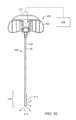
- FIG. 1is a plan view of an osteotome of the invention.
- FIG. 2is a side view of the osteotome of FIG. 1 .
- FIG. 3is a cross sectional view of the osteotome of FIG. 1 .
- FIG. 4is an enlarged sectional view of the handle of the osteotome of FIG. 1 .
- FIG. 5is an enlarged sectional view of the working end of the osteotome of FIG. 1 .
- FIG. 6Ais a sectional view of the working end of FIG. 5 in a linear configuration.
- FIG. 6Bis a sectional view of the working end of FIG. 5 in a curved configuration.
- FIGS. 7A-7Care schematic sectional views of a method of use of the osteotome of FIG. 1 .
- FIG. 8is another embodiment of an osteotome working end.
- FIG. 9is another embodiment of an osteotome working end.
- FIG. 10is another variation of an osteotome with an outer sleeve.
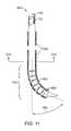
- FIG. 11is a cut-away view of the working end of the osteotome of FIG. 10 .
- FIG. 12Ais sectional view of another embodiment of working end, taken along line 12 A- 12 A of FIG. 11 .
- FIGS. 12B and 12Cillustrate additional variations of preventing rotation between adjacent sleeves.
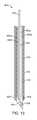
- FIG. 13is sectional view of another working end embodiment similar to that of FIG. 11 .
- FIG. 14is a cut-away perspective view of the working end of FIG. 13 .
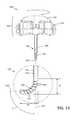
- FIG. 15illustrates another embodiment of an osteotome as described herein that has a distal working end that is configured for deformation resistance when used in very hard cancellous bone.
- FIG. 16illustrates an osteotome device as shown in FIG. 15 with a torque-limiting mechanism built into a handle portion.
- FIG. 17illustrates a de-mated slotted sleeve of the device of FIG. 15 wherein the slots are configured to resist radial deformation of the working end when articulated.
- FIGS. 18A and 18Billustrate first and second concentric slotted sleeves of the device of FIG. 15 from different sides to illustrate the configuration of the slots.
- FIG. 18Cillustrates a sleeve configuration with arcuate slots and a radial slot.
- FIGS. 19A-19Care enlarged schematic views the working end of the osteotome of FIG. 15 illustrating the progressive application of force would be applied by the working end to cancellous bone, wherein the force application progresses over different axial portions of the working end as it articulates.
- FIGS. 20A-20Bshow the distal end of a prior art stylet with a hinged distal tip that is used to treat cancellous bone; FIG. 19A showing the working end in a linear shape for insertion into bone; FIG. 19B showing the working end in an articulated shape for creating a space in bone having a certain area.
- FIG. 21is a view of the working end of FIGS. 15 and 19A-19C illustrating the width and volume of displaced cancellous bone caused by articulation of the working end.
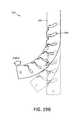
- FIG. 22is a view of the working end of FIGS. 15 and 19A-19C illustrating the volume of displaced cancellous bone caused by articulation and rotation of the working end.
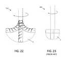
- FIG. 23is a view of the prior art stylet working end of FIGS. 20A-20B depicting the limited volume of cancellous bone that can be displaced by articulation and rotation of the prior art device.
- an apparatus or osteotome 100is shown that is configured for accessing the interior of a vertebral body and for creating a pathway in vertebral cancellous bone to receive bone cement.
- the apparatusis configured with an extension portion or member 105 for introducing through a pedicle and wherein a working end 110 of the extension member can be progressively actuated to curve a selected degree and/or rotated to create a curved pathway and cavity in the direction of the midline of the vertebral body.
- the apparatuscan be withdrawn and bone fill material can be introduced through a bone cement injection cannula.
- the apparatus 100itself can be used as a cement injector with the subsequent injection of cement through a lumen 112 of the apparatus.
- the apparatus 100comprises a handle 115 that is coupled to a proximal end of the extension member 105 .
- the extension member 105comprises an assembly of first (outer) sleeve 120 and a second (inner) sleeve 122 , with the first sleeve 120 having a proximal end 124 and distal end 126 .
- the second sleeve 122has a proximal end 134 and distal end 136 .
- the extension member 105is coupled to the handle 115 , as will be described below, to allow a physician to drive the extension member 105 into bone while contemporaneously actuating the working end 110 into an actuated or curved configuration (see FIG. 6 ).
- the handle 115can be fabricated of a polymer, metal or any other material suitable to withstand hammering or impact forces used to drive the assembly into bone (e.g., via use of a hammer or similar device on the handle 115 ).
- the inner and outer sleevesare fabricated of a suitable metal alloy, such as stainless steel or NiTi.
- the wall thicknesses of the inner and outer sleevescan range from about 0.005′′ to 0.010′′ with the outer diameter the outer sleeve ranging from about 2.5 mm to 5.0 mm.
- the handle 115comprises both a first grip portion 140 and a second actuator portion indicated at 142 .
- the grip portion 140is coupled to the first sleeve 120 as will be described below.
- the actuator portion 142is operatively coupled to the second sleeve 122 as will be described below.
- the actuator portion 142is rotatable relative to the grip portion 140 and one or more plastic flex tabs 145 of the grip portion 140 are configured to engage notches 146 in the rotatable actuator portion 142 to provide tactile indication and temporary locking of the handle portions 140 and 142 in a certain degree of rotation.
- the flex tabs 145thus engage and disengage with the notches 146 to permit ratcheting (rotation and locking) of the handle portions and the respective sleeve coupled thereto.
- the notches or slots in any of the sleevescan comprise a uniform width along the length of the working end or can comprise a varying width.
- the widthcan be selected in certain areas to effectuate a particular curved profile.
- the widthcan increase or decrease along the working end to create a curve having a varying radius.
- FIG. 4is a sectional view of the handle showing a mechanism for actuating the second inner sleeve 122 relative to the first outer sleeve 120 .
- the actuator portion 142 of the handle 115is configured with a fast-lead helical groove indicated at 150 that cooperates with a protruding thread 149 of the grip portion 140 of the handle.
- rotation of the actuation portion 142will move this portion to the position indicated at 150 (phantom view).
- the actuator portion 142when the actuator portion 142 is rotated a selected amount from about 45° to 720°, or from about 90° to 360°, the inner sleeve 122 is lifted proximally relative to the grip portion 140 and outer sleeve 120 to actuate the working end 110 .
- the actuator portion 142engages flange 152 that is welded to the proximal end 132 of inner sleeve 122 .
- the flange 152is lifted by means of a ball bearing assembly 154 disposed between the flange 152 and metal bearing surface 155 inserted into the grip portion 140 of the handle.
- the rotation of actuator 142can lift the inner sleeve 122 without creating torque on the inner sleeve.
- FIGS. 5, 6A and 6Bit can be seen that the working end 110 of the extension member 105 is articulated by cooperating slotted portions of the distal portions of outer sleeve 120 and inner sleeve 122 that are both thus capable of bending in a substantially tight radius.
- the outer sleeve 120has a plurality of slots or notches 162 therein that can be any slots that are perpendicular or angled relative to the axis of the sleeve.
- the inner sleeve 122has a plurality of slots or notches indicated at 164 that can be on an opposite side of the assembly relative to the slots 162 in the outer sleeve 120 .
- outer and inner sleevesare welded together at the distal region indicated at weld 160 . It thus can be understood that when inner sleeve 122 is translated in the proximal direction, the outer sleeve will be flexed as depicted in FIG. 6B . It can be understood that by rotating the actuator handle portion 142 a selected amount, the working end can be articulated to a selected degree.
- FIGS. 4, 5, 6A and 6Bfurther illustrate another element of the apparatus that comprises a flexible flat wire member 170 with a proximal end 171 and flange 172 that is engages the proximal side of flange 152 of the inner sleeve 122 .
- At least the distal portion 174 of the flat wire member 170is welded to the inner sleeve at weld 175 .
- This flat wire memberthus provides a safety feature to retain the working end in the event that the inner sleeve fails at one of the slots 164 .
- Another safety feature of the apparatuscomprises a torque limiter and release system that allows the entire handle assembly 115 to freely rotate—for example if the working end 110 is articulated, as in FIG, 6 B, when the physician rotates the handle and when the working end is engaged in strong cancellous bone.
- the grip portion 142 of the handle 115engages a collar 180 that is fixed to a proximal end 124 of the outer sleeve 120 .
- the collar 180further comprises notches 185 that are radially spaced about the collar and are engaged by a ball member 186 that is pushed by a spring 188 into notches 185 .
- the rotation of the handle 115overcomes the predetermined limit.
- the torque limiter assemblyis in its locked position, the ball bearing 186 is forced into one of the notches 185 in the collar 180 .
- the ball bearing 186disengages the notch 185 allowing the collar 180 to turn, and then reengages at the next notch, releasing anywhere from 0.5 inch-lbs to 7.5 inch-lbs, of torque.
- the inner sleeve 122is weakened on one side at its distal portion so as to permit the inner sleeve 122 to bend in either direction but is limited by the location of the notches in the outer sleeve 120 .
- the curvature of any articulated configurationis controlled by the spacing of the notches as well as the distance between each notch peak.
- the inner sleeve 122also has a beveled tip for entry through the cortical bone of a vertebral body. Either the inner sleeve or outer sleeve can form the distal tip.
- a physiciantaps or otherwise drives a stylet 200 and introducer sleeve 205 into a vertebral body 206 typically until the stylet tip 208 is within the anterior 1 ⁇ 3 of the vertebral body toward cortical bone 210 ( FIG. 7A ). Thereafter, the stylet 200 is removed and the sleeve 205 is moved proximally ( FIG. 7B ). As can be seen in FIG. 7B , the tool or osteotome 100 is inserted through the introducer sleeve 205 and articulated in a series of steps as described above.
- the working end 110can be articulated intermittently while applying driving forces and optionally rotational forces to the handle 115 to advance the working end through the cancellous bone 212 to create path or cavity 215 .
- the toolis then tapped to further drive the working end 110 to, toward or past the midline of the vertebra.
- the physiciancan alternatively articulate the working end 110 , and drive and rotate the working end further until imaging shows that the working end 100 has created a cavity 215 of an optimal configuration.
- the physicianreverses the sequence and progressively straightens the working end 110 as the extension member is withdrawn from the vertebral body 206 .
- the physiciancan insert a bone cement injector 220 into the path or cavity 215 created by osteotome 100 .
- FIG. 7Cillustrates a bone cement 222 , for example a PMMA cement, being injected from a bone cement source 225 .
- the apparatus 100can have a handle 115 with a Luer fitting for coupling a bone cement syringe and the bone cement can be injected through the lumen 112 of the apparatus.
- the lumencan have a lubricious surface layer or polymeric lining 250 to insure least resistance to bone cement as it flows through the lumen.
- the surface or lining 250can be a fluorinated polymer such as TEFLON® or polytetrafluroethylene (PTFE). Other suitable fluoropolymer resins can be used such as FEP and PFA.
- FEPFluorinated ethylenepropylene
- ECTFEEthylenechlorotrifluoro-ethylene
- ETFEPolyethylene
- PolyamidePolyamide
- PVDFPolyvinyl chloride
- siliconesilicone
- FIG. 9also shows the extension member or shaft 105 can be configured with an exterior flexible sleeve indicated at 255 .
- the flexible sleevecan be any commonly known biocompatible material, for example, the sleeve can comprise any of the materials described in the preceding paragraph.
- the working end 110can be configured to deflect over a length indicated at 260 in a substantially smooth curve.
- the degree of articulation of the working end 100can be at least 45°, 90°, 135° or at least 180° as indicated at 265 ( FIG. 9 ).
- the slots of the outer 120 and inner sleeves 120can be varied to produce a device having a radius of curvature that varies among the length 260 of the device 100 .
- the inner sleevecan be spring loaded relative the outer sleeve, in such a way as to allow the working end to straighten under a selected level of force when pulled in a linear direction. This feature allows the physician to withdraw the assembly from the vertebral body partly or completely without further rotation the actuating portion 142 of handle 115 .
- the force-limitercan be provided to allow less than about 10 inch-lbs of force to be applied to bone.
- the working end 110is configured with a tip 240 that deflects to the position indicated at 240 ′ when driven into bone.
- the tip 240is coupled to the sleeve assembly by resilient member 242 , for example a flexible metal such as stainless steel or NiTi. It has been found that the flexing of the tip 240 causes its distal surface area to engage cancellous bone which can assist in deflecting the working end 110 as it is hammered into bone.
- the actuator handlecan include a secondary (or optional) mechanism for actuating the working end.
- the mechanismwould include a hammer-able member with a ratchet such that each tap of the hammer would advance assembly and progressively actuate the working end into a curved configuration.
- a ratchet mechanismas known in the art would maintain the assembly in each of a plurality of articulated configurations.
- a releasewould be provided to allow for release of the ratchet to provide for straightening the extension member 105 for withdrawal from the vertebral body.
- FIGS. 10 and 11illustrate another variation of a bone treatment device 400 with a handle 402 and extension member 405 extending to working end 410 having a similar construction to that FIGS. 1 to 6B .
- the device 400operates as described previously with notched first (outer) sleeve 120 and cooperating notched second (inner) sleeve 122 .
- the variation shown in FIGS. 10 and 11also includes a third concentric notched sleeve 420 , exterior to the first 120 and second 122 sleeves.
- the notches or slots in sleeve 420 at the working end 410permit deflection of the sleeve as indicated at 265 in FIG. 11 .
- FIG. 10also illustrates the treatment device 400 as including a luer fitting 412 that allows the device 402 to be coupled to a source of a filler material (e.g., a bone filler or bone cement material).
- a filler materiale.g., a bone filler or bone cement material.
- the luercan be removable from the handle 402 to allow application of an impact force on the handle as described above.
- the luer fitting 402can be located on the actuating portion of the handle, the stationary part of the handle or even along the sleeve.
- variations of the device 400permit coupling the filler material with a lumen extending through the sleeves (or between adjacent sleeves) to deposit filler material at the working end 410 .
- filler materialcan be deposited through a distal end of the sleeves (where the sharp tip is solid) or can be deposited through openings in a side-wall of the sleeves.
- this configurationare within the scope of those familiar in the field.
- the third notched sleeve 420is configured with its smooth (non-notched) surface 424 disposed to face inwardly on the articulated working end ( FIG. 11 ) such that a solid surface forms the interior of the curved portion of the working end 410 .
- the smooth surface 424allows withdrawal of the device 110 into a cannula or introducer 205 without creating a risk that the slots or notches become caught on a cannula 205 (see e.g., FIG. 7B ).
- the third (outermost) sleeve 420can extend from an intermediate location on the extension member 405 to a distal end of the working end 410 .
- variations of the deviceinclude the third sleeve 420 extending to the handle 402 .
- the third sleeve 420is typically not coupled to the handle 402 so that any rotational force or torque generated by the handle 402 is not directly transmitted to the third sleeve 420 .
- the third sleeve 420is coupled to the second sleeve 120 at only one axial location.
- the third sleeve 420is affixed to second sleeve 420 by welds 428 at the distal end of the working end 410 .
- the welds or other attachment meanse.g., a pin, key/keyway, protrusion, etc.
- the sleeve 420can be fabricated of any bio-compatible material.
- the third sleeveis fabricated form a 3.00 mm diameter stainless steel material with a wall thickness of 0.007′′.
- the first, second and third sleevesare sized to have dimensions to allow a sliding fit between the sleeves.
- FIG. 12Ais a sectional view of extension member 405 of another variation, similar to that shown in FIGS. 10-11 .
- the variation depicted by FIG. 12Acomprises non-round configurations of concentric slidable sleeves (double or triple sleeve devices). This configuration limits or prevents rotation between the sleeves and allows the physician to apply greater forces to the bone to create a cavity.
- FIG. 12Aillustrates an oval configuration
- any non-round shapeis within the scope of this disclosure.
- the cross-sectional shapecan comprise a square, polygonal, or other radially keyed configuration as shown in FIGS. 12B and 12C . As shown in FIG.
- the sleevescan include a key 407 and a receiving keyway 409 to prevent rotation but allow relative or axial sliding of the sleeves.
- the keycan comprise any protrusion or member that slides within a receiving keyway.
- the keycan comprise a pin or any raised protrusion on an exterior or interior of a respective sleeve.
- first 122 and second 120 sleevesare illustrated. However, any of the sleeves can be configured with the key/keyway. Preventing rotation between sleeves improves the ability to apply force to bone at the articulated working end.
- FIGS. 13-14illustrate another variation of a working end 410 of an osteotome device.
- the working end 410includes one or more flat spring elements 450 , 460 a , 460 b , 460 c , 460 d , that prevent relative rotation of the sleeves of the assembly thus allowing greater rotational forces to be applied to cancellous bone from an articulated working end.
- the spring elementsfurther urge the working end assembly into a linear configuration.
- a rotational forceis applied to the handle as described above, once this rotational force is removed, the spring elements urge the working end into a linear configuration.
- one or more of the spring elementscan extend through the sleeves for affixing to a handle to prevent rotation.
- flat spring element 450is fixed to sleeve assembly by weld 455 .
- the spring elementis fixed at each end to prevent its rotation.
- Alternate variationsinclude one or more spring elements being affixed to the inner sleeve assembly at a medial section of the sleeve.
- variations of the osteotomecan include any number of spring elements 460 a - 460 d .
- These additional spring elements 460 a - 460 dcan be welded at either a proximal or distal end thereof to an adjacent element or a sleeve to allow the element to function as a leaf spring.
- FIGS. 15-16illustrate another embodiment of an osteotome 500 with shaft assembly 505 having an articulating working end 510 that is designed to provide especially high strength and thus is adapted for use in dense, hard cancellous bone.
- the working end 510exhibits high strength in applying high forces capable of displacing dense cancellous bone as the working end is moved from a linear insertion shape towards an articulated, non-linear shape.
- the working end 510exhibits high strength in resisting radial deformation when the articulated working end articulates to displace dense cancellous bone.
- handle 512is coupled to the shaft assembly 505 that extends about an indicated at 515 .
- the first handle portion or body 516 and the rotatable actuator or second handle body 518function as described in previous embodiments to articulate the working end 510 and axis 515 from a linear configuration to a curved configuration.
- FIGS. 15 and 16show that the first handle body 516 is coupled to outer sleeve 520 of the shaft assembly 505 and the second handle body 518 is coupled to inner sleeve 522 .
- FIG. 16is a sectional view of handle 512 again showing the mechanism for actuating the second inner sleeve 522 . relative to the first outer sleeve 520 , wherein the first and second handle bodies 516 and 518 are mated along a fast-lead helical thread 526 .
- a torque limiting mechanismis provided in handle 512 which comprises a ball 535 that is urged by spring 536 into a detent 538 in metal collar 540 that is fixedly coupled to handle body 516 .
- a set screw 542is provided to adjust the force at which the torque-release mechanism will release under rotation of the handle.
- the reset torque release mechanismis set to release at a minimum of 8 inch-lbs torque. In one embodiment, the release is set at 8 inch-lbs of torque, 10 inch-lbs of torque, 12 inch-lbs of torque, or 15 inch-lbs of torque.
- the working end 510is configured with a series of slots 550 in the first and second sleeves 520 and 522 that allow for articulation of the assembly.
- the slots 550are provided in both sleeves and can range in number from about 5 to 20.
- additional variations of the devicecan include any number of slots in either sleeve.
- This variationalso illustrates slots that have an arcuate configuration rather than being a simple radial slot is shown in previous embodiments.
- the slots 550each have a first radial slot portion 552 that extends substantially radially about a sleeve 520 or 522 and a second axial slot portion 555 that extends substantially axially in a sleeve 520 or 522 .
- FIG. 17shows an outer sleeve 520 de-mated from the shaft assembly 505 to more particularly depict the dimensions and features of arcuate slots 550 .
- the arcuate slots 550are also configured as a ‘keyed’ or interlocking features wherein one slot edge comprises a projecting ‘key’ element 560 that slides into and engages a key-receiving shape 562 of the opposing slot edge when the sleeve is articulated.
- the interlocking projecting and receiving features 560 and 562provide the shaft assembly 505 with significantly increased strength in resisting deformation when the working end is rotated in dense cancellous bone.
- the arcuate slots 550as depicted in FIG.
- either or both sleevescan include any combination of arcuate and radial slots in the same sleeve.
- a cooperating sleeve without the arcuate slots 550 of FIG. 17can have radially-oriented slots as described in earlier embodiments.
- the radial oriented slotsas shown previously, comprise slots that extend about a portion of the circumference of the sleeve. Where each radial oriented slot is typically within a plane is perpendicular to an axis of the sleeve (when straight).
- An arcuate slotalso is located about a portion of the circumference of the sleeve but is not limited to within a plane that is perpendicular to an axis of the sleeve. As shown in FIG. 18B , the arcuate slots are angled when viewed from a side of the device.
- a sleevecan include both arcuate slots and radial slots as shown in FIG. 18C .
- the arcuate shaped slotscan also be referred to as axial oriented slots as the direction of the slot is parallel or angled from an axis of the sleeve while a radial oriented slot is perpendicular to an axis of the sleeve.
- Such a combination of slotscan be provided on any sleeve (an inner sleeve, an outer sleeve, or both sleeves).
- FIG. 18Ais a plan view of inner sleeve 522 de-mated from shaft assembly 505 and again shows the arcuate slots 550 with interlocking projecting and receiving features 560 and 562 .
- FIG. 18Bit can be seen that on shaft assembly 505 includes arcuate slots 550 in both sleeves. The slot can be aligned or non-aligned when the working end is in a linear position.
- the distal ends of the shaftscan be coupled together by a press-fit pins inserted into holes 566 in the sleeves ( FIG. 17 ) or by any other suitable fastening means such as welding.
- the arcuate slots 550have a varied width, again for providing greater resistance to torsional, twisting or radial deformation when in use.
- the slot width A on the axially-extending slot portions 555 along the sides 570 a and 570 b of the projecting feature 560is less than the slot width R on the radial-extending slot portion 552 adjacent the end surface 572 of projecting feature 560 .
- FIGS. 18A, 18B and 20it can be understood how the keyed featured 560 and 562 will mesh and interlock when the working end is articulated and thus resist deformation under twisting loads.
- the axial slot portions 555have a width A of less than 0.010′′, 008′′ or 0.006′′.
- the said radial slot portions 552have a width R that greater than 0.006′′, 008′′ or 0.010′′.
- Such slotcan be cut by a laser cutter as is known in the art.
- the working end 510is adapted for providing a sharp, tight radius curvature which is desirable in an osteotome 500 used in a vertebral body.
- the transverse dimension TD of the working end 510 in the fully articulated positionis at least 10 mm.
- the working end 510is capable of articulation such that the linear axis 515 is deflected at least 90° to axis 515 ′ as depicted in FIG. 15 .
- the deflectable shaft portionhas a length dimension LD of 12 mm or less in its linear shape ( FIG.
- the working endhas a deflectable shaft portion that provides a ratio of at least 0.8:1 of the maximum transverse dimension TD relative to the length dimension LD of the deflecting shaft portion.
- FIGS. 19A-19Canother aspect of the invention relates to the level of forces that can be applied to bone when articulating the working end 510 , without regard to rotation of the articulated working end.
- movement of the working end toward the articulated configurationcan apply at least 30 lbs. force to cancellous bone, or at least 50 lbs. force to bone or at least 70 lbs. force to bone.
- another aspect of the inventionrelates to the manner is which forces are applied to bone when the working end is progressively articulated and in which there is not single hinge point around which the working end pivots.
- FIGS. 19A-19Cillustrate that maximum forces are applied at the distal tip of the device in a progressive manner as first the most distal portion of the shaft articulates, then an adjacent proximal portion of the shaft articulated an so forth.
- This aspect of the working enddiffers greatly from the prior art stylet device and working end 580 of FIGS. 20A-20B , wherein the stylet tip 582 is actuated by pull rod 584 which caused the tip 582 to swing around a single pivot point 585 which thus loads the entire elongated surface 588 of the stylet tip 582 . It can be understood that device of FIGS.
- FIG. 21depicts another aspect of the invention wherein it can be seen that working end 510 can be progressively articulated to displace a path in cancellous bone having a width W.
- the width Wis equal to the diameter of the working end 510 .
- the prior art device of FIG. 20Bcan typically only displace a path in cancellous bone having a width X, which is less that the diameter of the tool.
- FIGS. 22 and 23illustrate another aspect of the invention wherein the working end when rotated can displace a much greater volume of cancellous bone that the prior art device of FIGS. 20A-20B .
- FIG. 22it can be seen that rotation of working 510 as it is articulated can great a very large displaced volume Y of cancellous bone compared to the volume Z that could potentially be displaced by the working end 580 of FIGS. 20A-20B .
Landscapes
- Health & Medical Sciences (AREA)
- Life Sciences & Earth Sciences (AREA)
- Surgery (AREA)
- Orthopedic Medicine & Surgery (AREA)
- Medical Informatics (AREA)
- General Health & Medical Sciences (AREA)
- Biomedical Technology (AREA)
- Heart & Thoracic Surgery (AREA)
- Nuclear Medicine, Radiotherapy & Molecular Imaging (AREA)
- Molecular Biology (AREA)
- Animal Behavior & Ethology (AREA)
- Engineering & Computer Science (AREA)
- Public Health (AREA)
- Veterinary Medicine (AREA)
- Dentistry (AREA)
- Oral & Maxillofacial Surgery (AREA)
- Pathology (AREA)
- Surgical Instruments (AREA)
- Prostheses (AREA)
Abstract
Description
Claims (15)
Priority Applications (1)
| Application Number | Priority Date | Filing Date | Title |
|---|---|---|---|
| US13/302,927US9649116B2 (en) | 2010-11-22 | 2011-11-22 | System for use in treatment of vertebral fractures |
Applications Claiming Priority (2)
| Application Number | Priority Date | Filing Date | Title |
|---|---|---|---|
| US41604210P | 2010-11-22 | 2010-11-22 | |
| US13/302,927US9649116B2 (en) | 2010-11-22 | 2011-11-22 | System for use in treatment of vertebral fractures |
Publications (2)
| Publication Number | Publication Date |
|---|---|
| US20120130381A1 US20120130381A1 (en) | 2012-05-24 |
| US9649116B2true US9649116B2 (en) | 2017-05-16 |
Family
ID=46065029
Family Applications (1)
| Application Number | Title | Priority Date | Filing Date |
|---|---|---|---|
| US13/302,927Active2033-08-26US9649116B2 (en) | 2010-11-22 | 2011-11-22 | System for use in treatment of vertebral fractures |
Country Status (7)
| Country | Link |
|---|---|
| US (1) | US9649116B2 (en) |
| EP (2) | EP3187132B1 (en) |
| JP (3) | JP5865387B2 (en) |
| CA (1) | CA2818876C (en) |
| DK (1) | DK2642931T3 (en) |
| ES (1) | ES2626256T3 (en) |
| WO (1) | WO2012071464A1 (en) |
Cited By (13)
| Publication number | Priority date | Publication date | Assignee | Title |
|---|---|---|---|---|
| US10028753B2 (en) | 2008-09-26 | 2018-07-24 | Relievant Medsystems, Inc. | Spine treatment kits |
| US10111704B2 (en) | 2002-09-30 | 2018-10-30 | Relievant Medsystems, Inc. | Intraosseous nerve treatment |
| US10265099B2 (en) | 2008-09-26 | 2019-04-23 | Relievant Medsystems, Inc. | Systems for accessing nerves within bone |
| US10357258B2 (en) | 2012-11-05 | 2019-07-23 | Relievant Medsystems, Inc. | Systems and methods for creating curved paths through bone |
| US10390877B2 (en) | 2011-12-30 | 2019-08-27 | Relievant Medsystems, Inc. | Systems and methods for treating back pain |
| US10456187B2 (en) | 2013-08-08 | 2019-10-29 | Relievant Medsystems, Inc. | Modulating nerves within bone using bone fasteners |
| US10463423B2 (en) | 2003-03-28 | 2019-11-05 | Relievant Medsystems, Inc. | Thermal denervation devices and methods |
| US10588691B2 (en) | 2012-09-12 | 2020-03-17 | Relievant Medsystems, Inc. | Radiofrequency ablation of tissue within a vertebral body |
| USRE48460E1 (en) | 2002-09-30 | 2021-03-09 | Relievant Medsystems, Inc. | Method of treating an intraosseous nerve |
| US11007010B2 (en) | 2019-09-12 | 2021-05-18 | Relevant Medsysterns, Inc. | Curved bone access systems |
| US12039731B2 (en) | 2020-12-22 | 2024-07-16 | Relievant Medsystems, Inc. | Prediction of candidates for spinal neuromodulation |
| US12082876B1 (en) | 2020-09-28 | 2024-09-10 | Relievant Medsystems, Inc. | Introducer drill |
| US12433668B1 (en) | 2021-11-08 | 2025-10-07 | Relievant Medsystems, Inc. | Impedance stoppage mitigation during radiofrequency tissue ablation procedures |
Families Citing this family (45)
| Publication number | Priority date | Publication date | Assignee | Title |
|---|---|---|---|---|
| US9510885B2 (en) | 2007-11-16 | 2016-12-06 | Osseon Llc | Steerable and curvable cavity creation system |
| US20090131867A1 (en) | 2007-11-16 | 2009-05-21 | Liu Y King | Steerable vertebroplasty system with cavity creation element |
| US8758349B2 (en) | 2008-10-13 | 2014-06-24 | Dfine, Inc. | Systems for treating a vertebral body |
| JP5575777B2 (en) | 2008-09-30 | 2014-08-20 | ディファイン, インコーポレイテッド | System used to treat vertebral fractures |
| US20100298832A1 (en) | 2009-05-20 | 2010-11-25 | Osseon Therapeutics, Inc. | Steerable curvable vertebroplasty drill |
| US10058336B2 (en) | 2010-04-08 | 2018-08-28 | Dfine, Inc. | System for use in treatment of vertebral fractures |
| CN102985015B (en) | 2010-04-29 | 2016-08-03 | Dfine有限公司 | System for treating vertebral fractures |
| US9526507B2 (en) | 2010-04-29 | 2016-12-27 | Dfine, Inc. | System for use in treatment of vertebral fractures |
| US9125671B2 (en) | 2010-04-29 | 2015-09-08 | Dfine, Inc. | System for use in treatment of vertebral fractures |
| ES2626256T3 (en) | 2010-11-22 | 2017-07-24 | Dfine, Inc. | System to use in the treatment of vertebral fractures |
| ES2864589T3 (en) | 2011-04-12 | 2021-10-14 | Thermedical Inc | Devices for conformal therapy in fluid-enhanced ablation |
| US9119639B2 (en) | 2011-08-09 | 2015-09-01 | DePuy Synthes Products, Inc. | Articulated cavity creator |
| CA2868869C (en) | 2012-03-27 | 2021-01-12 | Dfine, Inc. | Methods and systems for use in controlling tissue ablation volume by temperature monitoring |
| EP3593740B1 (en) | 2012-06-20 | 2021-10-06 | Stryker Corporation | System for off-axis tissue manipulation |
| US10022176B2 (en) | 2012-08-15 | 2018-07-17 | Thermedical, Inc. | Low profile fluid enhanced ablation therapy devices and methods |
| US9918766B2 (en) | 2012-12-12 | 2018-03-20 | Dfine, Inc. | Devices, methods and systems for affixing an access device to a vertebral body for the insertion of bone cement |
| US9241729B2 (en) | 2012-12-14 | 2016-01-26 | DePuy Synthes Products, Inc. | Device to aid in the deployment of a shape memory instrument |
| US9439693B2 (en) | 2013-02-01 | 2016-09-13 | DePuy Synthes Products, Inc. | Steerable needle assembly for use in vertebral body augmentation |
| US9033972B2 (en) | 2013-03-15 | 2015-05-19 | Thermedical, Inc. | Methods and devices for fluid enhanced microwave ablation therapy |
| US9610396B2 (en) | 2013-03-15 | 2017-04-04 | Thermedical, Inc. | Systems and methods for visualizing fluid enhanced ablation therapy |
| EP2832309B1 (en)* | 2013-07-31 | 2018-03-07 | Biedermann Technologies GmbH & Co. KG | Implant for bones or vertebrae with self-constrained flexibility |
| EP3057517B1 (en) | 2013-10-15 | 2020-04-08 | Stryker Corporation | Device for creating a void space in a living tissue, the device including a handle with a control knob that can be set regardless of the orientation of the handle |
| US9968373B1 (en)* | 2014-02-21 | 2018-05-15 | Surgentec, Llc | Handles for needle assemblies |
| US10350387B2 (en)* | 2014-06-02 | 2019-07-16 | Medtronic, Inc. | Implant tool for substernal or pericardial access |
| WO2016138443A2 (en) | 2015-02-26 | 2016-09-01 | Stryker Corporation | Surgical instrument with articulation region |
| US9901392B2 (en) | 2015-05-11 | 2018-02-27 | Dfine, Inc. | System for use in treatment of vertebral fractures |
| WO2017180706A1 (en)* | 2016-04-12 | 2017-10-19 | Applied Medical Resources Corporation | Surgical stapler having articulation mechanism |
| CN109661209A (en) | 2016-07-01 | 2019-04-19 | 锐凌公司 | Arthroscope device and method |
| DE102016113355A1 (en)* | 2016-07-20 | 2018-01-25 | B. Braun Melsungen Ag | Medical-technical clamping device with slip clutch |
| US9743984B1 (en) | 2016-08-11 | 2017-08-29 | Thermedical, Inc. | Devices and methods for delivering fluid to tissue during ablation therapy |
| JP2019534130A (en) | 2016-10-27 | 2019-11-28 | ディーファイン,インコーポレイティド | Articulated osteotome with cement delivery channel |
| WO2018097992A2 (en) | 2016-11-22 | 2018-05-31 | Dfine, Inc. | Swivel hub |
| CA3041114A1 (en) | 2016-11-28 | 2018-05-31 | Dfine, Inc. | Tumor ablation devices and related methods |
| US10470781B2 (en) | 2016-12-09 | 2019-11-12 | Dfine, Inc. | Medical devices for treating hard tissues and related methods |
| US10660656B2 (en) | 2017-01-06 | 2020-05-26 | Dfine, Inc. | Osteotome with a distal portion for simultaneous advancement and articulation |
| US11007347B2 (en) | 2017-04-26 | 2021-05-18 | Biosense Webster (Israel) Ltd. | Deflectable insertion tool |
| US10933214B2 (en)* | 2017-04-26 | 2021-03-02 | Biosense Webster (Israel) Ltd. | Method for producing a deflectable insertion tool |
| US11083871B2 (en) | 2018-05-03 | 2021-08-10 | Thermedical, Inc. | Selectively deployable catheter ablation devices |
| US11918277B2 (en) | 2018-07-16 | 2024-03-05 | Thermedical, Inc. | Inferred maximum temperature monitoring for irrigated ablation therapy |
| US11083596B2 (en)* | 2018-09-29 | 2021-08-10 | Jan William Duncan | Minimally invasive transforaminal lumbar interbody fusion |
| US11937864B2 (en) | 2018-11-08 | 2024-03-26 | Dfine, Inc. | Ablation systems with parameter-based modulation and related devices and methods |
| US11849986B2 (en) | 2019-04-24 | 2023-12-26 | Stryker Corporation | Systems and methods for off-axis augmentation of a vertebral body |
| US11986229B2 (en) | 2019-09-18 | 2024-05-21 | Merit Medical Systems, Inc. | Osteotome with inflatable portion and multiwire articulation |
| JP7211582B1 (en) | 2021-08-31 | 2023-01-24 | 慶應義塾 | puncture probe |
| WO2024116100A1 (en)* | 2022-11-30 | 2024-06-06 | Medtronic Holding Company Sàrl | Basivertebral nerve access tool, system, and method |
Citations (89)
| Publication number | Priority date | Publication date | Assignee | Title |
|---|---|---|---|---|
| US3140623A (en)* | 1961-08-29 | 1964-07-14 | Pendleton Tool Ind Inc | Predetermined torque release wrench |
| US4411266A (en) | 1980-09-24 | 1983-10-25 | Cosman Eric R | Thermocouple radio frequency lesion electrode |
| US4456017A (en) | 1982-11-22 | 1984-06-26 | Cordis Corporation | Coil spring guide with deflectable tip |
| US4473077A (en)* | 1982-05-28 | 1984-09-25 | United States Surgical Corporation | Surgical stapler apparatus with flexible shaft |
| US4476861A (en) | 1979-11-06 | 1984-10-16 | Christos Dimakos | Instrument for removal of a bone cement tube in an artificial femur head reimplantation |
| US4595006A (en) | 1982-08-16 | 1986-06-17 | Burke Dennis W | Apparatus for cemented implantation of prostheses |
| WO1993004634A1 (en) | 1991-09-12 | 1993-03-18 | Surgical Dynamics, Inc. | Bendable dissectomy probe and steerable cannula |
| US5282821A (en) | 1993-01-26 | 1994-02-01 | Donahue John R | Adjustable surgical instrument |
| US5284128A (en) | 1992-01-24 | 1994-02-08 | Applied Medical Resources Corporation | Surgical manipulator |
| US5322505A (en) | 1990-02-07 | 1994-06-21 | Smith & Nephew Dyonics, Inc. | Surgical instrument |
| US5322064A (en)* | 1991-02-15 | 1994-06-21 | Lundquist Ingemar H | Torquable catheter and method |
| US5449351A (en) | 1993-09-09 | 1995-09-12 | Zohmann; Walter A. | Atraumatic needle for lumbar puncture |
| US5458597A (en) | 1993-11-08 | 1995-10-17 | Zomed International | Device for treating cancer and non-malignant tumors and methods |
| US5599346A (en) | 1993-11-08 | 1997-02-04 | Zomed International, Inc. | RF treatment system |
| WO1997003611A1 (en)* | 1995-07-18 | 1997-02-06 | Edwards, Garland, U. | Flexible shaft |
| US5620447A (en) | 1993-01-29 | 1997-04-15 | Smith & Nephew Dyonics Inc. | Surgical instrument |
| US5628771A (en) | 1993-05-12 | 1997-05-13 | Olympus Optical Co., Ltd. | Electromagnetic-wave thermatological device |
| US5662680A (en) | 1991-10-18 | 1997-09-02 | Desai; Ashvin H. | Endoscopic surgical instrument |
| US5695513A (en) | 1996-03-01 | 1997-12-09 | Metagen, Llc | Flexible cutting tool and methods for its use |
| US5697536A (en) | 1992-01-07 | 1997-12-16 | Arthrocare Corporation | System and method for electrosurgical cutting and ablation |
| US5810804A (en) | 1995-08-15 | 1998-09-22 | Rita Medical Systems | Multiple antenna ablation apparatus and method with cooling element |
| US5833632A (en) | 1995-12-07 | 1998-11-10 | Sarcos, Inc. | Hollow guide wire apparatus catheters |
| US5851212A (en) | 1997-06-11 | 1998-12-22 | Endius Incorporated | Surgical instrument |
| US5902251A (en) | 1996-05-06 | 1999-05-11 | Vanhooydonk; Neil C. | Transcervical intrauterine applicator for intrauterine hyperthermia |
| US5921956A (en) | 1997-09-24 | 1999-07-13 | Smith & Nephew, Inc. | Surgical instrument |
| US5928239A (en) | 1998-03-16 | 1999-07-27 | University Of Washington | Percutaneous surgical cavitation device and method |
| US5944715A (en) | 1996-06-20 | 1999-08-31 | Gyrus Medical Limited | Electrosurgical instrument |
| US6073051A (en) | 1996-08-13 | 2000-06-06 | Oratec Interventions, Inc. | Apparatus for treating intervertebal discs with electromagnetic energy |
| US6106524A (en) | 1995-03-03 | 2000-08-22 | Neothermia Corporation | Methods and apparatus for therapeutic cauterization of predetermined volumes of biological tissue |
| US6123702A (en) | 1998-09-10 | 2000-09-26 | Scimed Life Systems, Inc. | Systems and methods for controlling power in an electrosurgical probe |
| US6135999A (en) | 1997-02-12 | 2000-10-24 | Oratec Internationals, Inc. | Concave probe for arthroscopic surgery |
| US6231615B1 (en) | 1997-10-14 | 2001-05-15 | Parallax Medical, Inc. | Enhanced visibility materials for implantation in hard tissue |
| US6280441B1 (en) | 1997-12-15 | 2001-08-28 | Sherwood Services Ag | Apparatus and method for RF lesioning |
| US20020026197A1 (en) | 2000-08-11 | 2002-02-28 | Foley Kevin T. | Surgical instrumentation and method for treatment of the spine |
| US6409722B1 (en) | 1998-07-07 | 2002-06-25 | Medtronic, Inc. | Apparatus and method for creating, maintaining, and controlling a virtual electrode used for the ablation of tissue |
| US6440138B1 (en) | 1998-04-06 | 2002-08-27 | Kyphon Inc. | Structures and methods for creating cavities in interior body regions |
| US6447506B1 (en) | 1993-10-15 | 2002-09-10 | Ep Technologies, Inc. | Systems and methods for creating long, thin lesions in body tissue |
| US20020133148A1 (en) | 2001-01-11 | 2002-09-19 | Daniel Steven A. | Bone-treatment instrument and method |
| US6464683B1 (en) | 1997-04-25 | 2002-10-15 | Schneider (Usa) Inc. | Trilayer, extruded medical tubing and medical devices incorporating such tubbing |
| US6478793B1 (en) | 1999-06-11 | 2002-11-12 | Sherwood Services Ag | Ablation treatment of bone metastases |
| US20030014094A1 (en) | 2001-07-13 | 2003-01-16 | Radiant Medical, Inc. | Catheter system with on-board temperature probe |
| US20030130664A1 (en) | 1998-08-14 | 2003-07-10 | Kyphon Inc. | Systems and methods for treating vertebral bodies |
| US6602248B1 (en) | 1995-06-07 | 2003-08-05 | Arthro Care Corp. | Methods for repairing damaged intervertebral discs |
| US20030212395A1 (en) | 2000-05-12 | 2003-11-13 | Arthrocare Corporation | Systems and methods for electrosurgery |
| US20030212394A1 (en) | 2001-05-10 | 2003-11-13 | Rob Pearson | Tissue ablation apparatus and method |
| WO2003101308A1 (en) | 2002-06-04 | 2003-12-11 | Office Of Technology Licensing Stanford University | Device and method for rapid aspiration and collection of body tissue from within an enclosed body space |
| US20040087936A1 (en) | 2000-11-16 | 2004-05-06 | Barrx, Inc. | System and method for treating abnormal tissue in an organ having a layered tissue structure |
| JP2004242936A (en) | 2003-02-14 | 2004-09-02 | Terumo Corp | Puncture needle |
| US20050177210A1 (en) | 2002-03-05 | 2005-08-11 | Baylis Medical Company Inc. | Electrosurgical tissue treatment method |
| US20050216018A1 (en) | 2004-03-29 | 2005-09-29 | Sennett Andrew R | Orthopedic surgery access devices |
| US20060025763A1 (en) | 2000-08-21 | 2006-02-02 | Dale Nelson | Ablation catheter with cooled linear electrode |
| US7022133B2 (en) | 1997-11-14 | 2006-04-04 | Scimed Life Systems, Inc. | Multi-sheath delivery catheter |
| US20060264819A1 (en) | 2005-05-05 | 2006-11-23 | Brian Fischer | Deflectable catheter steering and locking system |
| CN2841051Y (en) | 2005-08-24 | 2006-11-29 | 汤枧根 | The umbrella shape therapeutic electrode |
| US7156843B2 (en) | 2003-09-08 | 2007-01-02 | Medtronic, Inc. | Irrigated focal ablation tip |
| US7186234B2 (en) | 1995-11-22 | 2007-03-06 | Arthrocare Corporation | Electrosurgical apparatus and methods for treatment and removal of tissue |
| US20070055281A1 (en) | 1994-01-26 | 2007-03-08 | Kyphon Inc. | Methods for treating a fractured and/or diseased vertebral body by incremental introduction of bone filling material |
| US20070156130A1 (en) | 2005-12-29 | 2007-07-05 | Boston Scientific Scimed, Inc. | Low-profile, expanding single needle ablation probe |
| US7267683B2 (en) | 1996-08-13 | 2007-09-11 | Oratec Interventions, Inc. | Method for treating intervertebral discs |
| US20080033422A1 (en) | 2006-08-04 | 2008-02-07 | Turner Paul F | Microwave applicator with margin temperature sensing element |
| US20080058821A1 (en) | 2004-02-04 | 2008-03-06 | Tissuelink Medical, Inc. | Fluid-assisted medical devices and methods |
| WO2008076330A1 (en) | 2006-12-15 | 2008-06-26 | Soteira, Inc. | Drills and methods for vertebrostenting |
| WO2008084479A2 (en) | 2007-01-09 | 2008-07-17 | Nonlinear Technologies Ltd. | Devices for forming curved or closed-loop structures |
| US20080183165A1 (en) | 2007-01-31 | 2008-07-31 | Steven Paul Buysse | Thermal Feedback Systems and Methods of Using the Same |
| US20080208255A1 (en) | 2004-08-11 | 2008-08-28 | Tzony Siegal | Devices For Introduction Into A Body Via A Substantially Straight Conduit To Form A Predefined Curved Configuration, And Methods Employing Same |
| US20080228192A1 (en) | 2005-09-28 | 2008-09-18 | Disc-O-Tech Medical Technologies, Ltd. | Cannula |
| US20080249525A1 (en) | 2005-11-08 | 2008-10-09 | U & I Corporation | Radio Frequency Ablation Electrode for Selected Tissue Removal |
| US20090131948A1 (en) | 2007-11-16 | 2009-05-21 | Osseon Therapeutics, Inc. | Steerable vertebroplasty system |
| US7569054B2 (en) | 1988-06-13 | 2009-08-04 | Warsaw Orthopedic, Inc. | Tubular member having a passage and opposed bone contacting extensions |
| US7595634B2 (en) | 2006-04-12 | 2009-09-29 | Valeo Vision | Method of determining the angular position of a headlight by several magnetic field measurement means |
| US20090264892A1 (en) | 2003-06-17 | 2009-10-22 | Depuy Spine, Inc. | Methods, Materials and Apparatus for Treating Bone or Other Tissue |
| US7625364B2 (en) | 2003-05-27 | 2009-12-01 | Cardia, Inc. | Flexible center connection for occlusion device |
| US20090299282A1 (en) | 2007-11-16 | 2009-12-03 | Osseon Therapeutics, Inc. | Steerable vertebroplasty system with a plurality of cavity creation elements |
| US20100082033A1 (en) | 2008-09-30 | 2010-04-01 | Dfine, Inc. | System for use in treatment of vertebral fractures |
| US20100152724A1 (en) | 2008-12-12 | 2010-06-17 | Arthrocare Corporation | Systems and methods for limiting joint temperature |
| WO2010081187A1 (en) | 2009-01-15 | 2010-07-22 | Cathrx Ltd | Steerable stylet |
| US20100211076A1 (en) | 2008-10-13 | 2010-08-19 | Dfine, Inc. | Systems for treating a vertebral body |
| US20110034884A9 (en) | 2002-09-30 | 2011-02-10 | Relievant Medsystems, Inc. | Systems and methods for navigating an instrument through bone |
| US7905884B2 (en) | 2006-04-27 | 2011-03-15 | Warsaw Orthopedic, Inc. | Method for use of dilating stylet and cannula |
| US20110160737A1 (en) | 2008-07-15 | 2011-06-30 | Thomas Steffen | Bone cement injection device |
| US20110251615A1 (en) | 2010-04-08 | 2011-10-13 | Dfine, Inc. | System for use in treatment of vertebral fractures |
| WO2011137357A1 (en) | 2010-04-29 | 2011-11-03 | Dfine, Inc. | System for use in treatment of vertebral fractures |
| WO2011137377A1 (en) | 2010-04-29 | 2011-11-03 | Dfine, Inc. | System for use in treatment of vertebral fractures |
| US20110301590A1 (en) | 2010-06-03 | 2011-12-08 | Tyco Healthcare Group Lp | Specific Absorption Rate Measurement and Energy-Delivery Device Characterization Using Image Analysis |
| WO2012071464A1 (en) | 2010-11-22 | 2012-05-31 | Dfine, Inc. | System for use in treatment of vertebral fractures |
| US8246627B2 (en) | 2008-08-07 | 2012-08-21 | Stryker Corporation | Cement delivery device for introducing cement into tissue, the device having a cavity creator |
| US20120330180A1 (en) | 2010-01-07 | 2012-12-27 | Relievant Medsystems, Inc. | Vertebral bone channeling systems |
| US8591507B2 (en) | 2012-03-27 | 2013-11-26 | Dfine, Inc. | Methods and systems for use in controlling tissue ablation volume by temperature monitoring |
| US20140163566A1 (en) | 2012-12-12 | 2014-06-12 | Dfine, Inc. | Devices, methods and systems for affixing an access device to a vertebral body for the insertion of bone cement |
- 2011
- 2011-11-22ESES11843745.8Tpatent/ES2626256T3/enactiveActive
- 2011-11-22USUS13/302,927patent/US9649116B2/enactiveActive
- 2011-11-22DKDK11843745.8Tpatent/DK2642931T3/enactive
- 2011-11-22JPJP2013541030Apatent/JP5865387B2/enactiveActive
- 2011-11-22EPEP17154660.9Apatent/EP3187132B1/enactiveActive
- 2011-11-22WOPCT/US2011/061942patent/WO2012071464A1/enactiveApplication Filing
- 2011-11-22CACA2818876Apatent/CA2818876C/enactiveActive
- 2011-11-22EPEP11843745.8Apatent/EP2642931B1/enactiveActive
- 2015
- 2015-12-25JPJP2015253249Apatent/JP6228182B2/enactiveActive
- 2017
- 2017-08-15JPJP2017156790Apatent/JP2017196539A/enactivePending
Patent Citations (110)
| Publication number | Priority date | Publication date | Assignee | Title |
|---|---|---|---|---|
| US3140623A (en)* | 1961-08-29 | 1964-07-14 | Pendleton Tool Ind Inc | Predetermined torque release wrench |
| US4476861A (en) | 1979-11-06 | 1984-10-16 | Christos Dimakos | Instrument for removal of a bone cement tube in an artificial femur head reimplantation |
| US4411266A (en) | 1980-09-24 | 1983-10-25 | Cosman Eric R | Thermocouple radio frequency lesion electrode |
| US4473077A (en)* | 1982-05-28 | 1984-09-25 | United States Surgical Corporation | Surgical stapler apparatus with flexible shaft |
| US4595006A (en) | 1982-08-16 | 1986-06-17 | Burke Dennis W | Apparatus for cemented implantation of prostheses |
| US4456017A (en) | 1982-11-22 | 1984-06-26 | Cordis Corporation | Coil spring guide with deflectable tip |
| US7569054B2 (en) | 1988-06-13 | 2009-08-04 | Warsaw Orthopedic, Inc. | Tubular member having a passage and opposed bone contacting extensions |
| US5322505A (en) | 1990-02-07 | 1994-06-21 | Smith & Nephew Dyonics, Inc. | Surgical instrument |
| US5322064A (en)* | 1991-02-15 | 1994-06-21 | Lundquist Ingemar H | Torquable catheter and method |
| WO1993004634A1 (en) | 1991-09-12 | 1993-03-18 | Surgical Dynamics, Inc. | Bendable dissectomy probe and steerable cannula |
| US5662680A (en) | 1991-10-18 | 1997-09-02 | Desai; Ashvin H. | Endoscopic surgical instrument |
| US5697536A (en) | 1992-01-07 | 1997-12-16 | Arthrocare Corporation | System and method for electrosurgical cutting and ablation |
| US5284128A (en) | 1992-01-24 | 1994-02-08 | Applied Medical Resources Corporation | Surgical manipulator |
| US5282821A (en) | 1993-01-26 | 1994-02-01 | Donahue John R | Adjustable surgical instrument |
| US5620447A (en) | 1993-01-29 | 1997-04-15 | Smith & Nephew Dyonics Inc. | Surgical instrument |
| US5628771A (en) | 1993-05-12 | 1997-05-13 | Olympus Optical Co., Ltd. | Electromagnetic-wave thermatological device |
| US5449351A (en) | 1993-09-09 | 1995-09-12 | Zohmann; Walter A. | Atraumatic needle for lumbar puncture |
| US6447506B1 (en) | 1993-10-15 | 2002-09-10 | Ep Technologies, Inc. | Systems and methods for creating long, thin lesions in body tissue |
| US5599346A (en) | 1993-11-08 | 1997-02-04 | Zomed International, Inc. | RF treatment system |
| US5458597A (en) | 1993-11-08 | 1995-10-17 | Zomed International | Device for treating cancer and non-malignant tumors and methods |
| US20070055281A1 (en) | 1994-01-26 | 2007-03-08 | Kyphon Inc. | Methods for treating a fractured and/or diseased vertebral body by incremental introduction of bone filling material |
| US6106524A (en) | 1995-03-03 | 2000-08-22 | Neothermia Corporation | Methods and apparatus for therapeutic cauterization of predetermined volumes of biological tissue |
| US6602248B1 (en) | 1995-06-07 | 2003-08-05 | Arthro Care Corp. | Methods for repairing damaged intervertebral discs |
| WO1997003611A1 (en)* | 1995-07-18 | 1997-02-06 | Edwards, Garland, U. | Flexible shaft |
| US5810804A (en) | 1995-08-15 | 1998-09-22 | Rita Medical Systems | Multiple antenna ablation apparatus and method with cooling element |
| US7270661B2 (en) | 1995-11-22 | 2007-09-18 | Arthocare Corporation | Electrosurgical apparatus and methods for treatment and removal of tissue |
| US7186234B2 (en) | 1995-11-22 | 2007-03-06 | Arthrocare Corporation | Electrosurgical apparatus and methods for treatment and removal of tissue |
| US5833632A (en) | 1995-12-07 | 1998-11-10 | Sarcos, Inc. | Hollow guide wire apparatus catheters |
| US5695513A (en) | 1996-03-01 | 1997-12-09 | Metagen, Llc | Flexible cutting tool and methods for its use |
| US5902251A (en) | 1996-05-06 | 1999-05-11 | Vanhooydonk; Neil C. | Transcervical intrauterine applicator for intrauterine hyperthermia |
| US5944715A (en) | 1996-06-20 | 1999-08-31 | Gyrus Medical Limited | Electrosurgical instrument |
| US6073051A (en) | 1996-08-13 | 2000-06-06 | Oratec Interventions, Inc. | Apparatus for treating intervertebal discs with electromagnetic energy |
| US7267683B2 (en) | 1996-08-13 | 2007-09-11 | Oratec Interventions, Inc. | Method for treating intervertebral discs |
| US6135999A (en) | 1997-02-12 | 2000-10-24 | Oratec Internationals, Inc. | Concave probe for arthroscopic surgery |
| US6464683B1 (en) | 1997-04-25 | 2002-10-15 | Schneider (Usa) Inc. | Trilayer, extruded medical tubing and medical devices incorporating such tubbing |
| US5851212A (en) | 1997-06-11 | 1998-12-22 | Endius Incorporated | Surgical instrument |
| US5921956A (en) | 1997-09-24 | 1999-07-13 | Smith & Nephew, Inc. | Surgical instrument |
| US6231615B1 (en) | 1997-10-14 | 2001-05-15 | Parallax Medical, Inc. | Enhanced visibility materials for implantation in hard tissue |
| US7022133B2 (en) | 1997-11-14 | 2006-04-04 | Scimed Life Systems, Inc. | Multi-sheath delivery catheter |
| US6280441B1 (en) | 1997-12-15 | 2001-08-28 | Sherwood Services Ag | Apparatus and method for RF lesioning |
| US5928239A (en) | 1998-03-16 | 1999-07-27 | University Of Washington | Percutaneous surgical cavitation device and method |
| US6440138B1 (en) | 1998-04-06 | 2002-08-27 | Kyphon Inc. | Structures and methods for creating cavities in interior body regions |
| US6863672B2 (en) | 1998-04-06 | 2005-03-08 | Kyphon Inc. | Structures and methods for creating cavities in interior body regions |
| US6409722B1 (en) | 1998-07-07 | 2002-06-25 | Medtronic, Inc. | Apparatus and method for creating, maintaining, and controlling a virtual electrode used for the ablation of tissue |
| US20030130664A1 (en) | 1998-08-14 | 2003-07-10 | Kyphon Inc. | Systems and methods for treating vertebral bodies |
| US6123702A (en) | 1998-09-10 | 2000-09-26 | Scimed Life Systems, Inc. | Systems and methods for controlling power in an electrosurgical probe |
| US7480533B2 (en) | 1999-06-11 | 2009-01-20 | Covidien Ag | Ablation treatment of bone metastases |
| US6881214B2 (en) | 1999-06-11 | 2005-04-19 | Sherwood Services Ag | Ablation treatment of bone metastases |
| US6478793B1 (en) | 1999-06-11 | 2002-11-12 | Sherwood Services Ag | Ablation treatment of bone metastases |
| US20030212395A1 (en) | 2000-05-12 | 2003-11-13 | Arthrocare Corporation | Systems and methods for electrosurgery |
| US20080004615A1 (en) | 2000-05-12 | 2008-01-03 | Arthrocare Corporation | Systems and methods for electrosurgical spine surgery |
| US20020026197A1 (en) | 2000-08-11 | 2002-02-28 | Foley Kevin T. | Surgical instrumentation and method for treatment of the spine |
| US20060025763A1 (en) | 2000-08-21 | 2006-02-02 | Dale Nelson | Ablation catheter with cooled linear electrode |
| US20040087936A1 (en) | 2000-11-16 | 2004-05-06 | Barrx, Inc. | System and method for treating abnormal tissue in an organ having a layered tissue structure |
| US6622731B2 (en) | 2001-01-11 | 2003-09-23 | Rita Medical Systems, Inc. | Bone-treatment instrument and method |
| US7108696B2 (en) | 2001-01-11 | 2006-09-19 | Rita Medical Systems, Inc. | Bone-treatment instrument and method |
| US20020133148A1 (en) | 2001-01-11 | 2002-09-19 | Daniel Steven A. | Bone-treatment instrument and method |
| US20030212394A1 (en) | 2001-05-10 | 2003-11-13 | Rob Pearson | Tissue ablation apparatus and method |
| US20030014094A1 (en) | 2001-07-13 | 2003-01-16 | Radiant Medical, Inc. | Catheter system with on-board temperature probe |
| US20050177210A1 (en) | 2002-03-05 | 2005-08-11 | Baylis Medical Company Inc. | Electrosurgical tissue treatment method |
| WO2003101308A1 (en) | 2002-06-04 | 2003-12-11 | Office Of Technology Licensing Stanford University | Device and method for rapid aspiration and collection of body tissue from within an enclosed body space |
| US20110034884A9 (en) | 2002-09-30 | 2011-02-10 | Relievant Medsystems, Inc. | Systems and methods for navigating an instrument through bone |
| JP2004242936A (en) | 2003-02-14 | 2004-09-02 | Terumo Corp | Puncture needle |
| US7625364B2 (en) | 2003-05-27 | 2009-12-01 | Cardia, Inc. | Flexible center connection for occlusion device |
| US20090264892A1 (en) | 2003-06-17 | 2009-10-22 | Depuy Spine, Inc. | Methods, Materials and Apparatus for Treating Bone or Other Tissue |
| US7156843B2 (en) | 2003-09-08 | 2007-01-02 | Medtronic, Inc. | Irrigated focal ablation tip |
| US20080058821A1 (en) | 2004-02-04 | 2008-03-06 | Tissuelink Medical, Inc. | Fluid-assisted medical devices and methods |
| US20050216018A1 (en) | 2004-03-29 | 2005-09-29 | Sennett Andrew R | Orthopedic surgery access devices |
| US20080208255A1 (en) | 2004-08-11 | 2008-08-28 | Tzony Siegal | Devices For Introduction Into A Body Via A Substantially Straight Conduit To Form A Predefined Curved Configuration, And Methods Employing Same |
| US7503920B2 (en) | 2004-08-11 | 2009-03-17 | Tzony Siegal | Spinal surgery system and method |
| US20060264819A1 (en) | 2005-05-05 | 2006-11-23 | Brian Fischer | Deflectable catheter steering and locking system |
| CN2841051Y (en) | 2005-08-24 | 2006-11-29 | 汤枧根 | The umbrella shape therapeutic electrode |
| US20080228192A1 (en) | 2005-09-28 | 2008-09-18 | Disc-O-Tech Medical Technologies, Ltd. | Cannula |
| US20080249525A1 (en) | 2005-11-08 | 2008-10-09 | U & I Corporation | Radio Frequency Ablation Electrode for Selected Tissue Removal |
| US20070156130A1 (en) | 2005-12-29 | 2007-07-05 | Boston Scientific Scimed, Inc. | Low-profile, expanding single needle ablation probe |
| US7595634B2 (en) | 2006-04-12 | 2009-09-29 | Valeo Vision | Method of determining the angular position of a headlight by several magnetic field measurement means |
| US7905884B2 (en) | 2006-04-27 | 2011-03-15 | Warsaw Orthopedic, Inc. | Method for use of dilating stylet and cannula |
| US20080033422A1 (en) | 2006-08-04 | 2008-02-07 | Turner Paul F | Microwave applicator with margin temperature sensing element |
| WO2008076330A1 (en) | 2006-12-15 | 2008-06-26 | Soteira, Inc. | Drills and methods for vertebrostenting |
| WO2008084479A2 (en) | 2007-01-09 | 2008-07-17 | Nonlinear Technologies Ltd. | Devices for forming curved or closed-loop structures |
| US20080183165A1 (en) | 2007-01-31 | 2008-07-31 | Steven Paul Buysse | Thermal Feedback Systems and Methods of Using the Same |
| US20090131948A1 (en) | 2007-11-16 | 2009-05-21 | Osseon Therapeutics, Inc. | Steerable vertebroplasty system |
| US20090299282A1 (en) | 2007-11-16 | 2009-12-03 | Osseon Therapeutics, Inc. | Steerable vertebroplasty system with a plurality of cavity creation elements |
| US20110160737A1 (en) | 2008-07-15 | 2011-06-30 | Thomas Steffen | Bone cement injection device |
| US8246627B2 (en) | 2008-08-07 | 2012-08-21 | Stryker Corporation | Cement delivery device for introducing cement into tissue, the device having a cavity creator |
| US20100082033A1 (en) | 2008-09-30 | 2010-04-01 | Dfine, Inc. | System for use in treatment of vertebral fractures |
| WO2010039894A1 (en) | 2008-09-30 | 2010-04-08 | Dfine, Inc. | System for use in treatment of vertebral fractures |
| US9113974B2 (en) | 2008-09-30 | 2015-08-25 | Dfine, Inc. | System for use in treatment of vertebral fractures |
| US20140135779A1 (en) | 2008-09-30 | 2014-05-15 | Dfine, Inc. | System for use in treatment of vertebral fractures |
| US8663226B2 (en) | 2008-09-30 | 2014-03-04 | Dfine, Inc. | System for use in treatment of vertebral fractures |
| US20140371740A1 (en) | 2008-10-13 | 2014-12-18 | Dfine, Inc. | Systems for treating a vertebral body |
| US8758349B2 (en) | 2008-10-13 | 2014-06-24 | Dfine, Inc. | Systems for treating a vertebral body |
| US20100211076A1 (en) | 2008-10-13 | 2010-08-19 | Dfine, Inc. | Systems for treating a vertebral body |
| US20100152724A1 (en) | 2008-12-12 | 2010-06-17 | Arthrocare Corporation | Systems and methods for limiting joint temperature |
| WO2010081187A1 (en) | 2009-01-15 | 2010-07-22 | Cathrx Ltd | Steerable stylet |
| US20120330301A1 (en) | 2010-01-07 | 2012-12-27 | Relievant Medsystems, Inc. | Vertebral bone navigation systems |
| US20120330180A1 (en) | 2010-01-07 | 2012-12-27 | Relievant Medsystems, Inc. | Vertebral bone channeling systems |
| US20110251615A1 (en) | 2010-04-08 | 2011-10-13 | Dfine, Inc. | System for use in treatment of vertebral fractures |
| US9125671B2 (en) | 2010-04-29 | 2015-09-08 | Dfine, Inc. | System for use in treatment of vertebral fractures |
| US20110295262A1 (en) | 2010-04-29 | 2011-12-01 | Dfine, Inc. | System for use in treatment of vertebral fractures |
| US20110295261A1 (en) | 2010-04-29 | 2011-12-01 | Dfine, Inc. | System for use in treatment of vertebral fractures |
| WO2011137357A1 (en) | 2010-04-29 | 2011-11-03 | Dfine, Inc. | System for use in treatment of vertebral fractures |
| WO2011137377A1 (en) | 2010-04-29 | 2011-11-03 | Dfine, Inc. | System for use in treatment of vertebral fractures |
| US20110301590A1 (en) | 2010-06-03 | 2011-12-08 | Tyco Healthcare Group Lp | Specific Absorption Rate Measurement and Energy-Delivery Device Characterization Using Image Analysis |
| WO2012071464A1 (en) | 2010-11-22 | 2012-05-31 | Dfine, Inc. | System for use in treatment of vertebral fractures |
| US8864760B2 (en) | 2012-03-27 | 2014-10-21 | Dfine, Inc. | Methods and systems for use in controlling tissue ablation volume by temperature monitoring |
| US20140350542A1 (en) | 2012-03-27 | 2014-11-27 | Dfine, Inc. | Methods and systems for use in controlling tissue ablation volume by temperature monitoring |
| US8591507B2 (en) | 2012-03-27 | 2013-11-26 | Dfine, Inc. | Methods and systems for use in controlling tissue ablation volume by temperature monitoring |
| WO2014093673A1 (en) | 2012-12-12 | 2014-06-19 | Dfine, Inc. | Devices, methods and systems for affixing an access device to a vertebral body for the insertion of bone cement |
| US20140163566A1 (en) | 2012-12-12 | 2014-06-12 | Dfine, Inc. | Devices, methods and systems for affixing an access device to a vertebral body for the insertion of bone cement |
Non-Patent Citations (5)
| Title |
|---|
| U.S. Appl. No. 12/571,174, filed Sep. 30, 2009. |
| U.S. Appl. No. 12/578,455, filed Oct. 13, 2009. |
| U.S. Appl. No. 13/083,411, filed April 8, 2011. |
| U.S. Appl. No. 13/097,988, filed April 29, 2011. |
| U.S. Appl. No. 13/098,116, filed April 29, 2011. |
Cited By (36)
| Publication number | Priority date | Publication date | Assignee | Title |
|---|---|---|---|---|
| US11596468B2 (en) | 2002-09-30 | 2023-03-07 | Relievant Medsystems, Inc. | Intraosseous nerve treatment |
| US10111704B2 (en) | 2002-09-30 | 2018-10-30 | Relievant Medsystems, Inc. | Intraosseous nerve treatment |
| US10478246B2 (en) | 2002-09-30 | 2019-11-19 | Relievant Medsystems, Inc. | Ablation of tissue within vertebral body involving internal cooling |
| USRE48460E1 (en) | 2002-09-30 | 2021-03-09 | Relievant Medsystems, Inc. | Method of treating an intraosseous nerve |
| US10463423B2 (en) | 2003-03-28 | 2019-11-05 | Relievant Medsystems, Inc. | Thermal denervation devices and methods |
| US10265099B2 (en) | 2008-09-26 | 2019-04-23 | Relievant Medsystems, Inc. | Systems for accessing nerves within bone |
| US12329412B2 (en) | 2008-09-26 | 2025-06-17 | Relievant Medsystems, Inc. | Systems for accessing nerves within bone |
| US10028753B2 (en) | 2008-09-26 | 2018-07-24 | Relievant Medsystems, Inc. | Spine treatment kits |
| US12303166B2 (en) | 2008-09-26 | 2025-05-20 | Relievant Medsystems, Inc. | Methods for accessing nerves within bone |
| US12161350B2 (en) | 2008-09-26 | 2024-12-10 | Relievant Medsystems, Inc. | Systems for treating nerves within bone using steam |
| US11471171B2 (en) | 2008-09-26 | 2022-10-18 | Relievant Medsystems, Inc. | Bipolar radiofrequency ablation systems for treatment within bone |
| US10905440B2 (en) | 2008-09-26 | 2021-02-02 | Relievant Medsystems, Inc. | Nerve modulation systems |
| US10390877B2 (en) | 2011-12-30 | 2019-08-27 | Relievant Medsystems, Inc. | Systems and methods for treating back pain |
| US12059193B2 (en) | 2011-12-30 | 2024-08-13 | Relievant Medsystems, Inc. | Methods of denervating vertebral body using external energy source |
| US11471210B2 (en) | 2011-12-30 | 2022-10-18 | Relievant Medsystems, Inc. | Methods of denervating vertebral body using external energy source |
| US11737814B2 (en) | 2012-09-12 | 2023-08-29 | Relievant Medsystems, Inc. | Cryotherapy treatment for back pain |
| US11701168B2 (en) | 2012-09-12 | 2023-07-18 | Relievant Medsystems, Inc. | Radiofrequency ablation of tissue within a vertebral body |
| US11690667B2 (en) | 2012-09-12 | 2023-07-04 | Relievant Medsystems, Inc. | Radiofrequency ablation of tissue within a vertebral body |
| US10588691B2 (en) | 2012-09-12 | 2020-03-17 | Relievant Medsystems, Inc. | Radiofrequency ablation of tissue within a vertebral body |
| US11234764B1 (en) | 2012-11-05 | 2022-02-01 | Relievant Medsystems, Inc. | Systems for navigation and treatment within a vertebral body |
| US11974759B2 (en) | 2012-11-05 | 2024-05-07 | Relievant Medsystems, Inc. | Methods of navigation and treatment within a vertebral body |
| US11291502B2 (en) | 2012-11-05 | 2022-04-05 | Relievant Medsystems, Inc. | Methods of navigation and treatment within a vertebral body |
| US10357258B2 (en) | 2012-11-05 | 2019-07-23 | Relievant Medsystems, Inc. | Systems and methods for creating curved paths through bone |
| US10517611B2 (en) | 2012-11-05 | 2019-12-31 | Relievant Medsystems, Inc. | Systems for navigation and treatment within a vertebral body |
| US11160563B2 (en) | 2012-11-05 | 2021-11-02 | Relievant Medsystems, Inc. | Systems for navigation and treatment within a vertebral body |
| US12193719B2 (en) | 2013-08-08 | 2025-01-14 | Relievant Medsystems, Inc. | Modulating nerves within bone |
| US11065046B2 (en) | 2013-08-08 | 2021-07-20 | Relievant Medsystems, Inc. | Modulating nerves within bone |
| US10456187B2 (en) | 2013-08-08 | 2019-10-29 | Relievant Medsystems, Inc. | Modulating nerves within bone using bone fasteners |
| US11123103B2 (en) | 2019-09-12 | 2021-09-21 | Relievant Medsystems, Inc. | Introducer systems for bone access |
| US11007010B2 (en) | 2019-09-12 | 2021-05-18 | Relevant Medsysterns, Inc. | Curved bone access systems |
| US11202655B2 (en) | 2019-09-12 | 2021-12-21 | Relievant Medsystems, Inc. | Accessing and treating tissue within a vertebral body |
| US11426199B2 (en) | 2019-09-12 | 2022-08-30 | Relievant Medsystems, Inc. | Methods of treating a vertebral body |
| US11207100B2 (en) | 2019-09-12 | 2021-12-28 | Relievant Medsystems, Inc. | Methods of detecting and treating back pain |
| US12082876B1 (en) | 2020-09-28 | 2024-09-10 | Relievant Medsystems, Inc. | Introducer drill |
| US12039731B2 (en) | 2020-12-22 | 2024-07-16 | Relievant Medsystems, Inc. | Prediction of candidates for spinal neuromodulation |
| US12433668B1 (en) | 2021-11-08 | 2025-10-07 | Relievant Medsystems, Inc. | Impedance stoppage mitigation during radiofrequency tissue ablation procedures |
Also Published As
| Publication number | Publication date |
|---|---|
| US20120130381A1 (en) | 2012-05-24 |
| EP2642931B1 (en) | 2017-03-15 |
| EP2642931A1 (en) | 2013-10-02 |
| JP6228182B2 (en) | 2017-11-08 |
| WO2012071464A1 (en) | 2012-05-31 |
| CA2818876C (en) | 2018-10-02 |
| JP2016040019A (en) | 2016-03-24 |
| JP5865387B2 (en) | 2016-02-17 |
| JP2017196539A (en) | 2017-11-02 |
| EP3187132A1 (en) | 2017-07-05 |
| EP2642931A4 (en) | 2015-12-30 |
| JP2014502865A (en) | 2014-02-06 |
| CA2818876A1 (en) | 2012-05-31 |
| ES2626256T3 (en) | 2017-07-24 |
| EP3187132B1 (en) | 2019-06-26 |
| DK2642931T3 (en) | 2017-06-06 |
Similar Documents
| Publication | Publication Date | Title |
|---|---|---|
| US9649116B2 (en) | System for use in treatment of vertebral fractures | |
| US10245092B2 (en) | System for use in treatment of vertebral fractures | |
| US10299805B2 (en) | Systems for treating a vertebral body | |
| US10123809B2 (en) | System for use in treatment of vertebral fractures | |
| US10327841B2 (en) | System for use in treatment of vertebral fractures |
Legal Events
| Date | Code | Title | Description |
|---|---|---|---|
| AS | Assignment | Owner name:DFINE, INC., CALIFORNIA Free format text:ASSIGNMENT OF ASSIGNORS INTEREST;ASSIGNOR:GERMAIN, AARON;REEL/FRAME:027448/0402 Effective date:20111127 | |
| AS | Assignment | Owner name:WELLS FARGO BANK, NATIONAL ASSOCIATION, AS ADMINISTRATIVE AGENT, NORTH CAROLINA Free format text:SECURITY INTEREST;ASSIGNOR:DFINE, INC.;REEL/FRAME:039481/0260 Effective date:20160706 Owner name:WELLS FARGO BANK, NATIONAL ASSOCIATION, AS ADMINIS Free format text:SECURITY INTEREST;ASSIGNOR:DFINE, INC.;REEL/FRAME:039481/0260 Effective date:20160706 | |
| STCF | Information on status: patent grant | Free format text:PATENTED CASE | |
| FEPP | Fee payment procedure | Free format text:SURCHARGE FOR LATE PAYMENT, LARGE ENTITY (ORIGINAL EVENT CODE: M1554); ENTITY STATUS OF PATENT OWNER: LARGE ENTITY | |
| MAFP | Maintenance fee payment | Free format text:PAYMENT OF MAINTENANCE FEE, 4TH YEAR, LARGE ENTITY (ORIGINAL EVENT CODE: M1551); ENTITY STATUS OF PATENT OWNER: LARGE ENTITY Year of fee payment:4 | |
| MAFP | Maintenance fee payment | Free format text:PAYMENT OF MAINTENANCE FEE, 8TH YEAR, LARGE ENTITY (ORIGINAL EVENT CODE: M1552); ENTITY STATUS OF PATENT OWNER: LARGE ENTITY Year of fee payment:8 |