US9649016B2 - Endoscopic camera and endoscopic device - Google Patents
Endoscopic camera and endoscopic deviceDownload PDFInfo
- Publication number
- US9649016B2 US9649016B2US14/003,071US201214003071AUS9649016B2US 9649016 B2US9649016 B2US 9649016B2US 201214003071 AUS201214003071 AUS 201214003071AUS 9649016 B2US9649016 B2US 9649016B2
- Authority
- US
- United States
- Prior art keywords
- camera head
- cylindrical case
- endoscopic
- cover
- endoscopic camera
- Prior art date
- Legal status (The legal status is an assumption and is not a legal conclusion. Google has not performed a legal analysis and makes no representation as to the accuracy of the status listed.)
- Expired - Fee Related, expires
Links
Images


Classifications
- A—HUMAN NECESSITIES
- A61—MEDICAL OR VETERINARY SCIENCE; HYGIENE
- A61B—DIAGNOSIS; SURGERY; IDENTIFICATION
- A61B1/00—Instruments for performing medical examinations of the interior of cavities or tubes of the body by visual or photographical inspection, e.g. endoscopes; Illuminating arrangements therefor
- A61B1/00163—Optical arrangements
- A61B1/00174—Optical arrangements characterised by the viewing angles
- A61B1/00183—Optical arrangements characterised by the viewing angles for variable viewing angles
- A—HUMAN NECESSITIES
- A61—MEDICAL OR VETERINARY SCIENCE; HYGIENE
- A61B—DIAGNOSIS; SURGERY; IDENTIFICATION
- A61B1/00—Instruments for performing medical examinations of the interior of cavities or tubes of the body by visual or photographical inspection, e.g. endoscopes; Illuminating arrangements therefor
- A61B1/00163—Optical arrangements
- A61B1/00174—Optical arrangements characterised by the viewing angles
- A—HUMAN NECESSITIES
- A61—MEDICAL OR VETERINARY SCIENCE; HYGIENE
- A61B—DIAGNOSIS; SURGERY; IDENTIFICATION
- A61B1/00—Instruments for performing medical examinations of the interior of cavities or tubes of the body by visual or photographical inspection, e.g. endoscopes; Illuminating arrangements therefor
- A61B1/04—Instruments for performing medical examinations of the interior of cavities or tubes of the body by visual or photographical inspection, e.g. endoscopes; Illuminating arrangements therefor combined with photographic or television appliances
- A61B1/05—Instruments for performing medical examinations of the interior of cavities or tubes of the body by visual or photographical inspection, e.g. endoscopes; Illuminating arrangements therefor combined with photographic or television appliances characterised by the image sensor, e.g. camera, being in the distal end portion
Definitions
- the present inventionrelates to an endoscopic camera and an endoscopic device having an expanded visual field.
- a rigid endoscope cameraIn various fields such as a medical field and an industrial field, a rigid endoscope camera has conventionally been used (see, for example, Patent Literatures 1 and 2). Such an endoscopic camera is required to have a function to change the direction of the visual field of the endoscopic camera in accordance with use applications or observation objects. Accordingly, a conventional endoscopic camera includes a mechanism for changing a photographing direction of an imaging unit (direction of the visual field of the endoscopic camera) in accordance with use applications or observation objects.
- the conventional endoscopic cameracan change the direction of the visual field by rotating the imaging unit in a tilt direction
- the range of a changeable direction of the visual fieldis limited to the front side of a camera head.
- the back side of the camera headcannot be included in the visual field (the back side of the camera head cannot be photographed).
- the present inventionhas been made to solve the aforementioned conventional problem, and an object of the present invention is to provide an endoscopic camera and an endoscopic device capable of expanding its visual field up to an oblique back side.
- An endoscopic camera of the present inventionis adapted to include: a rigid case having a cylindrical shape with a top end portion being obliquely cut off; a camera head provided at the top end portion of the rigid case while at least a part of the camera head is exposed to an outside from the top end portion of the rigid case; a semispherical cover mounted on the top end portion of the rigid case to cover an exposed part of the camera head with a specified clearance present between the semispherical cover and the camera head; and a rotation driving unit adapted to rotate the camera head around a specified rotating axis, wherein the rotating axis is provided so as to pass through a center of the camera head and to position on a plane formed by obliquely cutting off the top end portion of the rigid case.
- a semispherical coveris obliquely mounted on the top end portion of the rigid case, and a camera head is rotated inside the semispherical cover which is obliquely mounted thereon.
- the rotating axis (tilt axis) of the camera headis provided so as to pass through the center of the camera head and to be vertical to a central axis of the rigid case on the plane obtained by obliquely cutting off the top end portion of the rigid case. Therefore, by rotating the camera head, the back side (oblique back side) of the camera head can be photographed.
- the endoscopic camerais adapted to include a plate-like belt which has a thickness smaller than the clearance and which has both end portions being fixed to the camera head so that the camera head is retained while being sandwiched from both sides, and the rotation driving unit is provided inside the rigid case at a position different from that of the camera head and is adapted to rotate the camera head around the rotating shaft by pulling one end portion of the belt.
- the camera headis retained while being sandwiched from both sides with the plate-like belt. Since the camera head can be positioned with the plate-like belt in this way, it is not necessary to provide another mechanism that positions the camera head on the periphery of the camera head at the top end portion of the rigid case. Moreover, when the camera head is rotated around the rotating axis (tilt axis), rotation driving force (force to pull and push the belt) is transmitted from the rotation driving unit to the camera head through the plate-like belt. In this case, the rotation driving unit is placed inside the rigid case at a position different from that of the camera head.
- the endoscopic camera of the present inventionis adapted so that a flange portion is extendedly provided from an edge of the semispherical cover toward an outside, and a joint portion to be joined with the rigid case is provided at a top end portion of the flange portion.
- An endoscopic device of the present inventionis adapted to include an above-described endoscopic camera and a signal processing unit adapted to perform specified signal processing on a video signal acquired from the endoscopic camera.
- the endoscopic devicecan also photograph the back side (oblique back side) of the camera head by rotating the camera head inside the obliquely mounted semispherical cover as in the case of the above-described endoscopic camera.
- the present inventioncan provide an endoscopic camera having an effect of being able to expand its visual field up to an oblique back side.
- FIG. 1is an explanatory view showing a principal part of an endoscopic camera in an embodiment of the present invention.
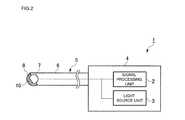
- FIG. 2is a block diagram of an endoscopic device in the embodiment of the present invention.
- FIG. 3is an enlarged view showing a principal part of an endoscopic camera in the embodiment of the present invention.
- FIGS. 4 a and 4 bare explanatory views of a rotation mechanism in a tilt direction in the embodiment of the present invention.
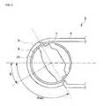
- FIG. 5is an explanatory view of a mounting configuration of a semispherical cover (modified example) in the embodiment of the present invention.
- FIGS. 6 a and 6 bare perspective views of a semispherical cover (modified example) in the embodiment of the present invention.
- an endoscopic device in an embodiment of the present inventionwill be described with reference to the drawings.
- an endoscopic device used as an abdominoscope and the likethat observe an abdominal cavity.
- an endoscopic device 1includes a main body unit 4 that incorporates a signal processing unit 2 , a light source unit 3 and the like, and an endoscopic camera 5 removably mounted on the main body unit 4 .
- the signal processing unit 2has a function to perform specified signal processing on a video input signal acquired from the endoscopic camera 5 to generate a video output signal that is to be outputted to a monitor (not shown) and the like.
- the light source unit 3has a function to send illumination light to the endoscopic camera 5 with use of an optical fiber (not shown) and the like.
- the endoscopic camera 5includes a rigid case 6 having a cylindrical shape with a top end portion being obliquely cut off, and a spherical camera head 7 provided at the top end portion of the rigid case 6 .
- a part (generally half) of the camera head 7is exposed to an outside from the top end portion of the rigid case 6 , and a remainder (a remaining half) of the camera head 7 is housed in the rigid case 6 .
- the top end portion of the rigid case 6has a semispherical cover 8 provided to cover the exposed portion of the camera head 7 .
- the cover 8is made from a transparent optical glass or an optical plastic. Note that a specified clearance 9 is provided between the camera head 7 and the cover 8 . Note that although only a part of the cover 8 is shown in FIG. 1 for the sake of explanation, the cover 8 has a 1 ⁇ 2 sphere (semi-sphere) shape in actuality.
- the camera head 7includes a lens 10 .
- both ends of a tilt belt 11are respectively fixed at positions of a pair of upper and lower poles which are shifted from an optical axis of the lens 10 by 90 degrees on the spherical surface of the camera head 7 .
- the tilt belt 11has a thickness smaller than the clearance 9 between the camera head 7 and the cover 8 .
- the tilt belt 11is fixed to the camera head 7 with use of fixing bolts 12 .
- Rotation driving force of a tilt motor 13is transmitted to the tilt belt 11 through a pulley 14 .
- the tilt motor 13corresponds to a rotation driving unit of the present invention.
- a vertical direction of an image taken with the endoscopic camera 5 and displayed on a monitorcorresponds to the “tilt direction”.
- the tilt axisis provided so as to pass through the center of the sphere of the camera head 7 and to position on a plane obtained by obliquely cutting off the top end portion of the rigid case 6 .
- the tilt axisis vertical to the central axis of the rigid case 6 .
- the tilt motor 13 and the pulley 14are provided inside the rigid case 6 at positions different from that of the camera head 7 (rear positions inside the rigid case 6 ).
- a rotating shaft(a rotating shaft X of the tilt motor 13 , or a rotating shaft Y of the pulley 14 ) that generates rotation driving force to drive the camera head 7 in the tilt direction is placed at a position different from the position of a rotating axis (tilt axis Z) of the camera head 7 (see FIG. 4 ).
- the tilt belt 11is crossed between the camera head 7 and the pulley 14 , and a belt insertion hole 15 is provided in a position where the tilt belt 11 is crossed.
- a guide unit 16 that guides the tilt belt 11may be provided inside the rigid case 6 in the case where the tilt belt 11 is crossed.
- a flange portion 17may be provided at an edge of the semispherical cover 8 .
- a half-elliptical flange portion 17may extendedly be provided so as to spread from a semicircular part on the lower side (lower side in FIG. 5 ) of the edge (circular edge) of the semispherical cover 8 toward the outside (from the center of the semispherical cover 8 toward the outside), and a joint portion 18 to be joined with the rigid case 6 is provided at the top end portion of the flange portion 17 .
- the lower sidelower side in FIG.
- a recess portion 19is defined between the semispherical cover 8 and the case 6 . As shown in FIG. 5 , the recess portion 19 is defined between the edge of the semispherical cover 8 and the flange portion 17 .
- the visual fieldcan be expanded up to the oblique back side.
- the semispherical cover 8is obliquely mounted on the top end portion of the rigid case 6 , and the spherical camera head 7 is rotated inside the semispherical cover 8 which is obliquely mounted thereon.
- the rotating shaft (tilt shaft) of the camera head 7is provided so as to pass through the center of the camera head 7 and to be vertical to the central axis of the rigid case 6 on the plane obtained by obliquely cutting off the top end portion of the rigid case 6 . Therefore, by rotating the camera head 7 , the back side (oblique back side) of the camera head 7 can be photographed.
- a tilt angle ⁇ of the camera head 7can take a value in an angle range of 0° to ⁇ MAX .
- the visual fieldis expanded to the oblique back side of the camera head 7 .
- the spherical camera head 7is retained while being sandwiched from both sides with the plate-like belt. Since the position of the camera head 7 can be set with the plate-like belt in this way, it is not necessary to provide another mechanism that positions the camera head 7 on the periphery of the camera head 7 at the top end portion of the rigid case 6 . Moreover, when the camera head 7 is rotated around the rotating axis (tilt axis), rotation driving force (force to pull and push the belt) is transmitted from the rotation driving unit to the camera head 7 through the plate-like belt.
- the rotation driving unitis placed inside the rigid case 6 at a position different from that of the camera head 7 . Accordingly, it is not necessary to provide another mechanism that rotates the camera head on the periphery of the camera head at the top end portion of the rigid case 6 . Therefore, since one configuration that is a plate-like belt can implement both the function to retain the camera head 7 and the function to rotate the camera head 7 , downsizing (downsizing which is difficult with a retention mechanism and a rotation mechanism being separately provided) of the endoscopic camera 5 is achieved.
- the cover 8is obliquely mounted on the top end portion of the rigid case 6 . Accordingly, if the joint portion 18 is provided on the lower edge of the semispherical cover 8 as it is (shown with a broken line in FIG. 5 ), an inner space of the rigid case 6 is diminished by the joint portion 18 , which makes it difficult to insert the large-diameter camera head 7 into the rigid case 6 .
- the flange portion 17is extendedly provided from the lower edge of the semispherical cover 8 toward the outside, and the joint portion 18 to be joined with the rigid case 6 is provided at the top end portion of the flange portion 17 . As a result, the inner space of the rigid case 6 can be expanded, which makes it easy to insert the large-diameter camera head 7 into the rigid case 6 .
- the entire camera head 7has been described as a sphere.
- the scope of the present inventionis not limited thereto, and at least a portion of the camera head 7 that faces the cover 8 at the time of rotation may be a spherical shape.
- the endoscopic device according to the present inventionhas the effect of being able to expand the visual field up to the oblique back side and therefore is useful as a device such as an endoscopic camera for medical use and industrial use.
Landscapes
- Health & Medical Sciences (AREA)
- Life Sciences & Earth Sciences (AREA)
- Surgery (AREA)
- Biomedical Technology (AREA)
- Medical Informatics (AREA)
- Optics & Photonics (AREA)
- Pathology (AREA)
- Radiology & Medical Imaging (AREA)
- Biophysics (AREA)
- Engineering & Computer Science (AREA)
- Physics & Mathematics (AREA)
- Heart & Thoracic Surgery (AREA)
- Nuclear Medicine, Radiotherapy & Molecular Imaging (AREA)
- Molecular Biology (AREA)
- Animal Behavior & Ethology (AREA)
- General Health & Medical Sciences (AREA)
- Public Health (AREA)
- Veterinary Medicine (AREA)
- Endoscopes (AREA)
- Instruments For Viewing The Inside Of Hollow Bodies (AREA)
- Structure And Mechanism Of Cameras (AREA)
Abstract
Description
- Patent Literature 1: Japanese Patent Application Laid-Open No. 7-327916
- Patent Literature 2: Japanese Patent Application Laid-Open No. 2009-125188
- 1 Endoscopic device
- 2 Signal processing unit
- 3 Light source unit
- 4 Main body unit
- 5 Endoscopic camera
- 6 Rigid case
- 7 Camera head
- 8 Cover
- 9 Clearance
- 10 Lens
- 11 Tilt belt
- 12 Bolt
- 13 Tilt motor (rotation driving unit)
- 14 Pulley
- 15 Belt insertion hole
- 16 Guide unit
- 17 Flange portion
- 18 Joint portion
- 19 Recess portion
Claims (13)
Applications Claiming Priority (3)
| Application Number | Priority Date | Filing Date | Title |
|---|---|---|---|
| JP2011052571 | 2011-03-10 | ||
| JP2011-052571 | 2011-03-10 | ||
| PCT/JP2012/001380WO2012120837A1 (en) | 2011-03-10 | 2012-02-29 | Endoscopic camera and endoscopic device |
Publications (2)
| Publication Number | Publication Date |
|---|---|
| US20140012080A1 US20140012080A1 (en) | 2014-01-09 |
| US9649016B2true US9649016B2 (en) | 2017-05-16 |
Family
ID=46797810
Family Applications (1)
| Application Number | Title | Priority Date | Filing Date |
|---|---|---|---|
| US14/003,071Expired - Fee RelatedUS9649016B2 (en) | 2011-03-10 | 2012-02-29 | Endoscopic camera and endoscopic device |
Country Status (5)
| Country | Link |
|---|---|
| US (1) | US9649016B2 (en) |
| JP (3) | JP5695180B2 (en) |
| CN (1) | CN203468565U (en) |
| DE (1) | DE112012001170B4 (en) |
| WO (1) | WO2012120837A1 (en) |
Cited By (4)
| Publication number | Priority date | Publication date | Assignee | Title |
|---|---|---|---|---|
| US20170325671A1 (en)* | 2016-05-13 | 2017-11-16 | Karl Storz Endovision, Inc. | Optical instrument and articulating image sensing apparatus therefor |
| EP3769658A1 (en)* | 2019-07-23 | 2021-01-27 | National University of Ireland Galway | A scope |
| US20230371789A1 (en)* | 2017-03-09 | 2023-11-23 | Nitesh Ratnakar | Endoscope with self-encased self-illuminating wide-angle panoramic imaging module |
| US12048418B2 (en) | 2020-03-10 | 2024-07-30 | Vti Medical, Inc. | Multi-angle imaging platform |
Families Citing this family (12)
| Publication number | Priority date | Publication date | Assignee | Title |
|---|---|---|---|---|
| WO2012120837A1 (en)* | 2011-03-10 | 2012-09-13 | パナソニック株式会社 | Endoscopic camera and endoscopic device |
| US10571679B2 (en) | 2017-01-06 | 2020-02-25 | Karl Storz Imaging, Inc. | Endoscope incorporating multiple image sensors for increased resolution |
| WO2019003613A1 (en)* | 2017-06-30 | 2019-01-03 | シャープ株式会社 | Endoscope device, endoscope system, light projection device, and fluid treatment device |
| US11533435B2 (en)* | 2018-04-06 | 2022-12-20 | Board Of Trustees Of Southern Illinois University | Multifunctional camera system for video assisted thoracic surgery |
| DE102019101089A1 (en)* | 2019-01-16 | 2020-07-16 | Vizaar Industrial Imaging Ag | Endoscopic probe actuator, endoscopic probe, and method for controlling an endoscopic probe actuator |
| WO2023026074A1 (en)* | 2021-08-24 | 2023-03-02 | Memic Innovative Surgery Ltd. | Imaging device with elongate arm and pivotable camera |
| CN110353611A (en)* | 2019-08-09 | 2019-10-22 | 杭州幕林眼镜有限公司 | One kind being based on the endoscopic device of human body |
| DE102020132776A1 (en)* | 2020-12-09 | 2022-06-09 | Karl Storz Se & Co. Kg | Hybrid endoscope with rotating drum for sterile medical applications |
| DE102020132778A1 (en)* | 2020-12-09 | 2022-06-09 | Karl Storz Se & Co. Kg | Endoscope with rotary drum and operating procedures |
| CN112716437A (en)* | 2020-12-28 | 2021-04-30 | 四川大学 | Medical implantable image acquisition device |
| JP6948027B1 (en) | 2021-06-02 | 2021-10-13 | ニレック株式会社 | Endoscope and handle operation unit |
| WO2023182972A1 (en) | 2022-03-21 | 2023-09-28 | Karl Storz Endovision, Inc. | Optical instrument with articulating image sensing apparatus and working channel |
Citations (39)
| Publication number | Priority date | Publication date | Assignee | Title |
|---|---|---|---|---|
| US3145249A (en)* | 1962-01-02 | 1964-08-18 | Bausch & Lomb | Endoscope window |
| US3856000A (en)* | 1972-06-19 | 1974-12-24 | Machido Seisakusho Kk | Endoscope |
| US3896793A (en)* | 1973-06-19 | 1975-07-29 | Olympus Optical Co | Endoscope with view field altering means |
| JPH06121567A (en) | 1992-10-08 | 1994-04-28 | Hitachi Metals Ltd | Motor controller |
| JPH07327916A (en) | 1994-06-02 | 1995-12-19 | Olympus Optical Co Ltd | Visual field direction varying type endoscope |
| US5575754A (en)* | 1995-02-24 | 1996-11-19 | Olympus Optical Co., Ltd. | Endoscopic apparatus for three dimensional instrumentation |
| US5762603A (en)* | 1995-09-15 | 1998-06-09 | Pinotage, Llc | Endoscope having elevation and azimuth control of camera assembly |
| JPH11337844A (en) | 1998-05-22 | 1999-12-10 | Terumo Corp | Endoscope |
| US6277064B1 (en)* | 1997-12-30 | 2001-08-21 | Inbae Yoon | Surgical instrument with rotatably mounted offset endoscope |
| US6309345B1 (en)* | 1997-08-21 | 2001-10-30 | Paul Stelzer | Minimally invasive surgery device |
| US6364830B1 (en)* | 1999-11-30 | 2002-04-02 | Durell & Gitelis, Inc. | Variable view arthroscope |
| US6638216B1 (en)* | 2000-08-30 | 2003-10-28 | Durell & Gitelis, Inc. | Variable view arthroscope |
| US6648817B2 (en)* | 2001-11-15 | 2003-11-18 | Endactive, Inc. | Apparatus and method for stereo viewing in variable direction-of-view endoscopy |
| JP2004156749A (en) | 2002-11-08 | 2004-06-03 | Nissan Motor Co Ltd | Toroidal continuously variable transmission |
| US20050096502A1 (en)* | 2003-10-29 | 2005-05-05 | Khalili Theodore M. | Robotic surgical device |
| US20050124858A1 (en)* | 2003-09-01 | 2005-06-09 | Hirohiko Matsuzawa | Capsule type endoscope |
| US6916286B2 (en)* | 2001-08-09 | 2005-07-12 | Smith & Nephew, Inc. | Endoscope with imaging probe |
| US20060129032A1 (en) | 2000-08-30 | 2006-06-15 | Durell & Gitelis, Inc. | Variable view arthroscope with charge coupled device |
| US7066879B2 (en)* | 2003-07-15 | 2006-06-27 | The Trustees Of Columbia University In The City Of New York | Insertable device and system for minimal access procedure |
| US20060264709A1 (en)* | 2004-01-26 | 2006-11-23 | Olympus Corporation | Capsule-type medical apparatus |
| US20070055103A1 (en) | 2005-08-31 | 2007-03-08 | Siegfried Hoefig | Endoscope with variable direction of view |
| US7344494B2 (en)* | 2004-02-09 | 2008-03-18 | Karl Storz Development Corp. | Endoscope with variable direction of view module |
| US7347860B2 (en)* | 2003-10-08 | 2008-03-25 | Pentax Corporation | Endoscope for high-frequency treatment |
| US7448993B2 (en)* | 2003-09-30 | 2008-11-11 | Olympus Corporation | Gastrointestinal tract examining apparatus |
| US20090048486A1 (en)* | 2007-08-08 | 2009-02-19 | Wilson-Cook Medical Inc. | Distal Tip for an Endoscope |
| US20090062605A1 (en) | 2007-08-31 | 2009-03-05 | Tatsuya Orihara | Capsule endoscope |
| JP2009125188A (en) | 2007-11-21 | 2009-06-11 | Panasonic Corp | Endoscope device and endoscope camera device |
| US7625338B2 (en)* | 2003-12-31 | 2009-12-01 | Given Imaging, Ltd. | In-vivo sensing device with alterable fields of view |
| US7662094B2 (en)* | 2002-05-14 | 2010-02-16 | Given Imaging Ltd. | Optical head assembly with dome, and device for use thereof |
| US8075478B2 (en)* | 2003-04-22 | 2011-12-13 | Campos Jorge A | System, apparatus, and method for viewing a visually obscured portion of a cavity |
| US8088065B2 (en)* | 2008-10-29 | 2012-01-03 | Olympus Medical Systems Corp. | Medical instrument |
| US8277373B2 (en)* | 2004-04-14 | 2012-10-02 | Usgi Medical, Inc. | Methods and apparaus for off-axis visualization |
| US8376932B2 (en)* | 2008-10-29 | 2013-02-19 | Cook Medical Technologies Llc | Endoscope endcap for suturing tissue |
| US8485968B2 (en)* | 2009-10-12 | 2013-07-16 | Sopro-Comeg Gmbh | Endoscope |
| US20130242071A1 (en) | 2012-03-13 | 2013-09-19 | Panasonic Corporation | Endoscope camera |
| US8562513B2 (en)* | 2008-05-20 | 2013-10-22 | Olympus Medical Systems Corp. | Endoscope device |
| US8702597B2 (en)* | 2003-12-31 | 2014-04-22 | Given Imaging Ltd. | Immobilizable in-vivo imager with moveable focusing mechanism |
| US20140249369A1 (en)* | 2011-10-03 | 2014-09-04 | Serendipity Co., Ltd | Imaging apparatus and rigid endoscope |
| US8870758B2 (en)* | 2010-11-02 | 2014-10-28 | Karl Storz Gmbh & Co. Kg | Endoscope with adjustable viewing angle |
Family Cites Families (4)
| Publication number | Priority date | Publication date | Assignee | Title |
|---|---|---|---|---|
| GB2354836B (en)* | 1999-09-28 | 2003-06-04 | Keymed | Improvements relating to borescopes and endoscopes with variable direction of view |
| JP4598498B2 (en) | 2004-11-29 | 2010-12-15 | オリンパス株式会社 | Intra-subject introduction device |
| US8814782B2 (en)* | 2008-07-08 | 2014-08-26 | Karl Storz Imaging, Inc. | Solid state variable direction of view endoscope |
| WO2012120837A1 (en)* | 2011-03-10 | 2012-09-13 | パナソニック株式会社 | Endoscopic camera and endoscopic device |
- 2012
- 2012-02-29WOPCT/JP2012/001380patent/WO2012120837A1/enactiveApplication Filing
- 2012-02-29JPJP2013503378Apatent/JP5695180B2/ennot_activeExpired - Fee Related
- 2012-02-29USUS14/003,071patent/US9649016B2/ennot_activeExpired - Fee Related
- 2012-02-29DEDE112012001170.8Tpatent/DE112012001170B4/ennot_activeExpired - Fee Related
- 2012-02-29CNCN201290000335.8Upatent/CN203468565U/ennot_activeExpired - Fee Related
- 2015
- 2015-02-05JPJP2015020849Apatent/JP5950218B2/ennot_activeExpired - Fee Related
- 2016
- 2016-05-26JPJP2016104945Apatent/JP6238180B2/ennot_activeExpired - Fee Related
Patent Citations (46)
| Publication number | Priority date | Publication date | Assignee | Title |
|---|---|---|---|---|
| US3145249A (en)* | 1962-01-02 | 1964-08-18 | Bausch & Lomb | Endoscope window |
| US3856000A (en)* | 1972-06-19 | 1974-12-24 | Machido Seisakusho Kk | Endoscope |
| US3896793A (en)* | 1973-06-19 | 1975-07-29 | Olympus Optical Co | Endoscope with view field altering means |
| JPH06121567A (en) | 1992-10-08 | 1994-04-28 | Hitachi Metals Ltd | Motor controller |
| JPH07327916A (en) | 1994-06-02 | 1995-12-19 | Olympus Optical Co Ltd | Visual field direction varying type endoscope |
| US5575754A (en)* | 1995-02-24 | 1996-11-19 | Olympus Optical Co., Ltd. | Endoscopic apparatus for three dimensional instrumentation |
| US5762603A (en)* | 1995-09-15 | 1998-06-09 | Pinotage, Llc | Endoscope having elevation and azimuth control of camera assembly |
| US6309345B1 (en)* | 1997-08-21 | 2001-10-30 | Paul Stelzer | Minimally invasive surgery device |
| US6277064B1 (en)* | 1997-12-30 | 2001-08-21 | Inbae Yoon | Surgical instrument with rotatably mounted offset endoscope |
| JPH11337844A (en) | 1998-05-22 | 1999-12-10 | Terumo Corp | Endoscope |
| US6364830B1 (en)* | 1999-11-30 | 2002-04-02 | Durell & Gitelis, Inc. | Variable view arthroscope |
| US6638216B1 (en)* | 2000-08-30 | 2003-10-28 | Durell & Gitelis, Inc. | Variable view arthroscope |
| US20060129032A1 (en) | 2000-08-30 | 2006-06-15 | Durell & Gitelis, Inc. | Variable view arthroscope with charge coupled device |
| US7175593B2 (en)* | 2000-08-30 | 2007-02-13 | Durell & Gitelis, Inc. | Variable view arthroscope with charge coupled device |
| US6916286B2 (en)* | 2001-08-09 | 2005-07-12 | Smith & Nephew, Inc. | Endoscope with imaging probe |
| US6648817B2 (en)* | 2001-11-15 | 2003-11-18 | Endactive, Inc. | Apparatus and method for stereo viewing in variable direction-of-view endoscopy |
| US7662094B2 (en)* | 2002-05-14 | 2010-02-16 | Given Imaging Ltd. | Optical head assembly with dome, and device for use thereof |
| JP2004156749A (en) | 2002-11-08 | 2004-06-03 | Nissan Motor Co Ltd | Toroidal continuously variable transmission |
| US8075478B2 (en)* | 2003-04-22 | 2011-12-13 | Campos Jorge A | System, apparatus, and method for viewing a visually obscured portion of a cavity |
| US7066879B2 (en)* | 2003-07-15 | 2006-06-27 | The Trustees Of Columbia University In The City Of New York | Insertable device and system for minimal access procedure |
| US20070055105A1 (en)* | 2003-09-01 | 2007-03-08 | Hirohiko Matsuzawa | Capsule type endoscope |
| US20050124858A1 (en)* | 2003-09-01 | 2005-06-09 | Hirohiko Matsuzawa | Capsule type endoscope |
| US7448993B2 (en)* | 2003-09-30 | 2008-11-11 | Olympus Corporation | Gastrointestinal tract examining apparatus |
| US7347860B2 (en)* | 2003-10-08 | 2008-03-25 | Pentax Corporation | Endoscope for high-frequency treatment |
| JP2007509710A (en) | 2003-10-27 | 2007-04-19 | ダレル・アンド・ジテリス・インコーポレイテッド | Variable-field arthroscope using CCD |
| US20050096502A1 (en)* | 2003-10-29 | 2005-05-05 | Khalili Theodore M. | Robotic surgical device |
| US7625338B2 (en)* | 2003-12-31 | 2009-12-01 | Given Imaging, Ltd. | In-vivo sensing device with alterable fields of view |
| US8702597B2 (en)* | 2003-12-31 | 2014-04-22 | Given Imaging Ltd. | Immobilizable in-vivo imager with moveable focusing mechanism |
| US20060264709A1 (en)* | 2004-01-26 | 2006-11-23 | Olympus Corporation | Capsule-type medical apparatus |
| US7344494B2 (en)* | 2004-02-09 | 2008-03-18 | Karl Storz Development Corp. | Endoscope with variable direction of view module |
| US8277373B2 (en)* | 2004-04-14 | 2012-10-02 | Usgi Medical, Inc. | Methods and apparaus for off-axis visualization |
| US7553277B2 (en)* | 2005-08-31 | 2009-06-30 | Karl Storz Gmbh & Co. Kg | Endoscope with variable direction of view |
| US20070055103A1 (en) | 2005-08-31 | 2007-03-08 | Siegfried Hoefig | Endoscope with variable direction of view |
| JP2007075604A (en) | 2005-08-31 | 2007-03-29 | Karl Stortz Gmbh & Co Kg | Visual direction adjustable type endoscope |
| US20090048486A1 (en)* | 2007-08-08 | 2009-02-19 | Wilson-Cook Medical Inc. | Distal Tip for an Endoscope |
| US20090062605A1 (en) | 2007-08-31 | 2009-03-05 | Tatsuya Orihara | Capsule endoscope |
| JP2009056058A (en) | 2007-08-31 | 2009-03-19 | Olympus Medical Systems Corp | Capsule endoscope |
| US20110211052A1 (en) | 2007-11-21 | 2011-09-01 | Panasonic Corporation | Endoscope device, camera device for endoscope, and defogging method |
| JP2009125188A (en) | 2007-11-21 | 2009-06-11 | Panasonic Corp | Endoscope device and endoscope camera device |
| US8562513B2 (en)* | 2008-05-20 | 2013-10-22 | Olympus Medical Systems Corp. | Endoscope device |
| US8088065B2 (en)* | 2008-10-29 | 2012-01-03 | Olympus Medical Systems Corp. | Medical instrument |
| US8376932B2 (en)* | 2008-10-29 | 2013-02-19 | Cook Medical Technologies Llc | Endoscope endcap for suturing tissue |
| US8485968B2 (en)* | 2009-10-12 | 2013-07-16 | Sopro-Comeg Gmbh | Endoscope |
| US8870758B2 (en)* | 2010-11-02 | 2014-10-28 | Karl Storz Gmbh & Co. Kg | Endoscope with adjustable viewing angle |
| US20140249369A1 (en)* | 2011-10-03 | 2014-09-04 | Serendipity Co., Ltd | Imaging apparatus and rigid endoscope |
| US20130242071A1 (en) | 2012-03-13 | 2013-09-19 | Panasonic Corporation | Endoscope camera |
Non-Patent Citations (2)
| Title |
|---|
| Japanese Office Action having mail date of Sep. 30, 2014. |
| Search report from International Search Report in PCT/JP2012/001380, mail date is Jun. 12, 2012. |
Cited By (5)
| Publication number | Priority date | Publication date | Assignee | Title |
|---|---|---|---|---|
| US20170325671A1 (en)* | 2016-05-13 | 2017-11-16 | Karl Storz Endovision, Inc. | Optical instrument and articulating image sensing apparatus therefor |
| US10517470B2 (en)* | 2016-05-13 | 2019-12-31 | Karl Storz Endovision, Inc. | Optical instrument and articulating image sensing apparatus therefor |
| US20230371789A1 (en)* | 2017-03-09 | 2023-11-23 | Nitesh Ratnakar | Endoscope with self-encased self-illuminating wide-angle panoramic imaging module |
| EP3769658A1 (en)* | 2019-07-23 | 2021-01-27 | National University of Ireland Galway | A scope |
| US12048418B2 (en) | 2020-03-10 | 2024-07-30 | Vti Medical, Inc. | Multi-angle imaging platform |
Also Published As
| Publication number | Publication date |
|---|---|
| DE112012001170B4 (en) | 2018-08-23 |
| WO2012120837A1 (en) | 2012-09-13 |
| JP2015134169A (en) | 2015-07-27 |
| CN203468565U (en) | 2014-03-12 |
| JP6238180B2 (en) | 2017-11-29 |
| JPWO2012120837A1 (en) | 2014-07-17 |
| US20140012080A1 (en) | 2014-01-09 |
| JP5950218B2 (en) | 2016-07-13 |
| JP2016174947A (en) | 2016-10-06 |
| JP5695180B2 (en) | 2015-04-01 |
| DE112012001170T5 (en) | 2013-12-19 |
Similar Documents
| Publication | Publication Date | Title |
|---|---|---|
| US9649016B2 (en) | Endoscopic camera and endoscopic device | |
| EP2474262A1 (en) | Stereoscopic endoscope | |
| WO2013088709A1 (en) | Endoscope and endoscope system provided with same | |
| JP2017507680A5 (en) | ||
| US10067333B2 (en) | Endoscope having image pickup sensor and first and second light blocking members | |
| JP2016536093A5 (en) | ||
| WO2020042887A1 (en) | Electronic endoscope and electronic endoscope system | |
| JP6064089B1 (en) | Endoscope | |
| JP7247702B2 (en) | Endoscope system, endoscope control method, and imaging control device | |
| JP4363931B2 (en) | Capsule endoscope | |
| JP5932165B1 (en) | Endoscope | |
| US8821386B2 (en) | Micro robot system and capsule endoscope system for examining a tubular digestive system | |
| JP5789758B2 (en) | Drive mechanism and camera device | |
| JP5086661B2 (en) | Endoscope adapter optical system and endoscope | |
| JP2022038180A5 (en) | ||
| JP2013192798A (en) | Endoscope system | |
| JP2012161522A (en) | Endoscope camera and endoscope apparatus | |
| JPH03103810A (en) | Industiral endoscope device | |
| JP2014039696A (en) | Rotary chopper driver in light source device for endoscope | |
| US20240237882A1 (en) | An endoscope | |
| JP2003098570A (en) | Endoscope | |
| JP2012143426A (en) | Endoscope camera and endoscope apparatus | |
| JP2005279119A (en) | Operation device for endoscope and endoscope system | |
| WO2016035366A1 (en) | Imaging system | |
| CN107920189A (en) | Panoramic endoscope device |
Legal Events
| Date | Code | Title | Description |
|---|---|---|---|
| AS | Assignment | Owner name:PANASONIC CORPORATION, JAPAN Free format text:ASSIGNMENT OF ASSIGNORS INTEREST;ASSIGNORS:WADA, JYOUJI;TAKENAGA, YUUICHI;REEL/FRAME:031588/0508 Effective date:20130724 | |
| AS | Assignment | Owner name:PANASONIC INTELLECTUAL PROPERTY MANAGEMENT CO., LTD., JAPAN Free format text:ASSIGNMENT OF ASSIGNORS INTEREST;ASSIGNOR:PANASONIC CORPORATION;REEL/FRAME:034194/0143 Effective date:20141110 Owner name:PANASONIC INTELLECTUAL PROPERTY MANAGEMENT CO., LT Free format text:ASSIGNMENT OF ASSIGNORS INTEREST;ASSIGNOR:PANASONIC CORPORATION;REEL/FRAME:034194/0143 Effective date:20141110 | |
| STCF | Information on status: patent grant | Free format text:PATENTED CASE | |
| AS | Assignment | Owner name:PANASONIC I-PRO SENSING SOLUTIONS CO., LTD., JAPAN Free format text:ASSIGNMENT OF ASSIGNORS INTEREST;ASSIGNOR:PANASONIC INTELLECTUAL PROPERTY MANAGEMENT CO., LTD.;REEL/FRAME:051369/0172 Effective date:20191001 | |
| AS | Assignment | Owner name:PANASONIC INTELLECTUAL PROPERTY MANAGEMENT CO., LTD., JAPAN Free format text:CORRECTIVE ASSIGNMENT TO CORRECT THE ERRONEOUSLY FILED APPLICATION NUMBERS 13/384239, 13/498734, 14/116681 AND 14/301144 PREVIOUSLY RECORDED ON REEL 034194 FRAME 0143. ASSIGNOR(S) HEREBY CONFIRMS THE ASSIGNMENT;ASSIGNOR:PANASONIC CORPORATION;REEL/FRAME:056788/0362 Effective date:20141110 | |
| FEPP | Fee payment procedure | Free format text:MAINTENANCE FEE REMINDER MAILED (ORIGINAL EVENT CODE: REM.); ENTITY STATUS OF PATENT OWNER: LARGE ENTITY | |
| LAPS | Lapse for failure to pay maintenance fees | Free format text:PATENT EXPIRED FOR FAILURE TO PAY MAINTENANCE FEES (ORIGINAL EVENT CODE: EXP.); ENTITY STATUS OF PATENT OWNER: LARGE ENTITY | |
| STCH | Information on status: patent discontinuation | Free format text:PATENT EXPIRED DUE TO NONPAYMENT OF MAINTENANCE FEES UNDER 37 CFR 1.362 | |
| FP | Lapsed due to failure to pay maintenance fee | Effective date:20210516 |