US9647274B2 - Method of making a proton exchange membrane using a gas diffusion electrode as a substrate - Google Patents
Method of making a proton exchange membrane using a gas diffusion electrode as a substrateDownload PDFInfo
- Publication number
- US9647274B2 US9647274B2US11/972,817US97281708AUS9647274B2US 9647274 B2US9647274 B2US 9647274B2US 97281708 AUS97281708 AUS 97281708AUS 9647274 B2US9647274 B2US 9647274B2
- Authority
- US
- United States
- Prior art keywords
- layer
- exchange membrane
- proton exchange
- gas diffusion
- diffusion media
- Prior art date
- Legal status (The legal status is an assumption and is not a legal conclusion. Google has not performed a legal analysis and makes no representation as to the accuracy of the status listed.)
- Active, expires
Links
Images


Classifications
- H—ELECTRICITY
- H01—ELECTRIC ELEMENTS
- H01M—PROCESSES OR MEANS, e.g. BATTERIES, FOR THE DIRECT CONVERSION OF CHEMICAL ENERGY INTO ELECTRICAL ENERGY
- H01M4/00—Electrodes
- H01M4/86—Inert electrodes with catalytic activity, e.g. for fuel cells
- H01M4/88—Processes of manufacture
- H01M4/8825—Methods for deposition of the catalytic active composition
- H—ELECTRICITY
- H01—ELECTRIC ELEMENTS
- H01M—PROCESSES OR MEANS, e.g. BATTERIES, FOR THE DIRECT CONVERSION OF CHEMICAL ENERGY INTO ELECTRICAL ENERGY
- H01M8/00—Fuel cells; Manufacture thereof
- H01M8/10—Fuel cells with solid electrolytes
- H01M8/1004—Fuel cells with solid electrolytes characterised by membrane-electrode assemblies [MEA]
- H—ELECTRICITY
- H01—ELECTRIC ELEMENTS
- H01M—PROCESSES OR MEANS, e.g. BATTERIES, FOR THE DIRECT CONVERSION OF CHEMICAL ENERGY INTO ELECTRICAL ENERGY
- H01M8/00—Fuel cells; Manufacture thereof
- H01M8/10—Fuel cells with solid electrolytes
- H01M8/1016—Fuel cells with solid electrolytes characterised by the electrolyte material
- H01M8/1018—Polymeric electrolyte materials
- H01M8/1069—Polymeric electrolyte materials characterised by the manufacturing processes
- B—PERFORMING OPERATIONS; TRANSPORTING
- B05—SPRAYING OR ATOMISING IN GENERAL; APPLYING FLUENT MATERIALS TO SURFACES, IN GENERAL
- B05D—PROCESSES FOR APPLYING FLUENT MATERIALS TO SURFACES, IN GENERAL
- B05D5/00—Processes for applying liquids or other fluent materials to surfaces to obtain special surface effects, finishes or structures
- B05D5/12—Processes for applying liquids or other fluent materials to surfaces to obtain special surface effects, finishes or structures to obtain a coating with specific electrical properties
- B—PERFORMING OPERATIONS; TRANSPORTING
- B32—LAYERED PRODUCTS
- B32B—LAYERED PRODUCTS, i.e. PRODUCTS BUILT-UP OF STRATA OF FLAT OR NON-FLAT, e.g. CELLULAR OR HONEYCOMB, FORM
- B32B37/00—Methods or apparatus for laminating, e.g. by curing or by ultrasonic bonding
- B32B37/02—Methods or apparatus for laminating, e.g. by curing or by ultrasonic bonding characterised by a sequence of laminating steps, e.g. by adding new layers at consecutive laminating stations
- B—PERFORMING OPERATIONS; TRANSPORTING
- B32—LAYERED PRODUCTS
- B32B—LAYERED PRODUCTS, i.e. PRODUCTS BUILT-UP OF STRATA OF FLAT OR NON-FLAT, e.g. CELLULAR OR HONEYCOMB, FORM
- B32B37/00—Methods or apparatus for laminating, e.g. by curing or by ultrasonic bonding
- B32B37/06—Methods or apparatus for laminating, e.g. by curing or by ultrasonic bonding characterised by the heating method
- B—PERFORMING OPERATIONS; TRANSPORTING
- B32—LAYERED PRODUCTS
- B32B—LAYERED PRODUCTS, i.e. PRODUCTS BUILT-UP OF STRATA OF FLAT OR NON-FLAT, e.g. CELLULAR OR HONEYCOMB, FORM
- B32B37/00—Methods or apparatus for laminating, e.g. by curing or by ultrasonic bonding
- B32B37/10—Methods or apparatus for laminating, e.g. by curing or by ultrasonic bonding characterised by the pressing technique, e.g. using action of vacuum or fluid pressure
- H—ELECTRICITY
- H01—ELECTRIC ELEMENTS
- H01M—PROCESSES OR MEANS, e.g. BATTERIES, FOR THE DIRECT CONVERSION OF CHEMICAL ENERGY INTO ELECTRICAL ENERGY
- H01M8/00—Fuel cells; Manufacture thereof
- H01M8/10—Fuel cells with solid electrolytes
- H01M2008/1095—Fuel cells with polymeric electrolytes
- H—ELECTRICITY
- H01—ELECTRIC ELEMENTS
- H01M—PROCESSES OR MEANS, e.g. BATTERIES, FOR THE DIRECT CONVERSION OF CHEMICAL ENERGY INTO ELECTRICAL ENERGY
- H01M4/00—Electrodes
- H01M4/86—Inert electrodes with catalytic activity, e.g. for fuel cells
- H01M4/88—Processes of manufacture
- H01M4/8878—Treatment steps after deposition of the catalytic active composition or after shaping of the electrode being free-standing body
- H01M4/8892—Impregnation or coating of the catalyst layer, e.g. by an ionomer
- Y—GENERAL TAGGING OF NEW TECHNOLOGICAL DEVELOPMENTS; GENERAL TAGGING OF CROSS-SECTIONAL TECHNOLOGIES SPANNING OVER SEVERAL SECTIONS OF THE IPC; TECHNICAL SUBJECTS COVERED BY FORMER USPC CROSS-REFERENCE ART COLLECTIONS [XRACs] AND DIGESTS
- Y02—TECHNOLOGIES OR APPLICATIONS FOR MITIGATION OR ADAPTATION AGAINST CLIMATE CHANGE
- Y02E—REDUCTION OF GREENHOUSE GAS [GHG] EMISSIONS, RELATED TO ENERGY GENERATION, TRANSMISSION OR DISTRIBUTION
- Y02E60/00—Enabling technologies; Technologies with a potential or indirect contribution to GHG emissions mitigation
- Y02E60/30—Hydrogen technology
- Y02E60/50—Fuel cells
- Y—GENERAL TAGGING OF NEW TECHNOLOGICAL DEVELOPMENTS; GENERAL TAGGING OF CROSS-SECTIONAL TECHNOLOGIES SPANNING OVER SEVERAL SECTIONS OF THE IPC; TECHNICAL SUBJECTS COVERED BY FORMER USPC CROSS-REFERENCE ART COLLECTIONS [XRACs] AND DIGESTS
- Y02—TECHNOLOGIES OR APPLICATIONS FOR MITIGATION OR ADAPTATION AGAINST CLIMATE CHANGE
- Y02P—CLIMATE CHANGE MITIGATION TECHNOLOGIES IN THE PRODUCTION OR PROCESSING OF GOODS
- Y02P70/00—Climate change mitigation technologies in the production process for final industrial or consumer products
- Y02P70/50—Manufacturing or production processes characterised by the final manufactured product
- Y02P70/56—
Definitions
- the field to which the disclosure generally relatesincludes a membrane electrode assembly (MEA) and, more particularly, an MEA for a proton exchange membrane fuel cell.
- MEAmembrane electrode assembly
- Hydrogenis a very attractive fuel because it is clean and can be used to efficiently produce electricity in a fuel cell.
- the automotive industryexpends significant resources in the development of hydrogen fuel cells as a source of power for vehicles. Such vehicles would be more efficient and generate fewer emissions than today's vehicles employing internal combustion engines.
- a hydrogen fuel cellis an electro-chemical device that includes an anode and a cathode with an electrolyte between the anode and the cathode.
- the anodereceives hydrogen-rich gas or pure hydrogen and the cathode receives oxygen or air.
- the hydrogen gasis dissociated in the anode to generate free protons and electrons.
- the protonspass through the electrolyte to the cathode, where the protons react with the oxygen and the electrons in the cathode to generate water.
- the electrons from the anodeare unable to pass through the electrolyte. Therefore, the electrons are directed through a load to perform work before they are sent to the cathode.
- the workmay be used, for example, to operate a vehicle.
- Proton exchange membrane fuel cellsgenerally include a solid polymer electrolyte proton conducting membrane, such as a perfluorosulfonic acid membrane.
- the anode and the cathodetypically include finely divided catalytic particles supported on carbon particles and mixed with an ionomer and a solvent.
- the combination of the anode, cathode and membranedefine a membrane electrode assembly (MEA).
- the MEAmay also include gas diffusion media, a porous layer that is necessary for gas and water transport through the MEA.
- the catalyst layermay be coated on the diffusion media, for example the catalyst layer may be rolled or painted or sprayed on the diffusion media as a slurry, and then compressed. It is known in the art to sandwich the membrane between two pieces of the catalyst coated diffusion media with the catalyst sides facing the membrane, and then to hot-press to bond the catalyst coated diffusion media to the membrane.
- One embodimentincludes a method comprising providing a first catalyst coated gas diffusion media layer, depositing a wet first proton exchange membrane layer over the first catalyst coated gas diffusion media layer to form a first proton exchange membrane layer; providing a second catalyst coated gas diffusion media layer; contacting the second catalyst coated gas diffusion media layer, or second proton exchange membrane layer, with the first proton exchange membrane layer; and hot pressing together the catalyst coated diffusion layers and proton exchange membrane layer(s).
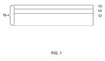
- FIG. 1illustrates a method according to one embodiment of the invention
- FIG. 2illustrates a method according to one embodiment of the invention
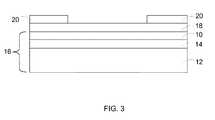
- FIG. 3illustrates a method according to one embodiment of the invention
- FIG. 4Aillustrates a method according to one embodiment of the invention
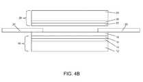
- FIG. 4Billustrates a method according to one embodiment of the invention
- FIG. 4Cillustrates a method according to one embodiment of the invention
- FIG. 5is a cross-sectional view of a membrane electrode assembly, according to one embodiment of the invention.
- FIG. 6illustrates a method according to one embodiment of the invention
- FIG. 7is a cross-sectional view of a membrane electrode assembly, according to one embodiment of the invention.
- a methodis provided by which a proton exchange membrane is made using a catalyst coated gas diffusion electrode as a substrate.
- a first catalyst layer 10is applied to a first gas diffusion media layer 12 to form a first catalyst coated gas diffusion media layer 16 .
- the first catalyst layer 10may include suitable catalytic particles, for example, metals such as platinum, platinum alloys, and other catalysts known to those skilled in the fuel cell art.
- the first gas diffusion media layer 12may be a conventional fuel cell gas diffusion material such as nonwoven carbon fiber paper, woven carbon cloth, or carbon foam, for example.
- the applying of the catalyst layer 10may include any suitable method of applying, for example, rolling, painting, or spraying. In another embodiment, as shown in FIG.
- a first microporous layer 14is applied to the first gas diffusion media layer 12 and the first catalyst layer 10 is applied over the first microporous layer 14 to form the first catalyst coated gas diffusion media layer 16 .
- the applying of the first microporous layer 14may include any suitable method of applying, for example, rolling or painting.
- the microporous layer 14may include particles and a binder. Suitable particles for the microporous layer 14 may include, but are not limited to, graphitic, graphitized, or conductive carbon particles.
- Suitable binders for the microporous layer 14may include at least one of polytetrafluoroethylene (PTFE), polyvinylidenefluoride (PVDF), fluoroethylene propylene (FEP), or other organic or inorganic hydrophobic materials.
- PTFEpolytetrafluoroethylene
- PVDFpolyvinylidenefluoride
- FEPfluoroethylene propylene
- a first wet proton exchange membrane layeris formed over the first catalyst coated gas diffusion media layer 16 .
- the forming of the first wet proton exchange membrane layermay include any suitable technique, for example casting, laminating, imbibing, or spraying.
- the first wet proton exchange membranemay include a support or reinforcing sheet, for example a sheet of porous layer, for example expanded polytetrafluoroethylene (ePTFE) or Teflon.
- the first wet proton exchange membranemay include a support including one of a porous material less than 30 ⁇ m thick, a paper less than 30 ⁇ m thick, polyolefins, polyethylene, polypropylene, polyesters, polyphenylene sulfide, or polymers with crystalline melting temperatures which do not dissolve in the coating solvents or dispersants used to imbibe an ionomer into the support material.
- the porous material or papermay be available from Crane and Co., Dalton, Mass.
- the polyethylene or polypropylenemay be available from DSM or Tonen Chemical Nasu Co., Ltd., Japan.
- the formingcomprises casting, wherein a reinforcing sheet is evenly deposited over the catalyst layer 10 and an ionomer solution is applied over the reinforcing sheet.
- the ionomer solutionmay be, but is not limited to, an ionomer dispersion including Nafion 1000 (20 wt. %) in 40-48 wt. % 1-propanol and 30-38 wt. % water.
- the ionomer solutionmay infiltrate or fill the pores of the reinforcing sheet.
- the ionomer solutionmay also penetrate at least one of the catalyst layer 10 and the microporous layer 14 .
- the ionomer solutionmay be heated to flash off the solvents and provide a dried solid polymer membrane reinforced by the ePTFE.
- the forming of the first wet proton exchange membranecomprises laminating, imbibing, or spraying, wherein the reinforcing sheet is immersed in the ionomer solution to form a wet membrane, and then this wet reinforced membrane is evenly deposited over the catalyst layer 10 .
- the first wet proton exchange membrane layermay be dried, for example under low pressure, to form a first proton exchange membrane layer 18 .
- a multilayer coating including the catalyst layer 10 and the first proton exchange membrane layer 18may be deposited over the first gas diffusion media layer 12 .
- the wet first microporous layer 14is applied to the first gas diffusion media layer 12 , dried, and sintered; the wet first catalyst layer 10 is applied to the first microporous layer 14 ; the first wet proton exchange membrane layer may be formed over the wet first catalyst layer 10 ; and all the layers may be dried simultaneously at the end of the process.
- the various methods described hereinmay eliminate the need for an additional proton exchange membrane layer substrate, for example polyethylene and polypropylene polymer based films, typically used in the manufacture and further processing of a proton exchange membrane layer.
- catalyst decal substratefor example porous ePTFE, or a non-porous substrate film for example ethylene-tetrafluoroethylene (ETFE), and a hot press transfer step to transfer the catalyst layer 10 to the membrane as is typical with membrane electrode assembly (MEA) fabrication.
- a catalyst decal substratefor example porous ePTFE, or a non-porous substrate film for example ethylene-tetrafluoroethylene (ETFE)
- EFEethylene-tetrafluoroethylene
- a subgasket 20may be deposited over the first proton exchange membrane layer 18 .
- a subgasket material or fluidmay be deposited, cast, silk-screened, or molded over the first proton exchange membrane layer 18 and hardened, cured, or dried to form a subgasket 20 .
- the subgasket material or fluidmay be cast, molded, or applied as a film sheet with cutouts to provide the electrochemically active area of the membrane electrode assembly.
- the subgasketmay provide desired chemical, mechanical, and electrical properties and functions at the perimeter of the finished membrane electrode assembly and may also include an integral elastomeric type seal.
- the depositing of the wet proton exchange membrane layer over the catalyst coated gas diffusion media layerallows the membrane electrode assembly to be fabricated using continuous processing, for example, roll processing.
- individual sheets of membrane over a catalyst coated diffusion media layermay be cut from a longer or continuous sheet.
- the first catalyst coated gas diffusion media layer with the first proton exchange membrane layer thereonmay be cut into at least two portions.
- the processmay eliminate the need to handle sheets of vulnerable membranes and also reduces alignment steps.
- the processmay eliminate the need to provide an additional substrate, for example a plastic or polymer film, for the purpose of fabricating or conveying the proton exchange membrane.
- a second catalyst layer 22is applied to a second gas diffusion media layer 24 to form a second catalyst coated gas diffusion media layer 26 . At least a portion of the second catalyst layer 22 may be received in the cutout of the subgasket 20 .
- the second catalyst layer 22may include suitable catalytic particles, for example, metals such as platinum, platinum alloys, and other catalysts known to those skilled in the fuel cell art.
- the second gas diffusion media layer 24may be a conventional fuel cell gas diffusion material such as nonwoven carbon fiber paper, woven carbon cloth, or carbon foam, for example.
- the applying of the second catalyst layer 22may include any suitable method of applying, for example, rolling, painting, or spraying.
- an optional second microporous layer 28is applied to the second gas diffusion media layer 24 and the second catalyst layer 22 is applied over the second microporous layer 28 to form the second catalyst coated gas diffusion media layer 26 .
- the microporous layer 28may include particles and a binder. Suitable particles for the microporous layer 28 may include, but are not limited to, graphitic, graphitized, or conductive carbon particles. Suitable binders for the microporous layer 28 may include at least one of polytetrafluoroethylene (PTFE), polyvinylidenefluoride (PVDF), fluoroethylene propylene (FEP), or other organic or inorganic hydrophobic materials.
- PTFEpolytetrafluoroethylene
- PVDFpolyvinylidenefluoride
- FEPfluoroethylene propylene
- the applying of the second microporous layer 28may include any suitable method of applying, for example, rolling, painting, or spraying.
- the second catalyst coated gas diffusion media layer 26 and the first proton exchange membrane layer 18 formed over the first catalyst coated gas diffusion media layer 16may be hot pressed together. After hot pressing, the second catalyst coated gas diffusion media layer 26 and the first proton exchange membrane layer 18 formed over the first catalyst coated gas diffusion media layer 16 may be cut into at least two portions. Alternatively, individual sheets may be cut into at least two pieces before hot pressing. In one embodiment, before hot pressing, the subgaskets 20 are deposited over the first proton exchange membrane layer 18 .
- a subgasket material or fluidmay be deposited, cast, or molded over the first proton exchange membrane layer 18 and hardened, cured, or dried to form a subgasket 20 .
- the subgasket material or fluidmay be cast, molded, or applied as a film sheet with cutouts to provide the electrochemically active area of the membrane electrode assembly.
- the hot pressingresults in a product 30 shown in FIG. 5 .
- the processmay eliminate the need to handle sheets of vulnerable membranes and also reduces alignment steps.
- the processmay eliminate the need to provide an additional substrate, for example a plastic or polymer film, for the purpose of fabricating or conveying the proton exchange membrane.
- the subgasket 20may extend past the edge of the first proton exchange membrane layer 18 and the first catalyst coated gas diffusion media layer 16 .
- an elastomer seal 19may be provided in contact with the subgasket 20 extending past the edge of the first proton exchange membrane layer 18 and the first catalyst coated gas diffusion media layer 16 .
- Bipolar platesmay be provided to receive a portion of the second catalyst coated gas diffusion media layer 26 and to receive a portion of the first catalyst coated gas diffusion media layer 16 and the first proton exchange membrane layer 18 , so that the bipolar plates engage the seal 19 to trap the reactant gases between the bipolar plates.
- the seal 19may extend a distance sufficient to cover the second catalyst coated gas diffusion media layer 26 and the first catalyst coated gas diffusion media layer 16 and the first proton exchange membrane layer 18 .
- the subgasket 20 of product 30 shown in FIG. 5may also extend past the edge of the first proton exchange membrane layer 18 and the subgasket 20 may include an elastomer seal 19 .
- the first catalyst coated gas diffusion media layer 16is the cathode gas diffusion media layer and the second catalyst coated gas diffusion media layer 26 is the anode gas diffusion media layer. In another embodiment, the first catalyst coated gas diffusion media layer 16 is the anode gas diffusion media layer and the second catalyst coated gas diffusion media layer 26 is the cathode gas diffusion media layer.
- the gas diffusion media layers 12 and 24provide gas transport to the catalyst layers 10 and 22 , respectively, and the optional microporous layers 14 and 28 are hydrophobic layers that assist in the management of water away from the proton exchange membrane(s).
- a second wet proton exchange membrane layeris deposited over the second catalyst coated diffusion media layer 26 .
- the forming of the second wet proton exchange membranemay include any suitable technique, for example casting, laminating, or imbibing.
- the second wet proton exchange membranemay include a support or reinforcing sheet, for example a sheet of porous material, for example expanded polytetrafluoroethylene (ePTFE) or Teflon.
- the second wet proton exchange membranemay include a support including one of a porous material less than 30 ⁇ m thick, a paper less than 30 ⁇ m thick, polyolefins, polyethylene, polypropylene, polyesters, polyphenylene sulfide, or polymers with crystalline melting temperatures which do not dissolve in the coating solvents or dispersants used to imbibe an ionomer into the support material.
- the formingcomprises casting, wherein a reinforcing sheet is evenly deposited over the catalyst layer 22 and an ionomer solution is applied over the reinforcing sheet.
- the ionomer solutionmay be, but is not limited to, an ionomer dispersion including Nafion 1000 in 40 wt.
- the ionomer solutionmay infiltrate or fill the pores of the reinforcing sheet.
- the ionomer solutionmay also penetrate at least one of the catalyst layer 22 and the microporous layer 28 .
- the ionomer solutionmay be heated to flash off the solvents and provide a dried solid polymer membrane reinforced by the ePTFE.
- the forming of the second wet proton exchange membranecomprises laminating or imbibing, wherein the reinforcing sheet is immersed in the ionomer solution to form a wet membrane, and then this wet reinforced membrane is evenly deposited over the catalyst layer 22 .
- the second wet proton exchange membrane layermay be dried, for example under low pressure, to form a second proton exchange membrane layer 32 .
- a subgasket 20may be deposited over the first proton exchange membrane layer 18 , as shown in FIG. 6 .
- the subgasket 20 of FIG. 6may extend past the edge of the first proton exchange membrane layer 18 and the subgasket 20 may include an elastomer seal 19 .
- the subgasket 20is deposited over the second proton exchange membrane layer 32 .
- the layersare assembled wet.
- the first dried proton exchange membrane layer 18 formed over the first catalyst coated gas diffusion media layer 16 and the second dried proton exchange membrane layer 32 formed over the second catalyst coated gas diffusion media layer 26are hot pressed together. Alternatively, individual sheets may be cut into at least two pieces before hot pressing. The hot pressing results in the product 34 shown in FIG. 7 .
- a portion of the second ionically conductive membrane layer 32overlies the subgasket 20 and a portion of the first ionically conductive proton exchange membrane layer 18 underlies the subgasket 20 .
- the subgasket 20is not deposited over the first proton exchange membrane layer 18 or the second proton exchange membrane layer 32 before hot pressing.
- the product 34may be cut into at least two portions.
- the subgasket 20 of FIG. 7may also extend past the edge of the first proton exchange membrane layer 18 and the subgasket 20 may include an elastomer seal 19 .
- Carbon fiber paper available from Toray Industries, Inc.was coated with a microporous layer (containing Teflon emulsion), was sintered at 350° C., and then was coated with a dispersion of platinum on carbon (Tanaka) in a liquid ionomer solution.
- the multilayer coated carbon fiber paperwas heated on an 80° C. platen and an ionomer dispersion (Nafion 1000 in 40 wt. % 1-propanol and 60-wt. % water) was applied using an Erichsen coater operated at 12.5-mm/sec with a Bird applicator having a 12-mil coating gap. The ionomer coating was allowed to dry for 1 hour at 80° C. The composite was then heated at 130° C.
- Carbon fiber paper from Toraywas coated with a microporous layer (containing Teflon emulsion), was sintered at 350° C., and then was coated with a dispersion of platinum on carbon (Tanaka) in a liquid ionomer solution.
- the multilayerwas then heated at 120° C. for 30 minutes.
- the multilayer coated carbon fiber paperwas then heated with the catalyst side up on an 80° C. platen, and expanded Teflon membrane (Donaldson Tetratex 1316) was spread evenly on top of the catalyst layer of the carbon paper support.
- Ionomer dispersionNafion 1000 in 40 wt. % 1-propanol and 60-wt.
- % waterwas then applied using an Erichsen coater operated at 12.5-mm/sec with a Bird applicator having a 12-mil coating gap.
- the ionomer coatingdried at 80° C. for 1 hour and then at 130° C. for 2 hours.
- a second sheet of catalyst-coated diffusion media with a microporous layerwas laid on top of the dried ionomer coated gas diffusion layer with the catalyst layer side of the carbon fiber paper facing towards the coated ionomer layer.
- the compositeand was then hot pressed at between 320 and 350° F. for six minutes at between 20 and 300 pounds per square inch pressure. After cooling to room temperature, the resultant composite was evaluated as a membrane electrode assembly in a fuel cell.
- Teflon membrane(Donaldson Tetratex 1316) was immersed in ionomer dispersion (Nafion 1000, DE2020, available from DuPont de Nemours), and then the wet membrane was spread evenly on top of the catalyst layer that had previously been coated on top of a sintered Teflon microporous layer situated on a Toray carbon fiber paper support (O30), prepared as described in Example 1.
- the compositewas then heated on an 80° C. platen of an Erichsen coater.
- a second layer of carbon fiber diffusion media with microporous layer and catalyst layerwas applied to the ionomer-imbibed ePTFE layer with the catalyst layer facing towards the ionomer layer.
- the compositewas then hot pressed at between 320 and 350° F. for six minutes at between 20 and 300 pounds per square inch pressure.
- the resultant compositewas used as a membrane electrode assembly in a hydrogen air fuel cell.
- More than one layer of ionomer imbibed expanded tetrafluoroethylene membrane from Donaldsoncan be applied to the ionomer layer prepared as in Example 3.
- the multiple layers of ePTFEare arranged such that the machine and transverse directions of the ePTFE layers are placed diagonally to each other to improve the strength of the composite.
- one or more coatings of ionomer dispersioncan be applied to the ionomer layer in Example 3 until the desired dried ionomer membrane thickness is obtained.
- Teflon membraneDonaldson Tetratex 13166 was immersed in ionomer dispersion (Nafion 1000, DE2020, available from DuPont de Nemours), and then the wet membrane was spread evenly on top of glass. A layer of carbon fiber diffusion media was applied to the wet ionomer-imbibed, expanded-polytetrafluoroethylene membrane.
- the carbon fiber(Toray O3O) had a platinum on carbon, catalyst layer that had previously been coated on top of a sintered Teflon microporous layer that was prepared as described in Example 1. The composite was then heated on an 80° C. platen of an Erichsen coater.
- the ionomer and diffusion media compositeWhen completely dry, the ionomer and diffusion media composite was removed from the glass by immersion in water until the composite released from the glass support. Another layer of ionomer dispersion was applied to the first ionomer layer on the carbon fiber diffusion media using a 12-mil gap Bird Applicator, and the composite was heated on the platen of an Erichsen coater that was set at 80° C. The composite was then heated stepwise from 80° C. to 120° C. and then was maintained at 120° C. for four hours. A second layer of carbon fiber diffusion media with microporous layer and catalyst layer was then applied to the ionomer layer with the catalyst layer facing towards the ionomer layer. The multi-layer composite was then hot pressed at between 320 and 350° F. for six minutes at between 20 and 300 pounds per square inch pressure. The resultant composite was then used as a membrane electrode assembly in a hydrogen air fuel cell.
Landscapes
- Engineering & Computer Science (AREA)
- Manufacturing & Machinery (AREA)
- Chemical & Material Sciences (AREA)
- Chemical Kinetics & Catalysis (AREA)
- Electrochemistry (AREA)
- General Chemical & Material Sciences (AREA)
- Life Sciences & Earth Sciences (AREA)
- Sustainable Development (AREA)
- Sustainable Energy (AREA)
- Fuel Cell (AREA)
- Inert Electrodes (AREA)
Abstract
Description
Claims (10)
Priority Applications (7)
| Application Number | Priority Date | Filing Date | Title |
|---|---|---|---|
| US11/972,817US9647274B2 (en) | 2008-01-11 | 2008-01-11 | Method of making a proton exchange membrane using a gas diffusion electrode as a substrate |
| DE102009004054ADE102009004054A1 (en) | 2008-01-11 | 2009-01-08 | A process for producing a proton exchange membrane using a gas diffusion electrode as a substrate |
| CNA200910007287XACN101483243A (en) | 2008-01-11 | 2009-01-09 | Method of making a proton exchange membrane using a gas diffusion electrode as a substrate |
| US13/434,898US9780399B2 (en) | 2008-01-11 | 2012-03-30 | Electrode assembly with integrated reinforcement layer |
| US13/836,894US9722269B2 (en) | 2008-01-11 | 2013-03-15 | Reinforced electrode assembly |
| US15/458,512US9899685B2 (en) | 2008-01-11 | 2017-03-14 | Method of making a proton exchange membrane using a gas diffusion electrode as a substrate |
| US15/599,978US10454122B2 (en) | 2008-01-11 | 2017-05-19 | Reinforced electrode assembly |
Applications Claiming Priority (1)
| Application Number | Priority Date | Filing Date | Title |
|---|---|---|---|
| US11/972,817US9647274B2 (en) | 2008-01-11 | 2008-01-11 | Method of making a proton exchange membrane using a gas diffusion electrode as a substrate |
Related Child Applications (3)
| Application Number | Title | Priority Date | Filing Date |
|---|---|---|---|
| US13/005,587Continuation-In-PartUS9419286B2 (en) | 2008-01-11 | 2011-01-13 | Wet lamination process for reducing mud cracking in fuel cell components |
| US13/434,898Continuation-In-PartUS9780399B2 (en) | 2008-01-11 | 2012-03-30 | Electrode assembly with integrated reinforcement layer |
| US15/458,512ContinuationUS9899685B2 (en) | 2008-01-11 | 2017-03-14 | Method of making a proton exchange membrane using a gas diffusion electrode as a substrate |
Publications (2)
| Publication Number | Publication Date |
|---|---|
| US20090181276A1 US20090181276A1 (en) | 2009-07-16 |
| US9647274B2true US9647274B2 (en) | 2017-05-09 |
Family
ID=40794647
Family Applications (2)
| Application Number | Title | Priority Date | Filing Date |
|---|---|---|---|
| US11/972,817Active2033-12-07US9647274B2 (en) | 2008-01-11 | 2008-01-11 | Method of making a proton exchange membrane using a gas diffusion electrode as a substrate |
| US15/458,512ActiveUS9899685B2 (en) | 2008-01-11 | 2017-03-14 | Method of making a proton exchange membrane using a gas diffusion electrode as a substrate |
Family Applications After (1)
| Application Number | Title | Priority Date | Filing Date |
|---|---|---|---|
| US15/458,512ActiveUS9899685B2 (en) | 2008-01-11 | 2017-03-14 | Method of making a proton exchange membrane using a gas diffusion electrode as a substrate |
Country Status (3)
| Country | Link |
|---|---|
| US (2) | US9647274B2 (en) |
| CN (1) | CN101483243A (en) |
| DE (1) | DE102009004054A1 (en) |
Families Citing this family (20)
| Publication number | Priority date | Publication date | Assignee | Title |
|---|---|---|---|---|
| US9419286B2 (en)* | 2011-01-13 | 2016-08-16 | GM Global Technology Operations LLC | Wet lamination process for reducing mud cracking in fuel cell components |
| US9780399B2 (en) | 2008-01-11 | 2017-10-03 | GM Global Technology Operations LLC | Electrode assembly with integrated reinforcement layer |
| US9722269B2 (en) | 2008-01-11 | 2017-08-01 | GM Global Technology Operations LLC | Reinforced electrode assembly |
| US9012346B2 (en) | 2010-11-04 | 2015-04-21 | GM Global Technology Operations LLC | Wet lamination process for reducing mud cracking in fuel cell components |
| DE102013205284B4 (en) | 2012-03-30 | 2021-12-30 | GM Global Technology Operations, LLC (n.d. Ges. d. Staates Delaware) | Electrode arrangement with an integrated reinforcement layer |
| JP6063284B2 (en)* | 2013-02-14 | 2017-01-18 | 本田技研工業株式会社 | Manufacturing method of electrolyte membrane / electrode structure for fuel cell |
| DE102014102894A1 (en)* | 2013-03-15 | 2014-09-18 | GM Global Technology Operations LLC (n. d. Ges. d. Staates Delaware) | Reinforced electrode arrangement |
| DE102014102820B4 (en) | 2013-03-15 | 2022-04-14 | GM Global Technology Operations, LLC (n.d. Ges. d. Staates Delaware) | METHOD OF MAKING A REINFORCED DIAPHRAGM ELECTRODE ASSEMBLY |
| WO2015116959A1 (en)* | 2014-01-31 | 2015-08-06 | Paragon Space Development Corporation | Ionomer-membrane water processing apparatus |
| US9695066B2 (en) | 2014-01-31 | 2017-07-04 | Paragon Space Development Corporation | Ionomer-membrane water processing apparatus |
| US11168013B2 (en) | 2016-09-16 | 2021-11-09 | Paragon Space Development Corporation | In-situ resource utilization-derived water purification and hydrogen and oxygen production |
| US10752523B2 (en) | 2016-09-16 | 2020-08-25 | Paragon Space Development Corporation | Systems and methods for recovery of purified water and concentrated brine |
| WO2019086025A1 (en)* | 2017-11-06 | 2019-05-09 | 中车青岛四方机车车辆股份有限公司 | Membrane electrode assembly of fuel cell and preparation method therefor |
| US10811713B2 (en)* | 2018-01-29 | 2020-10-20 | GM Global Technology Operations LLC | Method of manufacturing an integrated water vapor transfer device and fuel cell |
| CN110534779B (en)* | 2019-08-21 | 2021-02-02 | 清华大学 | A kind of non-fluoropolymer reinforced membrane electrode and preparation method thereof |
| US11557783B2 (en)* | 2019-09-05 | 2023-01-17 | Hyundai Motor Company | Polymer electrolyte membrane for fuel cells and method for manufacturing the same |
| GB202117684D0 (en)* | 2021-12-08 | 2022-01-19 | Johnson Matthey Fuel Cells Ltd | Method |
| DE102023131980A1 (en) | 2023-11-16 | 2025-05-22 | Carl Freudenberg Kg | Membrane electrode assembly with planar reinforcement component |
| DE102023131979A1 (en)* | 2023-11-16 | 2025-05-22 | Carl Freudenberg Kg | Sealed membrane electrode assembly |
| US20250250699A1 (en)* | 2024-02-05 | 2025-08-07 | GM Global Technology Operations LLC | Systems and methods for direct coating of electrodes on porous substrates for electrolyzers |
Citations (15)
| Publication number | Priority date | Publication date | Assignee | Title |
|---|---|---|---|---|
| US5318863A (en) | 1991-12-17 | 1994-06-07 | Bcs Technology, Inc. | Near ambient, unhumidified solid polymer fuel cell |
| CN1108818A (en) | 1994-12-05 | 1995-09-20 | 马永林 | Gas-diffusion electrode preparation method |
| CN1414652A (en) | 2001-10-24 | 2003-04-30 | 中国科学院大连化学物理研究所 | Method of preparing membrane electrode using recasted perfluro sulfonic acid proton exchange film |
| WO2003100894A2 (en) | 2002-05-17 | 2003-12-04 | 3M Innovative Properties Company | Membrane electrode assembly with compression control gasket |
| US20040214064A1 (en)* | 2002-07-05 | 2004-10-28 | Cavalca Carlos Alberto | Ionomer for use in fuel cells and method of making same |
| US20050019649A1 (en) | 2001-11-30 | 2005-01-27 | Osamu Kakutani | Method for manufacturing electrode for fuel cell |
| US20050164072A1 (en) | 2004-01-22 | 2005-07-28 | Yan Susan G. | Durable membrane electrode assembly catalyst coated diffusion media with no lamination to membrane |
| US20050233067A1 (en) | 2002-05-31 | 2005-10-20 | Gascoyne John M | Manufacture of a gas diffusion electrode |
| WO2007014236A2 (en) | 2005-07-26 | 2007-02-01 | Knauf Insulation Gmbh | Binders and materials made therewith |
| CN1949574A (en) | 2005-10-14 | 2007-04-18 | 通用汽车环球科技运作公司 | Multilayer polyelectrolyte membranes for fuel cells |
| CN1949570A (en) | 2005-10-10 | 2007-04-18 | 中国科学院大连化学物理研究所 | Gas diffusion layer for low temp fuel cell and preparing process thereof |
| WO2007119132A1 (en)* | 2006-04-14 | 2007-10-25 | Toyota Jidosha Kabushiki Kaisha | Fuel cell membrane-electrode assembly and production method therefor |
| US20080143061A1 (en)* | 2006-12-15 | 2008-06-19 | 3M Innovative Properties Company | Gas diffusion layer incorporating a gasket |
| CN101212054A (en) | 2006-12-31 | 2008-07-02 | 比亚迪股份有限公司 | Fuel cell membrane electrode and preparation method thereof |
| CN101425583A (en) | 2007-11-02 | 2009-05-06 | 清华大学 | Fuel cell membrane electrode and preparation thereof |
Family Cites Families (2)
| Publication number | Priority date | Publication date | Assignee | Title |
|---|---|---|---|---|
| US20040209965A1 (en)* | 1998-10-16 | 2004-10-21 | Gascoyne John Malcolm | Process for preparing a solid polymer electrolyte membrane |
| KR100767531B1 (en)* | 2006-10-31 | 2007-10-17 | 현대자동차주식회사 | Membrane-electrode assembly with reduced interfacial resistance between catalyst electrode layer and electrolyte membrane |
- 2008
- 2008-01-11USUS11/972,817patent/US9647274B2/enactiveActive
- 2009
- 2009-01-08DEDE102009004054Apatent/DE102009004054A1/ennot_activeWithdrawn
- 2009-01-09CNCNA200910007287XApatent/CN101483243A/enactivePending
- 2017
- 2017-03-14USUS15/458,512patent/US9899685B2/enactiveActive
Patent Citations (18)
| Publication number | Priority date | Publication date | Assignee | Title |
|---|---|---|---|---|
| US5318863A (en) | 1991-12-17 | 1994-06-07 | Bcs Technology, Inc. | Near ambient, unhumidified solid polymer fuel cell |
| CN1108818A (en) | 1994-12-05 | 1995-09-20 | 马永林 | Gas-diffusion electrode preparation method |
| CN1414652A (en) | 2001-10-24 | 2003-04-30 | 中国科学院大连化学物理研究所 | Method of preparing membrane electrode using recasted perfluro sulfonic acid proton exchange film |
| US20050019649A1 (en) | 2001-11-30 | 2005-01-27 | Osamu Kakutani | Method for manufacturing electrode for fuel cell |
| CN1613162A (en) | 2001-11-30 | 2005-05-04 | 本田技研工业株式会社 | Method for manufacturing electrode for fuel cell |
| CN1669166A (en) | 2002-05-17 | 2005-09-14 | 3M创新有限公司 | Membrane electrode assembly with compression control gasket |
| WO2003100894A2 (en) | 2002-05-17 | 2003-12-04 | 3M Innovative Properties Company | Membrane electrode assembly with compression control gasket |
| US20050233067A1 (en) | 2002-05-31 | 2005-10-20 | Gascoyne John M | Manufacture of a gas diffusion electrode |
| US20040214064A1 (en)* | 2002-07-05 | 2004-10-28 | Cavalca Carlos Alberto | Ionomer for use in fuel cells and method of making same |
| US20050164072A1 (en) | 2004-01-22 | 2005-07-28 | Yan Susan G. | Durable membrane electrode assembly catalyst coated diffusion media with no lamination to membrane |
| WO2007014236A2 (en) | 2005-07-26 | 2007-02-01 | Knauf Insulation Gmbh | Binders and materials made therewith |
| CN1949570A (en) | 2005-10-10 | 2007-04-18 | 中国科学院大连化学物理研究所 | Gas diffusion layer for low temp fuel cell and preparing process thereof |
| CN1949574A (en) | 2005-10-14 | 2007-04-18 | 通用汽车环球科技运作公司 | Multilayer polyelectrolyte membranes for fuel cells |
| US20070087245A1 (en) | 2005-10-14 | 2007-04-19 | Fuller Timothy J | Multilayer polyelectrolyte membranes for fuel cells |
| WO2007119132A1 (en)* | 2006-04-14 | 2007-10-25 | Toyota Jidosha Kabushiki Kaisha | Fuel cell membrane-electrode assembly and production method therefor |
| US20080143061A1 (en)* | 2006-12-15 | 2008-06-19 | 3M Innovative Properties Company | Gas diffusion layer incorporating a gasket |
| CN101212054A (en) | 2006-12-31 | 2008-07-02 | 比亚迪股份有限公司 | Fuel cell membrane electrode and preparation method thereof |
| CN101425583A (en) | 2007-11-02 | 2009-05-06 | 清华大学 | Fuel cell membrane electrode and preparation thereof |
Also Published As
| Publication number | Publication date |
|---|---|
| US20090181276A1 (en) | 2009-07-16 |
| US9899685B2 (en) | 2018-02-20 |
| US20170187044A1 (en) | 2017-06-29 |
| CN101483243A (en) | 2009-07-15 |
| DE102009004054A1 (en) | 2009-07-30 |
Similar Documents
| Publication | Publication Date | Title |
|---|---|---|
| US9899685B2 (en) | Method of making a proton exchange membrane using a gas diffusion electrode as a substrate | |
| US7291419B2 (en) | Durable membrane electrode assembly catalyst coated diffusion media with no lamination to membrane | |
| US8026018B2 (en) | Electrolyte membrane-electrode assembly and production method thereof | |
| EP1671388B1 (en) | Catalyst-coated membrane with integrated sealing material and membrane-electrode assembly produced therefrom | |
| CN101027807B (en) | MEA | |
| JP2006511061A (en) | One-step method for joining and sealing fuel cell membrane electrode assemblies | |
| CA2767891A1 (en) | Gas diffusion layer member for solid polymer type fuel cell and solid polymer type fuel cell | |
| US7955758B2 (en) | Membrane electrode assembly prepared by direct spray of catalyst to membrane | |
| US9203093B2 (en) | Fuel cell electrode | |
| CN115699373A (en) | Method of manufacturing membrane electrode assembly | |
| JP5286887B2 (en) | Membrane / electrode assembly with reinforcing sheet for polymer electrolyte fuel cell and method for producing the same | |
| US8586265B2 (en) | Method of forming membrane electrode assemblies for electrochemical devices | |
| KR102158547B1 (en) | Membrane-seal assembly | |
| US8430985B2 (en) | Microporous layer assembly and method of making the same | |
| KR100957302B1 (en) | Manufacturing method of membrane-electrode assembly for fuel cell | |
| JP2006338939A (en) | Electrolyte membrane-electrode assembly | |
| KR20090132214A (en) | Membrane electrode assembly for fuel cell, manufacturing method thereof and fuel cell comprising same | |
| JP2007250468A (en) | Electrolyte membrane | |
| US20200303753A1 (en) | Membrane and process | |
| KR20240012363A (en) | Catalyst-coated membranes and preparation methods | |
| CN104838527B (en) | The manufacture method of electrode for fuel cell piece | |
| WO2007089908A1 (en) | Method of forming membrane electrode assemblies for electrochemical devices | |
| US20250273704A1 (en) | Fuel cell and method for manufacturing fuel cell | |
| KR100774729B1 (en) | Method of manufacturing 3-layer electrolyte membrane / electrode assembly by sublayer transfer method | |
| JP2009259661A (en) | Membrane-electrode stack and polymer-electrolyte fuel cell equipped with the same |
Legal Events
| Date | Code | Title | Description |
|---|---|---|---|
| AS | Assignment | Owner name:GM GLOBAL TECHNOLOGY OPERATIONS, INC., MICHIGAN Free format text:ASSIGNMENT OF ASSIGNORS INTEREST;ASSIGNORS:BEUTEL, MATTHEW J.;FULLER, TIMOTHY J.;REEL/FRAME:020354/0679 Effective date:20071218 | |
| AS | Assignment | Owner name:UNITED STATES DEPARTMENT OF THE TREASURY, DISTRICT Free format text:SECURITY AGREEMENT;ASSIGNOR:GM GLOBAL TECHNOLOGY OPERATIONS, INC.;REEL/FRAME:022195/0334 Effective date:20081231 Owner name:UNITED STATES DEPARTMENT OF THE TREASURY,DISTRICT Free format text:SECURITY AGREEMENT;ASSIGNOR:GM GLOBAL TECHNOLOGY OPERATIONS, INC.;REEL/FRAME:022195/0334 Effective date:20081231 | |
| AS | Assignment | Owner name:CITICORP USA, INC. AS AGENT FOR BANK PRIORITY SECU Free format text:SECURITY AGREEMENT;ASSIGNOR:GM GLOBAL TECHNOLOGY OPERATIONS, INC.;REEL/FRAME:022554/0479 Effective date:20090409 Owner name:CITICORP USA, INC. AS AGENT FOR HEDGE PRIORITY SEC Free format text:SECURITY AGREEMENT;ASSIGNOR:GM GLOBAL TECHNOLOGY OPERATIONS, INC.;REEL/FRAME:022554/0479 Effective date:20090409 | |
| AS | Assignment | Owner name:GM GLOBAL TECHNOLOGY OPERATIONS, INC., MICHIGAN Free format text:RELEASE BY SECURED PARTY;ASSIGNOR:UNITED STATES DEPARTMENT OF THE TREASURY;REEL/FRAME:023124/0670 Effective date:20090709 Owner name:GM GLOBAL TECHNOLOGY OPERATIONS, INC.,MICHIGAN Free format text:RELEASE BY SECURED PARTY;ASSIGNOR:UNITED STATES DEPARTMENT OF THE TREASURY;REEL/FRAME:023124/0670 Effective date:20090709 | |
| AS | Assignment | Owner name:GM GLOBAL TECHNOLOGY OPERATIONS, INC., MICHIGAN Free format text:RELEASE BY SECURED PARTY;ASSIGNORS:CITICORP USA, INC. AS AGENT FOR BANK PRIORITY SECURED PARTIES;CITICORP USA, INC. AS AGENT FOR HEDGE PRIORITY SECURED PARTIES;REEL/FRAME:023155/0880 Effective date:20090814 Owner name:GM GLOBAL TECHNOLOGY OPERATIONS, INC.,MICHIGAN Free format text:RELEASE BY SECURED PARTY;ASSIGNORS:CITICORP USA, INC. AS AGENT FOR BANK PRIORITY SECURED PARTIES;CITICORP USA, INC. AS AGENT FOR HEDGE PRIORITY SECURED PARTIES;REEL/FRAME:023155/0880 Effective date:20090814 | |
| AS | Assignment | Owner name:UNITED STATES DEPARTMENT OF THE TREASURY, DISTRICT Free format text:SECURITY AGREEMENT;ASSIGNOR:GM GLOBAL TECHNOLOGY OPERATIONS, INC.;REEL/FRAME:023156/0215 Effective date:20090710 Owner name:UNITED STATES DEPARTMENT OF THE TREASURY,DISTRICT Free format text:SECURITY AGREEMENT;ASSIGNOR:GM GLOBAL TECHNOLOGY OPERATIONS, INC.;REEL/FRAME:023156/0215 Effective date:20090710 | |
| AS | Assignment | Owner name:UAW RETIREE MEDICAL BENEFITS TRUST, MICHIGAN Free format text:SECURITY AGREEMENT;ASSIGNOR:GM GLOBAL TECHNOLOGY OPERATIONS, INC.;REEL/FRAME:023162/0187 Effective date:20090710 Owner name:UAW RETIREE MEDICAL BENEFITS TRUST,MICHIGAN Free format text:SECURITY AGREEMENT;ASSIGNOR:GM GLOBAL TECHNOLOGY OPERATIONS, INC.;REEL/FRAME:023162/0187 Effective date:20090710 | |
| AS | Assignment | Owner name:GM GLOBAL TECHNOLOGY OPERATIONS, INC., MICHIGAN Free format text:RELEASE BY SECURED PARTY;ASSIGNOR:UNITED STATES DEPARTMENT OF THE TREASURY;REEL/FRAME:025245/0780 Effective date:20100420 | |
| AS | Assignment | Owner name:GM GLOBAL TECHNOLOGY OPERATIONS, INC., MICHIGAN Free format text:RELEASE BY SECURED PARTY;ASSIGNOR:UAW RETIREE MEDICAL BENEFITS TRUST;REEL/FRAME:025315/0001 Effective date:20101026 | |
| AS | Assignment | Owner name:WILMINGTON TRUST COMPANY, DELAWARE Free format text:SECURITY AGREEMENT;ASSIGNOR:GM GLOBAL TECHNOLOGY OPERATIONS, INC.;REEL/FRAME:025324/0475 Effective date:20101027 | |
| AS | Assignment | Owner name:GM GLOBAL TECHNOLOGY OPERATIONS LLC, MICHIGAN Free format text:CHANGE OF NAME;ASSIGNOR:GM GLOBAL TECHNOLOGY OPERATIONS, INC.;REEL/FRAME:025781/0035 Effective date:20101202 | |
| AS | Assignment | Owner name:GM GLOBAL TECHNOLOGY OPERATIONS LLC, MICHIGAN Free format text:RELEASE BY SECURED PARTY;ASSIGNOR:WILMINGTON TRUST COMPANY;REEL/FRAME:034185/0587 Effective date:20141017 | |
| FEPP | Fee payment procedure | Free format text:PAYER NUMBER DE-ASSIGNED (ORIGINAL EVENT CODE: RMPN); ENTITY STATUS OF PATENT OWNER: LARGE ENTITY Free format text:PAYOR NUMBER ASSIGNED (ORIGINAL EVENT CODE: ASPN); ENTITY STATUS OF PATENT OWNER: LARGE ENTITY | |
| STCF | Information on status: patent grant | Free format text:PATENTED CASE | |
| MAFP | Maintenance fee payment | Free format text:PAYMENT OF MAINTENANCE FEE, 4TH YEAR, LARGE ENTITY (ORIGINAL EVENT CODE: M1551); ENTITY STATUS OF PATENT OWNER: LARGE ENTITY Year of fee payment:4 | |
| MAFP | Maintenance fee payment | Free format text:PAYMENT OF MAINTENANCE FEE, 8TH YEAR, LARGE ENTITY (ORIGINAL EVENT CODE: M1552); ENTITY STATUS OF PATENT OWNER: LARGE ENTITY Year of fee payment:8 |