US9646638B1 - Co-located gimbal-based DSA disk drive suspension with traces routed around slider pad - Google Patents
Co-located gimbal-based DSA disk drive suspension with traces routed around slider padDownload PDFInfo
- Publication number
- US9646638B1 US9646638B1US15/154,734US201615154734AUS9646638B1US 9646638 B1US9646638 B1US 9646638B1US 201615154734 AUS201615154734 AUS 201615154734AUS 9646638 B1US9646638 B1US 9646638B1
- Authority
- US
- United States
- Prior art keywords
- pair
- motor
- flexure
- tongue
- contact pad
- Prior art date
- Legal status (The legal status is an assumption and is not a legal conclusion. Google has not performed a legal analysis and makes no representation as to the accuracy of the status listed.)
- Active
Links
Images


Classifications
- G—PHYSICS
- G11—INFORMATION STORAGE
- G11B—INFORMATION STORAGE BASED ON RELATIVE MOVEMENT BETWEEN RECORD CARRIER AND TRANSDUCER
- G11B5/00—Recording by magnetisation or demagnetisation of a record carrier; Reproducing by magnetic means; Record carriers therefor
- G11B5/48—Disposition or mounting of heads or head supports relative to record carriers ; arrangements of heads, e.g. for scanning the record carrier to increase the relative speed
- G11B5/4806—Disposition or mounting of heads or head supports relative to record carriers ; arrangements of heads, e.g. for scanning the record carrier to increase the relative speed specially adapted for disk drive assemblies, e.g. assembly prior to operation, hard or flexible disk drives
- G11B5/4826—Mounting, aligning or attachment of the transducer head relative to the arm assembly, e.g. slider holding members, gimbals, adhesive
- G11B5/483—Piezoelectric devices between head and arm, e.g. for fine adjustment
- G—PHYSICS
- G11—INFORMATION STORAGE
- G11B—INFORMATION STORAGE BASED ON RELATIVE MOVEMENT BETWEEN RECORD CARRIER AND TRANSDUCER
- G11B5/00—Recording by magnetisation or demagnetisation of a record carrier; Reproducing by magnetic means; Record carriers therefor
- G11B5/48—Disposition or mounting of heads or head supports relative to record carriers ; arrangements of heads, e.g. for scanning the record carrier to increase the relative speed
- G11B5/4806—Disposition or mounting of heads or head supports relative to record carriers ; arrangements of heads, e.g. for scanning the record carrier to increase the relative speed specially adapted for disk drive assemblies, e.g. assembly prior to operation, hard or flexible disk drives
- G11B5/4826—Mounting, aligning or attachment of the transducer head relative to the arm assembly, e.g. slider holding members, gimbals, adhesive
- G—PHYSICS
- G11—INFORMATION STORAGE
- G11B—INFORMATION STORAGE BASED ON RELATIVE MOVEMENT BETWEEN RECORD CARRIER AND TRANSDUCER
- G11B5/00—Recording by magnetisation or demagnetisation of a record carrier; Reproducing by magnetic means; Record carriers therefor
- G11B5/48—Disposition or mounting of heads or head supports relative to record carriers ; arrangements of heads, e.g. for scanning the record carrier to increase the relative speed
- G11B5/4806—Disposition or mounting of heads or head supports relative to record carriers ; arrangements of heads, e.g. for scanning the record carrier to increase the relative speed specially adapted for disk drive assemblies, e.g. assembly prior to operation, hard or flexible disk drives
- G11B5/4833—Structure of the arm assembly, e.g. load beams, flexures, parts of the arm adapted for controlling vertical force on the head
- G—PHYSICS
- G11—INFORMATION STORAGE
- G11B—INFORMATION STORAGE BASED ON RELATIVE MOVEMENT BETWEEN RECORD CARRIER AND TRANSDUCER
- G11B5/00—Recording by magnetisation or demagnetisation of a record carrier; Reproducing by magnetic means; Record carriers therefor
- G11B5/48—Disposition or mounting of heads or head supports relative to record carriers ; arrangements of heads, e.g. for scanning the record carrier to increase the relative speed
- G11B5/4806—Disposition or mounting of heads or head supports relative to record carriers ; arrangements of heads, e.g. for scanning the record carrier to increase the relative speed specially adapted for disk drive assemblies, e.g. assembly prior to operation, hard or flexible disk drives
- G11B5/4853—Constructional details of the electrical connection between head and arm
- G—PHYSICS
- G11—INFORMATION STORAGE
- G11B—INFORMATION STORAGE BASED ON RELATIVE MOVEMENT BETWEEN RECORD CARRIER AND TRANSDUCER
- G11B5/00—Recording by magnetisation or demagnetisation of a record carrier; Reproducing by magnetic means; Record carriers therefor
- G11B5/48—Disposition or mounting of heads or head supports relative to record carriers ; arrangements of heads, e.g. for scanning the record carrier to increase the relative speed
- G11B5/54—Disposition or mounting of heads or head supports relative to record carriers ; arrangements of heads, e.g. for scanning the record carrier to increase the relative speed with provision for moving the head into or out of its operative position or across tracks
- G11B5/55—Track change, selection or acquisition by displacement of the head
- G11B5/5521—Track change, selection or acquisition by displacement of the head across disk tracks
- G11B5/5552—Track change, selection or acquisition by displacement of the head across disk tracks using fine positioning means for track acquisition separate from the coarse (e.g. track changing) positioning means
- G—PHYSICS
- G11—INFORMATION STORAGE
- G11B—INFORMATION STORAGE BASED ON RELATIVE MOVEMENT BETWEEN RECORD CARRIER AND TRANSDUCER
- G11B5/00—Recording by magnetisation or demagnetisation of a record carrier; Reproducing by magnetic means; Record carriers therefor
- G11B5/48—Disposition or mounting of heads or head supports relative to record carriers ; arrangements of heads, e.g. for scanning the record carrier to increase the relative speed
- G11B5/58—Disposition or mounting of heads or head supports relative to record carriers ; arrangements of heads, e.g. for scanning the record carrier to increase the relative speed with provision for moving the head for the purpose of maintaining alignment of the head relative to the record carrier during transducing operation, e.g. to compensate for surface irregularities of the latter or for track following
- G11B5/596—Disposition or mounting of heads or head supports relative to record carriers ; arrangements of heads, e.g. for scanning the record carrier to increase the relative speed with provision for moving the head for the purpose of maintaining alignment of the head relative to the record carrier during transducing operation, e.g. to compensate for surface irregularities of the latter or for track following for track following on disks
- G—PHYSICS
- G11—INFORMATION STORAGE
- G11B—INFORMATION STORAGE BASED ON RELATIVE MOVEMENT BETWEEN RECORD CARRIER AND TRANSDUCER
- G11B5/00—Recording by magnetisation or demagnetisation of a record carrier; Reproducing by magnetic means; Record carriers therefor
- G11B5/48—Disposition or mounting of heads or head supports relative to record carriers ; arrangements of heads, e.g. for scanning the record carrier to increase the relative speed
- G11B5/4806—Disposition or mounting of heads or head supports relative to record carriers ; arrangements of heads, e.g. for scanning the record carrier to increase the relative speed specially adapted for disk drive assemblies, e.g. assembly prior to operation, hard or flexible disk drives
- G11B5/4873—Disposition or mounting of heads or head supports relative to record carriers ; arrangements of heads, e.g. for scanning the record carrier to increase the relative speed specially adapted for disk drive assemblies, e.g. assembly prior to operation, hard or flexible disk drives the arm comprising piezoelectric or other actuators for adjustment of the arm
Definitions
- the present disclosurerelates to disk drives and suspensions for disk drives.
- Dual stage actuation (DSA) suspension disk drive head suspensions and disk drives incorporating DSA suspensionsare generally known and commercially available.
- DSA suspensions having an actuation structure on the baseplate or other mounting portion of the suspension, i.e., proximal to the spring or hinge region of the suspensionare described in the Okawara U.S. Pat. No. 8,199,442, the Shum U.S. Pat. No. 8,665,567, the Fuchino U.S. Pat. No. 8,405,934 and the Imamura U.S. Pat. No. 5,764,444.
- DSA suspensions having actuation structures located on the loadbeam or gimbal portions of the suspension, i.e., distal to the spring or hinge regionare also known and disclosed, for example, in the Jurgenson U.S. Pat. No. 5,657,188, the Krinke U.S. Pat. No. 7,256,968 and the Yao U.S. Patent Publication No. 2008/0144225.
- Co-located gimbal-based DSA suspensionsare disclosed in the Miller U.S. Pat. Nos. 8,681,456, 8,896,970 and 9,147,413. All of the above-identified patents and patent applications are incorporated herein by reference in their entirety for all purposes.
- DSA suspensionswith enhanced performance capabilities are desired.
- the suspensionsshould be capable of being efficiently manufactured.
- a suspension having a DSA structure on a gimbaled flexureincludes a loadbeam and a flexure attached to the loadbeam.
- the flexureincludes a metal layer, the metal layer including a pair of spring arms, a tongue including a slider mounting surface, and a pair of struts including a first strut and a second strut.
- the pair of strutsconnects the pair of spring arms to the tongue, the first strut having a distal-most edge, the second strut having a proximal-most edge.
- the suspensionfurther includes a pair of traces, each trace in the pair of traces including one or more insulated conductors, the pair of traces being routed around opposite sides of the slider mounting surface, over the pair of struts to a set of terminal contacts on a distal portion of the tongue.
- the suspensionalso includes a motor mounted on the flexure, the motor having opposite lateral ends, the motor orientated laterally across the flexure such that the opposite lateral ends of the motor are on opposite lateral sides of the flexure. Electrical activation of the motor rotates the slider mounting surface relative to the loadbeam.
- Various examplesconcern suspension having a DSA structure on a gimbaled flexure comprising a loadbeam, and a flexure attached to the loadbeam, the flexure comprising a metal layer.
- the metal layerincludes a pair of spring arms, a tongue comprising a slider mounting surface, and a pair of struts including a first strut and a second strut, the pair of struts connecting the pair of spring arms to the tongue, the first strut having a distal-most edge, the second strut having a proximal-most edge.
- the suspensionfurther includes a pair of traces, each trace including one or more insulated conductors routed to a set of terminal contacts on a distal portion of the tongue.
- the suspensionalso includes a motor mounted on the flexure, the motor having opposite lateral ends, the motor orientated laterally across the flexure such that the opposite lateral ends of the motor are on opposite lateral sides of the flexure, wherein electrical activation of the motor rotates the slider mounting surface relative to the loadbeam.
- the suspensionalso includes a first electrical contact pad in electrical communication with the motor, conductive adhesive electrically connecting the first electrical contact pad to the at least one of the insulated conductors, and a second electrical contact pad in electrical communication with the motor.
- the first electrical contact padis in electrical communication with at least one of the insulated conductors of the traces and provides a power supply to drive the motor.
- the second electrical contact padis in electrical communication with the metal layer and provides a ground connection to the motor.
- the first electrical contact padis separated by gap from the adjacent spring arm, the gap being configured to mitigate electrical shorting between the metal layer and the at least one of the insulated conductors caused by spillover of the conductive adhesive during a manufacturing process.
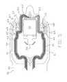
- FIG. 1is an isometric view of the loadbeam side of a suspension assembly having a DSA gimbal in accordance with examples of the invention.
- FIG. 2is a detailed isometric view of the loadbeam side of the suspension of FIG. 1 .
- FIG. 3is an isometric view of a distal portion of the gimbal side of the suspension of FIGS. 1 and 2 .
- FIG. 4is a top view of the flexure and DSA structure of FIG. 3 illustrating conductive traces within the flexure.
- FIG. 5illustrates the flexure and DSA structure of FIG. 4 with the addition of the head slider.
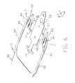
- FIG. 6is an isometric view of the metal layer of the flexure of FIGS. 1-3 prior to the formation of the T-shaped sway limiter.
- FIG. 7is an isometric view of the flexure and DSA structure of FIGS. 1-3 from the loadbeam side of the suspension.
- FIG. 8illustrates the flexure and DSA structure of FIG. 7 with the addition of the motor.
- Disk drive suspensionscan be susceptible to unwanted swaying, particularly DSA suspensions designed to articulate laterally over disk media.
- Various features that can be employed to prevent unwanted sway and/or arrest sway motion in DSA suspensionsare presented herein. Disclosed techniques further facilitate efficient manufacturing of such DSA suspensions.
- FIG. 1is an isometric view of the loadbeam side of a suspension 10 having a flexure 12 with a co-located or gimbal-based DSA structure 14 .
- FIG. 2is a detailed isometric view of the loadbeam 18 and the DSA structure 14 of FIG. 1 .
- the suspension 10includes a baseplate 16 as a proximal mounting structure and a loadbeam 18 having a rigid or beam region 20 coupled to the baseplate 16 along a spring or hinge region 22 .
- Each of the baseplate 16 and the loadbeam 18can be formed from metal, such as stainless steel.
- a gimbal 24is located at the distal end of the flexure 12 .
- a DSA structure 14is located on the gimbal 24 , adjacent the distal end of the loadbeam 18 .
- a head slider 32( FIG. 5 ) is mounted to the gimbal 24 on the side of the flexure 12 that is opposite the loadbeam 18 .
- One or more transducers(not shown) for reading and/or writing to disk media are located on and/or in the head slider 32 .
- a T-shaped sway limiter 26extends from the flexure 12 and limits the relative motion of the flexure 12 and the head slider 32 relative to beam region 20 of loadbeam 18 .
- the axes key shown in FIG. 2indicates X, Y, and Z axes.
- the suspension 10is generally elongated along the X axis in distal and proximal directions.
- a longitudinal axis of the suspension 10accordingly extends lengthwise along the suspension 10 , parallel with the X-axis.
- Proximal and distalrefers to the relative direction or position along the longitudinal axis of the suspension 10 while lateral refers to the left and right directions (along the Y-axis) orthogonal to the longitudinal axis of the suspension 10 .
- the baseplate 16is proximal of the loadbeam 18 as shown in FIG. 1 while opposite ends of the motor 34 extend laterally.
- the suspension 10including the flexure 12 and the loadbeam 18 , has a generally planar orientation co-planar with the X-Y plane.
- the Z axisrepresents height or bottom and top orientations.
- the distal end of the flexure 12is cantilevered from the base portion 50 .
- the spring arms 52apply a force through the tongue 33 and the motor 34 , to maintain contact between the motor 34 and the beam region 20 of the loadbeam 18 , e.g., such as contact between the motor 34 and a dimple (not shown) on the beam region 20 .
- Contact between the motor 34 and a dimpleallows the tongue 33 and the head slider 32 to pitch and roll as needed during operation of the suspension 10 , such as in response to vibration and/or wind generated by spinning disk media, as well as rotate in response to activation of the motor 34 .
- the head slider 32is mounted on the tongue 33 .
- the top side of the head slider 32can be attached with adhesive to a slider mounting surface on the bottom side of the tongue 33 .
- the suspension 10may utilize energy-assisted magnetic recording (EAMR) element, which uses various types of energy to selectively change the coercively of disk media, such as by heating a small area of the disk media to temporarily change the coercivity of the area just before writing.
- EAMRenergy-assisted magnetic recording
- HAIVIRheat-assisted magnetic recording
- MAMRmicrowave assisted magnetic recording
- An EAMR elementcan be mounted on the tongue 33 (e.g., on a top surface of the tongue 33 ) and can project vertically up through the window 15 in the loadbeam 18 .
- Examples of the present disclosurecan include an EAMR element, such as in any manner disclosed in the commonly assigned Bennin U.S. Pat. No. 8,717,712, which is incorporated by reference herein in its entirety for all purposes.
- FIG. 3is an isometric view of a distal portion of the gimbal side of the suspension 10 .
- FIG. 4is a top view of the flexure 12 with the co-located or gimbal-based DSA structure 14 illustrating a pair of sets of conductive traces 60 within the flexure.
- FIG. 5illustrates the flexure 12 and the DSA structure 14 with the addition of the head slider 32 .
- the flexure 12includes a stainless steel layer 40 (or other metal layer) that forms the main structure support of the flexure 12 .
- the flexure 12further includes traces 60 , which include a dielectric base layer and individual conductors, the individual conductors within traces 60 being electrically isolated from the stainless steel layer 40 by the dielectric base layer.
- the stainless steel layer 40includes a base portion 50 which can be attached (e.g., by welding) to the loadbeam 18 .
- the stainless steel layer 40further includes a pair of spring arms 52 , a tongue 33 , and struts 56 , 57 that respectively connect the pair of spring arms 52 to the tongue 33 .
- the strut 56is offset proximally of the strut 57 .
- the pair of struts 56 , 57can be referred to as a proximal strut 56 with the proximal-most edge and a distal strut 57 with the distal-most edge.
- the traces 60extend along the distal end of the flexure 12 between the pair of spring arms 52 and around the tongue 33 .
- the traces 60comprise a dielectric base layer (e.g., a polymer such as polyimide) and at least one conductor extending along the base layer.
- the conductorscan further be covered by a cover coat of the dielectric material.
- the traces 60route the conductors along the suspension 10 to electrically connect components of the suspension 10 (e.g., transducers of the head slider 32 ) to control circuitry of the hard disk drive. Routing the traces 60 between the spring arms 52 minimizes the width of the distal end of the flexure 12 and minimizes the use of material as compared to routing the traces 60 outside of the pair of spring arms 52 .
- each trace 60can extend from the base portion to the tongue 33 while being entirely between the lateral spring arms 52 .
- each trace 60extends from the base portion 50 to the tongue 33 while no part of the trace 60 is laterally beyond either spring arm 52 , wherein the trace 60 may overlap with a spring arm 52 .
- each of the traces 60extends from the base portion 50 to the tongue 33 substantially between the lateral spring arms 52 , wherein a portion of each of the traces 60 may extend laterally beyond a spring arm 52 to a minor degree. It is noted that routing the traces 60 between the spring arms 52 may have a tendency to increase sway gain.
- the pair of conductive traces 60are routed around opposite sides of the slider mounting surface 31 , over the pair of struts 56 , 57 and include distal bends 63 to reach a set of terminal contacts 62 on a distal portion of the tongue 33 .
- the conductive traces 60are routed around opposite sides of the slider mounting surface 31 , but the conductive traces 60 are also routed around opposite sides of the tongue 33 .
- the conductive traces 60include optional tethers 61 within the dielectric base layer that provide an intermediate mechanical contact point with the adjacent lateral spring arm 52 over the span between the base portion 50 and the struts 56 , 57 .
- the tethers 61function to help maintain the traces 60 in a flat planar configuration rather than a twisted configuration.
- the motor 34is located along an opposing side of the tongue 33 relative to the slider mounting surface 31 .
- One or more conductors of the conductive traces 60provide a power supply to drive the motor 34 .
- the one or more insulated conductors of the conductive traces 60further connect, via a conductive contact pad 64 of the conductive traces 60 to an electrical contact pad 44 of the stainless steel layer 40 .
- Contact pad 44serves as the positive terminal for the motor 34 .
- a conductive adhesivemay connect at least one of the insulated conductors within the conductive traces 60 to the electrical contact pad 44 such that the least one of the insulated conductors within the conductive traces 60 is in electrical communication with the electrical contact pad 44 .
- the electrical contact pad 44 within the stainless steel layer 40is separated by gaps between both the outer arm portion and the inner arm portion of the adjacent spring arm 52 , and in the illustrated example the electrical contact pad 44 is an island within the stainless steel layer 40 .
- the gap 68between the inner arm portion of the adjacent spring arm 52 and the electrical contact pad 44 .
- the gap 68is configured to mitigate electrical shorting between the stainless steel layer 40 and the at least one of the insulated conductors caused by spillover of the conductive adhesive during a manufacturing process. This may improve the repeatability of the manufacturing process and result in a higher proportion of useable suspensions.
- the conductive traces 60further include a tether 66 within the dielectric layer that extends between the electrical contact pad 44 and the adjacent spring arm 52 . The tether 66 may help maintain the electrical contact pad 44 within a common plane as the stainless steel layer 40 of the flexure 12 during assembly of the suspension 10 .
- the stainless steel layer 40further includes an electrical contact pad 45 within the stainless steel layer 40 opposite the electrical contact pad 44 .
- the electrical contact pad 45is an extension of the spring arms 52 , and serves as the negative terminal for the motor 34 by providing a ground connection for the motor 34 .
- the electrical contact pad 45directly connects to the adjacent spring arm 52 of the stainless steel layer 40 (the stainless steel layer 40 is connected to ground).
- the configuration of the electrical contact pad 45 , the adjacent spring arm 52 and the adjacent conductive trace 60is approximately symmetrical to that of the electrical contact pad 44 and its adjacent spring arm 52 and conductive trace 60 .
- both the electrical contact pad 44 and the electrical contact pad 45are separate from the tongue 33 and on opposite sides of the tongue 33 in an approximately symmetrical arrangement about a longitudinal midline of the flexure 12 .
- the arrangement of the conductive traces 60 and the spring arm 52 adjacent the electrical contact pad 45is largely to provide symmetry with the structures adjacent the electrical contact pad 44 within the dielectric layer of conductive traces 60 .
- the conductive traces 60include a nonconductive contact pad 65 , which is approximately symmetrical to the conductive contact pad 64 .
- the electrical contact pad 45is separated by gaps between both the outer arm portion and the inner arm portion of the adjacent spring arm 52 .
- the gap 68functions to mitigate electrical shorting between the stainless steel layer 40 and the at least one of the insulated conductors caused by spillover of the conductive adhesive applied during a manufacturing process to connect the conductive contact pad 64 with the electrical contact pad 44 , it is not necessary to use conductive adhesive to connect the nonconductive contact pad 65 to the electrical contact pad 45 .
- the gap 69is included to provide symmetry with the gap 68 .
- the conductive traces 60further include a tether 67 within the dielectric layer that extends between the electrical contact pad 45 and the adjacent spring arm 52 .
- the tether 66may help maintain the electrical contact pad 44 within a common plane as the stainless steel layer 40 of the flexure 12 during assembly, the contact pad 45 is directly connected to the stainless steel layer 40 of the flexure 12 such that the tether 67 is not needed to constrain the electrical contact pad 45 during assembly. Instead, the tether 67 is included to provide symmetry with the tether 66
- the DSA structure 14limits or eliminates traces or polymer layers from between the stainless steel layer 40 of the flexure 12 and the head slider 32 .
- Such a configurationreduces a standoff height for the head slider 32 , and may also facilitate HAMR compatibility in that the stainless steel layer 40 remains uncovered by conductive traces 60 to allow room for HAMR components adjacent window 15 .
- the configuration of the conductive traces 60provides for approximate symmetry between conductive traces 60 .
- FIG. 6is an isometric view of the stainless steel layer 40 of the flexure 12 prior to the formation of the T-shaped sway limiter 26 .
- FIG. 7is an isometric view of the flexure 12 and the DSA structure 14 from the loadbeam side of the suspension 10 .
- FIG. 8illustrates the flexure 12 and the DSA structure 14 as shown in FIG. 7 with the addition of the motor 34 .
- the stainless steel layer 40forms the spring arms 52 , the struts 56 , 57 , and the tongue 33 .
- Each spring arm 52is elongated along the gimbal 24 .
- the spring arms 52are respectively on opposite lateral sides of the gimbal 24 .
- the spring arms 52support the tongue 33 .
- the tongue 33is an elongated portion (elongated along the X axis) that is located between the spring arms 52 .
- each of the spring arms 52includes an outer arm portion 41 and an inner arm portion 42 .
- Each outer arm portion 41is continuous with a respective inner arm portion 42 via a distal bend 43 in the spring arm 52 .
- the pair of struts 56 , 57connects and supports the tongue 33 between the spring arms 52 within the stainless steel layer 40 .
- the struts 56 , 57can be the sole structural linkage between the spring arms 52 and the tongue 33 .
- the struts 56 , 57in connecting with the tongue 33 , can be the only part of the stainless steel layer 40 that connects between the spring arms 52 distal of the base portion 50 .
- the struts 56 , 57can each be the narrowest part of the stainless steel layer 40 in an X-Y plane while the thickness of the stainless steel layer 40 can be consistent along the flexure 12 .
- the struts 56 , 57are offset from one another. Specifically, the strut 56 is located proximally with respect to the strut 57 . This offset arrangement facilitates rotational movement of the tongue 33 .
- the spring arms 52on which opposite ends of the motor 34 are mounted, are laterally pushed outward or pulled inward, which correspondingly laterally pulls the struts 56 , 57 outward or pushes the struts 56 , 57 inward at the offset points at which the struts 56 , 57 connect to the tongue 33 .
- the pushing or pulling of the struts 56 , 57 on the tongue 33 at the offset pointsapplies a torque or moment to the tongue 33 between the struts 56 , 57 , which rotates the tongue 33 .
- the motor 34can be a piezoelectric element.
- the motor 34expands and contracts when electrically activated by a drive signal delivered by control circuitry of the hard disk drive.
- the motor 34is mounted to the gimbal 24 of the flexure 12 between the loadbeam 18 and the head slider 32 . Activation of the motor 34 actuates the tongue 33 , and the head slider 32 mounted thereon.
- Rotation or other tracking of the head slider 32provides fine position control of the read/write transducers of the head slider 32 to selectively scan over specific sectors of disk media. For example, rotation of head slider relative to a beam region of a loadbeam 18 is described in the commonly assigned Miller U.S. Pat. No. 8,896,970, which is incorporated by reference herein in its entirety for all purposes.
- the manner in which the traces 60 are routed to connect with the tongue 33 , or elements fixed to the tongue 33can imbalance the tongue 33 .
- tension within the traces 60can apply a force to the tongue 33 , offsetting the rotational balance of the tongue 33 .
- Rotational imbalance of the tongue 33can increase sway gain. Routing the traces 60 between the spring arms 52 to minimize suspension width and/or adding an EAMR element, risks misbalancing the tongue 33 and increasing sway gain.
- the present disclosureprovides features that counteract such misbalancing.
- stainless steel layer 40may be designed to be as symmetric as possible about its midline. Minimal exceptions to the symmetry of stainless steel layer 40 include struts 56 , 57 being asymmetrical from one another.
- electrical contact pad 45is an extension of the spring arms 52 and serves as the negative terminal for the motor 34 , whereas the electrical contact pad 44 is separated from the spring arms 52 .
Landscapes
- Supporting Of Heads In Record-Carrier Devices (AREA)
- Adjustment Of The Magnetic Head Position Track Following On Tapes (AREA)
Abstract
Description
This application claims priority to Provisional Application No. 62/335,150, filed May 12, 2016, which is herein incorporated by reference in its entirety.
The present disclosure relates to disk drives and suspensions for disk drives.
Dual stage actuation (DSA) suspension disk drive head suspensions and disk drives incorporating DSA suspensions are generally known and commercially available. For example, DSA suspensions having an actuation structure on the baseplate or other mounting portion of the suspension, i.e., proximal to the spring or hinge region of the suspension, are described in the Okawara U.S. Pat. No. 8,199,442, the Shum U.S. Pat. No. 8,665,567, the Fuchino U.S. Pat. No. 8,405,934 and the Imamura U.S. Pat. No. 5,764,444. DSA suspensions having actuation structures located on the loadbeam or gimbal portions of the suspension, i.e., distal to the spring or hinge region, are also known and disclosed, for example, in the Jurgenson U.S. Pat. No. 5,657,188, the Krinke U.S. Pat. No. 7,256,968 and the Yao U.S. Patent Publication No. 2008/0144225. Co-located gimbal-based DSA suspensions are disclosed in the Miller U.S. Pat. Nos. 8,681,456, 8,896,970 and 9,147,413. All of the above-identified patents and patent applications are incorporated herein by reference in their entirety for all purposes.
There remains a continuing need for improved DSA suspensions. DSA suspensions with enhanced performance capabilities are desired. The suspensions should be capable of being efficiently manufactured.
Various examples concern a suspension having a DSA structure on a gimbaled flexure includes a loadbeam and a flexure attached to the loadbeam. The flexure includes a metal layer, the metal layer including a pair of spring arms, a tongue including a slider mounting surface, and a pair of struts including a first strut and a second strut. The pair of struts connects the pair of spring arms to the tongue, the first strut having a distal-most edge, the second strut having a proximal-most edge. The suspension further includes a pair of traces, each trace in the pair of traces including one or more insulated conductors, the pair of traces being routed around opposite sides of the slider mounting surface, over the pair of struts to a set of terminal contacts on a distal portion of the tongue. The suspension also includes a motor mounted on the flexure, the motor having opposite lateral ends, the motor orientated laterally across the flexure such that the opposite lateral ends of the motor are on opposite lateral sides of the flexure. Electrical activation of the motor rotates the slider mounting surface relative to the loadbeam.
Various examples concern suspension having a DSA structure on a gimbaled flexure comprising a loadbeam, and a flexure attached to the loadbeam, the flexure comprising a metal layer. The metal layer includes a pair of spring arms, a tongue comprising a slider mounting surface, and a pair of struts including a first strut and a second strut, the pair of struts connecting the pair of spring arms to the tongue, the first strut having a distal-most edge, the second strut having a proximal-most edge. The suspension further includes a pair of traces, each trace including one or more insulated conductors routed to a set of terminal contacts on a distal portion of the tongue. The suspension also includes a motor mounted on the flexure, the motor having opposite lateral ends, the motor orientated laterally across the flexure such that the opposite lateral ends of the motor are on opposite lateral sides of the flexure, wherein electrical activation of the motor rotates the slider mounting surface relative to the loadbeam. The suspension also includes a first electrical contact pad in electrical communication with the motor, conductive adhesive electrically connecting the first electrical contact pad to the at least one of the insulated conductors, and a second electrical contact pad in electrical communication with the motor. The first electrical contact pad is in electrical communication with at least one of the insulated conductors of the traces and provides a power supply to drive the motor. The second electrical contact pad is in electrical communication with the metal layer and provides a ground connection to the motor. The first electrical contact pad is separated by gap from the adjacent spring arm, the gap being configured to mitigate electrical shorting between the metal layer and the at least one of the insulated conductors caused by spillover of the conductive adhesive during a manufacturing process.
Further features and modifications of the various examples are further discussed herein and shown in the drawings. While examples are disclosed, still other embodiments of the present disclosure will become apparent to those skilled in the art from the following detailed description, which shows and describes illustrative examples of this disclosure. Accordingly, the drawings and detailed description are to be regarded as illustrative in nature and not restrictive.
Disk drive suspensions can be susceptible to unwanted swaying, particularly DSA suspensions designed to articulate laterally over disk media. Various features that can be employed to prevent unwanted sway and/or arrest sway motion in DSA suspensions are presented herein. Disclosed techniques further facilitate efficient manufacturing of such DSA suspensions.
The axes key shown inFIG. 2 indicates X, Y, and Z axes. Thesuspension 10 is generally elongated along the X axis in distal and proximal directions. A longitudinal axis of thesuspension 10 accordingly extends lengthwise along thesuspension 10, parallel with the X-axis. Proximal and distal, as used herein, refers to the relative direction or position along the longitudinal axis of thesuspension 10 while lateral refers to the left and right directions (along the Y-axis) orthogonal to the longitudinal axis of thesuspension 10. For example, thebaseplate 16 is proximal of theloadbeam 18 as shown inFIG. 1 while opposite ends of themotor 34 extend laterally. Thesuspension 10, including theflexure 12 and theloadbeam 18, has a generally planar orientation co-planar with the X-Y plane. The Z axis represents height or bottom and top orientations.
The distal end of theflexure 12 is cantilevered from thebase portion 50. Thespring arms 52 apply a force through thetongue 33 and themotor 34, to maintain contact between themotor 34 and thebeam region 20 of theloadbeam 18, e.g., such as contact between themotor 34 and a dimple (not shown) on thebeam region 20. Contact between themotor 34 and a dimple allows thetongue 33 and thehead slider 32 to pitch and roll as needed during operation of thesuspension 10, such as in response to vibration and/or wind generated by spinning disk media, as well as rotate in response to activation of themotor 34. Thehead slider 32 is mounted on thetongue 33. For example, the top side of thehead slider 32 can be attached with adhesive to a slider mounting surface on the bottom side of thetongue 33.
Thesuspension 10 may utilize energy-assisted magnetic recording (EAMR) element, which uses various types of energy to selectively change the coercively of disk media, such as by heating a small area of the disk media to temporarily change the coercivity of the area just before writing. Various types of EAMR exist, such as heat-assisted magnetic recording (HAIVIR) and microwave assisted magnetic recording (MAMR). An EAMR element can be mounted on the tongue33 (e.g., on a top surface of the tongue33) and can project vertically up through the window15 in theloadbeam 18. Examples of the present disclosure can include an EAMR element, such as in any manner disclosed in the commonly assigned Bennin U.S. Pat. No. 8,717,712, which is incorporated by reference herein in its entirety for all purposes.
Theflexure 12 includes a stainless steel layer40 (or other metal layer) that forms the main structure support of theflexure 12. Theflexure 12 further includestraces 60, which include a dielectric base layer and individual conductors, the individual conductors withintraces 60 being electrically isolated from thestainless steel layer 40 by the dielectric base layer.
Thestainless steel layer 40 includes abase portion 50 which can be attached (e.g., by welding) to theloadbeam 18. Thestainless steel layer 40 further includes a pair ofspring arms 52, atongue 33, and struts56,57 that respectively connect the pair ofspring arms 52 to thetongue 33. Thestrut 56 is offset proximally of thestrut 57. In this way, the pair ofstruts proximal strut 56 with the proximal-most edge and adistal strut 57 with the distal-most edge.
Thetraces 60 extend along the distal end of theflexure 12 between the pair ofspring arms 52 and around thetongue 33. Thetraces 60 comprise a dielectric base layer (e.g., a polymer such as polyimide) and at least one conductor extending along the base layer. The conductors can further be covered by a cover coat of the dielectric material. Thetraces 60 route the conductors along thesuspension 10 to electrically connect components of the suspension10 (e.g., transducers of the head slider32) to control circuitry of the hard disk drive. Routing thetraces 60 between thespring arms 52 minimizes the width of the distal end of theflexure 12 and minimizes the use of material as compared to routing thetraces 60 outside of the pair ofspring arms 52. In some examples, no part of eithertrace 60 extends laterally beyond either of thespring arms 52. For example, eachtrace 60 can extend from the base portion to thetongue 33 while being entirely between thelateral spring arms 52. In some examples, eachtrace 60 extends from thebase portion 50 to thetongue 33 while no part of thetrace 60 is laterally beyond eitherspring arm 52, wherein thetrace 60 may overlap with aspring arm 52. In some alternative examples, each of thetraces 60 extends from thebase portion 50 to thetongue 33 substantially between thelateral spring arms 52, wherein a portion of each of thetraces 60 may extend laterally beyond aspring arm 52 to a minor degree. It is noted that routing thetraces 60 between thespring arms 52 may have a tendency to increase sway gain.
As shown inFIGS. 3-5 , the pair ofconductive traces 60 are routed around opposite sides of theslider mounting surface 31, over the pair ofstruts distal bends 63 to reach a set ofterminal contacts 62 on a distal portion of thetongue 33. In this example, not only are theconductive traces 60 are routed around opposite sides of theslider mounting surface 31, but the conductive traces60 are also routed around opposite sides of thetongue 33. By routing the conductive traces60 around opposite sides of theslider mounting surface 31, contact is avoided with theslider mounting surface 31.
The conductive traces60 includeoptional tethers 61 within the dielectric base layer that provide an intermediate mechanical contact point with the adjacentlateral spring arm 52 over the span between thebase portion 50 and thestruts tethers 61 function to help maintain thetraces 60 in a flat planar configuration rather than a twisted configuration.
Themotor 34 is located along an opposing side of thetongue 33 relative to theslider mounting surface 31. One or more conductors of the conductive traces60 provide a power supply to drive themotor 34. The one or more insulated conductors of the conductive traces60 further connect, via aconductive contact pad 64 of the conductive traces60 to anelectrical contact pad 44 of thestainless steel layer 40.Contact pad 44 serves as the positive terminal for themotor 34. A conductive adhesive may connect at least one of the insulated conductors within the conductive traces60 to theelectrical contact pad 44 such that the least one of the insulated conductors within the conductive traces60 is in electrical communication with theelectrical contact pad 44.
Theelectrical contact pad 44 within thestainless steel layer 40 is separated by gaps between both the outer arm portion and the inner arm portion of theadjacent spring arm 52, and in the illustrated example theelectrical contact pad 44 is an island within thestainless steel layer 40. Thegap 68 between the inner arm portion of theadjacent spring arm 52 and theelectrical contact pad 44. Thegap 68 is configured to mitigate electrical shorting between thestainless steel layer 40 and the at least one of the insulated conductors caused by spillover of the conductive adhesive during a manufacturing process. This may improve the repeatability of the manufacturing process and result in a higher proportion of useable suspensions. The conductive traces60 further include atether 66 within the dielectric layer that extends between theelectrical contact pad 44 and theadjacent spring arm 52. Thetether 66 may help maintain theelectrical contact pad 44 within a common plane as thestainless steel layer 40 of theflexure 12 during assembly of thesuspension 10.
Thestainless steel layer 40 further includes anelectrical contact pad 45 within thestainless steel layer 40 opposite theelectrical contact pad 44. Theelectrical contact pad 45 is an extension of thespring arms 52, and serves as the negative terminal for themotor 34 by providing a ground connection for themotor 34. As the negative terminal, theelectrical contact pad 45 directly connects to theadjacent spring arm 52 of the stainless steel layer40 (thestainless steel layer 40 is connected to ground). Otherwise, the configuration of theelectrical contact pad 45, theadjacent spring arm 52 and the adjacentconductive trace 60 is approximately symmetrical to that of theelectrical contact pad 44 and itsadjacent spring arm 52 andconductive trace 60. For example, both theelectrical contact pad 44 and theelectrical contact pad 45 are separate from thetongue 33 and on opposite sides of thetongue 33 in an approximately symmetrical arrangement about a longitudinal midline of theflexure 12.
The arrangement of the conductive traces60 and thespring arm 52 adjacent theelectrical contact pad 45 is largely to provide symmetry with the structures adjacent theelectrical contact pad 44 within the dielectric layer of conductive traces60. For example, the conductive traces60 include anonconductive contact pad 65, which is approximately symmetrical to theconductive contact pad 64. Within conductive traces60, theelectrical contact pad 45 is separated by gaps between both the outer arm portion and the inner arm portion of theadjacent spring arm 52. However, while thegap 68 functions to mitigate electrical shorting between thestainless steel layer 40 and the at least one of the insulated conductors caused by spillover of the conductive adhesive applied during a manufacturing process to connect theconductive contact pad 64 with theelectrical contact pad 44, it is not necessary to use conductive adhesive to connect thenonconductive contact pad 65 to theelectrical contact pad 45. Instead, thegap 69 is included to provide symmetry with thegap 68. As another example, the conductive traces60 further include atether 67 within the dielectric layer that extends between theelectrical contact pad 45 and theadjacent spring arm 52. However, while thetether 66 may help maintain theelectrical contact pad 44 within a common plane as thestainless steel layer 40 of theflexure 12 during assembly, thecontact pad 45 is directly connected to thestainless steel layer 40 of theflexure 12 such that thetether 67 is not needed to constrain theelectrical contact pad 45 during assembly. Instead, thetether 67 is included to provide symmetry with thetether 66
In comparison to alternative designs in which the conductive traces60 run through a slider mounting surface, theDSA structure 14 limits or eliminates traces or polymer layers from between thestainless steel layer 40 of theflexure 12 and thehead slider 32. Such a configuration reduces a standoff height for thehead slider 32, and may also facilitate HAMR compatibility in that thestainless steel layer 40 remains uncovered byconductive traces 60 to allow room for HAMR components adjacent window15. In addition, the configuration of the conductive traces60 provides for approximate symmetry between conductive traces60.
As shown inFIG. 6 , thestainless steel layer 40 forms thespring arms 52, thestruts tongue 33. Eachspring arm 52 is elongated along thegimbal 24. Thespring arms 52 are respectively on opposite lateral sides of thegimbal 24. Thespring arms 52 support thetongue 33. Thetongue 33 is an elongated portion (elongated along the X axis) that is located between thespring arms 52.
As shown inFIG. 6 , each of thespring arms 52 includes anouter arm portion 41 and aninner arm portion 42. Eachouter arm portion 41 is continuous with a respectiveinner arm portion 42 via adistal bend 43 in thespring arm 52. The pair ofstruts tongue 33 between thespring arms 52 within thestainless steel layer 40. Specifically, in this example, thestruts spring arms 52 and thetongue 33. Also in this example, thestruts tongue 33, can be the only part of thestainless steel layer 40 that connects between thespring arms 52 distal of thebase portion 50. As shown, thestruts stainless steel layer 40 in an X-Y plane while the thickness of thestainless steel layer 40 can be consistent along theflexure 12. As shown, thestruts strut 56 is located proximally with respect to thestrut 57. This offset arrangement facilitates rotational movement of thetongue 33.
For example, as the motor34 (FIG. 8 ) expands or contracts, thespring arms 52, on which opposite ends of themotor 34 are mounted, are laterally pushed outward or pulled inward, which correspondingly laterally pulls thestruts struts struts tongue 33. The pushing or pulling of thestruts tongue 33 at the offset points applies a torque or moment to thetongue 33 between thestruts tongue 33. Themotor 34 can be a piezoelectric element. Themotor 34 expands and contracts when electrically activated by a drive signal delivered by control circuitry of the hard disk drive. Themotor 34 is mounted to thegimbal 24 of theflexure 12 between the loadbeam18 and thehead slider 32. Activation of themotor 34 actuates thetongue 33, and thehead slider 32 mounted thereon. Rotation or other tracking of thehead slider 32 provides fine position control of the read/write transducers of thehead slider 32 to selectively scan over specific sectors of disk media. For example, rotation of head slider relative to a beam region of aloadbeam 18 is described in the commonly assigned Miller U.S. Pat. No. 8,896,970, which is incorporated by reference herein in its entirety for all purposes.
Also, the manner in which thetraces 60 are routed to connect with thetongue 33, or elements fixed to thetongue 33, can imbalance thetongue 33. For example, tension within thetraces 60 can apply a force to thetongue 33, offsetting the rotational balance of thetongue 33. Rotational imbalance of thetongue 33 can increase sway gain. Routing thetraces 60 between thespring arms 52 to minimize suspension width and/or adding an EAMR element, risks misbalancing thetongue 33 and increasing sway gain. However, the present disclosure provides features that counteract such misbalancing.
For example,stainless steel layer 40 may be designed to be as symmetric as possible about its midline. Minimal exceptions to the symmetry ofstainless steel layer 40 includestruts electrical contact pad 45 is an extension of thespring arms 52 and serves as the negative terminal for themotor 34, whereas theelectrical contact pad 44 is separated from thespring arms 52.
Although the present disclosure has been described with reference to the examples, those skilled in the art will recognize that changes can be made in form and detail without departing from the spirit and scope of the disclosure. For example, although described in connection with certain co-located DSA structures, stiffeners and associated features described herein can be used in connection with motors on other DSA structures, including other co-located DSA structures. In addition, the examples of the present disclosure can be modified with any feature disclosed in commonly owned Miller U.S. Pat. No. 8,675,314; Miller U.S. Pat. No. 8,681,456; Miller U.S. Pat. No. 8,891,206; and Miller U.S. Pat. No. 8,896,968, each of which is incorporated herein in its entirety for all purposes. Moreover, any of the examples of such disclosures can be modified in view the present disclosure.
Claims (19)
1. A suspension having a dual stage actuation (DSA) structure on a gimbaled flexure comprising:
a loadbeam;
a flexure attached to the loadbeam, the flexure including a metal layer, the metal layer comprising:
a pair of spring arms;
a tongue comprising a slider mounting surface including a slider contact area for receiving a slider; and
a pair of struts including a first strut and a second strut, the pair of struts connecting the pair of spring arms to the tongue, the first strut having a distal-most edge, the second strut having a proximal-most edge;
a pair of traces, each trace in the pair of traces including one or more insulated conductors, the pair of traces being routed around opposite sides of the slider contact area of the slider mounting surface, over the pair of struts to a set of terminal contacts on a distal portion of the tongue,
wherein each trace in the pair of traces is routed to avoid contact with the slider contact area of the slider mounting surface; and
a motor mounted on the flexure, the motor having opposite lateral ends, the motor orientated laterally across the flexure such that the opposite lateral ends of the motor are on opposite lateral sides of the flexure, wherein electrical activation of the motor rotates the slider mounting surface relative to the loadbeam.
2. The suspension ofclaim 1 , further comprising:
a first electrical contact pad in electrical communication with the motor; and
a second electrical contact pad in electrical communication with the motor,
wherein the first electrical contact pad is in electrical communication with at least one of the insulated conductors of the traces and provides a power supply to drive the motor, and
wherein the second electrical contact pad is in electrical communication with the metal layer and provides a ground connection to the motor.
3. The suspension ofclaim 1 , wherein the pair of traces are routed around opposite sides of the tongue.
4. The suspension ofclaim 1 , wherein electrical activation of the motor bends the pair of struts to rotate the tongue relative to the loadbeam.
5. The suspension ofclaim 1 , wherein the metal layer further comprises a base portion from which the pair of spring arms extend distally.
6. The suspension ofclaim 5 , wherein the pair of traces extend from the base portion to the tongue without extending laterally beyond the pair of spring arms.
7. The suspension ofclaim 1 , further comprising a slider mounted on the slider contact area of the slider mounting surface of the tongue, wherein the motor is located along an opposing side of the tongue relative to the slider mounting surface.
8. The suspension ofclaim 1 , wherein the pair of struts are the only part of the metal layer that connects between the pair of spring arms and the tongue.
9. A suspension having a dual stage actuation (DSA) structure on a gimbaled flexure comprising:
a loadbeam;
a flexure attached to the loadbeam, the flexure including a metal layer, the metal layer comprising:
a pair of spring arms;
a tongue comprising a slider mounting surface including a slider contact area for receiving a slider; and
a pair of struts including a first strut and a second strut, the pair of struts connecting the pair of spring arms to the tongue, the first strut having a distal-most edge, the second strut having a proximal-most edge;
a pair of traces, each trace in the pair of traces including one or more insulated conductors, the pair of traces being routed around opposite sides of the slider contact area of the slider mounting surface, over the pair of struts to a set of terminal contacts on a distal portion of the tongue;
a motor mounted on the flexure, the motor having opposite lateral ends, the motor orientated laterally across the flexure such that the opposite lateral ends of the motor are on opposite lateral sides of the flexure, wherein electrical activation of the motor rotates the slider mounting surface relative to the loadbeam;
a first electrical contact pad in electrical communication with the motor; and
a second electrical contact pad in electrical communication with the motor,
wherein the first electrical contact pad is in electrical communication with at least one of the insulated conductors of the traces and provides a power supply to drive the motor,
wherein the second electrical contact pad is in electrical communication with the metal layer and provides a ground connection to the motor, and
wherein the first electrical contact pad and the second electrical contact pad are separate from the tongue and on opposite sides of the tongue in an approximately symmetrical arrangement about a longitudinal midline of the flexure.
10. The suspension ofclaim 9 , further comprising tethers connecting the each of the traces to the adjacent one of the first electrical contact pad and the second electrical contact pad.
11. A suspension having a dual stage actuation (DSA) structure on a gimbaled flexure comprising:
a loadbeam;
a flexure attached to the loadbeam, the flexure including a metal layer, the metal layer comprising:
a pair of spring arms;
a tongue comprising a slider mounting surface including a slider contact area for receiving a slider; and
a pair of struts including a first strut and a second strut, the pair of struts connecting the pair of spring arms to the tongue, the first strut having a distal-most edge, the second strut having a proximal-most edge;
a pair of traces, each trace in the pair of traces including one or more insulated conductors, the pair of traces being routed around opposite sides of the slider contact area of the slider mounting surface, over the pair of struts to a set of terminal contacts on a distal portion of the tongue;
a motor mounted on the flexure, the motor having opposite lateral ends, the motor orientated laterally across the flexure such that the opposite lateral ends of the motor are on opposite lateral sides of the flexure, wherein electrical activation of the motor rotates the slider mounting surface relative to the loadbeam;
a first electrical contact pad in electrical communication with the motor; and
a second electrical contact pad in electrical communication with the motor,
wherein the first electrical contact pad is in electrical communication with at least one of the insulated conductors of the traces and provides a power supply to drive the motor,
wherein the second electrical contact pad is in electrical communication with the metal layer and provides a ground connection to the motor,
wherein each spring arm comprises an outer arm portion, an inner arm portion, and a distal bend that connects the inner arm portion to the outer arm portion,
wherein the pair of struts respectively connect to the inner arm portions of the pair of spring arms, and
wherein the first and second electrical contact pads are located between the outer arm portion the inner arm portion of each spring arm on opposing sides of the flexure.
12. The suspension ofclaim 11 , further comprising conductive adhesive electrically connecting the first electrical contact pad to the at least one of the insulated conductors,
wherein the first electrical contact pad is separated by gaps between both the outer arm portion and the inner arm portion of an adjacent spring arm of the pair of spring arms, the gap being configured to mitigate electrical shorting between the metal layer and the at least one of the insulated conductors caused by spillover of the conductive adhesive during a manufacturing process.
13. A suspension having a dual stage actuation (DSA) structure on a gimbaled flexure comprising:
a loadbeam;
a flexure attached to the loadbeam, the flexure including a metal layer, the metal layer comprising:
a pair of spring arms;
a tongue comprising a slider mounting surface; and
a pair of struts including a first strut and a second strut, the pair of struts connecting the pair of spring arms to the tongue, the first strut having a distal-most edge, the second strut having a proximal-most edge;
a pair of traces, each trace in the pair of traces including one or more insulated conductors, the pair of traces being routed over the pair of struts to a set of terminal contacts on a distal portion of the tongue; and
a motor mounted on the flexure, the motor having opposite lateral ends, the motor orientated laterally across the flexure such that the opposite lateral ends of the motor are on opposite lateral sides of the flexure, wherein electrical activation of the motor rotates the slider mounting surface relative to the loadbeam,
wherein each trace comprises at least one tether connecting the trace to an adjacent spring arm of the pair of spring arms.
14. A suspension having a dual stage actuation (DSA) structure on a gimbaled flexure comprising:
a loadbeam;
a flexure attached to the loadbeam, the flexure including a metal layer, the metal layer comprising:
a pair of spring arms;
a tongue comprising a slider mounting surface; and
a pair of struts including a first strut and a second strut, the pair of struts connecting the pair of spring arms to the tongue, the first strut having a distal-most edge, the second strut having a proximal-most edge;
a pair of traces, each trace including one or more insulated conductors routed to a set of terminal contacts on a distal portion of the tongue;
a motor mounted on the flexure, the motor having opposite lateral ends, the motor orientated laterally across the flexure such that the opposite lateral ends of the motor are on opposite lateral sides of the flexure, wherein electrical activation of the motor rotates the slider mounting surface relative to the loadbeam;
a first electrical contact pad in electrical communication with the motor;
conductive adhesive electrically connecting the first electrical contact pad to the at least one of the insulated conductors; and
a second electrical contact pad in electrical communication with the motor,
wherein the first electrical contact pad is in electrical communication with at least one of the insulated conductors of the traces and provides a power supply to drive the motor,
wherein the second electrical contact pad is in electrical communication with the metal layer and provides a ground connection to the motor, and
wherein the first electrical contact pad is separated by gap from an adjacent spring arm of the pair of spring arms, the gap being configured to mitigate electrical shorting between the metal layer and the at least one of the insulated conductors caused by spillover of the conductive adhesive during a manufacturing process.
15. The suspension ofclaim 14 , wherein the first electrical contact pad and the second electrical contact pad are separate from the tongue and on opposite sides of the tongue in an approximately symmetrical arrangement about a longitudinal midline of the flexure.
16. The suspension ofclaim 15 , further comprising tethers connecting the each of the traces to the adjacent one of the first electrical contact pad and the second electrical contact pad.
17. The suspension ofclaim 14 ,
wherein each spring arm comprises an outer arm portion, an inner arm portion, and a distal bend that connects the inner arm portion to the outer arm portion,
wherein the pair of struts respectively connect to the inner arm portions of the pair of spring arms,
wherein the first and second electrical contact pads are located between the outer arm portion the inner arm portion of each spring arm on opposing sides of the flexure.
18. The suspension ofclaim 17 , wherein the first electrical contact pad is separated by gaps between both the outer arm portion and the inner arm portion of an adjacent spring arm of the pair of spring arms, the gap being configured to mitigate electrical shorting between the metal layer and the at least one of the insulated conductors caused by spillover of the conductive adhesive during a manufacturing process.
19. The suspension ofclaim 14 , further comprising a slider mounted on the slider mounting surface of the tongue, wherein the motor is located along an opposing side of the tongue relative to the slider mounting surface.
Priority Applications (4)
| Application Number | Priority Date | Filing Date | Title |
|---|---|---|---|
| US15/154,734US9646638B1 (en) | 2016-05-12 | 2016-05-13 | Co-located gimbal-based DSA disk drive suspension with traces routed around slider pad |
| US15/589,817US10109305B2 (en) | 2016-05-12 | 2017-05-08 | Co-located gimbal-based DSA disk drive suspension with traces routed around slider pad |
| PCT/US2017/032024WO2017197030A1 (en) | 2016-05-12 | 2017-05-10 | Co-located gimbal-based dsa disk drive suspension with traces routed around slider pad |
| JP2018559799AJP2019515410A (en) | 2016-05-12 | 2017-05-10 | Co-located gimbal based DSA disk drive suspension with traces routed around the slider pad |
Applications Claiming Priority (2)
| Application Number | Priority Date | Filing Date | Title |
|---|---|---|---|
| US201662335150P | 2016-05-12 | 2016-05-12 | |
| US15/154,734US9646638B1 (en) | 2016-05-12 | 2016-05-13 | Co-located gimbal-based DSA disk drive suspension with traces routed around slider pad |
Related Child Applications (1)
| Application Number | Title | Priority Date | Filing Date |
|---|---|---|---|
| US15/589,817ContinuationUS10109305B2 (en) | 2016-05-12 | 2017-05-08 | Co-located gimbal-based DSA disk drive suspension with traces routed around slider pad |
Publications (1)
| Publication Number | Publication Date |
|---|---|
| US9646638B1true US9646638B1 (en) | 2017-05-09 |
Family
ID=58643607
Family Applications (2)
| Application Number | Title | Priority Date | Filing Date |
|---|---|---|---|
| US15/154,734ActiveUS9646638B1 (en) | 2016-05-12 | 2016-05-13 | Co-located gimbal-based DSA disk drive suspension with traces routed around slider pad |
| US15/589,817ActiveUS10109305B2 (en) | 2016-05-12 | 2017-05-08 | Co-located gimbal-based DSA disk drive suspension with traces routed around slider pad |
Family Applications After (1)
| Application Number | Title | Priority Date | Filing Date |
|---|---|---|---|
| US15/589,817ActiveUS10109305B2 (en) | 2016-05-12 | 2017-05-08 | Co-located gimbal-based DSA disk drive suspension with traces routed around slider pad |
Country Status (3)
| Country | Link |
|---|---|
| US (2) | US9646638B1 (en) |
| JP (1) | JP2019515410A (en) |
| WO (1) | WO2017197030A1 (en) |
Cited By (6)
| Publication number | Priority date | Publication date | Assignee | Title |
|---|---|---|---|---|
| US10109305B2 (en)* | 2016-05-12 | 2018-10-23 | Hutchinson Technology Incorporated | Co-located gimbal-based DSA disk drive suspension with traces routed around slider pad |
| US10783909B1 (en) | 2018-05-14 | 2020-09-22 | Seagate Technology | In-plane gimbal tongue microactuator system |
| US10991388B1 (en)* | 2019-11-14 | 2021-04-27 | Nhk Spring Co., Ltd. | Suspension for disk device having a damper member for suppressing wobble of a flexure |
| US11043236B1 (en) | 2020-12-18 | 2021-06-22 | Seagate Technology Llc | Curved outer gimbal strut |
| US12380922B2 (en) | 2023-10-10 | 2025-08-05 | Western Digital Technologies, Inc. | Suspension load beam rail-based gimbal limiter |
| US12387752B2 (en) | 2020-01-31 | 2025-08-12 | Magnecomp Corporation | Suspension damping |
Families Citing this family (3)
| Publication number | Priority date | Publication date | Assignee | Title |
|---|---|---|---|---|
| JP2021149978A (en)* | 2020-03-16 | 2021-09-27 | 株式会社東芝 | Disk device |
| US11501797B2 (en)* | 2020-05-15 | 2022-11-15 | Magnecomp Corporation | Actuator joint with non-straight edge |
| US20250191609A1 (en)* | 2023-12-11 | 2025-06-12 | Magnecomp Corporation | Profile Shape Control For Gimbal Assembly |
Citations (484)
| Publication number | Priority date | Publication date | Assignee | Title |
|---|---|---|---|---|
| US3320556A (en) | 1963-05-23 | 1967-05-16 | Bell Telephone Labor Inc | Impedance transformer |
| US3582575A (en) | 1969-07-02 | 1971-06-01 | Insul 8 Corp | Composite conductor bar and method of manufacture |
| US3862522A (en) | 1973-08-10 | 1975-01-28 | Fiber Bond Corp | Needled scouring pad |
| US3877120A (en) | 1970-02-20 | 1975-04-15 | Toray Industries | Needle board |
| US3910339A (en) | 1971-12-13 | 1975-10-07 | Hyman Kramer | Webbing strip-to-tubular frame member fastenings |
| US4014257A (en) | 1975-07-28 | 1977-03-29 | Minnesota Mining And Manufacturing Company | Apparatus for die cutting indicia on a multilayer tape |
| US4168214A (en) | 1978-06-14 | 1979-09-18 | American Chemical And Refining Company, Inc. | Gold electroplating bath and method of making the same |
| US4181554A (en) | 1978-10-06 | 1980-01-01 | National Semiconductor Corporation | Method of applying polarized film to liquid crystal display cells |
| US4299130A (en) | 1979-10-22 | 1981-11-10 | Gould Inc. | Thin film strain gage apparatus with unstrained temperature compensation resistances |
| US4418239A (en) | 1981-08-24 | 1983-11-29 | Oak Industries Inc. | Flexible connector with interconnection between conductive traces |
| US4422906A (en) | 1981-09-17 | 1983-12-27 | Masami Kobayashi | Process for direct gold plating of stainless steel |
| US4659438A (en) | 1980-05-29 | 1987-04-21 | Degussa Aktiengesellschaft | Process for the treatment of stainless steel for a direct galvanic gold plating |
| US4916798A (en) | 1988-08-26 | 1990-04-17 | Jack Toering | Method of applying applique or like object to a baseplate |
| JPH0398825A (en) | 1989-09-06 | 1991-04-24 | Toppan Printing Co Ltd | filling seal machine |
| US5140288A (en) | 1991-04-08 | 1992-08-18 | Motorola, Inc. | Wide band transmission line impedance matching transformer |
| US5189779A (en) | 1991-04-09 | 1993-03-02 | Allsteel Inc. | Method of installation of a grommet assembly to a wall panel |
| US5212847A (en) | 1992-01-21 | 1993-05-25 | Nagl Manufacturing Company | Swab and method of manufacturing and using it |
| US5275076A (en) | 1991-12-16 | 1994-01-04 | Atlas Die Inc. | Steel rule die having improved rule holders |
| US5321568A (en) | 1993-04-22 | 1994-06-14 | Maxtor Corporation | Head suspension assembly with improved pitch and roll characteristics |
| US5320272A (en) | 1993-04-02 | 1994-06-14 | Motorola, Inc. | Tin-bismuth solder connection having improved high temperature properties, and process for forming same |
| US5333085A (en) | 1990-11-06 | 1994-07-26 | Seagate Technology, Inc. | Read/write gimbal with limited range of motion |
| US5427848A (en) | 1991-05-06 | 1995-06-27 | International Business Machines Corporation | Stress balanced composite laminate material |
| US5459921A (en) | 1993-11-12 | 1995-10-24 | Seagate Technology, Inc. | Method of making a disc drive actuator arm with arm compliance compensation |
| US5485053A (en) | 1993-10-15 | 1996-01-16 | Univ America Catholic | Method and device for active constrained layer damping for vibration and sound control |
| US5491597A (en) | 1994-04-15 | 1996-02-13 | Hutchinson Technology Incorporated | Gimbal flexure and electrical interconnect assembly |
| US5521778A (en) | 1994-08-30 | 1996-05-28 | International Business Machines Corporation | Disk drive with primary and secondary actuator drives |
| US5526208A (en) | 1994-08-17 | 1996-06-11 | Quantum Corporation | Flex circuit vibration sensor |
| US5598307A (en) | 1994-04-15 | 1997-01-28 | Hutchinson Technology Inc. | Integrated gimbal suspension assembly |
| US5608591A (en) | 1995-06-09 | 1997-03-04 | International Business Machines Corporation | Integrated head-electronics interconnection suspension for a data recording disk drive |
| US5608590A (en) | 1994-06-20 | 1997-03-04 | Hutchinson Technology Incorporated | Gimballing flexure with static compensation and load print intregal etched features |
| US5631786A (en) | 1994-05-19 | 1997-05-20 | International Business Machines Corporation | Termination pad manipulator for a laminated suspension in a data storage system |
| US5636089A (en) | 1995-08-01 | 1997-06-03 | Hutchinson Technology Incorporated | Head suspension with spaced static attitude compensation protuberance and load dimple |
| US5651723A (en) | 1994-04-13 | 1997-07-29 | Viratec Thin Films, Inc. | Method and apparatus for cleaning substrates in preparation for deposition of thin film coatings |
| US5657186A (en) | 1994-09-01 | 1997-08-12 | Tdk Corporation | Device for supporting a magnetic head slider and magnetic head apparatus provided with the device including grounding electrical connection |
| US5657188A (en) | 1995-06-01 | 1997-08-12 | Hutchinson Technology Incorporated | Head suspension with tracking microactuator |
| US5666241A (en) | 1995-07-10 | 1997-09-09 | Magnecomp Corp. | Double dimple disk drive suspension |
| US5666717A (en) | 1994-07-27 | 1997-09-16 | Nippon Mektron, Ltd. | Method for manufacturing a magnetic head suspension |
| US5694270A (en) | 1995-07-03 | 1997-12-02 | Fujitsu Limited | Head assembly having laminated conductor patterns |
| JPH103632A (en) | 1996-06-12 | 1998-01-06 | Dainippon Printing Co Ltd | Magnetic head suspension |
| EP0591954B1 (en) | 1992-10-07 | 1998-01-07 | Read-Rite Corporation | Magnetic head suspension assembly fabricated with integral load beam and flexure |
| US5712749A (en) | 1995-03-02 | 1998-01-27 | Hutchinson Technology Incorporated | Reduced capacitance of electrical conductor on head suspension assembly |
| US5714444A (en) | 1994-11-18 | 1998-02-03 | Nsk Ltd. | Grease composition |
| US5717547A (en) | 1996-10-03 | 1998-02-10 | Quantum Corporation | Multi-trace transmission lines for R/W head interconnect in hard disk drive |
| US5722142A (en) | 1997-01-06 | 1998-03-03 | Myers; Michael R. | Installation tool for irrigation emitter barbs |
| US5734526A (en) | 1996-12-31 | 1998-03-31 | Hutchinson Technology Incorporated | Monocoque head suspension and its method of construction |
| US5737152A (en) | 1995-10-27 | 1998-04-07 | Quantum Corporation | Suspension with multi-layered integrated conductor trace array for optimized electrical parameters |
| WO1998020485A1 (en) | 1996-11-06 | 1998-05-14 | Quantum Corporation | Head suspension with self-shielding 'twisted' integrated conductor trace array |
| US5754368A (en) | 1995-10-27 | 1998-05-19 | Tdk Corporation | Suspension, slider-suspension assembly, assembly carriage device and manufacturing method of suspension |
| US5764444A (en) | 1991-07-23 | 1998-06-09 | Fujitsu Limited | Mechanism for minute movement of a head |
| US5773889A (en) | 1992-11-17 | 1998-06-30 | Fujitsu Limited | Wire interconnect structures for connecting an integrated circuit to a substrate |
| US5790347A (en) | 1996-12-23 | 1998-08-04 | Hutchinson Technology Incorporated | Head suspension load beam and flexure construction for reducing structural height |
| US5795435A (en) | 1995-11-08 | 1998-08-18 | Waters, Jr.; Jesse Walter | Transfer tape applicator system |
| US5796552A (en) | 1996-10-03 | 1998-08-18 | Quantum Corporation | Suspension with biaxially shielded conductor trace array |
| US5805382A (en) | 1996-06-21 | 1998-09-08 | International Business Machines Corporation | Integrated conductor magnetic recording head and suspension having cross-over integrated circuits for noise reduction |
| US5812344A (en) | 1997-05-12 | 1998-09-22 | Quantum Corporation | Suspension with integrated conductor trace array having optimized cross-sectional high frequency current density |
| US5818662A (en) | 1996-07-15 | 1998-10-06 | International Business Machines Corporation | Static attitude and stiffness control for an integrated suspension |
| US5857257A (en) | 1996-09-27 | 1999-01-12 | Nippon Mektron, Ltd. | Method of manufacturing magnetic head suspension having circuit wiring pattern |
| US5862015A (en) | 1996-05-23 | 1999-01-19 | Hutchinson Technology Incorporated | Head suspension with resonance feedback transducer |
| US5862010A (en) | 1997-07-08 | 1999-01-19 | International Business Machines Corporation | Transducer suspension system |
| US5889137A (en) | 1995-07-12 | 1999-03-30 | Georgia-Pacific Resins, Inc. | Phenolic polymers made by aralkylation reactions |
| US5892637A (en) | 1996-05-10 | 1999-04-06 | International Business Machines Corporation | Multi-piece integrated suspension assembly for a magnetic storage system |
| US5898544A (en) | 1997-06-13 | 1999-04-27 | Hutchinson Technology Incorporated | Base plate-mounted microactuator for a suspension |
| US5898541A (en) | 1996-12-04 | 1999-04-27 | Seagate Technology, Inc. | Leading surface slider microactuator |
| US5914834A (en) | 1996-06-17 | 1999-06-22 | Hutchinson Technology, Inc. | Head suspension assembly with electrical interconnect by slider bond pads and gimbal bonding zones |
| US5922000A (en) | 1997-11-19 | 1999-07-13 | Redfield Corp. | Linear punch |
| US5921131A (en) | 1996-06-28 | 1999-07-13 | Hutchinson Technology Incorporated | Method for frictionally guiding and forming ferrous metal |
| US5924187A (en) | 1998-01-06 | 1999-07-20 | Hutchinson Technology Incorporated | Integrated lead head suspension assembly having an etched laminated load beam and flexure with deposited conductors |
| US5929390A (en) | 1994-09-14 | 1999-07-27 | Ishida Co., Ltd. | Load cell weighing apparatus using the same |
| US5956212A (en) | 1997-12-29 | 1999-09-21 | Headway Technologies, Inc. | Static attitude adjustment of a trace-suspension assembly |
| US5973882A (en) | 1996-08-07 | 1999-10-26 | Hutchinson Technology, Inc. | Moment-flex head suspension |
| US5973884A (en) | 1997-07-21 | 1999-10-26 | K. R. Precision Public Company Limited | Gimbal assembly with offset slider pad and cross beam for pitch and roll stiffness and high vertical and horizontal stiffness |
| US5995329A (en) | 1996-04-09 | 1999-11-30 | Tdk Corporation | Hard magnetic disc unit having head gimbal assemblies |
| US5995328A (en) | 1996-10-03 | 1999-11-30 | Quantum Corporation | Multi-layered integrated conductor trace array interconnect structure having optimized electrical parameters |
| US6011671A (en) | 1997-04-10 | 2000-01-04 | Seagate Technology, Inc. | Head gimbal assembly for limiting dimple separation for a data storage device |
| US6029334A (en) | 1997-12-02 | 2000-02-29 | Unova Ip Corp. | Hemming method and apparatus |
| US6038102A (en) | 1997-01-21 | 2000-03-14 | Quantum Corporation | Conductor trace array having interleaved passive conductors |
| US6046887A (en) | 1997-07-11 | 2000-04-04 | Nhk Spring Co., Ltd. | Suspension for disc drive |
| US6055132A (en) | 1998-06-04 | 2000-04-25 | Internatinal Business Machines Corporation | Integrated lead suspension flexure for attaching a micro-actuator with a transducer slider |
| US6063228A (en) | 1996-04-23 | 2000-05-16 | Hitachi Cable, Ltd. | Method and apparatus for sticking a film to a lead frame |
| US6075676A (en) | 1998-04-28 | 2000-06-13 | Fujitsu Limited | Head assembly including shorted head leads for preventing damage of head during manufacture of a magnetic storage system |
| US6078470A (en) | 1996-06-28 | 2000-06-20 | Hutchinson Technology, Inc. | Head suspension having a modified dimple design |
| US6085456A (en) | 1997-07-14 | 2000-07-11 | Battaglia; Vincent P | Sheet metal fish hook |
| US6095023A (en) | 1996-12-05 | 2000-08-01 | Canon Kabushiki Kaisha | Methods of cutting and mounting soft parts and apparatuses for cutting and mounting soft parts |
| US6108175A (en) | 1996-12-16 | 2000-08-22 | Seagate Technology, Inc. | Bimorph piezoelectric microactuator head and flexure assembly |
| US6115221A (en) | 1996-12-03 | 2000-09-05 | Nec Corporation | Magnetic head slider support mechanism and magnetic disk storage |
| US6118637A (en) | 1998-01-08 | 2000-09-12 | Seagate Technology, Inc. | Piezoelectric assembly for micropositioning a disc drive head |
| US6144531A (en) | 1997-06-06 | 2000-11-07 | Alps Electric Co., Ltd. | Magnetic head assembly having a suspension with a loading projection and manufacturing method thereof |
| US6146813A (en) | 1999-01-13 | 2000-11-14 | Applied Kinetics Inc. | Method and shunting and deshunting an electrical component and a shuntable/shunted electrical component |
| US6157522A (en) | 1998-04-07 | 2000-12-05 | Seagate Technology Llc | Suspension-level microactuator |
| US6156982A (en) | 1999-09-24 | 2000-12-05 | Honeywell Inc. | Low current high temperature switch contacts |
| US6172853B1 (en) | 1999-05-20 | 2001-01-09 | Hutchinson Technology Incorporated | Head suspension having a near dimple motion limiter |
| US6181520B1 (en) | 1997-07-04 | 2001-01-30 | Fujitsu Limited | Head slider and disk unit having contact detection means |
| US6195227B1 (en) | 1997-12-30 | 2001-02-27 | International Business Machines, Inc. | Integrated 3D limiters for microactuators |
| JP2001057039A (en) | 1999-08-13 | 2001-02-27 | Sony Corp | Head suspension, head gimbals assembly and actuator |
| US6215629B1 (en) | 1998-04-16 | 2001-04-10 | Seagate Technology Llc | Unitary synchronous flexure microactuator |
| US6215622B1 (en) | 1996-01-02 | 2001-04-10 | International Business Machines Corporation | Laminated hard disk head suspension and etching process |
| US6229673B1 (en) | 1992-01-20 | 2001-05-08 | Fujitsu Limited | Magnetic head assembly with contact-type head chip mounting and electrically connecting arrangements |
| US6233124B1 (en) | 1998-11-18 | 2001-05-15 | Seagate Technology Llc | Piezoelectric microactuator suspension assembly with improved stroke length |
| US6239953B1 (en) | 1999-10-15 | 2001-05-29 | Magnecomp Corp. | Microactuated disk drive suspension with heightened stroke sensitivity |
| US20010001937A1 (en) | 1998-07-29 | 2001-05-31 | David Benes | Die retention pallet for material cutting devices |
| US6246552B1 (en) | 1996-10-31 | 2001-06-12 | Tdk Corporation | Read/write head including displacement generating means that elongates and contracts by inverse piezoelectric effect of electrostrictive effect |
| US6246546B1 (en) | 1997-10-02 | 2001-06-12 | Hutchinson Technology Incorporated | Coined partial etched dimple in a head suspension and method of manufacture |
| US6249404B1 (en) | 1999-02-04 | 2001-06-19 | Read-Rite Corporation | Head gimbal assembly with a flexible printed circuit having a serpentine substrate |
| US6262868B1 (en) | 1997-12-30 | 2001-07-17 | International Business Machines Corporation | Method and structures used for connecting recording head signal wires in a microactuator |
| JP2001202731A (en) | 1999-11-10 | 2001-07-27 | Toppan Printing Co Ltd | Flexure, method of manufacturing the same, and flexure substrate used therein |
| US20010012181A1 (en) | 1996-09-26 | 2001-08-09 | Hiroo Inoue | Suspension assembly |
| US6275358B1 (en) | 1997-01-21 | 2001-08-14 | Maxtor Corporation | Conductor trace array having passive stub conductors |
| US20010013993A1 (en) | 1998-06-09 | 2001-08-16 | Warren Coon | Flexure-slider bonding system |
| US6278587B1 (en) | 1999-04-21 | 2001-08-21 | Magnecomp Corp. | Positive coupling of piezoelectric devices in disk drive suspensions |
| US6282062B1 (en) | 1998-02-27 | 2001-08-28 | Tdk Corporation | Magnetic head apparatus with head IC chip |
| US6289564B1 (en) | 1997-08-15 | 2001-09-18 | Seagate Technology Llc | Method of making a piezoelectric microactuator for precise head positioning |
| US6295185B1 (en) | 1998-04-07 | 2001-09-25 | Seagate Technology Llc | Disc drive suspension having a moving coil or moving magnet microactuator |
| US6297936B1 (en) | 1998-11-09 | 2001-10-02 | Seagate Technology Llc | Integral load beam push-pull microactuator |
| US6300846B1 (en) | 1999-03-18 | 2001-10-09 | Molex Incorporated | Flat flexible cable with ground conductors |
| US20010030838A1 (en) | 2000-04-13 | 2001-10-18 | Nhk Spring Co., Ltd. | Suspension for disc drive |
| US6307715B1 (en) | 1996-08-30 | 2001-10-23 | Read-Rite Corporation | Head suspension having reduced torsional vibration |
| US6308483B1 (en) | 2000-07-07 | 2001-10-30 | Robert L. Romine | Roofing fastener assembly |
| JP2001307442A (en) | 2000-02-14 | 2001-11-02 | Hitachi Ltd | Head support mechanism |
| US6320730B1 (en) | 1998-09-26 | 2001-11-20 | Seagate Technology Llc | Low-stress disc drive microactuator cradle |
| US20010043443A1 (en) | 2000-05-22 | 2001-11-22 | Nhk Spring Co., Ltd. | Suspension for disc drive |
| US6330132B1 (en) | 1999-03-02 | 2001-12-11 | Alps Electric Co., Ltd. | Magnetic head with high bonding strength of member for bonding head element and conductive pattern connected to external circuit |
| US20020012194A1 (en) | 2000-07-04 | 2002-01-31 | Tatsuhiko Inagaki | Head actuator and hard disc drive including the same |
| US6349017B1 (en) | 1997-02-21 | 2002-02-19 | Read-Rite Corporation | Magnetic head suspension assembly using bonding pads of a slider to an attachment surface of a flexure |
| US6366431B1 (en) | 1998-12-25 | 2002-04-02 | International Business Machines Corporation | Head supporting arm having laser beam exposing aperture |
| US6376964B1 (en) | 2001-05-16 | 2002-04-23 | Read-Rite Corporation | Collocated rotating flexure microactuator for dual-stage servo in disk drives |
| US6380483B1 (en) | 1999-03-08 | 2002-04-30 | Ibc Corporation | Connector for flexible electrical conduit |
| US6381821B1 (en) | 1999-11-24 | 2002-05-07 | L.A.P. Innovations, Inc. | Emitter barb installation tool and emitter barb cluster |
| US6387111B1 (en) | 1998-12-31 | 2002-05-14 | Arthrex, Inc. | Method of using a meniscal vascular punch |
| US6396667B1 (en) | 1997-06-24 | 2002-05-28 | Seagate Technology Llc | Electromagnetic disc drive microactuator and suspension |
| US6399899B1 (en) | 1999-11-19 | 2002-06-04 | Nitto Denko Corporation | Suspension board with circuit |
| US6400532B1 (en) | 1998-06-17 | 2002-06-04 | Magnecomp Corp. | Recording head suspension with coupled dimple and channel |
| US6404594B1 (en) | 1999-03-12 | 2002-06-11 | Hitachi, Ltd. | Magnetic disk drive with integrated electrical conductors for recording element |
| JP2002170607A (en) | 2000-12-01 | 2002-06-14 | Fujikura Ltd | Jumper parts, jumper structure and short-circuit method of flexible printed circuit |
| US6407481B1 (en) | 1999-03-05 | 2002-06-18 | Ngk Insulators, Ltd. | Piezoelectric/electrostrictive device having convexly curved diaphragm |
| US20020075606A1 (en) | 2000-12-15 | 2002-06-20 | Nhk Spring Co., Ltd. | Suspension for disc drive |
| US6424500B1 (en) | 2000-02-24 | 2002-07-23 | Magnecomp Corp. | Trace flexure suspension with differential impedance in read and write conductor circuits |
| US20020118492A1 (en) | 2001-02-23 | 2002-08-29 | Mitsuru Watanabe | Magnetic head device having suspension with microactuator bonded thereto |
| US6445546B1 (en) | 1999-03-24 | 2002-09-03 | Magnecomp Corporation | Snap-in assembly of suspension limiter having both high shock and load/unload cycle capability |
| US6459549B1 (en) | 1999-07-15 | 2002-10-01 | International Business Machines Corporation | Hard disk drive with slider support structure and head gimbal assembly |
| US20020149888A1 (en) | 1999-08-02 | 2002-10-17 | Michiharu Motonishi | Method for manufacturing a circuit board capable of protecting an MR magnetic head therein against electrostatic breakdown and a method for manufacturing a magnetic head using the same |
| US20020159845A1 (en) | 1999-09-24 | 2002-10-31 | Mike Mikell | Synthetic hay bale and method of using same |
| US6480359B1 (en) | 2000-05-09 | 2002-11-12 | 3M Innovative Properties Company | Hard disk drive suspension with integral flexible circuit |
| US20020168897A1 (en) | 2001-05-08 | 2002-11-14 | Chang Jen Jou | Metal shield having bent edges and method of manufacturing |
| US6487045B1 (en) | 1999-06-03 | 2002-11-26 | Nec Corporation | Magnetic disc apparatus and magnetic head in which a recording/reproduction element is mounted on a slider via a piezoelectric element |
| US20020176209A1 (en) | 2001-05-23 | 2002-11-28 | Schulz Kevin J. | Stiffened suspension for a storage device having a layer of composite material |
| US6490228B2 (en) | 2001-02-16 | 2002-12-03 | Koninklijke Philips Electronics N.V. | Apparatus and method of forming electrical connections to an acoustic transducer |
| US20020178778A1 (en) | 2001-06-01 | 2002-12-05 | Thom Terry T. | Fiber optic cable trough component notching system |
| US6493192B2 (en) | 2000-06-22 | 2002-12-10 | Seagate Technology Llc | Disc drive with improved head pitch adjustment |
| US6493190B1 (en) | 2000-08-16 | 2002-12-10 | Magnecomp Corporation | Trace flexure with controlled impedance |
| US6498704B1 (en) | 2000-02-23 | 2002-12-24 | Maxtor Corporation | Disk drive with viscoelastic damper disposed between adjacent load beams |
| US6501625B1 (en) | 1999-06-29 | 2002-12-31 | Hutchinson Technology Incorporated | Disk drive suspension with multi-layered piezoelectric actuator controlled gram load |
| US20030011118A1 (en) | 2001-07-13 | 2003-01-16 | Tamon Kasajima | Vibration-canceling mechanism and head gimbal assembly with the vibration-canceling mechanism |
| US20030011936A1 (en) | 2001-07-10 | 2003-01-16 | Himes Adam K. | Head gimbal assembly including dampening for air bearing vibration |
| US20030051890A1 (en) | 2000-02-14 | 2003-03-20 | Marshall Kenneth Edward | Pneumatic crimping and capping handheld tool |
| US6539609B2 (en) | 1994-07-05 | 2003-04-01 | International Business Machines Corporation | Method of forming a head gimbal assembly |
| US6549376B1 (en) | 2000-03-31 | 2003-04-15 | John E. Scura | Gimbal suspension with vibration damper |
| US6549736B2 (en) | 2000-01-19 | 2003-04-15 | Canon Kabushiki Kaisha | Process cartridge, engaging member therefor and method for mounting developing roller and magnet |
| US6563676B1 (en) | 1999-09-28 | 2003-05-13 | Maxtor Corporation | Disk drive actuator arm |
| US20030089520A1 (en) | 2001-11-13 | 2003-05-15 | Yasunari Ooyabu | Wired circuit board |
| US6581262B1 (en) | 2002-10-29 | 2003-06-24 | Michael Myers | Installation tool for irrigation emitter barbs |
| US6596184B1 (en) | 1999-02-15 | 2003-07-22 | International Business Machines Corporation | Non-homogeneous laminate materials for suspensions with conductor support blocks |
| US20030135985A1 (en) | 2002-01-19 | 2003-07-24 | Ming Gao Yao | Method and apparatus for the physical and electrical coupling of a hard disk micro-actuator and magnetic head to a drive arm suspension |
| US6600631B1 (en) | 1989-11-27 | 2003-07-29 | Censtor Corp. | Transducer/flexure/conductor structure for electromagnetic read/write system |
| JP2003223771A (en) | 2002-01-25 | 2003-08-08 | Hitachi Ltd | Head slider support mechanism, head assembly, and recording / reproducing device |
| JP2003234549A (en) | 2002-02-07 | 2003-08-22 | Nitto Denko Corp | Flexible wiring board |
| US6621658B1 (en) | 1999-07-14 | 2003-09-16 | Material Sciences Corporation | Vibration damping laminate with vibration isolating cut therein |
| US6621653B1 (en) | 2000-06-09 | 2003-09-16 | Hitachi Global Storage Technologies Netherlands B.V. | Secondary actuator system for mode compensation |
| US20030174445A1 (en) | 2002-03-14 | 2003-09-18 | Jih-Shiuan Luo | Electrostatic discharge protection for disk drive integrated lead suspension |
| US6639761B1 (en) | 1999-12-02 | 2003-10-28 | Seagate Technology Llc | Micro-actuator damping and humidity protection |
| US20030202293A1 (en) | 2002-04-26 | 2003-10-30 | Shigeo Nakamura | Disk drive |
| US20030210499A1 (en) | 2002-05-07 | 2003-11-13 | International Business Machines Corporation | Damping of vertical and offtrack dynamic modes gain at the slider in a disc drive |
| US6647621B1 (en) | 2000-03-24 | 2003-11-18 | Hutchinson Technology Incorporated | Electrical resistance reduction method for thermosetting conductive epoxy contacts in integrated lead suspensions |
| US6653763B2 (en) | 2000-06-08 | 2003-11-25 | Sae Magnetics (H.K.) Ltd. | Dual stage actuator systems for high density hard disk drives using annular rotary piezoelectric actuators |
| US6661617B1 (en) | 1999-12-14 | 2003-12-09 | Seagate Technology Llc | Structure and fabrication process for integrated moving-coil magnetic micro-actuator |
| US6661618B2 (en) | 2000-12-27 | 2003-12-09 | Nhk Spring Co., Ltd. | Suspension for disc drive with insulating cover film on piezoelectric element |
| US20040007322A1 (en) | 2000-06-27 | 2004-01-15 | Lechat Jacques B | Adhesives with improved die-cutting performance |
| US20040008449A1 (en) | 2002-02-26 | 2004-01-15 | Girard Mark T. | Limiter for integral flexible circuit suspension assembly and method of assembling |
| JP2004039056A (en) | 2002-07-01 | 2004-02-05 | Fujikura Ltd | Circuit-integrated suspension, flexible circuit board, and method of manufacturing the same |
| US20040027727A1 (en) | 2000-02-14 | 2004-02-12 | Toshihiko Shimizu | Magnetic disk apparatus |
| US20040027728A1 (en) | 2002-08-06 | 2004-02-12 | Coffey Kevin Robert | Magnetic head having a heater circuit for thermally-assisted writing |
| US20040032093A1 (en) | 2002-06-19 | 2004-02-19 | Ali Razavi | Pattern adhesive seal products and method of production |
| US6704158B2 (en) | 2001-06-05 | 2004-03-09 | Western Digital (Fremont), Inc. | Shear mode multilayered collocated micro-actuator for dual-stage servo controllers in disk drives |
| US6704157B2 (en) | 2000-04-14 | 2004-03-09 | Seagate Technology Llc | Passive damping method and circuit for data storage device actuator |
| US6704165B2 (en) | 2001-06-08 | 2004-03-09 | Seagate Technology Llc | Attachment of a head-gimbal assembly to a printed circuit board actuator arm using Z-axis conductive adhesive film |
| US6714385B1 (en) | 2001-04-16 | 2004-03-30 | Hutchinson Technology Inc. | Apparatus and method for controlling common mode impedance in disk drive head suspensions |
| US6714384B2 (en) | 1998-12-07 | 2004-03-30 | Seagate Technology Llc | Reduced stiffness printed circuit head interconnect |
| US20040070884A1 (en) | 2002-10-09 | 2004-04-15 | Nhk Spring Co., Ltd. | Disc drive suspension |
| US6724580B2 (en) | 2000-02-16 | 2004-04-20 | Matsushita Electric Industrial Co., Ltd. | Actuator with piezoelectric member |
| US6728077B1 (en) | 1997-07-03 | 2004-04-27 | Seagate Technology Llc | Suspension-level piezoelectric microactuator |
| US6728057B2 (en) | 2000-05-10 | 2004-04-27 | Seagate Technology Llc | Frequency extension method and apparatus for fast rise time writers |
| US20040084198A1 (en) | 2002-11-01 | 2004-05-06 | Jack Seidler | Two-piece electrical RF shield and method of manufacturing the same |
| US6735055B1 (en) | 1998-05-07 | 2004-05-11 | Seagate Technology Llc | Microactuator structure with vibration attenuation properties |
| US6737931B2 (en) | 2002-07-19 | 2004-05-18 | Agilent Technologies, Inc. | Device interconnects and methods of making the same |
| US6738225B1 (en) | 1999-04-28 | 2004-05-18 | Magnecomp Corporation | Alignment of sliders with a dimple post in head gimbal assemblies |
| US6741424B1 (en) | 2001-08-31 | 2004-05-25 | Hutchinson Technology, Inc. | Head suspension with rail and stiffener combination |
| US6751062B2 (en) | 2001-07-04 | 2004-06-15 | Saesmagnetics (H.K.) Ltd. | Vibration-canceling mechanism and head gimbal assembly with the vibration-canceling mechanism |
| US20040125508A1 (en) | 2002-12-27 | 2004-07-01 | Kr Precision Public Company Limited | Method and apparatus for forming a plurality of actuation devices on suspension structures for hard disk drive suspension |
| US6760194B2 (en) | 2000-11-28 | 2004-07-06 | Sae Magentics (H.K.) Ltd. | Head gimbal assembly with piezoelectric microactuator |
| US6760182B2 (en) | 2001-02-19 | 2004-07-06 | Seagate Technology Llc | Temperature compensated fly height control |
| US6760196B1 (en) | 2001-12-12 | 2004-07-06 | Western Digital, Inc. | Microactuator with offsetting hinges and method for high-resolution positioning of magnetic read/write head |
| US6765761B2 (en) | 2002-04-24 | 2004-07-20 | International Business Machines Corp. | Swageless mount plate or unimount arm based milliactuated suspension |
| US6771466B2 (en) | 2001-07-04 | 2004-08-03 | Sae Magnetics (H.K.) Ltd. | Vibration-canceling mechanism and head gimbal assembly with the vibration-canceling mechanism |
| US6771467B2 (en) | 2001-07-04 | 2004-08-03 | Sae Magnetics (H.K.) Ltd. | Vibration-canceling mechanism and head gimbal assembly with the vibration-canceling mechanism |
| US6789593B1 (en) | 2002-10-29 | 2004-09-14 | John Hui | Hole puncher and reinforcer |
| US20040181932A1 (en) | 2003-03-17 | 2004-09-23 | Yao Ming Gao | System and method for manufacturing a hard disk drive suspension flexure and for preventing damage due to electrical arcing |
| US6798597B1 (en) | 2001-02-02 | 2004-09-28 | Marvell International Ltd. | Write channel having preamplifier and non-uniform transmission line |
| US6796018B1 (en) | 2001-12-21 | 2004-09-28 | Western Digital (Fremont), Inc. | Method of forming a slider/suspension assembly |
| US6797888B2 (en) | 2001-01-26 | 2004-09-28 | Nitto Denko Corporation | Junction flexible wiring circuit board |
| US6801402B1 (en) | 2002-10-31 | 2004-10-05 | Western Digital Technologies, Inc. | ESD-protected head gimbal assembly for use in a disk drive |
| US6802496B1 (en) | 2002-12-09 | 2004-10-12 | John Preta | Fence bracket system and fence system using the fence bracket system |
| JP2004300489A (en) | 2003-03-31 | 2004-10-28 | Nisshin Steel Co Ltd | Electric contact made of stainless steel |
| US20040221447A1 (en) | 2003-05-07 | 2004-11-11 | Jun Ishii | Method of producing wired circuit board |
| US6831539B1 (en) | 2003-08-28 | 2004-12-14 | Seagate Technology Llc | Magnetic microactuator for disc with integrated head connections and limiters drives |
| US20040250952A1 (en) | 2000-06-27 | 2004-12-16 | Lechat Jachques B. | Adhesives with improved die-cutting performance |
| US6833978B2 (en) | 2002-04-24 | 2004-12-21 | Hitachi Global Storage Technologies | Micro-actuator integrated lead suspension head terminations |
| US20040264056A1 (en) | 2003-06-26 | 2004-12-30 | Eunkyu Jang | Symmetric interconnect design for a flexure arm of a hard disk drive |
| US6839204B2 (en) | 2000-09-19 | 2005-01-04 | Tdk Corporation | Head gimbal assembly with a ground or source voltage lead conductor |
| US6841737B2 (en) | 2001-07-17 | 2005-01-11 | Nitto Denko Corporation | Wired circuit board |
| US6856075B1 (en) | 2001-06-22 | 2005-02-15 | Hutchinson Technology Incorporated | Enhancements for adhesive attachment of piezoelectric motor elements to a disk drive suspension |
| US6859345B2 (en) | 1999-08-17 | 2005-02-22 | Seagate Technology Llc | Bending microactuator having a two-piece suspension design |
| US20050045914A1 (en) | 2003-07-09 | 2005-03-03 | Newport Corporation | Flip chip device assembly machine |
| US20050060864A1 (en) | 2001-08-06 | 2005-03-24 | George Nikolaidis | Method and means for connecting barbed tubular connectors |
| US20050061542A1 (en) | 2003-09-22 | 2005-03-24 | Hidenori Aonuma | Suspension board with circuit and procuding method thereof |
| US6882506B2 (en) | 2002-02-01 | 2005-04-19 | Fujitsu Limited | Head suspension having reduced heat deformation |
| US6891700B2 (en) | 2001-02-27 | 2005-05-10 | Tdk Corporation | Head gimbal assembly |
| US20050101983A1 (en) | 1998-05-29 | 2005-05-12 | By-Pass,Inc. | Method and apparatus for forming apertures in blood vessels |
| US20050105217A1 (en) | 2001-12-05 | 2005-05-19 | Haesung Kwon | Method and apparatus coupling at least one piezoelectric device to a slider in a hard disk drive for microactuation |
| US6898042B2 (en) | 2001-05-23 | 2005-05-24 | Seagate Technology Llc | Slider level microactuator with integrated fly control |
| US6900967B1 (en) | 2000-02-24 | 2005-05-31 | Magnecomp Corporation | Trace flexure suspension with differential insulator and trace structures for locally tailoring impedance |
| US20050117257A1 (en) | 2003-12-01 | 2005-06-02 | Kr Precision Public Company Limited | Method to form electrostatic discharge protection on flexible circuits |
| US6922305B2 (en) | 2002-11-18 | 2005-07-26 | Hitachi Global Storage Technologies Netherlands B.V. | Apparatus and method for reducing vibrational excitation in storage devices with dual stage actuators |
| JP2005209336A (en) | 2004-01-19 | 2005-08-04 | Samsung Electronics Co Ltd | Suspension assembly for disk drive actuator and actuator for disk drive |
| US20050180053A1 (en) | 2004-02-18 | 2005-08-18 | Headway Technologies, Inc. | Cross talk and EME minimizing suspension design |
| US6934127B2 (en) | 2002-11-04 | 2005-08-23 | Sae Magnetics (H.K.) Ltd. | Precise positioning actuator for head element, head gimbal assembly with the actuator and disk drive apparatus with the head gimbal assembly |
| US6943991B2 (en) | 2002-08-26 | 2005-09-13 | Sae Magnetics (H.K.) Ltd. | Suspension design for the co-located PZT micro-actuator |
| US6942817B2 (en) | 2000-03-24 | 2005-09-13 | Dainippon Printing Co., Ltd. | Method of manufacturing wireless suspension blank |
| US6950288B2 (en) | 2002-10-09 | 2005-09-27 | Sae Magnetics (H.K.) Ltd. | Integrated method and device for a dual stage micro-actuator and suspension design for the hard disk driver |
| US6961221B1 (en) | 2001-12-18 | 2005-11-01 | Western Digital (Fremont), Inc. | Piezoelectric microactuators with substantially fixed axis of rotation and magnified stroke |
| US6963471B2 (en) | 2002-04-10 | 2005-11-08 | Nhk Spring Co., Ltd. | Wiring member of a disc drive suspension having an insulating layer with thick-walled and thin-walled portions |
| US20050254175A1 (en) | 2004-05-14 | 2005-11-17 | Hutchinson Technology Incorporated | Method for making noble metal conductive leads for suspension assemblies |
| US6975488B1 (en) | 2002-04-30 | 2005-12-13 | Magnecomp Corporation | Suspension interconnect with controlled noise |
| US6977790B1 (en) | 2001-05-04 | 2005-12-20 | Maxtor Corporation | Design scheme to increase the gain of strain based sensors in hard disk drive actuators |
| US20050280944A1 (en) | 2004-06-16 | 2005-12-22 | Chao-Hui Yang | Method for providing electrical crossover in laminated structure |
| US7006333B1 (en) | 2001-06-28 | 2006-02-28 | Magnecomp Corporation | Suspension with flexure mounted microactuator |
| US20060044698A1 (en) | 2004-08-26 | 2006-03-02 | Toshiki Hirano | Disk drive with rotary piezoelectric microactuator |
| US7016159B1 (en) | 2001-07-24 | 2006-03-21 | Hutchinson Technology Incorporated | Disk drive head suspension with spring rails for base plate microactuation |
| US7020949B2 (en) | 2001-03-12 | 2006-04-04 | Tdk Corporation | Method of fabricating head supporting member |
| US7023667B2 (en) | 2002-10-07 | 2006-04-04 | Hitachi Global Storage Technologies Netherlands B.V. | Dual stage suspension with PZT actuators arranged to improve actuation in suspensions of short length |
| US20060077594A1 (en) | 2004-10-07 | 2006-04-13 | Seagate Technology Llc | Co-located microacturator lever assembly |
| US7050267B2 (en) | 2003-03-27 | 2006-05-23 | Samsung Electronics Co., Ltd. | Head-gimbal assembly of hard disk drive |
| US7057857B1 (en) | 2002-12-20 | 2006-06-06 | Western Digital (Fremont), Inc. | Dimple pivot post for a rotary co-located microactuator |
| US7064928B2 (en) | 2002-10-11 | 2006-06-20 | Sae Magnetics (H.K.) Ltd. | Method and apparatus for providing an additional ground pad and electrical connection for grounding a magnetic recording head |
| US7068473B2 (en) | 2001-01-22 | 2006-06-27 | Kinetic Ceramics, Inc. | Piezoelectric microactuator for improved tracking control of disk drive read/write heads |
| US7079357B1 (en) | 2002-04-30 | 2006-07-18 | Magnecomp Corporation | Additive-process suspension interconnect with controlled noise |
| US20060181812A1 (en) | 2003-11-13 | 2006-08-17 | Haesung Kwon | Method and apparatus coupling to a slider in a hard disk drive for microactuation |
| US7099117B1 (en) | 2003-09-30 | 2006-08-29 | Western Digital Technologies, Inc. | Head stack assembly including a trace suspension assembly backing layer and a ground trace for grounding a slider |
| US7099115B2 (en) | 2002-02-02 | 2006-08-29 | Sae Magnetics (H.K.) Ltd. | Head gimbal assembly with precise positioning actuator for head element, disk drive apparatus with the head gimbal assembly, and manufacturing method of the head gimbal assembly |
| US20060193086A1 (en) | 2005-02-28 | 2006-08-31 | Sae Magnetics (H.K) Ltd | Micro-actuator, head gimbal assembly and disk drive unit with the same |
| US20060209465A1 (en) | 2005-03-17 | 2006-09-21 | Kenichi Takikawa | Head suspension |
| US20060238924A1 (en) | 2002-12-18 | 2006-10-26 | Gatzen Hans-Heirich | Write/read head provided with an intergrated microactuator |
| US7132607B2 (en) | 2003-06-04 | 2006-11-07 | Nitto Denko Corporation | Wired circuit board |
| US7144687B2 (en) | 2001-12-18 | 2006-12-05 | Tdk Corporation | Manufacturing method for magnetic head suspension |
| US20060274452A1 (en) | 2005-06-02 | 2006-12-07 | Arya Satya P | Method for utilizing a suspension flexure polyimide material web to dampen a flexure nose portion of a head gimbal assembly |
| US20060274453A1 (en) | 2005-06-02 | 2006-12-07 | Arya Satya P | Method for utilizing a stainless steel framework for changing the resonance frequency range of a flexure nose portion of a head gimbal assembly |
| US20060279880A1 (en) | 2005-06-08 | 2006-12-14 | Seagate Technology Llc | Suspension with sway beam micropositioning |
| US7158348B2 (en) | 2002-05-01 | 2007-01-02 | Hitachi Global Storage Technologies Netherlands B.V. | Integrated lead suspension for use in a disk drive using a tri-metal laminate and method for fabrication |
| US20070005072A1 (en) | 2005-06-18 | 2007-01-04 | Ortho Impact Inc. | Pedicle punch |
| US7161765B2 (en) | 1998-11-13 | 2007-01-09 | Tdk Corporation | Write/read head supporting mechanism, and write/read system |
| US7161767B2 (en) | 2002-07-16 | 2007-01-09 | Sae Magnetics (H.K.) Ltd. | Wireless suspension design with ground plane structure |
| US7177119B1 (en) | 2000-12-05 | 2007-02-13 | Hutchinson Technology Incorporated | Microactuated head suspension with ring springs |
| US7185409B1 (en) | 2005-02-17 | 2007-03-06 | Michael Myers | Installation tool for irrigation emitter barbs with cutter |
| US20070057548A1 (en) | 2005-04-29 | 2007-03-15 | Buffa John A | Adjustable Lumbar Support for Vehicle Seat |
| JP2007115864A (en) | 2005-10-20 | 2007-05-10 | Nitto Denko Corp | Wiring circuit board and manufacturing method thereof |
| US7218481B1 (en) | 2002-10-07 | 2007-05-15 | Hutchinson Technology Incorporated | Apparatus for insulating and electrically connecting piezoelectric motor in dual stage actuator suspension |
| US20070133128A1 (en) | 2005-12-09 | 2007-06-14 | Nhk Spring Co., Ltd. | Head suspension with multilayer ground, flexure with multilayer ground, and methods of manufacturing them |
| US20070153430A1 (en) | 2006-01-04 | 2007-07-05 | Samsung Electronics Co., Ltd. | Micro actuator and data storage apparatus employing the same |
| US7256968B1 (en) | 2000-09-11 | 2007-08-14 | Hutchinson Technology Incorporated | Microactuated dimple for head suspensions |
| US7271958B2 (en) | 2005-02-04 | 2007-09-18 | Samsung Electro-Machanics Co., Ltd. | Diffractive light modulator |
| US20070223146A1 (en) | 2006-03-22 | 2007-09-27 | Sae Magnetics (H.K.) Ltd. | Rotational PZT micro-actuator, head gimbal assembly, and disk drive unit with same |
| US20070227769A1 (en) | 2005-12-08 | 2007-10-04 | Brodsky William L | Method and Apparatus for Electrically Connecting Two Substrates Using a Resilient Wire Bundle Captured in an Aperture of an Interposer by a Retention Member |
| US7283331B2 (en) | 2004-06-04 | 2007-10-16 | Samsung Electronics, Co., Ltd. | Method and apparatus reducing off track head motion due to disk vibration in a hard disk drive |
| US20070253176A1 (en) | 2006-05-01 | 2007-11-01 | Nitto Denko Corporation | Wired circuit board |
| US7292413B1 (en) | 2001-08-01 | 2007-11-06 | Magnecomp Corporation | Microactuated suspension with shear transmission of force |
| US7307817B1 (en) | 2001-09-30 | 2007-12-11 | Magnecomp Corporation | Disk drive suspension with limiter feature |
| US7322241B2 (en) | 2005-01-20 | 2008-01-29 | Oki Electric Industry Co., Ltd. | Acceleration sensor with redundant contact holes |
| US20080024928A1 (en) | 2006-07-26 | 2008-01-31 | Sae Magnetics (H.K.) Ltd. | HGA having separate dimple element, disk drive unit with the same, and manufacturing method thereof |
| US20080024933A1 (en) | 2006-07-31 | 2008-01-31 | Sae Magnetics (H. K.) Ltd., | Method and system of integrating micro-actuator to suspension for HGA of disk drive device |
| US7336436B2 (en) | 2004-07-29 | 2008-02-26 | Samsung Electronics Co., Ltd. | Head gimbal assemblies for very low flying height heads with optional micro-actuators in a hard disk drive |
| US7336444B2 (en) | 2005-02-09 | 2008-02-26 | Fujitsu Limited | Magnetic head assembly |
| US7338693B2 (en) | 2003-04-10 | 2008-03-04 | Yupo Corporation | Pressure-sensitive adhesion-processed sheet |
| US20080071302A1 (en) | 2005-06-18 | 2008-03-20 | Hector Castillo | Pedicle punch with cannula |
| US20080084638A1 (en) | 2006-10-09 | 2008-04-10 | Seagate Technology Llc | Material Selection for a Suspension Assembly |
| US7375930B2 (en) | 2002-12-27 | 2008-05-20 | Magnecomp Corporation | Apparatus for PZT actuation device for hard disk drives |
| US7379274B2 (en) | 2005-02-28 | 2008-05-27 | Sae Magnetics (H.K.) Ltd. | Rotational PZT micro-actuator, head gimbal assembly, and disk drive unit with the same |
| US20080124842A1 (en) | 2006-11-07 | 2008-05-29 | Avery Dennison Corporation | Method and apparatus for linear die transfer |
| US7382582B1 (en) | 2000-03-21 | 2008-06-03 | Magnecomp Corporation | Reduced cross talk in wireless suspensions |
| US7384531B1 (en) | 2004-02-19 | 2008-06-10 | Hutchinson Technology Incorporated | Plated ground features for integrated lead suspensions |
| US7385788B2 (en) | 2004-07-13 | 2008-06-10 | Fujitsu Limited | Carriage assembly of a hard disk drive |
| US20080144225A1 (en) | 2006-12-14 | 2008-06-19 | Sae Magnetics (H.K.) Ltd. | Techniques for reducing flexure distortion and gimbal separation for thin-film PZT micro-actuators of head gimbal assemblies |
| US7403357B1 (en) | 2004-08-05 | 2008-07-22 | Maxtor Corporation | Disk drive flexure assembly with a plurality of support bond pad apertures with a bond pad disposed over a bond pad support and part of each support bond pad aperture |
| US7408745B2 (en) | 2005-05-10 | 2008-08-05 | Sae Magnetics (H.K.) Ltd. | Sway-type micro-actuator with slider holding arms for a disk drive head gimbal assembly |
| US20080192384A1 (en) | 2007-02-12 | 2008-08-14 | Hutchinson Technology Incorporated | Integrated lead flexure with embedded traces |
| US20080198511A1 (en) | 2007-02-20 | 2008-08-21 | Toshiki Hirano | Suspension for a hard disk drive microactuator |
| US7417830B1 (en) | 2005-08-31 | 2008-08-26 | Magnecomp Corporation | Head gimbal assembly with dual-mode piezo microactuator |
| US7420778B2 (en) | 2003-12-22 | 2008-09-02 | Seagate Technology Llc | Suspension component with sealed damping layer |
| US20080229842A1 (en) | 2007-03-19 | 2008-09-25 | Fujitsu Limited | Suspension equipped with vibration sensor and manufacturing method thereof |
| US20080247131A1 (en) | 2007-04-04 | 2008-10-09 | Dai Nippon Printing Co., Ltd. | Substrate for suspension |
| US20080251201A1 (en) | 2004-01-22 | 2008-10-16 | 3M Innovative Properties Company | Adhesive Tape For Structural Bonding |
| US20080264557A1 (en) | 2007-04-27 | 2008-10-30 | Finn Tech, Inc. | Method and apparatus for fabricating composite protective material |
| US20080273266A1 (en) | 2007-05-04 | 2008-11-06 | Hutchinson Technology Incorporated | Integrated lead head suspension with tapered trace spacing |
| US20080272122A1 (en) | 2005-10-21 | 2008-11-06 | Paul Son | Closure Device for Containers for Beverages or Other Liquids |
| US20080273269A1 (en) | 2007-05-04 | 2008-11-06 | Hutchinson Technology Incorporated | Disk drive head suspension flexures having alternating width stacked leads |
| US7459835B1 (en) | 2006-03-06 | 2008-12-02 | Magnecomp Corporation | Loading-protected bending microactuator in additive suspensions |
| US7460337B1 (en) | 2006-06-30 | 2008-12-02 | Magnecomp Corporation | Low density, high rigidity disk drive suspension for high resonance frequency applications |
| US20090027807A1 (en) | 2007-07-25 | 2009-01-29 | Sae Magnetics (H.K.) Ltd. | Head gimbal assembly having balanced weight, disk drive unit with the same and manufacturing method thereof |
| US7499246B2 (en) | 2004-06-02 | 2009-03-03 | Tdk Corporation | Magnetic head device |
| US7518830B1 (en) | 2006-04-19 | 2009-04-14 | Hutchinson Technology Incorporated | Dual sided electrical traces for disk drive suspension flexures |
| US20090135523A1 (en) | 2007-11-14 | 2009-05-28 | Hitachi Global Storage Technologies Netherlands B.V. | Microactuator, head gimbal assembly, and disk drive device |
| US20090147407A1 (en) | 2007-12-10 | 2009-06-11 | Fu-Ying Huang | Integrated flexure tongue micro-actuator |
| US20090168249A1 (en) | 2007-12-26 | 2009-07-02 | Nitto Denko Corporation | Flexure based shock and vibration sensor for head suspensions in hard disk drives |
| US20090176120A1 (en) | 2008-01-08 | 2009-07-09 | Treadstone Technologies, Inc. | Highly electrically conductive surfaces for electrochemical applications |
| US20090183359A1 (en) | 2008-01-22 | 2009-07-23 | Nhk Spring Co., Ltd. | Method, apparatus and jig for manufacturing head suspension, and head suspension |
| US7567410B1 (en) | 2006-10-31 | 2009-07-28 | Western Digital Technologies, Inc. | Flexure including a heat sink and a dielectric layer under trace termination pads |
| US20090190263A1 (en) | 2006-06-22 | 2009-07-30 | Yoichi Miura | Substrate for suspension, and production process thereof |
| US7595965B1 (en) | 2005-11-18 | 2009-09-29 | Magnecomp Corporation | Single PZT actuator for effecting rotation of head suspension loads |
| US20090244786A1 (en) | 2008-03-28 | 2009-10-01 | Hitachi Global Storage Technologies Netherlands B.V. | System, method and apparatus for flexure-integrated microactuator |
| US20090284870A1 (en) | 2008-05-16 | 2009-11-19 | Fujitsu Limited | Head suspension assembly and storage medium drive |
| US7625654B2 (en) | 2002-06-05 | 2009-12-01 | Gm Global Technology Operations, Inc. | Ultra-low loadings of Au for stainless steel bipolar plates |
| US20090294740A1 (en) | 2006-04-26 | 2009-12-03 | Kulite Semiconductor Products, Inc. | Method and apparatus for preventing catastrophic contact failure in ultra high temperature piezoresistive sensors and transducers |
| US7629539B2 (en) | 2006-06-29 | 2009-12-08 | Nitto Denko Corporation | Wired circuit board |
| US7636222B1 (en) | 2006-02-10 | 2009-12-22 | Maxtor Corporation | Tuned mass actuator arms for decreasing track misregistration in a depopulated head suspension disk drive |
| US7643252B2 (en) | 2005-02-21 | 2010-01-05 | Nhk Spring Co., Ltd. | Head suspension having wiring disposed with conductive layer |
| US20100007993A1 (en) | 2008-07-14 | 2010-01-14 | Hitachi Global Storage Technologies Netherlands B.V. | Integrated lead suspension with multiple crossover coplanar connection of the electrically conductive traces |
| US7649254B2 (en) | 2006-05-01 | 2010-01-19 | Flextronics Ap, Llc | Conductive stiffener for a flexible substrate |
| US7663841B2 (en) | 2005-02-28 | 2010-02-16 | Seagate Technology Llc | Resonance control features for a head gimbal assembly |
| US7667921B2 (en) | 2002-12-12 | 2010-02-23 | Hitachi Global Storage Technologies Japan, Ltd. | Suspension having magnetic head assembly mounted thereon and magnetic recording disk drive using the suspension |
| US7675713B2 (en) | 2005-05-27 | 2010-03-09 | Nhk Spring Co., Ltd. | Head suspension with flexure vibration clearance |
| US20100067151A1 (en) | 2008-09-08 | 2010-03-18 | Nhk Spring Co., Ltd. | Electrical connecting structure for piezoelectric element, piezoelectric actuator, head suspension, and electrical connecting structure for conductive part |
| US20100073825A1 (en) | 2008-09-24 | 2010-03-25 | Nhk Spring Co., Ltd. | Head suspension |
| US7688552B2 (en) | 2006-08-09 | 2010-03-30 | Sae Magnetics (H.K.) Ltd. | Head gimbal assembly having dimple-shaft limiter and manufacturing method thereof and disk drive unit with the same |
| US7692899B2 (en) | 2005-02-21 | 2010-04-06 | Nhk Spring Co., Ltd. | Head suspension having wiring disposed in contact with slightly conductive flexible resin |
| US7697237B1 (en) | 2007-01-11 | 2010-04-13 | Hutchinson Technology Incorporated | Shielded copper-dielectric flexure for disk drive head suspensions |
| US7701673B2 (en) | 2005-05-17 | 2010-04-20 | Sae Magnetics (Hk) Ltd. | Gimbal design with solder ball bond pads and trailing edge limiter tab for a recording head |
| US20100097726A1 (en) | 2008-10-20 | 2010-04-22 | Seagate Technology Llc | Cost reduced microactuator suspension |
| US7710688B1 (en) | 2007-02-06 | 2010-05-04 | Hutchinson Technology Incorporated | Split embedded signal transmission planes in integrated lead disk drive suspensions |
| US7710687B1 (en) | 2006-09-13 | 2010-05-04 | Hutchinson Technology Incorporated | High conductivity ground planes for integrated lead suspensions |
| US7719798B2 (en) | 2006-02-14 | 2010-05-18 | Sae Magnetics (H.K.) Ltd. | Rotational micro-actuator integrated with suspension of head gimbal assembly, and disk drive unit with the same |
| US7724476B1 (en) | 2004-09-16 | 2010-05-25 | Hutchinson Technology Incorporated | Coined headlift with formed rail offset for a disk drive head suspension component |
| US7724478B2 (en) | 2004-08-09 | 2010-05-25 | Hitachi Global Storage Technologies Netherlands B.V. | Magnetic disk drive, wiring connection structure and terminal structure |
| US20100142081A1 (en) | 2008-12-04 | 2010-06-10 | Toshiba Storage Device Corporation | Magnetic disk device, actuator arm, and suspension |
| US20100143743A1 (en) | 2006-02-15 | 2010-06-10 | Nippon Steel Materials Co., Ltd. | Stainless steel substrate with conductive metal layer, hard disk suspension material and hard disk suspension manufactured by using the material |
| US20100165516A1 (en) | 2008-12-25 | 2010-07-01 | Nhk Spring Co., Ltd. | Electrical connecting structure and electrical connecting method for piezoelectric element, piezoelectric actuator, and head suspension |
| US20100165515A1 (en) | 2008-12-25 | 2010-07-01 | Nhk Spring Co., Ltd. | Wiring connecting structure for piezoelectric element, wiring connecting method, piezoelectric actuator, and head suspension |
| US20100177445A1 (en) | 2009-01-15 | 2010-07-15 | Nhk Spring Co., Ltd. | Wiring connecting structure for piezoelectric actuator, piezoelectric actuator, and head suspension |
| US7768746B2 (en) | 2005-12-29 | 2010-08-03 | Sae Magnetics (H.K.) Ltd. | Rotational micro-actuator with a rotatable plate, head gimbal assembly and disk drive device with the same |
| US20100195252A1 (en) | 2009-02-04 | 2010-08-05 | Nhk Spring Co., Ltd. | Electrode structure of piezoelectric element, method of forming electrode of piezoelectric element, piezoelectric actuator, and head suspension |
| US20100195251A1 (en) | 2007-10-05 | 2010-08-05 | Toshiba Storage Device Corporation | Micro actuator device, head suspension assembly and storage medium driving device |
| US20100208425A1 (en) | 2006-05-10 | 2010-08-19 | Carmen Rapisarda | Solder and Lead-Free Electronic Circuit and Method of Manufacturing Same |
| US20100208390A1 (en) | 2009-02-16 | 2010-08-19 | Nhk Spring Co., Ltd., | Head suspension |
| US20100220414A1 (en) | 2009-03-02 | 2010-09-02 | Seagate Technology Llc | Head gimbal assembly without bus traces for plating |
| US7804663B2 (en) | 2006-12-20 | 2010-09-28 | Hitachi Global Storage Technologies Netherlands B.V. | High frequency interconnect signal transmission lines |
| US20100246071A1 (en) | 2009-03-31 | 2010-09-30 | Toshiba Storage Device Corporation | Head suspension assembly and magnetic disk drive |
| US7813083B2 (en) | 2006-01-18 | 2010-10-12 | Maxtor Corporation | Disk drive load arm structure having a strain sensor and method of its fabrication |
| US7813084B1 (en) | 2007-02-22 | 2010-10-12 | Hutchinson Technology Incorporated | Co-planar shielded write traces for disk drive head suspensions |
| US7821742B1 (en) | 2005-05-12 | 2010-10-26 | Magnecomp Corporation | High stroke sensitivity suspension with laminate load beam for additive laminated and other interconnect support |
| US20100271735A1 (en) | 2009-04-24 | 2010-10-28 | Magnecomp Corporation | Wireless Microactuator Motor Assembly for Use in a Hard Disk Drive Suspension, and Mechanical and Electrical Connections Thereto |
| US7826177B1 (en) | 2006-10-18 | 2010-11-02 | Western Digital Technologies, Inc. | Flexure having arms with reduced centroid offset for supporting a head in a disk drive |
| US20100277834A1 (en) | 2009-04-30 | 2010-11-04 | Nhk Spring Co., Ltd. | Disk drive suspension and manufacturing method therefor |
| US7835113B1 (en) | 2006-10-27 | 2010-11-16 | Hutchinson Technology Incorporated | Deep dimple structure for head suspension component |
| US7832082B1 (en) | 2006-10-10 | 2010-11-16 | Hutchinson Technology Incorporated | Method for manufacturing an integrated lead suspension component |
| US20100290158A1 (en) | 2009-05-15 | 2010-11-18 | Nhk Spring Co., Ltd. | Head suspension |
| US7872344B2 (en) | 1995-10-31 | 2011-01-18 | Tessera, Inc. | Microelectronic assemblies having compliant layers |
| US20110013319A1 (en) | 2009-07-16 | 2011-01-20 | Eiji Soga | Disk drive with micro-actuator interconnect conditioning |
| US7875804B1 (en) | 2006-09-27 | 2011-01-25 | Hutchinson Technology Incorporated | Plated ground features for integrated lead suspensions |
| US7902639B2 (en) | 2005-05-13 | 2011-03-08 | Siluria Technologies, Inc. | Printable electric circuits, electronic components and method of forming the same |
| US20110058282A1 (en) | 2009-09-04 | 2011-03-10 | Suncall Corporation | Magnetic Head Suspension |
| US20110058281A1 (en) | 2009-09-08 | 2011-03-10 | Nhk Spring Co., Ltd. | Disk drive suspension |
| US7914926B2 (en) | 2005-03-17 | 2011-03-29 | Hitachi Maxell, Ltd. | Flat-shaped battery |
| US7923644B2 (en) | 2008-11-10 | 2011-04-12 | Nitto Denko Corporation | Printed circuit board and method of manufacturing the same |
| US7924530B1 (en) | 2007-11-14 | 2011-04-12 | Magnecomp Corporation | Head suspension having a punched gimbal dimple with coined inclined inner and outer surfaces oriented at different angles and method of fabricating same |
| US7929252B1 (en) | 2006-10-10 | 2011-04-19 | Hutchinson Technology Incorporated | Multi-layer ground plane structures for integrated lead suspensions |
| US20110096438A1 (en) | 2008-12-18 | 2011-04-28 | Shigenori Takada | Head-gimbal assembly with trace configured to reduce stress on a microactuator and disk drive including the head-gimbal assembly |
| US20110096440A1 (en) | 2009-10-22 | 2011-04-28 | Seagate Technology Llc | Head gimbal assembly with contact detection |
| US7946010B1 (en) | 2010-08-12 | 2011-05-24 | EMC Industries LLC | Installation tool for irrigation emitter barbs and tubing punch |
| US20110123145A1 (en) | 2009-11-26 | 2011-05-26 | Nitto Denko Corporation | Suspension board with circuit |
| US20110141624A1 (en) | 2009-12-15 | 2011-06-16 | Nhk Spring Co., Ltd. | Head suspension and method of manufacturing head suspension |
| US20110141626A1 (en) | 2009-12-10 | 2011-06-16 | Hitachi Global Storage Technologies Netherlands B.V. | Magnetic recording disk drive with integrated lead suspension having multiple segments for optimal characteristic impedance |
| US20110159767A1 (en) | 2008-06-12 | 2011-06-30 | Teijin Limited | Nonwoven fabric, felt and production processes therefor |
| US7983008B2 (en) | 2005-10-24 | 2011-07-19 | The Chinese University Of Hong Kong | Piezoelectric actuated suspension with passive damping in hard disk drives |
| US8004798B1 (en) | 2008-03-31 | 2011-08-23 | Magnecomp Corporation | High bandwidth flexure for hard disk drives |
| US20110228425A1 (en) | 2010-03-17 | 2011-09-22 | Western Digital Technologies, Inc. | Suspension assembly having a microactuator electrically connected to a gold coating on a stainless steel surface |
| US20110242708A1 (en) | 2010-03-31 | 2011-10-06 | Nhk Spring Co., Ltd. | Electronic apparatus and disk drive suspension |
| US20110279929A1 (en) | 2010-05-12 | 2011-11-17 | Nhk Spring Co., Ltd. | Electrical connection structure for piezoelectric element and head suspension |
| US8072708B2 (en) | 2007-10-11 | 2011-12-06 | Nhk Spring Co., Ltd | Head suspension, load beam, and method of manufacturing load beam |
| US20110299288A1 (en) | 2004-02-06 | 2011-12-08 | Carmen Rapisarda | Solder and Lead Free Electronic Circuit and Method of Manufacturing Same |
| US20110299197A1 (en) | 2010-06-04 | 2011-12-08 | Hitachi, Ltd. | Hard disk drive |
| US8089728B2 (en) | 2009-07-23 | 2012-01-03 | Sae Magnetics (H.K.) Ltd. | Head gimbal assembly, suspension for the head gimbal assembly, and disk drive unit with the same |
| US20120002329A1 (en) | 2010-06-30 | 2012-01-05 | Western Digital (Fremont), Llc | Suspension assembly having a microactuator grounded to a flexure |
| US20120000376A1 (en) | 2010-07-02 | 2012-01-05 | Canon Kabushiki Kaisha | Method for manufacturing fiber absorber |
| US8120878B1 (en) | 2008-10-17 | 2012-02-21 | Hutchinson Technology Incorporated | Tubular stiffening rails for head suspension components |
| US8125736B2 (en) | 2007-10-04 | 2012-02-28 | Nhk Spring Co., Ltd. | Head suspension, load beam, and method of manufacturing load beam |
| US8125741B2 (en) | 2007-07-20 | 2012-02-28 | Magnecomp Corporation | Rotational, shear mode, piezoelectric motor integrated into a collocated, rotational, shear mode, piezoelectric micro-actuated suspension, head or head/gimbal assembly for improved tracking in disk drives and disk drive equipment |
| US8144436B2 (en) | 2009-05-25 | 2012-03-27 | Nhk Spring Co., Ltd. | Head suspension |
| US8149545B1 (en) | 2008-10-23 | 2012-04-03 | Magnecomp Corporation | Low profile load beam with etched cavity for PZT microactuator |
| US20120081815A1 (en) | 2010-10-01 | 2012-04-05 | Nhk Spring Co., Ltd. | Wiring structure of flexure |
| US20120081813A1 (en) | 2010-09-30 | 2012-04-05 | Kabushiki Kaisha Toshiba | Wiring structure, data recording device, and electronic apparatus |
| US20120087041A1 (en) | 2010-10-07 | 2012-04-12 | Nitto Denko Corporation | Suspension board with circuit |
| US8161626B2 (en) | 2009-02-17 | 2012-04-24 | Nhk Spring Co., Ltd. | Method for manufacturing a suspension |
| US20120099226A1 (en) | 2010-10-22 | 2012-04-26 | Seagate Technology Llc | Compact microactuator head assembly |
| US8169746B1 (en) | 2008-04-08 | 2012-05-01 | Hutchinson Technology Incorporated | Integrated lead suspension with multiple trace configurations |
| US8174797B2 (en) | 2010-03-03 | 2012-05-08 | Nhk Spring Co., Ltd. | Head suspension and method of manufacturing head suspension |
| US20120113547A1 (en) | 2010-11-10 | 2012-05-10 | Nitto Denko Corporation | Suspension board with circuit and producing method thereof |
| US8189281B2 (en) | 2009-12-18 | 2012-05-29 | Hitachi Global Storage Technologies Netherlands B.V. | Magnetic recording disk drive with write driver to write head transmission line having non-uniform sections for optimal write current pulse overshoot |
| US8194359B2 (en) | 2008-05-21 | 2012-06-05 | Sae Magnetics (H.K.) Ltd. | Piezoelectric element having etched portion to form stepped recesses between layers and manufacturing method thereof, head gimbal assembly, and disk drive device with the same |
| US8199441B2 (en) | 2008-09-19 | 2012-06-12 | Nhk Spring Co., Ltd. | Head suspension |
| US8228642B1 (en) | 2009-02-16 | 2012-07-24 | Magnecomp Corporation | Dual stage actuator suspension having a single microactuator and employing pseudo symmetry to achieve suspension balance |
| US8248736B2 (en) | 2009-09-08 | 2012-08-21 | Nhk Spring Co., Ltd. | Disk drive suspension having a microactuator mounting section |
| US8254062B2 (en) | 2008-10-20 | 2012-08-28 | Seagate Technology Llc | Recessed base plate for data transducer suspension |
| US8259416B1 (en) | 2008-05-09 | 2012-09-04 | Hutchinson Technology Incorporated | Head suspension having viscoelastic load point |
| US8264797B2 (en) | 2009-12-21 | 2012-09-11 | Western Digital (Fremont), Llc | Head gimbal assembly having a radial rotary piezoelectric microactuator between a read head and a flexure tongue |
| US20120248759A1 (en) | 2011-03-30 | 2012-10-04 | Feith Raymond P | Barbed fittings, fitting insertion tools and methods relating to same |
| US8284524B2 (en) | 2003-07-29 | 2012-10-09 | Meyer Dallas W | Integrated recording head with selective movement |
| US8289656B1 (en) | 2008-11-19 | 2012-10-16 | Western Digital Technologies, Inc. | Disk drive comprising stacked and stepped traces for improved transmission line performance |
| US8295012B1 (en) | 2011-06-14 | 2012-10-23 | Western Digital Technologies, Inc. | Disk drive suspension assembly with rotary fine actuator at flexure tongue |
| US8300362B2 (en) | 2009-06-15 | 2012-10-30 | Seagate Technology Llc | Slider-gimbal scratch mitigation |
| US20120276232A1 (en) | 2011-04-29 | 2012-11-01 | Tyco Healthcare Group Lp | Apparatus and Method of Forming Barbs on a Suture |
| US8305712B2 (en) | 2009-12-23 | 2012-11-06 | Hitachi Global Storage Technologies, Netherlands B.V. | Tunable microstrip signal transmission path in a hard disk drive |
| US20120279757A1 (en) | 2011-05-06 | 2012-11-08 | Nitto Denko Corporation | Printed circuit board and method of manufacturing the same |
| US20120281316A1 (en) | 2009-03-26 | 2012-11-08 | Suncall Corporation | Magnetic Head Suspension |
| US8310790B1 (en)* | 2011-06-11 | 2012-11-13 | Nhk Spring Co., Ltd | Remote drive rotary head dual stage actuator |
| US20120285306A1 (en) | 2011-05-11 | 2012-11-15 | Bruce Weibelt | Rotary die cutter insert |
| US8339748B2 (en) | 2010-06-29 | 2012-12-25 | Western Digital Technologies, Inc. | Suspension assembly having a microactuator bonded to a flexure |
| US8351160B2 (en) | 2010-05-13 | 2013-01-08 | Suncall Corporation | Magnetic head suspension utilizing laminate conductor connecting piezoelectric elements via first and second connecting openings in the laminate |
| US20130021698A1 (en) | 2011-07-20 | 2013-01-24 | Seagate Technology Llc | Gimbal limiter for suspension with lift tab |
| US20130020112A1 (en) | 2011-07-21 | 2013-01-24 | Nitto Denko Corporation | Wired circuit board |
| US8363361B2 (en) | 2009-10-09 | 2013-01-29 | Nhk Spring Co., Ltd. | Disk drive suspension having a microactuator mounting section provided with a microactuator element and manufacturing method for the disk drive suspension |
| US8379349B1 (en) | 2007-05-04 | 2013-02-19 | Hutchinson Technology Incorporated | Trace jumpers for disc drive suspensions |
| US20130047807A1 (en) | 2011-08-30 | 2013-02-28 | Nhk Spring Co., Ltd. | Method of punching damper with use of hollow punch, punching apparatus for the method, and attaching apparatus with the punching apparatus |
| US8405933B2 (en) | 2009-10-27 | 2013-03-26 | Nhk Spring Co., Ltd. | Disk drive suspension having a load beam and flexure, a projection height of a dimple formed on the flexure being less than a projecting height of a protrusion formed on a surface of the load beam which faces the dimple |
| US20130107488A1 (en) | 2011-11-02 | 2013-05-02 | Nhk Spring Co., Ltd. | Wiring structure of head suspension having a stacked interleaved part and method of manufacturing the same |
| US8446694B1 (en) | 2011-06-14 | 2013-05-21 | Western Digital Technologies, Inc. | Disk drive head suspension assembly with embedded in-plane actuator at flexure tongue |
| US8456780B1 (en) | 2012-02-10 | 2013-06-04 | HGST Netherlands B.V. | Uncoupled piezoelectric milli-actuator assembly |
| US20130176646A1 (en) | 2012-01-05 | 2013-07-11 | Nhk Spring Co., Ltd. | Interleaved circuit of flexure for disk drive |
| US8498082B1 (en) | 2011-03-23 | 2013-07-30 | Magnecomp Corporation | DSA suspension with improved microactuator stroke length |
| US8508888B2 (en) | 2011-07-21 | 2013-08-13 | Nitto Denko Corporation | Suspension board with circuit |
| US8526142B1 (en) | 2010-12-30 | 2013-09-03 | Magnecomp Corporation | Hard disk drive DSA suspension having PZT encapsulation dam |
| US20130242436A1 (en) | 2012-03-15 | 2013-09-19 | Nhk Spring Co., Ltd. | Terminal structure, flexure, and head suspension having a terminal face on metal layer connected to wiring layer |
| US20130242434A1 (en) | 2012-03-16 | 2013-09-19 | Hutchinson Technology Incorporated | Mid-loadbeam dual stage actuated (dsa) disk drive head suspension |
| US20130248231A1 (en) | 2012-03-22 | 2013-09-26 | Hutchinson Technology Incorporated | Ground feature for disk drive head suspension flexures |
| US8553364B1 (en) | 2005-09-09 | 2013-10-08 | Magnecomp Corporation | Low impedance, high bandwidth disk drive suspension circuit |
| US20130265674A1 (en) | 2012-04-04 | 2013-10-10 | Nhk Spring Co., Ltd | Gimbal assembly with a gold tongue/dimple interface and methods of making the same |
| US8559137B2 (en) | 2010-10-07 | 2013-10-15 | Nhk Spring Co., Ltd. | Piezoelectric actuator and head suspension |
| US20130279042A1 (en) | 2012-04-19 | 2013-10-24 | Sae Magnetics (H.K.) Ltd. | Thin film piezoelectric element and manufacturing method thereof, micro-actuator, head gimbal assembly and disk drive unit with the same |
| US8582243B2 (en) | 2011-01-05 | 2013-11-12 | Sae Magentics (H.K.) Ltd. | Suspension with supporting pieces, head gimbal assembly and disk drive unit with the same |
| US8593764B1 (en) | 2011-06-14 | 2013-11-26 | Western Digital Technologies, Inc. | Method for fine actuation of a head during operation of a disk drive |
| US8630067B2 (en) | 2008-10-03 | 2014-01-14 | Nhk Spring Co., Ltd. | Head suspension and method of manufacturing head suspension |
| US8634166B2 (en) | 2010-07-15 | 2014-01-21 | Dai Nippon Printing Co., Ltd. | Suspension substrate, suspension, head suspension, hard disk drive having a conductive connection section covered by a metallic support layer, method for manufacturing suspension substrate and method for testing continuity of suspension |
| US20140022670A1 (en) | 2012-07-19 | 2014-01-23 | Epas | Disk drive suspension |
| US20140022674A1 (en) | 2012-07-19 | 2014-01-23 | Nhk Spring Co., Ltd. | Disk drive suspension |
| US20140022675A1 (en) | 2012-07-19 | 2014-01-23 | Epas | Disk drive suspension |
| US20140022671A1 (en) | 2012-07-19 | 2014-01-23 | Nhk Spring Co., Ltd. | Disk drive suspension |
| WO2014021440A1 (en) | 2012-07-31 | 2014-02-06 | Tdk Corporation | Piezoelectric device, piezoelectric actuator, hard disk drive, ink jet printer apparatus, and piezoelectric sensor |
| US20140063660A1 (en) | 2012-08-31 | 2014-03-06 | Hutchinson Technology Incorporated | Damped dual stage actuation disk drive suspensions |
| US8675314B1 (en) | 2013-08-21 | 2014-03-18 | Hutchinson Technology Incorporated | Co-located gimbal-based dual stage actuation disk drive suspensions with offset motors |
| US20140078621A1 (en) | 2012-09-14 | 2014-03-20 | Hutchinson Technology Incorporated | Co-located gimbal-based dual stage actuation disk drive suspensions |
| US20140085754A1 (en) | 2012-09-27 | 2014-03-27 | Nhk Spring Co., Ltd. | Disk drive suspension |
| US20140085755A1 (en) | 2012-09-27 | 2014-03-27 | Nhk Spring Co., Ltd. | Disk drive suspension |
| US20140098440A1 (en)* | 2012-10-10 | 2014-04-10 | Hutchinson Technology Incorporated | Co-located gimbal-based dual stage actuation disk drive suspensions with dampers |
| US8717712B1 (en) | 2013-07-15 | 2014-05-06 | Hutchinson Technology Incorporated | Disk drive suspension assembly having a partially flangeless load point dimple |
| US20140146649A1 (en) | 2012-11-28 | 2014-05-29 | Hutchinson Technology Incorporated | Head suspension flexure with integrated strain sensor and sputtered traces |
| US20140168821A1 (en) | 2012-12-17 | 2014-06-19 | Hutchinson Technology Incorporated | Co-located gimbal-based dual stage actuation disk drive suspensions with motor stiffener |
| US8780503B2 (en) | 2012-10-16 | 2014-07-15 | Seagate Technology Llc | Multi-layer piezoelectric transducer with inactive layers |
| US8792214B1 (en) | 2013-07-23 | 2014-07-29 | Hutchinson Technology Incorporated | Electrical contacts to motors in dual stage actuated suspensions |
| US20140216221A1 (en) | 2013-02-07 | 2014-08-07 | Nhk Spring Co., Ltd. | Method of punching out a damper from a damper material having a constraint layer, punching apparatus used for the method, and attaching apparatus with the punching apparatus |
| US8834660B1 (en) | 2014-01-07 | 2014-09-16 | Hutchinson Technology Incorporated | Visco pad placement in disk drives |
| US8896970B1 (en)* | 2013-12-31 | 2014-11-25 | Hutchinson Technology Incorporated | Balanced co-located gimbal-based dual stage actuation disk drive suspensions |
| US8896969B1 (en)* | 2013-05-23 | 2014-11-25 | Hutchinson Technology Incorporated | Two-motor co-located gimbal-based dual stage actuation disk drive suspensions with motor stiffeners |
| US20150055255A1 (en) | 2010-05-24 | 2015-02-26 | Hutchinson Technology Incorporated | Low resistance ground joints for dual stage actuation disk drive suspensions |
| US20150162033A1 (en) | 2013-12-05 | 2015-06-11 | Hutchinson Technology Incorporated | Constrained dimple pad damper for disk drive head suspension |
| US9070392B1 (en)* | 2014-12-16 | 2015-06-30 | Hutchinson Technology Incorporated | Piezoelectric disk drive suspension motors having plated stiffeners |
| US20150194170A1 (en) | 2014-01-03 | 2015-07-09 | Hutchinson Technology Incorporated | Balanced multi-trace transmission in a hard disk drive flexure |
| US9117468B1 (en) | 2013-03-18 | 2015-08-25 | Magnecomp Corporation | Hard drive suspension microactuator with restraining layer for control of bending |
| US9296188B1 (en) | 2015-02-17 | 2016-03-29 | Hutchinson Technology Incorporated | Partial curing of a microactuator mounting adhesive in a disk drive suspension |
| US9318136B1 (en) | 2014-12-22 | 2016-04-19 | Hutchinson Technology Incorporated | Multilayer disk drive motors having out-of-plane bending |
Family Cites Families (1)
| Publication number | Priority date | Publication date | Assignee | Title |
|---|---|---|---|---|
| US9646638B1 (en)* | 2016-05-12 | 2017-05-09 | Hutchinson Technology Incorporated | Co-located gimbal-based DSA disk drive suspension with traces routed around slider pad |
- 2016
- 2016-05-13USUS15/154,734patent/US9646638B1/enactiveActive
- 2017
- 2017-05-08USUS15/589,817patent/US10109305B2/enactiveActive
- 2017-05-10JPJP2018559799Apatent/JP2019515410A/ennot_activeCeased
- 2017-05-10WOPCT/US2017/032024patent/WO2017197030A1/ennot_activeCeased
Patent Citations (575)
| Publication number | Priority date | Publication date | Assignee | Title |
|---|---|---|---|---|
| US3320556A (en) | 1963-05-23 | 1967-05-16 | Bell Telephone Labor Inc | Impedance transformer |
| US3582575A (en) | 1969-07-02 | 1971-06-01 | Insul 8 Corp | Composite conductor bar and method of manufacture |
| US3877120A (en) | 1970-02-20 | 1975-04-15 | Toray Industries | Needle board |
| US3910339A (en) | 1971-12-13 | 1975-10-07 | Hyman Kramer | Webbing strip-to-tubular frame member fastenings |
| US3862522A (en) | 1973-08-10 | 1975-01-28 | Fiber Bond Corp | Needled scouring pad |
| US4014257A (en) | 1975-07-28 | 1977-03-29 | Minnesota Mining And Manufacturing Company | Apparatus for die cutting indicia on a multilayer tape |
| US4168214A (en) | 1978-06-14 | 1979-09-18 | American Chemical And Refining Company, Inc. | Gold electroplating bath and method of making the same |
| US4181554A (en) | 1978-10-06 | 1980-01-01 | National Semiconductor Corporation | Method of applying polarized film to liquid crystal display cells |
| US4299130A (en) | 1979-10-22 | 1981-11-10 | Gould Inc. | Thin film strain gage apparatus with unstrained temperature compensation resistances |
| US4659438A (en) | 1980-05-29 | 1987-04-21 | Degussa Aktiengesellschaft | Process for the treatment of stainless steel for a direct galvanic gold plating |
| US4418239A (en) | 1981-08-24 | 1983-11-29 | Oak Industries Inc. | Flexible connector with interconnection between conductive traces |
| US4422906A (en) | 1981-09-17 | 1983-12-27 | Masami Kobayashi | Process for direct gold plating of stainless steel |
| US4916798A (en) | 1988-08-26 | 1990-04-17 | Jack Toering | Method of applying applique or like object to a baseplate |
| JPH0398825A (en) | 1989-09-06 | 1991-04-24 | Toppan Printing Co Ltd | filling seal machine |
| US6600631B1 (en) | 1989-11-27 | 2003-07-29 | Censtor Corp. | Transducer/flexure/conductor structure for electromagnetic read/write system |
| US5333085A (en) | 1990-11-06 | 1994-07-26 | Seagate Technology, Inc. | Read/write gimbal with limited range of motion |
| US5140288A (en) | 1991-04-08 | 1992-08-18 | Motorola, Inc. | Wide band transmission line impedance matching transformer |
| US5189779A (en) | 1991-04-09 | 1993-03-02 | Allsteel Inc. | Method of installation of a grommet assembly to a wall panel |
| US5427848A (en) | 1991-05-06 | 1995-06-27 | International Business Machines Corporation | Stress balanced composite laminate material |
| US5764444A (en) | 1991-07-23 | 1998-06-09 | Fujitsu Limited | Mechanism for minute movement of a head |
| US5275076A (en) | 1991-12-16 | 1994-01-04 | Atlas Die Inc. | Steel rule die having improved rule holders |
| US6229673B1 (en) | 1992-01-20 | 2001-05-08 | Fujitsu Limited | Magnetic head assembly with contact-type head chip mounting and electrically connecting arrangements |
| US5212847A (en) | 1992-01-21 | 1993-05-25 | Nagl Manufacturing Company | Swab and method of manufacturing and using it |
| EP0591954B1 (en) | 1992-10-07 | 1998-01-07 | Read-Rite Corporation | Magnetic head suspension assembly fabricated with integral load beam and flexure |
| US5773889A (en) | 1992-11-17 | 1998-06-30 | Fujitsu Limited | Wire interconnect structures for connecting an integrated circuit to a substrate |
| US5320272A (en) | 1993-04-02 | 1994-06-14 | Motorola, Inc. | Tin-bismuth solder connection having improved high temperature properties, and process for forming same |
| US5321568A (en) | 1993-04-22 | 1994-06-14 | Maxtor Corporation | Head suspension assembly with improved pitch and roll characteristics |
| US5485053A (en) | 1993-10-15 | 1996-01-16 | Univ America Catholic | Method and device for active constrained layer damping for vibration and sound control |
| US5459921A (en) | 1993-11-12 | 1995-10-24 | Seagate Technology, Inc. | Method of making a disc drive actuator arm with arm compliance compensation |
| US5651723A (en) | 1994-04-13 | 1997-07-29 | Viratec Thin Films, Inc. | Method and apparatus for cleaning substrates in preparation for deposition of thin film coatings |
| US5491597A (en) | 1994-04-15 | 1996-02-13 | Hutchinson Technology Incorporated | Gimbal flexure and electrical interconnect assembly |
| US5598307A (en) | 1994-04-15 | 1997-01-28 | Hutchinson Technology Inc. | Integrated gimbal suspension assembly |
| US5631786A (en) | 1994-05-19 | 1997-05-20 | International Business Machines Corporation | Termination pad manipulator for a laminated suspension in a data storage system |
| US5608590A (en) | 1994-06-20 | 1997-03-04 | Hutchinson Technology Incorporated | Gimballing flexure with static compensation and load print intregal etched features |
| US6539609B2 (en) | 1994-07-05 | 2003-04-01 | International Business Machines Corporation | Method of forming a head gimbal assembly |
| US5666717A (en) | 1994-07-27 | 1997-09-16 | Nippon Mektron, Ltd. | Method for manufacturing a magnetic head suspension |
| US5526208A (en) | 1994-08-17 | 1996-06-11 | Quantum Corporation | Flex circuit vibration sensor |
| US5521778A (en) | 1994-08-30 | 1996-05-28 | International Business Machines Corporation | Disk drive with primary and secondary actuator drives |
| US5657186A (en) | 1994-09-01 | 1997-08-12 | Tdk Corporation | Device for supporting a magnetic head slider and magnetic head apparatus provided with the device including grounding electrical connection |
| US5929390A (en) | 1994-09-14 | 1999-07-27 | Ishida Co., Ltd. | Load cell weighing apparatus using the same |
| US5714444A (en) | 1994-11-18 | 1998-02-03 | Nsk Ltd. | Grease composition |
| US5712749A (en) | 1995-03-02 | 1998-01-27 | Hutchinson Technology Incorporated | Reduced capacitance of electrical conductor on head suspension assembly |
| US5657188A (en) | 1995-06-01 | 1997-08-12 | Hutchinson Technology Incorporated | Head suspension with tracking microactuator |
| US5608591A (en) | 1995-06-09 | 1997-03-04 | International Business Machines Corporation | Integrated head-electronics interconnection suspension for a data recording disk drive |
| US5694270A (en) | 1995-07-03 | 1997-12-02 | Fujitsu Limited | Head assembly having laminated conductor patterns |
| US5666241A (en) | 1995-07-10 | 1997-09-09 | Magnecomp Corp. | Double dimple disk drive suspension |
| US5889137A (en) | 1995-07-12 | 1999-03-30 | Georgia-Pacific Resins, Inc. | Phenolic polymers made by aralkylation reactions |
| US5636089A (en) | 1995-08-01 | 1997-06-03 | Hutchinson Technology Incorporated | Head suspension with spaced static attitude compensation protuberance and load dimple |
| US5754368A (en) | 1995-10-27 | 1998-05-19 | Tdk Corporation | Suspension, slider-suspension assembly, assembly carriage device and manufacturing method of suspension |
| US5737152A (en) | 1995-10-27 | 1998-04-07 | Quantum Corporation | Suspension with multi-layered integrated conductor trace array for optimized electrical parameters |
| US7872344B2 (en) | 1995-10-31 | 2011-01-18 | Tessera, Inc. | Microelectronic assemblies having compliant layers |
| US5795435A (en) | 1995-11-08 | 1998-08-18 | Waters, Jr.; Jesse Walter | Transfer tape applicator system |
| US6215622B1 (en) | 1996-01-02 | 2001-04-10 | International Business Machines Corporation | Laminated hard disk head suspension and etching process |
| US5995329A (en) | 1996-04-09 | 1999-11-30 | Tdk Corporation | Hard magnetic disc unit having head gimbal assemblies |
| US6063228A (en) | 1996-04-23 | 2000-05-16 | Hitachi Cable, Ltd. | Method and apparatus for sticking a film to a lead frame |
| US5892637A (en) | 1996-05-10 | 1999-04-06 | International Business Machines Corporation | Multi-piece integrated suspension assembly for a magnetic storage system |
| US5862015A (en) | 1996-05-23 | 1999-01-19 | Hutchinson Technology Incorporated | Head suspension with resonance feedback transducer |
| USRE40975E1 (en) | 1996-05-23 | 2009-11-17 | Hutchinson Technology Incorporated | Head suspension with resonance feedback transducer |
| JPH103632A (en) | 1996-06-12 | 1998-01-06 | Dainippon Printing Co Ltd | Magnetic head suspension |
| US5914834A (en) | 1996-06-17 | 1999-06-22 | Hutchinson Technology, Inc. | Head suspension assembly with electrical interconnect by slider bond pads and gimbal bonding zones |
| US5805382A (en) | 1996-06-21 | 1998-09-08 | International Business Machines Corporation | Integrated conductor magnetic recording head and suspension having cross-over integrated circuits for noise reduction |
| US6078470A (en) | 1996-06-28 | 2000-06-20 | Hutchinson Technology, Inc. | Head suspension having a modified dimple design |
| US5921131A (en) | 1996-06-28 | 1999-07-13 | Hutchinson Technology Incorporated | Method for frictionally guiding and forming ferrous metal |
| US5818662A (en) | 1996-07-15 | 1998-10-06 | International Business Machines Corporation | Static attitude and stiffness control for an integrated suspension |
| US5973882A (en) | 1996-08-07 | 1999-10-26 | Hutchinson Technology, Inc. | Moment-flex head suspension |
| US6307715B1 (en) | 1996-08-30 | 2001-10-23 | Read-Rite Corporation | Head suspension having reduced torsional vibration |
| US20010012181A1 (en) | 1996-09-26 | 2001-08-09 | Hiroo Inoue | Suspension assembly |
| US5857257A (en) | 1996-09-27 | 1999-01-12 | Nippon Mektron, Ltd. | Method of manufacturing magnetic head suspension having circuit wiring pattern |
| US5995328A (en) | 1996-10-03 | 1999-11-30 | Quantum Corporation | Multi-layered integrated conductor trace array interconnect structure having optimized electrical parameters |
| US5796552A (en) | 1996-10-03 | 1998-08-18 | Quantum Corporation | Suspension with biaxially shielded conductor trace array |
| EP0834867B1 (en) | 1996-10-03 | 2007-05-02 | Maxtor Corporation | Suspension with multi-layered integrated conductor trace array for optimized electrical parameters |
| US5717547A (en) | 1996-10-03 | 1998-02-10 | Quantum Corporation | Multi-trace transmission lines for R/W head interconnect in hard disk drive |
| US6246552B1 (en) | 1996-10-31 | 2001-06-12 | Tdk Corporation | Read/write head including displacement generating means that elongates and contracts by inverse piezoelectric effect of electrostrictive effect |
| WO1998020485A1 (en) | 1996-11-06 | 1998-05-14 | Quantum Corporation | Head suspension with self-shielding 'twisted' integrated conductor trace array |
| US6115221A (en) | 1996-12-03 | 2000-09-05 | Nec Corporation | Magnetic head slider support mechanism and magnetic disk storage |
| US5898541A (en) | 1996-12-04 | 1999-04-27 | Seagate Technology, Inc. | Leading surface slider microactuator |
| US6095023A (en) | 1996-12-05 | 2000-08-01 | Canon Kabushiki Kaisha | Methods of cutting and mounting soft parts and apparatuses for cutting and mounting soft parts |
| US6108175A (en) | 1996-12-16 | 2000-08-22 | Seagate Technology, Inc. | Bimorph piezoelectric microactuator head and flexure assembly |
| US5790347A (en) | 1996-12-23 | 1998-08-04 | Hutchinson Technology Incorporated | Head suspension load beam and flexure construction for reducing structural height |
| US5734526A (en) | 1996-12-31 | 1998-03-31 | Hutchinson Technology Incorporated | Monocoque head suspension and its method of construction |
| US5722142A (en) | 1997-01-06 | 1998-03-03 | Myers; Michael R. | Installation tool for irrigation emitter barbs |
| US5893201A (en) | 1997-01-06 | 1999-04-13 | Myers; Michael R. | Installation tool for irrigation emitter barbs |
| US6038102A (en) | 1997-01-21 | 2000-03-14 | Quantum Corporation | Conductor trace array having interleaved passive conductors |
| US6275358B1 (en) | 1997-01-21 | 2001-08-14 | Maxtor Corporation | Conductor trace array having passive stub conductors |
| US6349017B1 (en) | 1997-02-21 | 2002-02-19 | Read-Rite Corporation | Magnetic head suspension assembly using bonding pads of a slider to an attachment surface of a flexure |
| US6011671A (en) | 1997-04-10 | 2000-01-04 | Seagate Technology, Inc. | Head gimbal assembly for limiting dimple separation for a data storage device |
| US5812344A (en) | 1997-05-12 | 1998-09-22 | Quantum Corporation | Suspension with integrated conductor trace array having optimized cross-sectional high frequency current density |
| US6144531A (en) | 1997-06-06 | 2000-11-07 | Alps Electric Co., Ltd. | Magnetic head assembly having a suspension with a loading projection and manufacturing method thereof |
| US5898544A (en) | 1997-06-13 | 1999-04-27 | Hutchinson Technology Incorporated | Base plate-mounted microactuator for a suspension |
| US6396667B1 (en) | 1997-06-24 | 2002-05-28 | Seagate Technology Llc | Electromagnetic disc drive microactuator and suspension |
| US6728077B1 (en) | 1997-07-03 | 2004-04-27 | Seagate Technology Llc | Suspension-level piezoelectric microactuator |
| US6181520B1 (en) | 1997-07-04 | 2001-01-30 | Fujitsu Limited | Head slider and disk unit having contact detection means |
| US5862010A (en) | 1997-07-08 | 1999-01-19 | International Business Machines Corporation | Transducer suspension system |
| US5986853A (en) | 1997-07-08 | 1999-11-16 | International Business Machines Corporation | Transducer suspension system |
| US6046887A (en) | 1997-07-11 | 2000-04-04 | Nhk Spring Co., Ltd. | Suspension for disc drive |
| US6085456A (en) | 1997-07-14 | 2000-07-11 | Battaglia; Vincent P | Sheet metal fish hook |
| US5973884A (en) | 1997-07-21 | 1999-10-26 | K. R. Precision Public Company Limited | Gimbal assembly with offset slider pad and cross beam for pitch and roll stiffness and high vertical and horizontal stiffness |
| US6289564B1 (en) | 1997-08-15 | 2001-09-18 | Seagate Technology Llc | Method of making a piezoelectric microactuator for precise head positioning |
| US6246546B1 (en) | 1997-10-02 | 2001-06-12 | Hutchinson Technology Incorporated | Coined partial etched dimple in a head suspension and method of manufacture |
| US5922000A (en) | 1997-11-19 | 1999-07-13 | Redfield Corp. | Linear punch |
| US6029334A (en) | 1997-12-02 | 2000-02-29 | Unova Ip Corp. | Hemming method and apparatus |
| US5956212A (en) | 1997-12-29 | 1999-09-21 | Headway Technologies, Inc. | Static attitude adjustment of a trace-suspension assembly |
| US6195227B1 (en) | 1997-12-30 | 2001-02-27 | International Business Machines, Inc. | Integrated 3D limiters for microactuators |
| US6262868B1 (en) | 1997-12-30 | 2001-07-17 | International Business Machines Corporation | Method and structures used for connecting recording head signal wires in a microactuator |
| US5924187A (en) | 1998-01-06 | 1999-07-20 | Hutchinson Technology Incorporated | Integrated lead head suspension assembly having an etched laminated load beam and flexure with deposited conductors |
| US6118637A (en) | 1998-01-08 | 2000-09-12 | Seagate Technology, Inc. | Piezoelectric assembly for micropositioning a disc drive head |
| US6282062B1 (en) | 1998-02-27 | 2001-08-28 | Tdk Corporation | Magnetic head apparatus with head IC chip |
| US6636388B2 (en) | 1998-04-07 | 2003-10-21 | Seagate Technology Llc | Disc drive suspension having a moving coil or moving magnet microactuator |
| US6157522A (en) | 1998-04-07 | 2000-12-05 | Seagate Technology Llc | Suspension-level microactuator |
| US6295185B1 (en) | 1998-04-07 | 2001-09-25 | Seagate Technology Llc | Disc drive suspension having a moving coil or moving magnet microactuator |
| US6215629B1 (en) | 1998-04-16 | 2001-04-10 | Seagate Technology Llc | Unitary synchronous flexure microactuator |
| US6075676A (en) | 1998-04-28 | 2000-06-13 | Fujitsu Limited | Head assembly including shorted head leads for preventing damage of head during manufacture of a magnetic storage system |
| US6735055B1 (en) | 1998-05-07 | 2004-05-11 | Seagate Technology Llc | Microactuator structure with vibration attenuation properties |
| US20050101983A1 (en) | 1998-05-29 | 2005-05-12 | By-Pass,Inc. | Method and apparatus for forming apertures in blood vessels |
| US6055132A (en) | 1998-06-04 | 2000-04-25 | Internatinal Business Machines Corporation | Integrated lead suspension flexure for attaching a micro-actuator with a transducer slider |
| US20010013993A1 (en) | 1998-06-09 | 2001-08-16 | Warren Coon | Flexure-slider bonding system |
| US6400532B1 (en) | 1998-06-17 | 2002-06-04 | Magnecomp Corp. | Recording head suspension with coupled dimple and channel |
| US20010001937A1 (en) | 1998-07-29 | 2001-05-31 | David Benes | Die retention pallet for material cutting devices |
| US6320730B1 (en) | 1998-09-26 | 2001-11-20 | Seagate Technology Llc | Low-stress disc drive microactuator cradle |
| US6297936B1 (en) | 1998-11-09 | 2001-10-02 | Seagate Technology Llc | Integral load beam push-pull microactuator |
| US7161765B2 (en) | 1998-11-13 | 2007-01-09 | Tdk Corporation | Write/read head supporting mechanism, and write/read system |
| US6233124B1 (en) | 1998-11-18 | 2001-05-15 | Seagate Technology Llc | Piezoelectric microactuator suspension assembly with improved stroke length |
| US6714384B2 (en) | 1998-12-07 | 2004-03-30 | Seagate Technology Llc | Reduced stiffness printed circuit head interconnect |
| US6366431B1 (en) | 1998-12-25 | 2002-04-02 | International Business Machines Corporation | Head supporting arm having laser beam exposing aperture |
| US6387111B1 (en) | 1998-12-31 | 2002-05-14 | Arthrex, Inc. | Method of using a meniscal vascular punch |
| US6146813A (en) | 1999-01-13 | 2000-11-14 | Applied Kinetics Inc. | Method and shunting and deshunting an electrical component and a shuntable/shunted electrical component |
| US6249404B1 (en) | 1999-02-04 | 2001-06-19 | Read-Rite Corporation | Head gimbal assembly with a flexible printed circuit having a serpentine substrate |
| US6596184B1 (en) | 1999-02-15 | 2003-07-22 | International Business Machines Corporation | Non-homogeneous laminate materials for suspensions with conductor support blocks |
| US6330132B1 (en) | 1999-03-02 | 2001-12-11 | Alps Electric Co., Ltd. | Magnetic head with high bonding strength of member for bonding head element and conductive pattern connected to external circuit |
| US6407481B1 (en) | 1999-03-05 | 2002-06-18 | Ngk Insulators, Ltd. | Piezoelectric/electrostrictive device having convexly curved diaphragm |
| US6380483B1 (en) | 1999-03-08 | 2002-04-30 | Ibc Corporation | Connector for flexible electrical conduit |
| US6404594B1 (en) | 1999-03-12 | 2002-06-11 | Hitachi, Ltd. | Magnetic disk drive with integrated electrical conductors for recording element |
| US20050063097A1 (en) | 1999-03-12 | 2005-03-24 | Yohji Maruyama | Magnetic disk drive |
| US6300846B1 (en) | 1999-03-18 | 2001-10-09 | Molex Incorporated | Flat flexible cable with ground conductors |
| US6445546B1 (en) | 1999-03-24 | 2002-09-03 | Magnecomp Corporation | Snap-in assembly of suspension limiter having both high shock and load/unload cycle capability |
| US6278587B1 (en) | 1999-04-21 | 2001-08-21 | Magnecomp Corp. | Positive coupling of piezoelectric devices in disk drive suspensions |
| US6738225B1 (en) | 1999-04-28 | 2004-05-18 | Magnecomp Corporation | Alignment of sliders with a dimple post in head gimbal assemblies |
| US6172853B1 (en) | 1999-05-20 | 2001-01-09 | Hutchinson Technology Incorporated | Head suspension having a near dimple motion limiter |
| US6487045B1 (en) | 1999-06-03 | 2002-11-26 | Nec Corporation | Magnetic disc apparatus and magnetic head in which a recording/reproduction element is mounted on a slider via a piezoelectric element |
| US6501625B1 (en) | 1999-06-29 | 2002-12-31 | Hutchinson Technology Incorporated | Disk drive suspension with multi-layered piezoelectric actuator controlled gram load |
| US7082670B2 (en) | 1999-06-29 | 2006-08-01 | Hutchinson Technology, Inc. | Method for actively controlling the gram load on a disk drive suspension assembly |
| US6621658B1 (en) | 1999-07-14 | 2003-09-16 | Material Sciences Corporation | Vibration damping laminate with vibration isolating cut therein |
| US6459549B1 (en) | 1999-07-15 | 2002-10-01 | International Business Machines Corporation | Hard disk drive with slider support structure and head gimbal assembly |
| US20020149888A1 (en) | 1999-08-02 | 2002-10-17 | Michiharu Motonishi | Method for manufacturing a circuit board capable of protecting an MR magnetic head therein against electrostatic breakdown and a method for manufacturing a magnetic head using the same |
| JP2001057039A (en) | 1999-08-13 | 2001-02-27 | Sony Corp | Head suspension, head gimbals assembly and actuator |
| US6859345B2 (en) | 1999-08-17 | 2005-02-22 | Seagate Technology Llc | Bending microactuator having a two-piece suspension design |
| US20020159845A1 (en) | 1999-09-24 | 2002-10-31 | Mike Mikell | Synthetic hay bale and method of using same |
| US6156982A (en) | 1999-09-24 | 2000-12-05 | Honeywell Inc. | Low current high temperature switch contacts |
| US6563676B1 (en) | 1999-09-28 | 2003-05-13 | Maxtor Corporation | Disk drive actuator arm |
| US6239953B1 (en) | 1999-10-15 | 2001-05-29 | Magnecomp Corp. | Microactuated disk drive suspension with heightened stroke sensitivity |
| JP2001202731A (en) | 1999-11-10 | 2001-07-27 | Toppan Printing Co Ltd | Flexure, method of manufacturing the same, and flexure substrate used therein |
| US6399899B1 (en) | 1999-11-19 | 2002-06-04 | Nitto Denko Corporation | Suspension board with circuit |
| US6381821B1 (en) | 1999-11-24 | 2002-05-07 | L.A.P. Innovations, Inc. | Emitter barb installation tool and emitter barb cluster |
| US6639761B1 (en) | 1999-12-02 | 2003-10-28 | Seagate Technology Llc | Micro-actuator damping and humidity protection |
| US6661617B1 (en) | 1999-12-14 | 2003-12-09 | Seagate Technology Llc | Structure and fabrication process for integrated moving-coil magnetic micro-actuator |
| US6549736B2 (en) | 2000-01-19 | 2003-04-15 | Canon Kabushiki Kaisha | Process cartridge, engaging member therefor and method for mounting developing roller and magnet |
| JP2001307442A (en) | 2000-02-14 | 2001-11-02 | Hitachi Ltd | Head support mechanism |
| US7130159B2 (en) | 2000-02-14 | 2006-10-31 | Hitachi Global Storage Technologies Japan, Ltd. | Magnetic disk apparatus |
| US20040027727A1 (en) | 2000-02-14 | 2004-02-12 | Toshihiko Shimizu | Magnetic disk apparatus |
| US20030051890A1 (en) | 2000-02-14 | 2003-03-20 | Marshall Kenneth Edward | Pneumatic crimping and capping handheld tool |
| US20090080117A1 (en) | 2000-02-14 | 2009-03-26 | Toshihiko Shimizu | Magnetic disk apparatus |
| US6724580B2 (en) | 2000-02-16 | 2004-04-20 | Matsushita Electric Industrial Co., Ltd. | Actuator with piezoelectric member |
| US6498704B1 (en) | 2000-02-23 | 2002-12-24 | Maxtor Corporation | Disk drive with viscoelastic damper disposed between adjacent load beams |
| US6424500B1 (en) | 2000-02-24 | 2002-07-23 | Magnecomp Corp. | Trace flexure suspension with differential impedance in read and write conductor circuits |
| US6900967B1 (en) | 2000-02-24 | 2005-05-31 | Magnecomp Corporation | Trace flexure suspension with differential insulator and trace structures for locally tailoring impedance |
| US7382582B1 (en) | 2000-03-21 | 2008-06-03 | Magnecomp Corporation | Reduced cross talk in wireless suspensions |
| US6942817B2 (en) | 2000-03-24 | 2005-09-13 | Dainippon Printing Co., Ltd. | Method of manufacturing wireless suspension blank |
| US6647621B1 (en) | 2000-03-24 | 2003-11-18 | Hutchinson Technology Incorporated | Electrical resistance reduction method for thermosetting conductive epoxy contacts in integrated lead suspensions |
| US6549376B1 (en) | 2000-03-31 | 2003-04-15 | John E. Scura | Gimbal suspension with vibration damper |
| US20010030838A1 (en) | 2000-04-13 | 2001-10-18 | Nhk Spring Co., Ltd. | Suspension for disc drive |
| US6704157B2 (en) | 2000-04-14 | 2004-03-09 | Seagate Technology Llc | Passive damping method and circuit for data storage device actuator |
| US6735052B2 (en) | 2000-05-09 | 2004-05-11 | 3M Innovative Properties Company | Hard disk drive suspension with integral flexible circuit |
| US20030053258A1 (en) | 2000-05-09 | 2003-03-20 | Dunn Christopher G. | Hard disk drive suspension with integral flexible circuit |
| US6480359B1 (en) | 2000-05-09 | 2002-11-12 | 3M Innovative Properties Company | Hard disk drive suspension with integral flexible circuit |
| US6728057B2 (en) | 2000-05-10 | 2004-04-27 | Seagate Technology Llc | Frequency extension method and apparatus for fast rise time writers |
| JP2002050140A (en) | 2000-05-22 | 2002-02-15 | Hitachi Ltd | Suspension for disk drive |
| US20010043443A1 (en) | 2000-05-22 | 2001-11-22 | Nhk Spring Co., Ltd. | Suspension for disc drive |
| US6731472B2 (en) | 2000-05-22 | 2004-05-04 | Nhk Spring Co., Ltd. | Suspension for disc drive |
| US6653763B2 (en) | 2000-06-08 | 2003-11-25 | Sae Magnetics (H.K.) Ltd. | Dual stage actuator systems for high density hard disk drives using annular rotary piezoelectric actuators |
| US6621653B1 (en) | 2000-06-09 | 2003-09-16 | Hitachi Global Storage Technologies Netherlands B.V. | Secondary actuator system for mode compensation |
| US6493192B2 (en) | 2000-06-22 | 2002-12-10 | Seagate Technology Llc | Disc drive with improved head pitch adjustment |
| US20040007322A1 (en) | 2000-06-27 | 2004-01-15 | Lechat Jacques B | Adhesives with improved die-cutting performance |
| US7288590B2 (en) | 2000-06-27 | 2007-10-30 | Exxon Chemical Patents, Inc. | Adhesives with improved die-cutting performance |
| US20040250952A1 (en) | 2000-06-27 | 2004-12-16 | Lechat Jachques B. | Adhesives with improved die-cutting performance |
| US20020012194A1 (en) | 2000-07-04 | 2002-01-31 | Tatsuhiko Inagaki | Head actuator and hard disc drive including the same |
| US6308483B1 (en) | 2000-07-07 | 2001-10-30 | Robert L. Romine | Roofing fastener assembly |
| US6493190B1 (en) | 2000-08-16 | 2002-12-10 | Magnecomp Corporation | Trace flexure with controlled impedance |
| US7256968B1 (en) | 2000-09-11 | 2007-08-14 | Hutchinson Technology Incorporated | Microactuated dimple for head suspensions |
| US6839204B2 (en) | 2000-09-19 | 2005-01-04 | Tdk Corporation | Head gimbal assembly with a ground or source voltage lead conductor |
| US6760194B2 (en) | 2000-11-28 | 2004-07-06 | Sae Magentics (H.K.) Ltd. | Head gimbal assembly with piezoelectric microactuator |
| JP2002170607A (en) | 2000-12-01 | 2002-06-14 | Fujikura Ltd | Jumper parts, jumper structure and short-circuit method of flexible printed circuit |
| US7177119B1 (en) | 2000-12-05 | 2007-02-13 | Hutchinson Technology Incorporated | Microactuated head suspension with ring springs |
| US6597541B2 (en) | 2000-12-15 | 2003-07-22 | Nhk Spring Co., Ltd. | Suspension for disc drive |
| US20020075606A1 (en) | 2000-12-15 | 2002-06-20 | Nhk Spring Co., Ltd. | Suspension for disc drive |
| US6661618B2 (en) | 2000-12-27 | 2003-12-09 | Nhk Spring Co., Ltd. | Suspension for disc drive with insulating cover film on piezoelectric element |
| US7068473B2 (en) | 2001-01-22 | 2006-06-27 | Kinetic Ceramics, Inc. | Piezoelectric microactuator for improved tracking control of disk drive read/write heads |
| US6797888B2 (en) | 2001-01-26 | 2004-09-28 | Nitto Denko Corporation | Junction flexible wiring circuit board |
| US6798597B1 (en) | 2001-02-02 | 2004-09-28 | Marvell International Ltd. | Write channel having preamplifier and non-uniform transmission line |
| US6490228B2 (en) | 2001-02-16 | 2002-12-03 | Koninklijke Philips Electronics N.V. | Apparatus and method of forming electrical connections to an acoustic transducer |
| US6760182B2 (en) | 2001-02-19 | 2004-07-06 | Seagate Technology Llc | Temperature compensated fly height control |
| US20020118492A1 (en) | 2001-02-23 | 2002-08-29 | Mitsuru Watanabe | Magnetic head device having suspension with microactuator bonded thereto |
| US6791802B2 (en) | 2001-02-23 | 2004-09-14 | Alps Electric Co., Ltd. | Magnetic head device having suspension with microactuator bonded thereto |
| US6891700B2 (en) | 2001-02-27 | 2005-05-10 | Tdk Corporation | Head gimbal assembly |
| US7020949B2 (en) | 2001-03-12 | 2006-04-04 | Tdk Corporation | Method of fabricating head supporting member |
| US6762913B1 (en) | 2001-04-16 | 2004-07-13 | Hutchinson Technology Inc. | Method for controlling common mode impedance in disk drive head suspensions |
| US6714385B1 (en) | 2001-04-16 | 2004-03-30 | Hutchinson Technology Inc. | Apparatus and method for controlling common mode impedance in disk drive head suspensions |
| US6977790B1 (en) | 2001-05-04 | 2005-12-20 | Maxtor Corporation | Design scheme to increase the gain of strain based sensors in hard disk drive actuators |
| US20020168897A1 (en) | 2001-05-08 | 2002-11-14 | Chang Jen Jou | Metal shield having bent edges and method of manufacturing |
| US6752661B2 (en) | 2001-05-08 | 2004-06-22 | Hon Hai Precision Ind. Co., Ltd. | Metal shield having bent edges and method of manufacturing |
| US6376964B1 (en) | 2001-05-16 | 2002-04-23 | Read-Rite Corporation | Collocated rotating flexure microactuator for dual-stage servo in disk drives |
| US20020176209A1 (en) | 2001-05-23 | 2002-11-28 | Schulz Kevin J. | Stiffened suspension for a storage device having a layer of composite material |
| US6898042B2 (en) | 2001-05-23 | 2005-05-24 | Seagate Technology Llc | Slider level microactuator with integrated fly control |
| US20020178778A1 (en) | 2001-06-01 | 2002-12-05 | Thom Terry T. | Fiber optic cable trough component notching system |
| US6711930B2 (en) | 2001-06-01 | 2004-03-30 | Telect, Inc. | Fiber optic cable trough component notching system |
| US6704158B2 (en) | 2001-06-05 | 2004-03-09 | Western Digital (Fremont), Inc. | Shear mode multilayered collocated micro-actuator for dual-stage servo controllers in disk drives |
| US6704165B2 (en) | 2001-06-08 | 2004-03-09 | Seagate Technology Llc | Attachment of a head-gimbal assembly to a printed circuit board actuator arm using Z-axis conductive adhesive film |
| US6856075B1 (en) | 2001-06-22 | 2005-02-15 | Hutchinson Technology Incorporated | Enhancements for adhesive attachment of piezoelectric motor elements to a disk drive suspension |
| US7006333B1 (en) | 2001-06-28 | 2006-02-28 | Magnecomp Corporation | Suspension with flexure mounted microactuator |
| US6751062B2 (en) | 2001-07-04 | 2004-06-15 | Saesmagnetics (H.K.) Ltd. | Vibration-canceling mechanism and head gimbal assembly with the vibration-canceling mechanism |
| US6771467B2 (en) | 2001-07-04 | 2004-08-03 | Sae Magnetics (H.K.) Ltd. | Vibration-canceling mechanism and head gimbal assembly with the vibration-canceling mechanism |
| US6771466B2 (en) | 2001-07-04 | 2004-08-03 | Sae Magnetics (H.K.) Ltd. | Vibration-canceling mechanism and head gimbal assembly with the vibration-canceling mechanism |
| US20040207957A1 (en) | 2001-07-04 | 2004-10-21 | Sae Magnetics (H.K.) Ltd. | Vibration-canceling mechanism and head gimbal assembly with the vibration-canceling mechanism |
| US20030011936A1 (en) | 2001-07-10 | 2003-01-16 | Himes Adam K. | Head gimbal assembly including dampening for air bearing vibration |
| US20030011118A1 (en) | 2001-07-13 | 2003-01-16 | Tamon Kasajima | Vibration-canceling mechanism and head gimbal assembly with the vibration-canceling mechanism |
| US6841737B2 (en) | 2001-07-17 | 2005-01-11 | Nitto Denko Corporation | Wired circuit board |
| US7016159B1 (en) | 2001-07-24 | 2006-03-21 | Hutchinson Technology Incorporated | Disk drive head suspension with spring rails for base plate microactuation |
| US7292413B1 (en) | 2001-08-01 | 2007-11-06 | Magnecomp Corporation | Microactuated suspension with shear transmission of force |
| US20050060864A1 (en) | 2001-08-06 | 2005-03-24 | George Nikolaidis | Method and means for connecting barbed tubular connectors |
| US20060248702A1 (en) | 2001-08-06 | 2006-11-09 | George Nikolaidis | Method and Means for Connecting Barbed Tubular Connectors |
| US6741424B1 (en) | 2001-08-31 | 2004-05-25 | Hutchinson Technology, Inc. | Head suspension with rail and stiffener combination |
| US7307817B1 (en) | 2001-09-30 | 2007-12-11 | Magnecomp Corporation | Disk drive suspension with limiter feature |
| US20030089520A1 (en) | 2001-11-13 | 2003-05-15 | Yasunari Ooyabu | Wired circuit board |
| US20050105217A1 (en) | 2001-12-05 | 2005-05-19 | Haesung Kwon | Method and apparatus coupling at least one piezoelectric device to a slider in a hard disk drive for microactuation |
| US6760196B1 (en) | 2001-12-12 | 2004-07-06 | Western Digital, Inc. | Microactuator with offsetting hinges and method for high-resolution positioning of magnetic read/write head |
| US6961221B1 (en) | 2001-12-18 | 2005-11-01 | Western Digital (Fremont), Inc. | Piezoelectric microactuators with substantially fixed axis of rotation and magnified stroke |
| US7144687B2 (en) | 2001-12-18 | 2006-12-05 | Tdk Corporation | Manufacturing method for magnetic head suspension |
| US6796018B1 (en) | 2001-12-21 | 2004-09-28 | Western Digital (Fremont), Inc. | Method of forming a slider/suspension assembly |
| US20030135985A1 (en) | 2002-01-19 | 2003-07-24 | Ming Gao Yao | Method and apparatus for the physical and electrical coupling of a hard disk micro-actuator and magnetic head to a drive arm suspension |
| JP2003223771A (en) | 2002-01-25 | 2003-08-08 | Hitachi Ltd | Head slider support mechanism, head assembly, and recording / reproducing device |
| US6882506B2 (en) | 2002-02-01 | 2005-04-19 | Fujitsu Limited | Head suspension having reduced heat deformation |
| US7099115B2 (en) | 2002-02-02 | 2006-08-29 | Sae Magnetics (H.K.) Ltd. | Head gimbal assembly with precise positioning actuator for head element, disk drive apparatus with the head gimbal assembly, and manufacturing method of the head gimbal assembly |
| JP2003234549A (en) | 2002-02-07 | 2003-08-22 | Nitto Denko Corp | Flexible wiring board |
| US20040008449A1 (en) | 2002-02-26 | 2004-01-15 | Girard Mark T. | Limiter for integral flexible circuit suspension assembly and method of assembling |
| US20030174445A1 (en) | 2002-03-14 | 2003-09-18 | Jih-Shiuan Luo | Electrostatic discharge protection for disk drive integrated lead suspension |
| US6963471B2 (en) | 2002-04-10 | 2005-11-08 | Nhk Spring Co., Ltd. | Wiring member of a disc drive suspension having an insulating layer with thick-walled and thin-walled portions |
| US6833978B2 (en) | 2002-04-24 | 2004-12-21 | Hitachi Global Storage Technologies | Micro-actuator integrated lead suspension head terminations |
| US6765761B2 (en) | 2002-04-24 | 2004-07-20 | International Business Machines Corp. | Swageless mount plate or unimount arm based milliactuated suspension |
| US20030202293A1 (en) | 2002-04-26 | 2003-10-30 | Shigeo Nakamura | Disk drive |
| US7079357B1 (en) | 2002-04-30 | 2006-07-18 | Magnecomp Corporation | Additive-process suspension interconnect with controlled noise |
| US6975488B1 (en) | 2002-04-30 | 2005-12-13 | Magnecomp Corporation | Suspension interconnect with controlled noise |
| US7158348B2 (en) | 2002-05-01 | 2007-01-02 | Hitachi Global Storage Technologies Netherlands B.V. | Integrated lead suspension for use in a disk drive using a tri-metal laminate and method for fabrication |
| US20030210499A1 (en) | 2002-05-07 | 2003-11-13 | International Business Machines Corporation | Damping of vertical and offtrack dynamic modes gain at the slider in a disc drive |
| US7625654B2 (en) | 2002-06-05 | 2009-12-01 | Gm Global Technology Operations, Inc. | Ultra-low loadings of Au for stainless steel bipolar plates |
| US20040032093A1 (en) | 2002-06-19 | 2004-02-19 | Ali Razavi | Pattern adhesive seal products and method of production |
| JP2004039056A (en) | 2002-07-01 | 2004-02-05 | Fujikura Ltd | Circuit-integrated suspension, flexible circuit board, and method of manufacturing the same |
| US7161767B2 (en) | 2002-07-16 | 2007-01-09 | Sae Magnetics (H.K.) Ltd. | Wireless suspension design with ground plane structure |
| US6737931B2 (en) | 2002-07-19 | 2004-05-18 | Agilent Technologies, Inc. | Device interconnects and methods of making the same |
| US20040027728A1 (en) | 2002-08-06 | 2004-02-12 | Coffey Kevin Robert | Magnetic head having a heater circuit for thermally-assisted writing |
| US6943991B2 (en) | 2002-08-26 | 2005-09-13 | Sae Magnetics (H.K.) Ltd. | Suspension design for the co-located PZT micro-actuator |
| US7159300B2 (en) | 2002-08-26 | 2007-01-09 | Sae Magnetics (H.K.) Ltd. | Method for manufacturing a suspension design for a co-located PZT micro-actuator |
| US7218481B1 (en) | 2002-10-07 | 2007-05-15 | Hutchinson Technology Incorporated | Apparatus for insulating and electrically connecting piezoelectric motor in dual stage actuator suspension |
| US7023667B2 (en) | 2002-10-07 | 2006-04-04 | Hitachi Global Storage Technologies Netherlands B.V. | Dual stage suspension with PZT actuators arranged to improve actuation in suspensions of short length |
| US7092215B2 (en) | 2002-10-09 | 2006-08-15 | Nhk Spring Co., Ltd. | Disc drive suspension including a wired flexure with conductors arranged to reduce crosstalk |
| US6950288B2 (en) | 2002-10-09 | 2005-09-27 | Sae Magnetics (H.K.) Ltd. | Integrated method and device for a dual stage micro-actuator and suspension design for the hard disk driver |
| US20040070884A1 (en) | 2002-10-09 | 2004-04-15 | Nhk Spring Co., Ltd. | Disc drive suspension |
| US7391594B2 (en) | 2002-10-11 | 2008-06-24 | Sae Magnetics (H.K.) Ltd. | Apparatus for providing an additional ground pad and electrical connection for grounding a magnetic recording head |
| US7064928B2 (en) | 2002-10-11 | 2006-06-20 | Sae Magnetics (H.K.) Ltd. | Method and apparatus for providing an additional ground pad and electrical connection for grounding a magnetic recording head |
| US6789593B1 (en) | 2002-10-29 | 2004-09-14 | John Hui | Hole puncher and reinforcer |
| US6581262B1 (en) | 2002-10-29 | 2003-06-24 | Michael Myers | Installation tool for irrigation emitter barbs |
| US6801402B1 (en) | 2002-10-31 | 2004-10-05 | Western Digital Technologies, Inc. | ESD-protected head gimbal assembly for use in a disk drive |
| US6870091B2 (en) | 2002-11-01 | 2005-03-22 | Interplex Nas, Inc. | Two-piece electrical RF shield and method of manufacturing the same |
| US20040084198A1 (en) | 2002-11-01 | 2004-05-06 | Jack Seidler | Two-piece electrical RF shield and method of manufacturing the same |
| US6934127B2 (en) | 2002-11-04 | 2005-08-23 | Sae Magnetics (H.K.) Ltd. | Precise positioning actuator for head element, head gimbal assembly with the actuator and disk drive apparatus with the head gimbal assembly |
| US6922305B2 (en) | 2002-11-18 | 2005-07-26 | Hitachi Global Storage Technologies Netherlands B.V. | Apparatus and method for reducing vibrational excitation in storage devices with dual stage actuators |
| US6802496B1 (en) | 2002-12-09 | 2004-10-12 | John Preta | Fence bracket system and fence system using the fence bracket system |
| US7667921B2 (en) | 2002-12-12 | 2010-02-23 | Hitachi Global Storage Technologies Japan, Ltd. | Suspension having magnetic head assembly mounted thereon and magnetic recording disk drive using the suspension |
| US20060238924A1 (en) | 2002-12-18 | 2006-10-26 | Gatzen Hans-Heirich | Write/read head provided with an intergrated microactuator |
| US7057857B1 (en) | 2002-12-20 | 2006-06-06 | Western Digital (Fremont), Inc. | Dimple pivot post for a rotary co-located microactuator |
| US7375930B2 (en) | 2002-12-27 | 2008-05-20 | Magnecomp Corporation | Apparatus for PZT actuation device for hard disk drives |
| US20040125508A1 (en) | 2002-12-27 | 2004-07-01 | Kr Precision Public Company Limited | Method and apparatus for forming a plurality of actuation devices on suspension structures for hard disk drive suspension |
| US20040181932A1 (en) | 2003-03-17 | 2004-09-23 | Yao Ming Gao | System and method for manufacturing a hard disk drive suspension flexure and for preventing damage due to electrical arcing |
| US7050267B2 (en) | 2003-03-27 | 2006-05-23 | Samsung Electronics Co., Ltd. | Head-gimbal assembly of hard disk drive |
| JP2004300489A (en) | 2003-03-31 | 2004-10-28 | Nisshin Steel Co Ltd | Electric contact made of stainless steel |
| US7338693B2 (en) | 2003-04-10 | 2008-03-04 | Yupo Corporation | Pressure-sensitive adhesion-processed sheet |
| US20040221447A1 (en) | 2003-05-07 | 2004-11-11 | Jun Ishii | Method of producing wired circuit board |
| US7132607B2 (en) | 2003-06-04 | 2006-11-07 | Nitto Denko Corporation | Wired circuit board |
| US20040264056A1 (en) | 2003-06-26 | 2004-12-30 | Eunkyu Jang | Symmetric interconnect design for a flexure arm of a hard disk drive |
| US20050045914A1 (en) | 2003-07-09 | 2005-03-03 | Newport Corporation | Flip chip device assembly machine |
| US8284524B2 (en) | 2003-07-29 | 2012-10-09 | Meyer Dallas W | Integrated recording head with selective movement |
| US6831539B1 (en) | 2003-08-28 | 2004-12-14 | Seagate Technology Llc | Magnetic microactuator for disc with integrated head connections and limiters drives |
| US20050061542A1 (en) | 2003-09-22 | 2005-03-24 | Hidenori Aonuma | Suspension board with circuit and procuding method thereof |
| US7129418B2 (en) | 2003-09-22 | 2006-10-31 | Nitto Denko Corporation | Suspension board with circuit and producing method thereof |
| US7099117B1 (en) | 2003-09-30 | 2006-08-29 | Western Digital Technologies, Inc. | Head stack assembly including a trace suspension assembly backing layer and a ground trace for grounding a slider |
| US20060181812A1 (en) | 2003-11-13 | 2006-08-17 | Haesung Kwon | Method and apparatus coupling to a slider in a hard disk drive for microactuation |
| US20050117257A1 (en) | 2003-12-01 | 2005-06-02 | Kr Precision Public Company Limited | Method to form electrostatic discharge protection on flexible circuits |
| US7420778B2 (en) | 2003-12-22 | 2008-09-02 | Seagate Technology Llc | Suspension component with sealed damping layer |
| JP2005209336A (en) | 2004-01-19 | 2005-08-04 | Samsung Electronics Co Ltd | Suspension assembly for disk drive actuator and actuator for disk drive |
| US20080251201A1 (en) | 2004-01-22 | 2008-10-16 | 3M Innovative Properties Company | Adhesive Tape For Structural Bonding |
| US20110299288A1 (en) | 2004-02-06 | 2011-12-08 | Carmen Rapisarda | Solder and Lead Free Electronic Circuit and Method of Manufacturing Same |
| US20050180053A1 (en) | 2004-02-18 | 2005-08-18 | Headway Technologies, Inc. | Cross talk and EME minimizing suspension design |
| US7384531B1 (en) | 2004-02-19 | 2008-06-10 | Hutchinson Technology Incorporated | Plated ground features for integrated lead suspensions |
| US20050254175A1 (en) | 2004-05-14 | 2005-11-17 | Hutchinson Technology Incorporated | Method for making noble metal conductive leads for suspension assemblies |
| US7142395B2 (en) | 2004-05-14 | 2006-11-28 | Hutchinson Technology Incorporated | Method for making noble metal conductive leads for suspension assemblies |
| US7388733B2 (en) | 2004-05-14 | 2008-06-17 | Hutchinson Technology Incorporated | Method for making noble metal conductive leads for suspension assemblies |
| US20070041123A1 (en) | 2004-05-14 | 2007-02-22 | Hutchinson Technology Incorporated | Method for making noble metal conductive leads for suspension assemblies |
| US7499246B2 (en) | 2004-06-02 | 2009-03-03 | Tdk Corporation | Magnetic head device |
| US7283331B2 (en) | 2004-06-04 | 2007-10-16 | Samsung Electronics, Co., Ltd. | Method and apparatus reducing off track head motion due to disk vibration in a hard disk drive |
| US20050280944A1 (en) | 2004-06-16 | 2005-12-22 | Chao-Hui Yang | Method for providing electrical crossover in laminated structure |
| US7342750B2 (en) | 2004-06-16 | 2008-03-11 | Sae Magnetics (H.K.) Ltd. | Method for providing electrical crossover in a laminated structure |
| US7385788B2 (en) | 2004-07-13 | 2008-06-10 | Fujitsu Limited | Carriage assembly of a hard disk drive |
| US7336436B2 (en) | 2004-07-29 | 2008-02-26 | Samsung Electronics Co., Ltd. | Head gimbal assemblies for very low flying height heads with optional micro-actuators in a hard disk drive |
| US7403357B1 (en) | 2004-08-05 | 2008-07-22 | Maxtor Corporation | Disk drive flexure assembly with a plurality of support bond pad apertures with a bond pad disposed over a bond pad support and part of each support bond pad aperture |
| US7724478B2 (en) | 2004-08-09 | 2010-05-25 | Hitachi Global Storage Technologies Netherlands B.V. | Magnetic disk drive, wiring connection structure and terminal structure |
| US20060044698A1 (en) | 2004-08-26 | 2006-03-02 | Toshiki Hirano | Disk drive with rotary piezoelectric microactuator |
| US7345851B2 (en) | 2004-08-26 | 2008-03-18 | Hitachi Global Storage Technologies Netherlands B.V. | Disk drive with rotary piezoelectric microactuator |
| US7724476B1 (en) | 2004-09-16 | 2010-05-25 | Hutchinson Technology Incorporated | Coined headlift with formed rail offset for a disk drive head suspension component |
| US20060077594A1 (en) | 2004-10-07 | 2006-04-13 | Seagate Technology Llc | Co-located microacturator lever assembly |
| US7466520B2 (en) | 2004-10-07 | 2008-12-16 | Seagate Technology Llc | Co-located microactuator lever assembly |
| US7509859B2 (en) | 2005-01-20 | 2009-03-31 | Oki Semiconductor Co., Ltd. | Acceleration sensor with redundant contact holes |
| US7322241B2 (en) | 2005-01-20 | 2008-01-29 | Oki Electric Industry Co., Ltd. | Acceleration sensor with redundant contact holes |
| US7271958B2 (en) | 2005-02-04 | 2007-09-18 | Samsung Electro-Machanics Co., Ltd. | Diffractive light modulator |
| US7336444B2 (en) | 2005-02-09 | 2008-02-26 | Fujitsu Limited | Magnetic head assembly |
| US7185409B1 (en) | 2005-02-17 | 2007-03-06 | Michael Myers | Installation tool for irrigation emitter barbs with cutter |
| US7692899B2 (en) | 2005-02-21 | 2010-04-06 | Nhk Spring Co., Ltd. | Head suspension having wiring disposed in contact with slightly conductive flexible resin |
| US7643252B2 (en) | 2005-02-21 | 2010-01-05 | Nhk Spring Co., Ltd. | Head suspension having wiring disposed with conductive layer |
| US7379274B2 (en) | 2005-02-28 | 2008-05-27 | Sae Magnetics (H.K.) Ltd. | Rotational PZT micro-actuator, head gimbal assembly, and disk drive unit with the same |
| US7663841B2 (en) | 2005-02-28 | 2010-02-16 | Seagate Technology Llc | Resonance control features for a head gimbal assembly |
| US20060193086A1 (en) | 2005-02-28 | 2006-08-31 | Sae Magnetics (H.K) Ltd | Micro-actuator, head gimbal assembly and disk drive unit with the same |
| US7914926B2 (en) | 2005-03-17 | 2011-03-29 | Hitachi Maxell, Ltd. | Flat-shaped battery |
| US20060209465A1 (en) | 2005-03-17 | 2006-09-21 | Kenichi Takikawa | Head suspension |
| US20070057548A1 (en) | 2005-04-29 | 2007-03-15 | Buffa John A | Adjustable Lumbar Support for Vehicle Seat |
| US7408745B2 (en) | 2005-05-10 | 2008-08-05 | Sae Magnetics (H.K.) Ltd. | Sway-type micro-actuator with slider holding arms for a disk drive head gimbal assembly |
| US7821742B1 (en) | 2005-05-12 | 2010-10-26 | Magnecomp Corporation | High stroke sensitivity suspension with laminate load beam for additive laminated and other interconnect support |
| US7902639B2 (en) | 2005-05-13 | 2011-03-08 | Siluria Technologies, Inc. | Printable electric circuits, electronic components and method of forming the same |
| US7701673B2 (en) | 2005-05-17 | 2010-04-20 | Sae Magnetics (Hk) Ltd. | Gimbal design with solder ball bond pads and trailing edge limiter tab for a recording head |
| US7675713B2 (en) | 2005-05-27 | 2010-03-09 | Nhk Spring Co., Ltd. | Head suspension with flexure vibration clearance |
| US20060274453A1 (en) | 2005-06-02 | 2006-12-07 | Arya Satya P | Method for utilizing a stainless steel framework for changing the resonance frequency range of a flexure nose portion of a head gimbal assembly |
| US20060274452A1 (en) | 2005-06-02 | 2006-12-07 | Arya Satya P | Method for utilizing a suspension flexure polyimide material web to dampen a flexure nose portion of a head gimbal assembly |
| US20060279880A1 (en) | 2005-06-08 | 2006-12-14 | Seagate Technology Llc | Suspension with sway beam micropositioning |
| US20070005072A1 (en) | 2005-06-18 | 2007-01-04 | Ortho Impact Inc. | Pedicle punch |
| US20080071302A1 (en) | 2005-06-18 | 2008-03-20 | Hector Castillo | Pedicle punch with cannula |
| US7417830B1 (en) | 2005-08-31 | 2008-08-26 | Magnecomp Corporation | Head gimbal assembly with dual-mode piezo microactuator |
| US8553364B1 (en) | 2005-09-09 | 2013-10-08 | Magnecomp Corporation | Low impedance, high bandwidth disk drive suspension circuit |
| JP2007115864A (en) | 2005-10-20 | 2007-05-10 | Nitto Denko Corp | Wiring circuit board and manufacturing method thereof |
| US20080272122A1 (en) | 2005-10-21 | 2008-11-06 | Paul Son | Closure Device for Containers for Beverages or Other Liquids |
| US7983008B2 (en) | 2005-10-24 | 2011-07-19 | The Chinese University Of Hong Kong | Piezoelectric actuated suspension with passive damping in hard disk drives |
| US7595965B1 (en) | 2005-11-18 | 2009-09-29 | Magnecomp Corporation | Single PZT actuator for effecting rotation of head suspension loads |
| US7751153B1 (en) | 2005-11-18 | 2010-07-06 | Magnecomp Corporation | Suspension assembly having recessed actuator with simplified lead connection |
| US20070227769A1 (en) | 2005-12-08 | 2007-10-04 | Brodsky William L | Method and Apparatus for Electrically Connecting Two Substrates Using a Resilient Wire Bundle Captured in an Aperture of an Interposer by a Retention Member |
| US20070133128A1 (en) | 2005-12-09 | 2007-06-14 | Nhk Spring Co., Ltd. | Head suspension with multilayer ground, flexure with multilayer ground, and methods of manufacturing them |
| US7701674B2 (en) | 2005-12-09 | 2010-04-20 | Nhk Spring Co., Ltd. | Head suspension with multilayer ground, flexure with multilayer ground, and methods of manufacturing them |
| US7768746B2 (en) | 2005-12-29 | 2010-08-03 | Sae Magnetics (H.K.) Ltd. | Rotational micro-actuator with a rotatable plate, head gimbal assembly and disk drive device with the same |
| US20070153430A1 (en) | 2006-01-04 | 2007-07-05 | Samsung Electronics Co., Ltd. | Micro actuator and data storage apparatus employing the same |
| US7813083B2 (en) | 2006-01-18 | 2010-10-12 | Maxtor Corporation | Disk drive load arm structure having a strain sensor and method of its fabrication |
| US7636222B1 (en) | 2006-02-10 | 2009-12-22 | Maxtor Corporation | Tuned mass actuator arms for decreasing track misregistration in a depopulated head suspension disk drive |
| US7719798B2 (en) | 2006-02-14 | 2010-05-18 | Sae Magnetics (H.K.) Ltd. | Rotational micro-actuator integrated with suspension of head gimbal assembly, and disk drive unit with the same |
| US20100143743A1 (en) | 2006-02-15 | 2010-06-10 | Nippon Steel Materials Co., Ltd. | Stainless steel substrate with conductive metal layer, hard disk suspension material and hard disk suspension manufactured by using the material |
| US7459835B1 (en) | 2006-03-06 | 2008-12-02 | Magnecomp Corporation | Loading-protected bending microactuator in additive suspensions |
| US20070223146A1 (en) | 2006-03-22 | 2007-09-27 | Sae Magnetics (H.K.) Ltd. | Rotational PZT micro-actuator, head gimbal assembly, and disk drive unit with same |
| US7518830B1 (en) | 2006-04-19 | 2009-04-14 | Hutchinson Technology Incorporated | Dual sided electrical traces for disk drive suspension flexures |
| US20090294740A1 (en) | 2006-04-26 | 2009-12-03 | Kulite Semiconductor Products, Inc. | Method and apparatus for preventing catastrophic contact failure in ultra high temperature piezoresistive sensors and transducers |
| US20070253176A1 (en) | 2006-05-01 | 2007-11-01 | Nitto Denko Corporation | Wired circuit board |
| US7649254B2 (en) | 2006-05-01 | 2010-01-19 | Flextronics Ap, Llc | Conductive stiffener for a flexible substrate |
| US20100208425A1 (en) | 2006-05-10 | 2010-08-19 | Carmen Rapisarda | Solder and Lead-Free Electronic Circuit and Method of Manufacturing Same |
| US20090190263A1 (en) | 2006-06-22 | 2009-07-30 | Yoichi Miura | Substrate for suspension, and production process thereof |
| US7629539B2 (en) | 2006-06-29 | 2009-12-08 | Nitto Denko Corporation | Wired circuit board |
| US7460337B1 (en) | 2006-06-30 | 2008-12-02 | Magnecomp Corporation | Low density, high rigidity disk drive suspension for high resonance frequency applications |
| US20080024928A1 (en) | 2006-07-26 | 2008-01-31 | Sae Magnetics (H.K.) Ltd. | HGA having separate dimple element, disk drive unit with the same, and manufacturing method thereof |
| US20080024933A1 (en) | 2006-07-31 | 2008-01-31 | Sae Magnetics (H. K.) Ltd., | Method and system of integrating micro-actuator to suspension for HGA of disk drive device |
| US7688552B2 (en) | 2006-08-09 | 2010-03-30 | Sae Magnetics (H.K.) Ltd. | Head gimbal assembly having dimple-shaft limiter and manufacturing method thereof and disk drive unit with the same |
| US7710687B1 (en) | 2006-09-13 | 2010-05-04 | Hutchinson Technology Incorporated | High conductivity ground planes for integrated lead suspensions |
| US7875804B1 (en) | 2006-09-27 | 2011-01-25 | Hutchinson Technology Incorporated | Plated ground features for integrated lead suspensions |
| US20080084638A1 (en) | 2006-10-09 | 2008-04-10 | Seagate Technology Llc | Material Selection for a Suspension Assembly |
| US8144430B2 (en) | 2006-10-10 | 2012-03-27 | Hutchinson Technology Incorporated | Multi-layer ground plane structures for integrated lead suspensions |
| US7929252B1 (en) | 2006-10-10 | 2011-04-19 | Hutchinson Technology Incorporated | Multi-layer ground plane structures for integrated lead suspensions |
| US8296929B2 (en) | 2006-10-10 | 2012-10-30 | Hutchinson Technology Incorporated | Method for manufacturing an integrated lead suspension |
| US7832082B1 (en) | 2006-10-10 | 2010-11-16 | Hutchinson Technology Incorporated | Method for manufacturing an integrated lead suspension component |
| US7826177B1 (en) | 2006-10-18 | 2010-11-02 | Western Digital Technologies, Inc. | Flexure having arms with reduced centroid offset for supporting a head in a disk drive |
| US7835113B1 (en) | 2006-10-27 | 2010-11-16 | Hutchinson Technology Incorporated | Deep dimple structure for head suspension component |
| US7567410B1 (en) | 2006-10-31 | 2009-07-28 | Western Digital Technologies, Inc. | Flexure including a heat sink and a dielectric layer under trace termination pads |
| US20080124842A1 (en) | 2006-11-07 | 2008-05-29 | Avery Dennison Corporation | Method and apparatus for linear die transfer |
| US20080144225A1 (en) | 2006-12-14 | 2008-06-19 | Sae Magnetics (H.K.) Ltd. | Techniques for reducing flexure distortion and gimbal separation for thin-film PZT micro-actuators of head gimbal assemblies |
| US7804663B2 (en) | 2006-12-20 | 2010-09-28 | Hitachi Global Storage Technologies Netherlands B.V. | High frequency interconnect signal transmission lines |
| US7697237B1 (en) | 2007-01-11 | 2010-04-13 | Hutchinson Technology Incorporated | Shielded copper-dielectric flexure for disk drive head suspensions |
| US7710688B1 (en) | 2007-02-06 | 2010-05-04 | Hutchinson Technology Incorporated | Split embedded signal transmission planes in integrated lead disk drive suspensions |
| US20080192384A1 (en) | 2007-02-12 | 2008-08-14 | Hutchinson Technology Incorporated | Integrated lead flexure with embedded traces |
| US20080198511A1 (en) | 2007-02-20 | 2008-08-21 | Toshiki Hirano | Suspension for a hard disk drive microactuator |
| US7813084B1 (en) | 2007-02-22 | 2010-10-12 | Hutchinson Technology Incorporated | Co-planar shielded write traces for disk drive head suspensions |
| US20080229842A1 (en) | 2007-03-19 | 2008-09-25 | Fujitsu Limited | Suspension equipped with vibration sensor and manufacturing method thereof |
| US20080247131A1 (en) | 2007-04-04 | 2008-10-09 | Dai Nippon Printing Co., Ltd. | Substrate for suspension |
| US20120180956A1 (en) | 2007-04-27 | 2012-07-19 | Daniel Kim | Method and apparatus for fabricating composite protective material |
| US20080264557A1 (en) | 2007-04-27 | 2008-10-30 | Finn Tech, Inc. | Method and apparatus for fabricating composite protective material |
| US8157947B2 (en) | 2007-04-27 | 2012-04-17 | Applied Ft Composite Solutions Inc. | Method and apparatus for fabricating composite protective material |
| US20080273266A1 (en) | 2007-05-04 | 2008-11-06 | Hutchinson Technology Incorporated | Integrated lead head suspension with tapered trace spacing |
| US7782572B2 (en) | 2007-05-04 | 2010-08-24 | Hutchinson Technology Incorporated | Disk drive head suspension flexures having alternating width stacked leads |
| US8379349B1 (en) | 2007-05-04 | 2013-02-19 | Hutchinson Technology Incorporated | Trace jumpers for disc drive suspensions |
| JP2008276927A (en) | 2007-05-04 | 2008-11-13 | Hutchinson Technol Inc | Integrated lead head suspension with tapered trace spacing |
| US7986494B2 (en) | 2007-05-04 | 2011-07-26 | Hutchinson Technology Incorporated | Integrated lead head suspension with tapered trace spacing |
| US20080273269A1 (en) | 2007-05-04 | 2008-11-06 | Hutchinson Technology Incorporated | Disk drive head suspension flexures having alternating width stacked leads |
| US8665565B2 (en) | 2007-05-04 | 2014-03-04 | Hutchinson Technology Incorporated | Trace jumpers for disc drive suspensions |
| US8125741B2 (en) | 2007-07-20 | 2012-02-28 | Magnecomp Corporation | Rotational, shear mode, piezoelectric motor integrated into a collocated, rotational, shear mode, piezoelectric micro-actuated suspension, head or head/gimbal assembly for improved tracking in disk drives and disk drive equipment |
| US20090027807A1 (en) | 2007-07-25 | 2009-01-29 | Sae Magnetics (H.K.) Ltd. | Head gimbal assembly having balanced weight, disk drive unit with the same and manufacturing method thereof |
| US8125736B2 (en) | 2007-10-04 | 2012-02-28 | Nhk Spring Co., Ltd. | Head suspension, load beam, and method of manufacturing load beam |
| US20100195251A1 (en) | 2007-10-05 | 2010-08-05 | Toshiba Storage Device Corporation | Micro actuator device, head suspension assembly and storage medium driving device |
| US8072708B2 (en) | 2007-10-11 | 2011-12-06 | Nhk Spring Co., Ltd | Head suspension, load beam, and method of manufacturing load beam |
| US7924530B1 (en) | 2007-11-14 | 2011-04-12 | Magnecomp Corporation | Head suspension having a punched gimbal dimple with coined inclined inner and outer surfaces oriented at different angles and method of fabricating same |
| US20090135523A1 (en) | 2007-11-14 | 2009-05-28 | Hitachi Global Storage Technologies Netherlands B.V. | Microactuator, head gimbal assembly, and disk drive device |
| US20090147407A1 (en) | 2007-12-10 | 2009-06-11 | Fu-Ying Huang | Integrated flexure tongue micro-actuator |
| US20090168249A1 (en) | 2007-12-26 | 2009-07-02 | Nitto Denko Corporation | Flexure based shock and vibration sensor for head suspensions in hard disk drives |
| US20090176120A1 (en) | 2008-01-08 | 2009-07-09 | Treadstone Technologies, Inc. | Highly electrically conductive surfaces for electrochemical applications |
| US20130055561A1 (en) | 2008-01-22 | 2013-03-07 | Nhk Spring Co., Ltd. | Method, apparatus and jig for manufacturing head suspension, and head suspension |
| US8151440B2 (en) | 2008-01-22 | 2012-04-10 | Nhk Spring Co., Ltd. | Method for manufacturing a head suspension |
| US20090183359A1 (en) | 2008-01-22 | 2009-07-23 | Nhk Spring Co., Ltd. | Method, apparatus and jig for manufacturing head suspension, and head suspension |
| US8085508B2 (en) | 2008-03-28 | 2011-12-27 | Hitachi Global Storage Technologies Netherlands B.V. | System, method and apparatus for flexure-integrated microactuator |
| US20090244786A1 (en) | 2008-03-28 | 2009-10-01 | Hitachi Global Storage Technologies Netherlands B.V. | System, method and apparatus for flexure-integrated microactuator |
| US8004798B1 (en) | 2008-03-31 | 2011-08-23 | Magnecomp Corporation | High bandwidth flexure for hard disk drives |
| US8169746B1 (en) | 2008-04-08 | 2012-05-01 | Hutchinson Technology Incorporated | Integrated lead suspension with multiple trace configurations |
| US8259416B1 (en) | 2008-05-09 | 2012-09-04 | Hutchinson Technology Incorporated | Head suspension having viscoelastic load point |
| US20090284870A1 (en) | 2008-05-16 | 2009-11-19 | Fujitsu Limited | Head suspension assembly and storage medium drive |
| US8194359B2 (en) | 2008-05-21 | 2012-06-05 | Sae Magnetics (H.K.) Ltd. | Piezoelectric element having etched portion to form stepped recesses between layers and manufacturing method thereof, head gimbal assembly, and disk drive device with the same |
| US20110159767A1 (en) | 2008-06-12 | 2011-06-30 | Teijin Limited | Nonwoven fabric, felt and production processes therefor |
| US8154827B2 (en) | 2008-07-14 | 2012-04-10 | Hitachi Global Storage Technologies Netherlands B.V. | Integrated lead suspension with multiple crossover coplanar connection of the electrically conductive traces |
| US20100007993A1 (en) | 2008-07-14 | 2010-01-14 | Hitachi Global Storage Technologies Netherlands B.V. | Integrated lead suspension with multiple crossover coplanar connection of the electrically conductive traces |
| US8199442B2 (en) | 2008-09-08 | 2012-06-12 | Nhk Spring Co., Ltd. | Electrical connecting structure for piezoelectric element, piezoelectric actuator, head suspension, and electrical connecting structure for conductive part |
| US20100067151A1 (en) | 2008-09-08 | 2010-03-18 | Nhk Spring Co., Ltd. | Electrical connecting structure for piezoelectric element, piezoelectric actuator, head suspension, and electrical connecting structure for conductive part |
| US8199441B2 (en) | 2008-09-19 | 2012-06-12 | Nhk Spring Co., Ltd. | Head suspension |
| US20100073825A1 (en) | 2008-09-24 | 2010-03-25 | Nhk Spring Co., Ltd. | Head suspension |
| US8630067B2 (en) | 2008-10-03 | 2014-01-14 | Nhk Spring Co., Ltd. | Head suspension and method of manufacturing head suspension |
| US8120878B1 (en) | 2008-10-17 | 2012-02-21 | Hutchinson Technology Incorporated | Tubular stiffening rails for head suspension components |
| US8254062B2 (en) | 2008-10-20 | 2012-08-28 | Seagate Technology Llc | Recessed base plate for data transducer suspension |
| US20100097726A1 (en) | 2008-10-20 | 2010-04-22 | Seagate Technology Llc | Cost reduced microactuator suspension |
| US8149545B1 (en) | 2008-10-23 | 2012-04-03 | Magnecomp Corporation | Low profile load beam with etched cavity for PZT microactuator |
| US7923644B2 (en) | 2008-11-10 | 2011-04-12 | Nitto Denko Corporation | Printed circuit board and method of manufacturing the same |
| US8289656B1 (en) | 2008-11-19 | 2012-10-16 | Western Digital Technologies, Inc. | Disk drive comprising stacked and stepped traces for improved transmission line performance |
| US20100142081A1 (en) | 2008-12-04 | 2010-06-10 | Toshiba Storage Device Corporation | Magnetic disk device, actuator arm, and suspension |
| US20110096438A1 (en) | 2008-12-18 | 2011-04-28 | Shigenori Takada | Head-gimbal assembly with trace configured to reduce stress on a microactuator and disk drive including the head-gimbal assembly |
| US8248731B2 (en) | 2008-12-25 | 2012-08-21 | Nhk Spring Co., Ltd. | Electrical connection between piezoelectric actuator and head suspension |
| US8149542B2 (en) | 2008-12-25 | 2012-04-03 | Nhk Spring Co., Ltd. | Wiring connecting structure for piezoelectric element, wiring connecting method, piezoelectric actuator, and head suspension |
| US20100165516A1 (en) | 2008-12-25 | 2010-07-01 | Nhk Spring Co., Ltd. | Electrical connecting structure and electrical connecting method for piezoelectric element, piezoelectric actuator, and head suspension |
| US20100165515A1 (en) | 2008-12-25 | 2010-07-01 | Nhk Spring Co., Ltd. | Wiring connecting structure for piezoelectric element, wiring connecting method, piezoelectric actuator, and head suspension |
| US8248734B2 (en) | 2009-01-15 | 2012-08-21 | Nhk Spring Co., Ltd. | Wiring connecting structure for piezoelectric actuator, piezoelectric actuator, and head suspension |
| US20100177445A1 (en) | 2009-01-15 | 2010-07-15 | Nhk Spring Co., Ltd. | Wiring connecting structure for piezoelectric actuator, piezoelectric actuator, and head suspension |
| US20100195252A1 (en) | 2009-02-04 | 2010-08-05 | Nhk Spring Co., Ltd. | Electrode structure of piezoelectric element, method of forming electrode of piezoelectric element, piezoelectric actuator, and head suspension |
| US20100208390A1 (en) | 2009-02-16 | 2010-08-19 | Nhk Spring Co., Ltd., | Head suspension |
| US8331061B2 (en) | 2009-02-16 | 2012-12-11 | Nhk Spring Co., Ltd. | Head suspension including integral piezoelectric element electrode support member |
| US8228642B1 (en) | 2009-02-16 | 2012-07-24 | Magnecomp Corporation | Dual stage actuator suspension having a single microactuator and employing pseudo symmetry to achieve suspension balance |
| US8161626B2 (en) | 2009-02-17 | 2012-04-24 | Nhk Spring Co., Ltd. | Method for manufacturing a suspension |
| US20100220414A1 (en) | 2009-03-02 | 2010-09-02 | Seagate Technology Llc | Head gimbal assembly without bus traces for plating |
| US20120281316A1 (en) | 2009-03-26 | 2012-11-08 | Suncall Corporation | Magnetic Head Suspension |
| US20100246071A1 (en) | 2009-03-31 | 2010-09-30 | Toshiba Storage Device Corporation | Head suspension assembly and magnetic disk drive |
| US8189301B2 (en) | 2009-04-24 | 2012-05-29 | Magnecomp Corporation | Wireless microactuator motor assembly for use in a hard disk drive suspension, and mechanical and electrical connections thereto |
| US20100271735A1 (en) | 2009-04-24 | 2010-10-28 | Magnecomp Corporation | Wireless Microactuator Motor Assembly for Use in a Hard Disk Drive Suspension, and Mechanical and Electrical Connections Thereto |
| US20100277834A1 (en) | 2009-04-30 | 2010-11-04 | Nhk Spring Co., Ltd. | Disk drive suspension and manufacturing method therefor |
| US8369046B2 (en) | 2009-04-30 | 2013-02-05 | Nhk Spring Co., Ltd. | Disk drive suspension having a recess in a load beam or baseplate to contain damping material, and a lid portion for the recess formed by a plate-like constituent member of the suspension |
| US20100290158A1 (en) | 2009-05-15 | 2010-11-18 | Nhk Spring Co., Ltd. | Head suspension |
| US8144436B2 (en) | 2009-05-25 | 2012-03-27 | Nhk Spring Co., Ltd. | Head suspension |
| US8300362B2 (en) | 2009-06-15 | 2012-10-30 | Seagate Technology Llc | Slider-gimbal scratch mitigation |
| US20110013319A1 (en) | 2009-07-16 | 2011-01-20 | Eiji Soga | Disk drive with micro-actuator interconnect conditioning |
| US8089728B2 (en) | 2009-07-23 | 2012-01-03 | Sae Magnetics (H.K.) Ltd. | Head gimbal assembly, suspension for the head gimbal assembly, and disk drive unit with the same |
| US20110058282A1 (en) | 2009-09-04 | 2011-03-10 | Suncall Corporation | Magnetic Head Suspension |
| US8248735B2 (en) | 2009-09-04 | 2012-08-21 | Suncall Corporation | Magnetic head suspension for supporting piezoelectric elements in a non-facing manner relative to suspension structure |
| US8248736B2 (en) | 2009-09-08 | 2012-08-21 | Nhk Spring Co., Ltd. | Disk drive suspension having a microactuator mounting section |
| US8503133B2 (en) | 2009-09-08 | 2013-08-06 | Nhk Spring Co., Ltd. | Flexure to be secured to a load beam of a disk drive suspension |
| US20110058281A1 (en) | 2009-09-08 | 2011-03-10 | Nhk Spring Co., Ltd. | Disk drive suspension |
| US8363361B2 (en) | 2009-10-09 | 2013-01-29 | Nhk Spring Co., Ltd. | Disk drive suspension having a microactuator mounting section provided with a microactuator element and manufacturing method for the disk drive suspension |
| US20110096440A1 (en) | 2009-10-22 | 2011-04-28 | Seagate Technology Llc | Head gimbal assembly with contact detection |
| US8405933B2 (en) | 2009-10-27 | 2013-03-26 | Nhk Spring Co., Ltd. | Disk drive suspension having a load beam and flexure, a projection height of a dimple formed on the flexure being less than a projecting height of a protrusion formed on a surface of the load beam which faces the dimple |
| US20110123145A1 (en) | 2009-11-26 | 2011-05-26 | Nitto Denko Corporation | Suspension board with circuit |
| US8233240B2 (en) | 2009-12-10 | 2012-07-31 | Hitachi Global Storage Technologies Netherlands B.V. | Magnetic recording disk drive with integrated lead suspension having multiple segments for optimal characteristic impedance |
| US20110141626A1 (en) | 2009-12-10 | 2011-06-16 | Hitachi Global Storage Technologies Netherlands B.V. | Magnetic recording disk drive with integrated lead suspension having multiple segments for optimal characteristic impedance |
| US20110141624A1 (en) | 2009-12-15 | 2011-06-16 | Nhk Spring Co., Ltd. | Head suspension and method of manufacturing head suspension |
| US8189281B2 (en) | 2009-12-18 | 2012-05-29 | Hitachi Global Storage Technologies Netherlands B.V. | Magnetic recording disk drive with write driver to write head transmission line having non-uniform sections for optimal write current pulse overshoot |
| US8264797B2 (en) | 2009-12-21 | 2012-09-11 | Western Digital (Fremont), Llc | Head gimbal assembly having a radial rotary piezoelectric microactuator between a read head and a flexure tongue |
| US8305712B2 (en) | 2009-12-23 | 2012-11-06 | Hitachi Global Storage Technologies, Netherlands B.V. | Tunable microstrip signal transmission path in a hard disk drive |
| US8174797B2 (en) | 2010-03-03 | 2012-05-08 | Nhk Spring Co., Ltd. | Head suspension and method of manufacturing head suspension |
| US20110228425A1 (en) | 2010-03-17 | 2011-09-22 | Western Digital Technologies, Inc. | Suspension assembly having a microactuator electrically connected to a gold coating on a stainless steel surface |
| US8542465B2 (en) | 2010-03-17 | 2013-09-24 | Western Digital Technologies, Inc. | Suspension assembly having a microactuator electrically connected to a gold coating on a stainless steel surface |
| US8405934B2 (en) | 2010-03-31 | 2013-03-26 | Nhk Spring Co., Ltd. | Electronic apparatus and disk drive suspension |
| US20110242708A1 (en) | 2010-03-31 | 2011-10-06 | Nhk Spring Co., Ltd. | Electronic apparatus and disk drive suspension |
| US20110279929A1 (en) | 2010-05-12 | 2011-11-17 | Nhk Spring Co., Ltd. | Electrical connection structure for piezoelectric element and head suspension |
| US8351160B2 (en) | 2010-05-13 | 2013-01-08 | Suncall Corporation | Magnetic head suspension utilizing laminate conductor connecting piezoelectric elements via first and second connecting openings in the laminate |
| US9245555B2 (en) | 2010-05-24 | 2016-01-26 | Hutchinson Technology Incorporated | Low resistance ground joints for dual stage actuation disk drive suspensions |
| US20150055255A1 (en) | 2010-05-24 | 2015-02-26 | Hutchinson Technology Incorporated | Low resistance ground joints for dual stage actuation disk drive suspensions |
| US20110299197A1 (en) | 2010-06-04 | 2011-12-08 | Hitachi, Ltd. | Hard disk drive |
| US8339748B2 (en) | 2010-06-29 | 2012-12-25 | Western Digital Technologies, Inc. | Suspension assembly having a microactuator bonded to a flexure |
| US20120002329A1 (en) | 2010-06-30 | 2012-01-05 | Western Digital (Fremont), Llc | Suspension assembly having a microactuator grounded to a flexure |
| US8665567B2 (en) | 2010-06-30 | 2014-03-04 | Western Digital Technologies, Inc. | Suspension assembly having a microactuator grounded to a flexure |
| US20120000376A1 (en) | 2010-07-02 | 2012-01-05 | Canon Kabushiki Kaisha | Method for manufacturing fiber absorber |
| US8741195B2 (en) | 2010-07-02 | 2014-06-03 | Canon Kabushiki Kaisha | Method for manufacturing fiber absorber |
| US8634166B2 (en) | 2010-07-15 | 2014-01-21 | Dai Nippon Printing Co., Ltd. | Suspension substrate, suspension, head suspension, hard disk drive having a conductive connection section covered by a metallic support layer, method for manufacturing suspension substrate and method for testing continuity of suspension |
| US7946010B1 (en) | 2010-08-12 | 2011-05-24 | EMC Industries LLC | Installation tool for irrigation emitter barbs and tubing punch |
| US20120081813A1 (en) | 2010-09-30 | 2012-04-05 | Kabushiki Kaisha Toshiba | Wiring structure, data recording device, and electronic apparatus |
| US8300363B2 (en) | 2010-10-01 | 2012-10-30 | Nhk Spring Co., Ltd. | Wiring structure of flexure |
| US20120081815A1 (en) | 2010-10-01 | 2012-04-05 | Nhk Spring Co., Ltd. | Wiring structure of flexure |
| US8559137B2 (en) | 2010-10-07 | 2013-10-15 | Nhk Spring Co., Ltd. | Piezoelectric actuator and head suspension |
| US20120087041A1 (en) | 2010-10-07 | 2012-04-12 | Nitto Denko Corporation | Suspension board with circuit |
| US8289652B2 (en) | 2010-10-22 | 2012-10-16 | Seagate Technology Llc | Compact microactuator head assembly |
| US20120099226A1 (en) | 2010-10-22 | 2012-04-26 | Seagate Technology Llc | Compact microactuator head assembly |
| US20120113547A1 (en) | 2010-11-10 | 2012-05-10 | Nitto Denko Corporation | Suspension board with circuit and producing method thereof |
| US8526142B1 (en) | 2010-12-30 | 2013-09-03 | Magnecomp Corporation | Hard disk drive DSA suspension having PZT encapsulation dam |
| US8582243B2 (en) | 2011-01-05 | 2013-11-12 | Sae Magentics (H.K.) Ltd. | Suspension with supporting pieces, head gimbal assembly and disk drive unit with the same |
| US8498082B1 (en) | 2011-03-23 | 2013-07-30 | Magnecomp Corporation | DSA suspension with improved microactuator stroke length |
| US20120248759A1 (en) | 2011-03-30 | 2012-10-04 | Feith Raymond P | Barbed fittings, fitting insertion tools and methods relating to same |
| US20120276232A1 (en) | 2011-04-29 | 2012-11-01 | Tyco Healthcare Group Lp | Apparatus and Method of Forming Barbs on a Suture |
| US20120279757A1 (en) | 2011-05-06 | 2012-11-08 | Nitto Denko Corporation | Printed circuit board and method of manufacturing the same |
| US20120285306A1 (en) | 2011-05-11 | 2012-11-15 | Bruce Weibelt | Rotary die cutter insert |
| US8310790B1 (en)* | 2011-06-11 | 2012-11-13 | Nhk Spring Co., Ltd | Remote drive rotary head dual stage actuator |
| US8593764B1 (en) | 2011-06-14 | 2013-11-26 | Western Digital Technologies, Inc. | Method for fine actuation of a head during operation of a disk drive |
| US8446694B1 (en) | 2011-06-14 | 2013-05-21 | Western Digital Technologies, Inc. | Disk drive head suspension assembly with embedded in-plane actuator at flexure tongue |
| US8295012B1 (en) | 2011-06-14 | 2012-10-23 | Western Digital Technologies, Inc. | Disk drive suspension assembly with rotary fine actuator at flexure tongue |
| US20130021698A1 (en) | 2011-07-20 | 2013-01-24 | Seagate Technology Llc | Gimbal limiter for suspension with lift tab |
| US20130020112A1 (en) | 2011-07-21 | 2013-01-24 | Nitto Denko Corporation | Wired circuit board |
| US8508888B2 (en) | 2011-07-21 | 2013-08-13 | Nitto Denko Corporation | Suspension board with circuit |
| US20130047807A1 (en) | 2011-08-30 | 2013-02-28 | Nhk Spring Co., Ltd. | Method of punching damper with use of hollow punch, punching apparatus for the method, and attaching apparatus with the punching apparatus |
| US20130107488A1 (en) | 2011-11-02 | 2013-05-02 | Nhk Spring Co., Ltd. | Wiring structure of head suspension having a stacked interleaved part and method of manufacturing the same |
| US20130176646A1 (en) | 2012-01-05 | 2013-07-11 | Nhk Spring Co., Ltd. | Interleaved circuit of flexure for disk drive |
| US8456780B1 (en) | 2012-02-10 | 2013-06-04 | HGST Netherlands B.V. | Uncoupled piezoelectric milli-actuator assembly |
| US20130242436A1 (en) | 2012-03-15 | 2013-09-19 | Nhk Spring Co., Ltd. | Terminal structure, flexure, and head suspension having a terminal face on metal layer connected to wiring layer |
| US20130242434A1 (en) | 2012-03-16 | 2013-09-19 | Hutchinson Technology Incorporated | Mid-loadbeam dual stage actuated (dsa) disk drive head suspension |
| US20130248231A1 (en) | 2012-03-22 | 2013-09-26 | Hutchinson Technology Incorporated | Ground feature for disk drive head suspension flexures |
| US9093117B2 (en) | 2012-03-22 | 2015-07-28 | Hutchinson Technology Incorporated | Ground feature for disk drive head suspension flexures |
| US20130265674A1 (en) | 2012-04-04 | 2013-10-10 | Nhk Spring Co., Ltd | Gimbal assembly with a gold tongue/dimple interface and methods of making the same |
| US20130279042A1 (en) | 2012-04-19 | 2013-10-24 | Sae Magnetics (H.K.) Ltd. | Thin film piezoelectric element and manufacturing method thereof, micro-actuator, head gimbal assembly and disk drive unit with the same |
| US20140022674A1 (en) | 2012-07-19 | 2014-01-23 | Nhk Spring Co., Ltd. | Disk drive suspension |
| US20140022675A1 (en) | 2012-07-19 | 2014-01-23 | Epas | Disk drive suspension |
| US20140022671A1 (en) | 2012-07-19 | 2014-01-23 | Nhk Spring Co., Ltd. | Disk drive suspension |
| US20140022670A1 (en) | 2012-07-19 | 2014-01-23 | Epas | Disk drive suspension |
| WO2014021440A1 (en) | 2012-07-31 | 2014-02-06 | Tdk Corporation | Piezoelectric device, piezoelectric actuator, hard disk drive, ink jet printer apparatus, and piezoelectric sensor |
| US9036302B2 (en) | 2012-08-31 | 2015-05-19 | Hutchinson Technology Incorporated | Damped dual stage actuation disk drive suspensions |
| US20140362475A1 (en) | 2012-08-31 | 2014-12-11 | Hutchinson Technology Incorporated | Damped dual stage actuation disk drive suspensions |
| US20140063660A1 (en) | 2012-08-31 | 2014-03-06 | Hutchinson Technology Incorporated | Damped dual stage actuation disk drive suspensions |
| US8681456B1 (en)* | 2012-09-14 | 2014-03-25 | Hutchinson Technology Incorporated | Co-located gimbal-based dual stage actuation disk drive suspensions |
| US20140078621A1 (en) | 2012-09-14 | 2014-03-20 | Hutchinson Technology Incorporated | Co-located gimbal-based dual stage actuation disk drive suspensions |
| US20140198412A1 (en) | 2012-09-14 | 2014-07-17 | Hutchinson Technology Incorporated | Co-located gimbal-based dual stage actuation disk drive suspensions |
| US20140085754A1 (en) | 2012-09-27 | 2014-03-27 | Nhk Spring Co., Ltd. | Disk drive suspension |
| US20140085755A1 (en) | 2012-09-27 | 2014-03-27 | Nhk Spring Co., Ltd. | Disk drive suspension |
| US20140098440A1 (en)* | 2012-10-10 | 2014-04-10 | Hutchinson Technology Incorporated | Co-located gimbal-based dual stage actuation disk drive suspensions with dampers |
| US8896968B2 (en)* | 2012-10-10 | 2014-11-25 | Hutchinson Technology Incorporated | Co-located gimbal-based dual stage actuation disk drive suspensions with dampers |
| US9240203B2 (en) | 2012-10-10 | 2016-01-19 | Hutchinson Technology Incorporated | Co-located gimbal-based dual stage actuation disk drive suspensions with dampers |
| US20140362476A1 (en) | 2012-10-10 | 2014-12-11 | Hutchinson Technology Incorporated | Co-located gimbal-based dual stage actuation disk drive suspensions with dampers |
| US8780503B2 (en) | 2012-10-16 | 2014-07-15 | Seagate Technology Llc | Multi-layer piezoelectric transducer with inactive layers |
| US20140146649A1 (en) | 2012-11-28 | 2014-05-29 | Hutchinson Technology Incorporated | Head suspension flexure with integrated strain sensor and sputtered traces |
| US20150055256A1 (en) | 2012-12-17 | 2015-02-26 | Hutchinson Technology Incorporated | Co-located gimbal-based dual stage actuation disk drive suspensions with motor stiffeners |
| US8891206B2 (en) | 2012-12-17 | 2014-11-18 | Hutchinson Technology Incorporated | Co-located gimbal-based dual stage actuation disk drive suspensions with motor stiffener |
| US20140168821A1 (en) | 2012-12-17 | 2014-06-19 | Hutchinson Technology Incorporated | Co-located gimbal-based dual stage actuation disk drive suspensions with motor stiffener |
| US9257139B2 (en) | 2012-12-17 | 2016-02-09 | Hutchinson Technology Incorporated | Co-located gimbal-based dual stage actuation disk drive suspensions with motor stiffeners |
| US20140216221A1 (en) | 2013-02-07 | 2014-08-07 | Nhk Spring Co., Ltd. | Method of punching out a damper from a damper material having a constraint layer, punching apparatus used for the method, and attaching apparatus with the punching apparatus |
| US9117468B1 (en) | 2013-03-18 | 2015-08-25 | Magnecomp Corporation | Hard drive suspension microactuator with restraining layer for control of bending |
| US8896969B1 (en)* | 2013-05-23 | 2014-11-25 | Hutchinson Technology Incorporated | Two-motor co-located gimbal-based dual stage actuation disk drive suspensions with motor stiffeners |
| WO2014190001A1 (en) | 2013-05-23 | 2014-11-27 | Hutchinson Technology Incorporated | Two-motor co-located gimbal-based dual stage actuation disk drive suspensions with motor stiffeners |
| US20150062758A1 (en) | 2013-05-23 | 2015-03-05 | Hutchinson Technology Incorporated | Two-motor co-located gimbal-based dual stage actuation disk drive suspensions with motor stiffeners |
| US20150356987A1 (en) | 2013-07-15 | 2015-12-10 | Hutchinson Technology Incorporated | Disk drive suspension assembly having a partially flangeless load point dimple |
| WO2015009733A1 (en) | 2013-07-15 | 2015-01-22 | Hutchinson Technology Incorporated | Partially flangeless dimple for a disk drive |
| US8717712B1 (en) | 2013-07-15 | 2014-05-06 | Hutchinson Technology Incorporated | Disk drive suspension assembly having a partially flangeless load point dimple |
| US9007726B2 (en) | 2013-07-15 | 2015-04-14 | Hutchinson Technology Incorporated | Disk drive suspension assembly having a partially flangeless load point dimple |
| US8885297B1 (en) | 2013-07-23 | 2014-11-11 | Hutchinson Technology Incorporated | Electrical contacts to motors in dual stage actuated suspensions |
| US8792214B1 (en) | 2013-07-23 | 2014-07-29 | Hutchinson Technology Incorporated | Electrical contacts to motors in dual stage actuated suspensions |
| US20150055254A1 (en) | 2013-08-21 | 2015-02-26 | Hutchinson Technology Incorporated | Co-located gimbal-based dual stage actuation disk drive suspensions with offset motors |
| US8675314B1 (en) | 2013-08-21 | 2014-03-18 | Hutchinson Technology Incorporated | Co-located gimbal-based dual stage actuation disk drive suspensions with offset motors |
| WO2015027034A2 (en) | 2013-08-21 | 2015-02-26 | Hutchinson Technology Incorporated | Co-located gimbal-based dual stage actuation disk drive suspensions with offset motors |
| US9330697B2 (en) | 2013-12-05 | 2016-05-03 | Hutchinson Technology Incorporated | Constrained dimple pad damper for disk drive head suspension |
| US20150162033A1 (en) | 2013-12-05 | 2015-06-11 | Hutchinson Technology Incorporated | Constrained dimple pad damper for disk drive head suspension |
| JP2015130221A (en) | 2013-12-31 | 2015-07-16 | ハッチンソン テクノロジー インコーポレイテッドHutchinson Technology Incorporated | Balanced co-located gimbal-based dual stage actuation disk drive suspensions |
| US9147413B2 (en) | 2013-12-31 | 2015-09-29 | Hutchinson Technology Incorporated | Balanced co-located gimbal-based dual stage actuation disk drive suspensions |
| US8896970B1 (en)* | 2013-12-31 | 2014-11-25 | Hutchinson Technology Incorporated | Balanced co-located gimbal-based dual stage actuation disk drive suspensions |
| US20150194170A1 (en) | 2014-01-03 | 2015-07-09 | Hutchinson Technology Incorporated | Balanced multi-trace transmission in a hard disk drive flexure |
| JP2015130225A (en) | 2014-01-07 | 2015-07-16 | ハッチンソン テクノロジー インコーポレイテッドHutchinson Technology Incorporated | Visco pad placement in disk drives |
| US8834660B1 (en) | 2014-01-07 | 2014-09-16 | Hutchinson Technology Incorporated | Visco pad placement in disk drives |
| US20150194176A1 (en) | 2014-01-07 | 2015-07-09 | Hutchinson Technology Incorporated | Visco pad placement in disk drives |
| US9070392B1 (en)* | 2014-12-16 | 2015-06-30 | Hutchinson Technology Incorporated | Piezoelectric disk drive suspension motors having plated stiffeners |
| US20160171995A1 (en) | 2014-12-16 | 2016-06-16 | Hutchinson Technology Incorporated | Piezoelectric disk drive suspension motors having plated stiffeners |
| US9318136B1 (en) | 2014-12-22 | 2016-04-19 | Hutchinson Technology Incorporated | Multilayer disk drive motors having out-of-plane bending |
| US20160196843A1 (en) | 2014-12-22 | 2016-07-07 | Hutchinson Technology Incorporated | Multilayer disk drive motors having out-of-plane bending |
| US9296188B1 (en) | 2015-02-17 | 2016-03-29 | Hutchinson Technology Incorporated | Partial curing of a microactuator mounting adhesive in a disk drive suspension |
| US20160240218A1 (en) | 2015-02-17 | 2016-08-18 | Hutchinson Technology Incorporated | Partial curing of a microactuator mounting adhesive in a disk drive suspension |
Non-Patent Citations (74)
| Title |
|---|
| "Calculating VLSI Wiring Capacitance", Jun. 1990, IBM Technical Disclosure Bulletin, vol. 33, Issue No. 1A, 2 pages. |
| 3M Ultra—pure Viscoelastic Damping Polymer 242NR01, Technical Data, Mar. 2012, 4 pages. |
| Cheng, Yang-Tse, "Vapor deposited thin gold coatings for high temperature electrical contacts", Electrical Contacts, 1996, Joint with the 18th International Conference on Electrical Contacts, Proceedings of the Forty-Second IEEE Holm Conference, Sep. 16-20, 1996 (abstract only). |
| Fu, Yao, "Design of a Hybrid Magnetic and Piezoelectric Polymer Microactuator", a thesis submitted to Industrial Research Institute Swinburne (IRIS), Swinburne University of Technology, Hawthorn, Victoria , Australia, Dec. 2005. |
| Harris, N.R. et al., "A Multilayer Thick-film PZT Actuator for MEMs Applications", Sensors and Actuators A: Physical, vol. 132, No. 1, Nov. 8, 2006, pp. 311-316. |
| Hentges, Reed T. et al., "Exploring Low Loss Suspension Interconnects for High Data Rates in Hard Disk Drives", IEEE Transactions on Magnetics, vol. 44, No. 1, Jan. 2008, pp. 169-174. |
| International Preliminary Examination Report issued in PCT/US2013/075320, completed Jun. 23, 2015, 7 pages. |
| International Preliminary Report on Patentability issued in PCT/US2013/052885, completed Mar. 3, 2015, 10 pages. |
| International Preliminary Report on Patentability issued in PCT/US2013/059702, completed Mar. 17, 2015, 6 pages. |
| International Preliminary Report on Patentability issued in PCT/US2014/038894, mailed Dec. 3, 2015, 6 pages. |
| International Preliminary Report on Patentability issued in PCT/US2014/046714, mailed Jan. 28, 2016, 8 pages. |
| International Preliminary Report on Patentability issued in PCT/US2014/047356, mailed Feb. 4, 2016, 9 pages. |
| International Preliminary Report on Patentability issued in PCT/US2014/052042, mailed Mar. 3, 2016, 7 pages. |
| International Search Report and Written Opinion issued in PCT/US13/75320, mailed May 20, 2014, 10 pages. |
| International Search Report and Written Opinion issued in PCT/US2013/031484, mailed May 30, 2013, 13 pages. |
| International Search Report and Written Opinion issued in PCT/US2013/033341, mailed Jun. 14, 2013, 9 pages. |
| International Search Report and Written Opinion issued in PCT/US2013/052885, mailed Feb. 7, 2014, 13 pages. |
| International Search Report and Written Opinion issued in PCT/US2013/052885, mailed Feb. 7, 2014, 16 pages. |
| International Search Report and Written Opinion issued in PCT/US2013/059702, dated Mar. 28, 2014, 9 pages. |
| International Search Report and Written Opinion issued in PCT/US2013/064314, dated Apr. 18, 2014, 10 pages. |
| International Search Report and Written Opinion issued in PCT/US2014/046714, mailed Jul. 15, 2014, 26 pages. |
| International Search Report and Written Opinion issued in PCT/US2014/052042, mailed Mar. 13, 2015, 10 pages. |
| Jing, Yang, "Fabrication of piezoelectric ceramic micro-actuator and its reliability for hard disk drives", Ultrasonics, Ferroelectrics and Frequency Control, IEEE, vol. 51, No. 11, Nov. 2004, pp. 1470-1476 (abstract only). |
| Kon, Stanley et al., "Piezoresistive and Piezoelectric MEMS Strain Sensors for Vibration Detection", Sensors and Smart Structures Technologies for Civil, Mechanical, and Aerospace Systems 2007, Proc. of SPIE vol. 6529. |
| Lengert, David et al., "Design of suspension-based and collocated dual stage actuated suspensions", Microsyst Technol (2012) 18:1615-1622. |
| Li, Longqiu et al., "An experimental study of the dimple-gimbal interface in a hard disk drive", Microsyst Technol (2011) 17:863-868. |
| Pichonat, Tristan et al., "Recent developments in MEMS-based miniature fuel cells", Microsyst Technol (2007) 13:1671-1678. |
| Pozar, David M. Microwave Engineering, 4th Edition, copyright 2012 by John Wiley & Sons, Inc., pp. 422-426. |
| Raeymaekers, B. et al., "Investigation of fretting wear at the dimple/gimbal interface in a hard disk drive suspension", Wear, vol. 268, Issues 11-12, May 12, 2010, pp. 1347-1353. |
| Raeymaekers, Bart et al., "Fretting Wear Between a Hollow Sphere and Flat Surface", Proceedings of the STLE/ASME International Joint Tribology Conference, Oct. 19-21, 2009, Memphis, TN USA, 4 pages. |
| Rajagopal, Indira et al., "Gold Plating of Critical Components for Space Applications: Challenges and Solutions", Gold Bull., 1992, 25(2), pp. 55-66. |
| U.S. Appl. No. 13/114,212, filed May 24, 2011, (23 pages). |
| U.S. Appl. No. 13/365,443 to Miller, Mark A., entitled Elongated Trace Tethers for Disk Drive Head Suspension Flexures, filed Feb. 3, 2012. |
| U.S. Appl. No. 13/690,883 to Tobias, Kyle T. et al., entitled Microstructure Patterned Surfaces for Integrated Lead Head Suspensions, filed Nov. 30, 2012. |
| U.S. Appl. No. 13/827,622 to Bjorstrom, Jacob D. et al., entitled Mid-Loadbeam Dual Stage Actuated (DSA) Disk Drive Head Suspension, filed Mar. 14, 2013. |
| U.S. Appl. No. 13/955,204 to Bjorstrom, Jacob D. et al., entitled Damped Dual Stage Actuation Disk Drive Suspensions, filed Jul. 31, 2013. |
| U.S. Appl. No. 13/955,204, to Bjorstrom, Jacob D. et al., Non-Final Office Action issued on Mar. 24, 2014, 7 pages. |
| U.S. Appl. No. 13/955,204, to Bjorstrom, Jacob D. et al., Non-Final Office Action issued on Oct. 29, 2013, 9 pages. |
| U.S. Appl. No. 13/955,204, to Bjorstrom, Jacob D. et al., Notice of Allowance issued on Jan. 7, 2014, 6 pages. |
| U.S. Appl. No. 13/955,204, to Bjorstrom, Jacob D. et al., Notice of Allowance issued on May 6, 2014, 5 pages. |
| U.S. Appl. No. 13/955,204, to Bjorstrom, Jacob D. et al., Response filed Apr. 18, 2014 to Non-Final Office Action issued on Mar. 24, 2014, 9 pages. |
| U.S. Appl. No. 13/955,204, to Bjorstrom, Jacob D. et al., Response filed Nov. 19, 2013 to Non-Final Office Action issued on Oct. 29, 2013, 11 pages. |
| U.S. Appl. No. 13/972,137 to Bjorstrom, Jacob D. et al., entitled Co-Located Gimbal-Based Dual Stage Actuation Disk Drive Suspensions With Offset Motors, filed Aug. 21, 2013. |
| U.S. Appl. No. 13/972,137, filed Aug. 21, 2013. |
| U.S. Appl. No. 13/972,137, to Bjorstrom, Jacob D, et al., Non-Final Office Action issued Nov. 5, 2013. |
| U.S. Appl. No. 13/972,137, to Bjorstrom, Jacob D. et al., Notice of Allowance issued on Jan. 17, 2014, 5 pages. |
| U.S. Appl. No. 13/972,137, to Bjorstrom, Jacob D. et al., Response filed Dec. 2, 2013 to Non-Final Office Action issued Nov. 5, 2013, 12 pages. |
| U.S. Appl. No. 14/026,427 to Miller, Mark A., entitled Co-Located Gimbal-Based Dual Stage Actuation Disk Drive Suspensions, filed Sep. 13, 2013. |
| U.S. Appl. No. 14/026,427, filed Sep. 13, 2013. |
| U.S. Appl. No. 14/044,238 to Miller, Mark A., entitied Co-Located Gimbal-Based Dual Stage Actuation Disk Drive Suspensions With Motor Stifeners, filed Oct. 2, 2013. |
| U.S. Appl. No. 14/044,238 to Miller, Mark A., Non-Final Office Action issued on Feb. 6, 2014, 9 pages. |
| U.S. Appl. No. 14/044,238, to Miller, Mark A., Response filed Apr. 22, 2014 to Non-Final Office Action issued on Feb. 6, 2014, 11 pages. |
| U.S. Appl. No. 14/050,660 to Miller, Mark A. et al., entitled Co-Located Gimbal-Based Dual Stage Actuation Disk Drive Suspensions With Dampers, filed Oct. 10, 2013. |
| U.S. Appl. No. 14/050,660, filed Oct. 10, 2013. |
| U.S. Appl. No. 14/050,660, to Miller, Mark A. et al., Non-Final Office Action issued on Mar. 31, 2014, 9 pages. |
| U.S. Appl. No. 14/056,481 entitled Two-Motor Co-Located Gimbal-Based Dual Stage Actuation Disk Drive Suspensions With Motor Stiffeners, filed Oct. 17, 2013. |
| U.S. Appl. No. 14/103,955 to Bjorstrom, Jacob D. et al., entitled Electrical Contacts to Motors in Dual Stage Actuated Suspensions, filed Dec. 12, 2013. |
| U.S. Appl. No. 14/141,617 to Bennin, Jeffry S. et al., entitled Disk Drive Suspension Assembly Having a Partially Flangeless Load Point Dimple, filed Dec. 27, 2013, 53 pages. |
| U.S. Appl. No. 14/145,515 to Miller, Mark A. et al., entitled Balanced Co-Located Gimbal-Based Dual Stage Actuation Disk Drive Suspensions, filed Dec. 31, 2013, 39 pages. |
| U.S. Appl. No. 14/146,760 to Roen, Michael E. entitled Balanced Multi-Trace Transmission in a Hard Disk Drive Flexure, filed Jan. 3, 2014, 32 pages. |
| U.S. Appl. No. 14/163,279 to Roen, Michael E. entitled Stepped Impedance Flexure Design in a Hard Disk Drive, filed Jan. 24, 2014. |
| U.S. Appl. No. 14/215,663 to Bjorstrom, Jacob D., entitled Co-Located Gimbal-Based Dual Stage Actuation Disk Drive Suspensions With Offset Motors, filed Mar. 17, 2014. |
| U.S. Appl. No. 14/216,288 to Miller, Mark A. et al., entitled Co-Located Gimbal-Based Dual Stage Actuation Disk Drive Suspension, filed Mar. 17, 2014, 84 pages. |
| U.S. Appl. No. 14/216,288, filed Sep. 14, 2012. |
| U.S. Appl. No. 14/270,070 to Bennin, Jeffry S. et al., entitled Disk Drive Suspension Assembly Having a Partially Flangeless Load Point Dimple, filed May 5, 2014. |
| U.S. Appl. No. 14/335,967 to Bjorstrom, Jacob D. et al., entitled Electrical Contacts to Motors in Dual Stage Actuated Suspensions, filed Jul. 21, 2014. |
| U.S. Appl. No. 14/467,543 to Bjorstrom, Jacob D. et al., entitled Damped Dual Stage Actuation Disk Drive Suspensions, filed Aug. 25, 2014. |
| U.S. Appl. No. 14/467,582 to Miller, Mark A. et al., entitled Co-Located Gimbal-Based Dual Stage Actuation Disk Drive Suspensions With Dampers, filed Aug. 25, 2014. |
| U.S. Appl. No. 14/467,582, filed Oct. 10, 2012. |
| U.S. Appl. No. 14/572,263, filed Dec. 16, 2014. |
| U.S. Appl. No. 14/579,063, filed Dec. 22, 2014. |
| U.S. Appl. No. 61/396,239 entitled Low Resistance Ground Joints for Dual Stage Actuation Disk Drive Suspensions, filed May 24, 2010, 16 pages. |
| U.S. Appl. No. 61/396,239, filed May 24, 2010, (16 pages). |
| Yoon, Wonseok et al., "Evaluation of coated metallic bipolar plates for polymer electrolyte membrane fuel cells", The Journal of Power Sources, vol. 197, No. 1, Apr. 15, 2008, pp. 265-273. |
Cited By (6)
| Publication number | Priority date | Publication date | Assignee | Title |
|---|---|---|---|---|
| US10109305B2 (en)* | 2016-05-12 | 2018-10-23 | Hutchinson Technology Incorporated | Co-located gimbal-based DSA disk drive suspension with traces routed around slider pad |
| US10783909B1 (en) | 2018-05-14 | 2020-09-22 | Seagate Technology | In-plane gimbal tongue microactuator system |
| US10991388B1 (en)* | 2019-11-14 | 2021-04-27 | Nhk Spring Co., Ltd. | Suspension for disk device having a damper member for suppressing wobble of a flexure |
| US12387752B2 (en) | 2020-01-31 | 2025-08-12 | Magnecomp Corporation | Suspension damping |
| US11043236B1 (en) | 2020-12-18 | 2021-06-22 | Seagate Technology Llc | Curved outer gimbal strut |
| US12380922B2 (en) | 2023-10-10 | 2025-08-05 | Western Digital Technologies, Inc. | Suspension load beam rail-based gimbal limiter |
Also Published As
| Publication number | Publication date |
|---|---|
| US20170330589A1 (en) | 2017-11-16 |
| WO2017197030A1 (en) | 2017-11-16 |
| JP2019515410A (en) | 2019-06-06 |
| US10109305B2 (en) | 2018-10-23 |
Similar Documents
| Publication | Publication Date | Title |
|---|---|---|
| US10109305B2 (en) | Co-located gimbal-based DSA disk drive suspension with traces routed around slider pad | |
| US9147413B2 (en) | Balanced co-located gimbal-based dual stage actuation disk drive suspensions | |
| US9472218B2 (en) | Suspension assembly having a microactuator electrically connected to a gold coating on a stainless steel surface | |
| US8446694B1 (en) | Disk drive head suspension assembly with embedded in-plane actuator at flexure tongue | |
| US8780504B1 (en) | Disk drive head suspension assembly with load beam inner rails between piezo actuator elements | |
| US8295012B1 (en) | Disk drive suspension assembly with rotary fine actuator at flexure tongue | |
| US7898770B1 (en) | Disk drive suspension assembly with a hinge arm attached at a recessed surface | |
| US8593764B1 (en) | Method for fine actuation of a head during operation of a disk drive | |
| US7315436B1 (en) | Suspension assembly with a shape memory actuator coupled to a gimbal | |
| US11308982B1 (en) | Curved outer gimbal strut | |
| US9117466B2 (en) | Disk drive suspension | |
| US20110317309A1 (en) | Suspension assembly having a microactuator bonded to a flexure | |
| JP7188874B2 (en) | A three-stage actuation disk drive suspension with a pseudo-structure integrally formed on the trace gimbal | |
| US12300282B2 (en) | Micro-dual stage actuated gimbal design | |
| US20130033785A1 (en) | Suspension, head gimbal assembly and disk drive unit with the same | |
| CN113393867B (en) | Suspension assembly and disc arrangement | |
| US20180144767A1 (en) | Dual Stage Actuated Suspension Having Shear-Mode PZT Actuators for Rotating Gimbal Tongue | |
| CN102543103A (en) | Disk drive flexure | |
| US11289120B1 (en) | Stress-reducing gimbal tethers | |
| JP7742838B2 (en) | Three-stage design for actuator mounting process on flexure | |
| JP2002329377A (en) | Head gimbals assembly having actuator for micropositioning of head element | |
| US11900974B2 (en) | Hard drive flexure including a trace overlapping a base layer feature | |
| JP7113776B2 (en) | Three-stage actuation disk drive suspension with single-sided actuator | |
| US10957350B1 (en) | Head gimbal assembly with structural yaw stiffener | |
| US20250191610A1 (en) | Flexible Head Gimbal Assembly For Hard Disk Drive Device |
Legal Events
| Date | Code | Title | Description |
|---|---|---|---|
| AS | Assignment | Owner name:HUTCHINSON TECHNOLOGY INCORPORATED, MINNESOTA Free format text:ASSIGNMENT OF ASSIGNORS INTEREST;ASSIGNORS:BJORSTROM, JACOB D.;POKORNOWSKI, ZACHARY A.;WHEATLEY, JOSEPH C.;REEL/FRAME:039431/0428 Effective date:20160513 | |
| STCF | Information on status: patent grant | Free format text:PATENTED CASE | |
| MAFP | Maintenance fee payment | Free format text:PAYMENT OF MAINTENANCE FEE, 4TH YEAR, LARGE ENTITY (ORIGINAL EVENT CODE: M1551); ENTITY STATUS OF PATENT OWNER: LARGE ENTITY Year of fee payment:4 | |
| MAFP | Maintenance fee payment | Free format text:PAYMENT OF MAINTENANCE FEE, 8TH YEAR, LARGE ENTITY (ORIGINAL EVENT CODE: M1552); ENTITY STATUS OF PATENT OWNER: LARGE ENTITY Year of fee payment:8 |