US9646136B2 - Physiological parameter measuring platform device supporting multiple workflows - Google Patents
Physiological parameter measuring platform device supporting multiple workflowsDownload PDFInfo
- Publication number
- US9646136B2 US9646136B2US14/994,576US201614994576AUS9646136B2US 9646136 B2US9646136 B2US 9646136B2US 201614994576 AUS201614994576 AUS 201614994576AUS 9646136 B2US9646136 B2US 9646136B2
- Authority
- US
- United States
- Prior art keywords
- patient
- screen
- pmp device
- user
- alarm
- Prior art date
- Legal status (The legal status is an assumption and is not a legal conclusion. Google has not performed a legal analysis and makes no representation as to the accuracy of the status listed.)
- Active
Links
Images


Classifications
- G06F19/3406—
- A—HUMAN NECESSITIES
- A61—MEDICAL OR VETERINARY SCIENCE; HYGIENE
- A61B—DIAGNOSIS; SURGERY; IDENTIFICATION
- A61B5/00—Measuring for diagnostic purposes; Identification of persons
- A61B5/02—Detecting, measuring or recording for evaluating the cardiovascular system, e.g. pulse, heart rate, blood pressure or blood flow
- A61B5/0205—Simultaneously evaluating both cardiovascular conditions and different types of body conditions, e.g. heart and respiratory condition
- A61B5/02055—Simultaneously evaluating both cardiovascular condition and temperature
- A—HUMAN NECESSITIES
- A61—MEDICAL OR VETERINARY SCIENCE; HYGIENE
- A61B—DIAGNOSIS; SURGERY; IDENTIFICATION
- A61B5/00—Measuring for diagnostic purposes; Identification of persons
- A61B5/74—Details of notification to user or communication with user or patient; User input means
- A61B5/742—Details of notification to user or communication with user or patient; User input means using visual displays
- A61B5/7445—Display arrangements, e.g. multiple display units
- A—HUMAN NECESSITIES
- A61—MEDICAL OR VETERINARY SCIENCE; HYGIENE
- A61B—DIAGNOSIS; SURGERY; IDENTIFICATION
- A61B5/00—Measuring for diagnostic purposes; Identification of persons
- A61B5/74—Details of notification to user or communication with user or patient; User input means
- A61B5/7475—User input or interface means, e.g. keyboard, pointing device, joystick
- G06F19/3487—
- G—PHYSICS
- G06—COMPUTING OR CALCULATING; COUNTING
- G06Q—INFORMATION AND COMMUNICATION TECHNOLOGY [ICT] SPECIALLY ADAPTED FOR ADMINISTRATIVE, COMMERCIAL, FINANCIAL, MANAGERIAL OR SUPERVISORY PURPOSES; SYSTEMS OR METHODS SPECIALLY ADAPTED FOR ADMINISTRATIVE, COMMERCIAL, FINANCIAL, MANAGERIAL OR SUPERVISORY PURPOSES, NOT OTHERWISE PROVIDED FOR
- G06Q10/00—Administration; Management
- G06Q10/06—Resources, workflows, human or project management; Enterprise or organisation planning; Enterprise or organisation modelling
- G—PHYSICS
- G06—COMPUTING OR CALCULATING; COUNTING
- G06Q—INFORMATION AND COMMUNICATION TECHNOLOGY [ICT] SPECIALLY ADAPTED FOR ADMINISTRATIVE, COMMERCIAL, FINANCIAL, MANAGERIAL OR SUPERVISORY PURPOSES; SYSTEMS OR METHODS SPECIALLY ADAPTED FOR ADMINISTRATIVE, COMMERCIAL, FINANCIAL, MANAGERIAL OR SUPERVISORY PURPOSES, NOT OTHERWISE PROVIDED FOR
- G06Q50/00—Information and communication technology [ICT] specially adapted for implementation of business processes of specific business sectors, e.g. utilities or tourism
- G06Q50/10—Services
- G06Q50/22—Social work or social welfare, e.g. community support activities or counselling services
- G—PHYSICS
- G16—INFORMATION AND COMMUNICATION TECHNOLOGY [ICT] SPECIALLY ADAPTED FOR SPECIFIC APPLICATION FIELDS
- G16H—HEALTHCARE INFORMATICS, i.e. INFORMATION AND COMMUNICATION TECHNOLOGY [ICT] SPECIALLY ADAPTED FOR THE HANDLING OR PROCESSING OF MEDICAL OR HEALTHCARE DATA
- G16H10/00—ICT specially adapted for the handling or processing of patient-related medical or healthcare data
- G16H10/60—ICT specially adapted for the handling or processing of patient-related medical or healthcare data for patient-specific data, e.g. for electronic patient records
- G—PHYSICS
- G16—INFORMATION AND COMMUNICATION TECHNOLOGY [ICT] SPECIALLY ADAPTED FOR SPECIFIC APPLICATION FIELDS
- G16H—HEALTHCARE INFORMATICS, i.e. INFORMATION AND COMMUNICATION TECHNOLOGY [ICT] SPECIALLY ADAPTED FOR THE HANDLING OR PROCESSING OF MEDICAL OR HEALTHCARE DATA
- G16H15/00—ICT specially adapted for medical reports, e.g. generation or transmission thereof
- G—PHYSICS
- G16—INFORMATION AND COMMUNICATION TECHNOLOGY [ICT] SPECIALLY ADAPTED FOR SPECIFIC APPLICATION FIELDS
- G16H—HEALTHCARE INFORMATICS, i.e. INFORMATION AND COMMUNICATION TECHNOLOGY [ICT] SPECIALLY ADAPTED FOR THE HANDLING OR PROCESSING OF MEDICAL OR HEALTHCARE DATA
- G16H40/00—ICT specially adapted for the management or administration of healthcare resources or facilities; ICT specially adapted for the management or operation of medical equipment or devices
- G16H40/60—ICT specially adapted for the management or administration of healthcare resources or facilities; ICT specially adapted for the management or operation of medical equipment or devices for the operation of medical equipment or devices
- G16H40/63—ICT specially adapted for the management or administration of healthcare resources or facilities; ICT specially adapted for the management or operation of medical equipment or devices for the operation of medical equipment or devices for local operation
- G—PHYSICS
- G16—INFORMATION AND COMMUNICATION TECHNOLOGY [ICT] SPECIALLY ADAPTED FOR SPECIFIC APPLICATION FIELDS
- G16H—HEALTHCARE INFORMATICS, i.e. INFORMATION AND COMMUNICATION TECHNOLOGY [ICT] SPECIALLY ADAPTED FOR THE HANDLING OR PROCESSING OF MEDICAL OR HEALTHCARE DATA
- G16H40/00—ICT specially adapted for the management or administration of healthcare resources or facilities; ICT specially adapted for the management or operation of medical equipment or devices
- G16H40/60—ICT specially adapted for the management or administration of healthcare resources or facilities; ICT specially adapted for the management or operation of medical equipment or devices for the operation of medical equipment or devices
- G16H40/67—ICT specially adapted for the management or administration of healthcare resources or facilities; ICT specially adapted for the management or operation of medical equipment or devices for the operation of medical equipment or devices for remote operation
- G—PHYSICS
- G16—INFORMATION AND COMMUNICATION TECHNOLOGY [ICT] SPECIALLY ADAPTED FOR SPECIFIC APPLICATION FIELDS
- G16Z—INFORMATION AND COMMUNICATION TECHNOLOGY [ICT] SPECIALLY ADAPTED FOR SPECIFIC APPLICATION FIELDS, NOT OTHERWISE PROVIDED FOR
- G16Z99/00—Subject matter not provided for in other main groups of this subclass
- A—HUMAN NECESSITIES
- A61—MEDICAL OR VETERINARY SCIENCE; HYGIENE
- A61B—DIAGNOSIS; SURGERY; IDENTIFICATION
- A61B5/00—Measuring for diagnostic purposes; Identification of persons
- A61B5/74—Details of notification to user or communication with user or patient; User input means
- A61B5/746—Alarms related to a physiological condition, e.g. details of setting alarm thresholds or avoiding false alarms
Definitions
- Health care practitionerssuch as nurses and physicians, use various types of health-care equipment to assist with the task of providing health care to a patient, also referred to herein as a health-care recipient.
- Some health-care equipmentreferred to as single function equipment, is designed to perform a particular function, such as temperature measurement.
- Some health-care equipment, referred to as multi-function equipmentis designed to implement the performance of more than one function, such as temperature measurement and blood pressure measurement. Such multi-function equipment may impose excess bulk and/or weight upon a user if such multi-function equipment is used for only one function or a subset of the functions implemented by the multi-function equipment.
- a physiological measuring platform (PMP) devicecomprises a central processing unit (CPU) that is configured to control operation of the PMP device.
- the PMP devicealso comprises a display screen.
- the PMP devicecomprises one or more computer readable data storage media storing software instructions that, when executed by the CPU, cause the PMP device to obtain a series of measurements of a physiological parameter of a monitored patient when the PMP device is operating within a monitoring workflow.
- the software instructionswhen execute by the CPU, further cause the PMP device to display, on the display screen, a monitoring workflow home screen when the PMP device is operating within the monitoring workflow.
- the monitoring workflow home screencontains a first representation of the physiological parameter of the monitored patient. The first representation is based on a measurement in the series of measurements.
- the software instructionswhen executed by the CPU, further cause the PMP device to obtain a measurement of the physiological parameter of each patient in a series of patients when the PMP device is operating within a non-monitoring workflow.
- the software instructionswhen executed by the CPU, further cause the PMP device to display, on the display screen, a non-monitoring workflow home screen when the PMP device is operating within the non-monitoring workflow.
- the non-monitoring workflow home screencontains a second representation of the physiological parameter of a given patient in the series of patients. The second representation is based on the measurement of the physiological parameter of the given patient in the series of patients.
- the monitoring workflow home screenis different than the non-monitoring workflow home screen.
- the methodcomprises, displaying, by a physiological measurement platform (PMP) device, a settings screen on a display screen, the settings screen enabling a user to select a workflow within which the PMP device is to operate.
- the methodfurther comprises, when the PMP device is operating within a monitoring workflow: obtaining, by the PMP device, a series of measurements of a physiological parameter of a monitored patient; and displaying, by the PMP device, a monitoring workflow home screen on the display screen.
- the monitoring workflow home screencontains a first representation of the physiological parameter of the given patient, the first representation based on a measurement in the series of measurements.
- the methodalso comprises when the PMP device is operating within a non-monitoring workflow: obtaining, by the PMP device, a measurement of the physiological parameter of each patient in a series of patients; and displaying, by the PMP device, a non-monitoring workflow home screen on the display screen.
- the non-monitoring workflow home screencontains a second representation of the physiological parameter of a given patient in the series of patients, the second representation based on the measurement of the physiological parameter of the given patient in the series of patients.
- Yet another aspectis a method comprising obtaining, by a physiological measuring platform (PMP) device, a measurement of a physiological parameter of a given patient.
- the methodalso comprises displaying an alarms screen on a display screen of the PMP device.
- the alarms screenenables a user of the PMP device to configure global alarm settings and parameter-specific alarm settings.
- the alarms screenincludes a compressed parameter reporting area.
- the compressed parameter reporting areacontains a compressed parameter frame containing a representation of the physiological parameter of the given patient.
- Yet another aspectis a method comprising obtaining, by a physiological measuring platform (PMP) device, a measurement of a physiological parameter of a patient.
- the methodalso comprises displaying, on a display screen of the PMP device, a parameter reporting area containing a representation of the physiological parameter of the patient.
- the methodcomprises displaying, on the display screen of the PMP device, an alarm message describing a first alarm when the first alarm is active.
- the first alarmis active when the measurement of the physiological parameter is outside an alarm range for the physiological parameter.
- the methodalso comprises modifying, on the display screen, the alarm message to describe a second alarm when the second alarm is active and when a user selects the alarm message.
- Yet another aspectis a method comprising displaying, on a display screen of a physiological measuring platform (PMP) device a settings screen.
- the settings screencontaining a set of interval program selection controls.
- the methodalso comprises receiving, by the PMP device, a selection by a user of one of the interval program selection controls.
- the methodcomprises obtaining, by the PMP device, measurements of a physiological parameter of a patient.
- the methodcomprises recording, by the PMP device, measurements of the physiological parameter at intervals specified by an interval program for a duration specified by the interval program.
- the interval programcorresponds to the selected one of the interval program selection controls.
- Yet another aspectis a computer-readable storage medium comprising software instructions that, when executed, cause a physiological measurement platform (PMP) device to display, on a display screen, a settings screen that enables a user to select a workflow within which the PMP device is to operate.
- PMPphysiological measurement platform
- the software instructionswhen executed, cause the PMP device to:
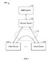
- FIG. 1is a block diagram illustrating an example system for collecting measurements of physiological parameters of patients.
- FIG. 2Aillustrates a view of an example physiological parameter measuring platform (PMP) device.
- PMPphysiological parameter measuring platform
- FIG. 2Billustrates an example user interface displayed on a user interface display of the PMP device of FIG. 2A .
- FIG. 3Aillustrates an example monitoring workflow home screen.
- FIG. 3Billustrates an example spot check workflow home screen.
- FIG. 3Cillustrates an example triage workflow home screen.
- FIG. 3Dillustrates an example alternative view of a patient's SpO2 level.
- FIG. 3Eillustrates the example monitoring workflow home screen when an alarm is active.
- FIG. 3Fillustrates the example monitoring workflow home screen when an alarm is active and when an alarm sound for the alarm has been temporarily silenced.
- FIG. 4illustrates an example patient selection screen.
- FIG. 5illustrates an example review screen.
- FIG. 6Aillustrates an example intervals pane of a settings screen.
- FIG. 6Billustrates an example device pane of the settings screen.
- FIG. 6Cillustrates an example clinician pane of the settings screen.
- FIGS. 6D-6Fillustrate example profile panes of the settings screen.
- FIG. 6Gillustrates an example advanced pane of the settings screen.
- FIG. 7Aillustrates an example global pane of an alarms screen.
- FIG. 7Billustrates an example temperature pane of the alarms screen.
- FIG. 7Cillustrates an example NIBP pane of the alarms screen.
- FIG. 7Dillustrates an example SpO2 pane of the alarms screen.
- FIG. 7Eillustrates an example pulse rate pane of the alarms screen.
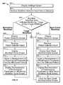
- FIG. 8is a flowchart illustrating an example operation performed by the PMP device.
- FIG. 9is a flowchart representing a continuation of the operation in which the workflow selection input indicates the triage workflow.
- FIG. 10is a flowchart illustrating an operation performed by the PMP device when the PMP device displays a workflow home screen.
- FIG. 11illustrates example physical components of the PMP device.
- Embodiments of the present inventionare directed to a physiological parameter measuring platform (PMP) device having a user interface configured to operate within and transition between each of a monitoring workflow and a non-monitoring workflow.
- PMPphysiological parameter measuring platform
- FIG. 1is a block diagram illustrating an example system 100 for collecting measurements of physiological parameters of patients.
- the system 100comprises an Electronic Medical Records (EMR) system 102 , an interface system 104 , a set of client devices 106 A- 106 N (collectively, “client devices 106 ”), and a network 108 .
- EMRElectronic Medical Records
- the network 108is an electronic communication network that facilitates communication between the client devices 106 and the between the client devices 106 and the interface system 104 .
- An electronic communication networkis a set of computing devices and links between the computing devices. The computing devices in the network use the links to enable communication among the computing devices in the network.
- the network 108can include routers, switches, mobile access points, bridges, hubs, intrusion detection devices, storage devices, standalone server devices, blade server devices, sensors, desktop computers, firewall devices, laptop computers, handheld computers, mobile telephones, and other types of computing devices.
- the network 108includes various types of links.
- the network 108can include wired and/or wireless links.
- the network 108is implemented at various scales.
- the network 108can be implemented as one or more local area networks (LANs), metropolitan area networks, subnets, wide area networks (such as the Internet), or can be implemented at another scale.
- LANslocal area networks
- subnetssuch as the Internet
- the EMR system 102is a computing system that allows storage, retrieval, and manipulation of electronic medical records.
- a computing systemis a system of one or more computing devices.
- a computing deviceis a physical, tangible device that processes data.
- Example types of computing devicesinclude personal computers, standalone server computers, blade server computers, mainframe computers, handheld computers, smart phones, special purpose computing devices, and other types of devices that process data.
- Each client device in the set of client devices 106is a computing device.
- the client devices 106can provide various types of functionality.
- the set of client devices 106can include one or more PMP devices (such as the PMP device 200 ).
- the set of client devices 106can include one or more wall-mounted devices. Such wall-mounted devices can have similar functionality to the PMP device 200 but are stationary instead of portable.
- the set of client devices 106can include one or more monitor devices. Such monitor devices can display representations of physiological parameters, but do not directly obtain measurements of the physiological parameters from patients.
- a monitor devicecould, for example, be used by a clinician to monitor the physiological parameters of multiple patients at one time.
- the client devices 106can communicate with each other through the network 108 .
- the client devices 106can communicate various types of data with each other through the network 108 .
- each of the PMP devicescan send data representing measurements of physiological parameters of patients to the monitor device. In this way, the monitor device can display representations of physiological parameters to a clinician.
- the interface system 104is a computing system that acts as an interface between the EMR system 102 and the client devices 106 .
- the interface system 104is a Connex system. Different EMR systems have different software interfaces. For example, the EMR system used by two different hospitals can have two different software interfaces.
- the interface system 104provides a single software interface to each of the client devices 106 .
- the client devices 106send requests to software interface provided by the interface system 104 .
- the interface system 104receives a request from one of the client devices 106 , the interface system 104 translates the request into a request that works with the software interface provided by the EMR system 102 .
- the interface system 104then provides the translated request to the software interface provided by the EMR system 102 .
- the interface system 104When the interface system 104 receives a response from the EMR system 102 , the interface system 104 translates the response from a format of the EMR system 102 to a system understood by the client devices 106 . The interface system 104 then forwards the translated response to an appropriate one of the client devices 106 .
- the client devices 106can send various types of data to the interface system 104 for storage in the EMR system 102 and can receive various types of data from the EMR system 102 through the interface system 104 .
- the client devices 106can send measurements of physiological parameters to the interface system 104 for storage in the EMR system 102 .
- a monitor devicecan retrieve past measurements of physiological parameters of patients from the EMR system 102 through the interface system 104 .
- FIG. 2Aillustrates a view of a PMP device 200 .
- the PMP device 200is classified and referred to as a portable monitor platform device.
- the PMP device 200includes multiple health care equipment (HCE) modules. Each of the HCE modules is configured to measure one or more physiological parameters of a health-care recipient, also referred to herein as a patient.
- HCEhealth care equipment
- a temperature measurement module 212is accessible from the front side of the PMP device 200 .
- a SpO2 module 214 and a non-invasive blood pressure (NIBP) module 216are accessible from a left hand side of the PMP device 200 .
- An upper handle portion 220enables the PMP device 200 to be carried by hand.
- a front side of the PMP device 200includes a display screen 218 and an outer surface of the temperature measurement module 212 .
- the temperature measurement module 212is designed to measure the body temperature of a patient.
- a “module”is a combination of a physical module structure which typically resides within the PMP device 200 and optional peripheral components (not shown) that typically attach to and reside outside of the PMP device 200 .
- the temperature measurement module 212includes a front panel 212 a .
- the front panel 212 ahas an outer surface that is accessible from the front side of the PMP device 200 .
- the front panel 212 aprovides access to a wall (not shown) storing a removable probe (not shown), also referred to as a temperature probe, that is attached to a probe handle 212 b .
- the probe and its attached probe handle 212 bare tethered to the temperature measurement module 212 via an insulated conductor 212 c .
- the probeis designed to make physical contact with a patient in order to sense a body temperature of the patient.
- a left hand side of the PMP device 200includes an outer surface of the SpO2 module 214 and an outer surface of the NIBP module 216 .
- the SpO2 module 214is a HCE module designed to measure oxygen content within the blood of a patient.
- the NIBP module 216is a HCE module designed to measure blood pressure of a patient.
- the SpO2 module 214includes a front panel 214 a .
- the front panel 214 aincludes an outer surface that is accessible from the left side of the PMP device 200 .
- the front panel 214 aincludes a connector 214 b that enables a connection between one or more peripheral SpO2 components (not shown) and a portion of the SpO2 module 214 residing inside the PMP device 200 .
- the peripheral SpO2 componentsreside external to the PMP device 200 .
- the peripheral SpO2 componentsare configured to interoperate with the SpO2 module 214 when connected to the SpO2 module 214 via the connector 214 b .
- the peripheral SpO2 componentsinclude a clip that attaches to an appendage of a patient, such as a finger. The clip is designed to detect and measure a pulse and an oxygen content of blood flowing within the patient.
- the NIBP module 216includes a front panel 216 a having an outer surface that is accessible from the left side of the PMP device 200 .
- the front panel 216 aincludes a connector 216 b that enables a connection between one or more peripheral NIBP components (not shown) and a portion of the NIBP module 216 residing inside the PMP device 200 .
- the peripheral NIBP componentsreside external to the PMP device 200 .
- the peripheral NIBP componentsare configured to interoperate with the NIBP module 216 when connected to the NIBP module 216 via the connector 216 b .
- the peripheral NIBP componentsinclude an inflatable cuff that attaches to an appendage of a patient, such as an upper arm of the patient.
- the inflatable cuffis designed to measure the systolic and diastolic blood pressure of the patient, the mean arterial pressure (MAP) of the patient, and the pulse rate of blood flowing within the patient.
- MAPmean arterial pressure
- the PMP device 200is able to operate within one or more workflows.
- a workflowis a series of one or more tasks that a user of the PMP device 200 performs.
- the PMP device 200provides functionality suitable for assisting the user in performing the workflow.
- the PMP device 200operates within different workflows, the PMP device 200 provides different functionality.
- the PMP device 200When the PMP device 200 is manufactured, the PMP device 200 is configured to be able to operate within one or more workflows. After the PMP device 200 is manufactured, the PMP device 200 can be reconfigured to operate within one or more additional workflows. In this way, a user can adapt the PMP device 200 for use in different workflows as needed.
- the PMP device 200operates within various workflows.
- the PMP device 200can operate within a monitoring workflow or a non-monitoring workflow.
- Example types of non-monitoring workflowsinclude, but are not limited to, a spot check workflow and a triage workflow.
- the names for the workflowscan be defined by the user.
- the usercan rename a “triage workflow” as “ED 3 North” or any other nomenclature as desired to provide more context to the user.
- the PMP device 200When the PMP device 200 is operating within the monitoring workflow, the PMP device 200 obtains a series of measurements of one or more physiological parameters of a single monitored patient over a period of time. In addition, the PMP device 200 displays, on the display screen 218 , a monitoring workflow home screen.
- the monitoring workflow home screencontains a representation of a physiological parameter of the monitored patient. The representation is based on at least one measurement in the series of measurements.
- a representation of a physiological parameteris a visible image conveying information about the physiological parameter.
- the PMP device 200can obtain a temperature measurement of a single patient once every ten minutes for six hours.
- the PMP device 200displays a monitoring workflow home screen that contains a representation of the patient's body temperature based on a most recent one of the temperature measurements. In this way, a user of the PMP device 200 can monitor the status of the patient.
- the PMP device 200When the PMP device 200 is operating within a non-monitoring workflow, the PMP device 200 obtains a measurement of one or more physiological parameters from each patient in a series of patients. In addition, the PMP device 200 displays a non-monitoring workflow home screen on the display screen 218 .
- the non-monitoring workflow home screencontains a representation of the physiological parameter of a given patient in the series of patients. The representation is based on the measurement of the physiological parameter of the given patient.
- the PMP device 200when the PMP device 200 is operating within a spot check workflow, the PMP device 200 obtains blood pressure measurements from a series of previously-identified patients.
- the PMP device 200displays a spot check workflow home screen containing a blood pressure measurement of a given patient in the series of previously-identified patients.
- a user of the PMP device 200can perform spot checks on the blood pressures of patients who have already been admitted to a hospital.
- a patientis a previously identified patient when the PMP device 200 stores information regarding the identity of the patient.
- the PMP device 200can obtain a single blood pressure measurement from each patient in a series of unidentified patients as the patients arrive at a hospital.
- the PMP device 200displays a triage workflow home screen containing a representation of the patients' blood pressure based on the single blood pressure measurements of the patients. In this way, a user of the PMP device 200 can perform triage on the series of unidentified patients as they arrive.
- a patientis an unidentified patient when the PMP device 200 does not store information regarding the identity of the patient.
- the monitoring workflow home screenis different than the non-monitoring workflow home screen.
- the monitoring workflow home screenis different than the non-monitoring workflow home screen in various ways.
- the monitoring workflow home screenincludes at least one user-selectable control that is not included in the non-monitoring workflow home screen.
- a representation of a physiological parameter in the monitoring workflow home screenhas a different size than a representation of the same physiological parameter in the non-monitoring workflow home screen.
- FIG. 2Billustrates an example user interface displayed on the display screen 218 of FIG. 2A .
- the PMP device 200outputs and displays user interfaces discussed in this document on the display screen 218 .
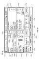
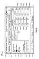
- FIG. 3Aillustrates an example monitoring workflow home screen 300 .
- the PMP device 200displays the monitoring workflow home screen 300 while the PMP device 200 is operating within a monitoring workflow.
- the monitoring workflowis designed for obtaining a series of physiological measurements associated with an identified patient over a period of time.
- the PMP device 200is functionally connected to one or more sensors that enable monitoring of at least one physiological parameter that is associated with a patient.
- each sensoris physically attached to the patient while the PMP device 200 is operating within the monitoring workflow.
- These sensorsinclude a temperature probe, a SpO2 clip, and a NIBP blood pressure cuff that are each attachable to the PMP device 200 as described above.
- the monitoring workflow home screen 300includes a device status area 312 , a navigation area 318 , and a content area 320 .
- the content area 320is divided into a parameter reporting area 314 and a patient attribute area 316 .
- the device status area 312contains data regarding a status of the PMP device 200 .
- the device status area 312includes text that identifies a clinician (“Patricia Jones”) and a health care facility location (“West 4A”).
- a current time of day value (“03:00”)is located towards the center of the device status area 312 .
- a date value (“12/29/2009”)is located to the right side of the time of day value.
- a remaining time of a battery (“1:10”) valueis located at the right side of the device status area 312 .
- the navigation area 318includes a home tab 319 a , a patients tab 319 b , an alarms tab 319 c , a review tab 319 d , and a settings tab 319 e .
- the home tab 319 a , the patients tab 319 b , the alarms tab 319 c , the review tab 319 d , and the settings tab 319 eare referred to herein collectively as the screen tabs 319 .
- Selection of screen tabs 319 b - 319 ecauses substitution of the monitoring workflow home screen 300 with another screen associated with the screen tabs 319 b - 319 e .
- the PMP device 200displays a patient screen when a user selects the patients tab 319 b .
- FIG. 4Aillustrates an example patient selection screen.
- the PMP device 200displays an alarms screen when a user selects the alarms tab 319 c .
- FIGS. 7A-7Eillustrate an example alarms screen.
- the PMP device 200displays a review screen when a user selects the review tab 319 d .
- FIG. 5discussed elsewhere in this document, illustrates an example review screen.
- the PMP device 200displays a settings screen when a user selects the settings tab 319 e .
- FIGS. 6A-6Gdiscussed elsewhere in this document, illustrate an example settings screen.
- the parameter reporting area 314includes one or more parameter reporting frames.
- Each of the parameter reporting framescontains a representation of a different physiological parameter a patient. The representations are based on one or more measurements of the physiological parameters of a monitored patient.
- each of the parameter reporting framescontains an alarm reporting area.
- the alarm reporting areasspecify upper alarm limits and lower alarm limits for the physiological parameters. The upper alarm limits and the lower alarm limits define the alarm ranges for the physiological parameters. Alarms associated with the physiological parameters are active when measurements of the physiological parameters are outside the alarm range for the physiological parameters.
- the parameter reporting area 314contains a NIBP frame 314 a , a pulse rate frame 314 b , a SpO2 frame 314 c , and a temperature frame 314 d .
- the NIBP frame 314 ais located within an upper left portion of the parameter reporting area 314 .
- the pulse rate frame 314 bis located within an upper right portion of the parameter reporting area 314 .
- the SpO2 frame 314 cis located within a lower left portion of the parameter reporting area 314 .
- the temperature frame 314 dis located within a lower right portion of the parameter reporting area 314 .
- the NIBP frame 314 acontains a representation of the blood pressure of the patient.
- the representation of the blood pressure of the patientis based on one or more measurements of the blood pressure of the patient.
- the NIBP frame 314 acontains various representations of the blood pressure of the patient.
- the NIBP frame 314 aincludes enlarged numerical text that represents a systolic blood pressure value (“120”) and a diastolic blood pressure value (“80”), separated from each other via a slash ‘/’ text character.
- the systolic blood pressure valueis located at the left side of the NIBP frame 314 a and the diastolic blood pressure is located to the right side of the systolic blood pressure value.
- An NIBP alarm status area 322 cis located at the right side of the NIBP frame 314 a .
- the NIBP alarm status area 322 cspecifies an upper alarm limit and a lower alarm limit for the patient's systolic blood pressure and an upper alarm limit and a lower alarm limit for the patient's diastolic blood pressure.
- the upper alarm limit and the lower alarm limit for the patient's systolic blood pressuredefine a systolic blood pressure alarm range.
- the upper alarm limit and the lower alarm limit for the patient's diastolic blood pressuredefine a diastolic blood pressure alarm range.
- An alarm associated with the patient's blood pressureis active when the patient's systolic blood pressure is outside the systolic blood pressure alarm range or when the patient's diastolic blood pressure is outside the diastolic blood pressure alarm range
- the NIBP frame 314 aalso contains a NIBP cuff inflation stop button 322 a .
- the NIBP cuff inflation stop button 322 ais labeled with the text “Stop.”
- the NIBP frame 314 aalso contains a NIBP automatic interval timer 322 b .
- the NIBP automatic interval timer 322 bis located between the diastolic blood pressure value and the NIBP alarm status area 322 c . Selection of the NIBP cuff inflation stop button 322 a ceases inflation of the NIBP cuff and toggles the label of the NIBP cuff inflation stop button 322 a to display the (“Start”) text.
- a userselects a button or control when the user provides input to the PMP device 200 that specifies the control. For example, a user can select a control by pressing the control, by pressing another button while the control is highlighted, or by another means. Selection of the NIBP cuff inflation stop button 322 a (now labeled the “Start” button) restarts inflation of the NIBP cuff and toggles the label of the NIBP cuff inflation stop button 322 a to display the (“Stop”) text.
- the NIBP automatic interval timer 322 bindicates an amount of time remaining before the next scheduled inflation of the NIBP cuff.
- a usercan determine the age of the current NIBP reading on the NIBP frame 314 a by subtracting the remaining time on the NIBP automatic interval timer 322 b from the original interval duration.
- the NIBP frame 314 aalso displays a MAP value in an extended label field 322 d.
- the pulse rate frame 314 bcontains a representation of the patient's pulse rate.
- the representation of the patient's pulse rateis based on one or more measurements of the patient's pulse rate.
- the pulse rate frame 314 bcontains different representations of the patient's pulse rate.
- the pulse rate frame 314 bincludes enlarged numerical text that represents a pulse rate value (“122”).
- the pulse rate value (“122”)is located at the left side of the pulse rate frame 314 b .
- a pulse rate alarm status area 324 ais located at the right side of the pulse rate frame 314 b .
- the pulse rate frame 314 balso indicates a source of the pulse rate in an extended label field 324 b.
- the pulse rate alarm status area 324 aspecifies an upper alarm limit and a lower alarm limit.
- the upper alarm limit and the lower alarm limitdefine a pulse rate alarm range.
- An alarm associated with the patient's pulse rateis active when the patient's pulse rate is outside the pulse rate alarm range.
- the SpO2 frame 314 ccontains a representation of the patient's SpO2 level.
- the representation of the patient's SpO2 levelis based on one or more measurements of the patient's SpO2 level.
- the SpO2 frame 314 ccontains different representations of the patient's SpO2 level.
- the SpO2 frame 314 cincludes enlarged numerical text that represents an SpO2 value (“97%”).
- the SpO2 value (“97%”)is located at the left side of the SpO2 frame 314 c and is accompanied by a ‘%’ text character on the right side of the SpO2 value.
- a SpO2 alarm status area 326 ais located at the right side of the SpO2 frame 314 c .
- An SpO2 alarm parameter 326 dappearing as a circle adjacent to the text (“25”), indicates a duration of time.
- the SpO2 alarm status area 326 aspecifies an upper alarm limit and a lower alarm limit.
- the upper alarm limit and the lower alarm limitdefine a SpO2 alarm range.
- An alarm associated with the patient's SpO2 levelis active when the patient's SpO2 level is outside the SpO2 alarm range for the duration of time indicated by the SpO2 alarm parameter 326 d .
- the SpO2 frame 314 calso includes a pulse amplitude blip bar 326 b which indicates pulse beat and shows the relative pulse amplitude. As the detected pulse becomes stronger, more bars in the pulse amplitude blip bar 326 b light up with each pulse.
- the SpO2 frame 314 calso includes an SpO2 response time control button 326 c that is configured for a user to control the SpO2 alarm parameter 326 d.
- the temperature frame 314 dcontains a representation of the patient's body temperature.
- the representation of the patient's body temperatureis based on one or more measurements of the patient's body temperature.
- the temperature frame 314 dcontains different representations of the patient's body temperature.
- the temperature frame 314 dincludes enlarged numerical text that represents a temperature value (“101.5”).
- the temperature value (“101.5”)is located at the left side of the temperature frame 314 d and is accompanied by a Fahrenheit degree indicating symbol on the right side of the temperature value.
- a temperature alarm status area 328 ais located at the right side of the temperature frame 314 d .
- the temperature alarm status area 328 aspecifies an upper alarm limit and a lower alarm limit.
- the upper alarm limit and the lower alarm limitdefine a temperature alarm range.
- An alarm associated with the patient's temperatureis active when the patient's temperature level is outside the temperature alarm range.
- the PMP device 200can measure the patient's temperature in either a predictive mode or in a direct mode.
- the PMP device 200predicts the patient's current temperature based on periodic readings of the patient's temperature.
- the PMP device 200measures the patient's temperature in the direct mode, the PMP device 200 continually measures the patient's temperature.
- the temperature value in the temperature frame 314 dis based on measurements received from a thermometer attached to a patient.
- the thermometercan be located at various places on the patient's body. Example locations on the patient's body where the thermometer can be located include in the patient's mouth, on the patient's thigh, in the patient's armpit, in the patient's rectum, and other locations.
- the temperature frame 314 dincludes a thermometry location control 328 b .
- the thermometry location control 328 bindicates a location on the patient's body where the thermometer is located. In the example of FIG. 3A , the thermometry location control 328 b indicates that the thermometer is located in the patient's mouth.
- the PMP device 200updates the thermometry location control 328 b such that the thermometry location control 328 b indicates a different location on the patient's body or whether the PMP device 200 is to obtain measurements of the patient's temperature in direct mode.
- the usercan continue selecting the thermometry location control 328 b until the thermometry location control 328 b indicates a location where the thermometer is located on the patient's body or until the thermometry location control 328 b indicates that measurements are to be obtained in direct mode.
- the PMP device 200accepts readings from a thermometer when the thermometer is located in the patient's mouth, in an adult patient's armpit, or in a pediatric patient's armpit.
- the thermometry location control 328 binitially indicates that the thermometer is in a patient's mouth.
- the thermometry location control 328 bindicates that the thermometer is located in an adult patient's armpit.
- the thermometry location control 328 bindicates that the thermometer is located in a pediatric patient's armpit.
- the thermometry location control 328 bindicates that the measurements of the patient's temperature are to be obtained in direct mode.
- the thermometry location control 328 bagain indicates that the thermometer is located in a patient's mouth.
- the display screen 218enables a user to select the parameter reporting frames 314 a - 314 d in order to change how the physiological parameters are represented in the parameter reporting frames 314 a - 314 d .
- each of the parameter reporting frames 314 a - 314 dcontains an initial representation of a physiological parameter.
- the parameter reporting framedisplays an alternate representation of the physiological parameter instead of the initial representation of the physiological parameter when a user selects the parameter reporting frame. For example, selecting the temperature frame 314 d toggles the temperature value between being expressed in Fahrenheit or Centigrade.
- the PMP device 200displays a waveform in the pulse rate frame 314 b instead of a number representing the patient's current pulse rate.
- the waveformrepresents a patient's pulse over time.
- the PMP device 200displays a number in the pulse rate frame 314 b representing the patient's current pulse rate.
- the PMP device 200displays a plethysmograhic waveform view in the SpO2 frame 314 c .
- FIG. 3Dillustrates an example alternate representation of a patient's SpO2 level.
- the SpO2 frame 314 ccontains a plethysmographic waveform view 325 .
- the patient attribute area 316contains data that specify attributes of a patient.
- the patient attribute area 316contains data that specify various attributes of a patient. For example, in some embodiments, text that identifies a patient is located at the left side of the patient attribute area 316 . In the example of FIG. 3A , the patient attribute area 316 contains the value “83645211” to identify the patient.
- the patient attribute area 316contains a patient type button 316 b that is labeled with the text “Adult.”
- the patient type button 316 bis located towards the center of the patient attribute area 316 .
- Patient-related attribute values that are labeled with the text (“HEIGHT”), (“WEIGHT”), (“PAIN”) and (“RR”)are located to the right side of the patient type button 316 b .
- a save button 316 gthat is labeled with the text (“Save”) is located at the right side of the patient attribute area 316 .
- the patient type button 316 bindicates a value of a patient type parameter associated with the current patient.
- the patient type parametercan store a value of “Adult”, “Pediatric”, or “Neonatal” patient type.
- the patient type parametercontrols the amount of air pressure applied to the NIBP cuff.
- the patient type parametercontrols the default alarm limits for the patient's physiological parameters.
- the usercan automatically change the alarm limits for the patient's physiological parameters.
- the usercan also manually set the alarm limits for physiological parameters.
- the monitoring workflow home screen 300is replaced by the patient selection screen as if the patients tab 319 b was selected.
- the PMP device 200When the save button 316 g is selected while the PMP device is operating in the monitoring workflow, the PMP device 200 saves a patient reading to local non-volatile storage within the PMP device 200 .
- the patient readingis a set of data that includes measurements of the physiological parameters of the patient. If applicable, the patient reading can also include data indicating attributes of the patient.
- a usercan use the review screen to review saved patient reading.
- the PMP device 200automatically attempts to transmit the patient reading to another computing node. A user can use the settings screen to specify the other computing node.
- the other computing nodeis an electronic medical records system.
- the other computing nodeis the interface system 104 .
- the PMP device 200does not clear the monitoring workflow home screen 300 when the save button 316 g is selected.
- the monitoring workflowis designed for obtaining a series of measurements of one or more physiological parameters of an identified patient over a period of time.
- a useruses the patient selection screen to select the identified patient.
- the PMP device 200is programmable via an intervals pane of the settings screen to periodically record measurements of one or more physiological parameters over time from the identified patient.
- a usermay select the save button 316 g one or more times. Each time the user selects the save button 316 g , the PMP device 200 locally saves the patient reading and attempts to send the patient reading to another computing node. The sending is dependent on the workflow in which the PMP device 200 is operating. In the spot check workflow (see FIG. 3B ), the PMP device 200 automatically sends the patient reading because a clinician is present when the measurements are obtained. When the PMP device 200 is operating in the monitoring workflow, a clinician may not be always present. Thus, the patient reading is not sent automatically. Instead, a clinician navigates to the review screen (See FIG. 5 ) and manually selects the patient reading that the user wants to send.
- the PMP device 200When the PMP device 200 is operating in the monitoring workflow, the representations of the physiological parameters and patient attributes remain displayed on the monitoring workflow home screen 300 , regardless of whether or not the patient reading is saved locally and/or transmitted to another computing node in response to a selection of the save button 316 g . Unlike the spot check and triage workflows, the PMP device 200 does not clear the monitoring workflow home screen 300 when a user selects the save button 316 g.
- the home screens for each workflow supported by the PMP device 200contain at least one common user interface element.
- the common user interface elementhas the same appearance in each of the home screens, but does not necessarily perform the same function in the home screens of the different workflows.
- the patient type button 316 b and the save button 316 gare user interface elements that are included within and common to the monitoring workflow home screen 300 and to home screens for the spot check workflow ( FIG. 3B ) and the triage workflow ( FIG. 3C ). Further, the patient type button 316 b and the save button 316 g have a same appearance but also have different functions depending upon which workflow the PMP device 200 is operating within.
- the PMP device 200When the PMP device 200 is operating in the monitoring workflow, the PMP device 200 clears the monitoring workflow home screen 300 upon discharge of the current (first) identified patient for which physiological parameters are being obtained. When the PMP device 200 clears the monitoring workflow home screen 300 , the PMP device 200 modifies the monitoring workflow home screen 300 such that the monitoring workflow home screen 300 no longer contains data representing physiological parameters of a patient and attributes of the patient. The monitored patient is discharged by the selection of another (second) identified patient for which to obtain physiological data, via the patient selection screen 400 or by power-cycling the PMP device 200 .
- the PMP device 200Upon selection of the second patient, the PMP device 200 locally stores the patient reading for the first patient and transmits the patient reading for the first patient to another computing node when a user selects a send patient reading control 448 a on the review screen (see FIG. 5 ). Upon attaching the sensors to the second identified patient, the PMP device 200 obtain measurements of a set of one or more physiological parameter from the second identified patient, periodically over time.
- the monitoring workflow home screen 300provides direct access to the alarm screen via the alarm status areas 322 c , 324 a , 326 a , 328 a located within the parameter reporting frames 314 a - 314 d .
- Each alarm status area 322 c , 324 a , 326 a , 328 aindicates high and low alarm limits and provides a visual indication of when an alarm is active.
- FIG. 3Eillustrates the monitoring workflow home screen 300 when an alarm is active.
- a perimeter around the parameter reporting frame for the particular physiological parametertransitions from a gray color to a red color. Changing the color of the perimeter provides a visual indication that the alarm is active.
- the perimeter around the parameter reporting framealso flashes, thereby providing another visual indication that the alarm is active.
- the bell-shaped symbol within the alarm status areatransitions from a white color to a red or yellow color, depending on a priority of the alarm. This provides another visual indication that the alarm is active.
- the bell-shaped symbol within the alarm status areatransitions from the red or yellow color to the white color.
- an alarm associated with the patient's pulse rateis active. Accordingly, the perimeter around the pulse rate frame 314 b is red instead of gray.
- the PMP device 200when an alarm associated with a particular physiological parameter is active, the PMP device 200 causes the device status area 312 to display an alarm message 380 .
- the alarm message 380visually indicates that an alarm is active and indicates a brief description of the alert. In the example FIG. 3E , the alarm message 380 indicates that the reason for the alert is that the patient's heart rate is too high.
- the PMP device 200when an alarm associated with a particular physiological parameter is active, the PMP device 200 emits an alarm sound. The PMP device 200 continues to emit the alarm sound until the alarm is deactivated or until a user temporarily silences the alarm sound. When the user temporarily silences the alarm sound, the PMP device 200 suspends emitting the alarm sound for a given time period.
- the useris able to temporarily silence the alarm sound in various ways. For example, in some embodiments, the user temporarily silences the alarm sound by touching the parameter reporting frame corresponding to the alarm. In other embodiments, the user temporarily silences the alarm sound by touching the alarm message 380 . In yet other embodiments, the user temporarily silences the alarm sound by selecting a physical button on the PMP device 200 .
- the PMP device 200When the user temporarily silences the alarm sound, the PMP device 200 resumes emitting the alarm sound after a given time period expires. For example, in some embodiments, the PMP device 200 resumes emitting the alarm sound after 30 seconds.
- the alarm message 380indicates a time remaining before the PMP device 200 resumes emitting the alarm sound.
- FIG. 3Fillustrates the monitoring workflow home screen 300 when an alarm is active and when the alarm sound for the alarm has been temporarily silenced.
- the alarm message 380indicates that eighty-nine seconds remain before the PMP device 200 resumes emitting the alarm sound.
- the useris able to temporarily silence the alarm sound for various lengths of time by selecting a button on the PMP device 200 or a control displayed by the PMP device 200 multiple times. For example, when the user selects the alarm message 380 one time, the PMP device 200 resumes emitting the alarm sound after sixty seconds. In this example, each time the user selects the alarm message 380 , the PMP device 200 adds thirty seconds to the length of time before the PMP device 200 resumes emitting the alarm sound. In some embodiments, the PMP device 200 prevents the user from temporarily silencing the alarm sound for more than a given amount of time. For example, in some embodiments, the PMP device 200 prevents the user from temporarily silencing the alarm sound for more than five minutes.
- the monitoring workflow home screen 300visually indicates that the alarm sound has been temporarily silenced.
- the monitoring workflow home screen 300visually indicates that the alarm sound has been temporarily silenced in various ways.
- the alarm message 380contains a bell-shaped icon when the alarm sound has been temporarily silenced.
- the bell-shaped iconhas an X-shaped mark over a bell. The lines of the X-shaped mark are dashed.
- the alarm message 380 or other parts of the monitoring workflow home screen 300contain differently shaped icons or visual indicators.
- the alarm status areas 322 c , 324 a , 326 a , 328 aact as navigational short cuts to appropriate panes within the alarms screen for each respective physiological parameter (See FIG. 7A ). In this way, selecting an alarm status area while no alarm is active results in the PMP device 200 displaying the same user interface as if a user selects the alarms tab 319 c and then selects an appropriate pane of the alarms screen. Navigation to the appropriate pane of the alarms screen happens only when the PMP device 200 is not emitting an alarm sound. In other words, the first selection of this area (or anywhere in the parameter reporting frame) would cause the alarm to silence the audio. A subsequent selection of the alarm status area performs the navigation.
- an alarm associated with a patient's pulse ratehas a high priority level and an alarm associated with detachment of a SpO2 clip has a medium priority level.
- the PMP device 200visually and/or sonically indicates alarms having different priority levels in different ways. For example, in some embodiments, when an alarm having a high priority level is active, the PMP device 200 displays visual indications of the alarm in a given color, such as red. When an alarm having a medium or low priority level is active, the PMP device 200 displays visual indications of the alarm in another color, such as yellow. Furthermore, in some embodiments, when an alarm having a high priority level is active, the PMP device 200 emits a given alarm sound, such as a continuous tone. When an alarm having a medium or low priority level is active, the PMP device 200 emits another alarm sound, such as a periodic beep.
- the PMP device 200can activate different alarms and/or emit different alarm sounds. For example, the PMP device 200 activates an alarm when a SpO2 clip detachment event occurs while the PMP device 200 operating within the monitoring workflow, but does not activate the alarm while in a non-operating in the monitoring workflow.
- This featurecan be convenient considering that the PMP device 200 and the patient are more likely to be unattended by a user of the PMP device 200 for periods of time when the PMP device 200 is operating in the monitoring workflow, but less likely when the PMP device 200 is operating in the spot check or the triage workflows.
- monitoring of SpO2may be prevented by the PMP device 200 beyond ten minutes if the PMP device 200 is operating in the spot check or the triage workflows.
- the PMP device 200indicates that multiple alarms are active.
- the PMP device 200indicates that multiple alarms are active in various ways.
- the alarm message 380includes an icon that indicates a number of alarms that are currently active.
- iconcan be a triangle containing the number of alarms that are currently active.
- the PMP device 200displays different visual indicators depending on the priority levels of concurrently active alarms. For example, when two or more high level alarms are active concurrently, the PMP device 200 displays visual indications for each of the high level alarms. In another example, when an alarm having a medium priority level (“the medium level alarm”) and an alarm having a high priority level (“the high level alarm”) are active concurrently, the PMP device 200 displays visual indications for the high level alarm and does not display visual indications for the medium level alarm. If the user of the PMP device 200 temporarily silences the alarm sound for the high level alarm, the PMP device 200 does not emit the alarm sound for the high level alarm or the alarm sound for the medium level alarm. When the high level alarm is resolved before the medium level alarm is resolved, the PMP device 200 displays visual indications for the medium level alarm and the PMP device 200 resumes emitting the alarm sound for the medium level alarm.
- the user of the PMP device 200is able to toggle between multiple concurrently active alarms by selecting one or more controls in the user interface of the PMP device 200 or by selecting one or more buttons on the PMP device 200 .
- the usercauses the PMP device 200 to display the visual indications for each of the multiple concurrently active alarms. For example, a first alarm and a second alarm can be concurrently active.
- the PMP device 200displays an alarm message describing a first alarm.
- the PMP device 200modifies the alarm message to describe a second alarm when a user selects the alarm message.
- the PMP device 200enables a user to customize the content within the monitoring workflow home screen 300 .
- the PMP device 200enables a user to adjust the relative sizes of the parameter reporting frames 314 a - 314 d within the monitoring workflow home screen 300 .
- the PMP device 200enables the user to add or remove parameter reporting frames from the monitoring workflow home screen 300 .
- the PMP device 200includes one or more predefined templates for the monitoring workflow home screen 300 . Each of the predefined templates specifies a predefined set of content within the monitoring workflow home screen 300 .
- one predefined templatespecifies that the monitoring workflow home screen 300 includes a large parameter reporting frame for the patient's blood pressure and three smaller parameter reporting frames for the patient's pulse rate, SpO2 level, and body temperature.
- another predefined templatespecifies that the monitoring workflow home screen 300 includes only a frame for the patient's SpO2 level and the patient's blood pressure. The user can customize the content within the monitoring workflow home screen 300 by selecting one of these predefined templates or by modifying one of these predefined templates.
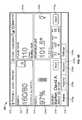
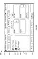
- FIG. 3Billustrates an example spot check workflow home screen 330 .
- the PMP device 200displays the spot check workflow home screen 330 when the PMP device 200 is operating in a spot check workflow.
- the spot check workflow home screen 330is referred to as the “Home” screen for the spot check workflow.
- each sensoris physically attached to an identified patient when the PMP device 200 is operating in the spot check workflow.
- These sensorsinclude a temperature probe, a SpO2 clip, and a NIBP blood pressure cuff. As described elsewhere in this document, the temperature probe, the SpO2 clip and the NIBP blood pressure cuff are peripheral to the PMP device 200 .
- the spot check workflow home screen 330includes a device status area 312 , a content area 320 , and a navigation area 318 .
- the content area 320includes a parameter reporting area 314 and a patient attribute area 316 .
- the parameter reporting area 314 of the spot check workflow home screen 330includes an NIBP frame 334 a , a pulse rate frame 314 b , a SpO2 frame 334 c and a temperature frame 334 d.
- the NIBP frame 334 acontains a representation of a patient's blood pressure. The representation is based on one or more measurements of the blood pressure of a previously identified patient.
- the NIBP frame 334 aincludes text representing the patient's systolic and diastolic blood pressure.
- the text representing the patient's systolic and diastolic blood pressureis larger than the text in the monitoring workflow home screen 300 representing the patient's systolic and diastolic blood pressure.
- the NIBP frame 334 a of the spot check workflow home screen 330does not include the NIBP alarm status area 322 c and does not include the NIBP automatic interval timer 322 b of the monitoring workflow home screen 300 .
- the pulse rate frame 334 bcontains a representation of the patient's pulse rate. The representation is based on one or more measurements of the pulse rate of the patient.
- the pulse rate frame 334 bincludes text representing the patient's pulse rate.
- the text representing the patient's pulse rateis larger than the text in the monitoring workflow home screen 300 representing the patient's pulse rate.
- the pulse rate frame 334 b of the spot check workflow home screen 330does not include the pulse rate alarm status area 324 a included within the pulse rate frame 314 b of the monitoring workflow home screen 300 .
- the SpO2 frame 334 ccontains a representation of the patient's SpO2 level. The representation is based on one or more measurements of the SpO2 level of the patient.
- the SpO2 frame 334 cincludes text representing the SpO2 value.
- the text representing the patient's SpO2 levelis larger than the text in the monitoring workflow home screen 300 representing the patient's SpO2 level.
- the SpO2 frame 334 cdoes not include the alarm status area 326 a , the SpO2 response time control button 326 c , or the SpO2 alarm parameter 326 d of the SpO2 frame 314 c of the monitoring workflow home screen 300 .
- the temperature frame 334 dcontains a representation of the patient's body temperature. The representation is based on one or more measurements of the body temperature of the patient.
- the temperature frame 334 dincludes text representing the patient's body temperature.
- the text representing the patient's body temperatureis larger than the text in the monitoring workflow home screen 300 representing the patient's body temperature.
- the temperature frame 334 d of the spot check workflow home screen 330does not include the temperature alarm status area 328 a included within the temperature frame 314 d of the monitoring workflow home screen 300 .
- the patient attribute area 316 of the spot check workflow home screen 330includes text that identifies the patient by name, initials, numerical identifier, or location.
- the patient attribute area 316includes text that identifies the patient as “Bar, D.”
- a useris able use the settings screen to configure the PMP device 200 to identify the patient by name or by number.
- the useris also able to use the settings screen to configure the PMP device 200 not to save or send patient readings when the PMP device 200 does not store information regarding the identity of the patient.
- the navigation area 318 of the spot check workflow home screen 330includes the home tab 319 a , the patients tab 319 b , the review tab 319 d , and the settings tab 319 e .
- the navigation area 318excludes the alarms tab 319 c included in the navigation area 318 of the monitoring workflow home screen 300 .
- the spot check workflow home screen 330does not provide direct navigation to the alarms screen as provided by the monitoring workflow home screen 300 .
- the PMP device 200When the PMP device 200 is operating in the spot check workflow, the PMP device 200 locally saves a patient reading and attempts to send the patient reading to another computing node when a user selects the save button 316 g .
- the patient readingincludes measurements of the physiological parameters of the patient and data identifying the patient.
- the PMP device 200clears the spot check workflow home screen 330 when the user selects the save button 316 g .
- the PMP device 200modifies the spot check workflow home screen 330 such that the spot check workflow home screen 330 no longer contains representations of the physiological parameters of the patient and attributes of the patient.
- the PMP device 200clears the spot check workflow home screen 330 when a user selects the save button 316 g of the spot check workflow home screen 330 , a first identified patient is essentially discharged when the user selects the save button 316 g . After selecting the save button 316 g , the user selects a second identified patient via the patient selection screen. Upon attaching the sensors to the second identified patient, the PMP device 200 obtains a set of one or more physiological parameter values from the second identified patient.
- the spot check workflowis designed for obtaining measurements of physiological parameters from each patient in a series of identified patients.
- a userselects each patient in the series of identified patients from the patient selection screen.
- a usercan select each patient in the series of identified patient by scanning barcodes of the patients, thereby bypassing the patient selection screen.
- a usercan identify a patient at any step in the workflow prior to saving the patient reading of the spot check workflow home screen 330 .
- a useruses the PMP device 200 to obtain measurements of one or more physiological parameters of that patient.
- the PMP device 200is attached to a first patient for no more time than is required to obtain one measurement for each of the NIBP, the pulse rate, the SpO2, and the body temperature of the first patient. The user then detaches the sensors from the first patient and attaches the sensors to a second patient that is next in the series of patients.
- a usercan use the spot check workflow “making rounds” within a health care facility.
- a cliniciancan use the PMP device 200 to obtain one set of measurements of physiological parameters for each patient in a group of twelve patients within a health care facility.
- the cliniciancan transport the PMP device 200 sequentially to each patient in the group of patients within one “round” of obtaining measurements of physiological parameters.
- Each “round” of obtaining measurements of physiological parameterscan be obtained for each patient in the patients of the group every hour during a working shift.
- the PMP device 200enables a user to customize the content within the spot check workflow home screen 330 .
- the PMP device 200enables a user to adjust the relative sizes of the parameter reporting frames 334 a - 334 d within the spot check workflow home screen 330 .
- the PMP device 200enables the user to add or remove parameter reporting frames from the spot check workflow home screen 330 .
- the PMP device 200includes one or more predefined templates for the spot check workflow home screen 330 . Each of the predefined templates specifies a predefined set of content within the spot check workflow home screen 330 . The user can customize the content within the spot check workflow home screen 330 by selecting one of these predefined templates or by modifying one of these predefined templates.
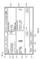
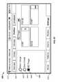
- FIG. 3Cillustrates an example triage workflow home screen 360 .
- the PMP device 200displays the triage workflow home screen 360 when the PMP device 200 is in a triage workflow.
- each sensoris operating in the monitoring workflow or the spot check workflow.
- These sensorsinclude the temperature probe, the SpO2 clip, and the blood pressure cuff that are each attachable to the PMP device 200 as described elsewhere in this document.
- the triage workflow home screen 360includes a device status area 312 , a content area 320 , and a navigation area 318 .
- the content area 320 of the triage workflow home screen 360includes a parameter reporting area 314 and a patient attribute area 316 .
- the parameter reporting area 314 of the triage workflow home screen 360includes an NIBP frame 364 a , a pulse rate frame 364 b , a SpO2 frame 364 c and a temperature frame 364 d.
- the NIBP frame 364 acontains a representation of the systolic and diastolic blood pressure of the patient. The representation is based on one or more measurements of the blood pressure of the patient.
- the NIBP frame 364 aincludes text representing the systolic and diastolic blood pressure of the patient.
- the size of the text in the NIBP frame 364 ais similar to the size of the text in the NIBP frame 334 a of the spot check workflow home screen 330 and larger than the size of the text in the NIBP frame 314 a of the monitoring workflow home screen 300 .
- the NIBP frame 364 adoes not include the NIBP alarm status area 322 c and does not include the NIBP automatic interval timer 322 b included in the NIBP frame 314 a of the monitoring workflow home screen 300 .
- the pulse rate frame 364 bcontains a representation of the pulse rate of the patient. The representation is based on one or more measurements of the pulse rate of the patient.
- the pulse rate frame 364 bcontains text representing the pulse rate value of the patient.
- the size of the text in the pulse rate frame 364 bis similar to the size of the text in the pulse rate frame 334 b of the spot check workflow home screen 330 and larger than the size of the text in the pulse rate frame 314 b of the monitoring workflow home screen 300 .
- the pulse rate frame 364 bdoes not include the pulse rate alarm status area 324 a that is included within the pulse rate frame 314 b of the monitoring workflow home screen 300 .
- the SpO2 frame 364 ccontains a representation of the SpO2 level of the patient. The representation is based on one or more measurements of the SpO2 level of the patient.
- the SpO2 frame 364 cincludes text representing the SpO2 value of the patient.
- the size of the text in the SpO2 frame 364 cis similar to the size of the text in the SpO2 frame 334 c of the spot check workflow home screen 330 and larger than the size of the text in the SpO2 frame 314 c of the monitoring workflow home screen 300 .
- the SpO2 frame 334 cdoes not include the alarm status area 326 a , the SpO2 response time control button 326 b , or the SpO2 alarm parameter 326 b of the SpO2 frame 314 c of the monitoring workflow home screen 300 .
- the temperature frame 364 dcontains a representation of the body temperature of the patient. The representation is based on one or more measurements of the body temperature of the patient.
- the temperature frame 364 dincludes text representing the body temperature of the patient.
- the size of the text in the temperature frame 364 dis similar to the size of the text in the temperature frame 334 d of the spot check workflow home screen 330 and larger than the size of the text in the temperature frame 314 d of the temperature frame 314 d of the monitoring workflow home screen 300 .
- the temperature frame 364 ddoes not include the temperature alarm status area 328 a that is included within the temperature frame 314 d of the monitoring workflow home screen 300 .
- the navigation area 318 of the triage workflow home screen 360includes the home tab 319 a , the review tab 319 d , and the settings tab 319 e .
- the navigation area 318 of the triage workflow home screen 360excludes the alarms tab 319 c of the monitoring workflow home screen 300 .
- the triage workflow home screen 360does not provide direct navigation to the alarms screen as provided by the monitoring workflow home screen 300 .
- the navigation area 318 of the triage workflow home screen 360excludes the patients tab 319 b of the monitoring workflow home screen 300 and the spot check workflow home screen 330 .
- the triage workflow home screen 360does not provide direct navigation to the patient selection screen as provided by the monitoring workflow home screen 300 and the spot check workflow home screen 330 .
- the patient attribute area 316 of the triage workflow home screen 360includes a patient type button 316 b and a save button 316 g .
- the patient attribute area 316does not include text that identifies the patient.
- the PMP device 200When the PMP device 200 is operating within the triage workflow, the PMP device 200 locally saves a patient reading of the triage workflow home screen 360 .
- the home screen data of the triage workflow home screen 360includes measurements of the physiological parameters of the unidentified patient.
- a usercan configure the PMP device 200 to transmit the patient reading of the triage workflow home screen 360 to another computing node in response to a selection of the save button 316 g .
- the PMP device 200clears the triage workflow home screen 360 when a user selects the save button 316 g .
- the PMP device 200modifies the triage workflow home screen 360 such that the triage workflow home screen 360 no longer contains representations of the physiological parameters of the patient.
- selection of the patient type button 316 btoggles the text label of the patient type button 316 b and toggles a value of a patient type parameter within the triage workflow home screen 360 .
- the text label and data value associated with the patient type button 316 btoggles between the label/values of (“Adult”), (“Pediatric”) and (“Neonatal”).
- the patient reading transmitted to another computing nodeincludes a patient type parameter value equal to (“Adult”), (“Pediatric”) and (“Neonatal”).
- the patient type datasubstitutes for patient identification data that is absent from the patient reading while operating within the triage workflow.
- a first unidentified patientis essentially discharged when a user selects the save button 316 g .
- the useruses the PMP device 200 to obtain a set of one or more measurements of physiological parameter from the second unidentified patient.
- the triage workflowis designed for obtaining measurements of physiological parameters from each of a series of unidentified patients.
- a userdoes not select each patient in the series of unidentified patients from the patient selection screen. Instead, the user attaches the sensors to each unidentified patient in sequence.
- the useruses the PMP device 200 to obtain measurements of one or more physiological parameters of that patient at that time.
- the userattaches the sensors to the patient for no more time that is required to obtain one measurement for each of the NIBP, the pulse rate, the SpO2 level, and the body temperature of the patient.
- the userthen detaches the sensors are from the patient and attaches the sensors to another patient that is next in the series of patients.
- the triage workflowcan be used for obtaining measurements of physiological parameters from unidentified health care recipients.
- the recipientsmay or may not be patients of a health care facility.
- the other computing nodeis a personal computer which receives the patient reading from the PMP device 200 with no patient names attached.
- the PMP device 200enables a user to customize the content within the triage workflow home screen 360 .
- the PMP device 200enables a user to adjust the relative sizes of the parameter reporting frames 364 within the triage workflow home screen 360 .
- the PMP device 200enables the user to add or remove parameter reporting frames from the triage workflow home screen 360 .
- the PMP device 200includes one or more predefined templates for the triage workflow home screen 360 .
- Each of the predefined templatesspecifies a predefined set of content within the triage workflow home screen 360 . The user can customize the content within the triage workflow home screen 360 by selecting one of these predefined templates or by modifying one of these predefined templates.
- FIG. 4illustrates an example patient selection screen 400 .
- a usercan navigate to the patient selection screen 400 by selecting the patients tab 319 b .
- the patient selection screen 400includes a device status area 312 , a pane selection tab area 310 and a navigation area 318 .
- the pane selection tab area 310includes four pane selection tabs that are labeled “List”, “Summary”, “Modifiers” and “Manual.”
- the list pane 418includes a column label area 412 , a patient listing area 414 , and a screen control area 416 .
- the device status area 312appears like the device status area 312 of the monitoring workflow home screen 300 , the device status area 312 of the spot check workflow home screen 330 , and the device status area 312 of the triage workflow home screen 360 .
- the navigation area 318appears like the navigation area 318 of the monitoring workflow home screen 300 .
- the patient listing area 414includes lines 415 a - 415 e (collectively, “lines 415 ”). Each of the lines 415 is associated with a different patient. For example, a patient having a name “Barker, D.” is listed on the line 415 a , a patient having a name “Connor, W.” is listed on the line 415 c , and a patient having a name “Davison, A” is listed on the line 415 e.
- the screen control area 416includes three buttons.
- a first (left) button that is labeled “Add”is utilized to add a patient to the patient listing area 414 .
- a second (middle) button that is labeled “Delete”is utilized to delete a patient from the patient listing area 414 .
- a third (right) button that is labeled “Select”is utilized to highlight a patient that listed within the patient listing area 414 .
- FIG. 5illustrates an example review screen 500 .
- a usercan navigate to the review screen 500 using the review tab 319 d .
- the review screen 500includes a device status area 312 , a review table 541 , a screen control area 548 , and a navigation area 318 .
- the device status area 312appears like the device status area 312 of the monitoring workflow home screen 300 , the device status area 312 of the spot check workflow home screen 330 , and the device status area 312 of the triage workflow home screen 360 .
- the navigation area 318 of the review screen 500appears like the navigation area 318 of the monitoring workflow home screen 300 .
- the review table 541includes a column label line 542 .
- the review table 541includes patient readings 546 a - 546 f and columns 552 a - 552 i .
- Each of the patient readings 546 a - 546 fcomprises a different set of measurements of physiological parameters of a patient.
- Each of the columns 552 b - 552 his associated with a different physiological parameter.
- Check marks in the column 552 aindicate whether particular ones of the patient readings 546 a - 546 f are selected. In the example of FIG. 5 , the patient readings 546 A and 546 e are selected.
- the patient reading 546 aincludes a patient name (“Barker, D.”) in the column 552 b , a date and time value in the column 552 c , a systolic and diastolic measurement value in the column 552 d , a mean arterial pressure (MAP) measurement value (not shown), a temperature measurement value in the column 552 f , a pulse measurement value in the column 552 g , an SpO2 measurement value in the column 552 h , and a patient attributes set of values in the column 552 i.
- MAPmean arterial pressure
- the screen control area 548includes a send patient reading button 548 a , a print patient reading button 548 b , a delete patient reading button 548 c and a view list box 548 d .
- the print patient reading button 548 bis utilized to send a selected patient reading.
- the print patient reading button 548 bis utilized to print selected patient readings.
- the delete patient reading button 548 cis utilized to delete selected patient readings.
- the view list box 548 denables filtering of the review table 541 . A user can use the view list box 548 d to select to view all available patient readings or only particular patient readings based on sent, unsent or alarm status.
- FIG. 6Aillustrates an example intervals pane 610 of a settings screen 600 .
- Direct navigation to the settings screen 600is provided from the monitoring workflow home screen 300 , from the spot check workflow home screen 330 , and from the triage workflow home screen 360 .
- a user of the PMP device 200navigates to the settings screen 600 by selecting the settings tab 319 e .
- the settings screen 600includes a device status area 312 , a pane selection tab area 604 , the intervals pane 610 and a navigation area 318 .
- the device status area 312 of the settings screen 600appears like the device status area 312 of the monitoring workflow home screen 300 , the device status area 312 of the spot check workflow home screen 330 , and the device status area 312 of the triage workflow home screen 360 .
- the pane selection tab area 604includes five pane selection tabs that are labeled “Intervals,” “Device,” “Clinician,” “Profiles,” and “Advanced.”
- the navigation area 318 of the settings screen 600appears like the navigation area 318 of the monitoring workflow home screen 300 .
- a usercan use the intervals pane 610 to program the PMP device 200 to save NIBP measurements, pulse rate measurements, SpO2 measurements, and temperature measurements for a patient at given intervals over an given time period. Other combinations of physiological parameters can be obtained at other fixed or non-fixed intervals.
- the intervals pane 610includes an automatic control 611 , a program control 612 , a stat control 613 , an off control (not shown), a print control 615 , and a start control 616 .
- the automatic control 611the settings screen 600 contains one or more controls for entering a fixed time period to right of control.
- the program control 612is selected, the settings screen 600 contains controls for defining and selecting interval programs.
- the stat control 613the settings screen 600 contains one or more controls for capturing and saving as many measurements of physiological parameters as possible within a time period, for example a five minute period.
- the off controlintervals are turned off.
- the print control 615is selected, a captured measurement at each interval may be printed.
- the start control 616is a command button to start the selected interval workflow: Automatic, Program, or Stat.
- the PMP device 200automatically initiates an NIBP reading and initiates the interval program once the start control 616 is selected.
- the program control 612is selected. Consequently, the intervals pane 610 includes controls for defining and selecting interval programs.
- An interval programis a set of parameters that governs the intervals at which the PMP device 200 records measurements of one or more physiological parameters of a patient and for lengths of time for which the PMP device 200 records the measurements of the one or more physiological parameters of the patient.
- the intervals pane 610contains interval program selection controls 660 a , 660 b (collectively, interval program selection controls 660 ). More or fewer controls 660 can be provided.
- the interval program selection controls 660specify the names of interval programs. In some examples, the interval program selection controls 660 specify names associated with the controls, such as “Transplant,” “Transfusion,” “Cardiac,” which represent names of interval programs.
- a userselects an interval program by selecting one of the interval program selection controls 660 that corresponds to the interval program. After selecting the interval program, the user starts the interval program by selecting the start control 616 .
- the PMP device 200records measurements of physiological parameters of a patient at the intervals specified by the interval program for the duration specified by the interval program.
- the monitoring workflow home screen 300contains remaining time controls.
- the remaining time controlsindicate amounts of time remaining before the PMP device 200 records measurements of the physiological parameters.
- the pulse rate frame 314 b of the monitoring workflow home screen 300can include a remaining time control that indicates that twenty seconds remain before the PMP device 200 records a measurement of the patient's pulse rate.
- the PMP device 200displays the intervals pane 610 when the user selects the remaining time controls. In this way, the user of the PMP device 200 can easily access the intervals pane 610 .
- the intervals pane 610contains a program name control 662 , duration controls 664 a - 664 e (collectively, “duration controls 664 ”), and interval controls 666 a - 666 e (collectively, “interval controls 666 ”).
- the duration controls 664 and the interval controls 666are organized into rows. Each row corresponds to a different physiological parameter of the patient. For example, a first row corresponds to the patient's blood pressure, a second row corresponds to the patient's pulse rate, and so on.
- the program name control 662contains the name of the interval program.
- the program name control 662indicates that the name of the interval program is “Transfusion.”
- the duration controls 664specify lengths of time during which the PMP device 200 is to record measurements of the physiological parameters.
- the interval controls 666specify lengths of time that the PMP device 200 waits between recording measurements of the physiological parameters.
- the duration control 664 aindicates 1 hour and the interval control 666 a indicates 15 minutes. Consequently, the PMP device 200 records measurements of a physiological parameter at 15 minute intervals for one hour after the “Transfusion” interval program starts.
- the userWhen the user selects an interval program using one of the interval program selection controls 660 , the user is able to change the values in the program name control 662 , the duration controls 664 , and the interval controls 666 . For example, the user can change the value of the duration control 664 b from one hour to two hours.
- FIG. 6Billustrates an example device pane 620 of the settings screen 600 .
- the settings screen 600includes a device status area 312 , a pane selection tab area 604 , a device pane 520 and a navigation area 318 .
- the device status area 312 , the pane selection tab area 604 , and the navigation area 318appear like that of FIG. 6A .
- the device pane 620provides controls and information for a user to select or view device characteristics.
- the device pane 620includes a set date and time control 622 , a touch-screen lock-out control 628 , and a command button 629 .
- the set date and time control 622is configured to set up a date and time for the PMP device 200 .
- a usermay select a date display format through the date format selection (not shown), such as MM/DD/YYYY.
- a usermay also select a time zone offset from UTC based on where the PMP device 200 is located.
- the touch-screen lock-out control 628is configured to allow a user to lock out the touch screen. When the command button 629 is selected, the touch screen is locked out immediately.
- FIG. 6Cillustrates an example clinician pane of the settings screen 600 .
- the settings screen 600includes a device status area 312 , a pane selection tab area 604 , a clinician pane 630 and a navigation area 318 .
- the device status area 312 , the pane selection tab area 604 and the navigation area 318appear like that of FIG. 6A .
- the clinician pane 630provides for entry of clinician identification.
- the clinician identifiedcan include a first name, a last name, a middle initial, and an identification number.
- FIGS. 6D-6Fillustrate an example profiles pane 640 of the settings screen 600 .
- the settings screen 600includes the device status area 312 , a pane selection tab area 604 , the profiles pane 640 and a navigation area 318 .
- the device status area 312 , the pane selection tab area 604 and the navigation area 318appear like that of FIG. 6A .
- the profiles pane 640allows a user to select a desired workflow within which the PMP device 200 is to operate.
- the profiles pane 640includes a “Med/Surge” control 642 , a “Spot Check” control 644 , and an “ED Triage” control 646 .
- a userselects the “Med/Surge” control 642 to select a “Med/Surge” workflow as the workflow in which the PMP device 200 is to operate.
- the userselects the “Spot Check” control 644 to select the spot check workflow as the workflow in which the PMP device 200 is to operate.
- the userselects the “ED triage” control 646 to select the triage workflow as the workflow in which the PMP device 200 is to operate.
- the profiles pane 640shows a preview of the home screen of the selected workflow.
- FIG. 6Gillustrates an example advanced pane 650 of the settings screen 600 .
- the settings screen 600includes a device status area 312 , a pane selection tab area 604 , the advanced pane 650 and a navigation area 318 .
- the device status area 312 , the pane selection tab area 504 and the navigation area 318appear like that of FIG. 6A .
- the advanced pane 650enables an administrator to access configuration settings that are likely to be set once or less frequently than those required for a normal use. When a proper access code is entered, the PMP device 200 switches to an administration workflow and the navigation tabs switch to advanced settings tabs.
- the advanced pane 650also provides read-only information about the PMP device 200 .
- FIG. 7Aillustrates an example global pane 710 of an alarms screen 700 .
- a user of the PMP device 200navigates to the alarms screen 700 by selecting the alarms tab 319 c .
- the alarms screen 700includes controls that enable a user to configure global alarm settings and parameter-specific alarm settings.
- the alarms screen 700includes the device status area 312 , a compressed parameter reporting area 702 , a pane selection tab area 704 , the global pane 710 , and the navigation area 318 .
- the device status area 312appears like the device status areas of the monitoring workflow home screen 300 , the spot check workflow home screen 330 and the triage workflow home screen 360 .
- the navigation area 318 of the alarms screen 700appears like the navigation area 318 of the monitoring workflow home screen 300 .
- the compressed parameter reporting area 702contains one or more compressed parameter frames containing data representing live physiological parameters of a patient.
- the compressed parameter reporting area 702contains a compressed NIBP frame 703 a , a compressed SpO2 frame 703 b , a compressed pulse rate frame 703 c , and a compressed temperature frame 703 d .
- the compressed NIBP frame 703 a , the compressed SpO2 frame 703 b , the compressed pulse rate frame 703 c , and the compressed temperature frame 703 dare referred to herein collectively as the compressed frames 703 .
- the compressed parameter reporting area 702has frame dimensions that are smaller than the frame dimensions of the parameter reporting area 314 of the monitoring workflow home screen 300 . Because the compressed parameter reporting area 702 is smaller than the parameter reporting area 314 , the compressed parameter reporting area 702 appears “squished” relative to the parameter reporting area 314 .
- the compressed NIBP frame 703 acontains a representation of the systolic and the diastolic blood pressure of the patient.
- the compressed SpO2 frame 703 bcontains a representation of a SpO2 percentage of the patient, a pulse amplitude blip bar, and alarm limits for the SpO2 parameter.
- the compressed pulse rate frame 703 ccontains a representation of a pulse rate of the patient.
- the compressed temperature frame 703 dcontains a representation of the body temperature of the patient.
- the compressed frames 703do not contain user-selectable controls. Consequently, the user is unable to toggle views of the physiological parameters from the compressed frames 703 .
- the corresponding one of the compressed frames 703provides a visual indication of the alarm. For example, when the patient's blood pressure is too high, a perimeter of the compressed NIBP frame 703 a changes from one color (e.g., gray) to a different color (e.g., red). Furthermore, when an alarm is active, the device status area 312 of the alarms screen 700 is replaced by an alarm message describing the alarm. In some embodiments, selecting the alarm message causes the PMP device 200 to temporarily stop emitting an alarm sound associated with the alarm.
- the pane selection tab area 704includes five pane selection tabs that are labeled “Global”, “NIBP”, “SpO2”, “Pulse” and “Temperature.”
- the PMP device 200updates the alarms screen 700 to contain a pane associated with the selected pane selection tab.
- the global pane 710is located below the compressed parameter reporting area 702 .
- the global pane 710provides controls for configuring global alarm settings for the PMP device 200 .
- the global alarm settingsare settings that apply to all alarms provided by the PMP device 200 .
- the global pane 710includes a reset button 712 a , a display alarm limit parameter button 712 b , a set of alarm audio buttons 712 c , a set of volume buttons 712 d , and a silence/reset button 712 e .
- a usercan use the reset button 712 a to reset alarm limits.
- the usercan use the display alarm limit parameter button 712 b to configure the PMP device 200 to display or not to display alarm limits.
- the usercan use the set of alarm audio buttons 712 c to configure the PMP device 200 to emit alarm sounds.
- the usercan use the set of volume buttons 712 d to set a volume of the alarm sounds to high, medium or low. Also, the user can use the silence/reset button 712 e to silence or reset alarms.
- FIG. 7Billustrates an example temperature pane 720 of the alarms screen 700 .
- the alarms screen 700includes the device status area 312 , the compressed parameter reporting area 702 , the pane selection tab area 704 , the temperature pane 720 , and a navigation area 318 .
- the device status area 312 , the compressed parameter reporting area 702 , the pane selection tab area 704 and the navigation area 318appear like that of FIG. 7A .
- the temperature pane 720is located below the compressed parameter reporting area 702 .
- the temperature pane 720enables a user of the PMP device 200 to configure parameter-specific alarm settings for the temperature alarm.
- the temperature pane 720provides controls 722 a , 722 b and 722 c .
- the control 722 asets the temperature alarm to ON or OFF.
- the control 722 bsets an upper temperature limit for the temperature alarm.
- the control 722 csets a lower temperature limit for the temperature alarm.
- FIG. 7Cillustrates an example NIBP pane 730 of the alarms screen 700 .
- the alarms screen 700includes a device status area 312 , a compressed parameter reporting area 702 , a pane selection tab area 704 , the NIBP pane 730 , and a navigation area 318 .
- the device status area 312 , the compressed parameter reporting area 702 , the pane selection tab area 704 and the navigation area 318appear like that of FIG. 7A .
- the NIBP pane 730enables a user of the PMP device 200 to configure parameter-specific alarm settings for the NIBP alarm.
- the NIBP pane 730contains a control 732 a to set the systolic and diastolic alarm ON or OFF.
- the NIBP pane 730also contains controls 732 b - 732 e to set the systolic and diastolic upper and lower alarm limits for the systolic and diastolic alarm.
- the NIBP pane 730provides controls 732 f , 732 g and 732 h .
- the control 732 fsets a MAP alarm to ON or OFF.
- the control 732 gsets set an upper MAP limit for the MAP alarm.
- the control 732 hsets a lower MAP limit for the MAP alarm.
- FIG. 7Dillustrates an example SpO2 pane 740 of the alarms screen 700 .
- the alarms screen 700includes the device status area 312 , the compressed parameter reporting area 702 , the pane selection tab area 704 , the SpO2 pane 740 , and the navigation area 318 .
- the device status area 312 , the compressed parameter reporting area 702 , the pane selection tab area 704 , and the navigation area 318appear like that of FIG. 7A .
- the SpO2 pane 740enables a user of the PMP device 200 to configure parameter-specific alarm settings for the SpO2 alarm.
- the SpO2 pane 740provides controls 742 a , 742 b and 742 c .
- the control 742 asets the SpO2 alarm to ON or OFF.
- the controls 742 b and 742 cset an upper SpO2 limit and a lower SpO2 limit for the SpO2 alarm.
- the SpO2 pane 740also includes a SatSecondsTM control 743 d . When a numeric value is selected, an SpO2 alarm is not activated until a length of time specified by the SatSeconds control 743 d has expired.
- the length of time specified by the SatSeconds control 743 dis based on a duration of a low SpO2 event multiplied by a number of percentage points that the patient's SpO2 falls outside the lower SpO2 alarm threshold. Also, the SatSeconds control 743 d appears next to the controls 742 b and 742 c when the control 742 a is set to ON. However, when the control 742 a is set to OFF, the SatSeconds control 743 d is not displayed and the alarm condition is not delayed per a SatSeconds algorithm.
- FIG. 7Eillustrates an example pulse rate pane 750 of the alarms screen 700 .
- the alarms screen 700includes the device status area 312 , the compressed parameter reporting area 702 , the pane selection tab area 704 , the pulse rate pane 750 and the navigation area 318 .
- the device status area 312 , the compressed parameter reporting area 702 , the pane selection tab area 704 and the navigation area 318appear like that of FIG. 7A .
- the pulse rate pane 750enables a user of the PMP device 200 to configure parameter-specific alarm settings for the pulse rate alarm.
- the pulse rate pane 750provides an on/off control 752 a , an upper limit control 752 b and a lower limit control 752 c .
- the on/off control 752 aallows a user to turn the pulse rate alarm on or off.
- the upper limit control 752 ballows a user to set an upper pulse rate limit for the pulse rate alarm.
- the lower limit control 752 callows a user to set a lower pulse rate limit for the pulse rate alarm.
- the upper limit control 752 bincludes a numerical portion, an up button and a down button.
- the numerical portion of the upper limit control 752 bspecifies an upper pulse rate limit for the pulse rate alarm. Selecting the up button of the upper limit control 752 b incrementally increases the upper pulse rate limit. Selecting the down button of the upper limit control 752 b incrementally decreases the upper pulse rate limit. Selecting the numerical portion of the upper limit control 752 b causes the PMP device 200 to display a numerical keypad. The user is able to use the numerical keypad to manually enter a value for the upper pulse rate limit.
- the lower limit control 752 cincludes a numerical portion, an up button, and a down button.
- the numerical portion of the lower limit control 752 cspecifies the lower pulse rate limit. Selecting the up button of the lower limit control 752 c incrementally increases the lower pulse rate limit. Selecting the down button of the lower limit control 752 c incrementally decreases the lower pulse rate limit. Selecting the numerical portion of the lower limit control 752 c causes the PMP device 200 to display a numerical keypad. The user is able to use the numerical keypad to manually enter a value for the lower pulse rate limit.
- the values that are entered by the userare validated for accuracy.
- upper and lower thresholds for each parametercan be set. If the user selects a value outside of the upper and lower thresholds, the system can prevent such a selection and/or alert the user. For example, if the user types in 300 minutes on the keypad for a parameter, and the upper threshold set for that parameter is 240 minutes, the system will not allow the user to increase the parameter to 300 minutes.
- various panes of the alarms screen 700can include other upper limit controls and other lower limit controls like the upper limit control 752 b and the lower limit control 752 c .
- the other upper limit controls and the other lower limit controlsallow a user to set upper limits and lower limits for alarms for various physiological parameters of patients.
- FIG. 8is a flowchart illustrating an example operation 800 performed by the PMP device 200 .
- the operation 800begins when the PMP device 200 displays the settings screen 600 ( 802 ).
- the PMP device 200receives workflow selection input from a clinician via the settings screen 600 ( 804 ).
- the PMP device 200determines whether the workflow selection input indicates the monitoring workflow, the triage workflow, or the spot check workflow ( 806 ). If the PMP device 200 determines that the workflow selection input indicates the triage workflow, the PMP device 200 performs the steps illustrated in FIG. 9 .
- the PMP device 200determines that the workflow selection input indicates the monitoring workflow, the PMP device 200 displays the patient selection screen 400 ( 808 ). The PMP device 200 then receives patient selection input from the clinician via the patient selection screen 400 ( 810 ). The patient selection input indicates a patient that the clinician intends to monitor.
- the PMP device 200displays the monitoring workflow home screen 300 ( 812 ). In some embodiments, the PMP device 200 displays the monitoring workflow home screen 300 automatically after the clinician selects the monitored patient via the patient selection screen 400 . In other embodiments, the PMP device 200 displays the monitoring workflow home screen 300 in response to the clinician selecting the home tab 319 a.
- the PMP device 200obtains a measurement of a physiological parameter of the monitored patient ( 814 ).
- the PMP device 200displays a representation of the physiological parameter on the monitoring workflow home screen 300 ( 816 ).
- the representation of the physiological parameteris based, at least in part, on the measurement of the physiological parameter.
- the PMP device 200then obtains another measurement of the physiological parameter from the same monitored patient ( 814 ). In this way, the PMP device 200 enables the clinician to monitor the physiological parameters of the same monitored patient over a period of time.
- the PMP device 200displays the patient selection screen 400 ( 818 ). In various embodiments, the PMP device 200 displays the patient selection screen 400 in response to various events. For example, in some embodiments, the PMP device 200 automatically displays the patient selection screen 400 when the PMP device 200 determines that the workflow selection input indicates the spot check workflow. In another example, the PMP device 200 displays the patient selection screen 400 in response to receiving a selection of the patients tab 319 b.
- the PMP device 200then receives patient selection input from the clinician via the patient selection screen 400 ( 820 ).
- the patient selection inputindicates a selected patient.
- the selected patientis a patient on whom the clinician intends to perform a spot check.
- the PMP device 200displays the spot check workflow home screen 330 ( 822 ).
- the PMP device 200displays the spot check workflow home screen 330 in response to various events. For example, in some embodiments, the PMP device 200 automatically displays the spot check workflow home screen 330 when the PMP device 200 receives the patient selection input from the clinician. In other embodiments, the PMP device 200 displays the spot check workflow home screen 330 in response to receiving a selection of the home tab 319 a.
- the PMP device 200then obtains a measurement of a physiological parameter of the selected patient ( 824 ). In response to obtaining the measurement of the physiological parameter of the selected patient, the PMP device 200 displays a representation of the physiological parameter of the selected patent ( 826 ). The representation of the physiological parameter is based, at least in part, on the measurement of the physiological parameter.
- the PMP device 200clears the home screen data from the spot check workflow home screen 330 ( 828 ).
- the PMP device 200displays the patient selection screen 400 again ( 818 ) and receives patient selection input indicating another patient ( 818 ), and so on. In this way, the PMP device 200 displays representations of physiological parameters of each patient in a series of patients.
- FIG. 9is a flowchart representing a continuation of the operation 800 in which the workflow selection input indicates the triage workflow.
- the PMP device 200determines that the workflow selection input indicates the triage workflow
- the PMP device 200displays the triage workflow home screen 360 ( 900 ).
- the PMP device 200displays the triage workflow home screen 360 in response to various events. For example, in some embodiments, the PMP device 200 automatically displays the triage workflow home screen 360 when the PMP device 200 determines that the workflow selection input indicates the triage workflow. In another example, the PMP device 200 displays the triage workflow home screen 360 when the PMP device 200 receives a selection of the home tab 319 a.
- the PMP device 200obtains a measurement of a physiological parameter of an unidentified patient in a series of patients ( 902 ). After obtaining the measurement, the PMP device 200 displays a representation of the physiological parameter on the triage workflow home screen 360 ( 904 ). The representation of the physiological parameter is based at least in part on the measurement of the physiological parameter.
- the PMP device 200clears the home screen data from the triage workflow home screen 360 ( 906 ).
- the PMP device 200then obtains a measurement of the physiological parameter of a different patient in the series of unidentified patients ( 902 ), displays a representation of the physiological parameter ( 904 ), and so on. In this way, the PMP device 200 displays representations of physiological parameters of each patient in the series of unidentified patients.
- FIG. 10is a flowchart illustrating an operation 1000 performed by the PMP device 200 when the PMP device 200 displays a workflow home screen.
- the PMP device 200can perform the operation 1000 when the PMP device 200 displays either the monitoring workflow home screen 300 , the spot check workflow home screen 330 , or the triage workflow home screen 360 .
- the PMP device 200initially waits to receive an event ( 1002 ).
- An eventis an occurrence or happening of significance to a task or program.
- the PMP device 200receives a measurement event when the PMP device 200 receives a measurement of a physiological parameter of a patient. If the PMP device 200 receives a measurement event (“YES” of 1004 ), the PMP device 200 determines whether the measurement of the physiological parameter is within an alarm range for the physiological parameter ( 1006 ). If the measurement of the physiological parameter is not within (i.e., is outside) the alarm range for the physiological parameter (“NO” of 1006 ), the PMP device 200 displays an alarm message on the workflow home screen ( 1008 ). In addition, the PMP device 200 emits an alarm sound ( 1010 ).
- the PMP device 200also generates a representation of the physiological parameter based on the measurement of the physiological parameter ( 1012 ).
- the PMP device 200generates the representation of the physiological parameter regardless of whether the measurement is within the alarm range of the physiological parameter.
- the PMP device 200then displays the representation of the physiological parameter on the workflow home screen ( 1014 ).
- the PMP device 200then waits for another event ( 1002 ).
- the PMP device 200can receive an alarm message selection event when the PMP device 200 displays an alarm message, there are two or more active alarms, and a clinician selects the alarm message. If the PMP device 200 receives an alarm message selection event (“YES” of 1016 ), the PMP device 200 modifies the alarm message such that the alarm message describes a next one of the active alarms ( 1018 ). The PMP device 200 then waits for another event ( 1002 ).
- the PMP device 200can receive an alarm silence event when an alarm is currently active, the PMP device 200 is emitting an alarm sound, and a clinician selects a control to suspend the alarm sound. If the PMP device 200 receives an alarm silence event (“YES” of 1020 ), the PMP device 200 suspends the alarm sound ( 1022 ). In addition, the PMP device 200 modifies the alarm message to indicate that the alarm has been silenced ( 1024 ). The PMP device 200 then waits for another event ( 1002 ).
- the PMP device 200can receive a representation selection event when a clinician selects a representation of a physiological parameter. If the PMP device 200 receives a representation selection event (“YES” of 1026 ), the PMP device 200 modifies a parameter reporting area associated with the physiological parameter such that the parameter reporting area contains a different representation of the physiological parameter ( 1028 ). The PMP device 200 then waits for another event ( 1002 ).
- the PMP device 200can receive a save selection event when a clinician selects a save button (e.g., save button 316 g ) on the workflow home screen. If the PMP device 200 receives a save selection event (“YES” of 1030 ), the PMP device 200 saves the home screen data ( 1032 ). The PMP device 200 then waits for another event ( 1002 ).
- a save selection event(“YES” of 1030 )
- the PMP device 200saves the home screen data ( 1032 ).
- the PMP device 200then waits for another event ( 1002 ).
- FIG. 11illustrates example physical components of the PMP device 200 .
- the PMP device 200include at least one central processing unit (“CPU”) 1108 , a system memory 1112 , and a system bus 1110 that couples the system memory 1112 to the CPU 1108 .
- the system memory 1112includes a random access memory (“RAM”) 1118 and a read-only memory (“ROM”) 1120 .
- RAMrandom access memory
- ROMread-only memory
- the PMP device 200further includes a mass storage device 1114 .
- the mass storage device 1114is able to store software instructions and data.
- the mass storage device 1114is connected to the CPU 1108 through a mass storage controller (not shown) connected to the bus 1110 .
- the mass storage device 1114 and its associated computer-readable data storage mediaprovide non-volatile, non-transitory storage for the PMP device 200 .
- computer-readable data storage mediacan be any available non-transitory, physical device or article of manufacture from which the PMP device 200 can read data and/or instructions.
- Computer-readable data storage mediainclude volatile and non-volatile, removable and non-removable media implemented in any method or technology for storage of information such as computer-readable software instructions, data structures, program modules or other data.
- Example types of computer-readable data storage mediainclude, but are not limited to, RAM, ROM, EPROM, EEPROM, flash memory or other solid state memory technology, CD-ROMs, digital versatile discs (“DVDs”), other optical storage media, magnetic cassettes, magnetic tape, magnetic disk storage or other magnetic storage devices, or any other medium which can be used to store the desired information and which can be accessed by the PMP device 200 .
- the PMP device 200may operate in a networked environment using logical connections to remote network devices through the network 108 , such as a local network, the Internet, or another type of network.
- the PMP device 200connects to the network 108 through a network interface unit 1116 connected to the bus 1110 . It should be appreciated that the network interface unit 1116 may also be utilized to connect to other types of networks and remote computing systems.
- the PMP device 200also includes an input/output controller 1122 for receiving and processing input from a number of other devices, including a keyboard, a mouse, a touch user interface display screen, or another type of input device. Similarly, the input/output controller 1122 may provide output to a touch user interface display screen, a printer, or other type of output device.
- the mass storage device 1114 and the RAM 1118 of the PMP device 200can store software instructions and data.
- the software instructionsinclude an operating system 1132 suitable for controlling the operation of the PMP device 200 .
- the mass storage device 1114 and/or the RAM 1118also store software instructions, that when executed by the CPU 1108 , cause the PMP device 200 to provide the functionality of the PMP device 200 discussed in this document.
- the mass storage device 1114 and/or the RAM 1118can store software instructions that, when executed by the CPU 1108 , cause the PMP device to display the monitoring workflow home screen 300 and other screens.
Landscapes
- Health & Medical Sciences (AREA)
- Engineering & Computer Science (AREA)
- Life Sciences & Earth Sciences (AREA)
- General Health & Medical Sciences (AREA)
- Biomedical Technology (AREA)
- Medical Informatics (AREA)
- Public Health (AREA)
- Business, Economics & Management (AREA)
- Physics & Mathematics (AREA)
- Primary Health Care (AREA)
- Epidemiology (AREA)
- Veterinary Medicine (AREA)
- Biophysics (AREA)
- Pathology (AREA)
- Heart & Thoracic Surgery (AREA)
- Molecular Biology (AREA)
- Surgery (AREA)
- Animal Behavior & Ethology (AREA)
- Cardiology (AREA)
- General Business, Economics & Management (AREA)
- Human Resources & Organizations (AREA)
- Economics (AREA)
- Strategic Management (AREA)
- Physiology (AREA)
- Entrepreneurship & Innovation (AREA)
- Tourism & Hospitality (AREA)
- Marketing (AREA)
- Theoretical Computer Science (AREA)
- General Physics & Mathematics (AREA)
- Operations Research (AREA)
- Quality & Reliability (AREA)
- Game Theory and Decision Science (AREA)
- Development Economics (AREA)
- Educational Administration (AREA)
- Pulmonology (AREA)
- Measuring And Recording Apparatus For Diagnosis (AREA)
- Child & Adolescent Psychology (AREA)
Abstract
Description
- obtain a series of measurements of a physiological parameter of a monitored patient;
- display a monitoring workflow home screen on the display screen, the monitoring workflow home screen containing a first representation of the physiological parameter, the first representation of the physiological parameter based on at least one measurement in the series of measurements; and
- display, on the display screen, an alarms screen that enables the user to configure global alarm settings and parameter-specific alarm settings. The alarms screen includes a compressed parameter reporting area. The compressed parameter reporting area contains a compressed parameter frame containing a second representation of the physiological parameter of the monitored patient.
When the user selects a spot check workflow from the settings screen, the software instructions, when executed, cause the PMP device to: - obtain a measurement of the physiological parameter of each patient in a series of previously identified patients; and
- display a spot check workflow home screen on the display screen. The spot check workflow home screen contains a third representation of the physiological parameter of a given patient in the series of previously identified patients. The third representation of the physiological parameter is based on the measurement of the physiological parameter of the given patient in the series of previously identified patients.
When the user selects a triage workflow from the settings screen, the software instructions, when executed, cause the PMP device to: - obtain a measurement of the physiological parameter of each patient in a series of unidentified patients; and
- display a triage workflow home screen on the display screen. The triage workflow home screen contains a fourth representation of the physiological parameter of a given patient in the series of unidentified patients, the fourth representation of the physiological parameter based on the measurement of the given patient in the series of unidentified patients.
The monitoring workflow home screen, the spot check workflow home screen, and the triage workflow home screen are each different from one another. The software instructions, when executed, also cause the PMP device to display, on the display screen, an alarm message describing a first alarm when the first alarm is active. The first alarm is active when a given measurement of the physiological parameter is outside an alarm range for the physiological parameter. The software instructions, when executed, also cause the PMP device to modify, on the display screen, the alarm message to describe a second alarm when the second alarm is active and when the user selects the alarm message. The software instructions, when executed, also cause the PMP device to emit an alarm sound when the first alarm is active. The software instructions, when executed, also cause the PMP device to suspend emitting the alarm sound for a given time period in response to user input. The software instructions, when executed, also cause the PMP device to extend the given time period when the PMP device receives additional user input before the given time period expires. The software instructions, when executed, also cause the PMP device to resume emitting the alarm sound when the given time period expires.
Claims (18)
Priority Applications (1)
| Application Number | Priority Date | Filing Date | Title |
|---|---|---|---|
| US14/994,576US9646136B2 (en) | 2009-09-18 | 2016-01-13 | Physiological parameter measuring platform device supporting multiple workflows |
Applications Claiming Priority (3)
| Application Number | Priority Date | Filing Date | Title |
|---|---|---|---|
| US24387209P | 2009-09-18 | 2009-09-18 | |
| US12/751,579US9265429B2 (en) | 2009-09-18 | 2010-03-31 | Physiological parameter measuring platform device supporting multiple workflows |
| US14/994,576US9646136B2 (en) | 2009-09-18 | 2016-01-13 | Physiological parameter measuring platform device supporting multiple workflows |
Related Parent Applications (1)
| Application Number | Title | Priority Date | Filing Date |
|---|---|---|---|
| US12/751,579ContinuationUS9265429B2 (en) | 2009-09-18 | 2010-03-31 | Physiological parameter measuring platform device supporting multiple workflows |
Publications (2)
| Publication Number | Publication Date |
|---|---|
| US20160125151A1 US20160125151A1 (en) | 2016-05-05 |
| US9646136B2true US9646136B2 (en) | 2017-05-09 |
Family
ID=43757234
Family Applications (2)
| Application Number | Title | Priority Date | Filing Date |
|---|---|---|---|
| US12/751,579Active2033-05-24US9265429B2 (en) | 2009-09-18 | 2010-03-31 | Physiological parameter measuring platform device supporting multiple workflows |
| US14/994,576ActiveUS9646136B2 (en) | 2009-09-18 | 2016-01-13 | Physiological parameter measuring platform device supporting multiple workflows |
Family Applications Before (1)
| Application Number | Title | Priority Date | Filing Date |
|---|---|---|---|
| US12/751,579Active2033-05-24US9265429B2 (en) | 2009-09-18 | 2010-03-31 | Physiological parameter measuring platform device supporting multiple workflows |
Country Status (5)
| Country | Link |
|---|---|
| US (2) | US9265429B2 (en) |
| EP (1) | EP2477537B1 (en) |
| CN (2) | CN102481100B (en) |
| AU (1) | AU2010295856B2 (en) |
| WO (1) | WO2011034790A2 (en) |
Cited By (1)
| Publication number | Priority date | Publication date | Assignee | Title |
|---|---|---|---|---|
| USD794060S1 (en)* | 2014-07-11 | 2017-08-08 | Huawei Technologies Co., Ltd | Display screen with graphical user interface |
Families Citing this family (236)
| Publication number | Priority date | Publication date | Assignee | Title |
|---|---|---|---|---|
| US20080221930A1 (en) | 2007-03-09 | 2008-09-11 | Spacelabs Medical, Inc. | Health data collection tool |
| US9265429B2 (en) | 2009-09-18 | 2016-02-23 | Welch Allyn, Inc. | Physiological parameter measuring platform device supporting multiple workflows |
| US9604020B2 (en) | 2009-10-16 | 2017-03-28 | Spacelabs Healthcare Llc | Integrated, extendable anesthesia system |
| CN102667423B (en) | 2009-10-16 | 2016-06-08 | 太空实验室健康护理有限公司 | light enhanced flow tube |
| US20110313789A1 (en) | 2010-01-22 | 2011-12-22 | Deka Products Limited Partnership | Electronic patient monitoring system |
| US11164672B2 (en) | 2010-01-22 | 2021-11-02 | Deka Products Limited Partnership | System and apparatus for electronic patient care |
| US10911515B2 (en) | 2012-05-24 | 2021-02-02 | Deka Products Limited Partnership | System, method, and apparatus for electronic patient care |
| US10453157B2 (en) | 2010-01-22 | 2019-10-22 | Deka Products Limited Partnership | System, method, and apparatus for electronic patient care |
| US11244745B2 (en) | 2010-01-22 | 2022-02-08 | Deka Products Limited Partnership | Computer-implemented method, system, and apparatus for electronic patient care |
| US11210611B2 (en)* | 2011-12-21 | 2021-12-28 | Deka Products Limited Partnership | System, method, and apparatus for electronic patient care |
| US11881307B2 (en) | 2012-05-24 | 2024-01-23 | Deka Products Limited Partnership | System, method, and apparatus for electronic patient care |
| USD678302S1 (en)* | 2010-05-26 | 2013-03-19 | Covidien Lp | Display screen with a transitional graphical user interface |
| USD674401S1 (en)* | 2010-05-26 | 2013-01-15 | Covidien Lp | Display screen with transitional graphical user interface |
| US8717181B2 (en)* | 2010-07-29 | 2014-05-06 | Hill-Rom Services, Inc. | Bed exit alert silence with automatic re-enable |
| USD671125S1 (en)* | 2010-09-02 | 2012-11-20 | Nellcor Puritan Bennett Llc | Display screen with a graphical user interface |
| WO2012068567A1 (en) | 2010-11-19 | 2012-05-24 | Spacelabs Healthcare, Llc | Dual serial bus interface |
| US9629566B2 (en) | 2011-03-11 | 2017-04-25 | Spacelabs Healthcare Llc | Methods and systems to determine multi-parameter managed alarm hierarchy during patient monitoring |
| USD691164S1 (en)* | 2011-09-30 | 2013-10-08 | Life Technologies Corporation | Display screen with graphical user interface |
| US9943269B2 (en)* | 2011-10-13 | 2018-04-17 | Masimo Corporation | System for displaying medical monitoring data |
| WO2013056171A2 (en)* | 2011-10-13 | 2013-04-18 | Spacelabs Healthcare, Llc | Integrated, extendable anesthesia system |
| EP2776278B1 (en) | 2011-10-28 | 2020-05-06 | Husqvarna AB | Indicator system for outdoor power equipment |
| AU2011380002B2 (en)* | 2011-10-28 | 2015-07-30 | Husqvarna Ab | Start fault indicator system |
| US10563681B2 (en) | 2011-12-21 | 2020-02-18 | Deka Products Limited Partnership | System, method, and apparatus for clamping |
| US9092762B2 (en) | 2012-04-05 | 2015-07-28 | Welch Allyn, Inc. | Medical device maintenance system |
| US10226200B2 (en) | 2012-04-05 | 2019-03-12 | Welch Allyn, Inc. | User interface enhancements for physiological parameter monitoring platform devices |
| US9055870B2 (en) | 2012-04-05 | 2015-06-16 | Welch Allyn, Inc. | Physiological parameter measuring platform device supporting multiple workflows |
| USD772252S1 (en) | 2012-04-05 | 2016-11-22 | Welch Allyn, Inc. | Patient monitoring device with a graphical user interface |
| US20130268283A1 (en)* | 2012-04-05 | 2013-10-10 | Welch Allyn, Inc. | Process to Streamline Workflow for Continuous Monitoring of a Patient |
| USD916713S1 (en) | 2012-04-05 | 2021-04-20 | Welch Allyn, Inc. | Display screen with graphical user interface for patient central monitoring station |
| US9235682B2 (en) | 2012-04-05 | 2016-01-12 | Welch Allyn, Inc. | Combined episodic and continuous parameter monitoring |
| US11871901B2 (en) | 2012-05-20 | 2024-01-16 | Cilag Gmbh International | Method for situational awareness for surgical network or surgical network connected device capable of adjusting function based on a sensed situation or usage |
| CN102693619B (en)* | 2012-06-04 | 2018-09-21 | 广州艾威梯通讯科技有限公司 | A kind of method and system carrying out time acquisition and management using Bluetooth technology during emergency medical |
| USD722322S1 (en)* | 2012-08-16 | 2015-02-10 | Bsh Bosch Und Siemens Hausgeraete Gmbh | Built-in home appliance display screen with graphical user interface |
| US9352951B2 (en)* | 2012-09-28 | 2016-05-31 | Franklin Fueling Systems, Inc. | Fuel delivery management system |
| US9351641B2 (en)* | 2012-10-04 | 2016-05-31 | Cerner Innovation, Inc. | Mobile processing device system for patient monitoring data acquisition |
| USD724428S1 (en)* | 2012-10-05 | 2015-03-17 | The Gillette Company | Shaving product package |
| US9787568B2 (en) | 2012-11-05 | 2017-10-10 | Cercacor Laboratories, Inc. | Physiological test credit method |
| CN103892795A (en)* | 2012-12-27 | 2014-07-02 | 北京超思电子技术股份有限公司 | Physiological parameter reminding method and device |
| USD753685S1 (en)* | 2013-02-06 | 2016-04-12 | Life Technologies Corporation | Thermal cycler display screen with graphical user interface |
| US20140235963A1 (en)* | 2013-02-15 | 2014-08-21 | Welch Allyn, Inc. | Remote Health Care System |
| WO2014140117A1 (en)* | 2013-03-12 | 2014-09-18 | Roche Diagnostics Gmbh | Method for transmitting a glucose measure, method for displaying status during a wireless transmission of a glucose measure and handheld glucose meter |
| US20140282148A1 (en)* | 2013-03-15 | 2014-09-18 | Thomas Blomseth Christiansen | Monitoring and Collaborative Analysis of a Condition |
| CN103941968A (en)* | 2013-05-07 | 2014-07-23 | 深圳市科曼医疗设备有限公司 | Monitor switchable in display interface and switching method for display interfaces of monitor |
| US10987026B2 (en) | 2013-05-30 | 2021-04-27 | Spacelabs Healthcare Llc | Capnography module with automatic switching between mainstream and sidestream monitoring |
| CN105324071B (en)* | 2013-06-24 | 2020-06-30 | 皇家飞利浦有限公司 | Early confirmation of extended aperiodic measurements |
| WO2015041150A1 (en)* | 2013-09-20 | 2015-03-26 | テルモ株式会社 | Display device and display method |
| USD783675S1 (en)* | 2013-11-18 | 2017-04-11 | Mitsubishi Electric Corporation | Information display for an automotive vehicle with a computer generated icon |
| USD789973S1 (en) | 2013-12-20 | 2017-06-20 | Roche Diagnostics Operations, Inc. | Display screen or portion thereof with graphical user interface and computer icons |
| US20150186023A1 (en)* | 2013-12-30 | 2015-07-02 | Welch Allyn, Inc. | Parameter measuring device with manual override selection |
| CN103799992A (en)* | 2014-02-21 | 2014-05-21 | 梁兴连 | Intelligent nursing instrument |
| CN104027101A (en)* | 2014-07-01 | 2014-09-10 | 尚奇浩康(北京)科技有限公司 | Electronic sphygmomanometer implementation method, electronic sphygmomanometer and blood pressure management system |
| USD789402S1 (en) | 2014-09-01 | 2017-06-13 | Apple Inc. | Display screen or portion thereof with graphical user interface |
| CA161248S (en) | 2014-09-02 | 2016-04-18 | Apple Inc | Display screen with graphical user interface |
| USD756357S1 (en) | 2014-09-02 | 2016-05-17 | Apple Inc. | Electronic device with graphical user interface |
| USD748807S1 (en)* | 2014-09-05 | 2016-02-02 | Welch Allyn, Inc. | Diagnostic device |
| USD748272S1 (en)* | 2014-09-05 | 2016-01-26 | Welch Allyn, Inc. | Diagnostic device |
| USD759254S1 (en)* | 2014-09-05 | 2016-06-14 | Welch Allyn, Inc. | Diagnostic device |
| USD839289S1 (en) | 2014-09-18 | 2019-01-29 | Aetna Inc. | Display screen with graphical user interface |
| USD810108S1 (en)* | 2014-09-18 | 2018-02-13 | Aetna Inc. | Display screen with graphical user interface |
| USD840422S1 (en) | 2014-09-18 | 2019-02-12 | Aetna Inc. | Display screen with graphical user interface |
| USD863328S1 (en) | 2014-09-18 | 2019-10-15 | Aetna Inc. | Display screen with graphical user interface |
| US11504192B2 (en) | 2014-10-30 | 2022-11-22 | Cilag Gmbh International | Method of hub communication with surgical instrument systems |
| USD791782S1 (en)* | 2014-11-07 | 2017-07-11 | The Esab Group Inc. | Display screen with graphical user interface |
| US10296965B2 (en) | 2014-11-07 | 2019-05-21 | Welch Allyn, Inc. | Device configuration |
| CN105631186A (en)* | 2014-11-07 | 2016-06-01 | 中国移动通信集团公司 | Sign data management method, device and system |
| USD762671S1 (en) | 2015-03-06 | 2016-08-02 | Apple Inc. | Display screen or portion thereof with animated graphical user interface |
| WO2017026282A1 (en)* | 2015-08-10 | 2017-02-16 | コニカミノルタ株式会社 | System for monitoring person to be monitored, monitoring information screen display device, and monitoring information screen display method |
| USD816682S1 (en)* | 2015-09-09 | 2018-05-01 | General Electric Company | Display screen with graphical user interface of an incubator |
| USD816681S1 (en)* | 2015-09-09 | 2018-05-01 | General Electric Company | Display screen with graphical user interface of an incubator |
| KR20180094082A (en)* | 2015-12-15 | 2018-08-22 | 레스퍼러토리 모션 인코포레이티드 | Assessment of respiratory rate monitoring to detect dyspnea and eliminate false alarms before pulse oximetry |
| USD801365S1 (en) | 2016-06-11 | 2017-10-31 | Apple Inc. | Display screen or portion thereof with graphical user interface |
| CN109963497A (en)* | 2016-08-01 | 2019-07-02 | 呼吸运动公司 | Advanced breathing monitor and system |
| JP6990040B2 (en)* | 2017-04-28 | 2022-01-12 | パラマウントベッド株式会社 | Bed system |
| WO2018201078A1 (en)* | 2017-04-28 | 2018-11-01 | Masimo Corporation | Spot check measurement system |
| USD826243S1 (en) | 2017-06-04 | 2018-08-21 | Apple Inc. | Display screen or portion thereof with animated graphical user interface |
| EP4039177B1 (en)* | 2017-10-19 | 2025-02-26 | Masimo Corporation | Display arrangement for medical monitoring system |
| CN111954486B (en) | 2017-10-27 | 2023-07-04 | 深圳迈瑞生物医疗电子股份有限公司 | Monitor, display method applied to monitor, display device and storage medium |
| US11311342B2 (en) | 2017-10-30 | 2022-04-26 | Cilag Gmbh International | Method for communicating with surgical instrument systems |
| US11510741B2 (en) | 2017-10-30 | 2022-11-29 | Cilag Gmbh International | Method for producing a surgical instrument comprising a smart electrical system |
| US11317919B2 (en) | 2017-10-30 | 2022-05-03 | Cilag Gmbh International | Clip applier comprising a clip crimping system |
| US11911045B2 (en) | 2017-10-30 | 2024-02-27 | Cllag GmbH International | Method for operating a powered articulating multi-clip applier |
| US11291510B2 (en) | 2017-10-30 | 2022-04-05 | Cilag Gmbh International | Method of hub communication with surgical instrument systems |
| US11026687B2 (en) | 2017-10-30 | 2021-06-08 | Cilag Gmbh International | Clip applier comprising clip advancing systems |
| US11801098B2 (en) | 2017-10-30 | 2023-10-31 | Cilag Gmbh International | Method of hub communication with surgical instrument systems |
| US11564756B2 (en) | 2017-10-30 | 2023-01-31 | Cilag Gmbh International | Method of hub communication with surgical instrument systems |
| US11925373B2 (en) | 2017-10-30 | 2024-03-12 | Cilag Gmbh International | Surgical suturing instrument comprising a non-circular needle |
| WO2019109351A1 (en)* | 2017-12-08 | 2019-06-13 | 深圳迈瑞生物医疗电子股份有限公司 | Method for displaying statistics of physiological parameters in monitoring device, and monitoring device |
| US12376855B2 (en) | 2017-12-28 | 2025-08-05 | Cilag Gmbh International | Safety systems for smart powered surgical stapling |
| US12096916B2 (en) | 2017-12-28 | 2024-09-24 | Cilag Gmbh International | Method of sensing particulate from smoke evacuated from a patient, adjusting the pump speed based on the sensed information, and communicating the functional parameters of the system to the hub |
| US12127729B2 (en) | 2017-12-28 | 2024-10-29 | Cilag Gmbh International | Method for smoke evacuation for surgical hub |
| US11464559B2 (en) | 2017-12-28 | 2022-10-11 | Cilag Gmbh International | Estimating state of ultrasonic end effector and control system therefor |
| US11903601B2 (en) | 2017-12-28 | 2024-02-20 | Cilag Gmbh International | Surgical instrument comprising a plurality of drive systems |
| US11304763B2 (en) | 2017-12-28 | 2022-04-19 | Cilag Gmbh International | Image capturing of the areas outside the abdomen to improve placement and control of a surgical device in use |
| US11786245B2 (en) | 2017-12-28 | 2023-10-17 | Cilag Gmbh International | Surgical systems with prioritized data transmission capabilities |
| US11284936B2 (en) | 2017-12-28 | 2022-03-29 | Cilag Gmbh International | Surgical instrument having a flexible electrode |
| US11529187B2 (en) | 2017-12-28 | 2022-12-20 | Cilag Gmbh International | Surgical evacuation sensor arrangements |
| US11602393B2 (en) | 2017-12-28 | 2023-03-14 | Cilag Gmbh International | Surgical evacuation sensing and generator control |
| US20190201142A1 (en) | 2017-12-28 | 2019-07-04 | Ethicon Llc | Automatic tool adjustments for robot-assisted surgical platforms |
| US11832899B2 (en) | 2017-12-28 | 2023-12-05 | Cilag Gmbh International | Surgical systems with autonomously adjustable control programs |
| US11786251B2 (en) | 2017-12-28 | 2023-10-17 | Cilag Gmbh International | Method for adaptive control schemes for surgical network control and interaction |
| US11291495B2 (en) | 2017-12-28 | 2022-04-05 | Cilag Gmbh International | Interruption of energy due to inadvertent capacitive coupling |
| US11540855B2 (en) | 2017-12-28 | 2023-01-03 | Cilag Gmbh International | Controlling activation of an ultrasonic surgical instrument according to the presence of tissue |
| US11376002B2 (en) | 2017-12-28 | 2022-07-05 | Cilag Gmbh International | Surgical instrument cartridge sensor assemblies |
| US11253315B2 (en) | 2017-12-28 | 2022-02-22 | Cilag Gmbh International | Increasing radio frequency to create pad-less monopolar loop |
| US11571234B2 (en) | 2017-12-28 | 2023-02-07 | Cilag Gmbh International | Temperature control of ultrasonic end effector and control system therefor |
| US12396806B2 (en) | 2017-12-28 | 2025-08-26 | Cilag Gmbh International | Adjustment of a surgical device function based on situational awareness |
| US10918310B2 (en) | 2018-01-03 | 2021-02-16 | Biosense Webster (Israel) Ltd. | Fast anatomical mapping (FAM) using volume filling |
| US11832840B2 (en) | 2017-12-28 | 2023-12-05 | Cilag Gmbh International | Surgical instrument having a flexible circuit |
| US11633237B2 (en) | 2017-12-28 | 2023-04-25 | Cilag Gmbh International | Usage and technique analysis of surgeon / staff performance against a baseline to optimize device utilization and performance for both current and future procedures |
| US11659023B2 (en) | 2017-12-28 | 2023-05-23 | Cilag Gmbh International | Method of hub communication |
| US11076921B2 (en) | 2017-12-28 | 2021-08-03 | Cilag Gmbh International | Adaptive control program updates for surgical hubs |
| US10892995B2 (en) | 2017-12-28 | 2021-01-12 | Ethicon Llc | Surgical network determination of prioritization of communication, interaction, or processing based on system or device needs |
| US11304745B2 (en) | 2017-12-28 | 2022-04-19 | Cilag Gmbh International | Surgical evacuation sensing and display |
| US11666331B2 (en) | 2017-12-28 | 2023-06-06 | Cilag Gmbh International | Systems for detecting proximity of surgical end effector to cancerous tissue |
| US11311306B2 (en) | 2017-12-28 | 2022-04-26 | Cilag Gmbh International | Surgical systems for detecting end effector tissue distribution irregularities |
| US11969216B2 (en) | 2017-12-28 | 2024-04-30 | Cilag Gmbh International | Surgical network recommendations from real time analysis of procedure variables against a baseline highlighting differences from the optimal solution |
| US11202570B2 (en) | 2017-12-28 | 2021-12-21 | Cilag Gmbh International | Communication hub and storage device for storing parameters and status of a surgical device to be shared with cloud based analytics systems |
| US11234756B2 (en) | 2017-12-28 | 2022-02-01 | Cilag Gmbh International | Powered surgical tool with predefined adjustable control algorithm for controlling end effector parameter |
| US11896322B2 (en) | 2017-12-28 | 2024-02-13 | Cilag Gmbh International | Sensing the patient position and contact utilizing the mono-polar return pad electrode to provide situational awareness to the hub |
| US11304699B2 (en) | 2017-12-28 | 2022-04-19 | Cilag Gmbh International | Method for adaptive control schemes for surgical network control and interaction |
| US11432885B2 (en) | 2017-12-28 | 2022-09-06 | Cilag Gmbh International | Sensing arrangements for robot-assisted surgical platforms |
| US11132462B2 (en) | 2017-12-28 | 2021-09-28 | Cilag Gmbh International | Data stripping method to interrogate patient records and create anonymized record |
| US12062442B2 (en) | 2017-12-28 | 2024-08-13 | Cilag Gmbh International | Method for operating surgical instrument systems |
| US11324557B2 (en) | 2017-12-28 | 2022-05-10 | Cilag Gmbh International | Surgical instrument with a sensing array |
| US11419630B2 (en) | 2017-12-28 | 2022-08-23 | Cilag Gmbh International | Surgical system distributed processing |
| US20190206569A1 (en) | 2017-12-28 | 2019-07-04 | Ethicon Llc | Method of cloud based data analytics for use with the hub |
| US20190201112A1 (en) | 2017-12-28 | 2019-07-04 | Ethicon Llc | Computer implemented interactive surgical systems |
| WO2019133144A1 (en) | 2017-12-28 | 2019-07-04 | Ethicon Llc | Detection and escalation of security responses of surgical instruments to increasing severity threats |
| US11266468B2 (en) | 2017-12-28 | 2022-03-08 | Cilag Gmbh International | Cooperative utilization of data derived from secondary sources by intelligent surgical hubs |
| US11464535B2 (en) | 2017-12-28 | 2022-10-11 | Cilag Gmbh International | Detection of end effector emersion in liquid |
| US11696760B2 (en) | 2017-12-28 | 2023-07-11 | Cilag Gmbh International | Safety systems for smart powered surgical stapling |
| US11864728B2 (en) | 2017-12-28 | 2024-01-09 | Cilag Gmbh International | Characterization of tissue irregularities through the use of mono-chromatic light refractivity |
| US11364075B2 (en) | 2017-12-28 | 2022-06-21 | Cilag Gmbh International | Radio frequency energy device for delivering combined electrical signals |
| US11179175B2 (en) | 2017-12-28 | 2021-11-23 | Cilag Gmbh International | Controlling an ultrasonic surgical instrument according to tissue location |
| US10758310B2 (en) | 2017-12-28 | 2020-09-01 | Ethicon Llc | Wireless pairing of a surgical device with another device within a sterile surgical field based on the usage and situational awareness of devices |
| US11424027B2 (en) | 2017-12-28 | 2022-08-23 | Cilag Gmbh International | Method for operating surgical instrument systems |
| US11937769B2 (en) | 2017-12-28 | 2024-03-26 | Cilag Gmbh International | Method of hub communication, processing, storage and display |
| US11166772B2 (en) | 2017-12-28 | 2021-11-09 | Cilag Gmbh International | Surgical hub coordination of control and communication of operating room devices |
| US11308075B2 (en) | 2017-12-28 | 2022-04-19 | Cilag Gmbh International | Surgical network, instrument, and cloud responses based on validation of received dataset and authentication of its source and integrity |
| US11969142B2 (en) | 2017-12-28 | 2024-04-30 | Cilag Gmbh International | Method of compressing tissue within a stapling device and simultaneously displaying the location of the tissue within the jaws |
| US20190201039A1 (en) | 2017-12-28 | 2019-07-04 | Ethicon Llc | Situational awareness of electrosurgical systems |
| US11109866B2 (en) | 2017-12-28 | 2021-09-07 | Cilag Gmbh International | Method for circular stapler control algorithm adjustment based on situational awareness |
| US11304720B2 (en) | 2017-12-28 | 2022-04-19 | Cilag Gmbh International | Activation of energy devices |
| US11998193B2 (en) | 2017-12-28 | 2024-06-04 | Cilag Gmbh International | Method for usage of the shroud as an aspect of sensing or controlling a powered surgical device, and a control algorithm to adjust its default operation |
| US11317937B2 (en) | 2018-03-08 | 2022-05-03 | Cilag Gmbh International | Determining the state of an ultrasonic end effector |
| US11857152B2 (en) | 2017-12-28 | 2024-01-02 | Cilag Gmbh International | Surgical hub spatial awareness to determine devices in operating theater |
| US11818052B2 (en) | 2017-12-28 | 2023-11-14 | Cilag Gmbh International | Surgical network determination of prioritization of communication, interaction, or processing based on system or device needs |
| US11013563B2 (en) | 2017-12-28 | 2021-05-25 | Ethicon Llc | Drive arrangements for robot-assisted surgical platforms |
| US11559307B2 (en) | 2017-12-28 | 2023-01-24 | Cilag Gmbh International | Method of robotic hub communication, detection, and control |
| US11026751B2 (en) | 2017-12-28 | 2021-06-08 | Cilag Gmbh International | Display of alignment of staple cartridge to prior linear staple line |
| US11559308B2 (en) | 2017-12-28 | 2023-01-24 | Cilag Gmbh International | Method for smart energy device infrastructure |
| US11389164B2 (en) | 2017-12-28 | 2022-07-19 | Cilag Gmbh International | Method of using reinforced flexible circuits with multiple sensors to optimize performance of radio frequency devices |
| US11257589B2 (en) | 2017-12-28 | 2022-02-22 | Cilag Gmbh International | Real-time analysis of comprehensive cost of all instrumentation used in surgery utilizing data fluidity to track instruments through stocking and in-house processes |
| US11576677B2 (en) | 2017-12-28 | 2023-02-14 | Cilag Gmbh International | Method of hub communication, processing, display, and cloud analytics |
| US11419667B2 (en) | 2017-12-28 | 2022-08-23 | Cilag Gmbh International | Ultrasonic energy device which varies pressure applied by clamp arm to provide threshold control pressure at a cut progression location |
| US11744604B2 (en) | 2017-12-28 | 2023-09-05 | Cilag Gmbh International | Surgical instrument with a hardware-only control circuit |
| US11896443B2 (en) | 2017-12-28 | 2024-02-13 | Cilag Gmbh International | Control of a surgical system through a surgical barrier |
| US11423007B2 (en) | 2017-12-28 | 2022-08-23 | Cilag Gmbh International | Adjustment of device control programs based on stratified contextual data in addition to the data |
| US11589888B2 (en) | 2017-12-28 | 2023-02-28 | Cilag Gmbh International | Method for controlling smart energy devices |
| US11410259B2 (en) | 2017-12-28 | 2022-08-09 | Cilag Gmbh International | Adaptive control program updates for surgical devices |
| US11446052B2 (en) | 2017-12-28 | 2022-09-20 | Cilag Gmbh International | Variation of radio frequency and ultrasonic power level in cooperation with varying clamp arm pressure to achieve predefined heat flux or power applied to tissue |
| US11678881B2 (en) | 2017-12-28 | 2023-06-20 | Cilag Gmbh International | Spatial awareness of surgical hubs in operating rooms |
| US20190201090A1 (en) | 2017-12-28 | 2019-07-04 | Ethicon Llc | Capacitive coupled return path pad with separable array elements |
| US11278281B2 (en) | 2017-12-28 | 2022-03-22 | Cilag Gmbh International | Interactive surgical system |
| US11612444B2 (en) | 2017-12-28 | 2023-03-28 | Cilag Gmbh International | Adjustment of a surgical device function based on situational awareness |
| USD885416S1 (en)* | 2018-01-05 | 2020-05-26 | Serres Oy | Display screen with computer-generated user interface |
| US12303159B2 (en) | 2018-03-08 | 2025-05-20 | Cilag Gmbh International | Methods for estimating and controlling state of ultrasonic end effector |
| US11259830B2 (en) | 2018-03-08 | 2022-03-01 | Cilag Gmbh International | Methods for controlling temperature in ultrasonic device |
| US11986233B2 (en) | 2018-03-08 | 2024-05-21 | Cilag Gmbh International | Adjustment of complex impedance to compensate for lost power in an articulating ultrasonic device |
| US11534196B2 (en) | 2018-03-08 | 2022-12-27 | Cilag Gmbh International | Using spectroscopy to determine device use state in combo instrument |
| US11471156B2 (en) | 2018-03-28 | 2022-10-18 | Cilag Gmbh International | Surgical stapling devices with improved rotary driven closure systems |
| US11090047B2 (en) | 2018-03-28 | 2021-08-17 | Cilag Gmbh International | Surgical instrument comprising an adaptive control system |
| US11589865B2 (en) | 2018-03-28 | 2023-02-28 | Cilag Gmbh International | Methods for controlling a powered surgical stapler that has separate rotary closure and firing systems |
| US11278280B2 (en) | 2018-03-28 | 2022-03-22 | Cilag Gmbh International | Surgical instrument comprising a jaw closure lockout |
| US11213294B2 (en) | 2018-03-28 | 2022-01-04 | Cilag Gmbh International | Surgical instrument comprising co-operating lockout features |
| USD880495S1 (en) | 2018-06-03 | 2020-04-07 | Apple Inc. | Electronic device with graphical user interface |
| CN109171755B (en)* | 2018-08-28 | 2021-12-14 | 深圳迈瑞生物医疗电子股份有限公司 | Monitoring system, physiological sign parameter display method and device |
| US11923084B2 (en) | 2018-09-07 | 2024-03-05 | Cilag Gmbh International | First and second communication protocol arrangement for driving primary and secondary devices through a single port |
| US11510720B2 (en) | 2018-09-07 | 2022-11-29 | Cilag Gmbh International | Managing simultaneous monopolar outputs using duty cycle and synchronization |
| US11804679B2 (en) | 2018-09-07 | 2023-10-31 | Cilag Gmbh International | Flexible hand-switch circuit |
| US12144136B2 (en) | 2018-09-07 | 2024-11-12 | Cilag Gmbh International | Modular surgical energy system with module positional awareness with digital logic |
| US20200078113A1 (en) | 2018-09-07 | 2020-03-12 | Ethicon Llc | Port presence detection system for modular energy system |
| USD901525S1 (en) | 2018-09-11 | 2020-11-10 | Apple Inc. | Electronic device with animated graphical user interface |
| USD1041511S1 (en) | 2018-10-11 | 2024-09-10 | Masimo Corporation | Display screen or portion thereof with a graphical user interface |
| USD916135S1 (en) | 2018-10-11 | 2021-04-13 | Masimo Corporation | Display screen or portion thereof with a graphical user interface |
| USD917550S1 (en) | 2018-10-11 | 2021-04-27 | Masimo Corporation | Display screen or portion thereof with a graphical user interface |
| USD998630S1 (en) | 2018-10-11 | 2023-09-12 | Masimo Corporation | Display screen or portion thereof with a graphical user interface |
| USD998631S1 (en) | 2018-10-11 | 2023-09-12 | Masimo Corporation | Display screen or portion thereof with a graphical user interface |
| US11406286B2 (en) | 2018-10-11 | 2022-08-09 | Masimo Corporation | Patient monitoring device with improved user interface |
| USD917564S1 (en) | 2018-10-11 | 2021-04-27 | Masimo Corporation | Display screen or portion thereof with graphical user interface |
| USD999246S1 (en) | 2018-10-11 | 2023-09-19 | Masimo Corporation | Display screen or portion thereof with a graphical user interface |
| US11369377B2 (en) | 2019-02-19 | 2022-06-28 | Cilag Gmbh International | Surgical stapling assembly with cartridge based retainer configured to unlock a firing lockout |
| US11331100B2 (en) | 2019-02-19 | 2022-05-17 | Cilag Gmbh International | Staple cartridge retainer system with authentication keys |
| US11464511B2 (en) | 2019-02-19 | 2022-10-11 | Cilag Gmbh International | Surgical staple cartridges with movable authentication key arrangements |
| US11317915B2 (en) | 2019-02-19 | 2022-05-03 | Cilag Gmbh International | Universal cartridge based key feature that unlocks multiple lockout arrangements in different surgical staplers |
| US11357503B2 (en) | 2019-02-19 | 2022-06-14 | Cilag Gmbh International | Staple cartridge retainers with frangible retention features and methods of using same |
| CN111803081A (en)* | 2019-03-12 | 2020-10-23 | 疆域康健创新医疗科技成都有限公司 | Physiological parameter monitoring device and medical equipment with same |
| US11218822B2 (en) | 2019-03-29 | 2022-01-04 | Cilag Gmbh International | Audio tone construction for an energy module of a modular energy system |
| WO2020199113A1 (en)* | 2019-04-02 | 2020-10-08 | 深圳迈瑞生物医疗电子股份有限公司 | Physiological parameter display method, medical device and storage medium |
| USD907053S1 (en) | 2019-05-31 | 2021-01-05 | Apple Inc. | Electronic device with animated graphical user interface |
| USD964564S1 (en) | 2019-06-25 | 2022-09-20 | Cilag Gmbh International | Surgical staple cartridge retainer with a closure system authentication key |
| USD952144S1 (en) | 2019-06-25 | 2022-05-17 | Cilag Gmbh International | Surgical staple cartridge retainer with firing system authentication key |
| USD950728S1 (en) | 2019-06-25 | 2022-05-03 | Cilag Gmbh International | Surgical staple cartridge |
| CN118902469A (en) | 2019-06-26 | 2024-11-08 | 太空实验室健康护理有限公司 | Modifying monitored physiological data using data of body worn sensors |
| USD938961S1 (en)* | 2019-08-14 | 2021-12-21 | GE Precision Healthcare LLC | Display screen with graphical user interface |
| US11424025B2 (en)* | 2019-08-30 | 2022-08-23 | GE Precision Healthcare LLC | Systems and methods for medical device monitoring |
| USD939545S1 (en)* | 2019-09-05 | 2021-12-28 | Cilag Gmbh International | Display panel or portion thereof with graphical user interface for energy module |
| USD928726S1 (en) | 2019-09-05 | 2021-08-24 | Cilag Gmbh International | Energy module monopolar port |
| USD928725S1 (en) | 2019-09-05 | 2021-08-24 | Cilag Gmbh International | Energy module |
| USD924139S1 (en) | 2019-09-05 | 2021-07-06 | Ethicon Llc | Energy module with a backplane connector |
| USD920350S1 (en)* | 2019-10-25 | 2021-05-25 | Eli Lilly And Company | Display screen with animated graphical user interface |
| USD920351S1 (en)* | 2019-11-12 | 2021-05-25 | Salesforce.Com, Inc. | Display screen or portion thereof with graphical user interface |
| US11918331B2 (en) | 2019-12-10 | 2024-03-05 | Hill-Rom Services, Inc. | Micro-movement and gesture detection using radar |
| US10942165B1 (en) | 2019-12-20 | 2021-03-09 | Dnae Group Holdings Ltd | Methods for preparing cartridges for in vitro diagnostics and related systems |
| JP7596696B2 (en)* | 2020-10-01 | 2024-12-10 | コニカミノルタ株式会社 | Vital information monitoring device, vital information monitoring system, and program |
| EP4272626A4 (en)* | 2020-12-30 | 2024-06-19 | Shenzhen Mindray Bio-Medical Electronics Co., Ltd. | Workflow definition method and vital sign monitoring device |
| CN113053508B (en)* | 2021-03-29 | 2024-07-26 | 深圳市科曼医疗设备有限公司 | Interaction control method and device based on touch screen |
| US11978554B2 (en) | 2021-03-30 | 2024-05-07 | Cilag Gmbh International | Radio frequency identification token for wireless surgical instruments |
| US11980411B2 (en) | 2021-03-30 | 2024-05-14 | Cilag Gmbh International | Header for modular energy system |
| US12369994B2 (en) | 2021-03-30 | 2025-07-29 | Cilag Gmbh International | Modular energy system with multi-energy port splitter for multiple energy devices |
| US12228987B2 (en) | 2021-03-30 | 2025-02-18 | Cilag Gmbh International | Method for energy delivery for modular energy system |
| US12142373B2 (en) | 2021-03-30 | 2024-11-12 | Cilag Gmbh International | Modular energy system with hardware mitigated communication |
| US11968776B2 (en) | 2021-03-30 | 2024-04-23 | Cilag Gmbh International | Method for mechanical packaging for modular energy system |
| US12329437B2 (en) | 2021-03-30 | 2025-06-17 | Cilag Gmbh International | Surgical proceduralization via modular energy system |
| US12040749B2 (en) | 2021-03-30 | 2024-07-16 | Cilag Gmbh International | Modular energy system with dual amplifiers and techniques for updating parameters thereof |
| US12127777B2 (en) | 2021-03-30 | 2024-10-29 | Cilag Gmbh International | Energy delivery mitigations for modular energy systems |
| US11950860B2 (en) | 2021-03-30 | 2024-04-09 | Cilag Gmbh International | User interface mitigation techniques for modular energy systems |
| US11963727B2 (en) | 2021-03-30 | 2024-04-23 | Cilag Gmbh International | Method for system architecture for modular energy system |
| US12004824B2 (en) | 2021-03-30 | 2024-06-11 | Cilag Gmbh International | Architecture for modular energy system |
| US12235697B2 (en) | 2021-03-30 | 2025-02-25 | Cilag Gmbh International | Backplane connector attachment mechanism for modular energy system |
| US11857252B2 (en) | 2021-03-30 | 2024-01-02 | Cilag Gmbh International | Bezel with light blocking features for modular energy system |
| US20220331051A1 (en) | 2021-04-14 | 2022-10-20 | Cilag Gmbh International | Utilizing contextual parameters of one or more surgical devices to predict a frequency interval for displaying surgical information |
| USD953359S1 (en)* | 2021-05-17 | 2022-05-31 | Xiushan Ye | Display screen or portion thereof with animated graphical user interface |
| CN117750903A (en)* | 2021-07-30 | 2024-03-22 | 深圳迈瑞生物医疗电子股份有限公司 | Medical equipment and information display method thereof |
| CN118435286A (en) | 2021-12-21 | 2024-08-02 | 伟伦公司 | Enhanced information during patient monitoring |
| US12079460B2 (en) | 2022-06-28 | 2024-09-03 | Cilag Gmbh International | Profiles for modular energy system |
Citations (201)
| Publication number | Priority date | Publication date | Assignee | Title |
|---|---|---|---|---|
| US5140519A (en) | 1988-05-19 | 1992-08-18 | Dragerwerk Aktiengesellschaft | Method for monitoring patient data and circuit arrangement therefor |
| USD366460S (en) | 1993-09-08 | 1996-01-23 | Donaldson Company, Inc. | Front face of a display panel for a dust collector |
| EP0707824A2 (en) | 1994-10-20 | 1996-04-24 | Hewlett-Packard Company | Telemetry docking station |
| US5701894A (en) | 1995-11-09 | 1997-12-30 | Del Mar Avionics | Modular physiological computer-recorder |
| JPH1091687A (en) | 1996-09-17 | 1998-04-10 | Sanyo Electric Co Ltd | Electronic medical office work device |
| USD427574S (en) | 1998-09-15 | 2000-07-04 | Sony Corporation | Computer generated image for a display panel or screen for controlling or editing image data |
| WO2001026021A1 (en) | 1999-10-01 | 2001-04-12 | Glaxo Group Limited | Remote patient assessment system |
| US6219046B1 (en) | 1998-09-17 | 2001-04-17 | General Electric Company | Man-machine interface for a virtual annunciator panel display |
| WO2001089362A2 (en) | 2000-05-19 | 2001-11-29 | Welch Allyn Protocol Inc. | Patient monitoring system |
| USD454139S1 (en) | 2001-02-20 | 2002-03-05 | Rightnow Technologies | Display screen for a computer |
| US6364834B1 (en) | 1996-11-13 | 2002-04-02 | Criticare Systems, Inc. | Method and system for remotely monitoring multiple medical parameters in an integrated medical monitoring system |
| US20020054141A1 (en) | 2000-11-03 | 2002-05-09 | Yen Hsiang Tsun | Computer system for displaying multiple window displays |
| US6398727B1 (en) | 1998-12-23 | 2002-06-04 | Baxter International Inc. | Method and apparatus for providing patient care |
| US20020078097A1 (en) | 2000-12-18 | 2002-06-20 | Institute For Information Industries | System for automatically allocating layout and the allocation method thereof |
| CN1356783A (en) | 2000-11-30 | 2002-07-03 | 佳能株式会社 | Portable terminal, health management method, and system using portable terminal |
| US6416471B1 (en) | 1999-04-15 | 2002-07-09 | Nexan Limited | Portable remote patient telemonitoring system |
| US20020126137A1 (en) | 2001-03-06 | 2002-09-12 | Kaestner Frederick G. | Data display device |
| US6469717B1 (en) | 1999-10-27 | 2002-10-22 | Dejarnette Research Systems, Inc. | Computerized apparatus and method for displaying X-rays and the like for radiological analysis including image shift |
| USD465226S1 (en) | 2001-06-18 | 2002-11-05 | Bellsouth Intellecutal Property Corporation | Display screen with a user interface icon |
| US20020177758A1 (en) | 1996-12-30 | 2002-11-28 | Ido Schoenberg | Patient treatment and progress monitor display |
| USD468322S1 (en) | 2001-02-09 | 2003-01-07 | Nanonation Incorporated | Image for a computer display |
| US6535714B2 (en) | 2000-06-30 | 2003-03-18 | University Of Florida | Method, system, and apparatus for medical device training |
| US20030060727A1 (en) | 2001-09-27 | 2003-03-27 | Kline Jeffrey A. | Non-invasive device and method for the diagnosis of pulmonary vascular occlusions |
| US20030135087A1 (en)* | 2001-11-01 | 2003-07-17 | Scott Laboratories, Inc. | User interface for sedation and analgesia delivery systems and methods |
| US6658276B2 (en) | 1999-01-25 | 2003-12-02 | Masimo Corporation | Pulse oximeter user interface |
| US20040002874A1 (en) | 2002-04-23 | 2004-01-01 | Judith Shaffer | Patient medical parameter trend indicative user interface display system |
| US6675031B1 (en) | 1999-04-14 | 2004-01-06 | Mallinckrodt Inc. | Method and circuit for indicating quality and accuracy of physiological measurements |
| US6707476B1 (en) | 2000-07-05 | 2004-03-16 | Ge Medical Systems Information Technologies, Inc. | Automatic layout selection for information monitoring system |
| US20040088199A1 (en) | 2002-10-31 | 2004-05-06 | Childress Allen B. | Method of forming a business rule |
| US20040111045A1 (en)* | 2002-11-20 | 2004-06-10 | Hoana Technologies, Inc. | Devices and methods for passive patient monitoring |
| US6783573B2 (en) | 2002-09-27 | 2004-08-31 | Welch Allyn Protocol, Inc. | Gas sampling system |
| US6828910B2 (en) | 2003-04-16 | 2004-12-07 | Ge Medical Systems Information Technologies, Inc. | Apparatus for monitoring gas concentrations |
| US20050114374A1 (en) | 2003-04-04 | 2005-05-26 | Juszkiewicz Henry E. | User interface for a combination compact disc recorder and player system |
| GB2409951A (en) | 2004-01-08 | 2005-07-13 | Remote Diagnostic Technologies | Wireless local area network of medical sensors |
| CN1649538A (en) | 2002-04-23 | 2005-08-03 | 德尔格医疗系统有限公司 | System and user interface supporting trend-indicative display of patient medical parameters |
| JP3682617B2 (en) | 1999-11-08 | 2005-08-10 | 日本光電工業株式会社 | Vertical split display method for multiple patient data |
| USD510582S1 (en) | 2003-04-11 | 2005-10-11 | Thang Hoang | Point of sale user interface for a computer display |
| US20050229110A1 (en) | 2002-06-06 | 2005-10-13 | Gunter Gegner | Method of optimizing the presentation on a display screen of objects of a user interface which can be freely positioned and scaled by means of control elements |
| US20050288571A1 (en) | 2002-08-20 | 2005-12-29 | Welch Allyn, Inc. | Mobile medical workstation |
| USD523440S1 (en) | 2004-06-23 | 2006-06-20 | Dellco Partnership | Menu screen for a cellularly communicative electronic device |
| US20060149597A1 (en) | 2005-01-03 | 2006-07-06 | Powell William C | System and method for real time viewing of critical patient data on mobile devices |
| WO2006076498A2 (en) | 2005-01-13 | 2006-07-20 | Welch Allyn, Inc. | Vital signs monitor |
| USD525982S1 (en) | 2004-09-14 | 2006-08-01 | Olympus Corporation | Icon for a digital camera |
| USD527011S1 (en) | 2004-11-19 | 2006-08-22 | Gencsus | Graphical user interface for a display screen |
| US20060200009A1 (en) | 2005-03-02 | 2006-09-07 | Spacelabs Medical, Inc. | Trending display of patient wellness |
| US20060228096A1 (en) | 2005-03-29 | 2006-10-12 | Takeshi Hoshino | Contents information display device |
| US20060229557A1 (en) | 2005-04-11 | 2006-10-12 | Fathallah Marwan A | User interface improvements for medical devices |
| US7124366B2 (en) | 1996-07-29 | 2006-10-17 | Avid Technology, Inc. | Graphical user interface for a motion video planning and editing system for a computer |
| US20060247948A1 (en) | 2005-04-29 | 2006-11-02 | Ellis Linda S | Graphical on-screen bed board with portable patient card |
| US7134994B2 (en) | 2002-05-20 | 2006-11-14 | Volcano Corporation | Multipurpose host system for invasive cardiovascular diagnostic measurement acquisition and display |
| US20070000494A1 (en) | 1999-06-30 | 2007-01-04 | Banner Michael J | Ventilator monitor system and method of using same |
| US20070067005A1 (en) | 2005-09-19 | 2007-03-22 | Kelly Schatz | Use of periodicity in medical data analysis |
| US20070150810A1 (en) | 2003-06-27 | 2007-06-28 | Itay Katz | Virtual desktop |
| USD545829S1 (en) | 2006-03-31 | 2007-07-03 | Microsoft Corporation | User interface for a portion of a display screen |
| US20070156456A1 (en) | 2006-01-04 | 2007-07-05 | Siemens Medical Solutions Health Services Corporation | System for Monitoring Healthcare Related Activity In A Healthcare Enterprise |
| US20070167694A1 (en) | 2005-12-21 | 2007-07-19 | Everest Biomedical Instruments Co. | Integrated Portable Anesthesia and Sedation Monitoring Apparatus |
| US20070167173A1 (en) | 2006-01-19 | 2007-07-19 | Halcrow Michael A | Generating and dynamically updating databases of WIFI hotspots locations and performance metrics via location mappers |
| US20070174079A1 (en) | 2005-12-01 | 2007-07-26 | Kraus Steven J | Apparatus and method for digital imaging, education, and internal marketing software and system |
| US20070185390A1 (en)* | 2003-08-19 | 2007-08-09 | Welch Allyn, Inc. | Information workflow for a medical diagnostic workstation |
| US20070197878A1 (en) | 2004-07-09 | 2007-08-23 | Dror Shklarski | Wearable device, system and method for monitoring physiological and/or environmental parameters |
| US20070203744A1 (en) | 2006-02-28 | 2007-08-30 | Stefan Scholl | Clinical workflow simulation tool and method |
| US20070215157A1 (en) | 2004-04-30 | 2007-09-20 | Straw Philip E | Rebreather Setpoint Controller and Display |
| CN101069638A (en) | 2006-05-11 | 2007-11-14 | 优胜瑞科技私人有限公司 | Wireless system used for health monitoring |
| US20070276261A1 (en) | 2006-05-25 | 2007-11-29 | Triage Wireless, Inc. | Bilateral device, system and method for monitoring vital signs |
| US20080012833A1 (en) | 2004-05-19 | 2008-01-17 | Werner Beck | Operator Control Element For A Device, In Particular A Medical Device |
| US20080021379A1 (en) | 1998-06-03 | 2008-01-24 | Scott Laboratories, Inc. | Drug delivery in association with medical or surgical procedures |
| US7336187B2 (en)* | 2002-10-18 | 2008-02-26 | The Trustees Of Boston University | Patient activity monitor |
| US20080058609A1 (en) | 2006-09-06 | 2008-03-06 | Stereotaxis, Inc. | Workflow driven method of performing multi-step medical procedures |
| US20080058614A1 (en) | 2005-09-20 | 2008-03-06 | Triage Wireless, Inc. | Wireless, internet-based system for measuring vital signs from a plurality of patients in a hospital or medical clinic |
| US20080055074A1 (en) | 2006-04-28 | 2008-03-06 | The Johns Hopkins University | Sensor-based Adaptive Wearable Devices and Methods |
| US20080072896A1 (en) | 2006-09-27 | 2008-03-27 | Nellcor Puritan Bennett Incorporated | Multi-Level User Interface for a Breathing Assistance System |
| US20080077026A1 (en) | 2006-09-07 | 2008-03-27 | Triage Wireless, Inc. | Hand-held vital signs monitor |
| US20080086691A1 (en) | 2006-10-10 | 2008-04-10 | Drager Medical Ag & Co. Kg | System for controlling and monitoring therapy modules of a medical workstation |
| US20080103375A1 (en) | 2006-09-22 | 2008-05-01 | Kiani Massi E | Patient monitor user interface |
| US20080115081A1 (en) | 2006-11-09 | 2008-05-15 | Microsoft Corporation | Enhanced windows management feature |
| US20080155406A1 (en) | 2006-12-26 | 2008-06-26 | Canon Kabushiki Kaisha | Gui generation apparatus and method for generating gui |
| US7409399B2 (en) | 2004-01-23 | 2008-08-05 | Canon Kabushiki Kaisha | Information processing apparatus, information processing method, and program |
| USD575296S1 (en) | 2007-06-25 | 2008-08-19 | Accenture Global Services Gmbh | User interface for a display |
| US20080208812A1 (en) | 2007-02-28 | 2008-08-28 | Yahoo! Inc. | Instant contact searching and presentation by category |
| USD576634S1 (en) | 2007-09-27 | 2008-09-09 | Adobe Systems Incorporated | Graphical user interface for a display screen |
| US20080229248A1 (en) | 2007-03-13 | 2008-09-18 | Apple Inc. | Associating geographic location information to digital objects for editing |
| US7433827B2 (en) | 1999-06-23 | 2008-10-07 | Visicu, Inc. | System and method for displaying a health status of hospitalized patients |
| US20080249377A1 (en) | 2005-08-25 | 2008-10-09 | Gambro Lundia Ab | Medical Apparatus |
| US20080249801A1 (en) | 2007-04-09 | 2008-10-09 | Siemens Medical Solutions Usa, Inc. | Distributed System for Monitoring Patient Video, Audio and Medical Parameter Data |
| USD579456S1 (en) | 2007-09-28 | 2008-10-28 | Industrial Technology Research Institute | Graphic user interface for a display panel |
| US20080281637A1 (en) | 2003-06-30 | 2008-11-13 | William Randolph Matz | System and Method of Automatically Displaying Patient Information |
| US20080318529A1 (en) | 2006-11-13 | 2008-12-25 | Joseph Harb | Interactive radio advertising and social networking |
| US20090005651A1 (en) | 2007-06-27 | 2009-01-01 | Welch Allyn, Inc. | Portable systems, devices and methods for displaying varied information depending on usage circumstances |
| USD586818S1 (en) | 2007-02-05 | 2009-02-17 | Telecom Transport Management, Inc. | Computer display with customer specific transport network performance user interface |
| US20090054743A1 (en) | 2005-03-02 | 2009-02-26 | Donald-Bane Stewart | Trending Display of Patient Wellness |
| US20090054798A1 (en) | 2004-11-22 | 2009-02-26 | Asthma Alert Limited | Respiration monitor and method of its operation |
| USD590413S1 (en) | 2008-03-22 | 2009-04-14 | Yahoo! Inc. | Computer user interface for a display screen |
| USD590414S1 (en) | 2008-03-22 | 2009-04-14 | Yahoo! Inc. | Computer user interface for a display screen |
| US20090112630A1 (en) | 2007-10-26 | 2009-04-30 | Collins Jr Williams F | System and method for collection and communication of data from multiple patient care devices |
| USD592156S1 (en) | 2007-05-10 | 2009-05-12 | Sma Solar Technology Ag | Display for inverter for photovoltaic installation |
| USD592675S1 (en) | 2008-03-22 | 2009-05-19 | Yahoo! Inc. | Computer user interface for a display screen |
| US20090132588A1 (en) | 2007-11-21 | 2009-05-21 | Prakash Mahesh | Integrated and intuitive display of clinical information |
| US20090131761A1 (en) | 2005-06-30 | 2009-05-21 | Koninklijke Philips Electronics N. V. | Device providing spot-check of vital signs using an in-the-ear probe |
| US20090143652A1 (en) | 2007-11-30 | 2009-06-04 | Ziehm Medical Llc | Apparatus and Method for Measuring, Recording and Transmitting Primary Health Indicators |
| US20090149927A1 (en) | 2007-12-05 | 2009-06-11 | Draeger Medical Systems, Inc. | Method and apparatus for controlling a warming therapy device |
| US20090158415A1 (en) | 2007-12-17 | 2009-06-18 | Verizon Business Network Services Inc. | Method and apparatus of providing an interface for managing network switches |
| US7565616B2 (en) | 2006-06-02 | 2009-07-21 | Hewlett-Packard Development Company, L.P. | System for controlling display content for multiple electronic display units |
| USD598923S1 (en) | 2008-10-09 | 2009-08-25 | Industrial Technology Research Institute | Graphic user interface for a display panel |
| USD598929S1 (en) | 2008-03-22 | 2009-08-25 | Yahoo! Inc. | Computer user interface for a display screen |
| EP2093683A2 (en) | 2008-02-24 | 2009-08-26 | Karl Storz Endoscopy-America, Inc. | Patient monitoring |
| USD599398S1 (en) | 2007-01-31 | 2009-09-01 | Hewlett-Packard Development Company, L.P. | Printer |
| USD599358S1 (en) | 2008-06-27 | 2009-09-01 | Microsoft Corporation | User interface for a portion of a display screen |
| US20090240193A1 (en) | 2008-02-21 | 2009-09-24 | Dexcom, Inc. | Systems and methods for customizing delivery of sensor data |
| US20090240116A1 (en) | 2008-03-21 | 2009-09-24 | Computerized Screening, Inc. | Triage based managed health kiosk system |
| US20090241958A1 (en) | 2008-03-27 | 2009-10-01 | Nellcor Puritan Bennett Llc | Method for selecting target settings in a medical device |
| USD603416S1 (en) | 2008-05-20 | 2009-11-03 | Adobe Systems Incorporated | User interface for a portion of a display screen |
| US20090275810A1 (en) | 2008-05-01 | 2009-11-05 | Starr Life Sciences Corp. | Portable modular pc based system for continuous monitoring of blood oxygenation and respiratory parameters |
| US20090275805A1 (en) | 2008-04-30 | 2009-11-05 | Welch Allyn, Inc. | On demand help/in-service for a medical device |
| US20090282340A1 (en) | 2007-03-07 | 2009-11-12 | Sony Corporation | Display control apparatus, display control method, display control program, and display system |
| US20090306482A1 (en) | 2008-06-10 | 2009-12-10 | General Electric Company | Patient monitoring system and method |
| US20090306488A1 (en) | 2005-02-18 | 2009-12-10 | Ammar Al-Ali | Portable patient monitor |
| US20090312648A1 (en) | 2008-06-16 | 2009-12-17 | Siemens Medical Solutions Usa, Inc. | Adaptive Medical Image Acquisition System |
| USD607463S1 (en) | 2008-02-19 | 2010-01-05 | Allstate Insurance Company | Portion of a display screen showing a user interface |
| USD608366S1 (en) | 2007-06-23 | 2010-01-19 | Apple Inc. | Graphical user interface for a display screen or portion thereof |
| JP2010015193A (en) | 2008-06-30 | 2010-01-21 | Fujitsu Ltd | Clinical information display apparatus, clinical information display method, and program |
| US7662106B2 (en) | 1997-11-03 | 2010-02-16 | Ric Investments, Llc. | Respiratory profile parameter determination apparatus |
| US20100050075A1 (en) | 2008-08-22 | 2010-02-25 | Lennox Manufacturing, Inc., A Corporation Of Delaware | Display apparatus and method for a control unit for an environmental control system |
| US20100069004A1 (en) | 2008-09-15 | 2010-03-18 | Sony Ericsson Mobile Communications Ab | Wireless connection for data devices |
| USD612860S1 (en) | 2007-12-20 | 2010-03-30 | Yahoo! Inc. | Graphical user interface for computer screen |
| US20100094096A1 (en) | 2008-10-14 | 2010-04-15 | Petruzzelli Joe | Patient monitor with visual reliability indicator |
| USRE41236E1 (en)* | 2000-07-05 | 2010-04-20 | Seely Andrew J E | Method and apparatus for multiple patient parameter variability analysis and display |
| USD614634S1 (en) | 2007-12-21 | 2010-04-27 | Laerdal Medical As | Icon for a portion of a computer screen for a medical training system |
| US7765479B2 (en) | 2005-01-05 | 2010-07-27 | The Directv Group, Inc. | Method and system for reconfiguring a selection system based on layers of categories descriptive of recordable events |
| US7774060B2 (en) | 2002-12-20 | 2010-08-10 | University Of Utah Research Foundation | System for providing emergency medical care with real-time instructions and associated methods |
| US7782302B2 (en) | 2006-07-10 | 2010-08-24 | Microsoft Corporation | Trackball for a mobile device |
| US7787946B2 (en) | 2003-08-18 | 2010-08-31 | Cardiac Pacemakers, Inc. | Patient monitoring, diagnosis, and/or therapy systems and methods |
| US20100218766A1 (en) | 2009-02-27 | 2010-09-02 | Nellcor Puritan Bennett Llc | Customizable mandatory/spontaneous closed loop mode selection |
| WO2010102069A2 (en) | 2009-03-04 | 2010-09-10 | Masimo Corporation | Medical monitoring system |
| US7810497B2 (en) | 2006-03-20 | 2010-10-12 | Ric Investments, Llc | Ventilatory control system |
| US20100274098A1 (en) | 2008-10-23 | 2010-10-28 | Edwards Lifesciences Corporation | Patient Monitoring System |
| WO2011001302A1 (en) | 2009-06-29 | 2011-01-06 | Koninklijke Philips Electronics, N.V. | Patient monitoring with automatic resizing of display sectors |
| US20110015502A1 (en) | 2006-03-31 | 2011-01-20 | Abbott Diabetes Care Inc. | Analyte Monitoring and Management System and Methods Therefor |
| USD632699S1 (en) | 2009-12-23 | 2011-02-15 | Mindray Ds Usa, Inc. | User interface for a patient monitor |
| US7895527B2 (en) | 2005-07-15 | 2011-02-22 | Siemens Medical Solutions Usa, Inc. | Systems, user interfaces, and methods for processing medical data |
| USD635150S1 (en) | 2009-09-01 | 2011-03-29 | Carelogistics, LLC | Graphical user interface for an electronic display |
| US7937134B2 (en) | 1994-09-21 | 2011-05-03 | Medrad, Inc. | Systems for controlling injection and/or imaging procedures |
| USD637603S1 (en) | 2009-05-14 | 2011-05-10 | Autotask Corporation | Service ticket interface for display screen of a communications terminal |
| USD640264S1 (en) | 2008-12-19 | 2011-06-21 | Hitachi, Ltd. | Graphical user interface for a display screen |
| US7967759B2 (en) | 2006-01-19 | 2011-06-28 | Boston Scientific Scimed, Inc. | Endoscopic system with integrated patient respiratory status indicator |
| US20110169644A1 (en) | 2008-10-10 | 2011-07-14 | Bilal Muhsin | Systems and methods for storing, analyzing, retrieving and displaying streaming medical data |
| US20110190600A1 (en) | 2010-02-03 | 2011-08-04 | Nellcor Puritan Bennett Llc | Combined physiological sensor systems and methods |
| USD643043S1 (en) | 2009-06-16 | 2011-08-09 | Smart Technologies Ulc | User interface for a display screen |
| US8001967B2 (en) | 1997-03-14 | 2011-08-23 | Nellcor Puritan Bennett Llc | Ventilator breath display and graphic user interface |
| US20110205577A1 (en) | 2010-02-19 | 2011-08-25 | Kyocera Mita Corporation | Display input device, image forming apparatus, and display method of the display input device |
| US20110209707A1 (en) | 2010-02-26 | 2011-09-01 | Nellcor Puritan Bennett Llc | Method And Apparatus For Oxygen Reprocessing Of Expiratory Gases In Mechanical Ventilation |
| US8020558B2 (en) | 2007-01-26 | 2011-09-20 | Cs Medical, Inc. | System for providing flow-targeted ventilation synchronized to a patient's breathing cycle |
| US20110227739A1 (en) | 2010-03-21 | 2011-09-22 | Jeffrey Jay Gilham | Multi-Display Bedside Monitoring System |
| US8028701B2 (en) | 2006-05-31 | 2011-10-04 | Masimo Corporation | Respiratory monitoring |
| US20110246565A1 (en) | 2010-03-31 | 2011-10-06 | Welch Allyn, Inc. | Extensibility for manipulation of medical data |
| US20110245630A1 (en)* | 2010-03-31 | 2011-10-06 | St Pierre Shawn C | Integrated Patient Data Management for Physiological Monitor Devices |
| USD646689S1 (en) | 2007-11-01 | 2011-10-11 | Where I've Been LLC | Graphical user interface for a display screen |
| US8038593B2 (en) | 2003-12-05 | 2011-10-18 | Carefusion 303, Inc. | System and method for network monitoring of multiple medical devices |
| US8046705B2 (en) | 2003-05-08 | 2011-10-25 | Hillcrest Laboratories, Inc. | Systems and methods for resolution consistent semantic zooming |
| US8055514B2 (en)* | 2005-07-19 | 2011-11-08 | Koninklijke Philips Electronics N.V. | User-centric methodology for navigating through and accessing databases of medical information management system |
| US20110276338A1 (en) | 2010-05-04 | 2011-11-10 | General Electric Company | Automated workflow engine in a delivery of healthcare |
| US20110290250A1 (en) | 2010-05-26 | 2011-12-01 | Lloyd Olson | Apparatus and method of monitoring and responding to respiratory depression |
| US8078983B2 (en) | 2007-12-18 | 2011-12-13 | Hospira, Inc. | User interface improvements for medical devices |
| US20110313301A1 (en) | 2010-06-17 | 2011-12-22 | Welch Allyn, Inc. | Blood pressure irregularity sensing |
| US20120000470A1 (en) | 2010-06-30 | 2012-01-05 | Nellcor Puritan Bennett Llc | Ventilator-Initiated Prompt Regarding Auto-PEEP Detection During Pressure Ventilation |
| USD652051S1 (en) | 2009-12-23 | 2012-01-10 | Mindray Ds Usa, Inc. | Patient monitor with portrait-oriented user interface |
| US20120016251A1 (en) | 2010-07-15 | 2012-01-19 | Siemens Medical Solutions Usa, Inc. | System for Respiration Data Processing and Characterization |
| US20120048090A1 (en) | 2002-04-18 | 2012-03-01 | Chang Type Industrial Company | Power Tool Control System and Table Saw Assembly |
| USD656153S1 (en) | 2010-07-09 | 2012-03-20 | Hitachi, Ltd. | Computer display with graphical user interface |
| USD656157S1 (en) | 2010-04-13 | 2012-03-20 | Vivotech, Inc. | Display screen with graphical user interface |
| USD656946S1 (en) | 2010-10-09 | 2012-04-03 | Mindray Ds Usa, Inc. | Anesthesia machine with user interface |
| USD657368S1 (en) | 2009-12-31 | 2012-04-10 | Welch Allyn, Inc. | Patient monitoring device with graphical user interface |
| US20120096367A1 (en) | 2010-10-19 | 2012-04-19 | Welch Allyn, Inc. | Adaptive display for patient monitoring |
| USD658196S1 (en) | 2010-03-22 | 2012-04-24 | Hillcrest Laboratories, Inc. | User interface for a display screen |
| USD658667S1 (en) | 2010-02-25 | 2012-05-01 | Broadsoft Casabi, Llc | Graphical user interface for a computer |
| US20120110444A1 (en) | 2010-10-28 | 2012-05-03 | Microsoft Corporation | Help Document Animated Visualization |
| US20120117099A1 (en) | 2009-07-21 | 2012-05-10 | Koninklijke Philips Electronics N.V. | Patient identification disambiguation systems and methods |
| USD664984S1 (en) | 2011-09-12 | 2012-08-07 | Microsoft Corporation | Display screen with animated user interface |
| USD664971S1 (en) | 2011-09-12 | 2012-08-07 | Microsoft Corporation | Display screen with animated graphical user interface |
| US20120215075A1 (en) | 2009-05-20 | 2012-08-23 | Saab Sensis Corporation | Corpsman/medic medical assistant system and method |
| USD666625S1 (en) | 2011-05-27 | 2012-09-04 | Microsoft Corporation | Display screen with animated graphical user interface |
| US20120296183A1 (en) | 2011-05-17 | 2012-11-22 | Welch Allyn, Inc. | Device configuration for supporting a patient oxygenation test |
| USD674401S1 (en) | 2010-05-26 | 2013-01-15 | Covidien Lp | Display screen with transitional graphical user interface |
| USD675218S1 (en) | 2011-08-22 | 2013-01-29 | Research In Motion Limited | Display screen with keyboard layout |
| USD676864S1 (en) | 2012-01-06 | 2013-02-26 | Microsoft Corporation | Display screen with animated graphical user interface |
| USD676863S1 (en) | 2012-01-06 | 2013-02-26 | Microsoft Corporation | Display screen with graphical user interface |
| US20130151285A1 (en) | 2011-12-09 | 2013-06-13 | Jeffrey Lee McLaren | System for automatically populating medical data |
| USD688685S1 (en) | 2012-06-20 | 2013-08-27 | Microsoft Corporation | Display screen with graphical user interface |
| USD689899S1 (en) | 2011-09-12 | 2013-09-17 | Microsoft Corporation | Display screen with animated graphical user interface |
| US20130267861A1 (en)* | 2012-04-05 | 2013-10-10 | Welch Allyn, Inc. | User Interface Enhancements for Physiological Parameter Monitoring Platform Devices |
| US20130265327A1 (en) | 2012-04-05 | 2013-10-10 | Welch Allyn, Inc. | Combined Episodic and Continuous Parameter Monitoring |
| US20130267793A1 (en) | 2012-04-05 | 2013-10-10 | Welch Allyn, Inc. | Physiological Parameter Measuring Platform Device Supporting Multiple Workflows |
| US20130267792A1 (en) | 2012-04-05 | 2013-10-10 | Welch Allyn, Inc. | Central Station Integration of Patient Data |
| US20130268283A1 (en) | 2012-04-05 | 2013-10-10 | Welch Allyn, Inc. | Process to Streamline Workflow for Continuous Monitoring of a Patient |
| US20130293373A1 (en) | 2011-01-06 | 2013-11-07 | Koninklijke Philips Electronics N.V. | Patient monitoring system and method for monitoring the physiological status of a patient |
| US20130311926A1 (en) | 2010-08-17 | 2013-11-21 | Welch Allyn, Inc. | User installed applications in a physiological parameter display device |
| USD695781S1 (en) | 2012-06-14 | 2013-12-17 | Microsoft Corporation | Display screen with animated graphical user interface |
| US20140098209A1 (en) | 2012-10-04 | 2014-04-10 | Siemens Medical Solutions Usa, Inc. | Mobile Processing Device System for Patient Monitoring Data Acquisition |
| US20140108041A1 (en) | 2011-06-20 | 2014-04-17 | Cerner Innovation, Inc. | Reducing disruption during medication administration |
| US20140135588A1 (en) | 2009-03-04 | 2014-05-15 | Masimo Corporation | Medical monitoring system |
| US8732604B2 (en) | 2010-06-16 | 2014-05-20 | Jds Uniphase Corporation | Interactive test device and a method of testing of a cable network |
| US9265429B2 (en)* | 2009-09-18 | 2016-02-23 | Welch Allyn, Inc. | Physiological parameter measuring platform device supporting multiple workflows |
Family Cites Families (5)
| Publication number | Priority date | Publication date | Assignee | Title |
|---|---|---|---|---|
| GB0306746D0 (en)* | 2003-03-24 | 2003-04-30 | Medic To Medic Ltd | A graphical user interface |
| JP2007536634A (en)* | 2004-05-04 | 2007-12-13 | フィッシャー−ローズマウント・システムズ・インコーポレーテッド | Service-oriented architecture for process control systems |
| DE102006049137B4 (en)* | 2006-10-18 | 2019-09-19 | Drägerwerk AG & Co. KGaA | Medical monitoring system and method for processing alarm signals |
| US20080234943A1 (en)* | 2007-03-20 | 2008-09-25 | Pinaki Ray | Computer program for diabetes management |
| US8825189B2 (en)* | 2007-11-13 | 2014-09-02 | Fisher Rosemount Systems, Inc. | Methods and apparatus to execute an auxiliary recipe and a batch recipe associated with a process control system |
- 2010
- 2010-03-31USUS12/751,579patent/US9265429B2/enactiveActive
- 2010-09-10CNCN201080039440.8Apatent/CN102481100B/enactiveActive
- 2010-09-10EPEP10817686.8Apatent/EP2477537B1/enactiveActive
- 2010-09-10WOPCT/US2010/048450patent/WO2011034790A2/enactiveApplication Filing
- 2010-09-10AUAU2010295856Apatent/AU2010295856B2/enactiveActive
- 2010-09-10CNCN201410354450.0Apatent/CN104095621B/enactiveActive
- 2016
- 2016-01-13USUS14/994,576patent/US9646136B2/enactiveActive
Patent Citations (210)
| Publication number | Priority date | Publication date | Assignee | Title |
|---|---|---|---|---|
| US5140519A (en) | 1988-05-19 | 1992-08-18 | Dragerwerk Aktiengesellschaft | Method for monitoring patient data and circuit arrangement therefor |
| USD366460S (en) | 1993-09-08 | 1996-01-23 | Donaldson Company, Inc. | Front face of a display panel for a dust collector |
| US7937134B2 (en) | 1994-09-21 | 2011-05-03 | Medrad, Inc. | Systems for controlling injection and/or imaging procedures |
| EP0707824A2 (en) | 1994-10-20 | 1996-04-24 | Hewlett-Packard Company | Telemetry docking station |
| US5701894A (en) | 1995-11-09 | 1997-12-30 | Del Mar Avionics | Modular physiological computer-recorder |
| US7124366B2 (en) | 1996-07-29 | 2006-10-17 | Avid Technology, Inc. | Graphical user interface for a motion video planning and editing system for a computer |
| JPH1091687A (en) | 1996-09-17 | 1998-04-10 | Sanyo Electric Co Ltd | Electronic medical office work device |
| US6364834B1 (en) | 1996-11-13 | 2002-04-02 | Criticare Systems, Inc. | Method and system for remotely monitoring multiple medical parameters in an integrated medical monitoring system |
| US20020177758A1 (en) | 1996-12-30 | 2002-11-28 | Ido Schoenberg | Patient treatment and progress monitor display |
| US8001967B2 (en) | 1997-03-14 | 2011-08-23 | Nellcor Puritan Bennett Llc | Ventilator breath display and graphic user interface |
| US20100097380A1 (en) | 1997-11-03 | 2010-04-22 | Ric Investments, Llc | Respiratory profile parameter determination method and apparatus |
| US7662106B2 (en) | 1997-11-03 | 2010-02-16 | Ric Investments, Llc. | Respiratory profile parameter determination apparatus |
| US20080021379A1 (en) | 1998-06-03 | 2008-01-24 | Scott Laboratories, Inc. | Drug delivery in association with medical or surgical procedures |
| USD427574S (en) | 1998-09-15 | 2000-07-04 | Sony Corporation | Computer generated image for a display panel or screen for controlling or editing image data |
| US6219046B1 (en) | 1998-09-17 | 2001-04-17 | General Electric Company | Man-machine interface for a virtual annunciator panel display |
| US6398727B1 (en) | 1998-12-23 | 2002-06-04 | Baxter International Inc. | Method and apparatus for providing patient care |
| US6658276B2 (en) | 1999-01-25 | 2003-12-02 | Masimo Corporation | Pulse oximeter user interface |
| US6675031B1 (en) | 1999-04-14 | 2004-01-06 | Mallinckrodt Inc. | Method and circuit for indicating quality and accuracy of physiological measurements |
| US6416471B1 (en) | 1999-04-15 | 2002-07-09 | Nexan Limited | Portable remote patient telemonitoring system |
| US7433827B2 (en) | 1999-06-23 | 2008-10-07 | Visicu, Inc. | System and method for displaying a health status of hospitalized patients |
| US20070000494A1 (en) | 1999-06-30 | 2007-01-04 | Banner Michael J | Ventilator monitor system and method of using same |
| WO2001026021A1 (en) | 1999-10-01 | 2001-04-12 | Glaxo Group Limited | Remote patient assessment system |
| US6469717B1 (en) | 1999-10-27 | 2002-10-22 | Dejarnette Research Systems, Inc. | Computerized apparatus and method for displaying X-rays and the like for radiological analysis including image shift |
| JP3682617B2 (en) | 1999-11-08 | 2005-08-10 | 日本光電工業株式会社 | Vertical split display method for multiple patient data |
| WO2001089362A2 (en) | 2000-05-19 | 2001-11-29 | Welch Allyn Protocol Inc. | Patient monitoring system |
| US6535714B2 (en) | 2000-06-30 | 2003-03-18 | University Of Florida | Method, system, and apparatus for medical device training |
| USRE41236E1 (en)* | 2000-07-05 | 2010-04-20 | Seely Andrew J E | Method and apparatus for multiple patient parameter variability analysis and display |
| US6707476B1 (en) | 2000-07-05 | 2004-03-16 | Ge Medical Systems Information Technologies, Inc. | Automatic layout selection for information monitoring system |
| US20020054141A1 (en) | 2000-11-03 | 2002-05-09 | Yen Hsiang Tsun | Computer system for displaying multiple window displays |
| CN1356783A (en) | 2000-11-30 | 2002-07-03 | 佳能株式会社 | Portable terminal, health management method, and system using portable terminal |
| US20020078097A1 (en) | 2000-12-18 | 2002-06-20 | Institute For Information Industries | System for automatically allocating layout and the allocation method thereof |
| USD468322S1 (en) | 2001-02-09 | 2003-01-07 | Nanonation Incorporated | Image for a computer display |
| USD454139S1 (en) | 2001-02-20 | 2002-03-05 | Rightnow Technologies | Display screen for a computer |
| US20020126137A1 (en) | 2001-03-06 | 2002-09-12 | Kaestner Frederick G. | Data display device |
| USD465226S1 (en) | 2001-06-18 | 2002-11-05 | Bellsouth Intellecutal Property Corporation | Display screen with a user interface icon |
| US20030060727A1 (en) | 2001-09-27 | 2003-03-27 | Kline Jeffrey A. | Non-invasive device and method for the diagnosis of pulmonary vascular occlusions |
| US20030135087A1 (en)* | 2001-11-01 | 2003-07-17 | Scott Laboratories, Inc. | User interface for sedation and analgesia delivery systems and methods |
| US20120048090A1 (en) | 2002-04-18 | 2012-03-01 | Chang Type Industrial Company | Power Tool Control System and Table Saw Assembly |
| CN1649538A (en) | 2002-04-23 | 2005-08-03 | 德尔格医疗系统有限公司 | System and user interface supporting trend-indicative display of patient medical parameters |
| US20040002874A1 (en) | 2002-04-23 | 2004-01-01 | Judith Shaffer | Patient medical parameter trend indicative user interface display system |
| US7134994B2 (en) | 2002-05-20 | 2006-11-14 | Volcano Corporation | Multipurpose host system for invasive cardiovascular diagnostic measurement acquisition and display |
| US20050229110A1 (en) | 2002-06-06 | 2005-10-13 | Gunter Gegner | Method of optimizing the presentation on a display screen of objects of a user interface which can be freely positioned and scaled by means of control elements |
| US20100324380A1 (en) | 2002-08-20 | 2010-12-23 | Welch Allyn, Inc. | Mobile medical workstation |
| US20050288571A1 (en) | 2002-08-20 | 2005-12-29 | Welch Allyn, Inc. | Mobile medical workstation |
| US6783573B2 (en) | 2002-09-27 | 2004-08-31 | Welch Allyn Protocol, Inc. | Gas sampling system |
| US7336187B2 (en)* | 2002-10-18 | 2008-02-26 | The Trustees Of Boston University | Patient activity monitor |
| US20040088199A1 (en) | 2002-10-31 | 2004-05-06 | Childress Allen B. | Method of forming a business rule |
| US20040111045A1 (en)* | 2002-11-20 | 2004-06-10 | Hoana Technologies, Inc. | Devices and methods for passive patient monitoring |
| US7774060B2 (en) | 2002-12-20 | 2010-08-10 | University Of Utah Research Foundation | System for providing emergency medical care with real-time instructions and associated methods |
| US20050114374A1 (en) | 2003-04-04 | 2005-05-26 | Juszkiewicz Henry E. | User interface for a combination compact disc recorder and player system |
| USD510582S1 (en) | 2003-04-11 | 2005-10-11 | Thang Hoang | Point of sale user interface for a computer display |
| US6828910B2 (en) | 2003-04-16 | 2004-12-07 | Ge Medical Systems Information Technologies, Inc. | Apparatus for monitoring gas concentrations |
| US8046705B2 (en) | 2003-05-08 | 2011-10-25 | Hillcrest Laboratories, Inc. | Systems and methods for resolution consistent semantic zooming |
| US20070150810A1 (en) | 2003-06-27 | 2007-06-28 | Itay Katz | Virtual desktop |
| US20080281637A1 (en) | 2003-06-30 | 2008-11-13 | William Randolph Matz | System and Method of Automatically Displaying Patient Information |
| US7787946B2 (en) | 2003-08-18 | 2010-08-31 | Cardiac Pacemakers, Inc. | Patient monitoring, diagnosis, and/or therapy systems and methods |
| US20070185390A1 (en)* | 2003-08-19 | 2007-08-09 | Welch Allyn, Inc. | Information workflow for a medical diagnostic workstation |
| US8038593B2 (en) | 2003-12-05 | 2011-10-18 | Carefusion 303, Inc. | System and method for network monitoring of multiple medical devices |
| GB2409951A (en) | 2004-01-08 | 2005-07-13 | Remote Diagnostic Technologies | Wireless local area network of medical sensors |
| US7409399B2 (en) | 2004-01-23 | 2008-08-05 | Canon Kabushiki Kaisha | Information processing apparatus, information processing method, and program |
| US20070215157A1 (en) | 2004-04-30 | 2007-09-20 | Straw Philip E | Rebreather Setpoint Controller and Display |
| US20080012833A1 (en) | 2004-05-19 | 2008-01-17 | Werner Beck | Operator Control Element For A Device, In Particular A Medical Device |
| USD523440S1 (en) | 2004-06-23 | 2006-06-20 | Dellco Partnership | Menu screen for a cellularly communicative electronic device |
| US20070197878A1 (en) | 2004-07-09 | 2007-08-23 | Dror Shklarski | Wearable device, system and method for monitoring physiological and/or environmental parameters |
| USD525982S1 (en) | 2004-09-14 | 2006-08-01 | Olympus Corporation | Icon for a digital camera |
| USD527011S1 (en) | 2004-11-19 | 2006-08-22 | Gencsus | Graphical user interface for a display screen |
| US20090054798A1 (en) | 2004-11-22 | 2009-02-26 | Asthma Alert Limited | Respiration monitor and method of its operation |
| US20060149597A1 (en) | 2005-01-03 | 2006-07-06 | Powell William C | System and method for real time viewing of critical patient data on mobile devices |
| US7765479B2 (en) | 2005-01-05 | 2010-07-27 | The Directv Group, Inc. | Method and system for reconfiguring a selection system based on layers of categories descriptive of recordable events |
| US20080281168A1 (en) | 2005-01-13 | 2008-11-13 | Welch Allyn, Inc. | Vital Signs Monitor |
| WO2006076498A2 (en) | 2005-01-13 | 2006-07-20 | Welch Allyn, Inc. | Vital signs monitor |
| US20090306488A1 (en) | 2005-02-18 | 2009-12-10 | Ammar Al-Ali | Portable patient monitor |
| US20060200009A1 (en) | 2005-03-02 | 2006-09-07 | Spacelabs Medical, Inc. | Trending display of patient wellness |
| US20090054743A1 (en) | 2005-03-02 | 2009-02-26 | Donald-Bane Stewart | Trending Display of Patient Wellness |
| US20060228096A1 (en) | 2005-03-29 | 2006-10-12 | Takeshi Hoshino | Contents information display device |
| US20060229557A1 (en) | 2005-04-11 | 2006-10-12 | Fathallah Marwan A | User interface improvements for medical devices |
| US20060247948A1 (en) | 2005-04-29 | 2006-11-02 | Ellis Linda S | Graphical on-screen bed board with portable patient card |
| US20090131761A1 (en) | 2005-06-30 | 2009-05-21 | Koninklijke Philips Electronics N. V. | Device providing spot-check of vital signs using an in-the-ear probe |
| US7895527B2 (en) | 2005-07-15 | 2011-02-22 | Siemens Medical Solutions Usa, Inc. | Systems, user interfaces, and methods for processing medical data |
| US8055514B2 (en)* | 2005-07-19 | 2011-11-08 | Koninklijke Philips Electronics N.V. | User-centric methodology for navigating through and accessing databases of medical information management system |
| US20080249377A1 (en) | 2005-08-25 | 2008-10-09 | Gambro Lundia Ab | Medical Apparatus |
| US20070067005A1 (en) | 2005-09-19 | 2007-03-22 | Kelly Schatz | Use of periodicity in medical data analysis |
| US20080058614A1 (en) | 2005-09-20 | 2008-03-06 | Triage Wireless, Inc. | Wireless, internet-based system for measuring vital signs from a plurality of patients in a hospital or medical clinic |
| US20070174079A1 (en) | 2005-12-01 | 2007-07-26 | Kraus Steven J | Apparatus and method for digital imaging, education, and internal marketing software and system |
| US20070167694A1 (en) | 2005-12-21 | 2007-07-19 | Everest Biomedical Instruments Co. | Integrated Portable Anesthesia and Sedation Monitoring Apparatus |
| US20070156456A1 (en) | 2006-01-04 | 2007-07-05 | Siemens Medical Solutions Health Services Corporation | System for Monitoring Healthcare Related Activity In A Healthcare Enterprise |
| US20070167173A1 (en) | 2006-01-19 | 2007-07-19 | Halcrow Michael A | Generating and dynamically updating databases of WIFI hotspots locations and performance metrics via location mappers |
| US7967759B2 (en) | 2006-01-19 | 2011-06-28 | Boston Scientific Scimed, Inc. | Endoscopic system with integrated patient respiratory status indicator |
| US20070203744A1 (en) | 2006-02-28 | 2007-08-30 | Stefan Scholl | Clinical workflow simulation tool and method |
| US7810497B2 (en) | 2006-03-20 | 2010-10-12 | Ric Investments, Llc | Ventilatory control system |
| US20110015502A1 (en) | 2006-03-31 | 2011-01-20 | Abbott Diabetes Care Inc. | Analyte Monitoring and Management System and Methods Therefor |
| USD545829S1 (en) | 2006-03-31 | 2007-07-03 | Microsoft Corporation | User interface for a portion of a display screen |
| US20080055074A1 (en) | 2006-04-28 | 2008-03-06 | The Johns Hopkins University | Sensor-based Adaptive Wearable Devices and Methods |
| CN101069638A (en) | 2006-05-11 | 2007-11-14 | 优胜瑞科技私人有限公司 | Wireless system used for health monitoring |
| US20070276261A1 (en) | 2006-05-25 | 2007-11-29 | Triage Wireless, Inc. | Bilateral device, system and method for monitoring vital signs |
| US8028701B2 (en) | 2006-05-31 | 2011-10-04 | Masimo Corporation | Respiratory monitoring |
| US7565616B2 (en) | 2006-06-02 | 2009-07-21 | Hewlett-Packard Development Company, L.P. | System for controlling display content for multiple electronic display units |
| US7782302B2 (en) | 2006-07-10 | 2010-08-24 | Microsoft Corporation | Trackball for a mobile device |
| US20080058609A1 (en) | 2006-09-06 | 2008-03-06 | Stereotaxis, Inc. | Workflow driven method of performing multi-step medical procedures |
| US20080077026A1 (en) | 2006-09-07 | 2008-03-27 | Triage Wireless, Inc. | Hand-held vital signs monitor |
| US20080103375A1 (en) | 2006-09-22 | 2008-05-01 | Kiani Massi E | Patient monitor user interface |
| US20080072896A1 (en) | 2006-09-27 | 2008-03-27 | Nellcor Puritan Bennett Incorporated | Multi-Level User Interface for a Breathing Assistance System |
| US20080086691A1 (en) | 2006-10-10 | 2008-04-10 | Drager Medical Ag & Co. Kg | System for controlling and monitoring therapy modules of a medical workstation |
| US20080115081A1 (en) | 2006-11-09 | 2008-05-15 | Microsoft Corporation | Enhanced windows management feature |
| US20080318529A1 (en) | 2006-11-13 | 2008-12-25 | Joseph Harb | Interactive radio advertising and social networking |
| US20080155406A1 (en) | 2006-12-26 | 2008-06-26 | Canon Kabushiki Kaisha | Gui generation apparatus and method for generating gui |
| US8020558B2 (en) | 2007-01-26 | 2011-09-20 | Cs Medical, Inc. | System for providing flow-targeted ventilation synchronized to a patient's breathing cycle |
| USD599398S1 (en) | 2007-01-31 | 2009-09-01 | Hewlett-Packard Development Company, L.P. | Printer |
| USD586818S1 (en) | 2007-02-05 | 2009-02-17 | Telecom Transport Management, Inc. | Computer display with customer specific transport network performance user interface |
| US20080208812A1 (en) | 2007-02-28 | 2008-08-28 | Yahoo! Inc. | Instant contact searching and presentation by category |
| US20090282340A1 (en) | 2007-03-07 | 2009-11-12 | Sony Corporation | Display control apparatus, display control method, display control program, and display system |
| US20080229248A1 (en) | 2007-03-13 | 2008-09-18 | Apple Inc. | Associating geographic location information to digital objects for editing |
| US20080249801A1 (en) | 2007-04-09 | 2008-10-09 | Siemens Medical Solutions Usa, Inc. | Distributed System for Monitoring Patient Video, Audio and Medical Parameter Data |
| USD592156S1 (en) | 2007-05-10 | 2009-05-12 | Sma Solar Technology Ag | Display for inverter for photovoltaic installation |
| USD608366S1 (en) | 2007-06-23 | 2010-01-19 | Apple Inc. | Graphical user interface for a display screen or portion thereof |
| USD575296S1 (en) | 2007-06-25 | 2008-08-19 | Accenture Global Services Gmbh | User interface for a display |
| US20090005651A1 (en) | 2007-06-27 | 2009-01-01 | Welch Allyn, Inc. | Portable systems, devices and methods for displaying varied information depending on usage circumstances |
| USD576634S1 (en) | 2007-09-27 | 2008-09-09 | Adobe Systems Incorporated | Graphical user interface for a display screen |
| USD579456S1 (en) | 2007-09-28 | 2008-10-28 | Industrial Technology Research Institute | Graphic user interface for a display panel |
| US20090112630A1 (en) | 2007-10-26 | 2009-04-30 | Collins Jr Williams F | System and method for collection and communication of data from multiple patient care devices |
| USD646689S1 (en) | 2007-11-01 | 2011-10-11 | Where I've Been LLC | Graphical user interface for a display screen |
| US20090132588A1 (en) | 2007-11-21 | 2009-05-21 | Prakash Mahesh | Integrated and intuitive display of clinical information |
| US20090143652A1 (en) | 2007-11-30 | 2009-06-04 | Ziehm Medical Llc | Apparatus and Method for Measuring, Recording and Transmitting Primary Health Indicators |
| US20090149927A1 (en) | 2007-12-05 | 2009-06-11 | Draeger Medical Systems, Inc. | Method and apparatus for controlling a warming therapy device |
| US20090158415A1 (en) | 2007-12-17 | 2009-06-18 | Verizon Business Network Services Inc. | Method and apparatus of providing an interface for managing network switches |
| US8078983B2 (en) | 2007-12-18 | 2011-12-13 | Hospira, Inc. | User interface improvements for medical devices |
| USD612860S1 (en) | 2007-12-20 | 2010-03-30 | Yahoo! Inc. | Graphical user interface for computer screen |
| USD614634S1 (en) | 2007-12-21 | 2010-04-27 | Laerdal Medical As | Icon for a portion of a computer screen for a medical training system |
| USD607463S1 (en) | 2008-02-19 | 2010-01-05 | Allstate Insurance Company | Portion of a display screen showing a user interface |
| US20090240193A1 (en) | 2008-02-21 | 2009-09-24 | Dexcom, Inc. | Systems and methods for customizing delivery of sensor data |
| EP2093683A2 (en) | 2008-02-24 | 2009-08-26 | Karl Storz Endoscopy-America, Inc. | Patient monitoring |
| US20090240116A1 (en) | 2008-03-21 | 2009-09-24 | Computerized Screening, Inc. | Triage based managed health kiosk system |
| USD598929S1 (en) | 2008-03-22 | 2009-08-25 | Yahoo! Inc. | Computer user interface for a display screen |
| USD590413S1 (en) | 2008-03-22 | 2009-04-14 | Yahoo! Inc. | Computer user interface for a display screen |
| USD590414S1 (en) | 2008-03-22 | 2009-04-14 | Yahoo! Inc. | Computer user interface for a display screen |
| USD592675S1 (en) | 2008-03-22 | 2009-05-19 | Yahoo! Inc. | Computer user interface for a display screen |
| US20090241958A1 (en) | 2008-03-27 | 2009-10-01 | Nellcor Puritan Bennett Llc | Method for selecting target settings in a medical device |
| US20090275805A1 (en) | 2008-04-30 | 2009-11-05 | Welch Allyn, Inc. | On demand help/in-service for a medical device |
| US20090275810A1 (en) | 2008-05-01 | 2009-11-05 | Starr Life Sciences Corp. | Portable modular pc based system for continuous monitoring of blood oxygenation and respiratory parameters |
| USD603416S1 (en) | 2008-05-20 | 2009-11-03 | Adobe Systems Incorporated | User interface for a portion of a display screen |
| US20090306482A1 (en) | 2008-06-10 | 2009-12-10 | General Electric Company | Patient monitoring system and method |
| US20090312648A1 (en) | 2008-06-16 | 2009-12-17 | Siemens Medical Solutions Usa, Inc. | Adaptive Medical Image Acquisition System |
| USD599358S1 (en) | 2008-06-27 | 2009-09-01 | Microsoft Corporation | User interface for a portion of a display screen |
| JP2010015193A (en) | 2008-06-30 | 2010-01-21 | Fujitsu Ltd | Clinical information display apparatus, clinical information display method, and program |
| US20100050075A1 (en) | 2008-08-22 | 2010-02-25 | Lennox Manufacturing, Inc., A Corporation Of Delaware | Display apparatus and method for a control unit for an environmental control system |
| US20110010621A1 (en) | 2008-08-22 | 2011-01-13 | Lennox Industries, Incorporated | Display apparatus and method having delay or reset reminders for an environmental control system |
| US20100069004A1 (en) | 2008-09-15 | 2010-03-18 | Sony Ericsson Mobile Communications Ab | Wireless connection for data devices |
| USD598923S1 (en) | 2008-10-09 | 2009-08-25 | Industrial Technology Research Institute | Graphic user interface for a display panel |
| US20110169644A1 (en) | 2008-10-10 | 2011-07-14 | Bilal Muhsin | Systems and methods for storing, analyzing, retrieving and displaying streaming medical data |
| US20100094096A1 (en) | 2008-10-14 | 2010-04-15 | Petruzzelli Joe | Patient monitor with visual reliability indicator |
| US20100274098A1 (en) | 2008-10-23 | 2010-10-28 | Edwards Lifesciences Corporation | Patient Monitoring System |
| USD640264S1 (en) | 2008-12-19 | 2011-06-21 | Hitachi, Ltd. | Graphical user interface for a display screen |
| US20100218766A1 (en) | 2009-02-27 | 2010-09-02 | Nellcor Puritan Bennett Llc | Customizable mandatory/spontaneous closed loop mode selection |
| WO2010102069A2 (en) | 2009-03-04 | 2010-09-10 | Masimo Corporation | Medical monitoring system |
| US20140135588A1 (en) | 2009-03-04 | 2014-05-15 | Masimo Corporation | Medical monitoring system |
| USD637603S1 (en) | 2009-05-14 | 2011-05-10 | Autotask Corporation | Service ticket interface for display screen of a communications terminal |
| US20120215075A1 (en) | 2009-05-20 | 2012-08-23 | Saab Sensis Corporation | Corpsman/medic medical assistant system and method |
| USD643043S1 (en) | 2009-06-16 | 2011-08-09 | Smart Technologies Ulc | User interface for a display screen |
| WO2011001302A1 (en) | 2009-06-29 | 2011-01-06 | Koninklijke Philips Electronics, N.V. | Patient monitoring with automatic resizing of display sectors |
| US20120095778A1 (en) | 2009-06-29 | 2012-04-19 | Koninklijke Philips Electronics N.V. | Patient monitoring with automatic resizing of display sectors |
| US20120117099A1 (en) | 2009-07-21 | 2012-05-10 | Koninklijke Philips Electronics N.V. | Patient identification disambiguation systems and methods |
| USD635150S1 (en) | 2009-09-01 | 2011-03-29 | Carelogistics, LLC | Graphical user interface for an electronic display |
| US9265429B2 (en)* | 2009-09-18 | 2016-02-23 | Welch Allyn, Inc. | Physiological parameter measuring platform device supporting multiple workflows |
| USD632699S1 (en) | 2009-12-23 | 2011-02-15 | Mindray Ds Usa, Inc. | User interface for a patient monitor |
| USD652051S1 (en) | 2009-12-23 | 2012-01-10 | Mindray Ds Usa, Inc. | Patient monitor with portrait-oriented user interface |
| USD667837S1 (en) | 2009-12-31 | 2012-09-25 | Welch Allyn, Inc. | Patient monitoring device with graphical user interface |
| USD657368S1 (en) | 2009-12-31 | 2012-04-10 | Welch Allyn, Inc. | Patient monitoring device with graphical user interface |
| USD667838S1 (en) | 2009-12-31 | 2012-09-25 | Welch Allyn, Inc. | Patient monitoring device with graphical user interface |
| US20110190600A1 (en) | 2010-02-03 | 2011-08-04 | Nellcor Puritan Bennett Llc | Combined physiological sensor systems and methods |
| US20110205577A1 (en) | 2010-02-19 | 2011-08-25 | Kyocera Mita Corporation | Display input device, image forming apparatus, and display method of the display input device |
| USD658667S1 (en) | 2010-02-25 | 2012-05-01 | Broadsoft Casabi, Llc | Graphical user interface for a computer |
| US20110209707A1 (en) | 2010-02-26 | 2011-09-01 | Nellcor Puritan Bennett Llc | Method And Apparatus For Oxygen Reprocessing Of Expiratory Gases In Mechanical Ventilation |
| US20110227739A1 (en) | 2010-03-21 | 2011-09-22 | Jeffrey Jay Gilham | Multi-Display Bedside Monitoring System |
| USD658196S1 (en) | 2010-03-22 | 2012-04-24 | Hillcrest Laboratories, Inc. | User interface for a display screen |
| US20140040429A1 (en) | 2010-03-31 | 2014-02-06 | Welch Allyn, Inc. | Extensibility for Manipulation of Medical Data |
| US20110245630A1 (en)* | 2010-03-31 | 2011-10-06 | St Pierre Shawn C | Integrated Patient Data Management for Physiological Monitor Devices |
| US20110246565A1 (en) | 2010-03-31 | 2011-10-06 | Welch Allyn, Inc. | Extensibility for manipulation of medical data |
| USD656157S1 (en) | 2010-04-13 | 2012-03-20 | Vivotech, Inc. | Display screen with graphical user interface |
| US20110276338A1 (en) | 2010-05-04 | 2011-11-10 | General Electric Company | Automated workflow engine in a delivery of healthcare |
| US20110290250A1 (en) | 2010-05-26 | 2011-12-01 | Lloyd Olson | Apparatus and method of monitoring and responding to respiratory depression |
| USD674401S1 (en) | 2010-05-26 | 2013-01-15 | Covidien Lp | Display screen with transitional graphical user interface |
| US8732604B2 (en) | 2010-06-16 | 2014-05-20 | Jds Uniphase Corporation | Interactive test device and a method of testing of a cable network |
| US20110313301A1 (en) | 2010-06-17 | 2011-12-22 | Welch Allyn, Inc. | Blood pressure irregularity sensing |
| US20120000470A1 (en) | 2010-06-30 | 2012-01-05 | Nellcor Puritan Bennett Llc | Ventilator-Initiated Prompt Regarding Auto-PEEP Detection During Pressure Ventilation |
| USD656153S1 (en) | 2010-07-09 | 2012-03-20 | Hitachi, Ltd. | Computer display with graphical user interface |
| US20120016251A1 (en) | 2010-07-15 | 2012-01-19 | Siemens Medical Solutions Usa, Inc. | System for Respiration Data Processing and Characterization |
| US20130311926A1 (en) | 2010-08-17 | 2013-11-21 | Welch Allyn, Inc. | User installed applications in a physiological parameter display device |
| USD656946S1 (en) | 2010-10-09 | 2012-04-03 | Mindray Ds Usa, Inc. | Anesthesia machine with user interface |
| US20120096367A1 (en) | 2010-10-19 | 2012-04-19 | Welch Allyn, Inc. | Adaptive display for patient monitoring |
| US20120110444A1 (en) | 2010-10-28 | 2012-05-03 | Microsoft Corporation | Help Document Animated Visualization |
| US20130293373A1 (en) | 2011-01-06 | 2013-11-07 | Koninklijke Philips Electronics N.V. | Patient monitoring system and method for monitoring the physiological status of a patient |
| US20120296183A1 (en) | 2011-05-17 | 2012-11-22 | Welch Allyn, Inc. | Device configuration for supporting a patient oxygenation test |
| USD666625S1 (en) | 2011-05-27 | 2012-09-04 | Microsoft Corporation | Display screen with animated graphical user interface |
| US20140108041A1 (en) | 2011-06-20 | 2014-04-17 | Cerner Innovation, Inc. | Reducing disruption during medication administration |
| USD675218S1 (en) | 2011-08-22 | 2013-01-29 | Research In Motion Limited | Display screen with keyboard layout |
| USD689899S1 (en) | 2011-09-12 | 2013-09-17 | Microsoft Corporation | Display screen with animated graphical user interface |
| USD664984S1 (en) | 2011-09-12 | 2012-08-07 | Microsoft Corporation | Display screen with animated user interface |
| USD664971S1 (en) | 2011-09-12 | 2012-08-07 | Microsoft Corporation | Display screen with animated graphical user interface |
| US20130151285A1 (en) | 2011-12-09 | 2013-06-13 | Jeffrey Lee McLaren | System for automatically populating medical data |
| USD676864S1 (en) | 2012-01-06 | 2013-02-26 | Microsoft Corporation | Display screen with animated graphical user interface |
| USD676863S1 (en) | 2012-01-06 | 2013-02-26 | Microsoft Corporation | Display screen with graphical user interface |
| US20130268283A1 (en) | 2012-04-05 | 2013-10-10 | Welch Allyn, Inc. | Process to Streamline Workflow for Continuous Monitoring of a Patient |
| US20130267861A1 (en)* | 2012-04-05 | 2013-10-10 | Welch Allyn, Inc. | User Interface Enhancements for Physiological Parameter Monitoring Platform Devices |
| US20130265327A1 (en) | 2012-04-05 | 2013-10-10 | Welch Allyn, Inc. | Combined Episodic and Continuous Parameter Monitoring |
| US20130267792A1 (en) | 2012-04-05 | 2013-10-10 | Welch Allyn, Inc. | Central Station Integration of Patient Data |
| US9055870B2 (en)* | 2012-04-05 | 2015-06-16 | Welch Allyn, Inc. | Physiological parameter measuring platform device supporting multiple workflows |
| US20130267793A1 (en) | 2012-04-05 | 2013-10-10 | Welch Allyn, Inc. | Physiological Parameter Measuring Platform Device Supporting Multiple Workflows |
| USD695781S1 (en) | 2012-06-14 | 2013-12-17 | Microsoft Corporation | Display screen with animated graphical user interface |
| USD688685S1 (en) | 2012-06-20 | 2013-08-27 | Microsoft Corporation | Display screen with graphical user interface |
| US20140098209A1 (en) | 2012-10-04 | 2014-04-10 | Siemens Medical Solutions Usa, Inc. | Mobile Processing Device System for Patient Monitoring Data Acquisition |
Non-Patent Citations (26)
| Title |
|---|
| Adams, A.P., Breathing System Disconnections, Br. J. Anaesth, 1994, vol. 73, No. 1, pp. 46-54. |
| Al-Qutayri et al.; Framework for Secure Wireless Health monitoring and remote Access System, Inderscience Enterprises Ltd. copyright 2010, 19 pages. |
| Capnography: An Objecti ve Tool for Assessing Respiratory Status, Physio-Control, Inc., 2008, pp. 1-8. |
| Colin Prodigy Press-Mate Prodigy II® Portable Vital Signs Monitors, DRE, Copyright 2009, accessed at: http://www.dremed.com/catalog/product—info.php/products—id/1181; 5 pages. |
| Extended European Search Report for PCT/US2010/048450, Nov. 18, 2014, 7 pages. |
| Fingertip Pulse Oximeter SPO2 Monitor Oxygen Oximeter; Copyright 1995-2010, accessed at: http://74.125.45.132/search?q=cache:ANfHne9je7gJ:cgi.ebay.com.sg/ws/eBayISAPI.dll%3FViewItem%26item%3D260412542031+"Fingertip+Pulse+Oximeter+SPO2+Monitor+Oxigen+Oximeter"&cd=2&hl=en&ct=clnk&gl=us; 6 pages. |
| Handheld Pulse Oximeter PM-60A, Contec Medical System Co. Ltd., Jul. 31, 2009; accessed at: http://www.tradeindia.com/selloffer/1858593/Handheld-Pulse-Oximeter-PM-60A.html; 5 pages. |
| International Search Report and Written Opinion in PCT/US2010/048450 dated Apr. 12, 2011, 9 pages. |
| International Search Report and Written Opinion in PCT/US2013/031342 mailed Jun. 24, 2013, 12 pages. |
| International Search Report and Written Opinion in PCT/US2013/031458 mailed Jun. 28, 2013, 10 pages. |
| International Search Report and Written Opinion in PCT/US2013/031486 mailed Jun. 28, 2013, 10 pages. |
| International Search Report and Written Opinion in PCT/US2013/031582 mailed Jun. 28, 2013, 11 pages. |
| Kozlovszky et al.; Network and Service Management and Diagnostics Solution of a Remote Patient Monitoring System, IEEE copyright 2011, 4 pages. |
| Lamberti et al.; Ubiquitous Real-Time Monitoring of Critical-Care Patients in Intensive Care Units, IEEE copyright 2003, 4 pages. |
| mCare 300 Vital Signs Monitor, Spacelabs Medical, Inc., Copyright 2006, 4 pages. |
| Multiple Vital Signs from One Non-invasive Sensor, Starr™ Life Sciences Corp., Copyright 2009, accessed at: http://www.starrlifesciences.com/mouseox.html; 1 page. |
| Nag et al., Wireless E-jacket ofr Multiparameter Biophysical Monitoring and Telemedicine Applications, Medial Devices and Biosensors, 2006, 3rd IEEE/EMBS Inernational Summer School, Sep. 4-6, 2006, pp. 40-44. |
| NTIA Handheld Pulse Oximeter, Frontline Systems; Dec. 31, 2009, accessed at: http://www.tradeindia.com/fp385774/NTIA-Handheld-Pulse-Oximeter.html; 3 pages. |
| O'Donoughue et al., Design and Implementation of a Framework for Monitoring Patients in Hospitals Using Wireless Sensors in Ad Hoc configuration, Engineering in Medicine and Biology Society, EMBS'06, 28th Annual International Confernece of the IEEE, vol., No., Aug. 30, 2006-Sep. 3, 2066, pp. 6449-6452. |
| Panorama™ Central Station, Surgical Product Guide copyright 2011, 2 pages. |
| Portable Patient Monitors, Welch Allyn, Copyright 2005-2006 MedDirect, Copyright 2005-2006, accessed at: http://www.meddirect.co.nz/Product.aspx?ProductId=3476; 1 page. |
| Station—Dictionary.com, [online], retrieved on Sep. 2, 2014, Retrived from, <URL:http://dictionary.reference.com/browse/station>, 4 pages. |
| U.S. Appl. No. 29/417,592, filed Apr. 5, 2012. |
| U.S. Appl. No. 29/417,611, filed Apr. 5, 2012. |
| Ultraview DM3—Dual Mode Vital Signs Monitor, Spacelabs Healthcare, Copyright 2010, 4 pages. |
| Zhao et al.; A Portable, Low-Cost, Batter-Powered Wireless Monitoring System for Obtaining Varying Physiologic Parameters from Multiple Subjects, IEEE copyright 2006, 4 pages. |
Cited By (2)
| Publication number | Priority date | Publication date | Assignee | Title |
|---|---|---|---|---|
| USD794060S1 (en)* | 2014-07-11 | 2017-08-08 | Huawei Technologies Co., Ltd | Display screen with graphical user interface |
| USD794057S1 (en)* | 2014-07-11 | 2017-08-08 | Huawei Technologies Co., Ltd | Display screen with graphical user interface |
Also Published As
| Publication number | Publication date |
|---|---|
| EP2477537A2 (en) | 2012-07-25 |
| US20110071420A1 (en) | 2011-03-24 |
| EP2477537A4 (en) | 2014-12-17 |
| WO2011034790A3 (en) | 2011-06-03 |
| US20160125151A1 (en) | 2016-05-05 |
| CN104095621A (en) | 2014-10-15 |
| WO2011034790A2 (en) | 2011-03-24 |
| CN102481100A (en) | 2012-05-30 |
| CN102481100B (en) | 2014-10-08 |
| AU2010295856A1 (en) | 2012-04-19 |
| EP2477537B1 (en) | 2021-05-19 |
| CN104095621B (en) | 2017-05-10 |
| US9265429B2 (en) | 2016-02-23 |
| AU2010295856B2 (en) | 2015-09-03 |
Similar Documents
| Publication | Publication Date | Title |
|---|---|---|
| US9646136B2 (en) | Physiological parameter measuring platform device supporting multiple workflows | |
| US11039797B2 (en) | Physiological parameter measuring platform device | |
| US20190150786A1 (en) | User Interface Enhancements for Physiological Parameter Monitoring Platform Devices | |
| US20150186023A1 (en) | Parameter measuring device with manual override selection | |
| CN103052956B (en) | For the demonstration of clinical events and the method for navigation | |
| US8719712B2 (en) | Adaptive display for patient monitoring | |
| US20150342538A1 (en) | Custom early warning scoring for medical device | |
| JP6692355B2 (en) | A method for score confidence interval estimation when vital sign sampling frequency is limited | |
| EP3189774B1 (en) | Medical sensor as well as using method therefor and operating device thereof | |
| US20170004258A1 (en) | Medical intervention data display for patient monitoring systems | |
| JP2021119989A (en) | Display device | |
| JP7014036B2 (en) | Information processing device and screen switching method | |
| CN112911992A (en) | Monitoring method, monitor and computer storage medium | |
| JP7563870B2 (en) | Biometric information management system and terminal device | |
| JP2017225735A (en) | Biological information measurement support device, biological information measurement device, biological information measurement support method and biological information measurement support program | |
| WO2020133347A1 (en) | Method and apparatus for monitoring patient | |
| JP2020156689A (en) | Biological information monitor system | |
| WO2020133430A1 (en) | Monitoring method and device based on physiological parameters, and computer storage medium | |
| US20240105329A1 (en) | Health score generation on medical device | |
| JP2010042102A (en) | Biological information monitor, function switching method in biological information monitor, and display method in biological information monitor | |
| JP2020036734A (en) | Biological information management system, management device, and display method |
Legal Events
| Date | Code | Title | Description |
|---|---|---|---|
| AS | Assignment | Owner name:JPMORGAN CHASE BANK, N.A., AS COLLATERAL AGENT, ILLINOIS Free format text:SECURITY AGREEMENT;ASSIGNORS:HILL-ROM SERVICES, INC.;ASPEN SURGICAL PRODUCTS, INC.;ALLEN MEDICAL SYSTEMS, INC.;AND OTHERS;REEL/FRAME:040145/0445 Effective date:20160921 Owner name:JPMORGAN CHASE BANK, N.A., AS COLLATERAL AGENT, IL Free format text:SECURITY AGREEMENT;ASSIGNORS:HILL-ROM SERVICES, INC.;ASPEN SURGICAL PRODUCTS, INC.;ALLEN MEDICAL SYSTEMS, INC.;AND OTHERS;REEL/FRAME:040145/0445 Effective date:20160921 | |
| STCF | Information on status: patent grant | Free format text:PATENTED CASE | |
| CC | Certificate of correction | ||
| AS | Assignment | Owner name:MORTARA INSTRUMENT SERVICES, INC., WISCONSIN Free format text:RELEASE BY SECURED PARTY;ASSIGNOR:JPMORGAN CHASE BANK, N.A.;REEL/FRAME:050254/0513 Effective date:20190830 Owner name:HILL-ROM SERVICES, INC., ILLINOIS Free format text:RELEASE BY SECURED PARTY;ASSIGNOR:JPMORGAN CHASE BANK, N.A.;REEL/FRAME:050254/0513 Effective date:20190830 Owner name:HILL-ROM COMPANY, INC., ILLINOIS Free format text:RELEASE BY SECURED PARTY;ASSIGNOR:JPMORGAN CHASE BANK, N.A.;REEL/FRAME:050254/0513 Effective date:20190830 Owner name:ALLEN MEDICAL SYSTEMS, INC., ILLINOIS Free format text:RELEASE BY SECURED PARTY;ASSIGNOR:JPMORGAN CHASE BANK, N.A.;REEL/FRAME:050254/0513 Effective date:20190830 Owner name:VOALTE, INC., FLORIDA Free format text:RELEASE BY SECURED PARTY;ASSIGNOR:JPMORGAN CHASE BANK, N.A.;REEL/FRAME:050254/0513 Effective date:20190830 Owner name:WELCH ALLYN, INC., NEW YORK Free format text:RELEASE BY SECURED PARTY;ASSIGNOR:JPMORGAN CHASE BANK, N.A.;REEL/FRAME:050254/0513 Effective date:20190830 Owner name:ANODYNE MEDICAL DEVICE, INC., FLORIDA Free format text:RELEASE BY SECURED PARTY;ASSIGNOR:JPMORGAN CHASE BANK, N.A.;REEL/FRAME:050254/0513 Effective date:20190830 Owner name:MORTARA INSTRUMENT, INC., WISCONSIN Free format text:RELEASE BY SECURED PARTY;ASSIGNOR:JPMORGAN CHASE BANK, N.A.;REEL/FRAME:050254/0513 Effective date:20190830 Owner name:HILL-ROM, INC., ILLINOIS Free format text:RELEASE BY SECURED PARTY;ASSIGNOR:JPMORGAN CHASE BANK, N.A.;REEL/FRAME:050254/0513 Effective date:20190830 | |
| AS | Assignment | Owner name:JPMORGAN CHASE BANK, N.A., ILLINOIS Free format text:SECURITY AGREEMENT;ASSIGNORS:HILL-ROM HOLDINGS, INC.;HILL-ROM, INC.;HILL-ROM SERVICES, INC.;AND OTHERS;REEL/FRAME:050260/0644 Effective date:20190830 | |
| MAFP | Maintenance fee payment | Free format text:PAYMENT OF MAINTENANCE FEE, 4TH YEAR, LARGE ENTITY (ORIGINAL EVENT CODE: M1551); ENTITY STATUS OF PATENT OWNER: LARGE ENTITY Year of fee payment:4 | |
| AS | Assignment | Owner name:HILL-ROM HOLDINGS, INC., ILLINOIS Free format text:RELEASE OF SECURITY INTEREST AT REEL/FRAME 050260/0644;ASSIGNOR:JPMORGAN CHASE BANK, N.A.;REEL/FRAME:058517/0001 Effective date:20211213 Owner name:BARDY DIAGNOSTICS, INC., ILLINOIS Free format text:RELEASE OF SECURITY INTEREST AT REEL/FRAME 050260/0644;ASSIGNOR:JPMORGAN CHASE BANK, N.A.;REEL/FRAME:058517/0001 Effective date:20211213 Owner name:VOALTE, INC., FLORIDA Free format text:RELEASE OF SECURITY INTEREST AT REEL/FRAME 050260/0644;ASSIGNOR:JPMORGAN CHASE BANK, N.A.;REEL/FRAME:058517/0001 Effective date:20211213 Owner name:HILL-ROM, INC., ILLINOIS Free format text:RELEASE OF SECURITY INTEREST AT REEL/FRAME 050260/0644;ASSIGNOR:JPMORGAN CHASE BANK, N.A.;REEL/FRAME:058517/0001 Effective date:20211213 Owner name:WELCH ALLYN, INC., NEW YORK Free format text:RELEASE OF SECURITY INTEREST AT REEL/FRAME 050260/0644;ASSIGNOR:JPMORGAN CHASE BANK, N.A.;REEL/FRAME:058517/0001 Effective date:20211213 Owner name:ALLEN MEDICAL SYSTEMS, INC., ILLINOIS Free format text:RELEASE OF SECURITY INTEREST AT REEL/FRAME 050260/0644;ASSIGNOR:JPMORGAN CHASE BANK, N.A.;REEL/FRAME:058517/0001 Effective date:20211213 Owner name:HILL-ROM SERVICES, INC., ILLINOIS Free format text:RELEASE OF SECURITY INTEREST AT REEL/FRAME 050260/0644;ASSIGNOR:JPMORGAN CHASE BANK, N.A.;REEL/FRAME:058517/0001 Effective date:20211213 Owner name:BREATHE TECHNOLOGIES, INC., CALIFORNIA Free format text:RELEASE OF SECURITY INTEREST AT REEL/FRAME 050260/0644;ASSIGNOR:JPMORGAN CHASE BANK, N.A.;REEL/FRAME:058517/0001 Effective date:20211213 | |
| MAFP | Maintenance fee payment | Free format text:PAYMENT OF MAINTENANCE FEE, 8TH YEAR, LARGE ENTITY (ORIGINAL EVENT CODE: M1552); ENTITY STATUS OF PATENT OWNER: LARGE ENTITY Year of fee payment:8 |