US9642652B2 - Variable angle bone plate with semi-constrained articulating screw - Google Patents
Variable angle bone plate with semi-constrained articulating screwDownload PDFInfo
- Publication number
- US9642652B2 US9642652B2US14/179,027US201414179027AUS9642652B2US 9642652 B2US9642652 B2US 9642652B2US 201414179027 AUS201414179027 AUS 201414179027AUS 9642652 B2US9642652 B2US 9642652B2
- Authority
- US
- United States
- Prior art keywords
- bone
- plate
- securing mechanism
- head
- activated
- Prior art date
- Legal status (The legal status is an assumption and is not a legal conclusion. Google has not performed a legal analysis and makes no representation as to the accuracy of the status listed.)
- Active
Links
- 210000000988bone and boneAnatomy0.000titleclaimsabstractdescription173
- 230000007246mechanismEffects0.000claimsabstractdescription134
- 238000004873anchoringMethods0.000claimsabstractdescription9
- 238000000034methodMethods0.000claimsdescription33
- 230000002401inhibitory effectEffects0.000claimsdescription13
- 230000003213activating effectEffects0.000claimsdescription6
- 230000004913activationEffects0.000claimsdescription4
- 238000010586diagramMethods0.000description26
- 239000000463materialSubstances0.000description10
- 230000004927fusionEffects0.000description9
- 230000003014reinforcing effectEffects0.000description7
- 230000008901benefitEffects0.000description5
- 230000008468bone growthEffects0.000description5
- 229910052588hydroxylapatiteInorganic materials0.000description5
- XYJRXVWERLGGKC-UHFFFAOYSA-Dpentacalcium;hydroxide;triphosphateChemical compound[OH-].[Ca+2].[Ca+2].[Ca+2].[Ca+2].[Ca+2].[O-]P([O-])([O-])=O.[O-]P([O-])([O-])=O.[O-]P([O-])([O-])=OXYJRXVWERLGGKC-UHFFFAOYSA-D0.000description5
- 238000007747platingMethods0.000description5
- 230000001737promoting effectEffects0.000description5
- 102000007350Bone Morphogenetic ProteinsHuman genes0.000description3
- 108010007726Bone Morphogenetic ProteinsProteins0.000description3
- 229940112869bone morphogenetic proteinDrugs0.000description3
- 230000008878couplingEffects0.000description3
- 238000010168coupling processMethods0.000description3
- 238000005859coupling reactionMethods0.000description3
- 238000009434installationMethods0.000description3
- 230000004048modificationEffects0.000description3
- 238000012986modificationMethods0.000description3
- 230000008569processEffects0.000description3
- 239000001506calcium phosphateSubstances0.000description2
- 238000006073displacement reactionMethods0.000description2
- 230000035876healingEffects0.000description2
- 238000007373indentationMethods0.000description2
- 230000002787reinforcementEffects0.000description2
- 239000000758substrateSubstances0.000description2
- QORWJWZARLRLPR-UHFFFAOYSA-Htricalcium bis(phosphate)Chemical compound[Ca+2].[Ca+2].[Ca+2].[O-]P([O-])([O-])=O.[O-]P([O-])([O-])=OQORWJWZARLRLPR-UHFFFAOYSA-H0.000description2
- 229940078499tricalcium phosphateDrugs0.000description2
- 229910000391tricalcium phosphateInorganic materials0.000description2
- 235000019731tricalcium phosphateNutrition0.000description2
- 208000007623LordosisDiseases0.000description1
- 230000006978adaptationEffects0.000description1
- 238000006243chemical reactionMethods0.000description1
- 239000004020conductorSubstances0.000description1
- 230000001419dependent effectEffects0.000description1
- 238000005516engineering processMethods0.000description1
- 230000012010growthEffects0.000description1
- 238000003780insertionMethods0.000description1
- 230000037431insertionEffects0.000description1
- 238000004519manufacturing processMethods0.000description1
- 238000003825pressingMethods0.000description1
- 108090000623proteins and genesProteins0.000description1
- 230000008439repair processEffects0.000description1
- 230000004044responseEffects0.000description1
- 230000036573scar formationEffects0.000description1
- 210000000278spinal cordAnatomy0.000description1
- 229910001220stainless steelInorganic materials0.000description1
- 239000010935stainless steelSubstances0.000description1
- 239000000126substanceSubstances0.000description1
- 238000001356surgical procedureMethods0.000description1
- 230000002123temporal effectEffects0.000description1
Images


Classifications
- A—HUMAN NECESSITIES
- A61—MEDICAL OR VETERINARY SCIENCE; HYGIENE
- A61B—DIAGNOSIS; SURGERY; IDENTIFICATION
- A61B17/00—Surgical instruments, devices or methods
- A61B17/56—Surgical instruments or methods for treatment of bones or joints; Devices specially adapted therefor
- A61B17/58—Surgical instruments or methods for treatment of bones or joints; Devices specially adapted therefor for osteosynthesis, e.g. bone plates, screws or setting implements
- A61B17/68—Internal fixation devices, including fasteners and spinal fixators, even if a part thereof projects from the skin
- A61B17/70—Spinal positioners or stabilisers, e.g. stabilisers comprising fluid filler in an implant
- A61B17/7059—Cortical plates
- A—HUMAN NECESSITIES
- A61—MEDICAL OR VETERINARY SCIENCE; HYGIENE
- A61B—DIAGNOSIS; SURGERY; IDENTIFICATION
- A61B17/00—Surgical instruments, devices or methods
- A61B17/56—Surgical instruments or methods for treatment of bones or joints; Devices specially adapted therefor
- A61B17/58—Surgical instruments or methods for treatment of bones or joints; Devices specially adapted therefor for osteosynthesis, e.g. bone plates, screws or setting implements
- A61B17/68—Internal fixation devices, including fasteners and spinal fixators, even if a part thereof projects from the skin
- A61B17/80—Cortical plates, i.e. bone plates; Instruments for holding or positioning cortical plates, or for compressing bones attached to cortical plates
- A61B17/8033—Cortical plates, i.e. bone plates; Instruments for holding or positioning cortical plates, or for compressing bones attached to cortical plates having indirect contact with screw heads, or having contact with screw heads maintained with the aid of additional components, e.g. nuts, wedges or head covers
- A61B17/8047—Cortical plates, i.e. bone plates; Instruments for holding or positioning cortical plates, or for compressing bones attached to cortical plates having indirect contact with screw heads, or having contact with screw heads maintained with the aid of additional components, e.g. nuts, wedges or head covers wherein the additional element surrounds the screw head in the plate hole
Definitions
- the present disclosuregenerally relates to human system reinforcement devices and methods. More particularly, the disclosure generally relates to plates (e.g., cervical) used to fuse and/or reinforce vertebrae including securing mechanisms configured to selectively restrict movement of fasteners used in combination with the plates.
- platese.g., cervical
- securing mechanismsconfigured to selectively restrict movement of fasteners used in combination with the plates.
- cervical plating systemsare used for this purpose. Such systems are composed of one or more plates and fastening screws for aligning and holding vertebrae in a desired position relative to one another.
- the earliest devicesconsisted of stainless steel plates and screws and required that the screws pass entirely through the vertebrae and into the spinal canal in order to engage the posterior cortex of the vertebral bodies. This required the ability to observe or visualize this area, which can be problematic in, for example, the lower cervical spine where the vertebrae may be hidden by obstructions.
- the vertebraeIn order to form holes in the vertebrae for the insertion of screws, the vertebrae must be drilled and tapped. Each of these operations involved the passage of an instrument entirely through the associated vertebrae and into the spinal column. Thus, these instruments come into close proximity to the spinal cord and the dural sac which are in close proximity to the back surfaces of the vertebrae. Any procedure which introduces an object into the spinal canal presents serious risks which are of concern to the surgeon.
- the use of the known plating systemsmay result in a loss of lordosis (i.e., the normal curve of the cervical spine when viewed from the side).
- a cervical platemay include an elongate plate which bridges, during use, substantially adjacent vertebrae by anchoring the plate to the vertebrae.
- the elongate platemay have a first surface and a second surface opposite the first surface.
- the first surfacemay be positioned, during use, adjacent to at least a portion of a surface of the vertebrae.
- the cervical platemay include a plurality of openings extending through the elongate plate.
- the cervical platemay include plurality of bone fasteners.
- the bone fastenersmay include a head and a shaft.
- the shaftmay be positionable, during use, in the opening such that the shaft engages, during use, at least one of the vertebrae and the head is inhibited from being conveyed through the opening such that the bone fasteners couple the elongate plate to the vertebrae.
- the cervical platemay include a securing mechanism. The securing mechanism may, when activated, inhibit removal of at least one of the bone fasteners and inhibit movement of at least the shaft of the bone fastener in a lateral direction, while allowing movement of at least the shaft of the bone fastener along a plane that is substantially parallel to the sagittal plane.
- the securing mechanismwhen activated, inhibits backing out of at least one of the bone fasteners from at least one of the plurality of openings.
- the securing mechanismwhen activated, may inhibit removal of at least two of the bone fasteners from at least one of the plurality of openings.
- the at least two bone fastenersmay be positioned substantially laterally relative to one another.
- the securing mechanismwhen activated, inhibits removal of at least four of the bone fasteners from at least one of the plurality of openings.
- the securing mechanismengages, when activated, a first side of a proximal end (e.g., the head or just below the head along the proximal end of the shaft) of the bone fastener. In some embodiments, the securing mechanism engages, when activated, a first side of the head of the bone fastener.
- the securing mechanismmay engage, when activated, a first side of the head of the bone fastener such that a second side, opposite of the first side, of the bone fastener engages an adjacent portion of the cervical plate forming the opening in which the bone fastener is positioned forming a friction fitting.
- the securing mechanismmay include a cam.
- the securing mechanismengages, when activated, a positionable member which moves from a first unengaged position to a second position engaging a first side of the head of the bone fastener forming a friction fitting.
- the securing mechanismengages, when activated, a deformable portion of the cervical plate deforming the deformable portion.
- the deformable portionmoves from a first unengaged position to a second position. The second position may engage a first side of the head of the bone fastener forming a friction fitting.
- the deformable portionmay include a ring which expands upon activation of the securing mechanism.
- the securing mechanismcomprises a screw which is conveyed, when the securing mechanism is activated, into an opening adjacent the deformable portion such that the conveyance of the screw into the opening deforms the deformable portion.
- the securing mechanismengages, when activated, a deformable portion of the cervical plate deforming the deformable portion.
- the deformable portiondeforms such that an engaging portion coupled to the deformable portion moves from a first unengaged position to a second position engaging a first side of the head of the bone fastener forming a friction fitting.
- the securing mechanismmay include a screw.
- the screwmay be conveyed, when the securing mechanism is activated, into an opening such that a head of the screw engages a first side of the head of the bone fastener.
- the screwmay engage the first side of the bone fastener such that a second side, opposite of the first side, of the bone fastener engages an adjacent portion of the cervical plate forming the opening in which the bone fastener is positioned forming a friction fitting.
- the securing mechanismmay include an elongated member positionable in an opening extending laterally through the elongated plate and at least one of the bone fasteners.
- the securing mechanismmay include an elongated member positionable in an opening extending laterally through the elongated plate and at least two of the bone fasteners.
- the cervical plateis used in combination with a bone graft.
- the cervical platemay include a bone graft coupled to the first surface of the elongate plate.
- the cervical platemay be used in combination with a bone growth promoting material.
- the bone growth promoting materialmay include at least one of bone, bone morphogenetic protein, hydroxyapatite, and hydroxyapatite tricalcium phosphate.
- a methodmay include positioning an elongate plate such that substantially adjacent vertebrae are bridged.
- the elongate platemay have a first surface and a second surface opposite the first surface.
- the first surfacemay be positioned adjacent to at least a portion of a surface of the vertebrae.
- the elongate platemay include a plurality of openings extending through the elongate plate.
- the methodmay include anchoring the plate to the vertebrae.
- the platemay be anchored to the vertebrae by positioning shafts of a plurality of bone fasteners in at least some of the plurality of openings such that the shaft engages at least one of the vertebrae.
- the methodmay include inhibiting a head of at least two of the bone fasteners from being conveyed through the opening such that the bone fasteners couple the elongate plate to the vertebrae.
- the methodmay include activating a securing mechanism such that inhibits removal of at least one of the bone fasteners is inhibited.
- the methodmay include inhibiting movement of at least the shaft of the bone fastener in a lateral direction using the securing mechanism.
- the methodmay include allowing movement of at least the shaft of the bone fastener along a substantially sagittal plane.
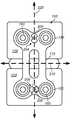
- FIG. 1depicts a diagram of a view of an embodiment of a cervical plate including at least four bone fasteners coupling the plate to two adjacent vertebrae and further including a securing mechanism in an inactivated state and a securing mechanism in an activated state.
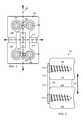
- FIG. 2depicts a diagram of a view of an embodiment of a cervical plate including at least two bone fasteners coupling the plate to two adjacent vertebrae. A graft has been positioned between the two vertebrae.
- FIG. 3depicts a diagram of a view of an embodiment of a cervical plate including a securing mechanism in an inactivated state and a securing mechanism in an activated state.
- FIG. 4depicts a diagram of a view of an embodiment of a cervical plate including a securing mechanism in an inactivated state and a securing mechanism in an activated state.
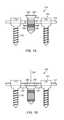
- FIGS. 5A-Bdepict a diagram of a view of an embodiment of a securing mechanism in an inactivated and activated state comprising a screw with a cam-shaped head and a deformable portion which may be used in combination with a cervical plate.
- FIGS. 6A-Bdepict a diagram of a view of an embodiment of a securing mechanism in an inactivated and activated state comprising a screw and a deformable portion which may be used in combination with a cervical plate.
- FIGS. 7A-Bdepict a diagram of an cross-sectional view of an embodiment of a securing mechanism in an inactivated and activated state comprising a screw and a deformable portion which may be used in combination with a cervical plate.
- FIGS. 8A-Bdepict a diagram of a cross-sectional view of an embodiment of a securing mechanism in an inactivated and activated state comprising a screw and a deformable portion which may be used in combination with a cervical plate.
- FIGS. 9A-Bdepict a diagram of a view of an embodiment of a securing mechanism in an inactivated and activated state comprising a screw which may be used in combination with a cervical plate.
- FIGS. 10A-Bdepict a diagram of a view of an embodiment of a securing mechanism in an inactivated and activated state comprising an elongated member and positionable portions which may be used in combination with a cervical plate.
- FIGS. 11A-Bdepict a diagram of an overhead and a side view of an embodiment of the heads of two bone fasteners and a securing mechanism comprising an elongated member in an activated state.
- FIGS. 12A-Bdepict a diagram of a view of an embodiment of a securing mechanism in an inactivated and activated state which may be used in combination with a bone reinforcing plate.
- FIGS. 13A-Bdepict a diagram of a view of an embodiment of a securing mechanism in an inactivated and activated state comprising positionable portions which may be used in combination with a bone reinforcing plate.
- first, second, third, and so forth as used hereinare used as labels for nouns that they precede, and do not imply any type of ordering (e.g., spatial, temporal, logical, etc.) unless such an ordering is otherwise explicitly indicated.
- a “third die electrically connected to the module substrate”does not preclude scenarios in which a “fourth die electrically connected to the module substrate” is connected prior to the third die, unless otherwise specified.
- a “second” featuredoes not require that a “first” feature be implemented prior to the “second” feature, unless otherwise specified.
- Various componentsmay be described as “configured to” perform a task or tasks.
- “configured to”is a broad recitation generally meaning “having structure that” performs the task or tasks during operation. As such, the component can be configured to perform the task even when the component is not currently performing that task (e.g., a set of electrical conductors may be configured to electrically connect a module to another module, even when the two modules are not connected).
- “configured to”may be a broad recitation of structure generally meaning “having circuitry that” performs the task or tasks during operation. As such, the component can be configured to perform the task even when the component is not currently on.
- the circuitry that forms the structure corresponding to “configured to”may include hardware circuits.
- connectiongenerally refers to pieces which may be joined or linked together.
- Coupledgenerally refers to pieces which may be used operatively with each other, or joined or linked together, with or without one or more intervening members.
- sagittal planegenerally refers to a substantially vertical plane which passes from ventral (front) to dorsal (rear) dividing a body into right and left portions.
- This disclosuredescribes systems and methods including, in some embodiments, a reinforcing plate with a bone fastener securing mechanism centered around the concept of frictional forces in the horizontal direction to prevent back out of fasteners which also semi-constrains the fasteners to allow controlled settling of a graft in the sagittal plane.
- the securing mechanismmay allow settling of the graft such that fastener failure is avoided.
- reinforcing plate 100may include elongate plate 110 which bridges, during use, substantially adjacent vertebrae 120 by anchoring the plate to the vertebrae.
- the elongate platemay have first surface 130 and second surface 140 opposite the first surface.
- the first surfacemay be positioned, during use, adjacent to at least a portion of a surface of the vertebrae.
- the cervical platemay include a plurality of openings 150 extending through the elongate plate.
- the cervical platemay include a plurality of bone fasteners 160 .
- the bone fastenersmay include head 170 and shaft 180 .
- the shaftmay be positionable, during use, in the opening such that the shaft engages, during use, at least one of the vertebrae and the head is inhibited from being conveyed through the opening such that the bone fasteners couple the elongate plate to the vertebrae.
- the cervical platemay include securing mechanism 200 .
- FIG. 1depicts a diagram of a view of an embodiment of cervical plate 100 including a securing mechanism 200 in an inactivated state 204 and a securing mechanism in an activated state 206 .
- the securing mechanismmay, when activated, inhibit removal (e.g., back out) of at least one of the bone fasteners and inhibit movement of at least the shaft of the bone fastener in a lateral direction 210 , while allowing movement of at least the shaft of the bone fastener along a substantially sagittal plane 220 (e.g., as depicted in FIGS. 1-2 ).
- FIG. 2depicts a diagram of a view of an embodiment of a cervical plate 100 including at least two bone fasteners 150 coupling the plate to two adjacent vertebrae 120 .
- Current platesmay include securing mechanisms which lock fasteners to the plate such that the fasteners cannot back out or even move at all relative to the plate the fasteners are locked to.
- This lack of any movement of the fasteners relative to the platemany times results in stresses being applied to the fasteners as the coupled vertebrae settle along the sagittal plane after installation. These stresses have historically resulted in fasteners failing after installation requiring follow up procedures to fix the failed portions and any damage to the subject caused by the failed portions.
- Securing mechanisms, after activation, described hereinare configured to allow limited movement of fasteners in a vertical direction or more accurately along a sagittal plane.
- Allowing movement of the fasteners in the sagittal plane after installationmay relieve fastener stresses due to the movement of the vertebrae (typically due to settling of graft 230 (e.g., as depicted in FIG. 2 )) which is installed with a plate during a fusion procedure, and, in addition, increase the probability of boney fusion.
- the securing mechanismwhen activated, inhibits backing out of at least one of the bone fasteners from at least one of the plurality of openings.
- the securing mechanismwhen activated, may inhibit removal of at least two of the bone fasteners from at least two of the plurality of openings (e.g., as depicted in FIG. 1 ).
- at least two bone fastenersmay be positioned substantially laterally relative to one another (e.g., as depicted in FIG. 1 ).
- at least two bone fastenersare positioned substantially vertically relative to one another (e.g., as depicted in FIGS. 13A-B ).
- the securing mechanismwhen activated, inhibits removal of at least four of the bone fasteners from at least one of the plurality of openings.
- the securing mechanismengages, when activated, a first side of a proximal end (e.g., the head or just below the head along the proximal end of the shaft) of the bone fastener. In some embodiments, the securing mechanism engages, when activated, a first side of head 170 of the bone fastener 160 . The securing mechanism may engage, when activated, a first side of the head of the bone fastener such that a second side, opposite of the first side, of the bone fastener engages an adjacent portion of the bone plate forming the opening in which the bone fastener is positioned forming a friction fitting. As depicted in FIG.
- 1 securing mechanism 200rotates about an axis from inactivated position 204 to an activated position 206 .
- the ends of the securing mechanismengage heads 170 of such that the heads engage the sides of openings 150 forming a friction fit.
- the lateral forces applied by the securing mechanisminhibit back out while still allowing movement of the fasteners along the sagittal plane.
- FIG. 3depicts a diagram of a view of an embodiment of cervical plate 100 including securing mechanism 200 in inactivated state 204 and securing mechanism 200 in activated state 206 .
- securing mechanism 200rotates 242 about an axis from inactivated position 204 to an activated position 206 .
- the securing mechanismengages, when activated, positionable member 244 which moves from a first unengaged position to a second position engaging a first side of head 170 of the bone fastener forming a friction fitting as the head engages the sides of openings 150 .
- FIG. 4depicts a diagram of a view of an embodiment of cervical plate 100 including securing mechanism 200 in inactivated state 204 and the securing mechanism in an activated state 206 .
- Securing mechanism 200may be positionable moving 240 from an inactivated and unengaged state to an activated and engaged state such that substantially lateral forces are applied to the fasteners 160 inhibiting back out.
- securing mechanism 200engages, when activated, deformable portion 250 of cervical plate 100 deforming the deformable portion.
- FIGS. 5A-Bdepict a diagram of an view of an embodiment of securing mechanism 200 in inactivated 204 and activated state 206 including screw 260 with a cam-shaped head and deformable portion 260 which may be used in combination with cervical plate 100 .
- the securing mechanismmay include a cam. When the deformable portion deforms, the deformable portion may move from a first unengaged position to a second position. The second position may engage a first side of the head of the bone fastener forming a friction fitting. In the embodiment depicted in FIGS.
- a screw with a cam-shaped headrotates such that the extended portion of the cam engages the deformable portion pushing one side in such that the sides press out in reaction.
- heads 170 of fasteners 160engage heads 170 of fasteners 160 with a laterally applied force (e.g., as depicted in FIG. 5B ).
- securing mechanism 200comprises screw 260 which is conveyed, when the securing mechanism is activated, into opening 270 adjacent deformable portion 250 such that the conveyance 280 of the screw into the opening deforms the deformable portion.
- the deformable portionmay move from a first unengaged position to a second position. The second position may engage a first side of the head of the bone fastener such that an opposing side of the head of the bone fastener engages a side of the opening in which the fastener is positioned forming a friction fitting.
- the securing mechanismengages, when activated, a deformable portion of the cervical plate deforming the deformable portion.
- FIGS. 7A-Bdepict a diagram of a cross-sectional view of an embodiment of securing mechanism 200 in inactivated 204 and activated 206 state comprising screw 260 and deformable portions 250 which may be used in combination with cervical plate 100 .
- a head of screw 260may be conveyed 290 into opening 270 deforming deformable portion 250 when engaged by the head displacing the deformable portion such that the deformable portion engages with a lateral force fasteners 160 .
- the deformable portionmay include a ring which expands upon activation of the securing mechanism.
- a deformable portionmay function to reposition an engaging portion of a securing mechanism when activated to exert lateral forces on fasteners of a plate.
- FIGS. 8A-Bdepict a diagram of a cross-sectional view of an embodiment of securing mechanism 200 in inactivated 204 and activated 206 state comprising screw 260 , deformable portion 250 , and engaging portion 300 which may be used in combination with cervical plate 100 .
- the screwmay be conveyed 310 , when the securing mechanism is activated, into opening 270 such that a head of the screw engages a first side of head 170 of bone fastener 160 .
- the deformable portiondeforms such that an engaging portion coupled to the deformable portion moves from a first unengaged position to a second position engaging a first side of the head of the bone fastener applying a lateral force forming a friction fitting between the engaging portion, the head and an opening in the plate wherein the fastener is positioned.
- the deformable portiondeforms in response to the head of the screw pushing against the deformable portion extending out opposing corners of the deformable portion.
- the securing mechanismmay include a screw.
- FIGS. 9A-Bdepict a diagram of a view of an embodiment of securing mechanism 200 in inactivated 204 and activated 206 state comprising screw 260 which may be used in combination with cervical plate 100 .
- the screwmay be conveyed 320 , when the securing mechanism is activated, into opening 270 such that a head of the screw engages a first side of heads 170 of bone fasteners 160 .
- the screwmay engage the first side of the bone fastener such that a second side, opposite of the first side, of the bone fastener engages an adjacent portion of the cervical plate forming the opening in which the bone fastener is positioned forming a friction fitting.
- the head of screw 260may apply lateral forces to heads 170 of fasteners 160 such that a friction fit is formed between the head of screw 260 , heads 170 and portions of plate 110 forming the openings on opposing sides to screw 260 .
- the securing mechanismmay include a positionable member for each fastener and an elongated member positionable in an opening through the elongated plate.
- FIGS. 10A-Bdepict a diagram of a view of an embodiment of securing mechanism 200 in inactivated 204 and activated 206 state comprising elongated member 330 and positionable members 244 which may be used in combination with cervical plate 100 .
- the securing mechanismmay include an elongated member positionable in opening 270 extending along a longitudinal axis through the elongated plate.
- the elongated membermay be positionable in the longitudinal opening in the plate.
- Indentations 340 along the elongated membermay have a smaller diameter than the remaining portions of the elongated member.
- the positionable membersmay be situated at a first position such that a portion of the positionable members sit within indentations 340 adjacent to the elongated member.
- the securing mechanismmay be activated by repositioning 350 elongated member 330 from a first position (depicted in FIG. 10A ) to a second position (depicted in FIG. 10B ). Repositioning the elongated member may convey positionable members from the first position (depicted in FIG. 10A ) to a second position (depicted in FIG. 10B ) due to the increasing diameter of the elongated member applying a lateral force to the positionable members which in turn convey that lateral force to head 170 of fasteners 160 pressing the head against the plate.
- the securing mechanismmay include an elongated member positionable in an opening extending laterally through the elongated plate and at least one of the bone fasteners.
- FIGS. 11A-Bdepict a diagram of an overhead and a side view of an embodiment of heads 170 of two bone fasteners 160 and securing mechanism 200 comprising elongated member 330 in activated state 206 .
- the elongated membermay extend through an opening extending through the plate and abutting at least one head of a fastener inhibiting back out while allowing some movement along the sagittal plane relieving stress on the fasteners.
- the openingmay include one or more stops which inhibit the elongated member from moving beyond a certain point.
- the elongated membermay be positioned through only one side of the plate due to the one or more stops.
- a platemay include an elongated member for each fastener providing advantages such as requiring less available space to insert the elongate member (due to the fact the elongated member is shorter since it does not have to extend through the entire width of the plate) during use.
- FIGS. 12A-Bdepict a diagram of a view of an embodiment of securing mechanism 200 in an inactivated and activated state which may be used in combination with a reinforcing plate 100 .
- Securing mechanism 200may include a cam (e.g., as depicted in FIGS. 12A-B ). The cam may rotate from an inactivated 204 to an activate 206 state.
- Fasteners 160may be positionable in openings 150 . The opening may extend within the plate such that lip 360 (formed in surface 140 ) extends over a portion of the opening.
- the camAs the cam is rotated from an inactivated state to an activated state the cam applies a lateral force against heads 170 of fasteners 160 such that at least a portion of the opposing side of the heads are positioned beneath lip 360 inhibiting back out and allowing controlled movement of the fasteners along certain predetermined planes.
- the cervical plateis used in combination with a graft (e.g., as depicted by bone graft 230 in FIG. 2 ).
- the cervical platemay include a bone graft coupled to the first surface of the elongate plate.
- the cervical platemay be used in combination with a bone growth promoting material.
- the bone growth promoting materialmay include at least one of bone, bone morphogenetic protein, hydroxyapatite, and hydroxyapatite tricalcium phosphate.
- Bone growth promoting materialsmay include, but are not limited to, bone, bone morphogenetic proteins, hydroxyapatite, genes coding for the production of bone, or any other material that intrinsically participates in the growth of bone from one of the adjacent vertebral bodies to the other of the adjacent vertebral bodies at the fusion site. Plate systems herein may be combined with a chemical substance to inhibit scar formation.
- FIGS. 13A-Bdepict a diagram of a view of an embodiment of securing mechanism 200 in inactivated 204 and activated 206 state comprising positionable portions which may be used in combination with a reinforcing plate 100 .
- the plate depicted in FIGS. 13A-Bmay be used to reinforce other bones in the body, elongated bones for example which may be found in the arms or legs. Other shapes as needed may be used for other bone reinforcing/fusing purposes.
- the securing mechanism depicted in FIGS. 13A-Bfunctions in a similar manner as the securing mechanism depicted in FIG. 1 .
- a methodmay include positioning an elongate plate such that substantially adjacent vertebrae are bridged.
- the elongate platemay have a first surface and a second surface opposite the first surface.
- the first surfacemay be positioned adjacent to at least a portion of a surface of the vertebrae.
- the elongate platemay include a plurality of openings extending through the elongate plate.
- the methodmay include anchoring the plate to the vertebrae.
- the platemay be anchored to the vertebrae by positioning shafts of a plurality of bone fasteners in at least some of the plurality of openings such that the shaft engages at least one of the vertebrae.
- the methodmay include inhibiting a head of at least two of the bone fasteners from being conveyed through the opening such that the bone fasteners couple the elongate plate to the vertebrae.
- the methodmay include activating a securing mechanism such that inhibits removal of at least one of the bone fasteners is inhibited.
- the methodmay include inhibiting movement of at least the shaft of the bone fastener in a lateral direction using the securing mechanism.
- the methodmay include allowing movement of at least the shaft of the bone fastener along a substantially sagittal plane.
Landscapes
- Health & Medical Sciences (AREA)
- Orthopedic Medicine & Surgery (AREA)
- Life Sciences & Earth Sciences (AREA)
- Surgery (AREA)
- Neurology (AREA)
- Heart & Thoracic Surgery (AREA)
- Engineering & Computer Science (AREA)
- Biomedical Technology (AREA)
- Nuclear Medicine, Radiotherapy & Molecular Imaging (AREA)
- Medical Informatics (AREA)
- Molecular Biology (AREA)
- Animal Behavior & Ethology (AREA)
- General Health & Medical Sciences (AREA)
- Public Health (AREA)
- Veterinary Medicine (AREA)
- Surgical Instruments (AREA)
Abstract
Description
Claims (30)
Priority Applications (1)
| Application Number | Priority Date | Filing Date | Title |
|---|---|---|---|
| US14/179,027US9642652B2 (en) | 2013-02-13 | 2014-02-12 | Variable angle bone plate with semi-constrained articulating screw |
Applications Claiming Priority (2)
| Application Number | Priority Date | Filing Date | Title |
|---|---|---|---|
| US201361764378P | 2013-02-13 | 2013-02-13 | |
| US14/179,027US9642652B2 (en) | 2013-02-13 | 2014-02-12 | Variable angle bone plate with semi-constrained articulating screw |
Publications (2)
| Publication Number | Publication Date |
|---|---|
| US20140236241A1 US20140236241A1 (en) | 2014-08-21 |
| US9642652B2true US9642652B2 (en) | 2017-05-09 |
Family
ID=51351782
Family Applications (1)
| Application Number | Title | Priority Date | Filing Date |
|---|---|---|---|
| US14/179,027ActiveUS9642652B2 (en) | 2013-02-13 | 2014-02-12 | Variable angle bone plate with semi-constrained articulating screw |
Country Status (1)
| Country | Link |
|---|---|
| US (1) | US9642652B2 (en) |
Families Citing this family (2)
| Publication number | Priority date | Publication date | Assignee | Title |
|---|---|---|---|---|
| US8425569B2 (en)* | 2010-05-19 | 2013-04-23 | Transcorp, Inc. | Implantable vertebral frame systems and related methods for spinal repair |
| US10543101B1 (en)* | 2015-12-01 | 2020-01-28 | Ctl Medical Corporation | Intervertebral implants and related systems and methods |
Citations (114)
| Publication number | Priority date | Publication date | Assignee | Title |
|---|---|---|---|---|
| US3433510A (en) | 1966-09-26 | 1969-03-18 | Flambeau Plastics Corp | Swivel joint structure |
| US5344421A (en)* | 1993-07-16 | 1994-09-06 | Amei Technologies Inc. | Apparatus and method for adjusting a bone plate |
| US5549612A (en)* | 1992-11-25 | 1996-08-27 | Codman & Shurtleff, Inc. | Osteosynthesis plate system |
| US5800435A (en) | 1996-10-09 | 1998-09-01 | Techsys, Llc | Modular spinal plate for use with modular polyaxial locking pedicle screws |
| US5904683A (en)* | 1998-07-10 | 1999-05-18 | Sulzer Spine-Tech Inc. | Anterior cervical vertebral stabilizing device |
| US6139550A (en)* | 1997-02-11 | 2000-10-31 | Michelson; Gary K. | Skeletal plating system |
| US6193721B1 (en) | 1997-02-11 | 2001-02-27 | Gary K. Michelson | Multi-lock anterior cervical plating system |
| US6258089B1 (en)* | 1998-05-19 | 2001-07-10 | Alphatec Manufacturing, Inc. | Anterior cervical plate and fixation system |
| US6361537B1 (en)* | 2001-05-18 | 2002-03-26 | Cinci M. Anderson | Surgical plate with pawl and process for repair of a broken bone |
| US20020077630A1 (en)* | 2000-12-19 | 2002-06-20 | Chih-I Lin | Spinal fixation and retrieval device |
| US20020120273A1 (en)* | 1999-10-13 | 2002-08-29 | Needham Dusty Anna | Anterior cervical plating system and method |
| US20030040749A1 (en)* | 2001-08-24 | 2003-02-27 | Grabowski John J. | Bone fixation device |
| US20030060828A1 (en)* | 2001-06-06 | 2003-03-27 | Michelson Gary K. | Dynamic multilock anterior cervical plate system having non-detachably fastened and moveable segments, instrumentation, and method for installation thereof |
| US20030078583A1 (en)* | 2001-10-23 | 2003-04-24 | Biedermann Motech Gmbh | Bone fixing device |
| US6602255B1 (en)* | 2000-06-26 | 2003-08-05 | Stryker Spine | Bone screw retaining system |
| US20030187440A1 (en)* | 2002-03-12 | 2003-10-02 | Marc Richelsoph | Bone plate and screw retaining mechanism |
| US6652525B1 (en)* | 1998-04-30 | 2003-11-25 | Sofamor S.N.C. | Anterior implant for the spine |
| US20040087951A1 (en)* | 2002-11-04 | 2004-05-06 | Khalili Farid Bruce | Fastener retention system |
| US20040127900A1 (en)* | 2002-12-31 | 2004-07-01 | Konieczynski David D. | Resilient bone plate and screw system allowing bi-directional assembly |
| US20040127899A1 (en)* | 2002-12-31 | 2004-07-01 | Konieczynski David D. | Bone plate and screw system allowing bi-directional attachment |
| US20040127904A1 (en)* | 2002-12-31 | 2004-07-01 | Konieczynski David D. | Bone plate and resilient screw system allowing bi-directional assembly |
| US20040220571A1 (en)* | 1998-04-30 | 2004-11-04 | Richard Assaker | Bone plate assembly |
| US20040220566A1 (en)* | 2003-05-01 | 2004-11-04 | Bray Robert S. | Slidable bone plate system |
| US20050021032A1 (en)* | 2003-07-22 | 2005-01-27 | Ja-Kyo Koo | Cervical spine fixator and screwdriver used therefor |
| US20050075633A1 (en)* | 2003-10-02 | 2005-04-07 | Thomas Ross | Anterior cervical plate |
| US20050085812A1 (en)* | 2003-10-21 | 2005-04-21 | Sherman Michael C. | Apparatus and method for providing dynamizable translations to orthopedic implants |
| US20050085814A1 (en)* | 2003-10-21 | 2005-04-21 | Sherman Michael C. | Dynamizable orthopedic implants and their use in treating bone defects |
| US20050149027A1 (en)* | 2000-06-26 | 2005-07-07 | Stryker Spine | Bone screw retaining system |
| US20050192577A1 (en)* | 2004-02-26 | 2005-09-01 | Pioneer Laboratories, Inc. | Bone plate system and methods |
| US20050234455A1 (en)* | 2004-04-19 | 2005-10-20 | Lawrence Binder | Bone fixation plate |
| US20050261689A1 (en)* | 2004-05-20 | 2005-11-24 | A-Spine Holding Group Corp. Ashg | Bone fixation device |
| US20050261690A1 (en)* | 2004-04-19 | 2005-11-24 | Binder Lawrence J | Bone fixation plate |
| US20050283152A1 (en)* | 2004-06-17 | 2005-12-22 | Lindemann Gary S | Method and apparatus for retaining screws in a plate |
| US20050288669A1 (en) | 2004-06-14 | 2005-12-29 | Abdou M S | Occipito fixation system and method of use |
| US7025769B1 (en)* | 2002-06-04 | 2006-04-11 | Nuvasive, Inc. | Surgical fixation system and related methods |
| US7041105B2 (en)* | 2001-06-06 | 2006-05-09 | Sdgi Holdings, Inc. | Dynamic, modular, multilock anterior cervical plate system having detachably fastened assembleable and moveable segments |
| US20060122602A1 (en)* | 2004-12-08 | 2006-06-08 | Depuy Spine, Inc. | Hybrid spinal plates |
| US20060122603A1 (en)* | 2004-12-08 | 2006-06-08 | Depuy Spine, Inc. | Hybrid bone screw and plate systems |
| US20060122605A1 (en)* | 2004-12-06 | 2006-06-08 | Suh Sean S | Translational plate with cover blocking system |
| US20060155285A1 (en)* | 2005-01-12 | 2006-07-13 | Kent Anderson | Anchor retaining mechanisms for bone plates |
| US20060200146A1 (en)* | 2005-01-06 | 2006-09-07 | Doubler Robert L | Spinal plate with screw locks and cam locks |
| US20060217725A1 (en)* | 2005-03-11 | 2006-09-28 | Suh Sean S | Translational plate with spring beam retainer |
| US20060235403A1 (en)* | 2005-03-17 | 2006-10-19 | Jason Blain | Flanged interbody fusion device with locking plate |
| US20060235399A1 (en)* | 2005-04-14 | 2006-10-19 | Sdgi Holdings, Inc. | Anti-backout mechanism for an implant fastener |
| US20060247639A1 (en)* | 2005-04-29 | 2006-11-02 | Sdgi Holdings, Inc. | Apparatus for retaining a bone anchor in a bone plate and method for use thereof |
| US20070123884A1 (en)* | 2005-11-09 | 2007-05-31 | Abdou M S | Bone fixation systems and methods of implantation |
| US20070123879A1 (en)* | 2003-02-05 | 2007-05-31 | Pioneer Laboratories, Inc. | Bone plate system |
| US20080015578A1 (en)* | 2006-07-12 | 2008-01-17 | Dave Erickson | Orthopedic implants comprising bioabsorbable metal |
| US20080097443A1 (en)* | 2006-06-30 | 2008-04-24 | Campbell Christopher M | Plating systems for bone fixation |
| US20080208263A1 (en)* | 2007-02-26 | 2008-08-28 | Butler Michael S | Spine plate with configured bone screw bores |
| US20080287999A1 (en)* | 2007-05-18 | 2008-11-20 | Markworth Aaron D | Anterior cervical plate with independent spring-loaded locking slides for each screw |
| US20090012571A1 (en)* | 2007-07-03 | 2009-01-08 | Pioneer Surgical Technology, Inc. | Bone Plate System |
| US20090062863A1 (en)* | 2007-07-26 | 2009-03-05 | Timothy Allen Peppers | Screw back-out prevention mechanism |
| US20090157121A1 (en)* | 2007-12-13 | 2009-06-18 | Harris Peter M | Dynamic anterior vertebral plate |
| US20090187218A1 (en)* | 2008-01-17 | 2009-07-23 | Amedica Corporation | Bone fixation plate with wire members for resisting back out of bone anchors |
| US20090192549A1 (en)* | 2008-01-30 | 2009-07-30 | Ebi, Llc | Bone plating system |
| US20100016901A1 (en)* | 2005-06-16 | 2010-01-21 | Robinson James C | Bone screw retaining system |
| US7662154B2 (en)* | 2005-09-16 | 2010-02-16 | Blackstone Medical, Inc. | Anterior cervical plating system |
| US20100042159A1 (en)* | 2008-07-17 | 2010-02-18 | Alphatec Spine, Inc. | Bone plate assembly |
| US20100049256A1 (en)* | 2007-01-30 | 2010-02-25 | Dong Myung Jeon | Anterior cerivcal plating system |
| US7674279B2 (en)* | 2006-10-13 | 2010-03-09 | Spinal U.S.A. | Bone plate |
| US20100121383A1 (en)* | 2008-11-10 | 2010-05-13 | Todd Stanaford | Method, system, and apparatus for mammalian bony segment stabilization |
| US20100234899A1 (en)* | 2008-12-10 | 2010-09-16 | Jeffrey Johnson | Bone plate and bone screw locking system |
| US20100292737A1 (en)* | 2009-05-15 | 2010-11-18 | Sean Suh | Orthopedic Plate Blocking Assembly |
| US7857836B2 (en)* | 2005-07-13 | 2010-12-28 | Acumed Llc | Bone plates with movable locking elements |
| US20110029023A1 (en)* | 2009-07-30 | 2011-02-03 | Clariance | Slide-type anti-backout device for prosthesis |
| US7909852B2 (en) | 2004-03-31 | 2011-03-22 | Depuy Spine Sarl | Adjustable-angle spinal fixation element |
| US20110118742A1 (en)* | 2009-05-12 | 2011-05-19 | Urs Hulliger | Readjustable Locking Plate Hole |
| US20110152945A1 (en)* | 2005-10-25 | 2011-06-23 | Anthem Orthopaedics, Llc | Bone fastening assembly |
| US20110184415A1 (en)* | 2010-01-26 | 2011-07-28 | Westmark Medical, Llc | Bone screw retention mechanism |
| US20110190770A1 (en)* | 2010-02-02 | 2011-08-04 | Sean Suh | Orthopedic Plating Assembly For Bone Fixation and Subsidence |
| US8057521B2 (en)* | 2005-06-03 | 2011-11-15 | Southern Spine, Llc | Surgical stabilization system |
| US20110282389A1 (en)* | 2010-05-17 | 2011-11-17 | Omni Surgical dba Spine 360 | Bone fixation plate assembly |
| US8066750B2 (en)* | 2006-10-06 | 2011-11-29 | Warsaw Orthopedic, Inc | Port structures for non-rigid bone plates |
| US20110313468A1 (en)* | 2007-10-16 | 2011-12-22 | James C Robinson | Bone screw retaining and removal system |
| US20110319893A1 (en)* | 2008-11-10 | 2011-12-29 | Todd Stanaford | Method, system, and apparatus for mammalian bony segment stabilization |
| US20120010666A1 (en)* | 2010-07-08 | 2012-01-12 | Songer Matthew N | Variable angle locking plate system |
| US8118847B2 (en)* | 2005-03-08 | 2012-02-21 | K2M, Inc. | Anterior vertebral plate with underside locking mechanism |
| US20120065690A1 (en)* | 2004-02-26 | 2012-03-15 | Scott Perrow | Bone Plate System |
| US20120095513A1 (en)* | 2010-10-15 | 2012-04-19 | Wasaw Orthopedic, Inc. | Retaining mechanism |
| US8167919B2 (en)* | 1999-10-13 | 2012-05-01 | Warsaw Orthopedic, Inc. | System and method for securing a plate to the spinal column |
| US8172842B2 (en)* | 2006-07-31 | 2012-05-08 | Orthopaedic International, Inc. | Cervical plate system having an insertable rotating element |
| US20120143193A1 (en)* | 2010-07-21 | 2012-06-07 | Urs Hulliger | Device for Osteosynthesis |
| US20120158068A1 (en)* | 2010-12-16 | 2012-06-21 | Warsaw Orthropedic, Inc. | Retaining mechanism |
| US20120179207A1 (en)* | 2011-01-10 | 2012-07-12 | Anis Mekhail | Surgical plate system and method |
| US20120191141A1 (en)* | 2011-01-20 | 2012-07-26 | Alphatec Spine, Inc. | Bone fixation systems and methods |
| US8262711B2 (en)* | 2009-03-13 | 2012-09-11 | Spinal Simplicity Llc | Dynamic vertebral column plate system |
| US20120232595A1 (en)* | 2011-03-07 | 2012-09-13 | Tyler HOLSCHLAG | Fastener retention system for spinal plates |
| US20120310289A1 (en)* | 2010-06-23 | 2012-12-06 | Apex Biomedical Company Llc | Flexible plate fixation of bone fractures |
| US8328855B2 (en)* | 2008-02-01 | 2012-12-11 | Alexandre Worcel | Osteosynthesis device with rapid fixing means |
| US20130006309A1 (en)* | 2011-06-30 | 2013-01-03 | Morgan Packard Lorio | Spinal plate and method for using same |
| US20130023936A1 (en)* | 2011-07-19 | 2013-01-24 | Moti Altarac | Anterior cervical plate |
| US8372152B2 (en)* | 2003-09-30 | 2013-02-12 | X-Spine Systems, Inc. | Spinal fusion system utilizing an implant plate having at least one integral lock and ratchet lock |
| US20130060291A1 (en)* | 2011-09-06 | 2013-03-07 | Samuel Petersheim | Spinal Plate |
| US8403970B1 (en)* | 2010-01-06 | 2013-03-26 | Bernard M. Bedor | Cervical plate system and method |
| US8409259B1 (en)* | 2010-01-06 | 2013-04-02 | Bernard M. Bedor | Cervical plate system and method |
| US20130184767A1 (en)* | 2012-01-17 | 2013-07-18 | Josh Kaufman | Spinal Plate And Locking Screw Devices, Methods, And Systems |
| US20130190825A1 (en)* | 2011-12-23 | 2013-07-25 | Pioneer Surgical Technology, Inc. | Bone Anchor Assembly, Bone Plate System, And Method |
| US8574270B2 (en)* | 2009-03-13 | 2013-11-05 | Spinal Simplicity Llc | Bone plate assembly with bone screw retention features |
| US8591556B2 (en)* | 2011-07-19 | 2013-11-26 | Globus Medical, Inc. | Locking confirmation mechanism for a bone screw and plate assembly |
| US20130325074A1 (en)* | 2012-06-05 | 2013-12-05 | Blackstone Medical, Inc. | Orthopedic devices with a locking mechanism |
| US8652182B1 (en)* | 2008-10-01 | 2014-02-18 | Spinal U.S.A. | Bone plate with retainer and stop for screw lock |
| US20140094856A1 (en)* | 2011-03-14 | 2014-04-03 | Genossis Llc | Locking Screws and Plates |
| US8690923B2 (en) | 2010-09-28 | 2014-04-08 | Exactech, Inc. | Bone fixation systems and methods |
| US8702766B2 (en)* | 2011-06-28 | 2014-04-22 | Corelink, Llc | Locking device for fixation mechanism of medical implant |
| US8728129B2 (en)* | 2011-01-07 | 2014-05-20 | Biomet Manufacturing, Llc | Variable angled locking screw |
| US20140172022A1 (en)* | 2009-05-15 | 2014-06-19 | Sean Suh | Orthopedic Plate Blocking Assembly |
| US20140276829A1 (en)* | 2013-03-14 | 2014-09-18 | Innovasis, Inc. | Modular bone fixation plate assembly |
| US20140277182A1 (en)* | 2013-03-12 | 2014-09-18 | Warsaw Orthopedic, Inc. | Spinal implant system and method |
| US8858603B1 (en)* | 2010-06-09 | 2014-10-14 | Choice Spine, L.P. | Cervical plate with screw retention clip |
| US8940030B1 (en)* | 2011-01-28 | 2015-01-27 | Nuvasive, Inc. | Spinal fixation system and related methods |
| US20150094774A1 (en)* | 2013-10-02 | 2015-04-02 | Karl W. Swann | Bone fixation assembly, including s-shaped resilient lock for screw locking clips |
| US20150112395A1 (en)* | 2012-05-08 | 2015-04-23 | Ortho Solutions Limited | Polyaxial locking assembly |
| US9039744B2 (en)* | 2011-10-04 | 2015-05-26 | Beacon Biomedical, Llc | Spinal plate assembly |
- 2014
- 2014-02-12USUS14/179,027patent/US9642652B2/enactiveActive
Patent Citations (123)
| Publication number | Priority date | Publication date | Assignee | Title |
|---|---|---|---|---|
| US3433510A (en) | 1966-09-26 | 1969-03-18 | Flambeau Plastics Corp | Swivel joint structure |
| US5549612A (en)* | 1992-11-25 | 1996-08-27 | Codman & Shurtleff, Inc. | Osteosynthesis plate system |
| US5344421A (en)* | 1993-07-16 | 1994-09-06 | Amei Technologies Inc. | Apparatus and method for adjusting a bone plate |
| US5800435A (en) | 1996-10-09 | 1998-09-01 | Techsys, Llc | Modular spinal plate for use with modular polyaxial locking pedicle screws |
| US6398783B1 (en) | 1997-02-11 | 2002-06-04 | Sulzer Spine-Tech Inc. | Multi-lock anterior cervical plate |
| US6139550A (en)* | 1997-02-11 | 2000-10-31 | Michelson; Gary K. | Skeletal plating system |
| US6193721B1 (en) | 1997-02-11 | 2001-02-27 | Gary K. Michelson | Multi-lock anterior cervical plating system |
| US7704255B2 (en) | 1997-02-11 | 2010-04-27 | Warsaw Orthopedic, Inc. | Threadless multi-lock anterior cervical plating system |
| US6527776B1 (en) | 1997-02-11 | 2003-03-04 | Gary K. Michelson | Locking element for locking at least two bone screws to an orthopedic device |
| US6652525B1 (en)* | 1998-04-30 | 2003-11-25 | Sofamor S.N.C. | Anterior implant for the spine |
| US20040220571A1 (en)* | 1998-04-30 | 2004-11-04 | Richard Assaker | Bone plate assembly |
| US6258089B1 (en)* | 1998-05-19 | 2001-07-10 | Alphatec Manufacturing, Inc. | Anterior cervical plate and fixation system |
| US5904683A (en)* | 1998-07-10 | 1999-05-18 | Sulzer Spine-Tech Inc. | Anterior cervical vertebral stabilizing device |
| US20020120273A1 (en)* | 1999-10-13 | 2002-08-29 | Needham Dusty Anna | Anterior cervical plating system and method |
| US8167919B2 (en)* | 1999-10-13 | 2012-05-01 | Warsaw Orthopedic, Inc. | System and method for securing a plate to the spinal column |
| US20050149027A1 (en)* | 2000-06-26 | 2005-07-07 | Stryker Spine | Bone screw retaining system |
| US6602255B1 (en)* | 2000-06-26 | 2003-08-05 | Stryker Spine | Bone screw retaining system |
| US20140243909A1 (en)* | 2000-06-26 | 2014-08-28 | Stryker Spine | Bone screw retaining system |
| US20020077630A1 (en)* | 2000-12-19 | 2002-06-20 | Chih-I Lin | Spinal fixation and retrieval device |
| US6361537B1 (en)* | 2001-05-18 | 2002-03-26 | Cinci M. Anderson | Surgical plate with pawl and process for repair of a broken bone |
| US20030060828A1 (en)* | 2001-06-06 | 2003-03-27 | Michelson Gary K. | Dynamic multilock anterior cervical plate system having non-detachably fastened and moveable segments, instrumentation, and method for installation thereof |
| US7041105B2 (en)* | 2001-06-06 | 2006-05-09 | Sdgi Holdings, Inc. | Dynamic, modular, multilock anterior cervical plate system having detachably fastened assembleable and moveable segments |
| US20030040749A1 (en)* | 2001-08-24 | 2003-02-27 | Grabowski John J. | Bone fixation device |
| US20030078583A1 (en)* | 2001-10-23 | 2003-04-24 | Biedermann Motech Gmbh | Bone fixing device |
| US20030187440A1 (en)* | 2002-03-12 | 2003-10-02 | Marc Richelsoph | Bone plate and screw retaining mechanism |
| US7025769B1 (en)* | 2002-06-04 | 2006-04-11 | Nuvasive, Inc. | Surgical fixation system and related methods |
| US20040087951A1 (en)* | 2002-11-04 | 2004-05-06 | Khalili Farid Bruce | Fastener retention system |
| US20140243908A1 (en)* | 2002-12-31 | 2014-08-28 | Depuy Spine, Inc. | Resilient bone plate and screw system allowing bi-directional assembly |
| US20040127900A1 (en)* | 2002-12-31 | 2004-07-01 | Konieczynski David D. | Resilient bone plate and screw system allowing bi-directional assembly |
| US20040127904A1 (en)* | 2002-12-31 | 2004-07-01 | Konieczynski David D. | Bone plate and resilient screw system allowing bi-directional assembly |
| US20040127899A1 (en)* | 2002-12-31 | 2004-07-01 | Konieczynski David D. | Bone plate and screw system allowing bi-directional attachment |
| US20070123879A1 (en)* | 2003-02-05 | 2007-05-31 | Pioneer Laboratories, Inc. | Bone plate system |
| US20040220566A1 (en)* | 2003-05-01 | 2004-11-04 | Bray Robert S. | Slidable bone plate system |
| US20050021032A1 (en)* | 2003-07-22 | 2005-01-27 | Ja-Kyo Koo | Cervical spine fixator and screwdriver used therefor |
| US8372152B2 (en)* | 2003-09-30 | 2013-02-12 | X-Spine Systems, Inc. | Spinal fusion system utilizing an implant plate having at least one integral lock and ratchet lock |
| US20050075633A1 (en)* | 2003-10-02 | 2005-04-07 | Thomas Ross | Anterior cervical plate |
| US20050085812A1 (en)* | 2003-10-21 | 2005-04-21 | Sherman Michael C. | Apparatus and method for providing dynamizable translations to orthopedic implants |
| US20050085814A1 (en)* | 2003-10-21 | 2005-04-21 | Sherman Michael C. | Dynamizable orthopedic implants and their use in treating bone defects |
| US20050192577A1 (en)* | 2004-02-26 | 2005-09-01 | Pioneer Laboratories, Inc. | Bone plate system and methods |
| US20120065690A1 (en)* | 2004-02-26 | 2012-03-15 | Scott Perrow | Bone Plate System |
| US8109974B2 (en) | 2004-03-31 | 2012-02-07 | Depuy Spine Sarl | Adjustable-angle spinal fixation element |
| US20110245874A1 (en) | 2004-03-31 | 2011-10-06 | Depuy Spine, Inc. | Adjustable-angle spinal fixation element |
| US7909852B2 (en) | 2004-03-31 | 2011-03-22 | Depuy Spine Sarl | Adjustable-angle spinal fixation element |
| US20050261690A1 (en)* | 2004-04-19 | 2005-11-24 | Binder Lawrence J | Bone fixation plate |
| US20050234455A1 (en)* | 2004-04-19 | 2005-10-20 | Lawrence Binder | Bone fixation plate |
| US20050261689A1 (en)* | 2004-05-20 | 2005-11-24 | A-Spine Holding Group Corp. Ashg | Bone fixation device |
| US20050288669A1 (en) | 2004-06-14 | 2005-12-29 | Abdou M S | Occipito fixation system and method of use |
| US20050283152A1 (en)* | 2004-06-17 | 2005-12-22 | Lindemann Gary S | Method and apparatus for retaining screws in a plate |
| US20060122605A1 (en)* | 2004-12-06 | 2006-06-08 | Suh Sean S | Translational plate with cover blocking system |
| US20060122602A1 (en)* | 2004-12-08 | 2006-06-08 | Depuy Spine, Inc. | Hybrid spinal plates |
| US20060122603A1 (en)* | 2004-12-08 | 2006-06-08 | Depuy Spine, Inc. | Hybrid bone screw and plate systems |
| US20060200146A1 (en)* | 2005-01-06 | 2006-09-07 | Doubler Robert L | Spinal plate with screw locks and cam locks |
| US20060155285A1 (en)* | 2005-01-12 | 2006-07-13 | Kent Anderson | Anchor retaining mechanisms for bone plates |
| US8118847B2 (en)* | 2005-03-08 | 2012-02-21 | K2M, Inc. | Anterior vertebral plate with underside locking mechanism |
| US20060217725A1 (en)* | 2005-03-11 | 2006-09-28 | Suh Sean S | Translational plate with spring beam retainer |
| US20060235403A1 (en)* | 2005-03-17 | 2006-10-19 | Jason Blain | Flanged interbody fusion device with locking plate |
| US20060235399A1 (en)* | 2005-04-14 | 2006-10-19 | Sdgi Holdings, Inc. | Anti-backout mechanism for an implant fastener |
| US20060247639A1 (en)* | 2005-04-29 | 2006-11-02 | Sdgi Holdings, Inc. | Apparatus for retaining a bone anchor in a bone plate and method for use thereof |
| US8057521B2 (en)* | 2005-06-03 | 2011-11-15 | Southern Spine, Llc | Surgical stabilization system |
| US20100016901A1 (en)* | 2005-06-16 | 2010-01-21 | Robinson James C | Bone screw retaining system |
| US7857836B2 (en)* | 2005-07-13 | 2010-12-28 | Acumed Llc | Bone plates with movable locking elements |
| US7662154B2 (en)* | 2005-09-16 | 2010-02-16 | Blackstone Medical, Inc. | Anterior cervical plating system |
| US20110152945A1 (en)* | 2005-10-25 | 2011-06-23 | Anthem Orthopaedics, Llc | Bone fastening assembly |
| US20070123884A1 (en)* | 2005-11-09 | 2007-05-31 | Abdou M S | Bone fixation systems and methods of implantation |
| US20080097443A1 (en)* | 2006-06-30 | 2008-04-24 | Campbell Christopher M | Plating systems for bone fixation |
| US20080015578A1 (en)* | 2006-07-12 | 2008-01-17 | Dave Erickson | Orthopedic implants comprising bioabsorbable metal |
| US8172842B2 (en)* | 2006-07-31 | 2012-05-08 | Orthopaedic International, Inc. | Cervical plate system having an insertable rotating element |
| US8066750B2 (en)* | 2006-10-06 | 2011-11-29 | Warsaw Orthopedic, Inc | Port structures for non-rigid bone plates |
| US7674279B2 (en)* | 2006-10-13 | 2010-03-09 | Spinal U.S.A. | Bone plate |
| US20100049256A1 (en)* | 2007-01-30 | 2010-02-25 | Dong Myung Jeon | Anterior cerivcal plating system |
| US20080208263A1 (en)* | 2007-02-26 | 2008-08-28 | Butler Michael S | Spine plate with configured bone screw bores |
| US20080287999A1 (en)* | 2007-05-18 | 2008-11-20 | Markworth Aaron D | Anterior cervical plate with independent spring-loaded locking slides for each screw |
| US20140128924A1 (en)* | 2007-07-03 | 2014-05-08 | Pioneer Surgical Technology, Inc. | Bone Plate System |
| US20090012571A1 (en)* | 2007-07-03 | 2009-01-08 | Pioneer Surgical Technology, Inc. | Bone Plate System |
| US20090062863A1 (en)* | 2007-07-26 | 2009-03-05 | Timothy Allen Peppers | Screw back-out prevention mechanism |
| US20110313468A1 (en)* | 2007-10-16 | 2011-12-22 | James C Robinson | Bone screw retaining and removal system |
| US20090157121A1 (en)* | 2007-12-13 | 2009-06-18 | Harris Peter M | Dynamic anterior vertebral plate |
| US20090187218A1 (en)* | 2008-01-17 | 2009-07-23 | Amedica Corporation | Bone fixation plate with wire members for resisting back out of bone anchors |
| US20090192549A1 (en)* | 2008-01-30 | 2009-07-30 | Ebi, Llc | Bone plating system |
| US8328855B2 (en)* | 2008-02-01 | 2012-12-11 | Alexandre Worcel | Osteosynthesis device with rapid fixing means |
| US20100042159A1 (en)* | 2008-07-17 | 2010-02-18 | Alphatec Spine, Inc. | Bone plate assembly |
| US8652182B1 (en)* | 2008-10-01 | 2014-02-18 | Spinal U.S.A. | Bone plate with retainer and stop for screw lock |
| US20100121383A1 (en)* | 2008-11-10 | 2010-05-13 | Todd Stanaford | Method, system, and apparatus for mammalian bony segment stabilization |
| US20110319893A1 (en)* | 2008-11-10 | 2011-12-29 | Todd Stanaford | Method, system, and apparatus for mammalian bony segment stabilization |
| US20100234899A1 (en)* | 2008-12-10 | 2010-09-16 | Jeffrey Johnson | Bone plate and bone screw locking system |
| US8262711B2 (en)* | 2009-03-13 | 2012-09-11 | Spinal Simplicity Llc | Dynamic vertebral column plate system |
| US8574270B2 (en)* | 2009-03-13 | 2013-11-05 | Spinal Simplicity Llc | Bone plate assembly with bone screw retention features |
| US20110118742A1 (en)* | 2009-05-12 | 2011-05-19 | Urs Hulliger | Readjustable Locking Plate Hole |
| US20100292737A1 (en)* | 2009-05-15 | 2010-11-18 | Sean Suh | Orthopedic Plate Blocking Assembly |
| US20140172022A1 (en)* | 2009-05-15 | 2014-06-19 | Sean Suh | Orthopedic Plate Blocking Assembly |
| US20110029023A1 (en)* | 2009-07-30 | 2011-02-03 | Clariance | Slide-type anti-backout device for prosthesis |
| US8409259B1 (en)* | 2010-01-06 | 2013-04-02 | Bernard M. Bedor | Cervical plate system and method |
| US8403970B1 (en)* | 2010-01-06 | 2013-03-26 | Bernard M. Bedor | Cervical plate system and method |
| US20110184415A1 (en)* | 2010-01-26 | 2011-07-28 | Westmark Medical, Llc | Bone screw retention mechanism |
| US20110190770A1 (en)* | 2010-02-02 | 2011-08-04 | Sean Suh | Orthopedic Plating Assembly For Bone Fixation and Subsidence |
| US8882814B2 (en)* | 2010-02-02 | 2014-11-11 | Globus Medical, Inc. | Orthopedic plating assembly for bone fixation and subsidence |
| US20110282389A1 (en)* | 2010-05-17 | 2011-11-17 | Omni Surgical dba Spine 360 | Bone fixation plate assembly |
| US8858603B1 (en)* | 2010-06-09 | 2014-10-14 | Choice Spine, L.P. | Cervical plate with screw retention clip |
| US20120310289A1 (en)* | 2010-06-23 | 2012-12-06 | Apex Biomedical Company Llc | Flexible plate fixation of bone fractures |
| US20120010666A1 (en)* | 2010-07-08 | 2012-01-12 | Songer Matthew N | Variable angle locking plate system |
| US20120143193A1 (en)* | 2010-07-21 | 2012-06-07 | Urs Hulliger | Device for Osteosynthesis |
| US8690923B2 (en) | 2010-09-28 | 2014-04-08 | Exactech, Inc. | Bone fixation systems and methods |
| US20120095513A1 (en)* | 2010-10-15 | 2012-04-19 | Wasaw Orthopedic, Inc. | Retaining mechanism |
| US20120158068A1 (en)* | 2010-12-16 | 2012-06-21 | Warsaw Orthropedic, Inc. | Retaining mechanism |
| US8728129B2 (en)* | 2011-01-07 | 2014-05-20 | Biomet Manufacturing, Llc | Variable angled locking screw |
| US20120179207A1 (en)* | 2011-01-10 | 2012-07-12 | Anis Mekhail | Surgical plate system and method |
| US20120191141A1 (en)* | 2011-01-20 | 2012-07-26 | Alphatec Spine, Inc. | Bone fixation systems and methods |
| US8940030B1 (en)* | 2011-01-28 | 2015-01-27 | Nuvasive, Inc. | Spinal fixation system and related methods |
| US20120232595A1 (en)* | 2011-03-07 | 2012-09-13 | Tyler HOLSCHLAG | Fastener retention system for spinal plates |
| US20140094856A1 (en)* | 2011-03-14 | 2014-04-03 | Genossis Llc | Locking Screws and Plates |
| US8702766B2 (en)* | 2011-06-28 | 2014-04-22 | Corelink, Llc | Locking device for fixation mechanism of medical implant |
| US20130006309A1 (en)* | 2011-06-30 | 2013-01-03 | Morgan Packard Lorio | Spinal plate and method for using same |
| US8591556B2 (en)* | 2011-07-19 | 2013-11-26 | Globus Medical, Inc. | Locking confirmation mechanism for a bone screw and plate assembly |
| US20130023936A1 (en)* | 2011-07-19 | 2013-01-24 | Moti Altarac | Anterior cervical plate |
| US20130060291A1 (en)* | 2011-09-06 | 2013-03-07 | Samuel Petersheim | Spinal Plate |
| US9039744B2 (en)* | 2011-10-04 | 2015-05-26 | Beacon Biomedical, Llc | Spinal plate assembly |
| US20130190825A1 (en)* | 2011-12-23 | 2013-07-25 | Pioneer Surgical Technology, Inc. | Bone Anchor Assembly, Bone Plate System, And Method |
| US20130184767A1 (en)* | 2012-01-17 | 2013-07-18 | Josh Kaufman | Spinal Plate And Locking Screw Devices, Methods, And Systems |
| US20150112395A1 (en)* | 2012-05-08 | 2015-04-23 | Ortho Solutions Limited | Polyaxial locking assembly |
| US20130325074A1 (en)* | 2012-06-05 | 2013-12-05 | Blackstone Medical, Inc. | Orthopedic devices with a locking mechanism |
| US20140277182A1 (en)* | 2013-03-12 | 2014-09-18 | Warsaw Orthopedic, Inc. | Spinal implant system and method |
| US20140276829A1 (en)* | 2013-03-14 | 2014-09-18 | Innovasis, Inc. | Modular bone fixation plate assembly |
| US20150094774A1 (en)* | 2013-10-02 | 2015-04-02 | Karl W. Swann | Bone fixation assembly, including s-shaped resilient lock for screw locking clips |
Also Published As
| Publication number | Publication date |
|---|---|
| US20140236241A1 (en) | 2014-08-21 |
Similar Documents
| Publication | Publication Date | Title |
|---|---|---|
| AU2016204323B2 (en) | Clamp for spinal cross connecting device | |
| US7186256B2 (en) | Dynamic, modular, single-lock anterior cervical plate system having assembleable and movable segments | |
| US8323283B2 (en) | Plate system having bone portion engaging anchors and connecting plate | |
| US7044952B2 (en) | Dynamic multilock anterior cervical plate system having non-detachably fastened and moveable segments | |
| US5645544A (en) | Variable angle extension rod | |
| US20020188296A1 (en) | Dynamic, modular, multilock anterior cervical plate system having detachably fastened assembleable and moveable segments, instrumentation, and method for installation thereof | |
| US20020183757A1 (en) | Dynamic single-lock anterior cervical plate system having non-detachably fastened and moveable segments, instrumentation, and method for installation thereof | |
| WO2007030363A3 (en) | Facet replacement/spacing and flexible spinal stabilization | |
| JP2009524499A (en) | Unlocked polyaxial joint in vertebral graft and method of use | |
| WO2005122930A3 (en) | Fastening system for spinal stabilization system | |
| US20070233093A1 (en) | Multilevel facet/laminar fixation system | |
| US20140277146A1 (en) | Cross-braced bilateral spinal rod connector | |
| US10188434B2 (en) | Hybrid multifunctional posterior interspinous fusion device | |
| AU2002322028A1 (en) | Anterior cervical plate system having vertebral body engaging anchors, connecting plate, and method for installation thereof | |
| JP2009512512A (en) | Bottom-loading multi-axis screw assembly | |
| WO2015171200A1 (en) | Hingeable and fixable bone plate system | |
| US20160058479A1 (en) | Surgical cross connector | |
| US9642652B2 (en) | Variable angle bone plate with semi-constrained articulating screw | |
| CN110680574A (en) | Front-back combined atlantoaxial fusion device | |
| CN211213704U (en) | Front-back combined atlantoaxial fusion device | |
| CN110680575A (en) | Anterior and posterior atlantoaxial fusion device | |
| EP1901668A1 (en) | Dual anchor spinal implant apparatus | |
| US20230069765A1 (en) | Connector implant for connecting two posterior rod portions | |
| US20200146841A1 (en) | Devices, systems, and methods for stabilization of intervertebral cages | |
| KR101684345B1 (en) | Replacement device for replacing a centrum and fixing a sacrum implant |
Legal Events
| Date | Code | Title | Description |
|---|---|---|---|
| AS | Assignment | Owner name:EXACTECH, INC., FLORIDA Free format text:ASSIGNMENT OF ASSIGNORS INTEREST;ASSIGNORS:SCIOSCIA, THOMAS N.;CLOUTIER, RAYMOND J.;MCATAMNEY, JASON A.;SIGNING DATES FROM 20140328 TO 20140602;REEL/FRAME:037726/0225 | |
| AS | Assignment | Owner name:CHOICE SPINE, LP, TENNESSEE Free format text:ASSIGNMENT OF ASSIGNORS INTEREST;ASSIGNOR:EXACTECH, INC.;REEL/FRAME:041425/0932 Effective date:20170301 | |
| STCF | Information on status: patent grant | Free format text:PATENTED CASE | |
| AS | Assignment | Owner name:CHOICE SPINE, LLC, TENNESSEE Free format text:CONVERSION OF ENTITY;ASSIGNOR:CHOICE SPINE, LP;REEL/FRAME:048147/0243 Effective date:20181119 | |
| AS | Assignment | Owner name:ABACUS FINANCE GROUP, LLC, NEW YORK Free format text:SECURITY INTEREST;ASSIGNOR:CHOICE SPINE, LLC;REEL/FRAME:047618/0524 Effective date:20181119 | |
| MAFP | Maintenance fee payment | Free format text:PAYMENT OF MAINTENANCE FEE, 4TH YR, SMALL ENTITY (ORIGINAL EVENT CODE: M2551); ENTITY STATUS OF PATENT OWNER: SMALL ENTITY Year of fee payment:4 | |
| MAFP | Maintenance fee payment | Free format text:PAYMENT OF MAINTENANCE FEE, 8TH YR, SMALL ENTITY (ORIGINAL EVENT CODE: M2552); ENTITY STATUS OF PATENT OWNER: SMALL ENTITY Year of fee payment:8 |