US9638883B1 - Passive alignment of array camera modules constructed from lens stack arrays and sensors based upon alignment information obtained during manufacture of array camera modules using an active alignment process - Google Patents
Passive alignment of array camera modules constructed from lens stack arrays and sensors based upon alignment information obtained during manufacture of array camera modules using an active alignment processDownload PDFInfo
- Publication number
- US9638883B1 US9638883B1US14/195,675US201414195675AUS9638883B1US 9638883 B1US9638883 B1US 9638883B1US 201414195675 AUS201414195675 AUS 201414195675AUS 9638883 B1US9638883 B1US 9638883B1
- Authority
- US
- United States
- Prior art keywords
- lens stack
- array
- sensor
- lens
- arrays
- Prior art date
- Legal status (The legal status is an assumption and is not a legal conclusion. Google has not performed a legal analysis and makes no representation as to the accuracy of the status listed.)
- Active, expires
Links
Images


Classifications
- G—PHYSICS
- G02—OPTICS
- G02B—OPTICAL ELEMENTS, SYSTEMS OR APPARATUS
- G02B7/00—Mountings, adjusting means, or light-tight connections, for optical elements
- G02B7/003—Alignment of optical elements
- G—PHYSICS
- G02—OPTICS
- G02B—OPTICAL ELEMENTS, SYSTEMS OR APPARATUS
- G02B13/00—Optical objectives specially designed for the purposes specified below
- G02B13/001—Miniaturised objectives for electronic devices, e.g. portable telephones, webcams, PDAs, small digital cameras
- G02B13/0085—Miniaturised objectives for electronic devices, e.g. portable telephones, webcams, PDAs, small digital cameras employing wafer level optics
- G—PHYSICS
- G06—COMPUTING OR CALCULATING; COUNTING
- G06T—IMAGE DATA PROCESSING OR GENERATION, IN GENERAL
- G06T7/00—Image analysis
- G06T7/0002—Inspection of images, e.g. flaw detection
- G06T7/0004—Industrial image inspection
- G—PHYSICS
- G06—COMPUTING OR CALCULATING; COUNTING
- G06T—IMAGE DATA PROCESSING OR GENERATION, IN GENERAL
- G06T2207/00—Indexing scheme for image analysis or image enhancement
- G06T2207/10—Image acquisition modality
- G06T2207/10052—Images from lightfield camera
- G—PHYSICS
- G06—COMPUTING OR CALCULATING; COUNTING
- G06T—IMAGE DATA PROCESSING OR GENERATION, IN GENERAL
- G06T2207/00—Indexing scheme for image analysis or image enhancement
- G06T2207/30—Subject of image; Context of image processing
- G06T2207/30204—Marker
- G06T2207/30208—Marker matrix
Definitions
- the present inventiongenerally relates to manufacturing array camera modules using active and passive alignment processes.
- array camerasare characterized in that they include an imager array, or sensor, that has multiple arrays of pixels, where each pixel array is intended to define a focal plane, and each focal plane has a separate lens stack.
- each focal planeincludes a plurality of rows of pixels that also forms a plurality of columns of pixels, and each focal plane is contained within a region of the imager that does not contain pixels from another focal plane.
- An imageis typically formed on each focal plane by its respective lens stack.
- the array camerais constructed using an imager array that incorporates multiple focal planes and an optic array of lens stacks.
- Systems and methods in accordance with embodiments of the inventionactively align a representative optic array of lens stacks with an imager array that includes multiple focal planes to form an array camera module, and subsequently passively aligns constituent optic arrays of lens stacks with constituent imager arrays based on data from the active alignment to construct array camera modules.
- a method of aligning a plurality of lens stack arrays with a corresponding plurality of sensorseach sensor including a plurality of focal planes, where each focal plane includes a plurality of rows of pixels that also form a plurality of columns of pixels, and where each focal plane is contained within a region of the imager array that does not contain pixels from another focal plane, the method including: aligning a first lens stack array relative to a first sensor in an initial position, where the lens stack array includes a plurality of lens stacks and the plurality of lens stacks forms a separate optical channel for each focal plane in the first sensor; varying the spatial relationship between the first lens stack array and the first sensor; capturing images of a known target using a plurality of active focal planes within the first sensor at different spatial relationships between the first lens stack array and the first sensor, the known target including at least one region of interest; scoring the images captured by the plurality of active focal planes, where the resulting scores provide a direct comparison of the extent to which at least one region of interest is focused in the
- a method for aligning a plurality of focal planesincludes: aligning a first lens stack array relative to a first sensor in an initial position, where the lens stack array includes a plurality of lens stacks and the plurality of lens stacks forms a separate optical channel for each focal plane in the first sensor; varying the spatial relationship between the first lens stack array and the first sensor; capturing images of a known target using a plurality of active focal planes within the first sensor at different spatial relationships between the first lens stack array and the first sensor, the known target including at least one region of interest; scoring the images captured by the plurality of active focal planes, where the resulting scores provide a direct comparison of the extent to which at least one region of interest is focused in the images; identifying a preferred spatial relationship for at least a second lens stack array relative to at least a
- FIG. 1conceptually illustrates an array camera.
- FIG. 2illustrates an array camera module
- FIG. 3illustrates an array camera module that employs a ⁇ filter.
- FIG. 4conceptually illustrates variations in focal length that can occur during the manufacture of an array camera module using a lens stack array and a sensor in accordance with embodiments of the invention.
- FIG. 5is a flowchart that illustrates a process for actively aligning a lens stack array and a sensor including an array of corresponding focal planes in accordance with an embodiment of the invention.
- FIG. 6schematically illustrates an initial configuration that may be used to actively align a lens stack array with a sensor in accordance with an embodiment of the invention.
- FIG. 7illustrates sweeping a lens stack array with respect to a sensor in accordance with an embodiment of the invention.
- FIG. 8illustrates a target that may be used during active alignment in accordance with many embodiments of the invention.
- FIG. 9is a flowchart that illustrates an active alignment process that uses an iterative computation process to yield an array camera module that is capable of capturing and recording images that have sufficient on-axis and off-axis performance in accordance with an embodiment of the invention.
- FIG. 10illustrates a process for actively aligning a representative optic array of lens stacks with a representative imager array, characterizing the active alignment, and using the characterization data to passively align similar optic arrays of lens stacks and imager arrays in accordance with embodiments of the invention.
- 12/935,504can be constructed from an optic array of lens stacks, also termed a ‘lens stack array’, where each lens stack in the array defines an optical channel, and where the lens stack array is associated with a monolithic imager array, or ‘sensor’, including a plurality of focal planes corresponding to the optical channels in the lens stack array.
- Each focal planecan include a plurality of rows of pixels that also forms a plurality of columns of pixels, and each focal plane may be contained within a region of the imager array that does not contain pixels from another focal plane. An image may be formed on each focal plane by a respective lens stack.
- the combination of a lens stack array and a sensorcan be understood to be an ‘array camera module’ and the combination of an individual lens stack and its corresponding focal plane within the sensor can be understood to be a ‘camera.’
- the lens stack array of an array camerais constructed so that each lens stack has the same focal length.
- the large number of tolerances involved in the manufacture of a lens stack arraycan result in the different lens stacks having varying focal lengths.
- the combination of all the manufacturing process variationstypically results in a deviation of the actual (“first order”) lens parameters—such as focal length—from the nominal prescription.
- first orderthe actual
- each lens stackcan have a different axial optimum image location.
- the senorsince the sensor may be monolithic, it typically cannot be placed a distance that corresponds with the focal length of each camera within an array camera module.
- processes in the manufacturing of conventional camera modulesthat can be utilized to align a lens stack array with a sensor to achieve acceptable imaging performance including active alignment processes and passive alignment processes.
- the term active alignmenttypically refers to a process for aligning an optical component or element (e.g. a lens stack array) with an image receiving component or element (e.g. comprising a monolithic sensor) to achieve a final desirable spatial arrangement by evaluating the efficacy of the imaging system's ability to capture and record images as a function of the spatial relationship between the optical component and the image receiving component, and using this evaluation information to assist in the aligning process.
- this processis implemented by using the imaging system to capture and record image data (typically of a known target) in real time as the optical component is moving relative to the image receiving component.
- the spatial relationship between the two changes, and the characteristics of the recorded image dataalso change correspondingly.
- This recorded image datamay then be used in aligning the optical component relative to the image receiving component in a desired manner.
- active alignmentcan generally be used to determine a spatial relationship that results in a camera module that is capable of recording images that exceed a threshold image quality.
- each camera modulewould be individually assembled using a rigorous assembly process, such as an active alignment process, to provide a quality configuration.
- performing such processes in bulkmay be costly and time-consuming.
- An alternative to the use of an active alignment process to manufacture camera modulesis the use of a passive alignment process.
- the term passive alignmenttypically refers to aligning an optical component with an image receiving component to achieve a final desirable spatial arrangement using predetermined configuration parameters (e.g., the spacing between the lens stack array and the sensor is predetermined).
- predetermined configuration parameterse.g., the spacing between the lens stack array and the sensor is predetermined.
- passive alignment processescan typically easily achieve a camera module that is in sufficient ‘translational alignment,’ i.e. the lens stacks of the lens stack array are lined up with their corresponding lenses (e.g.
- passive alignment processesmay typically be implemented much more cost-effectively and much more rapidly than active alignment processes, since they typically do not involve iteratively, and laboriously, evaluating the efficacy of cameras during the alignment process, like active alignment processes do.
- passive alignment processesby themselves, may result in a less optimal configuration than that which can be achieved using an active alignment process because they cannot take into account material variations and/or tolerances.
- Processes for aligning lens stack arrays with sensorsinvolve actively aligning a representative lens stack array with a representative sensor that has a plurality of focal planes, noting the final configuration of the actively aligned lens stack array and sensor, developing passive alignment configuration parameters based on the initial active alignment process, and passively aligning the remaining similar lens stack arrays and sensors.
- the deficiencies of the active alignmente.g., expense and processing time
- These embodimentsmay rely on the notion that lens stack arrays and sensors produced from the same process (e.g.
- lens stack arrays fabricated on the same wafermay have similar characteristics such that alignment characteristics are determined for a lens stack array and sensor using an active alignment process may be similarly applicable in aligning the remaining lens stack arrays and sensors produced from the same process. Accordingly, similar lens stack arrays and sensors may be ‘binned,’ i.e. similar lens stack arrays may be aggregated together and similar sensors may be aggregated together. Thus, passive alignment configuration parameters may be developed using the alignment characterization data obtained from the active alignment, and may then be implemented in passively aligning the remaining similar lens stack arrays and imager arrays. Hence, the instances of potentially labor-intensive active alignment processes may be reduced.
- the back focal lengths in the representative lens stack arrayare measured, for example using an optics measuring tool such as one manufactured by TriOptics Optical Test Instrument of Wedel, Germany, and these back focal lengths are then related to the final spatial relationship in the actively aligned configuration. Thereafter, with this relationship known, the back focal lengths of the remaining lens stack arrays may be measured, a desired spatial relationship may be computed, and passive alignment configuration parameters can be developed in accordance with embodiments of the invention. Passive alignment processes can then be used to align the remaining lens stack arrays and corresponding sensors to form array camera modules using the derived configuration parameters in further accordance with embodiments of the invention.
- any parameters where tolerances may be involved that have an effect on focusing in addition to the focal lengths measured e.g. by the TriOptics toolmay be measured by the appropriate measuring tool in accordance with embodiments of the invention. Accordingly, passive alignment configuration parameters may be developed in view of these measurements.
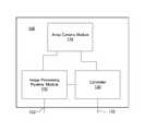
- FIG. 1A representative array camera architecture incorporating an array camera module and a processor is illustrated in FIG. 1 .
- the array camera 100includes an array camera module 110 , which is connected to an image processing pipeline module 120 and to a controller 130 .
- the image processing pipeline 120 and the controller 130are implemented using a processor.
- the image processing pipeline module 120is hardware, firmware, software, or a combination for processing the images received from the array camera module 110 .
- the image processing pipeline module 120is capable of processing image data captured by multiple focal planes in the camera module and can produce a synthesized higher resolution image using the captured image data. In a number of embodiments, the image processing pipeline module 120 provides the synthesized image data via an output 122 .
- the controller 130is hardware, software, firmware, or a combination thereof for controlling various operational parameters of the array camera module 110 .
- the controller 130receives inputs 132 from a user or other external components and sends operation signals to control the array camera module 110 .
- the controllercan also send information to the image processing pipeline module 120 to assist processing of the images captured by the focal planes in the array camera module 110 .
- FIG. 1Although a specific array camera architecture is illustrated in FIG. 1 , camera modules constructed using active alignment processes in accordance with embodiments of the invention can be utilized in any of a variety of array camera architectures. Camera modules that can be utilized in array cameras and processes for manufacturing camera modules utilizing active alignment processes in accordance with embodiments of the invention are discussed further below.
- An array camera modulemay be formed by aligning a lens stack array and an imager array in accordance with embodiments of the invention.
- Each lens stack in the lens stack arraymay define a separate optical channel.
- the lens stack arraymay be mounted to an imager array that includes a focal plane for each of the optical channels, where each focal plane includes an array of pixels or sensor elements configured to capture an image.
- the array camera modulecan be utilized to capture image data from multiple images of a scene that can be read out to a processor for further processing, e.g., to synthesize a high resolution image using super-resolution processing.
- FIG. 2An exploded view of an array camera module formed by combining a lens stack array with a monolithic sensor including an array of focal planes in accordance with an embodiment of the invention is illustrated in FIG. 2 .
- the array camera module 200includes a lens stack array 210 and a sensor 230 that includes an array of focal planes 240 .
- the lens stack array 210includes an array of lens stacks 220 .
- Each lens stackcreates an optical channel that resolves an image on the focal planes 240 on the sensor.
- Each of the lens stacksmay be of a different type.
- the optical channelsmay be used to capture images at different portions of the spectrum and the lens stack in each optical channel may be specifically optimized for the portion of the spectrum imaged by the focal plane associated with the optical channel.
- an array camera modulemay be patterned with “ ⁇ filter groups.”
- ⁇ filter groupsrefers to a pattern of color filters applied to the lens stack array of a camera module and processes for patterning array cameras with ⁇ filter groups are described in U.S. Patent Application Ser. No. 61/641,165, entitled “Camera Modules Patterned with ⁇ Filter Groups”, Venkataraman et al. The disclosure of U.S. Patent Application Ser. No. 61/641,165 is incorporated by reference herein in its entirety.
- FIG. 3illustrates a single ⁇ filter group, wherein 5 lenses are configured to receive green light, 2 lenses are configured to receive red light, and 2 lenses are configured to receive blue light.
- the lens stacksmay further have one or multiple separate optical elements axially arranged with respect to each other.
- a lens stack arraymay employ wafer level optics (WLO) technology.
- WLOis a technology that encompasses a number of processes, including, for example, molding of lens arrays on glass wafers, stacking of those wafers (including wafers having lenses replicated on either side of the substrate) with appropriate spacers, followed by packaging of the optics directly with the imager into a monolithic integrated module.
- the WLO proceduremay involve, among other procedures, using a diamond-turned mold to create each plastic lens element on a glass substrate. More specifically, the process chain in WLO generally includes producing a diamond turned lens master (both on an individual and array level), then producing a negative mould for replication of that master (also called a stamp or tool), and then finally forming a polymer replica on a glass substrate, which has been structured with appropriate supporting optical elements, such as, for example, apertures (transparent openings in light blocking material layers), and filters.
- appropriate supporting optical elementssuch as, for example, apertures (transparent openings in light blocking material layers), and filters.
- lens stack arraysusing specific WLO processes
- any of a variety of techniquescan be used to construct lens stack arrays, for instance those involving precision glass molding, polymer injection molding or wafer level polymer monolithic lens processes. Issues related to variation in back focal length of the lens stacks within lens stack arrays are discussed below.
- An array camera moduleis typically intended to be constructed in such a way that each focal plane (i.e. an array of pixels configured to capture an image formed on the focal plane by a corresponding lens stack) is positioned at the focal distance of each lens stack that forms an optical channel.
- each focal planei.e. an array of pixels configured to capture an image formed on the focal plane by a corresponding lens stack
- manufacturing variationscan result in the lens stack in each optical channel varying from its prescription, and in many instances, these variations can result in each lens stack within a lens stack array having a different focal length.
- parameters that may vary amongst individual lens stacks in a lens stack array because of manufacturing variationsinclude, but are not limited to: the radius of curvature in individual lenses, the conic, higher order aspheric coefficient, refractive index, thickness of the base layer, and/or overall lens height.
- any number of lens prescriptionsmay be used to characterize the lens fabrication process, and the respective tolerances may involve departures from these prescriptions in any number of ways, each of which may impact the back focal length. Due to the monolithic nature of the sensor, the spatial relationship of the focal planes (with respect to the lens stacks) cannot be individually customized to accommodate this variability.
- the array camera module 400includes a lens stack array 402 in which lens stacks 404 focus light on the focal planes 406 of sensor 408 .
- variance between the actually fabricated lens stack and its original prescriptioncan result in the lens stack having a focal length that varies slightly from its prescription and consequently an image distance that does not correspond with the distance between the lens stack array and the sensor. Accordingly, the images formed on the focal planes of the sensor can be out of focus.
- other manufacturing tolerances associated with the assembly of the array camera moduleincluding (but not limited to) variations in spacer thickness and alignment of the lens stack array relative to the sensor can impact all of the optical channels.
- Active and passive alignment processesmay be used in conjunction to mitigate problems associated with the variations in focal length or other thickness tolerances, and this is discussed in greater detail below.
- systems and methods in accordance with several embodiments of the inventioncan utilize an active alignment processes to manufacture one or more array camera modules, from which alignment information can be obtained for use in the manufacture of array camera modules using passive alignment processes.
- processes for actively aligning a lens stack array with a sensor to construct an array camera moduleinvolve reading image data captured by multiple focal planes on the sensor as the lens stack array is moved relative to the sensor. The image data can be utilized to evaluate the resulting image quality at different spatial relationships between the sensor and the lens stack array and the spatial relationship that provides a predetermined threshold level of image quality can be utilized to construct the camera module.
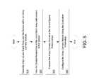
- FIG. 5A process that actively aligns a lens stack array with a sensor by generally aligning the two, varying their spatial relationship, evaluating the resulting configuration during the variation, and configuring the array camera module using the evaluation data in accordance with an embodiment of the invention is illustrated in FIG. 5 .
- a lens stack arrayis generally aligned ( 510 ) with a corresponding sensor that has multiple focal planes.
- the combinationis aligned so that each camera within the configuration is capable of capturing and recording images.
- the spatial relationship of the lens stack array with respect to the sensoris varied ( 520 ). In several embodiments, the variation is achieved by sweeping the lens stack array with respect to the sensor. Sweeping can be understood to mean moving one component (i.e. either the lens stack array or the sensor) in relation to the other over time. Sweeping may be in one degree of freedom or it can be across many degrees of freedom.
- the array nature of the camera modulemeans that variations in the x, y, and z-directions, and tip/tilt and rotation of the lens stack array with respect to the sensor can all have significant impact on the imaged data captured by the focal planes on the sensor.
- focus and consequently sharpness of the camerasis primarily affected by the z-direction and the tip/tilt of the lens stack array with respect to the sensor, with the tip/tilt principally affecting the performance of the corner cameras.
- the image quality of the camerais primarily driven by the optical system's ‘z-position’ with respect to the sensor.
- the path of the sweepis predetermined.
- the quality of the captured image datais evaluated ( 530 ) at the varied spatial relationships.
- the configurationis intermittently evaluated during a sweep of the lens stack array with respect to the sensor.
- the configurationis evaluated by evaluating multiple cameras' captured and recorded images of a known target at the varied spatial relationships.
- only a subset of the configuration's camerasis used for evaluation purposes.
- An MTF scoremay be determined for each recorded image and used to evaluate a respective camera at a respective spatial orientation.
- the recorded imagesmay also be evaluated at its different ROIs. For example, an MTF score may be assigned to each ROI within a recorded image.
- the array camera moduleis configured ( 540 ) using the information obtained during evaluation.
- the configurationinvolves concluding a spatial relationship between the lens stack array and the sensor that results in the corresponding array camera module being able to capture and record images that exceed a threshold quality.
- the configurationmay also involve disabling cameras that do not surpass a threshold quality.
- array camera modulesinclude a plurality of cameras, they can still function even when one or more of the cameras are disabled.
- the advantage of being able to disable a camerais that the average performance of the array including the camera may be much lower than the average performance of the remaining cameras when the disabled camera is excluded from consideration in determining the appropriate alignment of the lens stack array and sensor.
- any of a number of different processesmay be used to actively align a lens stack array with an array of focal planes to obtain alignment information that can be used to manufacture array camera modules using passive alignment processes in accordance with embodiments of the invention.
- An initial configuration for an active alignment process in accordance with embodiments of the inventionis discussed below.
- Active alignment processesmay begin from any number of initial configurations in accordance with embodiments of the invention.
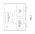
- An initial configuration for an active alignment processwhere a device that is capable of orienting a lens stack array is connected to a lens stack array of a corresponding array camera module, a processor is connected to the corresponding sensor, and a target is positioned and illuminated so that the array camera module can capture and record it in accordance with an embodiment of the invention is illustrated in FIG. 6 .
- the array camera module 610includes a lens stack array 620 and a sensor 630 that has corresponding focal planes. The lens stack array and the sensor are generally aligned so that they are capable of capturing and recording images of the target 640 .
- a device that is capable of spatially orienting the lens stack array 640is connected to the lens stack array 620 , and a processor 660 is connected to the sensor.
- the processor 660is capable of capturing and recording images from the sensor 630 , while the orientation of the lens stack array 620 is being varied, and the active alignment process can thereby be implemented.
- the combination of the device for spatially orienting the lens stack array 650 and the processor 660can be understood to be an active alignment machine 670 .
- the initial configurationinvolves generally aligning the lens stack array 620 and the sensor 630 so as to ensure that the lens stack array 620 and the sensor 630 are in sufficient translational and rotational alignment such that each lens stack is generally aligned with its corresponding focal plane.
- Translational motionhere refers to motion of a system (i.e. the lens stack array 620 or the sensor 630 ) in a direction parallel to its respective surface.
- Rotationhere refers to rotation of a system about the Z-axis (i.e. the axis defining the distance between the sensor and the lens stack array) relative to the other.
- General alignmentmay be achieved by, for example, monitoring a central feature on a test chart, and moving either the lens stack array or the sensor in translation (with respect to the other system) such that the central feature is centrally located within the central camera modules; this would indicate that the systems are in sufficient translational alignment.
- Either systemmay then be rotated with respect to the other so that the midpoints of each lens stack array and its corresponding focal plane define a line that runs generally parallel to the Z-axis. During this rotational adjustment, the systems may also be readjusted to preserve (or enhance) adequate translational alignment. In this way, each lens stack array may be generally aligned with its corresponding focal plane.
- any initial configurationmay be implemented that allows the spatial relationship between the lens stack array and the sensor to be varied, and further allows the corresponding array camera module to be evaluated, manipulated, and configured based on an evaluation of it.
- the varying of spatial relationships between the lens stack array and the sensor in accordance with embodiments of the inventionis discussed below.
- the spatial relationship between a lens stack array and a corresponding sensormay be varied in any number of ways.
- an active alignment processwhere a lens stack array is swept in a direction substantially normal to the sensor's planar surface in accordance with embodiments of the invention is illustrated in FIG. 7 .
- An array camera module 700includes a lens stack array 710 and a corresponding sensor 720 with an array of focal planes, and the active alignment process sweeps the lens stack array 710 in a predetermined direction 730 substantially normal to the sensor's surface (the z-direction). Note that sweeping the lens stack array in this fashion systematically varies the focus of each camera—typically cameras will be swept in focus and then out of focus.
- the array camera modulemay be evaluated on the varied spatial relationships along this sweep.
- Active alignment processes in accordance with embodiments of the inventioncan also include tipping, tilting, and/or rotating the lens stack array with respect to the sensor.
- only the distance between the lens stack array and the sensoris varied in a sweep referred to as a “through focus sweep” and all relevant calculations to determine the optimum alignment (including centering as well as focus and tip/tilt) are made from images captured during the through focus sweep using the respective curve fittings and center of gravity calculations, respectively.
- a through focus sweep of a skewed lens stack arrayalready provides information about the optimum tip/tilt of the lens stack array relative to the sensor by the appropriate plane fitting calculations of the peak focus positions or equalized MTF, respectively. These calculations are discussed further below.
- the manner in which the spatial relationship variesis computationally determined.
- the manner in which the spatial relationship variesmay be determined computationally based upon an initial evaluation of the array camera module.
- the manner in which the spatial relationship variesmay change during an active alignment process. For instance, after the lens stack array has been swept in a direction substantially normal to the sensor's planar surface, a processor may compute a different sweeping path that may facilitate a better configuration of the array camera module.
- the spatial relationship between the lens stack array and the sensormay be varied, the spatial relationship may also be varied in any number of other ways in accordance with embodiments of the invention.
- the evaluation of the array camera module at the varied spatial relationshipsis discussed below.
- evaluating the array camera module during the active alignment processinvolves having multiple cameras capture and record images of a known target, and evaluating these images.
- the imagesmay be evaluated by assessing their focus, for example.
- the assessment of the focusmay be performed in any number of ways in accordance with embodiments of the invention.
- an MTF scoremay be determined for a given recorded image.
- an MTF scoreis an advantageous metric insofar as MTF scores amongst different cameras can be directly compared with one another.
- a recorded imagemay be given a ‘focus score’ which can similarly be used to evaluate the recorded image.
- a focus scoremay be determined by convolving a kernel over contrasting features in an image, where the resulting value is related to the camera's ability to focus.
- a focus scoremay not necessarily be directly comparable to such scores from different cameras; instead a focus score may be more useful in evaluating a single camera.
- the selection of which scoring metric to usemay be determined, in part, by the speed in which the scores can be calculated. For instance, if it takes longer to compute an MTF score than to compute a focus score, the focus score may be used in the evaluation.
- the selection of which scoring metric to usemay also be determined, in part, by the accuracy and precision of the score. For instance, if the MTF score is a more precise means for evaluating image quality, then it may be used to evaluate the camera images.
- the active alignment processmay utilize several methods of evaluating a recorded image, and these methods may not necessarily be concurrent. For example, an evaluation based on focus scoring may be initially used, whereas an evaluation based on an MTF score may later be used. Additionally, the active alignment process may involve relating the different scoring metrics.
- focus scoringmay be used to evaluate the set of images recorded by an array camera, and MTF scoring may be used to evaluate a representative subset of those images.
- the MTF scores for the subsetmay then be normalized to the respective focus scores. And this determined relationship may be used to determine MTF scores for the remaining images.
- FIG. 8illustrates a known target used in accordance with many embodiments of the invention.
- the known target 800includes a central feature 810 that highlights a central ROI, also known as an “on-axis” ROI.
- the known targetfurther includes features 820 that highlight “off-axis” ROIs.
- the target illustrated in FIG. 8may also be used in determining a focus score.
- the determination of a focus score in conjunction with this targetmay involve convolving a kernel over areas of the image with contrasting features for each region of interest (e.g. the checkerboard patterns 840 or the dark slanted square against the light background 850 ), wherein the resulting value is proportional to the contrast between the features.
- the following convolution kernelmay be employed:
- This convolution kernelwill yield values that are proportional to a camera's ability to resolve contrast. Note that the value will either be positive or negative depending on whether the region being evaluated is transitioning from light to dark or dark to light. However, whether a region of interest is transitioning from light to dark or vice versa is irrelevant to a camera's ability to focus; therefore the absolute value of these values should be obtained. Then, a focus score for each ROI may be obtained by averaging these absolute values for each ROI.
- FIG. 8illustrates a particular known target that may be used in accordance with embodiments of the invention, many other embodiments utilize other known targets appropriate to the requirements of specific applications.
- the off-axis ROIsmay be placed in the corners of the target—this allows the performance of the camera to be tested at larger field heights.
- the ROIshave the advantage that the edges of the features are oriented in such a way that the tangential and sagittal components of the MTF and thus also the astigmatism can be directly derived and compared to prior lens test data.
- any of a variety of techniquescan be used to generate a focus score. More generally, the evaluation techniques herein described are merely illustrative. Any techniques for evaluating the efficacy of an array camera module may be incorporated in accordance with embodiments of the invention. Using the evaluation data to configure the array camera module is discussed below.
- Evaluation datamay be used to configure the array camera module in a number of respects.
- the array camera moduleis configured to minimize the detrimental impact caused by variance of focal length within a lens stack array.
- variance within a lens stack arraymay be caused by manufacturing process variations including (but not limited to) those that affect the following parameters: the radius of curvature in individual lenses, the conic, higher order aspheric coefficient, refractive index, thickness of the base layer, and/or overall lens height.
- the following manufacturing variations related to the fabrication of multiple lens stack arrays and camera modulesmay further exacerbate the variability in back focal lengths: the thickness of the lens substrates and spacers employed in the stack, especially those toward the sensor cover glass, the thickness of the sensor cover glass used, bond line thickness between the lens spacer and the sensor cover glass, and any air gap between the sensor and the sensor cover glass.
- many embodimentsevaluate the quality of each camera as a function of its spatial relationship to the sensor; thereafter, the information is used to orient the lens stack array with respect to the sensor so that any deterioration in the quality of the array camera due to the variance in focal length within the lens stack array is lessened.
- Several embodimentsgenerate mathematical equations that approximately characterize data related to camera quality as a function of spatial relationship, and use the derived equations to compute a desired spatial relationship that lessens the detrimental impact of variance in focal length. For example, some embodiments generate polynomial equations that approximately model the focal scoring data. Note that because of the nature of optics, each lens will typically have a peak focal value, and therefore polynomial equations are well suited to characterize the data. In many embodiments, the polynomial equations are generated by determining coefficients for predetermined generic polynomial equations (i.e. those with undetermined coefficients), such that the resulting equation approximately characterizes the data relating the camera quality to the spatial relationship. Many embodiments then use these derived equations to compute a best fit plane that characterizes a spatial relationship that reduces the detrimental impact of variance in focal length.
- the best-fit planesmay be computed in any number of ways.
- the best-fit planemay be computed to be a plane that includes an approximation of the peak values of the polynomial equations that characterize focal scoring data as a function of the spatial relationship.
- focal scoring datamay not necessarily be directly comparable across different cameras. Therefore, best-fit planes may also be computed by generating equivalent MTF scores, and determining a plane that maximizes the mean MTF score while minimizing its variance.
- the best-fit planesmay be computed to determine a plane wherein the MTF scores amongst the different lens stacks are equalized within some specified tolerance.
- any number of balancing algorithmsmay be employed to effectuate this computation as appropriate to the requirements of a specific application. The determination of these planes may then be used to facilitate the configuration of the array camera module.
- the configuration processinvolves orienting the lens stack array with respect to the sensor to form an array camera module that is capable of achieving pictures that have desired characteristics.
- the lens stack arrayis oriented with respect to sensor so as to achieve an array camera module that is capable of recording images, wherein the quality of the on-axis aspects of the recorded image exceeds a specified threshold criterion.
- the lens stack arrayis actively aligned with respect to the sensor to achieve an array camera module that is capable of recording images, wherein the quality of the off-axis aspects of the recorded image exceeds a specified threshold criterion.
- the configuration processmay involve disabling cameras that are above a certain threshold quality so as to avoid biasing the best fit plane determination.
- the lens stack arrayis actively aligned with respect to the sensor to achieve an array camera module that is capable of recording images, wherein the quality of both on-axis and off-axis regions of interest exceed respective specified threshold qualities.
- the configuration processinvolves disabling cameras that perform above or below a certain defined threshold quality.
- camerasare disabled when their quality, as determined by their ability to focus sharply when in a given spatial orientation, is above or below a threshold value. For example, some embodiments determine whether a camera should be disabled by evaluating an MTF score of its respective recorded images. In many embodiments, if the number of disabled cameras exceeds a specified value, then the array camera module is designated unacceptable.
- different threshold valuescan be specified for different types of cameras within the array camera module. For example, in a number of embodiments that employ ⁇ filter groups, different threshold values can be specified for the green cameras, the red cameras, and the blue cameras.
- information obtained during the evaluation aspect of the active alignment processis used to configure the functionality of the each camera. For example, if it is determined that a particular camera has a focal length that makes it better suited to record images of objects that are at a further distance, the array camera module can be configured to rely more heavily on that camera when synthesizing recorded images of objects at further distances.
- array camera modulescan be configured in any number of ways based on evaluations of the configuration in accordance with embodiments of the invention. Active alignment processes that configure array camera modules so that they are capable of capturing and recording images that have desirable image properties are discussed below.
- Active alignment processes in accordance with embodiments of the inventioncan use a variety of metrics to evaluate the image data that is captured during the active alignment process.
- the active alignment processcan optimize image quality in specific regions of the captured images, can optimize image quality in multiple regions of interest and/or can utilize a variety of metrics including (but not limited to) focus scoring and MTF scoring.
- An active alignment process that uses an iterative computation process to yield an array camera module that is capable of capturing and recording images that have sufficient on-axis and off-axis performance in accordance with an embodiment of the inventionis illustrated in FIG. 9 .
- the processis initially configured ( 902 ) so that a lens stack array and a corresponding sensor are mounted to an active alignment machine in a manner similar to that seen in FIG. 6 , so that they are generally operable as an array camera.
- Thismay include generally aligning the lens stack array with its corresponding sensor, which itself may include verifying that the lens stack array and the sensor are in sufficient rotational alignment such that each lens stack is generally aligned with its corresponding focal plane, as described above.
- a known target with an on-axis ROI and off-axis ROIs(similar to that depicted in FIG. 8 ) is positioned and illuminated so that the array camera module may capture and record its image.
- the initial configurationmay also include deactivating specific cameras in a predetermined fashion so that they do not record images during the alignment process.
- the lens stack arrayis swept ( 904 ) in a direction normal to the sensor's planar surface, in a manner similar to that seen in FIG. 7 , and may be swept for a predetermined distance.
- the active camerasintermittently capture and record ( 906 ) images of the known target.
- the processorevaluates ( 908 ) the recorded images and assigns a ‘focus score’ for each region of interest in each recorded image for each camera.
- Polynomial equationsare derived ( 910 ) for each region of interest captured by each camera that best characterizes the focus score as a function of the camera's distance from the sensor.
- the polynomial equationsare derived by calculating coefficients for a given a predetermined generic polynomial equation (i.e. a polynomial equation with undetermined coefficients).
- the polynomial equationswill typically have a peak value.
- An “on-axis best fit plane”is derived ( 912 ) using the peak values of the polynomial equations.
- the on-axis best fit planeis characterized in that it maximizes the peak values corresponding to the active cameras and/or minimizes the variance in the peak values.
- the lens stack arrayis then aligned ( 914 ) with the computed best fit on-axis plane.
- Each active cameracaptures and records ( 916 ) an image of the known target.
- Each recorded imageis then evaluated ( 918 ) by determining an MTF score for each ROI.
- Cameras that do not meet a threshold MTF scoreare disabled ( 920 ). For example, any cameras that do not have an MTF score within 20% of the median on-axis MTF score may be disabled, and subsequently excluded from further alignment position calculations.
- This thresholdmay of course be configurable. In other embodiments, other criteria are utilized to determine which cameras should be disabled. Moreover, if a specified number of cameras are disabled, the array camera is deemed unacceptable.
- the previously acquired focus scoring datais scaled ( 922 ) using the peak focus score and MTF scores.
- the focus scoring data(absolute values) are exposure/signal-level dependent. Thus different cameras (e.g. blue, green, red cameras) will have different absolute focus score peak values due to their different signal levels.
- MTFis a metric that is invariant to signal level. Thus, MTF enables the curves for focus score to be normalized such that the curve derived from focus score can also be used to compare each camera's peak performance and not only the position at which peak performance occurs. In other embodiments, any of a variety of metrics appropriate to a specific application can be utilized in determining camera peak performance.
- polynomial curvesmay then be derived ( 924 ) that characterize the scaled focus scores.
- each active camerawill be characterized by polynomial equations that characterize the camera's ability to resolve each respective region of interest.
- a best-fit on axis plane and a best-fit off axis planeare derived ( 926 ); in this instance, the best-fit planes are characterized in that they approximately maximize the mean MTF scores while minimizing their variance.
- a configurable number of planes that are evenly spaced between the two best-fit planes (on-axis and off-axis)are computed ( 928 ).
- Scaled focus scores for each camera at their respective corresponding positions along each of those planesare calculated ( 930 ).
- the lens stack arrayis then re-aligned ( 934 ) with this computed plane.
- the efficacy of the processis verified 936 . This may be accomplished by, for example, having each active camera record an image of the known target, determining an MTF score for each ROI within that image, and ensuring that each MTF score surpasses some threshold calculation.
- any number of processesmay be used to achieve an array camera module that is capable of capturing and recording images that have adequate on-axis and off-axis performance in accordance with embodiments of the invention.
- active alignment processescan be tailored to achieve any number of desirable picture characteristics in accordance with embodiments of the invention.
- active alignment processesincluding any of the above-described active alignment processes, may be used to derive alignment information from which configuration parameters can be derived for use in the manufacture of similar array camera modules using passive alignment processes, and this concept is discussed below.
- Passive alignment processes in accordance with embodiments of the inventionmay be utilized in the bulk manufacture of array camera modules based on configuration parameters derived from alignment information obtained from one or more similar array camera modules manufactured using active alignment processes.
- alignment informationis obtained by actively aligning one or more representative lens stack array(s) and sensor(s). The alignment information can then be used to derive configuration parameters that are utilized in the passive alignment of a plurality of lens stack arrays and sensors that are similar to the representative lens stack(s) and sensor(s).
- Lens stack arrays and sensorsthat are formed on the same respective wafers, or alternatively are formed in the same positions on different wafers, may be sufficiently similar such that an alignment configuration determined during the active alignment of the representative lens stack array and the imager array may be similarly effective across the remaining lens stack arrays and sensors.
- the representative lens stack array and sensordeviate from the remaining lens stack arrays and imager arrays in a known manner, the passive alignment parameters may be developed accordingly in view of the known extent of the deviation.
- a preferred spatial relationship for lens stack arrays and sensorsis identified based on the images obtained and evaluated for an actively aligned representative lens stack array and sensor, and if desirable, also based on measured differences between the actively aligned lens stack array and sensor and remaining constituent lens stack arrays and sensors.
- the lens stack arrays and sensorsmay then be affixed in the identified desired spatial relationships.
- configuration parameters for passively aligning and affixing lens stack arrays and sensorsaccount for the possibility that the bonding processes used to adjoin the passively aligned lens stack arrays and sensors may differ than those for the actively aligned lens stack array and sensor.
- the passively aligned lens stack arrays and sensorsmay require a different initial spacing prior to bonding in order to achieve the desired spatial relationship.
- a process that aligns a plurality of lens stack arrays and sensors by actively aligning a representative lens stack array and a representative sensor, recording data characterizing the active alignment, computing configuration parameters for the passive alignment of the remaining lens stack arrays and sensors using the recorded data, and passively aligning the lens stack arrays and sensors using the computed parametersis illustrated in FIG. 10 .
- a representative lens stack arrayis actively aligned ( 1010 ) with a corresponding representative sensor that has multiple focal planes. Any active alignment process may be employed, including (but not limited to) any of the above-described active alignment processes.
- the representative lens stack arrays and sensorsare found to be sufficiently similar to their respective constituents, such that it can reasonably be expected that the final configuration achieved by actively aligning the representative lens stack array and the sensor may reasonably be expected to apply just as effectively to the remaining lens stack arrays and sensors.
- lens stack arrays and sensors formed on the same respective wafersmay be sufficiently similar such that a configuration derived for one pair, can be expected to be similarly effective for the remaining pairs.
- Data characterizing the active alignmentis recorded ( 1020 ).
- the final spatial arrangement of the lens stack array relative to the sensor, which (if any) cameras were deactivated, and the results of any through focus sweepsmay be recorded.
- the overall performance of the actively aligned lens stack array and sensormay also be recorded, and may serve as a performance benchmark.
- the recordingmay be conducting in any suitable fashion.
- the machine conducting the active alignmentcan record the data.
- any other such machine capable of recording the characterization datacan do so.
- configuration parametersare computed ( 1030 ) for the passive alignment of the remaining lens stack arrays and sensors.
- the passive alignment configuration parametersare computed so as to replicate the final configuration of the actively aligned representative lens stack array and sensor.
- the configuration parametersmay include parameters relating to the spatial arrangement of the lens stack array relative to the sensor and may also include parameters related to the deactivation of cameras.
- the performance of the actively aligned camerais assessed in view of the through focus sweeps, which contain information regarding the best case performance of the cameras. This comparison may inform the extent of the impact that any adhesive curing processes used to affix the spatial relationship of lens stack arrays and sensors may have on the array camera's final imaging abilities. Accordingly, passive alignment configuration parameters may be developed to mitigate any anticipated adverse consequences of such adhesive procedures for affixing the final spatial relationship. For example, the configuration parameters may be developed so as to call for spacers of a greater or lesser thickness, based upon the impact of the adhesive curing process.
- the computation of the configuration parameterscomprises using an optics measuring tool (such as a measuring tool manufactured by TriOptics Optical Test Instrument) to measure the (average) back focal length, or any other parameters, of the various lens stacks in the to-be actively aligned lens stack array before it is aligned to the sensor, and relate these measurements to the spatial arrangement of the actively aligned lens stack array and sensor.
- the measurementsare performed during and/or after alignment.
- the optics measuring toolmay be used to measure the back focal lengths, or any other measurable parameters, in the remaining lens stack arrays; other measurement devices may be applied to determine any mechanical variations in the packages of the sensor arrays that affect e.g.
- the focusing quality(cover glass thickness, air gap).
- a desired spatial arrangement for these remaining lens stack arrays and sensorscan be computed using the known relationships, and configuration parameters for them can be computed accordingly. For example, in one instance, the distance between each lens stack and sensor within an actively aligned array camera module is measured and related to the respective lens stack's back focal length. A relationship may then be established between a given lens stack's back focal length and a preferable distances between the lens stack array and a sensor. Then, the back focal lengths of remaining lens stack arrays may be measured, and the lens stack array may be passively aligned in view of the relationship between a back focal length and a preferred distance.
- computing the passive alignment configuration parametersalso accounts for through focus curves insofar as the through focus curves may be indicative of the sensitivity of a camera's performance to its spatial relationship. Hence, the through focus curves may be used to determine the tolerances within which the spacers and bond lines used in the passive alignment processes should be implemented.
- the data contained in the through focus curvesmay assist in computing the passive configuration parameters as they characterize sensitivity of the cameras to the spatial relationship of their respective lens stack array relative to their respective focal plane.
- the through focus curvesmay be indicative of the sensitivity of a camera's performance to its spatial relationship.
- the data contained in the through focus curvescan be used in a variety of ways to facilitate the development of passive alignment configuration parameters in accordance with embodiments of the invention.
- the configuration parametersmay also specify how to achieve the desired spatial relationship. For example, the following thicknesses within a lens stack/sensor combination may be manipulated to achieve a desired spatial relationship between a lens stack and sensor; the spacer between the lens stack and the cover glass that shields the sensor, the cover glass thickness, the air gap between the cover glass and the sensor, and any spacer beads/adhesive bond lines used in affixing the configuration.
- the developed configuration parameterscan specify the desired respective thicknesses of these parameters to achieve the desired spatial relationship. Note that, in many instances, an actively aligned lens stack array and sensor may use a small spacer to separate the lens stack from the sensor cover glass.
- the configuration parametersmay be developed to achieve a desired spatial relationship while operating within the constraint of having the spacer thickness between the lens stack and the cover glass be constrained to within a particular range.
- this principalcan be applied more generally in that a desired spatial relationship can be attained in any manner, e.g. manipulating any dimensions within a lens stack/sensor combination, in accordance with embodiments of the invention.
- the thickness of the elements within the actively aligned lens stack array and sensormay be used in developing these configuration parameters. For example, a cross-section of the actively aligned lens stack array and sensor may be obtained, and the thickness of the relevant components can be measured. Alternatively, in the case where the thickness of the relevant components are all known, except that the adhesive bond line thickness is not known, this thickness may be obtained during the active alignment process by driving the lens stack against the sensor such that it mechanically contacts it, and subsequently repositioning the lens stack in its desired position; the distance between the point where the lens stack is contacting the sensor and its desired position can be approximated as the thickness of the adhesive bond gap. Passively aligned lens stack arrays and sensors may also be cross-sectioned so that the thickness of their elements can be measured. In particular, those passively aligned lens stack arrays and sensors that are exhibiting the best performance traits may be cross-sectioned, so that the thickness of their components may be determined. Accordingly, configuration parameters may be determined in view of these thickness measurements.
- the remaining lens stack arrays and sensorsmay be passively aligned ( 1040 ) to form array camera modules.
- This passive alignment processmay involve machining spacers and/or employing appropriately sized spacer beads in the adhesive to spatially orient the lens stack arrays and sensors in a desired manner, and may further involve deactivating specified cameras. For example, specific cameras may be deactivated if the final spatial arrangement is such that those cameras deviate in their performance abilities from remaining within the configuration. More generally, any of the above-described principles regarding enhancing the quality of the configuration (e.g. deactivating specific cameras, and augmenting the spatial relationship between the lens stack array and sensor) may be incorporated in passive alignment processes.
- the passively aligned array camera modulesmay be assessed to determine to what extent their performance abilities are sufficient in view of the imaging abilities of the actively aligned array camera module and/or in view of the through focus curves obtained during the active alignment process. Additionally, as before, the performance of the passively aligned array camera modules may be evaluated in view of the through focus curves, and this comparison may again inform the extent of the impact on the spatial arrangement that the adhesive curing processes may cause. Accordingly, the configuration parameters may be augmented in view of this information.
- the actively and passively aligned array camera modulesare assessed relative to the through focus curves, and this assessment is used to augment further alignments.
- the z-positioning of the lens stack array relative to the sensoris a key inquiry in the alignment process, and the through focus curves obtained during the active alignment process can reveal how camera performance varies as a function of relative distance between the lens stack array and the sensor.
- the through focus curves obtained during an active alignmentcan be used to predict the performance of the lens stack array and the sensor as actively aligned.
- the performance of the resulting array camera modulecan be compared against the predicted performance determined by evaluating the through focus curves, and any discrepancy between the predicted performance and the actual performance of the actively aligned lens stack array and sensor can be attributed to the impact that curing/adhesive processing (and/or any other finishing processing) had on the actively aligned lens stack array and sensor.
- MTF scores for the actively aligned cameramay be obtained, and compared against the through focus curve, to infer the actual final z-positioning of the lens stack array to sensor.
- this deviationmay be a function of the curing/adhesive processing, and/or any other finishing processing.
- the impact of these finishing processes becomescan be inferred, and further alignment processes can be augmented (e.g. adjusting spacer bead size) to compensate for this determined impact.
- passively aligned lens stack arrays and sensorsmay also be evaluated against the through focus curves obtained during the active alignment of the representative lens stack array and sensor to again gauge what the impact any finishing processes may have on the desired z-distance between the lens stack array and the sensor. Thereafter, further alignment processes can be also augmented in view of this determined impact.
- any measurement information obtained from optics measuring toolsmay also be used in augmenting the alignment procedures.
- the performance of passively aligned lens stack arraysmay be assessed against through focus curves obtained from active alignment; in this way, the efficacy of the passive alignment processes can be gauged.
Landscapes
- Physics & Mathematics (AREA)
- Engineering & Computer Science (AREA)
- General Physics & Mathematics (AREA)
- Optics & Photonics (AREA)
- Quality & Reliability (AREA)
- Computer Vision & Pattern Recognition (AREA)
- Theoretical Computer Science (AREA)
- Studio Devices (AREA)
Abstract
Description
Scaled Focus Scorez=(Focus Scorez/Peak Focus Score)*MTF Score
Claims (3)
Priority Applications (1)
| Application Number | Priority Date | Filing Date | Title |
|---|---|---|---|
| US14/195,675US9638883B1 (en) | 2013-03-04 | 2014-03-03 | Passive alignment of array camera modules constructed from lens stack arrays and sensors based upon alignment information obtained during manufacture of array camera modules using an active alignment process |
Applications Claiming Priority (2)
| Application Number | Priority Date | Filing Date | Title |
|---|---|---|---|
| US201361772443P | 2013-03-04 | 2013-03-04 | |
| US14/195,675US9638883B1 (en) | 2013-03-04 | 2014-03-03 | Passive alignment of array camera modules constructed from lens stack arrays and sensors based upon alignment information obtained during manufacture of array camera modules using an active alignment process |
Publications (1)
| Publication Number | Publication Date |
|---|---|
| US9638883B1true US9638883B1 (en) | 2017-05-02 |
Family
ID=58629140
Family Applications (1)
| Application Number | Title | Priority Date | Filing Date |
|---|---|---|---|
| US14/195,675Active2034-11-28US9638883B1 (en) | 2013-03-04 | 2014-03-03 | Passive alignment of array camera modules constructed from lens stack arrays and sensors based upon alignment information obtained during manufacture of array camera modules using an active alignment process |
Country Status (1)
| Country | Link |
|---|---|
| US (1) | US9638883B1 (en) |
Cited By (52)
| Publication number | Priority date | Publication date | Assignee | Title |
|---|---|---|---|---|
| US20170285308A1 (en)* | 2016-04-05 | 2017-10-05 | Qualcomm Incorporated | Systems and devices having single-sided wafer-level optics |
| US9807382B2 (en) | 2012-06-28 | 2017-10-31 | Fotonation Cayman Limited | Systems and methods for detecting defective camera arrays and optic arrays |
| US9888194B2 (en) | 2013-03-13 | 2018-02-06 | Fotonation Cayman Limited | Array camera architecture implementing quantum film image sensors |
| US9898856B2 (en) | 2013-09-27 | 2018-02-20 | Fotonation Cayman Limited | Systems and methods for depth-assisted perspective distortion correction |
| CN107783207A (en)* | 2017-11-27 | 2018-03-09 | 成都信息工程大学 | A kind of adjustable focus microlens array |
| US9917998B2 (en) | 2013-03-08 | 2018-03-13 | Fotonation Cayman Limited | Systems and methods for measuring scene information while capturing images using array cameras |
| US9986224B2 (en) | 2013-03-10 | 2018-05-29 | Fotonation Cayman Limited | System and methods for calibration of an array camera |
| US10019816B2 (en) | 2011-09-28 | 2018-07-10 | Fotonation Cayman Limited | Systems and methods for decoding image files containing depth maps stored as metadata |
| US10027901B2 (en) | 2008-05-20 | 2018-07-17 | Fotonation Cayman Limited | Systems and methods for generating depth maps using a camera arrays incorporating monochrome and color cameras |
| US10089740B2 (en) | 2014-03-07 | 2018-10-02 | Fotonation Limited | System and methods for depth regularization and semiautomatic interactive matting using RGB-D images |
| US10091405B2 (en) | 2013-03-14 | 2018-10-02 | Fotonation Cayman Limited | Systems and methods for reducing motion blur in images or video in ultra low light with array cameras |
| US10119808B2 (en) | 2013-11-18 | 2018-11-06 | Fotonation Limited | Systems and methods for estimating depth from projected texture using camera arrays |
| US10127682B2 (en) | 2013-03-13 | 2018-11-13 | Fotonation Limited | System and methods for calibration of an array camera |
| US10142560B2 (en) | 2008-05-20 | 2018-11-27 | Fotonation Limited | Capturing and processing of images including occlusions focused on an image sensor by a lens stack array |
| US10182216B2 (en) | 2013-03-15 | 2019-01-15 | Fotonation Limited | Extended color processing on pelican array cameras |
| US10218889B2 (en) | 2011-05-11 | 2019-02-26 | Fotonation Limited | Systems and methods for transmitting and receiving array camera image data |
| US10250871B2 (en) | 2014-09-29 | 2019-04-02 | Fotonation Limited | Systems and methods for dynamic calibration of array cameras |
| US10261219B2 (en) | 2012-06-30 | 2019-04-16 | Fotonation Limited | Systems and methods for manufacturing camera modules using active alignment of lens stack arrays and sensors |
| US20190150717A1 (en)* | 2016-06-13 | 2019-05-23 | CapsoVision, Inc. | Method and Apparatus of Lens Alignment for Capsule |
| US10306120B2 (en) | 2009-11-20 | 2019-05-28 | Fotonation Limited | Capturing and processing of images captured by camera arrays incorporating cameras with telephoto and conventional lenses to generate depth maps |
| US10311649B2 (en) | 2012-02-21 | 2019-06-04 | Fotonation Limited | Systems and method for performing depth based image editing |
| US10362291B2 (en)* | 2015-06-08 | 2019-07-23 | Interdigital Ce Patent Holdings | Light field imaging device |
| US10366472B2 (en) | 2010-12-14 | 2019-07-30 | Fotonation Limited | Systems and methods for synthesizing high resolution images using images captured by an array of independently controllable imagers |
| US10375302B2 (en) | 2011-09-19 | 2019-08-06 | Fotonation Limited | Systems and methods for controlling aliasing in images captured by an array camera for use in super resolution processing using pixel apertures |
| US10380752B2 (en) | 2012-08-21 | 2019-08-13 | Fotonation Limited | Systems and methods for estimating depth and visibility from a reference viewpoint for pixels in a set of images captured from different viewpoints |
| US10412314B2 (en) | 2013-03-14 | 2019-09-10 | Fotonation Limited | Systems and methods for photometric normalization in array cameras |
| US10455168B2 (en) | 2010-05-12 | 2019-10-22 | Fotonation Limited | Imager array interfaces |
| US10455218B2 (en) | 2013-03-15 | 2019-10-22 | Fotonation Limited | Systems and methods for estimating depth using stereo array cameras |
| US10462362B2 (en) | 2012-08-23 | 2019-10-29 | Fotonation Limited | Feature based high resolution motion estimation from low resolution images captured using an array source |
| US10482618B2 (en) | 2017-08-21 | 2019-11-19 | Fotonation Limited | Systems and methods for hybrid depth regularization |
| US10542208B2 (en) | 2013-03-15 | 2020-01-21 | Fotonation Limited | Systems and methods for synthesizing high resolution images using image deconvolution based on motion and depth information |
| US10674138B2 (en) | 2013-03-15 | 2020-06-02 | Fotonation Limited | Autofocus system for a conventional camera that uses depth information from an array camera |
| US10708492B2 (en) | 2013-11-26 | 2020-07-07 | Fotonation Limited | Array camera configurations incorporating constituent array cameras and constituent cameras |
| CN112150556A (en)* | 2020-08-31 | 2020-12-29 | 浙江赫千电子科技有限公司 | Active alignment method based on image quality feedback loop, assembly and manufacturing method of camera module and vehicle-mounted camera |
| US11270110B2 (en) | 2019-09-17 | 2022-03-08 | Boston Polarimetrics, Inc. | Systems and methods for surface modeling using polarization cues |
| US11290658B1 (en) | 2021-04-15 | 2022-03-29 | Boston Polarimetrics, Inc. | Systems and methods for camera exposure control |
| US11302012B2 (en) | 2019-11-30 | 2022-04-12 | Boston Polarimetrics, Inc. | Systems and methods for transparent object segmentation using polarization cues |
| US11435560B2 (en)* | 2019-02-22 | 2022-09-06 | Mitutoyo Corporation | Lens substrate stacking position calculating apparatus and program |
| US11525906B2 (en) | 2019-10-07 | 2022-12-13 | Intrinsic Innovation Llc | Systems and methods for augmentation of sensor systems and imaging systems with polarization |
| US11580667B2 (en) | 2020-01-29 | 2023-02-14 | Intrinsic Innovation Llc | Systems and methods for characterizing object pose detection and measurement systems |
| US11689813B2 (en) | 2021-07-01 | 2023-06-27 | Intrinsic Innovation Llc | Systems and methods for high dynamic range imaging using crossed polarizers |
| US11792538B2 (en) | 2008-05-20 | 2023-10-17 | Adeia Imaging Llc | Capturing and processing of images including occlusions focused on an image sensor by a lens stack array |
| US11797863B2 (en) | 2020-01-30 | 2023-10-24 | Intrinsic Innovation Llc | Systems and methods for synthesizing data for training statistical models on different imaging modalities including polarized images |
| US11954886B2 (en) | 2021-04-15 | 2024-04-09 | Intrinsic Innovation Llc | Systems and methods for six-degree of freedom pose estimation of deformable objects |
| US11953700B2 (en) | 2020-05-27 | 2024-04-09 | Intrinsic Innovation Llc | Multi-aperture polarization optical systems using beam splitters |
| US12020455B2 (en) | 2021-03-10 | 2024-06-25 | Intrinsic Innovation Llc | Systems and methods for high dynamic range image reconstruction |
| US12067746B2 (en) | 2021-05-07 | 2024-08-20 | Intrinsic Innovation Llc | Systems and methods for using computer vision to pick up small objects |
| US12069227B2 (en) | 2021-03-10 | 2024-08-20 | Intrinsic Innovation Llc | Multi-modal and multi-spectral stereo camera arrays |
| US12172310B2 (en) | 2021-06-29 | 2024-12-24 | Intrinsic Innovation Llc | Systems and methods for picking objects using 3-D geometry and segmentation |
| US12175741B2 (en) | 2021-06-22 | 2024-12-24 | Intrinsic Innovation Llc | Systems and methods for a vision guided end effector |
| US12293535B2 (en) | 2021-08-03 | 2025-05-06 | Intrinsic Innovation Llc | Systems and methods for training pose estimators in computer vision |
| US12340538B2 (en) | 2021-06-25 | 2025-06-24 | Intrinsic Innovation Llc | Systems and methods for generating and using visual datasets for training computer vision models |
Citations (255)
| Publication number | Priority date | Publication date | Assignee | Title |
|---|---|---|---|---|
| US4124798A (en) | 1965-12-09 | 1978-11-07 | Thompson Kenneth B | Optical viewing apparatus |
| US4198646A (en) | 1978-10-13 | 1980-04-15 | Hughes Aircraft Company | Monolithic imager for near-IR |
| US4323925A (en) | 1980-07-07 | 1982-04-06 | Avco Everett Research Laboratory, Inc. | Method and apparatus for arraying image sensor modules |
| US4460449A (en) | 1983-01-03 | 1984-07-17 | Amerace Corporation | Apparatus for making a tool |
| US5005083A (en) | 1988-05-19 | 1991-04-02 | Siemens Aktiengesellschaft | FLIR system with two optical channels for observing a wide and a narrow field of view |
| EP0840502A2 (en) | 1996-11-04 | 1998-05-06 | Eastman Kodak Company | Compact digital camera with segmented fields of view |
| US5808350A (en) | 1997-01-03 | 1998-09-15 | Raytheon Company | Integrated IR, visible and NIR sensor and methods of fabricating same |
| US5832312A (en) | 1996-02-22 | 1998-11-03 | Eastman Kodak Company | Watertight body for accommodating a photographic camera |
| US5880691A (en) | 1995-11-07 | 1999-03-09 | California Institute Of Technology | Capacitively coupled successive approximation ultra low power analog-to-digital converter |
| US5933190A (en) | 1995-04-18 | 1999-08-03 | Imec Vzw | Pixel structure, image sensor using such pixel structure and corresponding peripheral circuitry |
| US5973844A (en) | 1996-01-26 | 1999-10-26 | Proxemics | Lenslet array systems and methods |
| US6002743A (en) | 1996-07-17 | 1999-12-14 | Telymonde; Timothy D. | Method and apparatus for image acquisition from a plurality of cameras |
| US6034690A (en) | 1996-08-02 | 2000-03-07 | U.S. Philips Corporation | Post-processing generation of focus/defocus effects for computer graphics images |
| US6069365A (en) | 1997-11-25 | 2000-05-30 | Alan Y. Chow | Optical processor based imaging system |
| US6124974A (en) | 1996-01-26 | 2000-09-26 | Proxemics | Lenslet array systems and methods |
| US6141048A (en) | 1996-08-19 | 2000-10-31 | Eastman Kodak Company | Compact image capture device |
| US6160909A (en) | 1998-04-01 | 2000-12-12 | Canon Kabushiki Kaisha | Depth control for stereoscopic images |
| US6172352B1 (en) | 1998-03-20 | 2001-01-09 | Syscan, Inc. | Sensing module for accelerating signal readout from image sensors |
| US6205241B1 (en) | 1998-06-01 | 2001-03-20 | Canon Kabushiki Kaisha | Compression of stereoscopic images |
| US20010005225A1 (en) | 1997-07-24 | 2001-06-28 | Vincent S. Clark | Focal plane exposure control system for cmos area image sensors |
| US20020027608A1 (en) | 1998-09-23 | 2002-03-07 | Honeywell, Inc. | Method and apparatus for calibrating a tiled display |
| US6358862B1 (en) | 1999-09-02 | 2002-03-19 | Micron Technology, Inc | Passivation integrity improvements |
| US20020063807A1 (en) | 1999-04-19 | 2002-05-30 | Neal Margulis | Method for Performing Image Transforms in a Digital Display System |
| US20020087403A1 (en) | 2001-01-03 | 2002-07-04 | Nokia Corporation | Statistical metering and filtering of content via pixel-based metadata |
| US20020089596A1 (en) | 2000-12-28 | 2002-07-11 | Yasuo Suda | Image sensing apparatus |
| US20020094027A1 (en) | 2001-01-15 | 2002-07-18 | Noriyuki Sato | Transmission header compressor not compressing transmission headers attached to intra-frame coded moving-picture data |
| US20020113888A1 (en) | 2000-12-18 | 2002-08-22 | Kazuhiro Sonoda | Image pickup apparatus |
| US20020113867A1 (en) | 1997-02-20 | 2002-08-22 | Tomoshi Takigawa | Stereoscopic image display apparatus for detecting viewpoint position and forming stereoscopic image while following up viewpoint position |
| US20020163054A1 (en) | 2001-03-21 | 2002-11-07 | Yasuo Suda | Semiconductor device and its manufacture method |
| US20020167537A1 (en) | 2001-05-11 | 2002-11-14 | Miroslav Trajkovic | Motion-based tracking with pan-tilt-zoom camera |
| US20020177054A1 (en) | 2001-04-24 | 2002-11-28 | Kenji Saitoh | Exposure method and apparatus |
| US6571466B1 (en) | 2000-03-27 | 2003-06-03 | Amkor Technology, Inc. | Flip chip image sensor package fabrication method |
| US20030124763A1 (en) | 2001-05-30 | 2003-07-03 | Taiwan Semiconductor Manufacturing Company | Colors only process to reduce package yield loss |
| US6603513B1 (en) | 1999-02-16 | 2003-08-05 | Micron Technology, Inc. | Using a single control line to provide select and reset signals to image sensors in two rows of a digital imaging device |
| US6611289B1 (en) | 1999-01-15 | 2003-08-26 | Yanbin Yu | Digital cameras using multiple sensors with multiple lenses |
| US20030179418A1 (en) | 2002-03-19 | 2003-09-25 | Eastman Kodak Company | Producing a defective pixel map from defective cluster pixels in an area array image sensor |
| US20030211405A1 (en) | 2002-05-13 | 2003-11-13 | Kartik Venkataraman | Color filter imaging array and method of formation |
| US6671399B1 (en) | 1999-10-27 | 2003-12-30 | Canon Kabushiki Kaisha | Fast epipolar line adjustment of stereo pairs |
| US20040008271A1 (en) | 2002-07-04 | 2004-01-15 | Minolta Co., Ltd. | Imaging device and digital camera using the imaging device |
| US20040012689A1 (en) | 2002-07-16 | 2004-01-22 | Fairchild Imaging | Charge coupled devices in tiled arrays |
| US20040047274A1 (en) | 2002-06-27 | 2004-03-11 | Olumpus Optical Co., Ltd. | Image pickup lens unit and image pickup device |
| US20040050104A1 (en) | 2002-09-18 | 2004-03-18 | Eastman Kodak Company | Forming information transfer lens array |
| US20040056966A1 (en) | 2000-07-21 | 2004-03-25 | Schechner Yoav Y. | Method and apparatus for image mosaicing |
| US20040100570A1 (en) | 2002-11-19 | 2004-05-27 | Makoto Shizukuishi | Image sensor and digital camera |
| US20040114807A1 (en) | 2002-12-13 | 2004-06-17 | Dan Lelescu | Statistical representation and coding of light field data |
| US6765617B1 (en) | 1997-11-14 | 2004-07-20 | Tangen Reidar E | Optoelectronic camera and method for image formatting in the same |
| US6771833B1 (en) | 1999-08-20 | 2004-08-03 | Eastman Kodak Company | Method and system for enhancing digital images |
| US6774941B1 (en) | 1999-10-26 | 2004-08-10 | National Semiconductor Corporation | CCD output processing stage that amplifies signals from colored pixels based on the conversion efficiency of the colored pixels |
| US20040165090A1 (en) | 2003-02-13 | 2004-08-26 | Alex Ning | Auto-focus (AF) lens and process |
| US20040170340A1 (en) | 2003-02-27 | 2004-09-02 | Microsoft Corporation | Bayesian image super resolution |
| US20040174439A1 (en) | 2003-03-07 | 2004-09-09 | Upton Wayne A. | High frame rate high definition imaging system and method |
| US20040179834A1 (en) | 2003-03-14 | 2004-09-16 | Eastman Kodak Company | Camera using beam splitter with micro-lens image amplification |
| US6795253B2 (en) | 2002-05-08 | 2004-09-21 | Fuji Photo Optical Co., Ltd. | Imaging lens |
| US20040207836A1 (en) | 2002-09-27 | 2004-10-21 | Rajeshwar Chhibber | High dynamic range optical inspection system and method |
| US20040213449A1 (en) | 2003-02-03 | 2004-10-28 | Photon Dynamics, Inc. | Method and apparatus for optical inspection of a display |
| US20040218809A1 (en) | 2003-05-02 | 2004-11-04 | Microsoft Corporation | Cyclopean virtual imaging via generalized probabilistic smoothing |
| US20040251509A1 (en) | 2003-06-11 | 2004-12-16 | Choi Kyoung-Sei | CMOS type image sensor module having transparent polymeric encapsulation material |
| US20050006477A1 (en) | 2003-07-07 | 2005-01-13 | Mehul Patel | Imaging arrangement and barcode imager for imaging an optical code or target at a plurality of focal planes |
| US20050010621A1 (en) | 2003-07-07 | 2005-01-13 | Victor Pinto | Dynamic identification and correction of defective pixels |
| US20050012035A1 (en) | 2003-01-21 | 2005-01-20 | Miller Steven D. | System and method for significant dust detection and enhancement of dust images over land and ocean |
| US20050036778A1 (en) | 2003-08-12 | 2005-02-17 | Demonte Frank J. | Fixed-focus camera module and associated method of assembly |
| US20050048690A1 (en) | 2003-06-24 | 2005-03-03 | Katsumi Yamamoto | Image sensor having micro-lens array separated with trench structures and method of making |
| US20050068436A1 (en) | 2001-05-29 | 2005-03-31 | Miriam Fraenkel | CMOS imager for cellular applications and methods of using such |
| US6879735B1 (en) | 1998-09-14 | 2005-04-12 | University Of Utah Reasearch Foundation | Method of digital image enhancement and sharpening |
| US6903770B1 (en) | 1998-07-27 | 2005-06-07 | Sanyo Electric Co., Ltd. | Digital camera which produces a single image based on two exposures |
| US6909121B2 (en) | 1998-05-11 | 2005-06-21 | Seiko Epson Corporation | Microlens array substrate, method of manufacturing the same, and display device |
| US20050134712A1 (en) | 2003-12-18 | 2005-06-23 | Gruhlke Russell W. | Color image sensor having imaging element array forming images on respective regions of sensor elements |
| US20050151759A1 (en) | 2003-09-08 | 2005-07-14 | Gonzalez-Banos Hector H. | Systems and methods for directly generating a view using a layered approach |
| US20050205785A1 (en) | 2001-05-11 | 2005-09-22 | Bert Hornback | Imaging device with multiple fields of view incorporating memory-based temperature compensation of an uncooled focal plane array |
| US20050219363A1 (en) | 2004-04-05 | 2005-10-06 | Kohler Timothy L | Imaging device analysis systems and imaging device analysis methods |
| US20050225654A1 (en) | 2004-04-08 | 2005-10-13 | Digital Optics Corporation | Thin color camera |
| US6958862B1 (en) | 2003-04-21 | 2005-10-25 | Foveon, Inc. | Use of a lenslet array with a vertically stacked pixel array |
| US20050286612A1 (en) | 2004-06-28 | 2005-12-29 | Nec Electronics Corporation | De-interleaver, mobile communication terminal, and de-interleaving method |
| US20060002635A1 (en) | 2004-06-30 | 2006-01-05 | Oscar Nestares | Computing a higher resolution image from multiple lower resolution images using model-based, robust bayesian estimation |
| US20060023314A1 (en) | 2004-07-27 | 2006-02-02 | Boettiger Ulrich C | Controlling lens shape in a microlens array |
| JP2006033493A (en) | 2004-07-16 | 2006-02-02 | Matsushita Electric Ind Co Ltd | Imaging device |
| US20060038891A1 (en) | 2003-01-31 | 2006-02-23 | Masatoshi Okutomi | Method for creating high resolution color image, system for creating high resolution color image and program creating high resolution color image |
| US20060054782A1 (en) | 2004-08-25 | 2006-03-16 | Olsen Richard I | Apparatus for multiple camera devices and method of operating same |
| US20060072029A1 (en) | 2002-10-25 | 2006-04-06 | Konica Minolta Holdings, Inc. | Image input device |
| US20060087747A1 (en) | 2004-10-21 | 2006-04-27 | Konica Minolta Opto. Inc. | Optical system, image pickup device and digital apparatus |
| US20060098888A1 (en) | 2004-10-22 | 2006-05-11 | Nikon Corporation | Imaging device and image processing program for estimating fixed pattern noise from partial noise output of available pixel area |
| US20060103754A1 (en)* | 2004-11-16 | 2006-05-18 | Wenstrand John S | System and method for focusing a digital camera |
| US20060125936A1 (en) | 2004-12-15 | 2006-06-15 | Gruhike Russell W | Multi-lens imaging systems and methods |
| US20060138322A1 (en) | 2003-01-31 | 2006-06-29 | Costello Kenneth A | Backside imaging through a doped layer |
| US20060159369A1 (en) | 2005-01-19 | 2006-07-20 | U.S. Army Research Laboratory | Method of super-resolving images |
| US7085409B2 (en) | 2000-10-18 | 2006-08-01 | Sarnoff Corporation | Method and apparatus for synthesizing new video and/or still imagery from a collection of real video and/or still imagery |
| US20060187338A1 (en) | 2005-02-18 | 2006-08-24 | May Michael J | Camera phone using multiple lenses and image sensors to provide an extended zoom range |
| US20060210186A1 (en) | 1999-12-10 | 2006-09-21 | Kathrin Berkner | Multiscale sharpening and smoothing with wavelets |
| US20060243889A1 (en) | 2004-07-19 | 2006-11-02 | Farnworth Warren M | Microelectronic imagers with optical devices and methods of manufacturing such microelectronic imagers |
| US20060251410A1 (en) | 2005-05-05 | 2006-11-09 | Trutna William R Jr | Imaging device employing optical motion sensor as gyroscope |
| US20070002159A1 (en) | 2005-07-01 | 2007-01-04 | Olsen Richard I | Method and apparatus for use in camera and systems employing same |
| US20070024614A1 (en) | 2005-07-26 | 2007-02-01 | Tam Wa J | Generating a depth map from a two-dimensional source image for stereoscopic and multiview imaging |
| US20070041391A1 (en) | 2005-08-18 | 2007-02-22 | Micron Technology, Inc. | Method and apparatus for controlling imager output data rate |
| US20070040922A1 (en) | 2005-08-22 | 2007-02-22 | Micron Technology, Inc. | HDR/AB on multi-way shared pixels |
| US20070052825A1 (en) | 2000-08-07 | 2007-03-08 | Kwang-Bo Cho | Pixel optimization for color |
| US20070083114A1 (en) | 2005-08-26 | 2007-04-12 | The University Of Connecticut | Systems and methods for image resolution enhancement |
| US20070127831A1 (en) | 2003-04-10 | 2007-06-07 | Kartik Venkataraman | Compression system for integrated sensor devices |
| US20070139333A1 (en) | 2004-08-26 | 2007-06-21 | Susumu Sato | Optical element |
| US20070146511A1 (en) | 2005-11-17 | 2007-06-28 | Sony Corporation | Signal processing apparatus for solid-state imaging device, signal processing method, and imaging system |
| US20070160310A1 (en) | 2003-12-01 | 2007-07-12 | Japan Science And Technology Agency | Apparatus and method for image configuring |
| JP2007520107A (en) | 2003-12-18 | 2007-07-19 | アバゴ・テクノロジーズ・ジェネラル・アイピー(シンガポール)プライベート・リミテッド | Color image sensor having an image sensor for forming an image on each area of the sensor element |
| WO2007083579A1 (en) | 2006-01-20 | 2007-07-26 | Matsushita Electric Industrial Co., Ltd. | Compound eye camera module and method of producing the same |
| US20070171290A1 (en) | 2003-05-08 | 2007-07-26 | Ronald Kroger | Pixel patterns |
| US7262799B2 (en) | 2000-10-25 | 2007-08-28 | Canon Kabushiki Kaisha | Image sensing apparatus and its control method, control program, and storage medium |
| US20070211164A1 (en) | 2004-08-25 | 2007-09-13 | Olsen Richard I | Imager module optical focus and assembly method |
| US20070216765A1 (en) | 2006-03-16 | 2007-09-20 | Wong Earl Q | Simple method for calculating camera defocus from an image scene |
| US7292735B2 (en) | 2004-04-16 | 2007-11-06 | Microsoft Corporation | Virtual image artifact detection |
| US20070258706A1 (en) | 2006-05-08 | 2007-11-08 | Ramesh Raskar | Method for deblurring images using optimized temporal coding patterns |
| US20070257184A1 (en) | 2005-08-25 | 2007-11-08 | Olsen Richard I | Large dynamic range cameras |
| US20070258006A1 (en) | 2005-08-25 | 2007-11-08 | Olsen Richard I | Solid state camera optics frame and assembly |
| US7295697B1 (en) | 1999-12-06 | 2007-11-13 | Canon Kabushiki Kaisha | Depth information measurement apparatus and mixed reality presentation system |
| US20070268374A1 (en) | 2006-05-12 | 2007-11-22 | Robinson M D | End-to-end design of superresolution electro-optic imaging systems |
| US20070296847A1 (en) | 2006-06-21 | 2007-12-27 | Chao-Chi Chang | Method of making image capture unit |
| US20070296835A1 (en) | 2005-08-25 | 2007-12-27 | Olsen Richard I | Digital cameras with direct luminance and chrominance detection |
| CN101102388A (en) | 2006-07-06 | 2008-01-09 | 三星电子株式会社 | Image sensor and image sensing method using same |
| US20080019611A1 (en) | 2004-03-31 | 2008-01-24 | Canon Kabushiki Kaisha | Imaging System Performance Measurement |
| US20080025649A1 (en) | 2002-02-07 | 2008-01-31 | Microsoft Coporation | Transformation of exif images |
| US20080043095A1 (en) | 2006-04-04 | 2008-02-21 | Anthony Vetro | Method and System for Acquiring, Encoding, Decoding and Displaying 3D Light Fields |
| US20080043096A1 (en) | 2006-04-04 | 2008-02-21 | Anthony Vetro | Method and System for Decoding and Displaying 3D Light Fields |
| CN101147392A (en) | 2005-03-24 | 2008-03-19 | 松下电器产业株式会社 | Imaging device and lens array used therein |
| US20080080028A1 (en) | 2006-10-02 | 2008-04-03 | Micron Technology, Inc. | Imaging method, apparatus and system having extended depth of field |
| US20080084486A1 (en) | 2006-10-04 | 2008-04-10 | Enge Amy D | Providing multiple video signals from single sensor |
| US20080088793A1 (en) | 2006-09-25 | 2008-04-17 | Sverdrup Lawrence H | Methods and lenses for correction of chromatic aberration |
| US20080095523A1 (en) | 2006-10-18 | 2008-04-24 | Lynn Schilling-Benz | Lens array assisted focus detection |
| US20080118241A1 (en) | 2006-11-16 | 2008-05-22 | Tekolste Robert | Control of stray light in camera systems employing an optics stack and associated methods |
| US20080131019A1 (en) | 2006-12-01 | 2008-06-05 | Yi-Ren Ng | Interactive Refocusing of Electronic Images |
| US7391572B2 (en) | 2006-03-01 | 2008-06-24 | International Business Machines Corporation | Hybrid optical/electronic structures fabricated by a common molding process |
| US20080152296A1 (en) | 2006-12-21 | 2008-06-26 | Byung Tae Oh | Methods and Systems for Processing Film Grain Noise |
| US20080151097A1 (en) | 2006-12-22 | 2008-06-26 | Industrial Technology Research Institute | Autofocus searching method |
| US20080158698A1 (en) | 2006-12-29 | 2008-07-03 | Chao-Chi Chang | Lens barrel array and lens array and the method of making the same |
| US7408725B2 (en) | 2005-09-29 | 2008-08-05 | Fujinon Corporation | Single focus lens |
| US20080219654A1 (en) | 2007-03-09 | 2008-09-11 | Border John N | Camera using multiple lenses and image sensors to provide improved focusing capability |
| US20080218610A1 (en) | 2005-09-30 | 2008-09-11 | Glenn Harrison Chapman | Methods and Apparatus for Detecting Defects in Imaging Arrays by Image Analysis |
| US20080247653A1 (en) | 2007-04-03 | 2008-10-09 | Micron Technology, Inc. | Method and apparatus for parallelization of image compression encoders |
| US20080247638A1 (en) | 2007-03-26 | 2008-10-09 | Funai Electric Co., Ltd. | Three-Dimensional Object Imaging Device |
| US20080298674A1 (en) | 2007-05-29 | 2008-12-04 | Image Masters Inc. | Stereoscopic Panoramic imaging system |
| EP2026563A1 (en) | 2007-08-14 | 2009-02-18 | Deutsche Thomson OHG | System and method for detecting defective pixels |
| US20090052743A1 (en) | 2004-10-12 | 2009-02-26 | Axel Techmer | Motion estimation in a plurality of temporally successive digital images |
| US20090050946A1 (en) | 2004-07-25 | 2009-02-26 | Jacques Duparre | Camera module, array based thereon, and method for the production thereof |
| US20090060281A1 (en) | 2007-03-26 | 2009-03-05 | Funai Electric Co., Ltd. | Object Distance Deriving Device |
| US20090086074A1 (en) | 2007-09-27 | 2009-04-02 | Omnivision Technologies, Inc. | Dual mode camera solution apparatus, system, and method |
| US20090102956A1 (en) | 2007-10-18 | 2009-04-23 | Georgiev Todor G | Fast Computational Camera Based On Two Arrays of Lenses |
| US20090109306A1 (en) | 2007-10-26 | 2009-04-30 | Jizhang Shan | High dynamic range sensor with reduced line memory for color interpolation |
| US20090179142A1 (en) | 2006-01-23 | 2009-07-16 | Jacques Duparre | Image Detection System and Method For Production at Least One Image Detection System |
| US20090180021A1 (en) | 2008-01-15 | 2009-07-16 | Fujifilm Corporation | Method for adjusting position of image sensor, method and apparatus for manufacturing a camera module, and camera module |
| US20090200622A1 (en) | 2008-02-11 | 2009-08-13 | Omnivision Technologies, Inc. | Self-aligned filter for an image sensor |
| US20090207235A1 (en) | 2005-11-30 | 2009-08-20 | Gianluca Francini | Method for Determining Scattered Disparity Fields in Stereo Vision |
| US20090225203A1 (en) | 2008-02-28 | 2009-09-10 | Funai Electric Co., Ltd. | Compound-eye imaging device |
| US7606484B1 (en) | 2006-03-23 | 2009-10-20 | Flir Systems, Inc. | Infrared and near-infrared camera hyperframing |
| US20090268192A1 (en) | 2008-04-25 | 2009-10-29 | Rockwell Collins, Inc. | High dynamic range sensor system and method |
| US20090284651A1 (en) | 2008-05-19 | 2009-11-19 | Microsoft Corporation | Quantization and differential coding of alpha image data |
| US20090297056A1 (en) | 2008-05-28 | 2009-12-03 | Micron Technology, Inc. | Method and apparatus for extended depth-of-field image restoration |
| US20090302205A9 (en) | 2004-08-25 | 2009-12-10 | Olsen Richard I | Lens frame and optical focus assembly for imager module |
| US7633511B2 (en) | 2004-04-01 | 2009-12-15 | Microsoft Corporation | Pop-up light field |
| WO2009151903A2 (en) | 2008-05-20 | 2009-12-17 | Pelican Imaging Corporation | Capturing and processing of images using monolithic camera array with hetergeneous imagers |
| US7639435B2 (en) | 2007-04-04 | 2009-12-29 | Hon Hai Precision Industry Co., Ltd. | Optical module with adhesively mounted filter |
| US20090323195A1 (en) | 2008-06-27 | 2009-12-31 | Micron Technology, Inc. | Lens master devices, lens structures, imaging devices, and methods and apparatuses of making the same |
| US20090324118A1 (en) | 2008-06-30 | 2009-12-31 | Oleg Maslov | Computing higher resolution images from multiple lower resolution images |
| US20100002314A1 (en) | 2008-07-01 | 2010-01-07 | Micron Technology, Inc. | Lens system with symmetrical optics |
| US20100002313A1 (en) | 2008-07-02 | 2010-01-07 | Jacques Duparre | Method and apparatus providing singlet wafer lens system with field flattener |
| US7657090B2 (en) | 2003-05-26 | 2010-02-02 | Noritsu Koki Co., Ltd. | Region detecting method and region detecting apparatus |
| US20100053600A1 (en) | 2008-09-01 | 2010-03-04 | Funai Electric Co., Ltd. | Optical Condition Design Method for a Compound-Eye Imaging Device |
| US20100053342A1 (en) | 2008-09-04 | 2010-03-04 | Samsung Electronics Co. Ltd. | Image edit method and apparatus for mobile terminal |
| US7675681B2 (en) | 2007-02-02 | 2010-03-09 | Toshiba Matsushita Display Technology Co., Ltd. | Display device |
| US20100060746A9 (en) | 2004-08-25 | 2010-03-11 | Richard Ian Olsen | Simultaneous multiple field of view digital cameras |
| US20100086227A1 (en) | 2008-10-04 | 2010-04-08 | Microsoft Corporation | Image super-resolution using gradient profile prior |
| US20100097491A1 (en) | 2008-10-21 | 2010-04-22 | Stmicroelectronics S.R.L. | Compound camera sensor and related method of processing digital images |
| US7706634B2 (en) | 2003-01-20 | 2010-04-27 | Fraunhofer-Gesellschaft Zur Foerderung Der Angewandten Forschung E.V. | Method and camera (apparatus) for optically capturing a screen |
| US20100103259A1 (en) | 2008-10-20 | 2010-04-29 | Funai Electric Co., Ltd. | Object Distance Deriving Device |
| US20100103308A1 (en) | 2008-10-29 | 2010-04-29 | Jabil Circuit, Inc. | Positioning wafer lenses on electronic imagers |
| US20100111444A1 (en) | 2007-04-24 | 2010-05-06 | Coffman Thayne R | Method and system for fast dense stereoscopic ranging |
| US20100118127A1 (en) | 2008-11-13 | 2010-05-13 | Samsung Electronics Co., Ltd. | Wide depth of field 3D display apparatus and method |
| US7723662B2 (en) | 2005-10-07 | 2010-05-25 | The Board Of Trustees Of The Leland Stanford Junior University | Microscopy arrangements and approaches |
| US20100142839A1 (en) | 2008-11-19 | 2010-06-10 | Canon Kabushiki Kaisha | Dvc as generic file format for plenoptic camera |
| US20100157073A1 (en) | 2008-12-22 | 2010-06-24 | Yuhi Kondo | Image processing apparatus, image processing method, and program |
| US20100166410A1 (en) | 2008-12-27 | 2010-07-01 | Hon Hai Precision Industry Co., Ltd. | Camera module array for obtaining compound images |
| US20100177411A1 (en) | 2009-01-09 | 2010-07-15 | Shashikant Hegde | Wafer level lens replication on micro-electrical-mechanical systems |
| US20100195716A1 (en) | 2007-06-26 | 2010-08-05 | Koninklijke Philips Electronics N.V. | Method and system for encoding a 3d video signal, enclosed 3d video signal, method and system for decoder for a 3d video signal |
| US20100201834A1 (en) | 2009-02-10 | 2010-08-12 | Sony Corporation | Solid-state imaging device, method of manufacturing the same, and electronic apparatus |
| US20100220212A1 (en) | 2005-01-18 | 2010-09-02 | Perlman Stephen G | Apparatus and method for capturing still images and video using coded lens imaging techniques |
| US20100231285A1 (en) | 2009-03-12 | 2010-09-16 | Boomer James B | Mipi analog switch for automatic selection of multiple image sensors |
| US20100244165A1 (en) | 2009-03-26 | 2010-09-30 | Micron Technology, Inc. | Method and apparatus providing combined spacer and optical lens element |
| US20100265385A1 (en) | 2009-04-18 | 2010-10-21 | Knight Timothy J | Light Field Camera Image, File and Configuration Data, and Methods of Using, Storing and Communicating Same |
| US20100281070A1 (en) | 2009-05-01 | 2010-11-04 | Creative Technology Ltd | Data file having more than one mode of operation |
| US20100309292A1 (en) | 2007-11-29 | 2010-12-09 | Gwangju Institute Of Science And Technology | Method and apparatus for generating multi-viewpoint depth map, method for generating disparity of multi-viewpoint image |
| US20110018973A1 (en) | 2008-03-26 | 2011-01-27 | Konica Minolta Holdings, Inc. | Three-dimensional imaging device and method for calibrating three-dimensional imaging device |
| US20110032370A1 (en) | 2008-05-25 | 2011-02-10 | Avistar Communications Corporation | Synthetic image formation signal processing hardware for vignetted optoelectronic arrays, lensless cameras, and integrated camera-displays |
| US20110043661A1 (en) | 2008-02-08 | 2011-02-24 | University Of Kent | Camera Adapter Based Optical Imaging Apparatus |
| US20110043665A1 (en) | 2009-08-19 | 2011-02-24 | Kabushiki Kaisha Toshiba | Image processing device, solid-state imaging device, and camera module |
| US20110043668A1 (en) | 2009-08-24 | 2011-02-24 | Mckinnon Patrick R | Detection of Defective Pixels in an Image Sensor |
| US7912673B2 (en) | 2005-03-11 | 2011-03-22 | Creaform Inc. | Auto-referenced system and apparatus for three-dimensional scanning |
| US20110080487A1 (en)* | 2008-05-20 | 2011-04-07 | Pelican Imaging Corporation | Capturing and processing of images using monolithic camera array with heterogeneous imagers |
| US20110122308A1 (en) | 2009-11-20 | 2011-05-26 | Pelican Imaging Corporation | Capturing and processing of images using monolithic camera array with heterogeneous imagers |
| JP2011109484A (en) | 2009-11-18 | 2011-06-02 | Sharp Corp | Multi-lens camera apparatus and electronic information device |
| EP2336816A2 (en) | 2009-12-04 | 2011-06-22 | Ricoh Company, Ltd. | Imaging device |
| US20110153248A1 (en) | 2009-12-23 | 2011-06-23 | Yeming Gu | Ophthalmic quality metric system |
| US20110157321A1 (en) | 2009-12-25 | 2011-06-30 | Casio Computer Co., Ltd. | Imaging device, 3d modeling data creation method, and computer-readable recording medium storing programs |
| US20110211824A1 (en) | 2008-01-23 | 2011-09-01 | Georgiev Todor G | Methods and Apparatus for Full-Resolution Light-Field Capture and Rendering |
| US8013904B2 (en) | 2008-12-09 | 2011-09-06 | Seiko Epson Corporation | View projection matrix based high performance low latency display pipeline |
| US20110221658A1 (en) | 2010-02-28 | 2011-09-15 | Osterhout Group, Inc. | Augmented reality eyepiece with waveguide having a mirrored surface |
| WO2011116203A1 (en) | 2010-03-17 | 2011-09-22 | Pelican Imaging Corporation | Fabrication process for mastering imaging lens arrays |
| US8027531B2 (en) | 2004-07-21 | 2011-09-27 | The Board Of Trustees Of The Leland Stanford Junior University | Apparatus and method for capturing a scene using staggered triggering of dense camera arrays |
| WO2011143501A1 (en) | 2010-05-12 | 2011-11-17 | Pelican Imaging Corporation | Architectures for imager arrays and array cameras |
| US20110285866A1 (en) | 2010-05-18 | 2011-11-24 | Satish Kumar Bhrugumalla | Multi-Channel Imager |
| US20110298917A1 (en) | 2010-03-19 | 2011-12-08 | Satoshi Yanagita | Imaging apparatus, method, program, and recording medium used in the program |
| US8077245B2 (en) | 2004-03-17 | 2011-12-13 | Adamo Thomas J | Apparatus for imaging using an array of lenses |
| US20110310980A1 (en) | 2010-06-22 | 2011-12-22 | Qualcomm Mems Technologies, Inc. | Apparatus and methods for processing frames of video data across a display interface using a block-based encoding scheme and a tag id |
| GB2482022A (en) | 2010-07-16 | 2012-01-18 | St Microelectronics Res & Dev | Method for measuring resolution and aberration of lens and sensor |
| US8106949B2 (en) | 2009-03-26 | 2012-01-31 | Seiko Epson Corporation | Small memory footprint light transport matrix capture |
| US20120026342A1 (en) | 2010-07-27 | 2012-02-02 | Xiaoguang Yu | Electronic system communicating with image sensor |
| US20120026297A1 (en) | 2009-03-30 | 2012-02-02 | Shunichi Sato | Imaging apparatus and imaging method |
| US8126279B2 (en) | 2007-11-19 | 2012-02-28 | The University Of Arizona | Lifting-based view compensated compression and remote visualization of volume rendered images |
| CN102375199A (en) | 2010-08-11 | 2012-03-14 | 鸿富锦精密工业(深圳)有限公司 | Camera module |
| US20120069235A1 (en) | 2010-09-20 | 2012-03-22 | Canon Kabushiki Kaisha | Image capture with focus adjustment |
| US8164629B1 (en) | 2003-02-12 | 2012-04-24 | The Research Foundation Of State University Of New York | Linear system based, qualitative independent motion detection from compressed mpeg surveillance video |
| WO2012057620A2 (en) | 2010-10-24 | 2012-05-03 | Ziv Attar | System and method for imaging using multi aperture camera |
| US20120113413A1 (en) | 2009-08-11 | 2012-05-10 | Ether Precision, Inc | Method and device for algining a lens with an optical system |
| US8189089B1 (en) | 2009-01-20 | 2012-05-29 | Adobe Systems Incorporated | Methods and apparatus for reducing plenoptic camera artifacts |
| WO2012074361A1 (en) | 2010-12-03 | 2012-06-07 | Mimos Berhad | Method of image segmentation using intensity and depth information |
| US20120147139A1 (en) | 2010-03-19 | 2012-06-14 | Bo Li | Stereoscopic image aligning apparatus, stereoscopic image aligning method, and program of the same |
| US20120147205A1 (en) | 2010-12-14 | 2012-06-14 | Pelican Imaging Corporation | Systems and methods for synthesizing high resolution images using super-resolution processes |
| US20120154551A1 (en) | 2010-12-17 | 2012-06-21 | Canon Kabushiki Kaisha | Stereo image display system, stereo imaging apparatus and stereo display apparatus |
| US8213711B2 (en) | 2007-04-03 | 2012-07-03 | Her Majesty The Queen In Right Of Canada As Represented By The Minister Of Industry, Through The Communications Research Centre Canada | Method and graphical user interface for modifying depth maps |
| US20120188634A1 (en) | 2011-01-20 | 2012-07-26 | Kenneth Scott Kubala | Passively Athermalized Infrared Imaging System And Method Of Manufacturing Same |
| US20120229628A1 (en) | 2009-11-13 | 2012-09-13 | Eiji Ishiyama | Distance measuring apparatus, distance measuring method, distance measuring program, distance measuring system, and image pickup apparatus |
| US20120249550A1 (en) | 2009-04-18 | 2012-10-04 | Lytro, Inc. | Selective Transmission of Image Data Based on Device Attributes |
| US8305456B1 (en) | 2011-05-11 | 2012-11-06 | Pelican Imaging Corporation | Systems and methods for transmitting and receiving array camera image data |
| US20120314033A1 (en) | 2010-02-23 | 2012-12-13 | Lee Gun-Ill | Apparatus and method for generating 3d image data in a portable terminal |
| US20130003184A1 (en) | 2011-06-28 | 2013-01-03 | Pelican Imaging Corporation | Optical arrangements for use with an array camera |
| US20130002828A1 (en) | 2011-07-01 | 2013-01-03 | Yuanyuan Ding | Context and Epsilon Stereo Constrained Correspondence Matching |
| US20130010073A1 (en) | 2011-07-08 | 2013-01-10 | Do Minh N | System and method for generating a depth map and fusing images from a camera array |
| US8360574B2 (en) | 2006-03-20 | 2013-01-29 | High Performance Optics, Inc. | High performance selective light wavelength filtering providing improved contrast sensitivity |
| US20130050504A1 (en) | 2011-08-29 | 2013-02-28 | Qualcomm Incorporated | Fast calibration of displays using spectral-based colorimetrically calibrated multicolor camera |
| US8400555B1 (en) | 2009-12-01 | 2013-03-19 | Adobe Systems Incorporated | Focused plenoptic camera employing microlenses with different focal lengths |
| US20130070060A1 (en) | 2011-09-19 | 2013-03-21 | Pelican Imaging Corporation | Systems and methods for determining depth from multiple views of a scene that include aliasing using hypothesized fusion |
| US8406562B2 (en) | 2006-08-11 | 2013-03-26 | Geo Semiconductor Inc. | System and method for automated calibration and correction of display geometry and color |
| US20130076967A1 (en) | 2011-09-28 | 2013-03-28 | Apple Inc. | Dynamic Autofocus Opertions |
| US20130077882A1 (en) | 2011-09-28 | 2013-03-28 | Pelican Imaging Corporation | Systems and methods for decoding light field image files |
| US20130088637A1 (en) | 2011-10-11 | 2013-04-11 | Pelican Imaging Corporation | Lens Stack Arrays Including Adaptive Optical Elements |
| US20130113899A1 (en) | 2011-11-04 | 2013-05-09 | Kabushiki Kaisha Toshiba | Video processing device and video processing method |
| US20130128121A1 (en) | 2010-09-14 | 2013-05-23 | Aseem O. Agarwala | Methods and Apparatus for Video Completion |
| US20130147979A1 (en) | 2010-05-12 | 2013-06-13 | Pelican Imaging Corporation | Systems and methods for extending dynamic range of imager arrays by controlling pixel analog gain |
| WO2013119706A1 (en) | 2012-02-06 | 2013-08-15 | Pelican Imaging Corporation | Systems and methods for extending dynamic range of imager arrays by controlling pixel analog gain |
| US20130215108A1 (en) | 2012-02-21 | 2013-08-22 | Pelican Imaging Corporation | Systems and Methods for the Manipulation of Captured Light Field Image Data |
| US20130222556A1 (en) | 2010-09-22 | 2013-08-29 | Fujitsu Limited | Stereo picture generating device, and stereo picture generating method |
| US20130265459A1 (en) | 2011-06-28 | 2013-10-10 | Pelican Imaging Corporation | Optical arrangements for use with an array camera |
| US20130274923A1 (en) | 2012-04-13 | 2013-10-17 | Automation Engineering, Inc. | Active Alignment Using Continuous Motion Sweeps and Temporal Interpolation |
| US20140009586A1 (en) | 2009-07-31 | 2014-01-09 | 3D Media Corporation | Methods, systems, and computer-readable storage media for selecting image capture positions to generate three-dimensional images |
| US20140104490A1 (en) | 2012-10-12 | 2014-04-17 | Wintek Corporation | Image capture device |
| US20140192253A1 (en) | 2013-01-05 | 2014-07-10 | Tinz Optics, Inc. | Methods and apparatus for capturing and/or processing images |
| US20140198188A1 (en) | 2011-09-21 | 2014-07-17 | Fujifilm Corporation | Image processing device, method and recording medium, stereoscopic image capture device, portable electronic apparatus, printer, and stereoscopic image player device |
| WO2014160142A1 (en) | 2013-03-13 | 2014-10-02 | Pelican Imaging Corporation | Systems and methods for using alignment to increase sampling diversity of cameras in an array camera module |
| US20150124151A1 (en) | 2013-11-07 | 2015-05-07 | Pelican Imaging Corporation | Array Camera Modules Incorporating Independently Aligned Lens Stacks |
| US20150326852A1 (en) | 2012-06-28 | 2015-11-12 | Pelican Imaging Corporation | Systems and Methods for Detecting Defective Camera Arrays and Optic Arrays |
| US20160266284A1 (en) | 2012-06-30 | 2016-09-15 | Pelican Imaging Corporation | Systems and Methods for Manufacturing Camera Modules Using Active Alignment of Lens Stack Arrays and Sensors |
- 2014
- 2014-03-03USUS14/195,675patent/US9638883B1/enactiveActive
Patent Citations (298)
| Publication number | Priority date | Publication date | Assignee | Title |
|---|---|---|---|---|
| US4124798A (en) | 1965-12-09 | 1978-11-07 | Thompson Kenneth B | Optical viewing apparatus |
| US4198646A (en) | 1978-10-13 | 1980-04-15 | Hughes Aircraft Company | Monolithic imager for near-IR |
| US4323925A (en) | 1980-07-07 | 1982-04-06 | Avco Everett Research Laboratory, Inc. | Method and apparatus for arraying image sensor modules |
| US4460449A (en) | 1983-01-03 | 1984-07-17 | Amerace Corporation | Apparatus for making a tool |
| US5005083A (en) | 1988-05-19 | 1991-04-02 | Siemens Aktiengesellschaft | FLIR system with two optical channels for observing a wide and a narrow field of view |
| US5933190A (en) | 1995-04-18 | 1999-08-03 | Imec Vzw | Pixel structure, image sensor using such pixel structure and corresponding peripheral circuitry |
| US5880691A (en) | 1995-11-07 | 1999-03-09 | California Institute Of Technology | Capacitively coupled successive approximation ultra low power analog-to-digital converter |
| US6124974A (en) | 1996-01-26 | 2000-09-26 | Proxemics | Lenslet array systems and methods |
| US5973844A (en) | 1996-01-26 | 1999-10-26 | Proxemics | Lenslet array systems and methods |
| US5832312A (en) | 1996-02-22 | 1998-11-03 | Eastman Kodak Company | Watertight body for accommodating a photographic camera |
| US6002743A (en) | 1996-07-17 | 1999-12-14 | Telymonde; Timothy D. | Method and apparatus for image acquisition from a plurality of cameras |
| US6034690A (en) | 1996-08-02 | 2000-03-07 | U.S. Philips Corporation | Post-processing generation of focus/defocus effects for computer graphics images |
| US6141048A (en) | 1996-08-19 | 2000-10-31 | Eastman Kodak Company | Compact image capture device |
| EP0840502A2 (en) | 1996-11-04 | 1998-05-06 | Eastman Kodak Company | Compact digital camera with segmented fields of view |
| US6137535A (en) | 1996-11-04 | 2000-10-24 | Eastman Kodak Company | Compact digital camera with segmented fields of view |
| US5808350A (en) | 1997-01-03 | 1998-09-15 | Raytheon Company | Integrated IR, visible and NIR sensor and methods of fabricating same |
| US20020113867A1 (en) | 1997-02-20 | 2002-08-22 | Tomoshi Takigawa | Stereoscopic image display apparatus for detecting viewpoint position and forming stereoscopic image while following up viewpoint position |
| US20010005225A1 (en) | 1997-07-24 | 2001-06-28 | Vincent S. Clark | Focal plane exposure control system for cmos area image sensors |
| US6765617B1 (en) | 1997-11-14 | 2004-07-20 | Tangen Reidar E | Optoelectronic camera and method for image formatting in the same |
| US6069365A (en) | 1997-11-25 | 2000-05-30 | Alan Y. Chow | Optical processor based imaging system |
| US6172352B1 (en) | 1998-03-20 | 2001-01-09 | Syscan, Inc. | Sensing module for accelerating signal readout from image sensors |
| US6160909A (en) | 1998-04-01 | 2000-12-12 | Canon Kabushiki Kaisha | Depth control for stereoscopic images |
| US6909121B2 (en) | 1998-05-11 | 2005-06-21 | Seiko Epson Corporation | Microlens array substrate, method of manufacturing the same, and display device |
| US6205241B1 (en) | 1998-06-01 | 2001-03-20 | Canon Kabushiki Kaisha | Compression of stereoscopic images |
| US6903770B1 (en) | 1998-07-27 | 2005-06-07 | Sanyo Electric Co., Ltd. | Digital camera which produces a single image based on two exposures |
| US6879735B1 (en) | 1998-09-14 | 2005-04-12 | University Of Utah Reasearch Foundation | Method of digital image enhancement and sharpening |
| US20020027608A1 (en) | 1998-09-23 | 2002-03-07 | Honeywell, Inc. | Method and apparatus for calibrating a tiled display |
| US6611289B1 (en) | 1999-01-15 | 2003-08-26 | Yanbin Yu | Digital cameras using multiple sensors with multiple lenses |
| US6603513B1 (en) | 1999-02-16 | 2003-08-05 | Micron Technology, Inc. | Using a single control line to provide select and reset signals to image sensors in two rows of a digital imaging device |
| US20020063807A1 (en) | 1999-04-19 | 2002-05-30 | Neal Margulis | Method for Performing Image Transforms in a Digital Display System |
| US6771833B1 (en) | 1999-08-20 | 2004-08-03 | Eastman Kodak Company | Method and system for enhancing digital images |
| US6358862B1 (en) | 1999-09-02 | 2002-03-19 | Micron Technology, Inc | Passivation integrity improvements |
| US6774941B1 (en) | 1999-10-26 | 2004-08-10 | National Semiconductor Corporation | CCD output processing stage that amplifies signals from colored pixels based on the conversion efficiency of the colored pixels |
| US6671399B1 (en) | 1999-10-27 | 2003-12-30 | Canon Kabushiki Kaisha | Fast epipolar line adjustment of stereo pairs |
| US7295697B1 (en) | 1999-12-06 | 2007-11-13 | Canon Kabushiki Kaisha | Depth information measurement apparatus and mixed reality presentation system |
| US20060210186A1 (en) | 1999-12-10 | 2006-09-21 | Kathrin Berkner | Multiscale sharpening and smoothing with wavelets |
| US6571466B1 (en) | 2000-03-27 | 2003-06-03 | Amkor Technology, Inc. | Flip chip image sensor package fabrication method |
| US20040056966A1 (en) | 2000-07-21 | 2004-03-25 | Schechner Yoav Y. | Method and apparatus for image mosaicing |
| US20070052825A1 (en) | 2000-08-07 | 2007-03-08 | Kwang-Bo Cho | Pixel optimization for color |
| US7085409B2 (en) | 2000-10-18 | 2006-08-01 | Sarnoff Corporation | Method and apparatus for synthesizing new video and/or still imagery from a collection of real video and/or still imagery |
| US7262799B2 (en) | 2000-10-25 | 2007-08-28 | Canon Kabushiki Kaisha | Image sensing apparatus and its control method, control program, and storage medium |
| US20020113888A1 (en) | 2000-12-18 | 2002-08-22 | Kazuhiro Sonoda | Image pickup apparatus |
| US20020089596A1 (en) | 2000-12-28 | 2002-07-11 | Yasuo Suda | Image sensing apparatus |
| US20020087403A1 (en) | 2001-01-03 | 2002-07-04 | Nokia Corporation | Statistical metering and filtering of content via pixel-based metadata |
| US20020094027A1 (en) | 2001-01-15 | 2002-07-18 | Noriyuki Sato | Transmission header compressor not compressing transmission headers attached to intra-frame coded moving-picture data |
| US20020163054A1 (en) | 2001-03-21 | 2002-11-07 | Yasuo Suda | Semiconductor device and its manufacture method |
| US6635941B2 (en) | 2001-03-21 | 2003-10-21 | Canon Kabushiki Kaisha | Structure of semiconductor device with improved reliability |
| US20020177054A1 (en) | 2001-04-24 | 2002-11-28 | Kenji Saitoh | Exposure method and apparatus |
| US20020167537A1 (en) | 2001-05-11 | 2002-11-14 | Miroslav Trajkovic | Motion-based tracking with pan-tilt-zoom camera |
| US20050205785A1 (en) | 2001-05-11 | 2005-09-22 | Bert Hornback | Imaging device with multiple fields of view incorporating memory-based temperature compensation of an uncooled focal plane array |
| US20050068436A1 (en) | 2001-05-29 | 2005-03-31 | Miriam Fraenkel | CMOS imager for cellular applications and methods of using such |
| US20030124763A1 (en) | 2001-05-30 | 2003-07-03 | Taiwan Semiconductor Manufacturing Company | Colors only process to reduce package yield loss |
| US20080025649A1 (en) | 2002-02-07 | 2008-01-31 | Microsoft Coporation | Transformation of exif images |
| US20030179418A1 (en) | 2002-03-19 | 2003-09-25 | Eastman Kodak Company | Producing a defective pixel map from defective cluster pixels in an area array image sensor |
| US6795253B2 (en) | 2002-05-08 | 2004-09-21 | Fuji Photo Optical Co., Ltd. | Imaging lens |
| US20040234873A1 (en) | 2002-05-13 | 2004-11-25 | Kartik Venkataraman | Color filter imaging array and method of formation |
| US20030211405A1 (en) | 2002-05-13 | 2003-11-13 | Kartik Venkataraman | Color filter imaging array and method of formation |
| US20040047274A1 (en) | 2002-06-27 | 2004-03-11 | Olumpus Optical Co., Ltd. | Image pickup lens unit and image pickup device |
| US20040008271A1 (en) | 2002-07-04 | 2004-01-15 | Minolta Co., Ltd. | Imaging device and digital camera using the imaging device |
| US20040012689A1 (en) | 2002-07-16 | 2004-01-22 | Fairchild Imaging | Charge coupled devices in tiled arrays |
| US20040050104A1 (en) | 2002-09-18 | 2004-03-18 | Eastman Kodak Company | Forming information transfer lens array |
| US20040207836A1 (en) | 2002-09-27 | 2004-10-21 | Rajeshwar Chhibber | High dynamic range optical inspection system and method |
| US20060072029A1 (en) | 2002-10-25 | 2006-04-06 | Konica Minolta Holdings, Inc. | Image input device |
| US20040100570A1 (en) | 2002-11-19 | 2004-05-27 | Makoto Shizukuishi | Image sensor and digital camera |
| US20040114807A1 (en) | 2002-12-13 | 2004-06-17 | Dan Lelescu | Statistical representation and coding of light field data |
| US7706634B2 (en) | 2003-01-20 | 2010-04-27 | Fraunhofer-Gesellschaft Zur Foerderung Der Angewandten Forschung E.V. | Method and camera (apparatus) for optically capturing a screen |
| US20050012035A1 (en) | 2003-01-21 | 2005-01-20 | Miller Steven D. | System and method for significant dust detection and enhancement of dust images over land and ocean |
| US20060138322A1 (en) | 2003-01-31 | 2006-06-29 | Costello Kenneth A | Backside imaging through a doped layer |
| US20060038891A1 (en) | 2003-01-31 | 2006-02-23 | Masatoshi Okutomi | Method for creating high resolution color image, system for creating high resolution color image and program creating high resolution color image |
| US20040213449A1 (en) | 2003-02-03 | 2004-10-28 | Photon Dynamics, Inc. | Method and apparatus for optical inspection of a display |
| US8773536B1 (en) | 2003-02-12 | 2014-07-08 | The Research Foundation For The State University Of New York | Linear system based, qualitative independent motion detection from compressed MPEG surveillance video |
| US8164629B1 (en) | 2003-02-12 | 2012-04-24 | The Research Foundation Of State University Of New York | Linear system based, qualitative independent motion detection from compressed mpeg surveillance video |
| US20040165090A1 (en) | 2003-02-13 | 2004-08-26 | Alex Ning | Auto-focus (AF) lens and process |
| US20040170340A1 (en) | 2003-02-27 | 2004-09-02 | Microsoft Corporation | Bayesian image super resolution |
| US20040174439A1 (en) | 2003-03-07 | 2004-09-09 | Upton Wayne A. | High frame rate high definition imaging system and method |
| US20040179834A1 (en) | 2003-03-14 | 2004-09-16 | Eastman Kodak Company | Camera using beam splitter with micro-lens image amplification |
| US20070127831A1 (en) | 2003-04-10 | 2007-06-07 | Kartik Venkataraman | Compression system for integrated sensor devices |
| US6958862B1 (en) | 2003-04-21 | 2005-10-25 | Foveon, Inc. | Use of a lenslet array with a vertically stacked pixel array |
| US20040218809A1 (en) | 2003-05-02 | 2004-11-04 | Microsoft Corporation | Cyclopean virtual imaging via generalized probabilistic smoothing |
| US20070171290A1 (en) | 2003-05-08 | 2007-07-26 | Ronald Kroger | Pixel patterns |
| US7657090B2 (en) | 2003-05-26 | 2010-02-02 | Noritsu Koki Co., Ltd. | Region detecting method and region detecting apparatus |
| US20040251509A1 (en) | 2003-06-11 | 2004-12-16 | Choi Kyoung-Sei | CMOS type image sensor module having transparent polymeric encapsulation material |
| US20050048690A1 (en) | 2003-06-24 | 2005-03-03 | Katsumi Yamamoto | Image sensor having micro-lens array separated with trench structures and method of making |
| US8098304B2 (en) | 2003-07-07 | 2012-01-17 | Zoran Corporation | Dynamic identification and correction of defective pixels |
| US20050010621A1 (en) | 2003-07-07 | 2005-01-13 | Victor Pinto | Dynamic identification and correction of defective pixels |
| US20050006477A1 (en) | 2003-07-07 | 2005-01-13 | Mehul Patel | Imaging arrangement and barcode imager for imaging an optical code or target at a plurality of focal planes |
| US20050036778A1 (en) | 2003-08-12 | 2005-02-17 | Demonte Frank J. | Fixed-focus camera module and associated method of assembly |
| US20050151759A1 (en) | 2003-09-08 | 2005-07-14 | Gonzalez-Banos Hector H. | Systems and methods for directly generating a view using a layered approach |
| US20070160310A1 (en) | 2003-12-01 | 2007-07-12 | Japan Science And Technology Agency | Apparatus and method for image configuring |
| US20050134712A1 (en) | 2003-12-18 | 2005-06-23 | Gruhlke Russell W. | Color image sensor having imaging element array forming images on respective regions of sensor elements |
| JP2007520107A (en) | 2003-12-18 | 2007-07-19 | アバゴ・テクノロジーズ・ジェネラル・アイピー(シンガポール)プライベート・リミテッド | Color image sensor having an image sensor for forming an image on each area of the sensor element |
| US8077245B2 (en) | 2004-03-17 | 2011-12-13 | Adamo Thomas J | Apparatus for imaging using an array of lenses |
| US20080019611A1 (en) | 2004-03-31 | 2008-01-24 | Canon Kabushiki Kaisha | Imaging System Performance Measurement |
| US7633511B2 (en) | 2004-04-01 | 2009-12-15 | Microsoft Corporation | Pop-up light field |
| US20050219363A1 (en) | 2004-04-05 | 2005-10-06 | Kohler Timothy L | Imaging device analysis systems and imaging device analysis methods |
| US20050225654A1 (en) | 2004-04-08 | 2005-10-13 | Digital Optics Corporation | Thin color camera |
| US7292735B2 (en) | 2004-04-16 | 2007-11-06 | Microsoft Corporation | Virtual image artifact detection |
| US20050286612A1 (en) | 2004-06-28 | 2005-12-29 | Nec Electronics Corporation | De-interleaver, mobile communication terminal, and de-interleaving method |
| US20060002635A1 (en) | 2004-06-30 | 2006-01-05 | Oscar Nestares | Computing a higher resolution image from multiple lower resolution images using model-based, robust bayesian estimation |
| JP2006033493A (en) | 2004-07-16 | 2006-02-02 | Matsushita Electric Ind Co Ltd | Imaging device |
| US20060243889A1 (en) | 2004-07-19 | 2006-11-02 | Farnworth Warren M | Microelectronic imagers with optical devices and methods of manufacturing such microelectronic imagers |
| US8027531B2 (en) | 2004-07-21 | 2011-09-27 | The Board Of Trustees Of The Leland Stanford Junior University | Apparatus and method for capturing a scene using staggered triggering of dense camera arrays |
| US20090050946A1 (en) | 2004-07-25 | 2009-02-26 | Jacques Duparre | Camera module, array based thereon, and method for the production thereof |
| US20060176566A1 (en) | 2004-07-27 | 2006-08-10 | Boettiger Ulrich C | Controlling lens shape in a microlens array |
| US20060023314A1 (en) | 2004-07-27 | 2006-02-02 | Boettiger Ulrich C | Controlling lens shape in a microlens array |
| US20070211164A1 (en) | 2004-08-25 | 2007-09-13 | Olsen Richard I | Imager module optical focus and assembly method |
| US20060054782A1 (en) | 2004-08-25 | 2006-03-16 | Olsen Richard I | Apparatus for multiple camera devices and method of operating same |
| US7199348B2 (en) | 2004-08-25 | 2007-04-03 | Newport Imaging Corporation | Apparatus for multiple camera devices and method of operating same |
| US20090302205A9 (en) | 2004-08-25 | 2009-12-10 | Olsen Richard I | Lens frame and optical focus assembly for imager module |
| US20100208100A9 (en) | 2004-08-25 | 2010-08-19 | Newport Imaging Corporation | Digital camera with multiple pipeline signal processors |
| US20080030597A1 (en) | 2004-08-25 | 2008-02-07 | Newport Imaging Corporation | Digital camera with multiple pipeline signal processors |
| US20100060746A9 (en) | 2004-08-25 | 2010-03-11 | Richard Ian Olsen | Simultaneous multiple field of view digital cameras |
| US20070139333A1 (en) | 2004-08-26 | 2007-06-21 | Susumu Sato | Optical element |
| US20090052743A1 (en) | 2004-10-12 | 2009-02-26 | Axel Techmer | Motion estimation in a plurality of temporally successive digital images |
| US20060087747A1 (en) | 2004-10-21 | 2006-04-27 | Konica Minolta Opto. Inc. | Optical system, image pickup device and digital apparatus |
| US20060098888A1 (en) | 2004-10-22 | 2006-05-11 | Nikon Corporation | Imaging device and image processing program for estimating fixed pattern noise from partial noise output of available pixel area |
| US20060103754A1 (en)* | 2004-11-16 | 2006-05-18 | Wenstrand John S | System and method for focusing a digital camera |
| US20100002126A1 (en) | 2004-11-16 | 2010-01-07 | Aptina Imaging Corporation | System and method for focusing a digital camera |
| US20060125936A1 (en) | 2004-12-15 | 2006-06-15 | Gruhike Russell W | Multi-lens imaging systems and methods |
| US20100220212A1 (en) | 2005-01-18 | 2010-09-02 | Perlman Stephen G | Apparatus and method for capturing still images and video using coded lens imaging techniques |
| US20060159369A1 (en) | 2005-01-19 | 2006-07-20 | U.S. Army Research Laboratory | Method of super-resolving images |
| US20060187338A1 (en) | 2005-02-18 | 2006-08-24 | May Michael J | Camera phone using multiple lenses and image sensors to provide an extended zoom range |
| US7912673B2 (en) | 2005-03-11 | 2011-03-22 | Creaform Inc. | Auto-referenced system and apparatus for three-dimensional scanning |
| CN101147392A (en) | 2005-03-24 | 2008-03-19 | 松下电器产业株式会社 | Imaging device and lens array used therein |
| US20060251410A1 (en) | 2005-05-05 | 2006-11-09 | Trutna William R Jr | Imaging device employing optical motion sensor as gyroscope |
| US20070102622A1 (en) | 2005-07-01 | 2007-05-10 | Olsen Richard I | Apparatus for multiple camera devices and method of operating same |
| US20070002159A1 (en) | 2005-07-01 | 2007-01-04 | Olsen Richard I | Method and apparatus for use in camera and systems employing same |
| US20070024614A1 (en) | 2005-07-26 | 2007-02-01 | Tam Wa J | Generating a depth map from a two-dimensional source image for stereoscopic and multiview imaging |
| US20070041391A1 (en) | 2005-08-18 | 2007-02-22 | Micron Technology, Inc. | Method and apparatus for controlling imager output data rate |
| US20070040922A1 (en) | 2005-08-22 | 2007-02-22 | Micron Technology, Inc. | HDR/AB on multi-way shared pixels |
| US20070257184A1 (en) | 2005-08-25 | 2007-11-08 | Olsen Richard I | Large dynamic range cameras |
| US20070258006A1 (en) | 2005-08-25 | 2007-11-08 | Olsen Richard I | Solid state camera optics frame and assembly |
| US20070296835A1 (en) | 2005-08-25 | 2007-12-27 | Olsen Richard I | Digital cameras with direct luminance and chrominance detection |
| US20070083114A1 (en) | 2005-08-26 | 2007-04-12 | The University Of Connecticut | Systems and methods for image resolution enhancement |
| US7408725B2 (en) | 2005-09-29 | 2008-08-05 | Fujinon Corporation | Single focus lens |
| US20080218610A1 (en) | 2005-09-30 | 2008-09-11 | Glenn Harrison Chapman | Methods and Apparatus for Detecting Defects in Imaging Arrays by Image Analysis |
| US7723662B2 (en) | 2005-10-07 | 2010-05-25 | The Board Of Trustees Of The Leland Stanford Junior University | Microscopy arrangements and approaches |
| US20070146511A1 (en) | 2005-11-17 | 2007-06-28 | Sony Corporation | Signal processing apparatus for solid-state imaging device, signal processing method, and imaging system |
| US20090207235A1 (en) | 2005-11-30 | 2009-08-20 | Gianluca Francini | Method for Determining Scattered Disparity Fields in Stereo Vision |
| WO2007083579A1 (en) | 2006-01-20 | 2007-07-26 | Matsushita Electric Industrial Co., Ltd. | Compound eye camera module and method of producing the same |
| US20090179142A1 (en) | 2006-01-23 | 2009-07-16 | Jacques Duparre | Image Detection System and Method For Production at Least One Image Detection System |
| US7391572B2 (en) | 2006-03-01 | 2008-06-24 | International Business Machines Corporation | Hybrid optical/electronic structures fabricated by a common molding process |
| US20070216765A1 (en) | 2006-03-16 | 2007-09-20 | Wong Earl Q | Simple method for calculating camera defocus from an image scene |
| US8360574B2 (en) | 2006-03-20 | 2013-01-29 | High Performance Optics, Inc. | High performance selective light wavelength filtering providing improved contrast sensitivity |
| US7606484B1 (en) | 2006-03-23 | 2009-10-20 | Flir Systems, Inc. | Infrared and near-infrared camera hyperframing |
| US8044994B2 (en) | 2006-04-04 | 2011-10-25 | Mitsubishi Electric Research Laboratories, Inc. | Method and system for decoding and displaying 3D light fields |
| US20080043096A1 (en) | 2006-04-04 | 2008-02-21 | Anthony Vetro | Method and System for Decoding and Displaying 3D Light Fields |
| US20080043095A1 (en) | 2006-04-04 | 2008-02-21 | Anthony Vetro | Method and System for Acquiring, Encoding, Decoding and Displaying 3D Light Fields |
| US20070258706A1 (en) | 2006-05-08 | 2007-11-08 | Ramesh Raskar | Method for deblurring images using optimized temporal coding patterns |
| US20070268374A1 (en) | 2006-05-12 | 2007-11-22 | Robinson M D | End-to-end design of superresolution electro-optic imaging systems |
| US20070296847A1 (en) | 2006-06-21 | 2007-12-27 | Chao-Chi Chang | Method of making image capture unit |
| CN101102388A (en) | 2006-07-06 | 2008-01-09 | 三星电子株式会社 | Image sensor and image sensing method using same |
| US8406562B2 (en) | 2006-08-11 | 2013-03-26 | Geo Semiconductor Inc. | System and method for automated calibration and correction of display geometry and color |
| US20080088793A1 (en) | 2006-09-25 | 2008-04-17 | Sverdrup Lawrence H | Methods and lenses for correction of chromatic aberration |
| US20080080028A1 (en) | 2006-10-02 | 2008-04-03 | Micron Technology, Inc. | Imaging method, apparatus and system having extended depth of field |
| US20080084486A1 (en) | 2006-10-04 | 2008-04-10 | Enge Amy D | Providing multiple video signals from single sensor |
| US20080095523A1 (en) | 2006-10-18 | 2008-04-24 | Lynn Schilling-Benz | Lens array assisted focus detection |
| US20080118241A1 (en) | 2006-11-16 | 2008-05-22 | Tekolste Robert | Control of stray light in camera systems employing an optics stack and associated methods |
| US20080131019A1 (en) | 2006-12-01 | 2008-06-05 | Yi-Ren Ng | Interactive Refocusing of Electronic Images |
| US20080152296A1 (en) | 2006-12-21 | 2008-06-26 | Byung Tae Oh | Methods and Systems for Processing Film Grain Noise |
| TW200828994A (en) | 2006-12-22 | 2008-07-01 | Ind Tech Res Inst | Autofocus searching method |
| US20080151097A1 (en) | 2006-12-22 | 2008-06-26 | Industrial Technology Research Institute | Autofocus searching method |
| US20080158698A1 (en) | 2006-12-29 | 2008-07-03 | Chao-Chi Chang | Lens barrel array and lens array and the method of making the same |
| US7675681B2 (en) | 2007-02-02 | 2010-03-09 | Toshiba Matsushita Display Technology Co., Ltd. | Display device |
| US20080219654A1 (en) | 2007-03-09 | 2008-09-11 | Border John N | Camera using multiple lenses and image sensors to provide improved focusing capability |
| US20080247638A1 (en) | 2007-03-26 | 2008-10-09 | Funai Electric Co., Ltd. | Three-Dimensional Object Imaging Device |
| US20090060281A1 (en) | 2007-03-26 | 2009-03-05 | Funai Electric Co., Ltd. | Object Distance Deriving Device |
| US20080247653A1 (en) | 2007-04-03 | 2008-10-09 | Micron Technology, Inc. | Method and apparatus for parallelization of image compression encoders |
| US8213711B2 (en) | 2007-04-03 | 2012-07-03 | Her Majesty The Queen In Right Of Canada As Represented By The Minister Of Industry, Through The Communications Research Centre Canada | Method and graphical user interface for modifying depth maps |
| US7639435B2 (en) | 2007-04-04 | 2009-12-29 | Hon Hai Precision Industry Co., Ltd. | Optical module with adhesively mounted filter |
| US20100111444A1 (en) | 2007-04-24 | 2010-05-06 | Coffman Thayne R | Method and system for fast dense stereoscopic ranging |
| US20080298674A1 (en) | 2007-05-29 | 2008-12-04 | Image Masters Inc. | Stereoscopic Panoramic imaging system |
| US20100195716A1 (en) | 2007-06-26 | 2010-08-05 | Koninklijke Philips Electronics N.V. | Method and system for encoding a 3d video signal, enclosed 3d video signal, method and system for decoder for a 3d video signal |
| EP2026563A1 (en) | 2007-08-14 | 2009-02-18 | Deutsche Thomson OHG | System and method for detecting defective pixels |
| US20090086074A1 (en) | 2007-09-27 | 2009-04-02 | Omnivision Technologies, Inc. | Dual mode camera solution apparatus, system, and method |
| US20090102956A1 (en) | 2007-10-18 | 2009-04-23 | Georgiev Todor G | Fast Computational Camera Based On Two Arrays of Lenses |
| US20090109306A1 (en) | 2007-10-26 | 2009-04-30 | Jizhang Shan | High dynamic range sensor with reduced line memory for color interpolation |
| US8126279B2 (en) | 2007-11-19 | 2012-02-28 | The University Of Arizona | Lifting-based view compensated compression and remote visualization of volume rendered images |
| US20100309292A1 (en) | 2007-11-29 | 2010-12-09 | Gwangju Institute Of Science And Technology | Method and apparatus for generating multi-viewpoint depth map, method for generating disparity of multi-viewpoint image |
| US20090180021A1 (en) | 2008-01-15 | 2009-07-16 | Fujifilm Corporation | Method for adjusting position of image sensor, method and apparatus for manufacturing a camera module, and camera module |
| US20110211824A1 (en) | 2008-01-23 | 2011-09-01 | Georgiev Todor G | Methods and Apparatus for Full-Resolution Light-Field Capture and Rendering |
| US20110043661A1 (en) | 2008-02-08 | 2011-02-24 | University Of Kent | Camera Adapter Based Optical Imaging Apparatus |
| US20090200622A1 (en) | 2008-02-11 | 2009-08-13 | Omnivision Technologies, Inc. | Self-aligned filter for an image sensor |
| US20090225203A1 (en) | 2008-02-28 | 2009-09-10 | Funai Electric Co., Ltd. | Compound-eye imaging device |
| US20110018973A1 (en) | 2008-03-26 | 2011-01-27 | Konica Minolta Holdings, Inc. | Three-dimensional imaging device and method for calibrating three-dimensional imaging device |
| US20090268192A1 (en) | 2008-04-25 | 2009-10-29 | Rockwell Collins, Inc. | High dynamic range sensor system and method |
| US20090284651A1 (en) | 2008-05-19 | 2009-11-19 | Microsoft Corporation | Quantization and differential coding of alpha image data |
| US20110080487A1 (en)* | 2008-05-20 | 2011-04-07 | Pelican Imaging Corporation | Capturing and processing of images using monolithic camera array with heterogeneous imagers |
| US20110069189A1 (en) | 2008-05-20 | 2011-03-24 | Pelican Imaging Corporation | Capturing and processing of images using monolithic camera array with heterogeneous imagers |
| WO2009151903A2 (en) | 2008-05-20 | 2009-12-17 | Pelican Imaging Corporation | Capturing and processing of images using monolithic camera array with hetergeneous imagers |
| US20110032370A1 (en) | 2008-05-25 | 2011-02-10 | Avistar Communications Corporation | Synthetic image formation signal processing hardware for vignetted optoelectronic arrays, lensless cameras, and integrated camera-displays |
| US8131097B2 (en) | 2008-05-28 | 2012-03-06 | Aptina Imaging Corporation | Method and apparatus for extended depth-of-field image restoration |
| US20090297056A1 (en) | 2008-05-28 | 2009-12-03 | Micron Technology, Inc. | Method and apparatus for extended depth-of-field image restoration |
| US20090323195A1 (en) | 2008-06-27 | 2009-12-31 | Micron Technology, Inc. | Lens master devices, lens structures, imaging devices, and methods and apparatuses of making the same |
| US20090324118A1 (en) | 2008-06-30 | 2009-12-31 | Oleg Maslov | Computing higher resolution images from multiple lower resolution images |
| US20100002314A1 (en) | 2008-07-01 | 2010-01-07 | Micron Technology, Inc. | Lens system with symmetrical optics |
| US20100002313A1 (en) | 2008-07-02 | 2010-01-07 | Jacques Duparre | Method and apparatus providing singlet wafer lens system with field flattener |
| US20100053600A1 (en) | 2008-09-01 | 2010-03-04 | Funai Electric Co., Ltd. | Optical Condition Design Method for a Compound-Eye Imaging Device |
| US20100053342A1 (en) | 2008-09-04 | 2010-03-04 | Samsung Electronics Co. Ltd. | Image edit method and apparatus for mobile terminal |
| US20100086227A1 (en) | 2008-10-04 | 2010-04-08 | Microsoft Corporation | Image super-resolution using gradient profile prior |
| US20100103259A1 (en) | 2008-10-20 | 2010-04-29 | Funai Electric Co., Ltd. | Object Distance Deriving Device |
| US20100097491A1 (en) | 2008-10-21 | 2010-04-22 | Stmicroelectronics S.R.L. | Compound camera sensor and related method of processing digital images |
| US20100103308A1 (en) | 2008-10-29 | 2010-04-29 | Jabil Circuit, Inc. | Positioning wafer lenses on electronic imagers |
| US20100118127A1 (en) | 2008-11-13 | 2010-05-13 | Samsung Electronics Co., Ltd. | Wide depth of field 3D display apparatus and method |
| US20100142839A1 (en) | 2008-11-19 | 2010-06-10 | Canon Kabushiki Kaisha | Dvc as generic file format for plenoptic camera |
| US8013904B2 (en) | 2008-12-09 | 2011-09-06 | Seiko Epson Corporation | View projection matrix based high performance low latency display pipeline |
| US20100157073A1 (en) | 2008-12-22 | 2010-06-24 | Yuhi Kondo | Image processing apparatus, image processing method, and program |
| US20100166410A1 (en) | 2008-12-27 | 2010-07-01 | Hon Hai Precision Industry Co., Ltd. | Camera module array for obtaining compound images |
| US20100177411A1 (en) | 2009-01-09 | 2010-07-15 | Shashikant Hegde | Wafer level lens replication on micro-electrical-mechanical systems |
| US8189089B1 (en) | 2009-01-20 | 2012-05-29 | Adobe Systems Incorporated | Methods and apparatus for reducing plenoptic camera artifacts |
| US20100201834A1 (en) | 2009-02-10 | 2010-08-12 | Sony Corporation | Solid-state imaging device, method of manufacturing the same, and electronic apparatus |
| US20100231285A1 (en) | 2009-03-12 | 2010-09-16 | Boomer James B | Mipi analog switch for automatic selection of multiple image sensors |
| US20100244165A1 (en) | 2009-03-26 | 2010-09-30 | Micron Technology, Inc. | Method and apparatus providing combined spacer and optical lens element |
| US8106949B2 (en) | 2009-03-26 | 2012-01-31 | Seiko Epson Corporation | Small memory footprint light transport matrix capture |
| US20120026297A1 (en) | 2009-03-30 | 2012-02-02 | Shunichi Sato | Imaging apparatus and imaging method |
| US20120249550A1 (en) | 2009-04-18 | 2012-10-04 | Lytro, Inc. | Selective Transmission of Image Data Based on Device Attributes |
| US20100265385A1 (en) | 2009-04-18 | 2010-10-21 | Knight Timothy J | Light Field Camera Image, File and Configuration Data, and Methods of Using, Storing and Communicating Same |
| US20100281070A1 (en) | 2009-05-01 | 2010-11-04 | Creative Technology Ltd | Data file having more than one mode of operation |
| US20140009586A1 (en) | 2009-07-31 | 2014-01-09 | 3D Media Corporation | Methods, systems, and computer-readable storage media for selecting image capture positions to generate three-dimensional images |
| US20120113413A1 (en) | 2009-08-11 | 2012-05-10 | Ether Precision, Inc | Method and device for algining a lens with an optical system |
| US20110043665A1 (en) | 2009-08-19 | 2011-02-24 | Kabushiki Kaisha Toshiba | Image processing device, solid-state imaging device, and camera module |
| US20110043668A1 (en) | 2009-08-24 | 2011-02-24 | Mckinnon Patrick R | Detection of Defective Pixels in an Image Sensor |
| US20120229628A1 (en) | 2009-11-13 | 2012-09-13 | Eiji Ishiyama | Distance measuring apparatus, distance measuring method, distance measuring program, distance measuring system, and image pickup apparatus |
| JP2011109484A (en) | 2009-11-18 | 2011-06-02 | Sharp Corp | Multi-lens camera apparatus and electronic information device |
| US8514491B2 (en) | 2009-11-20 | 2013-08-20 | Pelican Imaging Corporation | Capturing and processing of images using monolithic camera array with heterogeneous imagers |
| WO2011063347A2 (en) | 2009-11-20 | 2011-05-26 | Pelican Imaging Corporation | Capturing and processing of images using monolithic camera array with heterogeneous imagers |
| US20110122308A1 (en) | 2009-11-20 | 2011-05-26 | Pelican Imaging Corporation | Capturing and processing of images using monolithic camera array with heterogeneous imagers |
| US8400555B1 (en) | 2009-12-01 | 2013-03-19 | Adobe Systems Incorporated | Focused plenoptic camera employing microlenses with different focal lengths |
| EP2336816A2 (en) | 2009-12-04 | 2011-06-22 | Ricoh Company, Ltd. | Imaging device |
| US20110153248A1 (en) | 2009-12-23 | 2011-06-23 | Yeming Gu | Ophthalmic quality metric system |
| US20110157321A1 (en) | 2009-12-25 | 2011-06-30 | Casio Computer Co., Ltd. | Imaging device, 3d modeling data creation method, and computer-readable recording medium storing programs |
| US20120314033A1 (en) | 2010-02-23 | 2012-12-13 | Lee Gun-Ill | Apparatus and method for generating 3d image data in a portable terminal |
| US20110221658A1 (en) | 2010-02-28 | 2011-09-15 | Osterhout Group, Inc. | Augmented reality eyepiece with waveguide having a mirrored surface |
| WO2011116203A1 (en) | 2010-03-17 | 2011-09-22 | Pelican Imaging Corporation | Fabrication process for mastering imaging lens arrays |
| US20120198677A1 (en) | 2010-03-17 | 2012-08-09 | Pelican Imaging Corporation | Fabrication process for mastering imaging lens arrays |
| US20110241234A1 (en) | 2010-03-17 | 2011-10-06 | Pelican Imaging Corporation | Fabrication process for mastering imaging lens arrays |
| US8231814B2 (en) | 2010-03-17 | 2012-07-31 | Pelican Imaging Corporation | Fabrication process for mastering imaging lens arrays |
| US20110298917A1 (en) | 2010-03-19 | 2011-12-08 | Satoshi Yanagita | Imaging apparatus, method, program, and recording medium used in the program |
| US20120147139A1 (en) | 2010-03-19 | 2012-06-14 | Bo Li | Stereoscopic image aligning apparatus, stereoscopic image aligning method, and program of the same |
| US20110279721A1 (en) | 2010-05-12 | 2011-11-17 | Pelican Imaging Corporation | Imager array interfaces |
| US20130147979A1 (en) | 2010-05-12 | 2013-06-13 | Pelican Imaging Corporation | Systems and methods for extending dynamic range of imager arrays by controlling pixel analog gain |
| WO2011143501A1 (en) | 2010-05-12 | 2011-11-17 | Pelican Imaging Corporation | Architectures for imager arrays and array cameras |
| US20120012748A1 (en) | 2010-05-12 | 2012-01-19 | Pelican Imaging Corporation | Architectures for imager arrays and array cameras |
| US20110285866A1 (en) | 2010-05-18 | 2011-11-24 | Satish Kumar Bhrugumalla | Multi-Channel Imager |
| US20110310980A1 (en) | 2010-06-22 | 2011-12-22 | Qualcomm Mems Technologies, Inc. | Apparatus and methods for processing frames of video data across a display interface using a block-based encoding scheme and a tag id |
| GB2482022A (en) | 2010-07-16 | 2012-01-18 | St Microelectronics Res & Dev | Method for measuring resolution and aberration of lens and sensor |
| US20120026342A1 (en) | 2010-07-27 | 2012-02-02 | Xiaoguang Yu | Electronic system communicating with image sensor |
| CN102375199A (en) | 2010-08-11 | 2012-03-14 | 鸿富锦精密工业(深圳)有限公司 | Camera module |
| US20130128121A1 (en) | 2010-09-14 | 2013-05-23 | Aseem O. Agarwala | Methods and Apparatus for Video Completion |
| US20120069235A1 (en) | 2010-09-20 | 2012-03-22 | Canon Kabushiki Kaisha | Image capture with focus adjustment |
| US20130222556A1 (en) | 2010-09-22 | 2013-08-29 | Fujitsu Limited | Stereo picture generating device, and stereo picture generating method |
| WO2012057622A1 (en) | 2010-10-24 | 2012-05-03 | Ziv Attar | System and method for imaging using multi aperture camera |
| WO2012057620A2 (en) | 2010-10-24 | 2012-05-03 | Ziv Attar | System and method for imaging using multi aperture camera |
| WO2012057621A1 (en) | 2010-10-24 | 2012-05-03 | Ziv Attar | System and method for imaging using multi aperture camera |
| WO2012057623A1 (en) | 2010-10-24 | 2012-05-03 | Ziv Attar | System and method for imaging and image processing |
| WO2012057619A1 (en) | 2010-10-24 | 2012-05-03 | Ziv Attar | System and method for imaging using multi aperture camera |
| WO2012057620A3 (en) | 2010-10-24 | 2012-06-14 | Ziv Attar | System and method for imaging using multi aperture camera |
| WO2012074361A1 (en) | 2010-12-03 | 2012-06-07 | Mimos Berhad | Method of image segmentation using intensity and depth information |
| US20120147205A1 (en) | 2010-12-14 | 2012-06-14 | Pelican Imaging Corporation | Systems and methods for synthesizing high resolution images using super-resolution processes |
| WO2012082904A1 (en) | 2010-12-14 | 2012-06-21 | Pelican Imaging Corporation | Systems and methods for synthesizing high resolution images using super-resolution processes |
| US20120154551A1 (en) | 2010-12-17 | 2012-06-21 | Canon Kabushiki Kaisha | Stereo image display system, stereo imaging apparatus and stereo display apparatus |
| US20120188634A1 (en) | 2011-01-20 | 2012-07-26 | Kenneth Scott Kubala | Passively Athermalized Infrared Imaging System And Method Of Manufacturing Same |
| US20120287291A1 (en) | 2011-05-11 | 2012-11-15 | Pelican Imaging Corporation | Systems and methods for transmitting and receiving array camera image data |
| US8305456B1 (en) | 2011-05-11 | 2012-11-06 | Pelican Imaging Corporation | Systems and methods for transmitting and receiving array camera image data |
| WO2013003276A1 (en) | 2011-06-28 | 2013-01-03 | Pelican Imaging Corporation | Optical arrangements for use with an array camera |
| US20130265459A1 (en) | 2011-06-28 | 2013-10-10 | Pelican Imaging Corporation | Optical arrangements for use with an array camera |
| US20130003184A1 (en) | 2011-06-28 | 2013-01-03 | Pelican Imaging Corporation | Optical arrangements for use with an array camera |
| US20130002828A1 (en) | 2011-07-01 | 2013-01-03 | Yuanyuan Ding | Context and Epsilon Stereo Constrained Correspondence Matching |
| US20130010073A1 (en) | 2011-07-08 | 2013-01-10 | Do Minh N | System and method for generating a depth map and fusing images from a camera array |
| US20130050504A1 (en) | 2011-08-29 | 2013-02-28 | Qualcomm Incorporated | Fast calibration of displays using spectral-based colorimetrically calibrated multicolor camera |
| WO2013043751A1 (en) | 2011-09-19 | 2013-03-28 | Pelican Imaging Corporation | Systems and methods for controlling aliasing in images captured by an array camera for use in super resolution processing using pixel apertures |
| WO2013043761A1 (en) | 2011-09-19 | 2013-03-28 | Pelican Imaging Corporation | Determining depth from multiple views of a scene that include aliasing using hypothesized fusion |
| US20130070060A1 (en) | 2011-09-19 | 2013-03-21 | Pelican Imaging Corporation | Systems and methods for determining depth from multiple views of a scene that include aliasing using hypothesized fusion |
| US20140198188A1 (en) | 2011-09-21 | 2014-07-17 | Fujifilm Corporation | Image processing device, method and recording medium, stereoscopic image capture device, portable electronic apparatus, printer, and stereoscopic image player device |
| US20130077880A1 (en) | 2011-09-28 | 2013-03-28 | Pelican Imaging Corporation | Systems and methods for encoding light field image files |
| US20130077882A1 (en) | 2011-09-28 | 2013-03-28 | Pelican Imaging Corporation | Systems and methods for decoding light field image files |
| US20130076967A1 (en) | 2011-09-28 | 2013-03-28 | Apple Inc. | Dynamic Autofocus Opertions |
| WO2013049699A1 (en) | 2011-09-28 | 2013-04-04 | Pelican Imaging Corporation | Systems and methods for encoding and decoding light field image files |
| US8542933B2 (en) | 2011-09-28 | 2013-09-24 | Pelican Imaging Corporation | Systems and methods for decoding light field image files |
| WO2013055960A1 (en) | 2011-10-11 | 2013-04-18 | Pelican Imaging Corporation | Lens stack arrays including adaptive optical elements |
| US20130088637A1 (en) | 2011-10-11 | 2013-04-11 | Pelican Imaging Corporation | Lens Stack Arrays Including Adaptive Optical Elements |
| US20130113899A1 (en) | 2011-11-04 | 2013-05-09 | Kabushiki Kaisha Toshiba | Video processing device and video processing method |
| WO2013119706A1 (en) | 2012-02-06 | 2013-08-15 | Pelican Imaging Corporation | Systems and methods for extending dynamic range of imager arrays by controlling pixel analog gain |
| US20130215108A1 (en) | 2012-02-21 | 2013-08-22 | Pelican Imaging Corporation | Systems and Methods for the Manipulation of Captured Light Field Image Data |
| WO2013126578A1 (en) | 2012-02-21 | 2013-08-29 | Pelican Imaging Corporation | Systems and methods for the manipulation of captured light field image data |
| US20130274923A1 (en) | 2012-04-13 | 2013-10-17 | Automation Engineering, Inc. | Active Alignment Using Continuous Motion Sweeps and Temporal Interpolation |
| US20150326852A1 (en) | 2012-06-28 | 2015-11-12 | Pelican Imaging Corporation | Systems and Methods for Detecting Defective Camera Arrays and Optic Arrays |
| US20160266284A1 (en) | 2012-06-30 | 2016-09-15 | Pelican Imaging Corporation | Systems and Methods for Manufacturing Camera Modules Using Active Alignment of Lens Stack Arrays and Sensors |
| US20140104490A1 (en) | 2012-10-12 | 2014-04-17 | Wintek Corporation | Image capture device |
| US20140192253A1 (en) | 2013-01-05 | 2014-07-10 | Tinz Optics, Inc. | Methods and apparatus for capturing and/or processing images |
| WO2014160142A1 (en) | 2013-03-13 | 2014-10-02 | Pelican Imaging Corporation | Systems and methods for using alignment to increase sampling diversity of cameras in an array camera module |
| US20150122411A1 (en) | 2013-11-07 | 2015-05-07 | Pelican Imaging Corporation | Methods of Manufacturing Array Camera Modules Incorporating Independently Aligned Lens Stacks |
| WO2015070105A1 (en) | 2013-11-07 | 2015-05-14 | Pelican Imaging Corporation | Methods of manufacturing array camera modules incorporating independently aligned lens stacks |
| US9185276B2 (en) | 2013-11-07 | 2015-11-10 | Pelican Imaging Corporation | Methods of manufacturing array camera modules incorporating independently aligned lens stacks |
| US20150124113A1 (en) | 2013-11-07 | 2015-05-07 | Pelican Imaging Corporation | Array Cameras Incorporating Independently Aligned Lens Stacks |
| US9264592B2 (en) | 2013-11-07 | 2016-02-16 | Pelican Imaging Corporation | Array camera modules incorporating independently aligned lens stacks |
| US9426343B2 (en) | 2013-11-07 | 2016-08-23 | Pelican Imaging Corporation | Array cameras incorporating independently aligned lens stacks |
| US20150124151A1 (en) | 2013-11-07 | 2015-05-07 | Pelican Imaging Corporation | Array Camera Modules Incorporating Independently Aligned Lens Stacks |
Non-Patent Citations (127)
| Title |
|---|
| Baker et al., "Limits on Super-Resolution and How to Break Them", IEEE Transactions on Pattern Analysis and Machine Intelligence, Sep. 2002, vol. 24, No. 9, pp. 1167-1183. |
| Bertero et al., "Super-resolution in computational imaging", Micron, 2003, vol. 34, Issues 6-7, 17 pgs. |
| Bishop et al., "Full-Resolution Depth Map Estimation from an Aliased Plenoptic Light Field", ACCV 2010, Part II, LNCS 6493, pp. 186-200, 2011. |
| Bishop et al., "Light Field Superresolution", Retrieved from http://home.eps.hw.ac.uk/˜sz73/ICCP09/LightFieldSuperresolution.pdf, 9 pgs.9. |
| Bishop et al., "The Light Field Camera: Extended Depth of Field, Aliasing, and Superresolution", IEEE Transactions on Pattern Analysis and Machine Intelligence, May 2012, vol. 34, No. 5, pp. 972-986. |
| Borman et al, "Image Sequence Processing", Source unknown, Oct. 14, 2002, 81 pgs. |
| Borman et al., "Block-Matching Sub-Pixel Motion Estimation from Noisy, Under-Sampled Frames—An Empirical Performance Evaluation", Proc SPIE, Dec. 1998, 3653, 10 pgs. |
| Borman et al., "Image Resampling and Constraint Formulation for Multi-Frame Super-Resolution Restoration", Proc. SPIE, Jun. 2003, 5016, 12 pgs. |
| Borman et al., "Linear models for multi-frame super-resolution restoration under non-affine registration and spatially varying PSF", Proc. SPIE, May 2004, vol. 5299, 12 pgs. |
| Borman et al., "Nonlinear Prediction Methods for Estimation of Clique Weighting Parameters in NonGaussian Image Models", Proc. SPIE, 1998. 3459, 9 pgs. |
| Borman et al., "Simultaneous Multi-Frame MAP Super-Resolution Video Enhancement Using Spatio-Temporal Priors", Image Processing, 1999, ICIP 99 Proceedings, vol. 3, pp. 469-473. |
| Borman et al., "Super-Resolution from Image Sequences—A Review", Circuits & Systems, 1998, pp. 374-378. |
| Borman, "Topics in Multiframe Superresolution Restoration", Thesis of Sean Borman, Apr. 2004, 282 pgs. |
| Bose et al., "Superresolution and Noise Filtering Using Moving Least Squares", IEEE Transactions on Image Processing, date unknown, 21 pgs. |
| Boye et al., "Comparison of Subpixel Image Registration Algorithms", Proc. of SPIE-IS&T Electronic Imaging, vol. 7246, pp. 72460X-1-72460X-9. |
| Bruckner et al., "Artificial compound eye applying hyperacuity", Optics Express, Dec. 11, 2006, vol. 14, No. 25, pp. 12076-12084. |
| Bruckner et al., "Driving microoptical imaging systems towards miniature camera applications", Proc. SPIE, Micro-Optics, 2010, 11 pgs. |
| Bruckner et al., "Thin wafer-level camera lenses inspired by insect compound eyes", Optics Express, Nov. 22, 2010, vol. 18, No. 24, pp. 24379-24394. |
| Capel, "Image Mosaicing and Super-resolution", [online], Retrieved on Nov. 10, 2012 (Nov. 10, 2012). Retrieved from the Internet at URL:<http://citeseerx.ist.psu.edu/viewdoc/download?doi=10.1.1.226.2643&rep=rep1 &type=pdf>, Title pg., abstract, table of contents, pp. 1-263 (269 total pages). |
| Chan et al., "Extending the Depth of Field in a Compound-Eye Imaging System with Super-Resolution Reconstruction", Proceedings—International Conference on Pattern Recognition, 2006, vol. 3, pp. 623-626. |
| Chan et al., "Investigation of Computational Compound-Eye Imaging System with Super-Resolution Reconstruction", IEEE, ISASSP 2006, pp. 1177-1180. |
| Chan et al., "Super-resolution reconstruction in a computational compound-eye imaging system", Multidim Syst Sign Process, 2007, vol. 18, pp. 83-101. |
| Drouin et al., "Fast Multiple-Baseline Stereo with Occlusion", Proceedings of the Fifth International Conference on 3-D Digital Imaging and Modeling, 2005, 8 pgs. |
| Drouin et al., "Geo-Consistency for Wide Multi-Camera Stereo", Proceedings of the 2005 IEEE Computer Society Conference on Computer Vision and Pattern Recognition, 2005, 8 pgs. |
| Drouin et al., "Improving Border Localization of Multi-Baseline Stereo Using Border-Cut", International Journal of Computer Vision, Jul. 2009, vol. 83, Issue 3, 8 pgs. |
| Duparre et al., "Artificial apposition compound eye fabricated by micro-optics technology", Applied Optics, Aug. 1, 2004, vol. 43, No. 22, pp. 4303-4310. |
| Duparre et al., "Artificial compound eye zoom camera", Bioinspiration & Biomimetics, 2008, vol. 3, pp. 1-6. |
| Duparre et al., "Artificial compound eyes—different concepts and their application to ultra flat image acquisition sensors", MOEMS and Miniaturized Systems IV, Proc. SPIE 5346, Jan. 2004, pp. 89-100. |
| Duparre et al., "Chirped arrays of refractive ellipsoidal microlenses for aberration correction under oblique incidence", Optics Express, Dec. 26, 2005, vol. 13, No. 26, pp. 10539-10551. |
| Duparre et al., "Micro-optical artificial compound eyes", Bioinspiration & Biomimetics, 2006, vol. 1, pp. R1-R16. |
| Duparre et al., "Microoptical artificial compound eyes—from design to experimental verification of two different concepts", Proc. of SPIE, Optical Design and Engineering II, vol. 5962, pp. 59622A-1-59622A-12. |
| Duparre et al., "Microoptical Artificial Compound Eyes—Two Different Concepts for Compact Imaging Systems", 11th Microoptics Conference, Oct. 30-Nov. 2, 2005, 2 pgs. |
| Duparre et al., "Microoptical telescope compound eye", Optics Express, Feb. 7, 2005, vol. 13, No. 3, pp. 889-903. |
| Duparre et al., "Micro-optically fabricated artificial apposition compound eye", Electronic Imaging—Science and Technology, Prod. SPIE 5301, Jan. 2004, pp. 25-33. |
| Duparre et al., "Novel Optics/Micro-Optics for Miniature Imaging Systems", Proc. of SPIE, 2006, vol. 6196, pp. 619607-1-619607-15. |
| Duparre et al., "Theoretical analysis of an artificial superposition compound eye for application in ultra flat digital image acquisition devices", Optical Systems Design, Proc. SPIE 5249, Sep. 2003, pp. 408-418. |
| Duparre et al., "Thin compound-eye camera", Applied Optics, May 20, 3005, vol. 44, No. 15, pp. 2949-2956. |
| Duparre et al., "Ultra-Thin Camera Based on Artificial Apposistion Compound Eyes", 10th Microoptics Conference, Sep. 1-3, 2004, 2 pgs. |
| Extended European Search Report for EP Application No. 13810429.4, Completed date Jan. 7, 2016, Mailed on Jan. 15, 2016, 6 Pgs. |
| Extended European Search Report for European Application EP13810229.8, Report Completed Apr. 14, 2016, Mailed Apr. 21, 2016, p. 7. |
| Fanaswala, "Regularized Super-Resolution of Multi-View Images", Retrieved on Nov. 10, 2012 (Nov. 10, 2012). Retrieved from the Internet at URL:<http://www.site.uottawa.ca/-edubois/theses/Fanaswala—thesis.pdf>, 163 pgs. |
| Farrell et al., "Resolution and Light Sensitivity Tradeoff with Pixel Size", Proceedings of the SPIE Electronic Imaging 2006 Conference, 2006, vol. 6069, 8 pgs. |
| Farsiu et al., "Advances and Challenges in Super-Resolution", International Journal of Imaging Systems and Technology, 2004, vol. 14, pp. 47-57. |
| Farsiu et al., "Fast and Robust Multiframe Super Resolution", IEEE Transactions on Image Processing, Oct. 2004, vol. 13, No. 10, pp. 1327-1344. |
| Farsiu et al., Multiframe Demosaicing and Super-Resolution of Color Images, IEEE Transactions on Image Processing, Jan. 2006, vol. 15, No. 1, pp. 141-159. |
| Feris et al., "Multi-Flash Stereopsis: Depth Edge Preserving Stereo with Small Baseline Illumination", IEEE Trans on PAMI, 2006, 31 pgs. |
| Fife et al., "A 3D Multi-Aperture Image Sensor Architecture", Custom Integrated Circuits Conference, 2006, CICC'06, IEEE, pp. 281-284. |
| Fife et al., "A 3MPixel Multi-Aperture Image Sensor with 0.7Mu Pixels in 0.11Mu CMOS", ISSCC 2008, Session 2, Image Sensors & Technology, 2008, pp. 48-50. |
| Fischer et al., Optical System Design, 2nd Edition, SPIE Press, pp. 191-198. |
| Fischer et al., Optical System Design, 2nd Edition, SPIE Press, pp. 49-58. |
| Hamilton, , "JPEG File Interchange Format, Version 1.02", Sep. 1, 1992, 9 pgs. |
| Hardie, "A Fast Image Super-Algorithm Using an Adaptive Wiener Filter", IEEE Transactions on Image Processing, Dec. 2007, vol. 16, No. 12, pp. 2953-2964. |
| Horisaki et al., "Irregular Lens Arrangement Design to Improve Imaging Performance of Compound-Eye Imaging Systems", Applied Physics Express, 2010, vol. 3, pp. 022501-1-022501-3. |
| Horisaki et al., "Superposition Imaging for Three-Dimensionally Space-Invariant Point Spread Functions", Applied Physics Express, 2011, vol. 4, pp. 112501-1-112501-3. |
| International Preliminary Report on Patentability for International Application PCT/US2013/046002, Report completed Dec. 31, 2014, Mailed Jan. 8, 2015, 6 Pgs. |
| International Preliminary Report on Patentability for International Application PCT/US2013/048772, Report completed Dec. 31, 2014, Mailed Jan. 8, 2015, 8 Pgs. |
| International Preliminary Report on Patentability for International Application PCT/US2014/025904, Report issued Sep. 15, 2015, Mailed Sep. 24, 2015, 5 Pgs. |
| International Preliminary Report on Patentability for International Application PCT/US2014/064693, Report issued May 10, 2016, Mailed May 19, 2016, 14 Pgs. |
| International Search Report and Written Opinion for International Application No. PCT/US13/46002, Search Completed Nov. 13, 2013, Mailed Nov. 29, 2013, 7 pgs. |
| International Search Report and Written Opinion for International Application No. PCT/US13/48772, Search Completed Oct. 21, 2013, Mailed Nov. 8, 2013, 6 pgs. |
| International Search Report and Written Opinion for International Application No. PCT/US13/56065, Search Completed Nov. 25, 2013, Mailed Nov. 26, 2013, 8 pgs. |
| International Search Report and Written Opinion for International Application No. PCT/US13/59991, Search Completed Feb. 6, 2014, Mailed Feb. 26, 2014, 8 pgs. |
| International Search Report and Written Opinion for International Application No. PCT/US2011/64921, Report Completed Feb. 25, 2011, mailed Mar. 6, 2012, 17 pgs. |
| International Search Report and Written Opinion for International Application No. PCT/US2013/024987, Search Completed Mar. 27, 2013, Mailed Apr. 15, 2013, 14 pgs. |
| International Search Report and Written Opinion for International Application No. PCT/US2013/027146, completed Apr. 2, 2013, 12 pgs. |
| International Search Report and Written Opinion for International Application No. PCT/US2013/056502, Search Completed Feb. 18, 2014, Mailed Mar. 19, 2014, 7 pgs. |
| International Search Report and Written Opinion for International Application PCT/US11/36349, mailed Aug. 22, 2011, 12 pgs. |
| International Search Report and Written Opinion for International Application PCT/US12/37670, Mailed Jul. 18, 2012, Search Completed Jul. 5, 2012, 9 pgs. |
| International Search Report and Written Opinion for International Application PCT/US2009/044687, completed Jan. 5, 2010, 13 pgs. |
| International Search Report and Written Opinion for International Application PCT/US2010/057661, completed Mar. 9, 2011, 14 pgs. |
| International Search Report and Written Opinion for International Application PCT/US2012/044014, completed Oct. 12, 2012, 15 pgs. |
| International Search Report and Written Opinion for International Application PCT/US2012/056151, completed Nov. 14, 2012, 10 pgs. |
| International Search Report and Written Opinion for International Application PCT/US2012/059813, completed Dec. 17, 2012, 8 pgs. |
| International Search Report and Written Opinion for International Application PCT/US2012/58093, completed Nov. 15, 2012, 12 pgs. |
| International Search Report and Written Opinion for International Application PCT/US2014/025904 report completed Jun. 10, 2014, Mailed Jul. 10, 2014, 6 Pgs. |
| International Search Report and Written Opinion for International Application PCT/US2014/064693, Report Completed Mar. 7, 2015, Mailed Apr. 2, 2015, 15 pgs. |
| Kang et al., "Handling Occlusions inn Dense Multi-View Stereo", Computer Vision and Pattern Recognition, 2001, vol. 1, pp. I-103-I-110. |
| Kitamura et al., "Reconstruction of a high-resolution image on a compound-eye image-capturing system", Applied Optics, Mar. 10, 2004, vol. 43, No. 8, pp. 1719-1727. |
| Krishnamurthy et al., "Compression and Transmission of Depth Maps for Image-Based Rendering", Image Processing, 2001, pp. 828-831. |
| Kutulakos et al., "Occluding Contour Detection Using Affine Invariants and Purposive Viewpoint Control", Proc., CVPR 94, 8 pgs. |
| Lensvector, "How LensVector Autofocus Works", http://www.lensvector.com/overview.html. |
| Levoy et al., "Light Field Rendering", Proc. ADM SIGGRAPH '96, pp. 1-12. |
| Levoy, "Light Fields and Computational Imaging", IEEE Computer Society, Aug. 2006, pp. 46-55. |
| Li et al., "A Hybrid Camera for Motion Deblurring and Depth Map Super-Resolution," Jun. 23-28, 2008, IEEE Conference on Computer Vision and Pattern Recognition, 8 pgs. Retrieved from www.eecis.udel.edu/˜jye/lab—research/08/deblur-feng.pdf on Feb. 5, 2014. |
| Liu et al., "Virtual View Reconstruction Using Temporal Information", 2012 IEEE International Conference on Multimedia and Expo, 2012, pp. 115-120. |
| Muehlebach, "Camera Auto Exposure Control for VSLAM Applications", Studies on Mechatronics. |
| Nayar, "Computational Cameras: Redefining the Image", IEEE Computer Society, Aug. 2006, pp. 30-38. |
| Ng et al., "Super-Resolution Image Restoration from Blurred Low-Resolution Images", Journal of Mathematical Imaging and Vision, 2005, vol. 23, pp. 367-378. |
| Ng, "Digital Light Field Photography", Thesis, Jul. 2006, 203 pgs. |
| Nitta et al., "Image reconstruction for thin observation module by bound optics by using the iterative backprojection method", Applied Optics, May 1, 2006, vol. 45, No. 13, pp. 2893-2900. |
| Nomura et al., "Scene Collages and Flexible Camera Arrays", Proceedings of Eurographics Symposium on Rendering, 2007, 12 pgs. |
| Office Action for U.S. Appl. No. 12/952,106, dated Aug. 16, 2012, 12 pgs. |
| Park et al., "Super-Resolution Image Reconstruction", IEEE Signal Processing Magazine, May 2003, pp. 21-36. |
| Pham et al., "Robust Super-Resolution without Regularization", Journal of Physics: Conference Series 124, 2008, pp. 1-19. |
| Polight, "Designing Imaging Products Using Reflowable Autofocus Lenses", http://www.polight.no/tunable-polymer-autofocus-lens-html--11.html. |
| Protter et al., "Generalizing the Nonlocal-Means to Super-Resolution Reconstruction", IEEE Transactions on Image Processing, Jan. 2009, vol. 18, No. 1, pp. 36-51. |
| Radtke et al., "Laser lithographic fabrication and characterization of a spherical artificial compound eye", Optics Express, Mar. 19, 2007, vol. 15, No. 6, pp. 3067-3077. |
| Rander et al., "Virtualized Reality: Constructing Time-Varying Virtual Worlds From Real World Events", Proc. of IEEE Visualization '97, Phoenix, Arizona, Oct. 19-24, 1997, pp. 277-283, 552. |
| Rhemann et al, "Fast Cost-Volume Filtering for Visual Correspondence and Beyond", IEEE Trans. Pattern Anal. Mach. Intell, 2013, vol. 35, No. 2, pp. 504-511. |
| Robertson et al., "Dynamic Range Improvement Through Multiple Exposures", In Proc. of the Int. Conf. on Image Processing, 1999, 5 pgs. |
| Robertson et al., "Estimation-theoretic approach to dynamic range enhancement using multiple exposures", Journal of Electronic Imaging, Apr. 2003, vol. 12, No. 2, pp. 219-228. |
| Roy et al., "Non-Uniform Hierarchical Pyramid Stereo for Large Images", Computer and Robot Vision, 2007, pp. 208-215. |
| Sauer et al., "Parallel Computation of Sequential Pixel Updates in Statistical Tomographic Reconstruction", ICIP 1995, pp. 93-96. |
| Shum et al., "Pop-Up Light Field: An Interactive Image-Based Modeling and Rendering System," Apr. 2004, ACM Transactions on Graphics, vol. 23, No. 2, pp. 143-162. Retrieved from http://131.107.65.14/en-us/um/people/jiansun/papers/PopupLightField—TOG.pdf on Feb. 5. |
| Stollberg et al., "The Gabor superlens as an alternative wafer-level camera approach inspired by superposition compound eyes of nocturnal insects", Optics Express, Aug. 31, 2009, vol. 17, No. 18, pp. 15747-15759. |
| Sun et al., "Image Super-Resolution Using Gradient Profile Prior", Source and date unknown, 8 pgs. |
| Takeda et al., "Super-resolution Without Explicit Subpixel Motion Estimation", IEEE Transaction on Image Processing, Sep. 2009, vol. 18, No. 9, pp. 1958-1975. |
| Tanida et al., "Color imaging with an integrated compound imaging system", Optics Express, Sep. 8, 2003, vol. 11, No. 18, pp. 2109-2117. |
| Tanida et al., "Thin observation module by bound optics (TOMBO): concept and experimental verification", Applied Optics, Apr. 10, 2001, vol. 40, No. 11, pp. 1806-1813. |
| Taylor, "Virtual camera movement: The way of the future?", American Cinematographer 77, 9 (Sep.), 93-100. |
| Vaish et al., "Reconstructing Occluded Surfaces Using Synthetic Apertures: Stereo, Focus and Robust Measures", Proceeding, CVPR '06 Proceedings of the 2006 IEEE Computer Society Conference on Computer Vision and Pattern Recognition—vol. 2, pp. 2331-2338. |
| Vaish et al., "Synthetic Aperture Focusing Using a Shear-Warp Factorization of the Viewing Transform", IEEE Workshop on A3DISS, CVPR, 2005, 8 pgs. |
| Vaish et al., "Using Plane + Parallax for Calibrating Dense Camera Arrays", IEEE Conference on Computer Vision and Pattern Recognition (CVPR), 2004, 8 pgs. |
| Vuong et al., "A New Auto Exposure and Auto White-Balance Algorithm to Detect High Dynamic Range Conditions Using CMOS Technology". |
| Wang, "Calculation of Image Position, Size and Orientation Using First Order Properties", 10 pgs. |
| Wetzstein et al., "Computational Plenoptic Imaging", Computer Graphics Forum, 2011, vol. 30, No. 8, pp. 2397-2426. |
| Wheeler et al., "Super-Resolution Image Synthesis Using Projections Onto Convex Sets in the Frequency Domain", Proc. SPIE, 2005, 5674, 12 pgs. |
| Wikipedia, "Polarizing Filter (Photography)". |
| Wilburn et al., "High Performance Imaging Using Large Camera Arrays", ACM Transactions on Graphics, Jul. 2005, vol. 24, No. 3, pp. 765-776. |
| Wilburn et al., "High-Speed Videography Using a Dense Camera Array", Proceeding, CVPR'04 Proceedings of the 2004 IEEE Computer Society Conference on Computer Vision and Pattern Recognition, pp. 294-301. |
| Wilburn et al., "The Light Field Video Camera", Proceedings of Media Processors 2002, SPIE Electronic Imaging, 2002, 8 pgs. |
| Wilburn, "High Performance Imaging Using Arrays of Inexpensive Cameras", Thesis of Bennett Wilburn, Dec. 2004, 128 pgs. |
| Wippermann et al., "Design and fabrication of a chirped array of refractive ellipsoidal micro-lenses for an apposition eye camera objective", Proceedings of SPIE, Optical Design and Engineering II, Oct. 15, 2005, 59622C-1-59622C-11. |
| Yang et al., "A Real-Time Distributed Light Field Camera", Eurographics Workshop on Rendering (2002), pp. 1-10. |
| Yang et al., "Superresolution Using Preconditioned Conjugate Gradient Method", Source and date unknown, 8 pgs. |
| Zhang et al., "A Self-Reconfigurable Camera Array", Eurographics Symposium on Rendering, 2004, 12. |
| Zomet et al., "Robust Super-Resolution", IEEE, 2001, pp. 1-6. |
Cited By (93)
| Publication number | Priority date | Publication date | Assignee | Title |
|---|---|---|---|---|
| US10027901B2 (en) | 2008-05-20 | 2018-07-17 | Fotonation Cayman Limited | Systems and methods for generating depth maps using a camera arrays incorporating monochrome and color cameras |
| US11792538B2 (en) | 2008-05-20 | 2023-10-17 | Adeia Imaging Llc | Capturing and processing of images including occlusions focused on an image sensor by a lens stack array |
| US12041360B2 (en) | 2008-05-20 | 2024-07-16 | Adeia Imaging Llc | Capturing and processing of images including occlusions focused on an image sensor by a lens stack array |
| US10142560B2 (en) | 2008-05-20 | 2018-11-27 | Fotonation Limited | Capturing and processing of images including occlusions focused on an image sensor by a lens stack array |
| US11412158B2 (en) | 2008-05-20 | 2022-08-09 | Fotonation Limited | Capturing and processing of images including occlusions focused on an image sensor by a lens stack array |
| US12022207B2 (en) | 2008-05-20 | 2024-06-25 | Adeia Imaging Llc | Capturing and processing of images including occlusions focused on an image sensor by a lens stack array |
| US10306120B2 (en) | 2009-11-20 | 2019-05-28 | Fotonation Limited | Capturing and processing of images captured by camera arrays incorporating cameras with telephoto and conventional lenses to generate depth maps |
| US10455168B2 (en) | 2010-05-12 | 2019-10-22 | Fotonation Limited | Imager array interfaces |
| US12243190B2 (en) | 2010-12-14 | 2025-03-04 | Adeia Imaging Llc | Systems and methods for synthesizing high resolution images using images captured by an array of independently controllable imagers |
| US10366472B2 (en) | 2010-12-14 | 2019-07-30 | Fotonation Limited | Systems and methods for synthesizing high resolution images using images captured by an array of independently controllable imagers |
| US11423513B2 (en) | 2010-12-14 | 2022-08-23 | Fotonation Limited | Systems and methods for synthesizing high resolution images using images captured by an array of independently controllable imagers |
| US11875475B2 (en) | 2010-12-14 | 2024-01-16 | Adeia Imaging Llc | Systems and methods for synthesizing high resolution images using images captured by an array of independently controllable imagers |
| US10742861B2 (en) | 2011-05-11 | 2020-08-11 | Fotonation Limited | Systems and methods for transmitting and receiving array camera image data |
| US10218889B2 (en) | 2011-05-11 | 2019-02-26 | Fotonation Limited | Systems and methods for transmitting and receiving array camera image data |
| US10375302B2 (en) | 2011-09-19 | 2019-08-06 | Fotonation Limited | Systems and methods for controlling aliasing in images captured by an array camera for use in super resolution processing using pixel apertures |
| US10275676B2 (en) | 2011-09-28 | 2019-04-30 | Fotonation Limited | Systems and methods for encoding image files containing depth maps stored as metadata |
| US11729365B2 (en) | 2011-09-28 | 2023-08-15 | Adela Imaging LLC | Systems and methods for encoding image files containing depth maps stored as metadata |
| US12052409B2 (en) | 2011-09-28 | 2024-07-30 | Adela Imaging LLC | Systems and methods for encoding image files containing depth maps stored as metadata |
| US10984276B2 (en) | 2011-09-28 | 2021-04-20 | Fotonation Limited | Systems and methods for encoding image files containing depth maps stored as metadata |
| US20180197035A1 (en) | 2011-09-28 | 2018-07-12 | Fotonation Cayman Limited | Systems and Methods for Encoding Image Files Containing Depth Maps Stored as Metadata |
| US10019816B2 (en) | 2011-09-28 | 2018-07-10 | Fotonation Cayman Limited | Systems and methods for decoding image files containing depth maps stored as metadata |
| US10430682B2 (en) | 2011-09-28 | 2019-10-01 | Fotonation Limited | Systems and methods for decoding image files containing depth maps stored as metadata |
| US10311649B2 (en) | 2012-02-21 | 2019-06-04 | Fotonation Limited | Systems and method for performing depth based image editing |
| US10334241B2 (en) | 2012-06-28 | 2019-06-25 | Fotonation Limited | Systems and methods for detecting defective camera arrays and optic arrays |
| US9807382B2 (en) | 2012-06-28 | 2017-10-31 | Fotonation Cayman Limited | Systems and methods for detecting defective camera arrays and optic arrays |
| US10261219B2 (en) | 2012-06-30 | 2019-04-16 | Fotonation Limited | Systems and methods for manufacturing camera modules using active alignment of lens stack arrays and sensors |
| US11022725B2 (en) | 2012-06-30 | 2021-06-01 | Fotonation Limited | Systems and methods for manufacturing camera modules using active alignment of lens stack arrays and sensors |
| US10380752B2 (en) | 2012-08-21 | 2019-08-13 | Fotonation Limited | Systems and methods for estimating depth and visibility from a reference viewpoint for pixels in a set of images captured from different viewpoints |
| US12437432B2 (en) | 2012-08-21 | 2025-10-07 | Adeia Imaging Llc | Systems and methods for estimating depth and visibility from a reference viewpoint for pixels in a set of images captured from different viewpoints |
| US12002233B2 (en) | 2012-08-21 | 2024-06-04 | Adeia Imaging Llc | Systems and methods for estimating depth and visibility from a reference viewpoint for pixels in a set of images captured from different viewpoints |
| US10462362B2 (en) | 2012-08-23 | 2019-10-29 | Fotonation Limited | Feature based high resolution motion estimation from low resolution images captured using an array source |
| US9917998B2 (en) | 2013-03-08 | 2018-03-13 | Fotonation Cayman Limited | Systems and methods for measuring scene information while capturing images using array cameras |
| US11272161B2 (en) | 2013-03-10 | 2022-03-08 | Fotonation Limited | System and methods for calibration of an array camera |
| US11570423B2 (en) | 2013-03-10 | 2023-01-31 | Adeia Imaging Llc | System and methods for calibration of an array camera |
| US9986224B2 (en) | 2013-03-10 | 2018-05-29 | Fotonation Cayman Limited | System and methods for calibration of an array camera |
| US11985293B2 (en) | 2013-03-10 | 2024-05-14 | Adeia Imaging Llc | System and methods for calibration of an array camera |
| US10958892B2 (en) | 2013-03-10 | 2021-03-23 | Fotonation Limited | System and methods for calibration of an array camera |
| US10225543B2 (en) | 2013-03-10 | 2019-03-05 | Fotonation Limited | System and methods for calibration of an array camera |
| US10127682B2 (en) | 2013-03-13 | 2018-11-13 | Fotonation Limited | System and methods for calibration of an array camera |
| US9888194B2 (en) | 2013-03-13 | 2018-02-06 | Fotonation Cayman Limited | Array camera architecture implementing quantum film image sensors |
| US10412314B2 (en) | 2013-03-14 | 2019-09-10 | Fotonation Limited | Systems and methods for photometric normalization in array cameras |
| US10547772B2 (en) | 2013-03-14 | 2020-01-28 | Fotonation Limited | Systems and methods for reducing motion blur in images or video in ultra low light with array cameras |
| US10091405B2 (en) | 2013-03-14 | 2018-10-02 | Fotonation Cayman Limited | Systems and methods for reducing motion blur in images or video in ultra low light with array cameras |
| US10182216B2 (en) | 2013-03-15 | 2019-01-15 | Fotonation Limited | Extended color processing on pelican array cameras |
| US10674138B2 (en) | 2013-03-15 | 2020-06-02 | Fotonation Limited | Autofocus system for a conventional camera that uses depth information from an array camera |
| US10542208B2 (en) | 2013-03-15 | 2020-01-21 | Fotonation Limited | Systems and methods for synthesizing high resolution images using image deconvolution based on motion and depth information |
| US10455218B2 (en) | 2013-03-15 | 2019-10-22 | Fotonation Limited | Systems and methods for estimating depth using stereo array cameras |
| US10638099B2 (en) | 2013-03-15 | 2020-04-28 | Fotonation Limited | Extended color processing on pelican array cameras |
| US9898856B2 (en) | 2013-09-27 | 2018-02-20 | Fotonation Cayman Limited | Systems and methods for depth-assisted perspective distortion correction |
| US10540806B2 (en) | 2013-09-27 | 2020-01-21 | Fotonation Limited | Systems and methods for depth-assisted perspective distortion correction |
| US10119808B2 (en) | 2013-11-18 | 2018-11-06 | Fotonation Limited | Systems and methods for estimating depth from projected texture using camera arrays |
| US10767981B2 (en) | 2013-11-18 | 2020-09-08 | Fotonation Limited | Systems and methods for estimating depth from projected texture using camera arrays |
| US11486698B2 (en) | 2013-11-18 | 2022-11-01 | Fotonation Limited | Systems and methods for estimating depth from projected texture using camera arrays |
| US10708492B2 (en) | 2013-11-26 | 2020-07-07 | Fotonation Limited | Array camera configurations incorporating constituent array cameras and constituent cameras |
| US10574905B2 (en) | 2014-03-07 | 2020-02-25 | Fotonation Limited | System and methods for depth regularization and semiautomatic interactive matting using RGB-D images |
| US10089740B2 (en) | 2014-03-07 | 2018-10-02 | Fotonation Limited | System and methods for depth regularization and semiautomatic interactive matting using RGB-D images |
| US10250871B2 (en) | 2014-09-29 | 2019-04-02 | Fotonation Limited | Systems and methods for dynamic calibration of array cameras |
| US11546576B2 (en) | 2014-09-29 | 2023-01-03 | Adeia Imaging Llc | Systems and methods for dynamic calibration of array cameras |
| US10362291B2 (en)* | 2015-06-08 | 2019-07-23 | Interdigital Ce Patent Holdings | Light field imaging device |
| US10394004B2 (en)* | 2016-04-05 | 2019-08-27 | Qualcomm Incorporated | Systems and devices having single-sided wafer-level optics |
| US20170285308A1 (en)* | 2016-04-05 | 2017-10-05 | Qualcomm Incorporated | Systems and devices having single-sided wafer-level optics |
| US10638920B2 (en)* | 2016-06-13 | 2020-05-05 | Capsovision Inc | Method and apparatus of lens alignment for capsule |
| US20190150717A1 (en)* | 2016-06-13 | 2019-05-23 | CapsoVision, Inc. | Method and Apparatus of Lens Alignment for Capsule |
| US10818026B2 (en) | 2017-08-21 | 2020-10-27 | Fotonation Limited | Systems and methods for hybrid depth regularization |
| US11983893B2 (en) | 2017-08-21 | 2024-05-14 | Adeia Imaging Llc | Systems and methods for hybrid depth regularization |
| US10482618B2 (en) | 2017-08-21 | 2019-11-19 | Fotonation Limited | Systems and methods for hybrid depth regularization |
| US11562498B2 (en) | 2017-08-21 | 2023-01-24 | Adela Imaging LLC | Systems and methods for hybrid depth regularization |
| CN107783207A (en)* | 2017-11-27 | 2018-03-09 | 成都信息工程大学 | A kind of adjustable focus microlens array |
| US11435560B2 (en)* | 2019-02-22 | 2022-09-06 | Mitutoyo Corporation | Lens substrate stacking position calculating apparatus and program |
| US11699273B2 (en) | 2019-09-17 | 2023-07-11 | Intrinsic Innovation Llc | Systems and methods for surface modeling using polarization cues |
| US11270110B2 (en) | 2019-09-17 | 2022-03-08 | Boston Polarimetrics, Inc. | Systems and methods for surface modeling using polarization cues |
| US12099148B2 (en) | 2019-10-07 | 2024-09-24 | Intrinsic Innovation Llc | Systems and methods for surface normals sensing with polarization |
| US11525906B2 (en) | 2019-10-07 | 2022-12-13 | Intrinsic Innovation Llc | Systems and methods for augmentation of sensor systems and imaging systems with polarization |
| US11982775B2 (en) | 2019-10-07 | 2024-05-14 | Intrinsic Innovation Llc | Systems and methods for augmentation of sensor systems and imaging systems with polarization |
| US12380568B2 (en) | 2019-11-30 | 2025-08-05 | Intrinsic Innovation Llc | Systems and methods for transparent object segmentation using polarization cues |
| US11842495B2 (en) | 2019-11-30 | 2023-12-12 | Intrinsic Innovation Llc | Systems and methods for transparent object segmentation using polarization cues |
| US11302012B2 (en) | 2019-11-30 | 2022-04-12 | Boston Polarimetrics, Inc. | Systems and methods for transparent object segmentation using polarization cues |
| US11580667B2 (en) | 2020-01-29 | 2023-02-14 | Intrinsic Innovation Llc | Systems and methods for characterizing object pose detection and measurement systems |
| US11797863B2 (en) | 2020-01-30 | 2023-10-24 | Intrinsic Innovation Llc | Systems and methods for synthesizing data for training statistical models on different imaging modalities including polarized images |
| US11953700B2 (en) | 2020-05-27 | 2024-04-09 | Intrinsic Innovation Llc | Multi-aperture polarization optical systems using beam splitters |
| CN112150556A (en)* | 2020-08-31 | 2020-12-29 | 浙江赫千电子科技有限公司 | Active alignment method based on image quality feedback loop, assembly and manufacturing method of camera module and vehicle-mounted camera |
| CN112150556B (en)* | 2020-08-31 | 2024-01-23 | 浙江赫千电子科技有限公司 | Active alignment method and assembly method of image quality feedback loop and camera |
| US12020455B2 (en) | 2021-03-10 | 2024-06-25 | Intrinsic Innovation Llc | Systems and methods for high dynamic range image reconstruction |
| US12069227B2 (en) | 2021-03-10 | 2024-08-20 | Intrinsic Innovation Llc | Multi-modal and multi-spectral stereo camera arrays |
| US11683594B2 (en) | 2021-04-15 | 2023-06-20 | Intrinsic Innovation Llc | Systems and methods for camera exposure control |
| US11290658B1 (en) | 2021-04-15 | 2022-03-29 | Boston Polarimetrics, Inc. | Systems and methods for camera exposure control |
| US11954886B2 (en) | 2021-04-15 | 2024-04-09 | Intrinsic Innovation Llc | Systems and methods for six-degree of freedom pose estimation of deformable objects |
| US12067746B2 (en) | 2021-05-07 | 2024-08-20 | Intrinsic Innovation Llc | Systems and methods for using computer vision to pick up small objects |
| US12175741B2 (en) | 2021-06-22 | 2024-12-24 | Intrinsic Innovation Llc | Systems and methods for a vision guided end effector |
| US12340538B2 (en) | 2021-06-25 | 2025-06-24 | Intrinsic Innovation Llc | Systems and methods for generating and using visual datasets for training computer vision models |
| US12172310B2 (en) | 2021-06-29 | 2024-12-24 | Intrinsic Innovation Llc | Systems and methods for picking objects using 3-D geometry and segmentation |
| US11689813B2 (en) | 2021-07-01 | 2023-06-27 | Intrinsic Innovation Llc | Systems and methods for high dynamic range imaging using crossed polarizers |
| US12293535B2 (en) | 2021-08-03 | 2025-05-06 | Intrinsic Innovation Llc | Systems and methods for training pose estimators in computer vision |
Similar Documents
| Publication | Publication Date | Title |
|---|---|---|
| US9638883B1 (en) | Passive alignment of array camera modules constructed from lens stack arrays and sensors based upon alignment information obtained during manufacture of array camera modules using an active alignment process | |
| US11022725B2 (en) | Systems and methods for manufacturing camera modules using active alignment of lens stack arrays and sensors | |
| WO2014160142A1 (en) | Systems and methods for using alignment to increase sampling diversity of cameras in an array camera module | |
| US9247117B2 (en) | Systems and methods for correcting for warpage of a sensor array in an array camera module by introducing warpage into a focal plane of a lens stack array | |
| CN105488810B (en) | A kind of focusing light-field camera inside and outside parameter scaling method | |
| CN105828000B (en) | Solid state image sensor and camera | |
| US8817166B2 (en) | Imaging device and imaging apparatus | |
| JP5627622B2 (en) | Solid-state imaging device and portable information terminal | |
| CN100409058C (en) | Device for measuring deflection of imaging element and its measuring method | |
| JP5548310B2 (en) | Imaging device, imaging system including imaging device, and imaging method | |
| JP4112165B2 (en) | Optical system adjustment method and adjustment apparatus | |
| CN109348129A (en) | A kind of the clarity detection method and system of cameras with fixed focus | |
| JP2007322128A (en) | The camera module | |
| TW202019157A (en) | Image sensors with phase detection auto-focus pixels | |
| CN102472882A (en) | Image pickup apparatus that performs automatic focus control and control method for the image pickup apparatus | |
| CN113671634B (en) | System and method for aligning multiple lens elements | |
| CN101673043B (en) | Wide-angle distortion testing system and method | |
| TWI865808B (en) | Semiconductor device for circuit metrology and method for measuring an overlay error | |
| JP6116151B2 (en) | Distance detector | |
| US20100139084A1 (en) | Head assembly manufacturing apparatus and head assembly manufacturing method | |
| US20150247987A1 (en) | Position adjustment device and position adjustment method | |
| JP6304964B2 (en) | Information processing apparatus, control method thereof, and system | |
| JP4686853B2 (en) | Manufacturing method of re-imaging lens | |
| WO2019233213A1 (en) | Optical camera lens, photographic module, and assembling methods therefor | |
| JP2003066307A (en) | Method of assembling and inspecting electronic imaging device and apparatus for assembling and inspecting electronic imaging device used therefor |
Legal Events
| Date | Code | Title | Description |
|---|---|---|---|
| AS | Assignment | Owner name:PELICAN IMAGING CORPORATION, CALIFORNIA Free format text:ASSIGNMENT OF ASSIGNORS INTEREST;ASSIGNOR:DUPARRE, JACQUES;REEL/FRAME:032343/0739 Effective date:20140228 | |
| AS | Assignment | Owner name:KIP PELI P1 LP, NEW YORK Free format text:SECURITY INTEREST;ASSIGNOR:PELICAN IMAGING CORPORATION;REEL/FRAME:037565/0439 Effective date:20151221 Owner name:DBD CREDIT FUNDING LLC, NEW YORK Free format text:SECURITY INTEREST;ASSIGNOR:PELICAN IMAGING CORPORATION;REEL/FRAME:037565/0417 Effective date:20151221 Owner name:KIP PELI P1 LP, NEW YORK Free format text:ASSIGNMENT OF ASSIGNORS INTEREST;ASSIGNOR:PELICAN IMAGING CORPORATION;REEL/FRAME:037565/0385 Effective date:20151221 | |
| AS | Assignment | Owner name:DBD CREDIT FUNDING LLC, NEW YORK Free format text:CORRECTIVE ASSIGNMENT TO CORRECT THE ASSIGNOR AND ASSIGNEE PREVIOUSLY RECORDED AT REEL: 037565 FRAME: 0439. ASSIGNOR(S) HEREBY CONFIRMS THE SECURITY INTEREST;ASSIGNOR:KIP PELI P1 LP;REEL/FRAME:037591/0377 Effective date:20151221 | |
| AS | Assignment | Owner name:DRAWBRIDGE OPPORTUNITIES FUND LP, NEW YORK Free format text:SECURITY INTEREST;ASSIGNOR:DBD CREDIT FUNDING LLC;REEL/FRAME:038982/0151 Effective date:20160608 Owner name:DRAWBRIDGE OPPORTUNITIES FUND LP, NEW YORK Free format text:SECURITY INTEREST;ASSIGNOR:DBD CREDIT FUNDING LLC;REEL/FRAME:039117/0345 Effective date:20160608 | |
| AS | Assignment | Owner name:DRAWBRIDGE SPECIAL OPPORTUNITIES FUND LP, NEW YORK Free format text:CHANGE OF NAME;ASSIGNOR:DBD CREDIT FUNDING LLC;REEL/FRAME:040423/0725 Effective date:20161019 Owner name:DRAWBRIDGE SPECIAL OPPORTUNITIES FUND LP, NEW YORK Free format text:CHANGE OF NAME;ASSIGNOR:DBD CREDIT FUNDING LLC;REEL/FRAME:040494/0930 Effective date:20161019 | |
| AS | Assignment | Owner name:PELICAN IMAGING CORPORATION, CALIFORNIA Free format text:ASSIGNMENT OF ASSIGNORS INTEREST;ASSIGNOR:KIP PELI P1 LP;REEL/FRAME:040674/0677 Effective date:20161031 Owner name:FOTONATION CAYMAN LIMITED, UNITED STATES Free format text:ASSIGNMENT OF ASSIGNORS INTEREST;ASSIGNOR:PELICAN IMAGING CORPORATION;REEL/FRAME:040675/0025 Effective date:20161031 | |
| STCF | Information on status: patent grant | Free format text:PATENTED CASE | |
| AS | Assignment | Owner name:FOTONATION LIMITED, IRELAND Free format text:ASSIGNMENT OF ASSIGNORS INTEREST;ASSIGNOR:FOTONATION CAYMAN LIMITED;REEL/FRAME:046539/0815 Effective date:20180516 | |
| MAFP | Maintenance fee payment | Free format text:PAYMENT OF MAINTENANCE FEE, 4TH YEAR, LARGE ENTITY (ORIGINAL EVENT CODE: M1551); ENTITY STATUS OF PATENT OWNER: LARGE ENTITY Year of fee payment:4 | |
| AS | Assignment | Owner name:BANK OF AMERICA, N.A., AS COLLATERAL AGENT, NORTH CAROLINA Free format text:SECURITY INTEREST;ASSIGNORS:ADEIA GUIDES INC.;ADEIA IMAGING LLC;ADEIA MEDIA HOLDINGS LLC;AND OTHERS;REEL/FRAME:063529/0272 Effective date:20230501 | |
| MAFP | Maintenance fee payment | Free format text:PAYMENT OF MAINTENANCE FEE, 8TH YEAR, LARGE ENTITY (ORIGINAL EVENT CODE: M1552); ENTITY STATUS OF PATENT OWNER: LARGE ENTITY Year of fee payment:8 |