US9638507B2 - Measurement machine utilizing a barcode to identify an inspection plan for an object - Google Patents
Measurement machine utilizing a barcode to identify an inspection plan for an objectDownload PDFInfo
- Publication number
- US9638507B2 US9638507B2US13/746,741US201313746741AUS9638507B2US 9638507 B2US9638507 B2US 9638507B2US 201313746741 AUS201313746741 AUS 201313746741AUS 9638507 B2US9638507 B2US 9638507B2
- Authority
- US
- United States
- Prior art keywords
- bar code
- inspection plan
- machine readable
- aacmm
- measurement
- Prior art date
- Legal status (The legal status is an assumption and is not a legal conclusion. Google has not performed a legal analysis and makes no representation as to the accuracy of the status listed.)
- Expired - Fee Related, expires
Links
Images


Classifications
- G—PHYSICS
- G01—MEASURING; TESTING
- G01B—MEASURING LENGTH, THICKNESS OR SIMILAR LINEAR DIMENSIONS; MEASURING ANGLES; MEASURING AREAS; MEASURING IRREGULARITIES OF SURFACES OR CONTOURS
- G01B5/00—Measuring arrangements characterised by the use of mechanical techniques
- G01B5/004—Measuring arrangements characterised by the use of mechanical techniques for measuring coordinates of points
- G01B5/008—Measuring arrangements characterised by the use of mechanical techniques for measuring coordinates of points using coordinate measuring machines
- G—PHYSICS
- G01—MEASURING; TESTING
- G01B—MEASURING LENGTH, THICKNESS OR SIMILAR LINEAR DIMENSIONS; MEASURING ANGLES; MEASURING AREAS; MEASURING IRREGULARITIES OF SURFACES OR CONTOURS
- G01B11/00—Measuring arrangements characterised by the use of optical techniques
- G01B11/002—Measuring arrangements characterised by the use of optical techniques for measuring two or more coordinates
- G01B11/005—Measuring arrangements characterised by the use of optical techniques for measuring two or more coordinates coordinate measuring machines
- G—PHYSICS
- G01—MEASURING; TESTING
- G01B—MEASURING LENGTH, THICKNESS OR SIMILAR LINEAR DIMENSIONS; MEASURING ANGLES; MEASURING AREAS; MEASURING IRREGULARITIES OF SURFACES OR CONTOURS
- G01B11/00—Measuring arrangements characterised by the use of optical techniques
- G01B11/02—Measuring arrangements characterised by the use of optical techniques for measuring length, width or thickness
- G01B11/03—Measuring arrangements characterised by the use of optical techniques for measuring length, width or thickness by measuring coordinates of points
- G—PHYSICS
- G01—MEASURING; TESTING
- G01B—MEASURING LENGTH, THICKNESS OR SIMILAR LINEAR DIMENSIONS; MEASURING ANGLES; MEASURING AREAS; MEASURING IRREGULARITIES OF SURFACES OR CONTOURS
- G01B11/00—Measuring arrangements characterised by the use of optical techniques
- G01B11/08—Measuring arrangements characterised by the use of optical techniques for measuring diameters
- G—PHYSICS
- G05—CONTROLLING; REGULATING
- G05B—CONTROL OR REGULATING SYSTEMS IN GENERAL; FUNCTIONAL ELEMENTS OF SUCH SYSTEMS; MONITORING OR TESTING ARRANGEMENTS FOR SUCH SYSTEMS OR ELEMENTS
- G05B19/00—Programme-control systems
- G05B19/02—Programme-control systems electric
- G05B19/04—Programme control other than numerical control, i.e. in sequence controllers or logic controllers
- G05B19/12—Programme control other than numerical control, i.e. in sequence controllers or logic controllers using record carriers
- G05B19/124—Programme control other than numerical control, i.e. in sequence controllers or logic controllers using record carriers using tapes, cards or discs with optically sensed marks or codes
- G—PHYSICS
- G05—CONTROLLING; REGULATING
- G05B—CONTROL OR REGULATING SYSTEMS IN GENERAL; FUNCTIONAL ELEMENTS OF SUCH SYSTEMS; MONITORING OR TESTING ARRANGEMENTS FOR SUCH SYSTEMS OR ELEMENTS
- G05B19/00—Programme-control systems
- G05B19/02—Programme-control systems electric
- G05B19/18—Numerical control [NC], i.e. automatically operating machines, in particular machine tools, e.g. in a manufacturing environment, so as to execute positioning, movement or co-ordinated operations by means of programme data in numerical form
- G05B19/409—Numerical control [NC], i.e. automatically operating machines, in particular machine tools, e.g. in a manufacturing environment, so as to execute positioning, movement or co-ordinated operations by means of programme data in numerical form characterised by using manual data input [MDI] or by using control panel, e.g. controlling functions with the panel; characterised by control panel details or by setting parameters
- G—PHYSICS
- G05—CONTROLLING; REGULATING
- G05B—CONTROL OR REGULATING SYSTEMS IN GENERAL; FUNCTIONAL ELEMENTS OF SUCH SYSTEMS; MONITORING OR TESTING ARRANGEMENTS FOR SUCH SYSTEMS OR ELEMENTS
- G05B19/00—Programme-control systems
- G05B19/02—Programme-control systems electric
- G05B19/18—Numerical control [NC], i.e. automatically operating machines, in particular machine tools, e.g. in a manufacturing environment, so as to execute positioning, movement or co-ordinated operations by means of programme data in numerical form
- G05B19/414—Structure of the control system, e.g. common controller or multiprocessor systems, interface to servo, programmable interface controller
- G—PHYSICS
- G05—CONTROLLING; REGULATING
- G05B—CONTROL OR REGULATING SYSTEMS IN GENERAL; FUNCTIONAL ELEMENTS OF SUCH SYSTEMS; MONITORING OR TESTING ARRANGEMENTS FOR SUCH SYSTEMS OR ELEMENTS
- G05B19/00—Programme-control systems
- G05B19/02—Programme-control systems electric
- G05B19/418—Total factory control, i.e. centrally controlling a plurality of machines, e.g. direct or distributed numerical control [DNC], flexible manufacturing systems [FMS], integrated manufacturing systems [IMS] or computer integrated manufacturing [CIM]
- G05B19/41835—Total factory control, i.e. centrally controlling a plurality of machines, e.g. direct or distributed numerical control [DNC], flexible manufacturing systems [FMS], integrated manufacturing systems [IMS] or computer integrated manufacturing [CIM] characterised by programme execution
- G—PHYSICS
- G05—CONTROLLING; REGULATING
- G05B—CONTROL OR REGULATING SYSTEMS IN GENERAL; FUNCTIONAL ELEMENTS OF SUCH SYSTEMS; MONITORING OR TESTING ARRANGEMENTS FOR SUCH SYSTEMS OR ELEMENTS
- G05B19/00—Programme-control systems
- G05B19/02—Programme-control systems electric
- G05B19/418—Total factory control, i.e. centrally controlling a plurality of machines, e.g. direct or distributed numerical control [DNC], flexible manufacturing systems [FMS], integrated manufacturing systems [IMS] or computer integrated manufacturing [CIM]
- G05B19/41865—Total factory control, i.e. centrally controlling a plurality of machines, e.g. direct or distributed numerical control [DNC], flexible manufacturing systems [FMS], integrated manufacturing systems [IMS] or computer integrated manufacturing [CIM] characterised by job scheduling, process planning, material flow
- G—PHYSICS
- G05—CONTROLLING; REGULATING
- G05B—CONTROL OR REGULATING SYSTEMS IN GENERAL; FUNCTIONAL ELEMENTS OF SUCH SYSTEMS; MONITORING OR TESTING ARRANGEMENTS FOR SUCH SYSTEMS OR ELEMENTS
- G05B19/00—Programme-control systems
- G05B19/02—Programme-control systems electric
- G05B19/418—Total factory control, i.e. centrally controlling a plurality of machines, e.g. direct or distributed numerical control [DNC], flexible manufacturing systems [FMS], integrated manufacturing systems [IMS] or computer integrated manufacturing [CIM]
- G05B19/41875—Total factory control, i.e. centrally controlling a plurality of machines, e.g. direct or distributed numerical control [DNC], flexible manufacturing systems [FMS], integrated manufacturing systems [IMS] or computer integrated manufacturing [CIM] characterised by quality surveillance of production
- G—PHYSICS
- G06—COMPUTING OR CALCULATING; COUNTING
- G06F—ELECTRIC DIGITAL DATA PROCESSING
- G06F17/00—Digital computing or data processing equipment or methods, specially adapted for specific functions
- G—PHYSICS
- G05—CONTROLLING; REGULATING
- G05B—CONTROL OR REGULATING SYSTEMS IN GENERAL; FUNCTIONAL ELEMENTS OF SUCH SYSTEMS; MONITORING OR TESTING ARRANGEMENTS FOR SUCH SYSTEMS OR ELEMENTS
- G05B2219/00—Program-control systems
- G05B2219/30—Nc systems
- G05B2219/36—Nc in input of data, input key till input tape
- G05B2219/36018—Language for dimensional measuring, inspection
- G—PHYSICS
- G05—CONTROLLING; REGULATING
- G05B—CONTROL OR REGULATING SYSTEMS IN GENERAL; FUNCTIONAL ELEMENTS OF SUCH SYSTEMS; MONITORING OR TESTING ARRANGEMENTS FOR SUCH SYSTEMS OR ELEMENTS
- G05B2219/00—Program-control systems
- G05B2219/30—Nc systems
- G05B2219/36—Nc in input of data, input key till input tape
- G05B2219/36369—Measuring object, spectacle glass, to derive position data
- G—PHYSICS
- G06—COMPUTING OR CALCULATING; COUNTING
- G06K—GRAPHICAL DATA READING; PRESENTATION OF DATA; RECORD CARRIERS; HANDLING RECORD CARRIERS
- G06K19/00—Record carriers for use with machines and with at least a part designed to carry digital markings
- G06K19/06—Record carriers for use with machines and with at least a part designed to carry digital markings characterised by the kind of the digital marking, e.g. shape, nature, code
- G06K19/06009—Record carriers for use with machines and with at least a part designed to carry digital markings characterised by the kind of the digital marking, e.g. shape, nature, code with optically detectable marking
- G06K19/06037—Record carriers for use with machines and with at least a part designed to carry digital markings characterised by the kind of the digital marking, e.g. shape, nature, code with optically detectable marking multi-dimensional coding
- G—PHYSICS
- G06—COMPUTING OR CALCULATING; COUNTING
- G06K—GRAPHICAL DATA READING; PRESENTATION OF DATA; RECORD CARRIERS; HANDLING RECORD CARRIERS
- G06K7/00—Methods or arrangements for sensing record carriers, e.g. for reading patterns
- G06K7/10—Methods or arrangements for sensing record carriers, e.g. for reading patterns by electromagnetic radiation, e.g. optical sensing; by corpuscular radiation
- G06K7/10544—Methods or arrangements for sensing record carriers, e.g. for reading patterns by electromagnetic radiation, e.g. optical sensing; by corpuscular radiation by scanning of the records by radiation in the optical part of the electromagnetic spectrum
- G06K7/10821—Methods or arrangements for sensing record carriers, e.g. for reading patterns by electromagnetic radiation, e.g. optical sensing; by corpuscular radiation by scanning of the records by radiation in the optical part of the electromagnetic spectrum further details of bar or optical code scanning devices
- G06K7/1092—Methods or arrangements for sensing record carriers, e.g. for reading patterns by electromagnetic radiation, e.g. optical sensing; by corpuscular radiation by scanning of the records by radiation in the optical part of the electromagnetic spectrum further details of bar or optical code scanning devices sensing by means of TV-scanning
- G—PHYSICS
- G06—COMPUTING OR CALCULATING; COUNTING
- G06K—GRAPHICAL DATA READING; PRESENTATION OF DATA; RECORD CARRIERS; HANDLING RECORD CARRIERS
- G06K7/00—Methods or arrangements for sensing record carriers, e.g. for reading patterns
- G06K7/10—Methods or arrangements for sensing record carriers, e.g. for reading patterns by electromagnetic radiation, e.g. optical sensing; by corpuscular radiation
- G06K7/14—Methods or arrangements for sensing record carriers, e.g. for reading patterns by electromagnetic radiation, e.g. optical sensing; by corpuscular radiation using light without selection of wavelength, e.g. sensing reflected white light
- G06K7/1404—Methods for optical code recognition
- G06K7/1408—Methods for optical code recognition the method being specifically adapted for the type of code
- G06K7/1417—2D bar codes
- Y—GENERAL TAGGING OF NEW TECHNOLOGICAL DEVELOPMENTS; GENERAL TAGGING OF CROSS-SECTIONAL TECHNOLOGIES SPANNING OVER SEVERAL SECTIONS OF THE IPC; TECHNICAL SUBJECTS COVERED BY FORMER USPC CROSS-REFERENCE ART COLLECTIONS [XRACs] AND DIGESTS
- Y02—TECHNOLOGIES OR APPLICATIONS FOR MITIGATION OR ADAPTATION AGAINST CLIMATE CHANGE
- Y02P—CLIMATE CHANGE MITIGATION TECHNOLOGIES IN THE PRODUCTION OR PROCESSING OF GOODS
- Y02P90/00—Enabling technologies with a potential contribution to greenhouse gas [GHG] emissions mitigation
- Y02P90/02—Total factory control, e.g. smart factories, flexible manufacturing systems [FMS] or integrated manufacturing systems [IMS]
Definitions
- the present disclosurerelates to a measurement machine for measuring an object, and more particularly to a measurement machine such as a portable articulated arm coordinate measuring machine or a laser tracker that measures an object according to a measurement or inspection plan that is identified by a bar code located on the object to be measured or on a drawing (e.g., a CAD drawing) of the object.
- a measurement machinesuch as a portable articulated arm coordinate measuring machine or a laser tracker that measures an object according to a measurement or inspection plan that is identified by a bar code located on the object to be measured or on a drawing (e.g., a CAD drawing) of the object.
- Portable articulated arm coordinate measuring machineshave found widespread use in the manufacturing or production of parts or objects where there is a need to rapidly and accurately verify the dimensions of the part during various stages of the manufacturing or production (e.g., machining) of the part.
- Portable AACMMsrepresent a vast improvement over known stationary or fixed, cost-intensive and relatively difficult to use measurement installations, particularly in the amount of time it takes to perform dimensional measurements of relatively complex parts.
- a user of a portable AACMMsimply guides a probe along the surface of the part or object to be measured. The measurement data are then recorded and provided to the user.
- the dataare provided to the user in visual form, for example, three-dimensional (3-D) form on a computer screen.
- the articulated arm CMMincludes a number of features including an additional rotational axis at the probe end, thereby providing for an arm with either a two-two-two or a two-two-three axis configuration (the latter case being a seven axis arm).
- a laser trackermeasures the 3-D coordinates of a certain point by sending a laser beam to the point, where the laser beam is typically intercepted by a retroreflector target.
- the laser trackerfinds the coordinates of the point by measuring the distance and the two angles to the target.
- the distanceis measured with a distance-measuring device such as an absolute distance meter (ADM) or an interferometer.
- ADMabsolute distance meter
- the anglesare measured with an angle-measuring device such as an angular encoder.
- a gimbaled beam-steering mechanism within the instrumentdirects the laser beam to the point of interest.
- the retroreflectormay be moved manually by hand, or automatically, over the surface of the object.
- the laser trackerfollows the movement of the retroreflector to measure the coordinates of the object.
- Exemplary laser trackersare disclosed in U.S. Pat. No. 4,790,651 to Brown et al., incorporated by reference herein; and U.S. Pat. No. 4,714,339 to Lau et al.
- the total stationwhich is most often used in surveying applications, may be used to measure the coordinates of diffusely scattering or retroreflective targets. The total station is closely related to the laser tracker.
- a common type of retroreflector targetis the spherically mounted retroreflector (SMR), which comprises a cube-corner retroreflector embedded within a metal sphere.
- the cube-corner retroreflectorcomprises three mutually perpendicular mirrors.
- the apex of the cube cornerwhich is the common point of intersection of the three mirrors, is located at the center of the sphere. It is common practice to place the spherical surface of the SMR in contact with an object under test and then move the SMR over the surface of the object being measured. Because of this placement of the cube corner within the sphere, the perpendicular distance from the apex of the cube corner to the surface of the object under test remains constant despite rotation of the SMR.
- the 3-D coordinates of the object's surfacecan be found by having a tracker follow the 3-D coordinates of an SMR moved over the surface. It is possible to place a glass window on the top of the SMR to prevent dust or dirt from contaminating the glass surfaces.
- a glass windowis shown in U.S. Pat. No. 7,388,654 to Raab et al., incorporated by reference herein.
- a gimbal mechanism within the laser trackermay be used to direct a laser beam from the tracker to the SMR. Part of the light retroreflected by the SMR enters the laser tracker and passes onto a position detector. The position of the light that hits the position detector is used by a tracker control system to adjust the rotation angles of the mechanical azimuth and zenith axes of the laser tracker to keep the laser beam centered on the SMR. In this way, the tracker is able to follow (track) the SMR as it is moved.
- Angular encoders attached to the mechanical azimuth and zenith axes of the trackermay measure the azimuth and zenith angles of the laser beam (with respect to the tracker frame of reference). The one distance measurement and two angle measurements performed by the laser tracker are sufficient to completely specify the three-dimensional location of the SMR.
- interferometersmay determine the distance from a starting point to a finishing point by counting the number of increments of known length (usually the half-wavelength of the laser light) that pass as a retroreflector target is moved between the two points. If the beam is broken during the measurement, the number of counts cannot be accurately known, causing the distance information to be lost.
- ADM in a laser trackerdetermines the absolute distance to a retroreflector target without regard to beam breaks, which also allows switching between targets. Because of this, the ADM is said to be capable of “point-and-shoot” measurement.
- the laser trackerIn its tracking mode, the laser tracker automatically follows movements of the SMR when the SMR is in the capture range of the tracker. If the laser beam is broken, tracking will stop.
- the beammay be broken by any of several means: (1) an obstruction between the instrument and SMR; (2) rapid movements of the SMR that are too fast for the instrument to follow; or (3) the direction of the SMR being turned beyond the acceptance angle of the SMR.
- the beammay remain fixed at the point of the beam break, at the last commanded position, or may go to a reference (“home”) position. It may be necessary for an operator to visually search for the tracking beam and place the SMR in the beam in order to lock the instrument onto the SMR and continue tracking.
- Some laser trackersinclude one or more cameras.
- a camera axismay be coaxial with the measurement beam or offset from the measurement beam by a fixed distance or angle.
- a cameramay be used to provide a wide field of view to locate retroreflectors.
- a modulated light source placed near the camera optical axismay illuminate retroreflectors, thereby making them easier to identify. In this case, the retroreflectors flash in phase with the illumination, whereas background objects do not.
- One application for such a camerais to detect multiple retroreflectors in the field of view and measure each retroreflector in an automated sequence. Exemplary systems are described in U.S. Pat. No. 6,166,809 to Pettersen et al., and U.S. Pat. No. 7,800,758 to Bridges et al., incorporated by reference herein.
- Some laser trackershave the ability to measure with six degrees of freedom (DOF), which may include three coordinates, such as x, y, and z, and three rotations, such as pitch, roll, and yaw.
- DOFdegrees of freedom
- Several systems based on laser trackersare available or have been proposed for measuring six degrees of freedom. Exemplary systems are described in U.S. Pat. No. 7,800,758 to Bridges et al., U.S. Pat. No. 5,973,788 to Pettersen et al., and U.S. Pat. No. 7,230,689 to Lau.
- a method for inspecting a part according to an inspection planuses a portable articulated arm coordinate measuring machine (AACMM) having a base; a manually positionable arm portion having opposed first and second ends, the second end of the arm portion being coupled to the base, the arm portion including a plurality of connected arm segments, each arm segment including at least one position transducer for producing a position signal; a measurement device coupled to the first end of the arm portion; and an electronic circuit which receives the position signal from the at least one position transducer and provides data corresponding to a position of the measurement device.
- the methodincludes the steps of generating an inspection plan for a part to be inspected to determine at least one characteristic of the part.
- a machine readable information symbolis generated that includes information that identifies the generated inspection plan.
- the generated machine readable information symbolis associated with the part.
- the machine readable information symbol from the partis read with a reader device configured to translate the machine readable information symbol to determine the information contained therein, the reader device being coupled to communicate with the AACMM.
- the at least one part characteristicis measured according to the generated inspection plan identified by the machine readable symbol.
- another method for inspecting a part according to an inspection planuses a laser tracker having a light source that emits a light beam towards a target located within an environment, and a reader device that captures the light beam reflected back to the laser scanner from the target located within the environment.
- the methodincludes the steps of generating an inspection plan for a part to be inspected to determine at least one characteristic of the part.
- a machine readable information symbolis generated that identifies the generated inspection plan.
- the generated machine readable information symbolis associated with the part.
- the machine readable information symbolis read with the reader device associated with the laser tracker.
- the partis inspected according to the generated inspection plan identified by machine readable information symbol read by the reader device.
- a system for inspecting a part according to an inspection planincludes a measurement machine configured to measure at least one characteristic of the part.
- a device having a processoris provided.
- the processorbeing responsive to executable computer instructions when executed on the processor for generating an inspection plan for a part to be inspected to determine at least one characteristic of the part, the processor further being responsive to generating a machine readable information symbol that includes information that identifies the generated inspection plan in response to the inspection plan being generated.
- a readeris coupled to communicate with the measurement machine and the device, the reader being configured to translate the machine readable information symbol to determine the information contained therein.
- FIG. 1including FIGS. 1A and 1B , are perspective views of a portable articulated arm coordinate measuring machine (AACMM) having embodiments of various aspects of the present invention therewithin;
- AACMMportable articulated arm coordinate measuring machine
- FIG. 2is a block diagram of electronics utilized as part of the AACMM of FIG. 1 in accordance with an embodiment
- FIG. 3is a block diagram describing detailed features of the electronic data processing system of FIG. 2 in accordance with an embodiment
- FIG. 4is a perspective view of the AACMM of FIG. 1 with the display arranged in an open position;
- FIG. 5is a flowchart of various steps in a method according to an embodiment of the present invention for generating an inspection plan for a part to be inspected, for generating a bar code associated with that inspection plan, and for reading the bar code and carrying out the steps in the inspection plan;
- FIG. 6is a view of a display screen illustrating one step in the method of FIG. 5 showing the generation of an inspection plan for a part to be inspected, according to an embodiment of the present invention
- FIG. 7is a view of a display screen illustrating another step in the method of FIG. 5 showing the assignment of a bar code to the inspection plan generated for the part to be inspected, according to an embodiment of the present invention
- FIG. 8is a view of a display screen illustrating another step in the method of FIG. 5 showing the bar code assigned to the corresponding inspection plan generated for the part to be inspected, according to an embodiment of the present invention
- FIG. 9including FIGS. 9A and 9B , show the bar code of FIG. 8 located on the part to be inspected ( FIG. 9A ) and located on a drawing of the part to be inspected ( FIG. 9B ), in another step of the method of FIG. 5 according to an embodiment of the present invention
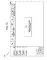
- FIG. 10is a view of a display screen illustrating another step in the method of FIG. 5 showing any one of a plurality of steps to be taken in the inspection plan generated for a part to be inspected, according to an embodiment of the present invention
- FIG. 11is a flowchart of various steps in a method according to another embodiment of the present invention for generating an inspection plan for a part to be inspected, for generating a bar code associated with that inspection plan, and for reading the bar code and carrying out the steps in the inspection plan;
- FIG. 12is a view of a display screen illustrating one step in the method of FIG. 11 showing the generation of an inspection plan for a part to be inspected, according to another embodiment of the present invention
- FIG. 13including FIGS. 13A and 13B , show the bar code of FIG. 12 located on a part to be inspected ( FIG. 13A ) and located on a drawing of a part to be inspected ( FIG. 13B ), in another step in the method of FIG. 11 according to another embodiment of the present invention;
- FIG. 14is a view of a display screen illustrating another step in the method of FIG. 11 showing any one of a plurality of steps to be taken in the inspection plan generated for a part to be inspected, according to an embodiment of the present invention
- FIG. 15is a perspective view of a laser tracker according to other embodiments of the present invention.
- FIG. 16is a perspective view of the laser tracker of FIG. 15 having computing and power supply elements attached thereto.
- AACMMPortable articulated arm coordinate measuring machines
- laser trackersare used in a variety of applications to obtain measurements of parts or objects, for example, to determine how accurately the part or object was made to the desired design specifications.
- Embodiments of the present inventionprovide advantages in allowing a user of the portable AACMM or laser tracker to access an inspection or measurement plan for a manufactured part or object with relative ease and quickness through use of a machine readable identification system, such as a bar code for example, associated with a corresponding inspection or measurement plan associated with that part or object.
- a machine readable identification systemsuch as a bar code for example, associated with a corresponding inspection or measurement plan associated with that part or object.
- each bar codeis associated with a single part or a group of parts.
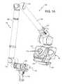
- FIGS. 1A and 1Billustrate, in perspective, an AACMM 100 according to various embodiments of the present invention, an articulated arm being one type of coordinate measuring machine.
- the exemplary AACMM 100may comprise a six or seven axis articulated measurement device having a probe end that includes a measurement probe housing 102 coupled to an arm portion 104 of the AACMM 100 at one end.
- the arm portion 104comprises a first arm segment 106 coupled to a second arm segment 108 by a first grouping of bearing cartridges 110 (e.g., two bearing cartridges).
- a second grouping of bearing cartridges 112couples the second arm segment 108 to the measurement probe housing 102 .
- a third grouping of bearing cartridges 114couples the first arm segment 106 to a base 116 located at the other end of the arm portion 104 of the AACMM 100 .
- Each grouping of bearing cartridges 110 , 112 , 114provides for multiple axes of articulated movement.
- the probe endmay include a measurement probe housing 102 that comprises the shaft of the seventh axis portion of the AACMM 100 (e.g., a cartridge containing an encoder system that determines movement of the measurement device, for example a probe 118 , in the seventh axis of the AACMM 100 ).
- the probe endmay rotate about an axis extending through the center of measurement probe housing 102 .
- the base 116is typically affixed to a work surface.
- Each bearing cartridge within each bearing cartridge grouping 110 , 112 , 114typically contains an encoder system (e.g., an optical angular encoder system).
- the encoder systemi.e., transducer
- the arm segments 106 , 108may be made from a suitably rigid material such as but not limited to a carbon composite material for example.
- a portable AACMM 100 with six or seven axes of articulated movementprovides advantages in allowing the operator to position the probe 118 in a desired location within a 360° area about the base 116 while providing an arm portion 104 that may be easily handled by the operator.
- an arm portion 104 having two arm segments 106 , 108is for exemplary purposes, and the claimed invention should not be so limited.
- An AACMM 100may have any number of arm segments coupled together by bearing cartridges (and, thus, more or less than six or seven axes of articulated movement or degrees of freedom).
- the probe 118is detachably mounted to the measurement probe housing 102 , which is connected to bearing cartridge grouping 112 .
- a handle 126is removable with respect to the measurement probe housing 102 by way of, for example, a quick-connect interface.
- the handle 126may be replaced with another device (e.g., a laser line probe, a bar code reader), thereby providing advantages in allowing the operator to use different measurement devices with the same AACMM 100 .
- the bar code readeris used in place of the handle 126 , or is mounted elsewhere on the portable AACMM, and is utilized to read or scan in machine-readable symbols (e.g. bar codes) that are indicative of measurement or inspection plans for a particular part or object to be measured by the portable AACMM.
- the probe housing 102houses a removable probe 118 , which is a contacting measurement device and may have different tips 118 that physically contact the object to be measured, including, but not limited to: ball, touch-sensitive, curved and extension type probes.
- the measurementis performed, for example, by a non-contacting device such as a laser line probe (LLP).
- LLPlaser line probe
- the handle 126is replaced with the LLP using the quick-connect interface.
- Other types of measurement devicesmay replace the removable handle 126 to provide additional functionality. Examples of such measurement devices include, but are not limited to, one or more illumination lights, a temperature sensor, a thermal scanner, a bar code reader or scanner, a projector, a paint sprayer, a camera, or the like, for example.
- the AACMM 100includes the removable handle 126 that provides advantages in allowing accessories or functionality to be changed without removing the measurement probe housing 102 from the bearing cartridge grouping 112 .
- the removable handle 126may also include an electrical connector that allows electrical power and data to be exchanged with the handle 126 and the corresponding electronics located in the probe end.
- each grouping of bearing cartridges 110 , 112 , 114allows the arm portion 104 of the AACMM 100 to move about multiple axes of rotation.
- each bearing cartridge grouping 110 , 112 , 114includes corresponding encoder systems, such as optical angular encoders for example, that are each arranged coaxially with the corresponding axis of rotation of, e.g., the arm segments 106 , 108 .
- the optical encoder systemdetects rotational (swivel) or transverse (hinge) movement of, e.g., each one of the arm segments 106 , 108 about the corresponding axis and transmits a signal to an electronic data processing system within the AACMM 100 as described in more detail herein below.
- Each individual raw encoder countis sent separately to the electronic data processing system as a signal where it is further processed into measurement data.
- No position calculator separate from the AACMM 100 itselfe.g., a serial box
- the base 116may include an attachment device or mounting device 120 .
- the mounting device 120allows the AACMM 100 to be removably mounted to a desired location, such as an inspection table, a machining center, a wall or the floor for example.
- the base 116includes a handle portion 122 that provides a convenient location for the operator to hold the base 116 as the AACMM 100 is being moved.
- the base 116further includes a movable cover portion 124 that folds down to reveal a user interface, such as a display screen 428 , as described in more detail herein after with respect to FIG. 4 .
- the base 116 of the portable AACMM 100contains or houses an electronic data processing system that includes two primary components: a base processing system that processes the data from the various encoder systems within the AACMM 100 as well as data representing other arm parameters to support three-dimensional (3-D) positional calculations; and a user interface processing system that includes an on-board operating system, a touch screen display, and resident application software that allows for relatively complete metrology functions to be implemented within the AACMM 100 without the need for connection to an external computer.
- a base processing systemthat processes the data from the various encoder systems within the AACMM 100 as well as data representing other arm parameters to support three-dimensional (3-D) positional calculations
- a user interface processing systemthat includes an on-board operating system, a touch screen display, and resident application software that allows for relatively complete metrology functions to be implemented within the AACMM 100 without the need for connection to an external computer.
- the electronic data processing system in the base 116may communicate with the encoder systems, sensors, and other peripheral hardware located away from the base 116 (e.g., a LLP that can be mounted to the removable handle 126 on the AACMM 100 ).
- the electronics that support these peripheral hardware devices or featuresmay be located in each of the bearing cartridge groupings 110 , 112 , 114 located within the portable AACMM 100 .
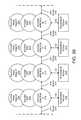
- FIG. 2is a block diagram of electronics utilized in an AACMM 100 in accordance with an embodiment.
- the embodiment shown in FIG. 2includes an electronic data processing system 210 including a base processor board 204 for implementing the base processing system, a user interface board 202 , a base power board 206 for providing power, a Bluetooth module 232 , and a base tilt board 208 .
- the user interface board 202includes a computer processor for executing application software to perform user interface, display, and other functions described herein.
- each encoder systemgenerates encoder data and includes: an encoder arm bus interface 214 , an encoder digital signal processor (DSP) 216 , an encoder read head interface 234 , and a temperature sensor 212 .
- DSPdigital signal processor
- Other devices, such as strain sensors,may be attached to the arm bus 218 .
- the probe end electronics 230include a probe end DSP 228 , a temperature sensor 212 , a handle/LLP interface bus 240 that connects with the handle 126 or the LLP 242 via the quick-connect interface in an embodiment, and a probe interface 226 .
- the quick-connect interfaceallows access by the handle 126 to the data bus, control lines, and power bus used by the LLP 242 and other accessories, such as a bar coder reader.
- the probe end electronics 230are located in the measurement probe housing 102 on the AACMM 100 .
- the handle 126may be removed from the quick-connect interface and measurement may be performed by the laser line probe (LLP) 242 communicating with the probe end electronics 230 of the AACMM 100 via the handle/LLP interface bus 240 .
- the electronic data processing system 210is located in the base 116 of the AACMM 100
- the probe end electronics 230are located in the measurement probe housing 102 of the AACMM 100
- the encoder systemsare located in the bearing cartridge groupings 110 , 112 , 114 .
- the probe interface 226may connect with the probe end DSP 228 by any suitable communications protocol, including commercially-available products from Maxim Integrated Products, Inc. that embody the 1-Wire® communications protocol 236 .
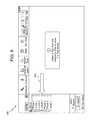
- FIG. 3is a block diagram describing detailed features of the electronic data processing system 210 of the AACMM 100 in accordance with an embodiment.
- the electronic data processing system 210is located in the base 116 of the AACMM 100 and includes the base processor board 204 , the user interface board 202 , a base power board 206 , a Bluetooth module 232 , and a base tilt module 208 .
- the base processor board 204includes the various functional blocks illustrated therein.
- a base processor function 302is utilized to support the collection of measurement data from the AACMM 100 and receives raw arm data (e.g., encoder system data) via the arm bus 218 and a bus control module function 308 .
- the memory function 304stores programs and static arm configuration data.
- the base processor board 204also includes an external hardware option port function 310 for communicating with any external hardware devices or accessories such as an LLP 242 .
- a real time clock (RTC) and log 306 , a battery pack interface (IF) 316 , and a diagnostic port 318are also included in the functionality in an embodiment of the base processor board 204 depicted in FIG. 3 .
- the base processor board 204also manages all the wired and wireless data communication with external (host computer) and internal (display processor 202 ) devices.
- the base processor board 204has the capability of communicating with an Ethernet network via an Ethernet function 320 (e.g., using a clock synchronization standard such as Institute of Electrical and Electronics Engineers (IEEE) 1588), with a wireless local area network (WLAN) via a LAN function 322 , and with Bluetooth module 232 via a parallel to serial communications (PSC) function 314 .
- the base processor board 204also includes a connection to a universal serial bus (USB) device 312 . It should be appreciated that the aforementioned bar code scanner may be connected to the AACMM 100 via one or more communications ports, such as but not limited to USB, Ethernet, Bluetooth, or Wi-Fi for example.
- the base processor board 204transmits and collects raw measurement data (e.g., encoder system counts, temperature readings) for processing into measurement data without the need for any preprocessing, such as disclosed in the serial box of the aforementioned '582 patent.
- the base processor 204sends the processed data to the display processor 328 on the user interface board 202 via an RS485 interface (IF) 326 .
- IFRS485 interface
- the base processor 204may also send the raw measurement data to an external computer.
- the angle and positional data received by the base processoris utilized by applications executing on the display processor 328 to provide an autonomous metrology system within the AACMM 100 .
- Applicationsmay be executed on the display processor 328 to support functions such as, but not limited to: measurement of features, guidance and training graphics, remote diagnostics, temperature corrections, control of various operational features, connection to various networks, and display of measured objects.
- the user interface board 202includes several interface options including a secure digital (SD) card interface 330 , a memory 332 , a USB Host interface 334 , a diagnostic port 336 , a camera port 340 , an audio/video interface 342 , a dial-up/cell modem 344 and a global positioning system (GPS) port 346 .
- SDsecure digital
- the electronic data processing system 210 shown in FIG. 3also includes a base power board 206 with an environmental recorder 362 for recording environmental data.
- the base power board 206also provides power to the electronic data processing system 210 using an AC/DC converter 358 and a battery charger control 360 .
- the base power board 206communicates with the base processor board 204 using inter-integrated circuit (I2C) serial single ended bus 354 as well as via a DMA serial peripheral interface (DSPI) 356 .
- I2Cinter-integrated circuit
- DSPIDMA serial peripheral interface
- the base power board 206is connected to a tilt sensor and radio frequency identification (RFID) module 208 via an input/output (I/O) expansion function 364 implemented in the base power board 206 .
- RFIDradio frequency identification
- all or a subset of the componentsmay be physically located in different locations and/or functions combined in different manners than that shown in FIG. 3 .
- the base processor board 204 and the user interface board 202are combined into one physical board.
- the AACMM 100includes the base 116 that includes the electronic data processing system 210 which is arranged to communicate via one or more buses 218 with the encoders associated with the bearing cartridge groupings 110 , 112 , 114 .
- the base 116includes a housing 400 with the mounting device 120 on one end and the bearing cartridge grouping 114 and arm portion 104 on an opposite end. On one side, the housing 400 includes a recess 402 .
- the recess 402is defined by an interior wall 404 , a first side wall 406 , a second side wall 408 and an end wall 410 .
- the side walls 406 , 408are arranged on an angle relative to the mounting plane of the AACMM 100 such that the recess 402 tapers from the end adjacent the mounting device 120 to the end adjacent the arm portion 104 .
- Adjacent the end wall 410 , the housing 400includes the handle portion 122 ( FIG. 1 ) that is sized to facilitate the carrying of the portable AACMM 100 by the operator.
- the housing 400includes the movable cover portion 124 , which includes a housing member 420 mounted to hinges 414 .
- the movable cover portion 124rotates about an axis between a closed position ( FIG. 1A ) and an open position ( FIG. 4 ). In the exemplary embodiment, when in the open position, the movable cover portion 124 is arranged at an obtuse angle relative to the interior wall 404 . It should be appreciated that the movable cover portion 124 is continuously rotatable and that the open position may be any position at which the operator can access and utilize the display screen 428 .
- On an outside of the housing member 420one or more indicators 432 may be mounted. The indicators 432 are visible to the operator when the movable cover portion 124 is in the closed position. The indicators 432 provide the operator with a visual indication of the communications status and/or the battery level of the AACMM 100 .
- a latch 415may be used to secure a battery within the housing 400 .
- the latchmay be movably disposed in the wall 404 .
- the latch 415may include a tab that engages a surface of the battery to prevent inadvertent removal.
- the batterymay be coupled to the battery pack interface 316 ( FIG. 3A ) and provides electrical power for the AACMM 100 when the AACMM 100 is not connected to an external power source (e.g. a wall outlet).
- the batteryincludes circuitry that communicates with the electronic data processing system 210 and transmits signals that may include but are not limited to: battery charge level; battery type; model number; manufacturer; characteristics; discharge rate; predicted remaining capacity; temperature; voltage; and an almost-discharged alarm so that the AACMM can shut down in a controlled manner.
- the movable cover portion 124further includes a face member 424 disposed on one side and coupled to the housing member 420 .
- the face member 424includes an opening 426 sized to allow the viewing of the display screen 428 .
- the housing member 420 and face member 424are generally thin wall structures, formed from an injection molded plastic material for example, that define a hollow interior portion. In an embodiment, the housing member 420 or face member 424 may be formed from other materials, including but not limited to steel or aluminum sheet metal for example.
- the housing member 420On an end opposite the hinges 414 , the housing member 420 includes a recessed area 434 . Adjacent the recessed area 434 is a projection 436 that provides a handle that facilitates the opening of the movable cover portion 124 when in the closed position.
- a latch member 438which includes a spring loaded lever 440 coupled to one or more members 442 .
- the members 442are arranged to move substantially perpendicular to the surface of the recessed area 434 in response to movement of the lever 440 .
- the latch member 438is positioned such that when the movable cover portion 124 is rotated to the closed position, the lever fits within an opening 444 along the top of the recess 402 . Adjacent the opening 444 are a pair of slots 446 sized to receive the member 442 . When in the closed position, the slots 446 retain the members 442 and prevent the movable cover portion 124 from accidentally opening. To open the movable cover portion 124 , the operator presses on the lever 440 causing the spring loaded members 442 to retract within the housing member 420 . Once the members 442 are retracted, the movable cover portion 124 is free to rotate.
- the display screen 428Arranged within the movable cover portion 124 is the display screen 428 , which is mounted to the face member 424 .
- the display screen 428provides a user interface that allows the operator to interact and operate the AACMM 100 without utilizing or connecting an external host computer. However, if desired, the portable AACMM 100 may connect with an external computer and the display on that external computer may be used to view date and other information associated with the AACMM 100 .
- the display 448may display information relative to the operations being conducted with the AACMM 100 , such as but not limited to the displaying of data derived from the positional encoders.
- the display screen 428is an LCD screen that can detect presence and location of a touch, such as by the operator's finger or a stylus for example, within the display area.
- the display screen 428may comprise a touch sensitive screen having elements for detecting the touch that include but are not limited to: resistive elements; surface acoustic wave elements; capacitive elements; surface capacitance elements; projected capacitance elements; infrared photodetector elements; strain gauge elements; optical imaging elements; dispersive signal elements; or acoustic pulse recognition elements.
- the display 428is arranged in bidirectional communication with the user interface board 202 and the base processor board 204 such that actuation of the display 428 by the operator may result in one or more signals being transmitted to or from the display 428 .
- the housing member 420may include one or more computer interfaces located along either or both of the sides of the display screen 428 .
- the interfacesallow the operator to connect the user interface board 202 to an external device, such as but not limited to: a computer; a computer network; a laptop; a barcode reader or scanner; a digital camera; a digital video camera; a keyboard; a mouse; a printer; a personal digital assistant (PDA); or a cellular phone for example.
- One of the interfacesmay comprise a USB host interface and the other interface may comprise a secure digital card interface.
- the user interface board 202includes a processor 328 that is arranged in bidirectional communication to accept and transmit signals from the display screen 428 and the electronic data processing system 210 .
- the arm portion 104is configured such that the position and length of the arm segments 106 , 108 do not allow the probe housing 102 , a probe tip 118 or the handle 126 to impact the display screen 428 as the probe end of the arm portion 104 is moved about the area adjacent the movable cover portion 124 .
- the travel of the arm portion 104results in a path that defines an outer periphery of travel for the probe end that results in a gap distance between the closest part of the probe end (e.g., the probe tip 118 ) and the display screen 428 when the display screen 428 is in an open position.
- the movable cover portion 124is fully open in the open position of the display screen 428 .
- the pathis arranged such that as the probe end moves downward (e.g., towards the mounting ring end), the probe end is carried away from the base 116 such that the probe end does not impact or contact the display screen 428 . It should be appreciated that providing the gap distance with a distance greater than zero provides an advantage in reducing or eliminating the potential for contact between the display screen 428 and the probe tip 118 .
- the afore described portable AACMM 100may comprise any type of multi-axis coordinate measurement machine, including the FARO® EDGE seven—axis articulated arm CMM or the FARO GAGE® six-axis articulated arm CMM—both available from FARO Technologies, Inc. of Lake Mary, Fla.
- any other type or make and model of coordinate measurement machinemay be utilized in accordance with various embodiments of the present invention.
- embodiments of the present inventionmay comprise a computer-aided manufacturing (CAM) based system that uses structured light.
- CAMcomputer-aided manufacturing
- Other machines or devices that may embody the present inventioninclude bridge CMMs, total stations, micrometers, or other types of dimensional metrology equipment.
- FIG. 5there illustrated is a flowchart 500 that shows steps in a method of an embodiment of the present invention.
- the methodmay be utilized to generate a measurement or inspection plan for a part or object to be measured by the CMM 100 , to assign or associate a bar code with that inspection plan, and to carry out the inspection plan by calling up that plan through use of the bar code assigned to that plan.
- FIGS. 6-10illustrate the various steps in the method shown in the flowchart 500 of FIG. 5 .
- an inspection planis generated in a step 510 for the part or object to be measured.
- the part or object to be measuredmay be any type of part or object that is manufactured in any way (e.g., by machining). It is commonly desired to measure or inspect the manufactured part to determine if certain various physical features of the part satisfactorily meet the desired design dimensions.
- the FARO GAGE® portable articulated arm CMMis typically used for this express purpose.
- FIG. 6illustrates a view 600 on the display screen 428 of the AACMM 100 or on a display screen of an external computer that visually shows a step in the process of generating the inspection plan.
- the display screen 428may comprise that described herein above with respect to the portable articulated arm CMM 100 in FIG.
- the display screen 428is integrated into the CMM 100 .
- the display screenmay comprise the visual display screen in an external computer (e.g., a laptop) connected with the CMM 100 of FIGS. 1-3 described herein above or with some other CMM or other device utilized.
- the CMM 100may comprise the afore mentioned FARO GAGE® portable articulated arm CMM, which may execute inspection software such as the CAM2® software for example, also available from FARO Technologies, Inc.
- the CMMexecutes the inspection software in carrying out the basic functionality of that CMM, including inspection, measurement, and analyzing and comparing measurement data and storing the results and providing the results to the user, for example, visually in several views displayed on a display screen.
- the inspection softwareguides the operator or user of the CMM in creating an inspection plan for a particular part or object to be measured or inspected.
- the part to be measured or inspectedis of certain dimensions and may have various physical features formed therein, such as holes, slots, groves, etc.
- the user or operator of the portable CMMfirst sets up the CMM so that it becomes operational. The user then calibrates the probe tip as directed by the software. The user can then check the accuracy of the calibration by measuring the dimensions of one or more calibrated gage blocks.
- the usermay then determine the accuracy of the various manufactured physical features of the part to be measured or inspected.
- These featuresmay be called out on the drawing print of the part itself, or may be called out is some other way (e.g., an accompanying part manual).
- the view 600 of FIG. 6shows the arrow 602 pointing to one of several physical features (e.g., a length between two features of the part) that the user can select when generating the inspection plan.
- Other common physical featuresinclude diameters of holes, distances and/or angles between features, etc.).
- FIG. 7there illustrated is another view 700 shown on the display screen in which now the inspection software or other software associated with a CMM instructs the user in a step 520 to associate a bar code with the inspection plan that was just created in the step 510 .
- the bar codecan be generated by the inspection software or can already exist and be stored in memory. In the latter case, the bar code may be generated during the design phase of the part, for example, along with the design drawings for that part. As such, the generated bar code can be included on the drawings.
- the bar codemay include the instructions for the inspection plan, or the bar code may act as a pointer to a data file (e.g., stored in memory) that contains the instructions for the inspection plan.
- the bar codemay be generated by other software, such as CAD software, or the bar code may be added on to the drawings by third party software.
- the bar codemay be generated by a machinist along with the CNC program to operate a milling machine.
- the bar codemay further be printed by the software onto media (e.g. an adhesive label) or the part itself.
- the bar codecan be selected and added by the user to the inspection plan.
- the inspection softwarefacilitates this step through use of the arrow 702 shown on the view 700 in FIG. 7 .
- the bar code generated or addedmay comprise any type of machine readable symbol now known or hereinafter developed, including, for example, the well-known two-dimensional (2-D) Aztec code. (ISO/IEC 24778.2008 standard) Other types of 2-D or 3-D machine readable symbols may be utilized.
- the 2-D Aztec codeis capable of supporting a maximum of 1914 bytes of data within the code.
- the Aztec codestore information about an inspection plan for the part, but the Aztec code may also be able to store or contain within itself additional information, such as information about the part or object itself (e.g., various physical characteristics and/or identifying features—model number—of the part or object).
- additional informationsuch as information about the part or object itself (e.g., various physical characteristics and/or identifying features—model number—of the part or object).
- the CMMcan identify and obtain information about the part solely from the information contained in the bar code.
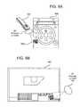
- FIG. 8there illustrated is another view 800 shown on the display screen in which the generated or selected bar code 802 is shown in the view 800 on the left side thereon.
- the bar code 802is now saved together with its associated inspection plan previously generated in the step 510 ; for example the bar code and its inspection plan may be stored together in a file in memory within the CMM and/or in an external computer connected with the CMM.
- FIG. 9including FIGS. 9A and 9B , there illustrated is the bar code previously generated in the step 510 of the method of FIG. 5 and showing the bar code 802 of FIG. 8 located on a part 900 to be inspected ( FIG. 9A ) and located on a drawing 902 (e.g., a CAD drawing) of the part 900 to be inspected ( FIG. 9B ), according to a step 540 in the method 500 of FIG. 5 .
- a drawing 902e.g., a CAD drawing
- FIG. 9Aafter the bar code 802 has been generated, it may be applied to the part 900 in various ways; for example, in the form of a sticker that is attached to the part 900 to be inspected ( FIG.
- bar code 802may contain information about a inspection plan for the part 900 . Also, as mentioned herein above, the bar code 802 may contain additional information, for example information about the part itself 900 , such as various physical characteristics or identifying features of the part 900 .
- a bar code reader or scannermay be utilized to read the bar code 802 in a step 550 of the method of FIG. 5 .
- the bar coder readermay be a part of the portable AACMM 100 of FIGS. 1-4 ; specifically, the bar code reader may be attached to the CMM 100 in place of the handle 126 .
- the bar code reader or scanneris not to be limited as such.
- the bar coder readermay be any type of bar coder reader; for example, a hand-held stand-alone reader not associated with any type of coordinate measurement machine.
- Another exampleis reading the bar code using a common cell phone or “smartphone” having a camera feature.
- Still another exampleis the use of a camera in a laser line probe to read the bar code.
- the readermay then communicate the as-read code to a coordinate measurement machine or other type of measuring device to enable that machine or device to then carry out the inspection plan.
- the communication of the as-read bar codecan take place by various ways, including wired or wireless configurations.
- the machine readable symbolis translated to ascertain the information embedded therein. From this information the associated inspection plan is determined, such as from a database or lookup table for example.
- the inspection planopens up in an embodiment; for example, as seen in the view 900 of FIG. 9 .
- the useris then prompted by the inspection software or other software in a step 560 of the method of FIG. 5 to carry out the various steps in the inspection plan.
- those actual dimensionsmay themselves be output as part of a 2-D bar code which may comprise a “sticker” that is attached to the part that was just inspected.
- those actual dimensionscan be utilized later on in various ways; for example, to “custom match” another mating part to the inspected part. More specifically, if the inspected part is on the “high side” in terms of actual dimensions, then another mating part may also be selected having dimensions that are also on the “high side,” thereby insuring a relatively better fit together.
- a personmay take a picture of the bar code on the measured part with, e.g., his cell phone, and an application on the phone displays the actual measured dimensions. This may act as a final confirmation to the mechanic before he installs the part.
- FIG. 11there illustrated is a flowchart 1100 that shows steps in a method of another embodiment of the present invention.
- the methodmay be utilized to generate a measurement or inspection plan for a part or object to be measured by the CMM 100 , to assign or associate a bar code with that inspection plan, and to carry out the inspection plan by calling up that plan through use of the bar code assigned to that plan.
- FIGS. 12-14illustrate the various steps in the method shown in the flowchart 1100 of FIG. 11 .
- a view 1200 on the display screen 428 of the AACMM 100 or a display screen of an external computerThe view 1200 visually shows a step in the process of generating the inspection plan and associating a bar code with it. More specifically, the view 1200 shows a step where a user or operator of software either generates a bar code for the inspection plan or adds a bar code to the inspection plan.
- the softwaremay correspond to CAD-based measurement software, CAD-based construction software, or some other type of software which contains design features of a part or object to be manufactured.
- the softwaremay run on a CMM or some other type of coordinate measurement machine, or an external computer that can connect with a CMM or coordinate measurement machine.
- the usermay select the various features of the part or object to be inspected or measured.
- the selected featuresmay then be compiled into a measurement or inspection plan that is represented by the generated or selected bar code.
- the inspection planitself may be integrated with the part design file (e.g., the CAD file for the particular part).
- FIGS. 13A and 13Bthere illustrated is the bar code previously generated or selected in FIG. 12 and showing a bar code 1304 located on a part 1300 to be inspected ( FIG. 13A ) and located on a drawing 1302 (e.g., a CAD drawing) of a part 1300 to be inspected ( FIG. 13B ), according to a step 1120 in the method of FIG. 11 .
- a bar code 1304located on a part 1300 to be inspected ( FIG. 13A ) and located on a drawing 1302 (e.g., a CAD drawing) of a part 1300 to be inspected ( FIG. 13B ), according to a step 1120 in the method of FIG. 11 .
- the bar code 1104after the bar code 1104 has been generated, it may be applied to the part 1100 , for example, in the form of a sticker attached to the part 1100 to be inspected ( FIG. 11A ), printed directly onto the drawing 1102 of the part ( FIG.
- the bar code 1104may contain information about a inspection plan for the part 1100 that is part of the CAD file or some other design file for the particular part. Also, as mentioned herein above, the bar code 1104 may contain additional information, for example information about the part itself 1100 , such as various physical characteristics or identifying features of the part 1100 .
- a bar code reader or scannermay be utilized to read the bar code 1104 in a step 1130 of the method 1100 of FIG. 11 .
- the bar coder readermay be a part of the portable AACMM 100 of FIGS. 1-4 ; specifically, the bar code reader may be attached to the CMM 100 in place of the handle 126 directly or connected to communicate via the wireless communications ports of the AACMM 100 .
- the bar code reader or scanneris not to be limited as such.
- the bar coder readermay be any type of bar coder reader; for example, a hand-held stand-alone reader not associated with any type of coordinate measurement machine. As such, once this reader reads or scans the bar code, the reader then would need to communicate the as-read code to a coordinate measurement machine or other type of measuring device to enable that machine or device to then carry out the inspection plan.
- the machine readable symbolis translated to determine the embedded information. From this information, the associated inspection plan may be identified. Once identified, the inspection plan opens up in inspection software; for example, as seen in the view 1200 of FIG. 12 . The user is then prompted by the software in a step 1140 to carry out the various steps in the inspection plan to ultimately determine if the manufactured part is within the design tolerances for that part.
- embodiments of the present inventionare not limited for use with portable articulated arm coordinate measurement machines. Instead, embodiments of the present invention may be utilized with other types of measurement machines or devices; for example a laser tracker, which is a common type of part or object measurement machine.
- the laser tracker 1530includes a gimbaled beam-steering mechanism 1532 that comprises a zenith carriage 1534 mounted on an azimuth base 1536 and rotated about an azimuth axis 1538 .
- a payload 1540is mounted on the zenith carriage 1534 and is rotated about a zenith axis 1542 .
- the zenith mechanical rotation axis 1542 and the azimuth mechanical rotation axis 1538intersect orthogonally, internally to the tracker 1530 , at a gimbal point 1544 , which is typically the origin for distance measurements.
- a laser beam 1546virtually passes through the gimbal point 1544 and is pointed orthogonal to the zenith axis 1542 .
- the laser beam 1546is in the plane normal to the zenith axis 1542 .
- the laser beam 1546is pointed in the desired direction by motors (not shown) located within the tracker 1530 that rotate the payload 1540 about the zenith axis 1542 and the azimuth axis 1538 .
- Zenith and azimuth angular encoderslocated internal to the tracker 1530 , are attached to the zenith mechanical axis 1542 and to the azimuth mechanical axis 1538 , and indicate, to a relatively high degree of accuracy, the angles of rotation.
- the laser beam 1546travels to an external target, such as a retroreflector 1548 ; for example, a spherically mounted retroreflector (SMR).
- SMRspherically mounted retroreflector
- Other types of targetsare possible for use with laser trackers; for example, there exist many types of six degree of freedom (6-DOF) probes).
- 6-DOFsix degree of freedom
- the laser beam 1546may comprise one or more laser wavelengths.
- a steering mechanism of the type shown in FIG. 15is assumed in the following discussion. However, other types of steering mechanisms are possible. For example, it may be possible to reflect a laser beam off a mirror rotated about the azimuth and zenith axes 1538 , 1542 . An example of the use of a mirror in this way is disclosed in U.S. Pat. No. 4,714,339 to Lau et al. The techniques described here are applicable, regardless of the type of steering mechanism utilized.
- each camera 1550may comprise a photosensitive array and a lens placed in front of the photosensitive array.
- the photosensitive arraymay be a CMOS or CCD array.
- the lensmay have a relatively wide field of view, for example, thirty or forty degrees. The purpose of the lens is to form an image on the photosensitive array of objects within the field of view of the lens.
- Each light source 1552is placed near a camera 1550 so that light from the light source 1552 is reflected off each retroreflector target 1548 onto the camera 1550 .
- retroreflector imagesare readily distinguished from the background on the photosensitive array as their image spots are brighter than background objects and are pulsed.
- the principle of triangulationcan be used to find the three-dimensional coordinates of any SMR 1548 within the field of view of the camera 1550 .
- the three-dimensional coordinates of the SMR 1548can be monitored as the SMR 1548 is moved from point to point.
- a use of two cameras for this purposeis described in U.S. Published Patent Application No. 2010/0128259 to Bridges.
- a light source 1552 and a camera 1550can be coaxial or nearly coaxial with the laser beams 1546 emitted by the tracker 1530 .
- a single camera 1550located on the payload or base 1540 of the tracker 1530 .
- a single camera 1550if located off the optical axis of the laser tracker 1530 , provides information about the two angles that define the direction to the retroreflector 1548 but not the distance to the retroreflector 1548 . In many cases, this information may be sufficient.
- the 3-D coordinates of the retroreflector 1548are needed when using a single camera 1550 , one possibility is to rotate the tracker 1530 in the azimuth direction by 180 degrees and then to flip the zenith axis 1542 to point back at the retroreflector 1548 . In this way, the target 1548 can be viewed from two different directions and the 3-D position of the retroreflector 1548 can be found using triangulation.
- Another possibilityis to switch between measuring and imaging of the target 1548 .
- An example of such a methodis described in international application WO 03/062744 to Bridges et al.
- Other camera arrangementsare possible and can be used with the methods described herein.
- an auxiliary unit 1560is usually a part of the laser tracker 1530 .
- the purpose of the auxiliary unit 1560is to supply electrical power to the laser tracker body and in some cases to also supply computing and clocking capability to the system. It is possible to eliminate the auxiliary unit 1560 altogether by moving the functionality of the auxiliary unit 1560 into the tracker body.
- the auxiliary unit 1560is attached to a general purpose computer 1562 .
- Application software loaded onto the general purpose computer 1562may provide application capabilities such as reverse engineering. It is also possible to eliminate the general purpose computer 1562 by building its computing capability directly into the laser tracker 1530 . In this case, a user interface, preferably providing keyboard and mouse functionality is built into the laser tracker 1530 .
- the connection between the auxiliary unit 1560 and the computer 1562may be wireless or through a cable of electrical wires.
- the computer 1562may be connected to a network, and the auxiliary unit 1560 may also be connected to a network.
- Plural instrumentsfor example, multiple measurement instruments or actuators, may be connected together, either through the computer 1562 or the auxiliary unit 1560 .
- embodiments of the laser tracker 1530 of FIGS. 15 and 16typically involve use of the one or more cameras 1550 on the laser tracker 1530 to read or scan a bar code that may be placed on a target (e.g., the SMR 1548 ) or on drawings of a part to be inspected.
- the software used to read, translate and interpret the machine readable symbolcan be stored in the tracker body itself, in the auxiliary unit 1560 , or in the computer 1562 . That is, similar to the embodiments discussed herein above with respect to the portable AACMMs, the laser tracker 1530 may contain software that allows a user to create an inspection plan for a part or object to be measured or inspected by the laser tracker.
- the softwaremay then allow the user to generate or select a bar code that identifies the associated inspection plan.
- the bar codemay then be placed on the target 1548 or on a drawing that illustrates the part, and the laser tracker 1530 may then utilize one or more of its cameras 1550 to read the bar code and then carry out the corresponding inspection plan.
Landscapes
- Physics & Mathematics (AREA)
- Engineering & Computer Science (AREA)
- General Physics & Mathematics (AREA)
- Automation & Control Theory (AREA)
- Manufacturing & Machinery (AREA)
- General Engineering & Computer Science (AREA)
- Quality & Reliability (AREA)
- Theoretical Computer Science (AREA)
- Human Computer Interaction (AREA)
- Databases & Information Systems (AREA)
- Mathematical Physics (AREA)
- Software Systems (AREA)
- Data Mining & Analysis (AREA)
- Length Measuring Devices With Unspecified Measuring Means (AREA)
- Length Measuring Devices By Optical Means (AREA)
Abstract
Description
The present application claims priority to U.S. Provisional Application Ser. No. 61/591,290 filed on Jan. 27, 2012, the contents of which are incorporated by reference herein.
The present disclosure relates to a measurement machine for measuring an object, and more particularly to a measurement machine such as a portable articulated arm coordinate measuring machine or a laser tracker that measures an object according to a measurement or inspection plan that is identified by a bar code located on the object to be measured or on a drawing (e.g., a CAD drawing) of the object.
Portable articulated arm coordinate measuring machines (AACMMs) have found widespread use in the manufacturing or production of parts or objects where there is a need to rapidly and accurately verify the dimensions of the part during various stages of the manufacturing or production (e.g., machining) of the part. Portable AACMMs represent a vast improvement over known stationary or fixed, cost-intensive and relatively difficult to use measurement installations, particularly in the amount of time it takes to perform dimensional measurements of relatively complex parts. Typically, a user of a portable AACMM simply guides a probe along the surface of the part or object to be measured. The measurement data are then recorded and provided to the user. In some cases, the data are provided to the user in visual form, for example, three-dimensional (3-D) form on a computer screen. In other cases, the data are provided to the user in numeric form, for example when measuring the diameter of a hole, the text “Diameter=1.0034” is displayed on a computer screen.
An example of a prior art portable articulated arm CMM is disclosed in commonly assigned U.S. Pat. No. 5,402,582 ('582), which is incorporated herein by reference in its entirety. The '582 patent discloses a 3-D measuring system comprised of a manually-operated articulated arm CMM having a support base on one end and a measurement probe at the other end. Commonly assigned U.S. Pat. No. 5,611,147 ('147), which is incorporated herein by reference in its entirety, discloses a similar articulated arm CMM. In the '147 patent, the articulated arm CMM includes a number of features including an additional rotational axis at the probe end, thereby providing for an arm with either a two-two-two or a two-two-three axis configuration (the latter case being a seven axis arm).
Another common type of measurement machine for measuring a part or object to determine whether or not that manufactured part or object conforms to the desired design specifications is a laser tracker. A laser tracker measures the 3-D coordinates of a certain point by sending a laser beam to the point, where the laser beam is typically intercepted by a retroreflector target. The laser tracker finds the coordinates of the point by measuring the distance and the two angles to the target. The distance is measured with a distance-measuring device such as an absolute distance meter (ADM) or an interferometer. The angles are measured with an angle-measuring device such as an angular encoder. A gimbaled beam-steering mechanism within the instrument directs the laser beam to the point of interest. The retroreflector may be moved manually by hand, or automatically, over the surface of the object. The laser tracker follows the movement of the retroreflector to measure the coordinates of the object. Exemplary laser trackers are disclosed in U.S. Pat. No. 4,790,651 to Brown et al., incorporated by reference herein; and U.S. Pat. No. 4,714,339 to Lau et al. The total station, which is most often used in surveying applications, may be used to measure the coordinates of diffusely scattering or retroreflective targets. The total station is closely related to the laser tracker.
A common type of retroreflector target is the spherically mounted retroreflector (SMR), which comprises a cube-corner retroreflector embedded within a metal sphere. The cube-corner retroreflector comprises three mutually perpendicular mirrors. The apex of the cube corner, which is the common point of intersection of the three mirrors, is located at the center of the sphere. It is common practice to place the spherical surface of the SMR in contact with an object under test and then move the SMR over the surface of the object being measured. Because of this placement of the cube corner within the sphere, the perpendicular distance from the apex of the cube corner to the surface of the object under test remains constant despite rotation of the SMR. Consequently, the 3-D coordinates of the object's surface can be found by having a tracker follow the 3-D coordinates of an SMR moved over the surface. It is possible to place a glass window on the top of the SMR to prevent dust or dirt from contaminating the glass surfaces. An example of such a glass surface is shown in U.S. Pat. No. 7,388,654 to Raab et al., incorporated by reference herein.
A gimbal mechanism within the laser tracker may be used to direct a laser beam from the tracker to the SMR. Part of the light retroreflected by the SMR enters the laser tracker and passes onto a position detector. The position of the light that hits the position detector is used by a tracker control system to adjust the rotation angles of the mechanical azimuth and zenith axes of the laser tracker to keep the laser beam centered on the SMR. In this way, the tracker is able to follow (track) the SMR as it is moved.
Angular encoders attached to the mechanical azimuth and zenith axes of the tracker may measure the azimuth and zenith angles of the laser beam (with respect to the tracker frame of reference). The one distance measurement and two angle measurements performed by the laser tracker are sufficient to completely specify the three-dimensional location of the SMR.
As mentioned, two types of distance meters may be found in laser trackers: interferometers and absolute distance meters (ADMs). In the laser tracker, an interferometer (if present) may determine the distance from a starting point to a finishing point by counting the number of increments of known length (usually the half-wavelength of the laser light) that pass as a retroreflector target is moved between the two points. If the beam is broken during the measurement, the number of counts cannot be accurately known, causing the distance information to be lost. By comparison, the ADM in a laser tracker determines the absolute distance to a retroreflector target without regard to beam breaks, which also allows switching between targets. Because of this, the ADM is said to be capable of “point-and-shoot” measurement. Initially, absolute distance meters were only able to measure stationary targets and for this reason were always used together with an interferometer. However, some modern absolute distance meters can make rapid measurements, thereby eliminating the need for an interferometer. Such an ADM is described in U.S. Pat. No. 7,352,446 to Bridges et al., incorporated by reference herein. The distances measured by interferometers and absolute distance meters are dependent on the speed of light through air. Since the speed of light varies with air temperature, barometric pressure, and air humidity, it is common practice to measure these quantities with sensors and to correct the speed of light in air to obtain more accurate distance readings. The distances measured by total stations also depend on the speed of light in air.
In its tracking mode, the laser tracker automatically follows movements of the SMR when the SMR is in the capture range of the tracker. If the laser beam is broken, tracking will stop. The beam may be broken by any of several means: (1) an obstruction between the instrument and SMR; (2) rapid movements of the SMR that are too fast for the instrument to follow; or (3) the direction of the SMR being turned beyond the acceptance angle of the SMR. By default, following the beam break, the beam may remain fixed at the point of the beam break, at the last commanded position, or may go to a reference (“home”) position. It may be necessary for an operator to visually search for the tracking beam and place the SMR in the beam in order to lock the instrument onto the SMR and continue tracking.
Some laser trackers include one or more cameras. A camera axis may be coaxial with the measurement beam or offset from the measurement beam by a fixed distance or angle. A camera may be used to provide a wide field of view to locate retroreflectors. A modulated light source placed near the camera optical axis may illuminate retroreflectors, thereby making them easier to identify. In this case, the retroreflectors flash in phase with the illumination, whereas background objects do not. One application for such a camera is to detect multiple retroreflectors in the field of view and measure each retroreflector in an automated sequence. Exemplary systems are described in U.S. Pat. No. 6,166,809 to Pettersen et al., and U.S. Pat. No. 7,800,758 to Bridges et al., incorporated by reference herein.
Some laser trackers have the ability to measure with six degrees of freedom (DOF), which may include three coordinates, such as x, y, and z, and three rotations, such as pitch, roll, and yaw. Several systems based on laser trackers are available or have been proposed for measuring six degrees of freedom. Exemplary systems are described in U.S. Pat. No. 7,800,758 to Bridges et al., U.S. Pat. No. 5,973,788 to Pettersen et al., and U.S. Pat. No. 7,230,689 to Lau.
While existing measurement machines such as portable AACMMs or laser trackers are suitable for their intended purposes, there remains a need for a simplified method of inspecting parts based on machine readable information provided on the parts or on representation of the parts.
In accordance with an embodiment of the invention, a method for inspecting a part according to an inspection plan is provided. The method uses a portable articulated arm coordinate measuring machine (AACMM) having a base; a manually positionable arm portion having opposed first and second ends, the second end of the arm portion being coupled to the base, the arm portion including a plurality of connected arm segments, each arm segment including at least one position transducer for producing a position signal; a measurement device coupled to the first end of the arm portion; and an electronic circuit which receives the position signal from the at least one position transducer and provides data corresponding to a position of the measurement device. The method includes the steps of generating an inspection plan for a part to be inspected to determine at least one characteristic of the part. A machine readable information symbol is generated that includes information that identifies the generated inspection plan. The generated machine readable information symbol is associated with the part. The machine readable information symbol from the part is read with a reader device configured to translate the machine readable information symbol to determine the information contained therein, the reader device being coupled to communicate with the AACMM. The at least one part characteristic is measured according to the generated inspection plan identified by the machine readable symbol.
According to another embodiment of the invention, another method for inspecting a part according to an inspection plan is provided. The method uses a laser tracker having a light source that emits a light beam towards a target located within an environment, and a reader device that captures the light beam reflected back to the laser scanner from the target located within the environment. The method includes the steps of generating an inspection plan for a part to be inspected to determine at least one characteristic of the part. A machine readable information symbol is generated that identifies the generated inspection plan. The generated machine readable information symbol is associated with the part. The machine readable information symbol is read with the reader device associated with the laser tracker. The part is inspected according to the generated inspection plan identified by machine readable information symbol read by the reader device.
According to another embodiment of the invention, a system for inspecting a part according to an inspection plan is provided. The system includes a measurement machine configured to measure at least one characteristic of the part. A device having a processor is provided. The processor being responsive to executable computer instructions when executed on the processor for generating an inspection plan for a part to be inspected to determine at least one characteristic of the part, the processor further being responsive to generating a machine readable information symbol that includes information that identifies the generated inspection plan in response to the inspection plan being generated. A reader is coupled to communicate with the measurement machine and the device, the reader being configured to translate the machine readable information symbol to determine the information contained therein.
Referring now to the drawings, exemplary embodiments are shown which should not be construed to be limiting regarding the entire scope of the disclosure, and wherein the elements are numbered alike in several FIGURES:
Portable articulated arm coordinate measuring machines (“AACMM”) and laser trackers are used in a variety of applications to obtain measurements of parts or objects, for example, to determine how accurately the part or object was made to the desired design specifications. Embodiments of the present invention provide advantages in allowing a user of the portable AACMM or laser tracker to access an inspection or measurement plan for a manufactured part or object with relative ease and quickness through use of a machine readable identification system, such as a bar code for example, associated with a corresponding inspection or measurement plan associated with that part or object. In the exemplary embodiment, each bar code is associated with a single part or a group of parts.
Each bearing cartridge within each bearingcartridge grouping respective arm segments bearing cartridge groupings probe 118 with respect to the base116 (and, thus, the position of the object being measured by theAACMM 100 in a certain frame of reference—for example a local or global frame of reference). Thearm segments portable AACMM 100 with six or seven axes of articulated movement (i.e., degrees of freedom) provides advantages in allowing the operator to position theprobe 118 in a desired location within a 360° area about thebase 116 while providing anarm portion 104 that may be easily handled by the operator. However, it should be appreciated that the illustration of anarm portion 104 having twoarm segments AACMM 100 may have any number of arm segments coupled together by bearing cartridges (and, thus, more or less than six or seven axes of articulated movement or degrees of freedom).
Theprobe 118 is detachably mounted to themeasurement probe housing 102, which is connected to bearingcartridge grouping 112. Ahandle 126 is removable with respect to themeasurement probe housing 102 by way of, for example, a quick-connect interface. Thehandle 126 may be replaced with another device (e.g., a laser line probe, a bar code reader), thereby providing advantages in allowing the operator to use different measurement devices with thesame AACMM 100. In various embodiments of the present invention, the bar code reader is used in place of thehandle 126, or is mounted elsewhere on the portable AACMM, and is utilized to read or scan in machine-readable symbols (e.g. bar codes) that are indicative of measurement or inspection plans for a particular part or object to be measured by the portable AACMM. These various embodiments that utilize a bar code reader are described in detail herein after.
In exemplary embodiments, theprobe housing 102 houses aremovable probe 118, which is a contacting measurement device and may havedifferent tips 118 that physically contact the object to be measured, including, but not limited to: ball, touch-sensitive, curved and extension type probes. In other embodiments, the measurement is performed, for example, by a non-contacting device such as a laser line probe (LLP). In an embodiment, thehandle 126 is replaced with the LLP using the quick-connect interface. Other types of measurement devices may replace theremovable handle 126 to provide additional functionality. Examples of such measurement devices include, but are not limited to, one or more illumination lights, a temperature sensor, a thermal scanner, a bar code reader or scanner, a projector, a paint sprayer, a camera, or the like, for example.
As shown inFIGS. 1A and 1B , theAACMM 100 includes theremovable handle 126 that provides advantages in allowing accessories or functionality to be changed without removing themeasurement probe housing 102 from the bearingcartridge grouping 112. As discussed in more detail below with respect toFIG. 2 , theremovable handle 126 may also include an electrical connector that allows electrical power and data to be exchanged with thehandle 126 and the corresponding electronics located in the probe end.
In various embodiments, each grouping of bearingcartridges arm portion 104 of theAACMM 100 to move about multiple axes of rotation. As mentioned, each bearingcartridge grouping arm segments arm segments AACMM 100 as described in more detail herein below. Each individual raw encoder count is sent separately to the electronic data processing system as a signal where it is further processed into measurement data. No position calculator separate from theAACMM 100 itself (e.g., a serial box) is used, as disclosed in commonly assigned U.S. Pat. No. 5,402,582 ('582).
The base116 may include an attachment device or mountingdevice 120. The mountingdevice 120 allows theAACMM 100 to be removably mounted to a desired location, such as an inspection table, a machining center, a wall or the floor for example. In one embodiment, thebase 116 includes ahandle portion 122 that provides a convenient location for the operator to hold the base116 as theAACMM 100 is being moved. In one embodiment, the base116 further includes amovable cover portion 124 that folds down to reveal a user interface, such as adisplay screen 428, as described in more detail herein after with respect toFIG. 4 .
In accordance with an embodiment, thebase 116 of theportable AACMM 100 contains or houses an electronic data processing system that includes two primary components: a base processing system that processes the data from the various encoder systems within theAACMM 100 as well as data representing other arm parameters to support three-dimensional (3-D) positional calculations; and a user interface processing system that includes an on-board operating system, a touch screen display, and resident application software that allows for relatively complete metrology functions to be implemented within theAACMM 100 without the need for connection to an external computer.
The electronic data processing system in thebase 116 may communicate with the encoder systems, sensors, and other peripheral hardware located away from the base116 (e.g., a LLP that can be mounted to theremovable handle 126 on the AACMM100). The electronics that support these peripheral hardware devices or features may be located in each of the bearingcartridge groupings portable AACMM 100.
As shown inFIG. 2 , the electronicdata processing system 210 is in communication with the aforementioned plurality of encoder systems via one ormore arm buses 218. In the embodiment depicted inFIG. 2 , each encoder system generates encoder data and includes: an encoderarm bus interface 214, an encoder digital signal processor (DSP)216, an encoder readhead interface 234, and atemperature sensor 212. Other devices, such as strain sensors, may be attached to thearm bus 218.
Also shown inFIG. 2 areprobe end electronics 230 that are in communication with thearm bus 218. Theprobe end electronics 230 include aprobe end DSP 228, atemperature sensor 212, a handle/LLP interface bus 240 that connects with thehandle 126 or theLLP 242 via the quick-connect interface in an embodiment, and a probe interface226. The quick-connect interface allows access by thehandle 126 to the data bus, control lines, and power bus used by theLLP 242 and other accessories, such as a bar coder reader. In an embodiment, theprobe end electronics 230 are located in themeasurement probe housing 102 on theAACMM 100. In an embodiment, thehandle 126 may be removed from the quick-connect interface and measurement may be performed by the laser line probe (LLP)242 communicating with theprobe end electronics 230 of theAACMM 100 via the handle/LLP interface bus 240. In an embodiment, the electronicdata processing system 210 is located in thebase 116 of theAACMM 100, theprobe end electronics 230 are located in themeasurement probe housing 102 of theAACMM 100, and the encoder systems are located in the bearingcartridge groupings probe end DSP 228 by any suitable communications protocol, including commercially-available products from Maxim Integrated Products, Inc. that embody the 1-Wire® communications protocol 236.
In an embodiment shown inFIG. 3 , thebase processor board 204 includes the various functional blocks illustrated therein. For example, abase processor function 302 is utilized to support the collection of measurement data from theAACMM 100 and receives raw arm data (e.g., encoder system data) via thearm bus 218 and a buscontrol module function 308. Thememory function 304 stores programs and static arm configuration data. Thebase processor board 204 also includes an external hardwareoption port function 310 for communicating with any external hardware devices or accessories such as anLLP 242. A real time clock (RTC) and log306, a battery pack interface (IF)316, and adiagnostic port 318 are also included in the functionality in an embodiment of thebase processor board 204 depicted inFIG. 3 .
Thebase processor board 204 also manages all the wired and wireless data communication with external (host computer) and internal (display processor202) devices. Thebase processor board 204 has the capability of communicating with an Ethernet network via an Ethernet function320 (e.g., using a clock synchronization standard such as Institute of Electrical and Electronics Engineers (IEEE) 1588), with a wireless local area network (WLAN) via aLAN function 322, and withBluetooth module 232 via a parallel to serial communications (PSC)function 314. Thebase processor board 204 also includes a connection to a universal serial bus (USB) device312. It should be appreciated that the aforementioned bar code scanner may be connected to theAACMM 100 via one or more communications ports, such as but not limited to USB, Ethernet, Bluetooth, or Wi-Fi for example.
Thebase processor board 204 transmits and collects raw measurement data (e.g., encoder system counts, temperature readings) for processing into measurement data without the need for any preprocessing, such as disclosed in the serial box of the aforementioned '582 patent. Thebase processor 204 sends the processed data to thedisplay processor 328 on theuser interface board 202 via an RS485 interface (IF)326. In an embodiment, thebase processor 204 may also send the raw measurement data to an external computer.
Turning now to theuser interface board 202 inFIG. 3 , the angle and positional data received by the base processor is utilized by applications executing on thedisplay processor 328 to provide an autonomous metrology system within theAACMM 100. Applications may be executed on thedisplay processor 328 to support functions such as, but not limited to: measurement of features, guidance and training graphics, remote diagnostics, temperature corrections, control of various operational features, connection to various networks, and display of measured objects. Along with thedisplay processor 328 and a liquid crystal display (LCD)338 (e.g., a touch screen LCD) user interface, theuser interface board 202 includes several interface options including a secure digital (SD)card interface 330, amemory 332, aUSB Host interface 334, a diagnostic port336, acamera port 340, an audio/video interface 342, a dial-up/cell modem 344 and a global positioning system (GPS)port 346.
The electronicdata processing system 210 shown inFIG. 3 also includes abase power board 206 with anenvironmental recorder 362 for recording environmental data. Thebase power board 206 also provides power to the electronicdata processing system 210 using an AC/DC converter 358 and abattery charger control 360. Thebase power board 206 communicates with thebase processor board 204 using inter-integrated circuit (I2C) serial single endedbus 354 as well as via a DMA serial peripheral interface (DSPI)356. Thebase power board 206 is connected to a tilt sensor and radio frequency identification (RFID)module 208 via an input/output (I/O)expansion function 364 implemented in thebase power board 206.
Though shown as separate components, in other embodiments all or a subset of the components may be physically located in different locations and/or functions combined in different manners than that shown inFIG. 3 . For example, in an embodiment, thebase processor board 204 and theuser interface board 202 are combined into one physical board.
Referring now toFIG. 4 , an embodiment is shown of theAACMM 100 having anintegrated display 428, which enables the user of theportable AACMM 100 to view various types of data or other information. TheAACMM 100 includes the base116 that includes the electronicdata processing system 210 which is arranged to communicate via one ormore buses 218 with the encoders associated with the bearingcartridge groupings base 116 includes ahousing 400 with the mountingdevice 120 on one end and the bearingcartridge grouping 114 andarm portion 104 on an opposite end. On one side, thehousing 400 includes arecess 402. Therecess 402 is defined by aninterior wall 404, afirst side wall 406, asecond side wall 408 and anend wall 410. Theside walls AACMM 100 such that therecess 402 tapers from the end adjacent the mountingdevice 120 to the end adjacent thearm portion 104. Adjacent theend wall 410, thehousing 400 includes the handle portion122 (FIG. 1 ) that is sized to facilitate the carrying of theportable AACMM 100 by the operator.
Thehousing 400 includes themovable cover portion 124, which includes ahousing member 420 mounted to hinges414. Themovable cover portion 124 rotates about an axis between a closed position (FIG. 1A ) and an open position (FIG. 4 ). In the exemplary embodiment, when in the open position, themovable cover portion 124 is arranged at an obtuse angle relative to theinterior wall 404. It should be appreciated that themovable cover portion 124 is continuously rotatable and that the open position may be any position at which the operator can access and utilize thedisplay screen 428. On an outside of thehousing member 420 one ormore indicators 432 may be mounted. Theindicators 432 are visible to the operator when themovable cover portion 124 is in the closed position. Theindicators 432 provide the operator with a visual indication of the communications status and/or the battery level of theAACMM 100.
Alatch 415 may be used to secure a battery within thehousing 400. The latch may be movably disposed in thewall 404. Thelatch 415 may include a tab that engages a surface of the battery to prevent inadvertent removal. The battery may be coupled to the battery pack interface316 (FIG. 3A ) and provides electrical power for theAACMM 100 when theAACMM 100 is not connected to an external power source (e.g. a wall outlet). In an exemplary embodiment, the battery includes circuitry that communicates with the electronicdata processing system 210 and transmits signals that may include but are not limited to: battery charge level; battery type; model number; manufacturer; characteristics; discharge rate; predicted remaining capacity; temperature; voltage; and an almost-discharged alarm so that the AACMM can shut down in a controlled manner.
Themovable cover portion 124 further includes aface member 424 disposed on one side and coupled to thehousing member 420. Theface member 424 includes anopening 426 sized to allow the viewing of thedisplay screen 428. Thehousing member 420 andface member 424 are generally thin wall structures, formed from an injection molded plastic material for example, that define a hollow interior portion. In an embodiment, thehousing member 420 orface member 424 may be formed from other materials, including but not limited to steel or aluminum sheet metal for example. On an end opposite thehinges 414, thehousing member 420 includes a recessedarea 434. Adjacent the recessedarea 434 is aprojection 436 that provides a handle that facilitates the opening of themovable cover portion 124 when in the closed position. Within the recessedarea 434 is alatch member 438, which includes a spring loadedlever 440 coupled to one ormore members 442. Themembers 442 are arranged to move substantially perpendicular to the surface of the recessedarea 434 in response to movement of thelever 440. Thelatch member 438 is positioned such that when themovable cover portion 124 is rotated to the closed position, the lever fits within anopening 444 along the top of therecess 402. Adjacent theopening 444 are a pair ofslots 446 sized to receive themember 442. When in the closed position, theslots 446 retain themembers 442 and prevent themovable cover portion 124 from accidentally opening. To open themovable cover portion 124, the operator presses on thelever 440 causing the spring loadedmembers 442 to retract within thehousing member 420. Once themembers 442 are retracted, themovable cover portion 124 is free to rotate.
Arranged within themovable cover portion 124 is thedisplay screen 428, which is mounted to theface member 424. Thedisplay screen 428 provides a user interface that allows the operator to interact and operate theAACMM 100 without utilizing or connecting an external host computer. However, if desired, theportable AACMM 100 may connect with an external computer and the display on that external computer may be used to view date and other information associated with theAACMM 100. The display448 may display information relative to the operations being conducted with theAACMM 100, such as but not limited to the displaying of data derived from the positional encoders. In one embodiment, thedisplay screen 428 is an LCD screen that can detect presence and location of a touch, such as by the operator's finger or a stylus for example, within the display area. Thedisplay screen 428 may comprise a touch sensitive screen having elements for detecting the touch that include but are not limited to: resistive elements; surface acoustic wave elements; capacitive elements; surface capacitance elements; projected capacitance elements; infrared photodetector elements; strain gauge elements; optical imaging elements; dispersive signal elements; or acoustic pulse recognition elements. Thedisplay 428 is arranged in bidirectional communication with theuser interface board 202 and thebase processor board 204 such that actuation of thedisplay 428 by the operator may result in one or more signals being transmitted to or from thedisplay 428.
In an embodiment, thehousing member 420 may include one or more computer interfaces located along either or both of the sides of thedisplay screen 428. The interfaces allow the operator to connect theuser interface board 202 to an external device, such as but not limited to: a computer; a computer network; a laptop; a barcode reader or scanner; a digital camera; a digital video camera; a keyboard; a mouse; a printer; a personal digital assistant (PDA); or a cellular phone for example. One of the interfaces may comprise a USB host interface and the other interface may comprise a secure digital card interface. As discussed above, theuser interface board 202 includes aprocessor 328 that is arranged in bidirectional communication to accept and transmit signals from thedisplay screen 428 and the electronicdata processing system 210.
It should be appreciated that when themovable cover portion 124 is in the open position it is desirable to prevent or minimize impacts on thedisplay screen 428. In the exemplary embodiment, thearm portion 104 is configured such that the position and length of thearm segments probe housing 102, aprobe tip 118 or thehandle 126 to impact thedisplay screen 428 as the probe end of thearm portion 104 is moved about the area adjacent themovable cover portion 124. As such, the travel of thearm portion 104 results in a path that defines an outer periphery of travel for the probe end that results in a gap distance between the closest part of the probe end (e.g., the probe tip118) and thedisplay screen 428 when thedisplay screen 428 is in an open position. In an embodiment, themovable cover portion 124 is fully open in the open position of thedisplay screen 428. The path is arranged such that as the probe end moves downward (e.g., towards the mounting ring end), the probe end is carried away from the base116 such that the probe end does not impact or contact thedisplay screen 428. It should be appreciated that providing the gap distance with a distance greater than zero provides an advantage in reducing or eliminating the potential for contact between thedisplay screen 428 and theprobe tip 118.
The afore describedportable AACMM 100 may comprise any type of multi-axis coordinate measurement machine, including the FARO® EDGE seven—axis articulated arm CMM or the FARO GAGE® six-axis articulated arm CMM—both available from FARO Technologies, Inc. of Lake Mary, Fla. However, any other type or make and model of coordinate measurement machine may be utilized in accordance with various embodiments of the present invention. For example, embodiments of the present invention may comprise a computer-aided manufacturing (CAM) based system that uses structured light. Other machines or devices that may embody the present invention include bridge CMMs, total stations, micrometers, or other types of dimensional metrology equipment.
Referring now toFIG. 5 , there illustrated is aflowchart 500 that shows steps in a method of an embodiment of the present invention. The method may be utilized to generate a measurement or inspection plan for a part or object to be measured by theCMM 100, to assign or associate a bar code with that inspection plan, and to carry out the inspection plan by calling up that plan through use of the bar code assigned to that plan.FIGS. 6-10 illustrate the various steps in the method shown in theflowchart 500 ofFIG. 5 .
Referring also toFIG. 6 , an inspection plan is generated in astep 510 for the part or object to be measured. The part or object to be measured may be any type of part or object that is manufactured in any way (e.g., by machining). It is commonly desired to measure or inspect the manufactured part to determine if certain various physical features of the part satisfactorily meet the desired design dimensions. The FARO GAGE® portable articulated arm CMM is typically used for this express purpose.FIG. 6 illustrates aview 600 on thedisplay screen 428 of theAACMM 100 or on a display screen of an external computer that visually shows a step in the process of generating the inspection plan. Thedisplay screen 428 may comprise that described herein above with respect to the portable articulatedarm CMM 100 inFIG. 4 in which thedisplay screen 428 is integrated into theCMM 100. In another embodiment, the display screen may comprise the visual display screen in an external computer (e.g., a laptop) connected with theCMM 100 ofFIGS. 1-3 described herein above or with some other CMM or other device utilized.
In the example shown inFIG. 6 , theCMM 100 may comprise the afore mentioned FARO GAGE® portable articulated arm CMM, which may execute inspection software such as the CAM2® software for example, also available from FARO Technologies, Inc. The CMM executes the inspection software in carrying out the basic functionality of that CMM, including inspection, measurement, and analyzing and comparing measurement data and storing the results and providing the results to the user, for example, visually in several views displayed on a display screen. The inspection software guides the operator or user of the CMM in creating an inspection plan for a particular part or object to be measured or inspected. For example, the part to be measured or inspected is of certain dimensions and may have various physical features formed therein, such as holes, slots, groves, etc. Typically, in creating the inspection plan the user or operator of the portable CMM first sets up the CMM so that it becomes operational. The user then calibrates the probe tip as directed by the software. The user can then check the accuracy of the calibration by measuring the dimensions of one or more calibrated gage blocks.
Once the CMM is calibrated, the user may then determine the accuracy of the various manufactured physical features of the part to be measured or inspected. These features may be called out on the drawing print of the part itself, or may be called out is some other way (e.g., an accompanying part manual). For example, theview 600 ofFIG. 6 shows thearrow 602 pointing to one of several physical features (e.g., a length between two features of the part) that the user can select when generating the inspection plan. Other common physical features include diameters of holes, distances and/or angles between features, etc.). As each feature is selected by the user, it is saved in memory as part of the particular inspection plan being generated. As the user systematically proceeds through and selects all the various physical features to be inspected on the part, the features are saved as part of that particular inspection plan.
Next, referring also toFIG. 7 , there illustrated is anotherview 700 shown on the display screen in which now the inspection software or other software associated with a CMM instructs the user in astep 520 to associate a bar code with the inspection plan that was just created in thestep 510. The bar code can be generated by the inspection software or can already exist and be stored in memory. In the latter case, the bar code may be generated during the design phase of the part, for example, along with the design drawings for that part. As such, the generated bar code can be included on the drawings. The bar code may include the instructions for the inspection plan, or the bar code may act as a pointer to a data file (e.g., stored in memory) that contains the instructions for the inspection plan. The bar code may be generated by other software, such as CAD software, or the bar code may be added on to the drawings by third party software. For example, the bar code may be generated by a machinist along with the CNC program to operate a milling machine. The bar code may further be printed by the software onto media (e.g. an adhesive label) or the part itself.
The bar code can be selected and added by the user to the inspection plan. The inspection software facilitates this step through use of thearrow 702 shown on theview 700 inFIG. 7 . The bar code generated or added may comprise any type of machine readable symbol now known or hereinafter developed, including, for example, the well-known two-dimensional (2-D) Aztec code. (ISO/IEC 24778.2008 standard) Other types of 2-D or 3-D machine readable symbols may be utilized. The 2-D Aztec code is capable of supporting a maximum of 1914 bytes of data within the code. Given this relatively large amount of data within the Aztec code, it is possible that not only can the Aztec code store information about an inspection plan for the part, but the Aztec code may also be able to store or contain within itself additional information, such as information about the part or object itself (e.g., various physical characteristics and/or identifying features—model number—of the part or object). As such, the CMM can identify and obtain information about the part solely from the information contained in the bar code.
Referring also toFIG. 8 , there illustrated is anotherview 800 shown on the display screen in which the generated or selectedbar code 802 is shown in theview 800 on the left side thereon. As such, in astep 530 of the method ofFIG. 5 thebar code 802 is now saved together with its associated inspection plan previously generated in thestep 510; for example the bar code and its inspection plan may be stored together in a file in memory within the CMM and/or in an external computer connected with the CMM.
Referring also toFIG. 9 , includingFIGS. 9A and 9B , there illustrated is the bar code previously generated in thestep 510 of the method ofFIG. 5 and showing thebar code 802 ofFIG. 8 located on apart 900 to be inspected (FIG. 9A ) and located on a drawing902 (e.g., a CAD drawing) of thepart 900 to be inspected (FIG. 9B ), according to astep 540 in themethod 500 ofFIG. 5 . InFIG. 9A , after thebar code 802 has been generated, it may be applied to thepart 900 in various ways; for example, in the form of a sticker that is attached to thepart 900 to be inspected (FIG. 9A ), or printed directly onto the drawing902 of the part (FIG. 9B ). As discussed herein above, thatbar code 802 may contain information about a inspection plan for thepart 900. Also, as mentioned herein above, thebar code 802 may contain additional information, for example information about the part itself900, such as various physical characteristics or identifying features of thepart 900.
Nevertheless, once thebar code 802 is associated with a part or with a drawing of a part, a bar code reader or scanner may be utilized to read thebar code 802 in astep 550 of the method ofFIG. 5 . For example, as mentioned herein above, the bar coder reader may be a part of theportable AACMM 100 ofFIGS. 1-4 ; specifically, the bar code reader may be attached to theCMM 100 in place of thehandle 126. However, the bar code reader or scanner is not to be limited as such. Instead, the bar coder reader may be any type of bar coder reader; for example, a hand-held stand-alone reader not associated with any type of coordinate measurement machine. Another example is reading the bar code using a common cell phone or “smartphone” having a camera feature. Still another example is the use of a camera in a laser line probe to read the bar code.
As such, once these readers read or scan the bar code, the reader may then communicate the as-read code to a coordinate measurement machine or other type of measuring device to enable that machine or device to then carry out the inspection plan. The communication of the as-read bar code can take place by various ways, including wired or wireless configurations.
Referring toFIG. 10 , once the user scans in thebar code 802 from the part itself900 or from the drawing902 of thepart 900, the machine readable symbol is translated to ascertain the information embedded therein. From this information the associated inspection plan is determined, such as from a database or lookup table for example. The inspection plan opens up in an embodiment; for example, as seen in theview 900 ofFIG. 9 . The user is then prompted by the inspection software or other software in astep 560 of the method ofFIG. 5 to carry out the various steps in the inspection plan.
In an alternative embodiment of the present invention, once the inspection plan has been completed (for example as per the steps outlined inFIGS. 6-10 above) and the actual or “as-built” dimensions of the part or object being inspected have been obtained by, for example, theCMM 100, those actual dimensions may themselves be output as part of a 2-D bar code which may comprise a “sticker” that is attached to the part that was just inspected. This way, those actual dimensions can be utilized later on in various ways; for example, to “custom match” another mating part to the inspected part. More specifically, if the inspected part is on the “high side” in terms of actual dimensions, then another mating part may also be selected having dimensions that are also on the “high side,” thereby insuring a relatively better fit together.
In still another embodiment of the present invention, a person (e.g., a mechanic) may take a picture of the bar code on the measured part with, e.g., his cell phone, and an application on the phone displays the actual measured dimensions. This may act as a final confirmation to the mechanic before he installs the part.
Referring now toFIG. 11 , there illustrated is aflowchart 1100 that shows steps in a method of another embodiment of the present invention. The method may be utilized to generate a measurement or inspection plan for a part or object to be measured by theCMM 100, to assign or associate a bar code with that inspection plan, and to carry out the inspection plan by calling up that plan through use of the bar code assigned to that plan.FIGS. 12-14 illustrate the various steps in the method shown in theflowchart 1100 ofFIG. 11 .
Referring also toFIG. 12 , there illustrated is aview 1200 on thedisplay screen 428 of theAACMM 100 or a display screen of an external computer. Theview 1200 visually shows a step in the process of generating the inspection plan and associating a bar code with it. More specifically, theview 1200 shows a step where a user or operator of software either generates a bar code for the inspection plan or adds a bar code to the inspection plan. The software may correspond to CAD-based measurement software, CAD-based construction software, or some other type of software which contains design features of a part or object to be manufactured. The software may run on a CMM or some other type of coordinate measurement machine, or an external computer that can connect with a CMM or coordinate measurement machine. As part of thisview 1200, the user may select the various features of the part or object to be inspected or measured. The selected features may then be compiled into a measurement or inspection plan that is represented by the generated or selected bar code. The inspection plan itself may be integrated with the part design file (e.g., the CAD file for the particular part).
Referring also toFIGS. 13A and 13B , there illustrated is the bar code previously generated or selected inFIG. 12 and showing abar code 1304 located on apart 1300 to be inspected (FIG. 13A ) and located on a drawing1302 (e.g., a CAD drawing) of apart 1300 to be inspected (FIG. 13B ), according to astep 1120 in the method ofFIG. 11 . InFIG. 13A , after the bar code1104 has been generated, it may be applied to thepart 1100, for example, in the form of a sticker attached to thepart 1100 to be inspected (FIG. 11A ), printed directly onto the drawing1102 of the part (FIG. 11B ) or otherwise affixed to the part (e.g. laser etching or printing the bar code onto the part). As discussed herein above, the bar code1104 may contain information about a inspection plan for thepart 1100 that is part of the CAD file or some other design file for the particular part. Also, as mentioned herein above, the bar code1104 may contain additional information, for example information about the part itself1100, such as various physical characteristics or identifying features of thepart 1100.
Nevertheless, once the bar code1104 is associated with apart 1100 or with a drawing1102 of apart 1100, a bar code reader or scanner may be utilized to read the bar code1104 in astep 1130 of themethod 1100 ofFIG. 11 . For example, as mentioned herein above, the bar coder reader may be a part of theportable AACMM 100 ofFIGS. 1-4 ; specifically, the bar code reader may be attached to theCMM 100 in place of thehandle 126 directly or connected to communicate via the wireless communications ports of theAACMM 100. However, the bar code reader or scanner is not to be limited as such. Instead, the bar coder reader may be any type of bar coder reader; for example, a hand-held stand-alone reader not associated with any type of coordinate measurement machine. As such, once this reader reads or scans the bar code, the reader then would need to communicate the as-read code to a coordinate measurement machine or other type of measuring device to enable that machine or device to then carry out the inspection plan.
Referring also toFIG. 14 , once the user scans in the bar code1104 from the part itself1100 or from the drawing1102 the machine readable symbol is translated to determine the embedded information. From this information, the associated inspection plan may be identified. Once identified, the inspection plan opens up in inspection software; for example, as seen in theview 1200 ofFIG. 12 . The user is then prompted by the software in astep 1140 to carry out the various steps in the inspection plan to ultimately determine if the manufactured part is within the design tolerances for that part.
As mentioned herein above, embodiments of the present invention are not limited for use with portable articulated arm coordinate measurement machines. Instead, embodiments of the present invention may be utilized with other types of measurement machines or devices; for example a laser tracker, which is a common type of part or object measurement machine.
Referring now toFIGS. 15 and 16 , there illustrated is an embodiment of alaser tracker 1530 that may be utilized in embodiments of the present invention. Thelaser tracker 1530 includes a gimbaled beam-steering mechanism 1532 that comprises azenith carriage 1534 mounted on anazimuth base 1536 and rotated about anazimuth axis 1538. Apayload 1540 is mounted on thezenith carriage 1534 and is rotated about azenith axis 1542. The zenithmechanical rotation axis 1542 and the azimuthmechanical rotation axis 1538 intersect orthogonally, internally to thetracker 1530, at agimbal point 1544, which is typically the origin for distance measurements. Alaser beam 1546 virtually passes through thegimbal point 1544 and is pointed orthogonal to thezenith axis 1542. In other words, thelaser beam 1546 is in the plane normal to thezenith axis 1542. Thelaser beam 1546 is pointed in the desired direction by motors (not shown) located within thetracker 1530 that rotate thepayload 1540 about thezenith axis 1542 and theazimuth axis 1538. Zenith and azimuth angular encoders (not shown), located internal to thetracker 1530, are attached to the zenithmechanical axis 1542 and to the azimuthmechanical axis 1538, and indicate, to a relatively high degree of accuracy, the angles of rotation. Thelaser beam 1546 travels to an external target, such as aretroreflector 1548; for example, a spherically mounted retroreflector (SMR). Other types of targets are possible for use with laser trackers; for example, there exist many types of six degree of freedom (6-DOF) probes). By measuring the radial distance between thegimbal point 1544 and theretroreflector 1548 and the rotation angles about the zenith andazimuth axes retroreflector 1548 is found within the spherical coordinate system of thetracker 1530.
Thelaser beam 1546 may comprise one or more laser wavelengths. For the sake of clarity and simplicity, a steering mechanism of the type shown inFIG. 15 is assumed in the following discussion. However, other types of steering mechanisms are possible. For example, it may be possible to reflect a laser beam off a mirror rotated about the azimuth andzenith axes
In thelaser tracker 1530, one ormore cameras 1550 andlight sources 1552 are located on thepayload 1540. Thelight sources 1552 illuminate the one or more retroreflector targets1548. Thelight sources 1552 may be LEDs electrically driven to repetitively emit pulsed light. Eachcamera 1550 may comprise a photosensitive array and a lens placed in front of the photosensitive array. The photosensitive array may be a CMOS or CCD array. The lens may have a relatively wide field of view, for example, thirty or forty degrees. The purpose of the lens is to form an image on the photosensitive array of objects within the field of view of the lens. Eachlight source 1552 is placed near acamera 1550 so that light from thelight source 1552 is reflected off eachretroreflector target 1548 onto thecamera 1550. In this way, retroreflector images are readily distinguished from the background on the photosensitive array as their image spots are brighter than background objects and are pulsed. In an embodiment, there are twocameras 1550 and twolight sources 1552 placed symmetrically about the line of thelaser beam 1546. By using twocameras 1550 in this way, the principle of triangulation can be used to find the three-dimensional coordinates of anySMR 1548 within the field of view of thecamera 1550. In addition, the three-dimensional coordinates of theSMR 1548 can be monitored as theSMR 1548 is moved from point to point. A use of two cameras for this purpose is described in U.S. Published Patent Application No. 2010/0128259 to Bridges.
Other arrangements of one ormore cameras 1550 andlight sources 1552 are possible. For example, alight source 1552 and acamera 1550 can be coaxial or nearly coaxial with thelaser beams 1546 emitted by thetracker 1530. In this case, it may be necessary to use optical filtering or similar methods to avoid saturating the photosensitive array of thecamera 1550 with thelaser beam 1546 from thetracker 1530.
Another possible arrangement is to use asingle camera 1550 located on the payload orbase 1540 of thetracker 1530. Asingle camera 1550, if located off the optical axis of thelaser tracker 1530, provides information about the two angles that define the direction to theretroreflector 1548 but not the distance to theretroreflector 1548. In many cases, this information may be sufficient. If the 3-D coordinates of theretroreflector 1548 are needed when using asingle camera 1550, one possibility is to rotate thetracker 1530 in the azimuth direction by 180 degrees and then to flip thezenith axis 1542 to point back at theretroreflector 1548. In this way, thetarget 1548 can be viewed from two different directions and the 3-D position of theretroreflector 1548 can be found using triangulation.
Another possibility is to switch between measuring and imaging of thetarget 1548. An example of such a method is described in international application WO 03/062744 to Bridges et al. Other camera arrangements are possible and can be used with the methods described herein.
As shown inFIG. 16 , anauxiliary unit 1560 is usually a part of thelaser tracker 1530. The purpose of theauxiliary unit 1560 is to supply electrical power to the laser tracker body and in some cases to also supply computing and clocking capability to the system. It is possible to eliminate theauxiliary unit 1560 altogether by moving the functionality of theauxiliary unit 1560 into the tracker body. In most cases, theauxiliary unit 1560 is attached to ageneral purpose computer 1562. Application software loaded onto thegeneral purpose computer 1562 may provide application capabilities such as reverse engineering. It is also possible to eliminate thegeneral purpose computer 1562 by building its computing capability directly into thelaser tracker 1530. In this case, a user interface, preferably providing keyboard and mouse functionality is built into thelaser tracker 1530. The connection between theauxiliary unit 1560 and thecomputer 1562 may be wireless or through a cable of electrical wires. Thecomputer 1562 may be connected to a network, and theauxiliary unit 1560 may also be connected to a network. Plural instruments, for example, multiple measurement instruments or actuators, may be connected together, either through thecomputer 1562 or theauxiliary unit 1560.
Use of embodiments of thelaser tracker 1530 ofFIGS. 15 and 16 in embodiments of the present invention typically involve use of the one ormore cameras 1550 on thelaser tracker 1530 to read or scan a bar code that may be placed on a target (e.g., the SMR1548) or on drawings of a part to be inspected. The software used to read, translate and interpret the machine readable symbol can be stored in the tracker body itself, in theauxiliary unit 1560, or in thecomputer 1562. That is, similar to the embodiments discussed herein above with respect to the portable AACMMs, thelaser tracker 1530 may contain software that allows a user to create an inspection plan for a part or object to be measured or inspected by the laser tracker. The software may then allow the user to generate or select a bar code that identifies the associated inspection plan. The bar code may then be placed on thetarget 1548 or on a drawing that illustrates the part, and thelaser tracker 1530 may then utilize one or more of itscameras 1550 to read the bar code and then carry out the corresponding inspection plan.
While the invention has been described with reference to example embodiments, it will be understood by those skilled in the art that various changes may be made and equivalents may be substituted for elements thereof without departing from the scope of the invention. In addition, many modifications may be made to adapt a particular situation or material to the teachings of the invention without departing from the essential scope thereof. Therefore, it is intended that the invention not be limited to the particular embodiment disclosed as the best mode contemplated for carrying out this invention, but that the invention will include all embodiments falling within the scope of the appended claims. Moreover, the use of the terms first, second, etc. do not denote any order or importance, but rather the terms first, second, etc. are used to distinguish one element from another. Furthermore, the use of the terms a, an, etc. do not denote a limitation of quantity, but rather denote the presence of at least one of the referenced item.
Claims (20)
1. A method for inspecting an object, the method comprising:
providing an articulated arm coordinate measuring machine (AACMM) having a base; a manually positionable arm portion having opposed first and second ends, the second end of the arm portion being coupled to the base, the arm portion including a plurality of connected arm segments, each arm segment including at least one position transducer for producing a position signal; a measurement device coupled to the first end of the arm portion; and an electronic circuit which receives the position signal from the at least one position transducer and provides data corresponding to a position of the measurement device;
providing a display;
providing a bar-code reader;
generating an inspection plan, the inspection plan being a series of steps to be performed by an operator using the articulated arm coordinate measuring machine, the series of steps including a first plurality of measurements by the articulated arm coordinate measuring machine to determine a diameter of a hole in the object;
generating a bar code, the bar code including a collection of machine readable symbols that describe each of the series of steps of the inspection plan;
reading the generated bar code with the bar-code reader to obtain inspection plan data;
sending the inspection plan data from the bar-code reader to a processor;
sending a signal from the processor to the display, the signal based at least in part on the inspection plan data;
receiving the signal by the display and providing on a display screen of the display a visual indication of each step from among the series of steps to be performed by the operator with at least one step being performed with the AACMM as a part of the inspection plan;
performing each step from among the series of steps by the operator;
wherein the at least one step includes measuring the diameter of the hole in the object with the measurement device of the articulated arm coordinate measuring machine in response to the first plurality of measurements performed by the operator;
determining whether the diameter of the hole is within a design tolerance; and
storing the diameter.
2. The method ofclaim 1 wherein the bar code is compliant with the ISO/IEC 24778.2008 standard.
3. The method ofclaim 1 further comprising affixing the bar code to the object.
4. The method ofclaim 1 affixing the bar code to a drawing of the object.
5. The method ofclaim 1 wherein, in the step of providing a display, the display is integrated into the articulated arm coordinate measuring machine.
6. The method ofclaim 1 further comprising:
generating a second machine readable information symbol in response to measuring the at least one part characteristic, the second machine readable information symbol including information on the measurement of the at least one part characteristic; and
affixing the second machine readable information symbol to the part.
7. The method ofclaim 6 further comprising matching the part with another part using the information on the second machine readable information symbol.
8. The method ofclaim 6 further comprising:
capturing an image of the second machine readable information symbol; and
displaying the information on the second machine readable information symbol.
9. The method ofclaim 8 wherein the displayed information includes the measurement of the at least one part characteristic.
10. The method ofclaim 9 wherein the step of capturing the image includes capturing the image with a cellular phone.
11. The method ofclaim 1 further comprising providing a bar code coupled to the arm portion adjacent the first end.
12. The method of claim ofclaim 1 wherein the first machine readable information symbol includes information on a location of a data file that contains the generated inspection plan.
13. The method ofclaim 1 wherein the first machine readable symbol includes information about the part.
14. The method ofclaim 13 wherein the information about the part includes at least one of physical characteristics of the part, identifying features of the part and a model number of the part.
15. The method ofclaim 1 wherein the first machine readable information symbol is a 3D machine readable symbol.
16. The method ofclaim 1 further comprising:
providing a laser line probe operably coupled to the AACMM, the laser line probe having a camera; and
reading the first machine readable information symbol with the camera.
17. The method ofclaim 1 wherein the step of generating the inspection plan includes integrating the generated inspection plan into a part design file.
18. The method ofclaim 17 wherein the part design file is a computer aided design file.
19. The method ofclaim 3 wherein the step of affixing the bar code to the part includes printing the bar code onto the part.
20. The method ofclaim 3 wherein the step of affixing the bar code to the part includes laser etching the bar code onto the part.
Priority Applications (2)
| Application Number | Priority Date | Filing Date | Title |
|---|---|---|---|
| US13/746,741US9638507B2 (en) | 2012-01-27 | 2013-01-22 | Measurement machine utilizing a barcode to identify an inspection plan for an object |
| US15/499,211US20170234669A1 (en) | 2012-01-27 | 2017-04-27 | Measurement machine utilizing a barcode to identify an inspection plan for an object |
Applications Claiming Priority (2)
| Application Number | Priority Date | Filing Date | Title |
|---|---|---|---|
| US201261591290P | 2012-01-27 | 2012-01-27 | |
| US13/746,741US9638507B2 (en) | 2012-01-27 | 2013-01-22 | Measurement machine utilizing a barcode to identify an inspection plan for an object |
Related Child Applications (1)
| Application Number | Title | Priority Date | Filing Date |
|---|---|---|---|
| US15/499,211DivisionUS20170234669A1 (en) | 2012-01-27 | 2017-04-27 | Measurement machine utilizing a barcode to identify an inspection plan for an object |
Publications (2)
| Publication Number | Publication Date |
|---|---|
| US20130197852A1 US20130197852A1 (en) | 2013-08-01 |
| US9638507B2true US9638507B2 (en) | 2017-05-02 |
Family
ID=47630596
Family Applications (2)
| Application Number | Title | Priority Date | Filing Date |
|---|---|---|---|
| US13/746,741Expired - Fee RelatedUS9638507B2 (en) | 2012-01-27 | 2013-01-22 | Measurement machine utilizing a barcode to identify an inspection plan for an object |
| US15/499,211AbandonedUS20170234669A1 (en) | 2012-01-27 | 2017-04-27 | Measurement machine utilizing a barcode to identify an inspection plan for an object |
Family Applications After (1)
| Application Number | Title | Priority Date | Filing Date |
|---|---|---|---|
| US15/499,211AbandonedUS20170234669A1 (en) | 2012-01-27 | 2017-04-27 | Measurement machine utilizing a barcode to identify an inspection plan for an object |
Country Status (6)
| Country | Link |
|---|---|
| US (2) | US9638507B2 (en) |
| JP (1) | JP6099675B2 (en) |
| CN (1) | CN104094081A (en) |
| DE (1) | DE112013000727T5 (en) |
| GB (1) | GB2515922A (en) |
| WO (1) | WO2013112455A1 (en) |
Cited By (2)
| Publication number | Priority date | Publication date | Assignee | Title |
|---|---|---|---|---|
| USD833894S1 (en)* | 2017-01-27 | 2018-11-20 | Faro Technologies, Inc | Measurement device |
| US10656629B2 (en) | 2018-02-13 | 2020-05-19 | Ford Motor Company | Method and system for linking fixture alignment modifications with a workpiece |
Families Citing this family (52)
| Publication number | Priority date | Publication date | Assignee | Title |
|---|---|---|---|---|
| DE102006031580A1 (en) | 2006-07-03 | 2008-01-17 | Faro Technologies, Inc., Lake Mary | Method and device for the three-dimensional detection of a spatial area |
| US8897482B2 (en)* | 2008-02-29 | 2014-11-25 | Trimble Ab | Stereo photogrammetry from a single station using a surveying instrument with an eccentric camera |
| EP2247922B1 (en) | 2008-02-29 | 2015-03-25 | Trimble AB | Determining coordinates of a target in relation to a survey instrument having at least two cameras |
| US9482755B2 (en) | 2008-11-17 | 2016-11-01 | Faro Technologies, Inc. | Measurement system having air temperature compensation between a target and a laser tracker |
| DE102009057101A1 (en) | 2009-11-20 | 2011-05-26 | Faro Technologies, Inc., Lake Mary | Device for optically scanning and measuring an environment |
| US9210288B2 (en) | 2009-11-20 | 2015-12-08 | Faro Technologies, Inc. | Three-dimensional scanner with dichroic beam splitters to capture a variety of signals |
| US9113023B2 (en) | 2009-11-20 | 2015-08-18 | Faro Technologies, Inc. | Three-dimensional scanner with spectroscopic energy detector |
| US9529083B2 (en) | 2009-11-20 | 2016-12-27 | Faro Technologies, Inc. | Three-dimensional scanner with enhanced spectroscopic energy detector |
| US9628775B2 (en) | 2010-01-20 | 2017-04-18 | Faro Technologies, Inc. | Articulated arm coordinate measurement machine having a 2D camera and method of obtaining 3D representations |
| US9607239B2 (en) | 2010-01-20 | 2017-03-28 | Faro Technologies, Inc. | Articulated arm coordinate measurement machine having a 2D camera and method of obtaining 3D representations |
| US9879976B2 (en) | 2010-01-20 | 2018-01-30 | Faro Technologies, Inc. | Articulated arm coordinate measurement machine that uses a 2D camera to determine 3D coordinates of smoothly continuous edge features |
| US9772394B2 (en) | 2010-04-21 | 2017-09-26 | Faro Technologies, Inc. | Method and apparatus for following an operator and locking onto a retroreflector with a laser tracker |
| DE102010020925B4 (en) | 2010-05-10 | 2014-02-27 | Faro Technologies, Inc. | Method for optically scanning and measuring an environment |
| US9686532B2 (en) | 2011-04-15 | 2017-06-20 | Faro Technologies, Inc. | System and method of acquiring three-dimensional coordinates using multiple coordinate measurement devices |
| US9482529B2 (en) | 2011-04-15 | 2016-11-01 | Faro Technologies, Inc. | Three-dimensional coordinate scanner and method of operation |
| JP2014516409A (en) | 2011-04-15 | 2014-07-10 | ファロ テクノロジーズ インコーポレーテッド | Improved position detector for laser trackers. |
| DE102012100609A1 (en) | 2012-01-25 | 2013-07-25 | Faro Technologies, Inc. | Device for optically scanning and measuring an environment |
| DE102012109481A1 (en) | 2012-10-05 | 2014-04-10 | Faro Technologies, Inc. | Device for optically scanning and measuring an environment |
| US9513107B2 (en) | 2012-10-05 | 2016-12-06 | Faro Technologies, Inc. | Registration calculation between three-dimensional (3D) scans based on two-dimensional (2D) scan data from a 3D scanner |
| US10067231B2 (en) | 2012-10-05 | 2018-09-04 | Faro Technologies, Inc. | Registration calculation of three-dimensional scanner data performed between scans based on measurements by two-dimensional scanner |
| DE102012112321B4 (en) | 2012-12-14 | 2015-03-05 | Faro Technologies, Inc. | Device for optically scanning and measuring an environment |
| US9041914B2 (en) | 2013-03-15 | 2015-05-26 | Faro Technologies, Inc. | Three-dimensional coordinate scanner and method of operation |
| US9429416B2 (en)* | 2013-12-06 | 2016-08-30 | Tesa Sa | Accessory for coordinate measuring machine |
| US10089415B2 (en) | 2013-12-19 | 2018-10-02 | Faro Technologies, Inc. | Three-dimensional coordinate scanner and method of operation |
| JP2015184279A (en)* | 2014-03-24 | 2015-10-22 | ファロ テクノロジーズ インコーポレーテッド | Coordinate measuring machine with rangefinder used to establish a reference frame |
| US9803969B2 (en) | 2014-05-14 | 2017-10-31 | Faro Technologies, Inc. | Metrology device and method of communicating with portable devices |
| US9903701B2 (en) | 2014-05-14 | 2018-02-27 | Faro Technologies, Inc. | Articulated arm coordinate measurement machine having a rotary switch |
| US9829305B2 (en) | 2014-05-14 | 2017-11-28 | Faro Technologies, Inc. | Metrology device and method of changing operating system |
| US9921046B2 (en)* | 2014-05-14 | 2018-03-20 | Faro Technologies, Inc. | Metrology device and method of servicing |
| US9746308B2 (en) | 2014-05-14 | 2017-08-29 | Faro Technologies, Inc. | Metrology device and method of performing an inspection |
| US9395174B2 (en) | 2014-06-27 | 2016-07-19 | Faro Technologies, Inc. | Determining retroreflector orientation by optimizing spatial fit |
| US9651361B2 (en) | 2014-10-08 | 2017-05-16 | Faro Technologies, Inc. | Coordinate measurement machine with redundant energy sources |
| EP3189477A4 (en)* | 2014-10-10 | 2018-03-28 | Sun Chemical Corporation | Authentication system |
| US9964402B2 (en)* | 2015-04-24 | 2018-05-08 | Faro Technologies, Inc. | Two-camera triangulation scanner with detachable coupling mechanism |
| EP3104118B1 (en) | 2015-06-12 | 2019-02-27 | Hexagon Technology Center GmbH | Method to control a drive mechanism of an automated machine having a camera |
| DE102015122844A1 (en) | 2015-12-27 | 2017-06-29 | Faro Technologies, Inc. | 3D measuring device with battery pack |
| JP6667780B2 (en)* | 2016-03-17 | 2020-03-18 | 株式会社東京精密 | Coordinate measuring machine, measuring method, and measuring program |
| DE102016209557B4 (en)* | 2016-06-01 | 2022-03-31 | Carl Zeiss Industrielle Messtechnik Gmbh | Method for identifying a workpiece, determining a measurement sequence and measuring a workpiece with a measuring device |
| US10832358B2 (en) | 2017-01-19 | 2020-11-10 | International Business Machines Corporation | Disposition manager for resource recovery |
| US10462444B2 (en) | 2017-04-17 | 2019-10-29 | Faro Technologies, Inc. | Three-dimensional inspection |
| US20200050814A1 (en)* | 2018-08-08 | 2020-02-13 | Esa Kimmo Piironen | Capacitive touch proximity sensing switch in a barcode scanning device |
| CN109269458A (en) | 2018-11-08 | 2019-01-25 | 中信戴卡股份有限公司 | A kind of coordinate measuring machine and method |
| CA3136082A1 (en)* | 2019-04-19 | 2020-10-22 | Ovad Custom Stages, Llc | Photographic paddle and process of use thereof |
| CN110081850A (en)* | 2019-05-22 | 2019-08-02 | 成都中电熊猫显示科技有限公司 | Pillar height measurement method, pillar height measuring device and pillar height measuring system |
| EP3859690B1 (en)* | 2020-01-28 | 2024-08-07 | Sony Group Corporation | Entrance permit control |
| JP7422332B2 (en)* | 2020-04-28 | 2024-01-26 | 株式会社東京精密 | Measuring device and its control method |
| US12246442B2 (en) | 2020-11-11 | 2025-03-11 | Faro Technologies, Inc. | Articulated arm coordinate measuring machine |
| EP4016210A1 (en)* | 2020-12-17 | 2022-06-22 | Airbus Operations GmbH | Positioning-, drilling-, and joining methods for a machine tool device |
| US12343860B2 (en)* | 2021-11-24 | 2025-07-01 | Hexagon Metrology, Inc. | Automated work-holding for precise fastening of light parts during automated transfer |
| US20230191634A1 (en)* | 2021-11-24 | 2023-06-22 | Hexagon Metrology, Inc. | Multistep Visual Assistance for Automated Inspection |
| CN116242294B (en)* | 2023-02-07 | 2024-11-26 | 浙江启明海洋电力工程有限公司 | A bending radius measuring device for cable laying acceptance |
| WO2024177815A1 (en)* | 2023-02-21 | 2024-08-29 | Hexagon Metrology, Inc. | Multistep visual assistance for automated inspection |
Citations (466)
| Publication number | Priority date | Publication date | Assignee | Title |
|---|---|---|---|---|
| US2484641A (en) | 1945-10-12 | 1949-10-11 | Western Electric Co | Method of separating adhering sheets by an air blast |
| US2612994A (en) | 1949-10-20 | 1952-10-07 | Norman J Woodland | Classifying apparatus and method |
| US2682804A (en) | 1950-09-26 | 1954-07-06 | Taylor Taylor & Hobson Ltd | Optical micrometer for alignment telescopes |
| US2784641A (en) | 1952-06-20 | 1957-03-12 | Keuffel & Esser Co | Alignment telescope |
| US3339457A (en) | 1964-06-26 | 1967-09-05 | Brevets Aero Mecaniques | Fire control systems |
| US3365717A (en) | 1965-09-03 | 1968-01-23 | South African Inventions | Method of and apparatus for providing a measure of the distance between two spaced points |
| US3464770A (en) | 1964-11-07 | 1969-09-02 | Leitz Ernst Gmbh | Combined sighting mechanism and laser range finder |
| US3497695A (en) | 1961-12-11 | 1970-02-24 | Raytheon Co | Radiant energy transmitting device |
| US3508828A (en) | 1963-11-11 | 1970-04-28 | Nat Res Dev | Distance measuring apparatus |
| US3619058A (en) | 1969-11-24 | 1971-11-09 | Hewlett Packard Co | Distance measuring apparatus |
| US3627429A (en) | 1968-08-14 | 1971-12-14 | Spectra Physics | Laser optical surveying instrument and method |
| US3658426A (en) | 1968-09-11 | 1972-04-25 | Itek Corp | Alignment telescope |
| US3728025A (en) | 1971-03-08 | 1973-04-17 | Cubic Corp | Optical distance measuring equipment |
| US3740141A (en) | 1971-09-20 | 1973-06-19 | Laser Systems & Electronics | Timing and measuring methods and means for laser distance measurements |
| US3779645A (en) | 1970-05-20 | 1973-12-18 | Nippon Kogaku Kk | Distance measuring device |
| US3813165A (en) | 1971-09-20 | 1974-05-28 | Laser Syst & Electronics Inc | Digital distance measuring apparatus employing modulated light beam |
| US3832056A (en) | 1972-03-13 | 1974-08-27 | Aga Corp | Distance measuring device using electro-optical techniques |
| US3900260A (en) | 1972-07-19 | 1975-08-19 | Mitec Moderne Ind Gmbh | Method and apparatus for measuring the distance and/or relative elevation between two points in an opto-electronic manner |
| US3914052A (en) | 1972-11-15 | 1975-10-21 | Aga Ab | Apparatus for use in equipment which measures physical quantities by sensing phased delays in electromagnetic radiation |
| DE7704949U1 (en) | 1977-02-18 | 1977-06-30 | Robert Bosch Gmbh, 7000 Stuttgart | PROJECTOR WITH RETRACTABLE HANDLE |
| CH589856A5 (en) | 1975-12-29 | 1977-07-15 | Kern & Co Ag | |
| US4113381A (en) | 1976-11-18 | 1978-09-12 | Hewlett-Packard Company | Surveying instrument and method |
| US4178515A (en) | 1978-05-12 | 1979-12-11 | Lockheed Electronics Co., Inc. | Optical signal communicating apparatus |
| US4297030A (en) | 1975-11-28 | 1981-10-27 | Mitec-Moderne-Industrietechnik Gmbh | Method and apparatus for measuring the distance and/or relative elevation between two points |
| JPS57147800A (en) | 1981-02-03 | 1982-09-11 | Mitetsuku Moderune Ind Tech Gm | Remote measuring method and apparatus based on measuring light pulse propagation time |
| JPS584881A (en) | 1981-06-26 | 1983-01-12 | 三菱レイヨン株式会社 | Dyeing of triacetate fiber |
| JPS5848881A (en) | 1981-06-09 | 1983-03-22 | エムテ−ツエ− メステヒニ−ク ウント オプトエレクトロニ−ク ア−ゲ− | Method and device for measuring distance |
| US4403857A (en) | 1979-10-23 | 1983-09-13 | South African Inventions Development Corporation | Distance measuring device and method |
| US4413907A (en) | 1980-11-07 | 1983-11-08 | Robert F. Deike | Remote control surveying |
| US4453825A (en) | 1979-12-07 | 1984-06-12 | Hewlett-Packard Company | Distance transducer |
| US4498764A (en) | 1981-06-09 | 1985-02-12 | Ludwig Bolkow | Dynamic control arrangement for a distance measuring apparatus |
| US4531833A (en) | 1981-08-31 | 1985-07-30 | Tokyo Kogaku Kikai Kabushiki Kaisha | Optical range finder |
| US4537475A (en) | 1983-04-01 | 1985-08-27 | The United States Of America As Represented By The United States Department Of Energy | Scattering apodizer for laser beams |
| US4560270A (en) | 1981-08-07 | 1985-12-24 | Geotronics Ab | Device included in a distance meter system |
| DE3530922A1 (en) | 1984-08-29 | 1986-04-30 | Optische Werke G. Rodenstock, 8000 München | Projection device for a guidance beam |
| US4632547A (en) | 1985-09-10 | 1986-12-30 | Broomer Research Corporation | Autocollimating alignment telescope |
| US4652130A (en) | 1983-12-22 | 1987-03-24 | Deutsche Forschungs- Und Versuchsanstalt Fur Luft- Und Raumfahrt E.V. | Method of and arrangement for an interferometer |
| US4689489A (en) | 1982-08-26 | 1987-08-25 | Shell Oil Company | Tank gauge system |
| US4692023A (en) | 1983-07-30 | 1987-09-08 | Tokyo Kagaku Kikai Kabushiki Kaisha | Optical adapter for a light-wave rangefinder |
| US4699508A (en) | 1981-06-09 | 1987-10-13 | Mtc Messtechnik Und Optelektronik Ag | Method of measuring the distance of a target and apparatus for its performance |
| US4707129A (en) | 1984-05-11 | 1987-11-17 | Hewlett-Packard Company | Three dimensional position measurement system using an interferometer |
| US4714339A (en) | 1986-02-28 | 1987-12-22 | The United States Of America As Represented By The Secretary Of Commerce | Three and five axis laser tracking systems |
| US4731812A (en) | 1985-05-09 | 1988-03-15 | Telefonaktiebolaget Lm Ericsson | Installation with portable, wireless telephone sets |
| US4731879A (en) | 1983-08-05 | 1988-03-15 | Messerschmitt-Boelkow-Blohm Gmbh | Remote data monitoring system |
| US4767257A (en) | 1985-12-23 | 1988-08-30 | Mitsubishi Denki Kabushiki Kaisha | Industrial robot |
| US4777660A (en) | 1984-11-06 | 1988-10-11 | Optelecom Incorporated | Retroreflective optical communication system |
| US4790651A (en) | 1987-09-30 | 1988-12-13 | Chesapeake Laser Systems, Inc. | Tracking laser interferometer |
| US4839507A (en) | 1987-11-06 | 1989-06-13 | Lance May | Method and arrangement for validating coupons |
| DE3827458A1 (en) | 1988-08-12 | 1990-02-15 | Michael H Dipl Ing Korte | Method and device for the determination of the spatial coordinates of any arbitrary measuring point |
| JPH02184788A (en) | 1989-01-11 | 1990-07-19 | Matsushita Electric Works Ltd | Range-finding sensor |
| WO1990012284A1 (en) | 1989-04-06 | 1990-10-18 | Geotronics Ab | An arrangement for performing position determination |
| US4983021A (en) | 1988-08-10 | 1991-01-08 | Fergason James L | Modulated retroreflector system |
| JPH0331715A (en) | 1989-06-29 | 1991-02-12 | Hazama Gumi Ltd | Automatic method and device for measuring displacement of measuring point |
| JPH0371116A (en) | 1989-08-08 | 1991-03-26 | American Teleph & Telegr Co <Att> | Fiber amplifier-coupled device doped with erbium |
| US5002388A (en) | 1988-03-16 | 1991-03-26 | Tokyo Kogaku Kikai Kabushiki Kaisha | Optical distance measuring apparatus having a measurement error compensating function |
| US5051934A (en) | 1987-12-22 | 1991-09-24 | Geotronics Ab | Ancillary arrangement for inclusion in a distance measuring instrument |
| US5069524A (en) | 1988-03-07 | 1991-12-03 | Honda Giken Kogyo Kabushiki Kaisha | Robot hand optical fiber connector coupling assembly |
| US5082364A (en) | 1990-08-31 | 1992-01-21 | Russell James T | Rf modulated optical beam distance measuring system and method |
| US5090131A (en) | 1989-04-25 | 1992-02-25 | Renishaw Plc | Position determining apparatus |
| JPH0465631A (en) | 1990-07-05 | 1992-03-02 | Sato Kogyo Co Ltd | Laser positioner and fixed point marking method using same |
| US5121242A (en) | 1991-02-04 | 1992-06-09 | Martin Marietta Corporation | Retro-reflective optical transceiver |
| US5138154A (en) | 1990-04-04 | 1992-08-11 | Gyration Inc. | Shaft angle encoder with rotating off-axis interference pattern |
| US5137354A (en) | 1990-07-18 | 1992-08-11 | Spectra-Physics, Inc. | Computer aided three dimensional positioning sensing system and method |
| US5162862A (en) | 1990-02-13 | 1992-11-10 | Optical Metrology Limited | Lightspeed-related measurement apparatus |
| US5198868A (en) | 1990-11-16 | 1993-03-30 | Sato Kogyo Co., Ltd. | Laser surveying system having a function of marking reference points |
| JPH05257005A (en) | 1992-02-06 | 1993-10-08 | Nec Corp | Light reflector |
| US5263103A (en) | 1992-11-16 | 1993-11-16 | At&T Bell Laboratories | Apparatus comprising a low reflection optical fiber termination |
| JPH05302976A (en) | 1992-04-24 | 1993-11-16 | Agency Of Ind Science & Technol | Distance measuring device |
| US5267014A (en) | 1992-04-21 | 1993-11-30 | Bodenseewerk Geratetechnik Gmbh | Position and orientation measurement device |
| JPH0665818A (en) | 1992-08-20 | 1994-03-08 | Fritz Stahlecker | Fiber bundle guiding apparatus for drawing device of spinning frame |
| US5301005A (en) | 1993-02-10 | 1994-04-05 | Spectra-Physics Laserplane, Inc. | Method and apparatus for determining the position of a retroreflective element |
| JPH0697288A (en) | 1992-09-09 | 1994-04-08 | Kawasaki Steel Corp | Manufacture of semiconductor device |
| US5319434A (en) | 1992-12-30 | 1994-06-07 | Litton Systems, Inc. | Laser rangefinder apparatus with fiber optic interface |
| JPH06214186A (en) | 1992-11-27 | 1994-08-05 | Eastman Kodak Co | Reformation method of laser-beam brightness shape and shaping method of beam |
| JPH06229715A (en) | 1992-12-08 | 1994-08-19 | Sokkia Co Ltd | Three-dimensional coordinate measuring device |
| US5347306A (en) | 1993-12-17 | 1994-09-13 | Mitsubishi Electric Research Laboratories, Inc. | Animated electronic meeting place |
| JPH06265355A (en) | 1993-03-12 | 1994-09-20 | Aikoushiya:Kk | Surveying target, surveying method and steel tower for power transmission |
| JPH074967A (en) | 1993-06-15 | 1995-01-10 | Nikon Corp | Surveying apparatus |
| US5392521A (en) | 1993-06-10 | 1995-02-28 | Allen; Michael P. | Surveyor's prism target |
| US5400130A (en) | 1992-05-26 | 1995-03-21 | Nikon Corporation | Light wave distance measuring apparatus |
| US5402193A (en) | 1993-08-30 | 1995-03-28 | Optical Gaging Products, Inc. | Method and means for projecting images in a contour projector |
| US5416321A (en) | 1993-04-08 | 1995-05-16 | Coleman Research Corporation | Integrated apparatus for mapping and characterizing the chemical composition of surfaces |
| US5440112A (en) | 1993-02-12 | 1995-08-08 | Kabushiki Kaisha Topcon | Surveying instrument having mode judgement means |
| US5440326A (en) | 1990-03-21 | 1995-08-08 | Gyration, Inc. | Gyroscopic pointer |
| US5448505A (en) | 1993-11-24 | 1995-09-05 | Tbe Boeing Company | Feed through dimensional measurement system |
| US5455670A (en) | 1993-05-27 | 1995-10-03 | Associated Universities, Inc. | Optical electronic distance measuring apparatus with movable mirror |
| WO1995034849A1 (en) | 1994-06-13 | 1995-12-21 | Contractor Tools Ab | A method and a device for remote controlling of one or more working machines |
| JPH08145679A (en) | 1994-11-25 | 1996-06-07 | Nippon Tetsudo Kensetsu Kodan | Target for three-dimensional survey |
| US5532816A (en) | 1994-03-15 | 1996-07-02 | Stellar Industries, Inc. | Laser tracking wheel alignment measurement apparatus and method |
| US5534992A (en) | 1993-08-30 | 1996-07-09 | Hamamatsu Photonics K.K. | Optical measuring apparatus |
| US5594169A (en) | 1994-11-04 | 1997-01-14 | Gyration,Inc. | Optically sensed wire gyroscope apparatus and system, and methods for manufacture and cursor control |
| JPH0914965A (en) | 1995-06-27 | 1997-01-17 | Nikon Corp | Surveying target |
| USD378751S (en) | 1995-10-19 | 1997-04-08 | Gyration, Inc. | Graphic display controller |
| JPH09113223A (en) | 1995-10-18 | 1997-05-02 | Fuji Xerox Co Ltd | Non-contacting method and instrument for measuring distance and attitude |
| US5671160A (en) | 1995-06-05 | 1997-09-23 | Gcs Properties | Position sensing system |
| EP0797076A2 (en) | 1996-03-18 | 1997-09-24 | Kabushiki Kaisha Topcon | Surveying system |
| US5698784A (en) | 1996-01-24 | 1997-12-16 | Gyration, Inc. | Vibratory rate gyroscope and methods of assembly and operation |
| JPH102722A (en) | 1996-06-18 | 1998-01-06 | Nippon Telegr & Teleph Corp <Ntt> | 3D position measuring device |
| US5724264A (en) | 1993-07-16 | 1998-03-03 | Immersion Human Interface Corp. | Method and apparatus for tracking the position and orientation of a stylus and for digitizing a 3-D object |
| US5737068A (en) | 1995-02-08 | 1998-04-07 | Asahi Kogaku Kogyo Kabushiki Kaisha | Electronic distance measuring device using a phase difference detection method |
| US5742379A (en) | 1995-11-29 | 1998-04-21 | Reifer; Michael H. | Device and method for electronically measuring distances |
| JPH10107357A (en) | 1996-09-20 | 1998-04-24 | Hewlett Packard Co <Hp> | Double harmonic split frequency laser |
| US5754284A (en) | 1996-10-09 | 1998-05-19 | Exfo Electro-Optical Engineering Inc. | Optical time domain reflectometer with internal reference reflector |
| US5764360A (en) | 1995-11-15 | 1998-06-09 | Leica Ag | Electro-optical measuring device for absolute distances |
| US5767952A (en) | 1994-12-09 | 1998-06-16 | Kabushiki Kaisha Topcon | Surveying instrument |
| US5771623A (en) | 1994-10-31 | 1998-06-30 | Swarovski Optik Kg | Telescopic sight |
| US5817243A (en) | 1996-10-30 | 1998-10-06 | Shaffer; Wayne K. | Method for applying decorative contrast designs to automotive and motorcycle parts using lasers |
| US5825350A (en) | 1996-03-13 | 1998-10-20 | Gyration, Inc. | Electronic pointing apparatus and method |
| US5828057A (en) | 1995-09-14 | 1998-10-27 | Spectra Precision Ab | Method and arrangement for target seeking |
| JPH10317874A (en) | 1997-05-23 | 1998-12-02 | Mac Kk | Automatic drilling system |
| US5861956A (en) | 1997-05-27 | 1999-01-19 | Spatialmetrix Corporation | Retroreflector for use with tooling ball |
| JPH11502629A (en) | 1996-01-24 | 1999-03-02 | ライカ アクチエンゲゼルシャフト | Measuring spherical reflector |
| US5880822A (en) | 1996-02-29 | 1999-03-09 | Kubo; Akio | Light wave distance measuring apparatus and method for determining distance of an object |
| US5886775A (en) | 1997-03-12 | 1999-03-23 | M+Ind | Noncontact digitizing imaging system |
| US5886777A (en) | 1995-05-12 | 1999-03-23 | Asahi Kogaku Kogyo Kabushiki Kaisha | Electronic distance measuring device |
| US5892575A (en) | 1996-05-10 | 1999-04-06 | Massachusetts Institute Of Technology | Method and apparatus for imaging a scene using a light detector operating in non-linear geiger-mode |
| EP0919831A2 (en) | 1997-11-14 | 1999-06-02 | Kabushiki Kaisha TOPCON | Communication system for surveying instrument |
| US5926388A (en) | 1994-12-09 | 1999-07-20 | Kimbrough; Thomas C. | System and method for producing a three dimensional relief |
| US5930030A (en) | 1996-01-19 | 1999-07-27 | Sdl, Inc. | Apparatus for pumping an optical gain medium with multiple light wavelengths |
| US5957559A (en) | 1997-04-29 | 1999-09-28 | Virtek Vision Corporation | Laser scanned menu |
| US5973788A (en) | 1995-10-12 | 1999-10-26 | Metronor Asa | System for point-by-point measuring of spatial coordinates |
| JPH11304465A (en) | 1998-04-16 | 1999-11-05 | Nikon Corp | Surveyor and point setting method |
| EP0957336A2 (en) | 1998-05-11 | 1999-11-17 | Northrop Grumman Corporation (a Delaware Corporation) | System and method for aligning coordinate systems for assembling an aircraft |
| US5991011A (en) | 1996-11-14 | 1999-11-23 | Sick Ag | Laser distance finding apparatus |
| JPH11337642A (en) | 1998-05-26 | 1999-12-10 | Nikon Corp | Lightwave ranging device |
| US6017125A (en) | 1997-09-12 | 2000-01-25 | The Regents Of The University Of California | Bar coded retroreflective target |
| TW381361B (en) | 1998-06-29 | 2000-02-01 | Quarton Inc | Calibration method for the optical axis of laser apparatus |
| US6034722A (en) | 1997-11-03 | 2000-03-07 | Trimble Navigation Limited | Remote control and viewing for a total station |
| US6052190A (en) | 1997-09-09 | 2000-04-18 | Utoptics, Inc. | Highly accurate three-dimensional surface digitizing system and methods |
| USD427087S (en) | 1999-03-19 | 2000-06-27 | Asahi Seimitsu Kabushiki Kaisha | Measurement surveying device |
| US6085155A (en) | 1996-03-19 | 2000-07-04 | Kabushiki Kaisha Topcon | Laser remote command system and targets therefor |
| US6097897A (en) | 1998-01-30 | 2000-08-01 | Olympus Optical Co., Ltd. | Camera |
| US6097491A (en) | 1996-04-10 | 2000-08-01 | Fraunhofer-Gesellschaft Zur Forderung Der Angewandten Forschung E.V. | Device for measuring the co-ordinates of one or several retroreflectors applied on an object |
| US6100540A (en) | 1999-02-22 | 2000-08-08 | Visidyne, Inc. | Laser displacement measurement system |
| CN1263807A (en) | 2000-03-09 | 2000-08-23 | 北京邮电大学 | Six-freedom parallel mechanism with triaxial nearly orthogonal |
| US6111563A (en) | 1997-10-27 | 2000-08-29 | Hines; Stephen P. | Cordless retroreflective optical computer mouse |
| US6122058A (en) | 1997-12-22 | 2000-09-19 | Asm Lithography B.V. | Interferometer system with two wavelengths, and lithographic apparatus provided with such a system |
| JP2000275042A (en) | 1999-03-26 | 2000-10-06 | Topcon Corp | Automatic surveying machine |
| US6133998A (en) | 1997-08-01 | 2000-10-17 | Carl Zeiss Jena Gmbh | Method and device for target seeking for geodetic devices |
| JP3109969B2 (en) | 1994-12-28 | 2000-11-20 | 松下電器産業株式会社 | Facsimile storage and switching equipment |
| JP2000346645A (en) | 1999-03-26 | 2000-12-15 | Topcon Corp | Surveying equipment |
| US6171018B1 (en) | 1997-11-10 | 2001-01-09 | Kabushiki Kaisha Topcon | Automatic control system for construction machinery |
| EP1067363A2 (en) | 1999-07-09 | 2001-01-10 | Kabushiki Kaisha Topcon | Surveying system |
| JP2001013247A (en) | 1999-07-01 | 2001-01-19 | Nikon Corp | Automatic surveying system |
| WO2001009642A1 (en) | 1999-07-28 | 2001-02-08 | Leica Geosystems Ag | Method and device for determining spatial positions and orientations |
| US6193371B1 (en) | 2000-03-27 | 2001-02-27 | Richard Snook | Keratometer/pachymeter |
| CN1290850A (en) | 2000-10-31 | 2001-04-11 | 上海交通大学 | Non-contact six-freedom motion measuring and analysing system |
| US6222465B1 (en) | 1998-12-09 | 2001-04-24 | Lucent Technologies Inc. | Gesture-based computer interface |
| JP2001165662A (en) | 1999-12-08 | 2001-06-22 | Toshiyasu Kato | Correct aligning device for reflecting prism or the like |
| US6262801B1 (en) | 1995-05-25 | 2001-07-17 | Kabushiki Kaisha Topcon | Laser reference level setting device |
| US6295174B1 (en) | 1999-02-16 | 2001-09-25 | Kabushiki Kaisha Topcon | Reflective prism device |
| JP2001272468A (en) | 2000-03-27 | 2001-10-05 | Nikon Corp | Optical waveguide device and lightwave distance measuring device using the same |
| JP2001284317A (en) | 2000-03-29 | 2001-10-12 | Hitachi Ltd | Processing method of solid surface and semiconductor manufacturing apparatus and method of manufacturing semiconductor device using the same |
| WO2001077613A1 (en) | 2000-04-06 | 2001-10-18 | Bae Systems Plc | Measurement system and method |
| DE10022054A1 (en) | 2000-05-06 | 2001-11-15 | Leuze Electronic Gmbh & Co | Optical distance sensor |
| US6324024B1 (en) | 1997-12-05 | 2001-11-27 | Asahi Kogaku Kogyo Kabushiki Kaisha | Reflector for distance measurement |
| US6330379B1 (en) | 1997-08-01 | 2001-12-11 | Jds Uniphase Inc. | Cascaded optical switch comprising at least one gate |
| JP2001353112A (en) | 2000-06-15 | 2001-12-25 | Sanyo Electric Co Ltd | Electric vacuum cleaner |
| US6344846B1 (en) | 1997-10-27 | 2002-02-05 | Stephen P. Hines | Optical retroreflective remote control |
| US6347290B1 (en) | 1998-06-24 | 2002-02-12 | Compaq Information Technologies Group, L.P. | Apparatus and method for detecting and executing positional and gesture commands corresponding to movement of handheld computing device |
| US6353764B1 (en) | 1997-11-27 | 2002-03-05 | Matsushita Electric Industrial Co., Ltd. | Control method |
| US20020033940A1 (en) | 2000-02-28 | 2002-03-21 | Hedges Tom M. | Apparatus and method for determining position |
| WO2002023121A1 (en) | 2000-09-13 | 2002-03-21 | Bae Systems Plc | Positioning in computer aided manufacturing by measuring both parts (cameras, retro reflectors) |
| JP2002089184A (en) | 2000-09-21 | 2002-03-27 | Ohbayashi Corp | Control method for marking device for mountain tunnel |
| JP2002098762A (en) | 2000-09-26 | 2002-04-05 | Nikon Corp | Lightwave ranging device |
| US6369880B1 (en) | 1998-12-01 | 2002-04-09 | Robert Bosch Gmbh | Device for measuring distance using a semiconductor laser in the visible wavelength range according to the running time method |
| US6369794B1 (en) | 1998-09-09 | 2002-04-09 | Matsushita Electric Industrial Co., Ltd. | Operation indication outputting device for giving operation indication according to type of user's action |
| WO2002037466A1 (en) | 2000-11-02 | 2002-05-10 | Essential Reality, Inc | Electronic user worn interface device |
| JP2002139310A (en) | 2000-11-06 | 2002-05-17 | Honda Motor Co Ltd | Three-dimensional measuring device and three-dimensional measuring method |
| DE10160090A1 (en) | 2000-12-07 | 2002-07-04 | Cooper Technologies Co | Modular fuse holder |
| JP2002209361A (en) | 2001-01-10 | 2002-07-26 | Canon Electronics Inc | Motor |
| CN1362692A (en) | 2002-02-07 | 2002-08-07 | 天津大学 | Laser scannning and tracking instrument with six feedom measurement function |
| US6433866B1 (en) | 1998-05-22 | 2002-08-13 | Trimble Navigation, Ltd | High precision GPS/RTK and laser machine control |
| US6445446B1 (en) | 1998-12-16 | 2002-09-03 | Kabushiki Kaisha Topcon | Surveying instrument |
| US6463393B1 (en) | 1996-10-21 | 2002-10-08 | Leica Geosystems Ag | Device for calibrating distance-measuring apparatus |
| US20020148133A1 (en) | 2001-03-06 | 2002-10-17 | Bridges Robert E. | Scale-bar artifact and methods of use |
| WO2002084327A2 (en) | 2001-04-10 | 2002-10-24 | Faro Technologies, Inc. | Chopper-stabilized absolute distance meter |
| US6490027B1 (en) | 1999-07-27 | 2002-12-03 | Suzanne K. Rajchel | Reduced noise optical system and method for measuring distance |
| US20020179866A1 (en) | 2001-04-13 | 2002-12-05 | Frank Hoeller | System and method for determining a position or/and orientation of two objects relative to each other as well as beam guiding arrangement, interferometer arrangement and device for changing an optical path length for use in such a system and method |
| US20030014212A1 (en) | 2001-07-12 | 2003-01-16 | Ralston Stuart E. | Augmented vision system using wireless communications |
| US20030033041A1 (en) | 2001-08-13 | 2003-02-13 | The Boeing Company | System and method for producing an assembly by directly implementing three-dimensional computer-aided design component definitions |
| US20030035195A1 (en) | 2001-08-16 | 2003-02-20 | Ilan Blech | Enhance thermal stability through optical segmentation |
| US6532060B1 (en) | 1999-03-31 | 2003-03-11 | Olympus Optical Co., Ltd. | Distance measuring apparatus |
| US20030066202A1 (en) | 2001-04-17 | 2003-04-10 | Eaton Homer L. | Self-loading spatial reference point array |
| US6559931B2 (en) | 2001-02-08 | 2003-05-06 | Nkk Corporation | Three-dimensional (3-D) coordinate measuring method, 3-D coordinate measuring apparatus, and large-structure building method |
| US6563569B2 (en) | 2000-09-25 | 2003-05-13 | Agency Of Industrial Science & Technology, Ministry Of International Trade & Industry | Laser tracking interferometric length measuring instrument and method of measuring length and coordinates using the same |
| US6567101B1 (en) | 1999-10-13 | 2003-05-20 | Gateway, Inc. | System and method utilizing motion input for manipulating a display of data |
| US6573883B1 (en) | 1998-06-24 | 2003-06-03 | Hewlett Packard Development Company, L.P. | Method and apparatus for controlling a computing device with gestures |
| US6573981B2 (en) | 1999-03-17 | 2003-06-03 | Kabushiki Kaisha Topcon | Electronic level |
| US6583862B1 (en) | 1999-06-10 | 2003-06-24 | Andreas Perger | Combined telescope and telemeter device |
| US6587244B1 (en) | 1998-10-08 | 2003-07-01 | Kabushiki Kaisha Topcon | Optical communication system for survey instrument |
| US20030125901A1 (en) | 2001-11-16 | 2003-07-03 | Kenneth Steffey | Method and system for assisting a user taking measurements using a coordinate measurement machine |
| US20030133092A1 (en) | 2001-04-13 | 2003-07-17 | Rogers Philip L. | Multi-function optical system and assembly |
| WO2003062744A1 (en) | 2002-01-16 | 2003-07-31 | Faro Technologies, Inc. | Laser-based coordinate measuring device and laser-based method for measuring coordinates |
| US6611617B1 (en) | 1995-07-26 | 2003-08-26 | Stephen James Crampton | Scanning apparatus and method |
| WO2003073121A1 (en) | 2002-02-22 | 2003-09-04 | Faro Laser Trackers, Llc | Spherically mounted light source with angle measuring device, tracking system, and method for determining coordinates |
| US6624916B1 (en) | 1997-02-11 | 2003-09-23 | Quantumbeam Limited | Signalling system |
| US6630993B1 (en) | 1999-03-22 | 2003-10-07 | Arc Second Inc. | Method and optical receiver with easy setup means for use in position measurement systems |
| US6633367B2 (en) | 2000-02-14 | 2003-10-14 | Hilti Aktiengesellschaft | Method and device for optoelectronic distance measurement |
| US20030206285A1 (en) | 2002-05-06 | 2003-11-06 | Automated Precision, Inc. | Nine dimensional laser tracking system and method |
| US6646732B2 (en) | 2000-07-19 | 2003-11-11 | Kabushiki Kaisha Topcon | Position determination and adjustment system and light sensing device used for the same |
| US6668466B1 (en) | 2000-10-19 | 2003-12-30 | Sandia Corporation | Highly accurate articulated coordinate measuring machine |
| US6678059B2 (en) | 2001-04-24 | 2004-01-13 | Korean Advanced Institute Of Science And Technology | Apparatus for measuring 6-degree-of-freedom motions of rigid body by using three-facet mirror |
| US6681031B2 (en) | 1998-08-10 | 2004-01-20 | Cybernet Systems Corporation | Gesture-controlled interfaces for self-service machines and other applications |
| CN1474159A (en) | 2003-07-02 | 2004-02-11 | 西安交通大学 | Linear array photoelectric sensor tomographic scanning three-dimensional measurement method and device |
| US20040035277A1 (en) | 2002-08-20 | 2004-02-26 | Hubbs William O. | Track and punch SMR marking device |
| JP2004108939A (en) | 2002-09-18 | 2004-04-08 | Pentax Precision Co Ltd | Remote control system of survey airplane |
| US20040075823A1 (en) | 2002-04-15 | 2004-04-22 | Robert Lewis | Distance measurement device |
| US6727985B2 (en) | 2000-09-27 | 2004-04-27 | Leica Geosystems Ag | System and method for signal acquisition in a distance meter |
| US6727984B2 (en) | 2002-01-08 | 2004-04-27 | Zeiss Optronik Gmbh | Multichannel receiver system for angularly resolved laser ranging measurement |
| US20040100705A1 (en) | 2002-11-27 | 2004-05-27 | Hubbs William O. | Spherical retro-reflector mount negative |
| US6765653B2 (en) | 2000-05-25 | 2004-07-20 | Pentax Corporation | Electronic distance meter |
| WO2004063668A2 (en) | 2003-01-09 | 2004-07-29 | Orbotech Ltd. | Method and apparatus for simultaneous 2-d and topographical inspection |
| US20040170363A1 (en) | 2003-02-27 | 2004-09-02 | Comau S.P.A. | Industrial robot |
| US20040189944A1 (en) | 2001-10-11 | 2004-09-30 | Kaufman Steven P | Method and system for visualizing surface errors |
| US6802133B2 (en) | 2001-03-14 | 2004-10-12 | Tesa Sa | Dimension-measuring column and method for entering a command to switch the measure mode in such a column |
| DE202004004945U1 (en) | 2004-03-26 | 2004-10-21 | Aua-Map Gmbh | Plumb rod e.g. for survey systems, has rod body having RFID tag and mobile computer, with interfaces for mutual change of data are provided, in addition system is Bluetooth (RTM) enabled |
| US20040218104A1 (en) | 2003-05-01 | 2004-11-04 | Smith Gregory C. | Multimedia user interface |
| US20040223139A1 (en) | 2003-05-09 | 2004-11-11 | Michael Vogel | Method for determining the spatial location and position of a reflector rod in relation to a marked ground point |
| JP2005010585A (en) | 2003-06-20 | 2005-01-13 | Tdk Corp | Holographic optical element, its manufacturing method, and holographic recording system |
| US6859744B2 (en) | 2000-11-30 | 2005-02-22 | Leica Geosystems Ag | Method and device for carrying out frequency synthesis in a distance measuring device |
| US6864966B2 (en) | 2000-08-25 | 2005-03-08 | Leica Geosystems Ag | Method and device for measuring distances |
| US20050058179A1 (en) | 2001-11-02 | 2005-03-17 | Phipps Jack M. | Temperature sensor with enhanced ambient air temperature detection |
| WO2005026772A2 (en) | 2003-09-05 | 2005-03-24 | Faro Technologies, Inc. | Self-compensating laser tracker |
| CN1608212A (en) | 2001-08-22 | 2005-04-20 | 精密自动化股份有限公司 | Six dimensional laser tracking system and method |
| US20050147477A1 (en) | 2004-01-06 | 2005-07-07 | The Boeing Company | Laser-guided coordination hole drilling |
| US20050185182A1 (en) | 2004-02-24 | 2005-08-25 | Simon Raab | Retroreflector covered by window |
| US6935036B2 (en) | 2002-02-14 | 2005-08-30 | Faro Technologies, Inc. | Portable coordinate measurement machine |
| US20050197145A1 (en) | 2004-03-03 | 2005-09-08 | Samsung Electro-Mechanics Co., Ltd. | Mobile phone capable of input of phone number without manipulating buttons and method of inputting phone number to the same |
| DE102004024171A1 (en) | 2004-03-09 | 2005-09-29 | Thorsten Beckmann | Room measurement procedure uses photogrammetric instrument from successive computer selected positions to create virtual CAD room for furniture matching |
| JP2005265700A (en) | 2004-03-19 | 2005-09-29 | Aisin Seiki Co Ltd | Work temperature correction method for CMM |
| US6957493B2 (en) | 2002-11-22 | 2005-10-25 | Kabushiki Kaisha Topcon | Automatic tracking apparatus for reflector |
| US20050254043A1 (en) | 2004-05-14 | 2005-11-17 | Sokkia Co., Ltd. | Survey system |
| DE102005019058A1 (en) | 2004-05-14 | 2005-12-01 | Sokkia Co. Ltd., Atsugi | surveying system |
| EP1607767A1 (en) | 2004-06-15 | 2005-12-21 | Hokuyo Automatic Co., Ltd. | Light wave distance measuring apparatus |
| US6980881B2 (en) | 1996-06-06 | 2005-12-27 | The Boeing Company | Software for improving the accuracy of machines |
| US20050284937A1 (en) | 2004-06-25 | 2005-12-29 | Ning Xi | Automated dimensional inspection |
| US20060009929A1 (en) | 2004-07-06 | 2006-01-12 | Boyette Roger L Jr | In-service insulated tank certification |
| US6996914B1 (en) | 2004-08-09 | 2006-02-14 | Project Consulting Services, Inc. | Method and apparatus for best fitting two or more items |
| US6996912B2 (en) | 2002-02-14 | 2006-02-14 | Faro Technologies, Inc. | Method for improving measurement accuracy of a portable coordinate measurement machine |
| JP2006058091A (en) | 2004-08-18 | 2006-03-02 | Fuji Xerox Co Ltd | Three-dimensional image measuring device and method |
| US20060055685A1 (en) | 2004-09-13 | 2006-03-16 | Microsoft Corporation | Asynchronous and synchronous gesture recognition |
| US20060066836A1 (en) | 2004-09-30 | 2006-03-30 | Bridges Robert E | Absolute distance meter that measures a moving retroreflector |
| JP2006084460A (en) | 2004-08-18 | 2006-03-30 | Tomohisa Oumoto | Indicating device, indicating method, installation information calculating device, and installation information calculation method |
| US7022971B2 (en) | 2003-05-19 | 2006-04-04 | Soatec Inc. | Laser measurement apparatus |
| US7023531B2 (en) | 2002-08-09 | 2006-04-04 | Hilti Aktiengesellschaft | Laser distance measuring device with phase delay measurement |
| WO2006052259A1 (en) | 2004-11-11 | 2006-05-18 | Pierre Bierre | 3d point location system |
| US20060103853A1 (en) | 2004-11-12 | 2006-05-18 | The Boeing Company | Optical projection system |
| WO2006055770A2 (en) | 2004-11-19 | 2006-05-26 | Dynalog, Inc. | Robot cell calibration |
| US7055253B2 (en) | 2002-10-25 | 2006-06-06 | Pentax Corporation | Surveying instrument |
| US20060132803A1 (en) | 2004-12-17 | 2006-06-22 | The Boeing Company | Method and apparatus for combining a targetless optical measurement function and optical projection of information |
| US20060140473A1 (en) | 2004-12-23 | 2006-06-29 | Brooksby Glen W | System and method for object measurement |
| US20060141435A1 (en) | 2004-12-15 | 2006-06-29 | Enhance Precision Electronics Co., Ltd. | Portable karaoke machine |
| US7072032B2 (en) | 2002-11-22 | 2006-07-04 | Kabushiki Kaisha Topcon | Automatic tracking apparatus for reflector |
| US20060145703A1 (en) | 2004-12-20 | 2006-07-06 | Marcus Steinbichler | Automatic component testing |
| US20060146009A1 (en) | 2003-01-22 | 2006-07-06 | Hanno Syrbe | Image control |
| US20060161379A1 (en) | 2001-01-24 | 2006-07-20 | Geovector Corporation | Pointing systems for addressing objects |
| US7095490B2 (en) | 2003-01-16 | 2006-08-22 | Kabushiki Kaisha Topcon | Electric distance meter |
| JP2006220514A (en) | 2005-02-09 | 2006-08-24 | Sokkia Co Ltd | Surveying system |
| US7099000B2 (en) | 2001-03-29 | 2006-08-29 | Michael Connolly | Laser leveling apparatus |
| US20060222237A1 (en) | 2005-02-05 | 2006-10-05 | The Chinese University Of Hong Kong | Method and apparatus for inspecting an object after stamping |
| US20060222314A1 (en) | 2005-03-29 | 2006-10-05 | Leica Geosystems Ag | Measurement system for determining six degrees of freedom of an object |
| US20060235611A1 (en)* | 2005-04-18 | 2006-10-19 | Dataforensics, Llc | Systems and methods for recording and reporting data collected from a remote location |
| US7130035B2 (en) | 2004-09-27 | 2006-10-31 | Kabushiki Kaisha Topcon | Target for surveying instrument |
| US7129927B2 (en) | 2000-03-13 | 2006-10-31 | Hans Arvid Mattson | Gesture recognition system |
| US20060262001A1 (en) | 2005-05-16 | 2006-11-23 | Kabushiki Kaisha Toshiba | Appliance control apparatus |
| US20060279246A1 (en) | 2005-06-10 | 2006-12-14 | Fanuc Ltd | Robot controller |
| US20070016386A1 (en) | 2005-07-15 | 2007-01-18 | Ernie Husted | Coordinate tracking system, apparatus and method of use |
| US20070019212A1 (en) | 2002-12-20 | 2007-01-25 | Trimble A.B., A Corporation Of Sweden | Surveying systems and methods |
| US7168174B2 (en) | 2005-03-14 | 2007-01-30 | Trimble Navigation Limited | Method and apparatus for machine element control |
| US20070024842A1 (en) | 2004-09-30 | 2007-02-01 | National University Corporation Nagoya University | Distance measurement device and distance measurement method |
| CN1926400A (en) | 2003-12-29 | 2007-03-07 | 法罗技术公司 | Laser scanner, and method for the optical scanning and measurement of a laser scanner environment |
| US7193695B2 (en) | 2004-01-30 | 2007-03-20 | Kabushiki Kaisya Sokkia | Survey system |
| US7196776B2 (en) | 2003-05-21 | 2007-03-27 | Kabushiki Kaisha Topcon | Distance-measuring system |
| US7222021B2 (en) | 2001-09-07 | 2007-05-22 | Kabushiki Kaisha Topcon | Operator guiding system |
| US7224444B2 (en) | 2002-08-03 | 2007-05-29 | Robert Bosch Gmbh | Method and device for optically measuring distance |
| US20070121095A1 (en) | 2005-11-28 | 2007-05-31 | Robert Lewis | Distance measurement device with short range optics |
| US20070127013A1 (en) | 2005-12-02 | 2007-06-07 | Trimble Ab | Surveying instrument and surveying method |
| US7230689B2 (en) | 2002-08-26 | 2007-06-12 | Lau Kam C | Multi-dimensional measuring system |
| US20070130785A1 (en) | 2005-10-07 | 2007-06-14 | Scott Bublitz | Ruggedized laser level |
| JP2007165331A (en) | 2000-10-18 | 2007-06-28 | Sharp Corp | Light-emitting display element |
| US7246030B2 (en) | 2002-02-14 | 2007-07-17 | Faro Technologies, Inc. | Portable coordinate measurement machine with integrated line laser scanner |
| WO2007079601A1 (en) | 2006-01-13 | 2007-07-19 | Leica Geosystems Ag | Tracking method and measuring system comprising a laser tracker |
| WO2007084209A2 (en) | 2005-11-10 | 2007-07-26 | Optical Air Data Systems, Llc | Single aperture multiple optical waveguide transceiver |
| US7256899B1 (en) | 2006-10-04 | 2007-08-14 | Ivan Faul | Wireless methods and systems for three-dimensional non-contact shape sensing |
| US7262863B2 (en) | 2002-08-28 | 2007-08-28 | Robert Bosch Gmbh | Distance measuring device |
| US7274802B2 (en) | 2002-11-22 | 2007-09-25 | Kabushiki Kaisha Topcon | Automatic tracking apparatus for reflector |
| DE102006013185A1 (en) | 2006-03-22 | 2007-09-27 | Refractory Intellectual Property Gmbh & Co. Kg | Method for determining the position and orientation of a measuring or repair device and a device operating according to the method |
| JP2007256872A (en) | 2006-03-27 | 2007-10-04 | Hitachi Ltd | Plasma display device |
| US20070236452A1 (en) | 2006-04-11 | 2007-10-11 | Shalini Venkatesh | Free-standing input device |
| US7286246B2 (en) | 2003-03-31 | 2007-10-23 | Mitutoyo Corporation | Method and apparatus for non-contact three-dimensional surface measurement |
| US20070247615A1 (en) | 2006-04-21 | 2007-10-25 | Faro Technologies, Inc. | Camera based six degree-of-freedom target measuring and target tracking device with rotatable mirror |
| WO2007123604A1 (en) | 2006-03-30 | 2007-11-01 | Raytheon Company | Pointable optical system with coude optics having a short on-gimbal path length |
| WO2007124010A2 (en) | 2006-04-20 | 2007-11-01 | Faro Technologies, Inc. | Camera based six degree-of-freedom target measuring and target tracking device |
| US20070285672A1 (en) | 2006-06-08 | 2007-12-13 | Konica Minolta Sensing, Inc. | Three-dimensional shape measuring method, three-dimensional shape measuring apparatus, and focus adjusting method |
| US20080002866A1 (en) | 2006-06-29 | 2008-01-03 | Konica Minolta Holdings, Inc. | Face authentication system and face authentication method |
| US7321420B2 (en) | 2005-03-03 | 2008-01-22 | Sokkia Co., Ltd. | Survey system |
| US20080024795A1 (en) | 2006-07-25 | 2008-01-31 | Konica Minolta Sensing, Inc. | Three-dimensional shape measuring system, and three-dimensional shape measuring method |
| US7325326B1 (en) | 2004-08-09 | 2008-02-05 | Project Consulting Services, Inc. | Method and apparatus for best fitting two or more items |
| JP2008027308A (en) | 2006-07-24 | 2008-02-07 | Sharp Corp | Mode switching knob |
| US20080043409A1 (en) | 2006-08-21 | 2008-02-21 | Stabila Messgerate Gustav Ullrich Gmbh | Protective device |
| US7336346B2 (en) | 2005-06-16 | 2008-02-26 | Sokkia Co., Ltd. | Distance measuring device and method thereof |
| US7339655B2 (en) | 2004-10-20 | 2008-03-04 | Sokkia Co., Ltd. | Electric optical distance wavelength meter |
| DE202006020299U1 (en) | 2006-05-16 | 2008-04-24 | Deutsches Zentrum für Luft- und Raumfahrt e.V. | 3D measurement arrangement |
| US20080107305A1 (en) | 2006-11-02 | 2008-05-08 | Northern Digital Inc. | Integrated mapping system |
| US20080122786A1 (en) | 1997-08-22 | 2008-05-29 | Pryor Timothy R | Advanced video gaming methods for education and play using camera based inputs |
| US7388658B2 (en) | 2005-01-12 | 2008-06-17 | Trimble Jena Gmbh | Inclination detection methods and apparatus |
| CN101203730A (en) | 2005-06-23 | 2008-06-18 | Faro科技有限公司 | Apparatus and method for repositioning an articulating arm coordinate measuring machine |
| US7401783B2 (en) | 1999-07-08 | 2008-07-22 | Pryor Timothy R | Camera based man machine interfaces |
| US20080203299A1 (en) | 2007-02-28 | 2008-08-28 | Hitachi High-Technologies Corporation | Charged Particle Beam Apparatus |
| US20080229592A1 (en) | 2005-06-13 | 2008-09-25 | Leica Geosystems Ag | Geodetic Target Object and Surveying System |
| US7429112B2 (en) | 2005-06-16 | 2008-09-30 | Land Instruments International Ltd. | Retro-reflector assembly and opacity monitor incorporating same |
| US20080239281A1 (en) | 2007-03-30 | 2008-10-02 | Faro Technologies, Inc. | Absolute distance meter |
| WO2008119073A2 (en) | 2007-03-28 | 2008-10-02 | Latham Plastics, Inc. | Portable optical measurement assembly and methods |
| US20080250659A1 (en) | 2007-04-16 | 2008-10-16 | Michel Bellerose | Method of making a part and related system |
| CN101297176A (en) | 2005-10-26 | 2008-10-29 | 特里伯耶拿有限公司 | Measurement method and instrument |
| US7446863B2 (en) | 2006-02-09 | 2008-11-04 | Sokkia Co., Ltd. | Automatic collimation device for surveying apparatus |
| US20080279446A1 (en) | 2002-05-21 | 2008-11-13 | University Of Kentucky Research Foundation | System and technique for retrieving depth information about a surface by projecting a composite image of modulated light patterns |
| US7453554B2 (en) | 2006-03-02 | 2008-11-18 | Asia Optical Co., Inc. | Phase measurement method and application thereof |
| US20080297808A1 (en) | 2005-12-06 | 2008-12-04 | Nabeel Agha Riza | Optical Sensor For Extreme Environments |
| US20080302200A1 (en) | 2007-06-06 | 2008-12-11 | Tobey Wayland E | Modular hybrid snake arm |
| US20080309949A1 (en) | 2007-06-13 | 2008-12-18 | Metris Canada Inc. | Laser metrology system and method |
| US20080316503A1 (en) | 2004-09-08 | 2008-12-25 | Smarsh Steven G | Automated Inspection Comparator/Shadowgraph System |
| US20080316497A1 (en) | 2007-06-20 | 2008-12-25 | Mitutoyo Corporation | Tracking type laser interferometer and method for resetting the same |
| US7471377B2 (en) | 2006-08-10 | 2008-12-30 | Asia Optical Co., Inc. | Laser distance measuring system with a shutter mechanism |
| US20090000136A1 (en) | 2005-08-08 | 2009-01-01 | Stephen James Crampton | Cmm Arm with Enhanced Manual Control |
| US7474388B2 (en) | 2005-06-06 | 2009-01-06 | Kabushiki Kaisha Topcon | Distance measuring device |
| US20090009747A1 (en) | 2006-03-23 | 2009-01-08 | Peter Wolf | Device for Optically Measuring Distance and Method for Operating Said Type of Device |
| US7480037B2 (en) | 2005-12-02 | 2009-01-20 | The Boeing Company | System for projecting flaws and inspection locations and associated method |
| JP2009014639A (en) | 2007-07-09 | 2009-01-22 | Sanyo Electric Co Ltd | Beam radiation unit and laser radar |
| US20090033621A1 (en) | 2005-12-09 | 2009-02-05 | Quinn Thomas J | Inertial Sensor-Based Pointing Device With Removable Transceiver |
| US7492444B2 (en) | 2007-03-22 | 2009-02-17 | Sokkia Co., Ltd. | Electric optical distance meter |
| US20090046271A1 (en) | 2007-01-19 | 2009-02-19 | Kim Theodore Constantikes | Fiber optically coupled, multiplexed, and chopped laser rangefinder |
| US7503123B2 (en) | 2006-07-03 | 2009-03-17 | Pentax Industrial Instruments Co., Ltd. | Surveying apparatus |
| US7511824B2 (en) | 2005-02-14 | 2009-03-31 | Digital Signal Corporation | Chirped coherent laser radar system and method |
| US7518709B2 (en) | 2004-01-29 | 2009-04-14 | Kabushiki Kaisha Topcon | Processing apparatus for pulsed signal and processing method for pulsed signal and program therefor |
| US20090109426A1 (en) | 2003-09-05 | 2009-04-30 | Faro Technologies, Inc. | Self-compensating laser tracker |
| DE102007058692A1 (en) | 2007-12-06 | 2009-06-10 | BSH Bosch und Siemens Hausgeräte GmbH | Retractable handle device for a door of a household appliance and household appliance with such a handle device |
| JP2009134761A (en) | 2009-03-16 | 2009-06-18 | Hitachi Ltd | Non-contact input interface device and information terminal device |
| US20090153817A1 (en) | 2004-09-14 | 2009-06-18 | Nikon Corporation | Correction method and exposure apparatus |
| US7555766B2 (en) | 2000-09-29 | 2009-06-30 | Sony Corporation | Audience response determination |
| US20090171618A1 (en) | 2007-12-27 | 2009-07-02 | Kabushiki Kaisha Topcon | Surveying system |
| US7564538B2 (en) | 2006-09-27 | 2009-07-21 | Kabushiki Kaisha Topcon | Measuring system |
| US7565216B2 (en) | 2006-09-11 | 2009-07-21 | Innovmetric Logiciels Inc. | Clearance measurement of manufactured parts |
| US7562459B2 (en) | 2006-01-06 | 2009-07-21 | Tcl Communication Technology Holdings, Ltd. | Method for entering commands and/or characters for a portable communication device equipped with a tilt sensor |
| US20090187373A1 (en) | 2002-02-14 | 2009-07-23 | Faro Technologies, Inc. | Portable coordinate measurement machine with integrated line laser scanner |
| US20090190125A1 (en) | 2006-02-07 | 2009-07-30 | Stephen Foster | Device and Method for Spectrometric System |
| US20090205088A1 (en) | 2006-04-27 | 2009-08-13 | Metris N.V. | Optical Scanning Probe |
| US20090213073A1 (en) | 2002-04-12 | 2009-08-27 | Obermeyer Henry K | Multi-Axis Joystick and Transducer Means Therefore |
| US20090240462A1 (en) | 2008-03-21 | 2009-09-24 | Analog Devices, Inc. | System and Method for Capturing an Event in MEMS Inertial Sensors |
| US20090240372A1 (en) | 2008-03-21 | 2009-09-24 | Variation Reduction Solutions, Inc. | External system for robotic accuracy enhancement |
| US20090239581A1 (en) | 2008-03-24 | 2009-09-24 | Shu Muk Lee | Accelerometer-controlled mobile handheld device |
| US20090240461A1 (en) | 2006-03-14 | 2009-09-24 | Sony Corporation | Body movement detector, body movement detection method and body movement detection program |
| US20090244277A1 (en) | 2008-03-25 | 2009-10-01 | Kabushiki Kaisha Topcon | Surveying system |
| US20090260240A1 (en) | 2006-10-06 | 2009-10-22 | Leica Geosystems Ag | Target object used for retroflexion of optical radiation |
| US7613501B2 (en) | 2005-06-16 | 2009-11-03 | Best Medical International, Inc. | System, tracker, and program product to facilitate and verify proper target alignment for radiation delivery, and related methods |
| US7634381B2 (en) | 2002-09-20 | 2009-12-15 | Trimble A.B. | Position control arrangement, especially for a surveying instrument, and a surveying instrument |
| USD605959S1 (en) | 2008-07-23 | 2009-12-15 | Leica Geosystems Ag | Land surveying total station measuring device |
| US7634374B2 (en) | 2004-04-26 | 2009-12-15 | Orthosoft Inc. | Method for permanent calibration based on actual measurement |
| US20100008543A1 (en) | 2007-04-05 | 2010-01-14 | Tomoaki Yamada | Shape measuring device and shape measuring method |
| US20100058252A1 (en) | 2008-08-28 | 2010-03-04 | Acer Incorporated | Gesture guide system and a method for controlling a computer system by a gesture |
| US20100091112A1 (en) | 2006-11-10 | 2010-04-15 | Stefan Veeser | Object position and orientation detection system |
| EP2177868A2 (en) | 2008-10-16 | 2010-04-21 | Hexagon Metrology, Inc | Articulating measuring arm with laser scanner |
| US7705830B2 (en) | 2001-02-10 | 2010-04-27 | Apple Inc. | System and method for packing multitouch gestures onto a hand |
| US20100103431A1 (en) | 2007-03-05 | 2010-04-29 | Andreas Haralambos Demopoulos | Determining Positions |
| WO2010057169A2 (en) | 2008-11-17 | 2010-05-20 | Faro Technologies, Inc. | Device and method for measuring six degrees of freedom |
| US7724380B2 (en) | 2005-05-30 | 2010-05-25 | Konica Minolta Sensing, Inc. | Method and system for three-dimensional measurement |
| US7728963B2 (en) | 2004-11-19 | 2010-06-01 | Leica Geosystems Ag | Method for determining the orientation of an orientation indicator |
| US7738083B2 (en) | 2008-02-05 | 2010-06-15 | Asia Optical Co., Inc. | Distant measurement method and distant measurement system |
| US20100149518A1 (en) | 2007-03-08 | 2010-06-17 | Trimble Ab | Methods and instruments for estimating target motion |
| US20100149525A1 (en) | 2008-12-11 | 2010-06-17 | Lau Kam C | Multi-dimensional measuring system with measuring instrument having 360° angular working range |
| CN101750012A (en) | 2008-12-19 | 2010-06-23 | 中国科学院沈阳自动化研究所 | Device for measuring six-dimensional position poses of object |
| US7751654B2 (en) | 2005-03-04 | 2010-07-06 | Cornell Research Foundation, Inc. | Electro-optic modulation |
| CN101776982A (en) | 2010-01-21 | 2010-07-14 | 中国传媒大学 | Control method of portable equipment by using digital compass |
| US20100176270A1 (en) | 2009-01-09 | 2010-07-15 | Lau Kam C | Volumetric error compensation system with laser tracker and active target |
| US7765084B2 (en) | 2002-09-20 | 2010-07-27 | Trimble A.B. | Position control arrangement, especially for a surveying instrument, and a surveying instrument |
| JP2010169633A (en) | 2009-01-26 | 2010-08-05 | Nikon Corp | Shape measurement device |
| CN201548192U (en) | 2009-10-19 | 2010-08-11 | 天津鼎成高新技术产业有限公司 | Six-degree-of-freedom real-time measuring device of compound motion mechanism |
| EP2219011A1 (en) | 2009-02-11 | 2010-08-18 | Leica Geosystems AG | Geodesic measuring device |
| US20100207938A1 (en) | 2009-02-18 | 2010-08-19 | International Press Of Boston, Inc. | Simultaneous three-dimensional geometry and color texture acquisition using single color camera |
| US20100225746A1 (en) | 2009-03-05 | 2010-09-09 | Prime Sense Ltd | Reference image techniques for three-dimensional sensing |
| WO2010100043A1 (en) | 2009-03-06 | 2010-09-10 | Leica Geosystems Ag | Geodesic measurement system and method for identifying a target unit having a geodesic measurement device |
| US20100235786A1 (en) | 2009-03-13 | 2010-09-16 | Primesense Ltd. | Enhanced 3d interfacing for remote devices |
| US20100234094A1 (en) | 2007-11-09 | 2010-09-16 | Wms Gaming Inc. | Interaction with 3d space in a gaming system |
| US7800758B1 (en) | 1999-07-23 | 2010-09-21 | Faro Laser Trackers, Llc | Laser-based coordinate measuring device and laser-based method for measuring coordinates |
| WO2010107434A1 (en) | 2009-03-19 | 2010-09-23 | General Electric Company | Optical gage and three-dimensional surface profile measurement method |
| US20100245851A1 (en) | 2009-03-31 | 2010-09-30 | Micrometric Vision Technologies | Method and apparatus for high-speed unconstrained three-dimensional digitalization |
| US20100250188A1 (en) | 2009-03-31 | 2010-09-30 | Brown Jerry G | Laser Targeting System |
| US20100250175A1 (en) | 2006-08-31 | 2010-09-30 | Faro Technologies, Inc. | Smart probe |
| US20100251148A1 (en) | 2009-03-31 | 2010-09-30 | Jerry G Brown | User Interface for Laser Targeting System |
| US7812736B2 (en) | 2001-02-02 | 2010-10-12 | Renishaw Plc | Machine tool probe |
| US7812969B2 (en) | 2006-06-23 | 2010-10-12 | Konica Minolta Sensing, Inc. | Three-dimensional shape measuring apparatus |
| US20100265316A1 (en) | 2009-04-16 | 2010-10-21 | Primesense Ltd. | Three-dimensional mapping and imaging |
| US20100277747A1 (en) | 2003-09-10 | 2010-11-04 | Metris Canada Inc. | Laser projection systems and methods |
| US20100284082A1 (en) | 2008-01-21 | 2010-11-11 | Primesense Ltd. | Optical pattern projection |
| US20100299103A1 (en) | 2009-05-21 | 2010-11-25 | Canon Kabushiki Kaisha | Three dimensional shape measurement apparatus, three dimensional shape measurement method, and computer program |
| EP2259010A1 (en) | 2008-03-11 | 2010-12-08 | Nikon Corporation | Reference sphere detecting device, reference sphere position detecting device, and three-dimensional coordinate measuring device |
| EP2259013A1 (en) | 2009-05-25 | 2010-12-08 | Siemens Aktiengesellschaft | Topographical measurement of an object |
| WO2010141120A2 (en) | 2009-02-20 | 2010-12-09 | Digital Signal Corporation | System and method for generating three dimensional images using lidar and video measurements |
| USD629314S1 (en) | 2009-04-23 | 2010-12-21 | Nikon-Trimble Co., Ltd. | Electronic tacheometer |
| WO2010148526A1 (en) | 2009-06-23 | 2010-12-29 | Leica Geosystem Ag | Tracking method and measuring system having a laser tracker |
| WO2010148525A1 (en) | 2009-06-23 | 2010-12-29 | Leica Geosystems Ag | Coordinate measuring device |
| US20110003507A1 (en) | 2008-08-14 | 2011-01-06 | Andrew Llc | Multi-shot Connector Assembly and Method of Manufacture |
| US20110007154A1 (en) | 2008-02-12 | 2011-01-13 | Michael Vogel | Determining coordinates of a target in relation to a survey instrument having a camera |
| US20110013281A1 (en) | 2006-08-22 | 2011-01-20 | Nippon Carbide Kogyo Kabushiki Kaisha | Triangular pyramid type cube corner retroreflection article, and its manufacturing method |
| US20110025827A1 (en) | 2009-07-30 | 2011-02-03 | Primesense Ltd. | Depth Mapping Based on Pattern Matching and Stereoscopic Information |
| US20110023578A1 (en) | 2008-02-29 | 2011-02-03 | Graesser Christian | Automated calibration of a surveying instrument |
| US20110032509A1 (en) | 2009-08-07 | 2011-02-10 | Faro Technologies, Inc. | Absolute distance meter with optical switch |
| US20110035952A1 (en) | 2008-04-21 | 2011-02-17 | Carl Zeiss Industrielle Messtechnik Gmbh | Display of results of a measurement of workpieces as a function of the detection of the gesture of a user |
| US7894079B1 (en) | 2009-11-09 | 2011-02-22 | Mitutoyo Corporation | Linear displacement sensor using a position sensitive photodetector |
| US20110043620A1 (en) | 2008-02-29 | 2011-02-24 | Set Svanholm | Determining coordinates of a target in relation to a survey instrument having at least two cameras |
| US20110052006A1 (en) | 2009-08-13 | 2011-03-03 | Primesense Ltd. | Extraction of skeletons from 3d maps |
| US7903237B1 (en) | 2009-08-13 | 2011-03-08 | Nen-Tsua Li | Laser rangefinder with a voice control function |
| DE102009040837A1 (en) | 2009-09-10 | 2011-03-17 | Carl Zeiss Ag | Devices and methods for position determination and surface measurement |
| US20110069322A1 (en) | 2009-09-21 | 2011-03-24 | Faro Technologies, Inc. | Laser pointing mechanism |
| US7929150B1 (en) | 2007-05-01 | 2011-04-19 | Lockheed Martin Corporation | Alignment interferometer telescope apparatus and method |
| US20110112786A1 (en) | 2009-11-06 | 2011-05-12 | Hexagon Metrology Ab | Cmm with improved sensors |
| US20110109502A1 (en) | 2009-11-09 | 2011-05-12 | Sullivan Steven J | Apparatus, system and method for displaying construction-related documents |
| EP2322901A2 (en) | 2009-11-16 | 2011-05-18 | Riegl Laser Measurement Systems GmbH | Method for improving position and orientation measurement data |
| US20110123097A1 (en) | 2008-04-18 | 2011-05-26 | Bart Van Coppenolle | Method and computer program for improving the dimensional acquisition of an object |
| US20110128625A1 (en) | 2009-12-01 | 2011-06-02 | The Boeing Company | Low Power Retro-Reflective Communications System and Method |
| US20110166824A1 (en) | 2009-11-10 | 2011-07-07 | Projection Works, Inc. | Hole Measurement Apparatuses |
| US20110170534A1 (en) | 2010-01-11 | 2011-07-14 | Faro Technologies, Inc. | Method and apparatus for synchronizing measurements taken by multiple metrology devices |
| US20110169924A1 (en) | 2009-11-09 | 2011-07-14 | Brett Stanton Haisty | Systems and methods for optically projecting three-dimensional text, images and/or symbols onto three-dimensional objects |
| US20110175745A1 (en) | 2010-01-20 | 2011-07-21 | Faro Technologies, Inc. | Embedded arm strain sensors |
| US20110179281A1 (en) | 2010-01-20 | 2011-07-21 | Apple Inc. | Hash function using a quasi-group operation |
| US20110173827A1 (en) | 2010-01-20 | 2011-07-21 | Faro Technologies, Inc. | Coordinate measurement machines with removable accessories |
| US20110176145A1 (en) | 2010-01-18 | 2011-07-21 | Faro Technologies, Inc | Sphere bar probe |
| US7990550B2 (en) | 2005-03-17 | 2011-08-02 | Leica Geosystems Ag | Method and system for determining position and orientation of an object |
| US7990523B2 (en) | 2005-02-10 | 2011-08-02 | Carl Zeiss Sports Optics Gmbh | Aiming telescope having a range finder |
| JP2011158371A (en) | 2010-02-02 | 2011-08-18 | Shinryo Corp | Three-dimensional position measuring and marking system, and method of using the same |
| WO2011107729A1 (en) | 2010-03-01 | 2011-09-09 | Renishaw Plc | Correcting errors in measurements taken using a coordinate positioning apparatus |
| US20110260033A1 (en) | 2010-04-21 | 2011-10-27 | Faro Technologies, Inc. | Method and apparatus for using gestures to control a laser tracker |
| US20110301902A1 (en) | 2010-06-04 | 2011-12-08 | Apple Inc. | Inertial measurement unit calibration system |
| US8087315B2 (en) | 2006-10-10 | 2012-01-03 | Honeywell International Inc. | Methods and systems for attaching and detaching a payload device to and from, respectively, a gimbal system without requiring use of a mechanical tool |
| US8094212B2 (en) | 2002-01-30 | 2012-01-10 | Intel Corporation | Audio-based attention grabber for imaging devices |
| US20120050255A1 (en) | 2010-08-31 | 2012-03-01 | New River Kinematics, Inc. | Off-line graphical user interface system and method for three-dimensional measurement |
| US20120065928A1 (en) | 2010-04-22 | 2012-03-15 | Metronor | Optical measurement system |
| CA2811444A1 (en) | 2010-09-16 | 2012-03-22 | Leica Geosystems Ag | Geodetic survey system having a camera integrated in a remote control unit |
| US20120099117A1 (en) | 2010-10-26 | 2012-04-26 | Mike Hanchett | Single laser beam measurment system |
| US20120120415A1 (en) | 2010-04-21 | 2012-05-17 | Faro Technologies, Inc. | Method and apparatus for using gestures to control a laser tracker |
| US20120124850A1 (en) | 2010-06-16 | 2012-05-24 | Trimble Jena Gmbh | Geodetic target for a geodetic instrument |
| US20120188559A1 (en) | 2009-07-22 | 2012-07-26 | Faro Technologies, Inc. | Device for optically scanning and measuring an environment |
| US8237934B1 (en) | 2009-11-18 | 2012-08-07 | The Boeing Company | Center marking nest for method of precision locating |
| US20120206716A1 (en) | 2011-02-14 | 2012-08-16 | Faro Technologies, Inc. | Target apparatus and method |
| US20120206808A1 (en) | 2011-02-14 | 2012-08-16 | Faro Technologies, Inc. | Cube corner retroreflector for measuring six degrees of freedom |
| US20120262573A1 (en) | 2011-04-15 | 2012-10-18 | Faro Technologies, Inc. | Six degree-of-freedom laser tracker that cooperates with a remote line scanner |
| US8320708B2 (en) | 2004-04-02 | 2012-11-27 | K-Nfb Reading Technology, Inc. | Tilt adjustment for optical character recognition in portable reading machine |
| US8379224B1 (en) | 2009-09-18 | 2013-02-19 | The Boeing Company | Prismatic alignment artifact |
| US8387961B2 (en) | 2008-01-18 | 2013-03-05 | Kwon-Hyun Im | Vacuum chuck |
| US20130096873A1 (en) | 2011-10-17 | 2013-04-18 | Kla-Tencor Corporation | Acquisition of Information for a Construction Site |
| US20130100282A1 (en) | 2010-06-21 | 2013-04-25 | Leica Geosystems Ag | Optical measurement method and measurement system for determining 3d coordinates on a measurement object surface |
| US20130128284A1 (en) | 2010-04-21 | 2013-05-23 | Faro Technologies, Inc. | Automatic measurement of dimensional data with a laser tracker |
| US20130155386A1 (en) | 2011-02-14 | 2013-06-20 | Faro Technologies, Inc. | Laser tracker used with six degree-of-freedom probe having separable spherical retroreflector |
| US8483512B2 (en) | 2007-05-10 | 2013-07-09 | Leica Geosystems Ag | Position determination method for a geodetic measuring device |
| US20130293684A1 (en) | 2011-04-15 | 2013-11-07 | Faro Technologies, Inc. | Three-dimensional coordinate scanner and method of operation |
| US20140002806A1 (en) | 2011-03-22 | 2014-01-02 | Leica Geosystems Ag | Electro-optical distance measuring device with a gesture-based measurement trigger that functions without contacting the measuring device |
| US20140028805A1 (en) | 2011-04-15 | 2014-01-30 | Faro Technologies, Inc. | System and method of acquiring three-dimensional coordinates using multiple coordinate measurment devices |
| US20140267629A1 (en) | 2011-04-15 | 2014-09-18 | Faro Technologies, Inc. | Diagnosing multipath interference and eliminating multipath interference in 3d scanners using automated repositioning |
| WO2014149702A1 (en) | 2013-03-15 | 2014-09-25 | Faro Technologies, Inc. | Three-dimensional coordinate scanner and method of operation |
| US20140320643A1 (en) | 2011-12-06 | 2014-10-30 | Leica Geosystems Ag | Laser tracker with position-sensitive detectors for searching for a target |
| JP5804881B2 (en) | 2011-09-30 | 2015-11-04 | ビアメカニクス株式会社 | Semiconductor laser module for direct writing exposure equipment |
| US20150331159A1 (en) | 2008-11-17 | 2015-11-19 | Faro Technologies, Inc. | Markings on glass cube-corner retroreflector and method of measuring retroreflector orientation |
| US20150365653A1 (en) | 2014-06-12 | 2015-12-17 | Faro Technologies, Inc. | Coordinate measuring device with a six degree-of-freedom handheld probe and integrated camera for augmented reality |
| US20150373321A1 (en) | 2014-06-12 | 2015-12-24 | Faro Technologies, Inc. | Six degree-of-freedom triangulation scanner and camera for augmented reality |
| JP6097288B2 (en) | 2011-07-29 | 2017-03-15 | マイクロソフト テクノロジー ライセンシング,エルエルシー | Query suggestions run on social networks (powered) |
Family Cites Families (9)
| Publication number | Priority date | Publication date | Assignee | Title |
|---|---|---|---|---|
| US5402582A (en) | 1993-02-23 | 1995-04-04 | Faro Technologies Inc. | Three dimensional coordinate measuring apparatus |
| US5611147A (en) | 1993-02-23 | 1997-03-18 | Faro Technologies, Inc. | Three dimensional coordinate measuring apparatus |
| JP3208096B2 (en)* | 1997-08-27 | 2001-09-10 | 株式会社アマダ | Automatic machining system by bar code |
| JP2001221618A (en)* | 2000-02-10 | 2001-08-17 | Auto Network Gijutsu Kenkyusho:Kk | Inspection of electrical components and panel shape in car interior |
| GB0309662D0 (en)* | 2003-04-28 | 2003-06-04 | Crampton Stephen | Robot CMM arm |
| EP2108917B1 (en)* | 2008-04-07 | 2012-10-03 | Leica Geosystems AG | Articulated arm coordinate measuring machine |
| JP2009258977A (en)* | 2008-04-16 | 2009-11-05 | Mitsubishi Electric Engineering Co Ltd | Drawing creation device, inspection result form creation device and inspection support system |
| CN101806574B (en)* | 2010-04-23 | 2012-05-30 | 浙江大学 | Restructurable joint arm type coordinate measurer |
| JP2011257304A (en)* | 2010-06-10 | 2011-12-22 | Hitachi High-Technologies Corp | Substrate inspection method and device |
- 2013
- 2013-01-22WOPCT/US2013/022515patent/WO2013112455A1/enactiveApplication Filing
- 2013-01-22USUS13/746,741patent/US9638507B2/ennot_activeExpired - Fee Related
- 2013-01-22DEDE112013000727.4Tpatent/DE112013000727T5/ennot_activeWithdrawn
- 2013-01-22GBGB1415088.2Apatent/GB2515922A/ennot_activeWithdrawn
- 2013-01-22JPJP2014554772Apatent/JP6099675B2/ennot_activeExpired - Fee Related
- 2013-01-22CNCN201380006948.1Apatent/CN104094081A/enactivePending
- 2017
- 2017-04-27USUS15/499,211patent/US20170234669A1/ennot_activeAbandoned
Patent Citations (640)
| Publication number | Priority date | Publication date | Assignee | Title |
|---|---|---|---|---|
| US2484641A (en) | 1945-10-12 | 1949-10-11 | Western Electric Co | Method of separating adhering sheets by an air blast |
| US2612994A (en) | 1949-10-20 | 1952-10-07 | Norman J Woodland | Classifying apparatus and method |
| US2682804A (en) | 1950-09-26 | 1954-07-06 | Taylor Taylor & Hobson Ltd | Optical micrometer for alignment telescopes |
| US2784641A (en) | 1952-06-20 | 1957-03-12 | Keuffel & Esser Co | Alignment telescope |
| US3497695A (en) | 1961-12-11 | 1970-02-24 | Raytheon Co | Radiant energy transmitting device |
| US3508828A (en) | 1963-11-11 | 1970-04-28 | Nat Res Dev | Distance measuring apparatus |
| US3339457A (en) | 1964-06-26 | 1967-09-05 | Brevets Aero Mecaniques | Fire control systems |
| US3464770A (en) | 1964-11-07 | 1969-09-02 | Leitz Ernst Gmbh | Combined sighting mechanism and laser range finder |
| US3365717A (en) | 1965-09-03 | 1968-01-23 | South African Inventions | Method of and apparatus for providing a measure of the distance between two spaced points |
| US3627429A (en) | 1968-08-14 | 1971-12-14 | Spectra Physics | Laser optical surveying instrument and method |
| US3658426A (en) | 1968-09-11 | 1972-04-25 | Itek Corp | Alignment telescope |
| US3619058A (en) | 1969-11-24 | 1971-11-09 | Hewlett Packard Co | Distance measuring apparatus |
| US3779645A (en) | 1970-05-20 | 1973-12-18 | Nippon Kogaku Kk | Distance measuring device |
| US3728025A (en) | 1971-03-08 | 1973-04-17 | Cubic Corp | Optical distance measuring equipment |
| US3740141A (en) | 1971-09-20 | 1973-06-19 | Laser Systems & Electronics | Timing and measuring methods and means for laser distance measurements |
| US3813165A (en) | 1971-09-20 | 1974-05-28 | Laser Syst & Electronics Inc | Digital distance measuring apparatus employing modulated light beam |
| US3832056A (en) | 1972-03-13 | 1974-08-27 | Aga Corp | Distance measuring device using electro-optical techniques |
| US3900260A (en) | 1972-07-19 | 1975-08-19 | Mitec Moderne Ind Gmbh | Method and apparatus for measuring the distance and/or relative elevation between two points in an opto-electronic manner |
| US3914052A (en) | 1972-11-15 | 1975-10-21 | Aga Ab | Apparatus for use in equipment which measures physical quantities by sensing phased delays in electromagnetic radiation |
| US4297030A (en) | 1975-11-28 | 1981-10-27 | Mitec-Moderne-Industrietechnik Gmbh | Method and apparatus for measuring the distance and/or relative elevation between two points |
| GB1543636A (en) | 1975-12-29 | 1979-04-04 | Kern & Co Ag | Electro-optical range-finder |
| CH589856A5 (en) | 1975-12-29 | 1977-07-15 | Kern & Co Ag | |
| US4113381A (en) | 1976-11-18 | 1978-09-12 | Hewlett-Packard Company | Surveying instrument and method |
| DE7704949U1 (en) | 1977-02-18 | 1977-06-30 | Robert Bosch Gmbh, 7000 Stuttgart | PROJECTOR WITH RETRACTABLE HANDLE |
| US4178515A (en) | 1978-05-12 | 1979-12-11 | Lockheed Electronics Co., Inc. | Optical signal communicating apparatus |
| US4403857A (en) | 1979-10-23 | 1983-09-13 | South African Inventions Development Corporation | Distance measuring device and method |
| US4453825A (en) | 1979-12-07 | 1984-06-12 | Hewlett-Packard Company | Distance transducer |
| US4413907A (en) | 1980-11-07 | 1983-11-08 | Robert F. Deike | Remote control surveying |
| JPS57147800A (en) | 1981-02-03 | 1982-09-11 | Mitetsuku Moderune Ind Tech Gm | Remote measuring method and apparatus based on measuring light pulse propagation time |
| US4521107A (en) | 1981-02-03 | 1985-06-04 | Mitec Moderne Industrietechnik Gmbh | Apparatus for measuring distances by measuring time of travel of a measuring light pulse |
| EP0166106A1 (en) | 1981-02-03 | 1986-01-02 | MITEC Mikroelektronik Mikrotechnik Informatik GmbH | Receiver circuit for a distance-measuring apparatus according to the principles of transition time measurement of a light pulse |
| JPS5848881A (en) | 1981-06-09 | 1983-03-22 | エムテ−ツエ− メステヒニ−ク ウント オプトエレクトロニ−ク ア−ゲ− | Method and device for measuring distance |
| US4498764A (en) | 1981-06-09 | 1985-02-12 | Ludwig Bolkow | Dynamic control arrangement for a distance measuring apparatus |
| US4699508A (en) | 1981-06-09 | 1987-10-13 | Mtc Messtechnik Und Optelektronik Ag | Method of measuring the distance of a target and apparatus for its performance |
| JPS584881A (en) | 1981-06-26 | 1983-01-12 | 三菱レイヨン株式会社 | Dyeing of triacetate fiber |
| US4560270A (en) | 1981-08-07 | 1985-12-24 | Geotronics Ab | Device included in a distance meter system |
| US4531833A (en) | 1981-08-31 | 1985-07-30 | Tokyo Kogaku Kikai Kabushiki Kaisha | Optical range finder |
| US4689489A (en) | 1982-08-26 | 1987-08-25 | Shell Oil Company | Tank gauge system |
| US4537475A (en) | 1983-04-01 | 1985-08-27 | The United States Of America As Represented By The United States Department Of Energy | Scattering apodizer for laser beams |
| US4692023A (en) | 1983-07-30 | 1987-09-08 | Tokyo Kagaku Kikai Kabushiki Kaisha | Optical adapter for a light-wave rangefinder |
| US4731879A (en) | 1983-08-05 | 1988-03-15 | Messerschmitt-Boelkow-Blohm Gmbh | Remote data monitoring system |
| US4652130A (en) | 1983-12-22 | 1987-03-24 | Deutsche Forschungs- Und Versuchsanstalt Fur Luft- Und Raumfahrt E.V. | Method of and arrangement for an interferometer |
| US4707129A (en) | 1984-05-11 | 1987-11-17 | Hewlett-Packard Company | Three dimensional position measurement system using an interferometer |
| DE3530922A1 (en) | 1984-08-29 | 1986-04-30 | Optische Werke G. Rodenstock, 8000 München | Projection device for a guidance beam |
| US4777660A (en) | 1984-11-06 | 1988-10-11 | Optelecom Incorporated | Retroreflective optical communication system |
| US4731812A (en) | 1985-05-09 | 1988-03-15 | Telefonaktiebolaget Lm Ericsson | Installation with portable, wireless telephone sets |
| US4632547A (en) | 1985-09-10 | 1986-12-30 | Broomer Research Corporation | Autocollimating alignment telescope |
| US4767257A (en) | 1985-12-23 | 1988-08-30 | Mitsubishi Denki Kabushiki Kaisha | Industrial robot |
| US4714339A (en) | 1986-02-28 | 1987-12-22 | The United States Of America As Represented By The Secretary Of Commerce | Three and five axis laser tracking systems |
| US4714339B2 (en) | 1986-02-28 | 2000-05-23 | Us Commerce | Three and five axis laser tracking systems |
| US4714339B1 (en) | 1986-02-28 | 1997-03-18 | Us Army | Three and five axis laser tracking systems |
| US4790651A (en) | 1987-09-30 | 1988-12-13 | Chesapeake Laser Systems, Inc. | Tracking laser interferometer |
| US4839507A (en) | 1987-11-06 | 1989-06-13 | Lance May | Method and arrangement for validating coupons |
| US5051934A (en) | 1987-12-22 | 1991-09-24 | Geotronics Ab | Ancillary arrangement for inclusion in a distance measuring instrument |
| US5069524A (en) | 1988-03-07 | 1991-12-03 | Honda Giken Kogyo Kabushiki Kaisha | Robot hand optical fiber connector coupling assembly |
| US5002388A (en) | 1988-03-16 | 1991-03-26 | Tokyo Kogaku Kikai Kabushiki Kaisha | Optical distance measuring apparatus having a measurement error compensating function |
| US4983021A (en) | 1988-08-10 | 1991-01-08 | Fergason James L | Modulated retroreflector system |
| DE3827458A1 (en) | 1988-08-12 | 1990-02-15 | Michael H Dipl Ing Korte | Method and device for the determination of the spatial coordinates of any arbitrary measuring point |
| JPH02184788A (en) | 1989-01-11 | 1990-07-19 | Matsushita Electric Works Ltd | Range-finding sensor |
| WO1990012284A1 (en) | 1989-04-06 | 1990-10-18 | Geotronics Ab | An arrangement for performing position determination |
| JPH04504468A (en) | 1989-04-06 | 1992-08-06 | スペクトラ プレシジョン アクティエボラーグ | position measuring device |
| US5313409A (en) | 1989-04-06 | 1994-05-17 | Geotronics | Arrangement for performing position determination |
| US5090131A (en) | 1989-04-25 | 1992-02-25 | Renishaw Plc | Position determining apparatus |
| JPH0331715A (en) | 1989-06-29 | 1991-02-12 | Hazama Gumi Ltd | Automatic method and device for measuring displacement of measuring point |
| JPH0371116A (en) | 1989-08-08 | 1991-03-26 | American Teleph & Telegr Co <Att> | Fiber amplifier-coupled device doped with erbium |
| US5162862A (en) | 1990-02-13 | 1992-11-10 | Optical Metrology Limited | Lightspeed-related measurement apparatus |
| US5440326A (en) | 1990-03-21 | 1995-08-08 | Gyration, Inc. | Gyroscopic pointer |
| US5898421A (en) | 1990-03-21 | 1999-04-27 | Gyration, Inc. | Gyroscopic pointer and method |
| US5138154A (en) | 1990-04-04 | 1992-08-11 | Gyration Inc. | Shaft angle encoder with rotating off-axis interference pattern |
| JPH0465631A (en) | 1990-07-05 | 1992-03-02 | Sato Kogyo Co Ltd | Laser positioner and fixed point marking method using same |
| US5237384A (en) | 1990-07-05 | 1993-08-17 | Sato Kogyo Co., Ltd. | Laser positioner and marking method using the same |
| US5137354A (en) | 1990-07-18 | 1992-08-11 | Spectra-Physics, Inc. | Computer aided three dimensional positioning sensing system and method |
| US5082364A (en) | 1990-08-31 | 1992-01-21 | Russell James T | Rf modulated optical beam distance measuring system and method |
| US5198868A (en) | 1990-11-16 | 1993-03-30 | Sato Kogyo Co., Ltd. | Laser surveying system having a function of marking reference points |
| US5121242A (en) | 1991-02-04 | 1992-06-09 | Martin Marietta Corporation | Retro-reflective optical transceiver |
| JPH05257005A (en) | 1992-02-06 | 1993-10-08 | Nec Corp | Light reflector |
| US5267014A (en) | 1992-04-21 | 1993-11-30 | Bodenseewerk Geratetechnik Gmbh | Position and orientation measurement device |
| JPH05302976A (en) | 1992-04-24 | 1993-11-16 | Agency Of Ind Science & Technol | Distance measuring device |
| US5400130A (en) | 1992-05-26 | 1995-03-21 | Nikon Corporation | Light wave distance measuring apparatus |
| JPH0665818A (en) | 1992-08-20 | 1994-03-08 | Fritz Stahlecker | Fiber bundle guiding apparatus for drawing device of spinning frame |
| JPH0697288A (en) | 1992-09-09 | 1994-04-08 | Kawasaki Steel Corp | Manufacture of semiconductor device |
| EP0598523A1 (en) | 1992-11-16 | 1994-05-25 | AT&T Corp. | Apparatus comprising a low reflection optical fiber termination |
| US5263103A (en) | 1992-11-16 | 1993-11-16 | At&T Bell Laboratories | Apparatus comprising a low reflection optical fiber termination |
| JPH06214186A (en) | 1992-11-27 | 1994-08-05 | Eastman Kodak Co | Reformation method of laser-beam brightness shape and shaping method of beam |
| JPH06229715A (en) | 1992-12-08 | 1994-08-19 | Sokkia Co Ltd | Three-dimensional coordinate measuring device |
| US5319434A (en) | 1992-12-30 | 1994-06-07 | Litton Systems, Inc. | Laser rangefinder apparatus with fiber optic interface |
| US5301005A (en) | 1993-02-10 | 1994-04-05 | Spectra-Physics Laserplane, Inc. | Method and apparatus for determining the position of a retroreflective element |
| US5440112A (en) | 1993-02-12 | 1995-08-08 | Kabushiki Kaisha Topcon | Surveying instrument having mode judgement means |
| JPH06265355A (en) | 1993-03-12 | 1994-09-20 | Aikoushiya:Kk | Surveying target, surveying method and steel tower for power transmission |
| US5416321A (en) | 1993-04-08 | 1995-05-16 | Coleman Research Corporation | Integrated apparatus for mapping and characterizing the chemical composition of surfaces |
| US5455670A (en) | 1993-05-27 | 1995-10-03 | Associated Universities, Inc. | Optical electronic distance measuring apparatus with movable mirror |
| US5392521A (en) | 1993-06-10 | 1995-02-28 | Allen; Michael P. | Surveyor's prism target |
| JPH074967A (en) | 1993-06-15 | 1995-01-10 | Nikon Corp | Surveying apparatus |
| US5724264A (en) | 1993-07-16 | 1998-03-03 | Immersion Human Interface Corp. | Method and apparatus for tracking the position and orientation of a stylus and for digitizing a 3-D object |
| US5402193A (en) | 1993-08-30 | 1995-03-28 | Optical Gaging Products, Inc. | Method and means for projecting images in a contour projector |
| US5534992A (en) | 1993-08-30 | 1996-07-09 | Hamamatsu Photonics K.K. | Optical measuring apparatus |
| US5448505A (en) | 1993-11-24 | 1995-09-05 | Tbe Boeing Company | Feed through dimensional measurement system |
| US5347306A (en) | 1993-12-17 | 1994-09-13 | Mitsubishi Electric Research Laboratories, Inc. | Animated electronic meeting place |
| US5532816A (en) | 1994-03-15 | 1996-07-02 | Stellar Industries, Inc. | Laser tracking wheel alignment measurement apparatus and method |
| WO1995034849A1 (en) | 1994-06-13 | 1995-12-21 | Contractor Tools Ab | A method and a device for remote controlling of one or more working machines |
| US5771623A (en) | 1994-10-31 | 1998-06-30 | Swarovski Optik Kg | Telescopic sight |
| US5594169A (en) | 1994-11-04 | 1997-01-14 | Gyration,Inc. | Optically sensed wire gyroscope apparatus and system, and methods for manufacture and cursor control |
| JPH08145679A (en) | 1994-11-25 | 1996-06-07 | Nippon Tetsudo Kensetsu Kodan | Target for three-dimensional survey |
| US5767952A (en) | 1994-12-09 | 1998-06-16 | Kabushiki Kaisha Topcon | Surveying instrument |
| US5926388A (en) | 1994-12-09 | 1999-07-20 | Kimbrough; Thomas C. | System and method for producing a three dimensional relief |
| JP3109969B2 (en) | 1994-12-28 | 2000-11-20 | 松下電器産業株式会社 | Facsimile storage and switching equipment |
| US5737068A (en) | 1995-02-08 | 1998-04-07 | Asahi Kogaku Kogyo Kabushiki Kaisha | Electronic distance measuring device using a phase difference detection method |
| US5886777A (en) | 1995-05-12 | 1999-03-23 | Asahi Kogaku Kogyo Kabushiki Kaisha | Electronic distance measuring device |
| US6262801B1 (en) | 1995-05-25 | 2001-07-17 | Kabushiki Kaisha Topcon | Laser reference level setting device |
| US5671160A (en) | 1995-06-05 | 1997-09-23 | Gcs Properties | Position sensing system |
| JPH0914965A (en) | 1995-06-27 | 1997-01-17 | Nikon Corp | Surveying target |
| US6611617B1 (en) | 1995-07-26 | 2003-08-26 | Stephen James Crampton | Scanning apparatus and method |
| US5828057A (en) | 1995-09-14 | 1998-10-27 | Spectra Precision Ab | Method and arrangement for target seeking |
| US5973788A (en) | 1995-10-12 | 1999-10-26 | Metronor Asa | System for point-by-point measuring of spatial coordinates |
| US6166809A (en) | 1995-10-12 | 2000-12-26 | Metronor Asa | System for point-by-point measuring of spatial coordinates |
| JPH09113223A (en) | 1995-10-18 | 1997-05-02 | Fuji Xerox Co Ltd | Non-contacting method and instrument for measuring distance and attitude |
| USD378751S (en) | 1995-10-19 | 1997-04-08 | Gyration, Inc. | Graphic display controller |
| US5764360A (en) | 1995-11-15 | 1998-06-09 | Leica Ag | Electro-optical measuring device for absolute distances |
| US5742379A (en) | 1995-11-29 | 1998-04-21 | Reifer; Michael H. | Device and method for electronically measuring distances |
| US5930030A (en) | 1996-01-19 | 1999-07-27 | Sdl, Inc. | Apparatus for pumping an optical gain medium with multiple light wavelengths |
| JP2000503476A (en) | 1996-01-19 | 2000-03-21 | エスディーエル インク. | Optical amplifier for providing high peak power with high energy level |
| US5698784A (en) | 1996-01-24 | 1997-12-16 | Gyration, Inc. | Vibratory rate gyroscope and methods of assembly and operation |
| US5893214A (en) | 1996-01-24 | 1999-04-13 | Leica Geosystems Ag | Measuring ball reflector |
| JPH11502629A (en) | 1996-01-24 | 1999-03-02 | ライカ アクチエンゲゼルシャフト | Measuring spherical reflector |
| US5880822A (en) | 1996-02-29 | 1999-03-09 | Kubo; Akio | Light wave distance measuring apparatus and method for determining distance of an object |
| US5825350A (en) | 1996-03-13 | 1998-10-20 | Gyration, Inc. | Electronic pointing apparatus and method |
| EP0797076A2 (en) | 1996-03-18 | 1997-09-24 | Kabushiki Kaisha Topcon | Surveying system |
| US6023326A (en) | 1996-03-18 | 2000-02-08 | Kabushiki Kaisha Topcon | Surveying system |
| US6085155A (en) | 1996-03-19 | 2000-07-04 | Kabushiki Kaisha Topcon | Laser remote command system and targets therefor |
| US6097491A (en) | 1996-04-10 | 2000-08-01 | Fraunhofer-Gesellschaft Zur Forderung Der Angewandten Forschung E.V. | Device for measuring the co-ordinates of one or several retroreflectors applied on an object |
| US5892575A (en) | 1996-05-10 | 1999-04-06 | Massachusetts Institute Of Technology | Method and apparatus for imaging a scene using a light detector operating in non-linear geiger-mode |
| US6980881B2 (en) | 1996-06-06 | 2005-12-27 | The Boeing Company | Software for improving the accuracy of machines |
| JPH102722A (en) | 1996-06-18 | 1998-01-06 | Nippon Telegr & Teleph Corp <Ntt> | 3D position measuring device |
| JPH10107357A (en) | 1996-09-20 | 1998-04-24 | Hewlett Packard Co <Hp> | Double harmonic split frequency laser |
| US5754284A (en) | 1996-10-09 | 1998-05-19 | Exfo Electro-Optical Engineering Inc. | Optical time domain reflectometer with internal reference reflector |
| US6463393B1 (en) | 1996-10-21 | 2002-10-08 | Leica Geosystems Ag | Device for calibrating distance-measuring apparatus |
| US5817243A (en) | 1996-10-30 | 1998-10-06 | Shaffer; Wayne K. | Method for applying decorative contrast designs to automotive and motorcycle parts using lasers |
| US5991011A (en) | 1996-11-14 | 1999-11-23 | Sick Ag | Laser distance finding apparatus |
| US6624916B1 (en) | 1997-02-11 | 2003-09-23 | Quantumbeam Limited | Signalling system |
| US5886775A (en) | 1997-03-12 | 1999-03-23 | M+Ind | Noncontact digitizing imaging system |
| US5957559A (en) | 1997-04-29 | 1999-09-28 | Virtek Vision Corporation | Laser scanned menu |
| US6036319A (en) | 1997-04-29 | 2000-03-14 | Virtek Vision Corporation | Laser scanned menu |
| JPH10317874A (en) | 1997-05-23 | 1998-12-02 | Mac Kk | Automatic drilling system |
| US5861956A (en) | 1997-05-27 | 1999-01-19 | Spatialmetrix Corporation | Retroreflector for use with tooling ball |
| US6133998A (en) | 1997-08-01 | 2000-10-17 | Carl Zeiss Jena Gmbh | Method and device for target seeking for geodetic devices |
| US6330379B1 (en) | 1997-08-01 | 2001-12-11 | Jds Uniphase Inc. | Cascaded optical switch comprising at least one gate |
| US8405604B2 (en) | 1997-08-22 | 2013-03-26 | Motion Games, Llc | Advanced video gaming methods for education and play using camera based inputs |
| US20080122786A1 (en) | 1997-08-22 | 2008-05-29 | Pryor Timothy R | Advanced video gaming methods for education and play using camera based inputs |
| US6052190A (en) | 1997-09-09 | 2000-04-18 | Utoptics, Inc. | Highly accurate three-dimensional surface digitizing system and methods |
| US6017125A (en) | 1997-09-12 | 2000-01-25 | The Regents Of The University Of California | Bar coded retroreflective target |
| US6111563A (en) | 1997-10-27 | 2000-08-29 | Hines; Stephen P. | Cordless retroreflective optical computer mouse |
| US6344846B1 (en) | 1997-10-27 | 2002-02-05 | Stephen P. Hines | Optical retroreflective remote control |
| US6034722A (en) | 1997-11-03 | 2000-03-07 | Trimble Navigation Limited | Remote control and viewing for a total station |
| US6171018B1 (en) | 1997-11-10 | 2001-01-09 | Kabushiki Kaisha Topcon | Automatic control system for construction machinery |
| US20010045534A1 (en) | 1997-11-14 | 2001-11-29 | Kazuaki Kimura | Communication system for surveying instrument |
| EP0919831A2 (en) | 1997-11-14 | 1999-06-02 | Kabushiki Kaisha TOPCON | Communication system for surveying instrument |
| US6353764B1 (en) | 1997-11-27 | 2002-03-05 | Matsushita Electric Industrial Co., Ltd. | Control method |
| US6324024B1 (en) | 1997-12-05 | 2001-11-27 | Asahi Kogaku Kogyo Kabushiki Kaisha | Reflector for distance measurement |
| US6122058A (en) | 1997-12-22 | 2000-09-19 | Asm Lithography B.V. | Interferometer system with two wavelengths, and lithographic apparatus provided with such a system |
| JP2001513204A (en) | 1997-12-22 | 2001-08-28 | エイエスエム リトグラフィー ベスローテン フエンノートシャップ | Interferometer system using two wavelengths and a lithographic apparatus comprising such a system |
| US6097897A (en) | 1998-01-30 | 2000-08-01 | Olympus Optical Co., Ltd. | Camera |
| JPH11304465A (en) | 1998-04-16 | 1999-11-05 | Nikon Corp | Surveyor and point setting method |
| US6317954B1 (en) | 1998-05-11 | 2001-11-20 | Vought Aircraft Industries, Inc. | System and method for aligning aircraft coordinate systems |
| EP0957336A2 (en) | 1998-05-11 | 1999-11-17 | Northrop Grumman Corporation (a Delaware Corporation) | System and method for aligning coordinate systems for assembling an aircraft |
| US6433866B1 (en) | 1998-05-22 | 2002-08-13 | Trimble Navigation, Ltd | High precision GPS/RTK and laser machine control |
| JPH11337642A (en) | 1998-05-26 | 1999-12-10 | Nikon Corp | Lightwave ranging device |
| US6347290B1 (en) | 1998-06-24 | 2002-02-12 | Compaq Information Technologies Group, L.P. | Apparatus and method for detecting and executing positional and gesture commands corresponding to movement of handheld computing device |
| US6573883B1 (en) | 1998-06-24 | 2003-06-03 | Hewlett Packard Development Company, L.P. | Method and apparatus for controlling a computing device with gestures |
| TW381361B (en) | 1998-06-29 | 2000-02-01 | Quarton Inc | Calibration method for the optical axis of laser apparatus |
| US6351483B1 (en) | 1998-06-29 | 2002-02-26 | Quarton, Inc. | Laser optical axis correcting method |
| US6681031B2 (en) | 1998-08-10 | 2004-01-20 | Cybernet Systems Corporation | Gesture-controlled interfaces for self-service machines and other applications |
| US6369794B1 (en) | 1998-09-09 | 2002-04-09 | Matsushita Electric Industrial Co., Ltd. | Operation indication outputting device for giving operation indication according to type of user's action |
| US6587244B1 (en) | 1998-10-08 | 2003-07-01 | Kabushiki Kaisha Topcon | Optical communication system for survey instrument |
| US6369880B1 (en) | 1998-12-01 | 2002-04-09 | Robert Bosch Gmbh | Device for measuring distance using a semiconductor laser in the visible wavelength range according to the running time method |
| US6222465B1 (en) | 1998-12-09 | 2001-04-24 | Lucent Technologies Inc. | Gesture-based computer interface |
| US6445446B1 (en) | 1998-12-16 | 2002-09-03 | Kabushiki Kaisha Topcon | Surveying instrument |
| US6295174B1 (en) | 1999-02-16 | 2001-09-25 | Kabushiki Kaisha Topcon | Reflective prism device |
| US6100540A (en) | 1999-02-22 | 2000-08-08 | Visidyne, Inc. | Laser displacement measurement system |
| US6573981B2 (en) | 1999-03-17 | 2003-06-03 | Kabushiki Kaisha Topcon | Electronic level |
| USD427087S (en) | 1999-03-19 | 2000-06-27 | Asahi Seimitsu Kabushiki Kaisha | Measurement surveying device |
| US6630993B1 (en) | 1999-03-22 | 2003-10-07 | Arc Second Inc. | Method and optical receiver with easy setup means for use in position measurement systems |
| US6462810B1 (en) | 1999-03-26 | 2002-10-08 | Kabushiki Kaisha Topcon | Surveying system |
| JP2000346645A (en) | 1999-03-26 | 2000-12-15 | Topcon Corp | Surveying equipment |
| US20020093646A1 (en) | 1999-03-26 | 2002-07-18 | Yoshiaki Muraoka | Surveying system |
| JP2000275042A (en) | 1999-03-26 | 2000-10-06 | Topcon Corp | Automatic surveying machine |
| US6532060B1 (en) | 1999-03-31 | 2003-03-11 | Olympus Optical Co., Ltd. | Distance measuring apparatus |
| US6583862B1 (en) | 1999-06-10 | 2003-06-24 | Andreas Perger | Combined telescope and telemeter device |
| JP2001013247A (en) | 1999-07-01 | 2001-01-19 | Nikon Corp | Automatic surveying system |
| US7401783B2 (en) | 1999-07-08 | 2008-07-22 | Pryor Timothy R | Camera based man machine interfaces |
| EP1067363A2 (en) | 1999-07-09 | 2001-01-10 | Kabushiki Kaisha Topcon | Surveying system |
| US6437859B1 (en) | 1999-07-09 | 2002-08-20 | Kabushiki Kaisha Topcon | Device for detecting optical position |
| US7800758B1 (en) | 1999-07-23 | 2010-09-21 | Faro Laser Trackers, Llc | Laser-based coordinate measuring device and laser-based method for measuring coordinates |
| US20110001958A1 (en) | 1999-07-23 | 2011-01-06 | Faro Laser Trackers, Llc | Laser-based coordinate measuring device and laser-based method for measuring coordinates |
| US6490027B1 (en) | 1999-07-27 | 2002-12-03 | Suzanne K. Rajchel | Reduced noise optical system and method for measuring distance |
| WO2001009642A1 (en) | 1999-07-28 | 2001-02-08 | Leica Geosystems Ag | Method and device for determining spatial positions and orientations |
| JP2003506691A (en) | 1999-07-28 | 2003-02-18 | ライカ・ゲオジステームス・アクチェンゲゼルシャフト | Method and apparatus for determining spatial position and orientation |
| US6667798B1 (en) | 1999-07-28 | 2003-12-23 | Leica Geosystems Ag | Method and device for determining spatial positions and orientations |
| US6567101B1 (en) | 1999-10-13 | 2003-05-20 | Gateway, Inc. | System and method utilizing motion input for manipulating a display of data |
| JP2001165662A (en) | 1999-12-08 | 2001-06-22 | Toshiyasu Kato | Correct aligning device for reflecting prism or the like |
| US6633367B2 (en) | 2000-02-14 | 2003-10-14 | Hilti Aktiengesellschaft | Method and device for optoelectronic distance measurement |
| US20020033940A1 (en) | 2000-02-28 | 2002-03-21 | Hedges Tom M. | Apparatus and method for determining position |
| US6501543B2 (en) | 2000-02-28 | 2002-12-31 | Arc Second, Inc. | Apparatus and method for determining position |
| CN1263807A (en) | 2000-03-09 | 2000-08-23 | 北京邮电大学 | Six-freedom parallel mechanism with triaxial nearly orthogonal |
| US7129927B2 (en) | 2000-03-13 | 2006-10-31 | Hans Arvid Mattson | Gesture recognition system |
| US6193371B1 (en) | 2000-03-27 | 2001-02-27 | Richard Snook | Keratometer/pachymeter |
| JP2001272468A (en) | 2000-03-27 | 2001-10-05 | Nikon Corp | Optical waveguide device and lightwave distance measuring device using the same |
| JP2001284317A (en) | 2000-03-29 | 2001-10-12 | Hitachi Ltd | Processing method of solid surface and semiconductor manufacturing apparatus and method of manufacturing semiconductor device using the same |
| WO2001077613A1 (en) | 2000-04-06 | 2001-10-18 | Bae Systems Plc | Measurement system and method |
| DE10022054A1 (en) | 2000-05-06 | 2001-11-15 | Leuze Electronic Gmbh & Co | Optical distance sensor |
| US6765653B2 (en) | 2000-05-25 | 2004-07-20 | Pentax Corporation | Electronic distance meter |
| JP2001353112A (en) | 2000-06-15 | 2001-12-25 | Sanyo Electric Co Ltd | Electric vacuum cleaner |
| US6646732B2 (en) | 2000-07-19 | 2003-11-11 | Kabushiki Kaisha Topcon | Position determination and adjustment system and light sensing device used for the same |
| US6864966B2 (en) | 2000-08-25 | 2005-03-08 | Leica Geosystems Ag | Method and device for measuring distances |
| WO2002023121A1 (en) | 2000-09-13 | 2002-03-21 | Bae Systems Plc | Positioning in computer aided manufacturing by measuring both parts (cameras, retro reflectors) |
| JP2004508954A (en) | 2000-09-13 | 2004-03-25 | ビ−エイイ− システムズ パブリック リミテッド カンパニ− | Positioning device and system |
| US20030090682A1 (en) | 2000-09-13 | 2003-05-15 | Gooch Richard Michael | Positioning in computer aided manufacturing by measuring both parts (cameras, retro reflectors) |
| JP2002089184A (en) | 2000-09-21 | 2002-03-27 | Ohbayashi Corp | Control method for marking device for mountain tunnel |
| US6563569B2 (en) | 2000-09-25 | 2003-05-13 | Agency Of Industrial Science & Technology, Ministry Of International Trade & Industry | Laser tracking interferometric length measuring instrument and method of measuring length and coordinates using the same |
| US20030179362A1 (en) | 2000-09-25 | 2003-09-25 | Agency Of Ind Sci & Tech Min Of Int'l Trade & Ind | Method of measuring length and coordinates using laser tracking interferometric length measuring instruments |
| JP2002098762A (en) | 2000-09-26 | 2002-04-05 | Nikon Corp | Lightwave ranging device |
| US6727985B2 (en) | 2000-09-27 | 2004-04-27 | Leica Geosystems Ag | System and method for signal acquisition in a distance meter |
| US7555766B2 (en) | 2000-09-29 | 2009-06-30 | Sony Corporation | Audience response determination |
| JP2007165331A (en) | 2000-10-18 | 2007-06-28 | Sharp Corp | Light-emitting display element |
| US6668466B1 (en) | 2000-10-19 | 2003-12-30 | Sandia Corporation | Highly accurate articulated coordinate measuring machine |
| CN1290850A (en) | 2000-10-31 | 2001-04-11 | 上海交通大学 | Non-contact six-freedom motion measuring and analysing system |
| WO2002037466A1 (en) | 2000-11-02 | 2002-05-10 | Essential Reality, Inc | Electronic user worn interface device |
| JP2002139310A (en) | 2000-11-06 | 2002-05-17 | Honda Motor Co Ltd | Three-dimensional measuring device and three-dimensional measuring method |
| US6859744B2 (en) | 2000-11-30 | 2005-02-22 | Leica Geosystems Ag | Method and device for carrying out frequency synthesis in a distance measuring device |
| DE10160090A1 (en) | 2000-12-07 | 2002-07-04 | Cooper Technologies Co | Modular fuse holder |
| US6650222B2 (en) | 2000-12-07 | 2003-11-18 | Cooper Technologies Company | Modular fuseholder |
| JP2002209361A (en) | 2001-01-10 | 2002-07-26 | Canon Electronics Inc | Motor |
| US20060161379A1 (en) | 2001-01-24 | 2006-07-20 | Geovector Corporation | Pointing systems for addressing objects |
| US7812736B2 (en) | 2001-02-02 | 2010-10-12 | Renishaw Plc | Machine tool probe |
| US6559931B2 (en) | 2001-02-08 | 2003-05-06 | Nkk Corporation | Three-dimensional (3-D) coordinate measuring method, 3-D coordinate measuring apparatus, and large-structure building method |
| US7705830B2 (en) | 2001-02-10 | 2010-04-27 | Apple Inc. | System and method for packing multitouch gestures onto a hand |
| US20020148133A1 (en) | 2001-03-06 | 2002-10-17 | Bridges Robert E. | Scale-bar artifact and methods of use |
| US6964113B2 (en) | 2001-03-06 | 2005-11-15 | Faro Laser Trackers, Llc | Scale-bar artifact and methods of use |
| US6802133B2 (en) | 2001-03-14 | 2004-10-12 | Tesa Sa | Dimension-measuring column and method for entering a command to switch the measure mode in such a column |
| US7099000B2 (en) | 2001-03-29 | 2006-08-29 | Michael Connolly | Laser leveling apparatus |
| CN1531659A (en) | 2001-04-10 | 2004-09-22 | �����ɷ� | Shutter stabilized absolute distance meter |
| US20030020895A1 (en) | 2001-04-10 | 2003-01-30 | Bridges Robert E. | Chopper-stabilized absolute distance meter |
| US6847436B2 (en) | 2001-04-10 | 2005-01-25 | Faro Laser Trackers, Llc | Chopper-stabilized absolute distance meter |
| WO2002084327A2 (en) | 2001-04-10 | 2002-10-24 | Faro Technologies, Inc. | Chopper-stabilized absolute distance meter |
| JP2004527751A (en) | 2001-04-10 | 2004-09-09 | ファロ テクノロジーズ インコーポレーテッド | Chopper stabilized absolute distance meter |
| US20030133092A1 (en) | 2001-04-13 | 2003-07-17 | Rogers Philip L. | Multi-function optical system and assembly |
| US20020179866A1 (en) | 2001-04-13 | 2002-12-05 | Frank Hoeller | System and method for determining a position or/and orientation of two objects relative to each other as well as beam guiding arrangement, interferometer arrangement and device for changing an optical path length for use in such a system and method |
| US20030066202A1 (en) | 2001-04-17 | 2003-04-10 | Eaton Homer L. | Self-loading spatial reference point array |
| US6678059B2 (en) | 2001-04-24 | 2004-01-13 | Korean Advanced Institute Of Science And Technology | Apparatus for measuring 6-degree-of-freedom motions of rigid body by using three-facet mirror |
| US20030014212A1 (en) | 2001-07-12 | 2003-01-16 | Ralston Stuart E. | Augmented vision system using wireless communications |
| US20030033041A1 (en) | 2001-08-13 | 2003-02-13 | The Boeing Company | System and method for producing an assembly by directly implementing three-dimensional computer-aided design component definitions |
| US20030035195A1 (en) | 2001-08-16 | 2003-02-20 | Ilan Blech | Enhance thermal stability through optical segmentation |
| CN1608212A (en) | 2001-08-22 | 2005-04-20 | 精密自动化股份有限公司 | Six dimensional laser tracking system and method |
| US7222021B2 (en) | 2001-09-07 | 2007-05-22 | Kabushiki Kaisha Topcon | Operator guiding system |
| US20040189944A1 (en) | 2001-10-11 | 2004-09-30 | Kaufman Steven P | Method and system for visualizing surface errors |
| US7372558B2 (en) | 2001-10-11 | 2008-05-13 | Laser Projection Technologies, Inc. | Method and system for visualizing surface errors |
| US20050058179A1 (en) | 2001-11-02 | 2005-03-17 | Phipps Jack M. | Temperature sensor with enhanced ambient air temperature detection |
| US20030125901A1 (en) | 2001-11-16 | 2003-07-03 | Kenneth Steffey | Method and system for assisting a user taking measurements using a coordinate measurement machine |
| US6727984B2 (en) | 2002-01-08 | 2004-04-27 | Zeiss Optronik Gmbh | Multichannel receiver system for angularly resolved laser ranging measurement |
| WO2003062744A1 (en) | 2002-01-16 | 2003-07-31 | Faro Technologies, Inc. | Laser-based coordinate measuring device and laser-based method for measuring coordinates |
| US8094212B2 (en) | 2002-01-30 | 2012-01-10 | Intel Corporation | Audio-based attention grabber for imaging devices |
| CN1362692A (en) | 2002-02-07 | 2002-08-07 | 天津大学 | Laser scannning and tracking instrument with six feedom measurement function |
| US6935036B2 (en) | 2002-02-14 | 2005-08-30 | Faro Technologies, Inc. | Portable coordinate measurement machine |
| US20060053647A1 (en) | 2002-02-14 | 2006-03-16 | Simon Raab | Method for improving measurement accuracy of a portable coordinate measurement machine |
| US20090187373A1 (en) | 2002-02-14 | 2009-07-23 | Faro Technologies, Inc. | Portable coordinate measurement machine with integrated line laser scanner |
| US6996912B2 (en) | 2002-02-14 | 2006-02-14 | Faro Technologies, Inc. | Method for improving measurement accuracy of a portable coordinate measurement machine |
| US7246030B2 (en) | 2002-02-14 | 2007-07-17 | Faro Technologies, Inc. | Portable coordinate measurement machine with integrated line laser scanner |
| US6965843B2 (en) | 2002-02-14 | 2005-11-15 | Faro Technologies, Inc. | Portable coordinate measurement machine with integrated line laser scanner |
| WO2003073121A1 (en) | 2002-02-22 | 2003-09-04 | Faro Laser Trackers, Llc | Spherically mounted light source with angle measuring device, tracking system, and method for determining coordinates |
| US20030227616A1 (en) | 2002-02-22 | 2003-12-11 | Bridges Robert E. | Spherically mounted light source with angle measuring device, tracking system, and method for determining coordinates |
| US7248374B2 (en) | 2002-02-22 | 2007-07-24 | Faro Laser Trackers Llc | Spherically mounted light source with angle measuring device, tracking system, and method for determining coordinates |
| US8094121B2 (en) | 2002-04-12 | 2012-01-10 | Henry K. Obermeyer | Multi-axis joystick and transducer means therefore |
| US20090213073A1 (en) | 2002-04-12 | 2009-08-27 | Obermeyer Henry K | Multi-Axis Joystick and Transducer Means Therefore |
| US20040075823A1 (en) | 2002-04-15 | 2004-04-22 | Robert Lewis | Distance measurement device |
| US20030206285A1 (en) | 2002-05-06 | 2003-11-06 | Automated Precision, Inc. | Nine dimensional laser tracking system and method |
| US20080279446A1 (en) | 2002-05-21 | 2008-11-13 | University Of Kentucky Research Foundation | System and technique for retrieving depth information about a surface by projecting a composite image of modulated light patterns |
| US7224444B2 (en) | 2002-08-03 | 2007-05-29 | Robert Bosch Gmbh | Method and device for optically measuring distance |
| US7023531B2 (en) | 2002-08-09 | 2006-04-04 | Hilti Aktiengesellschaft | Laser distance measuring device with phase delay measurement |
| US20040035277A1 (en) | 2002-08-20 | 2004-02-26 | Hubbs William O. | Track and punch SMR marking device |
| US7230689B2 (en) | 2002-08-26 | 2007-06-12 | Lau Kam C | Multi-dimensional measuring system |
| US7262863B2 (en) | 2002-08-28 | 2007-08-28 | Robert Bosch Gmbh | Distance measuring device |
| JP2004108939A (en) | 2002-09-18 | 2004-04-08 | Pentax Precision Co Ltd | Remote control system of survey airplane |
| US7634381B2 (en) | 2002-09-20 | 2009-12-15 | Trimble A.B. | Position control arrangement, especially for a surveying instrument, and a surveying instrument |
| US7765084B2 (en) | 2002-09-20 | 2010-07-27 | Trimble A.B. | Position control arrangement, especially for a surveying instrument, and a surveying instrument |
| US7055253B2 (en) | 2002-10-25 | 2006-06-06 | Pentax Corporation | Surveying instrument |
| US7274802B2 (en) | 2002-11-22 | 2007-09-25 | Kabushiki Kaisha Topcon | Automatic tracking apparatus for reflector |
| US7072032B2 (en) | 2002-11-22 | 2006-07-04 | Kabushiki Kaisha Topcon | Automatic tracking apparatus for reflector |
| US6957493B2 (en) | 2002-11-22 | 2005-10-25 | Kabushiki Kaisha Topcon | Automatic tracking apparatus for reflector |
| US20040100705A1 (en) | 2002-11-27 | 2004-05-27 | Hubbs William O. | Spherical retro-reflector mount negative |
| US7307710B2 (en) | 2002-12-20 | 2007-12-11 | Trimble Navigation Limited | Surveying methods and apparatus |
| US7423742B2 (en) | 2002-12-20 | 2008-09-09 | Trimble A.B. | Surveying systems and methods |
| US20070019212A1 (en) | 2002-12-20 | 2007-01-25 | Trimble A.B., A Corporation Of Sweden | Surveying systems and methods |
| DE60319016T2 (en) | 2002-12-20 | 2009-04-30 | Trimble Ab | MONITORING SYSTEM AND METHOD FOR USE THEREOF |
| US7253891B2 (en) | 2003-01-09 | 2007-08-07 | Orbotech Ltd. | Method and apparatus for simultaneous 2-D and topographical inspection |
| WO2004063668A2 (en) | 2003-01-09 | 2004-07-29 | Orbotech Ltd. | Method and apparatus for simultaneous 2-d and topographical inspection |
| US7095490B2 (en) | 2003-01-16 | 2006-08-22 | Kabushiki Kaisha Topcon | Electric distance meter |
| US20060146009A1 (en) | 2003-01-22 | 2006-07-06 | Hanno Syrbe | Image control |
| US20040170363A1 (en) | 2003-02-27 | 2004-09-02 | Comau S.P.A. | Industrial robot |
| US7286246B2 (en) | 2003-03-31 | 2007-10-23 | Mitutoyo Corporation | Method and apparatus for non-contact three-dimensional surface measurement |
| JP2006526844A (en) | 2003-05-01 | 2006-11-24 | トムソン ライセンシング | Multimedia user interface |
| US7782298B2 (en) | 2003-05-01 | 2010-08-24 | Thomson Licensing | Multimedia user interface |
| US20060164385A1 (en) | 2003-05-01 | 2006-07-27 | Smith Gregory C | Multimedia user interface |
| US20060164386A1 (en) | 2003-05-01 | 2006-07-27 | Smith Gregory C | Multimedia user interface |
| US20060164384A1 (en) | 2003-05-01 | 2006-07-27 | Smith Gregory C | Multimedia user interface |
| US7233316B2 (en) | 2003-05-01 | 2007-06-19 | Thomson Licensing | Multimedia user interface |
| US7692628B2 (en) | 2003-05-01 | 2010-04-06 | Thomson Licensing | Multimedia user interface |
| US7710396B2 (en) | 2003-05-01 | 2010-05-04 | Thomson Licensing | Multimedia user interface |
| US20040218104A1 (en) | 2003-05-01 | 2004-11-04 | Smith Gregory C. | Multimedia user interface |
| US20040223139A1 (en) | 2003-05-09 | 2004-11-11 | Michael Vogel | Method for determining the spatial location and position of a reflector rod in relation to a marked ground point |
| US7022971B2 (en) | 2003-05-19 | 2006-04-04 | Soatec Inc. | Laser measurement apparatus |
| US7196776B2 (en) | 2003-05-21 | 2007-03-27 | Kabushiki Kaisha Topcon | Distance-measuring system |
| JP2005010585A (en) | 2003-06-20 | 2005-01-13 | Tdk Corp | Holographic optical element, its manufacturing method, and holographic recording system |
| CN1474159A (en) | 2003-07-02 | 2004-02-11 | 西安交通大学 | Linear array photoelectric sensor tomographic scanning three-dimensional measurement method and device |
| US20050179890A1 (en) | 2003-09-05 | 2005-08-18 | Cramer Peter G. | Self-compensating laser tracker |
| US7466401B2 (en) | 2003-09-05 | 2008-12-16 | Faro Technologies, Inc. | Self-compensating laser tracker |
| US7327446B2 (en) | 2003-09-05 | 2008-02-05 | Faro Technologies, Inc. | Self-compensating laser tracker |
| US20090109426A1 (en) | 2003-09-05 | 2009-04-30 | Faro Technologies, Inc. | Self-compensating laser tracker |
| WO2005026772A2 (en) | 2003-09-05 | 2005-03-24 | Faro Technologies, Inc. | Self-compensating laser tracker |
| US7583375B2 (en) | 2003-09-05 | 2009-09-01 | Faro Technologies, Inc. | Self-compensating laser tracker |
| JP2007504459A (en) | 2003-09-05 | 2007-03-01 | ファロ テクノロジーズ インコーポレーテッド | Self-compensating laser tracker |
| US20100277747A1 (en) | 2003-09-10 | 2010-11-04 | Metris Canada Inc. | Laser projection systems and methods |
| CN1926400A (en) | 2003-12-29 | 2007-03-07 | 法罗技术公司 | Laser scanner, and method for the optical scanning and measurement of a laser scanner environment |
| US20050147477A1 (en) | 2004-01-06 | 2005-07-07 | The Boeing Company | Laser-guided coordination hole drilling |
| US7518709B2 (en) | 2004-01-29 | 2009-04-14 | Kabushiki Kaisha Topcon | Processing apparatus for pulsed signal and processing method for pulsed signal and program therefor |
| US7193695B2 (en) | 2004-01-30 | 2007-03-20 | Kabushiki Kaisya Sokkia | Survey system |
| US7388654B2 (en) | 2004-02-24 | 2008-06-17 | Faro Technologies, Inc. | Retroreflector covered by window |
| JP2007523357A (en) | 2004-02-24 | 2007-08-16 | ファロ テクノロジーズ インコーポレーテッド | Windowed retroreflector |
| US20050185182A1 (en) | 2004-02-24 | 2005-08-25 | Simon Raab | Retroreflector covered by window |
| US20050197145A1 (en) | 2004-03-03 | 2005-09-08 | Samsung Electro-Mechanics Co., Ltd. | Mobile phone capable of input of phone number without manipulating buttons and method of inputting phone number to the same |
| DE102004024171A1 (en) | 2004-03-09 | 2005-09-29 | Thorsten Beckmann | Room measurement procedure uses photogrammetric instrument from successive computer selected positions to create virtual CAD room for furniture matching |
| JP2005265700A (en) | 2004-03-19 | 2005-09-29 | Aisin Seiki Co Ltd | Work temperature correction method for CMM |
| DE202004004945U1 (en) | 2004-03-26 | 2004-10-21 | Aua-Map Gmbh | Plumb rod e.g. for survey systems, has rod body having RFID tag and mobile computer, with interfaces for mutual change of data are provided, in addition system is Bluetooth (RTM) enabled |
| US8320708B2 (en) | 2004-04-02 | 2012-11-27 | K-Nfb Reading Technology, Inc. | Tilt adjustment for optical character recognition in portable reading machine |
| US7634374B2 (en) | 2004-04-26 | 2009-12-15 | Orthosoft Inc. | Method for permanent calibration based on actual measurement |
| US20050254043A1 (en) | 2004-05-14 | 2005-11-17 | Sokkia Co., Ltd. | Survey system |
| US7345748B2 (en) | 2004-05-14 | 2008-03-18 | Sokkia Co. Ltd. | Survey system capable of remotely controlling a surveying instrument |
| DE102005019058A1 (en) | 2004-05-14 | 2005-12-01 | Sokkia Co. Ltd., Atsugi | surveying system |
| EP1607767A1 (en) | 2004-06-15 | 2005-12-21 | Hokuyo Automatic Co., Ltd. | Light wave distance measuring apparatus |
| JP2006003127A (en) | 2004-06-15 | 2006-01-05 | Hokuyo Automatic Co | Lightwave ranging device |
| US7177014B2 (en) | 2004-06-15 | 2007-02-13 | Hokuyo Automatic Co., Ltd. | Light wave distance measuring apparatus |
| US20050284937A1 (en) | 2004-06-25 | 2005-12-29 | Ning Xi | Automated dimensional inspection |
| US20060009929A1 (en) | 2004-07-06 | 2006-01-12 | Boyette Roger L Jr | In-service insulated tank certification |
| US7325326B1 (en) | 2004-08-09 | 2008-02-05 | Project Consulting Services, Inc. | Method and apparatus for best fitting two or more items |
| US6996914B1 (en) | 2004-08-09 | 2006-02-14 | Project Consulting Services, Inc. | Method and apparatus for best fitting two or more items |
| US7086169B1 (en) | 2004-08-09 | 2006-08-08 | Project Consulting Services, Inc. | Method and apparatus for best fitting two or more items |
| JP2006058091A (en) | 2004-08-18 | 2006-03-02 | Fuji Xerox Co Ltd | Three-dimensional image measuring device and method |
| JP2006084460A (en) | 2004-08-18 | 2006-03-30 | Tomohisa Oumoto | Indicating device, indicating method, installation information calculating device, and installation information calculation method |
| US20080316503A1 (en) | 2004-09-08 | 2008-12-25 | Smarsh Steven G | Automated Inspection Comparator/Shadowgraph System |
| US7614019B2 (en) | 2004-09-13 | 2009-11-03 | Microsoft Corporation | Asynchronous and synchronous gesture recognition |
| US20060055662A1 (en) | 2004-09-13 | 2006-03-16 | Microsoft Corporation | Flick gesture |
| US7761814B2 (en) | 2004-09-13 | 2010-07-20 | Microsoft Corporation | Flick gesture |
| US20060055685A1 (en) | 2004-09-13 | 2006-03-16 | Microsoft Corporation | Asynchronous and synchronous gesture recognition |
| US20090153817A1 (en) | 2004-09-14 | 2009-06-18 | Nikon Corporation | Correction method and exposure apparatus |
| US7130035B2 (en) | 2004-09-27 | 2006-10-31 | Kabushiki Kaisha Topcon | Target for surveying instrument |
| US7535555B2 (en) | 2004-09-30 | 2009-05-19 | National University Corporation Nagoya University | Distance measurement device and distance measurement method |
| CN101031817A (en) | 2004-09-30 | 2007-09-05 | Faro科技有限公司 | Absolute distance meter that measures a moving retroreflector |
| US20070024842A1 (en) | 2004-09-30 | 2007-02-01 | National University Corporation Nagoya University | Distance measurement device and distance measurement method |
| JP2008514967A (en) | 2004-09-30 | 2008-05-08 | ファロ テクノロジーズ インコーポレーテッド | Absolute rangefinder to measure moving retroreflectors |
| US20090066932A1 (en) | 2004-09-30 | 2009-03-12 | Faro Technologies, Inc. | Absolute distance meter that measures a moving retroreflector |
| US20060066836A1 (en) | 2004-09-30 | 2006-03-30 | Bridges Robert E | Absolute distance meter that measures a moving retroreflector |
| US7352446B2 (en) | 2004-09-30 | 2008-04-01 | Faro Technologies, Inc. | Absolute distance meter that measures a moving retroreflector |
| US7701559B2 (en) | 2004-09-30 | 2010-04-20 | Faro Technologies, Inc. | Absolute distance meter that measures a moving retroreflector |
| WO2006039682A1 (en) | 2004-09-30 | 2006-04-13 | Faro Technologies, Inc. | Absolute distance meter that measures a moving retroreflector |
| US7339655B2 (en) | 2004-10-20 | 2008-03-04 | Sokkia Co., Ltd. | Electric optical distance wavelength meter |
| WO2006052259A1 (en) | 2004-11-11 | 2006-05-18 | Pierre Bierre | 3d point location system |
| US20060103853A1 (en) | 2004-11-12 | 2006-05-18 | The Boeing Company | Optical projection system |
| US7728963B2 (en) | 2004-11-19 | 2010-06-01 | Leica Geosystems Ag | Method for determining the orientation of an orientation indicator |
| US20090157226A1 (en) | 2004-11-19 | 2009-06-18 | Dynalog ,Inc. | Robot-cell calibration |
| WO2006055770A2 (en) | 2004-11-19 | 2006-05-26 | Dynalog, Inc. | Robot cell calibration |
| US20060141435A1 (en) | 2004-12-15 | 2006-06-29 | Enhance Precision Electronics Co., Ltd. | Portable karaoke machine |
| US20060132803A1 (en) | 2004-12-17 | 2006-06-22 | The Boeing Company | Method and apparatus for combining a targetless optical measurement function and optical projection of information |
| US20060145703A1 (en) | 2004-12-20 | 2006-07-06 | Marcus Steinbichler | Automatic component testing |
| US20060140473A1 (en) | 2004-12-23 | 2006-06-29 | Brooksby Glen W | System and method for object measurement |
| US7388658B2 (en) | 2005-01-12 | 2008-06-17 | Trimble Jena Gmbh | Inclination detection methods and apparatus |
| US20060222237A1 (en) | 2005-02-05 | 2006-10-05 | The Chinese University Of Hong Kong | Method and apparatus for inspecting an object after stamping |
| JP2006220514A (en) | 2005-02-09 | 2006-08-24 | Sokkia Co Ltd | Surveying system |
| US7304729B2 (en) | 2005-02-09 | 2007-12-04 | Sokkia Co., Ltd. | Survey system |
| US7990523B2 (en) | 2005-02-10 | 2011-08-02 | Carl Zeiss Sports Optics Gmbh | Aiming telescope having a range finder |
| US7511824B2 (en) | 2005-02-14 | 2009-03-31 | Digital Signal Corporation | Chirped coherent laser radar system and method |
| US7321420B2 (en) | 2005-03-03 | 2008-01-22 | Sokkia Co., Ltd. | Survey system |
| US7751654B2 (en) | 2005-03-04 | 2010-07-06 | Cornell Research Foundation, Inc. | Electro-optic modulation |
| US7168174B2 (en) | 2005-03-14 | 2007-01-30 | Trimble Navigation Limited | Method and apparatus for machine element control |
| US7552539B2 (en) | 2005-03-14 | 2009-06-30 | Trimble Navigation Limited | Method and apparatus for machine element control |
| US7990550B2 (en) | 2005-03-17 | 2011-08-02 | Leica Geosystems Ag | Method and system for determining position and orientation of an object |
| US20060222314A1 (en) | 2005-03-29 | 2006-10-05 | Leica Geosystems Ag | Measurement system for determining six degrees of freedom of an object |
| JP2006276012A (en) | 2005-03-29 | 2006-10-12 | Leica Geosystems Ag | Measurement system for determining the six degrees of freedom of an object |
| US7312862B2 (en) | 2005-03-29 | 2007-12-25 | Leica Geosystems Ag | Measurement system for determining six degrees of freedom of an object |
| US20060235611A1 (en)* | 2005-04-18 | 2006-10-19 | Dataforensics, Llc | Systems and methods for recording and reporting data collected from a remote location |
| US20060262001A1 (en) | 2005-05-16 | 2006-11-23 | Kabushiki Kaisha Toshiba | Appliance control apparatus |
| US7541965B2 (en) | 2005-05-16 | 2009-06-02 | Kabuhsiki Kaisha Toshiba | Appliance control apparatus |
| US7724380B2 (en) | 2005-05-30 | 2010-05-25 | Konica Minolta Sensing, Inc. | Method and system for three-dimensional measurement |
| US7474388B2 (en) | 2005-06-06 | 2009-01-06 | Kabushiki Kaisha Topcon | Distance measuring device |
| US20060279246A1 (en) | 2005-06-10 | 2006-12-14 | Fanuc Ltd | Robot controller |
| US7804051B2 (en) | 2005-06-13 | 2010-09-28 | Leica Geosystems Ag | Geodetic target object and surveying system with a structural integration of transmitting channels and receiving channels into a common unit with a reflector component |
| JP2008544215A (en) | 2005-06-13 | 2008-12-04 | ライカ ジオシステムズ アクチェンゲゼルシャフト | Geodetic target and survey system |
| US20080229592A1 (en) | 2005-06-13 | 2008-09-25 | Leica Geosystems Ag | Geodetic Target Object and Surveying System |
| US7336346B2 (en) | 2005-06-16 | 2008-02-26 | Sokkia Co., Ltd. | Distance measuring device and method thereof |
| US7613501B2 (en) | 2005-06-16 | 2009-11-03 | Best Medical International, Inc. | System, tracker, and program product to facilitate and verify proper target alignment for radiation delivery, and related methods |
| US7429112B2 (en) | 2005-06-16 | 2008-09-30 | Land Instruments International Ltd. | Retro-reflector assembly and opacity monitor incorporating same |
| CN101203730A (en) | 2005-06-23 | 2008-06-18 | Faro科技有限公司 | Apparatus and method for repositioning an articulating arm coordinate measuring machine |
| US7804602B2 (en) | 2005-06-23 | 2010-09-28 | Faro Technologies, Inc. | Apparatus and method for relocating an articulating-arm coordinate measuring machine |
| US7285793B2 (en) | 2005-07-15 | 2007-10-23 | Verisurf Software, Inc. | Coordinate tracking system, apparatus and method of use |
| US20070016386A1 (en) | 2005-07-15 | 2007-01-18 | Ernie Husted | Coordinate tracking system, apparatus and method of use |
| US7954250B2 (en) | 2005-08-08 | 2011-06-07 | Nikon Metrology N.V. | CMM Arm with enhanced manual control |
| US20090000136A1 (en) | 2005-08-08 | 2009-01-01 | Stephen James Crampton | Cmm Arm with Enhanced Manual Control |
| US20070130785A1 (en) | 2005-10-07 | 2007-06-14 | Scott Bublitz | Ruggedized laser level |
| CN101297176A (en) | 2005-10-26 | 2008-10-29 | 特里伯耶拿有限公司 | Measurement method and instrument |
| WO2007084209A2 (en) | 2005-11-10 | 2007-07-26 | Optical Air Data Systems, Llc | Single aperture multiple optical waveguide transceiver |
| US8190030B2 (en) | 2005-11-10 | 2012-05-29 | Optical Air Data Systems, Llc | Single aperture multiple optical waveguide transceiver |
| US20070121095A1 (en) | 2005-11-28 | 2007-05-31 | Robert Lewis | Distance measurement device with short range optics |
| US20070127013A1 (en) | 2005-12-02 | 2007-06-07 | Trimble Ab | Surveying instrument and surveying method |
| US7480037B2 (en) | 2005-12-02 | 2009-01-20 | The Boeing Company | System for projecting flaws and inspection locations and associated method |
| US20080297808A1 (en) | 2005-12-06 | 2008-12-04 | Nabeel Agha Riza | Optical Sensor For Extreme Environments |
| US20090033621A1 (en) | 2005-12-09 | 2009-02-05 | Quinn Thomas J | Inertial Sensor-Based Pointing Device With Removable Transceiver |
| US8217893B2 (en) | 2005-12-09 | 2012-07-10 | Thomson Licensing | Inertial sensor-based pointing device with removable transceiver |
| US7562459B2 (en) | 2006-01-06 | 2009-07-21 | Tcl Communication Technology Holdings, Ltd. | Method for entering commands and/or characters for a portable communication device equipped with a tilt sensor |
| US8279430B2 (en) | 2006-01-13 | 2012-10-02 | Leica Geosystems Ag | Tracking method and measuring system comprising a laser tracker |
| US8125629B2 (en) | 2006-01-13 | 2012-02-28 | Leica Geosystems Ag | Tracking method and measuring system comprising a laser tracker |
| WO2007079601A1 (en) | 2006-01-13 | 2007-07-19 | Leica Geosystems Ag | Tracking method and measuring system comprising a laser tracker |
| US20120120391A1 (en) | 2006-01-13 | 2012-05-17 | Leica Geosystems Ag | Tracking method and measuring system comprising a laser tracker |
| CN101371160A (en) | 2006-01-13 | 2009-02-18 | 莱卡地球系统公开股份有限公司 | Tracking method and measuring system comprising a laser tracker |
| US20110181872A1 (en) | 2006-01-13 | 2011-07-28 | Leica Geosystems Ag | Tracking method and measuring system comprising a laser tracker |
| US20090190125A1 (en) | 2006-02-07 | 2009-07-30 | Stephen Foster | Device and Method for Spectrometric System |
| US7446863B2 (en) | 2006-02-09 | 2008-11-04 | Sokkia Co., Ltd. | Automatic collimation device for surveying apparatus |
| US7453554B2 (en) | 2006-03-02 | 2008-11-18 | Asia Optical Co., Inc. | Phase measurement method and application thereof |
| US7983872B2 (en) | 2006-03-14 | 2011-07-19 | Sony Corporation | Body movement detector, body movement detection method and body movement detection program |
| US20090240461A1 (en) | 2006-03-14 | 2009-09-24 | Sony Corporation | Body movement detector, body movement detection method and body movement detection program |
| US20100158361A1 (en) | 2006-03-22 | 2010-06-24 | Refractory Intellectual Property Gmbh & Co. Kg | Method for determining the position and orientation of a measuring or repair device and a device working in accordance with the method |
| DE102006013185A1 (en) | 2006-03-22 | 2007-09-27 | Refractory Intellectual Property Gmbh & Co. Kg | Method for determining the position and orientation of a measuring or repair device and a device operating according to the method |
| US20090009747A1 (en) | 2006-03-23 | 2009-01-08 | Peter Wolf | Device for Optically Measuring Distance and Method for Operating Said Type of Device |
| JP2007256872A (en) | 2006-03-27 | 2007-10-04 | Hitachi Ltd | Plasma display device |
| WO2007123604A1 (en) | 2006-03-30 | 2007-11-01 | Raytheon Company | Pointable optical system with coude optics having a short on-gimbal path length |
| US7976387B2 (en) | 2006-04-11 | 2011-07-12 | Avago Technologies General Ip (Singapore) Pte. Ltd. | Free-standing input device |
| US20070236452A1 (en) | 2006-04-11 | 2007-10-11 | Shalini Venkatesh | Free-standing input device |
| WO2007124010A2 (en) | 2006-04-20 | 2007-11-01 | Faro Technologies, Inc. | Camera based six degree-of-freedom target measuring and target tracking device |
| CN101427155A (en) | 2006-04-21 | 2009-05-06 | 法罗技术股份有限公司 | Camera-based 6DOF target measurement and target tracking device with rotatable mirror |
| US20070247615A1 (en) | 2006-04-21 | 2007-10-25 | Faro Technologies, Inc. | Camera based six degree-of-freedom target measuring and target tracking device with rotatable mirror |
| US20090205088A1 (en) | 2006-04-27 | 2009-08-13 | Metris N.V. | Optical Scanning Probe |
| DE202006020299U1 (en) | 2006-05-16 | 2008-04-24 | Deutsches Zentrum für Luft- und Raumfahrt e.V. | 3D measurement arrangement |
| US20070285672A1 (en) | 2006-06-08 | 2007-12-13 | Konica Minolta Sensing, Inc. | Three-dimensional shape measuring method, three-dimensional shape measuring apparatus, and focus adjusting method |
| US7812969B2 (en) | 2006-06-23 | 2010-10-12 | Konica Minolta Sensing, Inc. | Three-dimensional shape measuring apparatus |
| US20080002866A1 (en) | 2006-06-29 | 2008-01-03 | Konica Minolta Holdings, Inc. | Face authentication system and face authentication method |
| US7503123B2 (en) | 2006-07-03 | 2009-03-17 | Pentax Industrial Instruments Co., Ltd. | Surveying apparatus |
| JP2008027308A (en) | 2006-07-24 | 2008-02-07 | Sharp Corp | Mode switching knob |
| US20080024795A1 (en) | 2006-07-25 | 2008-01-31 | Konica Minolta Sensing, Inc. | Three-dimensional shape measuring system, and three-dimensional shape measuring method |
| US7471377B2 (en) | 2006-08-10 | 2008-12-30 | Asia Optical Co., Inc. | Laser distance measuring system with a shutter mechanism |
| US8360240B2 (en) | 2006-08-21 | 2013-01-29 | Stabila Messgerate Gustav Ullrich Gmbh | Protective device |
| US20080043409A1 (en) | 2006-08-21 | 2008-02-21 | Stabila Messgerate Gustav Ullrich Gmbh | Protective device |
| US20110013281A1 (en) | 2006-08-22 | 2011-01-20 | Nippon Carbide Kogyo Kabushiki Kaisha | Triangular pyramid type cube corner retroreflection article, and its manufacturing method |
| US20100250175A1 (en) | 2006-08-31 | 2010-09-30 | Faro Technologies, Inc. | Smart probe |
| US7565216B2 (en) | 2006-09-11 | 2009-07-21 | Innovmetric Logiciels Inc. | Clearance measurement of manufactured parts |
| US7564538B2 (en) | 2006-09-27 | 2009-07-21 | Kabushiki Kaisha Topcon | Measuring system |
| US7256899B1 (en) | 2006-10-04 | 2007-08-14 | Ivan Faul | Wireless methods and systems for three-dimensional non-contact shape sensing |
| US7336375B1 (en) | 2006-10-04 | 2008-02-26 | Ivan Faul | Wireless methods and systems for three-dimensional non-contact shape sensing |
| US20090260240A1 (en) | 2006-10-06 | 2009-10-22 | Leica Geosystems Ag | Target object used for retroflexion of optical radiation |
| US8087315B2 (en) | 2006-10-10 | 2012-01-03 | Honeywell International Inc. | Methods and systems for attaching and detaching a payload device to and from, respectively, a gimbal system without requiring use of a mechanical tool |
| WO2008052348A1 (en) | 2006-11-02 | 2008-05-08 | Northern Digital Inc. | Integrated mapping system |
| US20080107305A1 (en) | 2006-11-02 | 2008-05-08 | Northern Digital Inc. | Integrated mapping system |
| US20100091112A1 (en) | 2006-11-10 | 2010-04-15 | Stefan Veeser | Object position and orientation detection system |
| US20090046271A1 (en) | 2007-01-19 | 2009-02-19 | Kim Theodore Constantikes | Fiber optically coupled, multiplexed, and chopped laser rangefinder |
| US7586586B2 (en) | 2007-01-19 | 2009-09-08 | Associates Universities, Inc. | Fiber optically coupled, multiplexed, and chopped laser rangefinder |
| US20080203299A1 (en) | 2007-02-28 | 2008-08-28 | Hitachi High-Technologies Corporation | Charged Particle Beam Apparatus |
| US20100103431A1 (en) | 2007-03-05 | 2010-04-29 | Andreas Haralambos Demopoulos | Determining Positions |
| US20100149518A1 (en) | 2007-03-08 | 2010-06-17 | Trimble Ab | Methods and instruments for estimating target motion |
| US7492444B2 (en) | 2007-03-22 | 2009-02-17 | Sokkia Co., Ltd. | Electric optical distance meter |
| US20080246974A1 (en) | 2007-03-28 | 2008-10-09 | Jean Laurent Wilson | Portable Optical Measurement Assembly |
| WO2008119073A2 (en) | 2007-03-28 | 2008-10-02 | Latham Plastics, Inc. | Portable optical measurement assembly and methods |
| WO2008121919A1 (en) | 2007-03-30 | 2008-10-09 | Faro Technologies, Inc. | Absolute distance meter |
| US20080239281A1 (en) | 2007-03-30 | 2008-10-02 | Faro Technologies, Inc. | Absolute distance meter |
| US8244023B2 (en) | 2007-04-05 | 2012-08-14 | Nikon Corporation | Shape measuring device and shape measuring method |
| US20100008543A1 (en) | 2007-04-05 | 2010-01-14 | Tomoaki Yamada | Shape measuring device and shape measuring method |
| US20080250659A1 (en) | 2007-04-16 | 2008-10-16 | Michel Bellerose | Method of making a part and related system |
| US7929150B1 (en) | 2007-05-01 | 2011-04-19 | Lockheed Martin Corporation | Alignment interferometer telescope apparatus and method |
| US8483512B2 (en) | 2007-05-10 | 2013-07-09 | Leica Geosystems Ag | Position determination method for a geodetic measuring device |
| US20080302200A1 (en) | 2007-06-06 | 2008-12-11 | Tobey Wayland E | Modular hybrid snake arm |
| US20080309949A1 (en) | 2007-06-13 | 2008-12-18 | Metris Canada Inc. | Laser metrology system and method |
| US7876457B2 (en) | 2007-06-13 | 2011-01-25 | Nikon Metrology Nv | Laser metrology system and method |
| US20080316497A1 (en) | 2007-06-20 | 2008-12-25 | Mitutoyo Corporation | Tracking type laser interferometer and method for resetting the same |
| JP2009014639A (en) | 2007-07-09 | 2009-01-22 | Sanyo Electric Co Ltd | Beam radiation unit and laser radar |
| US20100234094A1 (en) | 2007-11-09 | 2010-09-16 | Wms Gaming Inc. | Interaction with 3d space in a gaming system |
| DE102007058692A1 (en) | 2007-12-06 | 2009-06-10 | BSH Bosch und Siemens Hausgeräte GmbH | Retractable handle device for a door of a household appliance and household appliance with such a handle device |
| US7701566B2 (en) | 2007-12-27 | 2010-04-20 | Kabushiki Kaisha Topcon | Surveying system |
| US20090171618A1 (en) | 2007-12-27 | 2009-07-02 | Kabushiki Kaisha Topcon | Surveying system |
| US8387961B2 (en) | 2008-01-18 | 2013-03-05 | Kwon-Hyun Im | Vacuum chuck |
| JP5302976B2 (en) | 2008-01-18 | 2013-10-02 | クウォン−ヒュン イム, | Vacuum chuck |
| US20100284082A1 (en) | 2008-01-21 | 2010-11-11 | Primesense Ltd. | Optical pattern projection |
| US7738083B2 (en) | 2008-02-05 | 2010-06-15 | Asia Optical Co., Inc. | Distant measurement method and distant measurement system |
| US20110007154A1 (en) | 2008-02-12 | 2011-01-13 | Michael Vogel | Determining coordinates of a target in relation to a survey instrument having a camera |
| US20110023578A1 (en) | 2008-02-29 | 2011-02-03 | Graesser Christian | Automated calibration of a surveying instrument |
| US20110043620A1 (en) | 2008-02-29 | 2011-02-24 | Set Svanholm | Determining coordinates of a target in relation to a survey instrument having at least two cameras |
| US8314939B2 (en) | 2008-03-11 | 2012-11-20 | Nikon Corporation | Reference sphere detecting device, reference sphere position detecting device, and three-dimensional-coordinate measuring device |
| EP2259010A1 (en) | 2008-03-11 | 2010-12-08 | Nikon Corporation | Reference sphere detecting device, reference sphere position detecting device, and three-dimensional coordinate measuring device |
| US8509949B2 (en) | 2008-03-21 | 2013-08-13 | Variation Reduction Solutions, Inc. | External system for robotic accuracy enhancement |
| US20090240462A1 (en) | 2008-03-21 | 2009-09-24 | Analog Devices, Inc. | System and Method for Capturing an Event in MEMS Inertial Sensors |
| US20090240372A1 (en) | 2008-03-21 | 2009-09-24 | Variation Reduction Solutions, Inc. | External system for robotic accuracy enhancement |
| US20090239581A1 (en) | 2008-03-24 | 2009-09-24 | Shu Muk Lee | Accelerometer-controlled mobile handheld device |
| US20090244277A1 (en) | 2008-03-25 | 2009-10-01 | Kabushiki Kaisha Topcon | Surveying system |
| JP2009229350A (en) | 2008-03-25 | 2009-10-08 | Topcon Corp | Survey system |
| US20110123097A1 (en) | 2008-04-18 | 2011-05-26 | Bart Van Coppenolle | Method and computer program for improving the dimensional acquisition of an object |
| US8638984B2 (en) | 2008-04-21 | 2014-01-28 | Carl Zeiss Industrielle Messtechnik Gmbh | Display of results of a measurement of workpieces as a function of the detection of the gesture of a user |
| US20110035952A1 (en) | 2008-04-21 | 2011-02-17 | Carl Zeiss Industrielle Messtechnik Gmbh | Display of results of a measurement of workpieces as a function of the detection of the gesture of a user |
| JP2011526706A (en) | 2008-04-21 | 2011-10-13 | カール・ツアイス・インダストリーエレ・メステクニク・ゲーエムベーハー | Display multiple results of a single measurement of a workpiece, depending on the detection result of the user's gesture |
| USD605959S1 (en) | 2008-07-23 | 2009-12-15 | Leica Geosystems Ag | Land surveying total station measuring device |
| US20110003507A1 (en) | 2008-08-14 | 2011-01-06 | Andrew Llc | Multi-shot Connector Assembly and Method of Manufacture |
| US20100058252A1 (en) | 2008-08-28 | 2010-03-04 | Acer Incorporated | Gesture guide system and a method for controlling a computer system by a gesture |
| US20100095542A1 (en)* | 2008-10-16 | 2010-04-22 | Romer, Inc. | Articulating measuring arm with laser scanner |
| US8438747B2 (en) | 2008-10-16 | 2013-05-14 | Hexagon Metrology, Inc. | Articulating measuring arm with laser scanner |
| EP2177868A2 (en) | 2008-10-16 | 2010-04-21 | Hexagon Metrology, Inc | Articulating measuring arm with laser scanner |
| US8525983B2 (en) | 2008-11-17 | 2013-09-03 | Faro Technologies, Inc. | Device and method for measuring six degrees of freedom |
| US20150331159A1 (en) | 2008-11-17 | 2015-11-19 | Faro Technologies, Inc. | Markings on glass cube-corner retroreflector and method of measuring retroreflector orientation |
| US20100128259A1 (en) | 2008-11-17 | 2010-05-27 | Faro Technologies, Inc. | Device and method for measuring six degrees of freedom |
| WO2010057169A2 (en) | 2008-11-17 | 2010-05-20 | Faro Technologies, Inc. | Device and method for measuring six degrees of freedom |
| JP2012509464A (en) | 2008-11-17 | 2012-04-19 | ファロ テクノロジーズ インコーポレーテッド | Six-degree-of-freedom measuring device and method |
| US8670114B2 (en) | 2008-11-17 | 2014-03-11 | Faro Technologies, Inc. | Device and method for measuring six degrees of freedom |
| US20100149525A1 (en) | 2008-12-11 | 2010-06-17 | Lau Kam C | Multi-dimensional measuring system with measuring instrument having 360° angular working range |
| CN101750012A (en) | 2008-12-19 | 2010-06-23 | 中国科学院沈阳自动化研究所 | Device for measuring six-dimensional position poses of object |
| US20100176270A1 (en) | 2009-01-09 | 2010-07-15 | Lau Kam C | Volumetric error compensation system with laser tracker and active target |
| JP2010169633A (en) | 2009-01-26 | 2010-08-05 | Nikon Corp | Shape measurement device |
| EP2219011A1 (en) | 2009-02-11 | 2010-08-18 | Leica Geosystems AG | Geodesic measuring device |
| US8699756B2 (en) | 2009-02-11 | 2014-04-15 | Leica Geosystems Ag | Geodetic measuring device |
| US20100207938A1 (en) | 2009-02-18 | 2010-08-19 | International Press Of Boston, Inc. | Simultaneous three-dimensional geometry and color texture acquisition using single color camera |
| WO2010141120A2 (en) | 2009-02-20 | 2010-12-09 | Digital Signal Corporation | System and method for generating three dimensional images using lidar and video measurements |
| US8717545B2 (en) | 2009-02-20 | 2014-05-06 | Digital Signal Corporation | System and method for generating three dimensional images using lidar and video measurements |
| US20100225746A1 (en) | 2009-03-05 | 2010-09-09 | Prime Sense Ltd | Reference image techniques for three-dimensional sensing |
| WO2010100043A1 (en) | 2009-03-06 | 2010-09-10 | Leica Geosystems Ag | Geodesic measurement system and method for identifying a target unit having a geodesic measurement device |
| US8553212B2 (en) | 2009-03-06 | 2013-10-08 | Leica Geosystems Ag | Geodesic measurement system and method for identifying a target unit having a geodesic measurement device |
| US20100235786A1 (en) | 2009-03-13 | 2010-09-16 | Primesense Ltd. | Enhanced 3d interfacing for remote devices |
| JP2009134761A (en) | 2009-03-16 | 2009-06-18 | Hitachi Ltd | Non-contact input interface device and information terminal device |
| WO2010107434A1 (en) | 2009-03-19 | 2010-09-23 | General Electric Company | Optical gage and three-dimensional surface profile measurement method |
| US20100250188A1 (en) | 2009-03-31 | 2010-09-30 | Brown Jerry G | Laser Targeting System |
| US20100251148A1 (en) | 2009-03-31 | 2010-09-30 | Jerry G Brown | User Interface for Laser Targeting System |
| US20100245851A1 (en) | 2009-03-31 | 2010-09-30 | Micrometric Vision Technologies | Method and apparatus for high-speed unconstrained three-dimensional digitalization |
| US20100265316A1 (en) | 2009-04-16 | 2010-10-21 | Primesense Ltd. | Three-dimensional mapping and imaging |
| USD629314S1 (en) | 2009-04-23 | 2010-12-21 | Nikon-Trimble Co., Ltd. | Electronic tacheometer |
| US20100299103A1 (en) | 2009-05-21 | 2010-11-25 | Canon Kabushiki Kaisha | Three dimensional shape measurement apparatus, three dimensional shape measurement method, and computer program |
| EP2259013A1 (en) | 2009-05-25 | 2010-12-08 | Siemens Aktiengesellschaft | Topographical measurement of an object |
| WO2010148525A1 (en) | 2009-06-23 | 2010-12-29 | Leica Geosystems Ag | Coordinate measuring device |
| WO2010148526A1 (en) | 2009-06-23 | 2010-12-29 | Leica Geosystem Ag | Tracking method and measuring system having a laser tracker |
| US20120105821A1 (en) | 2009-06-23 | 2012-05-03 | Leica Geosystems Ag | Tracking method and measuring system having a laser tracker |
| JP2012530909A (en) | 2009-06-23 | 2012-12-06 | ライカ・ジオシステムズ・アクチェンゲゼルシャフト | TRACKING METHOD AND MEASUREMENT SYSTEM HAVING LASER TRACKER |
| US8681317B2 (en) | 2009-06-23 | 2014-03-25 | Leica Geosystems Ag | Tracking method and measuring system having a laser tracker |
| EP2446300A1 (en) | 2009-06-23 | 2012-05-02 | Leica Geosystems AG | Tracking method and measuring system having a laser tracker |
| US8772719B2 (en) | 2009-06-23 | 2014-07-08 | Leica Geosystems Ag | Coordinate measuring device |
| US20120188559A1 (en) | 2009-07-22 | 2012-07-26 | Faro Technologies, Inc. | Device for optically scanning and measuring an environment |
| US20110025827A1 (en) | 2009-07-30 | 2011-02-03 | Primesense Ltd. | Depth Mapping Based on Pattern Matching and Stereoscopic Information |
| US20110032509A1 (en) | 2009-08-07 | 2011-02-10 | Faro Technologies, Inc. | Absolute distance meter with optical switch |
| US8659749B2 (en) | 2009-08-07 | 2014-02-25 | Faro Technologies, Inc. | Absolute distance meter with optical switch |
| US20110052006A1 (en) | 2009-08-13 | 2011-03-03 | Primesense Ltd. | Extraction of skeletons from 3d maps |
| US7903237B1 (en) | 2009-08-13 | 2011-03-08 | Nen-Tsua Li | Laser rangefinder with a voice control function |
| DE102009040837A1 (en) | 2009-09-10 | 2011-03-17 | Carl Zeiss Ag | Devices and methods for position determination and surface measurement |
| US20120218563A1 (en) | 2009-09-10 | 2012-08-30 | Bernd Spruck | Devices and methods for position determination and surface measurement |
| US8379224B1 (en) | 2009-09-18 | 2013-02-19 | The Boeing Company | Prismatic alignment artifact |
| US20110069322A1 (en) | 2009-09-21 | 2011-03-24 | Faro Technologies, Inc. | Laser pointing mechanism |
| WO2011035290A1 (en) | 2009-09-21 | 2011-03-24 | Faro Technologies, Inc. | Laser pointing mechanism |
| CN201548192U (en) | 2009-10-19 | 2010-08-11 | 天津鼎成高新技术产业有限公司 | Six-degree-of-freedom real-time measuring device of compound motion mechanism |
| US20110107612A1 (en) | 2009-11-06 | 2011-05-12 | Hexagon Metrology Ab | Articulated arm |
| US20110107611A1 (en) | 2009-11-06 | 2011-05-12 | Hexagon Metrology Ab | Systems and methods for control and calibration of a cmm |
| US20110107613A1 (en) | 2009-11-06 | 2011-05-12 | Hexagon Metrology Ab | Cmm with modular functionality |
| WO2011057130A2 (en) | 2009-11-06 | 2011-05-12 | Hexagon Metrology Ab | Improved articulated arm |
| US20110112786A1 (en) | 2009-11-06 | 2011-05-12 | Hexagon Metrology Ab | Cmm with improved sensors |
| US20110107614A1 (en) | 2009-11-06 | 2011-05-12 | Hexagon Metrology Ab | Enhanced position detection for a cmm |
| US8151477B2 (en) | 2009-11-06 | 2012-04-10 | Hexagon Metrology Ab | CMM with modular functionality |
| US20110109502A1 (en) | 2009-11-09 | 2011-05-12 | Sullivan Steven J | Apparatus, system and method for displaying construction-related documents |
| US7894079B1 (en) | 2009-11-09 | 2011-02-22 | Mitutoyo Corporation | Linear displacement sensor using a position sensitive photodetector |
| US20110169924A1 (en) | 2009-11-09 | 2011-07-14 | Brett Stanton Haisty | Systems and methods for optically projecting three-dimensional text, images and/or symbols onto three-dimensional objects |
| US20110166824A1 (en) | 2009-11-10 | 2011-07-07 | Projection Works, Inc. | Hole Measurement Apparatuses |
| EP2322901A2 (en) | 2009-11-16 | 2011-05-18 | Riegl Laser Measurement Systems GmbH | Method for improving position and orientation measurement data |
| US8237934B1 (en) | 2009-11-18 | 2012-08-07 | The Boeing Company | Center marking nest for method of precision locating |
| US20110128625A1 (en) | 2009-12-01 | 2011-06-02 | The Boeing Company | Low Power Retro-Reflective Communications System and Method |
| US8630314B2 (en) | 2010-01-11 | 2014-01-14 | Faro Technologies, Inc. | Method and apparatus for synchronizing measurements taken by multiple metrology devices |
| US20110170534A1 (en) | 2010-01-11 | 2011-07-14 | Faro Technologies, Inc. | Method and apparatus for synchronizing measurements taken by multiple metrology devices |
| US20110176145A1 (en) | 2010-01-18 | 2011-07-21 | Faro Technologies, Inc | Sphere bar probe |
| US8773667B2 (en) | 2010-01-18 | 2014-07-08 | Faro Technologies, Inc. | Sphere bar probe |
| WO2011112277A1 (en) | 2010-01-18 | 2011-09-15 | Faro Technologies, Inc. | Retroreflector probe adaptor for tracking hidden points |
| US20110179281A1 (en) | 2010-01-20 | 2011-07-21 | Apple Inc. | Hash function using a quasi-group operation |
| US20110175745A1 (en) | 2010-01-20 | 2011-07-21 | Faro Technologies, Inc. | Embedded arm strain sensors |
| US20110173827A1 (en) | 2010-01-20 | 2011-07-21 | Faro Technologies, Inc. | Coordinate measurement machines with removable accessories |
| CN101776982A (en) | 2010-01-21 | 2010-07-14 | 中国传媒大学 | Control method of portable equipment by using digital compass |
| JP2011158371A (en) | 2010-02-02 | 2011-08-18 | Shinryo Corp | Three-dimensional position measuring and marking system, and method of using the same |
| US20120317826A1 (en) | 2010-03-01 | 2012-12-20 | Renishaw Plc | Measurement method and apparatus |
| US8931183B2 (en) | 2010-03-01 | 2015-01-13 | Renishaw Plc | Measurement method and apparatus |
| WO2011107729A1 (en) | 2010-03-01 | 2011-09-09 | Renishaw Plc | Correcting errors in measurements taken using a coordinate positioning apparatus |
| US20130037694A1 (en) | 2010-04-21 | 2013-02-14 | Faro Technologies, Inc. | Method and apparatus for using gestures to control a laser tracker |
| US8422034B2 (en) | 2010-04-21 | 2013-04-16 | Faro Technologies, Inc. | Method and apparatus for using gestures to control a laser tracker |
| US8437011B2 (en) | 2010-04-21 | 2013-05-07 | Faro Technologies, Inc. | Method and apparatus for using gestures to control a laser tracker |
| US8654354B2 (en) | 2010-04-21 | 2014-02-18 | Faro Technologies, Inc. | Method and apparatus for using gestures to control a laser tracker |
| US20130128284A1 (en) | 2010-04-21 | 2013-05-23 | Faro Technologies, Inc. | Automatic measurement of dimensional data with a laser tracker |
| US20120120415A1 (en) | 2010-04-21 | 2012-05-17 | Faro Technologies, Inc. | Method and apparatus for using gestures to control a laser tracker |
| US8467071B2 (en) | 2010-04-21 | 2013-06-18 | Faro Technologies, Inc. | Automatic measurement of dimensional data with a laser tracker |
| JP2013525787A (en) | 2010-04-21 | 2013-06-20 | ファロ テクノロジーズ インコーポレーテッド | Method and apparatus for controlling a laser tracker using a gesture |
| US8537371B2 (en) | 2010-04-21 | 2013-09-17 | Faro Technologies, Inc. | Method and apparatus for using gestures to control a laser tracker |
| US8537375B2 (en) | 2010-04-21 | 2013-09-17 | Faro Technologies, Inc. | Method and apparatus for using gestures to control a laser tracker |
| US20110260033A1 (en) | 2010-04-21 | 2011-10-27 | Faro Technologies, Inc. | Method and apparatus for using gestures to control a laser tracker |
| US20120065928A1 (en) | 2010-04-22 | 2012-03-15 | Metronor | Optical measurement system |
| US8874406B2 (en) | 2010-04-22 | 2014-10-28 | Metronor As | Optical measurement system |
| US20110301902A1 (en) | 2010-06-04 | 2011-12-08 | Apple Inc. | Inertial measurement unit calibration system |
| US20120124850A1 (en) | 2010-06-16 | 2012-05-24 | Trimble Jena Gmbh | Geodetic target for a geodetic instrument |
| US20130100282A1 (en) | 2010-06-21 | 2013-04-25 | Leica Geosystems Ag | Optical measurement method and measurement system for determining 3d coordinates on a measurement object surface |
| US20120050255A1 (en) | 2010-08-31 | 2012-03-01 | New River Kinematics, Inc. | Off-line graphical user interface system and method for three-dimensional measurement |
| US20130162469A1 (en) | 2010-09-16 | 2013-06-27 | Leica Geosystems Ag | Geodetic survey system having a camera integrated in a remote control unit |
| CA2811444A1 (en) | 2010-09-16 | 2012-03-22 | Leica Geosystems Ag | Geodetic survey system having a camera integrated in a remote control unit |
| US20120099117A1 (en) | 2010-10-26 | 2012-04-26 | Mike Hanchett | Single laser beam measurment system |
| US20130155386A1 (en) | 2011-02-14 | 2013-06-20 | Faro Technologies, Inc. | Laser tracker used with six degree-of-freedom probe having separable spherical retroreflector |
| US20120206808A1 (en) | 2011-02-14 | 2012-08-16 | Faro Technologies, Inc. | Cube corner retroreflector for measuring six degrees of freedom |
| US8467072B2 (en) | 2011-02-14 | 2013-06-18 | Faro Technologies, Inc. | Target apparatus and method of making a measurement with the target apparatus |
| US8593648B2 (en) | 2011-02-14 | 2013-11-26 | Faro Technologies, Inc. | Target method using indentifier element to obtain sphere radius |
| US20120206716A1 (en) | 2011-02-14 | 2012-08-16 | Faro Technologies, Inc. | Target apparatus and method |
| US8740396B2 (en) | 2011-02-14 | 2014-06-03 | Faro Technologies, Inc. | Cube corner retroreflector for measuring six degrees of freedom |
| US8902408B2 (en) | 2011-02-14 | 2014-12-02 | Faro Technologies Inc. | Laser tracker used with six degree-of-freedom probe having separable spherical retroreflector |
| US20130201470A1 (en) | 2011-02-14 | 2013-08-08 | Faro Technologies, Inc. | Target apparatus and method |
| GB2503390A (en) | 2011-03-03 | 2013-12-25 | Faro Tech Inc | Target apparatus and method |
| GB2518998A (en) | 2011-03-03 | 2015-04-08 | Faro Tech Inc | Target apparatus and method |
| GB2518769A (en) | 2011-03-03 | 2015-04-01 | Faro Tech Inc | Target apparatus and method |
| GB2518544A (en) | 2011-03-03 | 2015-03-25 | Faro Tech Inc | Target apparatus and method |
| GB2516528A (en) | 2011-03-14 | 2015-01-28 | Faro Tech Inc | Automatic measurement of dimensional data with a laser tracker |
| US8619265B2 (en) | 2011-03-14 | 2013-12-31 | Faro Technologies, Inc. | Automatic measurement of dimensional data with a laser tracker |
| GB2503179A (en) | 2011-03-14 | 2013-12-18 | Faro Tech Inc | Automatic measurement of dimensional data with a laser tracker |
| US20140002806A1 (en) | 2011-03-22 | 2014-01-02 | Leica Geosystems Ag | Electro-optical distance measuring device with a gesture-based measurement trigger that functions without contacting the measuring device |
| US20140267629A1 (en) | 2011-04-15 | 2014-09-18 | Faro Technologies, Inc. | Diagnosing multipath interference and eliminating multipath interference in 3d scanners using automated repositioning |
| US9151830B2 (en) | 2011-04-15 | 2015-10-06 | Faro Technologies, Inc. | Six degree-of-freedom laser tracker that cooperates with a remote structured-light scanner |
| US9207309B2 (en) | 2011-04-15 | 2015-12-08 | Faro Technologies, Inc. | Six degree-of-freedom laser tracker that cooperates with a remote line scanner |
| US20120262573A1 (en) | 2011-04-15 | 2012-10-18 | Faro Technologies, Inc. | Six degree-of-freedom laser tracker that cooperates with a remote line scanner |
| US20130293684A1 (en) | 2011-04-15 | 2013-11-07 | Faro Technologies, Inc. | Three-dimensional coordinate scanner and method of operation |
| US20120262728A1 (en) | 2011-04-15 | 2012-10-18 | Faro Technologies, Inc. | Six degree-of-freedom laser tracker that cooperates with a remote projector to convey information |
| US20140028805A1 (en) | 2011-04-15 | 2014-01-30 | Faro Technologies, Inc. | System and method of acquiring three-dimensional coordinates using multiple coordinate measurment devices |
| US8848203B2 (en) | 2011-04-15 | 2014-09-30 | Faro Technologies, Inc. | Six degree-of-freedom laser tracker that cooperates with a remote projector to convey information |
| US20120265479A1 (en) | 2011-04-15 | 2012-10-18 | Faro Technologies, Inc. | Six degree-of-freedom laser tracker that cooperates with a remote sensor |
| US20120262550A1 (en) | 2011-04-15 | 2012-10-18 | Faro Technologies, Inc. | Six degree-of-freedom laser tracker that cooperates with a remote structured-light scanner |
| WO2012142074A2 (en) | 2011-04-15 | 2012-10-18 | Faro Technologies, Inc. | Six degree-of-freedom laser tracker that cooperates with a remote projector to convey information |
| JP6097288B2 (en) | 2011-07-29 | 2017-03-15 | マイクロソフト テクノロジー ライセンシング,エルエルシー | Query suggestions run on social networks (powered) |
| JP5804881B2 (en) | 2011-09-30 | 2015-11-04 | ビアメカニクス株式会社 | Semiconductor laser module for direct writing exposure equipment |
| US20130096873A1 (en) | 2011-10-17 | 2013-04-18 | Kla-Tencor Corporation | Acquisition of Information for a Construction Site |
| US20140320643A1 (en) | 2011-12-06 | 2014-10-30 | Leica Geosystems Ag | Laser tracker with position-sensitive detectors for searching for a target |
| WO2014149702A1 (en) | 2013-03-15 | 2014-09-25 | Faro Technologies, Inc. | Three-dimensional coordinate scanner and method of operation |
| WO2014149701A1 (en) | 2013-03-15 | 2014-09-25 | Faro Technologies, Inc. | Three-dimensional coordinate scanner and method of operation |
| WO2014149704A1 (en) | 2013-03-15 | 2014-09-25 | Faro Technologies, Inc. | Diagnosing multipath interference and eliminating multipath interference in 3d scanners using projection patterns |
| WO2014143644A1 (en) | 2013-03-15 | 2014-09-18 | Faro Technologies, Inc. | Three-dimensional coordinate scanner and method of operation |
| WO2014149705A1 (en) | 2013-03-15 | 2014-09-25 | Faro Technologies, Inc. | Diagnosing multipath interference and eliminating multipath interference in 3d scanners using automated repositioning |
| WO2014149706A1 (en) | 2013-03-15 | 2014-09-25 | Faro Technologies, Inc. | Diagnosing multipath interference and eliminating multipath interference in 3d scanners by directed probing |
| US20150365653A1 (en) | 2014-06-12 | 2015-12-17 | Faro Technologies, Inc. | Coordinate measuring device with a six degree-of-freedom handheld probe and integrated camera for augmented reality |
| US20150373321A1 (en) | 2014-06-12 | 2015-12-24 | Faro Technologies, Inc. | Six degree-of-freedom triangulation scanner and camera for augmented reality |
Non-Patent Citations (65)
| Title |
|---|
| "A New Generation of Total Stations from Leica Geosystems." K. Zeiske. Leica Geosystems AG, May 1999, 8 pages. |
| "DLP-Based Structured Light 3D Imaging Technologies and Applications" by J. Geng; Proceedings of SPIE, vol. 7932. Published Feb. 11, 2011, 15 pages. |
| "Fiber Optic Rotary Joints Product Guide"; Moog Inc; MS1071, rev. 2; p. 1-4; 2010; Retrieved on Nov. 13, 2013 from http://www.moog.com/literature/ICD/Moog-Fiber-Optic-Rotary-Joint—Catalog-en.pdf. |
| "Technical Brief: Fiber Optic Rotary Joint"; Document No. 303; Moog Inc; p. 1-6; 2008; Retrieved on Nov. 13, 2013 from http://www.moog.com/literature/MCG/FORJtechbrief.pdf. |
| 2×2 High Speed Lithium Niobate Interferometric Switch; [on-line]; JDS Uniphase Corporation; 2007; Retreived from www.jdsu.com. |
| AO Modulator—M040-8J-FxS; [online—technical data sheet]; Gooch & Housego; Nov. 2006; Retrieved from http://www.goochandhousego.com/. |
| Automated Precision, Inc., Product Specifications, Radian, Featuring INNOVO Technology, info@apisensor.com, Copyright 2011, 2 pages. |
| Burge, James H., et al, Use of a commerical laser tracker for optical alignment, Proc, of SPIE vol. 6676, Sep. 21, 2007, pp. 66760E-1-6 6760E-12. |
| Cao, et al."VisionWand: Interaction Techniques for Large Displays using a Passive Wand Tracked in 3D", Proceedings of the 16th Annual ACM Symposium on User Interface Software and Technology, UIST, vol. 5, Issue 2, pp. 173-182, (Jan. 2003). |
| Chen Jihua et al, Research on the Principle of 5/6-DOF Laser Tracking Metrology, Journal of Astronautic Metrology and Measurement vol. 27, No. 3, May 31, 2007, pp. 58-62 , (Machine Translation Attached). |
| Chen, Jihua, et al, Research on the Principle of 5/6-DOF Laser Tracking Metrology, Journal of Astronautic Metrology and Measurement vol. 27, No. 3, May 31, 2007, pp. 58-62. |
| Chen, Junewen, "Novel Laser Range Finding Algorithms", Proceedings of SPIE, vol. 6100, Jan. 1, 2006, pp. 61001Q-61001Q-8, XP55031002, ISSN: 0277-786X, DOI: 10.1117/12.645131, the whole document. |
| Cuypers, et al "Optical Measurement Techniques for Mobile and Large-Scale Dimensional Metrology" (2009) ; Optics and Lasers in Engineering pp. 292-300; vol. 47; Elsevier Ltd. XP 25914917A. |
| CUYPERS, W. ; VAN GESTEL, N. ; VOET, A. ; KRUTH, J.-P. ; MINGNEAU, J. ; BLEYS, P.: "Optical measurement techniques for mobile and large-scale dimensional metrology", OPTICS AND LASERS IN ENGINEERING, ELSEVIER, AMSTERDAM, NL, vol. 47, no. 3-4, 1 March 2009 (2009-03-01), AMSTERDAM, NL, pages 292 - 300, XP025914917, ISSN: 0143-8166, DOI: 10.1016/j.optlaseng.2008.03.013 |
| EOSpace—High-Speed Switches; [on-line technical brochure]; [Retrieved May 18, 2009]; Retrieved from http://www.cospace.com/Switches.htm. |
| FARO Laser Tracker ION; 2 pages; revised Apr. 23, 2010; FARO Technologies, Inc., www.lasertracker.faro.com. |
| Hanwei Xiong et al: "The Development of Optical Fringe Measurement System integrated with a CMM for Products Inspection." Proceedings of SPIE, vol. 7855, Nov. 3, 2010, pp. 78551W-7855W-8, XP055118356. ISSN: 0277-786X. |
| HANWEI XIONG, PAN MING, ZHANG XIANGWEI: "The development of optical fringe measurement system integrated with a CMM for products inspection", PROCEEDINGS OF SPIE, SPIE, vol. 7855, 3 November 2010 (2010-11-03), pages 78551W - 78551W-8, XP055118356, ISSN: 0277786X, DOI: 10.1117/12.870377 |
| Hecht, Jeff, Photonic Frontiers: Gesture Recognition: Lasers Bring Gesture Recognition to the Home, Laser Focus World, pp. 1-5, [Retrieved On-Line Mar. 3, 2011], http://www.optoiq.com/optoiq-2/en-us/index/photonics-technologies-applications/lfw-display/lfw. |
| Hui E et al: "Single-Step Assembly of Complex 3-D microstructures." Jan. 23, 2000, pp. 602-607, XP010377196. |
| HUI E.E., HOWE R.T., RODGERS M.S.: "Single-step assembly of complex 3-D microstructures", 23 January 2000 (2000-01-23) - 27 January 2000 (2000-01-27), pages 602 - 607, XP010377196 |
| Integrated Optical Amplitude Modulator; [on-line technical data sheet]; [Retrieved Jan. 16, 2015]; Jenoptik; Retrieved from http://www.jenoptik.com/cms/products.nsf/0/A6DF20B50AEE7819C12576FE0074E8E6/$File/amplitudemodulators—en.pdf?Open. |
| International Search Report mailed Mar. 19, 2013 for International Application Serial No. PCT/US2013/022515; International filing date Jan. 22, 2013. |
| International Search report of the International Application No. PCT/US2013/022515 mailed Aug. 7, 2014. |
| James H. Burge et al, Use of a commerical laser tracker for optical alignment, Proc, of SPIE vol. 6676, Sep. 21, 2007, pp. 66760E-1-6 6760E-12. |
| Jsladek et al: "The Hybrid Contact-Optical Coordinate Measuring System." Measurement, vol. 44, No. 3, Mar. 1, 2011, pp. 503-510, XPO55047404, ISSN: 0263-2241. |
| JUNEWEN CHEN: "Novel laser-range-finding algorithms", PROCEEDINGS OF SPIE, SPIE, vol. 6100, 1 January 2006 (2006-01-01), pages 61001Q - 61001Q-8, XP055031002, ISSN: 0277786X, DOI: 10.1117/12.645131 |
| Katowski "Optical 3-D Measurement Techniques—Applications in inspection, quality control and robotic" Vienna, Austria, Sep. 18-20, 1989. |
| Kester, Walt, Practical Analog Design Techniques, Analog Devices, Section 5, Undersampling Applications, Copyright 1995, pp. 5-1 to 5-34. |
| Kollorz, et al., "Gesture recognition with a time-of-flight camera", International Journal of Intelligent Systems Technologies and Applications, vol. 5, No. 3/4, pp. 334-343, [Retreived Aug. 11, 2011; http://www5.informatik.uni-erlangen.de/Forschung/Publikat. |
| LaserTRACER—measureing sub-micron in space; http://www.etalon-ag.com/index.php/en/products/lasertracer; 4 pages; Jun. 28, 2011; ETALON AG. |
| Leica Absolute Tracker AT401 Powerlock, Dec. 18, 2014. |
| Leica Absolute Tracker AT401-ASME B89.4.19-2006 Specifications; Hexagon Metrology; Leica Geosystems Metrology Products, Switzerland; 2 pages; www.leica-geosystems.com/metrology. |
| Leica Geosystems AG ED-"Leica Laser Tracker System", Internet Citation, Jun. 28, 2012 (Jun. 28, 2012), XP002678836, Retrieved from the Internet: URL:http://www.a-solution.com.au/pages/downloads/LTD500-Brochure-EN.pdf. |
| LEICA GEOSYSTEMS AG: "Leica Laser Tracker System", INTERNET CITATION, [ONLINE], 28 June 2012 (2012-06-28), pages 1 - 12, XP002678836, Retrieved from the Internet <URL:http://www.a-solution.com.au/pages/downloads/LTD500_Brochure_EN.pdf> [retrieved on 20120701] |
| Leica Geosystems Metrology, "Leica Absolute Tracker AT401, White Paper," Hexagon AB; 2010. |
| Leica Geosystems: "TPS1100 Professional Series", 1999, Retrieved from the Internet: URL:http://www.estig.ipbeja.pt/˜legvm/top—civil/TPS1100%20-%20A%20New%20Generation%20of%20Total%20Stations.pdf, [Retrieved on Jul. 2012] the whole document. |
| Li, et al., "Real Time Hand Gesture Recognition using a Range Camera", Australasian Conference on Robotics and Automation (ACRA), [Retrieved Aug. 10, 2011, http://www.araa.asn.au/acra/acra2009/papers/pap128s1.pdf] pp. 1-7 (2009). |
| Lightvision—High Speed Variable Optical Attenuators (VOA); [on-line]; A publication of Lightwaves 2020, Feb. 1, 2008; Retreived from http://www.lightwaves2020.com/home/. |
| Maekynen, A. J. et al., Tracking Laser Radar for 3-D Shape Measurements of Large Industrial Objects Based on Time-of-Flight Laser Rangefinding and Position-Sensitive Detection Techniques, IEEE Transactions on Instrumentation and Measurement, vol. 43, No. |
| Making the Big Step from Electronics to Photonics by Modulating a Beam of Light with Electricity; May 18, 2005; [on-line]; [Retrieved May 7, 2009]; Cornell University News Service; Retrieved from http://www.news.cornell.edu/stories/May05/LipsonElectroOptica. |
| MANG OU-YANG, CHEN-YI HUANG, JUNEWEN CHEN: "High-dynamic-range laser range finders based on a novel multimodulated frequency method", OPTICAL ENGINEERING, SPIE, vol. 45, no. 12, 1 January 2006 (2006-01-01), pages 123603, XP055031001, ISSN: 00913286, DOI: 10.1117/1.2402517 |
| Matsumaru, K., "Mobile Robot with Preliminary-Announcement and Display Function of Forthcoming Motion Using Projection Equipment," Robot and Human Interactive Communication, 2006. RO-MAN06. The 15th IEEE International Symposium, pp. 443-450, Sep. 6-8. |
| MEMS Variable Optical Attenuators Single/Multi-Channel; [on-line]; Jan. 17, 2005; Retreived from www.ozoptics.com. |
| Nanona High Speed & Low Loss Optical Swtich; [on-line technical data sheet]; [Retreived Oct. 14, 2010]; Retreived from http://www.bostonati.com/products/PI-FOS.pdf. |
| New River Kinematics, SA Arm—The Ultimate Measurement Software for Arms, Software Release! SA Sep. 30, 2010, [On-line], http://www.kinematics.com/news/software-release-sa20100930.html (1 of 14), [Retrieved Apr. 13, 2011 11:40:47 AM]. |
| Newport Company "Fiber Optic Scribes" https://web.archive.org/web/20120903063012/http://www.newport.com/Fiber-Optic-Scribes/835171/1033/info.aspx; 2012, 2 pages. |
| Newport Corporation "Projects in Fiber Optics: Applications Handbook", 1986; 3 pages. |
| Optical Circulator (3-Ports & 4-Ports); [on-line technical data sheet]; Alliance Fiber Optic Products, Inc. REV.D Jan. 15, 2004; Retrieved from www.afop.com. |
| Optical Circulators Improve Bidirectional Fiber Systems; By Jay S. Van Delden; [online]; [Retrieved May 18, 2009]; Laser Focus World; Retrieved from http://www.laserfocusworld.com/display—article/28411/12/nonc/nonc/News/Optical-circulators-improve-bidirecti. |
| Ou-Yang, Mang, et al., "High-Dynamic-Range Laser Range Finders Based on a Novel Multimodulated Frequency Method", Optical Engineering, vol. 45, No. 12, Jan. 1, 2006, p. 123603, XP55031001, ISSN: 0091-3286, DOI: 10.1117/1.2402517, the whole document. |
| Parker, et al "Instrument for Setting Radio Telescope Surfaces" (4 pp) XP 55055817A. |
| PCMM System Specifications Leica Absolute Tracker and Leica T-Products; Hexagon Metrology; Leica Geosystems Metrology Products, Switzerland; 8 pages; www.leica-geosystems.com/metrology. |
| Poujouly, Stephane, et al., "A Twofold Modulation Frequency Laser Range Finder; A Twofold Modulation Frequency Laser Range Finder", Journal of Optics. A, Pure and Applied Optics, Institute of Physics Publishing, Bristol, GB, vol. 4, No. 6, Nov. 1, 2. |
| Poujouly, Stephane, et al., Digital Laser Range Finder: Phase-Shift Estimation by Undersampling Technique; IEEE, Copyright 1999. |
| Rahman, et al., "Spatial-Geometric Approach to Physical Mobile Interaction Based on Accelerometer and IR Sensory Data Fusion", ACM Transactions on Multimedia Computing, Communications and Applications, vol. 6, No. 4, Article 28, Publication date: Nov. 2010, 23 pages. |
| Rahman, et al., "Spatial-Geometric Approach to Physical Mobile Interaction Based on Accelerometer and IR Sensory Data Fusion", ACM Transactions on Multimedia Computing, Communications and Applications, vol. 6, No. 4, Article 28, Publication date: Nov. 2010. |
| RS Series Remote Controlled Optical Switch; [on-line technical data sheet]; Sercalo Microtechnology, Ltd. [Retreived Oct. 14, 2010]; Retreived from http://www.sercalo.com/document/PDFs/DataSheets/RS%20datasheet.pdf. |
| Stone, et al. "Automated Part Tracking on the Construction Job Site" 8 pp; XP 55055816A; National Institute of Standards and Technology. |
| Super-Nyquist Operation of the AD9912 Yields a High RF Output Signal; Analog Devices, Inc., AN-939 Application Note; www.analog.com; Copyright 2007. |
| Takeuchi et al., "Ultraprecision 3D Micromachining of Glass"; Annals of the CIRP; Jan. 4, 1996; vol. 45; 401-404 pages. |
| Thorlabs "Ruby Dualscribe Fiber Optic Scribe" a Mechanical Drawing, 2014, 1 page. |
| Turk, et al., "Perceptual Interfaces", UCSB Technical Report 2003-33, pp. 1-43 [Retreived Aug. 11, 2011, http://www.cs.ucsb.edu/research/tech—reports/reports/2003-33.pdf] (2003). |
| WILLIAM C. STONE, L. PFEFFER, K. FURLANI: "Automated part tracking on the construction job site", NIST, 28 February 2000 (2000-02-28), XP055055816, Retrieved from the Internet <URL:http://www.bfrl.nist.gov/861/CMAG/publications/R2000.pdf> [retrieved on 20130308], DOI: 10.1061/40476(299)12 |
| Written Opinion of the International Searching Authority mailed Mar. 19, 2013 for International Application Serial No. PCT/US2013/022515; International filing date Jan. 22, 2013. |
Cited By (2)
| Publication number | Priority date | Publication date | Assignee | Title |
|---|---|---|---|---|
| USD833894S1 (en)* | 2017-01-27 | 2018-11-20 | Faro Technologies, Inc | Measurement device |
| US10656629B2 (en) | 2018-02-13 | 2020-05-19 | Ford Motor Company | Method and system for linking fixture alignment modifications with a workpiece |
Also Published As
| Publication number | Publication date |
|---|---|
| GB2515922A (en) | 2015-01-07 |
| JP2015509199A (en) | 2015-03-26 |
| WO2013112455A1 (en) | 2013-08-01 |
| US20170234669A1 (en) | 2017-08-17 |
| JP6099675B2 (en) | 2017-03-22 |
| CN104094081A (en) | 2014-10-08 |
| DE112013000727T5 (en) | 2014-11-06 |
| US20130197852A1 (en) | 2013-08-01 |
| GB201415088D0 (en) | 2014-10-08 |
Similar Documents
| Publication | Publication Date | Title |
|---|---|---|
| US9638507B2 (en) | Measurement machine utilizing a barcode to identify an inspection plan for an object | |
| US11262194B2 (en) | Triangulation scanner with blue-light projector | |
| US9228816B2 (en) | Method of determining a common coordinate system for an articulated arm coordinate measurement machine and a scanner | |
| US8875409B2 (en) | Coordinate measurement machines with removable accessories | |
| US9163922B2 (en) | Coordinate measurement machine with distance meter and camera to determine dimensions within camera images | |
| US8601702B2 (en) | Display for coordinate measuring machine | |
| US9500469B2 (en) | Laser line probe having improved high dynamic range | |
| US9803969B2 (en) | Metrology device and method of communicating with portable devices | |
| US9921046B2 (en) | Metrology device and method of servicing | |
| US9903701B2 (en) | Articulated arm coordinate measurement machine having a rotary switch | |
| WO2013188026A1 (en) | Coordinate measurement machines with removable accessories | |
| US20150330764A1 (en) | Metrology device and method of performing an inspection | |
| JP2015524916A (en) | Coordinate measuring machine with removable accessories | |
| JP2015513093A (en) | Coordinate measuring machine with removable accessories | |
| WO2016081235A1 (en) | Coordinate measurement machine with distance meter and camera to determine dimensions within camera images |
Legal Events
| Date | Code | Title | Description |
|---|---|---|---|
| AS | Assignment | Owner name:FARO TECHNOLOGIES, INC., FLORIDA Free format text:ASSIGNMENT OF ASSIGNORS INTEREST;ASSIGNORS:GRAU, MARKUS;PARKER, DAVID H.;REEL/FRAME:029673/0797 Effective date:20120227 | |
| STCF | Information on status: patent grant | Free format text:PATENTED CASE | |
| MAFP | Maintenance fee payment | Free format text:PAYMENT OF MAINTENANCE FEE, 4TH YEAR, LARGE ENTITY (ORIGINAL EVENT CODE: M1551); ENTITY STATUS OF PATENT OWNER: LARGE ENTITY Year of fee payment:4 | |
| FEPP | Fee payment procedure | Free format text:MAINTENANCE FEE REMINDER MAILED (ORIGINAL EVENT CODE: REM.); ENTITY STATUS OF PATENT OWNER: LARGE ENTITY | |
| LAPS | Lapse for failure to pay maintenance fees | Free format text:PATENT EXPIRED FOR FAILURE TO PAY MAINTENANCE FEES (ORIGINAL EVENT CODE: EXP.); ENTITY STATUS OF PATENT OWNER: LARGE ENTITY | |
| STCH | Information on status: patent discontinuation | Free format text:PATENT EXPIRED DUE TO NONPAYMENT OF MAINTENANCE FEES UNDER 37 CFR 1.362 | |
| FP | Lapsed due to failure to pay maintenance fee | Effective date:20250502 |