US9638301B2 - Ball type continuously variable transmission - Google Patents
Ball type continuously variable transmissionDownload PDFInfo
- Publication number
- US9638301B2 US9638301B2US14/925,813US201514925813AUS9638301B2US 9638301 B2US9638301 B2US 9638301B2US 201514925813 AUS201514925813 AUS 201514925813AUS 9638301 B2US9638301 B2US 9638301B2
- Authority
- US
- United States
- Prior art keywords
- variator
- variable transmission
- ratio
- ring assembly
- speed
- Prior art date
- Legal status (The legal status is an assumption and is not a legal conclusion. Google has not performed a legal analysis and makes no representation as to the accuracy of the status listed.)
- Expired - Fee Related, expires
Links
- 230000005540biological transmissionEffects0.000titleclaimsabstractdescription113
- 238000000034methodMethods0.000claimsdescription14
- 239000012530fluidSubstances0.000claimsdescription6
- 230000007423decreaseEffects0.000claimsdescription3
- 230000003247decreasing effectEffects0.000claims1
- 238000010586diagramMethods0.000description10
- 230000000694effectsEffects0.000description6
- 230000008859changeEffects0.000description3
- 238000002485combustion reactionMethods0.000description3
- 230000008878couplingEffects0.000description2
- 238000010168coupling processMethods0.000description2
- 238000005859coupling reactionMethods0.000description2
- 230000007935neutral effectEffects0.000description2
- 239000007787solidSubstances0.000description2
- 241001124569LycaenidaeSpecies0.000description1
- 230000000712assemblyEffects0.000description1
- 238000000429assemblyMethods0.000description1
- 230000001419dependent effectEffects0.000description1
- 239000000446fuelSubstances0.000description1
- 230000002706hydrostatic effectEffects0.000description1
- 238000010348incorporationMethods0.000description1
- 239000000314lubricantSubstances0.000description1
- 230000007246mechanismEffects0.000description1
- 238000006467substitution reactionMethods0.000description1
Images


Classifications
- F—MECHANICAL ENGINEERING; LIGHTING; HEATING; WEAPONS; BLASTING
- F16—ENGINEERING ELEMENTS AND UNITS; GENERAL MEASURES FOR PRODUCING AND MAINTAINING EFFECTIVE FUNCTIONING OF MACHINES OR INSTALLATIONS; THERMAL INSULATION IN GENERAL
- F16H—GEARING
- F16H37/00—Combinations of mechanical gearings, not provided for in groups F16H1/00 - F16H35/00
- F16H37/02—Combinations of mechanical gearings, not provided for in groups F16H1/00 - F16H35/00 comprising essentially only toothed or friction gearings
- F16H37/021—Combinations of mechanical gearings, not provided for in groups F16H1/00 - F16H35/00 comprising essentially only toothed or friction gearings toothed gearing combined with continuously variable friction gearing
- F16H37/022—Combinations of mechanical gearings, not provided for in groups F16H1/00 - F16H35/00 comprising essentially only toothed or friction gearings toothed gearing combined with continuously variable friction gearing the toothed gearing having orbital motion
- F—MECHANICAL ENGINEERING; LIGHTING; HEATING; WEAPONS; BLASTING
- F16—ENGINEERING ELEMENTS AND UNITS; GENERAL MEASURES FOR PRODUCING AND MAINTAINING EFFECTIVE FUNCTIONING OF MACHINES OR INSTALLATIONS; THERMAL INSULATION IN GENERAL
- F16H—GEARING
- F16H15/00—Gearings for conveying rotary motion with variable gear ratio, or for reversing rotary motion, by friction between rotary members
- F16H15/48—Gearings for conveying rotary motion with variable gear ratio, or for reversing rotary motion, by friction between rotary members with members having orbital motion
- F16H15/50—Gearings providing a continuous range of gear ratios
- F16H15/503—Gearings providing a continuous range of gear ratios in which two members co-operate by means of balls or rollers of uniform effective diameter, not mounted on shafts
- F—MECHANICAL ENGINEERING; LIGHTING; HEATING; WEAPONS; BLASTING
- F16—ENGINEERING ELEMENTS AND UNITS; GENERAL MEASURES FOR PRODUCING AND MAINTAINING EFFECTIVE FUNCTIONING OF MACHINES OR INSTALLATIONS; THERMAL INSULATION IN GENERAL
- F16H—GEARING
- F16H37/00—Combinations of mechanical gearings, not provided for in groups F16H1/00 - F16H35/00
- F16H37/02—Combinations of mechanical gearings, not provided for in groups F16H1/00 - F16H35/00 comprising essentially only toothed or friction gearings
- F16H37/06—Combinations of mechanical gearings, not provided for in groups F16H1/00 - F16H35/00 comprising essentially only toothed or friction gearings with a plurality of driving or driven shafts; with arrangements for dividing torque between two or more intermediate shafts
- F16H37/08—Combinations of mechanical gearings, not provided for in groups F16H1/00 - F16H35/00 comprising essentially only toothed or friction gearings with a plurality of driving or driven shafts; with arrangements for dividing torque between two or more intermediate shafts with differential gearing
- F16H37/0833—Combinations of mechanical gearings, not provided for in groups F16H1/00 - F16H35/00 comprising essentially only toothed or friction gearings with a plurality of driving or driven shafts; with arrangements for dividing torque between two or more intermediate shafts with differential gearing with arrangements for dividing torque between two or more intermediate shafts, i.e. with two or more internal power paths
- F16H37/084—Combinations of mechanical gearings, not provided for in groups F16H1/00 - F16H35/00 comprising essentially only toothed or friction gearings with a plurality of driving or driven shafts; with arrangements for dividing torque between two or more intermediate shafts with differential gearing with arrangements for dividing torque between two or more intermediate shafts, i.e. with two or more internal power paths at least one power path being a continuously variable transmission, i.e. CVT
- F16H37/086—CVT using two coaxial friction members cooperating with at least one intermediate friction member
- F—MECHANICAL ENGINEERING; LIGHTING; HEATING; WEAPONS; BLASTING
- F16—ENGINEERING ELEMENTS AND UNITS; GENERAL MEASURES FOR PRODUCING AND MAINTAINING EFFECTIVE FUNCTIONING OF MACHINES OR INSTALLATIONS; THERMAL INSULATION IN GENERAL
- F16H—GEARING
- F16H15/00—Gearings for conveying rotary motion with variable gear ratio, or for reversing rotary motion, by friction between rotary members
- F16H15/02—Gearings for conveying rotary motion with variable gear ratio, or for reversing rotary motion, by friction between rotary members without members having orbital motion
- F16H15/04—Gearings providing a continuous range of gear ratios
- F16H15/06—Gearings providing a continuous range of gear ratios in which a member A of uniform effective diameter mounted on a shaft may co-operate with different parts of a member B
- F16H15/26—Gearings providing a continuous range of gear ratios in which a member A of uniform effective diameter mounted on a shaft may co-operate with different parts of a member B in which the member B has a spherical friction surface centered on its axis of revolution
- F16H15/28—Gearings providing a continuous range of gear ratios in which a member A of uniform effective diameter mounted on a shaft may co-operate with different parts of a member B in which the member B has a spherical friction surface centered on its axis of revolution with external friction surface
- F—MECHANICAL ENGINEERING; LIGHTING; HEATING; WEAPONS; BLASTING
- F16—ENGINEERING ELEMENTS AND UNITS; GENERAL MEASURES FOR PRODUCING AND MAINTAINING EFFECTIVE FUNCTIONING OF MACHINES OR INSTALLATIONS; THERMAL INSULATION IN GENERAL
- F16H—GEARING
- F16H37/00—Combinations of mechanical gearings, not provided for in groups F16H1/00 - F16H35/00
- F16H37/02—Combinations of mechanical gearings, not provided for in groups F16H1/00 - F16H35/00 comprising essentially only toothed or friction gearings
- F16H37/021—Combinations of mechanical gearings, not provided for in groups F16H1/00 - F16H35/00 comprising essentially only toothed or friction gearings toothed gearing combined with continuously variable friction gearing
- F16H2037/026—Layouts with particular features of reversing gear, e.g. to achieve compact arrangement
- F—MECHANICAL ENGINEERING; LIGHTING; HEATING; WEAPONS; BLASTING
- F16—ENGINEERING ELEMENTS AND UNITS; GENERAL MEASURES FOR PRODUCING AND MAINTAINING EFFECTIVE FUNCTIONING OF MACHINES OR INSTALLATIONS; THERMAL INSULATION IN GENERAL
- F16H—GEARING
- F16H37/00—Combinations of mechanical gearings, not provided for in groups F16H1/00 - F16H35/00
- F16H37/02—Combinations of mechanical gearings, not provided for in groups F16H1/00 - F16H35/00 comprising essentially only toothed or friction gearings
- F16H37/06—Combinations of mechanical gearings, not provided for in groups F16H1/00 - F16H35/00 comprising essentially only toothed or friction gearings with a plurality of driving or driven shafts; with arrangements for dividing torque between two or more intermediate shafts
- F16H37/08—Combinations of mechanical gearings, not provided for in groups F16H1/00 - F16H35/00 comprising essentially only toothed or friction gearings with a plurality of driving or driven shafts; with arrangements for dividing torque between two or more intermediate shafts with differential gearing
- F16H37/0833—Combinations of mechanical gearings, not provided for in groups F16H1/00 - F16H35/00 comprising essentially only toothed or friction gearings with a plurality of driving or driven shafts; with arrangements for dividing torque between two or more intermediate shafts with differential gearing with arrangements for dividing torque between two or more intermediate shafts, i.e. with two or more internal power paths
- F16H37/084—Combinations of mechanical gearings, not provided for in groups F16H1/00 - F16H35/00 comprising essentially only toothed or friction gearings with a plurality of driving or driven shafts; with arrangements for dividing torque between two or more intermediate shafts with differential gearing with arrangements for dividing torque between two or more intermediate shafts, i.e. with two or more internal power paths at least one power path being a continuously variable transmission, i.e. CVT
- F16H2037/088—Power-split transmissions with summing differentials, with the input of the CVT connected or connectable to the input shaft
- F—MECHANICAL ENGINEERING; LIGHTING; HEATING; WEAPONS; BLASTING
- F16—ENGINEERING ELEMENTS AND UNITS; GENERAL MEASURES FOR PRODUCING AND MAINTAINING EFFECTIVE FUNCTIONING OF MACHINES OR INSTALLATIONS; THERMAL INSULATION IN GENERAL
- F16H—GEARING
- F16H37/00—Combinations of mechanical gearings, not provided for in groups F16H1/00 - F16H35/00
- F16H37/02—Combinations of mechanical gearings, not provided for in groups F16H1/00 - F16H35/00 comprising essentially only toothed or friction gearings
- F16H37/06—Combinations of mechanical gearings, not provided for in groups F16H1/00 - F16H35/00 comprising essentially only toothed or friction gearings with a plurality of driving or driven shafts; with arrangements for dividing torque between two or more intermediate shafts
- F16H37/08—Combinations of mechanical gearings, not provided for in groups F16H1/00 - F16H35/00 comprising essentially only toothed or friction gearings with a plurality of driving or driven shafts; with arrangements for dividing torque between two or more intermediate shafts with differential gearing
- F16H37/0833—Combinations of mechanical gearings, not provided for in groups F16H1/00 - F16H35/00 comprising essentially only toothed or friction gearings with a plurality of driving or driven shafts; with arrangements for dividing torque between two or more intermediate shafts with differential gearing with arrangements for dividing torque between two or more intermediate shafts, i.e. with two or more internal power paths
- F16H37/084—Combinations of mechanical gearings, not provided for in groups F16H1/00 - F16H35/00 comprising essentially only toothed or friction gearings with a plurality of driving or driven shafts; with arrangements for dividing torque between two or more intermediate shafts with differential gearing with arrangements for dividing torque between two or more intermediate shafts, i.e. with two or more internal power paths at least one power path being a continuously variable transmission, i.e. CVT
- F16H2037/0893—Combinations of mechanical gearings, not provided for in groups F16H1/00 - F16H35/00 comprising essentially only toothed or friction gearings with a plurality of driving or driven shafts; with arrangements for dividing torque between two or more intermediate shafts with differential gearing with arrangements for dividing torque between two or more intermediate shafts, i.e. with two or more internal power paths at least one power path being a continuously variable transmission, i.e. CVT characterised in that the ratio of the continuously variable transmission is different from zero when the output shaft speed is zero
- F—MECHANICAL ENGINEERING; LIGHTING; HEATING; WEAPONS; BLASTING
- F16—ENGINEERING ELEMENTS AND UNITS; GENERAL MEASURES FOR PRODUCING AND MAINTAINING EFFECTIVE FUNCTIONING OF MACHINES OR INSTALLATIONS; THERMAL INSULATION IN GENERAL
- F16H—GEARING
- F16H2200/00—Transmissions for multiple ratios
- F16H2200/20—Transmissions using gears with orbital motion
- F16H2200/2002—Transmissions using gears with orbital motion characterised by the number of sets of orbital gears
- F16H2200/2005—Transmissions using gears with orbital motion characterised by the number of sets of orbital gears with one sets of orbital gears
- F—MECHANICAL ENGINEERING; LIGHTING; HEATING; WEAPONS; BLASTING
- F16—ENGINEERING ELEMENTS AND UNITS; GENERAL MEASURES FOR PRODUCING AND MAINTAINING EFFECTIVE FUNCTIONING OF MACHINES OR INSTALLATIONS; THERMAL INSULATION IN GENERAL
- F16H—GEARING
- F16H2200/00—Transmissions for multiple ratios
- F16H2200/20—Transmissions using gears with orbital motion
- F16H2200/2002—Transmissions using gears with orbital motion characterised by the number of sets of orbital gears
- F16H2200/2007—Transmissions using gears with orbital motion characterised by the number of sets of orbital gears with two sets of orbital gears
Definitions
- variable transmissioncomprises a dampener (or damper) coupled to the input shaft and disposed between a power source and the variable transmission.
- variable transmissioncomprises a clutch in the driveline.
- variable transmissionmight comprise a clutch coupled to the dampener or at any other location to allow interrupting power transmission through the driveline.
- a vehicle drivelinecomprising: a power source, a variable transmission of any configuration described herein or that would be obvious to one of skill in the art having read the disclosure herein.
- the variable transmission of the vehicle drivelineis optionally drivingly engaged with the power source, and a vehicle output drivingly engaged with the variable transmission.
- the power sourceis drivingly engaged with the vehicle output.
- the vehicle drivelinecomprises a torsional dampener.
- the vehicle drivelinecomprises a clutch.
- the vehicle drivelinecomprises a variable transmission of any configuration described herein or that would be obvious to one of skill in the art having read the disclosure herein.
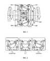
- FIG. 1is a side sectional view of a ball-type variator
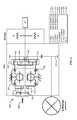
- FIG. 4is stick diagram of a power-splitting CVT configuration
- CVTsContinuously Variable Transmissions or CVTs have been developed.
- Those CVTsare of many types: belts with variable pulleys, toroidal, and conical, for non-limiting example.
- the principle of a CVTis that it enables the engine to run at its most efficient rotation speed by changing steplessly the transmission ratio in function of the speed of the car and the torque demand (throttle position) of the driver. If needed for example when accelerating, the CVT is configured to also shift to the most optimum ratio providing more power.
- a CVTis configured to change the ratio from the minimum to the maximum ratio without any interruption of the power transmission, as opposed to the opposite of usual transmissions which require an interruption of the power transmission by disengaging to shift from one discrete ratio to engage the next ratio.
- CVTsbased on a ball type variators, also known as CVP, for constant variable planetary.
- CVPconstant variable planetary
- the type of CVT provided hereincomprises a variator comprising a plurality of variator balls, depending on the application, two discs or annular rings 995 , 996 each having an engagement portion that engages the variator balls 997 , at least.
- the engagement portionsare optionally in a conical or toroidal convex or concave surface contact with the variator balls, as input ( 995 ) and output ( 996 ).
- the CVT 330is used to replace traditional transmission and is located between the engine (ICE or internal combustion engine) 300 and the differential 340 as shown on FIG. 3 .
- a torsional dampener (alternatively called a damper) 310is optionally introduced between the engine and the CVT to avoid transferring torque peaks and vibrations that could damage the CVT.
- this dampeneris coupled with a clutch 320 for the starting function or for allowing the engine to be decoupled from the transmission.
- the clutchis located at a different place in the driveline for allowing an interruption in the transmission of power in the driveline.
- variable transmissioncomprises a dampener (or damper) coupled to the input shaft and disposed between a power source and the variable transmission.
- the variatoris an asymmetric variator.
- the asymmetric variatorperform as a speed ratio shifter.
- the first ring assemblycomprises a first ring assembly engagement portion that is drivingly engaged with the variator ball
- second ring assemblycomprises a second ring assembly engagement portion that is drivingly engaged with the variator ball
- the first ring assembly engagement portionis offset from the second ring assembly engagement portion such that the speed ratio is greater than 1 or less than 1 when the variator balls are not tilted.
- the variatorcomprises a traction fluid.
- a vehicle drivelinecomprising: a power source, a variable transmission of any configuration described herein or that would be obvious to one of skill in the art having read the disclosure herein.
- the variable transmission of the vehicle drivelineis drivingly engaged with the power source, and a vehicle output drivingly engaged with the variable transmission.
- a methodcomprising providing a vehicle driveline comprising a variable transmission of any configuration described herein or that would be obvious to one of skill in the art having read the disclosure herein.
- variable transmissionscomprising: an input shaft; a variator (CVP) comprising a first ring assembly coupled to the input shaft, a carrier assembly comprising a plurality of tiltable variator balls drivingly engaged with the first ring assembly, and a second ring assembly drivingly engaged with the tiltable variator balls; and a planetary gearset comprising a planet carrier drivingly engaged with the input shaft, a ring drivingly engaged with the second ring assembly of the variator, and a sun gear drivingly engaged with the output of the vehicle, wherein the planetary gearset is configured to split power of the input shaft between the variator and a mechanical path going directly to the output through the planetary gear set.
- CVPvariator
- the first ring assembly and the second ring assemblyare drivingly coupled over a continuous range of speed ratios from a minimum speed ratio to a maximum speed ratio, and wherein the speed ratio is controlled by the tiltable variator balls.
- the tiltable variator ballscontrols the speed ratio between the first ring assembly and second ring assembly of the variator, and thereby controls the speed ratio between the planet carrier and ring of the planetary gearset.
- a minimum speed ratio and a maximum speed ratio between the input shaft and the sun of the planetary gearsetspan a range from negative to positive.
- the variable transmissionfurther comprises a damper coupled to the input shaft and disposed between a power source and the variable transmission.
- variable transmissionfurther comprises a clutch disposed between the power source and the variable transmission.
- the clutchis coupled to the damper or at a location to allow interrupting power transmission.
- variable transmissionfurther comprises a speed ratio shifter configured to shift a range of speed ratios to high or lower values.
- the speed ratio shiftercomprises a countershaft and gear drivingly engaged with the first ring assembly, the countershaft and gear having a gear ratio that shifts the speed ratio between the input shaft and the second ring assembly.
- the speed ratio shiftercomprises a planetary gearset, a portion of which is grounded.
- shifting the range of speed ratios to higher ratiosshifts the range of speed ratios between the planet carrier and sun of the planetary gearset to lower ratios.
- the range of speed ratiosis such that the range of speed ratios between the input shaft and the sun or output spans a negative ratio to a positive ratio.
- the range of speed ratiosis such that the range of speed ratios between the input shaft and the sun or output spans a negative ratio to a positive ratio, the negative ratio having equal magnitude as the positive ratio.
- the variable transmissionfurther comprises a second speed ratio shifter configured to shift a range of speed ratios to high or lower values.
- the second speed ratio shiftercomprises a planetary gear set comprising a sun, a ring and a gear, one of which is grounded to create a speed ratio.
- two of the sun, the ring, and the gearare not grounded and are connected to the input shaft and the first ring assembly.
- shifting the range of speed ratios to higher ratiosshifts the range of speed ratios between the planet carrier and sun of the planetary gearset to lower ratios.
- the range of speed ratiosis such that the range of speed ratios between the input shaft and the sun or output spans a negative ratio to a positive ratio.
- the range of speed ratiosis such that the range of speed ratios between the input shaft and the sun or output spans a negative ratio to a positive ratio, the negative ratio having equal magnitude as the positive ratio.
- the variatoris an asymmetric variator. In some embodiments, the asymmetric variator performs the function of the speed ratio shifter.
- a variable transmissioncomprise a variator coupled to a planetary gear system.
- the planetary gearsetis an epicyclic gearset.
- the planetary gearsetcomprises the carrier a plurality of planet gears, a sun gear, and a ring gear.
- the carrier, the sun gear, and the ring gearare rotatably disposed in the transmission housing.
- Each of the planet gearsis rotatably disposed on the carrier and is drivingly engaged with the sun gear and the ring gear.
- the sun gearis drivingly engaged with the output of the transmission.
- the ring gearis drivingly engaged with the second variator ring assembly; however, it is understood that the ring gear is optionally integrally formed with the second ring assembly.
- an internal combustion engine (ICE) or any other power plantis coupled to a power-splitting CVT configuration 400 comprising a variator 460 at the first ring assembly (input ring) 461 of the variator and the planet carrier 430 of the planetary gearset 450 .
- the output ring of the variator (second ring assembly) 462is coupled to the ring 410 of the planetary gearset and the sun gear 420 of the planetary gearset is the output of the transmission and is coupled to the differential 470 and drive axle of the vehicle.
- the ICEis linked directly to the planet gears 440 through the carrier but also indirectly through ring via the variator.
- connection to the ringis subject to the speed ratio of the variator, though the variator controls the flow of power from the ICE through the planetary gearset.
- the variator speed ratio between the maximum and minimum capabilities for the variatoris configured to change drastically over a continuum that includes both positive and negative values. This gives the ICE the ability to seamlessly achieve forward, neutral, and reverse gearing.
- This configurationis a power split configuration, meaning that there are multiple power paths that will be used at the same time. A part of the power will flow through the CVP (variator), the planetary ring, planet and going out through the sun while a certain amount of the power will directly flow through the carrier, planets and sun of the planetary.
- CVPvariable
- the planetary ringplanet and going out through the sun while a certain amount of the power will directly flow through the carrier, planets and sun of the planetary.
- Adding a gear ratio 680 greater than 1 to the input of the variatorshifts the planetary gear set 650 min speed and planetary gear set max speed higher levels. Indeed, the speed ratios are the same, but multiplied by a value greater than one. This has the effect of changing the output speed range (as reflected by the planetary sun gear's rotation) to lower levels. The effect is magnified by the planetary carrier/sun gear ratio allowing much more negative speed than before.
- Some embodiments of the inventionfeature a gear ratio mechanically placed on the other side of the CVP (but still linked to the first ring assembly or input of the variator) for the purpose of changing the overall speed/gear ratio range of the transmission.
- the embodiment 600 of FIG. 6includes an ICE drivingly engaged with a planet carrier 630 of a planetary gearset 650 .
- the ICEis linked directly to the planet gears 640 through the carrier but also indirectly through the ring gear 610 via the variator 660 .
- a gear ratio 680comprises a gear 681 on the input shaft, a counter shaft 670 and a gear 682 on the input ring (first ring assembly) 661 of the variator 660 .
- this gear ratiois optionally obtained with another layout such as a planetary of which one of the elements is fixed. This gear arrangement is presented to provide a first speed ratio between the ICE and the first ring assembly without changing the rotation direction between the ICE and the first ring assembly.
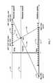
- the three horizontal axesrepresent respectively, from the bottom to the top, the sun rotation speed 701 , the planet carrier rotation speed 702 and the ring rotation speed 703 .
- the planet carrier 630is linked to the ICE and then always turns at the ICE speed, shown as a small dotted lines 704 crossing on the carrier axis.
- the ring 610is connected to the second ring assembly (output) 662 of the variator (CVP) 660 and is thus turning at a speed included in the following interval [ICE*CVP min Ratio*Gear speed ratio; ICE*CVP max Ratio*Gear speed ratio].
- the ratio at the input of the CVPis optionally configured or set according to the specifications of the vehicle. It has to be understood that this ratio is optionally bigger than 1 or smaller than 1. A speed ratio bigger than one increases the speed of the variator input ring while a gear speed ratio smaller than one decreases the speed of the variator input ring. Similarly, the counter shaft is optionally omitted if the objective is to reverse the speed of the variator input ring.
- An internal speed ratiois alternatively created using an asymmetric variator rather than the power split configurations of Example 1 and Example 2.
- Such a configurationeliminates need for the ratio gears and countershaft or planetary gear set of Example 2, thus reducing the parts of the overall variable transmission while providing the same functionality.
- an asymmetric variator that changes alpha anglescould be used in many other cases, increasing the spread, or giving better efficiency for a certain range of speed ratios
- the embodiment 1000 of FIG. 10comprises a planetary gearset 1050 to provide different power paths.
- the central part of the configuration of FIG. 10is the variator 1060 described previously in the document with an asymmetric design 900 of the first ring assembly 901 (variator input ring) and second ring assembly 902 (variator output ring).
- FIG. 10shows the speed diagram of the embodiment of FIG. 10 , which is similar to the speed diagram in FIG. 9 .
- the three horizontal axes of FIG. 11represent respectively, from the bottom to the top, the sun rotation speed 1101 , the planet carrier rotation speed 1102 and the ring rotation speed 1103 .
- the planet carrier 1030is linked to the ICE and then always turns at the ICE speed, shown as a vertical bar 1104 where the small dotted lines 1105 , 1106 intersect on the carrier axis.
- the ringis connected to the output 902 (second ring assembly) of the CVP 1060 and is thus turning at a speed included in the following interval [ICE*CVP min Ratio; ICE*CVP max Ratio].
- the solid interval 1109 on the sun axisshows the speed achievable on the sun depending on the variator speed ratio.
- a minimum speed ratio in the variatorbrings the sun speed to its maximum while the maximum speed ratio in the variator brings the sun speed to its maximum negative speed.
- the area comprised in between the dotted lines 1105 , 1106can be completely covered by only changing the speed ratio in the CVP. Thanks to this design, the amount of negative speeds can be increased compared to the previous configuration of Example 1. Such a feature is important in some applications such as Off-Highway applications in which the requirements include the same magnitude of positive and negative speeds.
- the dotted line 1110 on the ring axisshows the interval without gear ratio as it was in Example 1.
- the ICE in the embodiment of FIG. 10is connected to the planet carrier 1030 of the planetary 1050 and to the input ring 901 (first ring assembly) of the CVP 1060 . Additionally, the ICE is linked directly to the planet gears 1040 through the carrier but also indirectly through ring 1010 via the asymmetric variator 1060 . The variator output ring 902 (second ring assembly) is then connected to the ring 1010 of the planetary 1050 . The sun 1020 of the planetary is directly connected to the output 1070 of the transmission, itself linked to the differential and the wheel axle.
- variable transmissions disclosed hereinis used in bicycles, mopeds, scooters, motorcycles, automobiles, electric automobiles, trucks, sport utility vehicles (SUV's), lawn mowers, tractors, harvesters, agricultural machinery, all terrain vehicles (ATV's), jet ski's, personal watercraft vehicles, airplanes, trains, helicopters, buses, forklifts, golf carts, motorships, steam powered ships, submarines, space craft, or other vehicles that employ a transmission.
- SUV'ssport utility vehicles
- ATV'sall terrain vehicles
- jet ski'spersonal watercraft vehicles
- airplanestrains, helicopters, buses, forklifts
- golf cartsmotorships
- steam powered shipssubmarines, space craft, or other vehicles that employ a transmission.
- CVTball-type variators
- VDPVariable-diameter pulley
- Reeves drivea toroidal or roller-based CVT (Extroid CVT)
- a Magnetic CVT or mCVTRatcheting CVT
- Hydrostatic CVTsNaudic Incremental CVT (iCVT)
- Cone CVTsRadial roller CVT, Planetary CVT, or any other version CVT.
Landscapes
- Engineering & Computer Science (AREA)
- General Engineering & Computer Science (AREA)
- Mechanical Engineering (AREA)
- Transmission Devices (AREA)
- Friction Gearing (AREA)
Abstract
Description
Claims (15)
Priority Applications (1)
| Application Number | Priority Date | Filing Date | Title |
|---|---|---|---|
| US14/925,813US9638301B2 (en) | 2013-03-14 | 2015-10-28 | Ball type continuously variable transmission |
Applications Claiming Priority (4)
| Application Number | Priority Date | Filing Date | Title |
|---|---|---|---|
| US201361786299P | 2013-03-14 | 2013-03-14 | |
| US14/208,364US8926468B2 (en) | 2013-03-14 | 2014-03-13 | Ball type continuously variable transmission |
| US14/546,603US9194472B2 (en) | 2013-03-14 | 2014-11-18 | Ball type continuously variable transmission |
| US14/925,813US9638301B2 (en) | 2013-03-14 | 2015-10-28 | Ball type continuously variable transmission |
Related Parent Applications (1)
| Application Number | Title | Priority Date | Filing Date |
|---|---|---|---|
| US14/546,603ContinuationUS9194472B2 (en) | 2013-03-14 | 2014-11-18 | Ball type continuously variable transmission |
Publications (2)
| Publication Number | Publication Date |
|---|---|
| US20160069442A1 US20160069442A1 (en) | 2016-03-10 |
| US9638301B2true US9638301B2 (en) | 2017-05-02 |
Family
ID=51529677
Family Applications (4)
| Application Number | Title | Priority Date | Filing Date |
|---|---|---|---|
| US14/773,695Expired - Fee RelatedUS9689482B2 (en) | 2013-03-14 | 2014-03-12 | Ball type continuously variable transmission |
| US14/208,364Expired - Fee RelatedUS8926468B2 (en) | 2013-03-14 | 2014-03-13 | Ball type continuously variable transmission |
| US14/546,603Expired - Fee RelatedUS9194472B2 (en) | 2013-03-14 | 2014-11-18 | Ball type continuously variable transmission |
| US14/925,813Expired - Fee RelatedUS9638301B2 (en) | 2013-03-14 | 2015-10-28 | Ball type continuously variable transmission |
Family Applications Before (3)
| Application Number | Title | Priority Date | Filing Date |
|---|---|---|---|
| US14/773,695Expired - Fee RelatedUS9689482B2 (en) | 2013-03-14 | 2014-03-12 | Ball type continuously variable transmission |
| US14/208,364Expired - Fee RelatedUS8926468B2 (en) | 2013-03-14 | 2014-03-13 | Ball type continuously variable transmission |
| US14/546,603Expired - Fee RelatedUS9194472B2 (en) | 2013-03-14 | 2014-11-18 | Ball type continuously variable transmission |
Country Status (5)
| Country | Link |
|---|---|
| US (4) | US9689482B2 (en) |
| EP (1) | EP2971859A4 (en) |
| JP (1) | JP2016512312A (en) |
| CN (1) | CN105121905A (en) |
| WO (1) | WO2014159755A2 (en) |
Families Citing this family (65)
| Publication number | Priority date | Publication date | Assignee | Title |
|---|---|---|---|---|
| US7011600B2 (en) | 2003-02-28 | 2006-03-14 | Fallbrook Technologies Inc. | Continuously variable transmission |
| WO2006041718A2 (en) | 2004-10-05 | 2006-04-20 | Fallbrook Technologies, Inc. | Continuously variable transmission |
| WO2007070167A2 (en) | 2005-10-28 | 2007-06-21 | Fallbrook Technologies Inc. | Electromotive drives |
| PL1954959T3 (en) | 2005-11-22 | 2013-10-31 | Fallbrook Ip Co Llc | Continuously variable transmission |
| CN102221073B (en) | 2005-12-09 | 2013-03-27 | 福博科技术公司 | Continuously variable transmission |
| EP1811202A1 (en) | 2005-12-30 | 2007-07-25 | Fallbrook Technologies, Inc. | A continuously variable gear transmission |
| CN102269055B (en) | 2006-06-26 | 2013-08-28 | 福博科技术公司 | Continuously variable transmission |
| EP2125469A2 (en) | 2007-02-01 | 2009-12-02 | Fallbrook Technologies Inc. | System and methods for control of transmission and/or prime mover |
| US20100093479A1 (en) | 2007-02-12 | 2010-04-15 | Fallbrook Technologies Inc. | Continuously variable transmissions and methods therefor |
| TWI461615B (en) | 2007-02-16 | 2014-11-21 | Fallbrook Ip Co Llc | Infinitely variable transmissions, continuously variable transmissions, methods, assemblies, subassemblies, and components therefor |
| EP2142826B1 (en) | 2007-04-24 | 2015-10-28 | Fallbrook Intellectual Property Company LLC | Electric traction drives |
| US8641577B2 (en) | 2007-06-11 | 2014-02-04 | Fallbrook Intellectual Property Company Llc | Continuously variable transmission |
| CN103697120B (en) | 2007-07-05 | 2017-04-12 | 福博科技术公司 | Continuously variable transmission |
| CN103939602B (en) | 2007-11-16 | 2016-12-07 | 福博科知识产权有限责任公司 | Controllers for variable speed drives |
| US8321097B2 (en) | 2007-12-21 | 2012-11-27 | Fallbrook Intellectual Property Company Llc | Automatic transmissions and methods therefor |
| US8313405B2 (en) | 2008-02-29 | 2012-11-20 | Fallbrook Intellectual Property Company Llc | Continuously and/or infinitely variable transmissions and methods therefor |
| US8317651B2 (en)* | 2008-05-07 | 2012-11-27 | Fallbrook Intellectual Property Company Llc | Assemblies and methods for clamping force generation |
| CN102112778B (en) | 2008-06-06 | 2013-10-16 | 福博科技术公司 | Infinitely variable transmission, continuously variable transmission, methods, assemblies, subassemblies and components therefor |
| EP2304272B1 (en) | 2008-06-23 | 2017-03-08 | Fallbrook Intellectual Property Company LLC | Continuously variable transmission |
| CA2732668C (en) | 2008-08-05 | 2017-11-14 | Fallbrook Technologies Inc. | Methods for control of transmission and prime mover |
| US8469856B2 (en) | 2008-08-26 | 2013-06-25 | Fallbrook Intellectual Property Company Llc | Continuously variable transmission |
| US8167759B2 (en) | 2008-10-14 | 2012-05-01 | Fallbrook Technologies Inc. | Continuously variable transmission |
| ES2439647T3 (en) | 2009-04-16 | 2014-01-24 | Fallbrook Intellectual Property Company Llc | Stator set and speed change mechanism for a continuously variable transmission |
| US8512195B2 (en) | 2010-03-03 | 2013-08-20 | Fallbrook Intellectual Property Company Llc | Infinitely variable transmissions, continuously variable transmissions, methods, assemblies, subassemblies, and components therefor |
| US8888643B2 (en) | 2010-11-10 | 2014-11-18 | Fallbrook Intellectual Property Company Llc | Continuously variable transmission |
| US9347532B2 (en) | 2012-01-19 | 2016-05-24 | Dana Limited | Tilting ball variator continuously variable transmission torque vectoring device |
| CN104302949B (en) | 2012-01-23 | 2017-05-03 | 福博科知识产权有限责任公司 | Infinitely variable continuously variable transmission, continuously variable continuously variable transmission, method, assembly, subassembly, and parts thereof |
| CN104204615B (en) | 2012-02-15 | 2017-10-24 | 德纳有限公司 | Transmission device and the power train with tilt ball speed changer infinitely variable speed transmission |
| EP2893219A4 (en) | 2012-09-06 | 2016-12-28 | Dana Ltd | Transmission having a continuously or infinitely variable variator drive |
| CN104768787A (en) | 2012-09-07 | 2015-07-08 | 德纳有限公司 | Ball type CVT with powersplit paths |
| JP6320386B2 (en) | 2012-09-07 | 2018-05-09 | デーナ リミテッド | Ball type CVT / IVT including planetary gear set |
| WO2014039708A1 (en) | 2012-09-07 | 2014-03-13 | Dana Limited | Ball type cvt including a direct drive mode |
| US9689477B2 (en) | 2012-09-07 | 2017-06-27 | Dana Limited | Ball type continuously variable transmission/infinitely variable transmission |
| US9599204B2 (en) | 2012-09-07 | 2017-03-21 | Dana Limited | Ball type CVT with output coupled powerpaths |
| WO2014039713A1 (en) | 2012-09-07 | 2014-03-13 | Dana Limited | Ivt based on a ball type cvp including powersplit paths |
| US10030748B2 (en) | 2012-11-17 | 2018-07-24 | Dana Limited | Continuously variable transmission |
| WO2014124063A1 (en) | 2013-02-08 | 2014-08-14 | Microsoft Corporation | Pervasive service providing device-specific updates |
| US9551404B2 (en) | 2013-03-14 | 2017-01-24 | Dana Limited | Continuously variable transmission and an infinitely variable transmission variator drive |
| CN105121905A (en) | 2013-03-14 | 2015-12-02 | 德纳有限公司 | Ball type continuously variable transmission |
| KR102433297B1 (en) | 2013-04-19 | 2022-08-16 | 폴브룩 인텔렉츄얼 프로퍼티 컴퍼니 엘엘씨 | Continuously variable transmission |
| EP3004686B1 (en) | 2013-06-06 | 2018-08-08 | Dana Limited | 3-mode front wheel drive and rear wheel drive continuously variable planetary transmission |
| US20150142281A1 (en)* | 2013-11-18 | 2015-05-21 | Dana Limited | Braking management system for a transmission incorporating a cvp |
| WO2015073948A2 (en) | 2013-11-18 | 2015-05-21 | Dana Limited | Torque peak detection and control mechanism for cvp |
| US10030751B2 (en) | 2013-11-18 | 2018-07-24 | Dana Limited | Infinite variable transmission with planetary gear set |
| CN106536987A (en) | 2014-06-17 | 2017-03-22 | 德纳有限公司 | Off-highway continuously variable planetary-based multimore transmission including infinite variable transmission and direct continuously variable tranmission |
| US10400872B2 (en) | 2015-03-31 | 2019-09-03 | Fallbrook Intellectual Property Company Llc | Balanced split sun assemblies with integrated differential mechanisms, and variators and drive trains including balanced split sun assemblies |
| JP2018519478A (en)* | 2015-05-08 | 2018-07-19 | ダナ リミテッド | Control method for synchronous shift of transmission with continuously variable planetary mechanism |
| WO2017027404A1 (en)* | 2015-08-07 | 2017-02-16 | Dana Limited | Control system for an infinitely variable transmission |
| JP6448808B2 (en)* | 2015-09-09 | 2019-01-09 | ジヤトコ株式会社 | Control device for vehicle variator |
| EP3350480A4 (en)* | 2015-09-17 | 2019-05-01 | Dana Limited | Hybrid electric powertrain configurations with a ball variator used as a continuously variable mechanical transmission |
| CN108474459A (en)* | 2015-09-17 | 2018-08-31 | 德纳有限公司 | Hybrid electric power system configuration with the ball speed changing type contiuously variable transmission as dynamic branch |
| US10030594B2 (en) | 2015-09-18 | 2018-07-24 | Dana Limited | Abuse mode torque limiting control method for a ball-type continuously variable transmission |
| CN105443710A (en)* | 2015-12-16 | 2016-03-30 | 山东农业大学 | Friction-ball power split type continuously variable transmission |
| EP3187751B1 (en)* | 2015-12-30 | 2019-03-06 | Rolless GmbH | Infinitely adjustable planetary gear |
| US10047861B2 (en) | 2016-01-15 | 2018-08-14 | Fallbrook Intellectual Property Company Llc | Systems and methods for controlling rollback in continuously variable transmissions |
| KR102364407B1 (en) | 2016-03-18 | 2022-02-16 | 폴브룩 인텔렉츄얼 프로퍼티 컴퍼니 엘엘씨 | continuously variable transmission system and method |
| US10023266B2 (en) | 2016-05-11 | 2018-07-17 | Fallbrook Intellectual Property Company Llc | Systems and methods for automatic configuration and automatic calibration of continuously variable transmissions and bicycles having continuously variable transmissions |
| WO2018045121A1 (en)* | 2016-08-31 | 2018-03-08 | Dana Limited | Electric axle transmission with a ball variator continuoulsy variable planetary transmission with and without torque vectoring for electric and hybrid electric vehicles |
| US10011174B2 (en)* | 2016-11-04 | 2018-07-03 | Dana Heavy Vehicle Systems Group, Llc | Tandem axle gearing arrangement |
| US20190275884A1 (en)* | 2018-03-06 | 2019-09-12 | Dana Limited | Electric axle with variable ratio, a high efficiency lock up ratio, a neutral |
| US11215268B2 (en) | 2018-11-06 | 2022-01-04 | Fallbrook Intellectual Property Company Llc | Continuously variable transmissions, synchronous shifting, twin countershafts and methods for control of same |
| WO2020176392A1 (en) | 2019-02-26 | 2020-09-03 | Fallbrook Intellectual Property Company Llc | Reversible variable drives and systems and methods for control in forward and reverse directions |
| CN113007292B (en)* | 2021-03-02 | 2022-02-01 | 西华大学 | Roller planetary row transmission system with continuously variable characteristic parameters |
| CN113908455A (en)* | 2021-11-25 | 2022-01-11 | 华东交通大学 | Descent control device |
| CN114227764B (en)* | 2021-12-30 | 2024-06-18 | 重庆特斯联智慧科技股份有限公司 | Robot steering chassis structure suitable for small space |
Citations (276)
| Publication number | Priority date | Publication date | Assignee | Title |
|---|---|---|---|---|
| US1063244A (en) | 1908-03-18 | 1913-06-03 | Ludwig Maria Dieterich | Variable-power transmitting and controlling mechanism. |
| US1215969A (en) | 1916-12-14 | 1917-02-13 | Thomas E Murray | Sheet-metal piston. |
| US1526140A (en) | 1921-10-03 | 1925-02-10 | Hollow Ball Company Inc | Manufacture of hollow metal balls |
| US2019006A (en) | 1934-02-01 | 1935-10-29 | Ferrarl Lorenzo | Change speed gear |
| FR796188A (en) | 1935-10-04 | 1936-03-31 | Friction shifting | |
| US2060884A (en) | 1933-09-19 | 1936-11-17 | Erban Operating Corp | Power transmission mechanism |
| US2148759A (en) | 1938-02-10 | 1939-02-28 | Grand Cecil W Le | Variable transmission unit |
| US2405201A (en) | 1942-08-29 | 1946-08-06 | Imp Brass Mfg Co | Method of forming closed metal capsules |
| FR1030702A (en) | 1950-12-06 | 1953-06-16 | Tiltman Langley Lab Ltd | Improvements to variable speed ratio transmission mechanisms in a continuous range |
| US2660897A (en) | 1950-09-20 | 1953-12-01 | Dabo Ltd | Infinitely-variable change-speed gear |
| US2729118A (en) | 1955-04-25 | 1956-01-03 | Lyell M Emslie | Gearless differential |
| US2931235A (en) | 1957-11-12 | 1960-04-05 | George Cohen 600 Group Ltd | Variable speed friction drive transmissions |
| US3203278A (en) | 1963-01-02 | 1965-08-31 | Ford Motor Co | Variable speed friction drive transmission |
| FR1472282A (en) | 1966-02-24 | 1967-03-10 | Chambre Syndicale Des Fabrican | Method and apparatus for transforming a section of metal tube into a sphere, and application of the sphere thus obtained to the production of assembly nodes, in particular for tubular frames |
| DE1237380B (en) | 1958-08-13 | 1967-03-23 | Differential Diesel Engines Es | Supercharged internal combustion engine with a supercharging system with two drives |
| US3376633A (en) | 1966-04-20 | 1968-04-09 | Richard H. Wesley | Ball joint forming methods |
| GB1127825A (en) | 1966-06-15 | 1968-09-18 | Filden Engineering Ltd | Improvements relating to the manufacture of spherical and spheroidal objects |
| US3407687A (en) | 1967-03-27 | 1968-10-29 | Hayashi Tadashi | Variable ratio power transmission device |
| US3470720A (en) | 1967-09-01 | 1969-10-07 | Phillip R Eklund | Method of making hollow balls for use in ball bearing and/or similar rolling operations |
| US3505718A (en) | 1968-01-15 | 1970-04-14 | Gen Ind Inc | One-piece sheet metal hollow ball for ball valves |
| US3583060A (en) | 1968-12-30 | 1971-06-08 | Ametek Inc | Method of swaging a metal fitting on a steel wire |
| US3688600A (en) | 1971-04-26 | 1972-09-05 | Ford Motor Co | Infinitely variable overdrive transmission mechanism |
| US3765270A (en) | 1971-04-26 | 1973-10-16 | Ford Motor Co | Multiple ratio power transmission mechanism with an infinitely variable overdrive range |
| US3774280A (en) | 1972-07-18 | 1973-11-27 | Us Air Force | Method of fabricating hollow balls for use in rolling contact bearing applications |
| FR2185076A5 (en) | 1972-05-16 | 1973-12-28 | Burke John | |
| US3831245A (en) | 1973-03-01 | 1974-08-27 | Columbus Auto Parts | Method of producing ball joints |
| US3894559A (en) | 1974-03-28 | 1975-07-15 | Leland Q Depuy | Manifold valve |
| FR2280451A1 (en) | 1974-08-01 | 1976-02-27 | Roche Jean | Hollow spherical body mfr - with tubing hot or cold spun between hemispherical dies |
| US4046988A (en) | 1976-03-05 | 1977-09-06 | Kobe Steel Ltd. | Method of preventing base metal end crack in arc welding and end tab used therefor |
| US4187709A (en) | 1976-08-23 | 1980-02-12 | Kevin Strickland | Explosive forming |
| US4226140A (en) | 1976-12-14 | 1980-10-07 | Gaasenbeek Johannes L | Self-propelled vehicle |
| US4333358A (en) | 1979-12-18 | 1982-06-08 | Fiat-Allis Macchine Movimento Terra S.P.A. | Power-shift countershaft type transmission |
| US4344336A (en) | 1979-07-23 | 1982-08-17 | Ford Motor Company | Differential traction drive with extreme overall torque ratios for use in a gas turbine engine driveline |
| US4360090A (en) | 1980-10-20 | 1982-11-23 | General Motors Corporation | Torque reversal control valve for a torque converter clutch |
| US4368572A (en) | 1979-10-15 | 1983-01-18 | Toyo Kogyo Co., Ltd. | Method of manufacturing a shaft structure having a spherical bulb |
| DE3245045A1 (en) | 1982-12-06 | 1984-06-07 | Adam Opel AG, 6090 Rüsselsheim | Motor vehicle hybrid drive arrangement |
| US4464952A (en) | 1980-05-31 | 1984-08-14 | Bl Technology Limited | Control systems for continuously variable ratio transmissions (CVT) |
| EP0156936A1 (en) | 1984-04-03 | 1985-10-09 | Klinger AG | Process for producing a spherical plug for a fluid valve |
| EP0210053A2 (en) | 1985-07-22 | 1987-01-28 | Borg-Warner Corporation | Dual-pass continuously variable transmission with asymetric variator |
| US4693134A (en) | 1985-06-20 | 1987-09-15 | Excelermatic Inc. | High-powered vehicle drive train |
| US4731044A (en) | 1985-12-18 | 1988-03-15 | Borg-Warner Automotive, Inc. | Tension sensor and control arrangement for a continuously variable transmission |
| GB2196892A (en) | 1986-11-05 | 1988-05-11 | Concentric Pumps Ltd | Fixing components on shafts |
| US4756211A (en) | 1985-09-13 | 1988-07-12 | Fellows Thomas G | Continuously-variable ratio transmission for an automobile vehicle |
| US4784017A (en) | 1986-07-03 | 1988-11-15 | Johnshoy Edward W | Continuously variable transmission and torque retaining differential |
| US4856371A (en) | 1987-03-12 | 1989-08-15 | Tractiontec Corporation | Traction drive transmission system |
| US4856374A (en) | 1987-03-02 | 1989-08-15 | Planetroll Antriebe Gmbh | Adjustable transmission |
| US4950208A (en) | 1988-06-17 | 1990-08-21 | Malcolm Tomlinson | Variable ratio power transmission |
| US4963124A (en) | 1988-10-26 | 1990-10-16 | Toyota Jidosha Kabushiski Kaisha | Planetary gear transmission for motor vehicle |
| US4963122A (en) | 1987-06-04 | 1990-10-16 | The Gleason Works | Continuously variable differential |
| GB2248895A (en) | 1990-09-12 | 1992-04-22 | Malcolm Tomlinson | Double toroidal race variator with two variable outputs |
| US5109962A (en) | 1989-12-28 | 1992-05-05 | Fuji Jukogyo Kabushiki Kaisha | Transmission ratio control system for a continuously variable transmission |
| US5168778A (en) | 1991-08-29 | 1992-12-08 | Borg-Warner Automotive, Inc. | CVT downshift control strategy to minimize slip at the drive pulley |
| US5217412A (en) | 1990-10-20 | 1993-06-08 | Luk Lamellen Und Kupplungsbau Gmbh | Continuously variable speed transmission |
| US5230670A (en) | 1990-12-25 | 1993-07-27 | Nissan Motor Co., Ltd. | Friction roller type continuously variable transmission |
| US5238460A (en) | 1991-02-28 | 1993-08-24 | Mazda Motor Corporation | Power transmission system for vehicle |
| US5318486A (en) | 1991-08-16 | 1994-06-07 | Fichtel & Sachs Ag | Driving hub for a vehicle, particularly a bicycle, with an infinitely adjustable transmission ratio |
| US5390759A (en) | 1992-08-10 | 1995-02-21 | Sauer Inc. | Driving mechanism for an automotive propel drive |
| US5401221A (en) | 1990-08-17 | 1995-03-28 | Torotrak (Development) Limited | Transmission of the toroidal-race, rolling-traction type having a mixer and a reducer epicyclic type gearing with clutches brakes |
| US5520588A (en) | 1995-05-03 | 1996-05-28 | General Motors Corporation | Power transmission |
| US5527231A (en) | 1991-06-21 | 1996-06-18 | Dr. Ing. H.C.F. Porsche Ag | Method for controlling a continuously variable transmission of a motor vehicle |
| US5577423A (en) | 1994-03-04 | 1996-11-26 | Mimura; Kenji | Differential gear |
| US5599251A (en) | 1995-09-27 | 1997-02-04 | Ford Motor Company | Six speed automatic transmission for automotive vehicles |
| JPH09119506A (en) | 1995-10-23 | 1997-05-06 | Toyota Motor Corp | Differential device |
| US5659956A (en) | 1996-02-12 | 1997-08-26 | Braginsky; Mikhail | Process for the production of hollow ball bearings |
| US5683322A (en) | 1993-04-21 | 1997-11-04 | Meyerle; Michael | Continuous hydrostatic-mechanical branch power split transmission particularly for power vehicles |
| US5726353A (en) | 1995-11-21 | 1998-03-10 | Honda Giken Kogyo Kabushiki Kaisha | System for detecting torque of automatic vehicle transmission and controlling the same based on detected torque |
| US5730678A (en) | 1996-02-28 | 1998-03-24 | Gen Dynamics Defense Syst Inc | Multi-range, hydromechanical transmission for motor vehicles |
| US5766105A (en) | 1993-12-20 | 1998-06-16 | Torotrak (Development) Limited | Continuously variable transmission capable of torque control |
| US5776028A (en) | 1995-09-01 | 1998-07-07 | Honda Giken Kogyo Kabushiki Kaisha | Belt-type continuously variable transmission |
| US5800303A (en) | 1994-11-28 | 1998-09-01 | Chrysler Corporation | Four-speed automatic transmission |
| US5860888A (en) | 1996-06-18 | 1999-01-19 | Hyundai Motor Co. | Automatic transmission with a toroidal CVT and a belt type CVT for vehicle |
| US5915801A (en) | 1995-07-18 | 1999-06-29 | Toyota Jidosha Kabushiki Kaisha | Regenerative brake controller for controlling value of regenerative braking torque simulating engine braking torque |
| US5961415A (en) | 1998-09-17 | 1999-10-05 | Ford Global Technologies, Inc. | Single cavity toroidal traction drive continually variable transmission |
| US5971883A (en) | 1998-03-13 | 1999-10-26 | General Motors Corporation | Multi-speed power transmission |
| US5996226A (en) | 1997-12-23 | 1999-12-07 | Itt Manufacturing Enterprises, Inc. | Method of manufacturing push rod balls |
| US6009365A (en) | 1997-12-25 | 1999-12-28 | Nissan Motor Co., Ltd. | Vehicle drive system controller and control method |
| US6036616A (en) | 1998-03-19 | 2000-03-14 | Ford Global Technologies, Inc. | All wheel drive continously variable transmission having dual mode operation |
| US6045477A (en) | 1999-06-14 | 2000-04-04 | General Motors Corporation | Continuously variable multi-range powertrain with a geared neutral |
| US6053839A (en) | 1999-06-18 | 2000-04-25 | Ford Global Technologies, Inc. | Multiple speed overdrive transmission for a motor vehicle |
| US6059685A (en) | 1999-05-06 | 2000-05-09 | Ford Global Technologies, Inc. | Coaxial traction drive automatic transmission for automotive vehicles |
| US6071208A (en) | 1998-06-22 | 2000-06-06 | Koivunen; Erkki | Compact multi-ratio automatic transmission |
| US6080080A (en) | 1997-09-30 | 2000-06-27 | Robert Bosch Gmbh | Device and method for adjusting the transmission ratio of a CVT |
| US6083135A (en) | 1999-06-18 | 2000-07-04 | Ford Global Technologies, Inc. | Multiple speed overdrive transmission for a motor vehicle |
| US6086504A (en) | 1996-04-22 | 2000-07-11 | Zf Friedrichshafen Ag | Planetary gear and clutch-brake arrangement |
| US6089287A (en) | 1995-07-20 | 2000-07-18 | Black & Decker Inc. | Portable wood planing machine |
| US6095942A (en) | 1998-08-18 | 2000-08-01 | Honda Giken Kogyo Kabushiki Kaisha | Speed change control device for vehicular continuously variable transmission |
| US6155951A (en) | 1997-01-31 | 2000-12-05 | Zf Friedrichshafen Ag | Toroidal drive |
| US6203466B1 (en)* | 1999-07-27 | 2001-03-20 | Nsk Ltd. | Continuously variable transmission apparatus |
| US6217474B1 (en) | 1999-10-22 | 2001-04-17 | General Motors Corporation | Multi speed power transmission |
| US6251038B1 (en) | 1998-10-21 | 2001-06-26 | Nsk Ltd. | Continuously variable transmission unit |
| US6273838B1 (en) | 1999-07-08 | 2001-08-14 | Hyundai Motor Company | Gear train for vehicle automatic transmissions |
| US20020004438A1 (en) | 2000-07-10 | 2002-01-10 | Nissan Motor Co., Ltd. | Input torque limiting device for an infinitely variable transmission |
| US6342026B1 (en) | 1999-07-29 | 2002-01-29 | Aisin Seiki Kabushiki Kaisha | Automatic transmission for vehicles |
| US6358178B1 (en) | 2000-07-07 | 2002-03-19 | General Motors Corporation | Planetary gearing for a geared neutral traction drive |
| US6371880B1 (en) | 1999-06-03 | 2002-04-16 | Hyundai Motor Company | Limited slip differential |
| US20020094911A1 (en) | 2001-01-16 | 2002-07-18 | Haka Raymond James | Dual mode, geared neutral continuously variable transmission |
| US6481258B1 (en) | 1997-06-18 | 2002-11-19 | Jacob S. Belinky | Removable trailer hitch ball |
| US6554735B2 (en) | 2000-09-28 | 2003-04-29 | Fuji Jukogyo Kabushiki Kaisha | Planetary gear type differential apparatus |
| US6558285B1 (en) | 1999-06-26 | 2003-05-06 | Robert Bosch Gmbh | Friction-wheel planetary gear with bevel gears |
| US6585619B2 (en) | 2000-08-11 | 2003-07-01 | Daimler Chrysler Ag | Transmission arrangement |
| US6609994B2 (en) | 2001-03-16 | 2003-08-26 | Nissan Motor Co., Ltd. | Braking/driving control apparatus and method for automotive vehicle |
| US20030181280A1 (en) | 2002-02-15 | 2003-09-25 | Daimlerchrysler Ag | Motor vehicle transmission with a toroidal variable-speed drive unit |
| US6632157B1 (en) | 1998-09-29 | 2003-10-14 | Zf Batavia L.L.C. | Method for reducing the thermal load on an automatic transmission for a motor vehicle in emergency operating mode |
| US20030200783A1 (en) | 2002-04-26 | 2003-10-30 | Dean Shai | Hollow tubular blank provided in wall thereof with one or more reinforcing ribs |
| US6641497B2 (en) | 2001-12-07 | 2003-11-04 | Murray, Inc. | Epicyclic transmission for zero turning radius vehicles |
| US6645106B2 (en) | 2000-08-22 | 2003-11-11 | Teak-Seo Goo | Transmission for performing reliable continuously-variable-speed operation through gear meshing, and vehicle-use continuously-variable transmission device using it |
| US20030213125A1 (en) | 2002-05-20 | 2003-11-20 | Su-Yueh Chiuchang | Ball valve body manufacturing method |
| US20030216121A1 (en) | 2001-10-11 | 2003-11-20 | Mark Yarkosky | Method for in-building distribution using wireless access technology |
| US20030228952A1 (en) | 2002-06-05 | 2003-12-11 | Nissan Motor Co., Ltd. | Toroidal continuously variable transmission control apparatus |
| US6689012B2 (en) | 2001-04-26 | 2004-02-10 | Motion Technologies, Llc | Continuously variable transmission |
| US6705964B2 (en) | 2001-12-11 | 2004-03-16 | Jatco Ltd | Power transmission system |
| US20040058769A1 (en) | 2002-09-23 | 2004-03-25 | Larkin Robert P. | Multi-range parallel-hybrid continuously variable transmission |
| US20040061639A1 (en) | 2000-11-11 | 2004-04-01 | Klaus Voigtlaender | Radar device and method for operating a radar device |
| US6719659B2 (en) | 2000-05-05 | 2004-04-13 | Daimlerchrysler Ag | Continuously variable vehicle transmission |
| US6723016B2 (en) | 2001-09-27 | 2004-04-20 | Jatco Ltd | Torque split infinitely variable transmission |
| US6726590B2 (en) | 2001-04-28 | 2004-04-27 | Daimlerchrysler Ag | Speed change transmission arrangement including a continuously variable toroidal transmission |
| US6733412B2 (en) | 2001-05-21 | 2004-05-11 | Honda Giken Kogyo Kabushiki Kaisha | Automotive automatic transmission |
| US6752696B2 (en) | 2001-03-12 | 2004-06-22 | Nsk Ltd. | Rolling elements for rolling bearing, method of producing the same, and rolling bearing |
| US20040166984A1 (en) | 2002-12-05 | 2004-08-26 | Nsk Ltd. | Continuously variable transmission apparatus |
| US20040167391A1 (en) | 2003-02-25 | 2004-08-26 | Solar Matthew S. | Fiducial marker devices, tools, and methods |
| US20040171452A1 (en) | 2003-02-28 | 2004-09-02 | Miller Donald C. | Continuously variable transmission |
| US6793603B2 (en) | 2001-10-25 | 2004-09-21 | Tochigi Fuji Sangyo Kabushiki Kaisha | Power transmission system with sub transmission mechanism |
| US6849020B2 (en) | 2002-08-07 | 2005-02-01 | Jatco Ltd | Continuously variable power-split transmission |
| US6866606B2 (en) | 2001-10-25 | 2005-03-15 | Honda Giken Kogyo Kabushiki Kaisha | Continuously variable transmission system for vehicles |
| US20050102082A1 (en) | 2003-11-12 | 2005-05-12 | Nissan Motor Co., Ltd. | Shift control system of hybrid transmission |
| US20050137046A1 (en) | 2003-08-11 | 2005-06-23 | Miller Donald C. | Continuously variable planetary gear set |
| US20050164818A1 (en)* | 2002-02-25 | 2005-07-28 | Katsumi Kimura | Transmission apparatus |
| US6949045B2 (en) | 2002-10-24 | 2005-09-27 | Zf Friedrichshafen Ag | Power distributed 2-range transmission |
| US6979275B2 (en) | 2001-05-14 | 2005-12-27 | Nissan Motor Co., Ltd. | Auxiliary transmission in transmission system |
| WO2006002457A1 (en) | 2004-07-06 | 2006-01-12 | Bruce Winston Brockhoff | Solar collector |
| US6986725B2 (en) | 2002-11-01 | 2006-01-17 | Eaton Corporation | Continuously variable stepped transmission |
| WO2006041718A2 (en) | 2004-10-05 | 2006-04-20 | Fallbrook Technologies, Inc. | Continuously variable transmission |
| US7033298B2 (en) | 2002-12-18 | 2006-04-25 | General Motors Corporation | Family of five-speed dual-clutch transmissions having three planetary gear sets |
| US20060094515A1 (en) | 2004-10-29 | 2006-05-04 | Joseph Szuba | Universal joint assembly for an automotive driveline system |
| US7074154B2 (en) | 1998-08-12 | 2006-07-11 | Fallbrook Technologies Inc. | Continuously variable transmission |
| US7086981B2 (en) | 2004-02-18 | 2006-08-08 | The Gates Corporation | Transmission and constant speed accessory drive |
| US7104917B2 (en) | 2004-09-28 | 2006-09-12 | General Motors Corporation | Countershaft planetary transmissions |
| DE102005010751A1 (en) | 2005-03-09 | 2006-09-14 | Zf Friedrichshafen Ag | Differential transmission unit for four-wheel drive vehicle, employs variator drive principle to distribute input power between front and rear wheels |
| US7128681B2 (en) | 2003-11-12 | 2006-10-31 | Honda Motor Co., Ltd. | Transmission |
| US20060276294A1 (en) | 2005-06-03 | 2006-12-07 | Dan Coffey | Three-mode continuously variable transmission with a direct low mode and two split path high modes |
| US7160220B2 (en) | 2003-07-14 | 2007-01-09 | Nsk Ltd. | Continuously variable transmission apparatus |
| US20070032327A1 (en) | 2005-08-03 | 2007-02-08 | Madhusudan Raghavan | Electrically variable transmission having two or three planetary gear sets with two or three fixed interconnections |
| US20070042856A1 (en) | 2003-07-01 | 2007-02-22 | Greenwood Christopher J | Continuously variable ratio transmission system |
| US7186199B1 (en) | 2004-10-29 | 2007-03-06 | Torque-Traction Technologies. Llc. | Torque vectoring gear drive apparatus |
| US20070072732A1 (en) | 2005-09-23 | 2007-03-29 | Donald Klemen | Nine speed automatic transmission with six torque-transmitting mechanisms |
| WO2007046722A1 (en) | 2005-10-18 | 2007-04-26 | Champlon Joao Armando Soledade | Continuously variable transmission (cvt) through gears |
| US20070096556A1 (en) | 2005-10-28 | 2007-05-03 | Koichi Kokubo | Automatic braking apparatus for a vehicle |
| WO2007051827A1 (en) | 2005-11-02 | 2007-05-10 | Infinitrak, Llc | Continuously variable ratio transmission drive |
| US7234543B2 (en) | 2003-04-25 | 2007-06-26 | Intersyn Ip Holdings, Llc | Systems and methods for directionally drilling a borehole using a continuously variable transmission |
| US7288044B2 (en) | 2003-04-04 | 2007-10-30 | Zf Friedrichshafen Ag | Transmission, in particular an automated power-branched multi-speed gearing |
| US20070275808A1 (en) | 2006-05-25 | 2007-11-29 | Aisin Aw Co., Ltd. | Hybrid drive device |
| US7311634B2 (en) | 2005-09-28 | 2007-12-25 | Hyundai Motor Company | Seven-speed powertrain of an automatic transmission for vehicles |
| US7335126B2 (en) | 2005-02-23 | 2008-02-26 | Kabushikikaisha Equos Research | Continuously variable transmission |
| US7347801B2 (en) | 2004-04-30 | 2008-03-25 | Getrag Getriebe-Und Zahnradfabrik Hermann Hagenmeyer Gmbh & Cie Kg | Toroidal transmission |
| US20080103002A1 (en) | 2006-10-25 | 2008-05-01 | Holmes Alan G | Hybrid electrically variable transmission with dual power paths and selective motor connection |
| US7396309B2 (en) | 2005-05-31 | 2008-07-08 | Zf Friedrichshafen Ag | Split power transmission to include a variable drive |
| US20080185201A1 (en) | 2004-12-22 | 2008-08-07 | Timothy Bishop | Spring Hybrid Drive |
| JP2008180214A (en) | 2006-12-28 | 2008-08-07 | Toyota Motor Corp | Camshaft torque reduction mechanism for internal combustion engine |
| WO2008103543A1 (en) | 2007-02-23 | 2008-08-28 | Gm Global Technology Operations, Inc. | Low cost torque vectoring system |
| US7473202B2 (en) | 2005-04-15 | 2009-01-06 | Eaton Corporation | Continuously variable dual mode transmission |
| FR2918433A1 (en) | 2007-07-05 | 2009-01-09 | Peugeot Citroen Automobiles Sa | Transmission component for e.g. automobile, has hydraulic control system for controlling inclination of pivoting axis of each roller to control distribution of engine torques transmitted to disks |
| US20090017959A1 (en) | 2007-06-21 | 2009-01-15 | Luk Lamellen Und Kupplungsbau Beteiligungs Kg | Vehicle transmission with continuously variable transmission ratio |
| US7485069B2 (en) | 2006-07-20 | 2009-02-03 | Hyundai Motor Company | Power train of automatic transmission |
| US7497798B2 (en) | 2006-09-21 | 2009-03-03 | Hyundai Motor Company | Hybrid power train structure using toroidal variator |
| US20090062064A1 (en) | 2007-08-31 | 2009-03-05 | Toyota Jidosha Kabushiki Kaisha | Shift control apparatus |
| CN101392825A (en) | 2002-12-23 | 2009-03-25 | 卢克摩擦片和离合器两合公司 | Transmission with a steplessly adjustable transmission ratio, with or without branched power and with or without an electrical machine |
| US20090132135A1 (en) | 2007-11-16 | 2009-05-21 | Fallbrook Technologies Inc. | Controller for variable transmission |
| US20090221391A1 (en) | 2008-02-29 | 2009-09-03 | Fallbrook Technologies Inc. | Continuously and/or infinitely variable transmissions and methods therefor |
| US20090221393A1 (en) | 2005-09-29 | 2009-09-03 | Magna Steyr Fahrzeugtechnik Ag & Co Kg | Differential Gearing Unit For Motor Vehicles With Active Control Of The Drive Force Distribution |
| US7588514B2 (en) | 2005-12-27 | 2009-09-15 | Eaton Corporation | Method for controlling engine braking in a vehicle powertrain |
| US20090286651A1 (en) | 2008-05-13 | 2009-11-19 | Kawasaki Jukogyo Kabushiki Kaisha | Starting and generating apparatus for engine |
| US20090312137A1 (en) | 2002-09-30 | 2009-12-17 | Ulrich Rohs | Transmission |
| US7637838B2 (en) | 2006-02-14 | 2009-12-29 | Zf Friedrichshafen Ag | Multi-speed transmission |
| CN101617146A (en) | 2007-02-21 | 2009-12-30 | 托罗特拉克(开发)有限公司 | Stepless speed change transmission device |
| US7672770B2 (en) | 2005-06-15 | 2010-03-02 | Toyota Jidosha Kabushiki Kaisha | Deceleration control apparatus for a vehicle |
| US20100056322A1 (en) | 2008-08-26 | 2010-03-04 | Fallbrook Technologies Inc. | Continuously variable transmission |
| US20100093479A1 (en) | 2007-02-12 | 2010-04-15 | Fallbrook Technologies Inc. | Continuously variable transmissions and methods therefor |
| US20100106386A1 (en) | 2006-12-18 | 2010-04-29 | Peugeot Citroen Automobiles S.A. | Method for braking a hybrid vehicle and method for improving a hybrid vehicle implementing said method |
| US20100113211A1 (en) | 2007-02-26 | 2010-05-06 | Gif Gesellschaft Fur Industrieforschung Mbh | Drive arrangement with an infinitely variable sub-gear box |
| US7717815B2 (en) | 2005-07-23 | 2010-05-18 | Luk Lamellen Und Kupplungsbau Beteiligings Kg | Power-branched transmission having a plurality of transmission ration ranges with continuously variable transmission ratio |
| US20100137094A1 (en) | 2007-04-24 | 2010-06-03 | Fallbrook Technologies Inc. | Electric traction drives |
| US20100141193A1 (en) | 2008-12-04 | 2010-06-10 | Paola Rotondo | Torsional mode damping apparatus |
| US7780566B2 (en) | 2007-05-08 | 2010-08-24 | Hyundai Motor Company | 8-speed automatic transmission for a vehicle |
| US20100244755A1 (en) | 2009-03-30 | 2010-09-30 | Aisin Aw Co., Ltd. | Rotary electric machine control device |
| US20100267510A1 (en) | 2009-04-16 | 2010-10-21 | Fallbrook Technologies Inc. | Continuously variable transmission |
| US20100282020A1 (en) | 2007-09-04 | 2010-11-11 | Christopher John Greenwood | Continuously variable transmission |
| US20100304915A1 (en) | 2006-04-10 | 2010-12-02 | Derek Lahr | Cam-based infinitely variable transmission |
| US20100310815A1 (en) | 2008-02-01 | 2010-12-09 | Omnidea, Lda. | Plastic deformation technological process for production of thin wall revolution shells from tubular billets |
| US20110015021A1 (en) | 2009-07-16 | 2011-01-20 | Gm Global Technology Operations, Inc. | Clutch arrangements for an electrically-variable transmission |
| US7874153B2 (en) | 2005-12-16 | 2011-01-25 | Bosch Rexroth Ag | Hydrostatic drive and method of braking a hydrostatic drive |
| US7878935B2 (en) | 2007-11-26 | 2011-02-01 | Derek Lahr | Continuously variable transmission with external cam |
| WO2011011991A1 (en) | 2009-07-31 | 2011-02-03 | 中兴通讯股份有限公司 | Method and apparatus for network elements in lan to obtain service content |
| US20110034284A1 (en) | 2005-12-30 | 2011-02-10 | Fallbrook Technologies Inc. | Continuously variable transmission |
| US7951035B2 (en) | 2008-02-07 | 2011-05-31 | American Axle & Manufacturing, Inc. | Continuously variable torque vectoring axle assembly |
| US20110152031A1 (en) | 2009-12-16 | 2011-06-23 | Brian Schoolcraft | System and method for controlling endload force of a variator |
| US20110165986A1 (en) | 2010-07-19 | 2011-07-07 | Ford Global Technologies, Llc | Transmission Producing Continuously Speed Ratios |
| US20110165982A1 (en) | 2010-07-22 | 2011-07-07 | Ford Global Technologies, Llc | Accessory Drive and Engine Restarting System |
| US20110165985A1 (en) | 2010-12-07 | 2011-07-07 | Ford Global Technologies, Llc | Transmission Producing Continuously Variable Speed Ratios |
| US7980972B1 (en) | 2006-05-01 | 2011-07-19 | Purdue Research Foundation | Roller variator for actuating continuously variable transmissions |
| JP2011153583A (en) | 2010-01-28 | 2011-08-11 | Toyota Central R&D Labs Inc | Supercharger |
| US20110230297A1 (en) | 2010-03-18 | 2011-09-22 | Toyota Jidosha Kabushiki Kaisha | Continuously variable transmission |
| US8029401B2 (en) | 2008-10-31 | 2011-10-04 | Deere & Company | Split path power shift transmission |
| AU2011224083A1 (en) | 2004-10-05 | 2011-10-06 | Fallbrook Intellectual Property Company Llc | Continuously Variable Transmission |
| US8052569B2 (en) | 2005-10-26 | 2011-11-08 | Toyota Jidosha Kabushiki Kaisha | Controller of power transmission |
| US8062175B2 (en) | 2008-11-04 | 2011-11-22 | GM Global Technology Operations LLC | Method and apparatus for optimizing braking control during a threshold braking event |
| US20110300954A1 (en) | 2004-10-29 | 2011-12-08 | Value Extraction Llc | Universal joint assembly for an automotive driveline system |
| US20110319222A1 (en) | 2009-02-10 | 2011-12-29 | Toyota Jidosha Kabushiki Kaisha | Continuously variable transmission mechanism and transmission using the same |
| WO2012008884A1 (en) | 2010-07-16 | 2012-01-19 | Volvo Construction Equipment Ab | Continuously variable transmission and a working maching including a continuously variable transmission |
| US20120024991A1 (en) | 2010-08-02 | 2012-02-02 | Techtronic Floor Care Technology Limited | Force responsive shredder |
| US20120040794A1 (en) | 2010-08-16 | 2012-02-16 | Brian Schoolcraft | Gear scheme for infinitely variable transmission |
| CN202165536U (en) | 2011-06-30 | 2012-03-14 | 长城汽车股份有限公司 | Automatic transmission with six forward gears and reverse gear |
| US8142323B2 (en) | 2005-03-31 | 2012-03-27 | Torotrak (Development) Limited | Continuously variable transmission |
| US20120122624A1 (en) | 2010-11-15 | 2012-05-17 | Hawkins Jr Glen S | Input Clutch Assembly For Infinitely Variable Transmission |
| US20120142477A1 (en) | 2009-05-19 | 2012-06-07 | Torotrak (Development) Limited | Continuously variable ratio transmission |
| US20120165154A1 (en) | 2010-12-22 | 2012-06-28 | GM Global Technology Operations LLC | Planetary layshaft transmission |
| US8226518B2 (en) | 2005-06-06 | 2012-07-24 | Power Gear S.L. | Continually variable transmission |
| US8257216B2 (en) | 2010-01-14 | 2012-09-04 | Ford Global Technologies, Llc | Infinitely variable transmission |
| US8257217B2 (en) | 2009-02-03 | 2012-09-04 | Ford Global Technologies, Llc | Infinitely variable transmission with offset output shaft |
| US20120244990A1 (en) | 2009-12-02 | 2012-09-27 | Toyota Jidosha Kabushiki Kaisha | Continuously variable transmission |
| US8287414B2 (en) | 2007-10-02 | 2012-10-16 | Zf Friedrichshafen Ag | Transmission device having a variator |
| US8313404B2 (en) | 2007-02-16 | 2012-11-20 | Fallbrook Intellectual Property Company Llc | Infinitely variable transmissions, continuously variable transmissions, methods, assemblies, subassemblies, and components therefor |
| WO2012177187A1 (en) | 2011-06-21 | 2012-12-27 | Volvo Construction Equipment Ab | A method for controlling a power split continuously variable transmission and a power split continuously variable transmission |
| US8376903B2 (en) | 2006-11-08 | 2013-02-19 | Fallbrook Intellectual Property Company Llc | Clamping force generator |
| US8382636B2 (en) | 2009-12-02 | 2013-02-26 | Toyota Jidosha Kabushiki Kaisha | Continuously variable transmission |
| US8447480B2 (en) | 2008-01-31 | 2013-05-21 | Honda Motor Co., Ltd. | Transmission control method for continuously variable transmission |
| US20130130859A1 (en) | 2011-11-21 | 2013-05-23 | GM Global Technology Operations LLC | Two-mode continuously variable transmission |
| US20130133965A1 (en) | 2011-11-30 | 2013-05-30 | Martin T. Books | Vehicle braking management for a hybrid power train system |
| US20130184115A1 (en) | 2012-01-12 | 2013-07-18 | Shimano Inc. | Continuously variable bicycle transmission |
| WO2013109723A1 (en) | 2012-01-19 | 2013-07-25 | Dana Limited | Tilting ball variator continuously variable transmission torque vectoring device |
| WO2013123117A1 (en) | 2012-02-15 | 2013-08-22 | Dana Limited | Transmission and driveline having a tilting ball variator continuously variable transmission |
| US20130226416A1 (en) | 2012-02-28 | 2013-08-29 | Caterpillar Inc. | Multi-range hydro-mechanical transmission |
| US8545368B1 (en) | 2012-11-01 | 2013-10-01 | Caterpillar Inc. | Regulation of a machine with a continuously variable transmission and service brakes |
| US20130303325A1 (en) | 2012-05-09 | 2013-11-14 | GM Global Technology Operations LLC | Toroidal traction drive transmission |
| US20130304344A1 (en) | 2011-01-21 | 2013-11-14 | Toyota Jidosha Kabushiki Kaisha | Vehicle control apparatus |
| US8594867B2 (en) | 2007-11-04 | 2013-11-26 | GM Global Technology Operations LLC | System architecture for a blended braking system in a hybrid powertrain system |
| US20130338888A1 (en) | 2012-06-15 | 2013-12-19 | Charles F. Long | Variator control with torque protection |
| US8622871B2 (en) | 2010-12-20 | 2014-01-07 | Caterpillar Inc. | Control arrangement and method of controlling a transmission in a machine |
| US8639419B2 (en) | 2008-09-19 | 2014-01-28 | Cnh America Llc | Agricultural vehicle with a continuously variable transmission |
| US8668614B2 (en) | 2011-01-19 | 2014-03-11 | Vandyne Superturbo, Inc. | High torque traction drive |
| WO2014039846A2 (en) | 2012-09-07 | 2014-03-13 | Dana Limited | Active torque ripple rectifier |
| WO2014039439A1 (en) | 2012-09-07 | 2014-03-13 | Dana Limited | Ball type cvt/ivt including planetary gear sets |
| WO2014039447A1 (en) | 2012-09-06 | 2014-03-13 | Dana Limited | Transmission having a continuously or infinitely variable variator drive |
| WO2014039708A1 (en) | 2012-09-07 | 2014-03-13 | Dana Limited | Ball type cvt including a direct drive mode |
| WO2014039440A1 (en) | 2012-09-07 | 2014-03-13 | Dana Limited | Cvt based on a ball type cvp including powersplit paths through a bevel gear |
| WO2014039901A1 (en) | 2012-09-07 | 2014-03-13 | Dana Limited | Ball type continuously variable transmission/ infinitely variable transmission |
| WO2014039713A1 (en) | 2012-09-07 | 2014-03-13 | Dana Limited | Ivt based on a ball type cvp including powersplit paths |
| WO2014039438A2 (en) | 2012-09-06 | 2014-03-13 | Dana Limited | Cvt variator ball and method of construction thereof |
| WO2014039900A1 (en) | 2012-09-07 | 2014-03-13 | Dana Limited | Ball type cvt with powersplit paths |
| WO2014039448A2 (en) | 2012-09-07 | 2014-03-13 | Dana Limited | Ball type cvt with output coupled powerpaths |
| US8678975B2 (en) | 2010-08-05 | 2014-03-25 | Honda Motor Co., Ltd. | Vehicle braking system |
| WO2014078583A1 (en) | 2012-11-17 | 2014-05-22 | Dana Limited | Continuously variable transmission |
| WO2014124291A1 (en) | 2013-02-08 | 2014-08-14 | Dana Limited | Internal combustion engine coupled turbocharger with an infinitely variable transmission |
| US20140274552A1 (en) | 2013-03-14 | 2014-09-18 | Dana Limited | Cvt variator ball and method of construction thereof |
| US20140274540A1 (en) | 2013-03-15 | 2014-09-18 | Allison Transmission, Inc. | Split power infinitely variable transmission architecture |
| WO2014159755A2 (en) | 2013-03-14 | 2014-10-02 | Dana Limited | Ball type continuously variable transmission |
| WO2014159756A2 (en) | 2013-03-14 | 2014-10-02 | Dana Limited | Continuously variable transmission and an infinitely variable transmission variatory drive |
| WO2014165259A1 (en) | 2013-03-13 | 2014-10-09 | Dana Limited | Transmission with cvt and ivt variator drive |
| US8870711B2 (en) | 2008-10-14 | 2014-10-28 | Fallbrook Intellectual Property Company Llc | Continuously variable transmission |
| WO2014179717A1 (en) | 2013-05-03 | 2014-11-06 | Dana Limited | Dual-mode synchronous shift continuousley variable transmission |
| US20140329637A1 (en) | 2012-01-23 | 2014-11-06 | Fallbrook Intellectual Property Company Llc | Infinitely variable transmissions, continuously variable transmissions, methods, assemblies, subassemblies, and components therefor |
| WO2014179719A1 (en) | 2013-05-03 | 2014-11-06 | Dana Limited | 4-mode rear wheel drive continuously variable planetary transmission |
| US8888643B2 (en) | 2010-11-10 | 2014-11-18 | Fallbrook Intellectual Property Company Llc | Continuously variable transmission |
| WO2014186732A1 (en) | 2013-05-17 | 2014-11-20 | Dana Limited | 3-mode front-wheel drive continuously variable planetary transmission with stacked gearsets |
| WO2014197711A1 (en) | 2013-06-06 | 2014-12-11 | Dana Limited | 3-mode front wheel drive and rear wheel drive continuously variable planetary transmission |
| US20150024899A1 (en) | 2013-07-18 | 2015-01-22 | Dana Limited | Variable-radius contact geometry for traction drives |
| WO2015059601A1 (en) | 2013-10-21 | 2015-04-30 | Rubinetterie Utensilerie Bonomi S.R.L. | Assembly, precursor and process for forming hollow bodies |
| WO2015073883A1 (en) | 2013-11-18 | 2015-05-21 | Dana Limited | Infinite variable transmission with planetary gear set |
| US20150142281A1 (en) | 2013-11-18 | 2015-05-21 | Dana Limited | Braking management system for a transmission incorporating a cvp |
| WO2015073948A2 (en) | 2013-11-18 | 2015-05-21 | Dana Limited | Torque peak detection and control mechanism for cvp |
| US9114799B2 (en) | 2012-10-09 | 2015-08-25 | Kanzaki Kokyukoki Mfg. Co., Ltd. | Brake system for vehicle including continuously variable belt transmission |
| US9156463B2 (en) | 2011-05-18 | 2015-10-13 | Zf Friedrichshafen Ag | Vehicle and method for operating a vehicle |
| WO2015195759A2 (en) | 2014-06-17 | 2015-12-23 | Dana Limited | Off-highway continuously variable planetary-based multimore transmission including infinite variable transmission and direct continuously variable tranmission |
| WO2015200769A1 (en) | 2014-06-27 | 2015-12-30 | Dana Limited | 4-mode powersplit transmission based on continuously variable planetary technology |
| US20160109001A1 (en) | 2014-10-17 | 2016-04-21 | Allison Transmission, Inc. | Split power infinitely variable transmission architecture incorporating a planetary type ball variator with multiple fixed ranges and low variator load at vehicle launch |
| WO2016094254A1 (en) | 2014-12-08 | 2016-06-16 | Dana Limited | 3-mode front wheel drive and rear wheel drive continuously variable planetary transmission |
| US20160185353A1 (en) | 2013-08-08 | 2016-06-30 | Jatco Ltd | Transmission control device for continuously variable transmission |
Family Cites Families (1)
| Publication number | Priority date | Publication date | Assignee | Title |
|---|---|---|---|---|
| GB1554066A (en)* | 1976-01-22 | 1979-10-17 | Galbraith Eng Pty Ltd | Infinitely variable speed drive mechanism |
- 2014
- 2014-03-12CNCN201480014934.9Apatent/CN105121905A/enactivePending
- 2014-03-12EPEP14773340.6Apatent/EP2971859A4/ennot_activeWithdrawn
- 2014-03-12JPJP2016501717Apatent/JP2016512312A/enactivePending
- 2014-03-12WOPCT/US2014/025004patent/WO2014159755A2/enactiveApplication Filing
- 2014-03-12USUS14/773,695patent/US9689482B2/ennot_activeExpired - Fee Related
- 2014-03-13USUS14/208,364patent/US8926468B2/ennot_activeExpired - Fee Related
- 2014-11-18USUS14/546,603patent/US9194472B2/ennot_activeExpired - Fee Related
- 2015
- 2015-10-28USUS14/925,813patent/US9638301B2/ennot_activeExpired - Fee Related
Patent Citations (314)
| Publication number | Priority date | Publication date | Assignee | Title |
|---|---|---|---|---|
| US1063244A (en) | 1908-03-18 | 1913-06-03 | Ludwig Maria Dieterich | Variable-power transmitting and controlling mechanism. |
| US1215969A (en) | 1916-12-14 | 1917-02-13 | Thomas E Murray | Sheet-metal piston. |
| US1526140A (en) | 1921-10-03 | 1925-02-10 | Hollow Ball Company Inc | Manufacture of hollow metal balls |
| US2060884A (en) | 1933-09-19 | 1936-11-17 | Erban Operating Corp | Power transmission mechanism |
| US2019006A (en) | 1934-02-01 | 1935-10-29 | Ferrarl Lorenzo | Change speed gear |
| FR796188A (en) | 1935-10-04 | 1936-03-31 | Friction shifting | |
| US2148759A (en) | 1938-02-10 | 1939-02-28 | Grand Cecil W Le | Variable transmission unit |
| US2405201A (en) | 1942-08-29 | 1946-08-06 | Imp Brass Mfg Co | Method of forming closed metal capsules |
| US2660897A (en) | 1950-09-20 | 1953-12-01 | Dabo Ltd | Infinitely-variable change-speed gear |
| FR1030702A (en) | 1950-12-06 | 1953-06-16 | Tiltman Langley Lab Ltd | Improvements to variable speed ratio transmission mechanisms in a continuous range |
| US2729118A (en) | 1955-04-25 | 1956-01-03 | Lyell M Emslie | Gearless differential |
| US2931235A (en) | 1957-11-12 | 1960-04-05 | George Cohen 600 Group Ltd | Variable speed friction drive transmissions |
| DE1237380B (en) | 1958-08-13 | 1967-03-23 | Differential Diesel Engines Es | Supercharged internal combustion engine with a supercharging system with two drives |
| US3203278A (en) | 1963-01-02 | 1965-08-31 | Ford Motor Co | Variable speed friction drive transmission |
| FR1472282A (en) | 1966-02-24 | 1967-03-10 | Chambre Syndicale Des Fabrican | Method and apparatus for transforming a section of metal tube into a sphere, and application of the sphere thus obtained to the production of assembly nodes, in particular for tubular frames |
| US3376633A (en) | 1966-04-20 | 1968-04-09 | Richard H. Wesley | Ball joint forming methods |
| GB1127825A (en) | 1966-06-15 | 1968-09-18 | Filden Engineering Ltd | Improvements relating to the manufacture of spherical and spheroidal objects |
| US3407687A (en) | 1967-03-27 | 1968-10-29 | Hayashi Tadashi | Variable ratio power transmission device |
| US3470720A (en) | 1967-09-01 | 1969-10-07 | Phillip R Eklund | Method of making hollow balls for use in ball bearing and/or similar rolling operations |
| US3505718A (en) | 1968-01-15 | 1970-04-14 | Gen Ind Inc | One-piece sheet metal hollow ball for ball valves |
| US3583060A (en) | 1968-12-30 | 1971-06-08 | Ametek Inc | Method of swaging a metal fitting on a steel wire |
| US3765270A (en) | 1971-04-26 | 1973-10-16 | Ford Motor Co | Multiple ratio power transmission mechanism with an infinitely variable overdrive range |
| US3688600A (en) | 1971-04-26 | 1972-09-05 | Ford Motor Co | Infinitely variable overdrive transmission mechanism |
| FR2185076A5 (en) | 1972-05-16 | 1973-12-28 | Burke John | |
| US3774280A (en) | 1972-07-18 | 1973-11-27 | Us Air Force | Method of fabricating hollow balls for use in rolling contact bearing applications |
| US3831245A (en) | 1973-03-01 | 1974-08-27 | Columbus Auto Parts | Method of producing ball joints |
| US3894559A (en) | 1974-03-28 | 1975-07-15 | Leland Q Depuy | Manifold valve |
| FR2280451A1 (en) | 1974-08-01 | 1976-02-27 | Roche Jean | Hollow spherical body mfr - with tubing hot or cold spun between hemispherical dies |
| US4046988A (en) | 1976-03-05 | 1977-09-06 | Kobe Steel Ltd. | Method of preventing base metal end crack in arc welding and end tab used therefor |
| US4187709A (en) | 1976-08-23 | 1980-02-12 | Kevin Strickland | Explosive forming |
| US4226140A (en) | 1976-12-14 | 1980-10-07 | Gaasenbeek Johannes L | Self-propelled vehicle |
| US4344336A (en) | 1979-07-23 | 1982-08-17 | Ford Motor Company | Differential traction drive with extreme overall torque ratios for use in a gas turbine engine driveline |
| US4368572A (en) | 1979-10-15 | 1983-01-18 | Toyo Kogyo Co., Ltd. | Method of manufacturing a shaft structure having a spherical bulb |
| US4333358A (en) | 1979-12-18 | 1982-06-08 | Fiat-Allis Macchine Movimento Terra S.P.A. | Power-shift countershaft type transmission |
| US4464952A (en) | 1980-05-31 | 1984-08-14 | Bl Technology Limited | Control systems for continuously variable ratio transmissions (CVT) |
| US4360090A (en) | 1980-10-20 | 1982-11-23 | General Motors Corporation | Torque reversal control valve for a torque converter clutch |
| DE3245045A1 (en) | 1982-12-06 | 1984-06-07 | Adam Opel AG, 6090 Rüsselsheim | Motor vehicle hybrid drive arrangement |
| EP0156936A1 (en) | 1984-04-03 | 1985-10-09 | Klinger AG | Process for producing a spherical plug for a fluid valve |
| US4693134A (en) | 1985-06-20 | 1987-09-15 | Excelermatic Inc. | High-powered vehicle drive train |
| EP0210053A2 (en) | 1985-07-22 | 1987-01-28 | Borg-Warner Corporation | Dual-pass continuously variable transmission with asymetric variator |
| US4756211A (en) | 1985-09-13 | 1988-07-12 | Fellows Thomas G | Continuously-variable ratio transmission for an automobile vehicle |
| US4731044A (en) | 1985-12-18 | 1988-03-15 | Borg-Warner Automotive, Inc. | Tension sensor and control arrangement for a continuously variable transmission |
| US4784017A (en) | 1986-07-03 | 1988-11-15 | Johnshoy Edward W | Continuously variable transmission and torque retaining differential |
| GB2196892A (en) | 1986-11-05 | 1988-05-11 | Concentric Pumps Ltd | Fixing components on shafts |
| US4856374A (en) | 1987-03-02 | 1989-08-15 | Planetroll Antriebe Gmbh | Adjustable transmission |
| US4856371A (en) | 1987-03-12 | 1989-08-15 | Tractiontec Corporation | Traction drive transmission system |
| US4963122A (en) | 1987-06-04 | 1990-10-16 | The Gleason Works | Continuously variable differential |
| US4950208A (en) | 1988-06-17 | 1990-08-21 | Malcolm Tomlinson | Variable ratio power transmission |
| US4963124A (en) | 1988-10-26 | 1990-10-16 | Toyota Jidosha Kabushiski Kaisha | Planetary gear transmission for motor vehicle |
| US5109962A (en) | 1989-12-28 | 1992-05-05 | Fuji Jukogyo Kabushiki Kaisha | Transmission ratio control system for a continuously variable transmission |
| US5401221A (en) | 1990-08-17 | 1995-03-28 | Torotrak (Development) Limited | Transmission of the toroidal-race, rolling-traction type having a mixer and a reducer epicyclic type gearing with clutches brakes |
| GB2248895A (en) | 1990-09-12 | 1992-04-22 | Malcolm Tomlinson | Double toroidal race variator with two variable outputs |
| US5217412A (en) | 1990-10-20 | 1993-06-08 | Luk Lamellen Und Kupplungsbau Gmbh | Continuously variable speed transmission |
| US5230670A (en) | 1990-12-25 | 1993-07-27 | Nissan Motor Co., Ltd. | Friction roller type continuously variable transmission |
| US5238460A (en) | 1991-02-28 | 1993-08-24 | Mazda Motor Corporation | Power transmission system for vehicle |
| US5527231A (en) | 1991-06-21 | 1996-06-18 | Dr. Ing. H.C.F. Porsche Ag | Method for controlling a continuously variable transmission of a motor vehicle |
| US5318486A (en) | 1991-08-16 | 1994-06-07 | Fichtel & Sachs Ag | Driving hub for a vehicle, particularly a bicycle, with an infinitely adjustable transmission ratio |
| US5168778A (en) | 1991-08-29 | 1992-12-08 | Borg-Warner Automotive, Inc. | CVT downshift control strategy to minimize slip at the drive pulley |
| US5390759A (en) | 1992-08-10 | 1995-02-21 | Sauer Inc. | Driving mechanism for an automotive propel drive |
| US5683322A (en) | 1993-04-21 | 1997-11-04 | Meyerle; Michael | Continuous hydrostatic-mechanical branch power split transmission particularly for power vehicles |
| US5766105A (en) | 1993-12-20 | 1998-06-16 | Torotrak (Development) Limited | Continuously variable transmission capable of torque control |
| US5577423A (en) | 1994-03-04 | 1996-11-26 | Mimura; Kenji | Differential gear |
| US5800303A (en) | 1994-11-28 | 1998-09-01 | Chrysler Corporation | Four-speed automatic transmission |
| US5520588A (en) | 1995-05-03 | 1996-05-28 | General Motors Corporation | Power transmission |
| US5915801A (en) | 1995-07-18 | 1999-06-29 | Toyota Jidosha Kabushiki Kaisha | Regenerative brake controller for controlling value of regenerative braking torque simulating engine braking torque |
| US6089287A (en) | 1995-07-20 | 2000-07-18 | Black & Decker Inc. | Portable wood planing machine |
| US5776028A (en) | 1995-09-01 | 1998-07-07 | Honda Giken Kogyo Kabushiki Kaisha | Belt-type continuously variable transmission |
| US5599251A (en) | 1995-09-27 | 1997-02-04 | Ford Motor Company | Six speed automatic transmission for automotive vehicles |
| JPH09119506A (en) | 1995-10-23 | 1997-05-06 | Toyota Motor Corp | Differential device |
| US5726353A (en) | 1995-11-21 | 1998-03-10 | Honda Giken Kogyo Kabushiki Kaisha | System for detecting torque of automatic vehicle transmission and controlling the same based on detected torque |
| US5659956A (en) | 1996-02-12 | 1997-08-26 | Braginsky; Mikhail | Process for the production of hollow ball bearings |
| US5730678A (en) | 1996-02-28 | 1998-03-24 | Gen Dynamics Defense Syst Inc | Multi-range, hydromechanical transmission for motor vehicles |
| US6086504A (en) | 1996-04-22 | 2000-07-11 | Zf Friedrichshafen Ag | Planetary gear and clutch-brake arrangement |
| US5860888A (en) | 1996-06-18 | 1999-01-19 | Hyundai Motor Co. | Automatic transmission with a toroidal CVT and a belt type CVT for vehicle |
| US6155951A (en) | 1997-01-31 | 2000-12-05 | Zf Friedrichshafen Ag | Toroidal drive |
| US6481258B1 (en) | 1997-06-18 | 2002-11-19 | Jacob S. Belinky | Removable trailer hitch ball |
| US7727107B2 (en) | 1997-09-02 | 2010-06-01 | Fallbrook Technologies Inc. | Continuously variable transmission |
| US6080080A (en) | 1997-09-30 | 2000-06-27 | Robert Bosch Gmbh | Device and method for adjusting the transmission ratio of a CVT |
| US5996226A (en) | 1997-12-23 | 1999-12-07 | Itt Manufacturing Enterprises, Inc. | Method of manufacturing push rod balls |
| US6009365A (en) | 1997-12-25 | 1999-12-28 | Nissan Motor Co., Ltd. | Vehicle drive system controller and control method |
| US5971883A (en) | 1998-03-13 | 1999-10-26 | General Motors Corporation | Multi-speed power transmission |
| US6036616A (en) | 1998-03-19 | 2000-03-14 | Ford Global Technologies, Inc. | All wheel drive continously variable transmission having dual mode operation |
| US6071208A (en) | 1998-06-22 | 2000-06-06 | Koivunen; Erkki | Compact multi-ratio automatic transmission |
| US7074154B2 (en) | 1998-08-12 | 2006-07-11 | Fallbrook Technologies Inc. | Continuously variable transmission |
| US6095942A (en) | 1998-08-18 | 2000-08-01 | Honda Giken Kogyo Kabushiki Kaisha | Speed change control device for vehicular continuously variable transmission |
| US5961415A (en) | 1998-09-17 | 1999-10-05 | Ford Global Technologies, Inc. | Single cavity toroidal traction drive continually variable transmission |
| US6632157B1 (en) | 1998-09-29 | 2003-10-14 | Zf Batavia L.L.C. | Method for reducing the thermal load on an automatic transmission for a motor vehicle in emergency operating mode |
| US6251038B1 (en) | 1998-10-21 | 2001-06-26 | Nsk Ltd. | Continuously variable transmission unit |
| US6059685A (en) | 1999-05-06 | 2000-05-09 | Ford Global Technologies, Inc. | Coaxial traction drive automatic transmission for automotive vehicles |
| US6371880B1 (en) | 1999-06-03 | 2002-04-16 | Hyundai Motor Company | Limited slip differential |
| EP1061288A2 (en) | 1999-06-14 | 2000-12-20 | General Motors Corporation | A continuously variable multi-range powertrain with a geared neutral |
| US6045477A (en) | 1999-06-14 | 2000-04-04 | General Motors Corporation | Continuously variable multi-range powertrain with a geared neutral |
| US6083135A (en) | 1999-06-18 | 2000-07-04 | Ford Global Technologies, Inc. | Multiple speed overdrive transmission for a motor vehicle |
| US6053839A (en) | 1999-06-18 | 2000-04-25 | Ford Global Technologies, Inc. | Multiple speed overdrive transmission for a motor vehicle |
| US6558285B1 (en) | 1999-06-26 | 2003-05-06 | Robert Bosch Gmbh | Friction-wheel planetary gear with bevel gears |
| US6273838B1 (en) | 1999-07-08 | 2001-08-14 | Hyundai Motor Company | Gear train for vehicle automatic transmissions |
| US6203466B1 (en)* | 1999-07-27 | 2001-03-20 | Nsk Ltd. | Continuously variable transmission apparatus |
| US6342026B1 (en) | 1999-07-29 | 2002-01-29 | Aisin Seiki Kabushiki Kaisha | Automatic transmission for vehicles |
| US6217474B1 (en) | 1999-10-22 | 2001-04-17 | General Motors Corporation | Multi speed power transmission |
| US6719659B2 (en) | 2000-05-05 | 2004-04-13 | Daimlerchrysler Ag | Continuously variable vehicle transmission |
| US6358178B1 (en) | 2000-07-07 | 2002-03-19 | General Motors Corporation | Planetary gearing for a geared neutral traction drive |
| US20020004438A1 (en) | 2000-07-10 | 2002-01-10 | Nissan Motor Co., Ltd. | Input torque limiting device for an infinitely variable transmission |
| US6585619B2 (en) | 2000-08-11 | 2003-07-01 | Daimler Chrysler Ag | Transmission arrangement |
| US6645106B2 (en) | 2000-08-22 | 2003-11-11 | Teak-Seo Goo | Transmission for performing reliable continuously-variable-speed operation through gear meshing, and vehicle-use continuously-variable transmission device using it |
| US6554735B2 (en) | 2000-09-28 | 2003-04-29 | Fuji Jukogyo Kabushiki Kaisha | Planetary gear type differential apparatus |
| US20040061639A1 (en) | 2000-11-11 | 2004-04-01 | Klaus Voigtlaender | Radar device and method for operating a radar device |
| US20020094911A1 (en) | 2001-01-16 | 2002-07-18 | Haka Raymond James | Dual mode, geared neutral continuously variable transmission |
| US6752696B2 (en) | 2001-03-12 | 2004-06-22 | Nsk Ltd. | Rolling elements for rolling bearing, method of producing the same, and rolling bearing |
| US6609994B2 (en) | 2001-03-16 | 2003-08-26 | Nissan Motor Co., Ltd. | Braking/driving control apparatus and method for automotive vehicle |
| US6689012B2 (en) | 2001-04-26 | 2004-02-10 | Motion Technologies, Llc | Continuously variable transmission |
| US6726590B2 (en) | 2001-04-28 | 2004-04-27 | Daimlerchrysler Ag | Speed change transmission arrangement including a continuously variable toroidal transmission |
| US6979275B2 (en) | 2001-05-14 | 2005-12-27 | Nissan Motor Co., Ltd. | Auxiliary transmission in transmission system |
| US6733412B2 (en) | 2001-05-21 | 2004-05-11 | Honda Giken Kogyo Kabushiki Kaisha | Automotive automatic transmission |
| US6723016B2 (en) | 2001-09-27 | 2004-04-20 | Jatco Ltd | Torque split infinitely variable transmission |
| US20030216121A1 (en) | 2001-10-11 | 2003-11-20 | Mark Yarkosky | Method for in-building distribution using wireless access technology |
| US6866606B2 (en) | 2001-10-25 | 2005-03-15 | Honda Giken Kogyo Kabushiki Kaisha | Continuously variable transmission system for vehicles |
| US6793603B2 (en) | 2001-10-25 | 2004-09-21 | Tochigi Fuji Sangyo Kabushiki Kaisha | Power transmission system with sub transmission mechanism |
| US6641497B2 (en) | 2001-12-07 | 2003-11-04 | Murray, Inc. | Epicyclic transmission for zero turning radius vehicles |
| US6705964B2 (en) | 2001-12-11 | 2004-03-16 | Jatco Ltd | Power transmission system |
| US20030181280A1 (en) | 2002-02-15 | 2003-09-25 | Daimlerchrysler Ag | Motor vehicle transmission with a toroidal variable-speed drive unit |
| US20050164818A1 (en)* | 2002-02-25 | 2005-07-28 | Katsumi Kimura | Transmission apparatus |
| US20030200783A1 (en) | 2002-04-26 | 2003-10-30 | Dean Shai | Hollow tubular blank provided in wall thereof with one or more reinforcing ribs |
| US20030213125A1 (en) | 2002-05-20 | 2003-11-20 | Su-Yueh Chiuchang | Ball valve body manufacturing method |
| US20030228952A1 (en) | 2002-06-05 | 2003-12-11 | Nissan Motor Co., Ltd. | Toroidal continuously variable transmission control apparatus |
| US6849020B2 (en) | 2002-08-07 | 2005-02-01 | Jatco Ltd | Continuously variable power-split transmission |
| US20040058769A1 (en) | 2002-09-23 | 2004-03-25 | Larkin Robert P. | Multi-range parallel-hybrid continuously variable transmission |
| US20090312137A1 (en) | 2002-09-30 | 2009-12-17 | Ulrich Rohs | Transmission |
| US6949045B2 (en) | 2002-10-24 | 2005-09-27 | Zf Friedrichshafen Ag | Power distributed 2-range transmission |
| US7217214B2 (en) | 2002-11-01 | 2007-05-15 | Eaton Corporation | Continuously variable stepped transmission |
| US6986725B2 (en) | 2002-11-01 | 2006-01-17 | Eaton Corporation | Continuously variable stepped transmission |
| US20040166984A1 (en) | 2002-12-05 | 2004-08-26 | Nsk Ltd. | Continuously variable transmission apparatus |
| US7033298B2 (en) | 2002-12-18 | 2006-04-25 | General Motors Corporation | Family of five-speed dual-clutch transmissions having three planetary gear sets |
| CN101392825A (en) | 2002-12-23 | 2009-03-25 | 卢克摩擦片和离合器两合公司 | Transmission with a steplessly adjustable transmission ratio, with or without branched power and with or without an electrical machine |
| US20040167391A1 (en) | 2003-02-25 | 2004-08-26 | Solar Matthew S. | Fiducial marker devices, tools, and methods |
| US20120309579A1 (en) | 2003-02-28 | 2012-12-06 | Fallbrook Intellectual Property Company Llc | Continuously variable transmission |
| US20040171452A1 (en) | 2003-02-28 | 2004-09-02 | Miller Donald C. | Continuously variable transmission |
| US7686729B2 (en) | 2003-02-28 | 2010-03-30 | Fallbrook Technologies Inc. | Continuously variable transmission |
| US8066614B2 (en) | 2003-02-28 | 2011-11-29 | Fallbrook Technologies, Inc. | Continuously variable transmission |
| US20120035016A1 (en) | 2003-02-28 | 2012-02-09 | Fallbrook Technologies Inc. | Continuously variable transmission |
| US7288044B2 (en) | 2003-04-04 | 2007-10-30 | Zf Friedrichshafen Ag | Transmission, in particular an automated power-branched multi-speed gearing |
| US7234543B2 (en) | 2003-04-25 | 2007-06-26 | Intersyn Ip Holdings, Llc | Systems and methods for directionally drilling a borehole using a continuously variable transmission |
| US20070042856A1 (en) | 2003-07-01 | 2007-02-22 | Greenwood Christopher J | Continuously variable ratio transmission system |
| US7160220B2 (en) | 2003-07-14 | 2007-01-09 | Nsk Ltd. | Continuously variable transmission apparatus |
| US20050153810A1 (en) | 2003-08-11 | 2005-07-14 | Miller Donald C. | Continuously variable planetary gear set |
| US20070270270A1 (en) | 2003-08-11 | 2007-11-22 | Fallbrook Technologies Inc. | Continuously variable planetary gear set |
| US7470210B2 (en) | 2003-08-11 | 2008-12-30 | Fallbrook Technologies Inc. | Continuously variable planetary gear set |
| US7431677B2 (en) | 2003-08-11 | 2008-10-07 | Fallbrook Technologies Inc. | Continuously variable planetary gear set |
| US20050137046A1 (en) | 2003-08-11 | 2005-06-23 | Miller Donald C. | Continuously variable planetary gear set |
| US20050102082A1 (en) | 2003-11-12 | 2005-05-12 | Nissan Motor Co., Ltd. | Shift control system of hybrid transmission |
| US7128681B2 (en) | 2003-11-12 | 2006-10-31 | Honda Motor Co., Ltd. | Transmission |
| US7086981B2 (en) | 2004-02-18 | 2006-08-08 | The Gates Corporation | Transmission and constant speed accessory drive |
| US7347801B2 (en) | 2004-04-30 | 2008-03-25 | Getrag Getriebe-Und Zahnradfabrik Hermann Hagenmeyer Gmbh & Cie Kg | Toroidal transmission |
| WO2006002457A1 (en) | 2004-07-06 | 2006-01-12 | Bruce Winston Brockhoff | Solar collector |
| US7104917B2 (en) | 2004-09-28 | 2006-09-12 | General Motors Corporation | Countershaft planetary transmissions |
| AU2011224083A1 (en) | 2004-10-05 | 2011-10-06 | Fallbrook Intellectual Property Company Llc | Continuously Variable Transmission |
| WO2006041718A2 (en) | 2004-10-05 | 2006-04-20 | Fallbrook Technologies, Inc. | Continuously variable transmission |
| US20080039273A1 (en) | 2004-10-05 | 2008-02-14 | Fallbrook Technologies Inc. | Continuously variable transmission |
| US7186199B1 (en) | 2004-10-29 | 2007-03-06 | Torque-Traction Technologies. Llc. | Torque vectoring gear drive apparatus |
| US20060094515A1 (en) | 2004-10-29 | 2006-05-04 | Joseph Szuba | Universal joint assembly for an automotive driveline system |
| US20110300954A1 (en) | 2004-10-29 | 2011-12-08 | Value Extraction Llc | Universal joint assembly for an automotive driveline system |
| US20080185201A1 (en) | 2004-12-22 | 2008-08-07 | Timothy Bishop | Spring Hybrid Drive |
| US7335126B2 (en) | 2005-02-23 | 2008-02-26 | Kabushikikaisha Equos Research | Continuously variable transmission |
| DE102005010751A1 (en) | 2005-03-09 | 2006-09-14 | Zf Friedrichshafen Ag | Differential transmission unit for four-wheel drive vehicle, employs variator drive principle to distribute input power between front and rear wheels |
| US8142323B2 (en) | 2005-03-31 | 2012-03-27 | Torotrak (Development) Limited | Continuously variable transmission |
| US7473202B2 (en) | 2005-04-15 | 2009-01-06 | Eaton Corporation | Continuously variable dual mode transmission |
| US7396309B2 (en) | 2005-05-31 | 2008-07-08 | Zf Friedrichshafen Ag | Split power transmission to include a variable drive |
| US20060276294A1 (en) | 2005-06-03 | 2006-12-07 | Dan Coffey | Three-mode continuously variable transmission with a direct low mode and two split path high modes |
| US8226518B2 (en) | 2005-06-06 | 2012-07-24 | Power Gear S.L. | Continually variable transmission |
| US7672770B2 (en) | 2005-06-15 | 2010-03-02 | Toyota Jidosha Kabushiki Kaisha | Deceleration control apparatus for a vehicle |
| US7717815B2 (en) | 2005-07-23 | 2010-05-18 | Luk Lamellen Und Kupplungsbau Beteiligings Kg | Power-branched transmission having a plurality of transmission ration ranges with continuously variable transmission ratio |
| US20070032327A1 (en) | 2005-08-03 | 2007-02-08 | Madhusudan Raghavan | Electrically variable transmission having two or three planetary gear sets with two or three fixed interconnections |
| US20070072732A1 (en) | 2005-09-23 | 2007-03-29 | Donald Klemen | Nine speed automatic transmission with six torque-transmitting mechanisms |
| US7311634B2 (en) | 2005-09-28 | 2007-12-25 | Hyundai Motor Company | Seven-speed powertrain of an automatic transmission for vehicles |
| US20090221393A1 (en) | 2005-09-29 | 2009-09-03 | Magna Steyr Fahrzeugtechnik Ag & Co Kg | Differential Gearing Unit For Motor Vehicles With Active Control Of The Drive Force Distribution |
| WO2007046722A1 (en) | 2005-10-18 | 2007-04-26 | Champlon Joao Armando Soledade | Continuously variable transmission (cvt) through gears |
| US8052569B2 (en) | 2005-10-26 | 2011-11-08 | Toyota Jidosha Kabushiki Kaisha | Controller of power transmission |
| US20070096556A1 (en) | 2005-10-28 | 2007-05-03 | Koichi Kokubo | Automatic braking apparatus for a vehicle |
| WO2007051827A1 (en) | 2005-11-02 | 2007-05-10 | Infinitrak, Llc | Continuously variable ratio transmission drive |
| US7874153B2 (en) | 2005-12-16 | 2011-01-25 | Bosch Rexroth Ag | Hydrostatic drive and method of braking a hydrostatic drive |
| US7588514B2 (en) | 2005-12-27 | 2009-09-15 | Eaton Corporation | Method for controlling engine braking in a vehicle powertrain |
| US20110034284A1 (en) | 2005-12-30 | 2011-02-10 | Fallbrook Technologies Inc. | Continuously variable transmission |
| US7637838B2 (en) | 2006-02-14 | 2009-12-29 | Zf Friedrichshafen Ag | Multi-speed transmission |
| US20100304915A1 (en) | 2006-04-10 | 2010-12-02 | Derek Lahr | Cam-based infinitely variable transmission |
| US7980972B1 (en) | 2006-05-01 | 2011-07-19 | Purdue Research Foundation | Roller variator for actuating continuously variable transmissions |
| US20070275808A1 (en) | 2006-05-25 | 2007-11-29 | Aisin Aw Co., Ltd. | Hybrid drive device |
| US7485069B2 (en) | 2006-07-20 | 2009-02-03 | Hyundai Motor Company | Power train of automatic transmission |
| US7497798B2 (en) | 2006-09-21 | 2009-03-03 | Hyundai Motor Company | Hybrid power train structure using toroidal variator |
| US20080103002A1 (en) | 2006-10-25 | 2008-05-01 | Holmes Alan G | Hybrid electrically variable transmission with dual power paths and selective motor connection |
| US8376903B2 (en) | 2006-11-08 | 2013-02-19 | Fallbrook Intellectual Property Company Llc | Clamping force generator |
| US20100106386A1 (en) | 2006-12-18 | 2010-04-29 | Peugeot Citroen Automobiles S.A. | Method for braking a hybrid vehicle and method for improving a hybrid vehicle implementing said method |
| JP2008180214A (en) | 2006-12-28 | 2008-08-07 | Toyota Motor Corp | Camshaft torque reduction mechanism for internal combustion engine |
| US20100093479A1 (en) | 2007-02-12 | 2010-04-15 | Fallbrook Technologies Inc. | Continuously variable transmissions and methods therefor |
| US8313404B2 (en) | 2007-02-16 | 2012-11-20 | Fallbrook Intellectual Property Company Llc | Infinitely variable transmissions, continuously variable transmissions, methods, assemblies, subassemblies, and components therefor |
| EP2113056B1 (en) | 2007-02-21 | 2012-07-18 | Torotrak (Development) Limited | Continuously variable transmission |
| CN101617146A (en) | 2007-02-21 | 2009-12-30 | 托罗特拉克(开发)有限公司 | Stepless speed change transmission device |
| WO2008103543A1 (en) | 2007-02-23 | 2008-08-28 | Gm Global Technology Operations, Inc. | Low cost torque vectoring system |
| US20100113211A1 (en) | 2007-02-26 | 2010-05-06 | Gif Gesellschaft Fur Industrieforschung Mbh | Drive arrangement with an infinitely variable sub-gear box |
| US20100137094A1 (en) | 2007-04-24 | 2010-06-03 | Fallbrook Technologies Inc. | Electric traction drives |
| US7780566B2 (en) | 2007-05-08 | 2010-08-24 | Hyundai Motor Company | 8-speed automatic transmission for a vehicle |
| US20090017959A1 (en) | 2007-06-21 | 2009-01-15 | Luk Lamellen Und Kupplungsbau Beteiligungs Kg | Vehicle transmission with continuously variable transmission ratio |
| FR2918433A1 (en) | 2007-07-05 | 2009-01-09 | Peugeot Citroen Automobiles Sa | Transmission component for e.g. automobile, has hydraulic control system for controlling inclination of pivoting axis of each roller to control distribution of engine torques transmitted to disks |
| US20090062064A1 (en) | 2007-08-31 | 2009-03-05 | Toyota Jidosha Kabushiki Kaisha | Shift control apparatus |
| JP2009058085A (en) | 2007-08-31 | 2009-03-19 | Toyota Motor Corp | Shift control device |
| US20100282020A1 (en) | 2007-09-04 | 2010-11-11 | Christopher John Greenwood | Continuously variable transmission |
| US8287414B2 (en) | 2007-10-02 | 2012-10-16 | Zf Friedrichshafen Ag | Transmission device having a variator |
| US8594867B2 (en) | 2007-11-04 | 2013-11-26 | GM Global Technology Operations LLC | System architecture for a blended braking system in a hybrid powertrain system |
| US20150051801A1 (en) | 2007-11-16 | 2015-02-19 | Fallbrook Intellectual Property Company Llc | Controller for variable transmission |
| US20090132135A1 (en) | 2007-11-16 | 2009-05-21 | Fallbrook Technologies Inc. | Controller for variable transmission |
| US7878935B2 (en) | 2007-11-26 | 2011-02-01 | Derek Lahr | Continuously variable transmission with external cam |
| US8447480B2 (en) | 2008-01-31 | 2013-05-21 | Honda Motor Co., Ltd. | Transmission control method for continuously variable transmission |
| US20100310815A1 (en) | 2008-02-01 | 2010-12-09 | Omnidea, Lda. | Plastic deformation technological process for production of thin wall revolution shells from tubular billets |
| US7951035B2 (en) | 2008-02-07 | 2011-05-31 | American Axle & Manufacturing, Inc. | Continuously variable torque vectoring axle assembly |
| US20090221391A1 (en) | 2008-02-29 | 2009-09-03 | Fallbrook Technologies Inc. | Continuously and/or infinitely variable transmissions and methods therefor |
| US20090286651A1 (en) | 2008-05-13 | 2009-11-19 | Kawasaki Jukogyo Kabushiki Kaisha | Starting and generating apparatus for engine |
| US8469856B2 (en) | 2008-08-26 | 2013-06-25 | Fallbrook Intellectual Property Company Llc | Continuously variable transmission |
| US20100056322A1 (en) | 2008-08-26 | 2010-03-04 | Fallbrook Technologies Inc. | Continuously variable transmission |
| US8639419B2 (en) | 2008-09-19 | 2014-01-28 | Cnh America Llc | Agricultural vehicle with a continuously variable transmission |
| US8870711B2 (en) | 2008-10-14 | 2014-10-28 | Fallbrook Intellectual Property Company Llc | Continuously variable transmission |
| US8029401B2 (en) | 2008-10-31 | 2011-10-04 | Deere & Company | Split path power shift transmission |
| US8062175B2 (en) | 2008-11-04 | 2011-11-22 | GM Global Technology Operations LLC | Method and apparatus for optimizing braking control during a threshold braking event |
| US20100141193A1 (en) | 2008-12-04 | 2010-06-10 | Paola Rotondo | Torsional mode damping apparatus |
| US8257217B2 (en) | 2009-02-03 | 2012-09-04 | Ford Global Technologies, Llc | Infinitely variable transmission with offset output shaft |
| US20110319222A1 (en) | 2009-02-10 | 2011-12-29 | Toyota Jidosha Kabushiki Kaisha | Continuously variable transmission mechanism and transmission using the same |
| US20100244755A1 (en) | 2009-03-30 | 2010-09-30 | Aisin Aw Co., Ltd. | Rotary electric machine control device |
| US20100267510A1 (en) | 2009-04-16 | 2010-10-21 | Fallbrook Technologies Inc. | Continuously variable transmission |
| US20120142477A1 (en) | 2009-05-19 | 2012-06-07 | Torotrak (Development) Limited | Continuously variable ratio transmission |
| US20110015021A1 (en) | 2009-07-16 | 2011-01-20 | Gm Global Technology Operations, Inc. | Clutch arrangements for an electrically-variable transmission |
| WO2011011991A1 (en) | 2009-07-31 | 2011-02-03 | 中兴通讯股份有限公司 | Method and apparatus for network elements in lan to obtain service content |
| US8382636B2 (en) | 2009-12-02 | 2013-02-26 | Toyota Jidosha Kabushiki Kaisha | Continuously variable transmission |
| US20120244990A1 (en) | 2009-12-02 | 2012-09-27 | Toyota Jidosha Kabushiki Kaisha | Continuously variable transmission |
| US20110152031A1 (en) | 2009-12-16 | 2011-06-23 | Brian Schoolcraft | System and method for controlling endload force of a variator |
| US8257216B2 (en) | 2010-01-14 | 2012-09-04 | Ford Global Technologies, Llc | Infinitely variable transmission |
| JP2011153583A (en) | 2010-01-28 | 2011-08-11 | Toyota Central R&D Labs Inc | Supercharger |
| US20110230297A1 (en) | 2010-03-18 | 2011-09-22 | Toyota Jidosha Kabushiki Kaisha | Continuously variable transmission |
| WO2012008884A1 (en) | 2010-07-16 | 2012-01-19 | Volvo Construction Equipment Ab | Continuously variable transmission and a working maching including a continuously variable transmission |
| US20110165986A1 (en) | 2010-07-19 | 2011-07-07 | Ford Global Technologies, Llc | Transmission Producing Continuously Speed Ratios |
| US20110165982A1 (en) | 2010-07-22 | 2011-07-07 | Ford Global Technologies, Llc | Accessory Drive and Engine Restarting System |
| US20120024991A1 (en) | 2010-08-02 | 2012-02-02 | Techtronic Floor Care Technology Limited | Force responsive shredder |
| US8678975B2 (en) | 2010-08-05 | 2014-03-25 | Honda Motor Co., Ltd. | Vehicle braking system |
| US20120040794A1 (en) | 2010-08-16 | 2012-02-16 | Brian Schoolcraft | Gear scheme for infinitely variable transmission |
| US8888643B2 (en) | 2010-11-10 | 2014-11-18 | Fallbrook Intellectual Property Company Llc | Continuously variable transmission |
| US20120122624A1 (en) | 2010-11-15 | 2012-05-17 | Hawkins Jr Glen S | Input Clutch Assembly For Infinitely Variable Transmission |
| US20110165985A1 (en) | 2010-12-07 | 2011-07-07 | Ford Global Technologies, Llc | Transmission Producing Continuously Variable Speed Ratios |
| US8622871B2 (en) | 2010-12-20 | 2014-01-07 | Caterpillar Inc. | Control arrangement and method of controlling a transmission in a machine |
| US20120165154A1 (en) | 2010-12-22 | 2012-06-28 | GM Global Technology Operations LLC | Planetary layshaft transmission |
| US8668614B2 (en) | 2011-01-19 | 2014-03-11 | Vandyne Superturbo, Inc. | High torque traction drive |
| US20130304344A1 (en) | 2011-01-21 | 2013-11-14 | Toyota Jidosha Kabushiki Kaisha | Vehicle control apparatus |
| US9156463B2 (en) | 2011-05-18 | 2015-10-13 | Zf Friedrichshafen Ag | Vehicle and method for operating a vehicle |
| WO2012177187A1 (en) | 2011-06-21 | 2012-12-27 | Volvo Construction Equipment Ab | A method for controlling a power split continuously variable transmission and a power split continuously variable transmission |
| CN202165536U (en) | 2011-06-30 | 2012-03-14 | 长城汽车股份有限公司 | Automatic transmission with six forward gears and reverse gear |
| US20130130859A1 (en) | 2011-11-21 | 2013-05-23 | GM Global Technology Operations LLC | Two-mode continuously variable transmission |
| US20130133965A1 (en) | 2011-11-30 | 2013-05-30 | Martin T. Books | Vehicle braking management for a hybrid power train system |
| US20130184115A1 (en) | 2012-01-12 | 2013-07-18 | Shimano Inc. | Continuously variable bicycle transmission |
| US20130190131A1 (en) | 2012-01-19 | 2013-07-25 | Dana Limited | Tilting ball variator continuously variable transmission torque vectoring device |
| WO2013109723A1 (en) | 2012-01-19 | 2013-07-25 | Dana Limited | Tilting ball variator continuously variable transmission torque vectoring device |
| US20140329637A1 (en) | 2012-01-23 | 2014-11-06 | Fallbrook Intellectual Property Company Llc | Infinitely variable transmissions, continuously variable transmissions, methods, assemblies, subassemblies, and components therefor |
| WO2013123117A1 (en) | 2012-02-15 | 2013-08-22 | Dana Limited | Transmission and driveline having a tilting ball variator continuously variable transmission |
| US20160033021A1 (en) | 2012-02-15 | 2016-02-04 | Kenneth E. Cooper | Transmission and driveline having a tilting ball variator continuously variable transmission |
| US20130226416A1 (en) | 2012-02-28 | 2013-08-29 | Caterpillar Inc. | Multi-range hydro-mechanical transmission |
| US20130303325A1 (en) | 2012-05-09 | 2013-11-14 | GM Global Technology Operations LLC | Toroidal traction drive transmission |
| US20130338888A1 (en) | 2012-06-15 | 2013-12-19 | Charles F. Long | Variator control with torque protection |
| WO2014039447A1 (en) | 2012-09-06 | 2014-03-13 | Dana Limited | Transmission having a continuously or infinitely variable variator drive |
| US20150226294A1 (en) | 2012-09-06 | 2015-08-13 | Dana Limited | Transmission Having a Continuously or Infinitely Variable Variator Drive |
| WO2014039438A2 (en) | 2012-09-06 | 2014-03-13 | Dana Limited | Cvt variator ball and method of construction thereof |
| US20150159741A1 (en) | 2012-09-07 | 2015-06-11 | Dana Limited | Ball Type Continuously Variable Transmission/Infinitely Variable Transmission |
| WO2014039846A2 (en) | 2012-09-07 | 2014-03-13 | Dana Limited | Active torque ripple rectifier |
| US20150354676A1 (en) | 2012-09-07 | 2015-12-10 | Dana Limited | Ball type cvt including a direct drive mode |
| WO2014039448A2 (en) | 2012-09-07 | 2014-03-13 | Dana Limited | Ball type cvt with output coupled powerpaths |
| US20150252881A1 (en) | 2012-09-07 | 2015-09-10 | Dana Limited | Ivt based on a ball-type cvp including powersplit paths |
| US20150226299A1 (en) | 2012-09-07 | 2015-08-13 | Dana Limited | Ball type cvt/ivt including planetary gear sets |
| US20150226298A1 (en) | 2012-09-07 | 2015-08-13 | Dana Limited | Ball type continuously variable transmission/infinitely variable transmission |
| WO2014039439A1 (en) | 2012-09-07 | 2014-03-13 | Dana Limited | Ball type cvt/ivt including planetary gear sets |
| US20150204430A1 (en) | 2012-09-07 | 2015-07-23 | Dana Limited | Ball type cvt with powersplit paths |
| US20150204429A1 (en) | 2012-09-07 | 2015-07-23 | Dana Limited | Ball type cvt with output coupled powerpaths |
| WO2014039708A1 (en) | 2012-09-07 | 2014-03-13 | Dana Limited | Ball type cvt including a direct drive mode |
| WO2014039900A1 (en) | 2012-09-07 | 2014-03-13 | Dana Limited | Ball type cvt with powersplit paths |
| US9052000B2 (en) | 2012-09-07 | 2015-06-09 | Dana Limited | Ball type CVT/IVT including planetary gear sets |
| WO2014039713A1 (en) | 2012-09-07 | 2014-03-13 | Dana Limited | Ivt based on a ball type cvp including powersplit paths |
| US8986150B2 (en) | 2012-09-07 | 2015-03-24 | Dana Limited | Ball type continuously variable transmission/infinitely variable transmission |
| WO2014039901A1 (en) | 2012-09-07 | 2014-03-13 | Dana Limited | Ball type continuously variable transmission/ infinitely variable transmission |
| WO2014039440A1 (en) | 2012-09-07 | 2014-03-13 | Dana Limited | Cvt based on a ball type cvp including powersplit paths through a bevel gear |
| US9114799B2 (en) | 2012-10-09 | 2015-08-25 | Kanzaki Kokyukoki Mfg. Co., Ltd. | Brake system for vehicle including continuously variable belt transmission |
| US8545368B1 (en) | 2012-11-01 | 2013-10-01 | Caterpillar Inc. | Regulation of a machine with a continuously variable transmission and service brakes |
| US20160281828A1 (en) | 2012-11-17 | 2016-09-29 | Dana Limited | Continuously variable transmission |
| WO2014078583A1 (en) | 2012-11-17 | 2014-05-22 | Dana Limited | Continuously variable transmission |
| US20140223901A1 (en) | 2013-02-08 | 2014-08-14 | Dana Limited | Internal combustion engine coupled turbocharger with an infinitely variable transmission |
| WO2014124291A1 (en) | 2013-02-08 | 2014-08-14 | Dana Limited | Internal combustion engine coupled turbocharger with an infinitely variable transmission |
| WO2014165259A1 (en) | 2013-03-13 | 2014-10-09 | Dana Limited | Transmission with cvt and ivt variator drive |
| US20150111683A1 (en) | 2013-03-14 | 2015-04-23 | Dana Limited | Ball type continuously variable transmission |
| US20160047448A1 (en) | 2013-03-14 | 2016-02-18 | Dana Limited | Ball type continuously variable transmission |
| US20160123438A1 (en) | 2013-03-14 | 2016-05-05 | Dana Limited | Continuously variable transmission and an infinitely variable transmission variator drive |
| WO2014151889A2 (en) | 2013-03-14 | 2014-09-25 | Dana Limited | Cvt variator ball and method of construction thereof |
| US8926468B2 (en) | 2013-03-14 | 2015-01-06 | Dana Limited | Ball type continuously variable transmission |
| US20140274552A1 (en) | 2013-03-14 | 2014-09-18 | Dana Limited | Cvt variator ball and method of construction thereof |
| WO2014159756A2 (en) | 2013-03-14 | 2014-10-02 | Dana Limited | Continuously variable transmission and an infinitely variable transmission variatory drive |
| WO2014159755A2 (en) | 2013-03-14 | 2014-10-02 | Dana Limited | Ball type continuously variable transmission |
| US20140274540A1 (en) | 2013-03-15 | 2014-09-18 | Allison Transmission, Inc. | Split power infinitely variable transmission architecture |
| WO2014179717A1 (en) | 2013-05-03 | 2014-11-06 | Dana Limited | Dual-mode synchronous shift continuousley variable transmission |
| WO2014179719A1 (en) | 2013-05-03 | 2014-11-06 | Dana Limited | 4-mode rear wheel drive continuously variable planetary transmission |
| WO2014186732A1 (en) | 2013-05-17 | 2014-11-20 | Dana Limited | 3-mode front-wheel drive continuously variable planetary transmission with stacked gearsets |
| WO2014197711A1 (en) | 2013-06-06 | 2014-12-11 | Dana Limited | 3-mode front wheel drive and rear wheel drive continuously variable planetary transmission |
| US20160131235A1 (en) | 2013-06-06 | 2016-05-12 | Dana Limited | 3-mode front wheel drive and rear wheel drive continuously variable planetary transmission |
| US20150024899A1 (en) | 2013-07-18 | 2015-01-22 | Dana Limited | Variable-radius contact geometry for traction drives |
| US20160185353A1 (en) | 2013-08-08 | 2016-06-30 | Jatco Ltd | Transmission control device for continuously variable transmission |
| WO2015059601A1 (en) | 2013-10-21 | 2015-04-30 | Rubinetterie Utensilerie Bonomi S.R.L. | Assembly, precursor and process for forming hollow bodies |
| WO2015073883A1 (en) | 2013-11-18 | 2015-05-21 | Dana Limited | Infinite variable transmission with planetary gear set |
| US20150142281A1 (en) | 2013-11-18 | 2015-05-21 | Dana Limited | Braking management system for a transmission incorporating a cvp |
| WO2015073948A2 (en) | 2013-11-18 | 2015-05-21 | Dana Limited | Torque peak detection and control mechanism for cvp |
| WO2015073887A1 (en) | 2013-11-18 | 2015-05-21 | Dana Limited | Infinite variable transmission with planetary gear set |
| US20160290458A1 (en) | 2013-11-18 | 2016-10-06 | Evrim Taskiran | Infinitely variable transmission with planetary gear set |
| WO2015195759A2 (en) | 2014-06-17 | 2015-12-23 | Dana Limited | Off-highway continuously variable planetary-based multimore transmission including infinite variable transmission and direct continuously variable tranmission |
| WO2015200769A1 (en) | 2014-06-27 | 2015-12-30 | Dana Limited | 4-mode powersplit transmission based on continuously variable planetary technology |
| US20160109001A1 (en) | 2014-10-17 | 2016-04-21 | Allison Transmission, Inc. | Split power infinitely variable transmission architecture incorporating a planetary type ball variator with multiple fixed ranges and low variator load at vehicle launch |
| WO2016094254A1 (en) | 2014-12-08 | 2016-06-16 | Dana Limited | 3-mode front wheel drive and rear wheel drive continuously variable planetary transmission |
Non-Patent Citations (91)
| Title |
|---|
| Co-pending U.S. Appl. No. 15/067,427, filed Mar. 11, 2016. |
| Co-pending U.S. Appl. No. 15/067,752, filed Mar. 11, 2016. |
| Co-pending U.S. Appl. No. 15/209,487, filed Jul. 13, 2016. |
| Co-pending U.S. Appl. No. 15/215,179, filed Jul. 20, 2016. |
| Co-pending U.S. Appl. No. 15/260,472, filed Sep. 9, 2016. |
| Co-pending U.S. Appl. No. 15/265,163, filed Sep. 14, 2016. |
| Co-pending U.S. Appl. No. 15/265,226, filed Sep. 14, 2016. |
| Co-pending U.S. Appl. No. 15/272,774, filed Sep. 22, 2016. |
| Co-pending U.S. Appl. No. 15/284,940, filed Oct. 4, 2016. |
| Fallbrook Technologies. ‘NuVinci® Technology’, Feb. 26, 2013; [retrieved on Jun. 5, 2014]. Retrieved from internet: <URL: https://web.archive.org/web/20130226233109/http://www.fallbrooktech.com/nuvinci-technology. |
| Fallbrook Technologies. 'NuVinci® Technology', Feb. 26, 2013; [retrieved on Jun. 5, 2014]. Retrieved from internet: &It;URL: https://web.archive.org/web/20130226233109/http://www.fallbrooktech.com/nuvinci-technology. |
| Moore et al. A Three Revolute Cobot Using CVTs in Parallel, Proceedings of IMECE, 1999, 6 pgs. |
| PCT/US2013/021890 International Preliminary Report on Patentability dated Jul. 31, 2014. |
| PCT/US2013/021890 International Search Report dated Apr. 10, 2013. |
| PCT/US2013/026037 International Preliminary Report on Patentability dated Aug. 28, 2014. |
| PCT/US2013/026037 International Search Report dated Jul. 15, 2013. |
| PCT/US2013/057837 International Preliminary Report on Patentability dated Mar. 19, 2015. |
| PCT/US2013/057837 International Search Report and Written Opinion dated Mar. 31, 2014. |
| PCT/US2013/057838 International Preliminary Report on Patentability dated Mar. 19, 2015. |
| PCT/US2013/057838 International Search Report and Written Opinion dated Jan. 17, 2014. |
| PCT/US2013/057839 International Preliminary Report on Patentability dated Mar. 19, 2015. |
| PCT/US2013/057839 International Search Report and Written Opinion dated Feb. 6, 2014. |
| PCT/US2013/057866 International Preliminary Report on Patentability dated Mar. 19, 2015. |
| PCT/US2013/057866 International Search Report dated Feb. 11, 2014. |
| PCT/US2013/057868 International Preliminary Report on Patentability dated Mar. 19, 2015. |
| PCT/US2013/057868 International Search Report and Written Opinion dated Apr. 9, 2014. |
| PCT/US2013/058309 International Preliminary Report on Patentability dated Mar. 19, 2015. |
| PCT/US2013/058309 International Search Report and Written Opinion dated Feb. 11, 2014. |
| PCT/US2013/058318 International Preliminary Report on Patentability dated Mar. 19, 2015. |
| PCT/US2013/058318 International Search Report and Written Opinion dated Feb. 11, 2014. |
| PCT/US2013/058545 International Preliminary Report on Patentability dated Mar. 19, 2015. |
| PCT/US2013/058545 International Search Report and Written Opinion dated Feb. 19, 2014. |
| PCT/US2013/058615 International Preliminary Report on Patentability dated Mar. 19, 2015. |
| PCT/US2013/058615 International Search Report and Written Opinion dated Feb. 11, 2014. |
| PCT/US2013/058616 International Preliminary Report on Patentability dated Mar. 19, 2015. |
| PCT/US2013/058616 International Search Report and Written Opinion dated Feb. 11, 2014. |
| PCT/US2013/070177 International Preliminary Report on Patentability dated May 28, 2015. |
| PCT/US2013/070177 International Search Report and Written Opinion dated Apr. 14, 2014. |
| PCT/US2014/015352 International Search Report and Written Opinion dated May 27, 2014. |
| PCT/US2014/025001 International Preliminary Report on Patent ability dated Sep. 24, 2015. |
| PCT/US2014/025001 International Search Report and Written Opinion dated Jul. 14, 2014. |
| PCT/US2014/025004 International Preliminary Report on Patentability dated Oct. 1, 2015. |
| PCT/US2014/025004 International Search Report and Written Opinion dated Jul. 14, 2014. |
| PCT/US2014/025005 International Preliminary Report on Patentability dated Oct. 1, 2015. |
| PCT/US2014/025005 International Search Report and Written Opinion dated Jul. 14, 2014. |
| PCT/US2014/026619 International Preliminary Report on Patentability dated Sep. 24, 2015. |
| PCT/US2014/026619 International Search Report and Written Opinion dated Sep. 9, 2014. |
| PCT/US2014/036621 International Preliminary Report on Patentability dated Nov. 12, 2015. |
| PCT/US2014/036621 International Search Report and Written Opinion dated Sep. 4, 2014. |
| PCT/US2014/036623 International Preliminary Report on Patentability dated Nov. 12, 2015. |
| PCT/US2014/036623 International Search Report and Written Opinion dated Sep. 4, 2014. |
| PCT/US2014/038439 International Preliminary Report on Patentability dated Nov. 26, 2015. |
| PCT/US2014/038439 International Search Report and Written Opinion dated Sep. 30, 2014. |
| PCT/US2014/041124 International Preliminary Report on Patentability dated Dec. 17, 2015. |
| PCT/US2014/041124 International Search Report and Written Opinion dated Oct. 15, 2014. |
| PCT/US2014/065792 International Preliminary Report on Patentability dated Jun. 2, 2016. |
| PCT/US2014/065792 International Search Report and Written Opinion dated Apr. 9, 2015. |
| PCT/US2014/065796 International Preliminary Report on Patentability dated Nov. 6, 2015. |
| PCT/US2014/065796 International Search Report and Written Opinion dated Apr. 9, 2015. |
| PCT/US2014/065909 International Search Report and Written Opinion dated Feb. 19, 2015. |
| PCT/US2014/065909 Written Opinion dated Dec. 11, 2015. |
| PCT/US2014/065909 Written Opinion dated Jun. 6, 2016. |
| PCT/US2015/36170 International Search Report and Written Opinion dated Dec. 17, 2015. |
| PCT/US2015/37916 International Search Report and Written Opinion dated Sep. 29, 2015. |
| PCT/US2015/64087 International Search Report and Written Opinion dated Feb. 11, 2016. |
| PCT/US2016/027496 International Search Report and Written Opinion dated Jul. 8, 2016. |
| PCT/US2016/030930 International Search Report and Written Opinion dated Sep. 23, 2016. |
| PCT/US2016/038064 International Search Report and Written Opinion dated Sep. 7, 2016. |
| PCT/US2016/29853 International Search Report and Written Opinion dated Aug. 8, 2016. |
| U.S. Appl. No. 13/743,951 Office Action dated Aug. 19, 2015. |
| U.S. Appl. No. 13/743,951 Office Action dated Jan. 21, 2016. |
| U.S. Appl. No. 13/743,951 Office Action dated Mar. 18, 2015. |
| U.S. Appl. No. 14/017,054 Office Action dated Aug. 27, 2014. |
| U.S. Appl. No. 14/017,054 Office Action dated Dec. 12, 2014. |
| U.S. Appl. No. 14/175,584 Office Action dated Apr. 2, 2015. |
| U.S. Appl. No. 14/175,584 Office Action dated Dec. 3, 2015. |
| U.S. Appl. No. 14/210,130 Office Action dated Jun. 7, 2016. |
| U.S. Appl. No. 14/210,130 Office Action dated Nov. 20, 2015. |
| U.S. Appl. No. 14/334,538 Office Action dated Jul. 29, 2016. |
| U.S. Appl. No. 14/378,750 Office Action dated Apr. 8, 2016. |
| U.S. Appl. No. 14/425,598 Office Action dated Jun. 14, 2016. |
| U.S. Appl. No. 14/425,600 Office Action dated May 16, 2016. |
| U.S. Appl. No. 14/425,600 Office Action dated Sep. 23, 2016. |
| U.S. Appl. No. 14/425,842 Office Action dated Jul. 1, 2016. |
| U.S. Appl. No. 14/426,139 Office Action dated Oct. 6, 2015. |
| U.S. Appl. No. 14/542,336 Office Action dated Nov. 25, 2015. |
| U.S. Appl. No. 15/067,752 Office Action dated Jun. 30, 2016. |
| U.S. Appl. No. 60/616,399, filed Oct. 5, 2004. |
| U.S. Appl. No. 61/819,414, filed May 3, 2013. |
| U.S. Appl. No. 62/158,847, filed May 8, 2015. |
| Wong. The Temple of VTEC Asia Special Focus on the Multimatic Transmission. Temple of VTEC Asia. 2000. |
Also Published As
| Publication number | Publication date |
|---|---|
| US8926468B2 (en) | 2015-01-06 |
| US20160047448A1 (en) | 2016-02-18 |
| CN105121905A (en) | 2015-12-02 |
| EP2971859A4 (en) | 2016-12-28 |
| US20140274536A1 (en) | 2014-09-18 |
| EP2971859A2 (en) | 2016-01-20 |
| JP2016512312A (en) | 2016-04-25 |
| US20160069442A1 (en) | 2016-03-10 |
| US9689482B2 (en) | 2017-06-27 |
| US9194472B2 (en) | 2015-11-24 |
| WO2014159755A3 (en) | 2015-10-29 |
| WO2014159755A2 (en) | 2014-10-02 |
| US20150111683A1 (en) | 2015-04-23 |
Similar Documents
| Publication | Publication Date | Title |
|---|---|---|
| US9638301B2 (en) | Ball type continuously variable transmission | |
| US10088026B2 (en) | Ball type CVT with output coupled powerpaths | |
| US9353842B2 (en) | Ball type CVT with powersplit paths | |
| US10006527B2 (en) | Ball type continuously variable transmission/infinitely variable transmission | |
| US9052000B2 (en) | Ball type CVT/IVT including planetary gear sets | |
| US9556943B2 (en) | IVT based on a ball-type CVP including powersplit paths | |
| US9638296B2 (en) | Ball type CVT including a direct drive mode | |
| US10006529B2 (en) | Off-highway continuously variable planetary-based multimode transmission including infinite variable transmission and direct continuously variable transmission | |
| US20170152928A1 (en) | 4-mode powersplit transmission based on continuously variable planetary technology | |
| WO2014039440A1 (en) | Cvt based on a ball type cvp including powersplit paths through a bevel gear |
Legal Events
| Date | Code | Title | Description |
|---|---|---|---|
| AS | Assignment | Owner name:DANA LIMITED, OHIO Free format text:ASSIGNMENT OF ASSIGNORS INTEREST;ASSIGNORS:VERSTEYHE, MARK R.J.;DUCHENE, THIBAUT E.;BYLTIAUW, MATTHIAS W.J.;SIGNING DATES FROM 20140909 TO 20141021;REEL/FRAME:038375/0477 | |
| STCF | Information on status: patent grant | Free format text:PATENTED CASE | |
| AS | Assignment | Owner name:CITIBANK, N.A., NEW YORK Free format text:SECURITY AGREEMENT SUPPLEMENT;ASSIGNORS:DANA HEAVY VEHICLE SYSTEMS GROUP, LLC;DANA LIMITED;DANA AUTOMOTIVE SYSTEMS GROUP, LLC;AND OTHERS;REEL/FRAME:052459/0224 Effective date:20200416 Owner name:CITIBANK, N.A., NEW YORK Free format text:SECURITY AGREEMENT (BRIDGE);ASSIGNORS:DANA HEAVY VEHICLE SYSTEMS GROUP, LLC;DANA LIMITED;DANA AUTOMOTIVE SYSTEMS GROUP, LLC;AND OTHERS;REEL/FRAME:052459/0001 Effective date:20200416 | |
| AS | Assignment | Owner name:DANA AUTOMOTIVE SYSTEMS GROUP, LLC, OHIO Free format text:RELEASE BY SECURED PARTY;ASSIGNOR:CITIBANK, N.A.;REEL/FRAME:053309/0686 Effective date:20200619 Owner name:DANA HEAVY VEHICLE SYSTEMS GROUP, LLC, OHIO Free format text:RELEASE BY SECURED PARTY;ASSIGNOR:CITIBANK, N.A.;REEL/FRAME:053309/0686 Effective date:20200619 Owner name:DANA LIMITED, OHIO Free format text:RELEASE BY SECURED PARTY;ASSIGNOR:CITIBANK, N.A.;REEL/FRAME:053309/0686 Effective date:20200619 Owner name:FAIRFIELD MANUFACTURING COMPANY, INC., OHIO Free format text:RELEASE BY SECURED PARTY;ASSIGNOR:CITIBANK, N.A.;REEL/FRAME:053309/0686 Effective date:20200619 | |
| FEPP | Fee payment procedure | Free format text:MAINTENANCE FEE REMINDER MAILED (ORIGINAL EVENT CODE: REM.); ENTITY STATUS OF PATENT OWNER: LARGE ENTITY | |
| LAPS | Lapse for failure to pay maintenance fees | Free format text:PATENT EXPIRED FOR FAILURE TO PAY MAINTENANCE FEES (ORIGINAL EVENT CODE: EXP.); ENTITY STATUS OF PATENT OWNER: LARGE ENTITY | |
| STCH | Information on status: patent discontinuation | Free format text:PATENT EXPIRED DUE TO NONPAYMENT OF MAINTENANCE FEES UNDER 37 CFR 1.362 | |
| FP | Lapsed due to failure to pay maintenance fee | Effective date:20210502 |