US9638280B2 - Shock absorber with frequency dependent passive valve - Google Patents
Shock absorber with frequency dependent passive valveDownload PDFInfo
- Publication number
- US9638280B2 US9638280B2US14/878,397US201514878397AUS9638280B2US 9638280 B2US9638280 B2US 9638280B2US 201514878397 AUS201514878397 AUS 201514878397AUS 9638280 B2US9638280 B2US 9638280B2
- Authority
- US
- United States
- Prior art keywords
- valve
- shock absorber
- working fluid
- spool valve
- during
- Prior art date
- Legal status (The legal status is an assumption and is not a legal conclusion. Google has not performed a legal analysis and makes no representation as to the accuracy of the status listed.)
- Active
Links
Images


Classifications
- F—MECHANICAL ENGINEERING; LIGHTING; HEATING; WEAPONS; BLASTING
- F16—ENGINEERING ELEMENTS AND UNITS; GENERAL MEASURES FOR PRODUCING AND MAINTAINING EFFECTIVE FUNCTIONING OF MACHINES OR INSTALLATIONS; THERMAL INSULATION IN GENERAL
- F16F—SPRINGS; SHOCK-ABSORBERS; MEANS FOR DAMPING VIBRATION
- F16F9/00—Springs, vibration-dampers, shock-absorbers, or similarly-constructed movement-dampers using a fluid or the equivalent as damping medium
- F16F9/32—Details
- F16F9/50—Special means providing automatic damping adjustment, i.e. self-adjustment of damping by particular sliding movements of a valve element, other than flexions or displacement of valve discs; Special means providing self-adjustment of spring characteristics
- F16F9/512—Means responsive to load action, i.e. static load on the damper or dynamic fluid pressure changes in the damper, e.g. due to changes in velocity
- F16F9/5126—Piston, or piston-like valve elements
- F—MECHANICAL ENGINEERING; LIGHTING; HEATING; WEAPONS; BLASTING
- F16—ENGINEERING ELEMENTS AND UNITS; GENERAL MEASURES FOR PRODUCING AND MAINTAINING EFFECTIVE FUNCTIONING OF MACHINES OR INSTALLATIONS; THERMAL INSULATION IN GENERAL
- F16F—SPRINGS; SHOCK-ABSORBERS; MEANS FOR DAMPING VIBRATION
- F16F9/00—Springs, vibration-dampers, shock-absorbers, or similarly-constructed movement-dampers using a fluid or the equivalent as damping medium
- F16F9/32—Details
- F16F9/34—Special valve constructions; Shape or construction of throttling passages
- F16F9/348—Throttling passages in the form of annular discs or other plate-like elements which may or may not have a spring action, operating in opposite directions or singly, e.g. annular discs positioned on top of the valve or piston body
- F—MECHANICAL ENGINEERING; LIGHTING; HEATING; WEAPONS; BLASTING
- F16—ENGINEERING ELEMENTS AND UNITS; GENERAL MEASURES FOR PRODUCING AND MAINTAINING EFFECTIVE FUNCTIONING OF MACHINES OR INSTALLATIONS; THERMAL INSULATION IN GENERAL
- F16F—SPRINGS; SHOCK-ABSORBERS; MEANS FOR DAMPING VIBRATION
- F16F9/00—Springs, vibration-dampers, shock-absorbers, or similarly-constructed movement-dampers using a fluid or the equivalent as damping medium
- F16F9/32—Details
- F16F9/50—Special means providing automatic damping adjustment, i.e. self-adjustment of damping by particular sliding movements of a valve element, other than flexions or displacement of valve discs; Special means providing self-adjustment of spring characteristics
Definitions
- the present disclosurerelates to a hydraulic damper or shock absorber adapted for use in a suspension system such as the systems used for automotive vehicles. More particularly, the present disclosure relates to a hydraulic damper having a frequency dependent passive valving system that provides softer damping characteristics with high frequency road inputs in rebound and compression strokes.
- a conventional prior art hydraulic damper or shock absorbercomprises a cylinder defining a working chamber having a piston slidably disposed in the working chamber with the piston separating the interior of the cylinder into an upper and a lower working chamber.
- a piston rodis connected to the piston and extends out of one end of the cylinder.
- a first valving systemis incorporated for generating damping force during the extension or rebound stroke of the hydraulic damper and a second valving system is incorporated for generating damping force during the compression stroke of the hydraulic damper.
- damping force generating deviceshave been developed to generate desired damping forces in relation to the frequency of the inputs from the roads over which the vehicle travels. These frequency dependent selective damping devices provide the ability to have softer damping characteristics with higher frequency road inputs. These softer damping characteristics lead to a more effective isolation of the vehicle body from unwanted disturbances. Typically these frequency dependent damping devices operate only during an extension or rebound movement of the hydraulic damper or shock absorber.
- hydraulic dampersincludes the development of frequency dependent damping devices that improve the function in an extension/rebound movement or a compression movement of the hydraulic damper or shock absorber.
- the present disclosurerelates to a shock absorber having a pressure tube defining a fluid chamber for containing a working fluid.
- the shock absorberalso includes a reserve tube, with the pressure tube being disposed within the reserve tube to define a working fluid reservoir between the pressure tube and the reserve tube.
- a piston assemblyis disposed within the pressure tube and secured to a piston rod, the piston assembly dividing the fluid chamber into an upper working chamber and a lower working chamber.
- a base valve assemblyis disposed between the lower working chamber and the working fluid reservoir.
- the base valve assemblyincludes a frequency dependent valve system operable to act as a bypass to allow a portion of the working fluid to pass therethrough during high frequency movements of the shock absorber during each compression stroke of the piston assembly, to thus provide a minimum degree of damping.
- the frequency dependent valve systemalso is operable to at least substantially interrupt a flow of the working fluid therethrough during low frequency movements of the shock absorber during each of the compression strokes, to thus provide increased damping.
- a shock absorbercomprising a pressure tube defining a fluid chamber for containing a working fluid, and a reserve tube.
- the pressure tubeis disposed within the reserve tube to define a working fluid reservoir between the pressure tube and the reserve tube.
- a piston assemblydisposed within the pressure tube and secured to a piston rod, the piston assembly disposed dividing said fluid chamber into an upper working chamber and a lower working chamber.
- a base valve assemblyis disposed between the lower working chamber and the working fluid reservoir.
- the base valve assemblyincludes a frequency dependent valve system including an axially slidable spool valve responsive to a flow of the working fluid during a compression stroke, a valve seat plate in contact with a distal end of the spool valve, an interface member in contact with the valve seat plate, and a biasing element for biasing the interface member into contact with the valve seat plate.
- the spool valveexperiences only a relatively small degree of movement during a high frequency, short duration compression stroke of the piston assembly, thus allowing fluid pressure to urge the interface member away from the valve seat plate and allow a flow of the working fluid therebetween to the working fluid reservoir, to thus reduce a damping provided by the shock absorber.
- the spool valvemoves a greater axial distance than during the high frequency compression stroke, and thus causes the spool valve to apply sufficient pressure to the valve seat plate to at least substantially close off a flow of the working fluid between the interface member and the valve seat plate, to thus increase a damping provided by the shock absorber.
- the present disclosurerelates to a method for forming a shock absorber responsive to high and low frequency movements of the shock absorber during a compression stroke of a piston, to provide different levels of damping.
- the methodcomprises using a pressure tube to define a fluid chamber for containing a working fluid.
- the methodalso comprises using a reserve tube, with the pressure tube being disposed within the reserve tube, to define a working fluid reservoir between the pressure tube and the reserve tube.
- a piston assemblyis also used which is disposed within the pressure tube and secured to a piston rod, to divide the fluid chamber into an upper working chamber and a lower working chamber.
- a base valve assemblyis used which is disposed between the lower working chamber and the working fluid reservoir.
- the base valve assemblycontrols a flow of the working fluid between the lower working chamber and the working fluid reservoir.
- the methodfurther includes configuring the base valve to utilize an axially slidable spool valve responsive to a pressure of the working fluid during a compression stroke of the piston assembly.
- the spool valvehelps to form a bypass flow path during high frequency movements of the shock absorber during each compression stroke of the piston assembly, to thus provide a minimum degree of damping.
- the spool valveis also used to at least substantially interrupt a flow of the working fluid therethrough during low frequency movements of the shock absorber during each one of the compression strokes. This provides an increased degree of damping greater than the minimum degree of damping during the low frequency movements of the shock absorber.
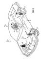
- FIG. 1is an illustration of an automobile using shock absorbers incorporating the frequency dependent damping device in accordance with the present disclosure
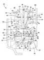
- FIG. 2is a cross-sectional side view of a monotube shock absorber incorporating either one the frequency dependent damping devices in accordance with the present disclosure
- FIG. 3is an enlarged cross-sectional side view illustrating a piston assembly of the shock absorber shown in FIG. 2 during incorporating a frequency dependent damping device which functions during a compression stroke of the shock absorber;
- FIG. 4is an enlarged cross-sectional side view illustrating a piston assembly of the shock absorber shown in FIG. 2 during incorporating a frequency dependent device which functions during an extension stroke of the shock absorber;
- FIG. 5is an enlarged cross-sectional side view illustrating a frequency dependent device in accordance with another embodiment of the present disclosure which functions during an extension stroke of the shock absorber;
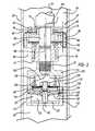
- FIG. 6is a high level cross-sectional side view illustrating a frequency dependent valve system incorporated in a base valve assembly of a dual tube shock absorber, and with a spool valve in a position which allows a flow of fluid through the spool valve during a high frequency movement of the shock absorber during a compression stroke of a rod mounted piston assembly, and which provides for a lesser degree of damping;
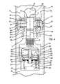
- FIG. 7is a view of the shock absorber of FIG. 6 but with the spool valve having been axially displaced by a sufficient buildup of fluid pressure on an upper surface of the spool valve during a low frequency movement of the shock absorber during a compression stroke, which effectively substantially reduces or completely interrupts a flow of the working fluid through the spool valve, which provides for an increased degree of damping.
- FIG. 1a vehicle incorporating a suspension system having the frequency dependent shock absorbers in accordance with the present disclosure which is designated generally by the reference numeral 10 .
- Vehicle 10includes a rear suspension 12 , a front suspension 14 and a body 16 .
- Rear suspension 12has a transversely extending rear axle assembly (not shown) adapted to operatively support the vehicle's rear wheels 18 .
- the rear axle assemblyis operatively connected to body 16 by means of a pair of shock absorbers 20 and a pair of helical coil springs 22 .
- front suspension 14includes a transversely extending front axle assembly (not shown) to operatively support the vehicle's front wheels 24 .
- the front axle assemblyis operatively connected to body 16 by means of a second pair of shock absorbers 26 and by a pair of helical coil springs 28 .
- Shock absorbers 20 and 26serve to dampen the relative motion of the unsprung portion (i.e. front and rear suspensions 12 and 14 , respectively) and the sprung portion (i.e. body 16 ) of vehicle 10 .
- vehicle 10has been depicted as a passenger car having front and rear axle assemblies, shock absorbers 20 and 26 may be used with other types of vehicles or in other types of applications such as vehicles incorporating independent front and/or independent rear suspension systems.
- shock absorberas used herein is meant to refer to dampers in general and thus will include MacPherson struts.
- shock absorber 20is shown in greater detail. While FIG. 2 shows only shock absorber 20 , it is to be understood that shock absorber 26 also includes the piston assembly described below for shock absorber 20 . Shock absorber 26 only differs from shock absorber 20 in the way in which it is adapted to be connected to the sprung and unsprung portions of vehicle 10 . Shock absorber 20 comprises a pressure tube 30 , a piston assembly 32 and a piston rod 34 .
- Pressure tube 30defines a fluid chamber 42 .
- Piston assembly 32is slidably disposed within pressure tube 30 and divides fluid chamber 42 into an upper working chamber 44 and a lower working chamber 46 .
- a seal 48is disposed between piston assembly 32 and pressure tube 30 to permit sliding movement of piston assembly 32 with respect to pressure tube 30 without generating undue frictional forces as well as sealing upper working chamber 44 from lower working chamber 46 .
- Piston rod 34is attached to piston assembly 32 and extends through upper working chamber 44 and through an upper end cap 50 which closes the upper end of pressure tube 30 .
- a sealing system 52seals the interface between upper end cap 50 and piston rod 34 .
- the end of piston rod 34 opposite to piston assembly 32is adapted to be secured to the sprung portion of vehicle 10 .
- piston rod 34is secured to body 16 or the sprung portion of vehicle 10 .
- Pressure tube 30is filled with fluid and it includes a fitting 54 for attachment to the unsprung portion of the vehicle.
- fitting 54is secured to the unsprung portion of the vehicle.
- Valving within piston assembly 32controls the movement of fluid between upper working chamber 44 and lower working chamber 46 during movement of piston assembly 32 within pressure tube 30 .
- piston assembly 32is attached to piston rod 34 and comprises a piston body 60 , a compression valve assembly 62 , an extension or rebound valve assembly 64 and a frequency dependent valve assembly 66 illustrated in FIG. 3 or a frequency dependent valve assembly 266 illustrated in FIG. 4 .
- Piston rod 34includes a reduced diameter section 68 located on the end of piston rod 34 disposed within pressure tube 30 to form a shoulder 70 for mounting the remaining components of piston assembly 32 .
- Piston body 60is located on reduced diameter section 68 with compression valve assembly 62 being located between piston body 60 and shoulder 70 and with rebound valve assembly 64 being located between piston body 60 and a threaded end 72 of piston rod 34 .
- a retaining nut 74is threadingly or slidingly received on threaded end 72 or reduced diameter section 68 of piston rod 34 to secure piston body 60 , compression valve assembly 62 and extension or rebound valve assembly 64 to piston rod 34 .
- Piston body 60defines a plurality of compression flow passages 76 and a plurality of rebound flow passages 78 .
- Compression valve assembly 62comprises a compression valve plate 80 , a valve stop 82 and a spring 84 .
- Valve plate 80is disposed adjacent to piston body 60 to cover the plurality of compression flow passages 76 .
- Valve stop 82is disposed adjacent shoulder 70 and spring 84 is disposed between valve plate 80 and valve stop 82 to bias valve plate 80 against piston body 60 .
- fluid pressurebuilds up in lower working chamber 46 until the fluid pressure applied to valve plate 80 through compression flow passages 76 overcomes the load provided by spring 84 .
- Valve plate 80will move away from piston body 60 and compress spring 84 to open compression flow passages 76 to allow fluid to flow from lower working chamber 46 to upper working chamber 44 as shown by arrows 86 in FIG. 3 .
- Rebound valve assembly 64comprises one or more valve plates 88 , a spring seat 90 and a spring 92 .
- Valve plates 88are disposed adjacent to piston body 60 to cover the plurality of rebound flow passages 78 .
- Spring seat 90is disposed immediately adjacent valve plates 88 .
- Spring 92is disposed between spring seat 90 and retaining nut 74 to bias spring seat 90 against valve plates 88 and valve plates 88 against piston body 60 .
- Retaining nut 74is threaded onto threaded end 72 of piston rod 34 to retain valve plates 88 against piston body 60 to close rebound flow passages 78 using spring 92 and spring seat 90 .
- valve plates 88will move away from piston body 60 and compress spring 92 to open rebound flow passages 78 to allow fluid to flow from upper working chamber 44 to lower working chamber 46 as shown by arrows 94 in FIG. 4 .
- Frequency dependent valve assembly 66provides frequency dependent damping in compression only.
- FIG. 4illustrates a frequency dependent valve assembly 266 for shock absorber 20 which provides frequency dependent damping in rebound (extension) only.
- Frequency dependent valve assembly 66includes a housing assembly 110 and a spool valve assembly 112 .
- Housing assembly 110includes an upper housing 114 and a lower housing 116 .
- Upper housing 114is threadingly or otherwise attached to the end of piston rod 34 .
- Lower housing 116is threadingly or otherwise attached to upper housing 114 .
- Spool valve assembly 112includes a spool valve 120 , a check valve 122 , an interface 124 and a plurality of valve discs 126 forming a bypass valve assembly, a retaining nut 128 , a spring seat 130 and a spring 132 .
- Spool valve 120is disposed within a fluid cavity 134 defined by housing assembly 110 .
- Check valve 122includes a valve seat 136 and a valve plate 138 .
- Spool valve 120is slidably disposed within both valve seat 136 and housing assembly 110 .
- Interface 124is disposed against spool valve 120 .
- the plurality of valve discs 126are disposed against interface 124 .
- Retaining nut 128is threadingly or otherwise received on interface 124 to retain the plurality of valve discs 126 on interface 124 .
- Spring seat 130is disposed against the plurality of valve discs 126 and spring 132 is disposed between housing assembly 110 and spring seat 130 to bias spring seat 130 against the plurality of valve discs 126 and the plurality of valve discs 126 against interface 124 .
- FIG. 3illustrates fluid flow during a compression stroke of shock absorber 20 .
- Compression valve assembly 62is a passive valve assembly with a firm damping characteristic.
- Flow path 200extends from lower working chamber 46 through an axial passage 140 in spool valve 120 into a bypass chamber 144 defined by interface 124 and the plurality of valve discs 126 .
- Flow path 200proceeds around the plurality of valve discs 126 into an axial fluid passage 146 and a radial passage 148 both extending through piston rod 34 .
- spool valve 120moves only a small distance.
- Arrow 200depicts the flow of fluid out of fluid cavity 134 during movement of spool valve 120 during a compression stroke. Fluid flows from fluid cavity 134 through a tunable orifice 150 in valve seat 136 and into axial passage 146 which leads to radial passage 148 which leads to upper working chamber 44 .
- Check valve 122remains closed during this movement of spool valve 120 during a compression stroke and opens to allow for the return of fluid into fluid cavity 134 from upper working chamber 44 through radial passage 148 and through axial passage 146 during a rebound stroke.
- Frequency dependent valve assembly 266provides frequency dependent damping in rebound only.
- Frequency dependent valve assembly 266includes a housing assembly 310 and a spool valve assembly 312 .
- Housing assembly 310includes an upper housing 314 and a lower housing 316 .
- Upper housing 314is threadingly or otherwise attached to the end of piston rod 34 .
- Lower housing 316is threadingly or otherwise attached to upper housing 314 .
- Spool valve assembly 312includes a spool valve 320 , a check valve 322 , an interface 324 and a plurality of valve discs 326 forming a bypass valve assembly, a retaining nut 328 , a spring seat 330 and a spring 332 .
- Spool valve 320is disposed within a fluid cavity 334 defined by housing assembly 310 .
- Check valve 322includes a valve seat 336 and a valve plate 338 .
- Spool valve 320is slidably disposed within both valve seat 336 and housing assembly 310 .
- Valve seat 336is fixedly attached to upper housing 314 by lower housing 316 .
- Interface 324is disposed against spool valve 320 .
- the plurality of valve discs 326are disposed against interface 324 .
- Retaining nut 328is threadingly or otherwise received on interface 324 to retain the plurality of valve discs 326 on interface 324 .
- Spring seat 330is disposed against the plurality of valve discs 326 and spring 332 is disposed between housing assembly 310 and spring seat 330 to bias spring seat 330 against the plurality of valve discs 326 and the plurality of valve discs 326 against interface 324 .
- FIG. 4illustrates fluid flow during a rebound stroke of shock absorber 20 .
- Rebound valve assembly 64is a passive valve assembly with a firm damping characteristic.
- Flow path 300extends from upper working chamber 44 through radial passageway 148 and axial passageway 146 both extending through piston rod 34 , through an axial passage 340 in spool valve 320 into a bypass chamber 344 defined by interface 324 and the plurality of valve discs 326 .
- Flow path 300proceeds around the plurality of valve discs 326 and through an aperture in lower housing 316 into lower working chamber 46 .
- spool valve 320moves only a small distance.
- the preload created by spring 332is low and the fluid pressure in bypass chamber 344 will easily deflect the plurality of valve discs 326 to create the flow illustrated by arrow 300 which flows through the aperture extending through lower housing 316 .
- spool valve 320is able to move a significant distance. This larger movement will move interface 324 , the plurality of valve discs 326 and spring seat 330 . This larger movement will compress spring 332 which increases the preload generated by spring 332 and the fluid pressure required to separate the plurality of valve discs 326 from interface 324 .
- Frequency dependent valve assembly 366is shown in accordance with another embodiment of the present invention.
- Frequency dependent valve assembly 366is a direct replacement for dependent valve assembly 266 as illustrated in FIG. 5 .
- Frequency dependent valve assembly 366provides frequency dependent damping in rebound/extension only.
- Frequency dependent valve assembly 366includes a housing assembly 410 and a spool valve assembly 412 .
- Housing assembly 410includes an upper housing 414 and a lower housing 416 .
- Upper housing 414is threadingly or otherwise attached to the end of piston rod 34 .
- Lower housing 416is threadingly or otherwise attached to upper housing 414 .
- Spool valve assembly 412includes a spool valve 420 , a check valve 422 , an interface 424 , a valve body 426 , one or more shim discs 428 and a spring 432 .
- Spool valve 420is disposed within a fluid cavity 434 defined by housing assembly 410 .
- Check valve 422includes a valve seat 436 and a valve plate 438 .
- Spool valve 420is slidably disposed within both valve seat 436 and housing assembly 410 .
- Valve seat 436is fixedly attached to upper housing 414 .
- Interface 424is disposed against spool valve 420 .
- Valve seat 436is disposed against interface 424 .
- Spring 432is disposed between lower housing 416 and valve body 426 to bias valve body 426 against interface 424 .
- the one or more shim discscontrol the biasing load for spring 432 .
- Interface 424 , valve body 426 and spring 432form a bypass valve assembly.
- FIG. 5illustrates fluid flow during a rebound stroke of shock absorber 20 .
- Rebound valve assembly 64is a passive valve assembly with a firm damping characteristic.
- Flow path 500extends from upper working chamber 44 through radial passageway 148 and axial passage 146 both extending through piston rod 34 , through an axial passage 440 in spool valve 420 into a bypass chamber 444 defined by interface 424 and valve body 426 .
- Flow path 500proceeds around valve body 426 and through at least one aperture in lower housing 416 into lower working chamber 46 .
- spool valve 420moves only a small distance.
- a shock absorber 600 having a base valve assembly 602 incorporating a compression valve assembly 604 and a frequency dependent valve system 606is shown.
- the shock absorber 600 in this exampleis a dual tube shock absorber having a reservoir chamber 600 a formed between a pressure tube 600 b and a reserve tube 600 c , as is well known in the art.
- the base valve assembly 602controls the flow of a working fluid between the reservoir 600 a and a working chamber of the shock absorber 600 as is also well known in the art.
- the compression valve assembly 604may have a cylinder end member 608 , a compression valve disc stack 610 , an upper valve pin 612 and a washer 614 secured to a neck 616 of the upper valve pin 612 .
- the upper valve pin 612has a bore 612 a extending through its full axial length.
- the upper valve pin 612also includes an enlarged head portion 618 that captures a biasing spring 620 and holds the biasing spring against an intake disc 622 , to thus hold the intake disc 622 against a plurality of lands 624 on a first side of the cylinder end member 608 .
- On a second side of the cylinder end member 608 the compression valve disc stack 610is held against a plurality of lands 626 by the washer 614 .
- the washer 614is held in position on the upper valve pin 612 by a nut 628 which applies a predetermined torque to the compression valve disc stack 610 .
- Lands 624 on the first side of the cylinder end member 608are aligned with rebound flow channels 630 in the cylinder end member 608 while lands 626 are aligned with compression flow channels 632 extending through the cylinder end member 608 .
- the frequency dependent valve system 606includes a valve connection member 634 which is secured to the cylinder end member 608 in any suitable manner, for example, by using a press fit or a threaded connection.
- the valve connection member 634has at least one, but more preferably a plurality, of circumferentially spaced apart holes 634 a which communicate with the reservoir chamber 600 a .
- An O-ring 636 positioned adjacent a distal end 612 b of the upper valve pin 612provides a seal between the upper valve pin and a bore 638 extending axially through the valve connection member 634 .
- the valve connection member 634further includes a cavity 640 in which is disposed an annular end stop member 642 , a spool valve 644 , an O-ring 646 , a check valve disc 648 , a valve body 650 having a bypass bore 650 a , and one or more shim discs 652 .
- the spool valve 644has an axial flow passage 654 extending through its full axial length which is aligned with a bore 656 in a valve seat plate 658 .
- the valve seat plate 658is sandwiched between a distal end of a neck portion 644 a of the spool valve 644 and an interface member 660 .
- the interface member 660includes an annular land 662 which contacts a generally planar surface of the valve seat plate 658 .
- a lower valve pin 664 having a radially offset bore 666is seated within a lower housing member 668 .
- the lower valve pin 664includes an axially formed boss 670 upon which a disc package 672 is mounted.
- Disc package 672contacts a lower outer peripheral surface of the interface member 660 and acts as a biasing element (i.e., spring) to preload the interface member 660 , and thus maintain the interface member 660 in contact with valve seat plate 658 .
- the lower housing member 668has a neck portion 674 which is secured within the cavity 640 such as by, for example, a press fit, a threaded connection, or by any other suitable connection arrangement.
- the frequency dependent valve system 606further includes a first or “upper” chamber 676 which is formed between an upper surface 644 a of the spool valve 644 a lower radially inward portion 678 of the valve connection member 634 , and a portion of the distal end 612 b of the upper valve pin 612 .
- a second or “lower” chamber 680is formed between an upper surface 650 b of the valve body 650 and a lower surface 644 b of the spool valve 644 .
- the base valve assembly 602is shown with arrows 682 and 684 denoting the flows of working fluid during a compression stroke of the piston (not shown) within the lower working chamber of the shock absorber 600 .
- the flow designated by arrow 686occurs only when the working fluid is being forced out from the second (lower) chamber 680 , as will be described in greater detail below.
- the lower working chamber within the pressure tube 600 bis the area denoted by reference number 688 in FIG. 7 and is that area within the interior of the pressure tube 600 b below the rod mounted piston, and above the base valve assembly 602 .
- a flow of working fluid 682flows through the compression flow path channels 632 in the cylinder end member 608 , through compression disc stack 610 , through the holes 634 a in the valve connection member 634 and into the reservoir chamber 600 a.
- a portion of the working fluid in the lower working chamber 688also flows through the bore 612 a in the upper valve pin 612 , through the annular end stop member 642 , through the bore 654 in the spool valve 644 , through the bore 656 in the valve seat plate 658 , around the perimeter of the interface member 660 , through the radially offset bore 666 in the lower valve pin 664 and into the reservoir chamber 600 a .
- the spool valve 644moves only a very slight distance.
- the pressure applied by the spool valve 644 on the interface member 660is therefore at a minimum predetermined force which allows the pressure behind the fluid flow 684 to easily displace the interface member 660 , against the biasing force from disc package 672 , from the valve seat plate 658 .
- Thisallows the fluid flow 684 to flow between the interface member 660 and the valve seat plate 658 , around the periphery of the interface member 660 and through the radially offset bore 666 in the lower valve pin 664 .
- the fluid flow 682will be as described above for the short duration movement.
- the longer duration of the shock absorber movementprovides sufficient time to displace the working fluid from the second (lower) chamber 680 , which causes a greater movement of the spool valve 644 downwardly against the biasing force from the disc package 672 , as shown in the drawing of FIG. 7 .
- the fluid in the second chamber 680is forced through the bypass bore 650 a , around the perimeter of the valve seat plate 658 , past the perimeter of the interface member 660 and through the radially offset bore 666 into the reservoir chamber 600 a , as indicated by the fluid flow 686 .
- the fluid pressure which has built up in the upper (i.e., first) chamber 676forces the spool valve 644 axially downwardly in the drawing of FIG. 7 against the biasing force of the disc package 672 , which significantly increases the biasing pressure applied by the spool valve 644 on the valve seat plate 658 .
- the fluid flowing through the bore 654 of the spool valve 644has insufficient pressure to displace the interface member 660 from the valve seat plate 658 . This completely interrupts, or at least substantially reduces, the flow of working fluid through the spool valve 644 bore 654 and through the bypass bore 666 , thus substantially or completely closing the frequency dependent valve system 606 .
- the damping provided during this condition of low frequency shock absorber motionwill be a maximum degree of damping. This provides the vehicle that the shock absorber 600 is being used on with a firm ride quality during low frequency compression movements of the shock absorber.
- the base valve assembly 602with its frequency dependent valve system 606 described herein, may be implemented in a shock absorber which also includes a frequency dependent valve assembly integrated into the piston assembly. Thus, frequency dependent damping may be utilized in both the rebound and compression strokes of the piston assembly of the shock absorber.
Landscapes
- Engineering & Computer Science (AREA)
- General Engineering & Computer Science (AREA)
- Mechanical Engineering (AREA)
- Physics & Mathematics (AREA)
- Fluid Mechanics (AREA)
- Fluid-Damping Devices (AREA)
Abstract
Description
Claims (17)
Priority Applications (1)
| Application Number | Priority Date | Filing Date | Title |
|---|---|---|---|
| US14/878,397US9638280B2 (en) | 2013-08-26 | 2015-10-08 | Shock absorber with frequency dependent passive valve |
Applications Claiming Priority (2)
| Application Number | Priority Date | Filing Date | Title |
|---|---|---|---|
| US13/975,454US9239092B2 (en) | 2013-08-26 | 2013-08-26 | Shock absorber with frequency dependent passive valve |
| US14/878,397US9638280B2 (en) | 2013-08-26 | 2015-10-08 | Shock absorber with frequency dependent passive valve |
Related Parent Applications (1)
| Application Number | Title | Priority Date | Filing Date |
|---|---|---|---|
| US13/975,454Continuation-In-PartUS9239092B2 (en) | 2013-08-26 | 2013-08-26 | Shock absorber with frequency dependent passive valve |
Publications (2)
| Publication Number | Publication Date |
|---|---|
| US20160025181A1 US20160025181A1 (en) | 2016-01-28 |
| US9638280B2true US9638280B2 (en) | 2017-05-02 |
Family
ID=55166393
Family Applications (1)
| Application Number | Title | Priority Date | Filing Date |
|---|---|---|---|
| US14/878,397ActiveUS9638280B2 (en) | 2013-08-26 | 2015-10-08 | Shock absorber with frequency dependent passive valve |
Country Status (1)
| Country | Link |
|---|---|
| US (1) | US9638280B2 (en) |
Cited By (4)
| Publication number | Priority date | Publication date | Assignee | Title |
|---|---|---|---|---|
| US20180156301A1 (en)* | 2015-04-24 | 2018-06-07 | Koni B.V. | Frequency selective damper valve, and shock absorber comprising such damper valve |
| US10865597B2 (en)* | 2017-11-06 | 2020-12-15 | King Slide Works Co., Ltd. | Furniture part and damping device thereof |
| US20220260129A1 (en)* | 2021-02-15 | 2022-08-18 | DRiV Automotive Inc. | Open bleed - base valve |
| US20230035676A1 (en)* | 2021-07-29 | 2023-02-02 | Rüdiger Kranz | Hydraulic Shock Absorber |
Families Citing this family (10)
| Publication number | Priority date | Publication date | Assignee | Title |
|---|---|---|---|---|
| JP6108550B2 (en)* | 2013-09-19 | 2017-04-05 | Kyb株式会社 | Shock absorber |
| US11047447B2 (en) | 2014-02-10 | 2021-06-29 | Fox Factory, Inc. | Valve assembly |
| DE102016208845A1 (en)* | 2016-05-23 | 2017-11-23 | Thyssenkrupp Ag | Frequency-selective vibration damper for motor vehicles with a bypass control valve |
| DE102016210950A1 (en) | 2016-06-20 | 2016-11-24 | Zf Friedrichshafen Ag | Frequency-selective bottom valve arrangement |
| DE102016212487A1 (en)* | 2016-07-08 | 2017-08-31 | Zf Friedrichshafen Ag | Hydraulic shock absorber |
| US10563721B2 (en) | 2017-04-24 | 2020-02-18 | Beijingwest Industries Co., Ltd | Hydraulic damper having a high frequency valve assembly |
| US11236799B2 (en)* | 2019-08-14 | 2022-02-01 | Tenneco Automotive Operating Company Inc. | Valve assembly for a damper |
| US11137076B1 (en)* | 2020-05-20 | 2021-10-05 | Borgwarner, Inc. | Spool valve plug |
| KR102772076B1 (en)* | 2020-10-09 | 2025-02-21 | 히다치 아스테모 가부시키가이샤 | buffer |
| DE102024200236A1 (en)* | 2024-01-11 | 2025-07-17 | Zf Friedrichshafen Ag | Bottom valve for a telescopic damper and telescopic damper |
Citations (57)
| Publication number | Priority date | Publication date | Assignee | Title |
|---|---|---|---|---|
| US1268452A (en) | 1913-09-19 | 1918-06-04 | Watson E Goodyear | Shock-absorber. |
| US2640564A (en)* | 1947-03-26 | 1953-06-02 | Cloudsley John Leslie | Fluid pressure relieving apparatus |
| FR1064843A (en) | 1953-09-15 | 1954-05-18 | Thermostatic telescopic hydraulic shock absorbers for suspensions | |
| US2911072A (en) | 1954-08-03 | 1959-11-03 | Gen Motors Corp | Hydraulic shock absorber |
| US3570635A (en) | 1967-12-11 | 1971-03-16 | Tatsuya Takagi | Oil-type vibration damper |
| JPS5680541A (en)* | 1979-12-07 | 1981-07-01 | Honda Motor Co Ltd | Shock absorber for vehicles |
| JPS5865340A (en)* | 1981-10-15 | 1983-04-19 | Kayaba Ind Co Ltd | Oil hydraulic shock absorber |
| US4442926A (en) | 1980-06-06 | 1984-04-17 | Tokiko Kabushiki Kaisha | Simplified hydraulic damper |
| US4453638A (en) | 1982-09-27 | 1984-06-12 | Wallace Christopher D | Hydraulic shock absorber |
| US4515252A (en) | 1982-05-31 | 1985-05-07 | Nissan Motor Company, Limited | Piston stroke responsive vortex-flow shock absorber |
| JPS60129443A (en)* | 1983-12-14 | 1985-07-10 | Showa Mfg Co Ltd | Hydraulic bumper for vehicle |
| JPS6383424A (en)* | 1986-09-26 | 1988-04-14 | Atsugi Motor Parts Co Ltd | Variable damping force hydraulic shock absorber |
| US4953671A (en) | 1988-08-12 | 1990-09-04 | Tokico Ltd. | Damping force adjustable hydraulic shock absorber |
| US5018608A (en) | 1989-05-19 | 1991-05-28 | Tokico Ltd. | Hydraulic shock absorber |
| JPH03129137A (en) | 1989-10-12 | 1991-06-03 | Atsugi Unisia Corp | Variable damping force hydraulic shock absorber |
| US5129488A (en) | 1989-11-16 | 1992-07-14 | Atsugi Unisia Corporation | Vibration mode responsive variable damping force shock absorber with feature of automatic selection of damping mode depending upon vibration mode of vehicular body |
| US5139119A (en) | 1988-08-13 | 1992-08-18 | Robert Bosch Gmbh | Apparatus for damping resilient vehicle wheel suspension systems |
| JPH05141468A (en)* | 1991-11-20 | 1993-06-08 | Tokico Ltd | Damping force adjustable hydraulic shock absorber |
| US5248014A (en) | 1990-10-19 | 1993-09-28 | Tokico Ltd. | Hydraulic shock absorber |
| US5261448A (en) | 1989-11-16 | 1993-11-16 | Atsugi Unisia Corp. | Vibration mode responsive variable damping force shock absorber with feature of automatic selection of damping mode depending upon vibration mode of vehicular body |
| DE4327358A1 (en) | 1993-04-08 | 1994-10-13 | Fichtel & Sachs Ag | Oscillation damper acting selectively with respect to frequency |
| US5386892A (en) | 1992-09-18 | 1995-02-07 | Tokico, Ltd. | Hydraulic shock absorber with shutters |
| US5423402A (en) | 1988-04-06 | 1995-06-13 | Koni, B.V. | Twin-pipe shock absorber |
| JPH07174183A (en) | 1993-12-17 | 1995-07-11 | Kayaba Ind Co Ltd | Hydraulic shock absorber |
| JPH07217696A (en) | 1994-01-31 | 1995-08-15 | Kayaba Ind Co Ltd | Hydraulic shock absorber |
| JPH08135715A (en) | 1994-09-12 | 1996-05-31 | Kayaba Ind Co Ltd | Hydraulic shock absorber |
| US6264015B1 (en) | 1996-02-22 | 2001-07-24 | Koni B. V. | Continuously variable single-tube shock absorber with bidirectional control valve |
| US6290035B1 (en) | 1998-03-19 | 2001-09-18 | Tenneco Automotive Inc. | Acceleration sensitive damping for automotive dampers |
| US6334516B1 (en) | 2000-04-27 | 2002-01-01 | Edelbrock | Acceleration sensitive twin tube shock absorber |
| US6450304B1 (en) | 2001-02-12 | 2002-09-17 | Delphi Technologies, Inc. | Piston and rod assembly for air-actuated variable damping |
| US6474454B2 (en) | 2000-05-31 | 2002-11-05 | Tokico Ltd. | Damping force control type hydraulic shock absorber |
| US6668986B2 (en) | 2002-01-08 | 2003-12-30 | Delphi Technologies, Inc. | Active hydraulic fluid vehicular suspension damper |
| US20040200946A1 (en) | 2003-04-12 | 2004-10-14 | Zf Sachs Ag | Vibration damper with amplitude-selective damping force |
| US20050045440A1 (en) | 2001-11-06 | 2005-03-03 | Kock Paul De | Shock absorber with frequency-dependent damping |
| US20060283675A1 (en) | 2005-06-06 | 2006-12-21 | Takashi Teraoka | Shock absorber |
| EP1906046A1 (en)* | 2006-09-28 | 2008-04-02 | Kayaba Industry Co., Ltd. | Base valve mechanism for shock absorber |
| US7699148B2 (en) | 2003-12-01 | 2010-04-20 | Zf Friedrichshafen Ag | Damping valve assembly with a progressive damping force characteristic |
| JP2011007213A (en) | 2009-06-23 | 2011-01-13 | Kyb Co Ltd | Buffer |
| WO2011120119A1 (en) | 2010-04-01 | 2011-10-06 | Magneti Marelli Cofap Companhia Fabricadora De Peças | Extension control valve for hydraulic damper |
| JP2012067880A (en) | 2010-09-24 | 2012-04-05 | Showa Corp | Frequency response type hydraulic damper |
| US20120160624A1 (en) | 2010-12-28 | 2012-06-28 | Yohei Katayama | Shock absorber |
| US20120160620A1 (en) | 2010-12-28 | 2012-06-28 | Mikio Yamashita | Damping force control type shock absorber |
| US20120217106A1 (en) | 2011-02-25 | 2012-08-30 | O'flynn Damian | Hydraulic damper spool valve |
| US20130048451A1 (en) | 2011-08-31 | 2013-02-28 | Mikio Yamashita | Shock absorber |
| US20130056317A1 (en) | 2011-09-02 | 2013-03-07 | Tae Ju Kim | Frequency/pressure sensitive shock absorber |
| WO2013051934A1 (en) | 2011-10-04 | 2013-04-11 | Koni B.V. | Fluid-filled, frequency-dependent damper |
| US20130140117A1 (en) | 2011-05-31 | 2013-06-06 | Chun Sung YU | Valve structure of shock absorber |
| JP5302639B2 (en) | 2008-11-21 | 2013-10-02 | 三菱重工業株式会社 | Servo control device |
| US20140048366A1 (en) | 2012-08-14 | 2014-02-20 | Mando Corporation | Piston valve of shock absorber |
| US20140048365A1 (en) | 2012-08-14 | 2014-02-20 | Mando Corporation | Valve assembly of shock absorber |
| WO2014104876A1 (en) | 2012-12-21 | 2014-07-03 | Koni B.V. | Shock absorber |
| US20150047936A1 (en) | 2012-03-27 | 2015-02-19 | Beijing West Industries Co., Ltd. | Amplitude sensitive hydraulic damper |
| US20150053518A1 (en) | 2013-08-26 | 2015-02-26 | Tenneco Automotive Operating Company Inc. | Shock absorber with frequency dependent passive valve |
| US8967344B2 (en) | 2011-07-21 | 2015-03-03 | Mando Corporation | Valve structure of shock absorber |
| US9080634B2 (en) | 2013-07-25 | 2015-07-14 | Tenneco Automotive Operating Company Inc. | Shock absorber with frequency dependent passive valve |
| US20150247546A1 (en) | 2014-02-28 | 2015-09-03 | Tenneco Automotive Operating Company Inc. | Shock absorber with frequency dependent passive valve |
| US20160047432A1 (en)* | 2014-08-14 | 2016-02-18 | Tenneco Automotive Operating Company Inc. | Shock absorber with frequency dependent passive valve |
- 2015
- 2015-10-08USUS14/878,397patent/US9638280B2/enactiveActive
Patent Citations (63)
| Publication number | Priority date | Publication date | Assignee | Title |
|---|---|---|---|---|
| US1268452A (en) | 1913-09-19 | 1918-06-04 | Watson E Goodyear | Shock-absorber. |
| US2640564A (en)* | 1947-03-26 | 1953-06-02 | Cloudsley John Leslie | Fluid pressure relieving apparatus |
| FR1064843A (en) | 1953-09-15 | 1954-05-18 | Thermostatic telescopic hydraulic shock absorbers for suspensions | |
| US2911072A (en) | 1954-08-03 | 1959-11-03 | Gen Motors Corp | Hydraulic shock absorber |
| US3570635A (en) | 1967-12-11 | 1971-03-16 | Tatsuya Takagi | Oil-type vibration damper |
| JPS5680541A (en)* | 1979-12-07 | 1981-07-01 | Honda Motor Co Ltd | Shock absorber for vehicles |
| US4442926A (en) | 1980-06-06 | 1984-04-17 | Tokiko Kabushiki Kaisha | Simplified hydraulic damper |
| JPS5865340A (en)* | 1981-10-15 | 1983-04-19 | Kayaba Ind Co Ltd | Oil hydraulic shock absorber |
| US4515252A (en) | 1982-05-31 | 1985-05-07 | Nissan Motor Company, Limited | Piston stroke responsive vortex-flow shock absorber |
| US4453638A (en) | 1982-09-27 | 1984-06-12 | Wallace Christopher D | Hydraulic shock absorber |
| JPS60129443A (en)* | 1983-12-14 | 1985-07-10 | Showa Mfg Co Ltd | Hydraulic bumper for vehicle |
| JPS6383424A (en)* | 1986-09-26 | 1988-04-14 | Atsugi Motor Parts Co Ltd | Variable damping force hydraulic shock absorber |
| US5423402A (en) | 1988-04-06 | 1995-06-13 | Koni, B.V. | Twin-pipe shock absorber |
| US5467852A (en) | 1988-04-06 | 1995-11-21 | Koni, B.V. | Twin-pipe shock absorber |
| US4953671A (en) | 1988-08-12 | 1990-09-04 | Tokico Ltd. | Damping force adjustable hydraulic shock absorber |
| US5139119A (en) | 1988-08-13 | 1992-08-18 | Robert Bosch Gmbh | Apparatus for damping resilient vehicle wheel suspension systems |
| US5018608A (en) | 1989-05-19 | 1991-05-28 | Tokico Ltd. | Hydraulic shock absorber |
| JPH03129137A (en) | 1989-10-12 | 1991-06-03 | Atsugi Unisia Corp | Variable damping force hydraulic shock absorber |
| US5261448A (en) | 1989-11-16 | 1993-11-16 | Atsugi Unisia Corp. | Vibration mode responsive variable damping force shock absorber with feature of automatic selection of damping mode depending upon vibration mode of vehicular body |
| US5129488A (en) | 1989-11-16 | 1992-07-14 | Atsugi Unisia Corporation | Vibration mode responsive variable damping force shock absorber with feature of automatic selection of damping mode depending upon vibration mode of vehicular body |
| US5248014A (en) | 1990-10-19 | 1993-09-28 | Tokico Ltd. | Hydraulic shock absorber |
| JPH05141468A (en)* | 1991-11-20 | 1993-06-08 | Tokico Ltd | Damping force adjustable hydraulic shock absorber |
| US5386892A (en) | 1992-09-18 | 1995-02-07 | Tokico, Ltd. | Hydraulic shock absorber with shutters |
| DE4327358A1 (en) | 1993-04-08 | 1994-10-13 | Fichtel & Sachs Ag | Oscillation damper acting selectively with respect to frequency |
| JPH07174183A (en) | 1993-12-17 | 1995-07-11 | Kayaba Ind Co Ltd | Hydraulic shock absorber |
| JPH07217696A (en) | 1994-01-31 | 1995-08-15 | Kayaba Ind Co Ltd | Hydraulic shock absorber |
| JPH08135715A (en) | 1994-09-12 | 1996-05-31 | Kayaba Ind Co Ltd | Hydraulic shock absorber |
| US6264015B1 (en) | 1996-02-22 | 2001-07-24 | Koni B. V. | Continuously variable single-tube shock absorber with bidirectional control valve |
| US6290035B1 (en) | 1998-03-19 | 2001-09-18 | Tenneco Automotive Inc. | Acceleration sensitive damping for automotive dampers |
| US6334516B1 (en) | 2000-04-27 | 2002-01-01 | Edelbrock | Acceleration sensitive twin tube shock absorber |
| US6474454B2 (en) | 2000-05-31 | 2002-11-05 | Tokico Ltd. | Damping force control type hydraulic shock absorber |
| US6450304B1 (en) | 2001-02-12 | 2002-09-17 | Delphi Technologies, Inc. | Piston and rod assembly for air-actuated variable damping |
| US7395907B2 (en) | 2001-11-06 | 2008-07-08 | Koni B.V. | Shock absorber with frequency-dependent damping |
| US20050045440A1 (en) | 2001-11-06 | 2005-03-03 | Kock Paul De | Shock absorber with frequency-dependent damping |
| EP1442227B1 (en) | 2001-11-06 | 2006-04-12 | Koni B.V. | Shock absorber with frequency-dependent damping |
| DE60210652T2 (en) | 2001-11-06 | 2006-08-24 | Koni B.V. | SHOCK ABSORBER WITH FREQUENCY DEPENDENT CUSHIONING |
| US6668986B2 (en) | 2002-01-08 | 2003-12-30 | Delphi Technologies, Inc. | Active hydraulic fluid vehicular suspension damper |
| US20040200946A1 (en) | 2003-04-12 | 2004-10-14 | Zf Sachs Ag | Vibration damper with amplitude-selective damping force |
| US7699148B2 (en) | 2003-12-01 | 2010-04-20 | Zf Friedrichshafen Ag | Damping valve assembly with a progressive damping force characteristic |
| US7958981B2 (en) | 2005-06-06 | 2011-06-14 | Kayaba Industry Co., Ltd. | Shock absorber |
| US20060283675A1 (en) | 2005-06-06 | 2006-12-21 | Takashi Teraoka | Shock absorber |
| EP1906046A1 (en)* | 2006-09-28 | 2008-04-02 | Kayaba Industry Co., Ltd. | Base valve mechanism for shock absorber |
| JP5302639B2 (en) | 2008-11-21 | 2013-10-02 | 三菱重工業株式会社 | Servo control device |
| JP2011007213A (en) | 2009-06-23 | 2011-01-13 | Kyb Co Ltd | Buffer |
| WO2011120119A1 (en) | 2010-04-01 | 2011-10-06 | Magneti Marelli Cofap Companhia Fabricadora De Peças | Extension control valve for hydraulic damper |
| JP2012067880A (en) | 2010-09-24 | 2012-04-05 | Showa Corp | Frequency response type hydraulic damper |
| US20120160624A1 (en) | 2010-12-28 | 2012-06-28 | Yohei Katayama | Shock absorber |
| US20120160620A1 (en) | 2010-12-28 | 2012-06-28 | Mikio Yamashita | Damping force control type shock absorber |
| US20120217106A1 (en) | 2011-02-25 | 2012-08-30 | O'flynn Damian | Hydraulic damper spool valve |
| US20130140117A1 (en) | 2011-05-31 | 2013-06-06 | Chun Sung YU | Valve structure of shock absorber |
| US8967344B2 (en) | 2011-07-21 | 2015-03-03 | Mando Corporation | Valve structure of shock absorber |
| US20130048451A1 (en) | 2011-08-31 | 2013-02-28 | Mikio Yamashita | Shock absorber |
| US20130056317A1 (en) | 2011-09-02 | 2013-03-07 | Tae Ju Kim | Frequency/pressure sensitive shock absorber |
| WO2013051934A1 (en) | 2011-10-04 | 2013-04-11 | Koni B.V. | Fluid-filled, frequency-dependent damper |
| US20150047936A1 (en) | 2012-03-27 | 2015-02-19 | Beijing West Industries Co., Ltd. | Amplitude sensitive hydraulic damper |
| KR20140022583A (en) | 2012-08-14 | 2014-02-25 | 주식회사 만도 | Valve assembly of shock absorber |
| US20140048365A1 (en) | 2012-08-14 | 2014-02-20 | Mando Corporation | Valve assembly of shock absorber |
| US20140048366A1 (en) | 2012-08-14 | 2014-02-20 | Mando Corporation | Piston valve of shock absorber |
| WO2014104876A1 (en) | 2012-12-21 | 2014-07-03 | Koni B.V. | Shock absorber |
| US9080634B2 (en) | 2013-07-25 | 2015-07-14 | Tenneco Automotive Operating Company Inc. | Shock absorber with frequency dependent passive valve |
| US20150053518A1 (en) | 2013-08-26 | 2015-02-26 | Tenneco Automotive Operating Company Inc. | Shock absorber with frequency dependent passive valve |
| US20150247546A1 (en) | 2014-02-28 | 2015-09-03 | Tenneco Automotive Operating Company Inc. | Shock absorber with frequency dependent passive valve |
| US20160047432A1 (en)* | 2014-08-14 | 2016-02-18 | Tenneco Automotive Operating Company Inc. | Shock absorber with frequency dependent passive valve |
Non-Patent Citations (1)
| Title |
|---|
| U.S. Appl. No. 14/459,513, filed Aug. 14, 2014, Nowaczyk et al. |
Cited By (7)
| Publication number | Priority date | Publication date | Assignee | Title |
|---|---|---|---|---|
| US20180156301A1 (en)* | 2015-04-24 | 2018-06-07 | Koni B.V. | Frequency selective damper valve, and shock absorber comprising such damper valve |
| US10670105B2 (en)* | 2015-04-24 | 2020-06-02 | Koni B.V. | Frequency selective damper valve, and shock absorber comprising such damper valve |
| US10865597B2 (en)* | 2017-11-06 | 2020-12-15 | King Slide Works Co., Ltd. | Furniture part and damping device thereof |
| US20220260129A1 (en)* | 2021-02-15 | 2022-08-18 | DRiV Automotive Inc. | Open bleed - base valve |
| US11808323B2 (en)* | 2021-02-15 | 2023-11-07 | DRiV Automotive Inc. | Open bleed-base valve |
| US20230035676A1 (en)* | 2021-07-29 | 2023-02-02 | Rüdiger Kranz | Hydraulic Shock Absorber |
| US11692605B2 (en)* | 2021-07-29 | 2023-07-04 | Rüdiger Kranz | Hydraulic shock absorber |
Also Published As
| Publication number | Publication date |
|---|---|
| US20160025181A1 (en) | 2016-01-28 |
Similar Documents
| Publication | Publication Date | Title |
|---|---|---|
| US9638280B2 (en) | Shock absorber with frequency dependent passive valve | |
| US9239092B2 (en) | Shock absorber with frequency dependent passive valve | |
| US9500255B2 (en) | Shock absorber with frequency dependent passive valve | |
| US9441700B2 (en) | Shock absorber with frequency dependent passive valve | |
| US9080634B2 (en) | Shock absorber with frequency dependent passive valve | |
| US8714320B2 (en) | Nested check high speed valve | |
| US8511447B2 (en) | Triple tube shock absorber having a shortened intermediate tube | |
| US9074651B2 (en) | Dual range damping system for a shock absorber | |
| US9222539B1 (en) | Shock absorber with frequency dependent passive valve | |
| US11236799B2 (en) | Valve assembly for a damper |
Legal Events
| Date | Code | Title | Description |
|---|---|---|---|
| AS | Assignment | Owner name:TENNECO AUTOMOTIVE OPERATING COMPANY INC., ILLINOI Free format text:ASSIGNMENT OF ASSIGNORS INTEREST;ASSIGNORS:NOWACZYK, MARK;PLAS, JELLE VAN DE;VOCHTEN, JAN;SIGNING DATES FROM 20151014 TO 20151015;REEL/FRAME:036905/0723 | |
| FEPP | Fee payment procedure | Free format text:PAYOR NUMBER ASSIGNED (ORIGINAL EVENT CODE: ASPN); ENTITY STATUS OF PATENT OWNER: LARGE ENTITY | |
| STCF | Information on status: patent grant | Free format text:PATENTED CASE | |
| AS | Assignment | Owner name:JPMORGAN CHASE BANK, N.A., AS ADMINISTRATIVE AGENT, ILLINOIS Free format text:GRANT OF SECURITY INTEREST IN PATENT RIGHTS;ASSIGNOR:TENNECO AUTOMOTIVE OPERATING COMPANY INC.;REEL/FRAME:042809/0515 Effective date:20170512 Owner name:JPMORGAN CHASE BANK, N.A., AS ADMINISTRATIVE AGENT Free format text:GRANT OF SECURITY INTEREST IN PATENT RIGHTS;ASSIGNOR:TENNECO AUTOMOTIVE OPERATING COMPANY INC.;REEL/FRAME:042809/0515 Effective date:20170512 | |
| AS | Assignment | Owner name:WILMINGTON TRUST, NATIONAL ASSOCIATION, AS COLLATERAL TRUSTEE, MINNESOTA Free format text:CONFIRMATORY GRANT OF SECURITY INTERESTS IN UNITED STATES PATENTS;ASSIGNORS:TENNECO INC.;TENNECO AUTOMOTIVE OPERATING COMPANY INC.;TENNECO INTERNATIONAL HOLDING CORP.;AND OTHERS;REEL/FRAME:047223/0001 Effective date:20181001 Owner name:WILMINGTON TRUST, NATIONAL ASSOCIATION, AS COLLATE Free format text:CONFIRMATORY GRANT OF SECURITY INTERESTS IN UNITED STATES PATENTS;ASSIGNORS:TENNECO INC.;TENNECO AUTOMOTIVE OPERATING COMPANY INC.;TENNECO INTERNATIONAL HOLDING CORP.;AND OTHERS;REEL/FRAME:047223/0001 Effective date:20181001 | |
| AS | Assignment | Owner name:TENNECO AUTOMOTIVE OPERATING COMPANY INC., ILLINOIS Free format text:RELEASE BY SECURED PARTY;ASSIGNOR:JPMORGAN CHASE BANK, N.A.;REEL/FRAME:048099/0716 Effective date:20181001 Owner name:TENNECO AUTOMOTIVE OPERATING COMPANY INC., ILLINOI Free format text:RELEASE BY SECURED PARTY;ASSIGNOR:JPMORGAN CHASE BANK, N.A.;REEL/FRAME:048099/0716 Effective date:20181001 | |
| MAFP | Maintenance fee payment | Free format text:PAYMENT OF MAINTENANCE FEE, 4TH YEAR, LARGE ENTITY (ORIGINAL EVENT CODE: M1551); ENTITY STATUS OF PATENT OWNER: LARGE ENTITY Year of fee payment:4 | |
| AS | Assignment | Owner name:WILMINGTON TRUST, NATIONAL ASSOCIATION, MINNESOTA Free format text:SECURITY AGREEMENT;ASSIGNORS:TENNECO INC.;THE PULLMAN COMPANY;FEDERAL-MOGUL IGNITION LLC;AND OTHERS;REEL/FRAME:054555/0592 Effective date:20201130 | |
| AS | Assignment | Owner name:WILMINGTON TRUST, NATIONAL ASSOCIATION, MINNESOTA Free format text:SECURITY AGREEMENT;ASSIGNORS:TENNECO INC.;TENNECO AUTOMOTIVE OPERATING COMPANY INC.;THE PULLMAN COMPANY;AND OTHERS;REEL/FRAME:055626/0065 Effective date:20210317 | |
| AS | Assignment | Owner name:FEDERAL-MOGUL PRODUCTS US LLC, MICHIGAN Free format text:RELEASE BY SECURED PARTY;ASSIGNOR:WILMINGTON TRUST, NATIONAL ASSOCIATION;REEL/FRAME:061975/0218 Effective date:20221117 Owner name:FEDERAL-MOGUL FINANCING CORPORATION, MICHIGAN Free format text:RELEASE BY SECURED PARTY;ASSIGNOR:WILMINGTON TRUST, NATIONAL ASSOCIATION;REEL/FRAME:061975/0218 Effective date:20221117 Owner name:FEDERAL-MOGUL FILTRATION LLC, MICHIGAN Free format text:RELEASE BY SECURED PARTY;ASSIGNOR:WILMINGTON TRUST, NATIONAL ASSOCIATION;REEL/FRAME:061975/0218 Effective date:20221117 Owner name:BECK ARNLEY HOLDINGS LLC, MICHIGAN Free format text:RELEASE BY SECURED PARTY;ASSIGNOR:WILMINGTON TRUST, NATIONAL ASSOCIATION;REEL/FRAME:061975/0218 Effective date:20221117 Owner name:FEDERAL-MOGUL SEVIERVILLE, LLC, MICHIGAN Free format text:RELEASE BY SECURED PARTY;ASSIGNOR:WILMINGTON TRUST, NATIONAL ASSOCIATION;REEL/FRAME:061975/0218 Effective date:20221117 Owner name:FEDERAL-MOGUL VALVE TRAIN INTERNATIONAL LLC, MICHIGAN Free format text:RELEASE BY SECURED PARTY;ASSIGNOR:WILMINGTON TRUST, NATIONAL ASSOCIATION;REEL/FRAME:061975/0218 Effective date:20221117 Owner name:F-M TSC REAL ESTATE HOLDINGS LLC, MICHIGAN Free format text:RELEASE BY SECURED PARTY;ASSIGNOR:WILMINGTON TRUST, NATIONAL ASSOCIATION;REEL/FRAME:061975/0218 Effective date:20221117 Owner name:F-M MOTORPARTS TSC LLC, MICHIGAN Free format text:RELEASE BY SECURED PARTY;ASSIGNOR:WILMINGTON TRUST, NATIONAL ASSOCIATION;REEL/FRAME:061975/0218 Effective date:20221117 Owner name:FEDERAL-MOGUL CHASSIS LLC, MICHIGAN Free format text:RELEASE BY SECURED PARTY;ASSIGNOR:WILMINGTON TRUST, NATIONAL ASSOCIATION;REEL/FRAME:061975/0218 Effective date:20221117 Owner name:FEDERAL-MOGUL MOTORPARTS LLC, MICHIGAN Free format text:RELEASE BY SECURED PARTY;ASSIGNOR:WILMINGTON TRUST, NATIONAL ASSOCIATION;REEL/FRAME:061975/0218 Effective date:20221117 Owner name:FEDERAL-MOGUL IGNITION LLC, MICHIGAN Free format text:RELEASE BY SECURED PARTY;ASSIGNOR:WILMINGTON TRUST, NATIONAL ASSOCIATION;REEL/FRAME:061975/0218 Effective date:20221117 Owner name:FEDERAL-MOGUL PISTON RINGS, LLC, MICHIGAN Free format text:RELEASE BY SECURED PARTY;ASSIGNOR:WILMINGTON TRUST, NATIONAL ASSOCIATION;REEL/FRAME:061975/0218 Effective date:20221117 Owner name:FEDERAL-MOGUL POWERTRAIN IP LLC, MICHIGAN Free format text:RELEASE BY SECURED PARTY;ASSIGNOR:WILMINGTON TRUST, NATIONAL ASSOCIATION;REEL/FRAME:061975/0218 Effective date:20221117 Owner name:FEDERAL-MOGUL POWERTRAIN LLC, MICHIGAN Free format text:RELEASE BY SECURED PARTY;ASSIGNOR:WILMINGTON TRUST, NATIONAL ASSOCIATION;REEL/FRAME:061975/0218 Effective date:20221117 Owner name:MUZZY-LYON AUTO PARTS LLC, ILLINOIS Free format text:RELEASE BY SECURED PARTY;ASSIGNOR:WILMINGTON TRUST, NATIONAL ASSOCIATION;REEL/FRAME:061975/0218 Effective date:20221117 Owner name:FELT PRODUCTS MFG. CO. LLC, ILLINOIS Free format text:RELEASE BY SECURED PARTY;ASSIGNOR:WILMINGTON TRUST, NATIONAL ASSOCIATION;REEL/FRAME:061975/0218 Effective date:20221117 Owner name:FEDERAL-MOGUL WORLD WIDE LLC, MICHIGAN Free format text:RELEASE BY SECURED PARTY;ASSIGNOR:WILMINGTON TRUST, NATIONAL ASSOCIATION;REEL/FRAME:061975/0218 Effective date:20221117 Owner name:CARTER AUTOMOTIVE COMPANY LLC, ILLINOIS Free format text:RELEASE BY SECURED PARTY;ASSIGNOR:WILMINGTON TRUST, NATIONAL ASSOCIATION;REEL/FRAME:061975/0218 Effective date:20221117 Owner name:TMC TEXAS INC., ILLINOIS Free format text:RELEASE BY SECURED PARTY;ASSIGNOR:WILMINGTON TRUST, NATIONAL ASSOCIATION;REEL/FRAME:061975/0218 Effective date:20221117 Owner name:CLEVITE INDUSTRIES INC., OHIO Free format text:RELEASE BY SECURED PARTY;ASSIGNOR:WILMINGTON TRUST, NATIONAL ASSOCIATION;REEL/FRAME:061975/0218 Effective date:20221117 Owner name:TENNECO GLOBAL HOLDINGS INC., ILLINOIS Free format text:RELEASE BY SECURED PARTY;ASSIGNOR:WILMINGTON TRUST, NATIONAL ASSOCIATION;REEL/FRAME:061975/0218 Effective date:20221117 Owner name:THE PULLMAN COMPANY, OHIO Free format text:RELEASE BY SECURED PARTY;ASSIGNOR:WILMINGTON TRUST, NATIONAL ASSOCIATION;REEL/FRAME:061975/0218 Effective date:20221117 Owner name:TENNECO INTERNATIONAL HOLDING CORP., ILLINOIS Free format text:RELEASE BY SECURED PARTY;ASSIGNOR:WILMINGTON TRUST, NATIONAL ASSOCIATION;REEL/FRAME:061975/0218 Effective date:20221117 Owner name:TENNECO AUTOMOTIVE OPERATING COMPANY INC., ILLINOIS Free format text:RELEASE BY SECURED PARTY;ASSIGNOR:WILMINGTON TRUST, NATIONAL ASSOCIATION;REEL/FRAME:061975/0218 Effective date:20221117 Owner name:TENNECO INC., ILLINOIS Free format text:RELEASE BY SECURED PARTY;ASSIGNOR:WILMINGTON TRUST, NATIONAL ASSOCIATION;REEL/FRAME:061975/0218 Effective date:20221117 Owner name:DRIV AUTOMOTIVE INC., MICHIGAN Free format text:RELEASE BY SECURED PARTY;ASSIGNOR:WILMINGTON TRUST, NATIONAL ASSOCIATION;REEL/FRAME:061971/0156 Effective date:20221117 Owner name:FEDERAL-MOGUL CHASSIS LLC, MICHIGAN Free format text:RELEASE BY SECURED PARTY;ASSIGNOR:WILMINGTON TRUST, NATIONAL ASSOCIATION;REEL/FRAME:061971/0156 Effective date:20221117 Owner name:FEDERAL-MOGUL WORLD WIDE LLC, MICHIGAN Free format text:RELEASE BY SECURED PARTY;ASSIGNOR:WILMINGTON TRUST, NATIONAL ASSOCIATION;REEL/FRAME:061971/0156 Effective date:20221117 Owner name:FEDERAL-MOGUL MOTORPARTS LLC, MICHIGAN Free format text:RELEASE BY SECURED PARTY;ASSIGNOR:WILMINGTON TRUST, NATIONAL ASSOCIATION;REEL/FRAME:061971/0156 Effective date:20221117 Owner name:FEDERAL-MOGUL PRODUCTS US LLC, MICHIGAN Free format text:RELEASE BY SECURED PARTY;ASSIGNOR:WILMINGTON TRUST, NATIONAL ASSOCIATION;REEL/FRAME:061971/0156 Effective date:20221117 Owner name:FEDERAL-MOGUL POWERTRAIN LLC, MICHIGAN Free format text:RELEASE BY SECURED PARTY;ASSIGNOR:WILMINGTON TRUST, NATIONAL ASSOCIATION;REEL/FRAME:061971/0156 Effective date:20221117 Owner name:FEDERAL-MOGUL IGNITION LLC, MICHIGAN Free format text:RELEASE BY SECURED PARTY;ASSIGNOR:WILMINGTON TRUST, NATIONAL ASSOCIATION;REEL/FRAME:061971/0156 Effective date:20221117 Owner name:THE PULLMAN COMPANY, OHIO Free format text:RELEASE BY SECURED PARTY;ASSIGNOR:WILMINGTON TRUST, NATIONAL ASSOCIATION;REEL/FRAME:061971/0156 Effective date:20221117 Owner name:TENNECO AUTOMOTIVE OPERATING COMPANY INC., ILLINOIS Free format text:RELEASE BY SECURED PARTY;ASSIGNOR:WILMINGTON TRUST, NATIONAL ASSOCIATION;REEL/FRAME:061971/0156 Effective date:20221117 Owner name:TENNECO INC., ILLINOIS Free format text:RELEASE BY SECURED PARTY;ASSIGNOR:WILMINGTON TRUST, NATIONAL ASSOCIATION;REEL/FRAME:061971/0156 Effective date:20221117 Owner name:DRIV AUTOMOTIVE INC., MICHIGAN Free format text:RELEASE BY SECURED PARTY;ASSIGNOR:WILMINGTON TRUST, NATIONAL ASSOCIATION;REEL/FRAME:061975/0031 Effective date:20221117 Owner name:FEDERAL-MOGUL CHASSIS LLC, MICHIGAN Free format text:RELEASE BY SECURED PARTY;ASSIGNOR:WILMINGTON TRUST, NATIONAL ASSOCIATION;REEL/FRAME:061975/0031 Effective date:20221117 Owner name:FEDERAL-MOGUL WORLD WIDE LLC, MICHIGAN Free format text:RELEASE BY SECURED PARTY;ASSIGNOR:WILMINGTON TRUST, NATIONAL ASSOCIATION;REEL/FRAME:061975/0031 Effective date:20221117 Owner name:FEDERAL-MOGUL PRODUCTS US LLC, MICHIGAN Free format text:RELEASE BY SECURED PARTY;ASSIGNOR:WILMINGTON TRUST, NATIONAL ASSOCIATION;REEL/FRAME:061975/0031 Effective date:20221117 Owner name:FEDERAL-MOGUL POWERTRAIN LLC, MICHIGAN Free format text:RELEASE BY SECURED PARTY;ASSIGNOR:WILMINGTON TRUST, NATIONAL ASSOCIATION;REEL/FRAME:061975/0031 Effective date:20221117 Owner name:FEDERAL-MOGUL IGNITION LLC, MICHIGAN Free format text:RELEASE BY SECURED PARTY;ASSIGNOR:WILMINGTON TRUST, NATIONAL ASSOCIATION;REEL/FRAME:061975/0031 Effective date:20221117 Owner name:THE PULLMAN COMPANY, OHIO Free format text:RELEASE BY SECURED PARTY;ASSIGNOR:WILMINGTON TRUST, NATIONAL ASSOCIATION;REEL/FRAME:061975/0031 Effective date:20221117 Owner name:TENNECO AUTOMOTIVE OPERATING COMPANY INC., ILLINOIS Free format text:RELEASE BY SECURED PARTY;ASSIGNOR:WILMINGTON TRUST, NATIONAL ASSOCIATION;REEL/FRAME:061975/0031 Effective date:20221117 Owner name:TENNECO INC., ILLINOIS Free format text:RELEASE BY SECURED PARTY;ASSIGNOR:WILMINGTON TRUST, NATIONAL ASSOCIATION;REEL/FRAME:061975/0031 Effective date:20221117 | |
| AS | Assignment | Owner name:CITIBANK, N.A., AS COLLATERAL AGENT, NEW YORK Free format text:NOTICE OF GRANT OF SECURITY INTEREST IN PATENTS (FIRST LIEN);ASSIGNORS:DRIV AUTOMOTIVE INC.;FEDERAL-MOGUL CHASSIS LLC;FEDERAL-MOGUL IGNITION LLC;AND OTHERS;REEL/FRAME:061989/0689 Effective date:20221117 | |
| AS | Assignment | Owner name:CITIBANK, N.A., AS COLLATERAL AGENT, NEW YORK Free format text:PATENT SECURITY AGREEMENT (ABL);ASSIGNORS:TENNECO INC.;DRIV AUTOMOTIVE INC.;FEDERAL-MOGUL CHASSIS LLC;AND OTHERS;REEL/FRAME:063268/0506 Effective date:20230406 | |
| MAFP | Maintenance fee payment | Free format text:PAYMENT OF MAINTENANCE FEE, 8TH YEAR, LARGE ENTITY (ORIGINAL EVENT CODE: M1552); ENTITY STATUS OF PATENT OWNER: LARGE ENTITY Year of fee payment:8 |