US9638266B2 - Electronic vehicular transmission including a sensor and coupling and control assembly for use therein - Google Patents
Electronic vehicular transmission including a sensor and coupling and control assembly for use thereinDownload PDFInfo
- Publication number
- US9638266B2 US9638266B2US14/675,850US201514675850AUS9638266B2US 9638266 B2US9638266 B2US 9638266B2US 201514675850 AUS201514675850 AUS 201514675850AUS 9638266 B2US9638266 B2US 9638266B2
- Authority
- US
- United States
- Prior art keywords
- coupling
- sensor
- locking
- coupling member
- assembly
- Prior art date
- Legal status (The legal status is an assumption and is not a legal conclusion. Google has not performed a legal analysis and makes no representation as to the accuracy of the status listed.)
- Active, expires
Links
Images


Classifications
- F—MECHANICAL ENGINEERING; LIGHTING; HEATING; WEAPONS; BLASTING
- F16—ENGINEERING ELEMENTS AND UNITS; GENERAL MEASURES FOR PRODUCING AND MAINTAINING EFFECTIVE FUNCTIONING OF MACHINES OR INSTALLATIONS; THERMAL INSULATION IN GENERAL
- F16D—COUPLINGS FOR TRANSMITTING ROTATION; CLUTCHES; BRAKES
- F16D27/00—Magnetically- or electrically- actuated clutches; Control or electric circuits therefor
- F16D27/02—Magnetically- or electrically- actuated clutches; Control or electric circuits therefor with electromagnets incorporated in the clutch, i.e. with collecting rings
- F16D27/09—Magnetically- or electrically- actuated clutches; Control or electric circuits therefor with electromagnets incorporated in the clutch, i.e. with collecting rings and with interengaging jaws or gear-teeth
- F—MECHANICAL ENGINEERING; LIGHTING; HEATING; WEAPONS; BLASTING
- F16—ENGINEERING ELEMENTS AND UNITS; GENERAL MEASURES FOR PRODUCING AND MAINTAINING EFFECTIVE FUNCTIONING OF MACHINES OR INSTALLATIONS; THERMAL INSULATION IN GENERAL
- F16D—COUPLINGS FOR TRANSMITTING ROTATION; CLUTCHES; BRAKES
- F16D27/00—Magnetically- or electrically- actuated clutches; Control or electric circuits therefor
- F16D27/10—Magnetically- or electrically- actuated clutches; Control or electric circuits therefor with an electromagnet not rotating with a clutching member, i.e. without collecting rings
- F—MECHANICAL ENGINEERING; LIGHTING; HEATING; WEAPONS; BLASTING
- F16—ENGINEERING ELEMENTS AND UNITS; GENERAL MEASURES FOR PRODUCING AND MAINTAINING EFFECTIVE FUNCTIONING OF MACHINES OR INSTALLATIONS; THERMAL INSULATION IN GENERAL
- F16D—COUPLINGS FOR TRANSMITTING ROTATION; CLUTCHES; BRAKES
- F16D41/00—Freewheels or freewheel clutches
- F16D41/02—Freewheels or freewheel clutches disengaged by contact of a part of or on the freewheel or freewheel clutch with a stationarily-mounted member
- F—MECHANICAL ENGINEERING; LIGHTING; HEATING; WEAPONS; BLASTING
- F16—ENGINEERING ELEMENTS AND UNITS; GENERAL MEASURES FOR PRODUCING AND MAINTAINING EFFECTIVE FUNCTIONING OF MACHINES OR INSTALLATIONS; THERMAL INSULATION IN GENERAL
- F16D—COUPLINGS FOR TRANSMITTING ROTATION; CLUTCHES; BRAKES
- F16D41/00—Freewheels or freewheel clutches
- F16D41/12—Freewheels or freewheel clutches with hinged pawl co-operating with teeth, cogs, or the like
- F16D41/125—Freewheels or freewheel clutches with hinged pawl co-operating with teeth, cogs, or the like the pawl movement having an axial component
- F—MECHANICAL ENGINEERING; LIGHTING; HEATING; WEAPONS; BLASTING
- F16—ENGINEERING ELEMENTS AND UNITS; GENERAL MEASURES FOR PRODUCING AND MAINTAINING EFFECTIVE FUNCTIONING OF MACHINES OR INSTALLATIONS; THERMAL INSULATION IN GENERAL
- F16D—COUPLINGS FOR TRANSMITTING ROTATION; CLUTCHES; BRAKES
- F16D41/00—Freewheels or freewheel clutches
- F16D41/12—Freewheels or freewheel clutches with hinged pawl co-operating with teeth, cogs, or the like
- F16D41/14—Freewheels or freewheel clutches with hinged pawl co-operating with teeth, cogs, or the like the effective stroke of the pawl being adjustable
- F—MECHANICAL ENGINEERING; LIGHTING; HEATING; WEAPONS; BLASTING
- F16—ENGINEERING ELEMENTS AND UNITS; GENERAL MEASURES FOR PRODUCING AND MAINTAINING EFFECTIVE FUNCTIONING OF MACHINES OR INSTALLATIONS; THERMAL INSULATION IN GENERAL
- F16D—COUPLINGS FOR TRANSMITTING ROTATION; CLUTCHES; BRAKES
- F16D2300/00—Special features for couplings or clutches
- F16D2300/18—Sensors; Details or arrangements thereof
Definitions
- This inventiongenerally relates to electronic vehicular transmissions including sensors and coupling and control assemblies for use in such transmissions.
- Coupling assembliessuch as clutches are used in a wide variety of applications to selectively couple power from a first rotatable driving member, such as a driving disk or plate, to a second, independently rotatable driven member, such as a driven disk or plate.
- a first rotatable driving membersuch as a driving disk or plate
- a second, independently rotatable driven membersuch as a driven disk or plate.
- the clutchengages to mechanically couple the driving member to the driven member only when the driving member rotates in a first direction relative to the driven member. Further, the clutch otherwise permits the driving member to freely rotate in the second direction relative to the driven member.
- Such “freewheeling” of the driving member in the second direction relative to the driven memberis also known as the “overrunning” condition.
- One type of one-way clutchincludes coaxial driving and driven plates having generally planar clutch faces in closely spaced, juxtaposed relationship.
- a plurality of recesses or pocketsis formed in the face of the driving plate at angularly spaced locations about the axis, and a strut or pawl is disposed in each of the pockets.
- Multiple recesses or notchesare formed in the face of the driven plate and are engageable with one or more of the struts when the driving plate is rotating in a first direction.
- the driving platerotates in a second direction opposite the first direction, the struts disengage the notches, thereby allowing freewheeling motion of the driving plate with respect to the driven plate.
- the driving plateWhen the driving plate reverses direction from the second direction to the first direction, the driving plate typically rotates relative to the driven plate until the clutch engages. As the amount of relative rotation increases, the potential for an engagement noise also increases.
- Controllable or selectable one-way clutchesare a departure from traditional one-way clutch designs.
- Selectable OWCsadd a second set of locking members in combination with a slide plate. The additional set of locking members plus the slide plate adds multiple functions to the OWC.
- controllable OWCsare capable of producing a mechanical connection between rotating or stationary shafts in one or both directions. Also, depending on the design, OWCs are capable of overrunning in one or both directions.
- a controllable OWCcontains an externally controlled selection or control mechanism. Movement of this selection mechanism can be between two or more positions which correspond to different operating modes.
- U.S. Pat. No. 5,927,455discloses a bi-directional overrunning pawl-type clutch
- U.S. Pat. No. 6,244,965discloses a planar overrunning coupling
- U.S. Pat. No. 6,290,044discloses a selectable one-way clutch assembly for use in an automatic transmission.
- U.S. Pat. Nos. 7,258,214 and 7,344,010disclose overrunning coupling assemblies
- U.S. Pat. No. 7,484,605discloses an overrunning radial coupling assembly or clutch.
- a properly designed controllable OWCcan have near-zero parasitic losses in the “off” state. It can also be activated by electro-mechanics and does not have either the complexity or parasitic losses of a hydraulic pump and valves.
- tip-in clunkis one of most difficult challenges due to absence of a torque converter.
- gear shift harshness and noisecalled clunk
- Tip-in clunkis especially acute in a parking-lot maneuver, in which a vehicle coasting at low speed is then accelerated in order to maneuver into a parking space.
- a powershift transmissionshould employ a control strategy that is different from that of a conventional automatic transmission.
- the control systemshould address the unique operating characteristics of a powershift transmission and include remedial steps to avoid the objectionable harshness yet not interfere with driver expectations and performance requirements of the powershift transmission. There is a need to eliminate shift harshness and noise associated with tip-in clunk in a powershift transmission.
- Coupledshould be interpreted to include clutches or brakes wherein one of the plates is drivably connected to a torque delivery element of a transmission and the other plate is drivably connected to another torque delivery element or is anchored and held stationary with respect to a transmission housing.
- the terms “coupling”, “clutch” and “brake”may be used interchangeably.
- a pocket platemay be provided with angularly disposed recesses or pockets about the axis of the one-way clutch.
- the pocketsare formed in the planar surface of the pocket plate.
- Each pocketreceives a torque transmitting strut, one end of which engages an anchor point in a pocket of the pocket plate.
- An opposite edge of the strutwhich may hereafter be referred to as an active edge, is movable from a position within the pocket to a position in which the active edge extends outwardly from the planar surface of the pocket plate.
- the strutsmay be biased away from the pocket plate by individual springs.
- a notch platemay be formed with a plurality of recesses or notches located approximately on the radius of the pockets of the pocket plate. The notches are formed in the planar surface of the notch plate.
- U.S. patents related to the present inventioninclude: U.S. Pat. Nos. 4,056,747; 5,052,534; 5,070,978; 5,449,057; 5,486,758; 5,678,668; 5,806,643; 5,871,071; 5,918,715; 5,964,331; 5,979,627; 6,065,576; 6,116,394; 6,125,980; 6,129,190; 6,186,299; 6,193,038; 6,386,349; 6,481,551; 6,505,721; 6,571,926; 6,814,201; 7,153,228; 7,275,628; 8,051,959; 8,196,724; and 8,286,772.
- U.S. Pat. No. 6,854,577discloses a sound-dampened, one-way clutch including a plastic/steel pair of struts to dampen engagement clunk.
- the plastic strutis slightly longer than the steel strut. This pattern can be doubled to dual engaging. This approach has had some success. However, the dampening function stopped when the plastic parts became exposed to hot oil over a period of time.
- Metal injection moldingis a metalworking process where finely-powdered metal is mixed with a measured amount of binder material to comprise a ‘feedstock’ capable of being handled by plastic processing equipment through a process known as injection mold forming.
- the molding processallows complex parts to be shaped in a single operation and in high volume. End products are commonly component items used in various industries and applications.
- the nature of MIM feedstock flowis defined by a science called rheology. Current equipment capability requires processing to stay limited to products that can be molded using typical volumes of 100 grams or less per “shot” into the mold. Rheology does allow this “shot” to be distributed into multiple cavities, thus becoming cost-effective for small, intricate, high-volume products which would otherwise be quite expensive to produce by alternate or classic methods.
- powder metallurgyThe variety of metals capable of implementation within MIM feedstock are referred to as powder metallurgy, and these contain the same alloying constituents found in industry standards for common and exotic metal applications. Subsequent conditioning operations are performed on the molded shape, where the binder material is removed and the metal particles are coalesced into the desired state for the metal alloy.
- U.S. patent documents related to at least one aspect of the present inventionincludes U.S. Pat. Nos. 8,813,929; 8,491,440; 8,491,439; 8,286,772; 8,272,488; 8,187,141; 8,079,453; 8,007,396; 7,942,781; 7,690,492; 7,661,518; 7,455,157; 7,455,156; 7,451,862; 7,448,481; 7,383,930; 7,223,198; 7,100,756; and 6,290,044; and U.S. published application Nos.
- U.S. patent documents related to at least one aspect of the present inventionincludes U.S. Pat. Nos. 8,720,659; 8,418,825; 5,996,758; 4,050,560; 8,061,496; 8,196,724; and U.S. published application Nos. 2014/0190785; 2014/0102844; 2014/0284167; 2012/0021862; 2012/0228076; 2004/0159517; and 2010/0127693.
- the term “sensor”is used to describe a circuit or assembly that includes a sensing element and other components.
- the term “magnetic field sensor”is used to describe a circuit or assembly that includes a magnetic field sensing element and electronics coupled to the magnetic field sensing element.
- magnetic field sensing elementis used to describe a variety of electronic elements that can sense a magnetic field.
- the magnetic field sensing elementscan be, but are not limited to, Hall effect elements, magnetoresistance elements, or magnetotransistors.
- Hall effect elementsfor example, a planar Hall element, a vertical Hall element, and a circular vertical Hall (CVH) element.
- magnetoresistance elementsfor example, a giant magnetoresistance (GMC) element, an anisotropic magnetoresistance element (AMR), a tunneling magnetoresistance (TMR) element, an Indium antimonide (InSb) sensor, and a magnetic tunnel junction (MTJ).
- GMCgiant magnetoresistance
- AMRanisotropic magnetoresistance element
- TMRtunneling magnetoresistance
- InSbIndium antimonide
- MTJmagnetic tunnel junction
- some of the above-described magnetic field sensing elementstend to have an axis of maximum sensitivity parallel to a substrate that supports the magnetic field sensing element, and others of the above-described magnetic field sensing elements tend to have an axis of maximum sensitivity perpendicular to a substrate that supports the magnetic field sensing element.
- planar Hall elementstend to have axes of sensitivity perpendicular to a substrate
- magnetoresistance elements and vertical Hall elementsincluding circular vertical Hall (CVH) sensing element
- Magnetic field sensorsare used in a variety of applications, including, but not limited to, an angle sensor that senses an angle of a direction of a magnetic field, a current sensor that senses a magnetic field generated by a current carried by a current-carrying conductor, a magnetic switch that senses the proximity of a ferromagnetic object, a rotation detector that senses passing ferromagnetic articles, for example, magnetic domains of a ring magnet, and a magnetic field sensor that senses a magnetic field density of a magnetic field.
- an angle sensorthat senses an angle of a direction of a magnetic field
- a current sensorthat senses a magnetic field generated by a current carried by a current-carrying conductor
- a magnetic switchthat senses the proximity of a ferromagnetic object
- a rotation detectorthat senses passing ferromagnetic articles, for example, magnetic domains of a ring magnet
- a magnetic field sensorthat senses a magnetic field density of a magnetic field.
- An object of at least one embodiment of the present inventionis to provide an electronic vehicular transmission including a sensor which provides an electrical signal for transmission control and a coupling and control assembly for use in the transmission wherein an electromechanical component of the assembly carries or supports the sensor.
- an electronic vehicular transmissionincluding a sensor for providing an electrical signal for electronic transmission control
- the transmissionincludes a transmission case and a controllable coupling assembly including a coupling member supported for rotation within the case about a rotational axis.
- the coupling memberhas a coupling face oriented to face radially with respect to the axis and has a set of ferromagnetic or magnetic locking formations.
- An electromechanical componentincludes a locking element and a sensor. The component is mounted to and extends into the case so that both the locking element and the sensor are in close-spaced opposition to the coupling face.
- the locking elementis movable across a gap towards the coupling face to a coupling position in response to the component receiving an electrical control signal.
- the locking elementabuttingly engages one of the locking formations to prevent rotation of the coupling member in one direction about the axis in the coupling position.
- the sensorsenses magnetic flux to produce an electrical output signal indicative of a speed of rotation of the coupling member.
- a variable magnetic fieldis generated in response to rotation of the locking formations past the sensor.
- the casemay have a bore extending completely therethrough the case wherein the component is press fit in the bore.
- the sensormay include a magnetic field sensing element.
- the sensormay be back-biased wherein the locking formations are ferromagnetic.
- the locking formationsmay comprise radially extending, angularly-spaced teeth.
- the componentmay comprise a solenoid having the sensor supported thereon.
- the locking elementmay be a locking strut.
- the membermay have a width wherein each locking formation extends the entire width of the member.
- a coupling and control assemblyincluding a sensor for providing an electrical signal for electronic transmission control.
- the assemblyincludes a controllable coupling assembly including a coupling member supported for rotation about a rotational axis.
- the coupling memberhas a coupling face oriented to face radially with respect to the axis and has a set of ferromagnetic or magnetic locking formations.
- An electromagnetic componentincludes a locking element and a sensor. The component is positioned relative to the coupling member so that both the locking element and the sensor are in close-spaced opposition to the first coupling face.
- the locking elementis movable across a gap towards the coupling face to a coupling position in response to the component receiving an electrical control signal.
- the locking elementabuttingly engages one of the locking formations to prevent rotation of the coupling member in one direction about the axis in the coupling position.
- the sensorsenses magnetic flux to produce an electrical output signal indicative of a speed of rotation of the coupling member.
- a variable magnetic fieldis generated in response to rotation of the locking formations past the sensor.
- the membermay have a width wherein each locking formation extends the entire width of the member.
- the sensormay include a magnetic field sensing element.
- the sensormay be back-biased wherein the locking formations are ferromagnetic.
- the locking formationsmay comprise radially extending, angularly-spaced teeth.
- the componentmay comprise a solenoid having the sensor supported thereon.
- a coupling and control assemblyincluding a sensor for providing an electrical signal for electronic transmission control.
- the assemblyincludes a controllable coupling assembly including first and second coupling members mounted for rotation relative to one another about a rotational axis.
- the first coupling memberhas a first coupling face oriented to face axially in a first direction with respect to the axis and the second coupling member has a second coupling face oriented to face axially in a second direction opposite the first direction with respect to the axis.
- the second coupling memberhas a third coupling face oriented to face radially with respect to the axis and has a set of ferromagnetic or magnetic locking formations.
- An electromechanical componentincludes a locking element and a sensor.
- the componentis positioned relative to the second coupling member so that both the locking member and the sensor are in close-spaced opposition to the third coupling face of the second coupling member.
- the locking elementis movable across a gap towards the third coupling face to a coupling position in response to the component receiving an electrical control signal.
- the locking elementabuttingly engages one of the ferromagnetic or magnetic locking formations to prevent rotation of the second coupling member in one direction about the axis in the coupling position.
- the sensorsenses magnetic flux to produce an electrical output signal indicative of a speed of rotation of the second coupling member.
- a variable magnetic fieldis generated in response to rotation of the set of ferromagnetic or magnetic locking formations past the sensor.
- the second coupling membermay have a width wherein each locking formation extends the entire width of the second coupling member.
- the sensormay include a magnetic field sensing element.
- the sensormay be back-biased wherein the locking formations are ferromagnetic.
- the set of ferromagnetic or magnetic locking formationsmay comprise radially extending, angularly-spaced teeth.
- the componentmay comprise a solenoid having the sensor supported thereon.
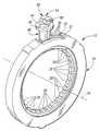
- FIG. 1is a schematic, perspective view of a controllable coupling assembly and an electromechanical component constructed in accordance with at least one embodiment of the present invention
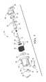
- FIG. 2is an exploded, perspective view of the assembly and component of FIG. 1 ;
- FIG. 3is a view of the assembly and component similar to the view of FIG. 2 but from a different angle;
- FIG. 4is an enlarged side view, partially broken away, of the assembly and component of FIG. 1 together with a second electromechanical component in phantom with locking elements of the components partially extended towards locking formations of a coupling member of the assembly;
- FIG. 5is a partial block diagram and side view, opposite the side view of FIG. 4 , but with one of the components in cross section and inserted in a case (also in cross section) of an electronic vehicle transmission constructed in accordance with at least one embodiment of the present invention
- FIG. 6is a perspective, schematic bottom view of the electromechanical component of the prior Figures.
- FIG. 7is an exploded, perspective view of the electromechanical component.
- the transmission 10includes a transmission case 40 having a bore 41 which extends completely through the case 40 .
- the transmission case 40has associated therewith an environment which is hostile to electrical components during use of the transmission 10 primarily because of: (1) hot oil contained therein, (2) contaminants in the oil which cause shorting of any electrical circuits therein and (3) vibration.
- the transmission 10also includes an electromechanical component, generally indicated at 14 , which is capable of operating in the hostile environment of the case 40 .
- the component 14may be referred to herein below as an SSI (i.e. selectable solenoid insert).
- the component 14is inserted through the bore 41 and held therein by threaded fasteners (not shown) which extend through holes 46 formed through an annular flange 44 of a housing, generally indicated at 48 , of the component 14 .
- the fastenersextend into threshold holes 42 formed in the case 40 about the bore 41 to secure the component 14 to the case 40 .
- the transmission 10also includes a controllable coupling assembly, generally included at 12 , which, in turn, includes first and second coupling members, 18 and 22 , respectively, mounted for rotation relative to one another about a rotational axis 16 .
- the first coupling member 18has a first coupling face 19 oriented to face axially in a first direction with respect to the axis 16 and the second coupling member 22 has a second coupling face 23 oriented to face axially in a second direction opposite the first direction with respect to the axis 16 .
- the second coupling member 22also has a third coupling face 25 oriented to face radially with respect to the axis 16 and having a set of locking formations or teeth 30 formed therein.
- the teeth 30are preferably ferromagnetic or magnetic teeth 30 .
- the coupling assembly 12also includes a set of forward locking elements or struts 20 which are received within angularly spaced pockets 26 formed in the face 23 of the coupling member 22 .
- the coupling member 22has a set of splines 28 formed on its inner diameter for drivingly engaging a drive or driven member (not shown) for rotation about the axis 16 .
- the assembly 12also includes a locking ring or plate, generally indicated at 24 , for insertion into an annular groove 36 of an axially extending wall 37 of the coupling member 18 to hold the coupling members 18 and 22 together.
- the locking plate 24has a circumferential cutout 34 which coincides or is aligned with a circumferential cutout 32 provided in the wall 37 of the member 18 when the plate 24 is inserted into the groove 36 . This feature allows a locking element or strut 52 of the component 14 to engage the teeth 30 of the member 22 as shown in FIGS. 4 and 5 .
- the housing part or housing 48has an outer coupling face 49 ( FIG. 5 ) in close-spaced opposition to the coupling face 25 of the member 22 when the members 18 and 22 are joined and assembled together by the locking ring 24 and after insertion of the component 14 into the bore 41 of the case 40 .
- the outer coupling face 49 of the housing part 48has a single, T-shaped recess or pocket 51 .
- the recess 51defines a load-bearing first surface shoulder 53 .
- the coupling face 25 of the member 22has a plurality of reverse notches or teeth 30 . Each tooth of the teeth 30 defines a load-bearing second surface or shoulder 31 .
- the locking strut or element 52is capable of extending between the coupling faces 25 and 49 of the member 22 and the part 48 , respectively, between coupling and uncoupling positions when the assembly 12 and case 40 are assembled together as is shown in FIGS. 4 and 5 .
- the element 52may comprise a ferromagnetic locking element or strut movable between first and second positions.
- the first positioni.e. coupling position
- the second positioni.e. non-coupling position
- the second positionis characterized by non-abutting engagement of the locking element 52 with a load-bearing shoulder 31 of at least one of the teeth 30 and the end wall of the housing part 48 .
- the electromechanical component or apparatus (i.e. SSI) 14includes the housing part 48 which has a closed axial end including the end wall.
- the end wallhas the outer coupling face 49 with the single pocket 51 which defines the load-bearing shoulder 53 which is in communication with an inner face of the end wall.
- the housing part 48may be a metal (such as aluminum) injection molded (MIM) part.
- the apparatus 14also includes an electromagnetic source, including at least one excitation coil 62 which is at least partially surrounded by a skirt of the housing part 48 .
- Electrical insulated wiring 64supplies electrical power to the coil 62 from a power source located outside the hot oil environment.
- the wiring 64extends from the coil 62 , through a hole 65 ( FIG. 5 ) formed through an end seal 82 , through a cavity 86 formed through an overmold 84 and to a solenoid controller.
- the strut 52is retained within the pocket 51 by a clevis-shaped retainer 50 .
- the strut 52is movable outwardly from the pocket 51 to its extended, coupling position characterized by abutting engagement of the strut 52 with a load-bearing surface or shoulder 31 of one of the teeth 30 .
- the apparatus 14also includes a reciprocating plunger, generally indicated at 70 , arranged concentrically relative to the at least one excitation coil 62 and is axially movable when the at least one excitation coil 62 is supplied with current via the wires 64 .
- the coil 62is wound or located about an actuator core or armature 76 and is potted between plates 60 and 78 .
- the armature 76is also axially movable upon coil excitation.
- the plate 60abuts against the inner face of the housing end wall.
- the plunger 70extends through a hole 61 ( FIG. 7 ) formed through the plate 60 and is connected at its leading end 72 to the element 52 to move the element 52 between its coupling and uncoupling positions.
- the plunger 70also extends through an aperture 75 formed through the armature 76 .
- the opposite end of the plunger 70has a locking nut or cap 80 positioned thereon which limits movement of the plunger 70 in the aperture 75 towards the teeth 30 by abutting against the lower surface of an annular spacer 68 which abuts against the lower surface of the armature 76 .
- the element 52is pivotally connected to the apertured leading end 72 of the plunger 70 wherein the plunger 70 pivotally moves the element 52 within the pocket 51 in response to reciprocating movement of the plunger 70 which, in turn, moves axially in response to reciprocating movement of the armature 76 .
- the apparatus 14also preferably includes a return spring 66 , which extends between the plate 60 and a shoulder in the outer surface of the actuator core or armature 76 , to return the plunger 70 and the armature 76 to their home position when the coil 62 is de-energized, thereby returning the element 52 to its uncoupling position.
- the apparatus 14also includes a spring 74 which urges the plunger 70 to move the element 52 towards its coupling position.
- the biasing member or spring 66urges the plunger 70 via the armature 76 to a return position which corresponds to its uncoupling position of the element 52 while the biasing member or spring 66 urges the plunger 70 and its connected element 52 to its coupled position.
- the housing part 48 and/or the plate 78may have holes (not shown) to allow oil to circulate within the housing part 48 .
- the at least one coil 62 , the housing part 48 , the armature 76 and the plunger 70comprise a low profile solenoid.
- the locking element 52may be a metal (such as aluminum) injection molded (i.e. MIM) strut.
- the element 52includes at least one and, preferably, two projecting leg portions 55 which provide an attachment location for the leading end 72 of the plunger 70 .
- Each leg portion 55has an aperture 57 .
- the apparatus 14further comprises a pivot pin 54 received within each aperture 57 and the aperture leading end 72 to allow rotational movement of the element 52 in response to reciprocating movement of the plunger 70 wherein the leading end 72 of the plunger 70 is connected to the element 52 via the pivot pin 54 .
- each aperture 55is an oblong aperture which receives the pivot pin 54 to allow both rotation and translational movement of the element 52 in response to reciprocating movement of the plunger 70 .
- Each locking strut 52may comprise any suitable rigid material such as ferrous metal, (i.e. steel).
- the component 14also includes a magnetic field speed sensor or device 56 which may comprise a differential Hall-effect device which senses speed of the teeth 30 as they rotate past the sensor 56 .
- the teeth 30may carry or support a rare-earth, automotive grade, magnet or pellet (not shown) which may be embedded in a hole formed in the outer surface of the teeth. In that case, the teeth 30 may be non-ferrous teeth such as aluminum teeth. Alternatively, and preferably, the teeth 30 are ferromagnetic teeth.
- the device 56is typically back-biased, has two wires 58 ( FIG. 7 ) and provides a current output based on speed of rotation of the teeth 30 past the sensor 56 .
- the device 56accurately detects the speed with a single output (i.e., current output).
- the device 56is preferably mounted adjacent to the pocket 51 and the wires 58 extend through the aperture 61 formed in the plate 60 .
- the wires 58 and the wires 64 of the coil 62are coupled to the solenoid controller which, in turn, is coupled to a main controller to supply drive signals to the coil 62 in response to control signals from the main controller.
- the device 56may be held in place by fasteners or by an adhesive so that a side surface of the device 56 is in close proximity to a side surface of the strut 52 in the uncoupling position of the strut 52 .
- the sensor 56is typically back-biased when the teeth 30 are ferromagnetic and typically includes a Hall sensor or sensing element mounted on a circuit board on which other electronics or components are mounted, as is well-known in the art.
- the sensor 56is preferably back-biased in that it includes a rare-earth magnet which creates a magnetic flux or field which varies as the teeth 30 move past the sensor 56 .
- the sensor 56may comprise a back-biased, differential Hall Effect device.
- the device 56is preferably a back-biased device wherein the device 56 includes a rare earth pellet or magnet whose magnetic field varies as the teeth 30 move therepast.
- the variable magnetic fieldis sensed by the magnetic sensing element of the device 56 .
- the output signal from the device 56is a feedback signal which is received by the solenoid controller. By providing feedback, the resulting closed-loop control system provides for true speed operation.
- the number of forward strutsi.e. 14
- the number of reverse strutsi.e. one or two
- the number of reverse notchesis greater than the number of forward notches.
- the number of reverse struts and notches and the number of forward struts and notchesare chosen so that the forward backlash is a non-zero integer multiple (i.e. “N”) of the reverse backlash and the forward pockets are uniformly angularly spaced about the axis 16 .
- Nnon-zero integer multiple
- High Power Densityvery surface of the inner and outer race is used.
- the radial surfacesare for reverse and the planar surfaces are for 1 st gear. They are independent and do not compete for the same real estate in the races.
- the concentric designcompetes for radial cross section and co-planar designs add a PM race.
- the largest possible strut/cam geometrycan be used in a smaller package. This increases the power density of the clutch.
- NVH AdvantagesMaximizing cams is great approach to reducing backlash. Many more cams can be formed into the race in the radial direction as opposed to the planar direction. Using the SSI 14 in the radial direction takes advantage of this feature.
- the solutionis to use two springs 66 and 76 , an actuator core or armature 76 , and a second internal piston called the plunger 70 that attaches to the strut 52 via a clevis connection.
- the armature 76always strokes ON and travels the full 3 mm closing the gap independent of the position of the strut 52 relative to the cams or teeth 30 .
- the forces keeping the armature 76 in the ON positionincrease by a magnitude when the gap is closed.
- the armature 76pushes the second spring 74 that pushes the plunger 70 attached to the strut 52 .
- the currentcan be dropped to a holding current that is a fraction of the initial pulse current.
- the strut 52is loaded by the second spring 74 in the apply direction. If the strut 52 is in between cams or teeth 30 , there is a second spring force pushing the strut 52 into the ON position as soon as the cam plate 22 rotates.
- the armature 70is now independent of strut position and can be PWMed.
- the armature 76would only stroke 1.3 mm and stop with a force of about 2 lbs. In a two-spring system the armature 76 always strokes the full 3 mm in 20 ms allowing the current to drop to a holding current. The second spring 74 applies the force to exit tooth butt.
- the prior arthas a speed sensor that passes through the outside of the outer race of the clutch to sense the speed of the inner race. It was presumed that it is for the non-sync reverse shift when rolling in the forward direction.
- At least one embodiment of the present inventionprovides the structure for a speed sensor chip set. It is possible to pot in a speed sensor chip set right into the SSI 14 . This has the advantage of flexing the structure of the SSI 14 to not only lock the inner race to ground in reverse, but also to sense the inner race speed all in the same part. This would eliminate the stand alone speed sensor, case machining and clutch machining to accommodate the stand alone speed sensor. This is a significant cost save.
Landscapes
- Engineering & Computer Science (AREA)
- General Engineering & Computer Science (AREA)
- Mechanical Engineering (AREA)
- Physics & Mathematics (AREA)
- Electromagnetism (AREA)
- Control Of Transmission Device (AREA)
Abstract
Description
| Reverse | Reverse | Reverse | Forward | Forward | Forward | Transitional | ||
| Entry | N | Notches | Struts | Backlash | Notches | Strut Sets | Backlash | Backlash |
| 1 | 2 | 79 | 1 | 4.556962 | 79 | 2 | 2.278481 | 1.139241 |
| 2 | 2 | 77 | 1 | 4.675325 | 77 | 2 | 2.337662 | 1.168831 |
| 3 | 3 | 80 | 1 | 4.5 | 80 | 3 | 1.5 | 0.75 |
| 4 | 3 | 79 | 1 | 4.556962 | 79 | 3 | 1.518987 | 0.759494 |
| 5 | 3 | 77 | 1 | 4.675325 | 77 | 3 | 1.558442 | 0.779221 |
| 6 | 3 | 76 | 1 | 4.736842 | 76 | 3 | 1.578947 | 0.789474 |
| 7 | 3 | 74 | 1 | 4.864865 | 74 | 3 | 1.621622 | 0.810811 |
| 8 | 3 | 73 | 1 | 4.931507 | 73 | 3 | 1.643836 | 0.821918 |
| 9 | 3 | 71 | 1 | 5.070423 | 71 | 3 | 1.690141 | 0.84507 |
| 10 | 3 | 70 | 1 | 5.142857 | 70 | 3 | 1.714286 | 0.857143 |
| 11 | 3 | 62 | 1 | 5.806452 | 62 | 3 | 1.935484 | 0.967742 |
| 12 | 3 | 61 | 1 | 5.901639 | 61 | 3 | 1.967213 | 0.983607 |
| 13 | 3 | 59 | 1 | 6.101695 | 59 | 3 | 2.033898 | 1.016949 |
| 14 | 3 | 58 | 1 | 6.206897 | 58 | 3 | 2.068966 | 1.034483 |
| 15 | 3 | 56 | 1 | 6.428571 | 56 | 3 | 2.142857 | 1.071429 |
| 16 | 3 | 55 | 1 | 6.545455 | 55 | 3 | 2.181818 | 1.090909 |
| 17 | 3 | 53 | 1 | 6.792453 | 53 | 3 | 2.264151 | 1.132075 |
| 18 | 3 | 52 | 1 | 6.923077 | 52 | 3 | 2.307692 | 1.153846 |
| 19 | 1 | 79 | 2 | 2.278481 | 79 | 2 | 2.278481 | 1.139241 |
| 20 | 1 | 77 | 2 | 2.337662 | 77 | 2 | 2.337662 | 1.168831 |
| 21 | 1 | 79 | 3 | 1.518987 | 79 | 3 | 1.518987 | 0.759494 |
| 22 | 1 | 80 | 3 | 1.5 | 80 | 3 | 1.5 | 0.75 |
| 23 | 1 | 79 | 3 | 1.518987 | 79 | 3 | 1.518987 | 0.759494 |
| 24 | 1 | 77 | 3 | 1.558442 | 77 | 3 | 1.558442 | 0.779221 |
| 25 | 1 | 76 | 3 | 1.578947 | 76 | 3 | 1.578947 | 0.789474 |
| 26 | 1 | 74 | 3 | 1.621622 | 74 | 3 | 1.621622 | 0.810811 |
| 27 | 1 | 73 | 3 | 1.643836 | 73 | 3 | 1.643836 | 0.821918 |
| 28 | 1 | 71 | 3 | 1.690141 | 71 | 3 | 1.690141 | 0.84507 |
| 29 | 1 | 70 | 3 | 1.714286 | 70 | 3 | 1.714286 | 0.857143 |
| 30 | 1 | 61 | 3 | 1.967213 | 61 | 3 | 1.967213 | 0.983607 |
| 31 | 1 | 59 | 3 | 2.033898 | 59 | 3 | 2.033898 | 1.016949 |
| 32 | 1 | 58 | 3 | 2.068966 | 58 | 3 | 2.068966 | 1.034483 |
| 33 | 1 | 56 | 3 | 2.142857 | 56 | 3 | 2.142857 | 1.071429 |
| 34 | 1 | 55 | 3 | 2.181818 | 55 | 3 | 2.181818 | 1.090909 |
| 35 | 1 | 53 | 3 | 2.264151 | 53 | 3 | 2.264151 | 1.132075 |
| 36 | 1 | 52 | 3 | 2.307692 | 52 | 3 | 2.307692 | 1.153846 |
- Wiring is outside the transmission.
- Eliminates the difficulty in routing lead wires from the clutch around rotating parts to the bulk head inside the box.
- Does not impact the number of wires passing through the bulk head connector.
- Coils are potted, leads are over molded, connector is external, completely segregated from the hot oil environment which prevents:
- Long term embrittlement of connector and wire insulation from hot oil exposure;
- Eliminates the possibility of contamination in oil shorting the circuit to power; and
- Vibration failures are greatly reduced (potted and over molded).
- Using the
SSI 14 as a common electro-mechanical component. - Tend to make it a high volume commodity thus reducing cost.
- Streamlines design, validation, and manufacturing—one and done approach.
- Using the
- Eliminate the slide plate and failure modes associated with the slide plate.
- Traditional MD approach—no concentric, co-planar design. Tried and true approach.
- Cost competitive—highest power density, 2 races, and an across the board approach for controls using the
SSIs 14. - Reduction of partial engagements.
- The
SSI 14strut 52 turns on faster than a hydraulic design using a slide plate. - The
SSI 14 can be turned on closer to the sync point when doing a rolling forward reverse shift because it takes only 20 ms or less to fire on. No hydraulic delay or temperature effects. - Soft turn off capable reduces impact loads when turning off
- No special driver is required. The
SSI 14 can fire initially and can be PWMed down to hold on. The higher pulse is to overcome a return spring designed for a 20 g impact.
- Temperature insensitive.
- Faster reaction time with small tolerance (20 ms or less).
- Much less energy to operate over life of application.
- Easier to route wires outside of box compared to packaging worm trails.
- Easy for diagnostic—software maintenance loop with a trickle voltage can measure resistance for temperature, continuity, or a short instantly setting a code.
- Contamination insensitive
Claims (20)
Priority Applications (5)
| Application Number | Priority Date | Filing Date | Title |
|---|---|---|---|
| US14/675,850US9638266B2 (en) | 2010-12-10 | 2015-04-01 | Electronic vehicular transmission including a sensor and coupling and control assembly for use therein |
| PCT/US2016/014236WO2016160100A1 (en) | 2015-04-01 | 2016-01-21 | Electronic vehicular transmission including a sensor and coupling and control assembly for use therein |
| US15/078,334US9562574B2 (en) | 2014-02-19 | 2016-03-23 | Controllable coupling assembly and coupling member for use in the assembly |
| US15/078,154US9482294B2 (en) | 2014-02-19 | 2016-03-23 | Coupling and control assembly including a sensor |
| US15/078,171US20160201738A1 (en) | 2014-02-19 | 2016-03-23 | Coupling and control assembly for use in an electronic vehicular transmission |
Applications Claiming Priority (8)
| Application Number | Priority Date | Filing Date | Title |
|---|---|---|---|
| US42185610P | 2010-12-10 | 2010-12-10 | |
| PCT/US2011/036634WO2012078202A1 (en) | 2010-12-10 | 2011-05-16 | Electromechanically actuated coupling and control assembly |
| US201313992785A | 2013-06-10 | 2013-06-10 | |
| US201361870434P | 2013-08-27 | 2013-08-27 | |
| US201461941741P | 2014-02-19 | 2014-02-19 | |
| US14/288,819US9234552B2 (en) | 2010-12-10 | 2014-05-28 | Magnetic system for controlling the operating mode of an overrunning coupling assembly and overrunning coupling and magnetic control assembly having same |
| US14/300,275US9127724B2 (en) | 2010-12-10 | 2014-06-10 | Electromechanical apparatus for use with a coupling assembly and controllable coupling assembly including such apparatus |
| US14/675,850US9638266B2 (en) | 2010-12-10 | 2015-04-01 | Electronic vehicular transmission including a sensor and coupling and control assembly for use therein |
Related Parent Applications (4)
| Application Number | Title | Priority Date | Filing Date |
|---|---|---|---|
| US14/288,819Continuation-In-PartUS9234552B2 (en) | 2010-12-10 | 2014-05-28 | Magnetic system for controlling the operating mode of an overrunning coupling assembly and overrunning coupling and magnetic control assembly having same |
| US14/300,275Continuation-In-PartUS9127724B2 (en) | 2010-12-10 | 2014-06-10 | Electromechanical apparatus for use with a coupling assembly and controllable coupling assembly including such apparatus |
| US15/078,154Continuation-In-PartUS9482294B2 (en) | 2014-02-19 | 2016-03-23 | Coupling and control assembly including a sensor |
| US15/078,334Continuation-In-PartUS9562574B2 (en) | 2014-02-19 | 2016-03-23 | Controllable coupling assembly and coupling member for use in the assembly |
Related Child Applications (4)
| Application Number | Title | Priority Date | Filing Date |
|---|---|---|---|
| US14/288,819Continuation-In-PartUS9234552B2 (en) | 2010-12-10 | 2014-05-28 | Magnetic system for controlling the operating mode of an overrunning coupling assembly and overrunning coupling and magnetic control assembly having same |
| US15/078,154Continuation-In-PartUS9482294B2 (en) | 2014-02-19 | 2016-03-23 | Coupling and control assembly including a sensor |
| US15/078,334Continuation-In-PartUS9562574B2 (en) | 2014-02-19 | 2016-03-23 | Controllable coupling assembly and coupling member for use in the assembly |
| US15/078,171Continuation-In-PartUS20160201738A1 (en) | 2014-02-19 | 2016-03-23 | Coupling and control assembly for use in an electronic vehicular transmission |
Publications (2)
| Publication Number | Publication Date |
|---|---|
| US20150204391A1 US20150204391A1 (en) | 2015-07-23 |
| US9638266B2true US9638266B2 (en) | 2017-05-02 |
Family
ID=53544415
Family Applications (1)
| Application Number | Title | Priority Date | Filing Date |
|---|---|---|---|
| US14/675,850Active2031-10-15US9638266B2 (en) | 2010-12-10 | 2015-04-01 | Electronic vehicular transmission including a sensor and coupling and control assembly for use therein |
Country Status (1)
| Country | Link |
|---|---|
| US (1) | US9638266B2 (en) |
Cited By (12)
| Publication number | Priority date | Publication date | Assignee | Title |
|---|---|---|---|---|
| US10208811B2 (en)* | 2013-07-29 | 2019-02-19 | Magna Powertrain Inc. | Selectable one-way clutch having strut with separate armature |
| DE102021102824A1 (en) | 2020-02-12 | 2021-08-12 | Means Industries, Inc. | ELECTRODYNAMIC CLUTCH AND CONTROL ASSEMBLY AND SWITCHABLE LINEAR ACTUATOR FOR USE IN THIS |
| DE102021104228A1 (en) | 2020-03-31 | 2021-09-30 | Means Industries, Inc. | Coupling and control arrangement with a non-contact, linear inductive position sensor |
| DE102021107969A1 (en) | 2020-03-31 | 2021-09-30 | Means Industries, Inc. | COUPLING AND CONTROL UNIT WITH A CONTACTLESS, INDUCTIVE POSITION SENSOR |
| US11215245B2 (en) | 2019-12-03 | 2022-01-04 | Means Industries, Inc. | Coupling and control assembly including controllable coupling assembly having speed sensor and methods of controlling the controllable coupling assembly using information from the speed sensor for park/hill-hold operations |
| US11346404B2 (en)* | 2018-10-09 | 2022-05-31 | Means Industries, Inc. | Coupling and control assembly for use in a motor vehicle |
| US11542992B2 (en) | 2020-03-31 | 2023-01-03 | Means Industries, Inc. | Coupling and control assembly including a non-contact, linear inductive position sensor |
| US11680610B2 (en) | 2021-02-11 | 2023-06-20 | Means Industries, Inc. | Clutch assembly having normally on strut configured to prevent shock load deployment |
| US11719292B2 (en) | 2021-01-22 | 2023-08-08 | Means Industries, Inc. | Strut clutch assembly torque locking mechanism, and clutch strut |
| US20230332653A1 (en)* | 2022-04-14 | 2023-10-19 | Means Industries, Inc. | Controllable clutch assembly |
| US11874142B2 (en) | 2020-03-31 | 2024-01-16 | Means Industries, Inc. | Coupling and control assembly including a position sensor |
| US12117049B2 (en) | 2021-10-06 | 2024-10-15 | Sigma Powertrain, Inc. | Position sensor assembly |
Families Citing this family (9)
| Publication number | Priority date | Publication date | Assignee | Title |
|---|---|---|---|---|
| CN104981623B (en)* | 2013-01-30 | 2017-09-08 | 博格华纳公司 | Multi-mode clutch module |
| US10487887B2 (en) | 2014-11-07 | 2019-11-26 | Means Industries, Inc. | Electromechanical apparatus for use with a controllable coupling assembly and coupling and electromechanical control assembly |
| US9657791B2 (en)* | 2015-03-12 | 2017-05-23 | GM Global Technology Operations LLC | Ultra-low-loss transmission brake utilizing a dual-solenoid electro-mechanical actuator |
| WO2017165501A1 (en)* | 2016-03-23 | 2017-09-28 | Means Industries, Inc. | Coupling and control assembly for use in an electronic vehicular transmission |
| US10533617B2 (en) | 2016-09-01 | 2020-01-14 | Magna Powertrain Inc. | Strut-type selectable clutch with hydraulic deployment prevention features |
| US9995390B2 (en)* | 2016-11-03 | 2018-06-12 | Ford Global Technologies, Llc | Brake mechanism for hybrid vehicle engine |
| US10544842B2 (en)* | 2017-03-24 | 2020-01-28 | Ford Global Technologies, Llc | One-way clutch for a vehicle |
| US11022186B2 (en) | 2018-04-18 | 2021-06-01 | Magna Powertrain, Inc. | Selectable one-way coupling with debris containment |
| JP1666420S (en)* | 2019-10-03 | 2020-08-24 |
Citations (140)
| Publication number | Priority date | Publication date | Assignee | Title |
|---|---|---|---|---|
| US2960287A (en) | 1957-08-05 | 1960-11-15 | Lockheed Aircraft Corp | Floating joint |
| US3130989A (en) | 1961-11-15 | 1964-04-28 | Micro Poise Engineering And Sa | Connecting rod and pivot pin connection |
| GB1007475A (en) | 1964-06-19 | 1965-10-13 | Ford Motor Co | Linearly movable clutch fork |
| US4050560A (en) | 1975-02-19 | 1977-09-27 | Stal-Laval Turbin Ab | Fluid pressure actuated clutch for starting multi-stage turbine |
| US4056747A (en) | 1976-01-22 | 1977-11-01 | Chrysler Corporation | Speed sensor |
| US4200002A (en) | 1976-07-28 | 1980-04-29 | Nissan Motor Company, Limited | Parking brake mechanism for motor vehicle equipped with power transmission with torque converter |
| US4340133A (en) | 1979-05-23 | 1982-07-20 | Zahnradfabrik Friedrichshafen Ag | Device for sensing the engagement position of a clutch |
| US5052534A (en) | 1990-10-30 | 1991-10-01 | Dana Corporation | Electromagnetic synchronizing and shifting clutch |
| US5070978A (en) | 1990-04-19 | 1991-12-10 | Pires Paul B | One way drive device |
| US5206573A (en) | 1991-12-06 | 1993-04-27 | Mccleer Arthur P | Starting control circuit |
| US5231265A (en) | 1990-09-28 | 1993-07-27 | Balance Dynamics Corporation | Method and apparatus for the transfer of electrical power to a balancer |
| US5362293A (en) | 1992-12-14 | 1994-11-08 | E. I. Du Pont De Nemours And Company | Drive clutch for a centrifuge rotor |
| US5387854A (en) | 1992-09-02 | 1995-02-07 | Electric Power Research Institute, Inc. | Method of torque notch minimization for quasi square wave back EMF permanent magnet synchronous machines with voltage source drive |
| US5394321A (en) | 1992-09-02 | 1995-02-28 | Electric Power Research Institute, Inc. | Quasi square-wave back-EMF permanent magnet AC machines with five or more phases |
| US5449057A (en) | 1993-10-26 | 1995-09-12 | Frank; Arthur R. | One-way clutch apparatus |
| US5597057A (en) | 1993-10-26 | 1997-01-28 | Brenco, Inc. | One-way clutch apparatus |
| US5638929A (en) | 1995-04-06 | 1997-06-17 | Hyundai Motor Company, Ltd. | Controllable one-way clutch for a vehicle |
| US5678668A (en) | 1996-08-26 | 1997-10-21 | Brenco, Incorporated | One-way overrunning clutch mechanism |
| US5806643A (en) | 1996-05-01 | 1998-09-15 | Epilogics, L.P. | One way drive device and mechanical assembly integrating the device |
| US5847469A (en) | 1996-02-29 | 1998-12-08 | Toyota Jidosha Kabushiki Kaisha | Hybrid drive system wherein electric motor or engine is selectively used for rearward driving of vehicle |
| US5856709A (en) | 1995-11-13 | 1999-01-05 | Toyota Jidosha Kabushiki Kaisha | Hybrid vehicle drive system having clutch between engine and synthesizing/distributing mechanism which is operatively connected to motor/generator |
| US5871071A (en) | 1996-06-21 | 1999-02-16 | Means Industries, Inc. | One-way high torque clutch mechanism |
| US5898249A (en) | 1996-06-14 | 1999-04-27 | Boggs, Iii; Paul D. | No slip eddy current drive |
| US5918715A (en) | 1997-06-09 | 1999-07-06 | Means Industries, Inc. | Overrunning planar clutch assembly |
| US5927455A (en) | 1997-07-21 | 1999-07-27 | Warn Industries | Overrunning pawl clutch |
| US5954174A (en) | 1996-09-03 | 1999-09-21 | Borg-Warner Automotive, Inc. | Ratchet one-way clutch assembly |
| US5964331A (en) | 1996-12-02 | 1999-10-12 | Means Industries, Inc. | One-way overrunning clutch |
| US5979627A (en) | 1997-12-10 | 1999-11-09 | Means Industries, Inc. | Damper assembly |
| US6019699A (en) | 1998-02-04 | 2000-02-01 | Toyota Jidosha Kabushiki Kaisha | Synchronized coast downshift control for hybrid vehicles |
| US6065576A (en) | 1998-03-20 | 2000-05-23 | Means Industries, Inc. | Strut for planar one-way clutch |
| US6075302A (en) | 1997-10-20 | 2000-06-13 | Mccleer; Patrick J. | Brushless heteropolar inductor machine |
| US6116394A (en) | 1999-08-13 | 2000-09-12 | Means Industries, Inc. | Overrunning coupling assembly |
| US6125980A (en) | 1998-02-24 | 2000-10-03 | Means Industries, Inc. | Overrunning coupling assembly and manufacturing method |
| US6186299B1 (en) | 1999-08-13 | 2001-02-13 | Means Industries, Inc. | Overrunning coupling assembly |
| US6193038B1 (en) | 1999-08-18 | 2001-02-27 | Means Industries, Inc. | One-way clutch and method for making same |
| US6237931B1 (en) | 1999-01-18 | 2001-05-29 | Tru-Hitch, Inc. | Towbar adapter |
| US6244965B1 (en) | 1997-04-28 | 2001-06-12 | Means Industries, Inc. | Controllable overrunning coupling |
| US6290044B1 (en) | 2000-04-03 | 2001-09-18 | General Motors Corporation | Selectable one-way clutch assembly |
| US6306057B1 (en) | 1997-12-05 | 2001-10-23 | Toyota Jidosha Kabushiki Kaisha | Hybrid drive system |
| US20020000724A1 (en) | 2000-03-23 | 2002-01-03 | Nick Kalargeros | Latch mechanism |
| US6344008B1 (en) | 1999-08-06 | 2002-02-05 | Toyota Jidosha Kabushiki Kaisha | Hybrid vehicle |
| US6386349B1 (en) | 2001-01-17 | 2002-05-14 | Means Industries, Inc. | Compact clutch assembly featuring dual selectively-operative one-way clutches |
| US6481551B1 (en) | 2000-11-27 | 2002-11-19 | Means Industries, Inc. | Inertia-actuated overrunning coupling assembly |
| US6503167B1 (en) | 2000-09-28 | 2003-01-07 | Spicer Technology, Inc. | Externally actuated locking differential assembly |
| US6505721B1 (en) | 2000-05-25 | 2003-01-14 | Means Industries, Inc. | Planar one-way clutch |
| US20030019708A1 (en)* | 2001-07-25 | 2003-01-30 | Ntn Corporation | Electronically controllable torque transmission device |
| US6571926B2 (en) | 2001-02-12 | 2003-06-03 | Means Industries, Inc. | One-way clutch assembly featuring improved strut stability |
| US20030126870A1 (en) | 2002-01-10 | 2003-07-10 | Meckstroth Richard J. | Momentary engagement and disengagement of automotive air conditioner clutch |
| US20040159517A1 (en) | 2003-02-13 | 2004-08-19 | Matthew Thomas | Bi-directional axially applied pawl clutch assembly |
| US20040216975A1 (en) | 2003-04-29 | 2004-11-04 | Means Industries, Inc. | Sound dampened one-way clutch |
| US6846257B2 (en) | 2002-12-11 | 2005-01-25 | Ntn Corporation | Series drive clutch |
| US6953409B2 (en) | 2003-12-19 | 2005-10-11 | General Motors Corporation | Two-mode, compound-split, hybrid electro-mechanical transmission having four fixed ratios |
| US20050279602A1 (en) | 2004-06-16 | 2005-12-22 | Means Industries, Inc. | Planar coupling assembly for an automatic transmission |
| US6982502B1 (en) | 2003-09-26 | 2006-01-03 | The United States Of America As Represented By The Secretary Of The Navy | Hybrid electric linear actuator |
| US20060021838A1 (en) | 2004-07-27 | 2006-02-02 | John Kimes | Ratcheting one-way clutch having piloted surfaces |
| US7025188B2 (en) | 2003-05-08 | 2006-04-11 | Luk Lamellen Und Kupplungsbau Beteiligungs Kg | Parking lock for an automated transmission of a motor vehicle |
| US20060124425A1 (en) | 2004-12-09 | 2006-06-15 | Means Industries, Inc. | Planar coupling assembly |
| US20060138777A1 (en) | 2003-06-25 | 2006-06-29 | Peter Hofbauer | Ring generator |
| US7093512B2 (en) | 2000-03-10 | 2006-08-22 | Hitachi, Ltd. | Automatic transmission, dynamo-electric machine, and car |
| US20060185957A1 (en) | 2004-07-27 | 2006-08-24 | Kimes John W | Dual-mode one-way torque transmitting device |
| US7100756B2 (en) | 2004-07-27 | 2006-09-05 | Ford Global Technologies, Llc | Overrunning clutch |
| US7153228B2 (en) | 2002-12-25 | 2006-12-26 | Sanden Corporation | Power transmission |
| US20070056825A1 (en) | 2005-09-14 | 2007-03-15 | Means Industries, Inc. | Overrunning coupling assembly including clustered pawls and method for controlling the engagement of planar members |
| US7198587B2 (en) | 2003-12-16 | 2007-04-03 | General Motors Corporation | Transmission with selectable braking one-way clutch |
| US7201690B2 (en) | 2003-05-29 | 2007-04-10 | Aisin Aw Co., Ltd. | Drive unit for vehicle |
| US20070107960A1 (en) | 2005-10-26 | 2007-05-17 | Aisin Aw Co., Ltd. | Hybrid drive apparatus |
| US7223198B2 (en) | 2004-07-27 | 2007-05-29 | Ford Global Technologies, Llc | Automatic transmission carrier assembly including an overrunning brake |
| US7223200B2 (en) | 2001-10-22 | 2007-05-29 | Toyota Jidosha Kabushiki Kaisha | Hybrid-vehicle drive system and operation method with a transmission |
| US7255186B2 (en) | 2002-08-02 | 2007-08-14 | Aisin Aw Co., Ltd. | Hybrid drive system and vehicle equipped therewith |
| US7256510B2 (en) | 2005-12-23 | 2007-08-14 | General Motors Corportion | Hybrid electro-mechanical transmission with single motor/generator and method of control |
| US7258214B2 (en) | 2005-06-09 | 2007-08-21 | Means Industries, Inc. | Overrunning coupling assembly and method for controlling the engagement of planar members |
| US7275628B2 (en) | 2005-06-09 | 2007-10-02 | Means Industries Inc. | Overrunning coupling assembly having improved shift feel and/or noise reduction |
| US20070278061A1 (en) | 2006-05-31 | 2007-12-06 | Gm Global Technology Operations, Inc. | Selectable One-Way Rocker Clutch |
| US7349010B2 (en) | 2003-04-11 | 2008-03-25 | Eastman Kodak Company | Digital camera including an on-line sales mode |
| US20080093190A1 (en) | 2004-09-15 | 2008-04-24 | Peugeot Citroen Automobiles Sa | Switching Device For A Motor Vehicle And Of This Device |
| US20080110715A1 (en) | 2006-11-13 | 2008-05-15 | Means Industries, Inc. | Fluid actuated overrunning coupling assembly |
| US7383930B2 (en) | 2004-07-27 | 2008-06-10 | Ford Global Technologies, Inc. | Overrunning clutch |
| US20080135369A1 (en) | 2006-12-06 | 2008-06-12 | Means Industries, Inc. | Stamped clutch pocket plate, method for making the pocket plate, and clutch including the pocket plate |
| US7393296B2 (en) | 2003-06-30 | 2008-07-01 | Toyota Jidosha Kabushiki Kaisha | Hybrid driving unit and vehicle carrying the same |
| US7397296B1 (en) | 2006-12-12 | 2008-07-08 | National Semiconductor Corporation | Power supply detection circuit biased by multiple power supply voltages for controlling a signal driver circuit |
| US20080169166A1 (en) | 2007-01-12 | 2008-07-17 | Gm Global Technology Operations, Inc. | Rocker Clutch Assembly |
| US20080169165A1 (en) | 2007-01-12 | 2008-07-17 | Gm Global Technology Operations, Inc. | Selectable One-Way Clutch with Symmetrical Struts |
| US20080188338A1 (en) | 2007-02-02 | 2008-08-07 | Kimes John W | Assembly including a planetary pinion carrier and one-way clutch |
| US20080185253A1 (en) | 2007-02-06 | 2008-08-07 | Kimes John W | Selectively controlled rocker one-way clutch |
| US20080223681A1 (en) | 2007-03-13 | 2008-09-18 | Stevenson Paul D | Selectable one-way clutch |
| US7426971B2 (en) | 2003-06-30 | 2008-09-23 | Toyota Jidosha Kabushiki Kaisha | Hybrid driving unit and vehicle carrying the same |
| US20080245360A1 (en) | 2007-03-23 | 2008-10-09 | Sunpower Corporation | Tilt Assembly for Tracking Solar Collector Assembly |
| US7448481B2 (en) | 2004-07-27 | 2008-11-11 | Ford Global Technologies, Llc | Ratcheting one-way clutch having rockers actuated by centrifugal force |
| US7451862B2 (en) | 2004-07-27 | 2008-11-18 | Ford Global Technologies, Llc | Ratcheting one-way clutch having rockers retained in closed pockets |
| US7455157B2 (en) | 2004-07-27 | 2008-11-25 | Ford Global Technologies, Llc | Ratcheting one-way clutch having rockers |
| US7455156B2 (en) | 2004-07-27 | 2008-11-25 | Ford Global Technologies, Llc | Overrunning clutch |
| US7464801B2 (en) | 2006-01-17 | 2008-12-16 | Gm Global Technology Operations, Inc. | Selectable one-way clutch |
| US7484605B2 (en) | 2005-06-09 | 2009-02-03 | Means Industries, Inc. | Overrunning radial coupling assembly and method for controlling the engagement of inner and outer members of the assembly |
| US7491151B2 (en) | 2005-10-31 | 2009-02-17 | Gm Global Technology Operations, Inc. | Selectable one-way clutch control |
| US20090062058A1 (en) | 2007-08-27 | 2009-03-05 | Kimes John W | Plantary Transmission Having Double Helical Teeth |
| US20090084653A1 (en) | 2007-09-28 | 2009-04-02 | Holmes Alan G | Electrically Variable Transmission with an Axially-Moveable Selectable One-Way Clutch Assembly |
| US20090098970A1 (en) | 2007-10-12 | 2009-04-16 | Means Industries, Inc. | High-Efficiency Vehicular Transmission |
| US20090127059A1 (en) | 2006-01-25 | 2009-05-21 | Getrag Innovations Gmbh | Clutch arrangement for motor vehicle transmission and method for engaging and disengaging a gearspeed |
| US20090133981A1 (en) | 2005-08-27 | 2009-05-28 | Deere & Company | Gear Shifting Point for the Establishment of a Connection, Fixed Against Rotation, Between a Gear and a Shaft |
| US20090142207A1 (en) | 2007-11-30 | 2009-06-04 | Stellarton Technologies Inc. | Bottom hole hollow core electric submersible pumping system |
| US20090159391A1 (en) | 2007-12-19 | 2009-06-25 | Means Industries, Inc. | Overrunning Coupling Assembly |
| US20090194381A1 (en) | 2008-02-04 | 2009-08-06 | Gm Global Technology Operations, Inc. | Method and apparatus for controlling a selectable one-way clutch in an electro-mechanical transmission |
| US20090211863A1 (en) | 2008-02-21 | 2009-08-27 | Means Industries, Inc. | Controllable Overrunning Coupling Assembly |
| US20090233755A1 (en) | 2008-03-14 | 2009-09-17 | Kimes John W | Overrunning Clutch Reacting a Force Produced by a Hydraulically Actuated Friction Brake |
| US20090255773A1 (en) | 2006-10-26 | 2009-10-15 | Getrag Getriebe- Und Zahnradfabrik Hermann Hagenmeyer Gmbh & Cie Kg | Actuator arrangement for a motor vehicle clutch |
| US20090266667A1 (en) | 2008-04-25 | 2009-10-29 | Gm Global Technology Operations, Inc. | Rocker-Type Selectable One-Way Clutch With Neutral Position |
| US7614466B2 (en) | 2004-10-14 | 2009-11-10 | Toyota Jidosha Kabushiki Kaisha | Hybrid drive system |
| US7621359B2 (en) | 2004-10-14 | 2009-11-24 | Aisin Aw Co., Ltd | Hybrid drive apparatus |
| US7661518B2 (en) | 2004-07-27 | 2010-02-16 | Ford Global Technologies, Llc | Preventing ratcheting on rockers of a one-way clutch |
| US20100071497A1 (en) | 2006-10-19 | 2010-03-25 | Zf Friedrichshafen Ag | Transmission device having at least one shift element which can be actuated by means of an actuator arrangement which has at least one electrical component |
| US7690492B2 (en) | 2006-12-12 | 2010-04-06 | Ford Global Technologies, Llc | Apparatus for directing fluid along a flow path in a motor vehicle transmission |
| US7690455B2 (en) | 2003-06-30 | 2010-04-06 | Toyota Jidosha Kabushiki Kaisha | Hybrid drive device and automobile mounted with device |
| US20100105515A1 (en) | 2008-10-24 | 2010-04-29 | Goleski Gregory D | Planet pinion carrier for a gearset |
| US20100127693A1 (en) | 2008-11-26 | 2010-05-27 | Gary Herman Wenzel | Transmission shift rail position sensor |
| US20100200358A1 (en) | 2009-02-06 | 2010-08-12 | Means Industries, Inc. | Overrunning coupling and control assembly including apparatus having a latching mechanism |
| US20100230226A1 (en) | 2009-03-13 | 2010-09-16 | Means Industries, Inc. | Overrunning one-way clutch or coupling assembly |
| US7806795B2 (en) | 2007-06-22 | 2010-10-05 | Toyota Jidosha Kabushiki Kaisha | Power output apparatus and hybrid vehicle with power output apparatus |
| US20100252384A1 (en) | 2009-04-01 | 2010-10-07 | Means Industries, Inc. | Controllable coupling assembly and overrunning coupling and control assembly utilizing same |
| US8007396B2 (en) | 2008-08-25 | 2011-08-30 | Ford Global Technologies, Llc | Planetary transmission having common carrier for generating six forward and two reverse drive ratios |
| US20110233026A1 (en) | 2010-03-26 | 2011-09-29 | Means Industries, Inc. | Overrunning coupling and control assembly including an electromechanical actuator subassembly |
| US8061496B2 (en) | 2008-07-22 | 2011-11-22 | GM Global Technology Operations LLC | Compact selection mechanism for a selectable one-way clutch |
| US20120021862A1 (en) | 2010-07-21 | 2012-01-26 | Ford Global Technologies, Llc | Electronic Locking Differential |
| US20120145505A1 (en) | 2010-12-10 | 2012-06-14 | Means Industries, Inc. | Strut for a controllable one-way clutch |
| US20120149518A1 (en) | 2010-12-10 | 2012-06-14 | Means Industries, Inc. | Vehicle drive system including a transmission |
| US20120152683A1 (en) | 2010-12-10 | 2012-06-21 | Means Industries, Inc. | Controllable coupling assembly |
| US20120152687A1 (en) | 2010-12-10 | 2012-06-21 | Means Industries, Inc. | Electromechanical assembly to control the operating mode of a coupling apparatus |
| US20120228076A1 (en) | 2011-03-07 | 2012-09-13 | GM Global Technology Operations LLC | Electromagnetically controlled clutch assembly and control method for the same |
| US8324890B2 (en) | 2009-09-18 | 2012-12-04 | Delphi Technologies, Inc. | Clutch position sensor for vehicle transmission |
| US20130062151A1 (en) | 2011-09-13 | 2013-03-14 | Means Industries, Inc. | Coupling assembly having an overrun mode and ratcheting reverse strut or radial ratchet for use therein |
| US8418825B2 (en) | 2010-10-28 | 2013-04-16 | Ford Global Technologies, Llc | Magnetically actuated mechanical diode |
| US20130277164A1 (en) | 2012-04-18 | 2013-10-24 | Means Industries, Inc. | Coupling and control assembly |
| US20130319812A1 (en) | 2012-06-05 | 2013-12-05 | Ford Glboal Technologies, Llc | Electromagnetic one-way coupling |
| US20140102844A1 (en) | 2012-10-17 | 2014-04-17 | Magna Powertrain Of America, Inc. | Electric actuator module for selectable clutch |
| US20140190785A1 (en) | 2013-01-10 | 2014-07-10 | Means Industries, Inc. | Compact overrunning coupling and control assembly having reduced part count and manufacturing complexity |
| US20140238811A1 (en) | 2013-02-28 | 2014-08-28 | Ford Global Technologies, Llc | Electromagnetically actuated axial one-way clutch |
| US20140284167A1 (en) | 2010-12-10 | 2014-09-25 | Means Industries, Inc. | Electromechanical apparatus for use with a coupling assembly and controllable coupling assembly including such apparatus |
| US20140305761A1 (en) | 2010-12-10 | 2014-10-16 | Means Industries, Inc. | Magnetic system for controlling the operating mode of an overrunning coupling assembly and overrunning coupling and magnetic control assembly having same |
| US20150000442A1 (en) | 2010-12-10 | 2015-01-01 | Means Industries, Inc. | Electronic, high-efficiency vehicular transmission, overrunning, non-friction coupling and control assembly and switchable linear actuator device for use therein |
| US20150014116A1 (en) | 2010-12-10 | 2015-01-15 | Means Industries, Inc. | Device and apparatus for controlling the operating mode of a coupling assembly, coupling and control assembly and electric motor disconnect and pass through assemblies |
| WO2015030899A1 (en) | 2013-08-27 | 2015-03-05 | Means Industries, Inc. | Magnetic system for controlling the operating mode of an overrunning coupling assembly and overrunning coupling and magnetic control assembly having same |
- 2015
- 2015-04-01USUS14/675,850patent/US9638266B2/enactiveActive
Patent Citations (159)
| Publication number | Priority date | Publication date | Assignee | Title |
|---|---|---|---|---|
| US2960287A (en) | 1957-08-05 | 1960-11-15 | Lockheed Aircraft Corp | Floating joint |
| US3130989A (en) | 1961-11-15 | 1964-04-28 | Micro Poise Engineering And Sa | Connecting rod and pivot pin connection |
| GB1007475A (en) | 1964-06-19 | 1965-10-13 | Ford Motor Co | Linearly movable clutch fork |
| US4050560A (en) | 1975-02-19 | 1977-09-27 | Stal-Laval Turbin Ab | Fluid pressure actuated clutch for starting multi-stage turbine |
| US4056747A (en) | 1976-01-22 | 1977-11-01 | Chrysler Corporation | Speed sensor |
| US4200002A (en) | 1976-07-28 | 1980-04-29 | Nissan Motor Company, Limited | Parking brake mechanism for motor vehicle equipped with power transmission with torque converter |
| US4340133A (en) | 1979-05-23 | 1982-07-20 | Zahnradfabrik Friedrichshafen Ag | Device for sensing the engagement position of a clutch |
| US5070978A (en) | 1990-04-19 | 1991-12-10 | Pires Paul B | One way drive device |
| US5231265A (en) | 1990-09-28 | 1993-07-27 | Balance Dynamics Corporation | Method and apparatus for the transfer of electrical power to a balancer |
| US5453598A (en) | 1990-09-28 | 1995-09-26 | The Balance Dynamics Corporation | Apparatus for the transfer of electrical power to a balancer |
| US5052534A (en) | 1990-10-30 | 1991-10-01 | Dana Corporation | Electromagnetic synchronizing and shifting clutch |
| US5206573A (en) | 1991-12-06 | 1993-04-27 | Mccleer Arthur P | Starting control circuit |
| US5387854A (en) | 1992-09-02 | 1995-02-07 | Electric Power Research Institute, Inc. | Method of torque notch minimization for quasi square wave back EMF permanent magnet synchronous machines with voltage source drive |
| US5394321A (en) | 1992-09-02 | 1995-02-28 | Electric Power Research Institute, Inc. | Quasi square-wave back-EMF permanent magnet AC machines with five or more phases |
| US5642009A (en) | 1992-09-02 | 1997-06-24 | Electric Power Research Institute, Inc. | Quasi square-wave back-EMF permanent magnet AC machines with five or more phases |
| US5362293A (en) | 1992-12-14 | 1994-11-08 | E. I. Du Pont De Nemours And Company | Drive clutch for a centrifuge rotor |
| US5449057A (en) | 1993-10-26 | 1995-09-12 | Frank; Arthur R. | One-way clutch apparatus |
| US5597057A (en) | 1993-10-26 | 1997-01-28 | Brenco, Inc. | One-way clutch apparatus |
| US5638929A (en) | 1995-04-06 | 1997-06-17 | Hyundai Motor Company, Ltd. | Controllable one-way clutch for a vehicle |
| US5856709A (en) | 1995-11-13 | 1999-01-05 | Toyota Jidosha Kabushiki Kaisha | Hybrid vehicle drive system having clutch between engine and synthesizing/distributing mechanism which is operatively connected to motor/generator |
| US5847469A (en) | 1996-02-29 | 1998-12-08 | Toyota Jidosha Kabushiki Kaisha | Hybrid drive system wherein electric motor or engine is selectively used for rearward driving of vehicle |
| US5806643A (en) | 1996-05-01 | 1998-09-15 | Epilogics, L.P. | One way drive device and mechanical assembly integrating the device |
| US5898249A (en) | 1996-06-14 | 1999-04-27 | Boggs, Iii; Paul D. | No slip eddy current drive |
| US5871071A (en) | 1996-06-21 | 1999-02-16 | Means Industries, Inc. | One-way high torque clutch mechanism |
| US5678668A (en) | 1996-08-26 | 1997-10-21 | Brenco, Incorporated | One-way overrunning clutch mechanism |
| US5954174A (en) | 1996-09-03 | 1999-09-21 | Borg-Warner Automotive, Inc. | Ratchet one-way clutch assembly |
| US5964331A (en) | 1996-12-02 | 1999-10-12 | Means Industries, Inc. | One-way overrunning clutch |
| US6129190A (en) | 1996-12-02 | 2000-10-10 | Means Industries, Inc. | One-way overrunning clutch |
| US6244965B1 (en) | 1997-04-28 | 2001-06-12 | Means Industries, Inc. | Controllable overrunning coupling |
| US5918715A (en) | 1997-06-09 | 1999-07-06 | Means Industries, Inc. | Overrunning planar clutch assembly |
| US5927455A (en) | 1997-07-21 | 1999-07-27 | Warn Industries | Overrunning pawl clutch |
| US6075302A (en) | 1997-10-20 | 2000-06-13 | Mccleer; Patrick J. | Brushless heteropolar inductor machine |
| US6306057B1 (en) | 1997-12-05 | 2001-10-23 | Toyota Jidosha Kabushiki Kaisha | Hybrid drive system |
| US5979627A (en) | 1997-12-10 | 1999-11-09 | Means Industries, Inc. | Damper assembly |
| US6019699A (en) | 1998-02-04 | 2000-02-01 | Toyota Jidosha Kabushiki Kaisha | Synchronized coast downshift control for hybrid vehicles |
| US6125980A (en) | 1998-02-24 | 2000-10-03 | Means Industries, Inc. | Overrunning coupling assembly and manufacturing method |
| US6065576A (en) | 1998-03-20 | 2000-05-23 | Means Industries, Inc. | Strut for planar one-way clutch |
| US6237931B1 (en) | 1999-01-18 | 2001-05-29 | Tru-Hitch, Inc. | Towbar adapter |
| US6344008B1 (en) | 1999-08-06 | 2002-02-05 | Toyota Jidosha Kabushiki Kaisha | Hybrid vehicle |
| US6186299B1 (en) | 1999-08-13 | 2001-02-13 | Means Industries, Inc. | Overrunning coupling assembly |
| US6116394A (en) | 1999-08-13 | 2000-09-12 | Means Industries, Inc. | Overrunning coupling assembly |
| US6193038B1 (en) | 1999-08-18 | 2001-02-27 | Means Industries, Inc. | One-way clutch and method for making same |
| US7093512B2 (en) | 2000-03-10 | 2006-08-22 | Hitachi, Ltd. | Automatic transmission, dynamo-electric machine, and car |
| US20020000724A1 (en) | 2000-03-23 | 2002-01-03 | Nick Kalargeros | Latch mechanism |
| US6290044B1 (en) | 2000-04-03 | 2001-09-18 | General Motors Corporation | Selectable one-way clutch assembly |
| US6505721B1 (en) | 2000-05-25 | 2003-01-14 | Means Industries, Inc. | Planar one-way clutch |
| US6503167B1 (en) | 2000-09-28 | 2003-01-07 | Spicer Technology, Inc. | Externally actuated locking differential assembly |
| US6481551B1 (en) | 2000-11-27 | 2002-11-19 | Means Industries, Inc. | Inertia-actuated overrunning coupling assembly |
| US6386349B1 (en) | 2001-01-17 | 2002-05-14 | Means Industries, Inc. | Compact clutch assembly featuring dual selectively-operative one-way clutches |
| US6571926B2 (en) | 2001-02-12 | 2003-06-03 | Means Industries, Inc. | One-way clutch assembly featuring improved strut stability |
| US20030019708A1 (en)* | 2001-07-25 | 2003-01-30 | Ntn Corporation | Electronically controllable torque transmission device |
| US7223200B2 (en) | 2001-10-22 | 2007-05-29 | Toyota Jidosha Kabushiki Kaisha | Hybrid-vehicle drive system and operation method with a transmission |
| US20030126870A1 (en) | 2002-01-10 | 2003-07-10 | Meckstroth Richard J. | Momentary engagement and disengagement of automotive air conditioner clutch |
| US7255186B2 (en) | 2002-08-02 | 2007-08-14 | Aisin Aw Co., Ltd. | Hybrid drive system and vehicle equipped therewith |
| US6846257B2 (en) | 2002-12-11 | 2005-01-25 | Ntn Corporation | Series drive clutch |
| US7153228B2 (en) | 2002-12-25 | 2006-12-26 | Sanden Corporation | Power transmission |
| US20040159517A1 (en) | 2003-02-13 | 2004-08-19 | Matthew Thomas | Bi-directional axially applied pawl clutch assembly |
| US6814201B2 (en) | 2003-02-13 | 2004-11-09 | Borgwarner, Inc. | Bi-directional axially applied pawl clutch assembly |
| US7349010B2 (en) | 2003-04-11 | 2008-03-25 | Eastman Kodak Company | Digital camera including an on-line sales mode |
| US6854577B2 (en) | 2003-04-29 | 2005-02-15 | Means Industries, Inc. | Sound dampened one-way clutch |
| US20040216975A1 (en) | 2003-04-29 | 2004-11-04 | Means Industries, Inc. | Sound dampened one-way clutch |
| US7025188B2 (en) | 2003-05-08 | 2006-04-11 | Luk Lamellen Und Kupplungsbau Beteiligungs Kg | Parking lock for an automated transmission of a motor vehicle |
| US7201690B2 (en) | 2003-05-29 | 2007-04-10 | Aisin Aw Co., Ltd. | Drive unit for vehicle |
| US20060138777A1 (en) | 2003-06-25 | 2006-06-29 | Peter Hofbauer | Ring generator |
| US7426971B2 (en) | 2003-06-30 | 2008-09-23 | Toyota Jidosha Kabushiki Kaisha | Hybrid driving unit and vehicle carrying the same |
| US7393296B2 (en) | 2003-06-30 | 2008-07-01 | Toyota Jidosha Kabushiki Kaisha | Hybrid driving unit and vehicle carrying the same |
| US7690455B2 (en) | 2003-06-30 | 2010-04-06 | Toyota Jidosha Kabushiki Kaisha | Hybrid drive device and automobile mounted with device |
| US6982502B1 (en) | 2003-09-26 | 2006-01-03 | The United States Of America As Represented By The Secretary Of The Navy | Hybrid electric linear actuator |
| US7198587B2 (en) | 2003-12-16 | 2007-04-03 | General Motors Corporation | Transmission with selectable braking one-way clutch |
| US6953409B2 (en) | 2003-12-19 | 2005-10-11 | General Motors Corporation | Two-mode, compound-split, hybrid electro-mechanical transmission having four fixed ratios |
| US20050279602A1 (en) | 2004-06-16 | 2005-12-22 | Means Industries, Inc. | Planar coupling assembly for an automatic transmission |
| US20060249345A1 (en) | 2004-06-16 | 2006-11-09 | Means Industries, Inc. | Planar coupling assembly for an automatic transmission |
| US7383930B2 (en) | 2004-07-27 | 2008-06-10 | Ford Global Technologies, Inc. | Overrunning clutch |
| US7661518B2 (en) | 2004-07-27 | 2010-02-16 | Ford Global Technologies, Llc | Preventing ratcheting on rockers of a one-way clutch |
| US7448481B2 (en) | 2004-07-27 | 2008-11-11 | Ford Global Technologies, Llc | Ratcheting one-way clutch having rockers actuated by centrifugal force |
| US7451862B2 (en) | 2004-07-27 | 2008-11-18 | Ford Global Technologies, Llc | Ratcheting one-way clutch having rockers retained in closed pockets |
| US7455157B2 (en) | 2004-07-27 | 2008-11-25 | Ford Global Technologies, Llc | Ratcheting one-way clutch having rockers |
| US7455156B2 (en) | 2004-07-27 | 2008-11-25 | Ford Global Technologies, Llc | Overrunning clutch |
| US7100756B2 (en) | 2004-07-27 | 2006-09-05 | Ford Global Technologies, Llc | Overrunning clutch |
| US20060021838A1 (en) | 2004-07-27 | 2006-02-02 | John Kimes | Ratcheting one-way clutch having piloted surfaces |
| US7223198B2 (en) | 2004-07-27 | 2007-05-29 | Ford Global Technologies, Llc | Automatic transmission carrier assembly including an overrunning brake |
| US20060185957A1 (en) | 2004-07-27 | 2006-08-24 | Kimes John W | Dual-mode one-way torque transmitting device |
| US20080093190A1 (en) | 2004-09-15 | 2008-04-24 | Peugeot Citroen Automobiles Sa | Switching Device For A Motor Vehicle And Of This Device |
| US7614466B2 (en) | 2004-10-14 | 2009-11-10 | Toyota Jidosha Kabushiki Kaisha | Hybrid drive system |
| US7621359B2 (en) | 2004-10-14 | 2009-11-24 | Aisin Aw Co., Ltd | Hybrid drive apparatus |
| US20060124425A1 (en) | 2004-12-09 | 2006-06-15 | Means Industries, Inc. | Planar coupling assembly |
| US7484605B2 (en) | 2005-06-09 | 2009-02-03 | Means Industries, Inc. | Overrunning radial coupling assembly and method for controlling the engagement of inner and outer members of the assembly |
| US7275628B2 (en) | 2005-06-09 | 2007-10-02 | Means Industries Inc. | Overrunning coupling assembly having improved shift feel and/or noise reduction |
| US7258214B2 (en) | 2005-06-09 | 2007-08-21 | Means Industries, Inc. | Overrunning coupling assembly and method for controlling the engagement of planar members |
| US20090133981A1 (en) | 2005-08-27 | 2009-05-28 | Deere & Company | Gear Shifting Point for the Establishment of a Connection, Fixed Against Rotation, Between a Gear and a Shaft |
| US7344010B2 (en) | 2005-09-14 | 2008-03-18 | Means Industries, Inc. | Overrunning coupling assembly including clustered pawls and method for controlling the engagement of planar members |
| US20070056825A1 (en) | 2005-09-14 | 2007-03-15 | Means Industries, Inc. | Overrunning coupling assembly including clustered pawls and method for controlling the engagement of planar members |
| US20070107960A1 (en) | 2005-10-26 | 2007-05-17 | Aisin Aw Co., Ltd. | Hybrid drive apparatus |
| US7491151B2 (en) | 2005-10-31 | 2009-02-17 | Gm Global Technology Operations, Inc. | Selectable one-way clutch control |
| US7256510B2 (en) | 2005-12-23 | 2007-08-14 | General Motors Corportion | Hybrid electro-mechanical transmission with single motor/generator and method of control |
| US7464801B2 (en) | 2006-01-17 | 2008-12-16 | Gm Global Technology Operations, Inc. | Selectable one-way clutch |
| US20090127059A1 (en) | 2006-01-25 | 2009-05-21 | Getrag Innovations Gmbh | Clutch arrangement for motor vehicle transmission and method for engaging and disengaging a gearspeed |
| US20070278061A1 (en) | 2006-05-31 | 2007-12-06 | Gm Global Technology Operations, Inc. | Selectable One-Way Rocker Clutch |
| US20100071497A1 (en) | 2006-10-19 | 2010-03-25 | Zf Friedrichshafen Ag | Transmission device having at least one shift element which can be actuated by means of an actuator arrangement which has at least one electrical component |
| US20090255773A1 (en) | 2006-10-26 | 2009-10-15 | Getrag Getriebe- Und Zahnradfabrik Hermann Hagenmeyer Gmbh & Cie Kg | Actuator arrangement for a motor vehicle clutch |
| US20080110715A1 (en) | 2006-11-13 | 2008-05-15 | Means Industries, Inc. | Fluid actuated overrunning coupling assembly |
| US20080135369A1 (en) | 2006-12-06 | 2008-06-12 | Means Industries, Inc. | Stamped clutch pocket plate, method for making the pocket plate, and clutch including the pocket plate |
| US7397296B1 (en) | 2006-12-12 | 2008-07-08 | National Semiconductor Corporation | Power supply detection circuit biased by multiple power supply voltages for controlling a signal driver circuit |
| US7690492B2 (en) | 2006-12-12 | 2010-04-06 | Ford Global Technologies, Llc | Apparatus for directing fluid along a flow path in a motor vehicle transmission |
| US20080169166A1 (en) | 2007-01-12 | 2008-07-17 | Gm Global Technology Operations, Inc. | Rocker Clutch Assembly |
| US20080169165A1 (en) | 2007-01-12 | 2008-07-17 | Gm Global Technology Operations, Inc. | Selectable One-Way Clutch with Symmetrical Struts |
| US8491440B2 (en) | 2007-02-02 | 2013-07-23 | Ford Global Technologies, Llc | Planetary pinion carrier and one-way clutch |
| US20080188338A1 (en) | 2007-02-02 | 2008-08-07 | Kimes John W | Assembly including a planetary pinion carrier and one-way clutch |
| US8491439B2 (en) | 2007-02-06 | 2013-07-23 | Ford Global Technologies, Llc | Selectively controlled rocker one-way clutch |
| US20080185253A1 (en) | 2007-02-06 | 2008-08-07 | Kimes John W | Selectively controlled rocker one-way clutch |
| US20080223681A1 (en) | 2007-03-13 | 2008-09-18 | Stevenson Paul D | Selectable one-way clutch |
| US20080245360A1 (en) | 2007-03-23 | 2008-10-09 | Sunpower Corporation | Tilt Assembly for Tracking Solar Collector Assembly |
| US7806795B2 (en) | 2007-06-22 | 2010-10-05 | Toyota Jidosha Kabushiki Kaisha | Power output apparatus and hybrid vehicle with power output apparatus |
| US20090062058A1 (en) | 2007-08-27 | 2009-03-05 | Kimes John W | Plantary Transmission Having Double Helical Teeth |
| US20090084653A1 (en) | 2007-09-28 | 2009-04-02 | Holmes Alan G | Electrically Variable Transmission with an Axially-Moveable Selectable One-Way Clutch Assembly |
| US20090098970A1 (en) | 2007-10-12 | 2009-04-16 | Means Industries, Inc. | High-Efficiency Vehicular Transmission |
| US7942781B2 (en) | 2007-10-12 | 2011-05-17 | Means Industries, Inc. | High-efficiency vehicular transmission |
| US20090142207A1 (en) | 2007-11-30 | 2009-06-04 | Stellarton Technologies Inc. | Bottom hole hollow core electric submersible pumping system |
| US20090159391A1 (en) | 2007-12-19 | 2009-06-25 | Means Industries, Inc. | Overrunning Coupling Assembly |
| US8051959B2 (en) | 2007-12-19 | 2011-11-08 | Means Industries, Inc. | Controllable or selectable bi-directional overrunning coupling assembly |
| US20090194381A1 (en) | 2008-02-04 | 2009-08-06 | Gm Global Technology Operations, Inc. | Method and apparatus for controlling a selectable one-way clutch in an electro-mechanical transmission |
| US8196724B2 (en) | 2008-02-04 | 2012-06-12 | GM Global Technology Operations LLC | Method and apparatus for controlling a selectable one-way clutch in an electro-mechanical transmission |
| US8079453B2 (en) | 2008-02-21 | 2011-12-20 | Means Industries, Inc. | Controllable overrunning coupling assembly |
| US20090211863A1 (en) | 2008-02-21 | 2009-08-27 | Means Industries, Inc. | Controllable Overrunning Coupling Assembly |
| US20090233755A1 (en) | 2008-03-14 | 2009-09-17 | Kimes John W | Overrunning Clutch Reacting a Force Produced by a Hydraulically Actuated Friction Brake |
| US20090266667A1 (en) | 2008-04-25 | 2009-10-29 | Gm Global Technology Operations, Inc. | Rocker-Type Selectable One-Way Clutch With Neutral Position |
| US8061496B2 (en) | 2008-07-22 | 2011-11-22 | GM Global Technology Operations LLC | Compact selection mechanism for a selectable one-way clutch |
| US8007396B2 (en) | 2008-08-25 | 2011-08-30 | Ford Global Technologies, Llc | Planetary transmission having common carrier for generating six forward and two reverse drive ratios |
| US8187141B2 (en) | 2008-10-24 | 2012-05-29 | Ford Global Technologies, Llc | Planet pinion carrier for a gearset |
| US20100105515A1 (en) | 2008-10-24 | 2010-04-29 | Goleski Gregory D | Planet pinion carrier for a gearset |
| US20100127693A1 (en) | 2008-11-26 | 2010-05-27 | Gary Herman Wenzel | Transmission shift rail position sensor |
| US8272488B2 (en) | 2009-02-06 | 2012-09-25 | Means Industries, Inc. | Overrunning coupling and control assembly including apparatus having a latching mechanism |
| US20100200358A1 (en) | 2009-02-06 | 2010-08-12 | Means Industries, Inc. | Overrunning coupling and control assembly including apparatus having a latching mechanism |
| US20100230226A1 (en) | 2009-03-13 | 2010-09-16 | Means Industries, Inc. | Overrunning one-way clutch or coupling assembly |
| US20100252384A1 (en) | 2009-04-01 | 2010-10-07 | Means Industries, Inc. | Controllable coupling assembly and overrunning coupling and control assembly utilizing same |
| US8286772B2 (en) | 2009-04-01 | 2012-10-16 | Means Industries, Inc. | Controllable coupling assembly and overrunning coupling and control assembly utilizing same |
| US8324890B2 (en) | 2009-09-18 | 2012-12-04 | Delphi Technologies, Inc. | Clutch position sensor for vehicle transmission |
| US8720659B2 (en) | 2010-03-26 | 2014-05-13 | Means Industries, Inc. | Overrunning coupling and control assembly including an electromechanical actuator subassembly |
| US20110233026A1 (en) | 2010-03-26 | 2011-09-29 | Means Industries, Inc. | Overrunning coupling and control assembly including an electromechanical actuator subassembly |
| US20120021862A1 (en) | 2010-07-21 | 2012-01-26 | Ford Global Technologies, Llc | Electronic Locking Differential |
| US8418825B2 (en) | 2010-10-28 | 2013-04-16 | Ford Global Technologies, Llc | Magnetically actuated mechanical diode |
| US20120145505A1 (en) | 2010-12-10 | 2012-06-14 | Means Industries, Inc. | Strut for a controllable one-way clutch |
| US20120152687A1 (en) | 2010-12-10 | 2012-06-21 | Means Industries, Inc. | Electromechanical assembly to control the operating mode of a coupling apparatus |
| US20120152683A1 (en) | 2010-12-10 | 2012-06-21 | Means Industries, Inc. | Controllable coupling assembly |
| US20120149518A1 (en) | 2010-12-10 | 2012-06-14 | Means Industries, Inc. | Vehicle drive system including a transmission |
| US20150014116A1 (en) | 2010-12-10 | 2015-01-15 | Means Industries, Inc. | Device and apparatus for controlling the operating mode of a coupling assembly, coupling and control assembly and electric motor disconnect and pass through assemblies |
| US20150000442A1 (en) | 2010-12-10 | 2015-01-01 | Means Industries, Inc. | Electronic, high-efficiency vehicular transmission, overrunning, non-friction coupling and control assembly and switchable linear actuator device for use therein |
| US8646587B2 (en)* | 2010-12-10 | 2014-02-11 | Means Industries, Inc. | Strut for a controllable one-way clutch |
| US20140305761A1 (en) | 2010-12-10 | 2014-10-16 | Means Industries, Inc. | Magnetic system for controlling the operating mode of an overrunning coupling assembly and overrunning coupling and magnetic control assembly having same |
| US8813929B2 (en) | 2010-12-10 | 2014-08-26 | Means Industries, Inc. | Controllable coupling assembly |
| US20140284167A1 (en) | 2010-12-10 | 2014-09-25 | Means Industries, Inc. | Electromechanical apparatus for use with a coupling assembly and controllable coupling assembly including such apparatus |
| US20120228076A1 (en) | 2011-03-07 | 2012-09-13 | GM Global Technology Operations LLC | Electromagnetically controlled clutch assembly and control method for the same |
| US20130062151A1 (en) | 2011-09-13 | 2013-03-14 | Means Industries, Inc. | Coupling assembly having an overrun mode and ratcheting reverse strut or radial ratchet for use therein |
| US20130277164A1 (en) | 2012-04-18 | 2013-10-24 | Means Industries, Inc. | Coupling and control assembly |
| US20130319812A1 (en) | 2012-06-05 | 2013-12-05 | Ford Glboal Technologies, Llc | Electromagnetic one-way coupling |
| US20140102844A1 (en) | 2012-10-17 | 2014-04-17 | Magna Powertrain Of America, Inc. | Electric actuator module for selectable clutch |
| US20140190785A1 (en) | 2013-01-10 | 2014-07-10 | Means Industries, Inc. | Compact overrunning coupling and control assembly having reduced part count and manufacturing complexity |
| US20140238811A1 (en) | 2013-02-28 | 2014-08-28 | Ford Global Technologies, Llc | Electromagnetically actuated axial one-way clutch |
| WO2015030899A1 (en) | 2013-08-27 | 2015-03-05 | Means Industries, Inc. | Magnetic system for controlling the operating mode of an overrunning coupling assembly and overrunning coupling and magnetic control assembly having same |
Non-Patent Citations (21)
| Title |
|---|
| International Preliminary Report on Patentability; International application No. PCT/US2011/036634; date of issuance of report Jun. 12, 2013. |
| International Preliminary Report on Patentability; related International application No. PCT/US2014/041631; date of issuance of report Mar. 1, 2016. |
| International Preliminary Report on Patentability; related International application No. PCT/US2014/056716; date of issuance of report Mar. 29, 2016. |
| International Preliminary Report on Patentability; related International application No. PCT/US2014/056749; date of issuance of report Mar. 29, 2016. |
| International Preliminary Report on Patentability; related International application No. PCT/US2014/057140; date of issuance of report Mar. 29, 2016. |
| International Search Report and Written Opinion; International application No. PCT/US12/050742; date of mailing Nov. 20, 2012. |
| International Search Report and Written Opinion; International application No. PCT/US2011/036634; date of mailing Aug. 25, 2011. |
| International Search Report and Written Opinion; International application No. PCT/US2014/041631; date of mailing Oct. 9, 2014. |
| International Search Report and Written Opinion; International application No. PCT/US2014/049044; date of mailing Nov. 24, 2014. |
| International Search Report and Written Opinion; related International application No. PCT/US16/14063; date of mailing Mar. 16, 2016. |
| International Search Report and Written Opinion; related International application No. PCT/US2016/013836; date of mailing Mar. 30, 2016. |
| International Search Report and Written Opinion; related International application No. PCT/US2016/014236; date of mailing Mar. 24, 2016. |
| International Search Report and Written Opinion; related International application No. PCT/US2016/014243; date of mailing Mar. 24, 2016. |
| Notice of Allowance and Fee(S) Due; related U.S. Appl. No. 14/086,202; dated Sep. 14, 2015. |
| Notice of Allowance and Fee(S) Due; related U.S. Appl. No. 14/675,840, filed Apr. 1, 2015; date mailed Dec. 3, 2015. |
| Notice of Allowance and Fee(S) Due; related U.S. Appl. No. 14/882,505; dated Aug. 1, 2016. |
| Notice of Allowance and Fee(S) Due; related U.S. Appl. No. 15/078,154; date mailed Sep. 12, 2016. |
| Notice of Allowance and Issue Fee Due; corresponding U.S. Appl. No. 13/992,785; date of mailing Jan. 30, 2015. |
| Office Action; related application U.S. Appl. No. 14/882,505; notification date May 19, 2016. |
| Office Action; related U.S. Appl. No. 14/675,840; dated Oct. 2, 2015. |
| Official Action; corresponding U.S. Appl. No. 13/992,785, filed Jun. 10, 2013. |
Cited By (17)
| Publication number | Priority date | Publication date | Assignee | Title |
|---|---|---|---|---|
| US10760622B2 (en) | 2013-07-29 | 2020-09-01 | Magna Powertrain, Inc. | Selectable one-way clutch having strut with separate armature |
| US10208811B2 (en)* | 2013-07-29 | 2019-02-19 | Magna Powertrain Inc. | Selectable one-way clutch having strut with separate armature |
| US11346404B2 (en)* | 2018-10-09 | 2022-05-31 | Means Industries, Inc. | Coupling and control assembly for use in a motor vehicle |
| US11215245B2 (en) | 2019-12-03 | 2022-01-04 | Means Industries, Inc. | Coupling and control assembly including controllable coupling assembly having speed sensor and methods of controlling the controllable coupling assembly using information from the speed sensor for park/hill-hold operations |
| DE102021102824A1 (en) | 2020-02-12 | 2021-08-12 | Means Industries, Inc. | ELECTRODYNAMIC CLUTCH AND CONTROL ASSEMBLY AND SWITCHABLE LINEAR ACTUATOR FOR USE IN THIS |
| US11953060B2 (en) | 2020-02-12 | 2024-04-09 | Means Industries, Inc. | Coupling and control assembly |
| US11286996B2 (en) | 2020-02-12 | 2022-03-29 | Means Industries, Inc. | Electro-dynamic coupling and control assembly and switchable linear actuator device for use therein |
| US11542992B2 (en) | 2020-03-31 | 2023-01-03 | Means Industries, Inc. | Coupling and control assembly including a non-contact, linear inductive position sensor |
| DE102021107969A1 (en) | 2020-03-31 | 2021-09-30 | Means Industries, Inc. | COUPLING AND CONTROL UNIT WITH A CONTACTLESS, INDUCTIVE POSITION SENSOR |
| US11874142B2 (en) | 2020-03-31 | 2024-01-16 | Means Industries, Inc. | Coupling and control assembly including a position sensor |
| DE102021104228A1 (en) | 2020-03-31 | 2021-09-30 | Means Industries, Inc. | Coupling and control arrangement with a non-contact, linear inductive position sensor |
| US11719292B2 (en) | 2021-01-22 | 2023-08-08 | Means Industries, Inc. | Strut clutch assembly torque locking mechanism, and clutch strut |
| US12092173B2 (en) | 2021-01-22 | 2024-09-17 | Means Industries, Inc. | Clutch strut, torque locking mechanism, and clutch assembly |
| US11680610B2 (en) | 2021-02-11 | 2023-06-20 | Means Industries, Inc. | Clutch assembly having normally on strut configured to prevent shock load deployment |
| US12117049B2 (en) | 2021-10-06 | 2024-10-15 | Sigma Powertrain, Inc. | Position sensor assembly |
| US20230332653A1 (en)* | 2022-04-14 | 2023-10-19 | Means Industries, Inc. | Controllable clutch assembly |
| US12092172B2 (en)* | 2022-04-14 | 2024-09-17 | Means Industries, Inc. | Controllable clutch assembly |
Also Published As
| Publication number | Publication date |
|---|---|
| US20150204391A1 (en) | 2015-07-23 |
Similar Documents
| Publication | Publication Date | Title |
|---|---|---|
| US9638266B2 (en) | Electronic vehicular transmission including a sensor and coupling and control assembly for use therein | |
| US9255614B2 (en) | Electronic vehicular transmission and coupling and control assembly for use therein | |
| US9541141B2 (en) | Electronic vehicular transmission, controllable coupling assembly and coupling member for use in the assembly | |
| US9562574B2 (en) | Controllable coupling assembly and coupling member for use in the assembly | |
| US9482294B2 (en) | Coupling and control assembly including a sensor | |
| US9234552B2 (en) | Magnetic system for controlling the operating mode of an overrunning coupling assembly and overrunning coupling and magnetic control assembly having same | |
| US20160201738A1 (en) | Coupling and control assembly for use in an electronic vehicular transmission | |
| US10487887B2 (en) | Electromechanical apparatus for use with a controllable coupling assembly and coupling and electromechanical control assembly | |
| JP6615976B2 (en) | Overrunning coupling assembly, magnetic system for controlling operating mode of overrunning coupling, and magnetic control assembly having the system | |
| US9909631B2 (en) | Apparatus for controllably actuating a selectable coupling assembly having multiple operating modes | |
| US11346404B2 (en) | Coupling and control assembly for use in a motor vehicle | |
| CN108368894B (en) | Electromechanical device for use with a controllable connection assembly, and connection and electromechanical control assembly | |
| US9541143B2 (en) | Magnetic system for controlling an operating mode of an overrunning coupling assembly and overrunning coupling and magnetic control assembly including the system | |
| JP2020521920A (en) | Overrunning non-friction radially coupled control assembly and switchable linear actuator equipment for use in the assembly | |
| EP2002155B1 (en) | Two wire dual sensor differential locking state detection system | |
| MX2008000433A (en) | Electro-magnetic release mechanism. | |
| EP3611395A1 (en) | Electronic vehicular transmission, controllable coupling assembly and coupling member for use in the assembly | |
| WO2016160100A1 (en) | Electronic vehicular transmission including a sensor and coupling and control assembly for use therein | |
| EP3433505B1 (en) | Coupling and control assembly including a sensor | |
| WO2016160098A1 (en) | Electronic vehicular transmission and coupling and control assembly for use therein | |
| WO2017165507A1 (en) | Controllable coupling assembly and coupling member for use in the assembly | |
| WO2017165501A1 (en) | Coupling and control assembly for use in an electronic vehicular transmission | |
| WO2017083617A1 (en) | Apparatus for controllably actuating a selectable coupling assembly having multiple operating modes | |
| Miroschnitschenko | Sensorless control of linear motion in a linear-rotary reluctance actuator integrated into an electromagnetic dog clutch. Actuators 2025, 1, 0 |
Legal Events
| Date | Code | Title | Description |
|---|---|---|---|
| AS | Assignment | Owner name:MEANS INDUSTRIES, INC., MICHIGAN Free format text:ASSIGNMENT OF ASSIGNORS INTEREST;ASSIGNOR:KIMES, JOHN W.;REEL/FRAME:035316/0769 Effective date:20150320 | |
| STCF | Information on status: patent grant | Free format text:PATENTED CASE | |
| AS | Assignment | Owner name:BANK OF AMERICA, N.A., AS ADMINISTRATIVE AGENT, ILLINOIS Free format text:NOTICE OF GRANT OF SECURITY INTEREST IN PATENTS;ASSIGNOR:MEANS INDUSTRIES, INC.;REEL/FRAME:042733/0796 Effective date:20170531 Owner name:BANK OF AMERICA, N.A., AS ADMINISTRATIVE AGENT, IL Free format text:NOTICE OF GRANT OF SECURITY INTEREST IN PATENTS;ASSIGNOR:MEANS INDUSTRIES, INC.;REEL/FRAME:042733/0796 Effective date:20170531 | |
| MAFP | Maintenance fee payment | Free format text:PAYMENT OF MAINTENANCE FEE, 4TH YEAR, LARGE ENTITY (ORIGINAL EVENT CODE: M1551); ENTITY STATUS OF PATENT OWNER: LARGE ENTITY Year of fee payment:4 | |
| MAFP | Maintenance fee payment | Free format text:PAYMENT OF MAINTENANCE FEE, 8TH YEAR, LARGE ENTITY (ORIGINAL EVENT CODE: M1552); ENTITY STATUS OF PATENT OWNER: LARGE ENTITY Year of fee payment:8 | |
| AS | Assignment | Owner name:WELLS FARGO BANK, NATIONAL ASSOCIATION, AS SUCCESSOR AGENT, NORTH CAROLINA Free format text:NOTICE OF SUCCESSOR AGENT AND ASSIGNMENT OF SECURITY INTEREST AT REEL/FRAME 042732/0796;ASSIGNOR:BANK OF AMERICA, N.A., AS THE RESIGNING AGENT;REEL/FRAME:070159/0192 Effective date:20250206 | |
| AS | Assignment | Owner name:WELLS FARGO BANK, NATIONAL ASSOCIATION, AS SUCCESSOR AGENT, NORTH CAROLINA Free format text:CORRECTIVE ASSIGNMENT TO CORRECT THE REEL REFERENCED IN THE CONVEYANCE BRIEF TO 042733 INSTEAD OF 042732. PREVIOUSLY RECORDED ON REEL 70159 FRAME 192. ASSIGNOR(S) HEREBY CONFIRMS THE NOTICE OF SUCCESSOR AGENT AND ASSIGNMENT OF SERCURITY INTEREST;ASSIGNOR:BANK OF AMERICA, N.A., AS THE RESIGNING AGENT;REEL/FRAME:071549/0193 Effective date:20250206 |