US9636229B2 - Solid freeform fabrication of implant components - Google Patents
Solid freeform fabrication of implant componentsDownload PDFInfo
- Publication number
- US9636229B2 US9636229B2US14/033,095US201314033095AUS9636229B2US 9636229 B2US9636229 B2US 9636229B2US 201314033095 AUS201314033095 AUS 201314033095AUS 9636229 B2US9636229 B2US 9636229B2
- Authority
- US
- United States
- Prior art keywords
- implant
- patient
- peg
- bone
- tibial tray
- Prior art date
- Legal status (The legal status is an assumption and is not a legal conclusion. Google has not performed a legal analysis and makes no representation as to the accuracy of the status listed.)
- Active
Links
- 239000007943implantSubstances0.000titleclaimsabstractdescription292
- 239000007787solidSubstances0.000titleclaimsabstractdescription17
- 238000010100freeform fabricationMethods0.000titleabstractdescription8
- 238000004519manufacturing processMethods0.000claimsabstractdescription91
- 238000000034methodMethods0.000claimsabstractdescription69
- 238000013461designMethods0.000claimsabstractdescription28
- 239000000654additiveSubstances0.000claimsabstractdescription20
- 230000000996additive effectEffects0.000claimsabstractdescription20
- 239000002184metalSubstances0.000claimsabstractdescription18
- 229910052751metalInorganic materials0.000claimsabstractdescription18
- 238000004873anchoringMethods0.000claimsdescription32
- 238000004458analytical methodMethods0.000claimsdescription17
- 238000000110selective laser sinteringMethods0.000claimsdescription15
- 238000005520cutting processMethods0.000claimsdescription9
- 238000002844meltingMethods0.000claimsdescription9
- 230000008018meltingEffects0.000claimsdescription9
- 210000002303tibiaAnatomy0.000claimsdescription7
- 230000008021depositionEffects0.000claimsdescription6
- 2380000101463D printingMethods0.000claimsdescription5
- 238000010894electron beam technologyMethods0.000claimsdescription5
- 238000007493shaping processMethods0.000claimsdescription4
- 238000000149argon plasma sinteringMethods0.000claimsdescription3
- 210000000629knee jointAnatomy0.000claims3
- 238000011882arthroplastyMethods0.000claims1
- 238000005516engineering processMethods0.000abstractdescription27
- 150000002739metalsChemical class0.000abstractdescription6
- 239000000463materialSubstances0.000description56
- 210000000988bone and boneAnatomy0.000description37
- 210000003484anatomyAnatomy0.000description34
- 239000000843powderSubstances0.000description26
- 238000001356surgical procedureMethods0.000description12
- 238000005266castingMethods0.000description11
- 238000012986modificationMethods0.000description11
- 230000004048modificationEffects0.000description11
- 230000008569processEffects0.000description9
- 238000000576coating methodMethods0.000description8
- 239000002245particleSubstances0.000description8
- 239000000047productSubstances0.000description8
- 239000002639bone cementSubstances0.000description7
- 210000003127kneeAnatomy0.000description6
- 238000011068loading methodMethods0.000description6
- 230000002093peripheral effectEffects0.000description6
- 229920000642polymerPolymers0.000description6
- 239000004568cementSubstances0.000description5
- 238000005452bendingMethods0.000description4
- 230000008901benefitEffects0.000description4
- 239000011248coating agentSubstances0.000description4
- 238000003384imaging methodMethods0.000description4
- 239000007788liquidSubstances0.000description4
- 239000000155meltSubstances0.000description4
- 230000000399orthopedic effectEffects0.000description4
- 239000004033plasticSubstances0.000description4
- 229920003023plasticPolymers0.000description4
- 239000011148porous materialSubstances0.000description4
- 230000001737promoting effectEffects0.000description4
- 230000035882stressEffects0.000description4
- 238000012800visualizationMethods0.000description4
- 239000011800void materialSubstances0.000description4
- 230000000740bleeding effectEffects0.000description3
- 239000000919ceramicSubstances0.000description3
- 230000006378damageEffects0.000description3
- 230000001419dependent effectEffects0.000description3
- 239000003814drugSubstances0.000description3
- -1electricalSubstances0.000description3
- 238000003754machiningMethods0.000description3
- 230000013011matingEffects0.000description3
- 239000002994raw materialSubstances0.000description3
- 230000008439repair processEffects0.000description3
- 238000002271resectionMethods0.000description3
- 238000000926separation methodMethods0.000description3
- 238000005482strain hardeningMethods0.000description3
- 230000003746surface roughnessEffects0.000description3
- CURLTUGMZLYLDI-UHFFFAOYSA-NCarbon dioxideChemical compoundO=C=OCURLTUGMZLYLDI-UHFFFAOYSA-N0.000description2
- 230000003466anti-cipated effectEffects0.000description2
- 239000011324beadSubstances0.000description2
- 230000015572biosynthetic processEffects0.000description2
- 230000008859changeEffects0.000description2
- 239000003795chemical substances by applicationSubstances0.000description2
- 239000002131composite materialSubstances0.000description2
- 238000001816coolingMethods0.000description2
- 238000011161developmentMethods0.000description2
- 238000009826distributionMethods0.000description2
- 229940079593drugDrugs0.000description2
- 230000000694effectsEffects0.000description2
- 238000005242forgingMethods0.000description2
- 239000008187granular materialSubstances0.000description2
- 238000010438heat treatmentMethods0.000description2
- 238000007373indentationMethods0.000description2
- 208000015181infectious diseaseDiseases0.000description2
- 230000002138osteoinductive effectEffects0.000description2
- 210000004417patellaAnatomy0.000description2
- 238000012545processingMethods0.000description2
- 210000004872soft tissueAnatomy0.000description2
- 210000005065subchondral bone plateAnatomy0.000description2
- 239000000126substanceSubstances0.000description2
- 210000001519tissueAnatomy0.000description2
- 238000003466weldingMethods0.000description2
- 208000037408Device failureDiseases0.000description1
- 239000004698PolyethyleneSubstances0.000description1
- 238000012356Product developmentMethods0.000description1
- 208000031737Tissue AdhesionsDiseases0.000description1
- 230000009471actionEffects0.000description1
- 230000003044adaptive effectEffects0.000description1
- 239000000853adhesiveSubstances0.000description1
- 230000001070adhesive effectEffects0.000description1
- 230000004075alterationEffects0.000description1
- 210000003423ankleAnatomy0.000description1
- 238000000137annealingMethods0.000description1
- 238000013459approachMethods0.000description1
- 239000012298atmosphereSubstances0.000description1
- 239000012620biological materialSubstances0.000description1
- 238000013406biomanufacturing processMethods0.000description1
- 229910002092carbon dioxideInorganic materials0.000description1
- 239000001569carbon dioxideSubstances0.000description1
- 238000005255carburizingMethods0.000description1
- 230000006835compressionEffects0.000description1
- 238000007906compressionMethods0.000description1
- 239000000470constituentSubstances0.000description1
- 238000010276constructionMethods0.000description1
- 229920003020cross-linked polyethylenePolymers0.000description1
- 239000004703cross-linked polyethyleneSubstances0.000description1
- 230000007547defectEffects0.000description1
- 230000007812deficiencyEffects0.000description1
- 238000012938design processMethods0.000description1
- 238000001514detection methodMethods0.000description1
- 238000005553drillingMethods0.000description1
- 230000002708enhancing effectEffects0.000description1
- 238000011156evaluationMethods0.000description1
- 238000001125extrusionMethods0.000description1
- 239000000835fiberSubstances0.000description1
- 239000012467final productSubstances0.000description1
- 210000002683footAnatomy0.000description1
- 230000004927fusionEffects0.000description1
- 230000035876healingEffects0.000description1
- 238000001513hot isostatic pressingMethods0.000description1
- 230000003116impacting effectEffects0.000description1
- 238000002513implantationMethods0.000description1
- 238000011065in-situ storageMethods0.000description1
- 238000010348incorporationMethods0.000description1
- 230000008595infiltrationEffects0.000description1
- 238000001764infiltrationMethods0.000description1
- 238000003780insertionMethods0.000description1
- 230000037431insertionEffects0.000description1
- 238000005304joiningMethods0.000description1
- 238000007648laser printingMethods0.000description1
- 239000011344liquid materialSubstances0.000description1
- 230000007774longtermEffects0.000description1
- 230000014759maintenance of locationEffects0.000description1
- 230000007257malfunctionEffects0.000description1
- 239000011159matrix materialSubstances0.000description1
- 238000005259measurementMethods0.000description1
- 238000002483medicationMethods0.000description1
- 238000010309melting processMethods0.000description1
- 229910001092metal group alloyInorganic materials0.000description1
- 239000002071nanotubeSubstances0.000description1
- 230000000278osteoconductive effectEffects0.000description1
- 230000003647oxidationEffects0.000description1
- 238000007254oxidation reactionMethods0.000description1
- 229920000573polyethylenePolymers0.000description1
- 238000007639printingMethods0.000description1
- 239000002296pyrolytic carbonSubstances0.000description1
- 230000005855radiationEffects0.000description1
- 238000007712rapid solidificationMethods0.000description1
- 238000007634remodelingMethods0.000description1
- 239000011347resinSubstances0.000description1
- 229920005989resinPolymers0.000description1
- 230000000284resting effectEffects0.000description1
- 230000002441reversible effectEffects0.000description1
- 239000004576sandSubstances0.000description1
- 238000005204segregationMethods0.000description1
- 230000035945sensitivityEffects0.000description1
- 238000004088simulationMethods0.000description1
- 239000011343solid materialSubstances0.000description1
- 239000007858starting materialSubstances0.000description1
- 239000000758substrateSubstances0.000description1
- 230000008646thermal stressEffects0.000description1
- 238000003856thermoformingMethods0.000description1
- 229920001169thermoplasticPolymers0.000description1
- 239000004416thermosoftening plasticSubstances0.000description1
- 210000001226toe jointAnatomy0.000description1
- 210000000689upper legAnatomy0.000description1
- 210000000707wristAnatomy0.000description1
- 210000002517zygapophyseal jointAnatomy0.000description1
Images


Classifications
- A—HUMAN NECESSITIES
- A61—MEDICAL OR VETERINARY SCIENCE; HYGIENE
- A61F—FILTERS IMPLANTABLE INTO BLOOD VESSELS; PROSTHESES; DEVICES PROVIDING PATENCY TO, OR PREVENTING COLLAPSING OF, TUBULAR STRUCTURES OF THE BODY, e.g. STENTS; ORTHOPAEDIC, NURSING OR CONTRACEPTIVE DEVICES; FOMENTATION; TREATMENT OR PROTECTION OF EYES OR EARS; BANDAGES, DRESSINGS OR ABSORBENT PADS; FIRST-AID KITS
- A61F2/00—Filters implantable into blood vessels; Prostheses, i.e. artificial substitutes or replacements for parts of the body; Appliances for connecting them with the body; Devices providing patency to, or preventing collapsing of, tubular structures of the body, e.g. stents
- A61F2/02—Prostheses implantable into the body
- A61F2/30—Joints
- A61F2/46—Special tools for implanting artificial joints
- A61F2/4603—Special tools for implanting artificial joints for insertion or extraction of endoprosthetic joints or of accessories thereof
- A61F2/461—Special tools for implanting artificial joints for insertion or extraction of endoprosthetic joints or of accessories thereof of knees
- A—HUMAN NECESSITIES
- A61—MEDICAL OR VETERINARY SCIENCE; HYGIENE
- A61F—FILTERS IMPLANTABLE INTO BLOOD VESSELS; PROSTHESES; DEVICES PROVIDING PATENCY TO, OR PREVENTING COLLAPSING OF, TUBULAR STRUCTURES OF THE BODY, e.g. STENTS; ORTHOPAEDIC, NURSING OR CONTRACEPTIVE DEVICES; FOMENTATION; TREATMENT OR PROTECTION OF EYES OR EARS; BANDAGES, DRESSINGS OR ABSORBENT PADS; FIRST-AID KITS
- A61F2/00—Filters implantable into blood vessels; Prostheses, i.e. artificial substitutes or replacements for parts of the body; Appliances for connecting them with the body; Devices providing patency to, or preventing collapsing of, tubular structures of the body, e.g. stents
- A61F2/02—Prostheses implantable into the body
- A61F2/30—Joints
- A61F2/38—Joints for elbows or knees
- A61F2/389—Tibial components
- B—PERFORMING OPERATIONS; TRANSPORTING
- B23—MACHINE TOOLS; METAL-WORKING NOT OTHERWISE PROVIDED FOR
- B23K—SOLDERING OR UNSOLDERING; WELDING; CLADDING OR PLATING BY SOLDERING OR WELDING; CUTTING BY APPLYING HEAT LOCALLY, e.g. FLAME CUTTING; WORKING BY LASER BEAM
- B23K15/00—Electron-beam welding or cutting
- B23K15/0046—Welding
- B23K15/0086—Welding welding for purposes other than joining, e.g. built-up welding
- B—PERFORMING OPERATIONS; TRANSPORTING
- B23—MACHINE TOOLS; METAL-WORKING NOT OTHERWISE PROVIDED FOR
- B23K—SOLDERING OR UNSOLDERING; WELDING; CLADDING OR PLATING BY SOLDERING OR WELDING; CUTTING BY APPLYING HEAT LOCALLY, e.g. FLAME CUTTING; WORKING BY LASER BEAM
- B23K26/00—Working by laser beam, e.g. welding, cutting or boring
- B23K26/34—Laser welding for purposes other than joining
- B23K26/342—Build-up welding
- B—PERFORMING OPERATIONS; TRANSPORTING
- B33—ADDITIVE MANUFACTURING TECHNOLOGY
- B33Y—ADDITIVE MANUFACTURING, i.e. MANUFACTURING OF THREE-DIMENSIONAL [3-D] OBJECTS BY ADDITIVE DEPOSITION, ADDITIVE AGGLOMERATION OR ADDITIVE LAYERING, e.g. BY 3-D PRINTING, STEREOLITHOGRAPHY OR SELECTIVE LASER SINTERING
- B33Y10/00—Processes of additive manufacturing
- B—PERFORMING OPERATIONS; TRANSPORTING
- B33—ADDITIVE MANUFACTURING TECHNOLOGY
- B33Y—ADDITIVE MANUFACTURING, i.e. MANUFACTURING OF THREE-DIMENSIONAL [3-D] OBJECTS BY ADDITIVE DEPOSITION, ADDITIVE AGGLOMERATION OR ADDITIVE LAYERING, e.g. BY 3-D PRINTING, STEREOLITHOGRAPHY OR SELECTIVE LASER SINTERING
- B33Y50/00—Data acquisition or data processing for additive manufacturing
- B33Y50/02—Data acquisition or data processing for additive manufacturing for controlling or regulating additive manufacturing processes
- B—PERFORMING OPERATIONS; TRANSPORTING
- B33—ADDITIVE MANUFACTURING TECHNOLOGY
- B33Y—ADDITIVE MANUFACTURING, i.e. MANUFACTURING OF THREE-DIMENSIONAL [3-D] OBJECTS BY ADDITIVE DEPOSITION, ADDITIVE AGGLOMERATION OR ADDITIVE LAYERING, e.g. BY 3-D PRINTING, STEREOLITHOGRAPHY OR SELECTIVE LASER SINTERING
- B33Y80/00—Products made by additive manufacturing
- A—HUMAN NECESSITIES
- A61—MEDICAL OR VETERINARY SCIENCE; HYGIENE
- A61B—DIAGNOSIS; SURGERY; IDENTIFICATION
- A61B17/00—Surgical instruments, devices or methods
- A61B17/16—Instruments for performing osteoclasis; Drills or chisels for bones; Trepans
- A61B17/17—Guides or aligning means for drills, mills, pins or wires
- A61B17/1739—Guides or aligning means for drills, mills, pins or wires specially adapted for particular parts of the body
- A61B17/1764—Guides or aligning means for drills, mills, pins or wires specially adapted for particular parts of the body for the knee
- A—HUMAN NECESSITIES
- A61—MEDICAL OR VETERINARY SCIENCE; HYGIENE
- A61B—DIAGNOSIS; SURGERY; IDENTIFICATION
- A61B34/00—Computer-aided surgery; Manipulators or robots specially adapted for use in surgery
- A61B34/10—Computer-aided planning, simulation or modelling of surgical operations
- A61B2034/101—Computer-aided simulation of surgical operations
- A61B2034/102—Modelling of surgical devices, implants or prosthesis
- A—HUMAN NECESSITIES
- A61—MEDICAL OR VETERINARY SCIENCE; HYGIENE
- A61F—FILTERS IMPLANTABLE INTO BLOOD VESSELS; PROSTHESES; DEVICES PROVIDING PATENCY TO, OR PREVENTING COLLAPSING OF, TUBULAR STRUCTURES OF THE BODY, e.g. STENTS; ORTHOPAEDIC, NURSING OR CONTRACEPTIVE DEVICES; FOMENTATION; TREATMENT OR PROTECTION OF EYES OR EARS; BANDAGES, DRESSINGS OR ABSORBENT PADS; FIRST-AID KITS
- A61F2/00—Filters implantable into blood vessels; Prostheses, i.e. artificial substitutes or replacements for parts of the body; Appliances for connecting them with the body; Devices providing patency to, or preventing collapsing of, tubular structures of the body, e.g. stents
- A61F2/02—Prostheses implantable into the body
- A61F2/30—Joints
- A61F2002/30001—Additional features of subject-matter classified in A61F2/28, A61F2/30 and subgroups thereof
- A61F2002/30316—The prosthesis having different structural features at different locations within the same prosthesis; Connections between prosthetic parts; Special structural features of bone or joint prostheses not otherwise provided for
- A61F2002/30535—Special structural features of bone or joint prostheses not otherwise provided for
- A61F2002/30561—Special structural features of bone or joint prostheses not otherwise provided for breakable or frangible
- A—HUMAN NECESSITIES
- A61—MEDICAL OR VETERINARY SCIENCE; HYGIENE
- A61F—FILTERS IMPLANTABLE INTO BLOOD VESSELS; PROSTHESES; DEVICES PROVIDING PATENCY TO, OR PREVENTING COLLAPSING OF, TUBULAR STRUCTURES OF THE BODY, e.g. STENTS; ORTHOPAEDIC, NURSING OR CONTRACEPTIVE DEVICES; FOMENTATION; TREATMENT OR PROTECTION OF EYES OR EARS; BANDAGES, DRESSINGS OR ABSORBENT PADS; FIRST-AID KITS
- A61F2/00—Filters implantable into blood vessels; Prostheses, i.e. artificial substitutes or replacements for parts of the body; Appliances for connecting them with the body; Devices providing patency to, or preventing collapsing of, tubular structures of the body, e.g. stents
- A61F2/02—Prostheses implantable into the body
- A61F2/30—Joints
- A61F2/30767—Special external or bone-contacting surface, e.g. coating for improving bone ingrowth
- A61F2/30771—Special external or bone-contacting surface, e.g. coating for improving bone ingrowth applied in original prostheses, e.g. holes or grooves
- A61F2002/30878—Special external or bone-contacting surface, e.g. coating for improving bone ingrowth applied in original prostheses, e.g. holes or grooves with non-sharp protrusions, for instance contacting the bone for anchoring, e.g. keels, pegs, pins, posts, shanks, stems, struts
- A—HUMAN NECESSITIES
- A61—MEDICAL OR VETERINARY SCIENCE; HYGIENE
- A61F—FILTERS IMPLANTABLE INTO BLOOD VESSELS; PROSTHESES; DEVICES PROVIDING PATENCY TO, OR PREVENTING COLLAPSING OF, TUBULAR STRUCTURES OF THE BODY, e.g. STENTS; ORTHOPAEDIC, NURSING OR CONTRACEPTIVE DEVICES; FOMENTATION; TREATMENT OR PROTECTION OF EYES OR EARS; BANDAGES, DRESSINGS OR ABSORBENT PADS; FIRST-AID KITS
- A61F2/00—Filters implantable into blood vessels; Prostheses, i.e. artificial substitutes or replacements for parts of the body; Appliances for connecting them with the body; Devices providing patency to, or preventing collapsing of, tubular structures of the body, e.g. stents
- A61F2/02—Prostheses implantable into the body
- A61F2/30—Joints
- A61F2/3094—Designing or manufacturing processes
- A61F2/30942—Designing or manufacturing processes for designing or making customized prostheses, e.g. using templates, CT or NMR scans, finite-element analysis or CAD-CAM techniques
- A61F2002/30962—Designing or manufacturing processes for designing or making customized prostheses, e.g. using templates, CT or NMR scans, finite-element analysis or CAD-CAM techniques using stereolithography
- A—HUMAN NECESSITIES
- A61—MEDICAL OR VETERINARY SCIENCE; HYGIENE
- A61F—FILTERS IMPLANTABLE INTO BLOOD VESSELS; PROSTHESES; DEVICES PROVIDING PATENCY TO, OR PREVENTING COLLAPSING OF, TUBULAR STRUCTURES OF THE BODY, e.g. STENTS; ORTHOPAEDIC, NURSING OR CONTRACEPTIVE DEVICES; FOMENTATION; TREATMENT OR PROTECTION OF EYES OR EARS; BANDAGES, DRESSINGS OR ABSORBENT PADS; FIRST-AID KITS
- A61F2/00—Filters implantable into blood vessels; Prostheses, i.e. artificial substitutes or replacements for parts of the body; Appliances for connecting them with the body; Devices providing patency to, or preventing collapsing of, tubular structures of the body, e.g. stents
- A61F2/02—Prostheses implantable into the body
- A61F2/30—Joints
- A61F2/3094—Designing or manufacturing processes
- A61F2002/30985—Designing or manufacturing processes using three dimensional printing [3DP]
- A—HUMAN NECESSITIES
- A61—MEDICAL OR VETERINARY SCIENCE; HYGIENE
- A61F—FILTERS IMPLANTABLE INTO BLOOD VESSELS; PROSTHESES; DEVICES PROVIDING PATENCY TO, OR PREVENTING COLLAPSING OF, TUBULAR STRUCTURES OF THE BODY, e.g. STENTS; ORTHOPAEDIC, NURSING OR CONTRACEPTIVE DEVICES; FOMENTATION; TREATMENT OR PROTECTION OF EYES OR EARS; BANDAGES, DRESSINGS OR ABSORBENT PADS; FIRST-AID KITS
- A61F2/00—Filters implantable into blood vessels; Prostheses, i.e. artificial substitutes or replacements for parts of the body; Appliances for connecting them with the body; Devices providing patency to, or preventing collapsing of, tubular structures of the body, e.g. stents
- A61F2/02—Prostheses implantable into the body
- A61F2/30—Joints
- A61F2/44—Joints for the spine, e.g. vertebrae, spinal discs
- A61F2002/4495—Joints for the spine, e.g. vertebrae, spinal discs having a fabric structure, e.g. made from wires or fibres
- A—HUMAN NECESSITIES
- A61—MEDICAL OR VETERINARY SCIENCE; HYGIENE
- A61F—FILTERS IMPLANTABLE INTO BLOOD VESSELS; PROSTHESES; DEVICES PROVIDING PATENCY TO, OR PREVENTING COLLAPSING OF, TUBULAR STRUCTURES OF THE BODY, e.g. STENTS; ORTHOPAEDIC, NURSING OR CONTRACEPTIVE DEVICES; FOMENTATION; TREATMENT OR PROTECTION OF EYES OR EARS; BANDAGES, DRESSINGS OR ABSORBENT PADS; FIRST-AID KITS
- A61F2/00—Filters implantable into blood vessels; Prostheses, i.e. artificial substitutes or replacements for parts of the body; Appliances for connecting them with the body; Devices providing patency to, or preventing collapsing of, tubular structures of the body, e.g. stents
- A61F2/02—Prostheses implantable into the body
- A61F2/30—Joints
- A61F2/46—Special tools for implanting artificial joints
- A61F2/4603—Special tools for implanting artificial joints for insertion or extraction of endoprosthetic joints or of accessories thereof
- A61F2002/4619—Special tools for implanting artificial joints for insertion or extraction of endoprosthetic joints or of accessories thereof for extraction
- B—PERFORMING OPERATIONS; TRANSPORTING
- B22—CASTING; POWDER METALLURGY
- B22F—WORKING METALLIC POWDER; MANUFACTURE OF ARTICLES FROM METALLIC POWDER; MAKING METALLIC POWDER; APPARATUS OR DEVICES SPECIALLY ADAPTED FOR METALLIC POWDER
- B22F10/00—Additive manufacturing of workpieces or articles from metallic powder
- B22F10/20—Direct sintering or melting
- B22F10/28—Powder bed fusion, e.g. selective laser melting [SLM] or electron beam melting [EBM]
- B—PERFORMING OPERATIONS; TRANSPORTING
- B22—CASTING; POWDER METALLURGY
- B22F—WORKING METALLIC POWDER; MANUFACTURE OF ARTICLES FROM METALLIC POWDER; MAKING METALLIC POWDER; APPARATUS OR DEVICES SPECIALLY ADAPTED FOR METALLIC POWDER
- B22F10/00—Additive manufacturing of workpieces or articles from metallic powder
- B22F10/30—Process control
- B22F10/38—Process control to achieve specific product aspects, e.g. surface smoothness, density, porosity or hollow structures
- B—PERFORMING OPERATIONS; TRANSPORTING
- B22—CASTING; POWDER METALLURGY
- B22F—WORKING METALLIC POWDER; MANUFACTURE OF ARTICLES FROM METALLIC POWDER; MAKING METALLIC POWDER; APPARATUS OR DEVICES SPECIALLY ADAPTED FOR METALLIC POWDER
- B22F2998/00—Supplementary information concerning processes or compositions relating to powder metallurgy
- B22F2998/10—Processes characterised by the sequence of their steps
- B—PERFORMING OPERATIONS; TRANSPORTING
- B33—ADDITIVE MANUFACTURING TECHNOLOGY
- B33Y—ADDITIVE MANUFACTURING, i.e. MANUFACTURING OF THREE-DIMENSIONAL [3-D] OBJECTS BY ADDITIVE DEPOSITION, ADDITIVE AGGLOMERATION OR ADDITIVE LAYERING, e.g. BY 3-D PRINTING, STEREOLITHOGRAPHY OR SELECTIVE LASER SINTERING
- B33Y50/00—Data acquisition or data processing for additive manufacturing
- Y—GENERAL TAGGING OF NEW TECHNOLOGICAL DEVELOPMENTS; GENERAL TAGGING OF CROSS-SECTIONAL TECHNOLOGIES SPANNING OVER SEVERAL SECTIONS OF THE IPC; TECHNICAL SUBJECTS COVERED BY FORMER USPC CROSS-REFERENCE ART COLLECTIONS [XRACs] AND DIGESTS
- Y02—TECHNOLOGIES OR APPLICATIONS FOR MITIGATION OR ADAPTATION AGAINST CLIMATE CHANGE
- Y02P—CLIMATE CHANGE MITIGATION TECHNOLOGIES IN THE PRODUCTION OR PROCESSING OF GOODS
- Y02P10/00—Technologies related to metal processing
- Y02P10/25—Process efficiency
- Y—GENERAL TAGGING OF NEW TECHNOLOGICAL DEVELOPMENTS; GENERAL TAGGING OF CROSS-SECTIONAL TECHNOLOGIES SPANNING OVER SEVERAL SECTIONS OF THE IPC; TECHNICAL SUBJECTS COVERED BY FORMER USPC CROSS-REFERENCE ART COLLECTIONS [XRACs] AND DIGESTS
- Y10—TECHNICAL SUBJECTS COVERED BY FORMER USPC
- Y10T—TECHNICAL SUBJECTS COVERED BY FORMER US CLASSIFICATION
- Y10T29/00—Metal working
- Y10T29/49—Method of mechanical manufacture
Definitions
- inventions described hereinrelate to methods and systems for manufacturing implants, implant components and/or related tools using solid freeform fabrication or additive metals technologies, including SLM (selective laser melting). More specifically, embodiments described herein include implants incorporating porous features.
- SLMselective laser melting
- FIG. 1depicts a schematic view of equipment and the process used in a typical SLM manufacturing process
- FIG. 2Adepicts a perspective view of a frangible portion or link to facilitate separation of an implant component portion at a predetermined location
- FIG. 2Bdepicts a side plan view of the frangible link of FIG. 2A ;
- FIG. 3Adepicts a partial view of a frangible portion formed internally within an implant body
- FIG. 3Bdepicts the frangible portion of FIG. 3A separated
- FIG. 4depicts a side plan view of one exemplary embodiment of tibial tray implant
- FIGS. 5A through 5Edepict exemplary surgical steps for removing the implant of FIG. 4 from a patient's anatomy
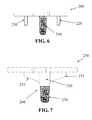
- FIG. 6depicts a side plan view of an alternative embodiment of a tibial tray implant
- FIG. 7depicts a side plan view of another alternative embodiment of a tibial tray implant
- FIGS. 8A through 8Cdepict exemplary surgical steps for removing the implant of FIG. 7 from a patient's anatomy
- FIGS. 9A and 9Bdepict one embodiment of a guide tool for use in removing the implant of FIG. 7 from a patient's anatomy
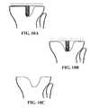
- FIGS. 10A through 10Cdepict exemplary surgical steps for removing an implant without a frangible portion or other revision feature
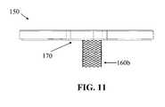
- FIG. 11depicts a side plan view of an exemplary embodiment of tibial tray including a peg comprising a mesh structure.
- Solid Freeform Fabricationincludes a group of emerging technologies that have revolutionized product development and manufacturing.
- the common feature shared by these technologiesis the ability to produce freeform, complex geometry components directly from a computer generated model.
- SFF processesgenerally rely on the concept of layerwise material addition in selected regions.
- a computer generated modelserves as the basis for making a replica.
- the modelis mathematically sliced and each slice is recreated in the material of choice to build a complete object.
- a typical SFF machinecan be likened to a miniaturized “manufacturing plant” representing the convergence of mechanical, chemical, electrical, materials and computer engineering sciences.
- SFFSelective Laser Sintering
- DMLSDirect Metal Laser Sintering
- EBMElectron Beam Melting
- SLMSelective Laser Melting
- SFF manufacturing processes and techniquesseek to minimize and/or eliminate the various inherent deficiencies or weaknesses, especially when final functional parts are being manufactured.
- the controlled inclusion of manufacturing artifactscan facilitate the creation and/or manufacture of implant components that are particularly well suited for use in accommodating unanticipated intraoperative modifications.
- SFF manufacturing processescan be employed to create patient-specific implants that are adaptable to a variety of surgical “options” presented to a surgeon, with one or more user-executed modifications to the implant component desirably altering the implant shape and/or performance to match the chosen surgical outcome.
- SFF manufacturing techniques described hereinincluding SLS, DMLS, EBM or SLM manufacturing, may be utilized to create complex geometries and/or surfaces that can be employed for a variety of functions, which could include the creation of textured and/or porous-walled surfaces, including cement pockets and/or bony ingrowth surfaces, for securing the implant to the patient's underlying bone.
- Various shapescould include defined micro-cavities and/or micro-protrusions on and/or within the implant surface.
- various embodiments described hereininclude implant components that incorporate frangible links, deformable regions, surface textures and/or other features that facilitate and/or enable the intraoperative modification of patient-specific and/or patient-adapted implant components by surgical personnel.
- Features described hereinwhich can be specifically tailored to an individual anatomy, can facilitate the use of standard and/or readily available surgical tools to alter various implant features to accommodate modifications that may occur during the surgical procedure.
- the various featurescan be manufactured as part of the initial manufacturing process, which may include creation of one or more implant components using Solid Freeform Fabrication methods, including via SLM.
- CNC CNCcomputer numerically controlled
- CAM CAMrefers to computer-aided manufacturing (CAM) and can be used to describe the use of software programming tools to efficiently manage manufacturing and production of products and prototypes.
- CAMcan be used with CAD to generate CNC code for manufacturing three- dimensional objects. Casting, Casting is a manufacturing technique that employs a including mold.
- a moldtypically includes the negative of the casting desired shape of a product.
- a liquid materialis poured using into the mold and allowed to cure, for example, with time, rapid cooling, and/or with the addition of a solidifying agent.
- the resulting solid material or castingcan be worked casting subsequently, for example, by sanding or bonding to patterns another casting to generate a final product.
- Weldingis a manufacturing technique in which two components are fused together at one or more locations.
- the component joining surfacesinclude metal or thermoplastic and heat is administered as part of the fusion technique.
- Forging Forgingis a manufacturing technique in which a product or component, typicaliy a metal, is shaped, typicaily by heating and applying force.
- Rapid Rapid prototypingrefers generally to automated proto- construction of a prototype or product, typically using an typing additive manufacturing technology, such as EBM, SLS, SLM, SLA, DMLS, 3DP, FDM and other technologies
- EBM ®EBM ®
- EBM ®electron beam melting
- SLS SLSselective laser sintering
- successive layers of a powderare deposited and melted with a scanning laser, for example, a carbon dioxide laser.
- SLM SLMrefers to selective laser melting TM (SLM), which is a technology similar to SLS; however, with SLM the powder material is fully melted to form a fully-dense product.
- SLA or SLA or SLrefers to stereolithography (SLA or SL), which SL is a liquid-based additive manufacturing technology. Typically, successive layers of a liquid resin are exposed to a curing, for example, with UV laser light, to solidify each layer and bond it to the layer below. This technology typically requires the additional and removal of support structures when creating particular geometries.
- DMLS DMLSrefers to direct metal laser sintering (DMLS), which is a powder-based additive manufacturing technology. Typically, metal powder is deposited and melted locally using a fiber optic laser.
- LC LCrefers to LaserCusing ®(LC), which is a powder-based additive manufacturing technology. LC is similar to DMLS; however, with LC a high-energy laser is used to completely melt the powder, thereby creating a fully- dense product.
- 3DP 3DPrefers to three-dimensional printing (3DP), which is a high-speed additive manufacturing technology that can deposit various types of materials in powder, liquid, or granular form in a printer-like fashion.
- Deposited layerscan be cured layer by layer or, alternatively, for granular deposition, an intervening adhesive step can be used to secure layered granules together in bed of granules and the multiple layers subsequently can be cured together, for example, with laser or light curing.
- LENS LENS ®refers to Laser Engineered Net Shaping TM (LENS ®), which is a powder-based additive manufacturing technology.
- LENS ®is a powder-based additive manufacturing technology.
- a metal powderis supplied to the focus of the laser beam at a deposition head. The laser beam melts the powder as it is applied, in raster fashion. The process continues layer by and layer and requires no subsequent curing. This technology supports net-shaping, which means that the product generated from the technology requires little or no subsequent surface finishing.
- FDM FDMrefers to fused deposition modeling TM (FDM) is an extrusion-based additive manufacturing technology. Typically, beads of heated extruded polymers are deposited row by row and layer by layer. The beads harden as the extruded polymer cools.
- Patient-specific and/or patient-engineered implantscan be produced using 3-dimensional printing technology (also known as Solid Freeform Fabrication or “SFF”) to create solid, physical implant components from an electronic or computerized data file (e.g., a CAD file).
- 3D printing techniquessuch as Selective Laser Sintering (SLS), EBM (Electron Beam Melting) and Selective Laser Melting (SLM—also known as Direct Metal Laser Sintering—DMLS—or LaserCusing) can allow the creation of durable metallic objects that are biocompatible and can directly serve as implant components.
- an implantcan include components and/or implant component parts produced via various methods.
- the knee implantcan include a metal femoral implant component produced by casting or by an additive manufacturing technique and having a patient-specific femoral intercondylar distance; a tibial component cut from a blank and machined to be patient-specific for the perimeter of the patient's cut tibia; and a tibial insert having a standard lock and a top surface that is patient-specific for at least the patient's intercondylar distance between the tibial insert dishes to accommodate the patient-specific femoral intercondylar distance of the femoral implant.
- a knee implantcan include a metal femoral implant component produced by casting or by an additive manufacturing technique that is patient-specific with respect to a particular patient's M-L dimension and standard with respect to the patient's femoral intercondylar distance; a tibial component cut from a blank and machined to be patient-specific for the perimeter of the patient's cut tibia; and a tibial insert having a standard lock and a top surface that includes a standard intercondylar distance between the tibial insert dishes to accommodate the standard femoral intercondylar distance of the femoral implant.
- the steps of designing an implant component and associated methods of SFF manufacturing such objects using additive material technologies such as SLS, SLM, EBM and/or SLS, as described herein,can include both configuring one or more features, measurements, and/or dimensions of the implant (e.g., derived from patient-specific data from a particular patient and adapted for the particular patient), manufacturing and finishing the implant.
- manufacturingcan include making the implant component from starting materials, for example, metals and/or polymers or other materials in solid (e.g., powders or blocks) or liquid form
- the design of an implant component or other manufactured objectmay be altered or modified to accommodate advantages and/or limitations of a specific manufacturing process, such as DMLS or SLM, which may result in differing designs for a single anatomical situation (i.e., for a single patient anatomy) based on differing manufacturing methods.
- a specific manufacturing processsuch as DMLS or SLM
- the various design changeswhich can (but not necessarily must) have varying degrees of impact on the ultimate performance and/or reliability of the implant, can be incorporated to accommodate a wide variety of considerations, including tolerancing and dimensioning limitations of specific manufacturing methodologies and/or equipment, design limitations and/or object feature (e.g., surface and/or subsurface feature) orientation and/or shape requirements.
- FIG. 1depicts a schematic view of equipment and the process used in a typical SLM manufacturing process.
- SLMis a powder bed 8 process that begins with the deposition of a thin layer of powder onto a substrate 30 , which can be disposed on a processing table 11 .
- a high power laser 6scans the surface of the powder, generating heat that causes the powder particles to melt (see melted powder 7 ) and form a melt pool which solidifies as a consolidated layer of material.
- another layer of powderis deposited, which is then subsequently scanned and melted/solidified to form the next layer of the part.
- This processcontinues with multiple layers 13 until enough layers of material have been deposited/melted/solidified to create a desired object 9 . Powder particles that are not melted remain loose and are removed (and can typically be reused) once the component is complete.
- SLM manufacturing processescan be employed in the design and/or manufacture of implant components having intentional “defects” or frangible features, deformable regions and/or other planned internal/external attributes that facilitate the revision and/or removal of implant components and/or portions thereof during primary and/or revision surgical procedures.
- implantscan include planned areas of increased porosity and/or localized lines of weakness that present reduced resistance to surgical cutting, drilling, impaction and/or other tools, as well as implant portions that facilitate modification, deformation, bending and/or work-hardening (and subsequent fracture, if desired) of various component features and/or portions thereof.
- the planned featuresmay facilitate the complete and/or partial removal of implant components, with the partial removal of implant portions potentially facilitating surgical access to implant pieces still remaining in contact with and/or secured to the patient's anatomy.
- various portions of implant componentsmay remain permanently anchored and/or otherwise connected to the patient's anatomy, and may be ignored and/or utilized for securement of revision implant components.
- implant components manufactured using SFF techniquescan include a variety of internal and external structures, which can be formed in a single manufacturing operation, if desired. For example, some portion of an implant component formed using SFF technology could have a relatively smooth, uniform and continuous external layer, while incorporating a less continuous or “disrupted” internal region in selected areas.
- various portions of the implantmay be sensitive or otherwise susceptible to specific and/or unusual loading modalities, which could be employed to selectively separate, flex, bend, fracture and/or otherwise modify portions of the implant.
- the use of rapid prototyping techniques to fabricate both the implant and disrupted region(s)is advantageous because it provides the ability to modify internal structural features of the implant in a desired manner while retaining a smooth, continuous external surface (where such a surface is desired).
- Other known fabrication methodssuch as casting, machining and/or thermoforming, fully surround the implant with a matrix material to form the shape of the implant, and thus internal structural features of the implant are generally uniform to the surface of the implant.
- the present disclosureprovides a designer with the ability to provide a high level of mechanical support for component retention (e.g., functional anchor pegs) where peg removal is not desired, as well as rapid and easy disengagement of the peg from the implant body if such removal is warranted.
- an adaptable featurecould include a frangible portion or link that facilitates separation of an implant component portion at a predetermined location.
- a frangible linkis shown in FIGS. 2A and 2B , which are perspective and side plan views, respectively, of a frangible portion 50 formed in an anchor peg body 60 to allow the peg to be frangibly separated from the implant body (not shown).
- the frangible portion 50can be formed at various locations along the peg and/or within the body, but in the embodiment shown the frangible portion 50 can be located adjacent where the anchor peg meets the implant body.
- the frangible portion 50can include a central section 70 and an outer wall section 80 , which as shown surrounds the central section 70 and forms a continuous outer surface with the remainder of the peg body 60 .
- the central section 70is formed during the SFF manufacturing processes to have a significantly weaker structure than the surrounding peg material, including the outer wall section.
- This central structurewhich in various embodiments could comprise a void, a highly porous structure, a loosely interconnected structure and/or a cavity partially or completely filled with virgin powder material (i.e., unheated powder material), all of which can be created as a portion of the peg and/or implant during the SFF manufacturing process.
- the central structurecould be formed using a SLM layering technique, with the melt pool creating the outer wall section 80 in a typical manner, and the design plan causing the control apparatus to avoid laser contact with the powder in the central structure.
- the outer wall sectioncould the formed using a SLM layering technique with the laser, and then using significantly less or more laser energy impacting on the material in the central section, which could weakly bond the material (less energy) and/or vaporize and “bubble” the material (more energy), creating a highly porous and significantly weaker central section.
- the frangible portion 50can be designed and adapted to break when a predetermined force and/or force vector(s) is/are applied to the peg, thereby allowing at least a portion of the peg to be separated from the implant body. In this manner, a portion of the implant can be designed to fracture and/or bend at a known location and/or under a known force without requiring alteration of the surface characteristics of the implant.
- a variety of physical design techniquescould be used to augment the frangible portion, which could include a reduced diameter region or thinned region of material formed between the peg and the implant body.
- Other configurations for the frangible portioncould include webbing, forming of an annular grooved in an outer surface of the peg, or other techniques known in the art.
- internal geometric featurescould be designed into the central cavity, such as geometry that limits and/or increases notch sensitivity or weakness/strength of the material, depending upon the desired outcome.
- the frangible portionin various embodiments will preferably be formed of the same material as the implant body.
- the frangible portioncan be designed to provide a weak spot in the anchor peg that allows the anchor peg to be easily separated from the implant body when a predetermined force is applied thereto.
- the frangible portioncould be formed internally within the implant body.
- an implant body 100has been formed using SFF manufacturing techniques with a frangible portion 110 including a void 115 or other manufactured artifact positioned adjacent an anchoring peg 120 .
- the peg 120can be separated from the implant body 100 by the application of sufficient force (see FIG. 3B ).
- the removal of the pegcan leave a relatively smooth implant surface and/or a small depression, with little or no material projection out of the implant surface to impede implantation of the non-modified implant (without the peg).
- the void 115could comprise a porous or other material that is exposed to the surface of the implant when the peg is removed. This material could facilitate bony ingrowth or adhesion of bone cement, if desired.
- the voidcould be used for attachment to the anatomical structures (e.g., as a securement hole for orthopedic screws, etc.) or as a connection point for additional implant components.
- an anchoring peg for a femoral implant componentcould include a frangible feature proximate an implant attachment location.
- the anchorcould comprise a cylindrical protrusion extending from a bone-facing portion of the implant, which desirably secures within a bore formed in the underlying anatomical structure, thereby securing the implant to the bone.
- the anchorcould comprise a cylindrical body, the majority of which comprises a solid, essentially uniform CrCo formed by a SLM manufacturing process.
- At a location proximate the implantat least one or more layers of the anchor could comprise a generally cylindrical exterior of relatively solid CrCo encasing a cylindrical internal portion comprising a generally disrupted material, with the interior forming a preferred fracture zone.
- a surgical wrench or other devicecould be used to grasp and rotate the anchor in a clockwise or counterclockwise direction.
- the rotational motionwould desirably impart sufficient stress on the thin cylindrical base region proximate the disrupted interior portion (with the interior portion desirably providing little or no resistance to the rotation), thereby allowing the thin outer wall to fracture and the anchor to detach from the implant.
- the implantcould then be utilized in the standard manner without the cylindrical anchor attached.
- the combination of the thin cylindrical wall surrounding the disrupted interior regionwould desirably provide sufficient support to withstand any expected flexion and/or tension/compression forces experience during normal anatomical loading conditions.
- an implantcould include a removable portion that can be removed and/or otherwise altered to change the shape and/or size of the implant.
- a femoral implant componentcould include a trochlear plate that extends the trochlear groove a desired distance towards and/or into the intercondylar notch.
- a plate structuremight be desired to prevent the natural patella from dislocating and/or dropping into the intercondylar notch after replacement of one or more femoral surfaces.
- an artificial patellar implant portionmay not require and/or desire the presence of the trochlear plate.
- the platecould be removed by grasping the plate portion with surgical pliers and rotating the plate relative to the implant, which desirably fractures and/or otherwise removes the plate structure without damaging or affecting any of the external articulating structures of the femoral implant.
- Various embodiments of patient-specific implants described hereincan include adaptable mating features for integrating with other orthopedic implant components.
- the adaptable mating featurescould include protrusions, flanges, blades, hooks, plates, openings, depressions and/or other attachment sites that can be selectively modified and/or removed by a user.
- such featurescould be integrated into knee and/or hip implant components, including an acetabular shell for a hip implant, that could be configured to couple with an augment, flange cup, mounting member and/or any other suitable orthopedic attachment, as well as various combinations thereof.
- an adaptable featurecould comprise one or more flanges or mounting members designed and manufactured via SFF techniques to be permanently fixed to an implant component.
- the flangescould include “disrupted” regions comprising frangible portions that allow for selective detachment between the implant body and a connection region, such as screw holes or other structures for receiving fasteners.
- the frangible portionscould incorporate reduced cross-sectional areas (in addition to or in place of deliberate disrupted regions, as described herein) that allow bending or breaking or cutting of the flange without disturbing the geometry of the implant body.
- a given flangecould be similarly designed, to allow removal of a portion of the flange while leaving a remaining portion of the flange connected to the implant body.
- the frangible portionscould include physical pre-stressing or otherwise be pretreated to make the frangible portions weaker than other areas of the mounting members.
- one or more porous pieces or surfacescould be designed for a patient-specific implant and provided on adaptable or bendable mounting members such as bendable flanges or plates, or any other mounting arrangement.
- the mounting arrangementcould be modular, attachable, or integrally-provided.
- the bendable region(s)could include “disrupted” regions, as described herein, specifically designed and structured during SFF formation to allow deformation of the mounting arrangement.
- Such bendable regionscould include porous or bony ingrowth surfaces, the locations of which could be modified by the surgeon in-situ to be positioned proximate to bleeding bone or other anatomy.
- adaptable and/or porous featuresmay be incorporated into an implant to reduce, by a certain degree, the stiffness and/or rigidity of an implant or anchoring component while maintaining a desired degree of strength.
- Such featuresmay facilitate the intra-operative modification of implant features (e.g., bending of an anchoring peg in a desired manner by operating room personnel) as well as potentially reduce the opportunity for fatigue or “work-hardening” fracture of implant components or support structures thereof.
- SFF manufacture of implant componentscan be used to create biofunctional implant structures and/or surfaces (and/or securement features), which may be particularized for an individual patient and/or surgical procedure.
- Such surfacescan be designed and utilized to achieve a wide variety of functional objectives, from creating osteo-inductive and/or osteo-conductive surfaces that desirably promote bony ingrowth to porous surfaces to promote bone cement adhesion (as well as relatively smooth surfaces that desirably inhibit bony and/or soft tissue adhesion).
- Utilizing SFF manufacturing to form implant structures with selectively varying bone ingrowth and/or fixation propertiescan permit manufacturing implant features with highly individualized and optimized, patient-adapted fixation characteristics.
- exemplary porous coating parameters that can be varied based on patient-specific informationcan include, for example, the locations on/in implant components where porous coating is used and/or features specific to the coating itself.
- SLM manufacturingcan be used to create an implant feature with a uniform internal microstructure (to desirably promote implant strength and/or durability) in combination with a roughened and/or porous surface structure that, depending upon a variety of manufacturing parameters, can be particularized for a wide variety of surgical objectives.
- an outer implant surfacecan be created having an optimal and/or designed pore size for promoting bone ingrowth in a certain patient population.
- an implant outer surfacecan be created having a designed pore size and/or surface roughness for promoting bone cement attachment and/or adhesion.
- implant modeling and SFF fabrication techniquescan be employed to create a unique implant.
- structures and/or surfaces of an implantcan selectively be porous, roughened, smooth and/or hardened.
- porouscan generally be used to describe any portion of structure having a plurality of holes, spaces, gaps, channels, etc. therein.
- a porous portioncan consist of a plurality of small discrete particles of material (e.g., metal) that were bonded together at their points of contact with each other to define a plurality of connected interstitial pores.
- a porous portioncan consist of an organized lattice, mesh, and/or grid of material having multiple channels, spaces, and/or pores therein.
- the structural nature of a porous portioncan be controlled by the design and/or manufacturing parameters provided to, as well the capabilities of, the SFF manufacturing equipment and process(es).
- the various surface features created by the SLM manufacturing processcould be dependent upon a wide variety of variables, including the grain size, shape and/or distribution (e.g., uniformity and/or nonuniformity) of the raw material, which may be particularized for a specific application and/or implant feature desired.
- various of the surface features of a patient-specific implantcould be particularized to accommodate a variety of objectives, including various combinations of the following: (1) Smooth surfaces; (2) hardened surfaces; (3) porous surfaces for promoting bone infiltration and/or ingrowth; (4) roughened and/or porous surfaces for promoting material adhesion such as bone cement securement; and/or (5) porous surfaces for containing osteo-inductive agents and/or medicaments.
- a tibial implantcould include one or more bone-facing surfaces that include specifically designed and manufactured porous surface features that promoted bone in-growth.
- porous featurescan be created in bone-facing portions of the implant (e.g., on one or more inner, bone facing surfaces and/or on the surface of impaction pegs, stems, pins and/or anchors, etc.) at locations where the intended surgical procedure is expected to create bleeding bone.
- non-porous surface featuresmay be created, such as along articulating and/or peripheral edge surfaces that are not expected to encounter bleeding bone and/or where bone ingrowth is not desired.
- implantif desired, other surface features may be incorporated, such as smooth and/or thickened surfaces where FEA or other analysis indicates the implant may experience increased and/or excessive stresses (e.g., thinned implant sections and/or notch sensitive locations, etc.). Still other portions of the implant may incorporate roughened and/or porous surfaces to accommodate bone cement and/or medications, if desired.
- one or more porous surfaces or other surface featurescan be designed into certain subregions of an implant component that interface with bone.
- such an implantcan include some bone-interfacing subregions, with other subregions designed to mate with cement or other securement materials, thereby creating a patient-specific hybrid cemented/porous-coated implant.
- a patient-specific implant componentcould include porous coatings on pegs or other anchor regions of the implant, with non-porous coatings (and/or coatings to facilitate securement by bone cement) on other bone-facing surfaces of the implant.
- a patient-specific implant componentcould include non-porous peg and/or anchor surface, with porous coatings on other bone-facing surfaces of the implant.
- an implantcan be designed and/or manufactured to include one or more porous regions that partially and/or completely extend through portions of the implant body.
- a tibial traymay include one or more porous regions of the implant that extend completely through the tray body (from caudal to cephalad surfaces of the implant, for example), thereby allowing bone to grow completely through the implant, if desired.
- Such porous regionscould be surrounded partially and/or completely by non-porous regions, such as a non-porous periphery of a tibial tray surrounding one or more porous regions formed centrally or in medial and lateral compartments of the tibial tray.
- such embodimentscould allow for bone ingrowth completely through the metallic tray and into contact with a polymer, ceramic and/or metallic tray insert.
- tibial alignment and/or securement finscould be partially and/or completely porous.
- a central pin for securing a hip resurfacing implantcould include one or more porous sections (or be completely porous), if desired.
- an articular surface repair systemcan be affixed to subchondral bone, with one or more stems, or pegs, extending through the subchondral plate into the marrow space.
- this designcan reduce the likelihood that the implant will settle deeper into the joint over time by resting portions of the implant against the subchondral bone.
- the stems, or pegscan be of any shape suitable to perform the function of anchoring the device to the bone.
- the pegscan be cylindrical or conical.
- the stems, or pegscan further include notches or openings to allow bone in-growth.
- the stemscan be porous coated for bone in-growth.
- the adaptive features described hereincan be applied to implant components for use with any joint including, without limitation, a spine, spinal articulations, an intervertebral disk, a facet joint, a shoulder, an elbow, a wrist, a hand, a finger, a hip, a knee, an ankle, a foot, or a toe joint.
- various embodiments described hereincan encompass and/or apply to the design, selection and/or manufacture of standard and/or modular implants and/or implant components, if such are appropriate to a given patient's anatomy, as well as associated guide tools.
- SLM manufacturing techniquescan be employed to design and manufacture implant components having adaptable features that desirably improve and/or simplify a surgeon's ability to perform a subsequent revision surgery.
- Revision of an implant componentmay be indicated for a host of reasons, including implant fracture and/or failure, excessive wear, infection and/or excessive pain.
- portions of an implant requiring revisionmay still remain anchored or otherwise secured to underlying portions of the patient's anatomy.
- the removal of an implant componentmay necessitate significant resection of the patient's anatomy, which leaves significantly less of the native anatomical structures remaining for fixation of the revision component(s).
- an implant component that was partially and/or fully-secured to the underlying anatomycould be difficult to separate from the patient's anatomy.
- a tibial tray implant having a centrally secured postit might be necessary for a surgeon to cut around the existing implant or otherwise position instrumentation around the implant to loosen it from the surrounding bone and/or other anatomy prior to removal.
- the tray included a tibial keel or other rotation-resistant structuresit could be difficult to cut around the keel or otherwise access various areas of the bone-implant interface to loosen the implant. It might be particularly difficult to access certain areas of the implant depending upon the chosen access type and/or path(s).
- the keel structurecould impede access to posterior/lateral portions of the bone-implant interface. Accordingly, a surgeon might need to remove a significant amount of bone to separate the implant from the tibia, as well as remove significant bone to facilitate access to inner portions of the implant and/or surrounding the central post (see FIGS. 10A through 10C , for example). These difficulties would be exacerbated by the lack of access to such support structures, which necessitated significant bone removal for access to underlying structures, especially where the implant attachment was well secured. Moreover, where complete separation between the implant and the underlying bone was unsuccessful, subsequent removal of the implant could involve considerable force and/or inadvertently and undesirably fracture additional portions of the remaining anatomy.
- implant componentscan be designed and manufactured with features that facilitate revision of the component(s), should a subsequent revision of the implant become necessary.
- implant featurescan include frangible and/or deformable sections that desirably withstand normal loading, but which are especially susceptible to specific loading modalities and/or modification by surgical tools, allowing portions and/or the entirety of the implant to be “released” and/or removed with little or no need for resection, modification and/or damage to the patient's underlying native anatomy.
- the implant componentcan be provided with guiding features that facilitate the use of surgical tools to release portions of the implant, including the use of guide tools or jigs that incorporate implant-specific and/or anatomy-specific surfaces (of combinations thereof) to guide surgical tools.
- a tibial implant component 150can include a centrally-located anchoring peg 160 a secured to a bone-facing side 170 of the implant.
- the pegcould comprise a generally cylindrical body made of powdered and laser-melted CrCo, which can be produced using a SLM manufacturing method as previously described (e.g., as part of the implant manufacturing process via SLM). All or at least a portion of the peg can comprise a porous structure, as discussed herein, to facilitation bone ingrowth and fixation.
- a base portion 175 of the anchoring peg proximate the implant surfacecan include an adaptable feature that may include a region of significantly increased porosity (which may or may not extend to the surface of the peg, at the designer's option) and/or a significantly reduced material strength.
- the base portion 175does not appreciably affect the strength or durability of the peg as an anchoring feature (or at least does not reduce peg strength below an acceptable minimal functional level to properly function as an implant anchor), but the porous region will significantly reduce the resistance of the peg base to cutting tools such as vibratory saws and/or drills.
- a tibial implant component 150can be manufactured with a peg 160 b formed, at least in part, of a lattice structure, as shown in FIG. 11 .
- the lattice structurecan comprise a plurality of organized individual filaments with openings between parallel filaments.
- the lattice structurecan form a general outer periphery configured in, for example, a cylindrical shape, similar to that of peg 160 a .
- the openings in the lattice structurecan provide for bone ingrowth.
- the structure of the lattice(including, e.g., the filament width, spacing between filaments, angle of filaments, interconnections between filaments) can be designed, engineered, and/or otherwise optimized to patient-specific and/or design parameters.
- a lattice structureas opposed to other porous structures, may be advantageous for providing a desired strength or durability of the peg as an anchoring feature (or at least does not reduce peg strength below an acceptable minimal functional level to properly function as an implant anchor), while utilizing individual filaments of relatively small diameter.
- Such a configuration, with small diameter filamentmay permit a substantial amount of bone ingrowth between individual filaments, thereby enhancing fixation.
- the small diameter of individual filamentsmay particularly facilitate detachment of the tibial tray from the peg during a revision surgery.
- a saw or other cutting toolmay be applied with, e.g., only the force needed to cut a single filament at a time, in order to cut through the lattice structure of the peg.
- This amount of force to cut through a single filamentmay be substantially smaller than, for example, the amount of force required to cut through a peg of comparable diameter that is formed of a solid (or possibly other porous) structure.
- pegs 160 a,bcan easily be separated from the tibial implant by advancing a saw or drill along the bone-facing surface of the implant (in a region between the native bone and the bone-facing side of the implant) and cutting the base of the peg at the porous region (see FIG. 5A ). Once the peg has been severed, the implant can be removed from the femur (see FIG. 5B ). Depending upon the surgical objectives as well as the revision implant components to be used, the pegs may be removed (e.g., using a coring drill 180 or other surgical tools well known in the art—see FIGS. 5C through 5E ), or the peg can remain within the anatomy, with a subsequent revision implant covering, “capping” or otherwise reattaching to some or all of the peg, if desired.
- a coring drill 180 or other surgical tools well known in the artsee FIGS. 5C through 5E
- FIG. 6depicts a tibial tray implant 200 having a plurality of anchoring pegs extending from a lower, bone-facing surface for securement to a tibial surface (not shown).
- the anchoring pegscan include a centrally-located porous peg 210 that provides for bony ingrowth and/or cement fixation, and peripherally placed pegs 220 which can comprise press-fit or other attachment arrangements.
- This arrangementwill desirably provide significantly more short-term and long-term fixation for the implant as compared to an implant having only a single anchoring peg and/or single type of fixation (i.e., only one of press-fit, cement fixation and/or bone ingrowth, for example).
- the surgeonmay elect to tunnel under the implant (as previously described) and avoid and/or sever the peripheral pegs (at the surgeon's option), and subsequently sever or fracture the centrally-located peg 210 .
- the central peg 210can be easily fractured and/or cut, as it desirably comprises a porous and/or weakened structure, as previously described.
- the peripheral pegsmay be of a smaller size and thus more easily broken or severed, or if not severed, the peripheral pegs may be easily withdrawn from the tibia if natural tissues and/or cement have not adhered to these relatively smoother peripheral pegs.
- the central peg 210may remain within the tibia, or it may be removed as previously described.
- FIG. 7depicts an alternative embodiment which includes a tibial tray 250 having a composite anchoring peg 260 that incorporates a solid proximal portion 265 and a porous distal portion 270 . Also includes are one or more wings 275 that can desirably provide rotational stability to the tray 250 , as known in the art.
- the composite anchoring peg 260can be inserted in a known manner, with the proximal portion 265 of the peg providing a press-fit securement, and the distal portion 270 desirably allowing for bony ingrowth.
- a surgical toolcan be inserted into and through a patient's soft tissues 280 and tibial bone 285 from a lateral aspect, and the anchoring peg 260 can be severed at a location proximate a boundary between the proximal portion 265 and the distal portion 270 (see FIG. 8A ). This desirably will release the tray 250 from the securely anchored porous distal portion 270 , and allow the tray 250 to be withdrawn from the tibia (see FIG. 8B ). If desired, the distal portion may remain permanently within the bone, or if may be removed using a coring drill or other tool (see FIG. 8C ).
- the disclosed embodimentsprovide for removal of relevant implant components and/or anchor portions in a least-invasive manner, thereby preserving significantly more bone and/or other anatomical support structures for the subsequent revision procedure. Moreover, depending upon the chosen revision implant components and procedure, one or more residual anchoring components still secured to the bone may be used to provide additional fixation for the revision components.
- the implant componentcan include guiding features that facilitate the use of surgical tools in accessing various adaptable features.
- a bone facing and/or peripheral edge of the implantcould include markings and/or protrusions/indentations that facilitate and/or guide the advancement of a surgical cutting tool.
- markings and/or protrusions/indentationsthat facilitate and/or guide the advancement of a surgical cutting tool.
- a guide tool or jigmay be provided that includes guiding features and/or implant-specific surfaces that conform to various implant surfaces (and/or protrusions/indentations on the implant surface) and/or native anatomical features that desirably guide surgical tools into contact with the relevant adaptable structures.
- Such guiding features and implant-specific surfacesmay be designed using implant data saved from a prior surgery, or such data may be constructed using patient-specific image data, if available.
- a guide tool 300 as depicted in FIG. 9Acan include a patient-specific surface 310 that desirably conforms to one or more exposed surfaces 315 of an implant 320 .
- the guide tool 300can include one or more alignment apertures 330 which provide for the controlled insertion and advancement on one or more cutting tools along a specific trajectory, which in this embodiment intersects an implant anchoring post 340 at a location proximate a solid/porous interface 350 (see FIG. 9B ).
- an implant componentcan include features such as internal voids and/or cavities that facilitate surgical removal and/or subsequent use.
- SLM manufacturing techniquescan be utilized to create an implant component with anchoring pegs having internal voids or other features that facilitate their subsequent removal if necessary.
- Such featurescan include a central bore region formed in a cylindrical anchoring peg that, when the peg is separated from the implant (such as, for example, as previously described herein), the resected surface of the peg exposes a central bore which can be utilized to remove the peg from the surrounding bony anatomy.
- a drill or other surgical toolcan be advanced into the bore, and attached to a slap hammer or other device which is employed in a known manner to remove the peg.
- the exposed central bore of the pegcould be utilized to anchor a subsequent implant, if desired.
- adaptable featuressuch as SFF manufactured voids and/or porous areas of lower material density can be employed to improve and/or facilitate non-invasive visualization (e.g., x-ray imaging or other techniques) of implant structures and/or bone interface regions (e.g., lucent lines, bone ingrowth, etc.) for a variety of reasons, including the detection of implant fatigue, fracture and/or loosening of implant components from the underlying bony anatomy.
- the featuresmay act as “windows” to facilitate the visualization of lucent lines or other anatomical/implant features.
- FEAFEA or other analysis of relevant implant datasets, which optionally may include analyses of material property information particular to the type of manufacturing processes as well as the design and/or orientation of the implant (as oriented and positioned in the intended build plan).
- Such an analysiscan occur immediately prior to SLM manufacture (e.g., FEA analysis of each object in the build plan, with relevant manufacturing and orientation data, can be evaluated) or the analysis may be conducted on some subset thereof at any point in the evaluation and virtual packing process.
- the FEA analysiswill desirably identify and/or highlight one or more locations of high stress and/or areas of localized implant weakness, including those that may be particular to the type of manufacturing processes as well as the design and orientation of the implant.
- FEA analysis of a part design and/or orientationidentifies one or more undesired regions of potential weakness and/or failure, it may be desirous to reposition and/or reorient the object in the build plan (and/or may necessitate modifying the implant design and/or build plan in some manner). Moreover, FEA analysis may be employed to ensure that one or more adaptable features (such as those described herein) have been properly designed to accommodate implant modification (e.g., fracture and/or bending) by surgical personnel.
- the maximum principal stress observed in FEA analysiscan be used to establish an acceptable minimum implant thickness for an implant component having a particular size and, optionally, for a particular patient (e.g., having a particular weight, age, activity level, etc).
- an implant component design or selectioncan depend, at least in part, on a threshold minimum implant component thickness.
- the threshold minimum implant component thicknesscan depend, at least in part, on patient-specific data, such as condylar width, femoral transepicondylar axis length, and/or the patient's specific weight.
- the threshold implant thickness, and/or any implant component featurecan be adapted to a particular patient based on a combination of patient-specific geometric data and on patient-specific anthropometric data.
- This approachcan apply to any implant component feature for any joint, for example, the knee, the hip, or the shoulder.
- the design of a given implant component and/or various features thereincan be further assessed and/or modified by including FEA modeling and/analysis, either alone or in combination with information relating to the specific manufacturing method chosen for creating the implant.
- FEAfinite element analysis
- a finite element analysis (FEA) of an SLM implant and/or intended implant designmay identify areas of the implant/design prone to increased and/or excessive loads, which may induce the designer to modify the design to better accommodate the anticipated loading (e.g., increase the local or global implant thickness and/or alter implant geometry or location of planar surfaces).
- FEA analysismay identify areas of concern that may impel a redesign of the implant to alleviate strength, durability and/or adaptability concerns.
- an FEA analysismay identify areas of one or more build objects that could benefit from some modification of the intended manufacturing process at one or more times part-way through the manufacturing process (e.g., “cross-hatching” or remelting an individual portion of a melt layer to reduce/avoid the formation of interconnected porosity and/or buckling deformation in a localized manner), and then continuing the layer deposition and laser melting process to complete the implant manufacture.
- the material properties (and/or potentially one or more component materials) of an implantcan be varied to accommodate unique or localized requirements.
- the porosity and/or tensile strength/elasticity of a material in a femoral implant componentmay be desirable for the porosity and/or tensile strength/elasticity of a material in a femoral implant component to vary along the surface or cross-sectional profile of the implant.
- the implantmay comprise various materials that are adhered, layered or otherwise arranged in some fashion, including the use of multiple types of materials and/or material properties in non-aligned layers (e.g., a composite-like layering materials), to accomplish various objectives of various embodiments disclosed herein.
- implants comprising metals, plastics and/or ceramic constituentsmay be formed of two or more materials, or may comprise a single material with sections or portions having varying material characteristics (e.g., by radiation, heating, cooling, hipping, annealing, chemical action, work hardening, peening, carburizing, hardening, surface treating, oxidation, etc.)
- the medial and/or lateral and/or superior and/or inferior portions of a tibial tray insetmay be formed from two or more materials adhered or otherwise connected in some manner, each material having a unique material property, resulting in an implant with differing mechanical properties on its medial and/or lateral and/or superior and/or inferior sides.
- Such an implantcould alternatively comprise a multi-layered material, with different materials and/or material properties exposed on the surface during a subsequent machining process (with the processing tools extending to differing depths), thereby resulting in a generally uniform layered material with different surface properties on the surface of its medial and lateral sides.
- any material known in the artcan be used for any of the implant systems and component described in the foregoing embodiments, for example including, but not limited to metal, metallic powders, metal alloys, combinations of metals, ceramics, plastic, polyethylene, cross-linked polyethylene's or polymers or plastics, pyrolytic carbon, nanotubes and carbons, as well as biologic materials.
- the DMLS/SLM raw materialcan comprise a CrCo powder having an average particle size of between 34 and 54 microns, although larger and/or smaller particles may be used with varying degrees of utility (as well as the use of differing size particles in creating a single implant component).
- the deposed particle layermay be approximately 60 microns thick which, when melted, consolidated and cooled, can create a solid structural layer of approximately 20 microns thickness.
- fixation techniques and combinations thereof known in the artcan be used for any of the implant systems and component described in the foregoing embodiments, for example including, but not limited to cementing techniques, porous coating of at least portions of an implant component, press fit techniques of at least a portion of an implant, ingrowth techniques, etc.
Landscapes
- Health & Medical Sciences (AREA)
- Engineering & Computer Science (AREA)
- Orthopedic Medicine & Surgery (AREA)
- Transplantation (AREA)
- Materials Engineering (AREA)
- Manufacturing & Machinery (AREA)
- Chemical & Material Sciences (AREA)
- Life Sciences & Earth Sciences (AREA)
- Veterinary Medicine (AREA)
- Vascular Medicine (AREA)
- Biomedical Technology (AREA)
- Animal Behavior & Ethology (AREA)
- General Health & Medical Sciences (AREA)
- Public Health (AREA)
- Heart & Thoracic Surgery (AREA)
- Physical Education & Sports Medicine (AREA)
- Oral & Maxillofacial Surgery (AREA)
- Cardiology (AREA)
- Mechanical Engineering (AREA)
- Physics & Mathematics (AREA)
- Optics & Photonics (AREA)
- Plasma & Fusion (AREA)
- Prostheses (AREA)
Abstract
Description
| Exemplary techniques for forming or altering a patient-specific and/or |
| patient-engineered implant component for a patient's anatomy |
| Technique | Brief description of technique and related notes |
| CNC | CNC refers to computer numerically controlled (CNC) |
| machine tools, a computer-driven technique, e.g., | |
| computer-code instructions, in which machine tools are | |
| driven by one or more computers. Embodiments of this | |
| method can interlace with CAD software to streamline the | |
| automated design and manufacturing process. | |
| CAM | CAM refers to computer-aided manufacturing (CAM) and |
| can be used to describe the use of software programming | |
| tools to efficiently manage manufacturing and production | |
| of products and prototypes. CAM can be used with CAD | |
| to generate CNC code for manufacturing three- | |
| dimensional objects. | |
| Casting, | Casting is a manufacturing technique that employs a |
| including | mold. Typically, a mold includes the negative of the |
| casting | desired shape of a product. A liquid material is poured |
| using | into the mold and allowed to cure, for example, with time, |
| rapid | cooling, and/or with the addition of a solidifying agent. |
| prototyped | The resulting solid material or casting can be worked |
| casting | subsequently, for example, by sanding or bonding to |
| patterns | another casting to generate a final product. |
| Welding | Welding is a manufacturing technique in which two |
| components are fused together at one or more locations. | |
| In certain embodiments, the component joining surfaces | |
| include metal or thermoplastic and heat is administered | |
| as part of the fusion technique. | |
| Forging | Forging is a manufacturing technique in which a product |
| or component, typicaliy a metal, is shaped, typicaily by | |
| heating and applying force. | |
| Rapid | Rapid prototyping refers generally to automated |
| proto- | construction of a prototype or product, typically using an |
| typing | additive manufacturing technology, such as EBM, SLS, |
| SLM, SLA, DMLS, 3DP, FDM and other technologies | |
| EBM ® | EBM ® refers to electron beam melting (EBM ®), which is |
| a powder-based additive manufacturing technology. | |
| Typically, successive layers of metal powder are | |
| deposited and melted with an electron beam in a vacuum. | |
| SLS | SLS refers to selective laser sintering (SLS), which is a |
| powder-based additive manufacturing technology. | |
| Typically, successive layers of a powder (e.g., polymer, | |
| metal, sand, or other material) are deposited and melted | |
| with a scanning laser, for example, a carbon dioxide | |
| laser. | |
| SLM | SLM refers to selective laser melting ™ (SLM), which is a |
| technology similar to SLS; however, with SLM the powder | |
| material is fully melted to form a fully-dense product. | |
| SLA or | SLA or SL refers to stereolithography (SLA or SL), which |
| SL | is a liquid-based additive manufacturing technology. |
| Typically, successive layers of a liquid resin are exposed | |
| to a curing, for example, with UV laser light, to solidify | |
| each layer and bond it to the layer below. This | |
| technology typically requires the additional and removal of | |
| support structures when creating particular geometries. | |
| DMLS | DMLS refers to direct metal laser sintering (DMLS), which |
| is a powder-based additive manufacturing technology. | |
| Typically, metal powder is deposited and melted locally | |
| using a fiber optic laser. Complex and highly accurate | |
| geometries can be produced with this technology. This | |
| technology supports net-shaping, which means that the | |
| product generated from the technology requires little or no | |
| subsequent surface finishing. | |
| LC | LC refers to LaserCusing ®(LC), which is a powder-based |
| additive manufacturing technology. LC is similar to | |
| DMLS; however, with LC a high-energy laser is used to | |
| completely melt the powder, thereby creating a fully- | |
| dense product. | |
| 3DP | 3DP refers to three-dimensional printing (3DP), which is a |
| high-speed additive manufacturing technology that can | |
| deposit various types of materials in powder, liquid, or | |
| granular form in a printer-like fashion. Deposited layers | |
| can be cured layer by layer or, alternatively, for granular | |
| deposition, an intervening adhesive step can be used to | |
| secure layered granules together in bed of granules and | |
| the multiple layers subsequently can be cured together, | |
| for example, with laser or light curing. | |
| LENS | LENS ® refers to Laser Engineered Net Shaping ™ |
| (LENS ®), which is a powder-based additive | |
| manufacturing technology. Typically, a metal powder is | |
| supplied to the focus of the laser beam at a deposition | |
| head. The laser beam melts the powder as it is applied, | |
| in raster fashion. The process continues layer by and | |
| layer and requires no subsequent curing. This technology | |
| supports net-shaping, which means that the product | |
| generated from the technology requires little or no | |
| subsequent surface finishing. | |
| FDM | FDM refers to fused deposition modeling ™ (FDM) is an |
| extrusion-based additive manufacturing technology. | |
| Typically, beads of heated extruded polymers are | |
| deposited row by row and layer by layer. The beads | |
| harden as the extruded polymer cools. | |
Claims (8)
Priority Applications (3)
| Application Number | Priority Date | Filing Date | Title |
|---|---|---|---|
| US14/033,095US9636229B2 (en) | 2012-09-20 | 2013-09-20 | Solid freeform fabrication of implant components |
| US15/582,994US10485676B2 (en) | 2012-09-20 | 2017-05-01 | Solid freeform fabrication of implant components |
| US16/695,988US20200100909A1 (en) | 2012-09-20 | 2019-11-26 | Solid Freeform Fabrication of Implant Components |
Applications Claiming Priority (3)
| Application Number | Priority Date | Filing Date | Title |
|---|---|---|---|
| US201261703768P | 2012-09-20 | 2012-09-20 | |
| US201361801992P | 2013-03-15 | 2013-03-15 | |
| US14/033,095US9636229B2 (en) | 2012-09-20 | 2013-09-20 | Solid freeform fabrication of implant components |
Related Child Applications (1)
| Application Number | Title | Priority Date | Filing Date |
|---|---|---|---|
| US15/582,994DivisionUS10485676B2 (en) | 2012-09-20 | 2017-05-01 | Solid freeform fabrication of implant components |
Publications (2)
| Publication Number | Publication Date |
|---|---|
| US20140172111A1 US20140172111A1 (en) | 2014-06-19 |
| US9636229B2true US9636229B2 (en) | 2017-05-02 |
Family
ID=50931815
Family Applications (3)
| Application Number | Title | Priority Date | Filing Date |
|---|---|---|---|
| US14/033,095ActiveUS9636229B2 (en) | 2012-09-20 | 2013-09-20 | Solid freeform fabrication of implant components |
| US15/582,994Active2033-12-21US10485676B2 (en) | 2012-09-20 | 2017-05-01 | Solid freeform fabrication of implant components |
| US16/695,988AbandonedUS20200100909A1 (en) | 2012-09-20 | 2019-11-26 | Solid Freeform Fabrication of Implant Components |
Family Applications After (2)
| Application Number | Title | Priority Date | Filing Date |
|---|---|---|---|
| US15/582,994Active2033-12-21US10485676B2 (en) | 2012-09-20 | 2017-05-01 | Solid freeform fabrication of implant components |
| US16/695,988AbandonedUS20200100909A1 (en) | 2012-09-20 | 2019-11-26 | Solid Freeform Fabrication of Implant Components |
Country Status (1)
| Country | Link |
|---|---|
| US (3) | US9636229B2 (en) |
Cited By (32)
| Publication number | Priority date | Publication date | Assignee | Title |
|---|---|---|---|---|
| US9849019B2 (en) | 2012-09-21 | 2017-12-26 | Conformis, Inc. | Methods and systems for optimizing design and manufacture of implant components using solid freeform fabrication |
| US9910935B2 (en)* | 2013-10-11 | 2018-03-06 | Advanced Solutions Life Sciences, Llc | System and workstation for the design, fabrication and assembly of bio-material constructs |
| US9949837B2 (en) | 2013-03-07 | 2018-04-24 | Howmedica Osteonics Corp. | Partially porous bone implant keel |
| US10405993B2 (en) | 2013-11-13 | 2019-09-10 | Tornier Sas | Shoulder patient specific instrument |
| US10456261B2 (en) | 2012-01-20 | 2019-10-29 | Conformis, Inc. | Devices, systems and methods for manufacturing orthopedic implants |
| US10456143B2 (en) | 2017-03-02 | 2019-10-29 | Titanium Fusion Technologies, Llc | Composite joint arthroplasty systems and methods |
| US10485676B2 (en) | 2012-09-20 | 2019-11-26 | Conformis, Inc. | Solid freeform fabrication of implant components |
| US10633976B2 (en) | 2017-07-25 | 2020-04-28 | Bell Helicopter Textron Inc. | Methods of customizing, manufacturing, and repairing a rotor blade using additive manufacturing processes |
| US10716676B2 (en) | 2008-06-20 | 2020-07-21 | Tornier Sas | Method for modeling a glenoid surface of a scapula, apparatus for implanting a glenoid component of a shoulder prosthesis, and method for producing such a component |
| US10940024B2 (en) | 2017-07-26 | 2021-03-09 | Optimotion Implants LLC | Universal femoral trial system and methods |
| US10959742B2 (en) | 2017-07-11 | 2021-03-30 | Tornier, Inc. | Patient specific humeral cutting guides |
| US11065016B2 (en) | 2015-12-16 | 2021-07-20 | Howmedica Osteonics Corp. | Patient specific instruments and methods for joint prosthesis |
| US11167375B2 (en) | 2018-08-10 | 2021-11-09 | The Research Foundation For The State University Of New York | Additive manufacturing processes and additively manufactured products |
| US11166733B2 (en) | 2017-07-11 | 2021-11-09 | Howmedica Osteonics Corp. | Guides and instruments for improving accuracy of glenoid implant placement |
| US11213403B2 (en) | 2019-03-14 | 2022-01-04 | Medos International Sarl | Devices and methods for optimized spinal fixation |
| US11284927B2 (en)* | 2018-02-02 | 2022-03-29 | Stryker European Holdings I, Llc | Orthopedic screw and porous structures thereof |
| US11324525B1 (en) | 2021-06-30 | 2022-05-10 | Kinos Medical Inc. | Surgical alignment guide assembly for total ankle replacement and method of using the same |
| US11406502B2 (en) | 2017-03-02 | 2022-08-09 | Optimotion Implants LLC | Orthopedic implants and methods |
| US11427350B2 (en) | 2019-01-31 | 2022-08-30 | Textron Innovations Inc. | Methods of forming and assembling a rotor blade using additive manufacturing processes |
| US11648706B2 (en) | 2018-04-26 | 2023-05-16 | San Diego State University Research Foundation | Selective sinter-based fabrication of fully dense complexing shaped parts |
| US11730603B2 (en) | 2020-09-03 | 2023-08-22 | Globus Medical, Inc. | Systems and methods for knee arthroplasty |
| US11806028B1 (en) | 2022-10-04 | 2023-11-07 | Restor3D, Inc. | Surgical guides and processes for producing and using the same |
| US11844697B2 (en) | 2020-09-03 | 2023-12-19 | Globus Medical, Inc. | Systems and methods for knee arthroplasty |
| USD1013875S1 (en) | 2020-01-08 | 2024-02-06 | Restor3D, Inc. | Spinal implant |
| USD1013876S1 (en) | 2020-01-08 | 2024-02-06 | Restor3D, Inc. | Osteotomy wedge |
| US11960266B1 (en) | 2023-08-23 | 2024-04-16 | Restor3D, Inc. | Patient-specific medical devices and additive manufacturing processes for producing the same |
| US12083027B2 (en) | 2017-03-02 | 2024-09-10 | Optimotion Implants LLC | Universal femoral trial system and methods |
| USD1051384S1 (en) | 2023-03-24 | 2024-11-12 | Restor3D, Inc. | Bone fixation pin |
| USD1052732S1 (en) | 2023-05-25 | 2024-11-26 | Restor3D, Inc. | Subtalar wedge |
| USD1053353S1 (en) | 2023-03-24 | 2024-12-03 | Restor3D, Inc. | Orthopedic screw |
| US12193939B2 (en) | 2017-12-29 | 2025-01-14 | Howmedica Osteonics Corp. | Patient specific humeral implant components |
| USD1071220S1 (en) | 2020-01-08 | 2025-04-15 | Restor3D, Inc. | Osteotomy wedge |
Families Citing this family (48)
| Publication number | Priority date | Publication date | Assignee | Title |
|---|---|---|---|---|
| US8556983B2 (en) | 2001-05-25 | 2013-10-15 | Conformis, Inc. | Patient-adapted and improved orthopedic implants, designs and related tools |
| US9603711B2 (en) | 2001-05-25 | 2017-03-28 | Conformis, Inc. | Patient-adapted and improved articular implants, designs and related guide tools |
| US8617242B2 (en) | 2001-05-25 | 2013-12-31 | Conformis, Inc. | Implant device and method for manufacture |
| US8480754B2 (en) | 2001-05-25 | 2013-07-09 | Conformis, Inc. | Patient-adapted and improved articular implants, designs and related guide tools |
| US8439926B2 (en) | 2001-05-25 | 2013-05-14 | Conformis, Inc. | Patient selectable joint arthroplasty devices and surgical tools |
| JP2006505366A (en) | 2002-11-07 | 2006-02-16 | コンフォーミス・インコーポレイテッド | Method of determining meniscus size and shape and devised treatment |
| WO2009111626A2 (en) | 2008-03-05 | 2009-09-11 | Conformis, Inc. | Implants for altering wear patterns of articular surfaces |
| WO2010099231A2 (en) | 2009-02-24 | 2010-09-02 | Conformis, Inc. | Automated systems for manufacturing patient-specific orthopedic implants and instrumentation |
| CA2782137A1 (en) | 2009-12-11 | 2011-06-16 | Conformis, Inc. | Patient-specific and patient-engineered orthopedic implants |
| WO2012112694A2 (en) | 2011-02-15 | 2012-08-23 | Conformis, Inc. | Medeling, analyzing and using anatomical data for patient-adapted implants. designs, tools and surgical procedures |
| WO2015024122A1 (en) | 2013-08-21 | 2015-02-26 | Laboratoires Bodycad Inc. | Anatomically adapted orthopedic implant and method of manufacturing same |
| US10667829B2 (en) | 2013-08-21 | 2020-06-02 | Laboratoires Bodycad Inc. | Bone resection guide and method |
| US10687956B2 (en) | 2014-06-17 | 2020-06-23 | Titan Spine, Inc. | Corpectomy implants with roughened bioactive lateral surfaces |
| US20170274599A1 (en)* | 2014-09-19 | 2017-09-28 | Kabushiki Kaisha Toshiba | Additive manufacturing apparatus and additive manufacturing method |
| US20160213405A1 (en) | 2015-01-27 | 2016-07-28 | K2M, Inc. | Vertebral plate systems and methods of use |
| US10028841B2 (en) | 2015-01-27 | 2018-07-24 | K2M, Inc. | Interbody spacer |
| JP6768001B2 (en) | 2015-04-29 | 2020-10-14 | インスティテュート フォー マスキュロスケレタル サイエンス アンド エジュケイション,リミテッド | Coiled implants and systems and how to make them |
| US10492921B2 (en) | 2015-04-29 | 2019-12-03 | Institute for Musculoskeletal Science and Education, Ltd. | Implant with arched bone contacting elements |
| US10449051B2 (en) | 2015-04-29 | 2019-10-22 | Institute for Musculoskeletal Science and Education, Ltd. | Implant with curved bone contacting elements |
| EP3090700A1 (en)* | 2015-05-08 | 2016-11-09 | Vrije Universiteit van Amsterdam | Customized dental implant and associated tooling |
| TWI726940B (en) | 2015-11-20 | 2021-05-11 | 美商泰坦脊柱股份有限公司 | Processes for additively manufacturing orthopedic implants |
| US11376660B2 (en) | 2015-11-20 | 2022-07-05 | Titan Spine, Inc. | Processes for additively manufacturing orthopedic implants |
| US10182917B2 (en)* | 2016-04-11 | 2019-01-22 | Arthrex, Inc. | Components for artificial joints |
| CA3032664A1 (en) | 2016-08-03 | 2018-02-08 | Titan Spine, Inc. | Implant surfaces that enhance osteoinduction |
| US10595990B2 (en)* | 2016-09-06 | 2020-03-24 | Gyrus Acmi, Inc. | Osseointegrative adjustable ossicular prosthesis |
| US10478312B2 (en) | 2016-10-25 | 2019-11-19 | Institute for Musculoskeletal Science and Education, Ltd. | Implant with protected fusion zones |
| US11033394B2 (en) | 2016-10-25 | 2021-06-15 | Institute for Musculoskeletal Science and Education, Ltd. | Implant with multi-layer bone interfacing lattice |
| USD808524S1 (en) | 2016-11-29 | 2018-01-23 | Laboratoires Bodycad Inc. | Femoral implant |
| US10493532B2 (en) | 2017-01-17 | 2019-12-03 | General Electric Company | Thermal expansion fit build plate for additive manufacturing |
| US10512549B2 (en) | 2017-03-13 | 2019-12-24 | Institute for Musculoskeletal Science and Education, Ltd. | Implant with structural members arranged around a ring |
| EP3415108B1 (en) | 2017-05-25 | 2024-09-04 | Stryker European Operations Holdings LLC | Fusion cage with integrated fixation and insertion features |
| US11006981B2 (en) | 2017-07-07 | 2021-05-18 | K2M, Inc. | Surgical implant and methods of additive manufacturing |
| US20190016059A1 (en)* | 2017-07-13 | 2019-01-17 | General Electric Company | Additive manufacturing methods and related components |
| WO2019051260A1 (en) | 2017-09-08 | 2019-03-14 | Pioneer Surgical Technology, Inc. | Intervertebral implants, instruments, and methods |
| US10744001B2 (en) | 2017-11-21 | 2020-08-18 | Institute for Musculoskeletal Science and Education, Ltd. | Implant with improved bone contact |
| US10940015B2 (en) | 2017-11-21 | 2021-03-09 | Institute for Musculoskeletal Science and Education, Ltd. | Implant with improved flow characteristics |
| US10948357B2 (en)* | 2018-05-10 | 2021-03-16 | United States Of America As Represented By The Secretary Of The Navy | Smart parts: embedded sensors for use in additive manufactured parts |
| CN108890233A (en)* | 2018-07-25 | 2018-11-27 | 合肥工业大学 | A method of carrying material increasing material manufacturing is got rid of by laser melting coating |
| US11002697B2 (en)* | 2018-08-17 | 2021-05-11 | The Boeing Company | Robotic infrared thermographic inspection for unitized composite structures |
| WO2020165530A1 (en)* | 2019-02-14 | 2020-08-20 | Safran | Method of additive manufacturing with separation via a frangible zone |
| US20240225790A1 (en)* | 2019-02-24 | 2024-07-11 | Abdelmadjid Djemai | Dental implant and self-locking fastening element with heterogeneous porous structures, and method for its production |
| US11642835B2 (en)* | 2019-04-04 | 2023-05-09 | Ohio State Innovation Foundation | Additive manufacturing methods utilizing a robotic arm |
| US20200330231A1 (en)* | 2019-04-18 | 2020-10-22 | Smed-Ta/Td, Llc | Methods of forming implants with porous surfaces using heat bonding |
| US11534307B2 (en) | 2019-09-16 | 2022-12-27 | K2M, Inc. | 3D printed cervical standalone implant |
| CN111618298B (en)* | 2020-04-30 | 2022-11-25 | 中北大学 | A high-efficiency collaborative additive manufacturing method for multi-material and variable stiffness structures |
| EP3950186A1 (en)* | 2020-08-03 | 2022-02-09 | Siemens Aktiengesellschaft | Method for detaching a 3d printed part, computer program product and cad/cam data set |
| US20240065846A1 (en)* | 2021-01-14 | 2024-02-29 | Smith & Nephew, Inc. | Additively manufactured orthopaedic implants and making the same |
| US12162072B2 (en)* | 2021-06-29 | 2024-12-10 | Howmedica Osteonics Corp. | Supports for cantilevered elements during additive manufacturing and methods of forming such supports |
Citations (143)
| Publication number | Priority date | Publication date | Assignee | Title |
|---|---|---|---|---|
| US4673409A (en) | 1984-04-25 | 1987-06-16 | Minnesota Mining And Manufacturing Company | Implant with attachment surface |
| DE3933459A1 (en) | 1989-10-06 | 1991-04-18 | Karsten Dipl Ing Reumann | Biomedical implant production equipment - uses computer tomographic image to generate implant profile for component mfr. |
| US5067964A (en) | 1989-12-13 | 1991-11-26 | Stryker Corporation | Articular surface repair |
| US5246530A (en) | 1990-04-20 | 1993-09-21 | Dynamet Incorporated | Method of producing porous metal surface |
| WO1993025157A1 (en) | 1992-06-18 | 1993-12-23 | Klaus Radermacher | Template for treatment tools and method for the treatment of osseous structures |
| US5365996A (en) | 1992-06-10 | 1994-11-22 | Amei Technologies Inc. | Method and apparatus for making customized fixation devices |
| JPH07236648A (en) | 1994-03-01 | 1995-09-12 | Sankyo Seiki Mfg Co Ltd | Artificial bone material and its processing method |
| JPH0825487A (en) | 1994-07-19 | 1996-01-30 | Teijin Seiki Co Ltd | Support formation method in stereolithography |
| EP0704193A1 (en) | 1994-09-27 | 1996-04-03 | Schuster, Luis, Dr.med. | Process for making an endoprosthesis suited for knee joint replacement |
| US5507820A (en) | 1992-12-14 | 1996-04-16 | Biomedical Engineering Trust I | Fixed bearing joint endoprosthesis |
| JPH09169056A (en) | 1995-12-20 | 1997-06-30 | Matsushita Electric Works Ltd | Production of three-dimensional shaped article |
| EP1074229A2 (en) | 1999-08-04 | 2001-02-07 | Schuster, Luis, Dr.med. | Method of manufacturing a knee joint replacing endoprosthesis |
| US6251143B1 (en) | 1999-06-04 | 2001-06-26 | Depuy Orthopaedics, Inc. | Cartilage repair unit |
| US6254639B1 (en) | 1996-09-25 | 2001-07-03 | Ninian Peckitt | Prosthetic implants |
| US6280478B1 (en)* | 1997-03-04 | 2001-08-28 | Implico B.V. | Artefact suitable for use as a bone implant |
| US20020059049A1 (en) | 2000-04-05 | 2002-05-16 | Therics, Inc | System and method for rapidly customizing design, manufacture and/or selection of biomedical devices |
| DE10055465A1 (en) | 2000-11-09 | 2002-05-23 | Blz Gmbh | Material useful for making bone replacement implants comprises nonmetallic inorganic filler particles embedded in a laser-sinterable biocompatible polymer matrix |
| US20020082741A1 (en) | 2000-07-27 | 2002-06-27 | Jyoti Mazumder | Fabrication of biomedical implants using direct metal deposition |
| US20020079601A1 (en) | 1996-12-20 | 2002-06-27 | Z Corporation | Method and apparatus for prototyping a three-dimensional object |
| US6510334B1 (en) | 2000-11-14 | 2003-01-21 | Luis Schuster | Method of producing an endoprosthesis as a joint substitute for a knee joint |
| US6527810B2 (en) | 1997-10-01 | 2003-03-04 | Wright Medical Technology, Inc. | Bone substitutes |
| US6540786B2 (en) | 1995-08-23 | 2003-04-01 | Jean Chibrac | Joint prosthesis members and method for making same |
| US20030080957A1 (en)* | 2001-10-30 | 2003-05-01 | Stewart Paul Joseph | System and method of direct mesh manipulation |
| US6632246B1 (en) | 2000-03-14 | 2003-10-14 | Chondrosite, Llc | Cartilage repair plug |
| WO2003094782A2 (en) | 2002-05-08 | 2003-11-20 | Mathys Medizinaltechnik Ag | Self-aligning knee prosthesis |
| US20030236473A1 (en) | 2000-10-31 | 2003-12-25 | Sylvie Dore | High precision modeling of a body part using a 3D imaging system |
| US6679917B2 (en) | 2000-05-01 | 2004-01-20 | Arthrosurface, Incorporated | System and method for joint resurface repair |
| US6712856B1 (en) | 2000-03-17 | 2004-03-30 | Kinamed, Inc. | Custom replacement device for resurfacing a femur and method of making the same |
| WO2004047688A1 (en) | 2002-11-22 | 2004-06-10 | Juridical Foundation Osaka Industrial Promotion Organization | Artificial joint, medical implant, and methods of producing the artificial joint and medical implant |
| US20040117015A1 (en) | 2000-12-04 | 2004-06-17 | Spineco | Molded surgical implant and method |
| JP2004166802A (en) | 2002-11-18 | 2004-06-17 | Kobe Steel Ltd | Artificial knee joint |
| US6799066B2 (en) | 2000-09-14 | 2004-09-28 | The Board Of Trustees Of The Leland Stanford Junior University | Technique for manipulating medical images |
| WO2005002473A1 (en) | 2003-07-02 | 2005-01-13 | Biomet Merck Limited | Prosthesis with artificial ligament |
| US20050137601A1 (en) | 2003-10-23 | 2005-06-23 | Assell Robert L. | Spinal nucleus extraction tool |
| US20050148843A1 (en) | 2003-12-30 | 2005-07-07 | Roose Jeffrey R. | System and method of designing and manufacturing customized instrumentation for accurate implantation of prosthesis by utilizing computed tomography data |
| US6932842B1 (en) | 1999-05-11 | 2005-08-23 | 3Di Gmbh | Method for generating patient-specific implants |
| US20050244239A1 (en) | 2002-05-30 | 2005-11-03 | Shimp Lawrence A | Method and apparatus for machining a surgical implant |
| US20050267584A1 (en) | 2001-05-25 | 2005-12-01 | Burdulis Albert G Jr | Patient selectable knee joint arthroplasty devices |
| US6978188B1 (en) | 2002-09-30 | 2005-12-20 | Medical Modeling, Llc | Method for contouring bone reconstruction plates |
| US7001672B2 (en) | 2003-12-03 | 2006-02-21 | Medicine Lodge, Inc. | Laser based metal deposition of implant structures |
| US20060069318A1 (en) | 2004-09-30 | 2006-03-30 | The Regents Of The University Of California | Method for assessment of the structure-function characteristics of structures in a human or animal body |
| US20060136058A1 (en) | 2004-12-17 | 2006-06-22 | William Pietrzak | Patient specific anatomically correct implants to repair or replace hard or soft tissue |
| EP1683593A2 (en) | 2004-12-30 | 2006-07-26 | Howmedica Osteonics Corp. | Laser produced porous structure |
| US20070005143A1 (en) | 2004-11-22 | 2007-01-04 | Ek Steven W | Articular surface implant and delivery system |
| US7172596B2 (en) | 2002-03-05 | 2007-02-06 | Coon Thomas M | Minimally invasive total knee arthroplasty method and instrumentation |
| US20070118243A1 (en) | 2005-10-14 | 2007-05-24 | Vantus Technology Corporation | Personal fit medical implants and orthopedic surgical instruments and methods for making |
| US20070118055A1 (en) | 2005-11-04 | 2007-05-24 | Smith & Nephew, Inc. | Systems and methods for facilitating surgical procedures involving custom medical implants |
| US20070142914A1 (en) | 2005-12-06 | 2007-06-21 | Eric Jones | Laser-produced porous surface |
| US20070198022A1 (en) | 2001-05-25 | 2007-08-23 | Conformis, Inc. | Patient Selectable Joint Arthroplasty Devices and Surgical Tools |
| JP2007236926A (en) | 2005-12-30 | 2007-09-20 | Howmedica Osteonics Corp | Laser-produced implant |
| US20070233141A1 (en) | 2006-02-15 | 2007-10-04 | Ilwhan Park | Arthroplasty devices and related methods |
| US20070226986A1 (en) | 2006-02-15 | 2007-10-04 | Ilwhan Park | Arthroplasty devices and related methods |
| US20070288030A1 (en) | 2006-06-09 | 2007-12-13 | Biomet Manufacturing Corp. | Patient Specific Knee Alignment Guide And Associated Method |
| DE102006037067A1 (en) | 2006-08-08 | 2008-02-14 | Metoxit Ag | Method for producing a porous, ceramic surface layer |
| WO2008021494A2 (en) | 2006-08-18 | 2008-02-21 | Smith & Nephew, Inc. | Systems and methods for designing, analyzing and using orthopaedic devices |
| US7368065B2 (en) | 2005-06-23 | 2008-05-06 | Depuy Products, Inc. | Implants with textured surface and methods for producing the same |
| US20080114370A1 (en) | 2006-06-09 | 2008-05-15 | Biomet Manufacturing Corp. | Patient-Specific Alignment Guide For Multiple Incisions |
| US20080147072A1 (en) | 2006-12-18 | 2008-06-19 | Ilwhan Park | Arthroplasty devices and related methods |
| US20080195216A1 (en) | 2001-05-25 | 2008-08-14 | Conformis, Inc. | Implant Device and Method for Manufacture |
| US20080257363A1 (en) | 2007-04-17 | 2008-10-23 | Biomet Manufacturing Corp. | Method And Apparatus For Manufacturing An Implant |
| US20080262624A1 (en) | 2007-04-17 | 2008-10-23 | Biomet Manufacturing Corp. | Patient-Modified Implant And Associated Method |
| US7445640B2 (en) | 1998-05-14 | 2008-11-04 | Hayes Medical, Inc. | Implant with composite coating |
| US7468075B2 (en) | 2001-05-25 | 2008-12-23 | Conformis, Inc. | Methods and compositions for articular repair |
| WO2009001083A1 (en) | 2007-06-25 | 2008-12-31 | Depuy International Ltd | Surgical instrument |
| WO2009039159A2 (en) | 2007-09-17 | 2009-03-26 | 3D Systems, Inc. | Region-based supports for parts produced by solid freeform fabrication |
| US20090088753A1 (en) | 2007-09-30 | 2009-04-02 | Aram Luke J | Customized Patient-Specific Instrumentation for Use in Orthopaedic Surgical Procedures |
| US20090110498A1 (en) | 2007-10-25 | 2009-04-30 | Ilwhan Park | Arthroplasty systems and devices, and related methods |
| US20090131941A1 (en) | 2002-05-15 | 2009-05-21 | Ilwhan Park | Total joint arthroplasty system |
| US20090138020A1 (en) | 2007-11-27 | 2009-05-28 | Otismed Corporation | Generating mri images usable for the creation of 3d bone models employed to make customized arthroplasty jigs |
| WO2009068892A1 (en) | 2007-11-29 | 2009-06-04 | Ortho-Pro-Teknica Limited | Method for manufacturing orthodontic appliances |
| US20090151736A1 (en) | 2007-04-17 | 2009-06-18 | Biomet Manufacturing Corp. | Method And Apparatus For Manufacturing An Implant |
| WO2009106816A1 (en) | 2008-02-27 | 2009-09-03 | Depuy International Ltd | Customised surgical apparatus |
| WO2009106366A1 (en) | 2008-02-27 | 2009-09-03 | Depuy Orthopädie Gmbh | Cutting guide comprising a movement indicator |
| US20090226068A1 (en) | 2008-03-05 | 2009-09-10 | Conformis, Inc. | Implants for Altering Wear Patterns of Articular Surfaces |
| US7603192B2 (en) | 2007-02-13 | 2009-10-13 | Orthohelix Surgical Designs, Inc. | Method of making orthopedic implants and the orthopedic implants |
| US20100049195A1 (en) | 2007-12-18 | 2010-02-25 | Otismed Corporation | Arthroplasty system and related methods |
| US20100082035A1 (en) | 2008-09-30 | 2010-04-01 | Ryan Keefer | Customized patient-specific acetabular orthopaedic surgical instrument and method of use and fabrication |
| US20100087829A1 (en) | 2006-02-27 | 2010-04-08 | Biomet Manufacturing Corp. | Patient Specific Alignment Guide With Cutting Surface and Laser Indicator |
| US7718109B2 (en) | 2005-02-14 | 2010-05-18 | Mayo Foundation For Medical Education And Research | Tissue support structure |
| US20100152741A1 (en) | 2008-12-16 | 2010-06-17 | Otismed Corporation | Unicompartmental customized arthroplasty cutting jigs and methods of making the same |
| US20100217270A1 (en) | 2009-02-25 | 2010-08-26 | Conformis, Inc. | Integrated Production of Patient-Specific Implants and Instrumentation |
| WO2010099359A1 (en) | 2009-02-25 | 2010-09-02 | Mohamed Rashwan Mahfouz | Customized orthopaedic implants and related methods |
| US20100256479A1 (en) | 2007-12-18 | 2010-10-07 | Otismed Corporation | Preoperatively planning an arthroplasty procedure and generating a corresponding patient specific arthroplasty resection guide |
| WO2010148103A1 (en) | 2009-06-18 | 2010-12-23 | Biomet Manufacturing Corp. | Patient specific alignment guide |
| US20100332194A1 (en) | 2009-04-29 | 2010-12-30 | Lifemodeler, Inc. | Implant training system |
| US20110029091A1 (en) | 2009-02-25 | 2011-02-03 | Conformis, Inc. | Patient-Adapted and Improved Orthopedic Implants, Designs, and Related Tools |
| US20110029093A1 (en) | 2001-05-25 | 2011-02-03 | Ray Bojarski | Patient-adapted and improved articular implants, designs and related guide tools |
| WO2011028624A1 (en) | 2009-08-26 | 2011-03-10 | Conformis, Inc. | Patient-specific orthopedic implants and models |
| US20110071533A1 (en) | 2006-02-27 | 2011-03-24 | Biomet Manufacturing Corp. | Patient-Specific Orthopedic Instruments |
| US20110087332A1 (en) | 2001-05-25 | 2011-04-14 | Ray Bojarski | Patient-adapted and improved articular implants, designs and related guide tools |
| US20110092804A1 (en) | 2006-02-27 | 2011-04-21 | Biomet Manufacturing Corp. | Patient-Specific Pre-Operative Planning |
| WO2011056995A2 (en) | 2009-11-04 | 2011-05-12 | Conformis, Inc. | Patient-adapted and improved orthopedic implants, designs and related tools |
| WO2011059641A1 (en) | 2009-10-29 | 2011-05-19 | Zimmer, Inc. | Patient-specific mill guide |
| US7983777B2 (en) | 2005-08-19 | 2011-07-19 | Mark Melton | System for biomedical implant creation and procurement |
| WO2011094540A2 (en) | 2010-01-29 | 2011-08-04 | Smith & Nephew, Inc. | Cruciate-retaining knee prosthesis |
| WO2011101474A1 (en) | 2010-02-19 | 2011-08-25 | Materialise Dental N.V. | Method and system for archiving subject-specific, three-dimensional information about the geometry of part of the body |
| US20110218545A1 (en) | 2010-03-04 | 2011-09-08 | Biomet Manufacturing Corp. | Patient-specific computed tomography guides |
| US8021154B2 (en) | 2007-03-28 | 2011-09-20 | Straumann Holding Ag | Method for manufacturing dental prostheses, method for creating a data record and computer-readable medium |
| US20110264097A1 (en) | 2008-06-27 | 2011-10-27 | Zimmer, Inc. | Acl accommodating tibial design |
| US20110266265A1 (en) | 2007-02-14 | 2011-11-03 | Conformis, Inc. | Implant Device and Method for Manufacture |
| US8070752B2 (en) | 2006-02-27 | 2011-12-06 | Biomet Manufacturing Corp. | Patient specific alignment guide and inter-operative adjustment |
| US8086336B2 (en) | 2002-09-30 | 2011-12-27 | Medical Modeling Inc. | Method for design and production of a custom-fit prosthesis |
| US8092462B2 (en) | 2000-03-10 | 2012-01-10 | Smith & Nephew, Inc. | Spacer for use in arthroplasty on a knee joint |
| US20120022659A1 (en) | 2010-07-24 | 2012-01-26 | Zimmer, Inc. | Asymmetric tibial components for a knee prosthesis |
| WO2012021241A2 (en) | 2010-08-12 | 2012-02-16 | Smith & Nephew, Inc. | Methods and devices for installing standard and reverse shoulder implants |
| WO2012021846A2 (en) | 2010-08-13 | 2012-02-16 | Smith & Nephew, Inc. | Patient-matched acetabular guide |
| WO2012021895A2 (en) | 2010-08-13 | 2012-02-16 | Smith & Nephew, Inc. | Systems and methods for optimizing parameters of orthopaedic procedures |
| WO2012027150A2 (en) | 2010-08-25 | 2012-03-01 | Siemens Corporation | Personalized orthopedic implant cad model generation |
| US8142886B2 (en) | 2007-07-24 | 2012-03-27 | Howmedica Osteonics Corp. | Porous laser sintered articles |
| US20120078598A1 (en) | 2010-09-27 | 2012-03-29 | Siemens Corporation | Custom Physics Simulation Joints |
| US8160345B2 (en) | 2008-04-30 | 2012-04-17 | Otismed Corporation | System and method for image segmentation in generating computer models of a joint to undergo arthroplasty |
| WO2012051542A2 (en) | 2010-10-14 | 2012-04-19 | Smith & Nephew, Inc. | Patient-matched instrumentation and methods |
| US20120116203A1 (en) | 2010-11-10 | 2012-05-10 | Wilfried Vancraen | Additive manufacturing flow for the production of patient-specific devices comprising unique patient-specific identifiers |
| US20120141034A1 (en) | 2010-10-29 | 2012-06-07 | The Cleveland Clinic Foundation | System of preoperative planning and provision of patient-specific surgical aids |
| US8221430B2 (en) | 2007-12-18 | 2012-07-17 | Otismed Corporation | System and method for manufacturing arthroplasty jigs |
| WO2012112698A2 (en) | 2011-02-15 | 2012-08-23 | Conformis, Inc. | Patient-adapted and improved articular implants, procedures and tools to address, assess, correct, modify and/or accommodate anatomical variation and/or asymmetry |
| US20120239045A1 (en) | 2011-03-17 | 2012-09-20 | Zimmer, Inc. | Patient-specific instruments for total ankle arthroplasty |
| US8282646B2 (en) | 2006-02-27 | 2012-10-09 | Biomet Manufacturing Corp. | Patient specific knee alignment guide and associated method |
| US20120265496A1 (en) | 2009-02-25 | 2012-10-18 | Mohamed Rashwan Mahfouz | Ethnic-Specific Orthopaedic Implants and Custom Cutting Jigs |
| US20120276509A1 (en) | 2010-10-29 | 2012-11-01 | The Cleveland Clinic Foundation | System of preoperative planning and provision of patient-specific surgical aids |
| US8311306B2 (en) | 2008-04-30 | 2012-11-13 | Otismed Corporation | System and method for image segmentation in generating computer models of a joint to undergo arthroplasty |
| US20120310364A1 (en) | 2011-05-06 | 2012-12-06 | Zimmer, Inc. | Patient-specific manufacturing of porous metal prostheses |
| US8329202B2 (en) | 2004-11-12 | 2012-12-11 | Depuy Products, Inc. | System and method for attaching soft tissue to an implant |
| US20120316564A1 (en) | 2011-06-13 | 2012-12-13 | Biomet Manufacturing Corp. | Drill guides for confirming alignment of patient-specific alignment guides |
| US20120323246A1 (en) | 2011-04-29 | 2012-12-20 | Biomet Manufacturing Corp. | Patient-Specific Partial Knee Guides And Other Instruments |
| US8337508B2 (en) | 2006-03-20 | 2012-12-25 | Perception Raisonnement Action En Medecine | Distractor system |
| US20130006250A1 (en) | 2011-07-01 | 2013-01-03 | Biomet Manufacturing Corp. | Patient-specific bone-cutting guidance instruments and methods |
| US20130035766A1 (en) | 2011-08-04 | 2013-02-07 | Biomet Manufacturing Corp. | Patient-specific pelvic implants for acetabular reconstruction |
| US8377066B2 (en) | 2006-02-27 | 2013-02-19 | Biomet Manufacturing Corp. | Patient-specific elbow guides and associated methods |
| US8380471B2 (en) | 2007-03-06 | 2013-02-19 | The Cleveland Clinic Foundation | Method and apparatus for preparing for a surgical procedure |
| US20130066321A1 (en) | 2010-03-10 | 2013-03-14 | Depuy Orthopadie Gmbh | Orthopaedic instrument |
| US8407067B2 (en) | 2007-04-17 | 2013-03-26 | Biomet Manufacturing Corp. | Method and apparatus for manufacturing an implant |
| US20130119579A1 (en) | 2011-09-20 | 2013-05-16 | The Cleveland Clinic Foundation | Method and system for producing at least one patient-specific surgical aid |
| US8457930B2 (en) | 2009-04-15 | 2013-06-04 | James Schroeder | Personalized fit and functional designed medical prostheses and surgical instruments and methods for making |
| US20130171019A1 (en) | 2010-09-03 | 2013-07-04 | Eos Gmbh Electro Optical Systems | Method of manufacturing a three-dimensional object having an internal structure |
| US20130204384A1 (en) | 2012-02-02 | 2013-08-08 | Biomet Manufacturing Corporation | Implant With Patient-Specific Porous Structure |
| US20130253522A1 (en) | 2001-05-25 | 2013-09-26 | Conformis, Inc. | Patient Selectable Joint Arthroplasty Devices and Surgical Tools |
| WO2013152341A1 (en) | 2012-04-06 | 2013-10-10 | Conformis, Inc. | Advanced methods, techniques, devices, and systems for cruciate retaining knee implants |
| WO2013155500A1 (en) | 2012-04-13 | 2013-10-17 | Conformis, Inc. | Devices and methods for additive manufacturing of implant components |
| US20140039631A1 (en) | 2001-05-25 | 2014-02-06 | Conformis, Inc. | Patient-adapted and improved articular implants, designs and related guide tools |
| WO2014047514A1 (en) | 2012-09-21 | 2014-03-27 | Conformis, Inc. | Methods and systems for optimizing design and manufacture of implant components using solid freeform fabrication |
| US20140172111A1 (en) | 2012-09-20 | 2014-06-19 | Conformis, Inc. | Solid freeform fabrication of implant components |
| US20140259629A1 (en) | 2013-03-15 | 2014-09-18 | Conformis, Inc. | Devices, methods and systems for forming implant components |
Family Cites Families (13)
| Publication number | Priority date | Publication date | Assignee | Title |
|---|---|---|---|---|
| DE69432023T2 (en) | 1993-09-10 | 2003-10-23 | The University Of Queensland, Santa Lucia | STEREOLITHOGRAPHIC ANATOMIC MODELING PROCESS |
| US7239908B1 (en) | 1998-09-14 | 2007-07-03 | The Board Of Trustees Of The Leland Stanford Junior University | Assessing the condition of a joint and devising treatment |
| US6206927B1 (en) | 1999-04-02 | 2001-03-27 | Barry M. Fell | Surgically implantable knee prothesis |
| AU2001249935A1 (en) | 2000-04-05 | 2001-10-23 | Therics, Inc. | System and method for rapidly customizing a design and remotely manufacturing biomedical devices using a computer system |
| US6592515B2 (en) | 2000-09-07 | 2003-07-15 | Ams Research Corporation | Implantable article and method |
| US20040102866A1 (en) | 2001-01-29 | 2004-05-27 | Harris Simon James | Modelling for surgery |
| US20170164957A1 (en) | 2001-05-25 | 2017-06-15 | Conformis, Inc. | Patient Selectable Joint Arthroplasty Devices and Surgical Tools |
| GB2378150A (en) | 2001-07-31 | 2003-02-05 | Dtm Corp | Fabricating a three-dimensional article from powder |
| GB2378151A (en) | 2001-07-31 | 2003-02-05 | Dtm Corp | Fabricating a three-dimensional article from powder |
| US8292967B2 (en) | 2005-04-21 | 2012-10-23 | Biomet Manufacturing Corp. | Method and apparatus for use of porous implants |
| US9408686B1 (en) | 2012-01-20 | 2016-08-09 | Conformis, Inc. | Devices, systems and methods for manufacturing orthopedic implants |
| US20130220570A1 (en) | 2012-02-29 | 2013-08-29 | Ford Motor Company | Additive fabrication technologies for creating molds for die components |
| US8888480B2 (en) | 2012-09-05 | 2014-11-18 | Aprecia Pharmaceuticals Company | Three-dimensional printing system and equipment assembly |
- 2013
- 2013-09-20USUS14/033,095patent/US9636229B2/enactiveActive
- 2017
- 2017-05-01USUS15/582,994patent/US10485676B2/enactiveActive
- 2019
- 2019-11-26USUS16/695,988patent/US20200100909A1/ennot_activeAbandoned
Patent Citations (173)
| Publication number | Priority date | Publication date | Assignee | Title |
|---|---|---|---|---|
| US4673409A (en) | 1984-04-25 | 1987-06-16 | Minnesota Mining And Manufacturing Company | Implant with attachment surface |
| DE3933459A1 (en) | 1989-10-06 | 1991-04-18 | Karsten Dipl Ing Reumann | Biomedical implant production equipment - uses computer tomographic image to generate implant profile for component mfr. |
| US5067964A (en) | 1989-12-13 | 1991-11-26 | Stryker Corporation | Articular surface repair |
| US5246530A (en) | 1990-04-20 | 1993-09-21 | Dynamet Incorporated | Method of producing porous metal surface |
| US5365996A (en) | 1992-06-10 | 1994-11-22 | Amei Technologies Inc. | Method and apparatus for making customized fixation devices |
| WO1993025157A1 (en) | 1992-06-18 | 1993-12-23 | Klaus Radermacher | Template for treatment tools and method for the treatment of osseous structures |
| US5507820A (en) | 1992-12-14 | 1996-04-16 | Biomedical Engineering Trust I | Fixed bearing joint endoprosthesis |
| JPH07236648A (en) | 1994-03-01 | 1995-09-12 | Sankyo Seiki Mfg Co Ltd | Artificial bone material and its processing method |
| JPH0825487A (en) | 1994-07-19 | 1996-01-30 | Teijin Seiki Co Ltd | Support formation method in stereolithography |
| EP0704193A1 (en) | 1994-09-27 | 1996-04-03 | Schuster, Luis, Dr.med. | Process for making an endoprosthesis suited for knee joint replacement |
| US5735277A (en) | 1994-09-27 | 1998-04-07 | Schuster; Luis | Method of producing an endoprosthesis as a joint substitute for knee-joints |
| DE4434539A1 (en) | 1994-09-27 | 1996-04-25 | Luis Dr Med Schuster | Process for the production of an endoprosthesis as a joint replacement for knee joints |
| US6540786B2 (en) | 1995-08-23 | 2003-04-01 | Jean Chibrac | Joint prosthesis members and method for making same |
| JPH09169056A (en) | 1995-12-20 | 1997-06-30 | Matsushita Electric Works Ltd | Production of three-dimensional shaped article |
| US6254639B1 (en) | 1996-09-25 | 2001-07-03 | Ninian Peckitt | Prosthetic implants |
| US20020079601A1 (en) | 1996-12-20 | 2002-06-27 | Z Corporation | Method and apparatus for prototyping a three-dimensional object |
| US6280478B1 (en)* | 1997-03-04 | 2001-08-28 | Implico B.V. | Artefact suitable for use as a bone implant |
| US6527810B2 (en) | 1997-10-01 | 2003-03-04 | Wright Medical Technology, Inc. | Bone substitutes |
| US7445640B2 (en) | 1998-05-14 | 2008-11-04 | Hayes Medical, Inc. | Implant with composite coating |
| US6932842B1 (en) | 1999-05-11 | 2005-08-23 | 3Di Gmbh | Method for generating patient-specific implants |
| US6251143B1 (en) | 1999-06-04 | 2001-06-26 | Depuy Orthopaedics, Inc. | Cartilage repair unit |
| EP1074229A2 (en) | 1999-08-04 | 2001-02-07 | Schuster, Luis, Dr.med. | Method of manufacturing a knee joint replacing endoprosthesis |
| US8092462B2 (en) | 2000-03-10 | 2012-01-10 | Smith & Nephew, Inc. | Spacer for use in arthroplasty on a knee joint |
| US6632246B1 (en) | 2000-03-14 | 2003-10-14 | Chondrosite, Llc | Cartilage repair plug |
| US20080215059A1 (en) | 2000-03-17 | 2008-09-04 | Kinamed, Inc. | Marking template for installing a custom replacement device for resurfacing a femur and associated installation method |
| US20050119664A1 (en) | 2000-03-17 | 2005-06-02 | Kinamed, Inc. | Marking template for installing a custom replacement device for resurfacing a femur and associated installation method |
| US6905514B2 (en) | 2000-03-17 | 2005-06-14 | Kinamed, Inc. | Custom replacement device for resurfacing a femur and method of making the same |
| US6712856B1 (en) | 2000-03-17 | 2004-03-30 | Kinamed, Inc. | Custom replacement device for resurfacing a femur and method of making the same |
| US20040098133A1 (en) | 2000-03-17 | 2004-05-20 | Roger Carignan | Custom replacement device for resurfacing a femur and method of making the same |
| US20020059049A1 (en) | 2000-04-05 | 2002-05-16 | Therics, Inc | System and method for rapidly customizing design, manufacture and/or selection of biomedical devices |
| US6679917B2 (en) | 2000-05-01 | 2004-01-20 | Arthrosurface, Incorporated | System and method for joint resurface repair |
| US20020082741A1 (en) | 2000-07-27 | 2002-06-27 | Jyoti Mazumder | Fabrication of biomedical implants using direct metal deposition |
| US6799066B2 (en) | 2000-09-14 | 2004-09-28 | The Board Of Trustees Of The Leland Stanford Junior University | Technique for manipulating medical images |
| US20030236473A1 (en) | 2000-10-31 | 2003-12-25 | Sylvie Dore | High precision modeling of a body part using a 3D imaging system |
| DE10055465A1 (en) | 2000-11-09 | 2002-05-23 | Blz Gmbh | Material useful for making bone replacement implants comprises nonmetallic inorganic filler particles embedded in a laser-sinterable biocompatible polymer matrix |
| US6510334B1 (en) | 2000-11-14 | 2003-01-21 | Luis Schuster | Method of producing an endoprosthesis as a joint substitute for a knee joint |
| US20040117015A1 (en) | 2000-12-04 | 2004-06-17 | Spineco | Molded surgical implant and method |
| US20140109384A1 (en) | 2001-05-25 | 2014-04-24 | Conformis, Inc. | Implant device and method for manufacture |
| US8617242B2 (en) | 2001-05-25 | 2013-12-31 | Conformis, Inc. | Implant device and method for manufacture |
| US20080195216A1 (en) | 2001-05-25 | 2008-08-14 | Conformis, Inc. | Implant Device and Method for Manufacture |
| US20130245803A1 (en) | 2001-05-25 | 2013-09-19 | Conformis, Inc. | Implant device and method for manufacture |
| US20130253522A1 (en) | 2001-05-25 | 2013-09-26 | Conformis, Inc. | Patient Selectable Joint Arthroplasty Devices and Surgical Tools |
| US20110029093A1 (en) | 2001-05-25 | 2011-02-03 | Ray Bojarski | Patient-adapted and improved articular implants, designs and related guide tools |
| US20050267584A1 (en) | 2001-05-25 | 2005-12-01 | Burdulis Albert G Jr | Patient selectable knee joint arthroplasty devices |
| US20140039631A1 (en) | 2001-05-25 | 2014-02-06 | Conformis, Inc. | Patient-adapted and improved articular implants, designs and related guide tools |
| US7468075B2 (en) | 2001-05-25 | 2008-12-23 | Conformis, Inc. | Methods and compositions for articular repair |
| US20110087332A1 (en) | 2001-05-25 | 2011-04-14 | Ray Bojarski | Patient-adapted and improved articular implants, designs and related guide tools |
| US20070198022A1 (en) | 2001-05-25 | 2007-08-23 | Conformis, Inc. | Patient Selectable Joint Arthroplasty Devices and Surgical Tools |
| US20030080957A1 (en)* | 2001-10-30 | 2003-05-01 | Stewart Paul Joseph | System and method of direct mesh manipulation |
| US7172596B2 (en) | 2002-03-05 | 2007-02-06 | Coon Thomas M | Minimally invasive total knee arthroplasty method and instrumentation |
| JP2005532089A (en) | 2002-05-08 | 2005-10-27 | マティス メディツィーナルテヒニク アーゲー | Self-aligning knee prosthesis |
| WO2003094782A2 (en) | 2002-05-08 | 2003-11-20 | Mathys Medizinaltechnik Ag | Self-aligning knee prosthesis |
| US20090131941A1 (en) | 2002-05-15 | 2009-05-21 | Ilwhan Park | Total joint arthroplasty system |
| US20140324205A1 (en) | 2002-05-15 | 2014-10-30 | Otismed Corporation | Method of manufacturing an arthroplasty jig |
| US20050244239A1 (en) | 2002-05-30 | 2005-11-03 | Shimp Lawrence A | Method and apparatus for machining a surgical implant |
| US8086336B2 (en) | 2002-09-30 | 2011-12-27 | Medical Modeling Inc. | Method for design and production of a custom-fit prosthesis |
| US6978188B1 (en) | 2002-09-30 | 2005-12-20 | Medical Modeling, Llc | Method for contouring bone reconstruction plates |
| JP2004166802A (en) | 2002-11-18 | 2004-06-17 | Kobe Steel Ltd | Artificial knee joint |
| WO2004047688A1 (en) | 2002-11-22 | 2004-06-10 | Juridical Foundation Osaka Industrial Promotion Organization | Artificial joint, medical implant, and methods of producing the artificial joint and medical implant |
| WO2005002473A1 (en) | 2003-07-02 | 2005-01-13 | Biomet Merck Limited | Prosthesis with artificial ligament |
| US20050137601A1 (en) | 2003-10-23 | 2005-06-23 | Assell Robert L. | Spinal nucleus extraction tool |
| US7632575B2 (en) | 2003-12-03 | 2009-12-15 | IMDS, Inc. | Laser based metal deposition (LBMD) of implant structures |
| US7001672B2 (en) | 2003-12-03 | 2006-02-21 | Medicine Lodge, Inc. | Laser based metal deposition of implant structures |
| US20050148843A1 (en) | 2003-12-30 | 2005-07-07 | Roose Jeffrey R. | System and method of designing and manufacturing customized instrumentation for accurate implantation of prosthesis by utilizing computed tomography data |
| US20060069318A1 (en) | 2004-09-30 | 2006-03-30 | The Regents Of The University Of California | Method for assessment of the structure-function characteristics of structures in a human or animal body |
| US8329202B2 (en) | 2004-11-12 | 2012-12-11 | Depuy Products, Inc. | System and method for attaching soft tissue to an implant |
| US20070005143A1 (en) | 2004-11-22 | 2007-01-04 | Ek Steven W | Articular surface implant and delivery system |
| US20060136058A1 (en) | 2004-12-17 | 2006-06-22 | William Pietrzak | Patient specific anatomically correct implants to repair or replace hard or soft tissue |
| EP1683593A2 (en) | 2004-12-30 | 2006-07-26 | Howmedica Osteonics Corp. | Laser produced porous structure |
| US7718109B2 (en) | 2005-02-14 | 2010-05-18 | Mayo Foundation For Medical Education And Research | Tissue support structure |
| US7368065B2 (en) | 2005-06-23 | 2008-05-06 | Depuy Products, Inc. | Implants with textured surface and methods for producing the same |
| US7983777B2 (en) | 2005-08-19 | 2011-07-19 | Mark Melton | System for biomedical implant creation and procurement |
| US20070118243A1 (en) | 2005-10-14 | 2007-05-24 | Vantus Technology Corporation | Personal fit medical implants and orthopedic surgical instruments and methods for making |
| US20070118055A1 (en) | 2005-11-04 | 2007-05-24 | Smith & Nephew, Inc. | Systems and methods for facilitating surgical procedures involving custom medical implants |
| EP1800700A2 (en) | 2005-12-06 | 2007-06-27 | Howmedica Osteonics Corp. | Implant with laser-produced porous surface |
| US20070142914A1 (en) | 2005-12-06 | 2007-06-21 | Eric Jones | Laser-produced porous surface |
| US20080004709A1 (en) | 2005-12-30 | 2008-01-03 | Howmedica Osteonics Corp. | Laser-produced implants |
| JP2007236926A (en) | 2005-12-30 | 2007-09-20 | Howmedica Osteonics Corp | Laser-produced implant |
| US20070226986A1 (en) | 2006-02-15 | 2007-10-04 | Ilwhan Park | Arthroplasty devices and related methods |
| US20070233141A1 (en) | 2006-02-15 | 2007-10-04 | Ilwhan Park | Arthroplasty devices and related methods |
| US8377066B2 (en) | 2006-02-27 | 2013-02-19 | Biomet Manufacturing Corp. | Patient-specific elbow guides and associated methods |
| US8282646B2 (en) | 2006-02-27 | 2012-10-09 | Biomet Manufacturing Corp. | Patient specific knee alignment guide and associated method |
| US8070752B2 (en) | 2006-02-27 | 2011-12-06 | Biomet Manufacturing Corp. | Patient specific alignment guide and inter-operative adjustment |
| US20110092804A1 (en) | 2006-02-27 | 2011-04-21 | Biomet Manufacturing Corp. | Patient-Specific Pre-Operative Planning |
| US20100087829A1 (en) | 2006-02-27 | 2010-04-08 | Biomet Manufacturing Corp. | Patient Specific Alignment Guide With Cutting Surface and Laser Indicator |
| US20110071533A1 (en) | 2006-02-27 | 2011-03-24 | Biomet Manufacturing Corp. | Patient-Specific Orthopedic Instruments |
| US8337508B2 (en) | 2006-03-20 | 2012-12-25 | Perception Raisonnement Action En Medecine | Distractor system |
| US8398646B2 (en) | 2006-06-09 | 2013-03-19 | Biomet Manufacturing Corp. | Patient-specific knee alignment guide and associated method |
| US20080114370A1 (en) | 2006-06-09 | 2008-05-15 | Biomet Manufacturing Corp. | Patient-Specific Alignment Guide For Multiple Incisions |
| US20070288030A1 (en) | 2006-06-09 | 2007-12-13 | Biomet Manufacturing Corp. | Patient Specific Knee Alignment Guide And Associated Method |
| DE102006037067A1 (en) | 2006-08-08 | 2008-02-14 | Metoxit Ag | Method for producing a porous, ceramic surface layer |
| WO2008021494A2 (en) | 2006-08-18 | 2008-02-21 | Smith & Nephew, Inc. | Systems and methods for designing, analyzing and using orthopaedic devices |
| US20080147072A1 (en) | 2006-12-18 | 2008-06-19 | Ilwhan Park | Arthroplasty devices and related methods |
| US7603192B2 (en) | 2007-02-13 | 2009-10-13 | Orthohelix Surgical Designs, Inc. | Method of making orthopedic implants and the orthopedic implants |
| WO2008101090A2 (en) | 2007-02-14 | 2008-08-21 | Conformis, Inc. | Implant device and method for manufacture |
| US20140250677A1 (en) | 2007-02-14 | 2014-09-11 | Conformis, Inc. | Implant Device and Method for Manufacture |
| US8735773B2 (en) | 2007-02-14 | 2014-05-27 | Conformis, Inc. | Implant device and method for manufacture |
| US20110266265A1 (en) | 2007-02-14 | 2011-11-03 | Conformis, Inc. | Implant Device and Method for Manufacture |
| US8380471B2 (en) | 2007-03-06 | 2013-02-19 | The Cleveland Clinic Foundation | Method and apparatus for preparing for a surgical procedure |
| US8021154B2 (en) | 2007-03-28 | 2011-09-20 | Straumann Holding Ag | Method for manufacturing dental prostheses, method for creating a data record and computer-readable medium |
| US20080262624A1 (en) | 2007-04-17 | 2008-10-23 | Biomet Manufacturing Corp. | Patient-Modified Implant And Associated Method |
| US20090151736A1 (en) | 2007-04-17 | 2009-06-18 | Biomet Manufacturing Corp. | Method And Apparatus For Manufacturing An Implant |
| US20080257363A1 (en) | 2007-04-17 | 2008-10-23 | Biomet Manufacturing Corp. | Method And Apparatus For Manufacturing An Implant |
| US8407067B2 (en) | 2007-04-17 | 2013-03-26 | Biomet Manufacturing Corp. | Method and apparatus for manufacturing an implant |
| WO2009001083A1 (en) | 2007-06-25 | 2008-12-31 | Depuy International Ltd | Surgical instrument |
| EP2173260B1 (en) | 2007-06-25 | 2012-01-11 | Depuy International Limited | Surgical instrument |
| US8142886B2 (en) | 2007-07-24 | 2012-03-27 | Howmedica Osteonics Corp. | Porous laser sintered articles |
| WO2009039159A2 (en) | 2007-09-17 | 2009-03-26 | 3D Systems, Inc. | Region-based supports for parts produced by solid freeform fabrication |
| JP2010538882A (en) | 2007-09-17 | 2010-12-16 | スリーディー システムズ インコーポレーテッド | Domain-based support for parts manufactured by solid freeform fabrication |
| US20090099567A1 (en) | 2007-09-30 | 2009-04-16 | Eric Zajac | Customized Patient-Specific Bone Cutting Blocks |
| US8425524B2 (en) | 2007-09-30 | 2013-04-23 | DePuy Synthes Products, LLC | Customized patient-specific multi-cutting blocks |
| US8377068B2 (en) | 2007-09-30 | 2013-02-19 | DePuy Synthes Products, LLC. | Customized patient-specific instrumentation for use in orthopaedic surgical procedures |
| US8419740B2 (en) | 2007-09-30 | 2013-04-16 | DePuy Synthes Products, LLC. | Customized patient-specific bone cutting instrumentation |
| US20090088753A1 (en) | 2007-09-30 | 2009-04-02 | Aram Luke J | Customized Patient-Specific Instrumentation for Use in Orthopaedic Surgical Procedures |
| US8357166B2 (en) | 2007-09-30 | 2013-01-22 | Depuy Products, Inc. | Customized patient-specific instrumentation and method for performing a bone re-cut |
| US20090110498A1 (en) | 2007-10-25 | 2009-04-30 | Ilwhan Park | Arthroplasty systems and devices, and related methods |
| US20090138020A1 (en) | 2007-11-27 | 2009-05-28 | Otismed Corporation | Generating mri images usable for the creation of 3d bone models employed to make customized arthroplasty jigs |
| WO2009068892A1 (en) | 2007-11-29 | 2009-06-04 | Ortho-Pro-Teknica Limited | Method for manufacturing orthodontic appliances |
| US20100049195A1 (en) | 2007-12-18 | 2010-02-25 | Otismed Corporation | Arthroplasty system and related methods |
| US20100256479A1 (en) | 2007-12-18 | 2010-10-07 | Otismed Corporation | Preoperatively planning an arthroplasty procedure and generating a corresponding patient specific arthroplasty resection guide |
| US8221430B2 (en) | 2007-12-18 | 2012-07-17 | Otismed Corporation | System and method for manufacturing arthroplasty jigs |
| WO2009106816A1 (en) | 2008-02-27 | 2009-09-03 | Depuy International Ltd | Customised surgical apparatus |
| WO2009106366A1 (en) | 2008-02-27 | 2009-09-03 | Depuy Orthopädie Gmbh | Cutting guide comprising a movement indicator |
| US20090226068A1 (en) | 2008-03-05 | 2009-09-10 | Conformis, Inc. | Implants for Altering Wear Patterns of Articular Surfaces |
| US8311306B2 (en) | 2008-04-30 | 2012-11-13 | Otismed Corporation | System and method for image segmentation in generating computer models of a joint to undergo arthroplasty |
| US8160345B2 (en) | 2008-04-30 | 2012-04-17 | Otismed Corporation | System and method for image segmentation in generating computer models of a joint to undergo arthroplasty |
| US20110264097A1 (en) | 2008-06-27 | 2011-10-27 | Zimmer, Inc. | Acl accommodating tibial design |
| US20100082035A1 (en) | 2008-09-30 | 2010-04-01 | Ryan Keefer | Customized patient-specific acetabular orthopaedic surgical instrument and method of use and fabrication |
| US20100152741A1 (en) | 2008-12-16 | 2010-06-17 | Otismed Corporation | Unicompartmental customized arthroplasty cutting jigs and methods of making the same |
| US20120265496A1 (en) | 2009-02-25 | 2012-10-18 | Mohamed Rashwan Mahfouz | Ethnic-Specific Orthopaedic Implants and Custom Cutting Jigs |
| WO2010099359A1 (en) | 2009-02-25 | 2010-09-02 | Mohamed Rashwan Mahfouz | Customized orthopaedic implants and related methods |
| US20100217270A1 (en) | 2009-02-25 | 2010-08-26 | Conformis, Inc. | Integrated Production of Patient-Specific Implants and Instrumentation |
| US20110029091A1 (en) | 2009-02-25 | 2011-02-03 | Conformis, Inc. | Patient-Adapted and Improved Orthopedic Implants, Designs, and Related Tools |
| US8457930B2 (en) | 2009-04-15 | 2013-06-04 | James Schroeder | Personalized fit and functional designed medical prostheses and surgical instruments and methods for making |
| US20100332194A1 (en) | 2009-04-29 | 2010-12-30 | Lifemodeler, Inc. | Implant training system |
| WO2010148103A1 (en) | 2009-06-18 | 2010-12-23 | Biomet Manufacturing Corp. | Patient specific alignment guide |
| WO2011028624A1 (en) | 2009-08-26 | 2011-03-10 | Conformis, Inc. | Patient-specific orthopedic implants and models |
| WO2011059641A1 (en) | 2009-10-29 | 2011-05-19 | Zimmer, Inc. | Patient-specific mill guide |
| WO2011056995A2 (en) | 2009-11-04 | 2011-05-12 | Conformis, Inc. | Patient-adapted and improved orthopedic implants, designs and related tools |
| WO2011094540A2 (en) | 2010-01-29 | 2011-08-04 | Smith & Nephew, Inc. | Cruciate-retaining knee prosthesis |
| WO2011101474A1 (en) | 2010-02-19 | 2011-08-25 | Materialise Dental N.V. | Method and system for archiving subject-specific, three-dimensional information about the geometry of part of the body |
| US20110218545A1 (en) | 2010-03-04 | 2011-09-08 | Biomet Manufacturing Corp. | Patient-specific computed tomography guides |
| US20130066321A1 (en) | 2010-03-10 | 2013-03-14 | Depuy Orthopadie Gmbh | Orthopaedic instrument |
| WO2011130421A1 (en) | 2010-04-14 | 2011-10-20 | Otismed Corporation | Preoperatively planning an arthroplasty procedure and generating a corresponding patient specific arthroplasty resection guide |
| US20120022659A1 (en) | 2010-07-24 | 2012-01-26 | Zimmer, Inc. | Asymmetric tibial components for a knee prosthesis |
| WO2012021241A2 (en) | 2010-08-12 | 2012-02-16 | Smith & Nephew, Inc. | Methods and devices for installing standard and reverse shoulder implants |
| WO2012021846A2 (en) | 2010-08-13 | 2012-02-16 | Smith & Nephew, Inc. | Patient-matched acetabular guide |
| WO2012021894A2 (en) | 2010-08-13 | 2012-02-16 | Smith & Nephew, Inc. | Systems and methods for optimizing parameters of orthopaedic procedures |
| WO2012021895A2 (en) | 2010-08-13 | 2012-02-16 | Smith & Nephew, Inc. | Systems and methods for optimizing parameters of orthopaedic procedures |
| WO2012027150A2 (en) | 2010-08-25 | 2012-03-01 | Siemens Corporation | Personalized orthopedic implant cad model generation |
| US20130171019A1 (en) | 2010-09-03 | 2013-07-04 | Eos Gmbh Electro Optical Systems | Method of manufacturing a three-dimensional object having an internal structure |
| US20120078598A1 (en) | 2010-09-27 | 2012-03-29 | Siemens Corporation | Custom Physics Simulation Joints |
| WO2012051542A2 (en) | 2010-10-14 | 2012-04-19 | Smith & Nephew, Inc. | Patient-matched instrumentation and methods |
| US20120141034A1 (en) | 2010-10-29 | 2012-06-07 | The Cleveland Clinic Foundation | System of preoperative planning and provision of patient-specific surgical aids |
| US20120276509A1 (en) | 2010-10-29 | 2012-11-01 | The Cleveland Clinic Foundation | System of preoperative planning and provision of patient-specific surgical aids |
| US20120116203A1 (en) | 2010-11-10 | 2012-05-10 | Wilfried Vancraen | Additive manufacturing flow for the production of patient-specific devices comprising unique patient-specific identifiers |
| WO2012112698A2 (en) | 2011-02-15 | 2012-08-23 | Conformis, Inc. | Patient-adapted and improved articular implants, procedures and tools to address, assess, correct, modify and/or accommodate anatomical variation and/or asymmetry |
| US20120239045A1 (en) | 2011-03-17 | 2012-09-20 | Zimmer, Inc. | Patient-specific instruments for total ankle arthroplasty |
| US20120323246A1 (en) | 2011-04-29 | 2012-12-20 | Biomet Manufacturing Corp. | Patient-Specific Partial Knee Guides And Other Instruments |
| US20120310364A1 (en) | 2011-05-06 | 2012-12-06 | Zimmer, Inc. | Patient-specific manufacturing of porous metal prostheses |
| US20120316564A1 (en) | 2011-06-13 | 2012-12-13 | Biomet Manufacturing Corp. | Drill guides for confirming alignment of patient-specific alignment guides |
| US20130006250A1 (en) | 2011-07-01 | 2013-01-03 | Biomet Manufacturing Corp. | Patient-specific bone-cutting guidance instruments and methods |
| US20130035766A1 (en) | 2011-08-04 | 2013-02-07 | Biomet Manufacturing Corp. | Patient-specific pelvic implants for acetabular reconstruction |
| US20130119579A1 (en) | 2011-09-20 | 2013-05-16 | The Cleveland Clinic Foundation | Method and system for producing at least one patient-specific surgical aid |
| US20130204384A1 (en) | 2012-02-02 | 2013-08-08 | Biomet Manufacturing Corporation | Implant With Patient-Specific Porous Structure |
| WO2013152341A1 (en) | 2012-04-06 | 2013-10-10 | Conformis, Inc. | Advanced methods, techniques, devices, and systems for cruciate retaining knee implants |
| US20150081029A1 (en) | 2012-04-06 | 2015-03-19 | Conformis, Inc. | Advanced Methods, Techniques, Devices, and Systems for Cruciate Retaining Knee Implants |
| WO2013155500A1 (en) | 2012-04-13 | 2013-10-17 | Conformis, Inc. | Devices and methods for additive manufacturing of implant components |
| US20150093283A1 (en) | 2012-04-13 | 2015-04-02 | Conformis, Inc. | Devices and Methods for Additive Manufacturing of Implant Components |
| US20140172111A1 (en) | 2012-09-20 | 2014-06-19 | Conformis, Inc. | Solid freeform fabrication of implant components |
| WO2014047514A1 (en) | 2012-09-21 | 2014-03-27 | Conformis, Inc. | Methods and systems for optimizing design and manufacture of implant components using solid freeform fabrication |
| US20140086780A1 (en) | 2012-09-21 | 2014-03-27 | Conformis, Inc. | Methods and systems for optimizing design and manufacture of implant components using solid freeform fabrication |
| US20140259629A1 (en) | 2013-03-15 | 2014-09-18 | Conformis, Inc. | Devices, methods and systems for forming implant components |
Non-Patent Citations (115)
| Title |
|---|
| Biemond et al., "Bone ingrowth potential of electron beam and selective laser melting produced trabecular-like implant surfaces with and without a biomimetic coating," Journal of Materials Science Materials in Medicine, vol. 24, No. 3, pp. 745-53, Dec. 21, 2012 (abstract only). |
| Birnbaum et al., "Computer-Assisted Orthopedic Surgery With Individual Templates and Comparison to Conventional Operation Method", Spine, vol. 26, No. 4, pp. 365-369, Feb. 2001. |
| Brandt et al., English Translation with Certification: "CRIGOS-Development of a Compact Robot System for Image-Guided Orthopedic Surgery," Der Orthopäde, Springer-Verlag, vol. 29, No. 7, pp. 645-649 (Jul. 2000). |
| Brandt et al., English Translation with Certification: "CRIGOS—Development of a Compact Robot System for Image-Guided Orthopedic Surgery," Der Orthopäde, Springer-Verlag, vol. 29, No. 7, pp. 645-649 (Jul. 2000). |
| Brandt et al., In German: "CRIGOS-Development of a Compact Robot System for Image-Guided Orthopedic Surgery," Der Orthopäde, Springer-Verlag, vol. 29, No. 7, pp. 645-649 (Jul. 2000). |
| Brandt et al., In German: "CRIGOS—Development of a Compact Robot System for Image-Guided Orthopedic Surgery," Der Orthopäde, Springer-Verlag, vol. 29, No. 7, pp. 645-649 (Jul. 2000). |
| Chelule et al., "Computer Aided Design of Personalized Jigs in Total Knee Replacement", 3rd Annual Meeting of CAOS Int'l Proc., Spain, Jun. 18, 21, 2003, pp. 58-59. |
| Chelule et al., "Patient-Specific Template to Preserve Bone Stock in Total Knee Replacement: Preliminary Results", 15th Annual ISTA Symposium, Sep. 2002, 1 page. |
| European Patent Office, Extended European Search Report-Application No. 12192903.8-1654 dated Apr. 17, 2013, 8 pages. |
| European Patent Office, Extended European Search Report—Application No. 12192903.8-1654 dated Apr. 17, 2013, 8 pages. |
| European Patent Office, Extended European Search Report-Application No. 13775348.9-1654 dated Mar. 10, 2015, 6 pages. |
| European Patent Office, Extended European Search Report—Application No. 13775348.9-1654 dated Mar. 10, 2015, 6 pages. |
| European Patent Office, Partial Supplementary European Search Report-Application No. 13771863.1-1654, dated Apr. 26, 2016, 7 pages. |
| European Patent Office, Partial Supplementary European Search Report—Application No. 13771863.1-1654, dated Apr. 26, 2016, 7 pages. |
| Froemel et al., "Computer Assisted Template Based Navigation for Total Knee Replacement", Documents presented at CAOS on Jun. 17, 2001, 4 pages. |
| Hafez et al., "Computer Assisted Total Knee Replacement: Could a Two-Piece Custom Template Replace the Complex Conventional Instrumentations?" Session 6: Novel Instruments; Computer Aided Surgery, Session 6, vol. 9, No. 3, pp. 93-94 (Jun. 2004). |
| Hafez et al., "Computer Assisted Total Knee Replacement: Could a Two-Piece Custom Template Replace the Complex Conventional Instrumentations?", 4th Annual Meeting of CAOS Int'l Proc., Chicago, Jun. 16-19, 2004, pp. 63-64. |
| Hafez et al., "Computer-Assisted Total Hip Arthroplasty: The Present and the Future", Future Rheumatology., vol. 1, pp. 121-131, 2006. |
| Hafez et al., "Computer-assisted Total Knee Arthroplasty Using Patient-specific Templating," Clinical Orthopaedics and Related Research, No. 444, pp. 184-192 (Mar. 2006). |
| Intergraph Corp. and Surgicad Corp., "Surgicad Design Combines 3-D Visualization with CAD Tools", Intergraph Corp. and Surgicad Corp. News Brief, 2 pages, Sep. 1993. |
| International Searching Authority, International Search Report-International Application No. PCT/US2008/053977, dated Sep. 30, 2008, together with the Written Opinion of the International Searching Authority, 17 pages. |
| International Searching Authority, International Search Report—International Application No. PCT/US2008/053977, dated Sep. 30, 2008, together with the Written Opinion of the International Searching Authority, 17 pages. |
| International Searching Authority, International Search Report-International Application No. PCT/US2012/025274, dated Oct. 25, 2012, together with the Written Opinion of the International Searching Authority, 12 pages. |
| International Searching Authority, International Search Report—International Application No. PCT/US2012/025274, dated Oct. 25, 2012, together with the Written Opinion of the International Searching Authority, 12 pages. |
| International Searching Authority, International Search Report-International Application No. PCT/US2013/035536 dated Jul. 18, 2013, together with the Written Opinion of the International Searching Authority, 9 pages. |
| International Searching Authority, International Search Report—International Application No. PCT/US2013/035536 dated Jul. 18, 2013, together with the Written Opinion of the International Searching Authority, 9 pages. |
| International Searching Authority, International Search Report-International Application No. PCT/US2013/036505 dated Jul. 29, 2013, together with the Written Opinion of the International Searching Authority, 7 pages. |
| International Searching Authority, International Search Report—International Application No. PCT/US2013/036505 dated Jul. 29, 2013, together with the Written Opinion of the International Searching Authority, 7 pages. |
| International Searching Authority, International Search Report-International Application No. PCT/US2013/061042 dated Jan. 10, 2014, together with the Written Opinion of the International Searching Authority, 12 pages. |
| International Searching Authority, International Search Report—International Application No. PCT/US2013/061042 dated Jan. 10, 2014, together with the Written Opinion of the International Searching Authority, 12 pages. |
| International Searching Authority, Invitation to Pay Additional Fees-International Application No. PCT/US2008/053977, dated Jul. 11, 2008, together with the Written Opinion of the International Searching Authority, 6 pages. |
| International Searching Authority, Invitation to Pay Additional Fees—International Application No. PCT/US2008/053977, dated Jul. 11, 2008, together with the Written Opinion of the International Searching Authority, 6 pages. |
| Japanese Patent Office, English Translation: Office Action pertaining to Japanese Patent Application No. 2015-505970 dated Nov. 24, 2015, 4 pages. |
| Japanese Patent Office, In Japanese: Office Action pertaining to Japanese Patent Application No. 2015-505970 dated Nov. 24, 2015, 2 pages. |
| Mumtaz et al., "Selective Laser Melting of Inconel 625 Using Pulse Shaping", Rapid Prototyping Journal, vol. 16, Iss. 4, pp. 248-257, 2010. |
| Petrovic et al. ; "Additive Manufacturing Solutions for Improved Medical Implants"; Mar. 21, 2012; chapter 7; pp. 147-181.* |
| Petrovic et al., "Additive Manufacturing Solutions for Improved Medical Implants", Biomedicine, Intech, pp. 148-180, Mar. 2012. |
| Portheine et al., "Computer-Assisted Total Knee Endoprosthetics with Planning-Specific Treatment Templates", Biomed. Tech., vol. 46, Supp. vol. 1, Jan. 2001-English translation. |
| Portheine et al., "Computer-Assisted Total Knee Endoprosthetics with Planning-Specific Treatment Templates", Biomed. Tech., vol. 46, Supp. vol. 1, Jan. 2001-In German. |
| Portheine et al., "CT-Based Planning and Individual Template Navigation in TKA", Navigation and Robotics in Total Joint and Spine Surgery, Springer, 48:336-342 (2004). |
| Portheine et al., "Development of a Clinical Demonstrator for Computer Assisted Orthopedic Surgery with CT Image Based Individual Templates." In Lemke HU, Vannier MW, Inamura K (eds). Computer Assisted Radiology and Surgery. Amsterdam, Elsevier 944-949, 1997. |
| Portheine et al., "Model-Based Operation Planning in Orthopedic Surgery", Thesis, RWTH Aachen University, Apr. 22, 2004, 170 pages-English Translation. |
| Portheine et al., "Model-Based Operation Planning in Orthopedic Surgery", Thesis, RWTH Aachen University, Apr. 22, 2004, 90 pages-In German. |
| Portheine et al., "Potentials of CT-based Planning and Template-based Procedure in Hip and Knee Surgery", Orth. Prac., vol. 36, pp. 786-791, 2000-English Translation. |
| Portheine et al., "Potentials of CT-based Planning and Template-based Procedure in Hip and Knee Surgery", Orth. Prac., vol. 36, pp. 786-791, 2000-In German. |
| Portheine et al., "Computer-Assisted Total Knee Endoprosthetics with Planning-Specific Treatment Templates", Biomed. Tech., vol. 46, Supp. vol. 1, Jan. 2001—English translation. |
| Portheine et al., "Computer-Assisted Total Knee Endoprosthetics with Planning-Specific Treatment Templates", Biomed. Tech., vol. 46, Supp. vol. 1, Jan. 2001—In German. |
| Portheine et al., "Model-Based Operation Planning in Orthopedic Surgery", Thesis, RWTH Aachen University, Apr. 22, 2004, 170 pages—English Translation. |
| Portheine et al., "Model-Based Operation Planning in Orthopedic Surgery", Thesis, RWTH Aachen University, Apr. 22, 2004, 90 pages—In German. |
| Portheine et al., "Potentials of CT-based Planning and Template-based Procedure in Hip and Knee Surgery", Orth. Prac., vol. 36, pp. 786-791, 2000—English Translation. |
| Portheine et al., "Potentials of CT-based Planning and Template-based Procedure in Hip and Knee Surgery", Orth. Prac., vol. 36, pp. 786-791, 2000—In German. |
| Pulido et al. "A Randomized Clinical Trial of 260 TKA: Porous-Metal Tibial Components were Reliable and Durable at Five Years", American Academy of Orthopaedic Surgeons: American Association of Orthopaedic Surgeons, 2013 AAOS Annual Meeting, Presentation Abstract, 2 pages, Mar. 21, 2013. |
| Radermacher et al., "Computer Assisted Orthopaedic Surgery With Image Based Individual Templates" Clinical Orthopaedics, Sep. 1998, vol. 354, pp. 28-38. |
| Radermacher et al., "Computer Assisted Orthopedic Surgery by Means of Individual Templates •Aspects and Analysis of Potential Applications •" Proceedings of the First International Symposium on Medical Robotics and Computer Assisted Surgery, vol. 1: Sessions I-III, MRCAS '94, Pittsburgh, PA, pp. 42-48 (Sep. 22-24, 1994). |
| Radermacher et al., "Computer Based Decision Support for the Planning of Contact Faces for Manual Registration with Individual Templates", Helmholtz-Institute for Biomed. Eng., 7 pages, 1997-98. |
| Radermacher et al., "Computer Integrated Advanced Orthopedics (CIAO)", 2nd European Conference on Eng. And Med., presented Apr. 26, 1993, 12 pages. |
| Radermacher et al., "Computer Integrated Orthopedic Surgery-Connection of Planning and Execution in Surgical Inventions." In Taylor, R., Lavallee, S., Burdea G. Mosges, R. (eds). Computer Integrated Surgery. Cambridge, MIT press 451-463, 1996. |
| Radermacher et al., "Computer Integrated Surgery-Connecting Planning and Execution of Surgical Intervention in Orthopedics", Surgical Therapy Technology, Helmholtz-Institute Aachen Research Report, 1991-1992, pp. 187, 196-202. |
| Radermacher et al., "Computer-assisted operative interventions in orthopedics-are there prospects for endoprosthetics as well?", Prac. Ortho., vol. 27, pp. 1-17, 1997-English Translation. |
| Radermacher et al., "Computer-assisted operative interventions in orthopedics-are there prospects for endoprosthetics as well?", Prac. Ortho., vol. 27, pp. 149-164, 1997-In German. |
| Radermacher et al., "Computer-Assisted Planning and Operation in Orthopedics", Orth. Prac. 36th year, pp. 731-737, Dec. 2000-English Translation. |
| Radermacher et al., "Computer-Assisted Planning and Operation in Orthopedics", Orth. Prac. 36th year, pp. 731-737, Dec. 2000-In German. |
| Radermacher et al., "CT Image Based Planning and Execution of Interventions in Orthopedic Surgery Using Individual Templates-Experimental Results and Aspects of Clinical Applications." In Nolte LP, Ganz, R. (eds). CAOS-Computer Assisted Orthopaedic Surgery. Bern, Hans Huber (In Press) 1998. |
| Radermacher et al., "Image Guided Orthopedic Surgery Using Individual Templates-Experimental Results and Aspects of the Development of a Demonstrator for Pelvis Surgery." In Troccaz J. Grimson E., Mosges R (eds). Computer Vision, Virtual Reality and Robotics in Medicine and Medical Robotics and Computer Assisted Surgery, Lecture Notes in Computer Science. Berlin, Springer-Verlag 606-615, 1997. |
| Radermacher et al., "Surgical Therapy Technology", Helmholtz-Institut Aachen Research Report, 1993-1994, pp. 189-219. |
| Radermacher et al., "Technique for Better Execution of CT Scan Planned Orthopedic Surgery on Bone Structures." In Lemke HW, Inamura, K., Jaffe, CC, Vannier, MW (eds). Computer Assisted Radiology, Berlin, Springer 933-938, 1995. |
| Radermacher et al., "Computer Assisted Orthopedic Surgery by Means of Individual Templates •Aspects and Analysis of Potential Applications •" Proceedings of the First International Symposium on Medical Robotics and Computer Assisted Surgery, vol. 1: Sessions I—III, MRCAS '94, Pittsburgh, PA, pp. 42-48 (Sep. 22-24, 1994). |
| Radermacher et al., "Computer Integrated Orthopedic Surgery—Connection of Planning and Execution in Surgical Inventions." In Taylor, R., Lavallee, S., Burdea G. Mosges, R. (eds). Computer Integrated Surgery. Cambridge, MIT press 451-463, 1996. |
| Radermacher et al., "Computer Integrated Surgery—Connecting Planning and Execution of Surgical Intervention in Orthopedics", Surgical Therapy Technology, Helmholtz-Institute Aachen Research Report, 1991-1992, pp. 187, 196-202. |
| Radermacher et al., "Computer-assisted operative interventions in orthopedics—are there prospects for endoprosthetics as well?", Prac. Ortho., vol. 27, pp. 1-17, 1997—English Translation. |
| Radermacher et al., "Computer-assisted operative interventions in orthopedics—are there prospects for endoprosthetics as well?", Prac. Ortho., vol. 27, pp. 149-164, 1997—In German. |
| Radermacher et al., "Computer-Assisted Planning and Operation in Orthopedics", Orth. Prac. 36th year, pp. 731-737, Dec. 2000—English Translation. |
| Radermacher et al., "Computer-Assisted Planning and Operation in Orthopedics", Orth. Prac. 36th year, pp. 731-737, Dec. 2000—In German. |
| Radermacher et al., "CT Image Based Planning and Execution of Interventions in Orthopedic Surgery Using Individual Templates—Experimental Results and Aspects of Clinical Applications." In Nolte LP, Ganz, R. (eds). CAOS—Computer Assisted Orthopaedic Surgery. Bern, Hans Huber (In Press) 1998. |
| Radermacher et al., "Image Guided Orthopedic Surgery Using Individual Templates—Experimental Results and Aspects of the Development of a Demonstrator for Pelvis Surgery." In Troccaz J. Grimson E., Mosges R (eds). Computer Vision, Virtual Reality and Robotics in Medicine and Medical Robotics and Computer Assisted Surgery, Lecture Notes in Computer Science. Berlin, Springer-Verlag 606-615, 1997. |
| Radermacher, "Computer Assisted Matching of Planning and Execution in Orthopedic Surgery", IEEE, EMBS, San Diego, 1993, pp. 946-947. |
| Radermacher, "Computer Assisted Matching of Planning and Execution in Orthopedic Surgery", Slide Presentation, San Diego, Nov. 29, 1993, 22 pages. |
| Radermacher, "Computer-Based Decision Support in the Selection and Evaluation of Contact Surfaces for Manual Referencing", Lecture presented at Helmholtz Meeting '98 and OSS '98, 1998, 6 pages-In German. |
| Radermacher, "Computer-Based Decision Support in the Selection and Evaluation of Contact Surfaces for Manual Referencing", Lecture presented at Helmholtz Meeting '98 and OSS '98, 1998, 8 pages-English Translation. |
| Radermacher, "Image Guided Orthopedic Surgery with Individual Templates", Helmhotz-Institute for Biomed. Eng., 2 pages, 1997. |
| Radermacher, "Template Based Navigation-An Efficient Technique for Hip and Knee Surgery", CAOS First Asian Meet, India, Mar. 27-28, 2004, pp. 44-50. |
| Radermacher, "Computer-Based Decision Support in the Selection and Evaluation of Contact Surfaces for Manual Referencing", Lecture presented at Helmholtz Meeting '98 and OSS '98, 1998, 6 pages—In German. |
| Radermacher, "Computer-Based Decision Support in the Selection and Evaluation of Contact Surfaces for Manual Referencing", Lecture presented at Helmholtz Meeting '98 and OSS '98, 1998, 8 pages—English Translation. |
| Radermacher, "Template Based Navigation—An Efficient Technique for Hip and Knee Surgery", CAOS First Asian Meet, India, Mar. 27-28, 2004, pp. 44-50. |
| Radermacher, English Translation: Helmholtz Institute of Biomedical Technology, "Computer-Assisted Planning and Execution of Orthopedic Surgery Using Individual Surgical Templates", May 18, 1999. |
| Radermacher, German Version: Helmholtz Institute of Biomedical Technology, "Computer-Assisted Planning and Execution of Orthopedic Surgery Using Individual Surgical Templates", May 18, 1999. |
| Rau et al., "Small and Neat", Medical Tech. Int'l, pp. 65, 67 and 69, 1993-94. |
| Schiffers et al., English Translation with Certification: "Planning and execution of orthopedic surgery using individualized templates," Der Orthopäde, Springer-Verlag, vol. 29, No. 7, pp. 636-640, (Jul. 2000). |
| Schiffers et al., In German: "Planning and execution of orthopedic surgery using individualized templates," Der Orthopäde, Springer-Verlag, vol. 29, No. 7, pp. 636-640, (Jul. 2000). |
| Schkommodau et al., "Clinical Application of Individual Templates for Pedicle Screw Placement in Comparison to Computer Navigation", Poster presented at CAOS, Feb. 18, 2000, 1 page. |
| Schkommodau et al., "Clinical Experience With the Individual Template Technique", Orth. Prac., vol. 37, No. 1, pp. 19-22, 2001-English Translation. |
| Schkommodau et al., "Clinical Experience With the Individual Template Technique", Orth. Prac., vol. 37, No. 1, pp. 19-22, 2001-In German. |
| Schkommodau et al., "Clinical Experience With the Individual Template Technique", Orth. Prac., vol. 37, No. 1, pp. 19-22, 2001—English Translation. |
| Schkommodau et al., "Clinical Experience With the Individual Template Technique", Orth. Prac., vol. 37, No. 1, pp. 19-22, 2001—In German. |
| Seel et al., "Three-Dimensional Planning and Virtual Radiographs in Revision Total Hip Arthroplasty for Instability", Clinical Orthopaedics and Related Research, No. 442, pp. 35-38, Jan. 2006. |
| Staudte et al., "Computer-Assisted Operation Planning and Technique in Orthopedics", North Rhine-Westphalia Acad. For Sciences, Lecture N.444, ISSN 0944-8799, 2000, 17 pages-In German. |
| Staudte et al., "Computer-Assisted Operation Planning and Technique in Orthopedics", North Rhine-Westphalia Acad. For Sciences, Lecture N.444, ISSN 0944-8799, 2000, 34 pages-English Translation. |
| Staudte et al., "Computer-Assisted Operation Planning and Technique in Orthopedics", North Rhine-Westphalia Acad. For Sciences, Lecture N.444, ISSN 0944-8799, 2000, 17 pages—In German. |
| Staudte et al., "Computer-Assisted Operation Planning and Technique in Orthopedics", North Rhine-Westphalia Acad. For Sciences, Lecture N.444, ISSN 0944-8799, 2000, 34 pages—English Translation. |
| Thoma et al., English Translation with Certification: "Custom-made knee endoprosthetics using subtraction data of three-dimensional CT scans-A new approach," Der Orthopäde, Springer-Verlag, vol. 29, No. 7, pp. 641-644, (Jul. 2000). |
| Thoma et al., English Translation with Certification: "Use of a New Subtraction Procedure Based on Three-Dimensional CT Scans for the Individual Treatment of Bone Defects in the Hip and Knee," Journal DGPW, No. 17, pp. 27-28 (May 1999). |
| Thoma et al., English Translation with Certification: "Custom-made knee endoprosthetics using subtraction data of three-dimensional CT scans—A new approach," Der Orthopäde, Springer-Verlag, vol. 29, No. 7, pp. 641-644, (Jul. 2000). |
| Thoma et al., In German: "Custom-made knee endoprosthetics using subtraction data of three-dimensional CT scans-A new approach," Der Orthopäde, Springer-Verlag, vol. 29, No. 7, pp. 641-644, (Jul. 2000). |
| Thoma et al., In German: "Use of a New Subtraction Procedure Based on Three-Dimensional CT Scans for the Individual Treatment of Bone Defects in the Hip and Knee," Journal DGPW, No. 17, pp. 27-28 (May 1999). |
| Thoma et al., In German: "Custom-made knee endoprosthetics using subtraction data of three-dimensional CT scans—A new approach," Der Orthopäde, Springer-Verlag, vol. 29, No. 7, pp. 641-644, (Jul. 2000). |
| U.S. Appl. No. 13/746,742, filed Jan. 22, 2013. |
| U.S. Appl. No. 13/887,712, filed May 6, 2013. |
| U.S. Appl. No. 14/033,350, filed Sep. 20, 2013. |
| U.S. Appl. No. 14/051,003, filed Oct. 10, 2013. |
| U.S. Appl. No. 14/134,064, filed Dec. 19, 2013. |
| U.S. Appl. No. 14/216,473, filed Mar. 17, 2014. |
| U.S. Appl. No. 14/285,151, filed May 22, 2014. |
| U.S. Appl. No. 14/389,987, filed Apr. 6, 2013. |
| U.S. Appl. No. 14/390,829, filed Apr. 13, 2013. |
| Wu et al., "Application of Laser Measuring, Numerical Simulation and Rapid Prototyping to Titanium Dental Castings", Dental Materials, vol. 17, pp. 102-108, 2001. |
Cited By (66)
| Publication number | Priority date | Publication date | Assignee | Title |
|---|---|---|---|---|
| US10716676B2 (en) | 2008-06-20 | 2020-07-21 | Tornier Sas | Method for modeling a glenoid surface of a scapula, apparatus for implanting a glenoid component of a shoulder prosthesis, and method for producing such a component |
| US11432930B2 (en) | 2008-06-20 | 2022-09-06 | Tornier Sas | Method for modeling a glenoid surface of a scapula, apparatus for implanting a glenoid component of a shoulder prosthesis, and method for producing such a component |
| US12156815B2 (en) | 2008-06-20 | 2024-12-03 | Tornier Sas | Method for modeling a glenoid surface of a scapula, apparatus for implanting a glenoid component of a shoulder prosthesis, and method for producing such a component |
| US12268608B2 (en) | 2008-06-20 | 2025-04-08 | Tornier Sas | Method for modeling a glenoid surface of a scapula, apparatus for implanting a glenoid component of a shoulder prosthesis, and method for producing such a component |
| US10456261B2 (en) | 2012-01-20 | 2019-10-29 | Conformis, Inc. | Devices, systems and methods for manufacturing orthopedic implants |
| US11419726B2 (en) | 2012-01-20 | 2022-08-23 | Conformis, Inc. | Systems and methods for manufacturing, preparation and use of blanks in orthopedic implants |
| US10485676B2 (en) | 2012-09-20 | 2019-11-26 | Conformis, Inc. | Solid freeform fabrication of implant components |
| US9849019B2 (en) | 2012-09-21 | 2017-12-26 | Conformis, Inc. | Methods and systems for optimizing design and manufacture of implant components using solid freeform fabrication |
| US12343261B2 (en) | 2013-03-07 | 2025-07-01 | Howmedica Osteonics Corp. | Partially porous tibial component |
| US12279961B2 (en) | 2013-03-07 | 2025-04-22 | Howmedica Osteonics Corp. | Method of manufacturing a tibial implant |
| US12268609B2 (en) | 2013-03-07 | 2025-04-08 | Howmedica Osteonics Corp. | Method of manufacturing a tibial implant |
| US9949837B2 (en) | 2013-03-07 | 2018-04-24 | Howmedica Osteonics Corp. | Partially porous bone implant keel |
| USD967960S1 (en) | 2013-03-07 | 2022-10-25 | Howmedica Osteonics Corp. | Porous tibial implant |
| US11564801B2 (en) | 2013-03-07 | 2023-01-31 | Howmedica Osteonics Corp. | Partially porous tibial component |
| US11768481B2 (en) | 2013-10-11 | 2023-09-26 | Advanced Solutions Life Sciences, Llc | System and workstation for the design, fabrication and assembly of bio-material constructs |
| US9910935B2 (en)* | 2013-10-11 | 2018-03-06 | Advanced Solutions Life Sciences, Llc | System and workstation for the design, fabrication and assembly of bio-material constructs |
| US11112769B2 (en) | 2013-10-11 | 2021-09-07 | Advanced Solutions Life Sciences, Llc | System and workstation for the design, fabrication and assembly of bio-material constructs |
| US12097129B2 (en) | 2013-11-13 | 2024-09-24 | Tornier Sas | Shoulder patient specific instrument |
| US11179249B2 (en) | 2013-11-13 | 2021-11-23 | Tornier Sas | Shoulder patient specific instrument |
| US10405993B2 (en) | 2013-11-13 | 2019-09-10 | Tornier Sas | Shoulder patient specific instrument |
| US11980377B2 (en) | 2015-12-16 | 2024-05-14 | Howmedica Osteonics Corp. | Patient specific instruments and methods for joint prosthesis |
| US11065016B2 (en) | 2015-12-16 | 2021-07-20 | Howmedica Osteonics Corp. | Patient specific instruments and methods for joint prosthesis |
| US12083027B2 (en) | 2017-03-02 | 2024-09-10 | Optimotion Implants LLC | Universal femoral trial system and methods |
| US10512471B2 (en) | 2017-03-02 | 2019-12-24 | Optimotion Implants LLC | Knee arthroplasty systems and methods |
| US10456143B2 (en) | 2017-03-02 | 2019-10-29 | Titanium Fusion Technologies, Llc | Composite joint arthroplasty systems and methods |
| US10905436B2 (en) | 2017-03-02 | 2021-02-02 | Optimotion Implants, Llc | Knee arthroplasty systems and methods |
| US11406502B2 (en) | 2017-03-02 | 2022-08-09 | Optimotion Implants LLC | Orthopedic implants and methods |
| US12251118B2 (en) | 2017-07-11 | 2025-03-18 | Howmedica Osteonics Corp. | Guides and instruments for improving accuracy of glenoid implant placement |
| US12178455B2 (en) | 2017-07-11 | 2024-12-31 | Howmedica Osteonics Corp. | Guides and instruments for improving accuracy of glenoid implant placement |
| US11278299B2 (en) | 2017-07-11 | 2022-03-22 | Howmedica Osteonics Corp | Guides and instruments for improving accuracy of glenoid implant placement |
| US11234721B2 (en) | 2017-07-11 | 2022-02-01 | Howmedica Osteonics Corp. | Guides and instruments for improving accuracy of glenoid implant placement |
| US11076873B2 (en) | 2017-07-11 | 2021-08-03 | Howmedica Osteonics Corp. | Patient specific humeral cutting guides |
| US11166733B2 (en) | 2017-07-11 | 2021-11-09 | Howmedica Osteonics Corp. | Guides and instruments for improving accuracy of glenoid implant placement |
| US12035929B2 (en) | 2017-07-11 | 2024-07-16 | Howmedica Osteonics Corp. | Patient specific humeral cutting guides |
| US11399851B2 (en) | 2017-07-11 | 2022-08-02 | Howmedica Osteonics Corp. | Guides and instruments for improving accuracy of glenoid implant placement |
| US11918239B2 (en) | 2017-07-11 | 2024-03-05 | Howmedica Osteonics Corp. | Guides and instruments for improving accuracy of glenoid implant placement |
| US12178456B2 (en) | 2017-07-11 | 2024-12-31 | Howmedica Osteonics Corp. | Guides and instruments for improving accuracy of glenoid implant placement |
| US12324598B2 (en) | 2017-07-11 | 2025-06-10 | Howmedica Osteonics Corp. | Guides and instruments for improving accuracy of glenoid implant placement |
| US10959742B2 (en) | 2017-07-11 | 2021-03-30 | Tornier, Inc. | Patient specific humeral cutting guides |
| US11629600B2 (en) | 2017-07-25 | 2023-04-18 | Textron Innovations Inc. | Methods of customizing, manufacturing, and repairing a rotor blade using additive manufacturing processes and a rotor blade incorporating the same |
| US10633976B2 (en) | 2017-07-25 | 2020-04-28 | Bell Helicopter Textron Inc. | Methods of customizing, manufacturing, and repairing a rotor blade using additive manufacturing processes |
| US10940024B2 (en) | 2017-07-26 | 2021-03-09 | Optimotion Implants LLC | Universal femoral trial system and methods |
| US11039938B2 (en) | 2017-07-26 | 2021-06-22 | Optimotion Implants LLC | Modular knee prothesis |
| US12193939B2 (en) | 2017-12-29 | 2025-01-14 | Howmedica Osteonics Corp. | Patient specific humeral implant components |
| US11284927B2 (en)* | 2018-02-02 | 2022-03-29 | Stryker European Holdings I, Llc | Orthopedic screw and porous structures thereof |
| US11648706B2 (en) | 2018-04-26 | 2023-05-16 | San Diego State University Research Foundation | Selective sinter-based fabrication of fully dense complexing shaped parts |
| US11167375B2 (en) | 2018-08-10 | 2021-11-09 | The Research Foundation For The State University Of New York | Additive manufacturing processes and additively manufactured products |
| US11426818B2 (en) | 2018-08-10 | 2022-08-30 | The Research Foundation for the State University | Additive manufacturing processes and additively manufactured products |
| US12122120B2 (en) | 2018-08-10 | 2024-10-22 | The Research Foundation For The State University Of New York | Additive manufacturing processes and additively manufactured products |
| US11427350B2 (en) | 2019-01-31 | 2022-08-30 | Textron Innovations Inc. | Methods of forming and assembling a rotor blade using additive manufacturing processes |
| US11213403B2 (en) | 2019-03-14 | 2022-01-04 | Medos International Sarl | Devices and methods for optimized spinal fixation |
| USD1071220S1 (en) | 2020-01-08 | 2025-04-15 | Restor3D, Inc. | Osteotomy wedge |
| USD1013876S1 (en) | 2020-01-08 | 2024-02-06 | Restor3D, Inc. | Osteotomy wedge |
| USD1013875S1 (en) | 2020-01-08 | 2024-02-06 | Restor3D, Inc. | Spinal implant |
| US12121449B2 (en) | 2020-09-03 | 2024-10-22 | Globus Medical, Inc. | Systems and methods for knee arthroplasty |
| US11844697B2 (en) | 2020-09-03 | 2023-12-19 | Globus Medical, Inc. | Systems and methods for knee arthroplasty |
| US11730603B2 (en) | 2020-09-03 | 2023-08-22 | Globus Medical, Inc. | Systems and methods for knee arthroplasty |
| US11839388B2 (en) | 2021-06-30 | 2023-12-12 | Restor3D, Inc. | Surgical alignment guide assembly for total ankle replacement and method of using the same |
| US11324525B1 (en) | 2021-06-30 | 2022-05-10 | Kinos Medical Inc. | Surgical alignment guide assembly for total ankle replacement and method of using the same |
| US11806028B1 (en) | 2022-10-04 | 2023-11-07 | Restor3D, Inc. | Surgical guides and processes for producing and using the same |
| US12042159B1 (en) | 2022-10-04 | 2024-07-23 | Restor3D, Inc. | Surgical guides and processes for producing and using the same |
| USD1053353S1 (en) | 2023-03-24 | 2024-12-03 | Restor3D, Inc. | Orthopedic screw |
| USD1051384S1 (en) | 2023-03-24 | 2024-11-12 | Restor3D, Inc. | Bone fixation pin |
| USD1052732S1 (en) | 2023-05-25 | 2024-11-26 | Restor3D, Inc. | Subtalar wedge |
| US12265373B1 (en) | 2023-08-23 | 2025-04-01 | Restor3D, Inc. | Patient-specific medical devices and additive manufacturing processes for producing the same |
| US11960266B1 (en) | 2023-08-23 | 2024-04-16 | Restor3D, Inc. | Patient-specific medical devices and additive manufacturing processes for producing the same |
Also Published As
| Publication number | Publication date |
|---|---|
| US20200100909A1 (en) | 2020-04-02 |
| US20170231783A1 (en) | 2017-08-17 |
| US10485676B2 (en) | 2019-11-26 |
| US20140172111A1 (en) | 2014-06-19 |
Similar Documents
| Publication | Publication Date | Title |
|---|---|---|
| US10485676B2 (en) | Solid freeform fabrication of implant components | |
| US12053186B2 (en) | Spring-fit surgical guides | |
| US9517134B2 (en) | Implant device and method for manufacture | |
| AU2013245697B2 (en) | Devices and methods for additive manufacturing of implant components | |
| US9849019B2 (en) | Methods and systems for optimizing design and manufacture of implant components using solid freeform fabrication | |
| EP2496183B1 (en) | Patient-adapted and improved orthopedic implants, designs and related tools | |
| US20200155323A1 (en) | Methods and Devices Related to Patient-Adapted Hip Joint Implants | |
| AU2012217654B2 (en) | Patient-adapted and improved articular implants, procedures and tools to address, assess, correct, modify and/or accommodate anatomical variation and/or asymmetry | |
| EP2819622A1 (en) | Patient-adapted posterior stabilized knee implants, designs and related methods and tools | |
| Harrysson et al. | Direct fabrication of custom orthopedic implants using electron beam melting technology | |
| Judkins et al. | Medical applications of additive manufacturing | |
| HK1241801A1 (en) | Devices and methods for additive manufacturing of implant components | |
| HK1206233B (en) | Devices and methods for additive manufacturing of implant components | |
| HK1173936B (en) | Patient-adapted and improved orthopedic implants, designs and related tools | |
| HK1220887B (en) | Systems, methods of making, and devices related to patient-adapted hip joint implants |
Legal Events
| Date | Code | Title | Description |
|---|---|---|---|
| AS | Assignment | Owner name:CONFORMIS, INC., MASSACHUSETTS Free format text:ASSIGNMENT OF ASSIGNORS INTEREST;ASSIGNORS:LANG, PHILIPP;SLAMIN, JOHN;REEL/FRAME:032310/0083 Effective date:20140109 | |
| STCF | Information on status: patent grant | Free format text:PATENTED CASE | |
| AS | Assignment | Owner name:OXFORD FINANCE LLC, AS COLLATERAL AGENT, VIRGINIA Free format text:SECURITY INTEREST;ASSIGNOR:CONFORMIS, INC.;REEL/FRAME:046676/0152 Effective date:20180731 | |
| AS | Assignment | Owner name:INNOVATUS LIFE SCIENCES LENDING FUND I, LP, AS COL Free format text:SECURITY INTEREST;ASSIGNORS:CONFORMIS, INC.;IMATX, INC.;CONFORMIS CARES LLC;REEL/FRAME:049588/0288 Effective date:20190625 Owner name:INNOVATUS LIFE SCIENCES LENDING FUND I, LP, AS COLLATERAL AGENT, NEW YORK Free format text:SECURITY INTEREST;ASSIGNORS:CONFORMIS, INC.;IMATX, INC.;CONFORMIS CARES LLC;REEL/FRAME:049588/0288 Effective date:20190625 | |
| AS | Assignment | Owner name:CONFORMIS, INC., MASSACHUSETTS Free format text:RELEASE BY SECURED PARTY;ASSIGNOR:OXFORD FINANCE LLC, AS COLLATERAL AGENT;REEL/FRAME:049599/0084 Effective date:20190625 | |
| MAFP | Maintenance fee payment | Free format text:PAYMENT OF MAINTENANCE FEE, 4TH YR, SMALL ENTITY (ORIGINAL EVENT CODE: M2551); ENTITY STATUS OF PATENT OWNER: SMALL ENTITY Year of fee payment:4 | |
| AS | Assignment | Owner name:MIDCAP FINANCIAL TRUST, AS AGENT, MARYLAND Free format text:SECURITY INTEREST;ASSIGNORS:CONFORMIS, INC.;IMATX, INC.;REEL/FRAME:058219/0346 Effective date:20211122 | |
| AS | Assignment | Owner name:INNOVATUS LIFE SCIENCES LENDING FUND I, LP, NEW YORK Free format text:RELEASE BY SECURED PARTY;ASSIGNORS:CONFORMIS, INC.;IMATX, INC.;CONFORMIS CARES LLC;REEL/FRAME:058234/0292 Effective date:20211122 | |
| AS | Assignment | Owner name:IMATX, INC., NORTH CAROLINA Free format text:RELEASE BY SECURED PARTY;ASSIGNOR:MIDCAP FINANCIAL TRUST, AS AGENT FOR LENDERS;REEL/FRAME:064818/0713 Effective date:20230905 Owner name:CONFORMIS, INC., NORTH CAROLINA Free format text:RELEASE BY SECURED PARTY;ASSIGNOR:MIDCAP FINANCIAL TRUST, AS AGENT FOR LENDERS;REEL/FRAME:064818/0713 Effective date:20230905 | |
| AS | Assignment | Owner name:TRINITY CAPITAL INC., AS ADMINISTRATIVE AGENT, ARIZONA Free format text:SECURITY INTEREST;ASSIGNORS:RESTOR3D, INC.;CONFORMIS, INC.;IMATX, INC.;REEL/FRAME:067679/0713 Effective date:20240604 | |
| MAFP | Maintenance fee payment | Free format text:PAYMENT OF MAINTENANCE FEE, 8TH YR, SMALL ENTITY (ORIGINAL EVENT CODE: M2552); ENTITY STATUS OF PATENT OWNER: SMALL ENTITY Year of fee payment:8 |