US9636226B2 - Traumatic bone fracture repair systems and methods - Google Patents
Traumatic bone fracture repair systems and methodsDownload PDFInfo
- Publication number
- US9636226B2 US9636226B2US14/215,961US201414215961AUS9636226B2US 9636226 B2US9636226 B2US 9636226B2US 201414215961 AUS201414215961 AUS 201414215961AUS 9636226 B2US9636226 B2US 9636226B2
- Authority
- US
- United States
- Prior art keywords
- implant
- truss
- bone
- planar
- web structure
- Prior art date
- Legal status (The legal status is an assumption and is not a legal conclusion. Google has not performed a legal analysis and makes no representation as to the accuracy of the status listed.)
- Active
Links
Images


Classifications
- A—HUMAN NECESSITIES
- A61—MEDICAL OR VETERINARY SCIENCE; HYGIENE
- A61F—FILTERS IMPLANTABLE INTO BLOOD VESSELS; PROSTHESES; DEVICES PROVIDING PATENCY TO, OR PREVENTING COLLAPSING OF, TUBULAR STRUCTURES OF THE BODY, e.g. STENTS; ORTHOPAEDIC, NURSING OR CONTRACEPTIVE DEVICES; FOMENTATION; TREATMENT OR PROTECTION OF EYES OR EARS; BANDAGES, DRESSINGS OR ABSORBENT PADS; FIRST-AID KITS
- A61F2/00—Filters implantable into blood vessels; Prostheses, i.e. artificial substitutes or replacements for parts of the body; Appliances for connecting them with the body; Devices providing patency to, or preventing collapsing of, tubular structures of the body, e.g. stents
- A61F2/02—Prostheses implantable into the body
- A61F2/30—Joints
- A61F2/30767—Special external or bone-contacting surface, e.g. coating for improving bone ingrowth
- A61F2/30907—Nets or sleeves applied to surface of prostheses or in cement
- A—HUMAN NECESSITIES
- A61—MEDICAL OR VETERINARY SCIENCE; HYGIENE
- A61B—DIAGNOSIS; SURGERY; IDENTIFICATION
- A61B17/00—Surgical instruments, devices or methods
- A61B17/56—Surgical instruments or methods for treatment of bones or joints; Devices specially adapted therefor
- A61B17/58—Surgical instruments or methods for treatment of bones or joints; Devices specially adapted therefor for osteosynthesis, e.g. bone plates, screws or setting implements
- A61B17/68—Internal fixation devices, including fasteners and spinal fixators, even if a part thereof projects from the skin
- A61B17/686—Plugs, i.e. elements forming interface between bone hole and implant or fastener, e.g. screw
- A—HUMAN NECESSITIES
- A61—MEDICAL OR VETERINARY SCIENCE; HYGIENE
- A61B—DIAGNOSIS; SURGERY; IDENTIFICATION
- A61B17/00—Surgical instruments, devices or methods
- A61B17/56—Surgical instruments or methods for treatment of bones or joints; Devices specially adapted therefor
- A61B17/58—Surgical instruments or methods for treatment of bones or joints; Devices specially adapted therefor for osteosynthesis, e.g. bone plates, screws or setting implements
- A61B17/68—Internal fixation devices, including fasteners and spinal fixators, even if a part thereof projects from the skin
- A61B17/80—Cortical plates, i.e. bone plates; Instruments for holding or positioning cortical plates, or for compressing bones attached to cortical plates
- A61B17/8095—Wedge osteotomy devices
- A—HUMAN NECESSITIES
- A61—MEDICAL OR VETERINARY SCIENCE; HYGIENE
- A61B—DIAGNOSIS; SURGERY; IDENTIFICATION
- A61B17/00—Surgical instruments, devices or methods
- A61B17/56—Surgical instruments or methods for treatment of bones or joints; Devices specially adapted therefor
- A61B17/58—Surgical instruments or methods for treatment of bones or joints; Devices specially adapted therefor for osteosynthesis, e.g. bone plates, screws or setting implements
- A61B17/68—Internal fixation devices, including fasteners and spinal fixators, even if a part thereof projects from the skin
- A61B17/84—Fasteners therefor or fasteners being internal fixation devices
- A61B17/86—Pins or screws or threaded wires; nuts therefor
- A61B17/866—Material or manufacture
- A—HUMAN NECESSITIES
- A61—MEDICAL OR VETERINARY SCIENCE; HYGIENE
- A61B—DIAGNOSIS; SURGERY; IDENTIFICATION
- A61B17/00—Surgical instruments, devices or methods
- A61B17/56—Surgical instruments or methods for treatment of bones or joints; Devices specially adapted therefor
- A61B17/58—Surgical instruments or methods for treatment of bones or joints; Devices specially adapted therefor for osteosynthesis, e.g. bone plates, screws or setting implements
- A61B17/68—Internal fixation devices, including fasteners and spinal fixators, even if a part thereof projects from the skin
- A61B17/84—Fasteners therefor or fasteners being internal fixation devices
- A61B17/86—Pins or screws or threaded wires; nuts therefor
- A61B17/869—Pins or screws or threaded wires; nuts therefor characterised by an open form, e.g. wire helix
- A—HUMAN NECESSITIES
- A61—MEDICAL OR VETERINARY SCIENCE; HYGIENE
- A61F—FILTERS IMPLANTABLE INTO BLOOD VESSELS; PROSTHESES; DEVICES PROVIDING PATENCY TO, OR PREVENTING COLLAPSING OF, TUBULAR STRUCTURES OF THE BODY, e.g. STENTS; ORTHOPAEDIC, NURSING OR CONTRACEPTIVE DEVICES; FOMENTATION; TREATMENT OR PROTECTION OF EYES OR EARS; BANDAGES, DRESSINGS OR ABSORBENT PADS; FIRST-AID KITS
- A61F2/00—Filters implantable into blood vessels; Prostheses, i.e. artificial substitutes or replacements for parts of the body; Appliances for connecting them with the body; Devices providing patency to, or preventing collapsing of, tubular structures of the body, e.g. stents
- A61F2/02—Prostheses implantable into the body
- A61F2/30—Joints
- A61F2/44—Joints for the spine, e.g. vertebrae, spinal discs
- A61F2/4455—Joints for the spine, e.g. vertebrae, spinal discs for the fusion of spinal bodies, e.g. intervertebral fusion of adjacent spinal bodies, e.g. fusion cages
- A61F2/447—Joints for the spine, e.g. vertebrae, spinal discs for the fusion of spinal bodies, e.g. intervertebral fusion of adjacent spinal bodies, e.g. fusion cages substantially parallelepipedal, e.g. having a rectangular or trapezoidal cross-section
- A—HUMAN NECESSITIES
- A61—MEDICAL OR VETERINARY SCIENCE; HYGIENE
- A61F—FILTERS IMPLANTABLE INTO BLOOD VESSELS; PROSTHESES; DEVICES PROVIDING PATENCY TO, OR PREVENTING COLLAPSING OF, TUBULAR STRUCTURES OF THE BODY, e.g. STENTS; ORTHOPAEDIC, NURSING OR CONTRACEPTIVE DEVICES; FOMENTATION; TREATMENT OR PROTECTION OF EYES OR EARS; BANDAGES, DRESSINGS OR ABSORBENT PADS; FIRST-AID KITS
- A61F2/00—Filters implantable into blood vessels; Prostheses, i.e. artificial substitutes or replacements for parts of the body; Appliances for connecting them with the body; Devices providing patency to, or preventing collapsing of, tubular structures of the body, e.g. stents
- A61F2/02—Prostheses implantable into the body
- A61F2/30—Joints
- A61F2/46—Special tools for implanting artificial joints
- A61F2/4603—Special tools for implanting artificial joints for insertion or extraction of endoprosthetic joints or of accessories thereof
- A61F2/4611—Special tools for implanting artificial joints for insertion or extraction of endoprosthetic joints or of accessories thereof of spinal prostheses
- A—HUMAN NECESSITIES
- A61—MEDICAL OR VETERINARY SCIENCE; HYGIENE
- A61F—FILTERS IMPLANTABLE INTO BLOOD VESSELS; PROSTHESES; DEVICES PROVIDING PATENCY TO, OR PREVENTING COLLAPSING OF, TUBULAR STRUCTURES OF THE BODY, e.g. STENTS; ORTHOPAEDIC, NURSING OR CONTRACEPTIVE DEVICES; FOMENTATION; TREATMENT OR PROTECTION OF EYES OR EARS; BANDAGES, DRESSINGS OR ABSORBENT PADS; FIRST-AID KITS
- A61F2/00—Filters implantable into blood vessels; Prostheses, i.e. artificial substitutes or replacements for parts of the body; Appliances for connecting them with the body; Devices providing patency to, or preventing collapsing of, tubular structures of the body, e.g. stents
- A61F2/02—Prostheses implantable into the body
- A61F2/28—Bones
- A61F2/2803—Bones for mandibular reconstruction
- A—HUMAN NECESSITIES
- A61—MEDICAL OR VETERINARY SCIENCE; HYGIENE
- A61F—FILTERS IMPLANTABLE INTO BLOOD VESSELS; PROSTHESES; DEVICES PROVIDING PATENCY TO, OR PREVENTING COLLAPSING OF, TUBULAR STRUCTURES OF THE BODY, e.g. STENTS; ORTHOPAEDIC, NURSING OR CONTRACEPTIVE DEVICES; FOMENTATION; TREATMENT OR PROTECTION OF EYES OR EARS; BANDAGES, DRESSINGS OR ABSORBENT PADS; FIRST-AID KITS
- A61F2/00—Filters implantable into blood vessels; Prostheses, i.e. artificial substitutes or replacements for parts of the body; Appliances for connecting them with the body; Devices providing patency to, or preventing collapsing of, tubular structures of the body, e.g. stents
- A61F2/02—Prostheses implantable into the body
- A61F2/28—Bones
- A61F2002/2835—Bone graft implants for filling a bony defect or an endoprosthesis cavity, e.g. by synthetic material or biological material
- A—HUMAN NECESSITIES
- A61—MEDICAL OR VETERINARY SCIENCE; HYGIENE
- A61F—FILTERS IMPLANTABLE INTO BLOOD VESSELS; PROSTHESES; DEVICES PROVIDING PATENCY TO, OR PREVENTING COLLAPSING OF, TUBULAR STRUCTURES OF THE BODY, e.g. STENTS; ORTHOPAEDIC, NURSING OR CONTRACEPTIVE DEVICES; FOMENTATION; TREATMENT OR PROTECTION OF EYES OR EARS; BANDAGES, DRESSINGS OR ABSORBENT PADS; FIRST-AID KITS
- A61F2/00—Filters implantable into blood vessels; Prostheses, i.e. artificial substitutes or replacements for parts of the body; Appliances for connecting them with the body; Devices providing patency to, or preventing collapsing of, tubular structures of the body, e.g. stents
- A61F2/02—Prostheses implantable into the body
- A61F2/30—Joints
- A61F2002/30001—Additional features of subject-matter classified in A61F2/28, A61F2/30 and subgroups thereof
- A61F2002/30108—Shapes
- A61F2002/3011—Cross-sections or two-dimensional shapes
- A61F2002/30138—Convex polygonal shapes
- A61F2002/30153—Convex polygonal shapes rectangular
- A—HUMAN NECESSITIES
- A61—MEDICAL OR VETERINARY SCIENCE; HYGIENE
- A61F—FILTERS IMPLANTABLE INTO BLOOD VESSELS; PROSTHESES; DEVICES PROVIDING PATENCY TO, OR PREVENTING COLLAPSING OF, TUBULAR STRUCTURES OF THE BODY, e.g. STENTS; ORTHOPAEDIC, NURSING OR CONTRACEPTIVE DEVICES; FOMENTATION; TREATMENT OR PROTECTION OF EYES OR EARS; BANDAGES, DRESSINGS OR ABSORBENT PADS; FIRST-AID KITS
- A61F2/00—Filters implantable into blood vessels; Prostheses, i.e. artificial substitutes or replacements for parts of the body; Appliances for connecting them with the body; Devices providing patency to, or preventing collapsing of, tubular structures of the body, e.g. stents
- A61F2/02—Prostheses implantable into the body
- A61F2/30—Joints
- A61F2002/30001—Additional features of subject-matter classified in A61F2/28, A61F2/30 and subgroups thereof
- A61F2002/30108—Shapes
- A61F2002/3011—Cross-sections or two-dimensional shapes
- A61F2002/30138—Convex polygonal shapes
- A61F2002/30156—Convex polygonal shapes triangular
- A—HUMAN NECESSITIES
- A61—MEDICAL OR VETERINARY SCIENCE; HYGIENE
- A61F—FILTERS IMPLANTABLE INTO BLOOD VESSELS; PROSTHESES; DEVICES PROVIDING PATENCY TO, OR PREVENTING COLLAPSING OF, TUBULAR STRUCTURES OF THE BODY, e.g. STENTS; ORTHOPAEDIC, NURSING OR CONTRACEPTIVE DEVICES; FOMENTATION; TREATMENT OR PROTECTION OF EYES OR EARS; BANDAGES, DRESSINGS OR ABSORBENT PADS; FIRST-AID KITS
- A61F2/00—Filters implantable into blood vessels; Prostheses, i.e. artificial substitutes or replacements for parts of the body; Appliances for connecting them with the body; Devices providing patency to, or preventing collapsing of, tubular structures of the body, e.g. stents
- A61F2/02—Prostheses implantable into the body
- A61F2/30—Joints
- A61F2002/30001—Additional features of subject-matter classified in A61F2/28, A61F2/30 and subgroups thereof
- A61F2002/30108—Shapes
- A61F2002/3011—Cross-sections or two-dimensional shapes
- A61F2002/30138—Convex polygonal shapes
- A61F2002/30158—Convex polygonal shapes trapezoidal
- A—HUMAN NECESSITIES
- A61—MEDICAL OR VETERINARY SCIENCE; HYGIENE
- A61F—FILTERS IMPLANTABLE INTO BLOOD VESSELS; PROSTHESES; DEVICES PROVIDING PATENCY TO, OR PREVENTING COLLAPSING OF, TUBULAR STRUCTURES OF THE BODY, e.g. STENTS; ORTHOPAEDIC, NURSING OR CONTRACEPTIVE DEVICES; FOMENTATION; TREATMENT OR PROTECTION OF EYES OR EARS; BANDAGES, DRESSINGS OR ABSORBENT PADS; FIRST-AID KITS
- A61F2/00—Filters implantable into blood vessels; Prostheses, i.e. artificial substitutes or replacements for parts of the body; Appliances for connecting them with the body; Devices providing patency to, or preventing collapsing of, tubular structures of the body, e.g. stents
- A61F2/02—Prostheses implantable into the body
- A61F2/30—Joints
- A61F2002/30001—Additional features of subject-matter classified in A61F2/28, A61F2/30 and subgroups thereof
- A61F2002/30108—Shapes
- A61F2002/3011—Cross-sections or two-dimensional shapes
- A61F2002/30159—Concave polygonal shapes
- A61F2002/30179—X-shaped
- A—HUMAN NECESSITIES
- A61—MEDICAL OR VETERINARY SCIENCE; HYGIENE
- A61F—FILTERS IMPLANTABLE INTO BLOOD VESSELS; PROSTHESES; DEVICES PROVIDING PATENCY TO, OR PREVENTING COLLAPSING OF, TUBULAR STRUCTURES OF THE BODY, e.g. STENTS; ORTHOPAEDIC, NURSING OR CONTRACEPTIVE DEVICES; FOMENTATION; TREATMENT OR PROTECTION OF EYES OR EARS; BANDAGES, DRESSINGS OR ABSORBENT PADS; FIRST-AID KITS
- A61F2/00—Filters implantable into blood vessels; Prostheses, i.e. artificial substitutes or replacements for parts of the body; Appliances for connecting them with the body; Devices providing patency to, or preventing collapsing of, tubular structures of the body, e.g. stents
- A61F2/02—Prostheses implantable into the body
- A61F2/30—Joints
- A61F2002/30001—Additional features of subject-matter classified in A61F2/28, A61F2/30 and subgroups thereof
- A61F2002/30108—Shapes
- A61F2002/30199—Three-dimensional shapes
- A61F2002/30273—Three-dimensional shapes pyramidal
- A61F2002/30275—Three-dimensional shapes pyramidal tetrahedral, i.e. having a triangular basis
- A61F2002/30278—
- A—HUMAN NECESSITIES
- A61—MEDICAL OR VETERINARY SCIENCE; HYGIENE
- A61F—FILTERS IMPLANTABLE INTO BLOOD VESSELS; PROSTHESES; DEVICES PROVIDING PATENCY TO, OR PREVENTING COLLAPSING OF, TUBULAR STRUCTURES OF THE BODY, e.g. STENTS; ORTHOPAEDIC, NURSING OR CONTRACEPTIVE DEVICES; FOMENTATION; TREATMENT OR PROTECTION OF EYES OR EARS; BANDAGES, DRESSINGS OR ABSORBENT PADS; FIRST-AID KITS
- A61F2/00—Filters implantable into blood vessels; Prostheses, i.e. artificial substitutes or replacements for parts of the body; Appliances for connecting them with the body; Devices providing patency to, or preventing collapsing of, tubular structures of the body, e.g. stents
- A61F2/02—Prostheses implantable into the body
- A61F2/30—Joints
- A61F2002/30001—Additional features of subject-matter classified in A61F2/28, A61F2/30 and subgroups thereof
- A61F2002/30108—Shapes
- A61F2002/30199—Three-dimensional shapes
- A61F2002/3028—Three-dimensional shapes polyhedral different from parallelepipedal and pyramidal
- A61F2002/30281—Three-dimensional shapes polyhedral different from parallelepipedal and pyramidal wedge-shaped
- A61F2002/30283—
- A—HUMAN NECESSITIES
- A61—MEDICAL OR VETERINARY SCIENCE; HYGIENE
- A61F—FILTERS IMPLANTABLE INTO BLOOD VESSELS; PROSTHESES; DEVICES PROVIDING PATENCY TO, OR PREVENTING COLLAPSING OF, TUBULAR STRUCTURES OF THE BODY, e.g. STENTS; ORTHOPAEDIC, NURSING OR CONTRACEPTIVE DEVICES; FOMENTATION; TREATMENT OR PROTECTION OF EYES OR EARS; BANDAGES, DRESSINGS OR ABSORBENT PADS; FIRST-AID KITS
- A61F2/00—Filters implantable into blood vessels; Prostheses, i.e. artificial substitutes or replacements for parts of the body; Appliances for connecting them with the body; Devices providing patency to, or preventing collapsing of, tubular structures of the body, e.g. stents
- A61F2/02—Prostheses implantable into the body
- A61F2/30—Joints
- A61F2002/30001—Additional features of subject-matter classified in A61F2/28, A61F2/30 and subgroups thereof
- A61F2002/30316—The prosthesis having different structural features at different locations within the same prosthesis; Connections between prosthetic parts; Special structural features of bone or joint prostheses not otherwise provided for
- A61F2002/30535—Special structural features of bone or joint prostheses not otherwise provided for
- A61F2002/30593—Special structural features of bone or joint prostheses not otherwise provided for hollow
- A—HUMAN NECESSITIES
- A61—MEDICAL OR VETERINARY SCIENCE; HYGIENE
- A61F—FILTERS IMPLANTABLE INTO BLOOD VESSELS; PROSTHESES; DEVICES PROVIDING PATENCY TO, OR PREVENTING COLLAPSING OF, TUBULAR STRUCTURES OF THE BODY, e.g. STENTS; ORTHOPAEDIC, NURSING OR CONTRACEPTIVE DEVICES; FOMENTATION; TREATMENT OR PROTECTION OF EYES OR EARS; BANDAGES, DRESSINGS OR ABSORBENT PADS; FIRST-AID KITS
- A61F2/00—Filters implantable into blood vessels; Prostheses, i.e. artificial substitutes or replacements for parts of the body; Appliances for connecting them with the body; Devices providing patency to, or preventing collapsing of, tubular structures of the body, e.g. stents
- A61F2/02—Prostheses implantable into the body
- A61F2/30—Joints
- A61F2002/30001—Additional features of subject-matter classified in A61F2/28, A61F2/30 and subgroups thereof
- A61F2002/30316—The prosthesis having different structural features at different locations within the same prosthesis; Connections between prosthetic parts; Special structural features of bone or joint prostheses not otherwise provided for
- A61F2002/30535—Special structural features of bone or joint prostheses not otherwise provided for
- A61F2002/30599—Special structural features of bone or joint prostheses not otherwise provided for stackable
- A—HUMAN NECESSITIES
- A61—MEDICAL OR VETERINARY SCIENCE; HYGIENE
- A61F—FILTERS IMPLANTABLE INTO BLOOD VESSELS; PROSTHESES; DEVICES PROVIDING PATENCY TO, OR PREVENTING COLLAPSING OF, TUBULAR STRUCTURES OF THE BODY, e.g. STENTS; ORTHOPAEDIC, NURSING OR CONTRACEPTIVE DEVICES; FOMENTATION; TREATMENT OR PROTECTION OF EYES OR EARS; BANDAGES, DRESSINGS OR ABSORBENT PADS; FIRST-AID KITS
- A61F2/00—Filters implantable into blood vessels; Prostheses, i.e. artificial substitutes or replacements for parts of the body; Appliances for connecting them with the body; Devices providing patency to, or preventing collapsing of, tubular structures of the body, e.g. stents
- A61F2/02—Prostheses implantable into the body
- A61F2/30—Joints
- A61F2/30721—Accessories
- A61F2/30734—Modular inserts, sleeves or augments, e.g. placed on proximal part of stem for fixation purposes or wedges for bridging a bone defect
- A61F2002/30736—Augments or augmentation pieces, e.g. wedges or blocks for bridging a bone defect
- A—HUMAN NECESSITIES
- A61—MEDICAL OR VETERINARY SCIENCE; HYGIENE
- A61F—FILTERS IMPLANTABLE INTO BLOOD VESSELS; PROSTHESES; DEVICES PROVIDING PATENCY TO, OR PREVENTING COLLAPSING OF, TUBULAR STRUCTURES OF THE BODY, e.g. STENTS; ORTHOPAEDIC, NURSING OR CONTRACEPTIVE DEVICES; FOMENTATION; TREATMENT OR PROTECTION OF EYES OR EARS; BANDAGES, DRESSINGS OR ABSORBENT PADS; FIRST-AID KITS
- A61F2/00—Filters implantable into blood vessels; Prostheses, i.e. artificial substitutes or replacements for parts of the body; Appliances for connecting them with the body; Devices providing patency to, or preventing collapsing of, tubular structures of the body, e.g. stents
- A61F2/02—Prostheses implantable into the body
- A61F2/30—Joints
- A61F2/30767—Special external or bone-contacting surface, e.g. coating for improving bone ingrowth
- A61F2/30771—Special external or bone-contacting surface, e.g. coating for improving bone ingrowth applied in original prostheses, e.g. holes or grooves
- A61F2002/30772—Apertures or holes, e.g. of circular cross section
- A—HUMAN NECESSITIES
- A61—MEDICAL OR VETERINARY SCIENCE; HYGIENE
- A61F—FILTERS IMPLANTABLE INTO BLOOD VESSELS; PROSTHESES; DEVICES PROVIDING PATENCY TO, OR PREVENTING COLLAPSING OF, TUBULAR STRUCTURES OF THE BODY, e.g. STENTS; ORTHOPAEDIC, NURSING OR CONTRACEPTIVE DEVICES; FOMENTATION; TREATMENT OR PROTECTION OF EYES OR EARS; BANDAGES, DRESSINGS OR ABSORBENT PADS; FIRST-AID KITS
- A61F2/00—Filters implantable into blood vessels; Prostheses, i.e. artificial substitutes or replacements for parts of the body; Appliances for connecting them with the body; Devices providing patency to, or preventing collapsing of, tubular structures of the body, e.g. stents
- A61F2/02—Prostheses implantable into the body
- A61F2/30—Joints
- A61F2/30767—Special external or bone-contacting surface, e.g. coating for improving bone ingrowth
- A61F2/30771—Special external or bone-contacting surface, e.g. coating for improving bone ingrowth applied in original prostheses, e.g. holes or grooves
- A61F2002/30841—Sharp anchoring protrusions for impaction into the bone, e.g. sharp pins, spikes
- A—HUMAN NECESSITIES
- A61—MEDICAL OR VETERINARY SCIENCE; HYGIENE
- A61F—FILTERS IMPLANTABLE INTO BLOOD VESSELS; PROSTHESES; DEVICES PROVIDING PATENCY TO, OR PREVENTING COLLAPSING OF, TUBULAR STRUCTURES OF THE BODY, e.g. STENTS; ORTHOPAEDIC, NURSING OR CONTRACEPTIVE DEVICES; FOMENTATION; TREATMENT OR PROTECTION OF EYES OR EARS; BANDAGES, DRESSINGS OR ABSORBENT PADS; FIRST-AID KITS
- A61F2/00—Filters implantable into blood vessels; Prostheses, i.e. artificial substitutes or replacements for parts of the body; Appliances for connecting them with the body; Devices providing patency to, or preventing collapsing of, tubular structures of the body, e.g. stents
- A61F2/02—Prostheses implantable into the body
- A61F2/30—Joints
- A61F2/30767—Special external or bone-contacting surface, e.g. coating for improving bone ingrowth
- A61F2/30771—Special external or bone-contacting surface, e.g. coating for improving bone ingrowth applied in original prostheses, e.g. holes or grooves
- A61F2002/3085—Special external or bone-contacting surface, e.g. coating for improving bone ingrowth applied in original prostheses, e.g. holes or grooves with a threaded, e.g. self-tapping, bone-engaging surface, e.g. external surface
- A—HUMAN NECESSITIES
- A61—MEDICAL OR VETERINARY SCIENCE; HYGIENE
- A61F—FILTERS IMPLANTABLE INTO BLOOD VESSELS; PROSTHESES; DEVICES PROVIDING PATENCY TO, OR PREVENTING COLLAPSING OF, TUBULAR STRUCTURES OF THE BODY, e.g. STENTS; ORTHOPAEDIC, NURSING OR CONTRACEPTIVE DEVICES; FOMENTATION; TREATMENT OR PROTECTION OF EYES OR EARS; BANDAGES, DRESSINGS OR ABSORBENT PADS; FIRST-AID KITS
- A61F2/00—Filters implantable into blood vessels; Prostheses, i.e. artificial substitutes or replacements for parts of the body; Appliances for connecting them with the body; Devices providing patency to, or preventing collapsing of, tubular structures of the body, e.g. stents
- A61F2/02—Prostheses implantable into the body
- A61F2/30—Joints
- A61F2/30767—Special external or bone-contacting surface, e.g. coating for improving bone ingrowth
- A61F2/30907—Nets or sleeves applied to surface of prostheses or in cement
- A61F2002/30909—Nets
- A61F2002/30914—Details of the mesh structure, e.g. disposition of the woven warp and weft wires
- A—HUMAN NECESSITIES
- A61—MEDICAL OR VETERINARY SCIENCE; HYGIENE
- A61F—FILTERS IMPLANTABLE INTO BLOOD VESSELS; PROSTHESES; DEVICES PROVIDING PATENCY TO, OR PREVENTING COLLAPSING OF, TUBULAR STRUCTURES OF THE BODY, e.g. STENTS; ORTHOPAEDIC, NURSING OR CONTRACEPTIVE DEVICES; FOMENTATION; TREATMENT OR PROTECTION OF EYES OR EARS; BANDAGES, DRESSINGS OR ABSORBENT PADS; FIRST-AID KITS
- A61F2/00—Filters implantable into blood vessels; Prostheses, i.e. artificial substitutes or replacements for parts of the body; Appliances for connecting them with the body; Devices providing patency to, or preventing collapsing of, tubular structures of the body, e.g. stents
- A61F2/02—Prostheses implantable into the body
- A61F2/30—Joints
- A61F2/30767—Special external or bone-contacting surface, e.g. coating for improving bone ingrowth
- A61F2002/3092—Special external or bone-contacting surface, e.g. coating for improving bone ingrowth having an open-celled or open-pored structure
- A—HUMAN NECESSITIES
- A61—MEDICAL OR VETERINARY SCIENCE; HYGIENE
- A61F—FILTERS IMPLANTABLE INTO BLOOD VESSELS; PROSTHESES; DEVICES PROVIDING PATENCY TO, OR PREVENTING COLLAPSING OF, TUBULAR STRUCTURES OF THE BODY, e.g. STENTS; ORTHOPAEDIC, NURSING OR CONTRACEPTIVE DEVICES; FOMENTATION; TREATMENT OR PROTECTION OF EYES OR EARS; BANDAGES, DRESSINGS OR ABSORBENT PADS; FIRST-AID KITS
- A61F2/00—Filters implantable into blood vessels; Prostheses, i.e. artificial substitutes or replacements for parts of the body; Appliances for connecting them with the body; Devices providing patency to, or preventing collapsing of, tubular structures of the body, e.g. stents
- A61F2/02—Prostheses implantable into the body
- A61F2/30—Joints
- A61F2/3094—Designing or manufacturing processes
- A61F2/30942—Designing or manufacturing processes for designing or making customized prostheses, e.g. using templates, CT or NMR scans, finite-element analysis or CAD-CAM techniques
- A61F2002/30943—Designing or manufacturing processes for designing or making customized prostheses, e.g. using templates, CT or NMR scans, finite-element analysis or CAD-CAM techniques using mathematical models
- A61F2002/30945—
- A—HUMAN NECESSITIES
- A61—MEDICAL OR VETERINARY SCIENCE; HYGIENE
- A61F—FILTERS IMPLANTABLE INTO BLOOD VESSELS; PROSTHESES; DEVICES PROVIDING PATENCY TO, OR PREVENTING COLLAPSING OF, TUBULAR STRUCTURES OF THE BODY, e.g. STENTS; ORTHOPAEDIC, NURSING OR CONTRACEPTIVE DEVICES; FOMENTATION; TREATMENT OR PROTECTION OF EYES OR EARS; BANDAGES, DRESSINGS OR ABSORBENT PADS; FIRST-AID KITS
- A61F2/00—Filters implantable into blood vessels; Prostheses, i.e. artificial substitutes or replacements for parts of the body; Appliances for connecting them with the body; Devices providing patency to, or preventing collapsing of, tubular structures of the body, e.g. stents
- A61F2/02—Prostheses implantable into the body
- A61F2/30—Joints
- A61F2/3094—Designing or manufacturing processes
- A61F2/30942—Designing or manufacturing processes for designing or making customized prostheses, e.g. using templates, CT or NMR scans, finite-element analysis or CAD-CAM techniques
- A61F2002/30952—Designing or manufacturing processes for designing or making customized prostheses, e.g. using templates, CT or NMR scans, finite-element analysis or CAD-CAM techniques using CAD-CAM techniques or NC-techniques
- A—HUMAN NECESSITIES
- A61—MEDICAL OR VETERINARY SCIENCE; HYGIENE
- A61F—FILTERS IMPLANTABLE INTO BLOOD VESSELS; PROSTHESES; DEVICES PROVIDING PATENCY TO, OR PREVENTING COLLAPSING OF, TUBULAR STRUCTURES OF THE BODY, e.g. STENTS; ORTHOPAEDIC, NURSING OR CONTRACEPTIVE DEVICES; FOMENTATION; TREATMENT OR PROTECTION OF EYES OR EARS; BANDAGES, DRESSINGS OR ABSORBENT PADS; FIRST-AID KITS
- A61F2/00—Filters implantable into blood vessels; Prostheses, i.e. artificial substitutes or replacements for parts of the body; Appliances for connecting them with the body; Devices providing patency to, or preventing collapsing of, tubular structures of the body, e.g. stents
- A61F2/02—Prostheses implantable into the body
- A61F2/30—Joints
- A61F2/3094—Designing or manufacturing processes
- A61F2/30942—Designing or manufacturing processes for designing or making customized prostheses, e.g. using templates, CT or NMR scans, finite-element analysis or CAD-CAM techniques
- A61F2002/30953—Designing or manufacturing processes for designing or making customized prostheses, e.g. using templates, CT or NMR scans, finite-element analysis or CAD-CAM techniques using a remote computer network, e.g. Internet
- A—HUMAN NECESSITIES
- A61—MEDICAL OR VETERINARY SCIENCE; HYGIENE
- A61F—FILTERS IMPLANTABLE INTO BLOOD VESSELS; PROSTHESES; DEVICES PROVIDING PATENCY TO, OR PREVENTING COLLAPSING OF, TUBULAR STRUCTURES OF THE BODY, e.g. STENTS; ORTHOPAEDIC, NURSING OR CONTRACEPTIVE DEVICES; FOMENTATION; TREATMENT OR PROTECTION OF EYES OR EARS; BANDAGES, DRESSINGS OR ABSORBENT PADS; FIRST-AID KITS
- A61F2/00—Filters implantable into blood vessels; Prostheses, i.e. artificial substitutes or replacements for parts of the body; Appliances for connecting them with the body; Devices providing patency to, or preventing collapsing of, tubular structures of the body, e.g. stents
- A61F2/02—Prostheses implantable into the body
- A61F2/30—Joints
- A61F2/3094—Designing or manufacturing processes
- A61F2/30942—Designing or manufacturing processes for designing or making customized prostheses, e.g. using templates, CT or NMR scans, finite-element analysis or CAD-CAM techniques
- A61F2002/30957—Designing or manufacturing processes for designing or making customized prostheses, e.g. using templates, CT or NMR scans, finite-element analysis or CAD-CAM techniques using a positive or a negative model, e.g. moulds
- A61F2002/30958—
- A—HUMAN NECESSITIES
- A61—MEDICAL OR VETERINARY SCIENCE; HYGIENE
- A61F—FILTERS IMPLANTABLE INTO BLOOD VESSELS; PROSTHESES; DEVICES PROVIDING PATENCY TO, OR PREVENTING COLLAPSING OF, TUBULAR STRUCTURES OF THE BODY, e.g. STENTS; ORTHOPAEDIC, NURSING OR CONTRACEPTIVE DEVICES; FOMENTATION; TREATMENT OR PROTECTION OF EYES OR EARS; BANDAGES, DRESSINGS OR ABSORBENT PADS; FIRST-AID KITS
- A61F2/00—Filters implantable into blood vessels; Prostheses, i.e. artificial substitutes or replacements for parts of the body; Appliances for connecting them with the body; Devices providing patency to, or preventing collapsing of, tubular structures of the body, e.g. stents
- A61F2/02—Prostheses implantable into the body
- A61F2/30—Joints
- A61F2/3094—Designing or manufacturing processes
- A61F2/30942—Designing or manufacturing processes for designing or making customized prostheses, e.g. using templates, CT or NMR scans, finite-element analysis or CAD-CAM techniques
- A61F2002/30962—Designing or manufacturing processes for designing or making customized prostheses, e.g. using templates, CT or NMR scans, finite-element analysis or CAD-CAM techniques using stereolithography
- A—HUMAN NECESSITIES
- A61—MEDICAL OR VETERINARY SCIENCE; HYGIENE
- A61F—FILTERS IMPLANTABLE INTO BLOOD VESSELS; PROSTHESES; DEVICES PROVIDING PATENCY TO, OR PREVENTING COLLAPSING OF, TUBULAR STRUCTURES OF THE BODY, e.g. STENTS; ORTHOPAEDIC, NURSING OR CONTRACEPTIVE DEVICES; FOMENTATION; TREATMENT OR PROTECTION OF EYES OR EARS; BANDAGES, DRESSINGS OR ABSORBENT PADS; FIRST-AID KITS
- A61F2/00—Filters implantable into blood vessels; Prostheses, i.e. artificial substitutes or replacements for parts of the body; Appliances for connecting them with the body; Devices providing patency to, or preventing collapsing of, tubular structures of the body, e.g. stents
- A61F2/02—Prostheses implantable into the body
- A61F2/30—Joints
- A61F2/3094—Designing or manufacturing processes
- A61F2002/30968—Sintering
- A—HUMAN NECESSITIES
- A61—MEDICAL OR VETERINARY SCIENCE; HYGIENE
- A61F—FILTERS IMPLANTABLE INTO BLOOD VESSELS; PROSTHESES; DEVICES PROVIDING PATENCY TO, OR PREVENTING COLLAPSING OF, TUBULAR STRUCTURES OF THE BODY, e.g. STENTS; ORTHOPAEDIC, NURSING OR CONTRACEPTIVE DEVICES; FOMENTATION; TREATMENT OR PROTECTION OF EYES OR EARS; BANDAGES, DRESSINGS OR ABSORBENT PADS; FIRST-AID KITS
- A61F2/00—Filters implantable into blood vessels; Prostheses, i.e. artificial substitutes or replacements for parts of the body; Appliances for connecting them with the body; Devices providing patency to, or preventing collapsing of, tubular structures of the body, e.g. stents
- A61F2/02—Prostheses implantable into the body
- A61F2/30—Joints
- A61F2/3094—Designing or manufacturing processes
- A61F2002/3097—Designing or manufacturing processes using laser
- A61F2002/4475—
- A—HUMAN NECESSITIES
- A61—MEDICAL OR VETERINARY SCIENCE; HYGIENE
- A61F—FILTERS IMPLANTABLE INTO BLOOD VESSELS; PROSTHESES; DEVICES PROVIDING PATENCY TO, OR PREVENTING COLLAPSING OF, TUBULAR STRUCTURES OF THE BODY, e.g. STENTS; ORTHOPAEDIC, NURSING OR CONTRACEPTIVE DEVICES; FOMENTATION; TREATMENT OR PROTECTION OF EYES OR EARS; BANDAGES, DRESSINGS OR ABSORBENT PADS; FIRST-AID KITS
- A61F2/00—Filters implantable into blood vessels; Prostheses, i.e. artificial substitutes or replacements for parts of the body; Appliances for connecting them with the body; Devices providing patency to, or preventing collapsing of, tubular structures of the body, e.g. stents
- A61F2/02—Prostheses implantable into the body
- A61F2/30—Joints
- A61F2/44—Joints for the spine, e.g. vertebrae, spinal discs
- A61F2002/448—Joints for the spine, e.g. vertebrae, spinal discs comprising multiple adjacent spinal implants within the same intervertebral space or within the same vertebra, e.g. comprising two adjacent spinal implants
- A—HUMAN NECESSITIES
- A61—MEDICAL OR VETERINARY SCIENCE; HYGIENE
- A61F—FILTERS IMPLANTABLE INTO BLOOD VESSELS; PROSTHESES; DEVICES PROVIDING PATENCY TO, OR PREVENTING COLLAPSING OF, TUBULAR STRUCTURES OF THE BODY, e.g. STENTS; ORTHOPAEDIC, NURSING OR CONTRACEPTIVE DEVICES; FOMENTATION; TREATMENT OR PROTECTION OF EYES OR EARS; BANDAGES, DRESSINGS OR ABSORBENT PADS; FIRST-AID KITS
- A61F2310/00—Prostheses classified in A61F2/28 or A61F2/30 - A61F2/44 being constructed from or coated with a particular material
- A61F2310/00005—The prosthesis being constructed from a particular material
- A61F2310/00011—Metals or alloys
- A61F2310/00017—Iron- or Fe-based alloys, e.g. stainless steel
- A—HUMAN NECESSITIES
- A61—MEDICAL OR VETERINARY SCIENCE; HYGIENE
- A61F—FILTERS IMPLANTABLE INTO BLOOD VESSELS; PROSTHESES; DEVICES PROVIDING PATENCY TO, OR PREVENTING COLLAPSING OF, TUBULAR STRUCTURES OF THE BODY, e.g. STENTS; ORTHOPAEDIC, NURSING OR CONTRACEPTIVE DEVICES; FOMENTATION; TREATMENT OR PROTECTION OF EYES OR EARS; BANDAGES, DRESSINGS OR ABSORBENT PADS; FIRST-AID KITS
- A61F2310/00—Prostheses classified in A61F2/28 or A61F2/30 - A61F2/44 being constructed from or coated with a particular material
- A61F2310/00005—The prosthesis being constructed from a particular material
- A61F2310/00011—Metals or alloys
- A61F2310/00023—Titanium or titanium-based alloys, e.g. Ti-Ni alloys
- A—HUMAN NECESSITIES
- A61—MEDICAL OR VETERINARY SCIENCE; HYGIENE
- A61F—FILTERS IMPLANTABLE INTO BLOOD VESSELS; PROSTHESES; DEVICES PROVIDING PATENCY TO, OR PREVENTING COLLAPSING OF, TUBULAR STRUCTURES OF THE BODY, e.g. STENTS; ORTHOPAEDIC, NURSING OR CONTRACEPTIVE DEVICES; FOMENTATION; TREATMENT OR PROTECTION OF EYES OR EARS; BANDAGES, DRESSINGS OR ABSORBENT PADS; FIRST-AID KITS
- A61F2310/00—Prostheses classified in A61F2/28 or A61F2/30 - A61F2/44 being constructed from or coated with a particular material
- A61F2310/00005—The prosthesis being constructed from a particular material
- A61F2310/00011—Metals or alloys
- A61F2310/00029—Cobalt-based alloys, e.g. Co-Cr alloys or Vitallium
- A—HUMAN NECESSITIES
- A61—MEDICAL OR VETERINARY SCIENCE; HYGIENE
- A61F—FILTERS IMPLANTABLE INTO BLOOD VESSELS; PROSTHESES; DEVICES PROVIDING PATENCY TO, OR PREVENTING COLLAPSING OF, TUBULAR STRUCTURES OF THE BODY, e.g. STENTS; ORTHOPAEDIC, NURSING OR CONTRACEPTIVE DEVICES; FOMENTATION; TREATMENT OR PROTECTION OF EYES OR EARS; BANDAGES, DRESSINGS OR ABSORBENT PADS; FIRST-AID KITS
- A61F2310/00—Prostheses classified in A61F2/28 or A61F2/30 - A61F2/44 being constructed from or coated with a particular material
- A61F2310/00005—The prosthesis being constructed from a particular material
- A61F2310/00011—Metals or alloys
- A61F2310/00035—Other metals or alloys
- A61F2310/00047—Aluminium or Al-based alloys
- A—HUMAN NECESSITIES
- A61—MEDICAL OR VETERINARY SCIENCE; HYGIENE
- A61F—FILTERS IMPLANTABLE INTO BLOOD VESSELS; PROSTHESES; DEVICES PROVIDING PATENCY TO, OR PREVENTING COLLAPSING OF, TUBULAR STRUCTURES OF THE BODY, e.g. STENTS; ORTHOPAEDIC, NURSING OR CONTRACEPTIVE DEVICES; FOMENTATION; TREATMENT OR PROTECTION OF EYES OR EARS; BANDAGES, DRESSINGS OR ABSORBENT PADS; FIRST-AID KITS
- A61F2310/00—Prostheses classified in A61F2/28 or A61F2/30 - A61F2/44 being constructed from or coated with a particular material
- A61F2310/00005—The prosthesis being constructed from a particular material
- A61F2310/00179—Ceramics or ceramic-like structures
- A—HUMAN NECESSITIES
- A61—MEDICAL OR VETERINARY SCIENCE; HYGIENE
- A61F—FILTERS IMPLANTABLE INTO BLOOD VESSELS; PROSTHESES; DEVICES PROVIDING PATENCY TO, OR PREVENTING COLLAPSING OF, TUBULAR STRUCTURES OF THE BODY, e.g. STENTS; ORTHOPAEDIC, NURSING OR CONTRACEPTIVE DEVICES; FOMENTATION; TREATMENT OR PROTECTION OF EYES OR EARS; BANDAGES, DRESSINGS OR ABSORBENT PADS; FIRST-AID KITS
- A61F2310/00—Prostheses classified in A61F2/28 or A61F2/30 - A61F2/44 being constructed from or coated with a particular material
- A61F2310/00389—The prosthesis being coated or covered with a particular material
- A61F2310/00592—Coating or prosthesis-covering structure made of ceramics or of ceramic-like compounds
- A61F2310/00598—Coating or prosthesis-covering structure made of compounds based on metal oxides or hydroxides
- A—HUMAN NECESSITIES
- A61—MEDICAL OR VETERINARY SCIENCE; HYGIENE
- A61F—FILTERS IMPLANTABLE INTO BLOOD VESSELS; PROSTHESES; DEVICES PROVIDING PATENCY TO, OR PREVENTING COLLAPSING OF, TUBULAR STRUCTURES OF THE BODY, e.g. STENTS; ORTHOPAEDIC, NURSING OR CONTRACEPTIVE DEVICES; FOMENTATION; TREATMENT OR PROTECTION OF EYES OR EARS; BANDAGES, DRESSINGS OR ABSORBENT PADS; FIRST-AID KITS
- A61F2310/00—Prostheses classified in A61F2/28 or A61F2/30 - A61F2/44 being constructed from or coated with a particular material
- A61F2310/00389—The prosthesis being coated or covered with a particular material
- A61F2310/00592—Coating or prosthesis-covering structure made of ceramics or of ceramic-like compounds
- A61F2310/00796—Coating or prosthesis-covering structure made of a phosphorus-containing compound, e.g. hydroxy(l)apatite
- A—HUMAN NECESSITIES
- A61—MEDICAL OR VETERINARY SCIENCE; HYGIENE
- A61F—FILTERS IMPLANTABLE INTO BLOOD VESSELS; PROSTHESES; DEVICES PROVIDING PATENCY TO, OR PREVENTING COLLAPSING OF, TUBULAR STRUCTURES OF THE BODY, e.g. STENTS; ORTHOPAEDIC, NURSING OR CONTRACEPTIVE DEVICES; FOMENTATION; TREATMENT OR PROTECTION OF EYES OR EARS; BANDAGES, DRESSINGS OR ABSORBENT PADS; FIRST-AID KITS
- A61F2310/00—Prostheses classified in A61F2/28 or A61F2/30 - A61F2/44 being constructed from or coated with a particular material
- A61F2310/00389—The prosthesis being coated or covered with a particular material
- A61F2310/00958—Coating or prosthesis-covering structure made of bone or of bony tissue
- A—HUMAN NECESSITIES
- A61—MEDICAL OR VETERINARY SCIENCE; HYGIENE
- A61F—FILTERS IMPLANTABLE INTO BLOOD VESSELS; PROSTHESES; DEVICES PROVIDING PATENCY TO, OR PREVENTING COLLAPSING OF, TUBULAR STRUCTURES OF THE BODY, e.g. STENTS; ORTHOPAEDIC, NURSING OR CONTRACEPTIVE DEVICES; FOMENTATION; TREATMENT OR PROTECTION OF EYES OR EARS; BANDAGES, DRESSINGS OR ABSORBENT PADS; FIRST-AID KITS
- A61F2310/00—Prostheses classified in A61F2/28 or A61F2/30 - A61F2/44 being constructed from or coated with a particular material
- A61F2310/00389—The prosthesis being coated or covered with a particular material
- A61F2310/0097—Coating or prosthesis-covering structure made of pharmaceutical products, e.g. antibiotics
- A—HUMAN NECESSITIES
- A61—MEDICAL OR VETERINARY SCIENCE; HYGIENE
- A61F—FILTERS IMPLANTABLE INTO BLOOD VESSELS; PROSTHESES; DEVICES PROVIDING PATENCY TO, OR PREVENTING COLLAPSING OF, TUBULAR STRUCTURES OF THE BODY, e.g. STENTS; ORTHOPAEDIC, NURSING OR CONTRACEPTIVE DEVICES; FOMENTATION; TREATMENT OR PROTECTION OF EYES OR EARS; BANDAGES, DRESSINGS OR ABSORBENT PADS; FIRST-AID KITS
- A61F2310/00—Prostheses classified in A61F2/28 or A61F2/30 - A61F2/44 being constructed from or coated with a particular material
- A61F2310/00389—The prosthesis being coated or covered with a particular material
- A61F2310/00976—Coating or prosthesis-covering structure made of proteins or of polypeptides, e.g. of bone morphogenic proteins BMP or of transforming growth factors TGF
Definitions
- the present inventionrelates generally to medical devices and, more specifically, to implants.
- Implantsmay be used in human and/or animals to support and/or secure one or more bones.
- implantsmay be used in the spine to support and/or replace damaged tissue between the vertebrae in the spine. Once implanted between two vertebrae, the implant may provide support between the two vertebrae and bone growth may take place around and through the implant to at least partially fuse the two vertebrae for long-term support.
- Implantsmay include relatively large rims with solid material that may cover, for example, 50% of the area that interacts with the endplate. The rim may provide a contact area between the implant and the vertebral endplates. Large rims may have several drawbacks. For example, large rims may impede bone growth and reduce the size of the bone column fusing the superior and inferior vertebral bodies.
- Spinal implantsmay include open channels through the center of the supporting rims in a superior/inferior direction.
- the open channel designmay require members of the implant that separate the rims that interact with the vertebral endplates to absorb the compressive forces between the vertebral endplates. This may increase the pressure on smaller areas of the vertebral endplates and may potentially lead to stress risers in the vertebral endplates.
- bone graft materialis often used in conjunction with implants to encourage bone growth
- the open column design of implantsmay reduce the likelihood of bone graft material from securing itself to the implant which could result in a bio-mechanical cooperation that is not conducive to promoting good fusion.
- Bone graft materialmay be packed into the implant in a high-pressure state to prevent bone graft material from exiting the implant while being placed between the vertebral endplates.
- the high-pressure statemay also reduce the potential for the bone graft material loosening due to motion between the implant and the vertebral endplates or compressive forces experienced during settling of the implant.
- a high-pressure environmentmay allow the bone graft material to re-model and fuse at greater strength. High-pressure states, however, may be difficult to create and maintain for the bone graft material in an implant.
- an implant for interfacing with a bone structureincludes a web structure, including a space truss, configured to interface with human bone tissue.
- the space trussincludes two or more planar truss units having a plurality of struts joined at nodes.
- an implant for interfacing with a bone structureincludes: a web structure that includes a space truss composed of two or more planar truss units having a plurality of struts joined at nodes, wherein the web structure is configured to interface with human bone tissue; and one or more channels formed in the web structure, the one or more channels extending through the web structure and having an channel exit in at least two sides of the web structure.
- One or more fastenersare positionable within the channels, wherein the fasteners couple the web structure to a bone during use.
- an implantin another embodiment, includes a distal end and a proximate end, wherein the proximal end comprises a space truss comprising two or more planar truss units having a plurality of struts joined at nodes, wherein the space truss is configured to interface with human bone tissue; and wherein the distal end comprises threading which allows the implant to be screwed into a bone structure.
- an implantin an alternate embodiment, includes a space truss having two or more planar truss units having a plurality of struts joined at nodes, wherein the space truss is configured to interface with human bone tissue; and wherein the exterior of the space truss comprises threading which allows the implant to be screwed into a bone structure.
- an implantin another embodiment, includes a space truss having two or more planar truss units having a plurality of struts joined at nodes, and a rod at least partially surrounded by the space truss.
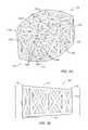
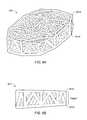
- FIGS. 1A-1Billustrate views of an implant with lordosis, according to an embodiment
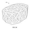
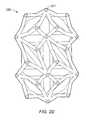
- FIGS. 2A-2Dillustrate views of an implant without lordosis, according to an embodiment
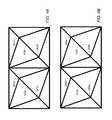
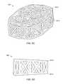
- FIGS. 3A-3Billustrate a web structure formed with triangular-shaped building blocks, according to an embodiment
- FIGS. 4A-4Billustrate a top structure of an internal web structure of the implant, according to an embodiment
- FIGS. 5A-5Cillustrate progressive sectioned views of the implant showing the internal structure of the implant, according to an embodiment
- FIG. 5Dillustrates an isometric view of the implant, according to an embodiment
- FIGS. 6A-6Dillustrate another configuration of the web structure, according to an embodiment
- FIG. 7illustrates a random web structure, according to an embodiment
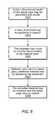
- FIG. 8illustrates a flowchart of a method for making an implant, according to an embodiment
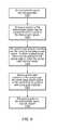
- FIG. 9illustrates a flowchart of a method for implanting a spinal implant, according to an embodiment
- FIGS. 10A-Cdepict an implant having one or more channels extending through the implant
- FIG. 11depicts the implant of FIGS. 10A-C coupled to an external support
- FIG. 12A-Bdepict implants having external threading
- FIG. 13depicts an implant for treatment of complex fractures of the proximal humerus
- FIG. 14depicts an implant used for revisions of failed total ankle replacements
- FIG. 15depicts an embodiment of an implant having three channels
- FIG. 16depicts an alternate embodiment of an implant having three channels
- FIG. 17depicts an embodiment of a bone rod connected to a space truss
- FIG. 18depicts a top-view of an embodiment of an implant which includes a web structure connected to a plate;
- FIG. 19depicts a trajectory guide device
- FIG. 20depicts an embodiment of a bone screw that includes a threaded space-truss proximal end.
- FIG. 21depicts an embodiment of a bone screw that includes a threaded space-truss proximal end having a cap for engaging bone;
- FIG. 22depicts an embodiment of a bone screw that includes a threaded space-truss proximal end and a threaded distal end;
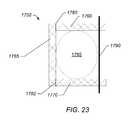
- FIG. 23depicts a schematic diagram of a truss cast used to form an exterior support for fractured bone structure.
- FIGS. 1A-1Billustrate views of implant 100 , according to an embodiment.
- the specifically depicted implant 100may be used, for example, in anterior lumbar inter-body fusion (ALIF) or posterior lumbar inter-body fusion (PLIF), however, it should be understood that implant 100 may have a variety of shapes suitable for bone fusion applications.
- implant 100may include a web structure with one or more trusses 102 (e.g., planar and space trusses).
- Implant 100may be used in various types of implants for humans or animals such as spinal implants, corpectomy devices, knee replacements, hip replacements, long bone reconstruction scaffolding, and cranio-maxifacial implants. Other implant uses are also contemplated.
- a “truss structure”is a structure having one or more elongate struts connected at joints referred to as nodes. Trusses may include variants of a pratt truss, king post truss, queen post truss, town's lattice truss, planar truss, space truss, and/or a tardendeel truss (other trusses may also be used).
- a “truss unit”is a structure having a perimeter defined by three or more elongate struts.”
- planar trussis a truss structure where all of the struts and nodes lie substantially within a single two-dimensional plane.
- a planar trussmay include one or more “truss units” where each of the struts is a substantially straight member such that the entirety of the struts and the nodes of the one or more truss units lie in substantially the same plane.
- a truss unit where each of the struts is a substantially straight strut and the entirety of the struts and the nodes of the truss unit lie in substantially the same planeis referred to as a “planar truss unit.”
- space trussis a truss having struts and nodes that are not substantially confined in a single two-dimensional plane.
- a space trussmay include two or more planar trusses (e.g., planar truss units) wherein at least one of the two or more planar trusses lies in a plane that is not substantially parallel to a plane of at least one or more of the other two or more planar trusses.
- a space trussmay include two planar truss units adjacent to one another (e.g., sharing a common strut) wherein each of the planar truss units lie in separate planes that are angled with respect to one another (e.g., not parallel to one another).
- a “triangular truss”is a structure having one or more triangular units that are formed by three straight struts connected at joints referred to as nodes.
- a triangular trussmay include three straight elongate strut members that are coupled to one another at three nodes to from a triangular shaped truss.
- a “planar triangular truss”is a triangular truss structure where all of the struts and nodes lie substantially within a single two-dimensional plane.
- Each triangular unitmay be referred to as a “triangular truss unit.”
- a triangular truss unit where each of the struts is a substantially straight member such that the entirety of the struts and the nodes of the triangular truss units lie in substantially the same planeis referred to as a “planar triangular truss unit.”
- a “triangular space truss”is a space truss including one or more triangular truss units.
- the trusses 102 of the web structuremay include one or more planar truss units (e.g., planar triangular truss units) constructed with straight or curved/arched members (e.g., struts) connected at various nodes.
- the trusses 102may be micro-trusses.
- a “micro-truss”is a truss having dimensions sufficiently small enough such that a plurality of micro-trusses can be assembled or other wise coupled to one another to form a web structure having a small enough overall dimension (e.g., height, length and width) such that substantially all of the web structure can be inserted into an implant location (e.g., between two vertebra).
- the diameters of the struts forming the micro-trussmay be between about 0.25 millimeters (mm) and 5 mm in diameter (e.g., a diameter of about 0.25 mm, 0.5 mm, 0.6 mm, 0.7 mm, 0.8 mm, 0.9 mm, 1 mm, 2 mm, 3 mm, 4 mm, or 5 mm).
- a micro-trussmay have an overall length or width of less than about 1 inch (e.g., a length less than about 0.9 in, 0.8 in, 0.7 in, 0.6 in, 0.5 in, 0.4 in, 0.3 in, 0.2 in, 0.1 in).
- the web structuremay extend throughout implant 100 (including the central portion of implant 100 ) to provide support throughout implant 100 .
- Trusses 102 of implant 100may thus support implant 100 against tensile, compressive, and shear forces.
- Web structuremay also reinforce implant 100 along multiple planes.
- the external truss structuremay, for example, provide support against tensile and compressive forces acting vertically through the implant, and the internal web structure may provide support against tensile, compressive, and shear forces along the various planes containing the respective trusses.
- the web structureincludes trusses 102 that form a triangulated web structure with multiple struts (e.g., struts 103 a - f ) (struts are generally referred to herein as “struts 103 ”).
- web structure of the implant 100may include an internal web structure that is at least partially enclosed by an external truss structure.
- web structure 101may include an internal web structure that includes a space truss having at least a portion of the space truss surrounded by an external truss structure that includes one or more planar trusses formed with a plurality of planar truss units that lie substantially in a single plane.
- FIG. 1Adepicts an embodiment of implant 100 having an internal web structure 104 and an external truss structure 105 .
- internal web structure 104includes a space truss defined by a plurality of planar truss units 106 coupled at an angle with respect to one another such that each adjacent truss unit is not co-planar with each adjacent truss units.
- Adjacent truss unitsmay include two truss units that share a strut and the respective two nodes at the ends of the shared strut.
- external truss structure 105includes a plurality of planar trusses that are coupled about an exterior, interior or other portion of the implant.
- the external truss structure 105includes a series of planar trusses 107 a,b that are coupled to one another.
- Planar truss 107 ais denoted by a dashed line [ - - - - - ]
- planar truss 107 bis denoted by dotted-dashed line [- • - • -].
- Each planar trussis formed from a plurality of planar truss units (e.g., triangular planar truss units.
- planar truss 107 aincludes four triangular planar truss units 108 a,b,c,d having a common vertex 110 and arranged to form a generally rectangular structure that lies in a single common plane.
- the four triangular planar truss unitsare arranged to form a substantially rectangular structure having “X” shaped struts extend from one corner of the rectangular structure to the opposite corner of the rectangular structure.
- the substantially rectangular structuremay include a trapezoidal shape.
- the trapezoidal shapemay be conducive to providing an implant including lordosis.
- Lordosismay include an angled orientation of surfaces (e.g., top and bottom) of an implant that provides for differences in thickness in anterior and posterior regions of the implant such that the implant is conducive for supporting the curvature of a vertebral column.
- planar trusses that form the external trussare coupled to one another, and are aligned along at least one axis.
- planar truss section 107 ais coupled to an adjacent planar truss 107 b .
- Planer truss sections 107 a,bare not parallel in all directions.
- Planar truss sections 107 a,bare, however, arranged parallel to one another in at least one direction (e.g., the vertical direction between the top and the bottom faces of implant 100 ).
- planar trusses 107 a,b and the additional planar trussesare arranged in series with an angle relative to one another to form a generally circular or polygon shaped enclosure having substantially vertical walls defined by the planar trusses and the planar truss units arranged in the vertical direction.
- the external truss portionmay encompass the sides, top, and/or bottom of the implant.
- the external truss portionmay include a top region, side regions, and/or a bottom region.
- FIG. 1Adepicts an embodiment of implant 100 wherein external truss portion 105 includes a top 111 , bottom 112 and a side region 113 .
- side region 113includes a series of planar trusses arranged vertically to form a circular/polygon ring-like structure that completely or at least partially surrounds the perimeter of the space truss disposed in the central portion of implant 100 .
- top portion 111 of external truss structure 105includes a plurality of truss units coupled to one another to form a planar truss that cover substantially all of the top region of internal web structure 104 .
- the top portion 111spans entirely the region between top edges of the side portion 113 of external truss structure 105 .
- top portion 111is formed from a single planar truss that includes a plurality of truss units that lie in substantially the same plane. In other words, the planar truss of top portion 111 defines a generally flat surface.
- the underside of implant 100may include the bottom portion 112 having a configuration similar to that of the top portion 111 .
- external truss structure 105may include a partial side, top and/or bottom external truss portions. Or may not include one or more of the side, top and bottom external truss portions.
- FIG. 2Cdepicts an embodiment of implant 100 that includes an internal web structure formed from space trusses, that does not have an external truss structure.
- implant 100may be formed from a biocompatible material such as a titanium alloy (e.g., ⁇ Titanium Aluminides), cobalt, chromium, stainless steel, Polyetheretherketone (PEEK), ceramics, etc. Other materials are also contemplated.
- implant 100may be made through a rapid prototyping process (e.g., electron beam melting (EBM) process) as further described below.
- EBMelectron beam melting
- Other processesare also possible (e.g., injection molding, casting, sintering, selective laser sintering (SLS), Direct Metal Laser Sintering (DMLS), etc).
- SLSmay include laser-sintering of high-performance polymers such as that provided by EOS of North America, Inc., headquartered in Novi, Mich., U.S.A.
- High-performance polymersmay include various forms of PEEK (e.g., HP3 having a tensile strength of up to about 95 mega Pascal (MPa) and a Young's modulus of up to about 4400 MPa and continuous operating temperature between about 180° C. (356° F.) and 260° C. (500° F.)).
- Other materialsmay include PA 12 and PA 11 provided by EOS of North America, Inc.
- the web structuremay be formed from a plurality of triangular planar truss units.
- the planar truss unitsmay be coupled to each other to define polyhedrons that define the internal web structure.
- Examples of polyhedron structures that may be created by joining planar truss unitsinclude, but are not limited to, tetrahedrons, pentahedrons, hexahedrons, heptahedrons, pyramids, octahedrons, dodecahedrons, icosahedrons, and spherical fullerenes.
- the space truss of the web structuremay connect multiple midpoints of tetrahedron building blocks and include a regular pattern of tetrahedron blocks arranged adjacent one another.
- the web structuremay not include a pattern of geometrical building blocks.
- FIG. 7illustrates an irregular pattern of struts that may be used in an implant 905 .
- Other web structuresare also contemplated. Examples of implants composed of a web structure are described in U.S. Published Patent Applications Nos.: 2010/0161061; 2011/0196495; 20110313532; and 2013/0030529, each of which is incorporated herein by reference.
- FIGS. 3A-3Billustrate a schematic view of a portion of an internal web structure formed with space units formed from triangular planar truss units.
- Triangular planar truss unitsmay be joined together to form tetrahedrons 300 a,b that may also be used as building blocks (other patterns from the triangles are also contemplated).
- Other building blocksare also contemplated (e.g., square-shaped building blocks).
- a web structuremay include a single tetrahedron, such as tetrahedron 300 a or 300 b alone or in combination with one or more other polyhedron.
- a web structuremay include two or more tetrahedrons 300 a,b .
- Tetrahedron 300 amay include four triangular faces in which three of the four triangles meet at each vertex.
- two tetrahedrons 300 a and 300 bmay be placed together at two adjacent faces to form space truss 313 with a hexahedron-shaped frame (including six faces).
- Hexahedron-shaped space truss 313may include first vertex 301 , second vertex 309 , third vertex 303 , fourth vertex 305 , and fifth vertex 307 .
- Common plane 311may be shared by two tetrahedrons (e.g., common plane 311 may include third vertex 303 , fourth vertex 305 , and fifth vertex 307 ) to form a hexahedron with first vertex 301 and second vertex 309 spaced away from common plane 311 .
- the center portion of the triangular shaped building blocksmay have a void region in their center that does not include any additional members (e.g., no members other than the struts forming the triangular shaped building blocks) extending there through.
- multiple hexahedron-shaped space trusses 313may be arranged in a side-by-side manner.
- Two space trusses 313 of implant 100may be connected via their first vertices 301 a,b through strut 103 r and connected via their second vertices 309 a,b through strut 103 t .
- two space trusses 313may be connected via their first vertices 301 c,d through strut 103 p and connected via their second vertices 309 c,d through strut 103 s .
- Other connectionsare also possible.
- space trusses 313may connect directly through side vertices (e.g., directly through corresponding vertices (such as vertices 303 a,b ) and/or share a common strut (such as strut 103 u )) and/or through a side face (e.g., side faces 111 a,b ).
- FIG. 4Aillustrates additional struts 103 (e.g., struts 103 p and 103 r ) connecting the first vertices (represented respectively by 301 a , 301 b , 301 c , and 301 d ) of four hexahedron-shaped space trusses in implant 100 .
- FIG. 4Billustrates additional struts 103 (e.g., struts 103 s and 103 t ) connecting second vertices 309 (represented respectively by 309 a , 309 b , 309 c , and 309 d ) of four hexahedron-shaped space trusses in implant 100 .
- additional struts 103may also be used internally between one or more vertices of the web structures to form additional trusses (e.g., see web structures in FIGS. 1A-2B ) (other structures are also possible).
- top surface 115 a and bottom surface 115 b of implant 100may include triangles, squares, circles or other shapes (e.g., a random or custom design).
- Top and bottom surfaces 115 a,bmay be used to connect the top and bottom vertices of various geometrical building blocks used in the web structure of implant 100 .
- each vertexmay be connected through struts to the neighboring vertices of other geometrical building blocks.
- Top surface 115 amay include other strut networks and/or connections.
- bottom surface 115 bmay mirror the top surface (and/or have other designs).
- top surface 115 a and bottom surface 115 bmay engage respective surfaces of two adjacent vertebrae when implant 100 is implanted.
- implant 100may include lordosis (e.g., an angle in top and/or bottom surfaces 115 a,b approximately in a range of 4 to 15 degrees (such as 4, 5, 6, 7, 8, 9, 10, 11, 12, 13, 14, or 15 degrees)) to further support the adjacent vertebrae when implanted.
- lordosismay include an angled orientation of surfaces (e.g., top and bottom) that provide for differences in thickness in the anterior and posterior portions of the implant such that the implant is conducive for supporting the curvature of a vertebral column.
- the thickness of implant 100is greater at or near the anterior portion 118 and lesser at or near the posterior portion 120 of the implant.
- the side portions of external truss structureare arranged substantially vertically, and the lordosis is formed by the angles of the top portion 111 and bottom portion 112 of external truss structure.
- top portion 111 and bottom portion 112 of external truss structureare not perpendicular to the vertical plane defined by the side portion 113 . Rather, the top portion 111 and bottom portion 112 are arranged with an acute angle relative to the vertical plane of side portion 113 at or near the anterior region 118 of implant 100 and with an obtuse angle relative to the vertical plane of side portion 113 at or near posterior region 120 of implant 100 .
- the vertical struts that form the planar truss of side portion 113 of external truss structure proximate posterior region 120 of implant 100are shorter than struts that form side portion of external truss structure proximate anterior region 118 of implant 100 .
- the struts forming the “X” cross members of the side planar trusses proximate the posterior region 120 of implant 100are shorter than struts forming the “X” cross members of the side planar trusses proximate the anterior region 118 of implant 100 .
- Other embodimentsmay include variations in the arrangement of the trusses to provide various configurations of the implant.
- top and bottom external truss portionsmay be non-perpendicular to the side portions of the external truss proximate the anterior and posterior portions of the implant.
- the side, top, and/or bottom portionsmay include multiple planar trusses angled relative to one another in any orientation.
- the top or bottom portionsmay include four planar trusses, each formed of multiple truss units, such that the portion(s) includes a pyramidal like shape.
- the implantmay not include lordosis.
- FIGS. 2A-2Billustrate two views of an embodiment of an implant 200 without lordosis.
- the top surface and bottom surfacemay not include connecting struts.
- FIGS. 2C-2Dillustrate two views of implant 250 without outer struts (e.g., without external truss portions formed of planar trusses).
- implant 250includes an internal web structure and does not include an external truss structure.
- the exterior faces of implant 250are defined by a plurality of truss units that are angled relative to each of its adjacent truss units.
- the relative alignment of the truss unitsresults in a non-planar exterior that includes a plurality of pointed junctions.
- the pointed junctionse.g., pointed junction 201
- the pointed junctionsmay operate to dig into the surrounding bone to hold the implant in place (for example, if the implant is being used in a corpectomy device).
- FIGS. 5A-5Cillustrate progressive sectioned views of implant 100 showing the internal structure of implant 100 , according to an embodiment.
- FIG. 5Aillustrates a sectioned view of a lower portion of implant 100 .
- Bottom surface 115 bis shown with various struts (e.g., struts 103 ) extending upward from bottom surface 115 b .
- FIG. 5Billustrates a sectioned view approximately mid-way through implant 100 .
- Strutssuch as struts 103 e,f , shared by various stacked tetrahedrons in the web structure are shown. Some struts extend through central portion 501 a and/or 501 b of implant 100 .
- FIG. 5Aillustrates a sectioned view of a lower portion of implant 100 .
- Bottom surface 115 bis shown with various struts (e.g., struts 103 ) extending upward from bottom surface 115 b .
- FIG. 5B
- central portion 501 amay include a rectangular region that has a width of approximately 50% of the implant width, a height of approximately 50% of the implant height, and a length of approximately 50% of the implant length and located in the center of implant 100 .
- central portion 501 bmay encompass a region (e.g., a spherical region, square region, etc.) of approximately a radius of approximately 1 ⁇ 8 to 1 ⁇ 4 of the width of implant 100 around a position located approximately at one half the width, approximately one half the length, and approximately one-half the height of implant 100 (i.e., the center of implant 100 ).
- Other central portionsare also contemplated.
- the central portionmay include a square region with a length of one of the sides of the square region approximately 1 ⁇ 4 to 1 ⁇ 2 the width of implant 100 around a position approximately at one half the width, approximately one half the length, and approximately one half the height of the implant.
- An example height 502 a , width 502 b , and length 502 cis shown in FIG. 5D .
- the heightmay be up to about 75 mm or more.
- the width and/or lengthcould be approximately 7 inches or longer.
- the width, length, and/or heightmay vary along implant 100 (e.g., the height may vary if the implant includes lordosis).
- the heightmay be taken at one of the opposing sides, the middle, and/or may be an average of one or more heights along the length of implant 100 .
- the web structuremay extend through central portion 501 a,b of the implant (e.g., at least one strut of the web structure may pass at least partially through central portion 501 a,b ).
- FIG. 5Cillustrates another sectioned view showing sectioned views of top tetrahedrons in the web structure.
- FIG. 5Dshows a complete view of implant 100 including top surface 115 a with vertices 301 a - d.
- FIGS. 6A-6Dillustrate alternate embodiments of an implant.
- different sections of the hexahedron-shaped geometric designmay be used.
- the bottom half of the hexahedron-shaped geometric designmay be used (primarily including the lower tetrahedron structures).
- implant 600may be expanded proportionately to have similar overall dimensions as the hexahedron-shaped geometric design (e.g., the tetrahedrons may be expanded to approximately twice the height of the tetrahedrons in the hexahedron-shaped geometric design to give implant 600 a height approximately the same as the hexahedron-shaped geometric design).
- implant 600may also be angled (e.g., on top surface 601 a and/or bottom surface 601 b ) to provide implant 600 with lordosis to, in some embodiments, have a better fit between the vertebral endplates.
- Top surface 601 a and/or bottom surface 601 bmay also include struts to connect nodes of implant 600 (e.g., see the strut network on the top surface in FIG. 6 a ). Other patterns of struts for top surface 601 a and/or bottom surface 601 b may also be used.
- implant 600may not include negative angles between struts and may thus be easier to create through a casting or molding process.
- FIGS. 6C-6Dillustrate another alternate embodiment of an implant.
- approximately the middle 40 to 60 percent of the hexahedron-shaped geometric designmay be used in implant 650 .
- an overall height of the hexahedron-shaped geometric designis approximately 37 mm
- approximately the bottom 10 mm and approximately the top 10 mm of the designmay be removed and approximately the middle 17 mm of the design may be used for the implant.
- Middle portion of implant 650may then be expanded proportionately such that the approximate height of the expanded design may be approximately 37 mm (or a different height as needed).
- Top surface 651 a and bottom surface 651 bmay include a network of struts (e.g., see the struts on top surface 651 a of FIG.
- FIG. 6Cother networks of struts are also contemplated.
- Other portions of the design for the implantare also contemplated (e.g., the top half of the design shown in FIG. 1A , the bottom half of the design shown in FIG. 1A , etc).
- Design portionsmay be proportionately expanded to meet specified dimensions (e.g., specified height, width, and length).
- the amount of strutsmay be reduced or material in the implant may be redistributed so that some struts may have a larger diameter and some may have a smaller diameter (e.g., the different diameters may reinforce against different directional forces).
- a partial-design cagemay be used (e.g., with half of the web structure so that the structure includes a tetrahedron.
- the implantmay include angled surfaces (e.g., an angled top surface 651 a and/or angled bottom surface 651 b ) to provide lordosis for implants to be implanted between the vertebral endplates.
- the web structure of an implantmay distribute forces throughout the implant when implanted.
- the connecting struts of the web structuremay extend throughout the core of an implant, and the interconnectivity of struts may disperse the stress of compressive forces throughout implant to reduce the potential of stress risers (the distribution of forces throughout the implant may prevent concentration of stress on one or more portions of the vertebrae that may otherwise result in damage to the vertebrae).
- the web structure of an implantmay also provide surface area for bone graft fusion.
- the web structure extending throughout an implantmay add additional surface areas (e.g., on the surface of the struts making up the implant) to fuse to the bone graft material and prevent bone graft material from loosening or migrating from the implant.
- the web structuremay also support bone in-growth.
- adjacent bonee.g., adjacent vertebrae if the implant is used as a spinal implant
- the bone growth and engagement between the bone growth and the implantmay further stabilize the implant.
- the surfaces of the implantmay be formed with a rough surface to assist in bone in-growth adhesion.
- strutsmay have a diameter approximately in a range of about 0.025 to 5 millimeters (mm) (e.g., 1.0 mm, 1.5 mm, 3 mm, etc). Other diameters are also contemplated (e.g., greater than 5 mm).
- the strutsmay have a length approximately in a range of 0.5 to 20 mm (e.g., depending on the implant size needed to, for example, fit a gap between vertebral endplates).
- strutsmay have a length approximately in a range of 30-40 mm for a hip implant.
- the reduced strut size of the web structuremay allow the open cells in implant 100 to facilitate bone growth (e.g., bone may grow through the open cells once implant 100 is implanted in the body).
- Average subsidence for implantsmay be approximately 1.5 mm within the first 3 weeks post op (other subsidence is also possible (e.g., approximately between 0.5 to 2.5 mm)).
- a strut size that approximately matches the subsidencee.g., a strut size of approximately 1.5 mm in diameter and a subsidence of approximately 1.5 mm
- the net 0 impedance throughout the entire surface area of the implant/vertebrae endplate interfacemay result in a larger fusion column of bone that may result in more stable fusion.
- Other fusion column sizesare also contemplated.
- the configuration of the implantmay redistribute the metal throughout the implant.
- a rimmay not be included on the implant (in some embodiments, a rim may be included).
- the resulting bone growth(e.g., spinal column) may grow through the implant.
- greater than 50% of the interior volume of implant 100may be open. In some embodiments, greater than 60%, greater than 70%, and/or greater than 80% of implant 100 may be open (e.g., 95%). In some embodiments, the open volume may be filled with bone growth material. For example, cancellous bone may be packed into an open/internal region of implant.
- the surfaces of the implantmay be coated/treated with a material intend to promote bone growth and/or bone adhesion and/or an anitmicrobial agent to prevent infections.
- the surface of the strutsmay be coated with a biologic and/or a bone growth factor.
- a biologicmay include a coating, such as hydroxyapatite, bone morphaginic protein (BMP), insulinlike growth factors I and II, transforming growth factor-beta, acidic and basic fibroblast growth factor, platelet-derived growth factor, and/or similar bone growth stimulant that facilitates good biological fixation between the bone growth and a surface of the implant.
- a bone growth factormay include a naturally occurring substance capable of stimulating cellular growth, proliferation and cellular differentiation (e.g., a protein or steroid hormone).
- the surface of the implante.g., the struts, the external truss structure, etc.
- collagenmay be coated with collagen.
- a biologic and/or growth factormay be secured to a central region of an implant.
- a biologic or growth factormay be provided on at least a portion of a strut that extends through central portion 501 a and/or 501 b of implant 100 , see FIG. 5B .
- Such an embodimentmay enable the delivery of a biologic and or a growth factor to a central portion of an implant.
- the biologic or growth factormay be physically secured to a strut in a central portion of the implant as opposed to being packed into an open volume that does not include a strut provided therein for the physical attachment of the biologic and/or growth factor.
- subsidencemay place additional pressure on the bone graft material (which may already be under compressive forces in the implant) and act to push the bone graft material toward the sides of the implant (according to Boussinesq's theory of adjacent material, when a force is applied to a member that is adjacent to other materials (such as sand, dirt, or bone graft material) the force against the member creates a zone of increased pressure (e.g., 60 degrees) in the adjacent material).
- Struts of the implantmay resist bone graft material protrusion from the sides of the web structure and may increase the pressure of the bone graft material.
- Bone graft materialmay need to be implanted in a higher-pressure environment to create an environment conducive to strong bone growth (e.g., according to Wolf's law that bone in a healthy person or animal will adapt to the loads it is placed under).
- the web structuremay thus increase the chance of stronger fusion.
- the trussesmay include a series of packing triangles, a two-web truss, a three-web truss, etc.
- the web structure for an implantmay include one or more trusses as described in U.S. Pat. No. 6,931,812 titled “Web Structure and Method For Making the Same”, which issued Aug. 23, 2005, which is hereby incorporated by reference in its entirety as though fully and completely set forth herein.
- FIG. 8illustrates a flowchart of a method for making an implant.
- an implantmay be made through rapid prototyping (e.g., electron beam melting, laser sintering, etc). It should be noted that in various embodiments of the methods described below, one or more of the elements described may be performed concurrently, in a different order than shown, or may be omitted entirely. Other additional elements may also be performed as desired. In some embodiments, a portion or the entire method may be performed automatically by a computer system.
- a three dimensional model of an implantis generated and stored in a storage medium accessible to a controller operable to control the implant production process.
- a layer of materiale.g., a powder, liquid, etc.
- the powdermay include ⁇ TiAl ( ⁇ Titanium Aluminides) which may be a high strength/low weight material. Other materials may also be used.
- the powdermay be formed using a gas atomization process and may include granules with diameters approximately in a range of 20 to 200 micrometers ( ⁇ m) (e.g., approximately 80 ⁇ m).
- the powdermay be delivered to the support through a distributer (e.g., delivered from a storage container).
- the distributer and/or the supportmay move during distribution to apply a layer (e.g., of powder) to the support.
- the layermay be approximately a uniform thickness (e.g., with an average thickness of 20 to 200 micrometers ( ⁇ m)).
- the distributer and supportmay not move (e.g., the material may be sprayed onto the support).
- the controllermoves an electron beam relative to the material layer.
- the electron beam generatormay be moved, and in some embodiments the support may be moved. If the material is ⁇ TiAl, a melting temperature approximately in a range of 1200 to 1800 degrees Celsius (e.g., 1500 degrees Celsius) may be obtained between the electron beam and the material.
- additional materialmay be applied by the distributer.
- the unmelted materialis removed and the implantcooled (e.g., using a cool inert gas).
- the edges of the implantmay be smoothed to remove rough edges (e.g., using a diamond sander).
- the implantmay include rough edges to increase friction between the implant and the surrounding bone to increase adhesion of the implant to the bone.
- an implantmay be cast or injection molded.
- multiple partsmay be cast or injection molded and joined together (e.g., through welding, melting, etc).
- individual struts forming the implantmay be generated separately (e.g., by casting, injection molding, etc.) and welded together to form the implant.
- multiple implants of different sizesmay be constructed and delivered in a kit. A medical health professional may choose an implant (e.g., according to a needed size) during the surgery. In some embodiments, multiple implants may be used at the implant site.
- Specialized toolsmay be used to insert the implants described herein. Examples of tools that may be used are described in U.S. Published Patent Applications Nos.: 2010/0161061; 2011/0196495; 20110313532; and 2013/0030529, each of which is incorporated herein by reference.
- FIG. 9illustrates a flowchart of a method for implanting a spinal implant, according to an embodiment. It should be noted that in various embodiments of the methods described below, one or more of the elements described may be performed concurrently, in a different order than shown, or may be omitted entirely. Other additional elements may also be performed as desired. In some embodiments, a portion or the entire method may be performed automatically by a computer system.
- an intersomatic spaceis accessed.
- an anterior openingmay be made in a patient's body for an anterior lumbar inter-body fusion (ALIF) approach or a posterior opening may be made for a posterior lumbar inter-body fusion (PLIF) approach.
- at least a portion of the intersomatic spaceis excised to form a cavity in the intersomatic space.
- the implantis inserted into the cavity in the intersomatic space.
- a handler, or some other deviceis used to grip the implant.
- a forcemay be applied to the implant (e.g., through a hammer) to insert the implant into the cavity.
- the implant and/or space in the cavitymay be packed with bone graft material.
- the access point to the intersomatic spacemay be closed (e.g., using sutures).
- the implantmay be customized.
- three dimensional measurements and/or shape of the implantmay be used to construct an implant that distributes the web structure throughout a three-dimensional shape design.
- a truss/web structuremay be disposed on at least a portion of an implant to facilitate coupling of the implant to an adjacent structure.
- one or more truss structuresmay be disposed on and/or extend from a surface (e.g., an interface plate) of the implant that is intended to contact, and at least partially adhere to, the bony structure during use.
- a surfacee.g., an interface plate
- one or more truss structuresmay be disposed on a contact surface of the intervertebral implant to facilitate bone growth that enhances coupling of the intervertebral implant to the bony structure.
- a truss structuremay include one or more struts that extend from the contact surface to define an open space for bone growth therethrough, thereby enabling bone through growth to interlock the bone structure and the truss structure with one another to couple the implant to the bony structure at or near the contact face.
- Such interlocking bone through growthmay inhibit movement between the implant and the bony structure which could otherwise lead to loosening, migration, subsidence, or dislodging of the implant from the intended position.
- Similar techniquesmay be employed with various types of implants, including those intended to interface with tissue and/or bone structures.
- a truss structuremay be employed on a contact surface of knee implants, in a corpectomy device, in a hip replacement, in a knee replacement, in a long bone reconstruction scaffold, or in a cranio-maxifacial implant hip implants, jaw implant, an implant for long bone reconstruction, foot and ankle implants, shoulder implants or other joint replacement implants or the like to enhance adherence of the implant to the adjacent bony structure or tissue.
- truss structures, and other structures, that may extend from the surface of an implant to facilitate coupling of the implant to an adjacent structureare described in U.S. Published Patent Application No. 2011/0313532, which is incorporated herein by reference.
- implants described hereinare depicted as being composed of substantially straight struts, it should be understood that the struts can be non-linear, including, but not limited to curved, arcuate and arch shaped. Examples of implants having non-linear struts are described in U.S. patent application Ser. No. 13/668,968, which is incorporated herein by reference.
- an implantmay be secured to the bone using one or more fasteners (e.g., screws). Fasteners may be coupled to any part of the implant structure to secure the implant to the bone.
- FIGS. 10A, 10B, and 10CAn embodiment of an implant having one or more channels that can receive a fastener is depicted in FIGS. 10A, 10B, and 10C .
- implant 400is composed of a web structure that includes a space truss 410 formed from two or more planar truss units having a plurality of struts joined at nodes.
- One or more channels 420are formed in the web structure. The channels extend through the web structure such that channel exits 425 a,b are present in at least two sides of the web structure (See FIG. 10C ). Channels may be defined by one or more substantially arcuate and/or circular struts 422 coupled to one or more adjacent planar truss units.
- the channelsmay be substantially tubular to receive a cylindrical fastener 430 (e.g., a bone screw).
- Fastener 430may move within channel 420 such that the sides of the fastener are not attached to space truss 410 .
- fastener 430may include a head (not shown) which contacts a surface of implant 400 to secure the implant to the bone.
- channels 420may be substantially threaded, having a threading that is complementary to threading of a bone screw.
- a bone screwis coupled to channel 420 by mating the bone screw with the threading of the channel. The threading of channel 420 , when coupled to the bone screw, help prevent pull out of the fastener from the implant.
- An external support 450may also be used to secure implant 400 to a bone structure, as depicted in FIG. 11 .
- External support 450may be coupled to the web structure of implant 400 using one or more fasteners 430 .
- Fasteners 430therefore, may pass through external support 450 , into channels 420 and into a bone structure to secure implant 400 and the external support to the bone.
- External support 450may include one or more openings 452 that correspond to the position of channels 420 disposed in implant 400 .
- External support 450may include additional openings 454 , which allow the support to be independently coupled to a bone structure. While depicted as a separate component of the implant system, it should be understood that external support may be integrated with implant 400 to form a unitary implant that includes a space truss attached to an external support.
- a bone structuremay be repaired using implant 400 .
- the implant 400may be placed proximate to, or in contact with, a bone structure in need of repair.
- Fasteners 430may be positioned in one or more of channels 420 and coupled to the bone structure.
- fasteners 430are bone screws.
- a bone screwmay be inserted into channels 420 and fastened to the bone by screwing the bone screw into the bone structure.
- channels 420may have threading complementary to the bone screw threading, such that the bone screw is coupled to the implant as well as the bone structure.
- an external support 450may be used to secure the implant to the bone structure.
- Implant 400may be placed proximate to a bone structure.
- External support 450may be placed proximate to, or in contact with, implant 400 , such that at least some of the openings 452 on external support 450 are aligned with one or more channels 420 of the implant.
- Fastenerse.g., bone screws
- Additional fastenersmay be positioned in one or more additional openings 454 and coupled to an external portion of the bone structure to provide additional support to the implant.
- external structure 450may be used as a guide for forming channels in an implant that does not have channels.
- An implantsuch as implant 100
- External support 450may be placed proximate to, or in contact with, a bone structure and implant 100 .
- At least a portion of the openings 452 of external structure 450are aligned with a portion of the implant.
- a drill, or other cutting devicemay be used to form channels in the implant, using the external support as a guide to determine where the channels are formed.
- the openings of the external support used to form the channelshave a depth sufficient to control the angle that the channel is drilled by providing a guide for the drill bit.
- the channels of the implantmay be custom made during implantation by selecting the external support having openings that will produce channels at the desired location and angle.
- FIG. 19depicts a trajectory guide device 1500 , which can be used to direct the placement of one or more bone screws into an implant.
- Trajectory guide 1500includes coupling section 1510 , and guide 1520 .
- Coupling sectionincludes one or more fasteners 1515 , which couple with corresponding fasteners on the implant.
- the guide 1520will rest against the skin of the patient and act as a guide, directing the placement of one or more bone screws.
- Guide 1520includes one or more channels 1530 through which a bone screw, or other fastening device, is inserted into the subject's skin and underlying bone.
- the channelsare positioned such that a fastener that is inserted through the guide into the subject will be aligned with a channel of the implant.
- an implant 700includes a distal end 720 and a proximal end 710 , wherein the proximal end comprises a space truss 715 comprising two or more planar truss units having a plurality of struts joined at nodes.
- the space trussis configured to interface with human bone tissue.
- Distal end 720includes threading 725 which allows the implant to be screwed into a bone structure.
- the threaded distal endis substantially solid.
- the threaded distal endin some embodiments, is a space truss having exterior threading.
- Slot 730may be used to insert the bone screw into a bone structure.
- FIG. 20depicts an embodiment of a bone screw 1600 that includes a proximal end 1610 and a distal end 1620 .
- Proximal end 1610includes a space truss 1615 comprising two or more planar truss units having a plurality of struts joined at nodes. The space truss is configured to interface with human bone tissue.
- Proximal end 1610includes threading 1625 which allows the implant to be screwed into a bone structure.
- Distal endincludes a slot 1630 that may be used to insert the bone screw into a bone structure.
- An opening 1640that may be used to couple bone screw 1600 to a rod or some other connector (such the bone screw acts as a pedicle screw) is formed in distal end. Opening 1640 is placed in the part of distal end that will extend from the bone after the proximal end is placed into the bone.
- the use of a truss structure in the proximal endallows the bone screw to be absorbed into the bone structure, providing a more secure connection that a threaded bone screw.
- the use of a pace trussalso helps prevent pullout of the bone screw due to forces placed on the bone screw due to the subjects normal movement.
- FIG. 21depicts an embodiment, of a bone screw 1650 that includes a proximal end 1660 and a distal end 1670 .
- Proximal end 1660includes a space truss 1665 comprising two or more planar truss units having a plurality of struts joined at nodes. The space truss is configured to interface with human bone tissue.
- Proximal end 1660includes threading 1675 which allows the implant to be screwed into a bone structure.
- Distal endincludes a head 1680 that may be used to insert couple two bone segments together. During use, head 1680 contacts a bone structure and as proximal end is screwed into the bone, the bone segment in contact with the head is pulled toward the bone segment in which the proximal head is embedded.
- FIG. 22depicts an embodiment of a bone screw 1700 that includes a proximal end 1710 and a distal end 1720 .
- Proximal end 1710may include a space truss 1715 or may be substantially solid (not shown). When present, a space truss is configured to interface with human bone tissue.
- Proximal end 1710includes threading 1725 having a first pitch which allows the implant to be screwed into a bone structure.
- Distal endalso includes threading 1730 having a second pitch which is different from the threading on the proximal end.
- Bone screw 1700may be used to couple two bone segments together. During use, a pilot hole is drilled through a first bone structure that allows proximal end 1710 to be passed through first bone structure.
- the proximal endis then brought into contact with a second bone segment and is screwed into the second bone segment.
- the threads on the distal endengage the first bone segment, drawing the second bone segment toward the first bone segment.
- bone screw 1700holds the two bone structures in contact with each other.
- FIG. 12Bdepicts an embodiment of a bone screw 750 .
- Bone screw 750is composed of a space truss 755 comprising two or more planar truss units having a plurality of struts joined at nodes.
- Space truss 755is configured to interface with human bone tissue.
- Threading 775is positioned around space truss allowing the bone screw to be screwed into a bone structure.
- End 760includes a slot 765 , or some other structure or shape that allows a fastening tool (e.g., a screwdriver) to couple with the distal end.
- a fastening toole.g., a screwdriver
- the fastening toolis used to secure threading 775 into the bone structure by allowing a user to rotate bone screw 750 .
- bone screwhas threading coupled to space truss 755 .
- one or more of the truss units of space truss 755may have one or more curved struts that together form threading 775 .
- Bone screw 750may be inserted into a bone structure by forming an opening in the bone structure sufficient to at least act as a pilot hole for the bone screw. The bone screw is placed in contact with the opening and rotated by coupling a fastening tool onto the end (e.g., through slot 765 ). Rotation of bone screw 750 , allows the threads to contact the bone structure, securing the implant into the bone structure. Bone screw 750 may be used for a variety of bone structures including but not limited to hip, knee, shoulder, elbow, spine bone structures.
- Proximal humeral fracturesremain a challenge to repair because of fragment comminution, poor bone quality, and the complexity of the anatomy to be reconstructed.
- Various osteosynthesis devicesare available for displaced fractures, for example, Kirschner wires, plates and screws, intramedullary nails, low-profile plates with fixed-angle locking plates, and anatomic or inverse humera prostheses.
- Kirschner wiresfor example, Kirschner wires, plates and screws, intramedullary nails, low-profile plates with fixed-angle locking plates, and anatomic or inverse humera prostheses.
- the outcome of these proceduresis inconsistent and depends largely on the surgical technique used and the surgeon's skill.
- an osteosynthesis implant 800may be used for the treatment of complex fractures of the proximal humerus.
- Implant 800is a triangular prism which is composed of a planar truss 810 . It is inserted in the proximal humeral cavity to stabilize the humeral head and tuberosities. The space truss structure improves the osteointegration of the device compared to other similar implants.
- an osteosynthesis implant 850may be used for revisions of failed total ankle replacements.
- Implant 850may be used to bridge structural defects left behind by the removal of the total ankle prosthesis.
- Implant 850is a block having a U-shaped cutout which is composed of a planar truss 860 .
- FIG. 15depicts an embodiment of an implant having one or more channels that can receive a fastener.
- implant 1100is composed of a web structure that includes a space truss 1110 formed from two or more planar truss units having a plurality of struts joined at nodes.
- One or more channels 1120are formed in the web structure. The channels extend through the web structure such that channel exits are present in at least two sides of the web structure. Channels may be defined by a channel structure 1125 coupled to one or more adjacent planar truss units.
- the channelsmay be substantially tubular to receive a cylindrical fastener (e.g., a bone screw).
- a fastenermay move within channel 1120 such that the sides of the fastener are not attached to space truss 1110 .
- a fastenermay include a head (not shown) which contacts a surface of implant 1100 to secure the implant to the bone.
- channel structures 1125may include threading 1130 that is complementary to threading of a bone screw.
- a bone screwis coupled to channel 1120 by mating the bone screw with the threading of the channel. The threading of channel 1120 , when coupled to the bone screw, help prevent pull out of the fastener from the implant.
- FIG. 16depicts an embodiment of an implant having one or more channels that can receive a fastener.
- implant 1150is composed of a web structure that includes a space truss 1160 formed from two or more planar truss units having a plurality of struts joined at nodes.
- One or more channels 1170are formed in the web structure. The channels extend through the web structure such that channel exits are present in at least two sides of the web structure. Channels may be defined by a channel structure 1175 coupled to one or more adjacent planar truss units.
- the channelsmay be substantially tubular to receive a cylindrical fastener (e.g., a bone screw).
- a fastenermay move within channel 1170 such that the sides of the fastener are not attached to space truss 1160 .
- a fastenermay include a head (not shown) which contacts a surface of implant 1150 to secure the implant to the bone.
- channel structures 1175may include threading 1180 that is complementary to threading of a bone screw.
- a bone screwis coupled to channel 1170 by mating the bone screw with the threading of the channel. The threading of channel 1170 , when coupled to the bone screw, help prevent pull out of the fastener from the implant.
- FIG. 18depicts a top-view of an embodiment of an implant 1400 which includes a web structure 1410 connected to a plate 1420 .
- Plate 1420includes one or more screw holes 1430 which allow a bone screw to be used to secure implant 1400 to an exterior of the bone.
- web structure 1410may be placed is a space formed in a bone, a natural space (e.g., as a spinal disk replacement device, or between two separated bone segments.
- plate 1420will rest on the exterior of the bone, and provides two screw holes 1430 that allow the user to secure the implant to the bone. In this manner, the implant is less likely to be pulled from the bone section during normal movement of the subject.
- FIG. 23depicts a schematic diagram of a truss cast used to form an exterior support for fractured bone structure.
- truss castcomprises a single truss structure or a plurality of space trusses coupled to each other. The truss cast is formed so that the it can be wrapped around the fractured bone, acting as a cast to hold the fractured bone segments in place.
- truss cast 1750includes three space trusses 1760 , 1765 and 1770 . Space trusses are coupled to each other using flexible connectors 1780 and 1782 . Flexible connectors allow the space trusses to be rotated, with respect to each other, by at least 90 degrees.
- Truss cast 1750includes a connector 1790 which extends from first space truss 1760 to third space truss 1770 .
- truss castis wrapped around bone 1785 at the site of the fracture.
- Connectoris fastened to space truss 1760 and 1770 to hold truss cast in place.
- connectormay include a tensioning device that draws the two space trusses 1760 and 1770 together to secure the truss cast against the bone. It should be understood that while the truss cast is depicted as having three space trusses, more or less space trusses may be used.
- a single space trussis used as a truss cast.
- the single space trussmay be formed of a substantially flexible material that allows the space truss to be pulled around the fractured bone segment by tensioning of the connector.
- an implantmay include a web structure.
- the web structure for the implantmay include a micro truss design.
- the micro truss designmay include a web structure with multiple struts.
- Other web structuresare also contemplated.
- the web structuremay extend throughout the implant (including a central portion of the implant). The web structure may thus reinforce the implant along multiple planes (including internal implant load bearing) and provide increased area for bone graft fusion.
- the web structuremay be used in implants such as spinal implants, corpectomy devices, hip replacements, knee replacements, long bone reconstruction scaffolding, and cranio-maxifacial implants. Other implant uses are also contemplated.
- multiple hexahedron-shaped web structuresmay be arranged in a side-by-side manner.
- the web structuresmay connect directly through side vertices (e.g., two or more hexahedron-shaped web structures may share a vertex).
- the web structuremay be angled to provide lordosis to the implant.
- strutshave been described and depicts as substantially straight elongated members, struts may also include elongated members curved/arched along at least a portion of their length. Accordingly, this description is to be construed as illustrative only and is for the purpose of teaching those skilled in the art the general manner of carrying out the invention. It is to be understood that the forms of the invention shown and described herein are to be taken as embodiments.
Landscapes
- Health & Medical Sciences (AREA)
- Orthopedic Medicine & Surgery (AREA)
- Engineering & Computer Science (AREA)
- Biomedical Technology (AREA)
- Life Sciences & Earth Sciences (AREA)
- Neurology (AREA)
- Veterinary Medicine (AREA)
- Heart & Thoracic Surgery (AREA)
- Public Health (AREA)
- Animal Behavior & Ethology (AREA)
- General Health & Medical Sciences (AREA)
- Transplantation (AREA)
- Surgery (AREA)
- Cardiology (AREA)
- Vascular Medicine (AREA)
- Oral & Maxillofacial Surgery (AREA)
- Nuclear Medicine, Radiotherapy & Molecular Imaging (AREA)
- Medical Informatics (AREA)
- Molecular Biology (AREA)
- Physical Education & Sports Medicine (AREA)
- Prostheses (AREA)
- Plastic & Reconstructive Surgery (AREA)
Abstract
Description
Claims (15)
Priority Applications (1)
| Application Number | Priority Date | Filing Date | Title |
|---|---|---|---|
| US14/215,961US9636226B2 (en) | 2013-03-15 | 2014-03-17 | Traumatic bone fracture repair systems and methods |
Applications Claiming Priority (2)
| Application Number | Priority Date | Filing Date | Title |
|---|---|---|---|
| US201361801524P | 2013-03-15 | 2013-03-15 | |
| US14/215,961US9636226B2 (en) | 2013-03-15 | 2014-03-17 | Traumatic bone fracture repair systems and methods |
Publications (2)
| Publication Number | Publication Date |
|---|---|
| US20140288649A1 US20140288649A1 (en) | 2014-09-25 |
| US9636226B2true US9636226B2 (en) | 2017-05-02 |
Family
ID=51538492
Family Applications (1)
| Application Number | Title | Priority Date | Filing Date |
|---|---|---|---|
| US14/215,961ActiveUS9636226B2 (en) | 2013-03-15 | 2014-03-17 | Traumatic bone fracture repair systems and methods |
Country Status (7)
| Country | Link |
|---|---|
| US (1) | US9636226B2 (en) |
| EP (2) | EP2967873B1 (en) |
| JP (2) | JP6573598B2 (en) |
| KR (1) | KR20150130528A (en) |
| CN (1) | CN105555233B (en) |
| CA (1) | CA2911880C (en) |
| WO (1) | WO2014145529A2 (en) |
Cited By (67)
| Publication number | Priority date | Publication date | Assignee | Title |
|---|---|---|---|---|
| US9839448B2 (en) | 2013-10-15 | 2017-12-12 | Si-Bone Inc. | Implant placement |
| US9949843B2 (en) | 2004-08-09 | 2018-04-24 | Si-Bone Inc. | Apparatus, systems, and methods for the fixation or fusion of bone |
| US10166033B2 (en) | 2014-09-18 | 2019-01-01 | Si-Bone Inc. | Implants for bone fixation or fusion |
| US10183442B1 (en) | 2018-03-02 | 2019-01-22 | Additive Device, Inc. | Medical devices and methods for producing the same |
| US10194962B2 (en) | 2014-09-18 | 2019-02-05 | Si-Bone Inc. | Matrix implant |
| US10201427B2 (en) | 2012-03-09 | 2019-02-12 | Si-Bone Inc. | Integrated implant |
| US10226357B2 (en)* | 2013-08-14 | 2019-03-12 | Joimax Gmbh | Interbody cage |
| US20190167433A1 (en)* | 2017-12-04 | 2019-06-06 | Duke University | Orthopedic implant for sustained drug release |
| US10363140B2 (en) | 2012-03-09 | 2019-07-30 | Si-Bone Inc. | Systems, device, and methods for joint fusion |
| US10376206B2 (en) | 2015-04-01 | 2019-08-13 | Si-Bone Inc. | Neuromonitoring systems and methods for bone fixation or fusion procedures |
| US10426533B2 (en) | 2012-05-04 | 2019-10-01 | Si-Bone Inc. | Fenestrated implant |
| US10507118B2 (en) | 2015-10-21 | 2019-12-17 | Mca Group, Llc | 3D printed osteogenesis scaffold |
| USD870888S1 (en) | 2018-03-02 | 2019-12-24 | Restor3D, Inc. | Accordion airway stent |
| USD870890S1 (en) | 2018-03-02 | 2019-12-24 | Restor3D, Inc. | Spiral airway stent |
| USD870889S1 (en) | 2018-03-02 | 2019-12-24 | Restor3D, Inc. | Cutout airway stent |
| US10517739B2 (en) | 2018-05-08 | 2019-12-31 | Globus Medical, Inc. | Intervertebral spinal implant |
| US10517737B2 (en) | 2015-05-22 | 2019-12-31 | Stryker European Operations Limited | Joint or segmental bone implant for deformity correction |
| USD871577S1 (en) | 2018-03-02 | 2019-12-31 | Restor3D, Inc. | Studded airway stent |
| US10603087B2 (en) | 2008-01-14 | 2020-03-31 | Conventus Orthopaedics, Inc. | Apparatus and methods for fracture repair |
| US10682238B2 (en) | 2018-05-08 | 2020-06-16 | Globus Medical, Inc. | Intervertebral spinal implant |
| US10744003B2 (en) | 2018-05-08 | 2020-08-18 | Globus Medical, Inc. | Intervertebral spinal implant |
| US10772732B1 (en) | 2020-01-08 | 2020-09-15 | Restor3D, Inc. | Sheet based triply periodic minimal surface implants for promoting osseointegration and methods for producing same |
| US10889053B1 (en) | 2019-03-25 | 2021-01-12 | Restor3D, Inc. | Custom surgical devices and method for manufacturing the same |
| US10898206B2 (en) | 2017-02-16 | 2021-01-26 | Paragon 28, Inc. | Implants, devices, systems, kits and methods of implanting |
| US10918426B2 (en) | 2017-07-04 | 2021-02-16 | Conventus Orthopaedics, Inc. | Apparatus and methods for treatment of a bone |
| US10940015B2 (en) | 2017-11-21 | 2021-03-09 | Institute for Musculoskeletal Science and Education, Ltd. | Implant with improved flow characteristics |
| US10959758B2 (en) | 2013-03-15 | 2021-03-30 | Si-Bone Inc. | Implants for spinal fixation or fusion |
| US10993754B2 (en) | 2017-05-12 | 2021-05-04 | Cutting Edge Spine Llc | Implants for tissue fixation and fusion |
| USD920517S1 (en) | 2020-01-08 | 2021-05-25 | Restor3D, Inc. | Osteotomy wedge |
| USD920515S1 (en) | 2020-01-08 | 2021-05-25 | Restor3D, Inc. | Spinal implant |
| USD920516S1 (en) | 2020-01-08 | 2021-05-25 | Restor3D, Inc. | Osteotomy wedge |
| US11033394B2 (en) | 2016-10-25 | 2021-06-15 | Institute for Musculoskeletal Science and Education, Ltd. | Implant with multi-layer bone interfacing lattice |
| US11039931B2 (en) | 2019-02-01 | 2021-06-22 | Globus Medical, Inc. | Intervertebral spinal implant |
| WO2021195151A1 (en) | 2020-03-23 | 2021-09-30 | 4Web, Inc. | Sacroiliac joint fusion systems and methods |
| US11147688B2 (en) | 2013-10-15 | 2021-10-19 | Si-Bone Inc. | Implant placement |
| US11160668B2 (en) | 2017-03-13 | 2021-11-02 | Institute for Musculoskeletal Science and Education, Ltd. | Implant with bone contacting elements having helical and undulating planar geometries |
| US11213405B2 (en) | 2017-03-13 | 2022-01-04 | Institute for Musculoskeletal Science and Education, Ltd. | Implant with structural members arranged around a ring |
| USD942011S1 (en) | 2020-11-13 | 2022-01-25 | Mirus Llc | Spinal implant |
| USD942624S1 (en) | 2020-11-13 | 2022-02-01 | Mirus Llc | Spinal implant |
| USD942623S1 (en) | 2020-11-13 | 2022-02-01 | Mirus Llc | Spinal implant |
| USD944400S1 (en) | 2020-11-13 | 2022-02-22 | Mirus Llc | Spinal implant |
| US11273048B2 (en)* | 2019-09-25 | 2022-03-15 | Mirus Llc | Interbody lattice structure |
| US11364057B2 (en) | 2009-03-27 | 2022-06-21 | Spinal Elements, Inc. | Flanged interbody fusion device |
| US11382769B2 (en) | 2018-09-20 | 2022-07-12 | Spinal Elements, Inc. | Spinal implant device |
| US11452611B2 (en) | 2016-10-25 | 2022-09-27 | Institute for Musculoskeletal Science and Education, Ltd. | Implant with protected fusion zones |
| US11510787B2 (en) | 2008-12-18 | 2022-11-29 | 4-Web Spine, Inc. | Implant having a shaft coated with a web structure |
| US20230071706A1 (en)* | 2019-09-25 | 2023-03-09 | Depuy Ireland Unlimited Company | Three-dimensional porous structures for bone ingrowth and methods for producing |
| WO2023182916A1 (en)* | 2022-03-22 | 2023-09-28 | Cavix Ab | Resorbable interbody fusion cage |
| US11793652B2 (en) | 2017-11-21 | 2023-10-24 | Institute for Musculoskeletal Science and Education, Ltd. | Implant with improved bone contact |
| US11806028B1 (en) | 2022-10-04 | 2023-11-07 | Restor3D, Inc. | Surgical guides and processes for producing and using the same |
| US11819419B2 (en) | 2015-04-29 | 2023-11-21 | Institute for Musculoskeletal Science and Education, Ltd. | Implant with curved bone contacting elements |
| US11826261B2 (en) | 2015-04-29 | 2023-11-28 | Institute for Musculoskeletal Science and Education, Ltd. | Coiled implants and systems and methods of use thereof |
| US11850144B1 (en) | 2022-09-28 | 2023-12-26 | Restor3D, Inc. | Ligament docking implants and processes for making and using same |
| US11911284B2 (en) | 2020-11-19 | 2024-02-27 | Spinal Elements, Inc. | Curved expandable interbody devices and deployment tools |
| US20240091020A1 (en)* | 2018-02-05 | 2024-03-21 | Paragon Advanced Technologies, Inc. | Bone fixation device |
| US11960266B1 (en) | 2023-08-23 | 2024-04-16 | Restor3D, Inc. | Patient-specific medical devices and additive manufacturing processes for producing the same |
| US12097123B2 (en) | 2015-04-29 | 2024-09-24 | Institute for Musculoskeletal Science and Education, Ltd. | Implant with arched bone contacting elements |
| US12102535B2 (en) | 2019-11-15 | 2024-10-01 | 4Web, Llc | Piezoelectric coated implants and methods of using piezoelectric coated implants to repair bone structures |
| US12115071B2 (en) | 2012-09-25 | 2024-10-15 | 4Web, Llc | Programmable intramedullary implants and methods of using programmable intramedullary implants to repair bone structures |
| USD1051384S1 (en) | 2023-03-24 | 2024-11-12 | Restor3D, Inc. | Bone fixation pin |
| USD1052732S1 (en) | 2023-05-25 | 2024-11-26 | Restor3D, Inc. | Subtalar wedge |
| USD1053353S1 (en) | 2023-03-24 | 2024-12-03 | Restor3D, Inc. | Orthopedic screw |
| US12201531B2 (en) | 2020-07-08 | 2025-01-21 | 4Web, Llc | Implants having bone growth promoting agents contained within biodegradable materials |
| US12279964B2 (en) | 2008-12-18 | 2025-04-22 | 4Web, Llc | Implants having bone growth promoting agents and methods of using such implants to repair bone structures |
| US12279969B2 (en) | 2020-12-17 | 2025-04-22 | Spinal Elements, Inc. | Spinal implant device |
| WO2025090846A1 (en)* | 2023-10-27 | 2025-05-01 | 4Web, Llc | Devices for securing implants to bone tissue |
| US12347100B2 (en) | 2020-11-19 | 2025-07-01 | Mazor Robotics Ltd. | Systems and methods for generating virtual images |
Families Citing this family (46)
| Publication number | Priority date | Publication date | Assignee | Title |
|---|---|---|---|---|
| AU2003261497B2 (en) | 2002-11-08 | 2009-02-26 | Howmedica Osteonics Corp. | Laser-produced porous surface |
| US20060147332A1 (en) | 2004-12-30 | 2006-07-06 | Howmedica Osteonics Corp. | Laser-produced porous structure |
| US20180228621A1 (en) | 2004-08-09 | 2018-08-16 | Mark A. Reiley | Apparatus, systems, and methods for the fixation or fusion of bone |
| US8728387B2 (en) | 2005-12-06 | 2014-05-20 | Howmedica Osteonics Corp. | Laser-produced porous surface |
| US9180010B2 (en) | 2012-04-06 | 2015-11-10 | Howmedica Osteonics Corp. | Surface modified unit cell lattice structures for optimized secure freeform fabrication |
| US9135374B2 (en) | 2012-04-06 | 2015-09-15 | Howmedica Osteonics Corp. | Surface modified unit cell lattice structures for optimized secure freeform fabrication |
| JP6310922B2 (en) | 2012-09-25 | 2018-04-11 | フォー−ウェブ・インコーポレイテッド | Programmable graft and method of using a programmable graft to repair bone structure |
| KR20150130528A (en) | 2013-03-15 | 2015-11-23 | 4웹, 인코포레이티드 | Traumatic bone fracture repair systems and methods |
| CN104665913B (en) | 2013-11-26 | 2017-06-06 | 财团法人工业技术研究院 | Bionic fixing device and pulling-out device thereof |
| CN104665906B (en)* | 2013-11-26 | 2017-09-08 | 财团法人工业技术研究院 | Bionic fixing device |
| CN104207867B (en)* | 2014-08-13 | 2017-02-22 | 中国科学院福建物质结构研究所 | Low-modulus medical implant porous scaffold structure |
| US11090168B2 (en)* | 2014-08-29 | 2021-08-17 | Newsouth Innovations Pty Limited | Fusion device |
| US10751185B2 (en)* | 2014-10-23 | 2020-08-25 | Spinesmith Partners, L.P. | Treatment of skeletal voids with implantable substrate hydrated with bone marrow concentrate |
| AU2016200195B2 (en) | 2015-01-14 | 2020-07-02 | Vb Spine Us Opco Llc | Spinal implant with fluid delivery capabilities |
| AU2016200179B2 (en) | 2015-01-14 | 2020-09-17 | Stryker European Operations Holdings Llc | Spinal implant with porous and solid surfaces |
| US10098746B1 (en) | 2015-02-13 | 2018-10-16 | Nextstep Arthropedix, LLC | Medical implants having desired surface features and methods of manufacturing |
| US10709570B2 (en) | 2015-04-29 | 2020-07-14 | Institute for Musculoskeletal Science and Education, Ltd. | Implant with a diagonal insertion axis |
| CA2930123A1 (en) | 2015-05-18 | 2016-11-18 | Stryker European Holdings I, Llc | Partially resorbable implants and methods |
| AU2016369593B2 (en) | 2015-12-16 | 2021-04-01 | Nuvasive, Inc. | Porous spinal fusion implant |
| US10660764B2 (en)* | 2016-06-14 | 2020-05-26 | The Trustees Of The Stevens Institute Of Technology | Load sustaining bone scaffolds for spinal fusion utilizing hyperbolic struts and translational strength gradients |
| CN106037993A (en)* | 2016-07-08 | 2016-10-26 | 北京大学人民医院 | Sacrum prosthesis |
| US10213317B2 (en) | 2017-03-13 | 2019-02-26 | Institute for Musculoskeletal Science and Education | Implant with supported helical members |
| US10667924B2 (en) | 2017-03-13 | 2020-06-02 | Institute for Musculoskeletal Science and Education, Ltd. | Corpectomy implant |
| US10064726B1 (en)* | 2017-04-18 | 2018-09-04 | Warsaw Orthopedic, Inc. | 3D printing of mesh implants for bone delivery |
| CN107137166B (en)* | 2017-05-09 | 2024-03-29 | 王文军 | Personalized 3D printing spine reconstruction device and preparation method thereof |
| US11298747B2 (en) | 2017-05-18 | 2022-04-12 | Howmedica Osteonics Corp. | High fatigue strength porous structure |
| KR101806140B1 (en) | 2017-06-29 | 2017-12-15 | 주식회사 멘티스로지텍 | Spinal implant with unit structure printed 3d printer |
| KR101960952B1 (en)* | 2017-08-11 | 2019-03-26 | 원광대학교산학협력단 | Biodegradable/biocompatible kagome cage with enhanced a mechanical property for spinal fusion |
| EP3459502B1 (en) | 2017-09-20 | 2024-05-22 | Stryker European Operations Holdings LLC | Spinal implants |
| US11116519B2 (en) | 2017-09-26 | 2021-09-14 | Si-Bone Inc. | Systems and methods for decorticating the sacroiliac joint |
| US10695192B2 (en) | 2018-01-31 | 2020-06-30 | Institute for Musculoskeletal Science and Education, Ltd. | Implant with internal support members |
| ES3011907T3 (en) | 2018-03-28 | 2025-04-08 | Si Bone Inc | Threaded implants for use across bone segments |
| JP7566632B2 (en)* | 2018-03-30 | 2024-10-15 | デピュイ・シンセス・プロダクツ・インコーポレイテッド | Surface texture and method of fabrication of three-dimensional porous structures for bone ingrowth - Patents.com |
| CN109397656A (en)* | 2018-11-15 | 2019-03-01 | 北京化工大学 | A kind of truss-like front mould board of injection machine |
| CN109925097B (en)* | 2019-01-28 | 2020-12-18 | 国家康复辅具研究中心 | Octahedral rod structural unit, bone implant and evaluation method of mass transfer performance |
| EP4613244A2 (en) | 2019-02-14 | 2025-09-10 | SI-Bone Inc. | Implants for spinal fixation and or fusion |
| US11369419B2 (en) | 2019-02-14 | 2022-06-28 | Si-Bone Inc. | Implants for spinal fixation and or fusion |
| CN109984871B (en)* | 2019-04-16 | 2021-06-01 | 华南协同创新研究院 | Porous implant structure for repairing bone injury and processing method |
| CA3159552A1 (en) | 2019-10-30 | 2021-05-06 | 4Web, Inc. | Programmable intramedullary implants and methods of using programmable intramedullary implants to repair bone structures |
| JP7646654B2 (en) | 2019-11-21 | 2025-03-17 | エスアイ-ボーン・インコーポレイテッド | Rod coupling assembly for bone stabilization construct - Patent application |
| AU2020392121B2 (en) | 2019-11-27 | 2025-05-22 | Si-Bone, Inc. | Bone stabilizing implants and methods of placement across SI joints |
| EP4072452A4 (en) | 2019-12-09 | 2023-12-20 | SI-Bone, Inc. | Sacro-iliac joint stabilizing implants and methods of implantation |
| CN111714254B (en)* | 2020-06-02 | 2024-07-16 | 广东施泰宝医疗科技有限公司 | Gradually-changed porous bone induction structure based on tetrahedron |
| CN113749831B (en)* | 2020-06-04 | 2024-04-26 | 上海凯利泰医疗科技股份有限公司 | Balloon scaffold, inflatable device and application thereof |
| EP4259015A4 (en) | 2020-12-09 | 2024-09-11 | SI-Bone, Inc. | SACROILIAC JOINT STABILIZATION IMPLANTS AND METHODS OF IMPLANTATION |
| WO2025038769A1 (en) | 2023-08-15 | 2025-02-20 | Si-Bone Inc. | Pelvic stabilization implants, methods of use and manufacture |
Citations (97)
| Publication number | Priority date | Publication date | Assignee | Title |
|---|---|---|---|---|
| US3840904A (en) | 1973-04-30 | 1974-10-15 | R Tronzo | Acetabular cup prosthesis |
| US3867728A (en) | 1971-12-30 | 1975-02-25 | Cutter Lab | Prosthesis for spinal repair |
| US4686970A (en) | 1983-12-15 | 1987-08-18 | A. W. Showell (Surgicraft) Limited | Devices for spinal fixation |
| EP0268115A1 (en) | 1986-11-03 | 1988-05-25 | Lutz Biedermann | Space keeping device, especially for a vertebra |
| US4904261A (en) | 1987-08-06 | 1990-02-27 | A. W. Showell (Surgicraft) Limited | Spinal implants |
| US4938771A (en) | 1987-09-17 | 1990-07-03 | Vilmos Vecsei | Femoral portion of a hip joint prosthesis |
| US5030233A (en) | 1984-10-17 | 1991-07-09 | Paul Ducheyne | Porous flexible metal fiber material for surgical implantation |
| EP0489684A1 (en) | 1990-12-05 | 1992-06-10 | SULZER Medizinaltechnik AG | Implant for the construction of bone tissue |
| US5201768A (en) | 1990-01-08 | 1993-04-13 | Caspari Richard B | Prosthesis for implant on the tibial plateau of the knee |
| US5282861A (en) | 1992-03-11 | 1994-02-01 | Ultramet | Open cell tantalum structures for cancellous bone implants and cell and tissue receptors |
| US5336266A (en) | 1990-01-08 | 1994-08-09 | Caspari Richard B | Knee joint prosthesis |
| US5433750A (en) | 1992-03-14 | 1995-07-18 | Eska Medical Gmbh & Co. | Bone replacement with different regions of porosities |
| US5571185A (en) | 1991-10-12 | 1996-11-05 | Eska Implants Gmbh | Process for the production of a bone implant and a bone implant produced thereby |
| US5609635A (en) | 1988-06-28 | 1997-03-11 | Michelson; Gary K. | Lordotic interbody spinal fusion implants |
| US5609637A (en) | 1993-07-09 | 1997-03-11 | Biedermann; Lutz | Space keeper, in particular for an intervertebral disk |
| US5676700A (en) | 1994-10-25 | 1997-10-14 | Osteonics Corp. | Interlocking structural elements and method for bone repair, augmentation and replacement |
| US5702451A (en) | 1995-02-14 | 1997-12-30 | Biedermann; Lutz | Space holder, in particular for a vertebra or an intervertebral disk |
| US5702449A (en) | 1995-06-07 | 1997-12-30 | Danek Medical, Inc. | Reinforced porous spinal implants |
| DE19721661A1 (en) | 1997-05-23 | 1998-11-26 | Zimmer Markus | Bone and cartilage replacement structures |
| US5879385A (en) | 1993-06-11 | 1999-03-09 | Hillway Surgical Limited | Surgical implant |
| US5897556A (en) | 1997-06-02 | 1999-04-27 | Sdgi Holdings, Inc. | Device for supporting weak bony structures |
| US5954504A (en) | 1997-03-31 | 1999-09-21 | Biohorizons Implants Systems | Design process for skeletal implants to optimize cellular response |
| US5989290A (en) | 1995-05-24 | 1999-11-23 | Biedermann; Lutz | Height-adjustable artificial vertebral body |
| US6010502A (en) | 1995-12-19 | 2000-01-04 | Spine-Tech, Inc. | Method and apparatus for conjoining bone bodies |
| US6143032A (en) | 1997-11-12 | 2000-11-07 | Schafer Micomed Gmbh | Intervertebral implant |
| US6149689A (en) | 1995-11-22 | 2000-11-21 | Eska Implants Gmbh & Co. | Implant as bone replacement |
| US6206924B1 (en)* | 1999-10-20 | 2001-03-27 | Interpore Cross Internat | Three-dimensional geometric bio-compatible porous engineered structure for use as a bone mass replacement or fusion augmentation device |
| US6245110B1 (en) | 1997-07-04 | 2001-06-12 | Eska Implants Gmbh & Co. | Shankless knee joint endoprosthesis |
| US6264695B1 (en) | 1999-09-30 | 2001-07-24 | Replication Medical, Inc. | Spinal nucleus implant |
| US6280478B1 (en) | 1997-03-04 | 2001-08-28 | Implico B.V. | Artefact suitable for use as a bone implant |
| US6290726B1 (en) | 2000-01-30 | 2001-09-18 | Diamicron, Inc. | Prosthetic hip joint having sintered polycrystalline diamond compact articulation surfaces |
| US6379385B1 (en) | 2000-01-06 | 2002-04-30 | Tutogen Medical Gmbh | Implant of bone matter |
| US6464727B1 (en) | 1999-09-01 | 2002-10-15 | Hugh R. Sharkey | Intervertebral spacer implant |
| US6585770B1 (en) | 1997-06-02 | 2003-07-01 | Sdgi Holdings, Inc. | Devices for supporting bony structures |
| US6660041B1 (en) | 1999-02-01 | 2003-12-09 | Eska Implants Gmbh & Co. | Hollow rasp for preparing a tubular bone |
| US6712852B1 (en) | 2002-09-30 | 2004-03-30 | Depuy Spine, Inc. | Laminoplasty cage |
| US20040082999A1 (en) | 2001-01-30 | 2004-04-29 | Robert Mathys | Bone implant, in particular, an inter-vertebral implant |
| US20040121451A1 (en) | 2001-03-16 | 2004-06-24 | Niko Moritz | Treatment of sols, gels and mixtures thereof |
| US6761738B1 (en) | 2000-09-19 | 2004-07-13 | Sdgi Holdings, Inc. | Reinforced molded implant formed of cortical bone |
| USD493533S1 (en) | 2003-02-14 | 2004-07-27 | Nuvasive, Inc. | Intervertebral implant |
| US20040236336A1 (en) | 2001-06-07 | 2004-11-25 | Opus Medical, Inc. | Method and apparatus for attaching connective tissues to bone using a suture anchoring device |
| US20050015154A1 (en) | 2003-06-25 | 2005-01-20 | Baylor College Of Medicine Office Of Technology Administration | Tissue integration design for seamless implant fixation |
| US20050033425A1 (en) | 2003-08-04 | 2005-02-10 | Schwab Frank J. | Bone supporting devices with bio-absorbable end members |
| US6866682B1 (en) | 1999-09-02 | 2005-03-15 | Stryker Spine | Distractable corpectomy device |
| US6881228B2 (en) | 1999-06-04 | 2005-04-19 | Sdgi Holdings, Inc. | Artificial disc implant |
| US20050129726A1 (en) | 2002-02-28 | 2005-06-16 | William Marsh Rice University | Pre-fabricated tissue-engineered plug |
| US20050143827A1 (en) | 1999-01-27 | 2005-06-30 | Disco-O-Tech Medical Technologies Ltd. | Expandable intervertebral spacer |
| US20050171613A1 (en) | 2001-12-13 | 2005-08-04 | Christian Sartorius | Wrist articulation prosthesis and set of elements allowing building of this prosthesis |
| US6931812B1 (en) | 2000-12-22 | 2005-08-23 | Stephen Leon Lipscomb | Web structure and method for making the same |
| US20050222683A1 (en) | 2004-03-31 | 2005-10-06 | Sdgi Holdings | Shape memory alloy disc replacement device |
| US6972019B2 (en) | 2001-01-23 | 2005-12-06 | Michelson Gary K | Interbody spinal implant with trailing end adapted to receive bone screws |
| US20060106461A1 (en) | 2004-11-12 | 2006-05-18 | Embry Jill M | Implantable vertebral lift |
| US20060147332A1 (en) | 2004-12-30 | 2006-07-06 | Howmedica Osteonics Corp. | Laser-produced porous structure |
| US20060200062A1 (en) | 2000-12-20 | 2006-09-07 | Usgi Medical Inc. | Multi-barbed device for retaining tissue in apposition and methods of use |
| US7156874B2 (en) | 2000-12-05 | 2007-01-02 | Stryker Spine | Spinal intervertebral implant adjustable in situ comprising hard pass point |
| US7163560B2 (en) | 2000-10-11 | 2007-01-16 | Mason Michael D | Method for graftless spinal fusion |
| US7163561B2 (en) | 2000-07-10 | 2007-01-16 | Warsaw Orthopedic, Inc. | Flanged interbody spinal fusion implants |
| US20070027544A1 (en) | 2005-07-28 | 2007-02-01 | Altiva Corporation | Spinal cage implant |
| US20070032876A1 (en) | 2005-08-05 | 2007-02-08 | Ron Clark | Knee joint prosthesis |
| US20070055376A1 (en) | 2002-02-02 | 2007-03-08 | Michelson Gary K | Spinal fusion implant having deployable bone engaging projections |
| US7208222B2 (en) | 2003-07-24 | 2007-04-24 | Viasys Healthcare Inc. | Assembled non-random foams |
| US20070179610A1 (en) | 2005-12-23 | 2007-08-02 | Lutz Biedermann | Multi-walled placeholder |
| US20070233248A1 (en) | 2005-09-26 | 2007-10-04 | Schwab Frank J | Anterior hybrid implant |
| US20070255420A1 (en) | 2005-08-26 | 2007-11-01 | Johnson James F | Thrust plate hip prosthesis |
| US7291149B1 (en) | 1995-06-07 | 2007-11-06 | Warsaw Orthopedic, Inc. | Method for inserting interbody spinal fusion implants |
| US20070270956A1 (en) | 2006-04-13 | 2007-11-22 | Sdgi Holdings, Inc. | Vertebral fusion implants and methods of use |
| US20080014457A1 (en) | 2006-07-14 | 2008-01-17 | Paolo Gennaro | Mass production of tridimensional articles made of intermetallic compounds |
| WO2008022206A2 (en) | 2006-08-15 | 2008-02-21 | Motionback Llc | Spinal implant |
| US20080071356A1 (en) | 2005-04-27 | 2008-03-20 | Stout Medical Group, L.P. | Expandable support device and methods of use |
| DE102006047663A1 (en) | 2006-09-29 | 2008-04-03 | Aesculap Ag & Co. Kg | Augmentation component for bone implant is constructed on bone implant from connected bridges that form cavities between them of dimensions between 0.5 and 6 mm |
| US20080154314A1 (en) | 2006-08-16 | 2008-06-26 | Mcdevitt Dennis M | Composite interference screw for attaching a graft ligament to a bone, and other apparatus for making attachments to bone |
| CN201164511Y (en) | 2008-03-03 | 2008-12-17 | 曼德卡姆有限公司 | Artificial hip joint acetabulum outer lining |
| US20090054987A1 (en)* | 2005-07-05 | 2009-02-26 | Spinefrontier Lls | Spinal fusion assembly |
| CN201200499Y (en) | 2008-05-19 | 2009-03-04 | 曼德卡姆有限公司 | Latticed metal orthopedic implant |
| US7572293B2 (en) | 2005-06-30 | 2009-08-11 | Depuy Products, Inc. | Tibial insert and associated surgical method |
| US7578850B2 (en) | 2005-04-18 | 2009-08-25 | Uni-Knee, Llc | Unicondylar knee implant |
| US20090228112A1 (en) | 2008-02-29 | 2009-09-10 | Ron Clark | Tibial Prosthesis |
| US20100106194A1 (en) | 2004-10-26 | 2010-04-29 | P Tech, Llc | Stabilizing a spinal anatomical structure |
| US20100161061A1 (en) | 2008-12-18 | 2010-06-24 | Jessee Hunt | Truss implant |
| US20100174377A1 (en) | 2007-06-07 | 2010-07-08 | Smith & Nephew, Inc. | Reticulated particle porous coating for medical implant use |
| US20100174380A1 (en) | 2006-11-13 | 2010-07-08 | Lewis Ralph H | Extended range of motion, constrained prosthetic hip-joint |
| US20100179667A1 (en) | 2009-01-15 | 2010-07-15 | The Curators Of The University Of Missouri | Scaffold for bone and tissue repair in mammals |
| US20100228355A1 (en) | 2007-09-17 | 2010-09-09 | Linares Medical Devices, Llc | Hip socket with assembleable male ball shape having integrally formed ligament and female receiver and installation kit |
| US20100298950A1 (en) | 2009-05-19 | 2010-11-25 | National University Of Ireland, Galway, Established By Charter Dated 1908 | Bone Implant with a Surface Anchoring Structure |
| US20110022180A1 (en) | 2009-07-24 | 2011-01-27 | Warsaw Orthopedic, Inc. | Implantable medical devices |
| US20110251690A1 (en) | 2010-04-09 | 2011-10-13 | Roger Berger | Intervertebral implant |
| US20110313532A1 (en) | 2010-06-18 | 2011-12-22 | Jessee Hunt | Bone implant interface system and method |
| US8292967B2 (en) | 2005-04-21 | 2012-10-23 | Biomet Manufacturing Corp. | Method and apparatus for use of porous implants |
| US20130030540A1 (en)* | 2011-07-26 | 2013-01-31 | Rita Leibinger GmbH & Co., KG | Tibia implant for tightening the patella tendons |
| US20130030529A1 (en) | 2011-07-29 | 2013-01-31 | Jessee Hunt | Implant interface system and method |
| US20130123935A1 (en) | 2011-11-03 | 2013-05-16 | Jessee Hunt | Method of length preservation during bone repair |
| US20130218282A1 (en) | 2012-02-08 | 2013-08-22 | Jessee Hunt | Prosthetic implant for ball and socket joints and method of use |
| US20140121776A1 (en) | 2012-09-25 | 2014-05-01 | 4Web, Inc. | Programmable implants and methods of using programmable implants to repair bone structures |
| US20140288649A1 (en) | 2013-03-15 | 2014-09-25 | 4Web, Inc. | Traumatic bone fracture repair systems and methods |
| US20140288650A1 (en) | 2013-03-15 | 2014-09-25 | 4Web, Inc. | Motion preservation implant and methods |
| US8906074B2 (en)* | 2011-01-25 | 2014-12-09 | DePuy Synthes Products, LLC | Expandable bone fixation implant |
| US8998990B2 (en) | 2006-07-24 | 2015-04-07 | DePuy Synthes Products, LLC | Intervertebral implant with keel |
Family Cites Families (8)
| Publication number | Priority date | Publication date | Assignee | Title |
|---|---|---|---|---|
| US6494883B1 (en)* | 2000-05-26 | 2002-12-17 | Bret A. Ferree | Bone reinforcers |
| US20020183858A1 (en)* | 2001-06-05 | 2002-12-05 | Contiliano Joseph H. | Attachment of absorbable tissue scaffolds to scaffold fixation devices |
| US8945184B2 (en)* | 2009-03-13 | 2015-02-03 | Spinal Simplicity Llc. | Interspinous process implant and fusion cage spacer |
| US9005292B2 (en)* | 2011-05-10 | 2015-04-14 | Hooman M. MELAMED | Vertebral spacer |
| WO2013006778A2 (en)* | 2011-07-07 | 2013-01-10 | 4-Web, Inc. | Foot and ankle implant system and method |
| CN102429716A (en)* | 2011-12-19 | 2012-05-02 | 北京爱康宜诚医疗器材股份有限公司 | Integrated-type internal set screw for vertebral column |
| FR2997623B1 (en)* | 2012-11-05 | 2015-12-18 | Lavigne Sainte Suzanne Christophe De | INTRAOSSIBLE SCREW FOR ATTACHING TO A BONE A BONE FRAGMENT OR TRANSPLANT AND METHOD OF MAKING SUCH AN INTRAOSSEVER SCREW |
| AU2020392121B2 (en)* | 2019-11-27 | 2025-05-22 | Si-Bone, Inc. | Bone stabilizing implants and methods of placement across SI joints |
- 2014
- 2014-03-17KRKR1020157029384Apatent/KR20150130528A/ennot_activeCeased
- 2014-03-17CACA2911880Apatent/CA2911880C/enactiveActive
- 2014-03-17EPEP14762747.5Apatent/EP2967873B1/enactiveActive
- 2014-03-17EPEP24200812.6Apatent/EP4458325A3/enactivePending
- 2014-03-17WOPCT/US2014/030319patent/WO2014145529A2/enactiveApplication Filing
- 2014-03-17USUS14/215,961patent/US9636226B2/enactiveActive
- 2014-03-17JPJP2016503373Apatent/JP6573598B2/enactiveActive
- 2014-03-17CNCN201480026652.0Apatent/CN105555233B/enactiveActive
- 2019
- 2019-08-09JPJP2019147711Apatent/JP6910397B2/enactiveActive
Patent Citations (106)
| Publication number | Priority date | Publication date | Assignee | Title |
|---|---|---|---|---|
| US3867728A (en) | 1971-12-30 | 1975-02-25 | Cutter Lab | Prosthesis for spinal repair |
| US3840904A (en) | 1973-04-30 | 1974-10-15 | R Tronzo | Acetabular cup prosthesis |
| US4686970A (en) | 1983-12-15 | 1987-08-18 | A. W. Showell (Surgicraft) Limited | Devices for spinal fixation |
| US5030233A (en) | 1984-10-17 | 1991-07-09 | Paul Ducheyne | Porous flexible metal fiber material for surgical implantation |
| EP0268115A1 (en) | 1986-11-03 | 1988-05-25 | Lutz Biedermann | Space keeping device, especially for a vertebra |
| US4820305A (en)* | 1986-11-03 | 1989-04-11 | Harms Juergen | Place holder, in particular for a vertebra body |
| US4904261A (en) | 1987-08-06 | 1990-02-27 | A. W. Showell (Surgicraft) Limited | Spinal implants |
| US4938771A (en) | 1987-09-17 | 1990-07-03 | Vilmos Vecsei | Femoral portion of a hip joint prosthesis |
| US5609635A (en) | 1988-06-28 | 1997-03-11 | Michelson; Gary K. | Lordotic interbody spinal fusion implants |
| US5201768A (en) | 1990-01-08 | 1993-04-13 | Caspari Richard B | Prosthesis for implant on the tibial plateau of the knee |
| US5336266A (en) | 1990-01-08 | 1994-08-09 | Caspari Richard B | Knee joint prosthesis |
| US5147402A (en) | 1990-12-05 | 1992-09-15 | Sulzer Brothers Limited | Implant for ingrowth of osseous tissue |
| EP0489684A1 (en) | 1990-12-05 | 1992-06-10 | SULZER Medizinaltechnik AG | Implant for the construction of bone tissue |
| US5571185A (en) | 1991-10-12 | 1996-11-05 | Eska Implants Gmbh | Process for the production of a bone implant and a bone implant produced thereby |
| US5282861A (en) | 1992-03-11 | 1994-02-01 | Ultramet | Open cell tantalum structures for cancellous bone implants and cell and tissue receptors |
| US5433750A (en) | 1992-03-14 | 1995-07-18 | Eska Medical Gmbh & Co. | Bone replacement with different regions of porosities |
| US5879385A (en) | 1993-06-11 | 1999-03-09 | Hillway Surgical Limited | Surgical implant |
| US5609637A (en) | 1993-07-09 | 1997-03-11 | Biedermann; Lutz | Space keeper, in particular for an intervertebral disk |
| US5676700A (en) | 1994-10-25 | 1997-10-14 | Osteonics Corp. | Interlocking structural elements and method for bone repair, augmentation and replacement |
| US5702451A (en) | 1995-02-14 | 1997-12-30 | Biedermann; Lutz | Space holder, in particular for a vertebra or an intervertebral disk |
| US5989290A (en) | 1995-05-24 | 1999-11-23 | Biedermann; Lutz | Height-adjustable artificial vertebral body |
| US7291149B1 (en) | 1995-06-07 | 2007-11-06 | Warsaw Orthopedic, Inc. | Method for inserting interbody spinal fusion implants |
| US5702449A (en) | 1995-06-07 | 1997-12-30 | Danek Medical, Inc. | Reinforced porous spinal implants |
| US6149689A (en) | 1995-11-22 | 2000-11-21 | Eska Implants Gmbh & Co. | Implant as bone replacement |
| US6010502A (en) | 1995-12-19 | 2000-01-04 | Spine-Tech, Inc. | Method and apparatus for conjoining bone bodies |
| US6280478B1 (en) | 1997-03-04 | 2001-08-28 | Implico B.V. | Artefact suitable for use as a bone implant |
| US5954504A (en) | 1997-03-31 | 1999-09-21 | Biohorizons Implants Systems | Design process for skeletal implants to optimize cellular response |
| DE19721661A1 (en) | 1997-05-23 | 1998-11-26 | Zimmer Markus | Bone and cartilage replacement structures |
| US5897556A (en) | 1997-06-02 | 1999-04-27 | Sdgi Holdings, Inc. | Device for supporting weak bony structures |
| US6585770B1 (en) | 1997-06-02 | 2003-07-01 | Sdgi Holdings, Inc. | Devices for supporting bony structures |
| US6245110B1 (en) | 1997-07-04 | 2001-06-12 | Eska Implants Gmbh & Co. | Shankless knee joint endoprosthesis |
| US6143032A (en) | 1997-11-12 | 2000-11-07 | Schafer Micomed Gmbh | Intervertebral implant |
| US20050143827A1 (en) | 1999-01-27 | 2005-06-30 | Disco-O-Tech Medical Technologies Ltd. | Expandable intervertebral spacer |
| US6660041B1 (en) | 1999-02-01 | 2003-12-09 | Eska Implants Gmbh & Co. | Hollow rasp for preparing a tubular bone |
| US6881228B2 (en) | 1999-06-04 | 2005-04-19 | Sdgi Holdings, Inc. | Artificial disc implant |
| US6464727B1 (en) | 1999-09-01 | 2002-10-15 | Hugh R. Sharkey | Intervertebral spacer implant |
| US6866682B1 (en) | 1999-09-02 | 2005-03-15 | Stryker Spine | Distractable corpectomy device |
| US6264695B1 (en) | 1999-09-30 | 2001-07-24 | Replication Medical, Inc. | Spinal nucleus implant |
| WO2001028460A1 (en) | 1999-10-20 | 2001-04-26 | Interpore Cross International | Three-dimensional geometric porous engineered structure for use as a bone mass replacement or fusion augmentation device |
| US6206924B1 (en)* | 1999-10-20 | 2001-03-27 | Interpore Cross Internat | Three-dimensional geometric bio-compatible porous engineered structure for use as a bone mass replacement or fusion augmentation device |
| US6379385B1 (en) | 2000-01-06 | 2002-04-30 | Tutogen Medical Gmbh | Implant of bone matter |
| US6290726B1 (en) | 2000-01-30 | 2001-09-18 | Diamicron, Inc. | Prosthetic hip joint having sintered polycrystalline diamond compact articulation surfaces |
| US7163561B2 (en) | 2000-07-10 | 2007-01-16 | Warsaw Orthopedic, Inc. | Flanged interbody spinal fusion implants |
| US6761738B1 (en) | 2000-09-19 | 2004-07-13 | Sdgi Holdings, Inc. | Reinforced molded implant formed of cortical bone |
| US7163560B2 (en) | 2000-10-11 | 2007-01-16 | Mason Michael D | Method for graftless spinal fusion |
| US7156874B2 (en) | 2000-12-05 | 2007-01-02 | Stryker Spine | Spinal intervertebral implant adjustable in situ comprising hard pass point |
| US20060200062A1 (en) | 2000-12-20 | 2006-09-07 | Usgi Medical Inc. | Multi-barbed device for retaining tissue in apposition and methods of use |
| US6931812B1 (en) | 2000-12-22 | 2005-08-23 | Stephen Leon Lipscomb | Web structure and method for making the same |
| US6972019B2 (en) | 2001-01-23 | 2005-12-06 | Michelson Gary K | Interbody spinal implant with trailing end adapted to receive bone screws |
| US20040082999A1 (en) | 2001-01-30 | 2004-04-29 | Robert Mathys | Bone implant, in particular, an inter-vertebral implant |
| US20040121451A1 (en) | 2001-03-16 | 2004-06-24 | Niko Moritz | Treatment of sols, gels and mixtures thereof |
| US20040236336A1 (en) | 2001-06-07 | 2004-11-25 | Opus Medical, Inc. | Method and apparatus for attaching connective tissues to bone using a suture anchoring device |
| US20050171613A1 (en) | 2001-12-13 | 2005-08-04 | Christian Sartorius | Wrist articulation prosthesis and set of elements allowing building of this prosthesis |
| US20070055376A1 (en) | 2002-02-02 | 2007-03-08 | Michelson Gary K | Spinal fusion implant having deployable bone engaging projections |
| US20050129726A1 (en) | 2002-02-28 | 2005-06-16 | William Marsh Rice University | Pre-fabricated tissue-engineered plug |
| US6712852B1 (en) | 2002-09-30 | 2004-03-30 | Depuy Spine, Inc. | Laminoplasty cage |
| USD493533S1 (en) | 2003-02-14 | 2004-07-27 | Nuvasive, Inc. | Intervertebral implant |
| US20050015154A1 (en) | 2003-06-25 | 2005-01-20 | Baylor College Of Medicine Office Of Technology Administration | Tissue integration design for seamless implant fixation |
| US7208222B2 (en) | 2003-07-24 | 2007-04-24 | Viasys Healthcare Inc. | Assembled non-random foams |
| US20050033425A1 (en) | 2003-08-04 | 2005-02-10 | Schwab Frank J. | Bone supporting devices with bio-absorbable end members |
| US20050222683A1 (en) | 2004-03-31 | 2005-10-06 | Sdgi Holdings | Shape memory alloy disc replacement device |
| US20100106194A1 (en) | 2004-10-26 | 2010-04-29 | P Tech, Llc | Stabilizing a spinal anatomical structure |
| US20060106461A1 (en) | 2004-11-12 | 2006-05-18 | Embry Jill M | Implantable vertebral lift |
| US20060147332A1 (en) | 2004-12-30 | 2006-07-06 | Howmedica Osteonics Corp. | Laser-produced porous structure |
| US7578850B2 (en) | 2005-04-18 | 2009-08-25 | Uni-Knee, Llc | Unicondylar knee implant |
| US8292967B2 (en) | 2005-04-21 | 2012-10-23 | Biomet Manufacturing Corp. | Method and apparatus for use of porous implants |
| US20080071356A1 (en) | 2005-04-27 | 2008-03-20 | Stout Medical Group, L.P. | Expandable support device and methods of use |
| US7572293B2 (en) | 2005-06-30 | 2009-08-11 | Depuy Products, Inc. | Tibial insert and associated surgical method |
| US20090054987A1 (en)* | 2005-07-05 | 2009-02-26 | Spinefrontier Lls | Spinal fusion assembly |
| US20070027544A1 (en) | 2005-07-28 | 2007-02-01 | Altiva Corporation | Spinal cage implant |
| US20070032876A1 (en) | 2005-08-05 | 2007-02-08 | Ron Clark | Knee joint prosthesis |
| US20070255420A1 (en) | 2005-08-26 | 2007-11-01 | Johnson James F | Thrust plate hip prosthesis |
| US20070233248A1 (en) | 2005-09-26 | 2007-10-04 | Schwab Frank J | Anterior hybrid implant |
| US20070179610A1 (en) | 2005-12-23 | 2007-08-02 | Lutz Biedermann | Multi-walled placeholder |
| US20070270956A1 (en) | 2006-04-13 | 2007-11-22 | Sdgi Holdings, Inc. | Vertebral fusion implants and methods of use |
| US20080014457A1 (en) | 2006-07-14 | 2008-01-17 | Paolo Gennaro | Mass production of tridimensional articles made of intermetallic compounds |
| US8998990B2 (en) | 2006-07-24 | 2015-04-07 | DePuy Synthes Products, LLC | Intervertebral implant with keel |
| WO2008022206A2 (en) | 2006-08-15 | 2008-02-21 | Motionback Llc | Spinal implant |
| US20080154314A1 (en) | 2006-08-16 | 2008-06-26 | Mcdevitt Dennis M | Composite interference screw for attaching a graft ligament to a bone, and other apparatus for making attachments to bone |
| DE102006047663A1 (en) | 2006-09-29 | 2008-04-03 | Aesculap Ag & Co. Kg | Augmentation component for bone implant is constructed on bone implant from connected bridges that form cavities between them of dimensions between 0.5 and 6 mm |
| US20100174380A1 (en) | 2006-11-13 | 2010-07-08 | Lewis Ralph H | Extended range of motion, constrained prosthetic hip-joint |
| US20100174377A1 (en) | 2007-06-07 | 2010-07-08 | Smith & Nephew, Inc. | Reticulated particle porous coating for medical implant use |
| US20100228355A1 (en) | 2007-09-17 | 2010-09-09 | Linares Medical Devices, Llc | Hip socket with assembleable male ball shape having integrally formed ligament and female receiver and installation kit |
| US20090228112A1 (en) | 2008-02-29 | 2009-09-10 | Ron Clark | Tibial Prosthesis |
| CN201164511Y (en) | 2008-03-03 | 2008-12-17 | 曼德卡姆有限公司 | Artificial hip joint acetabulum outer lining |
| CN201200499Y (en) | 2008-05-19 | 2009-03-04 | 曼德卡姆有限公司 | Latticed metal orthopedic implant |
| US20100161061A1 (en) | 2008-12-18 | 2010-06-24 | Jessee Hunt | Truss implant |
| WO2010080511A1 (en) | 2008-12-18 | 2010-07-15 | 4-Web Spine, Inc. | Truss implant |
| US20150282933A1 (en) | 2008-12-18 | 2015-10-08 | 4Web, Inc. | Implant interface system and device |
| US20110196495A1 (en) | 2008-12-18 | 2011-08-11 | 4-Web Spine, Inc. | Implant system and method |
| US20150282945A1 (en) | 2008-12-18 | 2015-10-08 | 4Web, Inc. | Implant device having a non-planar surface |
| US20150282946A1 (en) | 2008-12-18 | 2015-10-08 | 4Web, Inc. | Implant device having curved or arced struts |
| US20100179667A1 (en) | 2009-01-15 | 2010-07-15 | The Curators Of The University Of Missouri | Scaffold for bone and tissue repair in mammals |
| US20100298950A1 (en) | 2009-05-19 | 2010-11-25 | National University Of Ireland, Galway, Established By Charter Dated 1908 | Bone Implant with a Surface Anchoring Structure |
| US20110022180A1 (en) | 2009-07-24 | 2011-01-27 | Warsaw Orthopedic, Inc. | Implantable medical devices |
| US20110251690A1 (en) | 2010-04-09 | 2011-10-13 | Roger Berger | Intervertebral implant |
| US20110313532A1 (en) | 2010-06-18 | 2011-12-22 | Jessee Hunt | Bone implant interface system and method |
| US20130158672A1 (en) | 2010-06-18 | 2013-06-20 | 4-Web, Inc. | Bone implant interface system and method |
| US8906074B2 (en)* | 2011-01-25 | 2014-12-09 | DePuy Synthes Products, LLC | Expandable bone fixation implant |
| US20130030540A1 (en)* | 2011-07-26 | 2013-01-31 | Rita Leibinger GmbH & Co., KG | Tibia implant for tightening the patella tendons |
| US20130030529A1 (en) | 2011-07-29 | 2013-01-31 | Jessee Hunt | Implant interface system and method |
| US20130123935A1 (en) | 2011-11-03 | 2013-05-16 | Jessee Hunt | Method of length preservation during bone repair |
| US20130218282A1 (en) | 2012-02-08 | 2013-08-22 | Jessee Hunt | Prosthetic implant for ball and socket joints and method of use |
| US20140121776A1 (en) | 2012-09-25 | 2014-05-01 | 4Web, Inc. | Programmable implants and methods of using programmable implants to repair bone structures |
| US20140288650A1 (en) | 2013-03-15 | 2014-09-25 | 4Web, Inc. | Motion preservation implant and methods |
| US20140288649A1 (en) | 2013-03-15 | 2014-09-25 | 4Web, Inc. | Traumatic bone fracture repair systems and methods |
Non-Patent Citations (73)
| Title |
|---|
| "Biofoam Wedge System Surgical Technique" Wright, Copyright 2010. (pp. 1-12). |
| "Biofoam Wedge System" Wright, Copyright 2010. (pp. 1-4). |
| "CINN", accessed on Oct. 6, 2009 at <http://www.cinn.org/cr-articles/CR-artificial-disc.html>, Copyright 2008. (pp. 1-9). |
| "E-Manufacturing is making its inroad to series production", Nov. 20, 2008. (pp. 1-2). |
| "Image: C60a.phg", Wikipedia, accessed on Oct. 1, 2008 at <http://en.wikipedia.org/wiki/Image:C60a.png>. (pp. 1-3). |
| "Image:Icosahedron.svg", Wikipedia, accessed on Oct. 1, 2008 at <http://en.wikipedia.org/wiki/Image:Icosahedron.svg>. (pp. 1-2). |
| "Image:Octahedron.svg", Wikipedia, accessed on Oct. 1, 2008 at <http://en.wikipedia.org/wiki/Image:Octahedron.svg>. (pp. 1-3). |
| "Image:POV-Ray-Dodecahedron.svg", Wikipedia, accessed at on Oct. 1, 2008 at <http://en.wikipedia.org/wiki/Image:POV-Ray-Dodecahedron.svg>. (pp. 1-4). |
| "InFix Anterior Lumbar Device" Dec. 17, 2009. (p. 1). |
| "LPT2 Great Toe Implant" Wright, Copyright 2008. (p. 1-16). |
| "Midlantic Medical Systems—Geo Structure Rectangles (Posterior Approach)" accessed Jun. 11, 2008 at <http://www.midlanticmedical.com/products/anteriorColumnSpacers.php?p=2>. (p. 1). |
| "Midlantic Medical Systems—Nexus (Transverse Approach)" accessed Jun. 11, 2008 at <http://www.midlanticmedical.com/products/anteriorColumnSpacers.php?p=4>. (p. 1). |
| "Multifunctional Electrochemical Energy Storage Materials", accessed on Oct. 1, 2008 at <http://www.uvapf.org/technologies/index.cfm/fuseaction/invention/invention—id/85/?CFID=1785971&CFTOKEN=59649784&>. (pp. 1-2). |
| "NexGen Trabecular Metal Tibial Cone Augments" accessed at <http://catalog.zimmer.com/content/zpc/products/200/250/C6010E00812653.html>, Nov. 17, 2009. (p. 1). |
| "Rapid prototyping enables company to manufacture revolutionary new medical product", accessed at <http://www.newslettersonline.com/user/user.fas/s=63/fp=3/tp=47?T=open—article,565208&P=article>, Oct. 9, 2003. (pp. 1-2). |
| "Spinal Kinetics", accessed on Oct. 6, 2009 at <http://www.spinalkinetics.com/m6systems.html>. (p. 1). |
| "Truss" Wikipedia, accessed at <http://en.wikipedia.org/wiki/Truss>, Dec. 16, 2009. (pp. 1-9). |
| "Wolff's Law", Wikipedia, accessed at <http://en.wikipedia.org/wiki/Wolff's—law>, Jun. 9, 2010. (pp. 1-2). |
| "Zimmer Anatomical Shoulder Fracture System", copyright 2007. (pp. 1-6). |
| "Zimmer® Trabecular Metal™ Technology", accessed at <http://www.zimmerindia.com/z/ctl/op/global/action/1/id/9512/template/PC/navid/8173>, Jul. 9, 2006. (pp. 1-5). |
| Australian Examination Report for AU Application No. 2011267941 dated Jan. 16, 2014. |
| Australian Examination Report for Australian Patent Application No. 2009335771 dated Jan. 14, 2014. |
| Baranovskaya et al. ITECH M. Sc. Programme-Uni Stuttgart, Institut Fur Computerbasiertes Entwerfen (ICD, Stuttgart, Germany located at htpp://architecture-is-yes.tumblr.com/post/8525760 accessed Aug. 21, 2015. |
| Canadian Examination Report for Canadian Patent Application No. 2,746,505 dated Dec. 1, 2015. |
| Chinese Examination Report for CN Application No. 20130055597.3 dated Apr. 5, 2016. |
| Distension Blog located at htpp://kineticdistensio.blogspot.com/2011—10—0—archive.html including entry of Oct. 14, 2011. |
| EPO International Search Report and Written Opinion for PCT/US2009/068512 mailed May 12, 2010. (pp. 1-61). |
| EPO International Search Report and Written Opinion for PCT/US2011/040117 mailed Aug. 12, 2011. |
| European Examination Report for EP Application No. 09796208.8 dated Aug. 21, 2014. |
| European Examination Report for EP Application No. 09796208.8 dated Feb. 7, 2014. |
| Final Office Action for U.S. Appl. No. 12/818,508 issued Aug. 15, 2013. |
| Final Office Action for U.S. Appl. No. 12/818,508 issued Nov. 20, 2015. |
| Final Office Action for U.S. Appl. No. 13/194,561 issued Sep. 26, 2013. |
| Final Office Action for U.S. Appl. No. 13/805,231 issued Dec. 11, 2015. |
| International Preliminary Report on Patentability for PCT/US2009/068512 dated Mar. 31, 2011. (pp. 1-8). |
| International Preliminary Report on Patentability for PCT/US2011/040117 dated Dec. 19, 2012. |
| International Preliminary Report on Patentability for PCT/US2012/045717 dated Jan. 7, 2014. |
| International Preliminary Report on Patentability for PCT/US2012/048300 Feb. 4, 2014. |
| International Preliminary Report on Patentability for PCT/US2012/063600 issued May 6, 2014. |
| International Preliminary Report on Patentability for PCT/US2013/025281 issued Aug. 12, 2014. |
| International Preliminary Report on Patentability for PCT/US2013/061725 issued Mar. 13, 2015. |
| International Search Report and Written Opinion for PCT/US2012/045717 issued Jan. 30, 2013. |
| International Search Report and Written Opinion for PCT/US2012/048300 May 7, 2013. |
| International Search Report and Written Opinion for PCT/US2012/063600 issued Jan. 31, 2013. |
| International Search Report and Written Opinion for PCT/US2013/025281 issued May 15, 2013. |
| International Search Report and Written Opinion for PCT/US2013/061725 issued Jan. 13, 2014. |
| International Search Report and Written Opinion for PCT/US2014/030319 issued Apr. 6, 2015. |
| International Search Report and Written Opinion for PCT/US2014/30358 issued Aug. 27, 2014. |
| Japanese Examination Report for JP Application No. 2013-515407 dated Feb. 24, 2015. |
| Japanese Examination Report for JP Application No. 2013-515407 dated Nov. 24, 2015. |
| Japanese Examination Report for JP Application No. 2014-523976 dated May 24, 2016. |
| Murr et al. "Next-generation biomedical implants using additive manufacturing of complex, cellular and functional mesh arrays", Philosophical Transactions of the Royal Society, Mar. 22, 2010, vol. 368, No. 1917, pp. 1999-2032. |
| Office Action for U.S Appl. No. 13/668,968 issued Apr. 14, 2016. |
| Office Action for U.S Appl. No. 13/762,825 issued Mar. 7, 2016. |
| Office Action for U.S Appl. No. 14/743,579 issued Apr. 5, 2016. |
| Office Action for U.S Appl. No. 14/743,607 issued Apr. 6, 2016. |
| Office Action for U.S. Appl. No. 12/640,825 issued Aug. 30, 2012. |
| Office Action for U.S. Appl. No. 12/818,508 issued May 22, 2015. |
| Office Action for U.S. Appl. No. 12/960,092 issued Apr. 22, 2015. |
| Office Action for U.S. Appl. No. 12/960,092 issued Aug. 20, 2014. |
| Office Action for U.S. Appl. No. 121818,508 issued Feb. 4, 2013. |
| Office Action for U.S. Appl. No. 13/194,561 issued Jan. 20, 2015. |
| Office Action for U.S. Appl. No. 13/194,561 issued Mar. 19, 2013. |
| Office Action for U.S. Appl. No. 13/668,968 issued Aug. 18, 2014. |
| Office Action for U.S. Appl. No. 13/668,968 issued Jan. 7, 2015. |
| Office Action for U.S. Appl. No. 13/668,968 issued Jun. 29, 2015. |
| Office Action for U.S. Appl. No. 13/762,825 issued Dec. 12, 2014. |
| Office Action for U.S. Appl. No. 13/762,825 issued Jul. 2, 2014. |
| Office Action for U.S. Appl. No. 13/805,231 issued Aug. 20, 2015. |
| Office Action for U.S. Appl. No. 14/036,974 issued Jul. 22, 2015. |
| Office Action for U.S. Appl. No. 14/216,087 issued Aug. 27, 2015. |
| Supplemental European Search Report for EP Application No. 12846553.1 issued May 20, 2015. |
| Yan, et al. "Mechanical strain regulates osteoblast proliferation through integrin-mediated ERK activation", PloS One, Apr. 23, 2012, vol. 7, No. 4, Article No. e35709. |
Cited By (119)
| Publication number | Priority date | Publication date | Assignee | Title |
|---|---|---|---|---|
| US9949843B2 (en) | 2004-08-09 | 2018-04-24 | Si-Bone Inc. | Apparatus, systems, and methods for the fixation or fusion of bone |
| US10603087B2 (en) | 2008-01-14 | 2020-03-31 | Conventus Orthopaedics, Inc. | Apparatus and methods for fracture repair |
| US11399878B2 (en) | 2008-01-14 | 2022-08-02 | Conventus Orthopaedics, Inc. | Apparatus and methods for fracture repair |
| US11510787B2 (en) | 2008-12-18 | 2022-11-29 | 4-Web Spine, Inc. | Implant having a shaft coated with a web structure |
| US12263094B2 (en) | 2008-12-18 | 2025-04-01 | 4Web, Llc | Implant having a shaft coated with a web structure |
| US12279964B2 (en) | 2008-12-18 | 2025-04-22 | 4Web, Llc | Implants having bone growth promoting agents and methods of using such implants to repair bone structures |
| US11364057B2 (en) | 2009-03-27 | 2022-06-21 | Spinal Elements, Inc. | Flanged interbody fusion device |
| US10201427B2 (en) | 2012-03-09 | 2019-02-12 | Si-Bone Inc. | Integrated implant |
| US10363140B2 (en) | 2012-03-09 | 2019-07-30 | Si-Bone Inc. | Systems, device, and methods for joint fusion |
| US10426533B2 (en) | 2012-05-04 | 2019-10-01 | Si-Bone Inc. | Fenestrated implant |
| US12115071B2 (en) | 2012-09-25 | 2024-10-15 | 4Web, Llc | Programmable intramedullary implants and methods of using programmable intramedullary implants to repair bone structures |
| US10959758B2 (en) | 2013-03-15 | 2021-03-30 | Si-Bone Inc. | Implants for spinal fixation or fusion |
| US10226357B2 (en)* | 2013-08-14 | 2019-03-12 | Joimax Gmbh | Interbody cage |
| US9839448B2 (en) | 2013-10-15 | 2017-12-12 | Si-Bone Inc. | Implant placement |
| US11147688B2 (en) | 2013-10-15 | 2021-10-19 | Si-Bone Inc. | Implant placement |
| US10166033B2 (en) | 2014-09-18 | 2019-01-01 | Si-Bone Inc. | Implants for bone fixation or fusion |
| US10194962B2 (en) | 2014-09-18 | 2019-02-05 | Si-Bone Inc. | Matrix implant |
| US10376206B2 (en) | 2015-04-01 | 2019-08-13 | Si-Bone Inc. | Neuromonitoring systems and methods for bone fixation or fusion procedures |
| US11826261B2 (en) | 2015-04-29 | 2023-11-28 | Institute for Musculoskeletal Science and Education, Ltd. | Coiled implants and systems and methods of use thereof |
| US12097123B2 (en) | 2015-04-29 | 2024-09-24 | Institute for Musculoskeletal Science and Education, Ltd. | Implant with arched bone contacting elements |
| US11819419B2 (en) | 2015-04-29 | 2023-11-21 | Institute for Musculoskeletal Science and Education, Ltd. | Implant with curved bone contacting elements |
| US11759332B2 (en) | 2015-05-22 | 2023-09-19 | Stryker European Operations Limited | Joint or segmental bone implant for deformity correction |
| US10517737B2 (en) | 2015-05-22 | 2019-12-31 | Stryker European Operations Limited | Joint or segmental bone implant for deformity correction |
| US11395747B2 (en) | 2015-05-22 | 2022-07-26 | Stryker European Operations Limited | Joint or segmental bone implant for deformity correction |
| US10507118B2 (en) | 2015-10-21 | 2019-12-17 | Mca Group, Llc | 3D printed osteogenesis scaffold |
| US11033394B2 (en) | 2016-10-25 | 2021-06-15 | Institute for Musculoskeletal Science and Education, Ltd. | Implant with multi-layer bone interfacing lattice |
| US12208011B2 (en) | 2016-10-25 | 2025-01-28 | Institute for Musculoskeletal Science and Education, Ltd. | Implant with multi-layer bone interfacing lattice |
| US12042399B2 (en) | 2016-10-25 | 2024-07-23 | Institute for Musculoskeletal Science and Education, Ltd. | Implant with protected fusion zones |
| US11452611B2 (en) | 2016-10-25 | 2022-09-27 | Institute for Musculoskeletal Science and Education, Ltd. | Implant with protected fusion zones |
| US11883038B2 (en)* | 2017-02-16 | 2024-01-30 | Paragon 28, Inc. | Implants, devices, systems, kits and methods of implanting |
| US10898206B2 (en) | 2017-02-16 | 2021-01-26 | Paragon 28, Inc. | Implants, devices, systems, kits and methods of implanting |
| US20210145457A1 (en)* | 2017-02-16 | 2021-05-20 | Paragon 28, Inc. | Implants, devices, systems, kits and methods of implanting |
| US12303400B2 (en) | 2017-03-13 | 2025-05-20 | Institute for Musculoskeletal Science and Education, Ltd. | Implant with structural members arranged around a ring |
| US11938039B2 (en) | 2017-03-13 | 2024-03-26 | Institute for Musculoskeletal Science and Education, Ltd. | Implant with structural members arranged around a ring |
| US11213405B2 (en) | 2017-03-13 | 2022-01-04 | Institute for Musculoskeletal Science and Education, Ltd. | Implant with structural members arranged around a ring |
| US11160668B2 (en) | 2017-03-13 | 2021-11-02 | Institute for Musculoskeletal Science and Education, Ltd. | Implant with bone contacting elements having helical and undulating planar geometries |
| US10993754B2 (en) | 2017-05-12 | 2021-05-04 | Cutting Edge Spine Llc | Implants for tissue fixation and fusion |
| US11446070B2 (en) | 2017-05-12 | 2022-09-20 | Cutting Edge Spine Llc | Implants for tissue fixation and fusion |
| US12376895B2 (en) | 2017-05-12 | 2025-08-05 | Cutting Edge Spine Llc | Implants for tissue fixation and fusion |
| US12239350B2 (en) | 2017-05-12 | 2025-03-04 | Cutting Edge Spine Llc | Implants for tissue fixation and fusion |
| US11771482B2 (en) | 2017-05-12 | 2023-10-03 | Cutting Edge Spine Llc | Implants for tissue fixation and fusion |
| US10918426B2 (en) | 2017-07-04 | 2021-02-16 | Conventus Orthopaedics, Inc. | Apparatus and methods for treatment of a bone |
| US11951018B2 (en) | 2017-11-21 | 2024-04-09 | Institute for Musculoskeletal Science and Education, Ltd. | Implant with improved flow characteristics |
| US12186200B2 (en) | 2017-11-21 | 2025-01-07 | Institute for Musculoskeletal Science and Education, Ltd. | Implant with improved bone contact |
| US20240245526A1 (en)* | 2017-11-21 | 2024-07-25 | Institute for Musculoskeletal Science and Education, Ltd. | Implant with Improved Flow Characteristics |
| US11793652B2 (en) | 2017-11-21 | 2023-10-24 | Institute for Musculoskeletal Science and Education, Ltd. | Implant with improved bone contact |
| US10940015B2 (en) | 2017-11-21 | 2021-03-09 | Institute for Musculoskeletal Science and Education, Ltd. | Implant with improved flow characteristics |
| US20190167433A1 (en)* | 2017-12-04 | 2019-06-06 | Duke University | Orthopedic implant for sustained drug release |
| US20240091020A1 (en)* | 2018-02-05 | 2024-03-21 | Paragon Advanced Technologies, Inc. | Bone fixation device |
| US12336914B2 (en)* | 2018-02-05 | 2025-06-24 | Paragon Advanced Technologies, Inc. | Bone fixation device |
| USD870889S1 (en) | 2018-03-02 | 2019-12-24 | Restor3D, Inc. | Cutout airway stent |
| US10850442B1 (en) | 2018-03-02 | 2020-12-01 | Restor3D, Inc. | Medical devices and methods for producing the same |
| USD870888S1 (en) | 2018-03-02 | 2019-12-24 | Restor3D, Inc. | Accordion airway stent |
| US10183442B1 (en) | 2018-03-02 | 2019-01-22 | Additive Device, Inc. | Medical devices and methods for producing the same |
| USD870890S1 (en) | 2018-03-02 | 2019-12-24 | Restor3D, Inc. | Spiral airway stent |
| USD871577S1 (en) | 2018-03-02 | 2019-12-31 | Restor3D, Inc. | Studded airway stent |
| US11612494B2 (en) | 2018-05-08 | 2023-03-28 | Globus Medical Inc. | Intervertebral spinal implant |
| US11723779B2 (en) | 2018-05-08 | 2023-08-15 | Globus Medical Inc. | Intervertebral spinal implant |
| US12310859B2 (en) | 2018-05-08 | 2025-05-27 | Globus Medical, Inc. | Intervertebral spinal implant |
| US10524926B2 (en) | 2018-05-08 | 2020-01-07 | Globus Medical, Inc. | Intervertebral spinal implant |
| US10531962B2 (en) | 2018-05-08 | 2020-01-14 | Globus Medical, Inc. | Intervertebral spinal implant |
| US11141286B2 (en) | 2018-05-08 | 2021-10-12 | Globus Medical, Inc. | Intervertebral spinal implant |
| US10744003B2 (en) | 2018-05-08 | 2020-08-18 | Globus Medical, Inc. | Intervertebral spinal implant |
| US12336915B2 (en) | 2018-05-08 | 2025-06-24 | Globus Medical, Inc. | Intervertebral spinal implant |
| US11529239B2 (en) | 2018-05-08 | 2022-12-20 | Globus Medical, Inc. | Intervertebral spinal implant |
| US11534308B2 (en) | 2018-05-08 | 2022-12-27 | Globus Medical Inc. | Intervertebral spinal implant |
| US11547574B2 (en) | 2018-05-08 | 2023-01-10 | Globus Medical Inc. | Intervertebral spinal implant |
| US11564804B2 (en) | 2018-05-08 | 2023-01-31 | Globus Medical, Inc. | Intervertebral spinal implant |
| US10555819B2 (en) | 2018-05-08 | 2020-02-11 | Globus Medical, Inc. | Intervertebral spinal implant |
| US10617532B2 (en) | 2018-05-08 | 2020-04-14 | Globus Medical, Inc. | Intervertebral spinal implant |
| US10682238B2 (en) | 2018-05-08 | 2020-06-16 | Globus Medical, Inc. | Intervertebral spinal implant |
| US10517739B2 (en) | 2018-05-08 | 2019-12-31 | Globus Medical, Inc. | Intervertebral spinal implant |
| US11478361B2 (en) | 2018-05-08 | 2022-10-25 | Globus Medical, Inc. | Intervertebral spinal implant |
| US10524927B2 (en) | 2018-05-08 | 2020-01-07 | Globus Medical, Inc. | Intervertebral spinal implant |
| US12318311B2 (en) | 2018-09-20 | 2025-06-03 | Spinal Elements, Inc. | Spinal implant device |
| US11382769B2 (en) | 2018-09-20 | 2022-07-12 | Spinal Elements, Inc. | Spinal implant device |
| US12090060B2 (en) | 2019-02-01 | 2024-09-17 | Globus Medical Inc. | Inter vertebral spinal implant |
| US11039931B2 (en) | 2019-02-01 | 2021-06-22 | Globus Medical, Inc. | Intervertebral spinal implant |
| US10889053B1 (en) | 2019-03-25 | 2021-01-12 | Restor3D, Inc. | Custom surgical devices and method for manufacturing the same |
| US11576788B2 (en)* | 2019-09-25 | 2023-02-14 | Mirus Llc | Interbody lattice structure |
| US20230071706A1 (en)* | 2019-09-25 | 2023-03-09 | Depuy Ireland Unlimited Company | Three-dimensional porous structures for bone ingrowth and methods for producing |
| US11273048B2 (en)* | 2019-09-25 | 2022-03-15 | Mirus Llc | Interbody lattice structure |
| US12133801B2 (en)* | 2019-09-25 | 2024-11-05 | Depuy Ireland Unlimited Company | Three-dimensional porous structures for bone ingrowth and methods for producing |
| US12102535B2 (en) | 2019-11-15 | 2024-10-01 | 4Web, Llc | Piezoelectric coated implants and methods of using piezoelectric coated implants to repair bone structures |
| USD920516S1 (en) | 2020-01-08 | 2021-05-25 | Restor3D, Inc. | Osteotomy wedge |
| USD992116S1 (en) | 2020-01-08 | 2023-07-11 | Restor3D, Inc. | Osteotomy wedge |
| USD1013876S1 (en) | 2020-01-08 | 2024-02-06 | Restor3D, Inc. | Osteotomy wedge |
| US11484413B1 (en) | 2020-01-08 | 2022-11-01 | Restor3D, Inc. | Sheet based triply periodic minimal surface implants for promoting osseointegration and methods for producing same |
| USD920517S1 (en) | 2020-01-08 | 2021-05-25 | Restor3D, Inc. | Osteotomy wedge |
| USD920515S1 (en) | 2020-01-08 | 2021-05-25 | Restor3D, Inc. | Spinal implant |
| US10772732B1 (en) | 2020-01-08 | 2020-09-15 | Restor3D, Inc. | Sheet based triply periodic minimal surface implants for promoting osseointegration and methods for producing same |
| US11026798B1 (en) | 2020-01-08 | 2021-06-08 | Restor3D, Inc. | Sheet based triply periodic minimal surface implants for promoting osseointegration and methods for producing same |
| USD1013875S1 (en) | 2020-01-08 | 2024-02-06 | Restor3D, Inc. | Spinal implant |
| USD1071220S1 (en) | 2020-01-08 | 2025-04-15 | Restor3D, Inc. | Osteotomy wedge |
| EP4125650A4 (en)* | 2020-03-23 | 2024-05-15 | 4-web, Inc. | Sacroiliac joint fusion systems and methods |
| WO2021195151A1 (en) | 2020-03-23 | 2021-09-30 | 4Web, Inc. | Sacroiliac joint fusion systems and methods |
| US12201531B2 (en) | 2020-07-08 | 2025-01-21 | 4Web, Llc | Implants having bone growth promoting agents contained within biodegradable materials |
| USD968616S1 (en) | 2020-11-13 | 2022-11-01 | Mirus Llc | Medical device |
| USD944400S1 (en) | 2020-11-13 | 2022-02-22 | Mirus Llc | Spinal implant |
| USD942011S1 (en) | 2020-11-13 | 2022-01-25 | Mirus Llc | Spinal implant |
| USD942624S1 (en) | 2020-11-13 | 2022-02-01 | Mirus Llc | Spinal implant |
| USD942623S1 (en) | 2020-11-13 | 2022-02-01 | Mirus Llc | Spinal implant |
| USD968615S1 (en) | 2020-11-13 | 2022-11-01 | Mirus Llc | Medical device |
| USD968614S1 (en) | 2020-11-13 | 2022-11-01 | Mirus Llc | Medical device |
| USD969322S1 (en) | 2020-11-13 | 2022-11-08 | Mirus Llc | Medical device |
| US11911284B2 (en) | 2020-11-19 | 2024-02-27 | Spinal Elements, Inc. | Curved expandable interbody devices and deployment tools |
| US12414858B2 (en) | 2020-11-19 | 2025-09-16 | Spinal Elements, Inc. | Curved expandable interbody devices and deployment tools |
| US12347100B2 (en) | 2020-11-19 | 2025-07-01 | Mazor Robotics Ltd. | Systems and methods for generating virtual images |
| US12279969B2 (en) | 2020-12-17 | 2025-04-22 | Spinal Elements, Inc. | Spinal implant device |
| WO2023182916A1 (en)* | 2022-03-22 | 2023-09-28 | Cavix Ab | Resorbable interbody fusion cage |
| US11850144B1 (en) | 2022-09-28 | 2023-12-26 | Restor3D, Inc. | Ligament docking implants and processes for making and using same |
| US12042159B1 (en) | 2022-10-04 | 2024-07-23 | Restor3D, Inc. | Surgical guides and processes for producing and using the same |
| US11806028B1 (en) | 2022-10-04 | 2023-11-07 | Restor3D, Inc. | Surgical guides and processes for producing and using the same |
| USD1051384S1 (en) | 2023-03-24 | 2024-11-12 | Restor3D, Inc. | Bone fixation pin |
| USD1053353S1 (en) | 2023-03-24 | 2024-12-03 | Restor3D, Inc. | Orthopedic screw |
| USD1052732S1 (en) | 2023-05-25 | 2024-11-26 | Restor3D, Inc. | Subtalar wedge |
| US11960266B1 (en) | 2023-08-23 | 2024-04-16 | Restor3D, Inc. | Patient-specific medical devices and additive manufacturing processes for producing the same |
| US12265373B1 (en) | 2023-08-23 | 2025-04-01 | Restor3D, Inc. | Patient-specific medical devices and additive manufacturing processes for producing the same |
| WO2025090846A1 (en)* | 2023-10-27 | 2025-05-01 | 4Web, Llc | Devices for securing implants to bone tissue |
Also Published As
| Publication number | Publication date |
|---|---|
| JP2019213896A (en) | 2019-12-19 |
| KR20150130528A (en) | 2015-11-23 |
| EP2967873A4 (en) | 2017-03-01 |
| JP6910397B2 (en) | 2021-07-28 |
| EP2967873A2 (en) | 2016-01-20 |
| EP2967873B1 (en) | 2024-09-25 |
| EP4458325A3 (en) | 2025-01-22 |
| EP4458325A2 (en) | 2024-11-06 |
| CA2911880C (en) | 2022-02-08 |
| CA2911880A1 (en) | 2014-09-18 |
| JP2016513572A (en) | 2016-05-16 |
| WO2014145529A3 (en) | 2015-05-28 |
| US20140288649A1 (en) | 2014-09-25 |
| CN105555233B (en) | 2018-06-05 |
| JP6573598B2 (en) | 2019-09-11 |
| CN105555233A (en) | 2016-05-04 |
| WO2014145529A2 (en) | 2014-09-18 |
Similar Documents
| Publication | Publication Date | Title |
|---|---|---|
| US9636226B2 (en) | Traumatic bone fracture repair systems and methods | |
| US20210228360A1 (en) | Sacroiliac joint fusion systems and methods | |
| US11510787B2 (en) | Implant having a shaft coated with a web structure | |
| AU2018201065B2 (en) | Method of length preservation during bone repair | |
| US20170319344A1 (en) | Prosthetic implant for ball and socket joints and method of use |
Legal Events
| Date | Code | Title | Description |
|---|---|---|---|
| AS | Assignment | Owner name:COMERICA BANK, MICHIGAN Free format text:SECURITY INTEREST;ASSIGNOR:4WEB, INC.;REEL/FRAME:035184/0071 Effective date:20130910 | |
| AS | Assignment | Owner name:STEVENS FINANCIAL GROUP, LP, NEW JERSEY Free format text:SECURITY INTEREST;ASSIGNOR:4WEB, INC.;REEL/FRAME:036491/0177 Effective date:20150903 | |
| AS | Assignment | Owner name:4WEB, INC., TEXAS Free format text:ASSIGNMENT OF ASSIGNORS INTEREST;ASSIGNOR:HUNT, JESSEE;REEL/FRAME:041687/0410 Effective date:20140429 | |
| STCF | Information on status: patent grant | Free format text:PATENTED CASE | |
| AS | Assignment | Owner name:4WEB, INC., TEXAS Free format text:RELEASE BY SECURED PARTY;ASSIGNOR:STEVENS FINANCIAL GROUP, LP;REEL/FRAME:042029/0677 Effective date:20170413 | |
| AS | Assignment | Owner name:STEVENS FINANCIAL GROUP, LP, NEW JERSEY Free format text:SECURITY INTEREST;ASSIGNOR:4WEB, INC.;REEL/FRAME:042082/0481 Effective date:20170414 | |
| AS | Assignment | Owner name:MEDICAL DEVICE PARTNERS, LLC, FLORIDA Free format text:SECURITY INTEREST;ASSIGNOR:4WEB, INC.;REEL/FRAME:044082/0874 Effective date:20171024 | |
| AS | Assignment | Owner name:4WEB, INC., TEXAS Free format text:RELEASE BY SECURED PARTY;ASSIGNOR:COMERICA BANK;REEL/FRAME:049338/0001 Effective date:20190530 | |
| AS | Assignment | Owner name:SWK FUNDING LLC, TEXAS Free format text:INTELLECTUAL PROPERTY SECURITY AGREEMENT;ASSIGNOR:4WEB, INC.;REEL/FRAME:049346/0001 Effective date:20190603 | |
| AS | Assignment | Owner name:4WEB, INC., TEXAS Free format text:RELEASE BY SECURED PARTY;ASSIGNOR:MEDICAL DEVICE PARTNERS, LLC;REEL/FRAME:049362/0658 Effective date:20190603 Owner name:4WEB, INC., TEXAS Free format text:RELEASE BY SECURED PARTY;ASSIGNOR:STEVENS FINANCIAL GROUP, LP;REEL/FRAME:049362/0626 Effective date:20190603 | |
| FEPP | Fee payment procedure | Free format text:MAINTENANCE FEE REMINDER MAILED (ORIGINAL EVENT CODE: REM.); ENTITY STATUS OF PATENT OWNER: SMALL ENTITY | |
| FEPP | Fee payment procedure | Free format text:SURCHARGE FOR LATE PAYMENT, SMALL ENTITY (ORIGINAL EVENT CODE: M2554); ENTITY STATUS OF PATENT OWNER: SMALL ENTITY | |
| MAFP | Maintenance fee payment | Free format text:PAYMENT OF MAINTENANCE FEE, 4TH YR, SMALL ENTITY (ORIGINAL EVENT CODE: M2551); ENTITY STATUS OF PATENT OWNER: SMALL ENTITY Year of fee payment:4 | |
| AS | Assignment | Owner name:4WEB, INC., TEXAS Free format text:PARTIAL RELEASE OF INTELLECTUAL PROPERTY SECURITY INTEREST;ASSIGNOR:SWK FUNDING LLC;REEL/FRAME:066873/0807 Effective date:20240318 | |
| AS | Assignment | Owner name:4WEB, LLC, TEXAS Free format text:ASSIGNMENT OF ASSIGNORS INTEREST;ASSIGNOR:4WEB, INC.;REEL/FRAME:067024/0252 Effective date:20240318 | |
| MAFP | Maintenance fee payment | Free format text:PAYMENT OF MAINTENANCE FEE, 8TH YR, SMALL ENTITY (ORIGINAL EVENT CODE: M2552); ENTITY STATUS OF PATENT OWNER: SMALL ENTITY Year of fee payment:8 |