US9634593B2 - System and method for permanent magnet motor control - Google Patents
System and method for permanent magnet motor controlDownload PDFInfo
- Publication number
- US9634593B2 US9634593B2US13/871,598US201313871598AUS9634593B2US 9634593 B2US9634593 B2US 9634593B2US 201313871598 AUS201313871598 AUS 201313871598AUS 9634593 B2US9634593 B2US 9634593B2
- Authority
- US
- United States
- Prior art keywords
- electric motor
- module
- counter
- motor
- response
- Prior art date
- Legal status (The legal status is an assumption and is not a legal conclusion. Google has not performed a legal analysis and makes no representation as to the accuracy of the status listed.)
- Active, expires
Links
Images


Classifications
- H—ELECTRICITY
- H02—GENERATION; CONVERSION OR DISTRIBUTION OF ELECTRIC POWER
- H02P—CONTROL OR REGULATION OF ELECTRIC MOTORS, ELECTRIC GENERATORS OR DYNAMO-ELECTRIC CONVERTERS; CONTROLLING TRANSFORMERS, REACTORS OR CHOKE COILS
- H02P21/00—Arrangements or methods for the control of electric machines by vector control, e.g. by control of field orientation
- H02P21/22—Current control, e.g. using a current control loop
- H02P6/205—
- B—PERFORMING OPERATIONS; TRANSPORTING
- B60—VEHICLES IN GENERAL
- B60H—ARRANGEMENTS OF HEATING, COOLING, VENTILATING OR OTHER AIR-TREATING DEVICES SPECIALLY ADAPTED FOR PASSENGER OR GOODS SPACES OF VEHICLES
- B60H1/00—Heating, cooling or ventilating [HVAC] devices
- B60H1/00421—Driving arrangements for parts of a vehicle air-conditioning
- B60H1/00428—Driving arrangements for parts of a vehicle air-conditioning electric
- F—MECHANICAL ENGINEERING; LIGHTING; HEATING; WEAPONS; BLASTING
- F25—REFRIGERATION OR COOLING; COMBINED HEATING AND REFRIGERATION SYSTEMS; HEAT PUMP SYSTEMS; MANUFACTURE OR STORAGE OF ICE; LIQUEFACTION SOLIDIFICATION OF GASES
- F25B—REFRIGERATION MACHINES, PLANTS OR SYSTEMS; COMBINED HEATING AND REFRIGERATION SYSTEMS; HEAT PUMP SYSTEMS
- F25B49/00—Arrangement or mounting of control or safety devices
- F25B49/02—Arrangement or mounting of control or safety devices for compression type machines, plants or systems
- F25B49/025—Motor control arrangements
- H—ELECTRICITY
- H02—GENERATION; CONVERSION OR DISTRIBUTION OF ELECTRIC POWER
- H02P—CONTROL OR REGULATION OF ELECTRIC MOTORS, ELECTRIC GENERATORS OR DYNAMO-ELECTRIC CONVERTERS; CONTROLLING TRANSFORMERS, REACTORS OR CHOKE COILS
- H02P21/00—Arrangements or methods for the control of electric machines by vector control, e.g. by control of field orientation
- H02P21/14—Estimation or adaptation of machine parameters, e.g. flux, current or voltage
- H02P21/141—Flux estimation
- H—ELECTRICITY
- H02—GENERATION; CONVERSION OR DISTRIBUTION OF ELECTRIC POWER
- H02P—CONTROL OR REGULATION OF ELECTRIC MOTORS, ELECTRIC GENERATORS OR DYNAMO-ELECTRIC CONVERTERS; CONTROLLING TRANSFORMERS, REACTORS OR CHOKE COILS
- H02P21/00—Arrangements or methods for the control of electric machines by vector control, e.g. by control of field orientation
- H02P21/14—Estimation or adaptation of machine parameters, e.g. flux, current or voltage
- H02P21/18—Estimation of position or speed
- H—ELECTRICITY
- H02—GENERATION; CONVERSION OR DISTRIBUTION OF ELECTRIC POWER
- H02P—CONTROL OR REGULATION OF ELECTRIC MOTORS, ELECTRIC GENERATORS OR DYNAMO-ELECTRIC CONVERTERS; CONTROLLING TRANSFORMERS, REACTORS OR CHOKE COILS
- H02P29/00—Arrangements for regulating or controlling electric motors, appropriate for both AC and DC motors
- H02P29/02—Providing protection against overload without automatic interruption of supply
- H02P29/024—Detecting a fault condition, e.g. short circuit, locked rotor, open circuit or loss of load
- H02P29/0241—Detecting a fault condition, e.g. short circuit, locked rotor, open circuit or loss of load the fault being an overvoltage
- H—ELECTRICITY
- H02—GENERATION; CONVERSION OR DISTRIBUTION OF ELECTRIC POWER
- H02P—CONTROL OR REGULATION OF ELECTRIC MOTORS, ELECTRIC GENERATORS OR DYNAMO-ELECTRIC CONVERTERS; CONTROLLING TRANSFORMERS, REACTORS OR CHOKE COILS
- H02P6/00—Arrangements for controlling synchronous motors or other dynamo-electric motors using electronic commutation dependent on the rotor position; Electronic commutators therefor
- H02P6/12—Monitoring commutation; Providing indication of commutation failure
- H—ELECTRICITY
- H02—GENERATION; CONVERSION OR DISTRIBUTION OF ELECTRIC POWER
- H02P—CONTROL OR REGULATION OF ELECTRIC MOTORS, ELECTRIC GENERATORS OR DYNAMO-ELECTRIC CONVERTERS; CONTROLLING TRANSFORMERS, REACTORS OR CHOKE COILS
- H02P6/00—Arrangements for controlling synchronous motors or other dynamo-electric motors using electronic commutation dependent on the rotor position; Electronic commutators therefor
- H02P6/20—Arrangements for starting
- H02P6/21—Open loop start
- F—MECHANICAL ENGINEERING; LIGHTING; HEATING; WEAPONS; BLASTING
- F25—REFRIGERATION OR COOLING; COMBINED HEATING AND REFRIGERATION SYSTEMS; HEAT PUMP SYSTEMS; MANUFACTURE OR STORAGE OF ICE; LIQUEFACTION SOLIDIFICATION OF GASES
- F25B—REFRIGERATION MACHINES, PLANTS OR SYSTEMS; COMBINED HEATING AND REFRIGERATION SYSTEMS; HEAT PUMP SYSTEMS
- F25B2500/00—Problems to be solved
- F25B2500/26—Problems to be solved characterised by the startup of the refrigeration cycle
- F—MECHANICAL ENGINEERING; LIGHTING; HEATING; WEAPONS; BLASTING
- F25—REFRIGERATION OR COOLING; COMBINED HEATING AND REFRIGERATION SYSTEMS; HEAT PUMP SYSTEMS; MANUFACTURE OR STORAGE OF ICE; LIQUEFACTION SOLIDIFICATION OF GASES
- F25B—REFRIGERATION MACHINES, PLANTS OR SYSTEMS; COMBINED HEATING AND REFRIGERATION SYSTEMS; HEAT PUMP SYSTEMS
- F25B2600/00—Control issues
- F25B2600/02—Compressor control
- F25B2600/021—Inverters therefor
- F—MECHANICAL ENGINEERING; LIGHTING; HEATING; WEAPONS; BLASTING
- F25—REFRIGERATION OR COOLING; COMBINED HEATING AND REFRIGERATION SYSTEMS; HEAT PUMP SYSTEMS; MANUFACTURE OR STORAGE OF ICE; LIQUEFACTION SOLIDIFICATION OF GASES
- F25B—REFRIGERATION MACHINES, PLANTS OR SYSTEMS; COMBINED HEATING AND REFRIGERATION SYSTEMS; HEAT PUMP SYSTEMS
- F25B2700/00—Sensing or detecting of parameters; Sensors therefor
- F25B2700/17—Speeds
- F25B2700/171—Speeds of the compressor
- Y—GENERAL TAGGING OF NEW TECHNOLOGICAL DEVELOPMENTS; GENERAL TAGGING OF CROSS-SECTIONAL TECHNOLOGIES SPANNING OVER SEVERAL SECTIONS OF THE IPC; TECHNICAL SUBJECTS COVERED BY FORMER USPC CROSS-REFERENCE ART COLLECTIONS [XRACs] AND DIGESTS
- Y02—TECHNOLOGIES OR APPLICATIONS FOR MITIGATION OR ADAPTATION AGAINST CLIMATE CHANGE
- Y02T—CLIMATE CHANGE MITIGATION TECHNOLOGIES RELATED TO TRANSPORTATION
- Y02T10/00—Road transport of goods or passengers
- Y02T10/80—Technologies aiming to reduce greenhouse gasses emissions common to all road transportation technologies
- Y02T10/88—Optimized components or subsystems, e.g. lighting, actively controlled glasses
Definitions
- the present disclosurerelates to sensorless motor control and to systems and methods for permanent magnet motor control.
- Electric motorsare used in a wide variety of industrial and residential applications including, but not limited to, heating, ventilating, and air conditioning (HVAC) systems.
- HVACheating, ventilating, and air conditioning
- an electric motormay drive a compressor in an HVAC system.
- One or more additional electric motorsmay also be implemented in the HVAC system.
- the HVAC systemmay include another electric motor that drives a fan associated with a condenser.
- Another electric motormay be included in the HVAC system to drive a fan associated with an evaporator.
- Power factoris an indicator of the relationship between current and voltage in a circuit. Power factor may be expressed as a value between negative one and positive one.
- a power factor correction (PFC) systemgenerally operates to increase a circuit's power factor toward one, thereby increasing the circuit's use of real power and decreasing the amount of reactive power the circuit stores and returns to the source.
- a method of operating an electric motorincludes: starting the electric motor in an open loop control mode; operating an estimator that estimates operating conditions of the electric motor; and, while the electric motor is in the open loop control mode, evaluating a first parameter of the estimator.
- the methodfurther includes: in response to the evaluation of the first parameter, determining whether the estimator has converged; and in response to a determination that the estimator has not converged within a predetermined period of time after starting the electric motor, signaling a first fault condition.
- the electric motoris a compressor motor.
- the methodfurther includes: switching to a closed loop control mode; while the electric motor is in the closed loop control mode, evaluating a second parameter of the estimator; and in response to the evaluation of the second parameter, selectively signaling a second fault condition.
- the methodfurther includes signaling both the first fault condition and the second fault condition using a common 1-bit signal.
- the first parameterincludes total flux linkage derivatives.
- the evaluating the first parameterincludes calculating a variance of the total flux linkage derivatives.
- the second parameterincludes magnet flux linkages.
- the evaluating the second parameterincludes calculating a magnitude of the magnet flux linkages.
- the evaluating the second parameterincludes: comparing a measure of the second parameter with a threshold; incrementing a counter in response to the measure being greater than the threshold; and decrementing the counter in response to the measure being less than the threshold.
- the methodfurther includes applying an upper limit to the counter, wherein the counter is incremented only up to the upper limit.
- the methodfurther includes signaling the second fault condition in response to the counter being decremented to a lower limit.
- the methodfurther includes, for a second predetermined period of time beginning at the switch to closed loop mode, suspending incrementing the counter and decrementing the counter.
- the evaluating the first parameterincludes: comparing a measure of the first parameter to (i) a lower threshold and (ii) an upper threshold that is greater than the lower threshold; incrementing a counter in response to the measure being less than the lower threshold; and decrementing the counter in response to the measure being greater than the upper threshold.
- the evaluating the first parameterfurther includes, in response to the measure being between the lower threshold and the upper threshold, decrementing the counter in response to the counter being decremented immediately previously.
- the methodfurther includes: determining that the estimator has converged in response to the counter being incremented to an upper limit.
- the evaluating the first parameterfurther includes applying a lower limit to the counter, wherein the counter is decremented only down to the lower limit.
- switching to the closed loop control modeis performed in response to a determination that the estimator has converged.
- switching to the closed loop control modeis performed at the predetermined time after starting the electric motor.
- a control system for an electric motorincludes: an estimator module that estimates operating conditions of the electric motor; and a rotor check module.
- the rotor check modulecommands operation of the electric motor in an open loop control mode at startup of the electric motor; while the electric motor is in the open loop control mode, evaluates a first parameter of the estimator module; in response to the evaluation of the first parameter, determines whether the estimator module has converged; and in response to a determination that the estimator module has not converged within a predetermined period of time after starting the electric motor, signals a first fault condition.
- the electric motoris a compressor motor.
- the rotor checkfurther: commands a transition to operating the electric motor in a closed loop control mode; while the electric motor is in the closed loop control mode, evaluates a second parameter of the estimator module; and in response to the evaluation of the second parameter, selectively signals a second fault condition.
- the rotor check modulesignals both the first fault condition and the second fault condition using a common 1-bit signal.
- the first parameterincludes total flux linkage derivatives.
- the rotor check moduleevaluates the first parameter including calculating a variance of the total flux linkage derivatives.
- the second parameterincludes magnet flux linkages.
- the rotor check moduleevaluates the second parameter including calculating a magnitude of the magnet flux linkages.
- the rotor check moduleevaluates the second parameter further including: comparing a measure of the second parameter with a threshold; incrementing a counter in response to the measure being greater than the threshold; and decrementing the counter in response to the measure being less than the threshold.
- the rotor check modulefurther: applies an upper limit to the counter; and increments the counter only up to the upper limit.
- the rotor check modulesignals the second fault condition in response to the counter being decremented to a lower limit.
- the rotor check modulefor a second predetermined period of time beginning when the transition to the closed loop control mode is commanded, suspends incrementing the counter and decrementing the counter.
- the rotor check moduleevaluates the first parameter including: comparing a measure of the first parameter to (i) a lower threshold and (ii) an upper threshold that is greater than the lower threshold; incrementing a counter in response to the measure being less than the lower threshold; and decrementing the counter in response to the measure being greater than the upper threshold.
- the rotor check moduleevaluates the first parameter further including, in response to the measure being between the lower threshold and the upper threshold, decrementing the counter in response to the counter being decremented immediately previously.
- the rotor check moduledetermines that the estimator module has converged in response to the counter being incremented to an upper limit.
- the rotor check moduleevaluates the first parameter further including: applying a lower limit to the counter; and decrementing the counter only down to the lower limit.
- the rotor check modulecommands the transition to the closed loop control mode in response to a determination that the estimator module has converged.
- the rotor check modulecommands the transition to the closed loop control mode at the predetermined time after starting the electric motor.
- a systemin a feature, includes: a compressor including an electric motor; an inverter power module that includes a plurality of switches, that receives direct current (DC) power, and that powers the electric motor; an estimator module that estimates operating conditions of the electric motor; and a rotor check module.
- a compressorincluding an electric motor
- an inverter power modulethat includes a plurality of switches, that receives direct current (DC) power, and that powers the electric motor
- an estimator modulethat estimates operating conditions of the electric motor
- a rotor check modulea rotor check module.
- the rotor check modulecommands operation of the electric motor in an open loop control mode at startup of the electric motor; while the electric motor is in the open loop control mode, evaluates a first parameter of the estimator module; in response to the evaluation of the first parameter, determines whether the estimator module has converged; in response to a determination that the estimator module has not converged a predetermined period of time after starting the electric motor, signals a first fault condition; commands a transition to operating the electric motor in a closed loop control mode; while the electric motor is in the closed loop control mode, evaluates a second parameter of the estimator module; and in response to the evaluation of the second parameter, selectively signals a second fault condition.
- the systemfurther includes a pulse-width modulation (PWM) module that controls switching of the switches of the inverter power module based on at least one estimate of the estimator module.
- PWMpulse-width modulation
- a systemin a feature, includes: a resistance determination module that determines a d-axis resistance of an electric motor and a Q-axis resistance of the electric motor as a function of a bulk current; an inductance determination module that determines a d-axis inductance of the electric motor and a Q-axis inductance of the electric motor as a function of the bulk current; a flux estimation module that generates an estimated flux of the electric motor based on the d-axis resistance of the electric motor, the Q-axis resistance of the electric motor, the d-axis inductance of the electric motor, and the Q-axis inductance of the electric motor; an angle estimation module that generates an estimated angle of the electric motor based on the estimated flux of the electric motor; and a pulse-width modulation (PWM) module that, based on the estimated angle of the electric motor, controls switching of an inverter that powers the electric motor.
- PWMpulse-width modulation
- systemfurther includes a bulk current determination module that determines the bulk current based on a Q-axis current of the electric motor and a d-axis current of the electric motor.
- the systemfurther includes a bulk current determination module that determines a second bulk current based on a Q-axis current of the electric motor and a d-axis current of the electric motor and that determines the bulk current based on the second bulk current and a maximum allowable value of the bulk current.
- the bulk current determination modulesets the bulk current equal to the second bulk current divided by the maximum allowable value of the bulk current.
- the systemfurther includes a gain setting module that sets a gain, wherein at least one of: the resistance determination module determines the d-axis resistance further based on the gain; the resistance determination module determines the Q-axis resistance further based on the gain; the inductance determination module determines the d-axis inductance further based on the gain; the inductance determination module determines the Q-axis inductance further based on the gain; and the flux estimation module generates the estimated flux of the electric motor further based on the gain.
- the gain setting modulesets the gain based on at least one of the d-axis resistance, the Q-axis resistance, the d-axis inductance, and the Q-axis inductance.
- the gain setting modulesets the gain based on a first average of the d-axis resistance and the Q-axis resistance and a second average of the d-axis inductance and the Q-axis inductance.
- the gain setting modulesets the gain based on a speed of the electric motor.
- systemfurther includes a speed estimation module that generates an estimated speed of the electric motor based on the estimated angle of the electric motor, wherein the gain setting module sets the gain based on the estimated speed of the electric motor.
- systemfurther includes a bulk current determination module that determines the bulk current based on a Q-axis current of the electric motor and a d-axis current of the electric motor, wherein the gain setting module sets the gain based on the bulk current.
- the flux estimation modulethat updates the estimated flux of the electric motor at a first rate
- the gain setting moduleupdates the gain at a second rate that is equal to or slower than the first rate
- a systemin a feature, includes: a compressor including an electric motor; an inverter power module that includes a plurality of switches, that receives direct current (DC) power, and that powers the electric motor; a resistance determination module that determines a d-axis resistance of an electric motor and a Q-axis resistance of the electric motor as a function of a bulk current; an inductance determination module that determines a d-axis inductance of the electric motor and a Q-axis inductance of the electric motor as a function of the bulk current; a flux estimation module that generates an estimated flux of the electric motor based on the d-axis resistance of the electric motor, the Q-axis resistance of the electric motor, the d-axis inductance of the electric motor, and the Q-axis inductance of the electric motor; an angle estimation module that generates an estimated angle of the electric motor based on the estimated flux of the electric motor; and a pulse-width modulation (PWM) module that controls switching of
- PWM
- a methodin a feature, includes: determining a d-axis resistance of an electric motor and a Q-axis resistance of the electric motor as a function of a bulk current; determining a d-axis inductance of the electric motor and a Q-axis inductance of the electric motor as a function of the bulk current; and generating an estimated flux of the electric motor based on the d-axis resistance of the electric motor, the Q-axis resistance of the electric motor, the d-axis inductance of the electric motor, and the Q-axis inductance of the electric motor.
- the methodfurther includes: generating an estimated angle of the electric motor based on the estimated flux of the electric motor; and, based on the estimated angle of the electric motor, controlling switching of an inverter that powers the electric motor.
- the methodfurther includes determining the bulk current based on a Q-axis current of the electric motor and a d-axis current of the electric motor.
- the methodfurther includes: determining a second bulk current based on a Q-axis current of the electric motor and a d-axis current of the electric motor; and determining the bulk current based on the second bulk current and a maximum allowable value of the bulk current.
- the methodfurther includes setting the bulk current equal to the second bulk current divided by the maximum allowable value of the bulk current.
- the methodfurther includes: setting a gain; and at least one of: determining the d-axis resistance further based on the gain; determining the Q-axis resistance further based on the gain; determining the d-axis inductance further based on the gain; determining the Q-axis inductance further based on the gain; and generating the estimated flux of the electric motor further based on the gain.
- the methodfurther includes setting the gain based on at least one of the d-axis resistance, the Q-axis resistance, the d-axis inductance, and the Q-axis inductance.
- the methodfurther includes setting the gain based on a first average of the d-axis resistance and the Q-axis resistance and a second average of the d-axis inductance and the Q-axis inductance.
- the methodfurther includes setting the gain based on a speed of the electric motor.
- the methodfurther includes: generating an estimated speed of the electric motor based on the estimated angle of the electric motor; and setting the gain based on the estimated speed of the electric motor.
- the methodfurther includes: determining the bulk current based on a Q-axis current of the electric motor and a d-axis current of the electric motor; and setting the gain based on the bulk current.
- the methodfurther includes: updating the estimated flux of the electric motor at a first rate; and updating the gain at a second rate that is equal to or slower than the first rate.
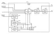
- FIG. 1is a functional block diagram of an example refrigeration system
- FIG. 2is a functional block diagram of an example drive controller and an example compressor
- FIGS. 3A-3Care simplified schematics of example power factor correction (PFC) modules
- FIGS. 4A-4Care simplified schematics of example inverter power modules and exemplary motors
- FIG. 5is a functional block diagram of a motor control module
- FIG. 6is a functional block diagram of an example implementation of the estimator module of FIG. 5 ;
- FIG. 7is a functional block diagram of an example Luenberger observer
- FIG. 8includes example graphs illustrating how d-axis resistance, Q-axis resistance, d-axis inductance, and Q-axis inductance may change with bulk current;
- FIG. 9is a flowchart depicting an example method of generating estimated position and estimated speed of a motor
- FIG. 10is a flowchart depicting example operation of a method for determining estimator convergence in open loop and closed loop modes and for initiating transition from open loop to closed loop;
- FIG. 11is a functional block diagram depicting an example implementation of the rotor check module of FIG. 5 .
- the refrigeration system 100may include a compressor 102 , a condenser 104 , an expansion valve 106 , and an evaporator 108 .
- the refrigeration system 100may include additional and/or alternative components.
- the present disclosureis applicable to other suitable types of refrigeration systems including, but not limited to, heating, ventilating, and air conditioning (HVAC), heat pump, refrigeration, and chiller systems.
- HVACheating, ventilating, and air conditioning
- the compressor 102receives refrigerant in vapor form and compresses the refrigerant.
- the compressor 102provides pressurized refrigerant in vapor form to the condenser 104 .
- the compressor 102includes an electric motor that drives a pump.
- the pump of the compressor 102may include a scroll compressor and/or a reciprocating compressor.
- the condenser 104transfers heat away from the refrigerant, thereby cooling the refrigerant.
- the refrigerant vaporis cooled to a temperature that is less than a saturation temperature, the refrigerant transforms into a liquid (or liquefied) refrigerant.
- the condenser 104may include an electric fan that increases the rate of heat transfer away from the refrigerant.
- the condenser 104provides the refrigerant to the evaporator 108 via the expansion valve 106 .
- the expansion valve 106controls the flow rate at which the refrigerant is supplied to the evaporator 108 .
- the expansion valve 106may include a thermostatic expansion valve or may be controlled electronically by, for example, a system controller 130 .
- a pressure drop caused by the expansion valve 106may cause a portion of the liquefied refrigerant to transform back into the vapor form. In this manner, the evaporator 108 may receive a mixture of refrigerant vapor and liquefied refrigerant.
- the refrigerantabsorbs heat in the evaporator 108 .
- Liquid refrigeranttransitions into vapor form when warmed to a temperature that is greater than the saturation temperature of the refrigerant.
- the evaporator 108may include an electric fan that increases the rate of heat transfer to the refrigerant.
- a utility 120provides power to the refrigeration system 100 .
- the utility 120may provide single-phase alternating current (AC) power at approximately 230 Volts (V) root mean squared (RMS) or at another suitable voltage.
- the utility 120may provide three-phase power at approximately 400 Volts RMS or 480 Volts RMS at a line frequency of, for example, 50 or 60 Hz.
- the utility 120may provide the AC power to the system controller 130 via an AC line.
- the AC powermay also be provided to a drive controller 132 via the AC line.
- the system controller 130controls the refrigeration system 100 .
- the system controller 130may control the refrigeration system 100 based on user inputs and/or parameters measured by various sensors (not shown).
- the sensorsmay include pressure sensors, temperature sensors, current sensors, voltage sensors, etc.
- the sensorsmay also include feedback information from the drive controller 132 , such as motor currents or torque, over a serial data bus or other suitable data buses.
- a user interface 134provides user inputs to the system controller 130 .
- the user interface 134may additionally or alternatively provide the user inputs to the drive controller 132 .
- the user inputsmay include, for example, a desired temperature, requests regarding operation of a fan (e.g., the evaporator fan), and/or other suitable inputs.
- the system controller 130may control operation of the fan of the condenser 104 , the fan of the evaporator 108 , and/or the expansion valve 106 .
- the drive controller 132may control the compressor 102 based on commands from the system controller 130 .
- the system controller 130may instruct the drive controller 132 to operate the compressor motor at a certain speed.
- the drive controller 132may also control the condenser fan.
- An electromagnetic interference (EMI) filter 202reduces EMI that might otherwise be injected back onto the AC line by the drive controller 132 .
- the EMI filter 202may also filter EMI carried on the AC line.
- a power factor correction (PFC) module 204receives AC power from the AC line as filtered by the EMI filter 202 .
- the PFC module 204(described in more detail with reference to FIGS. 3A, 3B, and 3C ) rectifies the AC power, thereby converting the AC input power into direct current (DC) power.
- the generated DC poweris provided at positive and negative terminals of the PFC module 204 .
- the PFC module 204also selectively provides power factor correction between the input AC power and the generated DC power.
- the PFC module 204selectively boosts the AC power to a DC voltage that is greater than a peak voltage of the AC power.
- the PFC module 204may operate in a passive mode, where the DC voltage generated is less than a peak voltage of the AC power.
- the PFC module 204may also operate in an active mode, where the DC voltage generated is greater than the peak voltage of the AC power.
- a DC voltage that is greater than the peak voltage of the AC powermay be referred to as a boosted DC voltage.
- AC power having an RMS voltage of 230 Vhas a peak voltage of approximately 325 V (230 V multiplied by the square root of 2).
- the PFC module 204may generate boosted DC voltages between approximately 350 V and approximately 410 V.
- the lower limit of 350 Vmay be imposed to avoid unstable operating regimes of the PFC module 204 .
- the limitsmay vary, such as with the actual AC input voltage value.
- the PFC module 204may be able to achieve higher boosted DC voltages than 410 V.
- the upper limit of 410 Vmay be imposed to improve long-term reliability of components that would experience greater stress at higher voltages, such as components in a DC filter 206 .
- the upper and/or lower limitsmay be varied dynamically.
- the DC filter 206filters the DC power generated by the PFC module 204 .
- the DC filter 206minimizes ripple voltage present in the DC power that results from the conversion of AC power to DC power.
- the DC filter 206may include one or more series or parallel filter capacitors connected between the positive and negative terminals of the PFC module 204 .
- the positive and negative terminals of the PFC module 204may be connected directly to positive and negative terminals of an inverter power module 208 .
- the inverter power module 208(described in more detail with reference to FIGS. 4A, 4B, and 4C ) converts the DC power, as filtered by the DC filter 206 , into AC power that is provided to the compressor motor.
- the inverter power module 208may convert the DC power into three-phase AC power and provide the phases of the AC power to three respective windings of the motor of the compressor 102 .
- the inverter power module 208may convert the DC power into more or fewer phases of power.
- a DC-DC power supply 220may also receive the filtered DC power.
- the DC-DC power supply 220converts the DC power into one or more DC voltages that are suitable for various components and functions.
- the DC-DC power supply 220may reduce the voltage of the DC power to a first DC voltage that is suitable for powering digital logic and a second DC voltage that is suitable for controlling switches within the PFC module 204 .
- the second DC voltagemay be selectively applied to gate terminals of the switches.
- DC powermay be provided by another DC power source (not shown)—for example, a DC power supply connected via a transformer to the main 230 VAC input.
- the first DC voltagemay be approximately 3.3 V and the second DC voltage may be approximately 15 V.
- the DC-DC power supply 220may also generate a third DC voltage.
- the third DC voltagemay be approximately 1.2 V.
- the third DC voltagemay be derived from the first DC voltage using a voltage regulator.
- the third DC voltagemay be used for core digital logic and the first DC voltage may be used for input/output circuitry of a PFC control module 250 and a motor control module 260 .
- the PFC control module 250controls the PFC module 204 , and the motor control module 260 controls the inverter power module 208 .
- the PFC control module 250controls switching of the switches within the PFC module 204
- the motor control module 260controls switching of switches within the inverter power module 208 .
- the PFC module 204may be implemented with 1, 2, 3, or more phases.
- a supervisor control module 270may communicate with the system controller 130 via a communications module 272 .
- the communications module 272may include an input/output port and other suitable components to serve as an interface between the system controller 130 and the supervisor control module 270 .
- the communications module 272may implement wired and/or wireless protocols.
- the supervisor control module 270provides various commands to the PFC control module 250 and the motor control module 260 .
- the supervisor control module 270may provide a commanded speed to the motor control module 260 .
- the commanded speedcorresponds to a desired rotational speed of the motor of the compressor 102 .
- the commanded compressor speedmay be provided to the supervisor control module 270 by the system controller 130 .
- the supervisor control module 270may determine or adjust the commanded compressor speed based on inputs provided via the communications module 272 and/or parameters measured by various sensors (i.e., sensor inputs). The supervisor control module 270 may also adjust the commanded compressor speed based on feedback from the PFC control module 250 and/or the motor control module 260 .
- the supervisor control module 270may also provide other commands to the PFC control module 250 and/or the motor control module 260 . For example, based on the commanded speed, the supervisor control module 270 may command the PFC control module 250 to produce a commanded bus voltage. The supervisor control module 270 may adjust the commanded bus voltage based on additional inputs, such as operating parameters of the inverter power module 208 and the measured voltage of the incoming AC line.
- the supervisor control module 270may diagnose faults in various systems of the drive controller 132 .
- the supervisor control module 270may receive fault information from the PFC control module 250 and/or the motor control module 260 .
- the supervisor control module 270may also receive fault information via the communications module 272 .
- the supervisor control module 270may manage reporting and clearing of faults between the drive controller 132 and the system controller 130 .
- the supervisor control module 270may instruct the PFC control module 250 and/or the motor control module 260 to enter a fault mode.
- the PFC control module 250may halt switching of the switches of the PFC module 204
- the motor control module 260may halt switching of the switches of the inverter power module 208 .
- the motor control module 260may directly provide fault information to the PFC control module 250 . In this way, the PFC control module 250 can respond to a fault identified by the motor control module 260 even if the supervisor control module 270 is not operating correctly and vice versa.
- the PFC control module 250may control switches in the PFC module 204 using pulse width modulation (PWM). More specifically, the PFC control module 250 may generate PWM signals that are applied to the switches of the PFC module 204 . The duty cycle of the PWM signals is varied to produce desired currents in the switches of the PFC module 204 . The desired currents are calculated based on an error between the measured DC bus voltage and a desired DC bus voltage. In other words, the desired currents are calculated in order to achieve the desired DC bus voltage. The desired currents may also be based on achieving desired power factor correction parameters, such as the shapes of current waveforms in the PFC module 204 .
- the PWM signals generated by the PFC control module 250may be referred to as PFC PWM signals.
- the motor control module 260may control switches in the inverter power module 208 using PWM in order to achieve the commanded compressor speed.
- the PWM signals generated by the motor control module 260may be referred to as inverter PWM signals.
- the duty cycle of the inverter PWM signalscontrols the current through the windings of the motor (i.e., motor currents) of the compressor 102 .
- the motor currentscontrol motor torque, and the motor control module 260 may control the motor torque to achieve the commanded compressor speed.
- the PFC control module 250 and the motor control module 260may also share data.
- the PFC control module 250may receive data from the motor control module 260 such as load, motor currents, estimated motor torque, inverter temperature, duty cycle of the inverter PWM signals, and other suitable parameters.
- the PFC control module 250may also receive data from the motor control module 260 , such as the measured DC bus voltage.
- the motor control module 260may receive data from the PFC control module 250 such as AC line voltage, current(s) through the PFC module 204 , estimated AC power, PFC temperature, commanded bus voltage, and other suitable parameters.
- the PFC control module 250 , the motor control module 260 , and the supervisor control module 270may be implemented on an integrated circuit (IC) 280 .
- the IC 280may include a digital signal processor (DSP), a field programmable gate array (FPGA), a microprocessor, etc.
- DSPdigital signal processor
- FPGAfield programmable gate array
- additional componentsmay be included in the IC 280 .
- various functions shown inside the IC 280 in FIG. 2may be implemented external to the IC 280 , such as in a second IC or in discrete circuitry.
- the supervisor control module 270may be integrated with the motor control module 260 .
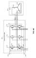
- FIG. 3Ais a schematic of an example implementation of the PFC module 204 .
- the PFC module 204receives AC power via first and second AC input terminals 302 and 304 .
- the AC powermay be, for example, the AC power output by the EMI filter 202 .
- the signals at the first and second AC input terminals 302 and 304may both be time-varying with respect to an earth ground.
- the PFC module 204outputs DC power to the DC filter 206 and the inverter power module 208 via a positive DC terminal 306 and a negative DC terminal 308 .
- An anode of a first rectifier diode 310is connected to the second AC input terminal 304 , and a cathode of the first rectifier diode 310 is connected to the positive DC terminal 306 .
- An anode of a second rectifier diode 312is connected to the negative DC terminal 308 , and a cathode of the second rectifier diode 312 is connected to the second AC input terminal 304 .
- Each of the rectifier diodes 310 and 312may be implemented as one or more individual series or parallel diodes.
- a switch block 320is connected between the positive and negative DC terminals 306 and 308 .
- the switch block 320includes a first PFC leg 330 that includes first and second switches 332 and 334 .
- the switches 332 and 334each include a first terminal, a second terminal, and a control terminal.
- each of the switches 332 and 334may be implemented as an insulated gate bipolar transistor (IGBT).
- the first, second, and control terminalsmay correspond to collector, emitter, and gate terminals, respectively.
- the first terminal of the first switch 332is connected to the positive DC terminal 306 .
- the second terminal of the first switch 332is connected to the first terminal of the second switch 334 .
- the second terminal of the second switch 334may be connected to the negative DC terminal 308 .
- the second terminal of the second switch 334may be connected to the negative DC terminal 308 via a shunt resistor 380 to enable measuring current flowing through the first PFC leg 330 .
- the control terminals of the switches 332 and 334receive generally complementary PFC PWM signals from the PFC control module 250 .
- the PFC PWM signal provided to the first switch 332is opposite in polarity to the PFC PWM signal provided to the second switch 334 .
- Short circuit currentmay flow when the turning on of one of the switches 332 and 334 overlaps with the turning off of the other of the switches 332 and 334 . Therefore, both the switches 332 and 334 may be turned off during a deadtime before either one of the switches 332 and 334 is turned on. Therefore, generally complementary means that two signals are opposite for most of their periods. However, around transitions, both signals may be low or high for some overlap period.
- the first PFC leg 330may also include first and second diodes 336 and 338 connected anti-parallel to the switches 332 and 334 , respectively.
- an anode of the first diode 336is connected to the second terminal of the first switch 332
- a cathode of the first diode 336is connected to the first terminal of the first switch 332 .
- An anode of the second diode 338is connected to the second terminal of the second switch 334
- a cathode of the second diode 338is connected to the first terminal of the second switch 334 .
- the switch block 320may include one or more additional PFC legs. In various implementations, the switch block 320 may include one additional PFC leg. As shown in FIG. 3A , the switch block 320 includes second and third PFC legs 350 and 360 . The number of PFC legs included in the switch block 320 may be chosen based on performance and cost. For example only, the magnitude of ripple (voltage and current) in the DC output of the PFC module 204 may decrease as the number of PFC legs increases. In addition, the amount of ripple current in the AC line current may decrease as the number of PFC legs increase. However, parts costs and implementation complexity may increase as the number of PFC legs increases.
- the second and third PFC legs 350 and 360 of the switch block 320may be similar to the first PFC leg 330 .
- the second and third PFC legs 350 and 360may each include respective components for the switches 332 and 334 , the diodes 336 and 338 , and respective shunt resistors connected in the same manner as the first PFC leg 330 .
- the PFC PWM signals provided to the switches of the additional PFC legsmay also be complementary.
- the PFC PWM signals provided to the additional PFC legsmay be phase shifted from each other and from the PFC PWM signals provided to the first PFC leg 330 .
- the phase shift of the PFC PWM signalsmay be determined by dividing 360 degrees (°) by the number of PFC legs.
- the switch block 320includes three PFC legs, the PFC PWM signals may be phase shifted from each other by 120° (or 180° for two phases, or 90° for four phases, etc.). Phase shifting the PFC PWM signals may cancel ripple in the AC line current as well as the DC output.
- the PFC module 204includes a first inductor 370 .
- the first inductor 370is connected between the first AC input terminal 302 and the second terminal of the first switch 332 .
- Additional inductorsmay connect the first AC input terminal 302 to additional PFC legs.
- FIG. 3Ashows a second inductor 372 and a third inductor 374 connecting the first AC input terminal 302 to the second and third PFC legs 350 and 360 , respectively.
- a voltagemay be measured across the shunt resistor 380 to determine current through the first PFC leg 330 according to Ohm's law.
- An amplifier(not shown), such as an operational amplifier, may amplify the voltage across the shunt resistor 380 .
- the amplified voltagemay be digitized, buffered, and/or filtered to determine the current through the first PFC leg 330 .
- Current through other PFC legsmay be determined using respective shunt resistors.
- a resistor 382may be connected in series with the negative DC terminal 308 , as shown in FIG. 3B .
- Current through the resistor 382may therefore indicate a total current output from the PFC module 204 .
- Current through each of the PFC legs 330 , 350 , and 360may be inferred from the total current based on the known phase timing of the current through the PFC legs 330 , 350 , and 360 .
- any method of measuring or sensing current through any or all of the PFC legs 330 , 350 , 360may be used.
- the current through the first PFC leg 330may be measured using a current sensor 387 (as shown in FIG. 3C ).
- the current sensor 387may be implemented in series with the first inductor 370 .
- the current sensor 387may include a Hall-effect sensor that measures the current through the first PFC leg 330 based on magnetic flux around the first inductor 370 .
- Current through the PFC legs 350 and 360may also be measured using associated current sensors 388 and 389 , respectively.
- the PFC module 204may also include first and second bypass diodes 390 and 392 .
- An anode of the first bypass diode 390is connected to the first AC input terminal 302
- a cathode of the first bypass diode 390is connected to the positive DC terminal 306 .
- An anode of the second bypass diode 392is connected to the negative DC terminal 308
- a cathode of the second bypass diode 392is connected to the first AC input terminal 302 .
- the bypass diodes 390 and 392may be power diodes, which may be designed to operate at low frequencies, such as, for example, frequencies less than approximately 100 Hz or approximately 200 Hz. Resistance of the bypass diodes 390 and 392 may be less than resistance of the inductors 370 , 372 , and 374 . Therefore, when the switches 332 and 334 within the switch block 320 are not being switched, current may flow through the bypass diodes 390 and 392 instead of the diodes 336 and 338 .
- the boosted DC voltagewill be greater than a peak voltage on the AC line.
- the bypass diodes 390 and 392will therefore not be forward biased and will remain inactive.
- the bypass diodes 390 and 392may provide lightning strike protection and power surge protection.
- the bypass diodes 390 and 392may be implemented with the rectifier diodes 310 and 312 in a single package.
- Vishay model number 26MT or 36MT or International Rectifier, model number 26 MB or 36 MBmay be used as the bypass diodes 390 and 392 and the rectifier diodes 310 and 312 .
- the rectifier diodes 310 and 312carry current whether the PFC module 204 is generating a boosted DC voltage or not. Therefore, in various implementations, each of the rectifier diodes 310 and 312 may be implemented as two or more physical diodes connected in parallel. Current sensors may be used to measure PFC phase currents in series with the inductors 370 , 372 , and 374 .
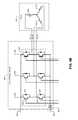
- FIG. 4Aa simplified schematic of a motor 400 and an example implementation of the inverter power module 208 is presented.
- the motor 400is a component of the compressor 102 of FIG. 2 .
- the principles of FIGS. 4A-4Cmay apply to other motors, including a motor of the condenser 104 .
- the inverter power module 208includes a switch block 402 .
- the switch block 402 and the switch block 320 of the PFC module 204may be implemented using a similar part. For example only, in FIG.
- a first inverter leg 410includes first and second switches 420 and 422 and first and second diodes 424 and 426 , which are arranged similarly to the switches 332 and 334 and the diodes 336 and 338 of FIG. 3A .
- the switch block 402receives the filtered DC voltage from the DC filter 206 via a positive DC terminal 404 and a negative DC terminal 406 .
- the first terminal of the first switch 420may be connected to the positive DC terminal 404
- the second terminal of the second switch 422may be connected to the negative DC terminal 406 .
- the control terminals of the switches 420 and 422receive generally complementary inverter PWM signals from the motor control module 260 .
- the switch block 402may include one or more additional inverter legs.
- the switch block 402may include one inverter leg for each phase or winding of the motor 400 .
- the switch block 402may include second and third inverter legs 430 and 440 , as shown in FIG. 4A .
- the inverter legs 410 , 430 , and 440may provide current to windings 450 , 452 , and 454 of the motor 400 , respectively.
- the windings 454 , 452 , and 450may be referred to as windings a, b, and c, respectively.
- Voltage applied to the windings 454 , 452 , and 450may be referred to as Va, Vb, and Vc, respectively.
- Current through the windings 454 , 452 , and 450may be referred to as Ia, Ib, and Ic, respectively.
- first ends of the windings 450 , 452 , and 454may be connected to a common node.
- Second ends of the windings 450 , 452 , and 454may be connected to the second terminal of the first switch 420 of the inverter legs 410 , 430 , and 440 , respectively.
- the inverter power module 208may also include a shunt resistor 460 that is associated with the first inverter leg 410 .
- the shunt resistor 460may be connected between the second terminal of the second switch 422 and the negative DC terminal 406 .
- respective shunt resistorsmay be located between each of the inverter legs 430 and 440 and the negative DC terminal 406 .
- current through the first winding 450 of the motor 400may be determined based on the voltage across the shunt resistor 460 of the first inverter leg 410 .
- the shunt resistor of one of the inverter legs 410 , 430 , or 440may be omitted. In such implementations, current may be inferred based on the measurements of the remaining shunt resistors.
- a resistor 462may be connected in series with the negative DC terminal 406 , as shown in FIG. 4B .
- Current through the resistor 462may therefore indicate a total current consumed by the inverter power module 208 .
- Current through each of the inverter legs 410 , 430 , and 440may be inferred from the total current based on the known phase timing of the current through the inverter legs 410 , 430 , and 440 . Further discussion of determining currents in an inverter can be found in commonly assigned U.S. Pat. No. 7,193,388, issued Mar. 20, 2007, which is incorporated by reference herein in its entirety.
- any method of measuring or sensing current through any or all of the inverter legs 410 , 430 , and 440may be used.
- the current through the first inverter leg 410may be measured using a current sensor 487 (shown in FIG. 4C ).
- the current sensor 487may be implemented between the first inverter leg 410 and the first winding 450 .
- Current through the inverter legs 430 and 440may also be measured using associated current sensors 488 and 489 , respectively.
- current sensorsmay be associated with two of the inverter legs 410 , 430 , and 440 . The current through the other one of the inverter legs 410 , 430 , and 440 may be determined based on an assumption that the current in the motor windings sums to zero.
- the motor control module 260controls switches within the inverter power module 208 to control voltages applied to the windings 454 , 452 , 450 (hereinafter, “windings a-c ”) of the motor 400 . This may also be referred to as controlling the inverter power module 208 or as controlling the motor 400 .
- the motor control module 260may apply voltages V a-c to windings a-c , respectively.
- Voltages V a-cmay collectively be referred to as output voltages.
- Currents I a-care generated in the windings a-c , respectively, when voltages V a-c are applied to the windings a-c .
- Currents I a-cmay collectively be referred to as winding currents.
- Currents in the windings a-cproduce magnetic flux about the windings a-c , and vice versa.
- the motor control module 260generates the output voltages to control the winding currents and/or to control magnetic flux.
- the inverter power module 208provides the switching voltage to the windings a-c .
- the motor 400includes a rotor (not shown) that rotates in response to the winding currents.
- the motor control module 260controls the amplitude, duty cycle, and/or frequency of the output voltages to control the torque and speed of the rotor.
- the motor control module 260may control the output voltages based on a commanded motor speed, which represents a desired rotational speed of the rotor.
- the motor control module 260may control the output voltages further based on a commanded motor current, a commanded motor torque, and/or one or more other parameters.
- the motor control module 260may implement field oriented control of the motor 400 . Accordingly, the motor control module 260 may map motor driving variables onto various frames of reference. Motor driving variables may include requested current/voltage values used to control the motor 400 as well as measured currents/voltages. For example, motor driving variables may include measured currents I a-c through the windings a-c and voltage requests used by the motor control module 260 to apply voltages V a-c to the windings a-c .
- the motor control module 260may map motor driving variables in an abc frame of reference (FoR), an ⁇ FoR, a qdr FoR, a qdv FoR, and/or one or more other FoRs.
- the qdv FoRis the FoR for the commanded speed.
- the abc FoRmay represent, for example, a three-phase stator frame based on the windings a-c .
- Each of the measured currents I a-cmay be mapped onto respective axes a, b, and c of the abc FoR.
- the motor control module 260may map requested voltages corresponding to voltages V a-c in the abc FoR.
- the ⁇ FoRincludes stationary, stator-based x and y coordinates onto which the motor driving variables are projected.
- the qdr FoRis a rotating FoR that corresponds to the rotor and rotates in sync with the rotor. Accordingly, the qdr FoR is based on an angle of the rotor.
- the motor control module 260may transform motor driving variables from one FoR to another FoR. For example, the motor control module 260 may transform currents represented in the abc FoR into currents represented in the ⁇ FoR and vice versa. The motor control module 260 may transform motor driving variables from the abc FoR to the ⁇ FoR using a numerical transformation. The motor control module 260 may transform motor driving variables from the ⁇ FoR to the qdr FoR based on the angle of the rotor. Additionally or alternatively, the motor control module 260 may transform motor driving variables into an arbitrary FoR rotating at a specific speed, and this speed could be chosen as the commanded speed.
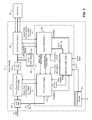
- the motor control module 260controls the inverter power module 208 based on the commanded speed from the supervisor control module 270 of FIG. 2 .
- a filter module 501may filter the commanded speed from the supervisor control module 270 of FIG. 2 .
- the output of the filter module 501is referred to below as the commanded speed ⁇ v .
- the filter module 501may implement a ramp function, which updates the commanded speed ⁇ v by up to a maximum increment during each predetermined interval of time.
- the motor control module 260may control the motor 400 based on a commanded FoR (e.g., a qdv FoR) when operating in open loop mode.
- the qdv FoRis associated with the commanded speed ⁇ v of the rotor and a commanded angle ( ⁇ v ) of the rotor.
- a commanded angle generation module 502may determine the commanded angle ⁇ v , such as by integrating the commanded speed ⁇ v .
- the motor control module 260may operate in various modes, such as open loop mode or closed loop mode.
- the motor control module 260may operate in open loop mode when starting the motor 400 and later transition to operating in closed loop mode.
- open loop modethe rotor will tend to synchronize with the commanded speed ⁇ v , especially when the motor control module 260 is operating the rotor at slower speeds.
- the actual rotor anglemay differ from the commanded angle ⁇ v because of a load applied to the motor 400 .
- a change in load while operating in open loop modemay change a phase difference between the commanded angle ⁇ v and the actual rotor angle.
- a rotor check module 503monitors estimator parameters from an estimator module 504 .
- the estimator module 504may also be referred to as an estimator.
- the rotor check module 503determines whether and when estimation has converged—i.e., whether and when the estimator module 504 is correctly tracking the actual operation of the motor 400 . If the estimator does not converge, or if the estimator converges but then diverges, the rotor check module 503 may signal a rotor fault. In response to the rotor fault, the motor 400 may be shut down or another operating mode may be entered to attempt to bring the estimator back in line with motor operation.
- the rotor check module 503may generate a transition signal.
- an angle/speed determination module 508may transition from using open loop speed and angle values to closed loop speed and angle values. Further information regarding example implementations of the transition from open loop to closed loop and estimator convergence can be found in commonly assigned patent application Ser. No. 12/852,625, filed Aug. 9, 2010, now U.S. Pat. No. 8,344,706, issued Jan. 1, 2013, and in commonly assigned patent application Ser. No. 12/570,504, filed Sep. 30, 2009, now published as U.S. Pub. No. 2011/0068724, the disclosures of which are hereby incorporated by reference in their entirety.
- the estimator module 504estimates the speed ( ⁇ est ) and angle ( ⁇ est ) of the rotor.
- the estimator module 504may determine the estimated speed ⁇ est based on the estimated angle ⁇ est .
- the estimator module 504may differentiate and filter the estimated angle ⁇ est over a period of time to determine the estimated speed ⁇ est .
- the estimator module 504may determine the estimated angle ⁇ est based on various motor driving variables.
- the motor driving variablesmay include V a-c to be applied to the windings a-c , I a-c measured in the windings a-c , alpha-beta variables, and qdv variables.
- the estimator module 504may determine the estimated angle ⁇ est based on the commanded speed ⁇ v .
- the estimator module 504may include a state observer (e.g., a Luenberger observer) to determine the estimated angle ⁇ est and the estimated speed ⁇ est based on the motor driving variables. Further description of sensorless control systems and methods can be found in U.S. Pat. No. 6,756,757, issued Jun.
- a current determination module 506may measure the currents I a-c of the windings a-c (hereinafter “measured currents”). In various implementations, two of the currents I a-c may be measured and the other one of the currents I a-c may be determined knowing that the sum of the (three) currents I a-c equals zero.
- the estimator module 504may use the measured currents to generate the estimated angle ⁇ est and the estimated speed ⁇ est . Stated broadly, the estimator module 504 estimates a total motor flux and a magnet flux, and the estimator module 504 generates the estimated angle and the estimated speed based on at least one of the estimated magnet flux and the estimated total flux.
- the estimator module 504estimates the total motor flux and the magnet flux as a function of the motor driving variables.
- the motor driving variablesinclude, among other things, motor resistances and motor inductances.
- the estimator module 504determines bulk current based on the measured currents and determines the motor resistances and motor inductances as a function of the bulk current.
- the angle/speed determination module 508generates an output angle ⁇ r and an output speed ⁇ r based on the currently enabled mode, such as open loop mode or closed loop mode.
- the angle/speed determination module 508may set the output angle ⁇ r equal to the commanded angle ⁇ v when operating in open loop mode and may set the output angle ⁇ r equal to the estimated angle ⁇ est when operating in closed loop mode.
- the angle/speed determination module 508gradually adjusts the output angle ⁇ r from the commanded angle ⁇ v to the estimated angle ⁇ est .
- This gradual adjustmentmay minimize transient current demands when transitioning from open loop mode to closed loop mode, which may prevent disruption of current control (described below) and/or estimation of the estimated angle ⁇ est .
- the gradual adjustmentmay therefore improve stability during transitions and allow for starting the motor 400 more reliably, especially under higher loads.
- the angle/speed determination module 508may set the output speed ⁇ r equal to the commanded speed ⁇ v when operating in open loop mode.
- the angle/speed determination module 508may set the output speed ⁇ r equal to the estimated speed ⁇ est when operating in closed loop mode.
- the angle/speed determination module 508may immediately switch the output speed ⁇ r from the commanded speed ⁇ v to the estimated speed ⁇ est when the rotor check module 503 instructs a transition from open loop mode to closed loop mode.
- the angle/speed determination module 508may also set the output (rotor) speed ⁇ r as a function of the estimated speed ⁇ est and the commanded speed ⁇ v .
- the rotor check module 503may also instruct a change from closed loop mode back to open loop mode. For example only, a transition back to open loop mode may be performed when error conditions are observed, such as a lost rotor or other abnormal operating conditions.
- the angle/speed determination module 508may therefore also switch the output speed ⁇ r from the estimated speed ⁇ est back to the commanded speed ⁇ v , and switch the output angle ⁇ r from the estimated angle ⁇ est back to the commanded angle ⁇ v .
- switching the output speed ⁇ rsimilarly to the transition from open loop mode to closed loop mode, switching the output speed ⁇ r may be performed immediately, while switching the output angle ⁇ r may be performed gradually.
- additional modesmay be supported. For example only, three, four, or more modes may be supported.
- the rotor check module 503may instruct the angle/speed determination module 508 to transition from one of the modes to another. During each transition, the angle/speed determination module 508 may switch the output speed ⁇ r immediately to a speed corresponding to the selected mode. Alternatively, the output speed ⁇ r may be ramped toward the speed of the selected mode. Further, the angle/speed determination module 508 ramps the output angle ⁇ r toward an angle corresponding to the selected mode.
- the rotor check module 503may instruct the angle/speed determination module 508 to transition from one of the modes to another using a transition signal. For example, the transition signal may specify a target mode to which the angle/speed determination module 508 should transition.
- a speed loop control module 510generates a demanded torque signal calculated to match the output speed ⁇ r to the commanded speed ⁇ v .
- the speed loop control module 510may be bypassed in open loop mode. In closed loop mode, the output speed ⁇ r is equal to the estimated speed ⁇ est of the motor 400 . Therefore, the speed loop control module 510 may generate the demanded torque signal in order to keep the speed of the motor 400 approximately equal to the commanded speed ⁇ v . For example only, when the output speed ⁇ r is less than the commanded speed ⁇ v , the speed loop control module 510 may increase the demanded torque, and vice versa.
- An Idr injection module 512generates a d-axis current (Idr) demand based on the DC bus voltage, the demanded torque signal, and the commanded speed ⁇ v .
- the Idr demandis used by current control, described below, for Idr injection, which may also be referred to as field weakening or phase advance.
- the Idr injection module 512may adjust the Idr demand based on an out of volts (OOV) signal, described below, and measured current.
- OOVout of volts
- a torque mapping module 514generates a Q-axis current (Iqr) demand based on the demanded torque signal. Torque may also be generated by the Idr demand and therefore, the torque mapping module 514 may determine the Iqr demand based also on the Idr demand or the actual Idr. For example only, the torque mapping module 514 may implement a maximum current limit. In various implementations, the torque mapping module 514 may compare a combination of the Idr demand and the Iqr demand to the maximum current limit, and reduce one or both of the demands when the combination exceeds the maximum current limit. In various implementations, the torque mapping module 514 may limit only the Iqr demand. For example only, the maximum current limit may be a root mean square limit, such as 25 Amps rms .
- the torque mapping module 514may output a limit signal to the speed loop control module 510 .
- the speed loop control module 510may temporarily suspend increasing the demanded torque.
- the speed loop control module 510may also temporarily suspend increasing the demanded torque based on the OOV signal.
- the speed loop control module 510may attempt to match the output speed ⁇ r to a reduced version of the commanded speed ⁇ v .
- the speed loop control module 510may selectively suspend error summing and/or integrating operation that would lead to increasing the demanded torque.
- the speed loop control module 510may stop increasing the demanded torque because the present demanded torque already cannot be achieved within the maximum current limit.
- a current control module 516determines voltage commands Vqr and Vdr, in the qdr FoR, based on the current demands Iqr and Idr.
- the voltage commands Vqr and Vdrmay be a Q-axis voltage command and a d-axis voltage command, respectively.
- the current control module 516may determine the voltage commands Vqr and Vdr based also on the measured currents.
- the current control module 516may attempt to match the measured currents to the Iqr and Idr demands by adjusting the voltage commands Vqr and Vdr.
- the current control module 516may also receive the output speed ⁇ r .
- An abc to qdr module 520maps the measured currents I a-c onto the qdr FoR based on the output angle ⁇ r .
- the resulting mapped currentmay be referred to as Iqdr, and may include Iqr and Idr components.
- the measured currents used by components of the motor control module 260such as the current control module 516 and the estimator module 504 , may therefore use the Iqdr representation of the measured currents.
- a qdr to ⁇ module 522may transform the voltage commands Vqr and Vdr from the qdr FoR to the ⁇ FoR, thereby generating a voltage request in the ⁇ FoR (hereinafter “voltage request”).
- the voltage requestmay indicate the voltages to be applied to the windings a-c .
- the qdr to ⁇ module 522may perform the transformation based on the output angle ⁇ r , and in various implementations, may perform the transformation based on the output speed ⁇ r .
- a pulse-width modulation (PWM) module 524generates duty cycle signals to control the inverter power module 208 using PWM.
- the PWM switching frequencymay be approximately 5 kHz or approximately 10 kHz.
- the inverter power module 208 and the motor 400have three phases, and the PWM module 524 generates three duty cycle signals, one for each inverter leg.
- each leg of the inverter power module 208includes a pair of complementary switches, and each of the duty cycle signals is therefore converted into complementary duty cycle signals, one for each of the complementary switches.
- the switch 420 and the switch 422 of the first inverter leg 410may be controlled with complementary duty cycles.
- the complementary duty cyclesmay be adjusted so that a switch is not turning on at the same time the other switch is turning off. In other words, the off-times of the two switches are partially overlapped.
- the PWM module 524determines the duty cycle signals based on the DC bus voltage and the voltage requests from the qdr to ⁇ module 522 .
- the PWM module 524may transform the voltage request from the ⁇ FoR to the abc FoR to determine three voltage demands, hereinafter Vr a , Vr b , and Vr b (collectively Vr a-c ), corresponding to the windings a-c , respectively.
- the drive controller 132When the voltage demands cannot be met given the present DC bus voltage, the drive controller 132 is defined to be operating in the OOV state. For example only, a maximum duty cycle may be defined in the PWM module 524 . If the voltage demands would result in one of the duty cycles being greater than the maximum duty cycle, the drive controller 132 is operating in the OOV state.
- the maximum duty cyclemay be set to be less than 100%, such as 96%, 95%, or 92%.
- the maximum duty cycle limitmay be set based on requirements for accurate measurement of the winding currents I a-c .
- the motor 400may respond not to the winding voltages themselves, but instead to differences between the winding voltages.
- applying 50 Volts to a first winding and 150 Volts to a second windingmay be equivalent to applying 0 Volts to the first winding and 100 Volts to the second winding. Therefore, even if one of the voltage demands may exceed an available voltage, the PWM module 524 may shift the voltage demands when generating the duty cycles.
- the PWM module 524may determine that the drive controller 132 is in the OOV state when a difference between any two of the three voltage demands is greater than the available voltage. For example only, the available voltage may be equal to the DC bus multiplied by the maximum duty cycle. In various implementations, the PWM module 524 may shift the duty cycles such that one of the duty cycles is set to zero. Alternatively, the PWM module 524 may shift the duty cycles such that the duty cycles are centered about a middle duty cycle, such as 50%. In various implementations, the PWM module 524 may shift the duty cycles using one or the other of these approaches, depending on an operating mode. For example only, the PWM module 524 may shift the duty cycles such that the lowest duty cycle is set to zero when the motor 400 is operating at speeds above a predetermined threshold.
- the PWM module 524may scale the voltage demands down before generating the duty cycles. Equivalently, the PWM module 524 may scale the duty cycles. In various implementations, the PWM module 524 may scale the duty cycles or voltage demands as little as possible, such that one of the duty cycles is set to the minimum duty cycle, and one of the duty cycles is set to the maximum duty cycle.
- the scaling factoris an indication of how far OOV the drive controller 132 currently is.
- the scaling factormay be referred to as OOV magnitude, and may be included in the OOV signal.
- the PWM module 524sets an OOV flag to a first value, such as 1.
- the PWM module 524sets the OOV flag to a second value, such as 0.
- the OOV flagmay be included in the OOV signal.
- a quantity called OOV amountmay be determined based on the OOV flag.
- the OOV amountmay indicate how often the drive controller 132 is operating OOV.
- the inverter power module 208may define an operating region shaped like a hexagon. The voltage demands may be thought of as circles within the hexagon. If the circles are centered within the hexagon, as the circles expand, they will touch the sides of the hexagon. When the circles expand beyond the hexagon, the circles become more and more clipped at each face of the hexagon. Clipping may correspond to the OOV state. As a result, the proportion of time that the voltage demands are clipping (producing the OOV state) indicates how far OOV the drive controller 132 is.
- the OOV amountmay represent a portion of the time that the drive controller 132 is spending in the OOV state.
- the OOV amountmay be determined by applying a filter, such as a digital low-pass filter, to the OOV flag.
- the OOV amountmay be determined by applying a moving average to the OOV flag. When the OOV flag assumes values of 0 or 1, the OOV amount will then range between 0 and 1, inclusive. When multiplied by 100, the OOV amount is the percentage of time the drive controller 132 is spending in the OOV state.
- the motor control module 260may use multiple approaches to minimize OOV operation, or to maintain OOV operation below a predetermined threshold.
- the Idr injection module 512may use the OOV amount in determining how to adjust the Idr demand.
- the speed loop control module 510may also use the OOV amount to determine when to suspend increases in the demanded torque.
- the current control module 516may suspend increases to one or both of the Vqr and Vdr commands based on the OOV flag. Additionally or alternatively, the current control module 516 may suspend integrator action when the OOV signal is generated.
- the estimator module 504can use the voltage commands and the measured currents provided in any FoR, such as the theta-v FoR.
- a three phase permanent magnet motormay be described by a set of equations in the so-called terminal variable or abc frame of reference. Operation of the motor 400 may be controlled such that the sum of currents across the three phases is zero.
- the equations recast in the alpha-beta frame of referencemay be written as:
- ⁇ ⁇ ⁇ 0⁇ f ⁇ C ⁇ P ⁇ ( ⁇ r ) + C ⁇ L Cabc ⁇ C - 1 ⁇ I ⁇ 0 + C ⁇ L Vabc ⁇ ( ⁇ r ) ⁇ C - 1 ⁇ I ⁇ 0
- V ⁇ 0R ⁇ 0 ⁇ I ⁇ 0 + ⁇ f ⁇ ⁇ r ⁇ C ⁇ Q ⁇ ( ⁇ r ) + L C ⁇ ⁇ ⁇ ⁇ ⁇ 0 ⁇ d d t ⁇ I ⁇ 0 + d d t ⁇ [ L V ⁇ ⁇ ⁇ 0 ⁇ ( ⁇ r ) ] ⁇ I ⁇ 0 + L V ⁇ ⁇ ⁇ 0 ⁇ ( ⁇ r ) ⁇ d d t ⁇ I ⁇ 0 + L V ⁇ ⁇ ⁇ 0 ⁇ ( ⁇ r ) ⁇ d d t ⁇ I ⁇ 0 + L V ⁇ ⁇
- the flux estimation module 604may include a Luenberger observer, a functional block diagram of which is illustrated by 700 in FIG. 7 . While use of a Luenberger observer is shown and described, the flux estimation module 604 may generate an estimated magnet flux and/or an estimated total flux using another suitable flux estimator, such as using a linear Kalman filter, an extended Kalman filter, an ensemble Kalman filter, an unscented Kalman filter, another suitable type of Kalman filter, or another suitable type of filter or observer.
- a Luenberger observera functional block diagram of which is illustrated by 700 in FIG. 7 . While use of a Luenberger observer is shown and described, the flux estimation module 604 may generate an estimated magnet flux and/or an estimated total flux using another suitable flux estimator, such as using a linear Kalman filter, an extended Kalman filter, an ensemble Kalman filter, an unscented Kalman filter, another suitable type of Kalman filter, or another suitable type of filter or observer.
- the flux estimation module 604may generate the estimated magnet flux and/or the estimated total flux based on the measured currents, the output speed ⁇ r , the commanded speed ⁇ v , and the voltage commands.
- the flux estimation module 604may generate the estimated magnet flux and/or the estimated total flux further based on Q-axis resistance (R q ) of the motor 400 , d-axis resistance (R d ) of the motor 400 , Q-axis inductance (L q ) of the motor 400 , and d-axis inductance (L d ) of the motor 400 .
- An angle estimation module 608generates the estimated angle ⁇ est based on at least one of the estimated magnet flux and the estimated total flux.
- a speed estimation module 612generates the estimated speed ⁇ est based on the estimated angle ⁇ est . For example, the speed estimation module 612 may differentiate and filter the estimated angle ⁇ est over a period of time to determine the estimated speed ⁇ est .
- Crefers to the 3 to 2 static FoR transformation, Clark's Transformation.
- Cis the measurement matrix and maps the estimated states to measurements.
- A( - R L + M - ⁇ v R L + M 0 ⁇ v - R L + M 0 R L + M 0 0 - ( ⁇ v - ⁇ r ) 0 0 ( ⁇ v - ⁇ r ) 0 )
- ⁇ B( 1 0 0 1 0 0 0 )
- ⁇ and C( 1 L + M 0 - 1 L + M 0 0 1 L + M 0 - 1 L + M ) .
- A( - R Q L Q - ⁇ v R Q L Q 0 ⁇ v - R d L d 0 R d L d 0 0 0 ⁇ r - ⁇ v 0 0 - ( ⁇ r - ⁇ v ) 0 )
- ⁇ B( 1 0 0 1 0 0 0 0 )
- ⁇ C( 1 L q 0 - 1 L q 0 0 1 L d 0 - 1 L d )
- ⁇ x( ⁇ Qv ⁇ dv ⁇ fQv ⁇ fdv )
- ⁇ u( V Qv V dv )
- R qis the Q-axis resistance of the motor 400
- R dis the d-axis resistance of the motor 400
- L qis the Q-axis inductance of the motor 400
- L dis the d-axis inductance of the motor 400
- the actual system state(at time k) can be obtained by integration from an initial condition (at time k ⁇ 1):
- the Q-axis resistance R q , the d-axis resistance R d , the Q-axis inductance L q , and the d-axis inductance L dare variable values.
- a resistance determination module 616determines the Q-axis resistance R q and the d-axis resistance R d .
- An inductance determination module 620determines the Q-axis inductance L q and the d-axis inductance L d .
- the resistance determination module 616 and the inductance determination module 620determine the Q-axis resistance R q , the d-axis resistance R d , the Q-axis inductance L q , and the d-axis inductance L d as functions of a bulk current I B .
- the resistance determination module 616may determine the Q-axis resistance R q and the d-axis resistance R d using the equations:
- the bulk current I Bmay be used in place of the normalized bulk current I NB .
- the inductance determination module 620may determine the Q-axis inductance L q and the d-axis inductance L d , for example, using the equations:
- the bulk current I Bmay be used in place of the normalized bulk current I NB .
- Coefficients a, b, c, and dare real numbers.
- a bulk current determination module 624determines the bulk current I B as a function of the measured currents (e.g., IQr and Idr). For example, the bulk current determination module 624 may determine the bulk current I B using the following equation or another suitable mathematical relationship.
- the function for determining the bulk current I Bmay be selected based on the functions that relate the bulk current I B to the Q-axis resistance R q , the d-axis resistance R d , the Q-axis inductance L q , and the d-axis inductance L d .
- the bulk current I Bcan be determined using other functions.
- a normalized version of the bulk current I Bmay be used to determine the Q-axis resistance R q , the d-axis resistance R d , the Q-axis inductance L q , and the d-axis inductance L d , as discussed above.
- the bulk current determination module 624may generate the normalized version of the bulk current I B , for example, by dividing the bulk current I B by a maximum allowable bulk current.
- one or more gainsmay be defined for specified pole locations. These gains may change with changes in one or more motor parameters (e.g., resistance or inductance).
- one or more gain valuese.g., K in the Luenberger observer case
- K in the Luenberger observer caseK in the Luenberger observer case
- a gain setting module 628sets one or more gain values (e.g., K in the Luenberger observer case and/or coefficients a-d used to determine the Q and d axis resistance and inductance values) used by the flux estimation module 604 to generate the estimated magnet flux and/or the estimated total flux.
- K in the Luenberger observer case and/or coefficients a-d used to determine the Q and d axis resistance and inductance valuesused by the flux estimation module 604 to generate the estimated magnet flux and/or the estimated total flux.
- polynomials for each motor parametermay be determined and optimized to minimize the error between estimated and measured angles.
- the gain setting module 628may set the one or more gain values based on one or more of the Q-axis resistance R q , the d-axis resistance R d , the Q-axis inductance L q , and the d-axis inductance L d .
- an average of the Q-axis resistance R q and the d-axis resistance R dmay be determined, an average of the Q-axis inductance L q and the d-axis inductance L d may be determined, and the gain setting module 628 may determine one or more gain values as a function of the averages.
- the averagesmay be weighted, for example, with respect to a range of the bulk current I B , and the one or more gain values may be determined as a function of the weighted averages.
- the one or more gain valuesmay be determined as a function of the bulk current I B .
- the one or more gain valuesmay be updated at a rate that is equal to or slower than the rate at which the flux estimation module 604 generates the estimated magnet flux and/or the estimated total flux.
- the one or more gain valuesmay be determined as a function of the bulk current I B and a speed of the motor 400 , such as the estimated speed ⁇ est , the output speed ⁇ r , or the commanded speed the output speed ⁇ v .
- the one or more gain valuesmay be updated at a rate that is equal to or slower than the rate at which the flux estimation module 604 generates the estimated magnet flux and/or the estimated total flux.
- the resistance and inductance averagescan be used and the gains can change dynamically based on the estimated speed ⁇ est , the output speed ⁇ r , or the commanded speed the output speed ⁇ v .
- FIG. 8includes an example graph 804 of how d-axis resistance and Q-axis resistance may change with bulk current I B .
- FIG. 8also includes an example graph 808 illustrative of how d-axis inductance and Q-axis inductance may change with bulk current I B .
- Controlmay begin with 904 where control determines the bulk current.
- I B⁇ square root over ( I Qv 2 +I dv 2 ) ⁇ .
- the function for determining the bulk current I Bmay be selected based on the functions that relate the bulk current I B to the Q-axis resistance R q , the d-axis resistance R d , the Q-axis inductance L q , and the d-axis inductance L d .
- the bulk current I Bcan be determined using other functions.
- controlmay determine the d-axis resistance, the Q-axis resistance, the d-axis inductance, and the Q-axis inductance.
- Controldetermines the d-axis resistance, the Q-axis resistance, the d-axis inductance, and the Q-axis inductance as functions of the bulk current I B .
- the normalized version of the bulk current I Bmay be used to determine the d-axis resistance, the Q-axis resistance, the d-axis inductance, and the Q-axis inductance.
- the d-axis resistance, the Q-axis resistance, the d-axis inductance, and the Q-axis inductanceusing the equations:
- controldetermines and sets the one or more gain values used to generate the estimated magnetic flux and/or the estimated total flux.
- one or more gain valuesmay be calculated using an average value of a motor parameter defined over the expected range of bulk currents; or, polynomials for each motor parameter may be determined and optimized to minimize the error between estimated and measured angles or as a function of the averages.
- the polynomialstypically have an order in the range of zero (constant) to cubic, and the q and d-axis values may or may not be coincident.
- controlmay determine the one or more gain values based on the average of the Q-axis resistance R q and the d-axis resistance R d and the average of the Q-axis inductance L q and the d-axis inductance L d , based on the weighted averages, based on the bulk current, or based on the bulk current and a speed of the motor 400 , such as the estimated speed ⁇ est , the output speed ⁇ r , or the commanded speed the output speed ⁇ v .
- the resistance and inductance averagescan be used and the gains can change dynamically based on the estimated speed ⁇ est , the output speed ⁇ r , or the commanded speed the output speed w v .
- Controlmay alternatively determine the one or more gain values as a function of load or bulk current.
- controlgenerates the estimated magnet flux and/or the estimated total flux.
- Controlgenerates the estimated magnet flux and/or the estimated total flux as functions of the Q-axis resistance R q , the d-axis resistance R d , the Q-axis inductance L q , and the d-axis inductance L d .
- Controlgenerates the estimated angle ⁇ est of the motor 400 as a function of at least one of the estimated magnet flux and the estimated total flux at 920 .
- Controlmay generate the estimated speed ⁇ est of the motor 400 based on the estimated angle ⁇ est of the motor 400 at 924 .
- controlmay generate the estimated speed ⁇ est of the motor 400 in another suitable manner, such as by solving an over-determined equation for the estimated speed ⁇ est .
- Controlstarts in 1004 , where the motor drive is started in open loop mode.
- Controlcontinues at 1008 , where the estimator is started.
- Controlcontinues at 1012 , where control begins calculating an average of total flux linkage derivatives.
- the controlcontinues at 1016 , where control begins calculating variance of the total flux linkage derivatives. The derivatives may be determined based on the averages from 1012 . This calculation continues while the motor is operating in open loop, and may stop or may continue when the motor is operating in closed loop mode.
- variance of total or magnet flux linkagesmay be used.
- each of the constituents of the variance equation above (within the brackets)may be filtered (e.g., averaged) before being squared.
- Controlcontinues at 1020 , where a Counter is initialized to 0.
- the Countertracks convergence of the estimator and increases as the estimator converges with the motor and decreases as the estimator diverges from the motor.
- Controlalso clears a Decrement_Flag, which is used to control decrementing the Counter when the estimator is no longer diverging from the motor but is not converging.
- Controlalso initializes a Timer to a startup value.
- This startup valuemay correspond to a maximum length of time within which startup of the motor is expected to occur. In other words, if the motor has not completely started by the time the Timer expires, it is likely that a problem is present.
- the startup valuemay also be based on the amount of time within which the estimator should converge with motor operation. When it takes longer for the estimator to converge with the motor than it takes the motor to start up, the convergence time may govern the startup value.
- Controlcontinues at 1024 , where control evaluates the variance from 1016 . If the variance is less than or equal to one, control transfers to 1028 ; otherwise, control transfers to 1032 . The value of one is shown for example only and may be determined based on motor and estimator characterizations and or may vary dynamically based on motor operating parameters.
- the Decrement_Flagis cleared. This indicates that, even if the variance increases slightly, decrementing should not be performed because the variance was previously small.
- Controlcontinues at 1036 , where a Counter is incremented to indicate the low variance. Control then continues at 1040 .
- controldetermines whether the variance is greater than three, and if so, transfers to 1044 ; otherwise, control transfers to 1048 . Again, the value of three is given as an example only, and may be predetermined or may vary dynamically.
- the Decrement_Flagis set.
- Controlcontinues at 1052 , where the Counter is decremented. In various implementations, the Counter may have a lower limit, such as zero—therefore, the Counter will not be decremented below zero. Control then continues at 1040 .
- the varianceis considered neither high nor low, and the Decrement_Flag is evaluated. If the Decrement_Flag is set, control transfers to 1052 to decrement the Counter; otherwise, control continues at 1040 .
- controldetermines whether the Counter is equal to a predetermined value, such as one-hundred fifty (150), indicating that the estimator has converged. If so, control transfers to 1056 ; otherwise, control transfers to 1060 .
- a predetermined valuesuch as one-hundred fifty (150)
- control signals a rotor fault conditionwhich may indicate a locked rotor, meaning that the rotor is physically stuck, or a lost rotor, meaning that the position of the rotor is not being accurately estimated for some reason.
- Controlcontinues at 1068 , where remedial action is performed. In the implementation of FIG. 10 , the motor drive is shut down. Control then stops. Control may try to restart the motor, possibly after a predetermined delay, at which point control will restart at 1004 .
- controlswitches the drive to closed loop mode. At this point, a gradual transition from open loop control angle and open loop speed to closed loop control angle and closed loop speed may begin.
- Controlcontinues at 1072 , where the Timer is initialized to a transition value.
- the transition valuemay be set based on a maximum period of time in which a transition may occur. For example, the transition value may be set based on the time it would take to transition if the starting difference between the open loop control angle and the closed loop control angle was at the maximum possible value.
- ⁇ f⁇ square root over ( ⁇ fQdv ′ ⁇ fQdv ) ⁇
- ⁇ fQdvis a 2 ⁇ 1 Vector with Q-axis magnet flux linkage ( ⁇ fQv ) and d-axis magnet flux linkage ( ⁇ fdv ) entries
- ⁇ fQdv ′is the vector transpose (1 ⁇ 2 vector) of ⁇ fQdv .
- controlevaluates the magnitude from 1080 . If the magnitude is greater than a threshold, such as 0.004, control transfers to 1088 ; otherwise, control transfers to 1092 .
- controlincrements the Counter and continues at 1096 .
- An upper limitmay be imposed on the Counter, such as 150 , meaning that the Counter will not be incremented above that upper limit.
- the Counteris decremented and control continues at 1096 .
- controlcompares the Counter to a lower threshold, such as 120. If the Counter has decreased to 120 or below, this is considered to be a loss of convergence, and control transfers to 1064 ; otherwise, control returns to 1084 .
- incrementingcan be performed using a negative or positive integer.
- the incrementingin an implementation where the incrementing is by positive one, the counter increases from zero to one-hundred fifty as the estimator converges.
- the incrementingin an implementation where the incrementing is by negative 1, the counter decreases from one-hundred fifth to zero as the estimator converges.
- An averaging module 1104receives estimator parameters from the estimator module 504 .
- the averaging module 1104may calculate averages of the derivative of total flux linkages.
- a statistical module 1108determines a statistical parameter of estimator parameters. For example, the statistical module 1108 calculates a variance of the derivative of total flux linkages.
- a multiplexer 1112is controlled by an output of a transition module 1116 .
- the transition module 1116may output a transition signal indicating closed loop or open loop mode. When the transition signal changes from open loop to closed loop, an angle and speed transition may begin, as described above.
- the multiplexer 1112selects the statistical module 1108 as the output from the multiplexer 1112 .
- the multiplexer 1112selects an input from a magnitude module 1120 .
- the magnitude module 1120calculates a magnitude of estimator parameters. For example only, the magnitude module 1120 may calculate the magnitude of magnet flux linkages.
- the output of the multiplexer 1112is received by an evaluation module 1124 .
- the evaluation module 1124compares the output of the multiplexer 1112 to one or more thresholds received from a thresholds module 1128 .
- the thresholds provided by the thresholds module 1128may be determined based on the state of the transition signal.
- the evaluation module 1124may also receive the transition signal to determine how to adjust a Counter, which is maintained by a counter module 1130 . For example only, in the closed loop mode, the evaluation module 1124 may compare the output of the multiplexer 1112 to a single threshold and increment or decrement the Counter based on that comparison. Meanwhile, in open loop mode, the evaluation module 1124 may compare the output of the multiplexer 1112 to a pair of thresholds, (i) decrement the Counter when the output is greater than the greater threshold, (ii) increment the Counter when the output is less than the lower threshold, and (iii) only if the Counter was already decrementing, decrement the Counter when the output is between the thresholds.
- the counter module 1130stores the Counter value, which is provided to the transition module 1116 and to a fault module 1132 .
- the transition module 1116may change the transition signal from open loop to closed loop once the output of the counter module 1130 reaches a predetermined value.
- a timer module 1136keeps track of time from when the motor starts. For example only, the timer may be initialized to a maximum expected value of the larger of motor start time and estimator convergence time. Once that timer expires, if the transition signal has not changed to closed loop mode, indicating estimator convergence, the fault module 1132 may declare a rotor fault. In various implementations, this may lead to shut down of the motor drive.
- the fault module 1132may also monitor the output of the counter module 1130 while in closed loop mode. If the output of the counter module 1130 falls below a predetermined threshold, the fault module 1132 signals the rotor fault.
- the counter module 1130may freeze—i.e., not increment or decrement—once the transition module 1116 signals a change from open loop to closed loop.
- the timer module 1136may further keep track of the time elapsed since the transition module 1116 signaled the change from open loop to closed loop. After a predetermined time, the timer module 1136 expires, and the expiration signal is used by the counter module 1130 to unfreeze incrementing and decrementing.
- estimator parametersinclude, but are not limited to, absolute value of the estimated magnet flux, variance of the absolute of the estimated magnet flux, and variance in the dot inner product of the signal:
- the averaging module 1104may use a rolling average, such as the following:
- y ⁇ ( k )1 f ⁇ x ⁇ ( k ) + 1 - f f ⁇ y ⁇ ( k - 1 )
- x(k)is the input value
- y(k)is the output value
- fis a weighting factor, which may be referred to as a forgetting factor.
- the value fmay be set within the range of 0 to 1 exclusive. As f increases toward 1, the contribution of previous values is lessened.
- the Countermay be incremented or decremented by other integer or noninteger values.
- the Countermay be decremented by larger integer values when the variance is larger.
- the size of the decrementmay be proportional to the difference between the variance and the threshold.
- a logarithmic relationshipmay be used so that very large temporary variances are not given disproportionate weight.
- the increment or decrement performed by the Countermay be based on a function that uses an input parameter and a rate of change of an input parameter; the input parameter in one example is variance.
- Further estimator parameters used by the rotor check module 503may include flux linkage as estimated by the observer, magnet flux as estimated by the observer, derivative of flux linkage from the observer, derivative of magnet flux from the observer, and an error term calculated from a measurement equation. Any one or more of the above parameters may be transformed into an alternative frame of reference.
- the observermay use a drive frame of reference, making it possible to transform the above parameters to a stationary frame of reference, an alternative rotating frame of reference, or an estimated electrical frame of reference. Further, two or more of the above parameters may be evaluated in determining convergence.
- varianceis the statistical parameter used as an example above, alternative statistical measures, such as standard deviation, may be used.
- other statistical testssuch as the chi-squared test, may be used.
- other methodswhich may be more computationally demanding, can be used. For example, see the cumulative sum algorithm, described in M. Basseville, I. Nikiforov, Detection of Abrupt Changes Theory and Applications , ISBN-13: 978-0131267800, the disclosure of which is hereby incorporated by reference in its entirety.
- the estimator aboveis described as being a Luenberger observer, alternative estimations processes may be used, such as a Kalman filter.
- the Kalman filtermay be a linear Kalman filter, an extended Kalman filter, an ensemble Kalman filter, an unscented Kalman filter, etc. See Dan Simon, Optimal State Estimation: Kalman, H - Infinity and Nonlinear Approaches , ISBN-13: 978-0471708582, the disclosure of which is hereby incorporated by reference in its entirety.
- modulemay be replaced with the term circuit.
- the term modulemay refer to, be part of, or include an Application Specific Integrated Circuit (ASIC); a digital, analog, or mixed analog/digital discrete circuit; a digital, analog, or mixed analog/digital integrated circuit; a combinational logic circuit; a field programmable gate array (FPGA); a processor (shared, dedicated, or group) that executes code; memory (shared, dedicated, or group) that stores code executed by a processor; other suitable hardware components that provide the described functionality; or a combination of some or all of the above, such as in a system-on-chip.
- ASICApplication Specific Integrated Circuit
- FPGAfield programmable gate array
- codemay include software, firmware, and/or microcode, and may refer to programs, routines, functions, classes, and/or objects.
- shared processorencompasses a single processor that executes some or all code from multiple modules.
- group processorencompasses a processor that, in combination with additional processors, executes some or all code from one or more modules.
- shared memoryencompasses a single memory that stores some or all code from multiple modules.
- group memoryencompasses a memory that, in combination with additional memories, stores some or all code from one or more modules.
- the term memorymay be a subset of the term computer-readable medium.
- Non-limiting examples of a non-transitory tangible computer readable mediuminclude nonvolatile memory, volatile memory, magnetic storage, and optical storage.
- the apparatuses and methods described in this applicationmay be partially or fully implemented by one or more computer programs executed by one or more processors.
- the computer programsinclude processor-executable instructions that are stored on at least one non-transitory tangible computer readable medium.
- the computer programsmay also include and/or rely on stored data.
Landscapes
- Engineering & Computer Science (AREA)
- Power Engineering (AREA)
- Physics & Mathematics (AREA)
- Mechanical Engineering (AREA)
- Thermal Sciences (AREA)
- General Engineering & Computer Science (AREA)
- Control Of Ac Motors In General (AREA)
Abstract
Description
θest=atan 2(λfQv,λfdv),
where a tan 2 is the two-argument (four-quadrant) arctangent function, and λfQvand λfdvare the Q and d axis magnet flux linkages.
where the A, B, and C matrices are expressed as:
where Rqis the Q-axis resistance of the
e=(y−C·{circumflex over (x)}),
which can be re-written as:
Re-writing the C matrix (the measurement matrix) in terms of Q-axis inductance (Lq) and d-axis inductance (Ld) yields:
λf2=λfQv2+λfdv2,
where λfis the estimated magnet flux. The
λ2=λQv2+λdv2,
where λ is the estimated total flux.
where c and d are experimentally determined, predetermined coefficients that relate the normalized bulk current INBto the Q-axis resistance Rqand the d-axis resistance Rd. In various implementations, the bulk current IBmay be used in place of the normalized bulk current INB. The
where a and b are experimentally determined, predetermined coefficients that relate the normalized bulk current INBto the Q-axis inductance Lqand the d-axis inductance Ld. In various implementations, the bulk current IBmay be used in place of the normalized bulk current INB. Coefficients a, b, c, and d are real numbers. While polynomial expressions for determining the Q-axis resistance Rq, the d-axis resistance Rd, the Q-axis inductance Lq, and the d-axis inductance Ldhave been described, other suitable functions may be used to determine the Q-axis resistance Rq, the d-axis resistance Rd, the Q-axis inductance Lq, and the d-axis inductance Ldbased on the bulk current IB. For example, an orthonormal polynomial function (e.g., a Chebyshev function), a trigonometric function, a neural network function, a fuzzy logic function, or a look-up table may be used.
IB=√{square root over (IQdv′·IQdv)},
where IQdvis a 1×2 Vector with Q-axis current (IQv) and d-axis current (Idv) entries, and IQdv′ is the vector transpose of IQdv. This equation can be re-written as:
IB=√{square root over (IQv2+Idv2)}.
The function for determining the bulk current IBmay be selected based on the functions that relate the bulk current IBto the Q-axis resistance Rq, the d-axis resistance Rd, the Q-axis inductance Lq, and the d-axis inductance Ld. In other words, the bulk current IBcan be determined using other functions.
It may be assumed that the lower bound of the expected range is zero.
IB=√{square root over (IQdv′·IQdv)},
where IQdvis a 1×2 Vector with Q-axis current (IQv) and d-axis current (Idv) entries, and IQdv′ is the vector transpose (2×1 vector) of IQdv. This equation can be re-written as:
IB=√{square root over (IQv2+Idv2)}.
The function for determining the bulk current IBmay be selected based on the functions that relate the bulk current IBto the Q-axis resistance Rq, the d-axis resistance Rd, the Q-axis inductance Lq, and the d-axis inductance Ld. In other words, the bulk current IBcan be determined using other functions.
where a and b are experimentally determined, predetermined coefficients that relate the bulk current IBto the Q-axis inductance Lqand the d-axis inductance Ld, c and d are experimentally determined, predetermined coefficients that relate the bulk current IBto the Q-axis resistance Rqand the d-axis resistance Rd, and coefficients a, b, c, and d are real numbers. While polynomial expressions for determining the Q-axis resistance Rq, the d-axis resistance Rd, the Q-axis inductance Lq, and the d-axis inductance Ldhave been described, another suitable function may be used to determine the Q-axis resistance Rq, the d-axis resistance Rd, the Q-axis inductance Lq, and the d-axis inductance Ldbased on the bulk current IB, such as an orthonormal polynomial function (e.g., a Chebyshev function), a trigonometric function, a neural network function, a fuzzy logic function, or a look-up table.
Variance=[dλ
In various implementations, variance of total or magnet flux linkages may be used. In various implementations, each of the constituents of the variance equation above (within the brackets) may be filtered (e.g., averaged) before being squared.
λf=√{square root over (λ2fQv+λ2fdv)},
where λfQvand λfdvare the magnet flux linkages. In various implementations, the square of λfcan be used (i.e., λf2). This equation can be re-written using vector notation as:
λf=√{square root over (λfQdv′·λfQdv)}
where λfQdvis a 2×1 Vector with Q-axis magnet flux linkage (λfQv) and d-axis magnet flux linkage (λfdv) entries, and λfQdv′ is the vector transpose (1×2 vector) of λfQdv.
where λQvand λdvare the total flux linkages and
λfQvand λfdvare the magnet flux linkages.
In the above equation, x(k) is the input value, y(k) is the output value, and f is a weighting factor, which may be referred to as a forgetting factor. The value f may be set within the range of 0 to 1 exclusive. As f increases toward 1, the contribution of previous values is lessened.
Claims (19)
Priority Applications (3)
| Application Number | Priority Date | Filing Date | Title |
|---|---|---|---|
| US13/871,598US9634593B2 (en) | 2012-04-26 | 2013-04-26 | System and method for permanent magnet motor control |
| US15/494,595US10075116B2 (en) | 2012-04-26 | 2017-04-24 | System and method for permanent magnet motor control |
| US15/494,591US9991834B2 (en) | 2012-04-26 | 2017-04-24 | System and method for permanent magnet motor control |
Applications Claiming Priority (2)
| Application Number | Priority Date | Filing Date | Title |
|---|---|---|---|
| US201261638937P | 2012-04-26 | 2012-04-26 | |
| US13/871,598US9634593B2 (en) | 2012-04-26 | 2013-04-26 | System and method for permanent magnet motor control |
Related Child Applications (2)
| Application Number | Title | Priority Date | Filing Date |
|---|---|---|---|
| US15/494,591ContinuationUS9991834B2 (en) | 2012-04-26 | 2017-04-24 | System and method for permanent magnet motor control |
| US15/494,595ContinuationUS10075116B2 (en) | 2012-04-26 | 2017-04-24 | System and method for permanent magnet motor control |
Publications (2)
| Publication Number | Publication Date |
|---|---|
| US20130342142A1 US20130342142A1 (en) | 2013-12-26 |
| US9634593B2true US9634593B2 (en) | 2017-04-25 |
Family
ID=49773863
Family Applications (3)
| Application Number | Title | Priority Date | Filing Date |
|---|---|---|---|
| US13/871,598Active2035-04-02US9634593B2 (en) | 2012-04-26 | 2013-04-26 | System and method for permanent magnet motor control |
| US15/494,591Active2033-05-07US9991834B2 (en) | 2012-04-26 | 2017-04-24 | System and method for permanent magnet motor control |
| US15/494,595ActiveUS10075116B2 (en) | 2012-04-26 | 2017-04-24 | System and method for permanent magnet motor control |
Family Applications After (2)
| Application Number | Title | Priority Date | Filing Date |
|---|---|---|---|
| US15/494,591Active2033-05-07US9991834B2 (en) | 2012-04-26 | 2017-04-24 | System and method for permanent magnet motor control |
| US15/494,595ActiveUS10075116B2 (en) | 2012-04-26 | 2017-04-24 | System and method for permanent magnet motor control |
Country Status (1)
| Country | Link |
|---|---|
| US (3) | US9634593B2 (en) |
Cited By (8)
| Publication number | Priority date | Publication date | Assignee | Title |
|---|---|---|---|---|
| US9772357B1 (en)* | 2016-03-16 | 2017-09-26 | Fuji Electric Co., Ltd. | Diagnostic apparatus |
| CN107317526A (en)* | 2017-04-28 | 2017-11-03 | 苏州半唐电子有限公司 | Without the startup method for sensing permagnetic synchronous motor and without sensing permagnetic synchronous motor |
| US20190356257A1 (en)* | 2018-05-16 | 2019-11-21 | GM Global Technology Operations LLC | Method and apparatus for controlling a switched reluctance electric motor |
| US10594241B1 (en) | 2018-11-14 | 2020-03-17 | Ford Global Technologies, Llc | Rotor position measurement and control |
| US20200091841A1 (en)* | 2018-09-18 | 2020-03-19 | Goodrich Actuation Systems Limited | Use of motor flux linkage maps for monitoring the health of an actuator |
| US11689142B2 (en) | 2021-05-20 | 2023-06-27 | Deere & Company | Inverter for controlling an electric machine without prior characterization |
| US20240313679A1 (en)* | 2023-03-16 | 2024-09-19 | Nxp Usa, Inc. | Field Oriented Control Of Permanent Magnet Synchronous Motor With Constant Power Factor Control Loop |
| US12231071B2 (en) | 2018-11-22 | 2025-02-18 | Dyson Technology Limited | Method of controlling a brushless permanent magnet motor |
Families Citing this family (28)
| Publication number | Priority date | Publication date | Assignee | Title |
|---|---|---|---|---|
| US8264192B2 (en) | 2009-08-10 | 2012-09-11 | Emerson Climate Technologies, Inc. | Controller and method for transitioning between control angles |
| AU2011383457B2 (en)* | 2011-12-14 | 2016-01-14 | Mitsubishi Electric Corporation | Heat pump device, and air conditioner, heat pump/hot-water supply machine, refrigerator, and freezer equipped with same |
| US9634593B2 (en) | 2012-04-26 | 2017-04-25 | Emerson Climate Technologies, Inc. | System and method for permanent magnet motor control |
| US9417638B2 (en)* | 2012-12-20 | 2016-08-16 | Automotive Research & Testing Center | Intelligent thermostatic control method and device for an air conditioner blowing cold and hot air |
| EP2887538B1 (en)* | 2013-12-20 | 2016-03-16 | Baumüller Nürnberg GmbH | Method for controlling and regulating an electromagnetic machine |
| US9912267B1 (en)* | 2015-05-26 | 2018-03-06 | Marvell International Ltd. | Rotor lock detection |
| DE102015006711A1 (en)* | 2015-05-29 | 2016-12-01 | Wabco Gmbh | Compressor for the production of compressed air, compressed air supply system, pneumatic system and method for operating a compressor |
| US9917540B2 (en)* | 2015-11-10 | 2018-03-13 | Stmicroelectrics S.R.L. | Mutual inductance voltage offset compensation for brushless DC sensorless motors |
| JP6203808B2 (en)* | 2015-11-27 | 2017-09-27 | ファナック株式会社 | Machine learning device, motor control system and machine learning method for learning fan motor cleaning interval |
| JP6390649B2 (en)* | 2016-03-18 | 2018-09-19 | 株式会社安川電機 | Power converter, motor power estimation method and motor control method |
| GB201607639D0 (en)* | 2016-05-02 | 2016-06-15 | Univ Leuven Kath | Sensing method |
| KR101755518B1 (en)* | 2016-08-12 | 2017-07-07 | 현대자동차 주식회사 | Apparatus and method for controlling compressor |
| JP2018046593A (en)* | 2016-09-12 | 2018-03-22 | コニカミノルタ株式会社 | Control device for permanent magnet synchronous motor, control method, and image forming apparatus |
| US10658960B2 (en)* | 2016-09-21 | 2020-05-19 | Hitachi, Ltd. | Motor control system and motor control method |
| WO2018136738A2 (en)* | 2017-01-20 | 2018-07-26 | Carrier Corporation | Transport refrigeration unit (tru) direct current (dc) architecture |
| WO2019205112A1 (en)* | 2018-04-27 | 2019-10-31 | 深圳拓邦股份有限公司 | Electric motor control method and device for air compressor |
| CN108599657B (en)* | 2018-04-27 | 2020-09-29 | 深圳拓邦股份有限公司 | Air compressor, and air compressor motor control method and device |
| CN110857961B (en)* | 2018-08-22 | 2020-11-20 | 珠海格力电器股份有限公司 | Debugging method, device and system for air conditioner motor |
| DE102019126244A1 (en)* | 2019-09-30 | 2021-04-01 | Dr. Ing. H.C. F. Porsche Aktiengesellschaft | System and method for calibrating a control unit of an electric motor for determining parameters of the electric motor |
| EP3923463A1 (en)* | 2020-06-11 | 2021-12-15 | MBDA UK Limited | Servo power limiting |
| US20230208332A1 (en)* | 2020-06-11 | 2023-06-29 | Mbda Uk Limited | A servo actuation system and method of actuating an article using such a servo actuation system |
| CN112260590A (en)* | 2020-09-30 | 2021-01-22 | 西安理工大学 | Control method based on IAUKF in permanent magnet linear synchronous motor |
| EP4220935A1 (en) | 2022-01-28 | 2023-08-02 | Hamilton Sundstrand Corporation | Electric motor control |
| WO2024091590A1 (en)* | 2022-10-26 | 2024-05-02 | Magna International Inc. | Luenberger current observer with adaptive gain for permanent magnet synchronous machines in automotive application |
| US12283910B2 (en) | 2022-12-05 | 2025-04-22 | Woodward, Inc. | Model-based health monitoring of electric motors |
| CN116979849B (en)* | 2023-09-25 | 2024-01-26 | 江西五十铃汽车有限公司 | Control method and system of permanent magnet synchronous motor |
| EP4614802A1 (en)* | 2024-03-06 | 2025-09-10 | Abb Schweiz Ag | A method for tracking the time of a drive outside limits |
| CN118300467B (en)* | 2024-04-09 | 2024-11-26 | 安徽大学 | Current prediction control method and computer equipment based on variable gain deadbeat motor |
Citations (332)
| Publication number | Priority date | Publication date | Assignee | Title |
|---|---|---|---|---|
| US4288726A (en) | 1980-03-31 | 1981-09-08 | General Motors Corporation | Permanent magnet motor control system |
| US4364237A (en) | 1981-02-02 | 1982-12-21 | Borg-Warner Corporation | Microcomputer control for inverter-driven heat pump |
| US4370564A (en) | 1980-06-04 | 1983-01-25 | Ricoh Company, Ltd. | AC Switching device |
| US4428016A (en) | 1980-12-02 | 1984-01-24 | The Boeing Company | Overload protected switching regulator |
| US4524316A (en) | 1983-10-11 | 1985-06-18 | General Electric Company | Speed reducing control system with voltage regulation for a polyphase electric motor |
| US4633157A (en) | 1984-08-27 | 1986-12-30 | Franklin Electric Co., Inc. | Control system for permanent magnet synchronous motor |
| US4662185A (en) | 1985-03-04 | 1987-05-05 | Hitachi, Ltd. | System of controlling refrigerator temperature |
| US4672298A (en) | 1983-05-06 | 1987-06-09 | Frederick Rohatyn | Power factor correction system |
| US4769587A (en) | 1987-03-09 | 1988-09-06 | Beckwith Electric Co. | Power factor control with overvoltage and undervoltage override control in a capacitor control system for a distribution system |
| US4825132A (en) | 1987-05-21 | 1989-04-25 | Eaton Corporation | Current mode motor control |
| US4866588A (en) | 1989-02-17 | 1989-09-12 | American Telephone And Telegraph Company At&T Bell Laboratories | Circuit for suppression of leading edge spike switched current |
| US4940929A (en) | 1989-06-23 | 1990-07-10 | Apollo Computer, Inc. | AC to DC converter with unity power factor |
| US5006774A (en) | 1990-03-13 | 1991-04-09 | Sundstrand Corporation | Torque angle control system for controlling the torque angle of a permanent magnet synchronous motor |
| US5006770A (en) | 1987-04-30 | 1991-04-09 | Fanuc Ltd | Servomotor velocity control apparatus |
| US5064356A (en) | 1990-10-01 | 1991-11-12 | Copeland Corporation | Counterweight shield for refrigeration compressor |
| US5172041A (en)* | 1990-08-01 | 1992-12-15 | Gec Alsthom Sa | Method and device for asynchronous electric motor control by magnetic flux regulation |
| US5173650A (en) | 1989-07-28 | 1992-12-22 | Aktiebolaget Electrolux | Method and a device for sensorless control of a reluctance motor |
| US5187417A (en) | 1990-08-06 | 1993-02-16 | Cincinnati Milacron Inc. | Motor control apparatus and method |
| US5220264A (en) | 1990-08-24 | 1993-06-15 | Toyota Jidosha Kabushiki Kaisha | Control system for an AC servomotor having a permanent magnet type |
| US5224025A (en) | 1992-04-21 | 1993-06-29 | Wisconsin Alumni Research Foundation | Forward converter with two active switches and unity power factor capability |
| US5296793A (en) | 1986-11-05 | 1994-03-22 | Massachusetts Institute Of Technology | State observer for synchronous motors |
| US5311435A (en) | 1991-11-27 | 1994-05-10 | Hughes Aircraft Company | Method for station keeping control of flexible spacecraft using onboard gain scheduling scheme |
| US5320506A (en) | 1990-10-01 | 1994-06-14 | Copeland Corporation | Oldham coupling for scroll compressor |
| US5359281A (en) | 1992-06-08 | 1994-10-25 | Motorola, Inc. | Quick-start and overvoltage protection for a switching regulator circuit |
| US5367236A (en) | 1992-09-21 | 1994-11-22 | Pitney Bowes Inc. | DC motor stall-detection system |
| US5371666A (en) | 1992-12-04 | 1994-12-06 | Square D Company | Average current mode control apparatus for an AC output amplifier |
| US5383109A (en) | 1993-12-10 | 1995-01-17 | University Of Colorado | High power factor boost rectifier apparatus |
| EP0645589A1 (en) | 1992-06-17 | 1995-03-29 | Daikin Industries, Limited | Operation control apparatus for air-conditioner |
| US5447414A (en) | 1994-05-27 | 1995-09-05 | Emerson Electric Co. | Constant air flow control apparatus and method |
| US5451832A (en) | 1993-07-01 | 1995-09-19 | Sgs-Thomson Microelectronics, Inc. | Method and circuitry for drag braking a polyphase DC motor |
| US5457375A (en) | 1994-05-27 | 1995-10-10 | Emerson Electric Co. | Sensorless commutation controller for a poly-phase dynamoelectric machine |
| US5461263A (en) | 1992-12-14 | 1995-10-24 | Square D Company | Method of phase synchronization between two AC signals |
| US5471117A (en) | 1994-05-11 | 1995-11-28 | Mti International, Inc. | Low power unity power factor ballast |
| US5483136A (en) | 1994-05-27 | 1996-01-09 | Emerson Electric Co. | EMI filter and method |
| US5495162A (en) | 1993-05-12 | 1996-02-27 | Sundstrand Corporation | Position-and-velocity sensorless control for starter generator electrical system using generator back-EMF voltage |
| US5498945A (en) | 1994-04-08 | 1996-03-12 | Ford Motor Company | Peak-torque-per-ampere (PTPA) control method for an induction motor |
| US5502370A (en) | 1994-09-06 | 1996-03-26 | Motorola, Inc. | Power factor control circuit having a boost current for increasing a speed of a voltage control loop and method therefor |
| US5502630A (en) | 1994-07-19 | 1996-03-26 | Transistor Devices, Inc. | Power factor corrected rectification |
| US5511202A (en) | 1993-07-26 | 1996-04-23 | International Business Machines Corporation | Desktop computer system having zero-volt system suspend and control unit for ascertaining interrupt controller base address |
| US5541484A (en) | 1995-02-07 | 1996-07-30 | Carrier Corporation | BLDCM phase current reconstruction circuit |
| US5547435A (en) | 1994-11-17 | 1996-08-20 | Ford Motor Company | Automatic transmission gear shift control during power reduction |
| JPH08249067A (en) | 1995-03-14 | 1996-09-27 | Yaskawa Electric Corp | Electric motor position control device |
| US5563781A (en) | 1993-11-24 | 1996-10-08 | Integrated Technology Corporation | Dual-mode power converter |
| US5565752A (en) | 1993-12-22 | 1996-10-15 | Wisconsin Alumni Research Foundation | Method and apparatus for transducerless position and velocity estimation in drives for AC machines |
| US5569994A (en) | 1992-11-06 | 1996-10-29 | Georgia Tech Research Corporation | Method and apparatus for sensorless control of permanent-magnet synchronous motors |
| US5576941A (en) | 1994-08-10 | 1996-11-19 | York Technologies, Inc. | Modular power supply system |
| US5602465A (en) | 1994-08-30 | 1997-02-11 | International Rectifier Corporation | Method and circuit to improve output voltage regulation and noise rejection of a power factor control stage |
| US5604385A (en) | 1995-05-22 | 1997-02-18 | Target Hi-Tech Electronics Ltd. | Apparatus for and method of evenly distributing an electrical load across a three phase power distribution network |
| US5605053A (en) | 1994-07-13 | 1997-02-25 | Kabushiki Kaisha Toshiba | Heat pump type air conditioner and method for controlling a heat pump type air conditioner |
| US5606950A (en) | 1994-10-27 | 1997-03-04 | Mitsubishi Denki Kabushiki Kaisha | Device for controlling the quantity of intake air to be supplied to an engine |
| JPH0962363A (en) | 1995-08-21 | 1997-03-07 | Yaskawa Electric Corp | Motor positioning control method |
| US5615097A (en) | 1994-09-20 | 1997-03-25 | Astec International, Ltd. | Transient over voltage protection circuit for electrical power converters |
| US5617013A (en) | 1994-06-13 | 1997-04-01 | Bull Hn Information Systems Italia S.P.A. | Power supply with power factor correction and protection against failures of the power factor correction |
| US5631550A (en) | 1996-04-25 | 1997-05-20 | Lockheed Martin Tactical Defense Systems | Digital control for active power factor correction |
| US5635810A (en) | 1995-09-20 | 1997-06-03 | Analog Devices, Inc. | Control system for a permanent magnet synchronous motor |
| US5637974A (en) | 1995-04-21 | 1997-06-10 | Itt Automotive Electrical Systems, Inc. | Method and apparatus for hybrid direct-indirect control of a switched reluctance motor |
| US5656915A (en) | 1995-08-28 | 1997-08-12 | Eaves; Stephen S. | Multicell battery pack bilateral power distribution unit with individual cell monitoring and control |
| US5682306A (en) | 1995-07-31 | 1997-10-28 | Hewlett-Packard Company | Switched mode power supply with power factor correction |
| JPH09308283A (en) | 1996-03-13 | 1997-11-28 | Ricoh Co Ltd | Positioning control device |
| US5736823A (en) | 1994-05-27 | 1998-04-07 | Emerson Electric Co. | Constant air flow control apparatus and method |
| US5742493A (en) | 1995-09-08 | 1998-04-21 | Hitachi, Ltd. | Power conversion apparatus |
| US5742151A (en) | 1996-06-20 | 1998-04-21 | Micro Linear Corporation | Input current shaping technique and low pin count for pfc-pwm boost converter |
| US5747971A (en) | 1996-08-08 | 1998-05-05 | Sundstrand Corporation | Position and velocity sensorless control for a motor generator system operated as a motor using exciter impedance |
| US5786992A (en) | 1994-04-08 | 1998-07-28 | Vlt Corporation | Efficient power conversion |
| US5789893A (en) | 1995-04-03 | 1998-08-04 | Switched Reluctance Drives, Ltd. | Angle firing controller and method of controlling a switched reluctance machine |
| US5793168A (en) | 1996-08-23 | 1998-08-11 | Micro Linear Corporation | Active deceleration circuit for a brushless DC motor |
| US5801935A (en) | 1996-04-30 | 1998-09-01 | Emerson Electric Co. | Digital power factor correction circuit |
| US5838124A (en) | 1997-08-28 | 1998-11-17 | Barber Colman | Systems and methods for braking of actuator and brushless DC motor therein |
| KR19980080006A (en) | 1997-03-07 | 1998-11-25 | 니시무로 다이조 | Power conversion device |
| US5854547A (en) | 1995-09-11 | 1998-12-29 | Kabushiki Kaisha Toshiba | Control system for permanent magnet synchronous motor |
| US5867379A (en) | 1995-01-12 | 1999-02-02 | University Of Colorado | Non-linear carrier controllers for high power factor rectification |
| US5877660A (en) | 1994-06-02 | 1999-03-02 | Nihon Dengyo Kosaku Co., Ltd. | Phase shifting device with rotatable cylindrical case having driver means on the end walls |
| US5903128A (en) | 1996-02-01 | 1999-05-11 | Denso Corporation | Sensorless control system and method of permanent magnet synchronous motor |
| US5917864A (en) | 1996-12-25 | 1999-06-29 | Mitsubishi Denki Kabushiki Kaisha | Automatic frequency control circuit |
| US5929590A (en) | 1997-01-07 | 1999-07-27 | Emerson Electric Co. | Method and apparatus for implementing sensorless control of a switched reluctance machine |
| US5949204A (en) | 1997-08-18 | 1999-09-07 | Alliedsignal Inc. | Method and apparatus for driving a brushless DC motor without rotor position sensors |
| US5953491A (en) | 1997-09-29 | 1999-09-14 | Alliedsignal Inc. | Control system for a permanent magnet motor |
| US5955847A (en) | 1994-06-10 | 1999-09-21 | Beacon Light Products, Inc. | Method for dimming a fluorescent lamp |
| US5960207A (en) | 1997-01-21 | 1999-09-28 | Dell Usa, L.P. | System and method for reducing power losses by gating an active power factor conversion process |
| US5970727A (en) | 1997-08-25 | 1999-10-26 | Mitsubishi Denki Kabushiki Kaisha | Refrigerating cycle apparatus |
| US5977660A (en) | 1996-08-09 | 1999-11-02 | Mesta Electronics, Inc. | Active harmonic filter and power factor corrector |
| US6005364A (en) | 1992-08-21 | 1999-12-21 | Btg International Limited | Rotor position measurement |
| CN1240058A (en) | 1996-12-09 | 1999-12-29 | 目标-高技术电子学公司 | Apparatus for and method of evenly distributing electrical load across n-phase power distribution network |
| US6026006A (en) | 1998-09-21 | 2000-02-15 | Lucent Technologies Inc. | Integrated three-phase power converter and method of operation thereof |
| JP2000044135A (en) | 1998-07-29 | 2000-02-15 | Nippon Otis Elevator Co | Speed control device in elevator and recording medium for recording speed detection program of elevator |
| US6031751A (en) | 1998-01-20 | 2000-02-29 | Reliance Electric Industrial Company | Small volume heat sink/electronic assembly |
| US6041609A (en) | 1995-07-06 | 2000-03-28 | Danfoss A/S | Compressor with control electronics |
| US6065298A (en) | 1997-06-20 | 2000-05-23 | Sharp Kabushiki Kaisha | Air conditioner automatically controlling operation based on supply voltage or supply frequency |
| US6081093A (en) | 1996-12-05 | 2000-06-27 | Kabushiki Kaisha Yaskawa Denki | Sensorless control method and apparatus of permanent magnet synchronous motor |
| JP2000199780A (en) | 1998-12-29 | 2000-07-18 | I C T:Kk | Inspection device of printed board |
| US6091215A (en) | 1998-06-02 | 2000-07-18 | Switched Reluctance Drives Limited | Trajectory controller |
| US6091233A (en) | 1999-01-14 | 2000-07-18 | Micro Linear Corporation | Interleaved zero current switching in a power factor correction boost converter |
| US6109048A (en) | 1999-01-20 | 2000-08-29 | Samsung Electronics Co., Ltd. | Refrigerator having a compressor with variable compression capacity |
| US6116040A (en) | 1999-03-15 | 2000-09-12 | Carrier Corporation | Apparatus for cooling the power electronics of a refrigeration compressor drive |
| CN1267405A (en) | 1997-06-18 | 2000-09-20 | 株式会社安川电机 | Method for inferring initial pole position of permanent magnet brushless motor |
| US6137258A (en)* | 1998-10-26 | 2000-10-24 | General Electric Company | System for speed-sensorless control of an induction machine |
| US6163127A (en)* | 1999-11-22 | 2000-12-19 | General Motors Corporation | System and method for controlling a position sensorless permanent magnet motor |
| US6181120B1 (en) | 1999-09-01 | 2001-01-30 | Intersil Corporation | Current mode dc/dc converter with controlled output impedance |
| US6184630B1 (en) | 1999-02-08 | 2001-02-06 | Philips Electronics North America Corporation | Electronic lamp ballast with voltage source power feedback to AC-side |
| US6198240B1 (en) | 1995-10-06 | 2001-03-06 | Hitachi, Ltd. | Motor controller |
| US6232692B1 (en) | 1998-08-03 | 2001-05-15 | General Electric Company | Sensorless control induction motor rotor slot shapes and fabrication methods |
| US6232734B1 (en) | 1999-06-01 | 2001-05-15 | Mitsubishi Denki Kabushiki Kaisha | Power module |
| US20010005320A1 (en) | 1999-11-30 | 2001-06-28 | Matsushita Elecric Industrial Co., Ltd. | Linear compressor driving device, medium and information assembly |
| US6256213B1 (en) | 1999-06-23 | 2001-07-03 | Avionic Instruments, Inc. | Means for transformer rectifier unit regulation |
| US6278256B1 (en) | 1994-12-21 | 2001-08-21 | Kabushiki Kaisha Toshiba | Electric vehicle control system for controlling a permanent magnet motor which drives the electric vehicle |
| US6297621B1 (en) | 2000-03-13 | 2001-10-02 | City University Of Hong Kong | Voltage sensorless control of power converters |
| US6304052B1 (en) | 2000-06-27 | 2001-10-16 | General Motors Corporation | Control system for a permanent magnet motor |
| JP2001314095A (en) | 2001-03-23 | 2001-11-09 | Hitachi Ltd | Electric motor driving device and air conditioner using the same |
| US6326750B1 (en) | 1999-06-17 | 2001-12-04 | Emerson Electric Co. | Active reduction of torque irregularities in rotating machines |
| US6362586B1 (en) | 2000-09-15 | 2002-03-26 | General Motors Corporation | Method and device for optimal torque control of a permanent magnet synchronous motor over an extended speed range |
| US6366070B1 (en) | 2001-07-12 | 2002-04-02 | Analog Devices, Inc. | Switching voltage regulator with dual modulation control scheme |
| US6369536B2 (en) | 1999-12-27 | 2002-04-09 | General Electric Company | Methods and apparatus for selecting an electronically commutated motor speed |
| US6373734B1 (en) | 2000-09-15 | 2002-04-16 | Artesyn Technologies, Inc. | Power factor correction control circuit and power supply including same |
| US6388905B2 (en) | 2000-07-04 | 2002-05-14 | Fidelix, Y.K. | Single phase AC-DC converter having a power factor control function |
| US20020057080A1 (en) | 2000-06-02 | 2002-05-16 | Iwatt | Optimized digital regulation of switching power supply |
| US6392418B1 (en) | 1999-09-16 | 2002-05-21 | Delphi Technologies, Inc. | Torque current comparison for current reasonableness diagnostics in a permanent magnet electric machine |
| US6396229B1 (en) | 2000-03-06 | 2002-05-28 | Hitachi, Ltd. | Method of estimating a rotor position of synchronous motor, method of controlling synchronous motor with no position sensor and a controller of synchronous motor |
| US6404154B2 (en) | 1998-06-02 | 2002-06-11 | Emerson Electric Co. | Force control system |
| US6411065B1 (en) | 1998-08-26 | 2002-06-25 | Satcon Technology Corporation | Integrated control system and method for controlling mode, synchronization, power factor, and utility outage ride through for micropower generation systems |
| JP2002199780A (en) | 2000-12-28 | 2002-07-12 | S G:Kk | Motor driver for continuous casting machine |
| US6424107B1 (en) | 2000-09-06 | 2002-07-23 | Trw Inc. | Apparatus and method for controlling an electric motor |
| US6433506B1 (en) | 2001-03-29 | 2002-08-13 | Ford Global Technologies, Inc. | Sensorless control system for induction motor employing direct torque and flux regulation |
| US6441580B2 (en) | 1999-12-17 | 2002-08-27 | Switched Reluctance Drives, Ltd. | Brushless machine control |
| US6443873B2 (en) | 2000-04-26 | 2002-09-03 | Mitsubishi Electric Engineering Co., Ltd. | Exercise therapy device |
| US6462491B1 (en) | 1999-01-27 | 2002-10-08 | Matsushita Electric Industrial Co., Ltd. | Position sensorless motor control apparatus |
| US6462974B1 (en) | 2001-09-27 | 2002-10-08 | York International Corporation | Space vector modulation-based control method and apparatus for three-phase pulse width modulated AC voltage regulators |
| US20020145837A1 (en)* | 2001-04-05 | 2002-10-10 | Krefta Ronald John | Method and system for controlling a permanent magnet machine during fault conditions |
| US20020149953A1 (en) | 1999-08-06 | 2002-10-17 | Smedley Keyue M. | Unified constant-frequency integration control of three-phase power factor corrected rectifiers, active power filters, and grid-connected inverters |
| US20020149331A1 (en)* | 1998-06-02 | 2002-10-17 | Marcinkiewicz Joseph Gerald | Flux feedback control system |
| US6467289B2 (en) | 2000-06-05 | 2002-10-22 | Denso Corporation | Hot-water supply system with heat pump cycle |
| US6483270B1 (en) | 1998-07-16 | 2002-11-19 | Seiko Epson Corporation | Method and device for controlling position sensorless motor |
| US20030006723A1 (en) | 2000-07-14 | 2003-01-09 | Sul Seung-Ki | Method and system of sensorless field orientation control for an AC motor |
| JP2003018704A (en) | 2001-06-29 | 2003-01-17 | Aisin Aw Co Ltd | Device, method and program for electric machine drive control |
| US6515442B1 (en) | 1998-09-28 | 2003-02-04 | Kabushiki Kaisha Yaskawa Denki | Position controller |
| US6523361B2 (en) | 2001-02-15 | 2003-02-25 | Sanden Corporation | Air conditioning systems |
| US20030052640A1 (en)* | 2001-08-09 | 2003-03-20 | Yoshitaka Iwaji | Synchronous motor driving system |
| US6567282B1 (en) | 2001-10-25 | 2003-05-20 | Hitachi, Ltd. | Apparatus and method of sensorless control for synchronous generator |
| US6586904B2 (en) | 2001-03-06 | 2003-07-01 | Switched Reluctance Drives, Ltd. | Compensation for variable voltage |
| US6594158B2 (en) | 1997-06-23 | 2003-07-15 | University Of Central Florida | AC/DC converter with power factor correction (PFC) |
| US6603226B1 (en) | 2000-10-13 | 2003-08-05 | Ford Motor Company | Electric machine drive having sensorless control |
| US6611117B1 (en) | 2000-04-21 | 2003-08-26 | Minebea Co., Ltd. | Drive circuit for a brushless DC motor |
| US20030163226A1 (en) | 2002-02-25 | 2003-08-28 | Hualin Tan | Estimating vehicle velocities using linear-parameter-varying and gain varying scheduling theories |
| US6619062B1 (en) | 1999-12-06 | 2003-09-16 | Daikin Industries, Ltd. | Scroll compressor and air conditioner |
| US6630806B1 (en) | 1998-11-06 | 2003-10-07 | Ludwig Emma Brits | System for controlling a rotary device |
| US6639377B2 (en) | 2001-03-08 | 2003-10-28 | Hitachi, Ltd. | Driving device for synchronous motor |
| US6644980B2 (en) | 2000-09-13 | 2003-11-11 | Fci | Connector structure, female connector, and male connector |
| US20030218444A1 (en)* | 2002-05-21 | 2003-11-27 | Emerson Electric Co. | Control system and method for a rotating electromagnetic machine |
| US6657877B2 (en) | 2000-09-28 | 2003-12-02 | Fuji Electric Co., Ltd. | Power supply circuit |
| US6661194B2 (en) | 2002-02-11 | 2003-12-09 | Ford Global Technologies, Llc | Real-time estimation of induction machine parameters using sinusoidal voltage signals |
| US6690137B2 (en) | 2001-06-06 | 2004-02-10 | Hitachi, Ltd. | Sensorless control system for synchronous motor |
| US6696812B2 (en) | 2001-04-11 | 2004-02-24 | Hitachi, Ltd. | Control apparatus for electric motor |
| US20040061467A1 (en) | 2002-10-01 | 2004-04-01 | Ke Liu | Speed-based open-loop start-up method for brushless DC motor |
| JP2004112942A (en) | 2002-09-19 | 2004-04-08 | Aisin Aw Co Ltd | Electrically driven machine controller, electrically driven machine control method, and program therefor |
| US6727668B1 (en) | 2002-06-19 | 2004-04-27 | Wavecrest Laboratories, Llc | Precision brushless motor control utilizing independent phase parameters |
| US6735284B2 (en) | 2002-10-10 | 2004-05-11 | Lg Electronics Inc. | System for controlling motor and method for the same |
| US6750626B2 (en) | 2002-09-11 | 2004-06-15 | Ford Global Technologies, Llc | Diagnostic strategy for an electric motor using sensorless control and a position sensor |
| US6756753B1 (en) | 2002-12-11 | 2004-06-29 | Emerson Electric Co. | Sensorless control system and method for a permanent magnet rotating machine |
| US6757185B2 (en) | 1999-12-22 | 2004-06-29 | E.E.S. Sistemas De Energia Ltda. | Method and control circuitry for a three-phase three-level boost-type rectifier |
| US6759827B2 (en) | 2000-09-18 | 2004-07-06 | Boc Edwards Japan Limited | Control circuit of brush-less motor, control circuit of sensor-less brush-less motor, brush-less motor apparatus, sensor-less brush-less motor apparatus and vacuum pump apparatus |
| US6771522B2 (en) | 2000-08-31 | 2004-08-03 | Kabushiki Kaisha Toshiba | Inverter parallel operation system |
| US6774592B2 (en) | 2001-12-03 | 2004-08-10 | Delphi Technologies, Inc. | Method and system for controlling a permanent magnet machine |
| US6772603B2 (en) | 2002-12-20 | 2004-08-10 | Ut-Battelle, Llc | Methods and apparatus for thermal management of vehicle systems and components |
| US6791293B2 (en) | 2001-08-27 | 2004-09-14 | Mitsubishi Denki Kabushiki Kaisha | Sensorless control device for synchronous electric motor |
| US6801012B1 (en) | 2003-03-31 | 2004-10-05 | Delphi Technologies, Inc. | Sensorless control of switched reluctance electric machines |
| US20040211009A1 (en) | 2003-04-28 | 2004-10-28 | Emerson Electric Co. | Method and system for determinging a washing machine load unbalance |
| US6822416B1 (en) | 1999-08-07 | 2004-11-23 | Robert Bosch Gmbh | Device for monitoring the measuring system of an electric drive |
| US6825637B2 (en) | 2001-04-24 | 2004-11-30 | Mitsubishi Denki Kabushiki Kaisha | System for controlling synchronous motor |
| US20040239296A1 (en) | 2001-12-12 | 2004-12-02 | Joel Turchi | Controlled frequency power factor correction circuit and method |
| US6828751B2 (en) | 2001-06-13 | 2004-12-07 | Emerson Electric Co. | Induction motor control system |
| US6831439B2 (en) | 2002-09-26 | 2004-12-14 | Electronics, Inc. | Apparatus for measuring magnetic flux of synchronous reluctance motor and sensorless control system for the same motor |
| US20040257028A1 (en) | 2003-06-23 | 2004-12-23 | Schulz Steven E. | Position sensorless control algorithm for AC machine |
| US20050030772A1 (en) | 2003-08-08 | 2005-02-10 | Phadke Vijay Gangadhar | Circuit for maintaining hold-up time while reducing bulk capacitor size and improving efficiency in a power supply |
| US20050046370A1 (en) | 2003-08-26 | 2005-03-03 | Gabriel Gallegos-Lopez | System and method for clamp current regulation in field-weakening operation of permanent magnet (PM) machines |
| WO2005025050A1 (en) | 2003-09-05 | 2005-03-17 | Matsushita Electric Industrial Co., Ltd. | Driving method and driving apparatus of permanent magnet synchronous motor for extending flux weakening region |
| US6873504B2 (en) | 2002-09-19 | 2005-03-29 | Carrier Corporation | System and method for detecting loss of phase in a compressor system |
| US6879124B1 (en) | 2004-01-07 | 2005-04-12 | Quan Jiang | Method to detect the true zero-crossing points of the phase back EMF for sensorless control of brushless DC motors |
| US6883333B2 (en) | 2002-11-12 | 2005-04-26 | The Penn State Research Foundation | Sensorless control of a harmonically driven electrodynamic machine for a thermoacoustic device or variable load |
| US6894454B2 (en) | 2002-10-10 | 2005-05-17 | General Motors Corporation | Position sensorless control algorithm for AC machine |
| US20050105311A1 (en) | 2003-10-01 | 2005-05-19 | International Rectifier Corporation | Bridge-less boost (BLB) power factor correction topology controlled with one cycle control |
| US6912142B2 (en) | 2000-01-24 | 2005-06-28 | Massachusetts Institute Of Technology | Alternator control circuit and related techniques |
| JP2005207942A (en) | 2004-01-23 | 2005-08-04 | Toshiba Elevator Co Ltd | Rotation detector |
| US6927553B2 (en) | 2003-09-12 | 2005-08-09 | Liang-Jui Chen | Phase-locked battery charge system |
| US6925823B2 (en) | 2003-10-28 | 2005-08-09 | Carrier Corporation | Refrigerant cycle with operating range extension |
| US20050187752A1 (en) | 2004-02-24 | 2005-08-25 | Colby Roy S. | Method and apparatus for signal phase locking |
| US6947504B1 (en) | 2001-02-16 | 2005-09-20 | The United States Of America As Represented By The Secretary Of The Navy | Frequency synchronizer |
| US20050204482A1 (en) | 2003-04-28 | 2005-09-22 | Emerson Electric Co. | Method and system for operating a clothes washing machine |
| US20050253546A1 (en) | 2004-05-12 | 2005-11-17 | Ebu-Papst St. Georgen Gmbh & Co. Kg | Method for sensorless operation of an electronically commutated motor and motor for carrying out such a method |
| US6973794B2 (en) | 2000-03-14 | 2005-12-13 | Hussmann Corporation | Refrigeration system and method of operating the same |
| US6979974B2 (en) | 2003-04-24 | 2005-12-27 | Switched Reluctance Drives Limited | Rotor position determination in a switched reluctance machine |
| US6984948B2 (en) | 2002-12-12 | 2006-01-10 | Matsushita Electric Industrial Co., Ltd. | Motor control apparatus |
| US20060013024A1 (en) | 2004-05-05 | 2006-01-19 | Erno Temesi | Rectifier circuit having a power factor correction |
| KR20060009199A (en) | 2004-07-21 | 2006-01-31 | 엘지전자 주식회사 | Speed control device and method of non-commutator motor |
| JP2006034070A (en) | 2004-07-21 | 2006-02-02 | Daikin Ind Ltd | Motor control method and motor control apparatus |
| US7000422B2 (en) | 2000-03-14 | 2006-02-21 | Hussmann Corporation | Refrigeration system and method of configuring the same |
| US7038423B2 (en) | 2004-05-07 | 2006-05-02 | Bay Controls, Inc. | Apparatus and method for ride through for AC induction motors |
| US7042180B2 (en) | 2003-01-24 | 2006-05-09 | Tecumseh Products Company | Brushless and sensorless DC motor control system with locked and stopped rotor detection |
| US20060097688A1 (en) | 2004-11-09 | 2006-05-11 | Patel Nitinkumar R | Start-up and restart of interior permanent magnet machines |
| US7051542B2 (en) | 2003-12-17 | 2006-05-30 | Carrier Corporation | Transcritical vapor compression optimization through maximization of heating capacity |
| US20060125427A1 (en) | 2002-11-28 | 2006-06-15 | Taro Kishibe | Method and apparatus for estimating rotor position and for sensorless control of a switched reluctance motor |
| US20060130504A1 (en) | 2004-12-17 | 2006-06-22 | Agrawal Nityanand J | Method and apparatus for control of a variable speed compressor |
| US7068016B2 (en) | 2002-11-01 | 2006-06-27 | International Rectifier Corporation | One cycle control PFC boost converter integrated circuit with inrush current limiting, fan motor speed control and housekeeping power supply controller |
| US7071641B2 (en) | 2003-07-23 | 2006-07-04 | Matsushita Electric Industrial Co., Ltd. | Motor control apparatus, and washing machine and drying machine using the same |
| US20060158065A1 (en) | 1999-07-20 | 2006-07-20 | Sri International A California Corporation | Electroactive polymer devices for moving fluid |
| US20060165393A1 (en) | 2004-01-20 | 2006-07-27 | Toyota Jidosha Kabushiki Kaisha | Power supply apparatus, motor drive control method using the same and motor vehicle having the same mounted thereon |
| US7084591B2 (en) | 2004-05-14 | 2006-08-01 | Aisin Aw Co., Ltd | Electric drive control device, electric drive control method, and program of same |
| US7088081B2 (en) | 2004-06-28 | 2006-08-08 | International Rectifier Corporation | High frequency partial boost power factor correction control circuit and method |
| US7088881B2 (en) | 2000-09-19 | 2006-08-08 | David Nir | Integrated optical switching device |
| US7095131B2 (en) | 1997-08-08 | 2006-08-22 | General Electric Company | Variable speed wind turbine generator |
| US7102305B2 (en) | 2003-05-22 | 2006-09-05 | Toyoda Koki Kabushiki Kaisha | Apparatus and method for controlling motor |
| US20060198172A1 (en) | 2003-10-01 | 2006-09-07 | International Rectifier Corporation | Bridgeless boost converter with PFC circuit |
| CN1864319A (en) | 2003-10-01 | 2006-11-15 | 国际整流器公司 | Bridgeless boost converter with pfc circuit |
| US7148664B2 (en) | 2004-06-28 | 2006-12-12 | International Rectifier Corporation | High frequency partial boost power factor correction control circuit and method |
| US7151359B2 (en) | 2003-01-27 | 2006-12-19 | Switched Reluctance Drives Limited | Variable reluctance generator |
| US20060290302A1 (en) | 2005-06-24 | 2006-12-28 | Marcinkiewicz Joseph G | Sensorless control systems and methods for permanent magnet rotating machines |
| US20060290304A1 (en) | 2005-06-24 | 2006-12-28 | Marcinkiewicz Joseph G | Control systems and methods for permanent magnet rotating machines |
| US7164590B2 (en) | 2002-07-29 | 2007-01-16 | International Rectifier Corporation | Power transfer system with reduced component ratings |
| US7176644B2 (en) | 2003-04-30 | 2007-02-13 | Matsushita Electric Industrial Co., Ltd. | Motor driving apparatus |
| US7183734B2 (en) | 2005-02-18 | 2007-02-27 | Atmel Corporation | Sensorless control of two-phase brushless DC motor |
| US20070046249A1 (en) | 2005-08-26 | 2007-03-01 | Sanyo Electric Co., Ltd. | Motor control device |
| CN1929290A (en) | 2005-08-26 | 2007-03-14 | 三洋电机株式会社 | Motor control device |
| US7193388B1 (en) | 2006-02-02 | 2007-03-20 | Emerson Electric Co. | Offset PWM signals for multiphase motor |
| US20070102939A1 (en) | 2005-10-10 | 2007-05-10 | Matthias Stommel | Method for operation of a wind energy installation |
| US20070120519A1 (en) | 2005-11-30 | 2007-05-31 | Kiyoshi Sakamoto | System and method for driving synchronous motor |
| CN1976211A (en) | 2006-12-12 | 2007-06-06 | 浙江大学 | Mixed speed regulating method for permanent magnetic synchronous motor |
| KR20070064726A (en) | 2005-12-19 | 2007-06-22 | 두산인프라코어 주식회사 | Motor control device for electric forklift driving |
| CN1987258A (en) | 2005-12-23 | 2007-06-27 | 乐金电子(天津)电器有限公司 | Variable frequency air conditioner and power factor compensating method for variable frequency air conditioner |
| US7262569B2 (en) | 2002-06-25 | 2007-08-28 | Trimble Navigation Limited | Electronic rotor pointing with high angular resolution |
| US7266001B1 (en) | 2004-03-19 | 2007-09-04 | Marvell International Ltd. | Method and apparatus for controlling power factor correction |
| US20070216344A1 (en) | 2006-03-16 | 2007-09-20 | Brian Welchko | Loss minimized PWM for voltage source inverters taking into account inverter non-linearity |
| US7295452B1 (en) | 2006-09-07 | 2007-11-13 | Green Mark Technology Inc. | Active power factor correction circuit and control method thereof |
| US20080002444A1 (en) | 2006-06-30 | 2008-01-03 | Sampat Shekhawat | High-efficiency power converter system |
| US20080018277A1 (en) | 2002-11-28 | 2008-01-24 | Nsk Ltd. | Motor and drive control device therefor |
| US20080031021A1 (en) | 2004-05-11 | 2008-02-07 | Thierry Ros | Ac/Dc Converter with Low Anharmonic Currents |
| US20080042613A1 (en) | 2006-06-28 | 2008-02-21 | Kabushiki Kaisha Toshiba | Motor control unit |
| US7348756B2 (en) | 2004-11-30 | 2008-03-25 | Honeywell International Inc. | Advanced current control method and apparatus for a motor drive system |
| US7352151B2 (en) | 2005-10-13 | 2008-04-01 | Denso Corporation | Method of estimating magnetic pole position in motor and apparatus of controlling the motor based on the estimated position |
| US7359224B2 (en) | 2005-04-28 | 2008-04-15 | International Rectifier Corporation | Digital implementation of power factor correction |
| JP2008125313A (en) | 2006-11-15 | 2008-05-29 | Sakae Shibazaki | Switching power supply |
| US7388340B2 (en) | 2005-09-20 | 2008-06-17 | Sanyo Electric Co., Ltd. | Driving device of motor |
| US7392158B2 (en) | 2002-07-25 | 2008-06-24 | Daikin Industries, Ltd. | Drive unit for compressor and refrigerator |
| KR20080060290A (en) | 2005-10-27 | 2008-07-01 | 도요다 지도샤 가부시끼가이샤 | Motor drive system |
| US7403404B2 (en) | 2005-03-23 | 2008-07-22 | Toshiba Mitsubishi-Electric Industrial Systems Corporation | Power inverter system and method of correcting supply voltage of the same |
| US20080185986A1 (en) | 2007-02-01 | 2008-08-07 | Marcinkiewicz Joseph G | Low noise heating, ventilating and/or air conditioning (HVAC) systems |
| US7420351B2 (en) | 2005-11-22 | 2008-09-02 | Schneider Toshiba Inverter Europe Sas | Power-factor correction device for variable speed drive |
| US20080246445A1 (en) | 2007-04-06 | 2008-10-09 | Wrathall Robert S | Power factor correction by measurement and removal of overtones |
| CN101299584A (en) | 2007-05-03 | 2008-11-05 | 通用汽车环球科技运作公司 | Method and apparatus to determine rotational position of an electrical machine |
| US20080272747A1 (en) | 2007-05-02 | 2008-11-06 | Cirrus Logic, Inc. | Programmable power control system |
| US20080284401A1 (en) | 2007-05-18 | 2008-11-20 | Eric Gregory Oettinger | Methods and apparatus to control a digital power supply |
| US7459874B2 (en) | 2007-02-20 | 2008-12-02 | Gm Global Technology Operations, Inc. | System and method for controlling electric drive systems |
| US20080304189A1 (en) | 2007-06-06 | 2008-12-11 | David Tang | Protection for permanent magnet motor control circuits |
| US20080310200A1 (en) | 2007-06-15 | 2008-12-18 | The Regents Of The University Of Colorado | Multi-phase modulator |
| CN101345886A (en) | 2008-09-03 | 2009-01-14 | 华为技术有限公司 | Method and device for phase error correction |
| US20090021208A1 (en) | 2007-07-19 | 2009-01-22 | Hamilton Sundstrand Corporation | On-line measurement of an induction machine's rotor time constant by small signal d-axis current injection |
| US20090027000A1 (en) | 2007-07-27 | 2009-01-29 | Gabriel Gallegos-Lopez | Linearity for field weakening in an interior permanent magnet machine |
| US20090026999A1 (en) | 2007-07-24 | 2009-01-29 | Honda Motor Co., Ltd. | Motor controller |
| US7495410B2 (en) | 2007-01-30 | 2009-02-24 | Rockwell Automation Technologies, Inc. | Systems and methods for improved motor drive power factor control |
| US7501776B2 (en) | 2006-05-03 | 2009-03-10 | Lg Electronics Inc. | Apparatus for controlling high speed operation of motor and method thereof |
| US20090085510A1 (en)* | 2007-09-28 | 2009-04-02 | Manish Pande | Motor Drive Using Flux Adjustment to Control Power Factor |
| CN101408568A (en) | 2007-10-12 | 2009-04-15 | 深圳科士达科技股份有限公司 | Method and device for measuring electrical signal phase of alternating current |
| WO2009048563A2 (en) | 2007-10-08 | 2009-04-16 | Emerson Climate Technologies, Inc. | Compressor having a power factor correction system and method |
| WO2009058024A1 (en) | 2007-10-31 | 2009-05-07 | Eltek Valere As | Device arranged for converting an ac input voltage to a dc output voltage |
| US20090122582A1 (en) | 2007-11-08 | 2009-05-14 | Ye Zhen Z | Digitally controlled three-phase pfc rectifier |
| CN201242570Y (en) | 2008-08-14 | 2009-05-20 | 西安爱邦电气有限公司 | Non-contact type high voltage phase-checking device |
| US7548035B2 (en) | 2003-11-26 | 2009-06-16 | Nsk Ltd. | Control apparatus of electric power steering apparatus |
| US20090153113A1 (en) | 2005-12-12 | 2009-06-18 | Ofer Zilberberg | Apparatus, method and system for control of ac/ac conversion |
| US20090160254A1 (en) | 2007-12-19 | 2009-06-25 | American Power Conversion Corporation | Systems for and methods of controlling operation of a ups |
| US7554281B2 (en) | 2004-05-14 | 2009-06-30 | Mitsubishi Electric Corporation | Synchronous machine control apparatus |
| US20090168476A1 (en) | 2007-12-28 | 2009-07-02 | Samsung Electro-Mechanics Co., Ltd. | Bridgeless power factor correction circuit |
| US20090174262A1 (en) | 2008-01-04 | 2009-07-09 | Martin Gary D | Power supply and controller circuits |
| US7570002B2 (en) | 2007-03-07 | 2009-08-04 | Kriwan Industrie-Elektronik Gmbh | Temperature tripping device |
| US7586286B2 (en) | 2006-11-17 | 2009-09-08 | Continental Automotive Systems Us, Inc. | Method and apparatus for motor control |
| US7595613B2 (en) | 1995-01-11 | 2009-09-29 | Microplanet Inc. | Method and apparatus for electronic power control |
| US20090243561A1 (en) | 2006-05-17 | 2009-10-01 | Sync Power Corp. | Method of power factor correction |
| US7615953B2 (en) | 2005-07-27 | 2009-11-10 | Rhea Vendors S.P.A. | Apparatus and process for controlling and adjusting the operating of electric motor actuated devices |
| US7619380B2 (en) | 2007-04-12 | 2009-11-17 | Hong Fu Jin Precision Industry (Shenzhen) Co., Ltd. | Method and apparatus for controlling rotational speed of fan |
| US7619385B2 (en) | 2005-07-29 | 2009-11-17 | Hitachi, Ltd. | Motor controller, washing machine, air conditioner and electric oil pump |
| US20090303764A1 (en) | 2003-10-30 | 2009-12-10 | Taotao Jin | Universal three phase controllers for power converters |
| US7652441B2 (en)* | 2005-07-01 | 2010-01-26 | International Rectifier Corporation | Method and system for starting a sensorless motor |
| US7667986B2 (en) | 2006-12-01 | 2010-02-23 | Flextronics International Usa, Inc. | Power system with power converters having an adaptive controller |
| US7675759B2 (en) | 2006-12-01 | 2010-03-09 | Flextronics International Usa, Inc. | Power system with power converters having an adaptive controller |
| US20100066283A1 (en) | 2006-10-19 | 2010-03-18 | Hidetoshi Kitanaka | Vector controller for permanent-magnet synchronous electric motor |
| US20100080026A1 (en) | 2008-10-01 | 2010-04-01 | Xiaoyang Zhang | Power factor correction circuit |
| US7694538B2 (en) | 2005-02-14 | 2010-04-13 | Emerson Electric Co. | Device and method for sensing temperature of a rotating electromagnetic machine |
| US7733044B2 (en) | 2005-02-24 | 2010-06-08 | Mitsubishi Heavy Industries, Ltd. | IPM motor system and control method thereof |
| US7770806B2 (en) | 2007-06-19 | 2010-08-10 | Nordyne Inc. | Temperature control in variable-capacity HVAC system |
| US7796389B2 (en) | 2008-11-26 | 2010-09-14 | General Electric Company | Method and apparatus for cooling electronics |
| US20100246228A1 (en) | 2009-03-25 | 2010-09-30 | Kazlauskas William J | poly-phase ac/dc active power converter |
| US7834573B2 (en) | 2007-07-31 | 2010-11-16 | Caterpillar Inc | Winding fault detection system |
| US20100292943A1 (en) | 2009-05-18 | 2010-11-18 | Minor Mark A | State Estimator for Rejecting Noise and Tracking and Updating Bias in Inertial Sensors and Associated Methods |
| US7843155B2 (en) | 2008-04-10 | 2010-11-30 | Hamilton Sundstrand Corporation | Direct flux regulated permanent magnet brushless motor utilizing sensorless control |
| US20100301787A1 (en) | 2009-05-28 | 2010-12-02 | Gm Global Technology Operations, Inc. | Methods, systems and apparatus for controlling operation of two alternating current (ac) machines |
| US20100301788A1 (en) | 2009-05-28 | 2010-12-02 | Aisin Aw Co., Ltd. | Control device for electric motor drive device |
| US7854137B2 (en) | 2005-06-07 | 2010-12-21 | Carrier Corporation | Variable speed compressor motor control for low speed operation |
| US20100327788A1 (en) | 2009-06-30 | 2010-12-30 | Francois Laulanet | Method for starting a brushless sensorless dc motor |
| EP2276157A1 (en) | 2009-07-17 | 2011-01-19 | Huawei Technologies Co., Ltd. | Power converter, device and method for interleaving controlling power factor correction circuits |
| US20110031920A1 (en) | 2009-08-10 | 2011-02-10 | Emerson Climate Technologies, Inc. | Controller and method for estimating, managing, and diagnosing motor parameters |
| US20110031919A1 (en) | 2009-08-10 | 2011-02-10 | Emerson Climate Technologies, Inc. | Controller and method for minimizing phase advance current |
| US20110032738A1 (en)* | 2009-08-10 | 2011-02-10 | Emerson Climate Technologies, Inc. | System and method for power factor correction |
| US20110031914A1 (en)* | 2009-08-10 | 2011-02-10 | Emerson Climate Technologies, Inc. | Controller and method for transitioning between control angles |
| US20110031943A1 (en) | 2009-08-10 | 2011-02-10 | Emerson Climate Technologies, Inc. | System and method for rejecting dc current in power factor correction systems |
| US7888881B2 (en) | 2005-07-28 | 2011-02-15 | Exclara, Inc. | Pulsed current averaging controller with amplitude modulation and time division multiplexing for arrays of independent pluralities of light emitting diodes |
| US7898197B2 (en) | 2007-07-27 | 2011-03-01 | Sanyo Electric Co., Ltd. | Motor control device |
| US20110057637A1 (en) | 2009-09-04 | 2011-03-10 | Richtek Technology Corporation | Boundary conduction mode switching regulator and driver circuit and control method thereof |
| US20110068724A1 (en)* | 2009-09-22 | 2011-03-24 | Emerson Electric Co. | Sensorless Lost/Found Rotor Detection for Permanent Magnet Motors |
| US20110075462A1 (en) | 2009-09-30 | 2011-03-31 | Astec International Limited | Bridgeless Boost PFC Circuits and Systems |
| US7940020B2 (en) | 2007-11-16 | 2011-05-10 | The Bergquist Torrington Company | Brushless DC motor with reduced current ripple |
| US7944163B2 (en) | 2007-08-02 | 2011-05-17 | Jtekt Corporation | Sensorless controlling apparatus of brushless motor |
| US20110127938A1 (en) | 2009-11-27 | 2011-06-02 | Denso Corporation | Drive motor control apparatus for vehicle, motor control system, method for correcting rotation angle of motor, program for performing the same, rotation detecting apparatus |
| US20110156619A1 (en) | 2008-08-28 | 2011-06-30 | Thk Co., Ltd. | Linear synchronous motor control method and control apparatus |
| US20110175560A1 (en)* | 2010-01-15 | 2011-07-21 | Honda Motor Co., Ltd. | Motor magnetic-pole-position estimating apparatus |
| US8044618B2 (en) | 2007-11-30 | 2011-10-25 | Hitachi, Ltd. | Control apparatus for AC motor |
| EP2381568A2 (en) | 2010-04-22 | 2011-10-26 | Huawei Technologies Co., Ltd. | Power factor correction converter and control method thereof |
| US8058824B2 (en) | 2005-12-23 | 2011-11-15 | Trw Limited | Electric motor control |
| US8089240B2 (en) | 2008-01-31 | 2012-01-03 | Lg Electronics Inc. | Motor and method for starting the same |
| US8115428B2 (en) | 2005-12-23 | 2012-02-14 | Trw Limited | Electric motor control |
| US8120298B2 (en) | 2006-05-04 | 2012-02-21 | Papst Licensing Gmbh & Co. Kg | Control unit for an electric motor, in particular for a fan motor |
| US8146377B2 (en) | 2005-05-06 | 2012-04-03 | Karamanos John C | Shipping and installation for heating, ventilation, and air conditioning (HVAC) |
| US8159161B2 (en) | 2008-08-20 | 2012-04-17 | Sanyo Electric Co., Ltd. | Motor control device |
| US8169180B2 (en) | 2007-12-21 | 2012-05-01 | Lg Electronics Inc. | Motor controller of air conditioner |
| US8188700B2 (en) | 2009-09-16 | 2012-05-29 | Inergy Technology Inc. | Apparatus and method for driving sensorless motor |
| US8242727B2 (en) | 2009-07-17 | 2012-08-14 | Dell Products, Lp | System and method for a high efficiency remote three phase fan commutation integration control in an information handling system |
| US20120206077A1 (en) | 2011-02-14 | 2012-08-16 | Denso Corporation | Apparatus for calculating rotational position of rotary machine |
| US8258731B2 (en) | 2007-07-30 | 2012-09-04 | Ricoh Company, Limited | Apparatus and method for starting motor |
| US8264860B2 (en) | 2009-08-10 | 2012-09-11 | Emerson Climate Technologies, Inc. | System and method for power factor correction frequency tracking and reference generation |
| US8264619B2 (en) | 2006-02-21 | 2012-09-11 | Mitsubishi Electric Visual Solutions America, Inc. | Remote control system and method for controlling television |
| US8294401B2 (en) | 2007-11-29 | 2012-10-23 | Technelec Ltd. | Control of electrical machines |
| US8324768B2 (en) | 2008-01-11 | 2012-12-04 | Mitsubishi Electric Corporation | Rotational angle detection device and method for permanent magnet dynamo-electric machine and electric power steering device |
| WO2013016505A2 (en) | 2011-07-27 | 2013-01-31 | Carrier Corporation | Method for smooth motor startup |
| US20130063100A1 (en) | 2011-09-13 | 2013-03-14 | Intel Mobile Communications GmbH | DC/DC Converter, Method for Providing an Output Voltage on the Basis of an Input Voltage and Computer Program |
| US8406021B2 (en) | 2009-08-10 | 2013-03-26 | Emerson Climate Technologies, Inc. | System and method for reducing line current distortion |
| US8476873B2 (en) | 2009-08-10 | 2013-07-02 | Emerson Climate Technologies, Inc. | System and method for current balancing |
| US8508166B2 (en) | 2009-08-10 | 2013-08-13 | Emerson Climate Technologies, Inc. | Power factor correction with variable bus voltage |
Family Cites Families (12)
| Publication number | Priority date | Publication date | Assignee | Title |
|---|---|---|---|---|
| JP2753288B2 (en) | 1988-11-30 | 1998-05-18 | 株式会社日立製作所 | PWM inverter control method and control device thereof, and PWM inverter system |
| JPH0837789A (en) | 1994-07-22 | 1996-02-06 | Nippon Reliance Kk | Control system of ac motor |
| JPH1127998A (en) | 1997-06-30 | 1999-01-29 | Meidensha Corp | Inverter device |
| US7411368B2 (en) | 2006-11-13 | 2008-08-12 | Matsushita Electric Industrial Co., Ltd. | Electric motor speed controller for vehicle |
| JP5131432B2 (en)* | 2007-02-08 | 2013-01-30 | 株式会社ジェイテクト | Motor control device |
| US7501799B2 (en) | 2007-06-20 | 2009-03-10 | Hamilton Sundstrand Corporation | Engine start system with a regulated permanent magnet machine |
| US7638959B2 (en) | 2007-12-14 | 2009-12-29 | Hamilton Sundstrand Corporation | Method of operating a brushless motor wherein open loop and closed loop controllers utilize different commutation methods |
| WO2011054032A1 (en)* | 2009-11-06 | 2011-05-12 | University Of Technology, Sydney | Sensorless ac motor controller |
| KR101761740B1 (en)* | 2011-02-01 | 2017-07-26 | 삼성전자 주식회사 | Apparatus for estimating inductance of permanent magnet synchronous motor and method the same |
| US8762349B2 (en) | 2011-07-14 | 2014-06-24 | Dell Products L.P. | Intelligent deduplication data prefetching |
| US20130033215A1 (en)* | 2011-08-01 | 2013-02-07 | Illinois Institute Of Technology | Apparatus and method for permanent magnet electric machine condition monitoring |
| US9634593B2 (en) | 2012-04-26 | 2017-04-25 | Emerson Climate Technologies, Inc. | System and method for permanent magnet motor control |
- 2013
- 2013-04-26USUS13/871,598patent/US9634593B2/enactiveActive
- 2017
- 2017-04-24USUS15/494,591patent/US9991834B2/enactiveActive
- 2017-04-24USUS15/494,595patent/US10075116B2/enactiveActive
Patent Citations (393)
| Publication number | Priority date | Publication date | Assignee | Title |
|---|---|---|---|---|
| US4288726A (en) | 1980-03-31 | 1981-09-08 | General Motors Corporation | Permanent magnet motor control system |
| US4370564A (en) | 1980-06-04 | 1983-01-25 | Ricoh Company, Ltd. | AC Switching device |
| US4428016A (en) | 1980-12-02 | 1984-01-24 | The Boeing Company | Overload protected switching regulator |
| US4364237A (en) | 1981-02-02 | 1982-12-21 | Borg-Warner Corporation | Microcomputer control for inverter-driven heat pump |
| US4672298A (en) | 1983-05-06 | 1987-06-09 | Frederick Rohatyn | Power factor correction system |
| US4524316A (en) | 1983-10-11 | 1985-06-18 | General Electric Company | Speed reducing control system with voltage regulation for a polyphase electric motor |
| US4633157A (en) | 1984-08-27 | 1986-12-30 | Franklin Electric Co., Inc. | Control system for permanent magnet synchronous motor |
| US4662185A (en) | 1985-03-04 | 1987-05-05 | Hitachi, Ltd. | System of controlling refrigerator temperature |
| US5296793A (en) | 1986-11-05 | 1994-03-22 | Massachusetts Institute Of Technology | State observer for synchronous motors |
| US4769587A (en) | 1987-03-09 | 1988-09-06 | Beckwith Electric Co. | Power factor control with overvoltage and undervoltage override control in a capacitor control system for a distribution system |
| US5006770A (en) | 1987-04-30 | 1991-04-09 | Fanuc Ltd | Servomotor velocity control apparatus |
| US4825132A (en) | 1987-05-21 | 1989-04-25 | Eaton Corporation | Current mode motor control |
| US4866588A (en) | 1989-02-17 | 1989-09-12 | American Telephone And Telegraph Company At&T Bell Laboratories | Circuit for suppression of leading edge spike switched current |
| US4940929A (en) | 1989-06-23 | 1990-07-10 | Apollo Computer, Inc. | AC to DC converter with unity power factor |
| US5173650A (en) | 1989-07-28 | 1992-12-22 | Aktiebolaget Electrolux | Method and a device for sensorless control of a reluctance motor |
| US5006774A (en) | 1990-03-13 | 1991-04-09 | Sundstrand Corporation | Torque angle control system for controlling the torque angle of a permanent magnet synchronous motor |
| US5172041A (en)* | 1990-08-01 | 1992-12-15 | Gec Alsthom Sa | Method and device for asynchronous electric motor control by magnetic flux regulation |
| US5187417A (en) | 1990-08-06 | 1993-02-16 | Cincinnati Milacron Inc. | Motor control apparatus and method |
| US5220264A (en) | 1990-08-24 | 1993-06-15 | Toyota Jidosha Kabushiki Kaisha | Control system for an AC servomotor having a permanent magnet type |
| US5320506A (en) | 1990-10-01 | 1994-06-14 | Copeland Corporation | Oldham coupling for scroll compressor |
| US5064356A (en) | 1990-10-01 | 1991-11-12 | Copeland Corporation | Counterweight shield for refrigeration compressor |
| US5311435A (en) | 1991-11-27 | 1994-05-10 | Hughes Aircraft Company | Method for station keeping control of flexible spacecraft using onboard gain scheduling scheme |
| US5224025A (en) | 1992-04-21 | 1993-06-29 | Wisconsin Alumni Research Foundation | Forward converter with two active switches and unity power factor capability |
| US5359281A (en) | 1992-06-08 | 1994-10-25 | Motorola, Inc. | Quick-start and overvoltage protection for a switching regulator circuit |
| EP0645589A1 (en) | 1992-06-17 | 1995-03-29 | Daikin Industries, Limited | Operation control apparatus for air-conditioner |
| US6005364A (en) | 1992-08-21 | 1999-12-21 | Btg International Limited | Rotor position measurement |
| US5367236A (en) | 1992-09-21 | 1994-11-22 | Pitney Bowes Inc. | DC motor stall-detection system |
| US5569994A (en) | 1992-11-06 | 1996-10-29 | Georgia Tech Research Corporation | Method and apparatus for sensorless control of permanent-magnet synchronous motors |
| US5371666A (en) | 1992-12-04 | 1994-12-06 | Square D Company | Average current mode control apparatus for an AC output amplifier |
| US5461263A (en) | 1992-12-14 | 1995-10-24 | Square D Company | Method of phase synchronization between two AC signals |
| US5495162A (en) | 1993-05-12 | 1996-02-27 | Sundstrand Corporation | Position-and-velocity sensorless control for starter generator electrical system using generator back-EMF voltage |
| US5451832A (en) | 1993-07-01 | 1995-09-19 | Sgs-Thomson Microelectronics, Inc. | Method and circuitry for drag braking a polyphase DC motor |
| US5511202A (en) | 1993-07-26 | 1996-04-23 | International Business Machines Corporation | Desktop computer system having zero-volt system suspend and control unit for ascertaining interrupt controller base address |
| US5563781A (en) | 1993-11-24 | 1996-10-08 | Integrated Technology Corporation | Dual-mode power converter |
| US5383109A (en) | 1993-12-10 | 1995-01-17 | University Of Colorado | High power factor boost rectifier apparatus |
| US5565752A (en) | 1993-12-22 | 1996-10-15 | Wisconsin Alumni Research Foundation | Method and apparatus for transducerless position and velocity estimation in drives for AC machines |
| US5786992A (en) | 1994-04-08 | 1998-07-28 | Vlt Corporation | Efficient power conversion |
| US5498945A (en) | 1994-04-08 | 1996-03-12 | Ford Motor Company | Peak-torque-per-ampere (PTPA) control method for an induction motor |
| US5471117A (en) | 1994-05-11 | 1995-11-28 | Mti International, Inc. | Low power unity power factor ballast |
| US5483136A (en) | 1994-05-27 | 1996-01-09 | Emerson Electric Co. | EMI filter and method |
| US5457375A (en) | 1994-05-27 | 1995-10-10 | Emerson Electric Co. | Sensorless commutation controller for a poly-phase dynamoelectric machine |
| US5447414A (en) | 1994-05-27 | 1995-09-05 | Emerson Electric Co. | Constant air flow control apparatus and method |
| US5736823A (en) | 1994-05-27 | 1998-04-07 | Emerson Electric Co. | Constant air flow control apparatus and method |
| US5877660A (en) | 1994-06-02 | 1999-03-02 | Nihon Dengyo Kosaku Co., Ltd. | Phase shifting device with rotatable cylindrical case having driver means on the end walls |
| US5955847A (en) | 1994-06-10 | 1999-09-21 | Beacon Light Products, Inc. | Method for dimming a fluorescent lamp |
| US5617013A (en) | 1994-06-13 | 1997-04-01 | Bull Hn Information Systems Italia S.P.A. | Power supply with power factor correction and protection against failures of the power factor correction |
| US5605053A (en) | 1994-07-13 | 1997-02-25 | Kabushiki Kaisha Toshiba | Heat pump type air conditioner and method for controlling a heat pump type air conditioner |
| US5502630A (en) | 1994-07-19 | 1996-03-26 | Transistor Devices, Inc. | Power factor corrected rectification |
| US5576941A (en) | 1994-08-10 | 1996-11-19 | York Technologies, Inc. | Modular power supply system |
| US5602465A (en) | 1994-08-30 | 1997-02-11 | International Rectifier Corporation | Method and circuit to improve output voltage regulation and noise rejection of a power factor control stage |
| US5502370A (en) | 1994-09-06 | 1996-03-26 | Motorola, Inc. | Power factor control circuit having a boost current for increasing a speed of a voltage control loop and method therefor |
| US5615097A (en) | 1994-09-20 | 1997-03-25 | Astec International, Ltd. | Transient over voltage protection circuit for electrical power converters |
| US5606950A (en) | 1994-10-27 | 1997-03-04 | Mitsubishi Denki Kabushiki Kaisha | Device for controlling the quantity of intake air to be supplied to an engine |
| US5547435A (en) | 1994-11-17 | 1996-08-20 | Ford Motor Company | Automatic transmission gear shift control during power reduction |
| US6278256B1 (en) | 1994-12-21 | 2001-08-21 | Kabushiki Kaisha Toshiba | Electric vehicle control system for controlling a permanent magnet motor which drives the electric vehicle |
| US7595613B2 (en) | 1995-01-11 | 2009-09-29 | Microplanet Inc. | Method and apparatus for electronic power control |
| US5867379A (en) | 1995-01-12 | 1999-02-02 | University Of Colorado | Non-linear carrier controllers for high power factor rectification |
| US5541484A (en) | 1995-02-07 | 1996-07-30 | Carrier Corporation | BLDCM phase current reconstruction circuit |
| JPH08249067A (en) | 1995-03-14 | 1996-09-27 | Yaskawa Electric Corp | Electric motor position control device |
| US5789893A (en) | 1995-04-03 | 1998-08-04 | Switched Reluctance Drives, Ltd. | Angle firing controller and method of controlling a switched reluctance machine |
| US5637974A (en) | 1995-04-21 | 1997-06-10 | Itt Automotive Electrical Systems, Inc. | Method and apparatus for hybrid direct-indirect control of a switched reluctance motor |
| US6018203A (en) | 1995-05-22 | 2000-01-25 | Target Hi-Tech Electronics Ltd. | Apparatus for and method of evenly distributing an electrical load across an n-phase power distribution network |
| US5604385A (en) | 1995-05-22 | 1997-02-18 | Target Hi-Tech Electronics Ltd. | Apparatus for and method of evenly distributing an electrical load across a three phase power distribution network |
| US6041609A (en) | 1995-07-06 | 2000-03-28 | Danfoss A/S | Compressor with control electronics |
| US5682306A (en) | 1995-07-31 | 1997-10-28 | Hewlett-Packard Company | Switched mode power supply with power factor correction |
| JPH0962363A (en) | 1995-08-21 | 1997-03-07 | Yaskawa Electric Corp | Motor positioning control method |
| US5656915A (en) | 1995-08-28 | 1997-08-12 | Eaves; Stephen S. | Multicell battery pack bilateral power distribution unit with individual cell monitoring and control |
| US5742493A (en) | 1995-09-08 | 1998-04-21 | Hitachi, Ltd. | Power conversion apparatus |
| US5854547A (en) | 1995-09-11 | 1998-12-29 | Kabushiki Kaisha Toshiba | Control system for permanent magnet synchronous motor |
| US5635810A (en) | 1995-09-20 | 1997-06-03 | Analog Devices, Inc. | Control system for a permanent magnet synchronous motor |
| US6198240B1 (en) | 1995-10-06 | 2001-03-06 | Hitachi, Ltd. | Motor controller |
| US5903128A (en) | 1996-02-01 | 1999-05-11 | Denso Corporation | Sensorless control system and method of permanent magnet synchronous motor |
| JPH09308283A (en) | 1996-03-13 | 1997-11-28 | Ricoh Co Ltd | Positioning control device |
| US5631550A (en) | 1996-04-25 | 1997-05-20 | Lockheed Martin Tactical Defense Systems | Digital control for active power factor correction |
| US5801935A (en) | 1996-04-30 | 1998-09-01 | Emerson Electric Co. | Digital power factor correction circuit |
| US5742151A (en) | 1996-06-20 | 1998-04-21 | Micro Linear Corporation | Input current shaping technique and low pin count for pfc-pwm boost converter |
| US5747971A (en) | 1996-08-08 | 1998-05-05 | Sundstrand Corporation | Position and velocity sensorless control for a motor generator system operated as a motor using exciter impedance |
| US5977660A (en) | 1996-08-09 | 1999-11-02 | Mesta Electronics, Inc. | Active harmonic filter and power factor corrector |
| US5793168A (en) | 1996-08-23 | 1998-08-11 | Micro Linear Corporation | Active deceleration circuit for a brushless DC motor |
| US6081093A (en) | 1996-12-05 | 2000-06-27 | Kabushiki Kaisha Yaskawa Denki | Sensorless control method and apparatus of permanent magnet synchronous motor |
| CN1240058A (en) | 1996-12-09 | 1999-12-29 | 目标-高技术电子学公司 | Apparatus for and method of evenly distributing electrical load across n-phase power distribution network |
| US5917864A (en) | 1996-12-25 | 1999-06-29 | Mitsubishi Denki Kabushiki Kaisha | Automatic frequency control circuit |
| US5929590A (en) | 1997-01-07 | 1999-07-27 | Emerson Electric Co. | Method and apparatus for implementing sensorless control of a switched reluctance machine |
| US5960207A (en) | 1997-01-21 | 1999-09-28 | Dell Usa, L.P. | System and method for reducing power losses by gating an active power factor conversion process |
| KR19980080006A (en) | 1997-03-07 | 1998-11-25 | 니시무로 다이조 | Power conversion device |
| CN1267405A (en) | 1997-06-18 | 2000-09-20 | 株式会社安川电机 | Method for inferring initial pole position of permanent magnet brushless motor |
| US6065298A (en) | 1997-06-20 | 2000-05-23 | Sharp Kabushiki Kaisha | Air conditioner automatically controlling operation based on supply voltage or supply frequency |
| US6594158B2 (en) | 1997-06-23 | 2003-07-15 | University Of Central Florida | AC/DC converter with power factor correction (PFC) |
| US7095131B2 (en) | 1997-08-08 | 2006-08-22 | General Electric Company | Variable speed wind turbine generator |
| US5949204A (en) | 1997-08-18 | 1999-09-07 | Alliedsignal Inc. | Method and apparatus for driving a brushless DC motor without rotor position sensors |
| US5970727A (en) | 1997-08-25 | 1999-10-26 | Mitsubishi Denki Kabushiki Kaisha | Refrigerating cycle apparatus |
| US5838124A (en) | 1997-08-28 | 1998-11-17 | Barber Colman | Systems and methods for braking of actuator and brushless DC motor therein |
| US5953491A (en) | 1997-09-29 | 1999-09-14 | Alliedsignal Inc. | Control system for a permanent magnet motor |
| US6031751A (en) | 1998-01-20 | 2000-02-29 | Reliance Electric Industrial Company | Small volume heat sink/electronic assembly |
| US6225767B1 (en) | 1998-06-02 | 2001-05-01 | Emerson Electric Co. | Trajectory controller |
| US6731083B2 (en) | 1998-06-02 | 2004-05-04 | Switched Reluctance Drives, Ltd. | Flux feedback control system |
| US6404154B2 (en) | 1998-06-02 | 2002-06-11 | Emerson Electric Co. | Force control system |
| US6091215A (en) | 1998-06-02 | 2000-07-18 | Switched Reluctance Drives Limited | Trajectory controller |
| US20020149331A1 (en)* | 1998-06-02 | 2002-10-17 | Marcinkiewicz Joseph Gerald | Flux feedback control system |
| US6483270B1 (en) | 1998-07-16 | 2002-11-19 | Seiko Epson Corporation | Method and device for controlling position sensorless motor |
| JP2000044135A (en) | 1998-07-29 | 2000-02-15 | Nippon Otis Elevator Co | Speed control device in elevator and recording medium for recording speed detection program of elevator |
| US6515395B1 (en) | 1998-08-03 | 2003-02-04 | General Electric Company | Sensorless control induction motor rotor slot shapes and fabrication methods |
| US6232692B1 (en) | 1998-08-03 | 2001-05-15 | General Electric Company | Sensorless control induction motor rotor slot shapes and fabrication methods |
| US6874221B2 (en) | 1998-08-03 | 2005-04-05 | General Electric Company | Sensorless control induction motor rotor slot shapes and fabrication methods |
| US6411065B1 (en) | 1998-08-26 | 2002-06-25 | Satcon Technology Corporation | Integrated control system and method for controlling mode, synchronization, power factor, and utility outage ride through for micropower generation systems |
| US6026006A (en) | 1998-09-21 | 2000-02-15 | Lucent Technologies Inc. | Integrated three-phase power converter and method of operation thereof |
| US6515442B1 (en) | 1998-09-28 | 2003-02-04 | Kabushiki Kaisha Yaskawa Denki | Position controller |
| US6137258A (en)* | 1998-10-26 | 2000-10-24 | General Electric Company | System for speed-sensorless control of an induction machine |
| US6630806B1 (en) | 1998-11-06 | 2003-10-07 | Ludwig Emma Brits | System for controlling a rotary device |
| JP2000199780A (en) | 1998-12-29 | 2000-07-18 | I C T:Kk | Inspection device of printed board |
| US6429673B1 (en) | 1998-12-29 | 2002-08-06 | Itc Company Ltd. | Printed wiring board inspection apparatus |
| US6091233A (en) | 1999-01-14 | 2000-07-18 | Micro Linear Corporation | Interleaved zero current switching in a power factor correction boost converter |
| US6109048A (en) | 1999-01-20 | 2000-08-29 | Samsung Electronics Co., Ltd. | Refrigerator having a compressor with variable compression capacity |
| US6462491B1 (en) | 1999-01-27 | 2002-10-08 | Matsushita Electric Industrial Co., Ltd. | Position sensorless motor control apparatus |
| US6184630B1 (en) | 1999-02-08 | 2001-02-06 | Philips Electronics North America Corporation | Electronic lamp ballast with voltage source power feedback to AC-side |
| CN1293885A (en) | 1999-02-08 | 2001-05-02 | 皇家菲利浦电子有限公司 | Electronic lamp ballast with power fractor correction |
| US6116040A (en) | 1999-03-15 | 2000-09-12 | Carrier Corporation | Apparatus for cooling the power electronics of a refrigeration compressor drive |
| US6232734B1 (en) | 1999-06-01 | 2001-05-15 | Mitsubishi Denki Kabushiki Kaisha | Power module |
| US6326750B1 (en) | 1999-06-17 | 2001-12-04 | Emerson Electric Co. | Active reduction of torque irregularities in rotating machines |
| US6256213B1 (en) | 1999-06-23 | 2001-07-03 | Avionic Instruments, Inc. | Means for transformer rectifier unit regulation |
| US20060158065A1 (en) | 1999-07-20 | 2006-07-20 | Sri International A California Corporation | Electroactive polymer devices for moving fluid |
| US20020149953A1 (en) | 1999-08-06 | 2002-10-17 | Smedley Keyue M. | Unified constant-frequency integration control of three-phase power factor corrected rectifiers, active power filters, and grid-connected inverters |
| US6822416B1 (en) | 1999-08-07 | 2004-11-23 | Robert Bosch Gmbh | Device for monitoring the measuring system of an electric drive |
| US6181120B1 (en) | 1999-09-01 | 2001-01-30 | Intersil Corporation | Current mode dc/dc converter with controlled output impedance |
| US6392418B1 (en) | 1999-09-16 | 2002-05-21 | Delphi Technologies, Inc. | Torque current comparison for current reasonableness diagnostics in a permanent magnet electric machine |
| US6163127A (en)* | 1999-11-22 | 2000-12-19 | General Motors Corporation | System and method for controlling a position sensorless permanent magnet motor |
| US20010005320A1 (en) | 1999-11-30 | 2001-06-28 | Matsushita Elecric Industrial Co., Ltd. | Linear compressor driving device, medium and information assembly |
| US6501240B2 (en) | 1999-11-30 | 2002-12-31 | Matsushita Electric Industrial Co., Ltd. | Linear compressor driving device, medium and information assembly |
| US6619062B1 (en) | 1999-12-06 | 2003-09-16 | Daikin Industries, Ltd. | Scroll compressor and air conditioner |
| US6441580B2 (en) | 1999-12-17 | 2002-08-27 | Switched Reluctance Drives, Ltd. | Brushless machine control |
| US6757185B2 (en) | 1999-12-22 | 2004-06-29 | E.E.S. Sistemas De Energia Ltda. | Method and control circuitry for a three-phase three-level boost-type rectifier |
| US6369536B2 (en) | 1999-12-27 | 2002-04-09 | General Electric Company | Methods and apparatus for selecting an electronically commutated motor speed |
| US6912142B2 (en) | 2000-01-24 | 2005-06-28 | Massachusetts Institute Of Technology | Alternator control circuit and related techniques |
| US6396229B1 (en) | 2000-03-06 | 2002-05-28 | Hitachi, Ltd. | Method of estimating a rotor position of synchronous motor, method of controlling synchronous motor with no position sensor and a controller of synchronous motor |
| US6297621B1 (en) | 2000-03-13 | 2001-10-02 | City University Of Hong Kong | Voltage sensorless control of power converters |
| US6973794B2 (en) | 2000-03-14 | 2005-12-13 | Hussmann Corporation | Refrigeration system and method of operating the same |
| US7320225B2 (en) | 2000-03-14 | 2008-01-22 | Hussmann Corporation | Refrigeration system and method of operating the same |
| US7000422B2 (en) | 2000-03-14 | 2006-02-21 | Hussmann Corporation | Refrigeration system and method of configuring the same |
| US6611117B1 (en) | 2000-04-21 | 2003-08-26 | Minebea Co., Ltd. | Drive circuit for a brushless DC motor |
| US6443873B2 (en) | 2000-04-26 | 2002-09-03 | Mitsubishi Electric Engineering Co., Ltd. | Exercise therapy device |
| US20020057080A1 (en) | 2000-06-02 | 2002-05-16 | Iwatt | Optimized digital regulation of switching power supply |
| US6467289B2 (en) | 2000-06-05 | 2002-10-22 | Denso Corporation | Hot-water supply system with heat pump cycle |
| US6304052B1 (en) | 2000-06-27 | 2001-10-16 | General Motors Corporation | Control system for a permanent magnet motor |
| US6388905B2 (en) | 2000-07-04 | 2002-05-14 | Fidelix, Y.K. | Single phase AC-DC converter having a power factor control function |
| US20030006723A1 (en) | 2000-07-14 | 2003-01-09 | Sul Seung-Ki | Method and system of sensorless field orientation control for an AC motor |
| US6771522B2 (en) | 2000-08-31 | 2004-08-03 | Kabushiki Kaisha Toshiba | Inverter parallel operation system |
| US6424107B1 (en) | 2000-09-06 | 2002-07-23 | Trw Inc. | Apparatus and method for controlling an electric motor |
| US6644980B2 (en) | 2000-09-13 | 2003-11-11 | Fci | Connector structure, female connector, and male connector |
| US6373734B1 (en) | 2000-09-15 | 2002-04-16 | Artesyn Technologies, Inc. | Power factor correction control circuit and power supply including same |
| US6362586B1 (en) | 2000-09-15 | 2002-03-26 | General Motors Corporation | Method and device for optimal torque control of a permanent magnet synchronous motor over an extended speed range |
| US6759827B2 (en) | 2000-09-18 | 2004-07-06 | Boc Edwards Japan Limited | Control circuit of brush-less motor, control circuit of sensor-less brush-less motor, brush-less motor apparatus, sensor-less brush-less motor apparatus and vacuum pump apparatus |
| US7088881B2 (en) | 2000-09-19 | 2006-08-08 | David Nir | Integrated optical switching device |
| US6657877B2 (en) | 2000-09-28 | 2003-12-02 | Fuji Electric Co., Ltd. | Power supply circuit |
| US6603226B1 (en) | 2000-10-13 | 2003-08-05 | Ford Motor Company | Electric machine drive having sensorless control |
| JP2002199780A (en) | 2000-12-28 | 2002-07-12 | S G:Kk | Motor driver for continuous casting machine |
| US6523361B2 (en) | 2001-02-15 | 2003-02-25 | Sanden Corporation | Air conditioning systems |
| US6947504B1 (en) | 2001-02-16 | 2005-09-20 | The United States Of America As Represented By The Secretary Of The Navy | Frequency synchronizer |
| US6586904B2 (en) | 2001-03-06 | 2003-07-01 | Switched Reluctance Drives, Ltd. | Compensation for variable voltage |
| US6639377B2 (en) | 2001-03-08 | 2003-10-28 | Hitachi, Ltd. | Driving device for synchronous motor |
| JP2001314095A (en) | 2001-03-23 | 2001-11-09 | Hitachi Ltd | Electric motor driving device and air conditioner using the same |
| US6433506B1 (en) | 2001-03-29 | 2002-08-13 | Ford Global Technologies, Inc. | Sensorless control system for induction motor employing direct torque and flux regulation |
| US20020145837A1 (en)* | 2001-04-05 | 2002-10-10 | Krefta Ronald John | Method and system for controlling a permanent magnet machine during fault conditions |
| US6696812B2 (en) | 2001-04-11 | 2004-02-24 | Hitachi, Ltd. | Control apparatus for electric motor |
| US6825637B2 (en) | 2001-04-24 | 2004-11-30 | Mitsubishi Denki Kabushiki Kaisha | System for controlling synchronous motor |
| US6690137B2 (en) | 2001-06-06 | 2004-02-10 | Hitachi, Ltd. | Sensorless control system for synchronous motor |
| US6828751B2 (en) | 2001-06-13 | 2004-12-07 | Emerson Electric Co. | Induction motor control system |
| JP2003018704A (en) | 2001-06-29 | 2003-01-17 | Aisin Aw Co Ltd | Device, method and program for electric machine drive control |
| US6366070B1 (en) | 2001-07-12 | 2002-04-02 | Analog Devices, Inc. | Switching voltage regulator with dual modulation control scheme |
| US6628099B2 (en) | 2001-08-09 | 2003-09-30 | Hitachi, Ltd. | Synchronous motor driving system and sensorless control method for a synchronous motor |
| US20030052640A1 (en)* | 2001-08-09 | 2003-03-20 | Yoshitaka Iwaji | Synchronous motor driving system |
| US20030057912A1 (en) | 2001-08-09 | 2003-03-27 | Yoshitaka Iwaji | Synchronous motor driving system and sensorless control method for a synchronous motor |
| US6791293B2 (en) | 2001-08-27 | 2004-09-14 | Mitsubishi Denki Kabushiki Kaisha | Sensorless control device for synchronous electric motor |
| US6462974B1 (en) | 2001-09-27 | 2002-10-08 | York International Corporation | Space vector modulation-based control method and apparatus for three-phase pulse width modulated AC voltage regulators |
| US6567282B1 (en) | 2001-10-25 | 2003-05-20 | Hitachi, Ltd. | Apparatus and method of sensorless control for synchronous generator |
| US6774592B2 (en) | 2001-12-03 | 2004-08-10 | Delphi Technologies, Inc. | Method and system for controlling a permanent magnet machine |
| US20040239296A1 (en) | 2001-12-12 | 2004-12-02 | Joel Turchi | Controlled frequency power factor correction circuit and method |
| US6661194B2 (en) | 2002-02-11 | 2003-12-09 | Ford Global Technologies, Llc | Real-time estimation of induction machine parameters using sinusoidal voltage signals |
| US20030163226A1 (en) | 2002-02-25 | 2003-08-28 | Hualin Tan | Estimating vehicle velocities using linear-parameter-varying and gain varying scheduling theories |
| US20030218444A1 (en)* | 2002-05-21 | 2003-11-27 | Emerson Electric Co. | Control system and method for a rotating electromagnetic machine |
| US6756757B2 (en) | 2002-05-21 | 2004-06-29 | Emerson Electric Company | Control system and method for a rotating electromagnetic machine |
| US6727668B1 (en) | 2002-06-19 | 2004-04-27 | Wavecrest Laboratories, Llc | Precision brushless motor control utilizing independent phase parameters |
| US7262569B2 (en) | 2002-06-25 | 2007-08-28 | Trimble Navigation Limited | Electronic rotor pointing with high angular resolution |
| US7392158B2 (en) | 2002-07-25 | 2008-06-24 | Daikin Industries, Ltd. | Drive unit for compressor and refrigerator |
| US7164590B2 (en) | 2002-07-29 | 2007-01-16 | International Rectifier Corporation | Power transfer system with reduced component ratings |
| US6750626B2 (en) | 2002-09-11 | 2004-06-15 | Ford Global Technologies, Llc | Diagnostic strategy for an electric motor using sensorless control and a position sensor |
| US6873504B2 (en) | 2002-09-19 | 2005-03-29 | Carrier Corporation | System and method for detecting loss of phase in a compressor system |
| JP2004112942A (en) | 2002-09-19 | 2004-04-08 | Aisin Aw Co Ltd | Electrically driven machine controller, electrically driven machine control method, and program therefor |
| US6831439B2 (en) | 2002-09-26 | 2004-12-14 | Electronics, Inc. | Apparatus for measuring magnetic flux of synchronous reluctance motor and sensorless control system for the same motor |
| US20040061467A1 (en) | 2002-10-01 | 2004-04-01 | Ke Liu | Speed-based open-loop start-up method for brushless DC motor |
| US6894454B2 (en) | 2002-10-10 | 2005-05-17 | General Motors Corporation | Position sensorless control algorithm for AC machine |
| US6735284B2 (en) | 2002-10-10 | 2004-05-11 | Lg Electronics Inc. | System for controlling motor and method for the same |
| US7068016B2 (en) | 2002-11-01 | 2006-06-27 | International Rectifier Corporation | One cycle control PFC boost converter integrated circuit with inrush current limiting, fan motor speed control and housekeeping power supply controller |
| US6883333B2 (en) | 2002-11-12 | 2005-04-26 | The Penn State Research Foundation | Sensorless control of a harmonically driven electrodynamic machine for a thermoacoustic device or variable load |
| US20060125427A1 (en) | 2002-11-28 | 2006-06-15 | Taro Kishibe | Method and apparatus for estimating rotor position and for sensorless control of a switched reluctance motor |
| US20080018277A1 (en) | 2002-11-28 | 2008-01-24 | Nsk Ltd. | Motor and drive control device therefor |
| US6756753B1 (en) | 2002-12-11 | 2004-06-29 | Emerson Electric Co. | Sensorless control system and method for a permanent magnet rotating machine |
| CN1748357A (en) | 2002-12-11 | 2006-03-15 | 艾默生电气公司 | Sensorless control system and method for a permanent magnet rotating machine |
| US6984948B2 (en) | 2002-12-12 | 2006-01-10 | Matsushita Electric Industrial Co., Ltd. | Motor control apparatus |
| US6772603B2 (en) | 2002-12-20 | 2004-08-10 | Ut-Battelle, Llc | Methods and apparatus for thermal management of vehicle systems and components |
| US7042180B2 (en) | 2003-01-24 | 2006-05-09 | Tecumseh Products Company | Brushless and sensorless DC motor control system with locked and stopped rotor detection |
| US7151359B2 (en) | 2003-01-27 | 2006-12-19 | Switched Reluctance Drives Limited | Variable reluctance generator |
| US6801012B1 (en) | 2003-03-31 | 2004-10-05 | Delphi Technologies, Inc. | Sensorless control of switched reluctance electric machines |
| US6979974B2 (en) | 2003-04-24 | 2005-12-27 | Switched Reluctance Drives Limited | Rotor position determination in a switched reluctance machine |
| US20050204482A1 (en) | 2003-04-28 | 2005-09-22 | Emerson Electric Co. | Method and system for operating a clothes washing machine |
| US7591038B2 (en) | 2003-04-28 | 2009-09-22 | Emerson Electric Co., | Method and system for operating a clothes washing machine |
| US20040211009A1 (en) | 2003-04-28 | 2004-10-28 | Emerson Electric Co. | Method and system for determinging a washing machine load unbalance |
| US7905122B2 (en) | 2003-04-28 | 2011-03-15 | Nidec Motor Corporation | Method and system for determining a washing machine load unbalance |
| US7176644B2 (en) | 2003-04-30 | 2007-02-13 | Matsushita Electric Industrial Co., Ltd. | Motor driving apparatus |
| US7102305B2 (en) | 2003-05-22 | 2006-09-05 | Toyoda Koki Kabushiki Kaisha | Apparatus and method for controlling motor |
| US20040257028A1 (en) | 2003-06-23 | 2004-12-23 | Schulz Steven E. | Position sensorless control algorithm for AC machine |
| US7071641B2 (en) | 2003-07-23 | 2006-07-04 | Matsushita Electric Industrial Co., Ltd. | Motor control apparatus, and washing machine and drying machine using the same |
| US7061212B2 (en) | 2003-08-08 | 2006-06-13 | Astec International Limited | Circuit for maintaining hold-up time while reducing bulk capacitor size and improving efficiency in a power supply |
| US20050030772A1 (en) | 2003-08-08 | 2005-02-10 | Phadke Vijay Gangadhar | Circuit for maintaining hold-up time while reducing bulk capacitor size and improving efficiency in a power supply |
| US20050046370A1 (en) | 2003-08-26 | 2005-03-03 | Gabriel Gallegos-Lopez | System and method for clamp current regulation in field-weakening operation of permanent magnet (PM) machines |
| US7242163B2 (en) | 2003-08-26 | 2007-07-10 | Delphi Technologies, Inc. | System and method for clamp current regulation in field-weakening operation of permanent magnet (PM) machines |
| WO2005025050A1 (en) | 2003-09-05 | 2005-03-17 | Matsushita Electric Industrial Co., Ltd. | Driving method and driving apparatus of permanent magnet synchronous motor for extending flux weakening region |
| US6927553B2 (en) | 2003-09-12 | 2005-08-09 | Liang-Jui Chen | Phase-locked battery charge system |
| US7164591B2 (en) | 2003-10-01 | 2007-01-16 | International Rectifier Corporation | Bridge-less boost (BLB) power factor correction topology controlled with one cycle control |
| US20060198172A1 (en) | 2003-10-01 | 2006-09-07 | International Rectifier Corporation | Bridgeless boost converter with PFC circuit |
| CN1864319A (en) | 2003-10-01 | 2006-11-15 | 国际整流器公司 | Bridgeless boost converter with pfc circuit |
| US20050105311A1 (en) | 2003-10-01 | 2005-05-19 | International Rectifier Corporation | Bridge-less boost (BLB) power factor correction topology controlled with one cycle control |
| US6925823B2 (en) | 2003-10-28 | 2005-08-09 | Carrier Corporation | Refrigerant cycle with operating range extension |
| US20090303764A1 (en) | 2003-10-30 | 2009-12-10 | Taotao Jin | Universal three phase controllers for power converters |
| US7548035B2 (en) | 2003-11-26 | 2009-06-16 | Nsk Ltd. | Control apparatus of electric power steering apparatus |
| US7051542B2 (en) | 2003-12-17 | 2006-05-30 | Carrier Corporation | Transcritical vapor compression optimization through maximization of heating capacity |
| US6879124B1 (en) | 2004-01-07 | 2005-04-12 | Quan Jiang | Method to detect the true zero-crossing points of the phase back EMF for sensorless control of brushless DC motors |
| KR20060129272A (en) | 2004-01-20 | 2006-12-15 | 도요다 지도샤 가부시끼가이샤 | Power supply, motor drive control method using power supply and motor vehicle with power supply |
| US20060165393A1 (en) | 2004-01-20 | 2006-07-27 | Toyota Jidosha Kabushiki Kaisha | Power supply apparatus, motor drive control method using the same and motor vehicle having the same mounted thereon |
| CN1890870A (en) | 2004-01-20 | 2007-01-03 | 丰田自动车株式会社 | Power supply device, motor drive control method using same and motor vehicle equipped with same |
| US7133602B2 (en) | 2004-01-20 | 2006-11-07 | Toyota Jidosha Kabushiki Kaisha | Power supply apparatus, motor drive control method using the same and motor vehicle having the same mounted thereon |
| US20070186691A1 (en) | 2004-01-23 | 2007-08-16 | Toshiba Elevator Kabushiki Kaisha | Rotation detection device |
| JP2005207942A (en) | 2004-01-23 | 2005-08-04 | Toshiba Elevator Co Ltd | Rotation detector |
| US7357041B2 (en) | 2004-01-23 | 2008-04-15 | Toshiba Elevator Kabushiki Kaisha | Rotation detection device |
| US20050187752A1 (en) | 2004-02-24 | 2005-08-25 | Colby Roy S. | Method and apparatus for signal phase locking |
| US7266001B1 (en) | 2004-03-19 | 2007-09-04 | Marvell International Ltd. | Method and apparatus for controlling power factor correction |
| US20060013024A1 (en) | 2004-05-05 | 2006-01-19 | Erno Temesi | Rectifier circuit having a power factor correction |
| US7038423B2 (en) | 2004-05-07 | 2006-05-02 | Bay Controls, Inc. | Apparatus and method for ride through for AC induction motors |
| US20080031021A1 (en) | 2004-05-11 | 2008-02-07 | Thierry Ros | Ac/Dc Converter with Low Anharmonic Currents |
| US8058825B2 (en) | 2004-05-12 | 2011-11-15 | Ebm-Papst St. Georgen Gmbh & Co. Kg | Method for sensorless operation of an electronically commutated motor and motor for carrying out such a method |
| US20050253546A1 (en) | 2004-05-12 | 2005-11-17 | Ebu-Papst St. Georgen Gmbh & Co. Kg | Method for sensorless operation of an electronically commutated motor and motor for carrying out such a method |
| US7084591B2 (en) | 2004-05-14 | 2006-08-01 | Aisin Aw Co., Ltd | Electric drive control device, electric drive control method, and program of same |
| US7554281B2 (en) | 2004-05-14 | 2009-06-30 | Mitsubishi Electric Corporation | Synchronous machine control apparatus |
| US7088081B2 (en) | 2004-06-28 | 2006-08-08 | International Rectifier Corporation | High frequency partial boost power factor correction control circuit and method |
| US7148664B2 (en) | 2004-06-28 | 2006-12-12 | International Rectifier Corporation | High frequency partial boost power factor correction control circuit and method |
| KR20060009199A (en) | 2004-07-21 | 2006-01-31 | 엘지전자 주식회사 | Speed control device and method of non-commutator motor |
| JP2006034070A (en) | 2004-07-21 | 2006-02-02 | Daikin Ind Ltd | Motor control method and motor control apparatus |
| US20060097688A1 (en) | 2004-11-09 | 2006-05-11 | Patel Nitinkumar R | Start-up and restart of interior permanent magnet machines |
| US7348756B2 (en) | 2004-11-30 | 2008-03-25 | Honeywell International Inc. | Advanced current control method and apparatus for a motor drive system |
| US20060130504A1 (en) | 2004-12-17 | 2006-06-22 | Agrawal Nityanand J | Method and apparatus for control of a variable speed compressor |
| US7908893B2 (en) | 2005-02-14 | 2011-03-22 | Emerson Electric Co. | Device and method for sensing temperature of a rotating electromagnetic machine |
| US7694538B2 (en) | 2005-02-14 | 2010-04-13 | Emerson Electric Co. | Device and method for sensing temperature of a rotating electromagnetic machine |
| US7183734B2 (en) | 2005-02-18 | 2007-02-27 | Atmel Corporation | Sensorless control of two-phase brushless DC motor |
| US7733044B2 (en) | 2005-02-24 | 2010-06-08 | Mitsubishi Heavy Industries, Ltd. | IPM motor system and control method thereof |
| US7403404B2 (en) | 2005-03-23 | 2008-07-22 | Toshiba Mitsubishi-Electric Industrial Systems Corporation | Power inverter system and method of correcting supply voltage of the same |
| US7359224B2 (en) | 2005-04-28 | 2008-04-15 | International Rectifier Corporation | Digital implementation of power factor correction |
| US8146377B2 (en) | 2005-05-06 | 2012-04-03 | Karamanos John C | Shipping and installation for heating, ventilation, and air conditioning (HVAC) |
| US7854137B2 (en) | 2005-06-07 | 2010-12-21 | Carrier Corporation | Variable speed compressor motor control for low speed operation |
| US20080278101A1 (en)* | 2005-06-24 | 2008-11-13 | Shahi Prakash B | Control systems and methods for permanent magnet rotating machines |
| US7342379B2 (en) | 2005-06-24 | 2008-03-11 | Emerson Electric Co. | Sensorless control systems and methods for permanent magnet rotating machines |
| US7583049B2 (en) | 2005-06-24 | 2009-09-01 | Emerson Electric Co. | Sensorless control systems and methods for permanent magnet rotating machines |
| US7208895B2 (en) | 2005-06-24 | 2007-04-24 | Emerson Electric Co. | Control systems and methods for permanent magnet rotating machines |
| US20070170880A1 (en) | 2005-06-24 | 2007-07-26 | Shahi Prakash B | Control systems and methods for starting permanent magnet rotating machines |
| US7375485B2 (en) | 2005-06-24 | 2008-05-20 | Emerson Electric Co. | Control systems and methods for starting permanent magnet rotating machines |
| US20060290304A1 (en) | 2005-06-24 | 2006-12-28 | Marcinkiewicz Joseph G | Control systems and methods for permanent magnet rotating machines |
| US20080143289A1 (en) | 2005-06-24 | 2008-06-19 | Marcinkiewicz Joseph G | Sensorless control systems and methods for permanent magnet rotating machines |
| US20060290302A1 (en) | 2005-06-24 | 2006-12-28 | Marcinkiewicz Joseph G | Sensorless control systems and methods for permanent magnet rotating machines |
| US7667423B2 (en) | 2005-06-24 | 2010-02-23 | Emerson Electric Co. | Control systems and methods for permanent magnet rotating machines |
| US7652441B2 (en)* | 2005-07-01 | 2010-01-26 | International Rectifier Corporation | Method and system for starting a sensorless motor |
| US7615953B2 (en) | 2005-07-27 | 2009-11-10 | Rhea Vendors S.P.A. | Apparatus and process for controlling and adjusting the operating of electric motor actuated devices |
| US7888881B2 (en) | 2005-07-28 | 2011-02-15 | Exclara, Inc. | Pulsed current averaging controller with amplitude modulation and time division multiplexing for arrays of independent pluralities of light emitting diodes |
| US7619385B2 (en) | 2005-07-29 | 2009-11-17 | Hitachi, Ltd. | Motor controller, washing machine, air conditioner and electric oil pump |
| US7504797B2 (en) | 2005-08-26 | 2009-03-17 | Sanyo Electric Co., Ltd. | Motor control device |
| JP2007259686A (en) | 2005-08-26 | 2007-10-04 | Sanyo Electric Co Ltd | Motor control unit |
| US20070046249A1 (en) | 2005-08-26 | 2007-03-01 | Sanyo Electric Co., Ltd. | Motor control device |
| CN1929290A (en) | 2005-08-26 | 2007-03-14 | 三洋电机株式会社 | Motor control device |
| US7388340B2 (en) | 2005-09-20 | 2008-06-17 | Sanyo Electric Co., Ltd. | Driving device of motor |
| US20070102939A1 (en) | 2005-10-10 | 2007-05-10 | Matthias Stommel | Method for operation of a wind energy installation |
| US7352151B2 (en) | 2005-10-13 | 2008-04-01 | Denso Corporation | Method of estimating magnetic pole position in motor and apparatus of controlling the motor based on the estimated position |
| KR20080060290A (en) | 2005-10-27 | 2008-07-01 | 도요다 지도샤 가부시끼가이샤 | Motor drive system |
| US7420351B2 (en) | 2005-11-22 | 2008-09-02 | Schneider Toshiba Inverter Europe Sas | Power-factor correction device for variable speed drive |
| US20070120519A1 (en) | 2005-11-30 | 2007-05-31 | Kiyoshi Sakamoto | System and method for driving synchronous motor |
| US20090153113A1 (en) | 2005-12-12 | 2009-06-18 | Ofer Zilberberg | Apparatus, method and system for control of ac/ac conversion |
| KR20070064726A (en) | 2005-12-19 | 2007-06-22 | 두산인프라코어 주식회사 | Motor control device for electric forklift driving |
| CN1987258A (en) | 2005-12-23 | 2007-06-27 | 乐金电子(天津)电器有限公司 | Variable frequency air conditioner and power factor compensating method for variable frequency air conditioner |
| US8115428B2 (en) | 2005-12-23 | 2012-02-14 | Trw Limited | Electric motor control |
| US8058824B2 (en) | 2005-12-23 | 2011-11-15 | Trw Limited | Electric motor control |
| US7193388B1 (en) | 2006-02-02 | 2007-03-20 | Emerson Electric Co. | Offset PWM signals for multiphase motor |
| US8264619B2 (en) | 2006-02-21 | 2012-09-11 | Mitsubishi Electric Visual Solutions America, Inc. | Remote control system and method for controlling television |
| CN101047342A (en) | 2006-03-16 | 2007-10-03 | 通用汽车环球科技运作公司 | Loss minimized PWM for voltage source inverters taking into account inverter non-linearity |
| US7391181B2 (en) | 2006-03-16 | 2008-06-24 | General Motors Corporation | Loss minimized PWM for voltage source inverters taking into account inverter non-linearity |
| US20070216344A1 (en) | 2006-03-16 | 2007-09-20 | Brian Welchko | Loss minimized PWM for voltage source inverters taking into account inverter non-linearity |
| US7501776B2 (en) | 2006-05-03 | 2009-03-10 | Lg Electronics Inc. | Apparatus for controlling high speed operation of motor and method thereof |
| US8120298B2 (en) | 2006-05-04 | 2012-02-21 | Papst Licensing Gmbh & Co. Kg | Control unit for an electric motor, in particular for a fan motor |
| US8041524B2 (en) | 2006-05-17 | 2011-10-18 | Sync Power Corp. | Method of power factor correction |
| US20090243561A1 (en) | 2006-05-17 | 2009-10-01 | Sync Power Corp. | Method of power factor correction |
| US7638967B2 (en) | 2006-06-28 | 2009-12-29 | Kabushiki Kaisha Toshiba | Motor control unit |
| US20080042613A1 (en) | 2006-06-28 | 2008-02-21 | Kabushiki Kaisha Toshiba | Motor control unit |
| US7518895B2 (en) | 2006-06-30 | 2009-04-14 | Fairchild Semiconductor Corporation | High-efficiency power converter system |
| US20080002444A1 (en) | 2006-06-30 | 2008-01-03 | Sampat Shekhawat | High-efficiency power converter system |
| CN101485073A (en) | 2006-06-30 | 2009-07-15 | 美国快捷半导体有限公司 | High-efficiency power coN. V.erter system |
| US7295452B1 (en) | 2006-09-07 | 2007-11-13 | Green Mark Technology Inc. | Active power factor correction circuit and control method thereof |
| US20100066283A1 (en) | 2006-10-19 | 2010-03-18 | Hidetoshi Kitanaka | Vector controller for permanent-magnet synchronous electric motor |
| JP2008125313A (en) | 2006-11-15 | 2008-05-29 | Sakae Shibazaki | Switching power supply |
| US7586286B2 (en) | 2006-11-17 | 2009-09-08 | Continental Automotive Systems Us, Inc. | Method and apparatus for motor control |
| US7675759B2 (en) | 2006-12-01 | 2010-03-09 | Flextronics International Usa, Inc. | Power system with power converters having an adaptive controller |
| US7667986B2 (en) | 2006-12-01 | 2010-02-23 | Flextronics International Usa, Inc. | Power system with power converters having an adaptive controller |
| CN1976211A (en) | 2006-12-12 | 2007-06-06 | 浙江大学 | Mixed speed regulating method for permanent magnetic synchronous motor |
| US7495410B2 (en) | 2007-01-30 | 2009-02-24 | Rockwell Automation Technologies, Inc. | Systems and methods for improved motor drive power factor control |
| US20080185986A1 (en) | 2007-02-01 | 2008-08-07 | Marcinkiewicz Joseph G | Low noise heating, ventilating and/or air conditioning (HVAC) systems |
| US7626349B2 (en) | 2007-02-01 | 2009-12-01 | Emerson Electric Co. | Low noise heating, ventilating and/or air conditioning (HVAC) systems |
| US7459874B2 (en) | 2007-02-20 | 2008-12-02 | Gm Global Technology Operations, Inc. | System and method for controlling electric drive systems |
| US7570002B2 (en) | 2007-03-07 | 2009-08-04 | Kriwan Industrie-Elektronik Gmbh | Temperature tripping device |
| US20080246445A1 (en) | 2007-04-06 | 2008-10-09 | Wrathall Robert S | Power factor correction by measurement and removal of overtones |
| US7619380B2 (en) | 2007-04-12 | 2009-11-17 | Hong Fu Jin Precision Industry (Shenzhen) Co., Ltd. | Method and apparatus for controlling rotational speed of fan |
| US7969125B2 (en) | 2007-05-02 | 2011-06-28 | Cirrus Logic, Inc. | Programmable power control system |
| US20080272747A1 (en) | 2007-05-02 | 2008-11-06 | Cirrus Logic, Inc. | Programmable power control system |
| CN101299584A (en) | 2007-05-03 | 2008-11-05 | 通用汽车环球科技运作公司 | Method and apparatus to determine rotational position of an electrical machine |
| US7688608B2 (en) | 2007-05-18 | 2010-03-30 | Texas Instruments Incorporated | Reference voltage change in a digital power supply |
| US20080284401A1 (en) | 2007-05-18 | 2008-11-20 | Eric Gregory Oettinger | Methods and apparatus to control a digital power supply |
| US20080304189A1 (en) | 2007-06-06 | 2008-12-11 | David Tang | Protection for permanent magnet motor control circuits |
| US20080310200A1 (en) | 2007-06-15 | 2008-12-18 | The Regents Of The University Of Colorado | Multi-phase modulator |
| US7770806B2 (en) | 2007-06-19 | 2010-08-10 | Nordyne Inc. | Temperature control in variable-capacity HVAC system |
| US20090021208A1 (en) | 2007-07-19 | 2009-01-22 | Hamilton Sundstrand Corporation | On-line measurement of an induction machine's rotor time constant by small signal d-axis current injection |
| US20090026999A1 (en) | 2007-07-24 | 2009-01-29 | Honda Motor Co., Ltd. | Motor controller |
| US20090027000A1 (en) | 2007-07-27 | 2009-01-29 | Gabriel Gallegos-Lopez | Linearity for field weakening in an interior permanent magnet machine |
| CN101399516A (en) | 2007-07-27 | 2009-04-01 | 通用汽车环球科技运作公司 | Linearity for field weakening in an interior permanent magnet machine |
| US7759886B2 (en) | 2007-07-27 | 2010-07-20 | Gm Global Technology Operations, Inc. | Linearity for field weakening in an interior permanent magnet machine |
| US7898197B2 (en) | 2007-07-27 | 2011-03-01 | Sanyo Electric Co., Ltd. | Motor control device |
| US20100231149A1 (en) | 2007-07-27 | 2010-09-16 | Gm Global Technology Operations, Inc. | Linearity for field weakening in an interior permanent magnet machine |
| US7923953B2 (en) | 2007-07-27 | 2011-04-12 | GM Global Technology Operations LLC | Linearity for field weakening in an interior permanent magnet machine |
| US8258731B2 (en) | 2007-07-30 | 2012-09-04 | Ricoh Company, Limited | Apparatus and method for starting motor |
| US7834573B2 (en) | 2007-07-31 | 2010-11-16 | Caterpillar Inc | Winding fault detection system |
| US7944163B2 (en) | 2007-08-02 | 2011-05-17 | Jtekt Corporation | Sensorless controlling apparatus of brushless motor |
| US20090085510A1 (en)* | 2007-09-28 | 2009-04-02 | Manish Pande | Motor Drive Using Flux Adjustment to Control Power Factor |
| US7683568B2 (en) | 2007-09-28 | 2010-03-23 | Rockwell Automation Technologies, Inc. | Motor drive using flux adjustment to control power factor |
| WO2009048563A2 (en) | 2007-10-08 | 2009-04-16 | Emerson Climate Technologies, Inc. | Compressor having a power factor correction system and method |
| CN101408568A (en) | 2007-10-12 | 2009-04-15 | 深圳科士达科技股份有限公司 | Method and device for measuring electrical signal phase of alternating current |
| WO2009058024A1 (en) | 2007-10-31 | 2009-05-07 | Eltek Valere As | Device arranged for converting an ac input voltage to a dc output voltage |
| US20090122582A1 (en) | 2007-11-08 | 2009-05-14 | Ye Zhen Z | Digitally controlled three-phase pfc rectifier |
| US7940020B2 (en) | 2007-11-16 | 2011-05-10 | The Bergquist Torrington Company | Brushless DC motor with reduced current ripple |
| US8294401B2 (en) | 2007-11-29 | 2012-10-23 | Technelec Ltd. | Control of electrical machines |
| US8044618B2 (en) | 2007-11-30 | 2011-10-25 | Hitachi, Ltd. | Control apparatus for AC motor |
| US20090160254A1 (en) | 2007-12-19 | 2009-06-25 | American Power Conversion Corporation | Systems for and methods of controlling operation of a ups |
| US7615891B2 (en) | 2007-12-19 | 2009-11-10 | American Power Conversion Corporation | Systems for and methods of controlling operation of a UPS |
| US8169180B2 (en) | 2007-12-21 | 2012-05-01 | Lg Electronics Inc. | Motor controller of air conditioner |
| US20090168476A1 (en) | 2007-12-28 | 2009-07-02 | Samsung Electro-Mechanics Co., Ltd. | Bridgeless power factor correction circuit |
| US20090174262A1 (en) | 2008-01-04 | 2009-07-09 | Martin Gary D | Power supply and controller circuits |
| US8324768B2 (en) | 2008-01-11 | 2012-12-04 | Mitsubishi Electric Corporation | Rotational angle detection device and method for permanent magnet dynamo-electric machine and electric power steering device |
| US8089240B2 (en) | 2008-01-31 | 2012-01-03 | Lg Electronics Inc. | Motor and method for starting the same |
| US7843155B2 (en) | 2008-04-10 | 2010-11-30 | Hamilton Sundstrand Corporation | Direct flux regulated permanent magnet brushless motor utilizing sensorless control |
| CN201242570Y (en) | 2008-08-14 | 2009-05-20 | 西安爱邦电气有限公司 | Non-contact type high voltage phase-checking device |
| US8159161B2 (en) | 2008-08-20 | 2012-04-17 | Sanyo Electric Co., Ltd. | Motor control device |
| US20110156619A1 (en) | 2008-08-28 | 2011-06-30 | Thk Co., Ltd. | Linear synchronous motor control method and control apparatus |
| CN101345886A (en) | 2008-09-03 | 2009-01-14 | 华为技术有限公司 | Method and device for phase error correction |
| US20100080026A1 (en) | 2008-10-01 | 2010-04-01 | Xiaoyang Zhang | Power factor correction circuit |
| US7796389B2 (en) | 2008-11-26 | 2010-09-14 | General Electric Company | Method and apparatus for cooling electronics |
| US20100246228A1 (en) | 2009-03-25 | 2010-09-30 | Kazlauskas William J | poly-phase ac/dc active power converter |
| US20100292943A1 (en) | 2009-05-18 | 2010-11-18 | Minor Mark A | State Estimator for Rejecting Noise and Tracking and Updating Bias in Inertial Sensors and Associated Methods |
| US20100301787A1 (en) | 2009-05-28 | 2010-12-02 | Gm Global Technology Operations, Inc. | Methods, systems and apparatus for controlling operation of two alternating current (ac) machines |
| US20100301788A1 (en) | 2009-05-28 | 2010-12-02 | Aisin Aw Co., Ltd. | Control device for electric motor drive device |
| US8148928B2 (en) | 2009-06-30 | 2012-04-03 | Semiconductor Components Industries, Llc | Method for starting a brushless sensorless DC motor |
| US20100327788A1 (en) | 2009-06-30 | 2010-12-30 | Francois Laulanet | Method for starting a brushless sensorless dc motor |
| KR20110001923A (en) | 2009-06-30 | 2011-01-06 | 세미컨덕터 콤포넨츠 인더스트리즈 엘엘씨 | How to Start a Brushless Sensorless DC Motor |
| US20110012579A1 (en) | 2009-07-17 | 2011-01-20 | Boning Huang | Power converter, device and method for interleaving controlling power factor correction circuits |
| US8242727B2 (en) | 2009-07-17 | 2012-08-14 | Dell Products, Lp | System and method for a high efficiency remote three phase fan commutation integration control in an information handling system |
| EP2276157A1 (en) | 2009-07-17 | 2011-01-19 | Huawei Technologies Co., Ltd. | Power converter, device and method for interleaving controlling power factor correction circuits |
| CN101958657A (en) | 2009-07-17 | 2011-01-26 | 华为技术有限公司 | Power conversion circuit and equipment, power factor correction circuit interleaving control method |
| US8264860B2 (en) | 2009-08-10 | 2012-09-11 | Emerson Climate Technologies, Inc. | System and method for power factor correction frequency tracking and reference generation |
| US8344706B2 (en) | 2009-08-10 | 2013-01-01 | Emerson Climate Technologies, Inc. | System and method for rejecting DC current in power factor correction systems |
| US20110031943A1 (en) | 2009-08-10 | 2011-02-10 | Emerson Climate Technologies, Inc. | System and method for rejecting dc current in power factor correction systems |
| US20110031920A1 (en) | 2009-08-10 | 2011-02-10 | Emerson Climate Technologies, Inc. | Controller and method for estimating, managing, and diagnosing motor parameters |
| US8476873B2 (en) | 2009-08-10 | 2013-07-02 | Emerson Climate Technologies, Inc. | System and method for current balancing |
| US8493014B2 (en) | 2009-08-10 | 2013-07-23 | Emerson Climate Technologies, Inc. | Controller and method for estimating, managing, and diagnosing motor parameters |
| US8358098B2 (en) | 2009-08-10 | 2013-01-22 | Emerson Climate Technologies, Inc. | System and method for power factor correction |
| US20120306414A1 (en) | 2009-08-10 | 2012-12-06 | Emerson Climate Technologies, Inc. | Controller and method for transitioning between control angles |
| US8547051B2 (en) | 2009-08-10 | 2013-10-01 | Emerson Climate Technologies, Inc. | Controller and method for transitioning between control angles |
| US20110031919A1 (en) | 2009-08-10 | 2011-02-10 | Emerson Climate Technologies, Inc. | Controller and method for minimizing phase advance current |
| US8508166B2 (en) | 2009-08-10 | 2013-08-13 | Emerson Climate Technologies, Inc. | Power factor correction with variable bus voltage |
| US8264192B2 (en) | 2009-08-10 | 2012-09-11 | Emerson Climate Technologies, Inc. | Controller and method for transitioning between control angles |
| US20110032738A1 (en)* | 2009-08-10 | 2011-02-10 | Emerson Climate Technologies, Inc. | System and method for power factor correction |
| US8406021B2 (en) | 2009-08-10 | 2013-03-26 | Emerson Climate Technologies, Inc. | System and method for reducing line current distortion |
| US20110031914A1 (en)* | 2009-08-10 | 2011-02-10 | Emerson Climate Technologies, Inc. | Controller and method for transitioning between control angles |
| US20110057637A1 (en) | 2009-09-04 | 2011-03-10 | Richtek Technology Corporation | Boundary conduction mode switching regulator and driver circuit and control method thereof |
| US8188700B2 (en) | 2009-09-16 | 2012-05-29 | Inergy Technology Inc. | Apparatus and method for driving sensorless motor |
| US20110068724A1 (en)* | 2009-09-22 | 2011-03-24 | Emerson Electric Co. | Sensorless Lost/Found Rotor Detection for Permanent Magnet Motors |
| US20110075462A1 (en) | 2009-09-30 | 2011-03-31 | Astec International Limited | Bridgeless Boost PFC Circuits and Systems |
| US20110127938A1 (en) | 2009-11-27 | 2011-06-02 | Denso Corporation | Drive motor control apparatus for vehicle, motor control system, method for correcting rotation angle of motor, program for performing the same, rotation detecting apparatus |
| US20110175560A1 (en)* | 2010-01-15 | 2011-07-21 | Honda Motor Co., Ltd. | Motor magnetic-pole-position estimating apparatus |
| EP2381568A2 (en) | 2010-04-22 | 2011-10-26 | Huawei Technologies Co., Ltd. | Power factor correction converter and control method thereof |
| US20120206077A1 (en) | 2011-02-14 | 2012-08-16 | Denso Corporation | Apparatus for calculating rotational position of rotary machine |
| WO2013016505A2 (en) | 2011-07-27 | 2013-01-31 | Carrier Corporation | Method for smooth motor startup |
| US20140152212A1 (en) | 2011-07-27 | 2014-06-05 | Carrier Corporation | Method for smooth motor startup |
| US20130063100A1 (en) | 2011-09-13 | 2013-03-14 | Intel Mobile Communications GmbH | DC/DC Converter, Method for Providing an Output Voltage on the Basis of an Input Voltage and Computer Program |
Non-Patent Citations (79)
| Title |
|---|
| "2nd Generation of PFC Solutions," Michael Frisch, Temesi Erno, Yu Jinghui, Tyco Electronics/Power Systems, Sep. 2004. |
| "Advantages of Interleaved Boost Converters for PFC," Michael O'Loughlin, Texas Instruments, Mar. 30, 2006. |
| "An AC Motor Closed Loop Performances With Different Rotor Flux Observers", M. Alexandru, R. Bojoi, G. Ghelardi and S.M. Tenconi; pp. 1-7; prior to Jun. 24, 2005. |
| "Energy Conversion and Transport"; George G. Karady and Keith Holbert; Chapter 9, Introduction to Motor Control and Power Electronics; EE360; pp. 1-37; prior to Jun. 24, 2005. |
| "High Performance Sensorless Solutions for Induction Motor Control", V. Bostan, M. Cuibus and C. Ilas; pp. 1-9; prior to Jun. 24, 2005. |
| "Indirect Rotor-Position Estimation Techniques for Switched Reluctance Motors-A Review"; Iqbal Hussain; pp. 1-15; prior to Jun. 24, 2005. |
| "Lecture 9: State Observer and Output Feedback Controller"; pp. 1-14; May 16, 2005. |
| "Minimum Error Entropy Luenberger Observer"; Jian-Wu Xu, Deniz Erdogmus and Jose C. Principe; pp. 1-13; prior to Jun. 24, 2005. |
| "Power-Factor Correction with Interleaved Boost Converters in Continuous-Inductor-Current Mode," Laszlo Balogh and Richard Redl, IEEE 1993. |
| "Real-Time Computer Control: An Introduction," Bennett, S., Prentice Hall International (UK) Ltd., Chapter 2 (pp. 19-47), 1988. |
| "Real-Time Computer Control: An Introduction," Bennett, S., Prentice Hall International (UK) Ltd., Chapter 4 (pp. 99-128), 1988. |
| "Sensorless Motor Control Method for Compressor Applications"; Yashvant Jani; pp. 1-23; Mar. 29, 2005. |
| "Indirect Rotor-Position Estimation Techniques for Switched Reluctance Motors—A Review"; Iqbal Hussain; pp. 1-15; prior to Jun. 24, 2005. |
| Baggio, J.E., et al., "Discrete control for three-level boost PFC converter," Telecommunications Energy Conference, 2002. INTELEC. 24th Annual International, pp. 627-633, 2002. doi: 10.1109/INTELEC.2002.1048772; URL: http://ieeexplore.ieee.org/stamp/stamp.jsp?tp=&arnumber=1048722&isnumber=22440. |
| Decision for Patent Grant regarding Korean Application No. 10-2012-7006277 dated Jan. 22, 2014; Translated by Y.S. Change & Associates. |
| Examination Communication from the European Patent Office regarding European Patent Application No. 10808617.4, dated Nov. 4, 2013. |
| Examination Communication regarding EP10808617.4, dated Dec. 9, 2014. |
| Examination Report No. 1 regarding Australian Application No. 2010282629 dated Jun. 3, 2013. |
| Extended European Search Report regarding Application No. 10808617.4-1242 / 2465187, dated Jan. 30, 2013. |
| Final Office Action regarding U.S. Appl. No. 13/963,317, dated Aug. 25, 2015. |
| First Chinese Office Action regarding Application No. 201080044562.6, dated Feb. 11, 2014. Translation provided by Unitalen Attorneys at Law. |
| First Chinese Office Action regarding Application No. 201080044563.0, dated Feb. 8, 2014. Translation provided by Unitalen Attorneys at Law. |
| First Chinese Office Action regarding Application No. 201080044591.2, dated Jan. 24, 2014. Translation provided by Unitalen Attorneys at Law. |
| First Office Action and Search Report from the State Intellectual Property Office of People's Republic of China regarding Chinese Patent Application No. 201080045539.9, dated Jan. 16, 2014. Translation provided by Unitalen Attorneys at Law. |
| First Office Action from State Intellectual Property Office for People's Republic of China regarding Chinese Patent Application No. 201080044559.4, dated Apr. 17, 2014. Translation provided by Unitalen Attorneys at Law. |
| First Office Action from the State Intellectual Property Office from People's Republic of China regarding Chinese Patent Application No. 201080045534.6, dated Feb. 8, 2014. Translation provided by Unitalen Attorneys at Law. |
| First Office Action from the State Intellectual Property Office of People's Republic of China regarding Application No. 201080044566.4, dated Jun. 17, 2014. Translation provided by Unitalen Attorneys at Law. |
| First Office Action from the State Intellectual Property Office of People's Republic of China regarding Chinese Patent Application No. 201080044561.1, dated Apr. 1, 2014. Translation provided by Unitalen Attorneys at Law. |
| International Seach Report regarding Application No. PCT/US2010/044991, mailed Apr. 22, 2011. |
| International Search Report regarding Application No. PCT/US2010/044982, mailed Feb. 23, 2011. |
| International Search Report regarding Application No. PCT/US2010/044993, mailed Apr. 25, 2011. |
| International Search Report regarding Application No. PCT/US2010/044998, Apr. 21, 2011. |
| International Search Report regarding Application No. PCT/US2010/045005, mailed Apr. 25, 2011. |
| International Search Report regarding Application No. PCT/US2010/045025, mailed Apr. 18, 2011. |
| International Search Report regarding Application No. PCT/US2010/045032, mailed Apr. 25, 2011. |
| International Search Report regarding Application No. PCT/US2010/045041, mailed Feb. 22, 2011. |
| International Search Report regarding Application No. PCT/US2010/045046, mailed Apr. 6, 2011. |
| International Search Report regarding Application No. PCT/US2013/054359, mailed Nov. 22, 2013. |
| Interview Summary regarding U.S. Appl. No. 12/852,565, dated Jan. 16, 2013. |
| Interview Summary regarding U.S. Appl. No. 12/852,565, dated Jun. 18, 2013. |
| Interview Summary regarding U.S. Appl. No. 12/852,619, dated Apr. 17, 2013. |
| Interview Summary regarding U.S. Appl. No. 13/963,317, dated Oct. 28, 2015. |
| Korean Decision for Patent Grant regarding Application No. 10-2012-7006166, dated Jun. 26, 2013. Translation provided by Y.S. Chang & Associates. |
| Laszlo Huber et al., "Performance Evaluation of Bridgeless PFC Boost Rectifiers." Delta Products Corporation. Power Electronics Laboratory. Applied Power Electronics Conference. APEC 2007-Twenty Second Annual IEEE, IEEE, PI. Feb. 1, 2007. pp. 165-171. |
| Laszlo Huber et al., "Performance Evaluation of Bridgeless PFC Boost Rectifiers." Delta Products Corporation. Power Electronics Laboratory. Applied Power Electronics Conference. APEC 2007—Twenty Second Annual IEEE, IEEE, PI. Feb. 1, 2007. pp. 165-171. |
| Non-Final Office Action regarding U.S. Appl. No. 12/852,557, dated Jan. 3, 2013. |
| Non-Final Office Action regarding U.S. Appl. No. 12/852,619, dated Mar. 27, 2013. |
| Notice of Acceptance regarding Australian Application No. 2010282629, dated Mar. 3, 2014. |
| Notice of Allowance and Fee(s) Due and Notice of Allowability regarding U.S. Appl. No. 12/852,549, dated Apr. 2, 2012. |
| Notice of Allowance and Fee(s) Due regarding U.S. Appl. No. 12/852,553, dated Sep. 21, 2012. |
| Notice of Allowance and Fee(s) Due regarding U.S. Appl. No. 12/852,565, dated Mar. 4, 2013. |
| Notice of Allowance and Fee(s) Due regarding U.S. Appl. No. 12/852,578, dated Nov. 23, 2012. |
| Notice of Allowance and Fee(s) Due regarding U.S. Appl. No. 12/852,961, dated Mar. 8, 2013. |
| Notice of Allowance and Fees Due regarding U.S. Appl. No. 12/852,625, dated Mar. 15, 2012. |
| Notice of Allowance and Fees Due regarding U.S. Appl. No. 13/964,595, dated May 27, 2015. |
| Notice of Allowance regarding U.S. Appl. No. 12/852,585, dated Aug. 28, 2012. |
| Notice of Allowance regarding U.S. Appl. No. 14/042,050, dated Jul. 6, 2015. |
| Notice of Grounds for Rejection regarding Korean Patent Application No. 10-2012-7006210, dated Mar. 22, 2013. Translation provided by Y.S. Chang & Associates. |
| Notification for Patent Registration Formality and Grant of Patent Right for Invention regarding Application No. 201080045539.9 dated Nov. 6, 2014; Translated by Unitalen Attorneys at Law. |
| Notification of Grounds for Refusal regarding Korean Application No. 10-2012-7006277 dated Sep. 23, 2013; Translated by Y.S. Change & Associates. |
| Notification of Grounds for Refusal regarding Korean Patent Application No. 10-2012-7006277, dated Jul. 23, 2013. Translation provided by Y.S. Chang & Associates. |
| Office Action regarding Chinese Patent Application No. 201410544799.0, dated Apr. 29, 2016. Translation provided by Unitalen Attorneys at Law. |
| Office Action regarding U.S. Appl. No. 12/852,565, dated Oct. 15, 2012. |
| Office Action regarding U.S. Appl. No. 13/963,317, mailed Mar. 16, 2015. |
| Office Action regarding U.S. Appl. No. 14/875,676, dated Jun. 3, 2016. |
| Search Report regarding European Patent Application No. 13827967, dated Mar. 31, 2016. |
| Second Office Action from the State Intellectual Property Office from People's Republic of China regarding Chinese Application No. 201080044559.4, dated Oct. 10, 2014. Translation provided by Unitalen Attorneys at Law. |
| Second Office Action from the State Intellectual Property Office of People's Republic of China regarding Chinese Patent Application No. 201080045539.9, dated Jul. 17, 2014. Translation provided by Unitalen Attorneys at Law. |
| Song Dan; Shanghia University; The air conditioning compressor drive sensorless permanent magnet synchronous motor vector control method; Mar. 2008; 26 pages. |
| Written Opinion of the International Searching Authority regarding Application No. PCT/US2010/044982, mailed Feb. 23, 2011. |
| Written Opinion of the International Searching Authority regarding Application No. PCT/US2010/044991, mailed Apr. 22, 2011. |
| Written Opinion of the International Searching Authority regarding Application No. PCT/US2010/044993, mailed Apr. 25, 2011. |
| Written Opinion of the International Searching Authority regarding Application No. PCT/US2010/044998, mailed Apr. 21, 2011. |
| Written Opinion of the International Searching Authority regarding Application No. PCT/US2010/045005, mailed Apr. 25, 2011. |
| Written Opinion of the International Searching Authority regarding Application No. PCT/US2010/045025, mailed Apr. 18, 2011. |
| Written Opinion of the International Searching Authority regarding Application No. PCT/US2010/045032, mailed Apr. 25, 2011. |
| Written Opinion of the International Searching Authority regarding Application No. PCT/US2010/045041, mailed Feb. 22, 2011. |
| Written Opinion of the International Searching Authority regarding Application No. PCT/US2010/045046, mailed Apr. 6, 2011. |
| Written Opinion of the International Searching Authority regarding Application No. PCT/US2013/054359, mailed Nov. 22, 2013. |
Cited By (10)
| Publication number | Priority date | Publication date | Assignee | Title |
|---|---|---|---|---|
| US9772357B1 (en)* | 2016-03-16 | 2017-09-26 | Fuji Electric Co., Ltd. | Diagnostic apparatus |
| CN107317526A (en)* | 2017-04-28 | 2017-11-03 | 苏州半唐电子有限公司 | Without the startup method for sensing permagnetic synchronous motor and without sensing permagnetic synchronous motor |
| CN107317526B (en)* | 2017-04-28 | 2019-12-10 | 苏州半唐电子有限公司 | method for starting sensorless permanent magnet synchronous motor and sensorless permanent magnet synchronous motor |
| US20190356257A1 (en)* | 2018-05-16 | 2019-11-21 | GM Global Technology Operations LLC | Method and apparatus for controlling a switched reluctance electric motor |
| US20200091841A1 (en)* | 2018-09-18 | 2020-03-19 | Goodrich Actuation Systems Limited | Use of motor flux linkage maps for monitoring the health of an actuator |
| US10594241B1 (en) | 2018-11-14 | 2020-03-17 | Ford Global Technologies, Llc | Rotor position measurement and control |
| US12231071B2 (en) | 2018-11-22 | 2025-02-18 | Dyson Technology Limited | Method of controlling a brushless permanent magnet motor |
| US11689142B2 (en) | 2021-05-20 | 2023-06-27 | Deere & Company | Inverter for controlling an electric machine without prior characterization |
| US20240313679A1 (en)* | 2023-03-16 | 2024-09-19 | Nxp Usa, Inc. | Field Oriented Control Of Permanent Magnet Synchronous Motor With Constant Power Factor Control Loop |
| US12308767B2 (en)* | 2023-03-16 | 2025-05-20 | Nxp Usa, Inc. | Field oriented control of permanent magnet synchronous motor with constant power factor control loop |
Also Published As
| Publication number | Publication date |
|---|---|
| US20130342142A1 (en) | 2013-12-26 |
| US20170229989A1 (en) | 2017-08-10 |
| US10075116B2 (en) | 2018-09-11 |
| US20170229987A1 (en) | 2017-08-10 |
| US9991834B2 (en) | 2018-06-05 |
Similar Documents
| Publication | Publication Date | Title |
|---|---|---|
| US10075116B2 (en) | System and method for permanent magnet motor control | |
| US9912263B2 (en) | Controller and method for transitioning between control angles | |
| US8493014B2 (en) | Controller and method for estimating, managing, and diagnosing motor parameters | |
| US8698433B2 (en) | Controller and method for minimizing phase advance current | |
| US8476873B2 (en) | System and method for current balancing | |
| US8344706B2 (en) | System and method for rejecting DC current in power factor correction systems | |
| US8406021B2 (en) | System and method for reducing line current distortion | |
| AU2010282629B2 (en) | Power factor correction with variable bus voltage | |
| US8264860B2 (en) | System and method for power factor correction frequency tracking and reference generation | |
| US8358098B2 (en) | System and method for power factor correction |
Legal Events
| Date | Code | Title | Description |
|---|---|---|---|
| AS | Assignment | Owner name:EMERSON CLIMATE TECHNOLOGIES, INC., OHIO Free format text:ASSIGNMENT OF ASSIGNORS INTEREST;ASSIGNORS:MARCINKIEWICZ, JOSEPH G.;GREEN, CHARLES E.;HENDERSON, MICHAEL I.;SIGNING DATES FROM 20131114 TO 20131219;REEL/FRAME:032190/0292 | |
| STCF | Information on status: patent grant | Free format text:PATENTED CASE | |
| MAFP | Maintenance fee payment | Free format text:PAYMENT OF MAINTENANCE FEE, 4TH YEAR, LARGE ENTITY (ORIGINAL EVENT CODE: M1551); ENTITY STATUS OF PATENT OWNER: LARGE ENTITY Year of fee payment:4 | |
| AS | Assignment | Owner name:COPELAND LP, OHIO Free format text:ENTITY CONVERSION;ASSIGNOR:EMERSON CLIMATE TECHNOLOGIES, INC.;REEL/FRAME:064058/0724 Effective date:20230503 | |
| AS | Assignment | Owner name:WELLS FARGO BANK, NATIONAL ASSOCIATION, AS COLLATERAL AGENT, CALIFORNIA Free format text:SECURITY INTEREST;ASSIGNOR:COPELAND LP;REEL/FRAME:064280/0695 Effective date:20230531 Owner name:U.S. BANK TRUST COMPANY, NATIONAL ASSOCIATION, AS NOTES COLLATERAL AGENT, MINNESOTA Free format text:SECURITY INTEREST;ASSIGNOR:COPELAND LP;REEL/FRAME:064279/0327 Effective date:20230531 Owner name:ROYAL BANK OF CANADA, AS COLLATERAL AGENT, CANADA Free format text:SECURITY INTEREST;ASSIGNOR:COPELAND LP;REEL/FRAME:064278/0598 Effective date:20230531 | |
| AS | Assignment | Owner name:U.S. BANK TRUST COMPANY, NATIONAL ASSOCIATION, AS NOTES COLLATERAL AGENT, MINNESOTA Free format text:SECURITY INTEREST;ASSIGNOR:COPELAND LP;REEL/FRAME:068241/0264 Effective date:20240708 | |
| MAFP | Maintenance fee payment | Free format text:PAYMENT OF MAINTENANCE FEE, 8TH YEAR, LARGE ENTITY (ORIGINAL EVENT CODE: M1552); ENTITY STATUS OF PATENT OWNER: LARGE ENTITY Year of fee payment:8 |